Dynamics of magnetic islands in large regimesA. Poyé, O. Agullo, A. Smolyakov, S. Benkadda, and X. Garbet Citation: Physics of Plasmas (1994-present) 21, 020705 (2014); doi: 10.1063/1.4867065 View online: http://dx.doi.org/10.1063/1.4867065 View Table of Contents: http://scitation.aip.org/content/aip/journal/pop/21/2?ver=pdfcov Published by the AIP Publishing
This article is copyrighted as indicated in the article. Reuse of AIP content is subject to the terms at: http://scitation.aip.org/termsconditions. Downloaded to IP:
147.210.245.180 On: Mon, 03 Mar 2014 09:10:51
Dynamics of magnetic islands in large D0 regimes
A. Poy�e,1 O. Agullo,1 A. Smolyakov,2 S. Benkadda,1 and X. Garbet31CNRS, Aix-Marseille Universit�e, PIIM UMR 7345, 13397 Marseille, France2Department of Physics and Engineering Physics, University of Saskatchewan, Saskatoon,Saskatchewan S7N 5E2, Canada3CEA, IRFM, F-13108 Saint Paul Lez Durance, France
(Received 7 January 2014; accepted 17 February 2014; published online 27 February 2014)
Saturation of magnetic islands at large values of the tearing mode stability parameter D0 is
investigated numerically. In such regimes, the island dynamics exhibit a number of transient
features such as coalescence instability, X-point collapse, and plasmoid generation. It is shown that
while conditions for these transient instabilities to appear depend on the viscosity and resistivity,
the final width of the saturated island is independent of such phenomena, as well as viscosity and
resistivity values. It is found that the saturated island width is strongly influenced by global
properties of the current profile and related to the equilibrium reconnected flux across the magnetic
island. VC 2014 AIP Publishing LLC. [http://dx.doi.org/10.1063/1.4867065]
The Rutherford type equation1 is widely used to predict
and control the magnetic island evolution in the experimental
conditions2–4 based on the D0 paradigm. The Rutherford
theory has been extended in Refs. 5 and 6 to describe the sat-
uration of magnetic islands due to the current gradient
effects. Regimes of small D0 ’ 1 have extensively been stud-
ied numerically7 and shown to be in good agreement with
analytic predictions.8–11 The purpose of our work is to study
the regimes with large D0 > 1 which occur often in many
practical applications. In such regimes, the Y-ribbon forma-
tion has been predicted theoretically12 and investigated7
numerically but saturation of magnetic islands was not inves-
tigated after the ribbon instabilities and plasmoid generation
were detected at larger D0. The coalescence instability was
also identified as an important part of the island dynam-
ics.13,14 It has been noted recently that overall island dynam-
ics and saturation are not well captured by D0 alone but
strongly depend on global properties of the current pro-
file.15,16 In this work, we show that the coalescence instabil-
ity, the Y-ribbon formation, and the plasmoid generation are
transient phenomena not hardly important for the saturated
width of the magnetic island. Plasma viscosity and resistivity
influence the dynamics and the conditions of the transient
processes but do not affect the saturated island. We show
that the final state of the saturated magnetic island is deter-
mined by global current profile effects,15 in particular, the
equilibrium magnetic flux distribution.
The magnetic island is described by the resistive MHD
equations for the electrostatic potential / and magnetic flux
w17,18
@txþ /;xf g ¼ wþWeq; Jeq þ j� �
þ ��?x; (1)
@twþ /;wþWeq
� �¼ gj; (2)
where g is the plasma resistivity, � is the plasma viscosity,
x ¼ r2?/ is the vorticity, j ¼ r2
?w is the current density
perturbations, and Weq corresponds to the magnetic equilib-
rium flux related to the equilibrium magnetic field Beq. The
equations are normalized with sA ¼ L?=VA for the time,
L?B0z for w, and L?VA for /, VA being the Alfv�en velocity,
sA is the Alfv�en time and L? is an equilibrium magnetic
shear length L? ¼ffiffiffiffiffiffiffiffiffiffiffiffiffiffiffiffiffiffiffiffiffiffiffiffiffiffiffiffiffiffi�Jeqð0Þ=J 00eqð0Þ
q. The coordinate y
stands for the poloidal direction and is periodic. At the radial
boundaries x ¼ 6LX=2, there is no radial plasma flow and
the wall is perfectly conducting. Plasma viscosity and resis-
tivity are varied: � ¼ 10�5; 10�3� �
and g ¼ 10�3; 10�4� �
, so
that the Prandtl number Pm ¼ �=g ¼ 10�1; 101� �
. The stabil-
ity parameter D0 2 1; 35½ �. Simulations of Eqs. (1) and (2) are
carried out with a 2D semispectral code including a 2/3 deal-
iazing rule in the poloidal direction with resolutions reaching
256 poloidal modes and 2097 grid points in the radial
direction.15
To investigate the generation of magnetic islands with
large D0, we have considered three symmetric equilibrium
profiles: BH ¼ �tanhðx=ffiffiffi2pÞy; BG ¼ �2 cosh�2ðx=
ffiffiffi8pÞ
tanhðx=ffiffiffi8pÞy,7 and BA ¼ BH þ A�
2tanh x�x�
a�
� �þ tanh
h
xþx�
a�
� �iy.15 The tearing instability develops at the singular
surface x¼ 0. We set LX ¼ 95; LX=a� ¼ 200. The profiles H,
G, and A, are normalized such that all have the same form
JeqðxÞ=Jeqð0Þ ¼ 1� x2=2 in the lowest order Taylor expan-
sion. The tree profiles are similar at the resonant surface and
show differences out of the resonant surface. These profiles
are selected to highlight the impact of the global profile
properties on the island evolution, in particular the role of
the parameterÐþLX=2
0Jeqdx, which is zero for the profile G,
while it is finite for the profile H. The profile A allows to
control parametrically the total current and the localization
of the equilibrium current features in the region away
from the rational surface. The tearing mode stability index
D0m ¼ lime!0 w0m eð Þ � w0m �eð Þ
=wm 0ð Þ is a function of
the poloidal mode number m and depends on the details of
the equilibrium profile. D0 will refer to the m¼ 1 mode
index.
1070-664X/2014/21(2)/020705/5/$30.00 VC 2014 AIP Publishing LLC21, 020705-1
PHYSICS OF PLASMAS 21, 020705 (2014)
This article is copyrighted as indicated in the article. Reuse of AIP content is subject to the terms at: http://scitation.aip.org/termsconditions. Downloaded to IP:
147.210.245.180 On: Mon, 03 Mar 2014 09:10:51
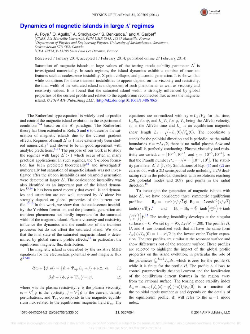
Our simulations show that, before saturation, the nonlin-
ear dynamics of the magnetic island at large D0 demonstrates
several transient phenomena predicted previously,7,12–14
such as the coalescence instability, the Y-ribbon formation,
and the plasmoids generation. This dynamics is further illus-
trated by the movie of the separatrix motion available in
Ref. 19 and in the Fig. 1. The critical parameter of magnetic
islands for experiments is the width. In the so called constant
w approximation,17 the magnetic island width w1 is deter-
mined by the amplitude of the m¼ 1 component of the mag-
netic flux w1 : w1 ¼ 4ffiffiffiffiffiffiffiffiffiffiffiffiffiffiffiffiffiffiffiffiffiffiffiffiffiffiw1ð0Þ=Jeqð0Þ
p. w1 is a measurement
of the perturbated flux at the rational surface. For large D0,the constant w approximation is not valid anymore, we intro-
duce ws, the distance between the right and left outermost
separatrix points across the O-point. The width ws is shown
by bold line in Fig. 1(c). The movie19 shows that the quanti-
ties w1 and ws are well defined in such D0 regime noteworthy
at saturation. ws corresponds to actual measurements in
Tokamak based on the temperature flattening inside the mag-
netic island.4,20 Other quantities have been investigated,
such as the island area inside the separatrices As. Our results
show that ws follows the same relation 2As ’ wsLY for all
profiles in our simulations, which indicate that despite differ-
ent profiles, ws is equivalent to As.
The analytical theory predicting magnetic island width
evolution is based on the asymptotic boundary layer approach
and Taylor expansion of the equilibrium current near the
rational surface. For the asymptotic boundary layer theory to
be valid, a number of inter-related parameters have to be
small: D0w� 1; w� 1 and kw� 1;w is the island width.
These conditions are quite restrictive, and generally impose
the condition D0 � 1 or even much less than unity.21 It is
worth noting that in astrophysical context, such as coronal
loops,22,23 D0 can be large; in a tokamak, typical D0 can reach
10 or more.24 For small D0 limit, the analytical theory predicts
the saturated island width to be the linear function of D08,9
w ¼ 2:44D0: (3)
This simple expression is in a good agreement with direct
numerical simulations for D0 of the order of unity,7–9,21 as
shown in Fig. 2. The agreement however breaks down for
larger values of D0. For both profiles H and G, island width
saturates with increasing D0, so that the island width becomes
independent of D0 for D0 � 1, contrary to the prediction
given by Eq. (3). This behaviour is in general predicted by
the higher order asymptotic theory25 which gives for the sat-
urated island width
w ¼ 2:44D0 1� 0:1w2½ �; (4)
though the theory of Ref. 25 is still based on the local
approximation. Our numerical simulations results show the
importance of global features of the equilibrium current
beyond those captured by the single D0 parameter.15 As
shown in Fig. 2, the island width for profiles H and G are dif-
ferent for the same values of D0 and the local current gradi-
ent. These results call for the investigation of the
mechanisms governing the island growth and saturation
beyond the D0 paradigm and characterization of the local and
global profile properties affecting the island width.
With increase of D0, the value of w1 is no longer a good
measure of the reconnection. The significant difference
between w1 and actual island width ws is observed at larger
values of D0 as shown in Fig. 2. The divergence between w1
and ws is due to the generation of the m¼ 0 mode. We will
show later that a relation between w1 and ws can be formu-
lated in terms of the reconnection stateÐ ws=2
0Beqdx.
We investigate now the impact of the transient phenom-
ena on the island saturation. The coalescence of magnetic
islands occurs when several harmonics with different m are
unstable, grow simultaneously, and merge together to form a
single island. An example of the process is shown in Figs.
1(a)–1(c). The coalescence instability is pronounced when
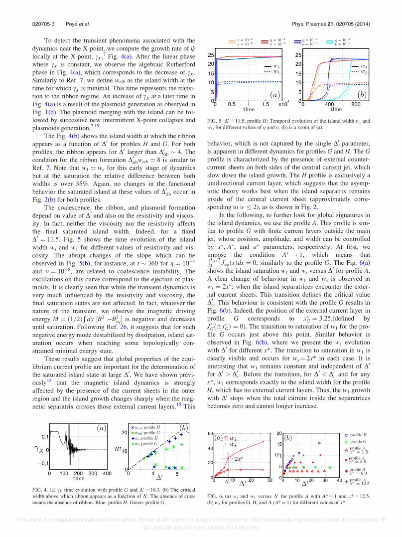
cm>1 > c1.13 Typical linear growth rates cm of the first three
modes versus D0 are shown in Fig. 3. It gives c2 ¼ c1 for
D0coal ’ 8 for profile H. Similarly, we found that for profile
G, the coalescence instability is expected at D0coal ’ 15. No
changes in the functional behaviour of ws and w1 with D0 are
observed around these values of D0coal in Fig. 2 for both pro-
files, which shows that coalescence is not involved in the ori-
gin of the discrepancy between w1 and ws.
FIG. 1. W contour plot with D0 ¼ 11.5, � ¼ 10�4, and profile H. (a)
Coalescence, t¼ 120. (b) Ribbon, t¼ 140. (c) End of transient, t¼ 400. (d)
Plasmoid example, g ¼ 10�4. � ¼ 10�5.
FIG. 2. (a) Island widths w1 (cross) and ws (circle) compared to theories Eq.
(3) dashed line and Eq. (4) dashed line. The profile H is in blue and profile Gin green. (b) Temporal zoom of (a) with additional data.
FIG. 3. Linear growth rate of tearing mode and its harmonics, profile H.
020705-2 Poy�e et al. Phys. Plasmas 21, 020705 (2014)
This article is copyrighted as indicated in the article. Reuse of AIP content is subject to the terms at: http://scitation.aip.org/termsconditions. Downloaded to IP:
147.210.245.180 On: Mon, 03 Mar 2014 09:10:51
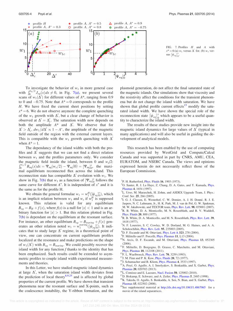
To detect the transient phenomena associated with the
dynamics near the X-point, we compute the growth rate of wlocally at the X-point, cX,7 Fig. 4(a). After the linear phase
where cX is constant, we observe the algebraic Rutherford
phase in Fig. 4(a), which corresponds to the decrease of cX.
Similarly to Ref. 7, we define wrib as the island width at the
time for which cX is minimal. This time represents the transi-
tion to the ribbon regime. An increase of cX at a later time in
Fig. 4(a) is a result of the plasmoid generation as observed in
Fig. 1(d). The plasmoid merging with the island can be fol-
lowed by successive new intermittent X-point collapses and
plasmoids generation.7,19
The Fig. 4(b) shows the island width at which the ribbon
appears as a function of D0 for profiles H and G. For both
profiles, the ribbon appears for D0 larger than D0rib � 4. The
condition for the ribbon formation D0ribwrib ’ 8 is similar to
Ref. 7. Note that w1 ’ ws for this early stage of dynamics
but at the saturation the relative difference between both
widths is over 35%. Again, no changes in the functional
behavior the saturated island at these values of D0rib occur in
Fig. 2(b) for both profiles.
The coalescence, the ribbon, and plasmoid formation
depend on value of D0 and also on the resistivity and viscos-
ity. In fact, neither the viscosity nor the resistivity affects
the final saturated island width. Indeed, for a fixed
D0 ¼ 11:5, Fig. 5 shows the time evolution of the island
width ws and w1 for different values of resistivity and vis-
cosity. The abrupt changes of the slope which can be
observed in Fig. 5(b), for instance, at t � 360 for g ¼ 10�4
and � ¼ 10�5, are related to coalescence instability. The
oscillations on this curve correspond to the ejection of plas-
moids. It is clearly seen that while the transient dynamics is
very much influenced by the resistivity and viscosity, the
final saturation states are not affected. In fact, whatever the
nature of the transient, we observe the magnetic driving
energy M ¼ 1=2ð ÞÐ
dx ½B2 �B2eq� is negative and decreases
until saturation. Following Ref. 26, it suggests that for such
negative energy mode destabilized by dissipation, island sat-
uration occurs when reaching some topologically con-
strained minimal energy state.
These results suggest that global properties of the equi-
librium current profile are important for the determination of
the saturated island state at large D0. We have shown previ-
ously15 that the magnetic island dynamics is strongly
affected by the presence of the current sheets in the outer
region and the island growth changes sharply when the mag-
netic separatrix crosses those external current layers.15 This
behavior, which is not captured by the single D0 parameter,
is apparent in different dynamics for profiles G and H. The Gprofile is characterized by the presence of external counter-
current sheets on both sides of the central current jet, which
slow down the island growth. The H profile is exclusively a
unidirectional current layer, which suggests that the asymp-
totic theory works best when the island separatrix remains
inside of the central current sheet (approximately corre-
sponding to w � 2), as is shown in Fig. 2.
In the following, to further look for global signatures in
the island dynamics, we use the profile A. This profile is sim-
ilar to profile G with finite current layers outside the main
jet, whose position, amplitude, and width can be controlled
by x�; A�, and a� parameters, respectively. At first, we
impose the condition A� ! 1, which means thatÐ LX=2
0JeqðxÞdx ¼ 0, similarly to the profile G. The Fig. 6(a)
shows the island saturation w1 and ws versus D0 for profile A.
A clear change of behaviour in w1 and ws is observed at
ws ¼ 2x�: when the island separatrices encounter the exter-
nal current sheets. This transition defines the critical value
D0c. This behaviour is consistent with the profile G results in
Fig. 6(b). Indeed, the position of the external current layer in
profile G corresponds to x�G ¼ 3:25.(defined by
J0Gð6x�GÞ ¼ 0). The transition to saturation of w1 for the pro-
file G occurs just above this point. Similar behavior is
observed in Fig. 6(b), where we present the w1 evolution
with D0 for different x*. The transition to saturation in w1 is
clearly visible and occurs for ws¼ 2x* in each case. It is
interesting that w1 remains constant and independent of D0
for D0 > D0c. Before the transition, for D0 < D0c and for any
x*, w1 corresponds exactly to the island width for the profile
H, which has no external current layers. Thus, the w1 growth
with D0 stops when the total current inside the separatrices
becomes zero and cannot longer increase.
FIG. 4. (a) cX time evolution with profile G and D0 ¼ 10.3. (b) The critical
width above which ribbon appears as a function of D0. The absence of cross
means the absence of ribbon. Blue: profile H. Green: profile G.
FIG. 5. D0 ¼ 11.5, profile H: Temporal evolution of the island width ws and
w1, for different values of g and �. (b) is a zoom of (a).
FIG. 6. (a) ws and w1 versus D0 for profile A with A*¼ 1 and x*¼ 12.5.
(b) w1 for profiles G, H, and A (A*¼ 1) for different values of x*.
020705-3 Poy�e et al. Phys. Plasmas 21, 020705 (2014)
This article is copyrighted as indicated in the article. Reuse of AIP content is subject to the terms at: http://scitation.aip.org/termsconditions. Downloaded to IP:
147.210.245.180 On: Mon, 03 Mar 2014 09:10:51
To investigate the behavior of w1 in more general case
withÐ LX=2
0JeqðxÞdx 6¼ 0, in Fig. 7(a), we present several
scans of w1ðD0Þ for different values of A*, ranging from 0.9
to 0 and �0.75. Note that A*¼ 0 corresponds to the profile
H. We have fixed the current sheet positions by setting
x*¼ 6. We do not observe anymore the complete quenching
of the w1 growth with D0, but a clear change of behavior is
observed at D0 ¼ D0c. The saturation width now depends on
both the amplitude A* and D0. We observe that for
D0 > D0c; dw1=dD0 / 1� A�, the amplitude of the magnetic
field outside of the region with the external current layers.
This is compatible with the w1 growth quenching with D0
when A*¼ 1.
The dependancy of the island widths with both the pro-
files and D0 suggests that we can not find a direct relation
between w1 and the profiles parameters only. We consider
the magnetic field inside the island, between 0 and ws/2:Ð ws=2
0BeqðxÞdx ¼ Weq ws=2ð Þ �Weq 0ð Þ ¼ Weq½ �s0, the maxi-
mal equilibrium reconnected flux across the island. This
reconnection state has compatible D0 evolution with w1. We
show in Fig. 7(b) that w1 as a function of Weq½ �s0 follows the
same curve for different A?. It is independent of x? and it is
the same as for the profile H.
We obtain the general formulae w1 ¼ wH1 ð½weq�
s0Þ, which
is an implicit relation between w1 and ws if wH1 is supposed
known. This relation is valid for any equilibrium
Beq ¼ BH þ f ðxÞ, where f(x) is a null for jxj < 1 and is an ar-
bitrary function for jxj > 1. But this relation plotted in Fig.
7(b) is dependant on the equilibrium at the resonant surface.
For instance, an other equilibrium Beq ¼ Btearing þ f ðxÞ gen-
erates an other relation noted w1 ¼ wtearing1 ð½weq�
s0Þ. It indi-
cates that to study large D0 regime, in a theoretical point of
view, one can concentrate on current equilibrium profiles
localized at the resonance and make predictions on the shape
of w1ðD0Þ with Beq ¼ Btearing. We could possibly recover the
island width for any function f thanks to the identity that has
been emphasized. Such results could be extended to asym-
metric profiles to couple island width experimental measure-
ments and theories.
In this Letter, we have studied magnetic island dynamics
at large D0, when the saturation island width deviates from
the prediction of local theory8,9,25 and is affected by global
properties of the current profile. We have shown that transient
phenomena near the resonant surface and X-points, such as
the coalescence instability, the Y-ribbon formation, and the
plasmoid generation, do not affect the final saturated state of
the magnetic islands. Our simulations show that viscosity and
the resistivity affect the conditions for the transient phenom-
ena but do not change the island width saturation. We have
shown that global profile current effects15 modify the satu-
rated island width. We have shown the special role of the
reconnection state weq
� �s0
which appears to be a useful quan-
tity to characterize the island width.
The results of these studies provide new insight into the
magnetic island dynamics for large values of D0 (typical in
many applications) and will also be useful in guiding the de-
velopment of analytical models.
This research has been enabled by the use of computing
resources provided by WestGrid and Compute/Calcul
Canada and was supported in part by CNRS, AMU, CEA,
EURATOM, and NSERC Canada. The views and opinions
expressed herein do not necessarily reflect those of the
European Commission.
1P. H. Rutherford, Phys. Fluids 16, 1903 (1973).2O. Sauter, R. J. La Haye, Z. Chang, D. A. Gates, and Y. Kamada, Phys.
Plasmas 4, 1654 (1997).3L. Urso, M. Maraschek, H. Zohm, and ASDEX Upgrade Team, J. Phys.:
Conf. Ser. 25, 266 (2005).4I. G. J. Classen, E. Westerhof, C. W. Domier, A. J. H. Donn�e, R. J. E.
Jaspers, N. C. Luhmann, Jr., H. K. Park, M. J. van de Pol, G. W. Spakman,
M. W. Jakubowski, and TEXTOR team, Phys. Rev. Lett. 98, 035001 (2007).5R. B. White, D. A. Monticello, M. N. Rosenbluth, and B. V. Waddell,
Phys. Fluids 20, 800 (1977).6R. B. White, D. A. Monticello, and M. N. Rosenbluth, Phys. Rev. Lett. 39,
1618 (1977).7N. F. Loureiro, S. C. Cowley, W. D. Dorland, M. G. Haines, and A. A.
Schekochihin, Phys. Rev. Lett. 95, 235003 (2005).8D. F. Escande and M. Ottaviani, Phys. Lett A 323, 278 (2004).9F. Militello and F. Porcelli, Phys. Plasmas 11, L13 (2004).
10N. Arcis, D. F. Escande, and M. Ottaviani, Phys. Plasmas 13, 052305
(2006).11F. Militello, D. Borgogno, D. Grasso, C. Marchetto, and M. Ottaviani,
Phys. Plasmas 18, 112108 (2011).12F. L. Waelbroeck, Phys. Rev. Lett. 70, 3259 (1993).13J. M. Finn and P. K. Kaw, Phys. Fluids 20, 72 (1977).14J. Schumacher and B. Kliem, Phys. Plasmas 4, 3533 (1997).15A. Poy�e, O. Agullo, A. I. Smolyakov, S. Benkadda, and X. Garbet, Phys.
Plasmas 20, 020702 (2013).16L. Comisso and E. Lazzaro, Nucl. Fusion 50, 125002 (2010).17D. Biskamp, E. Schwarz, and A. Zeiler, Phys. Plasmas 5, 2485 (1998).18K. Takeda, O. Agullo, S. Benkadda, A. Sen, N. Bian, and X. Garbet, Phys.
Plasmas 15, 022502 (2008).19See supplemental material at http://dx.doi.org/10.1063/1.4867065 for a
movie of the island separatrices.
FIG. 7. Profiles H and A with
x*¼ 6:(a) w1 versus D0
for. (b) w1 ver-
sus weq
� �s0.
020705-4 Poy�e et al. Phys. Plasmas 21, 020705 (2014)
This article is copyrighted as indicated in the article. Reuse of AIP content is subject to the terms at: http://scitation.aip.org/termsconditions. Downloaded to IP:
147.210.245.180 On: Mon, 03 Mar 2014 09:10:51

20R. Fitzpatrick, Phys. Plasmas 2, 825 (1995).21A. Poy�e, Ph.D. thesis, Aix-Marseille University, 2012.22A. B. Hassam, Astrophys. J. 348, 778–780 (1990).23Y. Huang and E. Zweibel, Phys. Plasmas 16, 042102 (2009).24P. Maget, H. L€utjens, R. Coelho, B. Alper, M. Brix, P. Buratti, R. J.
Buttery, E. De la Luna, N. Hawkes, G. T. A. Huysmans, I. Jenkins, C. D.
Challis, C. Giroud, X. Litaudon, J. Mailloux, M. Ottaviani, and JET-
EFDA Contributors, Nucl. Fusion 50, 045004 (2010).25A. I. Smolyakov, A. Poy�e, O. Agullo, S. Benkadda, and X. Garbet, Phys.
Plasmas 20, 062506 (2013).26E. A. Adler, R. M. Kulsrud, and R. B. White, Phys. Fluids 23, 1375
(1980).
020705-5 Poy�e et al. Phys. Plasmas 21, 020705 (2014)
This article is copyrighted as indicated in the article. Reuse of AIP content is subject to the terms at: http://scitation.aip.org/termsconditions. Downloaded to IP:
147.210.245.180 On: Mon, 03 Mar 2014 09:10:51