DuPont™ Flashing Systems Installation GuidelinesHelPInG you Get tHe job Done rIGHt
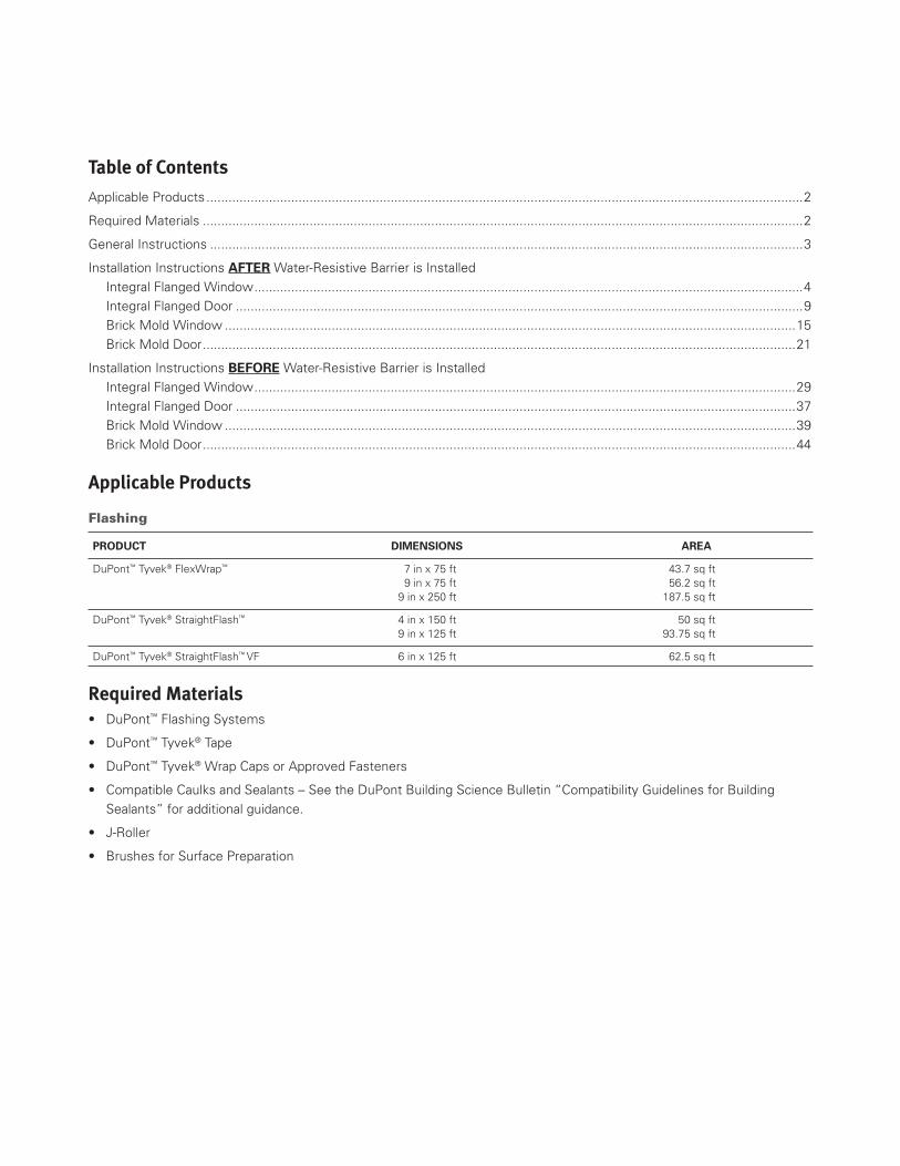
table of Contents
Applicable Products ..................................................................................................................................................................2
Required Materials ...................................................................................................................................................................2
General Instructions .................................................................................................................................................................3
Installation Instructions AFTER Water-Resistive Barrier is Installed
Integral Flanged Window .....................................................................................................................................................4
Integral Flanged Door ..........................................................................................................................................................9
Brick Mold Window ...........................................................................................................................................................15
Brick Mold Door .................................................................................................................................................................21
Installation Instructions BEFORE Water-Resistive Barrier is Installed
Integral Flanged Window ...................................................................................................................................................29
Integral Flanged Door ........................................................................................................................................................37
Brick Mold Window ...........................................................................................................................................................39
Brick Mold Door .................................................................................................................................................................44
Applicable Products
Flashing
PROducT dimEnsiOns AREA
DuPont™ Tyvek® FlexWrap™ 7 in x 75 ft 43.7 sq ft 9 in x 75 ft 56.2 sq ft 9 in x 250 ft 187.5 sq ft
DuPont™ Tyvek® StraightFlash™ 4 in x 150 ft 50 sq ft 9 in x 125 ft 93.75 sq ft
DuPont™ Tyvek® StraightFlash™ VF 6 in x 125 ft 62.5 sq ft
required Materials• DuPont™ Flashing Systems
• DuPont™ Tyvek® Tape
• DuPont™ Tyvek® Wrap Caps or Approved Fasteners
• Compatible Caulks and Sealants – See the DuPont Building Science Bulletin “Compatibility Guidelines for Building
Sealants” for additional guidance.
• J-Roller
• Brushes for Surface Preparation
3Copyright ©2006 E. I. du Pont de Nemours and Company. All Rights Reserved. v.6.1
General Instructions DuPont™ FlexWrap™, DuPont™ StraightFlash™ and DuPont™ StraightFlash™ VF should be installed on clean, dry surfaces
that are free of frost. Wipe surfaces to remove moisture, dirt, grease and other debris that could interfere with adhesion.
Apply pressure along entire surface for a good bond using a j-roller.
Remove all wrinkles and bubbles by smoothing surface and repositioning as necessary.
Door and window rough sill framing must be level or slightly sloped to the exterior to ensure drainage to the exterior.
When flashing the sill area for Windows and Doors, DuPont recommends the use of 7” wide DuPont™ FlexWrap™ for 2x4
framing and 9” wide DuPont™ Flexwrap™ for 2x6 framing.
dOnOTsTRETcH DuPont™ FlexWrap™ when installing along sills or jambs. DuPont™ FlexWrap™ is only intended to be
stretched when covering corners or curved sections.
DuPont™ FlexWrap™, DuPont™ StraightFlash™ and DuPont™ StraightFlash™ VF perform best when installed at temperatures
above 40°F (4°C).
Priming is generally not required for adhering DuPont Flashing Products to most common building materials. However,
adverse weather conditions or cold temperatures may require use of a primer to promote adhesion. Additionally, concrete,
masonry, and fiber faced exterior gypsum board require the use of approved primers. Consult your local DuPont™ Tyvek®
Specialist for primer recommendations and approved primers.
For additional guidelines and suggested caulks, please call 1-800-44-Tyvek (800-448-9835), visit our website at
www.Construction.Tyvek.com, or consult your local DuPont™ Tyvek® Specialist.
8“ Minimum
8“Minimum
Exterior InteriorExterior
B
C
B
A
D
A
4Copyright ©2006 E. I. du Pont de Nemours and Company. All Rights Reserved. v.6.1
DuPont™ Flashing Systems Installation Guidelines
Installation Methods for DuPont™ Flashing System AFter Water-resistive barrier (Wrb) is Installed
Integral Flanged Window AFTER Water-Resistive Barrier (WRB)
Method applies to following product:
• DuPont™ StraightFlash™
• DuPont™ FlexWrap™
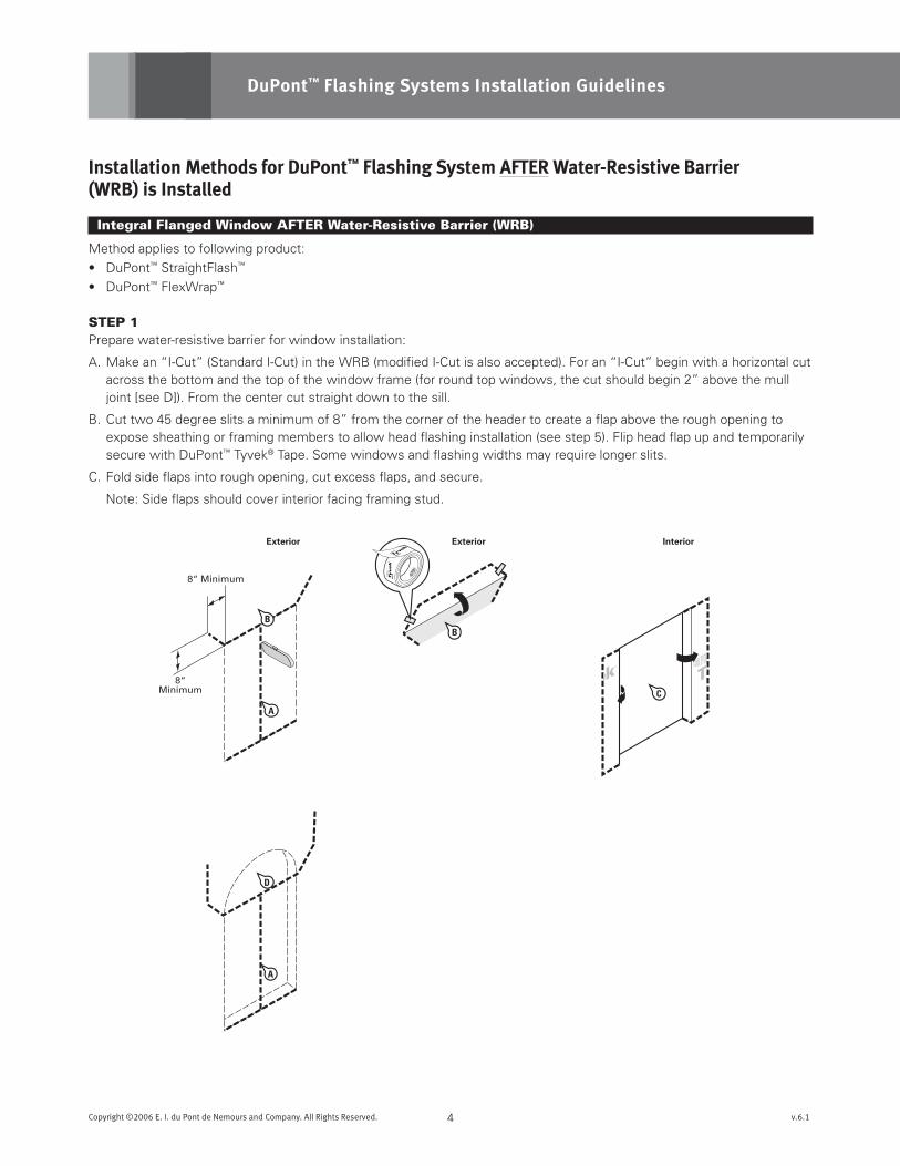
STEp 1Prepare water-resistive barrier for window installation:
A. Make an “I-Cut” (Standard I-Cut) in the WRB (modified I-Cut is also accepted). For an “I-Cut” begin with a horizontal cut across the bottom and the top of the window frame (for round top windows, the cut should begin 2” above the mull joint [see D]). From the center cut straight down to the sill.
B. Cut two 45 degree slits a minimum of 8” from the corner of the header to create a flap above the rough opening to expose sheathing or framing members to allow head flashing installation (see step 5). Flip head flap up and temporarily secure with DuPont™ Tyvek® Tape. Some windows and flashing widths may require longer slits.
C. Fold side flaps into rough opening, cut excess flaps, and secure.
Note: Side flaps should cover interior facing framing stud.
A
Sill Length+ 12 inches
(S)
6“Minimum
FRONT VIEW CORNER DETAIL
No Gap in Corner
DO NOT STRETCH
WRONG CORRECT
3
4
52
1
Window Jamb
DuPont™FlexWrap™
Sill
E
D
5Copyright ©2006 E. I. du Pont de Nemours and Company. All Rights Reserved. v.6.1
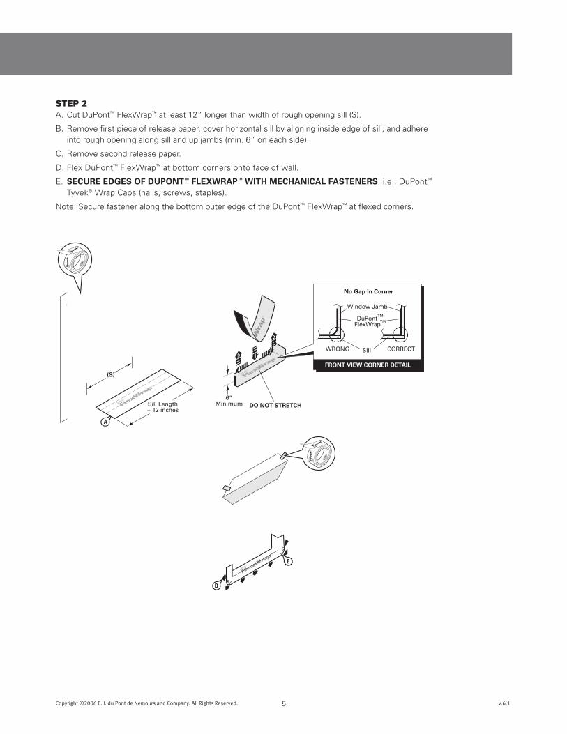
STEp 2A. Cut DuPont™ FlexWrap™ at least 12” longer than width of rough opening sill (S).
B. Remove first piece of release paper, cover horizontal sill by aligning inside edge of sill, and adhere into rough opening along sill and up jambs (min. 6” on each side).
C. Remove second release paper.
D. Flex DuPont™ FlexWrap™ at bottom corners onto face of wall.
E. sEcuREEdGEsOFduPOnT™FLEXWRAP™WiTHmEcHAnicALFAsTEnERs. i.e., DuPont™ Tyvek® Wrap Caps (nails, screws, staples).
Note: Secure fastener along the bottom outer edge of the DuPont™ FlexWrap™ at flexed corners.
A
A
B
B
C
6Copyright ©2006 E. I. du Pont de Nemours and Company. All Rights Reserved. v.6.1
DuPont™ Flashing Systems Installation Guidelines
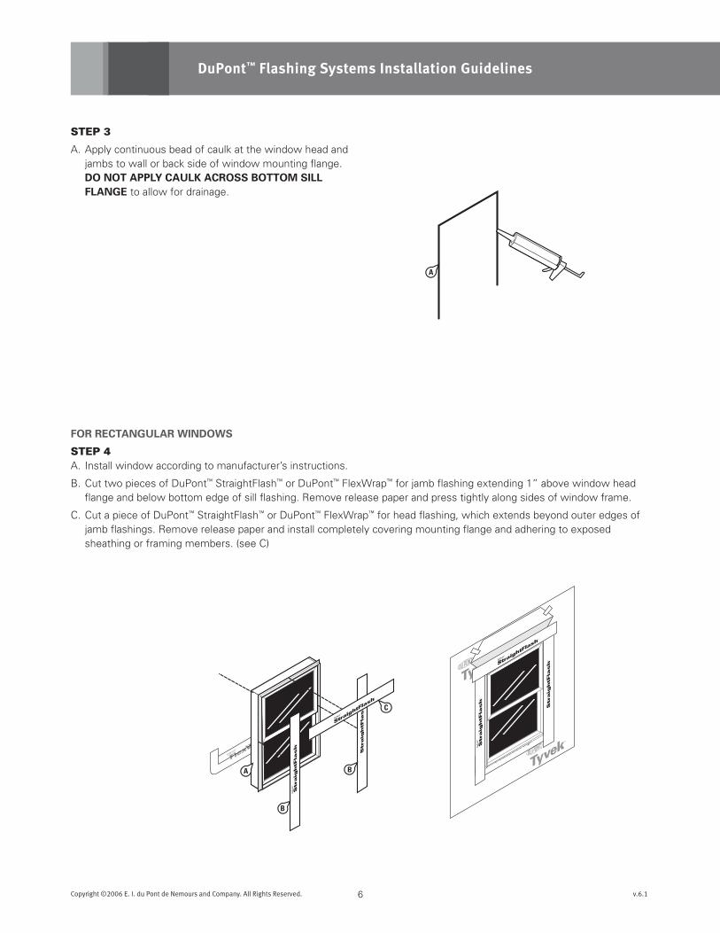
STEp 3
A. Apply continuous bead of caulk at the window head and jambs to wall or back side of window mounting flange. dOnOTAPPLYcAuLKAcROssBOTTOmsiLLFLAnGE to allow for drainage.
FORREcTAnGuLARWindOWs
STEp 4A. Install window according to manufacturer’s instructions.
B. Cut two pieces of DuPont™ StraightFlash™ or DuPont™ FlexWrap™ for jamb flashing extending 1” above window head flange and below bottom edge of sill flashing. Remove release paper and press tightly along sides of window frame.
C. Cut a piece of DuPont™ StraightFlash™ or DuPont™ FlexWrap™ for head flashing, which extends beyond outer edges of jamb flashings. Remove release paper and install completely covering mounting flange and adhering to exposed sheathing or framing members. (see C)
BA
Interior
B
BA
7Copyright ©2006 E. I. du Pont de Nemours and Company. All Rights Reserved. v.6.1
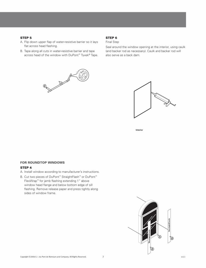
STEp 6Final Step
Seal around the window opening at the interior, using caulk (and backer rod as necessary). Caulk and backer rod will also serve as a back dam.
FOR ROUNDTOp WINDOWS
STEp 4A. Install window according to manufacturer’s instructions.
B. Cut two pieces of DuPont™ StraightFlash™ or DuPont™ FlexWrap™ for jamb flashing extending 1” above window head flange and below bottom edge of sill flashing. Remove release paper and press tightly along sides of window frame.
STEp 5A. Flip down upper flap of water-resistive barrier so it lays
flat across head flashing.
B. Tape along all cuts in water-resistive barrier and tape across head of the window with DuPont™ Tyvek® Tape.
6“ Minimum
H
AC
B
A
Interior
8Copyright ©2006 E. I. du Pont de Nemours and Company. All Rights Reserved. v.6.1
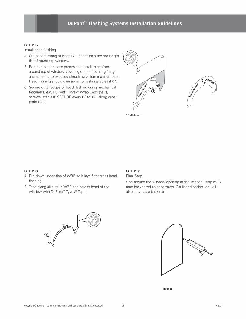
STEp 5Install head flashing
A. Cut head flashing at least 12” longer than the arc length (H) of round-top window.
B. Remove both release papers and install to conform around top of window, covering entire mounting flange and adhering to exposed sheathing or framing members. Head flashing should overlap jamb flashings at least 6”.
C. Secure outer edges of head flashing using mechanical fasteners. e.g. DuPont™ Tyvek® Wrap Caps (nails, screws, staples). SECURE every 6” to 12” along outer perimeter.
DuPont™ Flashing Systems Installation Guidelines
STEp 6A. Flip down upper flap of WRB so it lays flat across head
flashing.
B. Tape along all cuts in WRB and across head of the window with DuPont™ Tyvek® Tape.
STEp 7Final Step
Seal around the window opening at the interior, using caulk (and backer rod as necessary). Caulk and backer rod will also serve as a back dam.
C
B
B
A
Interior
9Copyright ©2006 E. I. du Pont de Nemours and Company. All Rights Reserved. v.6.1
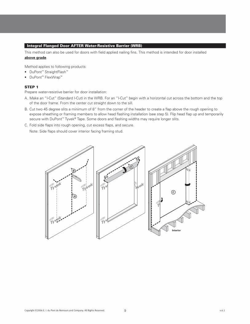
Integral Flanged Door AFTER Water-Resistive Barrier (WRB)
This method can also be used for doors with field applied nailing fins. This method is intended for door installed
abovegrade.
Method applies to following products:
• DuPont™ StraightFlash™
• DuPont™ FlexWrap™
STEp 1Prepare water-resistive barrier for door installation:
A. Make an “I-Cut” (Standard I-Cut) in the WRB. For an “I-Cut” begin with a horizontal cut across the bottom and the top of the door frame. From the center cut straight down to the sill.
B. Cut two 45 degree slits a minimum of 8” from the corner of the header to create a flap above the rough opening to expose sheathing or framing members to allow head flashing installation (see step 5). Flip head flap up and temporarily secure with DuPont™ Tyvek® Tape. Some doors and flashing widths may require longer slits.
C. Fold side flaps into rough opening, cut excess flaps, and secure.
Note: Side flaps should cover interior facing framing stud.
(S)
Sill Length+ 12 inches
7-inch for 2x4-inch studs9-inch for 2x6-inch studs
OverlapFront
Back
ScoredReleasePaper
Break ScoredRelease Paper
Peel Off2-piecesof ReleasePaper
A
B
C
10Copyright ©2006 E. I. du Pont de Nemours and Company. All Rights Reserved. v.6.1
DuPont™ Flashing Systems Installation Guidelines
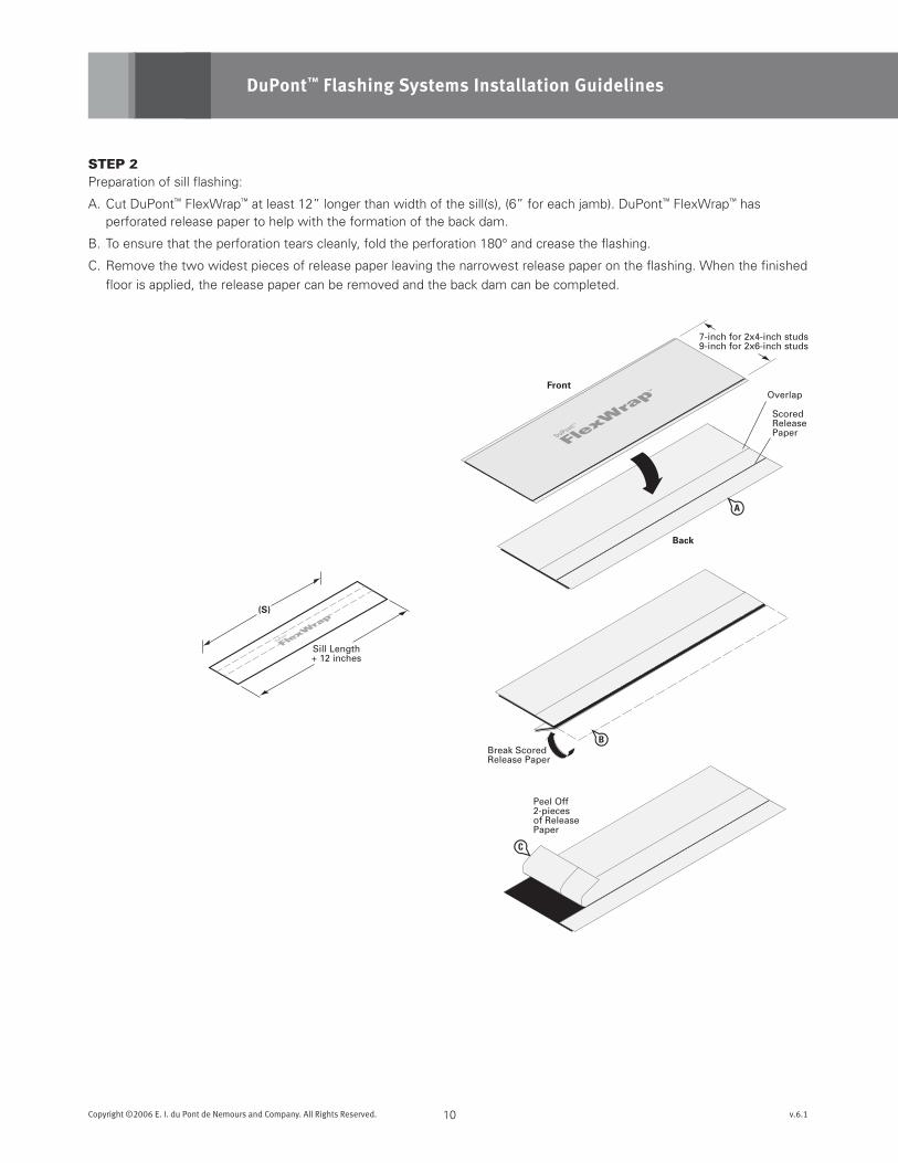
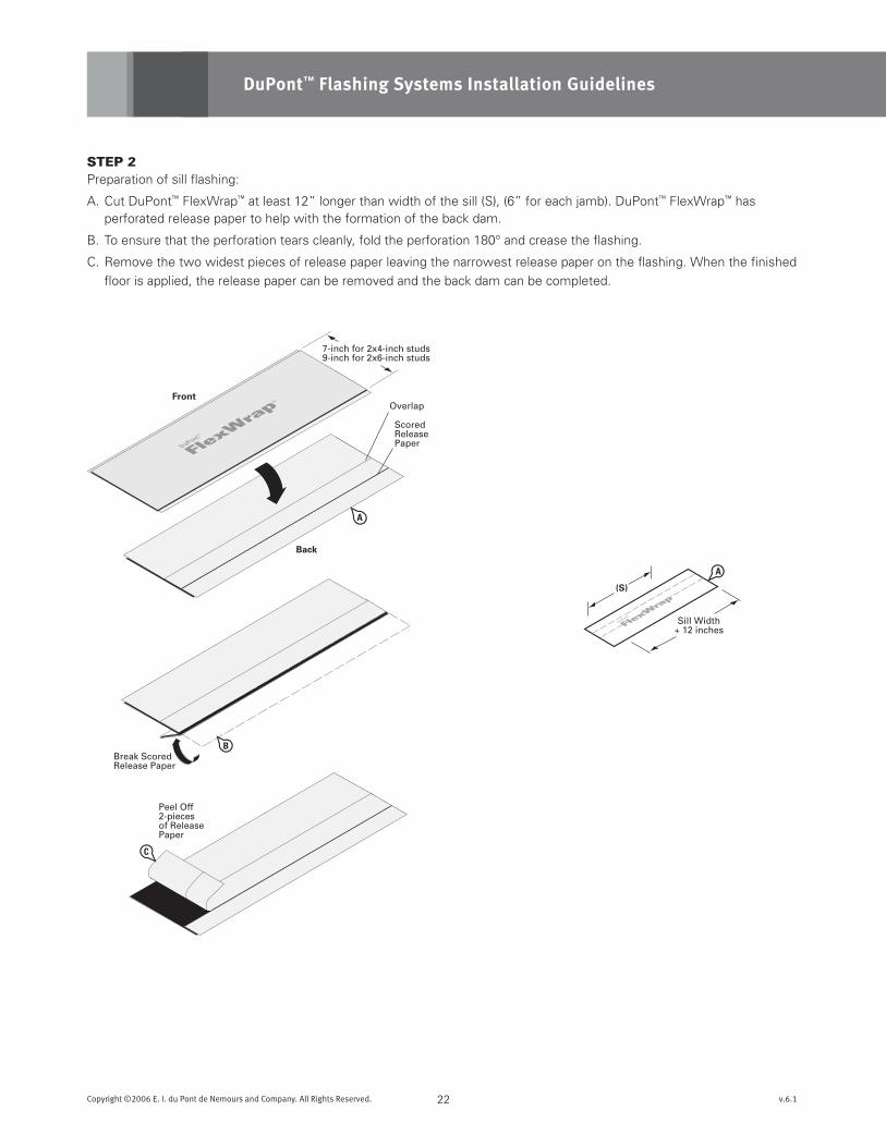
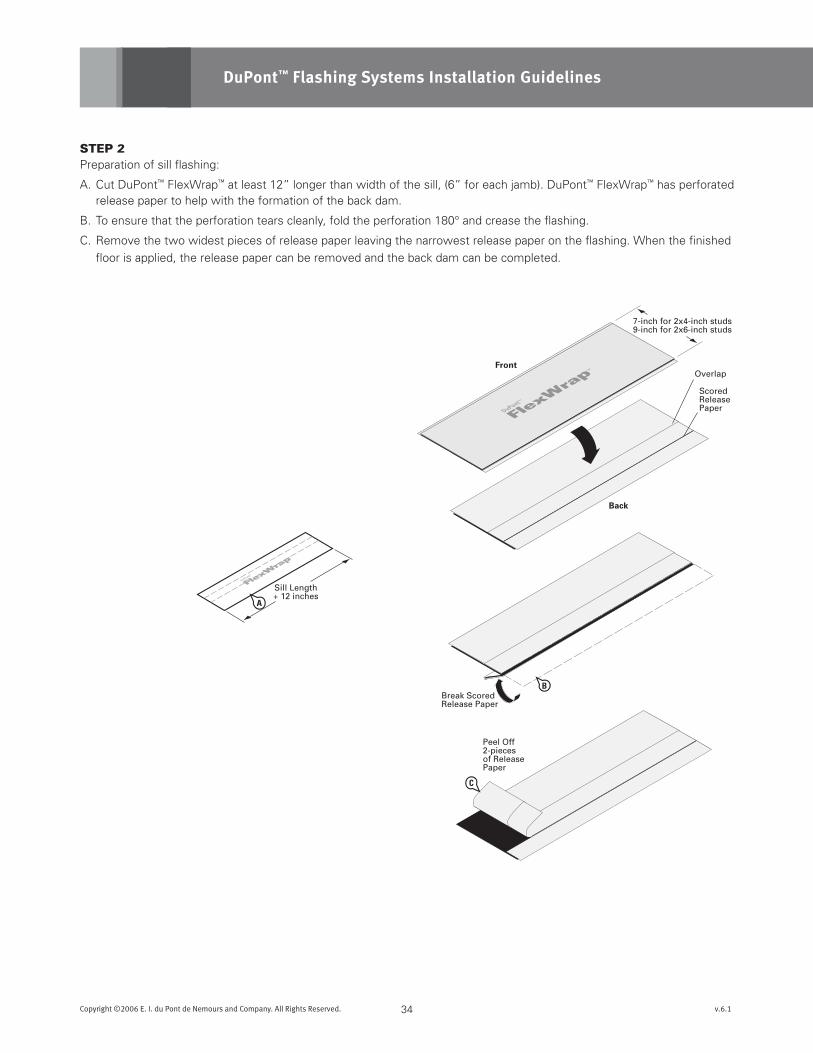
STEp 2Preparation of sill flashing:
A. Cut DuPont™ FlexWrap™ at least 12” longer than width of the sill(s), (6” for each jamb). DuPont™ FlexWrap™ has perforated release paper to help with the formation of the back dam.
B. To ensure that the perforation tears cleanly, fold the perforation 180° and crease the flashing.
C. Remove the two widest pieces of release paper leaving the narrowest release paper on the flashing. When the finished
floor is applied, the release paper can be removed and the back dam can be completed.
6“Minimum
FRONT VIEW CORNER DETAIL
No Gap in Corner
DO NOT STRETCH
WRONG CORRECT
3
4
5
21
Door Jamb
DuPont™FlexWrap™
Sill
A
DuPont™FlexWrap™
DuPont™Tyvek®
Sheathing
INTERIOR
Patio Door
DoorThreshold
TransitionThreshold
Flooring
Sub Floor
PlasticProtector(optional)
EXTERIOR
Optional
11Copyright ©2006 E. I. du Pont de Nemours and Company. All Rights Reserved. v.6.1
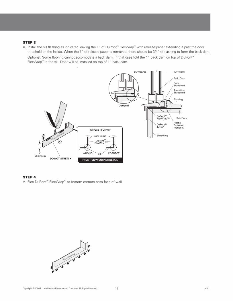
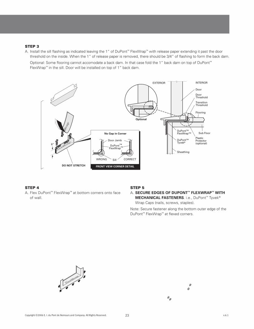
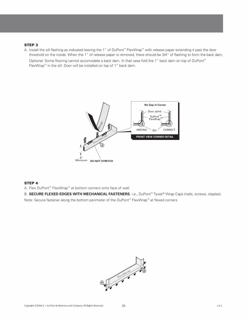
STEp 3A. Install the sill flashing as indicated leaving the 1” of DuPont™ FlexWrap™ with release paper extending it past the door
threshold on the inside. When the 1” of release paper is removed, there should be 3/4” of flashing to form the back dam.
Optional: Some flooring cannot accomodate a back dam. In that case fold the 1” back dam on top of DuPont™ FlexWrap™ in the sill. Door will be installed on top of 1” back dam.
STEp 4A. Flex DuPont™ FlexWrap™ at bottom corners onto face of wall.
Peel OffRelease Paperand attach tounderside of door
ButylAdhesive
10”
4” DuPont™StraightFlash™
12Copyright ©2006 E. I. du Pont de Nemours and Company. All Rights Reserved. v.6.1
DuPont™ Flashing Systems Installation Guidelines
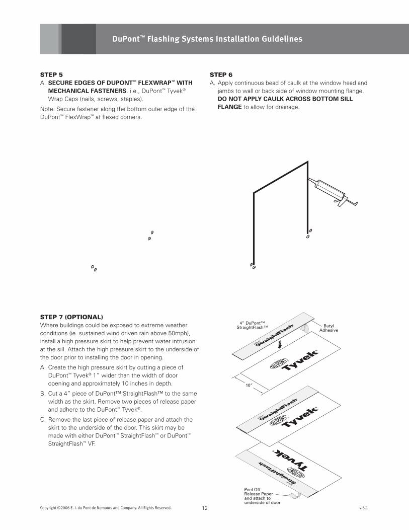
STEp 5A. sEcuREEdGEsOFduPOnT™FLEXWRAP™WiTH
mEcHAnicALFAsTEnERs. i.e., DuPont™ Tyvek® Wrap Caps (nails, screws, staples).
Note: Secure fastener along the bottom outer edge of the DuPont™ FlexWrap™ at flexed corners.
STEp 6A. Apply continuous bead of caulk at the window head and
jambs to wall or back side of window mounting flange. dOnOTAPPLYcAuLKAcROssBOTTOmsiLLFLAnGE to allow for drainage.
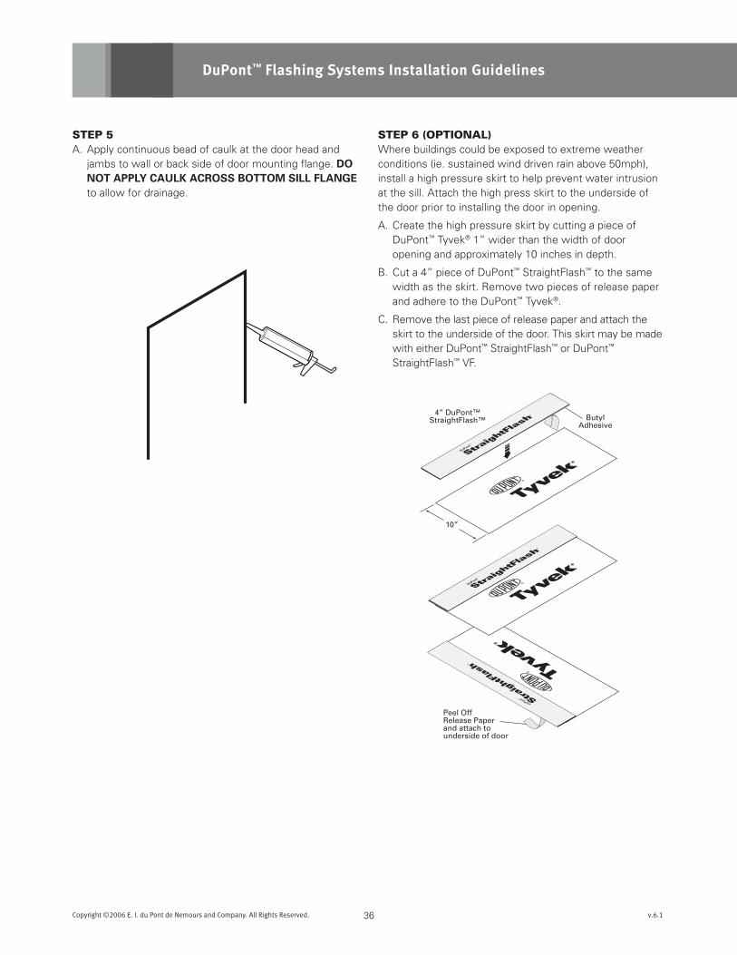
STEp 7 (OpTIONAl)Where buildings could be exposed to extreme weather conditions (ie. sustained wind driven rain above 50mph), install a high pressure skirt to help prevent water intrusion at the sill. Attach the high pressure skirt to the underside of the door prior to installing the door in opening.
A. Create the high pressure skirt by cutting a piece of DuPont™ Tyvek® 1” wider than the width of door opening and approximately 10 inches in depth.
B. Cut a 4” piece of DuPont™ StraightFlash™ to the same width as the skirt. Remove two pieces of release paper and adhere to the DuPont™ Tyvek®.
C. Remove the last piece of release paper and attach the skirt to the underside of the door. This skirt may be made with either DuPont™ StraightFlash™ or DuPont™ StraightFlash™ VF.
A
C
C
D
B
DuPont™FlexWrap™
DuPont™StraightFlash™
DuPont™Tyvek®
Sheathing
HighPressureSkirt
INTERIOR
Patio Door
DoorThreshold
TransitionThreshold
Flooring
Sub Floor
PlasticProtector(optional)
EXTERIOR
Optional
13Copyright ©2006 E. I. du Pont de Nemours and Company. All Rights Reserved. v.6.1
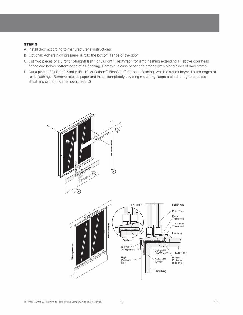
STEp 8A. Install door according to manufacturer’s instructions.
B. Optional: Adhere high pressure skirt to the bottom flange of the door.
C. Cut two pieces of DuPont™ StraightFlash™ or DuPont™ FlexWrap™ for jamb flashing extending 1” above door head flange and below bottom edge of sill flashing. Remove release paper and press tightly along sides of door frame.
D. Cut a piece of DuPont™ StraightFlash™ or DuPont™ FlexWrap™ for head flashing, which extends beyond outer edges of jamb flashings. Remove release paper and install completely covering mounting flange and adhering to exposed sheathing or framing members. (see C)
A
B
B
Fold Out and Up
Staples Tape
Fold In and Up
OR
Option One
Option Two
OR
14Copyright ©2006 E. I. du Pont de Nemours and Company. All Rights Reserved. v.6.1
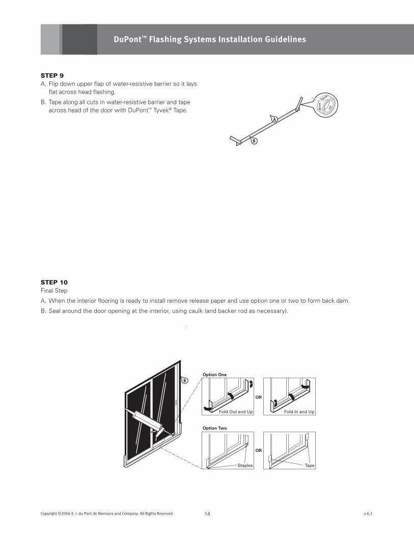
STEp 9A. Flip down upper flap of water-resistive barrier so it lays
flat across head flashing.
B. Tape along all cuts in water-resistive barrier and tape across head of the door with DuPont™ Tyvek® Tape.
DuPont™ Flashing Systems Installation Guidelines
STEp 10Final Step
A. When the interior flooring is ready to install remove release paper and use option one or two to form back dam.
B. Seal around the door opening at the interior, using caulk (and backer rod as necessary).
8“ Minimum
8“Minimum
Exterior InteriorExterior
B
B
A
C
15Copyright ©2006 E. I. du Pont de Nemours and Company. All Rights Reserved. v.6.1
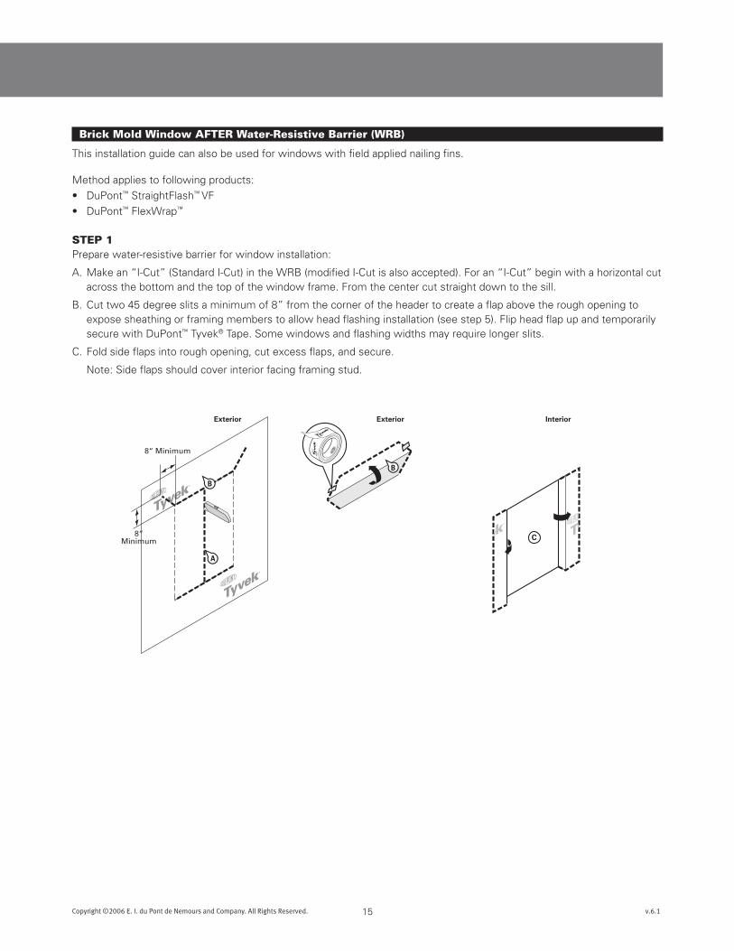
Brick Mold Window AFTER Water-Resistive Barrier (WRB)
This installation guide can also be used for windows with field applied nailing fins.
Method applies to following products:
• DuPont™ StraightFlash™ VF
• DuPont™ FlexWrap™
STEp 1Prepare water-resistive barrier for window installation:
A. Make an “I-Cut” (Standard I-Cut) in the WRB (modified I-Cut is also accepted). For an “I-Cut” begin with a horizontal cut across the bottom and the top of the window frame. From the center cut straight down to the sill.
B. Cut two 45 degree slits a minimum of 8” from the corner of the header to create a flap above the rough opening to expose sheathing or framing members to allow head flashing installation (see step 5). Flip head flap up and temporarily secure with DuPont™ Tyvek® Tape. Some windows and flashing widths may require longer slits.
C. Fold side flaps into rough opening, cut excess flaps, and secure.
Note: Side flaps should cover interior facing framing stud.
Sill Length+ 12 inches 6“
Minimum
FRONT VIEW CORNER DETAIL
No Gap in Corner
DO NOT STRETCH
WRONG CORRECT3
4
52
1
Window Jamb
DuPont™FlexWrap™
SillB
E
D
16Copyright ©2006 E. I. du Pont de Nemours and Company. All Rights Reserved. v.6.1
DuPont™ Flashing Systems Installation Guidelines
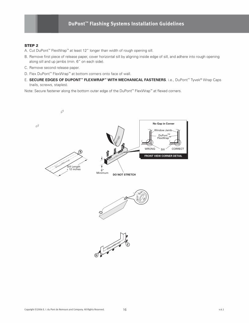
STEp 2A. Cut DuPont™ FlexWrap™ at least 12” longer than width of rough opening sill.
B. Remove first piece of release paper, cover horizontal sill by aligning inside edge of sill, and adhere into rough opening along sill and up jambs (min. 6” on each side).
C. Remove second release paper.
D. Flex DuPont™ FlexWrap™ at bottom corners onto face of wall.
E. sEcuREEdGEsOFduPOnT™FLEXWRAP™WiTHmEcHAnicALFAsTEnERs. i.e., DuPont™ Tyvek® Wrap Caps (nails, screws, staples).
Note: Secure fastener along the bottom outer edge of the DuPont™ FlexWrap™ at flexed corners.
WindowInterior
WindowInterior
WindowInterior
B
C
A
D
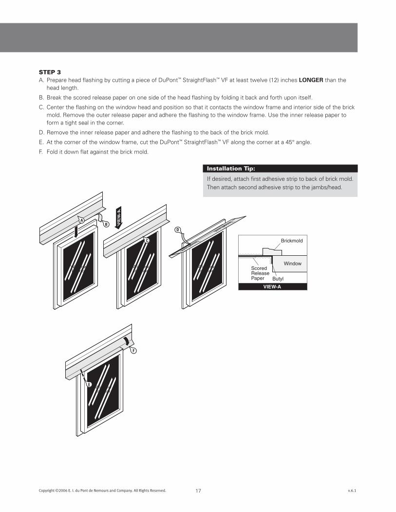
VIEW-A
Brickmold
Window
Butyl
ScoredReleasePaper
VIE
W-A
WindowInterior
F
E
17Copyright ©2006 E. I. du Pont de Nemours and Company. All Rights Reserved. v.6.1
STEp 3A. Prepare head flashing by cutting a piece of DuPont™ StraightFlash™ VF at least twelve (12) inches LOnGER than the
head length.
B. Break the scored release paper on one side of the head flashing by folding it back and forth upon itself.
C. Center the flashing on the window head and position so that it contacts the window frame and interior side of the brick mold. Remove the outer release paper and adhere the flashing to the window frame. Use the inner release paper to form a tight seal in the corner.
D. Remove the inner release paper and adhere the flashing to the back of the brick mold.
E. At the corner of the window frame, cut the DuPont™ StraightFlash™ VF along the corner at a 45° angle.
F. Fold it down flat against the brick mold.
Installation Tip:
If desired, attach first adhesive strip to back of brick mold.
Then attach second adhesive strip to the jambs/head.

WindowInterior
WindowInterior
Make sure theadhesive on thesepieces willoverlap.
WindowInterior1-1/2”
1”
E
D
C
A
WindowInterior
18Copyright ©2006 E. I. du Pont de Nemours and Company. All Rights Reserved. v.6.1
DuPont™ Flashing Systems Installation Guidelines
STEp 4A. Prepare jamb flashing by cutting a piece of DuPont™ StraightFlash™ VF at least six (6) inches LOnGER than the jamb.
B. Break the scored release paper on one side of the jamb flashing by folding it back and forth upon itself.
C. Position so that it contacts the window frame and interior side of the brick mold. Ensure that the jamb flashing is positioned 1-1/2 inch below the top edge of the head flashing. Jambflashingadhesivemustcomeincontactwithheadflashingadhesiveandoverlapby1-inch.
D. Remove the outer release paper and adhere the flashing to the window frame. Use the inner release paper to form a tight seal in the corner.
E. Remove the inner release paper and adhere the flashing to the back of the brick mold.
STEp 5A. At the corner of the window frame, cut the DuPont™ StraightFlash™ VF along the corner and fold it down flat to adhere
against the head flashing.
B. Repeat steps 4 and 5 to adhere the opposite side jamb flashing.
Installation Tip:
For ease of window
installation temporarily
secure head and jamb
flashing with tape to
exterior window.
Optional
B
C
D
D
D
D
A
B C
A
19Copyright ©2006 E. I. du Pont de Nemours and Company. All Rights Reserved. v.6.1
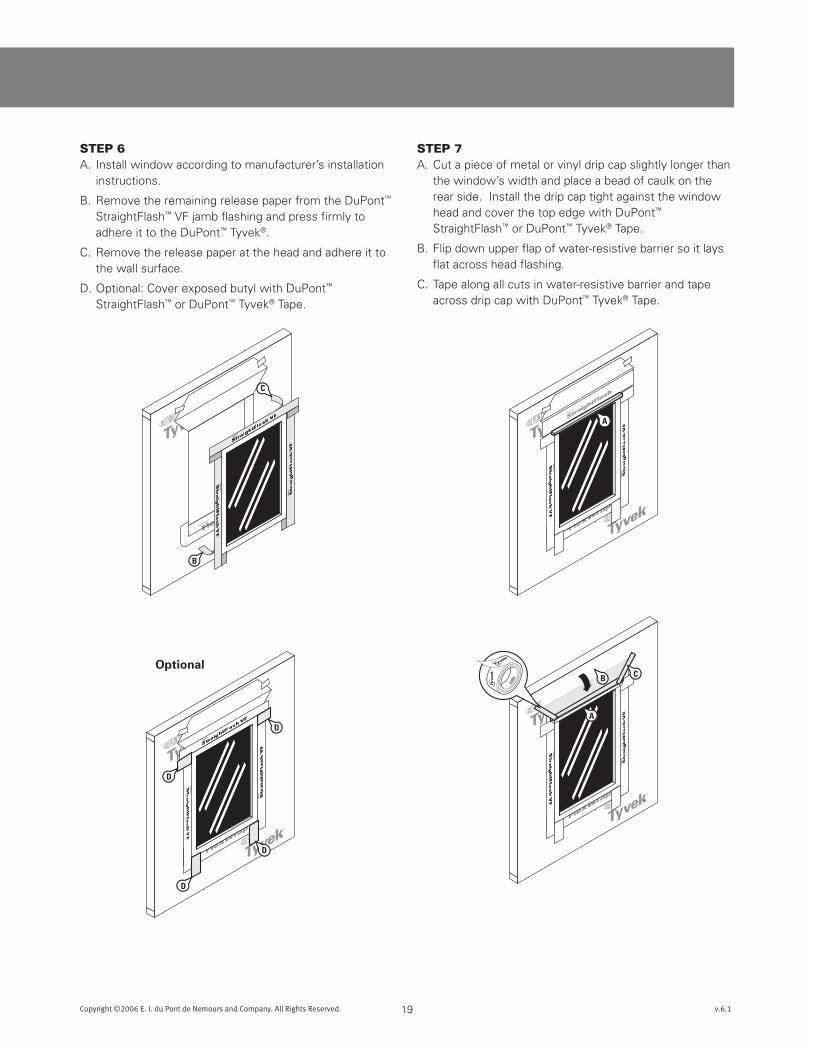
STEp 6A. Install window according to manufacturer’s installation
instructions.
B. Remove the remaining release paper from the DuPont™ StraightFlash™ VF jamb flashing and press firmly to adhere it to the DuPont™ Tyvek®.
C. Remove the release paper at the head and adhere it to the wall surface.
D. Optional: Cover exposed butyl with DuPont™ StraightFlash™ or DuPont™ Tyvek® Tape.
STEp 7A. Cut a piece of metal or vinyl drip cap slightly longer than
the window’s width and place a bead of caulk on the rear side. Install the drip cap tight against the window head and cover the top edge with DuPont™ StraightFlash™ or DuPont™ Tyvek® Tape.
B. Flip down upper flap of water-resistive barrier so it lays flat across head flashing.
C. Tape along all cuts in water-resistive barrier and tape across drip cap with DuPont™ Tyvek® Tape.
Interior
20Copyright ©2006 E. I. du Pont de Nemours and Company. All Rights Reserved. v.6.1
DuPont™ Flashing Systems Installation Guidelines
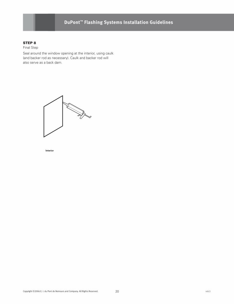
STEp 8Final Step
Seal around the window opening at the interior, using caulk (and backer rod as necessary). Caulk and backer rod will also serve as a back dam.
Interior
8“ Minimum
8“Minimum
A
B
C
C
B
21Copyright ©2006 E. I. du Pont de Nemours and Company. All Rights Reserved. v.6.1
Brick Mold Door AFTER Water-Resistive Barrier (WRB)
Method applies to following products:
• DuPont™ StraightFlash™ VF
• DuPont™ FlexWrap™
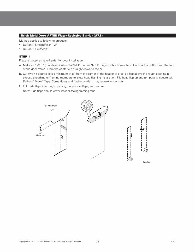
STEp 1Prepare water-resistive barrier for door installation:
A. Make an “I-Cut” (Standard I-Cut) in the WRB. For an “I-Cut” begin with a horizontal cut across the bottom and the top of the door frame. From the center cut straight down to the sill.
B. Cut two 45 degree slits a minimum of 8” from the corner of the header to create a flap above the rough opening to expose sheathing or framing members to allow head flashing installation. Flip head flap up and temporarily secure with DuPont™ Tyvek® Tape. Some doors and flashing widths may require longer slits.
C. Fold side flaps into rough opening, cut excess flaps, and secure.
Note: Side flaps should cover interior facing framing stud.
7-inch for 2x4-inch studs9-inch for 2x6-inch studs
OverlapFront
Back
ScoredReleasePaper
Break ScoredRelease Paper
Peel Off2-piecesof ReleasePaper
A
B
C
Sill Width+ 12 inches
A
(S)
22Copyright ©2006 E. I. du Pont de Nemours and Company. All Rights Reserved. v.6.1
DuPont™ Flashing Systems Installation Guidelines
STEp 2Preparation of sill flashing:
A. Cut DuPont™ FlexWrap™ at least 12” longer than width of the sill (S), (6” for each jamb). DuPont™ FlexWrap™ has perforated release paper to help with the formation of the back dam.
B. To ensure that the perforation tears cleanly, fold the perforation 180° and crease the flashing.
C. Remove the two widest pieces of release paper leaving the narrowest release paper on the flashing. When the finished
floor is applied, the release paper can be removed and the back dam can be completed.
6“
FRONT VIEW CORNER DETAIL
No Gap in Corner
DO NOT STRETCH
WRONG CORRECT
3
4
5 2
1
Door Jamb
DuPont™FlexWrap™
Sill
DuPont™FlexWrap™
DuPont™Tyvek®
Sheathing
INTERIOR
Door
DoorThreshold
TransitionThreshold
Flooring
Sub Floor
PlasticProtector(optional)
EXTERIOR
Optional
23Copyright ©2006 E. I. du Pont de Nemours and Company. All Rights Reserved. v.6.1
STEp 3A. Install the sill flashing as indicated leaving the 1” of DuPont™ FlexWrap™ with release paper extending it past the door
threshold on the inside. When the 1” of release paper is removed, there should be 3/4” of flashing to form the back dam.
Optional: Some flooring cannot accomodate a back dam. In that case fold the 1” back dam on top of DuPont™ FlexWrap™ in the sill. Door will be installed on top of 1” back dam.
STEp 4A. Flex DuPont™ FlexWrap™ at bottom corners onto face
of wall.
STEp 5A. sEcuREEdGEsOFduPOnT™FLEXWRAP™WiTH
mEcHAnicALFAsTEnERs. i.e., DuPont™ Tyvek® Wrap Caps (nails, screws, staples).
Note: Secure fastener along the bottom outer edge of the DuPont™ FlexWrap™ at flexed corners.
DoorInterior
DoorInterior
DoorInterior
CA
D
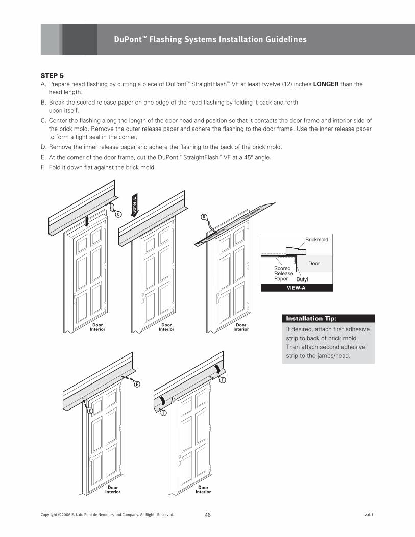
VIEW-A
Brickmold
Door
Butyl
ScoredReleasePaper
VIE
W-A
DoorInterior
F
E
24Copyright ©2006 E. I. du Pont de Nemours and Company. All Rights Reserved. v.6.1
DuPont™ Flashing Systems Installation Guidelines
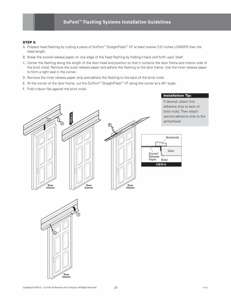
STEp 6A. Prepare head flashing by cutting a piece of DuPont™ StraightFlash™ VF at least twelve (12) inches LONGER than the
head length.
B. Break the scored release paper on one edge of the head flashing by folding it back and forth upon itself.
C. Center the flashing along the length of the door head and position so that it contacts the door frame and interior side of the brick mold. Remove the outer release paper and adhere the flashing to the door frame. Use the inner release paper to form a tight seal in the corner.
D. Remove the inner release paper strip and adhere the flashing to the back of the brick mold.
E. At the corner of the door frame, cut the DuPont™ StraightFlash™ VF along the corner at a 45° angle.
F. Fold it down flat against the brick mold.
Installation Tip:
If desired, attach first
adhesive strip to back of
brick mold. Then attach
second adhesive strip to the
jambs/head.
Make sure theadhesive on thesepieces willintersect.
1-1/2”
1”
DoorInterior
DoorInterior
DoorInterior
E
D
C
A
25Copyright ©2006 E. I. du Pont de Nemours and Company. All Rights Reserved. v.6.1
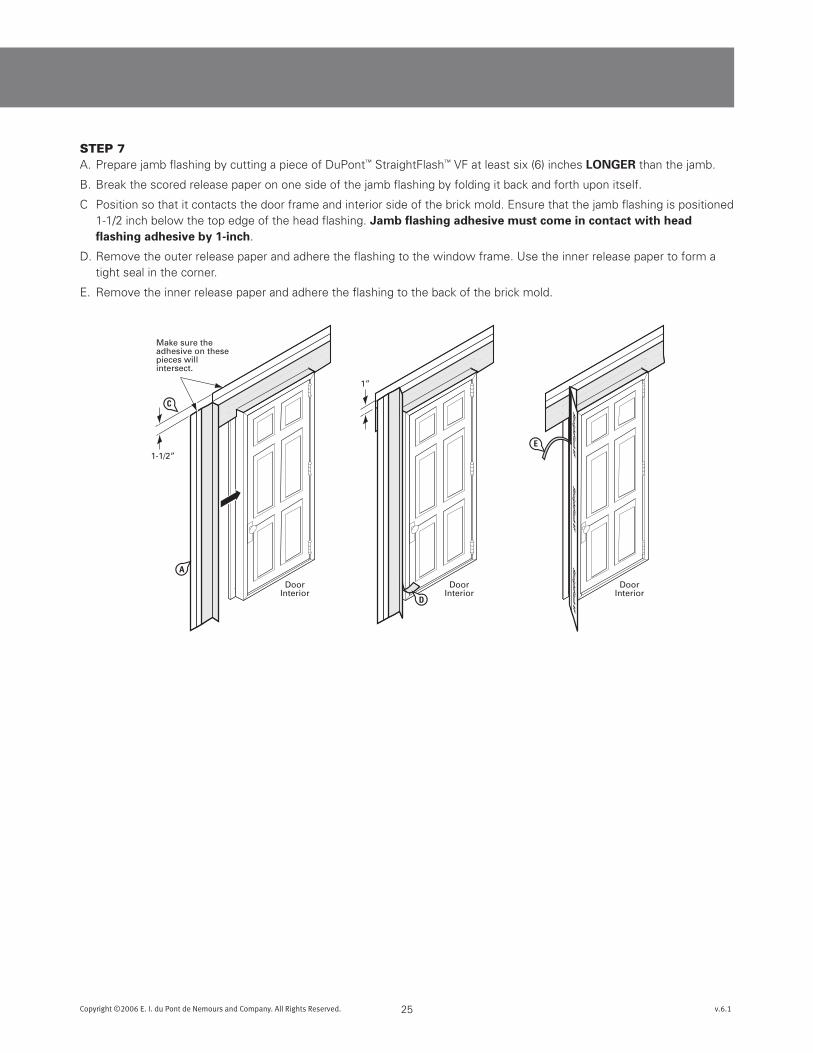
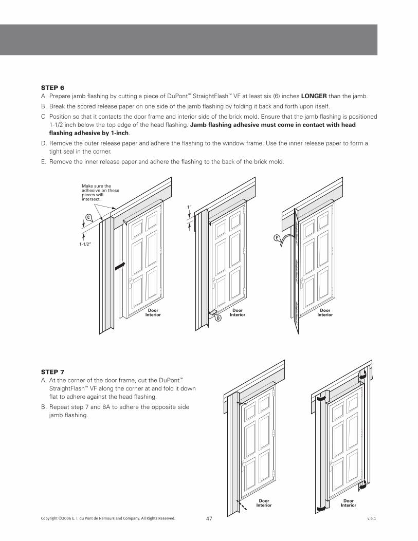
STEp 7A. Prepare jamb flashing by cutting a piece of DuPont™ StraightFlash™ VF at least six (6) inches LOnGER than the jamb.
B. Break the scored release paper on one side of the jamb flashing by folding it back and forth upon itself.
C Position so that it contacts the door frame and interior side of the brick mold. Ensure that the jamb flashing is positioned 1-1/2 inch below the top edge of the head flashing. Jambflashingadhesivemustcomeincontactwithheadflashingadhesiveby1-inch.
D. Remove the outer release paper and adhere the flashing to the window frame. Use the inner release paper to form a tight seal in the corner.
E. Remove the inner release paper and adhere the flashing to the back of the brick mold.
DoorInterior
Peel OffRelease Paperand attachto undersideof door
ButylAdhesive
10”
DuPont™StraightFlash™ VF
26Copyright ©2006 E. I. du Pont de Nemours and Company. All Rights Reserved. v.6.1
DuPont™ Flashing Systems Installation Guidelines
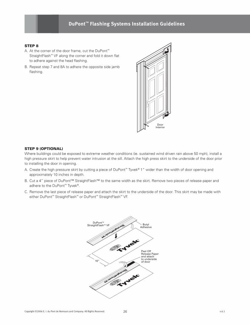
STEp 8A. At the corner of the door frame, cut the DuPont™
StraightFlash™ VF along the corner and fold it down flat to adhere against the head flashing.
B. Repeat step 7 and 8A to adhere the opposite side jamb flashing.
STEp 9 (OpTIONAl)Where buildings could be exposed to extreme weather conditions (ie. sustained wind driven rain above 50 mph), install a high pressure skirt to help prevent water intrusion at the sill. Attach the high press skirt to the underside of the door prior to installing the door in opening.
A. Create the high pressure skirt by cutting a piece of DuPont™ Tyvek® 1” wider than the width of door opening and approximately 10 inches in depth.
B. Cut a 4” piece of DuPont™ StraightFlash™ to the same width as the skirt. Remove two pieces of release paper and adhere to the DuPont™ Tyvek®.
C. Remove the last piece of release paper and attach the skirt to the underside of the door. This skirt may be made with either DuPont™ StraightFlash™ or DuPont™ StraightFlash™ VF.
C
B
OptionalHigh PressureSkirtC
C
D
27Copyright ©2006 E. I. du Pont de Nemours and Company. All Rights Reserved. v.6.1
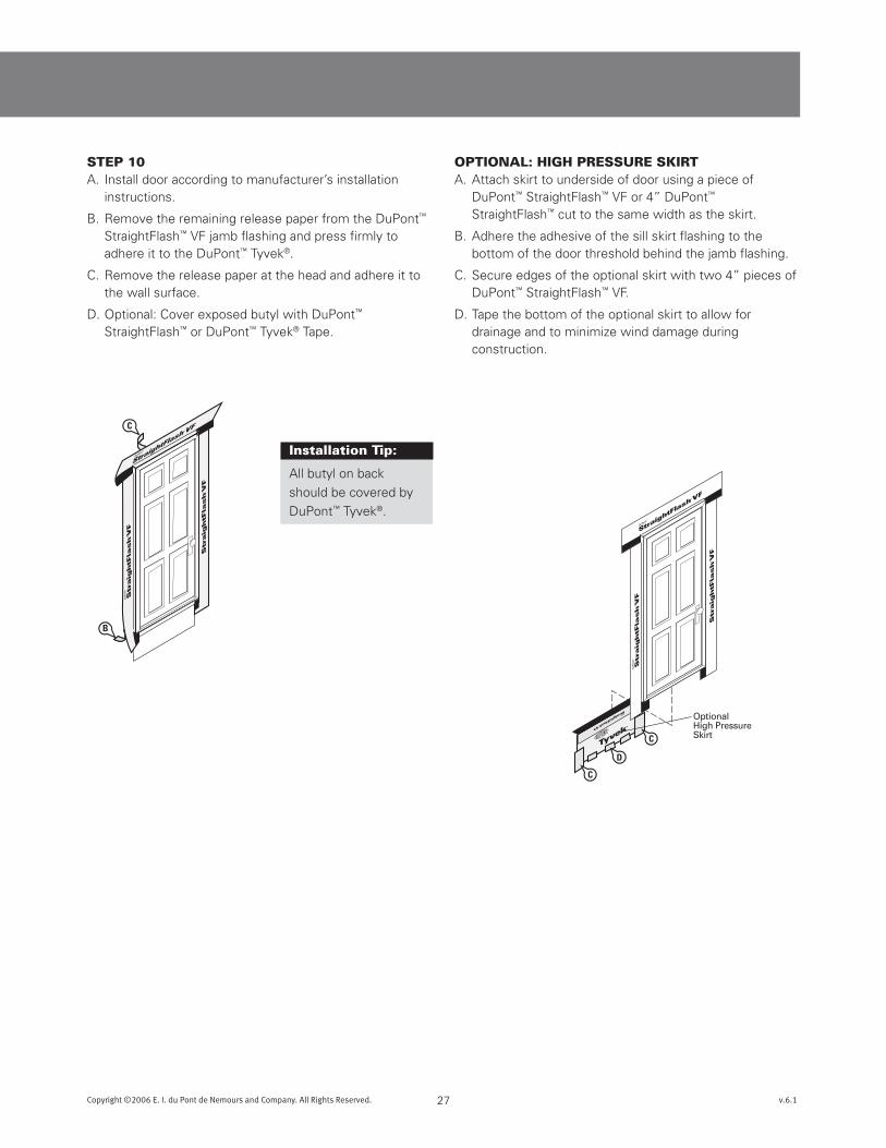
STEp 10A. Install door according to manufacturer’s installation
instructions.
B. Remove the remaining release paper from the DuPont™ StraightFlash™ VF jamb flashing and press firmly to adhere it to the DuPont™ Tyvek®.
C. Remove the release paper at the head and adhere it to the wall surface.
D. Optional: Cover exposed butyl with DuPont™ StraightFlash™ or DuPont™ Tyvek® Tape.
Installation Tip:
All butyl on back
should be covered by
DuPont™ Tyvek®.
OpTIONAl: HIgH pRESSURE SkIRTA. Attach skirt to underside of door using a piece of
DuPont™ StraightFlash™ VF or 4” DuPont™ StraightFlash™ cut to the same width as the skirt.
B. Adhere the adhesive of the sill skirt flashing to the bottom of the door threshold behind the jamb flashing.
C. Secure edges of the optional skirt with two 4” pieces of DuPont™ StraightFlash™ VF.
D. Tape the bottom of the optional skirt to allow for drainage and to minimize wind damage during construction.
DuPont™FlexWrap™
DuPont™StraightFlash™
DuPont™Tyvek®
Sheathing
HighPressureSkirt
INTERIOR
Patio Door
DoorThreshold
TransitionThreshold
Flooring
Sub Floor
PlasticProtector(optional)
EXTERIOR
Optional
Fold Out and Up
Staples Tape
Fold In and Up
OR
OR
Option One
Option Two
A
BC
28Copyright ©2006 E. I. du Pont de Nemours and Company. All Rights Reserved. v.6.1
DuPont™ Flashing Systems Installation Guidelines
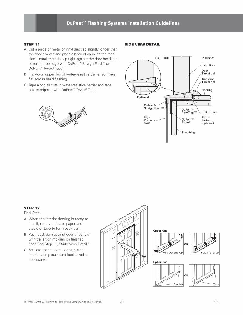
SIDE VIEW DETAIl
STEp 12Final Step
A. When the interior flooring is ready to install, remove release paper and staple or tape to form back dam.
B. Push back dam against door threshold with transition molding on finished floor. See Step 11, “Side View Detail.”
C. Seal around the door opening at the interior using caulk (and backer rod as necessary).
STEp 11A. Cut a piece of metal or vinyl drip cap slightly longer than
the door’s width and place a bead of caulk on the rear side. Install the drip cap tight against the door head and cover the top edge with DuPont™ StraightFlash™ or DuPont™ Tyvek® Tape.
B. Flip down upper flap of water-resistive barrier so it lays flat across head flashing.
C. Tape along all cuts in water-resistive barrier and tape across drip cap with DuPont™ Tyvek® Tape.
3
52
1
A
B
(S)
10“
Sill Length+ 12 inches
6“Minimum
FRONT VIEW CORNER DETAIL
No Gap in Corner
DO NOT STRETCH
WRONG CORRECT
4
Door Jamb
DuPont™FlexWrap™
Sill
F
E
29Copyright ©2006 E. I. du Pont de Nemours and Company. All Rights Reserved. v.6.1
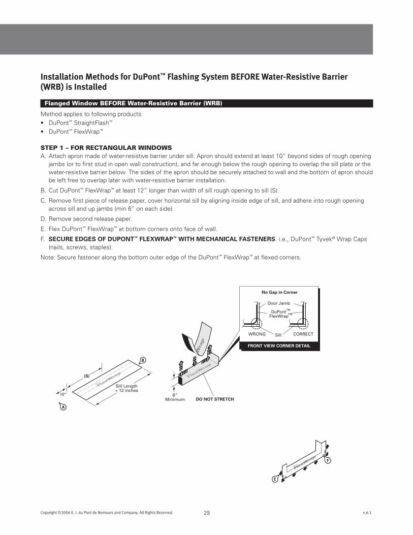
Installation Methods for DuPont™ Flashing System beFore Water-resistive barrier (Wrb) is Installed
Flanged Window BEFORE Water-Resistive Barrier (WRB)
Method applies to following products:
• DuPont™ StraightFlash™
• DuPont™ FlexWrap™
STEp 1 – FOR REcTANgUlAR WINDOWS A. Attach apron made of water-resistive barrier under sill. Apron should extend at least 10” beyond sides of rough opening
jambs (or to first stud in open wall construction), and far enough below the rough opening to overlap the sill plate or the water-resistive barrier below. The sides of the apron should be securely attached to wall and the bottom of apron should be left free to overlap later with water-resistive barrier installation.
B. Cut DuPont™ FlexWrap™ at least 12” longer than width of sill rough opening to sill (S).
C. Remove first piece of release paper, cover horizontal sill by aligning inside edge of sill, and adhere into rough opening across sill and up jambs (min 6” on each side).
D. Remove second release paper.
E. Flex DuPont™ FlexWrap™ at bottom corners onto face of wall.
F. sEcuREEdGEsOFduPOnT™FLEXWRAP™WiTHmEcHAnicALFAsTEnERs. i.e., DuPont™ Tyvek® Wrap Caps (nails, screws, staples).
Note: Secure fastener along the bottom outer edge of the DuPont™ FlexWrap™ at flexed corners.
A
A
B
B
C
30Copyright ©2006 E. I. du Pont de Nemours and Company. All Rights Reserved. v.6.1
DuPont™ Flashing Systems Installation Guidelines
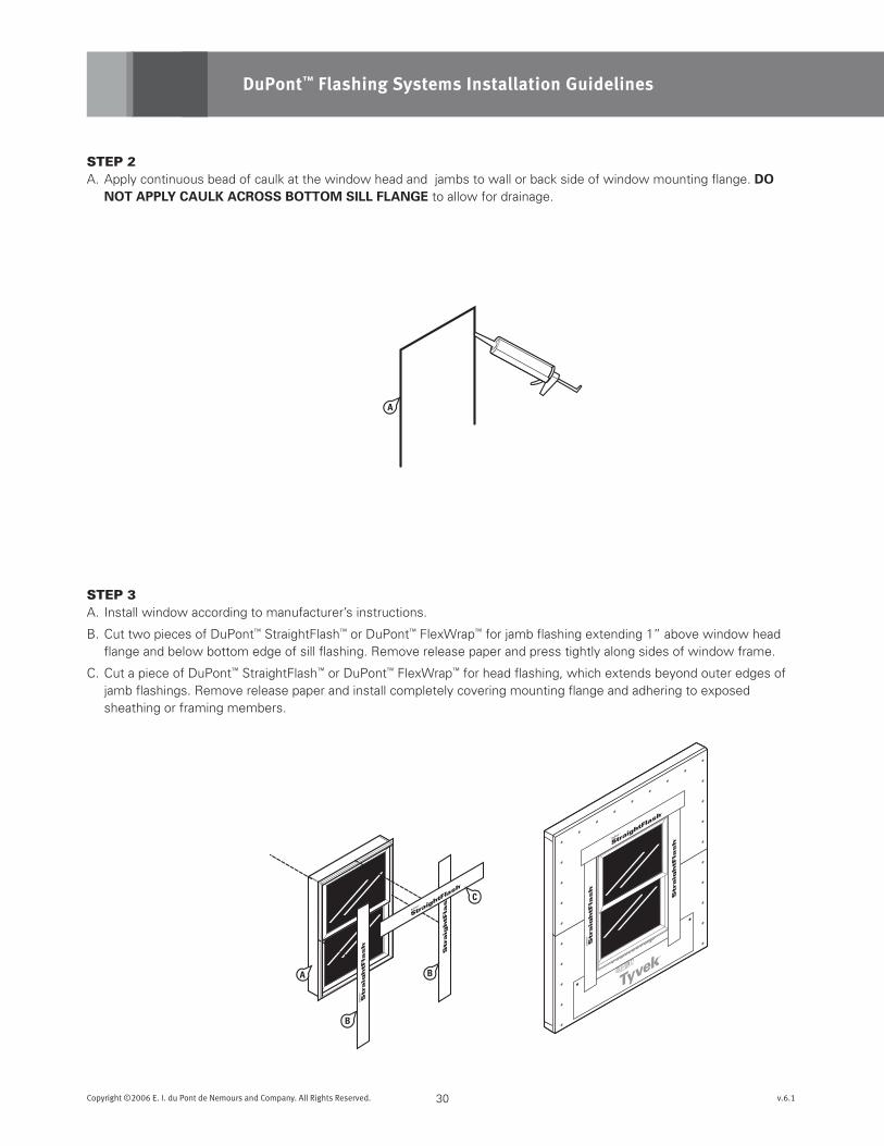
STEp 2A. Apply continuous bead of caulk at the window head and jambs to wall or back side of window mounting flange. dO
nOTAPPLYcAuLKAcROssBOTTOmsiLLFLAnGE to allow for drainage.
STEp 3A. Install window according to manufacturer’s instructions.
B. Cut two pieces of DuPont™ StraightFlash™ or DuPont™ FlexWrap™ for jamb flashing extending 1” above window head flange and below bottom edge of sill flashing. Remove release paper and press tightly along sides of window frame.
C. Cut a piece of DuPont™ StraightFlash™ or DuPont™ FlexWrap™ for head flashing, which extends beyond outer edges of jamb flashings. Remove release paper and install completely covering mounting flange and adhering to exposed sheathing or framing members.
6“ PastMullion
H C
Interior
Interior
31Copyright ©2006 E. I. du Pont de Nemours and Company. All Rights Reserved. v.6.1
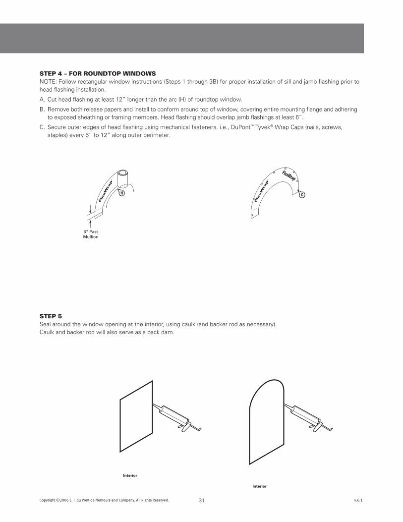
STEp 4 – FOR ROUNDTOp WINDOWSNOTE: Follow rectangular window instructions (Steps 1 through 3B) for proper installation of sill and jamb flashing prior to head flashing installation.
A. Cut head flashing at least 12” longer than the arc (H) of roundtop window.
B. Remove both release papers and install to conform around top of window, covering entire mounting flange and adhering to exposed sheathing or framing members. Head flashing should overlap jamb flashings at least 6”.
C. Secure outer edges of head flashing using mechanical fasteners. i.e., DuPont™ Tyvek® Wrap Caps (nails, screws, staples) every 6” to 12” along outer perimeter.
STEp 5Seal around the window opening at the interior, using caulk (and backer rod as necessary). Caulk and backer rod will also serve as a back dam.
DO NOT CUT!through
DuPont™ FlexWrap™
or apron.
Window
Place Apron overLower Layer of
DuPont™ Tyvek®
DuPont™ Tyvek®
Lower Layer
SIDE VIEW DETAIL
A
A
B
B
32Copyright ©2006 E. I. du Pont de Nemours and Company. All Rights Reserved. v.6.1
DuPont™ Flashing Systems Installation Guidelines
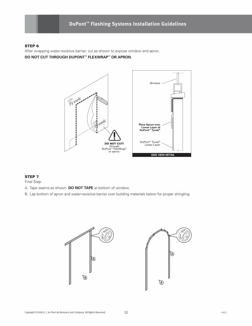
STEp 6After wrapping water-resistive barrier, cut as shown to expose window and apron.
dOnOTcuTTHROuGHduPOnT™FLEXWRAP™ORAPROn.
STEp 7Final Step
A. Tape seams as shown. dOnOTTAPE at bottom of window.
B. Lap bottom of apron and water-resistive barrier over building materials below for proper shingling.
10“ A
33Copyright ©2006 E. I. du Pont de Nemours and Company. All Rights Reserved. v.6.1
Integral Flanged Door BEFORE Water-Resistive Barrier (WRB)
Method applies to following products:
• DuPont™ StraightFlash™
• DuPont™ FlexWrap™
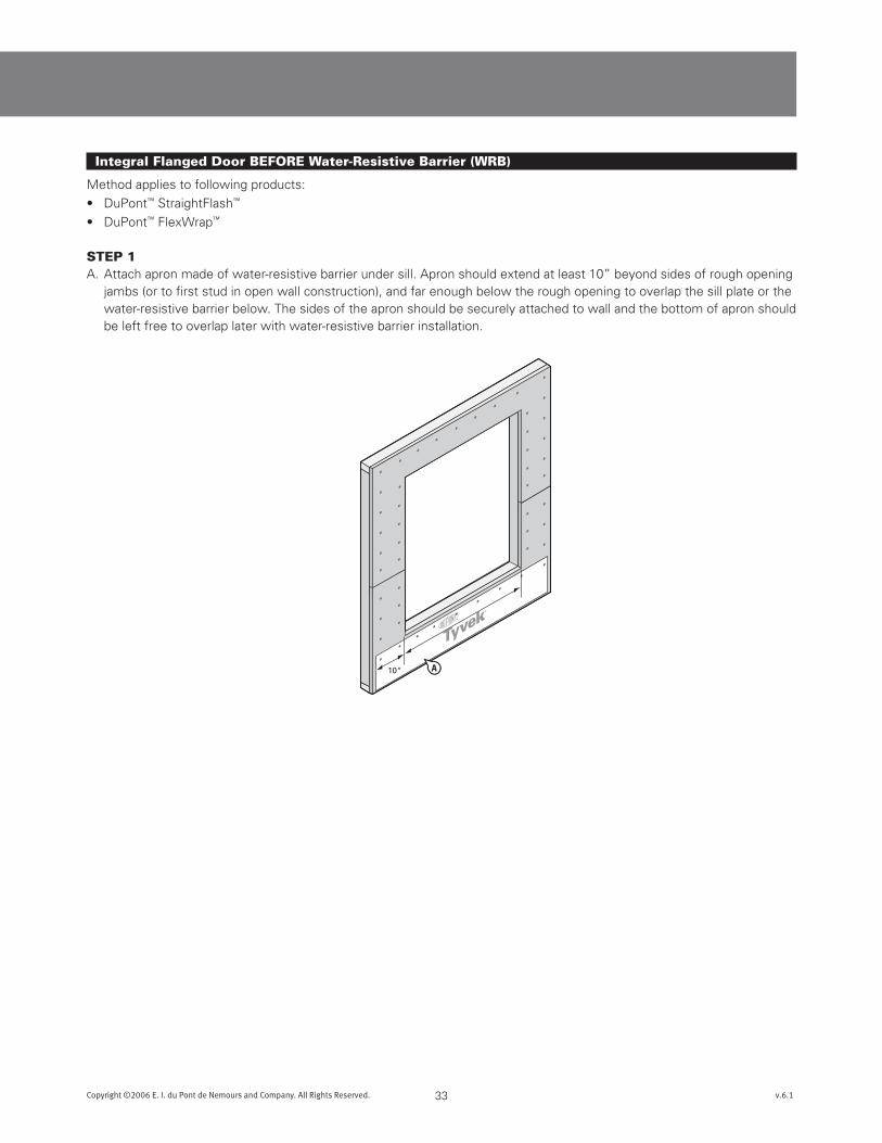
STEp 1A. Attach apron made of water-resistive barrier under sill. Apron should extend at least 10” beyond sides of rough opening
jambs (or to first stud in open wall construction), and far enough below the rough opening to overlap the sill plate or the water-resistive barrier below. The sides of the apron should be securely attached to wall and the bottom of apron should be left free to overlap later with water-resistive barrier installation.
Sill Length+ 12 inches
A
7-inch for 2x4-inch studs9-inch for 2x6-inch studs
OverlapFront
Back
ScoredReleasePaper
Break ScoredRelease Paper
Peel Off2-piecesof ReleasePaper
B
C
34Copyright ©2006 E. I. du Pont de Nemours and Company. All Rights Reserved. v.6.1
DuPont™ Flashing Systems Installation Guidelines
STEp 2Preparation of sill flashing:
A. Cut DuPont™ FlexWrap™ at least 12” longer than width of the sill, (6” for each jamb). DuPont™ FlexWrap™ has perforated release paper to help with the formation of the back dam.
B. To ensure that the perforation tears cleanly, fold the perforation 180° and crease the flashing.
C. Remove the two widest pieces of release paper leaving the narrowest release paper on the flashing. When the finished
floor is applied, the release paper can be removed and the back dam can be completed.
6“Minimum
FRONT VIEW CORNER DETAIL
No Gap in Corner
DO NOT STRETCH
WRONG CORRECT
3
4
5
21
Door Jamb
DuPont™FlexWrap™
Sill
A
A
B
35Copyright ©2006 E. I. du Pont de Nemours and Company. All Rights Reserved. v.6.1
STEp 3A. Install the sill flashing as indicated leaving the 1” of DuPont™ FlexWrap™ with release paper extending it past the door
threshold on the inside. When the 1” of release paper is removed, there should be 3/4” of flashing to form the back dam.
Optional: Some flooring cannot accomodate a back dam. In that case fold the 1” back dam on top of DuPont™ FlexWrap™ in the sill. Door will be installed on top of 1” back dam.
STEp 4A. Flex DuPont™ FlexWrap™ at bottom corners onto face of wall.
B.sEcuREFLEXEdEdGEsWiTHmEcHAnicALFAsTEnERs. i.e., DuPont™ Tyvek® Wrap Caps (nails, screws, staples).
Note: Secure fastener along the bottom perimeter of the DuPont™ FlexWrap™ at flexed corners
Peel OffRelease Paperand attach tounderside of door
ButylAdhesive
10”
4” DuPont™StraightFlash™
36Copyright ©2006 E. I. du Pont de Nemours and Company. All Rights Reserved. v.6.1
DuPont™ Flashing Systems Installation Guidelines
STEp 5A. Apply continuous bead of caulk at the door head and
jambs to wall or back side of door mounting flange. dOnOTAPPLYcAuLKAcROssBOTTOmsiLLFLAnGE to allow for drainage.
STEp 6 (OpTIONAl)Where buildings could be exposed to extreme weather conditions (ie. sustained wind driven rain above 50mph), install a high pressure skirt to help prevent water intrusion at the sill. Attach the high press skirt to the underside of the door prior to installing the door in opening.
A. Create the high pressure skirt by cutting a piece of DuPont™ Tyvek® 1” wider than the width of door opening and approximately 10 inches in depth.
B. Cut a 4” piece of DuPont™ StraightFlash™ to the same width as the skirt. Remove two pieces of release paper and adhere to the DuPont™ Tyvek®.
C. Remove the last piece of release paper and attach the skirt to the underside of the door. This skirt may be made with either DuPont™ StraightFlash™ or DuPont™ StraightFlash™ VF.
A
C
C
D
B
DuPont™FlexWrap™
DuPont™StraightFlash™
DuPont™Tyvek®
DuPont™Tyvek®
(apron)Sheathing
HighPressureSkirt
INTERIOR
Patio Door
DoorThreshold
TransitionThreshold
Flooring
Sub Floor
PlasticProtector(optional)
EXTERIOR
Optional
37Copyright ©2006 E. I. du Pont de Nemours and Company. All Rights Reserved. v.6.1
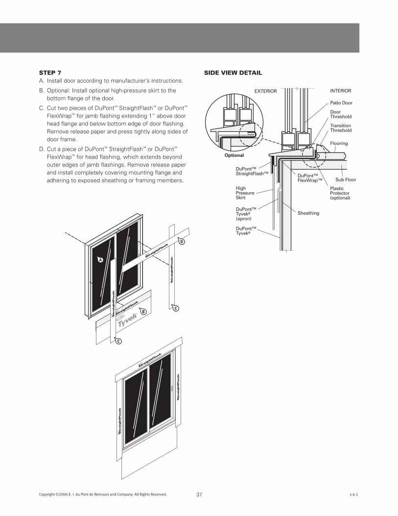
STEp 7A. Install door according to manufacturer’s instructions.
B. Optional: Install optional high-pressure skirt to the bottom flange of the door.
C. Cut two pieces of DuPont™ StraightFlash™ or DuPont™ FlexWrap™ for jamb flashing extending 1” above door head flange and below bottom edge of door flashing. Remove release paper and press tightly along sides of door frame.
D. Cut a piece of DuPont™ StraightFlash™ or DuPont™ FlexWrap™ for head flashing, which extends beyond outer edges of jamb flashings. Remove release paper and install completely covering mounting flange and adhering to exposed sheathing or framing members.
SIDE VIEW DETAIl
DO NOT CUT!through
Flashing, Apron, or Skirt.
38Copyright ©2006 E. I. du Pont de Nemours and Company. All Rights Reserved. v.6.1
DuPont™ Flashing Systems Installation Guidelines
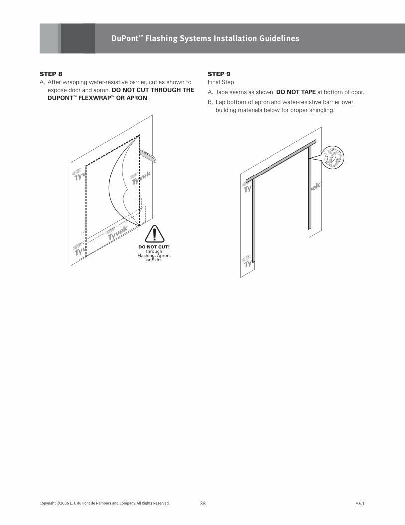
STEp 8A. After wrapping water-resistive barrier, cut as shown to
expose door and apron. dOnOTcuTTHROuGHTHEduPOnT™FLEXWRAP™ORAPROn.
STEp 9Final Step
A. Tape seams as shown. dOnOTTAPE at bottom of door.
B. Lap bottom of apron and water-resistive barrier over building materials below for proper shingling.
3
52
1
A
B
10“6“
Minimum
FRONT VIEW CORNER DETAIL
No Gap in Corner
DO NOT STRETCH
WRONG CORRECT
4
Door Jamb
DuPont™FlexWrap™
Sill
Sill Length+ 12 inches
F
E
39Copyright ©2006 E. I. du Pont de Nemours and Company. All Rights Reserved. v.6.1
Brick Mold Window BEFORE Water-Resistive Barrier (WRB)
This installation guide can also be used for windows with field applied nailing fins.
Method applies to following products:
• DuPont™ StraightFlash™ VF
• DuPont™ FlexWrap™
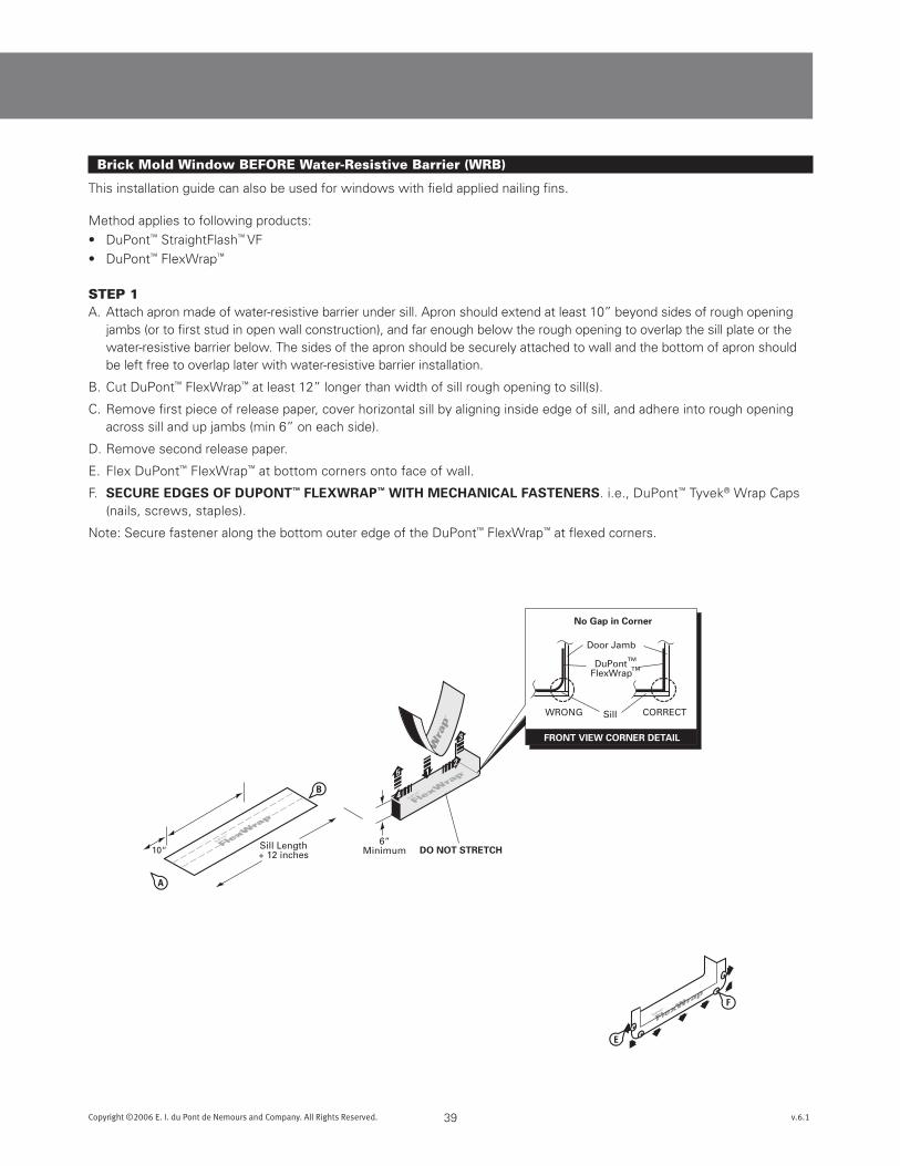
STEp 1A. Attach apron made of water-resistive barrier under sill. Apron should extend at least 10” beyond sides of rough opening
jambs (or to first stud in open wall construction), and far enough below the rough opening to overlap the sill plate or the water-resistive barrier below. The sides of the apron should be securely attached to wall and the bottom of apron should be left free to overlap later with water-resistive barrier installation.
B. Cut DuPont™ FlexWrap™ at least 12” longer than width of sill rough opening to sill(s).
C. Remove first piece of release paper, cover horizontal sill by aligning inside edge of sill, and adhere into rough opening across sill and up jambs (min 6” on each side).
D. Remove second release paper.
E. Flex DuPont™ FlexWrap™ at bottom corners onto face of wall.
F. sEcuREEdGEsOFduPOnT™FLEXWRAP™WiTHmEcHAnicALFAsTEnERs. i.e., DuPont™ Tyvek® Wrap Caps (nails, screws, staples).
Note: Secure fastener along the bottom outer edge of the DuPont™ FlexWrap™ at flexed corners.
WindowInterior
WindowInterior
WindowInterior
CD
VIEW-A
Brickmold
Window
Butyl
ScoredReleasePaper
VIE
W-A
WindowInterior
F
E
40Copyright ©2006 E. I. du Pont de Nemours and Company. All Rights Reserved. v.6.1
DuPont™ Flashing Systems Installation Guidelines
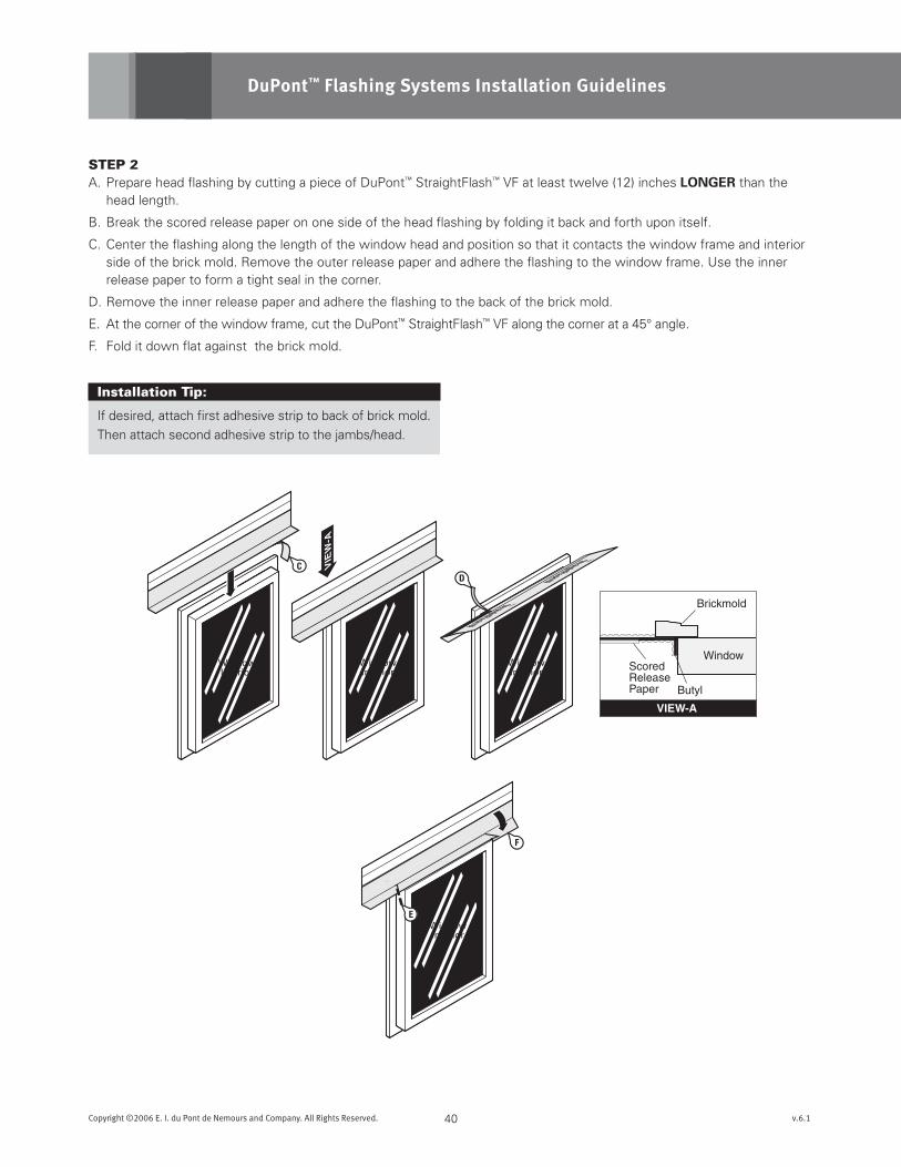
STEp 2A. Prepare head flashing by cutting a piece of DuPont™ StraightFlash™ VF at least twelve (12) inches LOnGER than the
head length.
B. Break the scored release paper on one side of the head flashing by folding it back and forth upon itself.
C. Center the flashing along the length of the window head and position so that it contacts the window frame and interior side of the brick mold. Remove the outer release paper and adhere the flashing to the window frame. Use the inner release paper to form a tight seal in the corner.
D. Remove the inner release paper and adhere the flashing to the back of the brick mold.
E. At the corner of the window frame, cut the DuPont™ StraightFlash™ VF along the corner at a 45° angle.
F. Fold it down flat against the brick mold.
Installation Tip:
If desired, attach first adhesive strip to back of brick mold.
Then attach second adhesive strip to the jambs/head.
WindowInterior
WindowInterior
Make sure theadhesive on thesepieces willoverlap.
WindowInterior1-1/2”
1”
E
D
C
WindowInterior
41Copyright ©2006 E. I. du Pont de Nemours and Company. All Rights Reserved. v.6.1
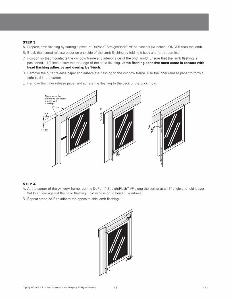
STEp 3A. Prepare jamb flashing by cutting a piece of DuPont™ StraightFlash™ VF at least six (6) inches LONGER than the jamb.
B. Break the scored release paper on one side of the jamb flashing by folding it back and forth upon itself.
C Position so that it contacts the window frame and interior side of the brick mold. Ensure that the jamb flashing is positioned 1-1/2 inch below the top edge of the head flashing. Jambflashingadhesivemustcomeincontactwithheadflashingadhesiveandoverlapby1-inch.
D. Remove the outer release paper and adhere the flashing to the window frame. Use the inner release paper to form a tight seal in the corner.
E. Remove the inner release paper and adhere the flashing to the back of the brick mold.
STEp 4A. At the corner of the window frame, cut the DuPont™ StraightFlash™ VF along the corner at a 45° angle and fold it over
flat to adhere against the head flashing. Fold excess on to head of windows.
B. Repeat steps 2A-E to adhere the opposite side jamb flashing.
B
C
B
A
A
A
A
Interior
42Copyright ©2006 E. I. du Pont de Nemours and Company. All Rights Reserved. v.6.1
DuPont™ Flashing Systems Installation Guidelines
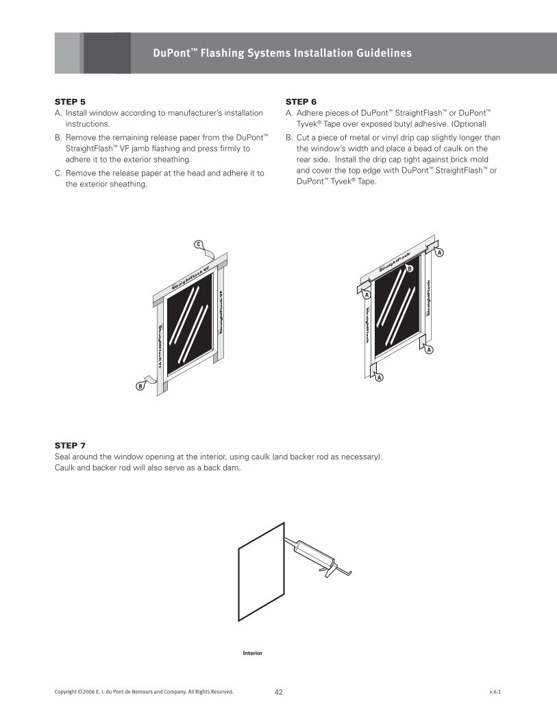
STEp 5A. Install window according to manufacturer’s installation
instructions.
B. Remove the remaining release paper from the DuPont™ StraightFlash™ VF jamb flashing and press firmly to adhere it to the exterior sheathing.
C. Remove the release paper at the head and adhere it to the exterior sheathing.
STEp 6A. Adhere pieces of DuPont™ StraightFlash™ or DuPont™
Tyvek® Tape over exposed butyl adhesive. (Optional)
B. Cut a piece of metal or vinyl drip cap slightly longer than the window’s width and place a bead of caulk on the rear side. Install the drip cap tight against brick mold and cover the top edge with DuPont™ StraightFlash™ or DuPont™ Tyvek® Tape.
STEp 7Seal around the window opening at the interior, using caulk (and backer rod as necessary). Caulk and backer rod will also serve as a back dam.
DO NOT CUT!through
DuPont™ FlexWrap™
or apron.
Window
Place Apron overLower Layer of
DuPont™ Tyvek®
DuPont™ Tyvek®
Lower Layer
SIDE VIEW DETAIL
A
A
A
B
B
43Copyright ©2006 E. I. du Pont de Nemours and Company. All Rights Reserved. v.6.1
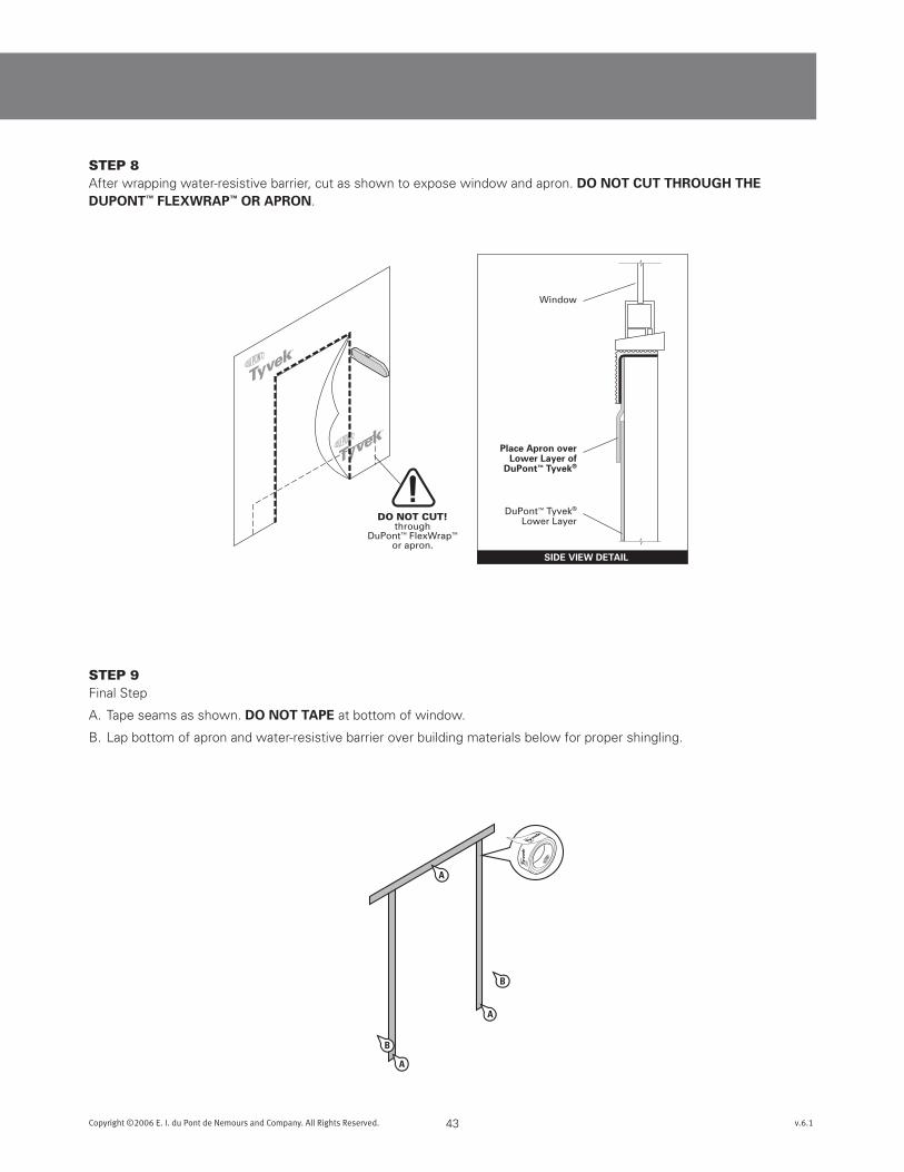
STEp 8After wrapping water-resistive barrier, cut as shown to expose window and apron. dOnOTcuTTHROuGHTHEduPOnT™FLEXWRAP™ORAPROn.
STEp 9Final Step
A. Tape seams as shown. dOnOTTAPE at bottom of window.
B. Lap bottom of apron and water-resistive barrier over building materials below for proper shingling.
10“
7-inch for 2x4-inch studs9-inch for 2x6-inch studs
Overlap Perf
Break Perf
Peel Off2-piecesof Backing
B
A
C
44Copyright ©2006 E. I. du Pont de Nemours and Company. All Rights Reserved. v.6.1
DuPont™ Flashing Systems Installation Guidelines
Brick Mold Door BEFORE Water-Resistive Barrier (WRB)
This installation guide can also be used for doors with field applied nailing fins. This guide is intended for door installed
abovegrade.
Method applies to following products:
• DuPont™ StraightFlash™ VF
• DuPont™ FlexWrap™
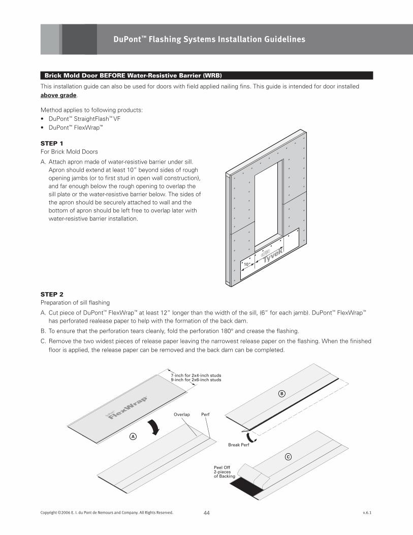
STEp 1For Brick Mold Doors
A. Attach apron made of water-resistive barrier under sill. Apron should extend at least 10” beyond sides of rough opening jambs (or to first stud in open wall construction), and far enough below the rough opening to overlap the sill plate or the water-resistive barrier below. The sides of the apron should be securely attached to wall and the bottom of apron should be left free to overlap later with water-resistive barrier installation.
STEp 2Preparation of sill flashing
A. Cut piece of DuPont™ FlexWrap™ at least 12” longer than the width of the sill, (6” for each jamb). DuPont™ FlexWrap™ has perforated realease paper to help with the formation of the back dam.
B. To ensure that the perforation tears cleanly, fold the perforation 180° and crease the flashing.
C. Remove the two widest pieces of release paper leaving the narrowest release paper on the flashing. When the finished
floor is applied, the release paper can be removed and the back dam can be completed.
6“
FRONT VIEW CORNER DETAIL
No Gap in Corner
DO NOT STRETCH
WRONG CORRECT
3
4
5 21
Door Jamb
DuPont™FlexWrap™
Sill
DuPont™FlexWrap™
DuPont™Tyvek®
Sheathing
INTERIOR
Door
DoorThreshold
TransitionThreshold
Flooring
Sub Floor
PlasticProtector(optional)
EXTERIOR
Optional
B
A
45Copyright ©2006 E. I. du Pont de Nemours and Company. All Rights Reserved. v.6.1
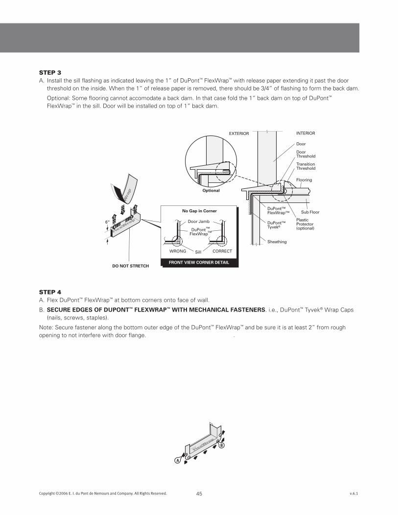
STEp 3A. Install the sill flashing as indicated leaving the 1” of DuPont™ FlexWrap™ with release paper extending it past the door
threshold on the inside. When the 1” of release paper is removed, there should be 3/4” of flashing to form the back dam.
Optional: Some flooring cannot accomodate a back dam. In that case fold the 1” back dam on top of DuPont™ FlexWrap™ in the sill. Door will be installed on top of 1” back dam.
STEp 4A. Flex DuPont™ FlexWrap™ at bottom corners onto face of wall.
B. sEcuREEdGEsOFduPOnT™FLEXWRAP™WiTHmEcHAnicALFAsTEnERs. i.e., DuPont™ Tyvek® Wrap Caps (nails, screws, staples).
Note: Secure fastener along the bottom outer edge of the DuPont™ FlexWrap™ and be sure it is at least 2” from rough opening to not interfere with door flange.
DoorInterior
DoorInterior
DoorInterior
C D
VIEW-A
Brickmold
Door
Butyl
ScoredReleasePaper
VIE
W-A
DoorInterior
DoorInterior
F
F
E
E
46Copyright ©2006 E. I. du Pont de Nemours and Company. All Rights Reserved. v.6.1
DuPont™ Flashing Systems Installation Guidelines
STEp 5A. Prepare head flashing by cutting a piece of DuPont™ StraightFlash™ VF at least twelve (12) inches LOnGER than the
head length.
B. Break the scored release paper on one edge of the head flashing by folding it back and forth upon itself.
C. Center the flashing along the length of the door head and position so that it contacts the door frame and interior side of the brick mold. Remove the outer release paper and adhere the flashing to the door frame. Use the inner release paper to form a tight seal in the corner.
D. Remove the inner release paper and adhere the flashing to the back of the brick mold.
E. At the corner of the door frame, cut the DuPont™ StraightFlash™ VF at a 45° angle.
F. Fold it down flat against the brick mold.
Installation Tip:
If desired, attach first adhesive
strip to back of brick mold.
Then attach second adhesive
strip to the jambs/head.
Make sure theadhesive on thesepieces willintersect.
1-1/2”
1”
DoorInterior
DoorInterior
DoorInterior
E
D
C
DoorInterior
DoorInterior
47Copyright ©2006 E. I. du Pont de Nemours and Company. All Rights Reserved. v.6.1
STEp 6A. Prepare jamb flashing by cutting a piece of DuPont™ StraightFlash™ VF at least six (6) inches LOnGER than the jamb.
B. Break the scored release paper on one side of the jamb flashing by folding it back and forth upon itself.
C Position so that it contacts the door frame and interior side of the brick mold. Ensure that the jamb flashing is positioned 1-1/2 inch below the top edge of the head flashing. Jambflashingadhesivemustcomeincontactwithheadflashingadhesiveby1-inch.
D. Remove the outer release paper and adhere the flashing to the window frame. Use the inner release paper to form a tight seal in the corner.
E. Remove the inner release paper and adhere the flashing to the back of the brick mold.
STEp 7A. At the corner of the door frame, cut the DuPont™
StraightFlash™ VF along the corner at and fold it down flat to adhere against the head flashing.
B. Repeat step 7 and 8A to adhere the opposite side jamb flashing.
C
B
Peel OffRelease Paperand attachto undersideof door
ButylAdhesive
10”
DuPont™StraightFlash™ VF
48Copyright ©2006 E. I. du Pont de Nemours and Company. All Rights Reserved. v.6.1
DuPont™ Flashing Systems Installation Guidelines
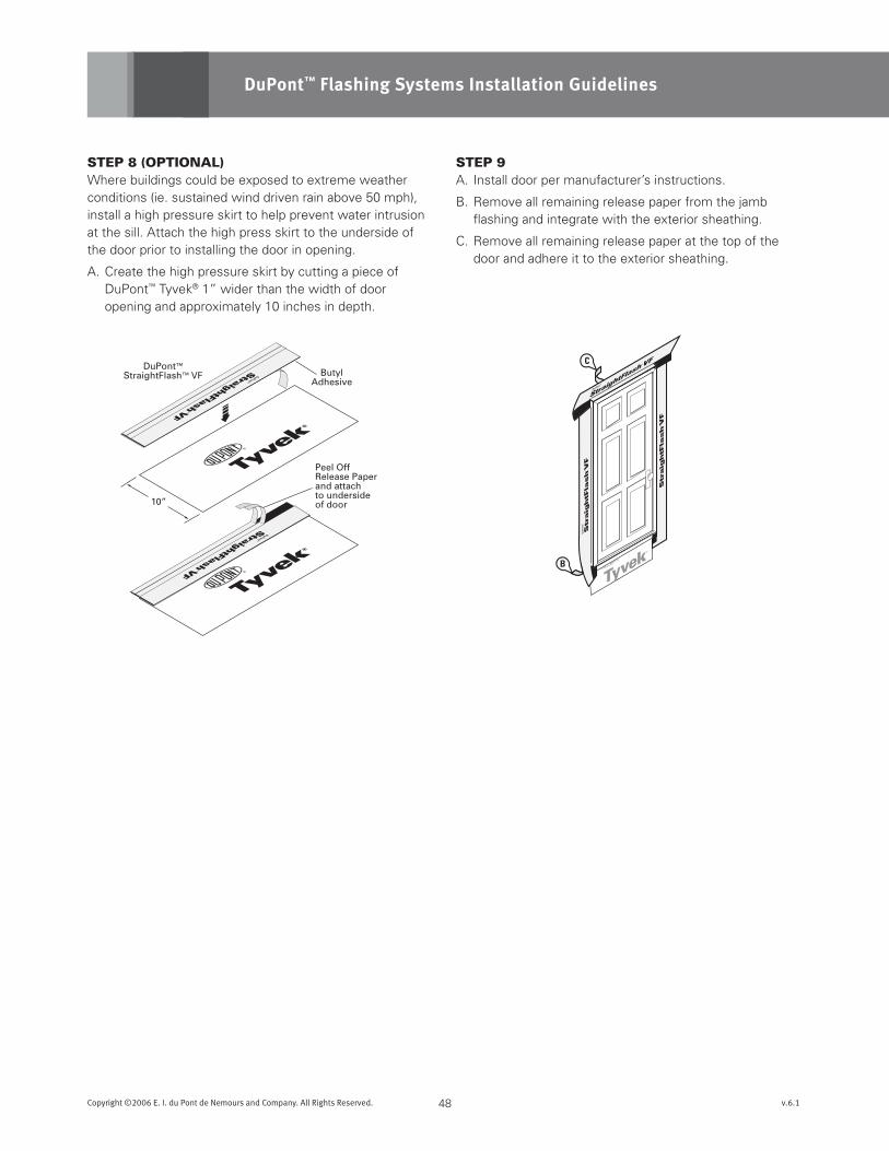
STEp 8 (OpTIONAl)Where buildings could be exposed to extreme weather conditions (ie. sustained wind driven rain above 50 mph), install a high pressure skirt to help prevent water intrusion at the sill. Attach the high press skirt to the underside of the door prior to installing the door in opening.
A. Create the high pressure skirt by cutting a piece of DuPont™ Tyvek® 1” wider than the width of door opening and approximately 10 inches in depth.
STEp 9A. Install door per manufacturer’s instructions.
B. Remove all remaining release paper from the jamb flashing and integrate with the exterior sheathing.
C. Remove all remaining release paper at the top of the door and adhere it to the exterior sheathing.
OptionalHigh PressureSkirtC
C
D
49Copyright ©2006 E. I. du Pont de Nemours and Company. All Rights Reserved. v.6.1
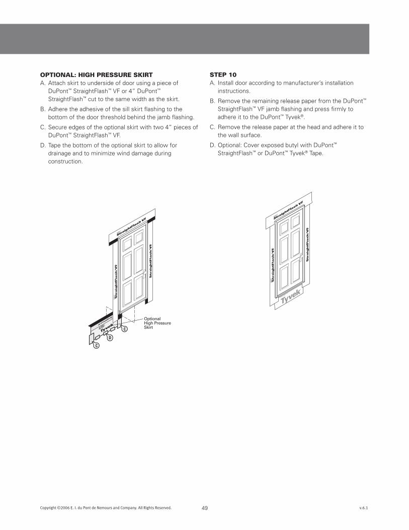
OpTIONAl: HIgH pRESSURE SkIRTA. Attach skirt to underside of door using a piece of
DuPont™ StraightFlash™ VF or 4” DuPont™ StraightFlash™ cut to the same width as the skirt.
B. Adhere the adhesive of the sill skirt flashing to the bottom of the door threshold behind the jamb flashing.
C. Secure edges of the optional skirt with two 4” pieces of DuPont™ StraightFlash™ VF.
D. Tape the bottom of the optional skirt to allow for drainage and to minimize wind damage during construction.
STEp 10A. Install door according to manufacturer’s installation
instructions.
B. Remove the remaining release paper from the DuPont™ StraightFlash™ VF jamb flashing and press firmly to adhere it to the DuPont™ Tyvek®.
C. Remove the release paper at the head and adhere it to the wall surface.
D. Optional: Cover exposed butyl with DuPont™ StraightFlash™ or DuPont™ Tyvek® Tape.
InteriorDO NOT CUT!
throughFlashing, Apron
or Skirt.
50Copyright ©2006 E. I. du Pont de Nemours and Company. All Rights Reserved. v.6.1
DuPont™ Flashing Systems Installation Guidelines
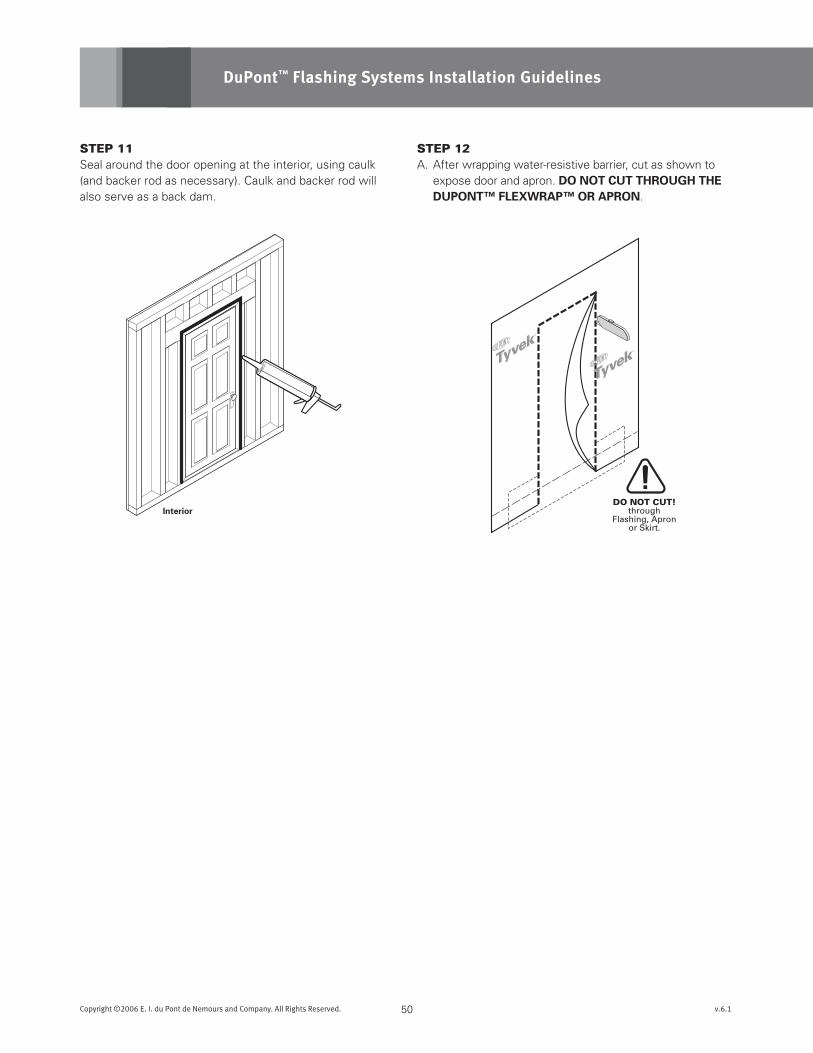
STEp 11Seal around the door opening at the interior, using caulk (and backer rod as necessary). Caulk and backer rod will also serve as a back dam.
STEp 12A. After wrapping water-resistive barrier, cut as shown to
expose door and apron. dOnOTcuTTHROuGHTHEduPOnT™FLEXWRAP™ORAPROn.
DuPont™FlexWrap™
DuPont™StraightFlash™
DuPont™Tyvek®
DuPont™Tyvek®
(apron)Sheathing
HighPressureSkirt
INTERIOR
Patio Door
DoorThreshold
TransitionThreshold
Flooring
Sub Floor
PlasticProtector(optional)
EXTERIOR
Optional
Fold Out and Up
Staples Tape
Fold In and Up
OR
OR
Option 1
Option 2
51Copyright ©2006 E. I. du Pont de Nemours and Company. All Rights Reserved. v.6.1
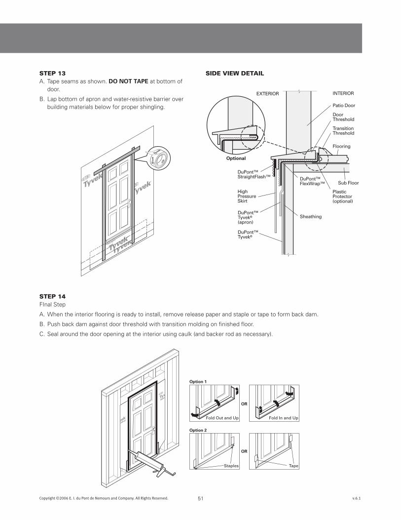
STEp 13A. Tape seams as shown. dOnOTTAPE at bottom of
door.
B. Lap bottom of apron and water-resistive barrier over building materials below for proper shingling.
STEp 14FInal Step
A. When the interior flooring is ready to install, remove release paper and staple or tape to form back dam.
B. Push back dam against door threshold with transition molding on finished floor.
C. Seal around the door opening at the interior using caulk (and backer rod as necessary).
SIDE VIEW DETAIl
For more information about DuPont™ Tyvek® Weatherization System products, please call 1-800-44-Tyvek or visit us at www.Construction.Tyvek.com
Copyright © 2006 E. I. du Pont de Nemours and Company. All rights reserved. The DuPont Oval Logo, DuPont™, The miracles of science™ , Tyvek®, Tyvek® HomeWrap®, Tyvek® StuccoWrap®, Tyvek® DrainWrap™, DuPont™ FlexWrap™, DuPont™ StraightFlash™ and DuPont™ StraightFlash™ VF are registered trademarks or trademarks of DuPont or its affiliates.. K-16280 08/06
Technical SpecificationsDuPont™ Tyvek® water-resistive barriers used in construction products is made from 100% flash spunbonded high density polyethylene fibers which have been bonded together by heat and pressure, without binders or fillers, into a tough, durable sheet structure. Additives have been incorporated into the polyethylene to provide ultraviolet light resistance. DuPont requires that DuPont™ Tyvek® water-resistive barriers be covered within four months (120 days) of installation.
DuPont™ Flashing Systems products are made from a synthetic rubber adhesive and a laminate of polyethylene film, elastic fiber, synthetic rubber adhesive, polyurethane adhesive, and a top sheet of flash spunbonded high density polyethylene fibers. Additives have been incorporated into these materials to provide ultraviolet light resistance. DuPont requires that DuPont™ Flashing Systems products be covered within four months (120 days) of installation.
WarningDuPont™ Tyvek® water-resistive barriers are slippery and should not be used in any application where it will be walked on. In addition, because it is slippery, DuPont recommends using kickjacks or scaffolding for exterior work above the first floor. If ladders must be used, extra caution must be taken to use them safely by following the requirements set forth in ANSI Standards 14.1, 14.2 and 14.5 for ladders made of wood, aluminum, and fiberglass, respectively. DuPont™ Tyvek® is combustible and should be protected from a flame and other high heat sources. DuPont™ Tyvek® will melt at 275°F (135°C) and if the temperature of DuPont™ Tyvek® reaches 750°F (400°C), it will burn and the fire may spread and fall away from the point of ignition. For more information, call 1-800-44-Tyvek.
DuPont™ Flashing Systems products and their release paper are slippery and should not be walked on. Remove release paper from work area immediately. DuPont™ Flashing Systems products will melt at temperatures greater than 250°F (121°C). DuPont™ Flashing Systems products are combustible and should be protected from flame and other high heat sources. DuPont™ Flashing Systems products will not support combustion if the heat source is removed. However, if burning occurs, ignited droplets may fall away from the point of ignition. For more information, call 1-800-44-Tyvek.
NoteWhen installed in conjunction with other building materials, DuPont™ Flashing Systems products must be properly shingled with these materials, such that water is diverted to the exterior of the wall system. DuPont™ Tyvek® products are water-resistive barriers not the primary water barrier (the outer facade is the primary barrier). Contamination of any DuPont™ Tyvek® water-resistive barriers and building papers with building site chemicals which increase their wettability (e.g., surfactants) will adversely affect their water resistance and therefore, their contribution to the overall water resistance of the wall system. DuPont™ Tyvek® Weatherization Systems products are to be used as outlined in this installation guideline. DuPont™ Flashing Systems products are not suggested for use on roof windows. For superior protection against bulk water penetration DuPont suggests a system combining a quality exterior facade, a good secondary water-resistive barrier and an exterior sheathing, appropriate flashing materials and details; and high quality windows and doors with particular attention to proper installation of each component. In a system where no exterior sheathing is used and DuPont™ Tyvek® is installed directly over the wall studs, exterior facade materials should be selected to ensure maximum protection against water intrusion. Careful workmanship and proper installation of each component is very important.
DuPont believes this information to be reliable and accurate. The information may be subject to revision as additional experience and knowledge is gained. It is the user’s responsibility to determine the proper construction materials needed.
For complete warranty information please see the full Warranty at www.Construction.Tyvek.com. To submit a warranty claim, please contact DuPont at www.Construction.Tyvek.com or call 1-800-44-Tyvek. Warranty coverage requires submission of proof of purchase of the DuPont™ Tyvek® at issue.
This information is not intended to be used by others for advertising, promotion or other publication for commercial purposes.