Drill String Safety Valve Project Report
Adam T. Bourgoyne, Jr., LSUL. Scott Stevens, U. Kentucky
Presentation Outline
n Background– Terminology– Problem Areas
n Objectives n Approachn Summary n Recommendations
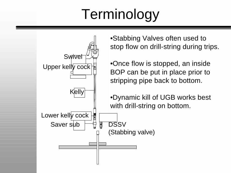
Swivel
Lower kelly cock
Kelly
Saver sub DSSV(Stabbing valve)
Upper kelly cock
Terminology
•Stabbing Valves often used to stop flow on drill-string during trips.
•Once flow is stopped, an inside BOP can be put in place prior to stripping pipe back to bottom.
•Dynamic kill of UGB works best with drill-string on bottom.
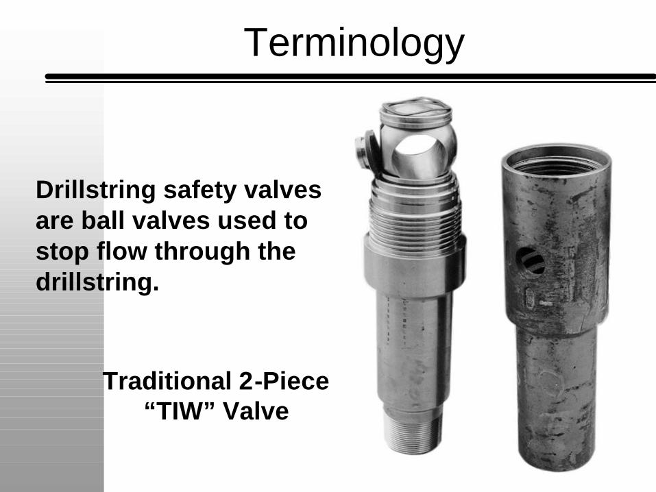
Traditional 2-Piece“TIW” Valve
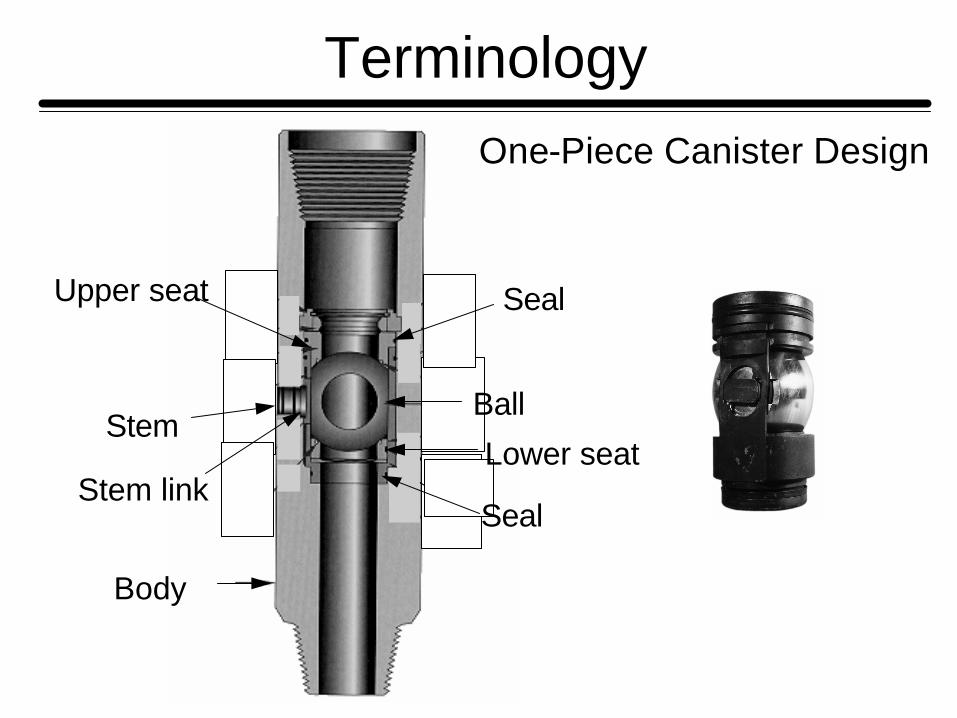
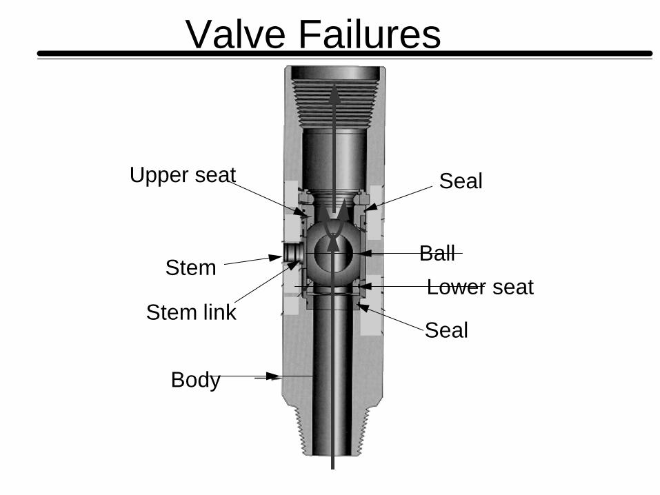
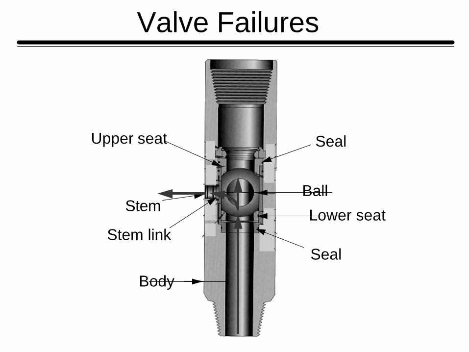
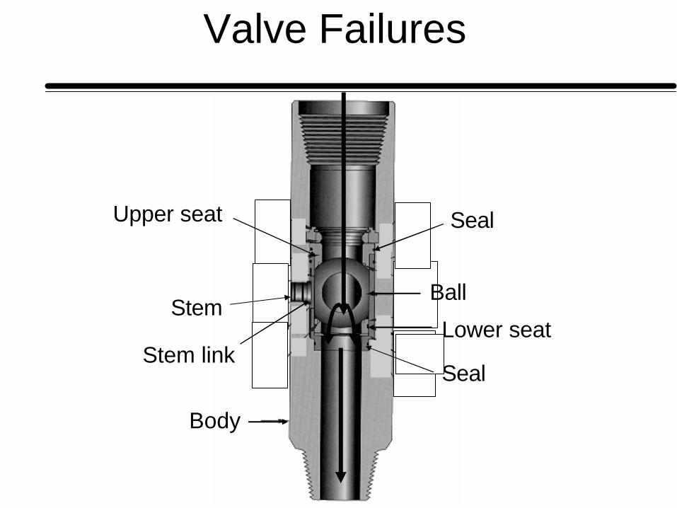
Drillstring safety valvesare ball valves used to stop flow through thedrillstring.
Terminology
Upper seat
Stem
Stem link
Body
Ball
Seal
Lower seat
Seal
Terminology
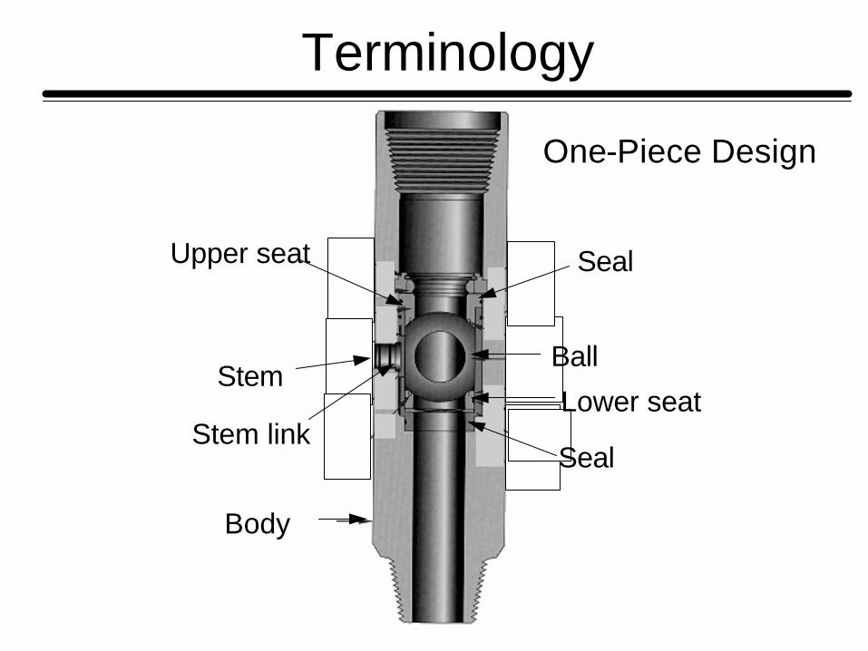
One-Piece Design
Upper seat
Stem
Stem link
Body
Ball
Seal
Lower seat
Seal
TerminologyOne-Piece Canister Design
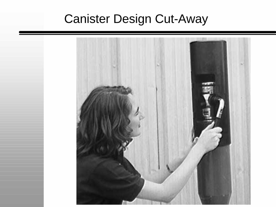
Canister Design Cut-Away
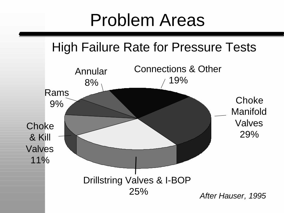
Problem Areas
Drillstring Valves & I-BOP 25%
ChokeManifold Valves29%
Connections & Other19%
Choke& Kill
Valves11%
Rams9%
Annular8%
After Hauser, 1995
High Failure Rate for Pressure Tests
Problems Seen in Practice
n Failure to Close n Failure to Openn Failure to Seal
– Bottom to top.– Top to bottom.– Inside to Outside.
•Mobil Oil Survey of operators identified 29 failures during well control.
•Problems have led to blowouts and loss of life.
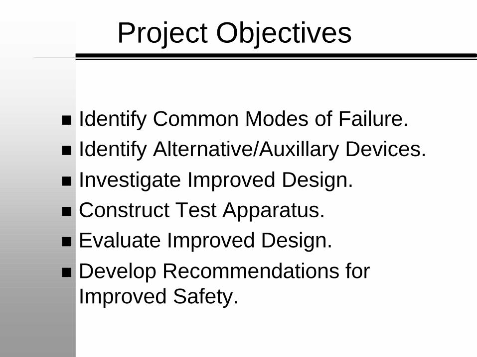
Project Objectives
n Identify Common Modes of Failure.n Identify Alternative/Auxillary Devices.n Investigate Improved Design.n Construct Test Apparatus.n Evaluate Improved Design.n Develop Recommendations for
Improved Safety.
Upper seat
Stem
Stem link
Body
Ball
Seal
Lower seat
Seal
Valve Failures
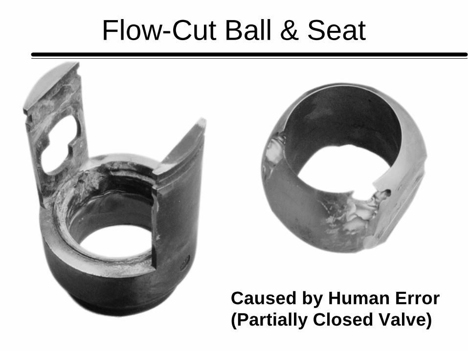
Flow-Cut Ball & Seat
Caused by Human Error(Partially Closed Valve)
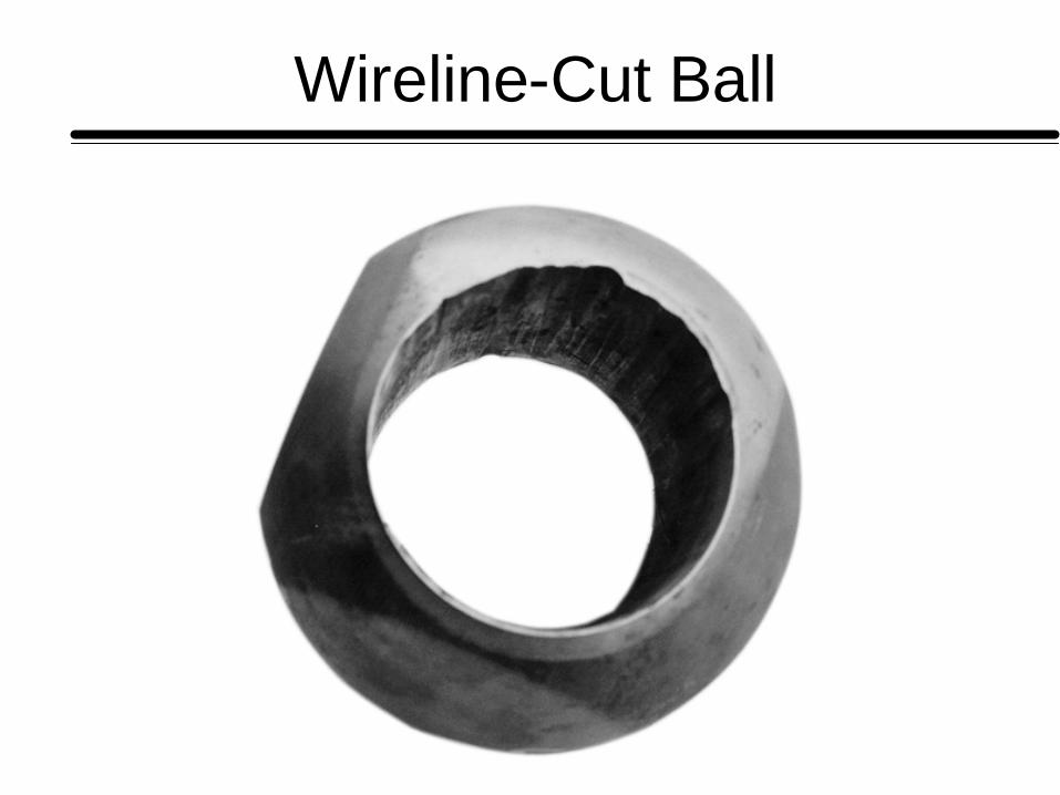
Wireline-Cut Ball
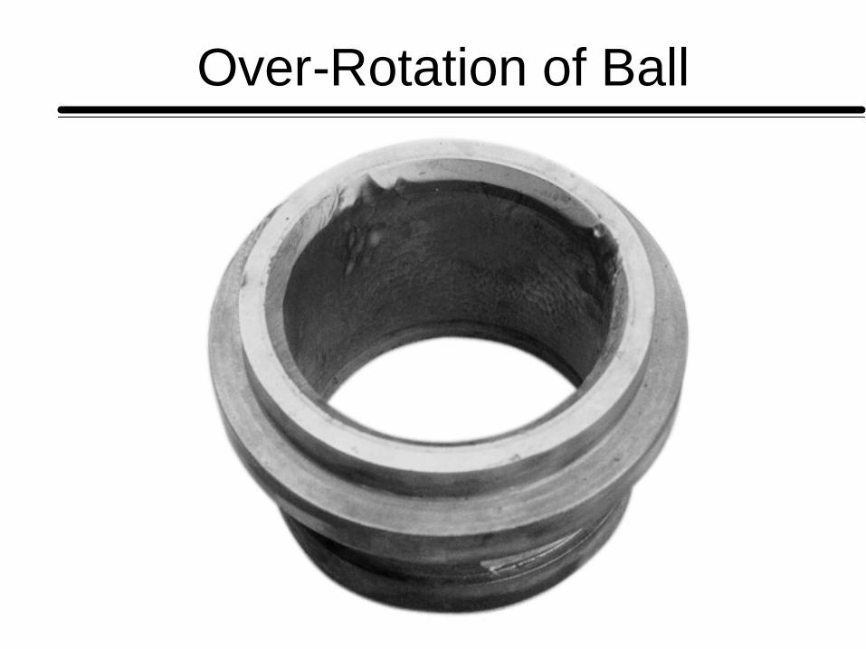
Over-Rotation of Ball
Upper seat
Stem
Stem link
Body
Ball
Seal
Lower seat
Seal
Valve Failures
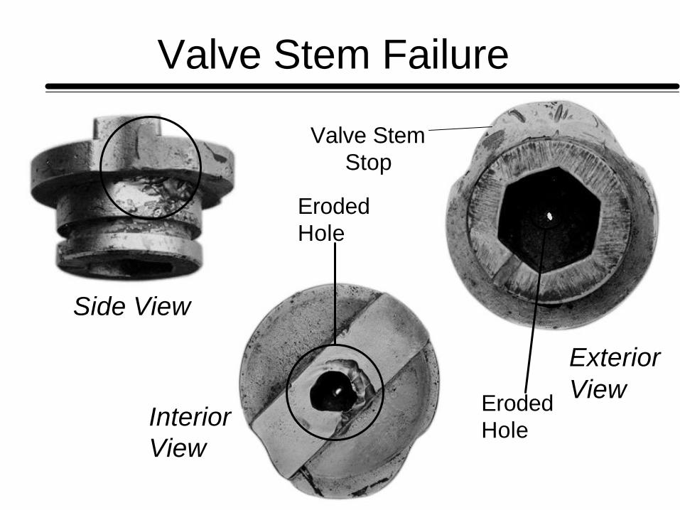
Side View
InteriorView
ExteriorView
Valve Stem Failure
Valve StemStop
Eroded Hole
Eroded Hole
Valve Failures
Upper seat
Stem
Stem link
Body
Ball
Seal
Lower seat
Seal
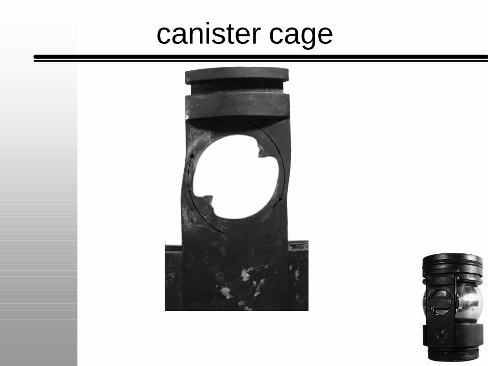
canister cage
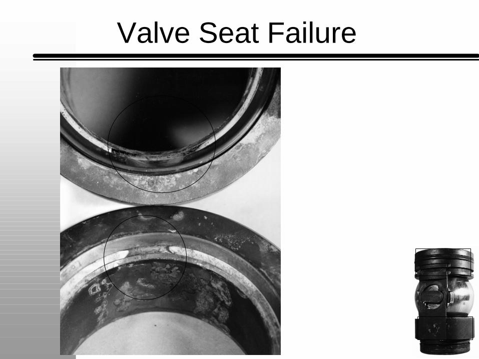
Valve Seat Failure
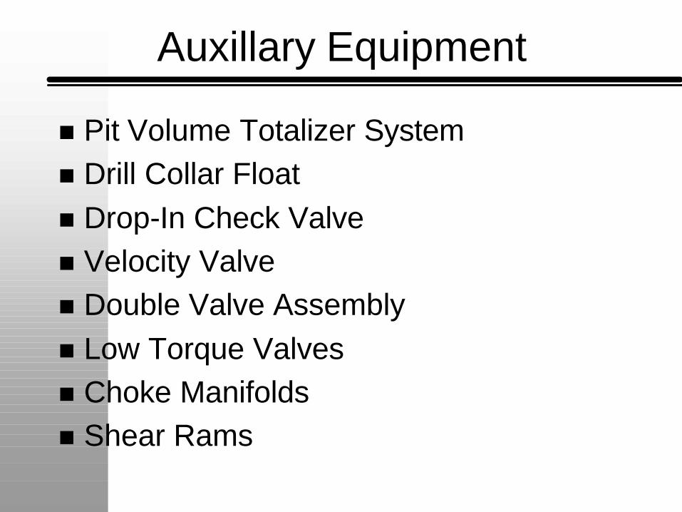
Auxillary Equipment
n Pit Volume Totalizer Systemn Drill Collar Floatn Drop-In Check Valven Velocity Valve n Double Valve Assemblyn Low Torque Valvesn Choke Manifoldsn Shear Rams
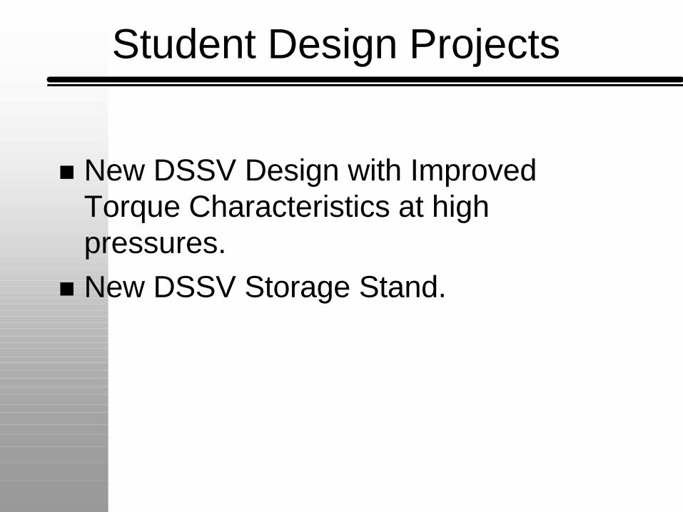
Student Design Projects
n New DSSV Design with Improved Torque Characteristics at high pressures.
n New DSSV Storage Stand.
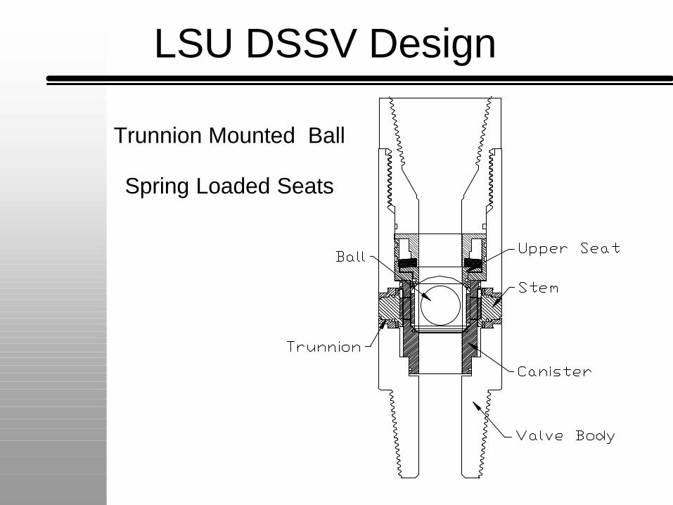
LSU DSSV Design
Trunnion Mounted Ball
Spring Loaded Seats
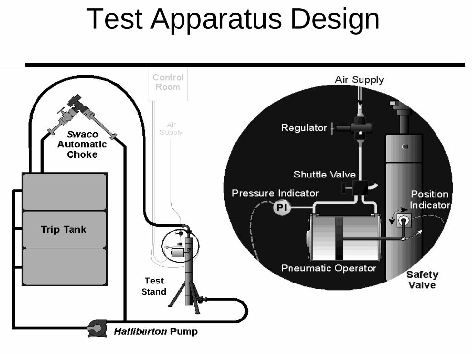
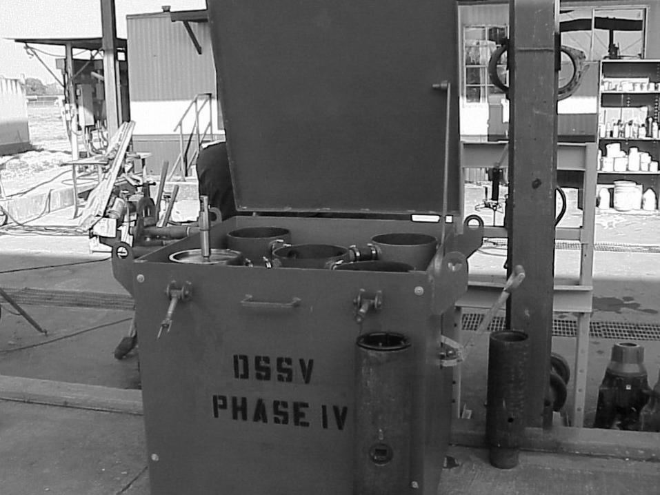
TestStand
Test Apparatus Design
Test Stand & Pump
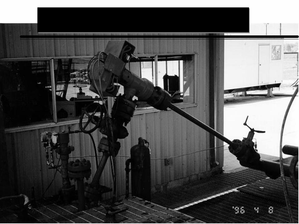
Choke & Control Room
0
10
20
30
40
50
60
70
80
90
100
0
100
200
300
400
500
600
700
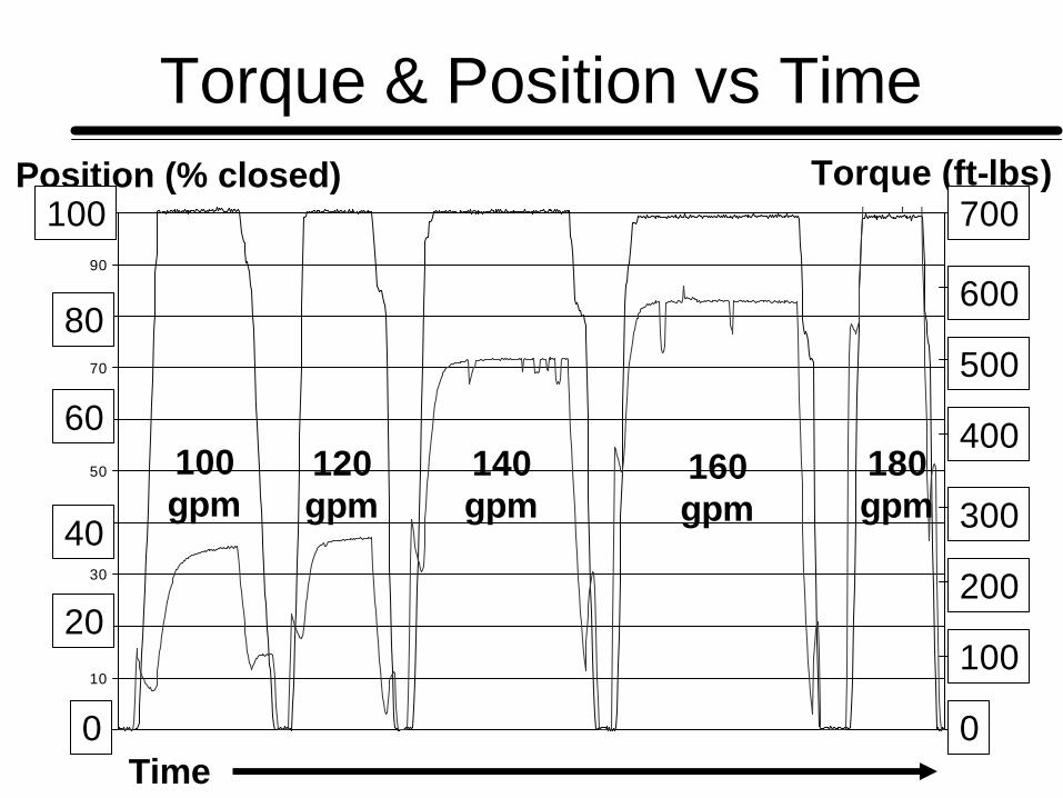
Torque & Position vs TimePosition (% closed) Torque (ft-lbs)
Time
100gpm
120gpm
140gpm
160gpm
180gpm
100
0
100
200
300
400
500
600
700
60
40
20
0
80
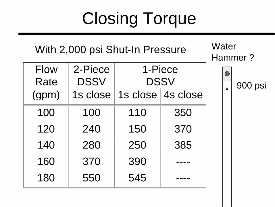
Closing Torque
With 2,000 psi Shut-In Pressure
FlowRate
2-PieceDSSV
1-PieceDSSV
(gpm) 1s close 1s close 4s close
100 100 110 350
120 240 150 370140 280 250 385
160 370 390 ----
180 550 545 ----
Water Hammer ?
900 psi
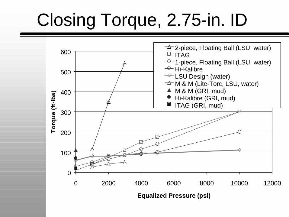
Closing Torque, 2.75-in. ID
0
100
200
300
400
500
600
0 2000 4000 6000 8000 10000 12000
Equalized Pressure (psi)
2-piece, Floating Ball (LSU, water)ITAG1-piece, Floating Ball (LSU, water)Hi-KalibreLSU Design (water)M & M (Lite-Torc, LSU, water)M & M (GRI, mud)Hi-Kalibre (GRI, mud)ITAG (GRI, mud)
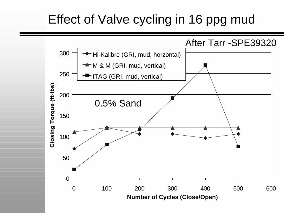
Effect of Valve cycling in 16 ppg mud
0
50
100
150
200
250
300
0 100 200 300 400 500 600Number of Cycles (Close/Open)
Hi-Kalibre (GRI, mud, horzontal)
M & M (GRI, mud, vertical)
ITAG (GRI, mud, vertical)
After Tarr -SPE39320
0.5% Sand
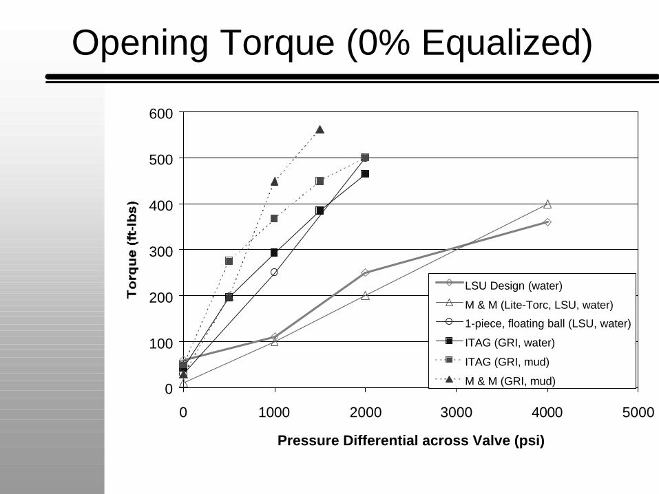
Opening Torque (0% Equalized)
0
100
200
300
400
500
600
0 1000 2000 3000 4000 5000
Pressure Differential across Valve (psi)
LSU Design (water)
M & M (Lite-Torc, LSU, water)
1-piece, floating ball (LSU, water)
ITAG (GRI, water)
ITAG (GRI, mud)
M & M (GRI, mud)
General Observations
n Operating torque requirements for valve can vary greatly with valve use and weathering.
n Valve storage and maintenance is an important aspect of maintaining low torque valve operation.
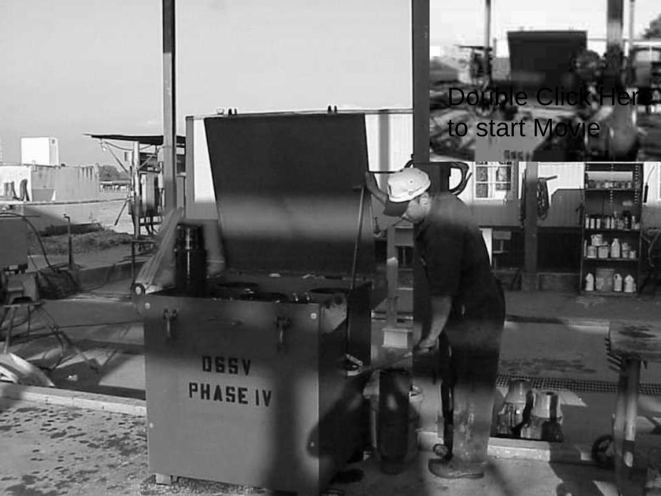
Double Click Hereto start Movie
Conclusions
n DSSV Failures are Significant.n Common Modes of Failure Identified.n Problems poorly understood in field.n Improved design is possible.n Valve maintenance is important.
Recommendationsn 1. The DSSV intended for use as a stabbing valve to stop flow through the
drillstring during tripping operations should not be used in the drillstring for other operations. The stabbing valve should be maintained in a "like-new" condition and used only during periodic pressure testing with fresh water.
n 2. Operators and/or drilling contractors should check threads, valve wrench, and lift sub on the stabbing valve and actuate the stabbing valve close and open each tour.
n 3. Operators and/or drilling contractors should use a drillstring float whenever practical to provide redundant protection against a high-rate flow through the drill-string during tripping operations.
n 4. When floats are not used, shear rams are recommended for redundant protection against blowouts through the drillstring during tripping operations.
n 5. Drill String Safety Valves should not be the only means for stopping flow from the drillstring at the surface when reverse circulating the well during completion operations. Flow should be routed through hydraulically operated valves and a choke manifold.
n 6. Drill string safety valves should not be the only means for stopping flow through the drill string when significant piping and flow restrictions are present above the valve.