ME 307 Machine Design I
Dr. A. Aziz Bazoune Chapter 8: Screws, Fasteners and the Design of Nonpermanent Joints

ME 307 Machine Design I
Dr. A. Aziz Bazoune Chapter 8: Screws, Fasteners and the Design of Nonpermanent Joints CH-8 LEC 35 Slide 2
ME 307 Machine Design I
Dr. A. Aziz Bazoune Chapter 8: Screws, Fasteners and the Design of Nonpermanent Joints CH-8 LEC 35 Slide 3
ME 307 Machine Design I
Dr. A. Aziz Bazoune Chapter 8: Screws, Fasteners and the Design of Nonpermanent Joints CH-8 LEC 35 Slide 4
ME 307 Machine Design I
Dr. A. Aziz Bazoune Chapter 8: Screws, Fasteners and the Design of Nonpermanent Joints CH-8 LEC 35 Slide 5
ME 307 Machine Design I
88 1 1 Thread Standards and DefinitionsThread Standards and Definitions88--1 1 Thread Standards and DefinitionsThread Standards and Definitions88--22 The Mechanics of Power ScrewsThe Mechanics of Power Screws88--33 Strength Constraints Strength Constraints 88--44 JointsJoints--Fasteners StiffnessFasteners Stiffness88 44 JointsJoints Fasteners StiffnessFasteners Stiffness88--55 JointsJoints--Member Stiffness Member Stiffness 88--66 Bolt Strength Bolt Strength 88--77 Tension JointsTension Joints--The External LoadThe External Load88--88 Relating Bolt Torque to Bolt TensionRelating Bolt Torque to Bolt Tension88--99 Statically Loaded Tension Joint with PreloadStatically Loaded Tension Joint with Preload88--1010 GasketedGasketed JointsJoints88--1111 Fatigue Loading of Tension JointsFatigue Loading of Tension Joints88--1212 Shear JointsShear Joints88--1313 SetscrewsSetscrews88 1414 Keys and PinsKeys and Pins
Dr. A. Aziz Bazoune Chapter 8: Screws, Fasteners and the Design of Nonpermanent Joints
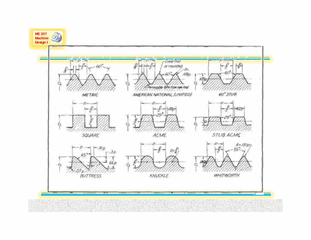
88--1414 Keys and PinsKeys and Pins88--1515 Stochastic ConsiderationsStochastic Considerations
CH-8 LEC 35 Slide 6
ME 307 Machine Design I
88--33 Strength Constraints Strength Constraints 88--44 JointsJoints--Fasteners StiffnessFasteners Stiffness88--55 JointsJoints--Member Stiffness Member Stiffness 88--66 Bolt Strength Bolt Strength
Dr. A. Aziz Bazoune Chapter 8: Screws, Fasteners and the Design of Nonpermanent Joints CH-8 LEC 35 Slide 7
ME 307 Machine Design I ExampleExample--33
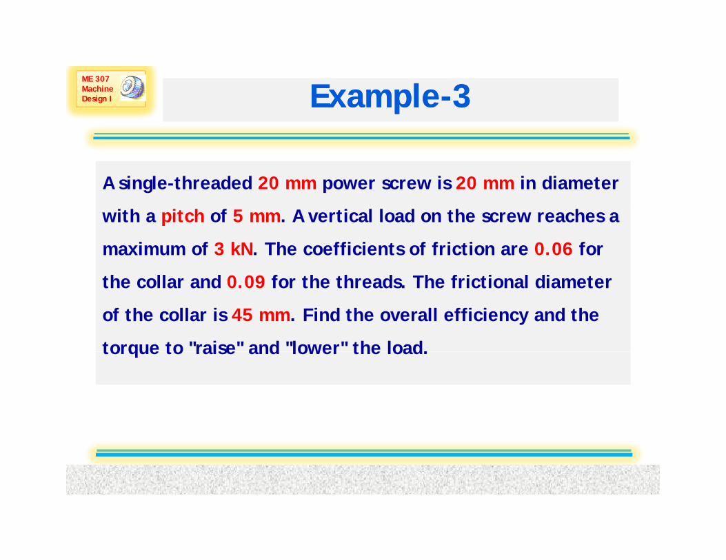
A single-threaded 20 mm power screw is 20 mm in diameter
h h f l l d h h with a pitch of 5 mm. A vertical load on the screw reaches a
maximum of 3 kN. The coefficients of friction are 0.06 for
the collar and 0 09 for the threads The frictional diameter the collar and 0.09 for the threads. The frictional diameter
of the collar is 45 mm. Find the overall efficiency and the
torque to "raise" and "lower" the load.torque to raise and lower the load.
Dr. A. Aziz Bazoune Chapter 8: Screws, Fasteners and the Design of Nonpermanent Joints CH-8 LEC 35 Slide 8

ME 307 Machine Design I ExampleExample--33
Given
Dr. A. Aziz Bazoune Chapter 8: Screws, Fasteners and the Design of Nonpermanent Joints CH-8 LEC 35 Slide 9

ME 307 Machine Design I ExampleExample--3 3 ((Cont.’dCont.’d))
Solution
Dr. A. Aziz Bazoune Chapter 8: Screws, Fasteners and the Design of Nonpermanent Joints CH-8 LEC 35 Slide 10

ME 307 Machine Design I ExampleExample--2 2 ((Cont.’dCont.’d))
Dr. A. Aziz Bazoune Chapter 8: Screws, Fasteners and the Design of Nonpermanent Joints CH-8 LEC 35 Slide 11

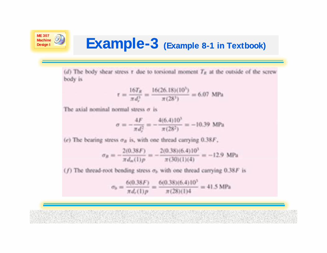
ME 307 Machine Design I Power Screws Stress Analysis
The following stresses should be checked on both the nut and the screw:
1. Shearing stress in screw body.
16T(8 7)
2. Axial stress in screw body
3rπd
τ = (8-7)
2
4
r
F FA πd
σ = = (8-8)
Dr. A. Aziz Bazoune Chapter 8: Screws, Fasteners and the Design of Nonpermanent Joints CH-8 LEC 35 Slide 12

ME 307 Machine Design I Power Screws Stress Analysis
3. Thread bearing stress
2/ 2B
m t m t
F Fπd n p πd n p
σ = − =− (8-10)
where nt is the number of engaged threads.
Figure 8-8 Geometry of square thread useful in finding bending and transverse shear stresses at the thread root
Dr. A. Aziz Bazoune Chapter 8: Screws, Fasteners and the Design of Nonpermanent Joints CH-8 LEC 35 Slide 13
stresses at the thread root

ME 307 Machine Design I Power Screws Stress Analysis
4. Thread bending stressThe bending stress at the root of the thread is given byis given by
( )( )( )( )
321 12 2
/ 2 2 24= =r t
r t
πd n pI π d n pC P( )
4FpM =
2
24 64b
t t
M Fp FI c πd n p πd n p
σ ⎛ ⎞= = =⎜ ⎟⎝ ⎠
(8-11)
4
Dr. A. Aziz Bazoune Chapter 8: Screws, Fasteners and the Design of Nonpermanent Joints CH-8 LEC 35 Slide 14
4 r t r tI c πd n p πd n p⎝ ⎠

ME 307 Machine Design I Power Screws Stress Analysis
5. Transverse shear stress at the center of the thread root
3 3 32 2 2m t m t
V F FA πd n p πd n p
τ = = = (8-12)
Notice that the transverse shear stress at the top of the root is zero p
0τ =
Dr. A. Aziz Bazoune Chapter 8: Screws, Fasteners and the Design of Nonpermanent Joints CH-8 LEC 35 Slide 15
ME 307 Machine Design I Power Screws Stress Analysis
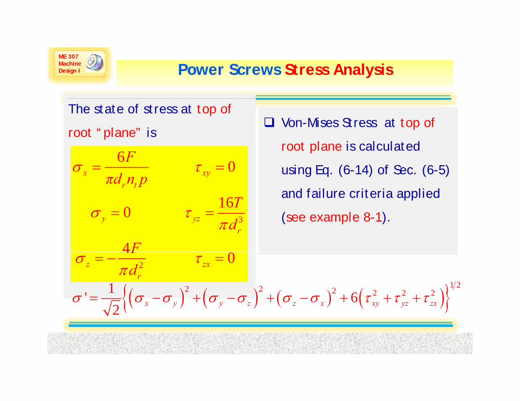
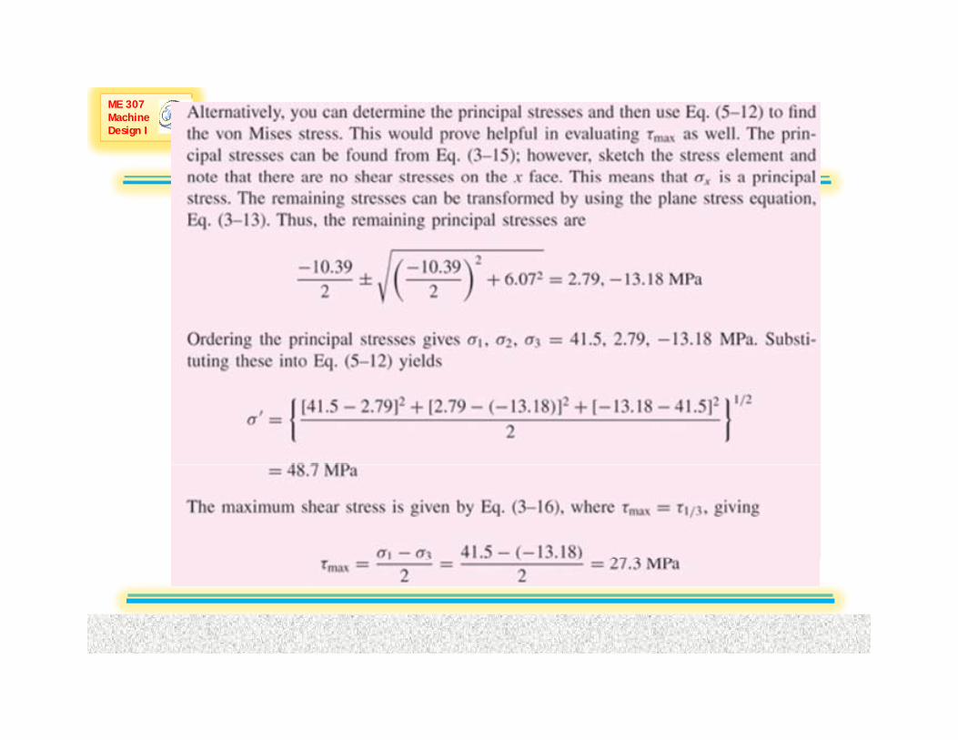
The state of stress at top of
root “plane” isVon-Mises Stress at top of
root plane is calculated 6 0
16
σ τ= =x xyr t
Fπd n p
T
root plane is calculated
using Eq. (6-14) of Sec. (6-5)
and failure criteria applied
3
160
4
σ τπ
= =y yzr
Td
F
(see example 8-1).
2
4 0σ τπ
= − =z zxr
Fd
( ) ( ) ( ) ( ){ }1 22 2 2 2 2 21' 6σ σ σ σ σ σ σ τ τ τ= − + − + − + + +x y y z z x xy yz zx
Dr. A. Aziz Bazoune Chapter 8: Screws, Fasteners and the Design of Nonpermanent Joints CH-8 LEC 35 Slide 16
( ) ( ) ( ) ( ){ }2 x y y z z x xy yz zx

ME 307 Machine Design I Power Screws Stress Analysis
The engaged threads cannot share the load equally. Some
experiments show thatexperiments show that
the first engaged thread carries 0.38 of the load
the second engaged thread carries 0.25 of the load
the third engaged thread carries 0.18 of the load
the seventh engaged thread is free of load
In estimating thread stresses b the eq ations above s bstit ting In estimating thread stresses by the equations above, substituting
nt to 1 will give the largest level of stresses in the thread-nut
combination
Dr. A. Aziz Bazoune Chapter 8: Screws, Fasteners and the Design of Nonpermanent Joints CH-8 LEC 35 Slide 17
combination
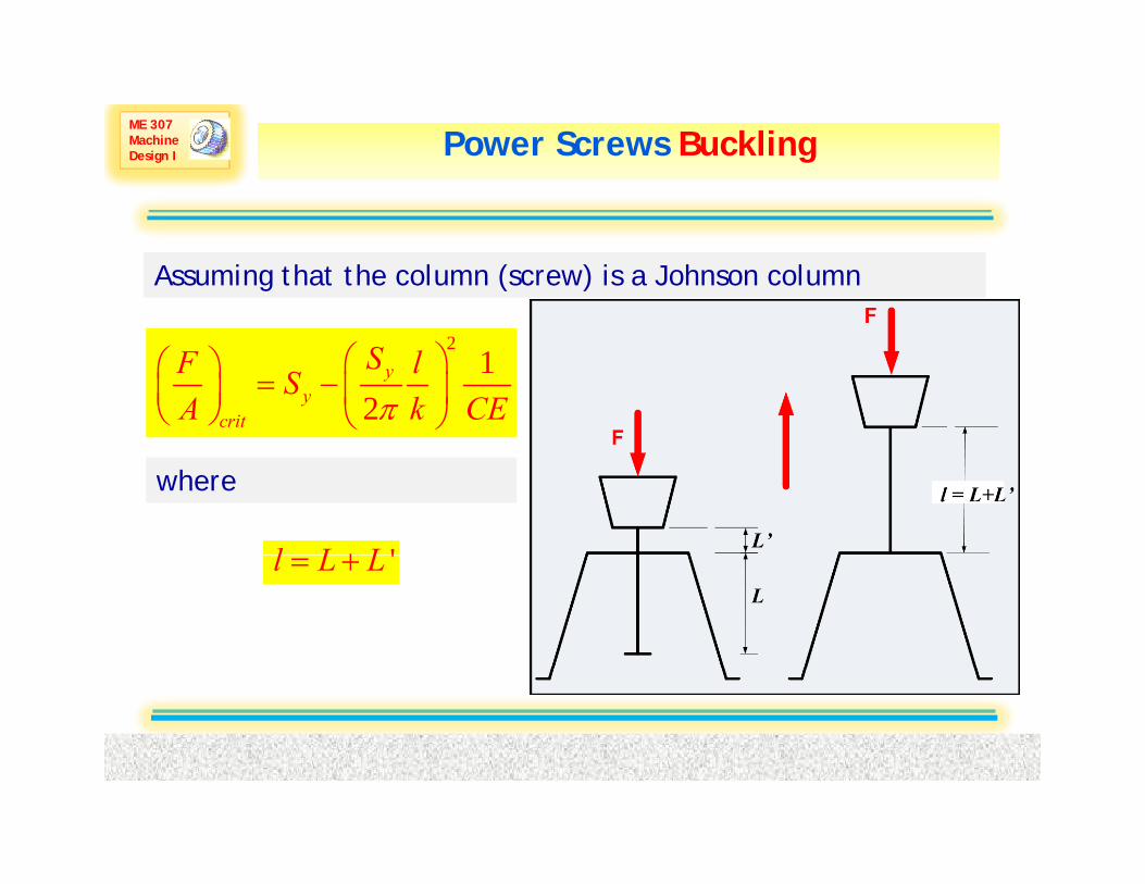
ME 307 Machine Design I Power Screws Buckling
Assuming that the column (screw) is a Johnson column
21
2y
ycrit
SF lSA k CEπ
⎛ ⎞⎛ ⎞ = − ⎜ ⎟⎜ ⎟⎝ ⎠ ⎝ ⎠
where
'l L L+ 'l L L= +
Dr. A. Aziz Bazoune Chapter 8: Screws, Fasteners and the Design of Nonpermanent Joints CH-8 LEC 35 Slide 18

ME 307 Machine Design I ExampleExample--3 3 (Example 8(Example 8--1 in Textbook)1 in Textbook)
Dr. A. Aziz Bazoune Chapter 8: Screws, Fasteners and the Design of Nonpermanent Joints CH-8 LEC 35 Slide 19

ME 307 Machine Design I
Dr. A. Aziz Bazoune Chapter 8: Screws, Fasteners and the Design of Nonpermanent Joints CH-8 LEC 35 Slide 20

ME 307 Machine Design I ExampleExample--3 3 (Example 8(Example 8--1 in Textbook)1 in Textbook)
Dr. A. Aziz Bazoune Chapter 8: Screws, Fasteners and the Design of Nonpermanent Joints CH-8 LEC 35 Slide 21
ME 307 Machine Design I ExampleExample--3 3 (Example 8(Example 8--1 in Textbook)1 in Textbook)
Dr. A. Aziz Bazoune Chapter 8: Screws, Fasteners and the Design of Nonpermanent Joints CH-8 LEC 35 Slide 22

ME 307 Machine Design I ExampleExample--3 3 (Example 8(Example 8--1 in Textbook)1 in Textbook)
Dr. A. Aziz Bazoune Chapter 8: Screws, Fasteners and the Design of Nonpermanent Joints CH-8 LEC 35 Slide 23
ME 307 Machine Design I
Dr. A. Aziz Bazoune Chapter 8: Screws, Fasteners and the Design of Nonpermanent Joints CH-8 LEC 35 Slide 24

ME 307 Machine Design I Types of fastenersTypes of fasteners
Three types of threaded fastener: (a) Screw (b)Bolt and nut; (c) Stud andnut (d) Threaded rod and nuts
Dr. A. Aziz Bazoune Chapter 8: Screws, Fasteners and the Design of Nonpermanent Joints CH-8 LEC 35 Slide 25
nut, (d) Threaded rod and nuts

ME 307 Machine Design I Threaded FastenersThreaded Fasteners
AA-- BOLTSBOLTS:
Purpose:Purpose:to clamp two or more members together.PPParts:Parts:(1) Head (Square or
Hexagonal)(2) Washer (d =1 5d)(2) Washer (dw=1.5d)(3) Threaded part (4) Unthreaded part
Dimensions of square and hexagonal bolts aregiven in TABLE A-29
Dr. A. Aziz Bazoune Chapter 8: Screws, Fasteners and the Design of Nonpermanent Joints CH-8 LEC 35 Slide 26

ME 307 Machine Design I Threaded FastenersThreaded Fasteners
The diameter of the washer faceis the same as the width acrossthe flats of the hexagon. The
12 in L 6 i
E
n4
nglish
⎧ + ≤⎪⎪D
thread length (LT) is :
412 in L 6 in2
⎪⎪= ⎨⎪ + >⎪⎩
TLD
Metric (in mm)2 6 L 125 482 12 1
Metric (in m
25 L 2002D 25 2
m)
00
+ ≤ ≤⎧⎪= + < ≤⎨⎪⎩
T
D DL D
LD is the nominal diameter
Dr. A. Aziz Bazoune Chapter 8: Screws, Fasteners and the Design of Nonpermanent Joints CH-8 LEC 35 Slide 27
2D+25 200⎪ >⎩ L
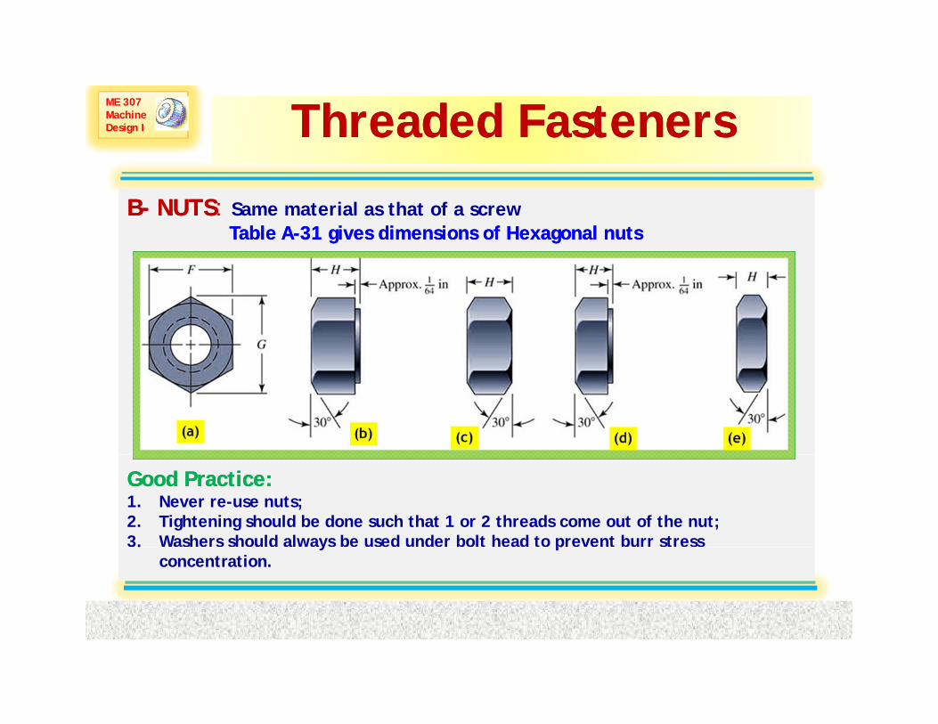
ME 307 Machine Design I Threaded FastenersThreaded Fasteners
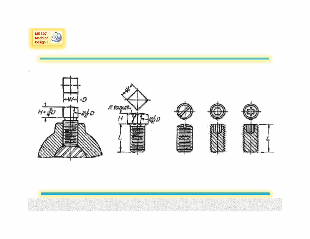
BB-- NUTSNUTS: Same material as that of a screwTable ATable A--31 gives dimensions of Hexagonal nuts31 gives dimensions of Hexagonal nuts
Good Practice:Good Practice:1. Never re-use nuts;2. Tightening should be done such that 1 or 2 threads come out of the nut;3. Washers should always be used under bolt head to prevent burr stress
Dr. A. Aziz Bazoune Chapter 8: Screws, Fasteners and the Design of Nonpermanent Joints CH-8 LEC 35 Slide 28
. y pconcentration.
ME 307 Machine Design I Threaded FastenersThreaded Fasteners
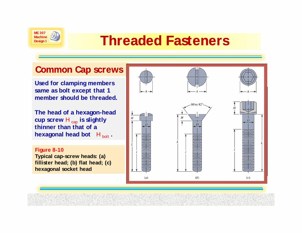
Common Cap screwsCommon Cap screwsUsed for clamping members same as bolt except that 1 member should be threaded.
The head of a hexagon-head cup screw H cap is slightly thinner than that of a hexagonal head bot H bolt .
Figure 8-10 Typical cap-screw heads: (a) fillister head; (b) flat head; (c) hexagonal socket head
Dr. A. Aziz Bazoune Chapter 8: Screws, Fasteners and the Design of Nonpermanent Joints CH-8 LEC 35 Slide 29
ME 307 Machine Design I
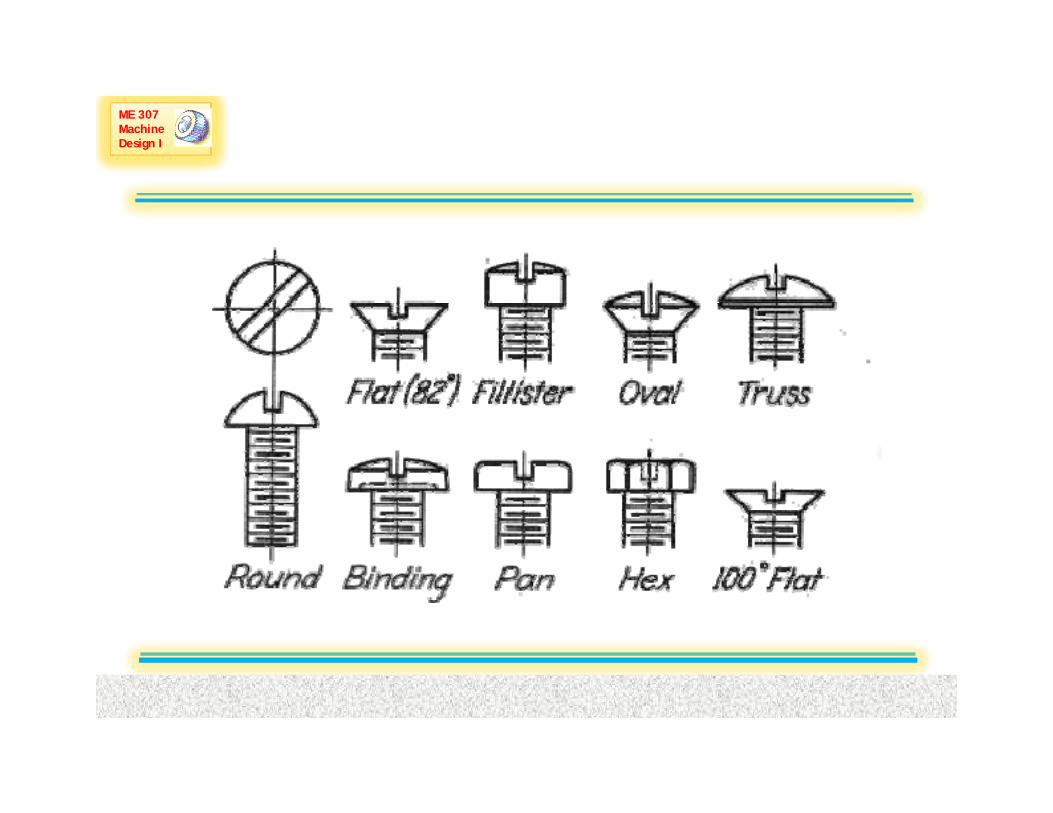
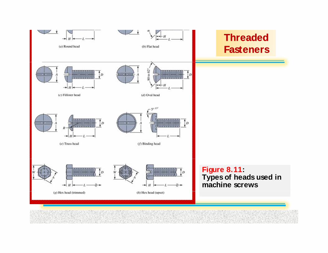
Threaded Threaded FastenersFasteners
Figure 8.11: Types of heads used in machine screws
Dr. A. Aziz Bazoune Chapter 8: Screws, Fasteners and the Design of Nonpermanent Joints CH-8 LEC 35 Slide 30
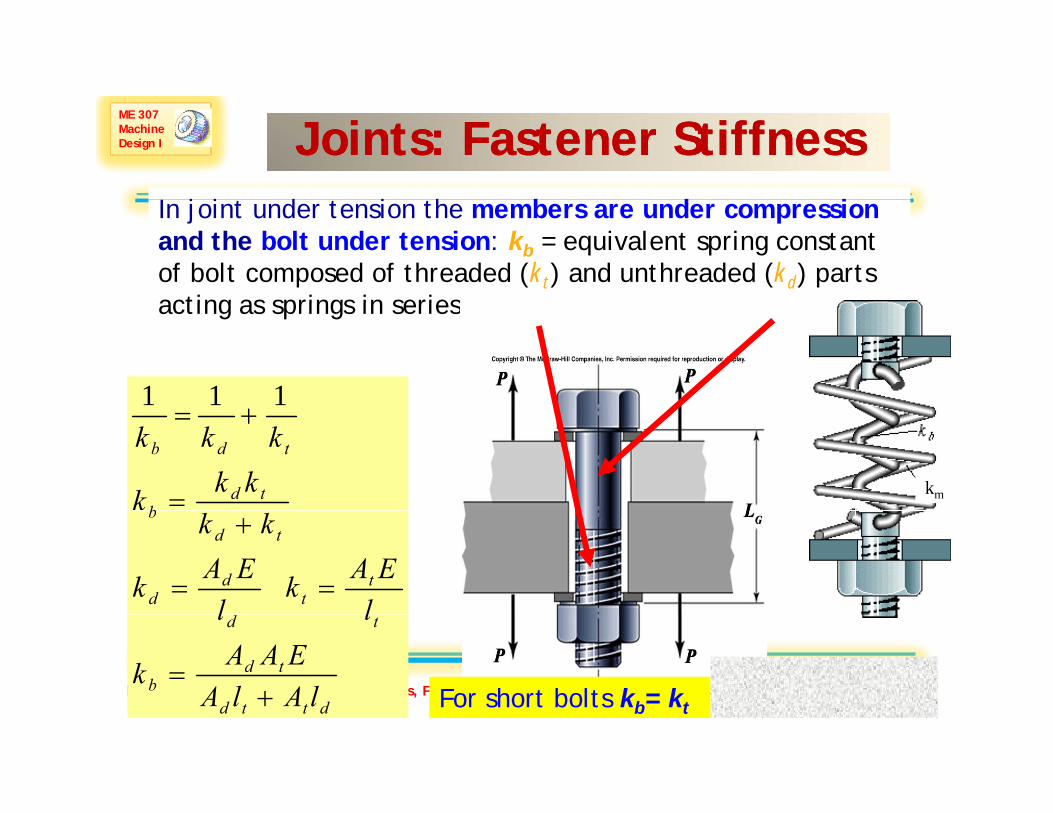
ME 307 Machine Design I Joints: Fastener Stiffness Joints: Fastener Stiffness
I j i d i h b d iIn joint under tension the members are under compressionand the bolt under tension: kb = equivalent spring constant of bolt composed of threaded (kt) and unthreaded (kd) parts acting as springs in series
111
acting as springs in series
tdb
tdb
kkk
kkk
=
+=
km
tt
dd
tdb
lEAk
lEAk
kk
==
+
Dr. A. Aziz Bazoune Chapter 8: Screws, Fasteners and the Design of Nonpermanent Jointsdttd
tdb
td
lAlAEAAk
ll
+=
For short bolts kb= ktCH-8 LEC 35 Slide 31

ME 307 Machine Design I
Joints: Fastener Stiffness
To find different parameters useparameters use table 8-7
Dr. A. Aziz Bazoune Chapter 8: Screws, Fasteners and the Design of Nonpermanent Joints CH-8 LEC 35 Slide 32
ME 307 Machine Design I
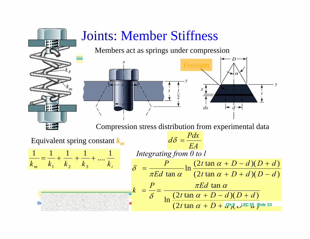
Joints: Member StiffnessMembers act as springs under compression
Frustum
mm
Equivalent spring constant km
Compression stress distribution from experimental data
EAPdxd =δ
im kkkkk1....1111
321
+++= Integrating from 0 to l
))(tan2())(tan2(ln
tan dDdDtdDdDt
EdP
−+++−+
=αα
απδ
Dr. A. Aziz Bazoune Chapter 8: Screws, Fasteners and the Design of Nonpermanent Joints ))(tan2())(tan2(ln
tan
dDdDtdDdDt
EdPk
−+++−+
==
αα
απδ
CH-8 LEC 35 Slide 33

ME 307 Machine Design I Joints: Member Stiffness
For Members made of Aluminum, hardened steel and cast iron 25 <a< 33For a= 30
)208(
))(1551())(155.1(ln
5774.0−
−+++−+
=
dDdDtdDdDt
Edk π
))(155.1( ++ dDdDt
If Members have same E with symmetrical frusta (l= 2t) they act as 2 identical springs k = k/2 For a= 30° and D = d = 1 5didentical springs km = k/2 For a= 30° and D = dw = 1.5d
)228(5.05774.05ln
5774.0
)(2−
+=
dlEdk m
π
Dr. A. Aziz Bazoune Chapter 8: Screws, Fasteners and the Design of Nonpermanent Joints
5.25774.05ln )(2
+ dl
CH-8 LEC 35 Slide 34
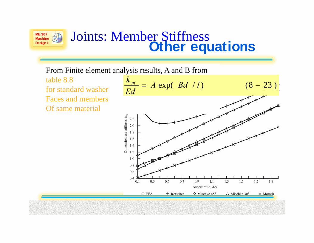
ME 307 Machine Design I Other equations
Joints: Member Stiffness
From Finite element analysis results, A and B from table 8.8 for standard washer )238()/exp( −= lBdA
Edk m
for standard washerFaces and membersOf same material
Ed
Dr. A. Aziz Bazoune Chapter 8: Screws, Fasteners and the Design of Nonpermanent Joints CH-8 LEC 35 Slide 35

ME 307 Machine Design I Bolt Strength
Bolt strength is specified by minimum proof strength Sp or minimum proof load, Fp and minimum tensile strength, Sut
The SAE specifications are given inThe SAE specifications are given in Table 8-9 bolt grades are numbered according to minimum tensile strength
proof strengthg
The ASTM Specs for steel bolts (structural) are in Table 8-10.Metric Specs are in table 8-11.
If Sp not available use Sp =0.85 SyFp = At Sp
Dr. A. Aziz Bazoune Chapter 8: Screws, Fasteners and the Design of Nonpermanent Joints CH-8 LEC 35 Slide 36

ME 307 Machine Design I Tension Joints
Static Analysisa) External Load
( )1b PPP +=Equilibrium bb CPPkP ==
External Load P is shared by bolt and members
( )
( )3&
)2(1
mbbm
mb
mb
kPPPP
PPP
===
==+
δ
δδδ
q
Compatibilitymb
mm
mbb
k
PCPkk
kP
CPPkk
P
−=+
=
+
)1( (4)
( )3&b
mbm k
Pkk
===δRelation P-δmb
b
kkkC+
=
C is the stiffness constant of the joint, For typical values of C see table 8-12
Dr. A. Aziz Bazoune Chapter 8: Screws, Fasteners and the Design of Nonpermanent Joints
For typical values of C see table 8 12Most of external Load P is taken by members
CH-8 LEC 35 Slide 37

ME 307 Machine Design I
Static Analysis
Tension Joints
Static Analysisb) Resultant Bolt & member loads: Fb& Fm
iibb
FPCFPFFCPFPF +=+=)1( Fm<0
iimm FPCFPF −−=−= )1(
c) Torque required to give preload Fi
Fi is preload; high preload is desirable in tension connections
⎞⎛Fi = 0.75 Fp For re-use
dfFfdFTl
2dfF
flπdπfdl
2dFT
ccimi
cci
m
mmi
+⎟⎟⎞
⎜⎜⎛ +
==
+⎟⎟⎠
⎞⎜⎜⎝
⎛−
+=
sectantan
secsec
αλλ
αα
i pFi = 0.90 Fp For permanent joint
dFffdT
dddddd2fl2πd
m
wc
m
+⎟⎟⎞
⎜⎜⎛ +
=
=+=+=
⎟⎟⎠
⎜⎜⎝ −
6250sectan
25.12/)5.1(2/)(sectan
][ αλ
αλ K is torque coefficientK values are given in table 8-15 (Average
Dr. A. Aziz Bazoune Chapter 8: Screws, Fasteners and the Design of Nonpermanent JointsdKFTffl
f2ddK
dFffl2d
T
icm
ic
=+⎟⎟⎠
⎞⎜⎜⎝
⎛−
+=
+⎟⎟⎠
⎜⎜⎝ −
=
625.0sectansectan
625.0sectan
][αλαλ
αλ( g
Value = 0.2)
CH-8 LEC 35 Slide 38

ME 307 Machine Design I
Static Anal sis
Tension Joints
Static Analysisd) Joint Safety
Failure of Joint occurs when:
FCPF ibb +==σ or 2) Joint separates
f1) Bolt yields
FnPCSstartsFailure
AAA
i
Pb
tttb
)(=σ
or 2) Joint separates
FPCF im −−= )1(0 = (1 C) P F
Let P0 be external load causing separation Fm=0
FASnfactorLoad
SAF
AnPC
itP
Pt
i
t
)(
−=
=+
( )CPFn
F
i
m
−=
=
1
0 0 = (1-C) P0-Fi
Dr. A. Aziz Bazoune Chapter 8: Screws, Fasteners and the Design of Nonpermanent JointsNCPFASnBoltsNFor
CPf
itP
/−
=
( )
( )CNPFnboltsnFor
CP
i
−=
1/
1
CH-8 LEC 35 Slide 39

ME 307 Machine Design I
Static Anal sis
Tension Joints
Static Analysise) Gasketed Joints
If a full gasket is present in joint
m
NAFp
/−=
f f g p jThe gasket pressure p is:
To maintain uniformity of pressure adjacent bolts
im
g
FnPCFnfactorloadWith
NA
)1(
/
−−= 0 = (1-C) P0-Fi
o maintain unifo mity of p essu e adjacent boltsshould not be placed more than 6 nominal diameters apart on bolt circle. To maintain wrench clearance bolts should be placed at least 3 d apart
gi A
NCnPFp )]1([ −−=
NdDbπ
3≤ ≤6
Dr. A. Aziz Bazoune Chapter 8: Screws, Fasteners and the Design of Nonpermanent Joints
Db is the diameter of the bolt circle
CH-8 LEC 35 Slide 40

ME 307 Machine Design I Tension Joints
Pb
F F
FaFmax=Fb
FaFatigue Analysis
Fi Fmb
In general, bolted joints are subject g j jto 0-Pmax,e.g pressure vessels, flanges, pipes, …
CC )(
2ib
ba
FF
FFF
+
−=
iiiib
tt
ii
t
ibba
FCPFFCPFFA
CPA
FFCPA
FFσ
+++
=−+
=−
=
)(22
)(2
Dr. A. Aziz Bazoune Chapter 8: Screws, Fasteners and the Design of Nonpermanent Joints
2ib
bmFFF +
= ibat
i
tt
ii
t
ibbm AAAA
σσσ +=+===22
)(2
CH-8 LEC 35 Slide 41
ME 307 Machine Design I
Fatig e Anal sis
Tension Joints
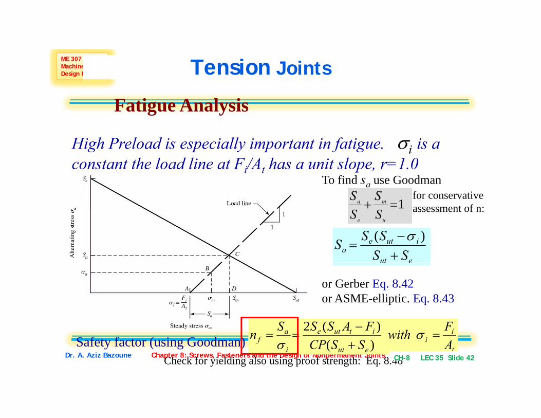
Fatigue Analysis
High Preload is especially important in fatigue. σi is a constant the load line at Fi/At has a unit slope, r=1.0
To find sa use Goodman
1=+ ma SS for conservative assessment of n:
ue SS
eut
iutea SS
SSS+−
=)( σ
assessment of n:
or Gerber Eq. 8.42or ASME-elliptic. Eq. 8.43
eut
Dr. A. Aziz Bazoune Chapter 8: Screws, Fasteners and the Design of Nonpermanent Jointst
ii
eut
itute
i
af A
FwithSSCP
FASSSn =+−
== σσ )(
)(2Safety factor (using Goodman)
Check for yielding also using proof strength: Eq. 8.48CH-8 LEC 35 Slide 42

ME 307 Machine Design I
F ti A l i
Tension Joints
Fatigue Analysis
In case of cut threads use the method described in chapter 7 with Kf values of table 8-16.
The fully corrected endurance limit for rolled threads is given in table 8-17
Dr. A. Aziz Bazoune Chapter 8: Screws, Fasteners and the Design of Nonpermanent Joints CH-8 LEC 35 Slide 43

ME 307 Machine Design I Fig.
8 198.19
Dr. A. Aziz Bazoune Chapter 8: Screws, Fasteners and the Design of Nonpermanent Joints CH-8 LEC 35 Slide 44

ME 307 Machine Design IFig.
8.21
Dr. A. Aziz Bazoune Chapter 8: Screws, Fasteners and the Design of Nonpermanent Joints CH-8 LEC 35 Slide 45

ME 307 Machine Design I Failure Modes of Riveted Fasteners
Under Shear
Failure modes due to shear loading of riveted fasteners. (a) Bending of member; (b) shear of rivet; (c) tensile failure of member; (e) bearing of rivet on member or bearing of member on rivet.
Dr. A. Aziz Bazoune Chapter 8: Screws, Fasteners and the Design of Nonpermanent Joints CH-8 LEC 35 Slide 46

ME 307 Machine Design I Shear Joints
Centroid of pins, rivets or boltsxAxAxAxAxAxA Σ++++
i
ii
AxA
AAAAAxAxAxAxAxAx
ΣΣ
=++++
++++=
54321
5544332211'
AAAAAA Σ
i
ii
AyA
AAAAAyAyAyAyAyAy
ΣΣ
=++++
++++=
54321
5544332211'
Dr. A. Aziz Bazoune Chapter 8: Screws, Fasteners and the Design of Nonpermanent Joints CH-8 LEC 35 Slide 47

ME 307 Machine Design I
Shear Joints
Shear of pins, rivets bolts due to eccentric loadingS e o p s, ve s bo s due o ecce c o d g
V & M statically indeterminate problem4 steps (assuming same diameter bolts, load shared equally)
1) Direct load F’
NVF ='
Primary Shear
ii
i
ii
yAA
xAx
ΣΣΣ
='
N2) Centroid
Dr. A. Aziz Bazoune Chapter 8: Screws, Fasteners and the Design of Nonpermanent Joints
i
ii
AyAy
ΣΣ
='
CH-8 LEC 35 Slide 48
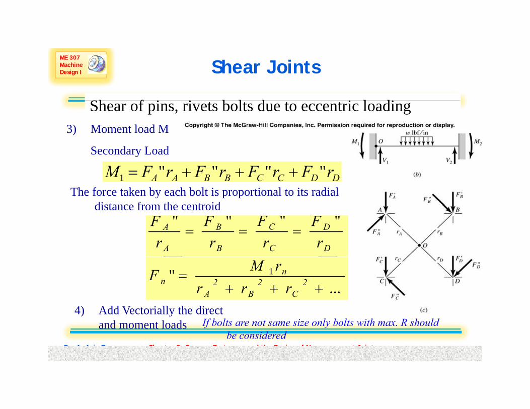
ME 307 Machine Design I Shear Joints
Sh f i i b l d i l diShear of pins, rivets bolts due to eccentric loading3) Moment load M
Secondary LoadSecondary Load
DDCCBBAA rFrFrFrFM """"1 +++=The force taken by each bolt is proportional to its radial
distance from the centroid""""
===D
D
C
C
B
B
A
A
rF
rF
rF
rF
distance from the centroid
..." 1
+++= 2
C2
B2
A
nn rrr
rMF
4) Add Vectorially the direct
Dr. A. Aziz Bazoune Chapter 8: Screws, Fasteners and the Design of Nonpermanent Joints
4) Add Vectorially the direct and moment loads If bolts are not same size only bolts with max. R should
be consideredCH-8 LEC 35 Slide 49

ME 307 Machine Design I
See Examples 8.6 and 8.7p
Dr. A. Aziz Bazoune Chapter 8: Screws, Fasteners and the Design of Nonpermanent Joints CH-8 LEC 35 Slide 50
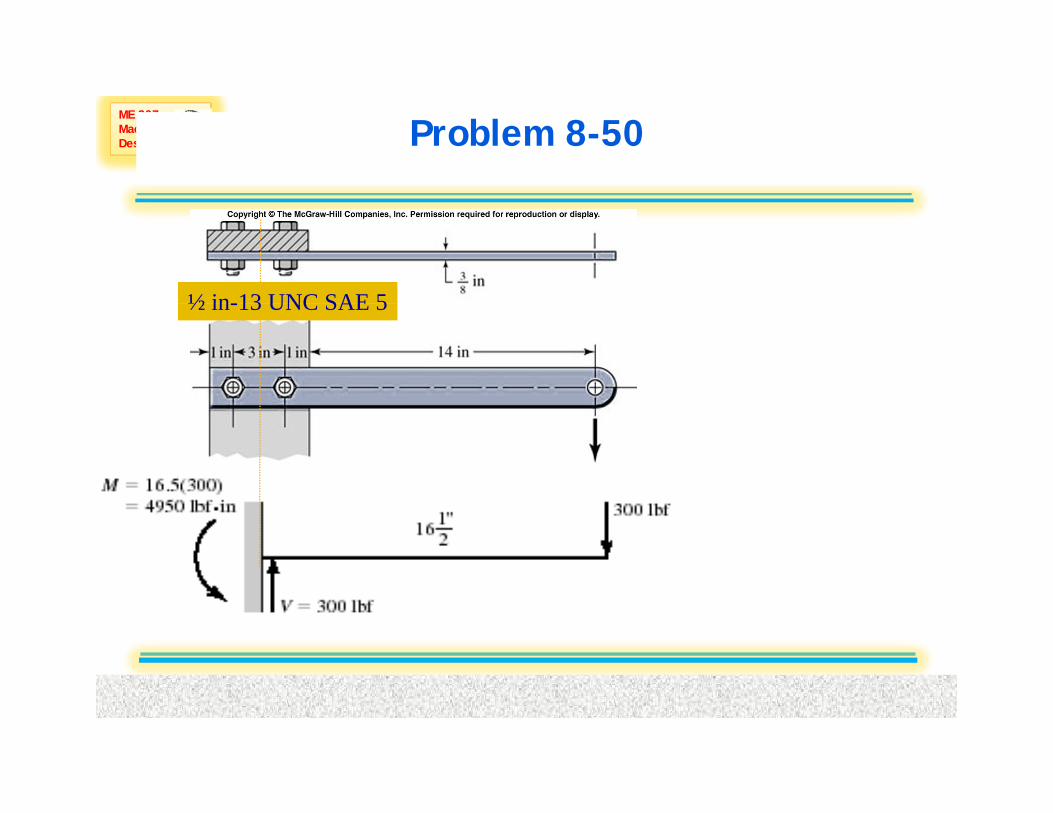
ME 307 Machine Design I Problem 8-50
½ in 13 UNC SAE 5½ in-13 UNC SAE 5
Dr. A. Aziz Bazoune Chapter 8: Screws, Fasteners and the Design of Nonpermanent Joints CH-8 LEC 35 Slide 51
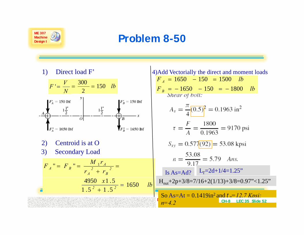
ME 307 Machine Design I Problem 8-50
1) Direct load F’VF =' lb150300
==
4)Add Vectorially the direct and moment loads
lbFlbF A
1800150165015001501650 =−=
NF lb150
2 lbF B 18001501650 −=−−=
2) Centroid is at O3) Secondary Load
rrrMFF 2
B2
A
ABA "" 1 =
+==
Is As=Ad? LT=2d+1/4=1.25”
Dr. A. Aziz Bazoune Chapter 8: Screws, Fasteners and the Design of Nonpermanent Joints
lbx22 1650
5.15.15.14950
=+
Hnut+2p+3/8=7/16+2(1/13)+3/8=0.97”<1.25”
So As=At = 0.1419in2 and tB=12.7 Kpsi; n=4.2 CH-8 LEC 35 Slide 52

ME 307 Machine Design I Problem 8-50
Dr. A. Aziz Bazoune Chapter 8: Screws, Fasteners and the Design of Nonpermanent Joints CH-8 LEC 35 Slide 53

ME 307 Machine Design I Problem 8-50
Dr. A. Aziz Bazoune Chapter 8: Screws, Fasteners and the Design of Nonpermanent Joints CH-8 LEC 35 Slide 54