M. Ettehadi , H. Ghasemi , S. Vaez-Zadeh
Electr. & Comput. Eng., Univ. of Tehran, IEEE Power & Energy society 2013
Student ; Reza Shahbazi
2014 December
Voltage Stability-Based DG Placementin Distribution Networks
1
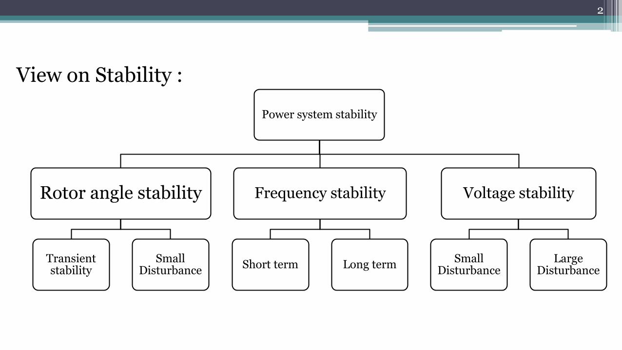
Power system stability
Rotor angle stability
Transient stability
Small Disturbance
Frequency stability
Short term Long term
Voltage stability
Small Disturbance
Large Disturbance
2
View on Stability :
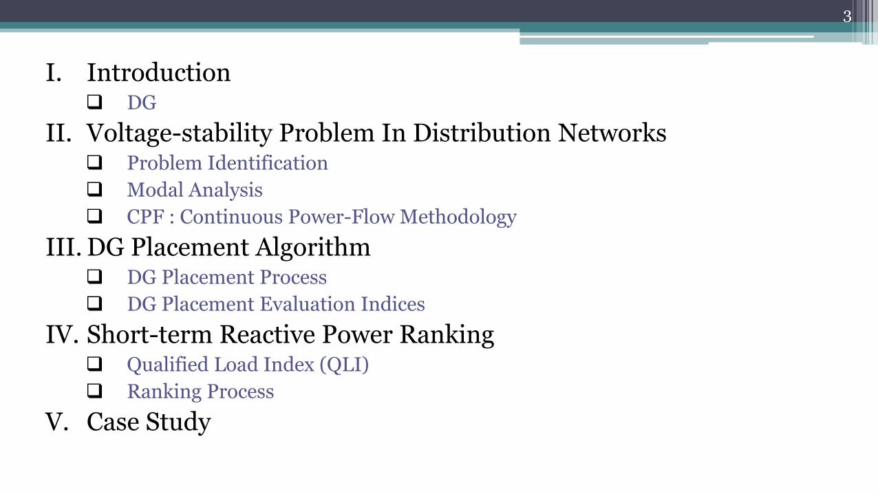
I. Introduction DG
II. Voltage-stability Problem In Distribution Networks Problem Identification
Modal Analysis
CPF : Continuous Power-Flow Methodology
III. DG Placement Algorithm DG Placement Process
DG Placement Evaluation Indices
IV. Short-term Reactive Power Ranking Qualified Load Index (QLI)
Ranking Process
V. Case Study
3

Introduction :
DG
4

DG (Distributed Generation)
Distributed generation (DG) is any electricity generating technology installed by a customer.
Generating power on-site (close to the load), rather than centrally, eliminates the cost, complexity, interdependencies, and inefficiencies associated with transmission and distribution.
Since reactive power cannot travel over long distances, system operators/dispatchers should provide it locally.
DG units are good local reactive power sources.
5
Voltage-stability Problem In Distribution Networks
Problem Identification
Modal Analysis
CPF : Continuous Power-Flow Methodology
6
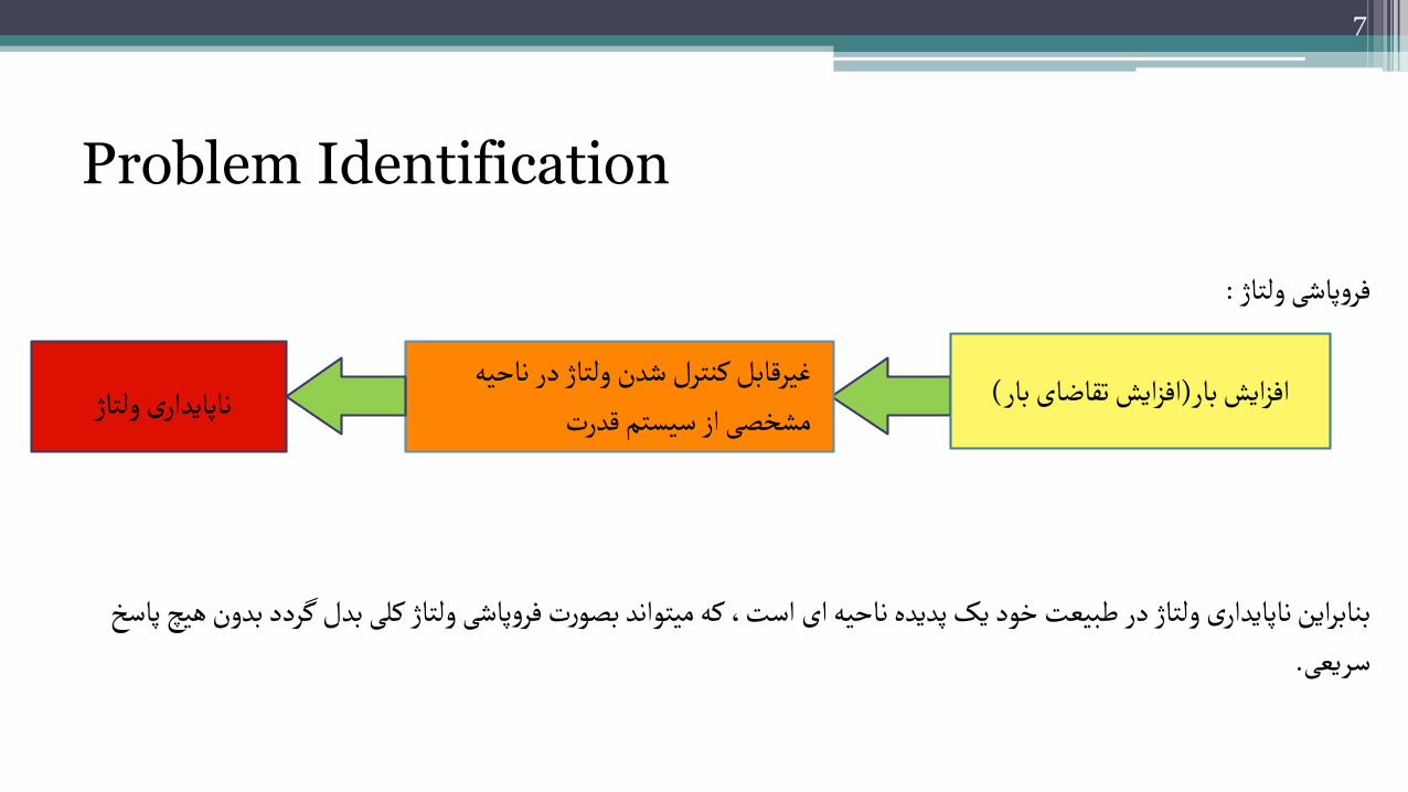
Problem Identification
:فروپاشی ولتاژ
دد بدون هیچ پاسخ بنابراین ناپایداری ولتاژ در طبیعت خود یک پدیده ناحیه ای است، که میتواند بصورت فروپاشی ولتاژ کلی بدل گر .سریعی
7
ه غیرقابل کنترل شدن ولتاژ در ناحی(افزایش تقاضای بار)بارافزایش ناپایداری ولتاژمشخصی از سیستم قدرت

Voltage stability (IEEE ):
refers to the ability of a power system to maintain steady voltages at all buses in the system after being subjected to a disturbance from a given initial operating condition
Voltage collapse :
usually occurs in heavily loaded systems that do not have sufficient local reactive power sources.
8
This reactive power shortage may lead to wide-area Blackouts

Tools for voltage stability analysis
Different methods exist in the literature for carrying out a steady state voltage stability analysis:
P-V curve method.
V-Q curve method and reactive power reserve.
Methods based on singularity of power flow Jacobian matrix at the point of voltage collapse.
Continuation power flow method.
9
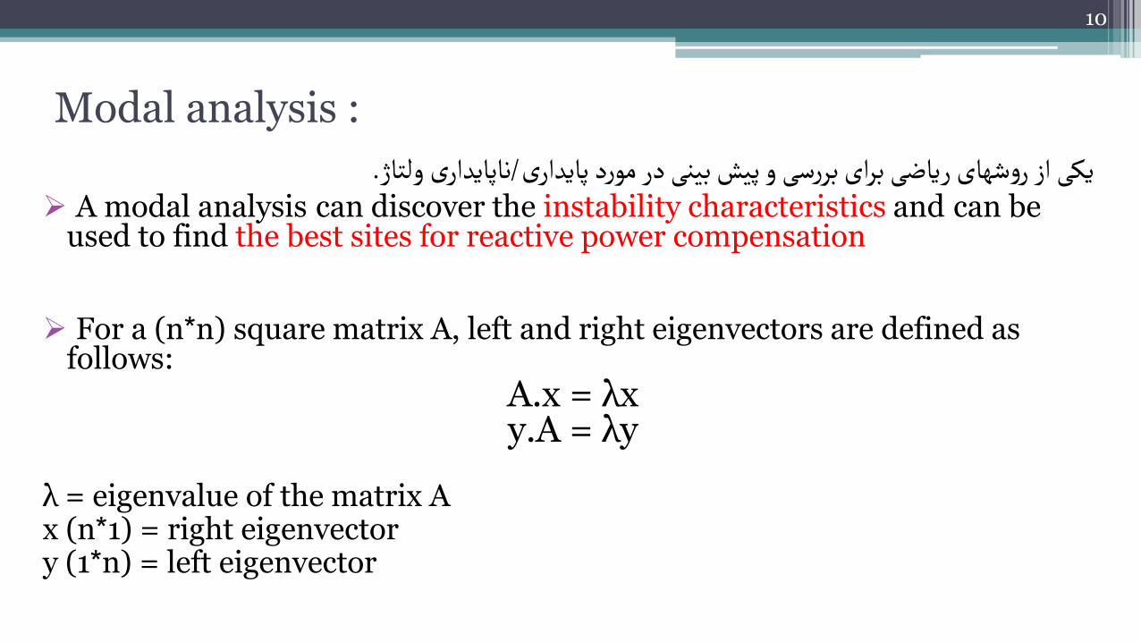
Modal analysis :
.ناپایداری ولتاژ/یکی از روشهای ریاضی برای بررسی و پیش بینی در مورد پایداری A modal analysis can discover the instability characteristics and can be
used to find the best sites for reactive power compensation
For a (n*n) square matrix A, left and right eigenvectors are defined as follows:
A.x = λx y.A = λy
λ = eigenvalue of the matrix Ax (n*1) = right eigenvectory (1*n) = left eigenvector
10
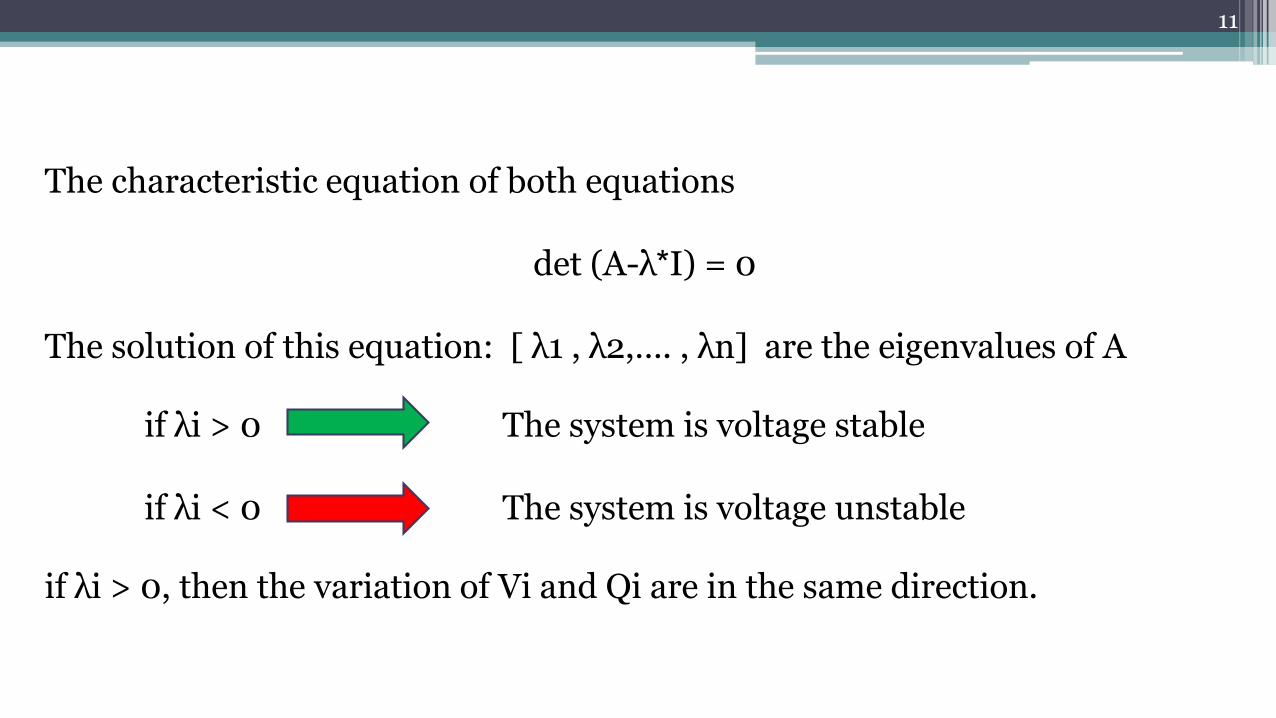
The characteristic equation of both equations
det (A-λ*I) = 0
The solution of this equation: [ λ1 , λ2,…. , λn] are the eigenvalues of A
if λi > 0 The system is voltage stable
if λi < 0 The system is voltage unstable
if λi > 0, then the variation of Vi and Qi are in the same direction.
11
Continuous Power-Flow ( CPF ( Methodology
VSM : Voltage Security Margin
The higher the VSM ,the more secure the system
Near the voltage collapse point It is difficult to obtain a power flow solution
Continuation power flow is a technique by which the power flow solutions can be obtained near or at the voltage collapse point
According to the proposed algorithm, a CPF is executed on the system under study
In this step we use CPF to identify the most sensitive bus to voltage collapse.
12
DG Placement Algorithm
DG Placement Process
DG Placement Evaluation Indices
13

DG Placement Process
The DG placement problem can be formulated by many objectiveFunctions including
Loss Minimization Voltage Profile Improvement Economical Revenue Environmental Impact Reduction Improvement On Reliability Aspects
Voltage security margin enhancement and loss reduction
14

the modal analysis is used concurrently to determine the critical modes and their associated buses.
The CPF can be used for the determination of
the VSM and the bus voltages at collapse points.
15
bus with a minimum voltage at the collapse point is defined as the most sensitive bus to voltage collapse.
This bus is selected as a candidate for DG placement.
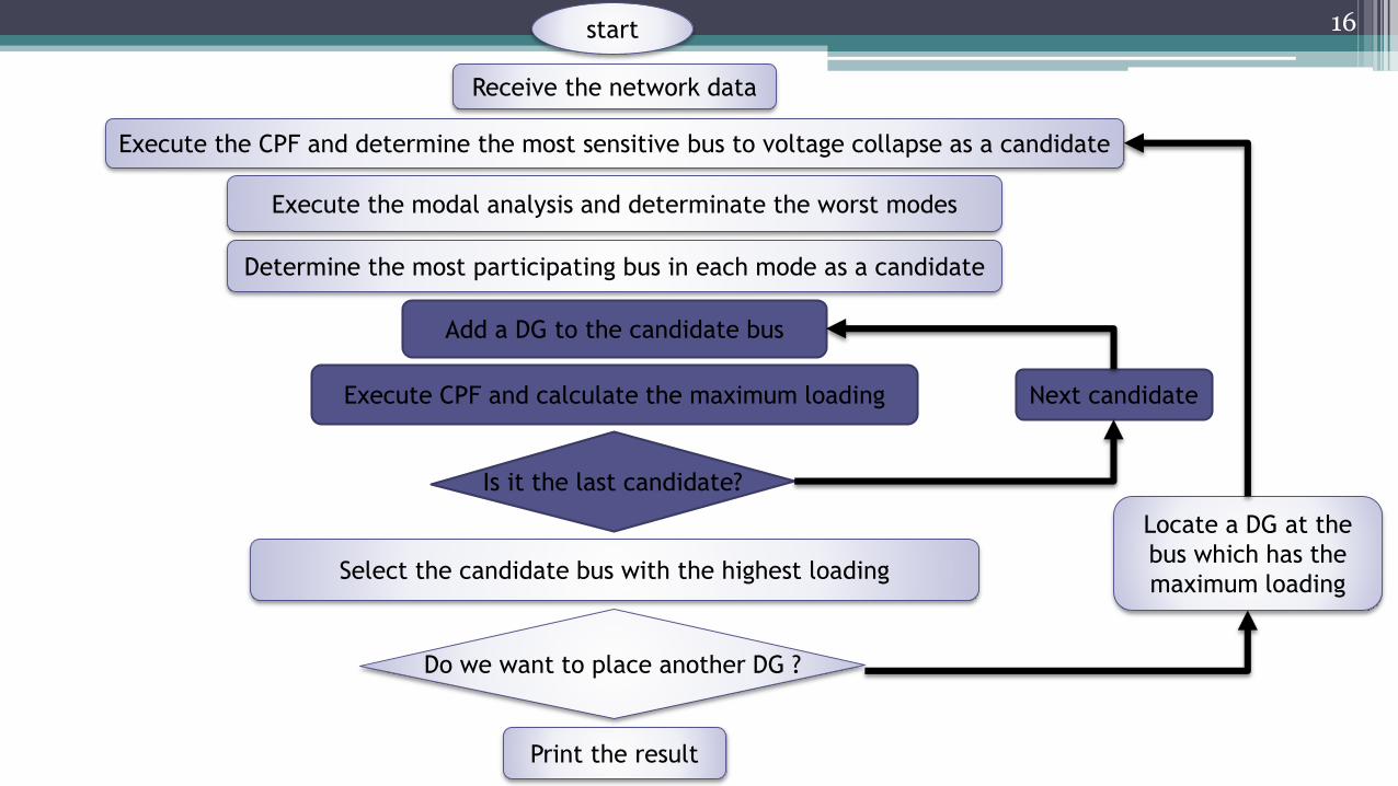
16start
Receive the network data
Execute the CPF and determine the most sensitive bus to voltage collapse as a candidate
Execute the modal analysis and determinate the worst modes
Determine the most participating bus in each mode as a candidate
Add a DG to the candidate bus
Execute CPF and calculate the maximum loading
Is it the last candidate?
Next candidate
Select the candidate bus with the highest loading
Do we want to place another DG ?
Print the result
Locate a DG at the
bus which has the
maximum loading
16

DG Placement Evaluation Indices
17
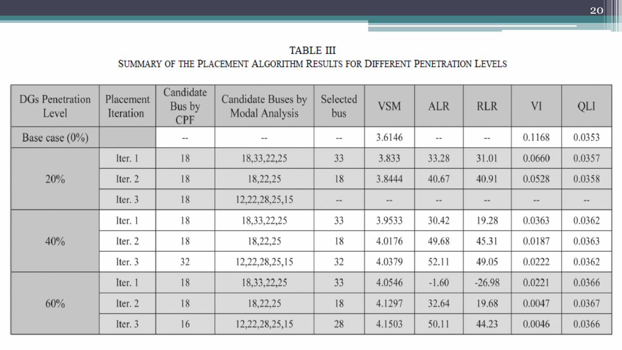
The higher the VSM, the more secure the system.
ALR and RLR show active and reactive loss
reduction after installing DG/DGs.
Higher values of and indicate better performance
of ALR and RLR DGs in loss reduction.
The lower the VI, the better the performance of
DG units.
• Application of the Placement Algorithm
CASE STUDY
18
19
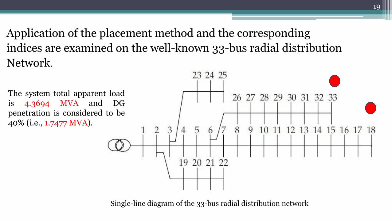
Application of the placement method and the corresponding
indices are examined on the well-known 33-bus radial distribution
Network.
Single-line diagram of the 33-bus radial distribution network
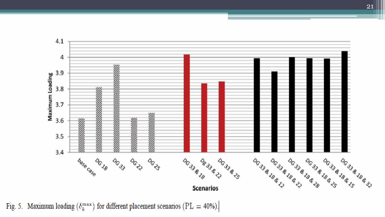
The system total apparent loadis 4.3694 MVA and DGpenetration is considered to be40% (i.e., 1.7477 MVA).
20
21

22

I. Voltage Stability-Based DG Placement in Distribution Networks
M. Ettehadi , H. Ghasemi , S. Vaez-Zadeh : Electr. & Comput. Eng., Univ. of Tehran, IEEE Power & Energy
society 2013
II. Voltage Stability Evaluation of The Khuzestan Power System in Iran Using CPF Method and Modal Analysis(2010)
Farbod Larki-Ahvaz, Iran ; Mahmood Joorabian-Ahvaz, Iran ; Homayoun Meshgin Kelk, Mojtaba Pishvaei-
Tafresh, Iran
III. Notes on Power System Voltage Stability By S. Chakrabarti, Dept. of EE, IIT, Kanpur
Refrences
23
I Really Appreciate Your Concern.
24