Sudan University of Science and Technology
College of Engineering
Electronics Engineering
DIAGNOSIS OF COMPUTER FAULTS BASED
ON EXPERT SYSTEM
A Research Submitted in Partial fulfillment for the Requirements
of the
Degree of B.Eng. (Honors) in Electronics Engineering
Prepared By:
1. Israa Kamal Al-Khalil Qurashi
2. Mohammed Abd-Allah Ibrahim Salih
3. Osama Taher Abd El-Roaf Hussain
4. Renad Ibrahim El-Hassan Ibrahim
Supervised By:
Dr. Yassir Ebied Mohammed
October 2017

I
استهالل
بسم اهلل الرحمن الرحيم
ىنمن خن حن جن يم ىم مم خم حم جميل ىل مل خل ٹٱٹٱٱ
يه ىه مه جه ين
١١٤طه:
.لييفقهوا قو * واحلل عقدة من لساني * ويسر لي أمري * صدريرب اشرح لي

II
DEDICATION
We dedicate this work to our supported parents and friends, which stand up
for us at the hardest times, supported and believed in us till we reached this
level.

III
ACKNOWLEDGEMENT
The completion of this project could not have been possible without
participation and assistance of so many people whose names may not all be
enumerated. However the group would like to express their deep appreciation
and indebtedness particularly to the following:
DR. Yassir Ebied Mohammed for his endless support kind and
understanding spirit.
To all relatives, friends, and others who in one way and another share
their support, either morally, financially or physically. Thank you.
IV
ABSTRACT
Different hardware system or electronics devices usually face application
fault as well as hardware fault. Expert system technology is used to introduce
a decision support system to enable normal users or technicians to diagnose
computer hardware failure. In this research work has been developed an
automated motherboard hardware failure diagnosis by just knowing
symptoms showed up from the problem. The system uses remote database
that can be shared by multiple users, and the ability to increase performance
over time by adjusting priority of rules. Data is mainly collected from
computer technicians and encoded into if-then rules, then forward chaining
inference technique developed using MATLAB. Finally developed a user
interface that take user selection and display diagnosis conclusion. Extensive
examination of the developed system has proved that our expert system
delivers the right conclusion unless it is not found in system database.

V
المستخلص
األجهزة المختلفة أو األجهزة اإللكترونية عادة ما تواجه اعطال في البرمجيات و كذلك اعطال في
مكونات الدائره. تستخدم تكنولوجيا النظام الخبيرإلنتاج نظام دعم القرارات لتمكين المستخدمين
ظام ألي يقوم ي قمنا بتطوير نالعاديين أو الفنيين لتشخيص فشل أجهزة الكمبيوتر. في هذا العمل البحث
بتشخيص مشاكل اللوحه االم لجهاز الكمبيوترعن طريق معرفة فقط أعراض ظهرت من المشكلة.
يستخدم النظام قاعدة بيانات يمكن الوصول لها عن بعد يمكن مشاركتها من قبل مستخدمين متعددين،
القواعد. تم جمع البيانات بشكل رئيسيوالقدرة على زيادة األداء بمرور الوقت من خالل تعديل أولوية
، ثم تم بناء داله االستنتاج المعروفه ((if-then rules من فنيي الكمبيوتر وتشفيرها في شكل قواعد
بأستخدام الماتالب . وأخيرا قمنا ببناء واجهة المستخدم التي تأخذ forward chaining)) بتقنيه
د أثبت الفحص الشامل للنظام أن النظام الخبير لدينا اختيار المستخدم وعرض خالصه التشخيص. وق
.سيعطي االستنتاج الصحيح ما لم يكن موجودا في قاعدة بيانات النظام
VI
TABLE OF CONTENTS
CHAPTER TITLE PAGE
DEDICATION II
ACKNOWLEDGEMENT III
ABSTRACT IV
V المستخلص
TABLE OF CONTENTS VI
LIST OF TABLES IX
LIST OF FIGURES X
1 Introduction 1
1.1 Preface 2
1.2 Problem Statement 3
1.3 Proposed Solution 3
1.4 Approach 4
1.5 Thesis Outline 4
2 Literature review, related work 5
2.1 Related work 6
VII
CHAPTER TITLE PAGE
3 System Description 10
3.1 Introduction 11
3.2 Steps of designing expert system 11
3.3 Rule-based expert systems 14
3.4 Types of inferring techniques 15
3.4.1 Forward Chaining 15
3.4.2 Backward Chaining 16
3.5 Learning Techniques 16
3.6 System Principles 17
3.7 The Problem Area of Motherboard Diagnosis 18
3.7.1 Motherboard System 19
3.7.2 POST test 19
3.8 Background and History 20
3.8.1 Dendral 23
3.8.2 CLIPS 23
3.9 Advantages of expert systems 24
4 System development and design 26
4.1 Introduction 27
4.2 System use case scenarios 27
4.3 Problems faced 32
4.4 System characteristics 34
VIII
CHAPTER TITLE PAGE
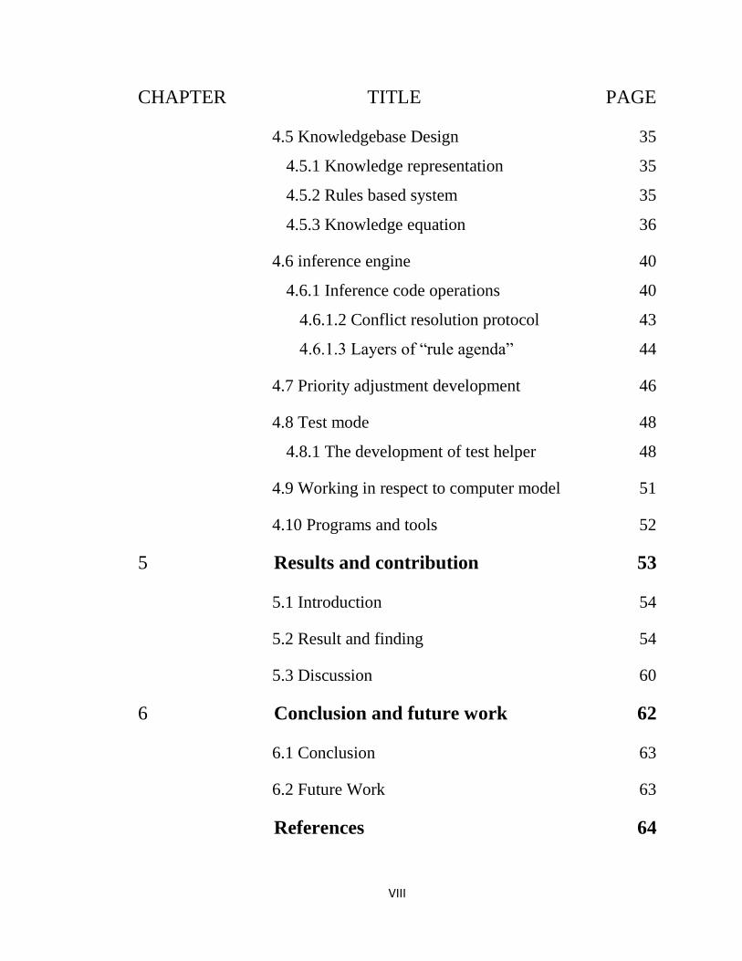
4.5 Knowledgebase Design 35
4.5.1 Knowledge representation 35
4.5.2 Rules based system 35
4.5.3 Knowledge equation 36
4.6 inference engine 40
4.6.1 Inference code operations 40
4.6.1.2 Conflict resolution protocol 43
4.6.1.3 Layers of “rule agenda” 44
4.7 Priority adjustment development 46
4.8 Test mode 48
4.8.1 The development of test helper 48
4.9 Working in respect to computer model 51
4.10 Programs and tools 52
5 Results and contribution 53
5.1 Introduction 54
5.2 Result and finding 54
5.3 Discussion 60
6 Conclusion and future work 62
6.1 Conclusion 63
6.2 Future Work 63
References 64
IX
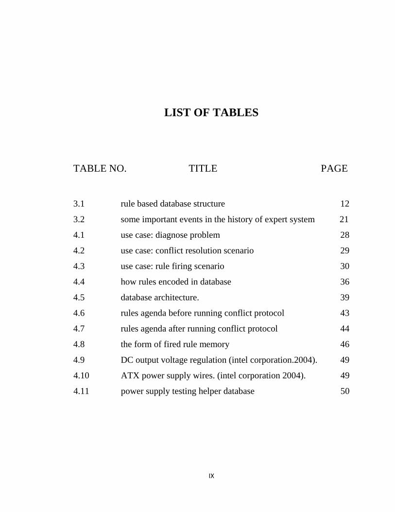
LIST OF TABLES
TABLE NO. TITLE PAGE
3.1 rule based database structure 12
3.2 some important events in the history of expert system 21
4.1 use case: diagnose problem 28
4.2 use case: conflict resolution scenario 29
4.3 use case: rule firing scenario 30
4.4 how rules encoded in database 36
4.5 database architecture. 39
4.6 rules agenda before running conflict protocol 43
4.7 rules agenda after running conflict protocol 44
4.8 the form of fired rule memory 46
4.9 DC output voltage regulation (intel corporation.2004). 49
4.10 ATX power supply wires. (intel corporation 2004). 49
4.11 power supply testing helper database 50
X
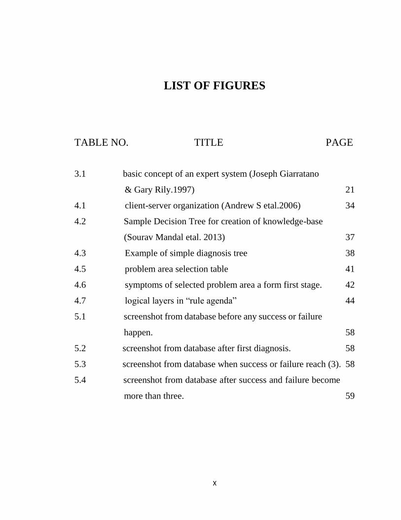
LIST OF FIGURES
TABLE NO. TITLE PAGE
3.1 basic concept of an expert system (Joseph Giarratano ------- -
-- & Gary Rily.1997) 21
4.1 client-server organization (Andrew S etal.2006) 34
4.2 Sample Decision Tree for creation of knowledge-base ---------
------- (Sourav Mandal etal. 2013) 37
4.3 Example of simple diagnosis tree 38
4.5 problem area selection table 41
4.6 symptoms of selected problem area a form first stage. 42
4.7 logical layers in “rule agenda” 44
5.1 screenshot from database before any success or failure -
---- happen. 58
5.2 screenshot from database after first diagnosis. 58
5.3 screenshot from database when success or failure reach (3). 58
5.4 screenshot from database after success and failure become - --
- more than three. 59

Chapter one
Introduction
Chapter one introduction
2
1.1 Preface
An Expert system is a computer system that emulates the decision
making ability of a human expert. [1]
Different hardware system or electronics devices usually face
application fault as well as hardware fault. Computer failure diagnosis is a
time consuming and costly task to do manually. The expert intelligent system
is introduced to develop hardware failure diagnosis for any computer system
using a rule based expert system and self-learning techniques and support
human technicians to diagnose motherboard hardware failure. As future
work, the proposed system is to be integrate with other sensing hardware to
be more automated. This project focus on motherboard hardware problems
and hardware failure diagnosis.
Parts of Expert System:
The following are main parts that constitute an expert system:
Database or knowledge-base (rule based).
Inference engine (forwards changing).
User interface (give user an ability to interact with the system).
Benefits of Expert System:
Ideally, people would need to have immediate contact with human
experts in every area of specialty that they might need, 24 hours a day. But
this can’t happen. Experts are scarce, busy and often difficult to reach, and
many decisions can’t wait for access to an expert. Knowledge Automation
systems provide a very effective and efficient way to provide prospects,
customers, employees and even advisors themselves with a way to have
access to top-level expert decision-making knowledge and advice for specific
problems.[2]
Chapter one introduction
3
The way a Knowledge Automation System Delivers Expert Advice:
When developing a system, the decision-making knowledge and procedures
of a human expert are converted to “rules”, a form of logical representation
that the computer can process. The rules are analyzed by the expert system
Inference Engine, which determines how to use them to perform a desired
action or reach a specific goal. [2]
The Inference Engine provides the “brains” that will determine what rules
to use, and how to use them. Since all decisions are based on a logical and
consistent use of precise rules, the system can logically explain the basis for
its conclusions, and provide consistent advice
The Inference Engine determines:
What possible answers there are to the problem?
What data is needed to determine if a particular answer is appropriate?
If there is a way to derive or calculate the needed data from other rules.
When enough data is available to eliminate a possible answer, and stop
asking unnecessary Questions related to it.
How to differentiate between remaining answers.
1.2 Problem Statement
Computer failure diagnosis is a time consuming and costly task to do
manually.
1.3 Proposed Solution
Development and use of expert system to take the job of diagnosis.
Chapter one introduction
4
1.4 Approach
1. After collecting enough knowledge start a small prototype of the main
software (inference engine, learning engine, and choose a suitable
reasoning mechanism) with a small database to test functionality and
make proposed changes.
2. Start collecting data to fill database and start training the system.
3. Developing test helper to help user test his/her component.
4. Developing a learning mechanism to increase system performance
over time.
5. Develop user interface.
1.5 Thesis Outline
Chapter 1: States research problem and proposed solution along with
the work approach and outlines.
Chapter 2: Literature review collecting enough knowledge to build
the first software prototype.
Chapter 3: General description of these types of systems.
Chapter 4: Methodology and our system description, design and
development.
Chapter 5: Conclusion and future work recommendation.

Chapter 2
Literature review, related work
Chapter two Literature review, related work
6
2.1 Related work
Sourav Mandal etal. (2013) DIAGNOSIS AND
TROUBLESHOOTING OF COMPUTER FAULTS the author stated “this
paper emphasizes an automated system that accepts the defects of any system
and then after consulting with an intelligent database, diagnoses and advises
for probable rectification. Implemented by Turbo Prolog programming
language and SQL database server. The proposed Computer Fault
Troubleshooter is a rule-based expert system and forward chaining for
inference engine. The system ask the user about problem by Interviews the
user and get fact about the problem in hand. The system also explains its
reasoning. [3]
Amanuel Ayde Ergado (2016) “Domain knowledge was acquired
using semi structured interview technique, observation and document
analysis.” the expert system was developed by using ‘if – then’ rules. The
developed system used backward chaining to infer the rules and provide
appropriate recommendations. The system learns new cases of the problem
and provides support for decision making. Implemented using “Three
languages, OPS5, SRL, and PROLOG”
The knowledge’s of domain experts acquired through interview question and
Document analysis and observation was made when the technicians are
troubleshooting problems. [4]
Youssef Bassil (2012) developed an expert PC troubleshooter, by
using rule based techniques and fuzzy system to diagnose POST beeps errors,
he used forward chaining as inference engine in rule based database and an
intelligent agent which assist in self-learning and knowledge acquisition,”

Chapter two Literature review, related work
7
The Expert PC Troubleshooter is implemented using ASP.NET 4.0 and
C#.NET 4.0 under the MS.NET Framework 4.0 and MS Visual Studio 2010.
The rule-base is implemented as a relational database using MS Office
Access 2010”. [5]
Advantages of this system is that it’s the self-learning agent that keep the
database up to date, Disadvantages of This system is it have a mic to hear and
diagnose the beep errors, but beeps error are different from one device
manufacture to other. No clearly way defined to make this distinguish
between beeps for every computer manufacture.
Amir HosseinKafi etal. (2016) build a fuzzy expert system by using
MATLAB FIS tool for real state recommendation the author stated that “to
develop a knowledge-based system, it is too difficult to elicit and integrate
knowledge from multiple experts”, so he used fuzzy Delphi Method.
Also he stated that there is no need to increase the number of rules in the
system the rule with the highest degree of importance must be selected for
the speed and accuracy of fuzzy expert system [6]
Sylvester I. Ele and Adesola, W.A (2013) Computer Fault Diagnosis
and Troubleshooting System (CFDTS) this system is built for personal
computer to help normal user to diagnose and fix their problems also assist
PC technicians in accurate diagnosis of PC fault by providing a systematic
and step-wise analysis of failure, possible cause(s) of the failure and offer
maintenance recommendations, the system designed using rule based
approach and MySQL database tool and NetBeans, Java Language for expert
system shell the author stated that “Troubleshooting and diagnosing a
computer system is a knowledge-intensive task.” [7]
Chapter two Literature review, related work
8
Abdullah Saad AlMalaise Al Ghamdi etal. (2013) built a simple
expert system provides troubleshooting procedures on how to diagnose
hardware problems in CPU, Motherboard and RAM. The system was built
using CLIPS programming language using rule based approach. The author
stated “our goal from building this simple expert system is to help computer
users to fix some basic hardware issues or even to perform more extensive
troubleshooting”
The weakness of this system is that the architecture of the system
doesn’t support a quick learning to system because it works in personal
computer and the author didn’t make a way to share information between
similar systems. [8]
The author advised to “create friendly interfaces and connecting
various expert system codes together”. In addition, it is also recommended to
make the system solve more hardware features, or even expand it to solve
software problems and show the relationship between the failure that had
occurred in both hardware and software. Another thing that can be done in
future is “deploying such a program online to rise the usability of the system
and provide facilities for users.”
Mazlina Md Mustaffa etal. (2014) this system haven’t been placed
into working prototype but it discussed a way to reduce computer faults
diagnosis time by decreasing the problem area into symptoms and facts, the
system will display the possible causes and suggest a solution. The rules of
the proposed expert system are in the form of if-then statements. The rule-
based system itself uses a simple technique and it starts with a rule-based,
which contains all of the appropriate knowledge encoded into If-Then rules.
Categories of rule in this system are an audio, Hard Disk, keyboard, mouse,
Chapter two Literature review, related work
9
power supply, processor, start up, Serial ATA, USB device, printer,
motherboard, CPU, RAM, peripheral, BIOS, Video Monitor and adapter,
DVD drive and DVD/CD recording. The author stated that “Computer
technicians do not need to check every part of the computer hardware to
diagnose computer hardware failure, but the users or technicians need only
to key in the name of the hardware in problem along with its symptoms or
facts into the system.” This system used this approach to decrease the
problem area
For future work the author advised to enhance this system to solve
more hardware problems and deploy it in internet to rise the systems
usability. [9]
In general the weakness of most expert systems is the lack of learning
techniques to update its own rules or the knowledge database is stored in local
device (the knowledge database is not sheared). Shared database makes the
system’s diagnosis very powerful because the system under consideration
will work in multiple problems in the same time and will learn and update a
common database upon it; this speeds the learning and fortunately the speed
the system reaches the right conclusion.
Secondly in the field of motherboard diagnosis in some cases the
expert need to test circuit component that he guesses it is miss functioning or
not functioning at all, so a hardware “test helper” will help user to test the
component that expert system may think it is the cause of the problem.
Chapter 3
System Description
Chapter three System Description
11
3.1 Introduction
An Expert system is a computer system that emulates the decision
making ability of a human expert. Different hardware system or electronics
devices usually face application fault as well as hardware faults. [3]
Depending on the experience of the technician, a simple problem could
take hours or even days to solve. So the specific task of an Expert System is
to be an alternative source of decision-making ability for organization to use
instead of relying on the expert knowledge or skill of few people or just one
person. [9]
3.2 Steps of designing expert system
Following steps are essential and necessary to develop an expert system, this
work follow them in different stages of system development as detailed here:
1) Define problem area: in this project the problem area is defined as
diagnosis of PC motherboard hardware faults or failure.
2) Choose and Design of knowledge base: the design of knowledge base
reflect how your expert system deal with information and facts and
how inference engine deal with facts and the techniques the system
uses to learn; after that the knowledge engineer can encode its
knowledge to this database.
In our project the rule based representation approach and MySQL
database server that have a remote access in the internet is used for a
number of benefits, first the rule based representation is simple and
human readable format that can be easily checked and corrected by
experts. Second in rule based approach it is too easy to implement an
explanation facility in forward chaining inference technique [11].
Third the rule base appears most suitable to diagnose problem using
Chapter three System Description
12
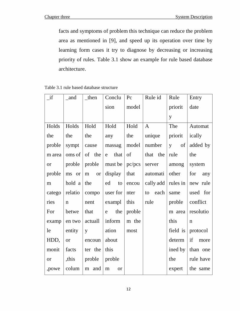
facts and symptoms of problem this technique can reduce the problem
area as mentioned in [9], and speed up its operation over time by
learning form cases it try to diagnose by decreasing or increasing
priority of rules. Table 3.1 show an example for rule based database
architecture.
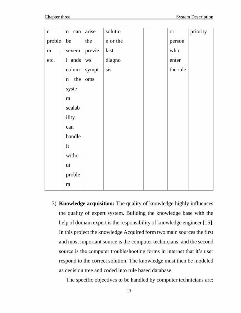
Table 3.1 rule based database structure
_if _and _then Conclu
sion
Pc
model
Rule id Rule
priorit
y
Entry
date
Holds
the
proble
m area
or
proble
m
catego
ries
For
examp
le
HDD,
monit
or
,powe
Holds
the
sympt
oms of
proble
ms or
hold a
relatio
n
betwe
en two
entity
or
facts
,this
colum
Hold
the
cause
of the
proble
m or
the
compo
nent
that
actuall
y
encoun
ter the
proble
m and
Hold
any
massag
e that
must be
display
ed to
user for
exampl
e the
inform
ation
about
this
proble
m or
Hold
the
model
of
pc/pcs
that
encou
nter
this
proble
m the
most
A
unique
number
that the
server
automati
cally add
to each
rule
The
priorit
y of
rule
among
other
rules in
same
proble
m area
this
field is
determ
ined by
the
expert
Automat
ically
added by
the
system
for any
new rule
used for
conflict
resolutio
n
protocol
if more
than one
rule have
the same
Chapter three System Description
13
r
proble
m ,
etc.
n can
be
severa
l ands
colum
n the
syste
m
scalab
ility
can
handle
it
witho
ut
proble
m
arise
the
previe
ws
sympt
oms
solutio
n or the
last
diagno
sis
or
person
who
enter
the rule
priority
3) Knowledge acquisition: The quality of knowledge highly influences
the quality of expert system. Building the knowledge base with the
help of domain expert is the responsibility of knowledge engineer [15].
In this project the knowledge Acquired form two main sources the first
and most important source is the computer technicians, and the second
source is the computer troubleshooting forms in internet that it’s user
respond to the correct solution. The knowledge must then be modeled
as decision tree and coded into rule based database.
The specific objectives to be handled by computer technicians are:
Chapter three System Description
14
to examine the situation base on the user’s input to the system, identify
the problem and provide a systematic and step-by-step analysis of the
causes of the problems, as well as provide maintenance recommendations
to users, and also guide them on how to get help from a more technical
expert in situations which are less clear. [7]
4) Designing the inference engine: the reasoning mechanism, in which
the system reason form given facts or ask for facts. Forward chaining
is used for this project for this reasons: first when a problem arise in
computer there is no known cause that must be verified or not there is
a various faults that can cause this problem or symptoms so the system
doesn’t know where to start in the first place. Second the operation of
forward chaining doesn’t leave rule in knowledge base without
examining it against user or sensors supported facts. Backward
chaining is not used in this project.
In respect to specific computer model: The rule that belong to this
problem area that have this computer model registered will be explored
by the system first for the reason of speeding operation.
3.3 Rule-based expert systems
One of the approaches used in knowledge based reasoning technique
is rule based reasoning (RBR) approach which is a system whose knowledge
representation involves a set of conditions [4]. Symbol dependent rules are
the most known reasoning methods and this popularity is mainly due to their
naturalness, which facilitates comprehension of the represented knowledge.
The basic forms of a rule, if <condition> then <conclusion> where
<condition> represents Premises and <conclusion> represents associated
action for the premises. The conditional Statements of the reasoning rules are
Chapter three System Description
15
linked with each other by using logical operators to generate Logical
functionalities. When sufficient conditions of a rule are satisfied, then the
conclusion is derived and the rule is said to be fired. Rule based reasoning
was dominantly applied to represent general knowledge. Rule based expert
systems have a significant role in many different domain areas such as
computer maintenance, medical diagnosis, electronic troubleshooting and
data interpretations. A typical rule based system consists of a list of rules, a
cluster of facts and an interpreter [4].
Rules: the rules in the knowledge base are representing what should
be done and what should not be done while some conditions are fulfilled. In
the same way, the knowledge acquired from domain experts stored in the
knowledge base as rules [4]. Rules can represent relations, recommendations,
strategies.
Why rule based representation: Because it simply service the project goals
and the most suitable representation to diagnose using symptoms of
problems.
3.4 Types of inferring techniques
Inference is the means by which we reason from given knowledge [10].
In rules based expert system inferring carried out by two popular used
reasoning techniques forward and backward chaining.
3.4.1 Forward Chaining:
Forward chaining looks at the IF part of a rule first. Once all of the
conditions are, met then the appropriate rule is chosen.
The forward-chaining algorithm is used which starts by questioning
the user who does not know anything about the solution, and investigates
progressively to reach the diagnosis results and propose some reasonable
Chapter three System Description
16
solutions.
Below is the pseudo-code of the forward-chaining algorithm used by
the inference engine of the proposed Expert PC Troubleshooter. [5]
Step 1: Read initial facts and store them into working memory.
Step 2: Check the condition part (left side) of every production rule in the
rule-base.
Step 3: If all the conditions are matched, fire the rule (execute the right side).
Step 4: If more facts are present, do the following:
Step 5: Read next fact and update working memory with the new facts.
Step 6: Go to step 2
Step 7: If more than one rule is selected, use the conflict resolution strategy
to select the most appropriate Rules and go to step 4.
Step 6: Continue until all facts are exhausted. [5]
3.4.2 Backward Chaining
Backward chaining starts with the conclusion, then identifies the IF
[5]. In this project Backward chaining is not used. Because forward chaining
is enough in this problem area.
3.5 Learning Techniques
Computer fault diagnosis is not a rigid problem that doesn’t change
with time.
The human expert can update his/her knowledge to accomplish knew tasks
and make a faster diagnosis from his/her past experience, so the expert system
needs a learning techniques to be able to act as automatic PC diagnosis and
speed or update its diagnosis over time.
Techniques used in our work to adjust the priority of rules are:
Chapter three System Description
17
First learn by increasing/decreasing rule priority (to be detailed further
in next chapters).
Second keep rules under analysis for expert review, the expert system
rules can face four situations:
1. The rule never entered the system agenda (this mean this rule is not
entered in a good format or doesn’t represent the problem area in a good
way).
2. The rule/rules entered the agenda but never been fired by the system (this
mean may be the rule/rules is not necessary
3. The rule/rules entered the agenda and fired but never gives the right
diagnosis or solution (this situation means may be the rule is incorrect or
miss formatted).
4. The rule/rules enters system agenda and often gives the right diagnosis
but its priority is low (in this case the rule priority must be increased).
(This technique is to be detailed in chapter 4).
3.6 System Principles
As same as all real word problems there is a symptoms that arise with
any problem area or failure, the human expert can distinguishes between this
symptoms based on his expertise in the field of problem area. As well as the
rule based system can benefit from this feature to distinguish between this
symptoms using diagnosis rules that state PROBLEM AREA – SYMPTOMS
- PROBLEM CAUSE by using simple IF-THEN rules.
The system goal is not to replace human techniques but it’s a step
towards automation of hardware problems diagnoses.

Chapter three System Description
18
Arie Ben-David, Leon Sterling (2006) found that the simpler decision
rules are more accurate and suitable for most human decision making
problems and stated that “it is pointless to allow decision trees or rule bases
to grow beyond an order of magnitude of ten branches or rules.”[16]. the
accuracy and quality of rules is more important than the number of rules.
The system is aided by a hardware test helper that can help user to test
his component. (To be detailed in chapter 4).
3.7 The Problem Area of Motherboard Diagnosis
The troubleshooting of motherboard is not an exact science, so there is
a need for expertise person to deal with it. The basic idea is that the computer
technician know the normal operation of the circuit under diagnosis and the
pattern of symptoms that show up with a specific problem/problems as stated
in [9].
What if the computer technician doesn’t know the problem from it’s
symptoms or cannot be sure what has caused this symptoms, he will test the
electric circuit or test a couple of solution that he sees maybe the suitable fix
for the problem until the problem being fixed or can’t be fixed by this
technician. If the problem has been fixed after trying number of solutions the
solution that fixes the problem will be remembered by the technician and
whenever a similar problem arise the technician applies this solution first.
As stated in [8] most motherboard related failures are due to the
"Onboard" regulated supplies and component failure within those circuits.
The on-board power supply circuit had partially failed and was overloading
subsequent components else the problem would be with the capacitors which
are defective in the first place. A motherboard failure on a laptop that is out
of warranty would usually mean that it is time for a new laptop. The price of
Chapter three System Description
19
a new motherboard is usually higher than the current value of the laptop. Bad
RAM is somehow harder to diagnose as similar symptoms may be caused by
software problems, other hardware problems or even motherboard failure.
3.7.1 Motherboard System
They can be divided into two categories based on computer, which are:
Main component that the motherboard will not function or miss
function if it’s encounter a faulty hardware or software. Those are:
Capacitors or any component that effect the power, CPU, RAM, power
supply PSU, power regulator circuit components, ROM BIOS, north
bridge chipset.
Secondary component that will not block the motherboard from
functioning but will make the PC unstable or can’t be used at all. Those
are: Capacitors, HDD, CPU fan, monitor, all cables except PSU cables,
and Graphic card.
Fortunately the motherboard system is good on testing itself, and this
test are temperature sensors and POST (power-on-self-test)
3.7.2 POST test
The first thing that the BIOS does when it boots the PC is to perform
what is called the Power-On Self-Test, or POST for short. The POST is a
built-in diagnostic program that checks your hardware to ensure that
everything is present and functioning properly, before the BIOS begins the
actual boot. It later continues with additional tests (such as the memory test
that you see printed on the screen) as the boot process is proceeding.
Some POST errors are considered "fatal" while others are not. A fatal
error means that it will halt the boot process immediately (an example would
be if no system memory at all is found). In fact, most POST boot errors are
Chapter three System Description
20
fatal, since the POST is testing vital system components. [17]
The bios generate a beep post code to show the user what is going on, this
beeps can be encoded as rules, note that beeps code are different from each
device manufacture to another, so each beeps code in database can be
reserved to a specific computer model.
3.8 Background and History
Expert system is branch of AI that makes extensive use of specialized
knowledge to solve problems at the level of a human expert. An expert is a
person that can solve problems that most people cannot solve or can solve
them more efficiently (but not cheaply).The expert system technology may
include special language, programs, and hardware designed to aid the
development and execution of expert system. [11]
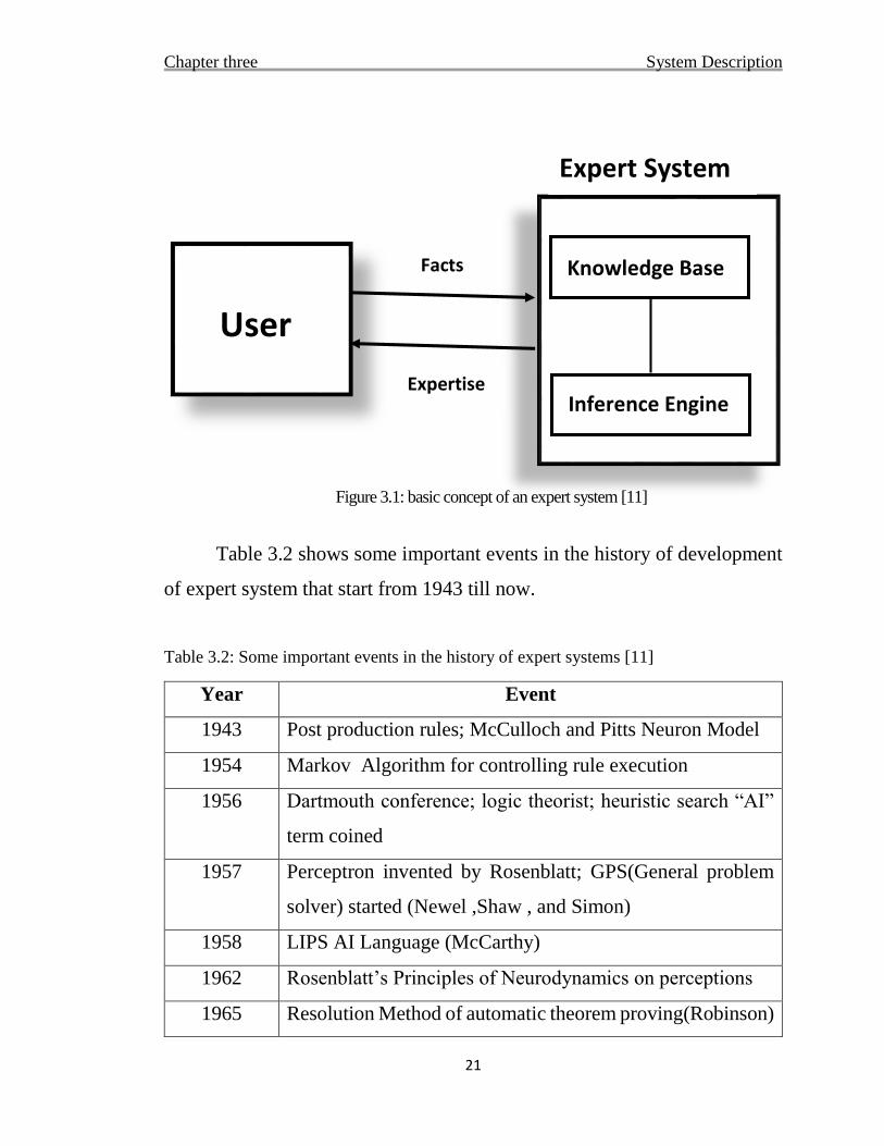
Figure 3.1 illustrates the basic concept of a knowledge-based expert
system. The user supplies facts or other information to the expert system and
receives expert advice or expertise in response. Internally, the expert system
consist of two main components. The knowledge base consist the knowledge
with which the inference engine draws conclusions. These conclusions are
the expert system’s responses to the user’s queries for expertise.
Chapter three System Description
21
Figure 3.1: basic concept of an expert system [11]
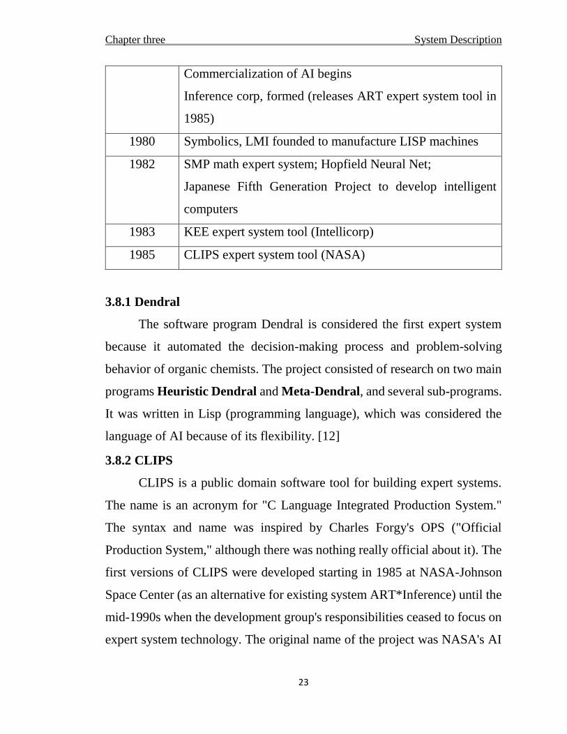
Table 3.2 shows some important events in the history of development
of expert system that start from 1943 till now.
Table 3.2: Some important events in the history of expert systems [11]
Year Event
1943 Post production rules; McCulloch and Pitts Neuron Model
1954 Markov Algorithm for controlling rule execution
1956 Dartmouth conference; logic theorist; heuristic search “AI”
term coined
1957 Perceptron invented by Rosenblatt; GPS(General problem
solver) started (Newel ,Shaw , and Simon)
1958 LIPS AI Language (McCarthy)
1962 Rosenblatt’s Principles of Neurodynamics on perceptions
1965 Resolution Method of automatic theorem proving(Robinson)
User
Knowledge Base
Inference Engine
Facts
Expertise
Expert System

Chapter three System Description
22
Fuzzy logic for reasoning about fuzzy objects(Zadeh)
Work begun on DENDRAL, the first expert
system(Feigenbaum, Buchanan, etal)
1968 Semantic nets, associative memory model (Quillian)
1969 MACSYMA math expert system (Martin and Moses)
1970 Work beings on PROLOG (Colmerauer, Roussel, etal)
1971 HEARSAY I for speech recognition
Human problem solving popularizes rules(Newel and
Simon)
1973 MYCIN expert system for medical diagnosis(Shortliiffe,
etal) leading to GUIDON, intelligent tutoring (Clancey)
TEIRESIAS, explanation facility concept (David) and
EMYCIN, first shell(Van Melle, Shortliffe, and Buchnan )
HEARSAY II, blackboard model of multiple cooperating
experts
1975 Frames, knowledge representation (Minsky)
1976 AM (Artificial Mathematician) creative discovery of math
concept’s (Lenar)
Dempster-Shefer Theory of Evidence for reasoning under
uncertainty
Work begun on PROSPECTOR expert system for mineral
exploration(Duda, Hart, etal)
1978 Work started on XCON/RI (McDcrmot, DEC) to configure
DEC computer systems
Meta-DENDRAL, metarules, and rule induction (Buchanan)
1979 Rete algorithm for fast pattern matching (Forgy)
Chapter three System Description
23
Commercialization of AI begins
Inference corp, formed (releases ART expert system tool in
1985)
1980 Symbolics, LMI founded to manufacture LISP machines
1982 SMP math expert system; Hopfield Neural Net;
Japanese Fifth Generation Project to develop intelligent
computers
1983 KEE expert system tool (Intellicorp)
1985 CLIPS expert system tool (NASA)
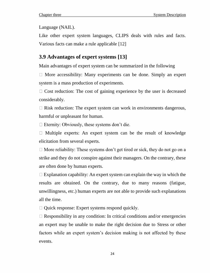
3.8.1 Dendral
The software program Dendral is considered the first expert system
because it automated the decision-making process and problem-solving
behavior of organic chemists. The project consisted of research on two main
programs Heuristic Dendral and Meta-Dendral, and several sub-programs.
It was written in Lisp (programming language), which was considered the
language of AI because of its flexibility. [12]
3.8.2 CLIPS
CLIPS is a public domain software tool for building expert systems.
The name is an acronym for "C Language Integrated Production System."
The syntax and name was inspired by Charles Forgy's OPS ("Official
Production System," although there was nothing really official about it). The
first versions of CLIPS were developed starting in 1985 at NASA-Johnson
Space Center (as an alternative for existing system ART*Inference) until the
mid-1990s when the development group's responsibilities ceased to focus on
expert system technology. The original name of the project was NASA's AI
Chapter three System Description
24
Language (NAIL).
Like other expert system languages, CLIPS deals with rules and facts.
Various facts can make a rule applicable [12]
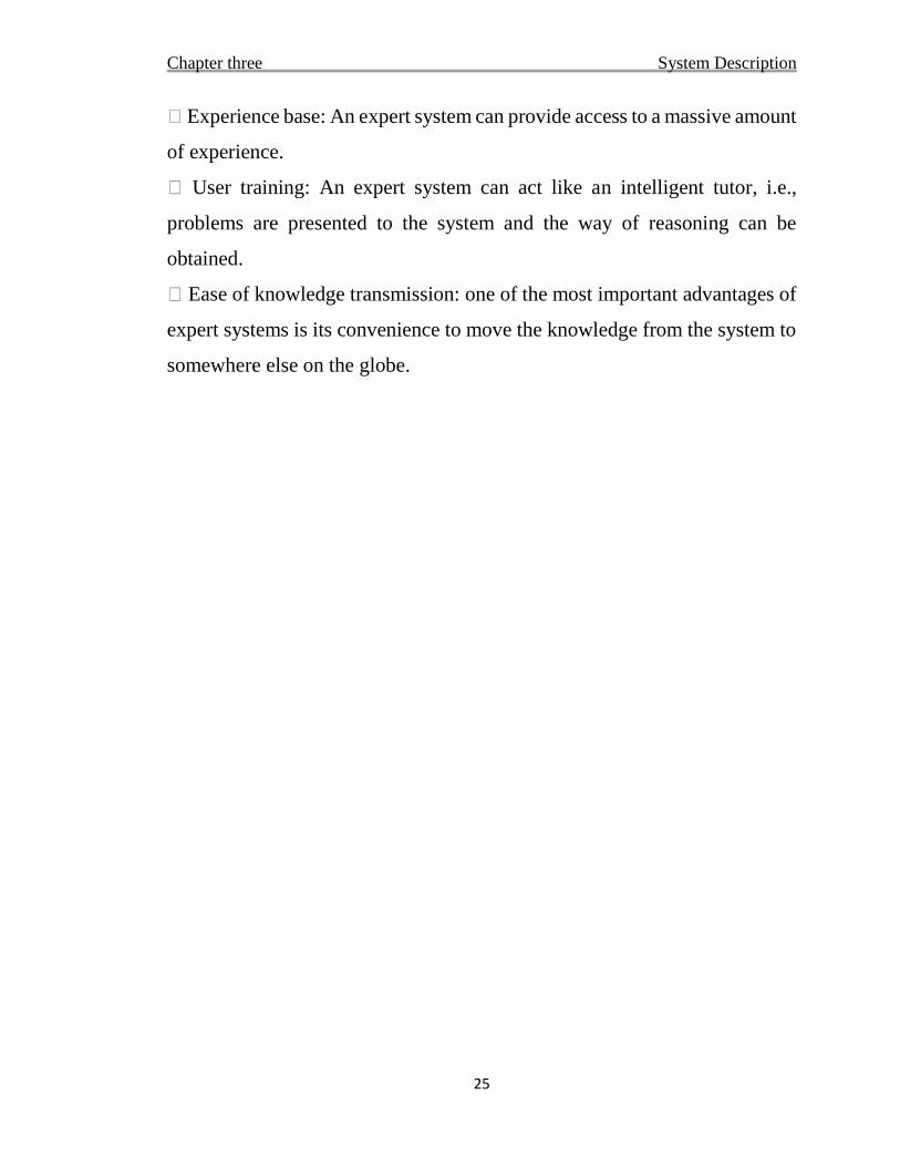
3.9 Advantages of expert systems [13]
Main advantages of expert system can be summarized in the following
� More accessibility: Many experiments can be done. Simply an expert
system is a mass production of experiments.
� Cost reduction: The cost of gaining experience by the user is decreased
considerably.
� Risk reduction: The expert system can work in environments dangerous,
harmful or unpleasant for human.
� Eternity: Obviously, these systems don’t die.
� Multiple experts: An expert system can be the result of knowledge
elicitation from several experts.
� More reliability: These systems don’t get tired or sick, they do not go on a
strike and they do not conspire against their managers. On the contrary, these
are often done by human experts.
� Explanation capability: An expert system can explain the way in which the
results are obtained. On the contrary, due to many reasons (fatigue,
unwillingness, etc.) human experts are not able to provide such explanations
all the time.
� Quick response: Expert systems respond quickly.
� Responsibility in any condition: In critical conditions and/or emergencies
an expert may be unable to make the right decision due to Stress or other
factors while an expert system’s decision making is not affected by these
events.
Chapter three System Description
25
� Experience base: An expert system can provide access to a massive amount
of experience.
� User training: An expert system can act like an intelligent tutor, i.e.,
problems are presented to the system and the way of reasoning can be
obtained.
� Ease of knowledge transmission: one of the most important advantages of
expert systems is its convenience to move the knowledge from the system to
somewhere else on the globe.

Chapter 4
System development and design
Chapter four System development and design
27
4.1 Introduction
The focus in the development of expert system is to acquire and
represent the knowledge and experience of a person(s) who have been
identified as possessing the special skill or mastery [18]. Also as was
mentioned expert system is the best solution to do the job of fast diagnosis
using only information about component encounter problem, and what
symptoms visible to user. Expert system components are knowledgebase,
inference engine and user interface where inference engine interact with the
user interface and the knowledge-base. The process of inference engine is
totally hidden from user.
In this chapter will be discussed and explain how has been developed
our expert system. Following the steps of designing mentioned in (chapter 3
section 3.2).
4.2 System use case scenarios
Scenario is “A narrative description of what people do and experience
as they try to make use of computer systems and applications” [M. Carrol,
Scenario-based Design, Wiley, 1995]. Scenario is an important aspect when
developing an application because it is useful in requirement elicitation in
first place and to reach the right design easily [19].
Chapter four System development and design
28
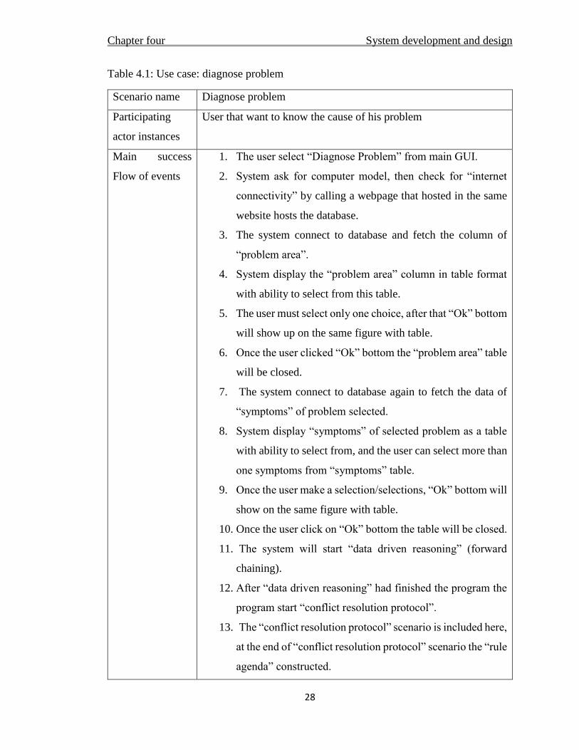
Table 4.1: Use case: diagnose problem
Scenario name Diagnose problem
Participating
actor instances
User that want to know the cause of his problem
Main success
Flow of events
1. The user select “Diagnose Problem” from main GUI.
2. System ask for computer model, then check for “internet
connectivity” by calling a webpage that hosted in the same
website hosts the database.
3. The system connect to database and fetch the column of
“problem area”.
4. System display the “problem area” column in table format
with ability to select from this table.
5. The user must select only one choice, after that “Ok” bottom
will show up on the same figure with table.
6. Once the user clicked “Ok” bottom the “problem area” table
will be closed.
7. The system connect to database again to fetch the data of
“symptoms” of problem selected.
8. System display “symptoms” of selected problem as a table
with ability to select from, and the user can select more than
one symptoms from “symptoms” table.
9. Once the user make a selection/selections, “Ok” bottom will
show on the same figure with table.
10. Once the user click on “Ok” bottom the table will be closed.
11. The system will start “data driven reasoning” (forward
chaining).
12. After “data driven reasoning” had finished the program the
program start “conflict resolution protocol”.
13. The “conflict resolution protocol” scenario is included here,
at the end of “conflict resolution protocol” scenario the “rule
agenda” constructed.
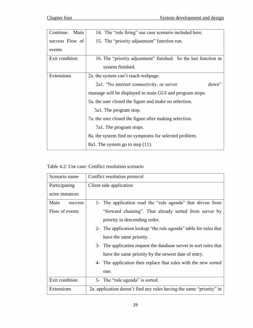
Chapter four System development and design
29
Continue. Main
success Flow of
events
14. The “rule firing” use case scenario included here.
15. The “priority adjustment” function run.
Exit condition 16. The “priority adjustment” finished. So the last function in
system finished.
Extensions 2a. the system can’t reach webpage.
2a1. “No internet connectivity, or server down”
massage will be displayed in main GUI and program stops.
5a. the user closed the figure and make no selection.
5a1. The program stop.
7a. the user closed the figure after making selection.
7a1. The program stops.
8a. the system find no symptoms for selected problem.
8a1. The system go to step (11).
Table 4.2: Use case: Conflict resolution scenario
Scenario name Conflict resolution protocol
Participating
actor instances
Client side application
Main success
Flow of events
1- The application read the “rule agenda” that driven from
“forward chaining”. That already sorted from server by
priority in descending order.
2- The application lookup “the rule agenda” table for rules that
have the same priority.
3- The application request the database server to sort rules that
have the same priority by the newest date of entry.
4- The application then replace that rules with the new sorted
one.
Exit condition 5- The “rule agenda” is sorted.
Extensions 2a. application doesn’t find any rules having the same “priority” in
Chapter four System development and design
30
“rule agenda”.
2a1. The “conflict resolution” stops.
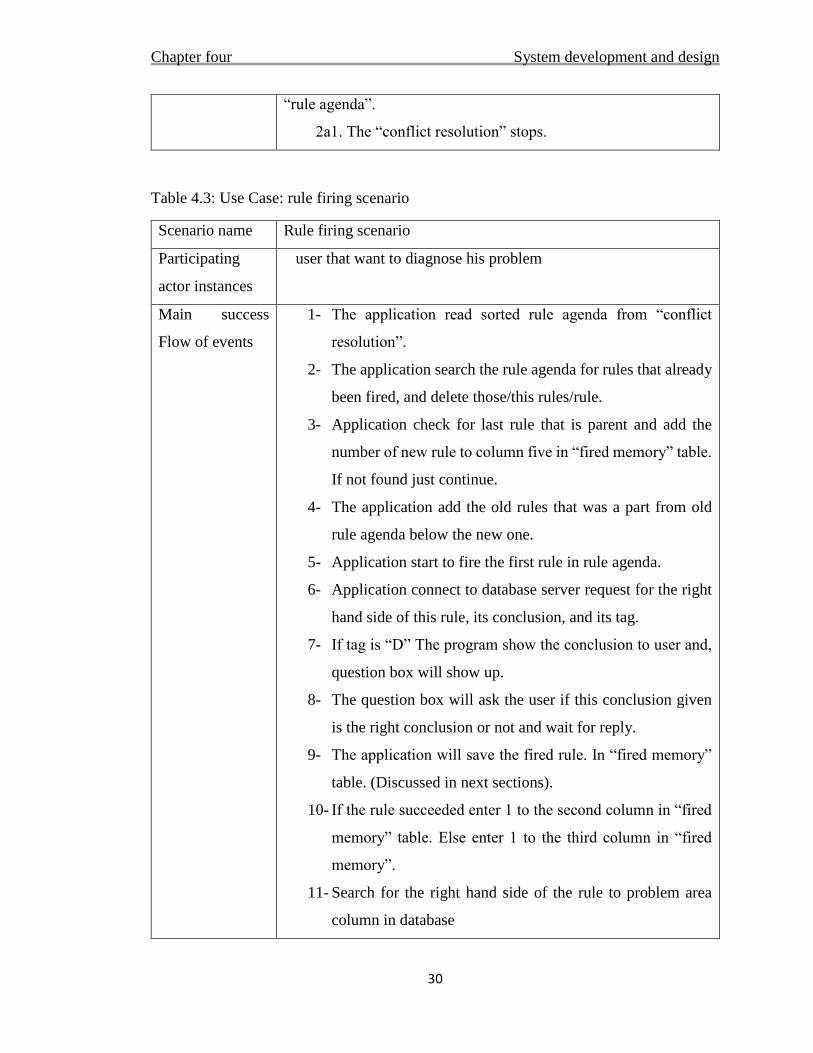
Table 4.3: Use Case: rule firing scenario
Scenario name Rule firing scenario
Participating
actor instances
user that want to diagnose his problem
Main success
Flow of events
1- The application read sorted rule agenda from “conflict
resolution”.
2- The application search the rule agenda for rules that already
been fired, and delete those/this rules/rule.
3- Application check for last rule that is parent and add the
number of new rule to column five in “fired memory” table.
If not found just continue.
4- The application add the old rules that was a part from old
rule agenda below the new one.
5- Application start to fire the first rule in rule agenda.
6- Application connect to database server request for the right
hand side of this rule, its conclusion, and its tag.
7- If tag is “D” The program show the conclusion to user and,
question box will show up.
8- The question box will ask the user if this conclusion given
is the right conclusion or not and wait for reply.
9- The application will save the fired rule. In “fired memory”
table. (Discussed in next sections).
10- If the rule succeeded enter 1 to the second column in “fired
memory” table. Else enter 1 to the third column in “fired
memory”.
11- Search for the right hand side of the rule to problem area
column in database
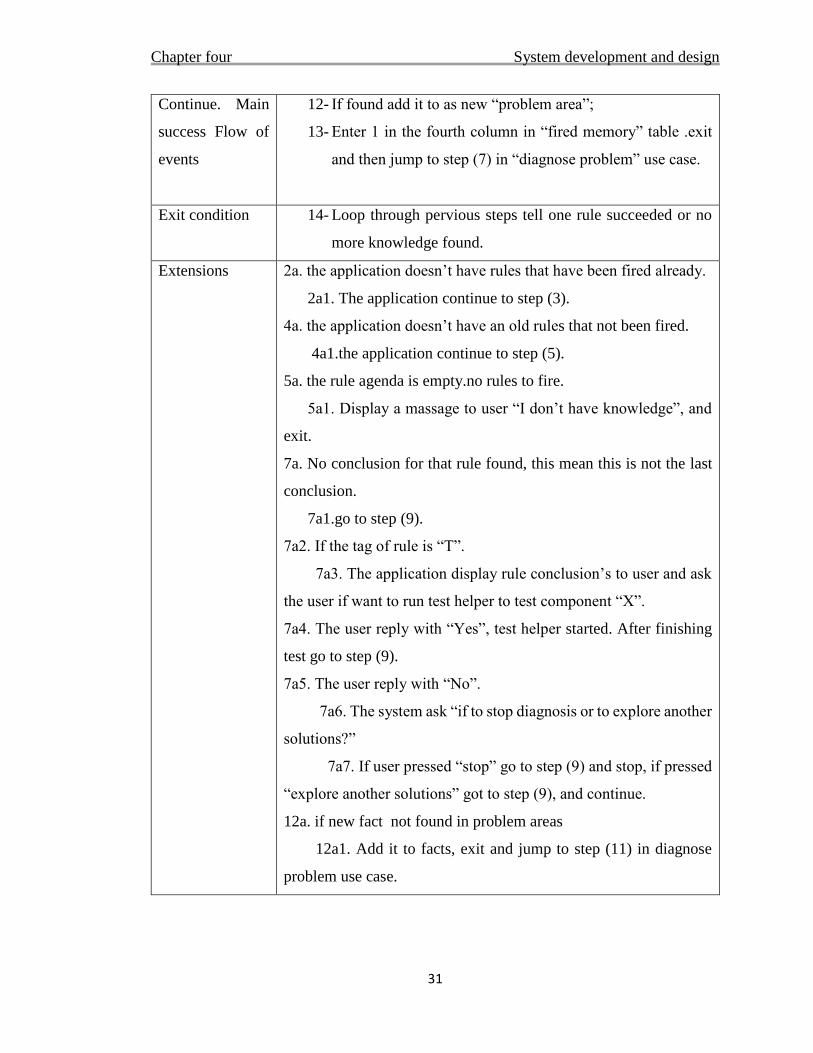
Chapter four System development and design
31
Continue. Main
success Flow of
events
12- If found add it to as new “problem area”;
13- Enter 1 in the fourth column in “fired memory” table .exit
and then jump to step (7) in “diagnose problem” use case.
Exit condition 14- Loop through pervious steps tell one rule succeeded or no
more knowledge found.
Extensions
2a. the application doesn’t have rules that have been fired already.
2a1. The application continue to step (3).
4a. the application doesn’t have an old rules that not been fired.
4a1.the application continue to step (5).
5a. the rule agenda is empty.no rules to fire.
5a1. Display a massage to user “I don’t have knowledge”, and
exit.
7a. No conclusion for that rule found, this mean this is not the last
conclusion.
7a1.go to step (9).
7a2. If the tag of rule is “T”.
7a3. The application display rule conclusion’s to user and ask
the user if want to run test helper to test component “X”.
7a4. The user reply with “Yes”, test helper started. After finishing
test go to step (9).
7a5. The user reply with “No”.
7a6. The system ask “if to stop diagnosis or to explore another
solutions?”
7a7. If user pressed “stop” go to step (9) and stop, if pressed
“explore another solutions” got to step (9), and continue.
12a. if new fact not found in problem areas
12a1. Add it to facts, exit and jump to step (11) in diagnose
problem use case.
Chapter four System development and design
32
4.3 Problems faced
Major problems that has been encountered while developing our system can
be outlined in the following:
Collecting accurate data: it is important to fill expert system database with
accurate diagnosis knowledge, but the expert information is hard to reach,
because experts are scarce, busy and often difficult to reach, second the
expert can’t explain his reasoning in a form of steps well.
Develop a way for the system to detect that rule/rules has been satisfied:
the rules in database are in a human readable format that make it difficult for
computers to process, so solved this problem by just using the ID if rules to
analyze it. The technique search the facts selected by user in database and
return each rule ID concluding this fact in its right-hand side, then sort this
rules and calculate the number of times that some facts found in each rule.
The number of facts found is equal to the real rule conditions if it is satisfied,
else the rule is not satisfied.
What conflict resolution protocol will be used: Conflict resolution protocol
is so important because in most cases more than one rule may be satisfied, in
our system this happens when the error’s symptoms can have multiple
reasons. (Conflict resolution protocol chosen for this project provided in
section 4.6.1.2).
Interaction with user: used question boxes and dialog boxes and main user
interface to interact with user.
How to distinguish between types of rules: there are diagnosis rule which
hold the main diagnosis rules, and there are relational rules which define
relation between two facts or more, and there are a diagnosis test rule which
define that the system can help the user to test the component in the right
Chapter four System development and design
33
hand side of rule to make sure this is the cause of the problem. So the system
must distinguish between these types of rules, used a TAG column that hold
the type for each rule.
How to develop a universal way for system to interact with rule firing
actions: the rule that have a conclusion is considered by the system as the
last conclusion, each rule does not have a conclusion is added by the system
to the left hand side of the system fact’s and searched in the problem area
(_IF column) in database. If found then this means this rule is a parent rule
to other rules, or the diagnosis tree for that rule have more branches, If not
found the system just search the database for possibility this new fact make
new rule/rules satisfied, but if no new rules satisfied this rule is ignored and
fire the next rule in “rule agenda”.
How to develop a way to check and restore computer’s model number,
for purpose of collect and store which problems happened more in some
computers models? It is useful if the system can register some types of errors
that happens a lot to computer models. (Discussed in section 4.9)
How to develop a test helper to test any circuit output? Develop a test
helper that just take input from user and process it can free human from
processing the data manually. (Discussed in section 4.8)
How the system can increase its performance over time: Many techniques
can be used to increase performance over time, in this project priority
adjustment technique has been used. (Discussed in section 4.7)
Chapter four System development and design
34
4.4 System characteristics
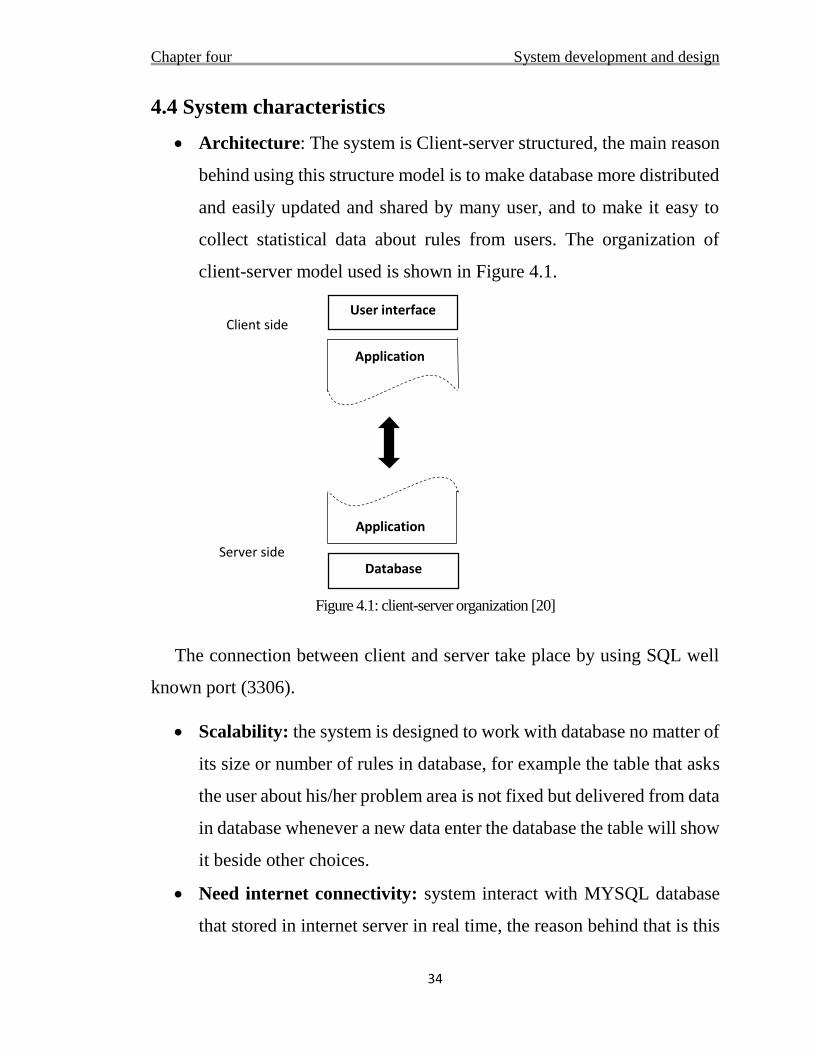
Architecture: The system is Client-server structured, the main reason
behind using this structure model is to make database more distributed
and easily updated and shared by many user, and to make it easy to
collect statistical data about rules from users. The organization of
client-server model used is shown in Figure 4.1.
Figure 4.1: client-server organization [20]
The connection between client and server take place by using SQL well
known port (3306).
Scalability: the system is designed to work with database no matter of
its size or number of rules in database, for example the table that asks
the user about his/her problem area is not fixed but delivered from data
in database whenever a new data enter the database the table will show
it beside other choices.
Need internet connectivity: system interact with MYSQL database
that stored in internet server in real time, the reason behind that is this
User interface
Database
Application
Application
Client side
Server side
Chapter four System development and design
35
technique gives the system the benefit of detecting changes in database
in real time. As any web application its speed depends on the speed of
the internet connection. This application can work with slow internet
connection but needs a stable connection.
Interaction between user and expert system: this belong to user-
interface functions, the user interface consist of: tables to select from,
question boxes, dialog boxes, and input boxes, all those beside the
main user interface page that display the system states and the
conclusion.
4.5 Knowledgebase Design
Well-formed knowledge base is the key element for a successful
diagnosis system. The data base must be filled with accurate and well
represented information, so the inference engine can use this knowledge to
make a right specific diagnosis from given fact.
4.5.1 Knowledge representation
In this system the knowledge base is represented using rules base
techniques which is detailed earlier in this report.
4.5.2 Rules based system
The rules based systems are the systems that their knowledge is
represented in a form of (IF_THEN) rules.
To reduce the problem area a technique is used by which the
knowledge is encoded in a form of: Problem area – Symptoms - The cause
of the problem as mentioned in [10], for example table 4.4:
Chapter four System development and design
36
Table 4.4: rules encoding in database
_IF _AND _THEN
Screen the image is distort RAM
This techniques is so useful in the problem area of motherboard
diagnosis. The researchers found there is no meaning for branches of
diagnosis tree to expand beyond ten branches, so in this project there is no
more than ten rules in each problem area.
4.5.3 Knowledge equation
The knowledge is collected from two main source:
1- Computer technicians: expert system knowledge base can be
collected from multiple technicians, therefore the system will
automatically increase or decrease the priority of rules depending
on their number of failure and success, using priority adjustment.
2- Internet forms that provided from computer companies and the
solution is provided from experts and the right answer is marked
and rated.
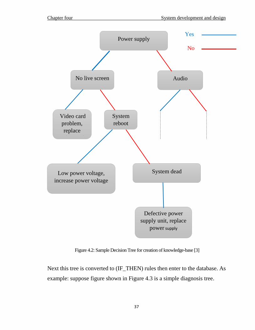
After collecting data, the data represented in a form of diagnosis tree for
example as the one shown in Figure 4.2.
Chapter four System development and design
37
90
Figure 4.2: Sample Decision Tree for creation of knowledge-base [3]
Next this tree is converted to (IF_THEN) rules then enter to the database. As
example: suppose figure shown in Figure 4.3 is a simple diagnosis tree.
Power supply
No live screen
Video card
problem,
replace
video card
System
reboot
Low power voltage,
increase power voltage
System dead
Defective power
supply unit, replace
power supply
Audio
Yes
No
Chapter four System development and design
38
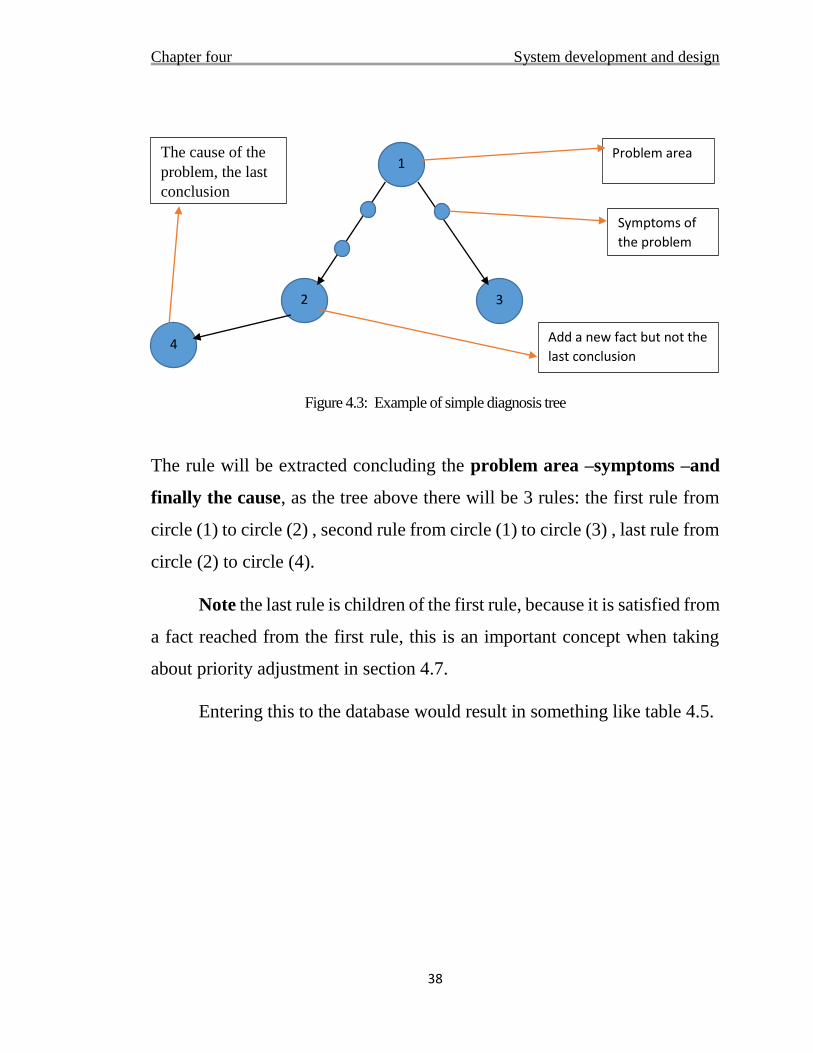
Figure 4.3: Example of simple diagnosis tree
The rule will be extracted concluding the problem area –symptoms –and
finally the cause, as the tree above there will be 3 rules: the first rule from
circle (1) to circle (2) , second rule from circle (1) to circle (3) , last rule from
circle (2) to circle (4).
Note the last rule is children of the first rule, because it is satisfied from
a fact reached from the first rule, this is an important concept when taking
about priority adjustment in section 4.7.
Entering this to the database would result in something like table 4.5.
3 2
1
Symptoms of
the problem
The cause of the
problem, the last
conclusion
Problem area
4 Add a new fact but not the
last conclusion
Chapter four System development and design
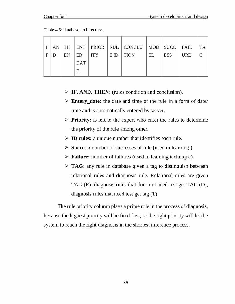
39
Table 4.5: database architecture.
I
F
AN
D
TH
EN
ENT
ER
DAT
E
PRIOR
ITY
RUL
E ID
CONCLU
TION
MOD
EL
SUCC
ESS
FAIL
URE
TA
G
IF, AND, THEN: (rules condition and conclusion).
Entery_date: the date and time of the rule in a form of date/
time and is automatically entered by server.
Priority: is left to the expert who enter the rules to determine
the priority of the rule among other.
ID rules: a unique number that identifies each rule.
Success: number of successes of rule (used in learning )
Failure: number of failures (used in learning technique).
TAG: any rule in database given a tag to distinguish between
relational rules and diagnosis rule. Relational rules are given
TAG (R), diagnosis rules that does not need test get TAG (D),
diagnosis rules that need test get tag (T).
The rule priority column plays a prime role in the process of diagnosis,
because the highest priority will be fired first, so the right priority will let the
system to reach the right diagnosis in the shortest inference process.
Chapter four System development and design
40
4.6 inference engine
Forward chaining techniques is used in this project to take the process
of inference from rules, forward chaining is also called (data driven
reasoning) and a type of first depth search.
Data driven reasoning means that the system first collect facts from
user and then infer from this facts.
4.6.1 Inference code operations
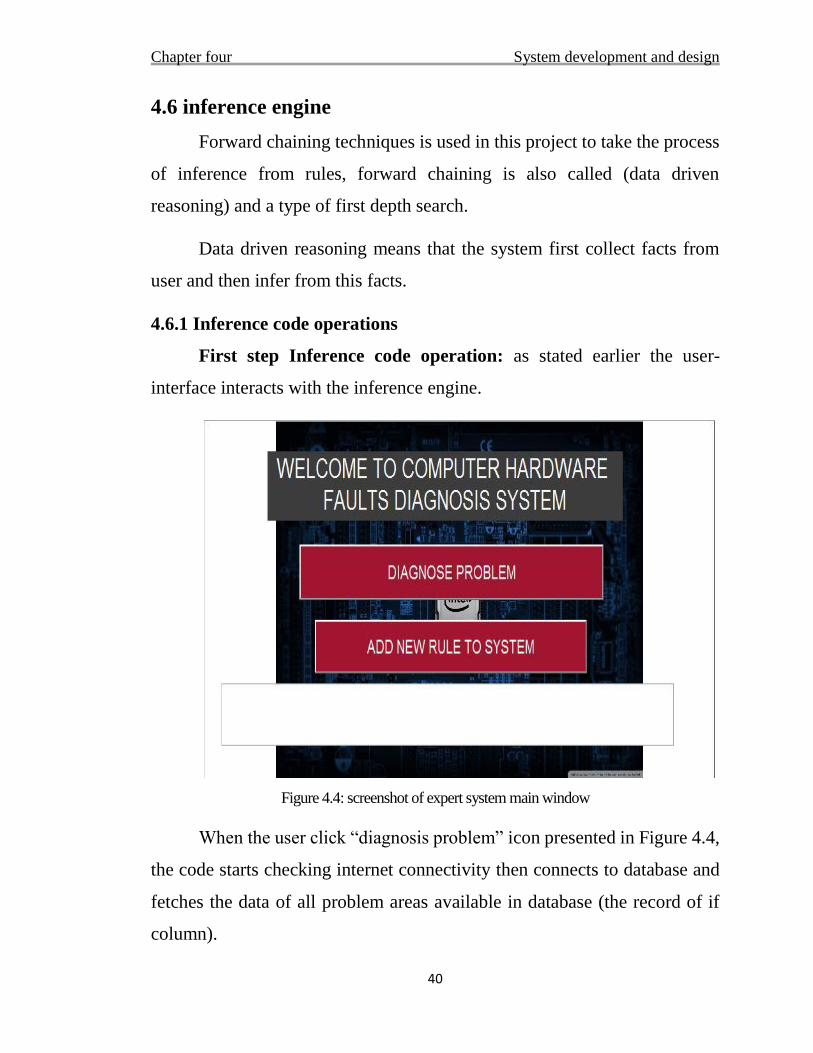
First step Inference code operation: as stated earlier the user-
interface interacts with the inference engine.
Figure 4.4: screenshot of expert system main window
When the user click “diagnosis problem” icon presented in Figure 4.4,
the code starts checking internet connectivity then connects to database and
fetches the data of all problem areas available in database (the record of if
column).
Chapter four System development and design
41
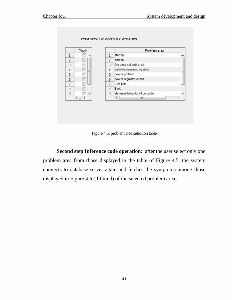
Figure 4.5: problem area selection table
Second step Inference code operation: after the user select only one
problem area from those displayed in the table of Figure 4.5, the system
connects to database server again and fetches the symptoms among those
displayed in Figure 4.6 (if found) of the selected problem area.
Chapter four System development and design
42
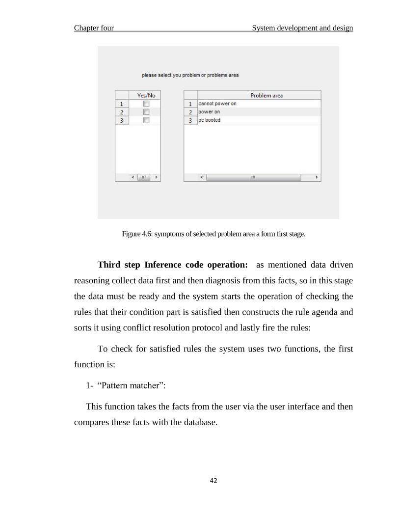
Figure 4.6: symptoms of selected problem area a form first stage.
Third step Inference code operation: as mentioned data driven
reasoning collect data first and then diagnosis from this facts, so in this stage
the data must be ready and the system starts the operation of checking the
rules that their condition part is satisfied then constructs the rule agenda and
sorts it using conflict resolution protocol and lastly fire the rules:
To check for satisfied rules the system uses two functions, the first
function is:
1- “Pattern matcher”:
This function takes the facts from the user via the user interface and then
compares these facts with the database.
Chapter four System development and design
43
2- “Rverification”:
After matching the facts with the database, this function determines which
rule can enter the rule-agenda (which rule’s condition is satisfied).
4.6.1.2 Conflict resolution protocol
Conflict resolution protocol is done by two ways the main way is using
priority, but if more than one rule have the same priority these rules will be
sorted using last entry_ date, for example:
Table 4.6: rules agenda before running conflict protocol
Rule_ ID PRIOPITY ENTERY_ DATE
2 9 2/8
3 2 2/8
4 1 3/8
17 1 5/8
The rule agenda is sorted from server from highest_ smallest priority
as in table 4.6 but a rule that has ID (4), (17) has the same priority, so the
“conflict_ protocol” function checks for this condition and if found it requests
the server to sort them by the newest date and re-entered to the same location
in the matrix as shown in table 4.7
Chapter four System development and design
44
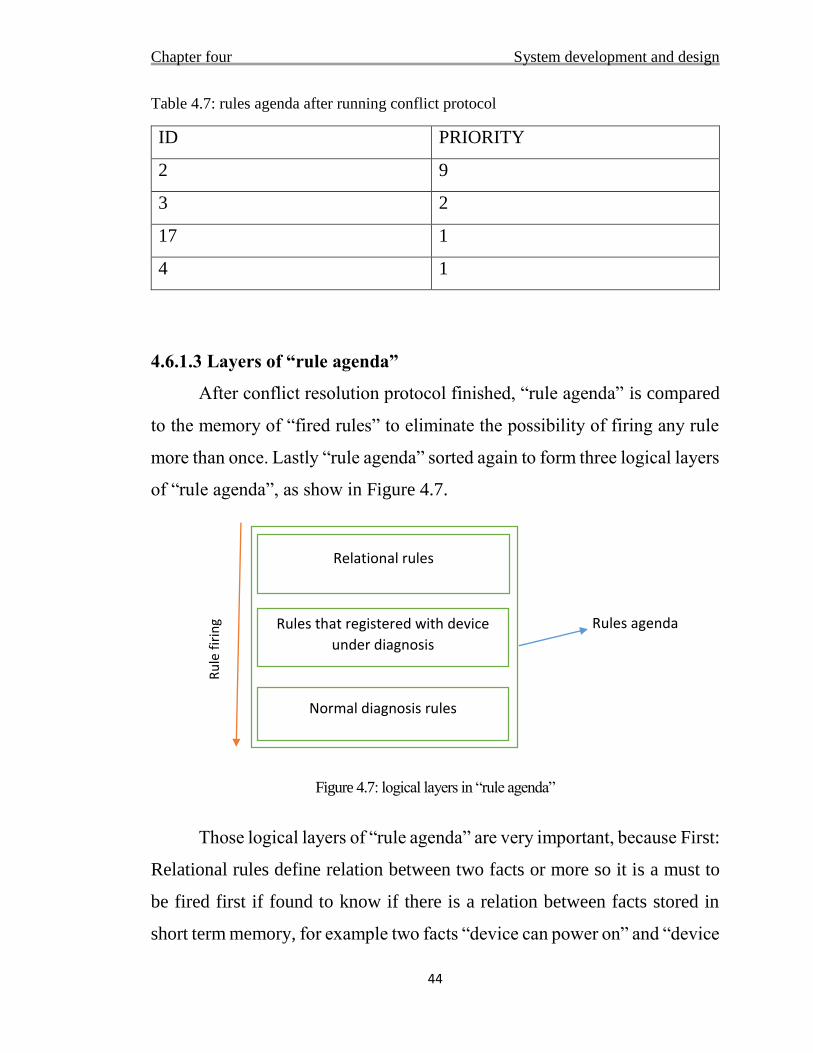
Table 4.7: rules agenda after running conflict protocol
ID PRIORITY
2 9
3 2
17 1
4 1
4.6.1.3 Layers of “rule agenda”
After conflict resolution protocol finished, “rule agenda” is compared
to the memory of “fired rules” to eliminate the possibility of firing any rule
more than once. Lastly “rule agenda” sorted again to form three logical layers
of “rule agenda”, as show in Figure 4.7.
Figure 4.7: logical layers in “rule agenda”
Those logical layers of “rule agenda” are very important, because First:
Relational rules define relation between two facts or more so it is a must to
be fired first if found to know if there is a relation between facts stored in
short term memory, for example two facts “device can power on” and “device
Rules agenda Rules that registered with device
under diagnosis
Normal diagnosis rules
Relational rules
Ru
le f
irin
g
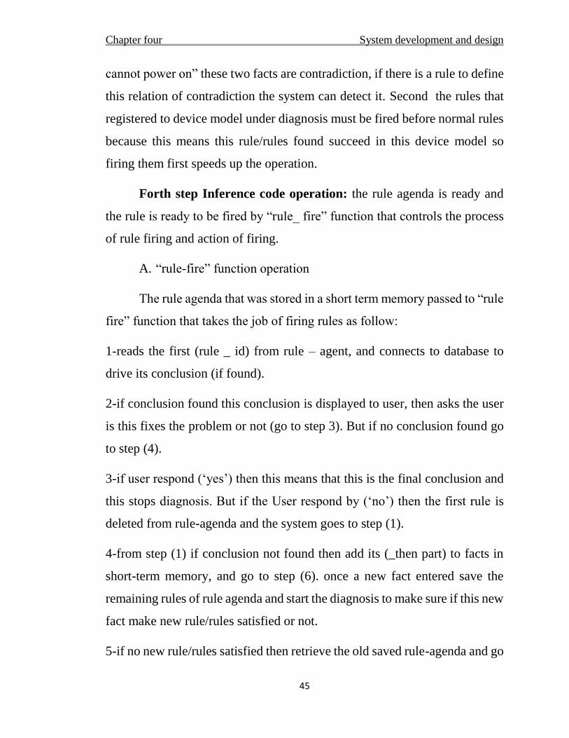
Chapter four System development and design
45
cannot power on” these two facts are contradiction, if there is a rule to define
this relation of contradiction the system can detect it. Second the rules that
registered to device model under diagnosis must be fired before normal rules
because this means this rule/rules found succeed in this device model so
firing them first speeds up the operation.
Forth step Inference code operation: the rule agenda is ready and
the rule is ready to be fired by “rule_ fire” function that controls the process
of rule firing and action of firing.
A. “rule-fire” function operation
The rule agenda that was stored in a short term memory passed to “rule
fire” function that takes the job of firing rules as follow:
1-reads the first (rule _ id) from rule – agent, and connects to database to
drive its conclusion (if found).
2-if conclusion found this conclusion is displayed to user, then asks the user
is this fixes the problem or not (go to step 3). But if no conclusion found go
to step (4).
3-if user respond (‘yes’) then this means that this is the final conclusion and
this stops diagnosis. But if the User respond by (‘no’) then the first rule is
deleted from rule-agenda and the system goes to step (1).
4-from step (1) if conclusion not found then add its (_then part) to facts in
short-term memory, and go to step (6). once a new fact entered save the
remaining rules of rule agenda and start the diagnosis to make sure if this new
fact make new rule/rules satisfied or not.
5-if no new rule/rules satisfied then retrieve the old saved rule-agenda and go
Chapter four System development and design
46
to (1). But if new rules found: Add the new rule-agenda to the top of the old
parent one and then go to step (1).
These steps are repeated until the right diagnosis is found or all rules
are fired.
4.7 Priority adjustment development
As mentioned before priority plays a prime role in inference because
the program fires the highest priority first, so if priority entered first by
knowledge engineer is highest than or lower than what it must be, the
inference takes more time to reach the right conclusion.
For this reason the priority adjustment function is developed to take
this responsibility, the priority adjustment works in two separate functions,
the first function run after inference is stopped by looking into the rules that
have been fired. Rules that have been fired are stored in this manner as can
be seen in table 4.8:
Table 4.8: the form of fired rule memory
Rule Id Succeeded failed Parent rule Number of
children’s
The succeeded, failure and parent rule label of fired rule memory is
indicated by either (1 or 0), number of children label have the number of
rules satisfied from a fact that reached from parent rule. Every rule is either
succeeded or failed. The success and failure of any parent rule depend on its
child/children rule success’s or failure’s.
Chapter four System development and design
47
Lastly this matrix is processed by priority adjustment and updated the
database with the new values of statistical information of success and failure
of this rules/rule.
After that the second function that run in server side takes the
responsibility of updating the priority of rules based on their success and
failure data. This function is a PHP web script that called by normal URL
address, this function work as follow:
If (success > =3 or failure > =3) and (success not equal 0 and failure
not equal 0) then priority = (success/failure).
If (success >= 3 and failure = 0) then priority = success/1.
If (failure >=3 and success=0) then priority =1/failure.
For example: assume for rule that have id (5) the success is (4) and the
failure (2) the new priority is (4/2) = (2).
Note that no more than one rule in the same problem area will succeeded in
the same diagnosis session.
The reason behind only adjust the priority only after one of successes
or failures number reach (3) is that just to make sure that the rule was fired
number of times enough to begin to process its priority.
This function is called from user device two times, first when checking
for internet connection the system connect to this webpage to check whether
the server can be reached or not and also this runs the code on webpage, the
second time after priority adjustment function finishes.
Chapter four System development and design
48
4.8 Test mode
Sometimes it is desired to test the component that inference engine
thinks it is the cause of the problem, for example (power supply unit). So our
problem is how to develop a testing helper to help user test their components,
first know what component need to be tested in first place, second the normal
output of this component, third what kind of devices can measure this
component. Some component can be tested using easy techniques used by
computer technicians.
Development of a test helper that can be used to test a well-known
normal output for any circuit using voltammeter or any voltage measuring
device, the voltammeter is desired because it is the main tool used by any
computer technician, this requires some basic knowledge about how to
measure voltage, detailed information about how to measure devices is not
mentioned by test helper.
4.8.1 The development of test helper
As mentioned earlier to test any circuit or device you need to know
how to test its behavior and compare it to the normal behavior, so the system
need a database to store information about how to test this component. Tried
to add to the same rules database but found that it is not efficient to use rules
representation in this situation, so a separate table that hold the testing data
and guide to each component separately has been built.
Take power supply unit for PCs as example, most well-known PSU is
ATX power supply ATX (Advanced Technology eXtended) is a motherboard
configuration specification developed by Intel. The specification defines the
key mechanical dimensions, mounting point, I/O panel, power and connector
interfaces between a computer case, a motherboard and a power supply.
Chapter four System development and design
49
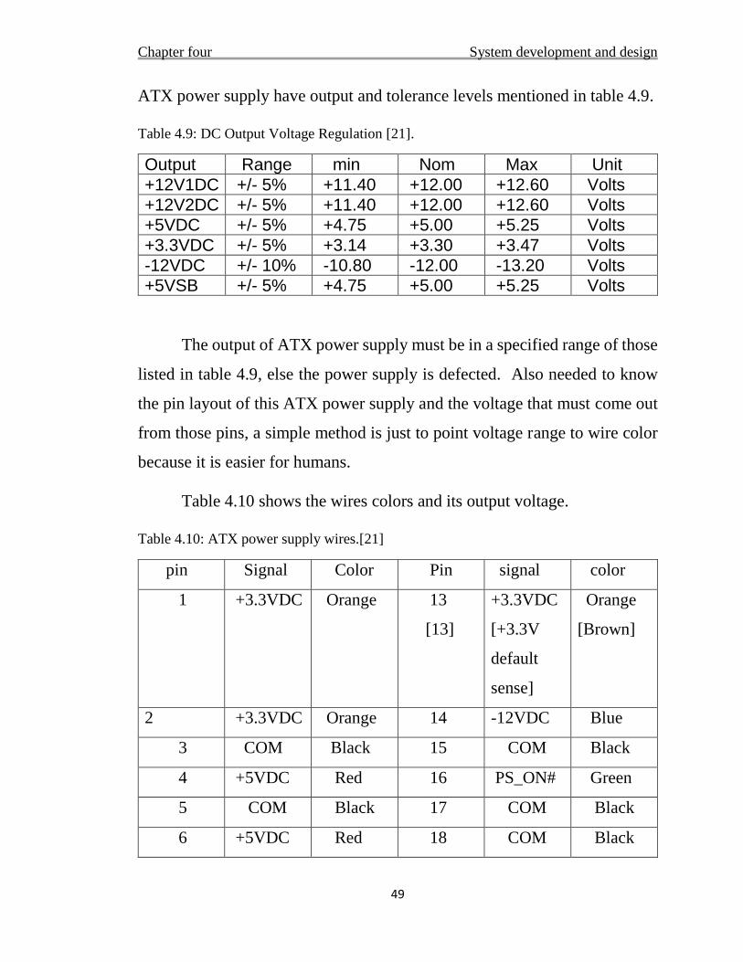
ATX power supply have output and tolerance levels mentioned in table 4.9.
Table 4.9: DC Output Voltage Regulation [21].
Output Range min Nom Max Unit
+12V1DC +/- 5% +11.40 +12.00 +12.60 Volts
+12V2DC +/- 5% +11.40 +12.00 +12.60 Volts
+5VDC +/- 5% +4.75 +5.00 +5.25 Volts
+3.3VDC +/- 5% +3.14 +3.30 +3.47 Volts
-12VDC +/- 10% -10.80 -12.00 -13.20 Volts
+5VSB +/- 5% +4.75 +5.00 +5.25 Volts
The output of ATX power supply must be in a specified range of those
listed in table 4.9, else the power supply is defected. Also needed to know
the pin layout of this ATX power supply and the voltage that must come out
from those pins, a simple method is just to point voltage range to wire color
because it is easier for humans.
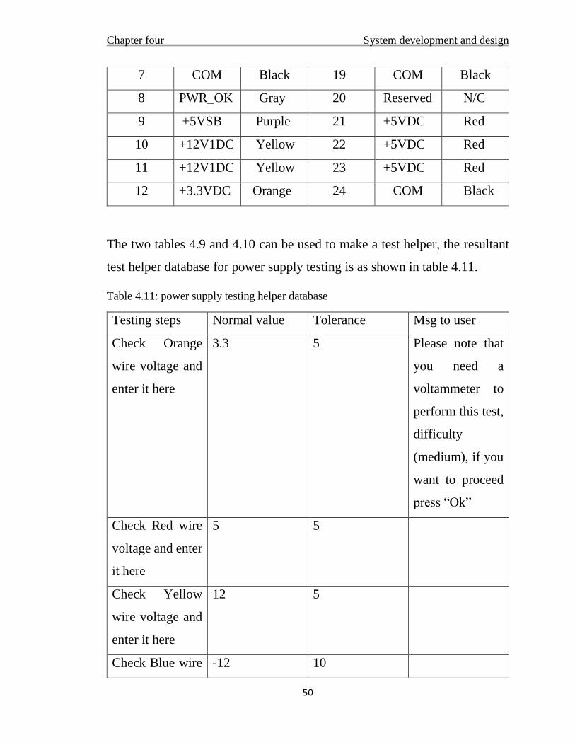
Table 4.10 shows the wires colors and its output voltage.
Table 4.10: ATX power supply wires.[21]
pin Signal Color Pin signal color
1 +3.3VDC Orange 13
[13]
+3.3VDC
[+3.3V
default
sense]
Orange
[Brown]
2 +3.3VDC Orange 14 -12VDC Blue
3 COM Black 15 COM Black
4 +5VDC Red 16 PS_ON# Green
5 COM Black 17 COM Black
6 +5VDC Red 18 COM Black
Chapter four System development and design
50
7 COM Black 19 COM Black
8 PWR_OK Gray 20 Reserved N/C
9 +5VSB Purple 21 +5VDC Red
10 +12V1DC Yellow 22 +5VDC Red
11 +12V1DC Yellow 23 +5VDC Red
12 +3.3VDC Orange 24 COM Black
The two tables 4.9 and 4.10 can be used to make a test helper, the resultant
test helper database for power supply testing is as shown in table 4.11.
Table 4.11: power supply testing helper database
Testing steps Normal value Tolerance Msg to user
Check Orange
wire voltage and
enter it here
3.3 5 Please note that
you need a
voltammeter to
perform this test,
difficulty
(medium), if you
want to proceed
press “Ok”
Check Red wire
voltage and enter
it here
5 5
Check Yellow
wire voltage and
enter it here
12 5
Check Blue wire -12 10
Chapter four System development and design
51
voltage and enter
it here
Lastly when user request for test the system searches the database for table
that have the name of the component need to be tested, so the table name
must be the name of component.
4.9 Working in respect to computer model
In the field of computer diagnosis it is useful to remember what a
specific problem happens to a certain computer model. Also some diagnosis
rules are not suitable for all types of computers so “model” column is
included in table 4.2, to reserve rule/rules for a specific computer model.
The system developed to ask the user for computer model first, and
when the user select a problem area the system checks the rules correspond
to this computer model or have no reserved computer model. The second time
computer model show up when the system is sorting the “rule agenda” in
layers (mentioned in section 4.5.1.3).
Chapter four System development and design
52
4.10 Programs and tools
The program is coded using ‘MATLAB 2015’, the code is a MATLAB
function and SQL queries, the database is setup using MySQL server
database 2012 that stored in the internet, and then connected to MATLAB
using ODBC driver.
In server side the database have a remote access from anywhere, the
connection to database is done by only one function that open and close the
connection.
Prototype model is used in development of software, number of
functions each have its own job and main function that control the execution
of those functions so any new function can be add easily by just calling it
from main function. Finally the user interface is designed using MATLAB
GUI tool.

Chapter 5
Results and contribution
Chapter five Results and contribution
54
5.1 Introduction
Computer failure diagnosis is a time consuming and costly task to do
manually. Expert system use knowledge which they reason about to draw
conclusions and provide solutions. [5]
An expert system to provide a solution based on hardware problems
symptoms is developed, to emulate the human ability of fast diagnosis using
only symptoms of the problem. The right solution will be reached unless it’s
not entered to database.
5.2 Result and finding
Knowledge acquisition was a time consuming task, but it become
easier if a situation examined and the human expert asked how to deal with
this kind of problems, the main source of knowledge in this project is
computer technicians. Also there is no need to increase the number of rules
in system to make it more accurate.
Shared database architecture gives the system the ability of easily
distributing information and update knowledge in the database between
multiple users in real time. But as well as this is a benefit some problem can
arise with some scenarios, assume a user selected a problem that have one
symptom, and while the inference engine check supported facts against rules
in database, some rules are updating by adding another symptoms, the
inference engine will find the updated rules not satisfied and if no rule
satisfied the system displays “no knowledge found” and stop diagnosis. The
user may not retry again after that, deleting the entire rule will have the same
effect.
Chapter five Results and contribution
55
After collecting starting data it is time to represent this data. The
developed expert system uses rule-based data representation to represent
knowledge in database. The results of these data representation are:
In problem area of PC hardware diagnosis, found it was too easy to
encode knowledge in form of rules.
The division of rules into (problem area – symptoms – problem cause)
is well suited to hardware diagnosis problem.
Rule based representation gives a good control over diagnosis rules,
and the system can easily measure the success and failure for each rule
individually.
Rule based representation represent knowledge in human readable
format this advantage give the expert the ability to easily check rules,
but it is not that good for computers to work with, because computer
doesn’t have the knowledge of what this data means.
Rule based representation can represent relational rules between facts
in system, this gives the expert system meta-knowledge about facts in
database.
In rule based representation, it is easy to reserve some rules for a
specific device model.
Rule based representation found not suitable to hold “test helper” data
of component.
The ability to collect diagnosis data from more than one expert and
represent each different diagnosis in different rule.
Rules can easily be connected to each other by including the left hand-
side of first rule in the right hand side of second rule.
Chapter five Results and contribution
56
If the conclusion of rule can be divided into multiple reasons, then
dividing that rule conclusion into new problem areas that state each
reason in separate rule is desired, because this gives the user the ability
to make a shortcut if he have some knowledge about the cause of the
problem.
The amount of knowledge can be entered into database is not limited,
but contradiction and conflict problem can arise with adding more
knowledge.
The updating and adding of new rules to system can be a task that never
end.
The inference technique used in this project is forward chaining, that
collect data first and then reason about that data to reach a conclusion, in
respect to inference engine found that:
Forward chaining technique is enough to our problem area and no need
for any other inference technique like backward chaining.
Forward chaining doesn’t leave any rule without examining it against
user supported facts.
It is easy to make a selectable table from rules because rules are
divided into (problem area –symptoms – the cause of the problem).
The inference engine can work with any database, unless it is not in
the same format that discussed in chapter 4 in table 4.2.
In long diagnosis tree the inference take longtime because the
inference engine connect to database in each time new fact is entered
to system.
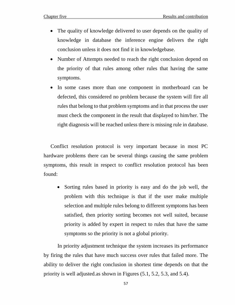
Chapter five Results and contribution
57
The quality of knowledge delivered to user depends on the quality of
knowledge in database the inference engine delivers the right
conclusion unless it does not find it in knowledgebase.
Number of Attempts needed to reach the right conclusion depend on
the priority of that rules among other rules that having the same
symptoms.
In some cases more than one component in motherboard can be
defected, this considered no problem because the system will fire all
rules that belong to that problem symptoms and in that process the user
must check the component in the result that displayed to him/her. The
right diagnosis will be reached unless there is missing rule in database.
Conflict resolution protocol is very important because in most PC
hardware problems there can be several things causing the same problem
symptoms, this result in respect to conflict resolution protocol has been
found:
Sorting rules based in priority is easy and do the job well, the
problem with this technique is that if the user make multiple
selection and multiple rules belong to different symptoms has been
satisfied, then priority sorting becomes not well suited, because
priority is added by expert in respect to rules that have the same
symptoms so the priority is not a global priority.
In priority adjustment technique the system increases its performance
by firing the rules that have much success over rules that failed more. The
ability to deliver the right conclusion in shortest time depends on that the
priority is well adjusted.as shown in Figures (5.1, 5.2, 5.3, and 5.4).
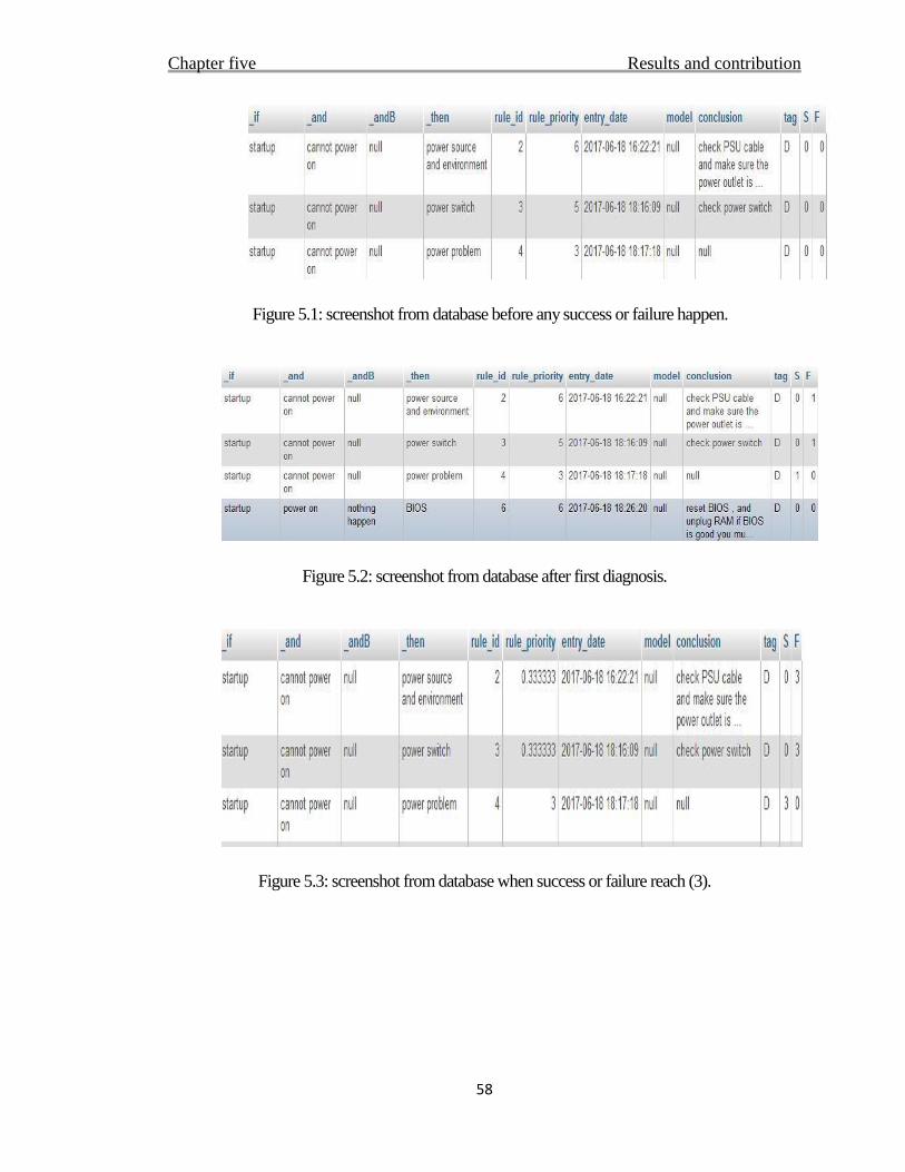
Chapter five Results and contribution
58
Figure 5.1: screenshot from database before any success or failure happen.
Figure 5.2: screenshot from database after first diagnosis.
Figure 5.3: screenshot from database when success or failure reach (3).
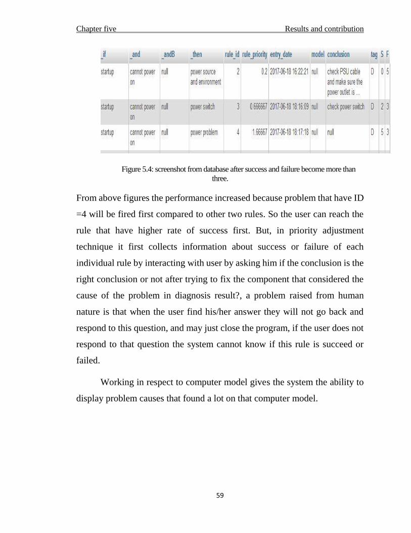
Chapter five Results and contribution
59
Figure 5.4: screenshot from database after success and failure become more than
three.
From above figures the performance increased because problem that have ID
=4 will be fired first compared to other two rules. So the user can reach the
rule that have higher rate of success first. But, in priority adjustment
technique it first collects information about success or failure of each
individual rule by interacting with user by asking him if the conclusion is the
right conclusion or not after trying to fix the component that considered the
cause of the problem in diagnosis result?, a problem raised from human
nature is that when the user find his/her answer they will not go back and
respond to this question, and may just close the program, if the user does not
respond to that question the system cannot know if this rule is succeed or
failed.
Working in respect to computer model gives the system the ability to
display problem causes that found a lot on that computer model.
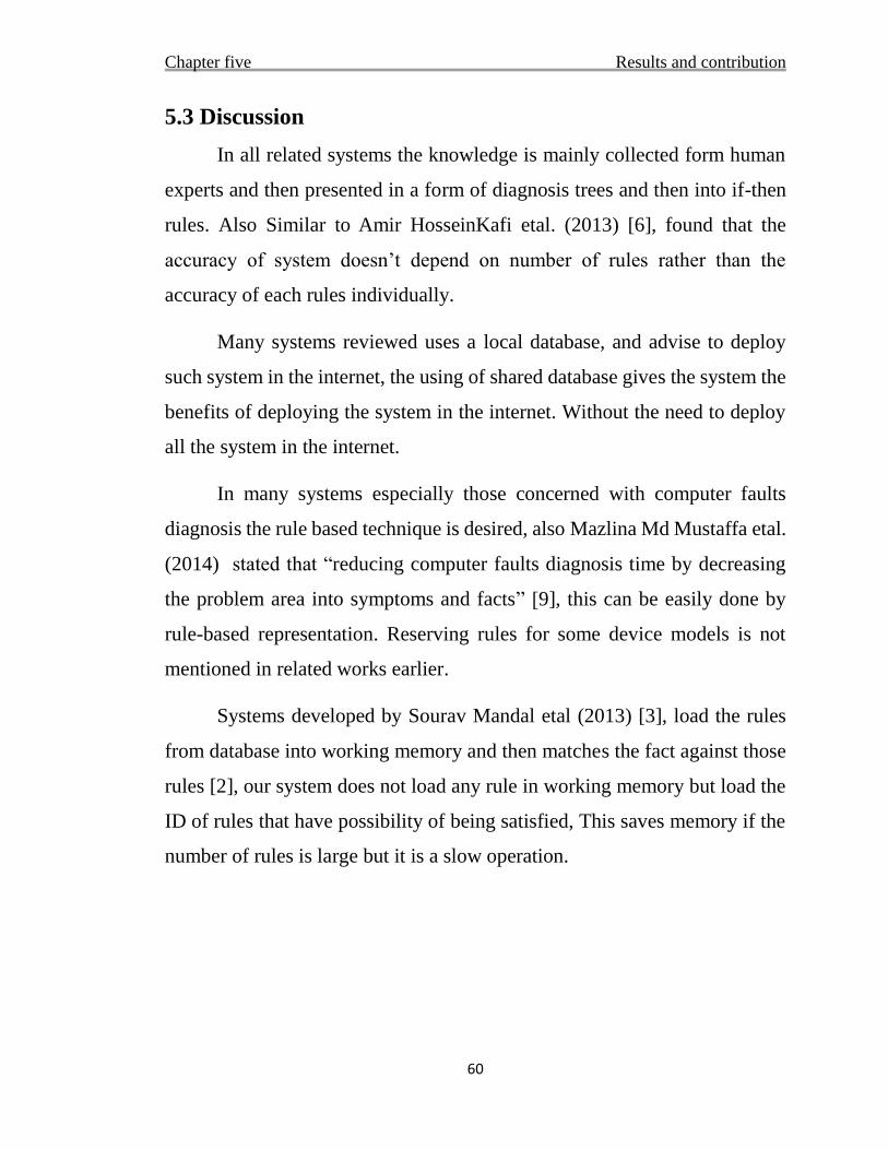
Chapter five Results and contribution
60
5.3 Discussion
In all related systems the knowledge is mainly collected form human
experts and then presented in a form of diagnosis trees and then into if-then
rules. Also Similar to Amir HosseinKafi etal. (2013) [6], found that the
accuracy of system doesn’t depend on number of rules rather than the
accuracy of each rules individually.
Many systems reviewed uses a local database, and advise to deploy
such system in the internet, the using of shared database gives the system the
benefits of deploying the system in the internet. Without the need to deploy
all the system in the internet.
In many systems especially those concerned with computer faults
diagnosis the rule based technique is desired, also Mazlina Md Mustaffa etal.
(2014) stated that “reducing computer faults diagnosis time by decreasing
the problem area into symptoms and facts” [9], this can be easily done by
rule-based representation. Reserving rules for some device models is not
mentioned in related works earlier.
Systems developed by Sourav Mandal etal (2013) [3], load the rules
from database into working memory and then matches the fact against those
rules [2], our system does not load any rule in working memory but load the
ID of rules that have possibility of being satisfied, This saves memory if the
number of rules is large but it is a slow operation.
Chapter five Results and contribution
61
When the system comes to measure rules success or failure the
problem of interaction raised this problem which is never addressed by any
author of reviewed systems but they advise for friendly user interface. In “test
helper” this is not a problem because the system will know if the rule succeed
or not from test result before user know it.

Chapter 6
Conclusion and future work
Chapter six Conclusion and future work
63
6.1 Conclusion
In this project an expert system to emulate the ability of human
technician to diagnose computer motherboard hardware failure has been
developed.
This project is a step forward full automation of computer hardware
problems diagnosis, the expert system is developed using MALAB function
and rule-based representation and forward chaining inference technique, the
proposed expert system can help human technicians to reach multiple
knowledge, and to do a component test. The expert system gives the ability
to share human’s knowledge more easily. Self-adjustment of priority of rules
speeds up the operation of diagnosis. Test helper for any component can be
built to help user test that component, component like power supply can be
tested by knowing the normal output from each pin and the accepted
tolerance.
6.2 Future Work
Using threading in programming expert system can increase system
performance, and make use of parallel processing.
Integrating the expert system with other sensing hardware and
software, can lead to a full automated hardware diagnosis system that does
not need any human interaction.

64
References
[1] Jackson & Peter, (1998) Introduction to Expert Systems, 3rd ed, Addison
Wesley.
[2] Exsys Corvid Quick-Start Guide - Fundamentals & Tutorials (2011)
. http://www.exsys.com/PDF/ExsysCORVID_QuickStartGuide.pdf
[3] Sourav Mandal1, etal (2013),”DIAGNOSIS AND
TROUBLESHOOTING OF COMPUTER FAULTS BASED ON EXPERT
SYSTEM AND ARTIFICIAL INTELLIGENCE.” International Journal of
Pure and Applied Mathematics Volume 83 No. 5 2013, 717-729.
[4] Amanuel Ayde Ergado (2016), “SELF LEARNING COMPUTER
TROUBLESHOOTING EXPERT SYSTEM”, International Journal of
Artificial Intelligence & Applications (IJAIA), Vol. 7, No. 1, January 2016.
[5] Youssef Bassil (2012), “EXPERT PC TROUBLESHOOTER WITH
FUZZY-LOGIC AND SELF-LEARNING SUPPORT”, International
Journal of Artificial Intelligence & Applications (IJAIA), Vol.3, No.2, March
2012.
[6] Amir HosseinKafi, HamedKazemipoor, Mohammad Ali AfsharKazem
(2013) “Design and Implementation of Fuzzy Expert System for Real Estate
Recommendation” IJISSM, 2013, 2(1): 142-147.
[7] Sylvester I. Ele and 2Adesola, W.A (2013) “Design of Computer Fault
Diagnosis and Troubleshooting System (CFDTS)”, West African Journal of
Industrial and Academic Research Vol.9 No.1 December 2013.
[8] Abdullah Saad AlMalaise Al Ghamdi , Syed Mutiullah Hussaini and
Abdul Khadar Jilani (2013) , “Empirical Model using Expert System
Techniques in Hardware Failure of a System during Backup of Data” ,
65
IJCSNS International Journal of Computer Science and Network Security,
VOL.13 No.2, February 2013.
[9] Mazlina Md Mustaffa1, A.S.Shibghatullah2,A.S.H.Basari3, B.Hussin4
(2014) “DIAGNOSING COMPUTER HARDWARE FAILURES USING
EXPERT SYSTEM (RULE-BASED TECHNIQUE”, nternational
Symposium on Research in Innovation and Sustainability 2014 (ISoRIS ’14)
15-16 October 2014, Malacca, Malaysia.
[10] İstanbul Teknik Üniversitesi “ARTIFICIAL INTELLIGENCE NOTES
REASONING METHODS LECTURER: COŞKUN SÖNMEZ”
[11] Joseph Giarratano & Gary Rily:”expert systems principles and
programming “third edition (1997).
[12]Wikipedia Dendral expert system: https://en.wikipedia.org/wiki/Dendral
Clips: https://en.wikipedia.org/wiki/CLIPS visited in 9-7-2017
[13] Vahid Rafe*1, Mahdi Hassani Goodarzi2, (2013) “A Novel Web-based
Human Advisor Fuzzy Expert System” 1, 2 Department of Computer
Engineering, Faculty of Engineering, Arak University, Arak, 38156-8-8349,
Iran. Department of Computer Engineering, Islamic Azad University- South
Tehran Branch, Iran.
[14] [e-book] Michael Negnevitsky (2005): Artificial Intelligence: A Guide
to Intelligent Systems--Chapter 4
[15] Mofreh A. Hogo, Khaled Fouad, Fouad Mousa (2009), “Web-Based
Expert System for Civil Service Regulations:RCSES” , (IJCSIS)
International Journal of Computer Science and Information Security, Vol. 6,
No. 3, 2009.
[16] Arie Ben-David *, Leon Sterling (2006) , “Generating rules from
examples of human multiattribute decision making should be simple” a
66
Management Information Systems, Department of Technology Management,
Holon Academic Institute of Technology, 52, Golomb St., P.O. Box 305,
Holon 58102, Israelb Department of Computer Science and Software
Engineering, University of Melbourne, Melbourne, Vic., Australia
[17] http://www.pcguide.com/ref/mbsys/bios/bootPOST-c.html visited in
10-7-2017
[18] Pomykalski, J. J., Truszkowski, W. F. & Brown, D. E.(1999) “Expert
System”, In The WileyEncyclopedia for Electrical and Electronics
Engineering (edited by J. Webster), February,1999
[19] Bernd Bruegge & Allen H. Dutoit (2010), Object-Oriented Software
Engineering Using UML, Patterns, and Java, Third Edition, Prentice Hall
[20] Andrew S. Tanenbaum, Maarten Van Steen (2006) Distributed
Systems_ Principles and Paradigms (2nd Edition)-Prentice Hall
[21] Intel Corporation 2004. ATX12V Power Supply Design Guide Version
2.01.