Development and characterization of reinforced poly(L-lactide)scaffolds for bone tissue engineering
Joo-Eon Park • Mitsugu Todo
Received: 26 October 2010 / Accepted: 10 March 2011 / Published online: 24 March 2011
� Springer Science+Business Media, LLC 2011
Abstract Novel reinforced poly(L-lactic acid) (PLLA)
scaffolds such as solid shell, porous shell, one beam and two
beam reinforced scaffolds were developed to improve the
mechanical properties of a standard PLLA scaffold. Exper-
imental results clearly indicated that the compressive
mechanical properties such as the strength and the modulus
are effectively improved by introducing the reinforcement
structures. A linear elastic model consisting of three phases,
that is, the reinforcement, the porous matrix and the
boundary layer was also introduced in order to predict the
compressive moduli of the reinforced scaffolds. The com-
parative study clearly showed that the simple theoretical
model can reasonably predict the moduli of the scaffolds
with three phase structures. The failure mechanism of the
solid shell and the porous shell reinforced scaffolds under
compression were found to be buckling of the solid shell and
localized buckling of the struts constructing the pores in the
porous shell, respectively. For the beam reinforced scaf-
folds, on the contrary, the primary failure mechanism was
understood to be micro-cracking within the beams and the
subsequent formation of the main-crack due to the coales-
cence of the micro-racks. The biological study was exhibited
that osteoblast-like cells, MC3T3-E1, were well adhered and
proliferated on the surfaces of the scaffolds after 12 days
culturing.
1 Introduction
Diseased or injured parts of bone tissue are generally
treated by transplantation such as autograft and allogeneic.
However, these clinical methods have disadvantages such
as infection, rejection symptom and limitation in quantity
[1, 2]. Over the past decade, various synthetic alternatives
for bone tissue treatment have been developed using vari-
ety of materials such as metals [3–6], ceramics [7–10],
polymers [11–15] and composite materials [16–21]. In
general, these biomaterials have three-dimensional porous
structures for cell culture and tissue ingrowth and therefore,
called scaffold.
The metallic materials such as stainless steel, titanium
and titanium alloys have generally been considered for the
substitution of damaged bone tissues [22–26]. The main
advantage of such metal implants is thought to be the
excellent mechanical properties; however, there are some
clinically unpleasant problems such as lack of cell adhe-
sion, low biodegradability and difficulty in fabrication of
porous structure. Furthermore, for a metal implant, a sec-
ond surgery is sometimes required in order to remove the
implant from the body with the related risks of toxicity due
to accumulation of metal ions induced by corrosion.
Bioactivity ceramics such as hydroxyapatite (HAp),
a-TCP and b-TCP consisting of calcium and phosphorous
are successfully used in bone regeneration because of their
components existing in natural bone and their high bio-
compatibility [27–33]. It is furthermore known that release
of Ca2? and PO43- ions from bioactive ceramic stimulates
cell proliferation and differentiation in vivo and in vitro
[30–32]. However, for example, non-biodegradability of
sintered HAp, relatively low strength of TCPs and the
brittleness of all the bioceramics are thought to be their
disadvantages [33].
J.-E. Park
Interdisciplinary Graduate School of Engineering Sciences,
Kyushu University, 6-1 Kasuga-koen, Kasuga 816-8580, Japan
M. Todo (&)
Research Institute for Applied Mechanics, Kyushu University,
6-1 Kasuga-koen, Kasuga 816-8580, Japan
e-mail: [email protected]
123
J Mater Sci: Mater Med (2011) 22:1171–1182
DOI 10.1007/s10856-011-4289-4
On the other hand, biocompatible synthetic or natural
polymers such as poly (L-lactide) (PLLA), poly (e-capro-
lactone) (PCL) and collagen have been used as biomaterials
for scaffold because of their biodegradability with non-
biotoxic characteristics as well as moderate mechanical and
physical properties [34, 35]. In recent years, bioactive
ceramics such as hydroxyapatite (HAp), a-TCP and b-TCP
have been used to improve the mechanical properties and
the cell adherence on these polymeric scaffolds because of
their compositional and structural similarities with bone and
teeth [36–45].
Most of the previous researches were interested in the
fabrication methods of scaffolds and described cell
growth factors without structural factors such as the
relationship between the mechanical properties and the
porous microstructure. Some studies have been reported
that the optimized porous structure of scaffold enhanced
initial cell adhesion and cell migration into the scaffold
[46–49]. Freed et al. [49] also insisted that well-inter-
connected porous structure needs to provide high surface
area with sufficient space for improving cell adhesion,
extracellular regeneration and minimal diffusional con-
strains; however, there might be a possibility for
decreasing mechanical strength by the large pore size
with high porosity. Therefore, a scaffold technology with
controllable mechanical properties and porosity needs to
be developed for seeded cells to adapt the mechanical
environments, excrete a sufficient amount of extracellular
matrices and accommodate a large number of cells and
ensure high rate of cell growth for successful tissue
regeneration [50–53].
In our previous study [54], we reported a novel core–
shell structural PLLA scaffold to stimulate the mechanical
properties as well as maintain high level of porosity for
cell culture. The experimental results showed a successful
improvement in the compressive mechanical properties
and a stable porous structure under compression. In the
present study, we have developed four different types of
reinforcements such as solid shell, porous shell, one beam
and two beams to control the mechanical and porous-
structural properties by using the solid–liquid phase
separation and freeze-drying methods. The compressive
properties were measured and the micro-structural defor-
mation and failure mechanisms were examined using a
field-emission electron microscope (FE-SEM) in order to
characterize and compare the effectiveness of the rein-
forcements. A simple linear elastic theory was also pre-
sented to predict the compressive modulus data. Cell
culture experiment on the scaffolds was also performed
with osteoblast-like MC3T3-E1 cells, and the cell adhe-
sion morphologies were then observed using FE-SEM to
compare the effect of reinforced structure on the cell
adhesion behavior.
2 Materials and methods
2.1 Materials and specimen preparation
Poly(L-lactic acid) (PLLA) pellets (Lacty #5000, Shimadzu
Co., Ltd) with the glass transition temperature of 69.72�C,
the melting temperature of 174.9�C, the density of 1.248 g/cm3
and the average molecular weight of 3.51 g mol-1 were
used to fabricate scaffolds and reinforcements. Porous
structures of PLLA, called mono-structural scaffolds, were
fabricated by using the solid–liquid phase separation and
freeze-drying methods [40, 45–49, 54]. The fabrication
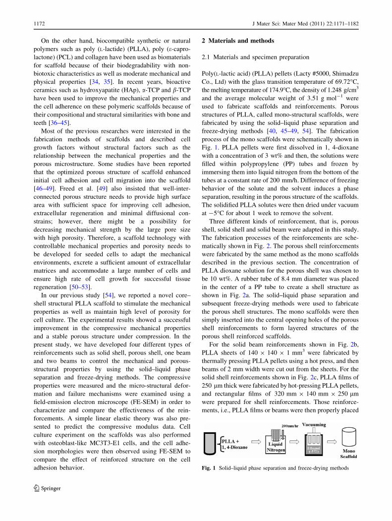
process of the mono scaffolds were schematically shown in
Fig. 1. PLLA pellets were first dissolved in 1, 4-dioxane
with a concentration of 3 wt% and then, the solutions were
filled within polypropylene (PP) tubes and frozen by
immersing them into liquid nitrogen from the bottom of the
tubes at a constant rate of 200 mm/h. Difference of freezing
behavior of the solute and the solvent induces a phase
separation, resulting in the porous structure of the scaffolds.
The solidified PLLA solutes were then dried under vacuum
at -5�C for about 1 week to remove the solvent.
Three different kinds of reinforcement, that is, porous
shell, solid shell and solid beam were adapted in this study.
The fabrication processes of the reinforcements are sche-
matically shown in Fig. 2. The porous shell reinforcements
were fabricated by the same method as the mono scaffolds
described in the previous section. The concentration of
PLLA dioxane solution for the porous shell was chosen to
be 10 wt%. A rubber tube of 8.4 mm diameter was placed
in the center of a PP tube to create a shell structure as
shown in Fig. 2a. The solid–liquid phase separation and
subsequent freeze-drying methods were used to fabricate
the porous shell structures. The mono scaffolds were then
simply inserted into the central opening holes of the porous
shell reinforcements to form layered structures of the
porous shell reinforced scaffolds.
For the solid beam reinforcements shown in Fig. 2b,
PLLA sheets of 140 9 140 9 1 mm3 were fabricated by
thermally pressing PLLA pellets using a hot press, and then
beams of 2 mm width were cut out from the sheets. For the
solid shell reinforcements shown in Fig. 2c, PLLA films of
250 lm thick were fabricated by hot-pressing PLLA pellets,
and rectangular films of 320 mm 9 140 mm 9 250 lm
were prepared for shell reinforcements. Those reinforce-
ments, i.e., PLLA films or beams were then properly placed
Fig. 1 Solid–liquid phase separation and freeze-drying methods
1172 J Mater Sci: Mater Med (2011) 22:1171–1182
123
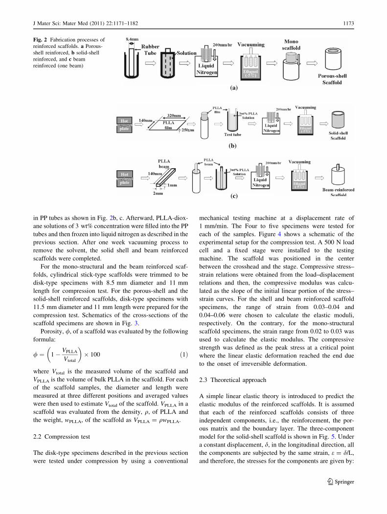
in PP tubes as shown in Fig. 2b, c. Afterward, PLLA-diox-
ane solutions of 3 wt% concentration were filled into the PP
tubes and then frozen into liquid nitrogen as described in the
previous section. After one week vacuuming process to
remove the solvent, the solid shell and beam reinforced
scaffolds were completed.
For the mono-structural and the beam reinforced scaf-
folds, cylindrical stick-type scaffolds were trimmed to be
disk-type specimens with 8.5 mm diameter and 11 mm
length for compression test. For the porous-shell and the
solid-shell reinforced scaffolds, disk-type specimens with
11.5 mm diameter and 11 mm length were prepared for the
compression test. Schematics of the cross-sections of the
scaffold specimens are shown in Fig. 3.
Porosity, /, of a scaffold was evaluated by the following
formula:
/ ¼ 1� VPLLA
Vtotal
� �� 100 ð1Þ
where Vtotal is the measured volume of the scaffold and
VPLLA is the volume of bulk PLLA in the scaffold. For each
of the scaffold samples, the diameter and length were
measured at three different positions and averaged values
were then used to estimate Vtotal of the scaffold. VPLLA in a
scaffold was evaluated from the density, q, of PLLA and
the weight, wPLLA, of the scaffold as VPLLA = qwPLLA.
2.2 Compression test
The disk-type specimens described in the previous section
were tested under compression by using a conventional
mechanical testing machine at a displacement rate of
1 mm/min. The Four to five specimens were tested for
each of the samples. Figure 4 shows a schematic of the
experimental setup for the compression test. A 500 N load
cell and a fixed stage were installed to the testing
machine. The scaffold was positioned in the center
between the crosshead and the stage. Compressive stress–
strain relations were obtained from the load–displacement
relations and then, the compressive modulus was calcu-
lated as the slope of the initial linear portion of the stress–
strain curves. For the shell and beam reinforced scaffold
specimens, the range of strain from 0.03–0.04 and
0.04–0.06 were chosen to calculate the elastic moduli,
respectively. On the contrary, for the mono-structural
scaffold specimens, the strain range from 0.02 to 0.03 was
used to calculate the elastic modulus. The compressive
strength was defined as the peak stress at a critical point
where the linear elastic deformation reached the end due
to the onset of irreversible deformation.
2.3 Theoretical approach
A simple linear elastic theory is introduced to predict the
elastic modulus of the reinforced scaffolds. It is assumed
that each of the reinforced scaffolds consists of three
independent components, i.e., the reinforcement, the por-
ous matrix and the boundary layer. The three-component
model for the solid-shell scaffold is shown in Fig. 5. Under
a constant displacement, d, in the longitudinal direction, all
the components are subjected by the same strain, e = d/L,
and therefore, the stresses for the components are given by:
(b)
(a)
(c)
Fig. 2 Fabrication processes of
reinforced scaffolds. a Porous-
shell reinforced, b solid-shell
reinforced, and c beam
reinforced (one beam)
J Mater Sci: Mater Med (2011) 22:1171–1182 1173
123
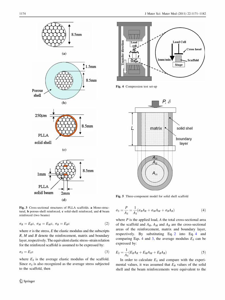
rR ¼ ERe; rM ¼ EMe; rB ¼ EBe ð2Þ
where r is the stress, E the elastic modulus and the subscripts
R, M and B denote the reinforcement, matrix and boundary
layer, respectively. The equivalent elastic stress–strain relation
for the reinforced scaffold is assumed to be expressed by:
rS ¼ ESe ð3Þ
where ES is the average elastic modulus of the scaffold.
Since rS is also recognized as the average stress subjected
to the scaffold, then
rS ¼P
AS¼ 1
ASrRAR þ rMAM þ rBABð Þ ð4Þ
where P is the applied load, A the total cross-sectional area
of the scaffold and AR, AM and AB are the cross-sectional
areas of the reinforcement, matrix and boundary layer,
respectively. By substituting Eq. 2 into Eq. 4 and
comparing Eqs. 4 and 3, the average modulus ES can be
expressed by:
ES ¼1
ASðERAR þ EMAM þ EBABÞ ð5Þ
In order to calculate ES and compare with the experi-
mental values, it was assumed that ER values of the solid
shell and the beam reinforcements were equivalent to the
(a)
(b)
(c)
(d)
Fig. 3 Cross-sectional structures of PLLA scaffolds. a Mono-struc-
tural, b porous-shell reinforced, c solid-shell reinforced, and d beam
reinforced (two beams)
Fig. 4 Compression test set-up
Fig. 5 Three-component model for solid shell scaffold
1174 J Mater Sci: Mater Med (2011) 22:1171–1182
123
elastic modulus of bulk PLLA that was evaluated by
compression tests of bulk PLLA specimens. ER of the
porous shell was chosen as the modulus of the mono-
structural scaffold made from 10 wt% PLLA solution. For
all the reinforced scaffolds, EM was assumed to be equiv-
alent to the modulus of the mono-structural scaffold made
from 3 wt% PLLA solution. EB was assumed to be equal to
the modulus of the mono-structural scaffold made from
30 wt% PLLA solution on the basis of structural analysis
of the porous structure of the boundary layer using
FE-SEM micrographs. The cross-sectional areas were
directly measured from FE-SEM micrographs. The data
used in this theoretical analysis are shown in Table 1.
2.4 Microstructural characterization
The porous microstructures of the scaffolds were charac-
terized using a field emission scanning electron microscope
(FE-SEM) (S-4100, Hitachi, Japan). FE-SEM was also
utilized to characterize the deformation mechanism at the
critical point. Undeformed and deformed samples of the
scaffolds were cut into about 5 mm pieces by flesh razor
blades after frozen in liquid nitrogen for several minutes
and placed on aluminum disks using carbon tapes, and the
entire surfaces were coated with Pt–Pd using an Ion sputter
coater (E-1030, Hitachi, Japan).
2.5 Cultivation of MC3T3-E1 cells
Osteoblast-like cells, MC3T3-E1, were cultured with
ascorbic-free a-MEM supplements with 1% penicillin–
streptomycin and 10% FBS in a 60 mm2 cell culture dish,
and the culture medium was changed every 2 days. The
culture dishes were placed in a humidified incubator at
37�C with 95% air/5% CO2 (v/v) during cell culturing. The
cells were counted using a hemacytometer every subculture
day. The cultured cells were suspended at the concentration
of 5 9 104 cells/ll in fresh medium to seed on the scaf-
folds. The cell suspensions of high concentration of 10 ll
were seeded onto the surfaces of pre-wetted scaffolds. The
scaffolds were submerged in ethanol for 1 h and then
soaked in PBS three times (30 min each). After sterilizing,
the scaffolds were then washed in prepared culture medium
twice (2 h each). The cell-seeded scaffolds were then
placed in the humidified incubator and the medium was
changed every 2 days. Adhesion behavior of MC3T3-E1
cells on the surfaces of the scaffolds were observed after
12 days of cell seeding.
3 Results and discussion
3.1 Porosity and microstructure
Porosity is thought to be one of the most important key
factors in designing scaffold for cell cultivation. Li et al.
[55] reported that the suitable porosity for improving cell
adhesion was more than 80%. Porosity values of the
scaffolds estimated by Eq. 1 are shown in Table 2. The
averaged porosities of the reinforced scaffolds were lower
than that of the mono-structural scaffold, however, still
higher than 80%. Such reduction of the averaged porosity
is obviously related to the existence of solid or dense
reinforcements in the scaffolds. Although the averaged
porosity decreases due to reinforcements, the fundamental
porosities of the porous matrices were almost the same as
the mono scaffold as shown in Table 2 in which the
averaged porosities and the porosities of the porous shell
and the matrices are presented.
FE-SEM micrographs of the microstructures of the
scaffolds are shown in Fig. 6. Homogeneous distributions
of pores are observed in all the scaffolds. In the porous-
shell scaffold (Fig. 6b), there exists a small gap between
the porous-outer shell and the core region because a mono
scaffold was simply inserted into the porous shell rein-
forcement. Figure 6c, d clearly show that the solid shell
and the beam reinforcement were firmly connected to the
porous matrix regions. It is noted that a porous boundary
region existed between the reinforcement and the porous-
matrix and had less porosity and smaller pore sizes than the
porous matrix region. It is thought that the solid rein-
forcements were slightly dissolved into the PLLA solution
Table 1 Properties used in the theoretical prediction of elastic
moduli
Porous-shell Solid-shell 1 Beam 2 Beams
ER (MPa) 41.8 322.9 322.9 322.9
EM (MPa) 5.52 5.52 5.52 5.52
EB (MPa) 111 111 111 111
AS (mm2) 102.1 57.1 45.4 47.5
AM (mm2) 55.4 51.6 37.9 35.6
AR (mm2) 46.7 3.47 1.44 2.88
AB (mm2) – 1.97 6.0 9.0
Table 2 Porosity values of PLLA scaffolds
Specimen Averaged
porosity (%)
Reinforcement
(%)
Porous
matrix (%)
Mono-structural 94.84 – –
Porous shell 88.11 80.34 94.84
Solid shell 82.91 – 93.74
1 Beam 88.85 – 93.64
2 Beams 83.6 – 92.39
J Mater Sci: Mater Med (2011) 22:1171–1182 1175
123
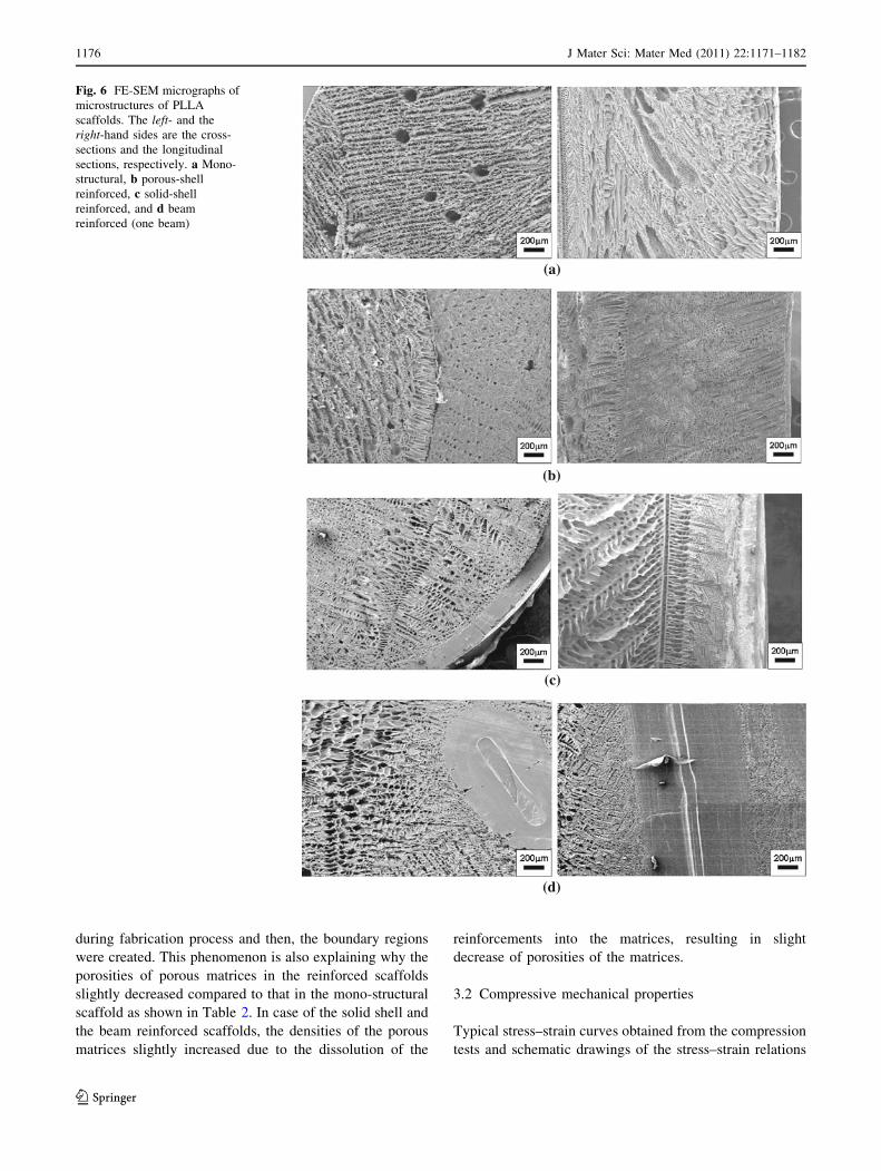
during fabrication process and then, the boundary regions
were created. This phenomenon is also explaining why the
porosities of porous matrices in the reinforced scaffolds
slightly decreased compared to that in the mono-structural
scaffold as shown in Table 2. In case of the solid shell and
the beam reinforced scaffolds, the densities of the porous
matrices slightly increased due to the dissolution of the
reinforcements into the matrices, resulting in slight
decrease of porosities of the matrices.
3.2 Compressive mechanical properties
Typical stress–strain curves obtained from the compression
tests and schematic drawings of the stress–strain relations
(a)
(b)
(c)
(d)
Fig. 6 FE-SEM micrographs of
microstructures of PLLA
scaffolds. The left- and the
right-hand sides are the cross-
sections and the longitudinal
sections, respectively. a Mono-
structural, b porous-shell
reinforced, c solid-shell
reinforced, and d beam
reinforced (one beam)
1176 J Mater Sci: Mater Med (2011) 22:1171–1182
123

are shown in Figure 7a, b. The stress–strain relations are
basically divided into four regions based on their defor-
mation behaviors as shown in Fig. 7b. The region 1 is
characterized by the gentle slope mainly due to the mis-
alignment between the specimen upper surface and the
loading device. The region 2 is recognized as the initial
linear portion corresponding to the global linear elastic
deformation of the scaffolds. The compressive moduli were
evaluated as the slopes of these regions. The region 3
contains the critical point at which the global elastic
deformation was ended due to local irreversible deforma-
tions such as microbuckling of the struts constructing pore
structures or delamination between the reinforcements and
the porous matrices. In the region 4, the stresses slightly
increased in the shell reinforced scaffolds, gradually
decreased in the beam reinforced scaffolds or was almost
constant in the mono-structural scaffold. These different
behaviors were caused by the different failure modes dis-
cussed in the Sect. 3.3. It is clearly seen from Fig. 7b that
the slope of the region 2, corresponding to the elastic
modulus, and the stress level at the critical point increased
due to the introduction of the reinforcements, suggesting
the improvement of the modulus and the strength. It is
noted that characterization of the relationship between the
deformation mechanism and the stress–strain relation in the
whole range of strain from 0 to 1 is also important in order
to understand the mechanical response of scaffolds under
compression. Such characterization for PLLA scaffolds has
been discussed in our previous paper [12].
The compressive elastic modulus and the strength are
shown in Fig. 8. It is clearly seen that both the modulus and
the strength were effectively improved by introducing the
reinforcements. The compressive properties of the beam
reinforced scaffolds were higher than those of the shell
reinforced scaffolds. The theoretical values of the modulus
obtained from Eq. 5 are compared with the experimental in
Fig. 9. The theory well predicts the tendency of the rein-
forcement effects, however, tends to result in overestima-
tion. The deformation of the reinforced porous structures
may differ from the simple linear elastic solid model
constructed in this study.
Fig. 7 Stress-strain relations in PLLA scaffolds. a Typical stress–
strain curves and b schematic of stress–strain relations
Fig. 8 Compressive mechanical properties of PLLA scaffolds
Fig. 9 Elastic modulus of theoretical and experimental results
of PLLA scaffolds
J Mater Sci: Mater Med (2011) 22:1171–1182 1177
123
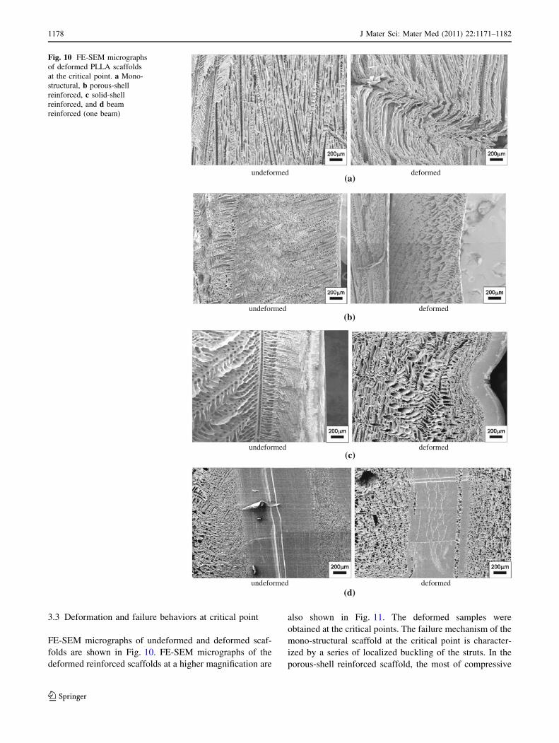
3.3 Deformation and failure behaviors at critical point
FE-SEM micrographs of undeformed and deformed scaf-
folds are shown in Fig. 10. FE-SEM micrographs of the
deformed reinforced scaffolds at a higher magnification are
also shown in Fig. 11. The deformed samples were
obtained at the critical points. The failure mechanism of the
mono-structural scaffold at the critical point is character-
ized by a series of localized buckling of the struts. In the
porous-shell reinforced scaffold, the most of compressive
undeformed deformed
undeformed deformed
undeformed deformed
undeformed deformed
(a)
(b)
(c)
(d)
Fig. 10 FE-SEM micrographs
of deformed PLLA scaffolds
at the critical point. a Mono-
structural, b porous-shell
reinforced, c solid-shell
reinforced, and d beam
reinforced (one beam)
1178 J Mater Sci: Mater Med (2011) 22:1171–1182
123
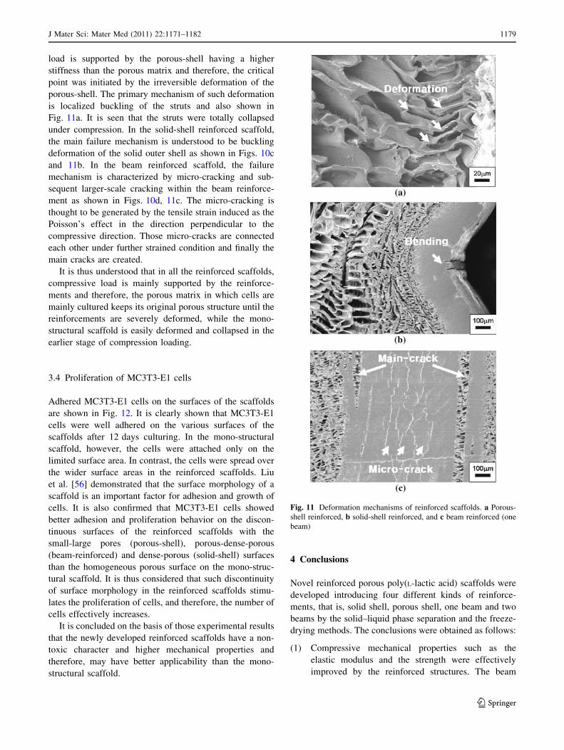
load is supported by the porous-shell having a higher
stiffness than the porous matrix and therefore, the critical
point was initiated by the irreversible deformation of the
porous-shell. The primary mechanism of such deformation
is localized buckling of the struts and also shown in
Fig. 11a. It is seen that the struts were totally collapsed
under compression. In the solid-shell reinforced scaffold,
the main failure mechanism is understood to be buckling
deformation of the solid outer shell as shown in Figs. 10c
and 11b. In the beam reinforced scaffold, the failure
mechanism is characterized by micro-cracking and sub-
sequent larger-scale cracking within the beam reinforce-
ment as shown in Figs. 10d, 11c. The micro-cracking is
thought to be generated by the tensile strain induced as the
Poisson’s effect in the direction perpendicular to the
compressive direction. Those micro-cracks are connected
each other under further strained condition and finally the
main cracks are created.
It is thus understood that in all the reinforced scaffolds,
compressive load is mainly supported by the reinforce-
ments and therefore, the porous matrix in which cells are
mainly cultured keeps its original porous structure until the
reinforcements are severely deformed, while the mono-
structural scaffold is easily deformed and collapsed in the
earlier stage of compression loading.
3.4 Proliferation of MC3T3-E1 cells
Adhered MC3T3-E1 cells on the surfaces of the scaffolds
are shown in Fig. 12. It is clearly shown that MC3T3-E1
cells were well adhered on the various surfaces of the
scaffolds after 12 days culturing. In the mono-structural
scaffold, however, the cells were attached only on the
limited surface area. In contrast, the cells were spread over
the wider surface areas in the reinforced scaffolds. Liu
et al. [56] demonstrated that the surface morphology of a
scaffold is an important factor for adhesion and growth of
cells. It is also confirmed that MC3T3-E1 cells showed
better adhesion and proliferation behavior on the discon-
tinuous surfaces of the reinforced scaffolds with the
small-large pores (porous-shell), porous-dense-porous
(beam-reinforced) and dense-porous (solid-shell) surfaces
than the homogeneous porous surface on the mono-struc-
tural scaffold. It is thus considered that such discontinuity
of surface morphology in the reinforced scaffolds stimu-
lates the proliferation of cells, and therefore, the number of
cells effectively increases.
It is concluded on the basis of those experimental results
that the newly developed reinforced scaffolds have a non-
toxic character and higher mechanical properties and
therefore, may have better applicability than the mono-
structural scaffold.
4 Conclusions
Novel reinforced porous poly(L-lactic acid) scaffolds were
developed introducing four different kinds of reinforce-
ments, that is, solid shell, porous shell, one beam and two
beams by the solid–liquid phase separation and the freeze-
drying methods. The conclusions were obtained as follows:
(1) Compressive mechanical properties such as the
elastic modulus and the strength were effectively
improved by the reinforced structures. The beam
(a)
(b)
(c)
Fig. 11 Deformation mechanisms of reinforced scaffolds. a Porous-
shell reinforced, b solid-shell reinforced, and c beam reinforced (one
beam)
J Mater Sci: Mater Med (2011) 22:1171–1182 1179
123

reinforced scaffolds exhibited higher mechanical
properties than the core–shell scaffolds.
(2) A simple theoretical approach on the basis of the
linear elastic mechanics was presented in order to
predict the compressive elastic moduli of the rein-
forced scaffolds. A three-phase model was introduced
and the analytical results well coincided with the
experimental results.
(3) In the solid shell reinforced scaffold, the primary
failure mechanism at the critical point was charac-
terized by the buckling of the solid shell under
compressive loading. In the porous shell reinforced
(a)
(b)
(c)
(d)
Fig. 12 Adhesion behaviors
of MC3T3-E1 cells on PLLA
scaffolds. a Mono-structural,
b porous-shell reinforced,
c solid-shell reinforced, and
d beam reinforced (one beam)
1180 J Mater Sci: Mater Med (2011) 22:1171–1182
123
scaffold, the porous shell was mainly deformed at the
critical point, and the main mechanism of failure was
the localized buckling of the struts constructing the
pores in the porous shell. For the beam reinforced
scaffolds, the primary failure mechanism was found
to be the micro-cracking within the beams and the
subsequent formation of the main-crack due to the
coalescence of the micro-racks.
(4) MC3T3-E1 cells were well adhered and proliferated
on the surfaces of the scaffolds. The cells were more
widely adhered on the reinforced scaffolds than the
mono-structural scaffold.
References
1. De Bore HH. The history of bone grafts. Clin Orthop Relat Res.
1988;226:292–8.
2. Vacanti CA, Kim W, Upton J, et al. Tissue-engineered growth of
bone and cartilage. Transplant Proc. 1993;25:1019–21.
3. Dolde JVD, Farber E, Spauwen PHM, Jansen JA. Bone tissue
reconstruction using titanium fiber mesh combined with rat bone
marrow stromal cells. Biomaterials. 2003;24:1745–50.
4. Nienhuijs MEL, Walboomers XF, Merkx MAW, et al. Bone-like
tissue formation using an equine COLLOSS� E-filled titanium
scaffolding material. Biomaterials. 2006;27:3109–14.
5. Fujibayashi S, Neo M, Kim HM, et al. Osteoinduction of porous
bioactive titanium metal. Biomaterials. 2004;25:443–50.
6. Li JP, Wijn JRD, Blitterswijk CAV, Groot KD. Porous Ti6Al4V
scaffold directly fabricating by rapid prototyping: preparation and
in vitro experiment. Biomaterials. 2006;27:1223–35.
7. Dellinger JG, Eurell JAC, Jamison RD. Bone response to 3D
periodic hydroxyapatite scaffolds with and without tailored
microporosity to deliver bone morphogenetic protein 2. J Biomed
Mater Res. 2005;76A:366–76.
8. Deville S, Saiz E, Tomsia AP. Freeze casting of hydroxyapatite
scaffolds for bone tissue engineering. Biomaterials. 2006;27:
5480–9.
9. Yuan H, Bruijn JD, Li Y, et al. Bone formation induced by cal-
cium phosphate ceramics in soft tissue of dogs: a comparative
study between porous a-TCP and b-TCP. J Mater Sci Mater Med.
2001;12:7–13.
10. Wiltfang J, Merten HA, Schlegel KA, et al. Degradation char-
acteristics of a and b tri-calcium-phosphate (TCP) in minipigs.
J Biomed Mater Res. 2002;63:115–21.
11. Reverchon E, Cardea S, Rapuano C. A new supercritical fluid-
based process to produce scaffolds for tissue replacement.
J Supercrit Fluids. 2008;45:365–73.
12. Todo M, Kuraoka H, Kim JW, et al. Deformation behavior and
mechanism of porous PLLA under compression. J Mater Sci.
2008;43:5644–6.
13. Lin ASP, Barrows TH, Cartmell SH, Guldberg RE. Microarchi-
tectural and mechanical characterization of oriented porous
polymer scaffolds. Biomaterials. 2003;24:481–9.
14. MA L, Gao C, Mao Z, et al. Collagen/chitosan porous scaffolds
with improved biostability for skin tissue engineering. Biomate-
rials. 2003;24:4833–41.
15. Seda Tıglı R, Karakecili A, Gumusderelioglu M. In vitro char-
acterization of chitosan scaffolds: influence of composition and
deacetylation degree. J Mater Sci Mater Med. 2007;18:1665–74.
16. Ghosh S, Viana JC, Reis RL, Mano JF. Bi-layered constructs
based on poly(L-lactic acid) and starch for tissue engineering of
osteochondral defects. Mater Sci Eng C. 2008;28:80–6.
17. Wei G, Ma PX. Structure and properties of nano-hydroxyapatite/
polymer composite scaffolds for bone tissue engineering. Bio-
materials. 2004;25:4749–57.
18. Miao X, Tan DM, Li J, Xiao Y, Crawford R. Mechanical and
biological properties of hydroxyapatite/tricalcium phosphate
scaffolds coated with poly(lactic-co-glycolic acid). Acta Bioma-
ter. 2008;4:638–45.
19. Yang XB, Webb D, Blaker J, et al. Evaluation of human bone
marrow stromal cell growth on biodegradable polymer/bioglass
composites. Biochem Biophys Res Commun. 2006;342:1098–107.
20. Yamamoto M, Takahashi Y, Hokugo A, Tabata Y. Enhanced
osteoinduction by controlled release of bone morphogenetic
protein-2 from biodegradable sponge composed of gelatin and
b-tricalcium phosphate. Biomaterials. 2005;26:4856–65.
21. Tanaka T, Eguchi S, Satoh H, et al. Microporous foams of
polymer blends of poly(L-lactic acid) and poly(e-caprolactone).
Desalination. 2008;234:175–83.
22. Oron A, Agar G, Oron U, Stein A. Correlation between rate of
bony ingrowth to stainless steel, pure titanium, and titanium alloy
implants in vivo and formation of hydroxyapetite on their sur-
faces in vitro. J Biomed Mater Res. 2008;91A:1006–9.
23. Wall EJ, Jain V, Vora V, Mehlman CT, Crawford AH. Complica-
tions of titanium and stainless steel elastic nail fixation of pediatric
femoral fractures. J Bone Joint Surg Am. 2008;90:1305–13.
24. Niinomi M. Mechanical biocompatibilities of titanium alloys for
biomedical applications. J Mecha Behav Biomed Mater. 2008;1:
30–42.
25. Zhang E, Xu L, Yu G, et al. In vivo evaluation of biodegradable
magnesium alloy bone implant in the first 6 months implantation.
J Biomed Mater Res. 2009;90A:882–93.
26. Chen J, Birch MA, Bull SJ. Nanomechanical characterization of
tissue engineered bone grown on titanium alloy in vitro. J Mater
Sci Mater Med. 2010;21:277–82.
27. Tadic D, Beckmann F, Schwarz K, Epple M. A novel method to
produce hydroxyapatite objects with interconnectingporosity that
avoids sintering. Biomaterials. 2004;25:3335–40.
28. Matsumura K, Hyon SH, Nakajima N, et al. Surface modification
of poly(ethylene-co-vinyl alcohol): hydroxyapatite immobiliza-
tion and control of periodontal ligament cells differentiation.
Biomaterials. 2004;25:4817–24.
29. Webster TJ, Ergun C, Doremus RH, et al. Enhanced functions
of osteoblasts on nanophase ceramics. Biomaterials. 2000;21:
1803–10.
30. Chen QZ, Efthymiou A, Salih V, Boccaccini AR. Bioglass�-
derived glass–ceramic scaffolds: study of cell proliferation and
scaffold degradation in vitro. J Biomed Mater Res. 2007;84A:
1049–60.
31. Bignon A, Chouteau J, Chevalier J, et al. Effect of micro- and
macroporosity of bone substitutes on their mechanical properties
and cellular response. J Mater Sci Mater Med. 2003;14:1089–97.
32. Peroglio M, Gremillard L, Chevalier J, et al. Toughening of bio-
ceramics scaffolds by polymer coating. J Eur Ceram Soc. 2007;
27:2679–85.
33. Rezwana K, Chena QZ, Blakera JJ, Boccaccini AR. Biodegrad-
able and bioactive porous polymer/inorganic composite scaffolds
for bone tissue engineering. Biomaterials. 2006;27:3413–31.
34. Todo M, Park JE, Kuraoka H, et al. Compressive deformation
behavior of porous PLLA/PCL polymer blend. J Mater Sci.
2009;44:4191–4.
35. Kim SS, Park MS, Jeon OJ, et al. Poly(lactide-co-glycolide)
hydroxyapatite composite scaffolds for bone tissue engineering.
Biomaterals. 2006;27:1399–409.
J Mater Sci: Mater Med (2011) 22:1171–1182 1181
123
36. Simon JL, Rekow ED, Thompson VP, et al. MicroCT analysis of
hydroxyapatite bone repair scaffolds created via three-dimen-
sional printing for evaluating the effects of scaffold architecture
on bone ingrowth. J Biomed Mater Res. 2007;85A:371–7.
37. George J, Kuboki Y, Miyata T. Differentiation of mesenchymal
stem cells into osteoblasts on honeycomb collagen scaffolds.
Biotech Bioeng. 2006;95:404–11.
38. Yunos DM, Bretcanu O, Boccaccini AR. Polymer-bioceramic
composites for tissue engineering scaffolds. J Mater Sci. 2008;43:
4433–42.
39. Kang Y, Yin G, Yuan Q, et al. Preparation of poly(L-lactic acid)/
b-tricalcium phosphate scaffold for bone tissue engineering
without organic solvent. Mater Lett. 2008;62:2029–32.
40. O’Brien FJ, Harley BA, Yannas IV, Gibson LJ. The effect of pore
size on cell adhesion in collagen-GAG scaffolds. Biomaterials.
2005;26:433–41.
41. Georgiou G, Mathieu L, Pioletti DP, et al. Polylactic acid–
phosphate glass composite foams as scaffolds for bone tissue
engineering. J Biomed Mater Res. 2007;80B:322–31.
42. Tsivintzelis I, Pavlidou E, Panayiotou C. Porous scaffolds pre-
pared by phase inversion using supercritical CO2 as antisolvent: I.
Poly(L-lactic acid). J Supercrit Fluids. 2007;40:317–22.
43. Maquet V, Boccaccini AR, Pravata L, et al. Preparation, char-
acterization, and in vitro degradation of bioresorbable and bio-
active composites based on Bioglass�-filled polylactide foams.
J Biomed Mater Res. 2003;66A:335–46.
44. Ang TH, Sultana FSA, Hutmacher DW, et al. Fabrication of 3D
chitosan–hydroxyapatite scaffolds using a robotic dispensing
system. Mater Sci Eng C. 2002;20:35–42.
45. Teng X, Ren J, Gu S. Preparation and characterization of porous
PDLLA/HA composite foams by supercritical carbon dioxide
technology. J Biomed Mater Res. 2006;81B:185–93.
46. Oh SH, Park IK, Kim JM, Lee JH. In vitro and in vivo charac-
teristics of PCL scaffolds with pore size gradient fabricated by a
centrifugation method. Biomaterials. 2007;28:1664–71.
47. Murphy CM, Haugh MG, O’Brien FJ. The effect of mean pore
size on cell attachment, proliferation and migration in collagen–
glycosaminoglycan scaffolds for bone tissue engineering. Bio-
materials. 2010;31:461–6.
48. Karageorgiou V, Kaplan D. Porosity of 3D biomaterial scaffolds
and osteogenesis. Biomaterials. 2005;26:5474–91.
49. He X, Lu H, Kawazoe N, Tateishi T, Chen G. A novel cylinder-
type poly(L-lactic acid)–collagen hybrid sponge for cartilage
tissue engineering. Tissue Eng C Methods. 2010;16:329–38.
50. Young CS, Terada S, Vacanti JP, et al. Tissue engineering of
complex tooth structures on biodegradable polymer scaffolds.
J Dent Res. 2002;81:695–700.
51. Tu C, Cai Q, Yang J, et al. The fabrication and characterization of
poly(lactic acid) scaffolds for tissue engineering by improved
solid-liquid phase separation. Polym Adv Technol. 2003;14:
565–73.
52. Hu FJ, Park TG, Lee DS. A facile preparation of highly inter-
connected macroporous poly(D, L-lactic acid-co-glycolic acid)
(PLGA) scaffolds by liquid–liquid phase separation of a PLGA–
dioxane–water ternary system. Polymer. 2003;44:1911–20.
53. Woo KM, Seo JH, Zhang R, Ma PX. Suppression of apoptosis by
enhanced protein adsorption on polymer/hydroxyapatite com-
posite scaffolds. Biomaterials. 2007;28:2622–30.
54. Park JE, Todo M. Development of layered porous poly(L-lactide)
for bone regeneration. J Mater Sci. 2010;45:3966–8.
55. Li X, Feng Q, Cui F. In vitro degradation of porous nano-
hydroxyapatite collagen PLLA scaffold reinforced by chitin
fibres. Mater Sci Eng C. 2006;26:716–20.
56. Liu HC, Lee IC, Wang JH, et al. Preparation of PLLA memb-
raines with different morphologies for culture of MG-63 cells.
Biomaterials. 2003;25:4047–56.
1182 J Mater Sci: Mater Med (2011) 22:1171–1182
123