1
A PROJECT REPORT
ON
“Design, Analysis of jar coupler 0f Mixer Grinder and Producing its Prototype
Using Additive Manufacturing”
Sybmitted by
PATEL ASAD AEJAZ ROLL NO: 16ME54
PASHA ABDULMUTALIB MOHD SAYYED ROLL NO: 16ME53
SAYYED ASLAM PEERPASHA ROLL NO: 15ME40
KHAN HARIS SHAKIL ROLL NO: 15ME17
In partial fulfillment for the award of the Degree
Of
BACHELOR OF ENGINEERING
IN
MECHANICAL ENGINEERING
UNDER THE GUIDANCE
Of
Prof. SHAIKH MOHAMMED JAWED
DEPARTMENT OF MECHANICAL ENGINEERING
ANJUMAN-I-ISLAM
KALSEKAR TECHNICAL CAMPUS NEW PANVEL,410206
UNIVERSITY OF MUMBAI
IR@AIKTC-KRRC
ir.aiktclibrary.org
2
CERTIFICATE
This is to certify that the project entitled “Design, Analysis and Manufacturing of jar
coupler 0f Mixer Grinder Using Additive Manufacturing”
Submitted by
PATEL ASAD AEJAZ ROLL NO: 16ME54
PASHA ABDULMUTALIB MOHD SAYYED ROLL NO: 16ME53
SAYYED ASLAM PEERPASHA ROLL NO: 15ME40 KHAN
HARIS SHAKIL ROLL NO: 15ME17
To the Kalsekar Technical Campus, New Panvel is a record of bonafide work carried
out by him under our supervision and guidance, for partial fulfillment of the requirements for
the award of the Degree of Bachelor of Engineering in Mechanical Engineering as prescribed
by University Of Mumbai, is approved.
Internal Examinar External Examiner
(Prof. Shaikh Mohammed Jawed) (prof._____________)
Head of Department DIRECTOR AIKTC
(Prof Zakir Ansari) ( DR. Abdul Razak )
IR@AIKTC-KRRC
ir.aiktclibrary.org
3
APPROVAL OF DISSERTATION
This is to certify that the thesis entitled
““Design, Analysis and Manufacturing of jar coupler 0f Mixer Grinder Using Additive
Manufacturing”
Submitted by
PATEL ASAD AEJAZ ROLL NO: 16ME54
PASHA ABDULMUTALIB MOHD SAYYED ROLL NO: 16ME53
SAYYED ASLAM PEERPASHA ROLL NO: 15ME40 KHAN
HARIS SHAKIL ROLL NO: 15ME17
In partial fulfillment of the requirements for the award of the Degree of Bachelor of
Engineering in Mechanical Engineering, as prescribed by University of Mumbai approved.
Internal Examinar External Examiner
(Prof. Shaikh Mohammed Javed) (prof._____________)
Date: __________
IR@AIKTC-KRRC
ir.aiktclibrary.org
4
ACKNOWLEDGEMENT
After the completion of this work, we would like to give our sincere thanks to all those
who helped us to reach our goal. It’s a great pleasure and moment of immense satisfaction for
us to express my profound gratitude to our guide Mr. SHAIKH MOHAMMAED JAWED
whose constant encouragement enabled us to work enthusiastically. His perpetual motivation,
patience and excellent expertise in discussion during progress of the project work have
benefited us to an extent, which is beyond expression.
We would also like to give our sincere thanks to Prof._ZAKIR ANSARI, Head Of
Department, Prof. SHAIKH MOHAMMED JAWED, Project Co-Guide and Prof.
RIZWAN SHAIKH, Project co-ordinator from Department of Mechanical Engineering,
Kalsekar Technical Campus, New Panvel, for their guidance, encouragement and support
during a project.
I am thankful to Dr. ABDUL RAZAK HONNUTAGI, Kalsekar Technical Campus
New Panvel, for providing an outstanding academic environment, also for providing the
adequate facilities.
Last but not the least I would also like to thank all the staffs of Kalsekar Technical Campus
(Mechanical Engineering Department) for their valuable guidance with their interest and
valuable suggestions brightened us.
IR@AIKTC-KRRC
ir.aiktclibrary.org
5
ABSTRACT Jar Coupler are power transmission components used to transfer power from one shaft to other.
Polymer gears finds its applications in all the segments of mechanical power transmission
system because of its high strength to weigh ratio. They are manufactured using injection
molding process which are costly due to mold cost and are more time consuming process.
Additive manufacturing technique can be implemented because of its compatibility to produce
complex designs and for customized requirements. The literature review shows that 3D
printing technology is useful for Product development for fast product delivery. Jar Coupler
used in Bajaj Mixer Grinding machine is considered in this project work and additive
manufacturing method is used to produce the product other than conventional method. This Jar
Coupler is made of Polyethylene polymer material. 3D modelling is done using Solidworks
2015 software. Finite Element analysis software SOLIDWORKS Simulation is used to study
the Strength. Jar Coupler is Manufactured by 3D printing FDM technique with PLA and Nylon
filament.
This method of manufacturing the Jar Coupler will results into product development in short
time and at low cost. These types of Jar Coupler can be used in any power transmission system
and can be manufactured with required load carrying capacity and complex designs. Jar
Coupler manufactured using additive manufacturing methods will reduce the manufacturing
time, easy to make customized parts instantly, low rate of wear and increase in life of Jar
Coupler.
IR@AIKTC-KRRC
ir.aiktclibrary.org
6
TABLE OF CONTENTS
CERTIFICATE ……………………………………………………………..02
APPROVAL OF PROJECT ……………………………………………......03
ACKNOWLEDGEMENT………………………………….…………….…04
ABSTRACT……………………………………………………………….…05
CHAPTER 1: INTRODUCTION...…………………………..………….…07
1.1 INTRODUCTION OF JAR COUPLER……………………………….…07
1.2 INTRODUCTION TO 3D PRINTING………………………....…….…..08
1.3 ADVANTAGES OF 3D PRINTING………………………….……….…09
CHAPTER 2: LITERATURE REVIEW…………………………….….…10
CHAPTER 3: OBJECTIVES AND PROBLEM DEFINITION………….12
3.1 OBJECTIVES……………….………………………………………….…12
3.2 PROBLEM DEFINITION……..……………………………………….…12
CHAPTER 4: METHODOLOGY……………………………………….….13
CHAPTER 5A: SELECTION OF JAR COUPLER...……………….….…15
5.1 SELECTION OF MIXER GRINDER
5.2 POLYMER JAR COUPLER IN TRANSMISSION
5.3 REQUIREMENT
CHAPTER 5B: TORSION TEST OF JAR COUPLER…………………...17
CHAPTER 6: MATERIAL SELECTION………………………………….19
CHAPTER 7: JAR COUPLER DAMAGE MODES………………………20
CHAPTER 8: REVERSE ENGINEERING AND 3D MODELLING…….20
8.1 REVERSE ENGINEERING……………………………………………………………………………21
8.2 REVERSE ENGINEERING OF JAR COUPLER…………………………………………………22
IR@AIKTC-KRRC
ir.aiktclibrary.org
7
8.3 INTRODUCTION TO SOLIDWORKS…………………………………………………………….22
8.4 RENDERED IMAGES OF JAR COUPLER……………………………………………………….23
CHAPTER 9: FEA ANALYSIS OF JAR COUPLER…………………….26
9.1 FEA OF EXISTING JAR COUPLER FOR ACTUAL WORKING CONDITIONS…….29
9.2 FEA OF NEW DESIGN JAR COUPLER……………………………………………………..….30
9.3 DESIGN CALCULATION…………………………………………………………………….………30
9.4 SIMULATION RESULT……………………………………………………………………….………31
CHAPTER 10: 3D PRINTING FILAMENT AND METHOD……………36
10.1 INTRODUCTION TO 3D PRINTING…………………………………..36
10.2 3D PRINTING METHODS……………………………………...………36
10.3 SELECTION OF 3D PRINTING METHOD……………………………38
10.4 MATERIALS FOR 3D PRINTING METHOD………………………….39
10.5 SHORTLISTING OF 3D PRINTING MATERIALS……………...….…39
10.6 MECHANICAL PROPERTIES OF MATERIALS………………....…...40
10.7 3D PRINTING FILAMENT OF JAR COUPLER……………….....……40
10.8 3D PRINTING USING FDM………………………………………...…..40
10.9 3D PRINTED PRODUCT COST ESTIMATION…………………...…..41
CHAPTER 11: RESULTS……………………………………………...……42
CHAPTER 12: CONCLUSION AND FUTURE SCOPE………………….43
REFERENCES………………………………………………………………..44
IR@AIKTC-KRRC
ir.aiktclibrary.org
8
Chapter 1
Introduction
1.1 Introduction to jar coupler Jar Coupler are power transmission components used to transfer power from one shaft to
other. A polymer gear finds its applications in all the segments of mechanical power transmission
system because of its high strength to weigh ratio. They are manufactured using by injection
molding which are costly due to mold cost and are more time consuming process. Additive
manufacturing technique can be implemented because of its compatibility to produce complex
designs and for customized requirements. The literature review shows that 3D printing technology is
useful for Product development for fast product delivery.
Jar Coupler used in Bajaj Mixer Grinding machine is considered in this project work and
additive manufacturing method is used to produce the product other than conventional method.
This Jar Coupler is made of Polyethylene polymer material. 3D modeling is done using Solidworks
2015 software. Finite Element analysis software ANSYS 15.0 is used to study the Maximum
Rotational Speed. Jar Coupler is manufactured using 3D printing FDM technique with PLA and Nylon
filament.
This method of manufacturing the Jar Coupler will results into product development in short
time and at low cost. These types of Jar Coupler can be used in any power transmission system and
can be manufactured with required load carrying capacity and complex designs. Jar Coupler
manufactured using additive manufacturing methods will reduce the manufacturing time, easy to
make customized gears instantly, low rate of wear and increase in life of Jar Coupler.
IR@AIKTC-KRRC
ir.aiktclibrary.org
9
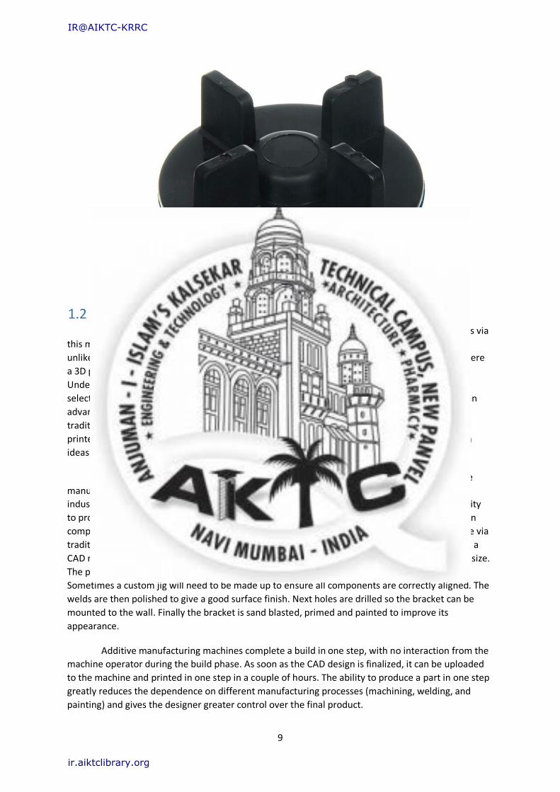
Fig No 1.1. Polymer Jar Coupler
1.2 Introduction to 3D printing 3D printing creates solid parts by building up objects one layer at a time. Producing parts via
this method offers many advantages over traditional manufacturing techniques.3D printing is
unlikely to replace many traditional manufacturing methods yet there are many applications where
a 3D printer is able to deliver a design quickly, with high accuracy from a functional material.
Understanding the advantages of 3D printing allows designers to make better decisions when
selecting a manufacturing technique that results delivery of the optimal product. One of the main
advantages of additive manufacture is the speed at which parts can be produced compared to
traditional manufacturing methods. Complex designs can be uploaded from a CAD model and
printed in a few hours. The advantage of this is the rapid verification and development of design
ideas.
Where in the past it may have taken days or even weeks to receive a prototype, additive
manufacturing places a model in the hands of the designer within a few hours. While the more
industrial additive manufacturing machines take longer to print and post process a part, the ability
to produce functional end parts at low to mid volumes offers a huge time saving advantage when
compared to traditional manufacturing techniques. Consider a custom steel bracket that is made via
traditional manufacturing methods. Similarly to additive manufacturing, the process begins with a
CAD model. Once the design is finalized, fabrication begins with first cutting the steel profiles to size.
The profiles are then clamped into position and welded one at a time to form the bracket.
Sometimes a custom jig will need to be made up to ensure all components are correctly aligned. The
welds are then polished to give a good surface finish. Next holes are drilled so the bracket can be
mounted to the wall. Finally the bracket is sand blasted, primed and painted to improve its
appearance.
Additive manufacturing machines complete a build in one step, with no interaction from the
machine operator during the build phase. As soon as the CAD design is finalized, it can be uploaded
to the machine and printed in one step in a couple of hours. The ability to produce a part in one step
greatly reduces the dependence on different manufacturing processes (machining, welding, and
painting) and gives the designer greater control over the final product.
IR@AIKTC-KRRC
ir.aiktclibrary.org
10
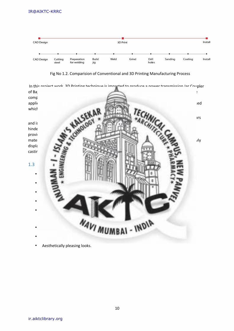
Fig No 1.2. Comparision of Conventional and 3D Printing Manufacturing Process
In this project work, 3D Printing technique is imparted to produce a power transmission Jar Coupler
of Bajaj Mixer Grinding machine. This manufacturing Process helps the engineers to produce the
component for small orders, Complex designs and in short time. For moderate strength
applications, other than going for injection molded Jar Coupler, 3D Printed Jar Coupler can be used
which results in less time to delivery, low cost and Customized designs.
Additive manufacturing (AM) also known as 3D printing has been around for over 30 years
and is now taking center stage in the medical manufacturing field. Initially computing power
hindered the technology but over the years various 3D printing technologies have emerged
providing the ability to make complex moving/interlocking products out of a wide range of
materials. These new AM processes and materials, when used in the correct application are slowly
displacing a percentage of the more traditional subtractive processes like CNC, machining and
casting.
1.3 Advantages of 3D Printed Material
• Anatomically Accurate printed parts are developed mostly used in biomedical field.
• Simple mechanism with complex parts can be made easily in low cost.
• 3D printed parts are comfortable & user friendly.
• Waterproof 3D printing materials are available such as PLA, ABS, NYL, PC etc.
• Lightweight products are manufactured without compromising with their strength,
Durability etc.
• Products made are hygienic.
• 3D printing materials are Recyclable materials which can be used again and again.
• Aesthetically pleasing looks.
IR@AIKTC-KRRC
ir.aiktclibrary.org
11
Chapter 2 Literature Reviews
P.B Pawar, Abhay A Utpat [1]: This works concerned with the replacing metallic gear with
composite material so as to improve performance of machine and to have longer working life. In
this work metallic gears of steel alloy and aluminum silicon carbide composite have been
manufactured which provides improved mechanical properties. Gears manufactured from
composite provides almost 60% less weight compared to steel gear while power rating of both gears
remains almost same. FE analysis also shows less chances of failure in Al-SiC. These gears can be
used for transmitting almost 24KW power.
Dr. Ir H.G. H. Van Melick [2]: This paper describes the investigation of a steel and plastic gear
transmission, using both numerical (FE) and analytical methods. The aim was to study the influence
of the stiffness of the gear material on the bending of the gear teeth, and the consequences on
contact path, load sharing, stresses and kinematics. It has been shown that the load sharing of a
steel-plastic gear pair changes dramatically compared to the conventional theory of steel gears.
K.Mao, P.Langlois, Z.Hu, K.Alharbi, X.Xu, M.Li, C.J. Spur Geare, D.Chetwynd [3]: This paper
concentrate on an extensive investigation of machine cut acetal gear wear and thermal mechanical
contact behavior. The results for machine cut acetal gears will be compared to previously published
results obtained for polymer gears manufactured through injection molding. It is concluded that the
wear rates for the machine cut and injection molded acetal gears tested are independent of the
manufacturing process. It is also concluded that machine cut acetal gears can be designed using the
existing methods for injection molded acetal gears.
S. Senthilvelan, R. Gnanamoorthy [4]: The aim is to check the effect of gear rotational speed on the
performance of unreinforced injection molded nylon 6 & glass fiber reinforced nylon 6 & gears &
also check the thermal (temperature) deformation of comparison between these two polymer
materials. It contain that, the testing of these two materials at various speed & torque level 5 in a
power absorption type gear testing, the tooth temperature of acetal gears using thermal camera &
the flank temperature using infrared pyrometer. There tested gear was observed using an optical
microscope to understand the failure mechanism. It conclude that the glass fibre reinforced nylon 6
gear shows superior performance over unreinforced nylon 6 gears due to its superior mechanical
strength & resistance to thermal deformation.
K. Mao, W. Li, C.J. Spur Geare, D Walton [5]: To investigated of acetal gear on the surface thermal
wear on the basis of ambient, bulk, & flash temperature. And to check the parameters like torque,
IR@AIKTC-KRRC
ir.aiktclibrary.org
12
speed, time to failure & wear is measured by bearing block using non contacting capacitive
transducer. This paper will concentrate on acetal prediction on the basis of surface temp, has been
investigated in details through three components ambient, bulk & flash temperature. Acetal gear
performance was found to be entirely dependent on surface temperature. It concludes that, acetal
gear has been applied to different loading condition gears with different geometry & good
agreement has been achieved between the prediction & test results.
Samy Yousuef, T.A. Osman, Abdel rahman H. Abdalla, Gamal A. Zohdy [6]: The paper deals with
the idea to remove barrier between nanotechnology and machine element application by blending
carbon nanotubes (CNT) with common types of acetal polymer gears (spur, helical, bevel and
worm). It is concluded that the CNT improves wear resistance and reduces the friction coefficient.
Nan composite polymer (CNT/acetal) spur, helical, bevel and worm gears were manufactured from
injected flanges and short rods. It is also concluded that the average wear resistance of the
CNTs/acetal spur, helical, bevel, and worm gears was improved by 28%, 35%, 44%, and 47%,
respectively.
Ashish N. Taywade, Dr. V. G. Arajpure [7]: This paper deals with the idea of gear designing and
development for automobile application. Low noise, less wear, self-lubrication, economic
considerations, light weight, simple designing and manufacturing. The study of molded gear
performance is important for economic reasons because it can be mass produced at a fraction of
the cost compared to machined gear. The plastic materials have corrosion resistance, low electrical
and thermal conductivity, easily formed into complex shapes, wide choices of appearance, colours
and transparencies.
Prof. Ajitabh Pateriya, Dipak Parasarm Kharat [8]: This paper deals with the finite element analysis
of deformation on spur gear teeth by applying static load on teeth. The feasibility of the project is
investigated and the results of the FEM analyses from ANSYS are presented. It is used for checking
the whether the design is safe or not. Finite element method has been used to calculate the
bending stress between two gears. It has been found that use of ANSYS gives results with enough
close to accurate which in the acceptable limits.
Ashutosh, Deepak Singathia [9]: In this paper the maximum stress developed i.e. Von Misses stress
in spur gear is determined. In the present the developed stress in the gear is determined using FEA
process with the help of ANSYS software. The geometry of the gear includes rim geometry with a
solid geometry and defined ratio parameters of the rim thickness to the tooth height more than 2 to
1. From investigations, it is seen that maximum Von misses stress for the different gears are almost
same and the effective factor of safety will be criterion for selecting material of gear. It is also
observed that, the maximum stress present in gear varies for various material conditions but a little.
Strain doesn’t have so much impact on the gear; therefore, without considering strain we can
concentrate on the factor of safety.
R. Yakut, H. Duzcukoglu, M.T. Demirci [10]: In this paper, usability of PC/ABS composite plastic
materials as spur gear was investigated. The purpose of the paper is to examine the load capacity of
PC/ABS spur gears and investigation of gear damage. The specific wear rate, the number of
revolutions and the increasing load changed each other directly proportional. In this study, it was
found that good operating conditions are comprised at low numbers of revolutions and the tooth
loads. PC/ABS gear should be preferred at low tooth and unwanted high power transmission.
IR@AIKTC-KRRC
ir.aiktclibrary.org
13
Chapter 3 Objective and Problem Definition
3.1 Objectives
• To Design the Jar Coupler of Mixer grinding machine using additive manufacturing Process
and to study the behavior.
• To replace the existing Jar Coupler used in Mixer Grinding machine.
• To select the affordable 3D printing method to manufacture Jar Coupler.
• To increase the strength of existing Jar Coupler manufacturing by using additive
manufacturing process.
3.2 Problem Definition
Jar Coupler used in mixer is made of polymer material. Most coupler endurance limit is less as they
are cheap made of nylon or any other material. However some jar coupler with high strength but
cost is high. So we can either reduce cost or at same cost we can redesign it by increasing area and
choosing alternative material to increase its shear strength and durability.
Chapter 4 Methodology
First of all, we have selected the specific application for 3D Printing in Mixer Grinder
i.e. Jar Coupler. Jar Coupler of Bajaj Classic 750 Mixer Grinder is considered. The Jar Coupler
is considered as important part of transmission system. To design Jar Coupler, it is required to
study various parameters and working condition. It includes Material, Dimensions, Working
and Boundary Conditions etc.
IR@AIKTC-KRRC
ir.aiktclibrary.org
14
Reverse Engineering Method is used to measure all the Parameters of the Jar Coupler.
3D Modeling of Jar Coupler has been done according to the dimensions obtained from Reverse
Engineering. Solidworks 2015 is used for 3D designing of the Jar Coupler because of its user
Friendly GUI.
Fig 4.1: Methodology of the project
Selection of 3D printing method is done depending on its strength, durability, cost and
availability. FDM is the more preferred method of printing components in additive
manufacturing industry because of its availability and low cost of manufacturing. 3D printing
materials such as PLA, ABS, Nylon 12 and PC have been shortlisted among the other
materials. Finally PLA and Nylon are selected for manufacturing because its Properties are
matching with actual Properties of the Jar Coupler.
Analysis of Jar Coupler is done in Finite element analysis software i.e. SOLIDWORKS
Simulation. Stresses, Strain energy and deformations have been calculated. Analysis is done
for Jar Coupler made of Polyethylene, PLA and Nylon 3D printed materials. Static structural
analysis is used to find the structural strength of the Jar Coupler subjected to Torque and
Centrifugal force due to rotation.
IR@AIKTC-KRRC
ir.aiktclibrary.org
15
Jar Coupler is 3D Printed using FDM technique and final finishing is done using the
finishing tools available in the market.
Chapter 5A Selection of Jar coupler
5.1 Selection of Mixer grinder
Bajaj Classic 750 Mixer Grinder is selected.
Brand: Bajaj
Model Name: Classic 750
Function Type: Manual Operated
Power Required: 750 watts, 230 V, 50 Hz
Maximum Speed: 18000 rpm
Fig 5.1: Baja mixer grinder
IR@AIKTC-KRRC
ir.aiktclibrary.org
16
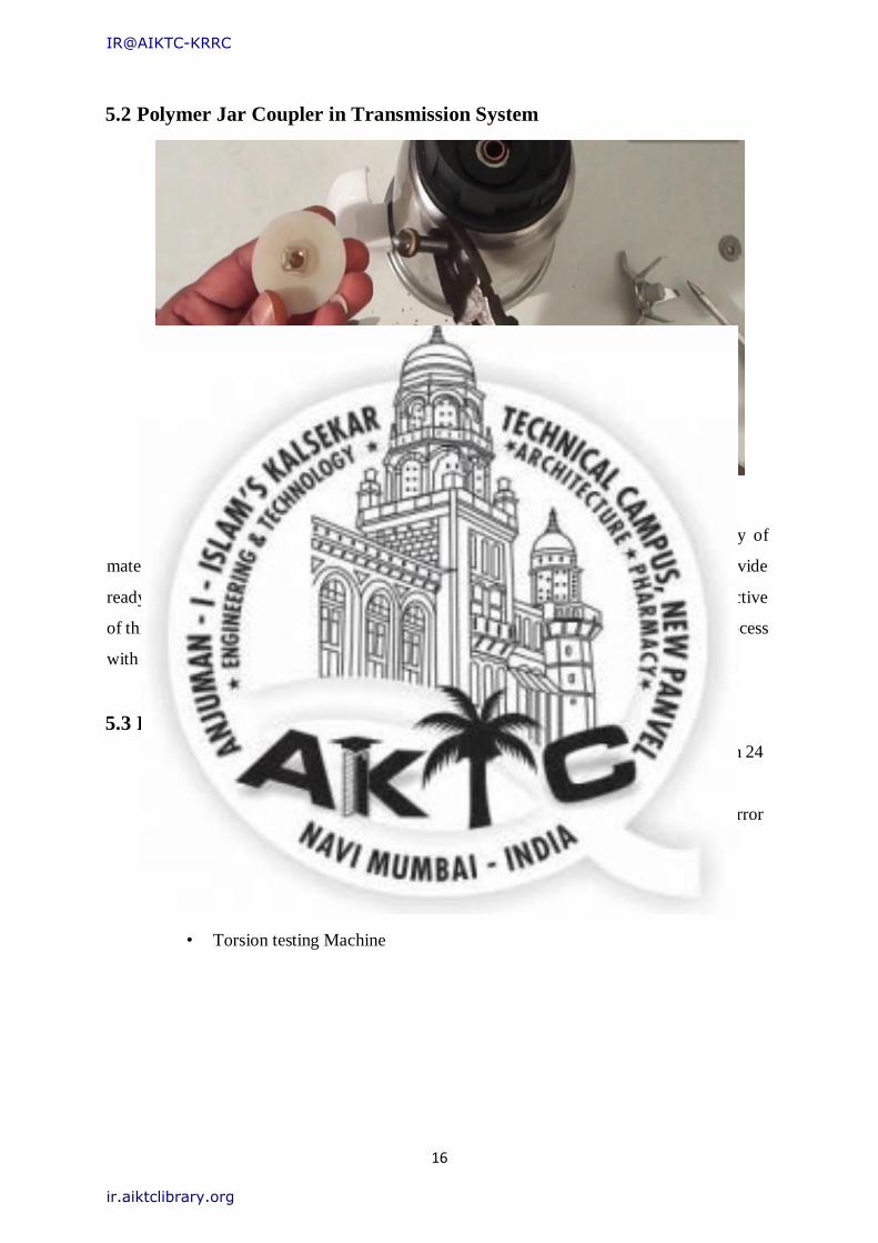
5.2 Polymer Jar Coupler in Transmission System
Fig 5.2: Polymer Jar Coupler in Transmission system
Generally used material for Jar Coupler is Basic Plastic because of Availability of
material in large scale. Different Manufacturers are available in the market to provide
readymade jar coupler ranging from 10 rupees per piece to 120 rupees per piece. The Objective
of this project work is to manufacturer the same jar Coupler with latest manufacturing process
with high strength and Low Cost.
5.3 Requirement
• To Manufacture a Jar Coupler with less Cost To develop the Jar Coupler in 24
Hrs.
• Manufacturing with Advance manufacturing technique without Human error
and with automatic system.
• Torsion testing Machine
IR@AIKTC-KRRC
ir.aiktclibrary.org
17
Chapter 5B
To perform experiment to determine strength and shear stress of
existing jar coupler using torque testing machine
It was to be used for Polymer Jar couplers based on several different levels of testing. This method is
to be applied on a pair of couplers. To test these materials different speeds of rotation, torque loads
and transferred powers to be used.
Fig 5.1: a) Block diagram b) Torsion testing Machine
IR@AIKTC-KRRC
ir.aiktclibrary.org
18
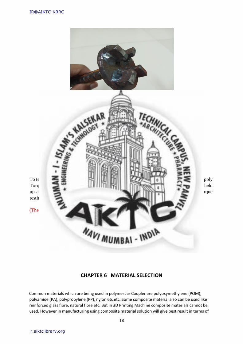
Fig5.2: Pattern of Existing Jar Coupler
To test this experiment jar coupler pattern was made with cast iron as shown in fig 5.2 to apply
Torque on polymer Jar coupler. Both the subjects “Jar Coupler And the instrument” to be held
up at two extreme points, opposite to each other and by application of torque from torque
testing machine, the strength of jar coupler was to be determined.
(The test could not be performed due to occurrence of pandemic).
CHAPTER 6 MATERIAL SELECTION
Common materials which are being used in polymer Jar Coupler are polyoxymethylene (POM),
polyamide (PA), polypropylene (PP), nylon 66, etc. Some composite material also can be used like
reinforced glass fibre, natural fibre etc. But in 3D Printing Machine composite materials cannot be
used. However in manufacturing using composite material solution will give best result in terms of
IR@AIKTC-KRRC
ir.aiktclibrary.org
19
strength as well as durability.eg. A 20% short glass fibre reinforced nylon 6/6 has high shear strength
with less Shrinkage.
In polymers Nylon, PLA, ABC materials have good stiffness and mechanical properties. One more
advantage is less cost.
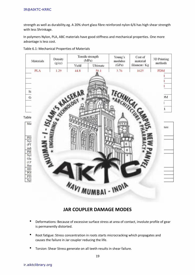
Table 6.1: Mechanical Properties of Materials
Table 6.2: Mechanical Properties of Reinforced Composite Material
CHAPTER 7
JAR COUPLER DAMAGE MODES
• Deformations: Because of excessive surface stress at area of contact, involute profile of gear
is permanently distorted.
• Root fatigue: Stress concentration in roots starts microcracking which propagates and
causes the failure in Jar coupler reducing the life.
• Torsion: Shear Stress generate on all teeth results in shear failure.
IR@AIKTC-KRRC
ir.aiktclibrary.org
20
• Wear: Combination of applied force and speed of sliding causes the material removal on
tooth s
Chapter 8 Reverse Engineering and 3D
Modeling using Solidworks
8.1 Reverse Engineering
Reverse engineering, also called back engineering, is the processes of extracting
knowledge or design information from a product and reproducing it or reproducing anything
based on the extracted information. The process often involves disassembling something and
analyzing its components and workings in detail.
Fig 6.1: Reverse Engineering Process
8.2 Reverse Engineering of Jar Coupler
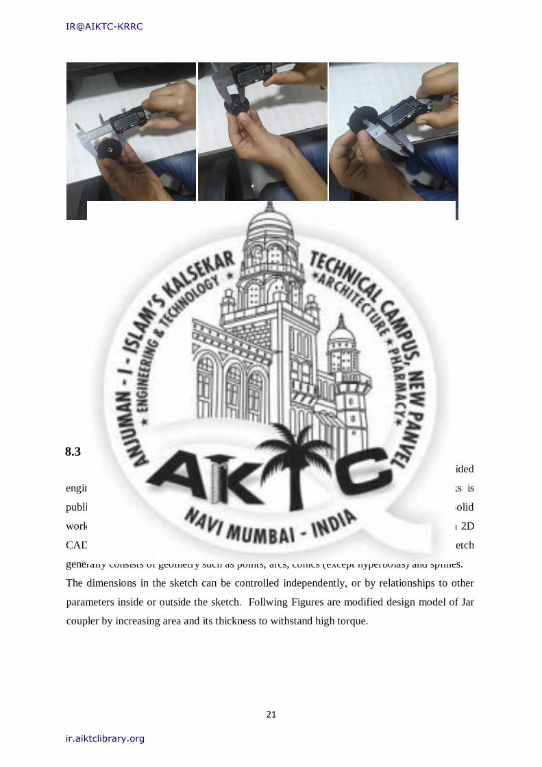
Reverse engineering of Jar Coupler is started by taking measurement of coupler’s
dimensions in microns using vainer caliper and recording it in book, as shown in fig. below.
These dimensions are used to make 3D model in CAD software.
IR@AIKTC-KRRC
ir.aiktclibrary.org
21
Fig 6.2: Measuring dimensions of Jar Coupler.
8.3 Introduction to Solidworks
Solid works is a solid-modeling computer aided design (CAD) and computer aided
engineering (CAE) computer program that runs on Microsoft windows. Solid works is
published by Dassault systems. Solid works currently markets several versions of the Solid
works CAD software in addition to e-drawings, a collaboration tool and a draft sight a 2D
CAD product. Building a model in Solid works usually stars with a 2D sketch. The sketch
generally consists of geometry such as points, arcs, conics (except hyperbolas) and splines.
The dimensions in the sketch can be controlled independently, or by relationships to other
parameters inside or outside the sketch. Follwing Figures are modified design model of Jar
coupler by increasing area and its thickness to withstand high torque.
IR@AIKTC-KRRC
ir.aiktclibrary.org
22
8.4 RENDERED IMAGES OF JAR COUPLER
8.4.1) DESIGN OF EXISTING JAR COUPLER WITH SOME MODIFICATIONS
Jar Coupler is used to transmit power from one shaft to other. Following are the images and Procedure of
existing jar coupler with just increasing in thickness of teeth.
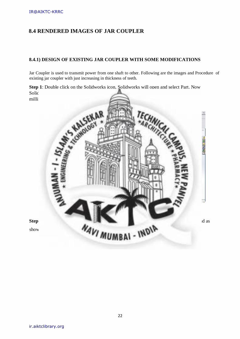
Step 1: Double click on the Solidworks icon, Solidworks will open and select Part. Now
Solidworks working window will open then first select the dimension standards in
millimeters.
Fig 8.4.1: Working window of Solidworks 2015.
Step 2: Select the plane and sketch according to the dimension and using Sketch command as
shown in fig.
IR@AIKTC-KRRC
ir.aiktclibrary.org
23
Fig 8.4.2: Sketch of base using command in Sketch tab.
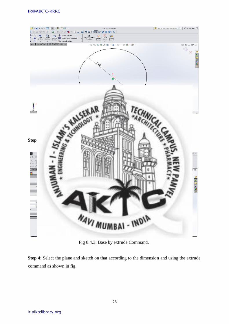
Step 3: Select the sketch and extrude using extrude feature as shown in fig.
Fig 8.4.3: Base by extrude Command.
Step 4: Select the plane and sketch on that according to the dimension and using the extrude
command as shown in fig.
IR@AIKTC-KRRC
ir.aiktclibrary.org
24
Fig 8.4.4: Extruded portion using Extrude Command.
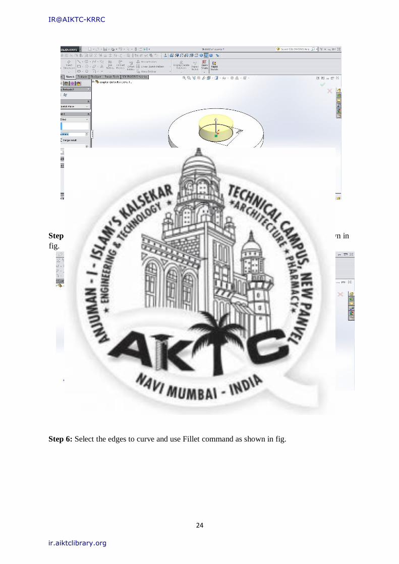
Step 5: Select the plane and sketch on that then cut using extrude-cut command as shown in
fig.
Fig 8.4.5: Slot for insert using Extrude-cut command.
Step 6: Select the edges to curve and use Fillet command as shown in fig.
IR@AIKTC-KRRC
ir.aiktclibrary.org
25
Fig
8.4.6: Curving edges using Fillet command.
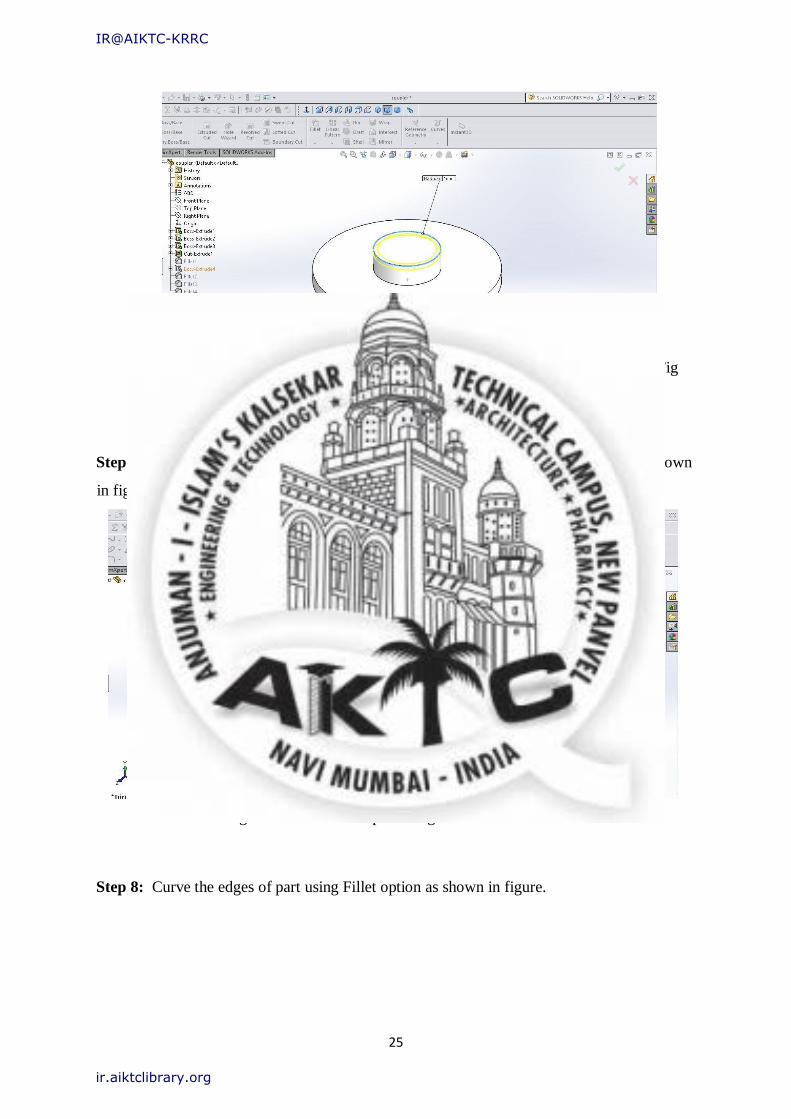
Step 7: Select the plane and sketch on that base and extrude using extrude command as shown
in fig.
Fig 8.4.7: Teeth of coupler using Extrude command.
Step 8: Curve the edges of part using Fillet option as shown in figure.
IR@AIKTC-KRRC
ir.aiktclibrary.org
26
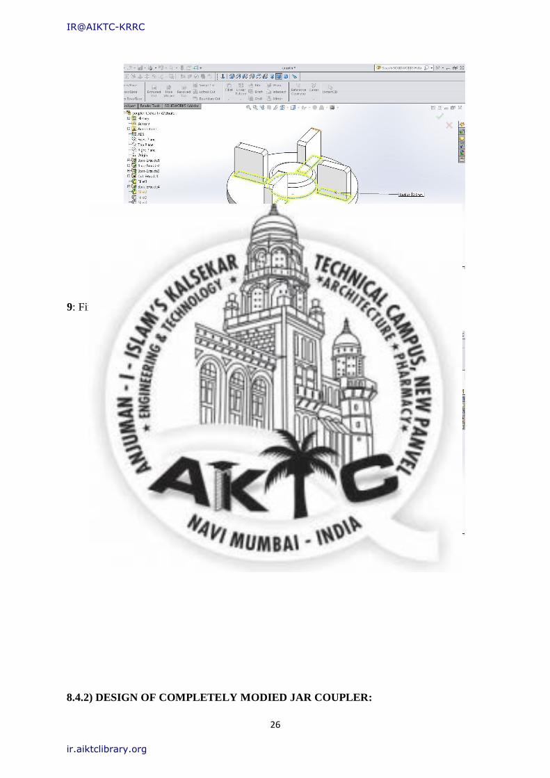
Fig 8.4.8: Curving edges using Fillet command. Step
9: Final Coupler 3D Model
Fig 8.4.9: Design of jar coupler
8.4.2) DESIGN OF COMPLETELY MODIED JAR COUPLER:
IR@AIKTC-KRRC
ir.aiktclibrary.org
27
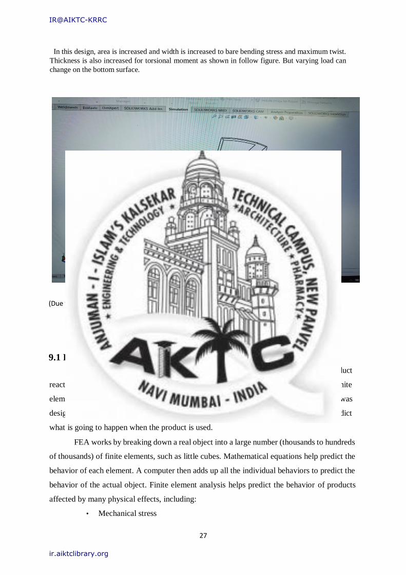
In this design, area is increased and width is increased to bare bending stress and maximum twist.
Thickness is also increased for torsional moment as shown in follow figure. But varying load can
change on the bottom surface.
Fig 8.4.10: Design of modified coupler
(Due to pandemic and network issue we could not perform test and did not get more design)
Chapter 9
FEA ANALYSIS OF JAR COUPLER
9.1 FEA of Jar Coupler for Actual Working Conditions
Finite element analysis (FEA) is a computerized method for predicting how a product
reacts to real-world forces, vibration, heat, fluid flow, and other physical effects. Finite
element analysis shows whether a product will break, wear out, or work the way it was
designed. It is called analysis, but in the product development process, it is used to predict
what is going to happen when the product is used.
FEA works by breaking down a real object into a large number (thousands to hundreds
of thousands) of finite elements, such as little cubes. Mathematical equations help predict the
behavior of each element. A computer then adds up all the individual behaviors to predict the
behavior of the actual object. Finite element analysis helps predict the behavior of products
affected by many physical effects, including:
• Mechanical stress
IR@AIKTC-KRRC
ir.aiktclibrary.org
28
• Mechanical vibration
• Fatigue
• Motion
• Heat transfer
• Fluid flow
• Electrostatics
• Plastic injection moldings.
9.2 Procedure of FEA
Finite Element Analysis is a mathematical representation of a physical system
comprising a part/assembly (model), material properties, and applicable boundary conditions
{collectively referred to as pre-processing}, the solution of that mathematical representation
{solving}, and the study of results of that solution {post-processing}.
9.2.1 Pre-processing
• Define the geometric domain of the problem.
• Define the element type(s) to be used.
• Define the material properties of the elements.
• Define the geometric properties of the elements (length, area, and the like).
• Define the element connectivity (mesh the model).
• Define the physical constraints (boundary conditions).
• Define the loadings.
9.2.2 Solution
• Computes the unknown values of the primary field variable(s)
• Computed values are then used by back substitution to compute additional,
derived
variables, such as reaction forces, element stresses, and heat flow.
IR@AIKTC-KRRC
ir.aiktclibrary.org
29
9.2.3 Post processing
• Postprocessor software contains sophisticated routines used for sorting,
printing, and plotting selected results from a finite element solution.
• It deals with the representation of result. Typically, the deformed configuration,
modes shapes, temperature, and stress distribution are computed and displayed
at this stage.
9.3 Design Calculations
• Jar Coupler rotates at 18000rpm and Power of 750Watts, Hence Toque acting on
the Jar Coupler is calculated by
•
• P • Where,
• P = Power in KW
• N = Rotational Speed in RPM
• T= Torque acting on the Jar Coupler
•
• 0.75 • T = 0.4Nm
• This shows that, Jar Coupler Subjected to torque of 0.4Nm.
• Loading Conditions:
• Now Jar Coupler has to be tested for Torque of 0.4Nm and Centrifugal Force at
18000rpm.
• Boundary Conditions:
• Center Point is fixed and Torque is applied on the Vertical Teeth's of the Jar Coupler.
Centrifugal Force is also applied on the Circular ring because of Rotational Motion.
9.4 Simulation Results:
9.4.1) Simulation results of exist jar coupler:
Following figures are the simulation result of existing jar coupler. Three materials are used i.e polyethylene
plastic, Nylon, PLA. Various stress and Deformation are considered.
IR@AIKTC-KRRC
ir.aiktclibrary.org
30
Fig 9.4.1 stress contour of coupler with Polyethylene plastic
Fig. 9.4.2 Stress contour of Coupler with Nylon Plastic.
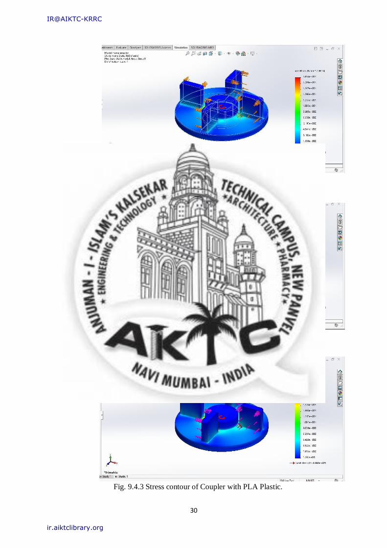
Fig. 9.4.3 Stress contour of Coupler with PLA Plastic.
IR@AIKTC-KRRC
ir.aiktclibrary.org
31
Fig 9.4.4: Deformation of coupler with Polyethylene plastic.
Fig 9.4.5: Deformation of coupler with Nylon plastic.
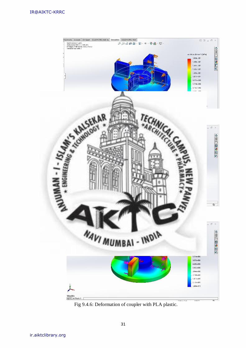
Fig 9.4.6: Deformation of coupler with PLA plastic.
IR@AIKTC-KRRC
ir.aiktclibrary.org
32
9.4.2) Simulation of modified jar coupler design: Following simulation fig is of PLA AND
Nylon by increasing width support behind teeth.
Fig 9.4.7: Static nodal stress of jar coupler of PLA
Fig 9.4.8 Deformation of Jar coupler using PLA
IR@AIKTC-KRRC
ir.aiktclibrary.org
33
Fig 9.4.9 Static nodal stress of Jar coupler using Nylon
Fig 9.4.10: Deformation of jar coupler using Nylon
IR@AIKTC-KRRC
ir.aiktclibrary.org
34
Chapter 10 3D printing Filament and Method
10.1 Introduction to 3D Printing
Additive Manufacturing (AM) is a term to describe set of technologies that create 3D objects
by adding layer-upon-layer of material. Materials can vary from technology to technology.
But there are some common features for all Addictive Manufacturing, such as usage of
computer together with special 3D modeling software.
The term Additive Manufacturing holds within such technologies like Rapid Prototyping
(RP), Direct Digital Manufacturing (DDM), Layered Manufacturing and 3D Printing. There
are different 3d printing methods that were developed to build 3D structures and objects. Some
of them are very popular nowadays; others have been dominated by competitors.
IR@AIKTC-KRRC
ir.aiktclibrary.org
35
10.2 3D Printing methods
• Stereo lithography (SLA)
Stereo lithography (SLA or SL; also known as Stereo lithography apparatus, optical
fabrication, photo-solidification, or resin printing) is a form of 3-D printing technology used
for creating models, prototypes, patterns, and production parts in a layer by layer fashion using
photo-polymerization, a process by which light causes chains of molecules to link, forming
polymers. Those polymers then make up the body of a three-dimensional solid. Stereo
lithography is used to create prototypes for products and in medical modeling, among other
uses.
While Stereo lithography is fast and can produce almost any design, it can be expensive.
• Fused deposition modeling (FDM)
3D printing machines that use FDM Technology build objects layer by layer from the
very bottom up by heating and extruding thermoplastic filament. The whole process is a bit
similar to stereo lithography. Firstly special software “cuts” CAD model into layers and
calculates the way printer’s extruder would build each layer. Along to thermoplastic a printer
can extrude support materials as well. Then the printer heats thermoplastic till its melting point
and extrudes it throughout nozzle onto base, which can also be called a build platform or a
table, along the calculated path. A computer of the 3d printer translates the dimensions of an
object into X, Y and Z coordinates and controls that the nozzle and the base follow calculated
path during printing. To support upper layer the printer may place underneath special material
that can be dissolved after printing is completed.
• Selective Laser Sintering (SLS)
Selective Laser Sintering (SLS) is a technique that uses laser as power source to form
solid 3D objects. The main difference between SLS and SLA is that it uses powdered material
in the vat instead of liquid resin as Stereo lithography does. Unlike some other additive
manufacturing processes, such as Stereo lithography (SLA) and fused deposition modeling
(FDM), SLS doesn’t need to use any support structures as the object being printed is constantly
surrounded by unsintered powder. The material to print with might be anything from nylon,
ceramics and glass to some metals like aluminum, steel or silver. Due to wide variety of
materials that can be used with this type of 3d printer the technology is very popular for 3D
printing customized products.
IR@AIKTC-KRRC
ir.aiktclibrary.org
36
• Selective laser melting (SLM)
Selective laser melting (SLM) is a technique that also uses 3D CAD data as a source
and forms 3D object by means of a high-power laser beam that fuses and melts metallic
powders together. In many sources SLM is considered to be a subcategory of selective laser
sintering (SLS). But this is not as true as SLM process fully melts the metal material into solid
3Ddimentional part unlike selective laser sintering.
• Electronic Beam Melting (EBM)
EBM is another type of additive manufacturing for metal parts. The same as SLM, this
3d printing method is a powder bed fusion technique. While SLM uses high-power laser beam
as its power source, EBM uses an electron beam instead, which is the main difference between
these two methods? The rest of the processes are pretty similar. The material used in EBM is
metal powder that melts and forms a 3D part layer by layer by means of a computer, which
controls electron beam in high vacuum. Contrary to SLS, EBM goes for full melting of the
metal powder. The process is usually conducted under high temperature up to 1000 °C.
Comparing to SLM the process of EBM is rather slow and expensive; also the availability of
materials is limited. So the method is not so popular though still used in some of manufacturing
processes.
• Laminated Object Manufacturing (LOM)
During the LOM process, layers of adhesive-coated paper, plastic or metal laminates
are fused together using heat and pressure and then cut to shape with a computer controlled
laser or knife. Post-processing of 3D printed parts includes such steps as machining and
drilling. The LOM process includes several steps. Firstly, CAD file is transformed to computer
format, which are usually STL or 3DS. LOM printers use continuous sheet coated with an
adhesive, which is laid down across substrate with a heated roller. The heated roller that is
passed over the material sheet on substrate melts its adhesive. Then laser or knife traces desired
dimensions of the part. Also the laser crosses hatches of any excess material in order to help
to remove it easily after the printing is done.
IR@AIKTC-KRRC
ir.aiktclibrary.org
37
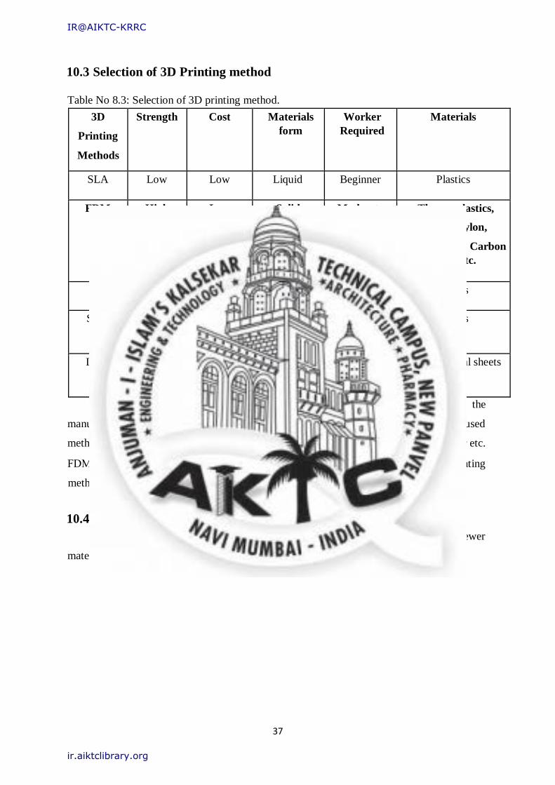
10.3 Selection of 3D Printing method
Table No 8.3: Selection of 3D printing method.
3D
Printing
Methods
Strength Cost Materials
form
Worker
Required
Materials
SLA Low Low Liquid Beginner Plastics
FDM High Low Solid Moderate Thermoplastics,
wood, Nylon,
ceramics, Carbon
fiber etc.
SLS High Very High Powder Expert Metals
SLM Very
High
Very High Powder Expert Metals
LOM Low High Sheet Moderate Papers, metal sheets
etc.
Fused deposition modeling (FDM) 3D printing method is selected for the
manufacturing of Spur Gear because its products have high strength; it is most widely used
method for 3D printing. It has huge variety of filaments such as nylon, wood, carbon fiber etc.
FDM method is simple doesn’t require an expert worker. It is also the cheapest 3D printing
method. FDM is used for manufacturing of Spur Gear.
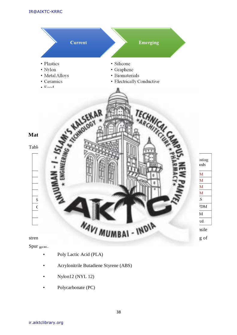
10.4 Materials for 3D Printing
The table below shows the range of materials that are used in 3d printing. Newer
materials are being launched with increasing frequency.
IR@AIKTC-KRRC
ir.aiktclibrary.org
38
Fig 8.4: Materials for 3D Printing.
10.5 Shortlisting of 3D Printing
Materials
Table 8.5: Shortlisted 3D printing materials.
The following 3D printing materials have been shortlisted because of their high tensile
strength, durability, availability and low cost which is required for the proper functioning of
Spur gear.
• Poly Lactic Acid (PLA)
• Acrylonitrile Butadiene Styrene (ABS)
• Nylon12 (NYL 12)
• Polycarbonate (PC)
IR@AIKTC-KRRC
ir.aiktclibrary.org
39
10.6 Mechanical properties of shortlisted 3D printing materials Material Selection is done on the basis of Availability of Printing Machine to print the
Component, Cost, and Weight Carrying Capacity and commonly preferred by the industry.
Table 8.6: Mechanical Properties of 3D printing materials.
Materials Density
(g/cc)
Tensile strength
(MPa)
Young’s
modulus
(GPa.) Yield Ultimate
PLA 1.29 44.8 50.1 3.76
ABS 1.05 40.7 41.4 2.10
NYL12 1.42 45.4 79.4 5.31
PC 1.20 63.3 60.6 2.36
10.7 3D Printing filament for Jar Coupler Manufacturing
Poly lactic acid and Nylon can be used to increase the strength of the existing Gear. Use
of Nylon results into increase in Cost because of its high cost of Filament.
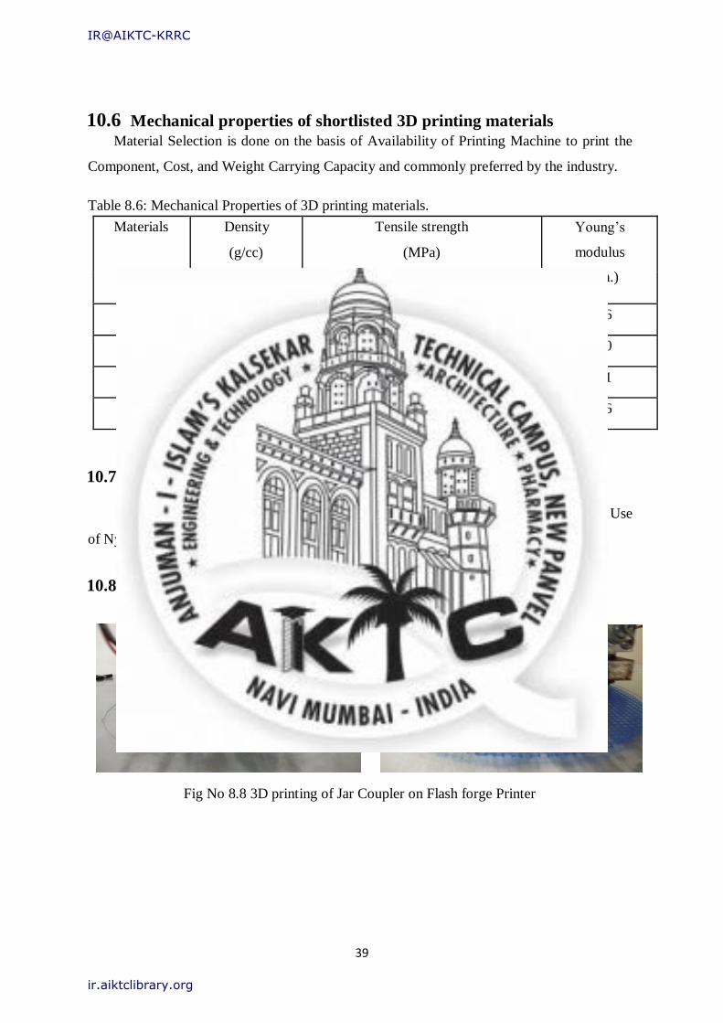
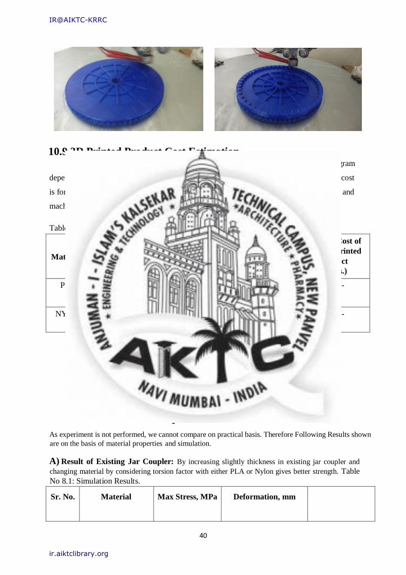
10.8 3D printing of Jar Coupler using FDM
Fig No 8.8 3D printing of Jar Coupler on Flash forge Printer
IR@AIKTC-KRRC
ir.aiktclibrary.org
40
10.9 3D Printed Product Cost Estimation Printing cost for 3D printed parts in the market varies from Rs. 5/gram to Rs. 25/gram
depending upon the machine used for printing and type of filament used. The above said cost
is for PLA, it may vary slightly for other materials also. This cost is inclusive of filament and
machining cost.
Table 8.9: Manufacturing cost Estimation.
Materials Density
(g/cc)
Cost of
Filament
per kg
Mass of
product
(Grams)
Cost of 3d
printing per Gram
(Rs.)
Total Cost of
3D printed
Product
(Rs.)
PLA 1.29 1625 8 10 80/-
NYL12 1.42 7150 8.8 10 88/-
Chapter 11 RESULTS
As experiment is not performed, we cannot compare on practical basis. Therefore Following Results shown
are on the basis of material properties and simulation.
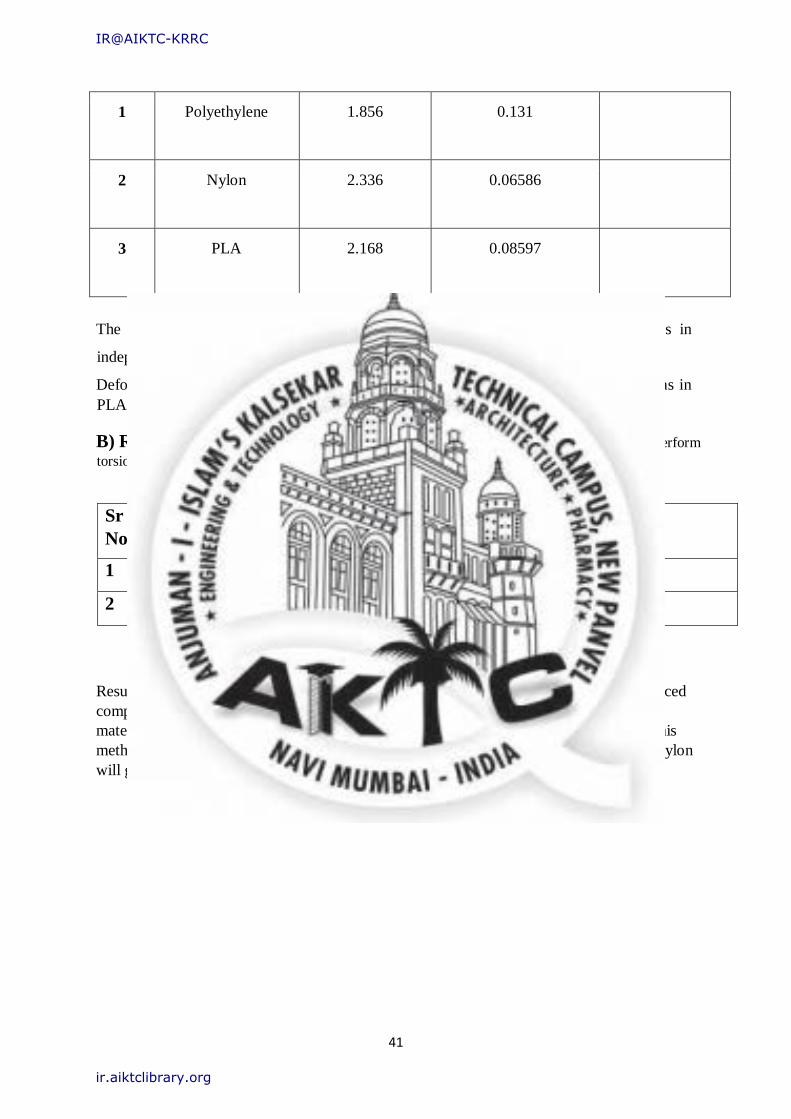
A) Result of Existing Jar Coupler: By increasing slightly thickness in existing jar coupler and
changing material by considering torsion factor with either PLA or Nylon gives better strength. Table
No 8.1: Simulation Results.
Sr. No. Material Max Stress, MPa Deformation, mm
IR@AIKTC-KRRC
ir.aiktclibrary.org
41
1 Polyethylene 1.856 0.131
2 Nylon 2.336 0.06586
3 PLA 2.168 0.08597
The above table shows that, stress is almost same in all the 3 materials, As Stress in
independent of the Young's Modulus.
Deformation is Very less in Nylon Material, but we can go for moderate Deformation as in
PLA Jar Coupler due to cost concern.
B) Result of Modified Design coupler: Results are not satisfied as we did not perform
torsion test. On the basis of simulation results are as follows.
Sr
No
Material Max
Mpa
Stress, Deformation(mm)
1 Nylon 3.546 0.032
2 PLA 3.96 0.0146
Results of modified jar coupler are not up to the mark. By replacing material with reinforced
composite glass or natural fibre with either Nylon or PLA will give better results but this
material cannot be use in 3D printer. However in manufacturing by injection moulding this
method can be used. Result A) is best for additive manufacturing. Either using PLA or Nylon
will give high torsional strength and durability.
IR@AIKTC-KRRC
ir.aiktclibrary.org
42
CHAPTER 12
CONCLUSION AND FUTURE SCOPE A) CONCLUSION:
• This type of Component design using advance manufacturing process will
result into fast product development. This helps the Manufacturer to
manufacture the parts without investing highly into Research and
Development. This also helps the designer to design the complex designs
without worrying about the manufacturing Process.
• PLA and Nylon materials have good stiffness and better strength so that jar
coupler life will increase with minimum cost manufacturing process. Also Jar
coupler made with composite glass fibre will give better strength and
durability.
• This also reduces the slack time of repair by manufacturing parts in short time
and fixing it in the assembly and to run it without waiting for ordering the part
and waiting to deliver it and then fix it.
B) FUTURE SCOPE: In the education segment, 3d printing can bring a number of
benefits to students and educators:
• It makes learning more fun.
• Fosters creativity and problem solving skills.
• Vastly improves retention and quality of learning.
• Creates excitement and engagement.
• Can improve rate of learning amongst special needs individuals. E.g. visually
challenged, Autistic, etc.
• Not expensive.
IR@AIKTC-KRRC
ir.aiktclibrary.org
43
References
• P. B. Pawar, Abhay A. Utpat, “Analysis of Composite Material Spur Gear under Static
Loading Condition”, “Science Direct”, Pg. 2968-2974, 2015.
• Dr. Ir H. G. H. Van Melick, “Tooth-Bending effects in plastic Spur Gears”, “Gear
technology” September/October 2007.
• K. Mao, P. Langlois, Z.Hu, K. Alharbi, X. Xu, M. Li, C.J. Hooke, D. Chetwynd, “The
wear and thermal mechanical contact behavior of machine cut polymer gears”,
“Science Direct”, Jan 2015.
• S. Senthilvelan, R. Gnanamoorthy, “Effect of rotational speed on the performance of
unreinforced & glass fiber reinforced nylon 6 spur gears”, ‘Science Direct’, 2007.
• K. Mao, W. Li, C.J. Hooke, D Walton, “Polymer gear surface thermal wear and its
performance prediction”, ’Science Direct’, 2010.
• Samy Yousuef, T. A. Osman, Abdelrahman H. Abdalla, and Gamal A. Zohdy, ”Wear
characterization of carbon nanotube reinforced acetyl spur, helical, bevel & worm
gears using a TS universal test rig” December 2014.
• Ashish N. Taywade, Dr. V.G. Arajpure, “Design and Development of Nylon 66 Plastic
Helical Gears in Automobile Application”, IJERT, ISSN: 2278-0181, Vol. 3, Issue 9
and September 2014.
• Prof. Ajitabh Pateriya, Dipak Parasarm Kharat, “Design and finite element method
analysis of gear mechanism for raw material crushing in plastic industry”, IJMERT,
Vol.1, No.1, July, 2015.
• Ashutosh, Deepak Singathia, “Finite element analysis modelling of spur gear”, IJEST
vol.5 no. 3 March 2013.
• R. Yakut, H. Duzcukoglu, M.T. Demirci, “The load capacity of PC/ABS spur gears
and investigation of gear damage”, ‘Archives of Materials Science And Engineering’,
Volume 40, Issue 1 November 2009.
IR@AIKTC-KRRC
ir.aiktclibrary.org
44
IR@AIKTC-KRRC
ir.aiktclibrary.org