DENTAL CAST
SURVEYOR
Presented by:
Dr. Tushar Bhagat
Ref: McCraken’s Removable partial prosthodontics.

CONTENT & REFERENCES
2

INTRODUCTION
Before 1918, all RPD were designed arbitrarily.
Turning point came in 1918, Dr. A. J. Fortunati, introduced dental cast
surveyor, which was used to determine the parallelism of surfaces.
After 1918, RPD service becomes from guesswork to an objective,
scientific based procedure.
In 1923, J. M. Ney Company introduced first commercially available
Surveyor.
3
1918

DEFINITION
Dental Cast Surveyor : An instrument used to determine the relative
parallelism of two or more surfaces of the teeth or other part of the cast of
dental arch.
4
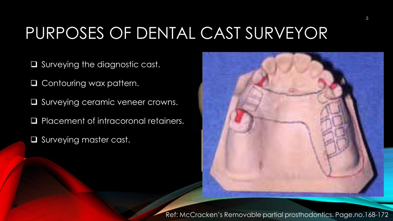
PURPOSES OF DENTAL CAST SURVEYOR
Surveying the diagnostic cast.
Contouring wax pattern.
Surveying ceramic veneer crowns.
Placement of intracoronal retainers.
Surveying master cast.
5
Ref: McCracken’s Removable partial prosthodontics. Page.no.168-172
Path of placementGuide planeLocate Area for retentionEliminate bony & tooth
interferences

PARTS OF SURVEYOR
1) Level platform
2) Vertical column / rod
3) Horizontal arm
4) Surveying arm
5) Surveying table / cast holder.
6) Surveying tools.
6
Ney dental surveyor
Ref: Stewart’s Removable partial prosthodonics. Page.no.205-206

1. LEVEL PLATFORM
Level platform is parallel to bench top
and on which the cast holder is moved.
Clean with an Acetone or Alcohol swab.
Small amount of polymethylmethacrylate
powder should be placed before
surveying.
7
Ney dental surveyor

VERTICAL COLUMN & HORIZONTAL ARM
Vertical column supports the suprastructure.
Horizontal arm that extents at right angle from the
vertical column.
8
Ney dental surveyor

SURVEYING ARM & SURVEYING TABLE
Surveying arm extends vertical from horizontal arm.
Surveying arm is capable of movement in a vertical
direction and contains a MANDREL at its lower end.
Mandrel holds surveying tools used in surveying
procedure.
Surveying table holds the cast which permits spatial
reorientation of the cast (ie, tipping or tilting)
9
Ney dental surveyor

SURVEYING TOOLS
1) Surveying tools that may be placed in mandrel.
1) Analysing rod (used to determine relative parallelism of
surfaces of dental cast)
2) Carbon marker (mark the height of contour)
3) Undercut gauge (used to identify position of desired
undercut, available in 0.010, 0.020 & 0.030 inch
embodiments.)
4) Wax knife (used during block out procedure & in
construction of surveyed restoration.)
10
Ney dental surveyor
Analyzing rod
Carbon marker
Un
de
rcu
t ga
ug
e
Wax knife

SURVEY PROCESS
I. Identifying the most favourable tilt. a) Retentive undercut
b) Interferences
c) Esthetics
d) Guiding plane
II. Path of insertion
III. Tripoding the cast
11
Ref: Stewart’s Removable partial prosthodonics. Page.no.207-220.

IDENTIFYING THE MOST FAVOURABLE TILT
If anterior of the cast is
lowered, the cast is said to
have anterior tilt, & so on.
12

IDENTIFYING THE MOST FAVOURABLE TILT
Four critical factors:
I. Presence of suitable undercuts
(Retentive undercut).
II. Elimination of hard & soft tissue
interferences (Interferences).
III. Creation of desirable Esthetics.
IV. Guide plane establishment.
13
Rarely is it possible to be achieve the optimum in all four area.

IDENTIFYING THE MOST FAVOURABLE TILT
a) Retentive undercut:
1. Retentive undercut must be present on the
abutment tooth.
2. If not present than,
1) Tilt of cast or,
2) Recontouring of enamel or,
3) Crowning of tooth.
14

IDENTIFYING THE MOST FAVOURABLE TILTb. Interferences:
I. Certain structure may interfere while
constructing RPD like (some teeth, bony
prominences, soft tissue undercuts)
II. Difficulties may be avoided by;
1. Changing the tilt.
2. Altering the design.
3. Surgical intervention.
15

IDENTIFYING THE MOST FAVOURABLE TILT
c)Esthetics: for optimum results;
1. Metal component less
visible
2. Selection of artificial teeth
16
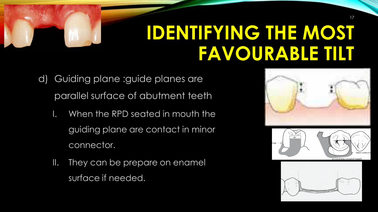
IDENTIFYING THE MOST FAVOURABLE TILT
d) Guiding plane :guide planes are
parallel surface of abutment teeth
I. When the RPD seated in mouth the
guiding plane are contact in minor
connector.
II. They can be prepare on enamel
surface if needed.
17

PATH OF INSERTION
I. Ideally all RPD should
have single path of
insertion, but in class I & II
situation it has more than
one.
18

TRIPODING THE CAST
a) Recording the favourable cast tilt for future
references (to re-orient the cast).
b) The procedure is called as tripoding or
tripodization.
c) There are several methods, but two are common.
19

TRIPODING THE CASTMethod 1:
Place three widely divergent dots (on
area which is not included in
component)on the tissue surface of the
cast using the tip of undercut gauge or
carbon marker, with vertical arm of the
surveyor in a locked position.
20

TRIPODING THE CASTMethod 2:
To score two sides and the dorsal
aspect of the base of the cast with a
sharp instrument held against the
surveyor blade. By tilting the cast until all
three lines are again parallel to surveyor
blade, the original position of cast can
be re-establish.
21

Thank you
22
Ref: McCraken’s Removable partial prosthodontics.