Dell PowerEdge R730Owner's Manual
Regulatory Model: E31S SeriesRegulatory Type: E31S001July 2020Rev. A05

Notes, cautions, and warnings
NOTE: A NOTE indicates important information that helps you make better use of your product.
CAUTION: A CAUTION indicates either potential damage to hardware or loss of data and tells you how to avoid
the problem.
WARNING: A WARNING indicates a potential for property damage, personal injury, or death.
© 2017 2020 Dell Inc. or its subsidiaries. All rights reserved. Dell, EMC, and other trademarks are trademarks of Dell Inc. or its subsidiaries.Other trademarks may be trademarks of their respective owners.

Chapter 1: Dell PowerEdge R730 system overview.........................................................................8Supported configurations for the PowerEdge R730 system.................................................................................... 8Front panel ......................................................................................................................................................................... 10
3.5 inch hard drive chassis........................................................................................................................................ 102.5 inch hard drive chassis.........................................................................................................................................12LCD panel....................................................................................................................................................................... 13
Back panel............................................................................................................................................................................16Diagnostic indicators......................................................................................................................................................... 17
Diagnostic indicators on the front panel.................................................................................................................17Hard drive indicator codes......................................................................................................................................... 18uSATA SSD indicator codes...................................................................................................................................... 19NIC indicator codes.....................................................................................................................................................20Power supply unit indicator codes.......................................................................................................................... 20iDRAC Direct LED indicator codes.......................................................................................................................... 22Quick Sync indicator codes.......................................................................................................................................24
Locating service tag of your system............................................................................................................................ 24
Chapter 2: Documentation resources...........................................................................................25
Chapter 3: Technical specifications............................................................................................. 27Chassis dimensions........................................................................................................................................................... 27Chassis weight................................................................................................................................................................... 28Processor specifications..................................................................................................................................................28PSU specifications............................................................................................................................................................ 28System battery specifications........................................................................................................................................28Expansion bus specifications..........................................................................................................................................28Memory specifications..................................................................................................................................................... 29Drive specifications...........................................................................................................................................................29
Hard drives....................................................................................................................................................................29Optical drive..................................................................................................................................................................29
Ports and connectors specifications............................................................................................................................ 30USB ports...................................................................................................................................................................... 30NIC ports....................................................................................................................................................................... 30Serial connector...........................................................................................................................................................30VGA ports......................................................................................................................................................................30Internal Dual SD Module............................................................................................................................................ 30
Video specifications..........................................................................................................................................................30Environmental specifications...........................................................................................................................................31
Particulate and gaseous contamination specifications ..................................................................................... 32Standard operating temperature............................................................................................................................. 32Expanded operating temperature............................................................................................................................33Expanded operating temperature restrictions......................................................................................................33
Chapter 4: Initial system setup and configuration........................................................................34
Contents
Contents 3
Setting up your system.................................................................................................................................................... 34iDRAC configuration......................................................................................................................................................... 34
Options to set up iDRAC IP address....................................................................................................................... 34Options to install the operating system.......................................................................................................................35
Methods to download firmware and drivers.........................................................................................................35
Chapter 5: Pre-operating system management applications........................................................ 37Options to manage the pre-operating system applications.................................................................................... 37System Setup..................................................................................................................................................................... 37
Viewing System Setup............................................................................................................................................... 38System Setup details.................................................................................................................................................. 38System BIOS.................................................................................................................................................................38iDRAC Settings utility................................................................................................................................................. 63Device Settings............................................................................................................................................................63
Dell Lifecycle Controller...................................................................................................................................................64Embedded systems management............................................................................................................................64
Boot Manager.....................................................................................................................................................................64Viewing Boot Manager...............................................................................................................................................64Boot Manager main menu......................................................................................................................................... 65
PXE boot............................................................................................................................................................................. 65
Chapter 6: Installing and removing system components.............................................................. 66Safety instructions............................................................................................................................................................66Before working inside your system............................................................................................................................... 67After working inside your system.................................................................................................................................. 67Recommended tools......................................................................................................................................................... 67Front bezel (optional)...................................................................................................................................................... 68
Removing the optional front bezel..........................................................................................................................68Installing the optional front bezel............................................................................................................................ 69
System cover...................................................................................................................................................................... 71Removing the system cover...................................................................................................................................... 71Installing the system cover........................................................................................................................................72
Inside the system...............................................................................................................................................................73Cooling shroud................................................................................................................................................................... 74
Removing the cooling shroud................................................................................................................................... 74Installing the cooling shroud..................................................................................................................................... 75
Cooling fans........................................................................................................................................................................ 75Removing a cooling fan.............................................................................................................................................. 76Installing a cooling fan................................................................................................................................................ 77
Cooling fan assembly ....................................................................................................................................................... 77Removing the cooling fan assembly........................................................................................................................ 77Installing the cooling fan assembly.......................................................................................................................... 78
System memory................................................................................................................................................................. 79General memory module installation guidelines.................................................................................................... 81Mode-specific guidelines............................................................................................................................................ 81Sample memory configurations................................................................................................................................82Removing memory modules......................................................................................................................................85Installing memory modules........................................................................................................................................ 86
Processors and heat sinks...............................................................................................................................................88
4 Contents

Removing a heat sink................................................................................................................................................. 88Removing a processor................................................................................................................................................90Installing a processor.................................................................................................................................................. 93Installing a heat sink....................................................................................................................................................94
PCIe card holder................................................................................................................................................................ 97Removing the PCIe card holder............................................................................................................................... 97Installing the PCIe card holder................................................................................................................................. 98Opening and closing the PCIe card holder latch..................................................................................................99
Cable retention bracket................................................................................................................................................. 100Removing the cable retention bracket................................................................................................................. 100Installing the cable retention bracket.................................................................................................................... 101
Integrated storage controller card.............................................................................................................................. 102Removing the integrated storage controller card..............................................................................................102Installing the integrated storage controller card................................................................................................ 104
Expansion cards and expansion card riser.................................................................................................................105Expansion card installation guidelines...................................................................................................................105Removing an expansion card from expansion card riser 2 or 3......................................................................106Installing an expansion card into the expansion card riser 2 or 3.................................................................. 108Removing an expansion card from the expansion card riser 1........................................................................109Installing an expansion card into the expansion card riser 1............................................................................ 110Removing the riser 1 blank........................................................................................................................................112Installing the riser 1 blank..........................................................................................................................................113Removing expansion card risers..............................................................................................................................114Installing expansion card risers................................................................................................................................ 117GPU card installation guidelines..............................................................................................................................119Removing the GPU card.......................................................................................................................................... 120Installing a GPU card................................................................................................................................................. 121
IDSDM ............................................................................................................................................................................... 122Removing an internal SD card.................................................................................................................................122Installing an internal SD card...................................................................................................................................123Removing the optional internal dual SD module.................................................................................................125Installing the optional internal dual SD module ..................................................................................................126
Network daughter card.................................................................................................................................................. 127Removing the network daughter card ................................................................................................................. 127Installing the network daughter card.................................................................................................................... 128
Internal USB memory key (optional)...........................................................................................................................129Replacing the optional internal USB memory key.............................................................................................. 130
System battery ................................................................................................................................................................ 131Replacing the system battery..................................................................................................................................131
Power supply units (PSU)............................................................................................................................................. 132Hot spare feature.......................................................................................................................................................132Removing the power supply unit blank.................................................................................................................133Installing the power supply unit blank................................................................................................................... 134Removing an AC power supply unit.......................................................................................................................134Installing an AC power supply unit.........................................................................................................................135Wiring instructions for a DC power supply unit..................................................................................................136Removing a DC power supply unit.........................................................................................................................139Installing a DC power supply unit........................................................................................................................... 140
System board.....................................................................................................................................................................141Removing the system board.................................................................................................................................... 141
Contents 5

Installing the system board......................................................................................................................................144Trusted Platform Module............................................................................................................................................... 147
Installing the Trusted Platform Module................................................................................................................ 147Initializing the TPM for BitLocker users............................................................................................................... 148Initializing the TPM for TXT users......................................................................................................................... 148
Hard drives........................................................................................................................................................................ 149Removing a 2.5-inch hard drive blank.................................................................................................................. 149Installing a 2.5-inch hard drive blank.................................................................................................................... 150Removing a 3.5-inch hard drive blank................................................................................................................... 151Installing a 3.5-inch hard drive blank..................................................................................................................... 151Removing a hot swappable hard drive or solid state drive.............................................................................. 152Installing a hot swappable hard drive or solid state drive................................................................................ 154Removing a hard drive or a solid state drive from a hard drive carrier........................................................ 155Installing a hard drive or solid state drives into a hard drive carrier............................................................. 156Removing a 1.8-inch hard drive blank................................................................................................................... 156Installing a 1.8-inch hard drive blank..................................................................................................................... 157Removing a 1.8-inch hard drive from a hard drive carrier............................................................................... 158Installing a 1.8-inch hard drive into a hard drive carrier................................................................................... 159
Hard drive backplane...................................................................................................................................................... 159Removing the hard drive backplane .....................................................................................................................159Installing the hard drive backplane ....................................................................................................................... 166
Tape backup unit (optional).......................................................................................................................................... 168Removing the tape backup unit ............................................................................................................................ 168Installing the tape backup unit .............................................................................................................................. 169
Optical drive (optional)...................................................................................................................................................170Removing the optical drive...................................................................................................................................... 170Installing the optical drive......................................................................................................................................... 171
SD vFlash card (optional).............................................................................................................................................. 172Replacing an optional SD vFlash media card....................................................................................................... 172
Control panel assembly...................................................................................................................................................173Removing the control panel ................................................................................................................................... 173Installing the control panel ......................................................................................................................................176
Chapter 7: Using system diagnostics......................................................................................... 180Dell Embedded System Diagnostics............................................................................................................................ 180
When to use the Embedded System Diagnostics.............................................................................................. 180Running the Embedded System Diagnostics from Boot Manager.................................................................180Running the Embedded System Diagnostics from the Dell Lifecycle Controller........................................180System diagnostic controls...................................................................................................................................... 181
Chapter 8: Jumpers and connectors...........................................................................................182System board jumper settings...................................................................................................................................... 182System board jumpers and connectors...................................................................................................................... 183Disabling forgotten password.......................................................................................................................................185
Chapter 9: Troubleshooting your system....................................................................................186Troubleshooting system startup failure......................................................................................................................186Troubleshooting external connections....................................................................................................................... 186Troubleshooting the video subsystem........................................................................................................................ 187
6 Contents

Troubleshooting a USB device......................................................................................................................................187Troubleshooting iDRAC Direct - USB XML configuration..................................................................................... 188Troubleshooting iDRAC Direct - Laptop connection...............................................................................................188Troubleshooting a serial input and output device....................................................................................................189Troubleshooting a NIC....................................................................................................................................................189Troubleshooting a wet system..................................................................................................................................... 190Troubleshooting a damaged system............................................................................................................................ 191Troubleshooting the system battery............................................................................................................................191Troubleshooting power supply units........................................................................................................................... 192
Troubleshooting power source problems............................................................................................................. 192Troubleshooting power supply unit problems..................................................................................................... 192
Troubleshooting cooling problems............................................................................................................................... 193Troubleshooting cooling fans........................................................................................................................................ 193Troubleshooting system memory.................................................................................................................................194Troubleshooting an internal USB key..........................................................................................................................195Troubleshooting a micro SD card................................................................................................................................ 195Troubleshooting an optical drive..................................................................................................................................196Troubleshooting a tape backup unit............................................................................................................................196Troubleshooting a drive or SSD....................................................................................................................................197Troubleshooting a storage controller..........................................................................................................................198Troubleshooting expansion cards................................................................................................................................ 198Troubleshooting processors..........................................................................................................................................199System messages........................................................................................................................................................... 200
Warning messages....................................................................................................................................................200Diagnostic messages................................................................................................................................................200Alert messages.......................................................................................................................................................... 200
Chapter 10: Getting help............................................................................................................ 201Contacting Dell EMC...................................................................................................................................................... 201Documentation feedback...............................................................................................................................................201Accessing system information by using QRL............................................................................................................201
Quick Resource Locator for PowerEdge R730 and R730xd systems.......................................................... 202
Contents 7

Dell PowerEdge R730 system overviewThe Dell PowerEdge R730 systems are rack servers that support up to two Intel Xeon E5-2600 v3 or Xeon E5-2600 v4processors, up to 24 DIMMs, and 16 hard drives or solid state drives (SSDs).Topics:
• Supported configurations for the PowerEdge R730 system• Front panel• Back panel• Diagnostic indicators• Locating service tag of your system
Supported configurations for the PowerEdge R730systemThe Dell PowerEdge R730 system supports the following configurations:
1
8 Dell PowerEdge R730 system overview

Figure 1. Supported configurations for the PowerEdge R730 system
Dell PowerEdge R730 system overview 9

Front panelThe front panel provides access to the features available on the front of the server, such as the power button, NMI button,system identification tag, system identification button, and USB and VGA ports. The diagnostic LEDs or the LCD panel isprominently located on the front panel. The hot swappable hard drives are accessible from the front panel.
3.5 inch hard drive chassis
Figure 2. Front panel features (3.5-inch hard drive chassis)
1. Power button 2. NMI button
3. System identification button 4. Video connector
5. LCD menu buttons 6. Information tag
7. LCD panel 8. Hard drives
9. USB management port/iDRAC Direct 10. vFlash media card slot
11. USB port 12. Optical drive
13. Quick Sync
Table 1. Front panel featuress (3.5-inch hard drive chassis)
Item Indicator, button, orconnector
Icon Description
1 Power button The power button controls the power supply output to thesystem.
NOTE: On ACPI compliant operating systems, when thepower button is used to shutdown the system, theoperating system performs a graceful shut down thesystem power is turned off.
2 NMI button Enables you to troubleshoot software and device driver errorswhen running certain operating systems. This button can bepressed by using the end of a paper clip.
NOTE: Use this button only if directed to do so by qualifiedsupport personnel or by instructions in the operatingsystem’s documentation.
3 System identification button Enables you to locate a particular system within a rack. Theidentification buttons are located on the front and back panels.
Press the system identification button to turn the system ID onor off.
NOTE:
10 Dell PowerEdge R730 system overview
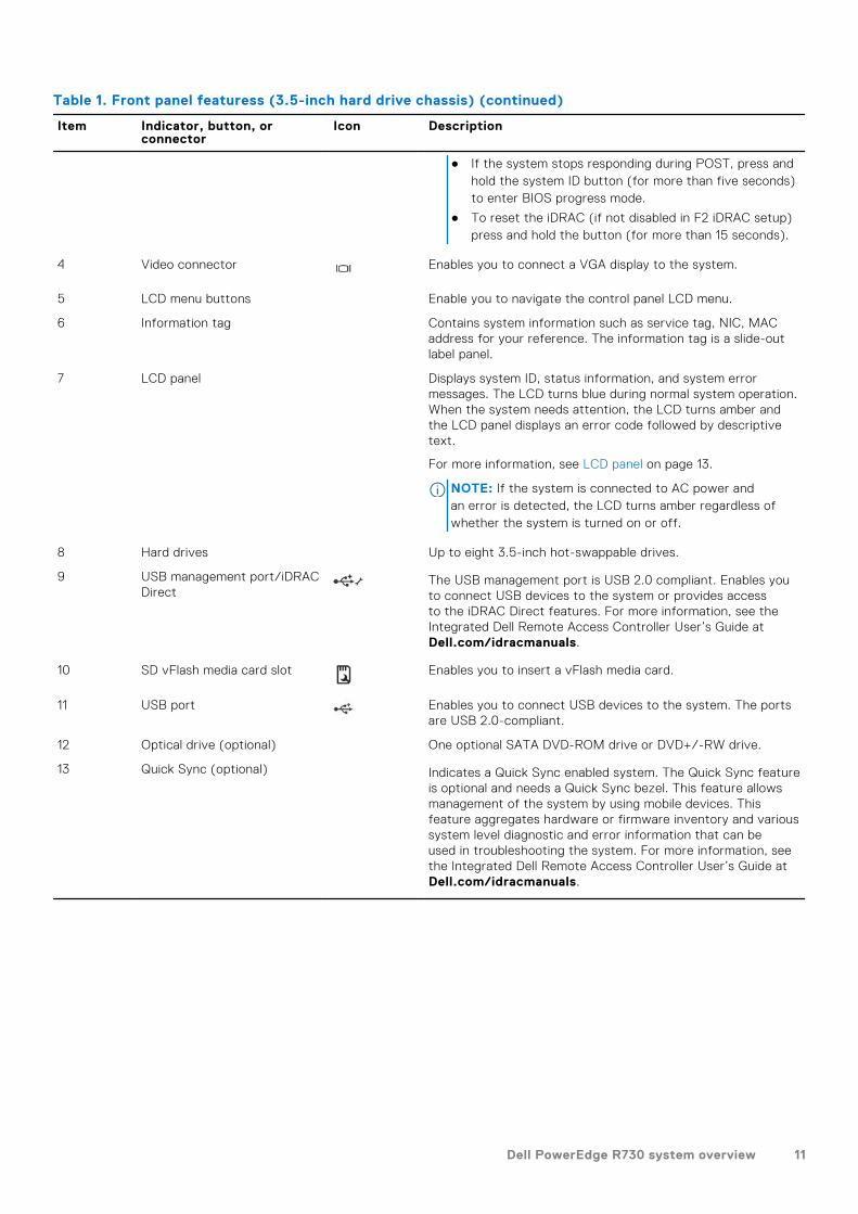
Table 1. Front panel featuress (3.5-inch hard drive chassis) (continued)
Item Indicator, button, orconnector
Icon Description
● If the system stops responding during POST, press andhold the system ID button (for more than five seconds)to enter BIOS progress mode.
● To reset the iDRAC (if not disabled in F2 iDRAC setup)press and hold the button (for more than 15 seconds).
4 Video connector Enables you to connect a VGA display to the system.
5 LCD menu buttons Enable you to navigate the control panel LCD menu.
6 Information tag Contains system information such as service tag, NIC, MACaddress for your reference. The information tag is a slide-outlabel panel.
7 LCD panel Displays system ID, status information, and system errormessages. The LCD turns blue during normal system operation.When the system needs attention, the LCD turns amber andthe LCD panel displays an error code followed by descriptivetext.
For more information, see LCD panel on page 13.
NOTE: If the system is connected to AC power andan error is detected, the LCD turns amber regardless ofwhether the system is turned on or off.
8 Hard drives Up to eight 3.5-inch hot-swappable drives.
9 USB management port/iDRACDirect
The USB management port is USB 2.0 compliant. Enables youto connect USB devices to the system or provides accessto the iDRAC Direct features. For more information, see theIntegrated Dell Remote Access Controller User’s Guide atDell.com/idracmanuals.
10 SD vFlash media card slot Enables you to insert a vFlash media card.
11 USB port Enables you to connect USB devices to the system. The portsare USB 2.0-compliant.
12 Optical drive (optional) One optional SATA DVD-ROM drive or DVD+/-RW drive.
13 Quick Sync (optional) Indicates a Quick Sync enabled system. The Quick Sync featureis optional and needs a Quick Sync bezel. This feature allowsmanagement of the system by using mobile devices. Thisfeature aggregates hardware or firmware inventory and varioussystem level diagnostic and error information that can beused in troubleshooting the system. For more information, seethe Integrated Dell Remote Access Controller User’s Guide atDell.com/idracmanuals.
Dell PowerEdge R730 system overview 11

2.5 inch hard drive chassis
Figure 3. Front panel features (2.5-inch hard drive/SSD chassis)
1. Power button 2. NMI button
3. System identification button 4. Video connector
5. LCD menu buttons 6. Information tag
7. LCD panel 8. Hard drives
9. vFlash media card slot 10. USB port
11. USB management port/iDRAC Direct 12. Optical drive
13. Tape drive slot 14. Quick Sync
Table 2. Front panel features (2.5-inch hard drive/SSD chassis)
Item Indicator, button, orconnector
Icon Description
1 Power button Enables you to know the power status of the system. Thepower indicator turns on when the system power is on. Thepower button controls the power supply output to the system.
NOTE: On ACPI compliant operating systems, when thepower button is used to shutdown the system, theoperating system performs a graceful shut down thesystem power is turned off.
2 NMI button Enables you to troubleshoot software and device driver errorswhen running certain operating systems. This button can bepressed by using the end of a paper clip.
NOTE: Use this button only if directed to do so byqualified support personnel or by instructions in theoperating system’s documentation.
3 System identification button Enables you to locate a particular system within a rack.The identification buttons are located on the front and backpanels.
Press the system identification button to turn the system IDon or off.
NOTE:
● If the system stops responding during POST, pressand hold the system ID button (for more than fiveseconds) to enter BIOS progress mode.
● To reset the iDRAC (if not disabled in F2 iDRAC setup)press and hold the button (for more than 15 seconds).
12 Dell PowerEdge R730 system overview

Table 2. Front panel features (2.5-inch hard drive/SSD chassis) (continued)
Item Indicator, button, orconnector
Icon Description
4 Video connector Enables you to connect a VGA display to the system.
5 LCD menu buttons Enable you to navigate the control panel LCD menu.
6 Information tag Contains system information such as service tag, NIC, MACaddress for your reference. The information tag is a slide-outlabel panel.
7 LCD panel Displays system ID, status information, and system errormessages. The LCD turns blue during normal systemoperation. When the system needs attention, the LCD turnsamber and the LCD panel displays an error code followed bydescriptive text.
NOTE: If the system is connected to AC power andan error is detected, the LCD turns amber regardless ofwhether the system is turned on or off.
For more information, see LCD panel on page 13.
8 Hard drives Up to sixteen 2.5-inch hot-swappable hard drives.
9 vFlash media card slot Enables you to insert a vFlash media card.
10 USB port Enables you to connect USB devices to the system. The portsare USB 2.0 compliant.
11 USB management port/iDRACDirect
The USB management port is USB 2.0 compliant. Enables youto connect USB devices to the system or provides accessto the iDRAC Direct features. For more information, see theIntegrated Dell Remote Access Controller User’s Guide atDell.com/idracmanuals.
12 Optical drive (optional) One optional SATA DVD-ROM drive or DVD+/-RW drive.
NOTE: DVD devices are data only.
13 Tape drive slot One optional 3.5-inch tape backup unit.
14 Quick Sync (optional) Indicates a Quick Sync enabled system. The Quick Syncfeature is optional and needs a Quick Sync bezel. This featureallows management of the system by using mobile devices.This feature aggregates hardware or firmware inventory andvarious system level diagnostic and error information that canbe used in troubleshooting the system. For more information,see the Integrated Dell Remote Access Controller User’sGuide at Dell.com/idracmanuals.
LCD panel
The LCD panel of your system provides system information, status, and error messages to indicate if the system is functioningcorrectly or if the system needs attention. For more information about error messages, see the Dell Event and Error MessagesReference Guide at Dell.com/openmanagemanuals >OpenManage software.● The LCD backlight turns blue during normal operating conditions.● When the system needs attention, the LCD turns amber, and displays an error code followed by descriptive text.
NOTE: If the system is connected to a power source and an error is detected, the LCD turns amber regardless of
whether the system is turned on or off.
● The LCD backlight is turned off when the system is in standby mode and can be turned on by pressing either the Select,Left, or Right button on the LCD panel.
● The LCD backlight remains off if LCD messaging is turned off using the iDRAC utility, the LCD panel, or other tools.
Dell PowerEdge R730 system overview 13

Figure 4. LCD panel features
Table 3. LCD panel features
Item Button Description
1 Left Moves the cursor back in one-step increments.
2 Select Selects the menu item highlighted by the cursor.
3 Right Moves the cursor forward in one-step increments.
During message scrolling:
● Press and hold the button to increase scrolling speed.● Release the button to stop.
NOTE: The display stops scrolling when the button is released. After 45seconds of inactivity, the display starts scrolling.
Related references
Setup menu on page 15
View menu on page 15
Related tasks
Viewing Home screen on page 14
Viewing Home screen
The Home screen displays user-configurable information about the system. This screen is displayed during normal systemoperation when there are no status messages or errors. When the system turns off and there are no errors, LCD enters thestandby mode after five minutes of inactivity. Press any button on the LCD to turn it on.
Steps
1. To view the Home screen, press one of the three navigation buttons (Select, Left, or Right).
2. To navigate to the Home screen from another menu, complete the following steps:
a. Press and hold the navigation button till the up arrow is displayed.
b. Navigate to the using the up arrow c. Select the Home icon.d. On the Home screen, press the Select button to enter the main menu.
Related references
LCD panel on page 13
Setup menu on page 15
View menu on page 15
14 Dell PowerEdge R730 system overview

Setup menu
NOTE: When you select an option in the Setup menu, you must confirm the option before proceeding to the next action.
Option Description
iDRAC Select DHCP or Static IP to configure the network mode. If Static IP is selected, the available fieldsare IP, Subnet (Sub), and Gateway (Gtw). Select Setup DNS to enable DNS and to view domainaddresses. Two separate DNS entries are available.
Set error Select SEL to view LCD error messages in a format that matches the IPMI description in the SEL. Thisenables you to match an LCD message with an SEL entry.
Select Simple to view LCD error messages in a simplified user-friendly description. For moreinformation about error messages, see the Dell Event and Error Messages Reference Guide at Dell.com/openmanagemanuals > OpenManage software.
Set home Select the default information to be displayed on the Home screen. See View menu section for theoptions and option items that can be set as the default on the Home screen.
Related references
LCD panel on page 13
View menu on page 15
Related tasks
Viewing Home screen on page 14
View menu
NOTE: When you select an option in the View menu, you must confirm the option before proceeding to the next action.
Option Description
iDRAC IP Displays the IPv4 or IPv6 addresses for iDRAC8. Addresses include DNS (Primary and Secondary),Gateway, IP, and Subnet (IPv6 does not have Subnet).
MAC Displays the MAC addresses for iDRAC, iSCSI, or Network devices.
Name Displays the name of the Host, Model, or User String for the system.
Number Displays the Asset tag or the Service tag for the system.
Power Displays the power output of the system in BTU/hr or Watts. The display format can be configured in theSet home submenu of the Setup menu.
Temperature Displays the temperature of the system in Celsius or Fahrenheit. The display format can be configured inthe Set home submenu of the Setup menu.
Related references
LCD panel on page 13
Setup menu on page 15
Related tasks
Viewing Home screen on page 14
Dell PowerEdge R730 system overview 15

Back panel
Figure 5. Back panel features
1. System identification button 2. System identification connector
3. iDRAC8 Enterprise port 4. Half-height PCIe expansion card slot
5. Serial connector 6. Video connector
7. USB port 8. Full-height PCIe expansion card slot
9. Ethernet connector 10. Power supply unit 1
11. Power supply unit 2
Table 4. Back panel features
Item Indicator, button, orconnector
Icon Description
1 System identification button The identification buttons on the front and back panels can beused to locate a particular system within a rack.
When one of these buttons is pressed, the LCD panel on thefront and the system status indicator on the back flashes untilone of the buttons is pressed again.
Press to toggle the system identification (ID) on or off.
If the system stops responding during POST, press and holdthe system ID button for more than five seconds to enterBIOS progress mode.
To reset iDRAC (if not disabled in F2 iDRAC setup) press andhold the button for more than 15 seconds.
2 System identificationconnector
Connects the optional system status indicator assemblythrough the optional cable management arm.
3 iDRAC8 Enterprise port Dedicated management port.
4 Half-height PCIe expansioncard slot (3)
Enables you to connect up to three half-height PCI Expressexpansion cards.
5 Serial connector Enables you to connect a serial device to the system.
6 Video connector Enables you to connect a VGA display to the system.
7 USB port (2) Enables you to connect USB devices to the system. The portsare USB 3.0-compliant.
16 Dell PowerEdge R730 system overview

Table 4. Back panel features (continued)
Item Indicator, button, orconnector
Icon Description
8 Full-height PCIe expansioncard slot (4)
Enables you to connect up to four full-height PCI Expressexpansion cards.
9 Ethernet connector (4) Four integrated 10/100/1000 Mbps Network Interface Card(NIC) connectors
or
Four integrated connectors that include:● Two 10/100/1000 Mbps NIC connectors● Two 100 Mbps/1 Gbps/10 Gbps SFP+/10 GbE T
connectors
10 Power supply unit (PSU1) AC 495 W, 750 W, or 1100 W
or
DC 750 W or 1100 W
11 Power supply unit (PSU2)
Diagnostic indicatorsThe diagnostic indicators on the system indicate operation and error status.
Diagnostic indicators on the front panel
NOTE: No diagnostic indicators are lit when the system is turned off. To start the system, plug it into a working power
source and press the power button.
Table 5. Diagnostic indicators
Icon Description Condition Corrective action
Health indicator The indicator turns solid blue if thesystem is in good health.
None required.
The indicator flashes amber:● When the system is turned on.● When the system is in standby.● If any error condition exists. For
example, a failed fan, PSU, or ahard drive.
Check the System Event Log or system messagesfor the specific issue. For more informationabout error messages, see the Dell Event andError Messages Reference Guide at Dell.com/openmanagemanuals > OpenManage software.
The POST process is interrupted without any videooutput due to invalid memory configurations. See theGetting help section.
Hard driveindicator
The indicator flashes amber ifthere is a hard drive error.
Check the System Event Log to determine thehard drive that has an error. Run the appropriateOnline Diagnostics test. Restart the system and runembedded diagnostics (ePSA). If the hard drives areconfigured in a RAID array, restart the system andenter the host adapter configuration utility program.
Electricalindicator
The indicator flashes amber if thesystem experiences an electricalerror (for example, voltage out ofrange, or a failed power supply unit(PSU) or voltage regulator).
Check the System Event Log or system messagesfor the specific issue. If it is due to a problem withthe PSU, check the LED on the PSU. Reseat thePSU. If the problem persists, see the Getting helpsection.
Dell PowerEdge R730 system overview 17

Table 5. Diagnostic indicators (continued)
Icon Description Condition Corrective action
Temperatureindicator
The indicator flashes amber ifthe system experiences a thermalerror (for example, the ambienttemperature is out of range or fanfailure).
Ensure that none of the following conditions exist:● A cooling fan has been removed or has failed.● System cover, cooling shroud, EMI filler panel,
memory module blank, or back filler bracket isremoved.
● Ambient temperature is too high.● External airflow is obstructed.See the Getting help section.
Memory indicator The indicator flashes amber if amemory error occurs.
Check the system event log or system messagesfor the location of the failed memory. Reseat thememory module. If the problem persists, see theGetting help section.
Related references
Getting help on page 201
Hard drive indicator codes
Each hard drive carrier has an activity indicator and a status indicator. The indicators provide information about the currentstatus of the hard drive. The activity LED indicates whether hard drive is currently in use or not. The status LED indicates thepower condition of the hard drive.
Figure 6. Hard drive indicators
1. Hard drive activity indicator2. Hard drive status indicator3. Hard drive
NOTE: If the hard drive is in the Advanced Host Controller Interface (AHCI) mode, the status indicator (on the right side)
does not turn on.
Table 6. Hard drive indicator codes
Drive-status indicator pattern Condition
Flashes green twice per second Identifying drive or preparing for removal.
Off Drive ready for insertion or removal.
18 Dell PowerEdge R730 system overview
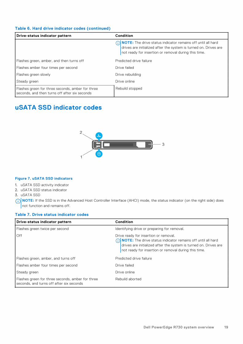
Table 6. Hard drive indicator codes (continued)
Drive-status indicator pattern Condition
NOTE: The drive status indicator remains off until all harddrives are initialized after the system is turned on. Drives arenot ready for insertion or removal during this time.
Flashes green, amber, and then turns off Predicted drive failure
Flashes amber four times per second Drive failed
Flashes green slowly Drive rebuilding
Steady green Drive online
Flashes green for three seconds, amber for threeseconds, and then turns off after six seconds
Rebuild stopped
uSATA SSD indicator codes
Figure 7. uSATA SSD indicators
1. uSATA SSD activity indicator2. uSATA SSD status indicator3. uSATA SSD
NOTE: If the SSD is in the Advanced Host Controller Interface (AHCI) mode, the status indicator (on the right side) does
not function and remains off.
Table 7. Drive status indicator codes
Drive-status indicator pattern Condition
Flashes green twice per second Identifying drive or preparing for removal.
Off Drive ready for insertion or removal.NOTE: The drive status indicator remains off until all harddrives are initialized after the system is turned on. Drives arenot ready for insertion or removal during this time.
Flashes green, amber, and turns off Predicted drive failure
Flashes amber four times per second Drive failed
Steady green Drive online
Flashes green for three seconds, amber for threeseconds, and turns off after six seconds
Rebuild aborted
Dell PowerEdge R730 system overview 19

NIC indicator codes
The NIC on the back panel has an indicator that provides information about the network activity and link status. The activityLED indicates whether the NIC is currently connected or not. The link LED indicates the speed of the connected network.
Figure 8. NIC Indicator Codes
1. link indicator2. activity indicator
Table 8. NIC indicators
Convention Status Condition
A Link and activity indicators are off. The NIC is not connected to the network.
B Link indicator is green. The NIC is connected to a valid network at its maximumport speed (1 Gbps or 10 Gbps).
C Link indicator is amber The NIC is connected to a valid network at less than itsmaximum port speed.
D Activity indicator is flashing. green Network data is being sent or received.
Power supply unit indicator codes
AC power supply units (PSUs) have an illuminated translucent handle that serves as an indicator and DC PSUs have an LED thatserves as an indicator. The indicator shows whether power is present or a power fault has occurred.
20 Dell PowerEdge R730 system overview
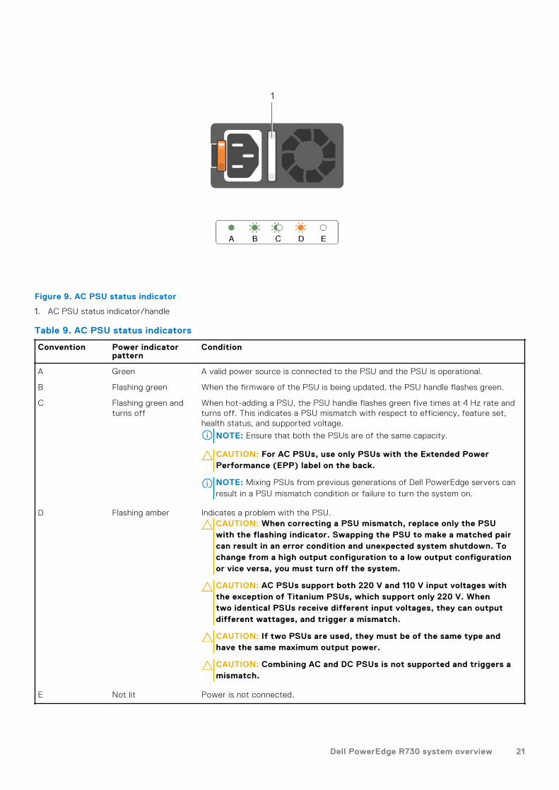
Figure 9. AC PSU status indicator
1. AC PSU status indicator/handle
Table 9. AC PSU status indicators
Convention Power indicatorpattern
Condition
A Green A valid power source is connected to the PSU and the PSU is operational.
B Flashing green When the firmware of the PSU is being updated, the PSU handle flashes green.
C Flashing green andturns off
When hot-adding a PSU, the PSU handle flashes green five times at 4 Hz rate andturns off. This indicates a PSU mismatch with respect to efficiency, feature set,health status, and supported voltage.
NOTE: Ensure that both the PSUs are of the same capacity.
CAUTION: For AC PSUs, use only PSUs with the Extended PowerPerformance (EPP) label on the back.
NOTE: Mixing PSUs from previous generations of Dell PowerEdge servers canresult in a PSU mismatch condition or failure to turn the system on.
D Flashing amber Indicates a problem with the PSU.CAUTION: When correcting a PSU mismatch, replace only the PSUwith the flashing indicator. Swapping the PSU to make a matched paircan result in an error condition and unexpected system shutdown. Tochange from a high output configuration to a low output configurationor vice versa, you must turn off the system.
CAUTION: AC PSUs support both 220 V and 110 V input voltages withthe exception of Titanium PSUs, which support only 220 V. Whentwo identical PSUs receive different input voltages, they can outputdifferent wattages, and trigger a mismatch.
CAUTION: If two PSUs are used, they must be of the same type andhave the same maximum output power.
CAUTION: Combining AC and DC PSUs is not supported and triggers amismatch.
E Not lit Power is not connected.
Dell PowerEdge R730 system overview 21
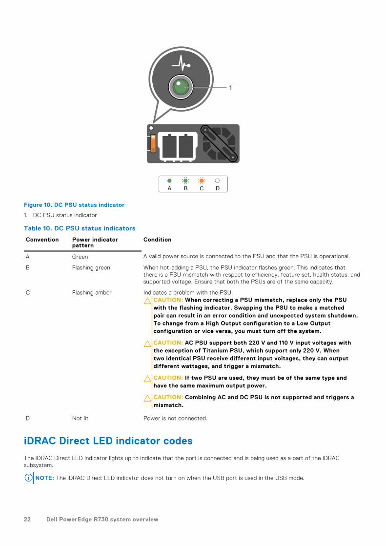
Figure 10. DC PSU status indicator
1. DC PSU status indicator
Table 10. DC PSU status indicators
Convention Power indicatorpattern
Condition
A Green A valid power source is connected to the PSU and that the PSU is operational.
B Flashing green When hot-adding a PSU, the PSU indicator flashes green. This indicates thatthere is a PSU mismatch with respect to efficiency, feature set, health status, andsupported voltage. Ensure that both the PSUs are of the same capacity.
C Flashing amber Indicates a problem with the PSU.CAUTION: When correcting a PSU mismatch, replace only the PSUwith the flashing indicator. Swapping the PSU to make a matchedpair can result in an error condition and unexpected system shutdown.To change from a High Output configuration to a Low Outputconfiguration or vice versa, you must turn off the system.
CAUTION: AC PSU support both 220 V and 110 V input voltages withthe exception of Titanium PSU, which support only 220 V. Whentwo identical PSU receive different input voltages, they can outputdifferent wattages, and trigger a mismatch.
CAUTION: If two PSU are used, they must be of the same type andhave the same maximum output power.
CAUTION: Combining AC and DC PSU is not supported and triggers amismatch.
D Not lit Power is not connected.
iDRAC Direct LED indicator codes
The iDRAC Direct LED indicator lights up to indicate that the port is connected and is being used as a part of the iDRACsubsystem.
NOTE: The iDRAC Direct LED indicator does not turn on when the USB port is used in the USB mode.
22 Dell PowerEdge R730 system overview
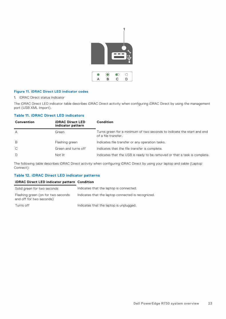
Figure 11. iDRAC Direct LED indicator codes
1. iDRAC Direct status indicator
The iDRAC Direct LED indicator table describes iDRAC Direct activity when configuring iDRAC Direct by using the managementport (USB XML Import).
Table 11. iDRAC Direct LED indicators
Convention iDRAC Direct LEDindicator pattern
Condition
A Green Turns green for a minimum of two seconds to indicate the start and endof a file transfer.
B Flashing green Indicates file transfer or any operation tasks.
C Green and turns off Indicates that the file transfer is complete.
D Not lit Indicates that the USB is ready to be removed or that a task is complete.
The following table describes iDRAC Direct activity when configuring iDRAC Direct by using your laptop and cable (LaptopConnect):
Table 12. iDRAC Direct LED indicator patterns
iDRAC Direct LED indicator pattern Condition
Solid green for two seconds Indicates that the laptop is connected.
Flashing green (on for two secondsand off for two seconds)
Indicates that the laptop connected is recognized.
Turns off Indicates that the laptop is unplugged.
Dell PowerEdge R730 system overview 23
Quick Sync indicator codes
Figure 12. Quick Sync
1. Quick Sync Status Indicator2. Quick Sync Activation Button
Table 13. Quick Sync indicator codes
Quick Sync indicatorpattern
Condition
Slow blink Quick Sync is waiting to be configured from iDRAC.
Solid Quick Sync is ready to transfer.
Blinks three times rapidlyand then turns off
Quick Sync feature is disabled from iDRAC.
Blinks continuously whenthe mobile devicetouches antenna
Indicates data transfer activity.
Blinks rapidlycontinuously when theactivation button ispressed
Quick Sync hardware is not responding properly.
Turns off Indicates that the Quick Sync feature is turned off. Use the activation button to activate it. Ifpressing the activation button does not turn on the LEDs, it indicates that power is not delivered tothe Quick Sync bezel.
Locating service tag of your systemYour system is identified by a unique Express Service Code and Service Tag number. The Express Service Code is and ServiceTag are found on the front of the system by pulling out the information tag. Alternatively, the information may be on a sticker onthe chassis of the system. This information is used by Dell to route support calls to the appropriate personnel.
24 Dell PowerEdge R730 system overview

Documentation resourcesThis section provides information about the documentation resources for your system.
To view the document that is listed in the documentation resources table:● From the Dell EMC support site:
1. Click the documentation link that is provided in the Location column in the table.2. Click the required product or product version.
NOTE: To locate the product name and model, see the front of your system.
3. On the Product Support page, click Manuals & documents.● Using search engines:
○ Type the name and version of the document in the search box.
Table 14.
Task Document Location
Setting up your system For more information about installing andsecuring the system into a rack, see theRail Installation Guide included with your racksolution.
For information about setting up your system,see the Getting Started Guide document that isshipped with your system.
https://www.dell.com/poweredgemanuals
Configuring yoursystem
For information about the iDRAC features,configuring and logging in to iDRAC, andmanaging your system remotely, see theIntegrated Dell Remote Access Controller User'sGuide.
For information about understandingRemote Access Controller Admin (RACADM)subcommands and supported RACADMinterfaces, see the RACADM CLI Guide foriDRAC.
For information about Redfish and its protocol,supported schema, and Redfish Eventingimplemented in iDRAC, see the Redfish APIGuide.
For information about iDRAC property databasegroup and object descriptions, see the AttributeRegistry Guide.
For information about Intel QuickAssistTechnology, see the Integrated Dell RemoteAccess Controller User's Guide.
https://www.dell.com/poweredgemanuals
For information about earlier versions of theiDRAC documents.
To identify the version of iDRAC available on yoursystem, on the iDRAC web interface, click ? >About.
https://www.dell.com/idracmanuals
For information about installing the operatingsystem, see the operating system documentation.
https://www.dell.com/operatingsystemmanuals
2
Documentation resources 25

Table 14. (continued)
Task Document Location
For information about updating drivers andfirmware, see the Methods to download firmwareand drivers section in this document.
www.dell.com/support/drivers
Managing your system For information about systems managementsoftware offered by Dell, see the DellOpenManage Systems Management OverviewGuide.
https://www.dell.com/poweredgemanuals
For information about setting up, using, andtroubleshooting OpenManage, see the DellOpenManage Server Administrator User’s Guide.
www.dell.com/openmanagemanuals >OpenManage Server Administrator
For information about installing, using, andtroubleshooting Dell OpenManage Enterprise, seethe Dell OpenManage Enterprise User’s Guide.
https://www.dell.com/openmanagemanuals
For information about installing and using DellSupportAssist, see the Dell EMC SupportAssistEnterprise User’s Guide.
https://www.dell.com/serviceabilitytools
For information about partner programsenterprise systems management, see theOpenManage Connections Enterprise SystemsManagement documents.
https://www.dell.com/openmanagemanuals
Working with theDell PowerEdge RAIDcontrollers
For information about understanding the featuresof the Dell PowerEdge RAID controllers (PERC),Software RAID controllers, or BOSS card anddeploying the cards, see the Storage controllerdocumentation.
www.dell.com/storagecontrollermanuals
Understanding eventand error messages
For information about the event and errormessages generated by the system firmware andagents that monitor system components, go toqrl.dell.com > Look Up > Error Code, type theerror code, and then click Look it up.
www.dell.com/qrl
Troubleshooting yoursystem
For information about identifying andtroubleshooting the PowerEdge server issues,see the Server Troubleshooting Guide.
https://www.dell.com/poweredgemanuals
26 Documentation resources
Technical specificationsThe technical and environmental specifications of your system are outlined in this section.
Topics:
• Chassis dimensions• Chassis weight• Processor specifications• PSU specifications• System battery specifications• Expansion bus specifications• Memory specifications• Drive specifications• Ports and connectors specifications• Video specifications• Environmental specifications
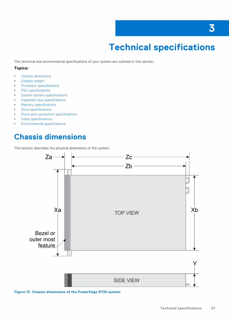
Chassis dimensionsThis section describes the physical dimensions of the system.
Figure 13. Chassis dimensions of the PowerEdge R730 system
3
Technical specifications 27
Table 15. Dimensions of the Dell PowerEdge R730 system
Xa Xb Y Za (withbezel)
Za (withoutbezel)
Zb Zc
482.4 mm 444.0 mm 87.3 mm 32.0 mm 18.0 mm 684.0 mm 723.0 mm
Chassis weightThis section describes the weight of the system.
Table 16. Chassis weight
System Maximum weight (with all hard drives/SSDs)
PowerEdge R730 ● 31.5 kg (69.45 lb) (3.5-inch hard drive systems)● 31.4 kg (69.23 lb) (2.5-inch hard drive systems)
Processor specificationsThe PowerEdge R730 system supports up to two Intel Xeon E5-2600 v3 or Intel Xeon E5-2600 v4 product family processors.
PSU specificationsThe PowerEdge R730 system supports up to two AC or DC redundant power supply units (PSUs).
Table 17. PSU specifications
PSU Class Heat dissipation(maximum)
Frequency Voltage
495 W AC Platinum 1908 BTU/hr 50/60 Hz 100–240 V AC, autoranging
750 W AC Platinum 2891 BTU/hr 50/60 Hz 100–240 V AC, autoranging
Titanium 2843 BTU/hr 50/60 Hz 200–240 V AC, autoranging
1100 W AC Platinum 4100 BTU/hr 50/60 Hz 100–240 V AC, autoranging
750 W DC (for Chinaonly)
Platinum 2902 BTU/hr 100–240 V AC and 240 V DC
1100 W DC N/A 4416 BTU/hr N/A –(48–60) V DC
NOTE: Heat dissipation is calculated using the PSU wattage rating.
NOTE: This system is also designed to connect to the IT power systems with a phase to phase voltage not exceeding 230
V.
System battery specificationsThe PowerEdge R730 system supports CR 2032 3.0-V lithium coin cell system battery.
Expansion bus specificationsThe PowerEdge R730 system supports PCI express (PCIe) generation 3 expansion cards, which need to be installed on thesystem board using expansion card risers. This system supports three types of expansion card risers. The following tableprovides the expansion card riser specifications:
28 Technical specifications
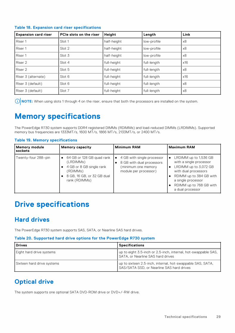
Table 18. Expansion card riser specifications
Expansion card riser PCIe slots on the riser Height Length Link
Riser 1 Slot 1 half-height low-profile x8
Riser 1 Slot 2 half-height low-profile x8
Riser 1 Slot 3 half-height low-profile x8
Riser 2 Slot 4 full-height full-length x16
Riser 2 Slot 5 full-height full-length x8
Riser 3 (alternate) Slot 6 full-height full-length x16
Riser 3 (default) Slot 6 full-height full-length x8
Riser 3 (default) Slot 7 full-height full-length x8
NOTE: When using slots 1 through 4 on the riser, ensure that both the processors are installed on the system.
Memory specificationsThe PowerEdge R730 system supports DDR4 registered DIMMs (RDIMMs) and load-reduced DIMMs (LRDIMMs). Supportedmemory bus frequencies are 1333MT/s, 1600 MT/s, 1866 MT/s, 2133MT/s, or 2400 MT/s.
Table 19. Memory specifications
Memory modulesockets
Memory capacity Minimum RAM Maximum RAM
Twenty-four 288–pin ● 64 GB or 128 GB quad rank(LRDIMMs)
● 4 GB or 8 GB single rank(RDIMMs)
● 8 GB, 16 GB, or 32 GB dualrank (RDIMMs)
● 4 GB with single processor● 8 GB with dual processors
(minimum one memorymodule per processor)
● LRDIMM up to 1,536 GBwith a single processor
● LRDIMM up to 3,072 GBwith dual processors
● RDIMM up to 384 GB witha single processor
● RDIMM up to 768 GB witha dual processor
Drive specifications
Hard drives
The PowerEdge R730 system supports SAS, SATA, or Nearline SAS hard drives.
Table 20. Supported hard drive options for the PowerEdge R730 system
Drives Specifications
Eight hard drive systems up to eight 3.5-inch or 2.5-inch, internal, hot-swappable SAS,SATA, or Nearline SAS hard drives
Sixteen hard drive systems up to sixteen 2.5-inch, internal, hot-swappable SAS, SATA,SAS/SATA SSD, or Nearline SAS hard drives
Optical drive
The system supports one optional SATA DVD-ROM drive or DVD+/-RW drive.
Technical specifications 29

Ports and connectors specifications
USB ports
The PowerEdge R730 system supports:● USB 2.0-compliant ports on the front panel● USB 3.0-compliant ports on the back panel● internal USB 3.0-compliant portThe following table provides more information about the USB specifications:
Table 21. USB specifications
System Front panel Back panel Internal
PowerEdge R730 ● One 4-pin, USB 2.0-compliant port
● One USB management port/iDRAC Direct
Two 9-pin, USB 3.0-compliantports
One 9-pin, USB 3.0-compliantport
NIC ports
The PowerEdge R730 system supports four Network Interface Controller (NIC) ports on the back panel, which is available inone of the following three NIC configurations:● Four RJ45 ports that support 1Gbps.● Two RJ45 ports that support up to 1Gbps and two SFP+ ports that support up to 10Gbps.● Two RJ45 ports that support up to 1Gbps and two RJ45 ports that support up to 10Gbps.
Serial connector
The serial connector connects a serial device to the system. The PowerEdge R730 system supports one serial connector on theback panel, which is a 9-pin connector, Data Terminal Equipment (DTE), 16550-compliant.
VGA ports
The Video Graphic Array (VGA) port enables you to connect the system to a VGA display. The PowerEdge R730 systemsupports two 15-pin VGA ports on the front and back panels.
Internal Dual SD Module
The PowerEdge R730 system supports two optional flash memory card slots with an internal dual SD module.
NOTE: One card slot is dedicated for redundancy.
Video specificationsThe PowerEdge R730 system supports Matrox G200eR2 graphics card with 16 MB capacity.
Table 22. Supported video resolution options
Resolution Refresh rate (Hz) Color depth (bits)
640x480 60,70 8, 16, 32
800x600 60,75, 85 8, 16, 32
30 Technical specifications

Table 22. Supported video resolution options (continued)
Resolution Refresh rate (Hz) Color depth (bits)
1024x768 60,75, 85 8, 16, 32
1152x864 60,75, 85 8, 16, 32
1280x1024 60,75 8, 16, 32
1440x900 60 8, 16, 32
Environmental specificationsNOTE: For additional information about environmental measurements for specific system configurations, see Dell.com/
environmental_datasheets.
Table 23. Temperature specifications
Temperature Specifications
Storage –40°C to 65°C (–40°F to 149°F)
Continuous operation (for altitude less than 950 m or3117 ft)
10°C to 35°C (50°F to 95°F) with no direct sunlight on theequipment.
Fresh air For information about fresh air, see Expanded Operating Temperaturesection.
Maximum temperature gradient (operating andstorage)
20°C/h (68°F/h)
Table 24. Relative humidity specifications
Relative humidity Specifications
Storage 5% to 95% RH with 33°C (91°F) maximum dew point. Atmospheremust be non-condensing at all times.
Operating 10% to 80% relative humidity with 29°C (84.2°F) maximum dewpoint.
Table 25. Maximum vibration specifications
Maximum vibration Specifications
Operating 0.26 Grms at 5 Hz to 350 Hz (all operation orientations).
Storage 1.88 Grms at 10 Hz to 500 Hz for 15 min (all six sides tested).
Table 26. Maximum shock specifications
Maximum vibration Specifications
Operating Six consecutively executed shock pulses in the positive and negative x,y, and z axes of 40 G for up to 2.3 ms.
Storage Six consecutively executed shock pulses in the positive and negative x,y, and z axes (one pulse on each side of the system) of 71 G for up to2 ms.
Table 27. Maximum altitude specifications
Maximum altitude Specifications
Operating 30482000 m (10,0006560 ft)
Storage 12,000 m (39,370 ft)
Technical specifications 31
Table 28. Operating temperature de-rating specifications
Operating temperature de-rating Specifications
Up to 35°C (95°F) Maximum temperature is reduced by 1°C/300 m (1°F/547 ft) above950 m (3,117 ft).
35°C to 40°C (95°F to 104°F) Maximum temperature is reduced by 1°C/175 m (1°F/319 ft) above950 m (3,117 ft).
40°C to 45°C (104°F to 113°F) Maximum temperature is reduced by 1°C/125 m (1°F/228 ft) above950 m (3,117 ft).
Particulate and gaseous contamination specifications
The following table defines the limitations that help avoid any equipment damage or failure from particulates and gaseouscontamination. If the levels of particulates or gaseous pollution exceed the specified limitations and result in equipment damageor failure, you may need to rectify the environmental conditions. Re-mediation of environmental conditions is the responsibilityof the customer.
Table 29. Particulate contamination specifications
Particulate contamination Specifications
Air filtration Data center air filtration as defined by ISO Class 8 per ISO 14644-1with a 95% upper confidence limit.
NOTE: This condition applies to data center environments only. Airfiltration requirements do not apply to IT equipment designed to beused outside a data center, in environments such as an office orfactory floor.
NOTE: Air entering the data center must have MERV11 or MERV13filtration.
Conductive dust Air must be free of conductive dust, zinc whiskers, or otherconductive particles.
NOTE: This condition applies to data center and non-data centerenvironments.
Corrosive dust ● Air must be free of corrosive dust.● Residual dust present in the air must have a deliquescent point less
than 60% relative humidity.
NOTE: This condition applies to data center and non-data centerenvironments.
Table 30. Gaseous contamination specifications
Gaseous contamination Specifications
Copper coupon corrosion rate <300 Å/month per Class G1 as defined by ANSI/ISA71.04-1985.
Silver coupon corrosion rate <200 Å/month as defined by AHSRAE TC9.9.
NOTE: Maximum corrosive contaminant levels measured at ≤50% relative humidity.
Standard operating temperature
Table 31. Standard operating temperature specifications
Standard operating temperature Specifications
Continuous operation (for altitude less than 950 m or3117 ft)
10°C to 35°C (50°F to 95°F) with no direct sunlight on theequipment.
32 Technical specifications

Expanded operating temperature
Table 32. Expanded operating temperature specifications
Expanded operating temperature Specifications
Continuous operation 5°C to 40°C at 5% to 85% RH with 29°C dew point.NOTE: Outside the standard operating temperature (10°C to35°C), the system can operate continuously in temperatures as lowas 5°C and as high as 40°C.
For temperatures between 35°C and 40°C, de-rate maximumallowable temperature by 1°C per 175 m above 950 m (1°F per 319ft).
≤ 1% of annual operating hours –5°C to 45°C at 5% to 90% RH with 29°C dew point.NOTE: Outside the standard operating temperature (10°C to35°C), the system can operate down to –5°C or up to 45°C for amaximum of 1% of its annual operating hours.
For temperatures between 40°C and 45°C, de-rate maximumallowable temperature by 1°C per 125 m above 950 m (1°F per 228ft).
NOTE: When operating in the expanded temperature range, system performance may be impacted.
NOTE: When operating in the expanded temperature range, ambient temperature warnings may be reported on the LCD
panel and in the System Event Log.
Expanded operating temperature restrictions
● Do not perform a cold startup below 5°C.● The operating temperature specified is for a maximum altitude of 3050 m (10,000 ft).● 160 W or higher wattage processor is not supported.● Redundant power supply units are required.● Non-Dell qualified peripheral cards and/or peripheral cards greater than 25 W are not supported.● The 3.5-inch hard drive chassis supports a maximum of 120 W processor.● The 2.5-inch hard drive chassis supports a maximum of 145 W processor.● Only SSDs are allowed in the hard drive slots at the back of the 3.5-inch hard drive chassis.● Mid drive configurations, eight 3.5-inch and eighteen 1.8-inch SSD configurations are not supported.● GPU is not supported● Tape backup unit (TBU) is not supported.
Technical specifications 33
Initial system setup and configuration
Topics:
• Setting up your system• iDRAC configuration• Options to install the operating system
Setting up your systemComplete the following steps to set up your system:
Steps
1. Unpack the system.
2. Install the system into the rack. For more information about installing the system into the rack, see your system RackInstallation Placemat at Dell.com/poweredgemanuals.
3. Connect the peripherals to the system.
4. Connect the system to its electrical outlet.
5. Turn the system on by pressing the power button or by using iDRAC.
6. Turn on the attached peripherals.
iDRAC configurationThe Integrated Dell Remote Access Controller (iDRAC) is designed to make system administrators more productive and improvethe overall availability of Dell EMC systems. iDRAC alerts administrators to system issues, helps them perform remote systemmanagement, and reduces the need for physical access to the system.
Options to set up iDRAC IP address
You must configure the initial network settings based on your network infrastructure to enable the communication to and fromiDRAC. You can set up the IP address by using one of the following interfaces:
Interfaces Document/Section
iDRAC Settingsutility
See iDRAC User's Guide available at https://www.dell.com/idracmanuals
Dell DeploymentToolkit
See OpenManage Deployment Toolkit User's Guide available at https://www.dell.com/openmanagemanuals
Dell LifecycleController
See Lifecycle Controller User's Guide available at https://www.dell.com/idracmanuals
Chassis or ServerLCD panel
See the LCD panel section
You must use the default iDRAC IP address 192.168.0.120 to configure the initial network settings, including setting up DHCP ora static IP for iDRAC.
NOTE: To access iDRAC, ensure that you install the iDRAC port card or connect the network cable to the Ethernet
connector 1 on the system board.
4
34 Initial system setup and configuration

NOTE: Ensure that you change the default user name and password after setting up the iDRAC IP address.
Log in to iDRAC
You can log in to iDRAC as:● iDRAC user● Microsoft Active Directory user● Lightweight Directory Access Protocol (LDAP) user
The default user name and password are root and calvin. You can also log in by using Single Sign-On or Smart Card.
NOTE: You must have iDRAC credentials to log in to iDRAC.
For more information about logging in to iDRAC and iDRAC licenses, see the latest Integrated Dell Remote Access ControllerUser's Guide at Dell.com/idracmanuals.
Options to install the operating systemIf the system is shipped without an operating system, install the supported operating system by using one of the followingresources:
Table 33. Resources to install the operating system
Resources Location
Dell Systems Management Tools and Documentation media https://www.dell.com/operatingsystemmanuals
Dell Lifecycle Controller https://www.dell.com/idracmanuals
Dell OpenManage Deployment Toolkit https://www.dell.com/openmanagemanuals
Dell certified VMware ESXi https://www.dell.com/virtualizationsolutions
Supported operating systems on Dell PowerEdge systems www.dell.com/ossupport
Installation and How-to videos for supported operatingsystems on Dell PowerEdge systems
https://www.youtube.com/playlist?list=PLe5xhhyFjDPfTCaDRFflB_VsoLpL8x84G
Methods to download firmware and drivers
You can download the firmware and drivers by using any of the following methods:
Table 34. Firmware and drivers
Methods Location
From the Dell Support site Global Technical Support
Using Dell Remote Access Controller Lifecycle Controller(iDRAC with LC)
Dell.com/idracmanuals
Using Dell Repository Manager (DRM) Dell.com/openmanagemanuals > OpenManage DeploymentToolkit
Using Dell OpenManage Essentials (OME) Dell.com/openmanagemanuals > OpenManage DeploymentToolkit
Using Dell Server Update Utility (SUU) Dell.com/openmanagemanuals > OpenManage DeploymentToolkit
Using Dell OpenManage Deployment Toolkit (DTK) Dell.com/openmanagemanuals > OpenManage DeploymentToolkit
Initial system setup and configuration 35

Downloading the drivers and firmware
Dell EMC recommends that you download and install the latest BIOS, drivers, and systems management firmware on yoursystem.
Prerequisites
Ensure that you clear the web browser cache before downloading the drivers and firmware.
Steps
1. Go to Dell.com/support/drivers.
2. In the Drivers & Downloads section, type the Service Tag of your system in the Service Tag or Express Service Codebox, and then click Submit.
NOTE: If you do not have the Service Tag, select Detect My Product to allow the system to automatically detect your
Service Tag, or in General support, navigate to your product.
3. Click Drivers & Downloads.The drivers that are applicable to your selection are displayed.
4. Download the drivers to a USB drive, CD, or DVD.
36 Initial system setup and configuration

Pre-operating system managementapplications
You can manage basic settings and features of a system without booting to the operating system by using the system firmware.
Topics:
• Options to manage the pre-operating system applications• System Setup• Dell Lifecycle Controller• Boot Manager• PXE boot
Options to manage the pre-operating systemapplicationsYour system has the following options to manage the pre-operating system applications:● System Setup● Boot Manager● Dell Lifecycle Controller● Preboot Execution Environment (PXE)
Related concepts
System Setup on page 37
Boot Manager on page 64
Dell Lifecycle Controller on page 64
PXE boot on page 65
System SetupBy using the System Setup screen, you can configure the BIOS settings, iDRAC settings, and device settings of your system.
NOTE: Help text for the selected field is displayed in the graphical browser by default. To view the help text in the text
browser, press F1.
You can access system setup by using two methods:● Standard graphical browser — The browser is enabled by default.● Text browser — The browser is enabled by using Console Redirection.
Related references
System Setup details on page 38
Related tasks
Viewing System Setup on page 38
5
Pre-operating system management applications 37
Viewing System Setup
To view the System Setup screen, perform the following steps:
Steps
1. Turn on, or restart your system.
2. Press F2 immediately after you see the following message:
F2 = System Setup
NOTE: If your operating system begins to load before you press F2, wait for the system to finish booting, and then
restart your system and try again.
Related concepts
System Setup on page 37
Related references
System Setup details on page 38
System Setup details
The System Setup Main Menu screen details are explained as follows:
Option Description
System BIOS Enables you to configure BIOS settings.
iDRAC Settings Enables you to configure iDRAC settings.
The iDRAC settings utility is an interface to set up and configure the iDRAC parameters by using UEFI(Unified Extensible Firmware Interface). You can enable or disable various iDRAC parameters by usingthe iDRAC settings utility. For more information about this utility, see Integrated Dell Remote AccessController User’s Guide at Dell.com/idracmanuals.
Device Settings Enables you to configure device settings.
Related concepts
System Setup on page 37
Related tasks
Viewing System Setup on page 38
System BIOS
You can use the System BIOS screen to edit specific functions such as boot order, system password, setup password, set theRAID mode, and enable or disable USB ports.
Related references
System BIOS Settings details on page 39
Boot Settings on page 40
Network Settings on page 42
System Information on page 48
Memory Settings on page 49
Processor Settings on page 50
SATA Settings on page 52
38 Pre-operating system management applications
Integrated Devices on page 55
Serial Communication on page 58
System Profile Settings on page 59
Miscellaneous Settings on page 61
iDRAC Settings utility on page 63
Device Settings on page 63
Related tasks
Viewing System BIOS on page 39
Viewing System BIOS
To view the System BIOS screen, perform the following steps:
Steps
1. Turn on, or restart your system.
2. Press F2 immediately after you see the following message:
F2 = System Setup
NOTE: If your operating system begins to load before you press F2, wait for the system to finish booting, and then
restart your system and try again.
3. On the System Setup Main Menu screen, click System BIOS.
Related references
System BIOS on page 38
System BIOS Settings details on page 39
System BIOS Settings details
About this task
The System BIOS Settings screen details are explained as follows:
Option Description
SystemInformation
Specifies information about the system such as the system model name, BIOS version, and Service Tag.
Memory Settings Specifies information and options related to the installed memory.
ProcessorSettings
Specifies information and options related to the processor such as speed and cache size.
SATA Settings Specifies options to enable or disable the integrated SATA controller and ports.
Boot Settings Specifies options to specify the boot mode (BIOS or UEFI). Enables you to modify UEFI and BIOS bootsettings.
Network Settings Specifies options to change the network settings.
IntegratedDevices
Specifies options to manage integrated device controllers and ports and specify related features andoptions.
SerialCommunication
Specifies options to manage the serial ports and specify related features and options.
System ProfileSettings
Specifies options to change the processor power management settings, memory frequency, and so on.
Pre-operating system management applications 39
Option Description
System Security Specifies options to configure the system security settings, such as system password, setup password,Trusted Platform Module (TPM) security. It also manages the power and NMI buttons on the system.
MiscellaneousSettings
Specifies options to change the system date, time, and so on.
Related references
System BIOS on page 38
Related tasks
Viewing System BIOS on page 39
Boot Settings
You can use the Boot Settings screen to set the boot mode to either BIOS or UEFI. It also enables you to specify the bootorder.
Related references
System BIOS on page 38
Choosing the system boot mode on page 41
Related tasks
Boot Settings details on page 41
Viewing Boot Settings on page 40
Changing the boot order on page 42
Viewing Boot Settings
To view the Boot Settings screen, perform the following steps:
Steps
1. Turn on, or restart your system.
2. Press F2 immediately after you see the following message:
F2 = System Setup
NOTE: If your operating system begins to load before you press F2, wait for the system to finish booting, and then
restart your system and try again.
3. On the System Setup Main Menu screen, click System BIOS.
4. On the System BIOS screen, click Boot Settings.
Related references
Boot Settings on page 40
Choosing the system boot mode on page 41
Related tasks
Boot Settings details on page 41
Changing the boot order on page 42
40 Pre-operating system management applications
Boot Settings details
About this task
The Boot Settings screen details are explained as follows:
Option Description
Boot Mode Enables you to set the boot mode of the system.CAUTION: Switching the boot mode may prevent the system from booting if the operating
system is not installed in the same boot mode.
If the operating system supports UEFI, you can set this option to UEFI. Setting this field to BIOS allowscompatibility with non-UEFI operating systems. This option is set to BIOS by default.
NOTE: Setting this field to UEFI disables the BIOS Boot Settings menu. Setting this field to BIOS
disables the UEFI Boot Settings menu.
Boot SequenceRetry
Enables or disables the Boot Sequence Retry feature. If this option is set to Enabled and the system failsto boot, the system reattempts the boot sequence after 30 seconds. This option is set to Enabled bydefault.
Hard-DiskFailover
Specifies the hard drive that is booted in the event of a hard drive failure. The devices are selected in theHard-Disk Drive Sequence on the Boot Option Setting menu. When this option is set to Disabled,only the first hard drive in the list is attempted to boot. When this option is set to Enabled, all hard drivesare attempted to boot in the order selected in the Hard-Disk Drive Sequence. This option is not enabledfor UEFI Boot Mode.
Boot OptionSettings
Configures the boot sequence and the boot devices.
BIOS BootSettings
Enables or disables BIOS boot options.
NOTE: This option is enabled only if the boot mode is BIOS.
UEFI BootSettings
Enables or disables UEFI Boot options. The Boot options include IPv4 PXE and IPv6 PXE. This option isset to IPv4 by default.
NOTE: This option is enabled only if the boot mode is UEFI.
Related references
Boot Settings on page 40
Choosing the system boot mode on page 41
Related tasks
Viewing Boot Settings on page 40
Changing the boot order on page 42
Choosing the system boot mode
System Setup enables you to specify one of the following boot modes for installing your operating system:
● BIOS boot mode (the default) is the standard BIOS-level boot interface.● Unified Extensible Firmware Interface (UEFI) (the default) boot mode is an enhanced 64-bit boot interface. If you have
configured your system to boot to UEFI mode, it replaces the system BIOS.1. From the System Setup Main Menu, click Boot Settings, and select Boot Mode.2. Select the boot mode you want the system to boot into.
CAUTION: Switching the boot mode may prevent the system from booting if the operating system is not
installed in the same boot mode.
3. After the system boots in the specified boot mode, proceed to install your operating system from that mode.
NOTE:
Pre-operating system management applications 41

● Operating systems must be UEFI-compatible to be installed from the UEFI boot mode. DOS and 32-bit operating
systems do not support UEFI and can only be installed from the BIOS boot mode.
● For the latest information about supported operating systems, go to Dell.com/ossupport.
Related references
Boot Settings on page 40
Related tasks
Boot Settings details on page 41
Viewing Boot Settings on page 40
Changing the boot order
About this task
You may have to change the boot order if you want to boot from a USB key or an optical drive. The following instructions mayvary if you have selected BIOS for Boot Mode.
Steps
1. On the System Setup Main Menu screen, click System BIOS > Boot Settings.
2. Click Boot Option Settings > Boot Sequence.
3. Use the arrow keys to select a boot device, and use the plus (+) and minus (-) sign keys to move the device down or up inthe order.
4. Click Exit, and then click Yes to save the settings on exit.
Related references
Boot Settings on page 40
Related tasks
Boot Settings details on page 41
Viewing Boot Settings on page 40
Network Settings
You can use the Network Settings screen to modify PXE device settings. The network settings option is available only in theUEFI mode.
NOTE: The BIOS does not control network settings in the BIOS mode. For the BIOS boot mode, the optional Boot ROM of
the network controllers handles the network settings.
Related concepts
UEFI iSCSI Settings on page 43
Related references
Network Settings screen details on page 43
UEFI iSCSI Settings details on page 44
System BIOS on page 38
Related tasks
Viewing Network Settings on page 43
Viewing UEFI iSCSI Settings on page 44
42 Pre-operating system management applications

Viewing Network Settings
To view the Network Settings screen, perform the following steps:
Steps
1. Turn on, or restart your system.
2. Press F2 immediately after you see the following message:
F2 = System Setup
NOTE: If your operating system begins to load before you press F2, wait for the system to finish booting, and then
restart your system and try again.
3. On the System Setup Main Menu screen, click System BIOS.
4. On the System BIOS screen, click Network Settings.
Related references
Network Settings on page 42
Network Settings screen details on page 43
Network Settings screen details
The Network Settings screen details are explained as follows:
About this task
Option Description
PXE Device n (n= 1 to 4)
Enables or disables the device. When enabled, a UEFI boot option is created for the device.
PXE Device nSettings(n = 1 to4)
Enables you to control the configuration of the PXE device.
Related references
Network Settings on page 42
Related tasks
Viewing Network Settings on page 43
UEFI iSCSI Settings
You can use the iSCSI Settings screen to modify iSCSI device settings. The iSCSI Settings option is available only in the UEFIboot mode. BIOS does not control network settings in the BIOS boot mode. For the BIOS boot mode, the option ROM of thenetwork controller handles the network settings.
Related references
UEFI iSCSI Settings details on page 44
UEFI iSCSI Settings on page 43
Related tasks
Viewing UEFI iSCSI Settings on page 44
Pre-operating system management applications 43
Viewing UEFI iSCSI Settings
To view the UEFI iSCSI Settings screen, perform the following steps:
Steps
1. Turn on, or restart your system.
2. Press F2 immediately after you see the following message:
F2 = System Setup
NOTE: If your operating system begins to load before you press F2, wait for the system to finish booting, and then
restart your system and try again.
3. On the System Setup Main Menu screen, click System BIOS.
4. On the System BIOS screen, click Network Settings.
5. On the Network Settings screen, click UEFI iSCSI Settings.
Related references
UEFI iSCSI Settings on page 43
UEFI iSCSI Settings details
The UEFI ISCSI Settings screen details are explained as follows:
Option Description
ISCSI InitiatorName
Specifies the name of the iSCSI initiator (iqn format).
ISCSI Device n (n= 1 to 4)
Enables or disables the iSCSI device. When disabled, a UEFI boot option is created for the iSCSI deviceautomatically.
System Security
You can use the System Security screen to perform specific functions such as setting the system password, setup passwordand disabling the power button.
Related references
Operating with a setup password enabled on page 47
System BIOS on page 38
Related tasks
System Security Settings details on page 45
Viewing System Security on page 44
Creating a system and setup password on page 46
Using your system password to secure your system on page 47
Deleting or changing system and setup password on page 47
Viewing System Security
To view the System Security screen, perform the following steps:
Steps
1. Turn on, or restart your system.
44 Pre-operating system management applications

2. Press F2 immediately after you see the following message:
F2 = System Setup
NOTE: If your operating system begins to load before you press F2, wait for the system to finish booting, and then
restart your system and try again.
3. On the System Setup Main Menu screen, click System BIOS.
4. On the System BIOS screen, click System Security.
Related references
System Security on page 44
Related tasks
System Security Settings details on page 45
System Security Settings details
About this task
The System Security Settings screen details are explained as follows:
Option Description
Intel AES-NI Improves the speed of applications by performing encryption and decryption by using the AdvancedEncryption Standard Instruction Set (AES-NI). This option is set to Enabled by default.
SystemPassword
Sets the system password. This option is set to Enabled by default and is read-only if the passwordjumper is not installed in the system.
Setup Password Sets the setup password. This option is read-only if the password jumper is not installed in the system.
Password Status Locks the system password. This option is set to Unlocked by default.
TPM Security NOTE: The TPM menu is available only when the TPM module is installed.
Enables you to control the reporting mode of the TPM. The TPM Security option is set to Off bydefault. You can only modify the TPM Status, TPM Activation, and Intel TXT fields if the TPM Statusfield is set to either On with Pre-boot Measurements or On without Pre-boot Measurements.
TPM Information Changes the operational state of the TPM. This option is set to No Change by default.
TPM Status Specifies the TPM status.
TPM Command CAUTION: Clearing the TPM results in the loss of all keys in the TPM. The loss of TPM keys
may affect booting to the operating system.
Clears all the contents of the TPM. The TPM Clear option is set to No by default.
Intel TXT Enables or disables the Intel Trusted Execution Technology (TXT) option. To enable the Intel TXT option,virtualization technology and TPM Security must be enabled with Pre-boot measurements. This option isset to Off by default.
Power Button Enables or disables the power button on the front of the system. This option is set to Enabled by default.
NMI Button Enables or disables the NMI button on the front of the system. This option is set to Disabled by default.
AC PowerRecovery
Sets how the system behaves after AC power is restored to the system. This option is set to Last bydefault.
AC PowerRecovery Delay
Sets the time delay for the system to power up after AC power is restored to the system. This option isset to Immediate by default.
User DefinedDelay (60s to240s)
Sets the User Defined Delay option when the User Defined option for AC Power Recovery Delay isselected.
Pre-operating system management applications 45
Option Description
UEFI VariableAccess
Provides varying degrees of securing UEFI variables. When set to Standard (the default), UEFI variablesare accessible in the operating system per the UEFI specification. When set to Controlled, selected UEFIvariables are protected in the environment and new UEFI boot entries are forced to be at the end of thecurrent boot order.
Secure BootPolicy
When Secure Boot policy is set to Standard, the BIOS uses the system manufacturer’s key andcertificates to authenticate pre-boot images. When Secure Boot policy is set to Custom, the BIOS usesthe user-defined key and certificates. Secure Boot policy is set to Standard by default.
Secure BootPolicy Summary
Specifies the list of certificates and hashes that secure boot uses to authenticate images.
Related references
System Security on page 44
Related tasks
Viewing System Security on page 44
Creating a system and setup password
Prerequisites
Ensure that the password jumper is enabled. The password jumper enables or disables the system password and setup passwordfeatures. For more information, see the System board jumper settings section.
NOTE: If the password jumper setting is disabled, the existing system password and setup password are deleted and you
need not provide the system password to boot the system.
Steps
1. To enter System Setup, press F2 immediately after turning on or rebooting your system.
2. On the System Setup Main Menu screen, click System BIOS > System Security.
3. On the System Security screen, verify that Password Status is set to Unlocked.
4. In the System Password field, type your system password, and press Enter or Tab.
Use the following guidelines to assign the system password:● A password can have up to 32 characters.● The password can contain the numbers 0 through 9.● Only the following special characters are allowed: space, (”), (+), (,), (-), (.), (/), (;), ([), (\), (]), (`).
A message prompts you to reenter the system password.
5. Reenter the system password, and click OK.
6. In the Setup Password field, type your setup password and press Enter or Tab.A message prompts you to reenter the setup password.
7. Reenter the setup password, and click OK.
8. Press Esc to return to the System BIOS screen. Press Esc again.
A message prompts you to save the changes.
NOTE: Password protection does not take effect until the system reboots.
Related references
System Security on page 44
46 Pre-operating system management applications
Using your system password to secure your system
About this task
If you have assigned a setup password, the system accepts your setup password as an alternate system password.
Steps
1. Turn on or reboot your system.
2. Type the system password and press Enter.
Next steps
When Password Status is set to Locked, type the system password and press Enter when prompted at reboot.
NOTE: If an incorrect system password is typed, the system displays a message and prompts you to reenter your password.
You have three attempts to type the correct password. After the third unsuccessful attempt, the system displays an error
message that the system has stopped functioning and must be turned off. Even after you turn off and restart the system,
the error message is displayed until the correct password is entered.
Related references
System Security on page 44
Deleting or changing system and setup password
Prerequisites
NOTE: You cannot delete or change an existing system or setup password if the Password Status is set to Locked.
Steps
1. To enter System Setup, press F2 immediately after turning on or restarting your system.
2. On the System Setup Main Menu screen, click System BIOS > System Security.
3. On the System Security screen, ensure that Password Status is set to Unlocked.
4. In the System Password field, alter or delete the existing system password, and then press Enter or Tab.
5. In the Setup Password field, alter or delete the existing setup password, and then press Enter or Tab.
If you change the system and setup password, a message prompts you to reenter the new password. If you delete thesystem and setup password, a message prompts you to confirm the deletion.
6. Press Esc to return to the System BIOS screen. Press Esc again, and a message prompts you to save the changes.
Related references
System Security on page 44
Operating with a setup password enabled
If Setup Password is set to Enabled, type the correct setup password before modifying the system setup options.
If you do not type the correct password in three attempts, the system displays the following message:
Invalid Password! Number of unsuccessful password attempts: <x> System Halted! Must power down.
Even after you turn off and restart the system, the error message is displayed until the correct password is typed. The followingoptions are exceptions:
● If System Password is not set to Enabled and is not locked through the Password Status option, you can assign asystem password. For more information, see the System Security Settings screen section.
Pre-operating system management applications 47

● You cannot disable or change an existing system password.
NOTE: You can use the password status option with the setup password option to protect the system password from
unauthorized changes.
Related references
System Security on page 44
System Information
You can use the System Information screen to view system properties such as Service Tag, system model name, and the BIOSversion.
Related references
System Information details on page 48
System BIOS on page 38
Related tasks
Viewing System Information on page 48
Viewing System Information
To view the System Information screen, perform the following steps:
Steps
1. Turn on, or restart your system.
2. Press F2 immediately after you see the following message:
F2 = System Setup
NOTE: If your operating system begins to load before you press F2, wait for the system to finish booting, and then
restart your system and try again.
3. On the System Setup Main Menu screen, click System BIOS.
4. On the System BIOS screen, click System Information.
Related references
System Information on page 48
System Information details
About this task
The System Information screen details are explained as follows:
Option Description
System ModelName
Specifies the system model name.
System BIOSVersion
Specifies the BIOS version installed on the system.
SystemManagementEngine Version
Specifies the current version of the Management Engine firmware.
48 Pre-operating system management applications

Option Description
System ServiceTag
Specifies the system Service Tag.
SystemManufacturer
Specifies the name of the system manufacturer.
SystemManufacturerContactInformation
Specifies the contact information of the system manufacturer.
System CPLDVersion
Specifies the current version of the system complex programmable logic device (CPLD) firmware.
UEFI ComplianceVersion
Specifies the UEFI compliance level of the system firmware.
Related references
System Information on page 48
System Information details on page 48
Related tasks
Viewing System Information on page 48
Memory Settings
You can use the Memory Settings screen to view all the memory settings and enable or disable specific memory functions,such as memory testing and node interleaving.
Related references
Memory Settings details on page 50
System BIOS on page 38
Related tasks
Viewing Memory Settings on page 49
Viewing Memory Settings
To view the Memory Settings screen, perform the following steps:
Steps
1. Turn on, or restart your system.
2. Press F2 immediately after you see the following message:
F2 = System Setup
NOTE: If your operating system begins to load before you press F2, wait for the system to finish booting, and then
restart your system and try again.
3. On the System Setup Main Menu screen, click System BIOS.
4. On the System BIOS screen, click Memory Settings.
Related references
Memory Settings on page 49
Memory Settings details on page 50
Pre-operating system management applications 49

Memory Settings details
About this task
The Memory Settings screen details are explained as follows:
Option Description
System MemorySize
Specifies the memory size in the system.
System MemoryType
Specifies the type of memory installed in the system.
System MemorySpeed
Specifies the memory speed.
System MemoryVoltage
Specifies the memory voltage.
Video Memory Specifies the amount of video memory.
System MemoryTesting
Specifies whether the memory tests are run during system boot. Options are Enabled and Disabled. Thisoption is set to Disabled by default.
MemoryOperating Mode
Specifies the memory operating mode. The options available are Optimizer Mode, Advanced ECCMode, Mirror Mode, Spare Mode, Spare with Advanced ECC Mode, Dell Fault Resilient Mode andDell NUMA Fault Resilient Mode. This option is set to Optimizer Mode by default.
NOTE: The Memory Operating Mode option can have different default and available options based
on the memory configuration of your system.
NOTE: The Dell Fault Resilient Mode option establishes an area of memory that is fault resilient.
This mode can be used by an operating system that supports the feature to load critical applications
or enables the operating system kernel to maximize system availability.
Node Interleaving Specifies if the Non-Uniform Memory Architecture (NUMA) is supported. If this field is set to Enabled,memory interleaving is supported if a symmetric memory configuration is installed. If the field is setto Disabled, the system supports NUMA (asymmetric) memory configurations. This option is set toDisabled by default.
Snoop Mode Specifies the Snoop Mode options. The Snoop Mode options available are Home Snoop, Early Snoop,and Cluster on Die. This option is set to Early Snoop by default. This field is available only when theNode Interleaving is set to Disabled.
Related references
Memory Settings on page 49
Related tasks
Viewing Memory Settings on page 49
Processor Settings
You can use the Processor Settings screen to view the processor settings, and perform specific functions such as enablingvirtualization technology, hardware prefetcher, and logical processor idling.
Related references
Processor Settings details on page 51
System BIOS on page 38
Related tasks
Viewing Processor Settings on page 51
50 Pre-operating system management applications
Viewing Processor Settings
To view the Processor Settings screen, perform the following steps:
Steps
1. Turn on, or restart your system.
2. Press F2 immediately after you see the following message:
F2 = System Setup
NOTE: If your operating system begins to load before you press F2, wait for the system to finish booting, and then
restart your system and try again.
3. On the System Setup Main Menu screen, click System BIOS.
4. On the System BIOS screen, click Processor Settings.
Related references
Processor Settings on page 50
Processor Settings details on page 51
Processor Settings details
About this task
The Processor Settings screen details are explained as follows:
Option Description
Logical Processor Enables or disables the logical processors and displays the number of logical processors. If this option isset to Enabled, the BIOS displays all the logical processors. If this option is set to Disabled, the BIOSdisplays only one logical processor per core. This option is set to Enabled by default.
QPI Speed Enables you to control QuickPath Interconnect data rate settings.
Alternate RTID(RequestorTransaction ID)Setting
Modifies Requestor Transaction IDs, which are QPI resources. This option is set to Disabled by default.
NOTE: Enabling this option may negatively impact the overall system performance.
VirtualizationTechnology
Enables or disables the additional hardware capabilities provided for virtualization. This option is set toEnabled by default.
AddressTranslationService (ATS)
Defines the Address Translation Cache (ATC) for devices to cache the DMA transactions. This optionprovides an interface between CPU and DMA Memory Management to a chipset's Address Translationand Protection Table to translate DMA addresses to host addresses. This option is set to Enabled bydefault.
Adjacent CacheLine Prefetch
Optimizes the system for applications that need high utilization of sequential memory access. This optionis set to Enabled by default. You can disable this option for applications that need high utilization ofrandom memory access.
HardwarePrefetcher
Enables or disables the hardware prefetcher. This option is set to Enabled by default.
DCU StreamerPrefetcher
Enables or disables the Data Cache Unit (DCU) streamer prefetcher. This option is set to Enabled bydefault.
DCU IPPrefetcher
Enables or disables the Data Cache Unit (DCU) IP prefetcher. This option is set to Enabled by default.
Execute Disable Enables you to run the disable memory protection technology. This option is set to Enabled by default.
Logical ProcessorIdling
Enables you to improve the energy efficiency of a system. It uses the operating system core parkingalgorithm and parks some of the logical processors in the system which in turn allows the corresponding
Pre-operating system management applications 51

Option Description
processor cores to transition into a lower power idle state. This option can only be enabled if theoperating system supports it. It is set to Disabled by default.
Configurable TDP Enables you to reconfigure the processor Thermal Design Power (TDP) levels during POST based on thepower and thermal delivery capabilities of the system. TDP verifies the maximum heat the cooling systemis needed to dissipate. This option is set to Nominal by default.
NOTE: This option is only available on certain stock keeping units (SKUs) of the processors.
X2Apic Mode Enables or disables the X2Apic mode.
Dell ControlledTurbo
Controls the turbo engagement. Enable this option only when System Profile is set to Performance.
NOTE: Depending on the number of installed CPUs, there may be up to four processor listings.
Number of Coresper Processor
Controls the number of enabled cores in each processor. This option is set to All by default.
Processor 64-bitSupport
Specifies if the processor(s) support 64-bit extensions.
Processor CoreSpeed
Specifies the maximum core frequency of the processor.
Processor 1 NOTE: Depending on the number of CPUs, there may be up to four processors listed.
The following settings are displayed for each processor installed in the system:
Option Description
Family-Model-Stepping
Specifies the family, model, and stepping of the processor as defined by Intel.
Brand Specifies the brand name.
Level 2 Cache Specifies the total L2 cache.
Level 3 Cache Specifies the total L3 cache.
Number of Cores Specifies the number of cores per processor.
Related references
Processor Settings on page 50
Related tasks
Viewing Processor Settings on page 51
SATA Settings
You can use the SATA Settings screen to view the SATA settings of SATA devices and enable RAID on your system.
Related references
System BIOS on page 38
Related tasks
SATA Settings details on page 53
Viewing SATA Settings on page 53
52 Pre-operating system management applications

Viewing SATA Settings
To view the SATA Settings screen, perform the following steps:
Steps
1. Turn on, or restart your system.
2. Press F2 immediately after you see the following message:
F2 = System Setup
NOTE: If your operating system begins to load before you press F2, wait for the system to finish booting, and then
restart your system and try again.
3. On the System Setup Main Menu screen, click System BIOS.
4. On the System BIOS screen, click SATA Settings.
Related references
SATA Settings on page 52
Related tasks
SATA Settings details on page 53
SATA Settings details
About this task
The SATA Settings screen details are explained as follows:
Option Description
Embedded SATA Enables the embedded SATA option to be set to Off, ATA, AHCI, or RAID modes. This option is set toAHCI by default.
Security FreezeLock
Sends Security Freeze Lock command to the Embedded SATA drives during POST. This option isapplicable only for ATA and AHCI modes.
Write Cache Enables or disables the command for Embedded SATA drives during POST.
Port A Sets the drive type of the selected device. For Embedded SATA settings in ATA mode, set this field toAuto to enable BIOS support. Set it to OFF to turn off BIOS support.
For AHCI or RAID mode, BIOS support is always enabled.
Option Description
Model Specifies the drive model of the selected device.
Drive Type Specifies the type of drive attached to the SATA port.
Capacity Specifies the total capacity of the hard drive. This field is undefined for removablemedia devices such as optical drives.
Port B Sets the drive type of the selected device. For Embedded SATA settings in ATA mode, set this field toAuto to enable BIOS support. Set it to OFF to turn off BIOS support.
For AHCI or RAID mode, BIOS support is always enabled.
Option Description
Model Specifies the drive model of the selected device.
Drive Type Specifies the type of drive attached to the SATA port.
Capacity Specifies the total capacity of the hard drive. This field is undefined for removablemedia devices such as optical drives.
Pre-operating system management applications 53

Option Description
Port C Sets the drive type of the selected device. For Embedded SATA settings in ATA mode, set this field toAuto to enable BIOS support. Set it to OFF to turn off BIOS support.
For AHCI or RAID mode, BIOS support is always enabled.
Option Description
Model Specifies the drive model of the selected device.
Drive Type Specifies the type of drive attached to the SATA port.
Capacity Specifies the total capacity of the hard drive. This field is undefined for removablemedia devices such as optical drives.
Port D Sets the drive type of the selected device. For Embedded SATA settings in ATA mode, set this field toAuto to enable BIOS support. Set it to OFF to turn off BIOS support.
For AHCI or RAID mode, BIOS support is always enabled.
Option Description
Model Specifies the drive model of the selected device.
Drive Type Specifies the type of drive attached to the SATA port.
Capacity Specifies the total capacity of the hard drive. This field is undefined for removablemedia devices such as optical drives.
Port E Sets the drive type of the selected device. For Embedded SATA settings in ATA mode, set this field toAuto to enable BIOS support. Set it to OFF to turn off BIOS support.
For AHCI or RAID mode, BIOS support is always enabled.
Option Description
Model Specifies the drive model of the selected device.
Drive Type Specifies the type of drive attached to the SATA port.
Capacity Specifies the total capacity of the hard drive. This field is undefined for removablemedia devices such as optical drives.
Port F Sets the drive type of the selected device. For Embedded SATA settings in ATA mode, set this field toAuto to enable BIOS support. Set it to OFF to turn off BIOS support.
For AHCI or RAID mode, BIOS support is always enabled.
Option Description
Model Specifies the drive model of the selected device.
Drive Type Specifies the type of drive attached to the SATA port.
Capacity Specifies the total capacity of the hard drive. This field is undefined for removablemedia devices such as optical drives.
Port G Sets the drive type of the selected device. For Embedded SATA settings in ATA mode, set this field toAuto to enable BIOS support. Set it to OFF to turn off BIOS support.
For AHCI or RAID mode, BIOS support is always enabled.
Option Description
Model Specifies the drive model of the selected device.
Drive Type Specifies the type of drive attached to the SATA port.
Capacity Specifies the total capacity of the hard drive. This field is undefined for removablemedia devices such as optical drives.
54 Pre-operating system management applications

Option Description
Port H Sets the drive type of the selected device. For Embedded SATA settings in ATA mode, set this field toAuto to enable BIOS support. Set it to OFF to turn off BIOS support.
For AHCI or RAID mode, BIOS support is always enabled.
Option Description
Model Specifies the drive model of the selected device.
Drive Type Specifies the type of drive attached to the SATA port.
Capacity Specifies the total capacity of the hard drive. This field is undefined for removablemedia devices such as optical drives.
Port I Sets the drive type of the selected device. For Embedded SATA settings in ATA mode, set this field toAuto to enable BIOS support. Set it to OFF to turn off BIOS support.
For AHCI or RAID mode, BIOS support is always enabled.
Option Description
Model Specifies the drive model of the selected device.
Drive Type Specifies the type of drive attached to the SATA port.
Capacity Specifies the total capacity of the hard drive. This field is undefined for removablemedia devices such as optical drives.
Port J Sets the drive type of the selected device. For Embedded SATA settings in ATA mode, set this field toAuto to enable BIOS support. Set it to OFF to turn off BIOS support.
For AHCI or RAID mode, BIOS support is always enabled.
Option Description
Model Specifies the drive model of the selected device.
Drive Type Specifies the type of drive attached to the SATA port.
Capacity Specifies the total capacity of the hard drive. This field is undefined for removablemedia devices such as optical drives.
Related references
SATA Settings on page 52
Related tasks
Viewing SATA Settings on page 53
Integrated Devices
You can use the Integrated Devices screen to view and configure the settings of all integrated devices including the videocontroller, integrated RAID controller, and the USB ports.
Related references
System BIOS on page 38
Related tasks
Integrated Devices details on page 56
Viewing Integrated Devices on page 56
Pre-operating system management applications 55
Viewing Integrated Devices
To view the Integrated Devices screen, perform the following steps:
Steps
1. Turn on, or restart your system.
2. Press F2 immediately after you see the following message:
F2 = System Setup
NOTE: If your operating system begins to load before you press F2, wait for the system to finish booting, and then
restart your system and try again.
3. On the System Setup Main Menu screen, click System BIOS.
4. On the System BIOS screen, click Integrated Devices.
Related references
Integrated Devices on page 55
Related tasks
Integrated Devices details on page 56
Integrated Devices details
About this task
The Integrated Devices screen details are explained as follows:
Option Description
USB 3.0 Setting Enables or disables the USB 3.0 support. Enable this option only if your operating system supports USB3.0. If you disable this option, devices operate at USB 2.0 speed. USB 3.0 is enabled by default.
User AccessibleUSB Ports
Enables or disables the USB ports. Selecting Only Back Ports On disables the front USB ports, selectingAll Ports Off disables all USB ports. The USB keyboard and mouse operate during boot process in certainoperating systems. After the boot process is complete, the USB keyboard and mouse do not work if theports are disabled.
NOTE: Selecting Only Back Ports On and All Ports Off disables the USB management port and
also restricts access to iDRAC features.
Internal USB Port Enables or disables the internal USB port. This option is set to Enabled by default.
Integrated RAIDController
Enables or disables the integrated RAID controller. This option is set to Enabled by default.
IntegratedNetwork Card 1
Enables or disables the integrated network card.
Embedded NIC1and NIC2
NOTE: The Embedded NIC1 and NIC2 options are only available on systems that do not have
Integrated Network Card 1.
Enables or disables the Embedded NIC1 and NIC2 options. If set to Disabled, the NIC may still beavailable for shared network access by the embedded management controller. The embedded NIC1and NIC2 options are only available on systems that do not have Network Daughter Cards (NDCs).The Embedded NIC1 and NIC2 option is mutually exclusive with the Integrated Network Card 1 option.Configure the Embedded NIC1 and NIC2 option by using the NIC management utilities of the system.
I/OAT DMAEngine
Enables or disables the I/OAT option. Enable only if the hardware and software support the feature.
I/O SnoopHoldoffResponse
Selects the number of cycles PCI I/O can withhold snoop requests from the CPU, to allow timeto complete its own write to LLC. This setting can help improve performance on workloads wherethroughput and latency are critical.
56 Pre-operating system management applications

Option Description
Embedded VideoController
Enables or disables the Embedded Video Controller option. This option is set to Enabled by default.
Current State ofEmbedded VideoController
Displays the current state of the embedded video controller. The Current State of Embedded VideoController option is a read-only field. If the Embedded Video Controller is the only display capability in thesystem (that is, no add-in graphics card is installed), then the Embedded Video Controller is automaticallyused as the primary display even if the Embedded Video Controller setting is set to Disabled.
SR-IOV GlobalEnable
Enables or disables the BIOS configuration of Single Root I/O Virtualization (SR-IOV) devices. This optionis set to Disabled by default.
OS WatchdogTimer
If your system stops responding, this watchdog timer aids in the recovery of your operating system.When this option is set to Enabled, the operating system initializes the timer. When this option is set toDisabled (the default), the timer does not have any effect on the system.
Memory MappedI/O above 4 GB
Enables or disables the support for PCIe devices that need large amounts of memory. This option is set toEnabled by default.
Slot Disablement Enables or disables the available PCIe slots on your system. The slot disablement feature controls theconfiguration of PCIe cards installed in the specified slot. Slots must be disabled only when the installedperipheral card prevents booting into the operating system or causes delays in system startup. If the slotis disabled, both the Option ROM and UEFI drivers are disabled.
Slot Bifurcation Enables you to control the bifurcation of the specified slot. Only slots that are present in your system areavailable for control.
The configuration for a x16 slot is default (x16), x8x8, or x4x4x4x4.
The configuration for a x8 slot is default (x8) or x4x4.
Slots Description
Slot 1 Bifurcation Controls the bifurcation of PCIe cards installed in the specified slot.
● When set to default, the slot operates at the default bifurcation for that slot.● When set to x4x4 the slot bifurcates to two links.
Slot 2 Bifurcation Controls the bifurcation of PCIe cards installed in the specified slot.
● When set to default, the slot operates at the default bifurcation for that slot.● When set to x4x4 the slot bifurcates to two links.
Slot 3 Bifurcation Controls the bifurcation of PCIe cards installed in the specified slot.
● When set to default, the slot operates at the default bifurcation for that slot.● When set to x4x4 the slot bifurcates to two links.
Slot 4 Bifurcation Controls the bifurcation of PCIe cards installed in the specified slot.
● When set to default, the slot operates at the default bifurcation for that slot.● When set to x8x8 or x4x4x4x4, the slot bifurcates to either two or four links
depending on the slot capability.
Slot 5Bifurcation
Controls the bifurcation of PCIe cards installed in the specified slot.
● When set to default, the slot operates at the default bifurcation for that slot.● When set to x4x4 the slot bifurcates to two links.
Slot 6 Bifurcation Controls the bifurcation of PCIe cards installed in the specified slot.
NOTE: This slot bifurcation is supported only in six slot systems.
● When set to default, the slot operates at the default bifurcation for that slot.● When set to x8x8 or x4x4x4x4, the slot bifurcates to either two or four links
depending on the slot capability.
NOTE: This slot bifurcation is supported only in seven slot systems.
● When set to default, the slot operates at the default bifurcation for that slot.● When set to x4x4 the slot bifurcates to two links.
Pre-operating system management applications 57

Option Description
Slot 7 Bifurcation Controls the bifurcation of PCIe cards installed in the specified slot.
NOTE: This slot bifurcation is supported only in seven slot systems.
● When set to default, the slot operates at the default bifurcation for that slot.● When set to x4x4 the slot bifurcates to two links.
Related references
Integrated Devices on page 55
Related tasks
Viewing Integrated Devices on page 56
Serial Communication
You can use the Serial Communication screen to view the properties of the serial communication port.
Related references
System BIOS on page 38
Related tasks
Serial Communication details on page 58
Viewing Serial Communication on page 58
Viewing Serial Communication
To view the Serial Communication screen, perform the following steps:
Steps
1. Turn on, or restart your system.
2. Press F2 immediately after you see the following message:
F2 = System Setup
NOTE: If your operating system begins to load before you press F2, wait for the system to finish booting, and then
restart your system and try again.
3. On the System Setup Main Menu screen, click System BIOS.
4. On the System BIOS screen, click Serial Communication.
Related references
Serial Communication on page 58
Related tasks
Serial Communication details on page 58
Serial Communication details
About this task
The Serial Communication screen details are explained as follows:
58 Pre-operating system management applications

Option Description
SerialCommunication
Selects serial communication devices (Serial Device 1 and Serial Device 2) in BIOS. BIOS consoleredirection can also be enabled and the port address can be specified. This option is set to Auto bydefault.
Serial PortAddress
Enables you to set the port address for serial devices. This option is set to Serial Device 1=COM2,Serial Device 2=COM1 by default.
NOTE: You can use only Serial Device 2 for the Serial Over LAN (SOL) feature. To use console
redirection by SOL, configure the same port address for console redirection and the serial device.
NOTE: Every time the system boots, the BIOS syncs the serial MUX setting saved in iDRAC. The
serial MUX setting can independently be changed in iDRAC. Loading the BIOS default settings from
within the BIOS setup utility may not always revert the serial MUX setting to the default setting of
Serial Device 1.
External SerialConnector
Enables you to associate the External Serial Connector to Serial Device 1, Serial Device 2, or the RemoteAccess Device by using this option.
NOTE: Only Serial Device 2 can be used for Serial Over LAN (SOL). To use console redirection by
SOL, configure the same port address for console redirection and the serial device.
NOTE: Every time the system boots, the BIOS syncs the serial MUX setting saved in iDRAC. The
serial MUX setting can independently be changed in iDRAC. Loading the BIOS default settings from
within the BIOS setup utility may not always revert this setting to the default setting of Serial Device
1.
Failsafe BaudRate
Specifies the failsafe baud rate for console redirection. The BIOS attempts to determine the baud rateautomatically. This failsafe baud rate is used only if the attempt fails, and the value must not be changed.This option is set to 115200 by default.
Remote TerminalType
Sets the remote console terminal type. This option is set to VT 100/VT 220 by default.
Redirection AfterBoot
Enables or disables the BIOS console redirection when the operating system is loaded. This option is setto Enabled by default.
Related references
Serial Communication on page 58
Related tasks
Viewing Serial Communication on page 58
System Profile Settings
You can use the System Profile Settings screen to enable specific system performance settings such as power management.
Related references
System BIOS on page 38
Related tasks
System Profile Settings details on page 60
Viewing System Profile Settings on page 60
Pre-operating system management applications 59

Viewing System Profile Settings
To view the System Profile Settings screen, perform the following steps:
Steps
1. Turn on, or restart your system.
2. Press F2 immediately after you see the following message:
F2 = System Setup
NOTE: If your operating system begins to load before you press F2, wait for the system to finish booting, and then
restart your system and try again.
3. On the System Setup Main Menu screen, click System BIOS.
4. On the System BIOS screen, click System Profile Settings.
Related references
System Profile Settings on page 59
Related tasks
System Profile Settings details on page 60
System Profile Settings details
About this task
The System Profile Settings screen details are explained as follows:
Option Description
System Profile Sets the system profile. If you set the System Profile option to a mode other than Custom, the BIOSautomatically sets the rest of the options. You can only change the rest of the options if the mode is setto Custom. This option is set to Performance Per Watt Optimized (DAPC) by default. DAPC is DellActive Power Controller.
NOTE: All the parameters on the system profile setting screen are available only when the System
Profile option is set to Custom.
CPU PowerManagement
Sets the CPU power management. This option is set to System DBPM (DAPC) by default.
MemoryFrequency
Sets the speed of the memory. You can select Maximum Performance, Maximum Reliability, or aspecific speed.
Turbo Boost Enables or disables the processor to operate in the turbo boost mode. This option is set to Enabled bydefault.
Energy EfficientTurbo
Enables or disables the Energy Efficient Turbo option.
Energy Efficient Turbo (EET) is a mode of operation where a processor’s core frequency is adjusted to bewithin the turbo range based on workload.
C1E Enables or disables the processor to switch to a minimum performance state when it is idle. This option isset to Enabled by default.
C States Enables or disables the processor to operate in all available power states. This option is set to Enabled bydefault.
CollaborativeCPUPerformanceControl
Enables or disables the CPU power management option. When set to Enabled, the CPU powermanagement is controlled by the OS DBPM and the System DBPM (DAPC). This option is set toDisabled by default.
60 Pre-operating system management applications

Option Description
Memory PatrolScrub
Sets the memory patrol scrub frequency. This option is set to Standard by default.
Memory RefreshRate
Sets the memory refresh rate to either 1x or 2x. This option is set to 1x by default.
UncoreFrequency
Enables you to select the Processor Uncore Frequency option.
Dynamic mode enables the processor to optimize power resources across the cores and uncore duringruntime. The optimization of the uncore frequency to either save power or optimize performance isinfluenced by the setting of the Energy Efficiency Policy option.
Energy EfficientPolicy
Enables you to select the Energy Efficient Policy option.
The CPU uses the setting to manipulate the internal behavior of the processor and determines whether totarget higher performance or better power savings.
Number ofTurbo BootEnabled Coresfor Processor 1
NOTE: If there are two processors installed in the system, you see an entry for Number of Turbo
Boost Enabled Cores for Processor 2.
Controls the number of turbo boost enabled cores for processor 1. The maximum number of cores isenabled by default.
Monitor/Mwait Enables the Monitor/Mwait instructions in the processor. This option is set to Enabled for all systemprofiles, except Custom by default.
NOTE: This option can be disabled only if the C States option in the Custom mode is set to
disabled.
NOTE: When C States is set to Enabled in the Custom mode, changing the Monitor/Mwait setting
does not impact the system power or performance.
Related references
System Profile Settings on page 59
Related tasks
Viewing System Profile Settings on page 60
Miscellaneous Settings
You can use the Miscellaneous Settings screen to perform specific functions such as updating the asset tag and changing thesystem date and time.
Related references
System BIOS on page 38
Related tasks
Miscellaneous Settings details on page 62
Viewing Miscellaneous Settings on page 61
Viewing Miscellaneous Settings
To view the Miscellaneous Settings screen, perform the following steps:
Steps
1. Turn on, or restart your system.
Pre-operating system management applications 61

2. Press F2 immediately after you see the following message:
F2 = System Setup
NOTE: If your operating system begins to load before you press F2, wait for the system to finish booting, and then
restart your system and try again.
3. On the System Setup Main Menu screen, click System BIOS.
4. On the System BIOS screen, click Miscellaneous Settings.
Related references
Miscellaneous Settings on page 61
Related tasks
Miscellaneous Settings details on page 62
Miscellaneous Settings details
About this task
The Miscellaneous Settings screen details are explained as follows:
Option Description
System Time Enables you to set the time on the system.
System Date Enables you to set the date on the system.
Asset Tag Specifies the asset tag and enables you to modify it for security and tracking purposes.
KeyboardNumLock
Enables you to set whether the system boots with the NumLock enabled or disabled. This option is set toOn by default.
NOTE: This option does not apply to 84-key keyboards.
F1/F2 Prompt onError
Enables or disables the F1/F2 prompt on error. This option is set to Enabled by default. The F1/F2prompt also includes keyboard errors.
Load LegacyVideo OptionROM
Enables you to determine whether the system BIOS loads the legacy video (INT 10H) option ROM fromthe video controller. Selecting Enabled in the operating system does not support UEFI video outputstandards. This field is available only for UEFI boot mode. You cannot set the option to Enabled if UEFISecure Boot mode is enabled.
In-SystemCharacterization
Enables or disables In-System Characterization. This option is set to Disabled by default. The twoother options are Enabled and Enabled - No Reboot.
NOTE: The default setting for In-System Characterization is subject to change in future BIOS
releases.
When enabled, In-System Characterization (ISC) executes during POST upon detecting relevant changesin system configuration to optimize system power and performance. ISC takes about 20 seconds toexecute, and system reset is needed for ISC results to be applied. The Enabled - No Reboot optionexecutes ISC and continues without applying ISC results until the next time system reset occurs. TheEnabled option executes ISC and forces an immediate system reset so that ISC results can be applied.It takes the system longer to be ready due to the forced system reset. When disabled, ISC does notexecute.
Related references
Miscellaneous Settings on page 61
Related tasks
Viewing Miscellaneous Settings on page 61
62 Pre-operating system management applications

iDRAC Settings utility
The iDRAC settings utility is an interface to set up and configure the iDRAC parameters by using UEFI. You can enable or disablevarious iDRAC parameters by using the iDRAC settings utility.
NOTE: Accessing some of the features on the iDRAC settings utility needs the iDRAC Enterprise License upgrade.
For more information about using iDRAC, see Dell Integrated Dell Remote Access Controller User's Guide at Dell.com/idracmanuals.
Related concepts
Device Settings on page 63
Related references
System BIOS on page 38
Related tasks
Entering the iDRAC Settings utility on page 63
Changing the thermal settings on page 63
Entering the iDRAC Settings utility
Steps
1. Turn on or restart the managed system.
2. Press F2 during Power-on Self-test (POST).
3. On the System Setup Main Menu page, click iDRAC Settings.The iDRAC Settings screen is displayed.
Related references
iDRAC Settings utility on page 63
Changing the thermal settings
The iDRAC settings utility enables you to select and customize the thermal control settings for your system.1. Click iDRAC Settings > Thermal.2. Under SYSTEM THERMAL PROFILE > Thermal Profile, select one of the following options:
● Default Thermal Profile Settings● Maximum Performance (Performance Optimized)● Minimum Power (Performance per Watt Optimized)
3. Under USER COOLING OPTIONS, set the Fan Speed Offset, Minimum Fan Speed, and Custom Minimum Fan Speed.4. Click Back > Finish > Yes.
Related references
iDRAC Settings utility on page 63
Device Settings
Device Settings enables you to configure device parameters.
Related references
System BIOS on page 38
Pre-operating system management applications 63

Dell Lifecycle ControllerDell Lifecycle Controller (LC) provides advanced embedded system management capabilities including system deployment,configuration, update, maintenance, and diagnosis. LC is delivered as part of the iDRAC out-of-band solution and Dell EMCsystem embedded Unified Extensible Firmware Interface (UEFI) applications.
Related references
Embedded systems management on page 64
Embedded systems management
The Dell Lifecycle Controller provides advanced embedded systems management throughout the lifecycle of the system. TheDell Lifecycle Controller can be started during the boot sequence and can function independently of the operating system.
NOTE: Certain platform configurations may not support the full set of features provided by the Dell Lifecycle Controller.
For more information about setting up the Dell Lifecycle Controller, configuring hardware and firmware, and deploying theoperating system, see the Dell Lifecycle Controller documentation at Dell.com/idracmanuals.
Related references
Dell Lifecycle Controller on page 64
Boot ManagerThe Boot Manager screen enables you to select boot options and diagnostic utilities.
Related references
Boot Manager main menu on page 65
System BIOS on page 38
Related tasks
Viewing Boot Manager on page 64
Viewing Boot Manager
To enter Boot Manager:
Steps
1. Turn on, or restart your system.
2. Press F11 when you see the following message:
F11 = Boot Manager
If your operating system begins to load before you press F11, allow the system to complete the booting, and then restart yoursystem and try again.
Related references
Boot Manager on page 64
Boot Manager main menu on page 65
64 Pre-operating system management applications

Boot Manager main menu
Menu item Description
Continue NormalBoot
The system attempts to boot to devices starting with the first item in the boot order. If the boot attemptfails, the system continues with the next item in the boot order until the boot is successful or no moreboot options are found.
One-shot BootMenu
Enables you to access boot menu, where you can select a one-time boot device to boot from.
Launch SystemSetup
Enables you to access System Setup.
Launch LifecycleController
Exits the Boot Manager and invokes the Dell Lifecycle Controller program.
System Utilities Enables you to launch System Utilities menu such as System Diagnostics and UEFI shell.
Related references
Boot Manager on page 64
Related tasks
Viewing Boot Manager on page 64
One-shot BIOS boot menu
One-shot BIOS boot menu enables you to select a boot device to boot from.
Related references
Boot Manager on page 64
System Utilities
System Utilities contains the following utilities that can be launched:● Launch Diagnostics● BIOS/UEFI Update File Explorer● Reboot System
NOTE: Depending on the boot mode selected, you might have BIOS or UEFI Update File Explorer.
Related references
Boot Manager on page 64
PXE bootYou can use the Preboot Execution Environment (PXE) option to boot and configure the networked systems, remotely.
NOTE: To access the PXE boot option, boot the system and then press F12. The system scans and displays the active
networked systems.
Pre-operating system management applications 65
Installing and removing system components
Topics:
• Safety instructions• Before working inside your system• After working inside your system• Recommended tools• Front bezel (optional)• System cover• Inside the system• Cooling shroud• Cooling fans• Cooling fan assembly• System memory• Processors and heat sinks• PCIe card holder• Cable retention bracket• Integrated storage controller card• Expansion cards and expansion card riser• IDSDM• Network daughter card• Internal USB memory key (optional)• System battery• Power supply units (PSU)• System board• Trusted Platform Module• Hard drives• Hard drive backplane• Tape backup unit (optional)• Optical drive (optional)• SD vFlash card (optional)• Control panel assembly
Safety instructionsNOTE: Whenever you need to lift the system, get others to assist you. To avoid injury, do not attempt to lift the system by
yourself.
WARNING: Opening or removing the system cover while the system is powered on may expose you to a risk of
electric shock.
CAUTION: Do not operate the system without the cover for a duration exceeding five minutes.
CAUTION: Many repairs may only be done by a certified service technician. You should only perform
troubleshooting and simple repairs as authorized in your product documentation, or as directed by the online or
telephone service and support team. Damage due to servicing that is not authorized by Dell is not covered by
your warranty. Read and follow the safety instructions that are shipped with your product.
NOTE: It is recommended that you always use an antistatic mat and antistatic strap while working on components inside
the system.
6
66 Installing and removing system components
NOTE: To ensure proper operation and cooling, all bays in the system and system fans must be populated always with
either a component or with a blank.
Before working inside your system
Prerequisites
Follow the safety guidelines listed in the Safety instructions section.
Steps
1. Turn off the system, including any attached peripherals.
2. Disconnect the system from the electrical outlet and disconnect the peripherals.
3. If installed, remove the front bezel.
4. If applicable, remove the system from the rack.
For more information, see the Rack Installation placemat at Dell.com/poweredgemanuals.
5. Remove the system cover.
Related tasks
Removing the optional front bezel on page 68
Removing the system cover on page 71
After working inside your system
Prerequisites
Follow the safety guidelines listed in the Safety instructions section.
Steps
1. Install the system cover.
2. If applicable, install the system into the rack.
For more information, see the Rack Installation placemat at Dell.com/poweredgemanuals.
3. If removed, install the front bezel.
4. Reconnect the peripherals and connect the system to the electrical outlet.
5. Turn on the system, including any attached peripherals.
Related tasks
Installing the system cover on page 72
Installing the optional front bezel on page 69
Recommended toolsYou need the following tools to perform the removal and installation procedures:● Key to the bezel lock.
The key is needed only if your system includes a bezel.
● Phillips #1 screwdriver● Phillips #2 screwdriver● Torx #T6, #T8, #T10, and #T15 screwdrivers● Wrist grounding strap
You need the following tools to assemble the cables for a DC power supply unit.
● AMP 90871-1 hand-crimping tool or equivalent
Installing and removing system components 67

● Tyco Electronics 58433-3 or equivalent● Wire-stripper pliers to remove insulation from size 10 AWG solid or stranded, insulated copper wire
NOTE: Use alpha wire part number 3080 or equivalent (65/30 stranding).
Front bezel (optional)The front bezel is attached to the front side of the system and prevents accidents while removing the hard drive or whenpressing the reset or power button. The front bezel can also be locked for additional security.
Removing the optional front bezel
Prerequisites
Follow the safety guidelines listed in the Safety instructions section.
Steps
1. Locate and remove the bezel key.
NOTE: The bezel key is attached to the back of the bezel.
2. Unlock the bezel by using the key.
3. Slide the release latch up, and pull the left end of the bezel.
4. Unhook the right end, and remove the bezel.
Figure 14. Removing the optional front bezel
a. release latchb. bezel lockc. front bezel
68 Installing and removing system components

Figure 15. Removing the optional Quick Sync front bezel
a. release latchb. bezel lockc. Quick Sync bezel
Installing the optional front bezel
Prerequisites
Follow the safety guidelines listed in the Safety instructions section.
Steps
1. Locate and remove the bezel key.
NOTE: The bezel key is attached to the back of the bezel.
2. Hook the right end of the bezel onto the chassis.
3. Fit the free end of the bezel onto the system.
4. Lock the bezel by using the key.
Installing and removing system components 69

Figure 16. Installing the optional front bezel
a. bezel lockb. front bezel
Figure 17. Installing the Quick Sync bezel
a. bezel lockb. Quick Sync bezel
70 Installing and removing system components
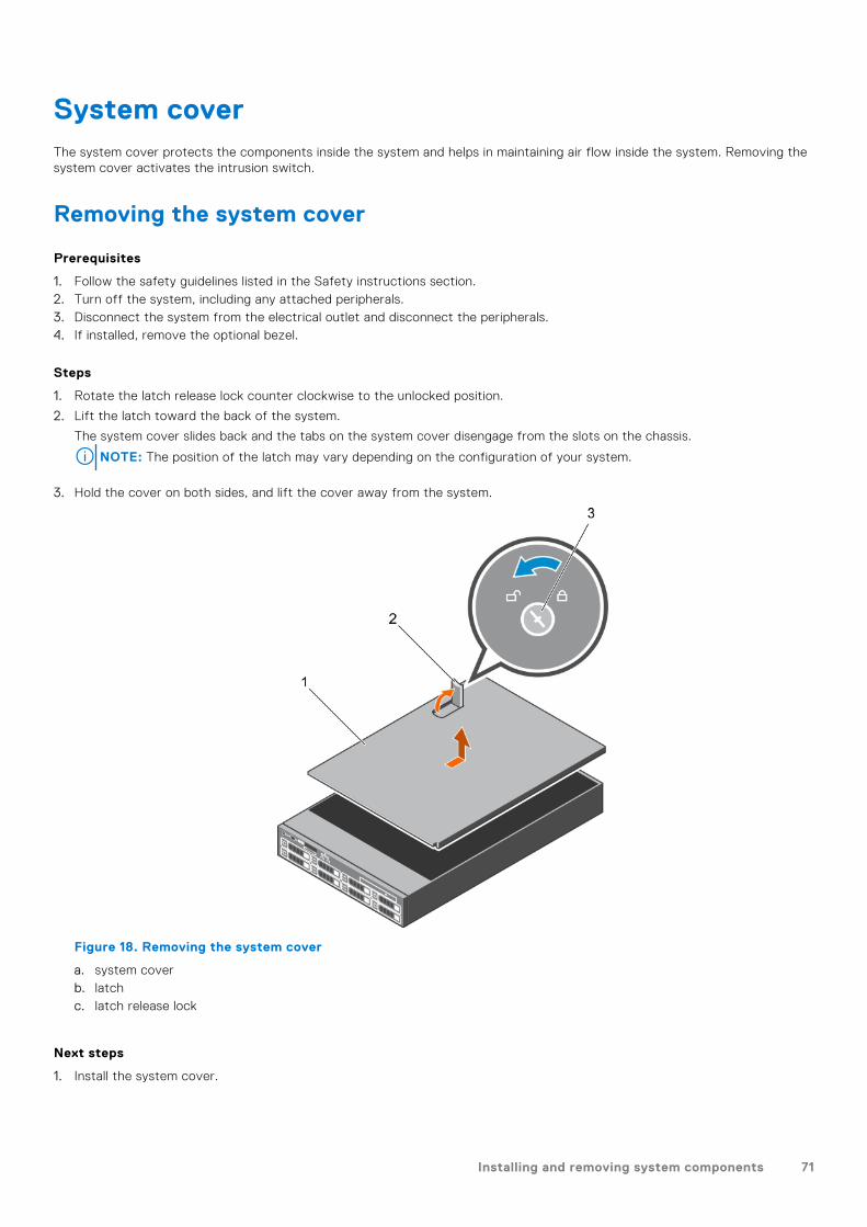
System coverThe system cover protects the components inside the system and helps in maintaining air flow inside the system. Removing thesystem cover activates the intrusion switch.
Removing the system cover
Prerequisites
1. Follow the safety guidelines listed in the Safety instructions section.2. Turn off the system, including any attached peripherals.3. Disconnect the system from the electrical outlet and disconnect the peripherals.4. If installed, remove the optional bezel.
Steps
1. Rotate the latch release lock counter clockwise to the unlocked position.
2. Lift the latch toward the back of the system.
The system cover slides back and the tabs on the system cover disengage from the slots on the chassis.
NOTE: The position of the latch may vary depending on the configuration of your system.
3. Hold the cover on both sides, and lift the cover away from the system.
Figure 18. Removing the system cover
a. system coverb. latchc. latch release lock
Next steps
1. Install the system cover.
Installing and removing system components 71
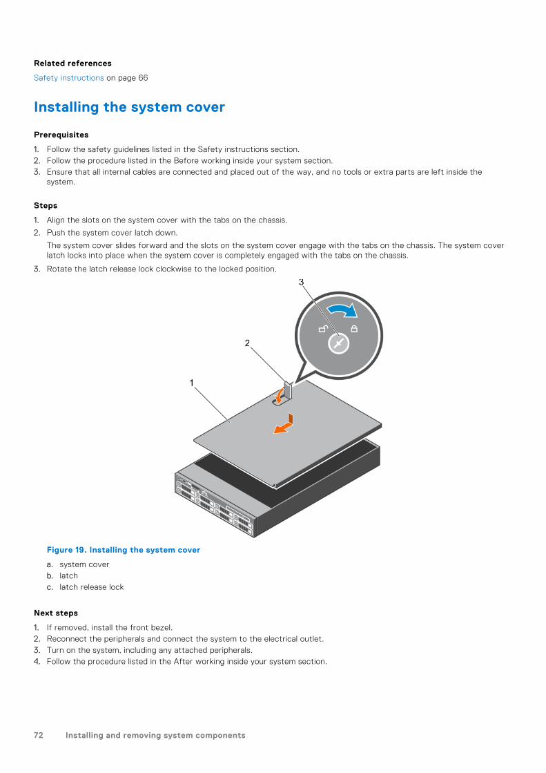
Related references
Safety instructions on page 66
Installing the system cover
Prerequisites
1. Follow the safety guidelines listed in the Safety instructions section.2. Follow the procedure listed in the Before working inside your system section.3. Ensure that all internal cables are connected and placed out of the way, and no tools or extra parts are left inside the
system.
Steps
1. Align the slots on the system cover with the tabs on the chassis.
2. Push the system cover latch down.
The system cover slides forward and the slots on the system cover engage with the tabs on the chassis. The system coverlatch locks into place when the system cover is completely engaged with the tabs on the chassis.
3. Rotate the latch release lock clockwise to the locked position.
Figure 19. Installing the system cover
a. system coverb. latchc. latch release lock
Next steps
1. If removed, install the front bezel.2. Reconnect the peripherals and connect the system to the electrical outlet.3. Turn on the system, including any attached peripherals.4. Follow the procedure listed in the After working inside your system section.
72 Installing and removing system components

Related references
Safety instructions on page 66
Related tasks
Installing the optional front bezel on page 69
Inside the systemCAUTION: Many repairs may only be done by a certified service technician. You should only perform
troubleshooting and simple repairs as authorized in your product documentation, or as directed by the online or
telephone service and support team. Damage due to servicing that is not authorized by Dell is not covered by
your warranty. Read and follow the safety instructions that are shipped with your product.
Figure 20. Inside the system
1. cooling fan in the cooling fan assembly (6) 2. processor (2)
3. DIMM (24) 4. PCIe card holder
5. internal USB port 6. power supply unit (2)
7. expansion card riser 3 8. network daughter card
9. expansion card riser 2 10. expansion card riser 1
11. hard drive backplane
Installing and removing system components 73

Cooling shroudThe cooling shroud aerodynamically directs the airflow across the entire system. The airflow passes through all the critical partsof the system, where the vacuum pulls air across the entire surface area of the heat sink, thus allowing increased cooling.
Removing the cooling shroud
Prerequisites
CAUTION: Many repairs may only be done by a certified service technician. You should only perform
troubleshooting and simple repairs as authorized in your product documentation, or as directed by the online or
telephone service and support team. Damage due to servicing that is not authorized by Dell is not covered by
your warranty. Read and follow the safety instructions that are shipped with your product.
CAUTION: Never operate your system with the air shroud removed. The system may get overheated quickly,
resulting in shutdown of the system and loss of data.
1. Follow the safety guidelines listed in the Safety instructions section.2. Follow the procedure listed in the Before working inside your system section.3. If installed, remove the full-length PCIe card.
Steps
Holding the touch points, lift the cooling shroud away from the system.
Figure 21. Removing the cooling shroud
a. cooling shroudb. touch point (2)
Next steps
1. Install the cooling shroud.2. If required, install the full-length PCIe card.3. Follow the procedure listed in the After working inside your system section.
Related references
Safety instructions on page 66
Related tasks
Before working inside your system on page 67
Removing an expansion card from expansion card riser 2 or 3 on page 106
74 Installing and removing system components
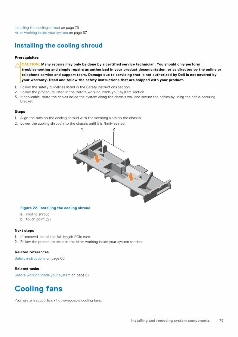
Installing the cooling shroud on page 75
After working inside your system on page 67
Installing the cooling shroud
Prerequisites
CAUTION: Many repairs may only be done by a certified service technician. You should only perform
troubleshooting and simple repairs as authorized in your product documentation, or as directed by the online or
telephone service and support team. Damage due to servicing that is not authorized by Dell is not covered by
your warranty. Read and follow the safety instructions that are shipped with your product.
1. Follow the safety guidelines listed in the Safety instructions section.2. Follow the procedure listed in the Before working inside your system section.3. If applicable, route the cables inside the system along the chassis wall and secure the cables by using the cable-securing
bracket.
Steps
1. Align the tabs on the cooling shroud with the securing slots on the chassis.
2. Lower the cooling shroud into the chassis until it is firmly seated.
Figure 22. Installing the cooling shroud
a. cooling shroudb. touch point (2)
Next steps
1. If removed, install the full-length PCIe card.2. Follow the procedure listed in the After working inside your system section.
Related references
Safety instructions on page 66
Related tasks
Before working inside your system on page 67
Cooling fansYour system supports six hot-swappable cooling fans.
Installing and removing system components 75

NOTE: In the event of a problem with a particular fan, the fan number is referenced by the system management software,
allowing you to easily identify and replace the proper fan by noting the fan numbers on the cooling fan assembly.
Removing a cooling fan
Prerequisites
1. Follow the safety guidelines listed in the Safety instructions section.2. Follow the procedure listed in the Before working inside your system section.
CAUTION: Many repairs may only be done by a certified service technician. You should only perform
troubleshooting and simple repairs as authorized in your product documentation, or as directed by the online or
telephone service and support team. Damage due to servicing that is not authorized by Dell is not covered by
your warranty. Read and follow the safety instructions that are shipped with your product.
CAUTION: The cooling fans are hot-swappable. To maintain proper cooling while the system is on, replace only
one fan at a time.
NOTE: The procedure for removing each fan is identical.
Steps
Press the fan release tab and lift the cooling fan out of the cooling fan assembly.
Figure 23. Removing a cooling fan
1. cooling fan assembly 2. cooling fan connector (6)
3. fan release tab (6) 4. cooling fan (6)
5. cooling fan connector on the system board (6)
Next steps
1. Install the cooling fan.2. Follow the procedure listed in the After working inside your system section.
Related references
Safety instructions on page 66
76 Installing and removing system components

Related tasks
Before working inside your system on page 67
Installing a cooling fan on page 77
After working inside your system on page 67
Installing a cooling fan
Prerequisites
1. Follow the safety guidelines listed in the Safety instructions section.2. Follow the procedure listed in the Before working inside your system section.
NOTE: The procedure for installing each fan is identical.
Steps
1. Align the connector at the base of the cooling fan with the connector on the system board.
2. Slide the cooling fan into the securing slot until the tab locks into place.
Next steps
Follow the procedure listed in the After working inside your system section.
Related references
Safety instructions on page 66
Related tasks
Before working inside your system on page 67
After working inside your system on page 67
Cooling fan assemblyThe cooling fan assembly ensures that the key components of the server such as the processors, hard drives, and memory getadequate air circulation to keep them cool. A failure in the server’s cooling system can result in the server overheating and maylead to damage.
Removing the cooling fan assembly
Prerequisites
1. Follow the safety guidelines listed in the Safety instructions section.2. Follow the procedure listed in the Before working inside your system section.
CAUTION: Many repairs may only be done by a certified service technician. You should only perform
troubleshooting and simple repairs as authorized in your product documentation, or as directed by the online or
telephone service and support team. Damage due to servicing that is not authorized by Dell is not covered by
your warranty. Read and follow the safety instructions that are shipped with your product.
Steps
1. Unlock the cooling fan assembly from the chassis by lifting the release levers.
2. Lift the cooling fan assembly out of the chassis.
Installing and removing system components 77

Figure 24. Removing the cooling fan assembly
1. cooling fan assembly 2. cooling fan (6)
3. release lever (2) 4. guide pin on the system board (2)
5. cooling fan connector (6) 6. guide pin on the chassis (6)
Next steps
1. Install the cooling fan assembly.2. Follow the procedure listed in the After working inside your system section.
Related references
Safety instructions on page 66
Related tasks
Before working inside your system on page 67
Installing the cooling fan assembly on page 78
After working inside your system on page 67
Installing the cooling fan assembly
Prerequisites
CAUTION: Many repairs may only be done by a certified service technician. You should only perform
troubleshooting and simple repairs as authorized in your product documentation, or as directed by the online or
telephone service and support team. Damage due to servicing that is not authorized by Dell is not covered by
your warranty. Read and follow the safety instructions that are shipped with your product.
1. Follow the safety guidelines listed in Safety instructions section.2. Follow the procedure listed in the Before working inside your system section.
78 Installing and removing system components

CAUTION: Ensure that the cables are correctly installed and retained by the cable retention bracket before
installing the cooling fan assembly. Incorrectly installed cables may get damaged.
Steps
1. Align the slots on the cooling fan assembly with the guide pins on the chassis.
2. Slide the cooling fan assembly into the chassis.
3. Lock the cooling fan assembly into the chassis by lowering the release levers until firmly seated.
Figure 25. Installing the cooling fan assembly
1. cooling fan assembly 2. cooling fan (6)
3. release lever (2) 4. guide pin on the system board (2)
5. cooling fan connector (6) 6. guide pin on the chassis (6)
Next steps
Follow the procedure listed in the After working inside your system section.
Related references
Safety instructions on page 66
Related tasks
Before working inside your system on page 67
After working inside your system on page 67
System memoryThe system supports DDR4 registered DIMMs (RDIMMs) and load reduced DIMMs (LRDIMMs). System memory holds theinstructions that are executed by the processor.
NOTE: MT/s indicates DIMM speed in MegaTransfers per second.
Installing and removing system components 79

Memory bus operating frequency can be 1866 MT/s, 2133 MT/s, or 2400 MT/s depending on the following factors:
● DIMM type (RDIMM or LRDIMM)● Number of DIMMs populated per channel● System profile selected (for example, Performance Optimized, Custom, or Dense Configuration Optimized)● Maximum supported DIMM frequency of the processors
Your system contains 24 memory sockets split into two sets of 12 sockets, one set per processor. Each 12-socket set isorganized into four channels. In each channel, the release tabs of the first socket are marked white, the second socket black,and the third socket green.
Figure 26. Memory socket locations
Memory channels are organized as follows:
Table 35. Memory channels
Processor Channel 0 Channel 1 Channel 2 Channel 3
Processor1
Slots A1, A5, and A9 Slots A2, A6, and A10 Slots A3, A7, and A11 Slots A4, A8, and A12
Processor2
Slots B1, B5, and B9 Slots B2, B6, and B10 Slots B3, B7, and B11 Slots B4, B8, and B12
The following table shows the memory populations and operating frequencies for the supported configurations:
80 Installing and removing system components

Table 36. Memory population
DIMM Type DIMMsPopulated/Channel
VoltageOperating Frequency
(in MT/s)Maximum DIMM Rank/Channel
RDIMM 1
1.2 V
2400, 2133, 1866 Dual rank or single rank
2 2400, 2133, 1866 Dual rank or single rank
3 1866 Dual rank or single rank
LRDIMM 1
1.2 V
2400, 2133, 1866 Quad rank
2 2400, 2133, 1866 Quad rank
3 2133, 1866 Quad rank
General memory module installation guidelines
NOTE: Memory configurations that fail to observe these guidelines can prevent your system from booting, stop responding
during memory configuration, or operating with reduced memory.
The system supports Flexible Memory Configuration, enabling the system to be configured and run in any valid chipsetarchitectural configuration. The following are the recommended guidelines for installing memory modules:
● RDIMMs and LRDIMMs must not be mixed.● x4 and x8 DRAM based memory modules can be mixed. For more information, see the Mode-specific guidelines section.● Up to three dual- or single-rank RDIMMs can be populated per channel.● Up to three LRDIMMs can be populated per channel regardless of rank count.● If memory modules with different speeds are installed, they will operate at the speed of the slowest installed memory
module(s) or slower depending on system DIMM configuration.● Populate memory module sockets only if a processor is installed. For single-processor systems, sockets A1 to A12 are
available. For dual-processor systems, sockets A1 to A12 and sockets B1 to B12 are available.● Populate all the sockets with white release tabs first, followed by the black release tabs, and then the green release tabs.● When mixing memory modules with different capacities, populate the sockets with memory modules with highest capacity
first. For example, if you want to mix 4 GB and 8 GB memory modules, populate 8 GB memory modules in the sockets withwhite release tabs and 4 GB memory modules in the sockets with black release tabs.
● In a dual-processor configuration, the memory configuration for each processor should be identical. For example, if youpopulate socket A1 for processor 1, then populate socket B1 for processor 2, and so on.
● Memory modules of different capacities can be mixed provided other memory population rules are followed (for example, 4GB and 8 GB memory modules can be mixed).
● Mixing of more than two memory module capacities in a system is not supported.● Populate four memory modules per processor (one DIMM per channel) at a time to maximize performance.
Mode-specific guidelines
Four memory channels are allocated to each processor. The allowable configurations depend on the memory mode selected.
Advanced Error Correction Code
Advanced Error Correction Code (ECC) mode extends SDDC from x4 DRAM based DIMMs to both x4 and x8 DRAMs. Thisprotects against single DRAM chip failures during normal operation.
The installation guidelines for memory modules are as follows:
● Memory modules must be identical in size, speed, and technology.● DIMMs installed in memory sockets with white release levers must be identical and the same rule applies for sockets with
black release levers. This ensures that identical DIMMs are installed in matched pair —for example, A1 with A2, A3 with A4,A5 with A6, and so on.
Installing and removing system components 81

Memory optimized independent channel mode
This mode supports Single Device Data Correction (SDDC) only for memory modules that use x4 device width. It does notimpose any specific slot population requirements.
Memory sparing
NOTE: To use memory sparing, this feature must be enabled in System Setup.
In this mode, one rank per channel is reserved as a spare. If persistent correctable errors are detected on a rank, the data fromthis rank is copied to the spare rank, and the failed rank is disabled.
With memory sparing enabled, the system memory available to the operating system is reduced by one rank per channel. Forexample, in a dual-processor configuration with sixteen 4 GB single-rank memory modules, the available system memory is: 3/4(ranks/channel) × 16 (memory modules) × 4 GB = 48 GB, and not 16 (memory modules) × 4 GB = 64 GB.
NOTE: Memory sparing does not offer protection against a multi-bit uncorrectable error.
NOTE: Both Advanced ECC/Lockstep and Optimizer modes support memory sparing.
Memory mirroring
Memory mirroring offers the strongest memory module reliability mode compared to all other modes, providing improveduncorrectable multi-bit failure protection. In a mirrored configuration, the total available system memory is one half of thetotal installed physical memory. Half of the installed memory is used to mirror the active memory modules. In the event of anuncorrectable error, the system switches over to the mirrored copy. This ensures SDDC and multi-bit protection.
The installation guidelines for memory modules are as follows:
● Memory modules must be identical in size, speed, and technology.● Memory modules installed in memory module sockets with white release levers must be identical and the same rule applies
for sockets with black and green release tabs. This ensures that identical memory modules are installed in matched pairs—for example, A1 with A2, A3 with A4, A5 with A6, and so on.
Table 37. Processor configuration
Processor Configuration Memory population rules Memory population information
Single CPU Memory population order {1,2}, {3,4} See Memory mirroring note
Sample memory configurations
The following tables show sample memory configurations for one and two processor configurations that follow the appropriatememory guidelines.
NOTE: 1 R, 2 R, 4 R and 8 R in the following tables indicate single, dual, and quad-rank DIMMs respectively.
Table 38. Memory configurations—single processor
Systemcapacity—in GB
DIMM size—in GB
Number ofDIMMs
DIMM rank, organization, andfrequency
DIMM slot population
4 4 1 1 R, x8, 2400 MT/s
1 R, x8, 2133 MT/s
A1
8 4 2 1 R, x8, 2400 MT/s
1 R, x8, 2133 MT/s
A1, A2
16 4 4 1 R, x8, 2400 MT/s
1 R, x8, 2133 MT/s
A1, A2, A3, A4
82 Installing and removing system components

Table 38. Memory configurations—single processor (continued)
Systemcapacity—in GB
DIMM size—in GB
Number ofDIMMs
DIMM rank, organization, andfrequency
DIMM slot population
8 2 1 R , x8, 2400 MT/s
1 R, x8, 2133 MT/s
A1, A2
24 4 6 1 R, x8, 2400 MT/s
1 R, x8, 2133 MT/s
A1, A2, A3, A4, A5, A6
48 4 12 1 R, x8, 1866 MT/s A1, A2, A3, A4, A5, A6, A7, A8, A9, A10,A11, A12
8 6 1 R, x8, 2400 MT/s
1 R, x8, 2133 MT/s
A1, A2, A3, A4, A5, A6
96 8 12 1 R, x8, 1866 MT/s A1, A2, A3, A4, A5, A6, A7, A8, A9, A10,A11, A12
16 6 2 R, x8, 2400 MT/s
2 R, x8, 2133 MT/s
A1, A2, A3, A4, A5, A6
128 16 8 2 R, x8, 2400 MT/s
2 R, x8, 2133 MT/s
A1, A2, A3, A4, A5, A6, A7, A8
144 8 10 1 R, x8, 1866 MT/s A1, A2, A3, A4, A5, A6, A7, A8, A9, A11*
16 10 2 R, x8, 1866 MT/s A1, A2, A3, A4, A5, A6, A7, A8, A9, A11*
256 32 8 2 R, x4, 2400 MT/s
2 R, x4, 2133 MT/s
A1, A2, A3, A4, A5, A6, A7, A8
384 32 12 2 R, x4, 1866 MT/s A1, A2, A3, A4, A5, A6, A7, A8, A9, A10,A11, A12
512 64 8 4 R, x4, 2133 MT/s
4 R, x4, 2400 MT/s
A1, A2, A3, A4, A5, A6, A7, A8
768 64 12 4 R, x4, 1866 MT/s
4 R, x4, 2133 MT/s
A1, A2, A3, A4, A5, A6, A7, A8, A9, A10,A11, A12
1536 128 12 8 R, x4, 2133 MT/s A1, A2, A3, A4, A5, A6, A7, A8, A9, A10,A11, A12
* 16 GB DIMMs must be installed in slots numbered A1, A2, A3, A4, A5, A6, A7, and A8 and 8 GB DIMMs must be installed inslots A9 and A11.
NOTE: If all 3 slots in the channel are populated with 128 GB LRDIMMS, the clock speed drops to 2133MHz.
Table 39. Memory configurations—2 processors
Systemcapacity—in GB
DIMM size—in GB
Number ofDIMMs
DIMM rank, organization, andfrequency
DIMM slot population
16 4 4 1 R, x8, 2400 MT/s
1 R, x8, 2133 MT/s
A1, A2, B1, B2
32 4 8 1 R, x8, 2400 MT/s A1, A2, A3, A4, B1, B2, B3, B4
Installing and removing system components 83

Table 39. Memory configurations—2 processors (continued)
Systemcapacity—in GB
DIMM size—in GB
Number ofDIMMs
DIMM rank, organization, andfrequency
DIMM slot population
1 R, x8, 2133 MT/s
64 4 16 1 R, x8, 2400 MT/s
1 R, x8, 2133 MT/s
A1, A2, A3, A4, A5, A6, A7, A8, B1, B2,B3, B4, B5, B6, B7, B8
8 8 1 R, x8, 2400 MT/s
1 R, x8, 2133 MT/s
A1, A2, A3, A4, B1, B2, B3, B4
96 4 24 1 R, x8, 1866 MT/s A1, A2, A3, A4, A5, A6, A7, A8, A9, A10,A11, A12, B1, B2, B3, B4, B5, B6, B7, B8,B9, B10, B11, B12
8 12 1 R, x8, 2400 MT/s
1 R, x8, 2133 MT/s
A1, A2, A3, A4, A5, A6, B1, B2, B3, B4,B5, B6
128 8 16 1 R, x8, 2400 MT/s
1 R, x8, 2133 MT/s
A1, A2, A3, A4, A5, A6, A7, A8, B1, B2,B3, B4, B5, B6, B7, B8
16 8 2 R, x8, 2400 MT/s
2 R, x8, 2133 MT/s
A1, A2, A3, A4, B1, B2, B3, B4
160 8 20 1 R, x8, 1866 MT/s A1, A2, A3, A4, A5, A6, A7, A8, A9, A10,B1, B2, B3, B4, B5, B6, B7, B8, B9, B10
192 8 24 1 R, x8, 1866 MT/s A1, A2, A3, A4, A5, A6, A7, A8, A9, A10,A11, A12, B1, B2, B3, B4, B5, B6, B7, B8,B9, B10, B11, B12
16 12 2 R, x8, 2400 MT/s
2 R, x8, 2133 MT/s
A1, A2, A3, A4, A5, A6, B1, B2, B3, B4,B5, B6
256 16 16 2 R, x8, 2400 MT/s
2 R, x8, 2133 MT/s
A1, A2, A3, A4, A5, A6, A7, A8, B1, B2,B3, B4, B5, B6, B7, B8
384 16 24 2 R, x8, 1866 MT/s A1, A2, A3, A4, A5, A6, A7, A8, A9, A10,A11, A12, B1, B2, B3, B4, B5, B6, B7, B8,B9, B10, B11, B12
32 12 2 R, x4, 2400 MT/s
2 R, x4, 2133 MT/s
A1, A2, A3, A4, A5, A6, B1, B2, B3, B4,B5, B6
512 32 16 2 R, x4, 2400 MT/s
2 R, x4, 2133 MT/s
A1, A2, A3, A4, A5, A6, A7, A8, B1, B2,B3, B4, B5, B6, B7, B8
64 8 4 R, x4, 2400 MT/s
4 R, x4, 2133 MT/s
A1, A2, A3, A4, B1, B2, B3, B4
768 32 24 2 R, x4, 1866 MT/s A1, A2, A3, A4, A5, A6, A7, A8, A9, A10,A11, A12, B1, B2, B3, B4, B5, B6, B7, B8,B9, B10, B11, B12
1024 64 16 4 R, x4, 2133 MT/s
4 R, x4, 2400 MT/s
A1, A2, A3, A4, A5, A6, A7, A8, B1, B2,B3, B4, B5, B6, B7, B8
84 Installing and removing system components
Table 39. Memory configurations—2 processors (continued)
Systemcapacity—in GB
DIMM size—in GB
Number ofDIMMs
DIMM rank, organization, andfrequency
DIMM slot population
1536 64 24 4 R, x4, 1866 MT/s
4 R, x4, 2133 MT/s
A1, A2, A3, A4, A5, A6, A7, A8, A9, A10,A11, A12, B1, B2, B3, B4, B5, B6, B7, B8,B9, B10, B11, B12
3072 128 24 8 R, x4, 2133 MT/s A1, A2, A3, A4, A5, A6, A7, A8, A9, A10,A11, A12, B1, B2, B3, B4, B5, B6, B7, B8,B9, B10, B11, B12
* 16 GB DIMMs must be installed in slots numbered A1, A2, A3, A4, B1, B2, B3, and B4 and 8 GB DIMMs must be installed in slotsA5, A6, B5, and B6.
NOTE: If all 3 slots in the channel are populated with 128 GB LRDIMMS, the clock speed drops to 2133MHz.
Removing memory modules
Prerequisites
CAUTION: Many repairs may only be done by a certified service technician. You should only perform
troubleshooting and simple repairs as authorized in your product documentation, or as directed by the online or
telephone service and support team. Damage due to servicing that is not authorized by Dell is not covered by
your warranty. Read and follow the safety instructions that are shipped with your product.
1. Follow the safety guidelines listed in the Safety instructions section.2. Follow the procedure listed in the Before working inside your system section.3. Remove the cooling shroud.4. If installed, remove the cooling fan assembly.5. If installed, remove the 165 W heat sink.
NOTE: The memory modules are hot to touch for some time after the system has been powered down. Allow the memory
modules to cool before handling them. Handle the memory modules by the card edges and avoid touching the components
or metallic contacts on the memory module.
CAUTION: To ensure proper system cooling, memory module blanks must be installed in any memory socket that
is not occupied. Remove memory module blanks only if you intend to install memory modules in those sockets.
Steps
1. Locate the appropriate memory module socket.
CAUTION: Handle each memory module only by the card edges, ensuring not to touch the middle of the
memory module or metallic contacts.
2. To release the memory module from the socket, simultaneously press the ejectors on both ends of the memory modulesocket.
3. Lift and remove the memory module from the system.
Installing and removing system components 85

Figure 27. Removing the memory module
a. memory moduleb. memory module socketc. memory module socket ejector (2)
Next steps
1. Install the memory module.
NOTE: If you are removing the memory module permanently, install a memory module blank.
2. Install the cooling shroud.3. If removed, install the 165 W heat sink.4. Follow the procedure listed in the After working inside your system section.
Related references
Safety instructions on page 66
Related tasks
Before working inside your system on page 67
Removing the cooling shroud on page 74
Removing the cooling fan assembly on page 77
Removing a heat sink on page 88
Installing a heat sink on page 94
Installing the cooling shroud on page 75
After working inside your system on page 67
Installing memory modules
Prerequisites
NOTE: The memory modules are hot to touch for some time after the system has been powered down. Allow the memory
modules to cool before handling them. Handle the memory modules by the card edges and avoid touching the components
or metallic contacts on the memory module.
CAUTION: Many repairs may only be done by a certified service technician. You should only perform
troubleshooting and simple repairs as authorized in your product documentation, or as directed by the online or
86 Installing and removing system components

telephone service and support team. Damage due to servicing that is not authorized by Dell is not covered by
your warranty. Read and follow the safety instructions that are shipped with your product.
1. Follow the safety guidelines listed in the Safety instructions section.2. Follow the procedure listed in the Before working inside your system section.3. Removing the cooling fan assembly.4. If installed, remove the 165 W heat sink.5. Remove the cooling shroud.
Steps
1. Locate the appropriate memory module socket.
CAUTION: Handle each memory module only by the card edges, ensuring not to touch the middle of the
memory module or metallic contacts.
2. Open the ejectors on the memory module socket outward to allow the memory module to be inserted into the socket.
3. Align the edge connector of the memory module with the alignment key of the memory module socket, and insert thememory module in the socket.
CAUTION: Do not apply pressure at the center of the memory module; apply pressure at both ends of the
memory module evenly.
NOTE: The memory module socket has an alignment key that enables you to install the memory module in the socket in
only one orientation.
4. Press the memory module with your thumbs until the socket levers firmly click into place.
When the memory module is properly seated in the socket, the levers on the memory module socket align with the levers onthe other sockets that have memory modules installed.
Figure 28. Installing the memory module
a. memory moduleb. alignment keyc. memory module socket ejector (2)
Next steps
1. Install the cooling shroud.2. If removed, install the 165 W heat sink.3. Follow the procedure listed in the After working inside your system section.4. Press F2 to enter System Setup, and check the System Memory setting.
Installing and removing system components 87

The system should have already changed the value to reflect the installed memory.
5. If the value is incorrect, one or more of the memory modules may not be installed properly. Ensure that the memory moduleis firmly seated in the memory module socket.
6. Run the system memory test in system diagnostics.
Related references
Safety instructions on page 66
Related tasks
Before working inside your system on page 67
Removing the cooling shroud on page 74
Removing the cooling fan assembly on page 77
Removing a heat sink on page 88
Installing a heat sink on page 94
Installing the cooling shroud on page 75
After working inside your system on page 67
Processors and heat sinksNOTE: If you are using the Intel E5-2689 v4 (165 W) processor:
● Using PCIe risers 1 and 3 can result in thermal errors.
● You must remove the 165 W heat sink to replace the memory module. You must also reapply the thermal paste when the
heat sink is removed.
● All the cooling fans work at optimum speed to ensure sufficient cooling.
Use the following procedures when:● Removing and installing a heat sink● Installing an additional processor● Replacing a processor
NOTE: To ensure proper cooling, you must install a processor blank in any empty processor socket.
Removing a heat sink
Prerequisites
CAUTION: Never remove the heat sink from a processor unless you intend to remove the processor. The heat
sink is necessary to maintain proper thermal conditions.
WARNING: The heat sink is hot to touch. Allow the heat sink to cool for some time after powering down the
system.
1. Follow the safety guidelines listed in the Safety instructions section.2. Follow the procedure listed in the Before working inside your system section.3. If installed, remove the full-length PCIe card(s).4. Remove the cooling shroud.5. Keep the Phillips #2 screwdriver ready.
Steps
1. Loosen one of the screws that secure the heat sink to the system board.
Allow some time (approximately 30 seconds) for the heat sink to loosen from the processor.
2. Remove the screw diagonally opposite to the screw that you first removed.
3. Repeat step 1 and 2 for removing the remaining two screws.
4. Remove the heat sink.
88 Installing and removing system components

Figure 29. Removing a heat sink
1. retention screw (4) 2. heat sink
3. processor shield 4. retention screw slot (4)
Figure 30. Removing a 165 W heat sink
1. heat sink 2. retention screw (4)
3. processor socket 4. retention screw slot (4)
Next steps
1. Replace the heat sink(s) and processor(s).2. Replace the processor and heat sink.3. Follow the procedure listed in the After working inside your system section.
Related references
Safety instructions on page 66
Related tasks
Before working inside your system on page 67
Installing and removing system components 89

Removing an expansion card from expansion card riser 2 or 3 on page 106
Removing the cooling shroud on page 74
Removing a processor on page 90
Installing a processor on page 93
Installing a heat sink on page 94
Installing the cooling shroud on page 75
Installing an expansion card into the expansion card riser 2 or 3 on page 108
After working inside your system on page 67
Removing a processor
Prerequisites
CAUTION: Many repairs may only be done by a certified service technician. You should only perform
troubleshooting and simple repairs as authorized in your product documentation, or as directed by the online or
telephone service and support team. Damage due to servicing that is not authorized by Dell is not covered by
your warranty. Read and follow the safety instructions that are shipped with your product.
NOTE: This is a Field Replaceable Unit (FRU). Removal and installation procedures should be performed only by Dell
certified service technicians.
NOTE: If you are upgrading your system, download the latest system BIOS version from Dell.com/support and follow the
instructions included in the compressed download file to install the update on your system.
NOTE: You can update the system BIOS by using the Dell Lifecycle Controller.
NOTE: To ensure proper system cooling, you must install a processor blank in any empty processor socket.
1. Follow the safety guidelines listed in the Safety instructions section.2. Follow the procedure listed in the Before working inside your system section.3. Keep the Phillips #2 screwdriver ready.4. If installed, remove the full-length PCIe card(s).5. Remove the cooling shroud.6. Remove the heat sink.
WARNING: The processor is hot to touch for some time after the system has been powered down. Allow the
processor to cool before removing it.
CAUTION: The processor is held in its socket under strong pressure. Be aware that the release lever can spring
up suddenly if not firmly grasped.
Steps
1. Release the open first socket lever near the unlock icon by pushing the lever down and out from under the tab.
2. Release the close first socket release lever near the lock icon by pushing the lever down and out from under the tab. Liftthe lever 90 degrees upward.
3. Lower the open first socket-release lever to lift the processor shield.
4. Hold the tab on the processor shield and lift the processor shield until the open first socket-release lever lifts up.
CAUTION: The socket pins are fragile and can be permanently damaged. Be careful not to bend the pins in
the socket when removing the processor out of the socket.
5. Lift the processor out of the socket and leave the open first socket-release lever up.
NOTE: If you are permanently removing the processor, you must install a socket protective cap in the vacant socket to
protect the socket pins and keep the socket free of dust.
NOTE: After removing the processor, place it in an anti-static container for reuse, return, or temporary storage. Do not
touch the bottom of the processor. Touch only the side edges of the processor.
90 Installing and removing system components

Figure 31. Processor shield
1. close first socket release lever 2. lock icon
3. processor 4. open first socket release lever
5. unlock icon
Installing and removing system components 91

Figure 32. Removing a processor
1. close first socket-release lever 2. pin-1 indicator of processor
3. processor 4. slot (4)
5. processor shield 6. open first socket-release lever
7. socket 8. socket keys (4)
Next steps
1. Replace the processor(s).2. Install the heat sink.3. Reinstall the cooling shroud.4. Follow the procedure listed in the After working inside your system section.
Related references
Safety instructions on page 66
Related tasks
Before working inside your system on page 67
Removing an expansion card from expansion card riser 2 or 3 on page 106
Removing the cooling shroud on page 74
Removing a heat sink on page 88
Installing a processor on page 93
Installing a heat sink on page 94
Installing the cooling shroud on page 75
Installing an expansion card into the expansion card riser 2 or 3 on page 108
After working inside your system on page 67
92 Installing and removing system components
Installing a processor
Prerequisites
CAUTION: Many repairs may only be done by a certified service technician. You should only perform
troubleshooting and simple repairs as authorized in your product documentation, or as directed by the online or
telephone service and support team. Damage due to servicing that is not authorized by Dell is not covered by
your warranty. Read and follow the safety instructions that are shipped with your product.
1. Follow the safety guidelines listed in the Safety instructions section.2. Follow the procedure listed in the Before working inside your system section.3. Keep the Phillips #2 screwdriver ready.4. If you are upgrading your system, download the latest system BIOS version from Dell.com/support and follow the
instructions included in the compressed download file to install the update on your system.
NOTE: You can also update the system BIOS by using the Dell Lifecycle Controller.
5. Remove the cooling shroud.
NOTE: If applicable, close the expansion card latch on the cooling shroud to release the full length card.
6. If connected, disconnect the cables from expansion card(s).7. If installed, remove the expansion card riser.
NOTE: The heat sink and processor are too hot to touch for some time after the system has been powered down. Allow the
heat sink and processor to cool down before handling them.
CAUTION: Never remove the heat sink from a processor unless you intend to remove the processor. The heat
sink is necessary to maintain proper thermal conditions.
NOTE: If you are installing a single processor, it must be installed in socket CPU1.
Steps
1. Unpack the new processor.
NOTE: If the processor has previously been used in a system, remove any remaining thermal grease from the processor
by using a lint-free cloth.
2. Locate the processor socket.
3. If applicable, remove the socket protective cap.
4. Release the open first socket-release lever near the unlock icon by pushing the lever down and out from under the tab.
5. Similarly, release the close first socket-release lever near the lock icon by pushing the lever down and out from underthe tab. Lift the lever 90 degrees upward.
6. Hold the tab near the lock symbol on the processor shield and lift it up and out of the way.
CAUTION: Positioning the processor incorrectly can permanently damage the system board or the processor.
Be careful not to bend the pins in the socket.
CAUTION: While removing or reinstalling the processor, wipe your hands of any contaminants. Contaminants
on the processor pins such as thermal grease or oil can damage the processor.
7. Align the processor with the socket keys.
CAUTION: Do not use force to seat the processor. When the processor is positioned correctly, it engages
easily into the socket.
8. Align the pin-1 indicator of the processor with the triangle on the system board.
9. Place the processor on the socket such that the slots on the processor align with the socket keys.
10. Close the processor shield.
11. Lower the close first socket-release lever near the lock icon and push it under the tab to lock it.
12. Similarly, lower the open first socket-release lever near the unlock icon and push it under the tab to lock it.
Installing and removing system components 93
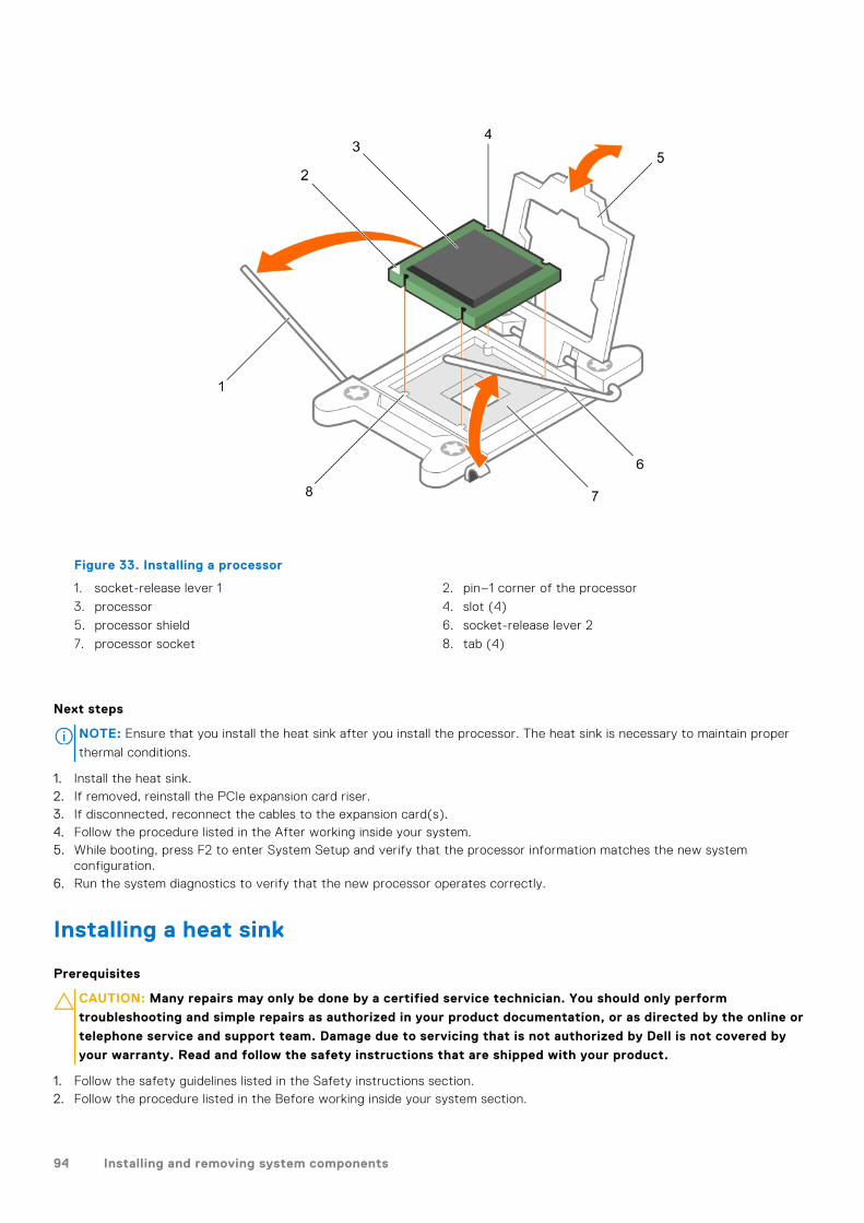
Figure 33. Installing a processor
1. socket-release lever 1 2. pin–1 corner of the processor
3. processor 4. slot (4)
5. processor shield 6. socket-release lever 2
7. processor socket 8. tab (4)
Next steps
NOTE: Ensure that you install the heat sink after you install the processor. The heat sink is necessary to maintain proper
thermal conditions.
1. Install the heat sink.2. If removed, reinstall the PCIe expansion card riser.3. If disconnected, reconnect the cables to the expansion card(s).4. Follow the procedure listed in the After working inside your system.5. While booting, press F2 to enter System Setup and verify that the processor information matches the new system
configuration.6. Run the system diagnostics to verify that the new processor operates correctly.
Installing a heat sink
Prerequisites
CAUTION: Many repairs may only be done by a certified service technician. You should only perform
troubleshooting and simple repairs as authorized in your product documentation, or as directed by the online or
telephone service and support team. Damage due to servicing that is not authorized by Dell is not covered by
your warranty. Read and follow the safety instructions that are shipped with your product.
1. Follow the safety guidelines listed in the Safety instructions section.2. Follow the procedure listed in the Before working inside your system section.
94 Installing and removing system components
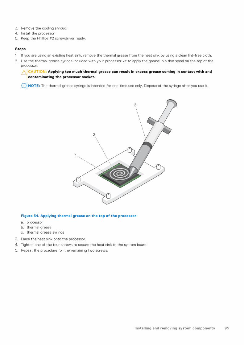
3. Remove the cooling shroud.4. Install the processor.5. Keep the Phillips #2 screwdriver ready.
Steps
1. If you are using an existing heat sink, remove the thermal grease from the heat sink by using a clean lint-free cloth.
2. Use the thermal grease syringe included with your processor kit to apply the grease in a thin spiral on the top of theprocessor.
CAUTION: Applying too much thermal grease can result in excess grease coming in contact with and
contaminating the processor socket.
NOTE: The thermal grease syringe is intended for one-time use only. Dispose of the syringe after you use it.
Figure 34. Applying thermal grease on the top of the processor
a. processorb. thermal greasec. thermal grease syringe
3. Place the heat sink onto the processor.
4. Tighten one of the four screws to secure the heat sink to the system board.
5. Repeat the procedure for the remaining two screws.
Installing and removing system components 95
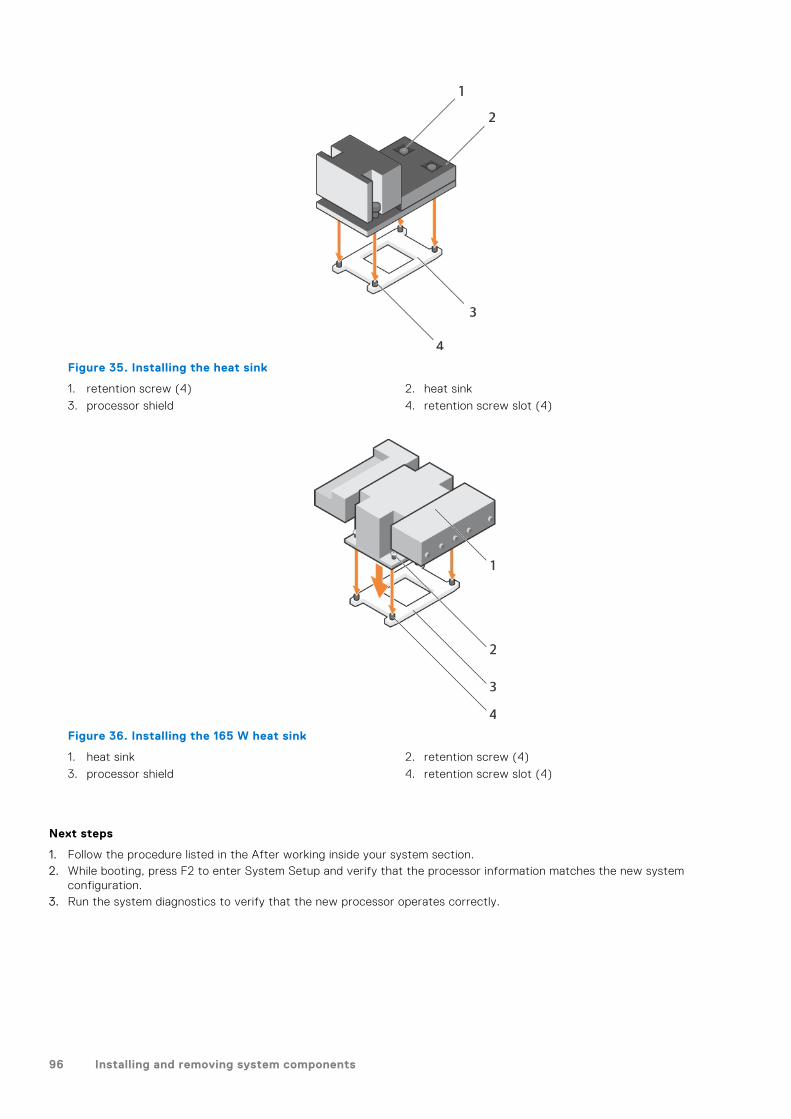
Figure 35. Installing the heat sink
1. retention screw (4) 2. heat sink
3. processor shield 4. retention screw slot (4)
Figure 36. Installing the 165 W heat sink
1. heat sink 2. retention screw (4)
3. processor shield 4. retention screw slot (4)
Next steps
1. Follow the procedure listed in the After working inside your system section.2. While booting, press F2 to enter System Setup and verify that the processor information matches the new system
configuration.3. Run the system diagnostics to verify that the new processor operates correctly.
96 Installing and removing system components
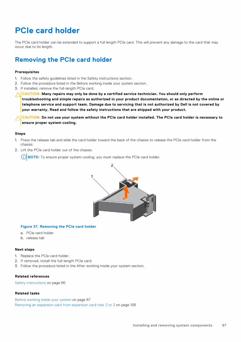
PCIe card holderThe PCIe card holder can be extended to support a full length PCIe card. This will prevent any damage to the card that mayoccur due to its length.
Removing the PCIe card holder
Prerequisites
1. Follow the safety guidelines listed in the Safety instructions section.2. Follow the procedure listed in the Before working inside your system section.3. If installed, remove the full-length PCIe card.
CAUTION: Many repairs may only be done by a certified service technician. You should only perform
troubleshooting and simple repairs as authorized in your product documentation, or as directed by the online or
telephone service and support team. Damage due to servicing that is not authorized by Dell is not covered by
your warranty. Read and follow the safety instructions that are shipped with your product.
CAUTION: Do not use your system without the PCIe card holder installed. The PCIe card holder is necessary to
ensure proper system cooling.
Steps
1. Press the release tab and slide the card holder toward the back of the chassis to release the PCIe card holder from thechassis.
2. Lift the PCIe card holder out of the chassis.
NOTE: To ensure proper system cooling, you must replace the PCIe card holder.
Figure 37. Removing the PCIe card holder
a. PCIe card holderb. release tab
Next steps
1. Replace the PCIe card holder.2. If removed, install the full-length PCIe card.3. Follow the procedure listed in the After working inside your system section.
Related references
Safety instructions on page 66
Related tasks
Before working inside your system on page 67
Removing an expansion card from expansion card riser 2 or 3 on page 106
Installing and removing system components 97
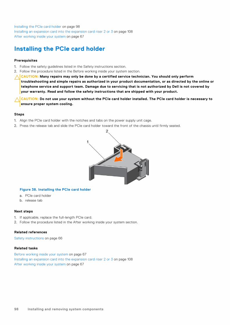
Installing the PCIe card holder on page 98
Installing an expansion card into the expansion card riser 2 or 3 on page 108
After working inside your system on page 67
Installing the PCIe card holder
Prerequisites
1. Follow the safety guidelines listed in the Safety instructions section.2. Follow the procedure listed in the Before working inside your system section.
CAUTION: Many repairs may only be done by a certified service technician. You should only perform
troubleshooting and simple repairs as authorized in your product documentation, or as directed by the online or
telephone service and support team. Damage due to servicing that is not authorized by Dell is not covered by
your warranty. Read and follow the safety instructions that are shipped with your product.
CAUTION: Do not use your system without the PCIe card holder installed. The PCIe card holder is necessary to
ensure proper system cooling.
Steps
1. Align the PCIe card holder with the notches and tabs on the power supply unit cage.
2. Press the release tab and slide the PCIe card holder toward the front of the chassis until firmly seated.
Figure 38. Installing the PCIe card holder
a. PCIe card holderb. release tab
Next steps
1. If applicable, replace the full-length PCIe card.2. Follow the procedure listed in the After working inside your system section.
Related references
Safety instructions on page 66
Related tasks
Before working inside your system on page 67
Installing an expansion card into the expansion card riser 2 or 3 on page 108
After working inside your system on page 67
98 Installing and removing system components

Opening and closing the PCIe card holder latch
Prerequisites
1. Follow the safety guidelines listed in Safety instructions section.2. Follow the procedure listed in the Before working inside your system section.
CAUTION: Many repairs may only be done by a certified service technician. You should only perform
troubleshooting and simple repairs as authorized in your product documentation, or as directed by the online or
telephone service and support team. Damage due to servicing that is not authorized by Dell is not covered by
your warranty. Read and follow the safety instructions that are shipped with your product.
Steps
1. To open the PCIe card holder latch, press the release tab.
2. To close the PCIe card holder latch, rotate the latch clockwise until it locks.
NOTE: Before installing a full-length PCIe card, the PCIe card holder latch must be closed. When the full-length PCIe
card is installed, open the PCIe card holder latch. Before removing the full-length PCIe card, you must close the PCIe
card holder latch.
Figure 39. Opening the PCIe card holder latch
a. PCIe card holderb. release tabc. PCIe card holder latch
Figure 40. Closing the PCIe card holder latch
a. PCIe card holderb. release tabc. PCIe card holder latch
Next steps
Follow the procedure listed in the After working inside your system section.
Installing and removing system components 99
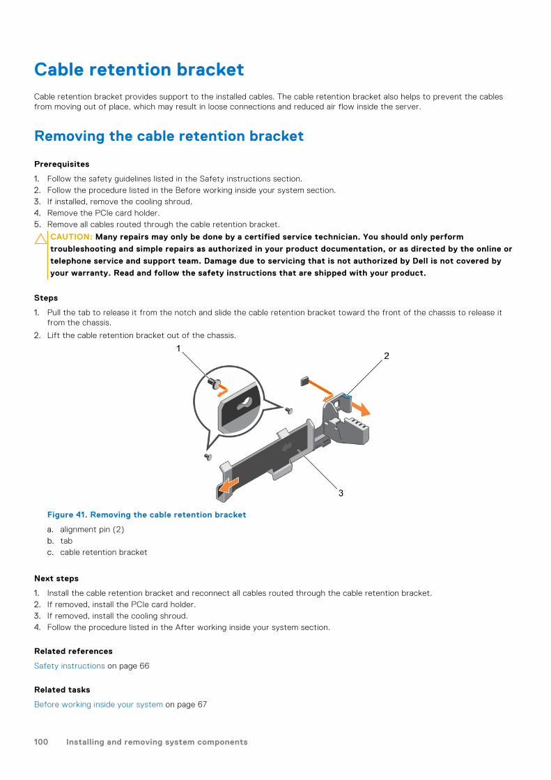
Cable retention bracketCable retention bracket provides support to the installed cables. The cable retention bracket also helps to prevent the cablesfrom moving out of place, which may result in loose connections and reduced air flow inside the server.
Removing the cable retention bracket
Prerequisites
1. Follow the safety guidelines listed in the Safety instructions section.2. Follow the procedure listed in the Before working inside your system section.3. If installed, remove the cooling shroud.4. Remove the PCIe card holder.5. Remove all cables routed through the cable retention bracket.
CAUTION: Many repairs may only be done by a certified service technician. You should only perform
troubleshooting and simple repairs as authorized in your product documentation, or as directed by the online or
telephone service and support team. Damage due to servicing that is not authorized by Dell is not covered by
your warranty. Read and follow the safety instructions that are shipped with your product.
Steps
1. Pull the tab to release it from the notch and slide the cable retention bracket toward the front of the chassis to release itfrom the chassis.
2. Lift the cable retention bracket out of the chassis.
Figure 41. Removing the cable retention bracket
a. alignment pin (2)b. tabc. cable retention bracket
Next steps
1. Install the cable retention bracket and reconnect all cables routed through the cable retention bracket.2. If removed, install the PCIe card holder.3. If removed, install the cooling shroud.4. Follow the procedure listed in the After working inside your system section.
Related references
Safety instructions on page 66
Related tasks
Before working inside your system on page 67
100 Installing and removing system components
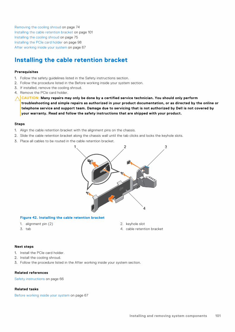
Removing the cooling shroud on page 74
Installing the cable retention bracket on page 101
Installing the cooling shroud on page 75
Installing the PCIe card holder on page 98
After working inside your system on page 67
Installing the cable retention bracket
Prerequisites
1. Follow the safety guidelines listed in the Safety instructions section.2. Follow the procedure listed in the Before working inside your system section.3. If installed, remove the cooling shroud.4. Remove the PCIe card holder.
CAUTION: Many repairs may only be done by a certified service technician. You should only perform
troubleshooting and simple repairs as authorized in your product documentation, or as directed by the online or
telephone service and support team. Damage due to servicing that is not authorized by Dell is not covered by
your warranty. Read and follow the safety instructions that are shipped with your product.
Steps
1. Align the cable retention bracket with the alignment pins on the chassis.
2. Slide the cable retention bracket along the chassis wall until the tab clicks and locks the keyhole slots.
3. Place all cables to be routed in the cable retention bracket.
Figure 42. Installing the cable retention bracket
1. alignment pin (2) 2. keyhole slot
3. tab 4. cable retention bracket
Next steps
1. Install the PCIe card holder.2. Install the cooling shroud.3. Follow the procedure listed in the After working inside your system section.
Related references
Safety instructions on page 66
Related tasks
Before working inside your system on page 67
Installing and removing system components 101

Removing the cooling shroud on page 74
Installing the cooling shroud on page 75
Installing the PCIe card holder on page 98
After working inside your system on page 67
Integrated storage controller cardYour system includes a dedicated expansion card slot on the system board for an integrated storage controller card. Theintegrated storage controller card provides the integrated storage subsystem for the internal hard drives in your system.Thecontroller supports SAS and SATA hard drives and also enables you to set up the hard drives in RAID configurations. The RAIDconfigurations depend on the version of the storage controller included with your system. The controller supports SAS harddrives.
Removing the integrated storage controller card
Prerequisites
CAUTION: Many repairs may only be done by a certified service technician. You should only perform
troubleshooting and simple repairs as authorized in your product documentation, or as directed by the online or
telephone service and support team. Damage due to servicing that is not authorized by Dell is not covered by
your warranty. Read and follow the safety instructions that are shipped with your product.
1. Follow the safety guidelines listed in the Safety instructions section.2. Follow the procedure listed in the Before working inside your system section.3. Remove the cooling shroud.4. Remove the expansion card riser 1.5. Keep the Phillips #2 screwdriver ready.
Steps
1. Loosen the screws that secure the integrated storage controller cable to the integrated storage controller card connector onthe system board.
2. Lift the integrated storage controller cable away from the integrated storage controller.
3. Lift one end of the card and angle it to disengage the card from the integrated storage controller card holder on the systemboard.
4. Lift the card out of the system.
102 Installing and removing system components

Figure 43. Removing the integrated storage controller card
1. integrated storage controller cable 2. integrated storage controller card
3. integrated storage controller card connector on thesystem board
4. integrated storage controller card holder
Next steps
1. Install the expansion card riser 1.2. Install the cooling shroud.3. Installing the integrated storage controller card.4. Follow the procedure listed in the After working inside your system section.
Related references
Safety instructions on page 66
Related tasks
Before working inside your system on page 67
Removing the cooling shroud on page 74
Removing expansion card risers on page 114
Installing expansion card risers on page 117
Installing the cooling shroud on page 75
After working inside your system on page 67
Installing and removing system components 103
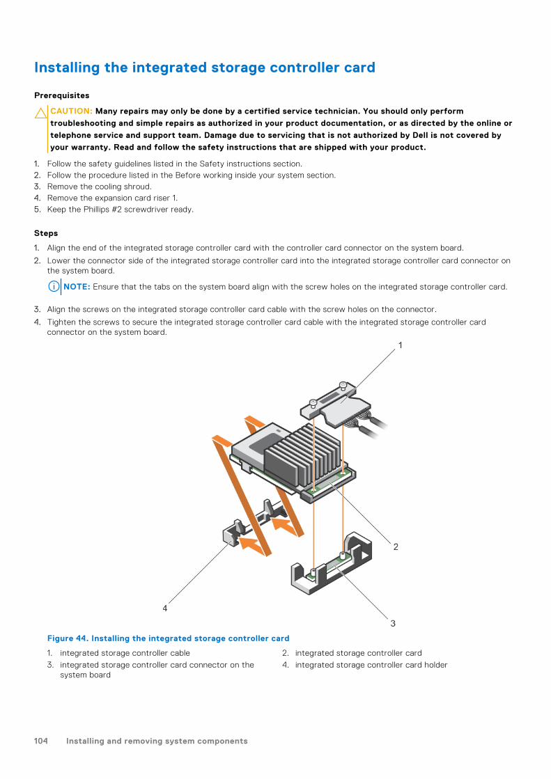
Installing the integrated storage controller card
Prerequisites
CAUTION: Many repairs may only be done by a certified service technician. You should only perform
troubleshooting and simple repairs as authorized in your product documentation, or as directed by the online or
telephone service and support team. Damage due to servicing that is not authorized by Dell is not covered by
your warranty. Read and follow the safety instructions that are shipped with your product.
1. Follow the safety guidelines listed in the Safety instructions section.2. Follow the procedure listed in the Before working inside your system section.3. Remove the cooling shroud.4. Remove the expansion card riser 1.5. Keep the Phillips #2 screwdriver ready.
Steps
1. Align the end of the integrated storage controller card with the controller card connector on the system board.
2. Lower the connector side of the integrated storage controller card into the integrated storage controller card connector onthe system board.
NOTE: Ensure that the tabs on the system board align with the screw holes on the integrated storage controller card.
3. Align the screws on the integrated storage controller card cable with the screw holes on the connector.
4. Tighten the screws to secure the integrated storage controller card cable with the integrated storage controller cardconnector on the system board.
Figure 44. Installing the integrated storage controller card
1. integrated storage controller cable 2. integrated storage controller card
3. integrated storage controller card connector on thesystem board
4. integrated storage controller card holder
104 Installing and removing system components

Next steps
1. Install the expansion card riser 1.2. Install the cooling shroud.3. Follow the procedure listed in the After working inside your system section.
Related references
Safety instructions on page 66
Related tasks
Before working inside your system on page 67
Removing the cooling shroud on page 74
Removing expansion card risers on page 114
Installing expansion card risers on page 117
Installing the cooling shroud on page 75
After working inside your system on page 67
Expansion cards and expansion card riserAn expansion card in the system is an add-on card that can be inserted into an expansion slot on the system board or riser cardto add enhanced functionality to the system through the expansion bus.
NOTE: A System Event Log (SEL) event is logged if an expansion card riser is unsupported or missing. It does not prevent
your system from turning on and no BIOS POST message or F1/F2 pause is displayed.
Expansion card installation guidelines
Depending on your system configuration, the following PCI Express (PCIe) generation 3 expansion cards are supported:
Table 40. Supported expansion cards
PCIe slot Riser Processor connection Height Length Link width Slot width
1 1 Processor 2 Low Profile Half Length x8 x16
2 1 Processor 2 Low Profile Half Length x8 x16
3 1 Processor 2 Low Profile Half Length x8 x16
4 2 Processor 2 Full Height Full Length x16 x16
5 2 Processor 1 Full Height Full Length x8 x16
6 3 (default) Processor 1 Full Height Full Length x8 x16
6 3 (alternate) Processor 1 Full Height Full Length x16 x16
7 3 (default) Processor 1 Full Height Full Length x8 x16
NOTE: To use PCIe slots 1 through 4 on the risers 1 and 2, both the processors must be installed.
NOTE: The expansion card slots are not hot-swappable.
The following table provides guidelines for installing expansion cards to ensure proper cooling and mechanical fit. The expansioncards with the highest priority should be installed first using the slot priority indicated. All the other expansion cards should beinstalled in the card priority and slot priority order.
Table 41. Expansion card installation order
Card priority Card type Slot priority Max allowed
1 GPU (double width) 6, 4 2
Installing and removing system components 105

Table 41. Expansion card installation order (continued)
Card priority Card type Slot priority Max allowed
GPU (single width) 6, 4, 7, 5 4
2 RAID H830 7, 6, 4, 5 2
RAID H830 (low profile) 3, 2 2
3
100G Intel Omni-Path Architecture Host (OPA)Channel Adapters (HCA)
4, 6 2
14 Gb InfiniBand, Fourteen Data Rate (FDR) HCA 3, 2, 1 3
40 Gb NICs (full height) 5, 7, 4, 6 4
40 Gb NICs (low profile) 3, 2, 1 3
25 Gb NICs (full height) 4, 6, 5 3
25 Gb NICs (low profile) 3, 2, 1 3
4 FC16 HBA (full height) 5, 7, 4, 6 4
FC16 HBA (low profile) 2, 3, 1 3
5 10 Gb NICs (full height) 5, 7, 4, 6 4
10 Gb NICs (low profile) 2, 3, 1 3
6 FC8 HBA (full height) 5, 7, 4, 6 4
FC8 HBA (low profile) 2, 3, 1 3
7 1 Gb NICs (full height) 5, 7, 4, 6 4
1 Gb NICs (low profile) 2, 3, 1 3
8 12 Gb SAS (low profile) 3, 2, 1 2
12 Gb SAS (full height) 6, 4, 5, 7 2
9 Integrated RAID integrated slot 1
10 NDC integrated slot 1
NOTE: Ensure that the 100 G OPA x16 card is installed in slot 6 (x16 PCIe) on the alternate riser 3.
Removing an expansion card from expansion card riser 2 or 3
Prerequisites
CAUTION: Many repairs may only be done by a certified service technician. You should only perform
troubleshooting and simple repairs as authorized in your product documentation, or as directed by the online or
telephone service and support team. Damage due to servicing that is not authorized by Dell is not covered by
your warranty. Read and follow the safety instructions that are shipped with your product.
1. Follow the safety guidelines listed in the Safety instructions section.2. Follow the procedure listed in the Before working inside your system section.3. When removing a card from riser 3, ensure that the PCIe holder latch is closed.
NOTE: The procedure for installing and removing a full length PCIe card is similar to the procedure for removing and
installing a GPU card.
Steps
1. Disconnect any cables connected to the expansion card.
2. Lift the expansion card latch out of the guide slot.
3. Hold the expansion card by its edges, and remove it from the expansion card connector.
106 Installing and removing system components

4. If you are removing the card permanently, install a metal filler bracket over the empty expansion slot opening and close theexpansion card latch.
NOTE: You must install a filler bracket over an empty expansion card slot to maintain Federal Communications
Commission (FCC) certification of the system. The brackets also keep dust and dirt out of the system and aid in
proper cooling and airflow inside the system. The filler bracket is necessary to maintain proper thermal conditions.
5. Install the expansion card latch into the slot.
6. Close the expansion card locking tabs.
Figure 45. Removing an expansion card from expansion card riser 2 or 3
1. expansion card 2. expansion card latch
3. expansion card riser 4. power connector (for GPU cards)
5. expansion card connector
Next steps
1. Install an expansion card into the expansion card riser.2. Follow the procedure listed in the After working inside your system section.
Related references
Safety instructions on page 66
Related tasks
Before working inside your system on page 67
After working inside your system on page 67
Installing and removing system components 107

Installing an expansion card into the expansion card riser 2 or 3
Prerequisites
1. Follow the safety guidelines listed in the Safety instructions section.2. Follow the procedure listed in the Before working inside your system section.
CAUTION: Many repairs may only be done by a certified service technician. You should only perform
troubleshooting and simple repairs as authorized in your product documentation, or as directed by the online or
telephone service and support team. Damage due to servicing that is not authorized by Dell is not covered by
your warranty. Read and follow the safety instructions that are shipped with your product.
Steps
1. Unpack the expansion card and prepare it for installation.
For instructions, see the documentation accompanying the card.
2. Lift the expansion card latch and remove the filler bracket.
3. Holding the card by its edges, position the card so that the connector on the expansion card aligns with the expansion cardconnector on the riser.
4. Insert the card-edge connector firmly into the expansion card connector until the card is fully seated.
5. Press the touch points to open the expansion card locking tabs.
6. Close the expansion card latch.
Figure 46. Installing an expansion card into the expansion card riser 2 or 3
1. expansion card 2. expansion card latch
3. expansion card riser 4. power connector (for GPU cards)
5. expansion card connector
7. If applicable, connect the cables to the expansion card.
108 Installing and removing system components

NOTE: When installing a GPU card on riser 2 or riser 3 (default), connect the GPU card power cable to the power
connector on the riser.
Next steps
1. Follow the procedure listed in the After working inside your system section.2. Install any device drivers required for the card as described in the documentation for the card.
Related references
Safety instructions on page 66
Related tasks
Before working inside your system on page 67
After working inside your system on page 67
Removing an expansion card from the expansion card riser 1
Prerequisites
CAUTION: Many repairs may only be done by a certified service technician. You should only perform
troubleshooting and simple repairs as authorized in your product documentation, or as directed by the online or
telephone service and support team. Damage due to servicing that is not authorized by Dell is not covered by
your warranty. Read and follow the safety instructions that are shipped with your product.
1. Follow the safety guidelines listed in the Safety instructions section.2. Follow the procedure listed in the Before working inside your system section.3. Disconnect any cables connected to the expansion card.4. Remove the expansion card riser.
NOTE: The expansion card riser 1 can be used only when both the processors are installed.
Steps
1. Press tab A and rotate the latch clockwise.
2. Press tab B and rotate the latch downward.
3. Remove the expansion card from the expansion card riser 1.
4. If you are removing the card permanently, install a metal filler bracket over the empty expansion slot opening, and then closethe expansion card latch.
NOTE: You must install a filler bracket over an empty expansion card slot to maintain Federal Communications
Commission (FCC) certification of the system. The brackets also keep dust and dirt out of the system and aid in
proper cooling and airflow inside the system. The filler bracket is necessary to maintain proper thermal conditions.
5. Close the latches of tab A and tab B.
Installing and removing system components 109

Figure 47. Removing an expansion card from expansion card riser 1
1. tab A 2. expansion card riser 1 cage
3. expansion card connector 4. tab B
5. latch 6. expansion card
Next steps
1. Install the expansion card.2. Install the expansion card riser.3. Follow the procedure listed in the After working inside your system section.
Related references
Safety instructions on page 66
Related tasks
Before working inside your system on page 67
Removing expansion card risers on page 114
Installing expansion card risers on page 117
After working inside your system on page 67
Installing an expansion card into the expansion card riser 1
Prerequisites
1. Follow the safety guidelines listed in the Safety instructions section.2. Follow the procedure listed in the Before working inside your system section.3. Remove the expansion card riser.
CAUTION: Many repairs may only be done by a certified service technician. You should only perform
troubleshooting and simple repairs as authorized in your product documentation, or as directed by the online or
telephone service and support team. Damage due to servicing that is not authorized by Dell is not covered by
your warranty. Read and follow the safety instructions that are shipped with your product.
NOTE: The expansion card riser 1 can be used only when both the processors are installed.
110 Installing and removing system components

Steps
1. Unpack the expansion card and prepare it for installation.
For instructions, see the documentation accompanying the card.
2. Press tab A and rotate the latch clockwise.
3. Press tab B and rotate the latch down.
4. Holding the card by its edges, position the card so that the card-edge connector aligns with the expansion card connector.
5. Insert the card-edge connector firmly into the expansion card connector until the card is fully seated.
6. Close the latches of tab A and tab B.
Figure 48. Installing an expansion card into the expansion card riser 1
1. tab A 2. expansion card riser 1 cage
3. expansion card connector 4. tab B
5. latch 6. expansion card
Next steps
1. Install the expansion card riser.2. If applicable, connect any cables to the expansion card.3. Follow the procedure listed in the After working inside your system section.4. Install any device drivers required for the card as described in the documentation for the card.
Related references
Safety instructions on page 66
Related tasks
Before working inside your system on page 67
Removing expansion card risers on page 114
Installing expansion card risers on page 117
After working inside your system on page 67
Installing and removing system components 111

Removing the riser 1 blank
Prerequisites
CAUTION: Many repairs may only be done by a certified service technician. You should only perform
troubleshooting and simple repairs as authorized in your product documentation, or as directed by the online or
telephone service and support team. Damage due to servicing that is not authorized by Dell is not covered by
your warranty. Read and follow the safety instructions that are shipped with your product.
1. Follow the safety guidelines listed in the Safety instructions section.2. Follow the procedure listed in the Before working inside your system section.3. Remove the expansion card riser.
Steps
Press the tabs on the riser 1 blank and push the riser 1 blank out of the chassis.
Figure 49. Removing the riser 1 blank
a. Slot on the chassisb. Tab (2)c. Riser 1 blank
Next steps
1. Install the expansion card risers.2. Follow the procedure listed in the After working inside your system section.
Related references
Safety instructions on page 66
Related tasks
Before working inside your system on page 67
Removing expansion card risers on page 114
Installing expansion card risers on page 117
After working inside your system on page 67
112 Installing and removing system components

Installing the riser 1 blank
Prerequisites
CAUTION: Many repairs may only be done by a certified service technician. You should only perform
troubleshooting and simple repairs as authorized in your product documentation, or as directed by the online or
telephone service and support team. Damage due to servicing that is not authorized by Dell is not covered by
your warranty. Read and follow the safety instructions that are shipped with your product.
Steps
To install the riser 1 blank, align the blank with the slot on the chassis and insert it into the chassis until it clicks into place.
Figure 50. Installing the riser 1 blank
a. slot on the chassisb. tab (2)c. riser 1 blank
Next steps
1. Install the expansion card risers.2. Follow the procedure listed in the After working inside your system section.
Related references
Safety instructions on page 66
Related tasks
Before working inside your system on page 67
Removing expansion card risers on page 114
Installing expansion card risers on page 117
After working inside your system on page 67
Installing and removing system components 113
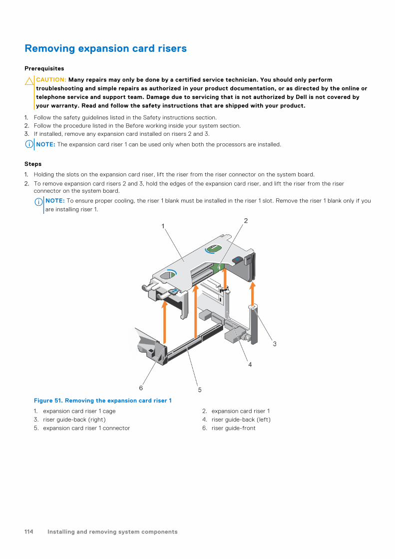
Removing expansion card risers
Prerequisites
CAUTION: Many repairs may only be done by a certified service technician. You should only perform
troubleshooting and simple repairs as authorized in your product documentation, or as directed by the online or
telephone service and support team. Damage due to servicing that is not authorized by Dell is not covered by
your warranty. Read and follow the safety instructions that are shipped with your product.
1. Follow the safety guidelines listed in the Safety instructions section.2. Follow the procedure listed in the Before working inside your system section.3. If installed, remove any expansion card installed on risers 2 and 3.
NOTE: The expansion card riser 1 can be used only when both the processors are installed.
Steps
1. Holding the slots on the expansion card riser, lift the riser from the riser connector on the system board.
2. To remove expansion card risers 2 and 3, hold the edges of the expansion card riser, and lift the riser from the riserconnector on the system board.
NOTE: To ensure proper cooling, the riser 1 blank must be installed in the riser 1 slot. Remove the riser 1 blank only if you
are installing riser 1.
Figure 51. Removing the expansion card riser 1
1. expansion card riser 1 cage 2. expansion card riser 1
3. riser guide-back (right) 4. riser guide-back (left)
5. expansion card riser 1 connector 6. riser guide-front
114 Installing and removing system components

Figure 52. Identifying connectors on the expansion card riser 1
a. expansion card slot 1b. expansion card slot 2c. expansion card slot 3
Figure 53. Removing the expansion card riser 2
1. power connector (for GPU cards) 2. expansion card riser 2
3. riser guide-back 4. expansion card riser 2 connector
5. riser guide-front
Installing and removing system components 115

Figure 54. Identifying connectors on the expansion card riser 2
a. expansion card slot 4b. expansion card slot 5c. power connector (for GPU cards)
Figure 55. Removing the expansion card riser 3
1. riser guide-front 2. power connector (for GPU cards)
3. expansion card riser 3 4. riser guide-back
5. expansion card riser 3 connector
116 Installing and removing system components

Figure 56. Identifying connectors on the expansion card riser 3
a. expansion card slot 6b. power connector (for GPU cards)
Next steps
1. If removed, install an expansion card on the riser.2. If applicable, replace the expansion card riser.3. Follow the procedure listed in the After working inside your system section.
Related references
Safety instructions on page 66
Related tasks
Before working inside your system on page 67
Removing an expansion card from expansion card riser 2 or 3 on page 106
Removing an expansion card from the expansion card riser 1 on page 109
Installing an expansion card into the expansion card riser 1 on page 110
Installing an expansion card into the expansion card riser 2 or 3 on page 108
After working inside your system on page 67
Installing expansion card risers
Prerequisites
1. Follow the safety guidelines listed in the Safety instructions section.2. Follow the procedure listed in the Before working inside your system section.3. If removed, install the expansion card(s) into the expansion card riser 1.
CAUTION: Many repairs may only be done by a certified service technician. You should only perform
troubleshooting and simple repairs as authorized in your product documentation, or as directed by the online or
telephone service and support team. Damage due to servicing that is not authorized by Dell is not covered by
your warranty. Read and follow the safety instructions that are shipped with your product.
Steps
1. Align the expansion card riser with the connectors and the riser guides on the system board.
2. Lower the expansion card riser into place until the expansion card riser is fully seated in the connector.
Installing and removing system components 117
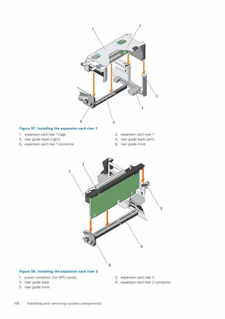
Figure 57. Installing the expansion card riser 1
1. expansion card riser 1 cage 2. expansion card riser 1
3. riser guide-back (right) 4. riser guide-back (left)
5. expansion card riser 1 connector 6. riser guide-front
Figure 58. Installing the expansion card riser 2
1. power connector (for GPU cards) 2. expansion card riser 2
3. riser guide-back 4. expansion card riser 2 connector
5. riser guide-front
118 Installing and removing system components

Figure 59. Installing the expansion card riser 3
1. riser guide-front 2. power connector (for GPU cards)
3. expansion card riser 3 4. riser guide-back
5. expansion card riser 3 connector
Next steps
1. Install the expansion card(s) into the expansion card risers 2 or 3.2. Follow the procedure listed in the After working inside your system section.3. Install any device drivers required for the card as described in the documentation for the card.
GPU card installation guidelines
● Ensure that both the processors are installed.● The processor must be of 135 W or less.● The processor must use a GPU kit low-profile heat sink.● Due to the high power consumption of GPUs, the ambient inlet temperature is restricted to 30°C to ensure adequate cooling
when one or more GPU cards are installed.● Ensure that the GPU enablement kit is available.
The GPU enablement kit includes:○ Low-profile heat sinks○ Power cables for the GPU cards○ Filler brackets with closeout EMI shield for unoccupied PCIe slots
● All GPU cards must be of the same type and model.● You can install up to two double-wide GPU cards.
NOTE: Two double-wide GPU cards configuration requires optional riser 3.
● You can install up to four single-wide GPU cards.● Ensure that your system uses the redundant 1100 W power supplies.
NOTE: When using the system with the Nvidia K80 GPU card, ensure that you install both PSUs with a minimum of 1100
W each and set the PSU configuration to non-redundant mode.
Installing and removing system components 119

Removing the GPU card
Prerequisites
1. Follow the safety guidelines listed in Safety instructions section.2. Follow the procedure listed in the Before working inside your system section.
Steps
1. Lift the expansion card latch.
2. Close the expansion card locking tabs on the cooling shroud and the risers.
3. Hold the GPU card by its edges and slide out the GPU card at an angle to release it from the connector on the riser card.
4. Disconnect the cable from the GPU card.
5. If you are removing the card permanently, install a metal filler bracket over the empty slot opening and close the expansioncard locking tabs.
NOTE: You must install a filler bracket over an empty expansion card slot to maintain Federal Communications
Commission (FCC) certification of the system. The brackets also keep dust and dirt out of the system and aid in
proper cooling and airflow inside the system. The filler bracket is necessary to maintain proper thermal conditions.
Figure 60. Removing the GPU card
1. expansion card locking tab (3) 2. GPU card
3. PCIe card holder latch 4. expansion card latch
5. expansion card riser 3
Next steps
Follow the procedure listed in the After working inside your system section.
120 Installing and removing system components

Installing a GPU card
Prerequisites
CAUTION: Many repairs may only be done by a certified service technician. You should only perform
troubleshooting and simple repairs as authorized in your product documentation, or as directed by the online or
telephone service and support team. Damage due to servicing that is not authorized by Dell is not covered by
your warranty. Read and follow the safety instructions that are shipped with your product.
1. Follow the safety guidelines listed in Safety instructions section.2. Follow the procedure listed in the Before working inside your system section.3. Remove the cooling shroud.4. Remove the heat sinks.
Steps
1. Unpack the GPU cards and the GPU enablement kit.
2. Install the heat sinks from the kit and reinstall the cooling shroud.
3. Close the expansion card locking tab on the cooling shroud and riser.
4. Lift the expansion card latch.
5. Remove the filler brackets for the single- or double-wide GPU cards.
6. Replace the remaining filler brackets with the brackets from the GPU kit.
7. Align the GPU card connector with the slot on the riser.
8. Insert the GPU card into the riser slot until it is fully seated.
9. Locate the GPU power connectors on the cable and plug them to the six-pin and eight-pin connectors on the GPU card.
NOTE: Ensure that the GPU card is installed correctly into the GPU card lock.
10. Press down on the GPU card lock to secure the card in position.
11. Ensure that the GPU card is seated into the PCIe card holder latch.
12. Press the touch point to open the PCIe card holder latch and/or the expansion card locking tabs.
13. Connect the GPU power cable to the riser.
14. Close the expansion card latch/latches.
Installing and removing system components 121

Figure 61. Installing the GPU card
1. expansion card locking tab (3) 2. GPU card
3. PCIe card holder latch 4. expansion card latch
5. expansion card riser 3
Next steps
Follow the procedure listed in the After working inside your system section.
IDSDMThe Internal Dual SD module (IDSDM) provides you with a redundant SD card solution. You can configure the IDSDM for storageor as the OS boot partition. The IDSDM card offers the following features:● Dual card operation — maintains a mirrored configuration by using SD cards in both the slots and provides redundancy.
NOTE: When the Redundancy option is set to Mirror Mode in the Integrated Devices screen of System Setup, the
information is replicated from one SD card to another.
● Single card operation — single card operation is supported, but without redundancy.
Removing an internal SD card
Prerequisites
1. Follow the safety guidelines listed in the Safety instructions section.2. Follow the procedure listed in the Before working inside your system section.
CAUTION: Many repairs may only be done by a certified service technician. You should only perform
troubleshooting and simple repairs as authorized in your product documentation, or as directed by the online or
telephone service and support team. Damage due to servicing that is not authorized by Dell is not covered by
your warranty. Read and follow the safety instructions that are shipped with your product.
122 Installing and removing system components
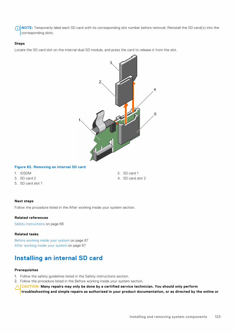
NOTE: Temporarily label each SD card with its corresponding slot number before removal. Reinstall the SD card(s) into the
corresponding slots.
Steps
Locate the SD card slot on the internal dual SD module, and press the card to release it from the slot.
Figure 62. Removing an internal SD card
1. IDSDM 2. SD card 1
3. SD card 2 4. SD card slot 2
5. SD card slot 1
Next steps
Follow the procedure listed in the After working inside your system section.
Related references
Safety instructions on page 66
Related tasks
Before working inside your system on page 67
After working inside your system on page 67
Installing an internal SD card
Prerequisites
1. Follow the safety guidelines listed in the Safety instructions section.2. Follow the procedure listed in the Before working inside your system section.
CAUTION: Many repairs may only be done by a certified service technician. You should only perform
troubleshooting and simple repairs as authorized in your product documentation, or as directed by the online or
Installing and removing system components 123

telephone service and support team. Damage due to servicing that is not authorized by Dell is not covered by
your warranty. Read and follow the safety instructions that are shipped with your product.
NOTE: To use an SD card with your system, ensure that the Internal SD Card Port is enabled in System Setup.
NOTE: Temporarily label each SD card with its corresponding slot number before removal. Re-install the SD card(s) into the
corresponding slots.
Steps
1. Locate the SD card connector on the internal dual SD module. Orient the SD card appropriately and insert the contact-pinend of the card into the slot.
NOTE: The slot is keyed to ensure correct insertion of the card.
2. Press the card into the card slot to lock it into place.
Figure 63. Installing an internal SD card
1. IDSDM 2. SD card 2
3. SD card 1 4. SD card slot 1
5. SD card slot 2
Next steps
Follow the procedure listed in the After working inside your system section.
Related references
Safety instructions on page 66
Related tasks
Before working inside your system on page 67
After working inside your system on page 67
124 Installing and removing system components

Removing the optional internal dual SD module
Prerequisites
CAUTION: Many repairs may only be done by a certified service technician. You should only perform
troubleshooting and simple repairs as authorized in your product documentation, or as directed by the online or
telephone service and support team. Damage due to servicing that is not authorized by Dell is not covered by
your warranty. Read and follow the safety instructions that are shipped with your product.
1. Follow the safety guidelines listed in the Safety instructions section.2. Follow the procedure listed in the Before working inside your system section.3. If installed, remove the SD cards.
NOTE: Temporarily label each SD card with its corresponding slot number before removal. Reinstall the SD cards into
the corresponding slots.
Steps
1. Locate the internal dual SD module (IDSDM) on the system board. To locate the internal dual SD module connector, see theSystem board connectors section.
2. Holding the pull tab, lift the IDSDM out of the system.
Figure 64. Removing the internal dual SD module (IDSDM)
a. IDSDMb. pull tabc. IDSDM connector
The following table describes the IDSDM indicator codes:
Table 42. IDSDM indicator codes
Convention IDSDM indicator code Description
A Green Indicates that the card is online.
B Flashing green Indicates rebuild or activity.
C Flashing amber Indicates card mismatch or that the card has failed.
D Amber Indicates that the card is offline, has failed, or is writeprotected.
E Not lit Indicates that the card is missing or is booting.
Installing and removing system components 125

Next steps
1. Install the IDSDM.2. If removed, install the SD cards.3. Follow the procedure listed in the After working inside your system section.
Related references
Safety instructions on page 66
System board jumpers and connectors on page 183
Related tasks
Before working inside your system on page 67
Removing an internal SD card on page 122
Installing the optional internal dual SD module on page 126
After working inside your system on page 67
Installing the optional internal dual SD module
Prerequisites
CAUTION: Many repairs may only be done by a certified service technician. You should only perform
troubleshooting and simple repairs as authorized in your product documentation, or as directed by the online or
telephone service and support team. Damage due to servicing that is not authorized by Dell is not covered by
your warranty. Read and follow the safety instructions that are shipped with your product.
1. Follow the safety guidelines listed in the Safety instructions section.2. Follow the procedure listed in the Before working inside your system section.
NOTE: Temporarily label each SD card with its corresponding slot before removal.
Steps
1. Locate the internal dual SD module (IDSDM) connector on the system board. To locate the IDSDM connector, see theSystem board connectors section.
2. Align the IDSDM with the connector on the system board.
3. Push the IDSDM until it is firmly seated on the system board.
Next steps
1. Install the SD cards.
NOTE: Re-install the SD cards into the same slots based on the labels you had marked on the cards during removal.
2. Follow the procedure listed in the After working inside your system section.
Related references
Safety instructions on page 66
Related tasks
Before working inside your system on page 67
Installing an internal SD card on page 123
After working inside your system on page 67
126 Installing and removing system components

Network daughter cardThe Network daughter card (NDC) is a small, removable mezzanine card. The NDC provides you with the flexibility of choosingdifferent network connectivity options, for example—4 x 1GbE, 2 x 10GbE and 2 x Converged Network Adapter.
Removing the network daughter card
Prerequisites
1. Follow the safety guidelines listed in the Safety instructions section.2. Follow the procedure listed in the Before working inside your system section.3. If installed, remove the expansion card riser 2.4. Keep the Phillips #1 screwdriver ready.
CAUTION: Many repairs may only be done by a certified service technician. You should only perform
troubleshooting and simple repairs as authorized in your product documentation, or as directed by the online or
telephone service and support team. Damage due to servicing that is not authorized by Dell is not covered by
your warranty. Read and follow the safety instructions that are shipped with your product.
Steps
1. Loosen the captive screws that secure the network daughter card (NDC) to the system board.
2. Hold the NDC by the edges on either side of the touch point, and lift the card to disengage it from the connector on thesystem board.
3. Slide the NDC away from the back of the system until the Ethernet connectors are clear of the slot in the back panel.
4. Lift the NDC out of the chassis.
Figure 65. Removing the NDC
1. captive screw socket (2) 2. connector on the system board
3. captive screw (2) 4. touch point (2)
Installing and removing system components 127

5. network daughter card (NDC) 6. back panel slot for Ethernet connectors
Next steps
1. Install the NDC.2. If removed, install the expansion card riser 1.3. Follow the procedure listed in the After working inside your system section.
Related references
Safety instructions on page 66
Related tasks
Before working inside your system on page 67
Removing an expansion card from expansion card riser 2 or 3 on page 106
Installing an expansion card into the expansion card riser 2 or 3 on page 108
Installing the network daughter card on page 128
After working inside your system on page 67
Installing the network daughter card
Prerequisites
1. Follow the safety guidelines listed in the Safety instructions section.2. Follow the procedure listed in the Before working inside your system section.3. If applicable, remove the expansion card riser 1.4. Keep the Phillips #1 screwdriver ready.
CAUTION: Many repairs may only be done by a certified service technician. You should only perform
troubleshooting and simple repairs as authorized in your product documentation, or as directed by the online or
telephone service and support team. Damage due to servicing that is not authorized by Dell is not covered by
your warranty. Read and follow the safety instructions that are shipped with your product.
Steps
1. Orient the network daughter card (NDC) so that the Ethernet connectors fit through the slot in the back panel.
2. Align the captive screws on the card with the captive screw sockets on the system board.
3. Press the touch points on the card until the card connector is firmly seated on the system board connector.
4. Tighten the captive screws to secure the NDC to the system board.
128 Installing and removing system components
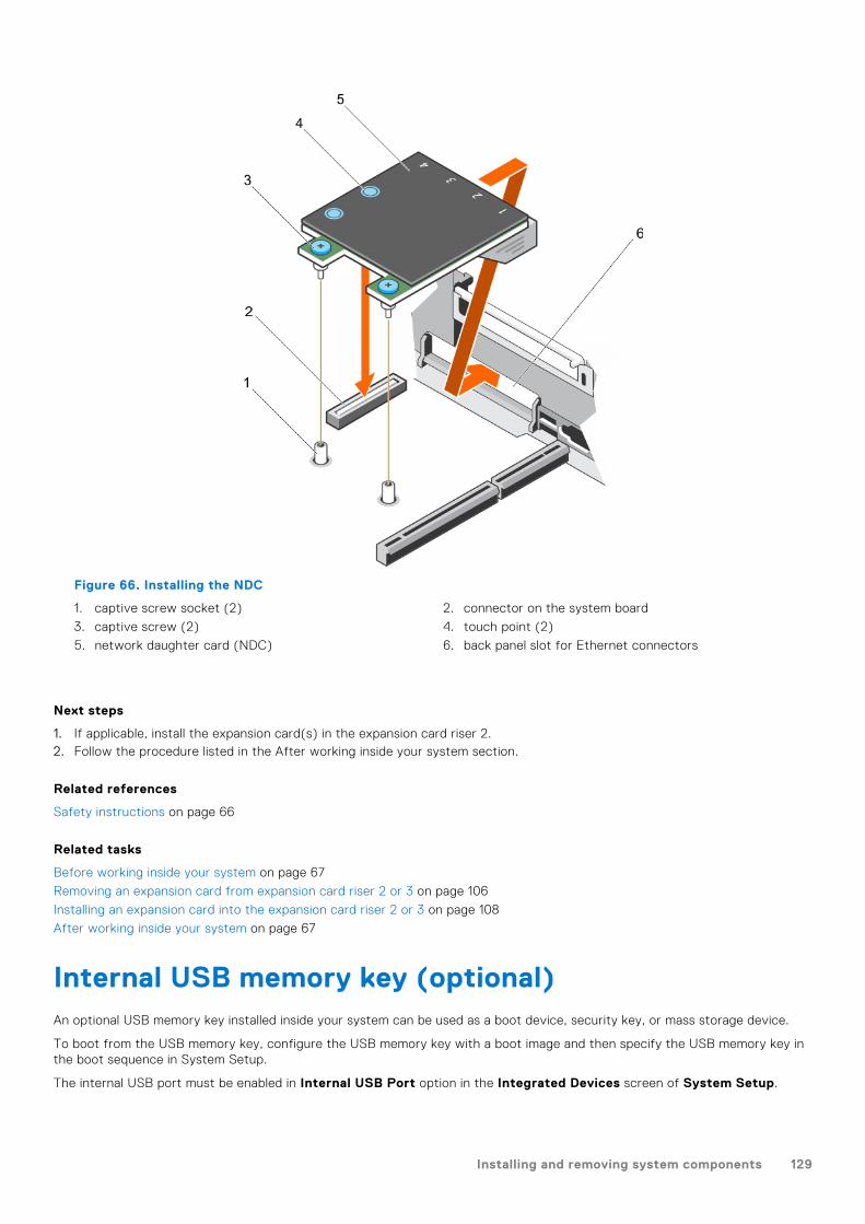
Figure 66. Installing the NDC
1. captive screw socket (2) 2. connector on the system board
3. captive screw (2) 4. touch point (2)
5. network daughter card (NDC) 6. back panel slot for Ethernet connectors
Next steps
1. If applicable, install the expansion card(s) in the expansion card riser 2.2. Follow the procedure listed in the After working inside your system section.
Related references
Safety instructions on page 66
Related tasks
Before working inside your system on page 67
Removing an expansion card from expansion card riser 2 or 3 on page 106
Installing an expansion card into the expansion card riser 2 or 3 on page 108
After working inside your system on page 67
Internal USB memory key (optional)An optional USB memory key installed inside your system can be used as a boot device, security key, or mass storage device.
To boot from the USB memory key, configure the USB memory key with a boot image and then specify the USB memory key inthe boot sequence in System Setup.
The internal USB port must be enabled in Internal USB Port option in the Integrated Devices screen of System Setup.
Installing and removing system components 129

NOTE: To locate the internal USB port (INT_USB) on the system board, see the System board jumpers and connectors
section.
Replacing the optional internal USB memory key
Prerequisites
1. Follow the safety guidelines listed in the Safety instructions section.2. Follow the procedure listed in the Before working inside your system section.
Steps
1. Locate the USB port or USB memory key on the system board.
To locate the USB port, see the System board jumpers and connectors section.
2. If installed, remove the USB memory key from the USB port.
Figure 67. Removing the internal USB memory key
a. USB memory keyb. USB port
3. Insert the replacement USB memory key into the USB port.
Figure 68. Installing the internal USB memory key
a. USB memory keyb. USB port
Next steps
1. Follow the procedure listed in the After working inside your system section.2. While booting, press F2 to enter System Setup and verify that the system detects the USB memory key.
Related references
Safety instructions on page 66
130 Installing and removing system components
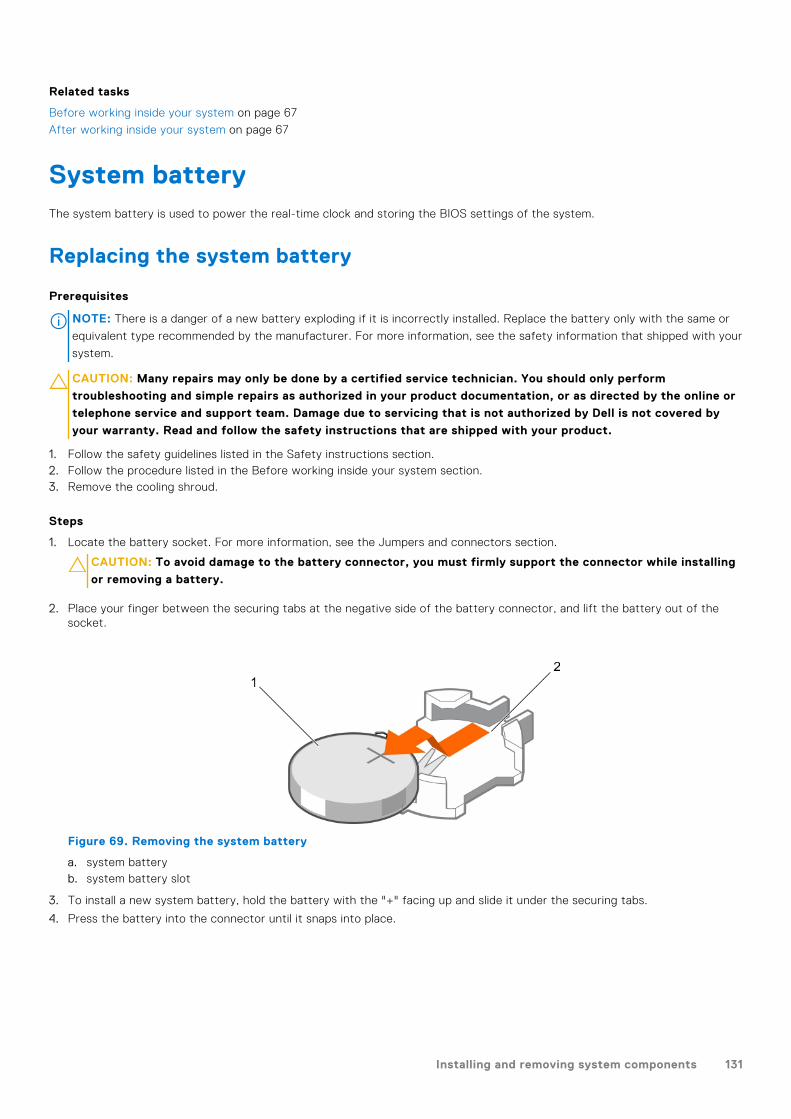
Related tasks
Before working inside your system on page 67
After working inside your system on page 67
System batteryThe system battery is used to power the real-time clock and storing the BIOS settings of the system.
Replacing the system battery
Prerequisites
NOTE: There is a danger of a new battery exploding if it is incorrectly installed. Replace the battery only with the same or
equivalent type recommended by the manufacturer. For more information, see the safety information that shipped with your
system.
CAUTION: Many repairs may only be done by a certified service technician. You should only perform
troubleshooting and simple repairs as authorized in your product documentation, or as directed by the online or
telephone service and support team. Damage due to servicing that is not authorized by Dell is not covered by
your warranty. Read and follow the safety instructions that are shipped with your product.
1. Follow the safety guidelines listed in the Safety instructions section.2. Follow the procedure listed in the Before working inside your system section.3. Remove the cooling shroud.
Steps
1. Locate the battery socket. For more information, see the Jumpers and connectors section.
CAUTION: To avoid damage to the battery connector, you must firmly support the connector while installing
or removing a battery.
2. Place your finger between the securing tabs at the negative side of the battery connector, and lift the battery out of thesocket.
Figure 69. Removing the system battery
a. system batteryb. system battery slot
3. To install a new system battery, hold the battery with the "+" facing up and slide it under the securing tabs.
4. Press the battery into the connector until it snaps into place.
Installing and removing system components 131
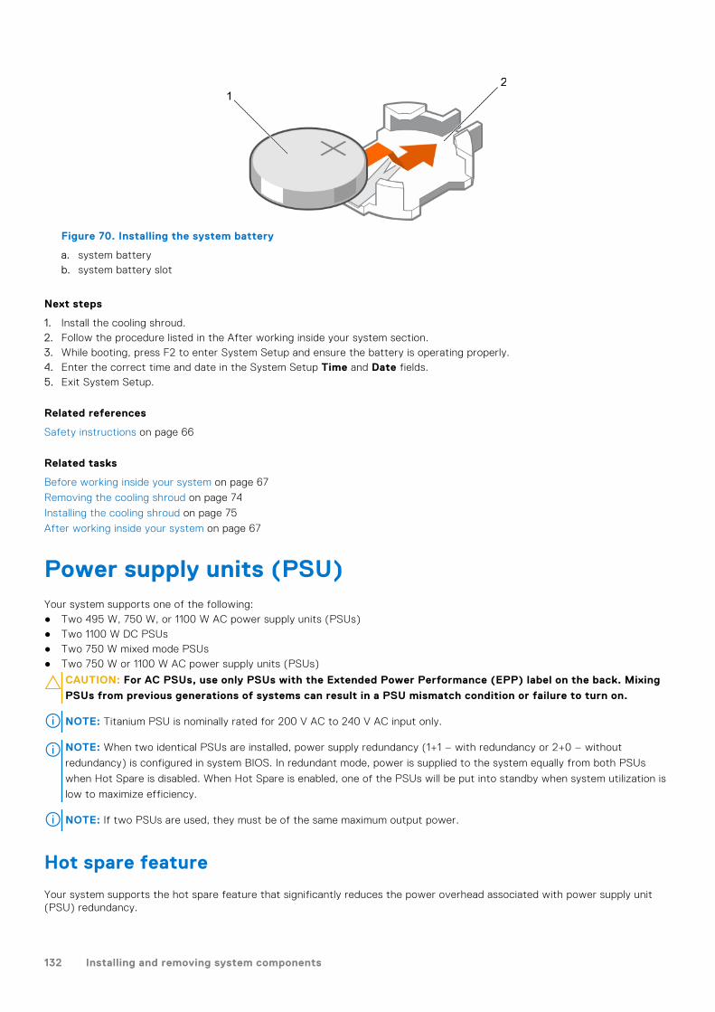
Figure 70. Installing the system battery
a. system batteryb. system battery slot
Next steps
1. Install the cooling shroud.2. Follow the procedure listed in the After working inside your system section.3. While booting, press F2 to enter System Setup and ensure the battery is operating properly.4. Enter the correct time and date in the System Setup Time and Date fields.5. Exit System Setup.
Related references
Safety instructions on page 66
Related tasks
Before working inside your system on page 67
Removing the cooling shroud on page 74
Installing the cooling shroud on page 75
After working inside your system on page 67
Power supply units (PSU)Your system supports one of the following:● Two 495 W, 750 W, or 1100 W AC power supply units (PSUs)● Two 1100 W DC PSUs● Two 750 W mixed mode PSUs● Two 750 W or 1100 W AC power supply units (PSUs)
CAUTION: For AC PSUs, use only PSUs with the Extended Power Performance (EPP) label on the back. Mixing
PSUs from previous generations of systems can result in a PSU mismatch condition or failure to turn on.
NOTE: Titanium PSU is nominally rated for 200 V AC to 240 V AC input only.
NOTE: When two identical PSUs are installed, power supply redundancy (1+1 – with redundancy or 2+0 – without
redundancy) is configured in system BIOS. In redundant mode, power is supplied to the system equally from both PSUs
when Hot Spare is disabled. When Hot Spare is enabled, one of the PSUs will be put into standby when system utilization is
low to maximize efficiency.
NOTE: If two PSUs are used, they must be of the same maximum output power.
Hot spare feature
Your system supports the hot spare feature that significantly reduces the power overhead associated with power supply unit(PSU) redundancy.
132 Installing and removing system components

When the hot spare feature is enabled, one of the redundant PSUs is switched to the sleep state. The active PSU supports 100percent of the load, thus operating at higher efficiency. The PSU in the sleep state monitors output voltage of the active PSU. Ifthe output voltage of the active PSU drops, the PSU in the sleep state returns to an active output state.
If having both PSUs active is more efficient than having one PSU in the sleep state, the active PSU can also activate thesleeping PSU.
The default PSU settings are as follows:● If the load on the active PSU is more than 50 percent, then the redundant PSU is switched to the active state.● If the load on the active PSU falls below 20 percent, then the redundant PSU is switched to the sleep state.
You can configure the hot spare feature by using the iDRAC settings. For more information about iDRAC settings, see theIntegrated Dell Remote Access Controller User’s Guide available at Dell.com/idracmanuals.
Removing the power supply unit blank
Install the power supply unit (PSU) blank only in the second PSU bay.
Prerequisites
CAUTION: Many repairs may only be done by a certified service technician. You should only perform
troubleshooting and simple repairs as authorized in your product documentation, or as directed by the online or
telephone service and support team. Damage due to servicing that is not authorized by Dell is not covered by
your warranty. Read and follow the safety instructions that are shipped with your product.
Follow the safety guidelines listed in the Safety instructions section.
Steps
If you are installing a second power supply unit (PSU), remove the PSU blank in the bay by pulling the blank outward.
CAUTION: To ensure proper system cooling, the PSU blank must be installed in the second PSU bay in a
non-redundant configuration. Remove the PSU blank only if you are installing a second PSU.
Figure 71. Removing the PSU blank
a. PSU blankb. PSU bay
Next steps
Install the PSU or PSU blank.
Installing and removing system components 133

Installing the power supply unit blank
Install the power supply unit (PSU) blank only in the second PSU bay.
Prerequisites
CAUTION: Many repairs may only be done by a certified service technician. You should only perform
troubleshooting and simple repairs as authorized in your product documentation, or as directed by the online or
telephone service and support team. Damage due to servicing that is not authorized by Dell is not covered by
your warranty. Read and follow the safety instructions that are shipped with your product.
1. Follow the safety guidelines listed in the Safety instructions section.
Steps
Align the power supply unit blank with the power supply unit slot and push it into the power supply unit slot until it clicks intoplace.
Figure 72. Installing the PSU blank
a. PSU blankb. PSU bay
Removing an AC power supply unit
Prerequisites
CAUTION: Many repairs may only be done by a certified service technician. You should only perform
troubleshooting and simple repairs as authorized in your product documentation, or as directed by the online or
telephone service and support team. Damage due to servicing that is not authorized by Dell is not covered by
your warranty. Read and follow the safety instructions that are shipped with your product.
CAUTION: The system needs one power supply unit (PSU) for normal operation. On power-redundant systems,
remove and replace only one PSU at a time in a system that is powered on.
If applicable, unlatch and lift the optional cable management arm if it interferes with the power supply unit (PSU) removal. Forinformation about the cable management arm, see the system’s rack documentation.
Follow the safety guidelines listed in the Safety instructions section.
Steps
1. Disconnect the power cable from the power source and from the PSU you intend to remove, and then remove the cablesfrom the strap.
134 Installing and removing system components

2. Press the release latch and slide the PSU out of the chassis by using the PSU handle.
Figure 73. Removing an AC PSU
1. release latch 2. PSU cable connector
3. PSU 4. power connector
5. PSU handle
Next steps
● If applicable, install the AC PSU.● If applicable, install the PSU blank.
Installing an AC power supply unit
Prerequisites
CAUTION: Many repairs may only be done by a certified service technician. You should only perform
troubleshooting and simple repairs as authorized in your product documentation, or as directed by the online or
telephone service and support team. Damage due to servicing that is not authorized by Dell is not covered by
your warranty. Read and follow the safety instructions that are shipped with your product.
NOTE: The maximum output power (shown in watts) is listed on the PSU label.
1. Follow the safety guidelines listed in the Safety instructions section.2. For systems that support redundant power supply units (PSUs), ensure that both the PSUs are of the same type and have
the same maximum output power.3. If installed, remove the PSU blank.
Steps
1. Slide the PSU into the chassis until the PSU is fully seated and the release latch snaps into place.
2. If applicable, relatch the cable management arm.
For information about the cable management arm, see the rack documentation of your system.
3. Connect the power cable to the PSU, and plug the cable into a power outlet.
CAUTION: When connecting the power cable, secure the cable with the strap.
NOTE: When installing, hot swapping, or hot-adding a new PSU, wait for 15 seconds for the system to recognize the
PSU and determine its status. The PSU redundancy may not occur until discovery is complete. Wait until the new PSU is
discovered and enabled before you remove the other PSU. The PSU status indicator turns green to signify that the PSU
is functioning properly.
Installing and removing system components 135

Figure 74. Installing an AC PSU
1. release latch 2. PSU cable connector
3. PSU 4. power connector
5. PSU handle
Wiring instructions for a DC power supply unit
Your system supports up to two –(48–60) V DC power supply units (PSUs).
NOTE: For equipment using –(48–60) V DC power supply units (PSUs), a qualified electrician must perform all connections
to DC power and to safety grounds. Do not attempt connecting to DC power or installing grounds yourself. All electrical
wiring must comply with applicable local or national codes and practices. Damage due to servicing that is not authorized by
Dell is not covered by your warranty. Read and follow all safety instructions that came with the product.
CAUTION: Wire the unit with copper only, unless otherwise specified, use only 10 American Wire Gauge (AWG)
wire rated minimum 90 ºC for source and return. Protect the –(48–60) V DC (1 wire) with a branch circuit
over-current protection rated 50 A for DC with a high interrupt current rating.
CAUTION: Connect the equipment to a –(48–60) V DC supply source that is electrically isolated from the AC
source (reliably grounded –(48–60) V DC SELV source). Ensure that the –(48–60) V DC source is efficiently
secured to earth (ground).
NOTE: A readily accessible disconnect device that is suitably approved and rated shall be incorporated in the field wiring.
Input requirements
● Supply voltage: –(48–60) V DC● Current consumption: 32 A (maximum)
Kit contents
● Dell part number 6RYJ9 terminal block or equivalent (1)● #6-32 nut equipped with lock washer (1)
Required tools
Wire-stripper pliers capable of removing insulation from size 10 AWG solid or stranded, insulated copper wire
136 Installing and removing system components
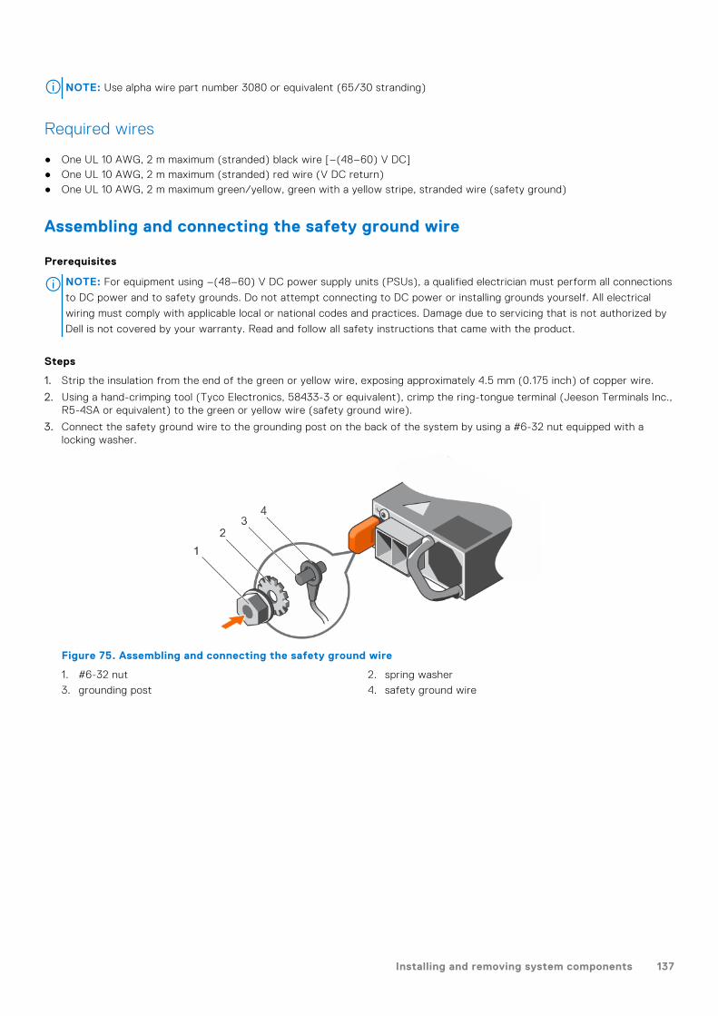
NOTE: Use alpha wire part number 3080 or equivalent (65/30 stranding)
Required wires
● One UL 10 AWG, 2 m maximum (stranded) black wire [–(48–60) V DC]● One UL 10 AWG, 2 m maximum (stranded) red wire (V DC return)● One UL 10 AWG, 2 m maximum green/yellow, green with a yellow stripe, stranded wire (safety ground)
Assembling and connecting the safety ground wire
Prerequisites
NOTE: For equipment using –(48–60) V DC power supply units (PSUs), a qualified electrician must perform all connections
to DC power and to safety grounds. Do not attempt connecting to DC power or installing grounds yourself. All electrical
wiring must comply with applicable local or national codes and practices. Damage due to servicing that is not authorized by
Dell is not covered by your warranty. Read and follow all safety instructions that came with the product.
Steps
1. Strip the insulation from the end of the green or yellow wire, exposing approximately 4.5 mm (0.175 inch) of copper wire.
2. Using a hand-crimping tool (Tyco Electronics, 58433-3 or equivalent), crimp the ring-tongue terminal (Jeeson Terminals Inc.,R5-4SA or equivalent) to the green or yellow wire (safety ground wire).
3. Connect the safety ground wire to the grounding post on the back of the system by using a #6-32 nut equipped with alocking washer.
Figure 75. Assembling and connecting the safety ground wire
1. #6-32 nut 2. spring washer
3. grounding post 4. safety ground wire
Installing and removing system components 137

Figure 76. Removing the safety ground wire
1. #6-32 nut 2. spring washer
3. grounding post 4. safety ground wire
Assembling the DC input power wires
Prerequisites
NOTE: For equipment using –(48–60) V DC power supply units (PSUs), a qualified electrician must perform all connections
to DC power and to safety grounds. Do not attempt connecting to DC power or installing grounds yourself. All electrical
wiring must comply with applicable local or national codes and practices. Damage due to servicing that is not authorized by
Dell is not covered by your warranty. Read and follow all safety instructions that came with the product.
Steps
1. Strip the insulation from the ends of the DC power wires, exposing approximately 13 mm (0.5 inch) of copper wire.
NOTE: Reversing polarity when connecting DC power wires can permanently damage the power supply or the system.
2. Insert the copper ends into the mating connectors and tighten the captive screws at the top of the mating connector byusing a Phillips #2 screwdriver.
NOTE: To protect the power supply from electrostatic discharge, the captive screws must be covered with the rubber
cap before inserting the mating connector into the power supply.
3. Rotate the rubber cap clockwise to fix it over the captive screws.
4. Insert the mating connector into the PSU.
138 Installing and removing system components

Figure 77. Assembling the DC Input Power Wires
1. DC wire RTN 2. DC power connector
3. captive screw (2) 4. rubber cap
5. DC power socket 6. DC wire –48 V
Figure 78. Removing the DC Input Power Wires
1. wire RTN 2. DC power connector
3. captive screw (2) 4. rubber cap
5. DC power socket 6. wire –48 V
Removing a DC power supply unit
Prerequisites
NOTE: For equipment using –(48–60) V DC power supply units (PSUs), a qualified electrician must perform all connections
to DC power and to safety grounds. Do not attempt connecting to DC power or installing grounds yourself. All electrical
wiring must comply with applicable local or national codes and practices. Damage due to servicing that is not authorized by
Dell is not covered by your warranty. Read and follow all safety instructions that came with the product.
Installing and removing system components 139
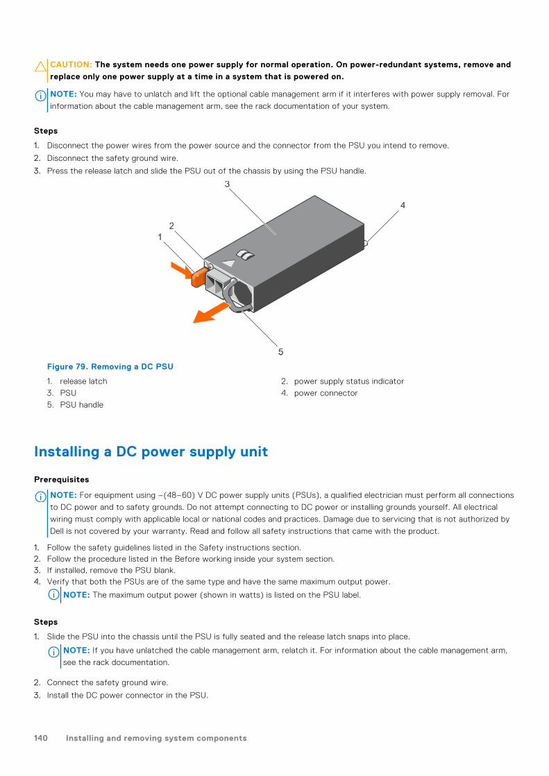
CAUTION: The system needs one power supply for normal operation. On power-redundant systems, remove and
replace only one power supply at a time in a system that is powered on.
NOTE: You may have to unlatch and lift the optional cable management arm if it interferes with power supply removal. For
information about the cable management arm, see the rack documentation of your system.
Steps
1. Disconnect the power wires from the power source and the connector from the PSU you intend to remove.
2. Disconnect the safety ground wire.
3. Press the release latch and slide the PSU out of the chassis by using the PSU handle.
Figure 79. Removing a DC PSU
1. release latch 2. power supply status indicator
3. PSU 4. power connector
5. PSU handle
Installing a DC power supply unit
Prerequisites
NOTE: For equipment using –(48–60) V DC power supply units (PSUs), a qualified electrician must perform all connections
to DC power and to safety grounds. Do not attempt connecting to DC power or installing grounds yourself. All electrical
wiring must comply with applicable local or national codes and practices. Damage due to servicing that is not authorized by
Dell is not covered by your warranty. Read and follow all safety instructions that came with the product.
1. Follow the safety guidelines listed in the Safety instructions section.2. Follow the procedure listed in the Before working inside your system section.3. If installed, remove the PSU blank.4. Verify that both the PSUs are of the same type and have the same maximum output power.
NOTE: The maximum output power (shown in watts) is listed on the PSU label.
Steps
1. Slide the PSU into the chassis until the PSU is fully seated and the release latch snaps into place.
NOTE: If you have unlatched the cable management arm, relatch it. For information about the cable management arm,
see the rack documentation.
2. Connect the safety ground wire.
3. Install the DC power connector in the PSU.
140 Installing and removing system components

CAUTION: When connecting the power wires, ensure that you secure the wires with the strap to the PSU
handle.
4. Connect the wires to a DC power source.
NOTE: When installing, hot-swapping, or hot-adding a new PSU, wait for 15 seconds for the system to recognize the
PSU and determine its status. The PSU status indicator turns green to signify that the PSU is functioning properly.
Figure 80. Installing a DC PSU
1. release latch 2. power supply status indicator
3. PSU 4. power connector
5. PSU handle
Next steps
● Follow the procedure listed in the After working inside your system section.
System boardA system board (also known as the motherboard) is the main printed circuit board in the system with different connectorsused to connect different components or peripherals of the system. A system board provides the electrical connections to thecomponents in the system to communicate.
Removing the system board
Prerequisites
CAUTION: Many repairs may only be done by a certified service technician. You should only perform
troubleshooting and simple repairs as authorized in your product documentation, or as directed by the online or
telephone service and support team. Damage due to servicing that is not authorized by Dell is not covered by
your warranty. Read and follow the safety instructions that are shipped with your product.
CAUTION: If you are using the Trusted Platform Module (TPM) with an encryption key, you may be prompted
to create a recovery key during program or System Setup. Be sure to create and safely store this recovery key.
If you replace this system board, you must supply the recovery key when you restart your system or program
before you can access the encrypted data on your hard drives.
CAUTION: Do not attempt to remove the TPM plug-in module from the system board. Once the TPM plug-in
module is installed, it is cryptographically bound to that specific system board. Any attempt to remove an
Installing and removing system components 141

installed TPM plug-in module breaks the cryptographic binding, and it cannot be re-installed or installed on
another system board.
1. Follow the safety guidelines listed in the Safety instructions section.2. Follow the procedure listed in the Before working inside your system section.3. Remove the following:
a. Cooling shroudb. Cooling fan assemblyc. Power supply unit(s)d. All expansion card riserse. Integrated storage controller cardf. Internal dual SD moduleg. Internal USB key (if installed)h. PCIe card holderi. Cable retention bracketj. Heat sink(s)/heat sink blank(s)k. Processors(s)/processor blank(s)
CAUTION: To prevent damage to the processor pins when replacing a faulty system board, ensure that
you cover the processor socket with the processor protective cap.
l. Memory modules and memory module blanksm. Network daughter card
Steps
1. Disconnect all cables from the system board.
CAUTION: Take care not to damage the system identification button while removing the system board from
the chassis.
CAUTION: Do not lift the system board by holding a memory module, processor, or other components.
2. Hold the system board holder, lift the blue release pin, lift the system board, and then slide it toward the front of the chassis.Sliding the system board toward the front of the chassis disengages the connectors from the back of the chassis slots.
3. Lift the system board out of the chassis.
142 Installing and removing system components

Figure 81. Removing the system board
a. release pinb. system boardc. system board holder
Next steps
1. Install the system board.2. Follow the procedure listed in the After working inside your system section.
Related references
Safety instructions on page 66
Related tasks
Before working inside your system on page 67
Removing the cooling shroud on page 74
Removing the cooling fan assembly on page 77
Removing an AC power supply unit on page 134
Removing a DC power supply unit on page 139
Removing expansion card risers on page 114
Installing and removing system components 143
Removing the integrated storage controller card on page 102
Removing the optional internal dual SD module on page 125
Replacing the optional internal USB memory key on page 130
Removing the PCIe card holder on page 97
Removing the cable retention bracket on page 100
Removing a heat sink on page 88
Removing a processor on page 90
Removing memory modules on page 85
Removing the network daughter card on page 127
Installing the system board on page 144
After working inside your system on page 67
Installing the system board
Prerequisites
1. Follow the safety guidelines listed in the Safety instructions section.2. Follow the procedure listed in the Before working inside your system section.
CAUTION: Many repairs may only be done by a certified service technician. You should only perform
troubleshooting and simple repairs as authorized in your product documentation, or as directed by the online or
telephone service and support team. Damage due to servicing that is not authorized by Dell is not covered by
your warranty. Read and follow the safety instructions that are shipped with your product.
Steps
1. Unpack the new system board assembly.
CAUTION: Do not lift the system board by holding a memory module, processor, or other components.
CAUTION: Take care not to damage the system identification button while placing the system board into the
chassis.
2. Hold the touch points and lower the system board into the chassis.
3. Push the system board toward the back of the chassis until the board clicks into place.
144 Installing and removing system components

Figure 82. Installing the system board
a. release pinb. system boardc. system board holder
Next steps
1. Install the Trusted Platform Module (TPM). For information about how to install the TPM, see the Installing the TrustedPlatform Module section. For more information on the TPM, see the Trusted Platform Module section.
NOTE: The TPM plug-in module is attached to the system board and cannot be removed. A replacement TPM plug-in
module will be provided for all system board replacements where a TPM plug-in module was installed.
2. Replace the following:a. Cable retention bracketb. PCIe card holderc. Integrated storage controller cardd. Internal USB key (if applicable)e. Internal dual SD modulef. All expansion card risersg. Heat sink(s)/heat sink blank(s) and processors(s)/processor blank(s)h. Memory modules and memory module blanksi. Network daughter cardj. Cooling fan assembly
Installing and removing system components 145

k. Cooling shroudl. Power supply unit(s)
3. Reconnect all cables to the system board.NOTE: Ensure that the cables inside the system are routed along the chassis wall and secured using the cable securing
bracket.
4. Follow the procedure listed in the After working inside your system section.5. Import your new or existing iDRAC Enterprise license. For more information, see Integrated Dell Remote Access Controller
User's Guide, at Dell.com/esmmanuals.6. Ensure that you:
a. Use the Easy Restore feature to restore the Service Tag. For more information, see the Easy restore section.b. If the Service Tag is not backed up in the backup flash device, enter the Service Tag manually. For more information, see
the Entering the Service Tag section.c. Update the BIOS and iDRAC versions.d. Re-enable the Trusted Platform Module (TPM). For more information, see the Re-enabling the Trusted Platform Module
(TPM) section.
Related tasks
Installing the cable retention bracket on page 101
Installing the PCIe card holder on page 98
Installing the integrated storage controller card on page 104
Replacing the optional internal USB memory key on page 130
Installing the optional internal dual SD module on page 126
Installing expansion card risers on page 117
Installing a heat sink on page 94
Installing a processor on page 93
Installing memory modules on page 86
Installing the network daughter card on page 128
Installing the cooling fan assembly on page 78
Installing the cooling shroud on page 75
Installing an AC power supply unit on page 135
Installing a DC power supply unit on page 140
Entering the system Service Tag by using System Setup
If Easy Restore fails to restore the Service Tag, use System Setup to enter the Service Tag.
Steps
1. Turn on the system.
2. Press F2 to enter System Setup.
3. Click Service Tag Settings.
4. Enter the Service Tag.
NOTE: You can enter the Service Tag only when the Service Tag field is empty. Ensure that you enter the correct
Service Tag. After the Service Tag is entered, it cannot be updated or changed.
5. Click OK.
6. Import your new or existing iDRAC Enterprise license.
For more information, see the Integrated Dell Remote Access Controller User's Guide at www.dell.com/poweredgemanuals .
Restoring the Service Tag by using the Easy Restore feature
By using the Easy Restore feature, you can restore your Service Tag, license, UEFI configuration, and the system configurationdata after replacing the system board. All data is automatically backed up in a backup flash device. If BIOS detects a new systemboard and the Service Tag in the backup flash device, BIOS prompts the user to restore the backup information.
146 Installing and removing system components
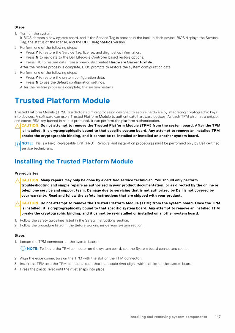
Steps
1. Turn on the system.If BIOS detects a new system board, and if the Service Tag is present in the backup flash device, BIOS displays the ServiceTag, the status of the license, and the UEFI Diagnostics version.
2. Perform one of the following steps:● Press Y to restore the Service Tag, license, and diagnostics information.● Press N to navigate to the Dell Lifecycle Controller based restore options.● Press F10 to restore data from a previously created Hardware Server Profile.After the restore process is complete, BIOS prompts to restore the system configuration data.
3. Perform one of the following steps:● Press Y to restore the system configuration data.● Press N to use the default configuration settings.After the restore process is complete, the system restarts.
Trusted Platform ModuleTrusted Platform Module (TPM) is a dedicated microprocessor designed to secure hardware by integrating cryptographic keysinto devices. A software can use a Trusted Platform Module to authenticate hardware devices. As each TPM chip has a uniqueand secret RSA key burned in as it is produced, it can perform the platform authentication.
CAUTION: Do not attempt to remove the Trusted Platform Module (TPM) from the system board. After the TPM
is installed, it is cryptographically bound to that specific system board. Any attempt to remove an installed TPM
breaks the cryptographic binding, and it cannot be re-installed or installed on another system board.
NOTE: This is a Field Replaceable Unit (FRU). Removal and installation procedures must be performed only by Dell certified
service technicians.
Installing the Trusted Platform Module
Prerequisites
CAUTION: Many repairs may only be done by a certified service technician. You should only perform
troubleshooting and simple repairs as authorized in your product documentation, or as directed by the online or
telephone service and support team. Damage due to servicing that is not authorized by Dell is not covered by
your warranty. Read and follow the safety instructions that are shipped with your product.
CAUTION: Do not attempt to remove the Trusted Platform Module (TPM) from the system board. Once the TPM
is installed, it is cryptographically bound to that specific system board. Any attempt to remove an installed TPM
breaks the cryptographic binding, and it cannot be re-installed or installed on another system board.
1. Follow the safety guidelines listed in the Safety instructions section.2. Follow the procedure listed in the Before working inside your system section.
Steps
1. Locate the TPM connector on the system board.
NOTE: To locate the TPM connector on the system board, see the System board connectors section.
2. Align the edge connectors on the TPM with the slot on the TPM connector.
3. Insert the TPM into the TPM connector such that the plastic rivet aligns with the slot on the system board.
4. Press the plastic rivet until the rivet snaps into place.
Installing and removing system components 147
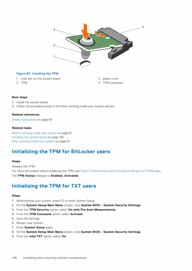
Figure 83. Installing the TPM
1. rivet slot on the system board 2. plastic rivet
3. TPM 4. TPM connector
Next steps
1. Install the system board.2. Follow the procedure listed in the After working inside your system section.
Related references
Safety instructions on page 66
Related tasks
Before working inside your system on page 67
Installing the system board on page 144
After working inside your system on page 67
Initializing the TPM for BitLocker users
Steps
Initialize the TPM.
For more information about initializing the TPM, see https://technet.microsoft.com/en-us/library/cc753140.aspx.
The TPM Status changes to Enabled, Activated.
Initializing the TPM for TXT users
Steps
1. While booting your system, press F2 to enter System Setup.
2. On the System Setup Main Menu screen, click System BIOS > System Security Settings.
3. From the TPM Security option, select On with Pre-boot Measurements.
4. From the TPM Command option, select Activate.
5. Save the settings.
6. Restart your system.
7. Enter System Setup again.
8. On the System Setup Main Menu screen, click System BIOS > System Security Settings.
9. From the Intel TXT option, select On.
148 Installing and removing system components
Hard drivesYour system supports entry hard drives and enterprise-class hard drives. Entry hard drives are designed for 5x8 operatingenvironment with less workload rating to drives and enterprise-class drives are designed for 24x7 operating environment.Selecting the correct drive class will enable the critical areas of quality, functionality, performance, and reliability to be optimizedfor the target implementation.
NOTE: Do not mix enterprise-class hard drives with entry hard drives.
Choosing the right drive type depends on the usage pattern. Improper use of entry hard drives (workload rating exceeds55TB/year) will lead to significant risk and increase the drives failure rate.
For more information on these hard drives, see the 512e and 4Kn Disk Formats whitepaper and 4K Sector HDD FAQdocument at Dell.com/poweredgemanuals.
All hard drives are connected to the system board through the hard drive backplane. Hard drives are supplied in hot-swappablehard drive carriers that fit in the hard drive slots.
CAUTION: Before attempting to remove or install a hard drive while the system is running, see the
documentation for the storage controller card to ensure that the host adapter is configured correctly to support
hot-swap hard drive removal and insertion.
CAUTION: Do not turn off or restart your system while the hard drive is being formatted. Doing so can cause a
hard drive failure.
Use only hard drives that have been tested and approved for use with the hard drive backplane.
When you format a hard drive, allow enough time for the formatting to be complete. Be aware that high-capacity hard drivescan take a long time to format.
Removing a 2.5-inch hard drive blank
Prerequisites
CAUTION: Many repairs may only be done by a certified service technician. Perform troubleshooting and simple
repairs as authorized in your product documentation, or as directed by the online or telephone service and
support team. Damage due to servicing that is not authorized by Dell is not covered by your warranty. Read and
follow the safety instructions that came with the product.
CAUTION: To maintain proper system cooling, all empty hard drive slots must have hard drive blanks installed.
1. Follow the safety guidelines listed in the Safety instructions section.2. If installed, remove the bezel.
Steps
Press the release button and slide the hard drive blank out of the hard drive slot.
Installing and removing system components 149
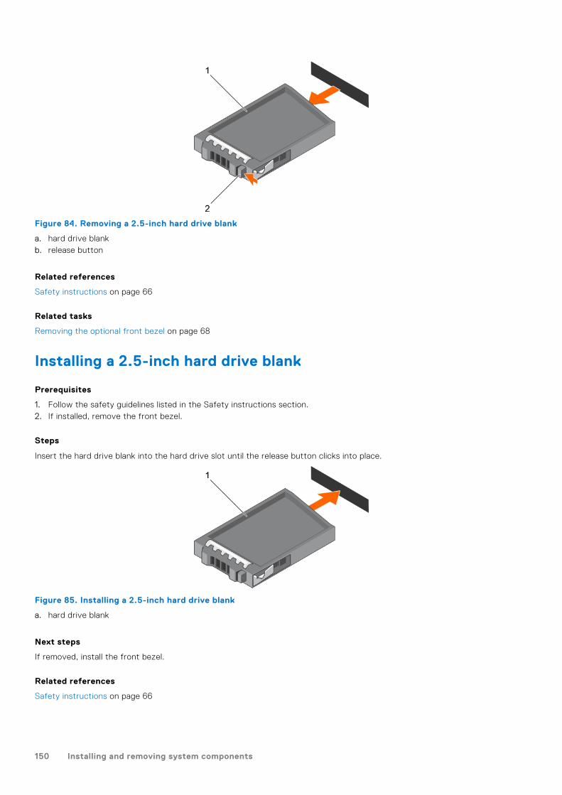
Figure 84. Removing a 2.5-inch hard drive blank
a. hard drive blankb. release button
Related references
Safety instructions on page 66
Related tasks
Removing the optional front bezel on page 68
Installing a 2.5-inch hard drive blank
Prerequisites
1. Follow the safety guidelines listed in the Safety instructions section.2. If installed, remove the front bezel.
Steps
Insert the hard drive blank into the hard drive slot until the release button clicks into place.
Figure 85. Installing a 2.5-inch hard drive blank
a. hard drive blank
Next steps
If removed, install the front bezel.
Related references
Safety instructions on page 66
150 Installing and removing system components
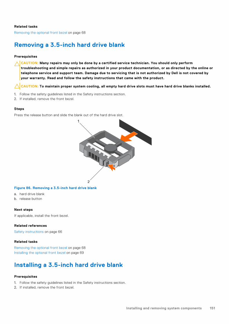
Related tasks
Removing the optional front bezel on page 68
Removing a 3.5-inch hard drive blank
Prerequisites
CAUTION: Many repairs may only be done by a certified service technician. You should only perform
troubleshooting and simple repairs as authorized in your product documentation, or as directed by the online or
telephone service and support team. Damage due to servicing that is not authorized by Dell is not covered by
your warranty. Read and follow the safety instructions that came with the product.
CAUTION: To maintain proper system cooling, all empty hard drive slots must have hard drive blanks installed.
1. Follow the safety guidelines listed in the Safety instructions section.2. If installed, remove the front bezel.
Steps
Press the release button and slide the blank out of the hard drive slot.
Figure 86. Removing a 3.5-inch hard drive blank
a. hard drive blankb. release button
Next steps
If applicable, install the front bezel.
Related references
Safety instructions on page 66
Related tasks
Removing the optional front bezel on page 68
Installing the optional front bezel on page 69
Installing a 3.5-inch hard drive blank
Prerequisites
1. Follow the safety guidelines listed in the Safety instructions section.2. If installed, remove the front bezel.
Installing and removing system components 151

Steps
Insert the hard drive blank into the hard drive slot until the release button clicks into place.
Figure 87. Installing a 3.5-inch hard drive blank
a. hard drive blank
Next steps
If applicable, install the front bezel.
Related references
Safety instructions on page 66
Related tasks
Removing the optional front bezel on page 68
Installing the optional front bezel on page 69
Removing a hot swappable hard drive or solid state drive
Prerequisites
CAUTION: Many repairs may only be done by a certified service technician. You should only perform
troubleshooting and simple repairs as authorized in your product documentation, or as directed by the online or
telephone service and support team. Damage due to servicing that is not authorized by Dell is not covered by
your warranty. Read and follow the safety instructions that came with the product.
1. Follow the safety guidelines listed in the Safety instructions section.2. Follow the procedure listed in the Before working inside your system section.3. If applicable, remove the bezel.4. If applicable, remove the system cover to remove hot-swappable drives inside your system.5. Using the management software, prepare the hard drive for removal. If the hard drive is online, the green activity or fault
indicator flashes while the drive is turning off. When the hard drive indicators are off, the hard drive is ready for removal.
For more information, see the documentation for the storage controller.
CAUTION: To prevent data loss, ensure that your operating system supports hot-swap drive installation. See the
documentation supplied with your operating system.
Steps
1. Press the release button to open the hard drive or SSD carrier release handle.
2. Slide the hard drive or SSD carrier out of the hard drive slot.
CAUTION: To maintain proper system cooling, all empty hard drive or SSD slots must have hard drive or SSD
blanks installed.
3. If you are not replacing the hard drive or SSD immediately, insert a hard drive or SSD blank in the empty hard drive slot.
152 Installing and removing system components

Figure 88. Removing a hot swappable hard drive or SSD
a. release buttonb. hard drive or SSD carrierc. hard drive or SSD carrier handle
Figure 89. Removing a 1.8 inch hot-swappable uSATA SSD carrier
a. release buttonb. SSD carrierc. SSD carrier handle
Related references
Safety instructions on page 66
Related tasks
Before working inside your system on page 67
Removing the optional front bezel on page 68
Installing the optional front bezel on page 69
Installing and removing system components 153
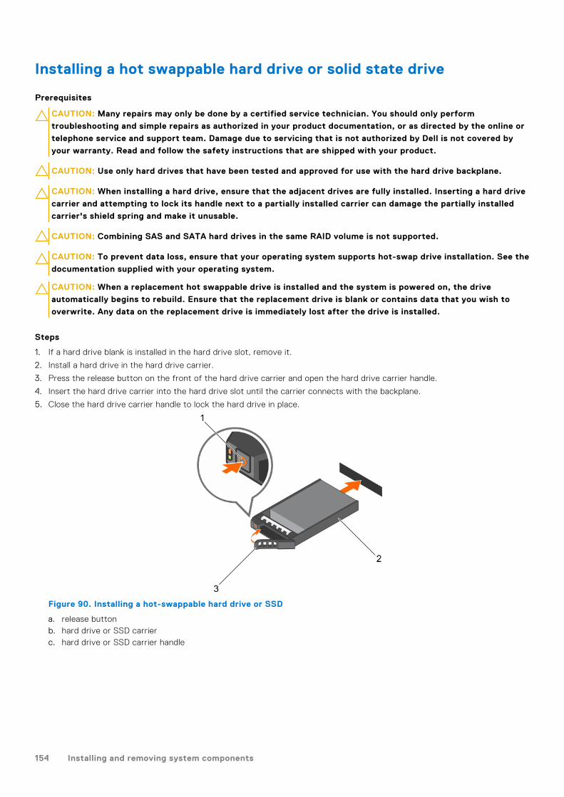
Installing a hot swappable hard drive or solid state drive
Prerequisites
CAUTION: Many repairs may only be done by a certified service technician. You should only perform
troubleshooting and simple repairs as authorized in your product documentation, or as directed by the online or
telephone service and support team. Damage due to servicing that is not authorized by Dell is not covered by
your warranty. Read and follow the safety instructions that are shipped with your product.
CAUTION: Use only hard drives that have been tested and approved for use with the hard drive backplane.
CAUTION: When installing a hard drive, ensure that the adjacent drives are fully installed. Inserting a hard drive
carrier and attempting to lock its handle next to a partially installed carrier can damage the partially installed
carrier's shield spring and make it unusable.
CAUTION: Combining SAS and SATA hard drives in the same RAID volume is not supported.
CAUTION: To prevent data loss, ensure that your operating system supports hot-swap drive installation. See the
documentation supplied with your operating system.
CAUTION: When a replacement hot swappable drive is installed and the system is powered on, the drive
automatically begins to rebuild. Ensure that the replacement drive is blank or contains data that you wish to
overwrite. Any data on the replacement drive is immediately lost after the drive is installed.
Steps
1. If a hard drive blank is installed in the hard drive slot, remove it.
2. Install a hard drive in the hard drive carrier.
3. Press the release button on the front of the hard drive carrier and open the hard drive carrier handle.
4. Insert the hard drive carrier into the hard drive slot until the carrier connects with the backplane.
5. Close the hard drive carrier handle to lock the hard drive in place.
Figure 90. Installing a hot-swappable hard drive or SSD
a. release buttonb. hard drive or SSD carrierc. hard drive or SSD carrier handle
154 Installing and removing system components

Figure 91. Installing a 1.8 inch hot-swappable uSATA SSD carrier
a. release buttonb. SSD carrierc. SSD carrier handle
Related tasks
Removing a 3.5-inch hard drive blank on page 151
Removing a 2.5-inch hard drive blank on page 149
Installing a hard drive or solid state drives into a hard drive carrier on page 156
Installing the hard drive backplane on page 166
Removing a hard drive or a solid state drive from a hard drivecarrier
Prerequisites
1. Keep the Phillips #1 screwdriver ready.2. Remove the hot swappable hard drive carrier from the system.
Steps
1. Remove the screws from the slide rails on the hard drive carrier.
2. Lift the hard drive out of the hard drive carrier.
Figure 92. Removing a hard drive from a hard drive carrier
a. screw (4)b. hard drivec. hard drive carrier
Installing and removing system components 155

Related video
http://www.Dell.com/QRL/Server/PER730/HDD
Next steps
If applicable, install a hard drive into the hard drive carrier.
Related tasks
Removing a hot swappable hard drive or solid state drive on page 152
Installing a hot swappable hard drive or solid state drive on page 154
Installing a hard drive or solid state drives into a hard drive carrier
Prerequisites
Steps
1. Insert the hard drive into the hard drive carrier with the connector end of the hard drive toward the back of the carrier.
2. Align the screw holes on the hard drive with the screws holes on the hard drive carrier.
When aligned correctly, the back of the hard drive is flush with the back of the hard drive carrier.
3. Attach the screws to secure the hard drive to the hard drive carrier.
Figure 93. Installing a hard drive into a hard drive carrier
1. screw (4)2. hard drive3. hard drive carrier
Next steps
Install the hot swappable hard drive carrier.
Removing a 1.8-inch hard drive blank
Prerequisites
1. Follow the safety guidelines listed in the Safety instructions section.2. If installed, remove the front bezel.
CAUTION: To maintain proper system cooling, all empty hard drive slots must have hard drive blanks installed.
Steps
Press the release button and slide the hard drive blank out of the hard drive slot.
156 Installing and removing system components

Figure 94. Removing a 1.8-inch hard drive blank
a. hard drive blankb. release button
Next steps
If applicable, install the front bezel.
Related references
Safety instructions on page 66
Related tasks
Removing the optional front bezel on page 68
Installing the optional front bezel on page 69
Installing a 1.8-inch hard drive blank
Prerequisites
1. Follow the safety guidelines listed in the Safety instructions section.
2. If installed, remove the front bezel.
Steps
Insert the hard drive blank into the hard drive slot until the release button clicks into place.
Next steps
If applicable, install the front bezel.
Installing and removing system components 157

Figure 95. Installing a 1.8-inch hard drive blank
1. hard drive blank
Related references
Safety instructions on page 66
Related tasks
Removing the optional front bezel on page 68
Installing the optional front bezel on page 69
Removing a 1.8-inch hard drive from a hard drive carrier
Prerequisites
1. Follow the safety guidelines listed in the Safety instructions section.2. Remove the hard drive carrier from the system.
Steps
1. Turn the hard drive carrier.
2. Pull the rails of the hard drive carrier and lift the hard drive out of the hard drive carrier.
Figure 96. Removing a 1.8-inch hard drive into a hard drive carrier
a. hard drive carrierb. hard drive
Related references
Safety instructions on page 66
158 Installing and removing system components

Installing a 1.8-inch hard drive into a hard drive carrier
Prerequisites
CAUTION: Many repairs may only be done by a certified service technician. You should only perform
troubleshooting and simple repairs as authorized in your product documentation, or as directed by the online or
telephone service and support team. Damage due to servicing that is not authorized by Dell is not covered by
your warranty. Read and follow the safety instructions that are shipped with your product.
Steps
Insert the hard drive into the hard drive carrier with the connector end of the hard drive toward the back.When aligned correctly, the back of the hard drive is flush with the back of the hard drive carrier.
Figure 97. Installing a 1.8-inch hard drive into a hard drive carrier
a. hard drive carrierb. hard drive
Hard drive backplaneDepending on your system configuration:
Table 43. Supported hard drives supported options for PowerEdge R730 systems
System Model Supported hard drives supported options
PowerEdge R730
2.5 inch (x16) SAS/SATA backplane, or
2.5 inch (x8) SAS/SATA backplane, or
3.5 inch (x8) SAS/SATA backplane
Removing the hard drive backplane
Prerequisites
1. Follow the safety guidelines listed in the Safety instructions section.2. Follow the procedure listed in the Before working inside your system section.3. Remove the cooling shroud.4. Remove the cooling fan assembly.5. Remove all hard drives.
CAUTION: Many repairs may only be done by a certified service technician. You should only perform
troubleshooting and simple repairs as authorized in your product documentation, or as directed by the online or
Installing and removing system components 159
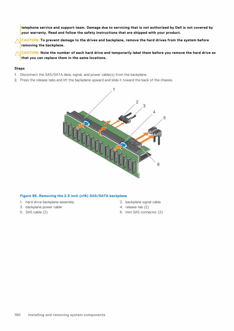
telephone service and support team. Damage due to servicing that is not authorized by Dell is not covered by
your warranty. Read and follow the safety instructions that are shipped with your product.
CAUTION: To prevent damage to the drives and backplane, remove the hard drives from the system before
removing the backplane.
CAUTION: Note the number of each hard drive and temporarily label them before you remove the hard drive so
that you can replace them in the same locations.
Steps
1. Disconnect the SAS/SATA data, signal, and power cable(s) from the backplane.
2. Press the release tabs and lift the backplane upward and slide it toward the back of the chassis.
Figure 98. Removing the 2.5 inch (x16) SAS/SATA backplane
1. hard drive backplane assembly 2. backplane signal cable
3. backplane power cable 4. release tab (2)
5. SAS cable (2) 6. mini SAS connector (2)
160 Installing and removing system components

Figure 99. Cabling diagram—2.5 inch (x16) SAS/SATA backplane
1. hard drive backplane expander 2. hard drive backplane
3. backplane signal connector 1 4. system board
5. integrated storage controller card
Figure 100. Removing the 2.5 inch (x8) SAS/SATA backplane
1. hard drive backplane 2. release tab
Installing and removing system components 161

3. backplane power cable 4. SAS cable (2)
5. backplane signal cable 6. mini SAS connector (2)
Figure 101. Cabling diagram—2.5 inch (x8) SAS/SATA backplane (option 1)
1. hard drive backplane 2. backplane signal connector 1
3. system board 4. integrated storage controller card
162 Installing and removing system components

Figure 102. Cabling diagram—2.5 inch (x8) SAS/SATA backplane (option 2)
1. hard drive backplane 2. backplane signal connector 1
3. system board 4. SAS A connector on the system board
5. SAS B connector on the system board
Installing and removing system components 163
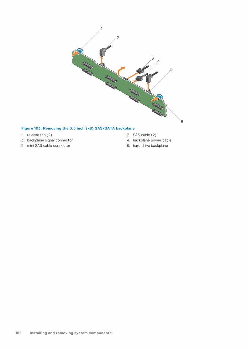
Figure 103. Removing the 3.5 inch (x8) SAS/SATA backplane
1. release tab (2) 2. SAS cable (2)
3. backplane signal connector 4. backplane power cable
5. mini SAS cable connector 6. hard drive backplane
164 Installing and removing system components

Figure 104. Cabling diagram—3.5 inch (x8) SAS/SATA backplane—(option 1)
1. hard drive backplane 2. backplane signal connector 1
3. system board 4. integrated storage controller card
Installing and removing system components 165
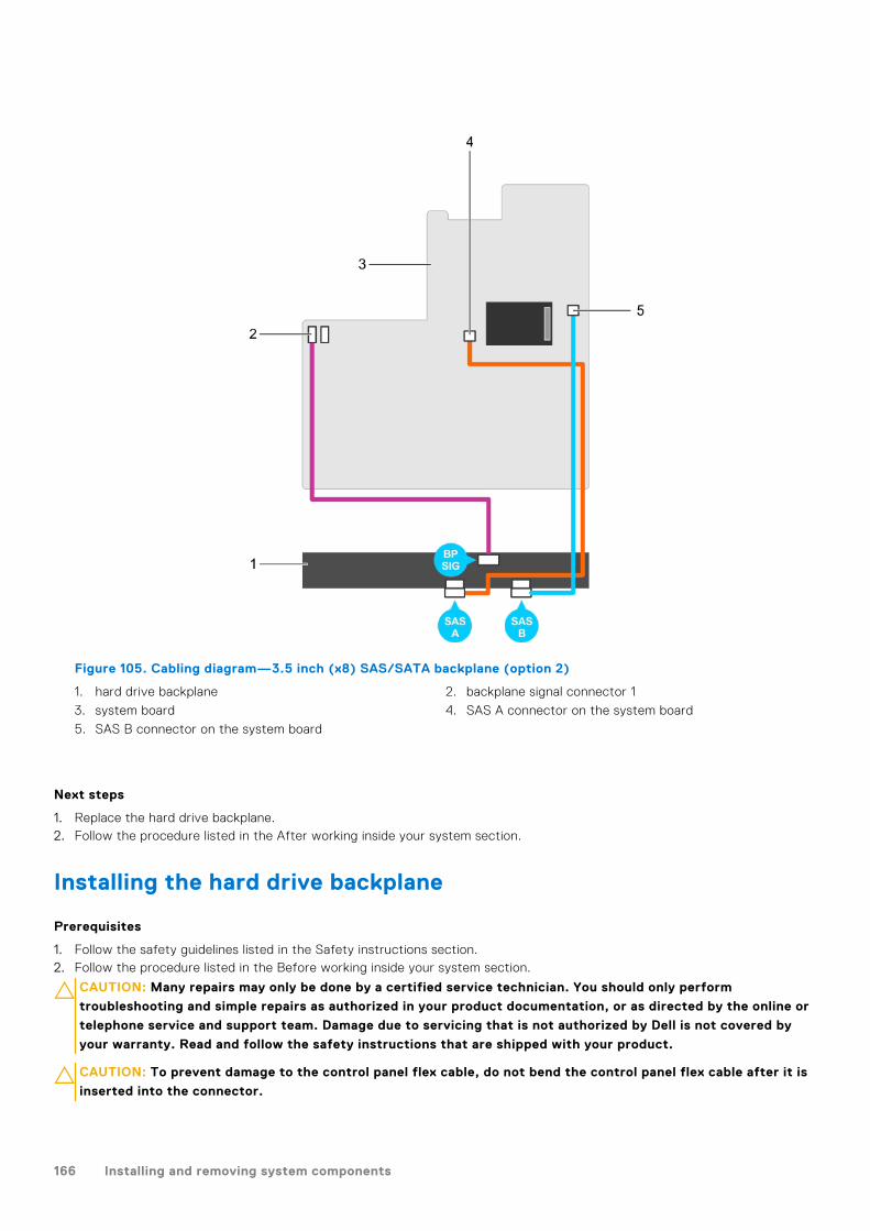
Figure 105. Cabling diagram—3.5 inch (x8) SAS/SATA backplane (option 2)
1. hard drive backplane 2. backplane signal connector 1
3. system board 4. SAS A connector on the system board
5. SAS B connector on the system board
Next steps
1. Replace the hard drive backplane.2. Follow the procedure listed in the After working inside your system section.
Installing the hard drive backplane
Prerequisites
1. Follow the safety guidelines listed in the Safety instructions section.2. Follow the procedure listed in the Before working inside your system section.
CAUTION: Many repairs may only be done by a certified service technician. You should only perform
troubleshooting and simple repairs as authorized in your product documentation, or as directed by the online or
telephone service and support team. Damage due to servicing that is not authorized by Dell is not covered by
your warranty. Read and follow the safety instructions that are shipped with your product.
CAUTION: To prevent damage to the control panel flex cable, do not bend the control panel flex cable after it is
inserted into the connector.
166 Installing and removing system components

Steps
1. Use the hooks on the chassis as guides to align the hard drive backplane.
2. Lower the hard drive backplane until the release tabs snap into place.
3. Connect the SAS/SATA SSD data, signal, and power cable(s) to the backplane.
Figure 106. Installing the 2.5 inch (x16) SAS/SATA backplane
1. hard drive backplane assembly 2. backplane signal cable
3. backplane power cable 4. release tab (2)
5. SAS cable (2) 6. mini SAS connector (2)
Figure 107. Installing the 2.5 inch (x8) SAS/SATA backplane
1. hard drive backplane 2. release tab
3. backplane power cable 4. SAS cable (2)
5. backplane signal cable 6. mini SAS connector (2)
Installing and removing system components 167

Figure 108. Installing the 3.5 inch (x8) SAS/SATA backplane
1. release tab (2) 2. SAS cable (2)
3. backplane signal connector 4. backplane power cable
5. mini SAS cable connector 6. hard drive backplane
Next steps
1. Replace the cooling fan assembly.2. Replace the cooling shroud.3. Install the hard drives in their original locations.4. Follow the procedure listed in the After working inside your system section.
Tape backup unit (optional)A tape backup unit (TBU) is a data storage device that reads and writes data on a magnetic tape. A TBU has the ability toperiodically copy the contents of all or a designated amount of data from its usual storage device to a tape cartridge device sothat, in the event that the source get irreparable damaged, the data will not be lost.
The tape backup unit is supported only on 2.5-inch hard drive systems.
Removing the tape backup unit
Prerequisites
1. Follow the safety guidelines listed in safety instructions section.2. Follow the procedure listed in the Before working inside your system section.
CAUTION: Many repairs may only be done by a certified service technician. You should only perform
troubleshooting and simple repairs as authorized in your product documentation, or as directed by the online or
telephone service and support team. Damage due to servicing that is not authorized by Dell is not covered by
your warranty. Read and follow the safety instructions that are shipped with your product.
Steps
1. Disconnect the power and data cables from the back of the tape backup unit.
168 Installing and removing system components

Ensure you note the routing of the power and data cables inside the chassis as you remove them from the system board andthe tape backup unit. You must route these cables properly when you replace them to prevent them from being pinched orcrimped.
2. To remove the tape backup unit, press the release tab and slide the tape backup unit out of the tape backup unit slot.
NOTE: If the tape backup unit is being permanently removed, install a tape backup unit blank by sliding it into the slot
until it snaps into place.
NOTE: The procedure to install and remove the tape backup unit blank is similar to that of the tape backup unit.
NOTE: Tape backup unit blank must be installed in empty tape backup unit slot to maintain FCC certification of the
system. The blank also keeps dust and dirt out of the system and aid in proper cooling and airflow inside the system.
Figure 109. Removing and installing the tape backup unit
a. tape backup unitb. tape backup unit slotc. release tab
Related references
Safety instructions on page 66
Related tasks
Before working inside your system on page 67
After working inside your system on page 67
Installing the tape backup unit
Prerequisites
1. Follow the safety guidelines listed in safety instructions section.2. Follow the procedure listed in the Before working inside your system section.
CAUTION: Many repairs may only be done by a certified service technician. You should only perform
troubleshooting and simple repairs as authorized in your product documentation, or as directed by the online or
telephone service and support team. Damage due to servicing that is not authorized by Dell is not covered by
your warranty. Read and follow the safety instructions that are shipped with your product.
Steps
1. Unpack and prepare the tape backup unit for installation.
For instructions, see the documentation that shipped with the drive.
Installing and removing system components 169
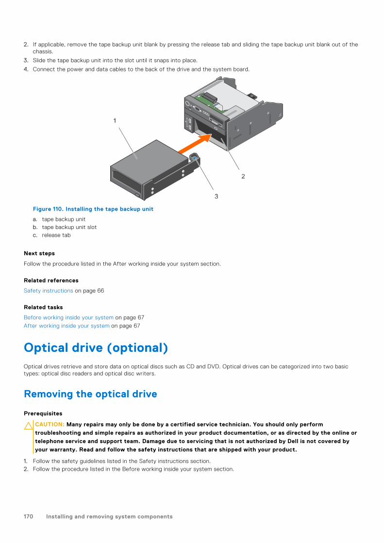
2. If applicable, remove the tape backup unit blank by pressing the release tab and sliding the tape backup unit blank out of thechassis.
3. Slide the tape backup unit into the slot until it snaps into place.
4. Connect the power and data cables to the back of the drive and the system board.
Figure 110. Installing the tape backup unit
a. tape backup unitb. tape backup unit slotc. release tab
Next steps
Follow the procedure listed in the After working inside your system section.
Related references
Safety instructions on page 66
Related tasks
Before working inside your system on page 67
After working inside your system on page 67
Optical drive (optional)Optical drives retrieve and store data on optical discs such as CD and DVD. Optical drives can be categorized into two basictypes: optical disc readers and optical disc writers.
Removing the optical drive
Prerequisites
CAUTION: Many repairs may only be done by a certified service technician. You should only perform
troubleshooting and simple repairs as authorized in your product documentation, or as directed by the online or
telephone service and support team. Damage due to servicing that is not authorized by Dell is not covered by
your warranty. Read and follow the safety instructions that are shipped with your product.
1. Follow the safety guidelines listed in the Safety instructions section.2. Follow the procedure listed in the Before working inside your system section.
170 Installing and removing system components

Steps
1. Disconnect the power and data cables from the back of the drive.
NOTE: Ensure that you note the routing of the power and data cable on the side of the system as you remove them
from the system board and drive. Route these cables properly when you replace them to prevent them from being
pinched or crimped.
2. To release the optical drive, press the release tab.
3. Slide the optical drive out of the system until it is free of the optical drive slot.
4. If you are not adding a new optical drive, install the optical drive blank. The procedure to install the optical drive blank is thesame as the optical drive.
Figure 111. Removing the optional optical drive
a. optical driveb. power and data cablec. release tab
Next steps
Follow the procedure listed in the After working inside your system section.
Related references
Safety instructions on page 66
Related tasks
Before working inside your system on page 67
After working inside your system on page 67
Installing the optical drive
Prerequisites
CAUTION: Many repairs may only be done by a certified service technician. You should only perform
troubleshooting and simple repairs as authorized in your product documentation, or as directed by the online or
telephone service and support team. Damage due to servicing that is not authorized by Dell is not covered by
your warranty. Read and follow the safety instructions that are shipped with your product.
1. Follow the safety guidelines listed in the Safety instructions section.2. Follow the procedure listed in the Before working inside your system section.3. If installed, remove the optical drive blank.
Installing and removing system components 171

Steps
1. Align the optical drive with the optical drive slot on the front of the chassis.
2. Slide in the optical drive until the release tab snaps into place.
3. Connect the power and data cable to the optical drive and system board.
NOTE: Route the cable properly on the side of the system to prevent it from being pinched or crimped.
Figure 112. Installing the optional optical drive
a. optical driveb. power and data cablec. release tab
Next steps
Follow the procedure listed in the After working inside your system section.
Related references
Safety instructions on page 66
Related tasks
Before working inside your system on page 67
After working inside your system on page 67
SD vFlash card (optional)An SD vFlash card is a Secure Digital (SD) card that plugs into the SD vFlash card slot in the iDRAC port card. It providespersistent on-demand local storage and a custom deployment environment that enables automation of server configuration,scripts, and imaging. It emulates USB device(s). For more information, see the Integrated Dell Remote Access Controller User'sGuide at Dell.com/idracmanuals.
Replacing an optional SD vFlash media card
Steps
1. Locate the SD vFlash media slot on the system.
For PowerEdge R730 systems the SD vFlash media card is located on the front panel of the system.
2. To remove the SD vFlash media card, push the card inward to release it, and pull the card from the card slot.
172 Installing and removing system components
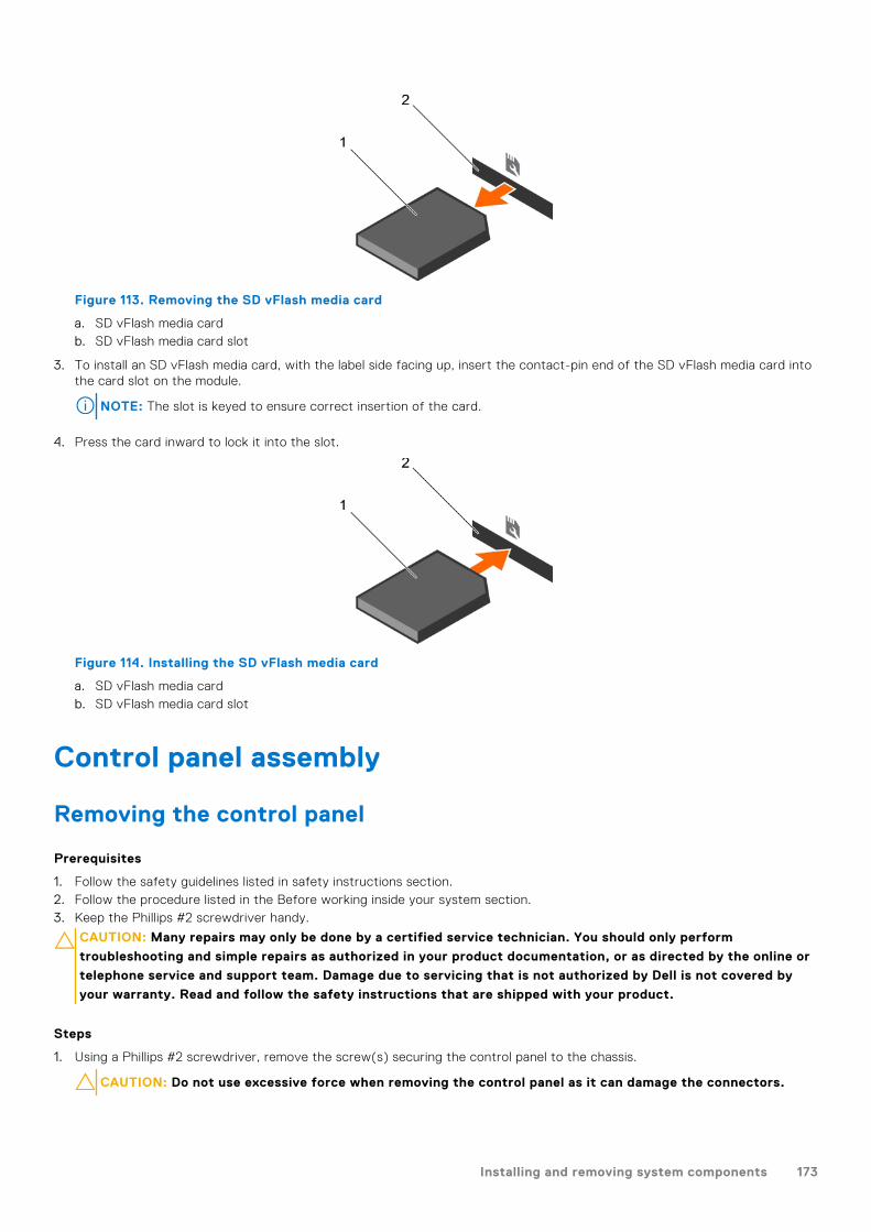
Figure 113. Removing the SD vFlash media card
a. SD vFlash media cardb. SD vFlash media card slot
3. To install an SD vFlash media card, with the label side facing up, insert the contact-pin end of the SD vFlash media card intothe card slot on the module.
NOTE: The slot is keyed to ensure correct insertion of the card.
4. Press the card inward to lock it into the slot.
Figure 114. Installing the SD vFlash media card
a. SD vFlash media cardb. SD vFlash media card slot
Control panel assembly
Removing the control panel
Prerequisites
1. Follow the safety guidelines listed in safety instructions section.2. Follow the procedure listed in the Before working inside your system section.3. Keep the Phillips #2 screwdriver handy.
CAUTION: Many repairs may only be done by a certified service technician. You should only perform
troubleshooting and simple repairs as authorized in your product documentation, or as directed by the online or
telephone service and support team. Damage due to servicing that is not authorized by Dell is not covered by
your warranty. Read and follow the safety instructions that are shipped with your product.
Steps
1. Using a Phillips #2 screwdriver, remove the screw(s) securing the control panel to the chassis.
CAUTION: Do not use excessive force when removing the control panel as it can damage the connectors.
Installing and removing system components 173

2. From inside the system, push the control panel out of the chassis.
3. Remove all the cables connecting the control panel to the chassis.
Figure 115. Removing the control panel—3.5 inch hard drive system
1. control panel 2. control panel board
3. control panel connector cable 4. USB connector cable
5. screw 6. vFlash media connector cable
174 Installing and removing system components
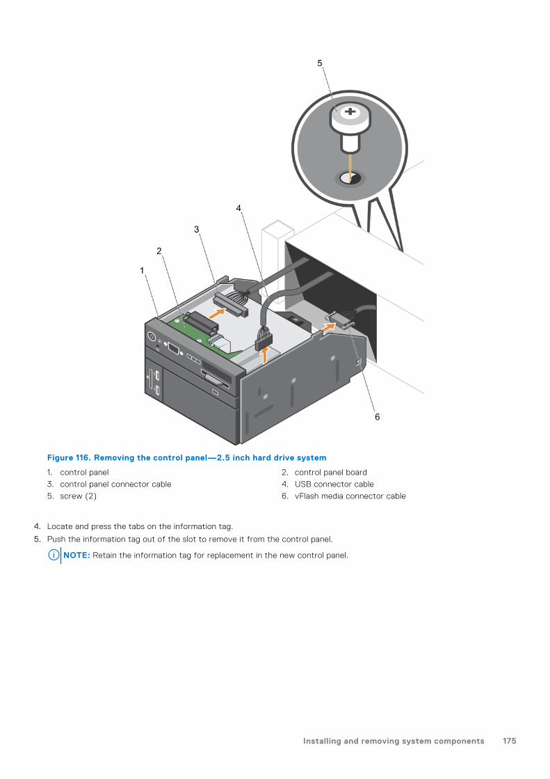
Figure 116. Removing the control panel—2.5 inch hard drive system
1. control panel 2. control panel board
3. control panel connector cable 4. USB connector cable
5. screw (2) 6. vFlash media connector cable
4. Locate and press the tabs on the information tag.
5. Push the information tag out of the slot to remove it from the control panel.
NOTE: Retain the information tag for replacement in the new control panel.
Installing and removing system components 175
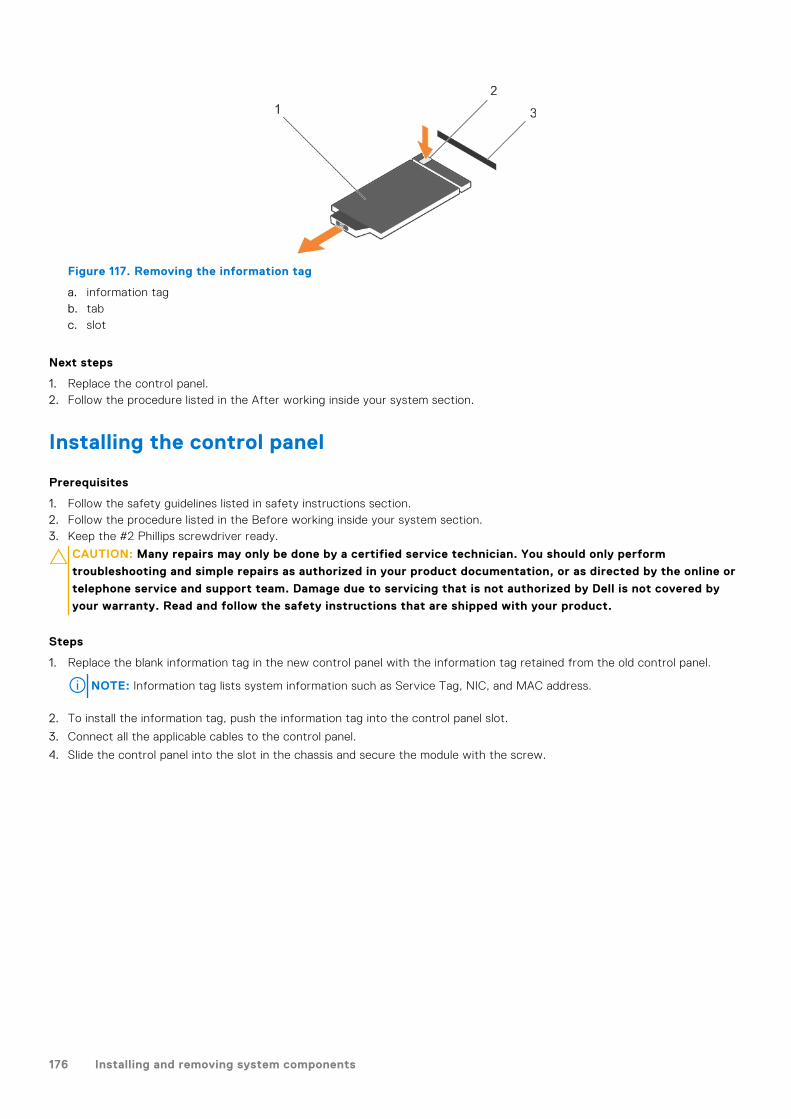
Figure 117. Removing the information tag
a. information tagb. tabc. slot
Next steps
1. Replace the control panel.2. Follow the procedure listed in the After working inside your system section.
Installing the control panel
Prerequisites
1. Follow the safety guidelines listed in safety instructions section.2. Follow the procedure listed in the Before working inside your system section.3. Keep the #2 Phillips screwdriver ready.
CAUTION: Many repairs may only be done by a certified service technician. You should only perform
troubleshooting and simple repairs as authorized in your product documentation, or as directed by the online or
telephone service and support team. Damage due to servicing that is not authorized by Dell is not covered by
your warranty. Read and follow the safety instructions that are shipped with your product.
Steps
1. Replace the blank information tag in the new control panel with the information tag retained from the old control panel.
NOTE: Information tag lists system information such as Service Tag, NIC, and MAC address.
2. To install the information tag, push the information tag into the control panel slot.
3. Connect all the applicable cables to the control panel.
4. Slide the control panel into the slot in the chassis and secure the module with the screw.
176 Installing and removing system components

Figure 118. Installing the control panel—3.5 inch hard drive system
1. control panel 2. control panel board
3. control panel connector cable 4. USB connector cable
5. screw 6. vFlash media connector cable
Installing and removing system components 177
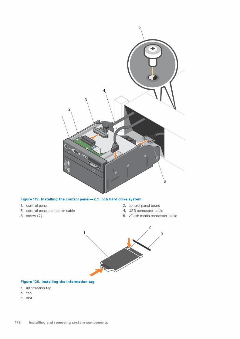
Figure 119. Installing the control panel—2.5 inch hard drive system
1. control panel 2. control panel board
3. control panel connector cable 4. USB connector cable
5. screw (2) 6. vFlash media connector cable
Figure 120. Installing the information tag
a. information tagb. tabc. slot
178 Installing and removing system components

Next steps
Follow the procedure listed in the After working inside your system section.
Installing and removing system components 179
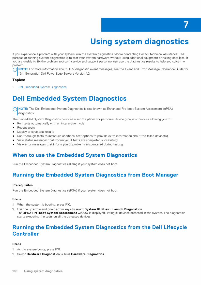
Using system diagnosticsIf you experience a problem with your system, run the system diagnostics before contacting Dell for technical assistance. Thepurpose of running system diagnostics is to test your system hardware without using additional equipment or risking data loss. Ifyou are unable to fix the problem yourself, service and support personnel can use the diagnostics results to help you solve theproblem.
NOTE: For more information about OEM diagnostic event messages, see the Event and Error Message Reference Guide for
13th Generation Dell PowerEdge Servers Version 1.2
Topics:
• Dell Embedded System Diagnostics
Dell Embedded System DiagnosticsNOTE: The Dell Embedded System Diagnostics is also known as Enhanced Pre-boot System Assessment (ePSA)
diagnostics.
The Embedded System Diagnostics provides a set of options for particular device groups or devices allowing you to:● Run tests automatically or in an interactive mode● Repeat tests● Display or save test results● Run thorough tests to introduce additional test options to provide extra information about the failed device(s)● View status messages that inform you if tests are completed successfully● View error messages that inform you of problems encountered during testing
When to use the Embedded System Diagnostics
Run the Embedded System Diagnostics (ePSA) if your system does not boot.
Running the Embedded System Diagnostics from Boot Manager
Prerequisites
Run the Embedded System Diagnostics (ePSA) if your system does not boot.
Steps
1. When the system is booting, press F10.
2. Use the up arrow and down arrow keys to select System Utilities > Launch Diagnostics.The ePSA Pre-boot System Assessment window is displayed, listing all devices detected in the system. The diagnosticsstarts executing the tests on all the detected devices.
Running the Embedded System Diagnostics from the Dell LifecycleController
Steps
1. As the system boots, press F10.
2. Select Hardware Diagnostics → Run Hardware Diagnostics.
7
180 Using system diagnostics

The ePSA Pre-boot System Assessment window is displayed, listing all devices detected in the system. The diagnosticsstarts executing the tests on all the detected devices.
System diagnostic controls
Menu Description
Configuration Displays the configuration and status information of all detected devices.
Results Displays the results of all tests that are run.
Systemhealth Provides the current overview of the system performance.
Event log Displays a time-stamped log of the results of all tests run on the system. This is displayed if at least oneevent description is recorded.
Using system diagnostics 181

Jumpers and connectors
Topics:
• System board jumper settings• System board jumpers and connectors• Disabling forgotten password
System board jumper settings
For information on resetting the password jumper to disable a password, see the Disabling a forgotten password section.
Table 44. System board jumper settings
Jumper Setting Description
PWRD_EN The password reset feature is enabled (pins 2–4). BIOS localaccess is unlocked at the next AC power cycle.
The password reset feature is disabled (pins 4–6).
NVRAM_CLR The configuration settings are retained at the next systemboot (pins 3–5).
The configuration settings are cleared at system boot (pins1–3).
Related tasks
Disabling forgotten password on page 185
8
182 Jumpers and connectors
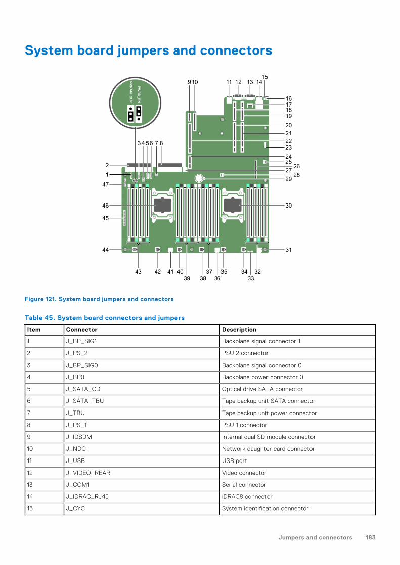
System board jumpers and connectors
Figure 121. System board jumpers and connectors
Table 45. System board connectors and jumpers
Item Connector Description
1 J_BP_SIG1 Backplane signal connector 1
2 J_PS_2 PSU 2 connector
3 J_BP_SIG0 Backplane signal connector 0
4 J_BP0 Backplane power connector 0
5 J_SATA_CD Optical drive SATA connector
6 J_SATA_TBU Tape backup unit SATA connector
7 J_TBU Tape backup unit power connector
8 J_PS_1 PSU 1 connector
9 J_IDSDM Internal dual SD module connector
10 J_NDC Network daughter card connector
11 J_USB USB port
12 J_VIDEO_REAR Video connector
13 J_COM1 Serial connector
14 J_IDRAC_RJ45 iDRAC8 connector
15 J_CYC System identification connector
Jumpers and connectors 183
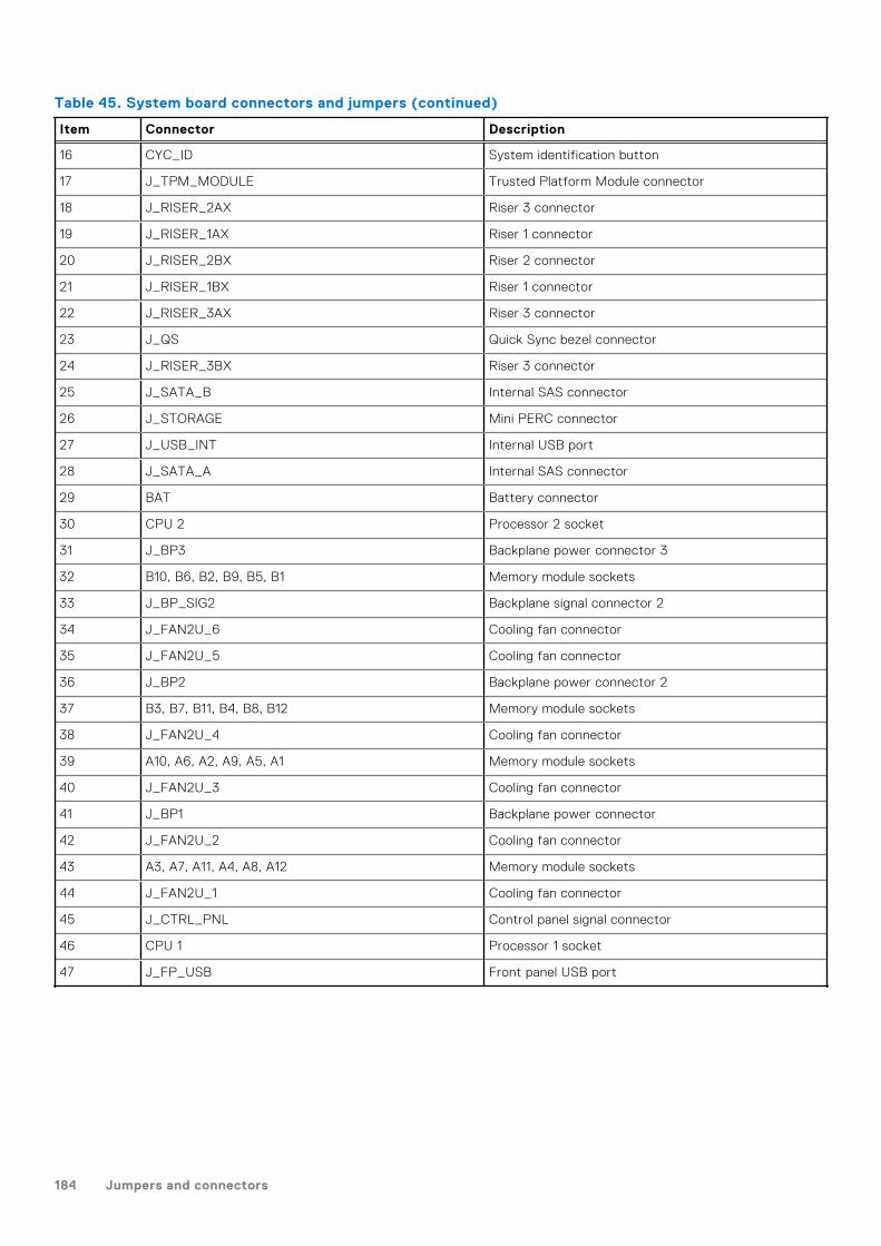
Table 45. System board connectors and jumpers (continued)
Item Connector Description
16 CYC_ID System identification button
17 J_TPM_MODULE Trusted Platform Module connector
18 J_RISER_2AX Riser 3 connector
19 J_RISER_1AX Riser 1 connector
20 J_RISER_2BX Riser 2 connector
21 J_RISER_1BX Riser 1 connector
22 J_RISER_3AX Riser 3 connector
23 J_QS Quick Sync bezel connector
24 J_RISER_3BX Riser 3 connector
25 J_SATA_B Internal SAS connector
26 J_STORAGE Mini PERC connector
27 J_USB_INT Internal USB port
28 J_SATA_A Internal SAS connector
29 BAT Battery connector
30 CPU 2 Processor 2 socket
31 J_BP3 Backplane power connector 3
32 B10, B6, B2, B9, B5, B1 Memory module sockets
33 J_BP_SIG2 Backplane signal connector 2
34 J_FAN2U_6 Cooling fan connector
35 J_FAN2U_5 Cooling fan connector
36 J_BP2 Backplane power connector 2
37 B3, B7, B11, B4, B8, B12 Memory module sockets
38 J_FAN2U_4 Cooling fan connector
39 A10, A6, A2, A9, A5, A1 Memory module sockets
40 J_FAN2U_3 Cooling fan connector
41 J_BP1 Backplane power connector
42 J_FAN2U_2 Cooling fan connector
43 A3, A7, A11, A4, A8, A12 Memory module sockets
44 J_FAN2U_1 Cooling fan connector
45 J_CTRL_PNL Control panel signal connector
46 CPU 1 Processor 1 socket
47 J_FP_USB Front panel USB port
184 Jumpers and connectors

Disabling forgotten passwordThe software security features of the system include a system password and a setup password. The password jumper enables ordisables password features and clears any password(s) currently in use.
Prerequisites
Steps
1. Turn off the system, including any attached peripherals, and disconnect the system from the electrical outlet.
2. Remove the system cover.
3. Move the jumper on the system board jumper from pins 4 and 6 to pins 2 and 4.
4. Install the system cover.
The existing passwords are not disabled (erased) until the system boots with the jumper on pins 2 and 4. However, beforeyou assign a new system and/or setup password, you must move the jumper back to pins 4 and 6.
NOTE: If you assign a new system and/or setup password with the jumper on pins 2 and 4, the system disables the new
password(s) the next time it boots.
5. Reconnect the system to its electrical outlet and turn on the system, including any attached peripherals.
6. Turn off the system, including any attached peripherals, and disconnect the system from the electrical outlet.
7. Remove the system cover.
8. Move the jumper on the system board jumper from pins 2 and 4 to pins 4 and 6.
9. Install the system cover.
10. Reconnect the system to its electrical outlet and turn on the system, including any attached peripherals.
11. Assign a new system and/or setup password.
Jumpers and connectors 185
Troubleshooting your system
Safety first — for you and your systemCAUTION: Many repairs may only be done by a certified service technician. You should only perform
troubleshooting and simple repairs as authorized in your product documentation, or as directed by the online or
telephone service and support team. Damage due to servicing that is not authorized by Dell is not covered by
your warranty. Read and follow the safety instructions that are shipped with your product.
NOTE: Solution validation was performed by using the factory shipped hardware configuration.
Topics:
• Troubleshooting system startup failure• Troubleshooting external connections• Troubleshooting the video subsystem• Troubleshooting a USB device• Troubleshooting iDRAC Direct - USB XML configuration• Troubleshooting iDRAC Direct - Laptop connection• Troubleshooting a serial input and output device• Troubleshooting a NIC• Troubleshooting a wet system• Troubleshooting a damaged system• Troubleshooting the system battery• Troubleshooting power supply units• Troubleshooting cooling problems• Troubleshooting cooling fans• Troubleshooting system memory• Troubleshooting an internal USB key• Troubleshooting a micro SD card• Troubleshooting an optical drive• Troubleshooting a tape backup unit• Troubleshooting a drive or SSD• Troubleshooting a storage controller• Troubleshooting expansion cards• Troubleshooting processors• System messages
Troubleshooting system startup failureIf you boot the system to the BIOS boot mode after installing an operating system from the UEFI Boot Manager, the systemstops responding. To avoid this issue, you must boot to the same boot mode in which you installed the operating system.
For all other startup issues, note the system messages that appear on the screen.
Troubleshooting external connectionsBefore troubleshooting any external devices, ensure that all external cables are securely attached to the external connectors onyour system.
9
186 Troubleshooting your system

● Compare the technical specification of the system with the external device to check the compatibility.● Check the external device functionality with some other similar system so that we are sure that the device is working fine.● Check any other similar external device with this system so that we are sure that the system port is working fine.
For any further queries contact, Global Technical Support.
Troubleshooting the video subsystem
Prerequisites
NOTE: Ensure that the Local Server Video Enabled option is selected in the iDRAC Graphical User Interface (GUI), under
Virtual Console. If this option is not selected, local video is disabled.
NOTE: The VGA ports are not hot-pluggable.
Steps
1. Check the cable connections (power and display) to the monitor.
2. Check the video interface cabling from the system to the monitor.
Results
If the tests run successfully, the problem is not related to video hardware.
Next steps
If the tests fail, see the Getting help section.
Related references
Getting help on page 201
Troubleshooting a USB device
Prerequisites
NOTE: Follow steps 1 to 6 to troubleshoot a USB keyboard or mouse. For other USB devices, go to step 7.
Steps
1. Disconnect the keyboard and/or mouse cables from the system and reconnect them.
2. If the problem persists, connect the keyboard and/or mouse to another USB port on the system.
3. If the problem is resolved, restart the system, enter System Setup, and check if the non-functioning USB ports are enabled.
NOTE: Older operating systems may not support USB 3.0.
4. Check if USB 3.0 is enabled in System Setup. If enabled, disable it and see if the issue is resolved.
5. In iDRAC Settings Utility, ensure that USB Management Port Mode is configured as Automatic or Standard OS Use.
6. If the problem is not resolved, replace the keyboard and/or mouse with a known working keyboard or mouse.
If the problem is not resolved, proceed to step 7 to troubleshoot other USB devices attached to the system.
If the problem is not resolved, proceed to troubleshoot other USB devices attached to the system.
7. Turn off all attached USB devices, and disconnect them from the system.
8. Restart the system.
9. If your keyboard is functioning, enter System Setup, verify that all USB ports are enabled on the Integrated Devicesscreen. If your keyboard is not functioning, use remote access to enable or disable the USB options.
10. Check if USB 3.0 is enabled in System Setup. If it is enabled, disable it and restart your system.
Troubleshooting your system 187

11. If the system is not accessible, reset the NVRAM_CLR jumper inside your system and restore the BIOS to the defaultsettings. See the System board jumper setting section
12. In the IDRAC Settings Utility, ensure that USB Management Port Mode is configured as Automatic or Standard OSUse.
13. Reconnect and turn on each USB device one at a time.
14. If a USB device causes the same problem, turn off the device, replace the USB cable with a known good cable, and turn onthe device.
Next steps
If all troubleshooting fails, see the Getting help section.
Related references
Getting help on page 201
System board jumper settings on page 182
Troubleshooting iDRAC Direct - USB XMLconfigurationFor information about USB storage device and system configuration, see Integrated Dell Remote Access Controller User's Guideat www.dell.com/poweredgemanuals
Steps
1. Ensure that your USB storage device is connected to the front USB Management Port, identified by icon.
2. Ensure that your USB storage device is configured with an NTFS or an FAT32 file system with only one partition.
3. Verify that the USB storage device is configured correctly. For more information about configuring the USB storage device,see Integrated Dell Remote Access Controller User's Guide at www.dell.com/poweredgemanuals
4. In the iDRAC Settings Utility, ensure that USB Management Port Mode is configured as Automatic or iDRAC DirectOnly.
5. Ensure that the iDRAC Managed: USB XML Configuration option is either Enabled or Enabled only when the serverhas default credential settings.
6. Remove and reinsert the USB storage device.
7. If import operation does not work, try with a different USB storage device.
Next steps
If all troubleshooting fails, see the Getting help section.
Related references
Getting help on page 201
Troubleshooting iDRAC Direct - Laptop connectionFor information about USB laptop connection and system configuration, see the Integrated Dell Remote Access ControllerUser's Guide at www.dell.com/poweredgemanuals.
Steps
1. Ensure that your laptop is connected to the front USB Management Port, identified by icon with a USB Type A/Acable.
2. On the iDRAC Settings Utility screen, ensure that USB Management Port Mode is configured as Automatic or iDRACDirect Only.
3. If the laptop is running Windows operating system, ensure that the iDRAC Virtual USB NIC device driver is installed.
188 Troubleshooting your system
4. If the driver is installed, ensure that you are not connected to any network through WiFi or cabled ethernet, as iDRAC Directuses a non-routable address.
Next steps
If all troubleshooting fails, see the Getting help section.
Related references
Getting help on page 201
Troubleshooting a serial input and output device
Prerequisites
Steps
1. Turn off the system and any peripheral devices connected to the serial port.
2. Swap the serial interface cable with a known working cable, and turn on the system and the I/O serial device.
If the problem is resolved, replace the interface cable with a known working cable.
3. Turn off the system and the I/O serial device, and swap the serial device with a compatible device.
4. Turn on the system and the I/O serial device.
Next steps
If the problem persists, see the Getting help section.
Related references
Getting help on page 201
Troubleshooting a NIC
Prerequisites
NOTE: Network Daughter Card (NDC) slot is not hot-pluggable.
Steps
1. Run the appropriate diagnostic test. For more information, see the Using system diagnostics section for the availablediagnostic tests.
2. Restart the system and check for any system messages pertaining to the NIC controller.
3. Check the appropriate indicator on the NIC connector:
● If the link indicator does not glow, the cable connected might be disengaged.● If the activity indicator does not glow, the network driver files might be damaged or missing. Install or replace the drivers
as necessary. For more information, see the NIC documentation.● Try another known good network cable.● If the problem persists, use another connector on the switch or hub.
4. Ensure that the appropriate drivers are installed and the protocols are bound. For more information, see the NICdocumentation.
5. Enter System Setup and confirm that the NIC ports are enabled on the Integrated Devices screen.
6. Ensure that all the NICs, hubs, and switches on the network are set to the same data transmission speed and duplex. Formore information, see the documentation for each network device.
7. Ensure that all the NICs and switches on the network are set to the same data transmission speed and duplex. For moreinformation, see the documentation for each network device.
8. Ensure that all network cables are of the proper type and do not exceed the maximum length.
Troubleshooting your system 189

Next steps
If the problem persists, see the Getting help section.
Related references
Getting help on page 201
Using system diagnostics on page 180
Troubleshooting a wet system
Prerequisites
CAUTION: Many repairs may only be done by a certified service technician. You should only perform
troubleshooting and simple repairs as authorized in your product documentation, or as directed by the online or
telephone service and support team. Damage due to servicing that is not authorized by Dell is not covered by
your warranty. Read and follow the safety instructions that are shipped with your product.
Steps
1. Turn off the system and attached peripherals, and disconnect the system from the electrical outlet.
2. Remove the system cover.
3. Remove the following components (if installed) from the system:
● Power supply unit(s)● Optical drive● Hard drives● Hard drive backplane● USB memory key● Hard drive tray● Cooling shroud● Expansion card risers (if installed)● Expansion cards● Cooling fan assembly (if installed)● Cooling fan(s)● Memory modules● Processor(s) and heat sink(s)● System board
4. Let the system dry thoroughly for at least 24 hours.
5. Reinstall the components you removed in step 3 except the expansion cards.
6. Install the system cover.
7. Turn on the system and attached peripherals.
If the problem persists, see the Getting help section.
8. If the system starts properly, turn off the system, and reinstall all the expansion cards that you removed.
9. Run the appropriate diagnostic test. For more information, see the Using system diagnostics section.
Next steps
If the tests fail, see the Getting help section.
Related references
Getting help on page 201
Using system diagnostics on page 180
190 Troubleshooting your system

Troubleshooting a damaged system
Prerequisites
CAUTION: Many repairs may only be done by a certified service technician. You should only perform
troubleshooting and simple repairs as authorized in your product documentation, or as directed by the online or
telephone service and support team. Damage due to servicing that is not authorized by Dell is not covered by
your warranty. Read and follow the safety instructions that are shipped with your product.
Steps
1. Turn off the system and attached peripherals, and disconnect the system from the electrical outlet.
2. Remove the system cover.
3. Ensure that the following components are properly installed:
● cooling shroud● expansion card risers (if installed)● expansion cards● power supply unit(s)● cooling fan assembly (if installed)● cooling fan(s)● processor(s) and heat sink(s)● memory modules● drive carriers or cage● drive backplane
4. Ensure that all cables are properly connected.
5. Install the system cover.
6. Run the appropriate diagnostic test. For more information, see the Using system diagnostics section.
Next steps
If the problem persists, see the Getting help section.
Related references
Getting help on page 201
Using system diagnostics on page 180
Troubleshooting the system battery
Prerequisites
CAUTION: Many repairs may only be done by a certified service technician. You should only perform
troubleshooting and simple repairs as authorized in your product documentation, or as directed by the online or
telephone service and support team. Damage due to servicing that is not authorized by Dell is not covered by
your warranty. Read and follow the safety instructions that are shipped with your product.
NOTE: If the system is turned off for long periods of time (for weeks or months), the NVRAM may lose the system
configuration information. This situation is caused by a defective battery.
NOTE: Some software may cause the system time to speed up or slow down. If the system seems to operate normally
except for the time set in System Setup, the problem may be caused by a software, rather than by a defective battery.
Steps
1. Re-enter the time and date in System Setup.
2. Turn off the system, and disconnect it from the electrical outlet for at least an hour.
3. Reconnect the system to the electrical outlet, and turn on the system.
Troubleshooting your system 191

4. Enter System Setup.
If the date and time displayed in System Setup are not correct, check the System Error Log (SEL) for system batterymessages.
Next steps
If the problem persists, see the Getting help section.
Related references
Getting help on page 201
Troubleshooting power supply units
Prerequisites
CAUTION: Many repairs may only be done by a certified service technician. You should only perform
troubleshooting and simple repairs as authorized in your product documentation, or as directed by the online or
telephone service and support team. Damage due to servicing that is not authorized by Dell is not covered by
your warranty. Read and follow the safety instructions that are shipped with your product.
The following sections provide information on troubleshooting power source and power supply units problems.
NOTE: Power Supply Units (PSUs) are hot-pluggable.
Troubleshooting power source problems
Steps
1. Press the power button to ensure that your system is turned on. If the power indicator does not glow when the powerbutton is pressed, press the power button firmly.
2. Plug in another working power supply unit to ensure that the system board is not faulty.
3. Ensure that no loose connections exist.
For example, loose power cables.
4. Ensure that the power source meets applicable standards.
5. Ensure that there are no short circuits.
6. Have a qualified electrician check the line voltage to ensure that it meets the needed specifications.
Results
NOTE: Some power supply units require 200-240V AC to deliver their rated capacity. For more information, see the system
Technical Specifications section in the Installation and Service Manual available at www.dell.com/poweredgemanuals.
Troubleshooting power supply unit problems
Steps
1. Ensure that no loose connections exist.
For example, loose power cables.
2. Ensure that the power supply handle LED indicates that the power supply is working properly.
3. If you have recently upgraded your system, ensure that the power supply unit has enough power to support the new system.
4. If you have a redundant power supply configuration, ensure that both the power supply units are of the same type andwattage.
If the LED You may have to upgrade to a higher wattage power supply unit.
5. Ensure that you use only power supply units with the Extended Power Performance (EPP) label on the back.
192 Troubleshooting your system

6. Reseat the power supply unit.
NOTE: After installing a power supply unit, allow several seconds for the system to recognize the power supply unit and
determine if it is working properly.
If the problem persists, see the Getting help section.
Related references
Getting help on page 201
Troubleshooting cooling problemsCAUTION: Many repairs may only be done by a certified service technician. You should only perform
troubleshooting and simple repairs as authorized in your product documentation, or as directed by the online or
telephone service and support team. Damage due to servicing that is not authorized by Dell is not covered by
your warranty. Read and follow the safety instructions that are shipped with your product.
Ensure that the following conditions exist:
● System cover, cooling shroud, EMI filler panel, or back filler bracket is not removed.● Ambient temperature is not higher than the system specific ambient temperature.● External airflow is not obstructed.● A cooling fan is not removed or has not failed.● The expansion card installation guidelines have been followed.
Additional cooling can be added by one of the following methods:
From the iDRAC web GUI:
1. Click Hardware > Fans > Setup.2. From the Fan Speed Offset drop-down list, select the cooling level that is required or set the minimum fan speed to a
custom value.
From F2 System Setup:
1. Select iDRAC Settings > Thermal, and set a higher fan speed from the fan speed offset or minimum fan speed.
From RACADM commands:
1. Run the command racadm help system.thermalsettingsFor more information, see Integrated Dell Remote Access User’s Guide at www.dell.com/poweredgemanuals
Troubleshooting cooling fans
Prerequisites
CAUTION: Many repairs may only be done by a certified service technician. You should only perform
troubleshooting and simple repairs as authorized in your product documentation, or as directed by the online or
telephone service and support team. Damage due to servicing that is not authorized by Dell is not covered by
your warranty. Read and follow the safety instructions that are shipped with your product.
NOTE: The fan number is referenced by the management software of the system. In the event of a problem with a
particular fan, you can easily identify and replace it by noting down the fan numbers on the cooling fan assembly.
1. Follow the safety guidelines listed in the Safety instructions section.2. Follow the procedure listed in the Before working inside your system section.
Steps
1. Reseat the fan or the fan's power cable.
2. Restart the system.
Troubleshooting your system 193

Next steps
1. Follow the procedure listed in the After working inside your system section.2. If the problem persists, see the Getting help section.
Related references
Getting help on page 201
Safety instructions on page 66
Related tasks
Before working inside your system on page 67
Troubleshooting system memory
Prerequisites
CAUTION: Many repairs may only be done by a certified service technician. You should only perform
troubleshooting and simple repairs as authorized in your product documentation, or as directed by the online or
telephone service and support team. Damage due to servicing that is not authorized by Dell is not covered by
your warranty. Read and follow the safety instructions that are shipped with your product.
NOTE: Memory slots are not hot-pluggable.
NOTE: NVDIMM-N battery is not hot-pluggable.
Steps
1. If the system is operational, run the appropriate diagnostic test. See the Using system diagnostics section for the availablediagnostic tests.
If the diagnostic tests indicate a fault, follow the corrective actions that are provided by the diagnostic tests.
2. If the system is not operational, turn off the system and attached peripherals, and unplug the system from the power source.Wait at least for 10 seconds, and then reconnect the system to the power source.
3. Turn on the system and attached peripherals, and note the messages on the screen.
If an error message is displayed indicating a fault with a specific memory module, go to step 12.
4. Enter System Setup, and check the system memory setting. Make any changes to the memory settings, if needed.
If the memory settings match the installed memory but the problem still persists, go to step 12.
5. Turn off the system and attached peripherals, and disconnect the system from the electrical outlet.
6. Remove the system cover.
7. Check the memory channels and ensure that they are populated correctly.
NOTE: See the system event log or system messages for the location of the failed memory module. Reinstall the
memory device.
8. Reseat the memory modules in their sockets.
9. Install the system cover.
10. Enter System Setup, and check the system memory setting.
If the problem is not resolved, proceed with step 11.
11. Remove the system cover.
12. If a diagnostic test or error message indicates a specific memory module as faulty, swap or replace the module with a knownworking memory module.
13. To troubleshoot an unspecified faulty memory module, replace the memory module in the first DIMM socket with a module ofthe same type and capacity.
If an error message is displayed on the screen, this may indicate a problem with one or more installed DIMM types, incorrectDIMM installation, or defective DIMMs. Follow the on-screen instructions to resolve the problem.
194 Troubleshooting your system

14. Install the system cover.
15. As the system boots, observe any error message that is displayed and the diagnostic indicators on the front of the system.
16. If the memory problem persists, repeat step 12 through step 15 for each memory module installed.
Next steps
If the problem persists, see the Getting help section.
Related references
Getting help on page 201
Using system diagnostics on page 180
Troubleshooting an internal USB key
Prerequisites
CAUTION: Many repairs may only be done by a certified service technician. You should only perform
troubleshooting and simple repairs as authorized in your product documentation, or as directed by the online or
telephone service and support team. Damage due to servicing that is not authorized by Dell is not covered by
your warranty. Read and follow the safety instructions that are shipped with your product.
Steps
1. Enter System Setup and ensure that the USB key port is enabled on the Integrated Devices screen.
2. Turn off the system and attached peripherals, and disconnect the system from the electrical outlet.
3. Remove the system cover.
4. Locate the USB key and reseat it.
5. Install the system cover.
6. Turn on the system and attached peripherals, and check if the USB key is functioning.
7. If the problem is not resolved, repeat step 2 and step 3.
8. Insert a known working USB key.
9. Install the system cover.
Next steps
If the problem persists, see the Getting help section.
Related references
Getting help on page 201
Troubleshooting a micro SD card
Prerequisites
NOTE: Certain micro SD cards have a physical write-protect power on the card. If the write-protect switch is turned on,
the micro SD card is not writable.
NOTE: IDSDM and vFlash slots are not hot-pluggable.
Steps
1. Enter System Setup, and ensure that the Internal SD Card Port is enabled.
2. Turn off the system, including any attached peripherals, and disconnect the system from the electrical outlet.
3. Remove the system cover.
Troubleshooting your system 195

NOTE: When an SD card failure occurs, the internal dual SD module controller notifies the system. On the next restart,
the system displayed a message indicating the failure. If redundancy is enabled at the time of SD card failure, a critical
alert is logged and chassis health will degrade.
4. Replace the failed micro SD card with a new micro SD card.
5. Install the system cover.
6. Reconnect the system to its electrical outlet and turn on the system, including any attached peripherals.
7. Enter System Setup, and ensure that the Internal SD Card Port and Internal SD Card Redundancy modes are set to theneeded modes.
Verify that the correct SD slot is set as Primary SD Card.
8. Check if the micro SD card is functioning properly.
9. If the Internal SD Card Redundancy option is set to Enabled at the time of the SD card failure, the system prompts youto perform a rebuild.
NOTE: The rebuild is always sourced from the primary SD card to the secondary SD card.
Troubleshooting an optical drive
Prerequisites
CAUTION: Many repairs may only be done by a certified service technician. You should only perform
troubleshooting and simple repairs as authorized in your product documentation, or as directed by the online or
telephone service and support team. Damage due to servicing that is not authorized by Dell is not covered by
your warranty. Read and follow the safety instructions that are shipped with your product.
Steps
1. Try using a different CD or DVD.
2. If the problem is not resolved, enter System Setup and ensure that the integrated SATA controller and the drive's SATA portare enabled.
3. Run the appropriate diagnostic test.
4. Turn off the system and attached peripherals, and disconnect the system from the electrical outlet.
5. If installed, remove the bezel.
6. Remove the system cover.
7. Ensure that the interface cable is securely connected to the optical drive and to the controller.
8. Ensure that a power cable is properly connected to the drive.
9. Install the system cover.
Next steps
If the problem persists, see the Getting help section.
Related references
Getting help on page 201
Troubleshooting a tape backup unit
Prerequisites
CAUTION: Many repairs may only be done by a certified service technician. You should only perform
troubleshooting and simple repairs as authorized in your product documentation, or as directed by the online or
telephone service and support team. Damage due to servicing that is not authorized by Dell is not covered by
your warranty. Read and follow the safety instructions that are shipped with your product.
196 Troubleshooting your system
Steps
1. Use a different tape cartridge.
2. Ensure that the device drivers for the tape backup unit are installed and are configured correctly. See your tape drivedocumentation for more information about device drivers.
3. Reinstall the tape-backup software as instructed in the tape-backup software documentation.
4. Ensure that the interface cable of the tape drive is connected to the external port on the controller card.
5. Perform the following steps to ensure that the controller card is properly installed:
a. Turn off the system and attached peripherals, and disconnect the system from the electrical outlet.b. Remove the system cover.c. Reseat the controller card in the expansion card slot.d. Install the system cover.e. Turn on the system and attached peripherals.
6. Run the appropriate diagnostic test. For more information, see the Using system diagnostics.
Next steps
If you cannot resolve the problem, see the Getting help section.
Related references
Getting help on page 201
Troubleshooting a drive or SSD
Prerequisites
CAUTION: This troubleshooting procedure can erase data stored on the drive. Before you proceed, back up all
files on the drive.
CAUTION: Many repairs may only be done by a certified service technician. You should only perform
troubleshooting and simple repairs as authorized in your product documentation, or as directed by the online or
telephone service and support team. Damage due to servicing that is not authorized by Dell is not covered by
your warranty. Read and follow the safety instructions that are shipped with your product.
Steps
1. Run the appropriate diagnostic test. See the Using system diagnostics section.
Depending on the results of the diagnostics test, proceed as required through the following steps.
2. If your system has a RAID controller and your drives are configured in a RAID array, perform the following steps:
a. Restart the system and press F10 during system startup to run the Dell Lifecycle Controller, and then run the HardwareConfiguration wizard to check the RAID configuration.
See the Dell Lifecycle Controller documentation or online help for information about RAID configuration.
b. Ensure that the drives are configured correctly for the RAID array.c. Take the drive offline and reseat the drive.d. Exit the configuration utility and allow the system to boot to the operating system.
3. Ensure that the needed device drivers for your controller card are installed and are configured correctly. For moreinformation, see the operating system documentation.
4. Restart the system and enter the System Setup.
5. Verify that the controller is enabled and the drives are displayed in the System Setup.
Next steps
If the problem persists, see the Getting help section.
Related references
Getting help on page 201
Troubleshooting your system 197
Using system diagnostics on page 180
Troubleshooting a storage controllerCAUTION: Many repairs may only be done by a certified service technician. You should only perform
troubleshooting and simple repairs as authorized in your product documentation, or as directed by the online or
telephone service and support team. Damage due to servicing that is not authorized by Dell is not covered by
your warranty. Read and follow the safety instructions that are shipped with your product.
NOTE: When troubleshooting a controller, see the documentation for your operating system and the controller.
NOTE: Mini-PERC socket is not hot-pluggable.
1. Run the appropriate diagnostic test. See the Using system diagnostics section.2. Turn off the system and attached peripherals, and disconnect the system from the electrical outlet.3. Remove the system cover.4. Verify that the installed expansion cards are compliant with the expansion card installation guidelines.5. Ensure that each expansion card is firmly seated in its connector.6. Install the system cover.7. Reconnect the system to the electrical outlet, and turn on the system and attached peripherals.8. If the problem is not resolved, turn off the system and attached peripherals, and disconnect the system from the electrical
outlet.9. Remove the system cover.10. Remove all expansion cards installed in the system.11. Install the system cover.12. Reconnect the system to the electrical outlet, and turn on the system and attached peripherals.13. Run the appropriate diagnostic test. See the Using system diagnostics section.
If the tests fail, see the Getting help section.
14. For each expansion card you removed in step 10, perform the following steps:a. Turn off the system and attached peripherals, and disconnect the system from the electrical outlet.b. Remove the system cover.c. Reinstall one of the expansion cards.d. Install the system cover.e. Run the appropriate diagnostic test. See the Using system diagnostics section.
If the problem persists, see the Getting help section.
Related references
Getting help on page 201
Using system diagnostics on page 180
Safety instructions on page 66
Related tasks
Removing the system cover on page 71
Removing an expansion card from expansion card riser 2 or 3 on page 106
Installing an expansion card into the expansion card riser 2 or 3 on page 108
Installing the system cover on page 72
Troubleshooting expansion cards
Prerequisites
CAUTION: Many repairs may only be done by a certified service technician. You should only perform
troubleshooting and simple repairs as authorized in your product documentation, or as directed by the online or
198 Troubleshooting your system
telephone service and support team. Damage due to servicing that is not authorized by Dell is not covered by
your warranty. Read and follow the safety instructions that are shipped with your product.
NOTE: When troubleshooting an expansion card, you also have to see the documentation for your operating system and the
expansion card.
NOTE: Riser slots are not hot-pluggable.
Steps
1. Run the appropriate diagnostic test. See the Using system diagnostics section.
2. Turn off the system and attached peripherals, and disconnect the system from the electrical outlet.
3. Remove the system cover.
4. Ensure that each expansion card is firmly seated in its connector.
5. Install the system cover.
6. Turn on the system and attached peripherals.
7. If the problem is not resolved, turn off the system and attached peripherals, and disconnect the system from the electricaloutlet.
8. Remove the system cover.
9. Remove all expansion cards installed in the system.
10. Install the system cover.
11. Run the appropriate diagnostic test. See the Using system diagnostics section.
If the tests fail, see the Getting help section.
12. For each expansion card you removed in step 8, perform the following steps:
a. Turn off the system and attached peripherals, and disconnect the system from the electrical outlet.b. Remove the system cover.c. Reinstall one of the expansion cards.d. Install the system cover.e. Run the appropriate diagnostic test. See the Using system diagnostics section.
Next steps
If the problem persists, see the Getting help section.
Related references
Getting help on page 201
Using system diagnostics on page 180
Safety instructions on page 66
Related tasks
Removing the system cover on page 71
Removing an expansion card from expansion card riser 2 or 3 on page 106
Installing an expansion card into the expansion card riser 2 or 3 on page 108
Installing the system cover on page 72
Troubleshooting processors
Prerequisites
CAUTION: Many repairs may only be done by a certified service technician. You should only perform
troubleshooting and simple repairs as authorized in your product documentation, or as directed by the online or
telephone service and support team. Damage due to servicing that is not authorized by Dell is not covered by
your warranty. Read and follow the safety instructions that are shipped with your product.
Troubleshooting your system 199

NOTE: Processor sockets are not hot-pluggable.
Steps
1. Run the appropriate diagnostics test. See the Using system diagnostics section.
2. Turn off the system and attached peripherals, and disconnect the system from the electrical outlet.
3. Remove the system cover.
4. Ensure that the processor and heat sink are properly installed.
5. Install the system cover.
6. Run the appropriate diagnostic test. See the Using system diagnostics section.
7. If the problem persists, see the Getting help section.
Related references
Getting help on page 201
Using system diagnostics on page 180
Related tasks
Removing the system cover on page 71
Installing the system cover on page 72
System messagesFor information about the event and error messages generated by the system firmware and agents that monitor systemcomponents, go to qrl.dell.com > Look Up > Error Code, type the error code, and then click Look it up.
Warning messages
A warning message alerts you to a possible problem and prompts you to respond before the system continues a task. Forexample, before you format a hard drive, a message warns you that you may lose all data on the hard drive. Warning messagesusually interrupt the task and need you to respond by typing y (yes) or n (no).
NOTE: Warning messages are generated by either the application or the operating system. For more information, see the
documentation that shipped with the operating system or application.
Diagnostic messages
The system diagnostic utility generates messages if there are errors detected when you run diagnostic tests on your system.For more information about system diagnostics, see the For information about the event and error messages generated by thesystem firmware and agents that monitor system components, go to qrl.dell.com > Look Up > Error Code, type the error code,and then click Look it up..
Alert messages
The systems management software generates alert messages for your system. Alert messages include information, status,warning, and failure messages for drive, temperature, fan, and power conditions. For more information, see the systemsmanagement software documentation links listed in the Documentation resources section of this manual.
200 Troubleshooting your system

Getting help
Topics:
• Contacting Dell EMC• Documentation feedback• Accessing system information by using QRL
Contacting Dell EMCDell EMC provides several online and telephone based support and service options. If you do not have an active internetconnection, you can find contact information about your purchase invoice, packing slip, bill, or Dell EMC product catalog.Availability varies by country and product, and some services may not be available in your area. To contact Dell EMC for sales,technical assistance, or customer service issues:
Steps
1. Go to www.dell.com/support/home.
2. Select your country from the drop-down menu on the lower right corner of the page.
3. For customized support:
a. Enter your system Service Tag in the Enter your Service Tag field.b. Click Submit.
The support page that lists the various support categories is displayed.
4. For general support:
a. Select your product category.b. Select your product segment.c. Select your product.
The support page that lists the various support categories is displayed.
5. For contact details of Dell EMC Global Technical Support:
a. Click Global Technical Support.b. Enter your system Service Tag in the Enter your Service Tag field on the Contact Us webpage.
Documentation feedbackYou can rate the documentation or write your feedback on any of our Dell EMC documentation pages and click Send Feedbackto send your feedback.
Accessing system information by using QRLYou can use the Quick Resource Locator (QRL) located on the information tag in the front of the system, to access theinformation about the PowerEdge system.
Prerequisites
Ensure that your smartphone or tablet has the QR code scanner installed.
The QRL includes the following information about your system:
● How-to videos● Reference materials, including the Installtion and Service Manual, LCD diagnostics, and mechanical overview● Your system service tag to quickly access your specific hardware configuration and warranty information
10
Getting help 201
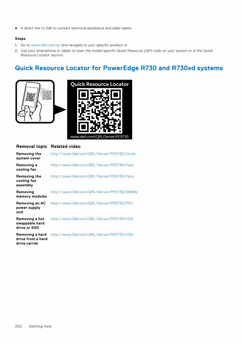
● A direct link to Dell to contact technical assistance and sales teams
Steps
1. Go to www.dell.com/qrl and navigate to your specific product or
2. Use your smartphone or tablet to scan the model-specific Quick Resource (QR) code on your system or in the QuickResource Locator section.
Quick Resource Locator for PowerEdge R730 and R730xd systems
Removal topic Related video
Removing thesystem cover
http://www.Dell.com/QRL/Server/PER730/Cover
Removing acooling fan
http://www.Dell.com/QRL/Server/PER730/Fans
Removing thecooling fanassembly
http://www.Dell.com/QRL/Server/PER730/Fans
Removingmemory modules
http://www.Dell.com/QRL/Server/PER730/DIMMs
Removing an ACpower supplyunit
http://www.Dell.com/QRL/Server/PER730/PSU
Removing a hotswappable harddrive or SSD
http://www.Dell.com/QRL/Server/PER730/HDD
Removing a harddrive from a harddrive carrier
http://www.Dell.com/QRL/Server/PER730/HDD
202 Getting help