CA08104001E For more information, visit:
www.eaton.com/consultants
August 2012
Contents
Solar (PV) Systems Interconnect 39.0-1
Sheet
39
22
23
24
25
26
27
28
29
30
31
32
33
34
35
36
37
38
39
40
41
42
43
001
So
lar
(PV
) S
yste
ms
Inte
rco
nn
ect
Solar (PV) Systems Interconnect
Grid-Tied Solar Inverters
Power Xpert Solar 250 kW Grid-Tied Inverter
General Description . . . . . . . . . . . . . . . . . . . . . . . . . . . . . . . . . . . . . . . .
39.1-1
Features and Benefits . . . . . . . . . . . . . . . . . . . . . . . . . . . . . . . . . . . . . . .
39.1-1
Standards and Certifications . . . . . . . . . . . . . . . . . . . . . . . . . . . . . . . . .
39.1-2
Product Selection . . . . . . . . . . . . . . . . . . . . . . . . . . . . . . . . . . . . . . . . . .
39.1-3
Technical Data and Specifications . . . . . . . . . . . . . . . . . . . . . . . . . . . . .
39.1-3
Dimensions . . . . . . . . . . . . . . . . . . . . . . . . . . . . . . . . . . . . . . . . . . . . . . .
39.1-6
3.8–7 kW Grid-Tied Solar Inverter
Features and Benefits . . . . . . . . . . . . . . . . . . . . . . . . . . . . . . . . . . . . . . .
39.1-7
Standards and Certifications . . . . . . . . . . . . . . . . . . . . . . . . . . . . . . . . .
39.1-7
Technical Data and Specifications . . . . . . . . . . . . . . . . . . . . . . . . . . . . .
39.1-8
Dimensions . . . . . . . . . . . . . . . . . . . . . . . . . . . . . . . . . . . . . . . . . . . . . . .
39.1-10
Solar DC Disconnect
General Description . . . . . . . . . . . . . . . . . . . . . . . . . . . . . . . . . . . . . . . . . . .
39.2-1
Features. . . . . . . . . . . . . . . . . . . . . . . . . . . . . . . . . . . . . . . . . . . . . . . . . . . . .
39.2-1
Standards and Certifications . . . . . . . . . . . . . . . . . . . . . . . . . . . . . . . . . . . .
39.2-2
Product Selection . . . . . . . . . . . . . . . . . . . . . . . . . . . . . . . . . . . . . . . . . . . . .
39.2-3
Photovoltaic String Disconnect Switch Application . . . . . . . . . . . . . . . . .
39.2-4
Dimensions . . . . . . . . . . . . . . . . . . . . . . . . . . . . . . . . . . . . . . . . . . . . . . . . . .
39.2-7
Combiner Boxes
General Description . . . . . . . . . . . . . . . . . . . . . . . . . . . . . . . . . . . . . . . . . . .
39.3-1
Features. . . . . . . . . . . . . . . . . . . . . . . . . . . . . . . . . . . . . . . . . . . . . . . . . . . . .
39.3-1
Standards and Certifications . . . . . . . . . . . . . . . . . . . . . . . . . . . . . . . . . . . .
39.3-1
Product Selection . . . . . . . . . . . . . . . . . . . . . . . . . . . . . . . . . . . . . . . . . . . . .
39.3-2
Dimensions . . . . . . . . . . . . . . . . . . . . . . . . . . . . . . . . . . . . . . . . . . . . . . . . . .
39.3-2
DC Ratings of Molded-Case Circuit Breakers
. . . . . . . . . . . . . . . .
See
Section 27.3
Reverse-Feed Circuit Breakers in Solar Applications
. . . . . . . . . .
See
Section 27.3
Specifications
See Eaton’s
Product Specification Guide
, available on CD or on the Web.CSI Format: . . . . . . . . . . . . . . . . . . . . . . . . 1995 2010
Solar DC Disconnect . . . . . . . . . . . . . .
Section 16441A Section 26 28 16.16
S-Max 250 kW Solar Grid-Tied Inverter

39.0-2
For more information, visit:
www.eaton.com/consultants
CA08104001E
August 2012
Solar (PV) Systems Interconnect
Sheet
39
22
23
24
25
26
27
28
29
30
31
32
33
34
35
36
37
38
39
40
41
42
43
002
This page intentionally left blank.

CA08104001E For more information, visit:
www.eaton.com/consultants
39.1-1
August 2012
Solar (PV) Systems Interconnect
Sheet
39
22
23
24
25
26
27
28
29
30
31
32
33
34
35
36
37
38
39
40
41
42
43
Grid-Tied Solar Inverters
General Description
003
Power Xpert Solar 250 kW Inverter
Power Xpert Solar 250 kW Inverter
Power Xpert Solar 250 kW Inverter Open
General Description
The Power Xpert Solar™ 250 kW inverters are designed for commercial and utility-scale photo-voltaic (PV) systems. Engineered for ease-of-installation, operation and maintenance, the Power Xpert Solar inverters contain the intelligence to automate the com-missioning, operation and shutdown procedures with minimal physical action. These robust, utility-interactive, three-phase inverters are based on
Eaton’s mature motor-drive assembly featuring Eaton’s Active Front End
©
(AFE) control technology.
The Power Xpert Solar 250 kW inverter is designed specifically for 480 Vac three-phase utility (grid) applications and 600 Vdc (open circuit) PV systems. It is an excellent choice for either indoor or outdoor installations from a company known for its state-of-the-art electrical products and industry support.
Features and Benefits
Table 39.1-1. Power Xpert Solar 250 kW Inverter Features and Customer Benefits
Feature Customer Benefit
Dual-Stage 250 kW inverter with hysteresis
■
2 x 125 kW design
■
Provides optimum efficiency in lower irradiance conditions, solar mornings and evenings
■
Offers less stressful power-stage operation for improved inverter longevity
■
Seamless dual-inverter operation
Grid-sensor based vector control
■
Precise synchronism and fast response to grid dynamics, ensuring a stable operation and an improved solar energy harvesting
Advanced proportional-integral-derivative (PID) control
■
Control loop feedback mechanism/algorithm
■
Precise synchronization to the grid
■
Finer current and power limits
■
Improved temperature limits
■
Better reactive power or power factor control
DC excitation algorithm and system control
■
Smart PV energy utilization over wasteful utility-based methods of energizing the transformer
■
Faster morning “wake-up” and power export
■
Faster mid-day re-connect improves energy harvesting during utility anomalies and outages
■
Minimal-stress “zero-crossing” grid connection process
■
Less part-count for improved solar-system reliability
■
Smart-control algorithm ensures lower stress on isolation transformer over adverse environmental conditions
■
Seamless grid connection and utility interface
Large DC bus capacitors
■
Extremely low ripple-current on the PV array makes for a better, trouble-free solar-module operation
■
Reduced stress on solar modules and wiring
Inverter re-combiner box with DC circuit breaker option available
■
Optional inverter re-combiner box with DC breakers to meet NEC 2011 requirements for safe DC disconnect, eliminating the need for external DC disconnects
■
DC breaker option eliminates the need to replace DC fuses, allowing cost and time savings (lowering O&M costs)
■
Current sensing of each DC input is available for array zone monitoring; DC input current is reported to inverter controller, which makes it available via Modbus
■
DC breakers can be individually turned off, allowing isolation of a defective sub-array while allowing other sub-arrays to operate. This feature enhances de-bugging procedures and maximizes fault-tolerance
■
DC breakers are available on different configurations and ampacity (90A DC, 100A DC, 125A DC, 150A DC, 175A DC, 200A DC and 225A DC)
AC overcurrent protectionand safety
■
Inverter is equipped with a 200 kAIC AC breaker that is operable from the outside of the unit via lockout/tagout–capable handle
■
No need for AC fuse replacements, minimizing O&M costs
■
Inverter doors are fitted with mechanical interlocks that will safely shut down the inverter if doors are opened
Maximum power point
■
Fast (mSec based) response time with variable step-size control reacts to sudden changes
■
Improved current response for low-irradiance periods, sudden-onset shading and grid outages
■
Superior solar-energy harvesting

39.1-2
For more information, visit:
www.eaton.com/consultants
CA08104001E
August 2012
Solar (PV) Systems Interconnect
Sheet
39
22
23
24
25
26
27
28
29
30
31
32
33
34
35
36
37
38
39
40
41
42
43
Grid-Tied Solar Inverters
General Description
004
Table 39.1-1. Power Xpert Solar 250 kW Inverter Features and Customer Benefits (Continued)
Feature Customer Benefit
Isolation-transformer-based solar inverter
■
Operates with all photovoltaic modules (technologies)
■
Negative and positive grounded PV systems
■
Monocrystalline silicon
■
Ploycrystalline silicon
■
Copper Indium Selenium (CIS)
■
Copper Indium Gallium (di) selenide (CIGS)
■
Cadmium Telluride (CdTe)
■
Amorphous Silicon (a-Si)
Eaton logic controller (ELC) watch-dog system
■
Ensures greater system integration and information response for display and stored performance data
■
Isolates controls from external interference (anti-hacking)
Rich standard features and options list
■
For National Electrical Code
®
, OSHA and NFPA
®
70E compliance
■
Manufacturing plant and facility process adherence
Standard (default examples)
■
Full-load DC switch disconnect and AC breaker
❑
Lockout/tagout compatible
■
Lockable display and controls door with window
❑
Sealed against the elements
■
Configurable utility connection
❑
Three-wire delta (A/B/C), no neutral required
❑
Four-wire wye (A/B/C/N), N-sensing only
■
100 kA surge protection
■
200 kAIC AC breaker
■
Large DC and AC conductor gland plates
❑
Bottom and immediate sides
■
Color, menu-driven display
■
Indicator lights (LEDs) and selection switch
❑
Remote, field-duplicable up-fits– Remote indicators (LEDs)– Remote OFF (shutdown)
Options:
■
AC view-window for visible blade disconnect
■
Infrared inspection ports for DC and AC cabinets
■
CEC approved 2% PBI power meter
■
Internal heater for humidity and cold temperature control
■
Multiple DC input (combiner) fuse and breaker options
■
SunSpec Alliance compatible monitoring (gateway)
Two-cabinet design
■
Inverter and isolation transformer
■
Enables integration into electrical rooms
■
Better package for roof-top installations
■
Easier to receive, lift, transport and secure
■
Design category(s) seismic complaint
■
Terminated transformer cables included
Easy maintenance
■
Eaton’s Electrical Services & Systems (EESS)
■
No ladder required to service cooling-system air filters; ground-level access
■
Three-door design ensures wide opening for limited-access locations
■
Country and worldwide local services
Commissioning
■
Country and worldwide local services
Human machine interface (HMI)
■
Inverter is equipped with a color touch screen LCD display that reports inverter status and allows operator to safely control and troubleshoot the inverter without opening doors
Standards and Certifications
■
UL
®
1741 2nd Edition January 2010, IEEE
®
1547
■
NFPA 70, National Electrical Code (NEC)
■
CEC Listed (California Energy Commission)
■
Seismic qualified to IBC/CBC

CA08104001E For more information, visit:
www.eaton.com/consultants
39.1-3
August 2012
Solar (PV) Systems Interconnect
Sheet 39
22
23
24
25
26
27
28
29
30
31
32
33
34
35
36
37
38
39
40
41
42
43
Grid-Tied Solar InvertersProduct Selection
005
Product SelectionThe catalog number is what determines the exact product feature set. The base configuration and subsequent
catalog number of the Power Xpert Solar™ 250 kW inverter is SOX23111B1092M0011.
Table 39.1-2. Catalog Numbering System
Technical Data and SpecificationsTable 39.1-3. Basic Parameters
Table 39.1-4. Basic Parameters
Description Power Xpert Solar 250 kW
Transformer (Supplied with Inverter)
Nominal power output 250 kW N/A
Dimensions in inches (mm) W x H x D
94.00 x 93.00 x 46.00(2387.6 x 2362.2 x 1168.4)
64.00 x 50.00 x 40.00(1625.6 x 1270.0 x 1016.0)
Gross weight in lbs (kg) 4000 (1814) 2850 (1293)
Input from Photovoltaic Array
Transformer Connections
Output to Utility (Grid)
600 Vdc (maximum) Supplied, terminated cables 480 Vac
300–600 MPPT Equipment grounding conductor Delta (three-wire) or wye (four-wire)
SOX 2 3 1 1 1 B 1 0 9 2 M 0 0 1 1
Part String
SOX = Power Xpert Solar inverters
Power Range
2 = 250 kW
Reserved
3 = None
Ground Scheme
1 = Negative ground2 = Positive ground
AC Output Voltage
1 = 480 Vac
Utility ConnectionConfiguration
1 = Delta2 = Wye
Reserved
B = None
Viewing Windows
1 = None2 = DC section3 = AC section4 = AC and DC section
Recombiner OCPD—Fusing
0 = No OCPD2 = 4 x 300A3 = 8 x 150A4 = 6 x 225A5 = 6 x 200A6 = 8 x 175A7 = 8 x 125A9 = Breaker option
Recombiner OCPD—DC Breaker
1 = 16 x 90A2 = 14 x 100A3 = 12 x 125A4 = 8 x 150A5 = 8 x 175A6 = 7 x 200A7 = 6 x 225A9 = Fuse option
Recombiner OCPD—DC Breaker with Shunt Trip and Current Sensors
0 = OCPD circuit breaker without shunt trip and current sensors
1 = OCPD circuit breaker with shunt trip and current sensors
2 = Not applicable (fuse option)
Inverter Communication
M = Modbus/TCP protocol (Ethernet-based)
Revenue-Grade Meter
0 = No meter1 = Revenue-grade meter included
Reserved
0 = No options
IR Inspection Port
1 = None6 = AC and DC cabinets
Destination Market—Language
1 = USA/English
Front ISO View of Inverterwith Transformer

39.1-4
For more information, visit: www.eaton.com/consultants CA08104001E
August 2012
Solar (PV) Systems Interconnect
Sheet 39
22
23
24
25
26
27
28
29
30
31
32
33
34
35
36
37
38
39
40
41
42
43
Grid-Tied Solar InvertersTechnical Data and Specifications
006
Table 39.1-5. Electrical, Mechanical and Equipment Specifications
� 400A (per phase) AC breaker.� Factory default is delta three-wire; wye
four-wire is field selectable (qualified personnel). The neutral is not a current carrying conductor in the wye four-wire configuration size per NEC Table 250.122. The inverter can operate in the delta configuration into a wye connection, without the neutral. Consult factory.
� To ensure the full MPPT range without power-clipping (reduced power output), prudent PV system designs shall consider the PV array’s Vmp voltage drop to the point of the inverter connection, ambient temper-atures and the PV system installation type’s effects on Vmp, solar module miss-match and tolerance variations, degradation of solar modules over time (solar system life), etc. Typical Vmp design values, based upon
known and expected conditions are 5–10% over the minimum MPPT tracking voltage. Reference NEC® 2011 Section 690, Solar Photovoltaic Systems.
� Factory default is 400 Vdc. Field selectable to 300 Vdc by qualified personnel.
� Maximum output power may de-rate above 3281 ft (1000m) due to environmental conditions (effective cooling). The maximum rated altitude is 9842 ft (3000m).
Description Specification
AC Output Specifications—Factory DefaultMaximum continuous output power 250 kW
Weighted efficiency (CEC) 96%
Maximum continuous output current 312A
Maximum branch overcurrent protection 400A �
Nominal operating voltage Three–phase 480 Vac
Operating voltage range 423–528 Vac
Nominal operating frequency 60 Hz
Operating frequency range 57.0–60.5 Hz
Tare loss 70W
Total Harmonic Distortion < 3% THD
Power factor > 0.99
Utility connection Delta three-wire (A, B, C); wye four-wire (A, B, C, N) �
Line synchronization characteristics Method 1, variation 1
Limits of voltage accuracy measurement (±1%)
Rated output power at 25C, 40C and 50C 250 kW
Fault Current SpecificationsMaximum fault current 365A for 8 ms
Integral AC breaker OCPD rating 200 kAIC �
Maximum utility back feed into PV array 0A
Interconnection Integrity Test CategoriesC62.41.2 Ring wave surge category B
C62.41.2 Combination wave surge category B
C37.90.1 RF immunity—compliance Yes
C37.90.2 Communication circuit—compliance Yes
DC Input SpecificationsDC maximum input voltage 600 Vdc
DC maximum power point tracking range (MPPT) 300–500 Vdc �
DC operating range 300–600 Vdc
DC Input start (wake-up) 400 Vdc �
DC operating current nominal 860A
Maximum DC ISC input 1340A
Factory configured PV array grounding Positive (option)/negative (default)
Mechanical Specifications and FeaturesOperating temperature range without power fold back –20° to 50°C
Storage temperature range –30° to 70°C
Enclosure rating UL Type 3R
Enclosure(s) construction Polyester powder coated
Relative humidity 0 to 95% noncondensing
Inverter weight 4000 lbs (1814 kg)
Transformer weight 2850 lbs (1293 kg)
Inverter envelope dimensions in inches (mm) H x W x D 94.00 x 93.00 x 46.00 (2387.6 x 2362.2 x 1168.4)
Transformer dimensions in inches (mm) H x W x D 64.00 x 50.00 x 40.00 (1625.6 x 1270.0 x 1016.0)
Inverter and transformer mounting Padmount—not freestanding
Isolation transformer—external Delta/Wye
Cooling Forced-air, convection
Maximum altitude 3300 ft (1000m) �
Air flow/inverter 48m3/min. / 1700 cfm
Seismic rating successfully evaluated Seismic qualified to IBC/CBC

CA08104001E For more information, visit: www.eaton.com/consultants
39.1-5August 2012
Solar (PV) Systems Interconnect
Sheet 39
22
23
24
25
26
27
28
29
30
31
32
33
34
35
36
37
38
39
40
41
42
43
Grid-Tied Solar InvertersTechnical Data and Specifications
007
Table 39.1-6. Commissioning and Operating—Inverter Settings
� Stated limits of accuracy for voltage ±1%.
Table 39.1-7. Commissioning and Operating—IEEE Settings
� Stated limits of accuracy for voltage ±1%.� Stated limits of accuracy for frequency two cycles.
DC Section Options—Combiner OptionThe Power Xpert Solar 250 kW inverter offers two over-current device options for the inverter input circuit—fusing options and DC breaker options. It is also available without input protection as the default. Regardless of the option selected, the inverter shall be installed in accordance with the latest edition of the National Electrical Code, ANSI/NFPA 70. All option fuses are rated for 600 Vdc.
Table 39.1-8. DC Input Fusing Options
Table 39.1-9. DC Input Breaker Options
Ventilation Requirements The required volume of air at the intake is 1700 cfm (48m3/min). No additional planning is required for the inverter to achieve this air-flow, based upon the clearances listed in Figure 39.1-1.
When installed inside a structure or located indoors, the cooling required for the Power Xpert Solar 250 kW inverter is 570 BTU/min and Eaton encourages coordination with our engineering team.
Description Default Adj. Values �
AC negative sequence current threshold 50A N/A
AC negative sequence voltage threshold 260 Vac N/A
Inverter DC start voltage 400 Vdc 300–400 Vdc
Condensation management On On/off
Description Voltage and Frequency �� Trip Times
Default Adj. Default Adj.
Fastovervoltage
120% (576) Vac
130–120% (624–576) Vac
0.16 N/A
Slowovervoltage
110% (528) Vac
120–110% (576–528) Vac
1 N/A
Fastundervoltage
50% (240) Vac
50–30% (240–144) Vac
0.16 N/A
Slowundervoltage
88% (423) Vac
88–50% (423–240) Vac
2 N/A
Overfrequency 60.5 Hz 60.5–60.4 Hz 0.16 N/A
Slowunderfrequency
59.8 Hz 59.8–57 Hz 1.7 0.16–300
Fastunderfrequency
57 Hz 57.0–57.1 Hz 0.16 N/A
Input Option Name
Conductor Size(Terminal Range)
TerminalTemperatureRating
No DC fuse input. Prepared busbars for landing the non-grounded PV conductors.Lugs not included
Per NEC (For UL approved crimp-on type 3/8-inch ring terminals)
N/A
Four DC fuse inputsTwo 300A fuses per bus
(2) 2/0(1000–250 kcmil)
75°C
Six DC fuse inputsThree 225A fuses per bus
(1) 250 kcmil(1000–250 kcmil)
75°C
Eight DC fuse inputsFour 125A fuses per bus
(1) 1/0(350 kcmil–6 AWG)
75°C
Eight DC fuse inputsFour 150A fuses per bus
(1) 2/0(350 kcmil–6 AWG)
75°C
Eight DC fuse inputsFour 175A fuses per bus
(1) 3/0(350 kcmil–6 AWG)
75°C
Eight DC fuse inputsFour 200A fuses per bus
(1) 4/0(350 kcmil–6 AWG)
75°C
Input Option Name
Conductor Size(Terminal Range)
TerminalTemperatureRating
Breaker options Per NEC (For UL approved crimp-on type 3/8-inch ring terminals)
N/A
Six DC breaker inputsSix 225A DC breakers per panel
(2) 2/0(4 AWG–4/0)
75°C
Seven DC breaker inputsSeven 200A DC breakers per panel
(2) 1 AWG(4 AWG–4/0)
75°C
Eight DC breaker inputsEight 175/150A DC breakers per panel
(1) 4/0(4 AWG–4/0)
75°C
Twelve DC breaker inputsSix 125A DC breakers per panel
(1) 1/0(4 AWG–4/0)
75°C
Fourteen DC breaker inputsSeven 100A DC breakers per panel
(1) 1 AWG(16 AWG–1/0)
75°C
Sixteen DC breaker inputsEight 90A DC breakers per panel
(1) 2 AWG(16 AWG–1/0)
75°C

39.1-6
For more information, visit: www.eaton.com/consultants CA08104001E
August 2012
Solar (PV) Systems Interconnect
Sheet 39
22
23
24
25
26
27
28
29
30
31
32
33
34
35
36
37
38
39
40
41
42
43
Grid-Tied Solar InvertersDimensions
008
Dimensions in Inches (mm)
Figure 39.1-1. Power Xpert Solar 250 kW Dimensions and Connection Diagrams
8.00-Inch (203.2 mm)Min. Equipment
Clearance, GreaterPersonal Clearance
Recommended
8.00-Inch (203.2 mm)Min. Clearance,Wall to Air Duct
36.00(914.4)
22.00(558.8)
35.70 Inches (906.8 mm)from Front of UnitDoors Open 80°
21.40(543.6)
30.00(762.0)
6.00(152.4)
18.06(458.7)
93.58(2376.9)
X6 ø 2.00 Lifting Holes
42.13(1070.1)
84.25(2140.0)
90.05(2287.3)
Fork Lift Pockets
Top ViewDoors Open
Top ViewMin. Clearance to Wall
Front ISO Viewof Inverter With
Transformer
97.25(2470.2)
45.42(1153.7)
Front ISO ViewInverter Unit
Only

CA08104001E For more information, visit: www.eaton.com/consultants
39.1-7August 2012
Solar (PV) Systems Interconnect
Sheet 39
22
23
24
25
26
27
28
29
30
31
32
33
34
35
36
37
38
39
40
41
42
43
Grid-Tied Solar InvertersGeneral Description
009
3.8–7 kW Grid-Tied Solar Inverter
3.8–7 kW Grid-Tied Solar Inverter
General DescriptionThe Eaton Grid-Tied Solar Inverters offer market-leading efficiency and voltage operating range, which maximizes energy yield and return on investment for consumers. Installation time and costs are greatly reduced through integrating the combiner box, AC/DC disconnects and wire raceway. The design also simplifies service on the unit through a two-piece modular configuration that allows the wiring box to remain connected and mounted if in the event you need to replace the power module.
Features and Benefits
Ratings and Warranty■ 3800W, 4000W, 5000W, 6000W,
7000W■ 10-year warranty
Maximum Energy Harvest■ 97% CEC efficiency■ Broad voltage operating range
(105–500 Vdc) for superior performance in low light and high temperature environments
■ Transformerless design
Saves Installation Time and Cost■ Integrated PV system AC/DC
disconnect switch■ Four branch circuit–rated negative
and positive fused inputs■ Integrated NEC compliant
wire raceway
Versatility in Installation■ Field-selectable voltage output:
208/240/277 Vac■ LCD display with nighttime
monitoring capabilities.■ NEMA 3R enclosure■ Two-piece modular design
Eaton Value■ A global leader in inverter technology■ Complete balance of system provider■ Eaton reputation for quality,
support and service■ Installation certification via Eaton
Certified Contractor Network (ECCN)
Features
Standards and Certifications■ ETL listed (in compliance with
UL 1741 standards)■ CSA■ CEC listed (California Energy
Commission)
Main Box Pantone 300 U
Main Box Top Cover
LCD Label
Wiring Box Top Cover
Wiring Box
39.1-8
For more information, visit: www.eaton.com/consultants CA08104001E
August 2012
Solar (PV) Systems Interconnect
Sheet 39
22
23
24
25
26
27
28
29
30
31
32
33
34
35
36
37
38
39
40
41
42
43
Grid-Tied Solar InvertersTechnical Data and Specifications
010
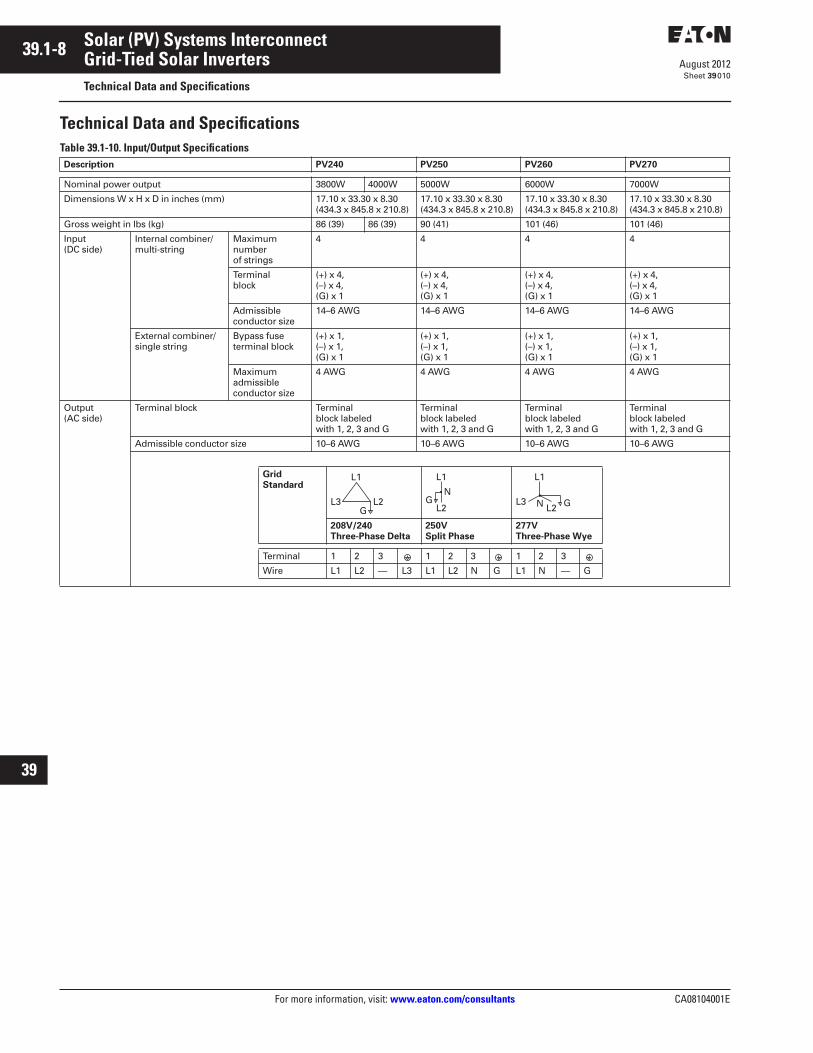
Technical Data and SpecificationsTable 39.1-10. Input/Output SpecificationsDescription PV240 PV250 PV260 PV270
Nominal power output 3800W 4000W 5000W 6000W 7000W
Dimensions W x H x D in inches (mm) 17.10 x 33.30 x 8.30(434.3 x 845.8 x 210.8)
17.10 x 33.30 x 8.30(434.3 x 845.8 x 210.8)
17.10 x 33.30 x 8.30(434.3 x 845.8 x 210.8)
17.10 x 33.30 x 8.30(434.3 x 845.8 x 210.8)
Gross weight in lbs (kg) 86 (39) 86 (39) 90 (41) 101 (46) 101 (46)
Input(DC side)
Internal combiner/multi-string
Maximum number of strings
4 4 4 4
Terminal block
(+) x 4, (–) x 4,(G) x 1
(+) x 4, (–) x 4, (G) x 1
(+) x 4, (–) x 4, (G) x 1
(+) x 4, (–) x 4, (G) x 1
Admissible conductor size
14–6 AWG 14–6 AWG 14–6 AWG 14–6 AWG
External combiner/single string
Bypass fuse terminal block
(+) x 1, (–) x 1, (G) x 1
(+) x 1, (–) x 1, (G) x 1
(+) x 1, (–) x 1, (G) x 1
(+) x 1, (–) x 1, (G) x 1
Maximumadmissibleconductor size
4 AWG 4 AWG 4 AWG 4 AWG
Output(AC side)
Terminal block Terminal block labeledwith 1, 2, 3 and G
Terminal block labeledwith 1, 2, 3 and G
Terminal block labeledwith 1, 2, 3 and G
Terminal block labeledwith 1, 2, 3 and G
Admissible conductor size 10–6 AWG 10–6 AWG 10–6 AWG 10–6 AWG
GridStandard
208V/240Three-Phase Delta
250VSplit Phase
277VThree-Phase Wye
Terminal 1 2 3 1 2 3 1 2 3
Wire L1 L2 — L3 L1 L2 N G L1 N — G
L1
L2L3G
L1
L2G
N
L1
L2L3 GN

CA08104001E For more information, visit: www.eaton.com/consultants
39.1-9August 2012
Solar (PV) Systems Interconnect
Sheet 39
22
23
24
25
26
27
28
29
30
31
32
33
34
35
36
37
38
39
40
41
42
43
Grid-Tied Solar InvertersTechnical Data and Specifications
011
Table 39.1-11. Technical DataDescription PV240 PV250 PV260 PV270
Input (DC) Nominal DC voltage 360V 360V 360V 360V 360V
Maximum DC voltage 600V 600V 600V 600V 600V
System startup voltage 150V 150V 150V 150V 150V
Shutdown voltage Typical 80V Typical 80V Typical 80V Typical 80V Typical 80V
MPPT voltage range 105–500V 200–500V 105–500V 105–500V 105–500V
Full rating voltage range 225–500V 225–500V 225–500V 225–500V 225–500V
Maximum DC current 19A 19A 26A 32A 37A
Number of DC input terminals 4 4 4 4 4
Output (AC) Nominal AC power at 240 Vac and 277 Vac
3800W 4000W 5000W 6000W 7000W
Nominal AC power at 208 Vac 3800W 3800W 4600W 6000W 7000W
Max. AC power at 240 Vac at 277 Vac 3800W 4000W 5000W 6000W 7000W
Maximum AC power at 208 Vac 3800W 3800W 4600W 6000W 7000W
Nominal AC voltage 208V, 240V or 277V 208V, 240V or 277V 208V, 240V or 277V 208V, 240V or 277V 208V, 240V or 277V
Nominal frequency 60 Hz 60 Hz 60 Hz 60 Hz 60 Hz
Disconnection time of excess operational frequency range
≤0.16 sec ≤0.16 sec ≤0.16 sec ≤0.16 sec ≤0.16 sec
Nominal AC current at 208 Vac 18.3A 18.3A 22.1A 28.9A 33.7A
Nominal AC current at 240 Vac 15.8A 16.7A 20.8A 25.0A 29.2A
Nominal AC current at 277 Vac 13.7A 14.4A 18.1A 21.7A 25.3A
Maximum AC current at 208 Vac 18.3A 18.5A 22.5A 30.0A 35.0A
Maximum AC current at 240 Vac 15.8A 18.5A 22.5A 28.5A 33.2A
Maximum AC current at 277 Vac 13.7A 16.4A 20.5A 24.6A 28.7A
Power factor >0.99 >0.99 >0.99 >0.99 >0.99
Efficiency Peak efficiency 97.5% 97.5% 97.5% 97.5% 97.5%
CEC efficiency 97.0% 97.0% 97.0% 97.0% 97.0%
General Data Topology Transformerless Transformerless Transformerless Transformerless Transformerless
Dimensions in inches (mm)W x H x D
17.10 x 33.30 x 8.30(434.3 x 845.8 x 210.8)
17.10 x 33.30 x 8.30(434.3 x 845.8 x 210.8)
17.10 x 33.30 x 8.30(434.3 x 845.8 x 210.8)
17.10 x 33.30 x 8.30(434.3 x 845.8 x 210.8)
17.10 x 33.30 x 8.30(434.3 x 845.8 x 210.8)
Gross weight in lbs (kg) 86 (39) 86 (39) 90 (41) 101 (46) 101 (46)
Power consumption: standby/night <7W / <0.2W <7W / <0.2W <7W / <0.2W <7W / <0.2W <7W / <0.2W
DC insulation resistance >4 megohms >4 megohms >4 megohms >4 megohms >4 megohms
Enclosure NEMA 3R NEMA 3R NEMA 3R NEMA 3R NEMA 3R
Heat dissipation Force air cooling, variable fan speed according to temperature on heat sink
Operating temperature range –25 to +50°C –25 to +50°C –25 to +50°C –25 to +50°C –25 to +50°C
Humidity 0 to 95%, noncondensing
0 to 95%, noncondensing
0 to 95%, noncondensing
0 to 95%, noncondensing
0 to 95%, noncondensing
Communication RS-232/Super-485 RS-232/Super-485 RS-232/Super-485 RS-232/Super-485 RS-232/Super-485
Ground fault protection Internal GFCI and isolation detection function in accordance with UL 1741
Disconnect Integrated AC and DC switch
Integrated AC and DC switch
Integrated AC and DC switch
Integrated AC and DC switch
Integrated AC and DC switch
Certifications ETL (in compliance with UL 1741), CSA, CEC
ETL (in compliance with UL 1741), CSA, CEC
ETL (in compliance with UL 1741), CSA, CEC
ETL (in compliance with UL 1741), CSA, CEC
ETL (in compliance with UL 1741), CSA, CEC
DC surge protection 4 kV 4 kV 4 kV 4 kV 4 kV
AC surge protection 6 kV 6 kV 6 kV 6 kV 6 kV
Warranty 10 years 10 years 10 years 10 years 10 years
39.1-10
For more information, visit: www.eaton.com/consultants CA08104001E
August 2012
Solar (PV) Systems Interconnect
Sheet 39
22
23
24
25
26
27
28
29
30
31
32
33
34
35
36
37
38
39
40
41
42
43
Grid-Tied Solar InvertersDimensions
012
Dimensions
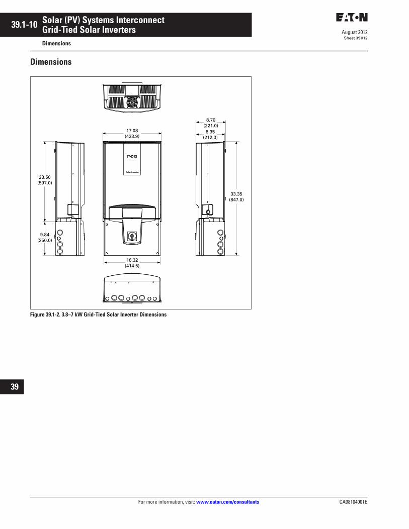
Figure 39.1-2. 3.8–7 kW Grid-Tied Solar Inverter Dimensions
8.70(221.0)8.35
(212.0)
33.35(847.0)
17.08(433.9)
9.84(250.0)
23.50(597.0)
16.32(414.5)
Solar Inverter
CA08104001E For more information, visit: www.eaton.com/consultants
39.1-11August 2012
Solar (PV) Systems Interconnect
Sheet 39
22
23
24
25
26
27
28
29
30
31
32
33
34
35
36
37
38
39
40
41
42
43
Grid-Tied Solar InvertersDimensions
013
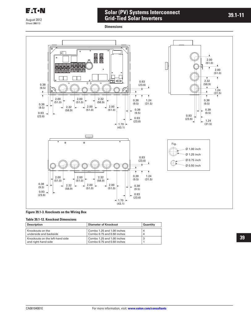
Figure 39.1-3. Knockouts on the Wiring Box
Table 39.1-12. Knockout DimensionsDescription Diameter of Knockout Quantity
Knockouts on the underside and backside
Combo 1.25 and 1.00 inchesCombo 0.75 and 0.50 inches
44
Knockouts on the left-hand sideand right-hand side
Combo 1.25 and 1.00 inchesCombo 0.75 and 0.50 inches
31
0.38(9.5)
0.93(23.6)
0.38(9.5)
0.38(9.5)
0.38(9.5)0.93
(23.6)
2.00(51.0)
2.00(51.0)
2.32(58.9)
2.00(51.0)
2.00(51.0)
2.32(58.9)
0.38(9.5)
0.93(23.6)
2.00(51.0)
2.00(51.0)
2.32(58.9)
2.00(51.0)
2.00(51.0)
2.32(58.9)
1.70(43.1)
0.93(23.6)
0.38(9.5)
1.70(43.1)
0.93(23.6)
0.38(9.5)
0.38(9.5)
1.24(31.5)
1.24(31.5)
0.93(23.6)
0.38(9.5)
1.24(31.5)
0.93(23.6)
1.24(31.5)
2.00(51.0)
2.00(51.0)
2.32(58.9)
Fig.
Ø 1.00 inch
Ø 1.25 inch
Ø 0.75 inch
Ø 0.50 inch
39.1-12
For more information, visit: www.eaton.com/consultants CA08104001E
August 2012
Solar (PV) Systems Interconnect
Sheet 39
22
23
24
25
26
27
28
29
30
31
32
33
34
35
36
37
38
39
40
41
42
43
014
This page intentionally left blank.

CA08104001E For more information, visit: www.eaton.com/consultants
39.2-1August 2012
Solar (PV) Systems Interconnect
Sheet 39
22
23
24
25
26
27
28
29
30
31
32
33
34
35
36
37
38
39
40
41
42
43
Solar DC Disconnect015
Solar Disconnect Switch
Solar Disconnect Switch
General Description
600 Vdc Heavy-Duty Fusible and Non-Fusible■ 30–600A■ Single-pole switch capable of
switching 1–600 Vdc circuit
Features
600 Vdc Heavy-Duty Fusible and Non-Fusible
NEC Required Labeling Factory-Installed Jumpers
Standard K-Switch Mechanism
Clear Deadfront Shield (covering all potentially live parts)
Fused Center Pole (isolates fuse clips from potentialback feed—only one fuse required per switch)
Factory-Installed Isolated Groundand Equipment Ground Lug
Switching 600 VdcWhen photovoltaic panels convert the sun’s energy into electricity, the power generated is direct current (DC). Typically, the systems are designed with DC system voltages in the 400–600V range. This is much higher voltage than typically found in building systems. The highervoltage, when combined with the lack of a current sine wave with zero crossings, creates a number of challenges in wiring, particularly when switching circuits on and off.
DC circuits consist of two wires—a positive and a negative. In most PV systems, one of these wires is grounded (like a neutral in an AC system). Which of the two wires is grounded is specified by the solar panel manufacturer. The more common application is a negative ground, and the location of this bond is usually found at the inverter. Per the National Electrical Code (NEC®) Section 690.5(A), only the current-carrying ungrounded conductor should be switched. Thus, in a negative-grounded system, onlythe positive wire is switched.
Unlike AC systems that possess a current sine wave with zero crossings, the interruption of higher voltage DC circuits requires an increased air gap to safely and quickly interrupt and break the arc. The increased gap is accomplished by wiring multiple poles of a single switch in series for safe arc interruption. All switch manufacturers require the use of multiple poles at 600 Vdc to maintain the UL listing. For this reason, a switch should only be used to switch one circuit. The UL listing of these products does not permit multiple circuits to be switched by one switch. Eaton’s new offeringof PV switches have multiple poles factory-wired, and they are approved for NEC Article 690 applications right from the box. Other manufacturers require the contractor to add jumpers to a two- or three-pole switch, add a neutral, and add labels to meet this requirement. For fusible switches, the new Eaton PV switch requires only one fuse per switch—saving the customer at least one fuse on each switch.

39.2-2
For more information, visit: www.eaton.com/consultants CA08104001E
August 2012
Solar (PV) Systems Interconnect
Sheet 39
22
23
24
25
26
27
28
29
30
31
32
33
34
35
36
37
38
39
40
41
42
43
Solar DC Disconnect016
Eaton’s Solar DisconnectEaton Corporation is proud to offer a new line of solar disconnects that pro-vide the best solution for switching solar PV circuits. This exciting new offering is the first UL 98 listed switch that is labeled as “suitable for NEC Article 690 photovoltaic applications per UL 1741 requirements.”
Features include:
■ Marked as suitable for NEC 690 PV applications up to 600 Vdc
■ UL 98 listed■ All switches are single-pole and
suitable for switching one circuit■ Clear polycarbonate deadfront to
guard against accidental contact with live parts
■ NEC 690.17—compliant labeling warning that the switch terminals may be energized in the open position
■ NEC 690.14.(C) 2 required “PV System Disconnect” label included
■ Isolated ground terminals (neutral) for grounded conductors
■ Ground lug for equipment grounding conductor
■ NEMA® 3R, 12 and 4X stainless enclosures
■ Fusible and non-fusible configura-tions—Class R fuse clips standard
■ Fuse clips are located on the center pole to ensure that both fuse clips are de-energized—meets NEC Article 690.16, which requires isolation of the fuse from all potential supply sources
■ Available for Flex Center modifica-tions (windows, pilot lights, 316 grade stainless, and so on)
Standards and Certifications■ UL 98 listed, File No. E5239 and
marked suitable for NEC Article 690 applications to UL 1741
Solar Disconnect Switch Solar Disconnect Switch (Interior View)
Solar Disconnect Switch (Close-Up Interior View)

CA08104001E For more information, visit: www.eaton.com/consultants
39.2-3August 2012
Solar (PV) Systems Interconnect
Sheet 39
22
23
24
25
26
27
28
29
30
31
32
33
34
35
36
37
38
39
40
41
42
43
Solar DC Disconnect017
Product Selection
Figure 39.2-1. Non-Fused Construction
Figure 39.2-2. Fused Construction
Table 39.2-1. NEMA 3R
Table 39.2-2. NEMA 12
Table 39.2-3. NEMA 4X
Line
GroundedConductorJunction Block
Load
GroundedConductorJunction Block
Line
Load
AmpereRating
FuseClass
CatalogNumber
30 30 60
RRR
DH161NRKDH161URKNDH162NRK
60 100 100
RRR
DH162URKNDH163NRKDH163URKN
200 200 400
RRR
DH164NRKDH164URKNDH165NRK
400 600 600
RRR
DH165URKNDH166NRKDH166URKN
800 80012001200
RRRR
DH167NRKDH167URKNDH168NRKDH168URKN
AmpereRating
FuseClass
CatalogNumber
30 30 60
RRR
DH161NDKDH161UDKNDH162NDK
60 100 100
RRR
DH162UDKNDH163NDKDH163UDKN
200 200 400
RRR
DH164NDKDH164UDKNDH165NDK
400 600 600
RRR
DH165UDKNDH166NDKDH166UDKN
800 80012001200
RRRR
DH167NDKDH167UDKNDH168NDKDH168UDKN
Ampere Rating
FuseClass
Catalog Number
30 30 60
RRR
DH161NWKDH161UWKNDH162NWK
60 100 100
RRR
DH162UWKNDH163NWKDH163UWKN
200 200 400
RRR
DH164NWKDH164UWKNDH165NWK
400 600 600
RRR
DH165UWKNDH166NWKDH166UWKN
800 8001200
RRR
DH167FWKDH167NWKDH167UWKN
12001200
RR
DH168NWKDH168UWKN

39.2-4
For more information, visit: www.eaton.com/consultants CA08104001E
August 2012
Solar (PV) Systems Interconnect
Sheet 39
22
23
24
25
26
27
28
29
30
31
32
33
34
35
36
37
38
39
40
41
42
43
Solar DC Disconnect018
Photovoltaic String Disconnect Switch Application
Introduction and Statement of ProblemNew installations of solar photovoltaic (PV) generation systems have increased the need for disconnect switches and overcurrent protective devices capable of interrupting currents at voltages up to 600 Vdc. This application is covered by NEC Article 690, Solar Photovoltaic (PV) Systems. Products applied as overcurrent protection must meet the design and testing requirements of the individual standards for each product:
■ Safety switches—UL 98■ Fuses—UL 248■ Circuit breakers—UL 489
PV system arrays generate DC current. The solar modules are wired in series, and the system voltage is the sum of the maximum output voltage of all of the modules in a string. 600 Vdc maximum was chosen as an optimal system voltage to reduce installation costs by reducing conductor size and to stay below the 600V threshold in NEC Article 490.
Prior to the growth in the number of installed PV systems, 600 Vdc was not a common system voltage. Thus, there was a limited availability of protection and switching devices that meet North American standards at this voltage. In addition, the grounding and ground fault requirements of these PV systems vary from that of other DC systems resulting in different switching and bonding schemes.
As the PV industry grows, overcurrent and switch products are intentionally or accidentally being applied in ways that are in conflict with the products’ listings. Added to this, some manufac-turers have “self-certified” products for use in ways that are outside of the products’ listing.
These situations make it difficult for installers and Authorities Having Jurisdiction (AHJs) to understand how to properly apply or inspect these products. Using or approving a product outside of its listed rating is a violation of NEC Article 210.3, and could open the installer or the AHJ to liability for misapplication of the product.
Solar Disconnect Switch Typical ApplicationsFigure 39.2-3 shows a common one-line diagram of PV systems in use today. There are no standard installa-tions due to the large variation in solar module capabilities and the large range of power capabilities. The DC system is 450–600V. There are a few problems associated with this configuration.
First, the switches shown are breaking 600 Vdc per pole. There are no UL 98 or 489 listed devices on the market today that are capable of passing the required short-circuit, overload and endurance tests associated with breaking a 600 Vdc circuit with one switching pole. When products from all manufacturers are tested to the standard in this configuration, the results are excessive heating caused by long arcing times and device failure within a very few test operation cycles.
Secondly, the fuses on the load side of the switch are not isolated from all potential sources as required by NEC
Article 690.16. If “Sw. 2” is opened for maintenance, the load side fuse holders in the switch that are connected to the inverter will still be energized if “Sw. 1” is closed and the modules are exposed to solar irradiation.
Switch Selection for Operating VoltageNEC 690.7 states that the maximum photovoltaic system source circuit voltage shall be calculated as the sum of the rated open circuit voltage of the series connected photovoltaic modules corrected for the lowest expected temperature. The correction factor can be as high as 1.25 per Table 690.7; this applies to crystalline and multicrystalline silicon modules. This theoretical voltage is the worst case (highest) possible voltage that the entire system could produce (basedon temperature, irradiance and angle), but is not likely to occur. Devices must be selected based on this maximum voltage.
Figure 39.2-3. DC Disconnect Misapplication Example—Single-Pole Switching of 600 Vdc
- + - + - + - + - + - +
+-
Sw.1 Sw. 2
Inverter
DC Disconnect Misapplication
CA08104001E For more information, visit: www.eaton.com/consultants
39.2-5August 2012
Solar (PV) Systems Interconnect
Sheet 39
22
23
24
25
26
27
28
29
30
31
32
33
34
35
36
37
38
39
40
41
42
43
Solar DC Disconnect019
DC Switch DesignSwitching DC currents requires a higher arcing voltage to be developed in the switch to clear the current as compared to AC circuits. The reason for the higher voltage is that unlike AC, DC does not have zero voltage crossings to facilitate clearing the arc. Thus to break the current, the voltage drop required across the arc gap is very high.
Switching devices primarily designed for DC service require additional arc control structures or design features to increase the total arcing voltage, so that fewer switching poles are needed for each circuit. These higher arc voltages can be developed by increasing the arc length (either larger single opening air gaps, or multiple openings in series), by adding several arc splitter plates, or by both methods together.
An alternative method of stretching the arc uses a magnetic field induced by an electromagnet or a permanent magnet structure to force arc move-ment. The limitation of the magnetic field from a permanent magnet is that it is unidirectional. That is, the magnet only stretches the arc when current flow is in the “normal” direction. Thus this design is polarity sensitive, and will not operate properly if it is miswired or in a fault condition where current flow is reversed from normal. In these instances, the magnetic field would push the arc in the wrong direction away from the arc suppression structure, potentially causing switch failure, property damage or fire. Any switch that is suitable only for use with either a Negative Grounded or Positive Grounded systems is a unidirectional device, and is subject to the problem of insufficient arc suppression of reverse currents.
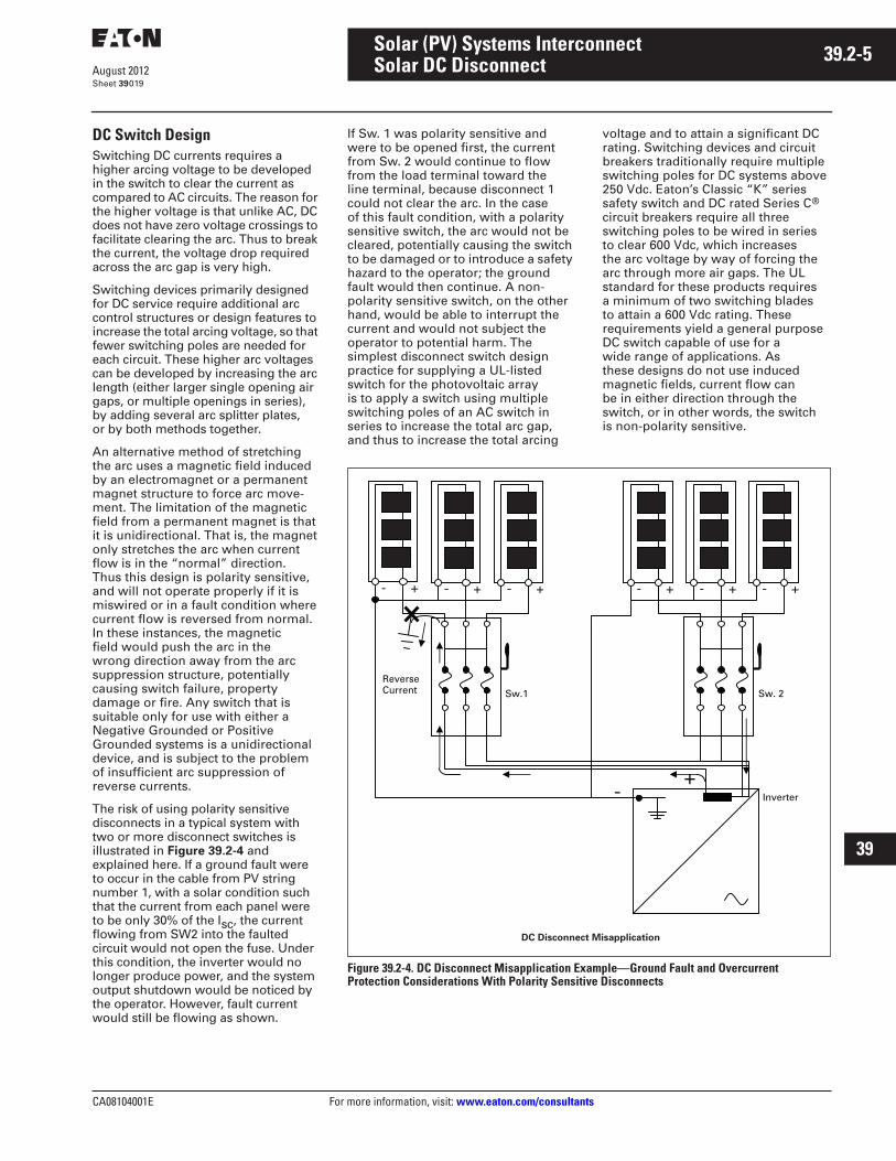
The risk of using polarity sensitive disconnects in a typical system with two or more disconnect switches is illustrated in Figure 39.2-4 and explained here. If a ground fault were to occur in the cable from PV string number 1, with a solar condition such that the current from each panel were to be only 30% of the Isc, the current flowing from SW2 into the faulted circuit would not open the fuse. Under this condition, the inverter would no longer produce power, and the system output shutdown would be noticed by the operator. However, fault current would still be flowing as shown.
If Sw. 1 was polarity sensitive and were to be opened first, the current from Sw. 2 would continue to flow from the load terminal toward the line terminal, because disconnect 1 could not clear the arc. In the case of this fault condition, with a polarity sensitive switch, the arc would not be cleared, potentially causing the switch to be damaged or to introduce a safety hazard to the operator; the ground fault would then continue. A non-polarity sensitive switch, on the other hand, would be able to interrupt the current and would not subject the operator to potential harm. The simplest disconnect switch design practice for supplying a UL-listed switch for the photovoltaic array is to apply a switch using multiple switching poles of an AC switch in series to increase the total arc gap,and thus to increase the total arcing
voltage and to attain a significant DC rating. Switching devices and circuit breakers traditionally require multiple switching poles for DC systems above 250 Vdc. Eaton’s Classic “K” series safety switch and DC rated Series C® circuit breakers require all three switching poles to be wired in series to clear 600 Vdc, which increases the arc voltage by way of forcing the arc through more air gaps. The UL standard for these products requires a minimum of two switching blades to attain a 600 Vdc rating. These requirements yield a general purpose DC switch capable of use for a wide range of applications. As these designs do not use induced magnetic fields, current flow can be in either direction through the switch, or in other words, the switch is non-polarity sensitive.
Figure 39.2-4. DC Disconnect Misapplication Example—Ground Fault and Overcurrent Protection Considerations With Polarity Sensitive Disconnects
- + - + - + - + - + - +
+- Inverter
Sw.1
ReverseCurrent Sw. 2
DC Disconnect Misapplication
39.2-6
For more information, visit: www.eaton.com/consultants CA08104001E
August 2012
Solar (PV) Systems Interconnect
Sheet 39
22
23
24
25
26
27
28
29
30
31
32
33
34
35
36
37
38
39
40
41
42
43
Solar DC Disconnect020
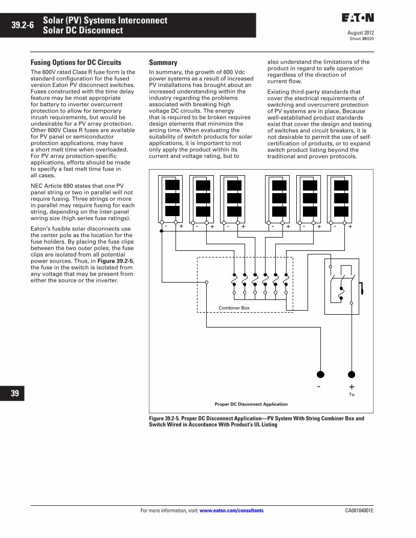
Fusing Options for DC CircuitsThe 600V rated Class R fuse form is the standard configuration for the fused version Eaton PV disconnect switches. Fuses constructed with the time delay feature may be most appropriate for battery to inverter overcurrent protection to allow for temporary inrush requirements, but would be undesirable for a PV array protection. Other 600V Class R fuses are available for PV panel or semiconductor protection applications, may have a short melt time when overloaded. For PV array protection-specific applications, efforts should be made to specify a fast melt time fuse in all cases.
NEC Article 690 states that one PV panel string or two in parallel will not require fusing. Three strings or more in parallel may require fusing for each string, depending on the inter-panel wiring size (high series fuse ratings).
Eaton’s fusible solar disconnects use the center pole as the location for the fuse holders. By placing the fuse clips between the two outer poles, the fuse clips are isolated from all potential power sources. Thus, in Figure 39.2-5, the fuse in the switch is isolated from any voltage that may be present from either the source or the inverter.
SummaryIn summary, the growth of 600 Vdc power systems as a result of increased PV installations has brought about an increased understanding within the industry regarding the problems associated with breaking high voltage DC circuits. The energy that is required to be broken requires design elements that minimize the arcing time. When evaluating the suitability of switch products for solar applications, it is important to not only apply the product within its current and voltage rating, but to
also understand the limitations of the product in regard to safe operation regardless of the direction of current flow.
Existing third-party standards that cover the electrical requirements of switching and overcurrent protection of PV systems are in place. Because well-established product standards exist that cover the design and testing of switches and circuit breakers, it is not desirable to permit the use of self-certification of products, or to expand switch product listing beyond the traditional and proven protocols.
Figure 39.2-5. Proper DC Disconnect Application—PV System With String Combiner Box and Switch Wired in Accordance With Product’s UL Listing
- + - + - + - + - + - +
Combiner Box
- To +
Proper DC Disconnect Application
CA08104001E For more information, visit: www.eaton.com/consultants
39.2-7August 2012
Solar (PV) Systems Interconnect
Sheet 39
22
23
24
25
26
27
28
29
30
31
32
33
34
35
36
37
38
39
40
41
42
43
Solar DC Disconnect021
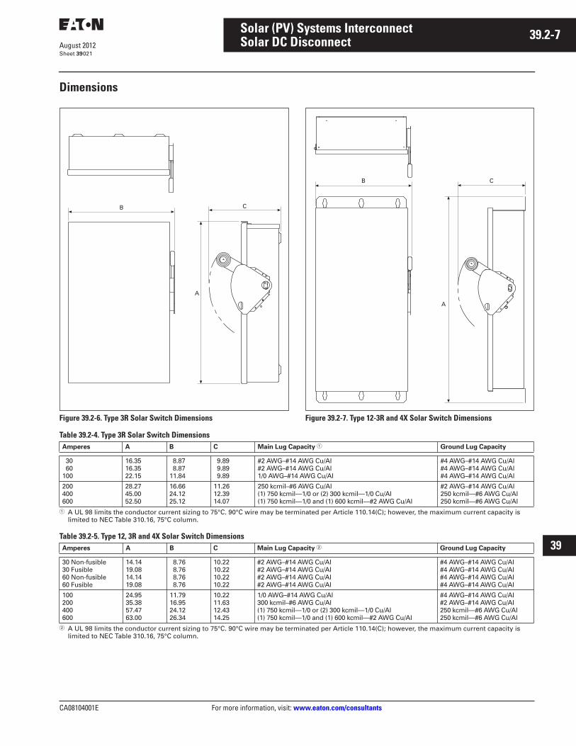
Dimensions
Figure 39.2-6. Type 3R Solar Switch Dimensions Figure 39.2-7. Type 12-3R and 4X Solar Switch Dimensions
Table 39.2-4. Type 3R Solar Switch Dimensions
� A UL 98 limits the conductor current sizing to 75°C. 90°C wire may be terminated per Article 110.14(C); however, the maximum current capacity is limited to NEC Table 310.16, 75°C column.
Table 39.2-5. Type 12, 3R and 4X Solar Switch Dimensions
� A UL 98 limits the conductor current sizing to 75°C. 90°C wire may be terminated per Article 110.14(C); however, the maximum current capacity is limited to NEC Table 310.16, 75°C column.
B C
A
B C
A
Amperes A B C Main Lug Capacity � Ground Lug Capacity
30 60100
16.3516.3522.15
8.87 8.8711.84
9.89 9.89 9.89
#2 AWG–#14 AWG Cu/Al#2 AWG–#14 AWG Cu/Al1/0 AWG–#14 AWG Cu/Al
#4 AWG–#14 AWG Cu/Al#4 AWG–#14 AWG Cu/Al#4 AWG–#14 AWG Cu/Al
200400600
28.2745.0052.50
16.6624.1225.12
11.2612.3914.07
250 kcmil–#6 AWG Cu/Al(1) 750 kcmil—1/0 or (2) 300 kcmil—1/0 Cu/Al(1) 750 kcmil—1/0 and (1) 600 kcmil—#2 AWG Cu/Al
#2 AWG–#14 AWG Cu/Al250 kcmil—#6 AWG Cu/Al250 kcmil—#6 AWG Cu/Al
Amperes A B C Main Lug Capacity � Ground Lug Capacity
30 Non-fusible30 Fusible60 Non-fusible60 Fusible
14.1419.0814.1419.08
8.76 8.76 8.76 8.76
10.2210.2210.2210.22
#2 AWG–#14 AWG Cu/Al#2 AWG–#14 AWG Cu/Al#2 AWG–#14 AWG Cu/Al#2 AWG–#14 AWG Cu/Al
#4 AWG–#14 AWG Cu/Al#4 AWG–#14 AWG Cu/Al#4 AWG–#14 AWG Cu/Al#4 AWG–#14 AWG Cu/Al
100200400600
24.9535.3857.4763.00
11.7916.9524.1226.34
10.2211.6312.4314.25
1/0 AWG–#14 AWG Cu/Al300 kcmil–#6 AWG Cu/Al(1) 750 kcmil—1/0 or (2) 300 kcmil—1/0 Cu/Al(1) 750 kcmil—1/0 and (1) 600 kcmil—#2 AWG Cu/Al
#4 AWG–#14 AWG Cu/Al#2 AWG–#14 AWG Cu/Al250 kcmil—#6 AWG Cu/Al250 kcmil—#6 AWG Cu/Al

39.2-8
For more information, visit: www.eaton.com/consultants CA08104001E
August 2012
Solar (PV) Systems Interconnect
Sheet 39
22
23
24
25
26
27
28
29
30
31
32
33
34
35
36
37
38
39
40
41
42
43
022
This page intentionally left blank.
CA08104001E For more information, visit: www.eaton.com/consultants
39.3-1August 2012
Solar (PV) Systems Interconnect
Sheet 39
22
23
24
25
26
27
28
29
30
31
32
33
34
35
36
37
38
39
40
41
42
43
Combiner Boxes023
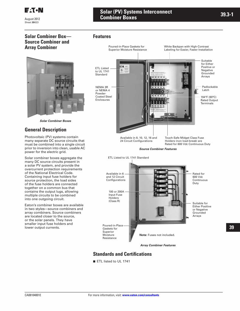
Solar Combiner Box—Source Combiner and Array Combiner
Solar Combiner Boxes
General DescriptionPhotovoltaic (PV) systems contain many separate DC source circuits that must be combined into a single circuit prior to inversion into clean, usable AC power for the electric grid.
Solar combiner boxes aggregate the many DC source circuits present in a solar PV system, and provide the overcurrent protection requirements of the National Electrical Code. Containing input fuse holders for source protection, the load sides of the fuse holders are connected together on a common bus that contains the output lugs, allowing multiple circuits to be combined into one outgoing circuit.
Eaton’s combiner boxes are available in two styles—source combiners and array combiners. Source combiners are located closer to the source, or the solar panels. They have smaller input fuse holders and lower output currents.
Features
Source Combiner Features
Array Combiner Features
Standards and Certifications■ ETL listed to UL 1741
ETL Listed to UL 1741 Standard
Touch-Safe Midget Class Fuse Holders (non load-break) are Rated for 600 Vdc Continuous Duty
Poured-in-Place Gaskets for Superior Moisture Resistance
Suitable for Either Positive or Negative Grounded Arrays
Available in 8, 10, 12, 16 and 24 Circuit Configurations
NEMA 3R or NEMA 4 Powder-Coated Steel Enclosures
194°F (90ºC) Rated Output Terminals
White Backpan with High-Contrast Labeling for Easier, Faster Installation
Padlockable Latch
ETL Listed to UL 1741 Standard
Rated for 600 Vdc Continuous Duty
Poured-in-Place Gaskets for Superior Moisture Resistance
Suitable for Either Positive or Negative Grounded Arrays
Available in 6 and 12 Circuit Configurations
100 or 200A Input Fuse Holders (Class R)
Note: Fuses not included.

39.3-2
For more information, visit: www.eaton.com/consultants CA08104001E
August 2012
Solar (PV) Systems Interconnect
Sheet 39
22
23
24
25
26
27
28
29
30
31
32
33
34
35
36
37
38
39
40
41
42
43
Combiner Boxes024
Product SelectionNote: Switched Combiners (for both Source and Array applications) that combine the below Combiners with DC disconnects in a single enclosure are also available. Contact Eaton for details.
Table 39.3-1. Source Combiners
� Fuses not included.� Total installed fuse capacity shall not exceed maximum continuous DC current rating.
Table 39.3-2. Array Combiners
� Fuses not included.� Total installed fuse capacity shall not exceed maximum continuous DC current rating.
DimensionsApproximate dimensions in inches (mm).
Table 39.3-3. Source Combiners
Table 39.3-4. Array Combiners
Number of Circuits
Maximum Fuse Size �
Incoming Wire Range
Output Conductors
Maximum Continuous DC Current
NEMA 3R Catalog Number
NEMA 4 Catalog Number
81012
303030
#16–#4#16–#4#16–#4
1–#6 to 350 kcmil1–#6 to 350 kcmil1–#6 to 350 kcmil
310310310
SC8RSC10RSC12R
SC8PSC10PSC12P
1624
3020 �
#16–#4#16–#4
2–#6 to 350 kcmil2–#6 to 350 kcmil
400400 �
SC16RSC24R
SC16PSC24P
Number of Circuits
Maximum Fuse Size �
Incoming Wire Range
Output Conductors
Maximum Continuous DC Current
NEMA 3R Catalog Number
NEMA 4 Catalog Number
612
100100
#6–2/0#6–2/0
2–#4 to 500 kcmil4–#4 to 500 kcmil
7201520
AC6100RAC12100R
AC6100PAC12100P
612
200200 �
#6–4/0#6–4/0
4–#4 to 500 kcmil4–#4 to 500 kcmil
15201520 �
AC6200RAC12200R
AC6200PAC12200P
Height Width Depth Weight in Lbs (kg)
NEMA 3R Catalog Number
NEMA 4 Catalog Number
16.00 (406.4)16.00 (406.4)16.00 (406.4)
12.00 (304.8)12.00 (304.8)12.00 (304.8)
6.00 (152.4)6.00 (152.4)6.00 (152.4)
30 (13.6)30 (13.6)30 (13.6)
SC8RSC10RSC12R
SC8PSC10PSC12P
16.00 (406.4)20.00 (508.0)
12.00 (304.8)20.00 (508.0)
6.00 (152.4)6.00 (152.4)
36 (16.3)45 (20.4)
SC16RSC24R
SC16PSC24P
Height Width Depth Weight in Lbs (kg)
NEMA 3R Catalog Number
NEMA 4 Catalog Number
36.00 (914.4)48.00 (1219.2)
36.00 (914.4)36.00 (914.4)
8.00 (203.2)8.00 (203.2)
156 (70.8)227 (103.0)
AC6100RAC12100R
AC6100PAC12100P
42.00 (1066.8)48.00 (1219.2)
36.00 (914.4)36.00 (914.4)
8.00 (203.2)8.00 (203.2)
206 (93.5)278 (126.2)
AC6200RAC12200R
AC6200PAC12200P