Compression Grounding
1-800-465-7051 (Canada)1-603-647-5299 (International) E-1
Table of Contents
Lightning Protection Information
Basic rules for selection are:
1. Must be like material to the conductor.2. Two bolts to ground rod—minimum, for mechanical.3. Cable to cable connections can be installed with one bolt, two bolt, or compression means.4. Cable to steel structure must have 8 in.2 contact with steel.5. Heavy duty stacks—mechanical only.6. On all connectors with heavy duty stack rating, we must offer 1/16” thick lead plating as an
option. The reason is closest 25 ft. to stack opening must use lead coated product.7. UL 96 Listing.
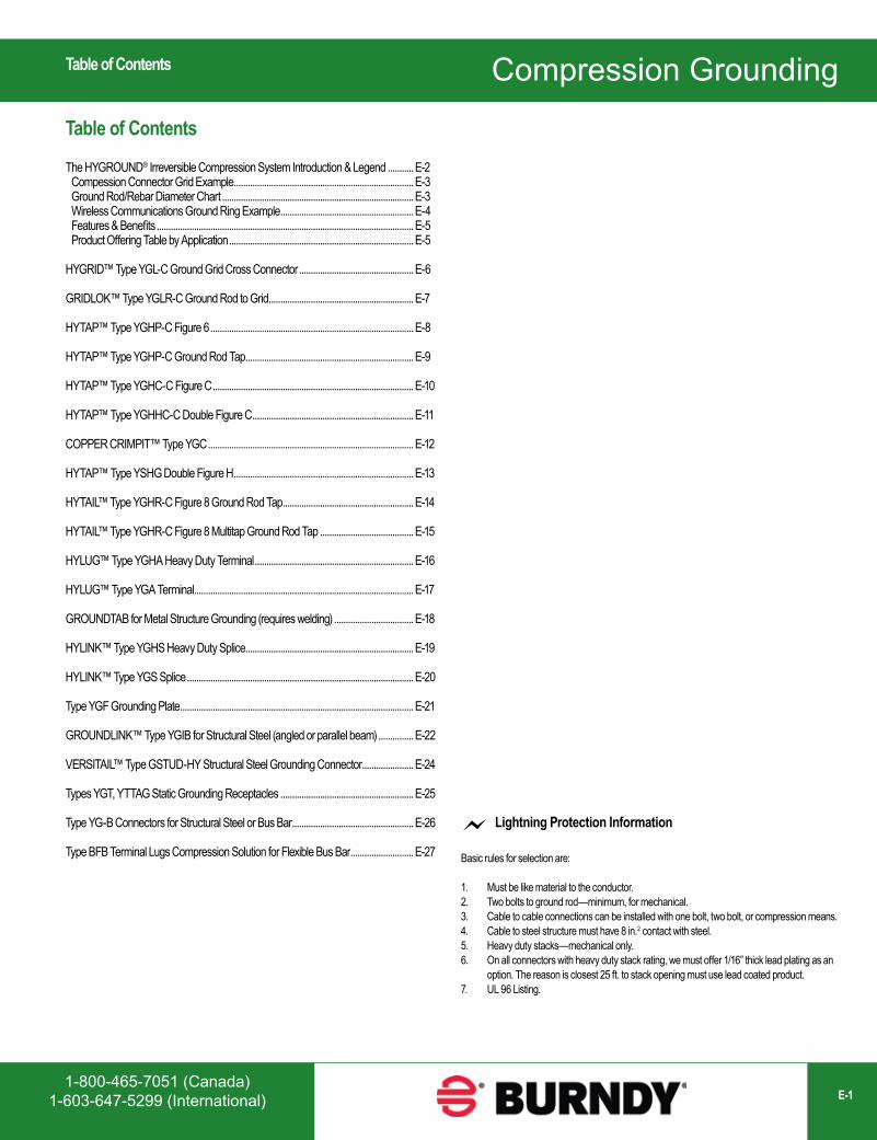
The HYGROUND® Irreversible Compression System Introduction & Legend ...........E-2 Compession Connector Grid Example .............................................................................E-3 Ground Rod/Rebar Diameter Chart ..................................................................................E-3 Wireless Communications Ground Ring Example .........................................................E-4 Features & Benefits ..............................................................................................................E-5 Product Offering Table by Application ...............................................................................E-5
HYGRID™ Type YGL-C Ground Grid Cross Connector .................................................E-6
GRIDLOK™ Type YGLR-C Ground Rod to Grid ..............................................................E-7
HYTAP™ Type YGHP-C Figure 6 .......................................................................................E-8
HYTAP™ Type YGHP-C Ground Rod Tap ........................................................................E-9
HYTAP™ Type YGHC-C Figure C ......................................................................................E-10
HYTAP™ Type YGHHC-C Double Figure C .....................................................................E-11
COPPER CRIMPIT™ Type YGC ........................................................................................E-12
HYTAP™ Type YSHG Double Figure H .............................................................................E-13
HYTAIL™ Type YGHR-C Figure 8 Ground Rod Tap ........................................................E-14
HYTAIL™ Type YGHR-C Figure 8 Multitap Ground Rod Tap ........................................E-15
HYLUG™ Type YGHA Heavy Duty Terminal ....................................................................E-16
HYLUG™ Type YGA Terminal ..............................................................................................E-17
GROUNDTAB for Metal Structure Grounding (requires welding) ..................................E-18
HYLINK™ Type YGHS Heavy Duty Splice........................................................................E-19
HYLINK™ Type YGS Splice .................................................................................................E-20
Type YGF Grounding Plate ....................................................................................................E-21
GROUNDLINK™ Type YGIB for Structural Steel (angled or parallel beam) ...............E-22
VERSITAIL™ Type GSTUD-HY Structural Steel Grounding Connector ......................E-24
Types YGT, YTTAG Static Grounding Receptacles .........................................................E-25
Type YG-B Connectors for Structural Steel or Bus Bar ....................................................E-26
Type BFB Terminal Lugs Compression Solution for Flexible Bus Bar ...........................E-27
Table of Contents
Compression Grounding
www.burndy.com1-800-346-4175 (US)E-2
HYGROUND® Compression SystemLegend
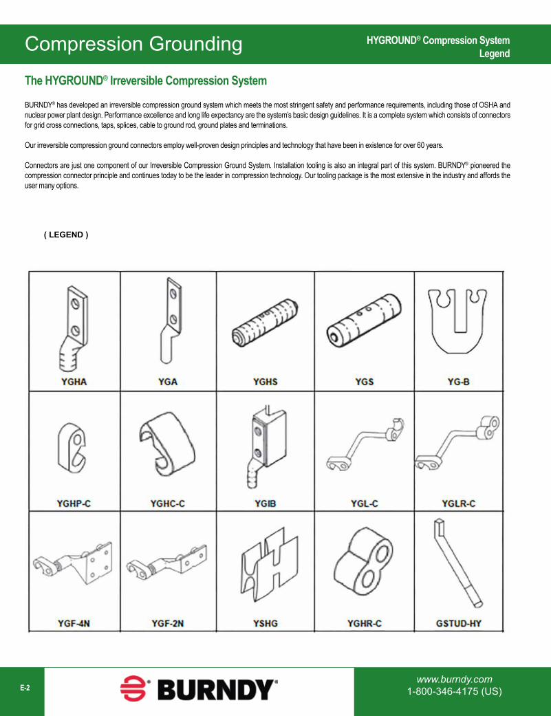
The HYGROUND® Irreversible Compression System
BURNDY® has developed an irreversible compression ground system which meets the most stringent safety and performance requirements, including those of OSHA and nuclear power plant design. Performance excellence and long life expectancy are the system’s basic design guidelines. It is a complete system which consists of connectors for grid cross connections, taps, splices, cable to ground rod, ground plates and terminations.
Our irreversible compression ground connectors employ well-proven design principles and technology that have been in existence for over 60 years.
Connectors are just one component of our Irreversible Compression Ground System. Installation tooling is also an integral part of this system. BURNDY® pioneered the compression connector principle and continues today to be the leader in compression technology. Our tooling package is the most extensive in the industry and affords the user many options.
( LEGEND )
Compression Grounding
1-800-465-7051 (Canada)1-603-647-5299 (International) E-3
HYGROUND® Compression SystemGrid Example / Ground Rod/Rebar Diameter Chart
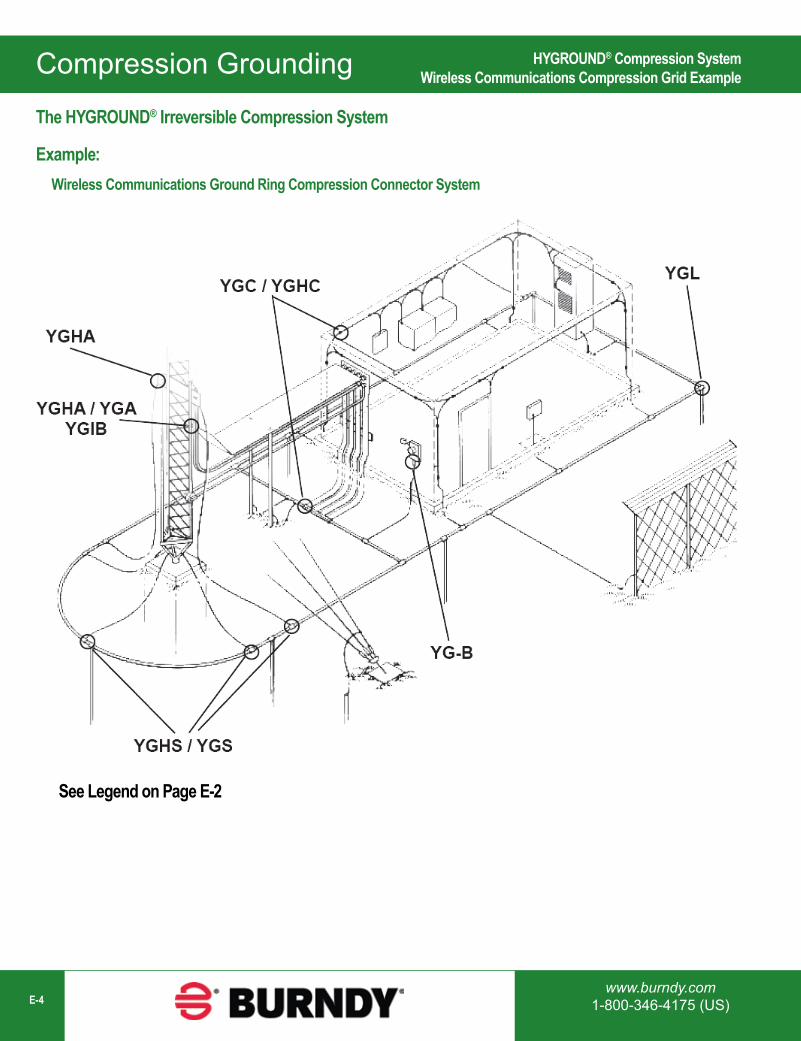
YGHP-C or YGHC-C
YGHR-C orYGHP-C
YGF-4NYSHG
GSTUD-HYYGF-2N
YGHP-C
YGHC-C orYGHP-C
YGHA orYGA
YGIB
YGHP-C orYGHC-C
YGLR-C orYGL-C
YGHR-C
YGL-C
YGHS orYGS
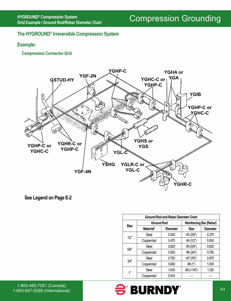
See Legend on Page E-2
The HYGROUND® Irreversible Compression System
Example: Compression Connector Grid
Ground Rod and Rebar Diameter Chart
SizeGround Rod Reinforcing Bar (Rebar)
Material* Diameter Size Diameter
1/2”Steel 0.500 #3 (3/8”) 0.375
Copperclad 0.475 #4 (1/2”) 0.500
5/8”Steel 0.625 #5 (5/8”) 0.625
Copperclad 0.563 #6 (3/4”) 0.750
3/4”Steel 0.750 #7 (7/8”) 0.875
Copperclad 0.682 #8 (1”) 1.000
1”Steel 1.000 #9 (1-1/8”) 1.128
Copperclad 0.914 — —
Compression Grounding
www.burndy.com1-800-346-4175 (US)E-4
HYGROUND® Compression SystemWireless Communications Compression Grid Example
The HYGROUND® Irreversible Compression System
Example: Wireless Communications Ground Ring Compression Connector System
See Legend on Page E-2
Compression Grounding
1-800-465-7051 (Canada)1-603-647-5299 (International) E-5
HYGROUND® Compression SystemFeatures and Benefits / Product Offering Table by Application
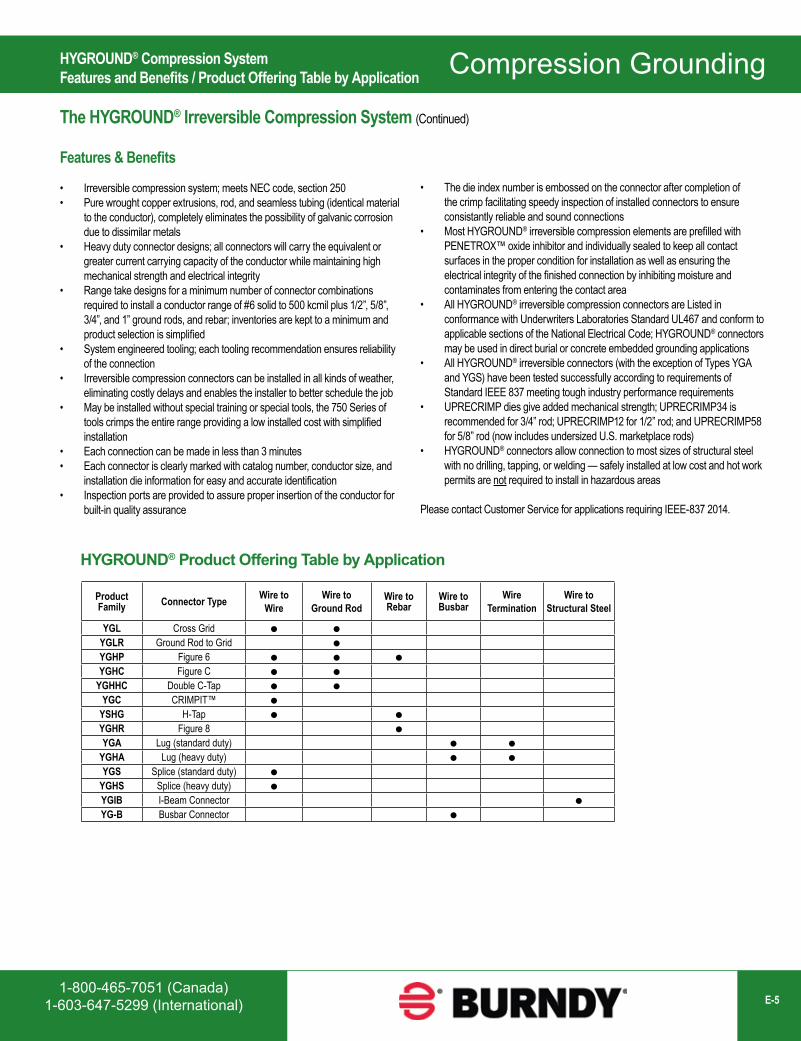
The HYGROUND® Irreversible Compression System (Continued)
Features & Benefits
• Irreversible compression system; meets NEC code, section 250• Pure wrought copper extrusions, rod, and seamless tubing (identical material
to the conductor), completely eliminates the possibility of galvanic corrosion due to dissimilar metals
• Heavy duty connector designs; all connectors will carry the equivalent or greater current carrying capacity of the conductor while maintaining high mechanical strength and electrical integrity
• Range take designs for a minimum number of connector combinations required to install a conductor range of #6 solid to 500 kcmil plus 1/2”, 5/8”, 3/4”, and 1” ground rods, and rebar; inventories are kept to a minimum and product selection is simplified
• System engineered tooling; each tooling recommendation ensures reliability of the connection
• Irreversible compression connectors can be installed in all kinds of weather, eliminating costly delays and enables the installer to better schedule the job
• May be installed without special training or special tools, the 750 Series of tools crimps the entire range providing a low installed cost with simplified installation
• Each connection can be made in less than 3 minutes• Each connector is clearly marked with catalog number, conductor size, and
installation die information for easy and accurate identification• Inspection ports are provided to assure proper insertion of the conductor for
built-in quality assurance
HYGROUND® Product Offering Table by Application
Product Family Connector Type Wire to
WireWire to
Ground RodWire to Rebar
Wire to Busbar
Wire Termination
Wire to Structural Steel
YGL Cross Grid
YGLR Ground Rod to Grid
YGHP Figure 6
YGHC Figure C
YGHHC Double C-Tap
YGC CRIMPIT™
YSHG H-Tap
YGHR Figure 8
YGA Lug (standard duty)
YGHA Lug (heavy duty)
YGS Splice (standard duty)
YGHS Splice (heavy duty)
YGIB I-Beam Connector
YG-B Busbar Connector
• The die index number is embossed on the connector after completion of the crimp facilitating speedy inspection of installed connectors to ensure consistantly reliable and sound connections
• Most HYGROUND® irreversible compression elements are prefilled with PENETROX™ oxide inhibitor and individually sealed to keep all contact surfaces in the proper condition for installation as well as ensuring the electrical integrity of the finished connection by inhibiting moisture and contaminates from entering the contact area
• All HYGROUND® irreversible compression connectors are Listed in conformance with Underwriters Laboratories Standard UL467 and conform to applicable sections of the National Electrical Code; HYGROUND® connectors may be used in direct burial or concrete embedded grounding applications
• All HYGROUND® irreversible connectors (with the exception of Types YGA and YGS) have been tested successfully according to requirements of Standard IEEE 837 meeting tough industry performance requirements
• UPRECRIMP dies give added mechanical strength; UPRECRIMP34 is recommended for 3/4” rod; UPRECRIMP12 for 1/2” rod; and UPRECRIMP58 for 5/8” rod (now includes undersized U.S. marketplace rods)
• HYGROUND® connectors allow connection to most sizes of structural steel with no drilling, tapping, or welding — safely installed at low cost and hot work permits are not required to install in hazardous areas
Please contact Customer Service for applications requiring IEEE-837 2014.
Compression Grounding
www.burndy.com1-800-346-4175 (US)E-6
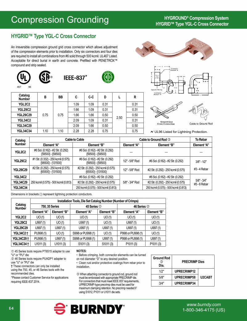
Catalog Number B BB C C-C D L R
YGL2C2
0.75 0.75
1.09 1.09 0.31
2.50
0.31YGL29C2 1.66 1.09 0.31 0.31YGL29C29 1.66 1.66 0.50 0.50YGL34C2 2.09 1.09 0.31 0.31YGL34C29 2.09 1.66 0.50 0.50YGL34C34 1.10 1.10 2.28 2.28 0.75 0.75
Catalog Number
Cable to Cable Cable to Ground Rod To RebarElement “A” Element “B” Element “A” Element “B” Element “A”
YGL2C2 #6 Sol. (0.162) - #2 Str. (0.292) {59500} - {59500}
#6 Sol. (0.162) - #2 Str. (0.292) {59500} - {59500} — — —
YGL29C2 #1 Str. (0.332) - 250 kcmil (0.575) {98500} - {131500}
#6 Sol. (0.162) - #2 Str. (0.292) {59500} - {59500} 1/2" - 5/8" Rod #6 Sol. (0.162) - #2 Str. (0.292) 3/8" - 1/2"
#3 - 4 RebarYGL29C29 #2 Str. (0.292) - 250 kcmil (0.575) {65500} - {131500}
#2 Str. (0.292) - 250 kcmil (0.575) {65500} - {131500} 1/2" - 5/8" Rod #2 Str. (0.292) - 250 kcmil (0.575)
YGL34C2250 kcmil (0.575) - 500 kcmil (0.813)
#6 Sol. (0.162) - #2 Str. (0.292)5/8" - 3/4" Rod
#6 Sol. (0.162) - #2 Str. (0.292)5/8" - 3/4"
#5 - 6 RebarYGL34C29 #2 Str. (0.292) - 250 kcmil (0.575) #2 Str. (0.292) - 250 kcmil (0.575)YGL34C34 250 kcmil (0.575) - 500 kcmil (0.813) 250 kcmil (0.575) - 500 kcmil (0.813)
Catalog Number
Installation Tools, Die Set Catalog Number (Number of Crimps)750, 35 Series 45 Series 46 Series
Element “A” Element “B” Element “A” Element “B” Element “A” Element “B”YGL2C2 UO (1) UO (1) UO (1) UO (1) UO (1) UO (1)YGL29C2 U997 (1) UO (1) U997 (1) UO (1) U997 (1) UO (1)YGL29C29 U997 (1) U997 (1) U997 (1) U997 (1) U997 (1) U997 (1)YGL34C2 † PU998 (1) UO (1) S998 or PU998 (1) UO (1) P998 or PU998 (1) UO (1)YGL34C29 † PU998 (1) U997 (1) S998 or PU998 (1) U997 (1) P998 or PU998 (1) U997 (1)YGL34C34 † U1011 (3) U1011 (3) S1011 (3) S1011 (3) P1011 (3) P1011 (3)
Dimensions in brackets { } represent lightning protection conductors.
45 Series tools require PT6515 adapter to use "U" or "PU" die 46 Series tools require PUADP1 adapter to use "U" or "PU" die† These connectors can only be installed using the 750, 45, or 46 Series tools with the recommended dies.*Please contact Customer Service for applications requiring IEEE-837 2014.
NOTES:• Before crimping, both connector elements can be turned on rod diameter “D” to any desired position.• Clean rust and/or protective coatings from rebar prior to installation.
When attaching connector to ground rod, ground rod must be embossed with appropriate PRECRIMP die. For connectors that must meet IEEE 837 requirements, UPRECRIMP-type precrimp dies must be used for maximum clamping retention. No precrimp needed if using S1012, P1011 or U1011 die sets.
Ground Rod
Dia. PRECRIMP Dies
1/2" UPRECRIMP12U2CABT5/8" UPRECRIMP58
3/4" UPRECRIMP34
467 96
UL96 Listed for Lightning Protection.
*
HYGRID™ Type YGL-C Cross Connector
An irreversible compression ground grid cross connector which allows adjustment of the compression elements prior to installation. Only six connectors and four dies are required to install all combinations from #6 solid through 500 kcmil. UL467 Listed. Acceptable for direct burial in earth and concrete. Prefilled with PENETROX™ compound and strip sealed.
HYGROUND® Compression SystemHYGRID™ Type YGL-C Cross Connector
Compression Grounding
1-800-465-7051 (Canada)1-603-647-5299 (International) E-7
HYGROUND® Compression SystemGRIDLOK™ Type YGLR-C Ground Rod to Grid Connector
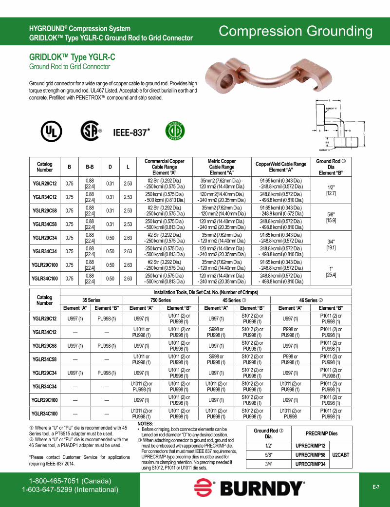
Catalog Number B B-B D L
Commercial Copper Cable Range Element “A”
Metric Copper Cable Range Element “A”
CopperWeld Cable Range Element “A”
Ground Rod Dia
Element “B”
YGLR29C12 0.75 0.88[22.4] 0.31 2.53 #2 Str. (0.292 Dia.)
- 250 kcmil (0.575 Dia.)35mm2 (7.62mm Dia.) -
120 mm2 (14.40mm Dia.)91.65 kcmil (0.343 Dia.) - 248.8 kcmil (0.572 Dia.) 1/2"
[12.7]YGLR34C12 0.75 0.88[22.4] 0.31 2.53 250 kcmil (0.575 Dia.)
- 500 kcmil (0.813 Dia.)120 mm2(14.40mm Dia.)
- 240 mm2 (20.35mm Dia.)248.8 kcmil (0.572 Dia.)
- 498.8 kcmil (0.810 Dia.)
YGLR29C58 0.75 0.88[22.4] 0.31 2.53 #2 Str. (0.292 Dia.)
- 250 kcmil (0.575 Dia.)35mm2 (7.62mm Dia.)
- 120 mm2 (14.40mm Dia.)91.65 kcmil (0.343 Dia.)
- 248.8 kcmil (0.572 Dia.) 5/8"[15.9]YGLR34C58 0.75 0.88
[22.4] 0.31 2.53 250 kcmil (0.575 Dia.) - 500 kcmil (0.813 Dia.)
120 mm2 (14.40mm Dia.) - 240 mm2 (20.35mm Dia.)
248.8 kcmil (0.572 Dia.) - 498.8 kcmil (0.810 Dia.)
YGLR29C34 0.75 0.88[22.4] 0.50 2.63 #2 Str. (0.292 Dia.)
- 250 kcmil (0.575 Dia.)35mm2 (7.62mm Dia.)
- 120 mm2 (14.40mm Dia.)91.65 kcmil (0.343 Dia.) - 248.8 kcmil (0.572 Dia.) 3/4"
[19.1]YGLR34C34 0.75 0.88[22.4] 0.50 2.63 250 kcmil (0.575 Dia.)
- 500 kcmil (0.813 Dia.)120 mm2 (14.40mm Dia.)
- 240 mm2 (20.35mm Dia.)248.8 kcmil (0.572 Dia.)
- 498.8 kcmil (0.810 Dia.)
YGLR29C100 0.75 0.88[22.4] 0.50 2.63 #2 Str. (0.292 Dia.)
- 250 kcmil (0.575 Dia.)35mm2 (7.62mm Dia.)
- 120 mm2 (14.40mm Dia.)91.65 kcmil (0.343 Dia.) - 248.8 kcmil (0.572 Dia.) 1"
[25.4]YGLR34C100 0.75 0.88[22.4] 0.50 2.63 250 kcmil (0.575 Dia.)
- 500 kcmil (0.813 Dia.)120 mm2 (14.40mm Dia.)
- 240 mm2 (20.35mm Dia.)248.8 kcmil (0.572 Dia.)
- 498.8 kcmil (0.810 Dia.)
Catalog Number
Installation Tools, Die Set Cat. No. (Number of Crimps)35 Series 750 Series 45 Series 46 Series
Element “A” Element “B” Element “A” Element “B” Element “A” Element “B” Element “A” Element “B”
YGLR29C12 U997 (1) PU998 (1) U997 (1) U1011 (2) or PU998 (1) U997 (1) S1012 (2) or
PU998 (1) U997 (1) P1011 (2) or PU998 (1)
YGLR34C12 — — U1011 or PU998 (1)
U1011 (2) or PU998 (1)
S998 or PU998 (1)
S1012 (2) or PU998 (1)
P998 or PU998 (1)
P1011 (2) or PU998 (1)
YGLR29C58 U997 (1) PU998 (1) U997 (1) U1011 (2) or PU998 (1) U997 (1) S1012 (2) or
PU998 (1) U997 (1) P1011 (2) or PU998 (1)
YGLR34C58 — — U1011 or PU998 (1)
U1011 (2) or PU998 (1)
S998 or PU998 (1)
S1012 (2) or PU998 (1)
P998 or PU998 (1)
P1011 (2) or PU998 (1)
YGLR29C34 U997 (1) PU998 (1) U997 (1) U1011 (2) or PU998 (1) U997 (1) S1012 (2) or
PU998 (1) U997 (1) P1011 (2) or PU998 (1)
YGLR34C34 — — U1011 (2) or PU998 (1)
U1011 (2) or PU998 (1)
U1011 (2) or PU998 (1)
S1012 (2) or PU998 (1)
U1011 (2) or PU998 (1)
P1011 (2) or PU998 (1)
YGLR29C100 — — U997 (1) U1011 (2) or PU998 (1) U997 (1) S1012 (2) or
PU998 (1) U997 (1) P1011 (2) or PU998 (1)
YGLR34C100 — — U1011 (2) or PU998 (1)
U1011 (2) or PU998 (1)
U1011 (2) or PU998 (1)
S1012 (2) or PU998 (1)
U1011 (2) or PU998
P1011 (2) or PU998 (1)
Ground Rod Dia. PRECRIMP Dies
1/2″ UPRECRIMP12U2CABT5/8″ UPRECRIMP58
3/4″ UPRECRIMP34
Where a “U” or “PU” die is recommended with 45 Series tool, a PT6515 adapter must be used. Where a “U” or “PU” die is recommended with the 46 Series tool, a PUADP1 adapter must be used.
NOTES:• Before crimping, both connector elements can be turned on rod diameter “D” to any desired position. When attaching connector to ground rod, ground rod must be embossed with appropriate PRECRIMP die. For connectors that must meet IEEE 837 requirements, UPRECRIMP-type precrimp dies must be used for maximum clamping retention. No precrimp needed if using S1012, P1011 or U1011 die sets.
*Please contact Customer Service for applications requiring IEEE-837 2014.
*
GRIDLOK™ Type YGLR-C Ground Rod to Grid Connector
Ground grid connector for a wide range of copper cable to ground rod. Provides high torque strength on ground rod. UL467 Listed. Acceptable for direct burial in earth and concrete. Prefilled with PENETROX™ compound and strip sealed.

Compression Grounding
www.burndy.com1-800-346-4175 (US)E-8
HYGROUND® Compression SystemHYTAP™ Type YGHP-C Figure 6 Connector
UL96 Listed for Lightning Protection.
Catalog Number
Fig.#
Accommodates Cable to Rebar
B Die Index
Installation Data
Run Tap Run Tap 750, 35Series
45Series
46Series
#of
Crimps
YGHP2C2 1#6 Sol. (0.162)
{59500} - #2 Str. (0.292)
{59500}
#6 Sol. (0.162) {59500} -
#2 Str. (0.292) {59500}
— —
0.75
O UO UO UO
1
YGHP2C6W6W 2 #6 Sol. (0.162) -
#2 Str. (0.292) #8 Sol. (0.128) -
#6 Str. (0.184) Qty. 2 — — 1
YGHP29C6W6W 2
1/0 Str. (0.372) {98500} -
250 kcmil (0.575) {131500}
1/2” - 5/8” Rod
#8 Sol. (0.128) - #6 Str. (0.184) Qty. 2
#3 Rebar 3/8-
1/2 #4 Rebar#8 Sol. -
6 Str.
997 U997 U997 U997
1
YGHP29C2 1 #4 Sol. (0.204) {#4 Sol.} - #2 Str. (0.292) {#2 Str.}
#3 Rebar 3/8-
1/2 #4 Rebar#2 Str.
2.31
1
YGHP29C26 1 1/0 Str. (0.372) {98500} - 2/0 Str. (0.419) {98500}
#3 Rebar 3/8-
1/2 #4 Rebar1/0 Str. - 2/0 Str. 1
YGHP29C29 1 3/0 Str. (0.470) {131500} -
250 kcmil (0.575) {211500}#3 Rebar 3/8
-1/2 #4 Rebar
3/0 Str. - 250 kcmil 1
YGHP34C2 1
250 kcmil (0.575) {250 kcmil} -
500 kcmil (0.813) {500 kcmil}
5/8” - 3/4” Rod
#4 Sol. (0.204) - #2 Str. (0.292)
#5 Rebar 5/8-
3/4 #6 Rebar—
998 PU998 PU998 or S998
PU998 or
P998
1
YGHP34C26 1 1/0 Str. (0.372) {98500} -
2/0 Str. (0.419) {98500}#5 Rebar 5/8
-3/4 #6 Rebar
1/0 Str. - 2/0 Str. 1
YGHP34C29 1 3/0 Str. (0.470) {131500} -
250 kcmil (0.575) {211500}#5 Rebar 5/8
-3/4 #6 Rebar
3/0 Str. - 250 kcmil 1
YGHP34C34 1
250 kcmil (0.575) - 500 kcmil (0.813) 5/8” - 3/4” Rod
350 kcmil (0.681) - 500 kcmil (0.843)
#5 Rebar 5/8-
3/4 #6 Rebar
350kcmil -
500 kcmil2.75 1011 U1011 S1011 P1011 3
45 Series tools require PT6515 adapter to use "U" or "PU" die 46 Series tools require PUADP1 adapter to use "U" or "PU" dieThese connectors can only be installed using the 750, 45 or 46 Series tools; cannot be installed with the 35 Series.When using #6 Sol in tap, fold conductor double for improved fill.Not UL96/CSAWhen using 3/0 in tap, minimum run conductor must be 2/0 Str.Clean rust and protective coatings from rebar prior to installation to provide proper ground connection. Precrimping is not required.
NOTES:Ground Rod Dia. PRECRIMP Dies
1/2″ UPRECRIMP12U2CABT5/8″ UPRECRIMP58
3/4″ UPRECRIMP34 When attaching connector to ground rod, ground rod must be embossed with appropriate PRECRIMP die. For connectors that must meet IEEE 837 requirements, UPRECRIMP-type precrimp dies must be used for maximum clamping retention. No precrimp needed if using S1012, P1011 or U1011 die sets.
Fig. 1 Fig. 2
*Please contact Customer Service for applications requiring IEEE-837 2014.
467 96
*
HYTAP™ Type YGHP-C Figure 6 Connector
Irreversible compression ground tap figure 6 can be used as a tap connector or as a tap splice connector. Four die sets and eight connectors can accommodate a conductor range from #8 solid through 500 kcmil plus 1/2”, 5/8” and 3/4” copper bonded ground rods. UL467 Listed. Acceptable for direct burial in earth and concrete. Prefilled with PENETROX™ compound and strip sealed.
Dimensions in brackets { } represent lightning protection conductors.
Compression Grounding
1-800-465-7051 (Canada)1-603-647-5299 (International) E-9
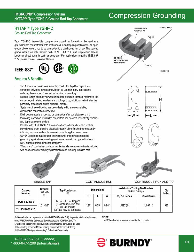
HYGROUND® Compression SystemHYTAP™ Type YGHP-C Ground Rod Tap Connector
Catalog Number
Ground Rod Dia.
Tap Conductor
Dimensions Installation Tooling Die Number (# of Crimps) Die
IndexH L W 35, 750 Series 46 Series
YGHP58C2W-21/2" - 5/8"
#2 Sol. - #6 Sol. Copper(1) Continuous Run and
(1) Tap or up to (2) Taps may be connected
1.90" 0.75" 0.94" U997 (1) U997 (1) 997YGHP58C2W-2TN
SINGLE TAP CONTINUOUS RUN CONTINUOUS RUN AND TAP
Ground rod must be precrimped with die U2CABT (Index 348); for greater rotational resistance use UPRECRIMP die; Galvanized Steel Rods require YGHP58C2W-2TN Either tap position may be left void when fewer than (2) conductors are used See Tooling Section in Master Catalog for complete tool and die listing Use PUADP1 adapter when using “U”-dies in 46 Series tools
NOTE: A 12″ bend radius is recommended for the conductor
DIE INDEXAND CONDUCTORINFORMATION
PREFILLED WITHPENETROX™ E
“THIRD HAND”
TAP (B)
TAP (A)
PATENTED*
HYTAP™ Type YGHP-C Ground Rod Tap Connector
Type YGHP-C irreversible compression ground tap figure 6 can be used as a ground rod tap connector for both continuous run and tapping applications. An open groove allows ground rod to be connected to a continuous run or tap. The second groove is for a tap only. Prefilled with PENETROX™ E and strip sealed. UL467 Listed for direct burial in earth or concrete. *For applications requiring IEEE-837 2014, please contact Customer Service.
Features & Benefits
• Tap A accepts a continuous run or tap conductor; Tap B accepts a tap conductor only; one connector style can be used for many applications reducing the number of connectors required in inventory
• Material is high conductivity wrought copper extrusion, identical material to the conductor, minimizing resistance and voltage drop; additionally eliminates the possibility of corrosion due to dissimilar metals
• System engineered tooling has been designed to ensure a reliable, dependable connection every time
• Die index number is embossed on connector after completion of crimp facilitating inspection of installed connectors and ensures consistently reliable and dependable connections
• Prefilled with PENETROX™ E compound and individually sealed in clear polyethylene sheet ensuring electrical integrity of the finished connection by inhibiting moisture and contaminates from entering the contact area
• UL467 Listed and may be used in direct burial or concrete embedded grounding applications providing quality assurance to recognized industry NEC standard from an independent party
• “Third Hand” constrains conductors while installer completes crimp is included with each connector simplifying installation and reducing installed cost
Compression Grounding
www.burndy.com1-800-346-4175 (US)E-10
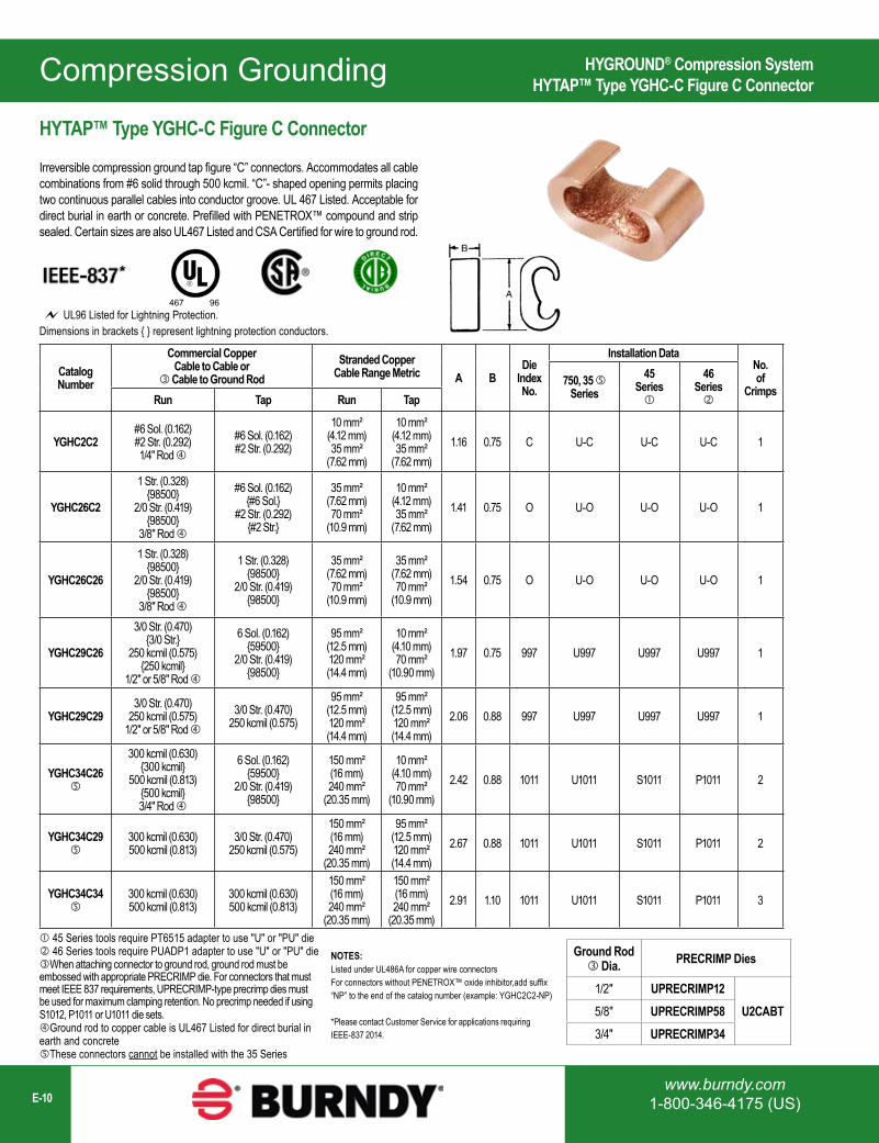
HYGROUND® Compression SystemHYTAP™ Type YGHC-C Figure C Connector
HYTAP™ Type YGHC-C Figure C Connector
Irreversible compression ground tap figure “C” connectors. Accommodates all cable combinations from #6 solid through 500 kcmil. “C”- shaped opening permits placing two continuous parallel cables into conductor groove. UL 467 Listed. Acceptable for direct burial in earth or concrete. Prefilled with PENETROX™ compound and strip sealed. Certain sizes are also UL467 Listed and CSA Certified for wire to ground rod.
Catalog Number
Commercial Copper Cable to Cable or
Cable to Ground RodStranded Copper
Cable Range Metric A BDie
Index No.
Installation DataNo. of
Crimps750, 35
Series45
Series
46 SeriesRun Tap Run Tap
YGHC2C2#6 Sol. (0.162)#2 Str. (0.292)1/4" Rod
#6 Sol. (0.162)#2 Str. (0.292)
10 mm² (4.12 mm)35 mm²
(7.62 mm)
10 mm² (4.12 mm)35 mm²
(7.62 mm)1.16 0.75 C U-C U-C U-C 1
YGHC26C2
1 Str. (0.328) {98500}
2/0 Str. (0.419) {98500}
3/8" Rod
#6 Sol. (0.162) {#6 Sol.}
#2 Str. (0.292) {#2 Str.}
35 mm² (7.62 mm)70 mm²
(10.9 mm)
10 mm² (4.12 mm)35 mm²
(7.62 mm)1.41 0.75 O U-O U-O U-O 1
YGHC26C26
1 Str. (0.328) {98500}
2/0 Str. (0.419) {98500}
3/8" Rod
1 Str. (0.328) {98500}
2/0 Str. (0.419) {98500}
35 mm² (7.62 mm)70 mm²
(10.9 mm)
35 mm² (7.62 mm)70 mm²
(10.9 mm)1.54 0.75 O U-O U-O U-O 1
YGHC29C26
3/0 Str. (0.470) {3/0 Str.}
250 kcmil (0.575) {250 kcmil}
1/2" or 5/8" Rod
6 Sol. (0.162) {59500}
2/0 Str. (0.419) {98500}
95 mm² (12.5 mm)120 mm² (14.4 mm)
10 mm² (4.10 mm)70 mm²
(10.90 mm)1.97 0.75 997 U997 U997 U997 1
YGHC29C293/0 Str. (0.470)
250 kcmil (0.575)1/2" or 5/8" Rod
3/0 Str. (0.470)250 kcmil (0.575)
95 mm² (12.5 mm)120 mm² (14.4 mm)
95 mm² (12.5 mm)120 mm² (14.4 mm)
2.06 0.88 997 U997 U997 U997 1
YGHC34C26
300 kcmil (0.630) {300 kcmil}
500 kcmil (0.813) {500 kcmil}3/4" Rod
6 Sol. (0.162) {59500}
2/0 Str. (0.419) {98500}
150 mm² (16 mm)240 mm²
(20.35 mm)
10 mm² (4.10 mm)70 mm²
(10.90 mm)2.42 0.88 1011 U1011 S1011 P1011 2
YGHC34C29
300 kcmil (0.630)500 kcmil (0.813)
3/0 Str. (0.470)250 kcmil (0.575)
150 mm² (16 mm)240 mm²
(20.35 mm)
95 mm² (12.5 mm)120 mm² (14.4 mm)
2.67 0.88 1011 U1011 S1011 P1011 2
YGHC34C34
300 kcmil (0.630)500 kcmil (0.813)
300 kcmil (0.630)500 kcmil (0.813)
150 mm² (16 mm)240 mm²
(20.35 mm)
150 mm² (16 mm)240 mm²
(20.35 mm)2.91 1.10 1011 U1011 S1011 P1011 3
Ground Rod Dia. PRECRIMP Dies
1/2" UPRECRIMP12U2CABT5/8" UPRECRIMP58
3/4" UPRECRIMP34
45 Series tools require PT6515 adapter to use "U" or "PU" die 46 Series tools require PUADP1 adapter to use "U" or "PU" dieWhen attaching connector to ground rod, ground rod must be embossed with appropriate PRECRIMP die. For connectors that must meet IEEE 837 requirements, UPRECRIMP-type precrimp dies must be used for maximum clamping retention. No precrimp needed if using S1012, P1011 or U1011 die sets.Ground rod to copper cable is UL467 Listed for direct burial in earth and concreteThese connectors cannot be installed with the 35 Series
NOTES:Listed under UL486A for copper wire connectorsFor connectors without PENETROX™ oxide inhibitor,add suffix “NP” to the end of the catalog number (example: YGHC2C2-NP)
*Please contact Customer Service for applications requiring IEEE-837 2014.
467 96 UL96 Listed for Lightning Protection.
*
Dimensions in brackets { } represent lightning protection conductors.
Compression Grounding
1-800-465-7051 (Canada)1-603-647-5299 (International) E-11
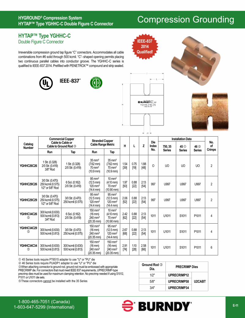
HYGROUND® Compression SystemHYTAP™ Type YGHHC-C Double Figure C Connector
IEEE-8372014
Qualified!
Catalog Number
Commercial Copper Cable to Cable or
Cable to Ground Rod Stranded Copper
Cable Range Metric H L ZDie
Index No.
Installation DataNo. of
Crimps750, 35Series
45 Series
46 SeriesRun Tap Run Tap
YGHHC26C261 Str. (0.328)
2/0 Str. (0.419) 3/8" Rod
1 Str. (0.328) 2/0 Str. (0.419)
35 mm² (7.62 mm)70 mm²
(10.9 mm)
35 mm² (7.62 mm)70 mm²
(10.9 mm)
1.54[39]
0.75[19]
1.88[48] O UO UO UO 2
YGHHC29C263/0 Str. (0.470)
250 kcmil (0.575) 1/2" or 5/8" Rod
6 Sol. (0.162) 2/0 Str. (0.419)
95 mm² (12.5 mm)120 mm² (14.4 mm)
10 mm² (4.10 mm)70 mm²
(10.90 mm)
1.97[50]
0.88[22]
2.13[54] 997 U997 U997 U997 2
YGHHC29C293/0 Str. (0.470)
250 kcmil (0.575)1/2" or 5/8" Rod
3/0 Str. (0.470)250 kcmil (0.575)
95 mm² (12.5 mm)120 mm² (14.4 mm)
95 mm² (12.5 mm)120 mm² (14.4 mm)
2.06[52]
0.88[22]
2.13[54] 997 U997 U997 U997 2
YGHHC34C26
300 kcmil (0.630) 500 kcmil (0.813)
3/4" Rod6 Sol. (0.162)
2/0 Str. (0.419)
150 mm² (16 mm)240 mm²
(20.35 mm)
10 mm² (4.10 mm)70 mm²
(10.90 mm)
2.42[62]
0.88[22]
2.13[54] 1011 U1011 S1011 P1011 4
YGHHC34C29 300 kcmil (0.630)
500 kcmil (0.813)3/0 Str. (0.470)
250 kcmil (0.575)
150 mm² (16 mm)240 mm²
(20.35 mm)
95 mm² (12.5 mm)120 mm² (14.4 mm)
2.67[68]
0.88[22]
2.13[54] 1011 U1011 S1011 P1011 4
YGHHC34C34
300 kcmil (0.630)500 kcmil (0.813)
300 kcmil (0.630)500 kcmil (0.813)
150 mm² (16 mm)240 mm²
(20.35 mm)
150 mm² (16 mm)240 mm²
(20.35 mm)
2.91[74]
1.10[28]
2.58[66] 1011 U1011 S1011 P1011 6
Ground Rod Dia. PRECRIMP Dies
1/2" UPRECRIMP12U2CABT5/8" UPRECRIMP58
3/4" UPRECRIMP34
HYTAP™ Type YGHHC-C Double Figure C Connector
Irreversible compression ground tap figure “C” connectors. Accommodates all cable combinations from #6 solid through 500 kcmil. “C”- shaped opening permits placing two continuous parallel cables into conductor groove. The YGHHC-C series is qualified to IEEE-837 2014. Prefilled with PENETROX™ compound and strip sealed.
45 Series tools require PT6515 adapter to use "U" or "PU" die 46 Series tools require PUADP1 adapter to use "U" or "PU" dieWhen attaching connector to ground rod, ground rod must be embossed with appropriate PRECRIMP die. For connectors that must meet IEEE 837 requirements, UPRECRIMP-type precrimp dies must be used for maximum clamping retention. No precrimp needed if using S1012, P1011 or U1011 die sets.These connectors cannot be installed with the 35 Series
Compression Grounding
www.burndy.com1-800-346-4175 (US)E-12
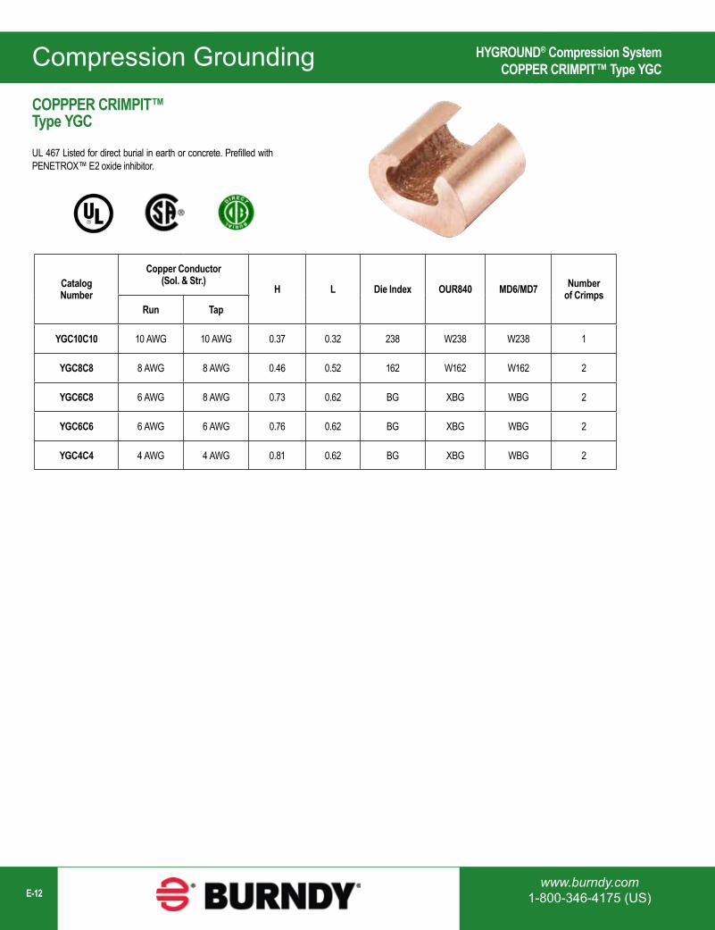
HYGROUND® Compression SystemCOPPER CRIMPIT™ Type YGC
Catalog Number
Copper Conductor (Sol. & Str.)
H L Die Index OUR840 MD6/MD7 Number of Crimps
Run Tap
YGC10C10 10 AWG 10 AWG 0.37 0.32 238 W238 W238 1
YGC8C8 8 AWG 8 AWG 0.46 0.52 162 W162 W162 2
YGC6C8 6 AWG 8 AWG 0.73 0.62 BG XBG WBG 2
YGC6C6 6 AWG 6 AWG 0.76 0.62 BG XBG WBG 2
YGC4C4 4 AWG 4 AWG 0.81 0.62 BG XBG WBG 2
COPPPER CRIMPIT™ Type YGC
UL 467 Listed for direct burial in earth or concrete. Prefilled with PENETROX™ E2 oxide inhibitor.
Compression Grounding
1-800-465-7051 (Canada)1-603-647-5299 (International) E-13
HYGROUND® Compression SystemHYTAP™ Type YSHG Double H-Tap Connector
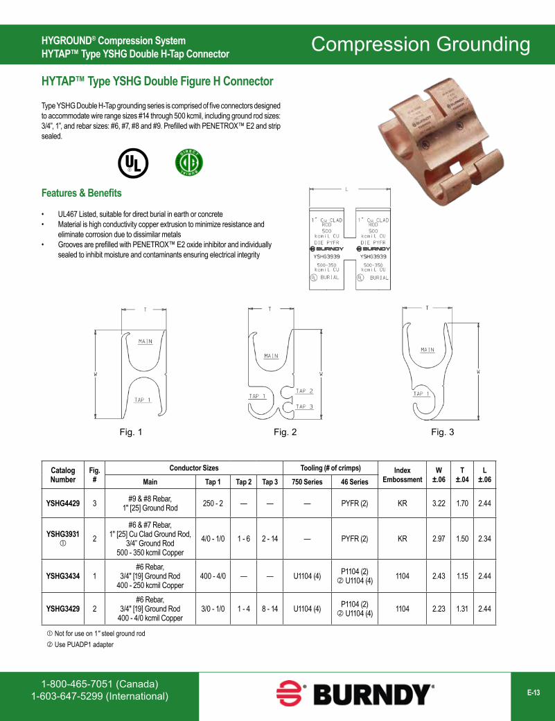
HYTAP™ Type YSHG Double Figure H Connector
Type YSHG Double H-Tap grounding series is comprised of five connectors designed to accommodate wire range sizes #14 through 500 kcmil, including ground rod sizes: 3/4”, 1”, and rebar sizes: #6, #7, #8 and #9. Prefilled with PENETROX™ E2 and strip sealed.
Catalog Number
Fig. #
Conductor Sizes Tooling (# of crimps) Index Embossment
W±.06
T±.04
L±.06Main Tap 1 Tap 2 Tap 3 750 Series 46 Series
YSHG4429 3 #9 & #8 Rebar, 1" [25] Ground Rod 250 - 2 — — — PYFR (2) KR 3.22 1.70 2.44
YSHG3931
2#6 & #7 Rebar,
1" [25] Cu Clad Ground Rod, 3/4” Ground Rod
500 - 350 kcmil Copper4/0 - 1/0 1 - 6 2 - 14 — PYFR (2) KR 2.97 1.50 2.34
YSHG3434 1#6 Rebar,
3/4" [19] Ground Rod400 - 250 kcmil Copper
400 - 4/0 — — U1104 (4) P1104 (2) U1104 (4) 1104 2.43 1.15 2.44
YSHG3429 2#6 Rebar,
3/4" [19] Ground Rod400 - 4/0 kcmil Copper
3/0 - 1/0 1 - 4 8 - 14 U1104 (4) P1104 (2) U1104 (4) 1104 2.23 1.31 2.44
Fig. 1 Fig. 2 Fig. 3
Not for use on 1″ steel ground rod Use PUADP1 adapter
Features & Benefits
• UL467 Listed, suitable for direct burial in earth or concrete• Material is high conductivity copper extrusion to minimize resistance and
eliminate corrosion due to dissimilar metals• Grooves are prefilled with PENETROX™ E2 oxide inhibitor and individually
sealed to inhibit moisture and contaminants ensuring electrical integrity
Compression Grounding
www.burndy.com1-800-346-4175 (US)E-14
HYGROUND® Compression SystemHYTAIL™ Type YGHR-C Ground Rod Tap Connector
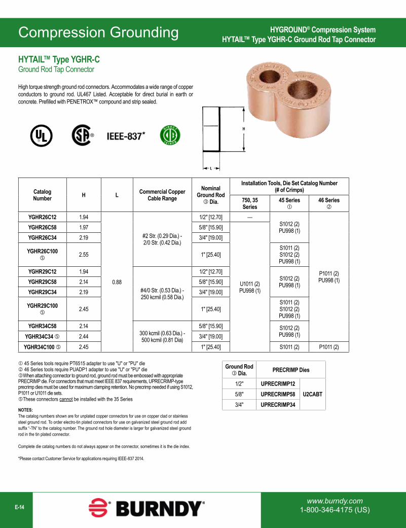
NOTES:The catalog numbers shown are for unplated copper connectors for use on copper clad or stainless steel ground rod. To order electro-tin plated connectors for use on galvanized steel ground rod add suffix “-TN” to the catalog number. The ground rod hole diameter is larger for galvanized steel ground rod in the tin plated connector.
Complete die catalog numbers do not always appear on the connector, sometimes it is the die index.
*Please contact Customer Service for applications requiring IEEE-837 2014.
Catalog Number H L Commercial Copper
Cable RangeNominal
Ground Rod Dia.
Installation Tools, Die Set Catalog Number (# of Crimps)
750, 35 Series
45 Series
46 Series
YGHR26C12 1.94
0.88
#2 Str. (0.29 Dia.) - 2/0 Str. (0.42 Dia.)
1/2" [12.70] —S1012 (2)PU998 (1)
P1011 (2)PU998 (1)
YGHR26C58 1.97 5/8" [15.90]
U1011 (2)PU998 (1)
YGHR26C34 2.19 3/4" [19.00]
YGHR26C100
2.55 1" [25.40]S1011 (2)S1012 (2)PU998 (1)
YGHR29C12 1.94
#4/0 Str. (0.53 Dia.) - 250 kcmil (0.58 Dia.)
1/2" [12.70]S1012 (2)PU998 (1)YGHR29C58 2.14 5/8" [15.90]
YGHR29C34 2.19 3/4" [19.00]
YGHR29C100
2.45 1" [25.40]S1011 (2)S1012 (2)PU998 (1)
YGHR34C58 2.14300 kcmil (0.63 Dia.) - 500 kcmil (0.81 Dia)
5/8" [15.90] S1012 (2)PU998 (1)YGHR34C34 2.44 3/4" [19.00]
YGHR34C100 2.45 1" [25.40] S1011 (2) P1011 (2)
*
HYTAIL™ Type YGHR-C Ground Rod Tap Connector
High torque strength ground rod connectors. Accommodates a wide range of copper conductors to ground rod. UL467 Listed. Acceptable for direct burial in earth or concrete. Prefilled with PENETROX™ compound and strip sealed.
Ground Rod Dia. PRECRIMP Dies
1/2" UPRECRIMP12U2CABT5/8" UPRECRIMP58
3/4" UPRECRIMP34
45 Series tools require PT6515 adapter to use "U" or "PU" die 46 Series tools require PUADP1 adapter to use "U" or "PU" dieWhen attaching connector to ground rod, ground rod must be embossed with appropriate PRECRIMP die. For connectors that must meet IEEE 837 requirements, UPRECRIMP-type precrimp dies must be used for maximum clamping retention. No precrimp needed if using S1012, P1011 or U1011 die sets.These connectors cannot be installed with the 35 Series
Compression Grounding
1-800-465-7051 (Canada)1-603-647-5299 (International) E-15
HYGROUND® Compression SystemHYTAIL™ Type YGHR-C Ground Rod Tap Connector
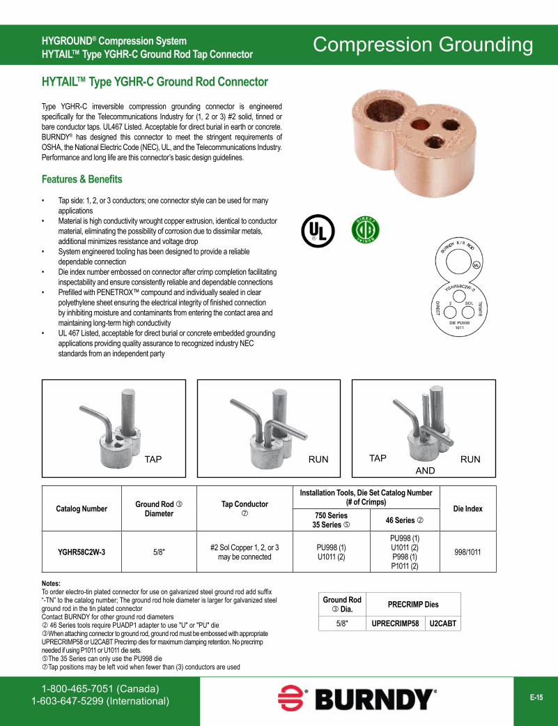
HYTAIL™ Type YGHR-C Ground Rod Connector
Type YGHR-C irreversible compression grounding connector is engineered specifically for the Telecommunications Industry for (1, 2 or 3) #2 solid, tinned or bare conductor taps. UL467 Listed. Acceptable for direct burial in earth or concrete. BURNDY® has designed this connector to meet the stringent requirements of OSHA, the National Electric Code (NEC), UL, and the Telecommunications Industry. Performance and long life are this connector’s basic design guidelines.
Features & Benefits
• Tap side: 1, 2, or 3 conductors; one connector style can be used for many applications
• Material is high conductivity wrought copper extrusion, identical to conductor material, eliminating the possibility of corrosion due to dissimilar metals, additional minimizes resistance and voltage drop
• System engineered tooling has been designed to provide a reliable dependable connection
• Die index number embossed on connector after crimp completion facilitating inspectability and ensure consistently reliable and dependable connections
• Prefilled with PENETROX™ compound and individually sealed in clear polyethylene sheet ensuring the electrical integrity of finished connection by inhibiting moisture and contaminants from entering the contact area and maintaining long-term high conductivity
• UL 467 Listed, acceptable for direct burial or concrete embedded grounding applications providing quality assurance to recognized industry NEC standards from an independent party
Catalog Number Ground Rod Diameter
Tap Conductor
Installation Tools, Die Set Catalog Number (# of Crimps)
Die Index750 Series
35 Series 46 Series
YGHR58C2W-3 5/8" #2 Sol Copper 1, 2, or 3 may be connected
PU998 (1)U1011 (2)
PU998 (1)U1011 (2)P998 (1)P1011 (2)
998/1011
TAP TAPAND
RUN RUN
Ground Rod Dia. PRECRIMP Dies
5/8" UPRECRIMP58 U2CABT
Notes:To order electro-tin plated connector for use on galvanized steel ground rod add suffix “-TN” to the catalog number; The ground rod hole diameter is larger for galvanized steel ground rod in the tin plated connectorContact BURNDY for other ground rod diameters 46 Series tools require PUADP1 adapter to use "U" or "PU" dieWhen attaching connector to ground rod, ground rod must be embossed with appropriate UPRECRIMP58 or U2CABT Precrimp dies for maximum clamping retention. No precrimp needed if using P1011 or U1011 die sets.The 35 Series can only use the PU998 dieTap positions may be left void when fewer than (3) conductors are used
Compression Grounding
www.burndy.com1-800-346-4175 (US)E-16
HYGROUND® Compression SystemHYLUG™ Type YGHA Heavy Duty Terminal
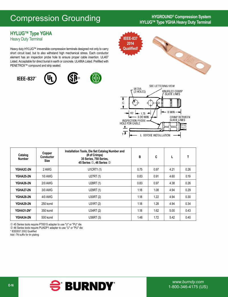
HYLUG™ Type YGHA Heavy Duty Terminal
Heavy duty HYLUG™ irreversible compression terminals designed not only to carry short circuit load, but to also withstand high mechanical stress. Each conductor element has an inspection probe hole to ensure proper cable insertion. UL467 Listed. Acceptable for direct burial in earth or concrete. UL486A Listed. Prefilled with PENETROX™ compound and strip sealed.
Catalog Number
Copper Conductor
Size
Installation Tools, Die Set Catalog Number and (# of Crimps)
35 Series, 750 Series,45 Series , 46 Series
B C L T
YGHA2C-2N 2 AWG U1CRT1 (1) 0.75 0.97 4.21 0.26
YGHA25-2N 1/0 AWG U27RT (1) 0.83 0.91 4.60 0.19
YGHA26-2N 2/0 AWG U28RT (1) 0.83 0.97 4.38 0.26
YGHA27-2N 3/0 AWG U29RT (1) 1.18 1.08 4.94 0.29
YGHA28-2N 4/0 AWG U30RT (2) 1.18 1.22 4.94 0.30
YGHA29-2N 250 kcmil U31RT (2) 1.18 1.28 4.94 0.34
YGHA31-2N* 350 kcmil U34RT (2) 1.18 1.62 5.00 0.43
YGHA34-2N 500 kcmil U36RT (3) 1.48 1.72 5.42 0.40
45 Series tools require PT6515 adapter to use "U" or "PU" die 46 Series tools require PUADP1 adapter to use "U" or "PU" die* IEEE837 2002 QualifiedAdd -TN suffix for tin plating
IEEE-8372014
Qualified!
Compression Grounding
1-800-465-7051 (Canada)1-603-647-5299 (International) E-17
HYGROUND® Compression SystemHYLUG™ Type YGA Terminal
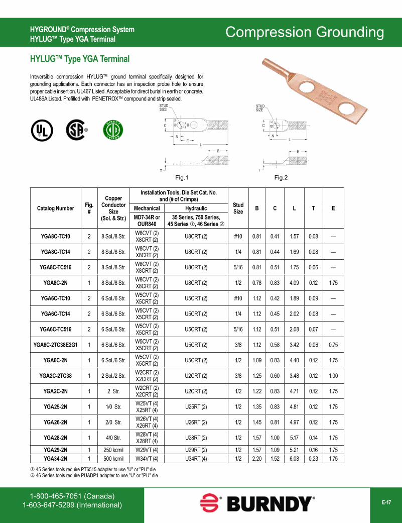
Catalog Number Fig. #
Copper Conductor
Size (Sol. & Str.)
Installation Tools, Die Set Cat. No. and (# of Crimps)
Stud Size B C L T EMechanical Hydraulic
MD7-34R or OUR840
35 Series, 750 Series,45 Series , 46 Series
YGA8C-TC10 2 8 Sol./8 Str. W8CVT (2)X8CRT (2) U8CRT (2) #10 0.81 0.41 1.57 0.08 —
YGA8C-TC14 2 8 Sol./8 Str. W8CVT (2)X8CRT (2) U8CRT (2) 1/4 0.81 0.44 1.69 0.08 —
YGA8C-TC516 2 8 Sol./8 Str. W8CVT (2)X8CRT (2) U8CRT (2) 5/16 0.81 0.51 1.75 0.06 —
YGA8C-2N 1 8 Sol./8 Str. W8CVT (2)X8CRT (2) U8CRT (2) 1/2 0.78 0.83 4.09 0.12 1.75
YGA6C-TC10 2 6 Sol./6 Str. W5CVT (2)X5CRT (2) U5CRT (2) #10 1.12 0.42 1.89 0.09 —
YGA6C-TC14 2 6 Sol./6 Str. W5CVT (2)X5CRT (2) U5CRT (2) 1/4 1.12 0.45 2.02 0.08 —
YGA6C-TC516 2 6 Sol./6 Str. W5CVT (2)X5CRT (2) U5CRT (2) 5/16 1.12 0.51 2.08 0.07 —
YGA6C-2TC38E2G1 1 6 Sol./6 Str. W5CVT (2)X5CRT (2) U5CRT (2) 3/8 1.12 0.58 3.42 0.06 0.75
YGA6C-2N 1 6 Sol./6 Str. W5CVT (2)X5CRT (2) U5CRT (2) 1/2 1.09 0.83 4.40 0.12 1.75
YGA2C-2TC38 1 2 Sol./2 Str. W2CRT (2)X2CRT (2) U2CRT (2) 3/8 1.25 0.60 3.48 0.12 1.00
YGA2C-2N 1 2 Str. W2CRT (2)X2CRT (2) U2CRT (2) 1/2 1.22 0.83 4.71 0.12 1.75
YGA25-2N 1 1/0 Str. W25VT (4)X25RT (4) U25RT (2) 1/2 1.35 0.83 4.81 0.12 1.75
YGA26-2N 1 2/0 Str. W26VT (4)X26RT (4) U26RT (2) 1/2 1.45 0.81 4.97 0.12 1.75
YGA28-2N 1 4/0 Str. W28VT (4)X28RT (4) U28RT (2) 1/2 1.57 1.00 5.17 0.14 1.75
YGA29-2N 1 250 kcmil W29VT (4) U29RT (2) 1/2 1.57 1.09 5.21 0.16 1.75YGA34-2N 1 500 kcmil W34VT (4) U34RT (4) 1/2 2.20 1.52 6.08 0.23 1.75
Fig.1 Fig.2
HYLUG™ Type YGA Terminal
Irreversible compression HYLUG™ ground terminal specifically designed for grounding applications. Each connector has an inspection probe hole to ensure proper cable insertion. UL467 Listed. Acceptable for direct burial in earth or concrete. UL486A Listed. Prefilled with PENETROX™ compound and strip sealed.
45 Series tools require PT6515 adapter to use "U" or "PU" die 46 Series tools require PUADP1 adapter to use "U" or "PU" die
Compression Grounding
www.burndy.com1-800-346-4175 (US)E-18
HYGROUND® Compression SystemGROUNDTAB for metal structure grounding (welding req’d)
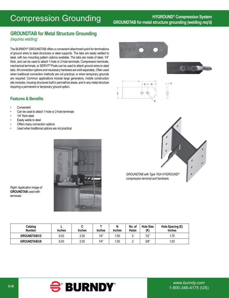
GROUNDTAB for Metal Structure Grounding(requires welding)
The BURNDY® GROUNDTAB offers a convenient attachment point for terminations of ground wires to steel structures or steel supports. The tabs are easily welded to steel, with two mounting pattern options available. The tabs are made of steel, 1/4” thick, and can be used to attach 1-hole or 2-hole terminals. Compression terminals, mechanical terminals, or SERVIT® Posts can be used to attach ground wires to steel tabs. All connection options and necessary hardware are sold separately. Often used when traditional connection methods are not practical, or when temporary grounds are required. Common applications include large generators, mobile construction site modules, housing structures built in permafrost areas, and in any metal structure requiring a permanent or temporary ground option.
Features & Benefits
• Convenient• Can be used to attach 1-hole or 2-hole terminals• 1/4” thick steel• Easily welds to steel• Offers many connection options• Used when traditional options are not practical
Catalog Number
L Inches
CInches
TInches
NInches
No. of Holes
Hole Size (K)
Hole Spacing (E)Inches
GROUNDTAB1/2 6.00 2.00 1/4” 1.50 2 1/2” 1.75GROUNDTAB3/8 6.00 2.00 1/4” 1.50 2 3/8” 1.00
GROUNDTAB with Type YGA HYGROUND®
compression terminal and hardware.
Right: Application image of GROUNDTAB used with terminals
Compression Grounding
1-800-465-7051 (Canada)1-603-647-5299 (International) E-19
HYGROUND® Compression SystemHYLINK™ Type YGHS Heavy Duty Splice
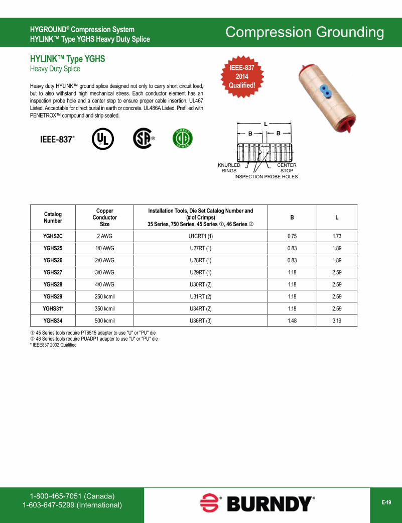
Catalog Number
Copper Conductor
Size
Installation Tools, Die Set Catalog Number and (# of Crimps)
35 Series, 750 Series, 45 Series , 46 Series B L
YGHS2C 2 AWG U1CRT1 (1) 0.75 1.73
YGHS25 1/0 AWG U27RT (1) 0.83 1.89
YGHS26 2/0 AWG U28RT (1) 0.83 1.89
YGHS27 3/0 AWG U29RT (1) 1.18 2.59
YGHS28 4/0 AWG U30RT (2) 1.18 2.59
YGHS29 250 kcmil U31RT (2) 1.18 2.59
YGHS31* 350 kcmil U34RT (2) 1.18 2.59
YGHS34 500 kcmil U36RT (3) 1.48 3.19
IEEE-8372014
Qualified!
HYLINK™ Type YGHS Heavy Duty Splice
Heavy duty HYLINK™ ground splice designed not only to carry short circuit load, but to also withstand high mechanical stress. Each conductor element has an inspection probe hole and a center stop to ensure proper cable insertion. UL467 Listed. Acceptable for direct burial in earth or concrete. UL486A Listed. Prefilled with PENETROX™ compound and strip sealed.
KNURLEDRINGS
INSPECTION PROBE HOLES
CENTERSTOP
45 Series tools require PT6515 adapter to use "U" or "PU" die 46 Series tools require PUADP1 adapter to use "U" or "PU" die* IEEE837 2002 Qualified
Compression Grounding
www.burndy.com1-800-346-4175 (US)E-20
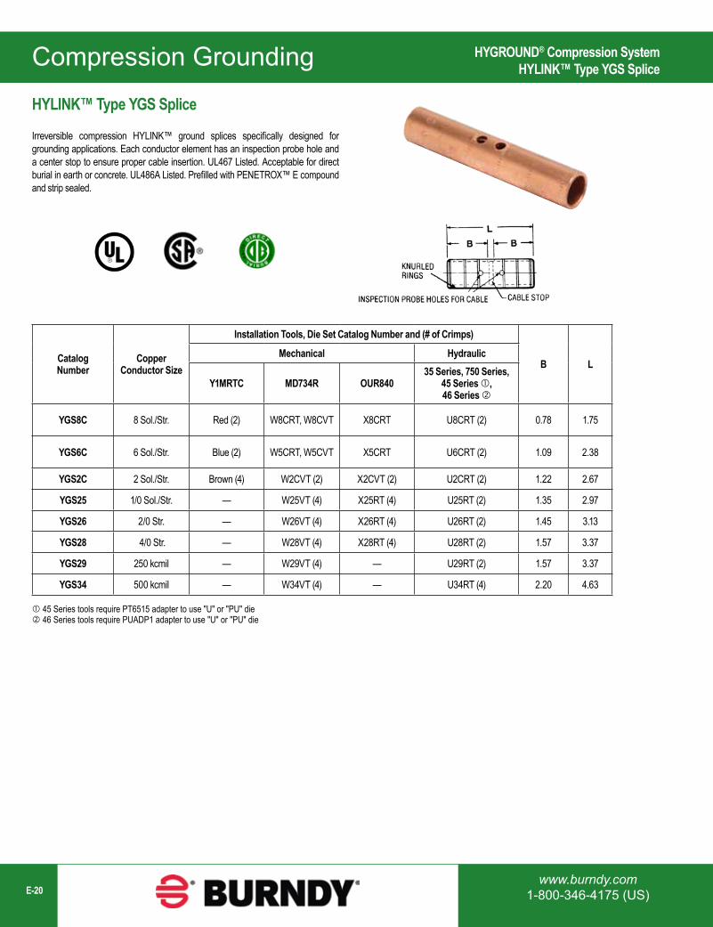
Catalog Number
Copper Conductor Size
Installation Tools, Die Set Catalog Number and (# of Crimps)
B LMechanical Hydraulic
Y1MRTC MD734R OUR84035 Series, 750 Series,
45 Series , 46 Series
YGS8C 8 Sol./Str. Red (2) W8CRT, W8CVT X8CRT U8CRT (2) 0.78 1.75
YGS6C 6 Sol./Str. Blue (2) W5CRT, W5CVT X5CRT U6CRT (2) 1.09 2.38
YGS2C 2 Sol./Str. Brown (4) W2CVT (2) X2CVT (2) U2CRT (2) 1.22 2.67
YGS25 1/0 Sol./Str. — W25VT (4) X25RT (4) U25RT (2) 1.35 2.97
YGS26 2/0 Str. — W26VT (4) X26RT (4) U26RT (2) 1.45 3.13
YGS28 4/0 Str. — W28VT (4) X28RT (4) U28RT (2) 1.57 3.37
YGS29 250 kcmil — W29VT (4) — U29RT (2) 1.57 3.37
YGS34 500 kcmil — W34VT (4) — U34RT (4) 2.20 4.63
HYLINK™ Type YGS Splice
Irreversible compression HYLINK™ ground splices specifically designed for grounding applications. Each conductor element has an inspection probe hole and a center stop to ensure proper cable insertion. UL467 Listed. Acceptable for direct burial in earth or concrete. UL486A Listed. Prefilled with PENETROX™ E compound and strip sealed.
HYGROUND® Compression SystemHYLINK™ Type YGS Splice
45 Series tools require PT6515 adapter to use "U" or "PU" die 46 Series tools require PUADP1 adapter to use "U" or "PU" die
Compression Grounding
1-800-465-7051 (Canada)1-603-647-5299 (International) E-21
Catalog Number
Fig. # C D H L T Y
Copper Conductor
Range
Tapped Holes Installation Tools, Die Set Cat. No., and (# of Crimps)
Size Hole Centers
35 Series,750 Series
45 Series
46 Series
YGF29-2N 1 2.00 3.25 3.62 5.78 1.31 2.00 2 AWG-250 kcmil 1/2 - 13 1-3/4 U997 (1) U997 (1) U997 (1)
YGF29-4N 2 3.25 3.25 3.62 5.78 1.31 2.00 2 AWG-250 kcmil 1/2 - 13 1-3/4 U997 (1) U997 (1) U997 (1)
YGF34-2N 1 2.00 3.25 4.62 5.40 1.31 2.19 250 kcmil-500 kcmil 1/2 - 13 1-3/4 U1011 (3) S1011 (2) P1011 (2)
YGF34-4N 2 3.75 3.75 4.62 5.90 1.31 2.19 250 kcmil-500 kcmil 1/2 - 13 1-3/4 U1011 (3) S1011 (2) P1011 (2)
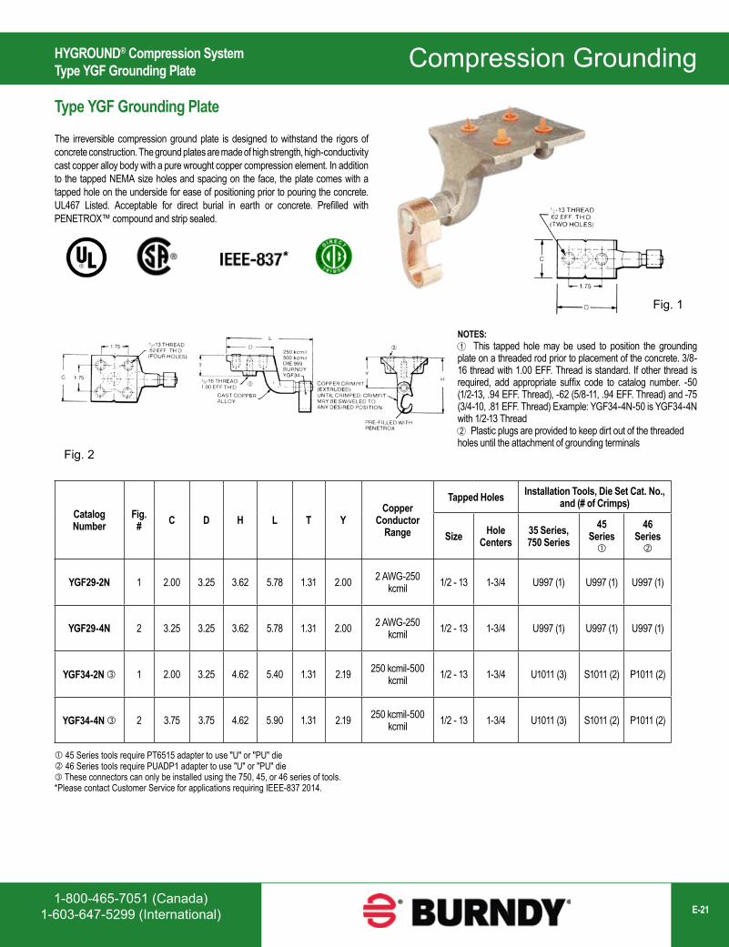
NOTES: This tapped hole may be used to position the grounding plate on a threaded rod prior to placement of the concrete. 3/8-16 thread with 1.00 EFF. Thread is standard. If other thread is required, add appropriate suffix code to catalog number. -50 (1/2-13, .94 EFF. Thread), -62 (5/8-11, .94 EFF. Thread) and -75 (3/4-10, .81 EFF. Thread) Example: YGF34-4N-50 is YGF34-4N with 1/2-13 Thread Plastic plugs are provided to keep dirt out of the threaded holes until the attachment of grounding terminals
1
2
Fig. 1
Fig. 2
HYGROUND® Compression SystemType YGF Grounding Plate
Type YGF Grounding Plate
The irreversible compression ground plate is designed to withstand the rigors of concrete construction. The ground plates are made of high strength, high-conductivity cast copper alloy body with a pure wrought copper compression element. In addition to the tapped NEMA size holes and spacing on the face, the plate comes with a tapped hole on the underside for ease of positioning prior to pouring the concrete. UL467 Listed. Acceptable for direct burial in earth or concrete. Prefilled with PENETROX™ compound and strip sealed.
*
45 Series tools require PT6515 adapter to use "U" or "PU" die 46 Series tools require PUADP1 adapter to use "U" or "PU" die These connectors can only be installed using the 750, 45, or 46 series of tools.*Please contact Customer Service for applications requiring IEEE-837 2014.
Compression Grounding
www.burndy.com1-800-346-4175 (US)E-22
Connector shipped with thread protection studs only. Order TMHG kits separately.
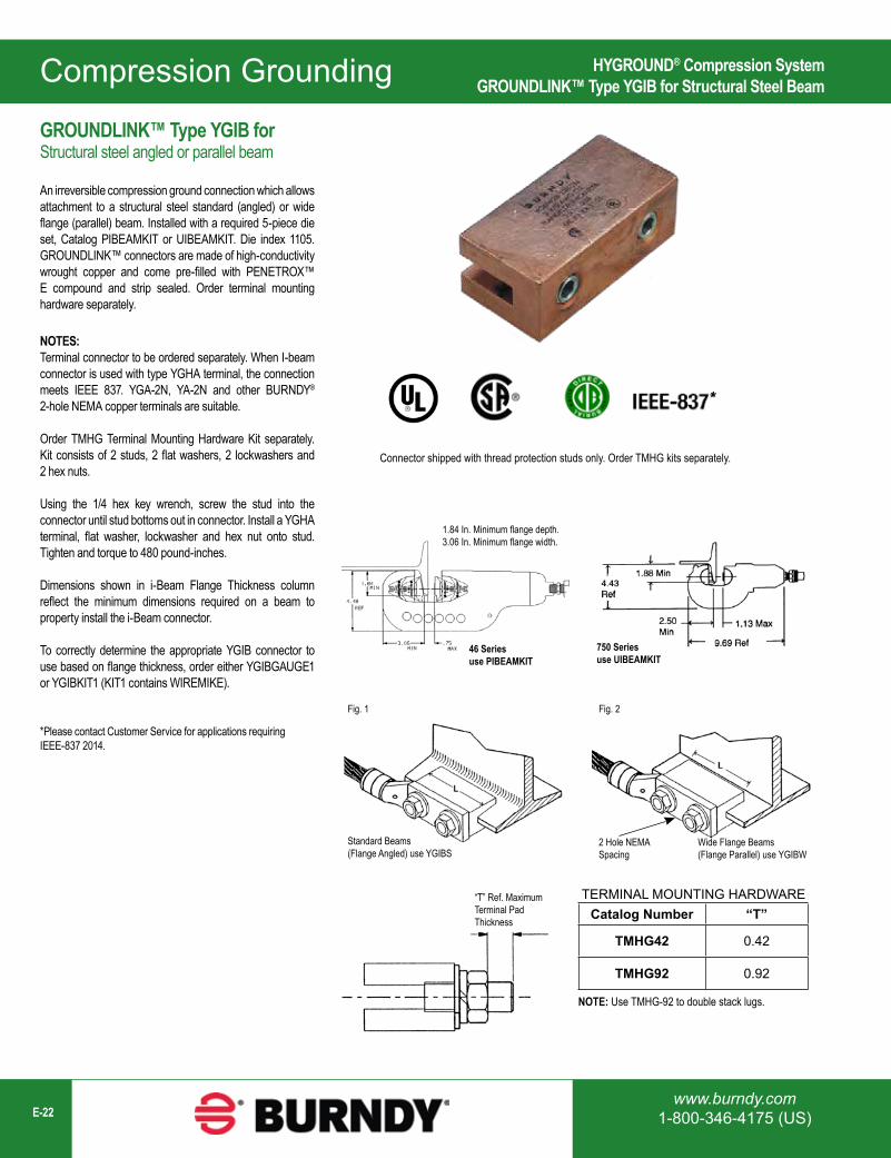
NOTES:Terminal connector to be ordered separately. When I-beam connector is used with type YGHA terminal, the connection meets IEEE 837. YGA-2N, YA-2N and other BURNDY® 2-hole NEMA copper terminals are suitable.
Order TMHG Terminal Mounting Hardware Kit separately. Kit consists of 2 studs, 2 flat washers, 2 lockwashers and 2 hex nuts.
Using the 1/4 hex key wrench, screw the stud into the connector until stud bottoms out in connector. Install a YGHA terminal, flat washer, lockwasher and hex nut onto stud. Tighten and torque to 480 pound-inches.
Dimensions shown in i-Beam Flange Thickness column reflect the minimum dimensions required on a beam to property install the i-Beam connector.
To correctly determine the appropriate YGIB connector to use based on flange thickness, order either YGIBGAUGE1 or YGIBKIT1 (KIT1 contains WIREMIKE).
1.84 In. Minimum flange depth.3.06 In. Minimum flange width.
46 Seriesuse PIBEAMKIT
750 Seriesuse UIBEAMKIT
Standard Beams(Flange Angled) use YGIBS
Fig. 1 Fig. 2
2 Hole NEMASpacing
Wide Flange Beams(Flange Parallel) use YGIBW
“T” Ref. MaximumTerminal PadThickness
TERMINAL MOUNTING HARDWARECatalog Number “T”
TMHG42 0.42
TMHG92 0.92
NOTE: Use TMHG-92 to double stack lugs.
*Please contact Customer Service for applications requiring IEEE-837 2014.
*
HYGROUND® Compression SystemGROUNDLINK™ Type YGIB for Structural Steel Beam
GROUNDLINK™ Type YGIB forStructural steel angled or parallel beam
An irreversible compression ground connection which allows attachment to a structural steel standard (angled) or wide flange (parallel) beam. Installed with a required 5-piece die set, Catalog PIBEAMKIT or UIBEAMKIT. Die index 1105. GROUNDLINK™ connectors are made of high-conductivity wrought copper and come pre-filled with PENETROX™ E compound and strip sealed. Order terminal mounting hardware separately.
Compression Grounding
1-800-465-7051 (Canada)1-603-647-5299 (International) E-23
Catalog Number Copper Conductor Size
Fig.# L J I-Beam Flange
ThicknessSuggested Terminals
TCopper Conductor Terminal
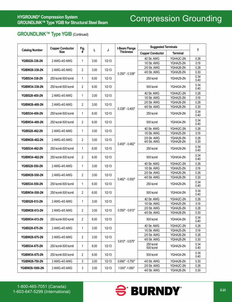
YGIBS28-338-2N 2 AWG-4/0 AWG 1 3.00 1/2-13
0.250" - 0.338"
#2 Str. AWG YGHA2C-2N 0.261/0 Str. AWG YGHA25-2N 0.19
YGIBW28-338-2N 2 AWG-4/0 AWG 2 3.00 1/2-13 2/0 Str. AWG YGHA26-2N 0.264/0 Str. AWG YGHA28-2N 0.30
YGIBS34-338-2N 250 kcmil-500 kcmil 1 6.00 1/2-13 250 kcmil YGHA29-2N 0.340.40
YGIBW34-338-2N 250 kcmil-500 kcmil 2 6.00 1/2-13 500 kcmil YGHA34-2N 0.340.40
YGIBS28-400-2N 2 AWG-4/0 AWG 1 3.00 1/2-13
0.338" - 0.400"
#2 Str. AWG YGHA2C-2N 0.261/0 Str. AWG YGHA25-2N 0.19
YGIBW28-400-2N 2 AWG-4/0 AWG 2 3.00 1/2-13 2/0 Str. AWG YGHA26-2N 0.264/0 Str. AWG YGHA28-2N 0.30
YGIBS34-400-2N 250 kcmil-500 kcmil 1 6.00 1/2-13 250 kcmil YGHA29-2N 0.340.40
YGIBW34-400-2N 250 kcmil-500 kcmil 2 6.00 1/2-13 500 kcmil YGHA34-2N 0.340.40
YGIBS28-462-2N 2 AWG-4/0 AWG 1 3.00 1/2-13
0.400" - 0.462"
#2 Str. AWG YGHA2C-2N 0.261/0 Str. AWG YGHA25-2N 0.19
YGIBW28-462-2N 2 AWG-4/0 AWG 2 3.00 1/2-13 2/0 Str. AWG4/0 Str. AWG
YGHA26-2NYGHA28-2N
0.260.30
YGIBS34-462-2N 250 kcmil-500 kcmil 1 6.00 1/2-13 250 kcmil YGHA29-2N 0.340.40
YGIBW34-462-2N 250 kcmil-500 kcmil 2 6.00 1/2-13 500 kcmil YGHA34-2N 0.340.40
YGIBS28-550-2N 2 AWG-4/0 AWG 1 3.00 1/2-13
0.462" - 0.550"
#2 Str. AWG YGHA2C-2N 0.261/0 Str. AWG YGHA25-2N 0.19
YGIBW28-550-2N 2 AWG-4/0 AWG 2 3.00 1/2-13 2/0 Str. AWG YGHA26-2N 0.264/0 Str. AWG YGHA28-2N 0.30
YGIBS34-550-2N 250 kcmil-500 kcmil 1 6.00 1/2-13 250 kcmil YGHA29-2N 0.340.40
YGIBW34-550-2N 250 kcmil-500 kcmil 2 6.00 1/2-13 500 kcmil YGHA34-2N 0.340.40
YGIBS28-613-2N 2 AWG-4/0 AWG 1 3.00 1/2-13
0.550" - 0.613"
#2 Str. AWG YGHA2C-2N 0.261/0 Str. AWG YGHA25-2N 0.19
YGIBW28-613-2N 2 AWG-4/0 AWG 2 3.00 1/2-13 2/0 Str. AWG YGHA26-2N 0.264/0 Str. AWG YGHA28-2N 0.30
YGIBW34-613-2N 250 kcmil-500 kcmil 2 6.00 1/2-13 500 kcmil YGHA34-2N 0.340.40
YGIBS28-675-2N 2 AWG-4/0 AWG 1 3.00 1/2-13
0.613" - 0.675"
#2 Str. AWG YGHA2C-2N 0.261/0 Str. AWG YGHA25-2N 0.19
YGIBW28-675-2N 2 AWG-4/0 AWG 2 3.00 1/2-13 2/0 Str. AWG YGHA26-2N 0.264/0 Str. AWG YGHA28-2N 0.30
YGIBS34-675-2N 250 kcmil-500 kcmil 1 6.00 1/2-13 250 kcmil500 kcmil YGHA29-2N 0.34
0.40
YGIBW34-675-2N 250 kcmil-500 kcmil 2 6.00 1/2-13 500 kcmil YGHA34-2N 0.340.40
YGIBW28-750-2N 2 AWG-4/0 AWG 3 3.00 1/2-13 0.690" - 0.750" 4/0 Str. AWG YGHA28-2N 0.30
YGIBW28-1000-2N 2 AWG-4/0 AWG 3 3.00 1/2-13 1.000" -1.060" 2/0 Str. AWG YGHA2C-2N 0.264/0 Str. AWG YGHA28-2N 0.30
HYGROUND® Compression SystemGROUNDLINK™ Type YGIB for Structural Steel Beam
GROUNDLINK™ Type YGIB (Continued)
Compression Grounding
www.burndy.com1-800-346-4175 (US)E-24
Catalog Number Nom Rod Size A B L T Electrical Equivalent Copper Conductor Size (AWG)*
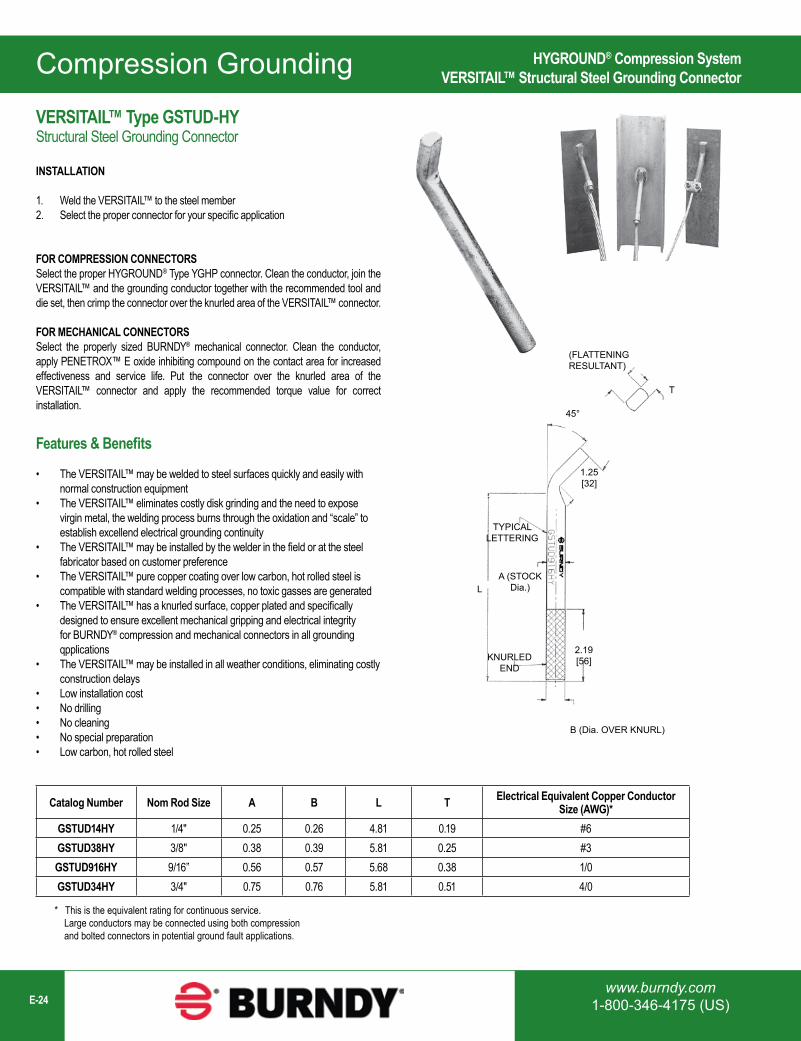
GSTUD14HY 1/4" 0.25 0.26 4.81 0.19 #6GSTUD38HY 3/8" 0.38 0.39 5.81 0.25 #3GSTUD916HY 9/16” 0.56 0.57 5.68 0.38 1/0GSTUD34HY 3/4" 0.75 0.76 5.81 0.51 4/0
* This is the equivalent rating for continuous service. Large conductors may be connected using both compression and bolted connectors in potential ground fault applications.
45°
L
1.25[32]
2.19[56]
(FLATTENINGRESULTANT)
TYPICALLETTERING
A (STOCKDia.)
KNURLEDEND
B (Dia. OVER KNURL)
T
HYGROUND® Compression SystemVERSITAIL™ Structural Steel Grounding Connector
VERSITAIL™ Type GSTUD-HY Structural Steel Grounding Connector
INSTALLATION
1. Weld the VERSITAIL™ to the steel member2. Select the proper connector for your specific application
FOR COMPRESSION CONNECTORSSelect the proper HYGROUND® Type YGHP connector. Clean the conductor, join the VERSITAIL™ and the grounding conductor together with the recommended tool and die set, then crimp the connector over the knurled area of the VERSITAIL™ connector.
FOR MECHANICAL CONNECTORSSelect the properly sized BURNDY® mechanical connector. Clean the conductor, apply PENETROX™ E oxide inhibiting compound on the contact area for increased effectiveness and service life. Put the connector over the knurled area of the VERSITAIL™ connector and apply the recommended torque value for correct installation.
Features & Benefits
• The VERSITAIL™ may be welded to steel surfaces quickly and easily with normal construction equipment
• The VERSITAIL™ eliminates costly disk grinding and the need to expose virgin metal, the welding process burns through the oxidation and “scale” to establish excellend electrical grounding continuity
• The VERSITAIL™ may be installed by the welder in the field or at the steel fabricator based on customer preference
• The VERSITAIL™ pure copper coating over low carbon, hot rolled steel is compatible with standard welding processes, no toxic gasses are generated
• The VERSITAIL™ has a knurled surface, copper plated and specifically designed to ensure excellent mechanical gripping and electrical integrity for BURNDY® compression and mechanical connectors in all grounding qpplications
• The VERSITAIL™ may be installed in all weather conditions, eliminating costly construction delays
• Low installation cost• No drilling• No cleaning• No special preparation• Low carbon, hot rolled steel

Compression Grounding
1-800-465-7051 (Canada)1-603-647-5299 (International) E-25
Catalog Number Fig. # HYGROUND®
Connector H D Y Dia Z Dia TD
YGT275 1 Select suitable YGHR, YGHP or YGLR for 3/4" ground rod and sized to ground
conductor.
5.50 2.75 0.75 0.56 -
YTTAG388 2 6.50 4.75 0.75 0.56 4.30
Type YGT Static Grounding Receptacle
with Cover
Type YTTAG CombinationStatic Grounding Receptacle
and Aircraft Tie Down Bar
Fig. 1 Fig. 2
NOTES:Install YGHR, YGHP or YGLR on Hub Y. Hub Z is inserted into 1/2" rigid conduit. The conduit is driven into the earth to provide support and provide correct level of receptacle prior to cement pour.
HYGROUND® Compression SystemTypes YGT, YTTAG, Static Grounding Receptacles
Types YGT, YTTAG Static Grounding Receptacles
The types YGT and YTTAG static grounding receptacles are designed for static grounding of equipment. The receptacle is connector to the ground grid with HYGROUND® compression connectors and finished flush with surface to provide a permanent, corrosion proof, grounding point.
Compression Grounding
www.burndy.com1-800-346-4175 (US)E-26
Fig. 1 Fig. 2
Fig. 3
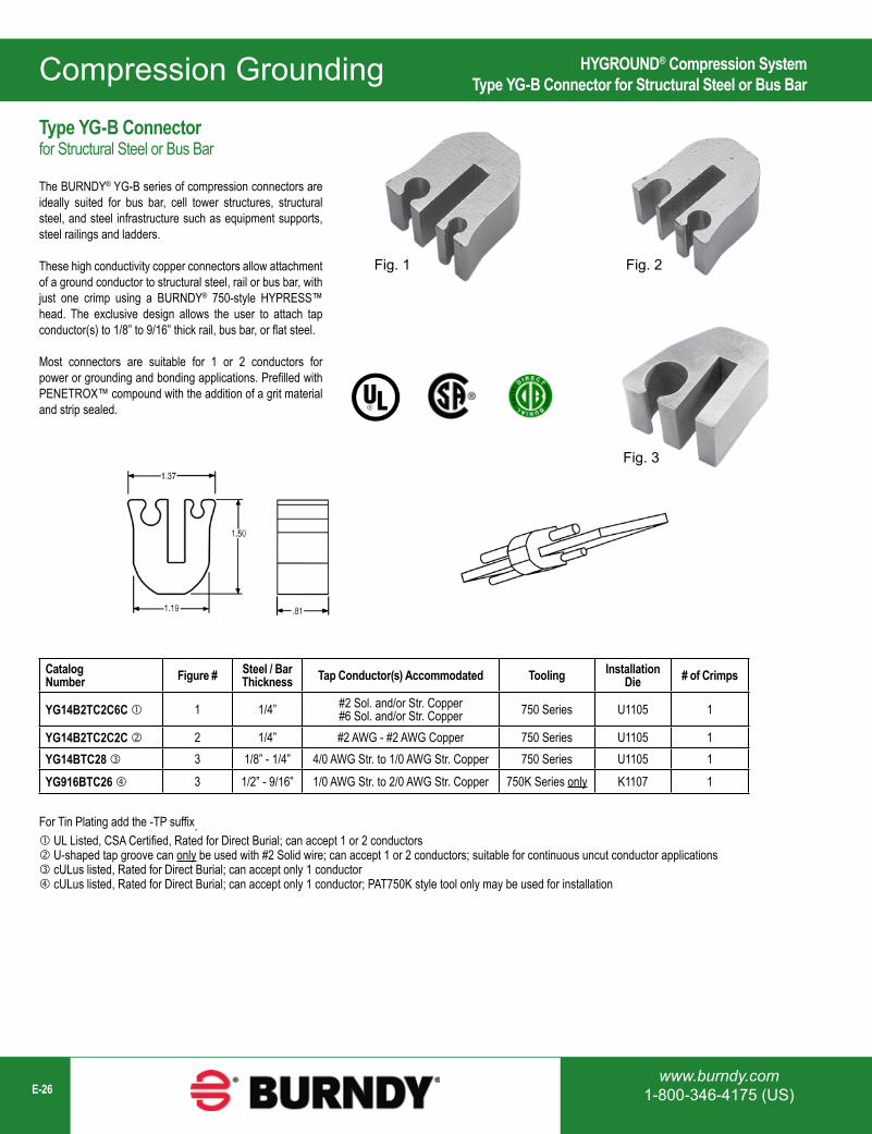
Catalog Number Figure # Steel / Bar
Thickness Tap Conductor(s) Accommodated Tooling Installation Die # of Crimps
YG14B2TC2C6C 1 1/4” #2 Sol. and/or Str. Copper#6 Sol. and/or Str. Copper 750 Series U1105 1
YG14B2TC2C2C 2 1/4” #2 AWG - #2 AWG Copper 750 Series U1105 1YG14BTC28 3 1/8” - 1/4” 4/0 AWG Str. to 1/0 AWG Str. Copper 750 Series U1105 1
YG916BTC26 3 1/2” - 9/16” 1/0 AWG Str. to 2/0 AWG Str. Copper 750K Series only K1107 1
For Tin Plating add the -TP suffix. UL Listed, CSA Certified, Rated for Direct Burial; can accept 1 or 2 conductors U-shaped tap groove can only be used with #2 Solid wire; can accept 1 or 2 conductors; suitable for continuous uncut conductor applications cULus listed, Rated for Direct Burial; can accept only 1 conductor cULus listed, Rated for Direct Burial; can accept only 1 conductor; PAT750K style tool only may be used for installation
HYGROUND® Compression SystemType YG-B Connector for Structural Steel or Bus Bar
Type YG-B Connector for Structural Steel or Bus Bar
The BURNDY® YG-B series of compression connectors are ideally suited for bus bar, cell tower structures, structural steel, and steel infrastructure such as equipment supports, steel railings and ladders.
These high conductivity copper connectors allow attachment of a ground conductor to structural steel, rail or bus bar, with just one crimp using a BURNDY® 750-style HYPRESS™ head. The exclusive design allows the user to attach tap conductor(s) to 1/8” to 9/16” thick rail, bus bar, or flat steel.
Most connectors are suitable for 1 or 2 conductors for power or grounding and bonding applications. Prefilled with PENETROX™ compound with the addition of a grit material and strip sealed.
Compression Grounding
1-800-465-7051 (Canada)1-603-647-5299 (International) E-27
Compression Solution for Flexible Bus Bar ApplicationsType BFB Terminal Lugs
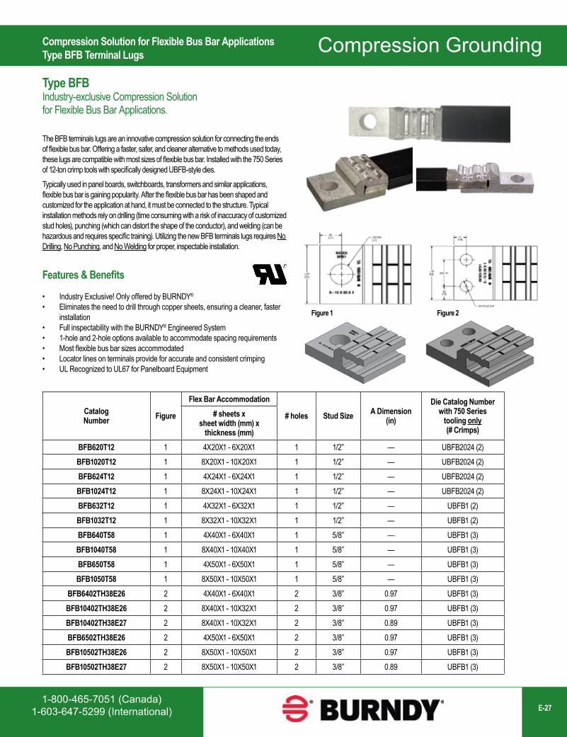
Type BFB Industry-exclusive Compression Solutionfor Flexible Bus Bar Applications.
The BFB terminals lugs are an innovative compression solution for connecting the ends of flexible bus bar. Offering a faster, safer, and cleaner alternative to methods used today, these lugs are compatible with most sizes of flexible bus bar. Installed with the 750 Series of 12-ton crimp tools with specifically designed UBFB-style dies. Typically used in panel boards, switchboards, transformers and similar applications, flexible bus bar is gaining popularity. After the flexible bus bar has been shaped and customized for the application at hand, it must be connected to the structure. Typical installation methods rely on drilling (time consuming with a risk of inaccuracy of customized stud holes), punching (which can distort the shape of the conductor), and welding (can be hazardous and requires specific training). Utilizing the new BFB terminals lugs requires No Drilling, No Punching, and No Welding for proper, inspectable installation.
Features & Benefits
• Industry Exclusive! Only offered by BURNDY®
• Eliminates the need to drill through copper sheets, ensuring a cleaner, faster installation
• Full inspectability with the BURNDY® Engineered System• 1-hole and 2-hole options available to accommodate spacing requirements• Most flexible bus bar sizes accommodated• Locator lines on terminals provide for accurate and consistent crimping• UL Recognized to UL67 for Panelboard Equipment
Figure 1 Figure 2
Catalog Number Figure
Flex Bar Accommodation
# holes Stud Size A Dimension(in)
Die Catalog Numberwith 750 Series
tooling only(# Crimps)
# sheets x sheet width (mm) x
thickness (mm)BFB620T12 1 4X20X1 - 6X20X1 1 1/2” — UBFB2024 (2)BFB1020T12 1 8X20X1 - 10X20X1 1 1/2” — UBFB2024 (2)BFB624T12 1 4X24X1 - 6X24X1 1 1/2” — UBFB2024 (2)BFB1024T12 1 8X24X1 - 10X24X1 1 1/2” — UBFB2024 (2)BFB632T12 1 4X32X1 - 6X32X1 1 1/2” — UBFB1 (2)BFB1032T12 1 8X32X1 - 10X32X1 1 1/2” — UBFB1 (2)BFB640T58 1 4X40X1 - 6X40X1 1 5/8” — UBFB1 (3)BFB1040T58 1 8X40X1 - 10X40X1 1 5/8” — UBFB1 (3)BFB650T58 1 4X50X1 - 6X50X1 1 5/8” — UBFB1 (3)BFB1050T58 1 8X50X1 - 10X50X1 1 5/8” — UBFB1 (3)
BFB6402TH38E26 2 4X40X1 - 6X40X1 2 3/8” 0.97 UBFB1 (3)BFB10402TH38E26 2 8X40X1 - 10X32X1 2 3/8” 0.97 UBFB1 (3)BFB10402TH38E27 2 8X40X1 - 10X32X1 2 3/8” 0.89 UBFB1 (3)BFB6502TH38E26 2 4X50X1 - 6X50X1 2 3/8” 0.97 UBFB1 (3)BFB10502TH38E26 2 8X50X1 - 10X50X1 2 3/8” 0.97 UBFB1 (3)BFB10502TH38E27 2 8X50X1 - 10X50X1 2 3/8” 0.89 UBFB1 (3)
Compression Grounding
www.burndy.com1-800-346-4175 (US)E-28
This page intentionally left blank
1-800-465-7051 (Canada)1-603-647-5299 (International) E-29
Mechanical GroundingMechanical GroundingTable of Contents
Mechancial Grounding Connectors Overview ...................................................................E-30
Types KC, K2C SERVIT POST™ Connectors (cable to flat) ..........................................E-30
Type KCKF Bulkhead Ground Connector ..........................................................................E-31
Types KC-J12, EQC632C1 Transformer Ground Connectors .......................................E-32
SERVIT® Type KS Split Bolt Connectors ............................................................................E-32
Type GRC High Strength Ground Rod Clamp for Copper Cable to Rod ......................E-33
Type GCRT1/0 Ground Clamp Range Taking up to 1/0 ...................................................E-33
Type GRL Light Duty Economical Ground Rod Clamp....................................................E-33
Type GKA Connector for Copper .........................................................................................E-34
Type KPB Connector for Copper ..........................................................................................E-34
QIKLUG™ Types CL50-1, CL50-1TN Copper Lay-in Connectors ................................E-35
QIKLUG™ Type CL Copper Lay-in Connectors ...............................................................E-35
The CONSTRICTOR® Type GCS-HEX Ground Connector to Steel ...........................E-36
Type GAR for Parallel or 90° Copper Cable Connection to Rod or Pipe ......................E-37
Types GAR-BU, GAR3902 Ground Connectors ..............................................................E-39
Type GAR-TC Water Pipe Ground Connector ...................................................................E-40
Type GD Two Copper Cables to Rod or Tube ...................................................................E-41
Type GP Two Copper Cables to Rod, Pipe, or Column ...................................................E-42
Type GK Three Copper Cables to Rod or Pipe .................................................................E-43
Type GG Ground Connector for Copper Bar, Strap, Braid, Cable to Rod or Tube ......E-44
Type FFG Fence Fabric Ground Clamps ............................................................................E-45
Type GA-H Copper Cable to “H” Beam or Square Fence Post ......................................E-46
Type GA-H30SS Copper Cable to Square Fence Post ...................................................E-46
Festoon Grounding System Kits ...........................................................................................E-47
Type GQ Ground Connector for Copper Cable to Tube ..................................................E-49
Type GX Ground Connector for Copper Cables ...............................................................E-49
Water Pipe Grounding; Miscellaneous Cast Bronze Clamps ..........................................E-50
Type GC-A Dual Rated Ground Clamp for Copper and Aluminum ...............................E-55
BONDIT® Intersystem Bonding Connector Type BDT (House or Meter Socket Mounted) .....................................................................................E-56
BONDIT® Intersystem Bonding Connector Type BDTIBB (Wall Mount).......................E-57
HandyBug™ Type SB Connectors (tap, splice or terminate)...........................................E-58
Type BWB680 Series Pool Water Bonding Kits ................................................................E-59
BARTAP™ Type QGFL Copper Cable to Flat Bar or Pad...............................................E-60
Types GB, GBM Ground Connector Copper Cable to Bar .............................................E-61
Types GC, GCM Ground Connector Two Copper Cables to Bar ..................................E-61
Type GL Ground Connector Two Copper Cables to Bar .................................................E-62
Type GZ Ground Connector Copper Cable to Bar ............................................................E-62
Types J, RGC Mechanical Rail Connectors .......................................................................E-63
Type GIE-G Heavy Duty Construction Ground Connector for Vehicle Grounding .....E-64
Type BSD Static Discharge Reels ........................................................................................E-65
STUDBUG™ Type GCB63T13G1 for Static Grounding Applications ..........................E-66
Type GSC75 All-in-one Ball & Socket Design with NEMA Pad ......................................E-67
Type GSC63 Ground Ball Stud with 90° NEMA Pad .......................................................E-67
Type GC-CT Cable Tray Ground Clamp.............................................................................E-68
Type BTCGC Clamp for Aluminum or Steel Cable Tray ..................................................E-68
SUPER-CLAMP™ Type GXP1828RF Raised Floor/Rebar Ground Connector .......E-69
UNIGROUND™ Type GRF Raised Floor Grounding Connector ..................................E-70
Types GP-G1, GP-RT Raised Floor Grounding Clamps .................................................E-71
Flexible Copper Braid Jumper General Information ..............................................................................................................E-72 Current Carrying Capacity ...................................................................................................E-72 Bulk Braid ................................................................................................................................E-72 Custom Designs and Custom Variations ..........................................................................E-73 Type B 1-Hole Ferrule End ..................................................................................................E-74 Type B 2-Hole Ferrule End ..................................................................................................E-75 Type BB-LT 1-Hole Connector End ...................................................................................E-77 Types CCY, B-B Covered Jumpers ...................................................................................E-78 Type BB-SS Stainless Steel Braid .....................................................................................E-79 Type B Undrilled Ferrules ....................................................................................................E-80 Type B-4N 4-Hole NEMA ...................................................................................................E-81 Cable Tray Bonding Straps .................................................................................................E-83
Type BGRK Grounding Kits ..................................................................................................E-84
Type BBB Copper Bus Bar ....................................................................................................E-88
Bus or Ground Bars; Copper, Tinned Copper, and Stainless Steel ...............................E-90
Perimeter Bar ...........................................................................................................................E-98
GRIDMAX®...............................................................................................................................E-100
1-800-387-6487 (Canada)1-603-647-5299 (International)
Mechanical Grounding
www.burndy.com1-800-346-4175 (US)E-30
TYPE KCOne Wire
TYPE K2COne or Two Wires Stranded Solid Stud
Diameter B CFx CFy D H HH
KC15 K2C15 12 AWG-9 AWG 12 AWG-8 AWG 1/4-20 3/8 1/2 3/8 1/2 5/8 7/8KC15B1 K2C15B1 12 AWG-9 AWG 12 AWG-8 AWG 1/4-20 7/8 1/2 3/8 1 5/8 7/8
KC17 K2C17 10 AWG-7 AWG 10 AWG-6 AWG 1/4-20 3/8 5/8 7/16 1/2 7/8 1KC17B1 K2C17B1 10 AWG-7 AWG 10 AWG-6 AWG 1/4-20 7/8 5/8 7/16 1 7/8 1KC20 K2C20 10 AWG-5 AWG 10 AWG-4 AWG 5/16-18 13/32 11/16 1/2 5/8 7/8 1-1/8
KC20B1 K2C20B1 10 AWG-5 AWG 10 AWG-4 AWG 5/16-18 27/32 11/16 1/2 1 7/8 1-1/8KC22 K2C22 10 AWG-3 AWG 10 AWG-2 AWG 3/8-16 15/32 3/4 5/8 5/8 1 1-1/4
KC22B1 K2C22B1 10 AWG-3 AWG 10 AWG-2 AWG 3/8-16 31/32 3/4 5/8 1-1/8 1 1-1/4KC23 K2C23 8 AWG-2 AWG 10 AWG-1 AWG 3/8-16 15/32 13/16 5/8 5/8 1 1-3/8
KC23B1 K2C23B1 8 AWG-2 AWG 10 AWG-1 AWG 3/8-16 31/32 13/16 5/8 1-1/8 1 1-3/8KC25 K2C25 2 AWG-1/0 AWG 2 AWG-2/0 AWG 1/2-13 9/16 15/16 3/4 3/4 1-1/8 1-5/8
KC25B1 K2C25B1 2 AWG-1/0 AWG 2 AWG-2/0 AWG 1/2-13 1-1/16 15/16 3/4 1-1/4 1-1/8 1-5/8KC26 K2C26 2 AWG-2/0 AWG 2 AWG-3/0 AWG 1/2-13 17/32 1 7/8 3/4 1-3/8 1-7/8
KC26B1 K2C26B1 2 AWG-2/0 AWG 2 AWG-3/0 AWG 1/2-13 1-1/16 1 7/8 1-1/4 1-3/8 1-7/8KC28 K2C28 1 AWG-4/0 AWG 1 AWG-4/0 AWG 5/8-11 3/4 1-1/2 1-3/16 1 1-3/4 2-1/4
KC28B1 K2C28B1 1 AWG-4/0 AWG 1 AWG-4/0 AWG 5/8-11 1-1/4 1-1/2 1-3/16 1-1/2 1-3/4 2-1/4— K2C28G3 1 AWG-4/0 AWG 1 AWG-4/0 AWG 1/2-13 1-1/4 1-1/2 1-3/16 1-1/2 1-3/4 2-1/4
KC31 K2C31 1 AWG-350 kcmil N/A 5/8-11 3/4 1-11/16 1-3/8 1 2-1/4 2-7/8KC31B1 K2C31B1 1 AWG-350 kcmil N/A 5/8-11 1-1/4 1-11/16 1-3/8 1-1/2 2-1/4 2-7/8KC34 K2C34 3/0 AWG-500 kcmil N/A 3/4-10 1 2 1-5/8 1-1/4 2-3/8 3-1/4
KC34B1 K2C34B1 3/0 AWG-500 kcmil N/A 3/4-10 1-1/2 2 1-5/8 1-3/4 2-3/8 3-1/4
KC
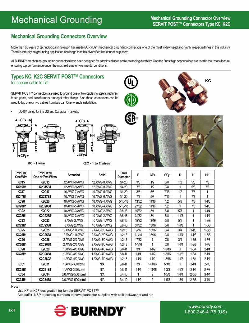
Mechanical Grounding Connector OverviewSERVIT POST™ Connectors Type KC, K2C
Mechanical Grounding Connectors Overview
More than 60 years of technological innovation has made BURNDY® mechanical grounding connectors one of the most widely used and highly respected lines in the industry. There is virtually no grounding application challenge that this diversified line cannot help solve.
All BURNDY mechanical grounding connectors have been designed for easy installation and outstanding durability. Only the finest high copper alloys are used in their manufacture, ensuring top performance under the most extreme environmental conditions.
Types KC, K2C SERVIT POST™ Connectors for copper cable to flat
SERVIT POST™ connectors are used to ground one or two cables to steel structures, fence posts, and transformers amongst other things. Also these connectors can be used to tap one or two cables from bus bar. One-wrench installation.
• UL467 Listed for the US and Canadian markets.
K2C - 1 to 2 wiresKC - 1 wire
Note: Use KF or K2F designation for female SERVIT POST™ Add suffix -NSP to catalog numbers to have connector supplied with split lockwasher and nut

1-800-465-7051 (Canada)1-603-647-5299 (International) E-31
Mechanical Grounding
CatalogNumber
ACCOMMODATES
NUT TORQUEIN-LBS [N-M] MAX. THRU HOLE
AWG METRICSTRANDED SOLID STRANDED
KCKF23 #8 (.146) - #2 (.292) #10 (.102) - #1 (.289) 10mm2 (4.1) - 35mm2 (6.5) 275 [31.1] 7/16KCKF25 #2 (.292) - 1/0 (.373) #2 (.258) - 2/0 (.365) 35mm2 (6.5) - 50mm2 (9.3) 385 [43.5] 9/16KCKF28 #1 (.332) - 4/0 (.528) #1 (.289) - 4/0 (.460) 50mm2 (9.3) - 95mm2 (12.8) 500 [56.5] 11/16
Notes: Dimensions in () are cable diameters. Diameters of AWG wires are in inches. Diameters for metric wires are given in mm.
*One flat washer and sealing washer to be installed on outside of box or, where applicable, to side of wall exposed to atmospheric or contaminated conditions. Remaining hardware to be mounted to opposite side of the wall as shown.
Qty Description1 1 Male Servit Post
2 1 Stainless Steel Split Lock Washer*
3 2 Stainless Steel Flat Washer*4 1 Sealing Washer*5 1 Female SERVIT®
Bulkhead Ground ConnectorType KCKF
Type KCKF Bulkhead Ground Connector
The “Bulkhead” connector is designed to allow a ground wire to be connected from the inside of a box or enclosure to the outside of a box or enclosure.
This new connector is supplied in kit form with a male SERVIT POST™, female SERVIT®, (2) stainless steel washers, split lock washer and sealing washer.
The available “Application Guideline” document helps describe the application with visuals and installation examples.
Features & Benefits
• Provides an easy way to connect ground wires “through” an enclosure wall• Includes Male SERVIT POST™, Female SERVIT®, (2) Stainless Steel
Washers, Split Lock Washer, Sealing Washer• Split Lock Washer allows adjustment of conductor orientation• Made of Silicon Bronze material (connectors) and Stainless Steel
Hardware, Sealing Washer• Meets NEMA 4X requirements when installed correctly• Application Guideline document available• Industry-proven split bolt/SERVIT POST™ technology• UL467 Listed for the US and Canadian Markets
Mechanical Grounding
www.burndy.com1-800-346-4175 (US)E-32
Catalog Number Ranges Stud SizeKC22J12T13 8 Sol. - 2 Sol. 1/2"-13
KC26 2 Sol. - 2/0 Str. 1/2"-13KC34J12T13 3/0 - 500 Str. 1/2"-13EQC632C1 8 Sol. - 2 Str. 1/2"-13
Catalog Number Cross Flats L W Copper Conductor
RangeRebar with (1)
#8 Sol. CuRecommended
TighteningTorque (in-lb)
KS15 0.50 0.85 0.38 10 - 8 Str. — 80
KS17 0.63 1.14 0.45 8 Str. - 6 Sol. — 165
KS20 0.69 1.20 0.51 8 Str. - 4 Sol. — 165
KS22 0.75 1.50 0.60 6 Str. - 2 Sol. — 275
KS23 0.82 1.54 0.62 6 Str. - 2 Str. — 275
KS25 0.94 1.77 0.73 4 Str. - 1/0 Str. — 385
KS26 1.05 1.94 0.82 2 Str. - 2/0 Str. #3 (3/8”) 385
KS27 1.36 1.86 1.17 1 Str. - 3/0 Str. — 500
KS29 1.36 2.07 1.17 1 Str. - 250 #4 (1/2”) 650
KS31 1.70 2.51 1.41 1/0 Str. - 350 #5 (5/8” 650
KS34 1.82 2.79 1.48 2/0 Str. - 500 #6 (3/4”) 825
EQC632C1
Transformer Ground Connectors Types KC-J12, EQC632C1Type KS SERVIT® Split Bolt Connectors for Copper
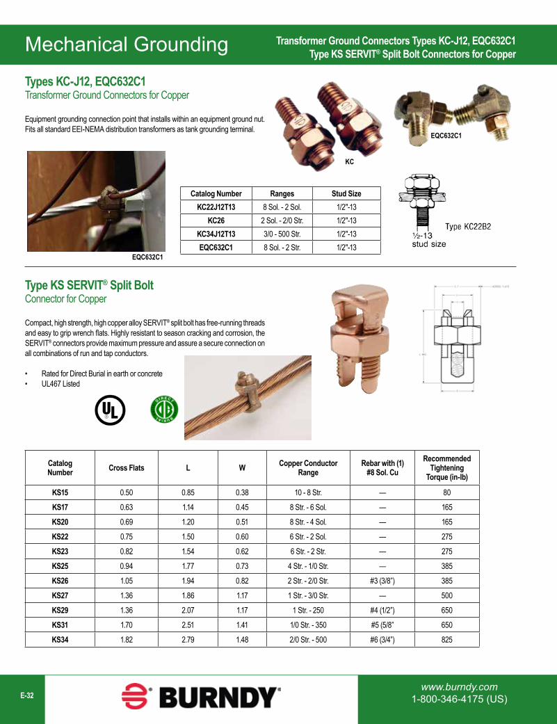
Types KC-J12, EQC632C1Transformer Ground Connectors for Copper
Equipment grounding connection point that installs within an equipment ground nut. Fits all standard EEI-NEMA distribution transformers as tank grounding terminal.
Type KS SERVIT® Split Bolt Connector for Copper
Compact, high strength, high copper alloy SERVIT® split bolt has free-running threads and easy to grip wrench flats. Highly resistant to season cracking and corrosion, the SERVIT® connectors provide maximum pressure and assure a secure connection on all combinations of run and tap conductors.
• Rated for Direct Burial in earth or concrete• UL467 Listed
KC
EQC632C1
1-800-465-7051 (Canada)1-603-647-5299 (International) E-33
Mechanical Grounding
Features & Benefits
• Range taking design helps reduce inventory needs
• Rated for Direct Burial in earth or concrete
• UL467 Listed for the US and Canadian Markets
• High copper alloy, stainless steel bolt
Catalog Number Drive RodConductor Range
H W L JMin. Max.
GRC12 1/2 10 Sol. 2 Str. 2.00 0.89 0.63 3/8GRC58 5/8 10 Sol. 1 Str. 2.19 0.95 0.63 3/8GRC34 3/4 8 Sol. 1/0 Str. 2.47 1.09 0.65 3/8
Catalog Number Rod SizeConductor Range
Minimum MaximumGRL3 3/8 in 10 AWG 4 AWGGRL4 1/2 in 10 AWG 2 AWGGRL5 5/8 in 10 AWG 2 AWGGRL6 3/4 in 10 AWG 2 AWG
Miscellaneous Ground Rod Clamps; High Strength (Type GRC);Range taking up to 1/0 (Type GCRT), Light Duty (Type GRL)
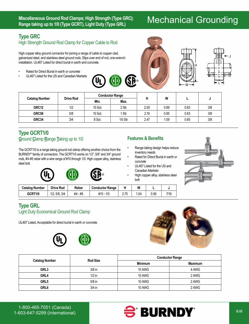
Type GRCHigh Strength Ground Rod Clamp for Copper Cable to Rod
High copper alloy ground connector for joining a range of cable to copper clad, galvanized steel, and stainless steel ground rods. Slips over end of rod, one-wrench installation. UL467 Listed for direct burial in earth and concrete.
• Rated for Direct Burial in earth or concrete• UL467 Listed for the US and Canadian Markets
Type GCRT1/0Ground Clamp Range Taking up to 1/0
The GCRT1/0 is a range taking ground rod clamp offering another choice from the BURNDY® family of connectors. The GCRT1/0 works on 1/2”, 5/8” and 3/4” ground rods, #4-#5 rebar with a wire range of #10 through 1/0. High copper alloy, stainless steel bolt.
Type GRLLight Duty Economical Ground Rod Clamp
UL467 Listed; Acceptable for direct burial in earth or concrete.
Catalog Number Drive Rod Rebar Conductor Range H W L JGCRT1/0 1/2, 5/8, 3/4 #4 - #5 #10 - 1/0 2.75 1.04 0.56 7/16
Mechanical Grounding
www.burndy.com1-800-346-4175 (US)E-34
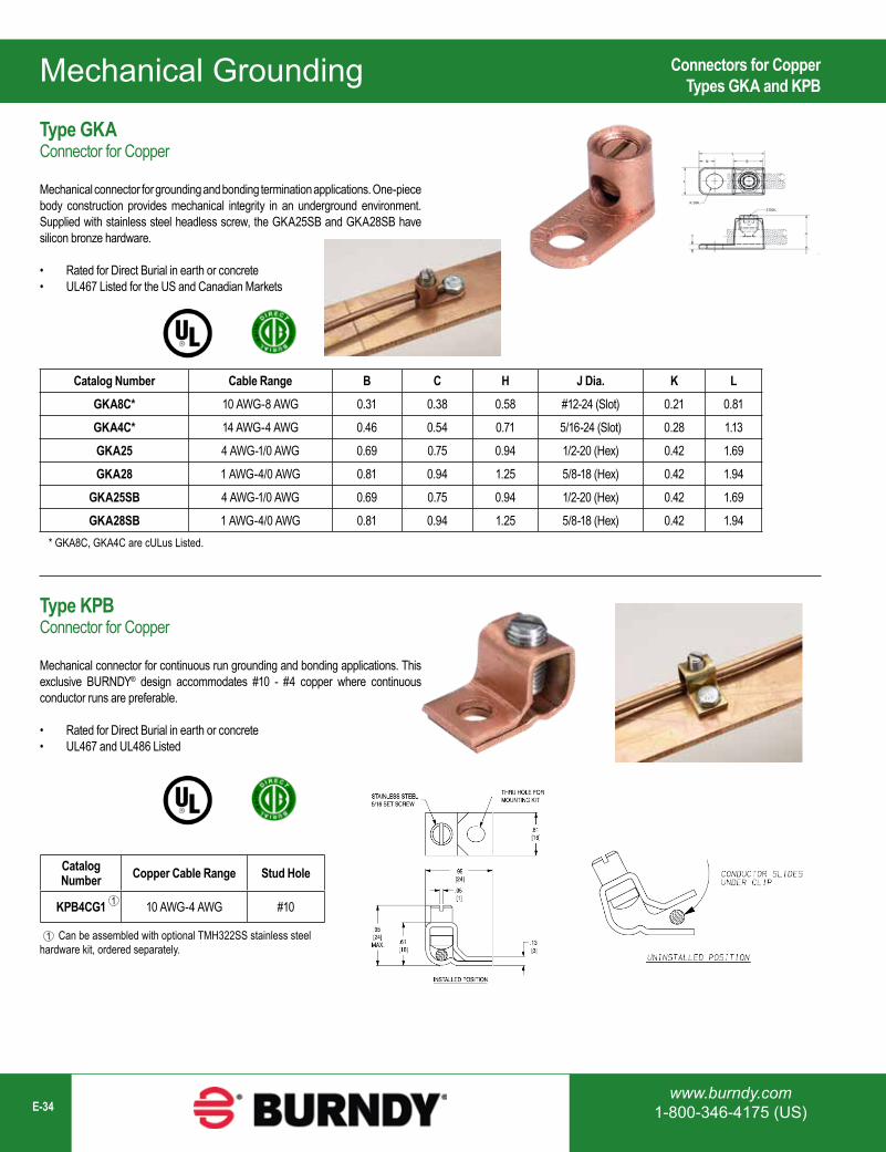
Catalog Number Cable Range B C H J Dia. K LGKA8C* 10 AWG-8 AWG 0.31 0.38 0.58 #12-24 (Slot) 0.21 0.81
GKA4C* 14 AWG-4 AWG 0.46 0.54 0.71 5/16-24 (Slot) 0.28 1.13
GKA25 4 AWG-1/0 AWG 0.69 0.75 0.94 1/2-20 (Hex) 0.42 1.69
GKA28 1 AWG-4/0 AWG 0.81 0.94 1.25 5/8-18 (Hex) 0.42 1.94
GKA25SB 4 AWG-1/0 AWG 0.69 0.75 0.94 1/2-20 (Hex) 0.42 1.69
GKA28SB 1 AWG-4/0 AWG 0.81 0.94 1.25 5/8-18 (Hex) 0.42 1.94
Catalog Number Copper Cable Range Stud Hole
KPB4CG1 10 AWG-4 AWG #10
* GKA8C, GKA4C are cULus Listed.
Can be assembled with optional TMH322SS stainless steel hardware kit, ordered separately.
1
Connectors for CopperTypes GKA and KPB
Type GKA Connector for Copper
Mechanical connector for grounding and bonding termination applications. One-piece body construction provides mechanical integrity in an underground environment. Supplied with stainless steel headless screw, the GKA25SB and GKA28SB have silicon bronze hardware.
• Rated for Direct Burial in earth or concrete• UL467 Listed for the US and Canadian Markets
Type KPB Connector for Copper
Mechanical connector for continuous run grounding and bonding applications. This exclusive BURNDY® design accommodates #10 - #4 copper where continuous conductor runs are preferable.
• Rated for Direct Burial in earth or concrete• UL467 and UL486 Listed
1
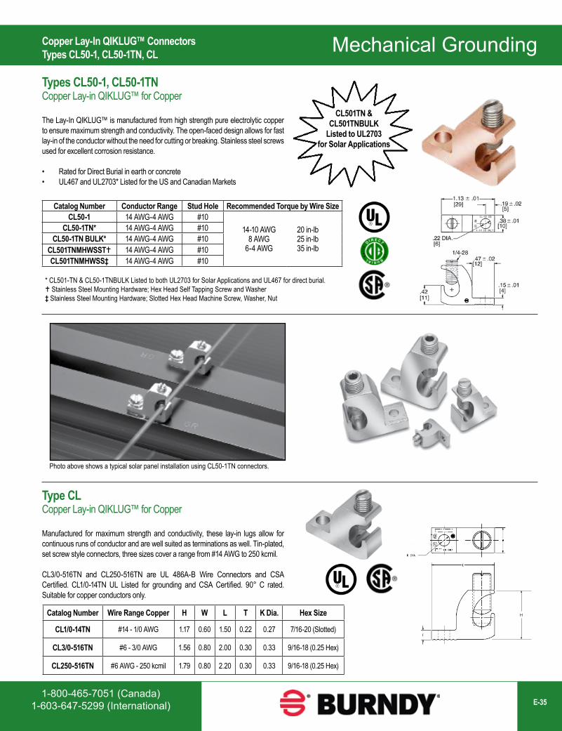
1-800-465-7051 (Canada)1-603-647-5299 (International) E-35
Mechanical Grounding
Catalog Number Conductor Range Stud Hole Recommended Torque by Wire SizeCL50-1 14 AWG-4 AWG #10
14-10 AWG 8 AWG
6-4 AWG
20 in-lb 25 in-lb 35 in-lb
CL50-1TN* 14 AWG-4 AWG #10CL50-1TN BULK* 14 AWG-4 AWG #10
CL501TNMHWSST 14 AWG-4 AWG #10CL501TNMHWSS‡ 14 AWG-4 AWG #10
Catalog Number Wire Range Copper H W L T K Dia. Hex Size
CL1/0-14TN #14 - 1/0 AWG 1.17 0.60 1.50 0.22 0.27 7/16-20 (Slotted)
CL3/0-516TN #6 - 3/0 AWG 1.56 0.80 2.00 0.30 0.33 9/16-18 (0.25 Hex)
CL250-516TN #6 AWG - 250 kcmil 1.79 0.80 2.20 0.30 0.33 9/16-18 (0.25 Hex)
Photo above shows a typical solar panel installation using CL50-1TN connectors.
H
CL501TN &CL501TNBULK
Listed to UL2703 for Solar Applications
* CL501-TN & CL50-1TNBULK Listed to both UL2703 for Solar Applications and UL467 for direct burial. Stainless Steel Mounting Hardware; Hex Head Self Tapping Screw and Washer‡ Stainless Steel Mounting Hardware; Slotted Hex Head Machine Screw, Washer, Nut
Copper Lay-In QIKLUG™ ConnectorsTypes CL50-1, CL50-1TN, CL
Types CL50-1, CL50-1TNCopper Lay-in QIKLUG™ for Copper
The Lay-In QIKLUG™ is manufactured from high strength pure electrolytic copper to ensure maximum strength and conductivity. The open-faced design allows for fast lay-in of the conductor without the need for cutting or breaking. Stainless steel screws used for excellent corrosion resistance.
• Rated for Direct Burial in earth or concrete• UL467 and UL2703* Listed for the US and Canadian Markets
Type CLCopper Lay-in QIKLUG™ for Copper
Manufactured for maximum strength and conductivity, these lay-in lugs allow for continuous runs of conductor and are well suited as terminations as well. Tin-plated, set screw style connectors, three sizes cover a range from #14 AWG to 250 kcmil.
CL3/0-516TN and CL250-516TN are UL 486A-B Wire Connectors and CSA Certified. CL1/0-14TN UL Listed for grounding and CSA Certified. 90° C rated. Suitable for copper conductors only.
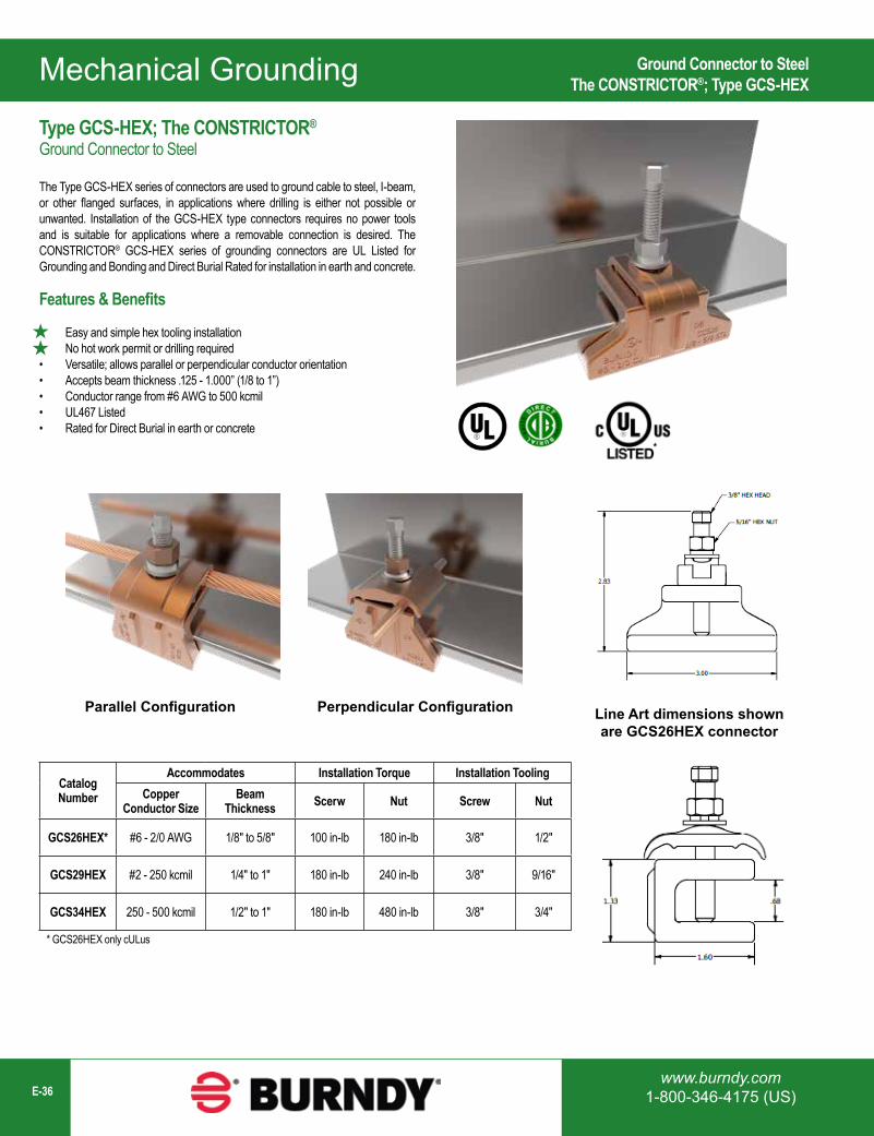
Mechanical Grounding
www.burndy.com1-800-346-4175 (US)E-36
Parallel Configuration Perpendicular Configuration
Catalog Number
Accommodates Installation Torque Installation ToolingCopper
Conductor SizeBeam
Thickness Scerw Nut Screw Nut
GCS26HEX* #6 - 2/0 AWG 1/8" to 5/8" 100 in-lb 180 in-lb 3/8" 1/2"
GCS29HEX #2 - 250 kcmil 1/4" to 1" 180 in-lb 240 in-lb 3/8" 9/16"
GCS34HEX 250 - 500 kcmil 1/2" to 1" 180 in-lb 480 in-lb 3/8" 3/4"
Ground Connector to SteelThe CONSTRICTOR®; Type GCS-HEX
Type GCS-HEX; The CONSTRICTOR®
Ground Connector to Steel
The Type GCS-HEX series of connectors are used to ground cable to steel, I-beam, or other flanged surfaces, in applications where drilling is either not possible or unwanted. Installation of the GCS-HEX type connectors requires no power tools and is suitable for applications where a removable connection is desired. The CONSTRICTOR® GCS-HEX series of grounding connectors are UL Listed for Grounding and Bonding and Direct Burial Rated for installation in earth and concrete.
Line Art dimensions shownare GCS26HEX connector
Features & Benefits
• Easy and simple hex tooling installation• No hot work permit or drilling required• Versatile; allows parallel or perpendicular conductor orientation• Accepts beam thickness .125 - 1.000” (1/8 to 1”)• Conductor range from #6 AWG to 500 kcmil• UL467 Listed• Rated for Direct Burial in earth or concrete
*
* GCS26HEX only cULus
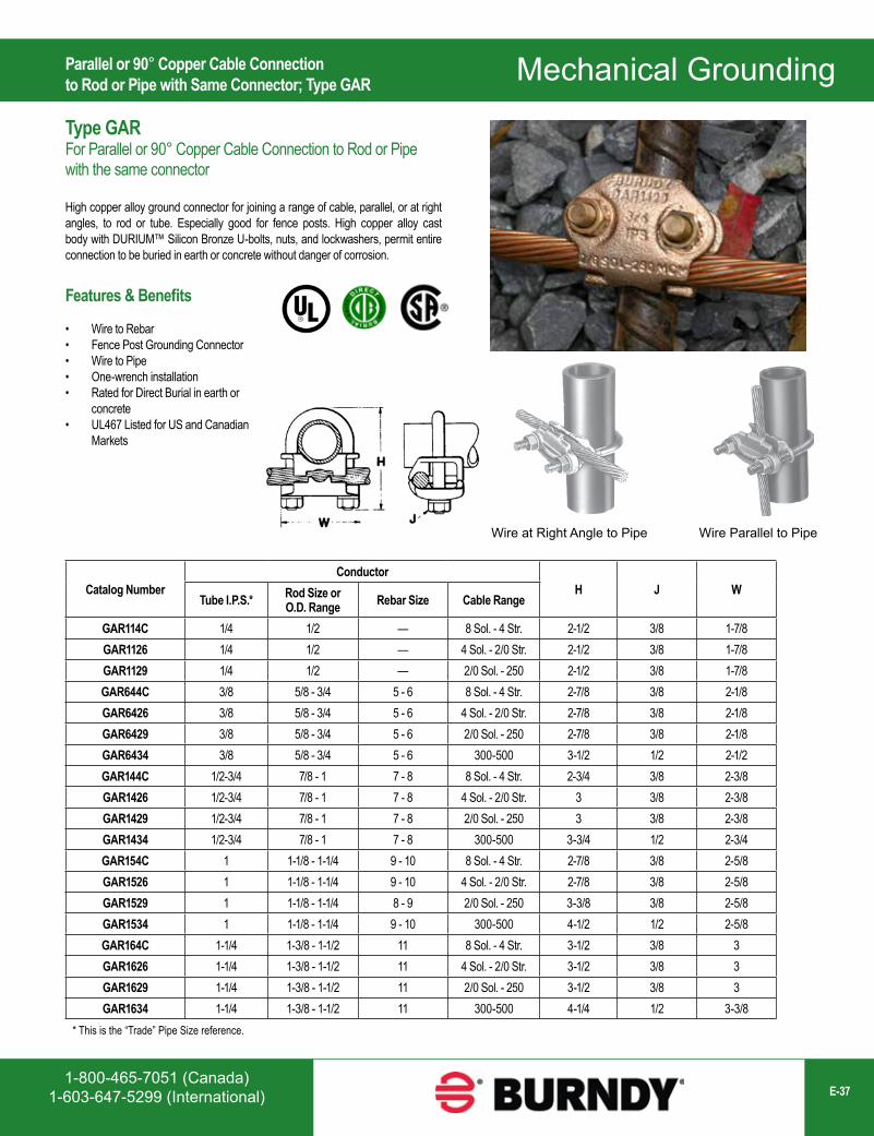
1-800-465-7051 (Canada)1-603-647-5299 (International) E-37
Mechanical Grounding
Catalog NumberConductor
H J WTube I.P.S.* Rod Size or
O.D. Range Rebar Size Cable Range
GAR114C 1/4 1/2 — 8 Sol. - 4 Str. 2-1/2 3/8 1-7/8GAR1126 1/4 1/2 — 4 Sol. - 2/0 Str. 2-1/2 3/8 1-7/8GAR1129 1/4 1/2 — 2/0 Sol. - 250 2-1/2 3/8 1-7/8GAR644C 3/8 5/8 - 3/4 5 - 6 8 Sol. - 4 Str. 2-7/8 3/8 2-1/8GAR6426 3/8 5/8 - 3/4 5 - 6 4 Sol. - 2/0 Str. 2-7/8 3/8 2-1/8GAR6429 3/8 5/8 - 3/4 5 - 6 2/0 Sol. - 250 2-7/8 3/8 2-1/8GAR6434 3/8 5/8 - 3/4 5 - 6 300-500 3-1/2 1/2 2-1/2GAR144C 1/2-3/4 7/8 - 1 7 - 8 8 Sol. - 4 Str. 2-3/4 3/8 2-3/8GAR1426 1/2-3/4 7/8 - 1 7 - 8 4 Sol. - 2/0 Str. 3 3/8 2-3/8GAR1429 1/2-3/4 7/8 - 1 7 - 8 2/0 Sol. - 250 3 3/8 2-3/8GAR1434 1/2-3/4 7/8 - 1 7 - 8 300-500 3-3/4 1/2 2-3/4GAR154C 1 1-1/8 - 1-1/4 9 - 10 8 Sol. - 4 Str. 2-7/8 3/8 2-5/8GAR1526 1 1-1/8 - 1-1/4 9 - 10 4 Sol. - 2/0 Str. 2-7/8 3/8 2-5/8GAR1529 1 1-1/8 - 1-1/4 8 - 9 2/0 Sol. - 250 3-3/8 3/8 2-5/8GAR1534 1 1-1/8 - 1-1/4 9 - 10 300-500 4-1/2 1/2 2-5/8GAR164C 1-1/4 1-3/8 - 1-1/2 11 8 Sol. - 4 Str. 3-1/2 3/8 3GAR1626 1-1/4 1-3/8 - 1-1/2 11 4 Sol. - 2/0 Str. 3-1/2 3/8 3GAR1629 1-1/4 1-3/8 - 1-1/2 11 2/0 Sol. - 250 3-1/2 3/8 3GAR1634 1-1/4 1-3/8 - 1-1/2 11 300-500 4-1/4 1/2 3-3/8
Wire at Right Angle to Pipe Wire Parallel to Pipe
* This is the “Trade” Pipe Size reference.
Parallel or 90° Copper Cable Connectionto Rod or Pipe with Same Connector; Type GAR
Type GARFor Parallel or 90° Copper Cable Connection to Rod or Pipewith the same connector
High copper alloy ground connector for joining a range of cable, parallel, or at right angles, to rod or tube. Especially good for fence posts. High copper alloy cast body with DURIUM™ Silicon Bronze U-bolts, nuts, and lockwashers, permit entire connection to be buried in earth or concrete without danger of corrosion.
Features & Benefits
• Wire to Rebar• Fence Post Grounding Connector• Wire to Pipe• One-wrench installation• Rated for Direct Burial in earth or
concrete• UL467 Listed for US and Canadian
Markets
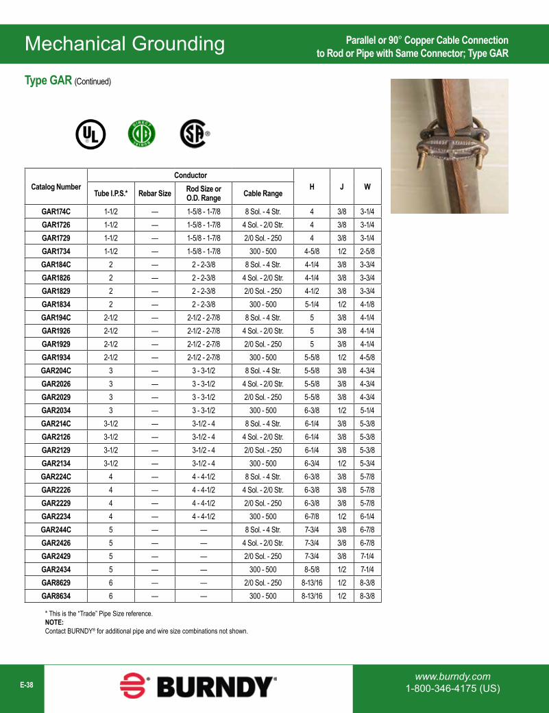
Mechanical Grounding
www.burndy.com1-800-346-4175 (US)E-38
Catalog NumberConductor
H J WTube I.P.S.* Rebar Size Rod Size or
O.D. Range Cable Range
GAR174C 1-1/2 — 1-5/8 - 1-7/8 8 Sol. - 4 Str. 4 3/8 3-1/4GAR1726 1-1/2 — 1-5/8 - 1-7/8 4 Sol. - 2/0 Str. 4 3/8 3-1/4GAR1729 1-1/2 — 1-5/8 - 1-7/8 2/0 Sol. - 250 4 3/8 3-1/4GAR1734 1-1/2 — 1-5/8 - 1-7/8 300 - 500 4-5/8 1/2 2-5/8GAR184C 2 — 2 - 2-3/8 8 Sol. - 4 Str. 4-1/4 3/8 3-3/4GAR1826 2 — 2 - 2-3/8 4 Sol. - 2/0 Str. 4-1/4 3/8 3-3/4GAR1829 2 — 2 - 2-3/8 2/0 Sol. - 250 4-1/2 3/8 3-3/4GAR1834 2 — 2 - 2-3/8 300 - 500 5-1/4 1/2 4-1/8GAR194C 2-1/2 — 2-1/2 - 2-7/8 8 Sol. - 4 Str. 5 3/8 4-1/4GAR1926 2-1/2 — 2-1/2 - 2-7/8 4 Sol. - 2/0 Str. 5 3/8 4-1/4GAR1929 2-1/2 — 2-1/2 - 2-7/8 2/0 Sol. - 250 5 3/8 4-1/4GAR1934 2-1/2 — 2-1/2 - 2-7/8 300 - 500 5-5/8 1/2 4-5/8GAR204C 3 — 3 - 3-1/2 8 Sol. - 4 Str. 5-5/8 3/8 4-3/4GAR2026 3 — 3 - 3-1/2 4 Sol. - 2/0 Str. 5-5/8 3/8 4-3/4GAR2029 3 — 3 - 3-1/2 2/0 Sol. - 250 5-5/8 3/8 4-3/4GAR2034 3 — 3 - 3-1/2 300 - 500 6-3/8 1/2 5-1/4GAR214C 3-1/2 — 3-1/2 - 4 8 Sol. - 4 Str. 6-1/4 3/8 5-3/8GAR2126 3-1/2 — 3-1/2 - 4 4 Sol. - 2/0 Str. 6-1/4 3/8 5-3/8GAR2129 3-1/2 — 3-1/2 - 4 2/0 Sol. - 250 6-1/4 3/8 5-3/8GAR2134 3-1/2 — 3-1/2 - 4 300 - 500 6-3/4 1/2 5-3/4GAR224C 4 — 4 - 4-1/2 8 Sol. - 4 Str. 6-3/8 3/8 5-7/8GAR2226 4 — 4 - 4-1/2 4 Sol. - 2/0 Str. 6-3/8 3/8 5-7/8GAR2229 4 — 4 - 4-1/2 2/0 Sol. - 250 6-3/8 3/8 5-7/8GAR2234 4 — 4 - 4-1/2 300 - 500 6-7/8 1/2 6-1/4GAR244C 5 — — 8 Sol. - 4 Str. 7-3/4 3/8 6-7/8GAR2426 5 — — 4 Sol. - 2/0 Str. 7-3/4 3/8 6-7/8GAR2429 5 — — 2/0 Sol. - 250 7-3/4 3/8 7-1/4GAR2434 5 — — 300 - 500 8-5/8 1/2 7-1/4GAR8629 6 — — 2/0 Sol. - 250 8-13/16 1/2 8-3/8GAR8634 6 — — 300 - 500 8-13/16 1/2 8-3/8
* This is the “Trade” Pipe Size reference.NOTE:Contact BURNDY® for additional pipe and wire size combinations not shown.
Parallel or 90° Copper Cable Connectionto Rod or Pipe with Same Connector; Type GAR
Type GAR (Continued)
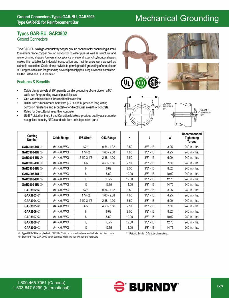
1-800-465-7051 (Canada)1-603-647-5299 (International) E-39
Mechanical Grounding
1
Catalog Number Cable Range IPS Size ** O.D. Range H J W
Recommended Tightening
TorqueGAR3902-BU #4- 4/0 AWG 1/2-1 0.84 - 1.32 3.50 3/8" - 16 3.25 240 in. - lbs.GAR3903-BU #4- 4/0 AWG 1 1/4-2 1.66 - 2.38 4.00 3/8" - 16 4.25 240 in. - lbs.GAR3904-BU #4- 4/0 AWG 2 1/2-3 1/2 2.88 - 4.00 6.50 3/8" - 16 6.00 240 in. - lbs.GAR3905-BU #4- 4/0 AWG 4-5 4.50 - 5.56 7.50 3/8" - 16 7.50 240 in. - lbs.GAR3906-BU #4- 4/0 AWG 6 6.62 8.50 3/8" - 16 8.62 240 in. - lbs.GAR3907-BU #4- 4/0 AWG 8 8.62 10.00 3/8" - 16 10.62 240 in. - lbs.GAR3908-BU #4- 4/0 AWG 10 10.75 12.00 3/8" - 16 12.75 240 in. - lbs.GAR3909-BU #4- 4/0 AWG 12 12.75 14.00 3/8" - 16 14.75 240 in. - lbs.
GAR3902 #4- 4/0 AWG 1/2-1 0.84 - 1.32 3.50 3/8" - 16 3.25 240 in. - lbs.GAR3903 #4- 4/0 AWG 1 1/4-2 1.66 - 2.38 4.00 3/8" - 16 4.25 240 in. - lbs.GAR3904 #4- 4/0 AWG 2 1/2-3 1/2 2.88 - 4.00 6.50 3/8" - 16 6.00 240 in. - lbs.GAR3905 #4- 4/0 AWG 4-5 4.50 - 5.56 7.50 3/8" - 16 7.50 240 in. - lbs.GAR3906 #4- 4/0 AWG 6 6.62 8.50 3/8" - 16 8.62 240 in. - lbs.GAR3907 #4- 4/0 AWG 8 8.62 10.00 3/8" - 16 10.62 240 in. - lbs.GAR3908 #4- 4/0 AWG 10 10.75 12.00 3/8" - 16 12.75 240 in. - lbs.GAR3909 #4- 4/0 AWG 12 12.75 14.00 3/8" - 16 14.75 240 in. - lbs.
Type GAR-BU is supplied with DURIUM™ silicon bronze hardware and is Listed for direct burial Standard Type GAR-3900 series supplied with galvanized U-bolt and hardware
** Refer to Section O for tube dimensions.
Types GAR-BU, GAR3902Ground Connectors
Type GAR-BU is a high-conductivity copper ground connector for connecting a small to medium range copper ground conductor to water pipe as well as structural and reinforcing rod shapes. Universal acceptance of several sizes of cylindrical shapes makes this suitable for industrial construction and maintenance work as well as cathodic protection. Cable clamp swivels to permit parallel grounding of one pipe or 90° degree cable run for grounding several parallel pipes. Single wrench installation. UL467 Listed and CSA Certified.
Ground Connectors Types GAR-BU, GAR3902; Type GAR-RB for Reinforcement Bar
Features & Benefits
• Cable clamp swivels at 90°; permits parallel grounding of one pipe on a 90° cable run for grounding several parallel pipes
• One-wrench installation for simplified installation• DURIUM™ silicon bronze hardware (-BU Series)* provides long lasting
corrosion resistance and acceptable for direct burial in earth of concrete• Rated for Direct Burial in earth or concrete• UL467 Listed for the US and Canadian Markets; provides quality assurance to
recognized industry NEC standards from an independent party
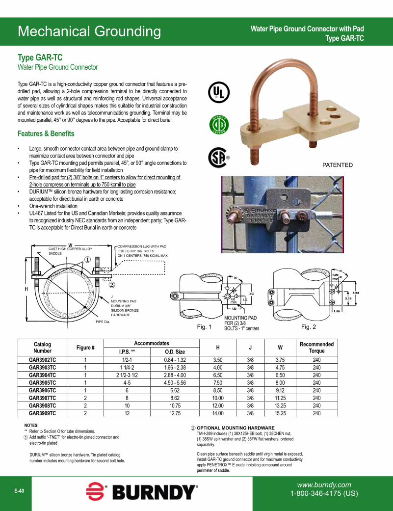
Mechanical Grounding
www.burndy.com1-800-346-4175 (US)E-40
COMPRESSION LUG WITH PADFOR (2) 3/8″ Dia. BOLTSON 1 CENTERS. 750 KCMIL MAX.
JMOUNTING PADDURIUM 3/8″SILICON BRONZEHARDWARE
PIPE Dia.
CAST HIGH COPPER ALLOY SADDLE
Fig. 2Fig. 1MOUNTING PADFOR (2) 3/8BOLTS - 1" centers
PATENTED
Catalog Number Figure #
AccommodatesH J W Recommended
TorqueI.P.S. ** O.D. SizeGAR3902TC 1 1/2-1 0.84 - 1.32 3.50 3/8 3.75 240GAR3903TC 1 1 1/4-2 1.66 - 2.38 4.00 3/8 4.75 240GAR3904TC 1 2 1/2-3 1/2 2.88 - 4.00 6.50 3/8 6.50 240GAR3905TC 1 4-5 4.50 - 5.56 7.50 3/8 8.00 240GAR3906TC 1 6 6.62 8.50 3/8 9.12 240GAR3907TC 2 8 8.62 10.00 3/8 11.25 240GAR3908TC 2 10 10.75 12.00 3/8 13.25 240GAR3909TC 2 12 12.75 14.00 3/8 15.25 240
NOTES:** Refer to Section O for tube dimensions. Add suffix “-TNET” for electro-tin plated connector and electro-tin plated DURIUM™ silicon bronze hardware. Tin plated catalog number includes mounting hardware for second bolt hole.
OPTIONAL MOUNTING HARDWARETMH-289 includes (1) 38X125HEB bolt, (1) 38CHEN nut, (1) 38SW split washer and (2) 38FW flat washers, ordered separately.
Clean pipe surface beneath saddle until virgin metal is exposed, install GAR-TC ground connector and for maximum conductivity, apply PENETROX™ E oxide inhibiting compound around perimeter of saddle.
1
2
Water Pipe Ground Connector with PadType GAR-TC
Features & Benefits
• Large, smooth connector contact area between pipe and ground clamp to maximize contact area between connector and pipe
• Type GAR-TC mounting pad permits parallel, 45°, or 90° angle connections to pipe for maximum flexibility for field installation
• Pre-drilled pad for (2) 3/8” bolts on 1” centers to allow for direct mounting of 2-hole compression terminals up to 750 kcmil to pipe
• DURIUM™ silicon bronze hardware for long lasting corrosion resistance; acceptable for direct burial in earth or concrete
• One-wrench installaiton• UL467 Listed for the US and Canadian Markets; provides quality assurance
to recognized industry NEC standards from an independent party; Type GAR-TC is acceptable for Direct Burial in earth or concrete
Type GAR-TCWater Pipe Ground Connector
Type GAR-TC is a high-conductivity copper ground connector that features a pre-drilled pad, allowing a 2-hole compression terminal to be directly connected to water pipe as well as structural and reinforcing rod shapes. Universal acceptance of several sizes of cylindrical shapes makes this suitable for industrial construction and maintenance work as well as telecommunications grounding. Terminal may be mounted parallel, 45° or 90° degrees to the pipe. Acceptable for direct burial.
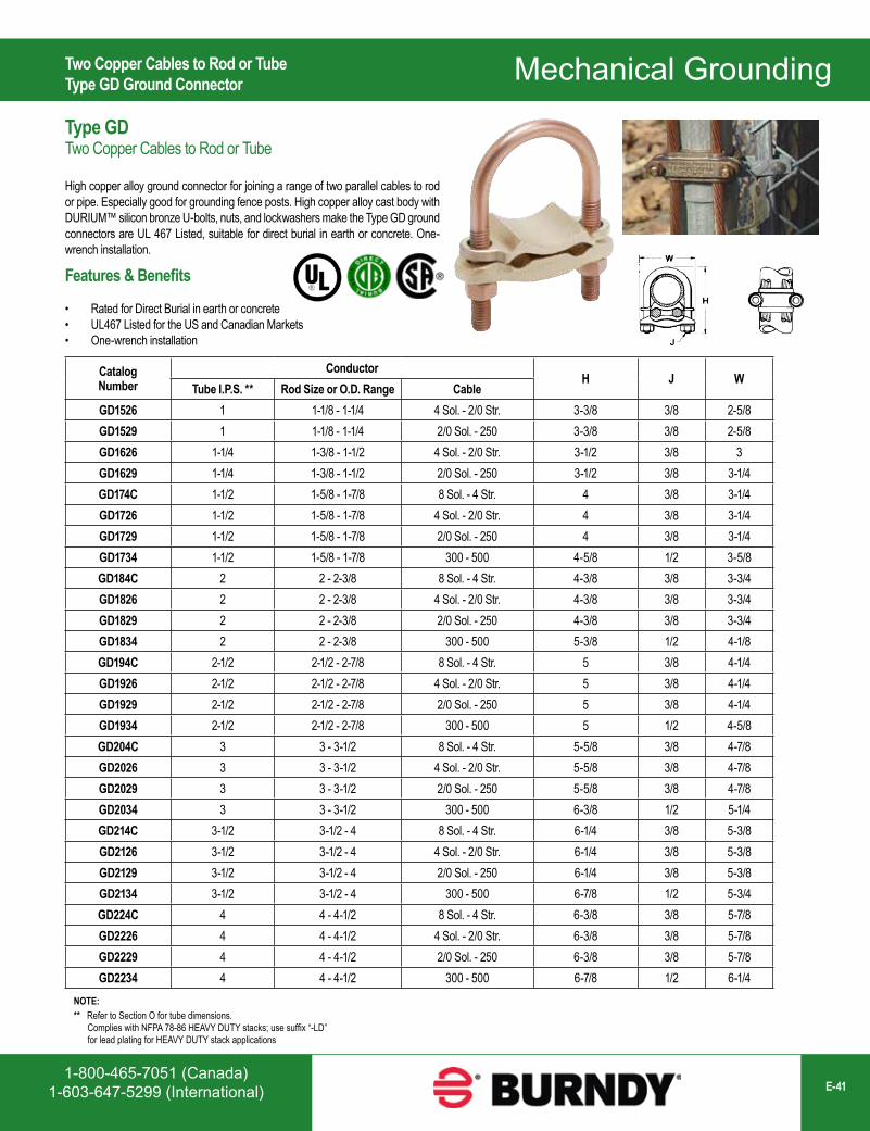
1-800-465-7051 (Canada)1-603-647-5299 (International) E-41
Mechanical Grounding
Catalog Number
ConductorH J W
Tube I.P.S. ** Rod Size or O.D. Range CableGD1526 1 1-1/8 - 1-1/4 4 Sol. - 2/0 Str. 3-3/8 3/8 2-5/8GD1529 1 1-1/8 - 1-1/4 2/0 Sol. - 250 3-3/8 3/8 2-5/8GD1626 1-1/4 1-3/8 - 1-1/2 4 Sol. - 2/0 Str. 3-1/2 3/8 3GD1629 1-1/4 1-3/8 - 1-1/2 2/0 Sol. - 250 3-1/2 3/8 3-1/4GD174C 1-1/2 1-5/8 - 1-7/8 8 Sol. - 4 Str. 4 3/8 3-1/4GD1726 1-1/2 1-5/8 - 1-7/8 4 Sol. - 2/0 Str. 4 3/8 3-1/4GD1729 1-1/2 1-5/8 - 1-7/8 2/0 Sol. - 250 4 3/8 3-1/4GD1734 1-1/2 1-5/8 - 1-7/8 300 - 500 4-5/8 1/2 3-5/8GD184C 2 2 - 2-3/8 8 Sol. - 4 Str. 4-3/8 3/8 3-3/4GD1826 2 2 - 2-3/8 4 Sol. - 2/0 Str. 4-3/8 3/8 3-3/4GD1829 2 2 - 2-3/8 2/0 Sol. - 250 4-3/8 3/8 3-3/4GD1834 2 2 - 2-3/8 300 - 500 5-3/8 1/2 4-1/8GD194C 2-1/2 2-1/2 - 2-7/8 8 Sol. - 4 Str. 5 3/8 4-1/4GD1926 2-1/2 2-1/2 - 2-7/8 4 Sol. - 2/0 Str. 5 3/8 4-1/4GD1929 2-1/2 2-1/2 - 2-7/8 2/0 Sol. - 250 5 3/8 4-1/4GD1934 2-1/2 2-1/2 - 2-7/8 300 - 500 5 1/2 4-5/8GD204C 3 3 - 3-1/2 8 Sol. - 4 Str. 5-5/8 3/8 4-7/8GD2026 3 3 - 3-1/2 4 Sol. - 2/0 Str. 5-5/8 3/8 4-7/8GD2029 3 3 - 3-1/2 2/0 Sol. - 250 5-5/8 3/8 4-7/8GD2034 3 3 - 3-1/2 300 - 500 6-3/8 1/2 5-1/4GD214C 3-1/2 3-1/2 - 4 8 Sol. - 4 Str. 6-1/4 3/8 5-3/8GD2126 3-1/2 3-1/2 - 4 4 Sol. - 2/0 Str. 6-1/4 3/8 5-3/8GD2129 3-1/2 3-1/2 - 4 2/0 Sol. - 250 6-1/4 3/8 5-3/8GD2134 3-1/2 3-1/2 - 4 300 - 500 6-7/8 1/2 5-3/4GD224C 4 4 - 4-1/2 8 Sol. - 4 Str. 6-3/8 3/8 5-7/8GD2226 4 4 - 4-1/2 4 Sol. - 2/0 Str. 6-3/8 3/8 5-7/8GD2229 4 4 - 4-1/2 2/0 Sol. - 250 6-3/8 3/8 5-7/8GD2234 4 4 - 4-1/2 300 - 500 6-7/8 1/2 6-1/4
NOTE:** Refer to Section O for tube dimensions. Complies with NFPA 78-86 HEAVY DUTY stacks; use suffix “-LD” for lead plating for HEAVY DUTY stack applications
Two Copper Cables to Rod or TubeType GD Ground Connector
Type GDTwo Copper Cables to Rod or Tube
High copper alloy ground connector for joining a range of two parallel cables to rod or pipe. Especially good for grounding fence posts. High copper alloy cast body with DURIUM™ silicon bronze U-bolts, nuts, and lockwashers make the Type GD ground connectors are UL 467 Listed, suitable for direct burial in earth or concrete. One-wrench installation.
Features & Benefits
• Rated for Direct Burial in earth or concrete• UL467 Listed for the US and Canadian Markets• One-wrench installation
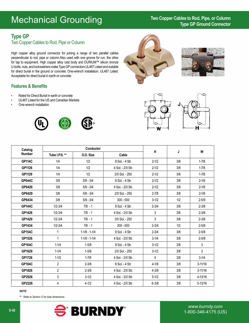
Mechanical Grounding
www.burndy.com1-800-346-4175 (US)E-42
Features & Benefits
• Rated for Direct Burial in earth or concrete• UL467 Listed for the US and Canadian Markets• One-wrench installation
Catalog Number
ConductorH J W
Tube I.P.S. ** O.D. Size CableGP114C 1/4 1/2 8 Sol. - 4 Str. 2-1/2 3/8 1-7/8GP1126 1/4 1/2 4 Sol. - 2/0 Str. 2-1/2 3/8 1-7/8GP1129 1/4 1/2 2/0 Sol. - 250 2-1/2 3/8 1-7/8GP644C 3/8 5/8 - 3/4 8 Sol. - 4 Str. 2-1/2 3/8 2-1/8GP6426 3/8 5/8 - 3/4 4 Sol. - 2/0 Str. 2-1/2 3/8 2-1/8GP6429 3/8 5/8 - 3/4 2/0 Sol. - 250 2-7/8 3/8 2-1/8GP6434 3/8 5/8 - 3/4 300 - 500 3-1/2 1/2 2-5/9GP144C 1/2-3/4 7/8 - 1 8 Sol. - 4 Str. 2-3/4 3/8 2-3/8GP1426 1/2-3/4 7/8 - 1 4 Sol. - 2/0 Str. 3 3/8 2-3/8GP1429 1/2-3/4 7/8 - 1 3/0 Sol. - 250 3 3/8 2-3/8GP1434 1/2-3/4 7/8 - 1 300 - 500 3-3/4 1/2 2-5/8GP154C 1 1-1/8 - 1-1/4 8 Sol. - 4 Str. 2-3/4 3/8 2-5/8GP1526 1 1-1/8 - 1-1/4 4 Sol. - 2/0 Str. 3-1/4 3/8 2-5/8GP164C 1-1/4 1-5/8 8 Sol. - 4 Str. 3-1/2 3/8 3GP1629 1-1/4 1-5/8 2/0 Sol. - 250 3-1/2 3/8 3GP1726 1-1/2 1-7/8 4 Sol. - 2/0 Str. 4 3/8 3-1/4GP184C 2 2-3/8 8 Sol. - 4 Str. 4-1/8 3/8 3-11/16GP1826 2 2-3/8 4 Sol. - 2/0 Str. 4-3/8 3/8 3-11/16GP2026 3 3-1/2 4 Sol. - 2/0 Str. 5-1/2 3/8 4-13/16GP2226 4 4-1/2 4 Sol. - 2/0 Str. 6-3/8 3/8 5-13/16
NOTE:
** Refer to Section O for tube dimensions.
Two Copper Cables to Rod, Pipe, or ColumnType GP Ground Connector
Type GPTwo Copper Cables to Rod, Pipe or Column
High copper alloy ground connector for joining a range of two parallel cables perpendicular to rod, pipe or column.Also used with one groove for run, the other for tap to equipment. High copper alloy cast body and DURIUM™ silicon bronze U-bolts, nuts, and lockwashers make Type GP connectors UL467 Listed and suitable for direct burial in the ground or concrete. One-wrench installation. UL467 Listed. Acceptable for direct burial in earth or concrete.
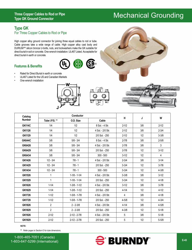
1-800-465-7051 (Canada)1-603-647-5299 (International) E-43
Mechanical Grounding
Features & Benefits
• Rated for Direct Burial in earth or concrete• UL467 Listed for the US and Canadian Markets• One-wrench installation
Catalog Number
ConductorH J W
Tube I.P.S. ** O.D. Size CableGK114C 1/4 1/2 8 Sol. - 4 Str. 2-1/2 3/8 2-1/2GK1126 1/4 1/2 4 Sol. - 2/0 Str. 2-1/2 3/8 2-3/4GK1129 1/4 1/2 2/0 Sol. - 250 2-1/2 1/2 3-3/8GK644C 3/8 5/8 - 3/4 8 Sol. - 4 Str. 2-7/8 3/8 2-5/8GK6426 3/8 5/8 - 3/4 4 Sol. - 2/0 Str. 2-7/8 3/8 3GK6429 3/8 5/8 - 3/4 2/0 Sol. - 250 2-7/8 1/2 3-1/2GK6434 3/8 5/8 - 3/4 300 - 500 3-1/2 1/2 4GK1426 1/2 - 3/4 7/8 - 1 4 Sol. - 2/0 Str. 2-3/4 3/8 3-1/4GK1429 1/2 - 3/4 7/8 - 1 2/0 Sol. - 250 3-3/4 1/2 3-7/8GK1434 1/2 - 3/4 7/8 - 1 300 - 500 3-3/4 1/2 4-3/8GK1526 1 1-1/8 - 1-1/4 4 Sol. - 2/0 Str. 3-3/8 3/8 3-1/2GK1529 1 1-1/8 - 1-1/4 2/0 Sol. - 250 3-3/4 1/2 4-1/8GK1626 1-1/4 1-3/8 - 1-1/2 4 Sol. - 2/0 Str. 3-1/2 3/8 3-7/8GK1629 1-1/4 1-3/8 - 1-1/2 2/0 Sol. - 250 4-1/4 1/2 4-1/2GK1726 1-1/2 1-5/8 - 1-7/8 4 Sol. - 2/0 Str. 4 3/8 4-1/8GK1729 1-1/2 1-5/8 - 1-7/8 2/0 Sol. - 250 4-5/8 1/2 4-3/4GK1826 2 2 - 2-3/8 4 Sol. - 2/0 Str. 4-1/4 3/8 4-5/8GK1829 2 2 - 2-3/8 2/0 Sol. - 250 4-3/8 1/2 5-1/8GK1926 2-1/2 2-1/2 - 2-7/8 4 Sol. - 2/0 Str. 5 3/8 5-1/8GK1929 2-1/2 2-1/2 - 2-7/8 2/0 Sol. - 250 5 1/2 5-5/8
NOTE:
** Refer pages to Section-O for tube dimensions.
Three Copper Cables to Rod or PipeType GK Ground Connector
Type GKFor Three Copper Cables to Rod or Pipe
High copper alloy ground connector for joining three equal cables to rod or tube. Cable grooves take a wide range of cable. High copper alloy cast body and DURIUM™ silicon bronze U-bolts, nuts, and lockwashers make the GK suitable for direct burial in soil or concrete. One-wrench installation. UL467 Listed. Acceptable for direct burial in earth or concrete.
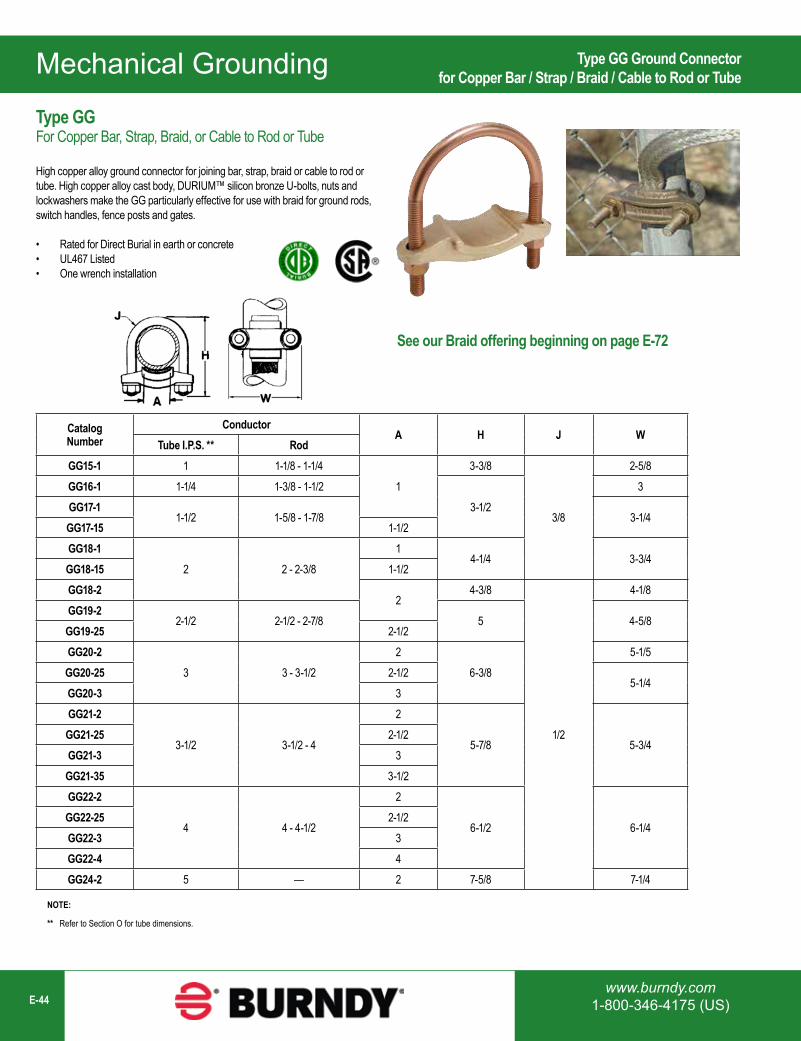
Mechanical Grounding
www.burndy.com1-800-346-4175 (US)E-44
Catalog Number
ConductorA H J W
Tube I.P.S. ** RodGG15-1 1 1-1/8 - 1-1/4
13-3/8
3/8
2-5/8GG16-1 1-1/4 1-3/8 - 1-1/2
3-1/23
GG17-11-1/2 1-5/8 - 1-7/8 3-1/4
GG17-15 1-1/2GG18-1
2 2 - 2-3/81
4-1/4 3-3/4GG18-15 1-1/2GG18-2
24-3/8
1/2
4-1/8GG19-2
2-1/2 2-1/2 - 2-7/8 5 4-5/8GG19-25 2-1/2GG20-2
3 3 - 3-1/22
6-3/85-1/5
GG20-25 2-1/25-1/4
GG20-3 3GG21-2
3-1/2 3-1/2 - 4
2
5-7/8 5-3/4GG21-25 2-1/2GG21-3 3GG21-35 3-1/2GG22-2
4 4 - 4-1/2
2
6-1/2 6-1/4GG22-25 2-1/2GG22-3 3GG22-4 4GG24-2 5 — 2 7-5/8 7-1/4
NOTE:
** Refer to Section O for tube dimensions.
Type GG Ground Connectorfor Copper Bar / Strap / Braid / Cable to Rod or Tube
Type GGFor Copper Bar, Strap, Braid, or Cable to Rod or Tube
High copper alloy ground connector for joining bar, strap, braid or cable to rod or tube. High copper alloy cast body, DURIUM™ silicon bronze U-bolts, nuts and lockwashers make the GG particularly effective for use with braid for ground rods, switch handles, fence posts and gates.
• Rated for Direct Burial in earth or concrete• UL467 Listed• One wrench installation
See our Braid offering beginning on page E-72
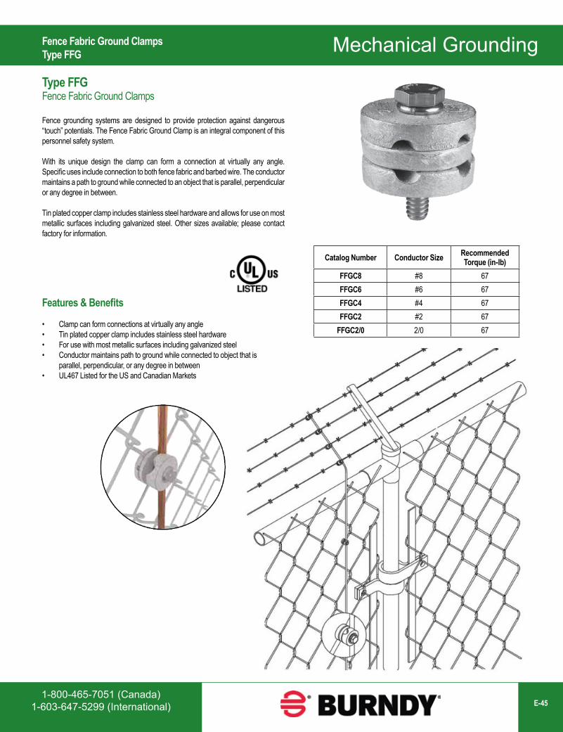
1-800-465-7051 (Canada)1-603-647-5299 (International) E-45
Mechanical Grounding
Catalog Number Conductor Size Recommended Torque (in-lb)
FFGC8 #8 67FFGC6 #6 67FFGC4 #4 67FFGC2 #2 67
FFGC2/0 2/0 67
Fence Fabric Ground ClampsType FFG
Type FFGFence Fabric Ground Clamps
Fence grounding systems are designed to provide protection against dangerous “touch” potentials. The Fence Fabric Ground Clamp is an integral component of this personnel safety system.
With its unique design the clamp can form a connection at virtually any angle. Specific uses include connection to both fence fabric and barbed wire. The conductor maintains a path to ground while connected to an object that is parallel, perpendicular or any degree in between.
Tin plated copper clamp includes stainless steel hardware and allows for use on most metallic surfaces including galvanized steel. Other sizes available; please contact factory for information.
Features & Benefits
• Clamp can form connections at virtually any angle• Tin plated copper clamp includes stainless steel hardware• For use with most metallic surfaces including galvanized steel• Conductor maintains path to ground while connected to object that is
parallel, perpendicular, or any degree in between• UL467 Listed for the US and Canadian Markets
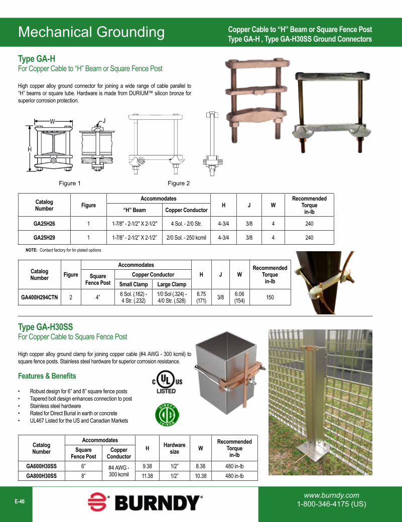
Mechanical Grounding
www.burndy.com1-800-346-4175 (US)E-46
Catalog Number Figure
AccommodatesH J W
Recommended Torque
in-lb“H” Beam Copper Conductor
GA25H26 1 1-7/8" - 2-1/2" X 2-1/2" 4 Sol. - 2/0 Str. 4-3/4 3/8 4 240
GA25H29 1 1-7/8” - 2-1/2” X 2-1/2” 2/0 Sol. - 250 kcmil 4-3/4 3/8 4 240
Catalog Number Figure
AccommodatesH J W
Recommended Torque
in-lbSquare
Fence PostCopper Conductor
Small Clamp Large Clamp
GA400H294CTN 2 4” 6 Sol. (.162) - 4 Str. (.232)
1/0 Sol (.324) -4/0 Str. (.528)
6.75(171) 3/8 6.06
(154) 150
Figure 1 Figure 2
NOTE: Contact factory for tin plated options
Copper Cable to “H” Beam or Square Fence PostType GA-H , Type GA-H30SS Ground Connectors
Type GA-HFor Copper Cable to “H” Beam or Square Fence Post
High copper alloy ground connector for joining a wide range of cable parallel to “H” beams or square tube. Hardware is made from DURIUM™ silicon bronze for superior corrosion protection.
Catalog Number
AccommodatesH Hardware
size WRecommended
Torquein-lb
Square Fence Post
Copper Conductor
GA600H30SS 6” #4 AWG - 300 kcmil
9.38 1/2” 8.38 480 in-lbGA800H30SS 8” 11.38 1/2” 10.38 480 in-lb
Features & Benefits
• Robust design for 6” and 8” square fence posts• Tapered bolt design enhances connection to post• Stainless steel hardware• Rated for Direct Burial in earth or concrete• UL467 Listed for the US and Canadian Markets
Type GA-H30SSFor Copper Cable to Square Fence Post
High copper alloy ground clamp for joining copper cable (#4 AWG - 300 kcmil) to square fence posts. Stainless steel hardware for superior corrosion resistance.
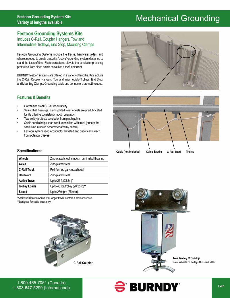
1-800-465-7051 (Canada)1-603-647-5299 (International) E-47
Mechanical Grounding
C-Rail TrackCable SaddleCable (not included) TrolleySpecifications:Wheels Zinc-plated steel; smooth running ball bearingAxles Zinc-plated steelC-Rail Track Roll-formed galvanized steelHardware Zinc-plated steelActive Travel Up to 25 ft (7.62m)*Trolley Loads Up to 45 lbs/trolley (20.25kg)**Speed Up to 250 fpm (75mpm)
*Additional kits are available for longer travel, contact customer service.**Designed for cable loads only.
Tow Trolley Close-Up Note: Wheels on trolleys fit inside C-RailC-Rail Coupler
Festoon Grounding System KitsVariety of lengths available
Festoon Grounding Systems KitsIncludes C-Rail, Coupler Hangers, Tow and Intermediate Trolleys, End Stop, Mounting Clamps
Festoon Grounding Systems include the tracks, hardware, axles, and wheels needed to create a quality, “active” grounding system designed to stand the tests of time. Festoon systems elevate the conductor providing protection from pinch points as well as a theft deterrent.
BURNDY festoon systems are offered in a variety of lengths. Kits include the C-Rail, Coupler Hangers, Tow and Intermediate Trolleys, End Stop, and Mounting Clamps. Grounding cable and connectors are not included.
Features & Benefits
• Galvanized steel C-Rail for durability• Sealed ball bearings in zinc-plated steel wheels are pre-lubricated
for life offering consistent smooth operation• Tow trolley protects conductor from pinch points• Cable saddle helps keep conductor in line with track (ensure the
cable size in use is accommodated by saddle)• Festoon system keeps conductor elevated and out of easy reach
from potential thieves
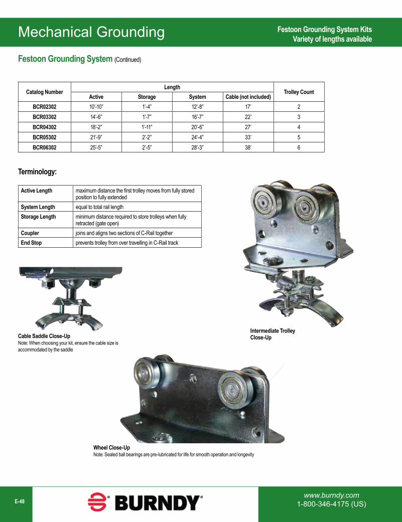
Mechanical Grounding
www.burndy.com1-800-346-4175 (US)E-48
Catalog NumberLength
Trolley CountActive Storage System Cable (not included)
BCR02302 10’-10” 1’-4” 12’-8” 17’ 2BCR03302 14’-6” 1’-7” 16’-7” 22’ 3BCR04302 18’-2” 1’-11” 20’-6” 27’ 4BCR05302 21’-9” 2’-2” 24’-4” 33’ 5BCR06302 25’-5” 2’-5” 28’-3” 38’ 6
Terminology:
Active Length maximum distance the first trolley moves from fully stored position to fully extended
System Length equal to total rail lengthStorage Length minimum distance required to store trolleys when fully
retracted (gate open)Coupler joins and aligns two sections of C-Rail togetherEnd Stop prevents trolley from over travelling in C-Rail track
Wheel Close-UpNote: Sealed ball bearings are pre-lubricated for life for smooth operation and longevity
Cable Saddle Close-UpNote: When choosing your kit, ensure the cable size is accommodated by the saddle
Intermediate Trolley Close-Up
Festoon Grounding System KitsVariety of lengths available
Festoon Grounding System (Continued)
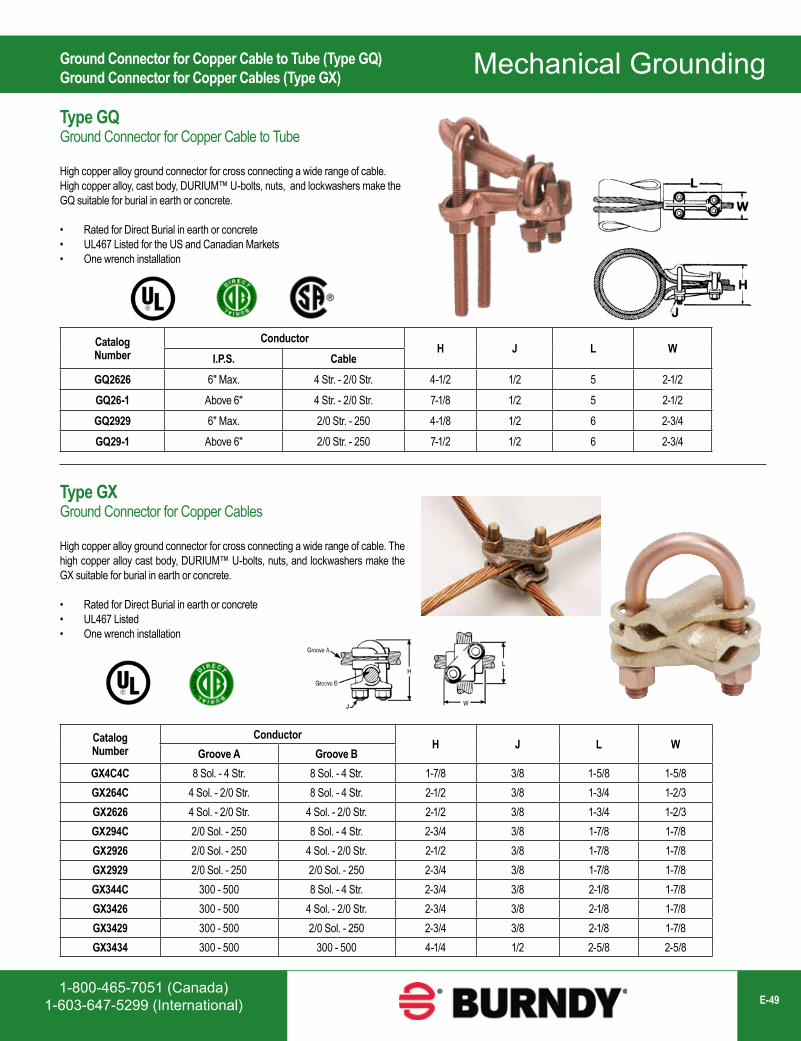
1-800-465-7051 (Canada)1-603-647-5299 (International) E-49
Mechanical Grounding
Catalog Number
ConductorH J L W
I.P.S. CableGQ2626 6" Max. 4 Str. - 2/0 Str. 4-1/2 1/2 5 2-1/2GQ26-1 Above 6" 4 Str. - 2/0 Str. 7-1/8 1/2 5 2-1/2GQ2929 6" Max. 2/0 Str. - 250 4-1/8 1/2 6 2-3/4GQ29-1 Above 6" 2/0 Str. - 250 7-1/2 1/2 6 2-3/4
Catalog Number
ConductorH J L W
Groove A Groove BGX4C4C 8 Sol. - 4 Str. 8 Sol. - 4 Str. 1-7/8 3/8 1-5/8 1-5/8GX264C 4 Sol. - 2/0 Str. 8 Sol. - 4 Str. 2-1/2 3/8 1-3/4 1-2/3GX2626 4 Sol. - 2/0 Str. 4 Sol. - 2/0 Str. 2-1/2 3/8 1-3/4 1-2/3GX294C 2/0 Sol. - 250 8 Sol. - 4 Str. 2-3/4 3/8 1-7/8 1-7/8GX2926 2/0 Sol. - 250 4 Sol. - 2/0 Str. 2-1/2 3/8 1-7/8 1-7/8GX2929 2/0 Sol. - 250 2/0 Sol. - 250 2-3/4 3/8 1-7/8 1-7/8GX344C 300 - 500 8 Sol. - 4 Str. 2-3/4 3/8 2-1/8 1-7/8GX3426 300 - 500 4 Sol. - 2/0 Str. 2-3/4 3/8 2-1/8 1-7/8GX3429 300 - 500 2/0 Sol. - 250 2-3/4 3/8 2-1/8 1-7/8GX3434 300 - 500 300 - 500 4-1/4 1/2 2-5/8 2-5/8
Ground Connector for Copper Cable to Tube (Type GQ)Ground Connector for Copper Cables (Type GX)
Type GQGround Connector for Copper Cable to Tube
High copper alloy ground connector for cross connecting a wide range of cable. High copper alloy, cast body, DURIUM™ U-bolts, nuts, and lockwashers make the GQ suitable for burial in earth or concrete.
• Rated for Direct Burial in earth or concrete• UL467 Listed for the US and Canadian Markets• One wrench installation
Type GXGround Connector for Copper Cables
High copper alloy ground connector for cross connecting a wide range of cable. The high copper alloy cast body, DURIUM™ U-bolts, nuts, and lockwashers make the GX suitable for burial in earth or concrete.
• Rated for Direct Burial in earth or concrete• UL467 Listed• One wrench installation
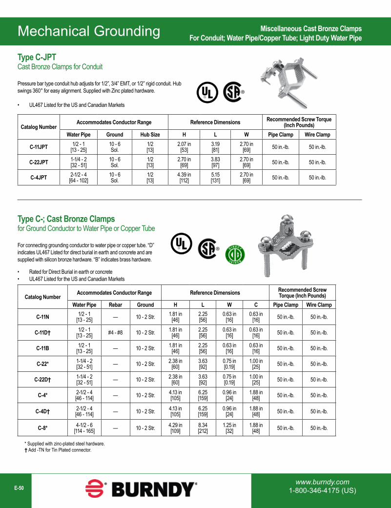
Mechanical Grounding
www.burndy.com1-800-346-4175 (US)E-50
Catalog NumberAccommodates Conductor Range Reference Dimensions Recommended Screw Torque
(Inch Pounds)Water Pipe Ground Hub Size H L W Pipe Clamp Wire Clamp
C-11JPT 1/2 - 1[13 - 25]
10 - 6Sol.
1/2[13]
2.07 in[53]
3.19[81]
2.70 in[69] 50 in.-lb. 50 in.-lb.
C-22JPT 1-1/4 - 2[32 - 51]
10 - 6Sol.
1/2[13]
2.70 in[69]
3.83[97]
2.70 in[69] 50 in.-lb. 50 in.-lb.
C-4JPT 2-1/2 - 4[64 - 102]
10 - 6Sol.
1/2[13]
4.39 in[112]
5.15[131]
2.70 in[69] 50 in.-lb. 50 in.-lb.
Catalog NumberAccommodates Conductor Range Reference Dimensions Recommended Screw
Torque (Inch Pounds)Water Pipe Rebar Ground H L W C Pipe Clamp Wire Clamp
C-11N 1/2 - 1[13 - 25] — 10 - 2 Str. 1.81 in
[46]2.25[56]
0.63 in[16]
0.63 in[16] 50 in.-lb. 50 in.-lb.
C-11D† 1/2 - 1[13 - 25] #4 - #8 10 - 2 Str. 1.81 in
[46]2.25[56]
0.63 in[16]
0.63 in[16] 50 in.-lb. 50 in.-lb.
C-11B 1/2 - 1[13 - 25] — 10 - 2 Str. 1.81 in
[46]2.25[56]
0.63 in[16]
0.63 in[16] 50 in.-lb. 50 in.-lb.
C-22* 1-1/4 - 2[32 - 51] — 10 - 2 Str. 2.38 in
[60]3.63[92]
0.75 in[0.19]
1.00 in[25] 50 in.-lb. 50 in.-lb.
C-22D† 1-1/4 - 2[32 - 51] — 10 - 2 Str. 2.38 in
[60]3.63[92]
0.75 in[0.19]
1.00 in[25] 50 in.-lb. 50 in.-lb.
C-4* 2-1/2 - 4[46 - 114] — 10 - 2 Str. 4.13 in
[105]6.25[159]
0.96 in[24]
1.88 in[48] 50 in.-lb. 50 in.-lb.
C-4D† 2-1/2 - 4[46 - 114] — 10 - 2 Str. 4.13 in
[105]6.25[159]
0.96 in[24]
1.88 in[48] 50 in.-lb. 50 in.-lb.
C-8* 4-1/2 - 6[114 - 165] — 10 - 2 Str. 4.29 in
[109]8.34[212]
1.25 in[32]
1.88 in[48] 50 in.-lb. 50 in.-lb.
* Supplied with zinc-plated steel hardware.† Add -TN for Tin Plated connector.
Type C-JPTCast Bronze Clamps for Conduit
Pressure bar type conduit hub adjusts for 1/2”, 3/4” EMT, or 1/2” rigid conduit. Hub swings 360° for easy alignment. Supplied with Zinc plated hardware.
• UL467 Listed for the US and Canadian Markets
Type C-; Cast Bronze Clampsfor Ground Conductor to Water Pipe or Copper Tube
For connecting grounding conductor to water pipe or copper tube. “D” indicates UL467 Listed for direct burial in earth and concrete and are supplied with silicon bronze hardware. “B” indicates brass hardware.
• Rated for Direct Burial in earth or concrete• UL467 Listed for the US and Canadian Markets
Miscellaneous Cast Bronze ClampsFor Conduit; Water Pipe/Copper Tube; Light Duty Water Pipe
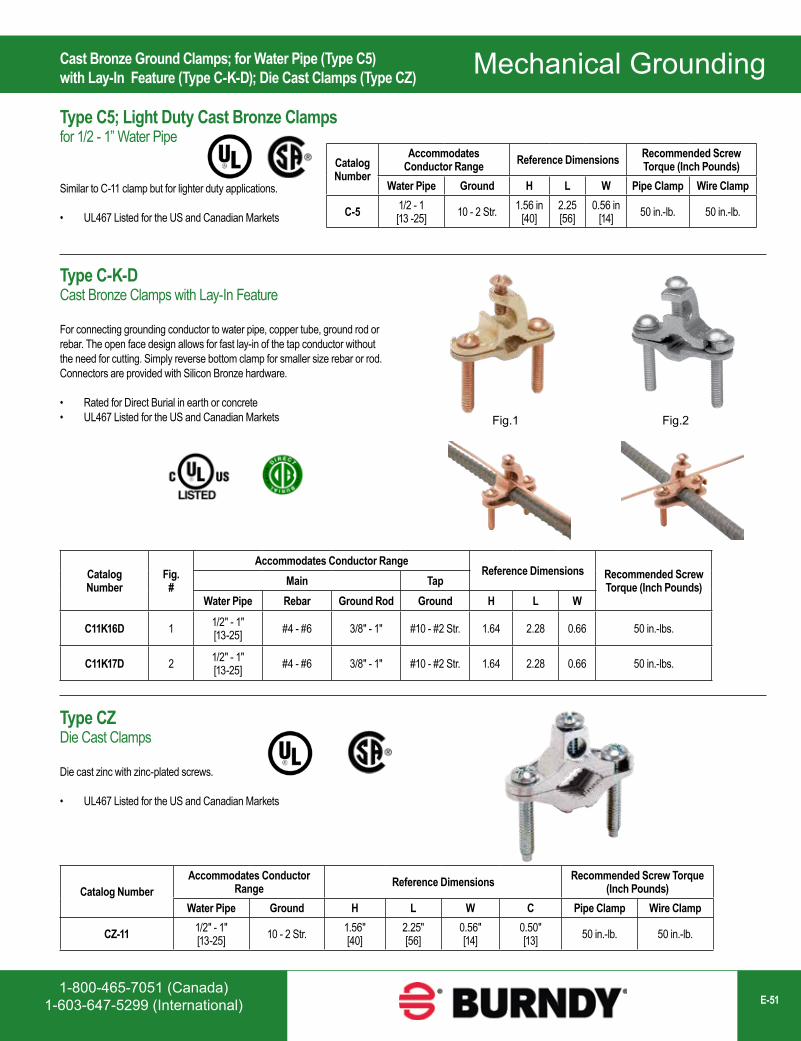
1-800-465-7051 (Canada)1-603-647-5299 (International) E-51
Mechanical GroundingType C5; Light Duty Cast Bronze Clampsfor 1/2 - 1” Water Pipe
Similar to C-11 clamp but for lighter duty applications.
• UL467 Listed for the US and Canadian Markets
Catalog Number
Accommodates Conductor Range Reference Dimensions Recommended Screw
Torque (Inch Pounds)Water Pipe Ground H L W Pipe Clamp Wire Clamp
C-5 1/2 - 1[13 -25] 10 - 2 Str. 1.56 in
[40]2.25[56]
0.56 in[14] 50 in.-lb. 50 in.-lb.
Catalog Number
Fig. #
Accommodates Conductor RangeReference Dimensions Recommended Screw
Torque (Inch Pounds)Main TapWater Pipe Rebar Ground Rod Ground H L W
C11K16D 1 1/2" - 1"[13-25] #4 - #6 3/8" - 1" #10 - #2 Str. 1.64 2.28 0.66 50 in.-lbs.
C11K17D 2 1/2" - 1"[13-25] #4 - #6 3/8" - 1" #10 - #2 Str. 1.64 2.28 0.66 50 in.-lbs.
Fig.1 Fig.2
Catalog NumberAccommodates Conductor
Range Reference Dimensions Recommended Screw Torque (Inch Pounds)
Water Pipe Ground H L W C Pipe Clamp Wire Clamp
CZ-11 1/2" - 1"[13-25] 10 - 2 Str. 1.56"
[40]2.25"[56]
0.56"[14]
0.50"[13] 50 in.-lb. 50 in.-lb.
Cast Bronze Ground Clamps; for Water Pipe (Type C5)with Lay-In Feature (Type C-K-D); Die Cast Clamps (Type CZ)
Type C-K-DCast Bronze Clamps with Lay-In Feature
For connecting grounding conductor to water pipe, copper tube, ground rod or rebar. The open face design allows for fast lay-in of the tap conductor without the need for cutting. Simply reverse bottom clamp for smaller size rebar or rod. Connectors are provided with Silicon Bronze hardware.
• Rated for Direct Burial in earth or concrete• UL467 Listed for the US and Canadian Markets
Type CZDie Cast Clamps
Die cast zinc with zinc-plated screws.
• UL467 Listed for the US and Canadian Markets
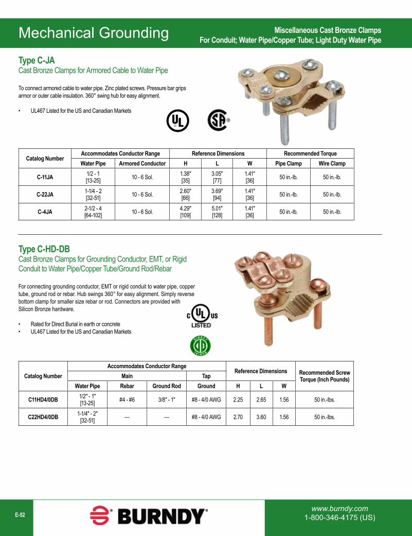
Mechanical Grounding
www.burndy.com1-800-346-4175 (US)E-52
Catalog NumberAccommodates Conductor Range Reference Dimensions Recommended TorqueWater Pipe Armored Conductor H L W Pipe Clamp Wire Clamp
C-11JA 1/2 - 1[13-25] 10 - 6 Sol. 1.38"
[35]3.05"[77]
1.41"[36] 50 in.-lb. 50 in.-lb.
C-22JA 1-1/4 - 2[32-51] 10 - 6 Sol. 2.60"
[66]3.69"[94]
1.41"[36] 50 in.-lb. 50 in.-lb.
C-4JA 2-1/2 - 4[64-102] 10 - 6 Sol. 4.29"
[109]5.01"[128]
1.41"[36] 50 in.-lb. 50 in.-lb.
Catalog NumberAccommodates Conductor Range
Reference Dimensions Recommended Screw Torque (Inch Pounds)Main Tap
Water Pipe Rebar Ground Rod Ground H L W
C11HD4/0DB 1/2" - 1"[13-25] #4 - #6 3/8" - 1" #8 - 4/0 AWG 2.25 2.65 1.56 50 in.-lbs.
C22HD4/0DB 1-1/4" - 2"[32-51] — — #8 - 4/0 AWG 2.70 3.60 1.56 50 in.-lbs.
Miscellaneous Cast Bronze ClampsFor Conduit; Water Pipe/Copper Tube; Light Duty Water Pipe
Type C-JACast Bronze Clamps for Armored Cable to Water Pipe
To connect armored cable to water pipe. Zinc plated screws. Pressure bar grips armor or outer cable insulation. 360° swing hub for easy alignment.
• UL467 Listed for the US and Canadian Markets
Type C-HD-DBCast Bronze Clamps for Grounding Conductor, EMT, or Rigid Conduit to Water Pipe/Copper Tube/Ground Rod/Rebar
For connecting grounding conductor, EMT or rigid conduit to water pipe, copper tube, ground rod or rebar. Hub swings 360° for easy alignment. Simply reverse bottom clamp for smaller size rebar or rod. Connectors are provided with Silicon Bronze hardware.
• Rated for Direct Burial in earth or concrete• UL467 Listed for the US and Canadian Markets
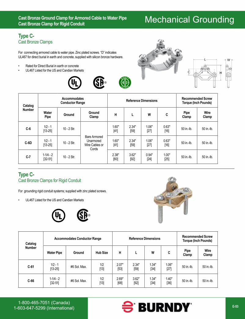
1-800-465-7051 (Canada)1-603-647-5299 (International) E-53
Mechanical Grounding
Catalog Number
Accommodates Conductor Range Reference Dimensions Recommended Screw
Torque (Inch Pounds)
Water Pipe Ground Ground
Clamp H L W C Pipe Clamp
Wire Clamp
C-6 1/2 - 1[13-25] 10 - 2 Str.
Bare ArmoredUnarmored
Wire Cables or Cords
1.60"[41]
2.34"[59]
1.06"[27]
0.63"[16] 50 in.-lb. 50 in.-lb.
C-6D 1/2 - 1[13-25] 10 - 2 Str. 1.60"
[41]2.34"[59]
1.06"[27]
0.63"[16] 50 in.-lb. 50 in.-lb.
C-7 1-1/4 - 2[32-51] 10 - 2 Str. 2.38"
[60]3.62"[92]
0.94"[24]
1.00"[25] 50 in.-lb. 50 in.-lb.
Catalog Number
Accommodates Conductor Range Reference Dimensions Recommended Screw Torque (Inch Pounds)
Water Pipe Ground Hub Size H L W C Pipe Clamp
Wire Clamp
C-61 1/2 - 1[13-25] #6 Sol. Max. 1/2
[13]2.07"[53]
2.34"[59]
1.34"[34]
1.06"[27] 50 in.-lb. 50 in.-lb.
C-66 1-1/4 - 2[32-51] #6 Sol. Max. 1/2
[13]2.69"[68]
3.62"[92]
1.34"[34]
1.40"[36] 50 in.-lb. 50 in.-lb.
Cast Bronze Ground Clamp for Armored Cable to Water PipeCast Bronze Clamp for Rigid Conduit
Type C-Cast Bronze Clamps
For connecting armored cable to water pipe. Zinc plated screws. “D” indicates UL467 for direct burial in earth and concrete, supplied with silicon bronze hardware.
• Rated for Direct Burial in earth or concrete• UL467 Listed for the US and Candian Markets
Type C-Cast Bronze Clamps for Rigid Conduit
For grounding rigid conduit systems; supplied with zinc plated screws.
• UL467 Listed for the US and Candian Markets
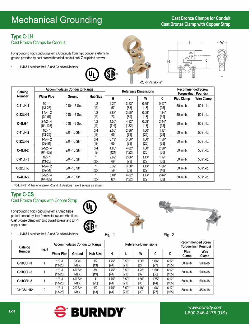
Mechanical Grounding
www.burndy.com1-800-346-4175 (US)E-54
Type C-LHCast Bronze Clamps for Conduit
For grounding rigid conduit systems. Continuity from rigid conduit systems to ground provided by cast bronze threaded conduit hub. Zinc plated screws.
• UL467 Listed for the US and Candian Markets
Catalog Number Fig. #
Accommodates Conductor Range Reference Dimensions Recommended Screw Torque (Inch Pounds)
Water Pipe Ground Hub Size H L W C D Pipe Clamp
Wire Clamp
C-11CSH-1 1 1/2 -1[13-25]
6 Sol.Max.
1/2[13]
1.75"[44]
8.50"[216]
1.06"[27]
1.06"[27]
6.12"[155] 50 in.-lb. 50 in.-lb.
C-11CSH-2 1 1/2 -1[13-25]
4/0 Str.Max.
3/4[19]
1.75"[44]
8.50"[216]
1.25"[32]
1.50"[38]
6.12"[155] 50 in.-lb. 50 in.-lb.
C-11CSH-3 1 1/2 -1[13-25]
4/0 Str.Max.
1[25]
1.75"[44]
8.50"[216]
1.50"[38]
1.75"[44]
6.12"[155] 50 in.-lb. 50 in.-lb.
C11CSLH12 2 1/2 -1[13-25]
2/0 Str.Max.
1/2[13]
1.75"[44]
8.50"[216]
1.18"[30]
1.06"[27]
6.12"[155] 50 in.-lb. 45 in.-lb.
Fig. 2
Catalog Number
Accommodates Conductor Range Reference Dimensions Recommended Screw Torque (Inch Pounds)
Water Pipe Ground Hub Size H L W C Pipe Clamp Wire Clamp
C-11LH-1 1/2 - 1[13-25] 10 Str. - 6 Sol. 1/2
[13]2.25"[57]
3.23"[83]
0.69"[18]
0.97"[25] 50 in.-lb. 50 in.-lb.
C-22LH-1 1-1/4 - 2[32-51] 10 Str. - 6 Sol. 1/2
[13]2.88"[73]
3.50"[89]
0.69"[18]
1.34"[34] 50 in.-lb. 50 in.-lb.
C-4LH-1 2-1/2 - 4[54-102] 10 Str. - 6 Sol. 1/2
[13]4.56"[116]
4.82"[122]
0.69"[18]
2.44"[62] 50 in.-lb. 50 in.-lb.
C-11LH-2 1/2 - 1[13-25] 2/0 - 10 Str. 3/4
[19]2.56"[65]
2.86"[73]
1.00"[25]
1.13"[29] 50 in.-lb. 50 in.-lb.
C-22LH-2 1-1/4 - 2[32-51] 2/0 - 10 Str. 3/4
[19]3.19"[65]
3.50"[89]
1.00"[25]
1.50"[38] 50 in.-lb. 50 in.-lb.
C-4LH-2 2-1/2 - 4[64-102] 2/0 - 10 Str. 3/4
[19]4.88"[124]
4.82"[122]
1.00"[25]
2.38"[60] 50 in.-lb. 50 in.-lb.
C-11LH-3 1/2 - 1[13-25] 3/0 - 10 Str. 1
[25]2.69"[68]
2.86"[73]
1.13"[29]
1.19"[30] 50 in.-lb. 50 in.-lb.
C-22LH-3 1-1/4 - 2[32-51] 3/0 - 10 Str. 1
[25]3.32"[59]
3.50"[89]
1.13"[29]
1.56"[40] 50 in.-lb. 50 in.-lb.
C-4LH-3 2-1/2 - 4[64-102] 3/0 - 10 Str. 1
[25]5.01"[127]
4.82"[122]
1.13"[29]
2.44"[62] 50 in.-lb. 50 in.-lb.
* C-LH with -1 has one screw; -2 and -3 Versions have 2 screws as shown.
-2, -3 Versions*
Fig. 1
Cast Bronze Clamps for ConduitCast Bronze Clamp with Copper Strap
Type C-CSCast Bronze Clamps with Copper Strap
For grounding rigid conduit systems. Strap helps protect conduit system from water system vibrations. Cast bronze clamp with zinc plated screws and ETP copper strap.
• UL467 Listed for the US and Candian Markets
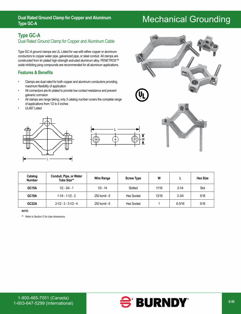
1-800-465-7051 (Canada)1-603-647-5299 (International) E-55
Mechanical Grounding
Catalog Number
Conduit, Pipe, or Water Tube Size** Wire Range Screw Type W L Hex Size
GC15A 1/2 - 3/4 - 1 1/0 - 14 Slotted 11/16 2-1/4 Slot
GC18A 1-1/4 - 1-1/2 - 2 250 kcmil - 6 Hex Socket 13/16 3-3/4 5/16
GC22A 2-1/2 - 3 - 3-1/2 - 4 250 kcmil - 6 Hex Socket 1 6-5/16 5/16
NOTE:
** Refer to Section O for tube dimensions.
Dual Rated Ground Clamp for Copper and AluminumType GC-A
Type GC-ADual Rated Ground Clamp for Copper and Aluminum Cable
Type GC-A ground clamps are UL Listed for use with either copper or aluminum conductors to copper water pipe, galvanized pipe, or steel conduit. All clamps are constructed from tin plated high-strength extruded aluminum alloy. PENETROX™ oxide inhibiting joing compounds are recommended for all aluminum applications.
Features & Benefits
• Clamps are dual rated for both copper and aluminum conductors providing maximum flexibility of application
• All connectors are tin plated to provide low contact resistance and prevent galvanic corrosion
• All clamps are range taking; only 3 catalog number covers the complete range of applications from 1/2 to 4 inches
• UL467 Listed
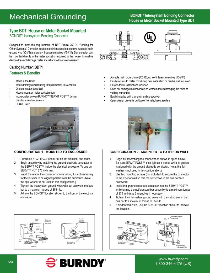
Mechanical Grounding
www.burndy.com1-800-346-4175 (US)E-56
Type BDT, House or Meter Socket MountedBONDIT® Intersystem Bonding Connector
Designed to meet the requirements of NEC Article 250.94 “Bonding for Other Systems”. Corrosion-resistant stainless steel set screws. Accepts main ground wire (#2-#8) and up to 4 intersystem wires (#6-#14). Same design can be mounted directly to the meter socket or mounted to the house. Innovative design does not damage meter socket and will not void warranty.
Catalog Number: BDT1
CONFIGURATION 1 - MOUNTED TO ENCLOSURE
1. Punch out a 1/2" or 3/4" knock out on the electrical enclosure. 2. Begin assembly by installing the ground electrode conductor in
the SERVIT POST™ inside the electrical enclosure. Torque on SERVIT® NUT: 275 in-lb max.
3. Install the rest of the connector shown below, it is not necessary for the bus bar to be aligned parallel with the enclosure. (Note: the split washer is not used in this configuration.)
4. Tighten the intersystem ground wires with set screws in the bus bar to a maximum torque of 35 in-lb.
5. Adhere the BONDIT® location sticker to the front of the electrical enclosure.
CONFIGURATION 2 - MOUNTED TO EXTERIOR WALL
1. Begin by assembling the connector as shown in figure below. Be sure SERVIT POST™ is as tight as it can be while its groove is aligned with the ground electrode conductor. (Note: the flat washer is not used in this configuration.)
2. Use two mounting screws (not included) to secure the connector to the exterior wall so that the set screws in the bus bar face downward.
3. Install the ground electrode conductor into the SERVIT POST™ while turning the nut/pressure bar assembly to a maximum torque of 275 in-lb (use 2 wrenches if necessary).
4. Tighten the intersystem ground wires with the set screws in the bus bar to a maximum torque of 35 in-lb.
5. If hidden from view, use the BONDIT® location sticker to indicate the location.
BONDIT® Intersystem Bonding ConnectorHouse or Meter Socket Mounted Type BDT
Features & Benefits
• Made in the USA!• Meets Intersystem Bonding Requirements; NEC 250.94• One connector does it all• House mount or meter socket mount• Incorporates proven BURNDY® SERVIT POST™ design• Stainless steel set screws• UL467 Listed
• Accepts main ground wire (#2-#8), up to 4 intersystem wires (#6-#14)• Easily mounts to meter box during new installation or can be wall mounted• Easy to follow instructions included• Does not damage meter socket; no worries about damaging the paint or
voiding warranties• Easily installed with a wrench and screwdriver• Open design prevents buildup of hornets, bees, spiders
IntersystemGrounding Wire
Ground ElectrodeConductor
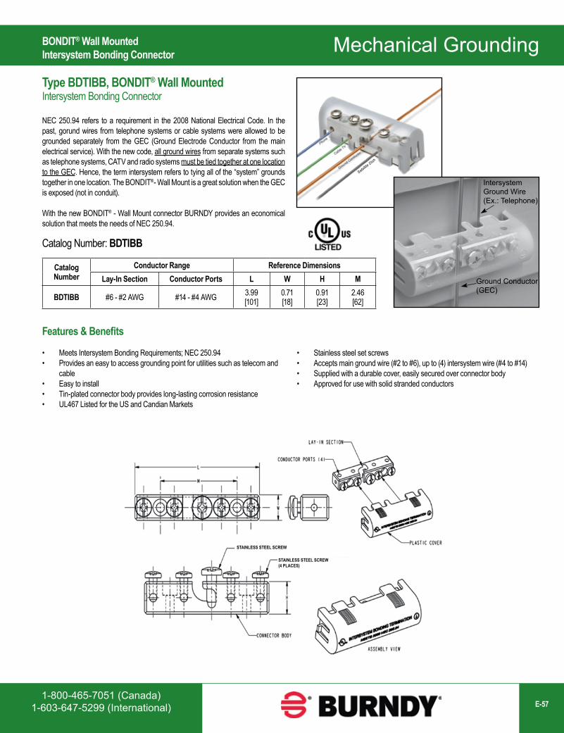
1-800-465-7051 (Canada)1-603-647-5299 (International) E-57
Mechanical Grounding
Satellite Dish
Catalog Number
Conductor Range Reference DimensionsLay-In Section Conductor Ports L W H M
BDTIBB #6 - #2 AWG #14 - #4 AWG 3.99[101]
0.71[18]
0.91[23]
2.46[62]
IntersystemGround Wire(Ex.: Telephone)
Ground Conductor(GEC)
BONDIT® Wall MountedIntersystem Bonding Connector
Type BDTIBB, BONDIT® Wall MountedIntersystem Bonding Connector
NEC 250.94 refers to a requirement in the 2008 National Electrical Code. In the past, gorund wires from telephone systems or cable systems were allowed to be grounded separately from the GEC (Ground Electrode Conductor from the main electrical service). With the new code, all ground wires from separate systems such as telephone systems, CATV and radio systems must be tied together at one location to the GEC. Hence, the term intersystem refers to tying all of the “system” grounds together in one location. The BONDIT®- Wall Mount is a great solution when the GEC is exposed (not in conduit).
With the new BONDIT® - Wall Mount connector BURNDY provides an economical solution that meets the needs of NEC 250.94.
Catalog Number: BDTIBB
Features & Benefits
• Meets Intersystem Bonding Requirements; NEC 250.94• Provides an easy to access grounding point for utilities such as telecom and
cable• Easy to install• Tin-plated connector body provides long-lasting corrosion resistance• UL467 Listed for the US and Candian Markets
• Stainless steel set screws• Accepts main ground wire (#2 to #6), up to (4) intersystem wire (#4 to #14)• Supplied with a durable cover, easily secured over connector body• Approved for use with solid stranded conductors
STAINLESS STEEL SCREW
STAINLESS STEEL SCREW(4 PLACES)
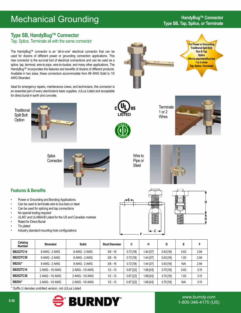
Mechanical Grounding
www.burndy.com1-800-346-4175 (US)E-58
For Power or GroundingTraditional Split Bolt
Run & TapSplice
Wire to pipe/steel/bus bar1 or 2 wires
Tap, Splice, Terminate
CatalogNumber Stranded Solid Stud Diameter C H D E F
SB232TC14 8 AWG - 2 AWG 8 AWG - 2 AWG 3/8 - 16 0.72 [18] 1.44 [37] 0.63 [16] 0.63 2.84SB232TC38 8 AWG - 2 AWG 8 AWG - 2 AWG 3/8 - 16 0.72 [18] 1.44 [37] 0.63 [16] 1.00 2.84SB23U* 8 AWG - 2 AWG 8 AWG - 2 AWG 3/8 - 16 0.72 [18] 1.44 [37] 0.63 [16] N/A 2.84SB252TC14 2 AWG - 1/0 AWG 2 AWG - 1/0 AWG 1/2 - 13 0.87 [22] 1.68 [43] 0.75 [19] 0.63 3.15SB252TC38 2 AWG - 1/0 AWG 2 AWG - 1/0 AWG 1/2 - 13 0.87 [22] 1.68 [43] 0.75 [19] 1.00 3.15SB25U* 2 AWG - 1/0 AWG 2 AWG - 1/0 AWG 1/2 - 13 0.87 [22] 1.68 [43] 0.75 [19] N/A 3.15
* Suffix U denotes undrilled version, not cULus Listed.
Traditional Split Bolt Option
SpliceConnection
Terminate 1 or 2 Wires
Wire to Pipe or Steel
E H
CF
D
HandyBug™ ConnectorType SB, Tap, Splice, or Terminate
Type SB, HandyBug™ ConnectorTap, Splice, Terminate all with the same connector
The HandyBug™ connector is an “all-in-one” electrical connector that can be used for dozens of different power or grounding connection applications. This new connector is the survival tool of electrical connections and can be used as a splice, tap, terminal, wire-to-pipe, wire-to-busbar, and many other applications. The HandyBug™ incorporates the features and benefits of dozens of different products. Available in two sizes, these connectors accommodate from #8 AWG Solid to 1/0 AWG Stranded.
Ideal for emergency repairs, maintenance crews, and technicians, this connector is an essential part of every electrician/s basic supplies. cULus Listed and acceptable for direct burial in earth and concrete.
Features & Benefits
• Power or Grounding and Bonding Applications• Can be used to terminate wire to bus bars or steel• Can be used for splicing and tap connections• No special tooling required• UL467 and UL486A/B Listed for the US and Canadian markets• Rated for Direct Burial• Tin plated• Industry standard mounting hole configurations
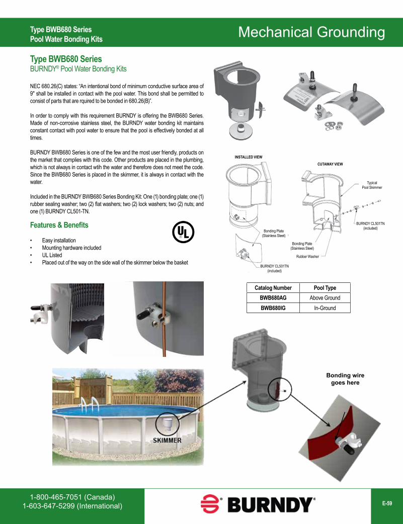
1-800-465-7051 (Canada)1-603-647-5299 (International) E-59
Mechanical Grounding
Catalog Number Pool TypeBWB680AG Above GroundBWB680IG In-Ground
Bonding wiregoes here
Type BWB680 SeriesPool Water Bonding Kits
Type BWB680 SeriesBURNDY® Pool Water Bonding Kits
NEC 680.26(C) states: “An intentional bond of minimum conductive surface area of 9″ shall be installed in contact with the pool water. This bond shall be permitted to consist of parts that are rquired to be bonded in 680.26(B)”.
In order to comply with this requirement BURNDY is offering the BWB680 Series. Made of non-corrosive stainless steel, the BURNDY water bonding kit maintains constant contact with pool water to ensure that the pool is effectively bonded at all times.
BURNDY BWB680 Series is one of the few and the most user friendly, products on the market that complies with this code. Other products are placed in the plumbing, which is not always in contact wtih the water and therefore does not meet the code. Since the BWB680 Series is placed in the skimmer, it is always in contact with the water.
Included in the BURNDY BWB680 Series Bonding Kit: One (1) bonding plate; one (1) rubber sealing washer; two (2) flat washers; two (2) lock washers; two (2) nuts; and one (1) BURNDY CL501-TN.
Features & Benefits
• Easy installation• Mounting hardware included• UL Listed• Placed out of the way on the side wall of the skimmer below the basket
Bonding Plate(Stainless Steel)
Bonding Plate(Stainless Steel)
BURNDY CL501TN (included)
Rubber Washer
BURNDY CL501TN (included)
TypicalPool Skimmer
INSTALLED VIEWCUTAWAY VIEW
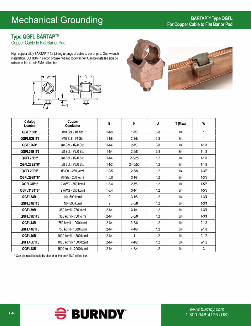
Mechanical Grounding
www.burndy.com1-800-346-4175 (US)E-60
Catalog Number
Copper Conductor B H J T (Max) W
QGFL1CB1 #10 Sol. - #1 Str. 1-1/8 1-7/8 3/8 1/4 1QGFL1CB1T6 #10 Sol. - #1 Str. 1-1/8 2-3/8 3/8 3/4 1QGFL26B1 #8 Sol. - #2/0 Str. 1-1/4 2-1/8 3/8 1/4 1-1/8
QGFL26B1T6 #8 Sol. - #2/0 Str. 1-1/4 2-5/8 3/8 3/4 1-1/8QGFL26B2* #8 Sol. - #2/0 Str. 1-1/4 2-8/25 1/2 1/4 1-1/8
QGFL26B2T6* #8 Sol. - #2/0 Str. 1-1/2 2-40/50 1/2 3/4 1-1/8QGFL29B1* #6 Str. - 250 kcmil 1-2/5 2-5/8 1/2 1/4 1-3/8
QGFL29B1T6* #6 Str. - 250 kcmil 1-5/8 3-1/8 1/2 3/4 1-3/8QGFL31B1* 2 AWG - 350 kcmil 1-3/4 2-7/8 1/2 1/4 1-5/8
QGFL31B1T6* 2 AWG - 350 kcmil 1-3/4 3-1/4 1/2 3/4 1-5/8QGFL34B1 1/0 -500 kcmil 2 3-1/8 1/2 1/4 1-3/4
QGFL34B1T6 1/0 -500 kcmil 2 3-5/8 1/2 3/4 1-3/4QGFL39B1 350 kcmil - 750 kcmil 2-1/4 3-1/4 1/2 1/4 1-3/4
QGFL39B1T6 350 kcmil - 750 kcmil 2-1/4 3-5/8 1/2 3/4 1-3/4QGFL44B1 750 kcmil - 1000 kcmil 2-1/4 3-3/8 1/2 1/4 2-1/8
QGFL44B1T6 750 kcmil - 1000 kcmil 2-1/4 4-1/8 1/2 3/4 2-1/8QGFL46B1 1000 kcmil - 1500 kcmil 2-1/4 4 1/2 1/4 2-1/2
QGFL46B1T6 1000 kcmil - 1500 kcmil 2-1/4 4-1/2 1/2 3/4 2-1/2QGFL48B1 1500 kcmil - 2000 kcmil 2-1/4 4-3/4 1/2 1/4 3
* Can be installed side by side or in line on NEMA drilled bar.
BARTAP™ Type QGFLFor Copper Cable to Flat Bar or Pad
Type QGFL BARTAP™Copper Cable to Flat Bar or Pad
High copper alloy BARTAP™ for joining a range of cable to bar or pad. One-wrench installation. DURIUM™ silicon bronze nut and lockwasher. Can be installed side by side or in line on a NEMA drilled bar.
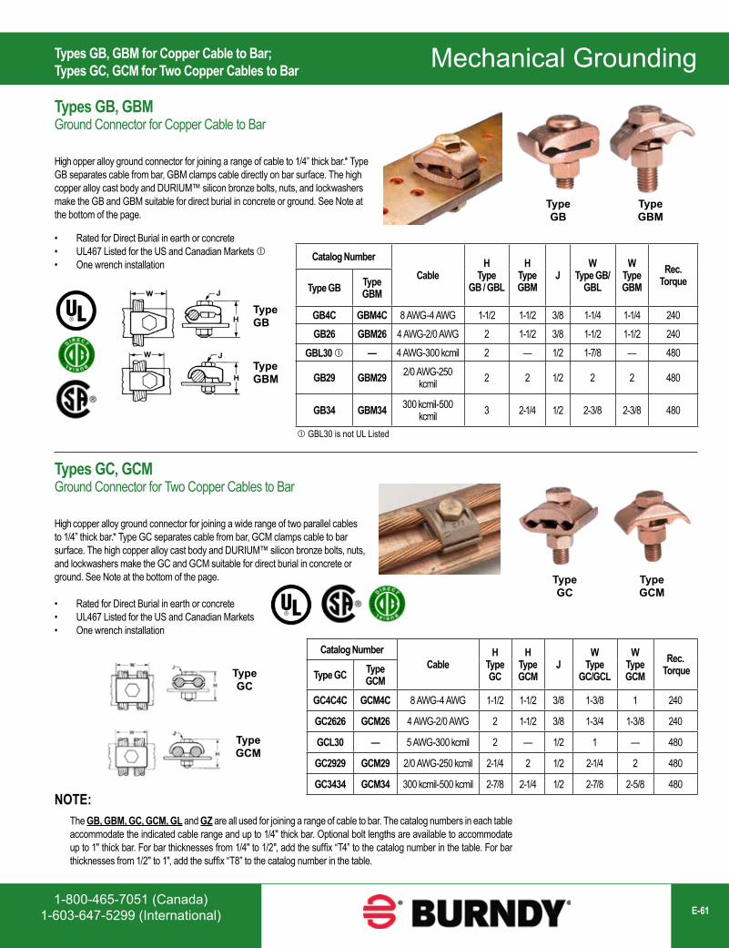
1-800-465-7051 (Canada)1-603-647-5299 (International) E-61
Mechanical Grounding
Catalog NumberCable
H Type GC
H Type GCM
JW
Type GC/GCL
W Type GCM
Rec. TorqueType GC Type
GCM
GC4C4C GCM4C 8 AWG-4 AWG 1-1/2 1-1/2 3/8 1-3/8 1 240
GC2626 GCM26 4 AWG-2/0 AWG 2 1-1/2 3/8 1-3/4 1-3/8 240
GCL30 — 5 AWG-300 kcmil 2 — 1/2 1 — 480
GC2929 GCM29 2/0 AWG-250 kcmil 2-1/4 2 1/2 2-1/4 2 480
GC3434 GCM34 300 kcmil-500 kcmil 2-7/8 2-1/4 1/2 2-7/8 2-5/8 480
TypeGB
TypeGBM
TypeGC
TypeGCM
The GB, GBM, GC, GCM, GL and GZ are all used for joining a range of cable to bar. The catalog numbers in each table accommodate the indicated cable range and up to 1/4″ thick bar. Optional bolt lengths are available to accommodate up to 1" thick bar. For bar thicknesses from 1/4″ to 1/2″, add the suffix “T4” to the catalog number in the table. For bar thicknesses from 1/2″ to 1″, add the suffix “T8” to the catalog number in the table.
NOTE:
Catalog NumberCable
H Type
GB / GBL
H Type GBM
JW
Type GB/GBL
W Type GBM
Rec. TorqueType GB Type
GBM
GB4C GBM4C 8 AWG-4 AWG 1-1/2 1-1/2 3/8 1-1/4 1-1/4 240GB26 GBM26 4 AWG-2/0 AWG 2 1-1/2 3/8 1-1/2 1-1/2 240
GBL30 — 4 AWG-300 kcmil 2 — 1/2 1-7/8 — 480
GB29 GBM29 2/0 AWG-250 kcmil 2 2 1/2 2 2 480
GB34 GBM34 300 kcmil-500 kcmil 3 2-1/4 1/2 2-3/8 2-3/8 480
GBL30 is not UL Listed
TypeGB
TypeGBM
Types GB, GBM for Copper Cable to Bar;Types GC, GCM for Two Copper Cables to Bar
Types GB, GBMGround Connector for Copper Cable to Bar
High opper alloy ground connector for joining a range of cable to 1/4” thick bar.* Type GB separates cable from bar, GBM clamps cable directly on bar surface. The high copper alloy cast body and DURIUM™ silicon bronze bolts, nuts, and lockwashers make the GB and GBM suitable for direct burial in concrete or ground. See Note at the bottom of the page.
Types GC, GCMGround Connector for Two Copper Cables to Bar
High copper alloy ground connector for joining a wide range of two parallel cables to 1/4” thick bar.* Type GC separates cable from bar, GCM clamps cable to bar surface. The high copper alloy cast body and DURIUM™ silicon bronze bolts, nuts, and lockwashers make the GC and GCM suitable for direct burial in concrete or ground. See Note at the bottom of the page.
TypeGC
TypeGCM
• Rated for Direct Burial in earth or concrete• UL467 Listed for the US and Canadian Markets • One wrench installation
• Rated for Direct Burial in earth or concrete• UL467 Listed for the US and Canadian Markets• One wrench installation
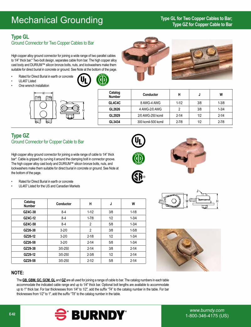
Mechanical Grounding
www.burndy.com1-800-346-4175 (US)E-62
Catalog Number Conductor H J W
GL4C4C 8 AWG-4 AWG 1-1/2 3/8 1-3/8GL2626 4 AWG-2/0 AWG 2 3/8 1-3/4GL2929 2/0 AWG-250 kcmil 2-1/4 1/2 2-1/4GL3434 300 kcmil-500 kcmil 2-7/8 1/2 2-7/8
Catalog Number Conductor H J W
GZ4C-38 8-4 1-1/2 3/8 1-1/8GZ4C-12 8-4 1-7/8 1/2 1-3/4GZ4C-58 8-4 2 5/8 1-3/4GZ26-38 3-2/0 2 3/8 1-5/8GZ26-12 3-2/0 2-1/8 1/2 1-3/4GZ26-58 3-2/0 2-1/4 5/8 1-3/4GZ29-38 3/0-250 2-1/4 3/8 2-1/4GZ29-12 3/0-250 2-3/8 1/2 2-1/4GZ29-58 3/0-250 2-1/2 5/8 2-1/4
Type GL for Two Copper Cables to Bar;Type GZ for Copper Cable to Bar
Type GLGround Connector for Two Copper Cables to Bar
High copper alloy ground connector for joining a wide range of two parallel cables to 1/4” thick bar.* Two-bolt design, separates cable from bar. The high copper alloy cast body and DURIUM™ silicon bronze bolts, nuts, and lockwashers make them suitable for direct burial in concrete or ground. See Note at the bottom of the page.
Type GZGround Connector for Copper Cable to Bar
High copper alloy ground connector for joining a wide range of cable to 1/4” thick bar*. Cable is gripped by curving it around the clamping bolt in connector groove. The high copper alloy cast body and DURIUM™ silicon bronze bolts, nuts, and lockwashers make them suitable for direct burial in concrete or ground. See Note at the bottom of the page.
• Rated for Direct Burial in earth or concrete• UL467 Listed• One wrench installation
• Rated for Direct Burial in earth or concrete• UL467 Listed for the US and Canadian Markets
The GB, GBM, GC, GCM, GL and GZ are all used for joining a range of cable to bar. The catalog numbers in each table accommodate the indicated cable range and up to 1/4″ thick bar. Optional bolt lengths are available to accommodate up to 1" thick bar. For bar thicknesses from 1/4″ to 1/2″, add the suffix “T4” to the catalog number in the table. For bar thicknesses from 1/2″ to 1″, add the suffix “T8” to the catalog number in the table.
NOTE:
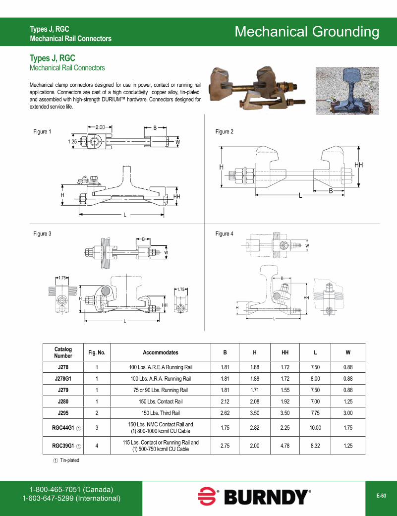
1-800-465-7051 (Canada)1-603-647-5299 (International) E-63
Mechanical Grounding
Catalog Number Fig. No. Accommodates B H HH L W
J278 1 100 Lbs. A.R.E.A Running Rail 1.81 1.88 1.72 7.50 0.88
J278G1 1 100 Lbs. A.R.A. Running Rail 1.81 1.88 1.72 8.00 0.88
J279 1 75 or 90 Lbs. Running Rail 1.81 1.71 1.55 7.50 0.88
J280 1 150 Lbs. Contact Rail 2.12 2.08 1.92 7.00 1.25
J295 2 150 Lbs. Third Rail 2.62 3.50 3.50 7.75 3.00
RGC44G1 3 150 Lbs. NMC Contact Rail and (1) 800-1000 kcmil CU Cable 1.75 2.82 2.25 10.00 1.75
RGC39G1 4 115 Lbs. Contact or Running Rail and (1) 500-750 kcmil CU Cable 2.75 2.00 4.78 8.32 1.25
Tin-plated1
1
1
Types J, RGCMechanical Rail Connectors
Types J, RGCMechanical Rail Connectors
Mechanical clamp connectors designed for use in power, contact or running rail applications. Connectors are cast of a high conductivity copper alloy, tin-plated, and assembled with high-strength DURIUM™ hardware. Connectors designed for extended service life.
Figure 1
Figure 4Figure 3
Figure 2
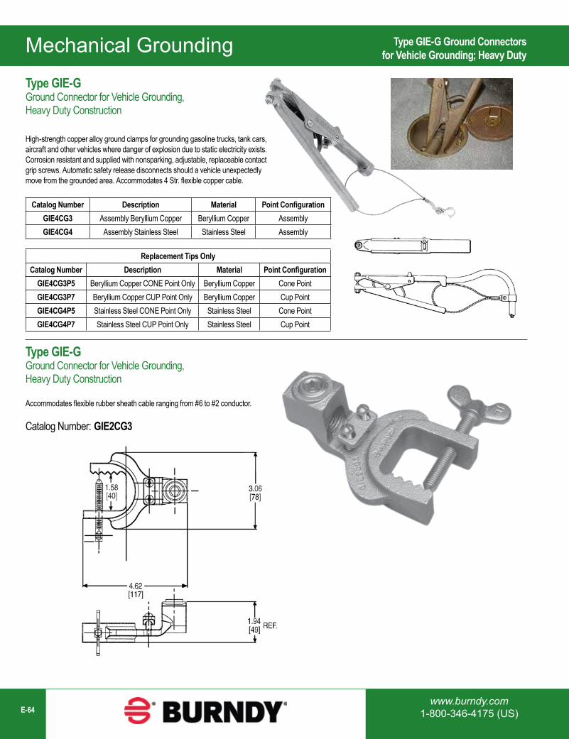
Mechanical Grounding
www.burndy.com1-800-346-4175 (US)E-64
Catalog Number Description Material Point ConfigurationGIE4CG3 Assembly Beryllium Copper Beryllium Copper AssemblyGIE4CG4 Assembly Stainless Steel Stainless Steel Assembly
Replacement Tips OnlyCatalog Number Description Material Point Configuration
GIE4CG3P5 Beryllium Copper CONE Point Only Beryllium Copper Cone PointGIE4CG3P7 Beryllium Copper CUP Point Only Beryllium Copper Cup PointGIE4CG4P5 Stainless Steel CONE Point Only Stainless Steel Cone PointGIE4CG4P7 Stainless Steel CUP Point Only Stainless Steel Cup Point
Type GIE-G Ground Connectorsfor Vehicle Grounding; Heavy Duty
Type GIE-GGround Connector for Vehicle Grounding, Heavy Duty Construction
High-strength copper alloy ground clamps for grounding gasoline trucks, tank cars, aircraft and other vehicles where danger of explosion due to static electricity exists. Corrosion resistant and supplied with nonsparking, adjustable, replaceable contact grip screws. Automatic safety release disconnects should a vehicle unexpectedly move from the grounded area. Accommodates 4 Str. flexible copper cable.
Type GIE-GGround Connector for Vehicle Grounding, Heavy Duty Construction
Accommodates flexible rubber sheath cable ranging from #6 to #2 conductor.
Catalog Number: GIE2CG3
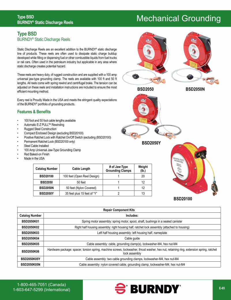
1-800-465-7051 (Canada)1-603-647-5299 (International) E-65
Mechanical Grounding
Catalog Number Cable Length # of Jaw-Type Grounding Clamps
Weight (lb.)
BSD20100 100 feet (Open Reel Design) 1 20
BSD2050 50 feet 1 12BSD2050N 50 feet (Nylon Covered) 1 12BSD2050Y 35 feet plus 15 feet of “Y” 2 13
BSD20100
BSD2050Y
BSD2050NBSD2050
Type BSDBURNDY® Static Discharge Reels
Type BSDBURNDY® Static Discharge Reels
Static Discharge Reels are an excellent addition to the BURNDY® static discharge line of products. These reels are often used to dissipate static charge buildup developed while filling or dispensing fuel or other combustible liquids from fuel trucks or rail cars. Often used in the petroleum industry but applicable in any area where static discharge creates potential hazard.
These reels are heavy duty, of rugged construction and are supplied with a 100 amp universal jaw-type grounding clamp. The reels are available with 100 ft and 50 ft lengths. All reels come with spring rewind and centrifugal brake. The tension can be adjusted on these reels and installation instructions are included to ensure the most efficient mounting method.
Every reel is Proudly Made in the USA and meets the stringent quality expectations of the BURNDY® portfolio of grounding products.
Features & Benefits
• 100 foot and 50 foot cable lengths available• Automatic E-Z PULL™ Rewinding• Rugged Steel Construction• Compact Enclosed Design (excluding BSD20100)• Positive Ratchet Lock with Ratchet On/Off Switch (excluding (BSD20100)• Permanent Ratchet Lock (BSD20100 only)• Steel Cable Installed• 100 Amp Universal Jaw-Type Grounding Clamp• Red Baked-on Finish• Made in the USA
Repair Component KitsCatalog Number Includes:
BSD2050K01 Spring motor assembly: spring motor, spool, shaft, bushings in a sealed canisterBSD2050K02 Right half housing assembly: right housing half, ratchet lock assembly (attached to housing)BSD2050K03 Left half housing assembly: left housing half, nameplateBSD2050K04 Cable guideBSD2050K05 Cable assembly: cable, grounding clamp(s), lockwasher-M4, hex nut-M4
BSD2050K06 Hardware package: spacer, torsion spring, machine screws, lockwasher, thrust washer, hex nut, retaining ring, extension spring, ratchet lock assembly
BSD2050K05Y Cable assembly: two cable grounding clamps, lockwasher-M4, hex nut-M4BSD2050K05N Cable assembly: nylon covered cable, grounding clamp, lockwasher-M4, hex nut-M4

Mechanical Grounding
www.burndy.com1-800-346-4175 (US)E-66
Type BSDCCEE Static Discharge "C" ClampType GCB63T13G1 The STUDBUG™
Note: Can be used with plate, bus bar or structural steel up to 1/4” thick.
Type GCB63T13G1STUDBUG™ for Static Grounding Applications
GCB63T13G1 is a temporary grounding stud for use on rail cars, chemical trucks, hazardous waste tankers or a petroleum vehicle to allow for static grounding protection, while in operation. It provides a contact point, allowing the rail car, truck or tanker to be grounded to an equipotential grid or ground rod, by using static reel or a ground cable.
Catalog Number: GCB63T13G1Features & Benefits
• Made of bronze; supplied with silicon bronze hardware• Secured by 1/2” hexagonal nut and split lockwasher• Can be used with universal clamps and ball stud clamps• Can be used at various angles to reach inaccessible areas• Add suffix “SS” for grounding stud with stainless steel hardware
Type BSDCCEEStatic Discharge “C” Clamp
The BSDCCEE is a static grounding “C” clamp used to provide electrical contact between containers used for dispensing liquids and the grounding grid. The reel or grounding cable is crimped onto the provided ring terminal which is then fastened to the clamp at the end of the set screw. The clamp can be used with galvanized or stainless steel cable with a maximum diameter of 1/8 inch. (Cable is not included.) The BSDCCEE has a galvanized steel body and includes the ring terminal, and stainless steel harware. (Winged Cup Point Set Screw and Dog Point Set Screw.)
Catalog Number: BSDCCEE
Features & Benefits
• Easy to install• Galvanized steel body and stainless steel hardware• Designed for clamping cable end to containers

1-800-465-7051 (Canada)1-603-647-5299 (International) E-67
Mechanical Grounding
Catalog Number Description Hole Information Pad Angle Ball Diameter
GSC752N30B Ground Stud (Straight)1/2” holes with 1.75” spacing
straight 30 mm (1.18”)GSC752N30B45 Ground Stud (45°) 45 degree 30 mm (1.18”)GSC752N30B90 Ground Stud (90°) 90 degree 30 mm (1.18”)
GSC7530BCOVER Ground Stud Cover — — —
GSC752N30B with GSC7530BCOVER
Catalog Number Description Hole Spacing
Pad Angle
Ball Diameter
GSC632NH1B Ground stud withoffset NEMA spacing pad 1.75” 90° 1”
(25.4mm)
GSC632NH1BCOVER1Thermoplastic elastomer
cover (orange) for GSC632NH1B
Not applicable for cover
Type GSC75; All-in-one Ball and Socket Design with NEMA Pad Type GSC63; Ground Ball Stud with 90° NEMA Pad
Type GSC75All-in-one Ball and Socket Design with NEMA Pad
Grounding studs provide a low resistance path in the event of a fault. The GSC75 series of studs are available in straight, 45°, and 90° variations with other angles available upon request. The GSC7530BCOVER provides a snug fit over the GSC75 studs when not in use to serve as an animal mitigation.
Features & Benefits
• High amperage rating• Critter guard/cover available• Available in Straight, 45°, and 90° variations• Ball and Socket design accomodates industry standard
clamps• All-in-one design with NEMA terminal pad in-line with stud
Type GSC63Ground Ball Stud with 90° NEMA Pad
Tin-plated cast copper alloy ground stud incorporates an offset pad featuring NEMA spacing and 1” ball stud. Used when servicing a pad mounted transformer, the GSC632NH1B and optional orange thermoplastic elastomer cover provide for safe maintenance of equipment for optimal uptime.
Features & Benefits
Stud
• 90° offset pad• NEMA Spacing• Cast Copper Alloy• Tin-plated for corrosion resistance
Cover
• Eye stem tool loop for install/removal• Orange thermoplastic elastomer material
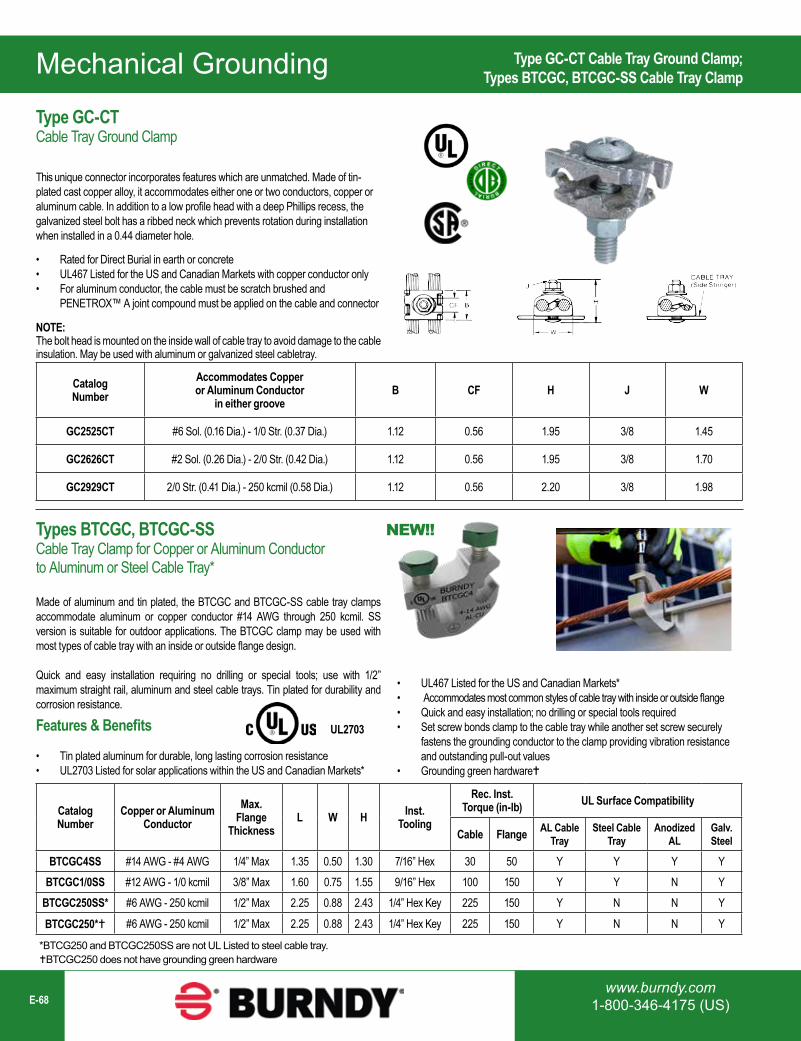
Mechanical Grounding
www.burndy.com1-800-346-4175 (US)E-68
Type GC-CT Cable Tray Ground Clamp;Types BTCGC, BTCGC-SS Cable Tray Clamp
Catalog Number
Accommodates Copper or Aluminum Conductor
in either grooveB CF H J W
GC2525CT #6 Sol. (0.16 Dia.) - 1/0 Str. (0.37 Dia.) 1.12 0.56 1.95 3/8 1.45
GC2626CT #2 Sol. (0.26 Dia.) - 2/0 Str. (0.42 Dia.) 1.12 0.56 1.95 3/8 1.70
GC2929CT 2/0 Str. (0.41 Dia.) - 250 kcmil (0.58 Dia.) 1.12 0.56 2.20 3/8 1.98
NOTE:The bolt head is mounted on the inside wall of cable tray to avoid damage to the cable insulation. May be used with aluminum or galvanized steel cabletray.
Catalog Number
Copper or Aluminum Conductor
Max. Flange
ThicknessL W H Inst.
Tooling
Rec. Inst. Torque (in-lb) UL Surface Compatibility
Cable Flange AL Cable Tray
Steel Cable Tray
Anodized AL
Galv. Steel
BTCGC4SS #14 AWG - #4 AWG 1/4” Max 1.35 0.50 1.30 7/16” Hex 30 50 Y Y Y YBTCGC1/0SS #12 AWG - 1/0 kcmil 3/8” Max 1.60 0.75 1.55 9/16” Hex 100 150 Y Y N Y
BTCGC250SS* #6 AWG - 250 kcmil 1/2” Max 2.25 0.88 2.43 1/4” Hex Key 225 150 Y N N Y
BTCGC250* #6 AWG - 250 kcmil 1/2” Max 2.25 0.88 2.43 1/4” Hex Key 225 150 Y N N Y
Type GC-CTCable Tray Ground Clamp
This unique connector incorporates features which are unmatched. Made of tin-plated cast copper alloy, it accommodates either one or two conductors, copper or aluminum cable. In addition to a low profile head with a deep Phillips recess, the galvanized steel bolt has a ribbed neck which prevents rotation during installation when installed in a 0.44 diameter hole.
Types BTCGC, BTCGC-SSCable Tray Clamp for Copper or Aluminum Conductor to Aluminum or Steel Cable Tray*
Made of aluminum and tin plated, the BTCGC and BTCGC-SS cable tray clamps accommodate aluminum or copper conductor #14 AWG through 250 kcmil. SS version is suitable for outdoor applications. The BTCGC clamp may be used with most types of cable tray with an inside or outside flange design.
Quick and easy installation requiring no drilling or special tools; use with 1/2” maximum straight rail, aluminum and steel cable trays. Tin plated for durability and corrosion resistance.
*BTCG250 and BTCGC250SS are not UL Listed to steel cable tray.BTCGC250 does not have grounding green hardware
Features & Benefits
• Tin plated aluminum for durable, long lasting corrosion resistance• UL2703 Listed for solar applications within the US and Canadian Markets*
UL2703
NEW!!
• Rated for Direct Burial in earth or concrete• UL467 Listed for the US and Canadian Markets with copper conductor only• For aluminum conductor, the cable must be scratch brushed and
PENETROX™ A joint compound must be applied on the cable and connector
• UL467 Listed for the US and Canadian Markets*• Accommodates most common styles of cable tray with inside or outside flange• Quick and easy installation; no drilling or special tools required• Set screw bonds clamp to the cable tray while another set screw securely
fastens the grounding conductor to the clamp providing vibration resistance and outstanding pull-out values
• Grounding green hardware
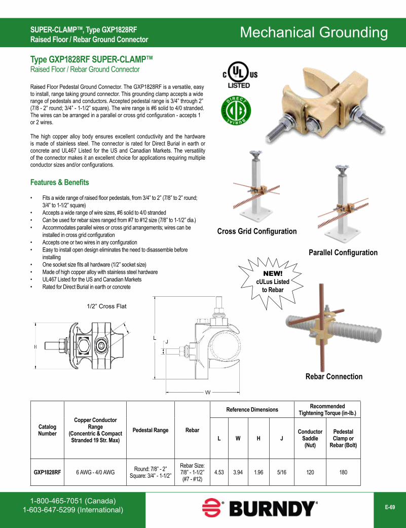
1-800-465-7051 (Canada)1-603-647-5299 (International) E-69
Mechanical Grounding
Catalog Number
Copper Conductor Range
(Concentric & Compact Stranded 19 Str. Max)
Pedestal Range Rebar
Reference Dimensions Recommended Tightening Torque (in-lb.)
L W H JConductor
Saddle (Nut)
Pedestal Clamp or
Rebar (Bolt)
GXP1828RF 6 AWG - 4/0 AWG Round: 7/8” - 2”Square: 3/4” - 1-1/2”
Rebar Size:7/8” - 1-1/2”(#7 - #12)
4.53 3.94 1.96 5/16 120 180
Cross Grid Configuration
Parallel Configuration
Rebar Connection
1/2” Cross Flat
NEW!cULus Listed
to Rebar
SUPER-CLAMP™, Type GXP1828RFRaised Floor / Rebar Ground Connector
Type GXP1828RF SUPER-CLAMP™Raised Floor / Rebar Ground Connector
Raised Floor Pedestal Ground Connector. The GXP1828RF is a versatile, easy to install, range taking ground connector. This grounding clamp accepts a wide range of pedestals and conductors. Accepted pedestal range is 3/4” through 2” (7/8 - 2” round; 3/4” - 1-1/2” square). The wire range is #6 solid to 4/0 stranded. The wires can be arranged in a parallel or cross grid configuration - accepts 1 or 2 wires.
The high copper alloy body ensures excellent conductivity and the hardware is made of stainless steel. The connector is rated for Direct Burial in earth or concrete and UL467 Listed for the US and Canadian Markets. The versatility of the connector makes it an excellent choice for applications requiring multiple conductor sizes and/or configurations.
Features & Benefits
• Fits a wide range of raised floor pedestals, from 3/4” to 2” (7/8” to 2” round; 3/4” to 1-1/2” square)
• Accepts a wide range of wire sizes, #6 solid to 4/0 stranded• Can be used for rebar sizes ranged from #7 to #12 size (7/8” to 1-1/2” dia.)• Accommodates parallel wires or cross grid arrangements; wires can be
installed in cross grid configuration• Accepts one or two wires in any configuration• Easy to install open design eliminates the need to disassemble before
installing• One socket size fits all hardware (1/2” socket size)• Made of high copper alloy with stainless steel hardware• UL467 Listed for the US and Canadian Markets• Rated for Direct Burial in earth or concrete
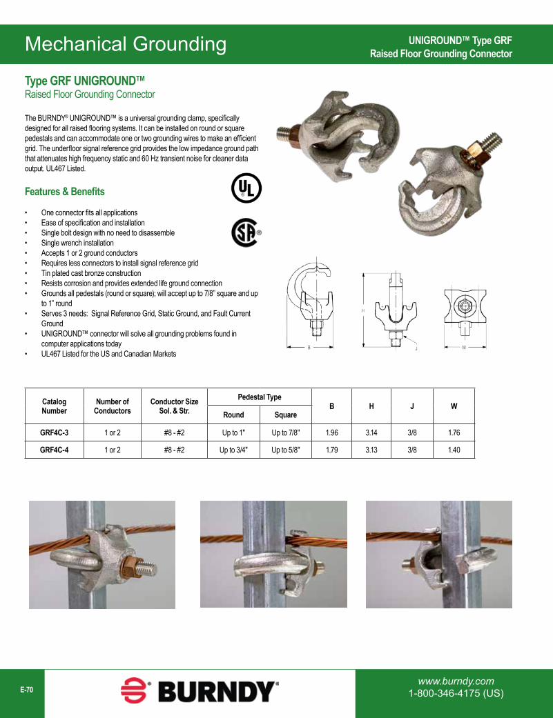
Mechanical Grounding
www.burndy.com1-800-346-4175 (US)E-70
Catalog Number
Number of Conductors
Conductor Size Sol. & Str.
Pedestal TypeB H J W
Round Square
GRF4C-3 1 or 2 #8 - #2 Up to 1" Up to 7/8" 1.96 3.14 3/8 1.76
GRF4C-4 1 or 2 #8 - #2 Up to 3/4" Up to 5/8" 1.79 3.13 3/8 1.40
UNIGROUND™ Type GRFRaised Floor Grounding Connector
Type GRF UNIGROUND™Raised Floor Grounding Connector
The BURNDY® UNIGROUND™ is a universal grounding clamp, specifically designed for all raised flooring systems. It can be installed on round or square pedestals and can accommodate one or two grounding wires to make an efficient grid. The underfloor signal reference grid provides the low impedance ground path that attenuates high frequency static and 60 Hz transient noise for cleaner data output. UL467 Listed.
Features & Benefits
• One connector fits all applications• Ease of specification and installation• Single bolt design with no need to disassemble• Single wrench installation• Accepts 1 or 2 ground conductors• Requires less connectors to install signal reference grid• Tin plated cast bronze construction• Resists corrosion and provides extended life ground connection• Grounds all pedestals (round or square); will accept up to 7/8” square and up
to 1” round• Serves 3 needs: Signal Reference Grid, Static Ground, and Fault Current
Ground• UNIGROUND™ connector will solve all grounding problems found in
computer applications today• UL467 Listed for the US and Canadian Markets
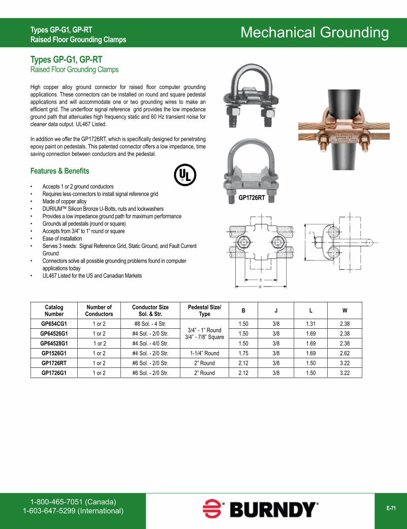
1-800-465-7051 (Canada)1-603-647-5299 (International) E-71
Mechanical Grounding
CatalogNumber
Number of Conductors
Conductor SizeSol. & Str.
Pedestal Size/Type B J L W
GP654CG1 1 or 2 #8 Sol. - 4 Str.3/4” - 1” Round
3/4” - 7/8” Square
1.50 3/8 1.31 2.38GP64526G1 1 or 2 #4 Sol. - 2/0 Str. 1.50 3/8 1.69 2.38GP64528G1 1 or 2 #4 Sol. - 4/0 Str. 1.50 3/8 1.69 2.38GP1526G1 1 or 2 #4 Sol. - 2/0 Str. 1-1/4” Round 1.75 3/8 1.69 2.62GP1726RT 1 or 2 #6 Sol. - 2/0 Str. 2” Round 2.12 3/8 1.50 3.22GP1726G1 1 or 2 #6 Sol. - 2/0 Str. 2” Round 2.12 3/8 1.50 3.22
GP1726RT
Types GP-G1, GP-RTRaised Floor Grounding Clamps
Types GP-G1, GP-RTRaised Floor Grounding Clamps
High copper alloy ground connector for raised floor computer grounding applications. These connectors can be installed on round and square pedestal applications and will accommodate one or two grounding wires to make an efficient grid. The underfloor signal reference grid provides the low impedance ground path that attenuates high frequency static and 60 Hz transient noise for cleaner data output. UL467 Listed.
In addition we offer the GP1726RT, which is specifically designed for penetrating epoxy paint on pedestals. This patented connector offers a low impedance, time saving connection between conductors and the pedestal.
Features & Benefits
• Accepts 1 or 2 ground conductors• Requires less connectors to install signal reference grid• Made of copper alloy• DURIUM™ Silicon Bronze U-Bolts, nuts and lockwashers• Provides a low impedance ground path for maximum performance• Grounds all pedestals (round or square)• Accepts from 3/4” to 1” round or square• Ease of installation• Serves 3 needs: Signal Reference Grid, Static Ground, and Fault Current
Ground• Connectors solve all possible grounding problems found in computer
applications today• UL467 Listed for the US and Canadian Markets
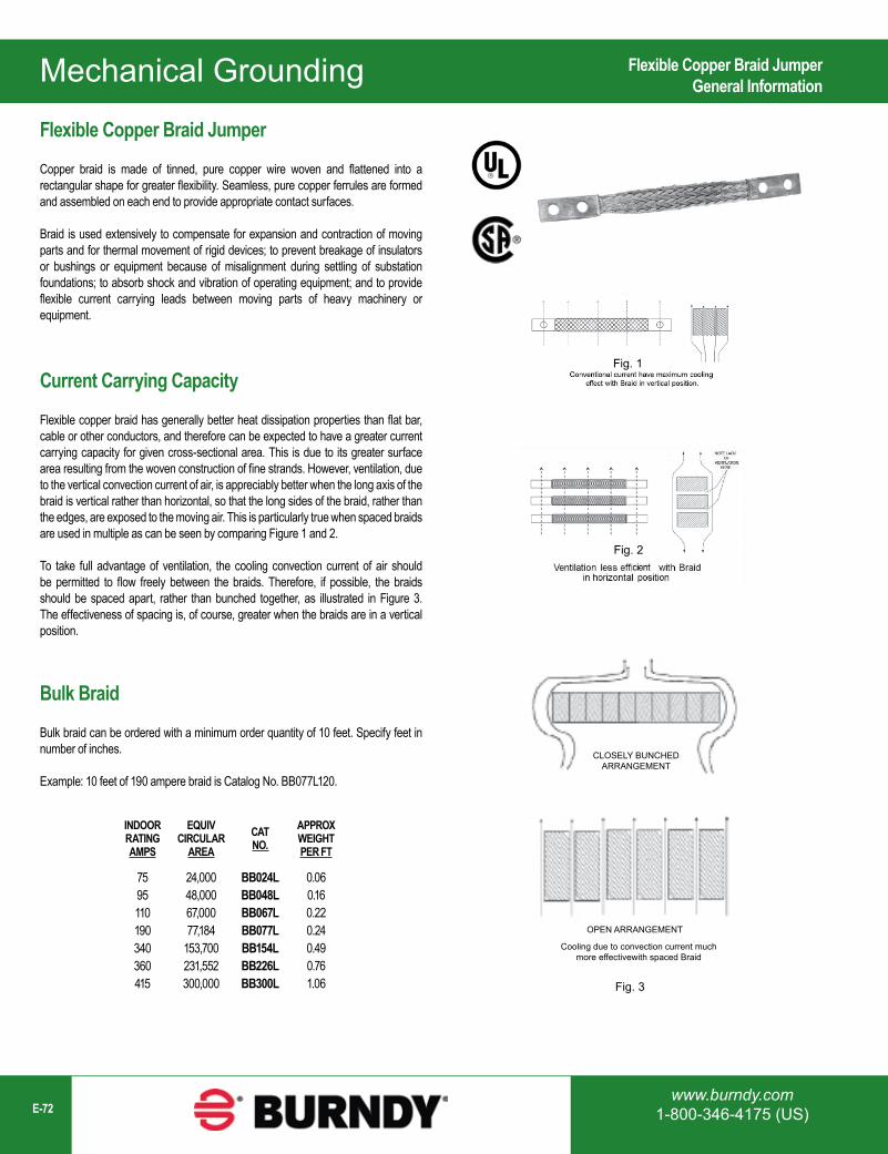
Mechanical Grounding
www.burndy.com1-800-346-4175 (US)E-72
INDOORRATINGAMPS
EQUIVCIRCULAR
AREACATNO.
APPROXWEIGHTPER FT
7595110190340360415
24,00048,00067,00077,184
153,700231,552300,000
BB024LBB048LBB067LBB077LBB154LBB226LBB300L
0.060.160.220.240.490.761.06
Fig. 1
Fig. 2
CLOSELY BUNCHEDARRANGEMENT
OPEN ARRANGEMENT
Cooling due to convection current muchmore effectivewith spaced Braid
Fig. 3
Flexible Copper Braid JumperGeneral Information
Flexible Copper Braid Jumper
Copper braid is made of tinned, pure copper wire woven and flattened into a rectangular shape for greater flexibility. Seamless, pure copper ferrules are formed and assembled on each end to provide appropriate contact surfaces.
Braid is used extensively to compensate for expansion and contraction of moving parts and for thermal movement of rigid devices; to prevent breakage of insulators or bushings or equipment because of misalignment during settling of substation foundations; to absorb shock and vibration of operating equipment; and to provide flexible current carrying leads between moving parts of heavy machinery or equipment.
Current Carrying Capacity
Flexible copper braid has generally better heat dissipation properties than flat bar, cable or other conductors, and therefore can be expected to have a greater current carrying capacity for given cross-sectional area. This is due to its greater surface area resulting from the woven construction of fine strands. However, ventilation, due to the vertical convection current of air, is appreciably better when the long axis of the braid is vertical rather than horizontal, so that the long sides of the braid, rather than the edges, are exposed to the moving air. This is particularly true when spaced braids are used in multiple as can be seen by comparing Figure 1 and 2.
To take full advantage of ventilation, the cooling convection current of air should be permitted to flow freely between the braids. Therefore, if possible, the braids should be spaced apart, rather than bunched together, as illustrated in Figure 3. The effectiveness of spacing is, of course, greater when the braids are in a vertical position.
Bulk Braid
Bulk braid can be ordered with a minimum order quantity of 10 feet. Specify feet in number of inches.
Example: 10 feet of 190 ampere braid is Catalog No. BB077L120.
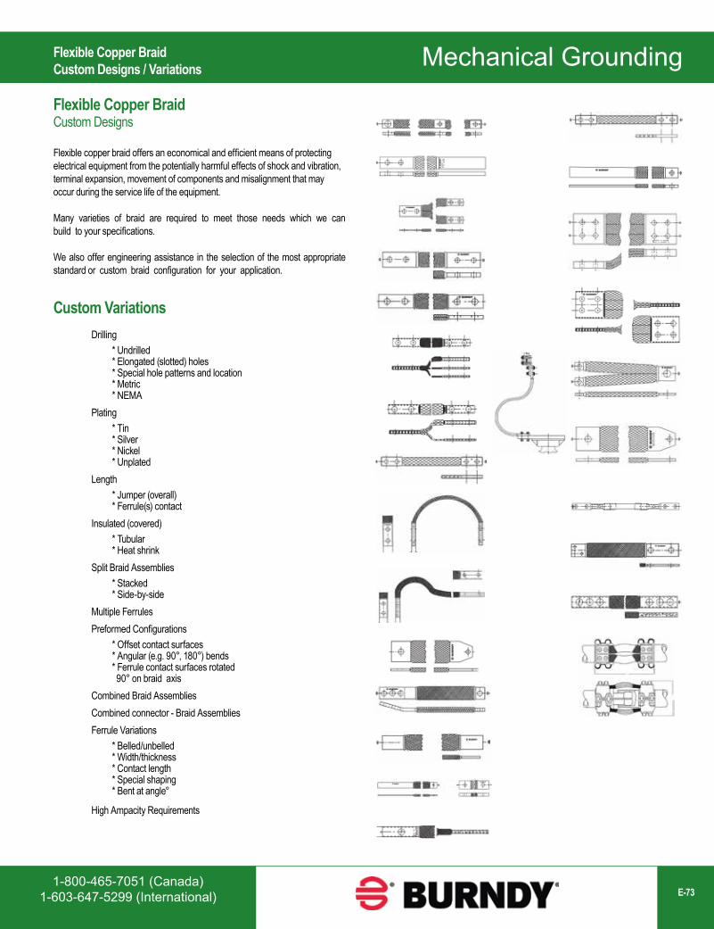
1-800-465-7051 (Canada)1-603-647-5299 (International) E-73
Mechanical Grounding
Drilling* Undrilled * Elongated (slotted) holes* Special hole patterns and location * Metric * NEMA
Plating* Tin * Silver * Nickel * Unplated
Length* Jumper (overall) * Ferrule(s) contact
Insulated (covered)* Tubular * Heat shrink
Split Braid Assemblies* Stacked * Side-by-side
Multiple Ferrules Preformed Configurations
* Offset contact surfaces * Angular (e.g. 90°, 180°) bends * Ferrule contact surfaces rotated 90° on braid axis
Combined Braid Assemblies Combined connector - Braid Assemblies Ferrule Variations
* Belled/unbelled * Width/thickness * Contact length * Special shaping * Bent at angle°
High Ampacity Requirements
Flexible Copper BraidCustom Designs
Flexible copper braid offers an economical and efficient means of protecting electrical equipment from the potentially harmful effects of shock and vibration, terminal expansion, movement of components and misalignment that may occur during the service life of the equipment.
Many varieties of braid are required to meet those needs which we can build to your specifications.
We also offer engineering assistance in the selection of the most appropriate standard or custom braid configuration for your application.
Flexible Copper BraidCustom Designs / Variations
Custom Variations
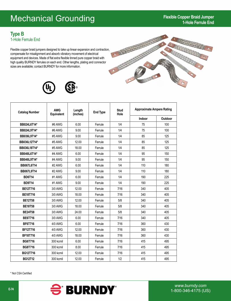
Mechanical Grounding
www.burndy.com1-800-346-4175 (US)E-74
Catalog Number AWG Equivalent
Length(inches) End Type Stud
HoleApproximate Ampere Rating
Indoor OutdoorBB024L6T14* #6 AWG 6.00 Ferrule 1/4 75 100BB024L9T14* #6 AWG 9.00 Ferrule 1/4 75 100BB036L9T14* #5 AWG 9.00 Ferrule 1/4 85 125BB036L12T14* #5 AWG 12.00 Ferrule 1/4 85 125BB036L18T14* #5 AWG 18.00 Ferrule 1/4 85 125BB048L6T14* #4 AWG 6.00 Ferrule 1/4 95 150BB048L9T14* #4 AWG 9.00 Ferrule 1/4 95 150BB067L6T14 #2 AWG 6.00 Ferrule 1/4 110 180BB067L9T14 #2 AWG 9.00 Ferrule 1/4 110 180
BD6T14 #1 AWG 6.00 Ferrule 1/4 190 225BD9T14 #1 AWG 9.00 Ferrule 1/4 190 225
BE12T716 3/0 AWG 12.00 Ferrule 7/16 340 405BE18T716 3/0 AWG 18.00 Ferrule 7/16 340 405BE12T58 3/0 AWG 12.00 Ferrule 5/8 340 405BE18T58 3/0 AWG 18.00 Ferrule 5/8 340 405BE24T58 3/0 AWG 24.00 Ferrule 5/8 340 405BE6T716 3/0 AWG 6.00 Ferrule 7/16 340 405BF6T716 4/0 AWG 6.00 Ferrule 7/16 360 430BF12T716 4/0 AWG 12.00 Ferrule 7/16 360 430BF18T716 4/0 AWG 18.00 Ferrule 7/16 360 430BG6T716 300 kcmil 6.00 Ferrule 7/16 415 495BG8T716 300 kcmil 8.00 Ferrule 7/16 415 495BG12T716 300 kcmil 12.00 Ferrule 7/16 415 495BG12T12 300 kcmil 12.00 Ferrule 1/2 415 495
* Not CSA Certified
Flexible Copper Braid Jumper1-Hole Ferrule End
Type B1-Hole Ferrule End
Flexible copper braid jumpers designed to take up linear expansion and contraction, compensate for misalignment and absorb vibratory movement of electrical equipment and devices. Made of flat extra flexible tinned pure copper braid with high quality BURNDY ferrules on each end. Other lengths, plating and connector sizes are availabile; contact BURNDY for more information.
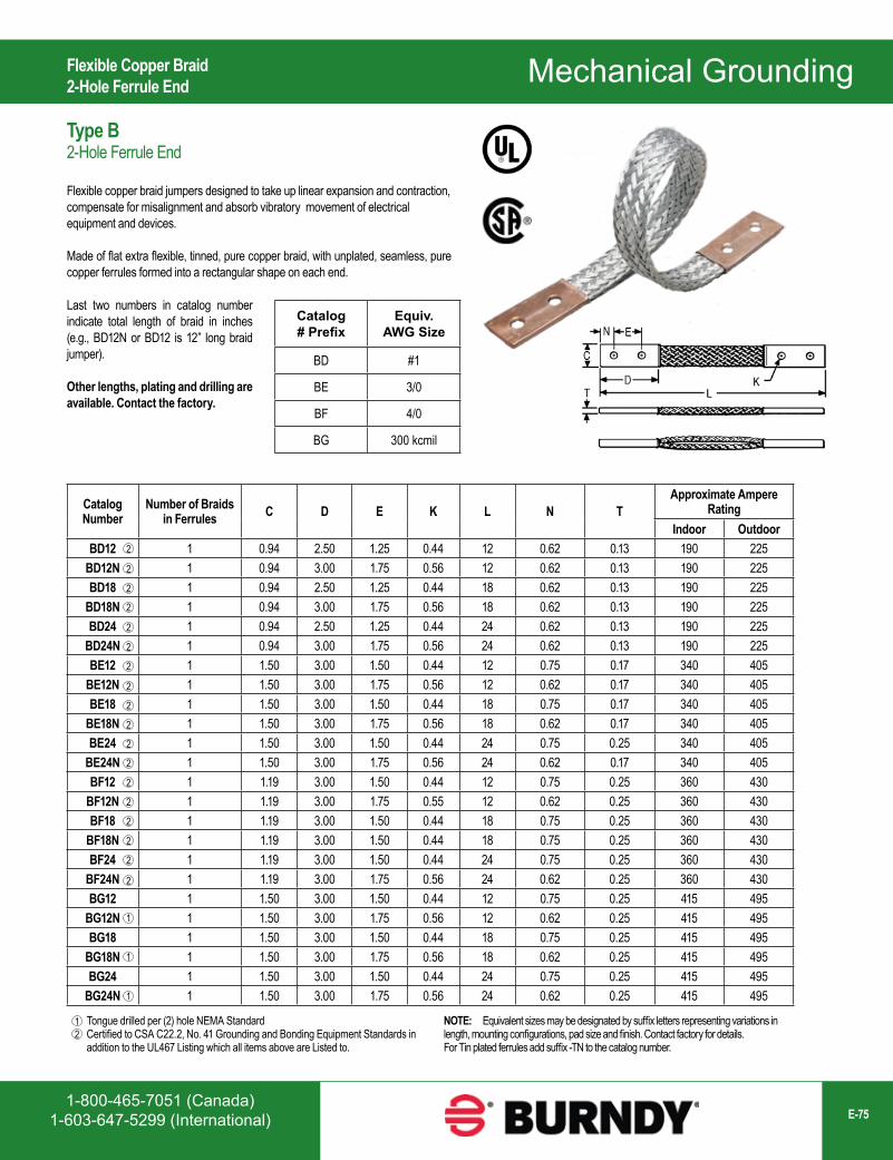
1-800-465-7051 (Canada)1-603-647-5299 (International) E-75
Mechanical Grounding
Tongue drilled per (2) hole NEMA StandardCertified to CSA C22.2, No. 41 Grounding and Bonding Equipment Standards in addition to the UL467 Listing which all items above are Listed to.
12
NOTE: Equivalent sizes may be designated by suffix letters representing variations in length, mounting configurations, pad size and finish. Contact factory for details. For Tin plated ferrules add suffix -TN to the catalog number.
Catalog# Prefix
Equiv.AWG Size
BD #1
BE 3/0
BF 4/0
BG 300 kcmil
Catalog Number
Number of Braids in Ferrules C D E K L N T
Approximate Ampere Rating
Indoor OutdoorBD12 1 0.94 2.50 1.25 0.44 12 0.62 0.13 190 225
BD12N 1 0.94 3.00 1.75 0.56 12 0.62 0.13 190 225BD18 1 0.94 2.50 1.25 0.44 18 0.62 0.13 190 225
BD18N 1 0.94 3.00 1.75 0.56 18 0.62 0.13 190 225BD24 1 0.94 2.50 1.25 0.44 24 0.62 0.13 190 225
BD24N 1 0.94 3.00 1.75 0.56 24 0.62 0.13 190 225BE12 1 1.50 3.00 1.50 0.44 12 0.75 0.17 340 405
BE12N 1 1.50 3.00 1.75 0.56 12 0.62 0.17 340 405BE18 1 1.50 3.00 1.50 0.44 18 0.75 0.17 340 405
BE18N 1 1.50 3.00 1.75 0.56 18 0.62 0.17 340 405BE24 1 1.50 3.00 1.50 0.44 24 0.75 0.25 340 405
BE24N 1 1.50 3.00 1.75 0.56 24 0.62 0.17 340 405BF12 1 1.19 3.00 1.50 0.44 12 0.75 0.25 360 430
BF12N 1 1.19 3.00 1.75 0.55 12 0.62 0.25 360 430BF18 1 1.19 3.00 1.50 0.44 18 0.75 0.25 360 430
BF18N 1 1.19 3.00 1.50 0.44 18 0.75 0.25 360 430BF24 1 1.19 3.00 1.50 0.44 24 0.75 0.25 360 430
BF24N 1 1.19 3.00 1.75 0.56 24 0.62 0.25 360 430BG12 1 1.50 3.00 1.50 0.44 12 0.75 0.25 415 495
BG12N 1 1.50 3.00 1.75 0.56 12 0.62 0.25 415 495BG18 1 1.50 3.00 1.50 0.44 18 0.75 0.25 415 495
BG18N 1 1.50 3.00 1.75 0.56 18 0.62 0.25 415 495BG24 1 1.50 3.00 1.50 0.44 24 0.75 0.25 415 495
BG24N 1 1.50 3.00 1.75 0.56 24 0.62 0.25 415 495
2
2
2
2
2
2
2
1
1
1
2
2
2
2
2
2
2
2
2
2
2
Flexible Copper Braid2-Hole Ferrule End
Type B2-Hole Ferrule End
Flexible copper braid jumpers designed to take up linear expansion and contraction, compensate for misalignment and absorb vibratory movement of electrical equipment and devices.
Made of flat extra flexible, tinned, pure copper braid, with unplated, seamless, pure copper ferrules formed into a rectangular shape on each end.
Last two numbers in catalog number indicate total length of braid in inches (e.g., BD12N or BD12 is 12” long braid jumper).
Other lengths, plating and drilling are available. Contact the factory.
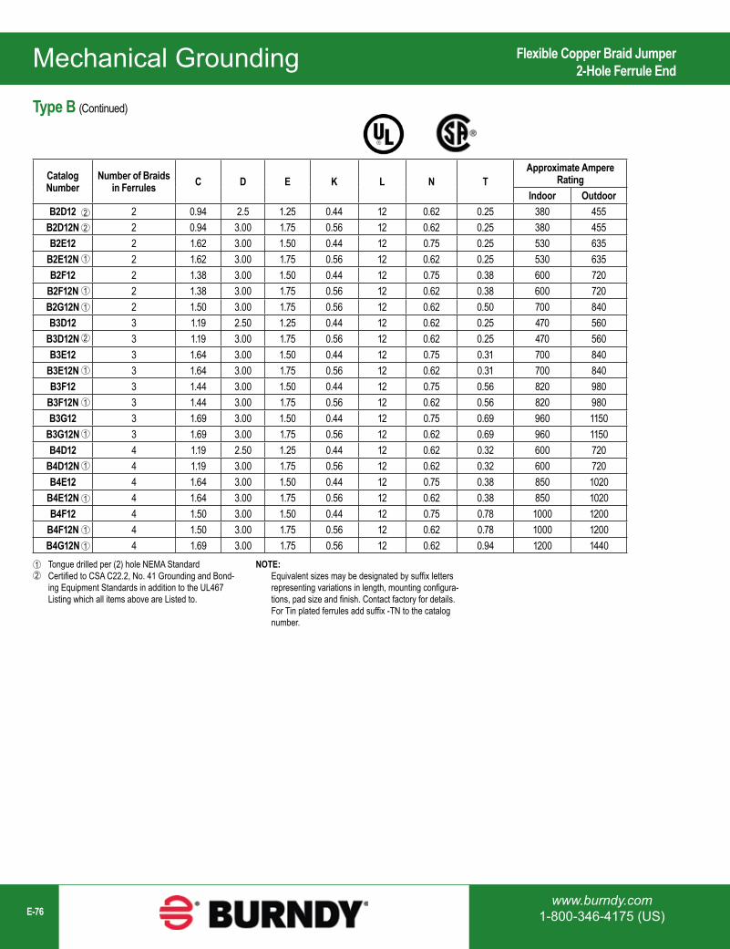
Mechanical Grounding
www.burndy.com1-800-346-4175 (US)E-76
Tongue drilled per (2) hole NEMA Standard Certified to CSA C22.2, No. 41 Grounding and Bond- ing Equipment Standards in addition to the UL467 Listing which all items above are Listed to.
12
NOTE: Equivalent sizes may be designated by suffix letters representing variations in length, mounting configura- tions, pad size and finish. Contact factory for details. For Tin plated ferrules add suffix -TN to the catalog number.
Catalog Number
Number of Braids in Ferrules C D E K L N T
Approximate Ampere Rating
Indoor OutdoorB2D12 2 0.94 2.5 1.25 0.44 12 0.62 0.25 380 455
B2D12N 2 0.94 3.00 1.75 0.56 12 0.62 0.25 380 455B2E12 2 1.62 3.00 1.50 0.44 12 0.75 0.25 530 635
B2E12N 2 1.62 3.00 1.75 0.56 12 0.62 0.25 530 635B2F12 2 1.38 3.00 1.50 0.44 12 0.75 0.38 600 720
B2F12N 2 1.38 3.00 1.75 0.56 12 0.62 0.38 600 720B2G12N 2 1.50 3.00 1.75 0.56 12 0.62 0.50 700 840B3D12 3 1.19 2.50 1.25 0.44 12 0.62 0.25 470 560
B3D12N 3 1.19 3.00 1.75 0.56 12 0.62 0.25 470 560B3E12 3 1.64 3.00 1.50 0.44 12 0.75 0.31 700 840
B3E12N 3 1.64 3.00 1.75 0.56 12 0.62 0.31 700 840B3F12 3 1.44 3.00 1.50 0.44 12 0.75 0.56 820 980
B3F12N 3 1.44 3.00 1.75 0.56 12 0.62 0.56 820 980B3G12 3 1.69 3.00 1.50 0.44 12 0.75 0.69 960 1150
B3G12N 3 1.69 3.00 1.75 0.56 12 0.62 0.69 960 1150B4D12 4 1.19 2.50 1.25 0.44 12 0.62 0.32 600 720
B4D12N 4 1.19 3.00 1.75 0.56 12 0.62 0.32 600 720B4E12 4 1.64 3.00 1.50 0.44 12 0.75 0.38 850 1020
B4E12N 4 1.64 3.00 1.75 0.56 12 0.62 0.38 850 1020B4F12 4 1.50 3.00 1.50 0.44 12 0.75 0.78 1000 1200
B4F12N 4 1.50 3.00 1.75 0.56 12 0.62 0.78 1000 1200B4G12N 4 1.69 3.00 1.75 0.56 12 0.62 0.94 1200 1440
2
1
1
1
2
1
1
1
1
1
1
1
2
Flexible Copper Braid Jumper2-Hole Ferrule End
Type B (Continued)

1-800-465-7051 (Canada)1-603-647-5299 (International) E-77
Mechanical Grounding
Catalog Number AWG Equivalent
Length(inches) End Type Stud
Hole
BB024L8LT14 #6 AWG 8.00 Connector 1/4BB024L12LT14 #6 AWG 12.00 Connector 1/4BB024L18LT14 #6 AWG 18.00 Connector 1/4BB024L24LT14 #6 AWG 24.00 Connector 1/4BB048L12LT14 #4 AWG 12.00 Connector 1/4BB048L18LT14 #4 AWG 18.00 Connector 1/4BB048L24LT14 #4 AWG 24.00 Connector 1/4BB048L12LT38 #4 AWG 12.00 Connector 3/8BB048L18LT38 #4 AWG 18.00 Connector 3/8BB048L24LT38 #4 AWG 24.00 Connector 3/8BB048L12LT12 #4 AWG 12.00 Connector 1/2BB048L18LT12 #4 AWG 18.00 Connector 1/2BB048L24LT12 #4 AWG 24.00 Connector 1/2
Flexible Copper Braid1-Hole Connector End
Type BB-LT1-Hole Connector End
Flexible copper braid jumpers designed to take up linear expansion and contraction, compensate for misalignment and absorb vibratory movement of electrical equipment and devices. Made of flat extra flexible tinned pure copper braid with high quality BURNDY tin plated connectors on each end. Other lengths, plating and connector sizes are availabile; contact BURNDY for more information.

Mechanical Grounding
www.burndy.com1-800-346-4175 (US)E-78
Catalog Number AWG Equivalent
Length(inches) End Type Stud
HoleHeat Shrink
ColorCCY106LT12G
#10 AWG
6.00
Connector
1/2
Green
CCY10L9T12G 9.00 1/2CCY10L12T12G 12.00 1/2CCY10L18T12G 18.00 1/2CCY10L24T12G 24.00 1/2
CCY10L12LT1090G 12.00 #8-#10CCY10L18LT1090G 18.00 #8-#10CCY10L24LT1090G 24.00 #8-#10
CCY10L6LT38G 6.00 3/8CCY10L9LT38G 9.00 3/8CCY10L12LT38G 12.00 3/8CCY10L18LT38G 18.00 3/8CCY10L24LT38G 24.00 3/8CCY10L7T14GY
#10 AWG
7.00
Connector
1/4
Green & Yellow
CCY10L9T14GY 9.00 1/4CCY10L12LT14GY 12.00 1/4CCY10L14LT14GY 14.00 1/4CCY10L18LT14GY 18.00 1/4BB024L12LT14B
#6 AWG12.00
Connector1/4
Black
BB024L18LT14B 18.00 1/4BB024L24LT14B 24.00 1/4
BD12NB#1 AWG
12.00Ferrule
2 hole NEMABD18NB 18.00 2 hole NEMABD24NB 24.00 2 hole NEMA
Covered Flexible Copper Braid JumperTypes CCY, B-B
Types CCY, B-BCovered Jumpers
Insulated flexible copper braid jumpers designed to take up linear expansion and contraction, compensate for misalignment and absorb vibratory movement of electrical equipment and devices. Made of extra flexible tinned pure copper braid with high quality BURNDY tin plated connectors or ferrules on each end. Other lengths, plating, insulation colors and connector sizes are available; contact BURNDY for more information.
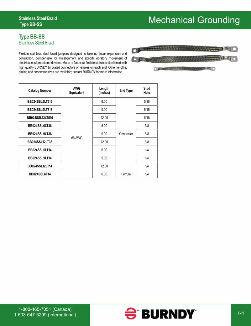
1-800-465-7051 (Canada)1-603-647-5299 (International) E-79
Mechanical Grounding
Catalog Number AWG Equivalent
Length(inches) End Type Stud
Hole
BB024SSL6LT516
#6 AWG
6.00
Connector
5/16
BB024SSL9LT516 9.00 5/16
BB024SSL12LT516 12.00 5/16
BB024SSL6LT38 6.00 3/8
BB024SSL9LT38 9.00 3/8
BB024SSL12LT38 12.00 3/8
BB024SSL6LT14 6.00 1/4
BB024SSL9LT14 9.00 1/4
BB024SSL12LT14 12.00 1/4
BB024SSL6T14 6.00 Ferrule 1/4
Stainless Steel Braid Type BB-SS
Type BB-SSStainless Steel Braid
Flexible stainless steel braid jumpers designed to take up linear expansion and contraction, compensate for misalignment and absorb vibratory movement of electrical equipment and devices. Made of flat extra flexible stainless steel braid with high quality BURNDY tin plated connectors or ferrules on each end. Other lengths, plating and connector sizes are available; contact BURNDY for more information.
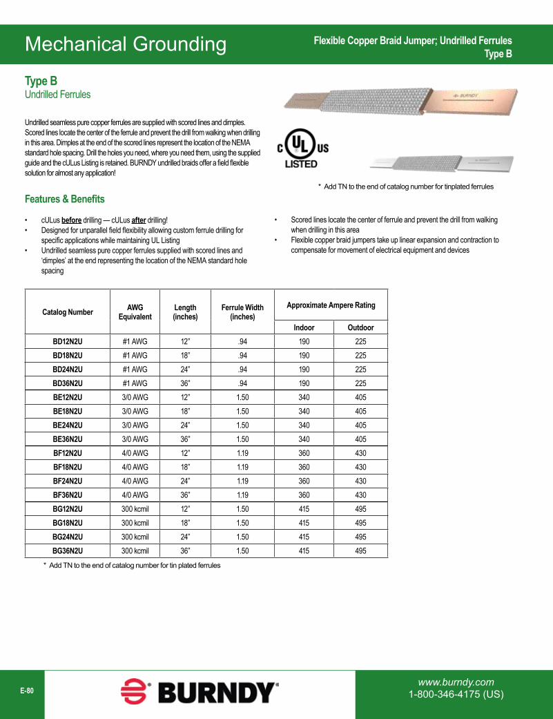
Mechanical Grounding
www.burndy.com1-800-346-4175 (US)E-80
Catalog Number AWG Equivalent
Length(inches)
Ferrule Width(inches)
Approximate Ampere Rating
Indoor OutdoorBD12N2U #1 AWG 12” .94 190 225BD18N2U #1 AWG 18” .94 190 225BD24N2U #1 AWG 24” .94 190 225BD36N2U #1 AWG 36” .94 190 225BE12N2U 3/0 AWG 12” 1.50 340 405BE18N2U 3/0 AWG 18” 1.50 340 405BE24N2U 3/0 AWG 24” 1.50 340 405BE36N2U 3/0 AWG 36” 1.50 340 405BF12N2U 4/0 AWG 12” 1.19 360 430BF18N2U 4/0 AWG 18” 1.19 360 430BF24N2U 4/0 AWG 24” 1.19 360 430BF36N2U 4/0 AWG 36” 1.19 360 430BG12N2U 300 kcmil 12” 1.50 415 495BG18N2U 300 kcmil 18” 1.50 415 495BG24N2U 300 kcmil 24” 1.50 415 495BG36N2U 300 kcmil 36” 1.50 415 495
* Add TN to the end of catalog number for tin plated ferrules
* Add TN to the end of catalog number for tinplated ferrules
Flexible Copper Braid Jumper; Undrilled FerrulesType B
Type BUndrilled Ferrules
Undrilled seamless pure copper ferrules are supplied with scored lines and dimples. Scored lines locate the center of the ferrule and prevent the drill from walking when drilling in this area. Dimples at the end of the scored lines represent the location of the NEMA standard hole spacing. Drill the holes you need, where you need them, using the supplied guide and the cULus Listing is retained. BURNDY undrilled braids offer a field flexible solution for almost any application!
Features & Benefits
• cULus before drilling — cULus after drilling!• Designed for unparallel field flexibility allowing custom ferrule drilling for
specific applications while maintaining UL Listing• Undrilled seamless pure copper ferrules supplied with scored lines and
‘dimples’ at the end representing the location of the NEMA standard hole spacing
• Scored lines locate the center of ferrule and prevent the drill from walking when drilling in this area
• Flexible copper braid jumpers take up linear expansion and contraction to compensate for movement of electrical equipment and devices
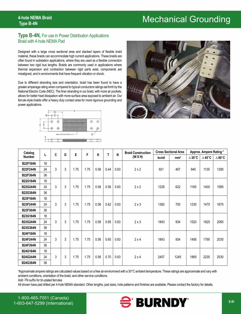
1-800-465-7051 (Canada)1-603-647-5299 (International) E-81
Mechanical Grounding4-hole NEMA Braid Type B-4N
Type B-4N, For use in Power Distribution ApplicationsBraid with 4-hole NEMA Pad
Designed with a large cross sectional area and stacked layers of flexible braid material, these braids can accommodate high current applications. These braids are often found in substation applications, where they are used as a flexible connection between two rigid bus lengths. Braids are commonly used in applications where thermal expansion and contraction between rigid parts exist, components are misaligned, and in environments that have frequent vibration or shock.
Due to different stranding size and orientation, braid has been found to have a greater amperage rating when compared to typical conductors ratings set forth by the National Electric Code (NEC). The finer stranding in our braid, with more air pockets, allows for better heat dissipation with more surface area exposed to ambient air. Our ferrule-style braids offer a heavy duty contact area for more rigorous grounding and power applications.
Catalog Number L C D E F K T N Braid Construction
(W X H)Cross Sectional Area Approx. Ampere Rating *
kcmil mm2 ∆ 30°C ∆ 45°C ∆ 60°CB22F184N 18
3 3 1.75 1.75 0.56 0.44 0.63 2 x 2 921 467 945 1135 1290B22F244N 24B22F364N 36B22G184N 18
3 3 1.75 1.75 0.56 0.56 0.63 2 x 2 1228 622 1165 1400 1585B22G244N 24B22G364N 36B23F184N 18
3 3 1.75 1.75 0.56 0.62 0.63 2 x 3 1382 700 1230 1475 1670B23F244N 24B23F364N 36B23G184N 18
3 3 1.75 1.75 0.56 0.65 0.63 2 x 3 1843 934 1520 1825 2065B23G244N 24B23G364N 36B24F184N 18
3 3 1.75 1.75 0.56 0.65 0.63 2 x 4 1843 934 1495 1795 2035B24F244N 24B24F364N 36B24G184N 18
3 3 1.75 1.75 0.56 0.70 0.63 2 x 4 2457 1245 1865 2235 2530B24G244N 24B24G364N 36
*Approximate ampere ratings are calculated values based on a free air environment with a 30°C ambient temperature. These ratings are approximate and vary with ambient conditions, orientation of the braid, and other service conditions.Add -TN suffix for tin-plated ferrules All shown have pad drilled per 4-hole NEMA standard. Other lengths, pad sizes, hole patterns and finishes are available. Please contact the factory for details.
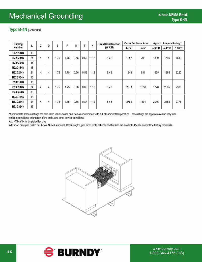
Mechanical Grounding
www.burndy.com1-800-346-4175 (US)E-82
4-hole NEMA Braid Type B-4N
Catalog Number L C D E F K T N Braid Construction
(W X H)Cross Sectional Area Approx. Ampere Rating *
kcmil mm2 ∆ 30°C ∆ 45°C ∆ 60°CB32F184N 18
4 4 1.75 1.75 0.56 0.50 1.12 3 x 2 1382 700 1330 1595 1810B32F244N 24B32F364N 36B32G184N 18
4 4 1.75 1.75 0.56 0.56 1.12 3 x 2 1843 934 1635 1965 2220B32G244N 24B32G364N 36B33F184N 18
4 4 1.75 1.75 0.56 0.65 1.12 3 x 3 2073 1050 1720 2065 2335B33F244N 24B33F364N 36B33G184N 18
4 4 1.75 1.75 0.56 0.87 1.12 3 x 3 2764 1401 2045 2455 2775B33G244N 24B33G364N 36
Type B-4N (Continued)
*Approximate ampere ratings are calculated values based on a free air environment with a 30°C ambient temperature. These ratings are approximate and vary with ambient conditions, orientation of the braid, and other service conditions.Add -TN suffix for tin-plated ferrules All shown have pad drilled per 4-hole NEMA standard. Other lengths, pad sizes, hole patterns and finishes are available. Please contact the factory for details.
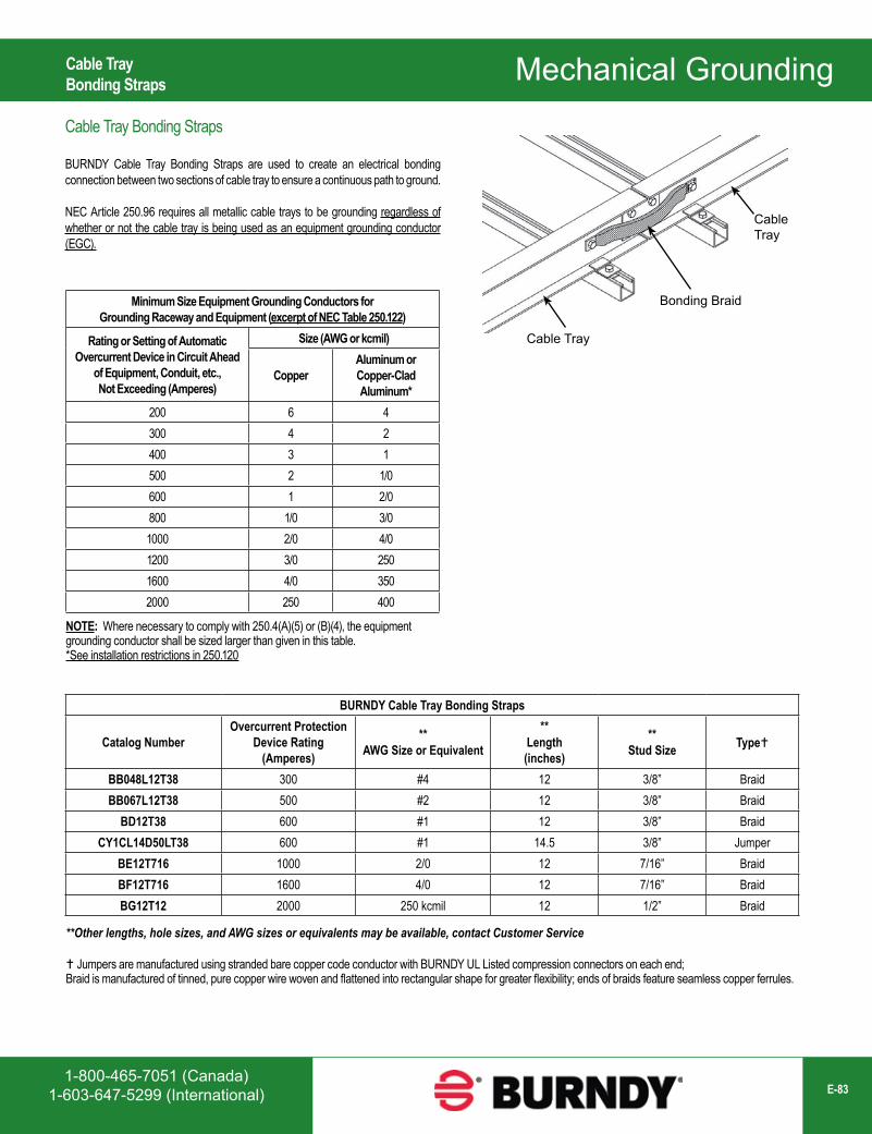
1-800-465-7051 (Canada)1-603-647-5299 (International) E-83
Mechanical GroundingCable TrayBonding Straps
Cable Tray Bonding Straps
BURNDY Cable Tray Bonding Straps are used to create an electrical bonding connection between two sections of cable tray to ensure a continuous path to ground.
NEC Article 250.96 requires all metallic cable trays to be grounding regardless of whether or not the cable tray is being used as an equipment grounding conductor (EGC).
Cable Tray
Cable Tray
Bonding BraidMinimum Size Equipment Grounding Conductors for Grounding Raceway and Equipment (excerpt of NEC Table 250.122)
Rating or Setting of Automatic Overcurrent Device in Circuit Ahead
of Equipment, Conduit, etc., Not Exceeding (Amperes)
Size (AWG or kcmil)
CopperAluminum or Copper-Clad Aluminum*
200 6 4300 4 2400 3 1500 2 1/0600 1 2/0800 1/0 3/01000 2/0 4/01200 3/0 2501600 4/0 3502000 250 400
NOTE: Where necessary to comply with 250.4(A)(5) or (B)(4), the equipment grounding conductor shall be sized larger than given in this table.*See installation restrictions in 250.120
BURNDY Cable Tray Bonding Straps
Catalog NumberOvercurrent Protection
Device Rating (Amperes)
**AWG Size or Equivalent
**Length(inches)
**Stud Size Type
BB048L12T38 300 #4 12 3/8” BraidBB067L12T38 500 #2 12 3/8” Braid
BD12T38 600 #1 12 3/8” BraidCY1CL14D50LT38 600 #1 14.5 3/8” Jumper
BE12T716 1000 2/0 12 7/16” BraidBF12T716 1600 4/0 12 7/16” BraidBG12T12 2000 250 kcmil 12 1/2” Braid
**Other lengths, hole sizes, and AWG sizes or equivalents may be available, contact Customer Service
Jumpers are manufactured using stranded bare copper code conductor with BURNDY UL Listed compression connectors on each end; Braid is manufactured of tinned, pure copper wire woven and flattened into rectangular shape for greater flexibility; ends of braids feature seamless copper ferrules.
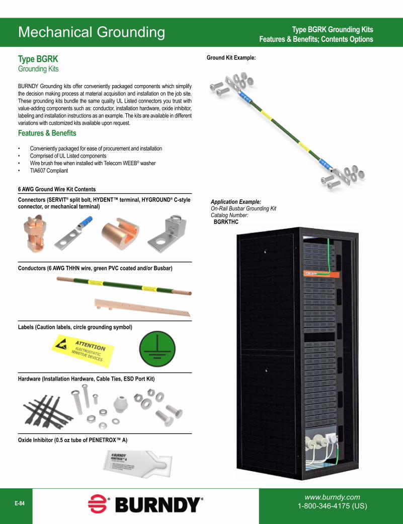
Mechanical Grounding
www.burndy.com1-800-346-4175 (US)E-84
Type BGRK Grounding KitsFeatures & Benefits; Contents Options
Type BGRKGrounding Kits
BURNDY Grounding kits offer conveniently packaged components which simplify the decision making process at material acquisition and installation on the job site. These grounding kits bundle the same quality UL Listed connectors you trust with value-adding components such as: conductor, installation hardware, oxide inhibitor, labeling and installation instructions as an example. The kits are available in different variations with customized kits available upon request.
Features & Benefits
• Conveniently packaged for ease of procurement and installation• Comprised of UL Listed components• Wire brush free when installed with Telecom WEEB® washer• TIA607 Compliant
Connectors (SERVIT® split bolt, HYDENT™ terminal, HYGROUND® C-style connector, or mechanical terminal)
Ground Kit Example:
Application Example: On-Rail Busbar Grounding KitCatalog Number: BGRKTHC
6 AWG Ground Wire Kit Contents
Conductors (6 AWG THHN wire, green PVC coated and/or Busbar)
Labels (Caution labels, circle grounding symbol)
Hardware (Installation Hardware, Cable Ties, ESD Port Kit)
Oxide Inhibitor (0.5 oz tube of PENETROX™ A)
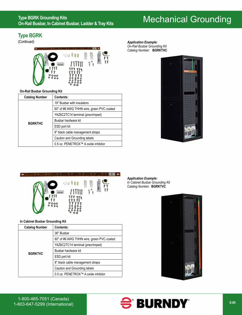
1-800-465-7051 (Canada)1-603-647-5299 (International) E-85
Mechanical GroundingType BGRK Grounding KitsOn-Rail Busbar, In Cabinet Busbar, Ladder & Tray Kits
Type BGRK(Continued)
On-Rail Busbar Grounding KitCatalog Number Contents:
BGRKTHC
19" Busbar with insulators60" of #6 AWG THHN wire, green PVC coatedYAZ6C2TC14 terminal (precrimped)Busbar hardware kitESD port kit8" black cable management strapsCaution and Grounding labels0.5 oz. PENETROX™ A oxide inhibitor
Application Example: On-Rail Busbar Grounding Kit Catalog Number: BGRKTHC
Application Example: In Cabinet Busbar Grounding Kit Catalog Number: BGRKTVC
In Cabinet Busbar Grounding KitCatalog Number Contents:
BGRKTVC
36" Busbar60" of #6 AWG THHN wire, green PVC coatedYAZ6C2TC14 terminal (precrimped)Busbar hardware kitESD port kit8" black cable management strapsCaution and Grounding labels0.5 oz. PENETROX™ A oxide inhibitor
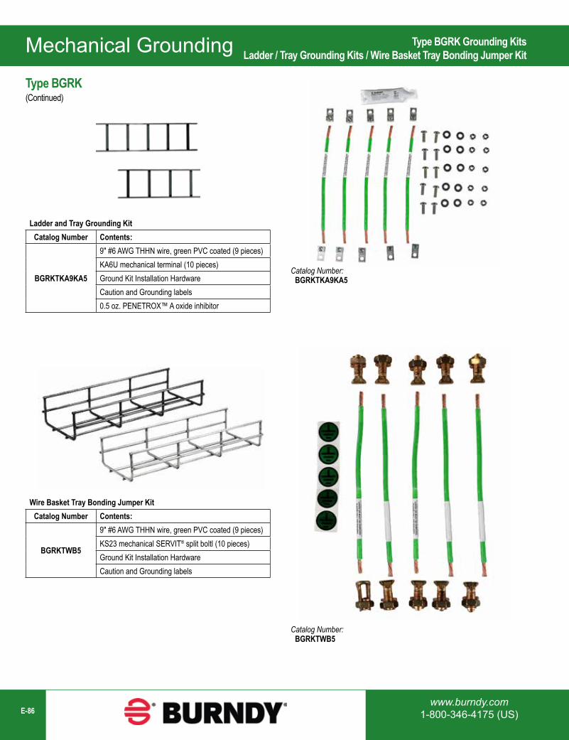
Mechanical Grounding
www.burndy.com1-800-346-4175 (US)E-86
Type BGRK Grounding KitsLadder / Tray Grounding Kits / Wire Basket Tray Bonding Jumper Kit
Ladder and Tray Grounding KitCatalog Number Contents:
BGRKTKA9KA5
9" #6 AWG THHN wire, green PVC coated (9 pieces)KA6U mechanical terminal (10 pieces)Ground Kit Installation HardwareCaution and Grounding labels0.5 oz. PENETROX™ A oxide inhibitor
Type BGRK(Continued)
Wire Basket Tray Bonding Jumper KitCatalog Number Contents:
BGRKTWB5
9" #6 AWG THHN wire, green PVC coated (9 pieces)KS23 mechanical SERVIT® split boltl (10 pieces)Ground Kit Installation HardwareCaution and Grounding labels
Catalog Number: BGRKTKA9KA5
Catalog Number: BGRKTWB5
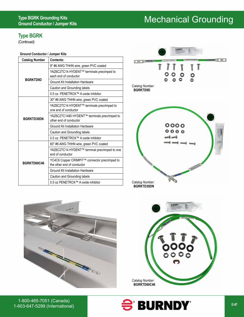
1-800-465-7051 (Canada)1-603-647-5299 (International) E-87
Mechanical GroundingType BGRK Grounding KitsGround Conductor / Jumper Kits
Type BGRK(Continued)
Ground Conductor / Jumper KitsCatalog Number Contents:
BGRKTD9D
9" #6 AWG THHN wire, green PVC coatedYAZ6C2TC14 HYDENT™ terminals precimped to each end of conductorGround Kit Installation HardwareCaution and Grounding labels0.5 oz. PENETROX™ A oxide inhibitor
BGRKTD30DN
30" #6 AWG THHN wire, green PVC coatedYAZ6C2TC14 HYDENT™ terminals precrimped to one end of conductorYAZ6C2TC1490 HYDENT™ terminals precrimped to other end of conductorGround Kit Installation HardwareCaution and Grounding labels0.5 oz. PENETROX™ A oxide inhibitor
BGRKTD60C46
60" #6 AWG THHN wire, green PVC coatedYAZ6C2TC14 HYDENT™ terminal precrimped to one end of conductorYC4C6 Copper CRIMPIT™ connector precrimped to the other end of conductorGround Kit Installation HardwareCaution and Grounding labels0.5 oz PENETROX™ A oxide inhibitor
Catalog Number: BGRKTD9D
Catalog Number: BGRKTD30DN
Catalog Number: BGRKTD60C46
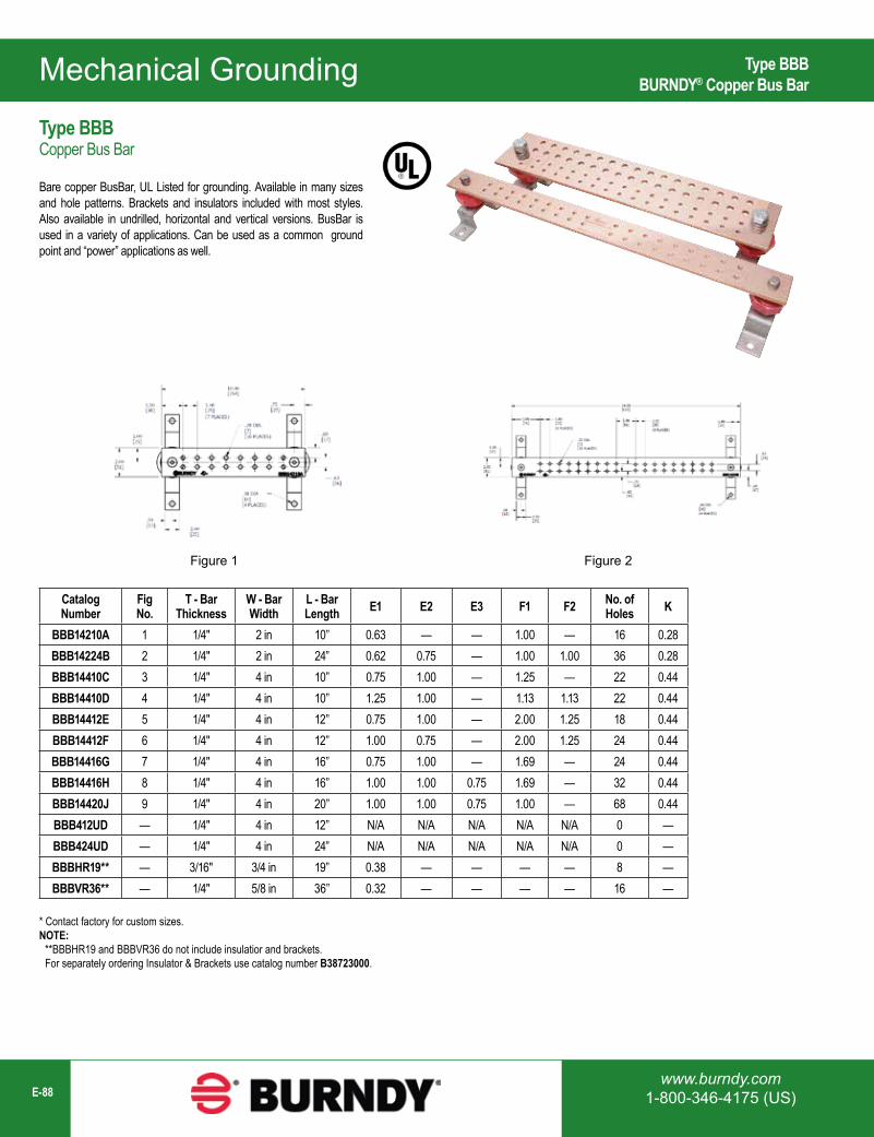
Mechanical Grounding
www.burndy.com1-800-346-4175 (US)E-88
Catalog Number
Fig No.
T - Bar Thickness
W - Bar Width
L - Bar Length E1 E2 E3 F1 F2 No. of
Holes K
BBB14210A 1 1/4" 2 in 10” 0.63 — — 1.00 — 16 0.28BBB14224B 2 1/4" 2 in 24” 0.62 0.75 — 1.00 1.00 36 0.28BBB14410C 3 1/4" 4 in 10” 0.75 1.00 — 1.25 — 22 0.44BBB14410D 4 1/4" 4 in 10” 1.25 1.00 — 1.13 1.13 22 0.44BBB14412E 5 1/4" 4 in 12” 0.75 1.00 — 2.00 1.25 18 0.44BBB14412F 6 1/4" 4 in 12” 1.00 0.75 — 2.00 1.25 24 0.44BBB14416G 7 1/4" 4 in 16” 0.75 1.00 — 1.69 — 24 0.44BBB14416H 8 1/4" 4 in 16” 1.00 1.00 0.75 1.69 — 32 0.44BBB14420J 9 1/4" 4 in 20” 1.00 1.00 0.75 1.00 — 68 0.44BBB412UD — 1/4" 4 in 12” N/A N/A N/A N/A N/A 0 —BBB424UD — 1/4" 4 in 24” N/A N/A N/A N/A N/A 0 —BBBHR19** — 3/16" 3/4 in 19” 0.38 — — — — 8 —BBBVR36** — 1/4" 5/8 in 36” 0.32 — — — — 16 —
* Contact factory for custom sizes.NOTE: **BBBHR19 and BBBVR36 do not include insulatior and brackets. For separately ordering Insulator & Brackets use catalog number B38723000.
Figure 1 Figure 2
Type BBBBURNDY® Copper Bus Bar
Type BBBCopper Bus Bar
Bare copper BusBar, UL Listed for grounding. Available in many sizes and hole patterns. Brackets and insulators included with most styles. Also available in undrilled, horizontal and vertical versions. BusBar is used in a variety of applications. Can be used as a common ground point and “power” applications as well.
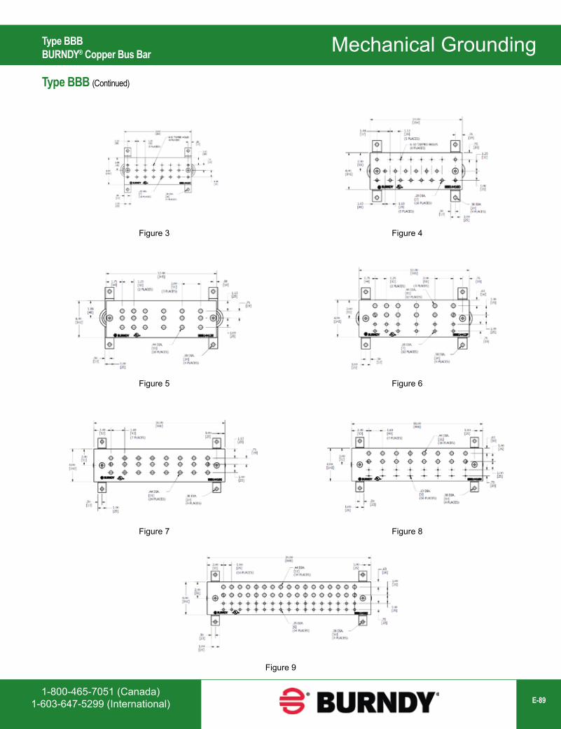
1-800-465-7051 (Canada)1-603-647-5299 (International) E-89
Mechanical GroundingType BBBBURNDY® Copper Bus Bar
Type BBB (Continued)
Figure 3 Figure 4
Figure 5 Figure 6
Figure 7 Figure 8
Figure 9
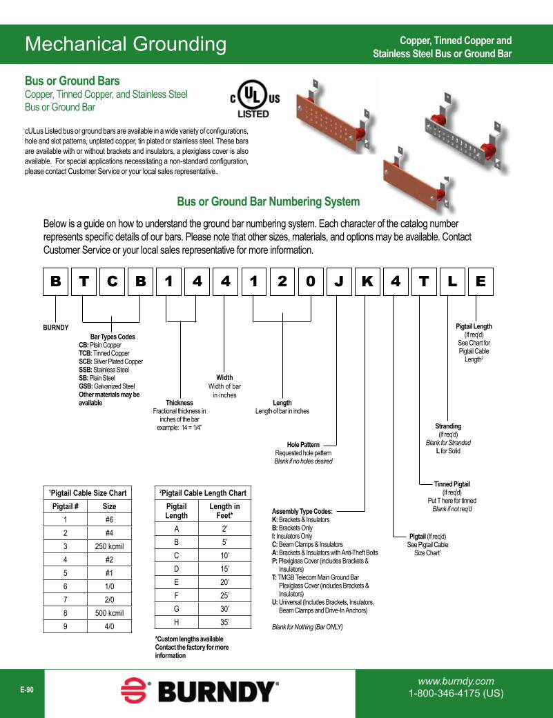
Mechanical Grounding
www.burndy.com1-800-346-4175 (US)E-90
Bus or Ground Bar Numbering SystemBelow is a guide on how to understand the ground bar numbering system. Each character of the catalog number represents specific details of our bars. Please note that other sizes, materials, and options may be available. Contact Customer Service or your local sales representative for more information.
B T C B 1 4 4 1 2 0 J K 4 T L E
BURNDYBar Types Codes
CB: Plain CopperTCB: Tinned CopperSCB: Silver Plated CopperSSB: Stainless SteelSB: Plain SteelGSB: Galvanized SteelOther materials may be available Thickness
Fractional thickness in inches of the bar
example: 14 = 1/4”
WidthWidth of bar
in inchesLength
Length of bar in inches
Hole PatternRequested hole patternBlank if no holes desired
Assembly Type Codes:K: Brackets & InsulatorsB: Brackets OnlyI: Insulators OnlyC: Beam Clamps & InsulatorsA: Brackets & Insulators with Anti-Theft BoltsP: Plexiglass Cover (includes Brackets & Insulators)T: TMGB Telecom Main Ground Bar Plexiglass Cover (includes Brackets & Insulators)U: Universal (Includes Brackets, Insulators, Beam Clamps and Drive-In Anchors)
Blank for Nothing (Bar ONLY)
Pigtail (If req’d) See Pigtail Cable
Size Chart1
Tinned Pigtail(If req’d)
Put T here for tinnedBlank if not req’d
Stranding(If req’d)
Blank for StrandedL for Solid
Pigtail Length(If req’d)
See Chart forPigtail Cable
Length2
1Pigtail Cable Size ChartPigtail # Size
1 #62 #43 250 kcmil4 #25 #16 1/07 2/08 500 kcmil9 4/0
2Pigtail Cable Length ChartPigtail Length
Length in Feet*
A 2’B 5’C 10’D 15’E 20’F 25’G 30’H 35’
*Custom lengths availableContact the factory for more information
Copper, Tinned Copper andStainless Steel Bus or Ground Bar
Bus or Ground BarsCopper, Tinned Copper, and Stainless Steel Bus or Ground Bar
cULus Listed bus or ground bars are available in a wide variety of configurations, hole and slot patterns, unplated copper, tin plated or stainless steel. These bars are available with or without brackets and insulators, a plexiglass cover is also available. For special applications necessitating a non-standard configuration, please contact Customer Service or your local sales representative..
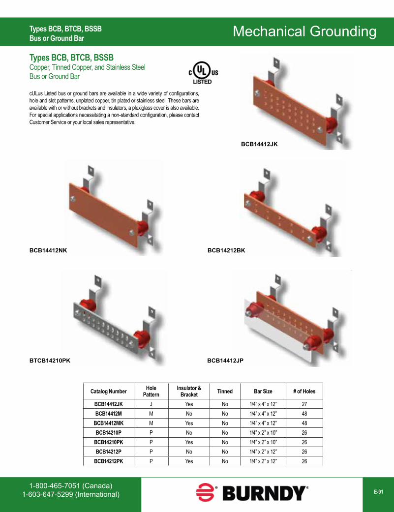
1-800-465-7051 (Canada)1-603-647-5299 (International) E-91
Mechanical Grounding
BCB14412JK
BCB14412NK
BTCB14210PK
BCB14212BK
BCB14412JP
Catalog Number HolePattern
Insulator & Bracket Tinned Bar Size # of Holes
BCB14412JK J Yes No 1/4” x 4” x 12” 27BCB14412M M No No 1/4” x 4” x 12” 48
BCB14412MK M Yes No 1/4” x 4” x 12” 48BCB14210P P No No 1/4” x 2” x 10” 26
BCB14210PK P Yes No 1/4” x 2” x 10” 26BCB14212P P No No 1/4” x 2” x 12” 26
BCB14212PK P Yes No 1/4” x 2” x 12” 26
Types BCB, BTCB, BSSBBus or Ground Bar
Types BCB, BTCB, BSSBCopper, Tinned Copper, and Stainless Steel Bus or Ground Bar
cULus Listed bus or ground bars are available in a wide variety of configurations, hole and slot patterns, unplated copper, tin plated or stainless steel. These bars are available with or without brackets and insulators, a plexiglass cover is also available. For special applications necessitating a non-standard configuration, please contact Customer Service or your local sales representative..
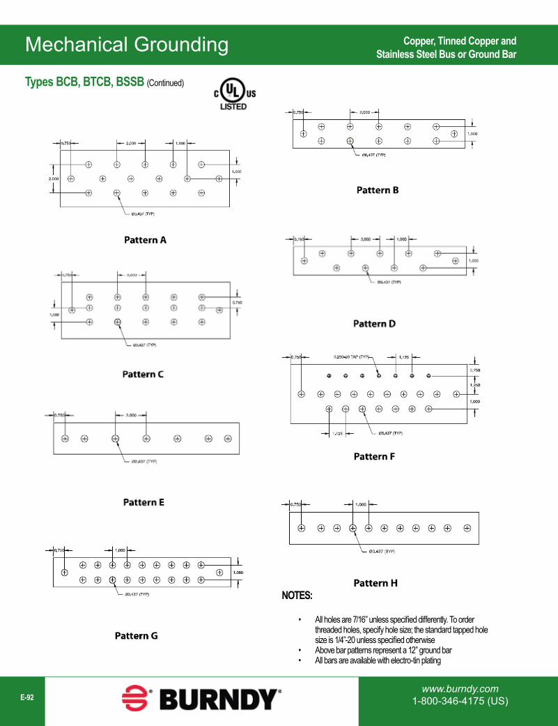
Mechanical Grounding
www.burndy.com1-800-346-4175 (US)E-92
NOTES:
• All holes are 7/16” unless specified differently. To order threaded holes, specify hole size; the standard tapped hole size is 1/4”-20 unless specified otherwise
• Above bar patterns represent a 12” ground bar• All bars are available with electro-tin plating
Copper, Tinned Copper andStainless Steel Bus or Ground Bar
Types BCB, BTCB, BSSB (Continued)
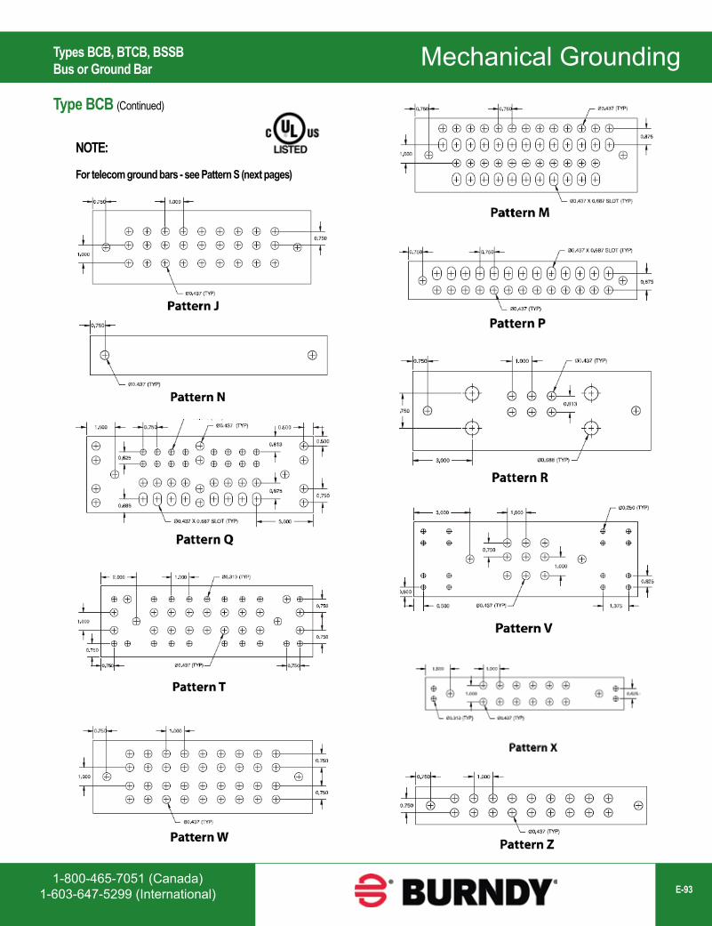
1-800-465-7051 (Canada)1-603-647-5299 (International) E-93
Mechanical Grounding
NOTE:
For telecom ground bars - see Pattern S (next pages)
Types BCB, BTCB, BSSBBus or Ground Bar
Type BCB (Continued)
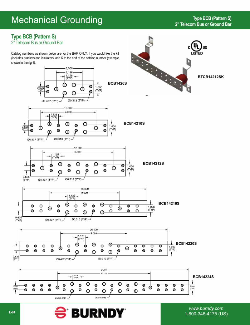
Mechanical Grounding
www.burndy.com1-800-346-4175 (US)E-94
Type BCB (Pattern S)2” Telecom Bus or Ground Bar
Catalog numbers as shown below are for the BAR ONLY; if you would like the kit (includes brackets and insulators) add K to the end of the catalog number (example shown to the right).
BTCB14212SKBCB1426S
BCB14210S
BCB14212S
BCB14216S
BCB14220S
BCB14224S
Type BCB (Pattern S)2” Telecom Bus or Ground Bar
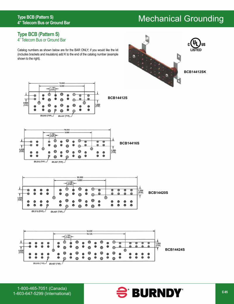
1-800-465-7051 (Canada)1-603-647-5299 (International) E-95
Mechanical Grounding
BCB14412S
BCB14416S
BCB14420S
BCB14424S
BCB14412SK
Type BCB (Pattern S)4” Telecom Bus or Ground Bar
Type BCB (Pattern S)4” Telecom Bus or Ground Bar
Catalog numbers as shown below are for the BAR ONLY; if you would like the kit (includes brackets and insulators) add K to the end of the catalog number (example shown to the right).
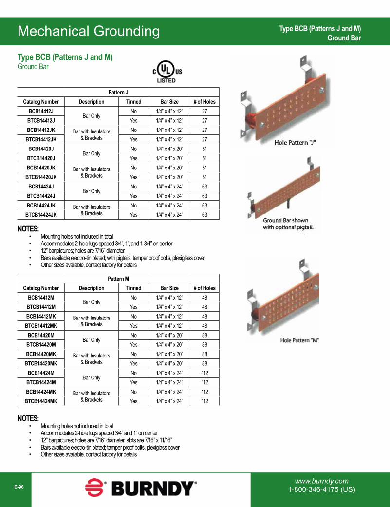
Mechanical Grounding
www.burndy.com1-800-346-4175 (US)E-96
Pattern JCatalog Number Description Tinned Bar Size # of Holes
BCB14412JBar Only
No 1/4” x 4” x 12” 27BTCB14412J Yes 1/4” x 4” x 12” 27BCB14412JK Bar with Insulators
& BracketsNo 1/4” x 4” x 12” 27
BTCB14412JK Yes 1/4” x 4” x 12” 27BCB14420J
Bar OnlyNo 1/4” x 4” x 20” 51
BTCB14420J Yes 1/4” x 4” x 20” 51BCB14420JK Bar with Insulators
& BracketsNo 1/4” x 4” x 20” 51
BTCB14420JK Yes 1/4” x 4” x 20” 51BCB14424J
Bar OnlyNo 1/4” x 4” x 24” 63
BTCB14424J Yes 1/4” x 4” x 24” 63BCB14424JK Bar with Insulators
& BracketsNo 1/4” x 4” x 24” 63
BTCB14424JK Yes 1/4” x 4” x 24” 63
NOTES:• Mounting holes not included in total• Accommodates 2-hole lugs spaced 3/4”, 1”, and 1-3/4” on center• 12” bar pictures; holes are 7/16” diameter• Bars available electro-tin plated; with pigtails, tamper proof bolts, plexiglass cover• Other sizes available, contact factory for details
Pattern MCatalog Number Description Tinned Bar Size # of Holes
BCB14412MBar Only
No 1/4” x 4” x 12” 48BTCB14412M Yes 1/4” x 4” x 12” 48BCB14412MK Bar with Insulators
& BracketsNo 1/4” x 4” x 12” 48
BTCB14412MK Yes 1/4” x 4” x 12” 48BCB14420M
Bar OnlyNo 1/4” x 4” x 20” 88
BTCB14420M Yes 1/4” x 4” x 20” 88BCB14420MK Bar with Insulators
& BracketsNo 1/4” x 4” x 20” 88
BTCB14420MK Yes 1/4” x 4” x 20” 88BCB14424M
Bar OnlyNo 1/4” x 4” x 24” 112
BTCB14424M Yes 1/4” x 4” x 24” 112BCB14424MK Bar with Insulators
& BracketsNo 1/4” x 4” x 24” 112
BTCB14424MK Yes 1/4” x 4” x 24” 112
NOTES:• Mounting holes not included in total• Accommodates 2-hole lugs spaced 3/4” and 1” on center• 12” bar pictures; holes are 7/16” diameter, slots are 7/16” x 11/16”• Bars available electro-tin plated; tamper proof bolts, plexiglass cover• Other sizes available, contact factory for details
Type BCB (Patterns J and M)Ground Bar
Type BCB (Patterns J and M)Ground Bar
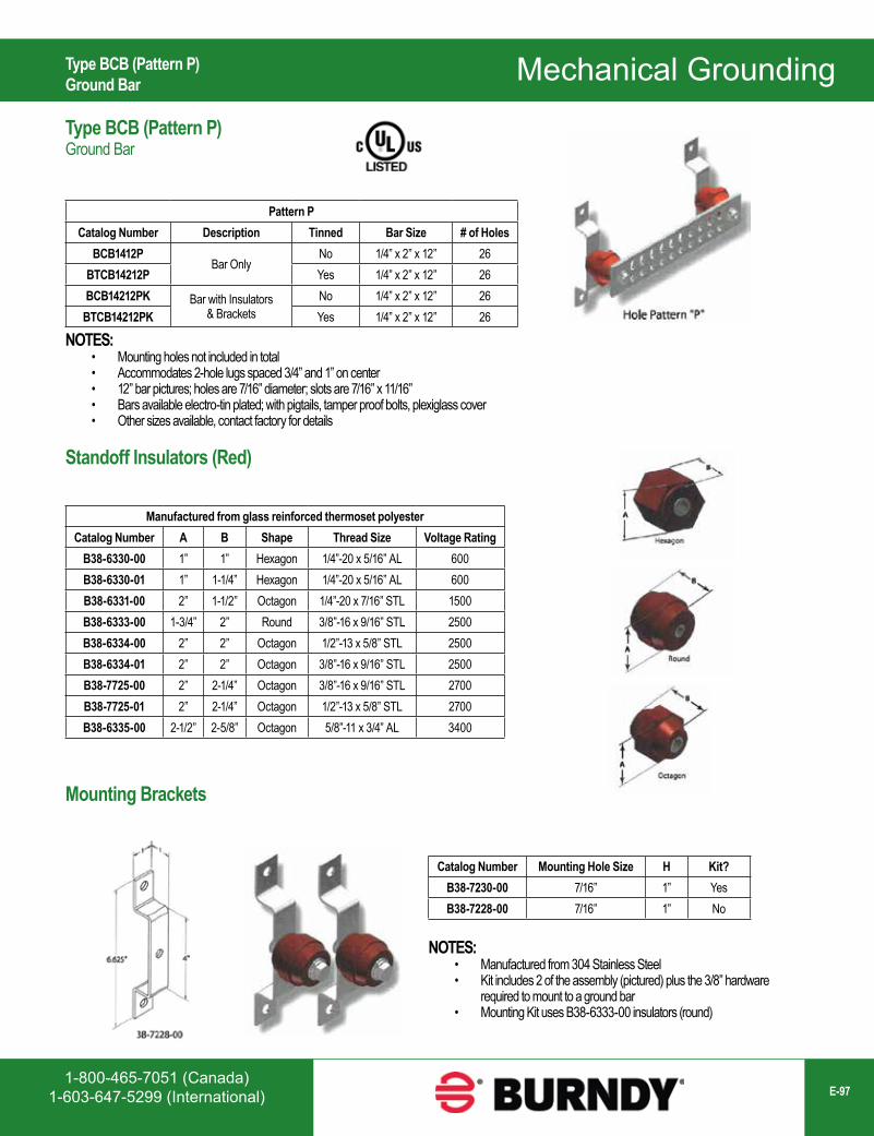
1-800-465-7051 (Canada)1-603-647-5299 (International) E-97
Mechanical Grounding
Pattern PCatalog Number Description Tinned Bar Size # of Holes
BCB1412PBar Only
No 1/4” x 2” x 12” 26BTCB14212P Yes 1/4” x 2” x 12” 26BCB14212PK Bar with Insulators
& BracketsNo 1/4” x 2” x 12” 26
BTCB14212PK Yes 1/4” x 2” x 12” 26
NOTES:• Mounting holes not included in total• Accommodates 2-hole lugs spaced 3/4” and 1” on center• 12” bar pictures; holes are 7/16” diameter; slots are 7/16” x 11/16”• Bars available electro-tin plated; with pigtails, tamper proof bolts, plexiglass cover• Other sizes available, contact factory for details
Standoff Insulators (Red)
Manufactured from glass reinforced thermoset polyesterCatalog Number A B Shape Thread Size Voltage Rating
B38-6330-00 1” 1” Hexagon 1/4”-20 x 5/16” AL 600B38-6330-01 1” 1-1/4” Hexagon 1/4”-20 x 5/16” AL 600B38-6331-00 2” 1-1/2” Octagon 1/4”-20 x 7/16” STL 1500B38-6333-00 1-3/4” 2” Round 3/8”-16 x 9/16” STL 2500B38-6334-00 2” 2” Octagon 1/2”-13 x 5/8” STL 2500B38-6334-01 2” 2” Octagon 3/8”-16 x 9/16” STL 2500B38-7725-00 2” 2-1/4” Octagon 3/8”-16 x 9/16” STL 2700B38-7725-01 2” 2-1/4” Octagon 1/2”-13 x 5/8” STL 2700B38-6335-00 2-1/2” 2-5/8” Octagon 5/8”-11 x 3/4” AL 3400
Catalog Number Mounting Hole Size H Kit?B38-7230-00 7/16” 1” YesB38-7228-00 7/16” 1” No
NOTES:• Manufactured from 304 Stainless Steel• Kit includes 2 of the assembly (pictured) plus the 3/8” hardware
required to mount to a ground bar• Mounting Kit uses B38-6333-00 insulators (round)
Type BCB (Pattern P)Ground Bar
Type BCB (Pattern P)Ground Bar
Mounting Brackets
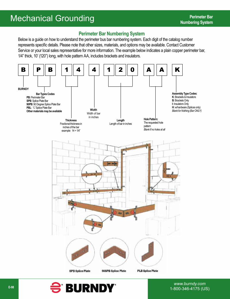
Mechanical Grounding
www.burndy.com1-800-346-4175 (US)E-98
Perimeter Bar Numbering SystemBelow is a guide on how to understand the perimeter bus bar numbering system. Each digit of the catalog number represents specific details. Please note that other sizes, materials, and options may be available. Contact Customer Service or your local sales representative for more information. The example below indicates a plain copper perimeter bar, 1/4” thick, 10’ (120”) long, with hole pattern AA, includes brackets and insulators.
B P B 1 4 4 1 2 0 A A K
BURNDYBar Types Codes
PB: Perimeter BarSPB: Splice Plate Bar90PB: 90 Degree Splice Plate BarPBL: “L” Splice Plate BarOther materials may be available
ThicknessFractional thickness in
inches of the barexample: 14 = 1/4”
WidthWidth of bar
in inchesLength
Length of bar in inchesHole Pattern:The requested hole pattern Blank if no holes at all
Assembly Type Codes:K: Brackets & InsulatorsB: Brackets OnlyI: Insulators OnlyH: w/hardware (Splices only)Blank for Nothing (Bar ONLY)
Perimeter BarNumbering System
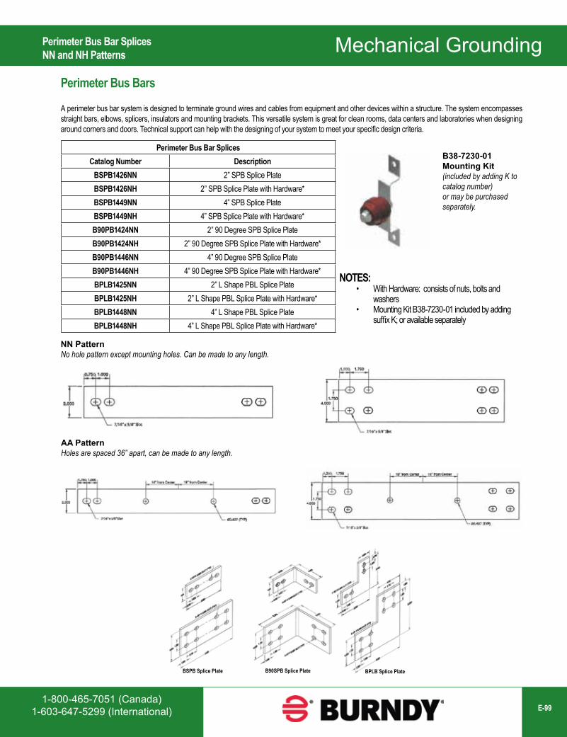
1-800-465-7051 (Canada)1-603-647-5299 (International) E-99
Mechanical GroundingPerimeter Bus Bars
A perimeter bus bar system is designed to terminate ground wires and cables from equipment and other devices within a structure. The system encompasses straight bars, elbows, splicers, insulators and mounting brackets. This versatile system is great for clean rooms, data centers and laboratories when designing around corners and doors. Technical support can help with the designing of your system to meet your specific design criteria.
Perimeter Bus Bar SplicesCatalog Number Description
BSPB1426NN 2” SPB Splice PlateBSPB1426NH 2” SPB Splice Plate with Hardware*BSPB1449NN 4” SPB Splice PlateBSPB1449NH 4” SPB Splice Plate with Hardware*B90PB1424NN 2” 90 Degree SPB Splice PlateB90PB1424NH 2” 90 Degree SPB Splice Plate with Hardware*B90PB1446NN 4” 90 Degree SPB Splice PlateB90PB1446NH 4” 90 Degree SPB Splice Plate with Hardware*BPLB1425NN 2” L Shape PBL Splice PlateBPLB1425NH 2” L Shape PBL Splice Plate with Hardware*BPLB1448NN 4” L Shape PBL Splice PlateBPLB1448NH 4” L Shape PBL Splice Plate with Hardware*
B38-7230-01Mounting Kit(included by adding K to catalog number)or may be purchased separately.
NOTES:• With Hardware: consists of nuts, bolts and
washers• Mounting Kit B38-7230-01 included by adding
suffix K; or available separately
NN PatternNo hole pattern except mounting holes. Can be made to any length.
AA PatternHoles are spaced 36” apart, can be made to any length.
Perimeter Bus Bar SplicesNN and NH Patterns
BSPB Splice Plate B90SPB Splice Plate BPLB Splice Plate
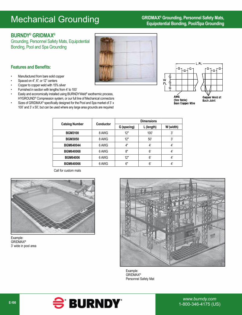
Mechanical Grounding
www.burndy.com1-800-346-4175 (US)E-100
Catalog Number ConductorDimensions
G (spacing) L (length) W (width)BGM3100 8 AWG 12" 100’ 3’BGM3050 8 AWG 12" 50’ 3’
BGM640044 6 AWG 4" 4’ 4’BGM640068 6 AWG 8" 6’ 4’BGM64006 6 AWG 12" 6’ 4’BGM640066 6 AWG 6" 6’ 4’
Call for custom mats
Example:GRIDMAX®
Personnel Safety Mat
Example:GRIDMAX®
3’ wide in pool area
GRIDMAX® Grounding, Personnel Safety Mats, Equipotential Bonding, Pool/Spa Grounding
BURNDY® GRIDMAX®
Grounding, Personnel Safety Mats, Equipotential Bonding, Pool and Spa Grounding
Features and Benefits:
• Manufactured from bare solid copper• Spaced on 4”, 6”, or 12” centers• Copper to copper weld with 15% silver• Furnished in section with lengths from 4’ to 100’• Easily and economically installed using BURNDYWeld® exothermic process,
HYGROUND® Compression system, or our full line of Mechanical connectors• Sizes of GRIDMAX® specifically designed for the Pool and Spa market of 3’ x
100’ and 3’ x 50’, but can be used where any large area grounds are required
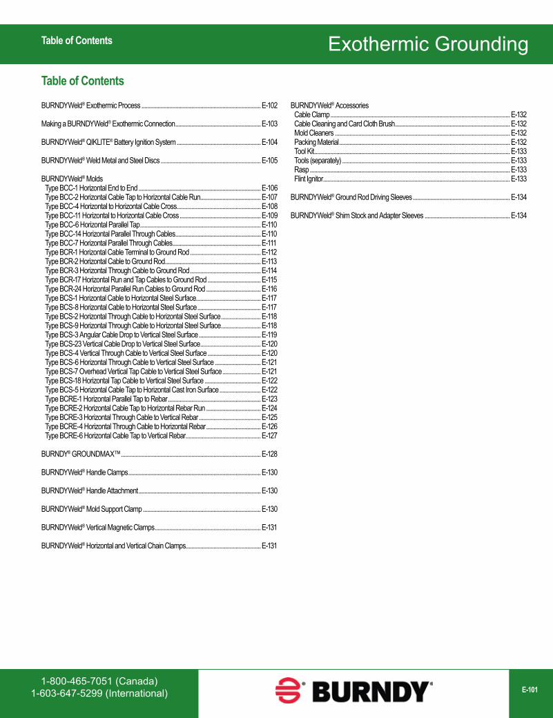
1-800-465-7051 (Canada)1-603-647-5299 (International) E-101
Exothermic GroundingTable of Contents
BURNDYWeld® Exothermic Process .................................................................................E-102
Making a BURNDYWeld® Exothermic Connection ..........................................................E-103
BURNDYWeld® QIKLITE® Battery Ignition System .........................................................E-104
BURNDYWeld® Weld Metal and Steel Discs ....................................................................E-105
BURNDYWeld® Molds Type BCC-1 Horizontal End to End ...................................................................................E-106 Type BCC-2 Horizontal Cable Tap to Horizontal Cable Run.........................................E-107 Type BCC-4 Horizontal to Horizontal Cable Cross .........................................................E-108 Type BCC-11 Horizontal to Horizontal Cable Cross .......................................................E-109 Type BCC-6 Horizontal Parallel Tap ..................................................................................E-110 Type BCC-14 Horizontal Parallel Through Cables ..........................................................E-110 Type BCC-7 Horizontal Parallel Through Cables ............................................................E-111 Type BCR-1 Horizontal Cable Terminal to Ground Rod ................................................E-112 Type BCR-2 Horizontal Cable to Ground Rod .................................................................E-113 Type BCR-3 Horizontal Through Cable to Ground Rod ................................................E-114 Type BCR-17 Horizontal Run and Tap Cables to Ground Rod ....................................E-115 Type BCR-24 Horizontal Parallel Run Cables to Ground Rod .....................................E-116 Type BCS-1 Horizontal Cable to Horizontal Steel Surface............................................E-117 Type BCS-8 Horizontal Cable to Horizontal Steel Surface ...........................................E-117 Type BCS-2 Horizontal Through Cable to Horizontal Steel Surface ...........................E-118 Type BCS-9 Horizontal Through Cable to Horizontal Steel Surface ...........................E-118 Type BCS-3 Angular Cable Drop to Vertical Steel Surface ..........................................E-119 Type BCS-23 Vertical Cable Drop to Vertical Steel Surface .........................................E-120 Type BCS-4 Vertical Through Cable to Vertical Steel Surface ....................................E-120 Type BCS-6 Horizontal Through Cable to Vertical Steel Surface ...............................E-121 Type BCS-7 Overhead Vertical Tap Cable to Vertical Steel Surface ..........................E-121 Type BCS-18 Horizontal Tap Cable to Vertical Steel Surface ......................................E-122 Type BCS-5 Horizontal Cable Tap to Horizontal Cast Iron Surface ............................E-122 Type BCRE-1 Horizontal Parallel Tap to Rebar ...............................................................E-123 Type BCRE-2 Horizontal Cable Tap to Horizontal Rebar Run .....................................E-124 Type BCRE-3 Horizontal Through Cable to Vertical Rebar ..........................................E-125 Type BCRE-4 Horizontal Through Cable to Horizontal Rebar .....................................E-126 Type BCRE-6 Horizontal Cable Tap to Vertical Rebar ...................................................E-127
BURNDY® GROUNDMAX™ ...............................................................................................E-128
BURNDYWeld® Handle Clamps ..........................................................................................E-130
BURNDYWeld® Handle Attachment ...................................................................................E-130
BURNDYWeld® Mold Support Clamp ................................................................................E-130
BURNDYWeld® Vertical Magnetic Clamps ........................................................................E-131
BURNDYWeld® Horizontal and Vertical Chain Clamps...................................................E-131
Table of Contents
Exothermic Grounding
BURNDYWeld® Accessories Cable Clamp ..........................................................................................................................E-132 Cable Cleaning and Card Cloth Brush ..............................................................................E-132 Mold Cleaners .......................................................................................................................E-132 Packing Material ....................................................................................................................E-132 Tool Kit .....................................................................................................................................E-133 Tools (separately) ..................................................................................................................E-133 Rasp ........................................................................................................................................E-133 Flint Ignitor ...............................................................................................................................E-133
BURNDYWeld® Ground Rod Driving Sleeves ..................................................................E-134
BURNDYWeld® Shim Stock and Adapter Sleeves ..........................................................E-134
1-800-465-7051 (Canada)1-603-647-5299 (International)
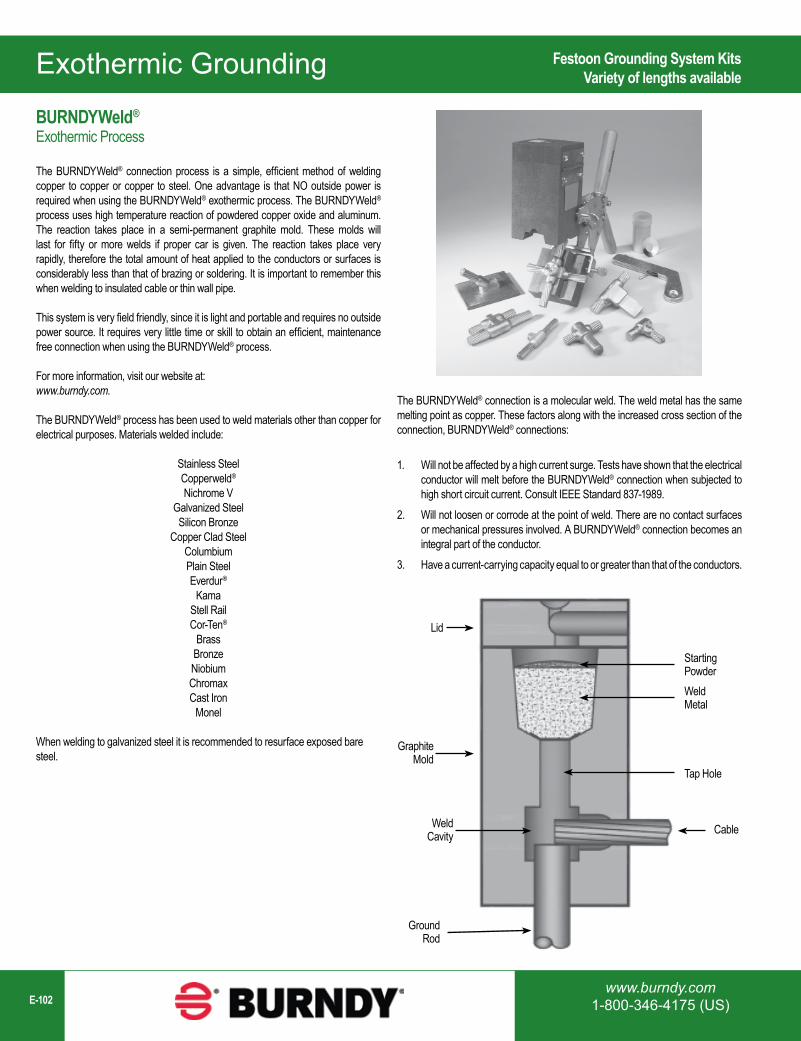
www.burndy.com1-800-346-4175 (US)E-102
Exothermic Grounding
Lid
Graphite Mold
WeldCavity
Ground Rod
StartingPowderWeldMetal
Tap Hole
Cable
BURNDYWeld®
Exothermic Process
The BURNDYWeld® connection process is a simple, efficient method of welding copper to copper or copper to steel. One advantage is that NO outside power is required when using the BURNDYWeld® exothermic process. The BURNDYWeld® process uses high temperature reaction of powdered copper oxide and aluminum. The reaction takes place in a semi-permanent graphite mold. These molds will last for fifty or more welds if proper car is given. The reaction takes place very rapidly, therefore the total amount of heat applied to the conductors or surfaces is considerably less than that of brazing or soldering. It is important to remember this when welding to insulated cable or thin wall pipe.
This system is very field friendly, since it is light and portable and requires no outside power source. It requires very little time or skill to obtain an efficient, maintenance free connection when using the BURNDYWeld® process.
For more information, visit our website at: www.burndy.com.
The BURNDYWeld® process has been used to weld materials other than copper for electrical purposes. Materials welded include:
Stainless SteelCopperweld®
Nichrome VGalvanized SteelSilicon Bronze
Copper Clad SteelColumbiumPlain SteelEverdur®
KamaStell RailCor-Ten®
BrassBronzeNiobiumChromaxCast Iron
Monel
When welding to galvanized steel it is recommended to resurface exposed bare steel.
Festoon Grounding System KitsVariety of lengths available
The BURNDYWeld® connection is a molecular weld. The weld metal has the same melting point as copper. These factors along with the increased cross section of the connection, BURNDYWeld® connections:
1. Will not be affected by a high current surge. Tests have shown that the electrical conductor will melt before the BURNDYWeld® connection when subjected to high short circuit current. Consult IEEE Standard 837-1989.
2. Will not loosen or corrode at the point of weld. There are no contact surfaces or mechanical pressures involved. A BURNDYWeld® connection becomes an integral part of the conductor.
3. Have a current-carrying capacity equal to or greater than that of the conductors.
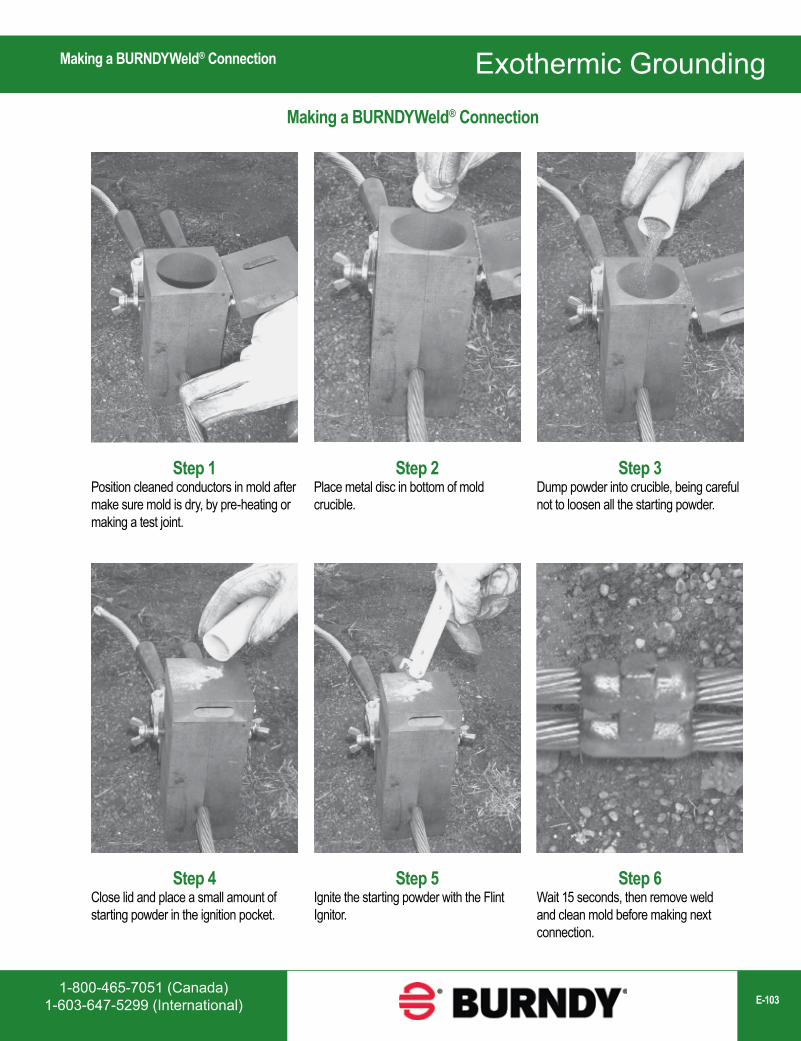
1-800-465-7051 (Canada)1-603-647-5299 (International) E-103
Exothermic Grounding
Step 1Position cleaned conductors in mold after make sure mold is dry, by pre-heating or making a test joint.
Step 6Wait 15 seconds, then remove weld and clean mold before making next connection.
Step 5Ignite the starting powder with the Flint Ignitor.
Step 4Close lid and place a small amount of starting powder in the ignition pocket.
Step 3Dump powder into crucible, being careful not to loosen all the starting powder.
Step 2Place metal disc in bottom of mold crucible.
Making a BURNDYWeld® Connection
Making a BURNDYWeld® Connection
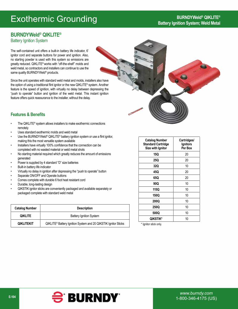
www.burndy.com1-800-346-4175 (US)E-104
Exothermic Grounding
Catalog Number Description
QIKLITE Battery Ignition System
QIKLITEKIT QIKLITE® Battery Ignition System and 20 QIKSTIK Ignitor Sticks
Catalog NumberStandard Cartridge
Size with Ignitor
Cartridges/IgnitorsPer Box
15Q 2025Q 2032Q 1045Q 2065Q 2090Q 10115Q 10150Q 10200Q 10250Q 10500Q 10
QIKSTIK* 10* Ignitor stick only.
BURNDYWeld® QIKLITE®
Battery Ignition System
The self-contained unit offers a built-in battery life indicator, 6’ ignitor cord and separate buttons for power and ignition. Also, no starting powder is used with this system so emissions are greatly reduced. QIKLITE® works with “off-the-shelf” molds and weld metal, so contractors and installers can continue to use the same quality BURNDYWeld® products.
Features & Benefits
• The QIKLITE® system allows installers to make exothermic connections remotely
• Uses standard exothermic molds and weld metal• Use the BURNDYWeld® QIKLITE® battery ignition system or use a flint ignitor,
making this the most versatile system available• Installers have virtually 100% confidence that the connection can be
completed with no wasted material or weld metal shots• No starting material required which greatly reduces the amount of emissions
generated• Power is supplied by 4 standard “D” size batteries• Built-in battery life indicator• Virtually no delay in ignition after depressing the “push to operate” button• Separate ON/OFF and Operate buttons• Comes complete with durable 6 foot heat resistant cord• Durable, long-lasting design• QIKSTIK ignitor sticks are conveniently packaged and available separately or
packaged complete with standard weld metal
BURNDYWeld® QIKLITE®
Battery Ignition System; Weld Metal
Since the unit operates with standard weld metal and molds, installers also have the option of using a traditional flint ignitor or the new QIKLITE® system. Another feature is the speed of ignition, with virtually no delay between depressing the “push to operate” button and ignition of the weld metal. This instant ignition feature offers quick reassurance to the installer, without the delay.
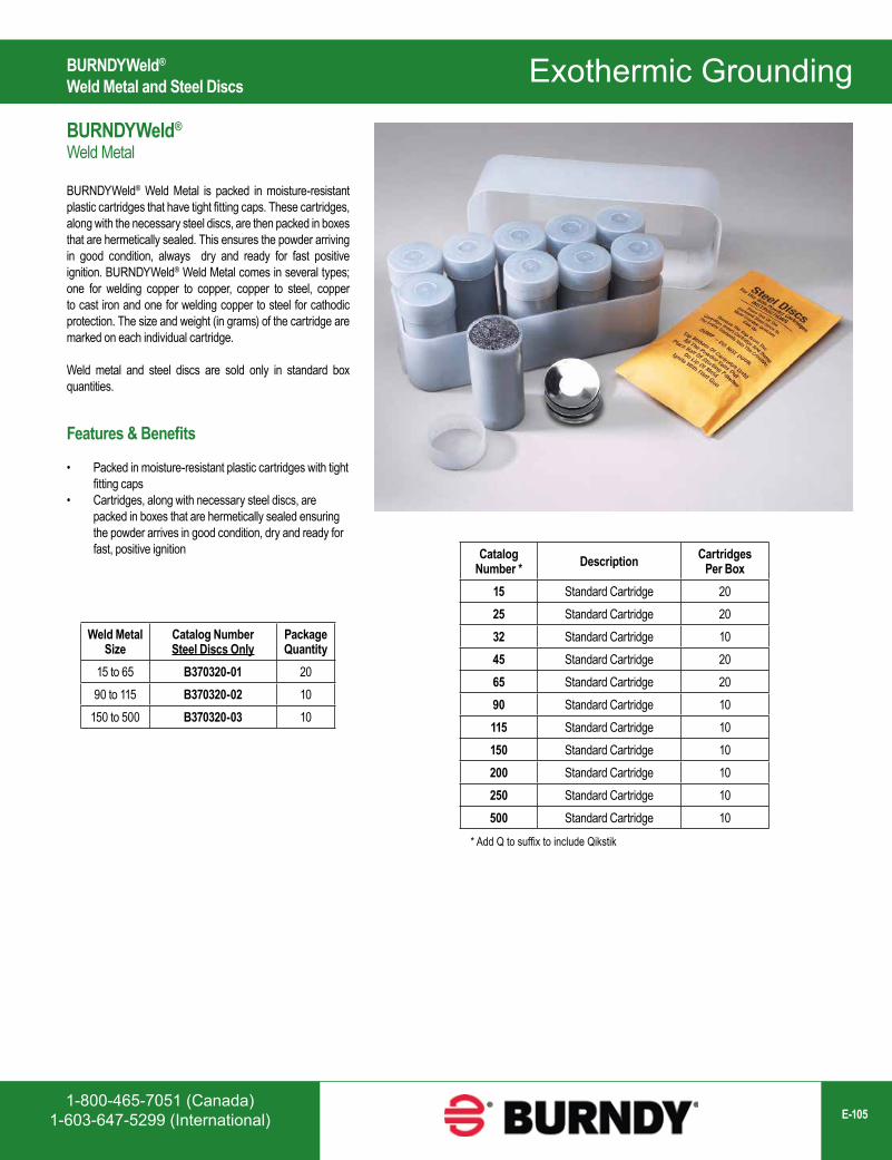
1-800-465-7051 (Canada)1-603-647-5299 (International) E-105
Exothermic Grounding
Catalog Number * Description Cartridges
Per Box15 Standard Cartridge 2025 Standard Cartridge 2032 Standard Cartridge 1045 Standard Cartridge 2065 Standard Cartridge 2090 Standard Cartridge 10115 Standard Cartridge 10150 Standard Cartridge 10200 Standard Cartridge 10250 Standard Cartridge 10500 Standard Cartridge 10
Weld Metal Size
Catalog NumberSteel Discs Only
Package Quantity
15 to 65 B370320-01 2090 to 115 B370320-02 10
150 to 500 B370320-03 10
* Add Q to suffix to include Qikstik
BURNDYWeld®
Weld Metal
BURNDYWeld® Weld Metal is packed in moisture-resistant plastic cartridges that have tight fitting caps. These cartridges, along with the necessary steel discs, are then packed in boxes that are hermetically sealed. This ensures the powder arriving in good condition, always dry and ready for fast positive ignition. BURNDYWeld® Weld Metal comes in several types; one for welding copper to copper, copper to steel, copper to cast iron and one for welding copper to steel for cathodic protection. The size and weight (in grams) of the cartridge are marked on each individual cartridge.
Weld metal and steel discs are sold only in standard box quantities.
Features & Benefits
• Packed in moisture-resistant plastic cartridges with tight fitting caps
• Cartridges, along with necessary steel discs, are packed in boxes that are hermetically sealed ensuring the powder arrives in good condition, dry and ready for fast, positive ignition
BURNDYWeld® Weld Metal and Steel Discs
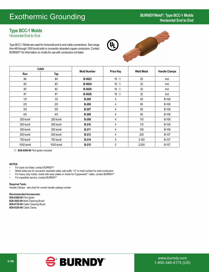
www.burndy.com1-800-346-4175 (US)E-106
Exothermic Grounding
CableMold Number Price Key Weld Metal Handle Clamps
Run Tap#4 #4 B-5623 18 25 Incl.#3 #3 B-5624 18 32 Incl.#2 #2 B-5625 18 32 Incl.#1 #1 B-5626 18 32 Incl.1/0 1/0 B-205 4 45 B-1062/0 2/0 B-206 4 65 B-1063/0 3/0 B-207 4 90 B-1064/0 4/0 B-208 4 90 B-106
250 kcmil 250 kcmil B-209 4 115 B-106300 kcmil 300 kcmil B-210 4 115 B-106350 kcmil 350 kcmil B-211 4 150 B-106500 kcmil 500 kcmil B-213 4 200 B-107750 kcmil 750 kcmil B-214 5 2-150 B-107
1000 kcmil 1000 kcmil B-215 5 2-200 B-107
1
1
1
1
B38-0309-00 Flint ignitor included1
NOTES:• For sizes not listed, contact BURNDY®
• Molds listed are for concentric stranded cable; add suffix “-S” to mold number for solid conductors• For heavy duty molds, molds with wear plates or molds for Copperweld ® cable, contact BURNDY®
• For expedited service, contact BURNDY®
Required Tools:Handle Clamps - see chart for correct handle catalog number
Recommended Accessories:B38-0309-00 Flint IgnitorB38-3922-00 Mold Cleaning BrushB38-0135-00 Cable Cleaning BrushB38-0330-00 Cable Clamp
BURNDYWeld®; Type BCC-1 MoldsHorizontal End to End
Type BCC-1 MoldsHorizontal End to End
Type BCC-1 Molds are used for horizontal end to end cable connections. Size range from #6 through 1000 kcmil solid or concentric stranded copper conductors. Contact BURNDY® for information on molds for use with conductors not listed.
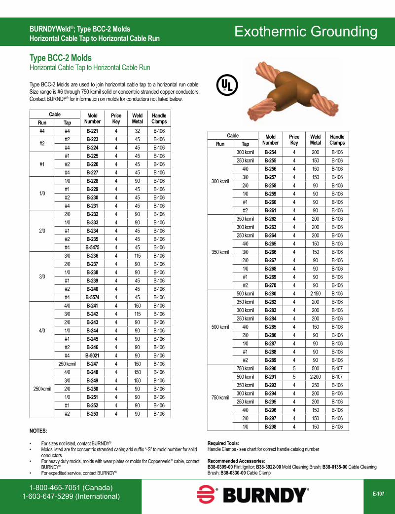
1-800-465-7051 (Canada)1-603-647-5299 (International) E-107
Exothermic Grounding
Cable Mold Number
Price Key
Weld Metal
Handle ClampsRun Tap
#4 #4 B-221 4 32 B-106
#2#2 B-223 4 45 B-106#4 B-224 4 45 B-106
#1#1 B-225 4 45 B-106#2 B-226 4 45 B-106#4 B-227 4 45 B-106
1/0
1/0 B-228 4 90 B-106#1 B-229 4 45 B-106#2 B-230 4 45 B-106#4 B-231 4 45 B-106
2/0
2/0 B-232 4 90 B-1061/0 B-333 4 90 B-106#1 B-234 4 45 B-106#2 B-235 4 45 B-106#4 B-5475 4 45 B-106
3/0
3/0 B-236 4 115 B-1062/0 B-237 4 90 B-1061/0 B-238 4 90 B-106#1 B-239 4 45 B-106#2 B-240 4 45 B-106#4 B-5574 4 45 B-106
4/0
4/0 B-241 4 150 B-1063/0 B-242 4 115 B-1062/0 B-243 4 90 B-1061/0 B-244 4 90 B-106#1 B-245 4 90 B-106#2 B-246 4 90 B-106#4 B-5021 4 90 B-106
250 kcmil
250 kcmil B-247 4 150 B-1064/0 B-248 4 150 B-1063/0 B-249 4 150 B-1062/0 B-250 4 90 B-1061/0 B-251 4 90 B-106#1 B-252 4 90 B-106#2 B-253 4 90 B-106
Cable Mold Number
Price Key
Weld Metal
Handle ClampsRun Tap
300 kcmil
300 kcmil B-254 4 200 B-106250 kcmil B-255 4 150 B-106
4/0 B-256 4 150 B-1063/0 B-257 4 150 B-1062/0 B-258 4 90 B-1061/0 B-259 4 90 B-106#1 B-260 4 90 B-106#2 B-261 4 90 B-106
350 kcmil
350 kcmil B-262 4 200 B-106300 kcmil B-263 4 200 B-106250 kcmil B-264 4 200 B-106
4/0 B-265 4 150 B-1063/0 B-266 4 150 B-1062/0 B-267 4 90 B-1061/0 B-268 4 90 B-106#1 B-269 4 90 B-106#2 B-270 4 90 B-106
500 kcmil
500 kcmil B-280 4 2-150 B-106350 kcmil B-282 4 200 B-106300 kcmil B-283 4 200 B-106250 kcmil B-284 4 200 B-106
4/0 B-285 4 150 B-1062/0 B-286 4 90 B-1061/0 B-287 4 90 B-106#1 B-288 4 90 B-106#2 B-289 4 90 B-106
750 kcmil
750 kcmil B-290 5 500 B-107500 kcmil B-291 5 2-200 B-107350 kcmil B-293 4 250 B-106300 kcmil B-294 4 200 B-106250 kcmil B-295 4 200 B-106
4/0 B-296 4 150 B-1062/0 B-297 4 150 B-1061/0 B-298 4 150 B-106
NOTES:
• For sizes not listed, contact BURNDY®
• Molds listed are for concentric stranded cable; add suffix “-S” to mold number for solid conductors
• For heavy duty molds, molds with wear plates or molds for Copperweld ® cable, contact BURNDY®
• For expedited service, contact BURNDY®
BURNDYWeld®; Type BCC-2 MoldsHorizontal Cable Tap to Horizontal Cable Run
Type BCC-2 MoldsHorizontal Cable Tap to Horizontal Cable Run
Type BCC-2 Molds are used to join horizontal cable tap to a horizontal run cable. Size range is #6 through 750 kcmil solid or concentric stranded copper conductors. Contact BURNDY® for information on molds for conductors not listed below.
Required Tools:Handle Clamps - see chart for correct handle catalog number
Recommended Accessories:B38-0309-00 Flint Ignitor; B38-3922-00 Mold Cleaning Brush; B38-0135-00 Cable Cleaning Brush; B38-0330-00 Cable Clamp
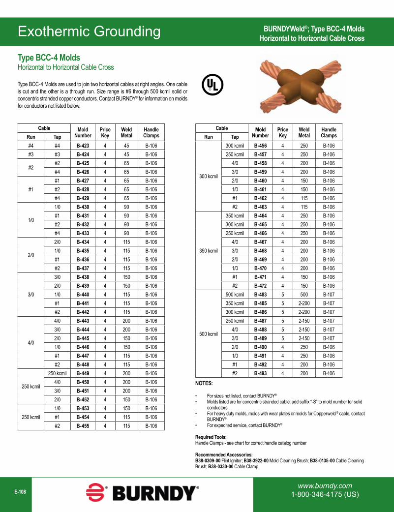
www.burndy.com1-800-346-4175 (US)E-108
Exothermic Grounding
Cable Mold Number
Price Key
Weld Metal
Handle ClampsRun Tap
#4 #4 B-423 4 45 B-106#3 #3 B-424 4 45 B-106
#2#2 B-425 4 65 B-106#4 B-426 4 65 B-106
#1#1 B-427 4 65 B-106#2 B-428 4 65 B-106#4 B-429 4 65 B-106
1/0
1/0 B-430 4 90 B-106#1 B-431 4 90 B-106#2 B-432 4 90 B-106#4 B-433 4 90 B-106
2/0
2/0 B-434 4 115 B-1061/0 B-435 4 115 B-106#1 B-436 4 115 B-106#2 B-437 4 115 B-106
3/0
3/0 B-438 4 150 B-1062/0 B-439 4 150 B-1061/0 B-440 4 115 B-106#1 B-441 4 115 B-106#2 B-442 4 115 B-106
4/0
4/0 B-443 4 200 B-1063/0 B-444 4 200 B-1062/0 B-445 4 150 B-1061/0 B-446 4 150 B-106#1 B-447 4 115 B-106#2 B-448 4 115 B-106
250 kcmil
250 kcmil B-449 4 200 B-1064/0 B-450 4 200 B-1063/0 B-451 4 200 B-1062/0 B-452 4 150 B-106
250 kcmil1/0 B-453 4 150 B-106#1 B-454 4 115 B-106#2 B-455 4 115 B-106
Cable Mold Number
Price Key
Weld Metal
Handle ClampsRun Tap
300 kcmil
300 kcmil B-456 4 250 B-106250 kcmil B-457 4 250 B-106
4/0 B-458 4 200 B-1063/0 B-459 4 200 B-1062/0 B-460 4 150 B-1061/0 B-461 4 150 B-106#1 B-462 4 115 B-106#2 B-463 4 115 B-106
350 kcmil
350 kcmil B-464 4 250 B-106300 kcmil B-465 4 250 B-106250 kcmil B-466 4 250 B-106
4/0 B-467 4 200 B-1063/0 B-468 4 200 B-1062/0 B-469 4 200 B-1061/0 B-470 4 200 B-106#1 B-471 4 150 B-106#2 B-472 4 150 B-106
500 kcmil
500 kcmil B-483 5 500 B-107350 kcmil B-485 5 2-200 B-107300 kcmil B-486 5 2-200 B-107250 kcmil B-487 5 2-150 B-107
4/0 B-488 5 2-150 B-1073/0 B-489 5 2-150 B-1072/0 B-490 4 250 B-1061/0 B-491 4 250 B-106#1 B-492 4 200 B-106#2 B-493 4 200 B-106
BURNDYWeld®; Type BCC-4 MoldsHorizontal to Horizontal Cable Cross
Type BCC-4 MoldsHorizontal to Horizontal Cable Cross
Type BCC-4 Molds are used to join two horizontal cables at right angles. One cable is cut and the other is a through run. Size range is #6 through 500 kcmil solid or concentric stranded copper conductors. Contact BURNDY® for information on molds for conductors not listed below.
NOTES:
• For sizes not listed, contact BURNDY®
• Molds listed are for concentric stranded cable; add suffix “-S” to mold number for solid conductors
• For heavy duty molds, molds with wear plates or molds for Copperweld ® cable, contact BURNDY®
• For expedited service, contact BURNDY®
Required Tools:Handle Clamps - see chart for correct handle catalog number
Recommended Accessories:B38-0309-00 Flint Ignitor; B38-3922-00 Mold Cleaning Brush; B38-0135-00 Cable Cleaning Brush; B38-0330-00 Cable Clamp

1-800-465-7051 (Canada)1-603-647-5299 (International) E-109
Exothermic Grounding
Cable Mold Number
Price Key
Weld Metal
Handle ClampsRun Tap
#6 #6 B-5432 19 45 Incl.#4 #4 B-2687 4 65 B-106
#2#2 B-2689 4 90 B-106#4 B-2690 4 65 B-106
#1#1 B-2691 4 115 B-106#2 B-2692 4 90 B-106#4 B-2693 4 90 B-106
1/0
1/0 B-2694 22 150 B-106#1 B-2695 22 150 B-106#2 B-2696 22 115 B-106#4 B-2697 22 115 B-106
2/0
2/0 B-2698 22 200 B-1061/0 B-2699 22 200 B-106#1 B-2700 22 150 B-106#2 B-2701 22 150 B-106
3/0
3/0 B-2702 22 250 B-1062/0 B-2703 22 200 B-1061/0 B-2704 22 200 B-106#1 B-2705 22 150 B-106#2 B-2706 22 150 B-106
4/0
4/0 B-2707 22 250 B-1063/0 B-2708 22 250 B-1062/0 B-2709 22 200 B-1061/0 B-2710 22 200 B-106#1 B-2711 22 150 B-106#2 B-2712 22 150 B-106
Cable Mold Number
Price Key
Weld Metal
Handle ClampsRun Tap
250 kcmil
250 kcmil B-2713 22 2-150 B-1064/0 B-2714 22 2-150 B-1063/0 B-2715 22 2-150 B-1062/0 B-2716 22 250 B-1061/0 B-2717 22 150 B-106#1 B-2718 22 200 B-106#2 B-2719 22 150 B-106
500 kcmil
500 kcmil B-2747 23 3-250 B-107250 kcmil B-2751 23 500 B-107
4/0 B-2752 23 500 B-1073/0 B-2753 23 500 B-1072/0 B-2754 23 2-200 B-1071/0 B-2755 22 2-150 B-106#1 B-2756 22 250 B-106#2 B-2757 22 250 B-106
NOTES:
• For sizes not listed, contact BURNDY®
• Molds listed are for concentric stranded cable; add suffix “-S” to mold number for solid conductors
• For heavy duty molds, molds with wear plates or molds for Copperweld ® cable, contact BURNDY®
• For expedited service, contact BURNDY®
Required Tools:Handle Clamps - see chart for correct handle catalog number
Recommended Accessories:B38-0309-00 Flint Ignitor; B38-3922-00 Mold Cleaning Brush; B38-0135-00 Cable Cleaning Brush; B38-0330-00 Cable Clamp
BURNDYWeld®; Type BCC-11 MoldsHorizontal to Horizontal Cable Cross
Type BCC-11 MoldsHorizontal to Horizontal Cable Cross
Type BCC-11 Molds are used to join uncut horizontal cables at right angles to each other. Size range is #6 through 500 kcmil solid or concentric stranded copper conductors. Contact BURNDY® for information on molds for conductors not listed below.
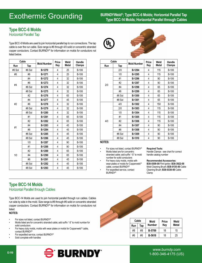
www.burndy.com1-800-346-4175 (US)E-110
Exothermic Grounding
CableMold Number Price
KeyWeld Metal
Handle ClampsRun Tap
#6 Sol #6 Sol B-1270 4 25 B-106#6 #6 B-1271 4 25 B-106
#4
#4 B-1272 4 32 B-106#6 B-1273 4 32 B-106
#6 Sol B-1274 4 32 B-106#8 Sol B-1275 4 32 B-106
#2
#2 B-1276 4 65 B-106#4 B-1277 4 45 B-106#6 B-1278 4 32 B-106
#6 Sol B-1279 4 32 B-106#8 Sol B-1280 4 32 B-106
#1
#1 B-1281 4 65 B-106#2 B-1282 4 65 B-106#4 B-1283 4 45 B-106#6 B-1284 4 45 B-106
#6 Sol B-1285 4 45 B-106#8 Sol B-1286 4 45 B-106
1/0
1/0 B-1287 4 90 B-106#1 B-1288 4 90 B-106#2 B-1289 4 65 B-106#4 B-1290 4 65 B-106#6 B-1291 4 45 B-106
#6 Sol B-1292 4 45 B-106#8 Sol B-1293 4 45 B-106
CableMold Number Price
KeyWeld Metal
Handle ClampsRun Tap
2/0
2/0 B-1294 4 115 B-1061/0 B-1295 4 115 B-106#1 B-1296 4 90 B-106#2 B-1297 4 90 B-106#4 B-1298 4 65 B-106#6 B-1299 4 65 B-106
#6 Sol B-1300 4 65 B-106#8 Sol B-1301 4 65 B-106
4/0
4/0 B-1302 4 150 B-1062/0 B-1303 4 115 B-1061/0 B-1304 4 115 B-106#1 B-1305 4 115 B-106#2 B-1306 4 115 B-106#4 B-1307 4 90 B-106#6 B-1308 4 90 B-106
#6 Sol B-1309 4 90 B-106#8 Sol B-1310 4 90 B-106
Cable Mold Number
Price Key
Weld MetalRun Tap
#8 #8 B-5709 18 15#6 #6 B-5618 18 25
NOTES:
• For sizes not listed, contact BURNDY®
• Molds listed are for concentric stranded cable; add suffix “-S” to mold number for solid conductors
• For heavy duty molds, molds with wear plates or molds for Copperweld ® cable, contact BURNDY®
• For expedited service, contact BURNDY®
NOTES:
• For sizes not listed, contact BURNDY®
• Molds listed are for concentric stranded cable; add suffix “-S” to mold number for solid conductors
• For heavy duty molds, molds with wear plates or molds for Copperweld ® cable, contact BURNDY®
• For expedited service, contact BURNDY®
• Sold complete with handles
BURNDYWeld®; Type BCC-6 Molds; Horizontal Parallel TapType BCC-14 Molds; Horizontal Parallel through Cables
Type BCC-6 MoldsHorizontal Parallel Tap
Type BCC-6 Molds are used to join horizontal parallel tap to run connections. The tap cable is over the run cable. Size range is #6 through 4/0 solid or concentric stranded copper conductors. Contact BURNDY® for information on molds for conductors not listed below.
Type BCC-14 MoldsHorizontal Parallel through Cables
Type BCC-14 Molds are used to join horizontal parallel through run cables. Cables run side by side in the mold. Size range is #8 through #6 solid or concentric stranded copper conductors. Contact BURNDY® for information on molds for conductors not listed.
Required Tools:Handle Clamps - see chart for correct handle catalog number
Recommended Accessories:B38-0309-00 Flint Ignitor; B38-3922-00 Mold Cleaning Brush; B38-0135-00 Cable Cleaning Brush; B38-0330-00 Cable Clamp
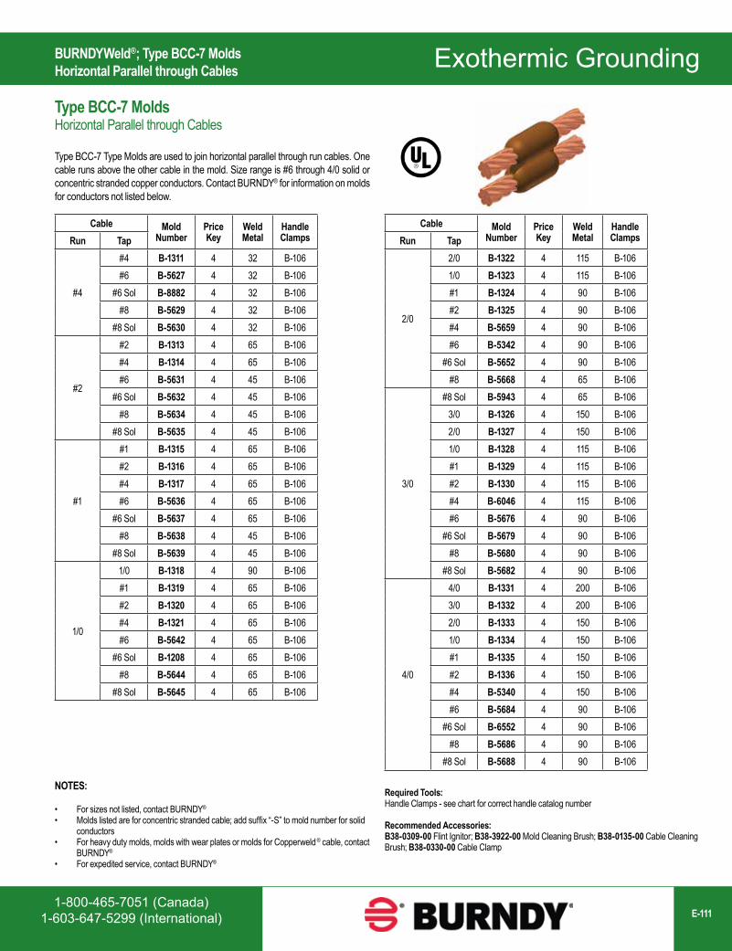
1-800-465-7051 (Canada)1-603-647-5299 (International) E-111
Exothermic Grounding
Cable Mold Number
Price Key
Weld Metal
Handle ClampsRun Tap
#4
#4 B-1311 4 32 B-106#6 B-5627 4 32 B-106
#6 Sol B-8882 4 32 B-106#8 B-5629 4 32 B-106
#8 Sol B-5630 4 32 B-106
#2
#2 B-1313 4 65 B-106#4 B-1314 4 65 B-106#6 B-5631 4 45 B-106
#6 Sol B-5632 4 45 B-106#8 B-5634 4 45 B-106
#8 Sol B-5635 4 45 B-106
#1
#1 B-1315 4 65 B-106#2 B-1316 4 65 B-106#4 B-1317 4 65 B-106#6 B-5636 4 65 B-106
#6 Sol B-5637 4 65 B-106#8 B-5638 4 45 B-106
#8 Sol B-5639 4 45 B-106
1/0
1/0 B-1318 4 90 B-106#1 B-1319 4 65 B-106#2 B-1320 4 65 B-106#4 B-1321 4 65 B-106#6 B-5642 4 65 B-106
#6 Sol B-1208 4 65 B-106#8 B-5644 4 65 B-106
#8 Sol B-5645 4 65 B-106
Cable Mold Number
Price Key
Weld Metal
Handle ClampsRun Tap
2/0
2/0 B-1322 4 115 B-1061/0 B-1323 4 115 B-106#1 B-1324 4 90 B-106#2 B-1325 4 90 B-106#4 B-5659 4 90 B-106#6 B-5342 4 90 B-106
#6 Sol B-5652 4 90 B-106#8 B-5668 4 65 B-106
3/0
#8 Sol B-5943 4 65 B-1063/0 B-1326 4 150 B-1062/0 B-1327 4 150 B-1061/0 B-1328 4 115 B-106#1 B-1329 4 115 B-106#2 B-1330 4 115 B-106#4 B-6046 4 115 B-106#6 B-5676 4 90 B-106
#6 Sol B-5679 4 90 B-106#8 B-5680 4 90 B-106
#8 Sol B-5682 4 90 B-106
4/0
4/0 B-1331 4 200 B-1063/0 B-1332 4 200 B-1062/0 B-1333 4 150 B-1061/0 B-1334 4 150 B-106#1 B-1335 4 150 B-106#2 B-1336 4 150 B-106#4 B-5340 4 150 B-106#6 B-5684 4 90 B-106
#6 Sol B-6552 4 90 B-106#8 B-5686 4 90 B-106
#8 Sol B-5688 4 90 B-106
NOTES:
• For sizes not listed, contact BURNDY®
• Molds listed are for concentric stranded cable; add suffix “-S” to mold number for solid conductors
• For heavy duty molds, molds with wear plates or molds for Copperweld ® cable, contact BURNDY®
• For expedited service, contact BURNDY®
BURNDYWeld®; Type BCC-7 MoldsHorizontal Parallel through Cables
Type BCC-7 MoldsHorizontal Parallel through Cables
Type BCC-7 Type Molds are used to join horizontal parallel through run cables. One cable runs above the other cable in the mold. Size range is #6 through 4/0 solid or concentric stranded copper conductors. Contact BURNDY® for information on molds for conductors not listed below.
Required Tools:Handle Clamps - see chart for correct handle catalog number
Recommended Accessories:B38-0309-00 Flint Ignitor; B38-3922-00 Mold Cleaning Brush; B38-0135-00 Cable Cleaning Brush; B38-0330-00 Cable Clamp
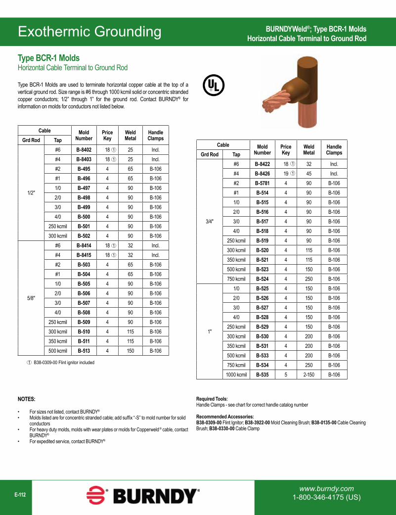
www.burndy.com1-800-346-4175 (US)E-112
Exothermic Grounding
Cable Mold Number
Price Key
Weld Metal
Handle ClampsGrd Rod Tap
1/2"
#6 B-8402 18 25 Incl.#4 B-8403 18 25 Incl.#2 B-495 4 65 B-106#1 B-496 4 65 B-1061/0 B-497 4 90 B-1062/0 B-498 4 90 B-1063/0 B-499 4 90 B-1064/0 B-500 4 90 B-106
250 kcmil B-501 4 90 B-106300 kcmil B-502 4 90 B-106
5/8"
#6 B-8414 18 32 Incl.#4 B-8415 18 32 Incl.#2 B-503 4 65 B-106#1 B-504 4 65 B-1061/0 B-505 4 90 B-1062/0 B-506 4 90 B-1063/0 B-507 4 90 B-1064/0 B-508 4 90 B-106
250 kcmil B-509 4 90 B-106300 kcmil B-510 4 115 B-106350 kcmil B-511 4 115 B-106500 kcmil B-513 4 150 B-106
B38-0309-00 Flint ignitor included1
1
1
1
1
NOTES:
• For sizes not listed, contact BURNDY®
• Molds listed are for concentric stranded cable; add suffix “-S” to mold number for solid conductors
• For heavy duty molds, molds with wear plates or molds for Copperweld ® cable, contact BURNDY®
• For expedited service, contact BURNDY®
Cable Mold Number
Price Key
Weld Metal
Handle ClampsGrd Rod Tap
3/4"
#6 B-8422 18 32 Incl.#4 B-8426 19 45 Incl.#2 B-5781 4 90 B-106#1 B-514 4 90 B-1061/0 B-515 4 90 B-1062/0 B-516 4 90 B-1063/0 B-517 4 90 B-1064/0 B-518 4 90 B-106
250 kcmil B-519 4 90 B-106300 kcmil B-520 4 115 B-106350 kcmil B-521 4 115 B-106500 kcmil B-523 4 150 B-106750 kcmil B-524 4 250 B-106
1"
1/0 B-525 4 150 B-1062/0 B-526 4 150 B-1063/0 B-527 4 150 B-1064/0 B-528 4 150 B-106
250 kcmil B-529 4 150 B-106300 kcmil B-530 4 200 B-106350 kcmil B-531 4 200 B-106500 kcmil B-533 4 200 B-106750 kcmil B-534 4 250 B-106
1000 kcmil B-535 5 2-150 B-106
1
1
BURNDYWeld®; Type BCR-1 MoldsHorizontal Cable Terminal to Ground Rod
Type BCR-1 MoldsHorizontal Cable Terminal to Ground Rod
Type BCR-1 Molds are used to terminate horizontal copper cable at the top of a vertical ground rod. Size range is #6 through 1000 kcmil solid or concentric stranded copper conductors; 1/2” through 1” for the ground rod. Contact BURNDY® for information on molds for conductors not listed below.
Required Tools:Handle Clamps - see chart for correct handle catalog number
Recommended Accessories:B38-0309-00 Flint Ignitor; B38-3922-00 Mold Cleaning Brush; B38-0135-00 Cable Cleaning Brush; B38-0330-00 Cable Clamp
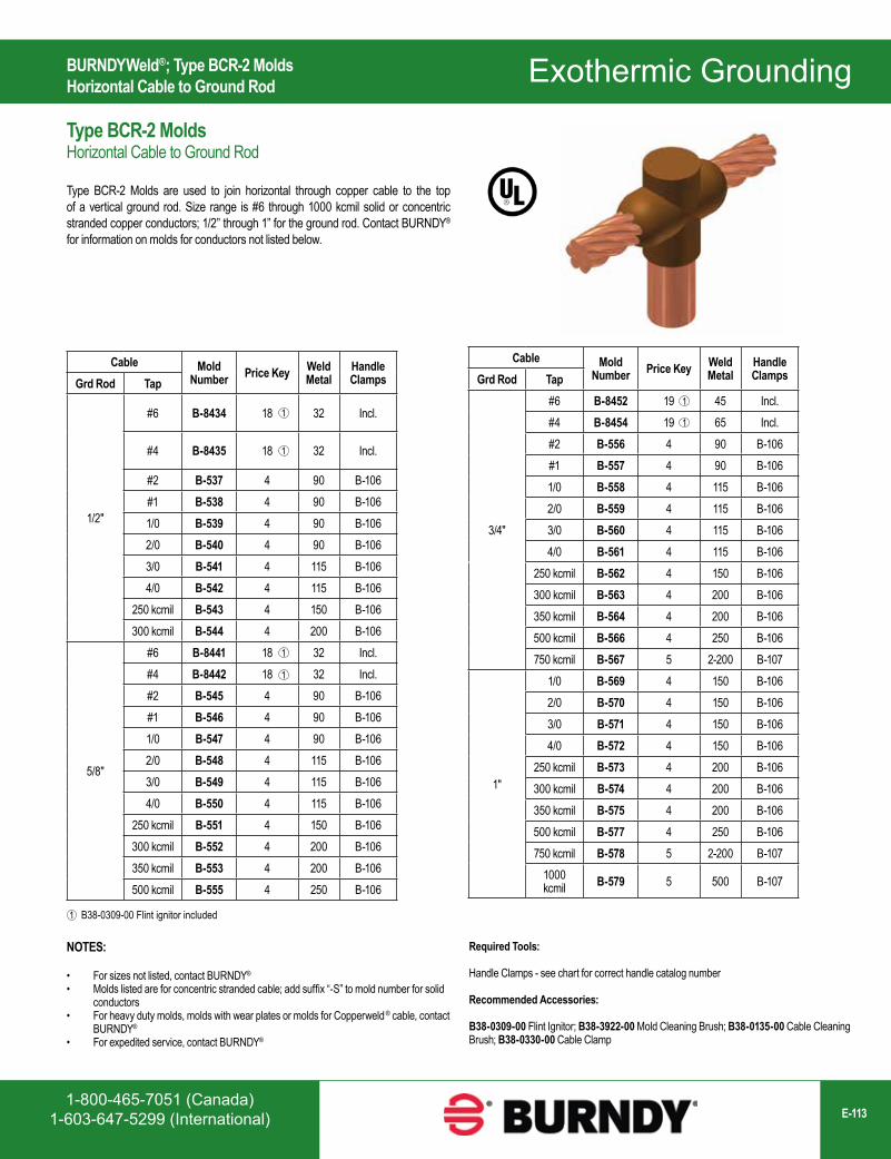
1-800-465-7051 (Canada)1-603-647-5299 (International) E-113
Exothermic Grounding
Cable Mold Number Price Key Weld
MetalHandle ClampsGrd Rod Tap
3/4"
#6 B-8452 19 45 Incl.#4 B-8454 19 65 Incl.#2 B-556 4 90 B-106#1 B-557 4 90 B-1061/0 B-558 4 115 B-1062/0 B-559 4 115 B-1063/0 B-560 4 115 B-1064/0 B-561 4 115 B-106
250 kcmil B-562 4 150 B-106300 kcmil B-563 4 200 B-106350 kcmil B-564 4 200 B-106500 kcmil B-566 4 250 B-106750 kcmil B-567 5 2-200 B-107
1"
1/0 B-569 4 150 B-1062/0 B-570 4 150 B-1063/0 B-571 4 150 B-1064/0 B-572 4 150 B-106
250 kcmil B-573 4 200 B-106300 kcmil B-574 4 200 B-106350 kcmil B-575 4 200 B-106500 kcmil B-577 4 250 B-106750 kcmil B-578 5 2-200 B-107
1000 kcmil B-579 5 500 B-107
1
1
Cable Mold Number Price Key Weld
MetalHandle ClampsGrd Rod Tap
1/2"
#6 B-8434 18 32 Incl.
#4 B-8435 18 32 Incl.
#2 B-537 4 90 B-106#1 B-538 4 90 B-1061/0 B-539 4 90 B-1062/0 B-540 4 90 B-1063/0 B-541 4 115 B-1064/0 B-542 4 115 B-106
250 kcmil B-543 4 150 B-106300 kcmil B-544 4 200 B-106
5/8"
#6 B-8441 18 32 Incl.#4 B-8442 18 32 Incl.#2 B-545 4 90 B-106#1 B-546 4 90 B-1061/0 B-547 4 90 B-1062/0 B-548 4 115 B-1063/0 B-549 4 115 B-1064/0 B-550 4 115 B-106
250 kcmil B-551 4 150 B-106300 kcmil B-552 4 200 B-106350 kcmil B-553 4 200 B-106500 kcmil B-555 4 250 B-106
1
1
1
1
1
B38-0309-00 Flint ignitor included
NOTES:
• For sizes not listed, contact BURNDY®
• Molds listed are for concentric stranded cable; add suffix “-S” to mold number for solid conductors
• For heavy duty molds, molds with wear plates or molds for Copperweld ® cable, contact BURNDY®
• For expedited service, contact BURNDY®
BURNDYWeld®; Type BCR-2 MoldsHorizontal Cable to Ground Rod
Type BCR-2 MoldsHorizontal Cable to Ground Rod
Type BCR-2 Molds are used to join horizontal through copper cable to the top of a vertical ground rod. Size range is #6 through 1000 kcmil solid or concentric stranded copper conductors; 1/2” through 1” for the ground rod. Contact BURNDY® for information on molds for conductors not listed below.
Required Tools:
Handle Clamps - see chart for correct handle catalog number
Recommended Accessories:
B38-0309-00 Flint Ignitor; B38-3922-00 Mold Cleaning Brush; B38-0135-00 Cable Cleaning Brush; B38-0330-00 Cable Clamp
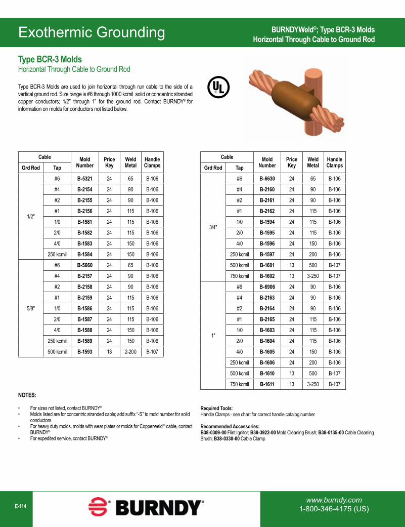
www.burndy.com1-800-346-4175 (US)E-114
Exothermic Grounding
Cable Mold Number
Price Key
Weld Metal
Handle ClampsGrd Rod Tap
1/2"
#6 B-5321 24 65 B-106
#4 B-2154 24 90 B-106
#2 B-2155 24 90 B-106
#1 B-2156 24 115 B-106
1/0 B-1581 24 115 B-106
2/0 B-1582 24 115 B-106
4/0 B-1583 24 150 B-106
250 kcmil B-1584 24 150 B-106
5/8"
#6 B-5660 24 65 B-106
#4 B-2157 24 90 B-106
#2 B-2158 24 90 B-106
#1 B-2159 24 115 B-106
1/0 B-1586 24 115 B-106
2/0 B-1587 24 115 B-106
4/0 B-1588 24 150 B-106
250 kcmil B-1589 24 150 B-106
500 kcmil B-1593 13 2-200 B-107
Cable Mold Number
Price Key
Weld Metal
Handle ClampsGrd Rod Tap
3/4"
#6 B-6630 24 65 B-106
#4 B-2160 24 90 B-106
#2 B-2161 24 90 B-106
#1 B-2162 24 115 B-106
1/0 B-1594 24 115 B-106
2/0 B-1595 24 115 B-106
4/0 B-1596 24 150 B-106
250 kcmil B-1597 24 200 B-106
500 kcmil B-1601 13 500 B-107
750 kcmil B-1602 13 3-250 B-107
1"
#6 B-6906 24 90 B-106
#4 B-2163 24 90 B-106
#2 B-2164 24 90 B-106
#1 B-2165 24 115 B-106
1/0 B-1603 24 115 B-106
2/0 B-1604 24 115 B-106
4/0 B-1605 24 150 B-106
250 kcmil B-1606 24 200 B-106
500 kcmil B-1610 13 500 B-107
750 kcmil B-1611 13 3-250 B-107
NOTES:
• For sizes not listed, contact BURNDY®
• Molds listed are for concentric stranded cable; add suffix “-S” to mold number for solid conductors
• For heavy duty molds, molds with wear plates or molds for Copperweld ® cable, contact BURNDY®
• For expedited service, contact BURNDY®
BURNDYWeld®; Type BCR-3 MoldsHorizontal Through Cable to Ground Rod
Type BCR-3 MoldsHorizontal Through Cable to Ground Rod
Type BCR-3 Molds are used to join horizontal through run cable to the side of a vertical ground rod. Size range is #6 through 1000 kcmil solid or concentric stranded copper conductors; 1/2” through 1” for the ground rod. Contact BURNDY® for information on molds for conductors not listed below.
Required Tools:Handle Clamps - see chart for correct handle catalog number
Recommended Accessories:B38-0309-00 Flint Ignitor; B38-3922-00 Mold Cleaning Brush; B38-0135-00 Cable Cleaning Brush; B38-0330-00 Cable Clamp
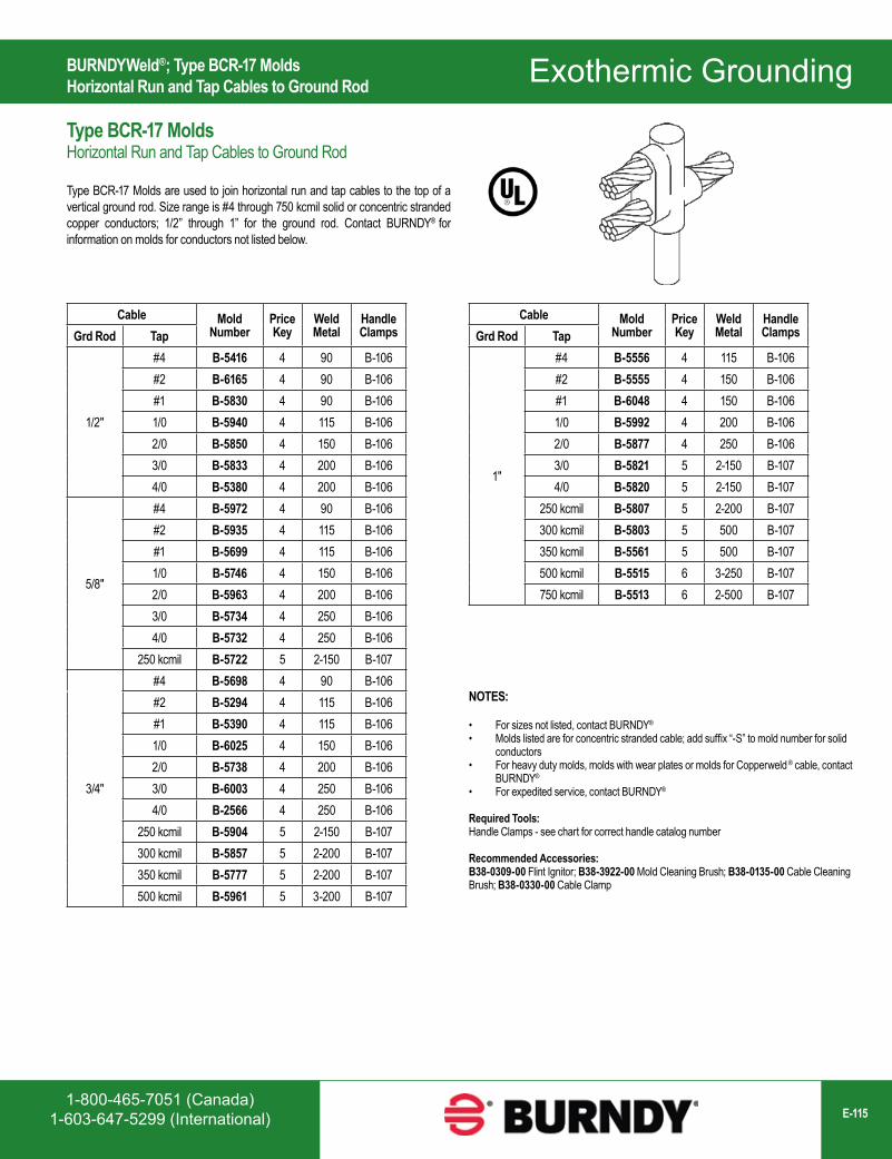
1-800-465-7051 (Canada)1-603-647-5299 (International) E-115
Exothermic Grounding
Cable Mold Number
Price Key
Weld Metal
Handle ClampsGrd Rod Tap
1/2"
#4 B-5416 4 90 B-106#2 B-6165 4 90 B-106#1 B-5830 4 90 B-1061/0 B-5940 4 115 B-1062/0 B-5850 4 150 B-1063/0 B-5833 4 200 B-1064/0 B-5380 4 200 B-106
5/8"
#4 B-5972 4 90 B-106#2 B-5935 4 115 B-106#1 B-5699 4 115 B-1061/0 B-5746 4 150 B-1062/0 B-5963 4 200 B-1063/0 B-5734 4 250 B-1064/0 B-5732 4 250 B-106
250 kcmil B-5722 5 2-150 B-107
3/4"
#4 B-5698 4 90 B-106#2 B-5294 4 115 B-106#1 B-5390 4 115 B-1061/0 B-6025 4 150 B-1062/0 B-5738 4 200 B-1063/0 B-6003 4 250 B-1064/0 B-2566 4 250 B-106
250 kcmil B-5904 5 2-150 B-107300 kcmil B-5857 5 2-200 B-107350 kcmil B-5777 5 2-200 B-107500 kcmil B-5961 5 3-200 B-107
Cable Mold Number
Price Key
Weld Metal
Handle ClampsGrd Rod Tap
1"
#4 B-5556 4 115 B-106#2 B-5555 4 150 B-106#1 B-6048 4 150 B-1061/0 B-5992 4 200 B-1062/0 B-5877 4 250 B-1063/0 B-5821 5 2-150 B-1074/0 B-5820 5 2-150 B-107
250 kcmil B-5807 5 2-200 B-107300 kcmil B-5803 5 500 B-107350 kcmil B-5561 5 500 B-107500 kcmil B-5515 6 3-250 B-107750 kcmil B-5513 6 2-500 B-107
NOTES:
• For sizes not listed, contact BURNDY®
• Molds listed are for concentric stranded cable; add suffix “-S” to mold number for solid conductors
• For heavy duty molds, molds with wear plates or molds for Copperweld ® cable, contact BURNDY®
• For expedited service, contact BURNDY®
Required Tools:Handle Clamps - see chart for correct handle catalog number
Recommended Accessories:B38-0309-00 Flint Ignitor; B38-3922-00 Mold Cleaning Brush; B38-0135-00 Cable Cleaning Brush; B38-0330-00 Cable Clamp
BURNDYWeld®; Type BCR-17 MoldsHorizontal Run and Tap Cables to Ground Rod
Type BCR-17 MoldsHorizontal Run and Tap Cables to Ground Rod
Type BCR-17 Molds are used to join horizontal run and tap cables to the top of a vertical ground rod. Size range is #4 through 750 kcmil solid or concentric stranded copper conductors; 1/2” through 1” for the ground rod. Contact BURNDY® for information on molds for conductors not listed below.
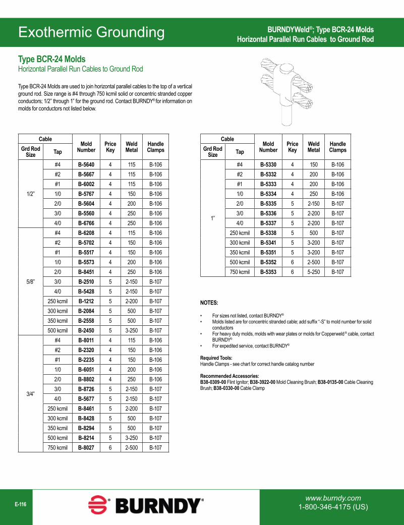
www.burndy.com1-800-346-4175 (US)E-116
Exothermic Grounding
CableMold
NumberPrice Key
Weld Metal
Handle ClampsGrd Rod
Size Tap
1/2”
#4 B-5640 4 115 B-106#2 B-5667 4 115 B-106#1 B-6002 4 115 B-1061/0 B-5767 4 150 B-1062/0 B-5604 4 200 B-1063/0 B-5560 4 250 B-1064/0 B-6766 4 250 B-106
5/8”
#4 B-6208 4 115 B-106#2 B-5702 4 150 B-106#1 B-5517 4 150 B-1061/0 B-5573 4 200 B-1062/0 B-8451 4 250 B-1063/0 B-2510 5 2-150 B-1074/0 B-5428 5 2-150 B-107
250 kcmil B-1212 5 2-200 B-107300 kcmil B-2084 5 500 B-107350 kcmil B-2558 5 500 B-107500 kcmil B-2450 5 3-250 B-107
3/4”
#4 B-8011 4 115 B-106#2 B-2320 4 150 B-106#1 B-2235 4 150 B-1061/0 B-6051 4 200 B-1062/0 B-8802 4 250 B-1063/0 B-8726 5 2-150 B-1074/0 B-5677 5 2-150 B-107
250 kcmil B-8461 5 2-200 B-107300 kcmil B-8428 5 500 B-107350 kcmil B-8294 5 500 B-107500 kcmil B-8214 5 3-250 B-107750 kcmil B-8027 6 2-500 B-107
CableMold
NumberPrice Key
Weld Metal
Handle ClampsGrd Rod
Size Tap
1”
#4 B-5330 4 150 B-106#2 B-5332 4 200 B-106#1 B-5333 4 200 B-1061/0 B-5334 4 250 B-1062/0 B-5335 5 2-150 B-1073/0 B-5336 5 2-200 B-1074/0 B-5337 5 2-200 B-107
250 kcmil B-5338 5 500 B-107300 kcmil B-5341 5 3-200 B-107350 kcmil B-5351 5 3-200 B-107500 kcmil B-5352 6 2-500 B-107750 kcmil B-5353 6 5-250 B-107
NOTES:
• For sizes not listed, contact BURNDY®
• Molds listed are for concentric stranded cable; add suffix “-S” to mold number for solid conductors
• For heavy duty molds, molds with wear plates or molds for Copperweld ® cable, contact BURNDY®
• For expedited service, contact BURNDY®
Required Tools:Handle Clamps - see chart for correct handle catalog number
Recommended Accessories:B38-0309-00 Flint Ignitor; B38-3922-00 Mold Cleaning Brush; B38-0135-00 Cable Cleaning Brush; B38-0330-00 Cable Clamp
BURNDYWeld®; Type BCR-24 MoldsHorizontal Parallel Run Cables to Ground Rod
Type BCR-24 MoldsHorizontal Parallel Run Cables to Ground Rod
Type BCR-24 Molds are used to join horizontal parallel cables to the top of a vertical ground rod. Size range is #4 through 750 kcmil solid or concentric stranded copper conductors; 1/2” through 1” for the ground rod. Contact BURNDY® for information on molds for conductors not listed below.
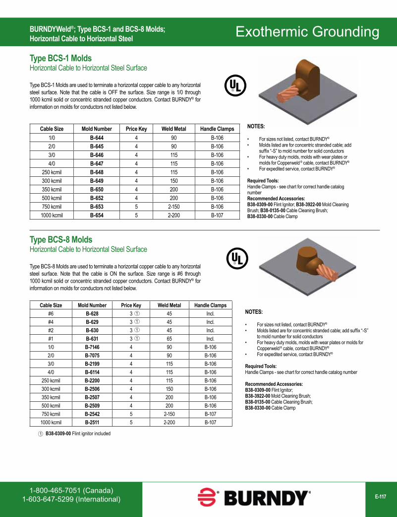
1-800-465-7051 (Canada)1-603-647-5299 (International) E-117
Exothermic Grounding
B38-0309-00 Flint ignitor included1
Cable Size Mold Number Price Key Weld Metal Handle Clamps#6 B-628 3 45 Incl.#4 B-629 3 45 Incl.#2 B-630 3 45 Incl.#1 B-631 3 65 Incl.1/0 B-7146 4 90 B-1062/0 B-7075 4 90 B-1063/0 B-2199 4 115 B-1064/0 B-6114 4 115 B-106
250 kcmil B-2200 4 115 B-106300 kcmil B-2506 4 150 B-106350 kcmil B-2507 4 200 B-106500 kcmil B-2509 4 200 B-106750 kcmil B-2542 5 2-150 B-107
1000 kcmil B-2511 5 2-200 B-107
11
1
1
NOTES:
• For sizes not listed, contact BURNDY®
• Molds listed are for concentric stranded cable; add suffix “-S” to mold number for solid conductors
• For heavy duty molds, molds with wear plates or molds for Copperweld ® cable, contact BURNDY®
• For expedited service, contact BURNDY®
Required Tools:Handle Clamps - see chart for correct handle catalog number
Recommended Accessories:B38-0309-00 Flint Ignitor; B38-3922-00 Mold Cleaning Brush; B38-0135-00 Cable Cleaning Brush; B38-0330-00 Cable Clamp
BURNDYWeld®; Type BCS-1 and BCS-8 Molds; Horizontal Cable to Horizontal Steel
Type BCS-1 MoldsHorizontal Cable to Horizontal Steel Surface
Type BCS-1 Molds are used to terminate a horizontal copper cable to any horizontal steel surface. Note that the cable is OFF the surface. Size range is 1/0 through 1000 kcmil solid or concentric stranded copper conductors. Contact BURNDY® for information on molds for conductors not listed below.
Cable Size Mold Number Price Key Weld Metal Handle Clamps1/0 B-644 4 90 B-1062/0 B-645 4 90 B-1063/0 B-646 4 115 B-1064/0 B-647 4 115 B-106
250 kcmil B-648 4 115 B-106300 kcmil B-649 4 150 B-106350 kcmil B-650 4 200 B-106500 kcmil B-652 4 200 B-106750 kcmil B-653 5 2-150 B-106
1000 kcmil B-654 5 2-200 B-107
Type BCS-8 MoldsHorizontal Cable to Horizontal Steel Surface
Type BCS-8 Molds are used to terminate a horizontal copper cable to any horizontal steel surface. Note that the cable is ON the surface. Size range is #6 through 1000 kcmil solid or concentric stranded copper conductors. Contact BURNDY® for information on molds for conductors not listed below.
NOTES:
• For sizes not listed, contact BURNDY®
• Molds listed are for concentric stranded cable; add suffix “-S” to mold number for solid conductors
• For heavy duty molds, molds with wear plates or molds for Copperweld ® cable, contact BURNDY®
• For expedited service, contact BURNDY®
Required Tools:Handle Clamps - see chart for correct handle catalog numberRecommended Accessories:B38-0309-00 Flint Ignitor; B38-3922-00 Mold Cleaning Brush; B38-0135-00 Cable Cleaning Brush; B38-0330-00 Cable Clamp
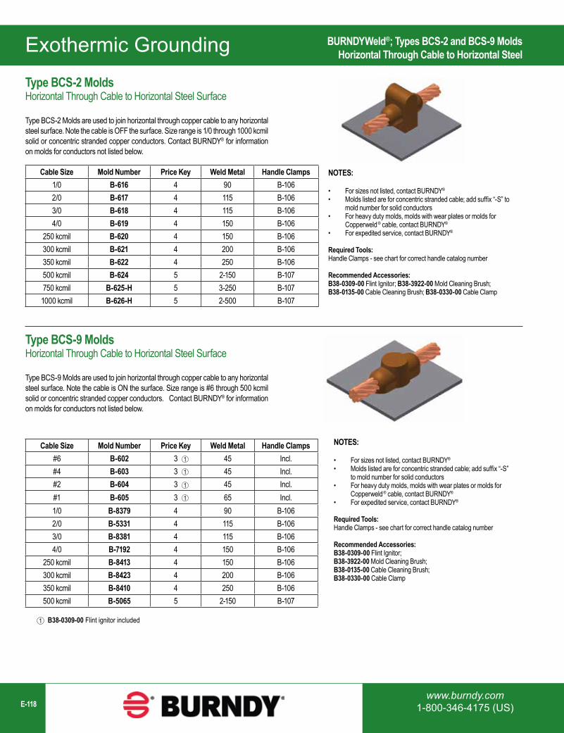
www.burndy.com1-800-346-4175 (US)E-118
Exothermic Grounding
Cable Size Mold Number Price Key Weld Metal Handle Clamps1/0 B-616 4 90 B-1062/0 B-617 4 115 B-1063/0 B-618 4 115 B-1064/0 B-619 4 150 B-106
250 kcmil B-620 4 150 B-106300 kcmil B-621 4 200 B-106350 kcmil B-622 4 250 B-106500 kcmil B-624 5 2-150 B-107750 kcmil B-625-H 5 3-250 B-107
1000 kcmil B-626-H 5 2-500 B-107
Cable Size Mold Number Price Key Weld Metal Handle Clamps#6 B-602 3 45 Incl.#4 B-603 3 45 Incl.#2 B-604 3 45 Incl.#1 B-605 3 65 Incl.1/0 B-8379 4 90 B-1062/0 B-5331 4 115 B-1063/0 B-8381 4 115 B-1064/0 B-7192 4 150 B-106
250 kcmil B-8413 4 150 B-106300 kcmil B-8423 4 200 B-106350 kcmil B-8410 4 250 B-106500 kcmil B-5065 5 2-150 B-107
1
1
1
1
NOTES:
• For sizes not listed, contact BURNDY®
• Molds listed are for concentric stranded cable; add suffix “-S” to mold number for solid conductors
• For heavy duty molds, molds with wear plates or molds for Copperweld ® cable, contact BURNDY®
• For expedited service, contact BURNDY®
Required Tools:Handle Clamps - see chart for correct handle catalog number
Recommended Accessories:B38-0309-00 Flint Ignitor; B38-3922-00 Mold Cleaning Brush; B38-0135-00 Cable Cleaning Brush; B38-0330-00 Cable Clamp
B38-0309-00 Flint ignitor included1
NOTES:
• For sizes not listed, contact BURNDY®
• Molds listed are for concentric stranded cable; add suffix “-S” to mold number for solid conductors
• For heavy duty molds, molds with wear plates or molds for Copperweld ® cable, contact BURNDY®
• For expedited service, contact BURNDY®
Required Tools:Handle Clamps - see chart for correct handle catalog number
Recommended Accessories:B38-0309-00 Flint Ignitor; B38-3922-00 Mold Cleaning Brush; B38-0135-00 Cable Cleaning Brush; B38-0330-00 Cable Clamp
BURNDYWeld®; Types BCS-2 and BCS-9 MoldsHorizontal Through Cable to Horizontal Steel
Type BCS-2 MoldsHorizontal Through Cable to Horizontal Steel Surface
Type BCS-2 Molds are used to join horizontal through copper cable to any horizontal steel surface. Note the cable is OFF the surface. Size range is 1/0 through 1000 kcmil solid or concentric stranded copper conductors. Contact BURNDY® for information on molds for conductors not listed below.
Type BCS-9 MoldsHorizontal Through Cable to Horizontal Steel Surface
Type BCS-9 Molds are used to join horizontal through copper cable to any horizontal steel surface. Note the cable is ON the surface. Size range is #6 through 500 kcmil solid or concentric stranded copper conductors. Contact BURNDY® for information on molds for conductors not listed below.
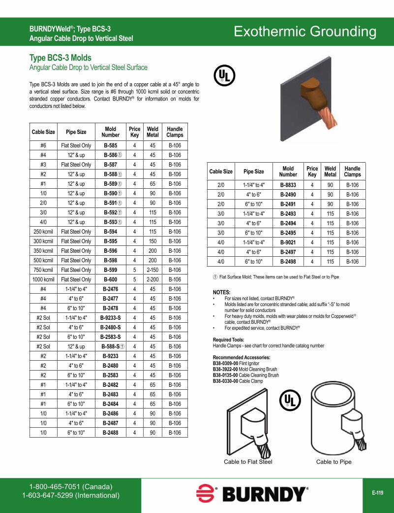
1-800-465-7051 (Canada)1-603-647-5299 (International) E-119
Exothermic Grounding
NOTES:• For sizes not listed, contact BURNDY®
• Molds listed are for concentric stranded cable; add suffix “-S” to mold number for solid conductors
• For heavy duty molds, molds with wear plates or molds for Copperweld ® cable, contact BURNDY®
• For expedited service, contact BURNDY®
Required Tools:Handle Clamps - see chart for correct handle catalog number
Recommended Accessories:B38-0309-00 Flint IgnitorB38-3922-00 Mold Cleaning BrushB38-0135-00 Cable Cleaning BrushB38-0330-00 Cable Clamp
Cable to Flat Steel Cable to Pipe
Cable Size Pipe Size Mold Number
Price Key
Weld Metal
Handle Clamps
2/0 1-1/4" to 4" B-8833 4 90 B-1062/0 4" to 6" B-2490 4 90 B-1062/0 6" to 10" B-2491 4 90 B-1063/0 1-1/4" to 4" B-2493 4 115 B-1063/0 4" to 6" B-2494 4 115 B-1063/0 6" to 10" B-2495 4 115 B-1064/0 1-1/4" to 4" B-9021 4 115 B-1064/0 4" to 6" B-2497 4 115 B-1064/0 6" to 10" B-2498 4 115 B-106
Flat Surface Mold; These items can be used to Flat Steel or to Pipe1
Cable Size Pipe Size Mold Number
Price Key
Weld Metal
Handle Clamps
#6 Flat Steel Only B-585 4 45 B-106#4 12" & up B-586 4 45 B-106#3 Flat Steel Only B-587 4 45 B-106#2 12" & up B-588 4 45 B-106#1 12" & up B-589 4 65 B-1061/0 12" & up B-590 4 90 B-1062/0 12" & up B-591 4 90 B-1063/0 12" & up B-592 4 115 B-1064/0 12" & up B-593 4 115 B-106
250 kcmil Flat Steel Only B-594 4 115 B-106300 kcmil Flat Steel Only B-595 4 150 B-106350 kcmil Flat Steel Only B-596 4 200 B-106500 kcmil Flat Steel Only B-598 4 200 B-106750 kcmil Flat Steel Only B-599 5 2-150 B-106
1000 kcmil Flat Steel Only B-600 5 2-200 B-106#4 1-1/4" to 4" B-2476 4 45 B-106#4 4" to 6" B-2477 4 45 B-106#4 6" to 10" B-2478 4 45 B-106
#2 Sol 1-1/4" to 4" B-9233-S 4 45 B-106#2 Sol 4" to 6" B-2480-S 4 45 B-106#2 Sol 6" to 10" B-2583-S 4 45 B-106#2 Sol 12" & up B-588-S 4 45 B-106
#2 1-1/4" to 4" B-9233 4 45 B-106#2 4" to 6" B-2480 4 45 B-106#2 6" to 10" B-2583 4 45 B-106#1 1-1/4" to 4" B-2482 4 65 B-106#1 4" to 6" B-2483 4 65 B-106#1 6" to 10" B-2484 4 65 B-1061/0 1-1/4" to 4" B-2486 4 90 B-1061/0 4" to 6" B-2487 4 90 B-1061/0 6" to 10" B-2488 4 90 B-106
1
1
1
1
1
1
1
1
BURNDYWeld®; Type BCS-3 Angular Cable Drop to Vertical Steel
Type BCS-3 MoldsAngular Cable Drop to Vertical Steel Surface
Type BCS-3 Molds are used to join the end of a copper cable at a 45° angle to a vertical steel surface. Size range is #6 through 1000 kcmil solid or concentric stranded copper conductors. Contact BURNDY® for information on molds for conductors not listed below.
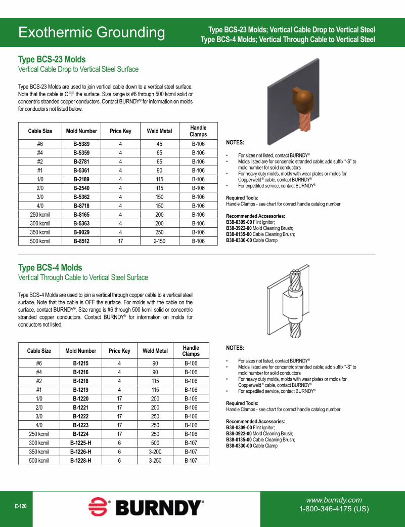
www.burndy.com1-800-346-4175 (US)E-120
Exothermic Grounding
Cable Size Mold Number Price Key Weld Metal Handle Clamps
#6 B-5389 4 45 B-106#4 B-5359 4 65 B-106#2 B-2781 4 65 B-106#1 B-5361 4 90 B-1061/0 B-2189 4 115 B-1062/0 B-2540 4 115 B-1063/0 B-5362 4 150 B-1064/0 B-8718 4 150 B-106
250 kcmil B-8165 4 200 B-106300 kcmil B-5363 4 200 B-106350 kcmil B-9029 4 250 B-106500 kcmil B-8512 17 2-150 B-106
Cable Size Mold Number Price Key Weld Metal Handle Clamps
#6 B-1215 4 90 B-106#4 B-1216 4 90 B-106#2 B-1218 4 115 B-106#1 B-1219 4 115 B-1061/0 B-1220 17 200 B-1062/0 B-1221 17 200 B-1063/0 B-1222 17 250 B-1064/0 B-1223 17 250 B-106
250 kcmil B-1224 17 250 B-106300 kcmil B-1225-H 6 500 B-107350 kcmil B-1226-H 6 3-200 B-107500 kcmil B-1228-H 6 3-250 B-107
NOTES:
• For sizes not listed, contact BURNDY®
• Molds listed are for concentric stranded cable; add suffix “-S” to mold number for solid conductors
• For heavy duty molds, molds with wear plates or molds for Copperweld ® cable, contact BURNDY®
• For expedited service, contact BURNDY®
Required Tools:Handle Clamps - see chart for correct handle catalog number
Recommended Accessories:B38-0309-00 Flint Ignitor; B38-3922-00 Mold Cleaning Brush; B38-0135-00 Cable Cleaning Brush; B38-0330-00 Cable Clamp
Type BCS-23 Molds; Vertical Cable Drop to Vertical Steel Type BCS-4 Molds; Vertical Through Cable to Vertical Steel
Type BCS-23 MoldsVertical Cable Drop to Vertical Steel Surface
Type BCS-23 Molds are used to join vertical cable down to a vertical steel surface. Note that the cable is OFF the surface. Size range is #6 through 500 kcmil solid or concentric stranded copper conductors. Contact BURNDY® for information on molds for conductors not listed below.
Type BCS-4 MoldsVertical Through Cable to Vertical Steel Surface
Type BCS-4 Molds are used to join a vertical through copper cable to a vertical steel surface. Note that the cable is OFF the surface. For molds with the cable on the surface, contact BURNDY®. Size range is #6 through 500 kcmil solid or concentric stranded copper conductors. Contact BURNDY® for information on molds for conductors not listed.
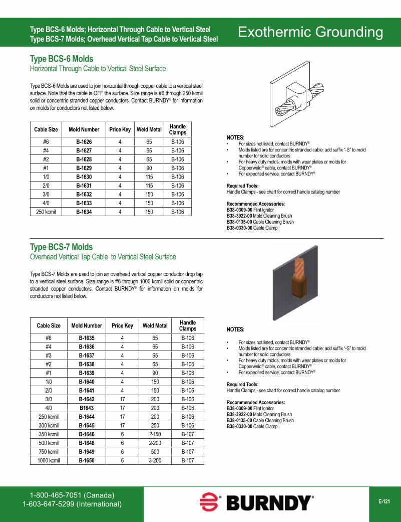
1-800-465-7051 (Canada)1-603-647-5299 (International) E-121
Exothermic Grounding
Cable Size Mold Number Price Key Weld Metal Handle Clamps
#6 B-1626 4 65 B-106#4 B-1627 4 65 B-106#2 B-1628 4 65 B-106#1 B-1629 4 90 B-1061/0 B-1630 4 115 B-1062/0 B-1631 4 115 B-1063/0 B-1632 4 150 B-1064/0 B-1633 4 150 B-106
250 kcmil B-1634 4 150 B-106
Cable Size Mold Number Price Key Weld Metal Handle Clamps
#6 B-1635 4 65 B-106#4 B-1636 4 65 B-106#3 B-1637 4 65 B-106#2 B-1638 4 65 B-106#1 B-1639 4 90 B-1061/0 B-1640 4 150 B-1062/0 B-1641 4 150 B-1063/0 B-1642 17 200 B-1064/0 B1643 17 200 B-106
250 kcmil B-1644 17 200 B-106300 kcmil B-1645 17 250 B-106350 kcmil B-1646 6 2-150 B-107500 kcmil B-1648 6 2-200 B-107750 kcmil B-1649 6 500 B-107
1000 kcmil B-1650 6 3-200 B-107
NOTES:• For sizes not listed, contact BURNDY®
• Molds listed are for concentric stranded cable; add suffix “-S” to mold number for solid conductors
• For heavy duty molds, molds with wear plates or molds for Copperweld ® cable, contact BURNDY®
• For expedited service, contact BURNDY®
Required Tools:Handle Clamps - see chart for correct handle catalog number
Recommended Accessories:B38-0309-00 Flint IgnitorB38-3922-00 Mold Cleaning BrushB38-0135-00 Cable Cleaning BrushB38-0330-00 Cable Clamp
NOTES:
• For sizes not listed, contact BURNDY®
• Molds listed are for concentric stranded cable; add suffix “-S” to mold number for solid conductors
• For heavy duty molds, molds with wear plates or molds for Copperweld ® cable, contact BURNDY®
• For expedited service, contact BURNDY®
Required Tools:Handle Clamps - see chart for correct handle catalog number
Recommended Accessories:B38-0309-00 Flint IgnitorB38-3922-00 Mold Cleaning BrushB38-0135-00 Cable Cleaning BrushB38-0330-00 Cable Clamp
Type BCS-6 Molds; Horizontal Through Cable to Vertical Steel Type BCS-7 Molds; Overhead Vertical Tap Cable to Vertical Steel
Type BCS-6 MoldsHorizontal Through Cable to Vertical Steel Surface
Type BCS-6 Molds are used to join horizontal through copper cable to a vertical steel surface. Note that the cable is OFF the surface. Size range is #6 through 250 kcmil solid or concentric stranded copper conductors. Contact BURNDY® for information on molds for conductors not listed below.
Type BCS-7 MoldsOverhead Vertical Tap Cable to Vertical Steel Surface
Type BCS-7 Molds are used to join an overhead vertical copper conductor drop tap to a vertical steel surface. Size range is #6 through 1000 kcmil solid or concentric stranded copper conductors. Contact BURNDY® for information on molds for conductors not listed below.

www.burndy.com1-800-346-4175 (US)E-122
Exothermic Grounding
Cable Size Mold Number Price Key Weld Metal Handle Clamps
#6 B-5910 4 45 B-106#4 B-2761 4 45 B-106#1 B-6060 4 65 B-1061/0 B-5419 4 90 B-1062/0 B-2567 4 90 B-1063/0 B-6072 4 115 B-1064/0 B-9253 4 115 B-106
250 kcmil B-2568 4 115 B-106300 kcmil B-6061 4 150 B-106350 kcmil B-6067 4 200 B-106500 kcmil B-8359 4 200 B-106
DO NOT use Type BCS-5 molds on Soil Pipe (ASTM A74-82). A test weld should be made on a section of pipe being used to determine
the possibility of detrimental metallurgical effects.
B38-0309-00 Flint ignitor included1
Cable Size Mold Number Price Key Weld Metal Handle Clamps
#6 Sol B-1613 3 2SCI Incl.#6 B-1614 3 25CI Incl.
#4 Sol B-1615 3 45CI Incl.#4 B-1616 3 45CI Incl.
#2 Sol B-1617 3 45CI Incl.#2 B-1618 3 45CI Incl.
#1 Sol B-1619 3 65CI Incl.#1 B-1620 3 65CI Incl.
1
1
1
1
1
1
1
1
NOTES:
• For sizes not listed, contact BURNDY®
• Molds listed are for concentric stranded cable; add suffix “-S” to mold number for solid conductors
• For heavy duty molds, molds with wear plates or molds for Copperweld ® cable, contact BURNDY®
• For expedited service, contact BURNDY®
Required Tools:Handle Clamps - see chart for correct handle catalog number
Recommended Accessories:B38-0309-00 Flint Ignitor; B38-3922-00 Mold Cleaning Brush; B38-0135-00 Cable Cleaning Brush; B38-0330-00 Cable Clamp
NOTES:• For sizes not listed, contact BURNDY®
• Molds listed are for concentric stranded cable; add suffix “-S” to mold number for solid conductors
• For heavy duty molds, molds with wear plates or molds for Copperweld ® cable, contact BURNDY®
• For expedited service, contact BURNDY®
Type BCS-18 Molds; Horizontal Tap Cable to Vertical SteelType BCS-5 Molds; Horizontal Cable Tap to Horizontal Cast Iron
Type BCS-18 MoldsHorizontal Tap Cable to Vertical Steel Surface
Type BCS-18 Molds are used to connect a horizontal conductor to a vertical steel surface. Note that the cable is ON the surface. Size range is #6 through 500 kcmil solid or concentric stranded copper conductors. Contact BURNDY® for information on molds for conductors not listed below.
Type BCS-5 MoldsHorizontal Cable Tap to Horizontal Cast Iron Surface
Type BCS-5 Molds are used to join horizontal cable taps to horizontal cast iron surfaces. Note that the cable is ON the surface. Size range is #6 through #1 solid or concentric stranded copper conductors. Contact BURNDY® for information on molds for conductors not listed below.
Required Tools:Handle Clamps - see chart for correct handle catalog number
Recommended Accessories:B38-0309-00 Flint IgnitorB38-3922-00 Mold Cleaning BrushB38-0135-00 Cable Cleaning BrushB38-0330-00 Cable Clamp
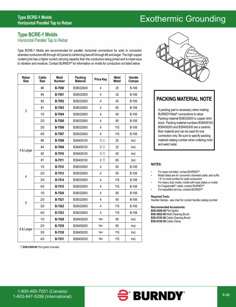
1-800-465-7051 (Canada)1-603-647-5299 (International) E-123
Exothermic Grounding
PACKING MATERIAL NOTE
A packing pad is necessary when making BURNDYWeld® connections to rebar. Packing material B38032900 is copper shim stock. Packing material numbers B38406100, B38406200 and B38406300 are a ceramic fiber material and can be used for one connection only. Be sure to specify packing material catalog number when ordering mold and weld metal.
NOTES:
• For sizes not listed, contact BURNDY®
• Molds listed are for concentric stranded cable; add suffix “-S” to mold number for solid conductors
• For heavy duty molds, molds with wear plates or molds for Copperweld ® cable, contact BURNDY®
• For expedited service, contact BURNDY®
Required Tools:Handle Clamps - see chart for correct handle catalog number
Recommended Accessories:B38-0309-00 Flint IgnitorB38-3922-00 Mold Cleaning BrushB38-0135-00 Cable Cleaning BrushB38-0330-00 Cable Clamp
B38-0309-00 Flint ignitor included1
Rebar Size
Cable Size
Mold Number
Packing Material Price Key Weld
MetalHandle Clamps
3
#6 B-7500 B38032900 4 25 B-106
#4 B-7501 B38032900 4 32 B-106
#2 B-7502 B38032900 4 45 B-106
#1 B-7503 B38032900 4 65 B-106
1/0 B-7504 B38032900 4 90 B-106
2/0 B-7505 B38032900 4 90 B-106
3/0 B-7506 B38032900 4 115 B-106
4/0 B-7507 B38032900 4 115 B-106
4 & Larger
#6 B-7508 B38406100 3 25 Incl.
#4 B-7509 B38406100 3 32 Incl.
#2 B-7510 B38406100 3 45 Incl.
#1 B-7511 B38406100 3 65 Incl.
4
1/0 B-7512 B38032900 4 90 B-106
2/0 B-7513 B38032900 4 90 B-106
3/0 B-7514 B38032900 4 115 B-106
4/0 B-7515 B38032900 4 115 B-106
5
1/0 B-7520 B38032900 4 90 B-106
2/0 B-7521 B38032900 4 90 B-106
3/0 B-7522 B38032900 4 115 B-106
4/0 B-7523 B38032900 4 115 B-106
6 & Larger
1/0 B-7528 B38406200 14+ 90 Incl.
2/0 B-7529 B38406200 14+ 90 Incl.
3/0 B-7530 B38406200 14+ 115 Incl.
4/0 B-7531 B38406200 14+ 115 Incl.
1
1
1
1
Type BCRE-1 MoldsHorizontal Parallel Tap to Rebar
Type BCRE-1 MoldsHorizontal Parallel Tap to Rebar
Type BCRE-1 Molds are recommended for parallel, horizontal connections for solid or concentric stranded conductors #6 through 4/0 joined to reinforcing bars #3 through #6 and larger. The high copper content joint has a higher current carrying capacity than the conductors being joined and is impervious to vibration and moisture. Contact BURNDY® for information on molds for conductors not listed below.
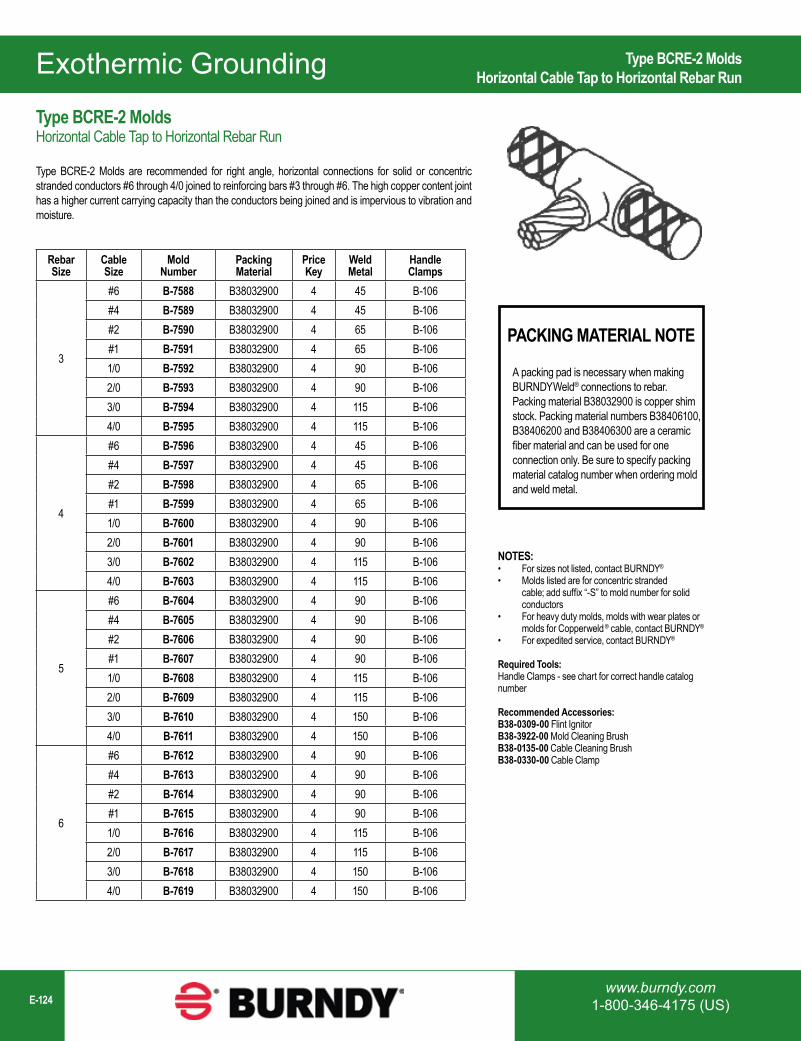
www.burndy.com1-800-346-4175 (US)E-124
Exothermic Grounding
Rebar Size
Cable Size
Mold Number
Packing Material
Price Key
Weld Metal
Handle Clamps
3
#6 B-7588 B38032900 4 45 B-106#4 B-7589 B38032900 4 45 B-106#2 B-7590 B38032900 4 65 B-106#1 B-7591 B38032900 4 65 B-1061/0 B-7592 B38032900 4 90 B-1062/0 B-7593 B38032900 4 90 B-1063/0 B-7594 B38032900 4 115 B-1064/0 B-7595 B38032900 4 115 B-106
4
#6 B-7596 B38032900 4 45 B-106#4 B-7597 B38032900 4 45 B-106#2 B-7598 B38032900 4 65 B-106#1 B-7599 B38032900 4 65 B-1061/0 B-7600 B38032900 4 90 B-1062/0 B-7601 B38032900 4 90 B-1063/0 B-7602 B38032900 4 115 B-1064/0 B-7603 B38032900 4 115 B-106
5
#6 B-7604 B38032900 4 90 B-106#4 B-7605 B38032900 4 90 B-106#2 B-7606 B38032900 4 90 B-106#1 B-7607 B38032900 4 90 B-1061/0 B-7608 B38032900 4 115 B-1062/0 B-7609 B38032900 4 115 B-1063/0 B-7610 B38032900 4 150 B-1064/0 B-7611 B38032900 4 150 B-106
6
#6 B-7612 B38032900 4 90 B-106#4 B-7613 B38032900 4 90 B-106#2 B-7614 B38032900 4 90 B-106#1 B-7615 B38032900 4 90 B-1061/0 B-7616 B38032900 4 115 B-1062/0 B-7617 B38032900 4 115 B-1063/0 B-7618 B38032900 4 150 B-1064/0 B-7619 B38032900 4 150 B-106
NOTES:• For sizes not listed, contact BURNDY®
• Molds listed are for concentric stranded cable; add suffix “-S” to mold number for solid conductors
• For heavy duty molds, molds with wear plates or molds for Copperweld ® cable, contact BURNDY®
• For expedited service, contact BURNDY®
Required Tools:Handle Clamps - see chart for correct handle catalog number
Recommended Accessories:B38-0309-00 Flint IgnitorB38-3922-00 Mold Cleaning BrushB38-0135-00 Cable Cleaning BrushB38-0330-00 Cable Clamp
Type BCRE-2 MoldsHorizontal Cable Tap to Horizontal Rebar Run
PACKING MATERIAL NOTE
A packing pad is necessary when making BURNDYWeld® connections to rebar. Packing material B38032900 is copper shim stock. Packing material numbers B38406100, B38406200 and B38406300 are a ceramic fiber material and can be used for one connection only. Be sure to specify packing material catalog number when ordering mold and weld metal.
Type BCRE-2 MoldsHorizontal Cable Tap to Horizontal Rebar Run
Type BCRE-2 Molds are recommended for right angle, horizontal connections for solid or concentric stranded conductors #6 through 4/0 joined to reinforcing bars #3 through #6. The high copper content joint has a higher current carrying capacity than the conductors being joined and is impervious to vibration and moisture.
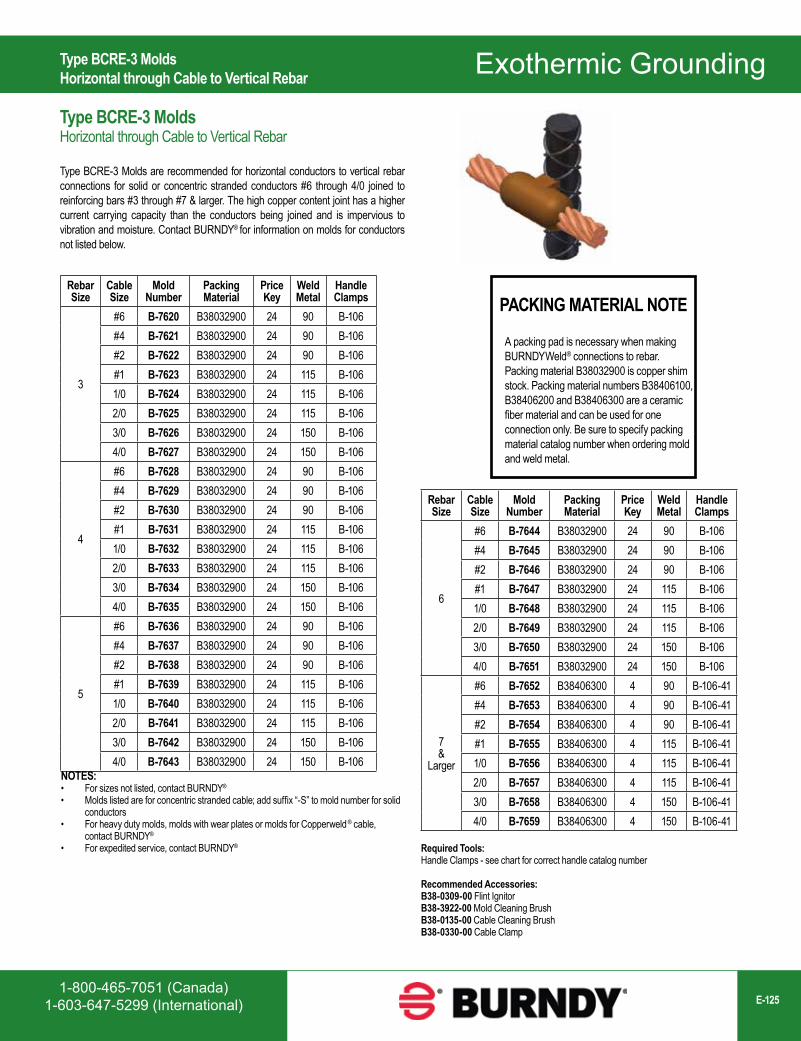
1-800-465-7051 (Canada)1-603-647-5299 (International) E-125
Exothermic Grounding
Rebar Size
Cable Size
Mold Number
Packing Material
Price Key
Weld Metal
Handle Clamps
3
#6 B-7620 B38032900 24 90 B-106#4 B-7621 B38032900 24 90 B-106#2 B-7622 B38032900 24 90 B-106#1 B-7623 B38032900 24 115 B-1061/0 B-7624 B38032900 24 115 B-1062/0 B-7625 B38032900 24 115 B-1063/0 B-7626 B38032900 24 150 B-1064/0 B-7627 B38032900 24 150 B-106
4
#6 B-7628 B38032900 24 90 B-106#4 B-7629 B38032900 24 90 B-106#2 B-7630 B38032900 24 90 B-106#1 B-7631 B38032900 24 115 B-1061/0 B-7632 B38032900 24 115 B-1062/0 B-7633 B38032900 24 115 B-1063/0 B-7634 B38032900 24 150 B-1064/0 B-7635 B38032900 24 150 B-106
5
#6 B-7636 B38032900 24 90 B-106#4 B-7637 B38032900 24 90 B-106#2 B-7638 B38032900 24 90 B-106#1 B-7639 B38032900 24 115 B-1061/0 B-7640 B38032900 24 115 B-1062/0 B-7641 B38032900 24 115 B-1063/0 B-7642 B38032900 24 150 B-1064/0 B-7643 B38032900 24 150 B-106
Rebar Size
Cable Size
Mold Number
Packing Material
Price Key
Weld Metal
Handle Clamps
6
#6 B-7644 B38032900 24 90 B-106#4 B-7645 B38032900 24 90 B-106#2 B-7646 B38032900 24 90 B-106#1 B-7647 B38032900 24 115 B-1061/0 B-7648 B38032900 24 115 B-1062/0 B-7649 B38032900 24 115 B-1063/0 B-7650 B38032900 24 150 B-1064/0 B-7651 B38032900 24 150 B-106
7 &
Larger
#6 B-7652 B38406300 4 90 B-106-41#4 B-7653 B38406300 4 90 B-106-41#2 B-7654 B38406300 4 90 B-106-41#1 B-7655 B38406300 4 115 B-106-411/0 B-7656 B38406300 4 115 B-106-412/0 B-7657 B38406300 4 115 B-106-413/0 B-7658 B38406300 4 150 B-106-414/0 B-7659 B38406300 4 150 B-106-41
PACKING MATERIAL NOTE
A packing pad is necessary when making BURNDYWeld® connections to rebar. Packing material B38032900 is copper shim stock. Packing material numbers B38406100, B38406200 and B38406300 are a ceramic fiber material and can be used for one connection only. Be sure to specify packing material catalog number when ordering mold and weld metal.
NOTES:• For sizes not listed, contact BURNDY®
• Molds listed are for concentric stranded cable; add suffix “-S” to mold number for solid conductors
• For heavy duty molds, molds with wear plates or molds for Copperweld ® cable, contact BURNDY®
• For expedited service, contact BURNDY®
Type BCRE-3 MoldsHorizontal through Cable to Vertical Rebar
Type BCRE-3 MoldsHorizontal through Cable to Vertical Rebar
Type BCRE-3 Molds are recommended for horizontal conductors to vertical rebar connections for solid or concentric stranded conductors #6 through 4/0 joined to reinforcing bars #3 through #7 & larger. The high copper content joint has a higher current carrying capacity than the conductors being joined and is impervious to vibration and moisture. Contact BURNDY® for information on molds for conductors not listed below.
Required Tools:Handle Clamps - see chart for correct handle catalog number
Recommended Accessories:B38-0309-00 Flint IgnitorB38-3922-00 Mold Cleaning BrushB38-0135-00 Cable Cleaning BrushB38-0330-00 Cable Clamp
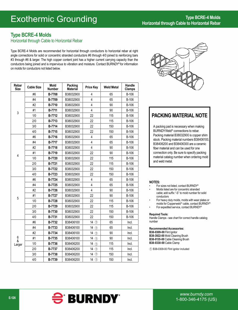
www.burndy.com1-800-346-4175 (US)E-126
Exothermic Grounding
Rebar Size Cable Size Mold
NumberPacking Material Price Key Weld Metal Handle
Clamps
3
#6 B-7708 B38032900 4 65 B-106#4 B-7709 B38032900 4 65 B-106#2 B-7710 B38032900 4 90 B-106#1 B-7711 B38032900 4 90 B-1061/0 B-7712 B38032900 22 115 B-1062/0 B-7713 B38032900 22 115 B-1063/0 B-7714 B38032900 22 150 B-1064/0 B-7715 B38032900 22 150 B-106
4
#6 B-7716 B38032900 4 65 B-106#4 B-7717 B38032900 4 65 B-106#2 B-7718 B38032900 4 90 B-106#1 B-7719 B38032900 22 90 B-1061/0 B-7720 B38032900 22 115 B-1062/0 B-7721 B38032900 22 115 B-1063/0 B-7722 B38032900 22 150 B-1064/0 B-7723 B38032900 22 150 B-106
5
#6 B-7724 B38032900 4 65 B-106#4 B-7725 B38032900 4 65 B-106#2 B-7726 B38032900 4 90 B-106#1 B-7727 B38032900 22 90 B-1061/0 B-7728 B38032900 22 115 B-1062/0 B-7729 B38032900 22 115 B-1063/0 B-7730 B38032900 22 150 B-1064/0 B-7731 B38032900 22 150 B-106
6 &
Larger
#6 B-7732 B38406100 14 65 Incl.#4 B-7733 B38406100 14 65 Incl.#2 B-7734 B38406100 14 90 Incl.#1 B-7735 B38406100 14 90 Incl.1/0 B-7736 B38406200 14 115 Incl.2/0 B-7737 B38406200 14 115 Incl.3/0 B-7738 B38406200 14 150 Incl.4/0 B-7739 B38406200 14 150 Incl.
1
1
1
1
1
1
1
1
PACKING MATERIAL NOTE
A packing pad is necessary when making BURNDYWeld® connections to rebar. Packing material B38032900 is copper shim stock. Packing material numbers B38406100, B38406200 and B38406300 are a ceramic fiber material and can be used for one connection only. Be sure to specify packing material catalog number when ordering mold and weld metal.
NOTES:• For sizes not listed, contact BURNDY®
• Molds listed are for concentric stranded cable; add suffix “-S” to mold number for solid conductors
• For heavy duty molds, molds with wear plates or molds for Copperweld ® cable, contact BURNDY®
• For expedited service, contact BURNDY®
Required Tools:Handle Clamps - see chart for correct handle catalog number
Recommended Accessories:B38-0309-00 Flint IgnitorB38-3922-00 Mold Cleaning BrushB38-0135-00 Cable Cleaning BrushB38-0330-00 Cable Clamp
B38-0309-00 Flint ignitor included1
Type BCRE-4 MoldsHorizontal through Cable to Horizontal Rebar
Type BCRE-4 MoldsHorizontal through Cable to Horizontal Rebar
Type BCRE-4 Molds are recommended for horizontal through conductors to horizontal rebar at right angle connections for solid or concentric stranded conductors #6 through 4/0 joined to reinforcing bars #3 through #6 & larger. The high copper content joint has a higher current carrying capacity than the conductors being joined and is impervious to vibration and moisture. Contact BURNDY® for information on molds for conductors not listed below.
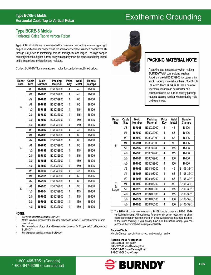
1-800-465-7051 (Canada)1-603-647-5299 (International) E-127
Exothermic Grounding
Rebar Size
Cable Size
Mold Number
Packing Material
Price Key
Weld Metal
Handle Clamps
3
#6 B-7884 B38032900 4 45 B-106#4 B-7885 B38032900 4 45 B-106#2 B-7886 B38032900 4 65 B-106#1 B-7887 B38032900 4 90 B-1061/0 B-7888 B38032900 4 115 B-1062/0 B-7889 B38032900 4 115 B-1063/0 B-7890 B38032900 4 150 B-1064/0 B-7891 B38032900 4 150 B-106
4
#6 B-7892 B38032900 4 45 B-106#4 B-7893 B38032900 4 65 B-106#2 B-7894 B38032900 4 65 B-106#1 B-7895 B38032900 4 90 B-1061/0 B-7896 B38032900 4 115 B-1062/0 B-7897 B38032900 4 115 B-1063/0 B-7898 B38032900 4 150 B-1064/0 B-7899 B38032900 4 150 B-106
5
#6 B-7900 B38032900 4 45 B-106#4 B-7901 B38032900 4 65 B-106#2 B-7902 B38032900 4 65 B-106#1 B-7903 B38032900 4 90 B-1061/0 B-7904 B38032900 4 115 B-1062/0 B-7905 B38032900 4 115 B-1063/0 B-7906 B38032900 4 150 B-1064/0 B-7907 B38032900 4 150 B-106
The B106-32 comes complete with a B-106 handle clamp and B40-0106-76 vertical chain clamp. Although good for use on all sizes of rebar, vertical chain clamps are strongly recommended on large size rebar as they hold the mold to the rebar securely. If you already have a B-106 handle clamp, you can purchase the vertical chain clamps separately.
1
PACKING MATERIAL NOTE
A packing pad is necessary when making BURNDYWeld® connections to rebar. Packing material B38032900 is copper shim stock. Packing material numbers B38406100, B38406200 and B38406300 are a ceramic fiber material and can be used for one connection only. Be sure to specify packing material catalog number when ordering mold and weld metal.
NOTES:• For sizes not listed, contact BURNDY®
• Molds listed are for concentric stranded cable; add suffix “-S” to mold number for solid conductors
• For heavy duty molds, molds with wear plates or molds for Copperweld ® cable, contact BURNDY®
• For expedited service, contact BURNDY®
Rebar Size
Cable Size
Mold Number
Packing Material
Price Key
Weld Metal
Handle Clamps
6
#6 B-7908 B38032900 4 45 B-106#4 B-7909 B38032900 4 65 B-106#2 B-7910 B38032900 4 65 B-106#1 B-7911 B38032900 4 90 B-1061/0 B-7912 B38032900 4 115 B-1062/0 B-7913 B38032900 4 115 B-1063/0 B-7914 B38032900 4 150 B-1064/0 B-7915 B38032900 4 150 B-106
7 &
Larger
#6 B-7916 B38406300 4 45 B-106-32#4 B-7917 B38406300 4 65 B-106-32#2 B-7918 B38406300 4 65 B-106-32#1 B-7919 B38406300 4 90 B-106-321/0 B-7920 B38406300 4 115 B-106-322/0 B-7921 B38406300 4 115 B-106-323/0 B-7922 B38406300 4 150 B-106-324/0 B-7923 B38406300 4 150 B-106-32
1
1
1
1
1
1
1
1
Type BCRE-6 MoldsHorizontal Cable Tap to Vertical Rebar
Type BCRE-6 MoldsHorizontal Cable Tap to Vertical Rebar
Type BCRE-6 Molds are recommended for horizontal conductors terminating at right angles to vertical rebar connections for solid or concentric stranded conductors #6 through 4/0 joined to reinforcing bars #3 through #7 and larger. The high copper content joint has a higher current carrying capacity than the conductors being joined and is impervious to vibration and moisture.
Contact BURNDY® for information on molds for conductors not listed below.
Required Tools:Handle Clamps - see chart for correct handle catalog number
Recommended Accessories:B38-0309-00 Flint IgnitorB38-3922-00 Mold Cleaning BrushB38-0135-00 Cable Cleaning BrushB38-0330-00 Cable Clamp
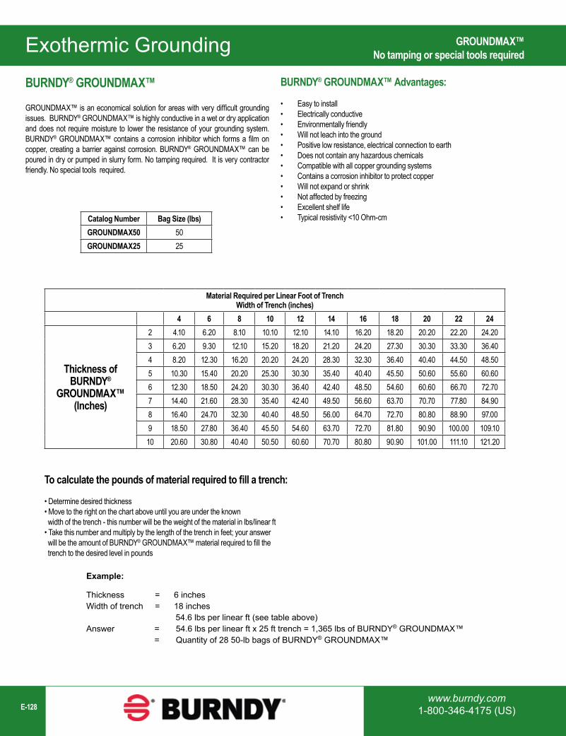
www.burndy.com1-800-346-4175 (US)E-128
Exothermic Grounding
To calculate the pounds of material required to fill a trench:
• Determine desired thickness• Move to the right on the chart above until you are under the known width of the trench - this number will be the weight of the material in lbs/linear ft• Take this number and multiply by the length of the trench in feet; your answer will be the amount of BURNDY® GROUNDMAX™ material required to fill the trench to the desired level in pounds
Material Required per Linear Foot of TrenchWidth of Trench (inches)
4 6 8 10 12 14 16 18 20 22 24
Thickness ofBURNDY®
GROUNDMAX™(Inches)
2 4.10 6.20 8.10 10.10 12.10 14.10 16.20 18.20 20.20 22.20 24.203 6.20 9.30 12.10 15.20 18.20 21.20 24.20 27.30 30.30 33.30 36.404 8.20 12.30 16.20 20.20 24.20 28.30 32.30 36.40 40.40 44.50 48.505 10.30 15.40 20.20 25.30 30.30 35.40 40.40 45.50 50.60 55.60 60.606 12.30 18.50 24.20 30.30 36.40 42.40 48.50 54.60 60.60 66.70 72.707 14.40 21.60 28.30 35.40 42.40 49.50 56.60 63.70 70.70 77.80 84.908 16.40 24.70 32.30 40.40 48.50 56.00 64.70 72.70 80.80 88.90 97.009 18.50 27.80 36.40 45.50 54.60 63.70 72.70 81.80 90.90 100.00 109.1010 20.60 30.80 40.40 50.50 60.60 70.70 80.80 90.90 101.00 111.10 121.20
Example:
Thickness = 6 inchesWidth of trench = 18 inches 54.6 lbs per linear ft (see table above)Answer = 54.6 lbs per linear ft x 25 ft trench = 1,365 lbs of BURNDY® GROUNDMAX™ = Quantity of 28 50-lb bags of BURNDY® GROUNDMAX™
GROUNDMAX™No tamping or special tools required
BURNDY® GROUNDMAX™
GROUNDMAX™ is an economical solution for areas with very difficult grounding issues. BURNDY® GROUNDMAX™ is highly conductive in a wet or dry application and does not require moisture to lower the resistance of your grounding system. BURNDY® GROUNDMAX™ contains a corrosion inhibitor which forms a film on copper, creating a barrier against corrosion. BURNDY® GROUNDMAX™ can be poured in dry or pumped in slurry form. No tamping required. It is very contractor friendly. No special tools required.
BURNDY® GROUNDMAX™ Advantages:
• Easy to install• Electrically conductive• Environmentally friendly• Will not leach into the ground• Positive low resistance, electrical connection to earth• Does not contain any hazardous chemicals• Compatible with all copper grounding systems• Contains a corrosion inhibitor to protect copper• Will not expand or shrink• Not affected by freezing• Excellent shelf life• Typical resistivity <10 Ohm-cmCatalog Number Bag Size (lbs)
GROUNDMAX50 50GROUNDMAX25 25
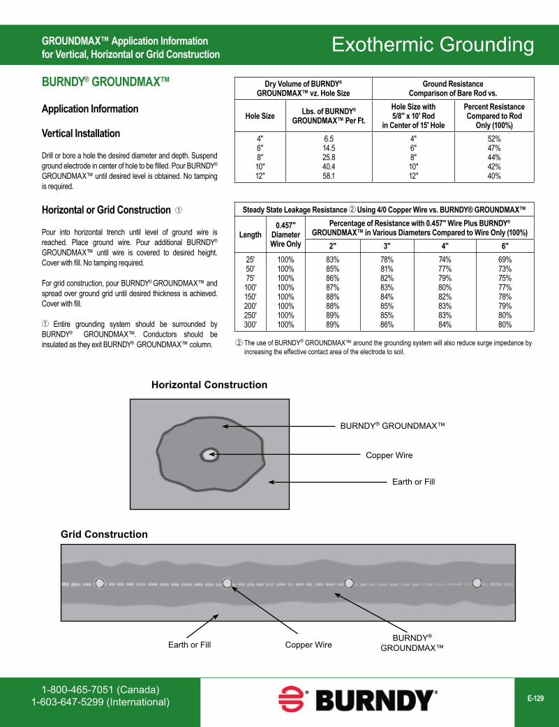
1-800-465-7051 (Canada)1-603-647-5299 (International) E-129
Exothermic Grounding
Grid Construction
Earth or Fill Copper WireBURNDY®
GROUNDMAX™
Dry Volume of BURNDY® GROUNDMAX™ vz. Hole Size
Ground Resistance Comparison of Bare Rod vs.
Hole Size Lbs. of BURNDY® GROUNDMAX™ Per Ft.
Hole Size with 5/8" x 10' Rod
in Center of 15' Hole
Percent Resistance Compared to Rod
Only (100%)4"6"8"10"12"
6.514.525.840.458.1
4"6"8"10"12"
52%47%44%42%40%
Steady State Leakage Resistance 2 Using 4/0 Copper Wire vs. BURNDY® GROUNDMAX™
Length0.457"
Diameter Wire Only
Percentage of Resistance with 0.457" Wire Plus BURNDY® GROUNDMAX™ in Various Diameters Compared to Wire Only (100%)
2" 3" 4" 6"25'50'75'
100'150'200'250'300'
100%100%100%100%100%100%100%100%
83%85%86%87%88%88%89%89%
78%81%82%83%84%85%85%86%
74%77%79%80%82%83%83%84%
69%73%75%77%78%79%80%80%
The use of BURNDY® GROUNDMAX™ around the grounding system will also reduce surge impedance by increasing the effective contact area of the electrode to soil.
2
Horizontal Construction
Earth or Fill
Copper Wire
BURNDY® GROUNDMAX™
GROUNDMAX™ Application Informationfor Vertical, Horizontal or Grid Construction
BURNDY® GROUNDMAX™
Application Information
Vertical Installation
Drill or bore a hole the desired diameter and depth. Suspend ground electrode in center of hole to be filled. Pour BURNDY® GROUNDMAX™ until desired level is obtained. No tamping is required.
Horizontal or Grid Construction 1
Pour into horizontal trench until level of ground wire is reached. Place ground wire. Pour additional BURNDY®
GROUNDMAX™ until wire is covered to desired height. Cover with fill. No tamping required.
For grid construction, pour BURNDY® GROUNDMAX™ and spread over ground grid until desired thickness is achieved. Cover with fill.
1 Entire grounding system should be surrounded by BURNDY® GROUNDMAX™. Conductors should be insulated as they exit BURNDY® GROUNDMAX™ column.
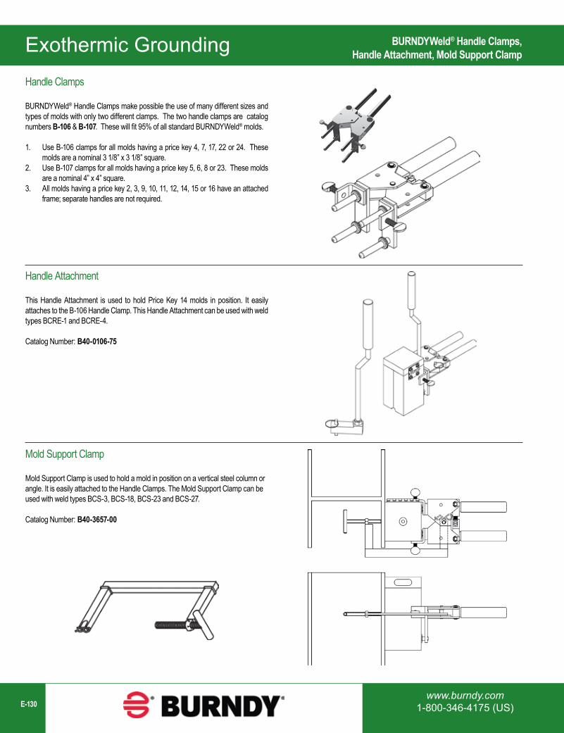
www.burndy.com1-800-346-4175 (US)E-130
Exothermic Grounding BURNDYWeld® Handle Clamps,Handle Attachment, Mold Support Clamp
Handle Clamps
BURNDYWeld® Handle Clamps make possible the use of many different sizes and types of molds with only two different clamps. The two handle clamps are catalog numbers B-106 & B-107. These will fit 95% of all standard BURNDYWeld® molds.
1. Use B-106 clamps for all molds having a price key 4, 7, 17, 22 or 24. These molds are a nominal 3 1/8” x 3 1/8” square.
2. Use B-107 clamps for all molds having a price key 5, 6, 8 or 23. These molds are a nominal 4” x 4” square.
3. All molds having a price key 2, 3, 9, 10, 11, 12, 14, 15 or 16 have an attached frame; separate handles are not required.
Handle Attachment
This Handle Attachment is used to hold Price Key 14 molds in position. It easily attaches to the B-106 Handle Clamp. This Handle Attachment can be used with weld types BCRE-1 and BCRE-4.
Catalog Number: B40-0106-75
Mold Support Clamp
Mold Support Clamp is used to hold a mold in position on a vertical steel column or angle. It is easily attached to the Handle Clamps. The Mold Support Clamp can be used with weld types BCS-3, BCS-18, BCS-23 and BCS-27.
Catalog Number: B40-3657-00
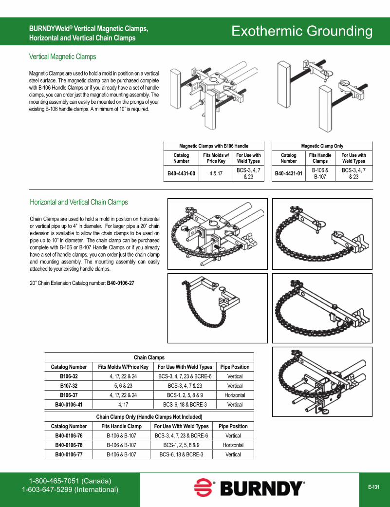
1-800-465-7051 (Canada)1-603-647-5299 (International) E-131
Exothermic Grounding
Magnetic Clamps with B106 Handle
Catalog Number
Fits Molds w/Price Key
For Use with Weld Types
B40-4431-00 4 & 17 BCS-3, 4, 7 & 23
Chain ClampsCatalog Number Fits Molds W/Price Key For Use With Weld Types Pipe Position
B106-32 4, 17, 22 & 24 BCS-3, 4, 7, 23 & BCRE-6 VerticalB107-32 5, 6 & 23 BCS-3, 4, 7 & 23 VerticalB106-37 4, 17, 22 & 24 BCS-1, 2, 5, 8 & 9 Horizontal
B40-0106-41 4, 17 BCS-6, 18 & BCRE-3 Vertical
Magnetic Clamp Only
Catalog Number
Fits Handle Clamps
For Use with Weld Types
B40-4431-01 B-106 & B-107
BCS-3, 4, 7 & 23
Chain Clamp Only (Handle Clamps Not Included)Catalog Number Fits Handle Clamp For Use With Weld Types Pipe Position
B40-0106-76 B-106 & B-107 BCS-3, 4, 7, 23 & BCRE-6 VerticalB40-0106-78 B-106 & B-107 BCS-1, 2, 5, 8 & 9 HorizontalB40-0106-77 B-106 & B-107 BCS-6, 18 & BCRE-3 Vertical
BURNDYWeld® Vertical Magnetic Clamps,Horizontal and Vertical Chain Clamps
Vertical Magnetic Clamps
Magnetic Clamps are used to hold a mold in position on a vertical steel surface. The magnetic clamp can be purchased complete with B-106 Handle Clamps or if you already have a set of handle clamps, you can order just the magnetic mounting assembly. The mounting assembly can easily be mounted on the prongs of your existing B-106 handle clamps. A minimum of 10” is required.
Horizontal and Vertical Chain Clamps
Chain Clamps are used to hold a mold in position on horizontal or vertical pipe up to 4” in diameter. For larger pipe a 20” chain extension is available to allow the chain clamps to be used on pipe up to 10” in diameter. The chain clamp can be purchased complete with B-106 or B-107 Handle Clamps or if you already have a set of handle clamps, you can order just the chain clamp and mounting assembly. The mounting assembly can easily attached to your existing handle clamps.
20” Chain Extension Catalog number: B40-0106-27

www.burndy.com1-800-346-4175 (US)E-132
Exothermic Grounding
Description Catalog NumberCable Cleaning Brush B38-0305-00Replacement Brush B38-0135-01Card Cloth Brush B38-0306-00
Mold Cleaning Brush B38-3922-00
Description Catalog Number1 lb. package B384129005 lb. package B38412905
BURNDYWeld® Accessories; Cable Clamp, Cable Cleaning,Card Cloth Brush, Mold Cleaners, Packing Material
Cable Clamp
The BURNDYWeld® Cable Clamp is recommended for holding a wide range of cables properly in place in molds when welding cables that are under tension. This prevents the cables from pulling out of the mold when the weld is made.
Cable Clamp: B38-0330-00
Cable Cleaning and Card Cloth Brush
The Cable Cleaning Brush is recommended for cleaning heavily oxidized cables. The V-shape brushes permit their use over a wide range of cable sizes. Brush assembly consists of a handle with two stiff wire bristle brushes that are rotatable, for longer life and are replaceable.
The Card Cloth Brush is used for cleaning large conductors and bus bar. It has short stiff bristles. These brushes are for cleaning cable only, not molds.
The Mold Cleaning Brush B38-3922-00 is used to clean the graphite mold without scratching the mold.
Mold Cleaners
Mold Cleaners are used to clean the slag from molds that are not split through the crucible.
B40-0319-01 for cartridge sizes #15 through #65
B40-0319-03 for cartridge sizes #90 through #500
Packing Material
Packing material is used to prevent the molten weld metal from leaking out of the mold. When the cable opening becomes worn from heavy use, the packing material may be used to prolong mold use. It is also used around 7 strand cable to prevent leaking. Packing material comes in a 1 lb. or 5 lb. package.
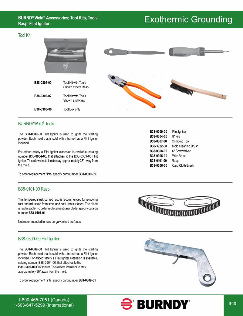
1-800-465-7051 (Canada)1-603-647-5299 (International) E-133
Exothermic Grounding
B38-0302-00 Tool Kit with Tools Shown except Rasp
B38-0302-02 Tool Kit with Tools Shown and Rasp
B38-0303-00 Tool Box only
BURNDYWeld® Accessories; Tool Kits, Tools,Rasp, Flint Ignitor
Tool Kit
BURNDYWeld® Tools
The B38-0309-00 Flint Ignitor is used to ignite the starting powder. Each mold that is sold with a frame has a Flint Ignitor included.
For added safety a Flint Ignitor extension is available, catalog number B38-0904-00, that attaches to the B38-0309-00 Flint Ignitor. This allows installers to stay approximately 36” away from the mold.
To order replacement flints, specify part number B38-0309-01.
B38-0309-00 Flint IgnitorB38-0304-00 8″ FileB38-0307-00 Crimping ToolB38-3922-00 Mold Cleaning BrushB38-0308-00 6″ ScrewdriverB38-0305-00 Wire BrushB38-0101-00 RaspB38-0306-00 Card Cloth Brush
B38-0101-00 Rasp
This tempered steel, curved rasp is recommended for removing rust and mill scale from steel and cast iron surfaces. The blade is replaceable. To order replacement rasp blade, specify catalog number B38-0101-01.
Not recommended for use on galvanized surfaces.
B38-0309-00 Flint Ignitor
The B38-0309-00 Flint Igniter is used to ignite the starting powder. Each mold that is sold with a frame has a Flint Igniter included. For added safety a Flint Igniter extension is available, catalog number B38-0904-00, that attaches to the B38-0309-00 Flint Igniter. This allows installers to stay approximately 36” away from the mold.
To order replacement flints, specify part number B38-0309-01
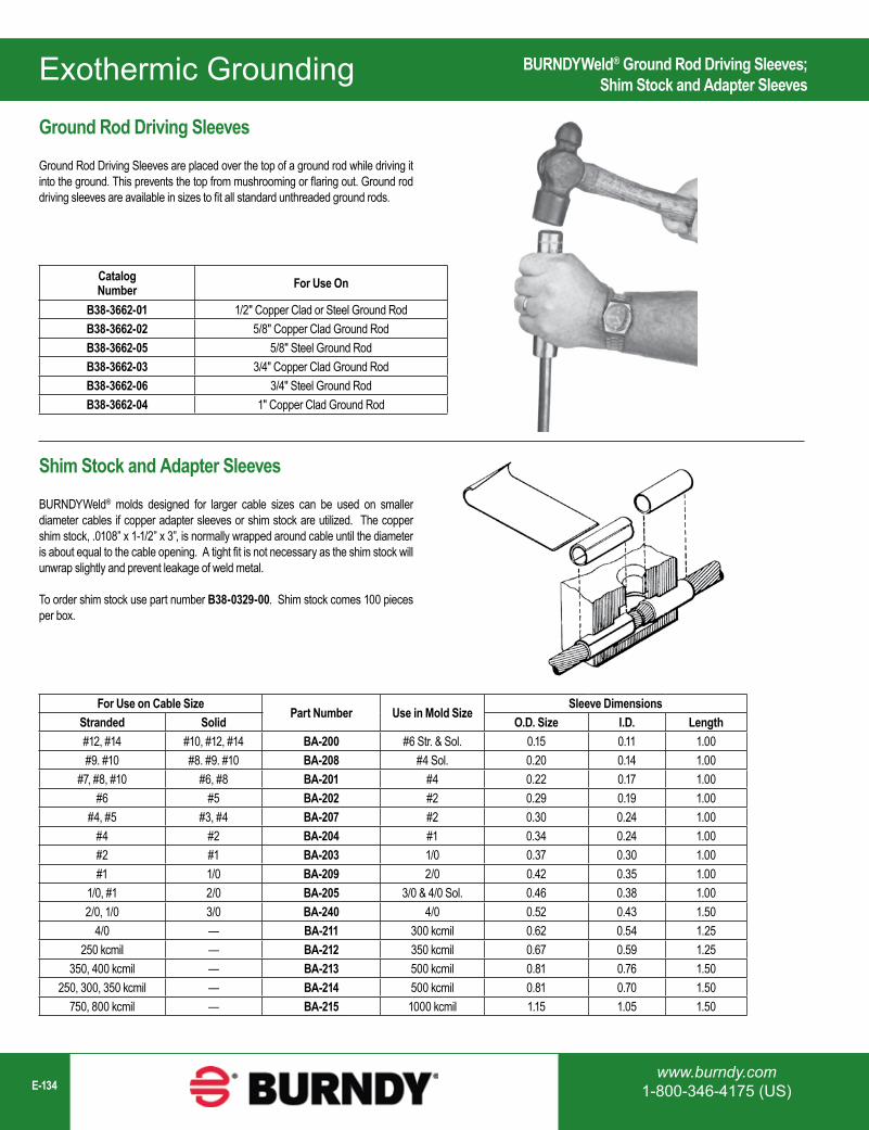
www.burndy.com1-800-346-4175 (US)E-134
Exothermic Grounding
CatalogNumber For Use On
B38-3662-01 1/2" Copper Clad or Steel Ground RodB38-3662-02 5/8" Copper Clad Ground RodB38-3662-05 5/8" Steel Ground RodB38-3662-03 3/4" Copper Clad Ground RodB38-3662-06 3/4" Steel Ground RodB38-3662-04 1" Copper Clad Ground Rod
For Use on Cable SizePart Number Use in Mold Size
Sleeve DimensionsStranded Solid O.D. Size I.D. Length#12, #14 #10, #12, #14 BA-200 #6 Str. & Sol. 0.15 0.11 1.00#9. #10 #8. #9. #10 BA-208 #4 Sol. 0.20 0.14 1.00
#7, #8, #10 #6, #8 BA-201 #4 0.22 0.17 1.00#6 #5 BA-202 #2 0.29 0.19 1.00
#4, #5 #3, #4 BA-207 #2 0.30 0.24 1.00#4 #2 BA-204 #1 0.34 0.24 1.00#2 #1 BA-203 1/0 0.37 0.30 1.00#1 1/0 BA-209 2/0 0.42 0.35 1.00
1/0, #1 2/0 BA-205 3/0 & 4/0 Sol. 0.46 0.38 1.002/0, 1/0 3/0 BA-240 4/0 0.52 0.43 1.50
4/0 — BA-211 300 kcmil 0.62 0.54 1.25250 kcmil — BA-212 350 kcmil 0.67 0.59 1.25
350, 400 kcmil — BA-213 500 kcmil 0.81 0.76 1.50250, 300, 350 kcmil — BA-214 500 kcmil 0.81 0.70 1.50
750, 800 kcmil — BA-215 1000 kcmil 1.15 1.05 1.50
BURNDYWeld® Ground Rod Driving Sleeves;Shim Stock and Adapter Sleeves
Ground Rod Driving Sleeves
Ground Rod Driving Sleeves are placed over the top of a ground rod while driving it into the ground. This prevents the top from mushrooming or flaring out. Ground rod driving sleeves are available in sizes to fit all standard unthreaded ground rods.
Shim Stock and Adapter Sleeves
BURNDYWeld® molds designed for larger cable sizes can be used on smaller diameter cables if copper adapter sleeves or shim stock are utilized. The copper shim stock, .0108” x 1-1/2” x 3”, is normally wrapped around cable until the diameter is about equal to the cable opening. A tight fit is not necessary as the shim stock will unwrap slightly and prevent leakage of weld metal.
To order shim stock use part number B38-0329-00. Shim stock comes 100 pieces per box.
Wiley Solutions
1-800-465-7051 (Canada)1-603-647-5299 (International) E-135
Wiley SolutionsTable of Contents
Wiley Solutions - Not Just for Solar Anymore! Solutions for Standard or Challenging Wire Management, Bonding, or Grounding Applications .....................................................................................................E-136
Wiley Cable Clips Flange Clips............................................................................................................................E-137 90° Flange Clips ....................................................................................................................E-138 180° Flange Clips ..................................................................................................................E-138 Rail Clips .................................................................................................................................E-138
Wiley Bundle Straps ................................................................................................................E-139
Wiley Edge Clip with Cable Tie .............................................................................................E-140
Wiley Coated Wire Management Coated Straps ........................................................................................................................E-141 Coated P-Clips ......................................................................................................................E-141
Grounding Lugs .......................................................................................................................E-142
WEEB® Washers (Washer Electrical Equipment Bond) ..................................................E-143
Telecom WEEB® Washer Two-Hole ...................................................................................E-150
Telecom WEEB® Washer Single Hole ................................................................................E-151
Bonding Jumper.......................................................................................................................E-153
Mid-Clamps ..............................................................................................................................E-155
ACE Conduit Entry Box ..........................................................................................................E-156
Table of Contents
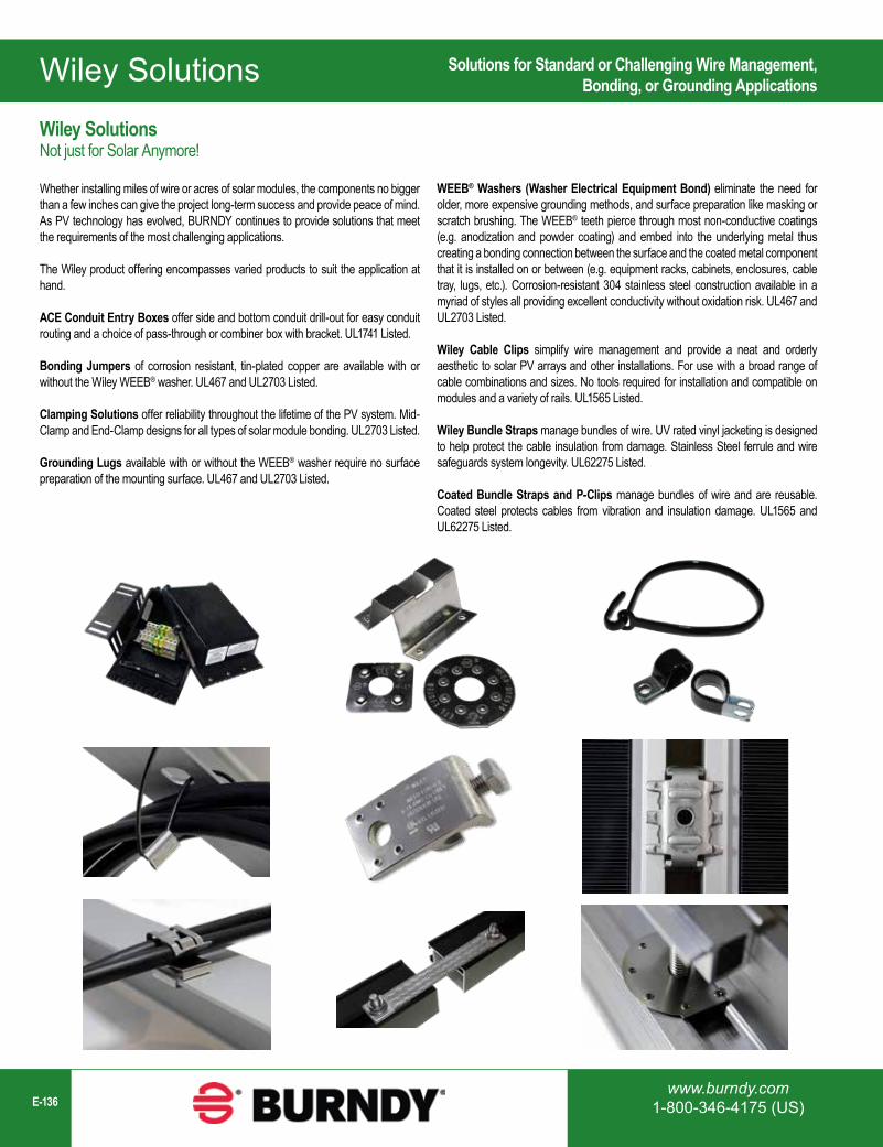
Wiley Solutions
www.burndy.com1-800-346-4175 (US)E-136
Wiley SolutionsNot just for Solar Anymore!
Whether installing miles of wire or acres of solar modules, the components no bigger than a few inches can give the project long-term success and provide peace of mind. As PV technology has evolved, BURNDY continues to provide solutions that meet the requirements of the most challenging applications.
The Wiley product offering encompasses varied products to suit the application at hand.
ACE Conduit Entry Boxes offer side and bottom conduit drill-out for easy conduit routing and a choice of pass-through or combiner box with bracket. UL1741 Listed.
Bonding Jumpers of corrosion resistant, tin-plated copper are available with or without the Wiley WEEB® washer. UL467 and UL2703 Listed.
Clamping Solutions offer reliability throughout the lifetime of the PV system. Mid-Clamp and End-Clamp designs for all types of solar module bonding. UL2703 Listed.
Grounding Lugs available with or without the WEEB® washer require no surface preparation of the mounting surface. UL467 and UL2703 Listed.
Solutions for Standard or Challenging Wire Management,Bonding, or Grounding Applications
WEEB® Washers (Washer Electrical Equipment Bond) eliminate the need for older, more expensive grounding methods, and surface preparation like masking or scratch brushing. The WEEB® teeth pierce through most non-conductive coatings (e.g. anodization and powder coating) and embed into the underlying metal thus creating a bonding connection between the surface and the coated metal component that it is installed on or between (e.g. equipment racks, cabinets, enclosures, cable tray, lugs, etc.). Corrosion-resistant 304 stainless steel construction available in a myriad of styles all providing excellent conductivity without oxidation risk. UL467 and UL2703 Listed.
Wiley Cable Clips simplify wire management and provide a neat and orderly aesthetic to solar PV arrays and other installations. For use with a broad range of cable combinations and sizes. No tools required for installation and compatible on modules and a variety of rails. UL1565 Listed.
Wiley Bundle Straps manage bundles of wire. UV rated vinyl jacketing is designed to help protect the cable insulation from damage. Stainless Steel ferrule and wire safeguards system longevity. UL62275 Listed.
Coated Bundle Straps and P-Clips manage bundles of wire and are reusable. Coated steel protects cables from vibration and insulation damage. UL1565 and UL62275 Listed.
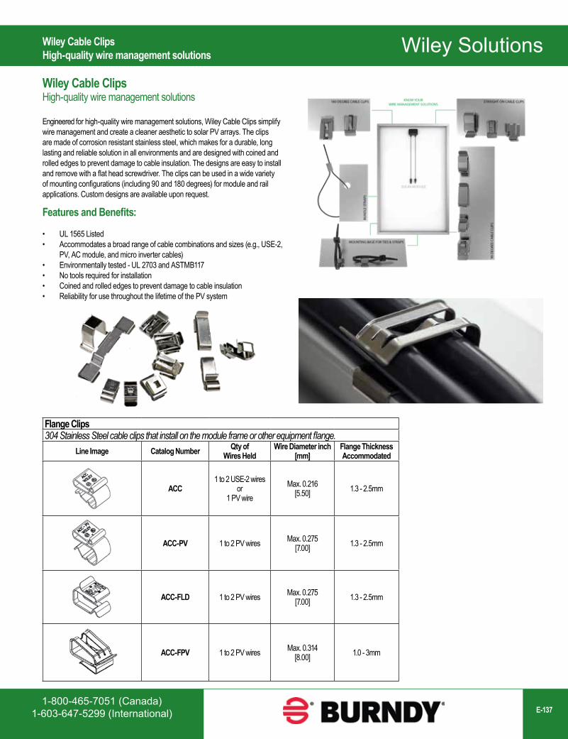
Wiley Solutions
1-800-465-7051 (Canada)1-603-647-5299 (International) E-137
Wiley Cable ClipsHigh-quality wire management solutions
Flange Clips304 Stainless Steel cable clips that install on the module frame or other equipment flange.
Line Image Catalog Number Qty ofWires Held
Wire Diameter inch[mm]
Flange Thickness Accommodated
ACC1 to 2 USE-2 wires
or1 PV wire
Max. 0.216[5.50] 1.3 - 2.5mm
ACC-PV 1 to 2 PV wires Max. 0.275 [7.00] 1.3 - 2.5mm
ACC-FLD 1 to 2 PV wires Max. 0.275 [7.00] 1.3 - 2.5mm
ACC-FPV 1 to 2 PV wires Max. 0.314[8.00] 1.0 - 3mm
Wiley Cable ClipsHigh-quality wire management solutions
Engineered for high-quality wire management solutions, Wiley Cable Clips simplify wire management and create a cleaner aesthetic to solar PV arrays. The clips are made of corrosion resistant stainless steel, which makes for a durable, long lasting and reliable solution in all environments and are designed with coined and rolled edges to prevent damage to cable insulation. The designs are easy to install and remove with a flat head screwdriver. The clips can be used in a wide variety of mounting configurations (including 90 and 180 degrees) for module and rail applications. Custom designs are available upon request.
Features and Benefits:
• UL 1565 Listed• Accommodates a broad range of cable combinations and sizes (e.g., USE-2,
PV, AC module, and micro inverter cables)• Environmentally tested - UL 2703 and ASTMB117• No tools required for installation• Coined and rolled edges to prevent damage to cable insulation• Reliability for use throughout the lifetime of the PV system
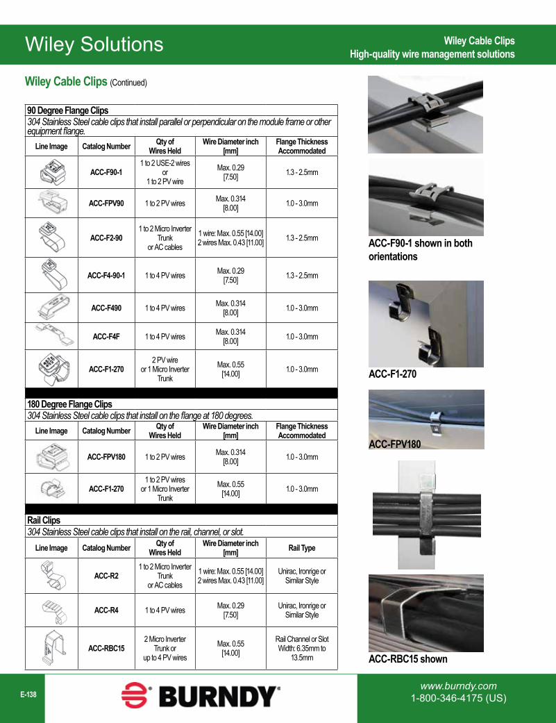
Wiley Solutions
www.burndy.com1-800-346-4175 (US)E-138
Wiley Cable ClipsHigh-quality wire management solutions
ACC-F90-1 shown in bothorientations
ACC-F1-270
ACC-RBC15 shown
90 Degree Flange Clips304 Stainless Steel cable clips that install parallel or perpendicular on the module frame or other equipment flange.
Line Image Catalog Number Qty ofWires Held
Wire Diameter inch[mm]
Flange ThicknessAccommodated
ACC-F90-11 to 2 USE-2 wires
or1 to 2 PV wire
Max. 0.29 [7.50] 1.3 - 2.5mm
ACC-FPV90 1 to 2 PV wires Max. 0.314 [8.00] 1.0 - 3.0mm
ACC-F2-901 to 2 Micro Inverter
Trunk or AC cables
1 wire: Max. 0.55 [14.00]2 wires Max. 0.43 [11.00] 1.3 - 2.5mm
ACC-F4-90-1 1 to 4 PV wires Max. 0.29 [7.50] 1.3 - 2.5mm
ACC-F490 1 to 4 PV wires Max. 0.314 [8.00] 1.0 - 3.0mm
ACC-F4F 1 to 4 PV wires Max. 0.314[8.00] 1.0 - 3.0mm
ACC-F1-2702 PV wire
or 1 Micro Inverter Trunk
Max. 0.55 [14.00] 1.0 - 3.0mm
180 Degree Flange Clips304 Stainless Steel cable clips that install on the flange at 180 degrees.
Line Image Catalog Number Qty ofWires Held
Wire Diameter inch[mm]
Flange ThicknessAccommodated
ACC-FPV180 1 to 2 PV wires Max. 0.314 [8.00] 1.0 - 3.0mm
ACC-F1-2701 to 2 PV wires
or 1 Micro Inverter Trunk
Max. 0.55 [14.00] 1.0 - 3.0mm
Rail Clips304 Stainless Steel cable clips that install on the rail, channel, or slot.
Line Image Catalog Number Qty ofWires Held
Wire Diameter inch[mm] Rail Type
ACC-R21 to 2 Micro Inverter
Trunkor AC cables
1 wire: Max. 0.55 [14.00]2 wires Max. 0.43 [11.00]
Unirac, Ironrige orSimilar Style
ACC-R4 1 to 4 PV wires Max. 0.29 [7.50]
Unirac, Ironrige orSimilar Style
ACC-RBC152 Micro Inverter
Trunk orup to 4 PV wires
Max. 0.55 [14.00]
Rail Channel or Slot Width: 6.35mm to
13.5mm
Wiley Cable Clips (Continued)
ACC-FPV180
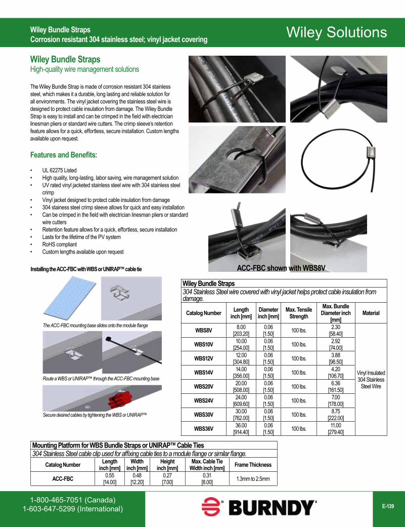
Wiley Solutions
1-800-465-7051 (Canada)1-603-647-5299 (International) E-139
Wiley Bundle StrapsCorrosion resistant 304 stainless steel; vinyl jacket covering
Mounting Platform for WBS Bundle Straps or UNIRAP™ Cable Ties304 Stainless Steel cable clip used for affixing cable ties to a module flange or similar flange.
Catalog Number Lengthinch [mm]
Widthinch [mm]
Heightinch [mm]
Max. Cable Tie Width inch [mm] Frame Thickness
ACC-FBC 0.55[14.00]
0.48[12.20]
0.27[7.00]
0.31[8.00] 1.3mm to 2.5mm
Wiley Bundle Straps304 Stainless Steel wire covered with vinyl jacket helps protect cable insulation from damage.
Catalog Number Lengthinch [mm]
Diameterinch [mm]
Max. Tensile Strength
Max. Bundle Diameter inch
[mm]Material
WBS8V 8.00[203.20]
0.06[1.50] 100 lbs. 2.30
[58.40]
Vinyl Insulated 304 Stainless
Steel Wire
WBS10V 10.00[254.00]
0.06[1.50] 100 lbs. 2.92
[74.00]
WBS12V 12.00[304.80]
0.06[1.50] 100 lbs. 3.88
[98.50]
WBS14V 14.00[356.00]
0.06[1.50] 100 lbs. 4.20
[106.70]
WBS20V 20.00[508.00]
0.06[1.50] 100 lbs. 6.36
[161.50]
WBS24V 24.00[609.60]
0.06[1.50] 100 lbs. 7.00
[178.00]
WBS30V 30.00[762.00]
0.06[1.50] 100 lbs. 8.75
[222.00]
WBS36V 36.00[914.40]
0.06[1.50] 100 lbs. 11.00
[279.40]
ACC-FBC shown with WBS8VInstalling the ACC-FBC with WBS or UNIRAP™ cable tie
The ACC-FBC mounting base slides onto the module flange
Route a WBS or UNIRAP™ through the ACC-FBC mounting base
Secure desired cables by tightening the WBS or UNIRAP™
Wiley Bundle StrapsHigh-quality wire management solutions
The Wiley Bundle Strap is made of corrosion resistant 304 stainless steel, which makes it a durable, long lasting and reliable solution for all environments. The vinyl jacket covering the stainless steel wire is designed to protect cable insulation from damage. The Wiley Bundle Strap is easy to install and can be crimped in the field with electrician linesman pliers or standard wire cutters. The crimp sleeve’s retention feature allows for a quick, effortless, secure installation. Custom lengths available upon request.
Features and Benefits:
• UL 62275 Listed• High quality, long-lasting, labor saving, wire management solution• UV rated vinyl jacketed stainless steel wire with 304 stainless steel
crimp• Vinyl jacket designed to protect cable insulation from damage• 304 stainess steel crimp sleeve allows for quick and easy installation• Can be crimped in the field with electrician linesman pliers or standard
wire cutters• Retention feature allows for a quick, effortless, secure installation• Lasts for the lifetime of the PV system• RoHS compliant• Custom lengths available upon request
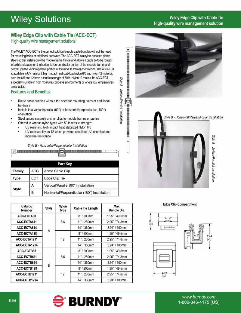
Wiley Solutions
www.burndy.com1-800-346-4175 (US)E-140
Wiley Edge Clip with Cable TieHigh-quality wire management solution
Wiley Edge Clip with Cable Tie (ACC-ECT)High-quality wire management solutions
The WILEY ACC-ECT is the perfect solution to route cable bundles without the need for mounting holes or additional hardware. The ACC-ECT is a nylon-encased plated steel clip that installs onto the module frame flange and allows a cable tie to be routed in both landscape (on the horizontal/perpendicular portion of the module frame) and portrait (on the vertical/parallel portion of the module frame) orientations. The ACC-ECT is available in UV resistant, high impact heat stabilized nylon 6/6 and nylon 12 material; both the 6/6 and 12 have a tensile strength of 50 lb. Nylon 12 makes the ACC-ECT especially suitable in high moisture, corrosive environments or where low temperatures are a factor.
Catalog Number Style Nylon
Type Cable Tie Length Max. Bundle Dia.
ACC-ECTA68
A
6/68” / 200mm 1.95” / 49.5mm
ACC-ECTA611 11” / 280mm 2.95” / 74.8mmACC-ECTA614 14” / 360mm 3.94” / 100mmACC-ECTA128
128” / 200mm 1.95” / 49.5mm
ACC-ECTA1211 11” / 280mm 2.95” / 74.8mmACC-ECTA1214 14” / 360mm 3.94” / 100mmACC-ECTB68
B
6/68” / 200mm 1.95” / 49.5mm
ACC-ECTB611 11” / 280mm 2.95” / 74.8mmACC-ECTB614 14” / 360mm 3.94” / 100mmACC-ECTB128
128” / 200mm 1.95” / 49.5mm
ACC-ECTB1211 11” / 280mm 2.95” / 74.8mmACC-ECTB1214 14” / 360mm 3.94” / 100mm
Part Key
Family ACC Acme Cable Clip
Type ECT Edge Clip Tie
Style A Vertical/Parallel (90°) Installation
B Horizontal/Perpendicular (180°) Installation
Style A - Vertical/Parallel Installation
Style B - Horizontal/Perpendicular Installation
Features and Benefits:
• Route cable bundles without the need for mounting holes or additional hardware
• Installs in a vertical/parallel (90°) or horizontal/perpendicular (180°) orientation
• Steel lances securely anchor clips to module frames or purlins• Offered in various nylon types with 50 lb tensile strength:
• UV resistant, high impact heat stabilized Nylon 6/6• UV resistant Nylon 12 which provides excellent UV, chemical and
moisture resistance
Edge Clip Compartment
Style A - Vertical/Parallel Installation
Style B - Horizontal/Perpendicular Installation
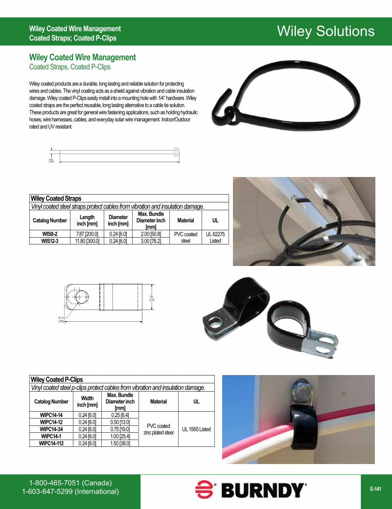
Wiley Solutions
1-800-465-7051 (Canada)1-603-647-5299 (International) E-141
Wiley Coated Wire ManagementCoated Straps; Coated P-Clips
Wiley Coated StrapsVinyl coated steel straps protect cables from vibration and insulation damage.
Catalog Number Lengthinch [mm]
Diameterinch [mm]
Max. Bundle Diameter inch
[mm]Material UL
WIS8-2 7.87 [200.0] 0.24 [6.0] 2.00 [50.8] PVC coated steel
UL 62275 ListedWIS12-3 11.80 [300.0] 0.24 [6.0] 3.00 [76.2]
Wiley Coated P-ClipsVinyl coated steel p-clips protect cables from vibration and insulation damage.
Catalog Number Widthinch [mm]
Max. Bundle Diameter inch
[mm]Material UL
WIPC14-14 0.24 [6.0] 0.25 [6.4]
PVC coated zinc plated steel UL 1565 Listed
WIPC14-12 0.24 [6.0] 0.50 [13.0]WIPC14-34 0.24 [6.0] 0.75 [19.0]WIPC14-1 0.24 [6.0] 1.00 [25.4]
WIPC14-112 0.24 [6.0] 1.50 [38.0]
Wiley Coated Wire ManagementCoated Straps, Coated P-Clips
Wiley coated products are a durable, long lasting and reliable solution for protecting wires and cables. The vinyl coating acts as a shield against vibration and cable insulation damage. Wiley coated P-Clips easily install into a mounting hole with 1/4” hardware. Wiley coated straps are the perfect reusable, long lasting alternative to a cable tie solution. These products are great for general wire fastening applications, such as holding hydraulic hoses, wire harnesses, cables, and everyday solar wire management. Indoor/Outdoor rated and UV resistant.
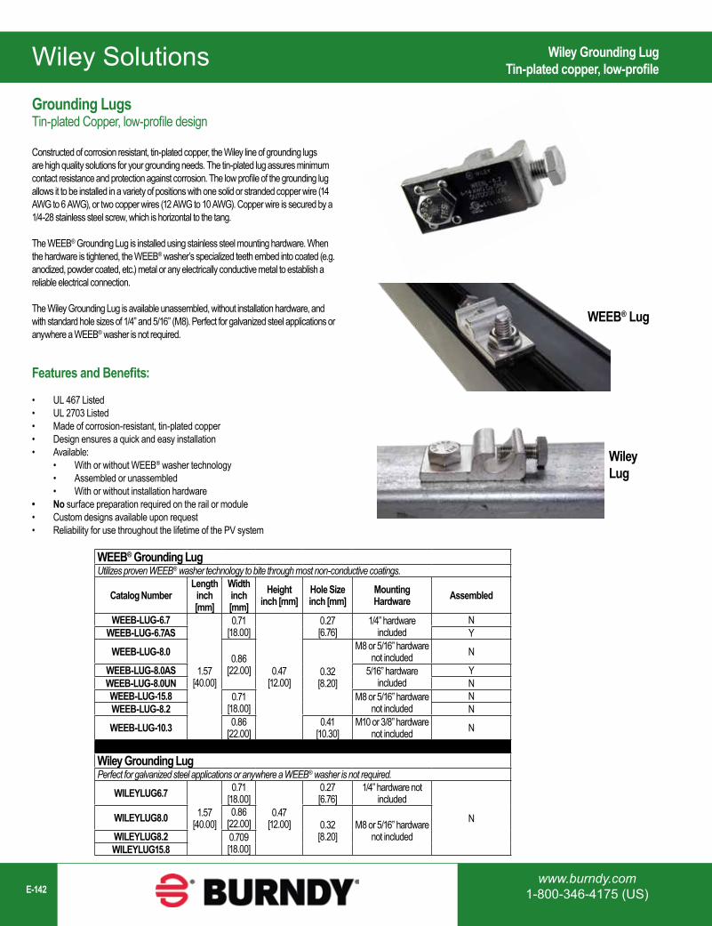
Wiley Solutions
www.burndy.com1-800-346-4175 (US)E-142
WEEB® Grounding LugUtilizes proven WEEB® washer technology to bite through most non-conductive coatings.
Catalog NumberLength
inch [mm]
Widthinch [mm]
Heightinch [mm]
Hole Sizeinch [mm]
Mounting Hardware Assembled
WEEB-LUG-6.7
1.57[40.00]
0.71[18.00]
0.47[12.00]
0.27[6.76]
1/4” hardware included
NWEEB-LUG-6.7AS Y
WEEB-LUG-8.0 0.86[22.00] 0.32
[8.20]
M8 or 5/16” hardware not included N
WEEB-LUG-8.0AS 5/16” hardware included
YWEEB-LUG-8.0UN NWEEB-LUG-15.8 0.71
[18.00]M8 or 5/16” hardware
not includedN
WEEB-LUG-8.2 N
WEEB-LUG-10.3 0.86[22.00]
0.41[10.30]
M10 or 3/8” hardwarenot included N
Wiley Grounding LugPerfect for galvanized steel applications or anywhere a WEEB® washer is not required.
WILEYLUG6.7
1.57[40.00]
0.71[18.00]
0.47[12.00]
0.27[6.76]
1/4” hardware not included
NWILEYLUG8.0 0.86[22.00] 0.32
[8.20]M8 or 5/16” hardware
not includedWILEYLUG8.2 0.709[18.00]WILEYLUG15.8
WEEB® Lug
Wiley Lug
Wiley Grounding LugTin-plated copper, low-profile
Grounding LugsTin-plated Copper, low-profile design
Constructed of corrosion resistant, tin-plated copper, the Wiley line of grounding lugs are high quality solutions for your grounding needs. The tin-plated lug assures minimum contact resistance and protection against corrosion. The low profile of the grounding lug allows it to be installed in a variety of positions with one solid or stranded copper wire (14 AWG to 6 AWG), or two copper wires (12 AWG to 10 AWG). Copper wire is secured by a 1/4-28 stainless steel screw, which is horizontal to the tang.
The WEEB® Grounding Lug is installed using stainless steel mounting hardware. When the hardware is tightened, the WEEB® washer’s specialized teeth embed into coated (e.g. anodized, powder coated, etc.) metal or any electrically conductive metal to establish a reliable electrical connection.
The Wiley Grounding Lug is available unassembled, without installation hardware, and with standard hole sizes of 1/4” and 5/16” (M8). Perfect for galvanized steel applications or anywhere a WEEB® washer is not required.
Features and Benefits:
• UL 467 Listed• UL 2703 Listed• Made of corrosion-resistant, tin-plated copper• Design ensures a quick and easy installation• Available:
• With or without WEEB® washer technology• Assembled or unassembled• With or without installation hardware
• No surface preparation required on the rail or module• Custom designs available upon request• Reliability for use throughout the lifetime of the PV system
Wiley Solutions
1-800-465-7051 (Canada)1-603-647-5299 (International) E-143
Integrated Bonding Clamp WEEB® WashersWEEB® clamp washers easily snap or slide onto a mid-clamp and/or end-clamp for quick installation.
Line Image Catalog NumberLength
inch [mm]
Widthinch [mm]
Heightinch [mm]
Hole Sizeinch [mm] Type
WEEB-BMC-1 1.57[40.00]
0.30[7.60]
0.19[4.83] N/A Clip On
WEEB-M-KR 1.65[41.90]
1.40[35.80]
0.22[5.50]
0.33[8.38] Slide On
WEEB-MSNR516 1.50[38.00]
1.57[40.00]
0.25[6.40]
0.43[11.00] Slide On
WEEB® WasherWasher Electrical Equipment Bond
A revolution in bonding, WEEB® washers eliminate the need for older, more expensive grounding methods while also significantly reducing the amount of labor and materials used installations. No surface preparation or masking required.
Here’s how it works: The WEEB® teeth pierce through most non-conductive coatings (e.g. anodization and powder coating) and embed into the underlying metal thus creating a bonding connection between the mounting surface and the coated metal component that it is installed on or between (e.g. equipment racks, cabinets, enclosures, cable tray, lugs, etc.). The result is excellent conductivity without oxidation — in solar it bonds the PV module frame with the metal racking structure. Essentially, the module and rail become one singular piece of metal, creating an electrical path to ground.
The WEEB® washers can be used in various applications like, but not limited to, coated equipment, fence, or cabinet bonding.
Features and Benefits:
• UL 467 Listed• UL 2703 Recognized; UL 2703 Listed with certain systems• Corrosion-resistant 304 stainless steel construction• Reliability for use throughout the lifetime of the PV system• Rated for outdoor use• Multi-use• Custom designs available upon request
WEEB® WashersWasher Electrical Equipment Bond (WEEB®)
Wiley Solutions
www.burndy.com1-800-346-4175 (US)E-144
Universal WEEB® Disk Washers - Top Clamp ApplicationsUniversal WEEB® Disk Washers allow for a wide range of compatibility across various racking systems and applications.
Line Image Catalog NumberLength
inch [mm]
Widthinch [mm]
Heightinch [mm]
Hole Sizeinch [mm] Type
WEEB-DSKBD34 1.57[40.00]
1.57[40.00]
0.07[1.75]
0.32[8.10] Disk
WEEB-DSK516-45 1.77[45.00]
1.77[45.00]
0.07[1.75]
0.32[8.10] Disk
Universal WEEB® Disk Washers - Bottom Mount ApplicationsUniversal WEEB® Disk Washers allow for a wide range of compatibility across various racking systems and applications.
Line Image Catalog NumberLength
inch [mm]
Widthinch [mm]
Heightinch [mm]
Hole Sizeinch [mm] Type
WEEB-DSK14 0.94[24.10]
0.94[24.10]
0.07[1.75]
0.26[6.75] Disk
WEEB-DSK516 1.01[25.75]
1.01[25.75]
0.07[1.75]
0.32[8.10] Disk
WEEB-DSK38 1.18[30.88]
1.18[30.88]
0.07[1.75]
0.39[9.80] Disk
WEEB-DSK12 1.39[35.38]
1.39[35.38]
0.07[1.75]
0.51[13.10] Disk
WEEB® Washers (Continued)
WEEB® WashersWasher Electrical Equipment Bond (WEEB®)
Wiley Solutions
1-800-465-7051 (Canada)1-603-647-5299 (International) E-145
Universal Frame Bottom Mount WEEB® WashersUniversal WEEB® FBM washers are used in Solar PV bottom mount applications and can be applied to applications outside of solar.
Line Image Catalog NumberLength
inch [mm]
Widthinch [mm]
Heightinch [mm]
Hole Sizeinch [mm] Type
WEEB-FBM14 1.78[45.25]
1.67[42.50]
0.12[3.20]
0.26[6.75] Clip On
WEEB-FBM516 1.81[46.00]
1.78[45.25]
0.12[3.20]
0.32[8.10] Clip On
Bottom Mount WEEB® WashersBottom mounting WEEB® washers bond PV modules to the mounting structure at the module mounting holes; May have features that can be applied to applications outside of solar and secure the WEEB® at holes, slots, or directly to the module frame prior to installation.
Line Image Catalog NumberLength
inch [mm]
Widthinch [mm]
Heightinch [mm]
Hole Sizeinch [mm] Type
WEEB-UIR 0.71[18.00]
0.71[18.00]
0.03[0.89]
0.26[6.75] Rigid
WEEB-11.5 0.87[22.10]
0.79[20.20]
0.15[4.00]
0.47[12.00] Rigid
WEEB-9.5 0.71[18.00]
0.59[15.10]
0.12[3.15]
0.39[10.00] Rigid
WEEB-9.5NL 0.71[18.00]
0.59[15.10]
0.07[1.74]
0.39[10.00] Rigid
WEEB® Washers (Continued)
WEEB® WashersWasher Electrical Equipment Bond (WEEB®)
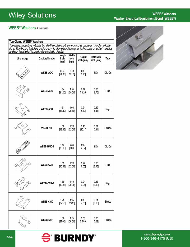
Wiley Solutions
www.burndy.com1-800-346-4175 (US)E-146
Top Clamp WEEB® WashersTop clamp mounting WEEBs bond PV modules to the mounting structure at mid-clamp loca-tions; May be pre-installed or slid onto mid-clamp hardware prior to the securement of modules and can be applied to applications outside of solar.
Line Image Catalog NumberLength
inch [mm]
Widthinch [mm]
Heightinch [mm]
Hole Sizeinch [mm] Type
WEEB-ADC 0.94[24.00]
0.73[18.66]
0.15[3.75] N/A Clip On
WEEB-ADR 1.34[34.00]
1.18[30.00]
0.72[18.25]
0.38[9.75] Rigid
WEEB-ASR 1.51[38.40]
1.00[25.50]
0.24[6.12]
0.32[8.14] Rigid
WEEB-ATF 1.68[42.66]
1.26[32.00]
0.40[10.11]
0.31[7.94] Flexible
WEEB-BMC-1 1.49[38.00]
0.30[7.60]
0.12[2.97] N/A Clip On
WEEB-CCR 1.59[40.33]
1.26[32.00]
0.24[6.05]
0.33[8.43] Rigid
WEEB-CCR-2 1.59[40.33]
1.49[38.00]
0.24[6.05]
0.33[8.43] Rigid
WEEB-CMC 1.28[32.50]
1.15[29.10]
0.19[4.83]
0.31[8.00] Slotted
WEEB-DHF 1.06[27.00]
1.13[28.60]
0.60[15.09]
0.30[7.69] Flexible
WEEB® Washers (Continued)
WEEB® WashersWasher Electrical Equipment Bond (WEEB®)
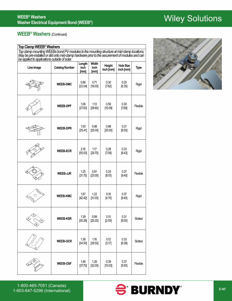
Wiley Solutions
1-800-465-7051 (Canada)1-603-647-5299 (International) E-147
Top Clamp WEEB® WashersTop clamp mounting WEEBs bond PV modules to the mounting structure at mid-clamp locations; May be pre-installed or slid onto mid-clamp hardware prior to the securement of modules and can be applied to applications outside of solar.
Line Image Catalog NumberLength
inch [mm]
Widthinch [mm]
Heightinch [mm]
Hole Sizeinch [mm] Type
WEEB-DMC 0.86[22.04]
0.71[18.00]
0.30[7.62]
0.25[6.35] Rigid
WEEB-DPF 1.06[27.00]
1.13[28.60]
0.59[15.09]
0.30[7.69] Flexible
WEEB-DPR 1.00[25.41]
0.98[25.00]
0.98[25.00]
0.31[8.00] Rigid
WEEB-ECR 2.16[55.00]
1.17[29.70]
0.28[7.09]
0.33[8.43] Rigid
WEEB-JJR 1.25[31.75]
0.91[23.00]
0.33[8.51]
0.37[9.40] Flexible
WEEB-KMC 1.67[42.42]
1.22[31.00]
0.18[4.70]
0.37[9.40] Rigid
WEEB-KSR 1.39[35.26]
0.99[25.20]
0.10[2.55]
0.31[8.00] Slotted
WEEB-OCR 1.36[34.50]
1.16[29.50]
0.12[3.17]
0.33[8.38] Slotted
WEEB-OSF 1.48[37.70]
1.26[32.00]
0.39[10.03]
0.37[9.55] Flexible
WEEB® Washers (Continued)
WEEB® WashersWasher Electrical Equipment Bond (WEEB®)

Wiley Solutions
www.burndy.com1-800-346-4175 (US)E-148
Top Clamp WEEB® WashersTop clamp mounting WEEBs bond PV modules to the mounting structure at mid-clamp locations; May be pre-installed or slid onto mid-clamp hardware prior to the securement of modules and can be applied to applications outside of solar.
Line Image Catalog NumberLength
inch [mm]
Widthinch [mm]
Heightinch [mm]
Hole Sizeinch [mm] Type
WEEB-PMC 1.58[40.11]
1.10[28.00]
0.25[6.37]
0.31[7.94] Rigid
WEEB-RPR 1.47[37.41]
1.14[28.85]
0.27[6.88]
0.32[8.20] Rigid
WEEB-SCR 1.72[43.70]
0.65[16.51]
0.28[7.11]
0.37[9.53] Rigid
WEEB-SMC-2 1.50[38.10]
0.98[25.00]
0.33[8.38]
0.32[8.20] Slotted
WEEB-SSF 1.33[33.86]
0.59[15.00]
0.67[16.94]
0.34[8.48] Flexible
WEEB-SSR 1.70[43.20]
1.35[34.30]
0.27[6.86]
0.37[9.53] Ridig
WEEB-STC 0.94[24.00]
0.42[10.58]
0.17[4.42] N/A Rigid
WEEB-UMC 1.49[37.91]
0.71[18.00]
0.29[7.34]
0.25[6.35] Rigid
WEEB-WMC 1.63[41.30]
1.31[33.50]
0.34[8.61]
0.31[7.94] Rigid
WEEB® Washers (Continued)
WEEB® WashersWasher Electrical Equipment Bond (WEEB®)
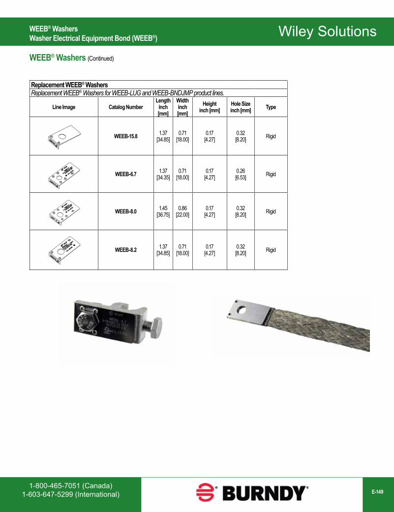
Wiley Solutions
1-800-465-7051 (Canada)1-603-647-5299 (International) E-149
Replacement WEEB® WashersReplacement WEEB® Washers for WEEB-LUG and WEEB-BNDJMP product lines.
Line Image Catalog NumberLength
inch [mm]
Widthinch [mm]
Heightinch [mm]
Hole Sizeinch [mm] Type
WEEB-15.8 1.37[34.85]
0.71[18.00]
0.17[4.27]
0.32[8.20] Rigid
WEEB-6.7 1.37[34.35]
0.71[18.00]
0.17[4.27]
0.26[6.53] Rigid
WEEB-8.0 1.45[36.75]
0.86[22.00]
0.17[4.27]
0.32[8.20] Rigid
WEEB-8.2 1.37[34.85]
0.71[18.00]
0.17[4.27]
0.32[8.20] Rigid
WEEB® Washers (Continued)
WEEB® WashersWasher Electrical Equipment Bond (WEEB®)
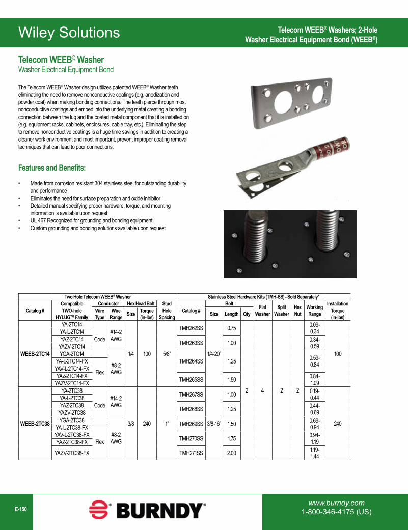
Wiley Solutions
www.burndy.com1-800-346-4175 (US)E-150
Two Hole Telecom WEEB® Washer Stainless Steel Hardware Kits (TMH-SS) - Sold Separately*
Catalog #Compatible TWO-hole
HYLUG™ Family
Conductor Hex Head Bolt Stud Hole
SpacingCatalog #
Bolt Flat Washer
Split Washer
Hex Nut
Working Range
Installation Torque (in-lbs)
Wire Type
Wire Range Size Torque
(in-lbs) Size Length Qty
WEEB-2TC14
YA-2TC14
Code#14-2AWG
1/4 100 5/8”
TMH262SS
1/4-20”
0.75
2 4 2 2
0.09-0.34
100
YA-L-2TC14YAZ-2TC14 TMH263SS 1.00 0.34-
0.59YAZV-2TC14YGA-2TC14
#8-2AWG
TMH264SS 1.25 0.59-0.84YA-L-2TC14-FX
FlexYAV-L-2TC14-FXYAZ-2TC14-FX TMH265SS 1.50 0.84-
1.09YAZV-2TC14-FX
WEEB-2TC38
YA-2TC38
Code#14-2AWG
3/8 240 1”
TMH267SS
3/8-16”
1.00 0.19-0.44
240
YA-L-2TC38YAZ-2TC38 TMH268SS 1.25 0.44-
0.69YAZV-2TC38YGA-2TC38
#8-2AWG
TMH269SS 1.50 0.69-0.94YA-L-2TC38-FX
FlexYAV-L-2TC38-FX TMH270SS 1.75 0.94-
1.19YAZ-2TC38-FX
YAZV-2TC38-FX TMH271SS 2.00 1.19-1.44
Telecom WEEB® WasherWasher Electrical Equipment Bond
The Telecom WEEB® Washer design utilizes patented WEEB® Washer teeth eliminating the need to remove nonconductive coatings (e.g. anodization and powder coat) when making bonding connections. The teeth pierce through most nonconductive coatings and embed into the underlying metal creating a bonding connection between the lug and the coated metal component that it is installed on (e.g. equipment racks, cabinets, enclosures, cable tray, etc.). Eliminating the step to remove nonconductive coatings is a huge time savings in addition to creating a cleaner work environment and most important, prevent improper coating removal techniques that can lead to poor connections.
Features and Benefits:
• Made from corrosion resistant 304 stainless steel for outstanding durability and performance
• Eliminates the need for surface preparation and oxide inhibitor• Detailed manual specifying proper hardware, torque, and mounting
information is available upon request• UL 467 Recognized for grounding and bonding equipment• Custom grounding and bonding solutions available upon request
Telecom WEEB® Washers; 2-HoleWasher Electrical Equipment Bond (WEEB®)
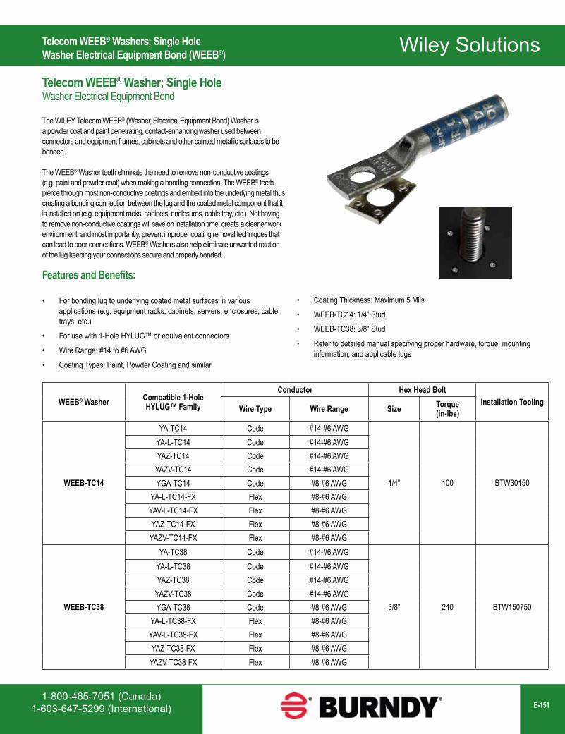
Wiley Solutions
1-800-465-7051 (Canada)1-603-647-5299 (International) E-151
Telecom WEEB® Washers; Single HoleWasher Electrical Equipment Bond (WEEB®)
Telecom WEEB® Washer; Single HoleWasher Electrical Equipment Bond
The WILEY Telecom WEEB® (Washer, Electrical Equipment Bond) Washer is a powder coat and paint penetrating, contact-enhancing washer used between connectors and equipment frames, cabinets and other painted metallic surfaces to be bonded.
The WEEB® Washer teeth eliminate the need to remove non-conductive coatings (e.g. paint and powder coat) when making a bonding connection. The WEEB® teeth pierce through most non-conductive coatings and embed into the underlying metal thus creating a bonding connection between the lug and the coated metal component that it is installed on (e.g. equipment racks, cabinets, enclosures, cable tray, etc.). Not having to remove non-conductive coatings will save on installation time, create a cleaner work environment, and most importantly, prevent improper coating removal techniques that can lead to poor connections. WEEB® Washers also help eliminate unwanted rotation of the lug keeping your connections secure and properly bonded.
Features and Benefits:
• For bonding lug to underlying coated metal surfaces in various applications (e.g. equipment racks, cabinets, servers, enclosures, cable trays, etc.)
• For use with 1-Hole HYLUG™ or equivalent connectors• Wire Range: #14 to #6 AWG• Coating Types: Paint, Powder Coating and similar
WEEB® Washer Compatible 1-Hole HYLUG™ Family
Conductor Hex Head BoltInstallation Tooling
Wire Type Wire Range Size Torque (in-lbs)
WEEB-TC14
YA-TC14 Code #14-#6 AWG
1/4” 100 BTW30150
YA-L-TC14 Code #14-#6 AWGYAZ-TC14 Code #14-#6 AWG
YAZV-TC14 Code #14-#6 AWGYGA-TC14 Code #8-#6 AWG
YA-L-TC14-FX Flex #8-#6 AWGYAV-L-TC14-FX Flex #8-#6 AWGYAZ-TC14-FX Flex #8-#6 AWG
YAZV-TC14-FX Flex #8-#6 AWG
WEEB-TC38
YA-TC38 Code #14-#6 AWG
3/8” 240 BTW150750
YA-L-TC38 Code #14-#6 AWGYAZ-TC38 Code #14-#6 AWG
YAZV-TC38 Code #14-#6 AWGYGA-TC38 Code #8-#6 AWG
YA-L-TC38-FX Flex #8-#6 AWGYAV-L-TC38-FX Flex #8-#6 AWGYAZ-TC38-FX Flex #8-#6 AWG
YAZV-TC38-FX Flex #8-#6 AWG
• Coating Thickness: Maximum 5 Mils• WEEB-TC14: 1/4” Stud• WEEB-TC38: 3/8” Stud• Refer to detailed manual specifying proper hardware, torque, mounting
information, and applicable lugs
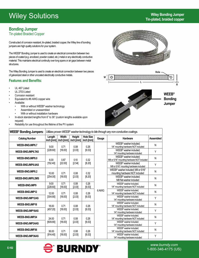
Wiley Solutions
www.burndy.com1-800-346-4175 (US)E-152
WEEB® Bonding Jumpers: Utilizes proven WEEB® washer technology to bite through any non-conductive coatings.
Catalog Number Lengthinch [mm]
Widthinch [mm]
Heightinch [mm]
Hole Sizeinch [mm] Gauge Hardware Assembled
WEEB-BNDJMP6.7 9.00[228.60]
0.71[18.00]
0.08[2.03]
0.26[6.53]
6 AWG
WEEB® washer included; 1/4” mounting hardware NOT included N
WEEB-BNDJMP6.7AS WEEB® washer included; 1/4” mounting hardware included Y
WEEB-BNDJMP8.0 6.00[152.40]
0.87[22.00]
0.10[2.54]
0.32[8.20]
WEEB® washer included; M8 or 5/16” mounting hardware NOT included N
WEEB-BNDJMP8.0AS WEEB® washer included; M8 or 5/16” mounting hardware included Y
WEEB-BNDJMP8.2 10.00[254.00]
0.71[18.00]
0.08[2.03]
0.32[8.20]
WEEB® washer included; M8 or 5/16” mounting hardware NOT included N
WEEB-BNDJMP8.2MS WEEB® washer included; M8 flat washer included N
WEEB-BNDJMP9 9.00[228.60]
0.71[18.00]
0.08[2.03]
0.26[6.53]
WEEB® washer included; 1/4” mounting hardware NOT included N
WEEB-BNDJMP12 12.00[304.80]
0.71[18.00]
0.08[2.03]
0.26[6.53]
WEEB® washer included; 1/4” mounting hardware NOT included N
WEEB-BNDJMP12AS WEEB® washer included; 1/4” mounting hardware included Y
WEEB-BNDJMP18 18.00[457.20]
0.71[18.00]
0.08[2.03]
0.26[6.53]
WEEB® washer included;1/4” mounting hardware NOT included N
WEEB-BNDJMP18AS WEEB® washer included;1/4” mounting hardware included Y
WEEB-BNDJMP24 24.00[609.80]
0.71[18.00]
0.08[2.03]
0.26[6.53]
WEEB® washer included; 1/4” mounting hardware NOT included N
WEEB-BNDJMP24AS WEEB® washer included; 1/4” mounting hardware included Y
WEEB-BNDJMP36 36.00[914.40]
0.71[18.00]
0.08[2.03]
0.26[6.53]
WEEB® washer included; 1/4” mounting hardware NOT included N
WEEB-BNDJMP36AS WEEB® washer included; 1/4” mounting hardware included Y
WEEB®
BondingJumper
Wiley Bonding JumperTin-plated, braided copper
Bonding JumperTin-plated Braided Copper
Constructed of corrosion resistant, tin-plated, braided copper, the Wiley line of bonding jumpers are high quality solutions for your system.
The WEEB® Bonding Jumper is used to create an electrical connection between two pieces of coated (e.g. anodized, powder coated, etc.) metal or any electrically conductive material. This maintains electrical continuity over long spans or air gaps between metal structures.
The Wiley Bonding Jumper is used to create an electrical connection between two pieces of galvanized steel or other uncoated electrically conductive metals.
Features and Benefits:
• UL 467 Listed• UL 2703 Listed• Corrosion resistant• Equivalent to #6 AWG copper wire• Available:
• With or without WEEB® washer technology• Assembled or unassembled• With or without installation hardware
• In-stock standard lengths from 6” to 36” (custom lengths available upon request)
• Reliability for use throughout the lifetime of the PV system
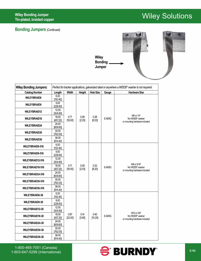
Wiley Solutions
1-800-465-7051 (Canada)1-603-647-5299 (International) E-153
Wiley Bonding Jumpers: Perfect for tracker applications, galvanized steel or anywhere a WEEB® washer is not required.Catalog Number Length Width Height Hole Size Gauge Hardware Size WILEYBRAID6 6.00
[152.40]
0.71[18.00]
0.08[2.03]
0.26[6.53] 6 AWG
M6 or 1/4” No WEEB® washer
or mounting hardware included
WILEYBRAID9 9.00[228.60]
WILEYBRAID12 12.00[304.80]
WILEYBRAID18 18.00[457.20]
WILEYBRAID24 24.00[609.80]
WILEYBRAID30 30.00[762.00]
WILEYBRAID36 36.00[914.40]
WILEYBRAID6-516 6.00[152.40]
0.71[18.00]
0.08[2.03]
0.32[8.20] 6 AWG
M8 or 5/16”No WEEB® washer
or mounting hardware included
WILEYBRAID9-516 9.00[228.60]
WILEYBRAID12-516 12.00[304.80]
WILEYBRAID18-516 18.00[457.20]
WILEYBRAID24-516 24.00[609.80]
WILEYBRAID30-516 30.00[762.00]
WILEYBRAID36-516 36.00[914.40]
WILEYBRAID6-38 6.00[152.40]
0.87[22.00]
0.14[3.65]
0.40[10.20] 6 AWG
M10 or 3/8”No WEEB® washer
or mounting hardware included
WILEYBRAID9-38 9.00[228.60]
WILEYBRAID12-38 12.00[304.80]
WILEYBRAID18-38 18.00[457.20]
WILEYBRAID24-38 24.00[609.80]
WILEYBRAID30-38 30.00[762.00]
WILEYBRAID36-38 36.00[914.40]
WileyBondingJumper
Wiley Bonding JumperTin-plated, braided copper
Bonding Jumpers (Continued)
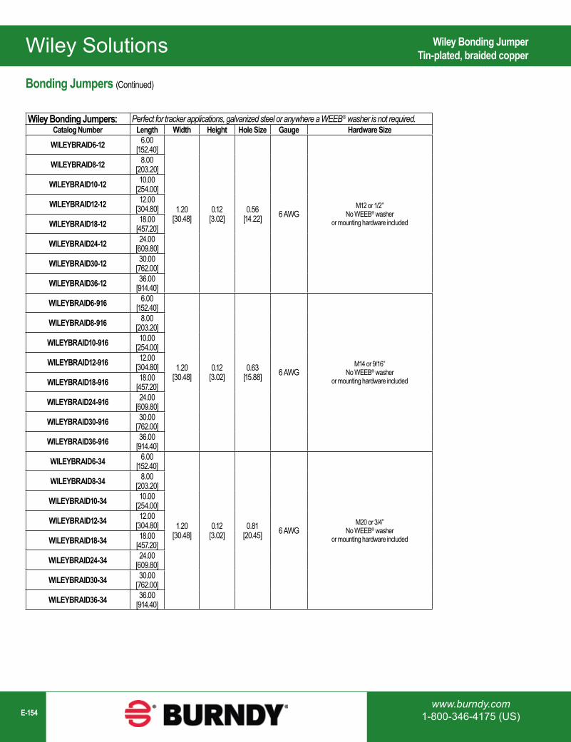
Wiley Solutions
www.burndy.com1-800-346-4175 (US)E-154
Wiley Bonding JumperTin-plated, braided copper
Wiley Bonding Jumpers: Perfect for tracker applications, galvanized steel or anywhere a WEEB® washer is not required.Catalog Number Length Width Height Hole Size Gauge Hardware Size
WILEYBRAID6-12 6.00[152.40]
1.20[30.48]
0.12[3.02]
0.56[14.22] 6 AWG
M12 or 1/2”No WEEB® washer
or mounting hardware included
WILEYBRAID8-12 8.00[203.20]
WILEYBRAID10-12 10.00[254.00]
WILEYBRAID12-12 12.00[304.80]
WILEYBRAID18-12 18.00[457.20]
WILEYBRAID24-12 24.00[609.80]
WILEYBRAID30-12 30.00[762.00]
WILEYBRAID36-12 36.00[914.40]
WILEYBRAID6-916 6.00[152.40]
1.20[30.48]
0.12[3.02]
0.63[15.88] 6 AWG
M14 or 9/16”No WEEB® washer
or mounting hardware included
WILEYBRAID8-916 8.00[203.20]
WILEYBRAID10-916 10.00[254.00]
WILEYBRAID12-916 12.00[304.80]
WILEYBRAID18-916 18.00[457.20]
WILEYBRAID24-916 24.00[609.80]
WILEYBRAID30-916 30.00[762.00]
WILEYBRAID36-916 36.00[914.40]
WILEYBRAID6-34 6.00[152.40]
1.20[30.48]
0.12[3.02]
0.81[20.45] 6 AWG
M20 or 3/4”No WEEB® washer
or mounting hardware included
WILEYBRAID8-34 8.00[203.20]
WILEYBRAID10-34 10.00[254.00]
WILEYBRAID12-34 12.00[304.80]
WILEYBRAID18-34 18.00[457.20]
WILEYBRAID24-34 24.00[609.80]
WILEYBRAID30-34 30.00[762.00]
WILEYBRAID36-34 36.00[914.40]
Bonding Jumpers (Continued)
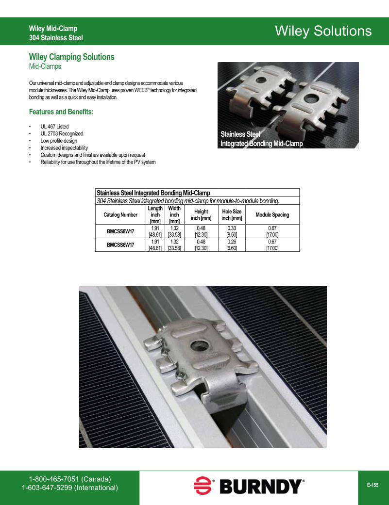
Wiley Solutions
1-800-465-7051 (Canada)1-603-647-5299 (International) E-155
Wiley Mid-Clamp304 Stainless Steel
Stainless SteelIntegrated Bonding Mid-Clamp
Stainless Steel Integrated Bonding Mid-Clamp304 Stainless Steel integrated bonding mid-clamp for module-to-module bonding.
Catalog NumberLength
inch [mm]
Widthinch [mm]
Heightinch [mm]
Hole Sizeinch [mm] Module Spacing
BMCSS8W17 1.91[48.61]
1.32[33.58]
0.48[12.30]
0.33[8.50]
0.67[17.00]
BMCSS6W17 1.91[48.61]
1.32[33.58]
0.48[12.30]
0.26[6.60]
0.67[17.00]
Wiley Clamping SolutionsMid-Clamps
Our universal mid-clamp and adjustable end clamp designs accommodate various module thicknesses. The Wiley Mid-Clamp uses proven WEEB® technology for integrated bonding as well as a quick and easy installation.
Features and Benefits:
• UL 467 Listed• UL 2703 Recognized• Low profile design• Increased inspectability• Custom designs and finishes available upon request• Reliability for use throughout the lifetime of the PV system
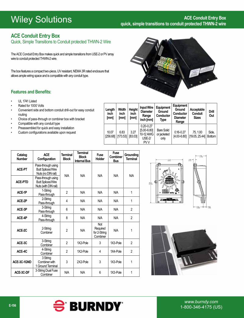
Wiley Solutions
www.burndy.com1-800-346-4175 (US)E-156
Catalog Number
ACE Configuration
Terminal Block
Terminal Block
Internal BusFuse
HolderFuse
Combiner Bus
Grounding Terminal
ACE-PTPass-through using Butt Splices/Wire Nuts (no DIN rail) N/A N/A N/A N/A N/A
ACE-PTDPass-through using Butt Splices/Wire Nuts (with DIN rail)
ACE-1P 1-String Pass-through 2 N/A N/A N/A 1
ACE-2P 2-String Pass-through 4 N/A N/A N/A 1
ACE-3P 3-String Pass-through 6 N/A N/A N/A 2
ACE-4P 4-String Pass-through 8 N/A N/A N/A 2
ACE-2C 2-String Combiner 2 N/A
Not Required
for 2-String Combiner
N/A 1
ACE-3C 3-String Combiner 2 1X2-Pole 3 1X3-Pole 2
ACE-4C 4-String Combiner 2 1X2-Pole 4 1X4-Pole 2
ACE-3C-1GND3 String
Combiner with 1 Ground Terminal
3 2X2-Pole 3 1X3-Pole 1
ACE-3C-DF 3-String Dual Fuse Combiner N/A N/A 6 1X3-Pole 1
Lengthinch[mm]
Widthinch[mm]
Heightinch[mm]
Input Wire Diameter Range
inch [mm]
Equipment Ground
Conductor Type
Equipment Ground
Conductor Diameter Range
Acceptable Conduit
SizesDrill Out
10.07[256.68]
6.83[173.53]
3.27[83.03]
0.20-0.27[5.00-6.80]10-12 AWG
USE-2/PV V
Bare Solid or jacketed
only0.16-0.27
[4.00-6.80].75, 1.00
[19.05, 25.44]Side,
Bottom
ACE Conduit Entry Boxquick, simple transitions to conduit protected THWN-2 wire
ACE Conduit Entry BoxQuick, Simple Transitions to Conduit protected THWN-2 Wire
The ACE Conduit Entry Box makes quick and simple transitions from USE-2 or PV array wire to conduit protected THWN-2 wire.
The box features a compact two-piece, UV resistant, NEMA 3R rated enclosure that allows ample wiring space and is compatible with any conduit type.
Features and Benefits:
• UL 1741 Listed• Rated for 1000 Volts• Convenient side and bottom conduit drill-out for easy conduit
routing• Choice of pass-through or combiner box with bracket• Compatible with any conduit type• Preassembled for quick and easy installation• Custom configurations available upon request