Topic #625-000-008 Plans Preparation Manual, Volume 2 January 1, 2017
Key Sheet and Signature Sheet 3-i
Chapter 3
Key Sheet and Signature Sheet
3.1 General ...................................................................................... 3-1
3.2 Key Sheet .................................................................................. 3-13.2.1 Financial Project ID, Federal Funds, County Name and
State Road Number .................................................... 3-13.2.2 Construction Contract Number, Fiscal Year and Sheet
Number ...................................................................... 3-23.2.3 Project Location Map and North Arrow ....................... 3-23.2.4 Contract Plans Components ....................................... 3-33.2.5 Index of Roadway Plans ............................................. 3-43.2.6 Professional Responsibility......................................... 3-63.2.7 Governing Design Standards and Standard
Specifications ............................................................. 3-73.2.8 Developmental Design Standards .............................. 3-73.2.9 Revisions ................................................................... 3-83.2.10 Strung Projects ........................................................... 3-8
3.3 Signature Sheet ......................................................................... 3-93.3.1 Digital Signature Placement ....................................... 3-93.3.2 Digital Signature Appearance ..................................... 3-93.3.3 Seal .......................................................................... 3-103.3.4 Statement of Responsibility ...................................... 3-103.3.5 Index ........................................................................ 3-103.3.6 Revisions ................................................................. 3-10
Topic #625-000-008 Plans Preparation Manual, Volume 2 January 1, 2017
Key Sheet and Signature Sheet 3-ii
THIS PAGE LEFT BLANK INTENTIONALLY
Topic #625-000-008 Plans Preparation Manual, Volume 2 January 1, 2017
Key Sheet and Signature Sheet 3-1
Chapter 3
Key Sheet and Signature Sheet
3.1 General
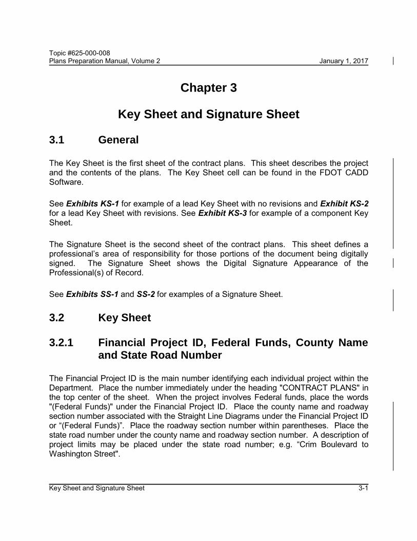
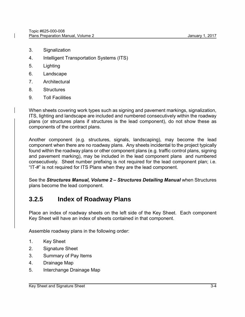
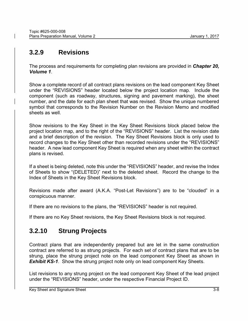
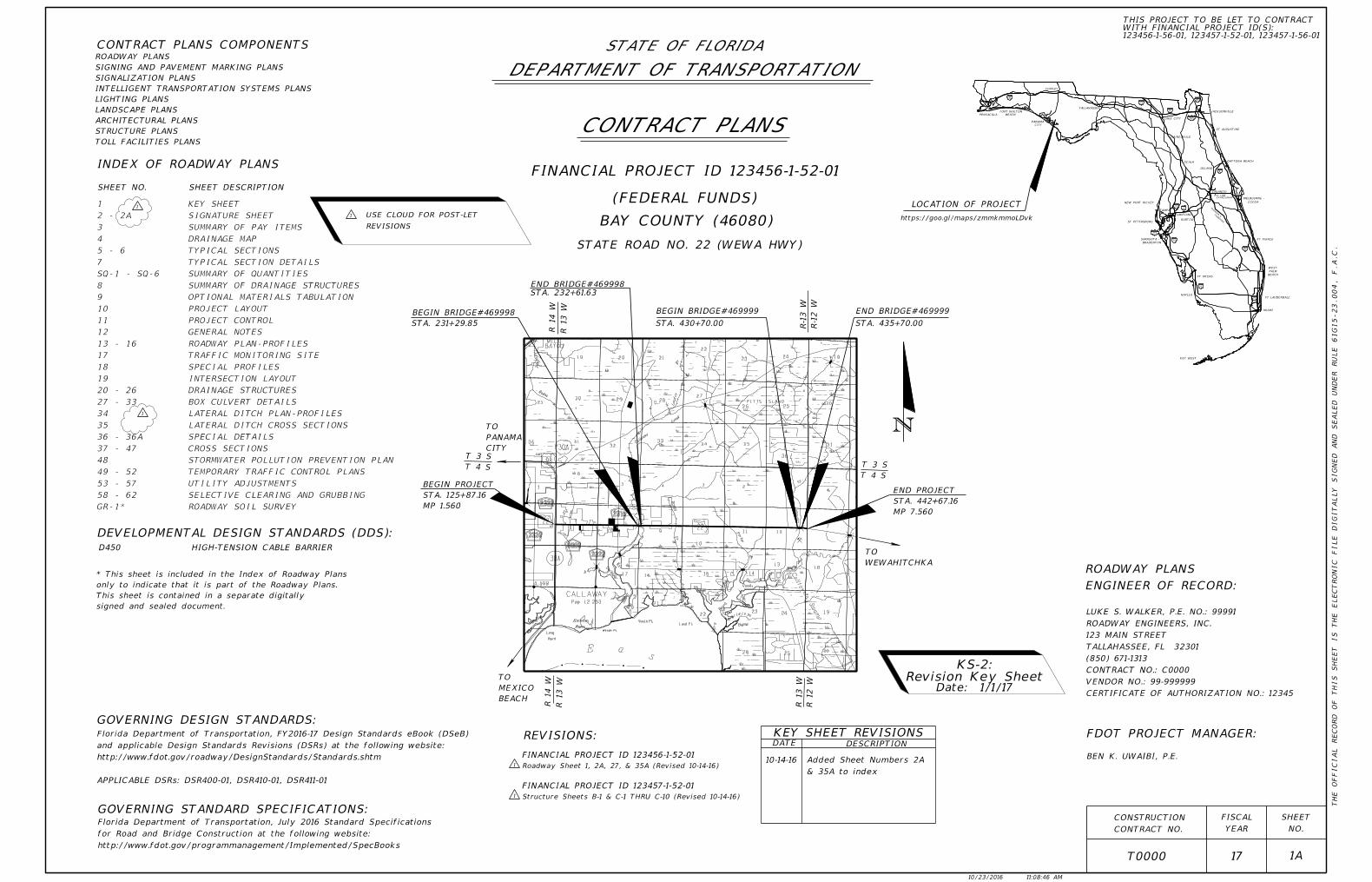
The Key Sheet is the first sheet of the contract plans. This sheet describes the project and the contents of the plans. The Key Sheet cell can be found in the FDOT CADD Software.
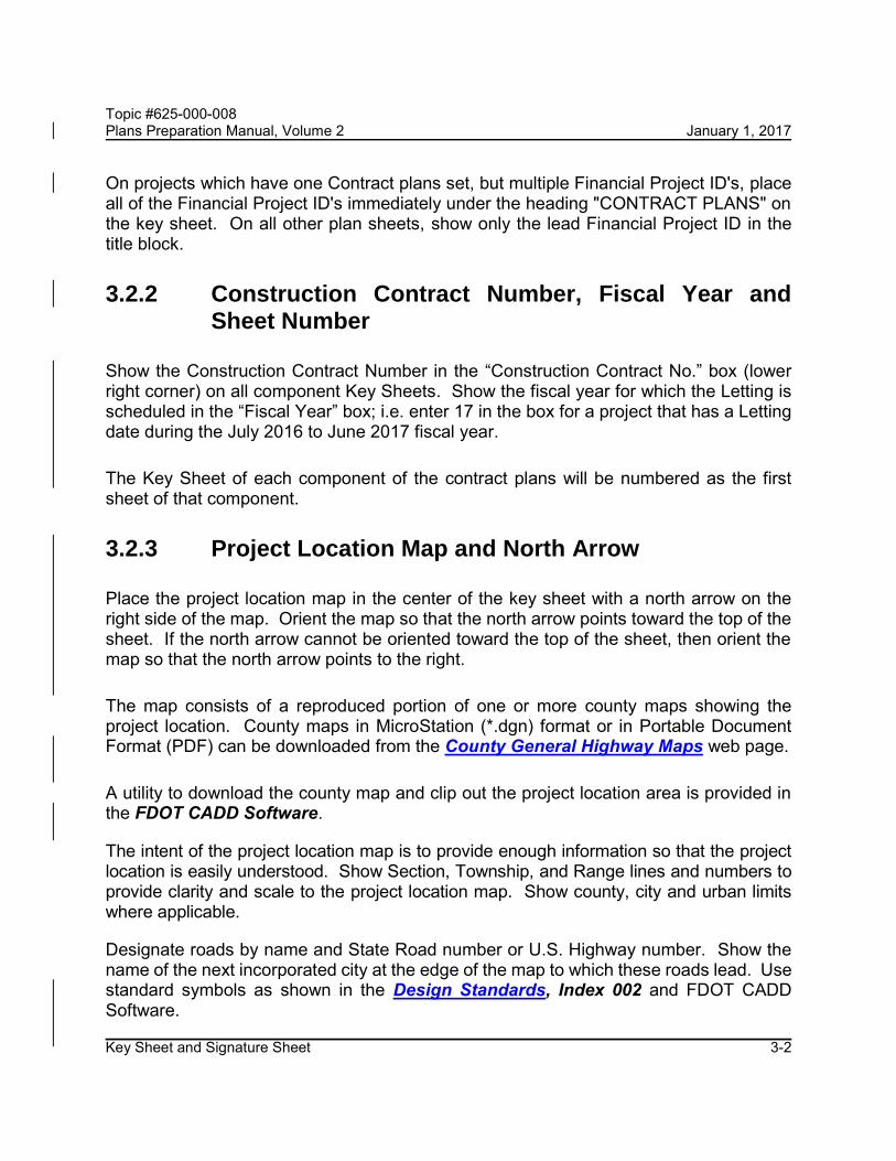
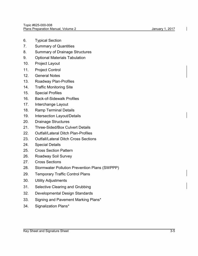
See Exhibits KS-1 for example of a lead Key Sheet with no revisions and Exhibit KS-2 for a lead Key Sheet with revisions. See Exhibit KS-3 for example of a component Key Sheet.
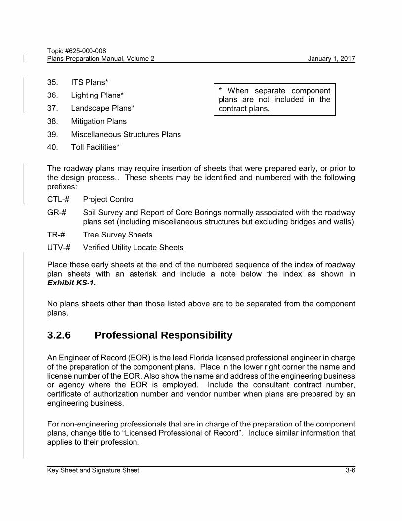
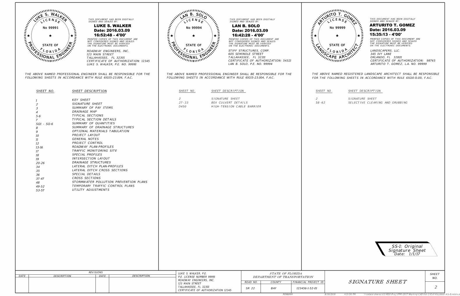
The Signature Sheet is the second sheet of the contract plans. This sheet defines a professional’s area of responsibility for those portions of the document being digitally signed. The Signature Sheet shows the Digital Signature Appearance of the Professional(s) of Record.
See Exhibits SS-1 and SS-2 for examples of a Signature Sheet.
3.2 Key Sheet
3.2.1 Financial Project ID, Federal Funds, County Name and State Road Number
The Financial Project ID is the main number identifying each individual project within the Department. Place the number immediately under the heading "CONTRACT PLANS" in the top center of the sheet. When the project involves Federal funds, place the words "(Federal Funds)" under the Financial Project ID. Place the county name and roadway section number associated with the Straight Line Diagrams under the Financial Project ID or “(Federal Funds)”. Place the roadway section number within parentheses. Place the state road number under the county name and roadway section number. A description of project limits may be placed under the state road number; e.g. “Crim Boulevard to Washington Street".
Topic #625-000-008 Plans Preparation Manual, Volume 2 January 1, 2017
Key Sheet and Signature Sheet 3-2
On projects which have one Contract plans set, but multiple Financial Project ID's, place all of the Financial Project ID's immediately under the heading "CONTRACT PLANS" on the key sheet. On all other plan sheets, show only the lead Financial Project ID in the title block.
3.2.2 Construction Contract Number, Fiscal Year and Sheet Number
Show the Construction Contract Number in the “Construction Contract No.” box (lower right corner) on all component Key Sheets. Show the fiscal year for which the Letting is scheduled in the “Fiscal Year” box; i.e. enter 17 in the box for a project that has a Letting date during the July 2016 to June 2017 fiscal year.
The Key Sheet of each component of the contract plans will be numbered as the first sheet of that component.
3.2.3 Project Location Map and North Arrow
Place the project location map in the center of the key sheet with a north arrow on the right side of the map. Orient the map so that the north arrow points toward the top of the sheet. If the north arrow cannot be oriented toward the top of the sheet, then orient the map so that the north arrow points to the right.
The map consists of a reproduced portion of one or more county maps showing the project location. County maps in MicroStation (*.dgn) format or in Portable Document Format (PDF) can be downloaded from the County General Highway Maps web page.
A utility to download the county map and clip out the project location area is provided in the FDOT CADD Software.
The intent of the project location map is to provide enough information so that the project location is easily understood. Show Section, Township, and Range lines and numbers to provide clarity and scale to the project location map. Show county, city and urban limits where applicable.
Designate roads by name and State Road number or U.S. Highway number. Show the name of the next incorporated city at the edge of the map to which these roads lead. Use standard symbols as shown in the Design Standards, Index 002 and FDOT CADD Software.
Topic #625-000-008 Plans Preparation Manual, Volume 2 January 1, 2017
Key Sheet and Signature Sheet 3-3
Indicate project location using a heavy solid line of substantial width. It is sometimes advantageous to show station numbers at regular intervals, particularly with city street projects. Flag and station the following:
Begin and end project limits. Provide milepost, correct to three decimals, underthe project stations.
Begin and end limits of bridges and bridge culverts. When an existing structure isbeing replaced, indicate the proposed structure and not the existing.
Station equations
Project exception limits (mileposts excluded from project)
Rail crossings within the limits of construction, including name of railroad,DOT/AAR crossing number, and railroad milepost.
Calculate the end milepost by adding the distance in miles between begin and end project to the begin milepost. Plans are to be prepared using stationing in linear feet. A project may be prepared using mileposts when linear foot stationing is unavailable. All station information is to be consistent with the station information entered into the Work Program Administration system during final design. See Volume 1, Section 14.2.
When several projects are covered by the same set of plans, flag and station begin and end project limits for each Financial Project ID.
Show the project location map only on the lead component Key Sheet.
Show a small-scale state map at the upper right portion of the lead component Key Sheet and indicate the location of the project thereon. The map may be shown on other component Key Sheets, but is not required.
3.2.4 Contract Plans Components
Contract plans are typically assembled as component plans that are associated with a primary work type. Roadway plans are typically the lead component of the contract plans. Provide a list of all component plans included in the contract plans in the upper left corner of the lead component Key Sheet in the following order:
1. Roadway2. Signing and Pavement Marking
Topic #625-000-008 Plans Preparation Manual, Volume 2 January 1, 2017
Key Sheet and Signature Sheet 3-4
3. Signalization 4. Intelligent Transportation Systems (ITS) 5. Lighting 6. Landscape 7. Architectural 8. Structures 9. Toll Facilities
When sheets covering work types such as signing and pavement markings, signalization, ITS, lighting and landscape are included and numbered consecutively within the roadway plans (or structures plans if structures is the lead component), do not show these as components of the contract plans.
Another component (e.g. structures, signals, landscaping), may become the lead component when there are no roadway plans. Any sheets incidental to the project typically found within the roadway plans or other component plans (e.g. traffic control plans, signing and pavement marking), may be included in the lead component plans and numbered consecutively. Sheet number prefixing is not required for the lead component plan; i.e. “IT-#” is not required for ITS Plans when they are the lead component.
See the Structures Manual, Volume 2 – Structures Detailing Manual when Structures plans become the lead component.
3.2.5 Index of Roadway Plans
Place an index of roadway sheets on the left side of the Key Sheet. Each component Key Sheet will have an index of sheets contained in that component.
Assemble roadway plans in the following order:
1. Key Sheet 2. Signature Sheet 3. Summary of Pay Items 4. Drainage Map 5. Interchange Drainage Map
Topic #625-000-008 Plans Preparation Manual, Volume 2 January 1, 2017
Key Sheet and Signature Sheet 3-5
6. Typical Section 7. Summary of Quantities 8. Summary of Drainage Structures 9. Optional Materials Tabulation 10. Project Layout 11. Project Control 12. General Notes 13. Roadway Plan-Profiles 14. Traffic Monitoring Site 15. Special Profiles 16. Back-of-Sidewalk Profiles 17. Interchange Layout 18. Ramp Terminal Details 19. Intersection Layout/Details 20. Drainage Structures 21. Three-Sided/Box Culvert Details 22. Outfall/Lateral Ditch Plan-Profiles 23. Outfall/Lateral Ditch Cross Sections 24. Special Details 25. Cross Section Pattern 26. Roadway Soil Survey 27. Cross Sections 28. Stormwater Pollution Prevention Plans (SWPPP) 29. Temporary Traffic Control Plans 30. Utility Adjustments 31. Selective Clearing and Grubbing 32. Developmental Design Standards 33. Signing and Pavement Marking Plans* 34. Signalization Plans*
Topic #625-000-008 Plans Preparation Manual, Volume 2 January 1, 2017
Key Sheet and Signature Sheet 3-6
35. ITS Plans* 36. Lighting Plans* 37. Landscape Plans* 38. Mitigation Plans 39. Miscellaneous Structures Plans 40. Toll Facilities*
The roadway plans may require insertion of sheets that were prepared early, or prior to the design process.. These sheets may be identified and numbered with the following prefixes: CTL-# Project Control GR-# Soil Survey and Report of Core Borings normally associated with the roadway
plans set (including miscellaneous structures but excluding bridges and walls) TR-# Tree Survey Sheets UTV-# Verified Utility Locate Sheets
Place these early sheets at the end of the numbered sequence of the index of roadway plan sheets with an asterisk and include a note below the index as shown in Exhibit KS-1.
No plans sheets other than those listed above are to be separated from the component plans.
3.2.6 Professional Responsibility
An Engineer of Record (EOR) is the lead Florida licensed professional engineer in charge of the preparation of the component plans. Place in the lower right corner the name and license number of the EOR. Also show the name and address of the engineering business or agency where the EOR is employed. Include the consultant contract number, certificate of authorization number and vendor number when plans are prepared by an engineering business.
For non-engineering professionals that are in charge of the preparation of the component plans, change title to “Licensed Professional of Record”. Include similar information that applies to their profession.
* When separate component plans are not included in the contract plans.
Topic #625-000-008 Plans Preparation Manual, Volume 2 January 1, 2017
Key Sheet and Signature Sheet 3-7
Place the name of the FDOT Project Manager below the EOR information. Show only the FDOT Project Manager at this location, except for:
When plans are prepared by Department Personnel, the name of the FDOT designer may be placed immediately below the name of the FDOT Project Manager.
When appropriate, the name of the GEC Project Manager may be placed immediately below the FDOT Project Manager.
3.2.7 Governing Design Standards and Standard Specifications
Show the governing Design Standards and Standard Specifications for Road and Bridge Construction on the lead component Key Sheet as shown on Exhibit KS-1. Do not show this reference on other component Key Sheets. For requirements of the Structures General Notes, see the Structures Detailing Manual, Section 5.2.
The Design Standards are published annually as an eBook and posted on the Roadway Design Office website. The release of the Design Standards eBook (DSeB) is announced by Design Bulletin which specifies the effective date for implementation.
When Design Standards Revisions (DSRs) are released by Design Bulletin, the engineer must determine which DSRs apply to the project and reference them as shown on Exhibit KS-1. If there are no applicable DSRs, the note regarding DSRs is not required.
3.2.8 Developmental Design Standards
Insert Developmental Design Standards (DDSs) at the end of each component plan set as applicable. When included in structure component plans, insert DDSs before existing bridge plans. List DDSs below the “Index of Sheets” for the plans component in which they are included. Follow the process shown in the “Developmental Design Standards Usage Process for Design-Bid-Build Projects” located in the link provided on the top of the Developmental Design Standards website for requesting and using a DDS.
Topic #625-000-008 Plans Preparation Manual, Volume 2 January 1, 2017
Key Sheet and Signature Sheet 3-8
3.2.9 Revisions
The process and requirements for completing plan revisions are provided in Chapter 20, Volume 1.
Show a complete record of all contract plans revisions on the lead component Key Sheet under the “REVISIONS” header located below the project location map. Include the component (such as roadway, structures, signing and pavement marking), the sheet number, and the date for each plan sheet that was revised. Show the unique numbered symbol that corresponds to the Revision Number on the Revision Memo and modified sheets as well.
Show revisions to the Key Sheet in the Key Sheet Revisions block placed below the project location map, and to the right of the “REVISIONS” header. List the revision date and a brief description of the revision. The Key Sheet Revisions block is only used to record changes to the Key Sheet other than recorded revisions under the “REVISIONS” header. A new lead component Key Sheet is required when any sheet within the contract plans is revised.
If a sheet is being deleted, note this under the “REVISIONS” header, and revise the Index of Sheets to show “(DELETED)” next to the deleted sheet. Record the change to the Index of Sheets in the Key Sheet Revisions block.
Revisions made after award (A.K.A. “Post-Let Revisions”) are to be “clouded” in a conspicuous manner.
If there are no revisions to the plans, the “REVISIONS” header is not required.
If there are no Key Sheet revisions, the Key Sheet Revisions block is not required.
3.2.10 Strung Projects
Contract plans that are independently prepared but are let in the same construction contract are referred to as strung projects. For each set of contract plans that are to be strung, place the strung project note on the lead component Key Sheet as shown in Exhibit KS-1. Show the strung project note only on lead component Key Sheets.
List revisions to any strung project on the lead component Key Sheet of the lead project under the “REVISIONS” header, under the respective Financial Project ID.
Topic #625-000-008 Plans Preparation Manual, Volume 2 January 1, 2017
Key Sheet and Signature Sheet 3-9
3.3 Signature Sheet
Projects are to be delivered as individual Signed and Sealed components of the contract plans (e.g. Roadway Plans, Signing and Pavement Marking Plans, Structure Plans). A Signature Sheet is required for component plans that are to be Signed and Sealed by more than one licensed professional. When component plans are to be Signed and Sealed by a single licensed professional a signature block can be placed on the Key Sheet in lieu of using a Signature Sheet (see KS-3). The Signature Sheet title block is to contain the information for the licensed professional that is responsible for the creation and content of the sheet. Do not place the Official Record note along the right edge of this sheet. See Section 19.2, Volume 1 for digital Signing and Sealing requirements. See Exhibits SS-1 and SS-2 for examples of a Signature Sheet.
3.3.1 Digital Signature Placement
By placing a digital signature on the Signature Sheet of a multi-sheet plans set, the licensed professional associates their professional signature with the entire plans set. The Signature Sheet provides a Statement of Responsibility delineating the extent of the professional’s responsibility and identifies the specific sheets for which the professional is accepting responsibility.
3.3.2 Digital Signature Appearance
A Digital Signature Appearance is the visual representation of a Digital Signature applied to a document. The Digital Signature Appearance is composed of combinations of informational fields (such as dates or text) and other information. The Digital Signature Appearance must include the professional’s name, and the date and time of signing stamp.
Topic #625-000-008 Plans Preparation Manual, Volume 2 January 1, 2017
Key Sheet and Signature Sheet 3-10
3.3.3 Seal
The professional will include a representation of their Seal next to the Digital Signature Appearance. Seal representations are provided with the FDOT CADD Software. Each respective Board of Professional Regulation has enacted in their section of the Florida Administrative Code the requirements for the size and representation of a Seal.
3.3.4 Statement of Responsibility
The Statement of Responsibility is used to define the licensed professional’s limits of responsibility and any exculpatory language. Place this statement below the Seal and Digital Signature Appearance and above the sheet index. The Statement of Responsibility must indicate the applicable Rule of the Florida Administrative Code (F.A.C.).
Exculpatory language may be included in cases where professionals share responsibility for content on any given sheet. In those cases additional text must include the limitations of their responsibility.
3.3.5 Index
The Index is a list of sheets that the licensed professional is responsible for signing and sealing. Place the Index below the Statement of Responsibility for each licensed professional. There may be sheets common to more than one licensed professional, and in such a case, exculpatory language should be used to differentiate each area of responsibility.
3.3.6 Revisions
A revision Signature Sheet is created when more than one licensed professional is required to Sign and Seal a revision package. The revision Signature Sheet is numbered using an alpha suffix (2A, 2B, etc.). Only the licensed professionals required to Sign and Seal the revision are to be included on the revision Signature Sheet. See Exhibit SS-2 for an example of a revision Signature Sheet.
N
LOCATION OF PROJECT
Date: 1/1/17
R-1
2
W
R-1
3
W
R 13
W
R 14
W
T 3 S
T 4 S
R 14
W
R 13
W
R 13
W
R 12
W
T 4 S
T 3 S
STA. 231+29.85
STA. 232+61.63
END BRIDGE#469999
STA. 435+70.00STA. 430+70.00
BEGIN BRIDGE#469998
END BRIDGE#469998
BEGIN BRIDGE#469999
WEWAHITCHKA
TO
BEACH
MEXICO
TO
CITY
PANAMA
TO
STATE OF FLORIDA
DEPARTMENT OF TRANSPORTATION
CONTRACT PLANS
11:08:17 AM10/23/2016
FINANCIAL PROJECT ID 123456-1-52-01
BAY COUNTY (46080)
(FEDERAL FUNDS)
INDEX OF ROADWAY PLANS
BEE LINEEXPRESSWAY
FLO
RID
A S
TU
RNPIK
E
10
PENSACOLA
FORT WALTON
BEACH
PANAMA
CITY
CHIPLEY
TALLAHASSEE
75
10
LAKE CITY 295
95
JACKSONVILLE
ST AUGUSTINE
GAINESVILLE
OCALA DAYTONA BEACH
DELAND
4
NEW PORT RICHEY
TAMPA
754
LAKELAND
MELBOURNE -
COCOA
ORLANDO
BARTOWST PETERSBURG
275
SARASOTA -
BRADENTON75
95
FT PIERCE
FT MYERS
WEST
PALM
BEACH
FT LAUDERDALE
MIAMI
75
75
NAPLES
KEY WEST
MP 1.560
STA. 125+87.16
BEGIN PROJECT
TH
E
OF
FI
CI
AL
RE
CO
RD
OF
THI
S
SH
EE
T I
S
TH
E
EL
EC
TR
ONI
C
FI
LE
DI
GI
TA
LL
Y
SI
GN
ED
AN
D
SE
AL
ED
UN
DE
R
RU
LE 61
G15-23.004,
F.
A.
C.
ENGINEER OF RECORD:
ROADWAY PLANS
123456-1-56-01, 123457-1-52-01, 123457-1-56-01WITH FINANCIAL PROJECT ID(S): THIS PROJECT TO BE LET TO CONTRACT
GOVERNING DESIGN STANDARDS:
MP 7.560
STA. 442+67.16
END PROJECT
24
25
36
1
19
30
31
6
7
18
24 19
2530
3233
34
345
8 9
10
151617
7
6
3136
1
35
2
11 12
13
14
2021
2223
26
20 21
22
272829
2530
24 19 23
26
California Swam
p
MillBayou
Pop. 12,253
CALLAWAY
Parker
Br.
Cr.Boggy
Cushion
Cr.
Reedy
Cr. L
awton
Br.
Calla
way
Creek
Mill
Bayou
aE s
Bayou
Emmons
Bayou
Callaway
Bayou
ciP
al ene
Bayou
l
Cooks
Bayou
Laird
Bayou
Long
Point
Wilson Pt.
Smith Pt.Laird Pt.
PITTS ISLAND
4,598
SHEET NO. SHEET DESCRIPTION
FDOT PROJECT MANAGER:
BEN K. UWAIBI, P.E.
Original Key SheetKS-1:
NO.
SHEET
1
CONTRACT NO.
CONSTRUCTION
T0000
22
2323
3026
30A
2325
22
2322
98
30A
2315
HIGH-TENSION CABLE BARRIERD450
DEVELOPMENTAL DESIGN STANDARDS (DDS):
GOVERNING STANDARD SPECIFICATIONS:
CONTRACT PLANS COMPONENTS
YEAR
FISCAL
17
TOLL FACILITIES PLANS
STRUCTURE PLANS
ARCHITECTURAL PLANS
LANDSCAPE PLANS
LIGHTING PLANS
INTELLIGENT TRANSPORTATION SYSTEMS PLANS
SIGNALIZATION PLANS
SIGNING AND PAVEMENT MARKING PLANS
ROADWAY PLANS
CERTIFICATE OF AUTHORIZATION NO.: 12345
VENDOR NO.: 99-999999
CONTRACT NO.: C0000
(850) 671-1313
TALLAHASSEE, FL 32301
123 MAIN STREET
ROADWAY ENGINEERS, INC.
LUKE S. WALKER, P.E. NO.: 99991
https://goo.gl/maps/zmmkmmoLDvk
STATE ROAD NO. 22 (WEWA HWY)
GR-1* ROADWAY SOIL SURVEY
58 - 62 SELECTIVE CLEARING AND GRUBBING
53 - 57 UTILITY ADJUSTMENTS
49 - 52 TEMPORARY TRAFFIC CONTROL PLANS
48 STORMWATER POLLUTION PREVENTION PLAN
37 - 47 CROSS SECTIONS
36 SPECIAL DETAILS
35 LATERAL DITCH CROSS SECTIONS
34 LATERAL DITCH PLAN-PROFILES
27 - 33 BOX CULVERT DETAILS
20 - 26 DRAINAGE STRUCTURES
19 INTERSECTION LAYOUT
18 SPECIAL PROFILES
17 TRAFFIC MONITORING SITE
13 - 16 ROADWAY PLAN-PROFILES
12 GENERAL NOTES
11 PROJECT CONTROL
10 PROJECT LAYOUT
9 OPTIONAL MATERIALS TABULATION
8 SUMMARY OF DRAINAGE STRUCTURES
SQ-1 - SQ-6 SUMMARY OF QUANTITIES
7 TYPICAL SECTION DETAILS
5 - 6 TYPICAL SECTIONS
4 DRAINAGE MAP
3 SUMMARY OF PAY ITEMS
2 SIGNATURE SHEET
1 KEY SHEET
signed and sealed document.
This sheet is contained in a separate digitally
only to indicate that it is part of the Roadway Plans.
* This sheet is included in the Index of Roadway Plans
is optional.Embeded link
APPLICABLE DSRs: DSR400-01, DSR410-01, DSR411-01
http://www.fdot.gov/roadway/DesignStandards/Standards.shtm
and applicable Design Standards Revisions (DSRs) at the following website:
Florida Department of Transportation, FY2016-17 Design Standards eBook (DSeB)
http://www.fdot.gov/programmanagement/Implemented/SpecBooks
for Road and Bridge Construction at the following website:
Florida Department of Transportation, July 2016 Standard Specifications
N
LOCATION OF PROJECT
R-1
2
W
R-1
3
W
R 13
W
R 14
W
T 3 S
T 4 S
R 14
W
R 13
W
R 13
W
R 12
W
T 4 S
T 3 S
STA. 231+29.85
STA. 232+61.63
END BRIDGE#469999
STA. 435+70.00STA. 430+70.00
BEGIN BRIDGE#469998
END BRIDGE#469998
BEGIN BRIDGE#469999
WEWAHITCHKA
TO
BEACH
MEXICO
TO
CITY
PANAMA
TO
STATE OF FLORIDA
DESCRIPTIONDATE
11:08:46 AM10/23/2016
BEE LINEEXPRESSWAY
TU
RNPIK
E
10
PENSACOLA
FORT WALTON
BEACH
PANAMA
CITY
CHIPLEY
TALLAHASSEE
75
10
LAKE CITY 295
95
JACKSONVILLE
ST AUGUSTINE
GAINESVILLE
OCALA DAYTONA BEACH
DELAND
4
NEW PORT RICHEY
TAMPA
754
LAKELAND
MELBOURNE -
COCOA
ORLANDO
BARTOWST PETERSBURG
275
SARASOTA -
BRADENTON75
95
FT PIERCE
FT MYERS
WEST
PALM
BEACH
FT LAUDERDALE
MIAMI
75
75
NAPLES
KEY WEST
KEY SHEET REVISIONS
1
10-14-16
TH
E
OF
FI
CI
AL
RE
CO
RD
OF
THI
S
SH
EE
T I
S
TH
E
EL
EC
TR
ONI
C
FI
LE
DI
GI
TA
LL
Y
SI
GN
ED
AN
D
SE
AL
ED
UN
DE
R
RU
LE 61
G15-23.004,
F.
A.
C.
123456-1-56-01, 123457-1-52-01, 123457-1-56-01WITH FINANCIAL PROJECT ID(S): THIS PROJECT TO BE LET TO CONTRACT
DEPARTMENT OF TRANSPORTATION
CONTRACT PLANS
FINANCIAL PROJECT ID 123456-1-52-01
BAY COUNTY (46080)
(FEDERAL FUNDS)
FINANCIAL PROJECT ID 123456-1-52-01
REVISIONS:
1
FINANCIAL PROJECT ID 123457-1-52-01
1 Structure Sheets B-1 & C-1 THRU C-10 (Revised 10-14-16)
REVISIONS
USE CLOUD FOR POST-LET
& 35A to index
Added Sheet Numbers 2A
MP 7.560
STA. 442+67.16
END PROJECT
24
25
36
1
19
30
31
6
7
18
24 19
2530
3233
34
345
8 9
10
151617
7
6
3136
1
35
2
11 12
13
14
2021
2223
26
20 21
22
272829
2530
24 19 23
26
California Swam
p
MillBayou
Pop. 12,253
CALLAWAY
Parker
Br.
Cr.Boggy
Cushion
Cr.
Reedy
Cr. L
awton
Br.
Calla
way
Creek
Mill
Bayou
aE s
Bayou
Emmons
Bayou
Callaway
Bayou
ciP
al ene
Bayou
l
Cooks
Bayou
Laird
Bayou
Long
Point
Wilson Pt.
Smith Pt.Laird Pt.
PITTS ISLAND
4,598
INDEX OF ROADWAY PLANS
GOVERNING DESIGN STANDARDS:
SHEET NO. SHEET DESCRIPTION
1
1
Roadway Sheet 1, 2A, 27, & 35A (Revised 10-14-16)
MP 1.560
STA. 125+87.16
BEGIN PROJECT
Date: 1/1/17
NO.
SHEET
1A
CONTRACT NO.
CONSTRUCTION
T0000
FDOT PROJECT MANAGER:
BEN K. UWAIBI, P.E.
Revision Key SheetKS-2:
ENGINEER OF RECORD:
ROADWAY PLANS
22
2315
2323
3026
30A
2325
22
2322
98
30A
DEVELOPMENTAL DESIGN STANDARDS (DDS):
HIGH-TENSION CABLE BARRIERD450
GOVERNING STANDARD SPECIFICATIONS:
CONTRACT PLANS COMPONENTS
YEAR
FISCAL
17
FLO
RID
A S
TOLL FACILITIES PLANS
STRUCTURE PLANS
ARCHITECTURAL PLANS
LANDSCAPE PLANS
LIGHTING PLANS
INTELLIGENT TRANSPORTATION SYSTEMS PLANS
SIGNALIZATION PLANS
SIGNING AND PAVEMENT MARKING PLANS
ROADWAY PLANS
CERTIFICATE OF AUTHORIZATION NO.: 12345
VENDOR NO.: 99-999999
CONTRACT NO.: C0000
(850) 671-1313
TALLAHASSEE, FL 32301
123 MAIN STREET
ROADWAY ENGINEERS, INC.
LUKE S. WALKER, P.E. NO.: 99991
https://goo.gl/maps/zmmkmmoLDvk
STATE ROAD NO. 22 (WEWA HWY)
GR-1* ROADWAY SOIL SURVEY
58 - 62 SELECTIVE CLEARING AND GRUBBING
53 - 57 UTILITY ADJUSTMENTS
49 - 52 TEMPORARY TRAFFIC CONTROL PLANS
48 STORMWATER POLLUTION PREVENTION PLAN
37 - 47 CROSS SECTIONS
36 - 36A SPECIAL DETAILS
35 LATERAL DITCH CROSS SECTIONS
34 LATERAL DITCH PLAN-PROFILES
27 - 33 BOX CULVERT DETAILS
20 - 26 DRAINAGE STRUCTURES
19 INTERSECTION LAYOUT
18 SPECIAL PROFILES
17 TRAFFIC MONITORING SITE
13 - 16 ROADWAY PLAN-PROFILES
12 GENERAL NOTES
11 PROJECT CONTROL
10 PROJECT LAYOUT
9 OPTIONAL MATERIALS TABULATION
8 SUMMARY OF DRAINAGE STRUCTURES
SQ-1 - SQ-6 SUMMARY OF QUANTITIES
7 TYPICAL SECTION DETAILS
5 - 6 TYPICAL SECTIONS
4 DRAINAGE MAP
3 SUMMARY OF PAY ITEMS
2 - 2A SIGNATURE SHEET
1 KEY SHEET
signed and sealed document.
This sheet is contained in a separate digitally
only to indicate that it is part of the Roadway Plans.
* This sheet is included in the Index of Roadway Plans
APPLICABLE DSRs: DSR400-01, DSR410-01, DSR411-01
http://www.fdot.gov/roadway/DesignStandards/Standards.shtm
and applicable Design Standards Revisions (DSRs) at the following website:
Florida Department of Transportation, FY2016-17 Design Standards eBook (DSeB)
http://www.fdot.gov/programmanagement/Implemented/SpecBooks
for Road and Bridge Construction at the following website:
Florida Department of Transportation, July 2016 Standard Specifications
8/10/2016RD960MH \\codata\shares\CO\RDO\Proj\PPM\2017\Working\CAD\Vol-2-Exh\Keysheet\KS-Exhibits.dgn4:31:54 PM
2 123456-1-52-01 BAY SR 22
ROAD NO. FINANCIAL PROJECT IDCOUNTY
DATE DESCRIPTION
REVISIONS
DATE DESCRIPTIONNO.
SHEETSTATE OF FLORIDA
DEPARTMENT OF TRANSPORTATION
SIGNATURE SHEET
ON THE ELECTRONIC DOCUMENTS.
THE SIGNATURE MUST BE VERIFIED
NOT CONSIDERED SIGNED AND SEALED.
PRINTED COPIES OF THIS DOCUMENT ARE
SIGNED AND SEALED BY:
THIS DOCUMENT HAS BEEN DIGITALLY SIGNED AND SEALED BY:
THIS DOCUMENT HAS BEEN DIGITALLY
ON THE ELECTRONIC DOCUMENTS.
THE SIGNATURE MUST BE VERIFIED
NOT CONSIDERED SIGNED AND SEALED.
PRINTED COPIES OF THIS DOCUMENT ARE
ON THE ELECTRONIC DOCUMENTS.
THE SIGNATURE MUST BE VERIFIED
NOT CONSIDERED SIGNED AND SEALED.
PRINTED COPIES OF THIS DOCUMENT ARE
SIGNED AND SEALED BY:
THIS DOCUMENT HAS BEEN DIGITALLY
SHEET DESCRIPTIONSHEET NO.
FOR THE FOLLOWING SHEETS IN ACCORDANCE WITH RULE 61G10-11.011, F.A.C.
THE ABOVE NAMED REGISTERED LANDSCAPE ARCHITECT SHALL BE RESPONSIBLE THE ABOVE NAMED PROFESSIONAL ENGINEER SHALL BE RESPONSIBLE FOR THE
FOLLOWING SHEETS IN ACCORDANCE WITH RULE 61G15-23.004, F.A.C.
16:52:48 - 4'00'
Date: 2016.03.09
LUKE S. WALKER
THE ABOVE NAMED PROFESSIONAL ENGINEER SHALL BE RESPONSIBLE FOR THE
FOLLOWING SHEETS IN ACCORDANCE WITH RULE 61G15-23.004, F.A.C.
STATE OF
� � �
RE
ENI
GNE LANOI
SS
E
FO
RP
ESNECIL
ADIROL
F
REKLAW .S EK
U
L
No 99991
LUKE S. WALKER, P.E. NO. 99991
CERTIFICATE OF AUTHORIZATION: 12345
TALLAHASSEE, FL 32301
123 MAIN STREET
ROADWAY ENGINEERS, INC.
STATE OF
� � �
ESNECIL
ADIROL
F
TC
E
TIHCRA EPAC
SD
NA
L
ZE
MOG .T OTIR
UT
RA
No 99999
15:35:13 - 4'00'
Date: 2016.03.09
ARTURITO T. GOMEZ
ARTURITO T. GOMEZ, L.A. NO. 99999
CERTIFICATE OF AUTHORIZATION: 98765
ORLANDO, FL 32801
345 IVY LANE
LANDSCAPERS, LLC.
STATE OF
� � �
RE
ENI
GNE LANOI
SS
E
FO
RP
ESNECIL
ADIROL
F
No 99994
OLOS .B NAL
16:42:28 - 4'00'
Date: 2016.03.09
LAN B. SOLO
LAN B. SOLO, P.E. NO. 99994
CERTIFICATE OF AUTHORIZATION: 54321
TALLAHASSEE, FL 32311
605 SEMINOLE STREET
STIFF STRUCTURES, CORP.
Date: 1/1/17
Signature SheetSS-1: Original
58-62 SELECTIVE CLEARING AND GRUBBING
2 SIGNATURE SHEET
SHEET NO. SHEET DESCRIPTION
D450 HIGH-TENSION CABLE BARRIER
27-33 BOX CULVERT DETAILS
2 SIGNATURE SHEET
SHEET NO. SHEET DESCRIPTION
123 MAIN STREET
TALLAHASSEE, FL 32301
CERTIFICATE OF AUTHORIZATION 12345
LUKE S. WALKER, P.E.
P.E. LICENSE NUMBER 99991
ROADWAY ENGINEERS, INC.
UTILITY ADJUSTMENTS
TEMPORARY TRAFFIC CONTROL PLANS
STORMWATER POLLUTION PREVENTION PLANS
CROSS SECTIONS
SPECIAL DETAILS
LATERAL DITCH CROSS SECTIONS
LATERAL DITCH PLAN-PROFILES
DRAINAGE STRUCTURES
INTERSECTION LAYOUT
SPECIAL PROFILES
TRAFFIC MONITORING SITE
ROADWAY PLAN-PROFILES
PROJECT CONTROL
GENERAL NOTES
PROJECT LAYOUT
OPTIONAL MATERIALS TABULATION
SUMMARY OF DRAINAGE STRUCTURES
SUMMARY OF QUANTITIES
TYPICAL SECTION DETAILS
TYPICAL SECTIONS
DRAINAGE MAP
SUMMARY OF PAY ITEMS
SIGNATURE SHEET
KEY SHEET
53-57
49-52
48
37-47
36
35
34
20-26
19
18
17
13-16
12
11
10
9
8
SQ1 - SQ-6
7
5-6
4
3
2
1
8/10/2016RD960MH \\codata\shares\CO\RDO\Proj\PPM\2017\Working\CAD\Vol-2-Exh\Keysheet\KS-Exhibits.dgn4:34:15 PM
ROAD NO. FINANCIAL PROJECT IDCOUNTY
DATE DESCRIPTION
REVISIONS
DATE DESCRIPTIONNO.
SHEETSTATE OF FLORIDA
DEPARTMENT OF TRANSPORTATION
SIGNATURE SHEET
1 ADDED SHEET
SR 22 BAY 123456-1-52-01
ON THE ELECTRONIC DOCUMENTS.
THE SIGNATURE MUST BE VERIFIED
NOT CONSIDERED SIGNED AND SEALED.
PRINTED COPIES OF THIS DOCUMENT ARE
SIGNED AND SEALED BY:
THIS DOCUMENT HAS BEEN DIGITALLY
10-14-16
THE ABOVE NAMED PROFESSIONAL ENGINEER SHALL BE RESPONSIBLE FOR THE
FOLLOWING SHEETS IN ACCORDANCE WITH RULE 61G15-23.004, F.A.C.
THE ABOVE NAMED PROFESSIONAL ENGINEER SHALL BE RESPONSIBLE FOR THE
FOLLOWING SHEETS IN ACCORDANCE WITH RULE 61G15-23.004, F.A.C.
13:50:13 - 04'00'
Date: 2016.10.14
LUKE S. WALKER
2A
STATE OF
� � �
RE
ENI
GNE LANOI
SS
E
FO
RP
ESNECIL
ADIROL
F
REKLAW .S EK
U
L
No 99991
LUKE S. WALKER, P.E. NO. 99991
CERTIFICATE OF AUTHORIZATION: 12345
TALLAHASSEE, FL 32301
123 MAIN STREET
ROADWAY ENGINEERS, INC.
ON THE ELECTRONIC DOCUMENTS.
THE SIGNATURE MUST BE VERIFIED
NOT CONSIDERED SIGNED AND SEALED.
PRINTED COPIES OF THIS DOCUMENT ARE
SIGNED AND SEALED BY:
THIS DOCUMENT HAS BEEN DIGITALLY
STATE OF
� � �
RE
ENI
GNE LANOI
SS
E
FO
RP
ESNECIL
ADIROL
F
No 99994
OLOS .B NAL
LAN B. SOLO, P.E. NO. 99994
CERTIFICATE OF AUTHORIZATION: 54321
TALLAHASSEE, FL 32311
605 SEMINOLE STREET
STIFF STRUCTURES, CORP.
14:44:24 - 4'00'
Date: 2016.10.14
LAN B. SOLO
Date: 1/1/17Signature SheetSS-2: Revision
27 BOX CULVERT DETAILS
2A SIGNATURE SHEET
SHEET NO. SHEET DESCRIPTION
36A SPECIAL DETAIL SHEET
2A SIGNATURE SHEET
1 KEY SHEET
SHEET NO. SHEET DESCRIPTION
123 MAIN STREET
TALLAHASSEE, FL 32301
CERTIFICATE OF AUTHORIZATION 12345
LUKE S. WALKER, P.E.
P.E. LICENSE NUMBER 99991
ROADWAY ENGINEERS, INC.
![Signature and Name of Invigilator OMR Sheet No. · Signature and Name of Invigilator 1. (Signature) (Name) 2. (Signature) (Name) PAPER - III Time : 2½ hours] DANCE [Maximum Marks](https://static.cupdf.com/doc/110x72/5ec9c8e7a5386c0d985257ce/signature-and-name-of-invigilator-omr-sheet-no-signature-and-name-of-invigilator.jpg)