1
CHAPTER 1
VOLTAGE, CURRENT AND RESISTANCE
LEARNING OUTCOME
Upon completing this chapter, students will be able to:
1. Define voltage, current and resistance and discuss the
characteristics of each. (PLO1-C1)
2. Recognize and discuss various types and values of resistors.
(PLO4-A2)
3. Describe a basic electric circuit. (PLO4-C1)
CONTENTS
1.1 Atomic Structure
All matter is made of atoms; and all atoms are made of electrons,
protons, and neutrons. An atom is the smallest particle of elements that
retains the characteristics of that element.
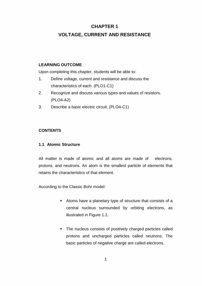
According to the Classic Bohr model:
Atoms have a planetary type of structure that consists of a
central nucleus surrounded by orbiting electrons, as
illustrated in Figure 1.1.
The nucleus consists of positively charged particles called
protons and uncharged particles called neutrons. The
basic particles of negative charge are called electrons.
2
Figure 1.1 The Bohr model of an atom showing electrons in
orbits around the nucleus. The “tails” on the electrons
indicate they are moving.
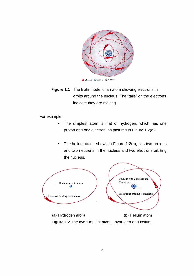
For example:
The simplest atom is that of hydrogen, which has one
proton and one electron, as pictured in Figure 1.2(a).
The helium atom, shown in Figure 1.2(b), has two protons
and two neutrons in the nucleus and two electrons orbiting
the nucleus.
(a) Hydrogen atom (b) Helium atom
Figure 1.2 The two simplest atoms, hydrogen and helium.
3
1.1.1 Atomic Number
All elements are arranged in the periodic table of the elements in order
according to their atomic number.
The atomic number equals the number of protons in the nucleus, which is
the same as the number of electrons in an electrically balanced (neutral)
atom.
For example:
Hydrogen has an atomic number of 1.
Helium has an atomic number of 2.
In their normal (or neutral) state, all atoms of a given element have the
same number of electrons as protons; the positive charges cancel the
negative charges, and the atom has a net charge of zero.
1.1.2 Electron Shells and Orbits
Electrons orbit the nucleus of an atom at certain distances from the
nucleus. Electrons near the nucleus have less energy than those in more
distant orbits.
It is known that only discrete (separate and distinct) values of electron
energies exist within atomic structure. Therefore, electrons must orbit only
at discrete distances from the nucleus.
1.1.2.1 Energy Levels
Each discrete distance (orbit) from the nucleus corresponds to a
certain energy level. In an atom, the orbits are grouped into energy
bands known as shells. A given atom has a fixed number of shells.
Each shell has a fixed maximum number of electrons at
permissible energy levels (orbits). The differences in energy levels
4
within a shell are much smaller than the difference in energy
between shells.
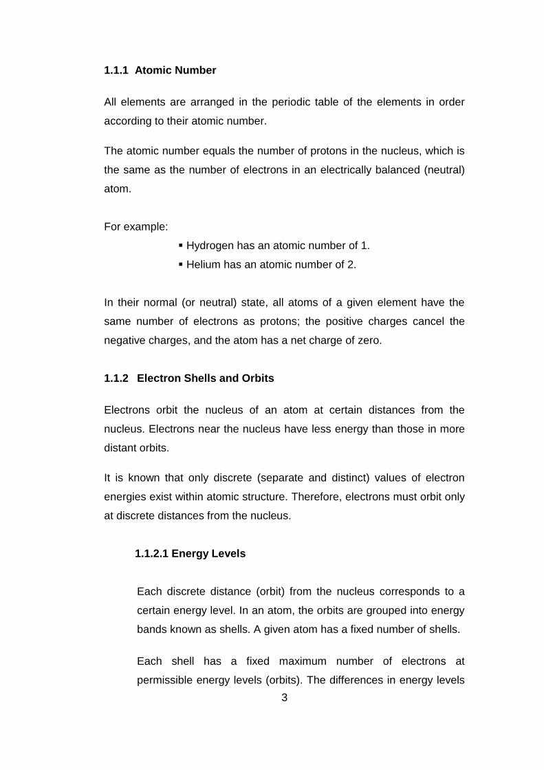
The shells are designated 1, 2, 3, and so on, with 1 being closest to
the nucleus. This energy band concept is illustrated in Figure 1.3:
The 1st shell with one energy level and
2nd shell with two energy levels. Additional shells may
exist in other types of atoms, depending on the
element.
Figure 1.3 Energy level increase as the distance from the nucleus
increases.
1.1.3 Valence Electrons
Electrons that are in orbits further from the nucleus have higher energy
and are less tightly bound to the atom than those closer to the nucleus.
This is because the force of attraction between the positively charged
nucleus and the negatively charged electron decreases with increasing
distance from the nucleus.
Electrons with the highest energy levels exist in the outermost shell of an
atom and are relatively loosely bound to the atom.
5
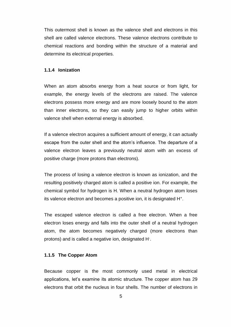
This outermost shell is known as the valence shell and electrons in this
shell are called valence electrons. These valence electrons contribute to
chemical reactions and bonding within the structure of a material and
determine its electrical properties.
1.1.4 Ionization
When an atom absorbs energy from a heat source or from light, for
example, the energy levels of the electrons are raised. The valence
electrons possess more energy and are more loosely bound to the atom
than inner electrons, so they can easily jump to higher orbits within
valence shell when external energy is absorbed.
If a valence electron acquires a sufficient amount of energy, it can actually
escape from the outer shell and the atom’s influence. The departure of a
valence electron leaves a previously neutral atom with an excess of
positive charge (more protons than electrons).
The process of losing a valence electron is known as ionization, and the
resulting positively charged atom is called a positive ion. For example, the
chemical symbol for hydrogen is H. When a neutral hydrogen atom loses
its valence electron and becomes a positive ion, it is designated H+.
The escaped valence electron is called a free electron. When a free
electron loses energy and falls into the outer shell of a neutral hydrogen
atom, the atom becomes negatively charged (more electrons than
protons) and is called a negative ion, designated H-.
1.1.5 The Copper Atom
Because copper is the most commonly used metal in electrical
applications, let’s examine its atomic structure. The copper atom has 29
electrons that orbit the nucleus in four shells. The number of electrons in
6
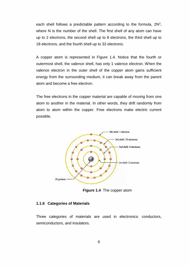
each shell follows a predictable pattern according to the formula, 2N2,
where N is the number of the shell. The first shell of any atom can have
up to 2 electrons, the second shell up to 8 electrons, the third shell up to
18 electrons, and the fourth shell up to 32 electrons.
A copper atom is represented in Figure 1.4. Notice that the fourth or
outermost shell, the valence shell, has only 1 valence electron. When the
valence electron in the outer shell of the copper atom gains sufficient
energy from the surrounding medium, it can break away from the parent
atom and become a free electron.
The free electrons in the copper material are capable of moving from one
atom to another in the material. In other words, they drift randomly from
atom to atom within the copper. Free electrons make electric current
possible.
Figure 1.4 The copper atom
1.1.6 Categories of Materials
Three categories of materials are used in electronics: conductors,
semiconductors, and insulators.
7
a. Conductors
Conductors are materials that readily allow current. Have a
large number of free electrons and are characterized by one to
three valence electrons in their structure. Most metals are good
conductors.
Silver is the best conductor and copper is next. Copper is the
most widely used conductive material because it is less
expensive than silver. Copper wire is commonly used as a
conductor.
b. Semiconductors
Semiconductors are classed below the conductors in their
ability to carry current because they have fewer free electrons
than do conductors. Have four valence electrons in their atomic
structures. Certain semiconductor materials are the basis for
modern electronic devices such as the diode, transistor, and
integrated circuit. Silicon and germanium are common semi
conductive materials.
c. Insulators
Insulating materials are poor conductors of electric current.
Used to prevent current where it is not wanted. Compared to
conductive materials, insulators have very few free electrons
and are characterized by more than four valence electrons in
their atomic structures.

8
1.2 Electrical Charge
The charge of an electron and that of a proton are equal in magnitude.
The electron is the smallest particle that exhibits negative electrical
charge. When an excess of electrons exists in a material, there is a net
negative electrical charge. When a deficiency of electrons exists, there is
a net positive electrical charge.
Electrical charge is symbolized by Q. Static electricity is the presence of a
net positive or negative charge in a material. Materials with charges of
opposite polarity are attracted to each other, and materials with charges of
the same polarity are repelled, as indicated in Figure 1.5.
A force acts between charges, as evidenced by the attraction or repulsion.
This force, called an electric field, consists of invisible lines of force, as
shown in Figure 1.6.
Figure 1.5 Attraction and repulsion of electrical charges.
Figure 1.6 Electric field between oppositely charged surfaces.
9
1.2.1 Coulomb: The Unit of Charge
Electrical charge (Q) is measured in Coulombs, abbreviated C. One
coulomb is the total charge possessed by 6.25 X 10¹⁸ electrons. A single
electron has a charge of 1.6 x 10⁻¹⁹C. The total charge in a given number
of electrons is stated in the following formula:
number of electrons
Q = ---------------------------------- (1.1)
6.25 x 10¹⁸ electrons/C
1.2.2 Positive and Negative Charge
Consider a neutral atom that is, one that has the same number of
electrons and protons and thus has no net charge. If a valence electron is
pulled away from the atom by the application of energy, the atom is left
with a net positive charge (more protons than electrons) and becomes a
positive ion.
If an atom acquires an extra electron in its outer shell, It has a net
negative charge and becomes a negative ion. The amount of energy
required to free a valence electron is related to the number of electrons in
the outer shell. An atom can have up to eight valence electrons. The more
complete the outer shell, the more stable the atom and thus the more
energy is required to release an electron.
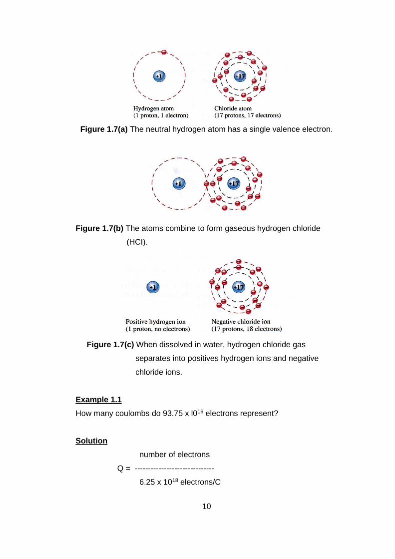
Figure 1.7(a), (b) and (c) illustrates the creation of a positive and a
negative ion when a hydrogen atom gives up its single valence electron to
a chloride atom, forming gaseous hydrogen chloride (HCI). When the
gaseous HCI is dissolved in water, hydrochloric acid is formed.
10
Figure 1.7(a) The neutral hydrogen atom has a single valence electron.
Figure 1.7(b) The atoms combine to form gaseous hydrogen chloride
(HCI).
Figure 1.7(c) When dissolved in water, hydrogen chloride gas
separates into positives hydrogen ions and negative
chloride ions.
Example 1.1
How many coulombs do 93.75 x l016 electrons represent?
Solution
number of electrons
Q = ------------------------------
6.25 x 10¹⁸ electrons/C

11
93.75 x l016 electrons
= ------------------------------
6.25 x 10¹⁸ electrons/C
= 15 x 10-2 C
= 0.15 C
1.3 Voltage
Voltage is defined energy per unit of charge V= W/Q, where
V = voltage in volts (V)
W = energy in joules (J)
Q = charge in coulomb (C)
1.3.1 Volt: The Unit of Voltage
The unit of voltage is the volt, symbolized by V. One volt is the potential
difference (voltage) between two points when one joule of energy is used
to move one coulomb of charge from one point to the other.
Example 1.2
If 50 J of energy are available for every 10 C of charge, what is the
voltage?
Solution
V = W/Q
= 50J/10C
= 5V
12
1.3.2 Sources of Voltage
a. Batteries
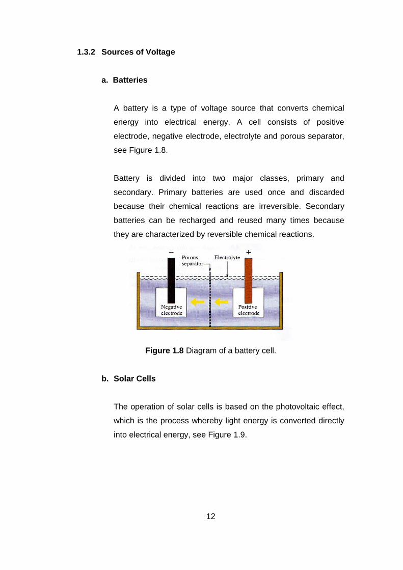
A battery is a type of voltage source that converts chemical
energy into electrical energy. A cell consists of positive
electrode, negative electrode, electrolyte and porous separator,
see Figure 1.8.
Battery is divided into two major classes, primary and
secondary. Primary batteries are used once and discarded
because their chemical reactions are irreversible. Secondary
batteries can be recharged and reused many times because
they are characterized by reversible chemical reactions.
Figure 1.8 Diagram of a battery cell.
b. Solar Cells
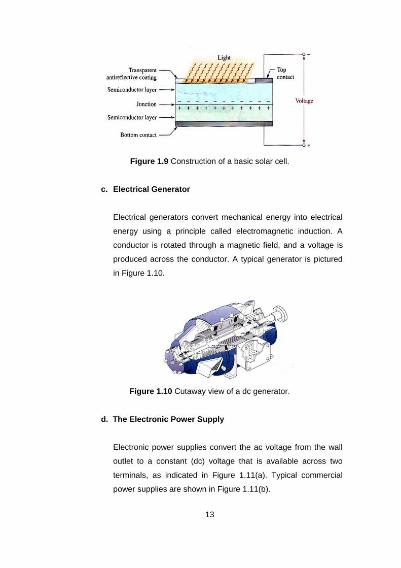
The operation of solar cells is based on the photovoltaic effect,
which is the process whereby light energy is converted directly
into electrical energy, see Figure 1.9.
13
Figure 1.9 Construction of a basic solar cell.
c. Electrical Generator
Electrical generators convert mechanical energy into electrical
energy using a principle called electromagnetic induction. A
conductor is rotated through a magnetic field, and a voltage is
produced across the conductor. A typical generator is pictured
in Figure 1.10.
Figure 1.10 Cutaway view of a dc generator.
d. The Electronic Power Supply
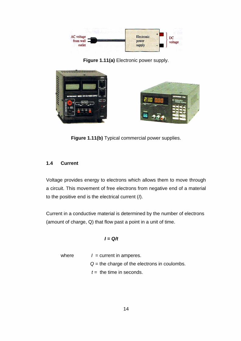
Electronic power supplies convert the ac voltage from the wall
outlet to a constant (dc) voltage that is available across two
terminals, as indicated in Figure 1.11(a). Typical commercial
power supplies are shown in Figure 1.11(b).
14
Figure 1.11(a) Electronic power supply.
Figure 1.11(b) Typical commercial power supplies.
1.4 Current
Voltage provides energy to electrons which allows them to move through
a circuit. This movement of free electrons from negative end of a material
to the positive end is the electrical current (I).
Current in a conductive material is determined by the number of electrons
(amount of charge, Q) that flow past a point in a unit of time.
I = Q/t
where I = current in amperes.
Q = the charge of the electrons in coulombs.
t = the time in seconds.
15
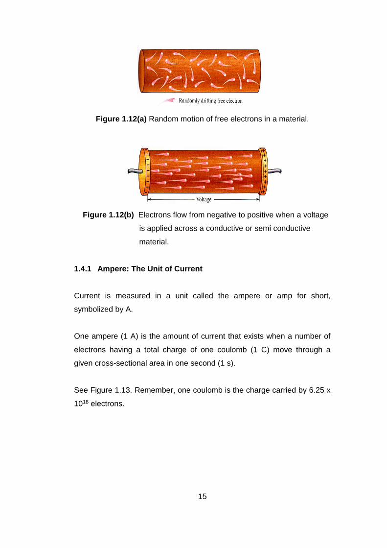
Figure 1.12(a) Random motion of free electrons in a material.
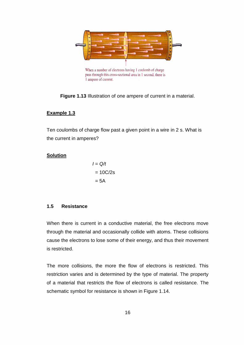
Figure 1.12(b) Electrons flow from negative to positive when a voltage
is applied across a conductive or semi conductive
material.
1.4.1 Ampere: The Unit of Current
Current is measured in a unit called the ampere or amp for short,
symbolized by A.
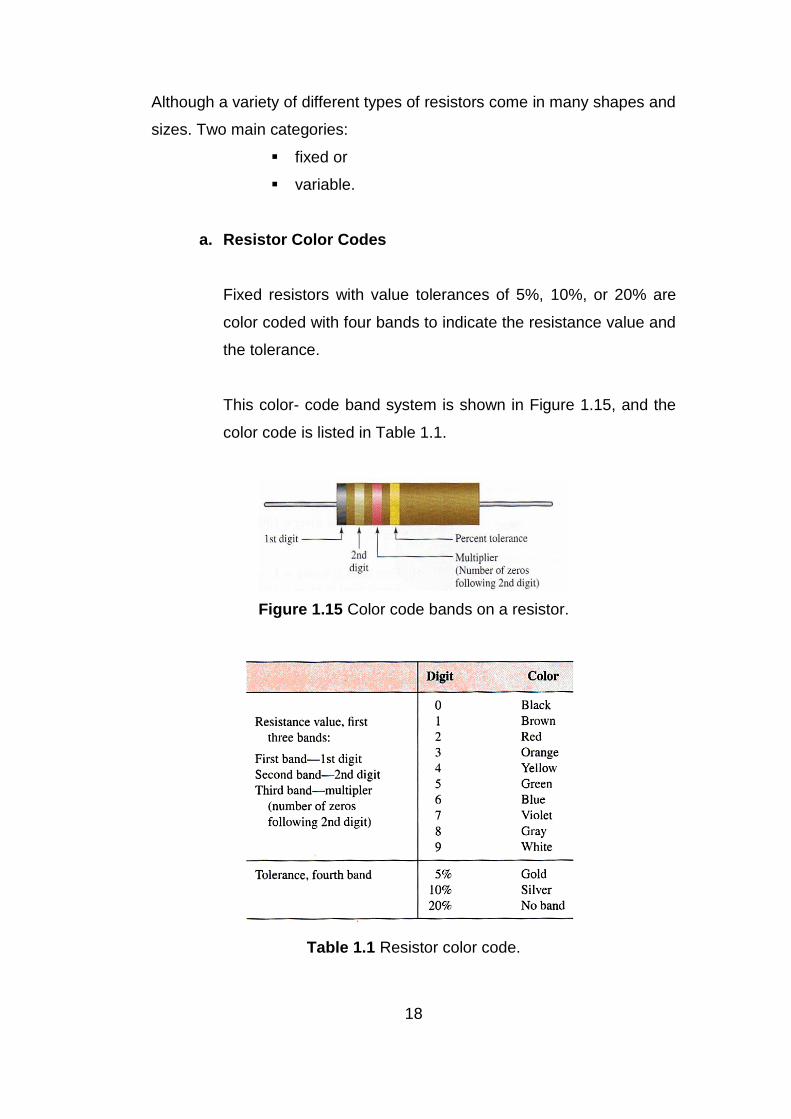
One ampere (1 A) is the amount of current that exists when a number of
electrons having a total charge of one coulomb (1 C) move through a
given cross-sectional area in one second (1 s).
See Figure 1.13. Remember, one coulomb is the charge carried by 6.25 x
1018 electrons.
16
Figure 1.13 Illustration of one ampere of current in a material.
Example 1.3
Ten coulombs of charge flow past a given point in a wire in 2 s. What is
the current in amperes?
Solution
I = Q/t
= 10C/2s
= 5A
1.5 Resistance
When there is current in a conductive material, the free electrons move
through the material and occasionally collide with atoms. These collisions
cause the electrons to lose some of their energy, and thus their movement
is restricted.
The more collisions, the more the flow of electrons is restricted. This
restriction varies and is determined by the type of material. The property
of a material that restricts the flow of electrons is called resistance. The
schematic symbol for resistance is shown in Figure 1.14.

17
Figure 1.14: Resistance symbol.
When there is current through any material that has resistance, heat is
produced by the collisions of free electrons and atoms. Therefore, wire,
which typically has a very small resistance, becomes warm when there is
sufficient current through it.
1.5.1 Ohm: The Unit of Resistance
One ohm (1 Ω) of resistance exists if there is one ampere (1 A) of current
in a material when one volt (1 V) is applied across the material.
a. Conductance
The reciprocal of resistance is conductance, symbolized by G. It
is a measure of the ease with which current is established. The
unit of conductance is the siemens (S). The formula:
G = 1/R
For example, the conductance of a 22kΩ resistor is G =
1/22kΩ= 45.5μS.
1.5.2 Resistors
Components that are specifically designed to have a certain amount of
resistance are called resistors. The principal applications of resistors are:
to limit current,
to divide voltage, and, in certain cases,
to generate heat.
18
Although a variety of different types of resistors come in many shapes and
sizes. Two main categories:
fixed or
variable.
a. Resistor Color Codes
Fixed resistors with value tolerances of 5%, 10%, or 20% are
color coded with four bands to indicate the resistance value and
the tolerance.
This color- code band system is shown in Figure 1.15, and the
color code is listed in Table 1.1.
Figure 1.15 Color code bands on a resistor.
Table 1.1 Resistor color code.

19
The color code is read as follows:
a. Start with the band closest to one end of the resistor. The
first band is the first digit of the resistance value. If it is not
clear which is the banded end, start from the end that does
not begin with a gold or silver band.
b. The second band is the second digit of the resistance value.
c. The third band is the number of zeros following the second
digit, or multiplier.
d. The fourth band indicates the tolerance and is usually gold
or silver.
1.5.3 Variable Resistors
Variable resistors are designed so that their resistance values can be
changed easily with a manual or an automatic adjustment.
Two basic uses for variable resistors are:
to divide voltage (potentiometer)
to control current (rheostat)
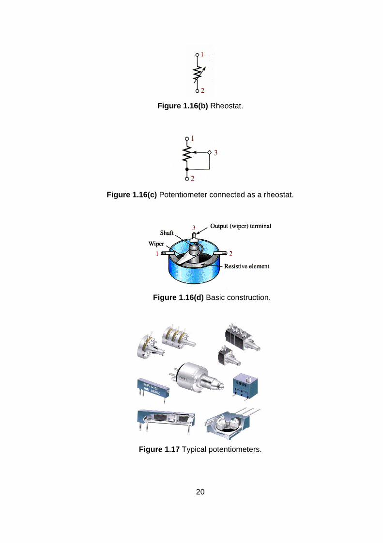
Schematic symbols for these types are shown in Figure 1.16(a), 1.16(b),
1.16(c). The potentiometer is a three-terminal device, as shown in figure
1.16(d). Some typical potentiometers are pictured in Figure 1.17.
Figure 1.16(a) Potentiometer.
20
Figure 1.16(b) Rheostat.
Figure 1.16(c) Potentiometer connected as a rheostat.
Figure 1.16(d) Basic construction.
Figure 1.17 Typical potentiometers.

21
1.6 The Electric Circuit
A basic electric circuit is an arrangement of physical components that use
voltage, current, and resistance to perform some useful function.
1.6.1 The Basic Circuit
Basically, an electric circuit consists of a voltage source, a load and a path
for current between the source and the load. Figure 1.18 shows an
example of a simple electric circuit:
Figure 1.18 A simple electric circuit.
A battery connected to a lamp with two conductors (wires). The battery is
the voltage source. The lamp is the load on the battery because it draws
current from the battery. The two wires provide the current path from the
positive terminal of the battery to the lamp and back to the negative
terminal of the battery.
Current goes through the filament of the lamp (which has a resistance),
causing it to emit visible light. Current through the battery occurs by
chemical action. In many practical cases, one terminal of the battery is
connected to a common or ground point.
22
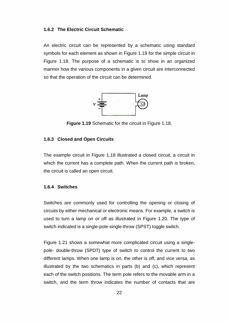
1.6.2 The Electric Circuit Schematic
An electric circuit can be represented by a schematic using standard
symbols for each element as shown in Figure 1.19 for the simple circuit in
Figure 1.18. The purpose of a schematic is to show in an organized
manner how the various components in a given circuit are interconnected
so that the operation of the circuit can be determined.
Figure 1.19 Schematic for the circuit in Figure 1.18.
1.6.3 Closed and Open Circuits
The example circuit in Figure 1.18 illustrated a closed circuit, a circuit in
which the current has a complete path. When the current path is broken,
the circuit is called an open circuit.
1.6.4 Switches
Switches are commonly used for controlling the opening or closing of
circuits by either mechanical or electronic means. For example, a switch is
used to turn a lamp on or off as illustrated in Figure 1.20. The type of
switch indicated is a single-pole-single-throw (SPST) toggle switch.
Figure 1.21 shows a somewhat more complicated circuit using a single-
pole- double-throw (SPDT) type of switch to control the current to two
different lamps. When one lamp is on, the other is off, and vice versa, as
illustrated by the two schematics in parts (b) and (c), which represent
each of the switch positions. The term pole refers to the movable arm in a
switch, and the term throw indicates the number of contacts that are

23
affected (either opened or closed) by a single switch action (a single
movement of a pole).
Figure 1.20 Basic closed and open circuits using an SPST switch for
control.
Figure 1.21 An example of an SPDT switch controlling two lamps.

24
In addition to the SPST and the SPDT switches (symbols are shown in
Figure 1.22(a) and (b)), the following other types are important:
a. Double-pole--single throw (DPST).
The DPST switch permits simultaneous opening or closing of
two sets of contacts. The symbol is shown in Figure 1.22(c).
The dashed line indicates that the contact arms are
mechanically linked so that both move with a single switch
action.
b. Double-pole--double-throw (DPDT).
The DPDT switch provides connection from one set of contacts
to either of two other sets. The schematic symbol is shown in
Figure 1.22(d).
c. Push-button (PB).
In the normally open push-button switch (NOPB), shown in
Figure 1.22(e), connection is made between two contacts when
the button is depressed, and connection is broken when the
button is released.
In the normally closed push-button switch (NCPB), shown in
Figure 1.22(f), connection between the two contacts is broken
when the button is depressed.
d. Rotary.
In a rotary switch, a knob is turned to make connection between
one contact and any one of several others. A symbol for a
simple six-position rotary switch is shown in Figure 1.22(g).

25
Figure 1.22 Switch symbols.
1.7 Basic Circuit Measurements
An electronics technician cannot function without knowing how to
measure voltage, current, and resistance.
1.7.1 Voltage, Current and Resistance Measurements
Are commonly required in electronics work. Special types of instruments
are used to measure these basic electrical quantities. The instrument
used to measure voltage is a voltmeter. The instrument used to measure
current is an ammeter and the instrument used to measure resistance is
an ohmmeter.
Commonly, all three instruments are combined into a single instrument
such as a multimeter or a VOM (volt-ohm-milliammeter), which can
choose what specific quantity to measure by selecting the switch setting.
Figure 1.23(a) shows an analog meter with a needle pointer and Figure
1.23(b) shows a digital multimeter (DMM), which provides a digital readout
of the measured quantity plus graphing capability.
26
Figure 1.23 Typical portable multimeters.
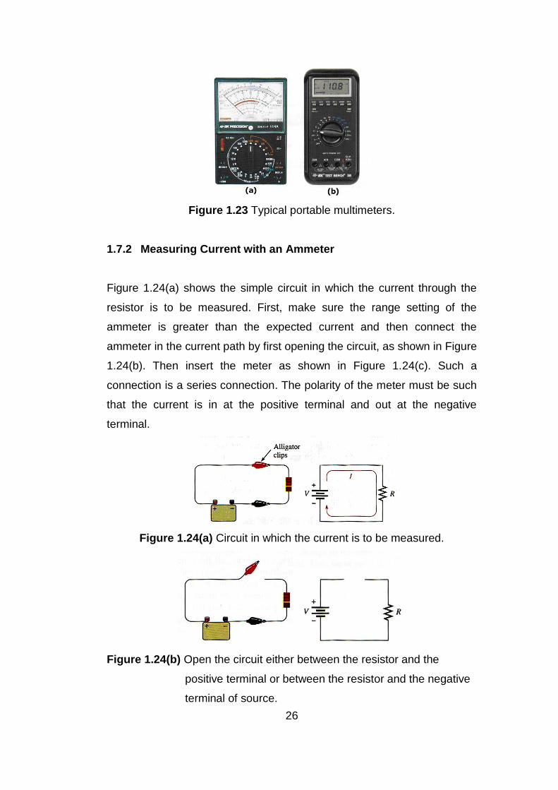
1.7.2 Measuring Current with an Ammeter
Figure 1.24(a) shows the simple circuit in which the current through the
resistor is to be measured. First, make sure the range setting of the
ammeter is greater than the expected current and then connect the
ammeter in the current path by first opening the circuit, as shown in Figure
1.24(b). Then insert the meter as shown in Figure 1.24(c). Such a
connection is a series connection. The polarity of the meter must be such
that the current is in at the positive terminal and out at the negative
terminal.
Figure 1.24(a) Circuit in which the current is to be measured.
Figure 1.24(b) Open the circuit either between the resistor and the
positive terminal or between the resistor and the negative
terminal of source.
27
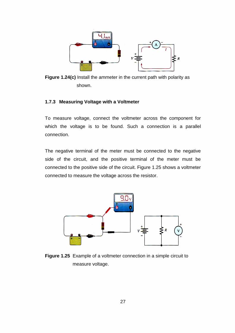
Figure 1.24(c) Install the ammeter in the current path with polarity as
shown.
1.7.3 Measuring Voltage with a Voltmeter
To measure voltage, connect the voltmeter across the component for
which the voltage is to be found. Such a connection is a parallel
connection.
The negative terminal of the meter must be connected to the negative
side of the circuit, and the positive terminal of the meter must be
connected to the positive side of the circuit. Figure 1.25 shows a voltmeter
connected to measure the voltage across the resistor.
Figure 1.25 Example of a voltmeter connection in a simple circuit to
measure voltage.
28
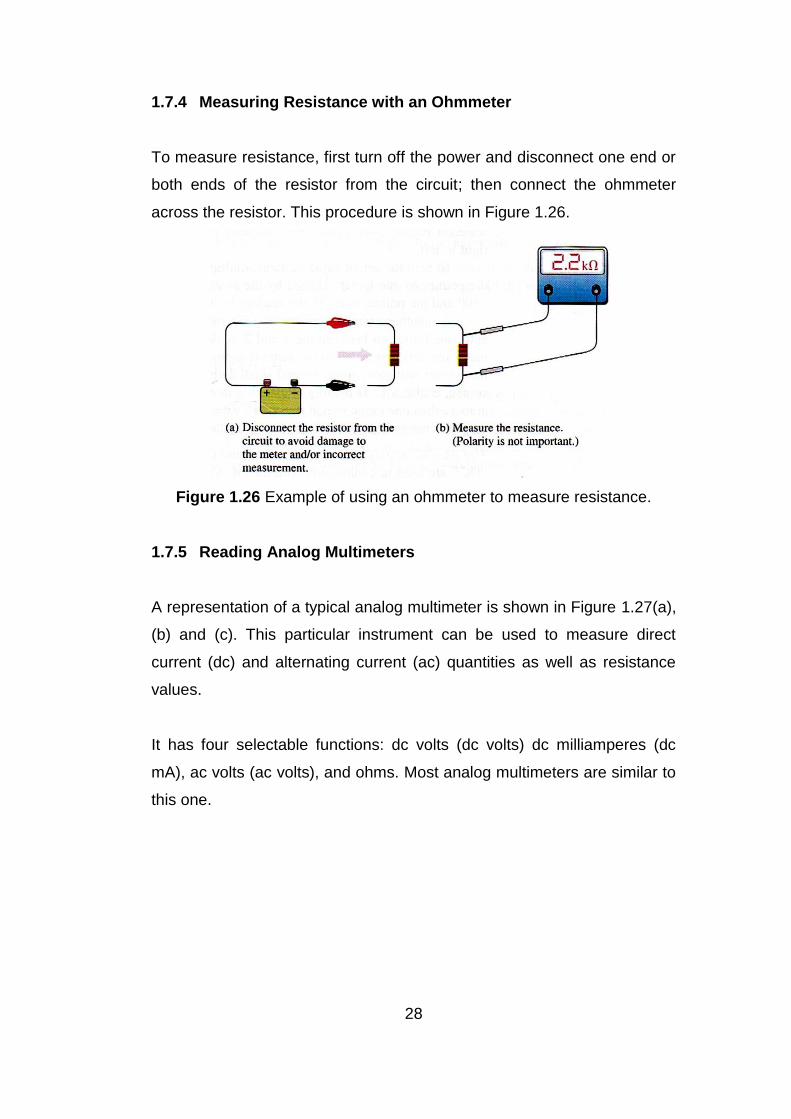
1.7.4 Measuring Resistance with an Ohmmeter
To measure resistance, first turn off the power and disconnect one end or
both ends of the resistor from the circuit; then connect the ohmmeter
across the resistor. This procedure is shown in Figure 1.26.
Figure 1.26 Example of using an ohmmeter to measure resistance.
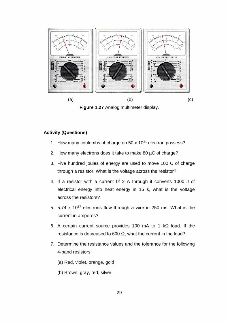
1.7.5 Reading Analog Multimeters
A representation of a typical analog multimeter is shown in Figure 1.27(a),
(b) and (c). This particular instrument can be used to measure direct
current (dc) and alternating current (ac) quantities as well as resistance
values.
It has four selectable functions: dc volts (dc volts) dc milliamperes (dc
mA), ac volts (ac volts), and ohms. Most analog multimeters are similar to
this one.
29
(a) (b) (c)
Figure 1.27 Analog multimeter display.
Activity (Questions)
1. How many coulombs of charge do 50 x 1031 electron possess?
2. How many electrons does it take to make 80 µC of charge?
3. Five hundred joules of energy are used to move 100 C of charge
through a resistor. What is the voltage across the resistor?
4. If a resistor with a current 0f 2 A through it converts 1000 J of
electrical energy into heat energy in 15 s, what is the voltage
across the resistors?
5. 5.74 x 10¹⁷ electrons flow through a wire in 250 ms. What is the
current in amperes?
6. A certain current source provides 100 mA to 1 kΩ load. If the
resistance is decreased to 500 Ω, what the current in the load?
7. Determine the resistance values and the tolerance for the following
4-band resistors:
(a) Red, violet, orange, gold
(b) Brown, gray, red, silver
30
8. Determine the color bands for each of the following 4-band
resistors. Assume each has a 5% tolerance.
(a) 0.47 Ω (b) 270 kΩ (c) 5.1 MΩ
9. What resistance is indicated by 4K7?
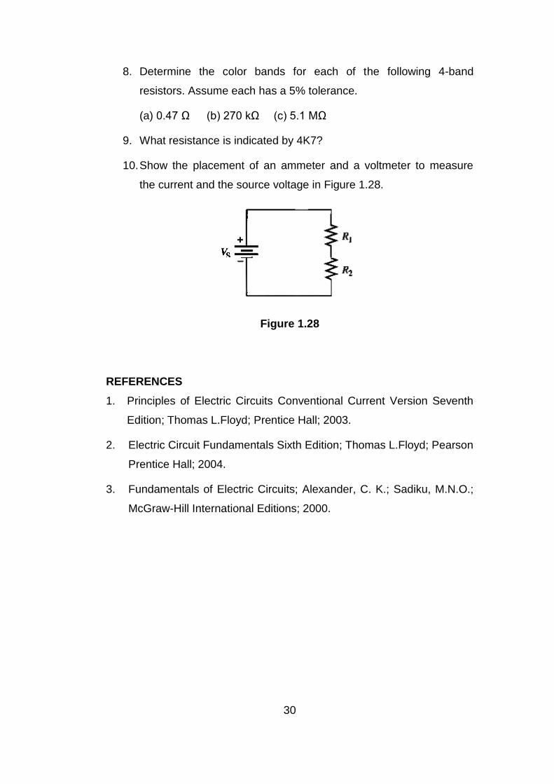
10. Show the placement of an ammeter and a voltmeter to measure
the current and the source voltage in Figure 1.28.
Figure 1.28
REFERENCES
1. Principles of Electric Circuits Conventional Current Version Seventh
Edition; Thomas L.Floyd; Prentice Hall; 2003.
2. Electric Circuit Fundamentals Sixth Edition; Thomas L.Floyd; Pearson
Prentice Hall; 2004.
3. Fundamentals of Electric Circuits; Alexander, C. K.; Sadiku, M.N.O.;
McGraw-Hill International Editions; 2000.