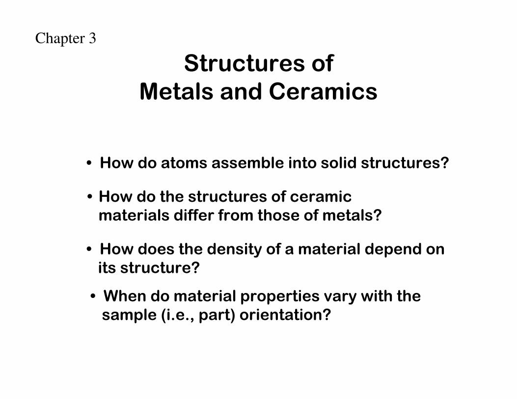
• How do atoms assemble into solid structures?
• How does the density of a material depend onits structure?
• When do material properties vary with thesample (i.e., part) orientation?
Structures of Metals and Ceramics
• How do the structures of ceramic materials differ from those of metals?
Chapter 3

• Non dense, random packing
• Dense, regular packing
Now, bonding energy is not only between two atoms, its from many atoms.
Dense, regular-packed structures tend to have lower energy.
Energy
r
typical neighbor bond length
typical neighbor bond energy
Energy
r
typical neighbor bond length
typical neighbor bond energy
ENERGY AND PACKING
average
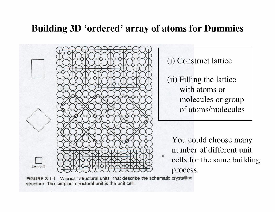
Building 3D ‘ordered’ array of atoms for Dummies
(i) Construct lattice
(ii) Filling the lattice
with atoms or
molecules or group
of atoms/molecules
You could choose many
number of different unit
cells for the same building
process.
7 Crystal Systems
&
14 Crystal Lattices
Any crystalline structure (3D ordered array of atoms/molecules)
must fall into one of the systems and one of the crystal lattices.

Unit cellsOften called ‘lattice constants’

• tend to be densely packed.
• have several reasons for dense packing:
-Typically, only one element is present, so all atomicradii are the same.-Metallic bonding is non-directional.-Nearest neighbor distances tend to be small inorder to lower bond energy.
• have the simplest crystal structures.
We will look at three such structures...
METALLIC CRYSTALS

B B
B
BB
B BC C
CA
A
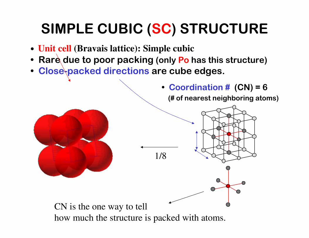
• Rare due to poor packing (only Po has this structure)• Close-packed directions are cube edges.
• Coordination # (CN) = 6(# of nearest neighboring atoms)
SIMPLE CUBIC (SC) STRUCTURE
• Unit cell (Bravais lattice): Simple cubic
1/8
CN is the one way to tell
how much the structure is packed with atoms.
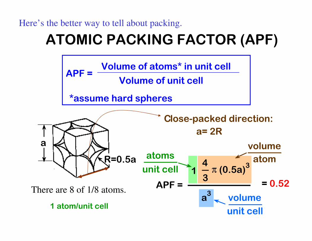
= 0.52
ATOMIC PACKING FACTOR (APF)
APF = Volume of atoms* in unit cell
Volume of unit cell
*assume hard spheres
Here’s the better way to tell about packing.
APF =
a3
4
3π (0.5a)31
atoms
unit cellatom
volume
unit cell
volume
a
R=0.5a
1 atom/unit cell
There are 8 of 1/8 atoms.
Close-packed direction:
a= 2R
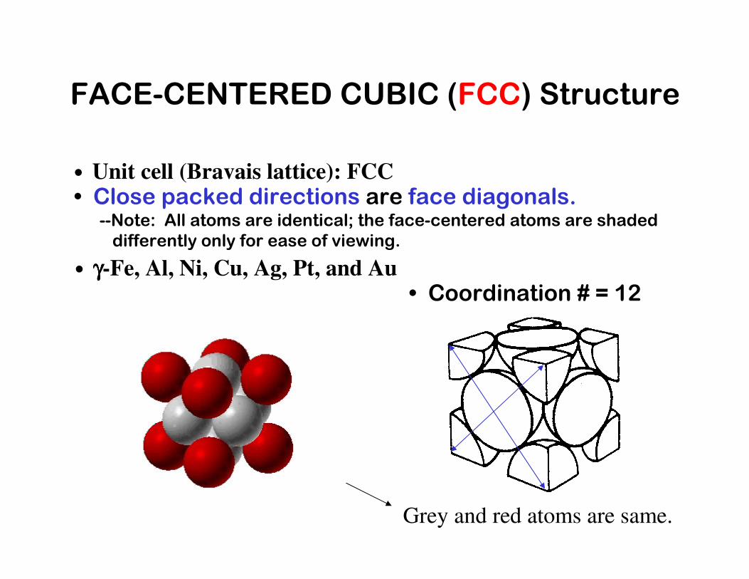
• Coordination # = 12
• Close packed directions are face diagonals.--Note: All atoms are identical; the face-centered atoms are shadeddifferently only for ease of viewing.
FACE-CENTERED CUBIC (FCC) Structure
• Unit cell (Bravais lattice): FCC
• γγγγ-Fe, Al, Ni, Cu, Ag, Pt, and Au
Grey and red atoms are same.
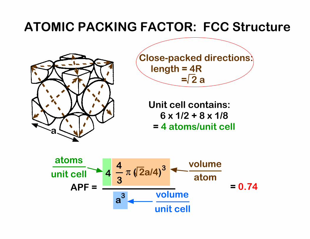
Unit cell contains: 6 x 1/2 + 8 x 1/8 = 4 atoms/unit cella
= 0.74
Close-packed directions: length = 4R
= 2 a
ATOMIC PACKING FACTOR: FCC Structure
APF =
a3
4
3π ( 2a/4)34
atoms
unit cell atom
volume
unit cell
volume

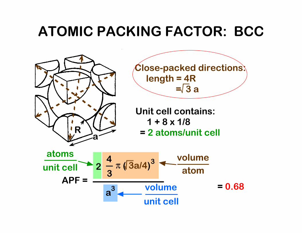
• Coordination # = 8
• Close packed directions are cube diagonals.
BODY-CENTERED CUBIC (BCC) Structure
• Unit cell (Bravais lattice): BCC
• αααα-Fe, Cr, Mo, W, and V
aR
= 0.68
Close-packed directions: length = 4R
= 3 a
Unit cell contains: 1 + 8 x 1/8 = 2 atoms/unit cell
ATOMIC PACKING FACTOR: BCC
APF =
a3
4
3π ( 3a/4)32
atoms
unit cell atom
volume
unit cell
volume
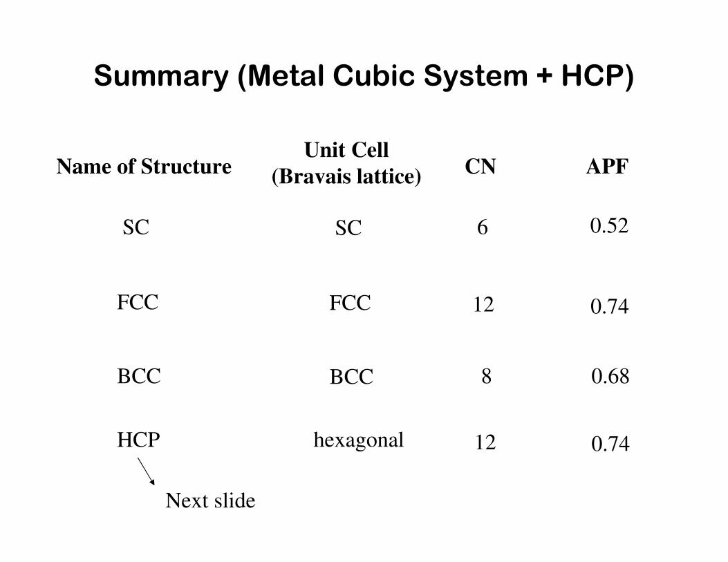
Summary (Metal Cubic System + HCP)
Name of StructureUnit Cell
(Bravais lattice) CN APF
SC
FCC
BCC
SC
FCC
BCC
6
12
8
0.52
0.74
0.68
HCP hexagonal 12 0.74
Next slide

• Coordination # = 12
• ABAB... Stacking Sequence
• APF = 0.74
• 3D Projection
• 2D ProjectionA sites
B sites
A sites
Bottom layer
Middle layer
Top layer
HEXAGONAL CLOSE-PACKED (HCP) STRUCTURE
• Unit cell (Bravais lattice): Hexagonal
• Be, Mg, α-Ti, Zn, and Zr Unit cell: 1/3 of it
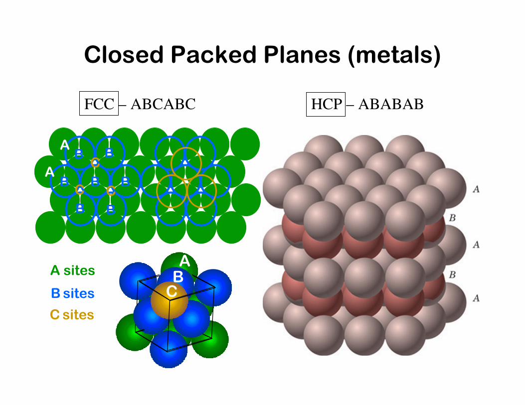
Closed Packed Planes (metals)
FCC – ABCABC HCP – ABABAB
B B
B
BB
B BC C
CA
A
A sites
B sites
C sites
ABC
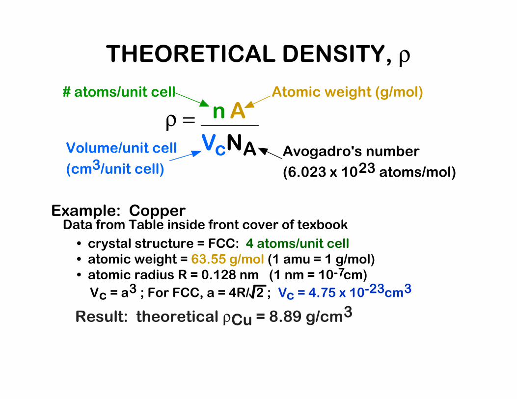
Example: Copper
ρ = nA
VcNA
# atoms/unit cell Atomic weight (g/mol)
Volume/unit cell
(cm3/unit cell)
Avogadro's number
(6.023 x 10²³ atoms/mol)
Data from Table inside front cover of texbook
• crystal structure = FCC: 4 atoms/unit cell• atomic weight = 63.55 g/mol (1 amu = 1 g/mol)• atomic radius R = 0.128 nm (1 nm = 10 cm)-7
Vc = a3 ; For FCC, a = 4R/ 2 ; Vc = 4.75 x 10
-23cm3
Result: theoretical ρCu = 8.89 g/cm3
THEORETICAL DENSITY, ρ
Before we study crystal structure of ceramics,
We need to learn crystallographic notations
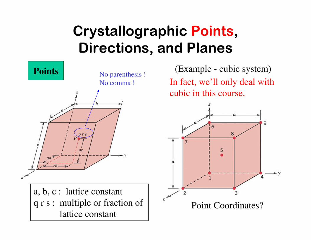
Crystallographic Points, Directions, and Planes
Points
Point Coordinates?
a, b, c : lattice constant
q r s : multiple or fraction of
lattice constant
(Example - cubic system)No parenthesis !
No comma ! In fact, we’ll only deal with
cubic in this course.
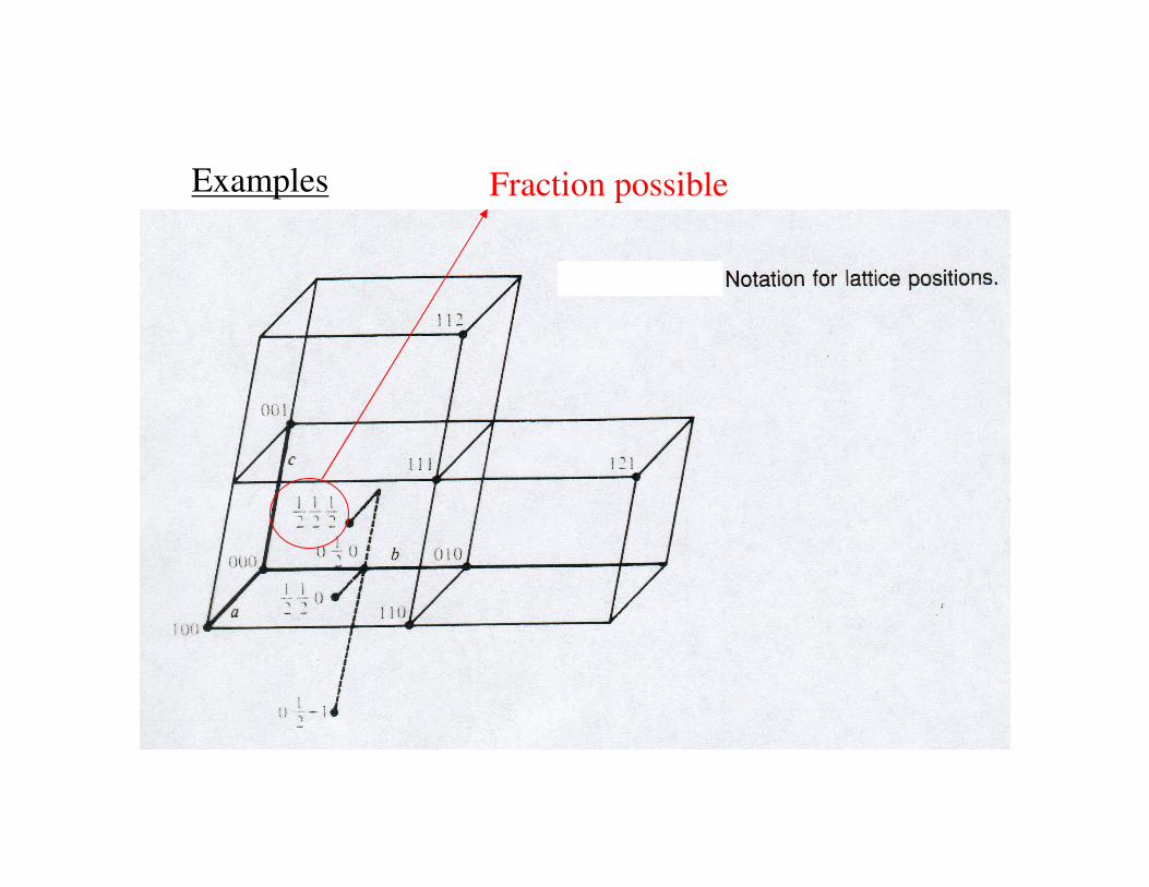
Examples Fraction possible

Crystallographic Points, Directions, and Planes
Directions (Cubic) [uvw] & <uvw> Miller Indices
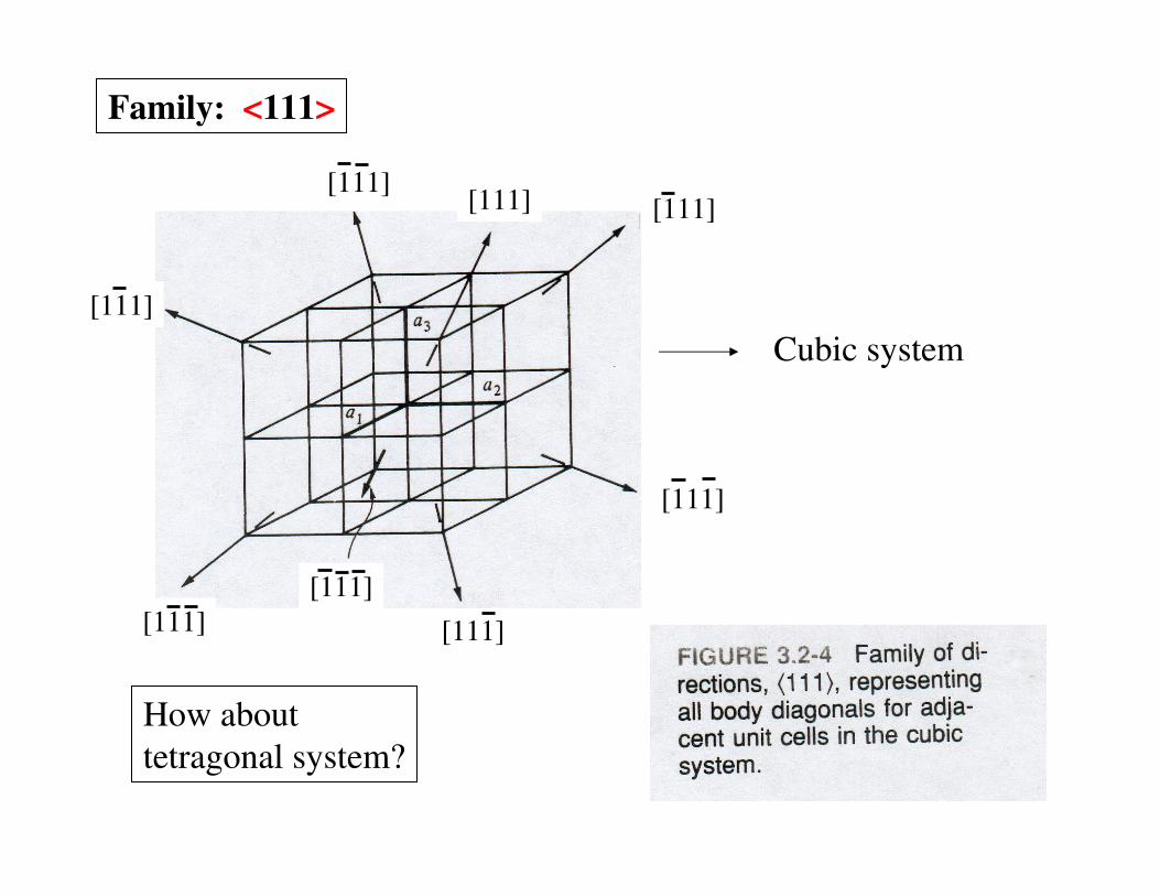
[111]
[111]
[111]
[111]
[111][111]
[111]
Family: <111>
[111]
Cubic system
How about
tetragonal system?
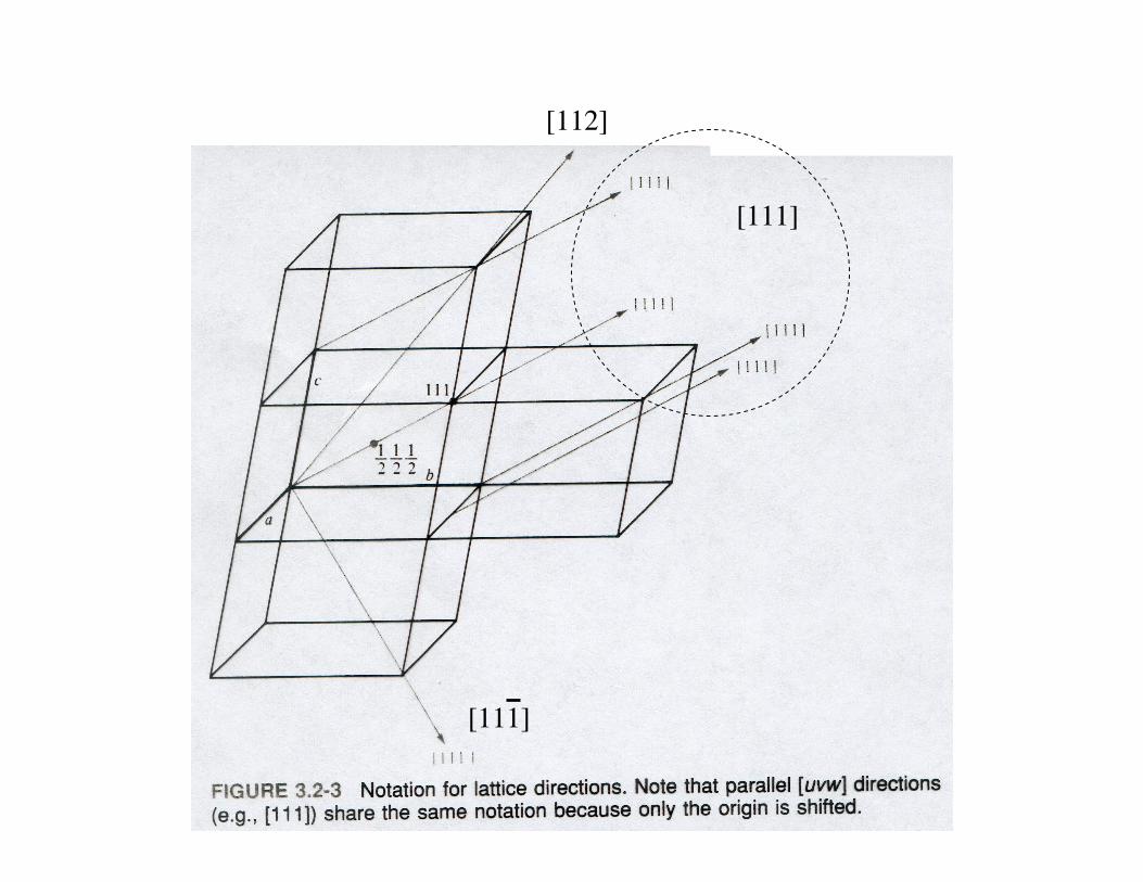
[112]
[111]
[111]

Crystallographic Points, Directions, and Planes
Planes (Cubic) (hkl) & {hkl} Miller Indices

Crystallographic Points, Directions, and Planes
Planes (Cubic)(hkl) & {hkl} Miller Indices

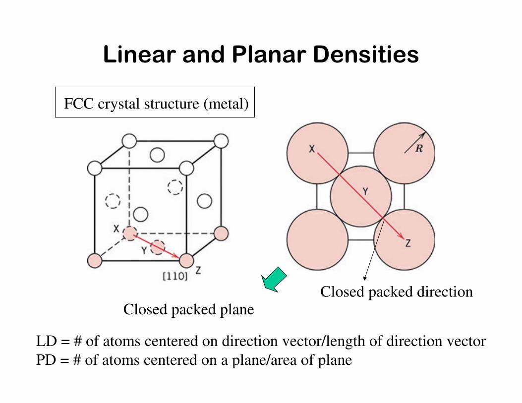
Linear and Planar Densities
FCC crystal structure (metal)
LD = # of atoms centered on direction vector/length of direction vector
PD = # of atoms centered on a plane/area of plane
Closed packed direction Closed packed plane
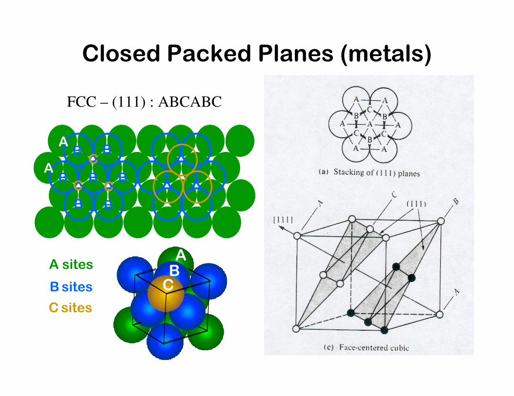
Closed Packed Planes (metals)
FCC – (111) : ABCABC
B B
B
BB
B BC C
CA
A
A sites
B sites
C sites
ABC

Closed Packed Planes (metals)
HCP – (0001): ABABAB
B B
B
BB
B BC C
CA
A
Unit cell:
hexagonal
Now we learn crystal structure of ceramics.

• Bonding:--Mostly ionic, some covalent.--% ionic character increases with difference in electronegativity.
He -
Ne -
Ar -
Kr -
Xe -
Rn -
Cl 3.0
Br 2.8
I 2.5
At 2.2
Li 1.0
Na 0.9
K 0.8
Rb 0.8
Cs 0.7
Fr 0.7
H 2.1
Be 1.5
Mg 1.2
Sr 1.0
Ba 0.9
Ra 0.9
Ti 1.5
Cr 1.6
Fe 1.8
Ni 1.8
Zn 1.8
As 2.0
C 2.5Si 1.8
F 4.0
Ca 1.0
Table of Electronegativities
CaF2: large
SiC: small
• Large vs small ionic bond character:
CERAMIC CRYSTALS
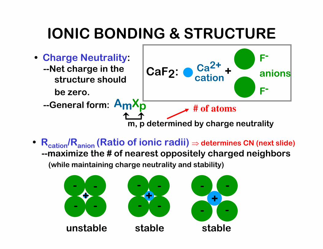
• Charge Neutrality:--Net charge in thestructure should
be zero.
--General form: AmXp
m, p determined by charge neutrality
• Rcation/Ranion (Ratio of ionic radii) ⇒ determines CN (next slide)
--maximize the # of nearest oppositely charged neighbors(while maintaining charge neutrality and stability)
- -
- -+
unstable
- -
- -+
stable
- -
- -+
stable
CaF2:Ca2+
cation
F-
F-
anions+
IONIC BONDING & STRUCTURE
# of atoms

Q: How many anions can you arrange around a cation?
rcationranion
rcationranion
Coord #
< .155 .155-.225 .225-.414 .414-.732 .732-1.0
ZnS (zincblende)
NaCl (sodium chloride)
CsCl (cesium chloride)
2 3 4 6 8
COORDINATION # AND IONIC RADII
• Coordination # increases with


• Structure of FCC metalsBravais lattice: FCCCoordination #: 12
• Structure of NaClBravais lattice: FCCCoordination #: 6
FCC Bravais lattice (Metal vs. Ionic Material)
Different crystal structures with the same Bravais lattice (unit cell)
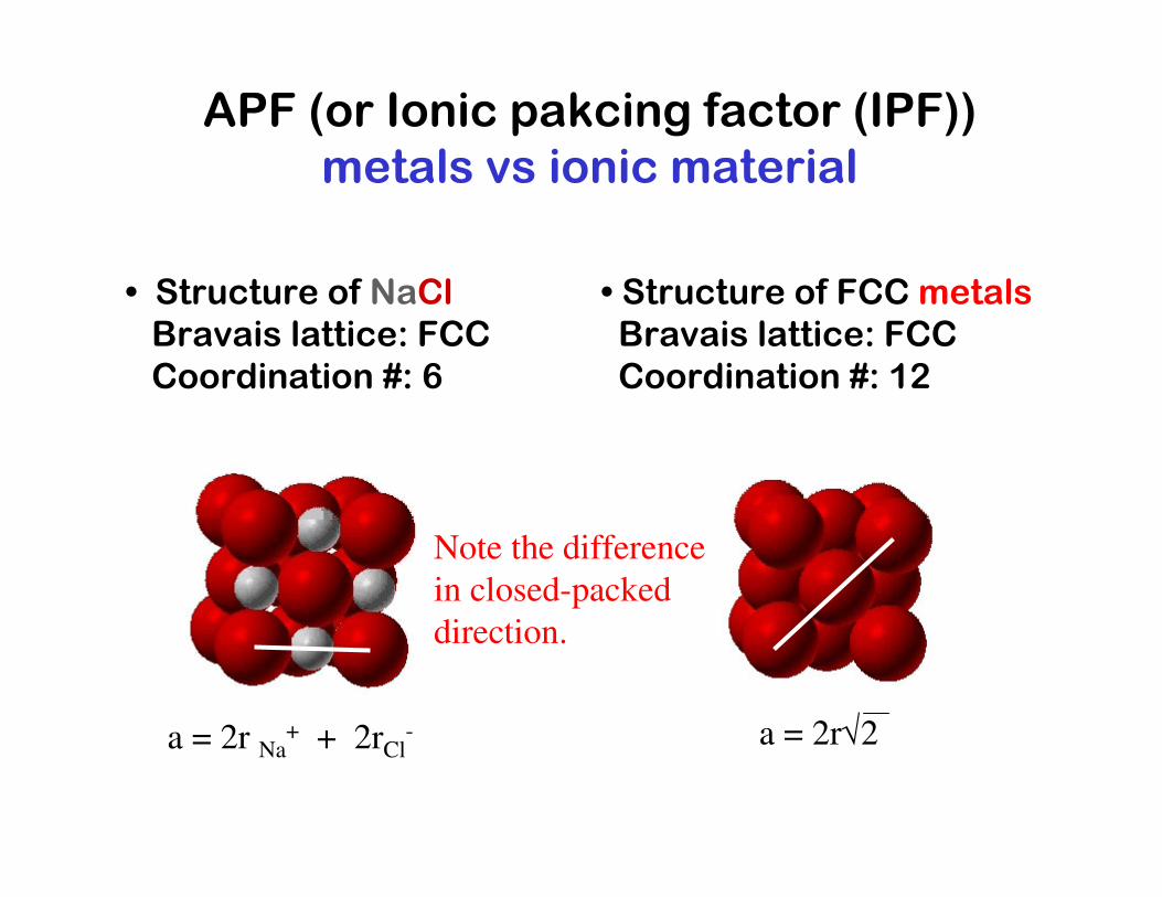
APF (or Ionic pakcing factor (IPF)) metals vs ionic material
• Structure of NaClBravais lattice: FCCCoordination #: 6
• Structure of FCC metalsBravais lattice: FCCCoordination #: 12
a = 2r Na+ + 2rCl
- a = 2r√2
Note the difference
in closed-packed
direction.
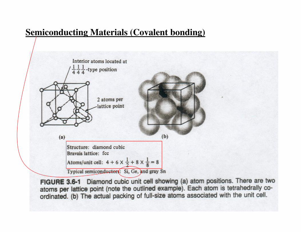
Semiconducting Materials (Covalent bonding)
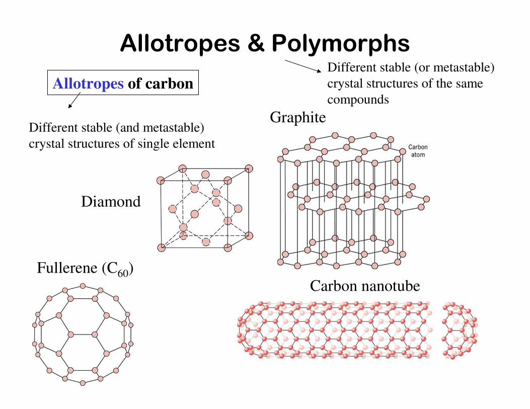
Allotropes & Polymorphs
Diamond
Graphite
Fullerene (C60)Carbon nanotube
Allotropes of carbonDifferent stable (or metastable)
crystal structures of the same
compounds
Different stable (and metastable)
crystal structures of single element

• atoms pack in periodic, 3D arrays• typical of:
Crystalline materials...
-metals-many ceramics-some polymers
• atoms have no periodic packing• occurs for:
Noncrystalline materials...
-complex structures-rapid cooling
Si Oxygen
crystalline SiO2
noncrystalline SiO2"Amorphous" = Noncrystalline
Crystalline vs. Amorphous

Single-crystalline vs. Polycrystalline
Grain
boundaries

• Most engineering materials are polycrystals.
• Nb-Hf-W plate with an electron beam weld.• Each "grain" is a single crystal.• If crystals are randomly oriented,overall component properties are not directional.
• Crystal sizes typ. range from 1 nm to 2 cm(i.e., from a few to millions of atomic layers).
1 mm
POLYCRYSTALS
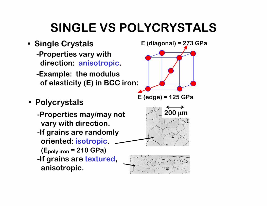
• Single Crystals
-Properties vary withdirection: anisotropic.
-Example: the modulusof elasticity (E) in BCC iron:
• Polycrystals
-Properties may/may notvary with direction.-If grains are randomlyoriented: isotropic.(Epoly iron = 210 GPa)
-If grains are textured,anisotropic.
E (diagonal) = 273 GPa
E (edge) = 125 GPa
200 µm
SINGLE VS POLYCRYSTALS

XXXX----ray Diffraction to determine Crystal Structureray Diffraction to determine Crystal Structureray Diffraction to determine Crystal Structureray Diffraction to determine Crystal Structure
• Incoming X-rays diffract from crystal planes.
X-ray
SourceDetector
Extra distance travelled by wave 2spacing
between
planes
Beams 1 & 2 have to be in phase
to be diffracted.
(next slide)
variables
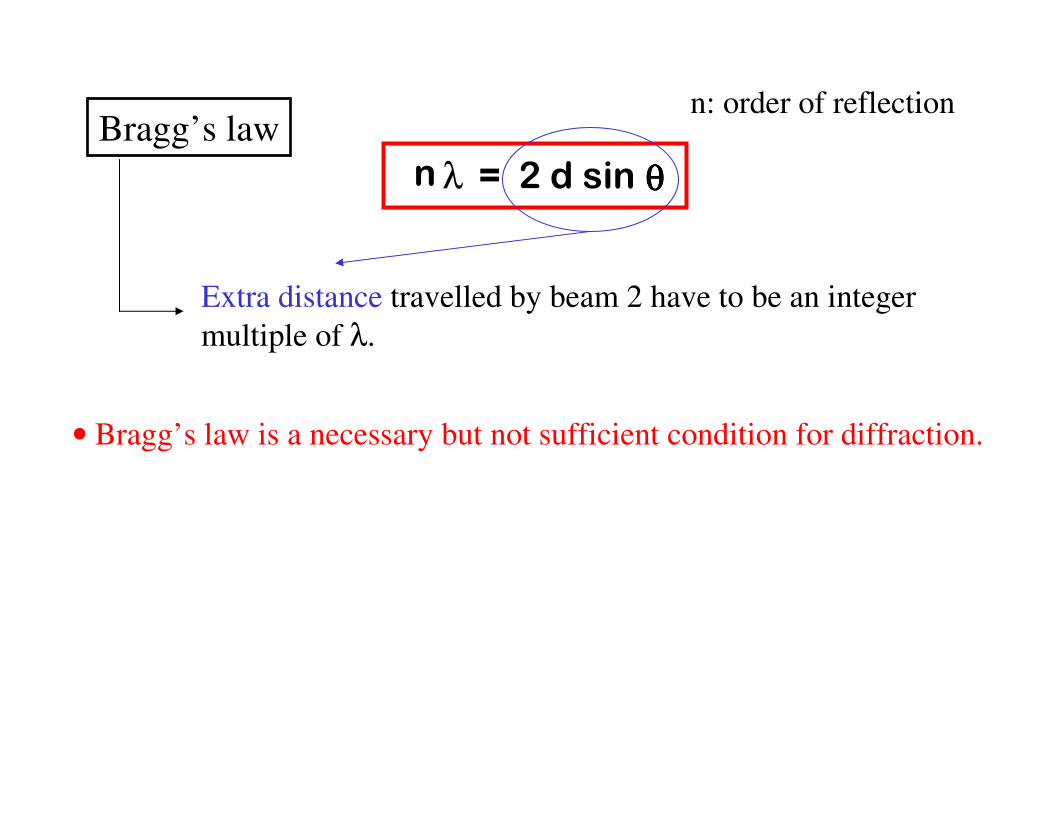
Bragg’s law
• Bragg’s law is a necessary but not sufficient condition for diffraction.
=λ 2 d sin θθθθn
Extra distance travelled by beam 2 have to be an integer
multiple of λ.
n: order of reflection

θθθθ-2θθθθ scan
X-ray
source Detector
Typically X-ray
source and detector
are both rotating.
If sample S is
polycrystalline,
X-ray data will
resemble the date below.
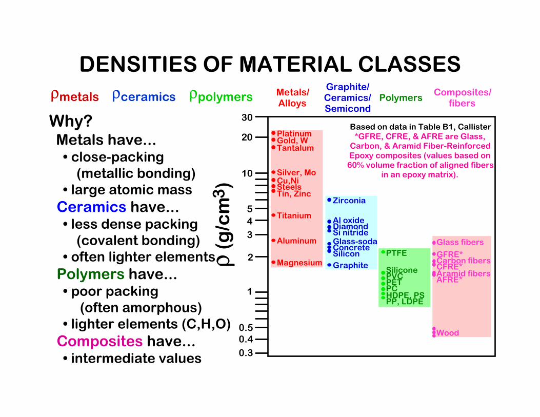
ρmetals� ρceramics� ρpolymers
ρ (g/cm3)
Graphite/ Ceramics/ Semicond
Metals/ Alloys
Composites/ fibers
Polymers
1
2
20
30Based on data in Table B1, Callister *GFRE, CFRE, & AFRE are Glass, Carbon, & Aramid Fiber-Reinforced Epoxy composites (values based on 60% volume fraction of aligned fibers
in an epoxy matrix). 10
3
4
5
0.3
0.4 0.5
Magnesium
Aluminum
Steels
Titanium
Cu,Ni
Tin, Zinc
Silver, Mo
Tantalum Gold, W Platinum
Graphite
Silicon
Glass-soda Concrete
Si nitride Diamond Al oxide
Zirconia
HDPE, PS PP, LDPE
PC
PTFE
PET PVC Silicone
Wood
AFRE*
CFRE*
GFRE*
Glass fibers
Carbon fibers
Aramid fibers
Why?Metals have...• close-packing(metallic bonding)
• large atomic mass
Ceramics have...• less dense packing(covalent bonding)
• often lighter elements
Polymers have...• poor packing(often amorphous)
• lighter elements (C,H,O)
Composites have...• intermediate values
DENSITIES OF MATERIAL CLASSES

• Atoms may assemble into crystalline oramorphous structures.
• We can predict the density of a material,provided we know the atomic weight, atomicradius, and crystal geometry (e.g., FCC,BCC, HCP).
• Material properties generally vary with singlecrystal orientation (i.e., they are anisotropic),but properties are generally non-directional(i.e., they are isotropic) in polycrystals withrandomly oriented grains.
SUMMARY