1
Cessna® 152 Please note that Flight Simulator X:SE must be correctly installed on your PC prior to
the installation and use of this C152 simulation.
Operations Manual Contents INTRODUCTION .....................................................................................................................4
Aircraft specifications ..........................................................................................................4 Dimensions.......................................................................................................................4 Engine ...............................................................................................................................4
Weights .............................................................................................................................5 Fuel and oil .......................................................................................................................5
Performance.....................................................................................................................5 Paint schemes .....................................................................................................................5
INSTALLATION, UPDATES AND SUPPORT ....................................................................6
Accessing the aircraft .........................................................................................................6 Updates.................................................................................................................................6
Technical Support ...............................................................................................................6 Regular News ......................................................................................................................6
SYSTEMS GUIDE...................................................................................................................7
Airframe.................................................................................................................................7 Fuel system ..........................................................................................................................7
Electrical system..................................................................................................................8 Master switch ...................................................................................................................8 Ammeter ...........................................................................................................................8
Circuit breakers................................................................................................................8 Vacuum system ...................................................................................................................9
Pitot-static system ...............................................................................................................9 Lighting system ....................................................................................................................9 Instrument markings ...........................................................................................................9
Airspeed indicator markings ..........................................................................................9 Engine indicator markings........................................................................................... 10
Limits .................................................................................................................................. 11 Weight limits .................................................................................................................. 11 Centre of gravity limits ................................................................................................. 11
Manoeuvre limits .......................................................................................................... 11 Flight load factor limits ................................................................................................. 11
2
Fuel limitations .............................................................................................................. 11 Landing gear ..................................................................................................................... 12
Doors and exits ................................................................................................................. 12 Flight controls.................................................................................................................... 12
Engine ................................................................................................................................ 13 Engine controls ............................................................................................................. 13 Engine instruments ...................................................................................................... 13
Ignition and starter system.......................................................................................... 13 Primer system ............................................................................................................... 13
Stall warning system ........................................................................................................ 14 PANEL GUIDE...................................................................................................................... 14
Panel selector ................................................................................................................... 15
Checklist panel ................................................................................................................. 15 Left main panel ................................................................................................................. 19
Control lock ................................................................................................................... 20 Hiding the yoke ............................................................................................................. 21
Left lower panel ................................................................................................................ 21
Start selector ................................................................................................................. 22 Cabin doors ....................................................................................................................... 23
Centre panel...................................................................................................................... 24 Lower centre panel........................................................................................................... 25 Right panel ........................................................................................................................ 26
Upper cockpit .................................................................................................................... 27 Lower cockpit .................................................................................................................... 27
KMA 20 – audio selector ................................................................................................. 28 KX 175B – COM 1 / NAV 1 radio ................................................................................... 29
COM controls ................................................................................................................ 29
NAV controls ................................................................................................................. 30 300 ADF receiver ............................................................................................................. 30
Frequency selection ..................................................................................................... 30 Operating modes .......................................................................................................... 31 ADF test ......................................................................................................................... 31
RT-359A – transponder ................................................................................................... 31 Operating the transponder .......................................................................................... 32
Important codes ............................................................................................................ 32 Squawk ident................................................................................................................. 32 Reply light ...................................................................................................................... 32
Towbar panel .................................................................................................................... 33 Flight computer ................................................................................................................. 34
GROUND ............................................................................................................................... 35 REFILL MENU ...................................................................................................................... 36 FAILURES ............................................................................................................................. 37
MENU BAR OPTIONS ........................................................................................................ 38 Gyro sounds ...................................................................................................................... 39
Engine management........................................................................................................ 39 Panel selector ................................................................................................................... 39
FLYING THE C152 .............................................................................................................. 39
Getting started .................................................................................................................. 42 Starting the engine ........................................................................................................... 48
Configuring the avionics .................................................................................................. 54
3
Taxi ..................................................................................................................................... 56 Take-off .............................................................................................................................. 58
Climb .................................................................................................................................. 59 Cruise ................................................................................................................................. 60
Descent .............................................................................................................................. 64 Approach and landing...................................................................................................... 65 Shutdown ........................................................................................................................... 67
NORMAL PROCEDURES .................................................................................................. 68 Airspeed (IAS) for normal operations............................................................................ 68
Pre-flight............................................................................................................................. 68 Cockpit ........................................................................................................................... 68 Left/right wing................................................................................................................ 69
Nose section ................................................................................................................. 69 Tail section .................................................................................................................... 69
Before starting engine ..................................................................................................... 69 Engine starting .................................................................................................................. 69
Hot engine ..................................................................................................................... 70
Taxiing................................................................................................................................ 70 Before take-off .................................................................................................................. 70
Take-off .............................................................................................................................. 71 Normal technique ......................................................................................................... 71 Short field take-off ........................................................................................................ 71
Climb .................................................................................................................................. 71 Cruise ................................................................................................................................. 72
Before landing ................................................................................................................... 72 Landing .............................................................................................................................. 72
Normal landing.............................................................................................................. 72
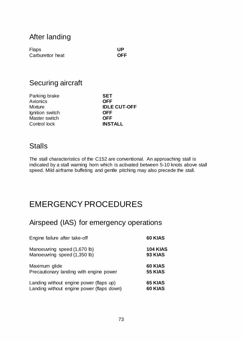
Short field landing......................................................................................................... 72 After landing ...................................................................................................................... 73
Securing aircraft ............................................................................................................... 73 Stalls ................................................................................................................................... 73
EMERGENCY PROCEDURES ......................................................................................... 73
Airspeed (IAS) for emergency operations .................................................................... 73 Engine failures .................................................................................................................. 74
Engine failure during take-off run............................................................................... 74 Engine failure immediately after take-off .................................................................. 74 Engine failure during flight .......................................................................................... 74
Forced landings ................................................................................................................ 74 Emergency landing without engine power ............................................................... 74
Precautionary landing with engine power................................................................. 75 Fires.................................................................................................................................... 75
During engine start on ground.................................................................................... 75
Engine fire in flight........................................................................................................ 75 Electrical fire.................................................................................................................. 76
Electrical failures .............................................................................................................. 76 Over-voltage light illuminates ..................................................................................... 76 Ammeter shows discharge ......................................................................................... 76
Icing .................................................................................................................................... 76 Spin recovery .................................................................................................................... 77
Airspeed indicating system failure ................................................................................. 77
4
CREDITS ............................................................................................................................... 77 COPYRIGHT ......................................................................................................................... 77
INTRODUCTION
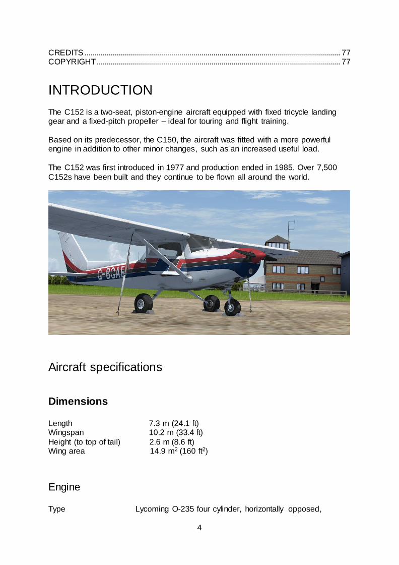
The C152 is a two-seat, piston-engine aircraft equipped with fixed tricycle landing gear and a fixed-pitch propeller – ideal for touring and flight training.
Based on its predecessor, the C150, the aircraft was fitted with a more powerful engine in addition to other minor changes, such as an increased useful load.
The C152 was first introduced in 1977 and production ended in 1985. Over 7,500
C152s have been built and they continue to be flown all around the world.
Aircraft specifications
Dimensions
Length 7.3 m (24.1 ft) Wingspan 10.2 m (33.4 ft)
Height (to top of tail) 2.6 m (8.6 ft) Wing area 14.9 m2 (160 ft2)
Engine
Type Lycoming O-235 four cylinder, horizontally opposed,
5
air-cooled piston Power 110 horsepower at 2,550 RPM
Propeller Two-blade, fixed-pitch
Weights
Empty weight 1,081 lb (490 kg) Maximum weight 1,670 lb (757 kg)
Maximum baggage weight 120 lb (54 kg) Maximum useful load 589 lb (267 kg)
Fuel and oil Fuel capacity 26 US gallons (13 per wing tank) Usable fuel 24.5 US gallons
Oil capacity 6 US quarts
Performance VNE (never exceed speed) 149 KIAS VNO (max. cruising speed) 111 KIAS VA (manoeuvring speed) 104 KIAS (at 1,670 lb)
93 KIAS (at 1,350 lb) VFE (max. flap speed) 85 KIAS
VSO (stall speed) 43 KIAS (landing configuration) Service ceiling 14,700 ft Range 590 nautical miles (75% power at 8,000 ft)
Paint schemes The C152 is supplied in the following eight paint schemes:
G-BGAE (UK)
G-BONW (UK)
N5310H (USA)
N95469 (USA)
D-EBPC (Germany)
F-GJCI (France)
C-GQOP (Canada)
VH-IVZ (Australia)

6
INSTALLATION, UPDATES AND SUPPORT
Installation is handled by Steam after purchase of the product. After purchasing the product the files will be downloaded and installation into the Scenery Library will be
automatic.
Accessing the aircraft To access the aircraft in FSX:
1. Click on ‘Free Flight’.
2. Select ‘Just Flight’ from the ‘Publisher’ drop-down menu. 3. Select ‘Cessna’ from the Manufacturer drop-down and choose one of
the schemes. 4. Tick the ‘Show all variations’ box to see all the available paint schemes.
Updates Updates to the product will automatically be deployed, downloaded and installed via
Steam to all users who own the product.
Technical Support To obtain technical support (in English) please visit the Support pages on the Just
Flight website. As a Just Flight customer you can obtain free technical support for any Just Flight or Just Trains product.
For support specifically on the Steam version of the add-on please contact Dovetail Games.
Regular News To get the latest news about Just Flight products, sign up for our Newsletter regular
emails.
7
SYSTEMS GUIDE
Airframe
The C152 is a single-engine, all-metal aircraft with fixed landing gear. The aircraft has seating for two occupants, a 120-pound luggage compartment and a 110 HP
engine.
The basic airframe is constructed out of aluminium alloy, with wingtips and fairings made of fibreglass. The fuselage is a semi-monocoque structure. There is a passenger door located on each side of the aircraft.
The wings are externally braced and have a one-degree dihedral angle. The trailing
edge of the wing provides a mount for the flaps and ailerons. The four-position wing flaps are electrically controlled by a lever located in the centre of the panel. Each wing contains one fuel tank.
A vertical and horizontal stabiliser, elevator and rudder make up the empennage.
The horizontal stabiliser contains the elevator trim tab actuator.
Fuel system
The fuel system was designed with simplicity in mind. Fuel is contained in two 13 US
gallon tanks, one in each wing. Of the total 26-gallon capacity, only 24.5 gallons are usable.
A fuel shut-off valve, located on the floor between the two seats, allows the pilot to control the flow of fuel to the engine.
Fuel quantity is indicated by electrically operated gauges on the lower left panel.
There is a separate fuel quantity gauge for each tank. The gauges cannot be relied upon for accurate readings and the fuel level should be checked manually before flight.

8
Electrical system Electrical power is supplied by a 28-volt DC system which is powered by an engine-driven, 60-amp alternator and a 24-volt, 14-amp hour battery. The power is supplied
through a single bus bar. A master switch controls the power to all circuits except the engine ignition system, clock and flight hour recorder. Avionics should be turned off
prior to starting the engine.
Master switch The master switch is a split-rocker type switch with OFF (down) and ON (up) positions. The left half of the switch (ALT) controls the alternator and the right half of
the switch (BAT) controls all the electrical power to the aircraft.
In normal conditions both halves of the switch are placed in the same position, but the BAT side of the switch can be turned on separately to check equipment while on the ground.
Ammeter The ammeter indicates the flow of current (in amperes) from the alternator to the
battery, or from the battery to the electrical system. If the engine is operating and the master switch is on, the ammeter indicates the rate of battery charging. If the alternator is not functioning, or if the electrical load exceeds the output of the
alternator, the ammeter indicates the rate of battery discharge.
A low voltage light indicates that the alternator has failed and that the battery is supplying all electrical power.
Circuit breakers
Most of the electrical circuits are protected by push-to-reset circuit breakers located on the lower centre of the panel.
Left-click on the circuit breakers to pull them out or push them in.
9
Vacuum system The vacuum system provides the suction necessary to operate the air-driven gyro instruments – the directional and attitude indicator. The system consists of an engine
vacuum pump, a vacuum relief valve, a filter and the necessary plumbing.
A suction gauge, mounted on the left panel, provides valuable information to the pilot about the operation of the vacuum system. A decrease in pressure, or zero pressure, over an extended period may indicate a problem with the vacuum system.
Normal vacuum readings are between 4.6-5.4 inches of mercury, a setting which
provides sufficient vacuum to operate all the gyros at their rated RPM.
Pitot-static system The system supplies both pitot and static pressure for the airspeed indicator,
altimeter and vertical speed indicator.
Pitot pressure is picked up by the pitot head on the bottom of the left wing. The switch for pitot heat (labelled PITOT HT) is located on the left lower panel. Static pressure is sensed by button-type vents on each side of the aft fuselage. A static
port is located on the lower left side of the forward fuselage.
Lighting system
Lights fitted to the aircraft include navigation, anti-collision beacon, taxi, landing,
instrument panel and cabin dome lights. The lights are controlled by rocker switches on the left lower panel.
A rheostat control knob on the left lower panel controls the integral instrument lighting. A cabin dome light is located on the overhead panel and is controlled by the
DOME LT switch on the left lower panel.
Instrument markings
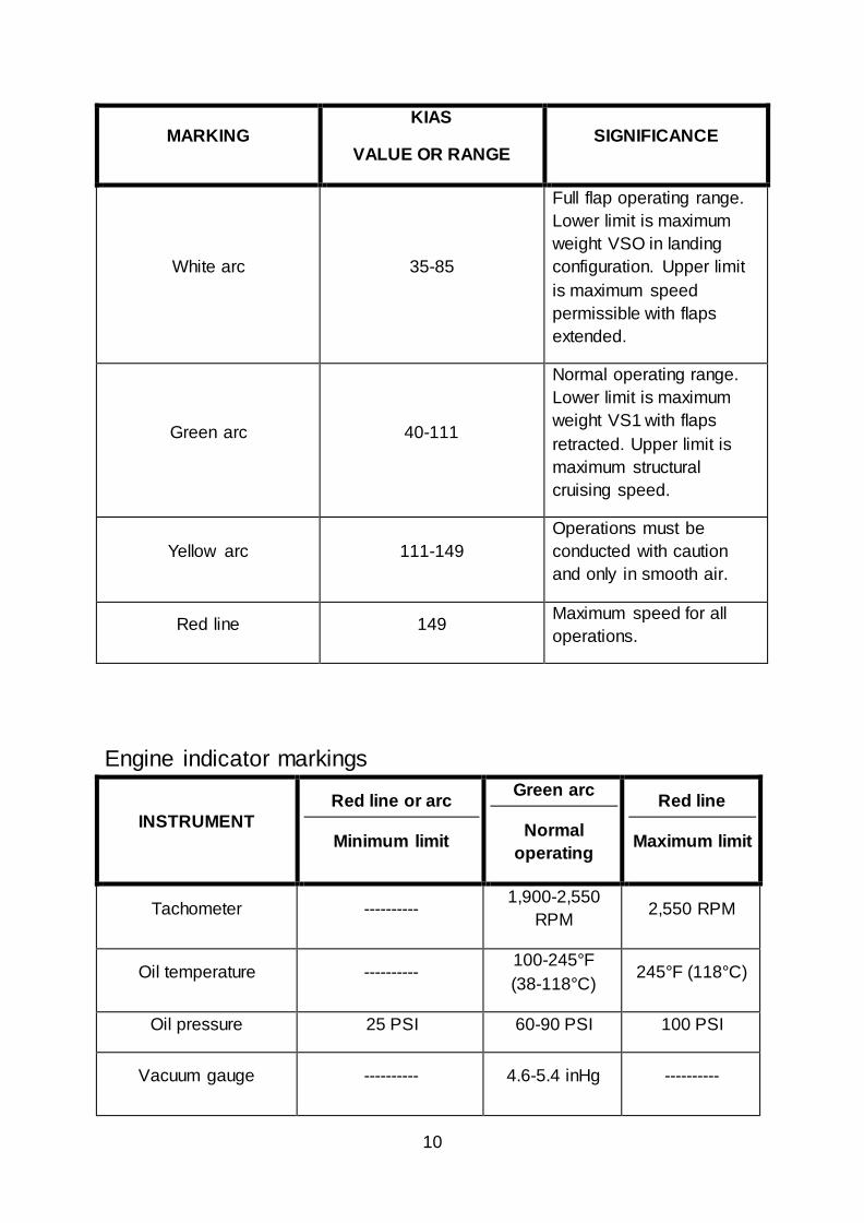
Airspeed indicator markings
10
MARKING KIAS
VALUE OR RANGE SIGNIFICANCE
White arc 35-85
Full flap operating range.
Lower limit is maximum
weight VSO in landing
configuration. Upper limit
is maximum speed
permissible with flaps
extended.
Green arc 40-111
Normal operating range.
Lower limit is maximum
weight VS1 with flaps
retracted. Upper limit is
maximum structural
cruising speed.
Yellow arc 111-149
Operations must be
conducted with caution
and only in smooth air.
Red line 149 Maximum speed for all
operations.
Engine indicator markings
INSTRUMENT
Red line or arc
Minimum limit
Green arc
Normal
operating
Red line
Maximum limit
Tachometer ---------- 1,900-2,550
RPM 2,550 RPM
Oil temperature ---------- 100-245°F
(38-118°C) 245°F (118°C)
Oil pressure 25 PSI 60-90 PSI 100 PSI
Vacuum gauge ---------- 4.6-5.4 inHg ----------
11
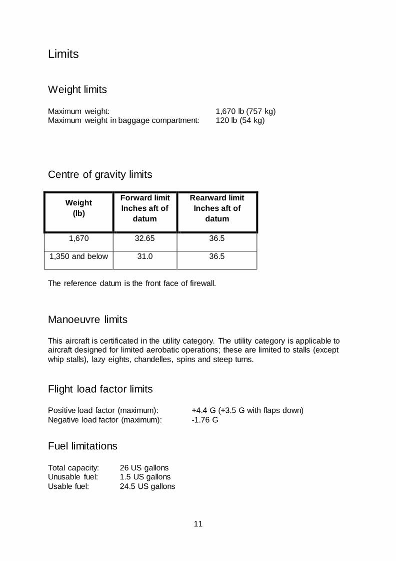
Limits
Weight limits
Maximum weight: 1,670 lb (757 kg) Maximum weight in baggage compartment: 120 lb (54 kg)
Centre of gravity limits
Weight
(lb)
Forward limit
Inches aft of
datum
Rearward limit
Inches aft of
datum
1,670 32.65 36.5
1,350 and below 31.0 36.5
The reference datum is the front face of firewall.
Manoeuvre limits
This aircraft is certificated in the utility category. The utility category is applicable to aircraft designed for limited aerobatic operations; these are limited to stalls (except
whip stalls), lazy eights, chandelles, spins and steep turns.
Flight load factor limits Positive load factor (maximum): +4.4 G (+3.5 G with flaps down)
Negative load factor (maximum): -1.76 G
Fuel limitations
Total capacity: 26 US gallons Unusable fuel: 1.5 US gallons
Usable fuel: 24.5 US gallons

12
Landing gear
The C152 is equipped with fixed tricycle landing gear.
The nose gear is steerable through a 30-degree arc each side of centre by use of the rudder pedals and toe brakes.
The hydraulically actuated disc brake system includes toe brakes on the left and right set of rudder pedals. The parking brake is controlled by a knob on the lower left
part of the panel.
Doors and exits
The aircraft is fitted with a door on either side of the fuselage. To open the door on the port side, press [Shift]+[E].
To open the door on the starboard side, press [Shift]+[E] then [2].
A door can be opened from within the virtual cockpit by clicking on the associated door latch to pull it to the open position and then clicking on the door handle to push
it open. It can be closed by clicking on the door handle to pull it closed and then clicking on the associated door latch to push it to the latched position.
Flight controls
Dual flight controls are provided. The flight control system consists of conventional aileron, rudder and elevator surfaces which are operated through mechanical
linkages – a yoke for the ailerons and elevator, and pedals for the rudder (and brakes).
The trim tab is controlled by a trim control wheel located in the centre of the panel. Rotating the wheel forward gives nose-down trim and rotation aft gives nose-up trim.
Electronically controlled single-slot flaps are provided. The flap control is in the
centre of the panel. To extend or retract the flaps, move the lever to the desired flap setting of 10, 20 or 30 degrees. An indicator located on the left side of the lever shows the flap movement. The flap system is protected by a 15-ampere circuit
breaker labelled FLAP.
The aircraft will experience a pitch change during flap extension or retraction. This pitch change can be corrected by either elevator trim or increased yoke force.
13
Engine
The C152 is powered by a four-cylinder, horizontally opposed engine rated at 110 horsepower at 2,550 RPM. It is equipped with a starter, alternator, two magnetos, a
vacuum pump and an oil filter.
Engine controls
The engine controls consist of a throttle control and a mixture control knob. These controls are located on the lower centre of the instrument panel.
The throttle knob is used to adjust the engine RPM, with the full forward position
being fully open and the full aft position being fully closed. The mixture control knob is used to adjust the air-to-fuel ratio. The engine is shut down by placing the mixture control knob in the fully lean position.
The carburettor heat control knob is located to the left of the throttle.
Engine instruments
Indicators enable the pilot to check oil pressure, oil temperature and RPM. The engine instruments are located on the lower left panel.
Ignition and starter system Engine ignition is provided by a dual magneto on two spark plugs per cylinder.
Ignition is controlled by a key-operated rotating selector on the lower left portion of the left panel. The selector operates clockwise, with right, left, left/right and start
positions.
Primer system To assist with engine starting, the aircraft is equipped with a manual priming system. The primer is operated by a plunger knob on the lower left panel, which features a
lock to prevent inadvertent use. To operate the knob, left-click once to unlock it and then again to pull it out. Right-click to push in the knob, and once you have finished
priming the aircraft, right-click again to lock it.
14
Stall warning system
An approaching stall is indicated by a stall warning horn which is activated between 5-10 knots above stall speed. Mild airframe buffeting and gentle pitching may also
precede the stall. Stall speeds are shown on a graph in the OPERATING DATA MANUAL included with this C152 software.
The stall warning horn emits a continuous sound and is not dependent on electrical power.
PANEL GUIDE
The instrument panel features the primary flight instruments and the engine instruments, as well as radios and navigation equipment.
The attitude and directional indicator, located on the left-hand instrument panel, are vacuum-operated. The vacuum (suction) gauge is co-located with these gauges. The
turn indicator is electrically operated.
The radios are located in the centre section of the panel and the circuit breakers are in the lower right corner of the panel. The engine controls and wing flap lever are below the radios on the centre panel.
The right-hand instrument panel also contains the tachometer, ammeter and other
instruments such as the flight hour recorder. Additional features include door windows and two sun visors.
A large baggage area behind the rear seats is accessible from the cabin. When
baggage is loaded, it is the pilot’s responsibility to ensure that the aircraft’s centre of gravity falls within the allowable CG range.
15
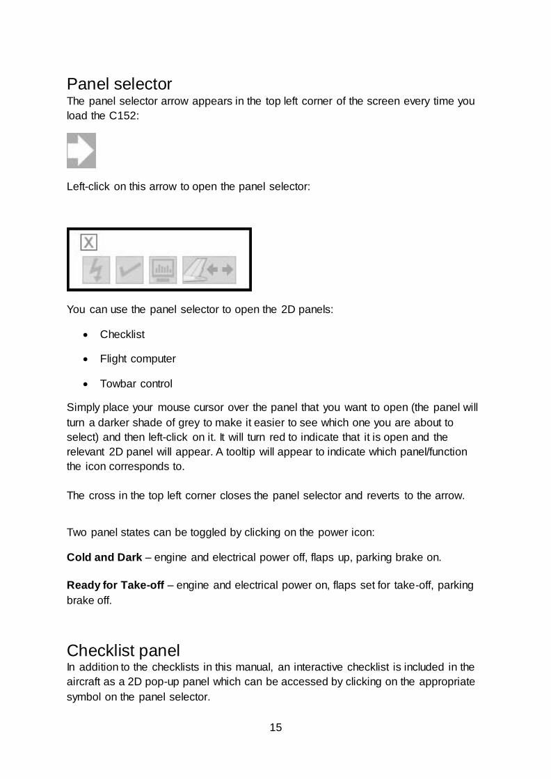
Panel selector The panel selector arrow appears in the top left corner of the screen every time you
load the C152:
Left-click on this arrow to open the panel selector:
You can use the panel selector to open the 2D panels:
Checklist
Flight computer
Towbar control
Simply place your mouse cursor over the panel that you want to open (the panel will
turn a darker shade of grey to make it easier to see which one you are about to
select) and then left-click on it. It will turn red to indicate that it is open and the
relevant 2D panel will appear. A tooltip will appear to indicate which panel/function
the icon corresponds to.
The cross in the top left corner closes the panel selector and reverts to the arrow.
Two panel states can be toggled by clicking on the power icon:
Cold and Dark – engine and electrical power off, flaps up, parking brake on.
Ready for Take-off – engine and electrical power on, flaps set for take-off, parking
brake off.
Checklist panel In addition to the checklists in this manual, an interactive checklist is included in the
aircraft as a 2D pop-up panel which can be accessed by clicking on the appropriate
symbol on the panel selector.
16

17
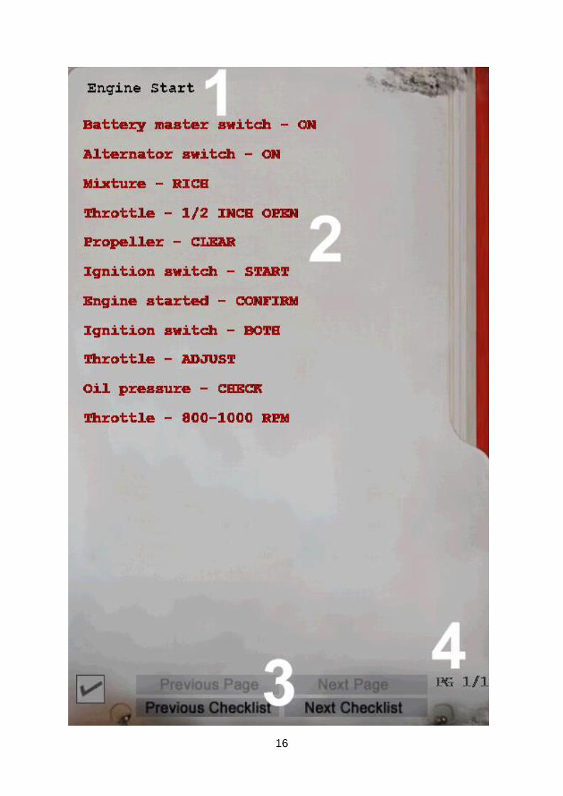
1. Checklist name – in the top left corner of the panel is the name of the currently
selected checklist, for example ‘Engine Start’.
2. Checklist items – the checklist items are displayed in the centre of the panel.
When the panel is first opened, or when a new checklist is selected, the items will
appear in red text. Click on the checklist item when you have completed the
relevant action/check and the item text will turn green to indicate that the item is
complete. Hover over longer checklist items to see all of the text.
3. Checklist navigation buttons – at the bottom of the panel are four buttons. These
allow you to cycle through the available checklists and select the previous/next
page of the selected checklist. The button will be greyed out if it is not active.
4. Current page number – the checklist page number is displayed in the bottom right
corner if there are multiple pages.
An interactive engine start checklist can be accessed by clicking on the icon in the
lower left corner of the Checklist panel when either the 'Before Start' or 'Engine Start'
checklist is selected.
The checklist items will automatically turn from red to green when you have
completed the associated check. The Failures section displays the status of possible
failures that will prevent engine starting. The failure items will automatically change
from green to red if the associated failure occurs.

18

19
Left main panel
1. Airspeed indicator (ASI) – indicates airspeed in knots (outer scale) and MPH
(inner scale)
2. Suction gauge
3. Attitude indicator (AI) – a pitch reference knob allows for the pitch bars (aircraft
symbol) position to be adjusted nose-up or nose-down
4. Clock – a knob allows for adjustment of the hour and minute hands
5. Altimeter – a barometric pressure scale is provided for hPa/mb. The pressure
setting knob tooltip displays the currently selected pressure in hPa/mb or inHg,
depending on which unit of measurement is currently active in the simulator
settings.
6. Omni-course (VOR 1) indicator – driven by KX 175B (or Flight1 GTN/GNS if
installed). The indicator features a CDI needle, fail flag and back course light.
7. Low voltage warning light
8. Turn and bank indicator
9. Direction indicator – caging knob (bottom left) controls rotation of the compass
card
10. Vertical speed indicator (VSI)
11. ADF indicator – driven by 300 ADF system. HDG knob controls rotation of the
compass card.

20
Control lock A control lock can be fitted to lock the ailerons and elevator control surfaces in a
neutral position. The control lock features a red flag which covers the ignition switch.
To install or remove the control lock, click on the base of the yoke where it enters the
centre of the panel.
The lock can only be fitted when the aircraft is on the ground.
21
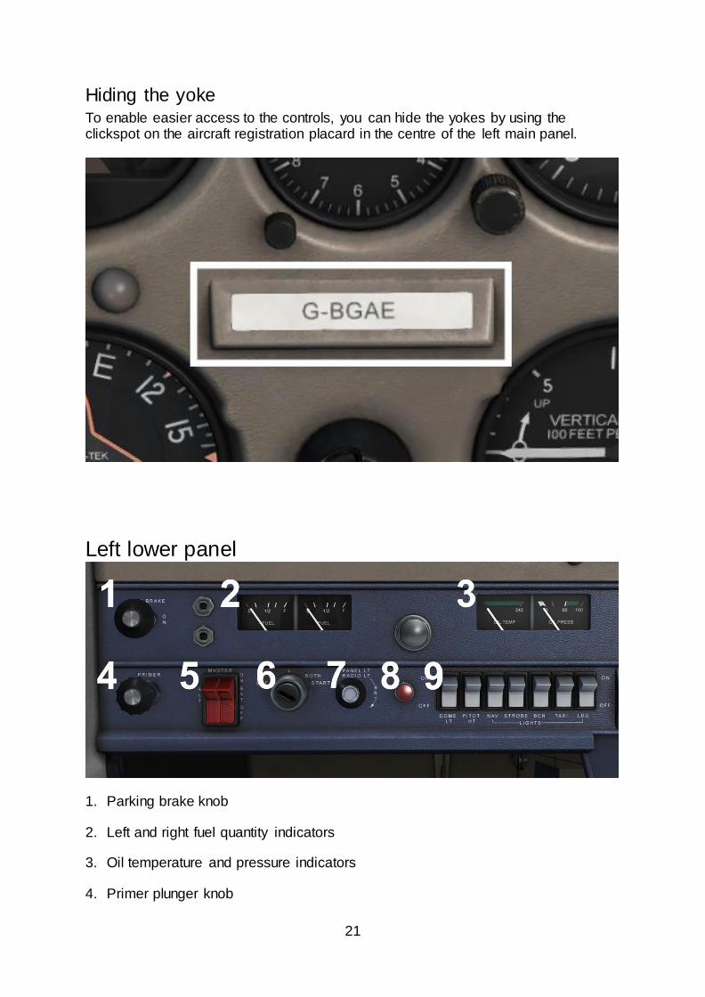
Hiding the yoke To enable easier access to the controls, you can hide the yokes by using the clickspot on the aircraft registration placard in the centre of the left main panel.
Left lower panel
1. Parking brake knob
2. Left and right fuel quantity indicators
3. Oil temperature and pressure indicators
4. Primer plunger knob
22
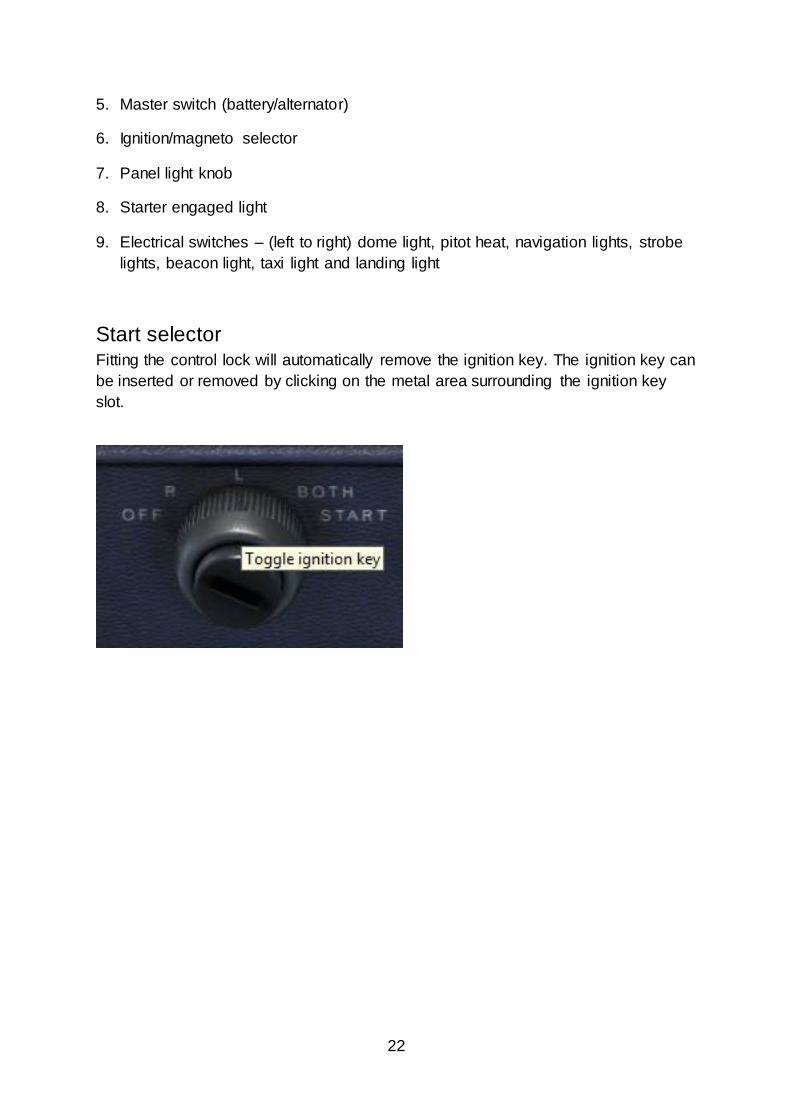
5. Master switch (battery/alternator)
6. Ignition/magneto selector
7. Panel light knob
8. Starter engaged light
9. Electrical switches – (left to right) dome light, pitot heat, navigation lights, strobe
lights, beacon light, taxi light and landing light
Start selector Fitting the control lock will automatically remove the ignition key. The ignition key can
be inserted or removed by clicking on the metal area surrounding the ignition key
slot.
23
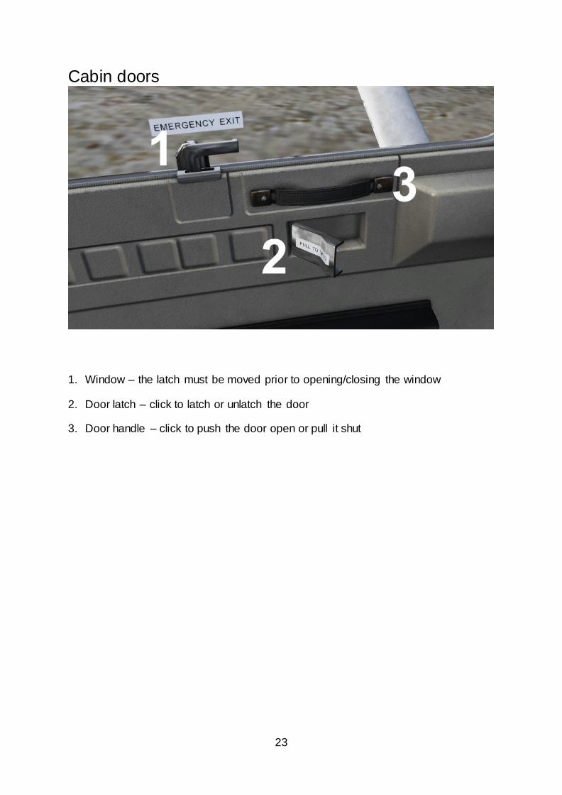
Cabin doors
1. Window – the latch must be moved prior to opening/closing the window
2. Door latch – click to latch or unlatch the door
3. Door handle – click to push the door open or pull it shut
24
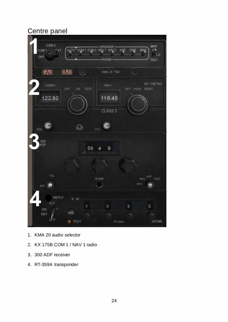
Centre panel
1. KMA 20 audio selector
2. KX 175B COM 1 / NAV 1 radio
3. 300 ADF receiver
4. RT-359A transponder
25
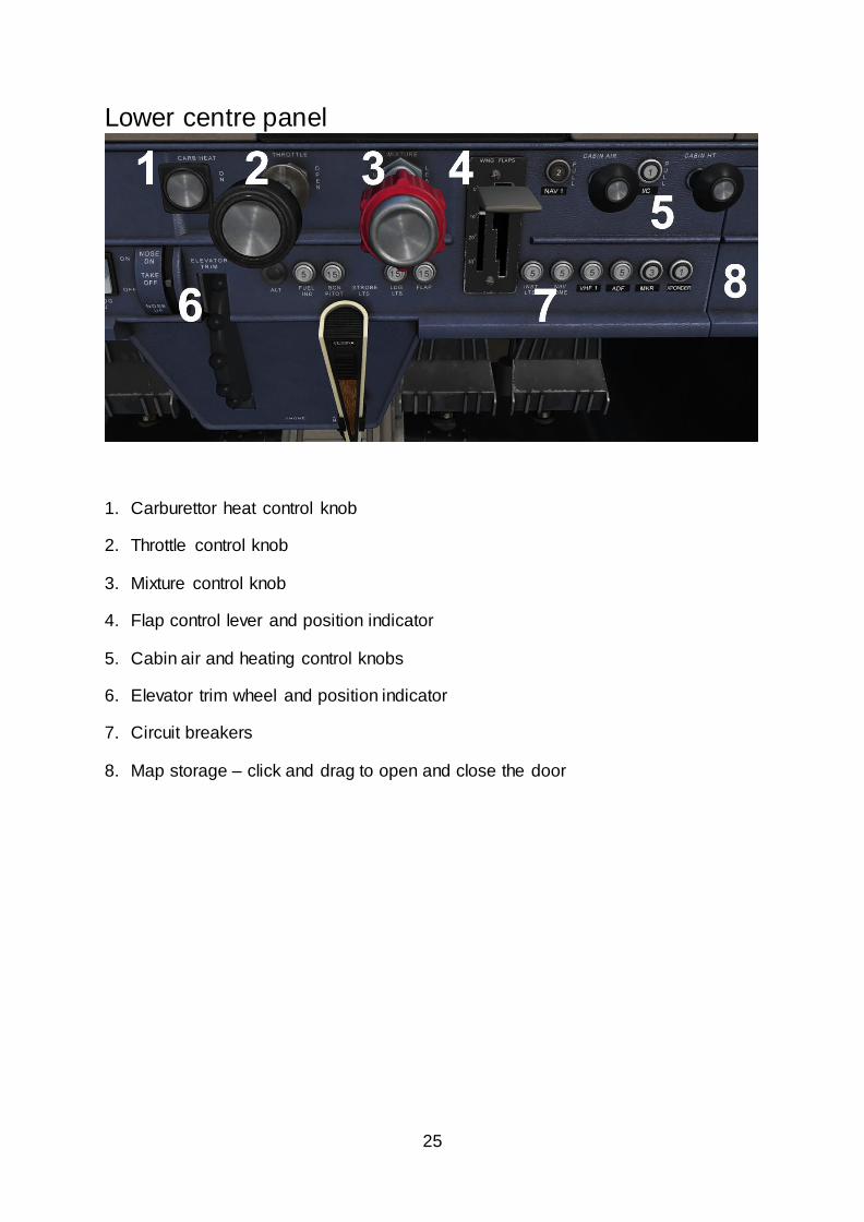
Lower centre panel
1. Carburettor heat control knob
2. Throttle control knob
3. Mixture control knob
4. Flap control lever and position indicator
5. Cabin air and heating control knobs
6. Elevator trim wheel and position indicator
7. Circuit breakers
8. Map storage – click and drag to open and close the door
26
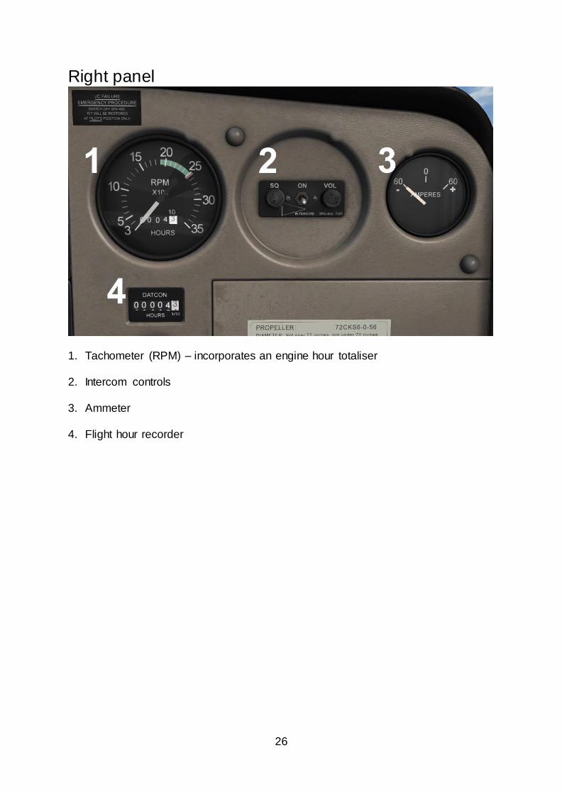
Right panel
1. Tachometer (RPM) – incorporates an engine hour totaliser
2. Intercom controls
3. Ammeter
4. Flight hour recorder
27
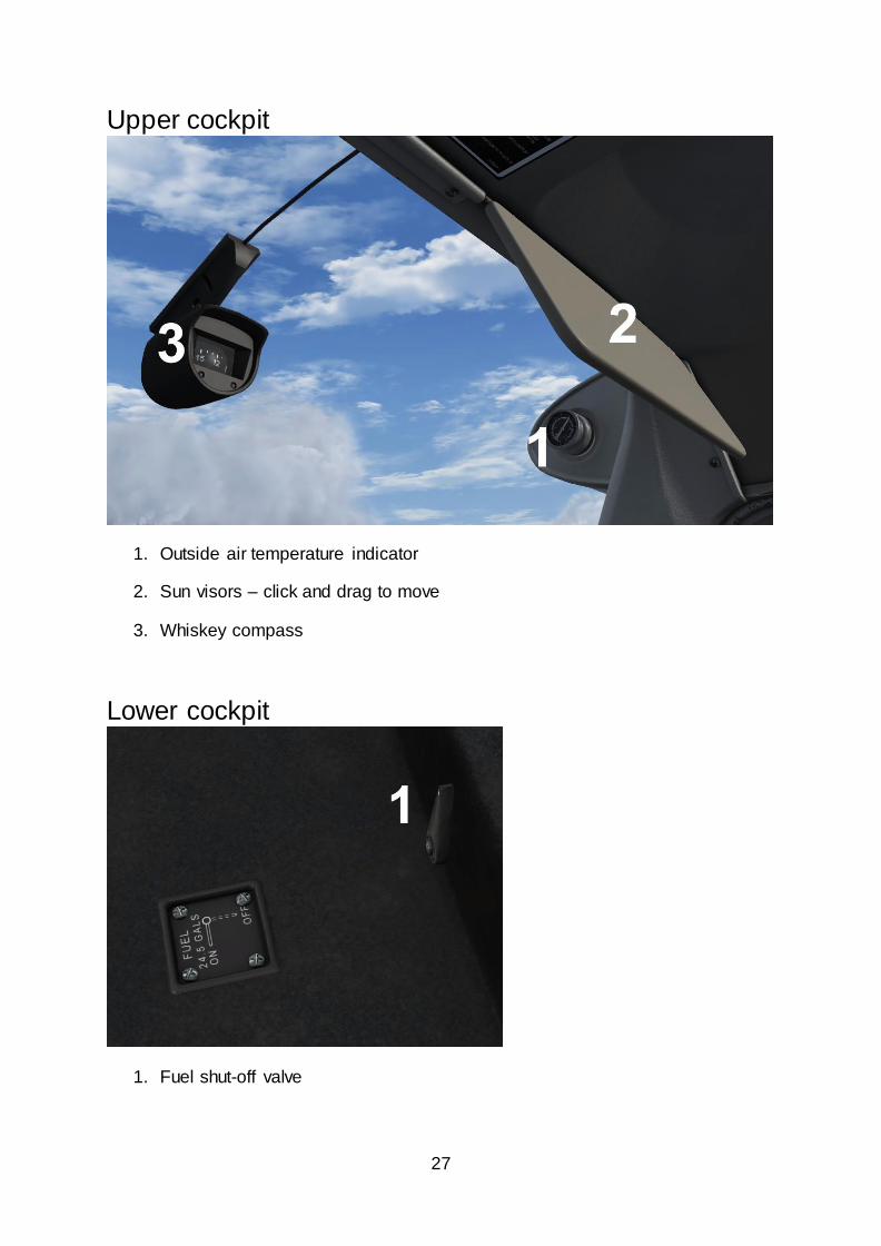
Upper cockpit
1. Outside air temperature indicator
2. Sun visors – click and drag to move
3. Whiskey compass
Lower cockpit
1. Fuel shut-off valve
28
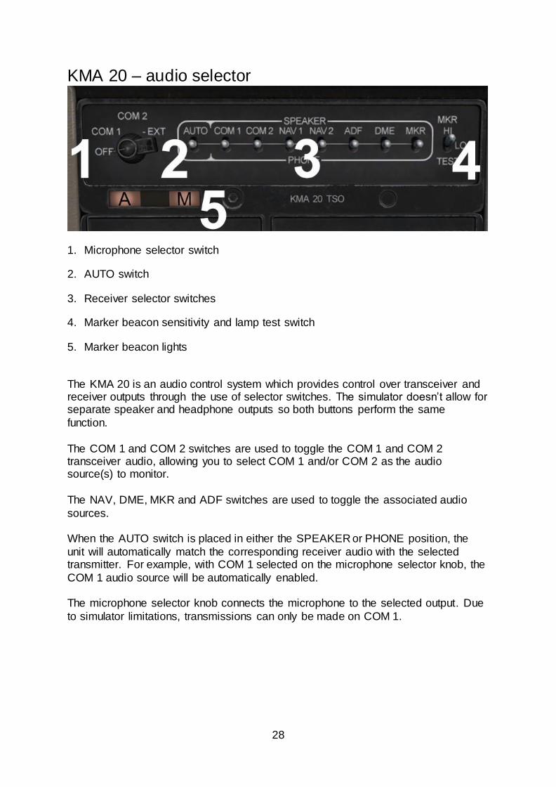
KMA 20 – audio selector
1. Microphone selector switch
2. AUTO switch
3. Receiver selector switches
4. Marker beacon sensitivity and lamp test switch
5. Marker beacon lights
The KMA 20 is an audio control system which provides control over transceiver and receiver outputs through the use of selector switches. The simulator doesn’t allow for separate speaker and headphone outputs so both buttons perform the same
function.
The COM 1 and COM 2 switches are used to toggle the COM 1 and COM 2 transceiver audio, allowing you to select COM 1 and/or COM 2 as the audio source(s) to monitor.
The NAV, DME, MKR and ADF switches are used to toggle the associated audio
sources. When the AUTO switch is placed in either the SPEAKER or PHONE position, the
unit will automatically match the corresponding receiver audio with the selected transmitter. For example, with COM 1 selected on the microphone selector knob, the
COM 1 audio source will be automatically enabled. The microphone selector knob connects the microphone to the selected output. Due
to simulator limitations, transmissions can only be made on COM 1.
29
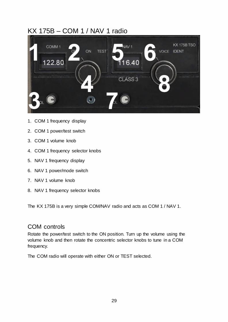
KX 175B – COM 1 / NAV 1 radio
1. COM 1 frequency display
2. COM 1 power/test switch
3. COM 1 volume knob
4. COM 1 frequency selector knobs
5. NAV 1 frequency display
6. NAV 1 power/mode switch
7. NAV 1 volume knob
8. NAV 1 frequency selector knobs
The KX 175B is a very simple COM/NAV radio and acts as COM 1 / NAV 1.
COM controls Rotate the power/test switch to the ON position. Turn up the volume using the
volume knob and then rotate the concentric selector knobs to tune in a COM
frequency.
The COM radio will operate with either ON or TEST selected.
30
NAV controls Rotate the power/mode switch to the VOICE position. Turn up the volume using the
volume knob and then rotate the concentric selector knobs to tune in a NAV
frequency.
Rotate the power/mode switch to the IDENT position to hear the audio identifier.
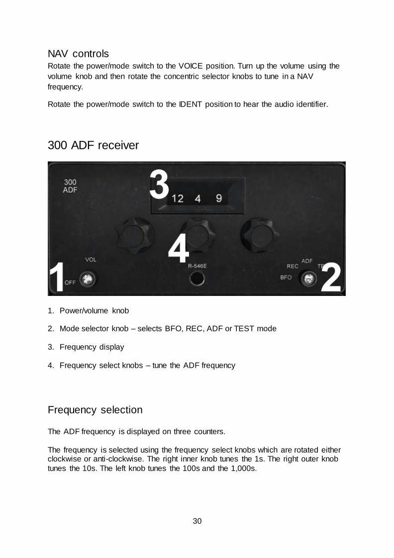
300 ADF receiver
1. Power/volume knob
2. Mode selector knob – selects BFO, REC, ADF or TEST mode
3. Frequency display
4. Frequency select knobs – tune the ADF frequency
Frequency selection The ADF frequency is displayed on three counters.
The frequency is selected using the frequency select knobs which are rotated either clockwise or anti-clockwise. The right inner knob tunes the 1s. The right outer knob
tunes the 10s. The left knob tunes the 100s and the 1,000s.
31
Operating modes
REC mode provides improved audio reception from the station tuned and is usually used for identification. The bearing pointer on the ADF indicator will be deactivated
and immediately turn to the 90° relative position and remain there during reception.
ADF mode activates the bearing pointer on the ADF indicator, causing it to point in the direction of the station relative to the aircraft heading.
BFO mode permits the carrier wave and the associated Morse code identifier broadcast on the carrier wave to be heard.
With TEST mode selected, the bearing pointer on the ADF indicator will be deactivated, immediately turn to the 90° relative position and remain there.
ADF test
Select TEST mode and confirm that the bearing pointer moves directly to the parked
90° position. Make sure that the unit is tuned to a usable frequency and then select
ADF mode. Confirm that the needle moves to the station bearing.
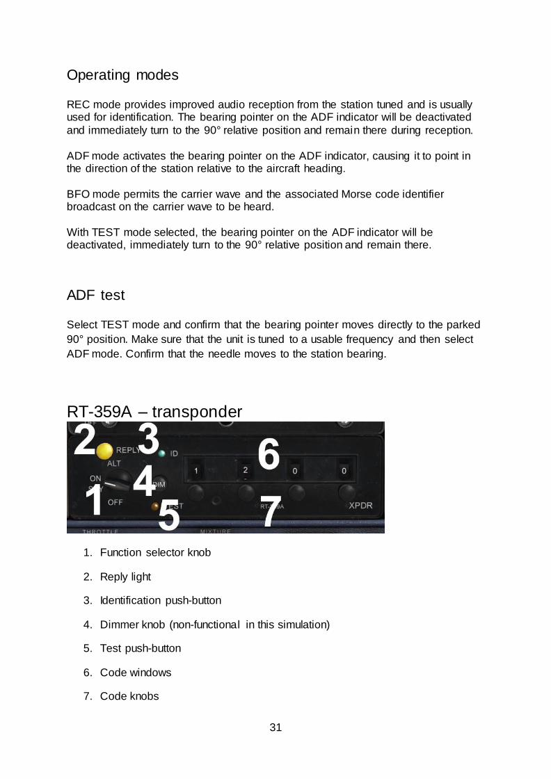
RT-359A – transponder
1. Function selector knob
2. Reply light
3. Identification push-button
4. Dimmer knob (non-functional in this simulation)
5. Test push-button
6. Code windows
7. Code knobs
32
Operating the transponder The function selector knob should be in the OFF position before starting the aircraft’s
engine. Select the required reply code by rotating the four code knobs (one per code
digit). The code will be displayed in the four code windows.
After starting the engine, turn the function selector to standby (SBY). The
transponder will take approximately 45-50 seconds to become operational. Once you
are airborne, turn the function selector to ON, enabling normal Mode A operation.
Turn the function selector to the altitude (ALT) position for altitude reporting (Mode
C) to ATC.
Important codes 7700: Emergency
7600: Communications failure
7500: Hijacking
0000: Reserved for military aircraft
Squawk ident When you are asked to ident by ATC, press and release the ident push-button. Your
aircraft will be positively identified to the air traffic controller.
Reply light During normal operation the reply light will flash to indicate that the transponder is
functioning properly and replying to interrogations from ground radar. Interrogations
occur at 10-15 second intervals, corresponding to each radar sweep.
33
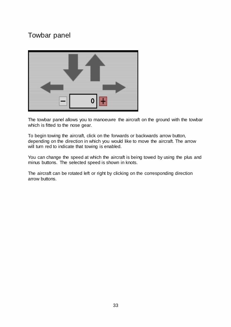
Towbar panel
The towbar panel allows you to manoeuvre the aircraft on the ground with the towbar
which is fitted to the nose gear. To begin towing the aircraft, click on the forwards or backwards arrow button,
depending on the direction in which you would like to move the aircraft. The arrow will turn red to indicate that towing is enabled.
You can change the speed at which the aircraft is being towed by using the plus and minus buttons. The selected speed is shown in knots.
The aircraft can be rotated left or right by clicking on the corresponding direction
arrow buttons.
34
Flight computer
35
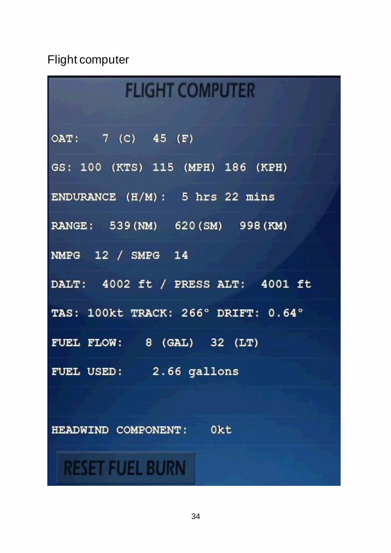
The flight computer provides a variety of information:
Outside air temperature (OAT) – Celsius and Fahrenheit
Groundspeed (GS) – nautical miles per hour, statute miles per hour and
kilometres per hour
Endurance – hours and minutes
Range – nautical miles, statute miles and kilometres
Nautical miles per gallon and statute miles per gallon
Density altitude and pressure altitude (feet)
True airspeed (knots), track (degrees) and drift (degrees)
Fuel flow – gallons and litres
Fuel used – total fuel burn (gallons)
Crosswind component (knots)
Headwind/tailwind component (knots)
The total fuel burn can be reset by clicking on the RESET FUEL BURN button.
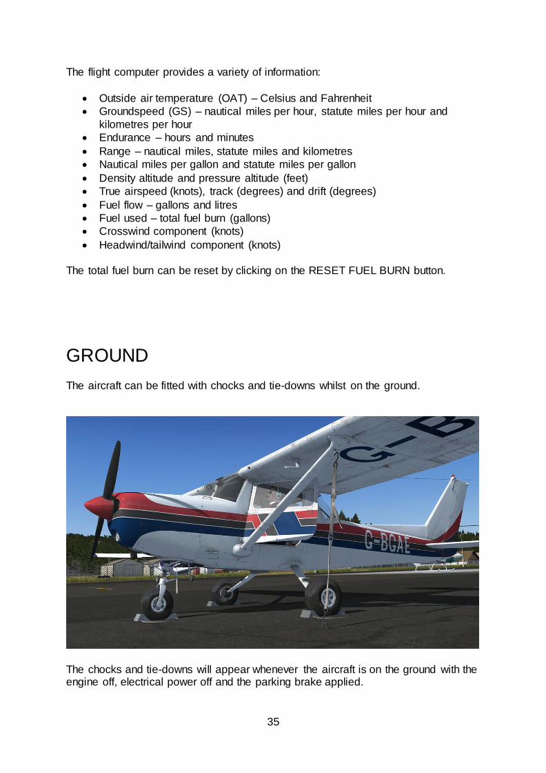
GROUND
The aircraft can be fitted with chocks and tie-downs whilst on the ground.
The chocks and tie-downs will appear whenever the aircraft is on the ground with the engine off, electrical power off and the parking brake applied.
36
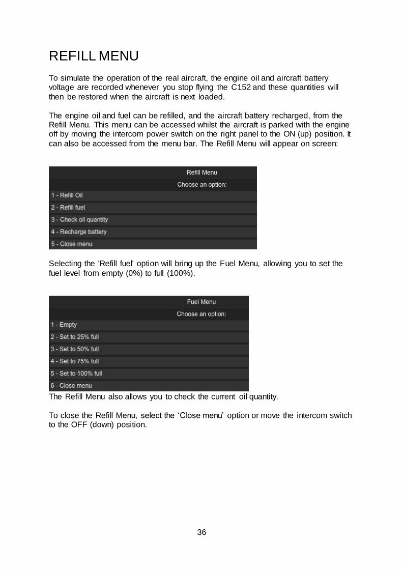
REFILL MENU To simulate the operation of the real aircraft, the engine oil and aircraft battery voltage are recorded whenever you stop flying the C152 and these quantities will
then be restored when the aircraft is next loaded.
The engine oil and fuel can be refilled, and the aircraft battery recharged, from the Refill Menu. This menu can be accessed whilst the aircraft is parked with the engine off by moving the intercom power switch on the right panel to the ON (up) position. It
can also be accessed from the menu bar. The Refill Menu will appear on screen:
Selecting the 'Refill fuel' option will bring up the Fuel Menu, allowing you to set the
fuel level from empty (0%) to full (100%).
The Refill Menu also allows you to check the current oil quantity.
To close the Refill Menu, select the ‘Close menu’ option or move the intercom switch to the OFF (down) position.
37
FAILURES In addition to supporting the simulator’s own failures system, this C152 simulation includes a few of the more common failures found on these aircraft:
Spark plug fouling – this can occur if the engine is kept at low RPM for
prolonged periods and symptoms include rough running with a subsequent increase in cockpit vibration. If fouling occurs, increase engine RPM.
Vapour lock – this can occur for up to approximately 30 minutes after the
engine has been shut down. After shutdown, fuel vapour can remain in the
fuel lines as the result of high temperatures. This vapour disrupts the operation of the fuel system and creates an incompatible mix of air and fuel,
so you might need a few attempts at starting the engine before ignition occurs. This problem is more likely to occur when operating in high temperatures.
Engine failure caused by low oil quantity – over time the engine will
consume oil. The current oil quantity can be checked and refilled using the Refill Menu. If the engine consumes all the oil, the engine will eventually fail.
Battery failure – the battery can be quickly drained either by leaving electrical
systems switched on without the engine (and therefore alternator) running, or
by repeated attempts to start the engine. The battery can be recharged using the Refill Menu.
These failures are disabled by default and can be enabled/disabled from the menu bar.
On-screen messages will appear to warn you in the event of low oil quantity or
battery voltage. If you are unable to start the engine, please check the following items:
Fuel flow – to ensure sufficient fuel flow for ignition, confirm that the fuel pump is
switched on and the mixture knob is set to rich (forward). Confirm fuel flow using the flow gauge prior to attempting an engine start. Refer to the NORMAL PROCEDURES
Vapour lock – this can occur for up to approximately 30 minutes after the engine
has been shut down. After shutdown, fuel vapour can remain in the fuel lines as the result of high temperatures. This vapour disrupts the operation of the fuel system and creates an incompatible mix of air and fuel, so you might need a few attempts at
starting the engine before ignition occurs. Oil quantity – if you have engine management/failures enabled, make sure that you
have sufficient engine oil before attempting to start the engine, otherwise engine failure may occur.
38
You can also start the engine using the power icon located on the 2D panel selector or the 'Ready for take-off' option in the menu bar.
MENU BAR OPTIONS When the C152 is loaded in FSX:SE , a new entry will appear in the ‘Add-ons’ menu
called ‘Just Flight C152’.
This menu allows you to select panel states, toggle various options and open the Refill Menu. Panel states Two panel states can be selected from the menu: Cold and Dark – engine and electrical power off, flaps up, parking brake on.
Ready for Take-off – engine and electrical power on, flaps set for take-off, parking
brake off.
The panel state (position of switches, levers etc.) is saved automatically whenever you save a flight using the simulator ‘Save’ menu. The panel state is automatically
reloaded when you subsequently load the saved flight.
39
The panel state can also be saved/reloaded automatically between non-saved flights, allowing you to always return to your cockpit in the same state that you last
left it. Cockpit state saving can be enabled/disabled using the ‘Toggle Cockpit State Saving’ option. A message will appear on screen to indicate whether cockpit state
saving is on or off.
Gyro sounds The turn coordinator gyro sounds were recorded from the real aircraft but we have
included an option to disable these sounds if you wish. To toggle these sounds on/off, select ‘Toggle Gyro Sounds’. A notification will appear on screen to indicate whether they are on or off.
Engine management You can enable or disable the following engine failure/management features:
Spark plug fouling
Vapour lock
Oil usage and engine failure caused by low oil quantity
Battery usage
To enable or disable these features, select the ‘Toggle Engine Management’ option.
A notification will appear on screen to indicate whether they are on or off.
Panel selector This option allows you to enable or disable the 2D panel selector arrow. The arrow
will no longer be visible if it is disabled and this setting will be remembered the next time you load the aircraft.
FLYING THE C152 In this tutorial flight we will be departing from Conington airfield, located six miles
south of Peterborough and 20 miles north-west of Cambridge, UK. We will be
heading north-west, passing to the east of RAF Wittering and RAF Cottesmore
before flying over RAF Cranwell and Gamston airfield.
40
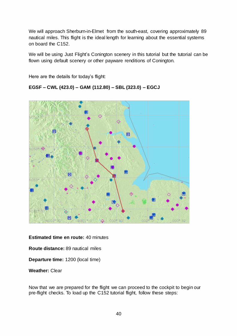
We will approach Sherburn-in-Elmet from the south-east, covering approximately 89
nautical miles. This flight is the ideal length for learning about the essential systems
on board the C152.
We will be using Just Flight’s Conington scenery in this tutorial but the tutorial can be
flown using default scenery or other payware renditions of Conington.
Here are the details for today’s flight: EGSF – CWL (423.0) – GAM (112.80) – SBL (323.0) – EGCJ
Estimated time en route: 40 minutes
Route distance: 89 nautical miles
Departure time: 1200 (local time)
Weather: Clear
Now that we are prepared for the flight we can proceed to the cockpit to begin our pre-flight checks. To load up the C152 tutorial flight, follow these steps:
41
1. Start Flight Simulator X, FSX: Steam Edition or Prepar3D.
2. If you are using FSX, select the Free Flight menu.
3. Choose Load.
4. Select Just Flight C152 tutorial flight from the list of saved flights.
5. Click on Fly Now! (Flight Simulator X) or OK (Prepar3D).
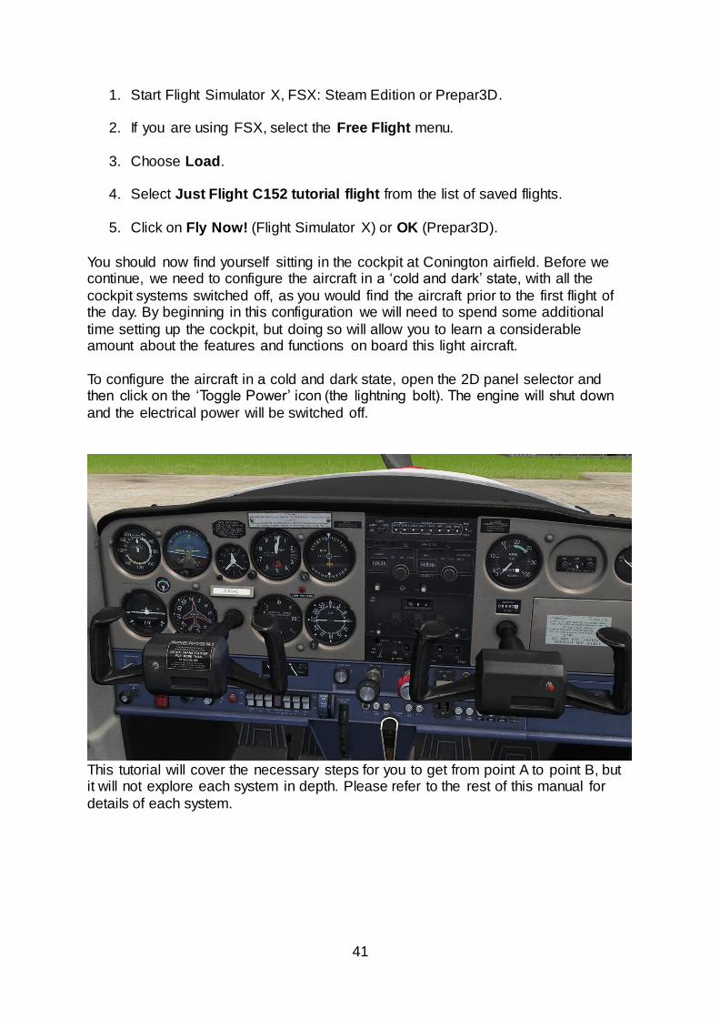
You should now find yourself sitting in the cockpit at Conington airfield. Before we continue, we need to configure the aircraft in a ‘cold and dark’ state, with all the
cockpit systems switched off, as you would find the aircraft prior to the first flight of the day. By beginning in this configuration we will need to spend some additional
time setting up the cockpit, but doing so will allow you to learn a considerable amount about the features and functions on board this light aircraft.
To configure the aircraft in a cold and dark state, open the 2D panel selector and then click on the ‘Toggle Power’ icon (the lightning bolt). The engine will shut down
and the electrical power will be switched off.
This tutorial will cover the necessary steps for you to get from point A to point B, but it will not explore each system in depth. Please refer to the rest of this manual for
details of each system.
42
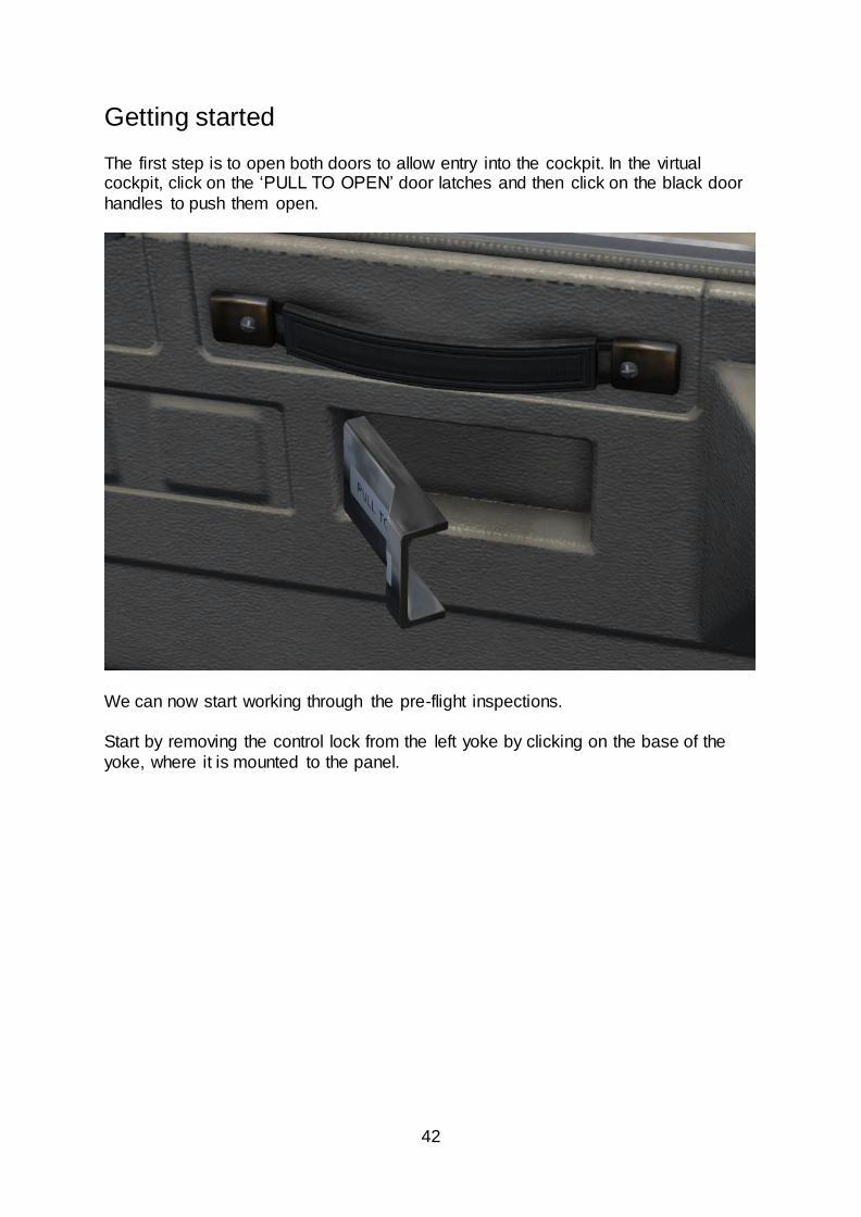
Getting started The first step is to open both doors to allow entry into the cockpit. In the virtual cockpit, click on the ‘PULL TO OPEN’ door latches and then click on the black door
handles to push them open.
We can now start working through the pre-flight inspections.
Start by removing the control lock from the left yoke by clicking on the base of the
yoke, where it is mounted to the panel.
43
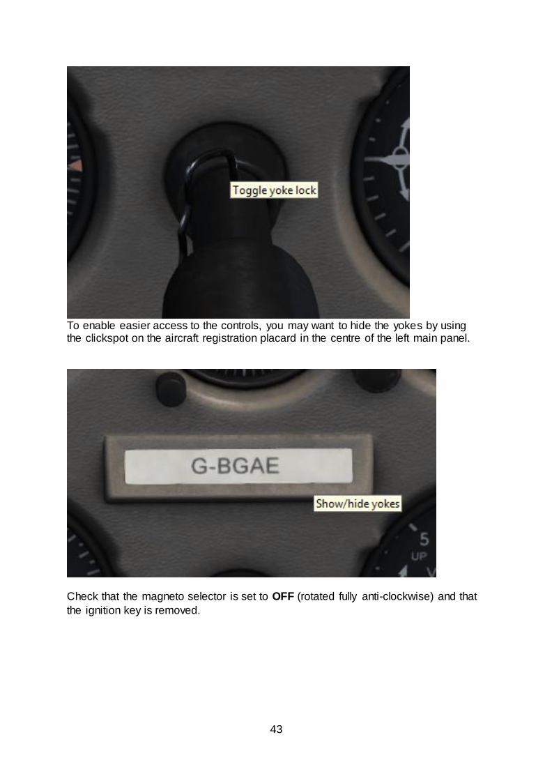
To enable easier access to the controls, you may want to hide the yokes by using the clickspot on the aircraft registration placard in the centre of the left main panel.
Check that the magneto selector is set to OFF (rotated fully anti-clockwise) and that
the ignition key is removed.
44
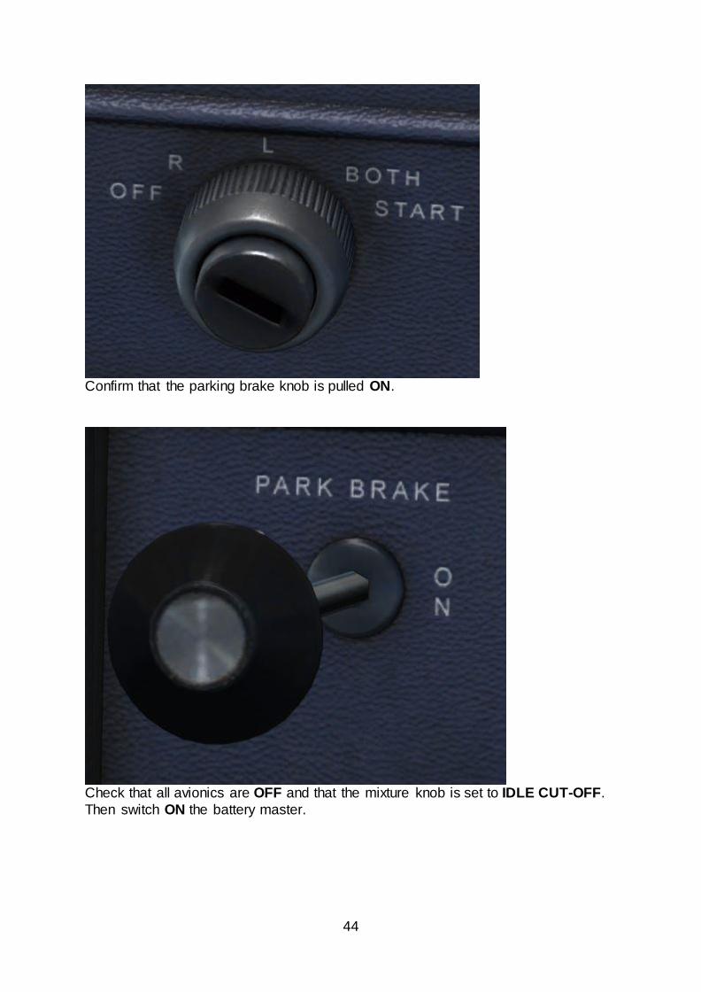
Confirm that the parking brake knob is pulled ON.
Check that all avionics are OFF and that the mixture knob is set to IDLE CUT-OFF.
Then switch ON the battery master.
45
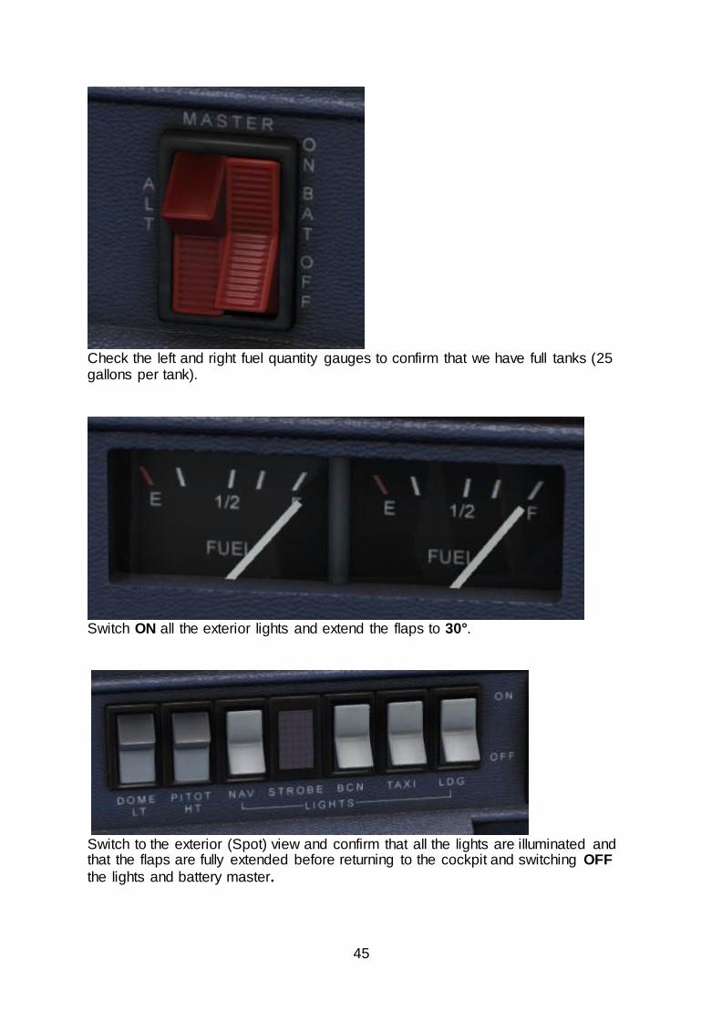
Check the left and right fuel quantity gauges to confirm that we have full tanks (25 gallons per tank).
Switch ON all the exterior lights and extend the flaps to 30°.
Switch to the exterior (Spot) view and confirm that all the lights are illuminated and that the flaps are fully extended before returning to the cockpit and switching OFF
the lights and battery master.
46
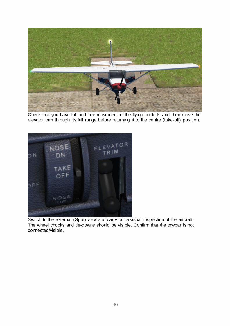
Check that you have full and free movement of the flying controls and then move the elevator trim through its full range before returning it to the centre (take-off) position.
Switch to the external (Spot) view and carry out a visual inspection of the aircraft.
The wheel chocks and tie-downs should be visible. Confirm that the towbar is not connected/visible.
47
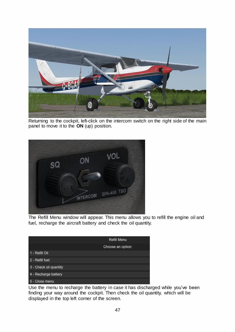
Returning to the cockpit, left-click on the intercom switch on the right side of the main panel to move it to the ON (up) position.
The Refill Menu window will appear. This menu allows you to refill the engine oil and
fuel, recharge the aircraft battery and check the oil quantity.
Use the menu to recharge the battery in case it has discharged while you’ve been finding your way around the cockpit. Then check the oil quantity, which will be
displayed in the top left corner of the screen.

48
If the oil quantity displayed is less than six quarts, use the ‘Refill Oil’ option to top it
up.
We are now finished with the Refill Menu, so select the ‘Close menu’ option. Once the menu has closed, left-click on the intercom switch to move it back to the OFF
(down) position.
Starting the engine
To avoid battery draining, we will start the engine before configuring the avionics for our departure.
Close the passenger doors by first clicking on the black door handles to pull them
shut and then clicking on the door latches to move them to the latched/locked position.
Check that the parking brake is set and that all circuit breakers are pushed in.
49
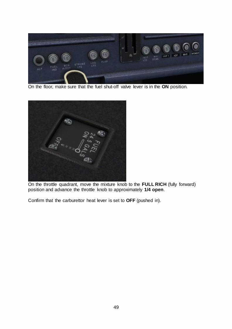
On the floor, make sure that the fuel shut-off valve lever is in the ON position.
On the throttle quadrant, move the mixture knob to the FULL RICH (fully forward) position and advance the throttle knob to approximately 1/4 open.
Confirm that the carburettor heat lever is set to OFF (pushed in).
50
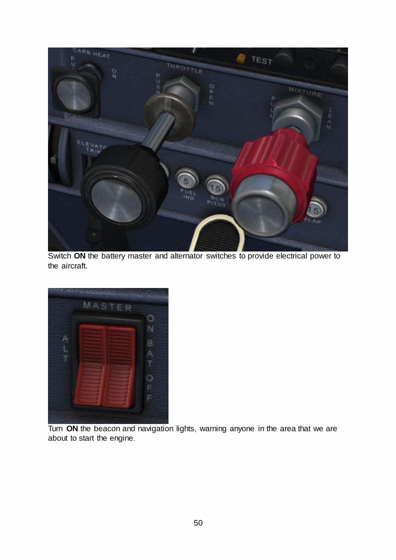
Switch ON the battery master and alternator switches to provide electrical power to
the aircraft.
Turn ON the beacon and navigation lights, warning anyone in the area that we are
about to start the engine.
51
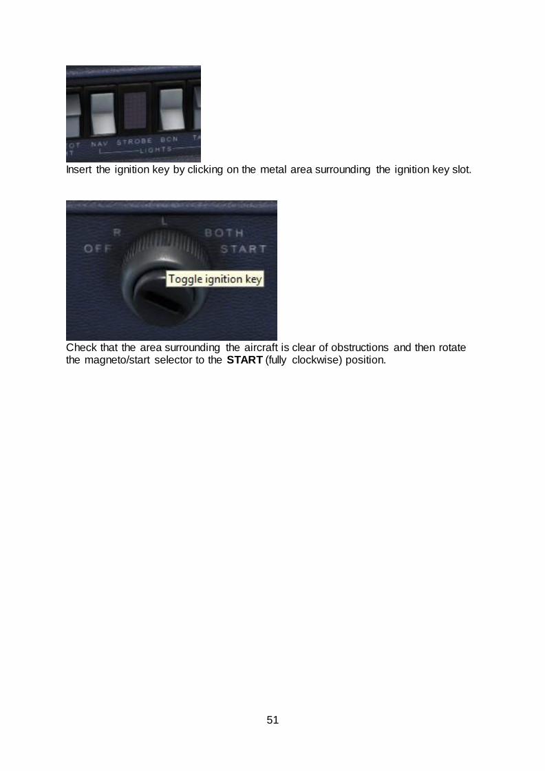
Insert the ignition key by clicking on the metal area surrounding the ignition key slot.
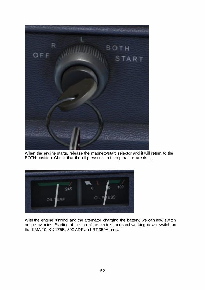
Check that the area surrounding the aircraft is clear of obstructions and then rotate the magneto/start selector to the START (fully clockwise) position.
52
When the engine starts, release the magneto/start selector and it will return to the BOTH position. Check that the oil pressure and temperature are rising.
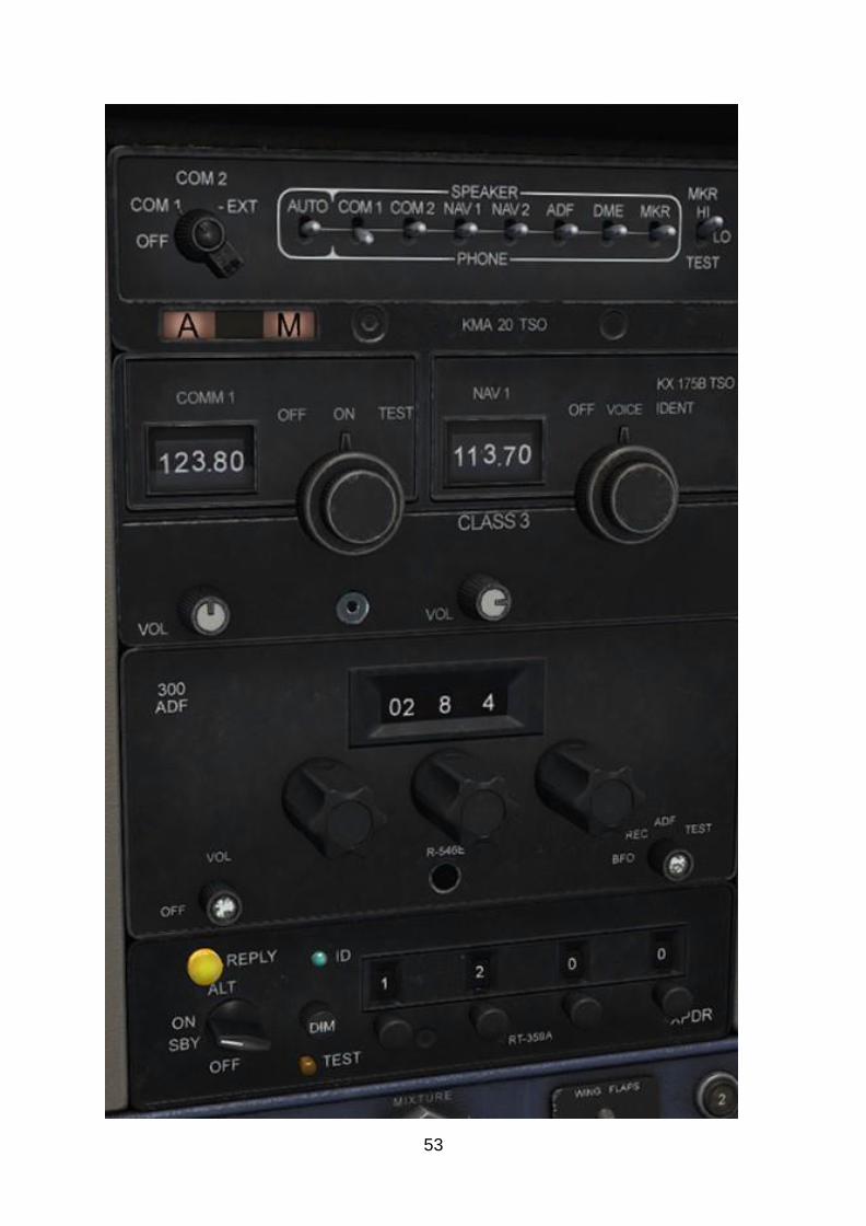
With the engine running and the alternator charging the battery, we can now switch on the avionics. Starting at the top of the centre panel and working down, switch on
the KMA 20, KX 175B, 300 ADF and RT-359A units.
53
54
Configuring the avionics We now need to configure the avionics for our departure.
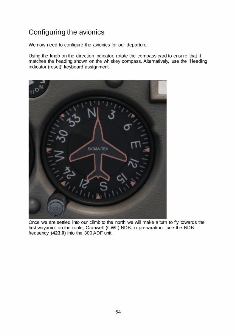
Using the knob on the direction indicator, rotate the compass card to ensure that it matches the heading shown on the whiskey compass. Alternatively, use the ‘Heading
indicator (reset)’ keyboard assignment.
Once we are settled into our climb to the north we will make a turn to fly towards the first waypoint on the route, Cranwell (CWL) NDB. In preparation, tune the NDB frequency (423.0) into the 300 ADF unit.
55
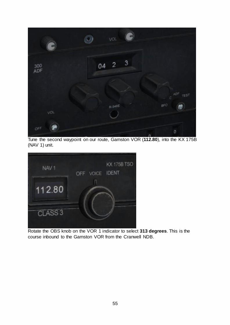
Tune the second waypoint on our route, Gamston VOR (112.80), into the KX 175B
(NAV 1) unit.
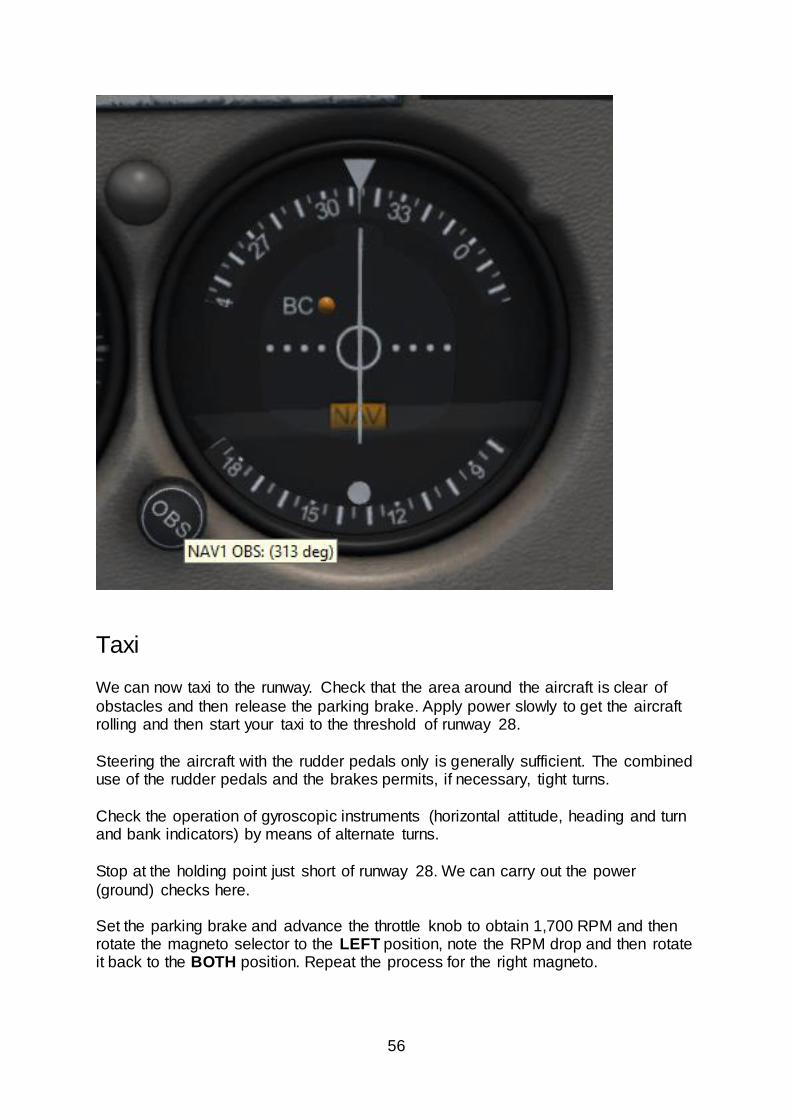
Rotate the OBS knob on the VOR 1 indicator to select 313 degrees. This is the
course inbound to the Gamston VOR from the Cranwell NDB.
56
Taxi We can now taxi to the runway. Check that the area around the aircraft is clear of
obstacles and then release the parking brake. Apply power slowly to get the aircraft rolling and then start your taxi to the threshold of runway 28.
Steering the aircraft with the rudder pedals only is generally sufficient. The combined use of the rudder pedals and the brakes permits, if necessary, tight turns.
Check the operation of gyroscopic instruments (horizontal attitude, heading and turn and bank indicators) by means of alternate turns.
Stop at the holding point just short of runway 28. We can carry out the power
(ground) checks here. Set the parking brake and advance the throttle knob to obtain 1,700 RPM and then rotate the magneto selector to the LEFT position, note the RPM drop and then rotate it back to the BOTH position. Repeat the process for the right magneto.
57
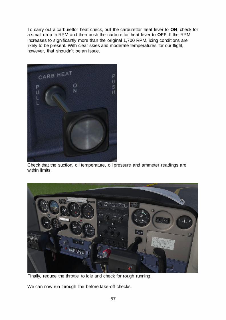
To carry out a carburettor heat check, pull the carburettor heat lever to ON, check for a small drop in RPM and then push the carburettor heat lever to OFF. If the RPM
increases to significantly more than the original 1,700 RPM, icing conditions are likely to be present. With clear skies and moderate temperatures for our flight,
however, that shouldn’t be an issue.
Check that the suction, oil temperature, oil pressure and ammeter readings are within limits.
Finally, reduce the throttle to idle and check for rough running.
We can now run through the before take-off checks.
58
Move the flap lever to 10° and look left and right to confirm that the flaps have
extended. Confirm that the battery master and alternator switches are both set to ON.
Check that the carburettor heat lever is set to OFF and that the mixture knob is in the
FULL RICH (fully forward) position.
Confirm that the magneto selector is in the BOTH position and that the primer is pushed in and locked, then switch ON the landing light.
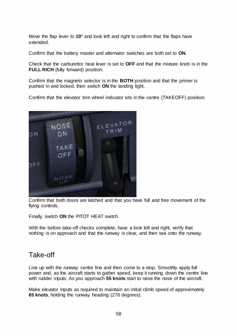
Confirm that the elevator trim wheel indicator sits in the centre (TAKEOFF) position.
Confirm that both doors are latched and that you have full and free movement of the flying controls.
Finally, switch ON the PITOT HEAT switch.
With the before take-off checks complete, have a look left and right, verify that nothing is on approach and that the runway is clear, and then taxi onto the runway.
Take-off
Line up with the runway centre line and then come to a stop. Smoothly apply full power and, as the aircraft starts to gather speed, keep it running down the centre line with rudder inputs. As you approach 55 knots start to raise the nose of the aircraft.
Make elevator inputs as required to maintain an initial climb speed of approximately 65 knots, holding the runway heading (276 degrees).
59
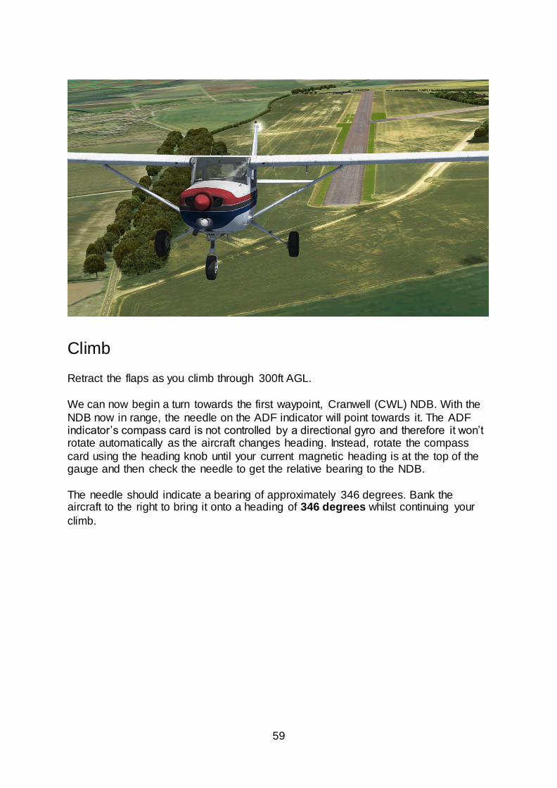
Climb Retract the flaps as you climb through 300ft AGL.
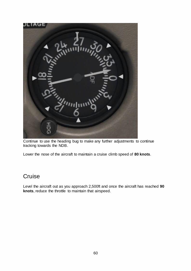
We can now begin a turn towards the first waypoint, Cranwell (CWL) NDB. With the
NDB now in range, the needle on the ADF indicator will point towards it. The ADF indicator’s compass card is not controlled by a directional gyro and therefore it won’t rotate automatically as the aircraft changes heading. Instead, rotate the compass
card using the heading knob until your current magnetic heading is at the top of the gauge and then check the needle to get the relative bearing to the NDB.
The needle should indicate a bearing of approximately 346 degrees. Bank the aircraft to the right to bring it onto a heading of 346 degrees whilst continuing your
climb.
60
Continue to use the heading bug to make any further adjustments to continue tracking towards the NDB.
Lower the nose of the aircraft to maintain a cruise climb speed of 80 knots.
Cruise Level the aircraft out as you approach 2,500ft and once the aircraft has reached 90
knots, reduce the throttle to maintain that airspeed.
61
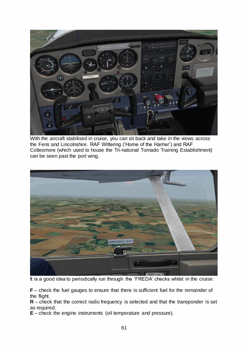
With the aircraft stabilised in cruise, you can sit back and take in the views across
the Fens and Lincolnshire. RAF Wittering (‘Home of the Harrier’) and RAF Cottesmore (which used to house the Tri-national Tornado Training Establishment)
can be seen past the port wing.
It is a good idea to periodically run through the ‘FREDA’ checks whilst in the cruise: F – check the fuel gauges to ensure that there is sufficient fuel for the remainder of
the flight. R – check that the correct radio frequency is selected and that the transponder is set
as required. E – check the engine instruments (oil temperature and pressure).
62
D – check that the direction indicator is correctly aligned with the whiskey compass
reading and that you are on the correct heading (towards the Cranwell NDB in this
case). A – check that the barometric pressure setting is correctly set on the altimeter.
RAF Cranwell should be visible ahead of the aircraft approximately 20 minutes into the flight. As the airfield begins to disappear under the nose of the aircraft, we will
begin our turn towards the Gamston VOR. We tuned in the frequency and selected the correct OBS on the VOR 1 indicator.
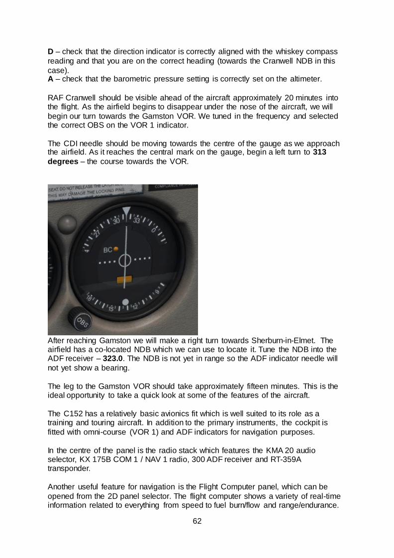
The CDI needle should be moving towards the centre of the gauge as we approach the airfield. As it reaches the central mark on the gauge, begin a left turn to 313
degrees – the course towards the VOR.
After reaching Gamston we will make a right turn towards Sherburn-in-Elmet. The airfield has a co-located NDB which we can use to locate it. Tune the NDB into the ADF receiver – 323.0. The NDB is not yet in range so the ADF indicator needle will
not yet show a bearing.
The leg to the Gamston VOR should take approximately fifteen minutes. This is the ideal opportunity to take a quick look at some of the features of the aircraft.
The C152 has a relatively basic avionics fit which is well suited to its role as a training and touring aircraft. In addition to the primary instruments, the cockpit is
fitted with omni-course (VOR 1) and ADF indicators for navigation purposes.
In the centre of the panel is the radio stack which features the KMA 20 audio selector, KX 175B COM 1 / NAV 1 radio, 300 ADF receiver and RT-359A transponder.
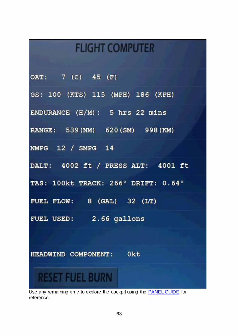
Another useful feature for navigation is the Flight Computer panel, which can be
opened from the 2D panel selector. The flight computer shows a variety of real-time information related to everything from speed to fuel burn/flow and range/endurance.
63
Use any remaining time to explore the cockpit using the PANEL GUIDE for
reference.
64
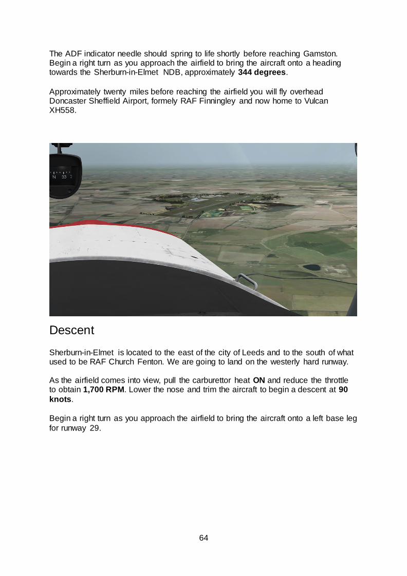
The ADF indicator needle should spring to life shortly before reaching Gamston. Begin a right turn as you approach the airfield to bring the aircraft onto a heading towards the Sherburn-in-Elmet NDB, approximately 344 degrees.
Approximately twenty miles before reaching the airfield you will fly overhead Doncaster Sheffield Airport, formely RAF Finningley and now home to Vulcan XH558.
Descent
Sherburn-in-Elmet is located to the east of the city of Leeds and to the south of what used to be RAF Church Fenton. We are going to land on the westerly hard runway. As the airfield comes into view, pull the carburettor heat ON and reduce the throttle to obtain 1,700 RPM. Lower the nose and trim the aircraft to begin a descent at 90
knots.
Begin a right turn as you approach the airfield to bring the aircraft onto a left base leg
for runway 29.
65
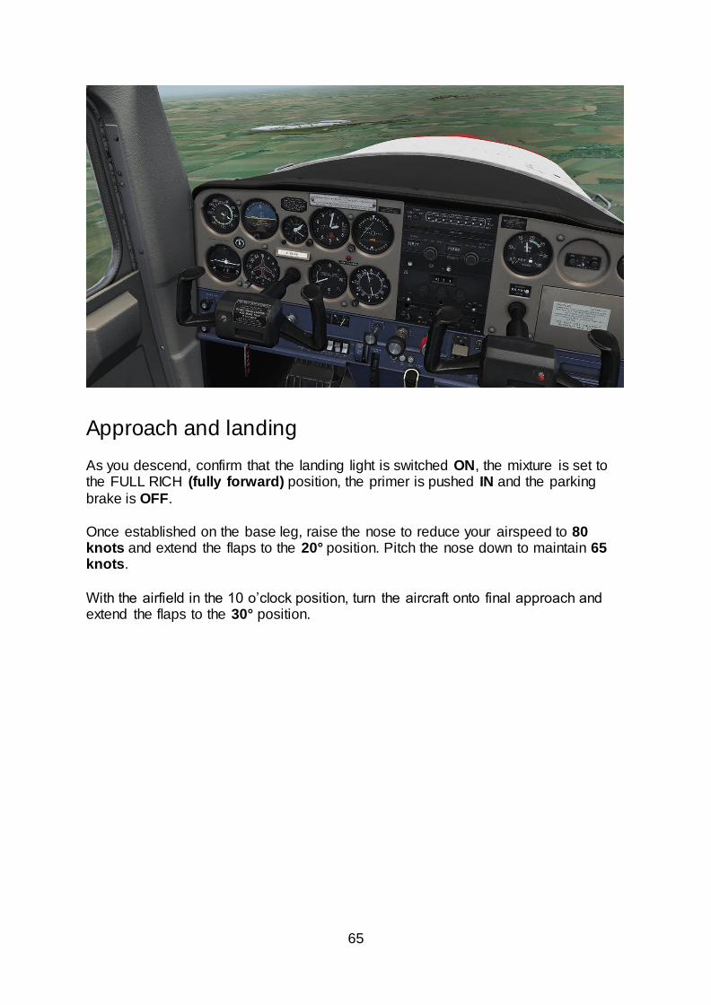
Approach and landing As you descend, confirm that the landing light is switched ON, the mixture is set to the FULL RICH (fully forward) position, the primer is pushed IN and the parking
brake is OFF.
Once established on the base leg, raise the nose to reduce your airspeed to 80 knots and extend the flaps to the 20° position. Pitch the nose down to maintain 65 knots.
With the airfield in the 10 o’clock position, turn the aircraft onto final approach and extend the flaps to the 30° position.
66
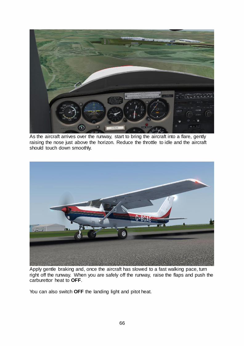
As the aircraft arrives over the runway, start to bring the aircraft into a flare, gently
raising the nose just above the horizon. Reduce the throttle to idle and the aircraft should touch down smoothly.
Apply gentle braking and, once the aircraft has slowed to a fast walking pace, turn
right off the runway. When you are safely off the runway, raise the flaps and push the carburettor heat to OFF.
You can also switch OFF the landing light and pitot heat.
67
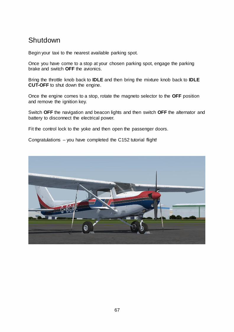
Shutdown
Begin your taxi to the nearest available parking spot. Once you have come to a stop at your chosen parking spot, engage the parking brake and switch OFF the avionics.
Bring the throttle knob back to IDLE and then bring the mixture knob back to IDLE CUT-OFF to shut down the engine.
Once the engine comes to a stop, rotate the magneto selector to the OFF position
and remove the ignition key.
Switch OFF the navigation and beacon lights and then switch OFF the alternator and
battery to disconnect the electrical power.
Fit the control lock to the yoke and then open the passenger doors.
Congratulations – you have completed the C152 tutorial flight!
68
NORMAL PROCEDURES
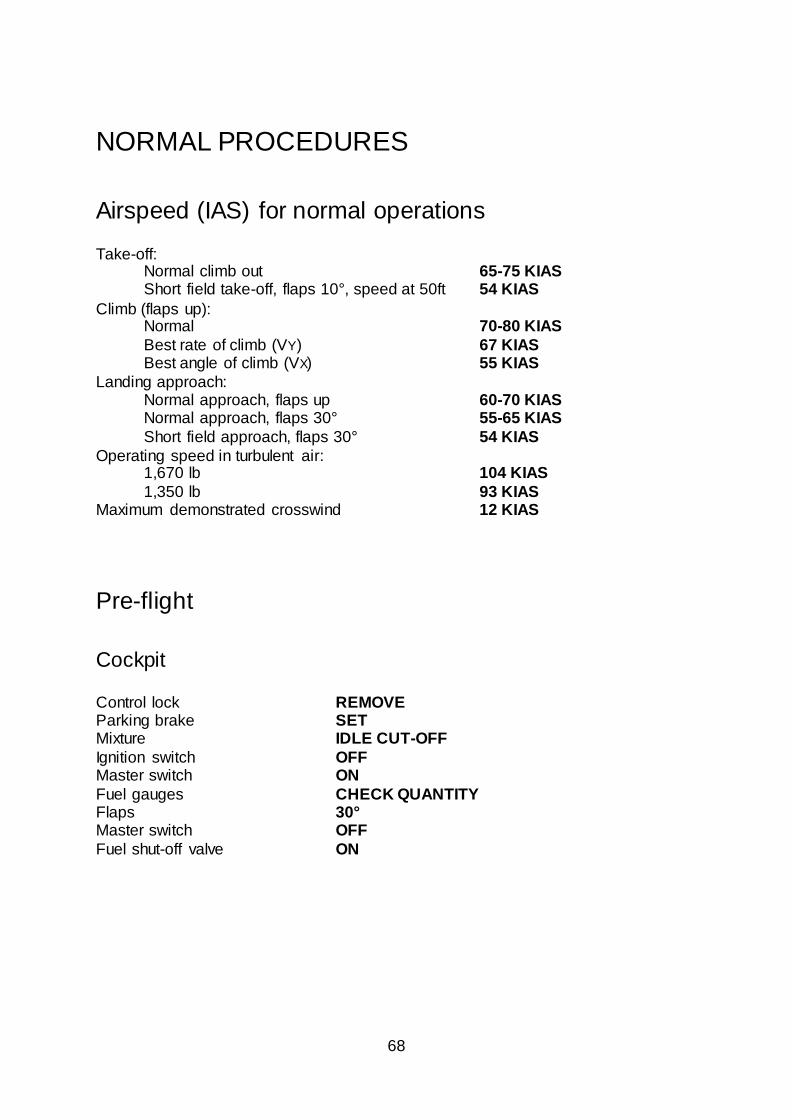
Airspeed (IAS) for normal operations
Take-off: Normal climb out 65-75 KIAS Short field take-off, flaps 10°, speed at 50ft 54 KIAS
Climb (flaps up): Normal 70-80 KIAS
Best rate of climb (VY) 67 KIAS Best angle of climb (VX) 55 KIAS
Landing approach: Normal approach, flaps up 60-70 KIAS Normal approach, flaps 30° 55-65 KIAS
Short field approach, flaps 30° 54 KIAS
Operating speed in turbulent air: 1,670 lb 104 KIAS
1,350 lb 93 KIAS Maximum demonstrated crosswind 12 KIAS
Pre-flight
Cockpit Control lock REMOVE Parking brake SET Mixture IDLE CUT-OFF
Ignition switch OFF Master switch ON
Fuel gauges CHECK QUANTITY Flaps 30° Master switch OFF
Fuel shut-off valve ON
69
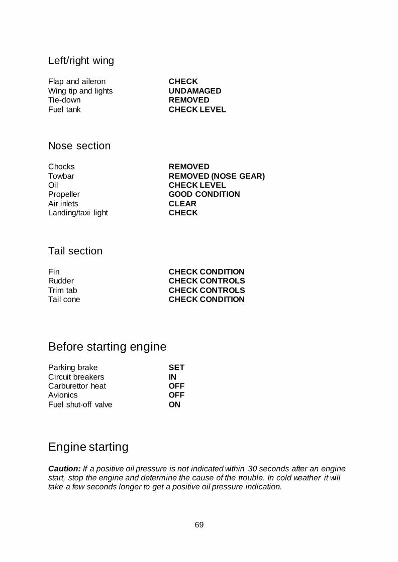
Left/right wing Flap and aileron CHECK
Wing tip and lights UNDAMAGED Tie-down REMOVED
Fuel tank CHECK LEVEL
Nose section Chocks REMOVED
Towbar REMOVED (NOSE GEAR) Oil CHECK LEVEL Propeller GOOD CONDITION
Air inlets CLEAR Landing/taxi light CHECK
Tail section Fin CHECK CONDITION Rudder CHECK CONTROLS
Trim tab CHECK CONTROLS Tail cone CHECK CONDITION
Before starting engine Parking brake SET
Circuit breakers IN Carburettor heat OFF Avionics OFF
Fuel shut-off valve ON
Engine starting
Caution: If a positive oil pressure is not indicated within 30 seconds after an engine start, stop the engine and determine the cause of the trouble. In cold weather it will take a few seconds longer to get a positive oil pressure indication.
70
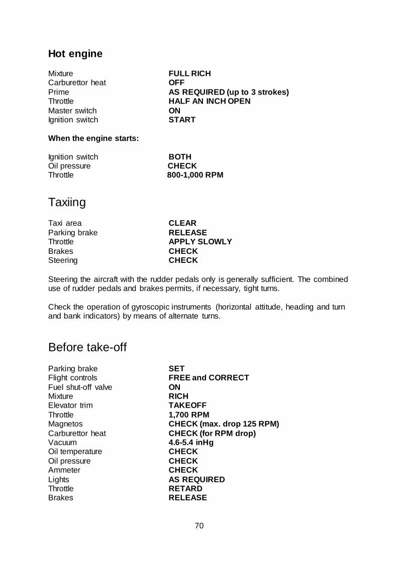
Hot engine Mixture FULL RICH Carburettor heat OFF
Prime AS REQUIRED (up to 3 strokes) Throttle HALF AN INCH OPEN
Master switch ON Ignition switch START
When the engine starts:
Ignition switch BOTH Oil pressure CHECK Throttle 800-1,000 RPM
Taxiing Taxi area CLEAR
Parking brake RELEASE Throttle APPLY SLOWLY
Brakes CHECK Steering CHECK
Steering the aircraft with the rudder pedals only is generally sufficient. The combined use of rudder pedals and brakes permits, if necessary, tight turns.
Check the operation of gyroscopic instruments (horizontal attitude, heading and turn and bank indicators) by means of alternate turns.
Before take-off
Parking brake SET Flight controls FREE and CORRECT
Fuel shut-off valve ON Mixture RICH Elevator trim TAKEOFF
Throttle 1,700 RPM Magnetos CHECK (max. drop 125 RPM)
Carburettor heat CHECK (for RPM drop) Vacuum 4.6-5.4 inHg Oil temperature CHECK
Oil pressure CHECK Ammeter CHECK
Lights AS REQUIRED Throttle RETARD Brakes RELEASE
71
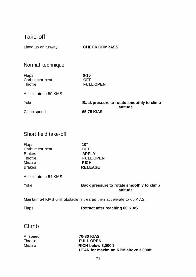
Take-off Lined up on runway CHECK COMPASS
Normal technique Flaps 0-10° Carburettor heat OFF Throttle FULL OPEN
Accelerate to 50 KIAS.
Yoke Back pressure to rotate smoothly to climb
attitude
Climb speed 65-75 KIAS
Short field take-off Flaps 10° Carburettor heat OFF
Brakes APPLY Throttle FULL OPEN Mixture RICH
Brakes RELEASE
Accelerate to 54 KIAS. Yoke Back pressure to rotate smoothly to climb
attitude
Maintain 54 KIAS until obstacle is cleared then accelerate to 65 KIAS. Flaps Retract after reaching 60 KIAS
Climb
Airspeed 70-80 KIAS Throttle FULL OPEN
Mixture RICH below 3,000ft LEAN for maximum RPM above 3,000ft

72
Cruise Power 1,900-2,550 RPM (no more than 75%)
Elevator trim ADJUST Mixture LEAN
Before landing Mixture RICH Carburettor heat ON (before closing throttle)
Landing
Normal landing
Airspeed 60-70 KIAS (flaps UP) Flaps AS REQUIRED (below 85 KIAS) Airspeed 55-65 KIAS (flaps DOWN)
Touchdown MAIN WHEELS FIRST Landing roll LOWER NOSE-WHEEL GENTLY
Braking MINIMUM REQUIRED
Short field landing
Airspeed 60-70 KIAS (flaps UP) Flaps 30° (below 85 KIAS) Airspeed MAINTAIN 54 KIAS
Power REDUCE to idle as obstacle is cleared Touchdown MAIN WHEELS FIRST
Brakes APPLY HEAVILY Flaps RETRACT
73
After landing Flaps UP
Carburettor heat OFF
Securing aircraft
Parking brake SET Avionics OFF Mixture IDLE CUT-OFF
Ignition switch OFF Master switch OFF
Control lock INSTALL
Stalls
The stall characteristics of the C152 are conventional. An approaching stall is
indicated by a stall warning horn which is activated between 5-10 knots above stall speed. Mild airframe buffeting and gentle pitching may also precede the stall.
EMERGENCY PROCEDURES
Airspeed (IAS) for emergency operations Engine failure after take-off 60 KIAS
Manoeuvring speed (1,670 lb) 104 KIAS Manoeuvring speed (1,350 lb) 93 KIAS
Maximum glide 60 KIAS
Precautionary landing with engine power 55 KIAS
Landing without engine power (flaps up) 65 KIAS
Landing without engine power (flaps down) 60 KIAS
74
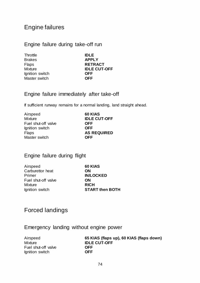
Engine failures
Engine failure during take-off run Throttle IDLE Brakes APPLY
Flaps RETRACT Mixture IDLE CUT-OFF Ignition switch OFF
Master switch OFF
Engine failure immediately after take-off
If sufficient runway remains for a normal landing, land straight ahead.
Airspeed 60 KIAS Mixture IDLE CUT-OFF
Fuel shut-off valve OFF Ignition switch OFF
Flaps AS REQUIRED Master switch OFF
Engine failure during flight Airspeed 60 KIAS Carburettor heat ON Primer IN/LOCKED
Fuel shut-off valve ON Mixture RICH
Ignition switch START then BOTH
Forced landings
Emergency landing without engine power Airspeed 65 KIAS (flaps up), 60 KIAS (flaps down)
Mixture IDLE CUT-OFF Fuel shut-off valve OFF Ignition switch OFF
75
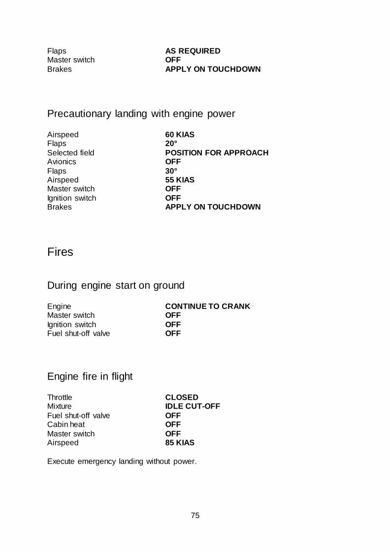
Flaps AS REQUIRED Master switch OFF
Brakes APPLY ON TOUCHDOWN
Precautionary landing with engine power Airspeed 60 KIAS Flaps 20°
Selected field POSITION FOR APPROACH Avionics OFF
Flaps 30° Airspeed 55 KIAS Master switch OFF
Ignition switch OFF Brakes APPLY ON TOUCHDOWN
Fires
During engine start on ground
Engine CONTINUE TO CRANK Master switch OFF
Ignition switch OFF Fuel shut-off valve OFF
Engine fire in flight Throttle CLOSED Mixture IDLE CUT-OFF
Fuel shut-off valve OFF Cabin heat OFF
Master switch OFF Airspeed 85 KIAS
Execute emergency landing without power.
76
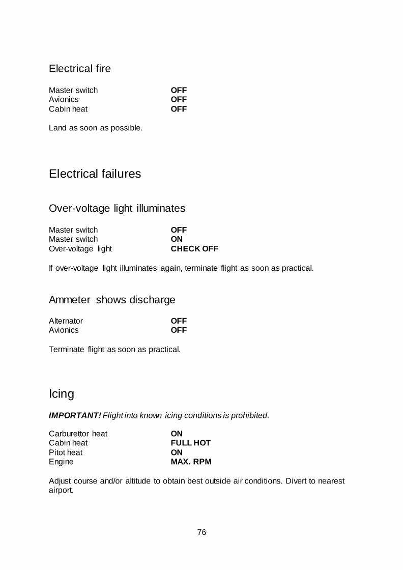
Electrical fire Master switch OFF Avionics OFF
Cabin heat OFF
Land as soon as possible.
Electrical failures
Over-voltage light illuminates Master switch OFF Master switch ON
Over-voltage light CHECK OFF
If over-voltage light illuminates again, terminate flight as soon as practical.
Ammeter shows discharge Alternator OFF Avionics OFF
Terminate flight as soon as practical.
Icing
IMPORTANT! Flight into known icing conditions is prohibited.
Carburettor heat ON Cabin heat FULL HOT
Pitot heat ON Engine MAX. RPM
Adjust course and/or altitude to obtain best outside air conditions. Divert to nearest airport.
77
Spin recovery Rudder HOLD OPPOSITE DIRECTION OF ROTATION Yoke FULL FORWARD, AILERONS NEUTRAL
Throttle IDLE
When spinning stops, centralise rudder, level the wings and ease out of the dive.
Airspeed indicating system failure In case of erroneous indications in flight:
Pitot heat ON
If erroneous indications persist, carry out a precautionary approach, maintaining an adequate airspeed margin above stall warning speed.
CREDITS
Project management Martyn Northall Aircraft modelling and design 3D Reach Aircraft systems and cockpit programming Martyn Northall
Aircraft liveries David Sweetman Flight dynamics Paul Frimston
Sounds Turbine Sound Studios Manual Martyn Northall Installer Martin Wright
Design Fink Creative
Special thanks to all the testers and to Flying Club Conington for giving us permission to photograph their aircraft.
COPYRIGHT ©2018 Just Flight. All rights reserved. Just Flight and the Just Flight logo are
trademarks of JustFlight London Limited, St. George’s House, George Street, Huntingdon, PE29 3GH, UK. All trademarks and brand names are trademarks or registered trademarks of the respective owners and their use herein does not imply
any association or endorsement by any third party.
Cessna® 152 is a trademark of Textron Innovations Inc. and is used under license to RailSimulator.com Ltd d/b/a/ Dovetail Games.


![s617306976.websitehome.co.uks617306976.websitehome.co.uk/AYASMagazines/AY April 1980.pdf112684S Cessna 404 N/R G-BDPH Cessna 172 n/s G—OWAC Cessna 152 TÆDS/BRI¥]EORD 1556 1724](https://static.cupdf.com/doc/110x72/5b2fa5db7f8b9adc6e8d83af/april-1980pdf112684s-cessna-404-nr-g-bdph-cessna-172-ns-gowac-cessna-152-tadsbrieord.jpg)