Experiment Instructions
CE 220 Fluidised Bed Formation

CE 220 FLUIDISED BED FORMATION
i
All
right
s re
serv
ed, G
.U.N
.T. G
erät
ebau
, Bar
sbüt
tel,
Ger
man
y 02
/201
2
Experiment Instructions
This manual must be kept by the unit.
Before operating the unit: - Read this manual.
- All participants must be instructed on handling of the unit and, where appropriate,
on the necessary safety precautions.
Version 0.2 Subject to technical alterations

CE 220 FLUIDISED BED FORMATION
All
right
s re
serv
ed, G
.U.N
.T. G
erät
ebau
, Bar
sbüt
tel,
Ger
man
y 02
/201
2
Table of Contents
1 Introduction . . . . . . . . . . . . . . . . . . . . . . . . . . . . . . . . . . . . . . . . . . . . . . . . . 1
2 Safety . . . . . . . . . . . . . . . . . . . . . . . . . . . . . . . . . . . . . . . . . . . . . . . . . . . . . . 3
2.1 Intended Use . . . . . . . . . . . . . . . . . . . . . . . . . . . . . . . . . . . . . . . . . . . . 3
2.2 Structure of the Safety Instructions . . . . . . . . . . . . . . . . . . . . . . . . . . . 3
2.3 Safety Instructions . . . . . . . . . . . . . . . . . . . . . . . . . . . . . . . . . . . . . . . . 4
3 Unit Description . . . . . . . . . . . . . . . . . . . . . . . . . . . . . . . . . . . . . . . . . . . . . . 6
3.1 Unit Layout . . . . . . . . . . . . . . . . . . . . . . . . . . . . . . . . . . . . . . . . . . . . . 6
3.2 Function of the System . . . . . . . . . . . . . . . . . . . . . . . . . . . . . . . . . . . . 7
3.2.1 Test Vessel for Compressed Air . . . . . . . . . . . . . . . . . . . . . . . 7
3.2.2 Test Vessel for Water . . . . . . . . . . . . . . . . . . . . . . . . . . . . . . . 9
3.3 Commissioning . . . . . . . . . . . . . . . . . . . . . . . . . . . . . . . . . . . . . . . . . 11
3.3.1 Single tube manometer. . . . . . . . . . . . . . . . . . . . . . . . . . . . . 12
3.3.2 U-tube manometer . . . . . . . . . . . . . . . . . . . . . . . . . . . . . . . . 13
3.3.3 Test vessel for air . . . . . . . . . . . . . . . . . . . . . . . . . . . . . . . . . 14
3.3.4 Test vessel for water. . . . . . . . . . . . . . . . . . . . . . . . . . . . . . . 15
4 Principles . . . . . . . . . . . . . . . . . . . . . . . . . . . . . . . . . . . . . . . . . . . . . . . . . . 17
4.1 Pressure Losses in Fluidised Beds . . . . . . . . . . . . . . . . . . . . . . . . . . 18
4.2 Pressure Curve in the Fluidised Bed . . . . . . . . . . . . . . . . . . . . . . . . . 18
4.3 Loosening Speed. . . . . . . . . . . . . . . . . . . . . . . . . . . . . . . . . . . . . . . . 19
5 Experiments . . . . . . . . . . . . . . . . . . . . . . . . . . . . . . . . . . . . . . . . . . . . . . . . 21
5.1 Preparing the Experiment . . . . . . . . . . . . . . . . . . . . . . . . . . . . . . . . . 21
5.1.1 Filling the Test Vessels. . . . . . . . . . . . . . . . . . . . . . . . . . . . . 22
5.1.2 Emptying the Air Test Vessel . . . . . . . . . . . . . . . . . . . . . . . . 23
5.1.3 Cleaning the Air Filter . . . . . . . . . . . . . . . . . . . . . . . . . . . . . . 24
5.1.4 Emptying the Water Test Vessel . . . . . . . . . . . . . . . . . . . . . 24
ii

CE 220 FLUIDISED BED FORMATION
All
right
s re
serv
ed, G
.U.N
.T. G
erät
ebau
, Bar
sbüt
tel,
Ger
man
y 02
/201
2
5.1.5 Plotting a Calibration Curve for Recording the Pressure Losses without Filling the Test Vessel . . . . . . . . . . . . . . . . . . . . . . . 25
5.2 Measuring the Pressure Loss with Air Flow . . . . . . . . . . . . . . . . . . . 28
5.2.1 Experiment Aim . . . . . . . . . . . . . . . . . . . . . . . . . . . . . . . . . . 28
5.2.2 Performing the Experiment . . . . . . . . . . . . . . . . . . . . . . . . . . 28
5.2.3 Evaluation of the Experiment . . . . . . . . . . . . . . . . . . . . . . . . 29
5.3 Measuring the Pressure Loss with Water Flow . . . . . . . . . . . . . . . . . 31
5.3.1 Experiment Aim . . . . . . . . . . . . . . . . . . . . . . . . . . . . . . . . . . 31
5.3.2 Performing the Experiment . . . . . . . . . . . . . . . . . . . . . . . . . . 31
5.3.3 Evaluation of the Experiment . . . . . . . . . . . . . . . . . . . . . . . . 32
5.4 Comparing Different Masses . . . . . . . . . . . . . . . . . . . . . . . . . . . . . . . 33
5.4.1 Experiment Aim . . . . . . . . . . . . . . . . . . . . . . . . . . . . . . . . . . 33
5.4.2 Performing the Experiment . . . . . . . . . . . . . . . . . . . . . . . . . . 33
5.4.3 Evaluation of the Experiment . . . . . . . . . . . . . . . . . . . . . . . . 34
5.5 Determination of the Loosening speed . . . . . . . . . . . . . . . . . . . . . . . 35
5.5.1 Experiment Aim . . . . . . . . . . . . . . . . . . . . . . . . . . . . . . . . . . 35
5.5.2 Performing the Experiment . . . . . . . . . . . . . . . . . . . . . . . . . . 35
5.5.3 Evaluation of the Experiment . . . . . . . . . . . . . . . . . . . . . . . . 35
5.6 Relationship between Flow Rate and Depth of the Fluidised Bed. . . 38
5.6.1 Experiment Aim . . . . . . . . . . . . . . . . . . . . . . . . . . . . . . . . . . 38
5.6.2 Performing the Experiment . . . . . . . . . . . . . . . . . . . . . . . . . . 38
5.6.3 Evaluation of the Experiment . . . . . . . . . . . . . . . . . . . . . . . . 39
6 Appendix . . . . . . . . . . . . . . . . . . . . . . . . . . . . . . . . . . . . . . . . . . . . . . . . . . 41
6.1 Technical Data. . . . . . . . . . . . . . . . . . . . . . . . . . . . . . . . . . . . . . . . . . 41
6.2 List of Symbols and Units . . . . . . . . . . . . . . . . . . . . . . . . . . . . . . . . . 43
6.3 Work Sheets . . . . . . . . . . . . . . . . . . . . . . . . . . . . . . . . . . . . . . . . . . . 44
6.3.1 Pressure Loss against Flow . . . . . . . . . . . . . . . . . . . . . . . . . 44
6.3.2 Calibration Curve for Pressure Losses . . . . . . . . . . . . . . . . . 45
7 Index . . . . . . . . . . . . . . . . . . . . . . . . . . . . . . . . . . . . . . . . . . . . . . . . . . . . . 46
iii

CE 220 FLUIDISED BED FORMATION
All
right
s re
serv
ed, G
.U.N
.T. G
erät
ebau
, Bar
sbüt
tel,
Ger
man
y 02
/201
2
1 Introduction
In fluidised beds, granular solid matter is held insuspension by a fluid flowing through it. As aresult the solid matter takes on the character of aliquid. This relates both to its fluid-mechanical andits thermodynamic properties.
Fluidised beds are in wide use in industry, e.g.:
• Tempering baths with even temperature distri-bution
• Powder coating
• Drying plant
• Furnaces
Using the CE 220 Fluidised Bed Formation unit,investigations can be performed on solid andfluidised masses of fine granular solid matter. Inparticular, the conditions that lead to a fluidisedbed can be investigated. The unit can be used inhigher education in the fluid mechanics andprocess technology areas. The range of experi-ments covers the following topics:
• Observation of the fluidisation process
• Influence of the particle size on the fluidisationprocess
• Fluidisation process in different media (air andwater)
• Fluid permeability of the solid mass and alsothe fluidised bed
• Height of the fluidised bed
• Pressure required for varying flow rates forseparation of mixtures of varying particle sizes(sedimentation)
Fig. 1.1 Fluidisation of masses of solid matter
Small gas flow
Medium gas flow
Large gas flow
Gas flow with transport of solid matter
Solid bed
Fluidised bed
Mass
1 Introduction 1

CE 220 FLUIDISED BED FORMATION
All
right
s re
serv
ed, G
.U.N
.T. G
erät
ebau
, Bar
sbüt
tel,
Ger
man
y 02
/201
2
The unit is designed as a table unit. All controlsand measuring equipment are clearly laid out ona panel.
The supplies (compressed air and flow of water)are integrated into the unit, so that no externalconnections are required.
1 Introduction 2
CE 220 FLUIDISED BED FORMATION
All
right
s re
serv
ed, G
.U.N
.T. G
erät
ebau
, Bar
sbüt
tel,
Ger
man
y 02
/201
2
2 Safety
2.1 Intended Use
The unit is to be used only for teaching purposes.
2.2 Structure of the Safety Instructions
The signal words DANGER, WARNING orCAUTION indicate the probability and potentialseverity of injury.
An additional symbol indicates the nature of thehazard or a required action.
Signal word Explanation
Indicates a situation which, if not avoided, will result in death or serious injury.
Indicates a situation which, if not avoided, may result in death or serious injury.
Indicates a situation which, if not avoided, may result in minor or moderately serious injury.
NOTICEIndicates a situation which may result in damage to equipment, or provides instructions on operation of the equipment.
DANGER
WARNING
CAUTION
2 Safety 3

CE 220 FLUIDISED BED FORMATION
All
right
s re
serv
ed, G
.U.N
.T. G
erät
ebau
, Bar
sbüt
tel,
Ger
man
y 02
/201
2
2.3 Safety Instructions
WARNINGExposed electrical connections at open rear.
Risk of electric shock.
• Disconnect from the mains supply before ope-ning.
• Work should only be performed by qualifiedelectricians.
• Protect the unit against moisture.
NOTICEParticles from the fluid bed must not enter thewater tank, as the diaphragm of the pump will bedamaged if it draws in solid matter.
NOTICEDo not over exceed the measuring range of thesingle tube manometer, as otherwise measuringliquid will enter the test vessel.
Symbol Explanation
Electrical voltage
Notice
2 Safety 4

CE 220 FLUIDISED BED FORMATION
All
right
s re
serv
ed, G
.U.N
.T. G
erät
ebau
, Bar
sbüt
tel,
Ger
man
y 02
/201
2
NOTICEDo not operate the pump or compressor against aclosed valve for too long, as otherwise the drivemotor will be overloaded.
NOTICEDo not fill the test vessel with materials that attackor damage plastics. The test vessel will be ren-dered unusable if such materials are used.
NOTICEOnly operate the unit in dry rooms indoors inwhich there are no flammable or caustic gasses,vapours or dusts
2 Safety 5
CE 220 FLUIDISED BED FORMATION
All
right
s re
serv
ed, G
.U.N
.T. G
erät
ebau
, Bar
sbüt
tel,
Ger
man
y 02
/201
2
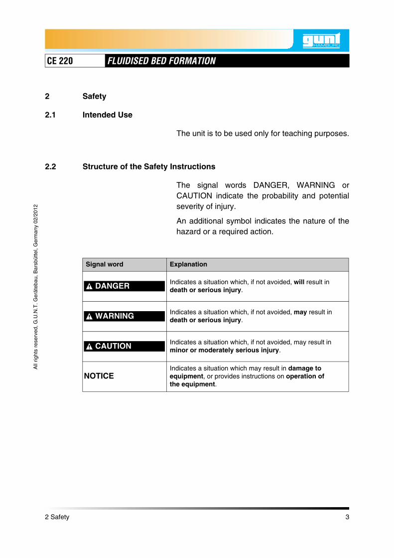
3 Unit Description
3.1 Unit Layout
Fig. 3.1 Layout CE 220
1 Table support with panel 16 Bypass valve for water2 Bypass valve for air with sound absorber 17 Water supply3 Rotameter for air with needle 18, 20 Sintered plate (not visible)4 Single tube manometer for differential air pressure 19, 21 Distribution chamber5 Switch for diaphragm compressor 22 Air supply6 Test vessel for air7 Air filter Further components are behind
the cover and not visible:8 Scale9 Water overflow
10 Fixing for the upper Sintered plate 23 Supply tank for water with drain tap and safety valve11 Test vessel for water
12 Bleed / vent valve 24 Diaphragm pump13 Two tube manometer for water pressure 25 Compressed air reservoir with
saftey valve14 Switch for diaphragm pump15 Rotameter for water with needle valve 26 Diaphragm compressor
1
2
3
4
5
22201817
14
13
15
16
910 8 7
6
1112
19 21
3 Unit Description 6
CE 220 FLUIDISED BED FORMATION
All
right
s re
serv
ed, G
.U.N
.T. G
erät
ebau
, Bar
sbüt
tel,
Ger
man
y 02
/201
2
The test stand is designed as a table unit. All com-ponents, controls and displays are clearlyarranged on a panel.
All the electrical circuitry is protected behind thepanel.
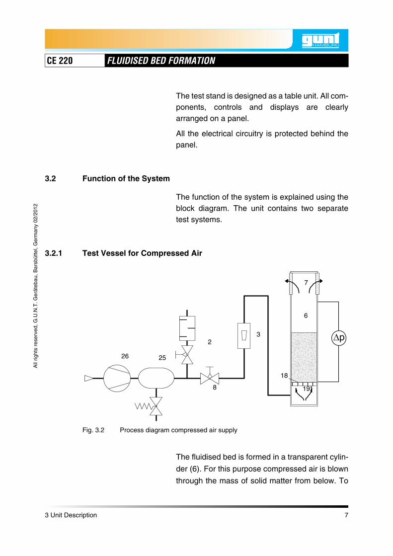
3.2 Function of the System
The function of the system is explained using theblock diagram. The unit contains two separatetest systems.
3.2.1 Test Vessel for Compressed Air
The fluidised bed is formed in a transparent cylin-
der (6). For this purpose compressed air is blown
through the mass of solid matter from below. To
Fig. 3.2 Process diagram compressed air supply
3
26 25
2
8
6
7
19*
18
3 Unit Description 7

CE 220 FLUIDISED BED FORMATION
All
right
s re
serv
ed, G
.U.N
.T. G
erät
ebau
, Bar
sbüt
tel,
Ger
man
y 02
/201
2
distribute the air evenly, the base of the cylinder is
made of a porous sintered metal plate (19).
NOTICEWith very fine particle sizes (<0,05mm, dusts), afluidised bed is very difficult to demonstrate, asthe material tends to clump. This also applies todamp materials.
The necessary air pressure underneath the
sintered plate in the distribution chamber (19) is
generated by a double diaphragm com-
pressor (26). To smooth the flow of air, an air
reservoir (25) is fitted in the compressed air line.
NOTICEA safety valve (25) limits the pressure in thereservoir to 3bar.
The air blown into the cylinder leaves the cylinder
at the top end via a dry paper air filter (7). In this
way particles drawn off from the mass are
securely retained and no loss of material occurs.
The air flow is adjusted using two valves. The
needle valve (3) on the rotameter is used to set
low volumetric flow rates. Larger volumetric flow
rates are set using the bypass valve (2), this has
an sound absorber (10) connected in series. The
flow rate is measured using a directly indicating
variable area rotameter (3).
To measure the differential pressure across the
height of the mass, two couplings are fitted at the
3 Unit Description 8

CE 220 FLUIDISED BED FORMATION
All
right
s re
serv
ed, G
.U.N
.T. G
erät
ebau
, Bar
sbüt
tel,
Ger
man
y 02
/201
2
top and bottom of the cylinder. The respective
pressure can be measured at the couplings using
hoses. The differential pressure is displayed
using a single tube manometer (4).
3.2.2 Test Vessel for Water
The fluidised bed is generated in a transparent
cylinder (11). For this purpose water is pumped
into the mass of solid matter from below. To
obtain an even flow of water, the base of the
cylinder is made of a porous sintered metal
plate (20).
Fig. 3.3 Process diagram water supply
23
15
21
9
20
16
24
11
3 Unit Description 9

CE 220 FLUIDISED BED FORMATION
All
right
s re
serv
ed, G
.U.N
.T. G
erät
ebau
, Bar
sbüt
tel,
Ger
man
y 02
/201
2
The water pressure required below the sintered
plate in the distribution chamber (21) is generated
using a diaphragm pump (24) that pumps the
water around a circuit. A supply tank (23) open to
the atmosphere contains a sufficient quantity of
water.
The flow of water is adjusted using two valves.
The needle valve (15) on the rotameter is used to
set low flow rates. Larger flow rates are set using
the bypass valve (16). The flow rate is measured
using a directly indicating variable area rota-
meter (15).
NOTICEA safety valve (23) limits the pressure in thereservoir to 1,5bar.
After flowing through the cylinder, the water
returns to the supply tank via an overflow (9). To
measure the differential pressure across the
height of the mass, two couplings are fitted at the
top and bottom of the cylinder. The respective
pressure can be measured at the couplings using
hoses.
The differential pressure is displayed using a two
tube manometer, the display range of which can
be varied by changing the initial air pressure. The
initial air pressure can be set using a valve.
3 Unit Description 10

CE 220 FLUIDISED BED FORMATION
All
right
s re
serv
ed, G
.U.N
.T. G
erät
ebau
, Bar
sbüt
tel,
Ger
man
y 02
/201
2
3.3 Commissioning
1. Switch off the pump (Fig. 3.1, Page 6, 14).
2. Switch off the compressor (Fig. 3.1,Page 6, 5).
3. Fully open the bypass valve for water (Fig.3.1, Page 6, 16).
4. Fully open the bypass valve for air (Fig. 3.1,Page 6, 2).
5. Close the needle valve on the rotameter forwater (Fig. 3.1, Page 6, 15).
6. Close the needle valve on the rotameter forair (Fig. 3.1, Page 6, 3).
7. Connect the unit to the power supply, makingsure the details on the rating plate corre-spond to those of the power supply.
3 Unit Description 11

CE 220 FLUIDISED BED FORMATION
All
right
s re
serv
ed, G
.U.N
.T. G
erät
ebau
, Bar
sbüt
tel,
Ger
man
y 02
/201
2
3.3.1 Single tube manometer
The procedure for filling the single tube manome-ter is as follows:
1. Slightly loosen the knurled screws thatsecure the scale so that the scale can bemoved (there are two knurled screws).
2. Move the scale to a central position so thatyou can move it up and down for subsequentcorrections.
3. Detach the hose at the pressure fitting fromthe pressure connection on the test vessel forair.
4. Carefully unscrew the pressure fitting.
5. Pour the special liquid supplied (type AWS10, = 0,87g/cm3) into the free opening untilthe "0" mark on the scale is reached.
6. If necessary, correct the zero mark by movingthe scale, until the line for the "0" mark isaligned with the liquid level.
7. Secure the scale by tightening the knurledscrews.
8. Carefully screw the pressure fitting back in.
9. Replace the previously detached hose on thepressure fitting on the test vessel for air.
10. The single tube manometer is now ready foruse.
Fig. 3.4 Single tube manometer
Pressure fitting
Sliding scale
Liquid
Knurled screw
NOTICEThe pressure fitting (+) is connectedto the lower pressure connection onthe test vessel for air, and the fitting(-) on the left-hand side of the singletube manometer is connected to theupper pressure connection on thetest vessel for air.
3 Unit Description 12

CE 220 FLUIDISED BED FORMATION
All
right
s re
serv
ed, G
.U.N
.T. G
erät
ebau
, Bar
sbüt
tel,
Ger
man
y 02
/201
2
3.3.2 U-tube manometer
The U-tube manometer is prepared for measure-ments as follows:
1. Close the upper bleed valve and open the twolower bleed valves.
2. Fully open the bypass valve (Fig. 3.1,Page 6, 16).
3. Switch on the pump (Fig. 3.1, Page 6, 14).
4. Fill the test vessel for water completely withwater.
5. Allow the water to continue flowing throughthe test vessel at a low flow rate.Depending on the material depth in the testcylinder, the water levels in the two manome-ter capillary tubes may be different for thenext step - adjust the average water level withthe centre of the scale.
6. Slightly open the upper bleed valve so thatthe water flows through the hoses into themanometer capillary tubes.
7. Close the upper bleed valve as soon as theaveraged water level reaches the centre ofthe scale.
8. Switch off the pump; the water level in themanometer capillary tubes should now be atthe level of the centre of the scale.
9. The U-tube manometer is now ready for use.
Fig. 3.5 U-tube manometer
Bleed valves
Set level here
Centre of scale
Left connec-tion
Right con-nection
NOTICEThe right connection is connected tothe lower pressure connection onthe test vessel for water, and the leftconnection is connected to theupper pressure connection.
3 Unit Description 13

CE 220 FLUIDISED BED FORMATION
All
right
s re
serv
ed, G
.U.N
.T. G
erät
ebau
, Bar
sbüt
tel,
Ger
man
y 02
/201
2
3.3.3 Test vessel for air
The procedure for filling the test vessel for air is asfollows:
1. Loosen the four knurled screws.
2. Lift the air filter off the cylinder flange.Exercise caution when lifting, as there arespacer sleeves under the air filter throughwhich the knurled screws are fed.
3. Set aside the air filter with the knurled screwsand spacer sleeves.
4. Pour the mass into the cylinder.In our experiment, glass beads with a particlediameter dp = 0,180...0,300mm are used at amass height of h = 50mm.
5. Place the spacer sleeves onto the threadedholes on the cylinder flange.
6. Carefully place the air filter onto the spacersleeves.
7. Replace the knurled screws in their originalposition, making sure that they are fed throughthe spacer sleeves.
8. Tighten the knurled screws.
9. The test vessel for air is now ready for use.
Fig. 3.6 Test vessel for air
Knurled screws (x4)
Spacer sleeves
Cylinder flange
3 Unit Description 14

CE 220 FLUIDISED BED FORMATION
All
right
s re
serv
ed, G
.U.N
.T. G
erät
ebau
, Bar
sbüt
tel,
Ger
man
y 02
/201
2
3.3.4 Test vessel for water
The test vessel for water must be filled in verysmall doses to achieve the desired materialdepth. The particles sink very slowly in the water,which means that the depth of the material canonly be seen some time after filling.
The procedure for filling the test vessel for wateris as follows:
1. Fully open the bypass valve (Fig. 3.1,Page 6, 16).
2. Switch on the pump (Fig. 3.1, Page 6, 14).
3. Half fill the test vessel for water with water.
4. Switch off the pump.
5. Detach the drain hose from the water over-flow.
6. Detach the measurement hose from thewater overflow.
7. Loosen the two knurled nuts.
8. Lift the water overflow off the cylinder flange.Exercise caution when lifting as there is asealing ring under the water overflow, whichis located in a a groove on the water overflow.
9. Set aside the water overflow with the knurlednuts and sealing ring.
10. Remove the sintered plate from the cylinderflange and set it aside.
11. Pour the mass into the cylinder.In our experiment, glass beads with a particlediameter dp = 0.420...00.590mm are used ata mass height of h = 100mm.
Fig. 3.7 Test vessel for water
Knurled nut
Sealing ring
Threaded rods
Water overflow
Sintered-metal plate
Cylinder flange
3 Unit Description 15

CE 220 FLUIDISED BED FORMATION
All
right
s re
serv
ed, G
.U.N
.T. G
erät
ebau
, Bar
sbüt
tel,
Ger
man
y 02
/201
2
12. Place the sintered plate in the recess pro-vided in the cylinder flange.
13. Place the sealing ring in the groove on thewater overflow.
14. Carefully place the water flow on the cylinderflange, making sure that the sealing ringremains in the groove.
15. Place the knurled nuts onto the threadedrods.
16. Tighten the knurled nuts.
17. Reconnect the drain hose to the coupling onthe water overflow.
18. Reconnect the measurement hose to thecoupling on the water overflow.
19. The test vessel for water is now ready for use.
3 Unit Description 16

CE 220 FLUIDISED BED FORMATION
All
right
s re
serv
ed, G
.U.N
.T. G
erät
ebau
, Bar
sbüt
tel,
Ger
man
y 02
/201
2
4 Principles
The basic principles set out in the following makeno claim to completeness. For further theoreticalexplanations, refer to the specialist literature.
A fluidised bed is a layer of fine granular solidmatter (mass) that is loosened by a fluid flowingthrough it to such an extent that the particles ofsolid matter are free to move within certain limits.The layer of solid material takes on similar proper-ties to a fluid.
To characterise a fluidised bed, the pressureloss of the fluid flowing through the bed can beused. When a fluid flows through the mass, ini-tially the pressure underneath the mass increasesas the flow speed increases until the pressureforces match the weight of the mass, and themass becomes suspended. With further increas-ing flow rate, the layer is set in motion andreaches a fluidised state. The pressure loss nowremains almost constant, even with furtherincreasing flow rate. From a certain flow rate, theparticles at the top no longer fall back into the flu-idised bed; they are drawn off by the fluid flow andremoved.
Fluidised beds are widely used in process tech-nology. Gaseous and sol id or liquid componentsof a chemical reaction are well mixed and broughtinto close contact with each other. This alsoapplies to fluidised bed furnace applications thatincinerate problem materials with low levels ofpollution.
Fig. 4.1 Dependency on pressure loss
p
Solid bed Fluidised bed
Solid matter removal
wwlo
4 Principles 17

CE 220 FLUIDISED BED FORMATION
All
right
s re
serv
ed, G
.U.N
.T. G
erät
ebau
, Bar
sbüt
tel,
Ger
man
y 02
/201
2
4.1 Pressure Losses in Fluidised Beds
From the equilibrium of drag, weight and lift, thepressure loss of a fluid flowing through theturbulent mass of particles is given by
(4.1)
Density of the fluid,
Density of the particle,
Density of the particle mass,
h Height of the mass.
4.2 Pressure Curve in the Fluidised Bed
The equilibrium of drag, weight and lift not onlyapplies at the base, but at any height in the mass.As can be seen in the previous section, thepressure loss is linearly dependent on the heightof the mass. Thus the pressure curve dropslinearly to zero from the base to the surface. Withy as the immersion depth in the mass, the follow-ing applies
(4.2)
p
p g 1f
p------–
h ps =
f
p
ps
p y ph------- y=
4 Principles 18
CE 220 FLUIDISED BED FORMATION
All
right
s re
serv
ed, G
.U.N
.T. G
erät
ebau
, Bar
sbüt
tel,
Ger
man
y 02
/201
2
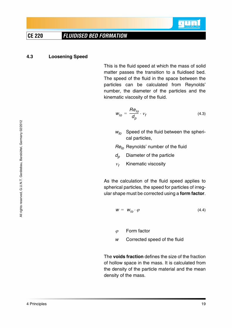
4.3 Loosening Speed
This is the fluid speed at which the mass of solidmatter passes the transition to a fluidised bed.The speed of the fluid in the space between theparticles can be calculated from Reynolds’number, the diameter of the particles and thekinematic viscosity of the fluid.
(4.3)
wlo Speed of the fluid between the spheri-cal particles,
Relo Reynolds’ number of the fluid
dp Diameter of the particle
Kinematic viscosity
As the calculation of the fluid speed applies tospherical particles, the speed for particles of irreg-ular shape must be corrected using a form factor.
(4.4)
Form factor
w Corrected speed of the fluid
The voids fraction defines the size of the fractionof hollow space in the mass. It is calculated fromthe density of the particle material and the meandensity of the mass.
wlo
Relo
dp------------ f=
f
w wlo =
4 Principles 19

CE 220 FLUIDISED BED FORMATION
All
right
s re
serv
ed, G
.U.N
.T. G
erät
ebau
, Bar
sbüt
tel,
Ger
man
y 02
/201
2
(4.5)
Voids fraction
The equilibrium of pressure loss and particle dragyields a relationship between the dimensionlessnumbers Re and Ar
(4.6)
Ar Archimedes‘ Number
The Archimedes’ Number Ar is calculated fromthe density, particle diameter and viscosity of thefluid
(4.7)
1ps
p--------–=
Relo 42,86 1 – 1 3,11 10 4– Ar 3
1 – 2------------------- + 1–
=
Arg dp
3
2----------------
p f–
f----------------=
4 Principles 20

CE 220 FLUIDISED BED FORMATION
All
right
s re
serv
ed, G
.U.N
.T. G
erät
ebau
, Bar
sbüt
tel,
Ger
man
y 02
/201
2
5 Experiments
The selection of experiments makes no claims ofcompleteness but is intended to be used as astimulus for your own experiments. The results shown are intended as a guide only.Depending on the construction of the individualcomponents, experimental skills and environmen-tal conditions, deviations may occur in the experi-ments. Nevertheless, the laws can be clearlydemonstrated.
5.1 Preparing the Experiment
• Place the unit on a flat bench top.
• Connect to power supply.
• Fill the storage tank with water (approx. 4ltr).
• Secure all hoses at the designated points.
• Open the bypass valves for air and water.
• Close the needle valves on the rotameters.
• Start the compressor with the relevant switchand check the function (delivery noise).
• Start the pump with the relevant switch andcheck the function (test vessel fills with water).
5 Experiments 21

CE 220 FLUIDISED BED FORMATION
All
right
s re
serv
ed, G
.U.N
.T. G
erät
ebau
, Bar
sbüt
tel,
Ger
man
y 02
/201
2
5.1.1 Filling the Test Vessels
Before experiments, the test vessels must befilled with the required mass. To practice using theunit, we recommend initially using one of the twospecimen materials supplied. These are glassbeads (ballotinis) with two different particle sizesand bulk densities.
dp = 0,180 - 0,300mm, = 1500
dp = 0,420 - 0,590mm, = 1500
The particle density for both is:
= 2400...2600
The air filter must be removed from the test vesselfor air to fill it with the bulk material.
The water vessel must be filled in very smalldoses to achieve the desired material depth. Theparticles sink very slowly in the water, whichmeans that the depth of the material can only beseen some time after filling.
NOTICEBefore filling the water vessel, make a roughcalculation of how deep the fluidised bed will be.No particles may get into the overflow as other-wise this can destroy the pump diaphragm.
pskgm3-------
pskgm3-------
pkgm3-------
5 Experiments 22

CE 220 FLUIDISED BED FORMATION
All
right
s re
serv
ed, G
.U.N
.T. G
erät
ebau
, Bar
sbüt
tel,
Ger
man
y 02
/201
2
5.1.2 Emptying the Air Test Vessel
• Detach all hoses on the test vessel.
• Unscrew the knurled screws (2) at theclamp (3).
• Remove the cylinder with the air filter andholder (1).
• Remove the knurled screws (4) on the air filter.Caution when removing. Maintain the seal.
• Empty the cylinder. To loosen adherent mate-rial, tap on the cylinder while simultaneouslyturning it.
• Blow clear the the pores in the sintered plateusing compressed air through the distributionchamber connection.Adherent material can be detached from insidewith a jet of compressed air.
NOTICEDust formation. Blow out in the open air ifrequired.
NOTICENever rinse out the air cylinder with water. Thiswashes the fine particles into the pores in thesintered plate and clog them up.
Fig. 5.1 Air test vessel
Fig. 5.2 Emptying and cleaning
4
1
2
3
5 Experiments 23

CE 220 FLUIDISED BED FORMATION
All
right
s re
serv
ed, G
.U.N
.T. G
erät
ebau
, Bar
sbüt
tel,
Ger
man
y 02
/201
2
5.1.3 Cleaning the Air Filter
If the air filter is clogged up by particles carriedalong, it must be cleaned as follows.
• Remove the air filter as described inChapter 5.1.2.
• Beat the air filter on a solid surface.Material beaten out can be returned to the solidmass.
• Blow out the air filter from outside with a com-pressed air jet.
NOTICEDust formation. Blow out in the open air ifrequired.
5.1.4 Emptying the Water Test Vessel
The test vessel is removed in a similar way to thatdescribed in Chapter 5.1.2 for the air test vessel.
• Detach all hoses on the test vessel.
• Unscrew the two knurled screws to remove thewater overflow.
• Detach the water overflow.
• Detach the two nuts on the retaining plate andremove the retaining plate upwards.
• Unscrew the two knurled screws at the clampfor holding the test vessel.
• Empty the cylinder. To loosen adherent mate-rial, tap on the cylinder while simultaneouslyturning it.
Fig. 5.3 Blowing out the air filter with compressed air
5 Experiments 24

CE 220 FLUIDISED BED FORMATION
All
right
s re
serv
ed, G
.U.N
.T. G
erät
ebau
, Bar
sbüt
tel,
Ger
man
y 02
/201
2
• Blow the pores in the sintered plate clear withcompressed air through the distribution cham-ber connection. Adherent material can beremoved from inside with a compressed air jet.
• Particles that are not removed from the wall bycompressed air can be removed by half fillingthe cylinder with water and then lightly shakingit. The particles can be separated from theliquid with a fine filter (coffee filter).
5.1.5 Plotting a Calibration Curve for Recording the Pressure Losses without Filling the Test Vessel
To record the individual pressure losses for thewater test vessel, a calibration curve must be plot-ted for each device without filling. Make sure thatno air bubbles form on the sintered metal as theyfalsify the measured results.
Procedure:
• Connect the pressure measuring connectionsto the manometer. On a two tube manometer,the display value can be set to the centre of themanometer with the venting and bleed valve.
• Fully open the bypass valve below the rotame-ter.
• Fully close the needle valve on the rotameter.
• Turn on the pump.
• Increase the flow in small increments by open-ing the needle valve.
• Continuously note the flow rate and differentialpressure in the table (see Appendix).
5 Experiments 25

CE 220 FLUIDISED BED FORMATION
All
right
s re
serv
ed, G
.U.N
.T. G
erät
ebau
, Bar
sbüt
tel,
Ger
man
y 02
/201
2
• Continue the measurements up to the maxi-mum flow.
• Plot the measured values in a diagram.
in 0 0,2 0,3 0,4 0,5 0,6 0,7 0,8 0,9 1,0 1,1
w in 0 2,19 3,29 4,38 5,48 6,57 7,67 8,77 9,86 10,96 12,06
Left scale
189 181 177 174 170 167 164 160 156 153 148
Right scale
190 198 202 206 210 214 217 222 226 230 235
in
mmWG1 17 25 32 40 47 53 62 70 77 87
in 1,2 1,3 1,4 1,5 1,6 1,7 1,8 1,9
w in 13,15 14,25 15,35 16,44 17,54 18,63 19,73 20,83
Left scale
145 140 136 131 127 123 119 116
Right scale
239 244 248 254 258 263 267 270
in
mmWG94 104 112 123 131 140 148 154
Tab. 5.1 Pressure loss against flow - liquid medium
Q·
Lmin-----------
ms----- 103
p
Q·
Lmin-----------
ms----- 103
p
5 Experiments 26

CE 220 FLUIDISED BED FORMATION
All
right
s re
serv
ed, G
.U.N
.T. G
erät
ebau
, Bar
sbüt
tel,
Ger
man
y 02
/201
2
The measurements with the water test vesselmust be corrected with the calibration curve youhave plotted yourself. This means that the pres-sure loss value through the sintered metal platesat the corresponding flow rate must be subtractedfrom the pressure difference values from theexperiments. The measurements in this manualare corrected.
Fig. 5.4 Example calibration curve for pressure lossesThe pressure losses were plotted with the water test vessel without filling.
Flow rate Q in Lmin----------
Pre
ssur
e di
ffere
nce
thro
ugh
sint
ered
met
al p
late
s in
mm
WC
p 0 0,5 1 1,5 2
010
2030405060
7080
90100110120130140
150160
170
180
5 Experiments 27
CE 220 FLUIDISED BED FORMATION
All
right
s re
serv
ed, G
.U.N
.T. G
erät
ebau
, Bar
sbüt
tel,
Ger
man
y 02
/201
2
5.2 Measuring the Pressure Loss with Air Flow
5.2.1 Experiment Aim
Measuring the pressure loss with air flow with amass with a mean particle diameter ofdp = 0,240mm.
The mass depth is h = 50mm.
5.2.2 Performing the Experiment
The pressure connections are connected to thesingle tube manometer.
• Fully open the bypass valve below the rotame-ter.
• Fully close the needle valve on the rotameter.
• Turn on the compressor.
• Increase the flow in small increments by open-ing the needle valve and observe the mass.
• Continuously note the flow rate and differentialpressure.
• As soon as the first signs of particle move-ments appear, the loosening speed has beenreached. Note the associated flow.
Repeat the measurements until a flow of 30 isreached. Above a certain value, the flow rate canonly be increased by closing the bypass valve.
Lmin----------
5 Experiments 28
CE 220 FLUIDISED BED FORMATION
All
right
s re
serv
ed, G
.U.N
.T. G
erät
ebau
, Bar
sbüt
tel,
Ger
man
y 02
/201
2
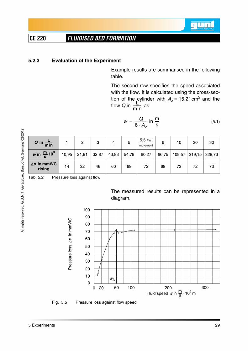
5.2.3 Evaluation of the Experiment
Example results are summarised in the followingtable.
The second row specifies the speed associatedwith the flow. It is calculated using the cross-sec-tion of the cylinder with Az = 15,21cm2 and theflow Q in as:
in (5.1)
The measured results can be represented in adiagram.
Lmin----------
w Q6 Az--------------=
ms-----
in 1 2 3 4 55,5 First
movement6 10 20 30
w in 10,95 21,91 32,87 43,83 54,79 60,27 66,75 109,57 219,15 328,73
in mmWC rising
14 32 46 60 68 72 68 72 72 73
Tab. 5.2 Pressure loss against flow
Q Lmin-----------
ms----- 103
p
Fig. 5.5 Pressure loss against flow speed
Fluid speed w in mms----- 103
Pre
ssur
e lo
ss
in m
mW
C
p
00
10
20
30
50
60
70
80
90
100
40
20 60 100 200 300
60
wlo
5 Experiments 29

CE 220 FLUIDISED BED FORMATION
All
right
s re
serv
ed, G
.U.N
.T. G
erät
ebau
, Bar
sbüt
tel,
Ger
man
y 02
/201
2
It is characteristic that, as the flow increases,there is initially an excess pressure. This indicatesthe loosening speed wlo. As the flow decreases,this effect cannot be identified.
5 Experiments 30
CE 220 FLUIDISED BED FORMATION
All
right
s re
serv
ed, G
.U.N
.T. G
erät
ebau
, Bar
sbüt
tel,
Ger
man
y 02
/201
2
5.3 Measuring the Pressure Loss with Water Flow
5.3.1 Experiment Aim
Measuring the pressure loss with water flow witha mass with a mean particle diameter ofdp = 0,505mm.
The mass depth is h = 100mm.
5.3.2 Performing the Experiment
The pressure connections are connected to thetwo tube manometer. The display value can beset to the centre of the manometer with the vent-ing and bleed valve.
• Fully open the bypass valve below the rotame-ter.
• Fully close the needle valve on the rotameter.
• Turn on the pump.
• Increase the flow in small increments by open-ing the needle valve and observe the mass.
• Continuously note the flow rate and differentialpressure.
• As soon as the first signs of particle move-ments appear, the loosening speed has beenreached. Note the associated flow.
Repeat the measurements until a flow of 1.5is reached. Above a certain value, the flow ratecan only be increased by closing the bypassvalve.
Lmin----------
5 Experiments 31

CE 220 FLUIDISED BED FORMATION
All
right
s re
serv
ed, G
.U.N
.T. G
erät
ebau
, Bar
sbüt
tel,
Ger
man
y 02
/201
2
5.3.3 Evaluation of the Experiment
Example results are summarised in the followingtable.
The second row specifies the speed associatedwith the flow. It is calculated using the cross-sec-tion of the cylinder with Az = 15,21cm2 and theflow Q in as:
in
The measured results can be represented in adiagram.
Lmin----------
w Q6 Az--------------=
ms-----
Q in 0,1 0,15 0,20,25 First
movement0,3 0,4 0,6 0,8 1,0 1,5
w in 1,096 1,645 2,192 2,739 3,287 4,383 6,575 8,766 10,957 16,437
in mmWC rising 55 66 79 88 86 87 87 87 87 87
Tab. 5.3 Pressure loss against flow
Lmin-----------
ms----- 103
p
Fig. 5.6 Pressure loss against flow speed
Fluid speed w in mms----- 103
Pre
ssur
e lo
ss
in m
mW
C
p
00
10
20
30
50
70
80
90
100
40
60
1,0 3,0 5,0 10,0 15,0
wlo
5 Experiments 32

CE 220 FLUIDISED BED FORMATION
All
right
s re
serv
ed, G
.U.N
.T. G
erät
ebau
, Bar
sbüt
tel,
Ger
man
y 02
/201
2
5.4 Comparing Different Masses
5.4.1 Experiment Aim
The comparison of different masses in the air testvessel is initially carried out using a mass with amean particle diameter of dp = 0,240mm .
The mass depth is h = 50mm.
The experiment is then repeated with a meanparticle diameter of dp = 0,505mm .
5.4.2 Performing the Experiment
The pressure connections are connected to thesingle tube manometer.
• Fully open the bypass valve below the rota-meter.
• Fully close the needle valve on the rotameter.
• Turn on the compressor.
• Increase the flow in small increments by open-ing the needle valve and observe the mass.
• Continuously note the flow rate and differentialpressure.
The compressed air flow rate is increased until thedifferential pressure is constant. The maximumpressure loss is noted.
5 Experiments 33

CE 220 FLUIDISED BED FORMATION
All
right
s re
serv
ed, G
.U.N
.T. G
erät
ebau
, Bar
sbüt
tel,
Ger
man
y 02
/201
2
5.4.3 Evaluation of the Experiment
It can be seen that, despite different particle sizes,the maximum differential pressure is the same forboth masses.
The measured maximum pressure loss for bothbeds is = 72mmWC. This measured value isnow compared with the theoretical value.
According to Formula (4.1):
(5.2)
Bulk density = 1500
Particle density = 2500
Fluid density = 1,25
Material depth h = 0,05m
(5.3)
(5.4)
The measured values and calculated values are agood match.
This experiment indicates that the maximum pres-sure loss in a fluidised bed depends on the bulkdensity, particle density, fluid density and thematerial depth. Unlike when determining theloosening speed, the particle size is unimportant.
p
p g 1f
p------–
h ps =
pskgm3-------
pkgm3-------
fkgm3-------
p 9,81 m
s2----- 1
1,25 kg
m3-------
2500 kg
m3-------
---------------------–
0,05m 1500 kg
m3------- =
p 0,735kPa 73,5mmWC= =
5 Experiments 34
CE 220 FLUIDISED BED FORMATION
All
right
s re
serv
ed, G
.U.N
.T. G
erät
ebau
, Bar
sbüt
tel,
Ger
man
y 02
/201
2
5.5 Determination of the Loosening speed
5.5.1 Experiment Aim
Determination of the loosening speed from theresults of the experiments in Chapter 5.2 andChapter 5.3.
5.5.2 Performing the Experiment
The flow speeds at which the first movementwithin the mass is visible in the experimentsdescribed above (Chapter 5.2 and Chapter 5.3)are noted.
5.5.3 Evaluation of the Experiment
The following values were measured:
Air: dp = 0,240mm, w = 0,0603
Water: dp = 0,505mm, w = 0,0274
The measured values are now compared with thetheoretical values.
First of all, the Archimedes number is calculatedusing Formula (4.7), page 20. The viscosity of theair is
For dp = 0,240mm
ms-----
ms-----
16 10 6– m2
s-------=
5 Experiments 35

CE 220 FLUIDISED BED FORMATION
All
right
s re
serv
ed, G
.U.N
.T. G
erät
ebau
, Bar
sbüt
tel,
Ger
man
y 02
/201
2
(5.5)
According to Formula (4.5), page 20 the voidageis:
(5.6)
Formula (4.6), page 20 gives the Reynoldsnumber:
(5.7)
and thus the speed according to Formula (4.3),page 19:
(5.8)
This value is a good match with the measuredvalue of w = 0,060 .
For water, the same calculation
(5.9)
Ar
9,81m
s2----- 0 000243 m
3
16 10 6– m2
s-------
2
--------------------------------------------------------
2500 kg
m3------- 1 25 kg
m3-------–
1,25 kg
m3-------
------------------------------------------------- 1059==
1
1500 kg
m3-------
2500 kg
m3-------
---------------------– 0,4= =
Relo 42,86 1 0,4– 1 3,11 10 4– 1059 0,43
1 0,4–2
-------------------- + 1–
0,742==
wlo0,773
0,00024m--------------------------- 16 10 6– m2
s------- 0,049m
s-----= =
ms-----
1 10 6– m2
s-------=
5 Experiments 36

CE 220 FLUIDISED BED FORMATION
All
right
s re
serv
ed, G
.U.N
.T. G
erät
ebau
, Bar
sbüt
tel,
Ger
man
y 02
/201
2
and
(5.10)
and
dp = 0,505mm
gives the following values:
A = 1895
= 0,4
Relo = 0,002601
This value is also a good match with the meas-ured value of w = 0.002739 .
If the particles do not have the form of spheres,the theoretically calculated loosening speed mustbe multiplied by a shape factor to obtain theactual speed. This shape factor converts anycross-section into an spherical alternative cross-section. The factor can be found in tables.
1000 kg
m3-------=
ms-----
ms-----
5 Experiments 37

CE 220 FLUIDISED BED FORMATION
All
right
s re
serv
ed, G
.U.N
.T. G
erät
ebau
, Bar
sbüt
tel,
Ger
man
y 02
/201
2
5.6 Relationship between Flow Rate and Depth of the Fluidised Bed
5.6.1 Experiment Aim
To determine the relationship between flow rateand the depth of the fluidised bed. A mass with amean particle diameter of dp = 0,505mm is used.
The material depth is h = 100mm.
This experiment is only possible in the water ves-sel as it is only here that the depth of the fluidisedbed is clearly identifiable.
5.6.2 Performing the Experiment
The pressure connections are connected to thetwo tube manometer. The display value can beset to the centre of the manometer with the vent-ing and bleed valve.
• Fully open the bypass valve below the rotame-ter.
• Fully close the needle valve on the rotameter.
• Turn on the pump.
• Increase the flow in small increments by open-ing the needle valve and observe the mass.
• Continuously note the flow rate and bed depth.
Repeat the measurements until a flow of 1,5is reached. Above a certain value, the flow ratecan only be increased by closing the bypassvalve.
Lmin----------
5 Experiments 38

CE 220 FLUIDISED BED FORMATION
All
right
s re
serv
ed, G
.U.N
.T. G
erät
ebau
, Bar
sbüt
tel,
Ger
man
y 02
/201
2
5.6.3 Evaluation of the Experiment
Example results are summarised in the followingtable.
Plotting the measured values in a diagram givesthe following figure:
It can be seen that, once the loosening speed isreached, the depth of the fluidised bed increasesproportionately to the flow rate.
Q
in 0,1 0,2 0,25 0,3 0,4 0,6 0,8 1,0 1,2 1,5
h
in mm100 100 105 111 119 130 145 157 172 196
Tab. 5.4 Fluidised bed depth against flow
Lmin-----------
Fig. 5.7 Fluidised bed depth against flow
Flow rate Q in Lmin----------
Bed
dep
th h
in m
m
wlo100
120
130
150
170
180
190
200
140
160
110
0 0,2 0,4 0,6 0,8 1,0 1,2 1,4
5 Experiments 39

CE 220 FLUIDISED BED FORMATION
All
right
s re
serv
ed, G
.U.N
.T. G
erät
ebau
, Bar
sbüt
tel,
Ger
man
y 02
/201
2
This experiment is only possible with fluidisedbeds in liquids, as this is the only place that ahomogeneous fluidised bed is formed.
Masses in gas flows form non-homogeneousfluidised beds with lots of bubbles, making itimpossible to read the depth.
5 Experiments 40
CE 220 FLUIDISED BED FORMATION
All
right
s re
serv
ed, G
.U.N
.T. G
erät
ebau
, Bar
sbüt
tel,
Ger
man
y 02
/201
2
6 Appendix
6.1 Technical Data
Dimensions
Length x width x height 750mm x 610mm x 1010 mm
Weight approx. 74 kg
Connections
Power supply 230V / 50 Hz
Nominal consumption (rating) 0,2 kW
Alternatives optional, see type plate
Test vessel (air and water)
Material PMMA
Length 550 mm
Diameter 44 mm
Capacity approx. 1,2 L
Scale 0...500 mm
Division 1 mm
Diaphragm compressor
Volumetric flow rate, maximum 39
Pressure, maximum 2,0 bar
Compressed air reservoir
Capacity 2 L
Proof pressure 10 bar
Safety valveadjustable 0...4 bar
Rotameter (air)
Measuring range 4...32
Lmin----------
Lmin----------
6 Appendix 41

CE 220 FLUIDISED BED FORMATION
All
right
s re
serv
ed, G
.U.N
.T. G
erät
ebau
, Bar
sbüt
tel,
Ger
man
y 02
/201
2
Single tube manometer (air)
Messbereich 0...200 mmWS
Diaphragm pump
Volumetric flow rate 1,8
at 1,0 bar
Supply tank (water)
Capacity ca. 4L
Safety valveadjustable 0...4 bar
Rotameter (water)
Measuring range 0,2... 2,2
Two tube manometer (water)
Measuring range 0...500 mmWS
Sample material
Type Glass beads (Ballotini)
Particle diameter 0,180...0,300 mm
and 0,420...0,590 mm
Density 2,4...2,6
Density of mass approx. 1,5
Lmin----------
Lmin----------
kgm3-------
kgm3-------
6 Appendix 42

CE 220 FLUIDISED BED FORMATION
All
right
s re
serv
ed, G
.U.N
.T. G
erät
ebau
, Bar
sbüt
tel,
Ger
man
y 02
/201
2
6.2 List of Symbols and Units
Symbol Mathematical / physical unit Unit
Ar Archimedes‘ number
Az Cross-section of the mass cm2, m2
d Diameter mm, m
dp Particle diameter mm, m
g Acceleration due to gravity
h Height of the mass mm, m
p Pressure bar, , Pa
Q Volumetric flow rate
Re Reynolds‘ number
w Speed
Voids fraction
Form factor
Viscosity
Density
m
s2-----
N
m2-------
Lmin----------
ms-----
m2
s-------
kg
m3-------
6 Appendix 43

CE 220 FLUIDISED BED FORMATION
All
right
s re
serv
ed, G
.U.N
.T. G
erät
ebau
, Bar
sbüt
tel,
Ger
man
y 02
/201
2
6.3 Work Sheets
6.3.1 Pressure Loss against Flow
in 0 0,2 0,3 0,4 0,5 0,6 0,7 0,8 0,9 1,0 1,1
w in 0 2,19 3,29 4,38 5,48 6,57 7,67 8,77 9,86 10,96 12,06
Left scale
Right scale
in
mmWGdecreasing
in 1,2 1,3 1,4 1,5 1,6 1,7 1,8 1,9
w in 13,15 14,25 15,35 16,44 17,54 18,63 19,73 20,83
Left scale
Right scale
in
mmWGdecreasing
Q·
Lmin-----------
ms----- 103
p
Q·
Lmin-----------
ms----- 103
p
6 Appendix 44

CE 220 FLUIDISED BED FORMATION
All
right
s re
serv
ed, G
.U.N
.T. G
erät
ebau
, Bar
sbüt
tel,
Ger
man
y 02
/201
2
6.3.2 Calibration Curve for Pressure Losses
Flow rate Q in Lmin----------
Pre
ssur
e di
ffere
nce
thro
ugh
sint
ered
met
al p
late
s in
mm
WS
p 0 0,5 1 1,5 2
010
20
30
4050
60
708090
100110120
130
140
150
160
170180
6 Appendix 45

CE 220 FLUIDISED BED FORMATION
All
right
s re
serv
ed, G
.U.N
.T. G
erät
ebau
, Bar
sbüt
tel,
Ger
man
y 02
/201
2
7 Index
A
Archimedes’ number . . . . . . . . . . . . . . . . . . . . . . . . . . . . . . . . . . . . . . . 20
B
Bulk density . . . . . . . . . . . . . . . . . . . . . . . . . . . . . . . . . . . . . . . . . . . . . . 22
C
Cleaning the air filter . . . . . . . . . . . . . . . . . . . . . . . . . . . . . . . . . . . . . . . 24
E
Emptying the air test vessel . . . . . . . . . . . . . . . . . . . . . . . . . . . . . . . . . 23Emptying the water test vessel . . . . . . . . . . . . . . . . . . . . . . . . . . . . . . . 24
F
Filling the test vessels . . . . . . . . . . . . . . . . . . . . . . . . . . . . . . . . . . . . . . 22Fluidised bed . . . . . . . . . . . . . . . . . . . . . . . . . . . . . . . . . . . . . . . . . . . . . 17Fluidised bed depth . . . . . . . . . . . . . . . . . . . . . . . . . . . . . . . . . . . . . . . . 38Fluidised bed furnace . . . . . . . . . . . . . . . . . . . . . . . . . . . . . . . . . . . . . . 17Form factor . . . . . . . . . . . . . . . . . . . . . . . . . . . . . . . . . . . . . . . . . . . . . . 19Function of the system . . . . . . . . . . . . . . . . . . . . . . . . . . . . . . . . . . . . . . 7
L
Loosening speed . . . . . . . . . . . . . . . . . . . . . . . . . . . . . . . . . . . . 19, 30, 35
M
Mass . . . . . . . . . . . . . . . . . . . . . . . . . . . . . . . . . . . . . . . . . . . . . . . . . . . 17
P
Paper air filter . . . . . . . . . . . . . . . . . . . . . . . . . . . . . . . . . . . . . . . . . . . . . 8Particle . . . . . . . . . . . . . . . . . . . . . . . . . . . . . . . . . . . . . . . . . . . . . . 17, 18Particle density . . . . . . . . . . . . . . . . . . . . . . . . . . . . . . . . . . . . . . . . . . . 22Pressure connections . . . . . . . . . . . . . . . . . . . . . . . . . . . . . 28, 31, 33, 38Pressure curve . . . . . . . . . . . . . . . . . . . . . . . . . . . . . . . . . . . . . . . . . . . 18Pressure loss . . . . . . . . . . . . . . . . . . . . . . . . . . . . . . . . . . . . . . 17, 18, 34Pressure loss against flow . . . . . . . . . . . . . . . . . . . . . . . . . . . . 26, 29, 32Process diagram compressed air supply . . . . . . . . . . . . . . . . . . . . . . . . 7Process diagram water supply . . . . . . . . . . . . . . . . . . . . . . . . . . . . . . . . 9
7 Index 46

CE 220 FLUIDISED BED FORMATION
All
right
s re
serv
ed, G
.U.N
.T. G
erät
ebau
, Bar
sbüt
tel,
Ger
man
y 02
/201
2
R
Reynolds’ number . . . . . . . . . . . . . . . . . . . . . . . . . . . . . . . . . . . . . . . . . 19Rotameter . . . . . . . . . . . . . . . . . . . . . . . . . . . . . . . . . . . . . . . . . . . . . 8, 10
S
Safety instructions . . . . . . . . . . . . . . . . . . . . . . . . . . . . . . . . . . . . . . . . . . 4Safety valve . . . . . . . . . . . . . . . . . . . . . . . . . . . . . . . . . . . . . . . . . . . 8, 10Single tube manometer . . . . . . . . . . . . . . . . . . . . . . . . . . . . . . . . . . . . . . 9Specimen material . . . . . . . . . . . . . . . . . . . . . . . . . . . . . . . . . . . . . . . . 22Symbols . . . . . . . . . . . . . . . . . . . . . . . . . . . . . . . . . . . . . . . . . . . . . . . . 43
T
Two tube manometer . . . . . . . . . . . . . . . . . . . . . . . . . . . . . . . . . . . . . . 10
U
Units . . . . . . . . . . . . . . . . . . . . . . . . . . . . . . . . . . . . . . . . . . . . . . . . . . . 43
V
Viscosity . . . . . . . . . . . . . . . . . . . . . . . . . . . . . . . . . . . . . . . . . . . . . . . . 19Voids fraction . . . . . . . . . . . . . . . . . . . . . . . . . . . . . . . . . . . . . . . . . . . . 19
7 Index 47