Explosion-Proof Gas Catalytic Heaters
Product Catalog

ContentsCata-Dyne™ Explosion-Proof Gas Catalytic Heaters ������������������������������������������������ 4
Infrared Technology ������������������������������������ 4How Our Cata‑Dyne™ Operates ���������������� 5How the Catalyst Works ����������������������������� 5
WX Series Explosion‑Proof Gas Catalytic Heaters �������������������������������������� 7MKII Series Explosion‑Proof Gas Catalytic Heaters �������������������������������������� 8WXS Series Explosion‑Proof Gas Catalytic Heaters �������������������������������������� 9BX Series Catalytic Heaters ��������������������������� 10‘G’ Series Catalytic Pad ‑ Non‑Hazardous Areas ����������������������������������� 10‘X’ Series Catalytic Pad ‑ Hazardous Areas ��� 10
Regulator Enclosures����������������������������������������������� 13
Pipe Preheater Enclosures �������������������������������������� 15
Rotary Meter Enclosures ����������������������������������������� 16
Motor Valve Enclosures ������������������������������������������� 17
Orifice Fitting Meter Enclosures ����������������������������� 18
Super Conductors ���������������������������������������������������� 19
Instrument Gas Preheaters ������������������������������������� 20
Enclosure Request for Quote Form ��������������� 21
Sure Seal™ Pipeline Systems ��������������������������������� 22
FLO-DRI Series Compressed Gas Scrubbing Systems �������������������������������������������������� 23
LH Series Natural Gas Line Heaters ����������������������� 25
Hybrid Capabilities ����������������������������������� 25
MLH Series Micro Line Heaters ������������������������������ 28
Standard Micro Line Heater Sizes ����������������� 29
CHS Series Cata-Dyne™ Heating Package ����������� 30
Control Panel Features ����������������������������� 30Control Panel Benefits ������������������������������ 30Heater Features ���������������������������������������� 30Heater Benefits ����������������������������������������� 30
Accessories �������������������������������������������������������������� 32
Safety Shut‑Off Valves ����������������������������������� 32ASV375 ‑ Safety Shut‑Off Valves �������������� 32ASV375NT ‑ Safety Shut‑Off Valves ���������� 32Mertik Combination Gas Controls/Valves � 32
Thermostatic Temperature Control Valve ������� 33Manual Shut‑Off Ball Valve ���������������������������� 33Thermocouples ��������������������������������������������� 33Gas Pressure Regulators ������������������������������� 34
Appliance Regulators ������������������������������� 34Service or Low Pressure Regulators ��������� 34High Pressure Regulators ������������������������� 34
Battery Cables/Electric Start Up Leads ��������� 35Battery Cable Cabinet ������������������������������ 35
Fuel Gas Hose ����������������������������������������������� 35Strap‑On Grilles ���������������������������������������� 36Snap‑On Grilles ���������������������������������������� 36
Gas Pressure Test Kit ������������������������������������ 36POL Adapters ������������������������������������������������ 36Stratafan™ ���������������������������������������������������� 37Vent Hood Assembly ������������������������������������� 37Wall Mounting Brackets ��������������������������������� 38
45˚ Wall Mount Brackets ��������������������������� 38Floor Stands �������������������������������������������������� 39
Conversion Data ������������������������������������������������������� 40
Inverse Square Law ������������������������������������������������� 40

As a leader in heating and fi ltration solutions, Thermon Heating Systems, Inc� is committed to ongoing research, product development and above all, excellence in customer service� With facilities across North America, Thermon Heating Systems manufactures fi ve of the top brands in industrial heating in addition to a comprehensive line of engineered industrial fi ltration products including:
Cata‑Dyne™ Explosion‑Proof Gas Catalytic HeatersRuffneck™ Heaters for the Harshest EnvironmentsCaloritech™ Engineered Electric Heat
3L Filters™ Engineered Filtration SystemsNorseman™ Electric Explosion‑Proof HeatersFastrax™ Track and Switch Heaters
Locations
Cata‑Dyne™ gas catalytic explosion‑proof heaters are available in various models with Btu ratings ranging from 1,000 to 48,000 Btu/hr (0�3 kW to 14�0 kW)� In addition, these heaters can be banked together to obtain any Btu (kW) rating desired� Thermon Heating Systems’ Cata‑Dyne™ heaters are competitively priced, simple to install and operate, and require minimal maintenance under normal operating conditions� These heaters are economical to operate and highly effi cient�
We invite you to visit www�thermon�com to view the broad range of innovative industrial heating products manufactured by Thermon Heating Systems, Inc�

4 Cata‑Dyne™
Cat
a‑D
yne™
Exp
losi
on‑
Pro
of G
as C
atal
ytic
Hea
ters
– In
frar
ed T
echn
olo
gy
The Industry Standard
Cata‑Dyne™ heaters boast the most efficient conversion of hydrocarbon fuels to infrared energy compared to
any competitive brand on the market today, with over a quarter of a million units in service during our 40‑year
history and an exceptional safety record�
Designed for both hazardous and non‑hazardous applications, Cata‑Dyne™ is the benchmark in innovation
for space or spot heating�
Customer Care
Thermon Heating Systems, Inc�'s state of the art, 105,000 square feet, Edmonton manufacturing facility is
designed to ensure our worldwide customer base of the most efficient explosion‑proof and general purpose
infrared gas catalytic heaters and heating systems for use in industrial heating� We are the only fully integrated
infrared gas catalytic manufacturing plant in the world, sharing our unique technology and manufacturing
techniques with three other manufacturing facilities� This enables us to exert greater quality control over our
product lines and allows us to respond quickly to our customer’s special heating application needs�
Thermon Heating Systems, Inc� has set the industry standard for total quality customer service by offering
same or next day product delivery� We also refurbish “well used” heaters into “like new” condition in our repair
service center�
Every heater manufactured or repaired by Thermon Heating Systems, Inc� undergoes stringent safety and
performance testing in accordance with all applicable Safety Certification standards including CSA and
FM� Our ongoing commitment to the safety and well being of our customers includes free product safety
instruction sessions by our field sales professionals covering everything from an overview of basic infrared
technology to detailed explanations on how our unique Cata‑Dyne™ catalytic technology works�
Infrared Technology
• Infrared is smart� it heats only what needs to be heated: personnel or equipment within a facility, not the
surrounding air
• Infrared is direct� it takes less time and energy to do the job
• Infrared is versatile� it handles a large variety of process and space heating
applications
• Infrared is environmentally friendly� it helps surpass today’s ever‑tightening
standards
Infrared radiation is a form of electromagnetic energy that is generated by the vibration
and rotation of atoms and molecules within all objects with temperatures above
absolute zero (0°Kelvin; ‑273°C; or ‑459°F)�
Electromagnetic energy, which travels at the speed of light, is comprised of waves that
can be measured both electrically and magnetically�
Infrared (literally meaning below or beyond the red) is located between the visible and
microwave portions of the electromagnetic spectrum and shares many of the same
properties of visible light, except it has a longer wavelength� When infrared waves
encounter a solid object they can be reflected (bounced off), diffracted (scattered),
refracted (bent), transmitted (pass through), or absorbed by the object� Several of these
effects can take place at the same time�
Cata-Dyne™ Explosion-Proof Gas Catalytic Heaters

5Cata‑Dyne™
How
Our C
ata‑Dyne™
Op
erates – Cata‑D
yne™ E
xplo
sion‑P
roof G
as Catalytic H
eaters
How Our Cata‑Dyne™ Operates
• Power is applied to the electrical elements which provide the required 120°C (250°F) preheat temperature for the catalyst pad
• Fuel enters the rear of the heater through an orifice and a gas distribution system
• The baffle plate prevents the insulation from choking off the fuel entry points
• The first layer of insulation allows the fuel to build up enough pressure to provide even gas distribution throughout the heater
• The fuel passes through the heater insulation and comes in contact with the under side of the catalyst
• With the catalyst pad at the preheat temperature, the fuel is converted into infrared energy
How the Catalyst Works
• Once the catalyst pad has reached the activation temperature of 120°C (250°F) the pad is ready to emit infrared energy
• Natural gas or propane and atmospheric oxygen chemically react with the proprietary catalyst in the pad
• The reaction creates infrared energy with water and carbon dioxide as by‑products
• The fuel should be clean dry gas; contaminants such as hydrogen sulphide, oil and moisture will affect the longevity of the pad
1� Bexel
2� Wire Mesh
3� Catalyst Pad
4� Heating Elements
5� Insulation
6� Baffle Plate
7� Spud Nozzel
8� Orifice Nut
9� Heater Box
10� Thermocouple
11� Safety Shut‑Off Valve
12� Junction Box
Heater Construction
Figure 1

6 Cata‑Dyne™
Cat
a‑D
yne™
Exp
losi
on‑
Pro
of G
as C
atal
ytic
Hea
ters
– M
od
el C
od
ing
W 12 24 1 1 1 1 1 1
Model SeriesW ‑ WX Series
MK ‑ MK SeriesH ‑ BX Series
WXS ‑ WXS Series*
Heater Size
Voltage0 ‑ No elements
1 ‑ 12 V2 ‑ 115V3 ‑ 208V4 ‑ 240V5 ‑ 480V6 ‑ 600V
7 ‑ 24V8 ‑ 380V
9 ‑ 12V/375W
Fuel Rating1 ‑ Natural (7" W�C�)2 ‑ Propane (11" W�C�)3 ‑ Natural (3�5" W�C�)4 ‑ Natural (4�5" W�C�)
Box Bracket Style
0 ‑ None
1 ‑ Short side
2 ‑ Long side
3 ‑ Perimeter side fl ange
4 ‑ Perimeter back fl ange
5 ‑ Face tabs
6 ‑ Flat brackets
7 ‑ Angle side brackets
8 ‑ Old style “l” brackets
9 ‑ Perimeter fl ange, back loading
Model Coding
Certifi cation0 ‑ NONE1 ‑ CSA2 ‑ FM
3 ‑ POLISH4 ‑ CE6 ‑ EAC
Thermal Sensor0 ‑ None
1 ‑ Thmcpl & ssov2 ‑ Single pole thmcpl
3 ‑ Snapswitch (close on rise)4 ‑ Snapswitch (open on rise)
5 ‑ Thermoswitch (close on rise)6 ‑ Thermoswitch (open on rise)
7 ‑ Thmcpl & Mertik valve8 ‑ thmcpl & tamper resistant SSOV
Catalyst PadX Series Pad
1 ‑ WX Pad4 ‑ BX Pad (6K)5 ‑ BX Pad (7K)
6 ‑ WX Pad (4K) CHS
G Series Pad2 ‑ ‘G’ Series (6K)3 ‑ ‘G’ Series (8K)
*Please call factory for the WXS�
Model Coding

7Cata‑Dyne™
WX
Series E
xplo
sion‑P
roof G
as Catalytic H
eaters – Cata‑D
yne™ E
xplo
sion‑P
roof G
as Catalytic H
eaters
WX Series Explosion-Proof Gas Catalytic HeatersThe Cata‑Dyne™ WX Series infrared gas catalytic explosion‑proof
heaters are the industry standard for hazardous location heating needs�
They are available in over twenty, three‑inch depth cabinet sizes, with
gas, electrical and accessory connections on the back side of the
heater� These are the heaters of choice for many of our customers who
have come to trust their reliability�
Applications
WX Series heaters are used in many different applications that involve spot or space heating where hazardous materials may be present�
These include:
• Comfort heating for industrial buildings and installations
• Freeze protection for equipment or components
• Drying or curing processes
Features
• Heater box constructed of 300 series stainless steel for corrosion
protection
• Cata‑Dyne™ proprietary explosion‑proof catalyst pad�
• Standard 3/8" NPT gas connections
• Explosion‑proof electrical junction box with standard 3/4" NPT
connections
• Cata‑Dyne™ heaters are designed to operate on either natural gas
or propane
• Cata‑Dyne™ heaters do not require electrical power to operate
once they have been started
• Our explosion‑proof catalytic technology is the most efficient in
the industrial heating market
• Heater contains no moving parts and is designed to operate
indefinitely when supplied with air and clean fuel
• Internal heater components such as our proprietary catalyst
pad and preheat Caloritech™ tubular element are manufactured
in‑house
Certifications
The WX Series Cata‑Dyne™ explosion‑proof catalytic heaters are approved for the following:
• Canadian Standards Association (CSA) for use in Class I, Division
1 & 2, Group D hazardous locations
• Factory Mutual (FM) for use in Class I, Division 1, Group D
hazardous locations� Temperature code T2C at an ambient
temperature of 40°C (104°F)
See Table 1, page 11 for fuel & electrical ratings�

8 Cata‑Dyne™
Cat
a‑D
yne™
Exp
losi
on‑
Pro
of G
as C
atal
ytic
Hea
ters
– M
KII
Ser
ies
Exp
losi
on‑
Pro
of G
as C
atal
ytic
Hea
ters
MKII Series Explosion-Proof Gas Catalytic Heaters
Applications
The Cata‑Dyne™ MKII Series heaters are used in many different
applications that involve spot or space heating where hazardous
materials may be present�
These include:
• Comfort heating for industrial buildings and installations
• Freeze protection for equipment or components
• Drying or curing processes
Features
• Heater box constructed of 300 series stainless steel for corrosion
protection
• Cata‑Dyne™ proprietary explosion‑proof catalyst pad�
• Standard 3/8" NPT gas connections
• Cata‑Dyne™ heaters are designed to operate on either natural gas
or propane
• Cata‑Dyne™ heaters do not require electrical power to operate
once they have been started
• Our QuikSTART heater technology reaches the catalytic threshold
faster, bringing the heater to full operating temperature in half
the time
• Shorter thermocouple is nickel plated with an added polymer
sleeve to enhance the corrosion protection for a stronger
electromagnetic connection to the safety shut‑off valve (SSOV)
• All gas control components as well as all electrical connections are
side mounted for easy installation and access
• Side mounted rating plate for easy visibility
• Single start up element with the same power and wattage rating
as used in the standard WX heaters dual elements
• Heater contains no moving parts and is designed to operate
indefinitely when supplied with air and clean fuel
• Internal heater components such as our proprietary catalyst
pad and preheat Caloritech™ tubular element are manufactured
in‑house
Certifications
The Cata‑Dyne™ MKII Series explosion‑proof catalytic heater is
approved for the following:
• Canadian Standards Association (CSA) for use in Class I, Division
1 & 2, Group D hazardous locations
• Factory Mutual (FM) for use in Class I, Division 1,Group D
hazardous locations� Temperature code T2C at an ambient
temperature of 40°C (104°F)
See Table 3, page 11 for fuel & electrical ratings
Our Cata‑Dyne™ MKII Series explosion‑proof catalytic heater has sleek side mount controls ideal for customers
seeking to reduce costs with easier and quicker heater installation�

9Cata‑Dyne™
WX
S S
eries Exp
losio
n‑Pro
of Gas C
atalytic Heaters – C
ata‑Dyne™
Exp
losio
n‑Pro
of Gas C
atalytic Heaters
Thinner Space Saving Unit
The Cata‑Dyne™ WXS Series “Slim Line” explosion‑proof catalytic heater is everything our WX Series heater has become renowned for with the added feature of a more compact 1 ½” (38 mm) thick stainless steel cabinet� This design versatility allows it to be used in both traditional installations and in compact enclosures for valves, regulators and instrumentation�
Applications
Slim Line heaters are used in many different applications that involve spot or space heating where hazardous materials may be present�
These include:
• Comfort heating for industrial buildings and installations
• Freeze protection for equipment or components
Features
• Now available in new 8" and 12" round heater sizes
• These units are designed to run on either clean natural gas
or propane
• All standard Cata‑Dyne™ accessories can be used with the Slim
Line models
• 1 ½” (38 mm) thinner than the standard Cata‑Dyne™ heater
• Equipped with universal mounting brackets, the heater can easily
be mounted into existing facilities or enclosures
• Heater boxes are constructed of 300 series stainless steel for
maximum corrosion protection
• Units are fitted with standard 3/8" NPT gas connections�
• No power is needed to operate the heaters or their controls
once the heater has started and the catalytic reaction has been
established
• Our QuikSTART heater technology reaches the catalytic threshold
faster bringing the heater to full operating temperature in half
the time
• Our explosion‑proof catalytic technology is the most efficient in
the industrial heating market
• Heater contains no moving parts and is designed to operate
indefinitely when supplied with air and clean fuel
• Internal heater components such as our proprietary catalyst pad
and preheat Caloritech™ tubular element are manufactured
in‑house
Certifications
• FM, Class I, Division 1, Group D explosion‑proof ratings
See Table 5, page 12 for fuel & electrical ratings�
WXS Series Explosion-Proof Gas Catalytic Heaters

10 Cata‑Dyne™
Cat
a‑D
yne™
Exp
losi
on‑
Pro
of G
as C
atal
ytic
Hea
ters
BX Series Catalytic Heaters
‘G’ Series Catalytic Pad - Non-Hazardous AreasThe Cata‑Dyne™ BX Series infrared gas catalytic heater with ‘G’ Series catalytic pad is designed for use in non‑hazardous heating applications such as infrared drying and curing ovens� It is fitted with a patented high temperature catalyst pad, operates on either natural or propane fuel and is available in a wide variety of cabinet sizes�
Applications
The large surface area of the Cata‑Dyne™ heater allows for efficient transfer of infrared heat that can be used in a variety of applications including:
– Facility space heating
– Process heating
– Freeze protection
– Comfort heating for personnel
– Ovens
Features
• Internal heater components such as our proprietary catalyst
pad and preheat Caloritech™ tubular element are manufactured
in‑house
• Multiple Btu input ratings and a variety of standard heater sizes
available
• Offered in a variety of preheat voltages
• Natural gas (NG) or propane (LPG) configurations
• Choice of manual control or electronic control options
• Multiple heater mounting bracket configurations available
• Heater contains no moving parts and is designed to operate
indefinitely when supplied with air and clean fuel
Certifications
• G Series catalytic pad is certified by Canadian Standards
Association (CSA) and Factory Mutual (FM) and (European
standards) for non‑hazardous area applications�
See Table 4, page 12 for fuel & electrical ratings�
‘X’ Series Catalytic Pad - Hazardous Areas(Only sold in the USA)
BX Series heaters are used in many different applications that involve spot or space heating where hazardous materials may be present�
Applications
– Comfort heating for industrial buildings and installations
– Freeze protection for equipment or components
– Drying or curing processes
Features
• Heater box constructed of 300 series stainless steel for corrosion
protection
• Standard 3/8" NPT gas connections
• Explosion‑proof electrical junction box with standard 3/4" NPT
connections
• Cata‑Dyne™ heaters are designed to operate on either natural
gas or propane
• Cata‑Dyne™ heaters do not require electrical power to operate
once they have been started
• Our explosion‑proof catalytic technology is the most efficient in
the industrial heating market
• Heater contains no moving parts and is designed to operate
indefinitely when supplied with air and clean fuel
• Internal heater components such as our proprietary catalyst
pad and preheat Caloritech™ tubular element are manufactured
in‑house
Certifications
• X Series catalytic pad is the industry standard for hazardous
location heating needs�
• Factory Mutual (FM) for use in Class I, Division 1, Group D
hazardous locations� Temperature code T2C at an ambient
temperature of 40°C (104°F)� This style heater is only sold in
the USA�
See Table 2, page 11 for fuel & electrical ratings�

11Cata‑Dyne™
WX
& B
X Fuel &
Electrical R
ating Data – C
ata‑Dyne™
Exp
losio
n‑Pro
of Gas C
atalytic Heaters
Table 1 – WX Series Fuel and Electrical Rating Data (CSA and FM)
Model No.
Max. Gas Input Min. Gas Input Max. Gas FlowStart‑Up Amperage
Natural Gas / Propane Natural Gas Propane CFH m3/hr
Btu/hr kW Btu/hr kW Btu/hr kWNatural
GasPropane
Natural Gas
Propane 12V 120V 208V 240V 380V 480V 600V
W6x6 1,250 0�366 500 0�147 375 0�110 1�25 0�5 0�0354 0�0142 7�1 0�7 – 0�4 – – –
W6x12 2,500 0�733 1,000 0�293 750 0�220 2�5 1�0 0�0708 0�0283 7�1 0�7 – 0�4 – – –
W6x24 5,000 1�465 2,000 0�586 1,500 0�440 5�0 2�0 0�1416 0�0566 15�0 2�1 1�2 1�0 – – –
W6x60 12,500 3�663 5,000 1�465 3,750 1�099 12�5 5�0 0�3540 0�1416 – – – – – 1�3 ‑
W8x8 2,222 0�651 900 0�264 700 0�205 2�2 0�9 0�0629 0�0252 7�1 0�7 ‑ 0�4 – – –
W10x12 4,167 1�221 1,700 0�498 1,250 0�366 4�2 1�7 0�1180 0�0472 15�0 2�1 1�2 1�0 – – –
W12x12 5,000 1�465 2,000 0�586 1,500 0�440 5�0 2�0 0�1416 0�0566 15�0 2�1 1�2 1�0 – – –
W12X24 10,000 2�931 4,000 1�172 3,000 0�879 10�0 4�0 0�2832 0�1133 30�0 4�2 2�4 2�1 – 1�5 0�9
W12x36 15,000 4�396 6,000 1�758 4,500 1�319 15�0 6�0 0�4248 0�1699 30�0 5�0 2�9 2�5 1�6 1�3 1�0
W12x48 20,000 5�861 8,000 2�345 6,000 1�758 20�0 8�0 0�5663 0�2265 30�0 6�7 3�9 3�3 2�1 1�7 1�3
W12x60 25,000 7�327 10,000 2�931 7,500 2�198 25�0 10�0 0�7079 0�2832 45�0 10�4 6�0 5�2 3�3 2�6 2�1
W12x72 30,000 8�792 12,000 3�517 9,000 2�638 30�0 12�0 0�8495 0�3398 ‑ 12�1 7�0 6�0 3�8 3�0 2�4
W18x24 15,000 4�396 6,000 1�758 4,500 1�319 15�0 6�0 0�4248 0�1699 30�0 4�2 2�4 2�1 – 1�5 –
W18x30 18,750 5�495 7,500 2�198 5,625 1�649 18�75 7�5 0�5309 0�2124 – – – – – 1�5 –
W18x36 22,500 6�594 9,000 2�638 6,750 1�978 22�5 9�0 0�6371 0�2549 – 10�0 5�8 5�0 3�2 2�5 2�0
W18x48 30,000 8�792 12,000 3�517 9,000 2�638 30�0 12�0 0�8495 0�3398 – 13�3 7�7 6�7 4�2 3�3 2�7
W18x60 37,500 10�990 15,000 4�396 11,250 3�297 37�5 15�0 1�0619 0�4248 – 20�8 12�0 10�4 6�6 5�2 4�2
W18x72 45,000 13�188 18,000 5�275 13,500 3�956 45�0 18�0 1�2743 0�5097 – 24�2 14�0 12�1 7�6 6�0 4�8
W24x24 20,000 5�861 8,000 2�345 6,000 1�758 20�0 8�0 0�5663 0�2265 30�0 4�2 2�4 2�1 – 1�5 –
W24x30 25,000 7�327 10,000 2�931 7,500 2�198 25�0 10�0 0�7079 0�2832 30�0 4�2 2�4 2�1 – 1�5 –
W24x36 30,000 8�792 12,000 3�517 9,000 2�638 30�0 12�0 0�8495 0�3398 – 10�0 5�8 5�0 3�2 2�5 2�0
W24x48 40,000 11�723 16,000 4�689 12,000 3�517 40�0 16�0 1�1327 0�4531 – 13�3 7�7 6�7 4�2 3�3 2�7
W24x60 50,000 14�654 20,000 5�861 15,000 4�396 50�0 20�0 1�4159 0�5663 – 20�8 12�0 10�4 6�6 5�2 4�2
W24x72 60,000 17�584 24,000 (7�034) 18,000 5�275 60�0 24�0 1�6990 0�6796 – 24�2 14�0 12�1 7�6 6�0 4�8
Table 2 – BX Series Fuel and Electrical Rating Data (FM only) ‑ Available only in the USA
Model No.
Max. Gas Input Min. Gas Input Max. Gas FlowStart‑Up Amperage
Natural Gas/ Propane Natural Gas Propane CFH m3/hr
Btu/hr kW Btu/hr kW Btu/hr kW Natural Gas Propane Natural Gas Propane 12V 120V 208V 240V 380V 480V 600V
H6x6 1,500 0�44 500 0�147 375 0�11 1�5 0�6 0�0425 0�017 7�1 0�7 – 0�4 – – –
H6x12 3,000 0�879 1,000 0�293 750 0�22 3 1�2 0�085 0�034 7�1 0�7 – 0�4 – – –
H6x24 6,000 1�758 2,000 0�586 1,500 0�44 6 2�4 0�1699 0�068 15 2�1 1�2 1 – – –
H8x8 2,667 0�782 900 0�264 700 0�205 2�7 1�1 0�0755 0�0302 7�1 0�7 – 0�4 – – –
H10x12 5,000 1�465 1,700 0�498 1,250 0�366 5 2 0�1416 0�0566 15 2�1 1�2 1 – – –
H12x12 6,000 1�758 2,000 0�586 1,500 0�44 6 2�4 0�1699 0�068 15 2�1 1�2 1 – – –
H12X24 12,000 3�517 4,000 1�172 3,000 0�879 12 4�8 0�3398 0�1359 30 4�2 2�4 2�1 – 1�5 0�9
H12x36 18,000 5�275 6,000 1�758 4,500 1�319 18 7�2 0�5097 0�2039 – 5 2�9 2�5 1�6 1�3 1
H12x48 24,000 7�034 8,000 2�345 6,000 1�758 24 9�6 0�6796 0�2718 30 6�7 3�9 3�3 2�1 1�7 1�3
H12x60 30,000 8�792 10,000 2�931 7,500 2�198 30 12 0�8495 0�3398 45 10�4 6 5�2 3�3 2�6 2�1
H12x72 36,000 10�551 12,000 3�517 9,000 2�638 36 14�4 1�0194 0�4078 – 12�1 7 6 3�8 3 2�4
H18x24 18,000 5�275 6,000 1�758 4,500 1�319 18 7�2 0�5097 0�2039 30 4�2 2�4 2�1 – 1�5 –
H18x30 22,500 6�594 7,500 2�198 5,625 1�649 22�5 9 0�6371 0�2549 – – – – – 1�5 –
H18x36 27,000 7�913 9,000 2�638 6,750 1�978 27 10�8 0�7646 0�3058 – 10 5�8 5 3�2 2�5 2
H18x48 36,000 10�551 12,000 3�517 9,000 2�638 36 14�4 1�0194 0�4078 – 13�3 7�7 6�7 4�2 3�3 2�7
H18x60 45,000 13�188 15,000 4�396 11,250 3�297 45 18 1�2743 0�5097 ‑ 20�8 12 10�4 6�6 5�2 4�2
H18x72 54,000 15�826 18,000 5�275 13,500 3�956 54 21�6 1�5291 0�6116 ‑ 24�2 14 12�1 7�6 6 4�8
H24x24 24,000 7�034 8,000 2�345 6,000 1�758 24 9�6 0�6796 0�2718 30 4�2 2�4 2�1 ‑ 1�5 ‑
H24x30 30,000 8�792 10,000 2�931 7,500 2�198 30 12 0�8495 0�3398 30 4�2 2�4 2�1 ‑ 1�5 ‑
H24x36 36,000 10�551 12,000 3�517 9,000 2�638 36 14�4 1�0194 0�4078 ‑ 10 5�8 5 3�2 2�5 2
H24x48 48,000 14�067 16,000 4�689 12,000 3�517 48 19�2 1�3592 0�5437 ‑ 13�3 7�7 6�7 4�2 3�3 2�7
H24x60 60,000 17�584 20,000 5�861 15,000 4�396 60 24 1�699 0�6796 ‑ 20�8 12 10�4 6�6 5�2 4�2
H24x72 72,000 21�101 24,000 7�034 18,000 5�275 72 28�8 2�0388 0�8155 ‑ 24�2 14 12�1 7�6 6 4�8
Table 3 – MKII Series (CSA and FM)

12 Cata‑Dyne™
Cat
a‑D
yne™
Exp
losi
on‑
Pro
of G
as C
atal
ytic
Hea
ters
– W
X &
BX
Fue
l & E
lect
rical
Rat
ing
Dat
a
Model No.
Max. Gas Input Min. Gas Input Max. Gas FlowStart‑Up
Amperage
Natural Gas / Propane Natural Gas Propane CFH m3/hr12V 120V
Btu/hr kW Btu/hr kW Btu/hr kW Natural Gas Propane Natural Gas Propane
MK12x12 5,000 1�464 2,000 0�586 1,500 0�440 5�0 2�0 0�1416 0�0566 15�0 2�1
MK12x24 10,000 2�929 4,000 1�172 3,000 0�879 10�0 4�0 0�2832 0�1133 30�0 4�2
MK18x24 15,000 4�393 6,000 1�758 4,500 1�319 15�0 6�0 0�4248 0�1699 30�0 4�2
MK18x48 30,000 8�787 12,000 3�517 9,000 2�638 30�0 12�0 0�8495 0�3398 – 13�3
MK24x24 20,000 5�858 8,000 2�345 6,000 1�758 20�0 8�0 0�5663 0�2265 30�0 4�2
MK24x48 40,000 11�716 16,000 4�689 12,000 3�517 40�0 16�0 1�1327 0�4531 – 13�3
Table 4 – G Series Fuel and Electrical Rating Data (CSA and FM ‑ Non‑Hazardous)
Model No.
Max. Gas Input Min. Gas Input Max. Gas Flow Start‑Up Amperage
Natural Gas / Propane Natural Gas Propane CFH m3/hr12V 120V 208V 240V 380V 480V 600V
Btu/hr kW Btu/hr kW Btu/hr kW Natural Gas Propane Natural Gas Propane
H6x6 1,500 0�440 500 0�147 375 0�110 1�5 0�6 0�0425 0�0170 7�1 0�7 – 0�4 – – –
H6x12 3,000 0�879 1,000 0�293 750 0�220 3�0 1�2 0�0850 0�0340 7�1 0�7 – 0�4 – – –
H6x24 6,000 1�758 2,000 0�586 1,500 0�440 6�0 2�4 0�1699 0�0680 15�0 2�1 1�2 1�0 – – –
H8x8 2,667 0�782 900 0�264 700 0�205 2�7 1�1 0�0755 0�0302 7�1 0�7 – 0�4 – – –
H10x12 5,000 1�465 1,700 0�498 1,250 0�366 5�0 2�0 0�1416 0�0566 15�0 2�1 1�2 1�0 – – –
H12x12 6,000 1�758 2,000 0�586 1,500 0�440 6�0 2�4 0�1699 0�0680 15�0 2�1 1�2 1�0 – – –
H12X24 12,000 3�517 4,000 1�172 3,000 0�879 12�0 4�8 0�3398 0�1359 30�0 4�2 2�4 2�1 – 1�5 0�9
H12x36 18,000 5�275 6,000 1�758 4,500 1�319 18�0 7�2 0�5097 0�2039 – 5�0 2�9 2�5 1�6 1�3 1�0
H12x48 24,000 7�034 8,000 2�345 6,000 1�758 24�0 9�6 0�6796 0�2718 30�0 6�7 3�9 3�3 2�1 1�7 1�3
H12x60 30,000 8�792 10,000 2�931 7,500 2�198 30�0 12�0 0�8495 0�3398 45�0 10�4 6�0 5�2 3�3 2�6 2�1
H12x72 36,000 10�551 12,000 3�517 9,000 2�638 36�0 14�4 1�0194 0�4078 – 12�1 7�0 6�0 3�8 3�0 2�4
H18x24 18,000 5�275 6,000 1�758 4,500 1�319 18�0 7�2 0�5097 0�2039 30�0 4�2 2�4 2�1 – 1�5 –
H18x30 22,500 6�594 7,500 2�198 5,625 1�649 22�5 9�0 0�6371 0�2549 – – – – – 1�5 –
H18x36 27,000 7�913 9,000 2�638 6,750 1�978 27�0 10�8 0�7646 0�3058 – 10�0 5�8 5�0 3�2 2�5 2�0
H18x48 36,000 10�551 12,000 3�517 9,000 2�638 36�0 14�4 1�0194 0�4078 – 13�3 7�7 6�7 4�2 3�3 2�7
H18x60 45,000 13�188 15,000 4�396 11,250 3�297 45�0 18�0 1�2743 0�5097 – 20�8 12�0 10�4 6�6 5�2 4�2
H18x72 54,000 15�826 18,000 5�275 13,500 3�956 54�0 21�6 1�5291 0�6116 – 24�2 14�0 12�1 7�6 6�0 4�8
H24x24 24,000 7�034 8,000 2�345 6,000 1�758 24�0 9�6 0�6796 0�2718 30�0 4�2 2�4 2�1 – 1�5 –
H24x30 30,000 8�792 10,000 2�931 7,500 2�198 30�0 12�0 0�8495 0�3398 30�0 4�2 2�4 2�1 – 1�5 –
H24x36 36,000 10�551 12,000 3�517 9,000 2�638 36�0 14�4 1�0194 0�4078 – 10�0 5�8 5�0 3�2 2�5 2�0
H24x48 48,000 14�067 16,000 4�689 12,000 3�517 48�0 19�2 1�3592 0�5437 – 13�3 7�7 6�7 4�2 3�3 2�7
H24x60 60,000 17�584 20,000 5�861 15,000 4�396 60�0 24�0 1�6990 0�6796 – 20�8 12�0 10�4 6�6 5�2 4�2
H24x72 72,000 21�101 24,000 7�034 18,000 5�275 72�0 28�8 2�0388 0�8155 – 24�2 14�0 12�1 7�6 6�0 4�8
Table 5 – WXS Slim Line Series Fuel and Electrical Rating Data (FM Only)
Model No.
Max. Gas Input Min. Gas Input Max. Gas Flow Start‑Up Amperage
Natural Gas / Propane Natural Gas Propane CFH m3/hr12V 120V 240V
Btu/hr kW Btu/hr kW Btu/hr kW Natural Gas Propane Natural Gas Propane
WXS6x6 1,750 0�513 583 0�171 438 0�128 1�8 0�7 0�0496 0�0198 7�1 0�7 0�4
WXS6x12 3,500 1�025 1,167 0�342 875 0�256 3�5 1�4 0�0991 0�0396 7�1 0�7 0�4
WXS6x24 7,000 2�050 2,333 0�684 1,750 0�513 7�0 2�8 0�1982 0�0793 15�0 2�1 1�0
WXS8x8 3,111 0�911 1,037 0�304 778 0�228 3�1 1�2 0�0881 0�0352 7�1 0�7 0�4
WXS10x12 5,833 1�709 1,944 0�570 1,458 0�427 5�8 2�3 0�1652 0�0661 15�0 2�1 1�0
WXS12x12 7,000 2�050 2,333 0�684 1,750 0�513 7�0 2�8 0�1982 0�0793 15�0 2�1 1�0
WXS12x24 14,000 4�101 4,667 1�368 3,500 1�026 14�0 5�6 0�3964 0�1586 30�0 4�2 2�0
WXS12x36 21,000 6�151 7,000 2�051 5,250 1�539 21�0 8�4 0�5947 0�2379 30�0 5�0 2�5
WXS12x48 28,000 8�201 9,333 2�735 7,000 2�051 28�0 11�2 0�7929 0�3172 30�0 6�7 3�3
WXS24x24 28,000 8�201 9,333 2�735 7,000 2�051 28�0 11�2 0�7929 0�3172 30�0 4�2 2�0
WXS24x36 42,000 12�302 14,000 4�103 10,500 3�077 42�0 16�8 1�1893 0�4757 ‑ 10�0 5�0
WXS24x48 56,000 16�402 18,667 5�471 14,000 4�103 56�0 22�4 1�5858 0�6343 ‑ 13�3 6�7
Rou
nd 8 in 2,500 0�732 825 0�242 625 0�183 2�5 1�0 0�0708 0�0283 7�1 0�7 ‑
12 in 5,500 1�611 1,825 0�535 1,375 0�403 5�5 2�2 0�1557 0�0623 15�0 2�1 ‑

13Cata‑Dyne™
Regulato
r Enclo
sures
Regulator EnclosuresThe Regulator Enclosure is specifically designed to provide freeze
protection for a wide variety of natural gas pipeline regulators�
Enclosures are designed for specific regulators and generic
applications�
Features
• Enclosure comes fully assembled
• Stainless steel enclosures provide added longevity for the
harshest environments
• Cata‑Dyne™ heaters are CSA or FM certified, available in both
natural gas or propane
• Optional thermostats and regulators are available
• Designed to clamp directly to the pipeline, spring clamps make
installation easy
• Custom designed enclosure packages available upon request
HEA 600D 1x1 2 Heater Type A
Model Series
HEA ‑ Heater enclosure assembly
Regulator
0100/0101 ‑ 6x6 enclosure
0102/0103 ‑ 6x12 enclosure
0104/0105 ‑ 6x24 enclosure
0106/0107 ‑ 8x8 enclosure
0108/0109 ‑ 10x12 enclosure
0110/0111 ‑ 12x12 enclosure
0600 ‑ Fisher 630 Big Joe
1301 ‑ Fisher 1301
0232 ‑ De 232
0461 ‑ Fisher 461
6300 ‑ Fisher 630
0627 ‑ Fisher 627
627F ‑ Fisher 627 fl anged
67CF ‑ Fisher 67CF
600D ‑ Fisher 600# D‑body valve
0EZR ‑ EZR enclosure
4413 ‑ TESCOM 44‑1300
TESC ‑ TESCOM
MOON ‑ Mooney Flow grid valve
Model Coding
Options
A – Appliance regulator (factory matched to heaters)
B – Service regulator (low pressure, 250 psig ‑ 11" w�c�)
B1 – Service regulator (low pressure, 250 psig ‑ 4" w�c�)
C – Service regulator (high pressure, 6000 psig ‑ 50 psi)
T – Thermostat [regular, 32°F ‑ 104°F, factory matched to heater(s)]
T1 – Thermostat
T2 – Thermostat (high temperature, 60°F ‑ 250°F)
V – Relief valve (Fisher 289U 5"‑25" w�c�)
V1 – Relief valve (Fisher H120, 120 psi)
G ‑ Pressure gauge
Pipe Size (in.) Inlet x Outlet
Number of Heaters
Uni
vers
al
W 1224 1 1 1 1 1 1
Model SeriesW ‑ WX SeriesH ‑ BX Series
WXS ‑ WXS Series
Heater Size
Heater Voltage1 ‑ 12V2 ‑ 120V
Thermal Sensor1 ‑ Thermocouple &
safety shut‑off valve2 ‑ H19 Thermocouple
Catalyst Pad
1 ‑ WX 2 ‑ BX/WXS
Fuel Rating1 ‑ Natural Gas (7" W�C�)2 ‑ Propane (11" W�C�)3 ‑ Natural Gas (3�5" W�C�)4 ‑ Natural Gas (4�5" W�C�)
Certifi cation0 ‑ None1 ‑ CSA2 ‑ FM
Box Bracket Style
0 ‑ Special1 ‑ Short side2 ‑ Long side
Note: Please call factory for other voltages and heater sizes�

14 Cata‑Dyne™
Reg
ulat
or
Enc
losu
res
Table 6 – Regulator Enclosures
Model No.* Description
Dimensions
L W H
in mm in mm in (mm) mm
HEA0100‑1X1‑1‑___0606 Enclosure, Universal 1 and 2" inlet pipe 10�125 257 8�375 213 8�563 218
HEA0101‑1X1‑2‑___0606 Enclosure, Universal 1 and 2" inlet pipe 10�125 257 8�375 213 8�563 218
HEA0102‑1X1‑1‑___0612 Enclosure, Universal 1 and 2" inlet pipe 12�250 311 11�000 279 8�250 210
HEA0103‑1X1‑2‑___0612 Enclosure, Universal 1 and 2" inlet pipe 12�250 311 11�000 279 8�250 210
HEA0104‑1X1‑1‑___0624 Enclosure, Universal 1 and 2" inlet pipe 24�500 622 11�000 279 8�250 210
HEA0105‑1X1‑1‑___0624 Enclosure, Universal 1 and 2" inlet pipe 24�500 622 11�000 279 8�250 210
HEA0106‑1X1‑2‑___0808 Enclosure, Universal 1 and 2" inlet pipe 12�125 308 14�125 359 10�188 259
HEA0107‑1X1‑2‑___0808 Enclosure, Universal 1 and 2" inlet pipe 12�125 308 14�125 359 10�188 259
HEA0108‑1X1‑1‑___1012 Enclosure, Universal 1 and 2" inlet pipe 14�000 356 16�000 406 14�000 356
HEA0109‑1X1‑2‑___1012 Enclosure, Universal 1 and 2" inlet pipe 14�000 356 16�000 406 14�000 356
HEA0110‑1X1‑1‑___1212 Enclosure, Universal 1 and 2" inlet pipe 14�000 356 16�000 406 14�000 356
HEA0111‑1X1‑2‑___1212 Enclosure, Universal 1 and 2" inlet pipe 14�000 356 16�000 406 14�000 356
HEA‑1301‑1X1‑1‑___0606 Enclosure, 1301 Regulator 6�375 162 9�000 229 8�375 213
HEA‑0232‑1X1‑1‑___0606 Enclosure, DE 232 Regulator, Basic 10�125 257 8�375 213 8�563 218
HEA‑0461‑1X1‑2‑___0808 Enclosure, Fisher 461‑S Regulator Flanged 17�625 448 19�183 487 11�750 298
HEA‑0461‑3X3‑1‑___0808 Enclosure, Fisher 461‑X57 Regulator, High Pressure 8�250 210 19�183 487 10�313 262
HEA‑0600‑1X1‑2‑___0808 Enclosure, 600 Series Reg, "BIG JOE" 12�125 308 14�125 359 10�188 259
HEA‑0600‑1X1‑2‑___0612 Enclosure, 600 Series Reg, "BIG JOE" 12�250 311 11�000 279 8�250 210
HEA‑0600‑1X1‑2‑___0612 Enclosure, 600 Series Reg, "BIG JOE", Flanged 12�250 311 11�000 279 8�250 210
HEA‑0600‑1X1‑2‑___1212 Enclosure, Fisher 630 Regulator 12�125 308 15�188 386 14�188 360
HEA‑0627‑1X1‑2‑___0808 Enclosure, Fisher 627 Regulator 12�125 308 12�500 318 7�500 191
HEA‑627F‑1X1‑1‑___1212 Enclosure, Fisher 627 Regulator Flanged 16�250 413 20�438 519 14�063 357
HEA‑627F‑1X1‑1‑___0808 Enclosure, Fisher 627 Regulator Flanged 16�250 413 20�438 519 14�063 357
HEA‑0627‑2X2‑1‑___0808 Enclosure, Fisher 627 Regulator 15�063 383 15�125 384 13�000 330
HEA‑0627‑1X1‑1‑___0808 Enclosure, Fisher 627 Regulator 15�063 383 15�125 384 13�000 330
HEA‑0627‑2X2‑1‑___1012 Enclosure, Fisher 627 Regulator 12�125 308 12�833 326 10�500 267
HEA‑67CF‑1X1‑1‑___0606 Enclosure, 67CF Regulator 6�438 164 9�000 229 8�375 213
HEA‑600D‑3X3‑2‑___1012 Enclosure, Similar to 600# Fisher D‑Body Valve 21�625 549 15�625 397 12�500 318
HEA‑0EZR‑2X2‑2‑___1212 Enclosure, Fisher 2" EZR Regulator 20�625 524 28�125 714 23�125 587
HEA‑0EZR‑1X1‑2‑___1212 Enclosure, Fisher 1" EZR Regulator 20�625 524 28�125 714 23�125 587
HEA‑0EZR‑3X3‑2‑___1212 Enclosure, Fisher 3" EZR Regulator 20�625 524 28�125 714 23�125 587
HEA‑0EZR‑4X4‑2‑___1212 Enclosure, Fisher 4" EZR Regulator 20�625 524 28�125 714 23�125 587
HEA‑0EZR‑6X6‑2‑___1212 Enclosure, Fisher 6" EZR Valve, CL 600 20�625 524 28�125 714 23�125 587
HEA‑0EZR‑8X8‑2‑___1212 Enclosure, Fisher 6" EZR Valve 8" x 6" Pipe Size 20�625 524 28�125 714 23�125 587
HEA‑MOON‑2X2‑2‑___1212 Enclosure, Mooney Flowgrid Valve 14�750 375 14�125 359 14�125 359
HEA‑TESC‑2X2‑1‑___0612 Enclosure, Tescom Regulator 12�000 305 10�000 254 7�000 178
HEA‑4413‑1X1‑1‑___0606 Enclosure, Tescom 44‑1300 Reg 11�125 283 10�313 262 8�750 222
*Note: "_" = WX, BX or WXS

15Cata‑Dyne™
Pip
e Preheater E
nclosures
Pipe Preheater EnclosuresThe Pipe Preheater Enclosure is designed to heat gas upstream of valves, chokes, orifice fittings and regulators� Commonly installed in locations where the valves, chokes, orifice fittings and regulators are not easily accessible�
Features
• Enclosure comes fully assembled
• Stainless steel enclosures provide added longevity for the harshest environments
• Cata‑Dyne™ heaters are CSA or FM certified, available in both natural gas
or propane
• Optional thermostats and regulators are available
• Designed to clamp directly to the pipeline, spring clamps make installation easy
• Custom designed enclosure packages available upon request
L
H
W
Table 7 – Pipe Preheater Enclosures
Model No. Description
Dimensions
L W H
in mm in mm in mm
HEA‑PP‑2X2‑2‑WX0624 Enclosure, 2" Pipe Preheater 24�000 610 12�000 305 9�000 229
HEA‑PP‑3X3‑2‑WX1224 Enclosure, 3" Pipe Preheater 24�000 610 20�000 508 15�500 394
HEA‑PP‑4X4‑2‑WX1224 Enclosure, 4" Pipe Preheater Peeked Top 25�000 635 12�000 305 15�000 381
HEA‑PP‑2X2‑2‑WX12X24 Enclosure, 2" Pipe Preheater 24�000 610 20�000 508 16�000 406
HEA‑PP‑2X2‑2‑WX0612 Enclosure, 2" Pipe Preheater 16�375 416 9�250 235 12�250 311
HEA‑PP‑4X4‑2‑WX1224 Enclosure, 4" Pipe Preheater 12�625 321 20�000 508 36�0625 916
HEA‑PP‑1X1‑2‑WX1224 Enclosure, 1" Pipe Preheater Rectangular 36�000 914 13�000 330 20�000 508
HEA‑PP‑2X2‑2‑WX0624 Enclosure, 2" Pipe Preheater c/w Dual Gas Trains 24�000 610 13�000 330 9�000 229
HEA‑PP‑4X4‑2‑WX1248 Enclosure, 4" Pipe Preheater 51�000 1294 20�000 508 20�000 508
HEA‑PP‑3X3‑2‑WX1248 Enclosure, 3" Pipe Preheater 51�000 1294 21�000 533 15�000 381
HEA‑PP‑1X1‑2‑WX1248 Enclosure, 1" Pipe Preheater 51�000 1294 21�000 533 15�000 381
HEA‑PP‑2X2‑2‑WX1248 Enclosure, 2" Pipe Preheater,c/w 12x48 48�000 1219 28�000 711 15�000 381
HEA‑PP‑1�5X1�5‑WX0624 Enclosure, 1�5" Pipe Preheater, Double 6x24 Heaters 24�000 610 12�000 305 9�000 229
HEA PP 1x1 2 Heater Type A
Model Series
HEA ‑ Heater enclosure assembly
Pipe Preheater
PP
Model Coding
Options
A – Appliance regulator (factory matched to heaters)
B – Service regulator (low pressure, 250 psig ‑ 11" w�c�)
B1 – Service regulator (low pressure, 250 psig ‑ 4" w�c�)
C – Service regulator (high pressure, 6000 psig ‑ 50 psi)
T – Thermostat [regular, 32°F ‑ 104°F, factory matched to heater(s)]
T1 – Thermostat
T2 – Thermostat (high temperature, 60°F ‑ 250°F)
V – Relief valve (Fisher 289U 5"‑25" w�c�)
V1 – Relief valve (Fisher H120, 120 psi)
G ‑ Pressure gauge
Pipe Size (in.) Inlet x Outlet
Number of Heaters
W 1224 1 1 1 1 1 1
Model SeriesW ‑ WX SeriesH ‑ BX Series
WXS ‑ WXS Series
Heater Size
Heater Voltage1 ‑ 12V2 ‑ 120V
Thermal Sensor1 ‑ Thermocouple &
safety shut‑off valve2 ‑ H19 Thermocouple
Catalyst Pad
1 ‑ WX 2 ‑ BX/WXS
Fuel Rating1 ‑ Natural Gas (7" W�C�)2 ‑ Propane (11" W�C�)3 ‑ Natural Gas (3�5" W�C�)4 ‑ Natural Gas (4�5" W�C�)
Certifi cation0 ‑ None1 ‑ CSA2 ‑ FM
Box Bracket Style
0 ‑ Special1 ‑ Short side2 ‑ Long side
Note: Please call factory for other voltages and heater sizes�

16 Cata‑Dyne™
Rot
ary
Met
er E
nclo
sure
s
Rotary Meter EnclosuresRotary Meter Enclosures are designed to prevent freezing of wet gas and creation of hydrates that can cause meters to fail or provide inaccurate readings�
Features• Designed to suit many different rotary meter
valves
• Enclosure comes fully assembled
• Stainless steel enclosures provide added
longevity for the harshest environments
• Cata‑Dyne™ heaters are CSA or FM certified,
available in both natural gas or propane
• Optional thermostats and regulators are
available
• Designed to clamp directly to the pipeline,
spring clamps make installation easy
• Custom designed enclosure packages
available upon request
Gas FlowL
H
W
Table 8 – Rotary Meter Enclosures
Model No. Description
Dimensions
L W H
in mm in mm in mm
HEA‑RM1M600‑2X2‑1‑WX0808 Enclosure, Roots 1M600 Meter 15�00 381 14�50 368 15�00 381
HEA‑RM1�5M‑2X2‑1‑WX0808 Enclosure, Roots 1�5M Meter 10�00 254 11�00 279 10�00 254
HEA‑RM2M175‑2X2‑1‑WX0808 Enclosure, 2M175 Meter 12�00 305 12�00 305 10�00 254
HEA‑RM3M125‑2X2‑1‑WX0808 Enclosure, 3M125 Meter 12�00 305 12�00 305 10�00 254
HEA‑RM3�6M600‑2X2‑1‑WX0808 Enclosure, Roots 3�6M600 Meter 15�00 381 16�00 406 14�00 356
HEA‑RM1�5M‑3X3‑1‑WX0612 Enclosure, Roots 1�5M Meter 14�00 356 10�00 254 10�00 254
HEA‑RM1M600‑3X3‑1‑WX0612 Enclosure, Roots 1M600 Meter 16�00 406 14�00 356 14�00 356
HEA‑RM3M125‑2X2‑1‑WX0612 Enclosure, Roots 3M125 Meter 11�00 279 16�00 406 15�00 381
HEA‑RM3M600‑3X3‑1‑WX0612 Enclosure, Roots 3M600 Meter 15�00 381 15�00 381 14�00 356
HEA‑RM5M‑3X3‑1‑WX0808 Enclosure, Roots 5M 11�00 279 16�00 406 11�00 279
HEA‑RM5M‑3X3‑1‑WX0612 Enclosure, Roots 5M 11�00 279 16�00 406 11�00 279
HEA‑RM7M‑3X3‑1‑WX1012 Enclosure, Roots 7M 15�00 381 15�00 381 16�00 406
HEA RM2M175 1x1 2 Heater Type A
Model SeriesHEA ‑ Heater enclosure
assembly
Model Coding
Options
A – Appliance regulator (factory matched to heaters)
B – Service regulator (low pressure, 250 psig ‑ 11" w�c�)
B1 – Service regulator (low pressure, 250 psig ‑ 4" w�c�)
C – Service regulator (high pressure, 6000 psig ‑ 50 psi)
T – Thermostat [regular, 32°F ‑ 104°F, factory matched to heater(s)]
T1 – Thermostat
T2 – Thermostat (high temperature, 60°F ‑ 250°F)
V – Relief valve (Fisher 289U 5"‑25" w�c�)
V1 – Relief valve (Fisher H120, 120 psi)
G ‑ Pressure gauge
Pipe Size (in.) Inlet x Outlet
Number of Heaters
W 1224 1 1 1 1 1 1
Model SeriesW ‑ WX SeriesH ‑ BX Series
WXS ‑ WXS Series
Heater Size
Heater Voltage1 ‑ 12V2 ‑ 120V
Thermal Sensor1 ‑ Thermocouple &
safety shut‑off valve2 ‑ H19 Thermocouple
Catalyst Pad
1 ‑ WX 2 ‑ BX/WXS
Fuel Rating1 ‑ Natural Gas (7" W�C�)2 ‑ Propane (11" W�C�)3 ‑ Natural Gas (3�5" W�C�)4 ‑ Natural Gas (4�5" W�C�)
Certifi cation0 ‑ None1 ‑ CSA2 ‑ FM
Box Bracket Style
0 ‑ Special1 ‑ Short side2 ‑ Long side
Note: Please call factory for other voltages and heater sizes�
Rotary Meter
RM1M600 ‑ Roots meter, 1M600RM1�5M ‑ Roots meter, 1�5MRM1�5M125 ‑ Roots meter, 1�5M125RM2M175 ‑ Roots meter, 2M175RM3M125 ‑ Roots meter, 3M125
RM3M600 ‑ Roots meter, 3M600RM3�6M600 ‑ Roots meter, 3�6M600RM5M ‑ Roots meter, 5MRM7M ‑ Roots meter, 7M
Figure 2

17Cata‑Dyne™
Moto
r Valve Enclo
sures
Motor Valve Enclosures
The Motor Valve Enclosure heats the critical portions of the motor valve to prevent freezing�
Features
• Designed to ensure that all the sensitive portions of the
valve are outside of the heated zone
• Enclosure comes fully assembled
• Stainless steel enclosures provide added longevity for the
harshest environments
• Cata‑Dyne™ heaters are CSA or FM certified, available in both
natural gas or propane
• Optional thermostats and regulators are available
• Designed to clamp directly to the pipeline, spring clamps make
installation easy
• Custom designed enclosure packages available upon request
Table 9 – Motor Valve Enclosures
Model No. Description
Dimensions
L W H
in mm in mm in mm
HEA‑MV1‑1X1‑1‑WX10X12 Enclosure, 1" Motor Valve 9�625 244 12�000 305 14�125 359
HEA‑MV2‑2X2‑2‑WX10X12 Enclosure, 2" Motor Valve 14�000 356 9�500 241 12�000 305
HEA‑MV1‑1X1‑2‑WX0808 Enclosure, 1" Motor Valve 10�000 254 8�000 203 10�563 268
LH
W
Gas Flow
HEA MV 1x1 2 Heater Type A
Model Series
HEA ‑ Heater enclosure assembly
Motor Valve
MV
Model Coding
Options
A – Appliance regulator (factory matched to heaters)
B – Service regulator (low pressure, 250 psig ‑ 11" w�c�)
B1 – Service regulator (low pressure, 250 psig ‑ 4" w�c�)
C – Service regulator (high pressure, 6000 psig ‑ 50 psi)
T – Thermostat [regular, 32°F ‑ 104°F, factory matched to heater(s)]
T1 – Thermostat
T2 – Thermostat (high temperature, 60°F ‑ 250°F)
V – Relief valve (Fisher 289U 5"‑25" w�c�)
V1 – Relief valve (Fisher H120, 120 psi)
G ‑ Pressure gauge
Pipe Size (in.) Inlet x Outlet
Number of Heaters
W 1224 1 1 1 1 1 1
Model SeriesW ‑ WX SeriesH ‑ BX Series
WXS ‑ WXS Series
Heater Size
Heater Voltage1 ‑ 12V2 ‑ 120V
Thermal Sensor1 ‑ Thermocouple &
safety shut‑off valve2 ‑ H19 Thermocouple
Catalyst Pad
1 ‑ WX 2 ‑ BX/WXS
Fuel Rating1 ‑ Natural Gas (7" W�C�)2 ‑ Propane (11" W�C�)3 ‑ Natural Gas (3�5" W�C�)4 ‑ Natural Gas (4�5" W�C�)
Certifi cation0 ‑ None1 ‑ CSA2 ‑ FM
Box Bracket Style
0 ‑ Special1 ‑ Short side2 ‑ Long side
Note: Please call factory for other voltages and heater sizes�
Figure 3

18 Cata‑Dyne™
Orifi
ce F
ittin
g M
eter
Enc
losu
res
Orifice Fitting Meter Enclosures
LH
W
Gas Flow
Table 10 – Motor Valve Enclosures
Model No. Description
Dimensions
L W H
in mm in mm in mm
HEA‑OF‑2X2‑1‑WX1012
Orifice Fitting 14 356 16 406 14 356HEA‑OF‑3X3‑1‑WX1012
HEA‑OF‑4X4‑1‑WX1012
HEA OF 1x1 2 Heater Type A
Model Series
HEA ‑ Heater enclosure assembly
Orifi ce Fittings
OF
Model Coding
Options
A – Appliance regulator (factory matched to heaters)
B – Service regulator (low pressure, 250 psig ‑ 11" w�c�)
B1 – Service regulator (low pressure, 250 psig ‑ 4" w�c�)
C – Service regulator (high pressure, 6000 psig ‑ 50 psi)
T – Thermostat [regular, 32°F ‑ 104°F, factory matched to heater(s)]
T1 – Thermostat
T2 – Thermostat (high temperature, 60°F ‑ 250°F)
V – Relief valve (Fisher 289U 5"‑25" w�c�)
V1 – Relief valve (Fisher H120, 120 psi)
G ‑ Pressure gauge
Pipe Size (in.) Inlet x Outlet
Number of Heaters
W 1224 1 1 1 1 1 1
Model SeriesW ‑ WX SeriesH ‑ BX Series
WXS ‑ WXS Series
Heater Size
Heater Voltage1 ‑ 12V2 ‑ 120V
Thermal Sensor1 ‑ Thermocouple &
safety shut‑off valve2 ‑ H19 Thermocouple
Catalyst Pad
1 ‑ WX 2 ‑ BX/WXS
Fuel Rating1 ‑ Natural Gas (7" W�C�)2 ‑ Propane (11" W�C�)3 ‑ Natural Gas (3�5" W�C�)4 ‑ Natural Gas (4�5" W�C�)
Certifi cation0 ‑ None1 ‑ CSA2 ‑ FM
Box Bracket Style
0 ‑ Special1 ‑ Short side2 ‑ Long side
Note: Please call factory for other voltages and heater sizes�
The Orifice Fitting Meter Enclosure heats an orifice fitting directly� The enclosure has an easily accessible entry for the orifice fitting adjustment� The assembly is designed to heat natural gas passing through the orifice to prevent icing and the dropout of liquids�
Features
• Designed to heat the orifice fitting directly
• Enclosure comes fully assembled
• Stainless steel enclosures provide added longevity for the harshest
environments
• Cata‑Dyne™ heaters are CSA or FM certified, available in both natural gas
or propane
• Optional thermostats and regulators are available
• Custom designed enclosure packages available upon request
• Designed to clamp directly to the pipeline, spring clamps make installation easy
• Custom designed enclosure packages available upon request
Figure 4

19Cata‑Dyne™
Sup
er Co
nducto
rs
L
H
W
Pipes
Super Conductors
The Super Conductor Enclosure‘s innovative design transfers heat using heat conducting rods, creating a moisture free heat source� The super conductor provides dry penetrating heat for small enclosures housing batteries, radio controls and other moisture sensitive equipment�
Features
• Designed to keep instrumentation at an operable temperature
• Electrical power is not required to maintain operation after
start‑up
• Designed to operate for extended periods of time without
maintenance
• Cata‑Dyne™ heaters are CSA and FM certified, available in
both natural gas and propane
• Custom sizes and designs available
SCH 4P 18 Heater Type
Model Series
SCH ‑ Super conductor heater enclosure assembly
Number of
Heat Pipes
Model Coding
Pipe Length W 1224 1 1 1 1 1 1
Model SeriesW ‑ WX SeriesH ‑ BX Series
WXS ‑ WXS Series
Heater Size
Heater Voltage1 ‑ 12V2 ‑ 120V
Thermal Sensor1 ‑ Thermocouple &
safety shut‑off valve2 ‑ H19 Thermocouple
Catalyst Pad
1 ‑ WX 2 ‑ BX/WXS
Fuel Rating1 ‑ Natural Gas (7" W�C�)2 ‑ Propane (11" W�C�)3 ‑ Natural Gas (3�5" W�C�)4 ‑ Natural Gas (4�5" W�C�)
Certifi cation0 ‑ None1 ‑ CSA2 ‑ FM
Box Bracket Style
0 ‑ Special1 ‑ Short side2 ‑ Long side
Note: Please call factory for other voltages and heater sizes�
Table 12 – Super Conductor Enclosures
Part No.Pipe Qty
Pipe Length
Heater Size
Length Width Height Pipe Length
in mm in in mm in mm in mm in mm
SCH‑4P‑18‑0808
4
18 457 8 x 8
17�30 439
17�20 437 10�40 264 8�50 216
SCH‑4P‑24‑0808 24 610 8 x 8 17�2 437 10�40 264 14�50 368
SCH‑4P‑33‑1212 33 838 12 x 12 19�00 478 14�75 375 19�50 495
Figure 6

20 Cata‑Dyne™
Inst
rum
ent
Gas
Pre
heat
ers
Instrument Gas Preheaters
LH
W
IGP 02 Heater Type A
Model Series
IGP – Instrument Gas Preheater
01 – Single Pass
02 – Double Pass
Model Coding
Options
A – Appliance regulator (factory matched to heaters)
B – Service regulator (low pressure, 250 psig ‑ 11" w�c�)
B1 – Service regulator (low pressure, 250 psig ‑ 4" w�c�)
C – Service regulator (high pressure, 6000 psig ‑ 50 psi)
M – Wall mount bracket (not applicable to HEA)
M1 – Pipe mount bracket (2" pipe size, U‑Bolt mount)
T – Thermostat [regular, 32°F ‑ 104°F, factory
matched to heater(s)]
T1 – Thermostat
T2 – Thermostat (high temperature, 60°F ‑ 250°F)
V – Relief valve (Fisher 289U 5"‑25" w�c�)
V1 – Relief valve (Fisher H120, 120 psi)
W 0808 1 1 1 1 1 1
Model seriesW ‑ WX SeriesH ‑ BX Series
0808 ‑ 8"1212 ‑ 12"
Heater Voltage1 ‑ 12V
2 ‑ 120V4 ‑ 240V
Thermal Sensor
Catalyst Pad
1 ‑ WX 2 ‑ BX
Fuel Rating1 ‑ Natural Gas (7" W�C�)2 ‑ Propane (11" W�C�)3 ‑ Natural Gas (3�5" W�C�)4 ‑ Natural Gas (4�5" W�C�)
Certifi cation1 ‑ CSA2 ‑ FM
Box Bracket Style
1 ‑ Short side
Note: Please call factory for other voltages and heater sizes�
The Instrument Gas Preheater is the preferred solution for the natural gas industry, providing freeze protection for instrument supply gas, pilot actuated regulators and related applications�
Features
• Stainless steel enclosure with both single & dual coil models
• Cata‑Dyne™ heaters are CSA and FM certified, available in both
natural gas and propane
• Operates for extended periods, without maintenance
• The compact unit helps eliminate the need for a separate facility to
keep gas temperatures optimal
• Often used for gas chromatographs, valves, pilots and other low flow
instruments
• Custom sizes and designs available
Table 13 – Instrument Gas Preheater
Part # CoilsHeater Size Length Width Height
in in mm in mm in mm
IGP‑01‑__0808 Single Pass8 x 8 6 152 14 356
14 356
IGP‑02‑__0808 Double Pass 18 457
IGP‑01‑__1212 Single Pass12 x 12 5 127 18 457
18 457
IGP‑02‑__1212 Double Pass 18 457
Figure 7

21Cata‑Dyne™
Enclo
sure Req
uest for Q
uote Form
Minimum: SCFM
Gas inlet before device:
Temperature limit of enclosed device:
Gas outlet after device:
Enclosure Request for Quote FormEnclosure Type
Regulator
Pipe Preheater
Rotary Meter
Motor Valve
Orifice Fitting
Super Conductor
Instrument Gas Preheater
Other (please specify):
Device to be Enclosed
Type of manufacturer, size, model:
Temperature
°F
°F °C
°C
°F °C
Piping
Diameter: Inlet (in)
Design temperature:
Design pressure (psig):
°F °C
Outlet (in)
Pressure
Gas inlet before regulator or enclosure (psig):
Gas outlet after regulator of enclosure (psig):
Gas Flow
Maximum: SCFM
Type of Gas Being HeatedNatural Gas
Other (please specify):
Super Conductor
Electrical/Controls
Supply Power: V
Hazardous Physical Dimensions Restrictions
Maximum:
Minimum:
L W H
L W H
L
H
GasW
AD
E
B
C
F
G
IJ
Dimension Size:
A
B
C
D
E
F
G
H
I
J
Other Field Restrictions (please specify):
Available Drawings/Sketches:
Available Photos:
Yes (please attach) No
Yes (please attach) No
Manual Shut‑off Ball Valve
Filter:
Filter Bypass Line
H2S
Options
Water Oil Particles
High temperature controller: 60°F to 250°F (15°C to 121°C)
Temperature controller: 32°F to 110°F (0°C to 43°C)
Thermostat Control
*Please provide complete contact information when submitting request for quote�

22 Cata‑Dyne™
Sur
e S
eal™
Pip
elin
e S
yste
ms
Sure Seal™ Pipeline Systems
Lifting Lugs
Adjustable Pipe
Roller
High Pressure Gas
Tubing
Main Zone
Regulator
Locking Mechanism
Locking Support
Cata‑Dyne™
Heaters
Table 11 – Sure Seal™ Pipeline Systems Dimensions & Data
Part No.
Pipe DimensionsWeight
Approx. Propane ConsumptionDiameter L W H
in mm in mm in mm in mm lbs kg lb/hr
SS2‑4/24 2 to 4 51 to 102
40 1016
30 762 15 381 78 35 2�2
SS6‑8/24 6 to 8 152 to 203 32 813 19 486 85 39 2�2
SS10‑12/24 10 to 12 254 to 305 34 864 23 584 94 42 2�2
SS16‑18/24 16 to 18 406 to 457 40 1016 28 714 122 55 3�8
SS20‑24/36 20 to 24 508 to 610 52 1321 52 1321 40 1016 205 93 5�5
The Cata‑Dyne™ Sure Seal™ pipeline system is a unique infrared heating system consisting of a number of Cata‑Dyne™ heaters mounted in a clamshell frame configuration to provide a safe and fast method of applying heat to the construction and maintenance of various sizes of pipeline systems�
Applications
Large surface area of the Cata‑Dyne™ heater allows for efficient transfer of infrared heat that can be utilized in a variety of pipeline applications�
• Suitable for preformed or wrap around sleeves
• Ideal for both preheat and shrink sleeve processes
• Can be used for baking to remove hydrogen
induced cracking
• Appropriate for a variety of manufacturers’ sleeves
• Can be used in windy or poor weather
Features
• Utilizes the Cata‑Dyne™ heater for high temperature applications
• Models available for 2" (51 mm) diameter or greater pipelines
• Requires no water, electricity or compressed air to operate
• Faster than tiger torch methods and uses less propane
• Portable and easily operated by one person, depending on
pipeline sizes
• Custom built equipment and other options are available upon
special request
• Utilizes the hottest catalytic gas heater on the market
Figure 5

23Cata‑Dyne™
Co
mp
ressed G
as Scrub
bing S
ystems – FLO
‑DR
I Series
FLO-DRI Series Compressed Gas Scrubbing SystemsThe FLO‑DRI gas scrubber removes gas contaminants including H2S, moisture, hydrocarbon, aerosols and particulate solids at point of use� All FLO‑DRI filters are engineered for low cost and long life, featuring easy cartridge change out, low pressure drop and low maintenance�
Applications
FLO‑DRI gas scrubbers employ various media cartridges to remove moisture oil, H2S and particulate down to 0�5 micron in size, providing clean, dry gas for critical applications�
Features
• Removes particulate down to 0�5 microns
in size
• O‑ring closure seal
• Working pressures up to 250 psig
• Variable flow rates with low pressure drop
• Drain cock
• Patented “quick change” filters
• Variety of filtration media available, including
activated carbon, activated aluminum and
molecular sieve
Table 14 – FLO‑DRI Compressed Gas Scrubbing System
Scrubbing System
Model No. PSIGNo. of
Cartridges
Overall Length
Overall Diameter
Port to Port Pipe Size Bed Cubic Cartridge Media Part No.
in mm in mm in mm NPT in2
Natural Gas
FLODRI‑G10A 150 1 8�50 216 4�00 102 5�00 1270 1/4" 12�56FLODRI‑10AAFLODRI‑10ACFLODRI‑10MS
FLODRI‑G25A 250 2 12�88 327 5�12 130 8�13 206 3/4" 30�78FLODRI‑25AAFLODRI‑25ACFLODRI‑25MS
FLODRI‑G60A 250 3 18�25 464 6�25 159 12�38 314 1" 84�47FLODRI‑60AAFLODRI‑60ACFLODRI‑60MS
FLODRI‑G100A 250 4 23�31 592 7�75 197 17�00 432 1 1/2" 199�06FLODRI‑100A
FLODRI‑100ACFLODRI‑100MS
FLODRI‑G150A 250 2 26�00 660 9�25 241 18�19 462 2" 376�52FLODRI‑150AAFLODRI‑150ACFLODRI‑150MS
Compressed Air
FLODRI‑M10A 150 1 8�50 216 4�00 102 5�00 1270 1/4" 12�56 FLODRI‑10RFLODRI‑M25V 125 2 12�88 327 5�12 133 8�13 206 3/4" 30�78
FLODRI‑25RFLODRI‑M25A 250 2 12�88 327 5�12 133 8�13 206 3/4" 30�78
FLODRI‑M60A 250 3 18�25 464 6�25 159 12�38 314 1" 84�47 FLODRI‑60RFLODRI‑M100A 250 4 23�31 592 7�75 197 17�00 432 1 1/2" 199�06 FLODRI‑100RFLODRI‑M150A 250 2 26�00 660 9�25 241 18�19 462 2" 376�52 FLODRI‑150R
FLODRI G 10 A
Model SeriesFLO‑DRI
Scrubbing System
G – Natural Gas
M – Compressed Air*
Model Coding
Barrel Material
A ‑ Aluminum
V ‑ Acrylic
Pipe Size
10 ‑ 1/4"
25 ‑ 3/4"
60 ‑ 1"
100 ‑ 1 1/2"
150 ‑ 2"
FLODRI 10 AA
Model SeriesFLO‑DRI
Replacement Cartridge Model Coding
Natural Gas Cartridge Media
AA ‑ Moisture Removal
AC ‑ Odor Removal
MS ‑ H2S & Moisture Removal
Compressed Air Cartridge Media
R ‑ Moisture Removal, Air Purifi er
Pipe Size
10 ‑ 1/4"
25 ‑ 3/4"
60 ‑ 1"
100 ‑ 1 1/2"
150 ‑ 2"
*Compressed air scrubbing systems includes air fi lter cartridges�

24 Cata‑Dyne™
FLO
‑DR
I Ser
ies
– C
om
pre
ssed
Gas
Scr
ubb
ing
Sys
tem
s
G‑10/M‑10
• 150 psig maximum allowable pressure
• 1/4" NPT pipe size
G‑100/M‑100
• 250 psig maximum allowable pressure
• 1 1/2" NPT pipe size
G‑25
• 250 psig maximum allowable pressure
• 3/4" NPT pipe size
G‑60/M‑60
• 250 psig maximum allowable pressure
• 1" NPT pipe size
M‑25
• 125 psig maximum allowable pressure
• 3/4" NPT pipe size
• For compressed air applications
G‑150/M‑150
• 250 psig maximum allowable pressure
• 2" NPT pipe size
FLODRI G 10 A
Model SeriesFLO‑DRI
Scrubbing System
G – Natural Gas
M – Compressed Air*
Model Coding
Barrel Material
A ‑ Aluminum
V ‑ Acrylic
Pipe Size
10 ‑ 1/4"
25 ‑ 3/4"
60 ‑ 1"
100 ‑ 1 1/2"
150 ‑ 2"
FLODRI 10 AA
Model SeriesFLO‑DRI
Replacement Cartridge Model Coding
Natural Gas Cartridge Media
AA ‑ Moisture Removal
AC ‑ Odor Removal
MS ‑ H2S & Moisture Removal
Compressed Air Cartridge Media
R ‑ Moisture Removal, Air Purifi er
Pipe Size
10 ‑ 1/4"
25 ‑ 3/4"
60 ‑ 1"
100 ‑ 1 1/2"
150 ‑ 2"
*Compressed air scrubbing systems includes air fi lter cartridges�
oteeN To order specify model number and cartridge media part number�

25Cata‑Dyne™
Natural G
as Line Heaters – LH
Series
LH Series Natural Gas Line HeatersThe Cata‑Dyne™ LH Line Heater prevents equipment freezing and possible hydrate formation during pressure reduction at natural gas regulating sites� The LH Line Heater heats the gas stream using infrared radiant heat transfer, eliminating the use of burners, glycol fluid and high maintenance heat exchange systems� It is also used to condition fuel gas for natural gas fired turbines or engines, and for heating gas and diluent streams in a variety of process applications� Custom engineered units for nonstandard applications are available�
The Cata‑Dyne™ LH Line Heater’s use of direct infrared heat transfer eliminates the need for traditional gas fired glycol bath systems� The elimination of glycol based heat transfer systems results in a more environmentally favourable installation� High field maintenance and operating costs are all eliminated by the Cata‑Dyne™ LH Line Heater�
Applications
Cata‑Dyne™ Line Heaters are used for a variety of applications in the oil & gas, pipeline, midstream, gas distribution, and power generation industries� Common applications include:
• Heating high pressure natural gas prior to pressure reduction to prevent
equipment freezing and the formation of hydrates�
• Conditioning fuel gas for natural gas fired turbines and engines�
• Heating of gas and diluent streams in a variety of process applications�
Features
• Infrared radiant energy provided by the silent Cata‑Dyne™ WX Gas
Catalytic Heater is NOx free providing the cleanest and quietest heating
system available�
• The flanged multi‑pass coil heat exchanger is designed and built to
the ASME B31�3 Code for Process Piping with Canadian Registration
Number�
• Enclosures feature galvanized steel structures with stainless‑steel
cladding, limiting corrosion and maintenance�
• Control options from manual stop/start with and without temperature
control to remote start/stop and automated feedback pneumatic or
electric temperature control�
• Automatic units feature engineered control panels with PLC control
systems�
• Infrared heat is accurately controlled to meet process temperature
requirements while economizing operating costs�
• Standard high temperature shutdowns, optional low flow shutdowns
available�
• Fuel gas system designed and built in accordance with CSA/Can –
B149�1 and NFPA 54�
• Electrical system designed and built in accordance with CSA/Can –
C22�2 and NEC (NFPA 70)�
• Catalytic heaters conform to ANSI Z83�20a‑2010/ CSA 2�34a‑2010
standard for Gas‑Fired Low Intensity Heaters and are CSA and FM
certified for use in Class I, Division 1 or 2, Group D hazardous locations�
Table 15 – Line Heaters
Model No.
Heater Input (Btu/hr)
External Dimensions in (mm)
Min. Max. Length x Width x Height
LH‑40 10,000 40,00056 x 48 x 84
(1420 x 1219 x 2130)LH‑60 15,000 60,000
LH‑80 20,000 80,000
LH‑100 25,000 100,000 78 x 68 x 90
(1980 x 1725 x 2286)LH‑160 40,000 160,000
Hybrid Capabilities
Only Thermon Heating Systems, Inc� offers the optional Catalytic/Electric Hybrid Line Heater� A secondary electric gas circulation heater is used to augment the capabilities of the base catalytic line heater� The hybrid design provides enhanced responsiveness to gas flow transients and deeper turn‑down capabilities�
oteeN
1� Custom designs and Btu ratings are available upon request�
2� Heater output between minimum and maximum values is manually selected on manual and sequential models�
3� Automatic zone control is only available with the automatic model�

26 Cata‑Dyne™
LH S
erie
s –
Nat
ural
Gas
Lin
e H
eate
rs
LH 40 M N T 12 1 600
Model SeriesLH – Line Heater
Heater Input
40 ‑ 40,000 Btu/hr
60 ‑ 60,000 Btu/hr
80 ‑ 80,000 Btu/hr
100 ‑ 100,000 Btu/hr
160 ‑ 160,000 Btu/hr
Model Coding
Temperature Control
NT ‑ Fixed heat output, outlet
temperature not controlled
T* ‑ Variable heat output, low/high,
outlet temperature controlled.
*Variable control from 40% to 100% of heater output.
Start‑up TypeM ‑ Manual
S ‑ SequentialA ‑ Automatic
(engineered option)
Start‑up Voltage (VAC)
12, 120, 208, 240, 480, 600
*Custom LH-160 and above
Flange Size1 ‑ 1"2 ‑ 2"3 ‑ 3"
Flange Rating600 ‑ 600 ANSI900 ‑ 900 ANSI
Figure 8 – Cata‑Dyne™ Line Heater

27Cata‑Dyne™
Natural G
as Line Heaters – LH
Series
Offset Serpentine
Tube Heat Exchanger
Exterior Stainless Steel Panels
Cata‑Dyne™ Gas
Catalytic Heaters
Gas Inlet
Gas Outlet
Manual or
Automatic Gas
Train Options
Stainless Steel
Tubing Frame
Figure 9 – Cata‑Dyne™ Custom Engineered Line Heater

28 Cata‑Dyne™
MLH
Ser
ies
– M
icro
Lin
e H
eate
rs
MLH Series Micro Line Heaters
The heart of each Micro Line Heater is the standard Cata‑Dyne™ WX Heater� The Cata‑Dyne™ WX Heater is the first and only explosion‑proof catalytic heater in North America to conform to the new ANSI Z83�20b‑2011/CSA 2�34b‑2011 standard for Gas‑Fired Low Intensity Heaters�
The Cata‑Dyne™ Micro Line Heater prevents equipment freezing and possible hydrate formation during pressure reduction at natural gas regulating sites� The Micro Line Heater heats the gas stream using infrared radiant heat transfer, eliminating the use of burners, glycol fluid and high maintenance heat exchange systems� Custom engineered units for nonstandard applications are available�
The Cata‑Dyne™ Micro Line Heater’s use of direct infrared heat transfer eliminates the need for traditional gas fired glycol bath systems� The elimination of glycol based heat transfer systems results in a more environmentally favourable installation� High field maintenance and operating costs are all eliminated by the Cata‑Dyne™ Micro Line Heater�
Features
• Allows for installation in existing facility by mounting onto 1" and 2"
piping reducing installation costs
• Certified for use in Class I, Division 1 & 2, Group D locations
• Conforms to CSA B149�3
• Meets the new ANSI Z83�20a‑2010/CSA 2�34a‑2010�
Sizes available from 10,000 to 40,000 Btu
• Handles between 40 to 130 Mcf/D of Natural Gas
• With pressure reductions as high as 1200 psi down to 50 psi
without freeze‑offs
• Simple thermostat controls allowing for easy adjustment
Benefits
• Ideal for lower flow conditions where Glycol Water Bath systems
are excessive
• Approximately ¼ of the cost of standard glycol water bath system
• No glycol
• Simple start‑up allows for system to be shut‑down and started as
required during low/zero flow conditions
• Reduced maintenance
Figure 10

29Cata‑Dyne™
Micro Line H
eaters – MLH
Series
28 1/8”
27 5/8”
20”
27”
28 5/8”
24 1/4”
24”28”
24 1/16”
28 1/8”
27 5/8”
20”
27”
28 5/8”
24 1/4”
24”28”
24 1/16”
28 1/8”
27 5/8”
20”
27”
28 5/8”
24 1/4”
24”28”
24 1/16”
Standard Micro Line Heater Sizes
Figure 11 – 6" x 24" Single Coil
Figure 12 – 12" x 24" Double Coil
Figure 13 – 24" x 24" Quad Coil

30 Cata‑Dyne™
Cat
a‑D
yne™
Hea
ting
Pac
kag
e –
CH
S S
erie
s
CHS Series Cata-Dyne™ Heating Package
The Cata‑Dyne™ CHS Series Heating Package is the industry standard for space and spot heating applications where flammable gases, vapours or liquids may be present� Equipped with explosion‑proof infrared heaters, this package comes standard or custom designed to meet any unique application�
The Cata‑Dyne™ infrared heaters are controlled either manually or with an integrated hazardous locations control panel�
Applications
Comfort heating for industrial buildings, CNG, LNG or propane vehicle maintenance facilities and freeze protection for equipment and components�
Control Panel Features
• Single switch "ON"/"OFF"/"STANDBY" control
• ‑18°C to 38°C (0°F to 100°F) thermostat
• Interlock terminals for integration with ancillary equipment
• Custom options available
• CSA C/US certified for Class I, Division 2, Group D, or optional ULC
certification for Class I, Division 1, Group D, IEC Ex
• Expandable to 6 zones
• Touch screen option for CSA Class 1, Division 2
• Exhaust fan control
Control Panel Benefits
• Single point control of multiple heaters
• Floor level access to all control functions
• Interlock terminals for remote "Enable" & "Standby"
• Self diagnostic fault indication
• Optional remote thermostat for each zone
Heater Features
• Proprietary Cata‑Dyne™ catalyst pad
• Corrosion resistant 300 series stainless‑steel construction
• Natural gas or propane operation
• Electric start available in 120V to 600V
• Individual heater models range from 8,000 to 48,000 Btu/hr
• CSA certified for use in Class I, Division 1 & 2, Group D hazardous
locations
• Certified to ANSI Z83�20a‑2010/CSA 2�34a‑2010
• NFPA30A Compliant
Heater Benefits
• No moving parts and designed to operate indefinitely when
supplied with clean fuel and adequate ventilation
• Heaters can be strategically positioned to optimize heat
distribution

31Cata‑Dyne™
Table 16 – Control Panel Capacities ‑ Heaters/Controllers Per Zone
Heater Preheat Wattage Max. Number of Heaters (Max. Current)
SizeBtu/hr Rating
120V 208V 240V 480V 600V120V AC 208V AC 240V AC 208V AC 240V AC 480V AC 600V AC
1Ø 3Ø
12x24 8000 500 500 500 700 55048 H
(200 A)48 H
(115 A)48 H
(100 A)48 H
(66�7 A)48 H
(57�8 A)48 H
(40�5 A)48 H
(25�4 A)
12x36 12000 600 600 600 600 60048 H
(240 A)48 H
(138 A)48 H
(120 A)48 H
(80�0 A)48 H
(69�4 A)48 H
(34�7 A)48 H
(27�7 A)
12x48 16000 800 800 800 800 80042 H
(280 A)48 H
(185 A)48 H
(160 A)48 H
(107 A)48 H
(92�5 A)48 H
(46�2 A)48 H
(37�0 A)
12x60 20000 1250 1250 1250 1250 125027 H
(281 A)48 H
(288 A)48 H
(250 A)48 H
(167 A)48 H
(145 A)48 H
(72�3 A)48 H
(57�8 A)
12x72 24000 1450 1450 1450 1450 145023 H
(280 A)39 H
(272 A)47 H
(284 A)48 H
(193 A)48 H
(168 A)48 H
(83�8 A)48 H
(67�1 A)
18x24 12000 500 500 500 700 –48 H
(200 A)48 H
(115 A)48 H
(100 A)48 H
(66�7 A)48 H
(57�8 A)48 H
(40�5 A)N/A
18x36 18000 1200 1200 1200 1200 120028 H
(280 A)48 H
(277 A)48 H
(240 A)48 H
(160 A)48 H
(139 A)48 H
(69�4 A)48 H
(55�5 A)
18x48 24000 1600 1600 1600 1600 160021 H
(280 A)36 H
(277 A)42 H
(280 A)48 H
(213 A)48 H
(185 A)48 H
(92�5 A)48 H
(74�0 A)
18x60 30000 2500 2500 2500 2500 250013 H
(271 A)24 H
(288 A)27 H
(281 A)39 H
(271 A)45 H
(271 A)48 H
(145 A)48 H
(116 A)
18x72 36000 2900 2900 2900 2900 290011 H
(266 A)20 H
(279 A)23 H
(278 A)33 H
(266 A)39 H
(272 A)48 H
(168 A)48 H
(134 A)
24x24 16000 500 500 500 700 –48 H
(200 A)48 H
(115 A)48 H
(100 A)48 H
(66�7 A)48 H
(57�8 A)48 H
(40�5 A)N/A
24x30 20000 500 500 500 700 –48 H
(200 A)48 H
(115 A)48 H
(100 A)48 H
(66�7 A)48 H
(57�8 A)48 H
(40�5 A)N/A
24x36 24000 1200 1200 1200 1200 120028 H
(280 A)48 H
(277 A)48 H
(240 A)48 H
(160 A)48 H
(139 A)48 H
(69�4 A)48 H
(55�5 A)
24x48 32000 1600 1600 1600 1600 160021 H
(280 A)36 H
(277 A)42 H
(280 A)48 H
(213 A)48 H
(185 A)48 H
(92�5 A)48 H
(74�0 A)
24x60 40000 2500 2500 2500 2500 250013 H
(271 A)24 H
(288 A)27 H
(281 A)39 H
(271 A)45 H
(271 A)48 H
(145 A)48 H
(116 A)
24x72 48000 2900 2900 2900 2900 290011 H
(266 A)20 H
(279 A)23 H
(278 A)33 H
(266 A)39 H
(272 A)48 H
(168 A)48 H
(134 A)
Figure 14 – Typical for 6 Stages (Hazardous Location Control Panel) Figure 15 – Typical for 1 Stage Unit (Hazardous Location Control Panel)

32 Cata‑Dyne™
Acc
esso
ries
– S
afet
y S
hut‑
Off
Val
ves
Accessories
Safety Shut-Off Valves• The safety shut‑off valve works in conjunction with the thermocouple to monitor the catalytic reaction
ensuring it is well established before fuel supply remains on unattended
• Designed to automatically shut off the gas supply to the heater if the thermocouple senses that the
catalyst pad has dropped below the activation temperature
• Two styles are available to suit your heating
application needs
ASV375 ‑ Safety Shut‑Off Valves
• 3/8" NPT connections and a maximum inlet pressure
of 1/2 psi
• Designed with a pilot test port located at the base of the valve that can be used to measure operating
pressure
Part No. Description
Valve ‑ ASV375 Safety Shut‑Off Valve & Thermostat
ASV375NT ‑ Safety Shut‑Off Valves
• The ASV375NT valve includes an additional tamper‑ resistant design discouraging mechanical attempts
to fix the valve open and override it’s safety feature
• 3/8" NPT connections and a maximum inlet pressure
of 1/2 psi
Part No. Description
Valve ‑ ASV375NT Tamper‑Proof Safety Shut‑Off Valve
Mertik Combination Gas Controls/Valves
• Designed as a non‑electric combination of the safety shut‑off valve and a thermostat control
• Includes a tamper‑resistant thermocouple connection that cannot be mechanically fixed open
Part No. Description
AC‑GV33 Combination Gas Control/Valve
• Certifications
– Mertik ‑ CSA approved and CE certified
– ASV375 and ASV375NT ‑ CSA approved
Thermostatic Temperature
In many typical oil & gas applications that are classified as Class I hazardous locations, the Cata‑Dyne™ heater must be installed in accordance with CSA and FM codes and regulations� As a result, the Cata‑Dyne™ product line is supported with essential accessories required to ensure the safe and efficient operation of the units�

33Cata‑Dyne™
Co
ntrol Valve / Manual S
hut‑Off B
all Valve / Co
ntrol Valve – Accesso
ries
Control Valve• This valve is designed with a bulb and capillary assembly that automatically regulates fuel flow to a
Cata‑Dyne™ heater from 100% when heat is required to approximately 30% when the thermostat is
satisfied
• This unit is used to control building temperature for spot and space
heating applications
• The sensing bulb is filled with a temperature sensitive liquid� Changes in the temperature at the bulb
expand and contract the liquid on temperature rise and fall causing the internal mechanism to modulate
the flow of fuel
• Temperature control range of 0°C to 44°C (32°F to 110°F)
• Maximum inlet pressure of 1/2 psi
• Each unit has a connection size of 3/8" NPT female and a capillary length of 5 ft (1�5 m)
• No electrical power is required to operate this unit
• Controls are factory set to specific Btu and fuel ratings for specific heater types and sizes� Contact
factory for the appropriate thermostat control valve�
• Certifications
– CSA approved
Part No. Description
AC‑TC 0°C to 44°C (32°F to 110°F)
Manual Shut-Off Ball Valve
• The ball valve is installed upstream of all auxiliary heater controls to manually shut‑
off the fuel supply to the Cata‑Dyne™ heater, see installation instructions for correct
configuration for each fuel type
• A 3/8" NPT shut‑off ball valve, with female NPT inlet and outlets in forged brass which
increases the strength of the body
• Supplied with all manually controlled Cata‑Dyne™ heaters
• The hard chrome‑plated ball has Teflon seats and an anti‑corrosion Dacromet treated
handle
• Certifications
– CSA approved and UL listed
Thermocouples• The Type K Thermocouple is a probe made from two dissimilar metals that monitors
the temperature of both the electrical start‑up element and the underside of the
catalyst pad inside the Cata‑Dyne™ heater
• Certifications
– Thermocouples are CSA approved

34 Cata‑Dyne™
Acc
esso
ries
– G
as P
ress
ure
Reg
ulat
ors
/ G
as P
ress
ure
Reg
ulat
ors
Gas Pressure Regulators• All regulators are designed to ensure there is a precise control of gas or propane flow
• The regulators are part of the piping system connecting to the Cata‑Dyne™ units, see installation and
operating instructions for precise configuration
• The following three types of regulators are available: Appliance Regulators, Service or Low Pressure
Regulators and High Pressure Regulators
Standard Appliance Regulator (AC‑R‑ES404‑7)
• The appliance regulator is used for controlling the manifold pressure on all natural gas Cata‑Dyne™
heaters and is supplied with all CSA certified models
• It is a spring type, nonadjustable appliance regulator with a maximum inlet pressure ½ psig
• Available pressure outlet settings are: 3�5", 4�5" and 7�0" w�c�
• Maximum flow capacity: 65,000 Btu/hr
• Certifications
– Appliance regulators are CSA approved
Standard Service or Low Pressure Regulator (AC‑R‑2511)
• Used as an appliance regulator for all model sizes of Cata‑Dyne™ heaters operating on LPG, and serves as
a natural gas low pressure line regulator when used in conjunction with the ES‑404 gas appliance regulator
• Self‑operated, spring loaded device that is field adjustable
• It has a maximum inlet pressure of 250 psig and is factory set at 11" w�c� or 4�5" w�c� outlet pressure, with a
connection size of 1/4" NPT inlet by 3/8" NPT outlet
• For gas applications with inlet gas less than 25 PSI use service regulator AC‑R‑HSR or AC‑R‑325
• Ambient temperature range: ‑40°C to 55°C (‑40°F to 130°F) or ‑29°C to 70°C (‑20°F to 160°F)
(Fisher regulator only)
• 1/8" NPT screwed vent connection is provided
• Certifications
– Low pressure regulators are CSA approved
High Pressure Regulator (AC‑R‑1301F)
• Maximum pressure of 6,000 psig inlet pressure and is factory set at 50 psig outlet pressure
• Connection size is 1/4" NPT (one inlet and two outlets)
• Certifications
– High pressure regulators are UL listed
Table 17 – Other Service Regulators Available
Part No. Description
AC‑R‑325‑3Low Pressure Regulator 5 psig ‑ 11" wc (2�7 kPa)
AC‑R‑325‑USLow Pressure Regulator ‑ CSA Approved
5 psig ‑ 4‑12" wc (1�0 to 3�0 kPa)
AC‑R‑HSR‑11Low Pressure Regulator
125 psig ‑ 11" wc (1�1 kPa)
AC‑R‑HSR‑5Low Pressure Regulator
125 psig ‑ 4�5" wc (1�1 kPa)

35Cata‑Dyne™
Battery C
ables/E
lectric Start U
p Lead
s / Fuel Gas H
ose – A
ccessories
Battery Cables/Electric Start Up Leads• Are used for starting a 12V Cata‑Dyne™ heater from a battery or other power supply
• Each set of cables comes with heavy duty spring loaded serrated jaw clamps at one end and closed loop
terminal ends the other
• A strain relief connector is attached at the terminal end to enable the user to seal the connection between
the cable and the junction box
• Lengths are available in 25 ft (7�6 m), 30 ft (9�14 m), and 40 ft (12�19 m)
Part No. Description
AC‑LEAD‑25 25 ft� Lead
AC‑LEAD‑30 30 ft� Lead
AC‑LEAD‑40 40 ft� Lead
Battery Cable Cabinet
• This mountable storage cabinet is a convenient solution for storing battery start‑up leads, offering protection
from adverse weather conditions
• Each cabinet is manufactured from heavy duty 20‑gauge stainless steel, and can be used with all lengths of
battery cables from 25 ft to 40 ft (7�6 m to 12�2 m)
• The units are lockable and easy to install
Part No. Description
IN‑BATBOX Battery Cable Cabinet
Fuel Gas Hose• Versatile braided rubber fuel hose
• These hoses have a 350 psi maximum working pressure, and are available in lengths of 5, 10, 15 and 20 ft
(7�6 m to 12�2 m)� Other custom sizes are available
• The connection size at each end is 3/8" NPT male
• Certifications
– CSA approved Type 1 natural and propane gas hose
Part No. Description
AC‑HOSE‑10 10 ft� Hose
AC‑HOSE 15 ft� Hose
IN‑P‑H‑3/8 x 20 ft� 20 ft� Hose
IN‑P‑H‑3/8 x 25 ft� 25 ft� Hose
IN‑P‑H‑3/8 x 30 ft� 30 ft� Hose

36 Cata‑Dyne™
Acc
esso
ries
– P
rote
ctio
n G
rille
s /
Gas
Pre
ssur
e Te
st K
it /
Pro
tect
ion
Gril
les
Protection GrillesTwo types of protection grills are available to protect personnel and objects from coming into direct contact with the face of the Cata‑Dyne™ heater�
Strap‑On Grilles
• Comes with four straps on all corners so the grille can be bolted to the heater box
• Can be bolted to a variety of standard Cata‑Dyne™ heaters
• The bolting hardware is included in the purchase
oteeN Cannot be used with MKII units. Not available for all sizes.
Snap‑On Grilles
• These snap on to the bezel of the Cata‑Dyne™ heater
• Available in a variety of sizes
• They do not require any additional hardware or tools
to install
• MKII units accept this style only
oteeN Can only be used with units manufactured after September 1, 2002.
Gas Pressure Test Kit• Pressure gauge and PVC tube used to accurately test and measure the gas pressure going into a
Cata‑Dyne™ heater by connecting the tube end to the gas test port of the Safety Shut‑Off Valve
• Portable kit, ideal for all heater sizes
• Eliminates the need to fit test ports on pipelines used for heater operation
• Includes a 15" w�c� (3�7 kPa) pressure gauge, a 6 ft (1�8 m) PVC tube and the connection to the SSOV
• Compatible with both natural gas and propane heaters
POL Adapters• Propane fitting adapter used as a straight adapter that reduces a propane cylinder adapter to 1/4" NPT
• Full flow brass fitting with a 7/8" (22 mm) hex nut
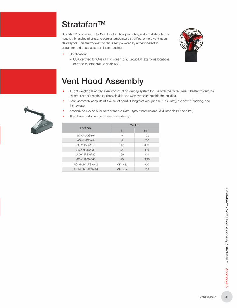
37Cata‑Dyne™
Stratafan™
/ Vent Ho
od
Assem
bly / S
tratafan™ – A
ccessories
Stratafan™Stratafan™ produces up to 150 cfm of air flow promoting uniform distribution of heat within enclosed areas, reducing temperature stratification and ventilation dead spots� This thermoelectric fan is self powered by a thermoelectric generator and has a cast aluminum housing�
• Certifications
– CSA certified for Class I, Divisions 1 & 2, Group D Hazardous locations;
certified to temperature code T3C
Vent Hood Assembly• A light weight galvanized steel construction venting system for use with the Cata‑Dyne™ heater to vent the
by‑products of reaction (carbon dioxide and water vapour) outside the building
• Each assembly consists of 1 exhaust hood, 1 length of vent pipe 30" (762 mm), 1 elbow, 1 flashing, and
1 snowcap
• Assemblies available for both standard Cata‑Dyne™ heaters and MKII models (12" and 24")
• The above parts can be ordered individually
Part No.Width
in mm
AC‑VHASSY‑6 6 152
AC‑VHASSY‑8 8 203
AC‑VHASSY‑12 12 305
AC‑VHASSY‑24 24 610
AC‑VHASSY‑36 36 914
AC‑VHASSY‑48 48 1219
AC‑MKIIVHASSY‑12 MKII ‑ 12 305
AC‑MKIIVHASSY‑24 MKII ‑ 24 610

38 Cata‑Dyne™
Acc
esso
ries
– W
all M
ount
ing
Bra
cket
s
Wall Mounting Brackets• Optional stainless steel or mild steel constructed mounting brackets and hardware
• Standard wall brackets can mount Cata‑Dyne™ heaters 7�5" (190 mm) away from the wall to allow
access to the back of the heater
• MKII model bracket sizes are half the length of our standard wall mounting brackets allowing the
heater to be installed closer to the wall
• Brackets for large units over 8,000 Btu/hr (2�3 kW) are manufactured from heavy gauge mild steel flat bar
Part No.Heater Size
(in)
AC‑WBRK‑08 8x8
AC‑WBRK‑06 6x24
AC‑WBRK‑12 12x12
AC‑WBRK‑12 12x24
AC‑WBRK‑12 12x36
AC‑WBRK‑12 12x48
AC‑WBRK‑12 12x60
AC‑WBRK‑12 12x72
AC‑WBRK‑1824 18x24
AC‑WBRK‑1836 18x36
AC‑WBRK‑1848 18x48
AC‑WBRK‑1860 18x60
AC‑WBRK‑1872 18x72
AC‑WBRK‑2424 24x24
AC‑WBRK‑2430 24x30
AC‑WBRK‑2436 24x36
AC‑WBRK‑2448 24x48
AC‑WBRK‑2460 24x60
AC‑WBRK‑2472 24x72
45˚ Wall Mount Brackets
• Specialized mounting angle brackets used to simplify the installation of all 18" and 24" Cata‑Dyne™ heaters
• Manufactured from mild rolled steel with a zinc plated finish
Part No. Description ‑ Mounting Angle Bracket
AC‑WBRK‑1824‑45 18 x 24, Short Side
AC‑WBRK‑1836‑45 18 x 36, Long Side
AC‑WBRK‑1848‑45 18 x 48, Long Side
AC‑WBRK‑1860‑45 18 x 60, Long Side
AC‑WBRK‑872‑45 18 x 72, Long Side
AC‑WBRK‑2424‑45 24 x 24, Long Side
AC‑WBRK‑2436‑45 24 x 36, Long Side
AC‑WBRK‑2448‑45 24 x 48, Long Side
AC‑WBRK‑2460‑45 24 x 60, Long Side
AC‑WBRK‑2472‑45 24 x 72, Long Side

39Cata‑Dyne™
Floo
r Stand
s – Accesso
ries
Floor Stands• 12‑gauge galvanized steel construction and hardware
• Allows the heater to be placed closer to an object than the wall mounting system
• Floor stands are adjustable, allowing the unit to be moved to the optimum height for the required
heating application
Part No. Description
AC‑FSS‑8 8x8
AC‑FSS‑24 6x24
AC‑FSS‑12 12x12
AC‑FSS‑24 12x24
AC‑FSL
12x36
12x48
12x60
12x72
18x24
18x36
18x48
18x60
18x72
24x24
24x30
24x36
24x48
24x60
24x72

40 Cata‑Dyne™
Co
nver
sio
n D
ata
/ In
vers
e S
qua
re L
aw
1000 Btu/hr = 0�2929 kW or 292�9 W 1000 Btu = 1�054 MJ 3,412 Btu/hr = 1�0 kW
1 psi = 27�91 inches w�c� 1 psi = 6�895 kPa 1 inch w�c� = 0�247 kPa
1 standard cubic foot NAT Gas = 1000 Btu 1 standard cubic foot LPG = 2,500 Btu
1 standard cubic meter NAT Gas = 37 MJ 1 standard cubic meter LPG = 88 MJ
1 pound LPG = 21,560 Btu 1 kilogram LPG = 50�1 MJ
3�5 inches w�c� = 8�7 mbar = 0�87 kPa = 0�126 psi 4 inches w�c� = 9�9 mbar = 0�99 kPa = 0�144 psi 7 inches w�c� = 17�3 mbar = 1�73 kPa = 0�251 psi 11 inches w�c� = 27�2 mbar = 2�72 kPa = 0�394 psi
°C = (°F ‑ 32) x (5/9) °F = (9/5 x °C) + 32
1 ft = 0�3048 m 1 ft² = 0�09290304 m² 1 ft³ = 0�02831685 m³ 1 in = 2�54 cm 1 in² = 6�4516 cm² 1 in³ = 16�38706 cm³ 1 psi = 27�91 in� w�c� 1 in� w�c� = 0�247 kPa
1 cfm = 0�028312 m³/hr
Conversion Data
Intensity of infrared energy is inversely proportional to the square of the
distance from the source of energy�
For infrared energy, this translates to: I=P/4πr²
Where: I = intensity of infrared at the heated object
P = total power emitted from IR source
r = the distance from the source to the heated object
Inverse Square Law

41Cata‑Dyne™
NOTES

42 Cata‑Dyne™
NOTES

43Cata‑Dyne™
NOTES

Edmonton, AB Head Offi ce1‑800‑661‑8529
780‑466‑3178
F 780‑468‑5904
Oakville, ON1‑800‑410‑3131
905‑829‑4422
F 905‑829‑4430
Orillia, ON1‑877‑325‑3473
(705) 325‑3473
F 705‑325‑2106
Houston, TX1‑855‑219‑2101
(281) 506‑2310
F 281‑506‑2316
Denver, CO1‑855‑244‑3128
(303) 979‑7339
F 303‑979‑7350
Printed in Canada M30410‑001�Rev�3�01
Visit www�thermon�com for detailed product information�
Edmonton, AB 1‑800‑661‑8529
780‑466‑3178
F 780‑468‑5904
Oakville, ON1‑800‑410‑3131
905‑829‑4422
F 905‑829‑4430
Orillia, ON1‑877‑325‑3473
705‑325‑3473
F 705‑325‑2106
Houston, TX1‑855‑219‑2101
281‑506‑2310
F 281‑506‑2316
Denver, CO1‑855‑244‑3128
303‑979‑7339
F 303‑979‑7350
As a leader in advanced heating and fi ltration solutions with facilities across North America, Thermon Heating Systems
manufactures six of the top brands in industrial heating in addition to a comprehensive line of engineered industrial
fi ltration products includinge
Cata‑Dyne™ is the industry standard in infrared gas catalytic heaters,
enclosures, pipeline systems and accessories� Customers across a wide range
of industries rely on Cata‑Dyne™ to supply them with safe, reliable, effi cient and
versatile infrared catalytic heating equipment for a variety of applications in both
hazardous and non‑hazardous environments�
Ruffneck™ is renowned for its rugged, reliable and versatile heavy‑duty explosion‑proof
heaters, heating systems and heating accessories� Ruffneck™ has a long and proud
history of supplying quality heating products for the harshest industrial environments to a
worldwide customer base for over 30 years� Ruffneck™ is well‑known in the industry for
its “ship the heat in a week” policy, where 95% of all standard orders are shipped within
one week of order placement�
Caloritech™ electric heaters, heating elements and heating accessories are well‑known
in the industry for their quality, reliability, performance and versatility� In addition to
standard “off the shelf” industrial heaters and heating systems com ponents, Caloritech™
also offers engineered heating solutions custom designed, manufactured and tested
to satisfy customer specifi cations� No matter what your application or environment,
Caloritech™ has a solution to fi t your heating needs�
3L Filters™ has satisfi ed the most demanding industrial fi ltration requirements
for over 40 years� A broad range of standard and custom products includes
liquid fi lters, strainers, separators, pressure vessels, and engineered products
and systems� 3L Filters™ has special expertise for nuclear, petrochemical, water
treatment and environmental applications�
Fastrax® has manufactured railroad track and switch heating since 1995� Fastrax®
engineers complete heating packages for the rail industry� Fastrax® track and
switch heaters are designed to provide the most effi cient heat transfer on rail
equipment and components for the coldest environments� In addition to heaters,
Fastrax® manufactures fully automatic energy saving controls to complete the rail
heating system�
Norseman™ is the most technologically advanced line of explosion‑proof electric
air heaters and heating accessories, including both forced air heaters and natural
convection heaters, as well as unit heaters, panel heaters and thermostats� Norseman™
offers innovative, low maintenance solutions for a wide range of applications in a variety
of industrial and commercial environments� Custom engineered heaters or heating
systems are available for specialized applications�
Printed in Canada Part No�M20406‑001 and Rev�9�09�


![EX Explosion Proof System[1]](https://static.cupdf.com/doc/110x72/577cc39e1a28aba711969580/ex-explosion-proof-system1.jpg)