17.1BLN-10201 • 520L0588 • Rev. CA • Nov 2007
Cartridge Valves Technical InformationDirectional Valves DCV 03
Dir
ecti
on
al c
on
tro
l val
ves
DC
V0
3
Introduction Index
• 3 position, 4-way, and 2 position, 4-way directional valves
• Cylindrical operating solenoids with separate operating coils – connector can be rotated 90°
• 4-land spool – reduced functional dependence on fluid viscosity
• Push button manual override
• Installation dimensions to ISO 4401-03-02-0-94 and DIN 24340-A6
DCV 03 directional control valves consist of: housing (1), control spool (5), with two centering springs (4), and cylindrical operating solenoids (2, 3).
The three-position directional valves have two solenoids and two springs. Two-position directional valves have either one solenoid and one return spring or two solenoids and a detent assembly.
The operating solenoids are DC. For AC supply the solenoids are provided with a rectifier, which is integrated directly into the connectors.
The plug connectors (6, 7) can be rotated 90°. By loosening the nut (8), the solenoids can be rotated 360°. This enables the solenoids to be replaced without opening the valves.
In the case of solenoid malfunction or power failure, the spool can be actuated by manual override (9), provided the pressure in T-port does not exceed 25 bar [360 psi].
The valve housing (1) is phosphate coated. The operating solenoids (2, 3) are zinc coated.
OVERVIEW � � � �
� � � �
� � � �
���������
FEATURES

17.2 BLN-10201 • 520L0588 • Rev. CA • Nov 2007 17.3BLN-10201 • 520L0588 • Rev. CA • Nov 2007
Cartridge Valves Technical InformationDirectional Valves DCV 03
Directio
nal co
ntro
l valves D
CV
03
Introduction Index
Cartridge Valves Technical InformationDirectional Valves DCV 03
Dir
ecti
on
al c
on
tro
l val
ves
DC
V0
3
Introduction Index
Specifications
Nominal size mm [in.] 6.0 [0.24]
Maximum flow l/min
[US gal/min]
See p-Q characteristics below
Max. operating pressure bar [psi] 320 [4640]
Max. back pressure (port T) bar [psi] 160 [2320]
Pressure drop bar [psi] see ∆ p-Q characteristics, page 4
Weight – with 1 solenoid
with 2 solenoids
Kg [lb] 1.6 [3.52]
2.2 [4.84]
TECHNICAL DATA
Operating limits for maximum hydraulic power transferred by the directional valve. Measured at viscosity = 35 mm2/sec (cSt) [166 SUS] and temperature = 40°C [104°F].
p - Q Characteristics
Spool Curve
Z11 1
C11 7
H11 4
P11 1
Y11 3
B11 9
Y41 7
Z21 1
C41 6
R11 4
R21 5
A51 6
P51 1
Y51 3
C51 7
Z51 1
Z71 8
Z81 8
Z91 8
R31 6
H51 8
F51 8
X11 4
K11 8
N11 8
J15 1
J75 10
L21 6
F11 6
CHARACTERISTICS
����
����
����
����
����
������
��������
������
������
��������
��
��
���
���
���
�� �� �� �� �� �� ���
�����
����������
������
� � � �� �� ����
���
����
����
����
����
����
���������

17.2 BLN-10201 • 520L0588 • Rev. CA • Nov 2007 17.3BLN-10201 • 520L0588 • Rev. CA • Nov 2007
Cartridge Valves Technical InformationDirectional Valves DCV 03
Directio
nal co
ntro
l valves D
CV
03
Introduction Index
Cartridge Valves Technical InformationDirectional Valves DCV 03
Dir
ecti
on
al c
on
tro
l val
ves
DC
V0
3
Introduction Index
CHARACTERISTICS (continued)
Spool P-A P-B A-T B-T P-T
Z11 2 2 3 3
C11 5 5 5 6 3
H11 2 2 2 2 3
P11 1 1 3 3
Y11 2 2 2 2
L21 2 2 3 3
B11 2 2 3 3
Y41 3 3 3 3
Z21 2 3
C41 4 4 5
F11 1 2 3 3
R11 2 2 3 3
R21 2 2 3 3
A51 2 2
P51 1 3
Y51 2 2
C51 2 3 4
Z51 2 3
Z71 3 3
Z81 3 3
Z91 3 3 3
R31 2 3
H51 2 3
F51 2 3
X11 2 2 3 3
K11 2 3
N11
J15 2 2 3 3
J75 2 2
∆p-Q Characteristics
Measured at viscosity = 35 mm2/sec (cSt) [166 SUS] and temperature = 40°C [104°F]
�
�
��
��
��
��
��
�� �� �� �� �� �� ���
���������������
������
� � � �� �� ����
��
��
���
���
���
���
���
���
���
�
��
���
���������
����
����
�����
����
17.4 BLN-10201 • 520L0588 • Rev. CA • Nov 2007 17.5BLN-10201 • 520L0588 • Rev. CA • Nov 2007
Cartridge Valves Technical InformationDirectional Valves DCV 03
Directio
nal co
ntro
l valves D
CV
03
Introduction Index
Cartridge Valves Technical InformationDirectional Valves DCV 03
Dir
ecti
on
al c
on
tro
l val
ves
DC
V0
3
Introduction Index
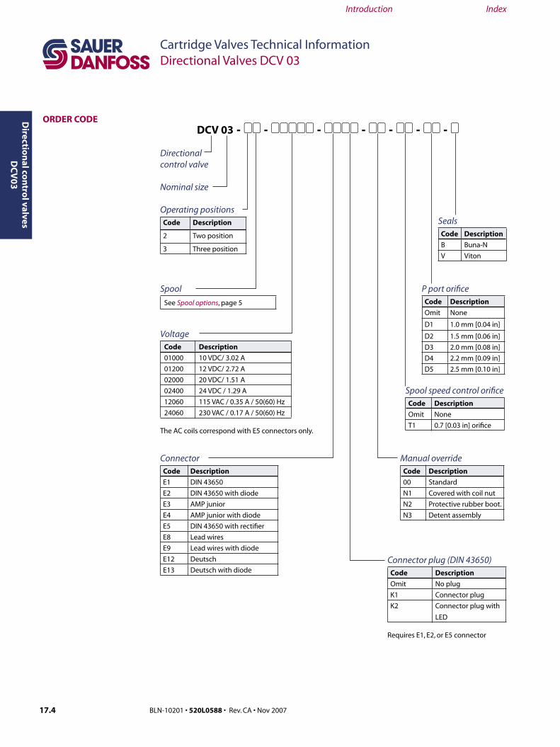
ORDER CODE
Operating positionsCode Description
2 Two position
3 Three position
Spool
See Spool options, page 5
SealsCode Description
B Buna-N
V Viton
P port orificeCode Description
Omit None
D1 1.0 mm [0.04 in]
D2 1.5 mm [0.06 in]
D3 2.0 mm [0.08 in]
D4 2.2 mm [0.09 in]
D5 2.5 mm [0.10 in]
Manual overrideCode Description
00 Standard
N1 Covered with coil nut
N2 Protective rubber boot.
N3 Detent assembly
VoltageCode Description
01000 10 VDC/ 3.02 A
01200 12 VDC/ 2.72 A
02000 20 VDC/ 1.51 A
02400 24 VDC / 1.29 A
12060 115 VAC / 0.35 A / 50(60) Hz
24060 230 VAC / 0.17 A / 50(60) Hz
The AC coils correspond with E5 connectors only.
Directional control valve
Nominal size
Connector plug (DIN 43650)Code Description
Omit No plug
K1 Connector plug
K2 Connector plug with
LED
Requires E1, E2, or E5 connector
ConnectorCode Description
E1 DIN 43650
E2 DIN 43650 with diode
E3 AMP junior
E4 AMP junior with diode
E5 DIN 43650 with rectifier
E8 Lead wires
E9 Lead wires with diode
E12 Deutsch
E13 Deutsch with diode
DCV 03 - 11 - 11111 - 1111 - 11 - 11 - 11 - 1
Spool speed control orificeCode Description
Omit None
T1 0.7 [0.03 in] orifice

17.4 BLN-10201 • 520L0588 • Rev. CA • Nov 2007 17.5BLN-10201 • 520L0588 • Rev. CA • Nov 2007
Cartridge Valves Technical InformationDirectional Valves DCV 03
Directio
nal co
ntro
l valves D
CV
03
Introduction Index
Cartridge Valves Technical InformationDirectional Valves DCV 03
Dir
ecti
on
al c
on
tro
l val
ves
DC
V0
3
Introduction Index
Functional SymbolsCode Symbol Transition Code Symbol Transition
Z11* Z51*
C11* Z71
H11* Z81
P11 Z91
Y11* R31
L21 H51
B11 F51
Y41 Z11*
Z21 X11
C41 C11
F11 H11
R11* K11
R21* N11
A51* F11
P51 J15*
Y51* J75
C51*
* standard spool options.
SPOOL OPTIONS
17.6 BLN-10201 • 520L0588 • Rev. CA • Nov 2007 17.7BLN-10201 • 520L0588 • Rev. CA • Nov 2007
Cartridge Valves Technical InformationDirectional Valves DCV 03
Directio
nal co
ntro
l valves D
CV
03
Introduction Index
Cartridge Valves Technical InformationDirectional Valves DCV 03
Dir
ecti
on
al c
on
tro
l val
ves
DC
V0
3
Introduction Index
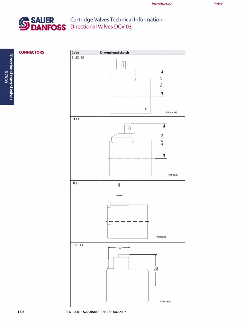
Code Dimensional sketch
E1, E2, E5
E3, E4
E8, E9
E12, E13
CONNECTORS
�
����
�����
��
���������
���������
�
����
����
����
���������
����������
����������
���������

17.6 BLN-10201 • 520L0588 • Rev. CA • Nov 2007 17.7BLN-10201 • 520L0588 • Rev. CA • Nov 2007
Cartridge Valves Technical InformationDirectional Valves DCV 03
Directio
nal co
ntro
l valves D
CV
03
Introduction Index
Cartridge Valves Technical InformationDirectional Valves DCV 03
Dir
ecti
on
al c
on
tro
l val
ves
DC
V0
3
Introduction Index
Code Type ModelMax. input
voltage
K1
Plug B (black) without rectifier250 VDC
230 VAC
Plug A (grey) without rectifier250 VDC
230 VAC
K2
Plug B (black)without rectifier and
with LED
30 VDC
230 VAC
Plug A (grey)without rectifier and
with LED
30 VDC
230 VAC
���������
Standard Covered with coil nut
code 00mm[in]
Code N1mm[in]
Manual overide covered by coil nut
MANUAL OVERIDE OPTIONS
�
�����������
���������
�����������
�
���������
CONNECTOROPTIONS DIN 43650
Rubber boot Detent assembly
Code N2mm [in]
Manual override protected by rubber boot
Code N3mm [in]
Manual overide with detent
�����������
�
���������
�����������
�����������
�
���������

17.8 BLN-10201 • 520L0588 • Rev. CA • Nov 2007 17.9BLN-10201 • 520L0588 • Rev. CA • Nov 2007
Cartridge Valves Technical InformationDirectional Valves DCV 03
Directio
nal co
ntro
l valves D
CV
03
Introduction Index
Cartridge Valves Technical InformationDirectional Valves DCV 03
Dir
ecti
on
al c
on
tro
l val
ves
DC
V0
3
Introduction Index
Code Sketch Description
T1 This directional valve provides
cushioned control spool shifting by
means of orifice situated in the solenoid
armature.
To ensure proper function, air bleeding
required. To bleed :
1. Remove Boot (2)
2. Open Plug (1)
3. Tighten plug after air is removed
4. Replace boot
Code D mm [in] Description
None None The orifice installed in the
P port restricts the input
flow.D1 1.0 [0.04]
D2 1.5 [0.06]
D3 2.0 [0.08]
D4 2.2 [0.09]
D5 2.5 [0.10]
�
� ������������
���������
P-PORT ORIFICE OPTIONS
SPOOL SPEED CONTROL ORIFICE
�
�
��
���������
17.8 BLN-10201 • 520L0588 • Rev. CA • Nov 2007 17.9BLN-10201 • 520L0588 • Rev. CA • Nov 2007
Cartridge Valves Technical InformationDirectional Valves DCV 03
Directio
nal co
ntro
l valves D
CV
03
Introduction Index
Cartridge Valves Technical InformationDirectional Valves DCV 03
Dir
ecti
on
al c
on
tro
l val
ves
DC
V0
3
Introduction Index
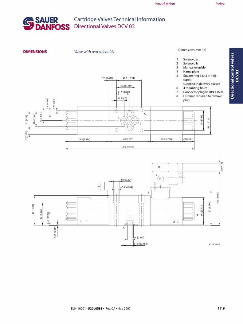
Valve with two solenoids
1 Solenoid a 2 Solenoid b 3 Manual override 4 Name plate 5 Square ring 12.42 ∞ 1.68 (5pcs) supplied in delivery packet 6 4 mounting holes 7 Connector plug to DIN 43650 8 Distance required to remove plug
DIMENSIONS Dimensions: mm [in]
������������ ������������
������������
������������
����������
����
�����
��
���� �
����
�
��������������������������������
�����������
������������
����
�����
��
����
����
���
����
�����
��
����
�����
��
�����
����
����
����
�
�����������
������������
�����
����
�
���
�����
���
���� �
����
�
���
�� ���
���
����������
�������������
����
�����
���
����
�����
���
�����
����
�
�����
����
�
� �
�
�
�
�
�
�
���������

17.10 BLN-10201 • 520L0588 • Rev. CA • Nov 2007 17.11BLN-10201 • 520L0588 • Rev. CA • Nov 2007
Cartridge Valves Technical InformationDirectional Valves DCV 03
Directio
nal co
ntro
l valves D
CV
03
Introduction Index
Cartridge Valves Technical InformationDirectional Valves DCV 03
Dir
ecti
on
al c
on
tro
l val
ves
DC
V0
3
Introduction Index
DIMENSIONS (continued)
Valve with one solenoid - side a
Functional symbols R11, R21, A51, P51, Y51, C51, Z51, H51, B51, M21,X25, J15, J75
Valve with one solenoid – size bFunctional symbols X11, C11, H11
������
� �
���������
Required surface finish of interface
Dimensions: mm [in]
��������������
������������������
���������

17.10 BLN-10201 • 520L0588 • Rev. CA • Nov 2007 17.11BLN-10201 • 520L0588 • Rev. CA • Nov 2007
Cartridge Valves Technical InformationDirectional Valves DCV 03
Directio
nal co
ntro
l valves D
CV
03
Introduction Index
Cartridge Valves Technical InformationDirectional Valves DCV 03
Dir
ecti
on
al c
on
tro
l val
ves
DC
V0
3
Introduction Index
1. Solenoid coil2. Nut + sealing ring3. Connector plug4. Orifice5. Seals6. Mounting bolts
Solenoid
Voltage
Connector
E1 E2 E3 E4 E5 E8 E9 E12 E13
Ordering number
01000 158-8048 158-8050 Consult factory Consult factory Consult factory 158-8082 Consult factory 158-8054 Consult factory
01200 158-8004 158-8051 Consult factory Consult factory Consult factory 158-8083 Consult factory 158-8055 11030059
02000 158-8049 158-8052 Consult factory Consult factory Consult factory 158-8084 Consult factory Consult factory Consult factory
02400 158-8009 158-8053 Consult factory Consult factory Consult factory 158-8085 Consult factory 158-8057 Consult factory
11550 Consult factory Consult factory
Not available
Consult factory
Not available23050 Consult factory Consult factory Consult factory
REPLACEMENT PARTS
�
�
��
�
�
�
���������

17.12 BLN-10201 • 520L0588 • Rev. CA • Nov 2007
Cartridge Valves Technical InformationDirectional Valves DCV 03
Directio
nal co
ntro
l valves D
CV
03
Introduction Index
Solenoid nutM/O code Type of nut Ordering number
No Code Standard nut 158-8005
N1 Closing nut Consult factory
N2 Nut with rubber cap Consult factory
N3 Nut with detent assembly Consult factory
Connector (DIN 43650)Code Model Connector plug A
gray
Connector plug B
black
Ordering number
K1 No rectifier or
LED
158-8076 088010080
K2 with LED Consult factory Consult factory
OrificeCode Diameter mm [in] Ordering number
D1 1.0 [0.039] 158-8013
D2 1.5 [0.059] 158-8003
D3 2.0 [0.078] 158-8079
D4 2.2 [0.87] 158-8080
D5 2.5 [0.098] 158-8081
Seal kit
Type Ordering number
Buna-N 158-8007
Viton 158-8062
Mounting bolts – set
Type Ordering number
M5 x 45 bolts 158-8026
No 10-24 bolts 158-8064
REPLACEMENT PARTS(continued)