APRIL 10, 1980
COLOR MONITORS GLAMORIZE BUSINESS COMPUTERS/153
Chips synthesize true-to-life speech/ 113
ECO embraces materials, processing/119
Elec ronucs.
FOUR DOLLARS A tMcGRAW-HILL PUBLICATION III
Calculator controls programmable precision multimeter

p•M•11...1•111...
Find Your Trimmer Application Here...
Model 7102B
10 10 R1
CW CW 9 9
Model 7103C Model 71040 Model 7105A Model 7125B Model 7106B Model 7126 s Model "7- 07
And incorporate trimmers and re in a single MFTpackage!
All trimmer applications require a fixed resistor or resistors to either divide a voltage or limit a current. The revolutionary MFT trimmer/resistor package, pioneered by Bourns, combines cermet trimmers and fixed resistors into a single JEDEC DIP package. More than just a DIP trimmer, the MFT trimmer/ resistor contains the total trimmer circuit in one DIP package.
Nine different MFT trimmer/resistor models, available in a broad range of resistance values, provide both multi-trimmer versions and various combinations of fixed resistors and trimmers that will satisfy almost any trimmer application.
Increased Reliability — Fewer PC board connections and pre-tested circuitry provide increased reliability. MFT trimmers/resistors are manufactured simultaneously on a common substrate, resulting in better temperature tracking than discrete components. Standard tempco tracking is 5Oppm/°C at —55°C to +125°C.
Saves Time, Space and Money — Auto- or hand-insertion of one component instead of many; less components to purchase, stock and handle; simplified circuit design; and less PC board space required. A multitude of advantages means increased productivity and lower on-board cost.
Worldwide Availability — MFT trimmers/resistors are now available throughout the world from Boums authorized representatives, distributors and international marketing affiliates.
For new applications, or your next generation of design, join the growing number of engineers who are specifying MFT trimmers/resistors. Call or write today for your MFT catalog. Or, see the EEM directory (Volume 2, pages 3791— 3801).
TRIMPOT PRODUCTS DIVISION, BOURNS, INC., 1200 Columbia Avenue, Riverside, CA 92507. Phone: 714 781-5204. TWX: 910 332-1252.
European Headquarters: Boums AG, Zugerstrasse 74 6340 Baar, Switzerland. Phone: 042 33 33 33. Telex: 78722.
SALES OFFICES Ariz. 602 257-9015 • Calif. 213 582-6391,408 377-6740 • Colo. 303 751-2600 • Fla. 305 771-6501 • Ga. 404 393-9E130 • III. 312 255-1903 • Ind. 317 844-8462 • Md. 301247-0400 • Mass. 617 237-6730 • Mien. 313 882 1717 • Minn 612 835-2252 • Mo. 816 358-8100 • 14.). 699 933-2600 • N.M. 505 296-0749 • N.Y. 516 271-3500. 607 272 2187 • Ohio 216 659-3131 • Tea. 214 2M-559-1 • Wash. 206 2E5- 1300 • Canada 514 487-3434. 416 638-5511.
For Immediate Application—Circle 120 For Future Application—Circle 220

A universal counter for 975. The smart money's on HP'S new 5314A Universal Counter because it does so much for so little. Now, in one low-cost counter, you can measure frequency up to 100 MHz, period down to 400 nanoseconds with 100 picosecond resolution, and time interval with 100 ns resolution. Add frequency ratio, ratio averaging, totalizing and a full complement of time interval measure-ment controls and you've got a package you'd expect to find at almost twice the 5314A's
$375 price. Options: internal battery and charger, $95; TCXO time base, $1.
Time interval measurement capabilities are truly outstanding at the 5314A's price. Instead of limited single channel controls, or none at all, the 5314A gives you both input trigger level and slope controls for two input channels. So now you can measure pulse widths or time between pulses with stop and start commands from either one or two input control lines.
HP's frequency counters also save you time and money. Using state-of-the-art components common to HM most sophisticated counters, the HP5380 frequency counter series offers high accuracy, high input sensitivity, input attenuators and direct counting for rapid, convenient frequency measurement and adjustments. 5381A 80 MHz, $295 • 5382A 225MHz, $395 • 5383A 520 MHz, $650.
To find out more about HP's low-.„, c6 cost laboratory grade counters and the
entire family of sophisticated and versatile HP counters call your nearest HP field office. Or write for the 5314A and 5380 series data sheets and electronic counter brochure to Hewlett Packard, 1507 Page Mill Road, Palo Alto, CA 94304.
Prices domestic U.S. A. only
HEWLETT PACKARD
HP: MAKING EXPERIENCE COUNT
02902A
Circle 1 on reader service card

•• '•
Available from stock. . .
HI?REL MIXpRS with a 3year guarantee.'
sr7.95 SRA-1 x
Five years ago, Mini-Circuits offered a two-year guarantee for its industry-standard SR1- hernjetically sealed
Double-Balanced Mixer. . . noW used worldwide for a variety of
se military and industrial applications.
The two-year guarantee was made possible bi rbfé.'use of.an accelerated-life screening test.for diodes • generally reserved only for space applications. -4;1, %fa*
• • . The HTRB-screened Schottky diodes are subjected to a one-volt negative bias at 150° for 168 hours, •‘ a stress designed to accelerate aging and force le time-related failures—thus screening out potentially unreliable diodes.
Mini-Circuits is proud to offer a three-year guarantee
for the SRA-1 achieved bV further stressing and tésting the assembled unit. Each completed SRA-1 experiences:
1. Burn-in for 96 hours at 100°C with 8 mA at 1 KHz. 2. Thermal shock. •
3. Gross and fine leak tests (per MIL-STD 202). And the three year guarantee SRA-1 is still only $7.95!
Of course, the additiooal testing adds to our cost, but our continuing commitment is to offer rferformance and reliability unmatched for off-the-shelf Double Balanced Mixers. So, for space or rugged industrial applications,
ensure highest system reliability by specifying
SRA-1 mixers, the only Doubled-Balanced Mixers with a thr_e?:yqar guarantee. . . from Mini-Circuits where low price goes hand in hand with unmatched quake
•
Model SRA-1 Freq. range (MHz) LO 0.5-500 RF 0.5-500 IF DC-500
Conversion losS (dB) Typ. Max. 1-250 MHz 5.5 7.0 0.5-500 MHz 6.5 8.5
Isolation (dB) Typ. Max. 0 5-5 MHz LO-RF 50 45
LO-IF 45 35 5-250 MHz LO-RF 45 30
LO-IF 40 25 250-500 MHz LO-RF 35 25
LO-IF 30 20
Min. Electronic Attenuation (20 mA) 3 dB Typ.
Signal, 1 dB Compression Level + 1 dBm
Impedance All Ports, 50 Ohms
LO Power + 7 dBm
1;;;;1 Mini-Circuits 2625 East 14th Street Brooklyn. New York 11235 (212) 769-0200
Domestic and International Telex 125460 International Telex 620156
71,
2 Circle 2 on reader service card Electronics/April 10, 1980

Electronics re)1 The International Magazine of Electronic Technology Vol. 53, No. 8 • April 10, 1980
105 Technical Articles
INSTRUMENTS
Calculatorlike controller teaches precision multimeter new steps, 105
SPEECH SYNTHESIS
Chip borrows human intonation, 113 ELECTRONIC COMPONENTS CONFERENCE
ECC menu adds processing, materials, 119
MICROCOMPUTERS
Managing memory to unloose the full power of microprocessors, 130
MICROCOMPUTERS
Special-function modules ride on computer board, 135
DESIGNER'S CASEBOOK: 126
ENGINEER'S NOTEBOOK: 142
37 Electronics Review DISPLAYS: Fluorescent graphics gains resolution, 37 COMPUTERS: Chips detect, correct errors, 38 SOLID STATE: IR sensor has uniform response, 39 PRODUCTION: CAD unit does more work for chip
designers, 40 BUSINESS: IC manufacturing equipment a growth market . . . , 40
. . . chip makers to shrug off recession, 42 CONSUMER: Second laser video disk player bows, 42 Canada promoting video information scheme, 44 SOLID STATE: ECL array shrinks to cut power loss, 44 NEWS BRIEFS: 46 COMMERCIAL: Meter-reading system may control home
alarms, 48 COMMUNICATIONS: GTE plans electronic mail, 52
63 Electronics International
FRANCE: Keyboard's contacts are normally closed, 67 JAPAN: VLSI Co-op Labs unveils last electron-beam system . . . , 67
EAST GERMANY: . . . as Zeiss shows similar unit, 68 BRITAIN: ICL unwraps new low-end mainframes, 70 Microprocessor system monitors boiler's efficiency, 72
81 Probing the News GOVERNMENT: Japanese make quality-control pitch, 81 LETTER FROM THE MIDWEST: Weather milder, prices
wilder, 85 COMPANIES: UTC's parts add up to $2.5 billion, 88
THE ECONOMY: Carter's program leaves 'em cold, 94
153 New Products
ROUNDUP: Color monitors blossom, 153 IN THE SPOTLIGHT: Nippon Electric enters U.S. fiber-
optics market, 160 Signal synthesizer sells for $995, 162 MICROCOMPUTERS: Development systems thrive, 164 COMMUNICATIONS: Harmonic distortion measured
automatically, quickly, 168
INSTRUMENTS: Scope processes waveform data, 174 COMPONENTS: Optical fiber has two windows, 176 PRODUCTION: System controls crystal thickness, 178 DATA ACQUISITION: A-d unit converts in 10 ns, 180 MATERIALS: 182
Departments Highlights, 4
Publisher's letter, 6 Readers' comments, 8 People, 14 Editorial, 24
Meetings, 26 Electronics newsletter, 33 Washington newsletter, 55 Washington commentary, 56 International newsletter, 63 Engineer's newsletter, 146 Products newsletter, 183
Services Employment opportunities, 184 Reprints available, 192
Reader service card, 193
Electronics/April 10, 1980 3

Electronics
EDITOR-IN-CHIEF: Samuel Weber
MANAGING EDITORS Technical: Raymond P. Capece,
Alfred Rosenblatt News: Gerald M. Walker International: Arthur Erikson
ASSISTANT MANAGING EDITORS: Howard Wolff, Margaret Eastman
SENIOR EDITOR: Ray Connolly
ART DIRECTOR: Fred Sklenar
ASSOCIATE EDITOR: Benjamin A. Mason
DEPARTMENT EDITORS Aerospace/Military: Ray Connolly Circuit Design: Vincent Biancomano Communications & Microwave: Harvey J. Hindin
Components: Roger Allan Computers & Peripherals: Anthony Durniak Industrial/Consumer: Gil Bassak Test, Measurement & Control: Richard W. Comerford
New Products: Ana Bishop Packaging & Production: Jerry Lyman Solid State: John G. Posa
CHIEF COPY EDITOR Margaret Eastman
COPY EDITORS: Mike Robinson, Charlotte Wiggers, Jeremy Young
ART: Charles D. Ciatto, Associate Director Paula Piazza, Assistant Director
EDITORIAL SECRETARIES: Maryann Tusa, Penny Reitman
EDITORIAL ASSISTANT: Marilyn B. Steinberg
REGIONAL EDITORS New York: Pamela Hamilton (212) 997-2306 Boston: James B. Brinton, Linda Lowe (617) 262-1160
Chicago: Larry Marion (312) 751-3805 Dallas: Wesley R. Iversen (214) 742-1747 Los Angeles: Larry Waller (213) 487-1160 Palo Alto: Bruce LeBoss, Manager
Martin Marshall, Computers & Instruments (415) 968-2712
Washington: Ray Connolly (202) 624-7592 Frankfurt: John Gosch 72-5566 London: Kevin Smith 493-1451 Paris: Arthur Erikson, Kenneth Dreyfack 720-20-70
Tokyo:Charles Cohen 581-9816
McGRAW-HILL WORLD NEWS Editor: Michael Johnson Brussels: James Smith Milan: Jett Ryser Moscow: Peter Hann Stockholm: Robert Skole Tokyo: Robert Neff
PUBLISHER: Paul W. Reiss
GENERAL MANAGER, DIRECT MARKETING OPERATIONS: Horace T. Howland
CIRCULATION MANAGER: Herbert A. Hunter
RESEARCH MANAGER: Margery D. Sholes
MARKETING ADMINISTRATION MANAGER: Frances M. Vallone
BOOKS & SPECIAL PROJECTS MANAGER: Janet Eyler
Highlights Cover: Calculatorlike keyboard programs precision multimeter, 105
Microcomputers controlling and simplifying multimeter operation have until now been inaccessable to the user: programmed to do specific jobs, they were not set up to learn new ones. But Fluke's new programmable 51/2 -digit multimeter enables the engineer to mold the processing power as needs dictate. Programs for a wide range of measurement tasks can be entered via an optional hand-held keyboard and stored in detachable modules.
Cover illustration is by Ron Chironna.
Japanese IC industry leaders make overtures in Washington, 81
When Japanese electronics manufacturers had trouble with product quality in the 1950s, they hired American consultants to help them straighten out the problem. Now, in the name of easing tensions in international trade, the Japanese come to Washington offering to show U. S. integrated-circuit makers how to improve the quality of their parts.
Speech-synthesis chip mimics individual human voices, 113
Not all speaking electronic gadgets made with National Semiconductor's speech synthesizer will sound the same—they can be given distinguishable, natural-sounding voices. To do this, waveforms of a given human voice are digitized; the data is then compressed and stored in semiconductor memory.
Mapping scheme expands 16-bit processor's memory space, 130
Since the addressing capabilities of microprocessors are approaching those of some mainframe computers, it's not surprising that sophisticated memory organization akin to that of mainframes and minicomputers is turning up in microcomputer systems. A Z8000-based microcomputer board incorporates a mapping scheme that both adds to the logical memory space and eases its management.
Small option cards are just right for board-level computers, 135
If a single-board computer's application demands extra math-processing power or more input/output ports, for instance, the extra circuitry may not justify another board of the same size. Intel Corp. has worked out a standard bus for attaching small expansion cards to a new family of single-board computers so that users can get what they need without waste.
. . . and in the next issue
A family of 16- going on 32-bit microprocessors made with high-performance n-channel mos . . . factors bearing on alpha-particle—induced soft errors in random-access memories . . . coverage of Elec-tro/80 . . . estimating losses in a butt joint between an optical fiber and a light-emitting diode . . . a floating-point math-processing chip.
April to. 1980 Volume 53. Number 8
Electronics (ISSN 0013-5070). Published every other Thursday with an additional issue this April by McGraw•Hoil, Inc. Founder, James H. McGraw 1860.1948. Publication office 1221 Avenue of the Americas. N Y.. N Y. 10020. Second class postage paid al New York. N.Y and additional mailing offices.
Executive. editorial, circulation and advertising addresses: Electronics, McGraw-Hill Building, 1221 Avenue of the Americas, New York, KY. 10020. Telephone (212) 997• 1221 Teletype 12.7960 TWO 710.581-4879 Cable address MCGRAWHIL LNEWYOR K.
Subscriptions limited to professional persons with active responsibility in electronics technology No subscriptions accepted without complete identification of subscriber name, title or job lunctioffi company or orga-nization, and product manufactured or services performed Based on information supplied, the publisher reserves the right to reject non. qualified requests Subscription rates. in the United States and posses-sions $18 one year, $31 Iwo years. $46 three years. company addressed and company libraries $23 one year, $41 two years. $58 three years: APO/FPO addressed $35 one year only; Canada and Mexico $19 one year, $32 two years. $47 three years: Europe $50 one year. $85 two years, 5115 three years: Japan. Israel and Brazil $70 one year. $115 two years, $165 three years. Australia and New Zealand $95 one year, $170 two years. $240 three years, including air height; all other countries $50 one year. $85 Iwo years. $125 three years Limited quota ol subscriptions available at higher-than-basic rate tor persons allied to held served. Check with publisher for these rates Single copies $460; special Anni-versary issue $960 each Please allow four to eight weeks tor shipment.
Officers of McGraw-Hill Publications Company Paul F. McPherson. President; Executive Vice Presidents. James E Boddorl, Gene W Solo. son. Group Vice President- Daniel A. McMillan; Senior Vice President-Editorial Ralph R Schulz; Vice Presidents: Kemp Anderson, Business
101.112 copies of this issue printed
SySterns Development; Stephen C. Croft. Manufacturing. Robert 13 Doll. Circulation; James E. Hackett, Controller; William H. Hammond, Commu-nications; Eric B Herr. Planning and and Development; John W. Patten. Sales; Edward E. Schirmer, International.
Officers of the Corporation Harold W. McGraw, Jr.. President, Chief Executive Officer. and Chairman ol the Board; Robert N. Landes, Senior Vice President and Secretary. Ralph J. Webb. Treasurer.
Title registered in U S Patent Office: Copyrighte 1980 by McGraw-Hill. Inc. All rights reserved. The contents ol this publication may not be reproduced in whole or in part without the consent of copyright owner. Where necessary, permission is granted by the copyright owner for
libraries and others registered with the Copyright Clearance Center (CCC). P.O Box 8891. Boston. MA 02114. to photocopy any article herein tor the base lee ol $0.50 per copy of the article plus $0.25 per page Payment should be sent directly to the CCC Copying done for other than personal or internal reference use without the express permis. sion of McGraw.Hill is prohibited. Requests for special permission or bulk orders should be addressed to the publisher ISSN 0013-5070/80$0.50+.25.
Subscribers: The publisher, upon written request to our New York office from any subscriber, agrees to refund that part of the subscription price applying to copies not yet mailed. Please send change.of -address notices or complaints to Fulfillment Manager; subscription orders to Circulation Manager. Electronics, at address below. Change-of-address notices should provide old as well as new address, including zip codes Attach address label from recent issue Allow one month for change lo become effective Subscriber Service. call (609) 448-8110. 9 a. m. to 4 p m. EST. Postmaster: Please send form 3579 lo Fulfillment Manager. Electron-
ics. P.O. Box 430, Hightstown. NJ 08520.
4 Electronics/April 10, 1980

switching KEPCCWTOK power
1 supplies
recognized 87 RECOGNIZED SWITCHERS FROM 30 TO 300 WATTS
HEAT SINK (OPTIONAL FINS AVAILABLE)
METAL CASE SWITCHING TRANSISTOR
eq.
DRUM CORE OUTPUT CHOKE
STACKED LOW ESL OUTPUT CAPACITORS /
CURRENT LIMIT ADJUSTMENT
LISTED PRINTED CIRCUIT BOAR .00.e COATED FOR MOISTURE AND FUNGUS RESISTANCE
KEPCD®
Recognized by the Underwriters Laboratory for use in electronic data processing equipment, graphic arts equipment, office appliances and business machines.
The UL investigatioi has demonstrated that the beauty of these fina power supplies is not just skin deep. They've passed flammability and temp-erature testing, as well as an input current and leakage-to-ground test. After being subjected to temperature and humidity conditioning, they handily passed UL's dielectric withstand testing.
If you want a tough, proven d-c power supply in your equipment, choose a Kepco/TDK switcher that's been wrung cut for you by UL.
OUTPUT VOLTAGE ADJUSTMENT
For complete specifications write Dept. CSF-14
TRANSFORMERS COATED COPPER WIRE ON TDK TYPE H7C1 FERRITE CORE
Nise
ENCAPSULATED INPUT BRIDGE RECTIFIER
BIFILAR WOUND INPUT EMI FILTER
LISTED INPUT-OUTPUT BARRIER STRIP
INTERIOR VIEW OF THE SIZE "S" (30W)
HIGH EFFICIENCY SWITCHER The power supply is normally enclosed in a one piece venti-lated aluminum housing for EMI shielding (meets VDE 0875/7.71 and VDE 0871/6.78 for radiated emissions).
KEPCO, INC. • 131-38 SANFORD AVENUE • FLUSHING, N.Y. 11352 U.S.A. • (212) 461-7000 • TWX #710-582-2631 • Cable: KEPCOPOWER NEWYORK
Circle 5 on reader service card

Now... the only RF power
amplifier you may ever need.
The new ENI 550L delivers 50W, 1.5-400 MHz.
1 This single unit is so incredibly versatile it can replace several you may be using now And you may never need another. It's an
extremely broadband high power, solid state, Class A linear amplifier. It's rated at 50W from 15-400 MHz But it can provide 100 Watts from 1.5-220 MHz. All you need with the 550L is any standard signal or sweep generator and you've got the
ultimate in linear power for such applications as RFI/EMI testing,
NMR, RF Transmission, ultrasonics and more
And, like all ENI power ampli-fiers, the 550L features uncon-ditional stability, instantaneous failsafe provisions, and absolute
protection from overloads and transients
The 550L represents the pinnacle in RF power versatility. There's
nothing like it commerciallyavail-able anywhere' And it may be the only RF power amplifier
you ever need For more information, a demon-stration, or a full line catalog, please contact us at ENI, 3000 Winton Road South, Rochester, NY 14623. Call 716/473-6900, or
telex 97-8283 ENI ROC
ENI , The advanced
design line of - power amplifiers
Publisher's letter
Remember those old movies in "which the heroes are songwriters who sit down at the piano and dash off new tunes on the spot? Well, something like that kind of inspira-tion came over the engineers who developed the 8860A digital multi-meter at John Fluke Manufacturing Co., Mountlake Terrace, Wash. Only this product was not com-
pleted on the spot. In this case the first question was, "What would happen if we attached a calculator to a voltmeter?" As with many such brainstorms, the Fluke engineers first tried out the concept on other Fluke engineers. A voltmeter was seemingly linked to a display and to a calculator, and then various com-pany personnel were asked what they would do with such a combination. It turned out that they liked the idea. But the test was not for real —the calculator was not actually hooked up to the voltmeter. Instead, an engi-neer sitting out of sight fed responses from the keyboard into the display. In any case, Fluke had the kernel of a new product. Some two years later, after much
research with customers, Fluke con-sumated the marriage of a calcula-torlike keyboard with a microproces-sor and a 51/2 -digit multimeter. The cover article on how it was done starts on page 105. Author Lee Meyer, Fluke's pro-
duct manager for the General Test and Service division, points out the danger in putting too much weight on inside opinion. "The original idea had so much appeal, it was easy to get carried away. That's why we made a special effort to check out this product with potential users throughout the project," he says. The other trick in this kind of
product development is to pick potential users who will provide frank opinions rather than feed back what they think the company wants to hear. "Sometimes we go over-board on talking to people who are on the negative side," Meyer adds. "The goal is to get objectivity."
In this age of specialization, is there "still room for a broad-based elec-
tronics conference? Yes, say Roger Allan, components editor, and Jerry Lyman, packaging and production editor, who put together our report on the upcoming Electronic Compo-nents Conference (p. 119). They were struck with the wide diversity of technical papers at the ECC.
Roger at first found it difficult to understand how the ECC can attract engineers when, for example, details of a laser-trimming circuit for hybrid components are presented alongside a discussion on the effects of polymer on palladium connector contacts. The answer came from program
chairman George Donaldson, super-visor of the Interconnections divi-sion, Sandia National Laboratories, Albuquerque. N. M. "It is because components manufacture, assembly technology, and materials disciplines interact so much with each other that the ECC survives as a confer-ence," he states.
napturing a new product category 'just as it takes off is one of the objectives of our Product Roundup features. The roundup of color moni-tors (p. 153) is no exception. In fact, it appears that there are more such devices to come, probably about the time of the National Computer Con-ference next month. "The announcements in the last
five to six months are only a drop in the bucket compared with what these companies say they have in store," comments Los Angeles bu-reau manager Larry Waller, who prepared the story. "And, not to be overlooked is the impact of the Japanese competitors on this mar-ket," adds Ana Bishop, assistant new products editor, who organized the roundup from the New York office. The upshot is that the color moni-
tor market has changed under the impetus of small-business comput-ers.
6 Circle 6 on reader service card Electronics/April 10, 1980

Need Boards? Cambion's got 'cm!
Need Connectors? Cambion's got 'em!
Need Terminals? Cambion's got 'em!
Need IC Sockets?
Cambion's got 'em!
Need witches?
. . ....,t.. .." . - _ . 4 • ....‹,
• 0 O. li 53 c > e 1 0 e «I 1
o qi, c e b
0 ., a I e›, 1
R THE BOARD!
Cambion's got 'em!
Need Spacers? Cambion's got 'em!
At Cambion, we make, stock, and deliver over 23,000 different electro-mechanical components. We've got four decades of proven experience in the field. Cambion has it all... reliability, de-pendability, and deliverability... at competitive prices. Get all the right connections in Cambion's Catalogs 800 and 121 - the right C
sources to implement your circuit design and purchasing plans! Whatever you need, whenever you need it, contact Your Cambion Connection for an immediate quote. But have your R O. number handy!
AMMON The Right Connection.
Cambridge Thermionic Corp., 445 Concord Ave., Cambridge, MA 02238. Tel: (617) 491-5400. Telex: 92-1480. TWX: (710) 320-6399. New York State (201) 529-1030 Baltimore/Washington (703)941-5470 Los Angeles (213) 326-7822
San Francisco (408) 371-0585 Ontario (416) 671-1588 England 0433 20831 Visit Cambion at Electro '80 Booth #2028 Circle 7 on reader service card

0,01 63-
WIMA W10IM0-A
220,11.1
330 , 100 'WIMA
,WIMA
470 1 100-
Li 680 100-WIMA
1000 100-WIMA
1500 100-WIMA
2200ri 100-WIMA
3300r1 100- WIMA
11 I 4700
W10IM0-A
0,33 63-WIMA
, 6800 100-WIMA
0015 63-
WIMA
0022 63-WIMA
06033_3
WIMA
0 047 1$3.
WINS
63-WIMA
WIMA
0,22 63-WIMA
PCM (printed circuit
module)
rrl
Complete ranges from 220 pF to 1.0 pF WIMA were first with 5 mm pcm plastic film capacitors — miniature components designed for semiconductor technology.
WIMA plastic film capac-itors show greater 7.eliability and should be preferred to other types.
The uniform lead spacing of 5 mm for the complete capacitance range is ideal for automatic component insertion.
WIMA have always been in the forefront of plastic film capacitor technology.
FKP 2: 220 pFto 0.01 !IF: D.E. 2-4 x 10 -4 FKC 2: 220 pFto 0.01 !IF: D. F. 1-2x 10 -3 FKS 2: 1000 pFto 0.015 IF: D. F. 5-6x 10 -3 MKS 2: 0,01 eto 1.0 IIF: D. F. 5-8 x10 (Typical values at 1000 Hz)
WILHELM WESTERMANN Spezialvertrieb elektronischer Bauelemente P.O. Box 2345 D-6800 Mannheim 1 Fed. Rep. of GeFmany
U.S. Sales Offices: THE INTERNATIONAL GROUP INC. North Dearman Street • P.O. Box 23 Irvington • New York 10533 (914) 591-8822
TAW ELECTRONICS CO. 4215 W. Burbank Blvd., Burbank California 91 505 (213) 846-3911
8 Circle 8 on reader service card
Readers' comments ABC was first
To the Editor: One of your readers has brought to our attention an item that appeared in your News Briefs column [Jan. 17, p. 48]. It refers to John W. Mauchly as co-inventor of the first electronic digital computer. The item cites page 308 of your April 1946 edition. The claim of Mauchly and J. Pres-
per Eckert Jr. was negated in a 1973 Federal district court decision. That decision recognized that John V. Atanasoff was the inventor of the first automatic electronic digital computer. He designed and built his computer, the ABC, while he was a member of the faculty at Iowa State University.
James L. Warner Information Service
Iowa State University Ames, Iowa
Bell's baby
To the Editor: "Two-layer resist technique produces submicrometer lines with standard optics" by James B. Brinton [Feb. 14, p. 47] was well written and informative, but it con-tained a few misstatements that should be corrected. The material in which the wafer is
soaked to make the upper layer pho-tosensitive is a potassium silver cya-nide solution, not a potassium silver selenide solution. The work described was solely a
Bell Labs development and not a joint effort with the Massachusetts Institute of Technology as stated. The student from MIT who coau-thored the paper that was delivered by Dr. K. L. Tai at the Conference on Advanced Research in Integrated Circuits did his work at Bell Labs as a summer employee.
Adam Heller Bell Laboratories Murray Hill, N. J.
Bubbles without TTL
To the Editor: "Bubble offerings start to balloon" [March 13, p. 41] was an excellent review of the grow-ing number of magnetic-bubble memory products now available from various vendors. I would like to call your attention to an oversight,
S-100 Analog I/O
A/D - D/A
High quality commercial grade S-100 bus compatible systems are designed for industrial and laboratory use.
A/D SYSTEM 12 Bit A/D with 16 channel single-ended or 8 channel differential, sample and hold amplifier and programmable gain instru-mentation amplifier (t5 mv to +5v input range FS). 8080 and Z80 interrupts. Selec-table input ranges and output configura-tions. System thru-put rate up to 25 kHz.
D/A SYSTEM 2 and 4 channel D/A modules, 12 bit, 1/2 LSB accuracy. Output ranges: i5v, ±10v, +10v, -10v. Plug in output op-amps. Typical conversion speed is3 microseconds
A/D's from $575 D/A's from $395
CDC CALIFORNIA DATA CORPORATION
34 75 Old Conejo Road, Suite C10 Newbury Park, California 91320 (805) 498 - 3651
Circle 102 on reader service card
FREE
Brochure,_ - - describes Electronics editorial reprints, services, books... • More than 70 article reprints in 15 subject categories
• Handy wall charts
• Custom-made reprint services
• Books especially for Electronics' readers
• Convenient postage-paid order cards
For your free copy, circle #2 7 5 on the reader service card.
Electronics/April 10, 1980

Innovations are what make Control Data's new tape drive so exceptionally reliable.
microdiagnostic aids_
optional formatter
dual format (both 1600 cpi PE and 800 cm UZI)
speeds to 45 ips
industry compatible interlace
multiple-drive capability
360°-hold down hub
microprocessor-based control logic
quiet operation and low power consumption
dual ceramic-blade tape cleaner
solid-state write ring sensor
Now with the introduction of our new 9214X tension arm tape transport, OEM's can incorporate exceptionally reliable tape capabilities into their design. And at low costs of acquisition and ownership.
Technical innovations like microprocessor
control, solid-state write enable sensing, and a design with fewer parts have brought 5000 hour MTBF reliability to half-inch tape.
Our optional embedded formatter simplifies interfacing and provides multiple-drive capability of up to four drives. The formatter can be moved from drive to drive quickly, if necessary.
Your customer will appreciate the easy tape loading and quiet operation. Low power consumption and a compact design save energy and space. And this newest member of Control Data's family of OEM tape equipment completes our line—now we can
satisfy your requirements for high-speed, medium-speed and low-speed tape peripherals.
Put quality behind your nameplate. For more information, call us at 612/853-3180. In Europe, contact one of our European representatives. Or return coupon to:
Robert C. Urban, Product Sales Manager Control Data Corporation, P.O. Box 0 Minneapolis, MN 55440
Tell me more about your new 9214X.
Name Title
Firm Address
City State
Phone_
@D
E-4-0
Zip
CONTROL DATA CORPORATION
Addressing society's major needs
Circle 9 on reader service card 9 Electronics/April 10, 1980

Choosing a 16-bit MPU is no easy job. We know. We went through it ourselves back in '78. We chose the Z8000 because we believed
you'd choose the Z8000. Because it's better. Here's why:
"The AmZ8000 has a better architecture!'
It has 16 registers. All general. All for you. Use them for data or addresses. Use them to write more efficient software with less code and faster execution. The AmZ8000 has gobs of
address space: 8M bytes of direct addressing in each of four possible address spaces. It has memory management with sophisticated relocation and protection features. It has a rich instruction set that operates on data types from quad length words right down to single bits. You can even map the I/O into memory or keep it separate.
Sven Simonsen, Vice President and Technical Director,
Advanced Micro Devices
As if all that weren't enough, the AmZ8000 has a whole series of string-oriented instructions to move, translate or compare up to 64K bytes of data in a single instruction.
"The AmZ8000 has a better future!'
The AmZ8000's architecture and instructions fit perfectly with today's computation, communi-cations and instrumentation markets. So do the peripherals. And all the popular existing parts for the 8080A/8085A, including the Am9511A
and Am9512 floating-point processors and the Am9517A
"The AmZ8000 is better for your application!'
10 Electronics/April 10, 1980

DMA circuit, work great with the AmZ8000. There's a CPU that's just right for you. For
imbedded controllers, where 64K of memory is enough, there's a compact 40-pin CPU that uses less memory for programs. For addressing large memory spaces, there's a 48-pin CPU that's software compatible. But best of all, we're getting ready to introduce
a bunch of new bipolar and MOS peripherals. There's an I/O device with a built-in FIFO, a chained DMA controller, error correction circuits and an editing CRT controller, just to name a few. As technology develops, newer and better
software-compatible CPUs with higher through-put will be coming your way.
"The AmZ8000 has better support:'
We know you need supporting documentation. And we've got it. Ask us for our Data Book, our Processor Interface Manual and our Processor Instruction Manual. We know you need software development
tools. And we've got them, too. There's our macro assembler with powerful high-level constructs and a relocatable linking loader,
and a PASCAL compiler. Cross-software is available, too.
If you need a hardware development system, our AmSYS8/8 with in-circuit emulator was designed just for the AmZ8000. So was our Am96/4016 Evaluation Board. (To learn all about them, come to one of our field seminars or take one of the courses offered by our Education Department.) And soon, you'll need parts. With the AmZ8000
you've got two major U.S. manufacturers with a mask-exchange agreement. We have inter-national partners, also. When you need parts, we'll be there.
"The AmZ8000 is better because we're better."
Advanced Micro Devices didn't become the nation's fastest growing IC company by accident. We did it by design. We only manufacture high-quality, high-volume parts. And from the day we opened for business, we've thrown in a freebie with every order: MIL-STD-883.
If you want your application to be better, get the MPU that's better. Get the AmZ8000. It's the best 16-bit family for you.
Advanced Micro Devices e 901Thompson Place • Sunnyvale, CA 94086 • Telephone (408) 732-2400
Electronics/April 10, 1980 Circle 11 on reader service card 11

A POWERFUL STATEMENT FROM
NJE "NJE Power Supplies and Systems
are THE BEST INVESTMENT in terms of watt hours per dollar
of any available anywhere!"
ASK US-WE CAN PROVE IT! • FERRORESONANT •
The same model can handle both 50Hz and 60Hz inputs. MTBF's in excess of 100,000 hrs. and efficiencies from 70% to 85%. Output power to 1000 watts. Densities up to 0.9 watts per cubic inch.
• SERIES-REGULATED •
HUE
High reliability, excel-lent line and load regulation, very low output ripple and noise, fast transient response, and remote control capability. Outputs available to 500 volts.
P.O. Box 50E DAYTON, N.J. 08810 (201) 329-4611 • TWX 710-480-5674
A DIVISION OF TECHNOLOGY DEVELOPMENT CORP. Circle 12 on reader service card
• POWER SYSTEMS •
t 0,
Incorporate up to eight modular supplies in one rack assembly. Systems may be tailored to your custom requirements by incorporating options from the extensive list available including panel metering, individual controls, test jacks, redun-dancy and load sharing. Combinations of ferroresonant and series regulated sup-plies may be accommodated.
ALL SUPPLIES CARRY OUR
5-YEAR WARRANTY
NM is a team dedicated to building Quality Power Supplies and lasting relationships with its customers.
Send for our Catalog ALL PRODUCTS COMPLETELY MFRD. IN U.S.A.
Readers' comments
however. Texas Instruments is in produc-
tion with custom bubble memory controllers that do not require the inconvenience of TTL implementa-tion. The TIB0901 interfaces with the TIB0203 92-kilobit bubble and has been in high-volume production for two years. The TIB0903 control-ler is also currently in production and is intended for use with our new TIB1000 1-megabit and TIB0500 half-megabit magnetic-bubble mem-ory.
James L. Allen Jr. Texas Instruments Inc.
Dallas, Texas
Wishful thinking
To the Editor: We at National appreciate the March 27 article on speech synthesis and our speech pro-cessor chip ["A pair of chips synthe-sizes lifelike speech," p. 39]. How-ever, a major concept needs to be clarified. Near the end it is stated that orig-
inal-equipment manufacturers can digitize voices themselves, which is not the case. The code-compression algorithm must be implemented at National for custom vocabularies and then supplied to OEMs in pro-grammable read-only memories or Roms. This particular coding maxi-mizes recognizability of the voice, making it possible for different prod-ucts actually to sound like different people.
In addition, the 25,000-quantity price quoted was intendçd- for cus-tom chip set vocabularies and not for standard evaluation kits. Although it would be a tremendous windfall for us, we really don't expect people to buy standard kits in those quantities. The price of the evaluation kit will be in the area of $150 for single quantities.
Dan Sowin National Semiconductor Corp.
Santa Clara, Calif.
1979 Index ready
The index of articles published in Elec-tronics during 1979 is available now. If you are interested in receiving a copy, circle 370 on the reader service card.
Electronics/April 10, 1980

We'll treat you like a CUSTOMER! We're the "action now" people who take your custom IC needs as seriously as you do. We know your business can't afford delays. So we give you the prompt attention you expect.
With full custom IC capabilities and some of the most advanced technology anywhere, we can meet your design, production and delivery schedules for digital and linear bipolar circuits. Need both on the same chip? We've done it with I2L... successfully!
CRE
And, if a full custom design isn't quite what you need, one of our circuits that has been processed up to the point where it is ready for your interconnect mask can be finished to your specifi-cations, saving design time and cost.
Call us today for ACTION! Dial (401) 463-6000 and ask for Custom IC Engineering Sales. Or write for this 12-page, full color brochure describing production of custom ICs the Cherry way.
SEMICON CHERRY SEMICONDUCTOR CORPORATION 99 Bald Hill Rd., Cranston, Rhode Island 02920 / (401)463-6000 / TWX 710-381-1757
A wholly owned subsidiary of Cherry Electrical Products Corp., Waukegan IL, U.S.A., 312 689 7700 • Worldwide affiliates and phone numbers: Cherry Mikroschalter GmbH, Auerbach, Germany, 09 643 181 Cherry Electrical Products Ltd., Sandridge (Huts) England, 44 727 32231 • Cherco Brasil Industria E Comercio Ltda., Sao Paulo, Brazil, 1111 246 4343 • Hirose Cherry Precision Co., Ltd , Kawasaki, Japan, 044 933 3511
Circle 13 on reader service card

EXPANDED ZIP DIP® II
Socket/Receptacle Series
New Textool models test up to 64 pin 900 mil devices
Textool's expanded ZIP DIP ll socket/receptacle series (12 different sizes) now offers new models capable of testing 64 pin 900 mil, 48 pin 600 mil, 42 pin 600 mil, and 28 pin 400 mil devices.
Versatile ZIP DIP Il sockets feature an enlarged entry for use with an even wider range of devices and a flat top plate for easier entry and extraction. Contacts are on even 100 mil spacing (300, 400, 600, and 900 mil) for more convenient mounting on standard hardware. A built-in "stop" insures that the ZIP DIP
II handle can't be easily overstressed. Top mounted assembly screws facilitate the replacement of damaged or worn internal parts. Textool has strengthened both hardware and plastic for increased reliability
and screw mounting of the socket to the ZIP DIP II
receptacle makes it possible a more positive
locking system. The ZIP DIP Il receptacle (shown with
socket mounted) has all the features of previous ZIP DIP receptacles, yet at a lower price. It virtually eliminates mechanical rejects, is a disposable plug-in unit requiring no soldering and has a typical life of 25,000-50,000 insertions. The receptacle is ideal for high volume hand testing and, since replacement time is eliminated, a test station can process literally millions of devices before it must be replaced.
Detailed information on these and other products from Textool . . . IC, MSI and LSI sockets and carriers, power semiconductor test sockets, and custom versions . . . is available from your nearest Textool sales representative or the factory direct.
Textool Products Department Electronic Products Division/3M 1410 W. Pioneer, Irving, Tex. 75061 214-259-2676
3M
People
Defense cash should flow
East, says Brownman
Harold L. Brownman is all for hav-ing more defense dollars spent in the Northeast. And as president of Lockheed Electronics Co., Plain-field, N. J., he may be in a good position to realize that goal. Brownman, 56, has been with
Lockheed Missiles & Space Co. since January 1977, when he joined after working for three years as the assistant secretary of the Army for installations and logistics. He came east to the electronics arm of the aircraft company last year, with ideas of bringing some of the Gov-ernment's defense spending from the West Coast. "Companies are blossoming in
defense and nondefense areas on the West Coast. The center of gravity in this industry has gone to California because of the large aircraft compa-nies," he notes. "We have got to fight to bring that center of gravity back here." As a native New Yorker, Brown-
man is well aware of how important a role New York—area companies played in establishing the early elec-tronics industries. "The New York metropolitan area was really the hub of the electronics business," he remi-nisces. "We have to be competitive in terms of personnel, policies, com-pensation, and fringe benefits to get the people back." Brownman sees two positive as-
pects of the East Coast, by compari-son with the West—lower housing costs, and the wide variety of engi-neering schools in the New York area. Brownman himself received an undergraduate degree in electrical engineering from the Polytechnic Institute of Brooklyn in 1944 and a masters in 1949. Brownman is positioning Lock-
heed Electronics to take advantage of increased government spending. His New Jersey company has been noted mainly for its radar, fire con-trol, and air-traffic control systems. And although Brownman is steering it toward new lines of business for future growth, he is still unsure of
Defense pie. Lockheed's Brownman intends to share in increased defense outlays.
exactly what these will be. "LEC'S strength is, in the main, in
the military marketplace, and I plan to continue to focus on that market-place." He adds, "I am not particu-larly enamored with the industrial and commercial marketplaces for LEC."
Ravenal sees portability
as key to future software
"With people switching micropro-cessors on the order of once a year, they are going to be forced to protect their software with portability," de-clares Bruce Ravenal, president of Language Resources Inc. of Sunny-vale, Calif. Ravenal, a co-designer of both Intel Corp.'s 8086 16-bit micro-processor and its 8087 math proces-sor, carried this conviction with him both into and out of Intel.
For achieving that portability, the Pascal language is an excellent vehi-cle, he believes, and he has therefore become cochairman of the American National Standards Institute and Institute of Electrical and Electronic Engineers' joint ANSI/X3J9—IEEE Pascal standards committee. Its goal is an any-host, any-microprocessor compiler using standard Pascal—a seemingly impossible task, but as a weekend mountain climber, Ravenal is used to attaining lofty goals.
Ravenal owes his convictions on portability to his professor at the University of Colorado, William Waite, who is now also a vice presi-dent of Language Resources. When
14 Circle 14 on reader service card Electronics/April 10, 1980

BARMY PROCESSOR SYSTEM
1ji 4 111111111111
FIRSTaRTm PMPÎ5
(k)
PIRST CUmnairl" LunY1/4J1U411%./fi INTRODUCES A NEW CONCEPT IN COST EFFECTIVE HIGH-SPEED ARITHMETIr opnrmING svSTEMS First Computer Corporotion, one of the world's largest System integrarors, has married Digital Equipment Corpora-tion's advanced PDP-11/23 Computer Systems with the new Floating Point System's FPS-100 Arithmetic Processor. This complete packaged Array Processor System provides the power to tackle tough computational problems which were previaJsly the domain of the -Super Computers-.
The FPS-100 is capable of ua to eight million floating point operations per second with an effective throughput of up to forty million•operations per second. . N ARCNITECTURE + REAL-TIME ENHANCEMENTS =
The FPS-100 is based on the proven parallel pipeline architecture of the FPS AP-120D. New enhancements such as extensive Real-Time capabilities provide maximum com-putational efficiency with a, minimum host computer interac-tion. The cost-performance of ,the New FIRSTAR System is unbeatable in the universe.
TM
EXTENSIVE PLY-El-010/4EN I sori v/ARE — SAVES
With every FIRSTAR System you can select from on exten-sive library of easy to use software consisting of an Assembler, Debugger, Simulator, Utilities, Moth Libraries, Signal Processing Libraries Image Processing Libraries, and Host Execurives. It's easy to start using your FIRSTAR System quickly.
.11 muur-TmKiNG REM-TIME SUPERVISOR This new Real-Time Supereisor permits the execution of multiple Real-Time tasks on a priority basis. SUPER-100 con virtually place ne FPS-100 in o stand-alone multi-tasking mode for the processing of multiple streams of input dote with o minimum of host computer dependency.
Select the Digital Equipment Corporation Operating System which best marches your application needs. FIRSTAR is available with either the RI-11 Real-Time Executive .or the RSX-11M Resource-Sharing Executive. All Operating Systems are fully supported by Digital. INSTALLATIOF ,LD SERVICE WORLDWIDE DI DEC
FIRSTAR Systems are jointly installed and maintained by DEC's and FPS's own Field Service Organizations. No third party maintenance to worry about.
Registered trademark of Floct ng Point Systems Inc.
TWX NUMBER 910-651-1916
computer corporation corporate square/825 north cass avenueiwestmont, Illinois 60559/(312) 920.1050
— Trademark First Computer Colporation Registered trodernarik of Digital Equipment Corporation AP-1 Circle 15 on reader service card

Circle 16 on reader service card
If George could only talk. . . He'd tell you that a dollar spent on Wabash relays is a dollar well spent. Wabash quality is unsurpassed in the electrical components industry. Fast delivery, dependaofe service and competitive pricing are Wabash by-laws. And, because our relays are 100% American made, Wabash will do more than keep your machinery running strong. Were doing our best to keep the U.S. dollar going strong as well, If you're in the market for relays, give Wabash a call. Dollar for dollar we make the best sense ... by George.
Wabash Relay & Electronics First and Webster Streets Wabash, Indiana 46992 (219) 563-2191
wabasli The Reed Relay Specialists
Our Alphanumeric Ticket Printer
For total versatility use our DMTP-9 program-mable ticket printer to print the full alphanumer-ic ASCII character set. Print with ribbon on standard tickets, cards or single-sheet forms, or use impact-sensitive paper for multiple copies. Even program character pitch to handle standard or enhanced printing of up to 48 characters per line on 39- to 59-line tickets. Stepper motor advance for 6 lines to the inch or .110" for graphics.
Mountable on tabletop or wall, the DMTP-9 does it all with ad-vanced stepper motor control electronics and a long-life needle matrix print head. For still more versatility, get it with the optional controllers, power supplies and interconnect cables systems for complete microprocessor/microcomputer compatibility, too. But first, write or call to get more details. Ask for Bulletin 924,
PRACTICAL AUTOMATION, INC. Trap Falls Road, Shelton. Conn.06484/Tel:(203) 929-5381
People
Right word. Language Resource's Ravenal
thinks Pascal is ideal for portability.
Ravenal left Intel to design a Pascal language compiler [Electronics, March 27, p. 185], he assembled a combined Intel and University of Colorado team that included Steven Morse, the principal architect of the 8086; Dean Schulz, the project lead-er for the first compiler for ANSI's 1977 version of Fortran; and Waite. What the group created was a
compiler that could directly generate source code for 8080, 8085, 8086, and 8088 microprocessors, along with coprocessors such as the 8087 and 8089. Moreover, they designed the compiler so that it could be run on a number of host systems, includ-ing the Control Data Cyber, VAX, and Intel MDS/ISIS II. "We call this retargeting— for microprocessors— and rehosting — for the host comput-ing systems," notes Ravenal. "The key: development of algorithms inde-pendent of the microprocessor."
Language Resources had an un-usual origin in that its first custom-ers provided the necessary seed mon-ey in mid-1978. They drew- up con-tracts with the fledgling firm solely on the basis of its founders' reputa-tions. Their faith proved well-founded, for the company booked $500,000 in 1979 and expects to double that figure in 1980. As his company grows, Ravenal is
becoming more concerned with qual-ity than sales volume. "As I see it, an emerging software company has two choices," he explains. "It can either aim to become a major software house, or it can be a tightly run small company. I would prefer our company to be the latter." D
1:5 Circle 103 on reader service card Electronics/ Avil 10. 1980

Inventory reports
Environmental control
Point-of-sale
Financial reports
Data entry
Computer graphics
Sylvania breaks the color barrier. Introducing America's first 19-inch color data display tube. Not just a tube with color. A tube with gorgeous, glorious, sharp Sylvania color.
Color that provides clearer images and better contrast than anything available anywhere. Color that makes small characters a breeze to read, with less fatigue. Crystal clear color created by a high density tri -dot mask. Color sharpened by a multiple-beam
electron gun and enhanced by a Chromatrix dark surround negative guard band, and a rare earth
phosphor system_ Sylvania color. It's completely changed the picture in data display tubes. Write Product Marketing Manager for our latest catalog: GTE Sylvania Data Display Tube Division 700 North Pratt Street Ottawa, Ohio 45875
SYLVA1111/1 Circle 17 on reader service card
,n4

Scientists and engineers find computer systems powerful tools
and control. Why? Interfacing power. Today's Hewlett-Packard desktop com-puters offer such features as buffered I/O, built-in I/O drivers, direct memory access (DMA), burst read/write, formatted read/ write, and vectored priority in-terrupt. With DMA you can acquire up to 800K bytes per second. One model gives you up to 449K bytes of fully usable memory; another offers assembly language. Every one gives you a choice of four interface proto-cols on plug-in cards: HP-IB, Bit-Parallel, DCD and RS-232-C.
Days, instead of weeks. You can unpack a system and have it up and running on a production line, or in the lab in about one-third of the time you'd expect. Days, instead of weeks or even months.
From lab to production line. Once it's up, your test and control system can move with ease from one environment to another with no hardware or operating system changes. This kind of flexibility, coupled with the pow-er and sophistication of today's models, makes an HP desktop computer the logical choice for your data acquisition and con-trol needs.
Friendly. Together with the power to handle your big data acquisition and control problems, to-day's systems retain the reliability and ease of use that have a ways characterized HP desktop computers.

today's desktop for data acquisition
DESIGNED FOR
SYSTEMS
HP-IB: Not just IEEE-488, but the hardware, docu-mentation and
support that delivers the shortest path to
a measurement system.
HP-IB reaches beyond IEEE-488-78 to cover the oper-ational area as well as the mechanical, electrical and
functional specifications. For example, HP-IB systems in-
corporate a built-in, high level I/O language that saves you the
time and expense of writing instru-ment drivers and configuring operating
systems. It means powerful inter-facing through a system in which a lot of the work has been done for you.
Versatile front ends
and peripherals expand your
system. Several card-cage instrumentation sub-
systems are available from HP with more than 40 different cards for such tasks
as analog and digital input and output, interrupt, counting, timing and step-per motor control. HP mass storage
media include flexible discs capable of handling data at burst rates and fixed
discs offering storage up to 120M bytes. These and other peripherals allow you
to configure a system that meets your needs today and accommodates growth,
as well.
11%swormlilmon-
U/3
••••
A wide selection. We build a broad range of desktop computers, with one just right for your data acquisition and control application. From the low cost HP 9815 through the HP 9825, the standard for HP-IB controllers; the HP System 35 with BASIC and assembly language; and the HP System 45B with advanced graphics capability, every HP desktop computer has superior interfacing characteristics in terms of human engineering, ease of use and power.
A growth path. HP can meet expanding needs with communi-cation links from desktop computers to HP 1000 series com-puters. For multi-user, multi tasking problems, HP 1000 systems offer a range of compati-ble RTE operating systems with soft-ware options for data base management, factory data collection and graphics.
For more information. Call 80°-821-3777, extension 137, toll-free day or night (Alaska and Hawaii included). In Missouri, call 800-892-7655, extension 137. Or write 3404 E. Harmony Road, Fort Collins, Colorado 80525. For a demonstration. Call the HP
regional office nearest you: East 201/ 265-5000; West 213/970-7500; Midwest 312/255-9800; South 404/955-1500; Canada 416/678-9430.
HEWLETT PACKARD
400/ 1
Circle 19 on reader service card


Dynamic Performance Intel delivers the 100ns, 16K 2118: Your ticket to a new
generation of dynamic RAMs for the 5-volt world.
Today the spotlight's on even higher performance systems featuring faster speeds, lower power and higher density. Now Intel's industry standard HMOS* 2118 gives designers the fastest access ever in a dynamic RAM, lowest power, and 16K density. Even more important, the 2118 is the first of the new generation of dynamic RAMs operating on a single 5V supply and setting the stage for tomorrow's 64K dynamic RAMs when they arrive.
Dramatic advantages for microcomputers
Designers of new high perfor-mance microcomputer systems, like those using Intel's 16-bit 8086 or our new 8MHz 8086-2, require faster memory and more of it. Our 2118 is made to order. Its
SV 16K
N/C
DIN
WE
RAS
AO
A2
Al
VDD
VSS NiC
CAS DIN
DO WE
A6 RAS
A3 AO
A4 A2
AS Al
NC VDD
5V 64K
VSS
CAS
DO
A6
A3
A4
AS
A 7
single 5V power supply operation makes it the first dynamic RAM ideally matched to the world of microprocessors. You'll get the highest density available in a compact, industry standard 16-pin DIP—assuring upward compatibility with higher density devices of the future. Plus your
choice of three speed versions, so you can tailor memory precisely to system requirements. As a microcomputer memory, the 2118 means simpler, more compact designs, and outright higher performance.
Rising star in main memory
It's a 5-volt world for main-frame memory designers, too. The 2118 gives you a head start on 5V-only 64K RAMs with a producible 5V 16K that's here today. The 2118 also delivers the speeds you need for high per-formance main memory. With a maximum access as fast as 100ns, you get speeds as fast as many static RAMs, but with lower costs and lower power to boot.
Premiere power saver Whether you're designing
microcomputers or mainframes, the 2118 means dramatic im-provements in power dissipation. With 150mW active and 11mW standby, you'll reduce device power consumption threefold compared with 3-supply devices. It means reduced overall system power dissipation, simpler designs, and far more economical cooling solutions.
HMOS for reliability and availability
Intel's HMOS is the high performance technology that has revolutionized the semiconductor industry, combining improved scaling, speed, power and density with reliability and producibility. We've already delivered over 18 million leading edge HMOS
Electronics/April 10, 1980 21
2118 FAMILY
2118-3 2118-4 2118-7
Maximum Access Time
100ns 12Ons 150ns
Maximum Act ive Power
150mW 137mW 126mW
Maximum Standby Power 11mW 11mW 11mW
devices: from our industry standard 2114A and 2147 static RAMs to our industry standard 16-bit 8086 microprocessor. Today Intel brings the perfor-mance advantages of HMOS to dynamic RAMs, too.
Start your production today Our 16K 2118 is in volume
production and on distributor shelves now. To order, or for more information, including our HMOS Reliability Report #18 and Article Reprint -71 on designing with the new genera-tion dynamic RAMs, contact your local Intel sales office or distributor. Or contact Intel Corporation, Literature Depart-ment, 3065 Bowers Avenue, Santa Clara, CA 95051. (408) 987-8080.
delivers. Europe: Intel International, Brussels, Belgium. Japan: Intel Japan, Tokyo. United States and Canadian distributors: Alliance, Almac/Stroum, Arrow Electronics, Avnet Electronics, Component Specialties, Hamilton/Avnet, Hamilton/Electro Sales, Harvey, Industrial Components, Pioneer, L.A.Varah, VVyle Distribution Group, Zentronics.
*HMOS is a patented process of Intel Corporation.


Finished 1 gin. smooth to fly thin film magnetics at 15,uin.
Think of this FOTOCERAM glass ceramic slider as an automatic pilot.
The magnetic disk starts, and it lifts off. The disk revs to 1500 ips or more, and the slider hovers at 15 pin, to read and write. The ask stops, and it safely touches down.
To make sure, Applied Magnetics machines the FUTOCERAM piece with ion milling and other advanced techniques after Corning photo-etches the basic configuration.
The material's homogeneous structure allows flatness of 4 pin., with average smoothness of 1 pin. Knoop hardness of 488 helps mini-mize head wear for years of safe take-offs and landings.
Applied Magnetics' advanced thin film transducers are deposited on a glass substrate. The glass is fused to the FOTOCERAM glass ceramic, one of the materials selected by Applied Magnetics for this application.
In other applications, FOTOCERAM and related FOTOFORM" materials are at work as critical components in gas discharge displays and in impact and non-impact printers.
If your design requires geometries such as holes, slots or channels, we chemically machine them as tiny as .002", as close as .004", with precision within .001".
FREE FOTOFORM SAMPLER BOX See the precision results of our work
with photosensitive glass and chemical machining. See
the detailed properties of all FOTOFORM products.
Call 607-974-4304 or write FGEOFORM Products Group, The Materials Business, M.S. 123A, Corning Glass Works,
Corning, N.Y. 14830.
CORNING Actual size of the FOTOCERAM slider is less than a quarter inch in length. It is a critical part of a complete thin film head assembly made by Applied Magnetics. Goleta. Calif.
Circle 23 on reader service card

Editorial
Outshining the teacher?
It was a strange happening indeed. The Japanese electronics companies had come to tell the Americans about quality control (p. 81). And on hand were Americans to confirm that the Japanese electronics companies practice what they preach, for the results are borne out in the high quality of their semiconductor components, consumer products, and computers. What has happened? Are the Japanese,
as one of their adages goes, "outshining the teacher"? The electronics industries in Japan started from scratch in the 1950s to establish quality control programs learned from the U. S. With typical Japanese zeal, they made quality control a way of life from top to bottom. It took time, but the decision to follow the long path has paid off. No longer does the world view the "Made in Japan" label with disdain. The Japanese have drawn a distinction
between what they see as the American view of quality control, which is to test, test, test, and throw out the failures. In their approach, the objective is to eliminate the failures by doing it right and then eliminate the tests. The ultimate objective is to use quality control to increase productivity.
But the most striking aspect of the quality control seminar put on by the Electronic Industries Association of Japan (EIA-J) is that the quality control movement on the island nation started at the top and trickled down to the individual workers. The message was that the same could be done in the United States. But because of the differences between the two cultures, many Americans might be sceptical.
Americans might well ask if the quality control function is the responsibility of a top manager, who sees to the company's total commitment. Quality control is one of those
motherhood topics that every company supports, but U. S. companies may not be able to match the Japanese in their all-out commitment.
In addition, the gulf between workers and management, between white collar and blue collar, is a factor in the United States. To some degree this adversary relationship is a hindrance to quality control, but not an insurmountable one. After all, the quality circle concept in which the Japanese take such pride started in America. This concept has workers, supervisors, and managers all working on solving quality problems in a cooperative effort. There are those who say that the American worker no longer has the drive or the incentive to participate in a quality circle. But some companies have successfully resurrected the idea. Others can do the same. Along this line, J. M. Juran, the world-
renowned expert in quality control, made an interesting observation following the Japanese QC seminar. He suggested that when American managers visit Japan to see at first hand how the Japanese run quality control programs, they should take along representatives of their work force with the goal of opening their eyes to what the American industry is up against.
Perhaps it does not require a trip to Japan for U. S. companies to make the effort to bring the work force in on the competitive pressures. It would not be too difficult to mount an information program not only to explain the need to meet the competitive challenge from overseas, but to challenge the worker to match the Japanese performance.
It is now high time to get back on the track of increasing productivity. Maybe then Americans will again be able to outshine their former students.
24 Electronics/April 10, 1980

Visit Our Booth 1612 manufacturers care El ectr°/8° in Boston
what programmer you use. Every domestic PROM manufacturer evaluates our programmers, so you get PROMs programmed exactly to vendors' specs.
Our U.L. listed Series 90 PROM programmer consists of inter-changeable plug-in PROM personal-ity modules and a control unit. To keep the system current and to in-sure programming reliability, we constantly work with the engineer-ing departments of all domestic PROM manufacturers. They inform us of important new programming algorithms and PROM technologies. Thus, as new PROMs come along or as old PROMs change their al-gorithms, we can quickly develop a
new PROM personality module or modify an existing one. We rou-tinely submit each module to the PROM manufacturer to evaluate our design and test our programming. We have secured vendor approval on modules for practically every PROM currently in use.
We have modules for specific PROMs, for whole PROM families and for gang programming 8 PROMs simultaneously. We also have a generic module for MMI PALs.
Backed by a 2-year warranty. Based on the field-proven reli-
ability of 5,000 PROM programmers and 10,000 personality modules, we
provide a 1-year parts and labor warranty on modules and a 2-year parts and labor warranty on control units.
Learn more from our 98-page PROM User's Guide.
A definitive work including cross reference charts on PROMs and other programmable devices. Call or write Pro-Log Corporation, 2411 Garden Road, Monterey, CA 93940, phone (408) 372-4593.
•-••
PRO-LOG COHI)()HATN)N
Microprocessors at your fingertips.
Circle 25 on reader service card

eitch\igiich\n \prob. fr. Gerraae glitschen, to she t. Orierta11y, ail ustwaeted, fa1se eleeonic pulse. 2:. I•\ ow, allY of a variety of problees that plague both hardware are software itl deal.
S% &sips. sYn spike, arp. eitchtixe«eich filc-ser\ n \oely from Gould \ t. A Biomatioe loec aealyier with S, 9, 16, 21 ol 32 chanrieis, saep1ing, rates to 200 N11-17., wad rry lengths to 204S words. 2,..rfhe 1,11tioate
soheion to troub1hootirg dietalio e eo es ¡lc.
GouLD 'tile An Electrical/Electronics Company 4600 Old Ironsides Drive. Santa Clara. CA 95050 L pa:0(e° For a Glitchfixer catalog. call Bob Lorentzen at 1408) 988-6800
Circle 26 on reader service card
W'in= OSCILLATOR a à International's OE Series of Crystal Oscillator Elements provide a complete crystal controlled signal source. The OE units cover the range 2000 KHz to 160 MHz. The standard 0E unit is de-signed to mount direct on a printed circuit board. Also available is printed circuit board plug-in type.
The various OE units are divided into groups by frequency and by tempera-ture stability. Models 0E-20 and 0E-30 are temperature compensated units. The listed "Overall Accuracy" includes room temperature or 25°C tolerance and may be considered a maximum value rather than nominal.
All OE units are de-signed for 9.5 to 15 volts dc operation. The 0E-20 and 0E-30 require a regulated source to maintain the listed tolerance with
Input supply less than 12 vdc.
Prices listed include oscillator and crystal. For the plug-in type add the suffix "P" after the OE number; cg 0E-1P.
0E-1, 5 and 10 can be supplied to oper-ate at 5 vdc with reduced rf output. Specify 5 vdc. when ordering.
Output — 10 dbm min. All oscillators over 66 MHz do not have frequency ad-just trimmers.
Cololoo Oscilletur Element Too
2000 KW to
64 NM
67 M14 to
139 M14
14 MI13 to
110 6114 OveroN Aseenoo
25.3 blames
035213 035214 035215
0E-1 0E-1 0E-1
$15.66 $17.99
$22.63 ± .01%
-300 to +60°C f .005%
035216 035217 035218
0E-5 0E-5 0E-5
519 44 $22 91
$30 17
± .002% -10° to +60°C
t .0005% 2 -66MHz +.001%
67 to 139 MHz +.0025%
140 to 160 MHz
Cotol“ Nombor
0641Mst Dom« 7.4
4000 kHz lo 20000 Pt Overall Accuracy
2rc blooms
035219 0E-10 822.91 • 0005% -10° to +60°C
Zero trimmer
035220 0E-20 $33.65 +.0005% -30° to +60°C
Zero trimmer
035221 0E-30 $69.63 t .0002% -30° to +60°C
Zero trimmer
OE INTERNATIONAL CRYSTAL MFG. CO., INC. 10 North Lee Oklahoma City, OK 73102 405/236-3741
Meetings
Hanover International Fair, German Trade Fair and Exposition Corp. (D-3000 Hanover 82, Messegelânde, West Germany), Hanover Fair-grounds, April 16-24.
18th International Magnetics Con-ference (Intermag), Magnetics Socie-ty of the IEEE, Sheraton-Boston Hotel, Boston, April 21-24.
29th Annual Conference and Exposi-tion, National Micrographics Asso-ciation (8719 Colesville Rd., Silver Spring, Md. 20910), New York Col-iseum, New York, April 21-25.
International Conference on the Electronic Office, Institute of Elec-trical and Radio Engineers (99 Gow-er St., London WC1E 6AZ, Eng-land), Penta Hotel, London, April 22-25.
Electro-Optical Warfare HI, Cabril-lo Crow Coven and Naval Ocean Systems Center (Dr. P. C. Fletcher, NOSC, Code 015, San Diego, Calif. 92152), NOSC, April 23-25.
International Aerospace Exhibition, German Trade Fair and Exposition Corp. (D-3000 Hanover 82, Messe-gelânde, West Germany), Hanover Airport, April 24—May 1.
Federal Data Processing Exposition, The Interface Group (160 Speen St., Framingham, Mass. 01701), Shera-ton-Washington Hotel, Washington, D. C., April 28-30.
International Radar Conference, IEEE, Stouffer's National Center Hotel, Arlington, Va., April 28-30.
International Symposium on Circuits and Systems, IEEE, Shamrock Hilton Hotel, Houston, April 28-30.
28th Annual National Relay Confer-ence, The National Association of Relay Manufacturers (D. D. Lingel-bach, Oklahoma State University, 202 Engineering South, Stillwater, Okla. 74074), Oklahoma State Uni-versity, Stillwater, April 28-30.
30th Annual Electronic Components
26 Circle 105 on reader service card Electronics/April 10, 1980

he great hope of society is in individual character
— VV. E. Channing
<;» Individual character. Ifs also the great hope of a com-pany. Especially an innovative company like Mostek.
Our foundation is people. Resourceful people. So the strength of our success evolves
from the strength of our people. The worth of their ideas, their dedication to our growth, their willingness to help us progress through change.
In return, our obligation is to provide a working environment that nourishes those individual strengths. To us. that means delegating responsibility. Encour-aging creative freedom and independent thought. Rewarding jobs well done. Recognizing the
individual wants and needs of all our people.
Judging by our success, it's an approach that works. In just ten years, Mostek has be-come the world leading supplier of dynamic RAMs. An innovative
leader in microcomputers and systems, and a pioneer
with clear dominance in the telecommunications market. supported by the broadest product line available.
Individual character. The more we encourage it. the stronger we expect to grow. Call us or write:
Mostek. 1200 West Crosby Road, Carrollton, Texas 75006. (214) 323-8806.
MOSTEK
c 1980 Moslek Corp
We are an equal opportundy employer mlhv
Circle 27 on reader service card

3 Families of control knobs at affordable prices. ALUMINUM SERIES Ours are better because they are
totally machined without compromise, even the knurls. Other features include: durable anodized finish, two stainless steel
set screws, all edges chamfered and the recessed bottom clears mounting nuts.
LEXINGTON SERIES This series is molded from high
quality phenolic resin in black or red. All have aluminum spin
plates, brass bushings for added strength and allen set screws.
COLLET SERIES A unique mounting technique is used which allows a firm attachment to any shaft without the use of exposed set screws.
Our no. 1 criteria for ALCOKNOBS is high quality. Offering
three broad families, all standard knobs are generally available
"off-the-shelf" in production quantities. However, we would be glad to quote on custom knobs. Write or call Customer Service for latest catalog and free sample.
e,
I
ALE
141/111„
/eire del- -nee
(i I
41111b
ALCO ELECTRONIC PRODUCTS, INC. a subsidiary of AUGAT, Inc.
1551 Osgood St., N. Andover, MA. 01845 (617) 685-4371 TVVX: 710 342-0552
Circle 28 on reader service card
FREE Brochure describes Electronics editorial reprints, services, books... • More than 70 article reprints in 15 subject categories
• Handy wall charts
• Custom-made reprint services
• Books especially for Electronics' readers
• Convenient postage-paid order cards
For your free copy,
circle # 275 on the
reader service card.
Meetings
Conference, IEEE et al., Hyatt Re-gency Hotel, San Francisco, April 28-30.
Second International Parametrics Conference, International Society of Parametric Analysis (P. 0. Box 3104, Dayton, Ohio 45431), Shera-ton Poste Inn, Cherry Hill, N. J., April 29-May 1.
Electronic Distribution Show and Conference, Electronic Industry Show Corp. (222 S. Riverside Plaza, Chicago, Ill. 60606) Las Vegas Hil-ton Hotel, Las Vegas, May 1-3.
Video '80—Congress and Exhibition on Video Systems, AMK GMbH (D-1000, Berlin, Messedamm 22), Berlin Fairgrounds, May 5-7.
World Electronics—Strategies for Success, Financial Times Confer-ences (10 Cannon St., London, England) and Mackintosh Interna-tional, Loews Monte Carlo Hotel, Monte Carlo, May 5-7.
26th International Instrumentation Symposium, Instrument Society of America (A. E. Bowman, Hy-Cal Engineering, 12105 Los Nietos Road, Santa Fe Springs, Calif. 90670), Red Lion Inn/Seatac Hotel, Seattle, Wash., May 5-8.
International Symposium on Com-puter Architecture, IEEE, La Boule, France, May 6-8.
15th Annual Microwave Power Sym-posium, International Microwave Power Institute (211 E. 43rd St., New York, N. Y. 10017), University of Iowa, Iowa City, May 6-9.
Microwave Power Tube Conference, Advisory Group on Electron Devices and Electron Devices Society of the IEEE, Naval Postgraduate School, Monterey, Calif., May 12-14.
Electro/80, IEEE, Hynes Memorial Auditorium, Boston, May 13-15.
Custom Integrated Circuits Confer-ence, IEEE, Americana Hotel, Ro-chester, N. Y., May 19-21.
28 Electronics/April 10, 1980

MOSTEK3870 Bring home the big one with our single-chip microcomputer.
Now you can bring that microcomputer idea to the sur-face with Mostek's 3870. Already, hundreds of companies have chosen it for its flexibility, reliabil-ity and low cost:
Shakespeare Marine Electronics: "We're using Mostek's 3870 as the con-troller in our chart printing fish finder, the Ultimate r We incorporated two sepa-rate programs in the 3870's 2K ROM memory This let us introduce a deluxe model—the Ultimate 2" that uses the same circuit." Ed Short ridge, Chief Engineer
Saxon Business Products, Inc.: "Mostek's 3870 cost-effectively replaced a three-chip microprocessor set. As the controller in the Saxon 301, 302, and soon—the 301R—bond copying machines, the 3870 has improved the Saxon-line reliability with field up-time at all time highs." Mike Bonavia, Electronic Engineer
The point is that our MK3870 is the performance and volume leader in the 8-bit single chip market—we've al - ready shipped over one million of them to customers around the world.
Bring home your big one with our 3870. Call or write Mostek,1215 West Crosby Road, Carrollton, lbxas 75006; phone (214) 242-0444. In Europe, contact Mostek Brussels;
phone 660.69.24. MOSTEK , Mein' eletorp
Circle 29 on reader service card

ByteWyde options start with 8K static RAMs.
Mostek calls it the 4118.
Tb appreciate the 4118, reali7e first that its credentials are im-pressive. It's the highest den-sity static available. The design is proven and reliable. In fact, MTBF is 285 years at 55t. The 4118 is also as fast as it is
reliable. Access time is a scant 12Ons (max.). Plus, it's available now, in quantity. At prices that are already cost-competitive with previous generation static RAMs.
Military versions of the 4118 are screened to MIL-STD 883B with access times of 150ns, 200ns and 250ns. And all three are guaranteed to operate over the full military temperature range of —55°C to +125°C.
It's a BYTEWYDE1'memory.
The 1K x 8 4118 is a member of Mostek's BYTE WYDE family of compatible RAMs,
ROMs and EPROMs. These memories have a common pin-out, so you can interchange all three types. And upgrade to next generation memories as well. Without redesign. The coordinated design path
concept of BYTEWYDE memo-ries gives you flexibility, up-gradeability and compatibility never before available. Consis-tent n-words x 8-bit organiza-tion makes these memories ideal for 8-bit and 16-bit micropro-cessor applications. By using them in building-block fashion, the design of a custom memory array is as easy as selecting and plugging in the circuits you need.
Compatible with ROMs and EPROMs.
The 4118 is housed in a 24-pin package and designed to fit a 28-pin P.C. board socket so you can interchange it with present and next generation ROMs and EPROMs. Including the widely accepted 2716 EPROM. That, in itself, opens up dramatic new opportunities for compact micro-processor memory. To explain: At design time, the
exact ratio of ROM/EPROM vs. RAM is rarely known. Also, changes in that ratio frequently occur during the product life. Without common pinout, you need to layout 2 matrices of
30 Electronics/April 10, 1980

4118 4801 4802 34000
sockets (1 for ROM/EPROM and 1 for RAM) to accommodate any change in the ratio. That wastes real estate. With a common pinout, however, you only need 1 matrix of 28-pin sockets. That reduces space and headaches.
Compatible with nee generation RAMs.
The coordinated packaging philosophy of the 4118 applies to density upgrades as well. In fact, with the 28-pin socket layout, upgrades to 32K x 8 can be made without redesign. Con-sequently, you can take advan-tage of technology advancements to increase density. And reduce
cost without redesign.
Compatible with microprocessors.
Like other BYTEWYDE memories, the 4118 interfaces directly with all present and future generation microproces-sors. An Output Enable control provides easy user control of the bus in all bus configurations. 'IWo selection control functions (Chip Enable and Output Enable)
BYTE WYDE— FAMILY PINOUTS
are consistently provided for all BYTEWYDE memories to avoid bus contention problems.
Give yourself a choice.
Before you select your next memory components, consider the design path implications associated with them. Can they be interchanged with other types? Or upgraded through several generations without redesign? If not, you owe it to your design to evaluate Mostek's BYTEWYDE memories. Th find out more, call or write: Mostek, 1215 W. Crosby Rd., Carrollton, lbxas 75006, (214) 323-6000. In Europe, contact Mostek Brussels at 660.69.24.
MOSTEK®
A7 Al Al
2716
Al
4816 37000 2764
FSTI
NC A7
NC Al2
A7
NC Al2 A7
A6 A6 A6
A5
A6 A6
A5
A4
A6
A5 A4
A6 A5
A4
A3
A2
A5 A5
A4
A3
A2
A5
A4 A4 A4
A3 A3 A3
A2
A3
A2
A3
A2 A2 A2
Al Al Al Al Al Al Al
AO
DO
D1
02
VSS
AO AO
DO
D1
AO
DO
D1
D2 VSS
AO DO
D1
02
VSS
AO
DO
D1
D2
VSS
AO
DO
D1
D2 VSS
DO D1
02
VSS
02
VSS
3(1)
4(2)
5(3) 6(4)
7(5)
8(6)
9(7)
10(8)
11(9)
12(10)
13(11)
14(12)
(24)26
(23)25
(22)24
(21)23
(20)22
(19)21
(18)20
(17)19
(16)18 (15)17
(14)16 (13)15
2764 37000 4816
VCC
NC
NC
A8
A9 All
DrNPP
VCC
NC NC
AS
A9 All
VCC WE CS
A8 A9
NC
2716 34000 4802 4118 4801
VCC VCC VCC VCC
A8
A9
VPP
A8
A9
NC
AS
A9
WE
AS
A9
v-Tir
A10
CE
A10 A10
CE
D7
06
D5 D4
D3
A10
CE
D7
D6
05 D4
D3
A10 A10 L:
D7 D7
06
D7
D6
05
D4
D7
D6
05
D4
07
D6
05 D4
03
D6
D5 D5 D4 04
03 D3 03 D3
CO 1980 Mostek Corp
Circle 31 on reader service card

Parallel I/O Port #1
Parallel 73 Port #2
.1111I11111111
Latched Outputs
4 MHz Crystal Clock
On Card Voltage
Regulation
Parallel ¡O Port tt3
RS-232 or Current Loop I/O Port #
4,4V7-'1'.4,...'19 4 * .i1J111J1.11111 4111111111M' •-.g. ' °'bs' -. .. . ... 000p, T
. '- i.F.• ; e. • . I ,
V. ._._ { . . ..__ « • _ i. , k . • o
8K ROM CapacPty
1K RAM
Programmable Baud Rate UART with
Interval Timers
— 4 MHz Z-80A
Standard Bus for Systm
Expandatilitp
Completely Buffered Bus Interface
The single card computer with the features
that help you in real life COMPLETE COMPUTER
In this advanced card you get a pro-fessional quality computer that meets today's engineering needs. And it's one that's complete. It lets you be up and running fast. All you need is a power supply and your ROM software. The computer itself is super. Fast
4 MHz operation. Capacity for 8K bytes of ROM (uses 2716 PROMs which can be programmed by our new 32K BYTE-SAVERS PROM card). There's also 1K of on-board static RAM. Further, you get straightforward interfacing through an RS-232 serial interface with ultra-fast speed of up to 76,800 baud — software programmable.
Other features include 24 bits of bi-directional parallel I/O and five on-board programmable timers. Add to that vectored interrupts.
Card Cage Cage
ENORMOUS EXPANDABILITY Besides all these features the Cro-
memco single card computer gives you enormous expandability if you ever need it. And it's easy to expand. First, you can expand with the new Cromemco 32K BYTESAVER PROM card mentioned above. Then there's Cromemco's broad line of 5100-bus-compatible memory and I/O interface cards. Cards with fea-tures such as relay interface, analog interface, graphics interface, opto-isolator input, and AID and D/A con-version. RAM and ROM cards, too.
32K BYTESAVER PROM caw
Cron:elm(' n c o r per a t e d
Specialists in computers and peripherals 280 BERNARDO AVE., MOUNTAIN VIEW CA 94040 • (415) 964 -7400
EASY TO USE Another convenience that makes the
Model SCC computer easy to use is our Z-80 monitor and 3K Control BASIC (in two ROMs). With this optional software you're ready to go. The monitor gives you 12 commands. The BASIC, with 36 commands/functions, will directly ac-cess I/O ports and memory locations — and call machine language subroutines.
Finally, to simplify things to the ulti-mate, we even have convenient card cages. Rugged card cages. They hold cards firmly. No jiggling out of sockets.
AVAILABLE NOW/LOW PRICE The Model SCC is available now at a
low price of only $450 burned-in and tested I32K BYTESAVER only $295).
So act today. Get this high-capability computer working tor you right away.
Circle 32 on reader service card

Electronics newsletter Ti to provide
speech technology
to Its customers
Chip reduces
number of devices
for floppy control
Now that National Semiconductor Corp. has announced plans to begin selling speech-synthesis chip sets to original-equipment manufacturers [Electronics, March 27, p. 39], look for Texas Instruments Inc. to make the technology behind its speech synthesis available to outside customers as well. Expected soon from the Dallas firm is a package that may include a second-generation, microprocessor-compatible speech-synthesis chip. Like its predecessor, which was first employed as part of a three-chip set in TI'S Speak & Spell learning aid [Electronics, June 22, 1978, p. 39], the new chip will be fabricated in p-mos and will work with a linear predictive coding technique. TI is believed to be setting up its regional technology center in Chicago to provide customer support for vocabulary development and for writing linear predictive code to be housed in standard erasable programmable read-only memory. Pending availability of the new chip, customers may begin work with the already available TM990/306 speech-synthesis module [Electronics, Nov. 8, 1979, p. 44].
Western Digital Corp. has come up with a chip that promises to reduce to four the number needed to control a floppy disk. A dozen or more discrete random logic devices must be used now. The Newport Beach, Calif., semiconductor specialty house says its WD 1691 performs data-separation and write precompensation with its phase-locked—loop logic and sells for $16 when ordered by the hundred. To make up an entire floppy-disk control, the 1691 is linked to one of Western Digital's 1790 family of controllers and a model 2143 clock, along with an external voltage control. The company is also providing kits with three of the four parts for $60.
New Dataphone service A new national data-communications service for discrete polling of more than 16,000 remote unattended terminals from a master station using
proposed by AT&T private lines is being proposed by American Telephone & Telegraph Co. In for remote monitoring a Federal Communications Commission filing, AT&T says its Dataphone
Select-a-Service employs voice-grade channels for monitoring and manag-ing systems for alarm and security, fire control, gas and oil pipelines, and power distribution. DSAS has a "new-speed solid-state switch" at each site, AT&T says, to limit noise buildup and simplify fault isolation and correc-tion without system shutdown — a problem in existing systems. The proposal to offer DSAS nationally on June 19 stems from the expanding market and resultant need to link the intrastate DSAS services covered by tariffs on file in 37 states.
U. S. rules urged The Federal Communications Commission got another spur this month to grapple with the issues of satellite-to-home TV transmission from two
for TV broadcasting internal studies projecting a worldwide boom in that market over the next from satellite to home decade. Though the technology for using high-power direct-broadcast
satellites (DBs) for beaming TV signals to small, low-cost home antennas is at hand, the reports' 275 pages note, the FCC must address spectrum allocation, as well as potentially controversial economic and legal regula-tory issues. Among them: whether to leave DBS operations to the market-place (with its potential for equipment incompatibility); whether to regu-late DBS as a broadcasting or common carrier service—or as a hybrid of the two—or as a "private radio" service; and whether standards should be set up for signal-coding and -decoding devices.
Electronics/April 10, 1980 33

Electronics newsletter
ADM-3A terminal The ubiquitous ADM-3A dumb terminal from Lear Siegler Inc.'s Data Products division in Anaheim, Calif., is about to be given a breath of new
to learn to life—and some intelligence. At next month's National Computer Confer-recognize voice ence in Anaheim, the ADM-3A will be shown with a new speech-
recognition unit that permits an operator to give data or commands accurately to a computer or auxiliary peripherals without using hands or maintaining eye contact with the terminal's display.
Manufactured by Heuristics Inc. of Sunnyvale, Calif., the voice-recogni-tion unit, which includes a Z80 8-bit microprocessor, 32 kilobytes of random-access memory, and up to 8 kilobytes of read-only memory, allows the user to talk into the terminal's noise-canceling microphone instead of typing certain functions on its keyboard. Meanwhile, Heuristics plans to make available a self-contained version of the voice recognizer, designated the 7000 voice controller, which will accept words and phrases up to 3 seconds in length — twice the acceptance rate of other such systems. Targeted at commercial and industrial markets, it will sell for $3,000.
Intel to preview Intel Corp. is about to distribute samples of its 2764 64-K ultraviolet-64 K E PROM f light-erasable programmable read-only memory to certain major accounts. - - or
However, the Santa Clara, Calif., firm still plans to begin general distribu-major customers tion of samples of the 64-K E-PROM in June and to ship production
quantities in the fourth quarter of this year. Meanwhile, in the wake of slashing prices in February by as much as 60% on its 2732A and 2732A 32-L E-PROMS, Intel now plans a further reduction on the order of 25% to 30% for the 32-k devices.
Shugart doubles Responding to the demands of systems designers for memory peripherals with more capacity and better performance, in low-cost, compact pack-
capaclty of its ages, Xerox Corp.'s Shugart Associates subsidiary will introduce a 58-fixed-disk drive megabyte 14-in. Winchester fixed-disk drive at next month's National
Computer Conference in Anaheim, Calif. The new SA4100, with double the capacity of the Sunnyvale, Calif., firm's existing 29-megabyte SA4008 drive [Electronics, Sept. 12, p. 34] will list for about $2,800 in large quantities. With an additional two disks and eight heads, the new drive retains the same compact size as the SA4000 series, mounting in a standard 19-in. rack And using 5.25 in. of panel space. Its recording density is 5,534 bits/in., with a track density of 172 tracks/in. It is expected to be available in the fourth quarter of this year.
Zilog proceeds Exxon Enterprises' establishment of Summit Systems in Cupertino, Calif., as a maker of office equipment [Electronics, March 13, p. 34] has not
with plans for changed Zilog Inc.'s plans to intensify its microcomputer systems business. terminal system Summit was spun out of Zilog, which is another Exxon enterprise. The
basis of this new systems effort, a multiterminal system dubbed the MCZ-2, is expected to be unveiled later this month. Besides more attractive packaging intended to make it easier for original-equipment manufacturers to integrate the device into business systems, the system reportedly has the hooks for enhancements, including a multitasking operating system and a networking scheme that will support multiproces-sor configurations.
34 Electronics/April 10, 1980

SEE US. EVERYWHERE.
Ouer 500,000 SELF-5[110 displays in computers, word processors, cash registers,
machine tools, typesetters...worldwide.
Burroughs sells more alphanumeric flat panel displays than all other manufacturers combined. The half million bright, crisp, SELF-SCAN panel displays in use today testify to the visual quality and reliability you can build into your next design.
Thin, lightweight SELF-SCAN gas plasma displays are available with optional microprocessor control. Easy to read even in high ambient light. Flicker and distortion- free, too.
All this for as low as 70 cents per character including drive electronics.
Build a bright future into your product. Make SELF-SCAN your first choice in displays. Send for specifications today. Burroughs OEM Marketing, Burroughs Place, Detroit, MI 48232, (313) 972-8031. In Europe, High Street, Rickmansworth Hertfordshire, England. Telephone 09237-70545.
Burroughs Circle 34 for general information Circle 35 for detailed specifications

Let us onvert th data.
It has been written Semiconductor's data the best cost/performance
So we're out to convert your data. And you. To make you a true believer, we offer our Data Conversion Design
Manual for a meager donation. It will enlighten you with application notes and specifications on our complete product line, including:
CMOS A/D Converters: 8, 10 and 12-bit binary; 3-state outputs; 31/2-digit BCD; ±1/2-bit accuracy.
CMOS D/A Converters: 12-bit; ±1/2 LBS; 2 ppm/°C temperature stability. V/F, FN Converters: 0.01%, 0.05%, or 0.25% linearity. Voltage References: 1.22V, 5V, 10V; temperature coefficients from 8.5 to
100 ppm/°C. Regardless of whether you have a new design or second-source re-
quirement, you'll get the best performance for the price. So send a $3.00 check or money order for a copy of Teledyne Semiconductor's data conver-sion bible. And let us help convert thy data and thee.
Teledyne Semiconductor, Dept. D1, 1300 Terra Bella Avenue, Mountain View, CA 94043; Phone: (415) 968-9241, ext. 241.
1rTELEDYNE SEMICONDUCTOR The Data Conversion Specialist
that Teledyne conversion IC's offer
ratios available.
36 Electronics/April 10, 1980

Electronics review_ Significant developments n technology and busIness
Fluorescent display alters drive method for high resolution by Roger Allan, Components Editor
New technique avoids
shadow effect that requires
too wide a dot spacing
for effective graphics
A Japanese display maker has de-vised an innovation in vacuum fluo-rescent technology that may open the door to high-resolution graphics and perhaps even video applications. Ise Electronics Corp. reports it has solved the problem of interference between adjacent elements that pre-cluded resolution high enough for anything more complex than alpha-numerics and simple graphics.
Engineers from the Ise, Japan, company will describe their develop-ment at this year's Society for Infor-mation Display meeting, in San Die-go, April 28—May 1. They have con-structed a matrix of 26 by 258 0.4-
ANODE ROWS
_à
CO C-1
GRIDS Go(—) (+)
26th ROW
millimeter-square zinc-oxide dots 0.25 mm apart, giving a viewing area of 16.55 by 167.35 mm. The dots are fluorescing anodes in what is the equivalent of a triode tube. Vacuum fluorescent displays con-
tinue to attract researchers because they combine low cost with high brightness, low power distribution, and multiple colors. Unfortunately, they also fall prey to what is known as the shadow effect: a current strong enough to drive a dot brightly will illuminate adjacent dots by elec-tron scattering, turning on these adjacent anodes partially or fully while leaving dim corners in the dot that is supposed to be illuminated.
Separation. The solution has been to separate the elements, which is fine for limited-character alphanu-meric displays but little else. Thus, the typical pitch, or center-to-center-distance between dots, has been 1 mm; in the Ise prototype display,
co
2
0 0 0 0 0 U C.D C.1
G2 (+1 G3(—) G4
4 4 1 Î IT
— 000000000-
i I 1 I I I
TO Go CONNECTED
(+) G2
however, the pitch is 0.65 mm. As described by Kazuhiko Kasano
and his team members, the Ise inno-vation is the drive technique. Con-ventionally, alternate dots are tied and driven together, but the new drive ties together every fifth dot. Each grid covers and controls two columns of dots (see figure). To turn on a dot, its grid and the
adjacent one are driven with a posi-tive voltage. In the conventional technique, the adjacent grid remains negative, repelling electrons from the positive grid and thus causing the shadow effect. An essential element in the new
technique is to use the anode voltage to control the fluorescing. Thus only the anode row line controlling the dot to be illuminated is given a posi-tive potential. The combined poten-tials cause the dot to fluoresce.
Although driving the display this way increases the pin count, inter-
(—I (—) (+) (—) A BCDA6
(— I G3
Different matrix. The troublesome shadow
effect in high-density vacuum fluorescent
displays is eliminated with this drive method.
The display has 26 rows (anodes) by 258
columns (grids). Overlapping drive pulses
(above) turn on only one anode (left).
Electronics/April 10, 1980 37

Electronics review
connections, and drive voltages, it also maximizes the output brightness level—the researchers report a 210-foot-lambert brightness and a lumi-nous efficiency of 5.2 lumens per watt. Moreover, they point out that the voltages of 70 v peak-to-peak for the anodes and 7.6 v for the filament
are much lower than those in plasma or electroluminescent displays. The display uses conventional vac-
uum fluorescent techniques except for thin-film interconnections, rather than thick-film, on the back panel. An 8-bit microprocessor provides the driving intelligence.
Computers
Chips detect and correct errors
in disk drives and main memories In recent months, semiconductor makers have introduced a variety of special-purpose chips that extend their offerings to computer makers well beyond the traditional solid-state memories. One of the obvious functions for dedicated integrated circuits is error detection and correc-tion, and American Micro Devices Inc. is jumping in with two new IC's, one for hard-disk drives and one for microprocessor-based systems. The high recording densities of
new disk drives increase the proba-bility of errors during data recovery, so burst-error-detection and -correc-tion schemes are growing more pop-
ular. But such schemes can take as many as 50 to 80 tcs to implement. The new n-channel mos
AmZ8065 burst-error processor, un-veiled at the recent International Electronic Components Exhibition in Paris, is a single-chip solution. It can detect and correct 12-bit burst errors in serial data streams at data rates up to 20 million bits/second [Electronics, March 27, p. 33].
Four codes. According to Krishna Rallapalli, manager of mos micro-processor operations for the Sunny-vale, Calif., company, the 8065 can handle four common multiple-error-correcting codes called Fire codes
Correcting another error type
As microprocessor-based systems develop the power to address ever larger chunks of main memory, keeping them error-free becomes more important. Thus Advanced Micro Devices Inc. has developed a single chip that performs error-correction and -detection on 16-bit-long data fields. The new 2960 is the first in a series of memory management parts that the
Sunnyvale, Calif., company plans as companions to its popular 2900 bit-slice-processor family. It also can be used with other microprocessors.
Using a modified Hamming code, the 2960 can generate 6 check bits for a 16-bit data field. By examining those check-bit errors, it can later correct single-bit errors and detect double-bit errors. Several of the parts can be cascaded to handle 32- or 64-bit data fields. To aid systems diagnostics, the bits associated with an error are accessible. Warren K. Miller, one of the chip's designers, says one of its biggest
advantages is that it does a function "that normally requires 20 to 30 chips." He is introducing the 2960 in a paper at next month's Electro/80 in Boston. To speed operation, the IC is fabricated in emitter-coupled logic with
TTL-compatible inputs and outputs. Although other details are not yet available, samples are scheduled to be available by the end of June with volume shipments late in the third quarter, a company spokesman says. To ease design of main memory subsystems, AMD is introducing several
other parts as well. Due in the next few months are the 2961 and 2962 bus buffers, the 2965 and 2966 memory drivers and the 2964 dynamic memory
controller, which itself will replace another 10 to 15 chips.-Anthony Durniak
after their inventor, William Fire. These polynominals include the mainframe-standard 48- and 56-bit codes popularized by IBM, as well as the minicomputer 32- and 35-bit ver-sions, and "cover over 80 percent of all applications for burst-error pro-cessing," Rallapalli claims. The new chips join peripheral-con-
trol ICs for such functions as control of cathode-ray-tube displays and floppy-disk drives. But instead of serving as components in micropro-cessor-based subsystems, the new AMD parts are aimed at larger, more sophisticated systems—including main memories (see "Correcting another error type").
Math. The 8065 divides a section of the data stream by the selected polynominal and the resulting check code is then appended to the data stream. With the 32-bit code, there is an 11-bit error burst in a 42,987-bit sector of the disk; the 56-bit code can detect and correct an 11-bit error burst in a 585,442-bit sector. When the data stream is read
back, the IC again performs the data-stream division for data valida-tion. Matching check codes indicate no errors, but if an error is detected the 8065 can extract the burst-error pattern, locate it in the data stream, and then correct the errors.
"There can be any number of bits in error as long as the distance between the first and the last error is 12 or fewer bits," Rallapalli says. This is the burst error common to disk drives, he explains.
Correction. If the 8065 detects an error, it has two methods of correc-tion available. These are the full-period clock-around and Chinese remainder theorems. The first is most often used in the
industry because it requires less hardware to implement. It is a brute-force method, Rallapalli says, and takes almost as long as the transfer of data from the disk in the first place. For example, the 32-bit code requires nearly 43,000 clock periods. With no sacrifice in accuracy,
Rallapalli notes, the user can select the high-speed correction method based on the Chinese remainder the-orem, which computes the error
38 Electronics/April 10, 1980

"eike 'e 11. yr ,141L.¡.24, -1111, AS. - "
•
1111111MAN. IV 11
4 -
Error lover. AMI's AmZ8065 serves as one-
chip burst-error detector and corrector in
hard-disk drives. It can handle four multiple-
error-correcting binary codes.
location and the correction needed. In the case of the 56-bit Fire code, this technique "lowers the worst-case time for a correction from over 500,000 clock periods to a maximum of Ill clock periods," he says.
Available in June in sample quan-tities, and in the third quarter at $69 each in 100-piece quantities, the AmZ8065 is characterized to work with the Z8000 16-bit microproces-sor as a drive controller. It will also be available as a general-purpgse device: the Am9520, characterizéd for operation with just about any microprocessor. -Bruce LeBoss
Solid state
Platinum IR sensor
has uniform response A new solid-state infrared sensor may mean far cheaper, lighter cam-eras able to produce instantaneous images for a wider range of applica-tions. The key is a focal-plane chip bearing platinum-silicide Schottky-barrier photodiodes sensitive well into the IR range. The major benefit of the chip is
the uniformity of its sensing-junction response. All junctions produce the
same current out for a given input, unlike other solid-state sensing ar-rays, and thus eliminate computer processing of output signals to recov-er accurate images.
Discovery. This characteristic uni-formity first turned up in photo-response measurements on suicide diodes being developed for high-speed switching applications at the Rome Air Development Center, Hanscom Air Force Base, Bedford, Mass. Researchers noted that heat-ing the metalized silicon substrate dissolved oxides and other impurities out of the silicon and into the metal, where they could not affect the uni-formity of the junctions. These diodes were nickel, but platinum reaches further into the IR range.
In applying silicide diodes to infrared sending systems, RADC had RCA Corp.'s integrated-circuit tech-nology research laboratory in Princeton, N. J., integrate charge-coupled—device circuitry into a de-sign with signal processing and transfer on a single chip. The result [Electronics, March 27, p. 33] is a quarter-inch-square focal-plane chip bearing 1,250 junctions in a matrix.
Horizontal and vertical CCD regis-ters separate the junctions. As the junctions activate, they discharge current to an adjacent CCD circuit for transfer by clock-controlled pulses to a video amplifier.
Simple. The process is little more complicated than that used in com-mercial CCD-based 35-millimeter cameras, says Freeman D. Shepherd, RADC's branch chief for electronics development technology. Like most infrared systems, however, devices using the chip will stilr require refrigeration to 95 Kelvin to elimi-nate extraneous, temperature-re-lated current, he adds. Shepherd foresees little funda-
mental difficulty in increasing the number of photodiodes on a chip to achieve image resolutions compara-ble to those of current IR cameras. "Right now we're getting mosaiclike images, but eventually we should have pictures as good as any you see on a television screen," he says. Both RADC and RCA's Automated Sys-
tems division in Burlington, Mass.,
have put the chip in cameras (see photograph).
Eliminating the need for computer post-processing of sensor signals will be a major factor cutting IR systems' costs. A military-grade IR sensor sys-tem now costs as much as $100,000; those using the chip could cost 90% less, weigh about 75% less, and con-sume only a quarter of the power. They should offer similar advantages over the alternative approach to IR cameras, which requires a bulky, expensive scanning mirror.
Uses. Commercial and medical systems also should see dramatic savings, Shepherd says. All this will mean wider applications for IR-sens-ing devices.
Military uses could include night-time intrusion surveillance, and RADC and RCA are working on an advanced sensor for that. The chip also might be used to detect hot
Smile. USAF physicist Lyn Skolnik tests
camera using a new IR sensor chip with
uniform platinum-silicide Schottky barrier
diodes needing no computer processing.
Electronics/April 10, 1980 39

Electronics review
spots in integrated circuits, signify-ing faulty connections. Medical uses could include scanning for tumors and circulatory problems by detect-ing hotter tissue. -Linda Lowe
Design automation
CAD unit does more
for chip designers Taking computer-aided design a step further, Hewlett-Packard Co. has devised a CAD system for integrated circuits that lets designers do a sim-ple sketch of the desired layout using a light pen and color graphics. The system interprets the sketch's sym-bols as circuit elements and the col-ors as masking levels and makes design-rule adjustments: the result is pattern data for a computerized mask maker. HP calls its system Sticks because
it takes over the design task at the stage of the topological (stick) dia-gram—and its speed and accuracy are deemed essential for the densely packed circuitry of the future. "It results in a cost reduction on the order of 2:1 to 10:1," depending on circuit characteristics and the skills of the designer being replaced, says Sam Boles, Sticks project manager at HP's General Systems division, Cupertino, Calif. Random logic. The new CAD sys-
tem is the first any company has been willing to discuss that auto-mates this time-consuming portion of random-logic design. Ism Corp. has a system for gate-array master-slice chips that can be applied to both the basic chip design and the interconnections layout at an earlier stage in the design process [Electron-ics, May 24, 1979, p. 129], but it is not applicable to random logic.
Boles notes that the concept of synthesizing pattern-generation data from a simple topological diagram "has knocked around the industry for some time." Apparently no com-pany except HP has been willing to invest the time and money it needs. As well as speeding the design pro-cess and making designers' lives
GRAPHICS PROGRAM fl DATA BASE DATA
HP1000 MINI-
COMPUTER
HP2600 SERIES
HP3000 MINI-
COMPUTER
LCOLOR MONITOR «.)
SKETCH PEN AND TABLET
Super CAD. Hewlett-Packard has devised a
computer-aided design system that lets EEs
use a light pen and sophisticated symbology
to sketch chip layouts.
easier, it can help alleviate the short-age of qualified designers, he notes. The considerable difference be-
tween the HP development and com-mercially available CAD systems is in the level of symbology. The commer-cial systems have libraries of circuit elements, which the designer calls up via a keyboard, taking into account some 60 or 70 design rules in making a layout. Sticks automatically syn-thesizes the layout from line and point symbols in the topological sketch. The system is in prototype, with
first delivery to a division operation expected this fall. There are no plans to market it, since CAD advances tend to be as jealously guarded secrets as process improvements.
Others. However, ic houses and other original-equipment makers with solid-state capabilities are also active in the advanced CAD area. Among them are Rockwell Interna-tional Corp., Motorola Inc.'s Austin, Texas, mos division, and American Microsystems Inc. System elements (see figure) are
standard hardware, with the excep-tion of the prototype color monitor. The key to Sticks is, of course, its software, and HP plans a massive development effort to extend the sys-tem's capability back to the circuit-schematic stage and ultimately to the logic-design stage. Also, Sticks now works only with HP'S comple-mentary-mos on sapphire process.
Boles says software already devel-oped includes a crude form of auto-matic spacing of circuit elements for the maximum density permitted by a process and a check for basic electri-cal errors. It will be compatible with what is called the silicon complier being developed at the California Institute of Technology [Electronics, Jan. 3, p. 40].
Rockwell International's Micro-electronic Devices division in Ana-heim, Calif., uses an advanced CAD system with color graphics and design-rule software that relies on the more traditional grid approach with a keyboard. Designers can more easily make circuit changes and opti-mize density than with Sticks, says Frank Micheletti, director of silicon devices technology.
At Ami in Santa Clara, Calif., designers use a keyboard-based sys-tem with color graphics that flashes when a design rule is violated. But it does not automatically lay out the chip according to the design rules.
However, it is likely that such companies on the forefront of ic technology will look at systems simi-lar to Sticks. Warren H. Weimann, CAD manager for Motorola's mos division, notes that the HP system is based on a graduate thesis in the public domain.
Motorola, for one, is looking at the concept, which Weimann says does offer big speed advantages. On the other hand, it can now perform a density squeeze in only one direction at a time, which does not give as dense a circuit as a designer can achieve, he notes. -Bruce LeBoss
Business
Manufacturing gear
is growth market . . . Beyond the looming recession, a boom market awaits makers of semi-conductor manufacturing equipment and their customers. That is the view of two industry experts— Michael Kraska, vice president of Merrill Lynch, Pierce, Fenner & Smith Inc., and Gunther Rudenberg, senior staff
40 Electronics/April 10, 1980

Why satisfied users of Kerimid 601 Polyimide printed circuit boards won't let us brag about the low-cost improvements
we made in their products.
No company wants to give away their trade secrets.
And to a number of electronic equipment man-ufacturers, Kerimid 601 polyimide laminate offers advantages they'd rather not share.
The reason is economics.
You see, polyimide laminate may appear Kerimid 601 not only costs to cost more than - less; it's epoxy. But informed companies know less brittle and makes Kerimid 601 not only increases a product's finished products more reliability, it also increases a company's durable. Circuit boards production yield. So in the long run,the higher can also be multiple-price isn't really higher. punched instead of indi-
This is possible because Kerimid 601's vidually machined. You can switch to
Kerimid 601 for your watch, calculator, computer or other electronic package without adapting or adding to your present equipment. And once you do, you'll discover why users of Kerimid 601 are so satisfied. And so silent.
But we aren't. We're always ready to brag about Kerimid 601. Just give us a call.
lower co-efficient of thermal expansion dramatically reduces the rejects caused by
smear and de-lamination you often get with epoxy and by allowing for the repair of boards that would other-wise be
• discarded. So instead
of contending with rejected cir-
cuit boards, you'll be con-tending with increased productivity.
Kerimid 601 can be thermally com-pression bonded at temperatures of 350 degrees centigrade and higher. It also
has outstanding thermal and Z axis dimensional stability as well as a high degree of moisture resis-tance. For this reason,
Kerimid 601 is approved for military use under military specifications, MIL-P-55617B, MIP-G-55636B and MIL-P-13949E.And in compari-son to ceramic boards,
Rhône-Poulenc Chemical Company, Chemicals Division PO. Box 125, Monmouth Junction, N.J. 08852-201-297-0100
Rhone-Poulenc Chimie Fine, Secteur Thermostables, 21 rue Jean Goujon, F 75360 Paris Cedex 08 France
lePRHÔNE-POULENC INC.
Electronics/April 10, 1980 Circle 41 on reader service card 41

Electronics review
Second video disk player bows Come June, U. S. consumers in a couple of cities will have a choice between two laser-based video disk players. Produced by Universal Pioneer Corp. (a Japanese amalgam of Pioneer Electronic Corp. of Japan, MCA Inc., and IBM Corp.), the VP-1000 will join the year-old video disk player marketed by the Magnavox unit of NV Philips. An MCA affiliate is already making disks that can play on either system. For $749, consumers will be able to buy the VP-1000 in four cities, including Minneapolis-St. Paul and Dallas-Fort Worth. The $775 Magnavision is now available in eight cities, including the Minneap-olis and Dallas markets.
Pioneer's entry should buttress the laser-pickup approach in the forthcom-ing marketing clash with RCA Corp.'s capacitance-pickup, groove-guided systems scheduled to appear in early 1981 [Electronics, March 13, p. 48]. MCA has been marketing an industrial version of the Pioneer machine for about a year. Like Magnavision, the VP-1000 has forward, reverse, and variable fast- and slow-motion operations, and it alone permits random access by frame number. Both machines have freeze-frame and frame-at-a-time functions with disks that run for less than an hour.
Stereophonic sound is a feature of both machines, and Pioneer has a pulse-code-modulated output to accommodate a future electronics package for decoding digital sound signals once a standard for digital recording is established. A new subunit, Pioneer Artists, will supply disks, concentrating on stereo music performances. MCA is completing construction of a new disk manufacturing plant to supply the growing market, estimated at 100,000 units this year and 4 million in 1985 by Argus Research Corp. At least one Japanese component supplier is betting on those estimates:
Olympus Optical Co., Tokyo, is marketing a pickup for optical players. Pioneer says it is testing the Olympus pickup. -Gil Bassak
member of Arthur D. Little Inc. The New York-based Krasko pre-
dicts that the era of very large-scale integration will act as catalyst for a jump in the manufacturing equip-ment growth rate to between 15% and 20% a year—the average annual growth rate for the five years ending in 1978 was 12%. A billion dollar industry in 1979, it will double by 1985 in Krasko's view—if semicon-ductor producers weather the reces-sion undamaged and can increase net profits enough to buy the expen-sive new equipment outright or pay off debts incurred in the purchase.
Bullish. Even on the recession, he is bullish, feeling that semiconductor businesses are well positioned to weather the next six months of uncertain business and foreseeing no repeat of the "Crash of '74." He also sees recent industry moves to increase profit margins as help in generating the capital needed for the capital expenditures that will in turn boost productivity—as does ADL'S Rudenberg (see following story).
Krasko sees average profit mar-gins increasing in the upswing cer-
tain to follow the recession. First the industry is exploiting its technology more effectively than in the past, and secondly, it is facing a growing demand for its products. Therefore he predicts an annual market of about four billion semiconductors of all types in five years, a threefold increase over his present estimate.
For Krasko's optimistic projec-tions to materialize, U. S. makers of semiconductor manufacturing equip-ment will have to stress the price-performance ratio of their new prod-ucts, he says. Failure to do so, he thinks, could divert customers to European and Japanese firms.
. . . chip makers
to shrug off recession In Cambridge, Mass., H. Gunther Rudenberg backs Krasko's projec-tions as he takes a detailed look at the worldwide semiconductor indus-try in a new ADL impact study. In fact, he expects only a temporary decline in the historic industry
growth rate of around 30% annually. Despite the acknowledged need
for higher industry profits, he says the constant-dollar price of semicon-ductors will continue to drop, though inflation may boost the actual price tags. He optimistically predicts a 1985 cost per function of 0.05e (see figure, p. 44).
Rudenberg says that industry cap-ital expenditures have been on the upswing for at least three years and should continue up, even though the cost of capital equipment is itself rising. Fortunately, he notes, the expensive new equipment also is more productive, making it possible for semiconductor houses to continue to reduce constant-dollar prices. The move to VLSI will not demand
immediate replacement of optical lithographic systems, he feels. In-stead he sees retrofit kits enabling many of today's masking systems to stay on line into the mid-1980s. He departs here from Krasko, who anticipates a quicker move into elec-tron-beam and X-ray lithography.
Even with retrofits keeping a par-tial lid on, industry capital invest-ment needs will be high. Ten years ago, he says, a firm had to invest about 50¢ in capital equipment to earn $1 in sales. Today, he sees the figure as 75¢ and climbing.
Recession. But recessions hurt, and like Krasko, Rudenberg expects one, if only in the first half of 1980. He estimates that the delivery growth rate of semiconductor de-vices will be halved by this year's recession, but that it could rebound as soon as the third or fourth quar-ters of 1980. Such a development would mean a
decline from a 30% growth rate to one of about 15%, followed by a return. Increased defense spending could drive growth well above 30% per year, he adds. The markets are there and grow-
ing also. The electronic office (which he expects to account for half the semiconductor sales in the 1980s), telecommunications, and the con-sumer markets will be growing at from 12% to 30% yearly. The auto-motive market is simply growing too rapidly to call, he says. Finally,
42 Electronics/April 10, 1980

12 bit
at
The 1410 sample and hold amplifier offers 12 bit accu-racy with maximum acquisition time for a ten volt step of 200 nanoseconds to 0.1% and 350 nanosec-onds to 0.01%.
In combination with a high performance con-
eel* H OLO PIE SAempilflE,8 A
44/4e7 ‘0,,
To
C 1°/C/teli 04/freeree
4k,oe,
COMIC
verter such as the 2850, it permits very accurate high speed operation.
Military versions of both are available.
Send for the data sheets, as well as
APPLICATION TECHNIQUES
bulletin AT-803.
Dynamic Measurements Corp. 6 Lowell Ave., Winchester, MA 01890. (617) 729-7870. -RNX (710) 348-6596
Call our toll free number 800-225-1151.
Circle 43 on reader service card

Electronics review
AVERAGE PRI
CE PER FUNCTION (CENTS
109 10 1° 10" 10'2 10 13 1019 CUMULATIVE FUNCTIONS PRODUCED
SOURCE ARTHUR D. LITTLE INC.
Dropping costs. The history of the long-term growth of the world semiconductor industry
suggests that the average price per function will continue to drop even if unit prices rise.
Rudenberg expects the electrical equipment industry to include in-creasingly large proportions of semi-conductor equipment in their new designs. Semiconductors already account for about 8% of the average cost of electronic test and other
equipment, and he expects this to grow to 10% in the latter 1980s. The instrument field is itself a fast-grow-ing market, a factor which will be bound to compound growth in this sector of the semiconductor business, he says. -James B. Brinton
Consumer
Canada promoting video information system
with advanced software capabilities Another contender is surfacing in the burgeoning field of video infor-mation systems. Sponsored by the Canadian government and various system and hardware suppliers in that country, Telidon could offer flexible transmission capabilities, easy-to-use color graphics, and con-siderable interactivity.
Competition. The technique is beginning field trials in Canada, and its promoters are trying to drum up U. S. interest. It is in competition with two other basic types of video information systems, both also using TV sets as displays: viewdata, which uses telephone lines as a transmis-sion medium, and teletext, which sends its data over the vertical blanking lines of standard television broadcasts.
A microprocessor and special soft-ware give the Telidon user's terminal its capabilities. Its sponsors make the point that it can use practically any transmission system, including satel-lites. "The terminal is almost entire-ly independent of the transmission mode and the data base," says a spokesman for the Canadian Depart-ment of Communications.
Data-base size is one of the major differences between the interactive viewdata systems, which permit users to become part of several net-works, and the teletext systems, which essentially let users call up pages of prepared information. As well as being adaptable to either type of use, Telidon could let one user communicate with another di-rectly if additional software and
memory capacity is provided. Considerable effort went into the
graphics capability—in fact, the entire system grew out of research by the Communication Depart-ment's Image Communications Lab-oratory into communication of graphic images. Image resolution of the system is 200 vertical and 256 horizontal picture elements, with double that possible with expanded video-picture memory. The color palette is eight grey shades and eight basic colors.
Graphics. Users can build pictures from basic geometric shapes, instead of working with the coordinates of a grid pattern. The program that per-mits this is one subset of the soft-ware; other subsets can be added to create images and speedily manipu-late, recreate, rotate, scale, or trans-pose in almost any way virtually any portion of an image.
Its sponsors say Telidon could be used as a home computer, for elec-tronic mail, and for similar applica-tions. They say both the software and hardware are designed for adaptability to improvements in computer, transmission, data-base management, and display technolo-gies. The terminal now costs over $1,000, but very large-scale inte-grated circuits should slash its cost by more than half, they say.
Field tests across Canada will involve cable, telephone, dedicated-wire-pair, and optical-fiber transmis-sion. Sponsored by phone companies, cable-Tv companies and educational into mid-1981, according to govern-ment officials.
-Gil Bassak and Ben Mason
Solid state
ECL array shrinks to drop power loss Coming later this year from Motor-ola Inc.'s Semiconductor group is a scaled-down version of its emitter-coupled-logic Macrocell array that, at 2 watts, dissipates only half the power. Thus the new Miniarray, with 24 major cells as against the larger version's 48, should appeal to
44 Electronics/April 10, 1980

From Percom
Low Cost Mini-Disk Data Storage for EXORcisee Bus Computers
• Compatible with EXORciser* and other 6800/6809 computers based on EXORciser* bus concept.
• 40- or 77-track drives in one-, two- and three-drive configurations add 102K bytes to 591K bytes of random access data on-line.
• 40-track LFD-400Er drives store data on both surfaces of mini-diskettes — almost 205K bytes per disk. • EXORciser* bus compatible controller includes 1K of RAM, provision for 3K of PROM. Mature design features explicit clock-data separator, drive motor inactivity time-out function, and more.
• Support software includes disk operating sys-tems, a file manager, text editor, assembly lan-guage program development/debugging aids, an extended BASIC interpreter, an SPL/M com-piler and business programs. Numerous pro-grams available from other suppliers may be used with LFD-400/800EX mini-disk systems with little or no modification. Watch for FORTRAN & Pascal announcements.
Low cost Percom LFD-400/800EX mini-disk data storage systems are a fast, dependable alternative to tape storage for 6800/6809 EXORciser* bus compu-ters. A single 40-track LFD-400Er drive adds 102K bytes of formatted on-line storage; a single 77-track LFD-800E' drive adds almost 200K bytes. And data may be stored and read from either surface of LFD-400Er minidiskettes.
Fast mini-disk data storage makes your Motorola EXORciser* or other EXORciser* bus computer more than just a development system or limited evaluation system
For example, at the low LFD-400/800 EX prices it becomes economical to use your development system as the final working system.
Data capture/retrieval in research, test and production environments is another application where versatile, random-access LFD-400/800EX storage can provide efficient operation.
Equipment control is yet another area where the speed and facility of mini-disk storage greatly expands application possibilities. Even if you use a mini-disk only to load and control programs you'll save simply by taking a lot less time than with slow, inconvenient tape storage. Moreover, by storing programs on fast-loading, low cost minidiskettes you eliminate the overhead of burning PROMs — an expense that quickly adds up to far more than the price of
an inexpensive Percom mini-disk system.
The bottom line? An EXORciser* or Micromodule*, with percom LFD-
400/800EX mini-disk data storage, is a remarkably adaptable mic-rocomputer —a system that meets the quality and dependability de-mands of industry yet is competi-tively priced with personal comput-ing systems.
"alefeetiegi
/2fie-ev -1/1/ -
Model
LFD-400Er LFD-800EX'' MPX Disk Operating System (2-chip ROM set) Standard versions for most popular monitors $69.95
LFD-400/800EX Users Instruction Manual: I nciudes driver utility listings, controller schematic $15.00
The system prices are single-quantity prices. A system in-cludes (1) the drives, power supplies and enclosure, (2) the EXORciser' bus compatible controller PC card with 1K RAM and provision for three 2708 EPROMs, (3) an interconnecting cable, (4) an 80-page users instruction manual, and (5) a system minidiskette. The Percom Software Services Group will customize the MPX DOS for a nominal charge if one of the standard versions is not suitable for your monitor. LFD-400EX' systems use 40-track drives; store 102K bytes of formatted data per minidiskette side. LFD-800EX systems use 77-track drives, store almost 200K bytes on one side of minicfiskette.
PRICES 1-drive 2-drive system system
$649.95 $1049.95 $945.95 $1599 95
3-drive system
$1449.95 $2245.95
Orders may be placed by dialing 1-800-527-1592 (outside of Texas) or (214) 272-3421 (in Texas). For additional technical information dial (214) 272-3421.
PERCOM DATA COMPANY, INC. 211 N KIRBY GARLAND. TEXAS 75042
12141272-342' PEE» Circle 45 on reader service card
11 r

Electronics review
the like of makers of computer peripherals and telecommunications and signal-processing gear. The 4-w typical power dissipation
for the Macrocell is no problem for mainframe computer builders who want EcL's speed and can cool their equipment relatively painlessly. "But there are a lot of guys out there that 4-w blows away," says James Miele, manager of business planning and tactical marketing for the Phoenix, Ariz., bipolar Integrated Circuits division. "Our studies show they need the speed, but not that density or that kind of power."
Cooler. Hence Miniarray, which can be kept in the ambient tempera-ture range with a heat sink and air-flow cooling of 500 linear feet per minute: the Macrocell needs 1,000 lin ft/min. Although the smaller array is still a paper product, poten-tial users are showing some interest.
Macrocell differs from other ECL gate arrays in being split into func-tional blocks rather than individual gates [Electronics, Feb. 15, 1979, p. 113], allowing a simpler metaliza-tion layer for the interconnection that adapts the array to a specific logic function. However, the Miniar-ray is not just a Macrocell chopped in two, even though the bipolar pro-cess is identical, says Jerry Prioste, system engineer on the project.
Rather, the 24 major cells, plus interfacing and output circuitry, are in a new layout that lets the chip fit into a 40-pin package, in place of Macrocell's 68-pin package. Motor-ola thinks the smaller package size will fit better in Miniarray's poten-tial applications. Real estate. The miniarray is on a 33,000-square-mil die, against Macrocell's 55,000-mil2 area. Its 24 cells equal 652 equivalent ECL gates if full adders and latches are imple-mented, or 904 with flip-flops and latches.
Potential speed is the same as the bigger version: 0.9- to 1.3-nanosec-ond propagation delay for cells con-nected as simple gates. Output cells can drive a 25- to 50-ohm transmis-sion line. Though it is possible to design
almost anything with the highly flex-
News briefs
Amdahl acquires a firm, seeks a merger IBM-compatible mainframe maker Amdahl Corp., Sunnyvale, Calif., is on the move to bolster its competitive position. The company and IBM-compatible peripheral maker Storage Technology Corp., Louisville, Colo., have signed a letter of intent to merge. At the same time Amdahl is acquiring Tran Telecommunications Corp., Marina Del Rey, Calif., a producer of digital-communications networks with 1979 revenues of about $22 million. Tran is expected to operate as an Amdahl subsidiary, if stockholders of the privately owned company approve the acquisition.
Better software wins cruise contract for Boeing Boeing Aerospace Co.'s better software for the AGM-86B air-launched Cruise missile proved a key element in the Air Force selection late last month of the Seattle company as prime contractor in the competition against General Dynamics Corp. Boeing's software linking the missile's flight controls with McDonnell Douglas Corp.'s electronic navigation system known as Tercom —for terrain contour matching [Electronics, July 21, 1977, p. 69] — was superior to the software designed for General Dynamics by McDonnell,
according to Air Force Secretary Hans Mark. Tercom permits cruise missiles to fly terrain-hugging patterns at altitudes of 200 to 600 feet and avoid detection by enemy ground radars. The five-year production program calls for 225 missiles and should be worth some $4 billion to Boeing, McDonnell Douglas Astronautics Co., St. Louis, and subcontractors. General Dynamics is not out in the cold, however; the St. Louis company already has produc-tion contracts for the Navy and Army versions
IEEE 1, Feerst it looks as if Irwin Feerst won't be getting $1.13 back from the Institute of Electrical and Electronics Engineers after all. Feerst believes that sum is the amount from his annual dues going toward the IEEE's increased public relations effort [Electronics, Feb. 14, p. 49], but the Civil Court of the City of New York believes otherwise. Last month the court dismissed his complaint on a motion filed by the IEEE for lack of jurisdiction and for failure to state a cause of action. Feerst says that he is not planning to appeal.
Sperry's Conigliaro dead at 55
Salvatore A. Conigliaro, until recently president of the Sperry division of Sperry Corp. died late last month after a long illness. Conigliaro, 55, had peen on a leave of absence from the company since January 7, and was to return as chairman of the Lake Success, N. Y., division in July. Robert L. Wendt had become president of the division following Conigliaro's departure.
National to make TI low-power Schottky parts In a move that should help quench the thirst for low-power Schottky TTL parts, National Semiconductor Corp., Santa Clara, Calif., plans to manufac-ture the 54AS/74AS and 54 / ALS / 74ALS Schottky series of Texas Instru-ments Inc. With a 4-nanosecond propagation delay at 1-milliwatt power dissipation, the 54ALS/74ALS series offers what is perhaps the best combi-nation of power and speed available, whereas the 54AS/74AS (1.5 ns at 20 mw) is useful where very high speed is required. The TI circuits are somewhat faster than National's own LS2 low-power Schottky parts [Electronics, Feb. 28, p. 149], but there is no functional duplication, so the company will make both families, it says.
Reins to change hands at IBM Late last month IBM's chairman, Frank T. Cary, announced that John R. Opel will become the chief executive officer as of Jan. 1, 1981. Opel was elected president in 1974; Cary became chairman and CEO in 1973 and will continue to serve as chairman of the board and of the board's executive committee, after Opel assumes his new responsibilities.
46 Electronics/April 10, 1980

Let's take the step... The step to the widest range of microwave components available on the market: • Microwave semiconductors (silicon and Ga As diodes and transistors) • MIC's and packaged modules • Ferrite components, materials and substrates • BAW delay lines and other passives • Components for optical communications.
... To a major European source for state-of-the-art technology and its team of experienced application engineers ready to answer to your need.
... To a brand new catalog available on request. Ask for it today!
THOMSON-CSF DIVISION COMPOSANTS MICROONDE 101, BD MURAT / 75781 PARIS CEDEX 16 FRANCE / TEL.: (33.1) 74396.40 TELEX: 204780 TCSF F
BENELUX THOMSON S.A-NV COMPONENTS AND TUBES DEPARTMENT 363, AV. LOUISE BP. 10 B. 1050 BRUXELLES TEL.: (32.2) 648 64.85
BRASIL THOMSON-CSF COMPONENTES DO BRASIL AV. ROQUE PETRONIO JR. CAÏXA POSTAL 4854 SAO PAULO TEL (55 11) 542 47 22
DENMARK SCANSUPPLY 20, NANNASGADE OK - 2200 - COPENHAGEN N TEL (45)183 50.90
FINLAND OY SUFRA AB RUUSULANKATU 20 A 12 0250 - HELSINKI 25 TEL • (358) 490 137
GERMANY THOMSON-CSF BAUELEMENTE GmbH FALLSTRASSE 42 D-8000 MUNICH 70 TEL (49.89) 76 75.1
ITALY THOMSON-CSF COMPONENT' VIA ME LCHIORRE GIOIA 72 20125 MILAN TEL.:139.2) 688 41.41
JAPAN THOMSON-CSF JAPAN K.K. COMPONENTS AND TUBES DEPARTMENT TBR BUILDING 701 KOJtMACHI 5-7, CHIYODA-KU TOKYO 102 tEL (8)3) 264 63.41
NORWAY TAHONIC A/S POSTBOKS 140 KAU/BAKKEN OSLO 9 TEL (47.2)16 16.10
SPAIN THOMSON-CSF COMPONENTES Y TUBOS ELECTRONICOS S.A. CALLE ALMAGRO, 3 MADRID 4 TEL: (34.1) 419 85.37
SWEDEN THOMSON-CSF KOMPONENTER & ELEKTRONROR AB SANDHAMNSGATAN 67 BOX 27080 S 102 51 - STOCKHOLM 27 TEL (468) 22 58 15
SWITZERLAND MODULATOR SA KÔNIZSTRASSE 194 C.H 3097 - LIEBEFELD-BERNE TEL.: (41.31) 59 22.22
UNITED KINGDOM THOMSON-CSF COMPONENTS AND MATERIALS Ltd RING WAY HOUSE BELL ROAD BASINGSTOKE HANTS RG24 00G TEL • (44 256) 29 155
UNITED STATES THOMSON-CSF COMPONENTS CORPORATION • SPECIAL PRODUCTS DIVISION 750 BLOOMFIELD AVENUE CLIFTON N.J 07015 TEL (1.201) 779 1004 • SOLID STATE MICROWAVE DIVISION MONTGOMERY VILLE. PA 18936 TEL (1 215) 362 8500 1.3
co
Electronics/April 10, 1980 Circle 47 on reader service card 47
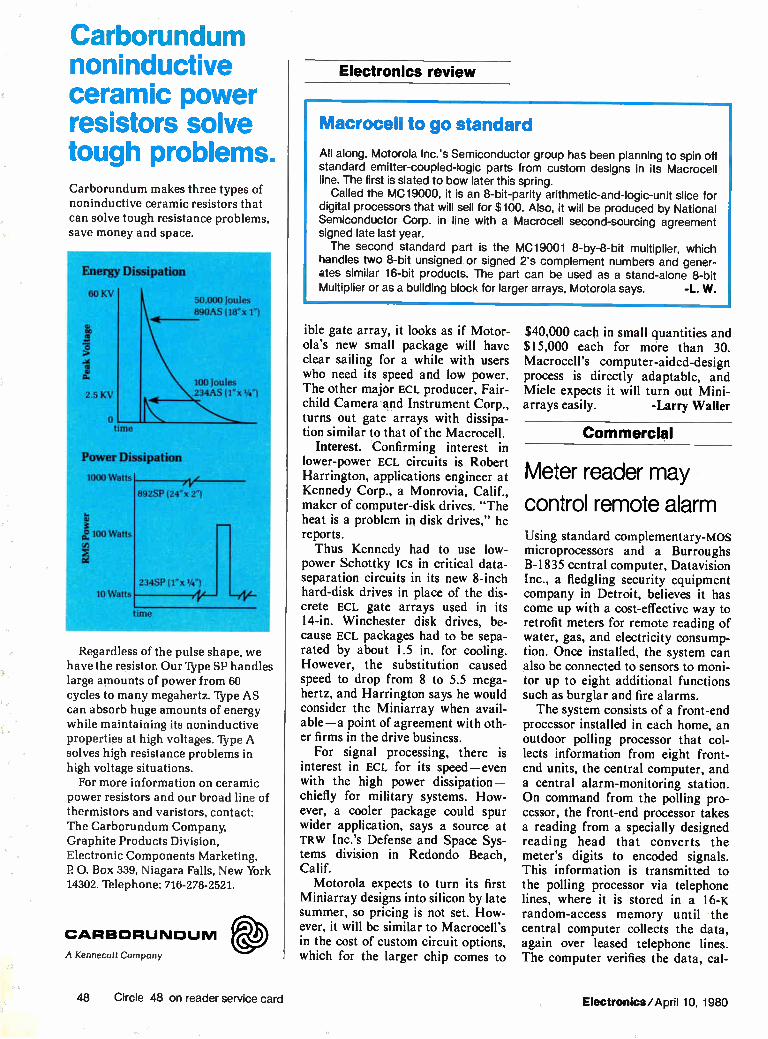
Carborundum noninductive ceramic power resistors solve tough problems. Carborundum makes three types of noninductive ceramic resistors that
can solve tough resistance problems, save money and space.
Energy Dissipation
60 KV
oc
7S
2.5 KV
o time
50,000 Joules
890AS (18"x 1")
100 Joules .234AS (1"x 1/4 ")
Power Dissipation
1000 Watts
892SP (24"x 2")
e 100 Watts
e 10 Watts '
234SP (lx 1/4")
ene
Regardless of of the pulse shape, we have the resistor. Our Type SP handles large amounts of power from 60 cycles to many megahertz. Type AS can absorb huge amounts of energy while maintaining its noninductive properties at high voltages. Type A
solves high resistance problems in high voltage situations.
For more information on ceramic power resistors and our broad line of thermistors and varistors, contact: The Carborundum Company, Graphite Products Division,
Electronic Components Marketing, P 0. Box 339, Niagara Falls, New York 14302. Telephone: 716-278-2521.
CARBORUNDUM
A Kennecott Company
Electronics review
Macrocell to go standard
All along, Motorola Inc.'s Semiconductor group has been planning to spin oft standard emitter-coupled-logic parts from custom designs in its Macrocell line. The first is slated to bow later this spring.
Called the MC19000, it is an 8-bit-parity arithmetic-and-logic-unit slice for digital processors that will sell for $100. Also, it will be produced by National Semiconductor Corp. in line with a Macrocell second-sourcing agreement signed late last year. The second standard part is the MC19001 8-by-8-bit multiplier, which
handles two 8-bit unsigned or signed 2's complement numbers and gener-ates similar 16-bit products. The part can be used as a stand-alone 8-bit Multiplier or as a building block for larger arrays, Motorola says. -L. W.
ible gate array, it looks as if Motor-ola's new small package will have clear sailing for a while with users who need its speed and low power. The other major ECL producer, Fair-child Camera and Instrument Corp., turns out gate arrays with dissipa-tion similar to that of the Macrocell.
Interest. Confirming interest in lower-power ECL circuits is Robert Harrington, applications engineer at Kennedy Corp., a Monrovia, Calif., maker of computer-disk drives. "The heat is a problem in disk drives," he reports. Thus Kennedy had to use low-
power Schottky ICs in critical data-separation circuits in its new 8-inch hard-disk drives in place of the dis-crete ECL gate arrays used in its 14-in. Winchester disk drives, be-cause ECL packages had to be sepa-rated by about 1.5 in. for cooling. However, the substitution caused speed to drop from 8 to 5.5 mega-hertz, and Harrington says he would consider the Miniarray when avail-able—a point of agreement with oth-er firms in the drive business.
For signal processing, there is interest in ECL for its speed—even with the high power dissipation— chiefly for military systems. How-ever, a cooler package could spur wider application, says a source at TRW Inc.'s Defense and Space Sys-tems division in Redondo Beach, Calif.
Motorola expects to turn its first Miniarray designs into silicon by late summer, so pricing is not set. How-ever, it will be similar to Macrocell's in the cost of custom circuit options, which for the larger chip comes to
$40,000 each in small quantities and $15,000 each for more than 30. Macrocell's computer-aided-design process is directly adaptable, and Miele expects it will turn out Mini-arrays easily. -Larry Waller
Commercial
Meter reader may
control remote alarm Using standard complementary-mos microprocessors and a Burroughs B-1835 central computer, Datavision Inc., a fledgling security equipment company in Detroit, believes it has come up with a cost-effective way to retrofit meters for remote reading of water, gas, and electricity consump-tion. Once installed, the system can also be connected to sensors to moni-tor up to eight additional functions such as burglar and fire alarms. The system consists of a front-end
processor installed in each home, an outdoor polling processor that col-lects information from eight front-end units, the central computer, and a central alarm-monitoring station. On command from the polling pro-cessor, the front-end processor takes a reading from a specially designed reading head that converts the meter's digits to encoded signals. This information is transmitted to the polling processor via telephone lines, where it is stored in a 16-K random-access memory until the central computer collects the data, again over leased telephone lines. The computer verifies the data, cal-
48 Circle 48 on reader service card Electronics/April 10, 1980

°NATIONAL ANTHEM 15 SEMICONDUCTOR NEWS FROM THE PRACTICAL WIZARDS OF SILICON VALLEY
The 804es are among us. NEW PRACTICALITY COMES TO MICROPROCESSING
Introducing Free literature— STARPLEX TM details inside with ISE TM
Series/80 4K static RAMs ¡IC products
improved for the real world
Field-programmable
PALS TM
Data Acquisition Logic Transistors Hybrids Linear Interface Bubble Memory
RAMs/ROMs/PROMs Transducers Displays Custom Circuits Optoelectronics
Memory Boards Microprocessors Development Systems Microcomputers Modules

NATIONAL ANTHFM
•
,•"'" _ ,/ femele-‘,.
- 'imam j 0111111111111
• "I i • - ;.-„•
,••••• • .""".
Series/80 microcomputer products brought back down to earth.
National doesn't just make over seventy-five Series/80 micro-
computer products.They make them practical with test points, options, functional design arm availability.
Some manufacturers build flashy boards loaded with far-out technology that you don't need and won't ever use. But not National. They make practical, reliable boards that do just what you buy them for.
And National makes more kinds of those practical, reliable Series/80 products
than any other manufacturer. The Series/80 Family is by no means
just a secondsourcesupp. No other supplier beats National's reliability, functionality of design, user options, or variety of products.
The Series/80 Family includes CPUs, memories, controllers, analog and digital I/O, peripheral controllers, firmware, card cages, power supplies, cables and just about any-thing you need for just about any application.
Test procedures make them practi-cally perfect. National's boards are designed to be functional, easy to design in and totally
consistent in operation.That's why test points have been designed into each board. So testing becomes an integral part of the design phase and continues throughout National's unique dynamic high temperature bum in.
The longest warranty in thq industry. To further ensure reliability, you also get a full one-year warranty with each Series/80 board that you buy from any of National's distributors worldwide.
All from the Practical Wizards who finally brought space-age technology back down to earth.

National's enhanced
Field-programmable PALs available
now. National now offers a family of Pro-
grammable Array Logic devices designed to replace standard UL logic. A single PAL can replace from 4 to 10 SSI/MSI packages. And PAL devices are fully field-programmable to provide the utmost in design flexibility and efficiency.
PAL's basic logic implementation is the familiar AND-OR array, where the AND array is programmable and the OR array is fixed.
PAL'S standard AND-OR logic and flex-ible I/O programming provides hitherto unknown design and production efficiency. Because logic modifications can be made more quickly and easily with PAL than with discrete random logic.
National is producing UL-compatible PALs with the same time-tested technol-ogy used to manufacture PROMs. And with 15 different PAL devices to choose from (including both mil and commercial temp), logic design efficiency and reliability is truly maximized.
National's high volume production capability means a dependable source of reliable PALs at the lowest possible cost. 11
8049s have arrived. °
PALernis on troderninc ark of and used under license with Monolithic
National's 8049 i.LP is smaller, faster and consumes less power. And
irs available now.
National is now in production with their industry standard INS8049 µP The ROMIess version (8039) is available right now at your local distributor.
The INS8049, which features 2K x 8 ROM, 128 x 8 RAM and 27 VO lines on a single chip, is currently available in both 6MHz and 11MHz versions.
And due to their leading edge XMOSTm technology, Nationars 8049s boast a myr-iad of transparent improvements. All of which result in considerable reductions in sys-tems costs.
For example, cycle times for the 6MHz
PART NUMBER
and 11MHz models are 2.5 and 1.36µsec, respectively. A battery charging circuit and a Schmitt triggered interrupt are also on-chip, which makes the 8049 ideal for sophisti-cated battery-operated applications.
The INS8049 consumes 40 to 50% less power in full operation and 12 to 35 times less power in standby mode.
The INS8049 P is in fact only one of several Series 48 Family devices already in production. All of which are fully supported by National's STARPLEX development system with ISE.The chart below describes all seven family members.
National's enhanced 8049 µPs give you the kind of single-chip practicalityyou've been waiting for. For less than you ever thought possible.
RAM ROM
8035 8038 8040' 8048
8049 8050'
8243
64 x 8 128 x 8
256 x 8 64 x 8 128 x8 256 x 8
16L I/O EXPANDER
O O
O 1024 x8
2048 x 8 4096 x 8
'These saris are proprietary yet pin-compatible with the 8048 and 8049. XMOS is a trademark of Nationcl Semiconductor Ccrporatian.

Working wonders on the
2147 4K static RAM.
National's new MM2147 static RAM is a 4096-word by 1-bit random access mem-ory that uses National's XMOSTm N-channel silicon-gate technology.
All of the 2147's internal circuits are full static. And they therefore need no clocks or other refreshing for operation. All data is read out non-destructively, and has the same polarity the input data has.
The 2147's separate chip select input automatically switches the part to its low power standby mode when it goes high. And the output is held in a high impedance state during write in order to simplify your common I/O applications.
The 2147 has other impressive fea-tures as well. All its inputs and outputs are directly TTL compatible. It has automatic power down, and high speed - down to 55ns cycle time. It has a TRI-STATE output for bus interface, separate Data In and Data Out pins, and a standard 18-pin dual in-line package.
In addition to all this, the 2147 is avail-able right now.
1 AO Al A2 A3
A5
2 3 4
5 6
11 D,,(D)
CS (S) 108 WE (W)
MEMORY ARRAY 64 ROWS
64 COLUMNS
12 • 3 14 5 6 7 All A10 A9 M A7 A6
18 •-oVCC 9 .-ovSS
7 D -(0)
TRI-STATE is a registered trademark of National Semiconductor Corporation
Introducing STARPLEX" with ISE.
National's fully developed development system.
The Practical Wizards have created an easy-to-use development tool that helps design engineers do their whole job on the STARPLEX development system.
STARPLEX can not only develop soft-ware for 8080, 8048, 8049, 8050, 8070, NSC800, 8085, and Z-80 microprocessors plus BLC/SBC Series 80 boards, but now with ISE (in-system-emulation) you can also test, analyze and debug prototype hardware/ software for the same products.
The ISE module is a separate unit incor-porating its own CPU, 32K bytes of user-programmable memory and all the necessary logic for breakpoints, tracing and mem-ory mapping.
With ISE, you can simultaneously run Iwo prototype microprocessors (in any com-bination). So for the first time, you can have real-time emulation or debugging in a multi-
processor environment. National's easy-to-learn ISE software
comes completely integrated into the STAR-PLEX system, including the unique Auto-matic Testing or "In-File" capability. In-File is an automatic testing mode that will implement a predefined sequence of tests. ISE can also record those results to show exactly how each part of the system performs during tests.
Our symbolic debugging capability pro-vides not only the usual breakpoint condi-tions, but also a "coast" command which allows you to continue executing a pro-gram after the breakpoint combination has been satisfied.
STARPLEX with ISE offers features not found in any other development system, yet it costs substantially less to own and oper-ate than any competitive system.
Practical Wizards, indeed. STARPLEX and ISE are •rademarks of National Semiconductor Corporation
What's new from the National archives? 003 E MM2147L Data Sheet 030 III INS8049 Data Sheet
025 E PAL Brochure 035 Ill Additional Series/80 Information
028 E STARPLEX and ISE 036 E Optoelectronics Handbook ($3.00) Data Sheets
Enclose check or money order based upon appropriate currency. Make checks pay-able to National Semiconductor. Allow 4-6 weeks for delivery.
NAME
TITLE
COMPANY
111 E ADDRESS CITY STATE _ _ _ ZIP
For desired information, mail coupon to: National Semiconductor Corporation 2900 Semiconductor Drive Mail Stop 16250 Santa Clara, California 95051
In Europe, mail coupon to: National Semiconductor GmbH lndustriestrasse 10 D-8080 Furstenfeldbruck West Germany
ffl National Ka Semiconductor
The Practical Wizards of Silicon Valley. NA9
e Copyright 1980 National Semiconductor Corporation

OUR NOVA 4 HAS ALL THE LATEST FEATURES. INCLUDING EARLY DELIVERY.
isok
41.x.
( e .,
That's why you should contact us right now for fast delivery of one of the most popular, compatible, re-liable computer systems ever made — the Data General NOVA® 4.
Our NOVA 4/C is the compo-nent OEM's dream come true, combining low price with reliability and flexibility
The NOVA 4/S offers fast scientific processing through its instruction prefetch processor, high-speed floating point, and
ri character manipulation abilities. Then there's the NOVA 4/X. It
provides all the features of the 4/S, with up to 256K bytes of memory
And every NOVA 4 is available with our new winchester-type tech-nology disc featuring integral diskette backup.
Whatever your application, there's a Data General NOVA 4 that's a perfect fit. With a delivery date that'll keep you from throw-ing fits. Data General Corporation, Westboro, MA 01580, I e (617) 366-8911. NOVA is a I registered trademark of I Data General. I °Data General I e, Corporation, 1980.
AT MCC, AlIAME1111, CA., MAT 19-22, 1980.
VISIT US AT 1100111 #1339
ee 096.2. e exc,oce e,:e-
e>2.-..ire,to.
/e-e e <is e
Circle 49

The 'Won Verporation
recording solutions for data acquisition, automatic testing, computer-aided design and more...
Dylon's GPIB (IEEE-488) 1/2-inch magnetic tape recording systems
_ World-wide computer data interchange II Archival data storage 1 Disc back-up . IBM and ANSI compatible formats LI Transfer rates to 100,000 bytes/sec. I: Dual buffers to 16,384 bytes.
3670 Ruffin Road, San l/ego CA 92123 (714) 292-5584 TWX: 910-335-1524
Circle 50 on reader service card
MR. CLEAN II The Cost Effective Solution To Contamination Problems
Mr. Clean II is our latest addition in our line of miniature, high quality, wave-solderable slide switches. This low cost switch is designed to work on our unique (patented and patents pending) 2-piece principle. This revolutionary design allows for soldering and cleaning of only the simple exposed base half of the switch. The switching mechanism in the upper half is never exposed to any pos-sible contamination.
These switches are designed for high reliability at a low cost. Mr. Clean Il features insert molded pin terminals in a high-heat temperature resistant base. Contacts are of hard gold over nickel barrier and recommenaed for low energy applications. Available circuit configurations include SPST, SPDT, DPST, DPDT, and Form
CHICAGO SWITCH, INC. 1714 N. Dame.n Avenue Chicago, Illinois 60647
Electronics review
Reader. Front-end processor in Datavision's
remote meter-reading system transmits en-
coded meter data to a polling processor linked to a computer.
culates the amount due, and pro-duces a bill ready for mailing.
Both the front-end and the polling processor are built around RCA-1802 microprocessors, which Datavi-sion chose for their low power opera-tion and resistance to external noise. The company designed the system to be compatible with the upcoming RCA-1804 microprocessor and plans to switch when the higher-capacity 1804 is available. Ultimately, a cus-tom chip will need to be designed, Datavision's president, Maurice B. Hogan, says, but the volume is not yet high enough. Suburban test. The first test of the
system, involving 25 homes in the suburban community of Grosse Pointe, Mich., is under way. The homes can be polled and billed in three minutes, compared with the several days it takes the communi-ty's water department to read the meters. If the initial trials succeed, the system could be expanded to cov-er some 2,100 homes and businesses. According to Datavision, the water department could cut its meter read-ing and billing costs by 50%. Larger electric and gas utilities could realize
50 Circle 106 on reader service card Electronics/April 10, 1980

80% reductions, he says. The meter-reading system is pri-
marily a means of opening up a mar-ket for security systems, explains Carlo Ugval, Datavision's chairman. Once the front-end and polling pro-cessors are in place, there is enough capacity to add alarm monitoring. In this setup, the front-end processor is connected to smoke detectors and to door and window sensors. When triggered, it alerts the polling proces-sor, which is usually located on a nearby telephone pole, and the alarm is immediately transferred to the central office. Eventually, the polling processor could be linked directly to terminals in the fire and police departments to provide direct emer-gency calls.
Although the system now uses leased telephone lines for informa-tion transmission, other means are available. The company is currently testing the telephone company's Da-taphone Select-a-Station simulator system and is also looking into the possibility of using cable TV lines. It has preliminary designs for an ultra-high-frequency transmitting and re-ceiving system as well.
Although Datavision is a small company competing with well-financed firms in the home security market, it is depending on getting a
Signal Processing MOS-LSI Filters/ SEMINAR
FOR CIRCUIT DESIGN ENGINEERS
A UNIQUE INTRODUCTION TO ANALOG SIGNAL PROCESSING TECHNOLOGY...FEATURING DELAY LINES AND INTEGRATED SWITCHED-CAPACITOR FILTERS... HARDWARE APPLICA-TION UNIT WILL BE DEMONSTRATED...
PROGRAM TO COVER . . . . Sampled Data Signal Processing using bucket-brigade, charge-coupled and switched-capacitor techniques. Delay line theory of operation, limitations and ap-plications. Transversal filter principles, monolithic designs, pro-grammability, custom design considerations. Switched-capacitor filters--advantages over transversal and discrete, hybrid designs. Correlator/matched filter solutions for data communications.
APPLICATIONS
AUDIO & MUSIC EFFECTS... DATA BUFFER-
ING . . . MODEMS. . . TONE SIGNALING . . NOISE
AND VIBRATION ANALYSIS...SPEECH
RECOGNITION (VOCODERS). . SIGNAL CONDI-
TIONING ...ADAPTIVE FILTERS.. SPREAD
SPECTRUM COMMUNICATIONS. . .
Seattle Denver Kansas City Dallas Los Angeles
May 19 May 20 May 21 May 22 May 23
Chicago Detroit Philadelphia Bait/Wash Orlando
June 2 June 3 June 4 June 5 June 6
Partial 1980 Schedule
PRESENTED BY:Mark D. Walby, Product Manager, EG&G Reticon. Mr. Walby holds a BSEE from MIT and an MSEE from Stanford University. He is a recognized circuit and system designer, author and speaker.
$25.00 ADMISSION INCLUDES: "New Revised" seminar handbook, free sample device, product data sheets, application notes and luncheon. Make your reservations by calling 408/738-4266 or send your check to: Analog Seminar, c/o EG&G Reticon, 345 Potrero Ave., Sunnyvale, CA 94086. Reservations close 10 days prior to seminar date.
Electronics/April 10, 1980 Circle 51 on reader service card 51

plants, PROFITS and people thrive in
co womi
re,
Superb business advan-tages—including location in the state with the nation's top business climate*—make Corpus Christi a logical choice if your company is planning to build, move or expand.
Highly productive work-ers .. lower living and operating costs ... excellent transportation systems: we have all these (and much more) to brighten your profit picture.
But once you've based your decision on all the right bottom-line reasons, relax and enjoy the beautiful bonus: a casual, fun-filled life in a semi-tropical vacationland,
replete with lots of surf and sunshine, fabulous hunting and fishing, and opportunities for outdoor recreation through-out the year.
Let us tell you more about your potential for profit and pleasure in Corpus Christi. Call (512) 883-5571 or mail the coupon. •Prom studies by the Fantus Company, plant locat on consultants and by the Department of Firance State of California
Please send me more information on industtial sites and the Corpus Christi area.
Name and Tide
Company
Street
City/State Zip
Brodie Allen. Director. Corpus Christi Industr,a1 Commission.
P.O. Box 640-E480, Corpus Christi, Texas 78403 (512) 883-S571
Circle 52 on reader service card
1979 Electronics Buyers' Guide
The only book of its kind in the field. If you haven't got it, you're not in the market.
To insure prompt delivery enclose your check with this coupon.
Electronic Buyers Guide 1221 Ave. of the Americas New York, N.Y. 10020
Yes, please send me copy(les) of 1979 EBG. D !'ve enclosed $30 per copy delivered in the USA Canada.
I've enclosed $52 per copy for delivery elsewhere
Name
Company
Street
or
Electronics review
foot in the door via the remote meter-reading approach it is promot-ing. The Grosse Pointe test will be key to its future. -David Whiteside
McGraw-Hill World News
GTE to offer
electronic mail By summer, yet another company will be offering electronic mail service. GTE Telenet, a subsidiary of General Telephone & Electronics Corp., will start up its Telemail using its existing nationwide com-mon-carrier network. A computer-based mail service enabling users to send, receive, and file messages elec-tronically, Telemail will be used with a wide variety of data terminals and word processors supporting telecom-munications interfaces. With this move, GTE is joining the
ranks of ITT with its Faxpak [Elec-tronics, March 27, p. 50], Xerox and its Ethernet, Satellite Business Sys-tems, and AT&T's troubled ACS.
Telemail will allow the user to access
an electronic "mail box" from any telephone using a desktop or porta-ble terminal. Telenet [Electronics, Dec. 20, 1979, p. 33] solves the prob-lem of interfacing equipment from different vendors by performing speed, code, and format conversions. The host machine that does this is a Tandem T-16 transaction processor, Eventually the Vienna, Va.—based subsidiary will offer the service of delivering voice messages, using store-and-forward technology. More. AT&T's Antelope system,
about which little more is known than a projected 1983 introduction, may also handle electronic mail—like functions of voice and data over existing twisted-wire pairs.
In another announcement late last month, Tymnet Inc., the Cuper-tino, Calif., common carrier, said that it will offer a second-generation mail service starting June 1. On-Tyme-II, based on the firm's existing electronic mail service, will provide direct communication between ASCII terminals and facsimile terminals, as will Faxpak. -Pamela Hamilton
City State Zip
52 Electronics/April 10, 1980

Kontron's Programmer Saves You Time and Money...
MPP 80S Field Service Programmers Only $1995
Well save you money from the very start. Why? Because we program following the PROM manufacturers specification . . . and we have approvals to prove it! No more lost bits in the field and expensive field service because of poor programming Also, if you have to go to the field to update software, our MPP 80S goes with you. It is no larger than a briefcase.
Kontrons MPP 80 series programmers are:
• Easy to operate
• Utilize RS232 interface
• Can be computer and remotely operated
• Have 17 data formats
• Offer auto baud and polarity select via key board
• Can be easily interfaced to IC handlers
• PROM manufacturer approved
• P controlled (Z80)
• Have standard UV lamp
• Full data manipulation
Now, Kontron offers a new EPROM gang programming module with interchange-able identifiers. Program and check via pass/fail Led's all popular EPROMS: 8 at a time. Use the gang module with our MPP 80S, E, or P • programmers.
PROM Sales Offices
AJUSONA Macdonald Associates 1.1 .662.966.1848 csuresitis °binge- Auoclate. Tel 213-439.07SO COLORADO Eiuler Sales &Service Tel' 303.794.1779
Write or ca Kontron Electro 700 South Claremont Street San Mateo, California 94402 800-227-6854
PROGRAMMERS: FLORIDA Synergetic. Tel: 813.595-5331 HAWAII Aloha Associate. Tel 80A941.1574 ILLINOIS Dot Trani. Tel 312-593-0282 INDIARA Loren Green of Indiana Tel. 317.293.9827 MASYLAND Bytech A.sociates Tel: 301.667-1591
Circle #53 for literature
KASSACHI7SETTS Support Electronics Tel. 617•935.9530 ICHISOUVU Keboo Tel 314.576.4111 NEW TERSEY ¡MR Sales T.I. 301-727.5335 SEW MEXICO In -Tronix Tel 505,266.7951 NEW YORK L-Mar Auociate. Tel: 7IA328•5240
OHIO Micro Sale. Corporation Tel. 513.433.8171 OREGON Weecon. Inc Tel: 503.283.0132 TEXAS Data Scientific Tel. 512.735,5073
CASADA Duncan lutrurnente Ltd Tel 416-742.4888
Circle #55 for demonstration
:S213VVVVV2ID021c1 VV0
21c1

Order your copy of the 1979 Electronics Buyers' Guide. There won't be another like it until June,1980.
The 1979 EBG is only a postage stamp away! Completely new listings of catalogs, new phone numbers, new addresses, new manufacturers, sales reps, and distributors! The total market in a book—four directories in one!
1. Directory of products. Over 4,000 products, over 5,000 manufacturers.
Directory of catalogs. Includes six post-paid catalog inquiry cards for 10-second ordering.
The only book of its kind in the field.
If you haven't got it, you're not in the market.
To insure prompt delivery enclose your check with the
coupon now.
3. Directory of manufacturers. Local sales offices, reps, and distributors, with phone numbers. Number of em-ployees and engineers, dollar volume, name of company contact.
4. Directory of trade names of products and their manufac-turers. You can trace a prod-uct by its trade name only.
Yes, please send me copies of 1979 EBG. 0 I've enclosed $30 per copy delivered in USA or Canada. Address: EBG, 1221 Avenue of the Americas, New York, N.Y. 10020.
I've enclosed $52 for air delivery elsewhere. Address: EBG, Shoppenhangers Road, Maidenhead, Berkshire S16, 2Q1 England.
Name
Company
Street
City
State Zip Country
54 Electronics/April 10, 1980

Washington newsletter
Budget cuts hit Technology education and research and development come up short in President Carter's revised fiscal 1981 spending plans for space, energy, and
SC hools, R&D; the National Science Foundation. Military electronics R&D remains essen-defense spared . . . tially unchanged, however, although a $1 billion cut in defense procure-
ment — mostly in aircraft and ship overhauls—is proposed. The NSF's education and research programs, heralded earlier as stimulating university science and engineering training [Electronics, Feb. 14, p. 95], will be cut $100 million under Carter's budget-balancing plan. The National Aero-nautics and Space Administration is scheduled to lose $224 million, much of it in space science programs, including the joint U. S.—European solar polar spacecraft program. Department of Energy solar R&D and demon-stration efforts, including photovoltaics, will also be hard hit by spending cuts of $247 million in fiscal 1981 in addition to a $32 million cutback proposed for the existing fiscal year.
. . . as Carter's priorities The budget debate to come in Congress—where Carter's priorities are already suspect —is sure to be fueled by concerned R&D communities in
raise questions In education and industry, not to mention social and urban program advo-Congress, industry cates outraged by even deeper cuts in their projects. One sore point:
NASA'S costly space shuttle program ($1.87 billion) is untouched by fiscal 1981 cutbacks because of its importance for launch and retrieval of military as well as civilian satellites, but funds to develop scientific experiments and equipment for the shuttle-borne manned Spacelab are proposed to be cut 60% to $29 million. Such R&D cuts "are nickel-and-dime economies that will do more harm in the long run than they achieve in savings," complains one senior House Budget Committee staff member. Suspicion of White House budget revisions overall is fanned in Congress and industry by what one electronics executive calls "Carter's fiscal sleight-of-hand." For example: in January, the President said his $615.8 billion spending program in fiscal 1981 would generate a $15.8 billion deficit. His revisions at the end of March cut outlays by only $4.3 billion to $661.5 billion, yet show a $16.5 billion surplus. The reason: Federal receipts are now forecast to rise from $600 billion to $628 billion because of increased gasoline taxes and withholding taxes on interest and dividends.
Solarsat studies Advocates of solar-power satellite systems will get their best insights into what the July 15 program recommendation to the Secretary of Energy will
to receive review be at the April 22-25 SPS Program Review and Symposium, which will be for July decision held on the University of Nebraska campus at Lincoln under the joint
sponsorship of the Department of Energy and the National Aeronautics and Space Administration. The Energy Department's Fred Koomanoff, SPS program chief and meeting chairman, will draw on the symposium's 170 papers — including about 100 by study contractors — in drafting the department's recommendation. It will be forwarded to the White House later. SPS systems would employ photovoltaic cells to generate electrical energy, which would be beamed via microwaves to earth antennas for regional distribution. SPS proponents like the Sunsat Energy Council suspect that the open meeting is being held in out-of-the-way Nebraska to limit public attention, but Koomanoff insists that the site was chosen be-cause "about half the contractors are from the West Coast or Texas."
Electronics/April 10, 1980 55

Washington commentary
Sen. Stevenson blasts technology policies
As Japan enters the 1980s with a clear industri-al strategy, the United States starts the decade "with no industrial strategy, no comprehensive energy policy, no food policy, no export strategy, and no strategy to repair the world's institutions for trade, development, and money."
This charge was leveled by Sen. Adlai Steven-son (D., Ill.) at a seminar on quality control and productivity presented for U. S. government officials and electronics industries executives by the Electronic Industries Association of Japan (see story, p. 81). Though such public critiques may be rare in Japan, American executives lis-tened appreciatively as the chairman of both the Senate Banking subcommittee on international finance and the Commerce subcommittee on science, technology and space ripped into the economic, trade, and technology policies of the Carter Administration. Stevenson can afford to speak with brutual candor about Government failures, having announced several months ago that he will not be a candidate for reelection in November.
Stevenson says only that he intends to contin-ue to speak out on public policy issues, but he has yet to disclose his future plans. In his role as chairman of two key Senate subcommittees, he has acquired extensive and detailed knowledge of economics and technology, particularly in the electronics industries. And he likes little of what he sees in the U. S.
Why the U.S. lags
"Far more important" to Japan's industrial success than its quality control techniques, says Stevenson, is "the ability of Japanese industry and government to work cooperatively to target market opportunities, develop commercial prod-ucts adapted to those opportunities, and funnel resources into projects with the greatest chance of increasing Japan's exports." The U. S., on the other hand, "has fallen
behind in the commercialization of technology," the Senator contends. "In general, American industry has been oriented to the domestic mar-ket. In electronics, it innovates, but it does not exploit innovations as aggressively as others." American government, he adds, "does little to encourage collaborative research and product development outside the military. Patent and antitrust policies have precluded the consortia which are a prominent factor in Japanese tech-nological advances."
It seems ironic to him that Japan's computer industry "is organized by government for invest-ment, basic research, and global competition,"
while "back in the U. S. the Justice Department is trying to break up Ism."
Comparing subsidies
Stevenson warns that in the absence of a sound industrial policy, "political pressures will lock the U. S. into the kind of spiral of subsidies, inefficiencies, and declining productivity which destroyed the British economy." And he offers one more biting example of that trend. "In general, the Japanese draw labor and capital away from declining sectors and channel pro-ductive resources to target industries—comput-ers, electronics, robotics, energy, and space. That may sound like government meddling, but the Ministry of International Trade and Indus-try's industrial investment is $2 billion—less than one ninth, as a percentage of gross national product, of what the British spend subsidizing corporate geriatric cases and little more than the U. S. intends to invest this year in 'the new Chrysler Corporation.' "
America's most competitive and innovative industries—aerospace, agriculture, and comput-ers—are those that have benefited most from Federal support of technology, the Senator argues, adding: "If by inadvertence, the U. S. stimulates an aerospace industry that dominates world markets, imagine what it might do by calculation."
Stevenson's solution for America's loosening grip on world technological leadership is not necessarily more government programs or plan-ning. He proposes: ▪ More government-industry cooperation in the form of incentives for corporate retraining of workers displaced by structural economic change. • Jointly funded generic industrial technology centers in universities and nonprofit research institutions. • An information system to evaluate commer-cial potential of new technologies, to identify export and productivity enhancement opportuni-ties, and to gather foreign intelligence. America should make use of foreign technology. • A national industrial strategy for competitive-ness that includes accelerated depreciation, R&D investment incentives, and corporate and capital gains tax reduction, provided that the reductions promote "industries of the future." That last condition is critical, Stevenson observes, since "those nations which have been most successful at promoting noninflationary growth have dem-onstrated that how a nation's money is spent is as important as how much." -Ray Connolly
56 Electronics/April 10, 1980

Tr; I-11E_ LL
Tr TI I ITTOF If 111.11.1\1_
Now...A Series of Sprague ICs that simplify gas discharge display Interface Sprague Se,ies UDN-6100/7100 Display Drivers offer the
systems designer a simplified, low-cost interface with planar gas discharge displays that essentially eliminate the need for dis-crete components. Designers can now take advantage of the superior aesthetics of gas discharge panels with their low power consumption, relative ease in customizing, and large digit capa-bility without the need to use large quantities of discrete components.
With broad commercial/industrial applications, these unique drivers find wide usage in business calculators, POS systems, cash registers, scales, appliances, clocks, electronic games, instrumentation, computer peripherals, industrial controls, avi-onics, and a variety of other display products. Series UDN-6100 Digit (anode) Drivers are rated with a supply
voltage of +120 V max. and an output current of 70 mA max.
FOR FAST INFORMATION, CALL YOUR NEAREST SPRAGUE SALES OFFICE: ;LABAMA, Sprague Elect- ic Co 205 883-0520 • ARIZONA, Sprague Electric Co 602 244-0154. 602 966-7233 • CALIFORNIA, R D Miner Co 714 421-5586: Wm J Purdy Co 415 347-7701 • COLORADO, Win J Purdy Co . 301777-1411 • CONNECTICUT, Sprague Electric Co . 203 261-2551: Ray Perron & Co.. Inc . 203 268-9631, 203 673-4825 • DIST. OF COLUMBIA. Sprague Electric Co (Govt sales only) 202-337-7820 • FLORIDA. Sprague Electric Co 305 831-3636 • ILLINOIS. Sprague Electric Co . 312 296-6620 • INDIANA. Sprague Electric Co 317.253-4247 • MARYLAND. Sprague Electric Co 301 792-7657 • MASSACHUSETTS. Sprague Electric Co . 617,899-9100, 411664-4411. Ray Perron 8 Co Inc 612969-8100 • MICHIGAN. Sprague Electric Co . 517 787-3934* MINNESOTA, HMR. Inc .612 831-7400 • MISSOURI. Sprague Electric Co.. 314181-2420o NEW HAMPSHIRE. Ray Perron F. Co . Inc 603 742-2321 • NEW JERSEY, Sprague Electric Co.. 201 696-8200: 609 795-2299, Tnnkle Sales Inc.. 609295-4200 • NEW MEXICO, Wm J Purdy Co . 505 266-7959 • NEW YORK, Sprague Electric Co 516 234-8700. 914 834-4439: 315 437-7311: Wm Run. Inc 914,834-8555: Pasten-Hunter Co . Inc . 315 437-2843* NORTH CAROLINA, Electronic Marketing Associates. 919 722-5151.01110, Sprague Electric Co . 513 866-2170.
Electronic Salesmasters. Inc 800,362-2616 • PENNSYLVANIA, Sprague Electric Co 215 467-5252. Innkle Sales Inc 215 922-2080 • SOUTH CAROLINA. Electronic Marketing Associates. 801233-4637 *TEXAS, Sprague Electric Co 214 235-1256 • VIRGINIA, Sprague Electric Co . 703-463-9161u WASHINGTON. Sprague Electric Co 206/632-7761u CANADA Sprague Electric of Canada. Ltd.. 416 766-6123 or 613.238-2542
They are available with 4, 6, or 8 drivers per device, in 14, 16, and 18 pin plastic and hermetic DIP packages, respectively.
Series UDN-7100 Segment (cathode) Drivers operate at a max. supply voltage of — 120 V. Circuits are available with nominal output current ratings from 0.6 mA to 14 mA. Each device has 8 drivers and is available in an 18-pin plastic or hermetic DIP package.
For application engineering assistance, write or call Paul Emerald, Semiconductor Division, Sprague Electric Company, 115 Northeast Cutoff, Worcester, Mass. 01606. Tel: 617/853-5000.
For Engineering Bulletins 29311 and 29312 as well as WR-172A 'Quick Guide to Interface Circuits', write to: Technical Literature Service, Sprague Electric Company, 35 Marshall Street, North Adams, Mass. 01247.
455-111443
SPRAGUE® THE MARK OF RELIABILITY
a subsidiary of GK Technologies
Circle 57 on reader service card

OF COURSE YOU NEVER VOLTAGE CONVERTER.
• +5V
+5V
ICL7660 VOLTAGE
CONVERTER
COMMAII111110111111
air
— 5V
I ou, > 40mA
10µF
POWER CONVERSION EFFICIENCY —98% @RL-r-- 5Ko,

HEARD °FA MONOLITHIC WE JUST INVENTED IT.
+5V IN. —5V OUT. Now, you can power your analog circuitry from your digital power supply. With a single chip. The ICL7660 monolithic voltage converter generates the negative voltages required by the analog functions in your sys-tem. Or, one ICL7660 provides —5V for a board-full of dynamic RAMs. +5V in. —5V out. Or, +1.5V to +10V in and —1.5V to —10V out. Require higher negative voltages? Cascade 7660's. Need more current? Just put 'em in parallel.
EFFICIENCY PLUS. Intersil's MAXCMOS" process brings you another first. A monolithic voltage converter with a voltage conversion efficiency of 99.9% (R, = 0°). Power conversion efficiency of 98% (R, =5K 11). And 'OUT capability greater than 40mA (R.,=55 ). You simply can't beat it. Period.
NO MORE KLUGES. One chip and two caps. Put 'em wherever you need 'em. And the ICL7660 virtually eliminates EMI problems caused by inductive converters.
GOOD NEWS. • Monolithic • Short circuit protection • Latch-up proof • 1.5 to 10V operation • Direct parallelling for more output current • Operates in simple voltage multipliers: VOUT = — nVIN•
MORE GOOD NEWS. The ICL7660 monolithic voltage converter costs just $1.95 in lots of 100 (8-pin epoxy DIP). Be sure to ask for quantity prices.
THE SYSTEMS APPROACH. The Intersil MAXCMOS" process, coupled with our broad experience in data acquisition
products, has led to a continuing series of high performance, low-power analog and data conversion products. Analog products that operate from a -± 5V supply. And now, a monolithic voltage converter that powers analog functions from your digital supply.
MORE INFORMATION? Call your Intersil Sales Office, Franchised Distributor, or return the coupon below. The ICL7660 is available now. In prototyping or production quantities.
INTERSIL SALES OFFICES: CALIFORNIA: Sunnyvale (408) 744-0618, Long Beach (213) 436-9261 • COLORADO: Aurora (303) 750-7004 • FLORIDA: Fort Lauderdale (305) 772-4122 • ILLINOIS: Hinsdale (312) 986-5303 • MASSACHUSETTS: Lexington (617) 861-6220 • MINNESOTA: Minneapolis (612) 925-1844 • NEW JERSEY: Englewood Cliffs (201) 567-5585 • OHIO: Dayton (513) 866-7328 • TEXAS: Dallas (214) 387-0539 • CANADA: Brampton, Ontario (416) 457-1014
INTERSIL FRANCHISED DISTRIBUTORS: Advent (IND, IA) • Alliance • Anthem • Arrow • Bell Industries • Cardinal • CESCO • Component Specialties • Components Plus • Diplomat (FLA, MD, NJ, UT) • Harvey (upstate NY) • Kierulff • LCOMP • Panda • Parrott • R.A.E. Ind. Elect. Ltd. • RESCO/ Raleigh • Schweber • Summitt • Western Microtechnology Sales • Wyle • Zentronics Ltd.
OIL ANALOG PRODUCTS— LINEAR CIRCUITS 10710 No.Tantau Ave., Cupertino, CA 95014 Tel: (408) 996-5000 TWX: 910-338-0171 (800) 538-7930 (outside California)
Gentlemen:
+5V in and —5V out? Monolithic? Send me the details on your ICL7660.
_While you're at it, send me your 20" x 24" Bertrand Russell poster.
Name
Company
Address
City State Zip
E41080

MiCROPROCeSSORS TTTTTTTTTT TTTTTTTTTT VTTTTTTTTT TTTTTTYTTT IIMMT 11TIMM TYTTTTTTTT
LaKje scale integRation L I
APPLYING MICROPROCESSORS
rtrtmt trImm rtmr rrmm Trm,mi rryttm TTTTTTTTTT rimmt
New hardware, software and applications
Bectronics iib'oi. (senes
CIRCU CIRCUITS CIRCUITS CIRCUITS CIRCUITS CIRCUITS foR electRonics engineeRs engineeRs engineeRs erxjineeRs engineeRs engineeRs Bectronics engineeRs Book sefies engineeRs
ineeRs
Basics OF daTa COMMUNICaT1ONS daTa daTa da-ra
design tec ni ues
foR electRohcs en ineeRs
memory design memory design
memory design: MICROCOMPUTERS TO MAINFRAMES
memory design memory design Bectronics ok Series
PeRsonal
rh utIng aRdwaRe and sofTwaRe bacs
glectIoniu, Pool( Sedes
Electronics Magazine Books
1. Microprocessors What you must know about available microprocessor technology, devices, informa-tion, 4th printing. $8.95
2. Applying Microprocessors 2nd and 3rd generation tech-nology. 26 detailed applica-tions from data networks to video games. $9.95
3. Large Scale Integration Covers the basic technology, new LSI devices, LSI testing procedures, plus system design and applications. $9.95
Electronics Magazine Books
P.O. Box 669, Hightstown, NJ 08520 (609) 448-1700, ext. 5494
No. of Copies Title
1. Microprocessors
2. Applying Microprocessors
3. Large Scale Integration
4. Basics of Data Communications
5. Circuits for Electronics Engineers
6. Design Techniques for Electronics Engineers
7. Memory Design: Microcomputers to Mainframes
8. Personal Computing: Hardware and Software Basics
4. Basics of Data Communications Includes 47 articles from Data Communications magazine covering more than 11 key areas. $12.95
5. Circuits for Electronics Engineers Contains 306 circuits arranged by 51 functions from Ampli-fiers to Voltage Regulating Circuits. Saves design drudgery. $15.95
6. Design Techniques for Electronics Engineers Nearly 300 articles drawn from "Engineer's Notebook." A storehouse of design problem solutions. $15.95
Price
$ 8.95
$ 9.95
$ 9.95
$12.95
$15.95
$15.95
$12.95
$11.95
7. Memory Design: Micro-computers to Mainframes The technology, devices, and applications that link memory components and system design. $12.95
8. Personal Computing: Hardware and Software Basics More than 50 articles from leading publications, including specifications, helpful hints, subject index. $11.95
If after my 10-day free-trial examination I am not fully satisfied I understand I that my payment will be refunded. )11 Payment enclosed ['Bill firm D Bill me Charge to my credit card:
RAmerican Express UI Diners Club Visa Master Charge•
Acct. No. Date Exp.
•On Master Charge only, first numbers above name
Name Title
Company
Street
City State Zip
Discounts of 40% on orders of 10 or more copies of each book. Signature
60 Electronics/April 10, 1980

NEW! From McGraw-Hill Publications and Electronics Magazine
INTEIRNATIONP1. Mete:TING OPPORTIOTIES
egceinegcb pute
equipment
and peri
Electronic components nd test ip
and accessories
Electronic production a equment Communications equipment and systems
Electronic dhach‘nes
Security systems
' Critical inforrnation that helps YOU iocus on global Markets eh the
greatest profit potential°
NEVER BEFORE PUBLISHED!
344 pages of official U.S. Government intelligence reports
International Marketing Opportunities ELECTRONICS
• Contains 102 reports that identify the best future markets for electronic products around the world.
• Compiled by McGraw-Hill editors from more than 1,500 pages of official U.S. government intelligence reports. (prepared by U.S. Commerce Department attaches)
• Reports cover 44 countries and six types of electronic products. Provide details on market growth, competition, investment opportunities, promotion opportunities, and government develop-ment policies in each country.
• Organized by major product category.
• Available now for marketing, corporate planning, and manufacturing executives in the electronics industries.
Extracted From Official U.S. Government Intelligence Reports
102 REPORTS COVER SIX PRODUCT CATEGORIES: • Computers and peripherals • Electronic components • Production and test equipment • Communications equipment and systems • Office and business machines • Security systems
TYPICAL MARKET REPORT. . . • Predicts future market growth
• Analyzes existing and potential competition
• Pinpoints specific high potential equipment needs
• Identifies trade and investment opportunities
• Shows market growth over last three years
• Reveals government development policies (and other factors) that will affect future demand in each country.
Electronics/April 10, 1980
r—
Money-Back Guarantee To. McGraw-Hill Publications
International Marketing Opportunities/ELECTRONICS 457 National Press Building Dept 48 Washington. D.0 20045
O YES, please rush me copy(ies) of International Marketing Opportunities/ELECTRONICS, a compilation of official U.S. government reports that identify the most profitable future markets for electronic pioducts around the world. I understand that I have 10 days to examine it and can return it within that time for a full refund. Price per copy . $157.00 ($174.00 for orders outside the U.S.). Price includes postage and handling. Orders outside the U.S. shipped airmail.
E My check is enclosed H Bill my company . E Bill me.
Name
Company
Address
City, State (Country), Zip
(Please allow 6 to 8 weeks tor delivery.)
61

THE SMART
LASER TRIM SYSTEM. It trims your operating costs, too.
II laser trim systems can trim components, but the CLS-33 from Chicago Laser Systems does much more. In addition to being designed to be the smartest, highest throughput laser trim system available, it reduces both immediate and long term trimmed network and hybrid costs.
Chicago Laser engineers have brought together a blend of micro-computer, laser optic and electro-mechanical technologies to form a well balanced state-of-the-art system. Its most striking aspect is its overall simplicity. With fewer major components than competitive sys-tems, the engineering sophistication of the CLS-33 has overcome traditional size and complexity barriers... an accomplishment recognized by the
Circle 62 on reader service card
The Chicago Laser Systems CLS-33 is the smart way to solve your network or hybrid trimming problems. For the complete story and a frank appraisal of how the CLS-33 can fill your needs, contact Chicago Laser Systems Inc.
many major network manufacturers who have installed it.
The system microcomputer is backed up by the laser trimming industry's most intelligent software operating system. It was developed specifically for high-speed laser trimming. The software directs the measurement/laser interaction, using a Chicago Laser exclusive high-level programming language. As a result, no comparable laser trim system is easier or faster to program than the CLS-33. On-line compiling and *editing are featured for user convenience and easy program debugging in user language.
Just as the powerful software reduces programming time and personnel costs,
the maintenance ease of the CLS-33 ensures low long-term costs. This sys-tem can be easily maintained by your maintenance staff. Training is quick and free to CLS customer personnel.
A variety of complementary parts han-dling mechanisms are available for the CLS-33. Fed by the recently introduced air-bearing Step-and Repeat Handler, the CLS-33 trims an incredible 100,000 resistors per hour. At the same time, the simple sophistication that has estab-lished Chicago Laser as a leader in the laser trim industry has been maintained. The handler is also available with stack load and unload to minimize operator support.
Chicago Laser %stems Inc. 4034 North Nashville Ave. Chicago, IL 60634 • Phone 312-282-2710

International newsletter BP0 demonstrates
picture viewdata
In a move aimed at reestablishing a technical lead in the international viewdata stakes, the British Post Office has demonstrated a picture viewdata system at an international conference on the subject—Viewdata '80, held in London, March 26-28. Full-color photographs, as well as alphanumeric text, can be stored in a computer and transmitted over telephone lines to be held in a frame store in the TV terminal. In contrast, Canada's Telidon system is capable of advanced graphics but not photo-graphs (see p. 44). The use of differential pulse-code modulation to compress the video data cuts the needed frame store size to 24 kilobytes and the transmission rate to 1,200 b/s. At that rate, a picture is transmit-ted in 1 minute; a practical system therefore requires a fast modem or direct connection to a digital exchange. Consequently, the post office sees picture viewdata, which is upwardly compatible with Prestel, its viewdata service, being introduced in the late 1980s and is concentrating on applica-tions for the private business and overseas markets.
Thomson-Brandt Thomson-Brandt SA, best known for the high-technology hardware sold around the world by its subsidiary, Thomson-GsF, aims to become the
wants to be No. 2 second-ranking color TV producer in Western Europe, behind the Dutch-In European color TV based Philips group. The Paris-based company, which took over the West
German TV maker, Nordmende KG, in 1978, wants to add to its stable Saba GmbH, in Villingen/Schwarzwald, West Germany, a money-losing member of GTE'S Consumer Electronics Group. Saba's output of some 500,000 color sets, added to the million-plus total for Thomson and Nordmende, would lift the French group to a level where it feels it could withstand the heavy competition in sight from Japanese suppliers. The latter are poised to move heavily into the big-screen market next year when the PAL patents that so far have kept them out start to expire.
Big Increase predicted
for West German
tabletop computer sales
By 1990, there will be some 1 million tabletop computers installed in West Germany —the type of systems known as home, hobby, or learning computers and selling for from $250 to $5,000. That forecast, from the Frankfurt-based computer consultants, Diebold Deutschland GmbH, works out to a fiftyfold increase over the number currently installed. The present West German home computer market is dominated by three firms, Commodore, Tandy's Radio Shack, and Apple, whose shares are pegged at 51%, 35%, and 4%, respectively. However, that ranking may change, Diebold says, as other firms, among them Hewlett-Packard, Texas Instru-ments, and West Germany's Triumph-Adler, move into the market.
Ti France devises Working with engineers at the electronics subsidiary of French auto maker Régie Renault, Texas Instruments France SA has developed a two-chip
t wo-c hi se for electronic ignition system for 2-liter engines. To be installed starting next Ignition control fall on Renault's new sport coupe, the Fuego, the system uses a single
passive sensor consisting of a simple coil and magnet to monitor crankshaft speed and position. At its heart is an integrated-injection-logic circuit that calculates the spark-timing advance. The timing-advance curve is stored in 64 22-bit words in a mask-programmed read-only memory. Thus there is no chance of mistiming, say Claude Jacquemin, automotive circuit manager for TI France in Villeneuve-Loubet, near Nice. The system can withstand temperatures of - 40° to + 125°C.
Electronics/April 10, 1980 63

International newsletter
Sharp develops C-MOS Joining the parade of integrated speech synthesizers is a complementary-mos circuit developed by Sharp Corp. that contains all the necessary speech synthesizer, components on its 5.3-by-5.2-mm chip (209 by 209 mils) except for a
makes watch talk 6-bit digital-to-analog converter. Its 4-kilobyte read-only memory has sufficient capacity for 13 to 22 seconds of speech, including a male voice, a female voice, or a tone, and can be expanded by the addition of up to 1 megabyte of external ROM. Sharp engineers say that the 2-mA current drain at 4.5 v is at least an order of magnitude lower than that for a competitive n-mos device recently announced by Matsushita Electric Industrial Co. The chip will be used in consumer products. Its first application will be
in what the company calls a quartz "secretary" watch. The size of a pocket radio, it uses speech synthesis in five ways. Besides announcing the present time at the touch of a button, it can be set to announce the hour and half hour or used as an alarm to announce a preset time by both voice and melody. It can also function as a timer to announce the passage of time or as a stopwatch to announce elapsed time. The watch is 114 by 60.7 by 23.0 mm (4.5 by 2.4 by 0.9 inches) and weighs 160 grams, including two AA batteries that will power it for a year. Sales will start April 25, with the price about $70.
Plessey launches Though integrated-circuit frequency-synthesizer channel tuners have t found slots in military mobile radios, they have generally proved too wo chi - universal
expensive for civil applications. Plessey Semiconductors Ltd., Swindon, frequency synthesizer aims to change that with a two-chip synthesizer set that it is launching at
Communications '80, April 15-18, in Birmingham, England. The set, which comes in three frequency versions, comprises a fast modulo-2 or -4 divider fabricated using Plessey's process for high-speed bipolar circuits and an n-mos controller capable of accepting inputs from read-only memory, programmable ROM, and microprocessors. It contains all decod-ing and control circuitry and requires only an external reference frequen-cy of 4.8 MHz. There are four divider circuits: a 1-GHz and a 512-MHz modulo-4 divider and two 200-MHz modulo-2 dividers. Philips was the first to market with a chip set, developed at its Redhill, Surrey, research laboratories [Electronics, Aug. 31, 1978, p. 74], but Plessey claims a price breakthrough. Its chip set will sell for $20 in volume quantities for some versions.
Companies to unveil Using the April 16-24 Hanover fair as a forum, a number of communica-T eletex gear tion equipment makers will introduce hardware for Teletex, the electronic
mail service that West Germany's post office plans to start next year at Hanover fair [Electronics, Nov. 9, 1978, p. 69]. For example, NV Philips Gloeilampen-
fabrieken's Data Systems division in Apeldoorn, the Netherlands, will stage what it terms the world's first public demonstration of international Teletex services, with its equipment tied to Philips terminals in New York, Montreal, and Stockholm. West Germany's Telefonbau und Normalzeit will show how a private automatic branch exchange can be used in Teletex communications; for that purpose, the Frankfurt-based firm has developed a microprocessor-controlled equipment that interfaces a PABX system with the digital data networks over which information is sent.
64 Electronics/April 10, 1980

Let light rule! The Zeiss Light-Section Microscope
A narrow beam of light profiles a surface whose characteristics you wish to measure. Then, you fine-tune a reference line and read heights or widths directly, in 1/2-micron steps.
Fast, accurate, non-destructive
You can easily obtain direct readings of heights and widths ranging from 1 micron to approxi-mately 400 microns. It's so simple even an inexperienced technician can learn how in minutes. And because there's no physical contact with the surface, there's no chance of damage or false readings. It's as accurate as only measurements made with light can be. Nationwide service.
The great name in optics
ZEINN
West Germany Circle 65 on reader service card
Carl Zeiss, Inc., 444 5th Avenue, New York, N.Y. 10018 (212) 730-4400. Branches: Atlanta, Boston, Chicago, Houston, Los Angeles, San Francisco, Washington, D.C. In Canada: 45 Valleybrook Drive, Don Mills, Ontario, M3B 2S6. Or call (416) 449-4660.
MEASURE AND INSTANTLY DOCUMENT:
Step differences on circuit boards and chips
Thickness of photoresist
Thickness and width of gold leads
Depth of scratches
Thick-film hybrids (wet & fired)
Glaze thickness
Thickness of magnetic layer on GGG

The biographies of 5,240 of your colleagues...
the most important people in the electronics industries worldwide
McGraw-Hill's
Leaders in Electronics Prepared by the Staff of Electronics 651 pages
This is the only reference devoted solely to biographies of the most influential people in electronics: corporate executives... technical managers...designers and developers of important products and processes... government and military officials... academics ... editors and publishers.., securities analysts... directors of trade and professional groups ...and consultants.
As easy to read as any professional publication in electronics
With LEADERS IN ELECTRONICS on your bookshelf, you no longer have to search through many different sources for bio-graphical data on your colleagues. What's more, you don't have to strain your eyes reading minuscule type, nor do you have to waste valuable time trying to decipher seemingly endless para-graphs of abbreviations. Boldface type spotlights the various information categories so that you can scan entries rapidly to pinpoint what you need.
Unique convenience feature... Index of biographees by affiliation
A special 80-page index lists individual organizations alphabeti-cally, complete with the names and titles of top employees. By looking up the names in the general biography listing, you can get a complete profile of the organization's top management in a matter of minutes. Plus an easy-access listing of independent consultants in every electronics specialty.
Order today using this coupon!
Sample Listing Jones, John I Chmn &CEO, Microprocessor Div of Computers Inc, 1023 W Warner Ave, Dayton, OH 45479, Tel (513) 555-2000. Born: Mar 26, 1926, Philadelphia, PA. Educatián: MBA, Harvard Business School, 1950; BSEE, Univ of Ill., 1946; PhD (Hon), Yale Univ, 1977. Professional Ex-perience: Natl Bur of Standards, 1956-74, Adm Eng; Litton Ind, 1954-56, Sr Eng; NCR Corp, 1950-54, Eng. Directorships: Computers Inc since 1975. Organizations: IEEE since 1946, Sec Head 1972-73; AAAS since 1971; Midwest Ind Mgt Assn since 1974. Awards: Fellow, IEEE, 1977; Public Service Award, City of Dayton, 1976. Patents Held:8 in computer circuits, incl Special Circuit for Microcomputer Chip Design 1975. Achievements: founded Microprocessor Inc 1974; project manager of first application of microprocessors for standard interfaces 1975. Books: 4 incl Small Circuits and Their Applications (editor), McGraw-Hill, New York, 1975. Personal: married 1950 to Mary (Smith), children John Jr, Jane Anne, Kevin. Residence: 344 W 34th St, Dayton, OH 45403, Tel (513) 555-4343.
Return coupon to: Leaders in Electronics RO. Box 669 Hightstown, New Jersey 08520 (609) 448-1700, ext. 5494
Send me copy (copies) of Leaders in Electronics on a 10-day money-back guarantee. I understand that if I am not absolutely satisfied, I may return the book(s) within ten days at no further obligation. Otherwise, McGraw-Hill will bill me $39.50 for each copy, plus applicable sales tax, shipping and handling charges.
r-Aie Iñi
Name
Title _
Company
Address
City State Zip
SAVE MONEY! Enclose payment in full, plus local sales tax, and McGraw-Hill pays all regular shipping and handling charges. Ten-day money-back guarantee still applies. Check enclosed Bill me Bill my company company purchase order This oiler ..obwr t to atceptance by McGraw•Hill. ELI
_J
66 Electronics/April 10, 1980

Electronics international Significant developments in technology and business
Switch contacts are normally closed in low-cost keyboard by Kenneth Dreyfack, Paris bureau
Novel design also replaces
springs with magnet that
keeps keys up, adding to
simplicity and reliability
A unique keyboard, which is also unusually simple, reliable, and low-cost, could revolutionize the key-board business for terminals, push-button telephones, electric typewrit-ers, and industrial equipment, be-lieves its inventor, Edouard Serras-Paulet of Sigma Industries SA in Montaubon, north of Toulouse.
His approach has two novel aspects. First, a magnet rather than a spring holds each key up. Second, and more important, depressing a key does not generate a current.
Dissatisfied. Serras, who is also the company's founder and presi-dent, explains that he began looking at keyboard design during the early 1970s, when as a designer of air-borne electronic equipment he saw the physical drawbacks in using springs to ensure key return. In 1972, he took out the first of a dozen patents protecting his new technique. The new keyboard's baseplate is
covered with a magnetized elastom-er, a rubberlike material containing magnetized particles. A small metal-lic disk attached to the key plunger ensures that each key stays firmly in place. The company guarantees that each key can be depressed 10 million times before showing signs of me-chanical fatigue.
Serras maintains that the magnet-ic system makes more sense mechan-ically. Spring-loaded keys require an increasing downward force as they
approach the contacts, reducing the probability of a firm contact when fully depressed. But in a magnetic system, the greatest downward force is required at the outset.
Closed. Serras did not stop there. To overcome one of the most com-mon malfunctions in traditional key-boards, a poor electrical contact when a key is depressed, his firm designed a keyboard in which the switch contacts are normally closed.
Electrically, the keyboard circuit consists of an X-Y matrix printed on a Mylar circuit board with an insu-lating layer keeping the two sets of axes apart. A key is located at each intersection, and each key contains a diode. Five volts are applied sequen-tially to the vertical columns. If no key is depressed, the current flows through the diodes to 47-kilohm pull-up resistors located at the end of each horizontal row. The current drain is less than 2 milliamperes.
Depressing a key opens the matrix and breaks the current flow to the resistor at the end of one of the rows. Since the current is applied to the columns sequentially, a simple counter is all that is needed to deter-mine the point in the matrix where the circuit has been opened.
Vive la différence! "All of our competitors work with contacts, but we have no contacts—we don't gen-erate any signal, and that is the big difference," says Serras enthusiasti-cally. He goes on to explain that the parasitic resistance of the diode is not critical, because the threshold voltage that determines whether the circuit is open or closed is 2.5 V. He adds that since the circuit is opened only when a key is depressed, and since the tolerance is so great, there
is no need for expensive contact materials. In fact, "the most expen-sive element in our keyboard is the key cap, which needs a double-injec-tion plastic process to imprint the character," he notes.
Keyboard testing also becomes much simpler, Serras points out. "If there is something wrong, it will show up immediately when the key-board is not in use," he stresses. "If there is nothing on the screen, then the keyboard is fine." Sigma Industries expects to start
large-scale production of its key-boards — tradenamed K-Serras — in June or July. By next year, it expects to be producing some 150,000 push-button telephone keyboards and 45,000 alphanumeric-terminal-type keyboards annually. With production and testing time
at about one minute per keyboard, and with assembly costs roughly one third to one quarter of those for tra-ditional techniques, Serras believes the future is bright.
His firm has commissioned Ar-thur D. Little Inc., Cambridge, Mass., to study setting up production facilities in North America. Mean-while, U. S. distribution will be han-dled by Seacor Inc., Norwood, N. J.
Japan
VLSI labs unveils
last E-beam unit . . A prototype design that can soon be used to make speedy electron-beam wafer-exposure systems for produc-tion rather than for merely showing feasibility is how Masashi Nakamu-
Electronics/April 10, 1980 67
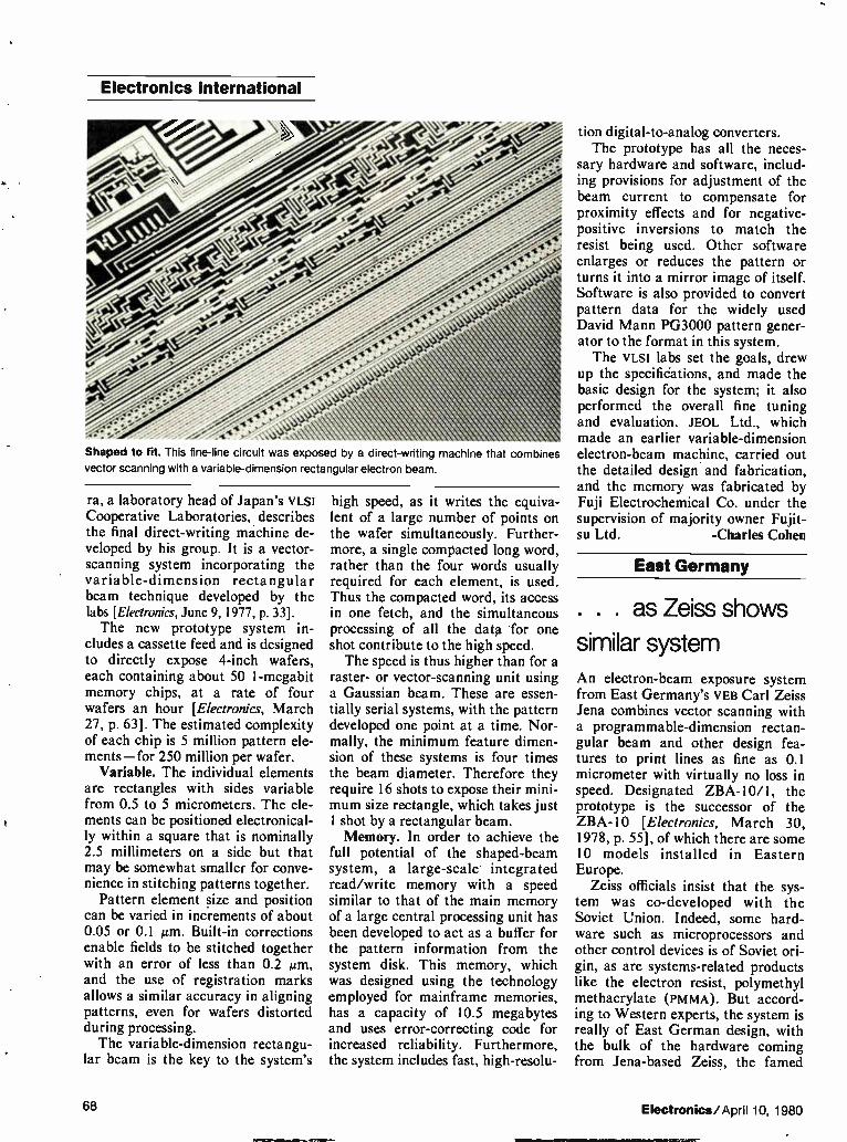
Electronics international
Shaped to fit. This fine-line circuit was exposed by a direct-writing machine that combines
vector scanning with a variable-dimension rectangular electron beam.
ra, a laboratory head of Japan's VLSI Cooperative Laboratories, describes the final direct-writing machine de-veloped by his group. It is a vector-scanning system incorporating the variable-dimension rectangular beam technique developed by the labs [Electronics, June 9, 1977, p. 33]. The new prototype system in-
cludes a cassette feed and is designed to directly expose 4-inch wafers, each containing about 50 1-megabit memory chips, at a rate of four wafers an hour [Electronics, March 27, p. 63]. The estimated complexity of each chip is 5 million pattern ele-ments—for 250 million per wafer.
Variable. The individual elements are rectangles with sides variable from 0.5 to 5 micrometers. The ele-ments can be positioned electronical-ly within a square that is nominally 2.5 millimeters on a side but that may be somewhat smaller for conve-nience in stitching patterns together.
Pattern element size and position can be varied in increments of about 0.05 or 0.1 gm. Built-in corrections enable fields to be stitched together with an error of less than 0.2 gm, and the use of registration marks allows a similar accuracy in aligning patterns, even for wafers distorted during processing. The variable-dimension rectangu-
lar beam is the key to the system's
high speed, as it writes the equiva-lent of a large number of points on the wafer simultaneously. Further-more, a single compacted long word, rather than the four words usually required for each element, is used. Thus the compacted word, its access in one fetch, and the simultaneous processing of all the data for one shot contribute to the high speed. The speed is thus higher than for a
raster- or vector-scanning unit using a Gaussian beam. These are essen-tially serial systems, with the pattern developed one point at a time. Nor-mally, the minimum feature dimen-sion of these systems is four times the beam diameter. Therefore they require 16 shots to expose their mini-mum size rectangle, which takes just 1 shot by a rectangular beam. Memory. In order to achieve the
full potential of the shaped-beam system, a large-scale integrated read/write memory with a speed similar to that of the main memory of a large central processing unit has been developed to act as a buffer for the pattern information from the system disk. This memory, which was designed using the technology employed for mainframe memories, has a capacity of 10.5 megabytes and uses error-correcting code for increased reliability. Furthermore, the system includes fast, high-resolu-
tion digital-to-analog converters. The prototype has all the neces-
sary hardware and software, includ-ing provisions for adjustment of the beam current to compensate for proximity effects and for negative-positive inversions to match the resist being used. Other software enlarges or reduces the pattern or turns it into a mirror image of itself. Software is also provided to convert pattern data for the widely used David Mann PG3000 pattern gener-ator to the format in this system. The VLSI labs set the goals, drew
up the specifications, and made the basic design for the system; it also performed the overall fine tuning and evaluation. JEOL Ltd., which made an earlier variable-dimension electron-beam machine, carried out the detailed design and fabrication, and the memory was fabricated by Fuji Electrochemical Co. under the supervision of majority owner Fujit-su Ltd. -Charles Cohen
East Germany
. . . as Zeiss shows
similar system An electron-beam exposure system from East Germany's VEB Carl Zeiss Jena combines vector scanning with a programmable-dimension rectan-gular beam and other design fea-tures to print lines as fine as 0.1 micrometer with virtually no loss in speed. Designated ZBA-10/1, the prototype is the successor of the ZBA-10 [Electronics, March 30, 1978, p. 55], of which there are some 10 models installed in Eastern Europe.
Zeiss officials insist that the sys-tem was co-developed with the Soviet Union. Indeed, some hard-ware such as microprocessors and other control devices is of Soviet ori-gin, as are systems-related products like the electron resist, polymethyl methacrylate (PmmA). But accord-ing to Western experts, the system is really of East German design, with the bulk of the hardware coming from Jena-based Zeiss, the famed
68 Electronics/April 10, 1980

"We came up with SPRINT' so you can print faster
without pinholes or skips: Product innovation is one of the ways DuPont makes sure you get consistent, high-quality performance.
"Our customers wanted to increase throughput on their existing equipment. This meant they needed thick film pastes that would print at high speeds, on large area sub-strates in long printing runs. Yields had to be maintained with no sacrifice in printing quality.
"We organized a research team with scientists skilled in organic vehicle research, and engineers with lots of on-line printing experience. The result was a family of revolutionary new vehicles called SPRINT." Many of our established prod-ucts are now available in SPRINT Printing Vehicle as well as most new products where it makes sense."
This is just one example of how our R&D organization focuses on market needs and comes up with innovative solu-tions in a hurry.
If you'd like to learn how SPRINT can achieve consistent processing and performance, run after run, write to: John Felten, DuPont Company, Room 37442, Wilmington, DE 19898.
Innovations for Electronics
S 0“
Circle 69 on reader service card

Electronics international
I III
72 11 1 ;
▪ _J I j s
1
• r7rr+
J.1 ,111
-J
cli
.4
J à
J. J
Teamwork. Vector scanning is combined with a variable-dimension electron beam to produce a direct-writing system for VLSI circuits like the experimental one shown here.
130-year-old optical equipment maker now also known for its work in planetariums.
Conceived to fulfill the require-ments of very large-scale integrated-circuit technologies, the ZBA-10/1 sports a respectable set of perfor-mance characteristics. Under ideal conditions, Zeiss says, it can gener-ate patterns with minimum feature dimensions of 0.1 gm. The maxi-mum exposure speed with 10,000 shots per square millimeter and a resist sensitivity of 1 microcoulomb per square centimeter is 1 square millimeter per second. The fully automatic computer-
controlled system accommodates masks up to 4 by 4 inches in size and wafers up to 4 in. in diameter. Beam deflection, controlled by a Zeiss-developed 15-bit digital-to-analog converter, is in 0.05-gm steps over a 1.5-by-1.5-mm area. By butting a number of such areas, any size chip can be handled. Deflection distortion is less than 0.1 gm and the registra-tion accuracy is within ±0.1 gm. The same holds for the feature posi-tion repeatability.
Range. Pointing up the system's versatility is its wide range of appli-cations. In addition to directly exposing wafers and making high-precision masks, it can be employed to produce reticles for wafer and
mask repeaters. Other jobs include the production of shadow masks for X-ray lithography and the genera-tion of patterned junction photo-cathodes, optical test and holograph-ic patterns, and integrated optic and thin-film device patterns. The throughput is less than one
hour for a 3-in.-diameter wafer with 1-gm lines and with about 25% of its total area exposed to the beam. Sig-nificantly, that throughput remains the same for narrower line widths— in contrast to other systems on the market, with which the process times increase substantially with decreas-ing feature dimensions. Knut Kaschlik, the man behind
Zeiss's development effort, sees di-rect wafer exposure for lc produc-tion with fast turnaround times as the prime function for electron-beam equipment in general "because that's where their potential can best be exploited." As for the ZBA-10/1, he feels it is well suited in work aimed at the development and fabrication of experimental 256-K random-access memories.
Contributing to system efficiency and productivity are several factors. Vector scanning boosts throughput, as it scans only those chip or mask areas that require exposure. With raster scanning, on the other hand, the whole area is scanned.
Programmable. More important perhaps is the use of a beam whose dimensions can be programmed. With this technique a beam of rec-tangular cross section can generate large-area patterns in one exposure cycle, which is not possible with a pointlike beam, and the beam's cross section can be varied according to the dimensions of lines generated.
Shaping the beam. In the ZBA-10/1, the rectangular beam shape is obtained by limiting condensers in the beam-generating column. The side lengths of the cross-sectional areas are variable between 0.1 and 10 gm. Since the beam has a quasi-rectangular current distribution over its cross section (instead of the some-what uneven distribution character-istic for pencil beams), line edges can be well defined.
Further enhancing productivity— by a factor of four compared with the ZBA-10 — is improved data transfer from the magnetic control tape to the computer. This was achieved by adding another buffer memory to the existing one.
While the control data is trans-ferred from the tape to one buffer, the other buffer feeds its data to the exposure control units. After the 4-K data blocks are dumped, the roles of the buffers are reversed. Thus, the data transfer and exposure processes are carried out simultaneously and independently of each other. The data blocks are transferred in 170 milliseconds. -John Gosch
Great Britain
ICL unwraps new
low-end mainframes International Computers Ltd. has taken the wraps off its ME29. With a raw speed of 3 million basic machine instructions per second, the new computer could more than re-establish its competitiveness in the low- to mid-range mainframe sector.
ICL uses this power to transform its successful but aging 2903 and 2904 from batch- to interactive ter-minal-processing systems. Thus the,
70 Electronics/April 10, 1980

It gets tougher all the time. Trying to match budget dollars with instrument performance can be a real problem. Unless the instrument is our Model 1062 Sweeper.
At only $890,* the Model 1062 is a full-performance laboratory sweeper with a 1-400 MHz frequency range. You can sweep any portion of that range at variable rates, and have triggering capability to boot. You'll also find
10 mW RF output, 2% sweep linearity, and ± 0.25 dB flatness— performance characteristics usually seen only on much more expensive instruments. The Model 1062 also includes
provision for an optional crystal-controlled birdy bypass marker system. Up to six plug-in marker modules may be added. The markers can be at single discrete frequencies or they can be harmonically related. Front-panel
Circle #70 for demonstration
Al TENUATION
o
controls vary marker amplitude and bandwidth. Get the sweeper that solves
budget and performance problems all at once. Get the Model 1062— still only $890* Wavetek Indiana, PO. Box 190,
66 North First Ave., Beech Grove, IN 46107. Toll free 800-428-4424; in Indiana (317) 783-3221. TWX (810) 341-3226
W AVŒTŒ 11Q *U.S. price only Circle #7I for literature
FIE0
Get our budget sweeper.

Electronics international
larger ME29, the model 45, can sport up to 200 display terminals and run over 50 user's programs simulta-neously. ICL has also thrown in a private viewdata capability, so that cheap viewdata terminals giving access to a company's data base can be widely dispersed about its offices. The ME29 has a big role to play
in ICL's marketing strategy: it both forms the entry-level system of its 2900 series and lays the groundwork for a single unified architecture based on a 32-bit-word structure and extending from the smallest to the largest of the firm's models. 32 bits. The now defunct 2903 and
2904 were 24-bit machines, whereas the bigger models in the 2900 series are all 32-bit systems. The ME29 follows this pattern and is a 32-bit microprogrammed machine that can efficiently emulate its 24-bit prede-cessors—with a five times greater throughput.
"It's a fast, high-revving emulator engine," explains project leader Bill Beard, who masterminded the new range. The speed comes from a cen-tral processing unit built with 10K
A microprocessor system and a novel oxygen-concentration sen-sor, both developed at City Uni-versity, London, have been com-bined in a compact boiler effi-ciency monitor from a small Brit-ish company, Neotronics Ltd., in Bishop's Stortford, Herts. The instrument's probe can be
inserted into the flue of a boiler fired by oil, gas, or solid fuel and within seconds will give a direct reading of the boiler's fuel effi-ciency. Adjusting the airflow to the optimum can cut fuel bills by 3% to 5%, quickly repaying an initial outlay of $1,000, says the company.
In the final production version, an Intel 8022 single-chip signal processor accepts inputs from a thermocouple and from the oxy-gen-concentration sensor— which was developed from work on lightweight zinc-air batteries— to directly drive a light-emitting-diode display. -K. S.
emitter-coupled logic, and the flexi-bility from microcode. The microcode is stored in a high-
performance control store. Engi-neered in 4-K static random-access memories, the store cycles at a nomi-nal 155 nanoseconds, with an instruction-prefetching mechanism that enables most operations to take place in 93 ns. At 128 kilobytes, the model 45's control store is twice the size of that of the model 35.
Microcode and intermediate re-sults in the control store are used to emulate the older machines. And to speed the processor, explains Beard, "we move more of the high-level applications and operating system code from main memory into micro-code." As a result, the ME29 can run either the old or the new operat-ing system, enabling users to migrate at their own speed to the new. Also, often used instructions like jump are hardware-decoded.
Partitioned. In hardware terms, the design is highly partitioned func-tionally. The CPU comprises three 8-by-12-inch four- to six-layer printed-circuit boards—one control-
ler board and two processor boards that each operate on 16 bits of data. An Ea.-level bus transfers data at
about 128 megabytes per second between the CPU and the micropro-gram controller, and a TTL.-level bus links main memory and input/out-put channels. The design, says Beard, "is a judicious mixture of ECL,TTL, and mos technology." The main store uses 16-K random-
access memories and is extensible in 128-kilobyte steps from 256 kilo-bytes to 1 megabyte. The word access time is 750 ns.
Operating. In addition to new hardware, there is also a new operat-ing system, called Transaction Ma-chine Environment. Based on the well-proven Exec 3A operating sys-tem, it adds features that give the ME29 a terminal-processing and a powerful networking capability. For example, it has a built-in telepro-cessing monitor, and it can access files on other ME29s in a network.
Furthermore, there is a new mem-ory management scheme, which ICL calls leaf addressing, that bears simi-larities to virtual memory systems found on larger machines; it allows the basic operating system to be expanded a leaf at a time. Thus the ME29 can evolve as needed. The new range begins at about
$78,000 and extends to some $555,000. Delivery is scheduled to start in the fall. Complete system. Fully config-
ured, a system would comprise a 1-megabyte main store, 16,000 meg-abytes of disk storage, up to three line printers, magnetic tape storage, and other peripheral units and sup-port 24 locally attached work sta-tions, plus numerous other terminals over remote communications lines. The five storage options range from a 35-megabyte fixed disk to a 500-megabyte fixed disk. Says Keith Bull, marketing man-
ager for the Putney, London, firm, "The ME29 is comparable with the IBM System/34 at its low end, with the System/38 throughout, and at the top with the IBM 4331. It has significant price-performance advan-tages over the equivalent IBM pro-duct at all levels." -Kevin Smith
72 Electronics/April 10, 1980

Turn your test data into decisions.
Miles of test system print-outs are a problem when you don't have time to dig in and analyze them. You're liable to ,, AR find the cause of a problem too late to do anything about it. Which means you've lost time, money and maybe a customer
That's when you need Integrator® II. It can take your reams of test data and synthe-size them into usable, action-oriented technical and man-agement reports. Continually. Or on command. And it can con-trol, manage and communicate device programs for up to eight remote test stations, whether you're using our Sentry® or SentinelTM systems.
Integrator is a powerful host
computer that gives you infor-mation you can use to get the most out of your test equipment. You can make in-formed decisions affecting pro-cess, yields and quality control in minutes. Rather than weeks.
Integrator hardware is modular and can be configured to match each specific user application. Software and firm-ware have been prepared specifically for semiconductor
testing. You get all the basic tools needed to make timely, effective decisions. At a surpris-ingly affordable price.
So when your time is tight and you've got to turn data into deci-sions, look into Integra-tor Call us at (408)
998-0123. Or write Fairchild Test Systems Group, 1725 Technology Drive, San Jose, California 95110.
FAIRCHILD
A Schlumberger Company
The Forst %molly
of ATE.


Managing the unmanageable: 57 tons of engineering data--cataloged, collated, cross-indexed and cross-referenced for you.
That's processed information. Any number of companies would like to help you with your information processing.
But only Information Handling Services provides you processed infor-mation . . . engineering data that's already been cataloged, collated, cross-indexed and cross-referenced for you. So that when you need one important catalog page, Industry Standard, Mil Spec or Government Spec. you can get it. Faster than with any comparable system in the world.
In other words, what you get from Information Handling Services isn't hard-ware that helps process data.
Its processed engineering data, presented in a useful, usable form.
The most comprehensive engineering data base in the world. We've been gathering and distributing engineering data for over twenty years. In the industrial area alone, we currently have over 23,000 different manufac-turers' catalogs. Plus the most comprehensive collection of Military Specs in the world. Along with 90% of the world's most important Industry Standards. In fact, our total data base now incorporates more than 8,000,000 pages of technical information.
Fast, easy access. Even more important, we've organized all this information into a system that delivers fast access. All you do is identify the product in which you're interested. Our unique Locator Index then directs you to the catalogs you need, to all appropriate Industry Codes and Standards, to Government and Military Specifi-cations, even to International Standards. In minutes.
One thousand people working for you. Information Handling Services does a better job of providing you with processed information, because we originated Visual Search Microfilm Files (VSMF). Today, our engineers spend tens of thousands of manhours each year simply organizing and cataloging technical data, to make it easier for you to use. For that matter, we have more than 1100 employees now producing a wide variety of information services ranging from manufacturers' catalogs to Military Specifications and Standards, and from an Industry Standards service to Federal Documents, including the Code of Federal Regulations.
Interested? Find out for yourself the difference between information processing and pro-cessed information. We have a complete information package that will give you more details, and that can help you determine which of our many information services might best relate to your work. Just write: Dept. 480, 15 Inverness Way East, Englewood, CO 80150. Or call (toll free) 1-800-821-2280, ext. 301 (in Missouri, call 1-800-892-7655, ext. 301.)
Not information processing, but processed information.
•,„ Information Handling Services W An Indtan Head Company

A 260 does many things that even the best general-purpose digital multimeters cannot do . . . or cannot do as well: Large, continuous analog display for directly indicating trends and for quick, easy nulling and peaking
Quick, positive "yes/no'« checks for voltage, current and continuity
Reliable and rapid checks of semiconductor junctions and forward/reverse resistance tests
High-current, low-resistance range pinpoints marginal bad contacts and cold solder joints
Wide, dynamic, continuous resistance ranges, not limited by the number of display digits Built-in wide-range —20 to +50 db measure-ment facilities
Superior AC frequency response 100 KHz
High immunity to voltage transients and rf interference—no expensive chips to wipe out
Does not generate rf radiation to cause inter-ference or to trigger external sensitive circuits
Needs no external power, avoids common mode problems
Fully passive voltage, current and dB tests, independent of any internal or external power source
Simple design for lowest maintenance costs and highest reliability
That's why the Simpson 260 continues to be the world's
most popular VOM!
Choose the 260 VOM that's best for you 260-7 (diode protected meter) $103.00
260-7M (with mirror scale) 107.00
260-7RT (in roll-top protective case) 116.00 260-7MRT (mirror scale and roll top case) 119.00
260-7P (relay overload protected) 153.00
260-7PM (relay overload protected with mirror scale) 156.00
2607PRT (relay overload protected in roll top case) 168.00
The New 260 Series 7 has all of the advancements and circuit protection features for which the Series 6 was famous . . . PLUS MANY NEW ADVANTAGES:
New reverse, recessed, in-sulated panel connectors with matching safety-engineered test leads
Off/Transit position of function switch shunts the meter movement and opens internal connections to the common and " + "jacks
Doubly-fused protection network now conveniently located in the directly ac-cessible battery-and-fuse compartment
xivierat eilko Custom-molded function-ally-engineered test leads feature reverse-type elbow connectors plus test prods with a ribbed finger grip behind safety barrier. Matching insulated alligator clips are included.
...and designed to meet the new UL 1244 standard for safety of electrical and electronic measuring and test equipment!

260® Series 7
See the broad scope of functions, features, and ranges built
260-7 into the all new
(1980)
All 260 Series 7 VOMs employ the Simpson vans-tor overload-protected taut-band suspension meter movement. All "P" versions include the additional Simpson overload relay cir-cuit protection system.
44tiew. 4:51>
A wide selection of optional accessory equipment ex-tends functions and scope of measurement capabil-ities of each 260 Series 7. Carrying cases, high volt-age probes, clamp ammeter attachment, °F/°C temper-ature probe, low-power ohms probe.
0E00 00 POR,10 lIvIt 00i WATT 000 0,00A5
-10A. +IV.
Series 1 (1938)
Series 2 (1947)
Series 3
Series 4 (1959) (1962)
Series 5 (1964)
Series 6 (1970)
Si«lee* 2 ri
APR10.7
VOLT-OHM- NYUJAMMETER 000n/ VO.0 5.000 VAC
500 MA.
TR/ 10 -
COMMON
50V. LUMPS.
250V.
500V. —f 1000V.
100 MA.
10 MA. Atom
1 MA.
— Rxl
R x100
R x10.000
L\ ALL TERMINALS IRV. MAX
ZERO OHMS
OUTPUT 360 VDC NAT
10.V. AG Of
I 0 0 0 V
SEE THE NEW 260 SERIES 7 VOrVIS AT YOUR LOCAL SIMPSON DISTRIBUTOR OR WRITE
FOR FULL DETAILS (INSTRUMENTS THAT STAY ACCURATE
SIMPSON ELECTRIC COMANY 1
853 Dundee Avenue, Elgin, Illinois 60120 (312) 697-2260 • Cable SIMELCO • Telex 72-2416
KATY
A000U215 GROUP
IN CANADA: Bach-Simpson Ltd.. London, Ontario AND IN ENGLAND: Bach-Simpson (U.K.) Ltd., Wadebridge, Cornwall IN INDIA: Ruttonsha-Simpson Private, Ltd., Vikhroli, Bombay
Circle 77 on reader service card

CPU IVI E I/O
HP—When you depend on logic

If you're working with mini- or micro-based systems, you'll find that HP's 1610B is a very efficient dedicated-bus logic state analyzer.
But unlike other analyzers, the HP 1610B can also handle multiplexed-bus analysis just as effectively. The reason? Because with multiplexed buses, addresçPs and data appear at different times on the same lines. And first-generation logic analyzers, with their single-clock design, simply cannot demulti-plex these correctly. One popular solution to this problem has been to build a
two-clock sequential acquisition system into a single package. While this approach will separate out address and read/write functions, it is still inferior to the 1610B. Why? Because this is still not true demultiplexing, in that this technique cannot correct for the real-time differential between the capture of address information and the capture of read/write data.
This means address and data information can be interleaved in the display. It requires the operator to interpret read or write functions. And it means that triggering may occur on false address/data combinations. In other words, it complicates analysis and may lead to false conclusions.
In comparison, the HP 1610B incorporates not two — but three clocks — plus a buffered memory to deliver true demulti-piecing. In short, the 1610B can independently monitor addre6ges, plus read and write data, to demultiplex in real time for efficient and accurate analysis. So with the 1610B, addresses and corresponding data are
displayed as a single line of information, for easy comparison with your original programs. And you're sure that if you trigger on an address-data combination, the data is present at that address at that specific point in the program.
Other important capabilities. In addition, the HP 1610B delivers other capabilities required for efficient state flow analysis of both bus structures. It will store information on a qualified basis, to permit selective editing. Which means you don't have to sort through unnecessary data. And it makes functional measurements, such as time
interval analysis, on the state flow, which speeds analysis and troubleshooting. Flexibility for the future. Because the 1610B is a 32-bit analyzer with user-selected para-meters, and a variety of options, you can use it with both mini and micro based systems, including 8-bit microprocessors such as the Motorola 6800 and the Intel 8085, as well as the newer 16-bit microprocessors such as the 28000. And, of course, it includes HP's popular menu program format that speeds set-ups and analysis. An economical solution to microprocessor-based systems analysis. Another good answer to the problem of microprocessor demulti-
plexing is the 1611A Logic State Analyzer, with HP's general-purpose module. This module incorporates a seven-clock system that allows multiplexed in-formation on common bus structures to be latched into 1611A in-puts at the appropriate time for display. If you're already using. an HP 1611A, you'll
find this module to be both an effective and cost-efficient solution. For complete details. The HP 1610B is priced at $12,500,* while the 1611A (in-cluding the general-purpose module) is $6,000.* For more information on these, and for an application note on state analysis of multiplexed microprocessors, write: Hewlett-Packard, 1507 Page Mill Road, Palo Alto, CA 94304. Or call the HP regional office nearest you: East (201) 265-5000, West (213) 970-7500, Midwest (312) 255-9800, South (404) 944-1500, Canada (416) 678-9430.
*Dome.tic U.S.A. price only
HEWLETT PACKARD 08.15
Circle 79 on reader service card

SYSTEM» NOW PROGRAMS MORE THAN 200 DIFFERENT PROMS WITH ONLY ONE
SeTWARE SELECTABLE MORIA.E.
IIQ Syrsterert
-
mob.. ••= cipriaLT,
GibLEP
In11?›,cilt.
Our new System 19/UniPak lets you program most MOS and bipolar PROM'S from AMD, Fairchild, Harris, Intel, MMI, Motorola, National, Raytheon, Signetics and Texas Instruments. UniPak's software assembles tne program-ming algorithm and selects the correct socket for 16, 18, 20, 24 and 28-pin PROMS.
System 19/UniPak gives you design and purchasing free-dom. This means you can select the best PROM for each application, and you can second-source for the best price and availability
Semi-house approvals and easy calibration help main-tain higher device yields. UniPak has earned written approv-al from device manufacturers. And easy calibration lets you keep per-formance within PROM manufactur-ers' specifications.
Circle 80 on reader service card
megeb
a algorithms shorten programming time enhanc-ing System 19's use as a pro-duction tool. UniPak is the first module to use a newly developed algorithm which makes it possible to program a 64K EPROM in less than half the time it takes to program a 16K EPROM using standard methods.
And the System 19/UniPak is easy to operate, with a minimum of operator training.
New System 19 concept is open ended to keep it state of the art. The System 19 is designed around a standard main frame and plug-in modules.
A.38 Eon Qom
Modules available now include the UniPak, a gang program-ming pak for MOS devices, and a series of programming paks for logic devices and individual PROM families.
23 communication formats including six
for development systems. Development systems, computers, teletypes and CRT terminals inter-face easily with the System 19. The System 19 accepts micro-processor instruction codes from Motorola, Intel. Tektronix, Fairchild, FutureData and other development systems without intermediary equipment.
Let us show you the future. The new Data I/O System 19/ UniPak is available now. To make arrangements for a demonstration or to get your free copy of this valuable 32-page book, circle reader ser-vice number or contact Data I/O, PO Box 308, Issaquah, WA 98027. Phone 206/455-3990 or TOLL FREE: 800;426-9016.
48‘efiel
,arieseei
DATO

Probing the news Analysis of technology and business developments
Japanese make quality-control pitch FIA-J tells Washington seminar that secret is no secret,
and that IC makers would like to share know-how with U. S. rivals
by Ray Connolly, Washington bureau manager
Japan's semiconductor manufactur-ers are coming to Washington to correct "misunderstandings" about their rising share of the U. S. market and thus deflect the kind of political critcism that accompanied their countrymen's earlier U. S. sales suc-cesses in stereo components, televi-sion receivers, motorcycles, cars, and steel. Their message: Japan's quality control is better and productivity is higher—and they would like to share these benefits with their American rivals. That message got strong support
from Hewlett-Packard Co. during a day-long quality-control seminar sponsored by the Electronic Indus-tries Association of Japan. It was conducted at the end of March for an invited audience of approximately 150 congressional staffers, Federal agency officials, and a handful of U. S. industry executives. They were told that HP'S in-house tests of 4-K and 16-K random-access memories bought from three Japanese and three U. S. suppliers showed the Japanese ics to be "consistently bet-ter," according to Richard W. Anderson, general manager of the Data Systems division in Cupertino, Calif. The HP test data (see table) represents, Anderson said, "A fright-ening set of statistics" for U. S. sem-iconductor markets. When HP qualified its first Ja-
panese vendor in mid-1977 "to fill the gap in domestic supplies," Anderson said, "prices were compet-itive with the U. S., but Japan was never the low bidder." After deter-mining that quality of 4-K and 16-K RAMS from Japan was "superior to that of the U. S. devices," Anderson said, HP qualified two more Japanese
suppliers during the 1979 domestic shortage and had the. same experi-ence. For HP, the "excellent" results with Japanese RAms meant fewer rejects, less costly rework, and, most important, "happier customers."
Called politics. Peter McCloskey, president of the Electronic Industries Association in Washington, repre-senting U. S. producers, found the HP statistics "very impressive," but he contends that the primary pur-pose of the EIA-J meeting was "more political —to reduce U. S. protec-tionist pressures rather than to stress quality control or productivity." In that broader political context, McCloskey believes the Japanese failed to address the primary prob-lem in U. S.—Japanese industrial relations. That, he says, is "fair and equal access to markets" in Japan for U. S. electronic products, includ-ing the multibillion-dollar market of Nippon Telegraph & Telephone Public Corp., which is now effective-ly closed to U. S. producers.
But EIA-J'S Washington counsel, H. William Tanaka, suggests that McCloskey may have missed the true message of the Japanese quali-ty-control seminar. "If the U. S. users of IC memories exercise the same discrimination as Hewlett-Packard and find a difference in U. S. and Japanese failure rates," Tanaka points out, "why cannot N11' and other Japanese equipment man-ufacturers do the same?" While acknowledging some difference be-tween U. S. and Japanese trade poli-cies—differences that are the crux of American makers' complaints— Tanaka argues that a greater threat to U. S. access to Japanese markets in the future "may lie in the percep-tion of Japanese buyers—including NTT—that they cannot be complete-ly confident that they will get U. S. products with failure rates equiva-lent to those that they can get in Japan."
Intel Corp.'s Robert Noyce, long a critic of Japanese trade policies,
HP TESTS FAVOR JAPANESE DEVICES
In-house tests by Hewlett-Packard Co.'s Data Systems division of 4-K and 16-K random-access memories from three Japanese and three U.S. manufacturers are shown. Except for the qualification index, figures are in percentages. The index, on a scale of 100, is a composite based on IC quality and repair costs.
Vendor Incoming tests Field failure/1,000 h Qualification index
J1
J2
J3
A 1
A2
A3
0
0
0
0.19
0.1 1
0.19
0.01
0.019
0.012
0.09
0.059
0.267
89.9
87.2
87.2
86.1
63.3
48.1
Electronics/April 10, 1980 81

Probing the news
"knows the true story of Japanese quality control and what it is achiev-ing," Tanaka maintains. "Otherwise, he would have filed dumping charges against Japan a long time ago."
Stevenson swings away. But the political issue of Japanese trade bar-riers was also raised during the EIA-J session by Sen. Adlai E. Stevenson (D., Ill.), chairman of both the bank-ing subcommittee on international finance and the Commerce subcom-mittee on science, technology, and space. After delivering a series of biting criticisms of Carter Adminis-tration economics, technology, and trade policies (see p. 56), Stevenson urged Japan to "do more to create a climate for cooperation by loosening constraints on the free flow of trade and technology."
Specifically, the senator called for opening of Japanese government procurement, including NTT, to for-eign bidders. Japan's "arbitrary cus-toms uplift could be eliminated, tar-iff reductions accelerated, product standards and product testing and certification systems clarified, and 'buy Japan' attitudes discouraged," Stevenson declared. He also pro-posed that Japan "invite subsidiaries of foreign firms to participate in its new software cartel" in order to "diffuse tensions."
Japanese semiconductor industry leaders at the meeting held firmly to
Quality words. J. M. Juran, left, the quality-control expert, at the EIA-J seminar in Washing-
ton with Hajime Karatsu, managing director of Matsushita Communication Industrial Co.
their premise that quality control is at the heart of the "misunderstand-ings" about U. S.—Japanese lc trade. Hitachi Ltd.'s Toshihiko Kubo, lead-er of the EIA-J contingent, said the Washington seminar for congressio-nal and Federal officials was de-signed to "lessen misunderstand-ings" and reduce U. S.—Japanese "frictions" that he believes "stem from segments of the U. S. semicon-ductor industry."
Increased emphasis on quality control coupled with automated pro-duction of ICs could help the U. S. industry overcome its shortage of engineering talent as those tech-niques have in Japan, said Toshiba Corp.'s executive director Teruyuki Nishijima in a post-session press briefing. Nishijima also proposed that U. S.—Japanese industrial rela-tions be improved by companies in both nations by agreements to share patents, developmental work, and production as second sources. Made in America. Matsushita
Communication Industrial Co.'s Ha-jime Karatsu pointed out that 50% of the automated production equip-ment, including large-scale inte-grated-circuit bonding machinery, used in Japanese plants to achieve high quality control was manufac-tured in the U. S.
Karatsu's message for U. S. man-ufacturers and engineers was that the key to quality control is not to increase production line tests and inspection to weed out inferior prod-
ucts. Rather, he advised them to eliminate potential failure sources at the point of product design, thus pre-cluding the need for extensive inspection and testing.
Karatsu's stress on design and automated production as quality control keys was supported by HP'S Anderson, who recalled being asked by a Japanese engineer, "Why do you Americans inspect so much? Don't you have confidence in your products and processes?" Anderson argued that Japan's competitive 1c position in the U. S. stems from the Japanese turn to production automa-tion in order to counter rising costs in the 1970s, whereas U. S. products turned instead to low-cost offshore assembly. In Anderson's view, Japan gained an advantage by employing quality control to "build Ics right in the first place," but American pro-ducers employed quality control for the more costly process of "finding and fixing" defective circuits pro-duced offshore.
Is there time? Though J. M. Juran, one of the pioneers of modern quality-control techniques and a consultant to Japanese producers, told the session that he believes Japan is now too far ahead in auto-mated quality output of ics for the U. S. to catch up, Anderson believes American producers could cut IC failure rates and match Japanese quality over a three-year cycle. "You have to invent out defects" in pro-duct design, Anderson told the semi-nar audience, "not beat on produc-tion people."
For the U. S. to match Japan's ic quality levels, however, Anderson believes American producers must change their attitudes and commit themselves to new goals, and then work with the Federal government to increase levels of research and devel-opment. The HP executive then reit-erated for the audience of Govern-ment officials a list of Federal sup-port programs for industry being pushed by the American Electronics Association, including tax reductions to enhance investment capital, as well as accelerated depreciation schedules for new plant and equip-ment. Nevertheless, Anderson con-ceded that he sees no chance of adoption of any of these proposals by Congress this year.
82 Electronics/April 10, 1980

THE TELEPHONE DESIGNERS' COLLECTION
3 OF THE MOST INNOVATIVE TELEPHONE COMPONENTS IN THE WORLD
Our designers at Mitel Semiconductor know the telephone. That's because they work side by side with Mitel Telecom engineers. The application of our semiconductor technology to the telephone has produced the most efficiently integrated phone components in the world.
The MT4320 Pulse Dialer The MT4320 allows the rotary dial
to be directly replaced by a push button pad. This pin for pin equivalent to the industry standard DF320 has an operating voltage range of 2 to 7 volts, 250µW operating power dissipation, and a stand-by current consumption of less than 11.4A. The MT4320 stores up to 20 digits, has last number redial, pin selectable line break/make ratio and pin selectable impulsing rate of 10, 16 or 20 PPS.
The MT4325 Programmable Dialer
The MT4325 has all of the features of the 4320. In addition it has an audible key tone and access programming for automatic dialing pause in redial mode.
The ML8204 Tone Ringer This replacement for the telephone
bell, with a minimum of external com-ponents, provides a pleasant warbling sound, and interfaces to the telephone line. The ML8204 has low power con-sumption, an on-chip regulator, positive switch-on and is packaged in an 8 pin minidip.
MITEL SEMICONDUCTOR, we've got the goods for you.
MITEL SEMICONDUCTOR United States: 1735 Jefferson Davis Highway, Suite 1009, Arlington, Virginia, U.S.A. 22202. Telephone (703) 243-1600
1223 Westchester Pike, Havertown, Pennsylvania, U.S.A. 19083. Telephone (215) 449-5556. 2321 Morena Blvd., Suite M. San Diego, California, U.S.A. 92110. Telephone (714) 276-3421.
Canada: P.O. Box 13089, Kanata, Ottawa, Ontario, Canada K2K 1X3. Telephone (613) 592-2122, Telex: 053-4596, TWX: 610-562-8529. 18 Airport Blvd., Bromont, Quebec, Canada JOE 1LO. Telephone (514) 534-2321, Telex: 05-267474.
Europe: Hamilton Road, Slough, Berkshire, England SL1 4QY. Telephone 0753-36137, 0753-36138, Telex: 847730 Fredericiagade 16, Suite 309, 1310 Copenhagen K, Denmark. Telephone 1011 119302, Telex: 27246
Asia: TST P.O. Box 98577, Kowloon, Hong Kong, 3-318256, Telex: 64235-Mitel HX
Copyright 1979 Mitel Corporation Circle 83 on reader service card

For controls that speak for themselves:
DANGER STOP TEST
AND CHECK TEMPERATURE
A microcomputer module that talks. From the leader. Texas Instruments.
In busy and visually cluttered in-dustrial environments, speech is of-ten the only effective means of com-munication. That's why Texas Instruments just added a unique speech synthesis module to its lead-ership series of TM990 microcompu-ters. Working with a TM990/100 or 101M CPU, the new TM990/306 module can verbalize 179 words, in-cluding 0 to 12 and A to Z. Loudly. And clearly.
Applications: the sky's the limit
Applications are limited only by your imagination. Anywhere you need vocal instructions, you can use the new TM990/306. In employee
training. lb replace or supplement alarms and indicators. Whenever you must improve the machine/man interface.
Expandable vocabulary
You construct commands and in-structions from the basic word bank. It's large enough for most in-dustrial applications. But, with a lit-tle ingenuity, you can enlarge the TM990/306 vocabulary. For in-stance, combine "N" with "crease" for "increase". Or "push" with "but-ton", "over" with "range".
An on-board amplifier can drive an 8-ohm speaker to a 2.5 watt out-put. You can also connect an exter-nal amplifier to the pre-amp output
so that everyone in an area can get the message at once. At a quantity one price of
$1280.00*, the TM990/306 module brings you clear, concise industrial grade speech. It brings to more than 60 the TM990 modules and ac-cessories that speed and simplify the use of microelectronics in com-mercial and industrial applications.
Hear the TM990/306 speak today. Arrange an audition at your nearest TI Distributor System Center. Or for more information, write Texas Instruments Incorporated, P.O. Box 1443, M/S 6404, Houston, Texas 77001. 'U.S. price, subject to change without notice
©1980 Texas Instruments Incorporated
Circle 84 on reader service card
TEXAS INSTRUMENTS INCORPORATED 85606

Probing the news
Letter from the Midwest
Weather milder, prices wilder Component makers and customers find rising cost of materials
means changes in design as well as purchasing arrangements
The cold hardly touched the Midwest this winter, but executives from the region's electronic component mak-ers found themselves in a cold war— between buyers and sellers of switches, connectors, and other com-ponents. Sharply escalating raw-material costs led to surcharges on precious metals and frequent general price increases. At one point, one component
maker had to add a 30-cent silver surcharge to a 40-cent switch, for example, and 10% surcharges are still prevalent despite the recent respite from February's $800-an-ounce gold prices.
Skyrocketing prices of gold, silver, other metals, and plastic resins in the last few months shattered the sereni-ty of the industry and some of its basic operating principles. Materials costs now exceed manufacturing manpower costs and are closing in or equaling total labor costs. Explains Walter L. Cherry, chairman and president of Cherry Electrical Prod-ucts Corp., Waukegan, Ill., "It all happened so quickly. Materials costs used to be secondary to manufactur-ing costs."
In the good old days—six months ago—most component makers in-cluded a small precious-metal sur-charge on bills to some, but not all, of their customers. Consumer pro-duct assemblers, such as chronically hard-pressed television set makers, were frequently exempted from the adders based on gold and silver con-tent of connectors and switches. But as gold and silver prices doubled and almost tripled on the commodity markets, the component makers tried to incorporate across-the-board surcharges to their customers.
by Larry Marion, Chicago bureau manager
"Some people got quite nasty about it," recalls Don J. Fleming, market-ing vice president at Robinson Nugent Inc., New Albany, Ind. Though the majority of customers of component suppliers like Robinson Nugent, Cherry, and Nolex Inc. of Lisle, Ill., reluctantly accepted the surcharges, a few switched suppliers.
However, some consumer elec-tronics companies stuck to their con-tract terms, refusing to accept sur-charges. Charles Quinn, purchasing manager of RCA Corp.'s Consumer Electronics Group in Indianapolis,
says that RCA's combination of mul-tisource agreements, purchasing power, and a firm policy of insisting that suppliers honor contract agree-ments shielded it from paying the adders that suppliers requested.
Fast rises. Surcharges are not the only sore points between component makers and their customers. Fre-quent price increases were unknown in the industry until a few years ago, but semiannual boosts of 5% to 6% each are now the rule, as past pro-ductivity and technology improve-ments fail to keep pace with the
Electronics/April 10, 1980 85

"When are you going to get yours?"
When are you going to get your very own, personal subscription to Electronics?
It could be very important to you. And we're not just referring to your status in the
office hierarchy You (and we) are in a quick-moving
business. News breaks frequently. Change is the name of the game. Awareness is the way to -win.
You've got to follow what's going on beyond your specialty Your career may have to
last longer than your specialty If change is the game, obsolescence is
the penalty for losing. Obsolescence of products, of technology and, unfortunately of people. We
can't change this fact. But we can help you cope with it.
Give us one hour of reading time every two weeks and we will keep you aware of what's going on around you and around the changing
world of electronics technology
Move up. Fill out one of the subscrip-tion postcards in this issue.
Electronics Magazine. The one worth paying for.
Probing the news
escalating cost of plastic resins. Materials substitution, something
component makers suggested to un-willing customers several years ago, is suddenly catching on, says John H. Klein, materials manager at Molex. Selective gold plating of con-tacts, and substituting tin over nickel for gold in some applications, has rapidly become an attractive alterna-tive, he reports. Reduced materials costs from selective plating enable Robinson Nugent to drop its gold surcharge, and Molex has two new alternative technologies under devel-opment that produce conductivity and anticorrosive characteristics similar to gold, Klein reports. And instead of depending on materials substitution to contain their prices, component makers are also redou-bling cost-reduction efforts in areas like purchasing.
Automation helps. Increased auto-mation is another step to lower pro-duction costs, and companies like Panduit Corp. of Tinley Park, Ill., are planning increased capital ex-penditures to improve productivity. Walter Cherry says he is cutting back inventories to reduce costs and become a more efficient operator, and Molex is boosting inventories to reduce lead times and improve deliv-ery rates. Oak Technology Inc. in Crystal Lake, Ill., a division of Oak Industries, is doing some of each— the company shows a 50% reduction in the number of custom rotary switch parts in the inventory, and new equipment to automate the pro-duction of the new standard items in its catalog. The price of these wrenching
changes has been high—profit mar-gins at Cherry, Methode Electronics Inc. of Chicago, and CTS Corp. of Elkhart, Ind., have shrunk in the last quarter. However, despite the van-ishing profits, frazzled nerves, and chaotic conditions, the cold war is leading to a warming thaw: Cherry reports that his customers and inter-nal designers now have "healthy cooperation," as both sides fine-tune procurement specifications and ex-amine alternative materials and pro-cesses to replace gold, silver, and other volatile commodities.
86 Electronics/April 10, 1980

0 A sueso.AFty ce UNITRODE CORPORATION
With a handful of Powercube's Cirkitblock' modules and a few clip leads, you can quickly syn-thesize an infinite variety of custom power supplies.
Cirldtblock modules have demonstrated capability to meet most design needs and are packaged within a 1" x 1" x 2" basic building block format so you can assemble supplies of any complexity to any form factor appropriate in building block fashion.
Design time to operating prototype can be reduced by more than 50% because conventional breadboarding is eliminated. Your quickly assembled "breadboard" of moles becomes your operating prototype.
Cirldtblock modules utilize space technology but are specified and priced for industrial as well as military applications. They can substan-tially reduce the "as installed" power supply costs in airborne and ground based instruments such as receivers, navigational systems, displays, stores management systems, and communication gear.
Cirkitblock functional modules not only save design time and money; they are also a lot of fun to work with.
Circle the reader service number to learn more about Powercube9s Cirkitblock functional modules. Send for free catalogues describing the entire Cirldtblock module family and packaging styles for complete power supplies.
POVV'ERCUBE POWERCUBE CORPORATION
EIGHT SUBURBAN PARK DRIVE
BILLERICA. MASSACHUSETTS 01821
.67l 667-9500
Electronics/April 10, 1980 Circle 87 on reader service card 87

Probing the news
Companies
UTC's parts add up to $2.5 billion That's what United Technologies' newly formed Electronics
Group, with Mostek at its core, expects to gross this year
by Pamela Hamilton, New York bureau manager
An electronics giant has quietly been put together in Hartford, Conn., that can now claim 53,000 employees and expectations of $2.5 billion to $3 bil-lion in sales this year. That could put it ahead of Digital Equipment Corp. ($1.8 billion in 1979) and Hewlett-Packard Co. ($2.36 billion). The Electronics Group of United
Technologies Corp. is the result of a major reorganization late last year that has left the corporation in a better position to integrate leading-edge technology into all of its varied product lines. The group's blue chip is the recently acquired Mostek Corp. [Electronics, Oct. II, 1979, p. 100], the Carrollton, Texas, semi-conductor manufacturer, which promises to fuel the group's growth
and to be the focal point of much technological innovation. The conglomerate known as UTC
has long been known for its expertise in the aircraft and space industries, most notably its Pratt and Whitney division. And with the acquisition of Otis Elevator Co. in 1976, and Car-rier Corp. in mid-1979, UTC has positioned itself well in the commer-cial-industrial marketplace. Also a key element lately has been Norden Systems, the military supplier in Norwalk, Conn. [Electronics, March 2, 1978, p. 82]. In fact, the man who has the line responsibility for the new group comes from Norden.
Peter L. Scott had led Norden during the five years since he joined UTC, changing it from a sluggish
product-oriented military supplier to a dedicated systems bidder. And in those five years it has doubled in sales—from $50 million in 1975 to about $100 million this coming year.
Scott, who has been heading the Electronics Group since the end of November, has similar plans for this enterprise; the group should be one of the primary areas of growth for UTC during the 1980s. Last year, UTC had total revenues of $9.1 bil-lion, up from $6.1 billion in 1978. The net income for 1979 was $325.6 million, up 39% from $234.1 million.
Leadership. Although the acquisi-tion of Mostek gains UTC an imme-diate source of semiconductor knowledge and products, Scott is quick to point out that this was not
UNITED TECHNOLOGIES CORP. ELECTRONICS GROUP
PETER L. SCOTT, EXECUTIVE VICE PRESIDENT
CONTROLS GROUP FARMINGTON, CONN.: RICHARD F. GAMBLE,
GROUP VICE PRESIDENT
HAMILTON STANDARD DIVISION
NORDEN SYSTEMS SUBSIDIARY
ESSEX CONTROLS DIVISION
INTERNATIONAL SUPPORT SYSTEMS SUBSIDIARY
AUTOMOTIVE GROUP DETROIT, MICH.:
EDWARD J. RAPETTI, GROUP VICE PRESIDENT
AUTOMOTIVE PRODUCTS DIVISION
COMPONENTS DIVISION
DIESEL PRODUCTS DIVISION
INSTRUMENTS DIVISION
ESSEX GROUP FORT WAYNE, IND.: JAMES A. O'CONNOR,
PRESIDENT
MAGNETIC WIRE DIVISION
POWER CONDUCTOR DIVISION
TELECOMMUNICATIONS PRODUCTS DIVISION
WIRE AND CABLE DIVISION
INDUSTRIAL WIRE PRODUCTS DIVISION
TRANSPORT MOTOR EXPRESS
MOSTEK CORP. CARROLLTON, TEXAS:
L. J. SE VIN, CHAIRMAN AND
CHIEF EXECUTIVE OFFICER
88 Electronics/April 10, 1980

the primary reason for the purchase. "We bought Mostek because it was a leader in its market segment. We didn't buy it just as a captive source for our own [semiconductor] needs." But with semiconductor technology expected to spread throughout vari-ous industries over the next 10 years, Scott readily admits that Mostek puts UTC in a much better position. "The common thread of the next
decade's growth will be semiconduc-tor-oriented, especially in LSI and vsu," says Scott, who considers himself, along with chairman and chief executive officer Harry J. Gray, a prime mover in acquiring the semiconductor firm. "We recog-nized that trend and the fact that we needed that capability." He adds, "Mostek will definitely be a benefit to the rest of United Technologies."
Mostek is expected to do $350 million to $380 million in sales over the next year, according to Scott. That is an increase from $134 mil-lion in sales in 1978. But UTC will have pumped over $120 million in capital investment into the semicon-ductor concern during the coming year, including building a new 250,000-square-foot facility in Colo-rado Springs.
Technological edge. As far as technology goes, Mostek will give UTC an edge in its current projects, as well as longer-term endeavors. "It was a good acquisition for both," notes Michael J. Krasco, vice presi-dent, securities, at Merrill Lynch, Pierce, Fenner & Smith of New York. "Mostek needed access to cash, and United Technologies needed access to technology."
Areas where Scott sees semicon-ductor technology being applied in the near future include military sys-tems ("the impact of VLSI on mili-tary systems will be great," he observes), the next generation of jet engines, and telecommunications systems using fiber optics. "The semiconductor business is a flywheel for prolonging and increasing growth," Scott declares.
Scott intends to set up an
advanced research and development center for his Electronics Group, to look at applications for microelec-tronics. He plans to use this applied research laboratory to explore areas such as semiconductor technology;
OUR BIG IDEA in IC FILTERS
is Smaller
‘.› Totally integrated MOS tunable filters
STOCK and CUSTOM
MORMAUZIO OYER.
- • - • • •
1•01MALIM FREOVERC,
NORMAL.° fin...CY NORMALIZED 1,11(0,ANC
Many filters immediately available in stock, custom designs also available: • Multiple filters in single package — up to 50 poles • Classical polynomial & ladder designs • Linear phase with sharp edge rates • Programmable Q as well as frequency
For complete details on this broad line of standard filters or on a custom design and how they can improve your product and reduce costs, call your nearest RETICON field office now.
e*EGaG RETICON 345 POTRERO AVENUE SUNNYVALE, CA 94086 TWX: 910-339-9343
For assistance call: Boston (617) 745-7400. Chicago (312) 640-7713. Son Francisco (408) 738-4266. Tokyo, Japan 133-3434411. Bracknell. England (0344) 53618
Electronics/April 10, 1980 Circle 88 on reader service card 89

**********************************
A PROFIT MARGIN up TO
ROBERT R NATHAN ASSOCIATES. INC 'REPORT BY
That's what electronics makers can average in the U.S. Virgin Islands
Here are a few reasons why: • You can quality for a lax subsidy equal to 90% of your federal income
taxes as well as on customs duties and excises on raw materials. •You can also obtain relief from all other local taxes for a period of 10 to
15 years. •Plus this unique bonus: Up to 50% of your Virgin Islands high
technology product can consist of foreign components and still enter the huge U.S. market duty free. No other Caribbean area offers this incentive for those who qualify.., and all under the American flag.
açb. ALL THIS ONLY IN THER ILS mime
***************************** David Puritz, Industrial Representative Virgin Islands Industrial Development Commission 10 Rockefeller Plaza, New York, N.Y. 10020
In confidence and without obligation tell me how I might make 39-63% profit in the U.S. Virgin Islands.
Name: Title. Company:
Address.
Major product or service.
**********************************
Probing the news
optical advances—including aspects of fiber-optic research—as well as all kinds of sensor development; he sees sensors being used in such diverse environments as measuring manifold pressure in cars, calculat-ing the number of people in an eleva-tor and for use in military applica-tions.
Scott does not, however, intend the center to operate as a research facility for all of UTC, but primarily for the benefit of the Electronics group. He will also be directing the group toward more software devel-opment, an area in which he believes costs will skyrocket over the next few years. "Systems development is per-sonnel-oriented because of the soft-ware. And to understand software, you have to know hardware," he explains. Once again, Scott is con-vinced Mostek should be able to give some direction in this area. Mostek also sees the center as a boon as the company enters the high-priced VLSI era. Says Gordon Hoffman, Mos-tek's manager of strategic planning, "Our view of future technologies fits well with UTC's view of R&D spend-ing." As more and more of urc's prod-
ucts and services become electronics-based, Scott's group will become of greater value to the corporation. "It was a reasonable, intelligent move on United Technologies' part," says Howard Mager, vice president at New York investment firm L. F. Rothschild, Unterberg, Towbin, in regard to the realignment at UTC. "The company is trying to get the most out of its internal strengths, and is looking at how best to utilize that [high-technology] capability. The acquisition of Mostek makes for a centerpiece," he adds. And for Scott, who is aiming at
doubling the size of the Electronics Group over the next five years (much as he did at Norden), the growth curve of the group may well exceed the overall growth of UTC. "Doubling in five years means grow-ing at a rate of 15% per year. If you're growing at that rate, you're staying at the leading edge of tech-nology," he says. And Scott fully intends to keep his group at that leading edge.
90 Circle 90 on reader service card Electronics/April 10, 1980

Electrical and Electronics Engineering Book Club
Ideas and answers at your fingertips
Take any 3 books for only $1.00 each (values to $78.00)
if you will join now for a trial period and agree to buy 3 more books-at handsome discounts-over the next 12 months.
Now you can build a valuable professional library easily, conveniently and at great savings! Select your introductory books now and mail in the coupon today. (Publishers' Prices shown)
36915. BUSCHBAUM'S COMPLETE HANDBOOK OF PRACTICAL ELECTRONIC REFERENCE DATA. Walter H. Buschbautr. $19.95
57775. LASER SAFETY HANDBOOK. Mallow and Chabot. $22.50
86720. WHAT EVERY ENGINEER SHOULD KNOW ABOUT MICROCOMPUTERS. Bennett and Evert. $9.75
44155. ELECTRONIC DESIGNER'S HANDBOOK. Thomas Keith Hemingway. $14.95
44900-3. ENCYCLOPEDIA OF COMPUTER SCI-ENCE. Edited by Ralston and Meek. Counts as 3 of your 3 books. $60.00
86710. WHAT EVERY ENGINEER SHOULD KNOW ABOUT PATENM. William G. Konold, et al.
$9.75
52214. HANDBOOK OF ELECTRONIC FORMU-LAS, SYMBOLS AND DEFINITIONS. John R. Brand. $15.95
83400. THEORY AND DESIGN OF SWITCHING CIRCUITS. Friedman and Menon. $22.95
44080. ELECTRIC POWER SYSTEM COMPO-NENTS. Stein and Hunt. $22.50
39825-2. COMPLEX DIGITAL CONTROL SYS-TEMS. Guthikonda V. Rao. Counts as 2 of your 3 books. $36.50
55353. INFORMATION RETRIEVAL SYSTEMS: Characteristics, Testing and Evaluation. F Wilfrid Lancaster. $19.95
86715. WHAT EVERY ENGINEER SHOULD KNOW ABOUT PRODUCT LIABILITY. Thorpe and Middendorf $ 9 .75
62348-2. MODERN ELECTRICAL COMMUNICA-TIONS. Stark and Tliteur. Counts as 2 of your 3 books.
$25.95
42175. DIAGNOSIS AND RELIABLE DESIGN OF DIGITAL SYSTEMS. Breuer and Friedman. $21.95
79150-2. SOFTWARE ENGINEERING. Jensen and Tonies. Treatment of technical and management as-pects. Counts as 2 of your 3 books. $27.50
80270. STARTING AND MANAGING YOUR OWN ENGINEERING PRACTICE. John A. Kuecken.
$13.95
83380-2. THEORY AND APPLICATION OF DIGI-TAL SIGNAL PROCESSING. Rabiner and Gold. Counts as 2 of your 3 books. $29.95
82725. TELECOMMUNICATIONS SWITCHING PRINCIPLES. M.T Hills. $22.50
84555-2. TRANSFORMER AND INDUCTOR DE-SIGN HANDBOOK. Wm. T McLyman. Manual for aerospace and electronics industries. Counts as 2 of your 3 books. $35.00
44125. ELECTRICAL ENGINEERING LICENSE REVIEW. Jones and Lima. $16.95
52210-2. HANDBOOK OF ELECTRONIC DESIGN AND ANALYSIS PROCEDURES USING PRO-GRAMMABLE CALCULATORS. Bruce K. Mur-dock. Counts as 2 of your 3 books. $26.50
69750. A PRACTICAL GUIDE TO COMPUTER METHODS FOR ENGINEERS. Terry E. Shoup.
$17.95
Membership Benefits. In addition to getting three books for only $1.00 each when you join, you keep saving substantially on the books you buy. • Also, you will immediately become eligible to participate in our Bonus Book Plan, with savings of at ieast 70% off the publishers' prices. • At 3-4 week intervais (16 times per year) you will receive the Book Club News, describing the coming Main Selection and Alternate Selections, together with a dated reply card. • If you want the Main Selection, do nothing and it will be sent to you automat-ically. • If you prefer another selection, or no book at all, simply indicate your choice on the card, and return it by the date specified. • You will have at least 10 days to decide. If because of late mail delivery of the News, you should receive a book you do not want, we guarantee return postage.
Special Selection
44145-3. ELECTRONICS ENGINEER'S REF-ERENCE BOOK. Edited by L. W. Rimer. Up-dated, covers electronic materials and compo-nents, solid state devices, integrated circuits, microelectronics, telecommunications and elec-tronics in industry plus much more. 1600 pages. Counts as 3 of your 3 books. $78.00
p mu me am
Electrical and Electronics Engineering Book Club
Riverside, New Jersey 08370
Please accept my application for trial member-ship and send me the three volumes indicated, billing me only SI each. I agree to purchase at least three additional Selections or Alternates during the first 12 months I am a member. Sav-ings range up to 30% and occasionally even more. My membership is cancelable any time after I buy these three books. A shipping and handling charge is added to all shipments.
3 books for $1 each. Indicate by number the books you want.
Note: Some expensive selections (noted in book descriptions) count as more than one choice.
No-Risk Guarantee: If you are not satisfied-for any reason-you may return your introductory books within 10 days and your membership will be canceled and you will owe nothing.
Name
Address
City
State Zip
(Offer good in Continental U.S. and Canada only. Prices slightly higher in Canada.) rs.4.AA2 •
a Circle 91 on reader service card

All electronic problems are
" \-\ e\``'
\\•:à \\\gç.,
MS-180 FREON o TF Solvent — High purity, low surface tension and fast evaporation. For critical cleaning of electronic components.
one MS-165 FREON TMS Solvent — Outstanding for removal of activated rosin flux, ionic soil and particulate matter.
MS-190
TMC Solvent er Remo'
IstePheie MS-190 FREON TMC Solvent — Fast cleaning action removes all types of organic flux. FREON is Du Pont's registered trademark for its fluorocarbon compounds.
MS-176 FREON TES Solvent — Offers long term compatibility with reactive metals and other solvent-sensitive materials.

MS-160 FREON T-P 35 Solvent — Excellent for precision cleaning and water film displace-ment.
MS-185 FREON TA Solvent — Stronger sol-vent action for oil film removal and other tough cleaning applications.
cleaning AL_ not alike.' That's why we offer 15 different solutions
We've developed and perfected 15 different precise solvent cleaners. Miller-Stephenson spray cleaners are specially designed to meet the toughest kind of cleaning problems you'll encounter on printed circuit boards or any other electronic application.
For years we've recognized industrial cleaning as a vital link in maintaining component and system reliability. That's why we take every possible precaution to make sure that every Miller-Stephenson product has the lowest re-sidual contamination in the industry — some approaching 5-7 parts per million. The general industry range is 50-130 ppm.
We use only the highest grade manufacturer certified solvents and nonflammable propel-lants and we double filter our solvents and propellants, first with a 5 micron filter, then with a Millipore 0.2 absolute filter. The filter-ed product goes directly into seamless cans, eliminating any possibility of flux contamina-tion from seamed cans. We have complete quality control, from tanker to customer.
Send for free Solvent Selection Guide... To help you quickly and easily find the precise solvent cleaner for your particular application, we're offering a FREE booklet. Simply circle the Miller-Stephenson reader service form in this magazine — or write to us.
miller-stephenson chemical co„inc. George Washington Highway, Danbury, CT 06810
Phone: (203) 743-4447
• LOS ANGELES • CHICAGO • TORONTO • DANBURY, CT. WORLDWIDE DISTRIBUTION [NI-4y
Circle 93 on reader service card

Probing the news
The Economy
Carter program leaves 'em cold Electronics executives say it does not go far enough, or that
it will have no effect; actions of Fed draw more interest
Reactions of electronics industry executives to President Carter's economic package range from calm-ly resigned to unprintably exasper-ated. But the consensus in a nation-wide sampling is that it is not going to help much.
Briefly, what the President an-nounced on March 14 was a multi-pronged attack on inflation. He called for reduced Federal spending, curbs on credit, increased energy conservation, and voluntary re-straints on prices and wages. Says Bernard L. Schwartz, chairman of Loral Corp. of New York City, "The Administration overpromised and underdelivered." More charitable was Reginald H. Jones, chairman of General Electric Co. in New York, who decided that the program was "a step in the right direction but inadequate." And Robert A. Line-berger, vice president for finance at Beckman Instruments Inc. of Fuller-ton, Calif., believes that "the Presi-dent's program did not take a heroic stance, so it will have no effect."
Getting down to specifics, Richard Campbell of TRW Inc.'s Electronics
group in Los Angeles agrees that the program will not trigger major changes. Campbell, executive vice president, points out that sales even to the strong markets—such as tele-communications equipment—have softened with those customers about to spend big money on capital equip-ment showing "a good deal of watch and wait."
But TRW may be peculiarly suited to cope with the 20% inflation rate of the U. S. because it has experience with operating in nations with high inflation rates, like Brazil. In fact, Campbell jokes that "maybe the answer is we have to start importing Brazilian accountants." As for pre-dicting inflation's impact, TRW has what it calls the rule of 72: divide 72 by the inflation rate to determine how long it will take for costs to double. At 20%, the answer is 3.6 years; at 12%, 6 years. Among computer makers, most
are reluctant to have their votes re-corded. However, one who is not is Frank S. Madren, director of pro-duct planning and management at Prime Computer Inc. in Wellesley
The Fed's action gets results
Even before President Carter decided to offer a program to help cure the nation's economic ills, the Federal Reserve Board made a move of its own. Last October, the Fed decided to tighten credit. Among its actions were an increase in the discount rate from 11% to 12%, a tightening of some reserve requirements, and a policy of slowing the growth of the money supply. The result, according to a survey made in January and February by the
McGraw-Hill Publications Co. Economic Department, has been a reduction by about $1.5 billion in 1980 capital spending plans of U. S. companies. As for electronics companies, they fall into several classifications in the survey. For example, 9.4% of electrical machinery makers responding will reduce outlays a total of 5%, while 33.3% of the instrument makers will chop 35.8% out of their budgets. The aerospace industry plans no cuts.
Hills, Mass. He does not think that the computer community faces the hard times of, say, the auto or hous-ing industries, but he is concerned about the availability of money. To Madren, the role of the Federal Reserve Board in regulating the money supply and the discount rate matters more than any presidential initiative (see "The Fed's action gets results," below). He believes that we are now on the leading edge of the recession, but has not seen any sof-tening of orders. "We don't even have any solid evidence of stretch-outs," he says.
Volcker fan. In the Midwest, the accent too is on Federal Reserve action. Walter L. Cherry, president of Cherry Electrical Products Corp. in Waukegan, Ill., says that "[Feder-al Reserve Chairman] Paul Volcker is the lifesaver in Washington" and any Carter budget cuts are too little and too late. Cherry says that the weak auto market, among other fac-tors, means that the recession is here now and that it will stay a year, but Kerry M. Krafthefer, vice president for sales and marketing at Molex Inc., a Lisle, Ill., connector and com-ponent maker, is more pessimistic. He says a recession lasting 20 to 30 months is on the horizon. Curbs on consumer credit are of
major concern to companies like RCA Corp.'s Consumer Electronics division in Indianapolis. There, Jack K. Sauter, vice president and general manager, assesses the possible affect against a background of booming color-television sales. Customers buying replacement sets have led that industry to a first quarter where sales moved along at a 10-million-set annual rate; however, Sauter expects
94 Electronics/April 10, 1980

The most important data communications
purchase you'll ever make isn't a device or component!
It's a timely, easy-to-follow guide that spells out exactly what you need to know to get the best possible deals on all data communications equipment. To turn data communications procurement into a smoothly running, cost-effective operation. And to save you thousands in data communications costs while delivering top-performance service!
Just published, this immensely important resource comes packed with the most authoritative and current information you need to make all your data communications purchasing decisions.
Plus step-by-step guidelines on the procurement process that speeds communications with vendors and assures that you get exactly the equipment you're looking for.
A first-of-its-kind working reference that puts right into your hands ...
• an alphabetical checklist of pro-curement document items to help you determine what's relevant to you and develop clauses or descriptions for the solicitation document
• sample solicitation format plus a compilation of solicitation clauses and forms most frequently used in procurement documents
• specifications for 38 devices, with a complete listing of both general and specific device specifications to consider when developing com-munications component requirements
tabulation of Bell System data-set operating characteristics to help you develop a functional modem procurement
vital facts to determine if special pin cross-connections are required to interface components with existing equipment
tables of present value interest factors for yearly and monthly periods varying from 6 to 15%. Vital for evaluating proposals for future costs
yearly energy costs of a continuously operating device in cents per Kilowatt hour
checklist to develop a schedule of procurement activities
plus invaluable guidance on the basic construction of a sample solicitation
Before you choose any data commu-nications equipment, choose the DATA COMMUNICATIONS PROCUREMENT MANUAL. The before-you-buy buy for every I data communications purchase!
Data Communications Procurement Manual by Gilbert Held 150 pages
Contents PROCUREMENT DOCUMENT ITEMS. SAMPLE SOLJCITATION CLAUSES AND FORMS. Cover Sheet. Contact Form and Representations, Certifications, and Other Vendor Statements. Instruc-tions, Conditions, and Notices to Vendors. Evaluation and Award Factors. Supplies/Services and Prices. Mandatory Specifications. Preservation/Packaging/ Packing. Deliveries or Performance. In-spection and Acceptance. Special Provisions. Contract Administration Data. General Provisions. List of Documents and Attachments. SPECIFICATIONS. General Specifications. Specific Specifica-tions (Acoustic Coupler, Analog Extension Unit, Analog Test Set. Automatic Calling Unit, Cable, Channel Service Unit, Code Converter, Concentrator, Controller, Data Access Arrangement, Data Compactor, Data Line Analyzer, Data Security Unit, Data Service Unit, Echo Suppressor, Facsimile Equipment, Frequency-Division Multiplexer, Front-End Processor, Interface Converter, Inverse Multiplexer, Limited-Distance Modem, Line Driver, MIL-STD-188C Adapter, Modem, Modem/ Line-Sharing Unit, Multipoint Modem, Multiport Modem, Parallel Interface Extender, Port Selector, Port-Sharing Unit, Remote Batch Terminal, Speech/Data Unit, Speed Converter, Statistical Multi-plexer, Switch, Time-Division Multiplexer, Transmission Test Set, Voice Adapter). APPENDIXES. Bell System Data Set Compatibility Guide. Modem Options. EIA Terminal/Modem Interface. Modem Interface Description. Present Value Interest Factors. Eneigy Consumption Cost. Communications Procurement Plan. Sample Modem Procurement.
Order today using this coupon!
Return coupon to:
Data Communications Procurement Manual
P.O. Box 669 Name Hightstown. New Jersey 08520
Send me copy (copies) of the Title DATA COMMUNICATIONS PROCUREMENT IMANUAL (606534-0) on a 10-day money-back company guarantee. I understand that if I am not abso-
I lutely satisfied, I may return the book(s) within Address I 10 days at no further obligation. Otherwise, I McGraw-Hill will bill me $24.50 for each copy, City .___
plus applicable sales tax, shipping and handling charges. State _
SAVE MONEY! Enclose payment in full, plus local sales tax, and McGraw-Hill pays all , I regular postage and handling charges. Ten-day money-back guarantee still applies. ae rie I
Check enclosed Bill me Bill my company
This offer subject to acceptance by McGraw-Hill and good only in U.S. Mtn] I .--J
EL
Electronics/April 10, 1980 95

Wait! There is a better answer. The CT-150 Microprocessor Systems Analyzer.
The hardware works. The software works. But the system won't.
Check these features. • Flexible means of analyzing • Displays data in real time • No programming • Self-contained/stand alone operation • RS-232C interface option available for
printout • Has own individual switches and LED
indicators • User visibility inside his own system • 12B x 30-bit data collection and storage
Look ahead - 96 words Look back - 31 words Breakpoint location - 1 word
• 30-channel data collection - recording micro-processors address bus, data bus four sta-tus bus lines, two user selectable inputs.
• Six modes of operation Step, Read 'Write, Breakpoint, Examine/Trap, Examine/Read, Window 'Read.
• Recorded instructions cycles are displayed sequentially
• Multiple selected breakpoint condition, gen-erated by combinations of selected data, control address and external inputs
• Offers bit-picking capability
• "Bit Select" selection switches in the data, addres control external input lines for set-ting up selected breakpoint conditions
• Selected address, selected instruction, selected command or an external input can be used to generate the selected breakpoint condition
• A selected breakpoint can be initiated after the breakpoint condition has been present a selected number of times
• Operate:: on the user system clock or an external clock
• Generates scope strobe pulse on d2tecting the selected breaxpoint condition
• Offers stop and go on breakpoint settings.
Before it is too late, contact CT1, and get a new look on life.
1 IF treattve Technology, Inc. 14415 N. Scottsdale Rd. Scottsdale, AZ 85260 USA
MINN ---itmítmáltà (602) 991-1491
MEd Circle 96 on reader service card
HOPE The project a ship launched. first there was the hospital ship S.S. HOPE. now retired. Today HOPE is an established project which has corned its goal of improving health through education to 24 developing countries of the world and the United States.
Give to:
pRojEur Deportment R PF Woshilqton, D.C. 20007
Probing the news
the year to close out with 9.2 million units moved, an indication that Tv demand will soften even beyond the recessionary level as credit proce-dures tighten. At Analog Devices Inc. in Nor-
wood, Mass., Selwyn Rabins, man-ager of strategic intelligence, expects the consumer sectors of his compa-ny's markets to suffer. Analog's best insulator against any sales loss due to Carter's curbs is the fact that about half its business is export based. But, Rabins says, "we still haven't seen the top prime rates. I expect 21% or 22% fairly soon, and prime could go much higher. How-ever, I think it could be on the way back down in six months or so.
Lookin' good. The eyes of Texans are focused upward. For Texas Instruments Inc. in Dallas, "there has not been any slowing of our order rates," says a spokesman. "our semiconductor backlog is strong and the same is true of our minicomputer business."
Richard V. Palermo also exudes optimism. Palermo, executive vice president for operations of Datapoint Corp. in San Antonio, says, "Our order rate continues to be higher than ever before. We have been watching for cancellations, switches from purchase to lease, or any of the signs that might indicate that tighter money and recession may be starting to affect our portion of the computer business, but so far we don't see any signs."
In the semiconductor industry, the President's promise of hard times will not change the price situation, says Ben Anixter, director of product marketing at Advanced Micro De-vices Inc., Sunnyvale, Calif. "Prices in the industry have been going down, and hard times won't change this," he says. But money will cost dearly for a long time, he maintains, disagreeing with those who say a recession is here. "Until we have a recession—and who knows when that will be—we won't see a lessen-ing of interest rates." LI
Reporting for this article was provided by Larry Marion in Chicago, Wesley R. Iversen in Dallas. James B. Brinton in Boston, Larry Waller In Los Angeles, and Bruce LeBoss in Palo Alto.
Electronics/April 10, 1980

The development of fiber optic CRTs left typesetters flat.
And flat is just the way they like it.
The flat front surface and the high efficiency of a fiber optic CRT means many things to typesetters. This means direct contact with the film or paper to be exposed. This means no costly lens system
between CRT and paper . This means high speed and high quality type production. This means a smaller physical package This also means an exceptional deflection yoke, such as the Syntronic C11955 yoke shown above Our precision yokes developed for fiber optic CRTs represent excellent linearity and minimum spot
growth center to edge Our yokes also represent experienced engineering with over 10 years of phototypesetting applications Contact our sales engineering staff for component and system information.
see us at Booth #420 SID '80
Precision yokes for exacting displays
Syntronic Instruments, Inc., 100 Industrial Road, Addison, IL 60101 (312) 543-6444
Circle 97 on reader service card
SUPER HIGH Power out ut PXciton's Super High Output IR Emitters and Materials, constructed \\\ \ 114/, from Gallium Aluminum Arsenide, emit at 880 nm and provide the following
FEATURES \\ 11 / III2x higher signal levels for your customers who need the higher output, or 1/2 \\\
/// thE current drain for battery powered applications MEmits infrared power at peak wavelength of 880 nm •Heterostructure GaAlAs material grown by liquid phase epitaxy IlDevices available sorted by total power output or by on-axis peak radiant intensity ZOff shelf delivery MCompetitively priced.
ADVANTAGES Standard packages—cost effective plastic devices and hermetic TO-46
ZSignificantly improved coupling efficiency with Si phototransistors MFits right into existing designs that use solution-grown 940 nm GaAs MA rugged, reliable product with a long, useful operating life span.
BENEFITS Z2x power output of premium, high output GaAs IR Emitters for applications such as — data transmission, smoke detectors, remote controls, photoelectric sensors, optical switches, and optical links •Ideal for new product and application designs that need more signal @Improved performance in present products.
Call us, or write, we're ready to
help you. calm' }Colton Corporation Shaker Park, 5 Hemlock Street Latham, New York 12110 (518) 783-7726, TWX: 710-444-4962
IR miners
Circle 109 on reader service card

«ffl,
We get all kinds of questions about relays. None of them are dumb. The dumb questions are the ones that never get asked. They can cost you. In power consumption. Packaging density.
Design efficiency. Field failures. That's why we invite you to ask them now. Ahead of time.
While you can still do something about it. So go ahead. Ask us anything you want. There are no dumb questions.
Centigrid ultra low power and low profile subminiature relays for direct PC board mounting.
III What makes the Centigrid the most rugged military subminiature EMR on the market?
III How does the Centigrid pin pattern improve reliability?
El How can I obtain prototype quantities quickly?
SerenDIP AC and DC solid state relays in standard 14 and 16-PIN DIPs.
How can an SSR switch both AC and DC?
111 How will SerenDIPs solve my low power AC switching needs?
El Are speed, long life, and bounce-free operation the only SerenDIP advantages?
Commercial TO-5 military type DPDT general, sensitive, and latching relays at civilian prices.
III How does the TO-5 relay get its excellent RF characteristics?
III What gives these TO-5 relays reliable contact rating from dry circuit to 1 amp?
El Why use a hermetically sealed relay in a commercial environment?
Sorry. You missed my question. Here it is
Name Title
Company Phone
City State Z p
Mail to: TELEDYNE RELAYS 12525 Daphne Ave., Hawthorne, California 90250, (213)777-0077
A
Circle 99 on reader service card

Ask us anything
about relays. There are no dumb questions. I TELEDYNE RELAYS

Tektronix Microprocessor Development Labs
At Boeing forty dedicated systemt
Tektronix 8001c
The Microprocessor Design Support Center (MDSC) is
Boeing's innovative answer to large scale microprocessor development. Tektronix makes it possible.
Boeing now supports over 120 engineers working on 35 projects.
Before the creation of the MDSC, Boeing used a variety of different vendors' stand-alone development systems. Each one supported only three engineers at a time, and more than one system was often needed for a single project. Now, software is developed on a DEC PDP 11/70® computer and transferred to six 8001 Micro-processor Development Labs for in-circuit emulation, debugging, and prototype integration. By using one multi-user host computer with six distributed 8001s, Boeing is able to more efficiently support 120 en-gineers. With 8001s costing half as much as stand-alone development systems.

couldn't do what six are doing.
Development isn't limited by dedicated, single-vendor systems. The 8001 supports every microprocessor Boeing uses, so, they're free to choose the right microprocessor for the job. And whether it's the Texas Instruments TMS9900, Zilog Z80A, Intel 8048, Motorola 6800, RCA 1802, or 14 others — the 8001 emulates it. Tek's multi-vendor support doesn't lock Boeing into one vendor's family of microprocessors.
Engineers get on board much fasteE When every engineer uses the same equipment and the same operating system for every proj-ect, it translates into a faster learning curve. And a more efficient, flexible team. For Boeing — or for you.
*-
The world over, Tektronix sup-ports your team with our team,
assisting you with every-thing from development
system configuration planning to training to service. Whether your development plans in-
clude our 8001 MDL, or our
stand-alone 8002A
, we'll back you with quality — every
step of the way. For a closer look at Boeing's innovative use
of the 8001, please call your local Tektronix Field Office or
write to us for our Boeing Application Note.
U.S.A. Tektronix, Inc. PO. Box 1700
Beaverton, OR 97075 Phone: 503/644-0161 Telex. 910-467-8708 Cable TEKTRONIX
Africa, Europe Middle East
Tektronix Intl, Inc. European Marketing Center
Postbox 827 1180 AV Amstelveen
The Netherlands Telex: 18312
Asia, Australia, Canada, Central South America, Japan
Tektronix, Inc. America's/Pacific
PO. Box 500 Beaverton, OR 97077 Telex: 910-467-8708 Cable: TEKTRONIX
Tektroni'x, COMMITTED TO EXrel I FNCE
For technical data circle 4100 on reader service card For demonstration circle 4101 on reader service card
For immediate action, dial our toll free . ,

PMI Introduces Buffers Designed As Buffers for Buffer Applications
Another Invention from
The White Knights of Linear Wonderland
PMI 1979
Lewis Carroll fashioned the White Knight in Through The Looking Glass after himself: a kindly soul who compulsively invented ways to do things better. Like spiked iron anklets for horses to guard against shark bites. Or pudding made from blotting paper be-cause it absorbed more flavor. Or a way to keep hair from falling out by training it to grow up a stick in the center of the head.
"Things never fall upward' he told Alice. "It's a plan of my own invention!"
It's easy to see why Carroll identified with the character, since the author had a few inventions that were ahead of their time: a traveling chess set with
holes to hold pegged pieces; an organ that played when you pulled punched paper tape through it (long before player pianos); and a game in which you moved letters around a board to form words, a century before "Scrabble" became the rage.
It's also easy to see why PMI identifies with the White Knight. We've got a room full of them, all trying to find better ways of doing things for design engi-neers. Their latest invention is a family of analog buf-fers that are designed to be buffers, not just op amps which have to be connected in a voltage follower mode.
Consider the wonderment of their inventions: the BUF-03, BUF-02, and BUF-01, the first buffers in all

of Linear Wonderland specified with a guaranteed maximum error. Our White Knights came up with a buffer for everyone, so pick the one that's right for your speed requirement, plug it in, and forget about any error analysis.
The BUF-03 is for those engineers who are really looking for speed. With a slew rate of 300v/psec, it offers a 5-to-1 increase in speed over any other mono-lithic buffer now available, while maintaining excellent DC accuracy. Not only that; it will handle any capaci-tive load you care to attach to it.
PMI BUFFERS SURROUND COMPETITION
0 ,2000
L80033 (HYBRID)
SLEW
RAT
E V/
ms (mi
nimu
m)
100
10
1.0
o loo 10 1 o 0.1
ACCURACY—mV MAX. OUTPUT ERROR
HIGH --* ACCURACY
IDEAL BUFFER
HIGH SPEED
**BUF03 .--...0 N
N 0***BUF03
*LM318 es. *HA2515 0 LM3100
0
N <*BUF02 N0
LM302
TCA410 0
\ \ \\
\
**BUF01
\ \
"O
*Connected in Buffer Configuration Accuracy includes all errors due to: Offset Voltage, TCVos, CMRR IB x Rs and Gain Error, measured at output
**PMI Buffers tested and guaranteed for total output error ***With voltage gain scaled (Gain NI. = 0.023% F.S. MAX.)
Our White Knights have made the BUF-03 avail-able in both packaged and chip form so thatyour White Knights could use it in high frequency filters, to build super-fast sample and holds, to drive cable shields, or in a variety of video applications.
The BUF-02 is the right buffer if you want accu-racy but don't care about all that speed. It has a speci-fied maximum error of 2.5mV over the full tempera-ture range and a slew rate of 24V/ps. Use it in any buffer application requiring better than 0.025% accu-racy (10V full scale) when processing full power frequencies less than 350kHz. You no longer have to settle for a slew rate that's lower than your frequency requirements dictate, just to improve accuracy!
As for the BUF-01, PMI's White Knights knew there were those in Linear Wonderland who needed
a buffer just right for low-speed applications where super accuracy was still important. That's why the -01 couples an 0.3V/psec slew rate with a guaranteed maximum error less than 250µV. This performance makes it perfect for AID or DIA systems with 12 to 14 bit accuracy requirements, for data acquisition sys-tems whose full power signal frequencies are less than 3kHz, or any high accuracy system where stability really counts.
If all this sounds like the impossible dream, chal-lenge our White Knights. Just fill in our "BUFFER IN SHINING ARMOR" coupon to get a free sample— either in packaged or chip form. Or go ahead and order now, if you like, from your favorite PMI distributor. And while you're at it, be sure to ask for the AN-40 application note, which will show you how our buffers that are really buffers can be used in a variety of applications.
If someone beat you to the coupon, write to us for your sample anyway (or circle #200 for literature). Our White Knights are ready for you.
Precision Monolithics, Incorporated
1500 Space Park Drive Santa Clara, California 95050 (408) 246-9222 TWX: 910-338-0528 Cable: MONO
In Europe contact: Precision Monolithics, Incorporated
c/o Bourns Ag ZUGERSTRASSE 74, 6340 Baar, Switzerland
Phone: 042/33 33 33 Telex: 78722
Check the box for the "BUFFER IN SHINING ARMOR" sample you'd like to have.
BUF-01 D BUF-02 D BUF-03
Mail to: Precision Monolithics, Inc., 1500 Space Park Drive, Santa Clara, CA 95050
or Precision Monolithics, Inc., c/o BOURNS AG Zugerstrasse 74, 6340 Baar, Switzerland
My name
Title
Company
Dept
Address
Phone (
4F-5137

Easily acquire the data you need.
Select parallel state, parallel timing, serial, or signature opera-tion. Simply press the appropriate key.
Choose synchronous or asyn-chronous sampling. Use the clock of the system under test or the 308's own internal clock. In either case, sampling rates up to 20 MHz are possible.
Enter the word you want to use as a trigger to acquire data. Other keys let you select an external trigger and trigger delay.
Press "start" and you're done. Now, you can view the acquired data in the format you want. Or, store the data in the reference memory by pressing the "store" key. Other function keys allow you to acquire new data and compare it with the reference memory.
TinIttt:.•
E T •
F4E. MO.. 28
25, 211 2C
sept. POST POS Ya-eeee
SoPL.
76543210 00101000 00101001 00101011 00101100
20 6.2,101101 2F" 00101111 30 00110000 32 00110010
33 34
001 108 1 I 00110100 00110110
•
OCT 0.30 051 053 054
055 057 060 062
063 064 066
In each data acquisition mode, all meas-urement parameters are displayed for your convenience.
M inimum kevstroking with the new 308 Data Analyzer from Tektronix.
I SONY Iliktrordx
308 DATA ANALYZER
Of course, the 308 Data Analyzer can do a lot more than we've shown here. For example, there's a self-test mutine at power-up, plus seven diagnostics, to ensure accu-rate results. And the 308 weighs only 8 pounds (3.6 kg), for easy portability.
For the full story contact your local Tektronix Field Office, or write us.
Tektronix, Inc. U.S. Marketing RO. Box 1700 Beaverton, Oregon 97075 Phone: (503) 644-0161 Telex: 910-467-8708 Cable: TEKTRONIX
Tektronix International, Inc. European Marketing Centre Postbox 827 1180 AV Amstelveen The Netherlands
Copyright 01979, Tektntnix. Inc. AU rights reserved. 843
Tektronix, COMMITTED TO EXCELLENCE
For immediate action, dial our toll free automatic answering service 1-800-547-1512
PARALLEL PARALLEL SERIAL TIMING STATE STATE
40M101811ACQUIStTION P1=311101t -new Fo-ftrearr SIGNA-RE( DECIMAL TURE
DO CLOCK TRIGO A
MIA= 1119!R DELAY.
111;—.; LI;l1 ,—SAMPLE 111111881.—, STORE FASTER SUMER DATA REF SAMPŒ
41; L —ri RE-START
START MP IF DATfflEf

Technical articles_
Calculatorlike controller teaches precision multimeter new steps
Optional keyboard lets user configure 51/2-digit unit
for physical as well as electrical measurements using program storage modules
by Lee Meyer, John Fluke Manufacturing Co., Mountlake Terrace, Wash.
In a relatively short time, the microprocessor has greatly expanded the capabilities of instruments. It has been used not just to enhance their reliability by reduc-ing their parts count but, more significantly, to increase their accuracy by means of special algorithms. This development has improved instrument performance in a most fundamental way, one that benefits all engineers. Now, the introduction of the 8860A and its calculat-
ing controller option points the way for intelligent digital multimeters. A 51/2 -digit meter, the 8860A has all the capabilities of precision voltmeters, but enhances them with a keystroke-programmable, calculatorlike detacha-
ble keyboard that gives users access to an internal processor. The keyboard allows users to write and exe-cute programs that configure the DMM, store readings, and solve complex algebraic, trigonometric, and statisti-cal formulas.
For Dmms, the label "intelligent" encompasses a num-ber of hard (or built-in) mathematical functions, includ-ing display offset modes, where a constant is subtracted from the reading before it is displayed, and automatic scaling, where the reading is multiplied by and added to a constant.
Automatic math functions such as conversion to deci-
A meeting of minds. To
check out a measurement
program that controls the
8860A OMM, the author
uses the easily attached
2020A instrumentation
printer on which it rests.
Programs for the 8860A—
entered on the keyboard
shown—are stored in de-
tachable. battery-powered
modules like the one near
tile author's left hand.
Electronics/April 10, 1980 105

Tandem processing Operation of the 8860A is controlled by two one-chip microcomputers, Mostek's 3870 and Intel's 8039. The 3870 configures the meter's analog section, setting the passive voltage divider and buffer amplifier and providing the timing, counting, and control functions for the a-d converter. Since it deals with the analog portion of the meter, this processor is located inside the analog guard enclosure that prevents the incoming signal from being distorted by outside interference. A single input circuit made up of a passive input divider,
and a buffer amplifier provides input scaling and buffering for all measurements. This approach allows the 8860A to have a 200-millivolt ac voltage range, which is unusual for a 51/2-digit multimeter, and therefore a 1-microvolt resolu-tion. It also allows a 10-megohm input resistance for ac measurements, which is 5 to 10 times greater than that of most 51/2-digit meters. The ac bandwidth is 300 kilohertz. The 3870 acts on information from and supplies mea-
PRECISION CURRENT SOURCE
• 1
PASSIVE VOLTAGE DIVIDER
GUARO
DISPLAY
FRONT PANEL CONTROLS
L _
14-
BUFFER AMPLIFIER
surement results to the 8039, which is external to the guard circuit. To maintain the guard's integrity, the com-munication path between the two processors is optically coupled. The 8039 scans the front-panel controls for control input, or receives control commands from an input/output option card. It transmits configuration and trigger commands across the guard; receives measure-ment data back; performs offset, limits test, peak-to-peak or other math functions if required; and sends the result to the display or an input/output option. One edge-card connector in the instrument accepts
either the IEEE-488 interface option or the calculating controller option: the two I/O options have similar archi-tectures. In each case, the circuit board contains circuitry specific to the I/O function, and a program ROM. The option is operated by the 8039 microprocessor in the basic instrument, using the program in the ROM on the optional circuit board.
3870 MICROCOMPUTER —
ANALOG TO DIGITAL CONVERTER
IOPTICALLY COUPLED
r ms-dc ONVERTER
EXTERNAL REFERENCE (OPTIONAL)
INPUT OUTPUT CONTROLLER WITH ADDITIONAL
PROGRAM READ-ONLY MEMORY
• IEEE 488 INTERFACE OR
• CALCULATING CONTROLLER
106 Electronics/April 10, 1980

bels, thermocouple linearization, automatic limit testing, and average and standard-deviation calculations are becoming common, and the 8860A handles them, too. Functions such as these make the user more efficient by automatically performing the calculations he would oth-erwise have to grind out himself. An area of instrument intelligence that has developed
more slowly than the other has been soft, or user-definable, math functions. Soft functions provide the user with the means to program into the DMM whatever formula or test he requires for his application. The 8860A offers that capability, which allows the user to read the output of optical sensors directly in lumens or foot candles, calculate force from the output of an accel-erometer, or analyze the output of a power supply to determine the percentage of ripple. The 8860A is an excellent indicator of the progress
that is being made in intelligent Dmms. It has three overall configurations—bench DMM, user-definable DMM, and IEEE-488 DMM.
The bench DMM
Like other laboratory Dmms, the 8860A is a precision high-performance meter. Adding intelligence to a meter of lower quality would have been like harnessing a greyhound to a dogsled: the swift and capable processor would be held back by the meter's low performance. The basic 8860A is a 51/2 -digit unit with a dc-voltage-
range accuracy specification of ±0.01% of reading guar-anteed for one year. It can measure the true rms value of ac voltages as high as 700 volts using dc as well as ac coupling. Resistance up to 20 megohms can be measured using either two-terminal or four-terminal techniques.
For the basic bench meter, adding intelligence makes the DMM easier to use in traditional ways. Many meters have used microprocessors to automatically switch to the optimum range —autoranging—arid the 8860A does this also, but with a pleasant twist. By having the processor disable the display until the correct range is determined (typically in little more than a second), the user is spared the annoyance of having the meter display values that vary in apparently random fashion—a phenomenon gen-erally referred to as range flashing. The processor is also used to set up the meter to make
different types of measurements. A particularly good example of this involves initial zeroing of the meter. Before processors, zeroing the meter meant shorting the inputs and then using a tuning tool inserted through the front panel to adjust the meter until the display read zero. Now that operation is performed by simply press-ing a button after the terminals are shorted. The proces-sor does the rest.
Preprocessed data
In addition to controlling range and configuring the meter for voltage or resistance readings, the micropro-cessor simplifies the measurement process by allowing readings to be modified before they are displayed. Offset values can be stored in internal registers—either by entering a number at the front panel or by storing an actual reading—and subtracted from the measurement before display. High and low limits for tolerance testing
can also be set in the same way, and when readings are made, a separate annunciation in the display will present an H, L, or P — high, low, or pass conditions—as well as the measured value. This features adds a dimension to go/no-go testing in that over- or under-value trends can be spotted easily, without the operator having to check whether a reading falls within a specified tolerance. The processor also permits storage of high and low
values in the peak-peak mode. Here the processor contin-ually compares the latest reading to the previous high and low values of the measurement, storing the new reading in place of the old whenever the old is exceeded. This frees the user from having to wade through reams of chart paper on long-term tests, such as overnight power-supply regulation checks in a temperature cham-ber. It also allows him to capture changes at the maxi-mum sampling rate of the meter. A selectable sampling rate also is due to the processor.
For continuous sampling, the user can choose sample rates of 21/2 or 121/2 samples per second. In the former case he gets the meter's full 51/2 -digit resolution; in the latter, the processor automatically limits the reading to 41/2 digits, in keeping with the accuracy of the faster conversion rate. Such functions as autoranging, offsetting, limit
setting, and sampling rate selection are becoming more common in meters. But with the addition of these func-tions, the need for front-panel controls is multiplying and the data content of the display is increasing. These changes would bury the face of the instrument in a mass of light-emitting diodes and switches, were it not for the cause of the changes itself--the processor.
A front panel with differences
The front panel of the 8860A is somewhat different from previous 51/2 -digit bench Dmms made by Fluke. Function, range, and operating mode—all 44 possibili-ties—are called into operation separately or in combina-tion by only 17 push buttons. This is possible because the push buttons configure analog circuitry indirectly through the processor, allowing it to interpret combina-tions of push button entries, rather than directly, by controlling reed switches. Which metering function or parameter a button
selects is determined by two color-coded push buttons— analogous to shift keys on many scientific calculators— at the bottom of the front panel (Fig. 1). The orange shift-function button calls into play the orange-lettered functions below the keys on the front panel. These include store and recall of limits and offset constants, peak-to-peak mode reset, four-terminal resistance mea-surement, meter zero, dc coupling, and trigger arm. Once one of those functions is selected, the shift mode is deselected and the push buttons revert to the functions described above them in black. The other shift button is white, and it prepares the
meter for entry of a numerical value prescribing, say, limits or offsets. The numeric value of each button is printed on a white background to its left. So that the status of each function with which the
operator might be concerned is clearly visible, annuncia-tor LEDs are positioned next to critical-function nine-
Electronics/April 10, 1980 107

1. Smart set. Even though there are only 17
of them, the front-panel push buttons can
call 44 different functions. The two buttons
at the bottom center set the secondary func-
tions of the buttons printed below and
beside each one; color coding shows which
second function the button selects.
INPUT 1141SENSE
loorg PEAR MAR A 3NAN'PEAK RIA1 I -
GUANO I NORM
— EAT RP
TER1 41
RANGE DOWN UP • AUTO
08b0A DIGITAL ATM MAT TER
2. Smarter set. An optional keypad lets engineers write measure-
ment programs in RPN that can be stored in detachable modules for
later use in the field or on a production line. Operators appear as
matrix coordinates on the display or in program printouts.
monies. They light when the function is operative. Range annunciation is accomplished by means of separate annunciators incorporated in the display.
By allowing user reconfiguration of operating soft-ware, the next generation of meters will be able to
MODIFIERS • FILTER U LIMITS
SAMPLE RATE U TRIG ,TI!
CONTROL •RXT RIF UMW PROS SEE IOC .
OW qtCH OUR OW
• NUM UPON
perform soft math functions and thus become more versatile. The 8860A, with the optional addition of a calculating controller—an internal logic card and an external, calculatorlike keyboard and program storage module—enters this next generation. Through the calculatorlike keyboard (Fig. 2), the user
gains access to the controlling microprocessor within the 8860A (see "Tandem processing," p. 106). The internal logic card provides number-crunching power and addi-tional instructions on how to interpret the keyboard inputs. The processor can either store these inputs in the nonvolatile program memory module for later use or else act on them directly. With the option installed, the meter takes on the architecture shown in Fig. 3.
Instructions are keyed in with reverse Polish notation (RPN), and the instruction set includes trigonometric, logarithmic, and arithmetical functions. It also provides programming functions such as conditional branching, direct and indirect addressing, editing, and display and format control. The calculating controller option also provides an
input/output port through which the 8860A can commu-nicate with an instrumentation printer such as the Fluke 2020A so that program instructions and measurement results can be listed. For the printout, the controller provides a 64-character ASCII alphanumeric set; it can also receive digital inputs through the i/o port.
With this calculating controller capability, the 8860 becomes more than a precision, benchtop multimeter —it becomes a measurement system. Its flexibility can best be demonstrated by examining a few of the many mea-surements a smart meter simplifies. A simple example of the user-definable application of
the 8860A is its use to measure the output power of an audio amplifier. As shown in Fig. 4, the 8860A can be programmed to take a voltage reading across a standard load, in this case an 8-ohm resistor, and calculate the power output of the amplifier using the equation P =
108 Electronics/April 10, 1980

PROG 1111111111 RUN
INPUT
FUNCTION AND DIGIT ENTRY KEYS ON CONTROL KEYBOARD
INTERNAL PROCESS AND STORAGE
PROGRAM MEMORY
OUTPUT
DISPLAY
PROG
TEST LEADS
RUN
DIGIT ENTRY KEYS ON CONTROL KEYBOARD
DMM
---".(VOLTAGE ANO RESISTANCE
MEASUREMENTS)
RCL
EXTERNAL DEVICE
(SUPPLIED BY USER)
DMM FRONT-PANEL
KEYS
SAMPLE
DATA PORT
— - 1
OFFSET MODIFIER
OFFSET VALUE
INPUT' OUTPUT
REGISTER R50- R57
LOCAL MODE ONLY
T REGISTER
Z REGISTER
Y REGISTER
X REGISTER
INITIAL VALUE
MATH COMPUTER >4—
RESULT
_J
PROD
PRINT BUFFER
PRINT rA L P H PRINT
MATH NOTATIONS
(FIX SCI END)
INPUT/ OUTPUT
REGISTERS R5O— R57
DATA I PORT
DMM REGISTERS R58, R66, R60, R66
DATA PORT
STO
AD DR
PRINTER
DISPLAY
3. X marks the spot. The X register is the center of activity with the calculating controller option installed and program running. Note that
input/output registers R50-LR57 may be accessed by a user-supplied external device through the data port also used by the printer.
V2/R. In effect, then, the 8860 can be made into a power meter with a I 0-step program. The program illustrates a key aspect of the 8860A: the
ability to configure the meter from software. Step 2 of the program shown in Fig. 4 recalls the ac-volts/auto-range configuration of the meter previously stored in a special 10-register segment of the memory module. Stor-ing the five-digit code eliminates the need to write the numbers that configure the meter in each program and thereby reduces the number of steps per program. In step 3, the recalled code is simply addressed to the front panel, which is treated just like any other register, and the meter is configured for the measurement.
There are a number of possible embellishments that could be made to this program. Power could be mea-sured in dBw, for example, by adding some steps. The meter could be configured for peak-to-peak storage and, with extra steps, response flatness calculated. To increase measurement accuracy the meter could be
configured to measure and store the value of the resistor before it was set up for the voltage measurement. After reading the resistance, an external trigger could signal the meter that the resistor was back in the circuit and to proceed with the measurement. With easily inserted program modules, the 8860A can
replace a host of dedicated bench meters. A slightly more complex program is that for measuring reactive components, such as capacitors or inductors. Figure 5 shows a test configuration for measuring capacitance.
Measuring capacitance
To measure capacitance, the 8860A is used with a signal generator that can be set to any frequency. The fact that the capacitance is measured at any frequency means that the measurement can be taken under typical conditions, so the value measured would be that of the capacitance in the final circuit. The program shown in Fig. 5 is based on the equation:
Electronics/April 10, 1980 109

AUDIO AMP E 8 ≤2
8860A DIGITAL
MULTIMETER
PROGRAM
Line No. Key entry Comments
01
02
03
04
05
06
07
08
09
10
d LBL 01
RCL 01
STO 66
d LBL 02
d SAMPLE
d X2
8
d DISPX
GTO 02
Labels the program for access
Recalls DMM configuration code previously stored in nonvolatile register 01
Configure DMM (Vac, autoranging)
Label for return jump
Take a reading in volts
Square the reading
Value of resistor in ohms
Divide X2 by 8
Display result
Jump back to step 04 and repeat
4. Power. A simple 10-step program turns the 8860A into an accurate power meter, here set up to measure output across a standard 8-fl
load. By changing step 7 to RCL 60, the load's value can be entered at the front panel as an offset value before each measurement.
C = 1 -1-{2 f[(VAR/VB)2 — 112]1/2)
The constants of the equation—VA, the voltage output of the signal generator; f, its frequency; and R, the resist-ance across which the measurement is taken—are metered by the operator at the time the measurement is made. These can be stored by pressing buttons on the front panel as well as on the calculator. Once these constants have been entered, the program
executes as much of the formula calculation as it can and stores the three results to speed calculation later in the program. It then configures the meter to make the measurement, makes it, calculates the capacitance using the precalculated results, and displays the final result — capacitance.
Display details
Note that in Fig. 5 the numerics that come up on the display as the program is written are shown next to the key entries. Entries are displayed with numbers that correspond to their row and column location on the keyboard: 14, for example, refers to the first row's fourth key, the down-shift key. Numerical entries appear as numbers and the code 66 refers to the front panel, which is treated as a register for configurations. The program line number also appears on the display to the right of the key codes and is automatically changed with inser-tions or deletions.
Keying in an individual program can take some time but needs to be done only once, as the program can be stored in a detachable program memory module. Not only is this convenient, but engineers can thereby write programs for use on the production line, where they can
be run without the use of the calculatorlike keyboard. In the capacitance program, for example, the operator would store V,, in the high limit register, R in the low limit register, and f in the offset register. He would then switch to remote and push the trigger-run button, and the test would be performed automatically.
Operator instructions could be given verbally or attached to the program module. But a more elegant way of instructing the operator in what to do is stored in the program for measuring power-supply load regula-tion. In this program, shown with the test setup in Fig. 6, the meter instructs the operator by sending commands to an external instrumentation printer. The printer tells the operator first to connect the power supply and, after the meter has checked the no-load value, to connect the load. The program halts at each of these steps until the operator presses the run button to indicate he has com-pleted the instruction.
After completing both measurements, the meter per-forms a calculation and commands the printer to print out GOOD or BAD and the percentage regulation. The criterion that determines whether the power supply pas-ses or fails can be changed from the front panel by the operator, who simply stores a new reference as an offset.
Program specifics
The program starts by calling up the DMM configura-tion stored in register 9, which among other things will set the meter for peak-peak operation, and by storing it in register 66. The program is structured as an operating program (lines 01-39) and four subroutines labeled 13, 12, 10, and 11 (lines 40-68). Subroutine 10 is a loop routine that the program uses to output CONNECT LOAD
110 Electronics/April 10, 1980

SIGNAL GENERATOR
Fil
LO
UNKNOWN
1- >>
PROGRAM
Line No. Key entry Displayed code
00
01
02
03
04
05
06
07
08
09
10
11
12
13
14
15
d LBL 00
u ENG 5
RCL 58
RCL 59
X
STO 00
RCL 59
d X2
STO 01
RCL 60
2
X
u e
X
STO 02
RCL 03
14 22 00
13 23 05
33 58
33 59
61
32 00
33 59
14 44
32 01
33 60
02
61
13 64
61
32 02
33 03
8860A DIGITAL
MULTIMETER
LO
PROGRAM
Line No. Key entry Displayed code
16
17
18
19
20
21
22
23
24
25
26
27
28
29
30
STO 66
d LBL 19
u SAMPLE
RCL 00
X Y
d X2
RCL 01
u ‘,/iF
RCL 02
X
U 1/X
d DISPX
GTO 19
32 00
14 22 19
13 11
33 00
21
71
14 44
33 01
41
13 44
33 02
61
13 74
14 21
22 19
and CONNECT P/S to the printer. It does so by calling numeric codes for the ASCII characters previously stored by the programmer in registers 2, 3, 4, and 5.
Subroutines 12 and 13 are also print subroutines. In step 36, the measurement result is compared to a refer-ence value stored in the offset register, register 60. (The operator can store this reference value from the front panel.) If the reference value is greater than or equal to the measured value, the program proceeds to the next step and goes to subroutine 12, which prints GOOD, whose code is stored in register 8. It then proceeds to subroutine 13, which prints % REG and the measured regulation. If the reference value is less than that mea-surement, the program skips subroutine 12, prints BAD, and continues with subroutine 13.
Since measurements have to be made twice—for the no-load and the load condition—the actual measurement is performed by subroutine 11 to save program lines. In this subroutine the input is sampled a number of times so that, in measuring full load conditions, the lowest voltage output would be measured.
It is possible that output voltage fluctuations could occur due to internal heating of the power supply caused by the load. So it was decided that multiple samples of the output should be taken over time. Before entering the sample routine, the operating program stores the number of samples to be taken in register 00. The DSZ function in the subroutine uses this number to count off the number of samples taken. A pause operator in the sam-ple subroutine halts operation for about 1 second, which becomes the approximate time between samples. There-fore, determining the number of samples sets the sample
REGISTERS
No. Content Comments
00 VA R
01 R2 Filled in by program
02 2rF Meter configuration
03 20002 entered by programmer
58 VA
59 R Ç, Filled from front panel or keyboard
60 f
5. Capacity. Before measuring unknown capacitance, V., R, and the
output frequency, f, must be stored in registers 58, 59, and 60,
respectively. The 8860A manipulates these constants before going
into the measurement loop that starts at step 17.
interval. Since the meter is configured to run in the peak-to-peak mode, it automatically captures the highest and lowest values sampled and stores them in registers 58 and 59. As part of the sample subroutine, these registers are checked and the appropriate parameter used in the program. With this program stored in a module and the register
values entered, all an operator on a production. line need do is follow the printed instructions given to him or her by the meter-printer combination. After each printed instruction, the program halts to allow the operator to make the necessary changes in the setup. When the operator is through with making the changes, he simply pushes the trigger-run button on the meter's front panel, and the meter continues with the measurement.
These three measurement programs for power, capaci-
Electronics/April 10, 1980 111

HI
POWER SUPPLY
OUT
LOAD
PROGRAM
Line No. Key entry
01
02
03
04
05
06
07
08
09
10
11
12
13
14
15
16
17
18
19
20
21
22
23
RCL 09
STO 66
u FIX 0
3
STO 00
RCL 04
STO 01
GSB 10
1
R/S
CLR X
STO 58
STO 59
5
STO 00
GSB 11
STO 10
RCL 05
STO 01
3
STO 00
GSB 10
2
8860A DIGITAL
MU LTIMETE R
LO
PROGRAM
Line No. Key entry
24
25
26
27
28
29
30
31
32
33
34
35
36
37
38
39
40
41
42
43
44
45
46
RIS
d FIX 4
CLR X
STO 58
STO 59
5
STO 00
GSB 11
RCL 10
4%
STO 10
RCL 60
d X --, Y
GTO 12
RCL 07
d PRINT ALPHA
d LBL 13
RCL 06
d PRINT ALPHA
RCL 10
d PRINT X
d PRINT LF
RIS
REGISTERS
No Content Comments
01 02 03 04 05 06 07 08 09 10 60
(varies) 454364
43575656 601763 54574144 85624547 424144
47575744 10042 no load value
reference
Filled by program ASCII " ect (space)" ASCII "Conn" ASCII "P/S (space)" ASCII "load" ASCII "% reg" ASCII "bad (space)" ASCII "good" Meter configuration Filled by program Filled from front panel or keyboard
filled in by programmer
PRINTER
PROGRAM
Line No. Key entry
47
48
49
50
51
52
53
54
55
56
57
58
59
60
61
62
63
64
65
66
67
68
GTO 00
d LBL 12
RCL 08
d PRINT ALPHA
GTO 13
d LBL 10
RCL
d PRINT ALPHA
DSZ 00
GTO 10
d PRINT LF
d PRINT LF
d RTN
d LBL 11
u SAMPLE
d PAUSE
DSZ 00
GTO 11
RCL 58
u X = 0
RCL 59
d RTN
6. Regulation. With this setup, the 8860A instructs the operator to
connect the power supply and load in sequence and then prints out
measurement results. Both printing and measurement are done by
subroutines (labels 10 and 11 respectively) to save program steps.
tance, and regulation indicate some of the possibilities of an intelligent meter. They eliminate the need for differ-ent types of meters to measure electrical parameters and could similarly do away with the need for other instru-ments dedicated to measuring electrically translated physical parameters. So in addition to making it simpler
to take the measurement, the 8860A decreases overall instrumentation costs. The 8860A can also be configured for use as a preci-
sion meter in IEEE-488 systems with an optional inter-face card that replaces the calculating controller card. The tradeoff of one set of functions for another was based on the fact that, in an IEEE-488 system, a calcu-lating capability in a DM M would be superfluous since the bus controller would be able to perform the calcula-tions more quickly.
Since the customer has already paid for intelligence in the controller, he does not need the extra cost of having it in the meter. By eliminating it, the 8860A becomes the lowest-cost fully programmable 51/2 -digit voltmeter (with both talk and listen functions) available today.
In the IEEE-488 configuration, the 8860 can take measurements at rates up to 45 readings per second with 31/2 -digit accuracy. All front-panel controls are program-mable, including trigger-mode selection, and the meter can be used in the learn mode, with an operator going through a test and controller remembering how he con-figures the meter.
112 Electronics/April 10, 1980

Speech-synthesis chip borrows human intonation
Specialized processor fetches pulse-code-modulated speech from ROM;
compression keeps data rate competitive with linear-predictive coding
by David W. Weinrich, National Semiconductor Corp., Santa Clara, Calif.
El The electronic synthesis of human speech represents another step in the continuing evolution of the interface between man and machine. Though human hands and eyes have sufficed to manage mechanical input and output in the past, the artificially manufactured voice is becoming increasingly important and will ultimately be indispensable.
Essential to the pervasiveness of voice synthesis is the availability of low-cost integrated circuits able to trans-form Is and Os stored in memory into words and phrases. One such set of chips is described in this article. The speech-synthesis chip set consists of a speech
processor and a read-only memory. With external filter-ing, the system generates fine quality speech, including the natural inflection and emphasis of the original sound. Any voice can be synthesized—adult or child, both male and female. The speech processor is based on ordinary sampling
and digitizing of an input signal at twice its highest
frequency. This is the technique employed for pulse-code modulation (Pcm). However, straight PCM would pro-duce far too many bits in proportion to the amount of talking. Therefore, a comprehensive data-compression scheme is used to condense the speech data significantly. The speech processor recreates the original waveform from the compressed data. The speech ROM contains compressed speech data as
well as frequency and amplitude information. The speech processor generates an interrupt at the end of each utterance so that several sequences or words can be cascaded to form different spoken expressions.
Digitization and compression
The system uses waveform digitization and compres-sion techniques (see "Techniques of speech synthesis"). This minimizes the hardware cost, but at the expense of memory. However, the compression techniques and algo-rithms developed by Forest Mozer at the University of
Techniques of speech synthesis
Three main techniques are presently being used to synthe-size human speech. They are formant synthesis, linear-predictive coding (LPC), and waveform digitization with compression. With these techniques, vocal utterances, or phonemes, can be linked by linguistic rules to generate words. With vocabularies of over 200 words, these rules and the electronic overhead from their implementation become cost-effective. For smaller vocabularies, however, full-word generation is generally most economical. As memory costs are reduced, the size of the vocabulary for this tradeoff will increase.
Formant synthesis is a technique for modeling the natu-ral resonances of the vocal tract. For recognizable speech, at least three formants should be used for each voice utterance.
With formant synthesis, voiced sounds are generated from an impulse source that is modulated in amplitude to control intensity. The resulting signal is passed through two levels of filtering. The first is a time-varying filter composed of cascaded resonators that correspond to the source-spectrum and mouth-radiation characteristics of the speech waveform.
Unvoiced sounds are generated as white noise is passed through a variable-pole-zero filter. The second
filter used for voiced sounds can be reused for the unvoiced sounds. The coefficients for these filters are stored in ROM. An approximate number of memory bits required for a second of speech is 400.'
Linear-predictive coding is very similar to formanesyn-thesis. Both are based in the frequency domain and both can use similar hardware. A basic difference is that LPC uses previous conditions to determine present filter coeffi-cients. The quality of the synthesis improves as the num-ber of coefficients is increased. With ten coefficients, an approximate number of bits per second required for speech is 1,200.2 Waveform digitization is the earliest approach taken for
speech synthesis, and this is the technique used by the devices described in this article. It relies on nothing more than sampling of the waveform in the time domain at twice the highest frequency of interest (this is known as the Nyquist rate). However, critical to the use of this technique is data compression; otherwise, memory requirements are prohibitive.
References 1. L. R. Rabiner, et al., "Computer Synthesis of Speech by Concatenation of Formant-Coded Words," Bell System Technical Journal, 1971. 2. Richard Wiggins, "Low Cost Speech Synthesis," Speech Recognition Synthesis Session, 1978 Midcon Professional Program.
Electronics/April 10, 1980 113

1. Squeeze. Fourier analysis transforms the original speech wave-
forms (a) into a signal that is symmetric about its center (b) and
twice as compact as the original. Another factor of two in compres-
sion is achieved by reducing quiet periods to silence (c).
California significantly reduce memory requirements so they are competitive with those of linear-predictive cod-ing, or LPC. Also, the semiconductor industry continues to lower memory costs. Wide waveform digitization and compression, the
speech is not only intelligible, but also recognizable as individual male and female voices. Typically, male voices require about 1,000 bits per word of speech. Because of the higher frequency of a female voice, a greater number of bits per second are required for synthesis. By trading off some quality for certain groups of words, this requirement can be reduced by 20%. The intent of a compression algorithm is the subjective
discarding of redundant speech information. The speech processor employs three compression techniques. One removes redundant pitch periods, portions of pitch peri-ods, redundant phonemes, and portions of phonemes. This is accomplished by using repetition periods: one period, produced n number of times, replaces n number of very similar periods. An average value for n may be 3 or 4 for voiced waveforms and 7 or 8 for unvoiced waveforms. A distinction should be made between voiced and
unvoiced utterances. Unvoiced utterances are indepen-
dent of the speaker; once a set of these has been created, they can be used repeatedly. It is critical to speech quality that a sufficiently large set of unvoiced utter-ances be developed. Voiced utterances are closely aligned to the speaker and must be created for each speaker and phoneme-meld combination.
Another compression method used by the processor is known as adaptive delta modulation. Because the speech waveform is relatively smooth and continuous, with the difference in amplitude between two successive digitiza-tions generally small, less information needs to be stored if the difference in amplitude between successive digiti-zation is used instead of the actual values. That is, the next amplitude in the new waveform is obtained by adding a delta value to the previous value. The third major compression technique is to remove
the direction component of a speech waveform through phase angle (0) adjustment. This is done by taking each pitch segment of the speech waveform (see Fig. 1 a) and finding its Fourier series. Each pitch segment is then represented by the equation:
F(t) = E b. cos (wt -F On) n I
The intelligibility of the speech is not determined by the phase angle (0) of the Fourier components, so these values can be adjusted to produce a waveform that has mirror symmetry and low amplitude for at least half of the period. An example is shown in Fig. lb, where a factor of two in compression is achieved. Even though the waveforms in Figs. 1 a and I b look completely differ-ent, they both produce the same sound. A final scheme for decreasing the information content
in a speech waveform without degrading its intelligibility is called half-period zeroing. The low-amplitude portion of the signal is reduced to silence. An example of this is shown in the transition from Fig. 1 b to lc. In (b), most of the amplitude or energy of the waveform is contained in the center half of the pitch period. It is consequently possible to delete the remainder of the waveform without causing a noticeable effect on the quality of the speech that has been produced. Another factor of two in com-pression appears in (c).
In summary, the waveform in Fig. lc shows the cumu-lative effects of phase-angle adjustment, half-period zeroing, and adaptive delta modulation. Three-quar-ter—period zeroing and the use of silence and of the stored duplication of pitch waveforms provide even fur-ther reduction.
Analysis and generation
To generate speech data using these compression tech-niques, it is first necessary to speak into a microphone and produce the analog signals representing the basic speech information. These are then passed through a differentiator to retain the higher-frequency compo-nents. This differentiated waveform is then sampled and digitized. The next step is to interpolate the digitization until all
pitch periods contain a fixed number of them—in this case, 128. This process may dictate adding or removing points as necessary. A computer program is then applied to the data to perform phase-angle adjustment, delta
114 Electronics/April 10, 1980

START ADDRESS
SPEECH ROM DATA
INTERRUPT
START SPEECH
COMMAND SELECT
CHIP SELECT
MULTI PLEXER
H CONTROL-WORD ADDRESS REGISTER
H PHONEME ADDRESS REGISTER
MULTI-PLEXER
CONTROL-WORD REGISTER
CONTROL LOGIC
DATA REGISTER
DELTA MODULATOR DECODER
DIGITAL-TO-ANALOG
CONVERTER
AMPLITUDE AND FREQUENCY REGISTER
OSCILLATOR AND FREQUENCY GENERATOR
SPEECH ROM ADDRESS
PROGRAMMABLE GAIN AMPLIFIER
SPEECH OUTPUT
2. Processor blocks. The starting address of the speech is loaded from the ROM into the processor's control word address register. The control word register is next filled with the address of the first block of actual speech data that is subsequently processed.
modulation, and half-period zeroing. The last step is used to select the periods that will be able to serve for multiple playbacks. The data generated by the analysis methods are stored
in the speech ROM along with control information. Up to 128 kilobits of ROM can be directly addressed without any additional hardware. Memory requirements of greater than 128 K are served with few external compo-nents, and both static and dynamic (clocked) Roms can be used in any case.
Chip configuration
Figure 2 is a block diagram of the speech processor chip. Each block of speech data has a control word that gives a complete description of how to process the data. It contains the frequency and amplitude information vital in recreating the natural inflection of human speech. It also specifies the ROM location, the type of waveform to be generated, the number of times to repeat it, and a bit to indicate whether or not this is the last control word. This bit enables the control logic to cascade blocks of speech data in such a way as to form words and sentences. Speech ROM sequences begin with an 8-bit starting
address that allows up to 256 expressions to be synthe-sized for each 128 K of ROM. Additional expressions are achieved with minimal external components. The start-ing address is first loaded into the control-word address register of the speech processor with a start pulse. The processor then fetches from the ROM the control word pertaining to the first block of speech data. The control word contains the address of the delta-modulated speech data that is loaded into a 14-bit up/down counter called the phoneme address register. The processor is now ready to fetch the actual speech data.
Before the data is processed, the type of speech wave-form must be decoded to determine its format—male or female, voiced or unvoiced, half-period—zeroed or not-as well as such characteristics as silence content.
If the decoded waveform is male with half-period zeroing, the speech output waveform will assume the shape shown in Fig. lc. In this figure, the delta-modulated speech-data processing is delayed for the first 32 digitizations. That is, for one quarter of the output waveform the speech processor puts out silence, which requires no ROM space.
Fetching the data
After this silence, speech data from the ROM is loaded into the processor's data register and passed on to the delta modulator decoder, which in turn converts the data into a 4-bit binary number for use by the digital-to-analog converter. Data processing continues to the mid-point—or 64 digitizations into the waveform—at which time the processor begins to fetch the speech data in the reverse direction. Fetching the data backwards continues for 32 more digitizations to the three-quarter point of the waveform, and then there is silence until the end of the
4-MEGAHERTZ OSCILLATOR
DIVIDER 2)
COUNT CLOCK
GENERATOR COUNT
LOAD
FREQUENCY REGISTER
DECODER
NINE-STAGE POLYNOMIAL COUNTER
DE-CODER
LATCH
SYSTEM CLOCK
3. Frequency synthesis. The frequency generator aboard the
speech processor includes a nine-stage polynomial counter, register,
decoder, and oscillator. Thirty-two frequencies can be generated for
male and female voices having different pitch periods.
Electronics/April 10, 1980 115

4
R2 R3
o
4111••
R30 + R31
R28 + R20
MULTIPLEXER
- SILENCE FROM DELTA-MODULATOR DECODER
.4- DIFFERENTIAL AMPLIFIER
c , _L_r C.:,
-S
SPEECH OUTPUT
GAIN REGISTER
GAIN DECODER
4. Back end. Just before speech emerges from the processor, it passes through a digital-to-analog converter and a programmable gain filter.
The converter uses a precision ladder network; the step between the seventh and eighth resistors serves as a threshold value.
waveform. Finally, the processor decides whether or not to repeat the preceding waveform. This information too is contained in the control word. The point is that at most only 32 digitizations are required to produce a waveform 128 digitizations long.
If and when the waveform is repeated a specified number of times, the processor fetches the next control word and generates the waveform it specifies. This is done in real time, with no discontinuities in the output waveform. After all waveforms are generated, the pro-cessor idles in silence. To provide natural inflection, a programmable fre-
quency generator is incorporated into the speech proces-sor. Changing the frequency accents syllables and cre-ates rising or falling pitches in different words. Each waveform can be synthesized at a different frequency if necessary.
o
-60
• 20 d3/DEC.A)7.
0 cIB/DECAO IÍPT ONAL)
•
60 dEl/OECAO (0P110 11)
10 100 1000 FREQUENCY (Hz)
10K
5. Response. Some external filtering of the speech obtained from the
processor is necessary for the highest quality sound. The minimum
external requirement is a low-pass filter with a cutoff frequency
around 200 Hz. Higher-frequency filtering might also be desirable.
A diagram of the programmable frequency generator is shown in Fig. 3. It consists of a nine-stage polynomial counter, register, decoder, and oscillator. The frequency to be generated is loaded from the speech ROM into the processor's frequency register at the beginning of each block of delta-modulated data. The register is decoded to set up a binary number that represents the desired modulus for the polynomial counter. An additional decoder is used to generate the desired duty cycle of the system clock waveform.
Thirty-two different frequencies can be generated with this circuit to synthesize male voices with pitch periods from 80 to 200 Hz and female voices with pitch periods from 160 to 400 H7.
Variable gain d-a converter
The d-a converter and programmable gain amplifier are shown in Fig. 4. The converter uses a precision resistor ladder network connected between VDD and Vss. Resistors 2 to 31 are small and of equal value. RI and R32 are large enough so that most of the voltage is dropped across them. The multiplexer selects the appro-priate value from the resistor network based on the information from the delta modulator decoder. There are 17 discrete voltage values in the converter.
Sixteen of these, Vo= VIS, are equally spaced. The 17th value, between steps V7 and Vg, has a normalized weight of 75. Thus for an equal range of values above and below silence, V7.5 is used as a threshold. The amplifier uses switched capacitors for gain con-
trol. This approach lends itself nicely to mos integrated circuit technology. Capacitor ratios can be controlled very easily and the proper frequencies can be derived from the main oscillator.
Conventional amplifier designs use resistors to control the dc gain, but it will be shown that switched capacitors are equivalent. For instance, if gain is given by:
116 Electronics/April 10, 1980

DATA
WRITE
ADDRESS BIT 0
INTERRUPT
CHIP SELECT
REGULATOR 5V
v o V,
SPEECH PROCESSOR
SPEECH
820 ii
TRIMMED OR ADJUSTED TO SILENCE VALUE FROM SPEECH PROCESSOR
1 MS2
4 MHz
20 pF
ADDRESS
DATA
CHIP ENABLE '
1.5 1(12
50 pF
12 kSI
0.068 pE
OSCILLATOR
ii s
VDD
0.033p F
SPEECH READ-ONLY MEMORY
*REQUIRED ONLY FOR CLOCKED DYNAMIC ROMs
VIID
220 pF
LM386
0.05 p
6. Slave. The speech processor and associated components are controlled by a master microprocessor attached to National's Microbus. The
speech chip is activated with a chip-select signal, the start pulse comes over the write line, and the address (A.) carries the mode.
Avfx = — (feedback resistance/input resistance) = — (Rf/Ri)
AvDc = — [1 /(f.Cr)]/[1 /(f.Ci)] = — (Ci/Cf)
To filter the clock and to add stability to the cirçuit, a these resistors can be replaced by capacitors and switch- capacitor C. can be added. The gain with C. included is:
es such that: Av = — (Ci/Cr) [l/(1 +wC./f.Cf)]
From tbis equation, the gain could be controlled by where f, is the frequency of operation for the switches varying either Ci or C. In this case, however, Cf is held and C is the capacitor value. Substitution gives: constant to ensure a uniform filter cutoff frequency; so
R = 1 /(f.C)
Electronics/April 10, 1980 117

/ 11 V
MOMENTARY
1 MS2
WRITE
ONE OF EIGHT
CHIP SELECT
v
SPEECH PROCESSOR
SW1 8
SPEECH
1 ra2
4 MHz
pF
REGULATOR 5 V
ADDRESS
DATA
CHIP ENABLE'
1.5 ki.2
.10 pF -r
FILTER .AND AMPLIFIER
(SEE FIG.6)
p.
SPEECH
ROM
CE
• REQUIRED ONLY FOR CLOCKED DYNAMIC ROMs
SPEAKER
7. Stand-alone. Switches are manually manipulated here to control the speech processor. The pull-up resistor on the write line is all that is
needed for switch debouncing. An application for this circuit might be a toy or game that talks when a button is pushed.
the gain is changed by varying C. Therefore, minimum gain is when C1 = Cil (see Fig. 4) and maximum gain is when all of the capacitors are switched into the circuit in parallel such that Ci = Cil + Ci2 + Cis + C4 + Cis + C16 Ci7 C18.
The dc gain with switched Capacitors can be expressed as:
A VDCn = (E Cix)/Cf -x.1
Eight different gain values are used and each gain value is 11/3 the previous gain value. Stray capacitances can easily alter the gain of the amplifier, so these are kept to a minimum.
Frequency response
Sonic external filtering of the speech output is neces-sary. In the synthesis procedure described earlier, the original speech was differentiated; therefore, the mini-mum external requirement would be a low-pass filter with a cutoff frequency of approximately 200 Hz (see Fig. 5). This cutoff frequency would be tuned for the particular voice being synthesized. For low-pitched male voices it may be 100 Hz, and for high-pitched female or children's voices it might be 300 Hz. Some additional filtering may be desirable depending
upon the speaker used in the system. Optional filters include a two-pole high-pass filter with a cutoff frequen-cy of 200 Hz and a two-pole low-pass filter with a cutoff frequency of from 6,000 to 8,000 Hz. The speech processor is easily attached to all popular
microprocessor systems. It also has the added feature of on-chip debouncing for interfacing to manual switches.
Figure 6 shows a configuration whereby a micropro-cessor controls the speech processor via National Semi-conductor's Microbus [Electronics, July 20, 1978, p. 113]. The starting address of the speech sequence is placed on the data bus (Do-137) lines. The speech chip is selected via chip select (ES) when the start-speech pulse is given over the write (Wk) line. The speech processor then executes the command specified by the command select input given over Ao. A use here might be in a talking clock, where the messages depend upon the time of day.
If Ao is a logic 0, the interrupt line is reset and a speech sequence begins. When the end of the sequence has been reached, the interrupt line goes high (generat-ing an interrupt) to indicate that the speech sequence has been completed. The microprocessor can then start another sequence, if so desired, to cascade words or phrases together for different messages. If Ao is a logic 1 when the start pulse is received, the interrupt line will be reset; however, a speech sequence will not be generated.
Applications
Figure 7 shows the system with a manual switch interface. The addition of a pull-up resistor on the write input (WR) completes the on-chip debouncing of the momentary contact. An application of this circuit might be a toy or game where the speech is required only when a switch is depressed.
118 Electronics/April 10, 1980

ECC menu adds processing, materials
Electronic Components Conference also serves up thermistors,
Hall-effect switches, tantalum capacitors, and CAD for hybrids
by Roger Allan, Components Editor and Jerry Lyman, Packaging & Production Editor
D Important developments in discrete components tend to get lost among the dazzling advances in monolithic integrated circuits— but not at the annual Electronic Components Conference. That is not to say the range of topics covered at the
San Francisco gathering is a narrow one. In three days (April 28-30), sessions cover materials, processing, wir-ing, computer-aided design and manufacturing, packag-ing and reliability, and of course the latest in discrete and hybrid components. The yearly conference, spon-sored by the Institute of Electrical and Electronics Engi-neers and the Electronic Industries Association and held this year at San Francisco's Hyatt Regency Hotel, may have outgrown its traditional name; but then the indus-try has changed radically since the first ECC. Many of the component developments announced at
the ECC parallel those of integrated circuits, making use of monolithic and thick- and thin-film techniques for their realization. In fact, an entire session is devoted to semiconductor processing, where semiconductor anneal-
ing, ion implantation, and crystal processing arc dis-cussed. An opening session on computer-aided design for hybrid circuits is further evidence of the close tracking of discrete technologies with those of monolithic ICs. Two of the more interesting developments in discrete
devices are covered in Session 3, "Discretes." One of these includes a thick-film thermistor described by Akira Ikegama and colleagues at the Production Engineering Research Laboratory of Hitachi Ltd., Tokyo, Japan. The thermistor offers high accuracy. stability, and reliability levels for a number of applications. Composed of a semiconducting oxide, precious metal,
ruthenium dioxide, and glass, Hitachi's thermistor is said to meet increasing demands for a simple means of temperature compensation in hybrid thick-film circuits for consumer, automotive, and control-system applica-tions. The Hitachi researchers have proven the thermis-tor's usefulness by applying it as a sensor in semiconduc-tor strain gages (Fig. I) and hybrid air-flow circuits. Various shapes of thermistor chips were made, including
SEMICONDUCTOR PIEZORESISTOR
THICK-FILM THERMISTOR
1. Strain bridge. A newly developed low-
cost thick-film thermistor can be used in the
bridge circuit of a strain-gage pressure trans-
ducer. Each shaded area consists of a sin-
gle-crystal silicon diaphragm on whose sur-
face piezoresistors are formed by a semicon-
ductor diffusion process.
Electronics/April 10, 1980 119

2. Commutation. Three TL175 Hall-effect switches can be used in a
four-pole brushless dc motor. Commutation occurs when the rotor is
in a neutral zone, midway between field poles. The inverter/buffers
increase the Hall switches current-handling capabilities.
sheet, comb, and sandwich types, the smallest being 1 by 2 millimeters. Resistivity ranges from 1 ohm-centimeter to 10 megohm-cm while the resistor constant spans 100 to 4,500. Accelerated life tests showed less than 0.02% shift per year in the resistance value.
Another Session 3 paper, by John L. Di Filippo, Texas Instruments Inc., Dallas, describes a low-cost monolithic silicon Hall-effect latching switch. The component, the TL175, is a vast improvement over present monolithic Hall-effect switches. The device uses an orthogonal-array Hall element said to be considerably less sensitive to mechanical stress and offer smaller offset voltages and tighter distributions than conventional Hall-effect switches. The result is a component with guaranteed minimum switching thresholds that remain bipolar, with a tight hysteresis loop, over — 40° to +125°C. This allows it to be used in automotive and industrial environ-ments. Figure 2 shows a novel use for the switch in a brushless de motor.
Initial evaluation of TL175 samples has shown a Hall-array sensitivity of approximately 20 microvolts/gauss with less than 10% variation from device to device. Over the device's wide operating-temperature range, Hall-array sensitivity over power-supply levels of 8.2 to 16.5 v was less than 5%. Additional data includes a trip-point variation of about 0.7 gauss/°C, 20 milliamperes of output current, and an operating frequency of at least 10 kilohertz.
Activity galore in capacitors
Session 12, "Resistors and Capacitors," highlights interesting developments in tantalum capacitors. A paper by L. G. Feinstein and R. J. Pagano, Bell Labora-tories, Allentown, Pa., described researchers' success in extending the useful range of precision thin-film tanta-lum capacitors up to 1 MHz through the use of an
3. Fuse. The fuse module in this solid-tantalum capacitor protects the
circuit the capacitor is hooked across when the capacitor overheats
because of increasing leakage currents. The fuse, a palladium-clad
aluminum wire, opens up when its temperature reaches 650°C.
aluminum underlay that reduced the capacitor's series resistance by a factor of 20. Conventional thin-film tantalum capacitors are limited to frequencies below 10 kHz, because of the frequency dependence of tantalum-anode series resistance. The researchers built a thin-film RC test circuit in
which an aluminum underlay 0.25 to 10 micrometers thick was used. The underlay is deposited by evaporation or magnetic sputtering onto a glazed ceramic substrate with a tantalum-oxide layer in between.
According to the researchers, the presence of the aluminum underlay did not affect the electrical proper-ties and life characteristics of the RC test circuit. Test results showed a series resistance of 2.9 ohms at 10 kHz, increasing to 3.2 9 at 400 kHz, to 4.5 9 at 4 MHz, and to 5.3 9 at 10 MHz, without the use of the aluminum underlay. With the underlay in place, these values dropped to 0.17, 0.20, 0.21, and 0.21 9, respectivçly.
Another Session 12 paper, by H. V. DeMatos, Union Carbide Corp., Greenville, S. C., reports on the design of an internal fuse for a high-frequency solid-tantalum capacitor. The fuse module is intended for high-frequen-cy bypass applications and consists of a fine bimetallic wire that reacts exothermically upon reaching a critical initiation temperature (Fig. 3).
Typically, solid-tantalum capacitors are widely used in filtering and frequency bypass applications, where often
120 Electronics/April 10, 1980

they are connected across a power-supply bus. Despite their low failure rates, solid tantalum capacitors can overheat and fail catastrophically, in turn causing much damage to the ever more complex power-supply circuits they are hooked across. The incorporation of the internal fuse module increases a circuit's protection. To minimize the equivalent series resistance (EsR) and
inductance values of the fuse element, fuse connections are kept as short as possible. The use of short ribbon leads allows for low ESR and inductance values of 0.1 and 0.5 nanohenry, respectively, for a 40-microfarad 10-v tantalum capacitor. The fuse element is a palladium-clad aluminum wire
that traverses an isolating cavity within the tantalum capacitor to link two conductor planes. The planes are parts of the capacitor's negative ribbon lead (anode). When increasing leakage currents heat the fuse material to 650° C, the palladium-aluminum junction opens up. One penalty is a slight increase in capacitor imped-
ance at high frequencies, although this increase is not severe for frequencies much less than 10 MHz. At a frequency of 10 MHz, impedance rises from about 0.1 to 0.2 SZ, and at 100 MHz, from about 0.4 to about 1 9. The comparison is for an unfused ribbon-lead tantalum capacitor of the same value.
Improvements in optoelectronics
Optoelectronic components are finding their way into more and more circuits. Two sessions, Session 6, "Op-toelectronics: Energy Conversion," and Session 8, "Lightwave Devices and Packaging" are on the agenda.
In Session 6, K. Firor and S. Hogan from the Solar Energy Research Institute, Golden, Colo., present an excellent overview of thick-film technology for making solar cells. Thick-film techniques are low-cost alterna-tives to more expensive thin-film techniques that are now applied to solar cells. The researchers conclude that thick-film screen print-
ing can be used for the metal contacts and back-surface fields of solar cells. New base-metal inks under investi-gation promise to reduce the cost of putting metal con-tacts on silicon solar cells. Depositing (by screen print-ing) dopants, anti-reflective layers, and protective coat-ings have all been shown feasible. When combined with the high-production-throughput advantages of thick-film processing, the technology appears a likely candidate for low-cost silicon solar cell processing. A related paper by N. K. Annamalai, C. C. Chao, and
M. Brown, Clarkson College of Technology, Potsdam, N. Y., shows that it is possible to fabricate high-efficien-cy solar cells by sequential evaporation of cadmium sulfide and copper sulfide. The technique yields high-performance solar cells that nevertheless are economical to manufacture. The conventional method of making CdS—Cu2S solar
cells is by vacuum deposition of the CdS material onto a substrate, followed by a wet-dip-barrier formation of the Cu2S layer. Although this process yields high-efficiency cells (about 10% efficiency), cell performance is not high and is subject to further degradation over time due to the presence of oxygen at the CdS—Cu2S interface. The new process discussed involves the formation of a planar
4. Laser module. Designed for fiber-optic systems, this dual in-line
hybrid laser module includes double-heterostructure gallium-alumi-
num arsenide diodes with oxide-insulated contact stripes. The fiber
tail is coupled to the laser diode through a microlens.
junction instead of the conventional textured junction. The use of an in situ resistance-monitoring technique allows the studying of CdS and Cu2S sheet resistivities while they are being deposited (not after deposition, as with conventional wet-dip-barrier methods). This makes possible individual solar-cell characterization.
In another optoelectronic energy topic, a paper by M. M. Robertson, Sandia National Laboratories, Albu-querque, N. M., shows the feasibility of transmitting power on optical-fiber components. The effort involves the conversion of electrical power to optical power, transmitting the optical power through fiber-optic com-ponents, and reconverting it to electrical power by means of photovoltaic cells. The initial step of electrical-to-optical power conver-
sion is performed with xenon arc lamps and injection laser diodes. The xenon lamps are used for power levels of a few hundred milliwatts to a few watts, and the injection laser diodes produce a few milliwatts. Gallium arsenide and silicon diodes are used as photovoltaic cells.
Test results show conversion efficiencies as high as 33.4%, when 1.34 mw of injection-laser optical power is converted to 0.45 mw of electrical power by a GaAs cell. The use of a xenon lamp putting out 3.55 w of optical power results in an output of 0.81 w for a maximum conversion efficiency of 22.8%. Xenon lamps with 0.43 w of optical power in conjunction with silicon photovoltaic cells result in an electrical output of 76 mw, for maximum conversion efficiency of 17.7%.
Linking optical sources with fibers
Session 8 contains several interesting papers reporting improvements in linking optical sources with fibers. In one paper, R. Stephen Speer and Bobby M. Hawkins from the Spectronics division of Honeywell Inc., Richardson, Texas, describe a planar gallium-aluminum
Electronics/April 10, 1980 121

Pinpointing failure mechanisms
The most impressive performance specifications are meaningless if the part cannot also claim a satisfactory level of reliability. Electronic devices have come a long way in this regard, but the search goes on for elusive failure mechanisms that tarnish the good name of compo-nent reliability. An idea of the sophisticated scientific tools and investigative techniques being brought to bear on this problem emerges from ECC Sessions 4 and 11, titled "Reliability l" and "Reliability II." The first of the two sessions includes papers on the
effect of flame retardants on the reliability of molded-plastic packages, corrosion mechanisms of plastic pack-ages, quasi-hermetic sealing of integrated circuits and its effect on reliability, and gross-leak hermeticity testing with helium. The performance of digital MOS and bipolar ICs at
temperatures up to 340°C, life-testing TTL and comple-mentary-MOS ICs at 300°C, and reliability-assurance test-ing with a scanning laser acoustic microscope are the subjects of other papers.
Papers in the second session address operating-temperature characterization of devices by transient anal-ysis, reliability considerations of thermal resistance, diffu-sion behavior in platinum-gold thin-film layers, the reliabili-ty of 250-watt pulsed L-band microwave transistors, and the characterization of electrical overstress in automobile power systems and the resulting destruction of semicon-ductor devices. The final paper looks at the performance of a thin-film aluminum oxide humidity sensor. Test results show that drift in the sensor's calibration curve caused by water vapor can be significant.
arsenide double-heterostructure light-emitting diode whose packaging allows it to be plug-mated with a fiber-optic cable without too much concern for align-ment accuracy, thanks to generous mechanical align-ment tolerances. The packaging concept is said to be compatible with common high-volume manufacturing techniques. It also provides a hermetic seal for the LED. The diode reportedly has internal quantum efficiencies as high as 100%.
R. C. Hooper, D. R. Smith, and B. R. White of the British Post Office Research Centre, Ipswich, England, report on a hybrid laser transmitter module for use in fiber-optic systems. The dual in-line laser module (Fig. 4), intended for communication systems with high trans-mission rates, has the laser-control and drive circuitry within the same package. A graded-index optical fiber tail is coupled into the laser diode through the package and is terminated with a demountable fiber connector. A GaAs metalized semiconductor FET (MES FET) is
used as the drive element. A feedback control circuit in the module stabilizes the laser's output power against variations resulting from laser degradation and tempera-ture fluctuations.
Multilayer wiring is the topic of Session 9. As inte-
5. Face-to-face. Tape-automated bonding may be applied to hybrids in two ways. In face-up TAB (right), the chip's back is epoxy-bonded to the ceramic substrate. In face-down TAB (left), leaded chips are bonded to the ceramic face down and covered with a silicone coat.
grated circuits head into the VLSI era, 100,000 devices per chip will become common. This tremendous density will be reflected in an increased circuit board or sub-strate wiring density.
Pc improvements called for
Two of the more important papers bf this session are "A Status Report on Multilayer Circuit Boards," by John C. Mather of Rockwell International Corp.'s Inter-connect Systems division, and "A Method of Manufac-turing High Density Fine Line Printed Circuit Multi-layer Substrates which can be Thermally Conductive," by Sanford Lebow, Pactel Corp., Newbury Park, Calif.
In the first paper, Mather presents an overview of today's capability in multilayer boards. He concludes that for the pc industry as a whole, it would be difficult to produce large volumes of boards with 7-mil lines and spaces, _14 conductive layers and plated through-holes with a length-to-diameter ratio of 4. What is needed, the paper points out, is breakthroughs
in technology that will leapfrog today's methods. Mather suggests the following: replacing plated through-holes with economical interstitial vias; making a heat sink an integral part of the multilayer assembly; imaging 1- to
122 Electronics/April 10, 1980

ANALYSIS PROGRAMS
HYBRID-CIRCUIT DESIGNER
SCHEMATIC INPUTS
USER INTERACTION GRAPHICS TERMINAL
9,600-BAUD LINE HCAD SOFTWARE ON MAINFRAME COMPUTER
MAGNETIC TAPE FOR ARTWORK GENERATION
PROCESS DRAWING FROM PLOTTER
6. CAD for hybrids. The Hybrid Computer Aided Design (HCAD) system is used on most thick- and thin-film hybrids at Tektronix. HCAD
combines interactive graphics, component modeling, design analysis, and documentation. The software resides in a Cyber 175 computer.
2-mil features without the cost of photoresists; using unreinforced resins with a high softening temperature for improved high-frequency performance; and hermeti-cally sealing entire circuit-board panels.
Lebow's paper describes a multilayer system that has two of the technical breakthroughs called for by Mather. The Pactel structure is composed of sequential layers of polyimide with ultrafine copper conductors additively plated on. Solid plated vias, a feature Mather suggests, connect the layers. Thermal columns incorporated in the multilayer substrate are bonded to a metal heat support.
Units in production at Pactel have 3- to 5-mil line widths, 4-mil vias, and up to six conductive layers. In the future, the same technology may fabricate denser units with 1-mil lines and spaces arid 1-mil vias. The major advantage of this board-fabrication system
is that the small vias allow greater density than can be obtained by conventional multilayer plated—through-hole pc boards or thick-film approaches. A further advantage is that vias, unlike the holes, need not go completely through the substrate, thus saving more valuable board real estate.
Heat management in this type of structure has proven superior to that in ceramic types. A copper heat column that goes through the multilayer substrate to a laminat-ed metal heat sink allows ICs to transfer heat directly to the sink without degrading the polyimide insulation material's performance. The starting point of board fabrication is a stainless-
steel carrier with a thin coat of copper plate. A negative film resist is laminated to this surface and then exposed to a circuit pattern by an ultraviolet source. The unex-posed resist is then removed and the unexposed area is additively plated with copper. The exposed photoresist is removed and polyimide is added to fill in these spaces. The process is repeated to build up successive conductive layers connected by vias. In the last step the carrier is removed from the stack of polyimide layers.
About face
Tape-automated bonding (TAB) came in for a share of ECC papers. One of the more innovative TAB papers was "Face-Down TAB for Hybrids" by J. L. Dais, J. S. Erich and D. Jaffe of Bell Laboratories, Allentown, Pa. It describes the use of a new face-down approach that
results in a structure that resembles a beam-leaded semi-conductor. This IC packaging method appears preferable for hybrid applications where cost or area considerations dominate. Conventional face-up TAB appears better where higher thermal conductivity or backside electrical contact are required.
In a face-up TAB, specially bumped chips are mass-bonded to chip sites'on patterns etched from a thin layer of copper laminated or plated on an insulating film [Electronics, Sept. 28, 1978, p. 121]. In a hybrid applica-tion, a chip and its copper interconnect are first excised froth a frame of tape; then, with chip and interconnect facing up as in the Fig. 5, the back side of the chip is epoxy-bonded to a ceramic substrate and the TAB inter-connect's outer leads are wire-bonded to conductive pads on the substrate.
In Bell Labs' new approach, bumped chips are inner-lead—bonded to tape sites on a gold-plated copper tape. Then leaded chips are excised from the tape. The result-ing package is placed face-down onto a ceramic sub-strate and its leads are attached to thin-film pads on the substrate with a manual beam-lead—bonding machine. After TAB bonding is complete, the circuit is cleaned and encapsulated in a Dow-Corning RTV silicon rubber. The authors note that the face-up TAB requires five
operations (chip excising, lead forming, preplacement, backside attachment, and lead bonding). By comparison, the face-down approach only needs the chip-excising and lead-bonding steps. Since the newer approach has fewer operations, it should lead to a lower assembly cost and higher yield.
Face-down TAB has one more important advantage over its rival TAB techniques. More chips per substrate area can be mounted with face-down TAB. The analysis from Bell Labs includes a comparison of face-up and face-down TAB and beam-lead packages as to the sub-strate area required for packages with varying numbers of leads. Face-down TAB and beam-lead packaging are shown to be comparable in required substrate area, and both offer a considerable space saving over face-up TAB.
However, face-up TAB has a much lower chip-to-substrate thermal resistance than either face-down TAB or beam-leaded chips. Thus face-up TAB is suitable for hybrids with higher power dissipation. The authors conclude that the face-down TAB tech-
Electronics/April 10, 1980 123

7. Plastic under attack. Plastic chip-carriers made by AMP Inc. with
test chips coated with various protective materials were tested for
1,000 hours at 85% humidity. Of 24 samples with passivated chips
and a Dow-Corning Q-3-6257 coating, none failed the test.
nique is suitable for attaching msi and LSI chips to multichip hybrids; its size, cost, and reliability factors are comparable to those of beam-leaded chips.
Like ICs, thick- and thin-film hybrids are growing larger, denser, and more complex. The hybrid designer, therefore, is turning to the computer for help. Respond-ing to this trend, the Ecc's organizers are devoting an entire session to this topic for the first time. John C. Hurt and Clayton L. Mohr of Tektronix Inc., Beaverton, Ore., are presenting one of the more extensive and informative papers on this subject: "A Computer-Aided Design for Hybrid Circuits."
Software aids hybrid design
The paper describes a software system called hybrid computer-aided design (HCAD), which is currently being used for nearly all thick- and thin-film designs at Tek-tronix. A hybrid-circuit designer sitting at a graphics display terminal can go directly from a schematic to artwork and documentation. Component design is auto-matic, but component placement and interconnections are worked out interactively by the user. The HCAD system (Fig. o combines interactive graph-
ics, hybrid component modeling, design analysis, pat-tern-generator output, and documentation. The soft-ware, which contains about 30,000 lines of code (primar-ily in Fortran), resides in a Cyber 175 computer and uses a minimum of 25 kilowords. The automatic component design relies on stored models and algorithms. If neces-sary, the user can interactively alter these designs. HCAD can do a thermal analysis of the layout and
interactively change the layout if necessary. A routine that handles potential fields can be called up to analyze special resistor shapes or to study methods of laser trimming. Nodal capacitance-to-ground calculations are also available. When design and layout are completed, the system
generates a magnetic tape that will run a pattern genera-tor directly. A user can obtain a plot of the layout with undesired lines removed; the plot includes labels, title block, and process data.
Plastic chip-carriers
Chip-carriers, a topic new to the ECC, now rate a complete session composed of an overview and five papers. One of the papers at this session, "Humidity Test of Pre-molded Chip Carriers," by Jacob H. Martin and L. David Hanley of the Charles Stark Draper Laborato-ry Inc., Cambridge, Mass., could have long-term impact on chip-carrier uses. Packaging specialists have long wanted to replace the expensive, leadless, hermetically sealed ceramic chip-carrier with a low-cost leaded plastic version with a nonhermetic seal. The tests reported by Martin and Hanley demonstrated that the plastic chip-carrier has the potential to protect the semiconductor chip. The paper describes carefqlly controlled humidity
tests at 85°C, 85% relative humidity, and 40 volts bias. The tests were run on 24-lead premolded chip-carrier packages made by AMP Inc. and containing test chips coated with various protective materials. The same test chips were also housed in plastic and ceramic DIPS for comparison. Chips in the plastic chip-carriers survived better than those in plastic DIPs. One chip-carrier group using passivated chips and a silicon-gel potting com-pound had no failures at all. Twelve groups of 24 parts each were used in the tests.
The first eight groups were AMP chip-carriers (Fig. 7) containing either passivated or unpassivated chips. Six of these eight groups used one of three common silicone potting compounds from Dow-Corning; the remaining two had no silicone protection against humidity. Two other groups were composed of plastic DIPS with passi-vated and unpassivated chips. The last two groups had passivated and unpassivated chips housed in hermetically sealed ceramic DIPS. Those served as the control to isolate any chip problems. One group of plastic carriers with a Dow-Corning
Q3-6527 coating and passivated chips had no failures for the full test time. Another group of carriers with the same gel and unpassivated chips had 10 failures at 30 hours, 2 failures at 100 hours, and no failures at 1,000 hours. In fact, among the carriers with silicone protec-tion, no failures occurred during the last 700 hours of testing.
Plastic carriers with unprotected unpassivated chips had only six units left after 30 hours and were withdrawn from the test. The unprotected carriers with passivated chips fared somewhat better-10 failures in 1,000 hours.
Epoxy DIPS had the next two highest failure rates after the unprotected chips in plastic carriers. Chips in sealed ceramic DiPs survived 1,000 hours with no failures, as expected. D
124 Electronics/April 10, 1980

The PPG Touch.
Prototype model
1030
It's PPG Nesa'and Nesatron' electronic glass. Incredibly versa-tile products with applications ranging from touch control panels to visual display devices. A PPG Nesa glass touch
control panel can replace virtually any electro-mechanical device. It's activated by the touch of a finger. And because there are no moving parts and nothing to break off, it simply does not wear out. Then there's PPG Nesatroti.
Use it in a visual display device. It'll enhance any design with its sleek combination of function,
durability and elegance. Consider the infinite
present and future applications of both PPG electronic glasses:
telephones, vending machines, microwave ovens, sewing machines, calculators, watches and instrumentation panels. The list goes on and on.
Learn more. Return the coupon today and start applying the PPG touch to your designs.
PPG: a Concern for the Future
INDUSTRIES
Industrial Glass Products PPG Industries, Inc. One Gateway Center Pittsburgh, Pa. 15222
E-240
Please send your technical and sales brochures about PPG Nesa" and Nesatron" electronic glass.
Name
Company
Title
Street
City
State 7ip
Telephone
Electronics/April 10, 1980 Circle 125 on reader service card 125

Designer's casebook
Converter in feedback loop improves voltage regulation by David Abrams
Winchester. Mass.
One of the most frustrating experiences a designer faces is to discover that his TTL or complementary-mos cir-cuit, which he intended for single-supply operation, actu-ally requires a minus potential at some miniscule current for one or two of its integrated circuits. A new chip, Intersil's 7660 voltage converter, now enables the design-er to obtain the minus voltage at low currents from a positive supply without the need for a transformer or other complicated inverter circuitry, and at low cost. In addition, placing the converter in a feedback loop that includes the chip's power-or driving-source permits a degree of voltage regulation that is not possible with the
conventional stand-alone driver configuration. As shown in (a), the 7660 can supply -3.5 volts to a
single chip in a c-mos or TTL system. The chip requires +3.5 V, which is generated by the LM 10 operational amplifier from the + 5-V supply. Although some other low-voltage op amp and an external reference could be substituted, the LM 10 will run off a single supply, has its own reference, and has an output stage that can swing within 1/2 V of the supply while delivering - 20 milliam-peres to the 7660. Though this circuit performs well at very low load
currents, its output voltage drops -rapidly as load currents increase (see table) because its output impedance is fairly high. At a no-load output voltage of -3.5 V the converter exhibits an output resistance of about 100 ohms, but it will increase 50% for V. = 2 V. This value will render the 7660 useless in systems where more then a few milliamperes are required.
By adding a single resistor and configuring the circuit to the topology in (b), however, the converter can be made to perform much as an ideal voltage source for
LM10
200 111 V
TVRI F (INTERNAL)
LMIO
200 mV
+5 V
7
LM10
4
1 33 kl2
R,
OUTPUT ADJUST
21(12
3
5 k12
21(12
+3.5 V
Cil+
-F TANTALUM 2
10pF T
OUTPUT ADJUST 51(12
R4 10012
c,
+5 V
7
LM 10
4
CAP
ICL 7660
CAP ONO
V
33 Id? "V\A RI
1pF TANTALUM
10pFT
8
-3 5 V
10 p F
V CAP T
ICL7660 V
CAP GOO
10pF
-3.5 V
RLII(S-21 10(mA) Vu
-, 0 3.50
10 0.34 3.45
6.8 0.47 3.37
4.7 0.74 3.36
3.3 1.02 3.34
2.2 1.60 3.30
1.5 2.22 3.26
1.0 2.97 3.20
0.68 4.48 3.08
0.47 6.12 2.94
0.33 8.23 2.73
0.22 10.38 2.48
0.15 13.50 2.06
R,_ (I<S2) lo (mA) Vo
-- 0 3.50
4.7 0.76 3.50
3.3 1.06 3.50
1.5 2.35 3.50
1.0 3.20 3.50
0.68 5.06 3.52
0.47 7.02 3.42
0.33 9.38 3.19
0.22 12.13 3.02
0.15 17.42 2.81
Regulatory loop. Intersil's 7660 voltage inverter provides a negative output from a positive source without transformers (a), but voltage
regulation is poor. Placing the 7660 in a feedback loop that includes the driving source (b) improves operation markedly.
126 Electronics/April 10, 1980

loads of 1 kilohm or greater. The regulation for loads less than 1 k9 will be much superior to that in (a), as seen in the table.
Here the circuit works as an inverting amplifier with a gain of — 17.5, which is set by (RI + R2)/R3. The con-verter provides a gain of — 1, requiring that the nonin-verting input of the op amp be used as the summing junction. Thus the circuit can still be run from a single supply because the LM I O's input common-mode range includes the negative supply (ground, in this case). R4 and CI provide local feedback around the op amp
to stabilize the loop. Without these components, the delay between input and output voltage changes of the 7660 would cause the output of the LM 10 to oscillate
between ground and +5 V. In operation, the feedback loop will force the op amp
to try to hold the negative output voltage constant. Even at the higher currents, the output resistance is half of what it is in (a). The circuit may also be used to supply negative volt-
ages other than —3.5 V. If higher voltages are desired, it is necessary to choose a supply voltage for the LM10 that will provide sufficient output from the op amp under the expected load conditions. In this case, the effective voltage gain of the 7660 drops from —0.99 ‘.1 to zero, and so the output voltage of the op amp must rise as the load current increases in order to compensate for the loss of gain.
PLL's lock indicator detects latching simply by Steve Kirby Department of Electronics, University of York, England
Much less complex than some of the previously described lock indicators for phase-locked loops,' with no need to derive and utilize a multiple of the input frequen-cy' for phase-comparison purposes, this circuit is easier to set up and use. It sacrifices nothing in the way of
accuracy and offers other advantages, such as the ability to lock onto harmonics of the input signal. The locking technique is illustrated for the c-mos
CD4046 PLL, whose output leads the input by 90° when the lock state is achieved. The loop's capture ratio is such that lock can be maintained for a square-wave input signal no greater than +90° and no less than — 90° out of phase with respect to fm. The 4013 D flip-flop detects phase differences by clocking the state of fh, at f.'s rising edge. Assuming the PLL and its associated loop filter are working properly, a steady Q = 1 at the output of the flip-flop indicates the PLL is in or will shortly be in the lock state. The noninverting input of the 741 com-parator will then rise to 10 volts through integrator
Monitor. Only two chips, flip-flop and comparator, are needed to detect lock condition in phase-locked loop. Rising edge of f., clocks in logic
is to D input of flip-flop under lock condition, causing A, to go high and LED to light. Output of flip-flop is otherwise a random train of pulses,
causing the voltage at the noninverting input of A, to drop below P's threshold, bringing A, low and turning off the LED.
Electronics/April 10, 1980 127

PERMANENT EXHIBITION
Scandinavian Electronics Mart
Europe's first permanent exhibition
of Scandinavian electronics.
Here a number of leading Nordic producers show the latest achievements of the Scandi-navian electronics industry within the fields of research, know-how and production.
Scandinavia's high technical standard is demonstrated through quality and functional electronic products.
Visit the new centre for rational purchasings and concentrated information on electronic components, instrumentation and manufac-tured equipment when you pass Copenhagen.
Open Monday - Friday from 10 a.m. - 4 p.m.
Jorgen Andersen Ingeniorl Irma A/S. DK - Arcodan Antenne Systemer A/S. DK - Bang 8 Olutsen A/S, OK- Chemitalic A/S. OK- Danayox A/S, OK- Dancom A/S, OK- Danica Elektronik A/S, OK - Danica Supply ApS. DK - Dansk Digital Teknik ApS, DK - Diplohmatic A/S, DK - DISA Elektronik A/S, DK- A/SElektrisk Bureau. N - Eleklronikcentralen.DK- ELM I A/S, DK EMRI ApS. OK - Fossnit A/S, DK - ONT Automatic A/S. DK - Hellesens. OK - Helweg-Mikkelsen Instrument A/S. DK -.A/S Tobias Jensen, DK Kamstrup-Meiro A/S, DK - LK-NES A/S, DK - Luxor Industri AB. S - H & K Lubcke Aktieselskab. DK - A/S Logstrup-Steel. OK-Micro Malic A/S, OK- Mirutryk ApS. DK - Modulohml/S.DK -Jorgen R Muller AIS, DK- Neselco A/S. DK - OY Nokia AB, SF - Peerless Fabrikerne A/S, DK - Piezodan ApS. OK- Polyamp AB. S - Poxyprint ApS, OK- Radiometer Electronics A/S, OK- Christian Rousing A/S. OK- Salcomp OY, SF - Sabra 0Y. SF - Seas Fabriker A S . N - Skandinayisk Elektroakustik A/S. DK-Del Store Nordiske Telegrat-Selskab A/S, DK - Stereo A/S. DK - K Suhr A/S. 01< - Transduktor A/S, DK - Aktieselskabet Videbaek Hoittaterlabnk. OK - Vitrohm Elektronisk Fabnk A/S. DK - %Moon Kondensatorlabrik A/S, DK-Zodiac Communications ApS, OK
"•,
Please send me further information on the Scandinavian Electronics Mart.
Send to:
Bella Center Marketing dept Center Boulevard DK-2300 Copenhagen S Denmark Tel. +45-1-51 88 1-1
qQ.
MU" for energy storage
specify Custom MICA Capacitors
Energy Density .05-.25 joules/in' at high voltage Capacitance to 40 uf Voltage to 50 KV Temperatures to 125C. without derating Custom's C Series mica capacitors will meet your requirements for a totally solid capacitor. Dielectric inspected before production for max-imum reliability.
( .1 gr."----77,mUST43"." 12 Browne St., Oneonta, NY 13820
u CUSTOM ELECTRONICS, INC.
..eer
Available in three basic types: CMR (-wrap and fill"); CER (epoxy housed); CEM (epoxy molded). Quick quotation and delivery. Also available: High Voltage K Series mica for maximum vol-umetric efficiency and Low Voltage T Series film for high temperature applications. Write for FREE C, K, T Series TechniTips.
PH: 807-432-3880 TWX: 510-241-8292
Circle 110 on reader service card
•
Semi-Finished Quartz Crystals Choose from the largest inventory in the U.S.
P. R. Hoffman is one of the world's largest pro-ducers of semi-finished quartz crystal wafers.
For nearly 40 years, we specialized in providing crystal blanks to finishers. Today we grow our own High-0 pure Z cultured quartz and process natural and cultured quartz to meet customer require-ments for electronic and electro-optical applications. We supply crystal blanks lapped to the customers final frequency tolerances. We can also meet the most stringent specifications supplied with regards to dimensioning and orienting to precise angles.
P. R. Hoffman maintains an inventory of over 2,000,000 crystals and can often ship from stock to meet your requirements. For information and prices, send your specifications to:
P.R. Hoffman A Norlin Technology Co. 321 Cherry Street, Carlisle, PA 17013 Telephone: 717-243-2011
128 Circle 128 on reader service card Circle 111 on reader service card

RI R2C, and its resulting high-going output will light the light-emitting diode.
If the PLL no longer locks on frequency, the phase of fin with respect to f051 will be random. The output of the flip-flop will thus be a train of variable-width pulses. The comparator input thus drops to approximately 5 y, and because potentiometer Pi sets the inverting input at approximately 7 V, Ai moves low, extinguishing the LED. The lock detector will lock onto higher harmonics of
fin. With a 50/50 mark-to-space square-wave signal,
locking has been observed to the fifth harmonic. If a less precise indication is tolerable, lock detection
can be achieved with even fewer parts by placing an LED at the output of the flip-flop and eliminating the compar-ator circuitry. Resistor R3 should be selected to hold the LED dim for the out-of-lock condition.
Reform« 1. J. A. Connelly and G. E. Prescott, "Phase-locked loop includes lock indicator," Electron-ics, Sept. 5, 1974, p. 112. 2. R. P. Leck, "Logic gates and LED indicate phase lock," Electronics, May 29, 1975, p. 106.
Three-chip logic analyzer maps four-input truth table by C. F. Haridge University of Ottawa, Ontario, Canada
Providing an extremely simple and low-cost alternative to the use of an oscilloscope, this logic analyzer will determine the truth table of circuits with as many as four inputs. The state of the circuit for a single moni-tored output is displayed by a four-by-four array of light-emitting diodes arranged in a Karnaugh-map con-figuration. Resistor-, diode-, and transistor-transistor-logic circuits can be checked directly, and only one input/output buffer is required to check complementary-mos designs. The analyzer's three basic functions—timing, scan-
ning, and display—are achieved with only three chips: the 555 oscillator, the 7493 4-bit counter, and the 74154
Logic functions. Low-cost logic analyzer, complete with light-emitting diodes arranged in Karnaugh-map configuration, monitor four-input
circuit response. RTL, DTL and TTL circuits may be checked directly; only one I/O buffer is needed for C-MOS designs.
4-to- I 6-line decoder. The 555, running at a minimum frequency of 480 hertz to eliminate display flicker, clocks the 7493 through its 16 states continuously. As a result, a binary sequence of 0-15 periodically drives the four inputs of the circuit under test. These logic signals are also applied to the decoder chip. Consequently if the instantaneous output of the circuit point under test is high for any given set of input variables A—D, the LED corresponding to the 4-bit output number of the 7493 will light up. The analyzer may be easily expanded to test circuits
having more than four inputs by adding the appropriatql number of counters, decoders, and LEDS. The clock fre-quency must also be increased to minimize flickering in the display. A higher clock frequency will reduce the on-time of
each LED, however. In order to compensate for this reduced brightness, resistor R4 must be made propor-tionally smaller.
Designer's casebook is a regular feature in Electronics. We invite readers to submit original and unpublished circuit ideas and solutions to design problems. Explain briefly but thoroughly the circuit's operating principle and purpose. We'll pay $50 for each item published.
Electronics/April 10, 1980 129

Managing memory to unloose the
full power of microprocessors Memory-mapping scheme doubles
Z8000's addressing capability
and creates 64 megabytes
of logical memory space
by Jeffrey J. Roloff Central Data Corp., Champaign, 111.
With the memory-addressing capabilities of micro-processors reaching to 16 megabytes—the maximum currently available on an IBM System/370 main-frame—simple memory organizations are no longer suf-ficient. If the full power of these processors is to be realized, they must be backed up by the concepts of memory management used by mainframes and minicom-puters. Otherwise the programmer would be swamped with the task of keeping track of the assigned memory. A powerful example of the application of these con-
cepts is a memory management circuit designed specifi-cally for the Zilog Z8001 16-bit microprocessor. Incor-porated into a recently announced single-board micro-computer, this circuitry can support up to 16 megabytes of physical main memory—twice as much as the basic Z8001. In addition, it can handle 16 logical address spaces of 4 megabytes each, for a total logical memory capability of 64 megabytes. This hardware, combined with special memory management routines incorporated into the operating system software, provides a sophisti-cated memory management scheme that falls just short of virtual memory. The segmented memory architecture of the Z8001
(see "The Z8000 processors," p.132) facilitates this management scheme. Thus this design cannot be directly carried over to other systems, but the concepts employed can just as easily be used with other processors.
On board
The Central Data microcomputer board can be the main central processing unit of any Multibus system (Fig. 1). The Z8001 runs at a speed of 4 megahertz, and its lines are gated to be completely compatible with the Multibus. The board also allows the user to have several of these processor boards and direct-memory-access devices on the bus at one time. The microcomputer board can handle two 16-K 2716
erasable programmable read-only memories to hold any monitor or bootstrap program. These E-PROMs are auto-matically selected when the system is initialized and can be deselected by writing to an output port. Among the peripheral chips used on the board are an
Intel 8253 programmable interval timer, with which interrupts with delayed starts of from 1 microsecond to 65 milliseconds can be generated. An Intel 8259A inter-rupt controller enables the program to set various inter-rupt priority levels to the Multibus's eight interrupt lines. An optional Advanced Micro Devices Am9511 arithmetic processor allows the user to perform complex floating-point arithmetic operations outside of the Z8001 microprocessor chip.
Central to the board's memory management circuitry are two fast random-access memories that function as the segment and page maps. A 4-bit latch holds the process number, a new portion of the address that was added just for this memory management scheme. Fur-thermore, to allow for the 24-bit addresses necessary to access 16 megabytes of memory, 4 lines were added to the 20 lines of the Multibus. The memory management circuit functions as an
address translator for any memory request. Logical addresses used in programs and generated by the Z8001
130 Electronics/April 10, 1980

1. Specialized hardware. Among the special circuitry added to this Z8000-based microcomputer board to manage memory are the process
number latch and two mapping RAMs. Four extra lines were added to the Multibus to handle the 24-bit addresses.
are changed to physical addresses to reflect where in physical memory the required data actually resides. The basic Z8000 addressing structure accesses 8 megabytes of memory through a two-tiered segmentation scheme. A 7-bit segment number points to 1 of a total of 128 segments, and a 16-bit offset, or address, refers to 1 of the 65,536 bytes contained in each segment.
The process number
As mentioned above, this design adds one more level of addressing: a 4-bit process number. This extra level was developed to allow more than one program or user to run on the Z8001 at a time. It establishes 16 separate logical address spaces that are completely independent; that is, one user or program cannot unintentionally access another's memory. Furthermore, both the logical memory and the physical memory are divided into pages 2 kilobytes in size. The process number points to the address space cur-
rently in use (Fig. 2). Each address space is subdivided into 64 segments, indicated by segment numbers. The segments are further subdivided into pages, which are referred to by page numbers. Finally, each individual byte in the page can be addressed. The process number enables the operating system to
manage memory more efficiently. This is especially evi-dent when switching between different programs in a timesharing environment. All that needs to be done is to save the contents of the registers and the CPU status and
to change the process number stored in the latch. Once the process number is changed back and the other process is again being executed, it will have the same address space it had before it was interrupted. The first memory map (process number 0000) is
reserved for the operating system. To further differenti-ate the operating system's address space from the others and ensure its independence, its segments are numbered 064 to 127. All the other spaces use segments that are numbered 000 to 063. When the operating system is running, the Z8001 is
said to be in the system mode; in the normal mode, a user's program is being executed. To prevent any user's program from interfering with the operating system, any references to segment numbers over 063 are trapped when the Z8001 is in the normal mode.
The mapping process
Essentially, the mapping process manipulates the three components of the logical address to generate a physical address (Fig. 3). First, remember that the oper-ating system running on the Z8001 in the system mode assigns 1 of the 15 available process numbers to each user of the system. It also sets up tables to keep track of the amount of memory requested by each user and the number of segments he intends to use and establishes the memory maps that allocate physical memory pages to those segments. Then, as the operating system lets another program, or process, become active, it writes the
Electronics/April 10, 1980 131

The Z8000 processors
The basic architecture of the 78000 16-bit microprocessor includes 16 16-bit general-purpose registers and seven types of data, ranging from single bits to 32-bit-long words and word strings [Electronics, Dec. 21, 1978, p. 81]. Eight addressing modes are available, and the instruction set includes 110 instructions that, when com-bined with the various data types available, offer a total of 414 instructions. The Z8000 operates in two modes: system and normal.
The system mode allows certain privileged operations that the normal mode does not, facilitating the isolation of operating system software from applications software. The chip comes in two versions. The Z8002 can address
only 64 kilobytes of memory and is called the nonseg-mented version. The 78001, used with this memory man-agement system in the Multibus 78000 CPU board, has a segmented memory that can directly access 8 megabytes of memory. To support this segmented-addressing technique, the
Z8001 uses a 23-bit address: the basic 16-bit address, plus a 7-bit segment address. The segment address points to 1 of 128 segments that contain up to 64 kilobytes each; the 16-bit address, or offset, indicates which of the bytes in the segment is being sought. The two parts of the address may be manipulated separately, facilitating the memory-mapping technique explained in the main text.
appropriate process number into the latch and changes the Z8001 to the normal mode.
For each memory access, the Z8001 places the seg-ment number out on its segment pins one clock cycle before the address lines become valid. When the segment number becomes valid, 6 of its bits are fed into the address lines of the segment-mapping RAMS, along with the output from the process-number latch. The seventh bit is not used in this mapping scheme, but the Z8001's normal-/system-mode signal is gated with the segment number to ensure a valid reference. The output of the segment map is the 5-bit segment address.
The segment address is then sent to the address lines of the page-mapping RAM, along with the upper 5 address bits from the Z8001. The page-mapping RAM determines exactly which page of a program's segment is being accessed. The output of this RAM, called the page address, joins the lower 11 Z8001 address bits to form the 24-bit expanded Multibus address. Two additional outputs from these RAMS prevent an
unmapped page from being accessed and memory from being mistakenly written into. If any page in a segment has not been assigned a corresponding physical address space, it is considered unmapped, and one output goes
15
ADDRESS SPACE 0
13
14
1
SEGMENT 63
62
SEGMENT 0
PAGE 0
PAGE 1
PAGE 2
PAGE 29
PAGE 30
PAGE 31
PROCESS NUMBER
SEGMENT NUMBER
PAGE ADDRESS
BYTE ADDRESS
2. Multilevel concept. Logically there are 16 address spaces of 4 megabytes each, indicated by the process number. The segment number
points to one of the 64 segments, whose 64 kilobytes are divided into 2-kilobyte pages, each byte of which is selectable.
132 Electronics/April 10, 1980

ADDRESS
BYTE
0 a--
•
PAGE —, 1(1 \ 15
10
NORMALISYSTEM-MODE BIT
SEGMENT NUMBER
PAGE-MAPPING RAM
o 13 BITS
PROCESS NUMBER
MAPPING CIRCUITRY
LOGICAL ADDRESS
PHYSICAL ADDRESS
3. Mapping. Segment-mapping RAM turns process and segment numbers into a segment address, which is added to the upper 5 bits of the
Z8000 address to find the page address in the page-mapping RAM. That plus rest of Z8000 address makes up the 24-bit physical address.
low. Likewise, if a write is attempted into a read-only page, the other output goes low. Either of these outputs causes a segment trap to occur, interrupting the Z8001 so that the problem can be resolved.
Also, segment address 31 always causes a trap because all 32 of its pages are kept unallocated and reserved for the operating system to keep track of unused pages of physical memory.
More than enough
Although each user can logically use 64 segments, he is liinited to the number of segments that are active, or mapped, at any one time. The reason is that only 32 real segment addresses are available, since the segment address from the segment map is 5 bits long. Each process can therefore generally have only 2 of its 64 segments active at any time. But because the circuit is designed with RAM, the number of segments assigned to each program is not dependent on any other program (except that the total of 32 cannot be exceeded). This means that one program could have 17 active segments and the other 15 programs 1 segment each, or any other combination totaling less than 32 segments.
Because most programs will need to work with only a total of one or two segments, there should be no need to have more than 32 process and segment combinations active at one time. Should that be necessary, however, the operating system software can remove certain maps from the segment-mapping RA.r.4 until they are needed. In this manner, one process can easily access 32 seg-
ments at once—which is 2 megabytes of storage if each page of each segment is allocated.
If a program needs more than 32 segments, the memo-ry management software routine can map only those segments currently in use. This procedure allows a full addressing capacity for each program of up to 64 seg-ments. However, virtually every system will use far less than the 32 segments available, making it unnecessary to swap maps in and out. Still, the board has been designed to allow larger numbers of segments with relatively little overhead. Remember that each program has its own set of sçgmçnt nqmbers, each independent of the other programs qr processes. The unique segment address assigned to the process and segment number combina-tion by the mapping hardware takes the place of the address relocation required during program loading in systems with a single address space.
Not virtual
What keeps this scheme from being a complete virtual memory system is the fact that it does not actually swap pages of data into and out of physical memory. Instead, It leaves all the data in physical memory and merely changes the maps to reflect which pages are active at any one time. Also, whereas virtual memory systems can automatically detect that the required data is not in physical memory and take the actions necessary to locate it, this system requires the user to handle those house-keeping chores. When other pages are needed, the user must issue a system call to tell the operating system to
Electronics/April 10, 1980 133

15 7
OFFSET
Another way to go
Recognizing that memory management would be critical to the success of its 16-bit microprocessor in large sys-tems, Zilog has developed its own memory management circuit, the Z8010. It will be available later this year. The Z8010, called a memory management unit, or
MMU, supports a single address space containing 64 segments that can vary in size from 256 to 65,536 bytes. These segments can be mapped into a total physical address space of 16 megabytes. Two MMU chips must be paired to support the entire 128 segments available on the Z8001, and multiple memory management units can be used to support the translation tables needed for multiple logical address spaces.
Using 22 special input/output instructions, the Z8001 in the system mode controls the memory management unit. The system software sets up the translation table in the MMU by arbitrarily assigning program, or logical, seg-
23-BIT LOGICAL ADDRESS
SEGMENT NUMBER
SEGMENT DESCRIPTOR REGISTER
Z8010 MEMORY-MANAGEMENT UNIT
23
24-BIT PHYSICAL ADDRESS
7'
ments to blocks of physical memory. It can also provide those segments with special attributes, such as read only, that protect the memory. The MMU translates the 23-bit logical address of the •
Z8001 into a 24-bit physical address that maps into physi-cal memory. The MMU's management scheme divides physical memory into 256-byte blocks and assigns seg-ments to contiguous blocks. A translation table in the MMU, set up by the operating
system, starts the memory-mapping process by convert-ing the 7-bit logical segment number into the base address of that segment in physical memory (see figure). The 16-bit base address is then added to the upper 8 bits of the logical address, or offset. The result is the upper 16 bits of the 24-bit physical address, while the lower 8 bits of the logical offset are carried forward to complete the physical address. By having this low-order portion of the address bypass the memory management unit, the num-ber of pins on that chip is reduced. Each memory segment is assigned several attributes
that serve to protect it. When the chip detects that any of these attributes are being violated, it generates a segment trap. In the case of an access violation, the MMU activates a suppress condition that inhibits memory writing or flags special data to be returned on a read access. The segment trap remains activated until acknowledged by the processor. When multiple MMUs are used, several schemes are
employed to choose the correct chip. The first approach, used to pair MMUs to support the full 128 segments, employs the upper-range-select flag in the MMU's mode register, in connection with the seventh bit of the segment number, to indicate that a second MMU is handling an additional 64 segments. When multiple MMUs are used to hold several transla-
tion tables, or maps, the multiple-segment-table and nor-mal-mode-select flags in the mode register, together with the normal-/system-mode signal, are used to select the appropriate MMU. Special external circuitry must be added, however, to monitor the Z8001's status lines and manipulate the MMU's normal-/system-mode line to per-form this selection. -Anthony Durniak
change the map and activate them. The primary reason for this limitation is that the Z8001 cannot be inter-rupted in the middle of an instruction in order to complete the memory management chores. It requires the instruction to be finished, even if the proper data is unavailable, and a complete context switch to be per-formed. This inherent part of the design would make a true virtual memory system inefficient. As mentioned earlier, the user must tell the operating
system how many segments are required. Before the process, or program, can access any memory, the operat-ing system must construct a map allocating physical memory to each segment in use. If not enough physical memory is available, the user is placed in a queue to wait until another process stops and the memory assigned to it becomes available.
Rather than use some of the physical memory addresses to refer to the mapping RAMS, these RAMS are treated as input/output ports of the Z8001. Since the
two RAMS require just 1,024 addresses each, and the Z8001 can address some 64-K I/O ports, that amount of overhead poses no problem. To set up the maps, then, the operating system executes output instructions. The seg-ment map starts at output-port address 800016, and the page map uses output-port addresses starting at A00016.
Because of the structure of the translation process, memory sharing between processes can be accomplished easily. Since all logical addresses must be mapped to their physical counterparts, it is a simple procedure to map two different logical pages from different processes to occupy the same physical address location.
Likewise, since each combination of process number and segment number is assigned an arbitrary segment address by the mapping circuitry, two or more processes can share an entire segment by simply assigning the same segment address to each process's segment map. Yet these shared segments need not have the same logical segment numbers for the processes involved. D
134 Electronics/April 10, 1980

Special-function modules ride on computer board
Smaller cards donate floating-point processing or added serial and parallel I/O
to primary single-board computer; memory is extensible on the main card
by Gary Sawyer, Jim Johnson, David Jurasek, and Steve Kassel, Intel Corp., Hillsboro, Ore.
D In the design Of board-level computers, two basic methods coexist. One is to pack each card with inte-grated circuits to the limits of its capacity, and the other is to distribute the computer functions among other boards occupying additional card slots. Both approaches have their advantages. The single
powerful module conserves space and expensive connec-tors, while the decentralized boards allow the user to pick and choose functions—and add them incremental-ly—although the expense of one board might spell over-kill for one particular application. A new concept in single-board computer architecture
strikes a neat compromise between both camps. Rather than cram more chips on an already overstuffed board, the idea is simply to provide it with a connector for plugging in smaller modules having limited functions for specialized applications.
Best of both worlds
This is the idea behind iSBX Multimodule boards, which cost from $155 to $450 apiece. Plugging into a primary processor card, 10.5-square-inch boards with various types of memory or input and output functions provide the larger single-board computer with more ver-satility. Linking the base board and these Multimodule boards is a new 36-line bus called the iSBX bus, for single-board expansion. This interface is destined to match the popularity of the main board's Multibus inter-face connector (Fig. 1). The iSBX bus is derived directly from the on-board
microprocessor system bus and, as such, an iSBX-compatible board becomes an integral element of the single-board computer. The physical interface uses a unique connector designed specifically for the iSBX bus. The bus is brought to a female connector on the single-board computer; its male equivalent is resident on the iSBX board (Fig. 2). The iSBC 80/10B board in Figs. 1 and 2 is the first
single-board computer to be compatible with the iSBX bus. Upwardly compatible with its predecessor, the iSBC 80/10A, the iSBC 80/10B is functionally equivalent but offers significant enhancements. The iSBC 80/10B board offers direct functional
expansion in three dimensions—not only read-only mem-ory (as in the iSBC 80/10A), but also static random-access memory and input and output, as facilitated by
the Multimodule boards. One kilobyte of static RAM is provided along with sockets for expansion in increments of 1-K bytes to 4-K bytes using standard 2114A-5 memo-ries. Read-only memory may be expanded with standard ultraviolet-light—erasable and mask-programmable types to 16-K bytes. The iSBC 80/10B also features an on-board
1.04-millisecond timer with ongoing clocking that users may optionally configure for microprocessor interrupts. In addition, power-fail control is provided for the 2114A-5 static RAMS, enabling the user to add battery backup if the memory contents must be preserved.
Three Multimodule boards
Being introduced along with the iSBC 80/10B are three Multimodule boards that expand the functional capacity of the single-board computer. Two of these, the $155 iSBX 350 and $230 iSBX 351, provide the same kind of input/output functions as are to be found on the processor board, only more of them.
For example, the 48 programmable I/O lines on the iSBC 80/10B board may be expanded to 72 lines by simply plugging in the iSBX 350 module—a 50% increase. Serial 1/0 is similarly expanded with the iSBX 351 module, which provides a programmable universal synchronous-asynchronous receiver/transmitter, or Usart (an 8251A), for compatibility with the RS-232-C and RS-449/422 interfaces. The iSBX 351 module fur-ther offers software-selectable baud rates and two pro-grammable 16-bit binary or binary-coded decimal timers. The third Multimodule board adds otherwise unavail-
able high-speed math capabilities to the iSBC 80/10B board. The $450 iSBX 332 board uses the 8232 floating-point processor for arithmetic compatible with the stan-dard currently being proposed by the Institute of Electri-cal and Electronics Engineers. Many applications require a custom design. To com-
plement the standard family of Multimodule boards, the iSBX 960-5 is provided. This includes five male iSBX connectors, and a full bus specification is available for custom interfacing by the user. This combination per-mits a user to satisfy his or her requirements for special-ized ho interfaces with the Multimodule concept. The Multimodule concept can be divided into two
logical elements: base boards and Multimodule boards.
Electronics/April 10, 1980 135

RS-232-C COMPATIBLE DEVICE SERIAL DATA/CONTROL INTERFACE RS-2 32-C INTERFACE JUMPER SELECTED
SOCKETS FOR 16-K-BY-8-BIT READ-ONLY MEMORY OR ERASABLE PROGRAMMABLE ROM
TELETYPE-WRITER ISERIAL DATA/CONTROL INTERFACE • TTY INTERFACE
1-K-BY-8-BIT RANDOM-ACCESS MEMORY (SOCKETS TO 4-K--BY-8-BITS)
BAUD-RATE SELECTOR (JUMPERS)
USE PERIPHERALS 48 PROGRAMMABLE PARALLEL INPUT' OUTPUT LINES 1.04-ms INTERVAL TIMER POWER FAIL INTERRUPT -
PROGRAMMABLE COMMUNI-CATIONS INTERFACE (USART) INTERRUPT SELECTOR (JUMPERS)
8080A CENTRAL PROCESSING UNIT ON BOARD SYSTEM BUS MULTIBUS INTERFACE
USER-DESIGNATED iSBX MULTIMODU LE BOARD iSBX BUS INTERFACE NEW BUS STANDARD iSBX BUS MU LTIMODULE CONNECTOR DRIVER/ TERMINATOR INTERFACE
PROGRAMMABLE PERIPHERAL INTERFACES
1. Distributed. The first processor card to receive the iSBX bus connector is the iSBC 80/10B, a follow-on to the iSBC 80/10A. The off-board
system bus is the Multibus, which interfaces to the on-board system bus. This, in turn, connects to the Multimddule board connector.
The base board is the master of the system in that it controls communication between the base's microproces-sor and the Multimodule board's port. Though the first base board is a single-board computer—the iSBC 80/108— Multibus-compatible slaves and intelligent I/O boards will also incorporate iSBX bus interfaces. The Multimodule board is a slave of the system in that it carries out uo commands from the base board.
The iSBX interface
The iSBX bus specification includes both electrical and mechanical characteristics. The mechanical inter-face is convenient and rugged; the Multimodule board is mounted to the base board in two places, at the top with a screw and at the bottom by the iSBX bus connector. The connector is extremely reliable. It has gold-plated phosphor-bronze contacts, it is keyed to assure proper orientation, and a shroud protects its pins during han-dling. The connector also incorporates interlocking tabs to ensure a solid mechanical interface.
Electrically, the iSBX bus interface lines can be
grouped into six classes—control, address and chip select, data, interrupts, options, and power—for a total of 36 signal lines.
Control lines can be further grouped into those for commands, initialization, a clock, and system control. The two command lines (ioRoi and iowRT/) are active-low u0-read and -write signals that control the communication link between the base board and the Multimodule board. With a chjp-select signal, an active command line indicates that the address lines are valid and that the Multimodule board should perform a speci-fied operation. The initialize line (reset) is an active-high input line
from the base board that puts the Multimodule board into a known internal state. The clock line (mcLK) has a frequency of 10 megahertz, + 0% or -10%. Being asyn-chronous with respect to all other Multimodule signals, this frequency can vary from base board to base board. The remaining control lines, MWAIT/ and MPST, are
output signals from the Multimodule board that control the state of the system. MWAIT/, active low, puts the
136 Electronics/April 10, 1980

2. Three to one. Below is the iSBC 80/10B main processor board, and above it are the three new Multimodule boards. They are, from left to
right, the iSBX 351 serial I/O module, the LSBX 350 parallel I/O module, and the iSBX 332 floating-point mathematics Multimodule board.
base-board processor into a wait state, allowing the Multimodule board extra time to perform a requested operation, if necessary. MWAIT/ is generated from address and chip-select information only. mpsr is tied to ground on the Multimodule board to inform the base board that a Multimodule board has been installed. The second class of iSBX bus lines includes the
address lines (MA0—MA2) and the chip-select lines (MCS0/ and MCS1/). The base board decodes 1/0 addresses to generate the chip-select signals for the Multimodule boards. In so doing, it normally decodes all but the three lowest-order addresses (MAo—MA2). A base board normally reserves two blocks of eight I/O ports for each iSBX bus connector provided.
Defining the lines
Eight bidirectional data lines (MD0—MD7, active high) carry information to and from the Multimodule ports. MD0 is the least significant bit. The two active high interrupt lines from the Multimodule board, MINTR0 and MINTR1, make interrupt requests to the base board. Two optional lines, OPTo and OPT1, are connected to
wire-wrapped posts on both the base and Multimodule boards. They may serve either as additional interrupts from the Multimodule board or as special signals from the base board.
Finally, all base boards provide + 5 and ± 12 volts to the Multimodule boards. These power lines complete the six iSBX bus classes. The primary function of the iSBX bus is to provide a
path for vo-mapped data between base board and Mul-timodule board. This happens when the base board per-forms an 110-read or I/O-write operation. There are two types of [/0-write operations, and the Multimodule board determines which is performed.
Data transfers
The first is a full-speed I/O write (Fig. 3). The base board generates a valid 1/0 address and chip-select and activates the 10WRT/ line after the set-up times are met. The 10WRT/ line will remain active for a minimum of 300 nanoseconds and the data will be valid for a mini-mum of 250 ns before 10WRT/ is removed. The base board then removes the data, address, and chip-select signals after the hold times shown in the timing diagram. The alternative 1/0 write is a write-with-wait,
used by Multimodule boards that cannot write into an i/o port at full speed. Again, the base board generates a valid address and chip-select. The Multimodule board activates the MWAIT/ signal based on address and chip-select information. This will remove the ready condition from the processor, causing it to go into a wait state after the write command has been activated and valid data
Electronics/April 10, 1980 137

3. Write types. Two modes of sending information to a Multimodule board are available: full-speed and with a wait state. The wait line is not
used for peripherals that meet the full-speed specifications. The wait signal extends the time for which data remains valid.
provided. The Multimodule board will remove the
MWAIT/ signal—allowing the processor to leave its wait state—when it has satisfied the write-pulse—width requirement. The base board removes the write com-mand, then the data, address, and chip-select signals, after the hold times are met. There are two types of i/o-read operations as well, and
again they are determined by the Multimodule board. The first is a full-speed uo read (Fig. 4). The base board generates a valid uo address and chip-select and, after the set-up timings are met, it activates the IORD/ line. The Multimodule board must generate valid data from the addressed Ito port in less than 250 ns. The base board reads the data and removes the command, address, and chip-select signals as indicated in the timing diagram.
Read-with-wait, whose timing is at right in Fig. 4, is used by Multimodule boards that cannot perform a read operation under the full-speed specifications. The base board generates a valid address and chip-select, just as with a full-speed read. However, the Multimodule board now activates the MWAIT/ signal, which in turn removes the ready input to the base's processor, putting it into a wait state. The processor activates the IORD/ signal before going into a wait state. The Multimodule board will remove the MWAIT/ sig-
nal when valid data can be read from the data bus. After reading the data, the base board removes the command, address, and chip-select signals. The iSBX 351 serial uo board is a good example of
how easily large-scale integrated circuits may be inter-faced by the iSBX bus. It presents the iSBC 80/10B
board with a second serial port. The iSBC 351 board (Fig. 5) provides a synchronous
or asynchronous serial communications channel with programmable format and baud rates up to 64 kilobits per second. In the synchronous mode, the user selects via software the number and format of the synchronization characters and the number of data bits. Parity may be even, odd, or disabled. In the asynchronous mode, the number of data bits and stop bits, as well as parity generation and detection, may be specified under pro-gram control. The added channel is compatible with either the RS-232-C or RS-422/449 interface. Two additional 16-bit counters are on the board for
other uses. Their mode of operation and count value may be written or read under program control. With the interrupt lines provided by the iSBX bus, they may also be used as real-time interrupt sources (see Table 1). As stated earlier, an 8251A Usart gives the iSBX 351
module a high-performance communications channel. In addition, an 8253 programmable interval timer (Pa) provides the three counters for clock generation and timing. Note in the block diagram of Fig. 5 that both devices are connected directly to the data, address, and command buses with no buffers. (Each chip, however, has its own chip-select line, preventing data bus conten-tion.) The absence of buffers keeps the parts count down and the speed up.
Also shown in the extra block diagram are two option-al lines that may be used as additional interrupt lines or to interface to the additional timer/counters. There are four interrupt sources on the board. Two, from the 8251A, indicate either that a character has been received
4. Read types. As in writing data into a Multimodule board, information is read from it in one of two ways: full speed or read-with-wait. The wait
state extends the length of time that data is valid. This is necessary for slower transactions such as analog-to-digital conversions.
138 Electronics/April 10, 1980

5. More serial I/O. The iSBX 351 serial input/output Multimodule board provides the base processor with an additional synchronous or
asynchronous communications channel—one that is compatible with either the RS-232-C or the RS-422/449 interface specifications.
for reading or that the transmitter buffer is empty and ready for transmission. Two other interrupts may be generated by the timer/counters. The timers count from an on-board crystal-controlled oscillator.
Compatible with both
The iSBX 351 module uses a unique split-edge con-nector to provide compatibility with both RS-232-C and RS-449 interfaces. RS-232-C is commonly used to com-municate with terminals, modems, and other equipment up to a distance of 50 feet away. RS-422 is a new interface that allows high-speed data transfers of up to 4,000 feet through differential lines that reduce noise such as crosstalk. The iSBX 351 module is the first expansion board to offer both interfaces. The iSBX 351 module is programmed by a series of
1/0-read and -write commands. Table 2 shows the 1/0 port assignments on the iSBC 80/10B board by way of explaining the code sequences in Table 3 that run on it. The first routine in Table 3, INIT, initializes the 8251A for asynchronous operation and programs the 8253 to generate a baud rate of 9,600. XMIT takes a character from the C register of the 8080A and sends it to the Usart for transmission. RECV gets a character from the Usart and places it in the accumulator. Note that in both data-transfer routines the Usart status register is check-
ed to ensure proper operation. The iSBX 350 programmable ho Multimodule board
provides 24 general-purpose ho lines (or three 8-bit ports) via a standard 50-pin edge connector, giving the iSBC 80/10B a total of 72 1/0 lines. The 8255A is the only LSI component on the board, and six sockets are provided for line drivers or terminators. Two bidirectional inverting 4-bit bus transceivers are
provided for one of the three ports; sockets for the other two are TTL-compatible, allowing the use of inverting, noninverting, or open-collector drivers. When either of these other two ports is used as an input, the lines may be terminated either with 1-kilohm pullup resistor packs or with 220/330-ohm pullup/pulldown resistors.
TABLE 1. ISBX BAUD
3!,1 SERIAL INPUT OUTPUT RATES AND INTERVAL
Minimum values
BOARD'S TIMES
Maximum values
Baud generator
18.75 bauds 64 kilobauds (limited by 8251A)
Single timer 1.63 e 428 ms
Dual cascaded timers
3.26 ms 7.8 h
Electronics/April 10, 1980 139

TABLE 2 iSBX 351 ADDRESS ASSIGNMENTS
Universal synchronous/ asynchronous receiver-transmitter
data port
control port
FO, F2, F4, or F6
Fl, F3, F5, or F7
Timer counter 0
counter 1
counter 2
control port
F8 or FC
F9 or FD
FA or FE
FB or FF
INT:
TABLE 3
MVI
OUT
MVI
OUT
MVI
OUT
MVI
OUT
RET
SERIAL i
A, 96
OFB
A, 8
OFA
A, OFE
OF1
A, 27
OF1
,PU r OUTPUT ROUTINES
Mode word to 8253 counter 2
Divide value to 8253 counter 2
Mode word to 8251A Usart
Command word to 8251A
XMIT: IN OF1 Check Usart status to make sure it's
ready to transmit a character ANI 01
JZ XMIT Loop until ready
MOV A, C Get data character
OUT OF0 Send it
RET
RECV: IN OF1 Check Usart status to see if a new
character has been received
ANI 02
JZ RECV Loop until data is available
IN OF1
ANI 38 Check framing, overrun, and parity
error bits
JNZ ERROR Jump to an error handler if there
are any problems
IN OF° Get data
RET
The iSBX 350 module supports all three 8255A modes: basic uo, strobed uo, and strobed bidirectional bus VO. Several of the handshaking signals are available as interrupt sources, and an additional external interrupt may be brought in via the edge connector. Programming this board is as simple as programming
the 8255As on the iSBC 80/10B itself. First, a mode word is written to the control port to specify the opera-tional mode for each port. Data transfer may then begin, in the form of i/o-read or -write operations. The iSBX 332 module is an accurate 32- or 64-bit
floating-point processor that performs arithmetic opera-tions in accordance with the proposed IEEE floating-point standard. It uses the 8232 floating-point processor. The math module uses one data format that has two
word lengths of 32 or 64 bits. The board will add, subtract, multiply, and divide for both word lengths.
TABLE
Command type
4: COMMAND FLOATING-POINT
Mnemonic
MNEMONICS OF ISBC 332 MATH MULTIMODULE
Command description'
32-bit
32-bit
32-bit
32-bit
64-bit
64-bit
64-bit
(34 bit
32-bit
64-bit
32-bit
64-bit
32-bit
64-bit
32-bit
SADD
SSUB
SMUL
SDIV
DADO
DSUB
DMUL
DDIV
CLR
CHSS
CHSD
PTOS
PTOD
POPS
POPO
XCHS
Add TOS to NOS. Result to NOS. Pop stack.
Subtract TOS from NOS. Result to NOS. Pop stack
Multiply NOS by TOS. Result to NOS. Pop stack.
Divide NOS by TOS. Result to NOS. Pop stack
Add TOS to NOS. Result to NOS. Pop stack.
Subtract TOS from NOS. Result to NOS. Pop stack.
Multiply NOS by TOS. Result to NOS. Pop stack.
Divide NOS by TOS. Result to NOS. Pop stack.
Clear status register.
Change sign of single-precision operand on TOS.
Change sign of double-precision operand on TOS.
Push single-precision operand on TOS
to NOS.
Push double-precision operand on TOS to NOS.
Pop single-precision operand from TOS. NOS becomes TOS.
Pop double-precision operand from TOS. NOS becomes TOS.
Exchange single-precision operands TOS and NOS.
1. abbreviations: NOS next on stack, TOS = top of stack
Table 4 shows the instruction mnemonics and functions, as well as the positions in the stack (top of stack or next on stack) the operands and results occupy.
The 8232 runs at 4 mHz for maximum throughput. A multiplication of two 32-bit quantities takes about 50 microseconds, excluding data entry and retrieval. In addition, two interrupts signal the base-board processor of completion of an operation or an error.
Floating-point math
The two word lengths of the floating-point standard were chosen for the highest speed and accuracy. If speed is the primary objective, the 32-bit format gives a dynamic range of approximately I0-" to 10+". If range and accuracy are required, the 64-bit format spans in excess of 10+3w to 10-"°. This wide dynamic range, in conjunction with highly accurate rounding algorithms, renders the iSBX 332 module ideal for scientific prob-lems and other applications requiring high speed, accu-racy, and range. El
140 Electronics/April 10, 1980

DOUBLE SIDED. DOUBLE DENSITY DOUBLE THE DEC RX02.
FULL RX02 COMPATIBILITY-HARDWARE, SOFTWARE, AND MEDIA. DOUBLE THE CAPACITY-ONE MEGABYTE ON EACH DISKETTE.
BUILT-IN BOOTSTRAP-CONFIGURE AN ENTIRE LSI SYSTEM IN A FOUR-SLOT BACKPLANE.
THE DSD 480 THE DSD 470
• FOR PDP 11 OR LSI-11 SYSTEMS. • ALL IBM AND DEC DISKETTE FORMATS— convenient data exchange between DEC and IBM systems.
• EXCLUSIVE "HYPERDIAGNOSTICS"— Built-in intelligence for switch-selectable self-testing and display.
• FOR LSI-11 SYSTEMS. • LSI-11/23 FOUR-LEVEL INTERRUPT ACKNOWLEDGEMENT—DEC standard for all future peripherals.
• ON-BOARD DIAGNOSTICS FROM ODT— Simplified incoming .nspection or system analysis.
LOW PROFILE, MODULAR PACKAGE-ONE HALF THE SIZE OF THE RX02. HIGHER PERFORMANCE-34% FASTER AVERAGE ACCESS THAN THE RX02.
Advanced technology and innovative engineering deliver DEC-compatible flexible disk systems with added capabilities and superior performance. When you need increased
storage capacity and proven reliability for your DEC computer, look to the leader—DATA SYSTEMS DESIGN. Please call me. CI Please send me more information.
My system: U LSI-11, PDP-11/03, LSI-11/2, LI LSI-11/23, U PDP-11/___
Name Title Company
Address City State Zip
Telephone Data Systems Design, Inc. Eastern Regional Sales 3130 Coronado Drive 990 Washington Street, Suite 101 Santa Clara, CA 95051 Dedham, MA 02026 (408) 249-9353 (617) 329-5730
E 4/10/80 TWX 910-338-0249 TWX 710-348-D563 - J
Circle 141 on reader service card

Engineer's notebook
Tricked interrupts speed processor's data transfer by G. Rodriguez-Izquierdo Department of Electronics. University of Santiago, Spain
Programs that transfer data to the memory of a micro-processor-based system first wait for a ready command from the external device to which the data is sent, then transfer the data, and finally check that the transfer is completed before exiting from the loop. This process is often unnecessarily time-consuming. As shown here, the time required to complete the wait phase of the routine may be reduced by synchronizing the external device to the system. A second improvement reduces the number of instructions in the re-enter loop by eliminating the check stage through simulated or "tricked" interrupts, and performing the check with hardware. To illustrate the technique, the required interface is
shown with a program that transfers a number of data samples from a fast 12-bit analog-to-digital converter— the Teledyne 4132-11, which has a 2-microsecond cycle time—to a 6800 microprocessor system, which has a 1-us cycle time. Data transfers and interrupts are trans-mitted through the 6820 peripheral interface adapter for handling one sample every 19 its. Two 7430 AND gates decode the address bus (which is assumed to have been partially decoded previously) jointly with the valid-memory address lines, A0—LA5. The first decoder detects
the occurrence of address 0012 16, which corresponds to one of the instructions in the program loop. The second decoder serves as a top-of-stack detector.
After system initialization, the program enters the read-data loop. As the system goes through address 0012 on each pass, the first decoder delivers a pulse which initiates a new conversion cycle. Meanwhile, the micro-processor executes the PSHA and JMP instructions. The time required to execute these instructions is seven machine cycles, and this period is greater than the converter's settling time. In this way, data is ready when requested by the LDA A instruction, and no wait interval is required. As for saving the time normally required to perform a
check, note the program reenters the loop with the instruction JMP. This operation is faster than any using the branch instructions contained in the 6800 system. The system thus reenters the loop unconditionally, and it therefore saves at least three microprocessor cycles (3 its per cycle) that would otherwise be required to verify a data transfer. At the same time, detection of the read-loop exit
condition is done by the top-of-stack decoder, which causes an interrupt when the specified number of sam-ples has been transferred into the stack. Normally, after servicing an interrupt, a program returns to the address where the interrupt originated and then returns to the read loop. The interrupt routine shown prevents this by changing the return address corresponding to the inter-rupt return location in the stack when the interrupt first occurs. Thus, after returning from an interrupt, the processor may be diverted at once to another task. D
VALID MEMORY ADDRESS
A0-A5
PARTIALLY DECODED ADDRESS BUS
A0-A5
VALID MEMORY ADDRESS
7430
LOOP PASS
(DECODE ADDRESS 0012)
7430
100 pF 2 kP
5 V
C, R,
A1 al 74121
ANALOG INPUT —1(..
START CONVER-SION
MSB
a-d CONVERTER (TELEDYNE 4132-11)
LSB
e.
TOP OF STACK (DECODE AS REQUESTED)
PAo-PA,
P80-PB,
PB4- PB,
CR1
6820 PERIPHERAL INTERFACE ADAPTER AND 6800
SYSTEM
Quickly. Interface activates a-d converter synchronously through decoder on each program read cycle in order that 4132-11 may transfer
one data sample to the peripheral interface adapter (PIA) without need for a data-ready command. Top-of-stack detector, in conjunction with
program, terminates transfer quickly by issuing an interrupt that simulates data-block transfer acknowledgment by PIA.
142 Electronics/April 10, 1980

6800 PROGRAM. FAST DATA TRANSFER
Location Label Op code Operand Comments
0000
0002
0005
0008
000B
000E
000F
0012
0013
LOOP
LDA A
STA A
STA A
LDS
LDA A
PSH A
LDA A
PSH A
JMP
04H
PIACRA
PIACRB
STACKP
PIADA
PIADB
LOOP
Initialize PIA
Initialize stack
Read least significant byte (8 bits)
Read most significant byte (4 bits)
Pulse is generated to start a-d cycle
INTERRUPT ROUTINE
00A0
00A2
00A4
00A5
00A7
00AR
00AB
00AE
STS
LDK
CLR A
STA A
LDA A
STA A
LDA A
RTI
MEM
MEM
5, X
COH
6, X
PIADB
Load stack pointer in index register
Change most significant byte of return address
Change least significant byte of return address
Clear interrupt
Go to address 0000
Calculator notes
Bucket curve program speeds noise-figure analysis by M. Fraser Department of Transport, Brisbane, Australia
Plotting a microwave system's noise-power—ratio (NPR), or bucket, curve to relate the individual components of system noise—tangential idle, intermodulation, and echo—is a tedious task. The graphical procedure, needed to identify the noise generated by the receiving equip-ment from that present in the receiving path, thus help-ing the designer locate noise sources and optimize system performance, may be eliminated entirely with this HP-25 program. With it, information on the type and ampli-tude of noise may be secured in minutes, rather than the hours normally required. As shown in the graphical approach (see nomograph)
once the high- and low-slot white-noise measurements have been made and the NPR curve plotted according to the standard procedure,' the tangential idle (Ta) line and the intermodulation (I n) lines are drawn. These three lines are then summed to produce the so-called radio-only curve, which gives the noise characteristics of the stand-alone receiving equipment.
Inconsistencies between the NPR curve and the radio-only curve are the result of echo distortion due either to mismatches in the receiving equipment system or to radio path anomalies. The shape of the echo curve, which provides clues to the source of the echo, is found by determining the logarithmic difference between the
NOISE POWER RATIO (
dB
28
32
36
40
44
48
52
56
60
64
68 -16 -12 -8 -4 0 4 8 12
RELATIVE NOISE LOAD (dB)
RADIO-ONLY NOISE NOMOGRAPH
MEASURED
\ RADIO ONLY
'4 III //
Ps \ j
// \ /1
2nd-ORDER / > INTERMOD- P P2 ULATION LINE --di/ /
• 11 P3
HIGHER-ORDER • IM LINE
II II
IDLE TANGENT LINE
V I I
Electronics/April 10, 1980 143

radio-only and NPR curves (see second chart). The aforementioned procedure is easily performed by
the calculator so that the radio-echo and echo-distortion noise figures can be found for spot values of T. and h. Given the measured or calculated values of the tangen-tial idle noise figure and the noise components created by intermodulation, the program finds the noise figure of the receiving equipment for a given relative noise load from iterative application of the equation:
P. = Pi— 10 log(1 + log1(13, — P,+,)/10]) = P,'
where Pi = PI = tangential idle noise in decibels, 131+1 = P2 = second order intermodulation component in deci-bels, and where P1+2 would equal P3 = high-order inter-modulation value in decibels.
Having Ps, the program then finds the system's echo distortion from:
Pd = P.— 10 log (1 — log-'[(Pm—P.)/10])
where P. is the total (system) measured noise (NPR) value. The method for finding P, and P2 are described in the mentioned Lenkurt note. As a check on the program, consider the case where PI = 50 dB, P2 = 53.5 dB, and P3 = 59.5 dB for a relative noise load of — 4 dB. Entering these values into the program as instructed yields Ps = 48.07 dB and Pc. = 41.95 dB.
References 1. "Bucket Curves," GTE Lenkurt Demodular, March and April 1976.
Engineer's notebook is a regular feature In Electronics. We invite readers to submit original design shortcuts, calculation aids, measurement and test techniques, and other ideas for saving engineering time or cost. We'll pay $50 for each item published.
Line Code Key
01 24 00 RCL 0
02 24 01 RCL 1
03 41 —
04 01 1 05 00 0
06 71 +
07 15 08 g 10"
08* 15 74 g NOP
09 01 1
10 51 +
11 08 flog
12 01 1
13 00 0 14 61 X
15 32 CHS
16 24 00 RCL 0
17 51 ' +
18 23 00 STO 0
19 24 02 RCL 2
20 23 01 STO 1 21 24 03 RCL 3
22 23 02 STO 2
23 24 01 RCL 1
24 15 61 g x # 0
25 13 01 GTO 01
26 24 00 RCL 0
*CHS, to find P0
Registers
Ro P1
R1 P2
R2 P3
Instructions
• Key in program
• Specify noise figures corresponding to tangential idle noise and components due to intermodulation so that magnitude of noise generated in communications equipment can be determined:
(P1), STO 0, (P2), STO 1, (P3), STO Z f PRGM RIS
Ps (dB) is displayed
• To find echo distortion, replace NOP instruction at location 8 with CHS, key in noise figures corresponding to measured system noise and radio-only value:
(Pm), STO 0, (Ps), STO 1, f PRGM RIS
P0 (dB) is displayed
144 Electronics/April 10, 1980

EASY, CLEAN AND EFFICIENT TIMING CHART
letrib▪ u• torshIp are welcome. PAT. PEND.
How often have you had a basket full of crumpled paper or your table covered with eraser shreds because you had to rewrite your timing charts many times before it was just right? No more of such mess now because Xebec Trading Corporation has brought out the Logic Scale, which is just a simple A4-size plastic board with 320 sliders arranged in eight horizontal rows. These sliders can be .moved vertically between two click-stop positions representing the two logic levels. All you need do for preparing your timing charts is to move the sliders in each row to represent the waveforms in your circuit and after you have fully checked your design just go to your office copying machine and take a copy for your files. A quick glance at the photograph will tell you more than all the description we could write here.
Material: ABS Plastic Dimensions: 297W x 2 10H x 7T mm
XEBEC TRADING CORP. No. 2I-12. -1-Chome, littsuya, Setagaya-ku. Tokyo. 157 Japan. CABLE: XEBEC JAPAN TELEX: 2324788 XEBEC J. TELEPHONE: (03)307-5641
Sound Value.
Efficient. Compact. Economical. Projects Unlimited's new AT-21 piezo ceramic transducer delivers a big sound.. 70 to 110 dBA ... at low cost. Designed for miniature use (only .9" in diameter) in pocket pagers, clocks, portable instruments, etc. With wires for P.C. board mounting. Operates at —20C to +60C, 3 to 6.0 KHI. Lightweight and wafer thin. Write: Projects Unlimited, Inc., 3680 Wyse Road,
Dayton, Ohio 45414. V (513) 890-1918.
TWX: 810-450-2523. unlimited
NEW
Circle 145 on -eader service card
INTEGRATING POWER ANALYZER
simultaneous readouts in amps.volts.watts
MODEL 4612 DIGITAL POWER ANALYZER
Rugged instrument performs test operations on motors and virtually any other electrical device. Its advanced features, many of them exclusive, include • NEW microprocessor control • NEW improved noise immunity • NEW floating-point non-blinking readouts for improved resolution • NEW manual start/stop for amp-, volt-, and watt-hour load measurements • Pushbutton range selection with overload and error protection • True RMS readouts
Request information on this precision power analyzer today
• No need for burden compensation • Illuminated pushbutton function controls • Ranges 0-50 amps, 0-600 volts, 0.30,000 watts • Typical accuracy better than .5% • Portable, needs no hard wiring, simple setup and operation • Analog and digital outputs optional
our catalog .11 ..‘ r..
THOMCAT itt or Call vs toll -Sn at
800-828-7844 (se.acept New Yotk Steil
IMIAGTROL, INC.
70 GARDENVILLE PARKWA't WEST BUFFALO, NEW YORK 14224 716-668-5555
Circle 113 on reader service card Circle 112 on reader service card

Engineer's newsletter
IEPS holds Thick-film power hybrids are rarely covered in any book or trade journal, but the International Electronics Packaging Society will present a work-
workshop on shop on the subject at the New York Coliseum on June 16. Addressing the power hybrids design and manufacture of power hybrids for switching power supplies, the
one-day session's topics will include hybrid design using discrete compo-nents, hybrid manufacturability, a survey of thermal-analysis techniques, and automatic laser trimming. A discussion of the availability of power hybrids in the marketplace is also on the agenda, as is one on military procurement of power supplies. For additional information, call Steve Konsowski, (301) 765-2191, or Robert Newton, (301) 765-2203.
Division of Heath
bent on selling
self-study materials
The Heath Co., purveyor for years of those do-it-yourself electronic kits, is capitalizing on its teaching expertise by offering a range of self-study courses that may be purchased individually or in quantity for company training programs. The Benton Harbor, Mich., firm has elevated its educational efforts to full division status and now offers more than 20 courses.
Each course consists of text material, programmed instruction sequences, audio-visual aids, self-checking quizzes, and hands-on experi-ments. None is priced over $100 and most are under $50. Subjects range from operational amplifiers and digital techniques to programming in the high-level language of Basic. The advanced electronics courses can be bought directly from Heath/Zenith Educational Systems, Benton Harbor, Mich. 49022. Call (616) 982-3411.
Laser Institute Numerous locations throughout the country will witness the Laser Insti-tute of America's efforts to keep engineers and scientists abreast of the
conducts scattered laser art this spring and summer. The series of week-long seminars begins lightwave seminars with "Laser Radiometry and Beam Diagnostics," to be held May 5-9 at
the National Bureau of Standards, Boulder, Colo. The topics include temporal and spatial characteristics of lasers, measurement techniques, and measurement equipment. "Laser Optics," scheduled for May 19-23 at the LaFonda Hotel, Santa Fe, N. M., addresses principles of geometric and wave optics. "Modern Optics for Scientists and Engineers," at The Lodge, Vail,
Colo., during the week of June 9, delves into new developments and techniques in optics, including beam propagation, information processing, detection and recording, and nonlinear phenomena; it is followed by "High Power Lasers," June 16-20, at the Holiday Inn in Vail.
"Laser Safety" is examined July 7-11 at the Quality Inn in Washing-ton, D. C., and the "Fundamentals and Applications of Lasers" will be taught at the Ramada Inn in Montreal, July 21-25. Back again at The Lodge in Vail, "Adaptive Optics and Phase Conjugation Methods," which includes optical imaging and isotope separation among its topics, will be given Aug. 4-8. The road show winds up at the LaFonda Hotel in Santa Fe, with a seminar on "Carbon Dioxide Lasers" Aug. 18-22.
Each course carries a fee of $550. For more information, contact the Short Course Director, Laser Institute of America, P. 0. Box 9000, Waco, Texas 76710. -Vincent Biancomano
146 Electronics/April 10, 1980

We cover the world of electronics technology with the only international edition in the field
You are reading the international edition of Electronics. The worldwide news and information is gathered for you by thirty-one editors stationed around the globe.
Every other week, the magazine is sent to subscribers in 123 countries outside of North America. Each issue is packed with important current information on indus-trial, scientific and military applications, electronics manufacturing, new products, new research, new designs.
Marketing information and statis-tics keep subscribers up to date with latest economic intelligence and new market developments, with interpretation of their meanings to the electronics industries.
Electronics magazine's interna-tional edition is the only way electronics engineers can keep up with worldwide developments in the field wherever they occur. If you are not now a subscriber, you are invited to become one. Simply mail in the subscription card which is bound into this magazine.
ftini•
Electronics Magazine The one worth paying for.
Electronics/April 10, 1980 147

GET THE WHOLE PACKAGE FROM MAI
Ititélittil MI1'1111101
Oittittgit MINIMUM IIItUftUI umileltuti iùuntrOm muumuu
11111111MM
Now you can get high capacity Augat wire-wrap panels in four new packaging systems featuring innovative solutions to your design problem.
The "whole pack-age" approach reduces total system design time because Augat has already engineered your packag-ing. And, you can utilize the same "off-the-shelf" system for both prototyping and production. Quick, easy access to each panel sim-plifies testing, repair and modification. These new packaging systems are designed in accordance
Vert,cal Page System
with RETMA spacing and fit into standard 19" cabinets.
Augat packaging systems are ideal for appli-cations in digital data proc-essing, process control, aerospace ground control.., almost any application where it is essential to move quickly from schematic to finished product.
- r. laitifileffigi
111119111111111111 100101111#1101. 110101111111111 10111011101181• , 1111111011111111 11811011011011101 111111110111111 1011101101101 UIIIUIIIIIIII 101000111111011101 01110011110011111
00010101110011101 fileffillfel01111
Vertical Page System
Handles up to eight standard Augat IC panels and packages up to 2,688 16-pin ICs.
Each of the eight pages opens quickly for easy access.
Cabling is located at the pivot point of each page allowing unrestricted air flow. Provisions in the chassis allow the user to strain relief the cables to prevent flex-ing. Heavy-duty slides are standard. Optional fan and filter are available.
Horizontal Card Cage This flexible system lets
you combine analog and digital; wire-wrap and
148 Electronics/April 10, 1980

Horizontal Page System
stitch-weld; and single, dou-ble and triple width boards in the same enclosure. Choose either a continuous backplane or three sepa-rate backplanes to provide the different voltages and grounds needed to mix ana-log and digital boards. All are assembled with 96-pin I/O connectors. Flexible spacing lets you use up to four wire-wrap boards (1.2" spacing) or 7 stitch-weld boards (.6" spacing) or a combination of the two. Guide separators let you mix different width boards. Fans are optional.
Horizontal Page System Handles up to four
Augat panels and pack-
Horizontal Card Cage
\
ages up to 1,560 16-pin ICs. Two systems can be mounted back-to-back. Each page folds down for fast, easy troubleshooting and IC replacement. And, the whole system was designed to make
cabling easy. Two top-mounted fans are optional.
New Drawer Systems Available in two sizes...
a two-board and a three-board version. Each board packages up to 390 ICs; both feature a standard rear-mounted back plane for easy cabling between boards or other systems. Cabling in rear allows unre-stricted air flow. Optional slides are offered for easy accessibility. Four fans with filter are available for cooling. Terminal block is provided for DC power entry
Augat Mating Boards Designed specifically
for our vertical page, hori-zontal page, and drawer systems and provide maxi-mum I/O to IC ratio. ICs are
oriented to pro-vide maximum cooling effi-ciency. Augat boards feature 24, 40-pin feed-thru I/O fields, DC power entry
at two locations and provi-sions nearby for installing both tantalum and disc capacitors.
As part of Augat's total packaging capability, our Datatex wire-wrapping facility will work from your schematic to develop soft-ware which eliminates many wiring errors.
So, if you've been look-ing for a source for the "whole package," get the best. Call or write Augat Inc.
CI 0
..... ..... "
"""
istiMMUMMW\M\U%%%\
le0.0000000e\\%%%\ MOMIUMM‘e\NeW‘e›.
10.00000Weee«AU
MUMWtOW\Wee\ 100000%0e0\ \U\ \V%
00000\e‘We Wee\
7 MytWenUrànfflveele \‘11.-eee
Drawer System
Augat, 33 Perry Avenue, P.O. Box 779, Attleboro, MA 02703. Tel: (617) 222-2202. In Europe—Augat SA-Fresnes, France: Tel: 668.30.90. Telex: 201.227 AUGSAF
AUGAT® Augat interconnection products, lsotronics microcircuit packag-ing, and Alco subminiature switches.
Electronics/April 10, 1980 Circle 149 on reader service card 149

e _ImeOfl !AV. Ask any user.
"With our intensive real-time demands, VAX is clearly the machine for the job."
Willfried Muller, VAX System Manager Institute of Nuclear Medicine German Cancer Research Center Heidelberg, Germany
The Institute for Nuclear Medicine at the German Cancer Research Center uses gamma cameras, ultrasonic scanners and X-ray com-puter tomography for the detection of tumors. These processed medical images are also used as input data for surgery and radiation therapy treatment planning.
For these applications, the Institute needed a powerful computer.
Willfried Muller, VAX System Manager, tells why they decided on Digital's VAX-11/780: 'We needed a machine that would not only process images quickly, but also help us develop new programs for our applica-tions. In both areas, VAX seemed to be ideal."
VAX's accessibility was also critical: "Our user community includes many different types of people. The fact that VAX is interactive and easy to use is very important to us.
"Also," Muller continues, "our image processing work made VAX's large program
capacity very attractive. It can hold several big matrixes simultaneously. Equally important, VAX can be expanded to meet our requirements for years to come."
On ease of program conversion, Muller says, 'We're finding it as simple as Digital promised."
And according to Muller, VAX's price/ performance ratio has proved "very favorable."
Concludes Muller, 'We don't know of another machine anywhere that could handle the job as well as VAX."
"VAX's real-time capabilities are even better than we expected."
Dr. Jim Larson, Technical Staff Electronics Research Center Rockwell International Anaheim, California

Scientists at the Information Sciences Laboratory at Rockwell International Electronics Research Center are developing computer applications such as target-spotting identifi-cation and tracking, image enhancement, and speech processing.
For such state-of-the-art research they needed a state-of-the-art computer. They chose Digital's VAX-11/780
According to Dr. Jim Larson, member of the technical staff at Rockwell International, "VAX gives us great real-time response. With our old mainframe computer, we had to suspend all of our other user processes during real-time digitization. But VAX's FORTRAN is a lot more powerful. On VAX you never even know when something is being digitized.
The fact that VAX is able to handle real-time and interactive analysis simultaneously is a feature that's especially attractive. Says Larson, "Our people only have to learn and use one computer."
"VAX's large address capacity makes it a powerful real-time machine."
Dr. William E. Drummond, Chairman Austin Research Associates Austin, Texas
At Austin Research Associates in Austin, Texas, plasma physicists are using VAX to con-duct far-ranging scientific research on the collec-tive acceleration of sub-atomic particles.
'We chose VAX because it provided the ability to directly address very large data arrays. And that is crucial to each of our applications," explains Dr. Drummond, Chairman at Austin Research.
"VAX has the capacity to acquire data simultaneously from 15 different experimental sensors, digitize it, and immediately present results to our researchers. And furthermore, "Drummond adds, "VAX gives us a perspective we never had before by rapidly providing data comparisons with thousands of earlier test results.
"In addition, while VAX is supporting several interactive users it can also handle our large number-crunching simulation programs, allowing us to off-load a CDC mainframe," says Drummond.
Digital's VAX-11/780 has redefined the level of performance you can expect from computers in its price range.
If your application requires high-speed real-time calculation and large number-crunching capability, there is simply no better system.
But don't take our word for it. Send for our new brochure. And listen to our customers. 1 CI Please send me the new "VAX— Ask Any User"
Brochure and detailed Technical Summary. D Please contact me.
Name Title
Company
Address
City State Zip
Phone My application is 0 Education E Medical D Laboratory D Engineering 0 Government D Resale D Other Send to: Digital Equipment Corporation, MR1-1/M55, 200 Forest St., Marlborough, MA 01752. Tel. 617-481-9511, Ext. 6885.
N-4-10-0
d Circle 151 on reader service card

Improve your memory with AVX multilayers
AVX mull ilaver ceramic capacitors are the perfect choice for decoupling today's greater density memory applications. Newer high-speed dynamic RAM's. with
faster edge rates require capacitors with lower impedance at high frequency to eliminate transient currents. This places a greater emphasis on the capacitor induc-tance and less emphasis on the ludic. board-level decoupling as in previot is designs.
«Re ill 111014ele-
-err • ee••
A
As a result, these conditions favor the use of MLC's in place of tantalum capaci-tors for the full range of decoupling needs. Contact AVX today for more information
on replacing tantalum with superior performance axial. radial and 2-pin DIP multi layer ceramics. Write to AVX Ceramics. Dept T-80. P.O. Box 867. Myrtle Beach. SC 29577. AVX. We'll help you improve your
memory.
/AVM Technology for the times
Circle 152 on reader service card
lei '"elem.....4 .„„ jrt
Aiteent, „ ,teety ,

SUPERSWITcH® SWITCHING POWER
RS VCEX
V VCEO 1500
merwee.,,, mom.
Ar 7773na:lefadff 4WAArilr
M / BU V 20 1 m
460
o 100
IC(sal)
Out-performing the best seller BUX 48 wasn't easy, but we've done it with our BUX 98.
Remember...we introduced the original BUX 48 more than 3 years ago.
Follow the state of the art with our new BUX 98.
You may depend on us, we're never far-away...
Circle 159 on reader service card
THOMSON-CSF DIVISION SEMICONDUCTEURS
USA THOMSON-CSF COMPONENTS CORP. P.O. BOX 1454 CANOGA PARK CAL. 91304 / 6660 VARIEL AV. CANOGA PARK CAL. 91303 TEL. (213) 887-1010 TM 910 494 1954 TLX 69 8481 BELGIUM and the NETHERLANDS THOMSON S.A. N.V. BRUXELLES TEL. (2)648-64.85 THOMSON SA NV. RA s'GRAVENMOER THE NETHERLANDS TEL (016)2317-600 BRASIL THOMSON-GSA COMPONENTES DO BRASIL SAO PAULO TEL.(55. 11) 542-47-22 DENMARK-SCAN SUPPLY COPENHAGEN TEL (011 83-50-90 FINLAND OY SUFRA AB HELSINKI TEL (0)490931/490437 GERMANY RYEST) THOMSON-CSF GmbH MUNCHEN TEL (089) 76-751 HONG-KONG KELSON INDUSTRIAL Co LW KOWLOON TEL 852-368-02-61 IRELAND NELTRONIC Lid DUBLIN TEL (01) 50-18-45 ITALIA THOMSON-CSF COMPONENT1 MILANO TEL. (2)6884-141 JAPAN THOMSON-COP JAPAN K K. TOKYO TEL. (03)264-6341f INTERNIX TOKYO TEL (03) 369-11-01 MOROCCO eRm CASABLANCA TEL 27-91.00/27-91-23 NORWAY TAHONIC AIS OSLO TEL. (02) 1(516.10 SINGAPORE THOMSON-CSF COMPONENTS SEA SINGAPORE TEL. 271437.01(272-94-12 I GENERAL ENGINEERS Corp. Ply. Ltd. SINGAPORE TEL 272-94- i2 SPAIN THOMSON-CSF COMPONENTES Y TUBOS BARCELONKTEL. (3) 373.30-11 /(1I 419-66-911719.65-51 / THOMSON-CSF COMPONENTES TUBOS MADRID TEL (1) 419-6040 /41941-55 SWEDEN THOMSON-COP KOM. PONENTER & ELECTRONROR AB STOCKHOLM TEL. (081 22.58.15 / DISTRIBUTOR - TH'S ELEKTRONIK AS SPANGA TEL (08) 760,01-90 SWITZERLAND MODULATOR SA. BERN.LIEBEFELD TEL (031) 59.22-22 TAIWAN HUGE CO- Lie TAIPEI REPU-BLIC OF CHINA TEL 7612070/767-9934 UNITED KINGDOM THOMSON-CSF COMPONENTS AND MATERIALS LW. DANNESHILL BASINGSTOKE HANTS TEL (0256) 29.155 1 AGENT & DISTRIBUTOR TRANSWORLD SCIENTIFIC Lie HIGH WYCOMBE BUCKS TEL (494) 36-381
HEADQUARTER SO, RUE JEAN-PIERRE TIMBAUD BP 5 / F-92403 COURBEVOIE FRANCE TEL. 33 (1) 788-50-01 TLX 610560

New products
NEC enters U. S. fiber optics market Starting with three products that are new even in Japan,
Nippon Electric will begin selling its fiber-optic components directly within the U. S.
by Ana L. Bishop, Assistant New Products Editor
Japan's Nippon Electric Co. is final-ly going to sell its fiber-optic compo-nents directly within the U. S. Among the many products the Tokyo-based company will be selling here through its U. S. subsidiary, NEC Electron, are components just recently introduced in Japan: an optical directional coupler, a step optical attenuator, and an optical-fiber terminating kit. "The growth of the fiber optics
industry in America has reached
directional coupler from NEC Electron comes in three Compact. The compact optical
versions—with three or four receptacles or three or four pigtails.
such dramatic proportions that to keep up with demand we just had to start distributing from within the continental U. S.," says Norio Kuro-chi, engineering manager for fiber-optic communications development in Tokyo. One of the new products to be sold
here is the OD-8501 step optical attenuator. The unit has four cells that come with attenuations of 0, 3, 7, and 17 dB and can be combined in groups of any three for maximum
values of 3.0 ± 0.5 to 20.0 ± 1.0 dB. The attenuators are specified to
have bidirectionality and accuracy of 0.5 dB or less and come with their own D-4-type optical connectors. They can be used for 800-to-900-nm-wavelength light with optical fibers of the step- and graded-index types.
Coupler. An optical directional coupler comes in three versions: models OD-8601 and OD-8602 have three and four receptacles, respec-tively; models OD-8603 and OD-8604 have four and three pigtails, respectively.
Each of the four couplers has three different splitting ratios. Type A couplers have a splitting ratio of 1:1, type B's ratio is 10:1, and type C couplers have a splitting ratio of 100:1. The accuracy of type A units is to within ±0.5 dB; it is to within ± 1 dB in type B couplers and to within ± 2 dB in type Cs. The inser-tion loss for the models is less than 2 dB. The isolation ranges from 13 to about 40 dB, depending on the mod-el. In quantities of 10 or more, the couplers sell for $506 to $630 apiece. Single units sell for $565 to $707.
For terminating optical fibers in the field or laboratory, NEC has the OD-9500 kit, which consists of con-nector parts, a lapping tool, an assembling tool, and resin. The kit's connection loss is 1 dB or less. The kit, which terminates glass-clad fibers with 125 ± 2-iim or 150 ± 2-gm outside diameters, will sell for $800. NEC will also offer its entire line of
optical devices, described in the com-pany's new comprehensive catalog. NEC Electron Inc., 3120 Central Expressway,
Santa Clara, Calif. 95051 Phone [339]
160 Electronics/April 10, 1980

THOMSON-CSF Semiconductors News
SUPERSWITC14 Transistors
Initially, the bestseller BUX 48 (10A — 850V YcEx) was designed for a 1 kW switchmode power supply, operating di-rectly on the 220V/240V mains.
One BUX 48 can handle an output power up to 1 kW in a single transistor forward converter.
The BUX 48 can simultaneously with-stand a VcE>400V and an IC of 55A which is a good security margin for a transistor which normally operates at an
Ic = 10A or 15A. Six or more BUX 48 are often used to
switch 60 Amps or more. Today by using the BUX 98, you can reduce the number of devices by half. The switching times on resistive load of the BUX 98 are specified as follows in the data sheets: tf = 0,8 ps, ts = 3 ms at IC = 20A; but in practice, the values of tf and ts can be im-proved by the correct choise of the circuit and the base drive—this you can even do yourself with the auto-regulated driver (see figures 1 and 2).
5iàs !dish— • 4 me base.°
all-tune 1,ims
I/II
tim •••• 1 ms Illppe trace
I:: wifll 4A/div.
II •I. III 1111
ewer trace
Fig 2 BUX 98 driven with auto-regulated driver. switch-ing 20A under 350V
Circle 161 on reader service card
Transient voltage suppressors "TRANSI "
7 new series of transient voltage sup-pressors have been added to the present range. Packaged in small axial lead metal and plastic cases the TRANSIL® are charac-terized by their high surge capability.
—(350 W, 700 W, 800 W, 1 KW, 1,5 KW, '3 KW, 5 KW/1 ms expo)
—Extremely fast respdnse ( time 1 ps) low impedance and complete voltage range(from 5.8 V to 200 V) TRANSIL® are available in unidirec-
tional or bidirectional configuration for AC and DC applications where large voltage transients can damage voltage sensitive components, integrated circuits, transistors ...TRANSIL® can be used: — in on board avionic electrical network, — input output telephonic lines, — in parallel on other protection devices
with slow response time. Circle 196 on reader service card
Schottky diodes
Several new types have been added to the already extensive range of Schottky diodes featuring very low turn on voltage (0,25 V typ @ 1 mA) and no stored charge. The DO 35 or DO 41 double plug
sealed glass case given these mass-produced diodes a high ruggedness and an excellent behaviour in polluted or tropical atmosphere.
• BAT 29 mixer diode NF = 6 db @ 1 GHz Qs < 3 pC @ 10 mA C<lpF@OV
• BAT 46 gold bonded germanium repla-cement IF= 150 mA VRm= 100 V VF < 0,45 V e 10 mA
• BYV1040 1 A rectifier VRm = 40 V VF<0,55 V (à 1 A Circle 198 on reader service card
"The power transistor in its environment"
You need to design power transistor equipment: —Switchmode power supply —High power — DC-AC converter —Motor drive —Ultrasonic generator —Induction heating...
You may be asking yourself any of the following questions: —How to improve the base drive? —How to define SOA? — What would a transistor do in the event of a short circuit on the load? —To what does the new concept "switch-
ing overload area" correspond? — What happens to inverse current in power transistor?... —How to choose a switching power tran-sistor (Icm —lc —Ic( sat))? —Is it absolutely necessary to use an emitter resistor when paralleling?
You will find all the foregoing informa-tion together with application examples in the handbook: "THE POWER TRANSISTOR IN ITS ENVIRONMENT"
Circle 197 on reader service card
Very fast rectifiers
Two new series of fast recovery rec-tifiers with low voltage drop have been added to the"SUPERSWITCH" series.
• BYW 98 (50--.-200V)
Io = 3 Amp.
trr <35 ns
VI: <0,85 V (à 10
D027 A plastic case • BI0Y=W3909A(m50p—. .. 150V)
trr < 50 ns
VF< 0,85 V (à 15A
TO-3 metal case
Circle 199 on reader service card
THOMSON-CSF DIVISION SEMICONDUCTEURS
Electronics/April 10, 1980 161

New products
Signal synthesizer sells for $995 2-MHz digital source aimed at benchtop use spins out both
sine and square waves with 1-Hz resolution
by Richard W. Comerford, Test, Measurement & Control Editor
Anyone buying a general-purpose benchtop signal source has always had to make some undesirable trade-offs. Simple oscillators sacrifice ac-curate tuning to ensure a low-distor-tion output, and function generators obtain higher accuracy at the cost of sine-wave distortion.
But Comstron Corp. plans to end that situation with a no-tradeoff sig-nal source that is completely digital. Called the model 1002 precision sig-nal source, it is a 2-MHz synthesized-signal generator—a practical bench tool that sells for only $995. The generator can put out both
sine and square waves whose fre-quency can be read to a resolution of 1 Hz from a 61/2-digit light-emitting-diode display. With frequencies that are accurate to within 1 ppm, the 1002 produces sine waves whose har-monics are suppressed by 60 dB below 100 kHz and 50 dB above;
spurious frequencies are 55 dB down below 5 kHz and 60 dB down above 5 kHz. Phase noise, or jitter, is sup-pressed 50 dB for a 30-kHz band centered at 1 MHz (excluding 1 Hz on either side) at full output. Square waves, produced by clipping, are symmetrical to within ± 5%, have rise and fall times of under 3 ns, and have a fixed amplitude of 2 v into a 50-9 load. Two aspects of the design allowed
the firm to keep the unit's price low, according to Len Borow, executive vice president. "One is Comstron's patented, direct-programmed differ-ential synthesis technique," says Borow, "and the other is the sine-wave amplitude setting technique." The differential synthesis tech-
nique mixes the outputs of two phase-locked loops to produce the final frequency. Both the main and vernier PLLs — which set the gross
and fine components of the frequen-cy, respectively—have an N multi-plier directly programmed using a binary-coded decimal number. The BCD number is obtained from
a spinwheel tuner that operates much like an optical shaft-angle encoder. Comstron eliminated a lot of analog circuitry and simplified operation by using the same tuner to set sine-wave amplitude.
For amplitude, the BCD counter output is used to address a read-only memory directly. The ROM contains a lookup table of settings for a digi-tally programmable attenuator at the output and an amplifier between the vernier PLL and the mixer. For the amplifier, a digital-to-analog converter is needed to change the stored setting to an analog control voltage, but the use of two devices to fix the final output level optimizes precision, Barow notes. The end result is that amplitude is easily set in 10-mv root-mean-square steps up to 1.99 v for a switch-selectable out-put to a 50- or 600-9 load. Read from a separate 21/2 -digit display, it is accurate to within ± 2%.
Completely setting up the 1002, then, is simply a matter of pressing a few keys and spinning the dial. Push-ing one of the keys twice locks the setting, a nice feature on a busy bench. The source, which will be on display at next month's Electro/80, comes with a crystal time base stable to within 5 ppm per year; a more precise, 1-ppm/yr crystal is optional. Also offered optionally is a $495 1EEE-488 interface. Delivery in the U. S. takes 30 days. Comstron Corp., 200 East Sunrise Highway,
Freeport, N. Y. 11520. Phone (516) 546-
9700 [340]
162 Electronics/April 10, 1980

Managing to cover all bases.
Expansion. Diversification. Acquisition. Growth. As a business becomes more complex, its information management needs expand exponentially. The more locations involved, for example, the greater the need for centralized control of intercity communications.
Many corporations seeking ways to increase productivity, while controlling communications costs at all locations, are converting to Bell's Dimension® PBX.
With Electronic Tandem Switching, it provides an integrated system with over 150 customized management and control capabilities. Its stored programs bring cost-saving features to the network, add time-saving functions to existing telephones. Long distance calls automatically take the least expensive routes. Calls that encounter busy signals are redialed electronically. Detailed calling records facilitate the allocation of charges. And each company as well as each of its locations can modify its own system without calling in Bell installers.
We have applied such advances for some of America's leading businesses, integrating many divisions, plants, warehouses and service centers into one total system.
That's our business—applying a knowledge of networks and advanced communications to the specialized information management needs of your business.
It's a process that starts with a call to your Bell System Account Executive.
The knowledge business
Electronics/April 10, 1980 Circle 163 on reader service card 163

New products
Microcomputers & systems
Development systems thrive
Three entries supporting
8-, 16-bit processors offer
more memory and languages
Almost every week brings forth new tools for more efficient development of software to run on microproces-sor-based products. The latest period brings to market three such systems, each presenting a different approach to the problem.
E-H International Inc., entering this market with a minicomputer-based system, sees the use of stand-alone emulation as key to future pro-duct design. Intel Corp., on the other hand, is moving to a 4-MHz proces-sor to increase code-generating effi-ciency of its development system family by 50%. And Texas Instru-ments Inc. islaking yet a third tack, offering a system to prompt third-party development of software for its home computer, the 99/4.
Following on the heels of the low-er-cost version of the Hewlett-Pack-
ard 64000 logic development system announced last month [Electronics, March 13, p. 166] is the E-H Micro-Support development system, which includes a stand-alone emulator in its $22,000 package. The terminal-sized system has a keyboard, a cath-ode-ray-tube display, a minicomput-er, a 10-megabyte 8-in. Winchester disk and controller, and 0.5 to 1 megabyte of backup floppy-diskette storage.
Flexible. Its primary language is Pascal, but the system can be pro-grammed with Fortran, and assem-bly language and Pascal can be mixed to fine-tune the program. The system's cross-assembly capabilities allow it to develop programs for vir-tually any of today's microproces-sors, limited only by its companion stand-alone emulator, the Micro-Support model 800 [Electronics, March 13, p. 168]. The model 800 can currently support the Z80, the 8080, or the 8085 and by October will be able to support the 8086 and Z8000 as well. The system's minicomputer uses
bit-slice logic to assemble 1,000 lines of instructions in 4 s. It has 32 K by 16 bits of random-access memory, which, with a 125-ns cycle time, is four times faster than the Shugart SA 1004 Winchester disk the system
also employs. The back end is con-figured as a 12-slot Multibus. The U. S. price of $22,000 is com-
parable to HP'S base price of $18,500 plus $4,800 extra for an emulator and 16 kilobytes of emulator memo-ry. "We build nearly everything from the ground up," E-H president Joseph McDowell notes, adding that the Xebec operating system used on the minicomputer has been field-proven over eight years.
This year, E-H will also give users the options of going to a higher-capacity 8-in. disk (about 20 mega-bytes), as well as to multiterminal, multi-user applications. "Whether we go up to eight termi-
nals," explains McDowell, depends only on the bus speed and the amount of storage on the disk." To allow it to adapt to a wide variety of terminals, the system has software-selectable baud rates.
Speed up. Meanwhile, Intel's In-tellec development system series, which has already been upgraded by the addition of a 5440-type cartridge disk [Electronics. Sept. 13, 1979, p. 41] and an 8-in. Winchester disk [Feb. 28, 1980, p. 222], now offers the 4-MHz 8085A-2 microprocessor in the model 225, rather than the 2.6-MHz 8080A-2 used in previous systems. The net result, according to Intellec series II product manager Chris Zing, is that "when combined with a model 740 hard-disk drive, the new unit offers about a 50% per-formance increase over the hard-disk model 240." The model 225 uses the same wait
states, one for a read and two for a write, as previous systems. In addi-tion, it makes three functions acces-sible via the Multibus to an in-circuit emulation (ICE) module that was previously inaccessible. These functions include two 8259 local interrupt controllers, a program-mable interval timer, and two chan-nels for universal synchronous/asyn-chronous receiver-transmitters. As a stand-alone unit, the 225 has
a $10,990 price tag that does not compare favorably with the $8,990 tag of the model 220, but then the 225 has 64 kilobytes of RAM on the CPU board, whereas the 220 has only
164 Electronics/April 10, 1980

New products
32 kilobytes. This means that an extra 32-kilobyte RAM board is not necessary for ICE-86 applications. Thus, the three-board ICE-86, two-board disk controller, and CPU all can fit into the six slots available in the mainframe. The 225 represents a $600 savings
for the designer who makes use of an 8086 and 8088 in a system when 64 kilobytes of memory, an ICE pack-age, and either an additional floppy diskette (model 235, $25,230 with software and ICE-86) or the car-tridge disk (model 245, $32,730 with software and ICE-86) would be required. The basic model 225 also contains
a single-sided, single-density 250-kilobyte floppy-disk drive that has been integrated into the console. The 220 does not have an integrated flop-py drive. A simple switch of CPU boards upgrades current Intellec sys-tems. The model 505 integrated pro-cessor card ($2,990), containing the 8085A-2 processor and 64 kilobytes of RAM, can be ordered separately.
In an effort to ensure the wide-spread development of software that will be needed to drive hardware sales of its 16-bit 99/4 home com-puter, Texas Instruments has assem-bled a support package that includes a new development system. A broader base. Using a Ti hard-
disk—based DS990/10 minicomputer as a host, the development system package includes software that al-lows third parties to develop 99/4 programs using Ti's Graphic Pro-gramming Language (on). That ability is important, since GPL is nec-essary to fully exploit the 99/4's advanced color graphics and pro-gram capabilities. The 99/4 itself supports Basic as a
development language; programs written on the 99/4 can be housed on cassette tape, on minifloppy disk, or in semiconductor memory. But the structured GPL supported on the 990/10-based development system package is optimized to produce a significantly more compact code for color graphics implementation than can be obtained using Basic.
This compact GPL code cannot be placed on disk or cassette but can be
Mini link for Intellec
With 16-bit architecture adding to their burden, developers of microcomput-er-based systems would benefit from sharing a minicomputer or mainframe. Users of the Intellec development system will benefit this June, when Intel begins deliveries of its MDS-383 upload or download link. Consisting of interconnecting cabling and a single- or double-density diskette, the MDS-383 sells for around $2,250. It connects any Intellec series II directly to any mainframe or minicomputer that uses bisynchronous communications.
This arrangement becomes beneficial when more than eight programmers are working on the same development project. The upload or download link allows their development systems to share a common file management system through the mainframe. "Now all programmers can be assured of working with the latest version of a program," notes Eric Michelman, an applications engineer at Intel. All the development systems systems can be accessed through the network of terminals connected to the mainframe. To set up an Intellec system with MDS-383 a user must supply a 9,600-
baud modem. Intellec 800 series users must in addition employ the iSBC-534, priced at $750.-M. M.
housed on the p-channel mos read-only memories that are used in the 99/4's plug-in solid-state Command Program Modules. Thus the use of GPL enables much larger programs to be developed for the command modules, each of which has a maxi-mum of 30 kilobytes of p-MOS ROM, plus an additional 8 bytes of faster, more expensive n-channel ROM. The development system's config-
uration is designed to allow pro-grams to be written on terminals attached to the 990/10, which also supports Basic and the 9900 assem-bly language, in addition to GPL. Once written, a program is down-loaded into dynamic RAM housed in a box with appropriate interface cir-cuitry for simulating a 99/4 ROM command module. With the simula-tor box cable plugged into the com-mand-module socket, program de-bugging can be done using a special-ly modified 99/4 debugging station and making use of a software devel-opment aid that comes with the package. Interface circuitry and software for RS-232 communica-tions between the 990/10 and the 99/4 debugging station are also included.
For buyers who already have a DS990/10 minicomputer, the 99/4 debugging station hardware and associated software sells for $12,280, including a week-long training class at Ti's Consumer Products group
operation in Lubbock, Texas, as well as toll-free telephone support. The addition of a bare-bones, one-
station DS990/10 raises the total purchase price of the development system package with software and 99/4 debugging hardware to about $43,000. A higher-capacity package that includes the 990/10 with four development stations and two 99/4 debugging stations is about $82,000. The new development system con-
figuration is part of an overall push by TI aimed at encouraging indepen-dent 99/4 software development for both resale and end-use applications. In third-party contracts, it is pursu-ing a multimedia approach in pro-moting development of software to be housed in a cassette, a minifloppy disk, or solid-state memory. Al-though more expensive, the 99/4's program command modules do offer advantages like relative security from pirating, durability, ease of use, and direct executability without downloading into RAM in the 99/4. Lower-priced 99/4 development sys-tems are in the works. Advent Inc., E-H International Inc. 696 Trim-ble Rd., San Jose, Calif. 95131. Phone (408) 946-9300 [371] Intel Corp., 3065 Bowers Ave., Santa Clara, Calif. 95051. Phone (408) 987-8080 [372] Texas Instruments Inc., Consumer Relations, P. 0. Box 53, Lubbock, Texas 79408. Phone (800) 858-1802; in Texas, (800) 692-1353 [373]
Electronics/April 10, 1980 165

From the motion picture "The Graduate," ©1967 Avco-Embassy Pictures Corp.
"I JUST WANT TO SAY ONE WORD TO YOU...
PLASTICS!"

"HITACHIC PLASTICS!" INTRODUCING HITACHI CMOS PLASTIC FECHNOLOG Now, more than ever before,
the world depends on electronic technological advancement to reduce our energy problems. And, we've responded. Through Hitachi CMOS technology.
"HI-CMOS" A technology so unique, it's
enabled us to combine the low power of CMOS and the high speeds of HMO with cost-effective NMOS densities.
With the low power of Hitachi CMOS we can now offer high-speed static RAMs in plastic with densities up to 16K.
CMOS PLASTIC VS. NMOS POWER LIMITS
Hitachi CMOS plastic technology allows plastic packaging of high-speed static RAMs to densities of 64K and beyond, whereas NMOS reaches the limit at 16K.
cr 4COmw LU
o
100mw cr LU
o
10mw 10
BITS/CHIP (K)
POWER IN HIGH-SPEED STATIC RAMs
100
This advanced CMOS plastic technology means you'll need only 200mw to operate our 16K devices compared to the 700mw operating power required by standard 16K NMOS cerdip RAMs.
MORE REASONS TO CHANGE TO CMOS PLASTIC
Pin-for-pin compatibility. Comparable high speeds. Radically lower-power dissipation. Lower operating temperatures. Reduced need for high-current power supplies. Prices
competitive with NMOS cerdip RAMs. The list goes on, but only you can make the comparison for use in your application.
55/70
55/70
120/150/200
300/450
350/450 •
The IR100 award winning HM6147 CMOS memory exemplifies this line of state-of-the-art products. A unique combination of high-speed NMOS memory cells and low-power CMOS peripheral circuits yield fast (55ns) access times with the low-power dissipation (75mw) characteristic of CMOS technology. Compare our plastic packaged HM6147, 4K x 1
CMOS RAM with your present 2147 device. You'll find ours offers unduplicated power advantages plus comparable speeds. Then compare our HM6148, 1K x 4 with any
2148. Our 55ns access time meets that of your 4K high-speed NMOS static, but only Hitachi adds lower-power characteristics: including 150mw operation and only 5µ,W during complete standby.
And, our 16K HM6116, 2K x 8 has an address access time of 12Ons with low-power dissipation during operation of 200mw, just 20µ,W during complete standby.
SAY GOODBYE TO HIGH POWER DISSIPATIO PROBLEMS Just say "HITACHICMOSPLASTICS" to your
Hitachi representative or distributor for data sheets, samples and prices. He'll make delivery, reduced power dissipation and lower cost a sure thing.
HITACHI Hitachi,Ltd.Tokyo,Japan
Hitachi. The sure thing. Hitachi America, Ltd. • Electronic Devices, Sales and Service Division
707 W Algonquin Road • Arlington Heights, IL 60005 • (312) 593-7660 • TLX20-6825
Stocking Distributors: Anthem • Bell • CAM/RPC • Diplomat • Future •Jaco • Marshall • Milgray • RC Components • Resco • RM Electronics • Sterling • Time • Western Micro Technology
Circle 167 on reader service card

New products
Communications
Audio distortion measured faster
Analyzer and oscillator join
forces to measure harmonic
distortion without adjustments
The process of making audio mea-surements is generally considered to be quite costly in terms of time and the level of operator skills required to perform such tests. Broadcast industry officials clamor that most, if not all, existing instruments capa-ble of making the measurements require continual manipulation by highly skilled technicians. However, a new system to be formally unveiled at the National Association of Broadcasters (NAB) convention, which begins in Las Vegas on Sun-day, April 13, should make attendees sit up and take note. The heart of the system is the AA
501, an automatic total-harmonic-distortion (THD) analyzer from Tek-tronix. When used with the firm's recently introduced SG 505, an
extremely low-distortion oscillator, it establishes a new performance level by permitting quick automatic THD measurements without operator as-sistance.
According to Warren Beals, audio market specialist at Tektronix, the AA 501/SG 505 system "dramati-cally lowers the cost of measuring signal distortion by reducing mea-surement time." What's more, he adds, steps such as level setting, tun-ing, and nulling, "which previously required a skilled operator, are done automatically by the AA 501's inter-nal circuitry." To simplify the operator's tasks
further, the AA 501 31/2 -digit light-emitting—diode display can read out distortion in percentages or deci-bels (autoranging). Signal input to the audio analyzer is displayed in decibels, decibels per minute, or volts. The detector is selectable— true root-mean-square or average— in all modes, as are four filters that minimize extraneous-signal effects. The AA 501 has several unique
features, among them a special zero-reference-memory circuit that sim-plifies measurements such as gain and loss, frequency response, and signal-to-noise ratio. It also features a bar graph display, which makes
Spectronics Distributors
AZ Moltronics, Phoenix (602) 272-7951
CA Jaco, Chatsworth (213) 998-2200
Jaco, San Jose (408) 263-1100
Moltronics, South Gate (213) 773-6521
Moltronics, San Diego (714) 278-5020
Moltronics, San Jose (408) 263-7373
Western Micro, Cupertino (408) 725-1660
CT C.C.I., E. Norwalk (203) 852-1001
FL Hammond, Ft. Lauderdale (305) 973-7103
Hammond, Orlando (305) 849-6060
IL Advent, Rosemont (312) 297-4910
Camelot, Chicago (312) 583-5588
IN Advent, Indianapolis (317) 297-4910
IA Advent, Cedar Rapids (319) 363-0221
MA Lionex, Burlington (617) 272-9400
MI Camelot, Livonia (313) 591-0055
MN ICI., Minneapolis (612) 831-2666
MI Olive, St. Louis (314) 426-4500
NJ Lionex, Fairfield (201) 227-7960
Mid Atlantic, Bellmawr (609) 931-5303
NM Electronic Devices, Albuquerque (505) 293-1935
NY Lionex, Woodbury (516) 921-4414
Summit, Buffalo (716) 884-3450
Zeus Components, Elmsford (914) 592-4120
NC Hammond, Greensboro (919) 275-6391
OH Reptron, Columbus (614) 436-6675
OR Parrott, Beaverton (503) 641-3355
SC Hammond, Greeneville (803) 233-4121
TX Jaco, Richardson (214) 235-9575
Solid State, Houston (713) 772-8483
Solid State, Irving (214) 438-5700
WI Parts Mart, Milwaukee (414) 276-1212
168 Electronics/April 10, 1980

c 1980 Spectroncs We just coupled our Sweet
Spot - LED to this innovative AMP connector and gave it the highest fiber driving power it's ever had.
Of course, its low profile and easy coupling advantages are still the same. But the Sweet Spot gives it much more design flexibility.
For example, now it can be used with practically any cable. And cou-pled with the widest selection of op-tcal receivers yet. Everything from high speed PIN diodes to low speed high sensitivity detectors. Plus, it pro-vides the simplest circuit interface and most practical opto-mechanical interface available. Here are some Sweet Spot detector options:
SPX 4690 Medium Speed Detector
This high sensitivity detector uti-lizes an on-chip transistor preampli-fier to simplify circuit design and has a broad operating bias range of up to 15V
SPX 4691 Sweet Spot PIN Diode With a response time of one
nanosecond and 5V operating bias, this high speed detector opens the door to hundreds of new possibilities.
SPX 4692 High Sensitivity PIN Diode
For interfacing large core fibers of 200 microns or more, this 15V PIN diode provides a performance level that will simplify many applications.
SPX 4693 Schmitt Detector This fully integrated detector/
interface circuit represents a major technology breakthrough. It's TTL and CMOS compatible and features a Schmitt Trigger output with total on-chip conditioning circuitry.
These are just a few of the end-less new design solutions created by Sweet Spot LED power.
TYPICAL TRANSMISSION DISTANCE (METERS)
SPX 4689*(SWEET SPOT LED) WITH:
DUPONT PFXP140
DUPONT . PFKPIR140
SIECOR 142
SIECOR 133
ITT T433
MAXIMUM DATA RATE
(Mb/s)
SPX 4690L MEDIUM SPEED DETECTOR
SPX 4691*— SWEET SPOT
10 40 1400 400 500 1
PIN DIODE
SPX 4692*— HIGH
10 35 — 650 950 30
SENSITIVITY PIN DIODE
SPX 4693*— SCHMITT
16 60 2400 1300 1900 10
DETECTOR 13 35 1700 700 1000 0.1
Solutions that, coupled with AMP's sophisticated connector tech-nology, bring fiber optics out of the lab— once and for all.
Contact Spectronics for more information at 830 East Arapaho Road, Richardson, Texas 75081. Telephone (214) 234-4271.
*Part number descnbes component/connector assembly
SOMPOMOS Adivision of Honeywell
Light years ahead. Circle 169 on reader service card

to high volume, custom-design switch panels...
Monopanel Touch Switches
from
CENTRALAB ClE3E3OUE3SEiE13698E+0
000EE00(1)0EtnE3 C1100E000000E39
I I 1 1 12 =aria Wi ono MI ea
°I" I
MIMI t
Designers of switch panels for today's newest products — from appliances to instrumentation —
are turning to Monopanel touch switches for custom designs that incorporate all the
circuitry, switching function and graphics they require. Centralab,
the industry's most complete touch switch facility, offers a
choice of film-base or rigid panels.
Recognized for over 50 years as experts in switch technology, Centralab is a singular source
of help for custom switch graphics and quality, high volume switch production
capabilities. Monopanel is the answer to your high density
switching needs. Batch processing enables us to economically produce as
many as 748 switches on a master panel that's only 11" x 17". Monopanel is a complete switch package that's thin, light, durable and 100% tested. More than 10 million failure-free
switching cycles attest to its long operational life.
Add the touch of innovation to your product. Call your Centralab Representative for a demonstration,
application help or information on prototyping panels, or write Centralab Electronics, Division
Globe-Union Inc., 5757 North Green Bay Avenue, P.O. Box 591, Milwaukee, Wisconsin 53201.
Circle 170 on reader service card

CENTRALAB REPRESENTATIVES
AL Huntsville CARTWRIGHT 8, BEAN e (205) 533-3509
AZ Phoenix CLEMICK-NEENAN it (602) 279-7649
CA Palo Alto BROOKS TECH. GROUP e (415) 328-3232 San Diego CLEMICK-NEENAN e (714) 268-8540 Sherman Oaks CLEMICK-NEENAN HP (213) 990-3150 Tustin CLEMICK-NEENAN e (714) 547-0966
CO Denver ELECTRO-REP. INC. e (303) 744-2821
CT Meriden CENTRALAB e (203) 235-0766
FL Ft. Lauderdale CARTWRIGHT & BEAN e (305) 735-4900 Orlando CARTWRIGHT & BEAN
(305) 422-4531
GA Atlanta CARTWRIGHT 8, BEAN 1r (404) 255-5262
HI Honolulu DOUGHERTY ENT. ir (808) 847-4144
IA Cedar Rapids JERRY VRBIK CO. e (319) 366-8733
IL Des Plaines CENTRALAB e (312) 827-4487
IN Indianapolis LES M. DeVOE CO. e (317) 842-3245
KS Shawnee Mission LOWELL-KANGAS e (913) 631-3515
LA Metairie CARTWRIGHT 8, BEAN
(504) 835-6220
MA Needham CENTRALAB e (617) 444-4781
MD Columbia BRESSON ASSOC. IV (215) 664-6460
MI Lathrup Village CENTRALAB e (313) 559-9095 St. Joseph CENTRALAB e (616) 983-0233
MN Minneapolis CENTRALAB te (612) 831-5212
MO St. Louis LOWELL-KANGAS e (314) 821-4050
MS Jackson CARTWRIGHT It BEAN e (601) 981-1368
NY Albany REAGAN/COMPAR e (518) 489-7408 Endwell REAGAN/COMPAR KS (607) 723-8743 Fairport REAGAN COMPAR e (716) 271-2230 Great Neck CENTRALAB IS (516) 466-6570 New Hartford REAGAN/COMPAR e (315) 732-3775
NC Charlotte CARTWRIGHT 8, BEAN e (704) 377-5673 Raleigh CARTWRIGHT & BEAN e (919) 781-6560
OH Brecksville CENTRALAB e (216) 526-1205 Worthington CENTRALAB e (614) 888-2150
OR Beaverton CENTRALAB tr (503) 643-5516
PA Narbenh BRESSON ASSOC. 13 (215) 664-6460
TN Knoxville CARTWRIGHT & BEAN e (615) 693-7450 Memphis CARTWRIGHT & BEAN 1r (901) 276-4442
TX Austin CENTRALAB te (512) 454-9529 El Paso CENTRALAB IS (915) 779-3961 Farmers Branch CENTRALAB e (214) 243-8791
VA Lynchburg BRESSON ASSOC. e (215) 664-6460
WA Bellevue CENTRALAB te (206) 454-7754
WI Milwaukee CENTRALAB ID (414) 228-2122
PUERTO RICO Hato-Rey M. ANDERSON CO. e (809) 751-2026
CANADA B.C. North Vancouver
ARWIN TECH SALES le (604) 980-4346
ONT Ajax McHUGH ELEC. e (416) 683-1540
CUE Ste. Dorothee Laval HARNETT ENT. e (514) 669-4184
aseseememesneediseeo cees000mp000cee Bi!BINEBLDOMOOMOOCIIIIM IMMEIMMIM00000001118
_TT=
New products
trend information easy to see to aid in making peaking and nulling adjustments. Other significant fea-tures of the AA 501 include its abili-ty to measure 3-µv to 200-v ac volt-age with autoranging and less than 0.0025% ( — 92 dB) residual distor-tion and noise over a full fundamen-tal-frequency range of 10 Hz to 100 kHz. The SG 505 oscillator significant-
ly boosts the measurement accuracy of the AA 501 because it has a speci-fied distortion of 0.0008% THD (typ-ically 0.0003%) from 20 Hz to 20 kHz. Continuous dial tuning and ver-nier frequency control allows for fin-er frequency adjustments over the AA 501's full frequency range. The SG 505 also has an extremely flat frequency response—within 0.1 dB from 10 Hz to 20 kHz—and a precise step attenuator that provides a cali-brated output from +10 to —60 dB in 10-dB steps plus variable attenua-tion between steps.
Both the AA 501 and SG 505 are packaged as plug-ins for Tektronix's TM 500 family of modular test and measurement instruments. Thus, they can be readily combined with the user's choice of more than 40 instruments—including oscillo-scopes, counters, and digital multi-meters — in a single package. "Mod-ularity also permits remote testing, especially important in audio field applications," notes Beals. An exam-ple of this is a studio-to-transmitter link with only one oscillator. In fact, the AA 501 automatically tunes to the SG 505 signal whether the two devices are housed side by side or miles apart, he adds.
Priced at $1,750, the basic AA 501 is available 18 weeks after receipt of order, as is a $600 option that allows measurement of inter-modulation distortion on signals that conform to standards such as those of the Society of Motion Picture and Television Engineers (SMPTE), DIN, or the International Telephone Con-sultative Committee (cciF). The SG 505, available now at $600, also comes with an intermodulation test-signal option for $125. Tektronix Inc., P. O. Box 1700, Beaverton,
Ore. 97075. Phone (503) 644-0161 [401]
Medium-speed switcher
sells for under $25,000
Even though the C/30 packet-switching processor system sells for under $25,000, it offers twice the throughput of competitive systems that may cost twice as much, accord-ing to Martin Oakes, director of marketing for BBN Computer Corp. Not only does the processor move data at speeds in excess of 130 pack-ets a second (each packet is 1,008 bits or less), but it also offers adaptive routing. In addition, the C/30 supports up to four host com-puters through as many as four Arpanet ports, six lines of rates of up to 56 kb/s to other nodes, and 64 asynchronous/synchronous termi-nals. It can be used either as a pri-mary packet processor in a small network, or as a node in a larger network like Arpanet. Many of the traditional input/out-
put hardware functions are imple-mented in the processor's firmware, or microcode. This allows a single high-speed communications port to serve asynchronous, synchronous, and binary-synchronous devices with speeds from 50 to 19,200 b/s by changing the random-access-memo-ry—based microcode. The C/30 is based on a micropro-
grammable central processing unit with an instruction set. The basic elements are a 1-K-by-20-bit register file; a 5I2-by-32-bit microcode read-only memory containing the loader, debugger, and console logic; and a microcode memory of 2, 4, or 8 K by 32 bits that contains the macro-instruction set and 1/0 emulation. The basic C/30 also includes two
1=l) ""° IIELVOIR HAdXI
136e1441
171

TEN-TEC ENCLOSURE CATALOG
CUSTOMIZED CABINETRY AT PRODUCTION LINE PRICES TEN-TEC's OEM cabinet line gives you affordable customizing freedom. 51 different sizes. Two construction styles: all-aluminum or aluminum and molded Cycolac. Two color styles: beige with walnut-grain end panels or gray with black pebble-grain (or choose your own). Custom chassis punching. Custom silk-screening. Your cabinas arrive ready for your product For less than you think. Ask for a quotation.
Write or call: TENy-411E1 eNviCer.ville, TN 37862 (815) 453-7172
Circle 172 on reader service card
3H ELECTRONICS Looking for a Linear IC Tester
with an Adequate Budget
MODEL 3H401 Using PDP11 Computer with two floppy discs • Continuous and pulsed high current testing of
regulators. • High current capability for testing power amplifier. • On-site testing and computation of parameters
temperature drift. • Capability of storing thousands of proerams in disc. • Uses standard available DEC software. • Adaptable to your other peripherals. • Two test-head options available. • Device characteization software available. • Yield analysis software. • IEEE Interface. • Summary sheet output.
OTHER MODELS 3H 203 For people with a limited budget -
Using PROM Programming. 3H 201 For reasonable budget -
Using card programming with ordinary pencil
Test capability for aft models include: OP-AMP/Compaiators/Regulators/Timers/Line Drivers & Receivers/ Analog Switches/Voltage Follower/Differential Amplifiers/Transistors Opto-Couplers/Special Devices
Our best reference: Satisfied customers throughout the world using 3H Testers Call for a demonstration .., ask about our leasing program
For more information call:
3H ELECTRONICS Leader in simplifying Linear IC Testing
HEADQUARTERS EUROPEAN HEADQUARTERS SOUTHERN CALIFORNIA
1289 Hammerwood Avenue Sunnyvale, CA 94086 Tel: (408) 734-5970 Telex: 352022
27C Chemin Bois:;ier 32129 Lindero Canyon Road 1223 Cologny Westlake Village, CA 91361 Geneva, Switzerland Tel: (213) 889-1365
New products
iio ports, a four-slot chassis with a battery-backup power supply, and semiconductor memory. The C/30 draws 30 w of power. It
fits in a standard 19-in.-wide rack and needs 12.5 in. of vertical space. It operates over the temperature range from 2° to 40°C and can be stored at —15° to +65°C. BBN Computer Corp., 33 Moulton St., Cam-
bridge, Mass. 02238. Phone Martin Oakes at (617) 491-1850 [402]
Fiber-optic components
have fast response times
The MFODIO4F p-i-n photodiode and the MFOE103F infrared light-emitting diode are both designed for use in fiber-optic systems. Capable of detecting infrared radiation, the MFODIO4F detector has a typical response time of 2 ns at 20 v and 6 ns at 5 V. It is useful in analog fiber-optic systems that require a 100-MHz bandwidth and in digital systems with up to 200-mb/s speeds. The MFOE103F, used as an infra-red source, has a typical response time of 15 ns. In data-communica-tion links operating at 5 v, the detec-tor can be used at a speed of up to 110 mb/s and the emitter at up to 20 Mb/s.
Both devices are packaged in Motorola's fiber-optic active-compo-nent (FoAc) plastic cases and are designed to fit directly into AMP Inc.'s P/N 227240-1 fiber-optic Op-timate connectors. In quantities of 100 to 499, the MFODIO4F and MFOE103F sell for $30 and $35, respectively. Motorola Semiconductor Products Inc., P. 0.
Box 20912, Phoenix, Ariz. 85036. Phone
Harry Koshi at (602) 244-4304 [406]
172 Circle 114 on reader service card Electronics/April 10, 1980

I
RODIGY PT900 SYSTEM FROM 3H INDUSTRIES TESTS:
Power Supplies
Relays
Transformers
All of the above
Our PRODIGY PT900 Power Supply Test System provides multiple answers to your test requirements in Production Testing, Incoming Inspection and Engineering Evaluation. The comolete turn-key system orovides a PDP 11/3 com-puter with two floppy disks, a video terminal with key-board. and programmable modules for testing power supplies, relays, transformers. regulators or batteries.
Proven software packages in PASCAL allow complete software control, using your choice of three programming methods: existing 3H proven test programs, primitive commands, or your own new test procedures written in simple testing language. You won't require a staff pro-grammer as the system features operator promptng, making it very easy to use.
The PRODIGY is not only the fastest power supply tester available, it is also the most versatile The modular design
11
INDUS I HIES 1289 Hammerwood Avenue, Sunnyvaie, CA 94086
(408) 734-5970 TELEX: 352022
of the PRODIGY makes it simple for you to expand your system to meet specific individual requirements.
The PRODIGY Multiple Choice Tester is the answer to your testing requirements. It's built with the same reliability that makes our linear test systems the most 'accepted in the world. For further information, contact one of our offices iisted below.
REPRESENTATIVES WORLD-WIDE
EUROPEAN HEADQUARTERS FAR EAST 27C Chemin Boissier Sumitomo Corporation 1223 Cologny NeW Sumitomo Shoji Geneva. Switzerland 22. Hitotsubashi 1-chorne
Chiyoda-ku. Tokyo Japan
SOUTHERN CALIFORNIA 32129 Lindero Canyon Road Suite 210 Westlake Village, CA 93161
Circle 173 on reader service card

New products
Instruments
Scope processes waveform data
Multichannel oscilloscope
with 16-bit microcomputer
samples transients every 2 ps
The Smartscope is an intelligent hybrid instrument—a cross between a multichannel oscilloscope and a 16-bit microcomputer—that is able to mathematically manipulate wave-forms into more useful forms. The Smartscope can work in conjunction with high-speed transient recorders or sampling oscilloscopes, sampling transients at 2-us intervals.
Versions are available with both two and four input channels, with each channel capable of sampling 1,000 data points per measurement with a sensitivity range of ± 100 mv to ± 20 V. Since the Smartscope samples a single transient waveform rather than a repeated one, it can sample transients at the 2-ms inter-vals while achieving 10-bit resolution on each data point.
The fun only begins with the acquisition of the data—once a waveform is captured, the Smart-scope's 9900-based microcomputer can go to work. It has 16 I 6-K read-only memories and 16 16-K random-access memories. The basic model 3220, which sells for $7,495, can re-cord two arrays, each representing a captured waveform or a waveform constructed by mathematically ma-nipulating the input data. Model 3280 ($7,995) has more RAM and can handle eight arrays of data, while model 3281 ($8,495) can store a total of 10,000 data points distrib-uted among eight arrays. The hybrid instrument can calcu-
late and display convolved wave-forms (F*G), as well as local maxi-mums, minimums, and the area under a curve between two cursors. The cursors can be used to seek a specified amplitude value or time location. The scope can also display peak-to-peak value, root-mean-square values, slope, 10-to-90% rise time, mean, and one/delta time val-ues. Any array of data can also be integrated, differentiated, smoothed, shifted, and rotated. Transcendental operators such as trigonometric, log-arithmic, inverse, square root, and exponential operators can also be
applied to any stored waveform. The Smartscope has such features
as the translation of time factors into the most convenient units. Instead of having to determine the 10% and 90% points on a waveform to calcu-late rise time, the user need only place cursors over the 0% and 100% points on the pulse in question. All bookkeeping information, such as labels for horizontal and vertical axes, date, title, and time of data acquisition may be displayed to fur-ther document the measurement. The trigger may also be offset in time, so that both post and pre-trigger information can be displayed. The Smartscope includes a 9-in.
cathode-ray tube, but its composite video output signal can be hooked up to larger displays for demonstration purposes. Information is manipu-lated by means of a hand-held calcu-latorlike keyboard, and user errors evoke a signal to try again instead of a branch to an error code. The Smartscope contains an RS-
232 communications capability, with an IEEE-488 communications link as a $995 option. For an additional $1,500, a fast-Fourier-transform software option allows a power mea-surement to be made in 40 s. A plotter option ($1,695 more) creates a hard-copy record of the stored information, while 5.25- and 8-in. floppy-disk drives are also available for off-line storage. T. G. Branden Corp., 5565 S. E. International
Way, Portland, Ore. 97222. Phone (503)
659-9366 [351]
40-channel logic monitor
has selectable thresholds
The model LM-3 logic monitor per-mits the simultaneous monitoring of up to 40 logic points, works with all logic families, and offers triggerable latching modes and selectable thresholds. Because it is less complex than logic analyzers, yet more sophisticated than fundamental logic probes, says the manufacturer, the LM-3 can be used at many testing levels. Three modes allow the unit to fol-
174 Electronics/April 10, 1980

NEW PRODUCT
CHARGE SENSITIVE PREAMPLIFIERS
Models A-203 and A-206 are a Charge Sensitive Preamplifier/Pulse Shaper and a matching Voltage Amplifier/Discriminator developed especially for instrumentation employing solid state detectors, propor-tional counters, photomultipliers, channel electron mutipliers or any charge produc-ing detectors in the pulse height anatysis or pulse counting mode of operation. These hybrid integrated circuits feature
single supply voltage, low power dissipa-tion (16mW), low noise, pole zero cancella-tion, unipolar and bipolar outputs and ad-justable discrimination level.
Model A-101 is a Charge Sensitive Pre-amplifier-Discriminator and Pulse Shaper developed especially for instrumentation employing photomultipliers, channel elec-tron multipliers and other charge produc-ing detectors in the pulse counting mode. Its small size (T0-8 package) allows moun-ting close to the collector of the multiplier. Power is typically 15 milliwatts and output interfaces directly with C-MOS and TTL logic. Input threshold and output pulse width are externally adjustable.
All Amptek, Inc., products have a one year warranty.
AMP> TEK
AMPTEK INC. 6 DeAngelo Drive, Bedford, Mass 01730
Tel: (617)275-2242
New products
low data and to latch on each trig-ger, on the first trigger only, or man-ually by means of a pushbutton. Three logic threshold levels can be set: a fixed + 2.2-v dc threshold, a variable, monitored threshold be-tween — 5 and + 10 v dc, and a supply-dependent threshold, deter-mined as 70% of the V. of the cir-cuit under test.
All channels present a constant input impedance of 0.5 m9 shunted by 6 pF, offer 5-MHz speeds, and are capable of capturing 100-ns events. Channel patterns are shown on 40 discrete light-emitting diode dis-plays. The suggested U. S. resale price is $585. Global Specialties Corp., 70 Fulton Terrace,
New Haven, Conn. 06509. Phone (800) 243-
6077 [353]
Controller interfaces
IEEE-488 bus to disk drive
An intelligent, single-board control-ler interfaces the IEEE-488 bus with two SA4000-series Winchester drives that store up to 58 megabytes each. The new MSC-1088 controller provides error correction and self-testing, and it upgrades from 14.5 Mb to over 100 Mb. It offers an alternative to floppy-disk storage for small business computers and micro-computer-based instrumentation. It controls Shugart Associates' 14.5-Mb SA4004, 29-Mb SA4008, and 58-Mb SA4100 drives. The unit is based on a bipolar
microprocessor, as are other MSC-1080-series controllers that interface to other buses. For software compat-ibility, the unit's high-level com-mand set can be used to write disk-operating tasks, or the manufacturer can supply special software-integra-tion versions with custom firmware for the microprocessor as an option.
Prices of the controller range from $2,650 in single-unit quantities to less than $2,000 in original-equip-ment-manufacturer quantities. De-livery takes from 60 to 90 days. Microcomputer Systems Corp., 432 Lake-
side Dr., Sunnyvale, Calif. 94086. Phone Don
Sumner at (408) 733-4200 [356]
20 71 22 73
2 3 4 23 -180 .188 7 8
Custom Hybrids
Aerospace • •
Medical Crystalonics can deliver prototype quantities of custom hybrid circuits in less than 12 weeks from the time you present your debugged design. Our people have been designing and building devices and circuits exclusively for high reliability applications for twenty years. Our engineers have sharpened their skills in teamwork with designers of aerospace, military and medical projects, such as F15, Hawk, Viking Mars, Intelsat and implantable pacemakers. We can ease you quickly and confidently through the transition from schematic to finished hybrid package. Utilize the hybrid's advantages of space, weight, reliability and cost by calling on our experience: (617) 491-1670.
'Fe TELEDYNE CRYSTALONICS 147 Sherman Street Cambridge, MA 02140 Tel: (617) 491-1670 TWX 710-320-1196
Circle 175 on reader service card Circle 115 on reader service card 175

New products
Components
Optical fiber has two windows
Fiber transmits light at 850
and 1,300 nm with 3.0 and
1.5 dB/km attenuation
Most optical fibers for communica-tions currently carry light signals from sources operating at about 850 nm, but since a fiber can carry more data farther if it is using sources operating at 1,300 nm, the greatest commercial interest at pre-sent lies in light sources operating at either 850 or 1,300 nm. To straddle the wavelength gap,
Corning has developed an optical fiber that transmits light well at 850 nm and even better at 1,300 nm. It is a result of improvements at Corning in glass-composition control and in manufacturing techniques. The com-pany claims the fiber offers "superi-or performance at the wavelengths of present sources and improved attenuation performance at wave-lengths proposed for second-genera-tion operation."
With a 50-µm core and a 125-nm outer diameter, the new fiber con-forms to generally accepted interna-tional standards for dimensions. The fibers are standardized according to a matrix that includes both attenua-tion and bandwidth. Thus, any one of five bandwidth specifications could be categorized with any one of three attenuation relationships, and vice versa. The three nominal attenuation
rates, at 850 and 1,300 nm, respec-tively, are: 2.5 and 1.0, 3.0 and 1.5, and 3.5 and 2.0 dB/km. The five nominal bandwidths (measured at 1 km) are 200, 400, 600, 800, and 1,000 MHz. The lower attenuation will always be at 1,300 nm, a feature that the company says makes the double-window fiber upgradeable, even when in use. In a paper pre-sented at the International Confer-ence on Fiber Optics in Industry in
London last month, Leslie Gunder-son, Corning's director of optical wavelength technology, predicted that sometime in the near future "it will be possible to specify a fiber having perhaps three 'windows' of operation, thus virtually tripling the signal-handling capacity compared to a single-window product." The two-window fiber's band-
width is equal to or greater than the amount specified throughout the entire spectral band between 850 and 1,300 nm. The fibers are coated with cellulose acetate lacquer and come on reels in 1,100-m lengths. Nominal numerical aperture of the fiber is 0.20. As an example of the prices, the
Corguide 3008D, which has an attenuation of 3.0 de/km in the first window and 1.5 dB/km in the second window, will sell for $1.40 per meter in 100-km quantities. This fiber has an 800-MHz minimum bandwidth (measured at 1 km) in both win-dows. Delivery time is four weeks after receipt of order. Corning Glass Works, Telecommunications
Products Department, Corning, N. Y. Phone
(607) 974-9000 [341]
Op amps have 0.3 mV p-p
input noise voltage
A family of operational amplifiers is intended to replace Precision Mono-lithics Inc.'s OP-01, OP-05, OP-07, and OP-10. Designated the MP5501/0P-01, MP5505/0P-05, MP5507/0P-07, and MP5510/0P-10, they are pin-compatible with the PMI line. The MP5507 has a low input noise voltage of 0.3 mv peak to peak from 0.1 to 10 Hz. It will not drift more than 1 µv per month.
For the MP5505, encased in a plastic miniature dual in-line pack-age, the price is $3.20 each in 100-piece quantities. In the same pack-age and quantity the MP5507/0P-07 sells for $4.50 and the MP5510/0P-10 for $11.28. Micro Power Systems Inc., 3100 Alfred St.,
Santa Clara, Calif. 95050. Phone (408) 247-
5350 [343]
Quad comparator has
current offset of 10 nA
Designed to offer twice the precision of most comparable quad compara-tors, the model CMP-04 has a maxi-mum offset voltage of 1 mv and a maximum offset current of 10 nA. The CMP-04 has a typical output sink current of 16 mA and a typical 1.3 its signal response. Operating either from a single 5.0-v supply or a dual supply of up to ± 18.0 v, the comparator is useful in set-point indicators, analog-to-digital convert-ers, oscillators, and zero-crossing detectors. The maximum power-sup-ply current of 2 mA remains almost constant even with changes in supply voltage and temperature.
Available in a 14-pin hermetic package, the model CM P-04 FY operates over the temperature range from —25° to + 85°C and the CMP-04 BY from —55° to +125°C; the CMP-04 BY/883 operates over the same range and meets MIL-STD-883 specifications.
In a quantity of 100 units, the CM P-04 BY sells for $9.95 each, the CMP-04 BY/883 for $11.95 each, and the CMP-04 FY for $6.50 each. Delivery is from stock. Precision Monolithics Inc., 1500 Space Park
Dr., Santa Clara, Calif. 95050. Phone David
Gillooly at (408) 246-9222 [346]
Quartz-crystal oscillator
consumes only 50 mA
Designated model LQXO-4, this quartz-crystal oscillator that con-sumes only 50 µA of current is useful in battery-powered products requir-ing a 10 kHz to 250 kHz timebase for precise frequency control. Self-con-tained in a TO-5 package, the hybrid unit consists of a tuning fork crystal, a complementary-mos amplifier, ca-pacitors, and resistors mounted on a thin-film substrate. The oscillator can operate over a temperature range from — 55° to +125°C, can withstand shock to 1,000 g, and is accurate to within ±0.01%
176 Electronics/April 10, 1980

Number 24 in a series of 27 listings.
( ± 0.02% typical). In quantities of 1,000, the LQXO-4 sells for $12.50. Delivery is from stock. Statek Corp., 512 N. Main St., Orange, Calif.
92668. Phone (714) 639-7810 [344]
Capacitors withstand
300°C temperatures
A line of capacitors with ranges from 1 to 250,000 pF and 50 to 2,000 NI de can withstand temperatures as high as 300°C and as low as - 55°C. Tolerances go as low as ± 1%. The devices are manufactured from vir-gin ruby mica and the leads are brazed to the element.
Prices vary with specifications. For example, one model, the FT44CM102K, is priced at $10 each in l0-pece quantities. KD Components, 3016 Orange St., Santa
Ana, Calif. 92707. Phone (714) 545-7108
[345]
Transistors aid
negative voltage supply
Two pnp silicon transistors, the PN4002 and the PN4003, have col-lector-emitter sustaining voltages of 80 and 100 v, respectively, with con-tinuous collector currents of 30 A and peak-collector currents of 40 A. Suitable for regulating negative-volt-age power supplies, the PN4002 has a collector-base voltage of 100 v and the PN4003 has one of 120 V. Both devices have an emitter-base voltage of 8 v and a continuous base current of 10 A. Saturation voltage is 1.2 V. Turn-on time is 600 ns with a fall time of 250 ns. At 30 A, the mini-mum gain is 10; at 15 A, the mini-mum gain is 20.
Power dissipation is 100 w at a 100°C case temperature; the devices derate at 1 w/°C above that point. In 100-piece quantities, the PN4002 sells for $40 each and the PN4003 sells for $44 each. Delivery is from stock to 30 days. Solid State Devices Inc., 14830 Valley View
Ave., La Mirada, Calif. 90638. Phone (213)
921-9660 [347)
THE 60-SECOND PLANT TOUR.
BUILDING #1606-267 19,087 sq. ft..7 years old.Tilt-up concrete floor, 19'ceiling. City water/sewer, natural gas, 100% sprinklered. Minutes to interstate. Community size: 33,580. Eastern Region. BUILDING #1606-270
18,000 sq. ft., 1-1/2 acres. Metal construction.20'ceiling at center, 6”concrete floor. Municipal water/sewer avail-able. Former sewing plant. Community size: 2,160. Western Region. BUILDING #1606.281
120,000 sq. ft.. 3 acres. Brick construction.16'to18'ceilings, bay spacing 32'x 30:100% air conditioned and sprinklered,
municipal water, sewer. Rail siding for three cars.One-shalf hour to major airport, min-utesto interstate.Community size: 8,680. Piedmont Region BUILDING #1606.271
15,000 sq. 6..53 acres. Metal construction. 120' x 120'clear span. 22'ceiling at center and 6''concrete floor. Municipal water/sewer, rail siding for eight cars. Community size: 19,410. Eastern Region. BUILDING #1606.277
46,500 sq. ft.,5.25 acres. Pre-cast concrete construction, completed in 1977. 24.ceiling, bay spacing 25'x 40: 6,500 sq. ft. office, air conditioned. Total space sprinklered. Rail
siding for two cars, levelers on truck loading docks. Community size: 2110. Western Region. BUILDING #1606-229
86,400 sq. 6..40 acres. Metal construction. 24' ceiling at eaves, bay spacing 30' x 240: Less than five minutes from major airport and interstate. Community size: 148,450. Piedmont Region. BUILDING #1606-276
44,090 sq.ft.,20 acres. Under construction, insulated con-crete panels with interior completed to occupant's specifications. 18:ceiling, bay spacing 40' x 30:Community size: 22,520. Eastern Region.
North Carolina has plant facilities in all sizes and shapes that are available for immediate occupancy. Here, you see just a sample. For more facts on these or other buildings or sites, write to: North Carolina Department of Commerce, Industrial Development Division,430 N. Salisbury St.,Raleigh,NC 27611.0r call (919)733-4151.
NORTH CAROLINA
Circle 177 on reader service card
/ LARGEST RADAR INVENTORY IN THE WORLD SYSTEMS 8. SPARES
AN/ALT-6-7-8 AN-APG-33 AN/APG-51 AN/APN-69 AN/APN-102 AN/APN-169 AN/APO-50 AN/APO-55 AN/APS-20 AN/APS-31A AN /APS-42-45 AN/APS-64 AN/ASB-4/9 AN/CPS-6B AN/CPS-9 AN/DPN-32 AN/FPS-6-8 AN AN/FPS-20-75 AN/FRC-39 AN /FR T-15 AN/GPA-30 AN/GPA-126 AN/MPO-4A-10 AN/MPO-29 AN AN/MPX-7 AN /M SCI-1A AN AN/SPA-8 AN/SPN-5 ANISPS-5B AN/SPS-6C AN/SRW-4C AN/TPN-12/17 AN/TPS-1D,E AN/TPS-10D AN/TPS-28 AN/TPS-34B AN/TPS-37 AN/TPX-21 AN/UPA-25-35 AN/UPX-4-6 AN/UPX-14 HIPAR MK-25 Nike Ajax Nike Hercules SCR-584
AUTOTRACK ANTENNA SCR-584 RADAR SYSTEM
360 deg AZ 210 deg EL. 1 mil. accu-racy. Missile vet. accel, and slew rates. Amplidyne control. Handle up to 20 ft. dish. Compl. control chassis. ALSO in stock 10 cm. van mounted rad. system. Conical scan. PPI. 6 It. dish. 300 pg. instr. bk. on radar. $50.
RF SOURCES 17-27 KHz 200 W CW 125-450 KHz 4 KW CW 2-30 MHz 3 KW CW 4-21 MHz 40 KW CW 24-350 MHz 100 W CW 80-240 MHz 500 W 2-5 uS 175-225 MHz 300 KW 1, 20 uS 200-2000 MHz 40 W CW 210-225 MHz 1 MW 5 uS 385-575 MHz 1.5 KW CW 400-700 MHz 1 KW .03 DC 950-1500 MHz 1 KW .06 DC 900-1040 MHz 5-10 KW .006 DC 1.2-1.35 GHz 500 KW 2 uS 1.5-9.0 GHz 150 W CW 3.2-3.3 GHz 10 KW .002 OC 2.7-2.9 GHz 1 MW 1 uS 3.1-3.5 GHz 1 MW 1.3 uS 2.7-2.9 GHz 5 MW 2-3 uS 4.4-5.0 GHz 1 KW CW 5.4-5.9 GHz 5 MW .001 DC 6 GHz 1 MW 1 uS 6.2-6.6 GHz 200 KW .37 uS 8.5-11 GHz 200 W CW 9.375 GHz 40 KW .5-1-2 uS 8.5-9.6 GHz 250 KW .0013 DC 15.5-17.5 GHz 135 KW .33-1-3 uS 24 GHz 40 KW .15 uS 35 GHz 50 KW .1 uS
MODULATORS 25 KW 5.5 KV 4.5 A; .0025 DC 144 KW 12 KV 12 A; .001 DC 250 KW 16 KV 16 A; .002 DC 405 KW 20 KV 20 A; .1 DC 500 KW 22 KV 28 A; .001 DC 1 MW 25 KV 40 A; .002 DC 3 MW 50 KV 60 A; 30 uS 10 MW 76 KV 135 A; .001 DC 66 MW 160 KV 400 A; .00
TRACKING SYSTEMS K BAND MONOPULSE 40 KW E-34 X BAND NIKE AJAX/HERCULES X BAND HI-RES MONOPULSE MOD IV X BAND OCA PAR II X BAND FIRE CONTROL 250 KW M-33 X BAND MOBILE 40 KW AN MPO-29 X BAND BEACON 100 W AN/DPN-62 S BAND 10 DISH 500 KW AN/MPO-18 S BAND 250 KW AN/MPO-10A S BAND 250 KW AN/MPS-9 X BAND HAWK MPO-34 X BAND HAWK MPO-33 C BAND 1.5 MW MPS-19(C) S BAND 14' DISH PRELORT
SEARCH SYSTEMS KU BAND AIRBORNE 135 KW B-58 X BAND WEATHER 250 KW AN/CPS-9 X BAND WEATHER 40 KW AN/SPN-5 X BAND 7 KW AN/TPS-21 X BAND CW DOPPLER AN/PPS-9/12 C BAND HOT FDR 1 MW TPS-37 C BAND 285 KW AN/SPS-5B/D S BAND HGT FINDER 5 MW AN/FPS-6 S BAND COHERENT 1 MW AN/FPS-18 S BAND 1 MW NIKE AJAX/HERC L BAND 40' ANT 500 KW AN/FPS-75 L BAND 500 KW AN/TPS-10/GSS-1 UHF 1 MW HELIHUT TPS-28
C BAND TRACKER Pwr: 1.5 MW Range: 250 miles Rece: paramp Display 5" "A" scopes. 10' dish w/linear or circ. polarization.
NIKE HERCULES SPARES /MAINTENANCE
Over 10,000 major components in stock w/repairs and overhaul facilities miler: SHOP 1 8 2 MAINTENANCE VANS.
SEND FOR FREE 24PAGE CATALOG
Radio Research Instrument Co., Inc.
2 Lake Avenue Ext., Danbury. CT 06810 (203) 792-6666 • Telex 962444
Electronics/April 10, 1980 Circle 116 on reader service card 177

( v _ )11110tlOPI IBC-80 MUITIBUI
dioploys
MATROX GRAPHIOS SYSTEMS
irio .liganweir 11 ni iii i ri ri'ill um ii$ II
I I I 11 111!" . II IgIglel I 11 : ,....11
. I
MATROX has the most complete line of CRT display boards for Inters/NSC Multibus in the industry. We have alphanumerics; graphics; color; black and white; variable resolution; external/internal sync; 50/60 Hz; software and much, much more. Just plug the board in any Multibus chassis connect video to any standard TV monitor, and presto, you have added a complete display to your system at a surprisingly low cost.
pASBC-2480 24 lines x 80 character alphanumerics
MSBC-256 256 x 256 clot graphics
MSBC-512.256 512 x 256 graphics
MSBC-512 512 x 512 graphics
MSBC-1024 1024 x 256 graphics
MSBC-24/320 24 x 80 alpha; 320 x 240 graphics combined
RGB-256 256 x 256 x 4; 16 color or grey graphics
And we have other uP displays and display controllers. These include state of the art OEM alphanumeric LED displays, alphanumeric video RAM's and CRT graphics controllers. They come as complete, ready to use sub-systems (single chips, modules, PCB's). Many of them are plug-in compatible with other buses PDP-11/LS1-11, S-100, Exorciser, STD as well as custom design capability.
matron electronic syitains
The Visible Solutions Company
5800 ANDOVER AVENUE TM R. MONTREAL QUE MIT INS TEL f514) 735-1182 TELEX 05-825651 US ONLY. TRIMES ERM.DING. MOOERS. N Y 12958
New products
Packaging & production
System controls crystal thickness
Automatic lapping of crystals
is accomplished with
automatic frequency control
Lapping is one of the most critical yet least modernized processes in the manufacture of quartz crystals. This process is used to adjust the few-mil thickness of quartz wafers to within a few millionths of an inch from the target width. It involves placing wafers in a lap machine and grinding them between two flat plates in the presence of a slurry, or liquid abra-sive. Many methods for monitoring crystal thickness have been tried, but none are suitable for reliably and precisely automating the production process of AT-cut quartz crystals whose useful frequency spectrum goes up to over 40 MHz.
Because of this and the increasing demand for precision crystals, Transat Corp. has come out with a patented automatic lapping control-ler (ALc). The system consists of a special indicator/controller and a special probe/mounting assembly. A sweep-frequency signal is in-
jected into an electrode on a lapping plate and resonances are observed as blanks pass under the electrode. Res-onance frequencies of individual blanks are shown on the indicator's light-emitting-diode display and are compared with an adjustable target frequency. Lapping is terminated automatically when the highest ob-served blank frequency exceeds the target frequency. The ALC provides automatic lap-
ping control of up to 43 MHz (ex-tendable to 80 MHz) for fundamen-tal, third, and fifth crystal overtones at an accuracy of 0.1%. It also indi-cates when the difference between the highest and lowest frequency gets too large during and after lap-ping. This difference is called the spread. Knowledge of the spread is important for two reasons. First, it determines when the lapping plates need to be reflattened. Second, it is needed to set the cutoff frequencies related to the spread. The ALC works with planetary and
eccentric laps and with oil- and water-based slurry. According to customer information, the ALC re-quires less operator skill and in-creases the output per operator by a factor of about two when used with one lapping machine and about three when timeshared between two lap-ping machines. Presently, Transat is evaluating its machine's application to semiconductor materials.
178 Circle 178 on reader service card Electronics/April 10, 1980

The Personal Computing Book
peRsonal grnPuting
handwaRe and sofTwoRe basics
!Electronics Series
Take the computer revolution into your own hands!
More than 50 articles are presented from leading publications in the field to give you this up-to-date guide that answers all your questions on person-al computing precisely and reliably.
Hardware • Software • Theory • Applications • Helpful Hints
Order today, and don't forget the other valuable Electronics Magazine Books listed in the coupon below.
r Electronics Magazine Books P.O. Box 669, Flightstown, NJ 08520
Send me...
D'A
copies of Microprocessors @ $8.95
copies of Applying Microprocessors @ $9 95
copies of Large Scale Integration @ $9.95
copies of Basics of Data Communica-tion!, @ $12.95
copes of Circuits for Electronics Eng,neers @ $15.95
copes of Design Techniques for Electronics Engineers @ $15.95
copies of Memory Design: Micro-computers to Mainframes @ $12.95
copies of New Product Trends in Electronics, No.1 @ $14.95
copies of Personal Computing: Hardware and Software Basics @ $11.95
Discounts of 40% on orders of 10 or more copies of each book.
I must be fully satisfied or you will refund full payment if the book is returned after ten-day trial examination.
Payment enclosed D Bill firm C Bill me
Charge to my credit card: D American Express
D Diners Club Ej Visa D Master Charge Acct. No Date Exp
On Master Charge only, first numbers above name
Name Title
Company
Street
City State Zip
New products
The price of the ALC is $6,200. Delivery takes 10 weeks. Transat Corp., 3713 Lee Rd., Shaker
Heights, Ohio 44120. Phone (216) 991-7300
[391]
Probe tester has 0.0001-in.
resolution in X-Y stage
Designed for the probe testing of semiconductor devices in either a wafer or packaged configuration, the REL-4000 failure analysis test sta-tion with the Bausch & Lomb Microzoom microscope offers high resolution and precise linear mo-tions. The microscope offers the user magnification ranges from 22.5X to 3000X via 10X, I 5X, or 20X eye-pieces. The test station consists of a 4-
by-4-in. micrometer X-Y stage with 0.0001-in, resolution, turret Z-O de-vice stage with 1-in. linear Z motion, and a theta rotational motion of 360°, 4-in.-diameter vacuum chuck, delayed probe ring lift with 1-in. lin-ear Z motion for probe ring posi-tioning, and vertical support posts. The REL-4000 will accept up to 10 Alessi microprobes. An average price for a complete
station with probe, including the microscope, is $12,500. Alessi Industries, 3195 Airport Loop Dr.,
Building C, Costa Mesa, Calif. 92626. Phone
(714) 979-8912 [395]
Bus bar ties together
wire-wrapped posts
A spring-tempered modified copper bar ties together wire-wrapped posts by just being in contact with them, eliminating the soldering process. The posts snap-fit into the notches on the bar. In a quantity of 100 lots, the back plane bus sells for $3.50 each.
Delivery is from stock for proto-type use. All other deliveries are from four to six weeks. Buss-Tronics, 261 St. Mihiel Dr., Unit One,
Riverside, N. J. 08075. Phone (609) 764-
9750 [400]
ECCOSHIELD RF-SHIELDED CHAMBERS AND
SHIELDING PRODUCTS
New folder describes types of chambers available and related shielding materials. ECCOSHIELD line includes rf-sealing, caulking, adhesive, lubricating products and conductive gaskets. Patented, self-sealing ECCOSHIELD MAS rf shielded door is also described.
Circle 183 on reader service card ELECTRICALLY CONDUCTIVE ADHESIVES AND COATINGS
coamu .7r.rerre
antosuammt.
ECCOAMP products offer high perform-ance and savings for bonding, coating, sealing electrical/electronic components with conductive plastic. They include "cold" solders, anti-static, reflective and absorbtive coatings. Some have electri-cal and thermal conductivity equivalent to metals.
Circle 184 on reader service card
RTV SILICONE RUBBER WITH SUPERIOR THERMAL
CONDUCTIVITY
g e —
ECCOSIL Cas1 Poly NtIrde PTV Silécone 4952 urelh•ne 8088sor
Comparative thermal conductivity graph shows the superior heat dissipation prop-erties of ECCOSIL° 4952 over other vari-ous elastomers. ECCOSIL 4952 cures at room or elevated temperature to a flexible silicone rubber capable of withstanding 500°F (260°C). Recommended for potting and encapsulating components from which heat is to be dissipated.
Circle 179 on reader service card
EMERSON & CUMING Dewey and Almy Chemical Division
W. R. Grace & Co. Canton, Massachusetts 02021 U.S.A.
Telephone (617)•828-3300
Signattue
Electronics/April 10, 1980 179

Electronics Magazine Book Series. Zero-risk trial offer. 1. Microprocessors What you must know about available microprocessor technology, devices, information. 4th printing. $8.95
APPVIrKi RONOCISSORS
,ohnnste ond
2. Applying Microprocessors 2nd and 3rd generation technology. 26 detailed applications from data networks to video games. $9.95
3. Large Scale Integration Covers the basic technology, new LSI devices, LSI testing procedures, plus system design and applications. $9.95
OF
a aO secant.
4. Basics of Data Communications Includes 47 articles from Data Communications magazine covering more than 11 key areas. $12.95.
5. Circuits for Electronics Engineers Contains 306 circuits arranged by 51 functions from Amplifiers to Voltage Regulating Circuits. Saves design drudgery. $15.95
Electronics Book Series P.O. Box 669, Hightstown, N.J. 08520
1. Send me copies of "Microprocessors" at $8.95 per copy. 2. Send me copies of "Applying Micro-processors" at $9.95 per copy. 3. Send me copies of "Large Scale Inte-gration" at $9.95 per copy. 4. Send me copies of "Basics of Data Communications" at $12.50 per copy. 5. Send me copies of "Circuits for Elec-tronics Engineers" at $15.95 per copy. Discounts of 40% on orders of 10 or more copies.
I must be fully satisfied or you will refund full payment if the book is returned after ten-day trial examination. O Payment enclosed CI Bill firm D Bill me
Charge to my credit card: 0 American Express O Diners Club
BankAmericard D Master Charge
Acc't No
Date exp. On Master Charge only, first numbers above name
Name Title
Company
Street
City State Zip
New products
Data acquisition
A-d converter has 10-ns speed
Parallelled 6-bit units, each
sampling at 110 MHz, achieve
resolution over 7 bits
A typical sampling rate or 110 MHz and a conversion time of less than 10 ns are the prime features of a self-contained monolithic analog-to-digital converter that Siemens AG is
now offering in sample quantities. Its resolution is 6 bits. But by adding one or more converters of the sanie type in parallel, resolutions of 7 or more bits can be achieved without affecting the sampling rate. The high speed, says Helmut
Güntner, a product-marketing spe-cialist in the company's Munich-based components group, makes the SDA 5010 well-suited for handling the fast analog signals encountered in radar and X-ray equipment, in ultrasound and medical systems, and in test and measuring instruments such as storage oscilloscopes and transient recorders. For slower sig-nals, Siemens is also offering sam-ples of a 50-MHz, 6-bit, I 2-ns a-d converter—the SDA 6020.
In order to appeal to as wide a market segment as possible, and to offer ease of application, the 5010's designers have paid particular atten-tion to these aspects: a wide input-voltage range, small power dissipa-tion, and convenient packaging. The
device, in a standard 16-pin, dual in-line ceramic package, handles input voltages from + 2.5 to —2.5 v —"a relatively wide range for a monolithic converter," says Güntner. It dissipates only 450 mw and the non-linearity is ± 1/4 least significant bit. This accuracy hardly changes with temperature. The 5010 packs a powerhouse of
functions on an II-mm-square chip. It incorporates a block of 64 com-parator stages, one with the same number of latches. It also has AND and OR encoders as well as output stages. For all this, the device con-tains only 1,100 components—tran-sistors and resistors. Its supply volt-ages are +5 and —5.2 v.
Fast. The key to the device's high speed, says Peter Rydval, one of the designers of the 5010, is the combi-nation of emitter-coupled-logic tech-nology and the parallel conversion technique. In this method, the anal-og signal is compared in the 64 com-parator stages with internal refer-ence voltages, the latter derived from voltage dividers. The results of the comparison are transferred to the 64 subsequent latches. The comparison and transfer oc-
cur during the sample mode—that is, when the strobe input is at a low logic level. When that input changes to a high level, thereby initiating the hold mode, the latches are separated from the comparators. The memory contents are then transformed in the AND and OR encoders and finally appear at the output as a digital word. With parallel conversion, which is inherently faster than suc-cessive approximation, the linearity changes negligibly with temperature because resistance ratios rather than absolute resistance values are in-volved, Rydval explains.
Since the latches are separate from the comparators during the hold, or storage, mode, the analog signal is always present at the con-verter input. This obviates the need for a sample-and-hold circuit at the extremely short conversion times. The relatively low switching noise inherent in ECL technology makes for minimum crosstalk between the converter's digital and analog parts.
Signature
180 Electronics/April 10, 1980

Which analog-signal range under-goes 6-bit resolution is determined by the potential at the voltage refer-ence terminals. When the analog sig-nal is greater than the positive refer-ence voltage, the signal is evaluated in the overflow comparator. The encoder circuits are designed so that when the positive reference voltage is exceeded, the data outputs zero through five are blocked and the overflow output becomes the 7th bit. This way, resolutions of 7, 8, and more bits can be achieved by simply adding an appropriate number of 5010 converters in parallel. Samples of the 5010 are available
now and volume quantities can be obtained in a few months, Güntner says. The unit price is $400. In lots of 10, the price drops to $285 and then to $200 in lots of 100 pieces. Siemens Corp., 186 Wood Ave. South, Iselin,
N. J. 08830. Phone (201) 494-1000 [381]
Outside the U. S.: Siemens AG, Components
Group, D-8000 Munich 80, P. O. Box
801709, West Germany 1382]
8085-based parallel-to-serial
converter sells for $1,990
A microprocessor-based parallel-to-serial converter—the PSC/4000 — sells for $1,990 in single quantities. The converter interfaces a variety of measuring devices with mini- and micro-computers, cathode-ray tubes, teletypewriters, and serial printers. The PSC/4000 uses an Intel 8085
microprocessor with up to 8 K of erasable-programmable read-only memory and 256 bytes of random-access memory. It has a buffered input and output, with 13 input lines, 16 1/0 lines, and 3 interrupt lines for its parallel programming. Program-mable RS-232, 20-mA, or two-wire direct interfaces are provided. Data can be edited and reformatted by the unit prior to output. Programmable elements in the serial interface are baud rate, parity, character length, and the number of stop bits. Delivery takes about 60 days. The Standard Register Co.. Data Systems,
P. 0. Box 1167, Dayton, Ohio 45401. Phone
J. A. Comely at (513) 223-6181 [385]
WIRE STRIPPERS EXCLUSIVE WITH CARPENTER MFG. Single or twin SWING BLADE Rotary Wire Strippers. Designed expressly for a clean and quick end-strip on all types of solid and stranded wire construction. Available in four electric powered models. Catalog upon request' FREE WIRE STRIPPING SERVICE Send a 3-5 ft. sample of your cable or wire and strip specifications. Stripped wire will be returned to you with a complete report and recommendations.
4C . ./ .1149iPPE74/ TER Fairgrounds Drive, Manlius, N.Y. 13104
/ MPG. co., INC.. (315) 682-9176
Circle 181 on reader service card
Designer's Choice
VW. - MO 'ffluir
41Z,
for Servo Feedback
Wortemi.99:%,
-,•■•
Trying to design a piece of equipment around a traditonal potentiometer is not always a cost-effective approach. Linkages, linear to rotary motion conversion, redundant housings, shafts, and bearings all add to the cost and bulk of a servo feedback system.
One answer to both cost and bulk is to let Waters design a custom feedback element around your needs. Our years of experience in producing long lived, low noise, accurate linear and non-linear elements can save you time and money. More importantly, you often can achieve performance simply not possible by conventional means.
For more information, circle the reader service number or
give Don Russell a call at (617) 358-2777.
WATERS MANUFACTURING, INC. LONGFELLOW CENTER, Wayland, Massachusetts 01778 • (617) 358-2777
Av.k/A
Electronics/April 10, 1980 Circle 117 on reader service card 181

To learn what's happen in the Golden State job ma don't miss the special California Career Opportunities Section in our upcoming May 22nd issue.
New Pressure Transducer. Catalog jtett Areivemodevii elemmellecià
Ilielege•rqm If you measure pres-sure, you'll want this condensed catalog. It describes a wide range of pressure trans-ducers and related '-••• instruments All units are built to exacting qual-ity standards for reliable, trouble-free operation in the toughest environments And at
prices you have to like. Send for catalog of stock models
DATA INSTRUMENTS INC.
New products/materials
This low-density, two-part epoxy sys-tem is designed for molding by the liquid-transfer method. Eccomold LTM 1090 can encapsulate such devices as coils, glass diodes, flat-packs, semiconductors, and inte-grated circuits at pressures less than 100 psi. At this pressure, the micro-balloon filler of the material will not be damaged. The Brookfield viscosi-ty of the epoxy is 40,000 and the mold shrinkage is 0.012 in./in. The epoxy system can be cured in 1 to 3 minutes at 250° to 340°F. After being cured, Eccomold LTM 1090 displays such properties as a volume resistivity of greater than 9x 10'4 ohm-cm, a specific gravity of 0.8, and a Shore D hardness of 85. In addition, it has a dielectric constant of 2.5 and a dissipation factor of 0.03, both at 1 MHz. Emerson & Cuming Dielectric Materials,
Dewey and Airily Chemical Division/W. R.
Grace & Co., Canton, Mass. 02021 [476]
This thermometer strip indicates a rise in temperature by changing from whitish gray to jet black in eight steps. Providing a permanent, nonreversible record, the Thermax strip is accurate to within 1°C or 1%, whichever is greater. Response time is less than 1 s. These self-adhesive strips are available in five standard ranges between 37°C (99°F) and 260°C (500°F). Measuring 2 in. by 0.75 in., they come in packets of 10 strips or in reels for as low as 60¢ per strip. BH Frank Co., 3733 W. 139th St., Haw-
thorne, Calif. 90250 [477]
A 99% alumina ceramic, 502-1400, can be machined and is operable at temperatures up to 2,600°F; at 3,400°C, it shrinks 12% to 14%. Aremcolox is useful for prototype work. The material has a compres-sive strength of 10,000 psi, a flexural strength of 8,000 psi, a dielectric strength of 100 v/mil, and a resistiv-ity of 101° ohm-cm. The machinable ceramic is available in rods ranging from 0.5 in. in diameter by 6 in. long to 21/2 in. in diameter by 3 in. long. Prices range from $32 to $45 each. Aremco Products Inc., P. 0. Box 429, Ossin-
ing, N. Y. 10562 [478] 4 Hartwell Place, Lexington, Mass. 02173
617-861-7450 TWX 710-326-0672
182 Circle 182 on reader service card Electronics/April 10, 1980

Products newsletter
improved analyzer A much improved version of Hewlett-Packard Co.'s model 1640 serial data analyzer is coming soon from the company's Colorado Springs
troubleshoots data division. The new model 1640B is a menu-driven troubleshooting instru-networks faster ment that can monitor or simulate elements of digital data-communica-
tions networks and that simplifies functional analysis of systems using serial interfaces. Two branching modes in the simulation operation allow a user-generated message to be transmitted repeatedly until a reply is received, while two other messages are kept on hold. A new memory bit shift allows bit-by-bit checking of transmitted or received data and other functions. Price of the 1640B is $5,800, with availability in four weeks.
Ti's 99/4 will Texas Instruments Inc. plans to introduce later this year an add-on memory peripheral for the 99/4 home computer that will provide up to 64
put on 64 kilobytes kilobytes of additional random-access memory. This will boost potential of RAM 99/4 RAM capacity to a total of 80 kilobytes. Also planned is a new
plug-in solid-state command module containing Extended Basic codes. TI hopes the additions will answer some users' complaints that the 99/4 by itself makes slower and harder work of developing cassette or disk programs than some competing personal computers.
OEM printers Data Printer Corp., Malden, Mass., is offering an original-equipment-manufacturer version of its 3000 series line printers— the 3001 series of
from Data Printer four models, which offer speeds from 150 to 900 lines/min with a get tougher standard 64-character ASCII font. Aimed at minicomputer and mainframe
systems in the $50,000 to $150,000 class, the Bandline printers exhibit heavier duty-cycle capabilities than the smaller 3000s. Features include changeable and customized fonts, as well as Chaintrain-type hammer-and-actuator combination to aid in resisting horizontal printing stress. Prices range from $5,805 to $10,215 per unit depending on speed. Delivery is in 60 to 90 days.
Price changes • Motorola Semiconductor is chopping prices about 40% on its fiber-optic components, believing that costs are still holding back faster customer growth. The emitter model MFOELO3F goes from $47 to $30.50, and an integrated-circuit detector-preamp, MFOD402, goes to $32.50 from $50. Officials at the company's optoelectronics group in Phoenix feel that stronger demand would justify automation, leading to much lower prices. • Intel Corp., Santa Clara, Calif., reduced the prices of its 2732 and 2732A 32-K ultraviolet-light—erasable programmable read-only memories by as much as 50%. • Spectronics Inc., a division of Honeywell Inc. in Dallas, has cut the price of its Sweet Spot SE3352-2 and -3 light-emitting and SD3322 photo diodes by over 20% for volume and 50% for single-quantity orders. • Verbatim Corp., Sunnyvale, Calif., increased prices by 3% to 10% on all of its magnetic media products—data cartridges, cassettes, and diskettes. • SD Systems, Garland, Texas, announced a price reduction in its Z-80—based computer, the SD-100, to $6,995. • To make way for the double-window optic fibers just introduced (see p. 176), Corning Glass Works, Corning, N. Y., decreased prices on its standard (850-nm) wavelength Corguide fibers as much as 33%.
Electronics/April 10, 1980 183

Classified section FOR ENGINEERING/TECHNICAL EMPLOYMENT OPPORTUNITIES
nuclear power professionals and specialists: there's a fresh start waiting at...
wolf creek! Looking for a fresh start? Now is the time to investigate your opportunity to join the new Wolf Creek Generating Station team.
Successful applicants will work in one of the newest facilities in the world representing the latest state-of-the-art and live in one of the most pleasant natural environments in the nation.
As a team member in this new facility, you'll enjoy an outstanding opportunity to advance to your fullest potential. Positions include:
• Shift Supervisors
• Reactor Operators
• Construction - Area Engineers
• Systems Engineers
• Computer Technicians
• Software Engineers
• Mechanical Maintenance Engineers
• Instrument & Control Engineers and Technicians
Wolf Creek Generating Station is a 1,150 megawatt facility scheduled for operation in 1983. The surrounding area offers some of the nation's cleanest air, an abundance of fishing, hunting and other outdoor recreation opportunities, and several hospitable communities for relaxed living. Several large metropolitan areas are located within a few hours driving.
Investigate these excellent career opportunities. Submit resume, including salary requirements and availability to:
Mr. Mark Nash P.O. Box 309 Burlington, Kansas 67201 Telephone: (316) 364-8421 Ext. 497
Ii .1(1E) AN EQUAL OPPORTUNITY EMPLOYER M/F/HC/V
Our nationwide search firm would like to confidentially represent you to the most prestigious, progressive companies in the U.S. Many different on-going projects for the experienced Engineer.
MICRO PROCESSORS ANALOG SOFTWARE SEMI-CONDUCTORS HARDWARE DIGITAL
COMMUNICATIONS
Salary $18-45K. Affiliates in all maior
PENTAD Darryl Lustig 3315 Algonquin Road Rolling Meadows, IL 60008 1312) 259-8696
11111
ENGINEERS • Design • Communication • Avionics • Digital • Systems • Analog • Test • Micro Processing
Our specialty is placing engineers with electronic and agricultural machinery com-panies. Engineering positions available anywhere in the United States. Companies pay for interview, relocation and fees.
Send resume to either
ALPS PERSONNEL INC. 505 1st Natl. Bank Bldg.
Peoria, Ill. 61602 Ph. (309) 676-4042 or
ALPS PERSONNEL INC. 235 S. Maitland Ave., Suite 113
Maitland, Fla. 32751 Ph. (305) 628-2577
ENGINEERS ELECTRONICS ENGINEERS, $18,000-$50,000. Choice entry level to management posi-tions immediately available in Pennsylvania & national loca-tions. Reply in strict confi-dence to J. G. Weir, President. WEIR PERSONNEL SERVICES, 535 Court St., Reading, PA 19603 (215/376-8486). BSEE / ELECTRONit DESIGN ENGINEERS, $18,000440,000 +. Immediaté, desirable up-state New York & nationwide. Jr. to Sr. project manage-ment. Engineering placement specialists since 1946. In con-fidence send resume or call James F. Corby, Pres., NOR-MILE PERSONNEL ASSOC., 5 Leroy St., Box 110 West-view Station, Binghamton, NY 13905 (607/723-5377). ELECTRONICS ENGINEERS, $18,000440,000. Suburban New Jersey & nationwide. Numerous choice positions in co's utilizing the latest State-of-Art methods & equipment. Reply in confidence to James E. Mann, VP/Eng., ARTHUR PERSONNEL, Suite A6, 8 Forest Avenue, Caldwell, NJ 07006 (201/226-4555). ELECTRONICS ENGINEERS, $20K-$40K. Immed. nation-wide state-of-the-art positions in digital, analog, micropro-cessor, microwave & instru-mentation techonology. For immed. confidential response, send resume w/salary his-tory to Glenn English, Pres., GLENN ENGLISH AGENCY, 7840 Mission Ctr. Ct., San Diego, CA 92108 (714/291.-9220). ENGINEERS to $40K. Get re-sults from the oldest private employment service (est. 1946) in the heart of New Eng-land with the best clients in the industry. Contact LANE EMPLOYMENT SERVICE, 405 Main Street, Worcester, MA 01608 (617/757-5678). DESIGN ENGINEERS to $38K. Central Penna & nationwide. Design connectors/terminals, microprocessors, controls. Re-ply in confidenoe to Z. A. Gon. glewski, MECK ASSOC, PER-SONNEL, 1517 Cedar Cliff, Camp Hill, PA 17011 (717/ 761-4777). ENGINEER, $40K. So. Cal. Eng. Group / State-of-the-Arts Air Defense System/Design— Installation — Test — Project Mgr. Contact The Professional Search Group, SALLY WAL-TERS PLACEMENT AGENCY, 320 Market St., San Fran-cisco, CA 94111 (415-981-1414).
NATIONAL PERSONNEL CONSUL T ANTS
— GREATER TEXAS POSITIONS —
Engineering and related management open-ings throughout the Southwest. Top clients paying all fees and relocation expenses. Send resume in confidence to: Alan Myler,
KEY SEARCH P.O. Box 38271 Dallas, TX 75238
184 Electronics/April 10, 1980

COMMUNICATIONS TECHNICIANS
Aramco seeks seasoned communications specialists who have the kind of experience that comes with hard work, not titles or degrees. We are the largest oil-producing company in the world, and the firm most responsible for develop-ing Saudi Arabia's energy resources. Aramco's projects are among the largest and most complex anywhere. An enormous communications system interlinks
our vast network of operations. You are needed now to support this growing activity. So think about expanding your communications career with Aramco in Saudi Arabia. And also think about the security of a job in the energy industry. We have immediate openings in the following
areas:
Specialist Telephone Equipment Technicians
We seek experienced people with versatile skills. We'll expect you to perform in these areas: instal-lation, modification, testing, maintenance and repair; and you must be skilled on all types of electronic and electromechanical automatic tele-phone exchanges, plus all related equipment and circuitry. You should be a good record keeper, and you
should have a high school diploma, or equivalent training that includes electronic and electrical the-ory. We also seek 8 years' or more experience in maintenance and repair of all types of telephone and teletype exchanges. Valid driver's license is required.
Electronics Technicians MW/MUX, VHF/UHF, HF-SSB
There are immediate openings in several major areas of Aramco's communications operations. We expect you to have at least 2 years' formal electronics training, plus 5 years' related work experience. Valid driver's license needed.
Senior Specialist Electronic Technicians
You should have a solid background in data cir-cuitry and transmission via telecommunications
facilities. You'll be involved in installation, main-tenance, testing and repair of data services carried on microwave, multiplex and common switched facilities. The vast Aramco communications network
includes VHF/UHF, radio telephone and radio alarm/control links, music/TV broadcasting, and electronic maintenance shops.
We'll expect you to make recommendations on operations improvements, testing techniques, test equipment, administrative control and training. Providing work direction will also be an impor-tant part of your job. You should have a high school diploma—plus 3
years' electronics tech school training and at least 10 years' related experience.
Senior Trouble Dispatchers You'll be a troubleshooter, yourself. You'll be providing work direction to technicians in the areas of telephone trouble reporting, dispatching, test desk and frame operations. You should have a high school diploma or equiva-
lent—plus 2 years' tech training in testboard opera-tions, including electrical and electronic theory courses. We also seek 8 or more years' experience in a commercial telephone system.
Unsurpassed compensation and benefits
The Aramco salary is competitive and a cost-of-living differential increases it even further. In addi-tion, Aramco people in Saudi Arabia receive a tax-protected premium for overseas employment which can amount to as much as 40 percent of the base salary. Money aside, Aramco offers an outstanding
combination of benefits including comfortable housing, abundant recreation, an excellent Ameri-can school system for the children, and 40 days' paid vacation every 121/2 months, time enough to travel in Europe, Africa and Asia. Interested? Send your résume in confidence to: Aramco Services Company, Department ELT-041080N NBA, 1100 Milam Building, Houston, Texas 77002.
CHALLENGE BY CHOICE
ARAMCO SERVICES COMPANY
Electronics/April 10, 1980 185

If you currently earn between $22,000 and $48,000 we've got a better job for you...NOW! Every day you spend in the wrong job is a waste of time, money and talent. YOURS! Your talents and experience are in great demand and you can choose among many rewarding opportunities available in your field. But how?
Talk to the experts at Wallach. We've been successfully recruiting professionals like yourself for over 15 years.
Nationwide opportunities include technical/management consulting, project management, R&D, test and systems evaluation in the fields of Communications, Satellites, Weapons, Intelligence, Computer, Energy, and Aerospace systems. Specific skill areas include:
• Minicomputers • Radar Systems • Microprocessors • Software development • Signal processing • Digital systems • Command & Control
Don't waste another day in the wrong job! Call Robert Beach collect at (301 762-1100 or send your resume in confidence. We can find you a better job. Let us prove it to you...NOW!
WALLACH...Your career connection
Equal OpportunIty Employer Agcy
•• • Ear" to ,.,
• s60,000 • • ackage• •P • ••••
• Communication Systems • EW/SIGINT/ELINT • Microwave Systems • Electromagnetics • Fire Control Systems
WALLACH associates, inc. 1010 Rockville Pike Box 6016 Rockville, Maryland 20852 (301) 762-1100
PROC. COMPUTER ENGRS.
Big earnings, big challenge,
81 40 days' vacation to
travel the world!
It's all yours. Now. Overseas. Our client, the world energy leader, is offering an
unparalleled professional earnings and benefits package including: a tax-protected premium which adds up to 40% to your base salary, excellent family housing, top-quality medical care and educational systems, plus 40 days' paid vacation to travel Europe, Asia, Africa.
Among the many fee-paid positions:
PROCESS COMPUTER ENGINEERS To $60,000 Pkg. (Hardware)
Requires BS Electrical Engineer with 3-5 years experience in designing and maintaining process computer and instrumentation systems.
For immediate interviews in your area, Call David Imperial in our International Division at
215-561-6300, or send confidential resume to:
PDXe morns personnel consultants
1500 chestnut street • philadelphia, pa 19102
NOTICE TO
EMPLOYERS: IMO IMO ....... Ma UM
Why we can recommend
our readers for the top jobs
The subscribers to this magazine have qualified professionally to receive it. They are also paid subscribers —interested enough in the technological content to have paid a minimum of $18 for a subscription. As subscribers to ELECTRONICS, our
readers have told you several things about themselves. They are ambitious. They are interested in expanding their knowledge in specific areas of the technology. And they are sophisticated in their need for and use of business and technology information.
Our readers are now in senior engineer-ing or engineering management, or they are on the road toward those levels. In either case, they are prime applicants for the top jobs in almost any area.
If you are interested in recruiting the best people in electronics, these pages are open to you for your recruitment advertis-ing.
Our readers are not "job-hoppers". To interest them you will have to combine present reward with challenge and op-portunity for future career advancement.
The cost of recruitment advertising on these pages is $71 per ad-
vertising inch. For information call or write:
Electronics Post Office Box 900, New York, NY 10020
Phone 212/997-2556
186
rew yOrk • pfinoetor, • catteure • clevolome • milminglon • Daemon
mice» • charlotte • elanta • leusla, • los 0111704111 • •• n frIencbco
Electronics/April 10, 1980

gandalf
ganikalf
gandalf
GANDALF ? Right, Gandalf! Specialists in the field of moving data, we make modems,
computer data switching systems, multiplexers and the like. And we do it well!
GROWING? Since we opened the doors in 1971, we've exhibited steady, controlled
growth and consistent profitability. We're now serving world markets from four manufacturing plants in three countries. Consolidated sales are projected at 20 million dollars this year.
UNIQUE ? We think so. Gandalf pioneered the short haul modem, computer data
switch and the cost effective medium range modem. We're innovative and create our markets by making the right product, at the right price, at the right time.
CHALLENGE9 You bet! Our engineering staff e thrives on challenge. At Gandalf,
engineers carry the ball for their own projects—from idea, through design, to production.
OTTAWA? An ideal place for both the engineer and the family. Located between
Toronto and Montreal, Canada's national capital is a clean, attractive city of about 1/2 million, boasting safe streets and friendly neighbor-
hoods. The four-season climate and easy access to wilderness areas make for ideal year-round recreation. Educational facilities including two universities, are complemented by excellent museums, galleries
and theatres. Of course, there are things we don't have—smog, hurricanes, gasoline shortages, expressway snarls and earthquakes.
ACTION? We have immediate openings in Ottawa for experienced engineers with
demonstrated ability in any of the following areas.
• FSK modem design • Data multiplexers • LS! design • Digital data switching
• Fiber optic communications • Megabit modems • Packet network interfaces • Data communications protocols
If you'd like to join the action, drop us a note, outlining your talents, accomplishments and ambitions.
GANDALF DATA COMMUNICATIONS LTD. Gandalf Plaza, 9 Slack Rd., Ottawa, Ontario, K2G0B7
You may wish to investigate other employment opportunities at:
GANDALF DATA INC. 1019 South Noel St., Wheeling, Illinois, 60090
GANDALF DIGITAL COMMUNICATIONS LTD. 4 Cranford Court, Hardwick Grange, Warrington, Cheshire, U.K.
Electronics/April 10, 1980 187

*MICROELECTRONICS DIVISION DIRECTOR* *VHSIC DEPUTY PROGRAM MANAGER* ELECTRONICS TECHNOLOGY & DEVICES LABORATORY ( ET&DL)
FORT MONMOUTH, NEW JERSEY Top level management and technical leadership opportunities are available in the Microelectronics Divi-sion of the ET&DL at Fort Monmouth, New Jersey. This leading Army laboratory, equipped with the latest R&D facilities for applied research, development and engineering, is expanding its microelectronics technology base in support of its R&D mission and the DOD Very High Speed Integrated Circuits (VHSIC) Program. Responsibilities range from applied research and development to design, production and field-ing of microelectronic subsystems, advanced development of related processes (oxidation, E-beam li-thography, diffusion, epitaxy, ion implantation, computer aided design, hybrids) and circuit design support to systems laboratories. Director and Deputy Program Manager positions offer challenges for progressive and innovative technical management of skilled staffs of scientists and engineers involved in the internal and contractual R&D programs with continuous interaction with other government agencies and industry. Program responsibilities are in the $20 Million/$12 Million per year ranges respectively.
Candidates should have an advanced degree (preferably a doctorate or equivalent) with a record of ac-complishment in organizing/managing major R&D programs in the microelectronics field. Experience in the following subfields is preferred:
• LSI/VLSI Processes and Process R&D • LSI/VLSI Systems/Subsystems Design & Architecture • Signal/Data Processing • IC Testing/Packaging
SALARY: $40,832 to $50,112 depending on qualifications with potential to advance to the Senior Execu-tive Service with incentive and bonus opportunities.
* * * * * * * * * *
We also have supervisory openings (Electronics Engineers/Physical Scientists) for Chief Advanced Technologies and Devices Branch and Chief, Reliability and Packaging Branch—both providing opportu-nities for independent research while supervising groups of 14 to 18 skilled scientists and engineers in these fields.
SALARY: $34,713 to $50,112 (GS-14 or 15) per year depending on qualifications.
* * * * * * * * * *
These are career positions in the Federal Service. If you meet the requirements, submit your resume to (or otherwise contact)
Dr. C. G. Thornton US Army Electronics Technology & Devices Laboratory
DELET-D Fort Monmouth, New Jersey 07703
AN EQUAL OPPORTUNITY EMPLOYER
Engineers • Design • Development • Project • Software
520,000-S50,000 Riddick Associates Engineering
Division specializes in placement of electrical and electronics engineers with top companies in the Southeast and throughout the U.S. We provide advice on careers, resumes and inter-views for a position tailored to your skills. Client companies pay all fees For details call or send resume in strict confidence to Phil Riddick President,
Riddick Associates, Ltd. 9 Koger Executive Center
Norfolk, VA 23502 Area 804-461-3994
TECHNICALLY ORIENTED... Sales/Marketing
Professionals...
$20,000-$60,000
If pu have a science or engineering degree...we invite jvu to discuss your careers...
... with placement consultants who understand your particular
qualifications & goals.
R.S.V.P. by calling or by sending your resume, in
confidence, to:
r. m. ferren associates, inc. (212) 986-5510
505 Fifth Ave., NYC 10017 ORPOIL-111, IVQIIRIES WELCOMED
FEE PAID Memo.
Your Ultimate Choice
DESIGN ENGINEER Salary Area $35,000
Small informal but innovative branch of Fortune 200 company now firming R&D team to develop advanced product line. Advanced degree plus experience in analog and micro process system design will qualify for this ground floor position. Southwest location and large company benefits including generous profit sharing, mark this exceptional opportunity. For further information contact Glenn Bixler or Bill McDaniel at
(713) 943-2860
ALL FEES ASSUMED BY COMPANIES
425 Houston Natural Gas Building 1200 Travis
Houston, Texas 77002
PERSONNEL SERVICES
ELECTRONICS DESIGN MANAGER
Major client seeks strong engineer to Manage Design department. Must know both firmware & software, be able to analyze tradeoffs, and accept product decision making responsibility
PRODUCT ASSURANCE MANAGER
Client requires Manager to head Product Assurance department. Will determine suitability for manufactur-ing. supervise testing, and review design. Opening due to promotion.
Contact In Confidence .
12121557-1000
*()-R -T - U -N -E
Personnel Agency. Inc A NATIONWIDE SERVICE 505 Fifth Avenue New York, NY 10017 FEE PAID Agency
OPPORTUNITY in ATLANTA, GEORGIA
Troubleshooting in-house electronic equipment
Electronic technician-2 plus years preferred. Troubleshoot-ing digital & analog circuits to component level. Send resume & salary requirements to:
P-2151, Electronics Class. Adv. Dept.
P.O. Box 900, NY, NY 10020
( RECESSION? POPPYCOCK!
Our clients, located in NY State and New England. report near-record numbers of job openings for degreed Electrical Engineers with 2-10 years design experience. All hiring costs paid.
SANDERS ASSOC. P.O. Box 127 Schenectady, NY 12301
518/370-23321
SOUTHWEST & SUNBELT
• Digital • Hardware • Analog • Software
• R&D • Design
$20,000 to $50,000
J. Robert Thompson Co., Inc. Specialist for EE's - Co Pays Fee Since 1967 - will provide resume service - or send resume, salary history, geographic preference.
EMPLOYMENT SERVICES
Electronic engineering growth posi-tions with clients located nationally. Our service is enhanced by the fact that I am an EE with 20 years in in-dustry and over 10 years in placing professionals on an employer fee paid basis. Send your resume to Joe Torcassi, Director, J. Anthony & Associates, PO Drawer AD, Lynchburg, OH 45142. 513/364-2305.
188 Electronics/April 10, 1980

Have questions about Allen - Bradley's opportunity for Engineers?
We have answers... Just call toll free
1-800-321-6980 (In Ohio Call 1-800-362-6120)
Talk to Tom O'Brien about your skills and background. Our continuing growth creates openings for many engineering disciplines including...
Software Engineers Capitalize on your Comp. Sci. or related degree and apply your software ex-perience —assembly languages, PASCAL, FOR-TRAN. Utilize our VAX11/780, DEC11/34 or TEKTRONIX Development Systems to support your designs.
Hardware/Firmware Design Engi-neers Design NC and PC systems employing advanced digital techniques. Degree and 2 + years experience desired. Your involvement would include design verification using VAX11/780, DEC11/34 or TEKTRONIX Development Systems.
Application Engineers Define customer control system requirements, prepare propo-sals and assist new product planning.
Product/Marketing Engineers Research and identify product opportunities based on industry requirements utilizing your degree and 2 + years of electronics or industrial experience.
We are a dynamic part of an international corporation employing over 17,000 people. Our products apply "leading edge" computer and microprocessor technology that in-creases productivity for all types of industry.
Our careers are challenging and rewarding... Let's Talk About It —Call Today!
or if you prefer, send your resume to:
ALLEN-B RADLEY 747 Alpha Drive, Highland Heights, Ohio 44143 An Equal Opportunity Employer M/F
Electronics/April 10, 1980 189

Electronics advertisers April 10, 1980
Advanced Micro Devices 10, 11 •• EMI Technology Data Recording Division 53 Pro-Log 25
•lz AEG Telefunken 9E • Electronic Navigation Industries 6 • Radio Research Instrument Company 177
• Alco Electronic Products (sub. of Augat) 28 Fairchild Test Systems 73 Rhone Poulenc 41
American Telephone & Telegraph 163 • First Computer Corporation 15 • Rohde & Schwarz 65, 1E, 16E
Ampetek Incorporated 175 • Genrad Incorporated 66 • SEPA S.P.A. 4E
Assembly & Test Equipment Corp. 95 Gould Santa Clara Division 26 • Sfernice 15E
• Augat, Inc. 49, 148 • GTE Sylvania Data Display Tube Division 32 • Siemens AG 13E
• Aventek 147 3H Electronics 172, 173 Simpson Electric 76, 77
5 AVX Materials Division 152 • Hewlett Packard 1, 18, 19, 78, 79 Sonimag 191
Bella Center 128 5 Hitachi America 166, 167 Spectronics 168, 169, 3rdC
Bentley Harris 157 P. R. Hoff man 128 Sprague Electric 57
• Bourns Inc. 2ndC Information Handling Services 74, 75 • Syntronic Instruments Incorporated 97
•• Burr Brown Research Corporation 170 INMAC 191 • Teac Corporation 91
Burroughs 35 Intel MPD 20, 21 Tektronix 104, 100, 101
California Data Corporation 8 • Interface Technology 152 Teledyne Crystalonics 175
• Cambion 5 International Crystal Mfg. Co. 26 • Teledyne Relays 98, 99
The Carborundum Company 48 Intersil 58, 59 Teledyne Semiconductor 36
Carpenter Manufacturing Co., Inc. 181 • ITT Intermetall 60 $ Ten-Tec Inc. 172
8 Centralab Electronics Division 170, 171 • ITT Standard AG 11E Texas Instruments Semiconductor 84
• Cherry Electrical Products 13 • Jepico Co Ltd 10E Textool Products Department Electronic 14 Div/3M
Chicago Laser Systems Incorporated 62 • Kepco Incorporated 7 Thomson CSF 47
Chicago Switch Incorporated 50 5 Kontron Electronic Inc. 53 Thomson CSFiDSC 158, 159, 161
• Citel 14E 8 Macmillan Book Clubs Incorporated 91 U.S. Virgin Islands Industrial Devel Comm. 90
• Clairex Electronics 4thC Magtrol 145 Viking Industries 155
• Communication Associates Inc. 8E • Matrox Electronic Systems 178 • Wabash Relay & Electronics 16
Control Data Corporation 9 • Micropolis Corporation 167 Waters Manufacturing 181
• Corning Glass Works, New Materials 22,23 • Miller-Stephens Chemical Co. Inc. 92,93 • Wavetek Indiana 71
Corpus Christi Industrial Commission 52 Mini-Circuits Laboratory 2 Wilhelm Westermann 8
Creative Technology Incorporated 96 Mostek Corporation 27, 29, 30, 31 Xebec Company Limited 145
Cromemco 17 Mitel Semiconductor Incorporated 83 Xciton 97
• Custom Electronics 128 • Murata Mfg. Co Ltd 12E $ Carl Zeiss 65
Data General Corporation 49 • National Semiconductor 48A, or 48D Classified and employment advertising F. J. Eberle, Manager 212-997-2557
Data I/O Corporation 80 • NJE 12 Allen-Bradley Co. 189 Anthony-Laine Personnel 184
Data Instruments 182 State of North Carolina 177 Aramco Services Co. 185 R.M. Ferren Assoc. 188 Fox-Morris Per Cons. Inc. 186
Data Systems Design 141 Percom Data Company 45 Fortune Personnel 188
Gandalf Data Inc. 187 Digital Equipment Technical Products 150. 151 • Philips Elcoma Market Promotion 6E Kansas GAS & Electric Co. 184
Key Search 184 Lowe, David M. 188
Duponts Photopolymers Film Resist System 69 • Philips T & M 2E, 3E National Personnel 184
Pentad 184 Riddick Assoc., Ltd. 188
Dylon Corporation 50 • Powercube Corporation (Div of Unitrode) 87 Sanders Associates 188
Thompson J. Robert 188 Dynamic Measurements Corporation 43 PPG Industries Electronic Glasses 125 U.S. Army 188
Wallach Associates, Inc. 186
EG & G Reticon 31 89 Practical Automation 16 • For more information of complete product line see
advertisement in the latest Electronics Buyers Guide Electronic Convention, Inc. 192 Precision Monolithics 102. 103 • Advertisers in Electronics International
5 Advertisers in Electronics domestic edition • Emerson & Cuming Inc. 179 • Projects Unlimited 145
190 Electronics/April 10, 1980

Advertising Sales Staff
Advertising sales manager: Paul W. Reiss 1221 Avenue of the Americas, New York, N.Y. 10020 [212] 997-3468 Atlanta, Ga. 30309: Peter Stien 100 Colony Square, 1175 Peachtree St., N.E. [404] 892-2868 Boston, Mass. 02118: Frank Mitchell 607 Boylston St., [617] 262-1160 Cleveland, Ohio 44113: William J. Boyle [716] 248-5620 Fort Lauderdale, Fla. 33308: Peter Stien 3000 N.E. 30th Place, Suite #400 [305] 563-9111 New York, N.Y. 10020 1221 Avenue of the Americas John Gallie [212] 997-3616 Matthew T. Reseska [212] 997-3617 Philadelphia, Pa. 19102: Matthew T. Reseska Three Parkway, [212] 997-3617 Pittsburgh, Pa. 15222: Matthew T. Reseska 4 Gateway Center, [212] 997-3617 Rochester, N.Y. 14534: William J. Boyle Powder Mill Office Park, 1163 Pittsford-Victor Rd., Pittsford, N.Y. 14534 [716] 248-5620
Advertising sales manager: Norm Rosen (Western)
3200 Wilshire Blvd., South Tower Los Angeles, Calif. 90010 [213] 487-1160 Chicago, III. 80811 645 North Michigan Avenue Jack Anderson [312] 751-3739 Robert M. Denmead [312] 751-3738 Detroit, Michigan 48202: Jack Anderson 1400 Fisher Bldg., (313) 873-7410 Costa Mesa, Calif. 92828: Edward E. Callahan 3001 Red Hill Ave. Bldg. #1 Suite 222 [714] 557-6292 Dallas, Texas 75201: John J. Uphues 2001 Bryan Tower, Suite 1070 [214] 742-1747 Denver, Colo. 80203: Harry B. Doyle, Jr. 655 Broadway, Suite 325 [303] 825-6731 Houston, Texas 77002: John J. Uphues 601 Jefferson Street, Dresser Tower [713] 659-8381 Los Angeles, Calif. 90010: Chuck Crowe 3200 Wilshire Blvd., South Tower [213] 487-1160 San Francisco, Calif. 94111: Don Farris, Larry Goldstein, 425 Battery Street, [415] 362-4600
Paris: Michael Sales 17 Rue-Georges Bizet, 75116 Paris, France Tel: 720-16-80 United Kingdom: Simon Smith 34 Dover Street, London W1 Tel: 01-493-1451 Scandinavia: Andrew Karnig and Assoc. and Simon Smith Kungsholmsgatan 10 112 27 Stockholm, Sweden Tel: 08 51 68 70 Telex: 179 51 Milan: Ferruccio Silvera 1 via Baracchini, Italy Phone 86-90-656 Brussels: 23 Chausses de Wavre Brussels 1040, Belgium Tel: 513-73-95 Frankfurt/Main: Fritz Krusebecker Liebigstrasse 27c, Germany Phone 72 01 81 Tokyo: Akio Saijo, McGraw-Hill Publications Overseas Corporation, Kasumigaseki Building 2-5, 3-chome, Kasumigaseki, Chiyoda-Ku, Tokyo, Japan [581] 9811
Business Department Thomas M. Egan Production Director [212] 997-3140
Carol Gallagher Production Manager [212] 997-2045
Betty Preis Production Manager Domestic [212] 997-2908
Thomas Kazich Production Manager Related Products [212] 997-2044
Karen Walpole Production Assistant [212) 997-2843
Frances Vallone Reader Service Manager [212] 997-6057
Electronics Buyers' Guide H.T. Howland, General Manager [212] 997-6642 Regina Hera, Directory Manager [212] 997-2544
Classified and Employment Advertising Frank Eberle, Manager [212] 997-2557
• sonimogj XVIII INTERNATIONAL IMAGE, SOUND AND ELECTRONICS SHOW
TO SEE AND HEAR
4 LARGE EXHIBITION PALACES DEALING WITH
3
Manufacturers of T.V., Radio, Hi-Fi Recording and play back equipment.
Hi-fi, Sound and Vision, Recording, Musical Instruments and Spectacular lighting systems.
2 Li 4
Components, Production Systems, Materials, Control Instruments, Security Systems, Communications (Professional, Radio hams).
Symposiums, Conventions, Meetings. Hi-Fi and Video demonstrations.
FAIR GROUNDS: BARCELONA (SPAIN) 29th september, 5th october, 1980 Trade visitors: 29th, 30th september and 1st october General Public: 2nd, 3rd, 4th and 5th october
INFORMATION: Avda. M Cristina, s/n. - BARCELONA-4 (Spain) Tel. 223 31 01
Telex 50458 FOIMB-E
Circle 191 on reader service card
N eFREE Catalog New 4-way relief from problems with minicomputer supplies and accessories.
1. One-stop shopping. I nmac (formerly known as
Minicomputer Accessories Corporation) has a catalog of over 1000 products. Every-thing from racks and line-printer paper to connectors and cables. Each designed to help keep your minicom-puter or word processing system up and running.
2. Hassle-free ordering. Inmac lets you order by
mail or phone. So keep this free catalog close. It makes those once-tough tasks like ordering your magnetic media easy, fast and foolproof.
3. Fast shipment of just the quantity you need. Inmac ships your order within 24 hours from centers in
California, New Jersey and Texas. In a bind? Call us for the many special services that can get your products to your installation even faster, with no minimum-order requirement.
4. Field-proven quality means precision performance. Inmac guarantees every product in these 70 pages for
at least 45 days. And even some for up to ten years.
Send for your FREE Inmac catalog or call (408) 727-1970 today!
2465 Augustine Drive, 0 .0. Box 4780, Santa Clara, CA 95051 C 1979 International Minicomputer Accessories Corporation
Electronics/April 10, 1980 Circle 190 on reader service card 191

...the easy way in.
Electro/80 is the East's largest high-technology electronics convention and exhibition. Three days of hands-on demonstrations of new products and systems, and exploration of leading-edge technology in an embodiment of the Electro/80 theme: "Electronics Leads the Way."
Save lime and money by registering in advance. Complete the registration form below and mail it, together with a check for $4 if you are an IEEE or ERA member, $9 if you are not, before April 18. You'll receive an embossed admission badge before Electro opens, May 13, entitling you to speedy entrance into Electro.
The pre-registration price is $1 less than at-the-door admission.
Mail the registration form today to: Electro/80, 999 North Sepulveda Boulevard, El Segundo, CA 90245.
Clip and Mail * Today , Electro May 13-15, 1980
g Boston, Mass.
Mall 111.1 MI IBM MI 11•111- IN MI IM IIA ADVANCE REGISTRATION FORM
I > 4 e Electra/0G "Ce. Enclose check with this form for pre•registration:
$4 IEEE ERA Members; Il Electromc Show and ConyentIon $9 Non-members. Boston — Hynes Auditorium
Mail to Electra P 0 Bpx 92275 111 May 13-15, 1980 Los Angeles, CA 90009 im Please PRINT as you want shown on badge. Orders filled until April 18. m Name Form . rm.'s! be completed for regis,at.on II
MLIIII I IIIIIIII I Position LAST Telephone ,OPTIONAL,
FIRST OR INITIALS
II I [ I [ I I [ [ I [ I l 1 l • I [ 1 [ — I I [ 1— I L_L__i I MEA CODE NUMBER li Company/Organization
1111111 1111 1111.111 .'1;
II Address. Bus. or Home
111111111 fi!111111111. 11111111,
city, state, bp Code
111 LII1 L I' I I PERSONS UNDER 18 YEARS OF AGE NOT ADMITTED STATE ZIP CODE
IM Ell IBM= MI la IN MI IN
CIRCLE ONE LETTER IN EACH BLOCK
A Cotcoratertecnneal management
o e Des,gnispec•Ieng env..
:i c Ençoneenng/manulactunng tecnreman
0 c, D Engneenno serwces
e , E Sales r Markeung 0 ›- F Purchapng/Procurement
G Educator/Student
AREA OF MAIN PRODUCT INTEREST
< C
ai0
01Z
e ye—e:"-77-
Adore components
Passwe components
Hardware
Tools Er produchon epreprnent
Computers
Computer penpnerals
Control systems 8 components
Electro -optical components
Enclosures
Instruments. mocateg
Instruments control
Mecnsmcal components
Merowaye components 8. systems
Power sources
Wee Cable A. connectors
Sponsored by Central New England Council and ME SAC Section, IEEE 4. and New England and New York Chapters, ERA ere
192 Electronics/April 10, 1980

Electronics Reader Service For additional information on products advertised, new products or new literature, use these business reply cards.
Complete entire card.
Please print or type.
Circle the number on the Reader Service postcard that corresponds to the number at the bottom of the advertisement, new product item, or new literature in which you are interested.
To aid the manufacturer in filling your request, please answer the three questions.
All inquiries from outside the U.S. that cannot reach Electronics before the expiration date noted on the Reader Service postcard must be mailed directly to the manufacturer. The manufacturer assumes all respon-sibilities for responding to inquiries.
Subscriptions & Renewals
Fill in the subscription card adjoining this card. Electronics will bill you at the address indicated on the card.
r IM EMI Mil IM1111 MI
reader service card expires July 10, 1980
L. I Electronics April 10, 1980 This reader service card expires July 10, 1980
I NAME TITLE
Electronics April 10, 1980 This
NAME TITLE
PHONE ( COMPANY
STREET ADDRESS (company 0 or home O check one)
CITY STATE ZIP Was Thus Magazine Personally Addressed to You? 0 Yes O No
Industry classification (check one): a D Computer & Related Equipment e D Test & Measuring Equipment b D Communications Equipment & Systems f D Consumer Products c D Navigation, Guidance or Control Systems g D Industrial Controls & Equipment d ID Aerospace, Underseas Ground Support h CI Components & Subassemblies
5 Source of Inquiry—DOMESTIC j ID Independent R&D Organizations k D Government
Your design function (check each letter that applies): X D I do electronic design or development engineering work. y ID I supervise electronic design or development engineering work. z O I set standards for, or evaluate electronic components, systems and materials.
Your principal job responsibility (check one) t D Management
Engineering
Estimate number of employees (at this location): 1. D under 20 2. D 20-99 3. 0 100-999 4. D over 1000
1 16 31 46 61 76 91 106 121 136 151 166 181 196 211 226 241 256 271 348 363 378 393 408 423 438 453 468 483 498 703 718 2 17 32 47 62 77 92 107 122 137 152 167 182 197 212 227 242 257 272 349 364 379 394 409 424 439 454 469 484 499 704 719 3 18 33 48 63 78 93 108 123 138 153 168 183 198 213 228 243 258 273 350 365 380 395 410 425 440 455 470 485 500 705 720 4 19 34 49 64 79 94 109 124 139 154 169 184 199 214 229 244 259 274 351 366 381 396 411 426 441 456 471 486 501 706 900 5 20 35 50 65 80 95 110 125 140 155 170 185 200 215 230 245 260 275 352 367 382 397 412 427 442 457 472 487 502 707 901 6 21 36 51 66 81 96 111 126 141 156 171 186 201 216 231 246 261 338 353 368 383 398 413 428 443 458 473 488 503 708 902 7 22 37 52 67 82 97 112 127 142 157 172 187 202 217 232 247 262 339 354 369 384 399 414 429 444 459 474 489 504 709 951 8 23 38 53 68 83 98 113 128 143 158 173 188 203 218 233 248 263 340 355 370 385 400 415 430 445 460 475 490 505 710 952 9 24 39 54 69 84 99 114 129 144 159 174 189 204 219 234 249 264 341 356 371 386 401 416 431 446 461 476 491 506 711 953
10 25 40 55 70 85 100 115 130 145 160 175 190 205 220 235 250 265 342 357 372 387 402 417 432 447 462 477 492 507 712 954 11 26 41 56 71 86 101 116 131 146 161 176 191 206 221 236 251 266 343 358 373 388 403 418 433 448 463 478 493 508 713 956 12 27 42 57 72 87 102 117 132 147 162 177 192 207 222 237 252 267 344 359 374 389 404 419 434 449 464 479 494 509 714 957 13 28 43 58 73 88 103 118 133 148 163 178 193 208 223 238 253 268 345 360 375 390 405 420 435 450 465 480 495 510 715 958 14 29 44 59 74 89 104 119 134 149 164 179 194 209 224 239 254 269 346 361 376 391 406 421 436 451 466 481 496 701 716 959 15 30 45 60 75 90 105 120 135 150 165 180 195 210 225 240 255 270 347 362 377 392 407 422 437 452 467 482 497 702 717 960
PHONE ( COMPANY
STREET ADDRESS (Company 0 or home D check one)
CITY STATE Was This Magazine Personally Addressed to You/ 0 Yes 0 No
Industry classification (check one): a D Computer & Related Equipment b I: Communications Equipment & Systems c D Navigation, Guidance or Control Systems d D Aerospace, Underseas Ground Support
e D Test & Measuring Equipment f El Consumer Products g D Industrial Controls & Equipment h 12 Components & Subassemblies
ZIP
5 Source of Inquiry—DOMESTIC j El Independent R&D Organizations k D Government
Your design function (check each letter that applies): Your principal job responsibility (check one) X D I do electronic design or development engineering work. t 0 Management y 0 I supervise electronic design or development engineering work. 0 Engineering z D I set standards for, or evaluate electronic components, systems and materials.
Estimate number of employees (at this location): 1. Ill under 20 2. I: 20-99 3.0 100-999 4. El over 1000
1 16 31 46 61 76 91 106 121 136 151 166 181 196 211 226 241 256 271 348 363 378 393 408 423 438 453 468 483 498 703 718 2 17 32 47 62 77 92 107 122 137 152 167 182 197 212 227 242 257 272 349 364 379 394 409 424 439 454 469 484 499 704 719 3 18 33 48 63 78 93 108 123 138 153 168 183 198 213 228 243 258 273 350 365 380 395 410 425 440 455 470 485 500 705 720 4 19 34 49 64 79 94 109 124 139 154 169 184 199 214 229 244 259 274 351 366 381 396 411 426 441 456 471 486 501 706 900 5 20 3 50 65 80 95 110 125 140 155 170 185 200 215 230 245 260 275 352 367 382 397 412 427 442 457 472 487 502 707 901
6 21 36 51 66 81 96 111 126 141 156 171 186 201 216 231 246 261 338 353 368 383 398 413 428 443 458 473 488 503 708 902 7 22 37 52 67 82 97 112 127 142 157 172 187 202 217 232 247 262 339 354 369 384 399 414 429 444 459 474 489 504 709 951 8 23 38 53 68 83 98 113 128 143 158 173 188 203 218 233 248 263 340 355 370 385 400 415 430 445 460 475 490 505 710 952 9 24 39 54 69 84 99 114 129 144 159 174 189 204 219 234 249 264 341 356 371 386 401 416 431 446 461 476 491 506 711 953
10 25 40 55 70 85 100 115 130 145 160 175 190 205 220 235 250 265 342 357 372 387 402 417 432 447 462 477 492 507 712 954
11 26 41 56 71 86 101 116 131 146 161 176 191 206 221 236 251 266 343 358 373 388 403 418 433 448 463 478 493 508 713 956 12 27 42 57 72 87 102 117 132 147 162 177 192 207 222 237 252 267 344 359 374 389 404 419 434 449 464 479 494 509 714 957 13 28 43 58 73 88 103 118 133 148 163 178 193 208 223 238 253 268 345 360 375 390 405 420 435 450 465 480 495 510 715 958 14 29 44 59 74 89 104 119 134 149 164 179 194 209 224 239 254 269 346 361 376 391 406 421 436 451 466 481 496 701 716 959 15 30 45 60 75 90 105 120 135 150 165 180 195 210 225 240 255 270 347 362 377 392 407 422 437 452 467 482 497 702 717 960

Electronics Reader Service
If the cards below have already been used,
you may obtain the needed information
by writing directly to the manufacturer,
or by sending your name and address,
plus the Reader Service number and issue date,
to Electronics Reader Service Department,
P.O. Box No. 2530, Clinton, Iowa 52734.
.1•11M UM Ma MUM Ma IIMMM IIMMM IIMMM MMMM MI» MMMM UM MU MIMI OM MI MI ME MIMI UMW MIMI MI MI MI MOM Ma MI Mill
Affix
Postage
Here
Electronics P.O. Box No. 2530 Clinton, Iowa 52735
:OM MIMM MMIIM IMMII MI Mil MIMM MI MI OM UM Min MMMM Ma MOM OM MUM MUM MUM MIMI UM MIMI OM MUM MUM MIMI MIMI UMW 4!
Affix
Postage
Here
Electronics P.O. Box No. 2530 Clinton, Iowa 52735

WE TURN OUT MORE LIGHTS THAN ANYBODY ELSE.
•
We've developed the industry's broadest and most advanced line of infrared LEDs and detectors. We also offer more opto package configura-tions. And more products available in volume orders.
That's everything you need for precision switching and sensing func-tions in applications requiring encod-ing, card and tape sensing, object positioning and detection. On the emitter side, our LEDs
utilize power efficiently to provide reliable and accurate operation in a variety of packages. We match that capability with high performance photodiodes, phototransistors, pho-todarlingtons and photo ICs. Plus, we manufacture the only opto Schmitt component with internal voltage regulation that's compatible with TTL, CMOS, and other standard logic families.
All Spectronics parts are available in volume from a nationwide net-work of distributors. And our staff of
TYPICAL SPECS FOR SPECTRONICS' EMITTERS AND DETECTORS
LED
Near IR Emission Tr
High efficiency
solution grown Po 5mW9i I, = 100 mA High puse current 30 A
PHOTODIODE
Application
c 1980 3oectror,cs
5 nS 40 µA H = 5 mw,cm2 V, = 20V Linear, analog or hi-frequency
PHOTOTRANSISTOR 930 nM T, 5 &IS
06 µS I. 12mA la H = 5 mwicm2 Vce = Va
Vc€ (SAT) 0 2V (u k = 4 mA Application General Purpose Detectors
PHOTODARLINGTON 7,
V,, t (SAT)
Application
100 LS
6 mA (ir H = 02 mw cm;:
'Ici = 5V 1 1V (a k = 1 mA
High current or high light sensitivity requirements
highly trained engineers is available to answer any questions you may have about the design or implemen-tation of our products.
So, if you've been in the dark about opto design, give us a call. We turn out more lights so you can turn out better designs.
For more information, call us at 214/234-4271. Or write to Spec-tronics, 830 East Arapaho Road, Richardson, Texas 75081.
Speolromes Adivision of Honeywell
Light years ahead. PHOTO IC
.4er 0,1tput T.
Outp,,t S n, Propagat or
App: Cat on
50 ^S
10 111 loads Vc1 4V
5 p.5 55to 1000
()pt.') Sw
Circle 901 on reader service card

Switch from the old to the new!
Low-cost OPTICAL SWITCHES
from Clair«
Switch from slow switching, moving parts and arcing problems to fast switching, solid-state, low-cost optical switches from Clairex.
Seventeen optical switches in the CLI 800 series lets you choose from: a wide range of sensor currents; phototransistor
and photodarlington outputs; and two voltage ranges, 30 and 55 volts. Each series features a model with a ten-mil slit over the sensor for applications necessitating stringent target resolution.
Clairex also offers the CLI 200 and CLI 300 series
44e tee or
that are designed for harsh environmental applications.
For details on the full line of Clairèx Optical Switches, call (914) 664-6602 or write Clairex 560 South Third Avenue, Mount Vernon, New York 10550.
CLAIREX ELECTRONICS A Division of Clairex Corporation
Circle 902 on reader service card