8/20/2019 Buehler Summet, Sample Prep and Analysis
http://slidepdf.com/reader/full/buehler-summet-sample-prep-and-analysis 1/136
1
8/20/2019 Buehler Summet, Sample Prep and Analysis
http://slidepdf.com/reader/full/buehler-summet-sample-prep-and-analysis 2/136
2
BUEHLER®
SUM-MET ™
The Science Behind Materials Preparation A Guide to Materials Preparation & Analysis

8/20/2019 Buehler Summet, Sample Prep and Analysis
http://slidepdf.com/reader/full/buehler-summet-sample-prep-and-analysis 3/136
3
BUEHLER® SUM-MET ™ - The Science Behind Materials Preparation
Copyright © 2007 BUEHLER
All rights reserved. No part of this publication may be reproduced, stored in a retrieval system or transmitted in
any form or by an means, electronic, mechanical, photocopying, recording or otherwise, without permission ofthe copyright holder.
ISBN Number: 0-9752898-0-2
FN NUMBER: FN01255
Printed in the United States of America
First Printing: 1M0107
This book was produced digitally by Buehler.
Trademarks
All terms mentioned in this book that are known to be trademarks or service marks have been appropriately
capitalized.
Warning and Disclaimer
Every effort has been made to make this book as complete and as accurate as possible, but no warranty or fit-
ness is implied. The information provided is on an “as is” basis. The authors and the publisher shall have neither
liability nor responsibility to any person or entity with respect to any loss or damages arising from the information
contained in this book.
8/20/2019 Buehler Summet, Sample Prep and Analysis
http://slidepdf.com/reader/full/buehler-summet-sample-prep-and-analysis 4/136
4
Table of Contents ................................................................4
Introduction ..........................................................................6
Sampling ................................................................................7
Goals of Specimen Preparation ......................................8
Method Development .......................................................8
Sectioning ..............................................................................9
Abrasive Wheel Cutting ........................................... 9
Precision Saws...........................................................12
Mounting of Specimens..................................................14
Clamp Mounting ......................................................14
Compression Mounting ........................................14
Castable Resins for Mounting .............................15
Edge Preservation....................................................17
Grinding ..............................................................................20
Grinding Media.........................................................20
Grinding Equipment ...............................................22
Polishing ...............................................................................23
Mechanical Polishing .............................................23
Electrolytic Polishing ..............................................24
Manual “Hand” Polishing .......................................24
Automatic Polishing ...............................................25
Polishing Cloths ........................................................25
Polishing Abrasives .................................................27
Examples of Preparation Procedure ...........................29
The Traditional Method .........................................29
Contemporary Methods ........................................29
Procedures for Specific Materials.................................32
Periodic Table of Elements ...................................33
Light Metals: Al, Mg and Be ..................................34 Aluminum .........................................................34
Magnesium ......................................................36
Beryllium ...........................................................37
Low Melting Point Metals:
Sb, Bi, Cd, Pb, Sn and Zn .......... .......... ........... .38
Refractory Metals: Ti, Zr, Hf, Cr, Mo,
Nb, Re, Ta, V and W ..........................................40
Titanium ............................................................40
Zirconium and Hafnium ..............................41
Other Refractory Metals: Cr, Mo, Nb,
Re, Ta, V and W .................................................43
Ferrous Metals...........................................................45
Copper, Nickel & Cobalt .........................................48
Copper ...............................................................48
Nickel ..................................................................49
Cobalt .................................................................50
Precious Metals.........................................................51
Thermally-Spray Coated Specimens .................53
Sintered Carbides ....................................................55
Ceramics ......................................................................57
Composites ................................................................59
Printed Circuit Boards ............................................61
Eletronic Materials ...................................................62
Polymers .....................................................................65
Etching ..................................................................................67
Etching Procedures .................................................67
Selective Etching......................................................68
Electrolytic Etching and Anodizing ...................71
Heat Tinting ...............................................................71
Interference Layer Method...................................72
Commonly Used Etchants for
Metals and Alloys .....................................................73
Table of Contents
8/20/2019 Buehler Summet, Sample Prep and Analysis
http://slidepdf.com/reader/full/buehler-summet-sample-prep-and-analysis 5/136
5
Table of Contents
Written by George F. Vander Voort with contributions from the Buehler laboratory staff, past and present.
Light Optical Microscopy................................................78
The Light Microscope .............................................79
Microscope Components .....................................79
Resolution ..................................................................82
Depth of Field ...........................................................83
Imaging Modes.........................................................83
Microindentation Hardness Testing ...........................87
The Vickers Test ........................................................87
The Knoop Test .........................................................88
Factors Affecting Accuracy, Precision
and Bias .......................................................................89
Automation ................................................................91
Image Capture & Analysis...............................................93
Acquisition .................................................................93
Clarification ................................................................96
Operator Interactive Measurements.................96
Automated Measurements ..................................96
Thresholding .............................................................96
Binary Operations ....................................................98
Common Applications ........................................ 100
Laboratory Safety ...........................................................101
Laboratory Equipment .......................................102
Personal Protective Equipment (PPE) ............102
Chemicals, Storage and Handling ................... 103
Etchants ....................................................................103
Solvents ....................................................................104
Acids ..........................................................................106
Bases ..........................................................................110
Other Chemicals ....................................................110
Summary ...........................................................................112
References ......................................................................... 113
Appendices ....................................................................... 115
ASTM Metallography Standards ...............................123
ISO Standards ..................................................................124
Other National Standards............................................ 125
Buehler Trademarks .......................................................128
Index ................................................................................... 129
Worldwide Sales Offices ............................................... 132
8/20/2019 Buehler Summet, Sample Prep and Analysis
http://slidepdf.com/reader/full/buehler-summet-sample-prep-and-analysis 6/136
6
INTRODUCTION
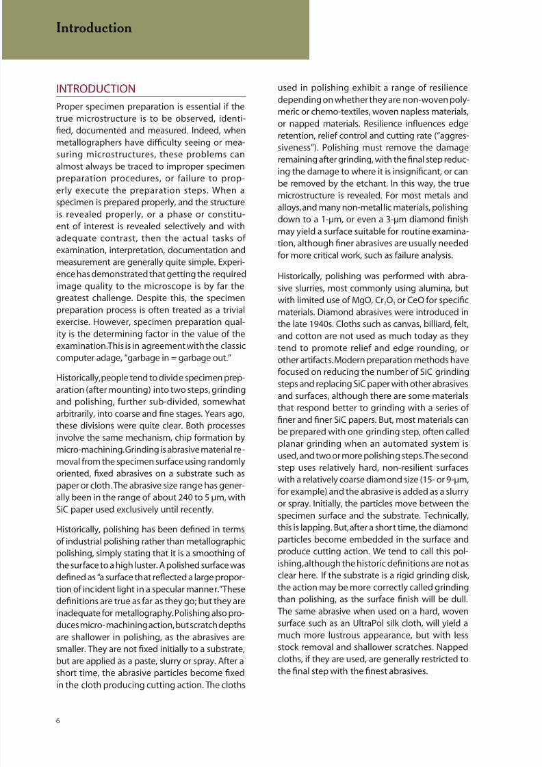
Proper specimen preparation is essential if thetrue microstructure is to be observed, identi-
fied, documented and measured. Indeed, whenmetallographers have difficulty seeing or mea-suring microstructures, these problems canalmost always be traced to improper specimenpreparation procedures, or failure to prop-erly execute the preparation steps. When aspecimen is prepared properly, and the structureis revealed properly, or a phase or constitu-ent of interest is revealed selectively and withadequate contrast, then the actual tasks ofexamination, interpretation, documentation andmeasurement are generally quite simple. Experi-ence has demonstrated that getting the requiredimage quality to the microscope is by far thegreatest challenge. Despite this, the specimenpreparation process is often treated as a trivialexercise. However, specimen preparation qual-ity is the determining factor in the value of theexamination. This is in agreement with the classiccomputer adage, “garbage in = garbage out.”
Historically, people tend to divide specimen prep-aration (after mounting) into two steps, grinding
and polishing, further sub-divided, somewhatarbitrarily, into coarse and fine stages. Years ago,these divisions were quite clear. Both processesinvolve the same mechanism, chip formation bymicro-machining. Grinding is abrasive material re-moval from the specimen surface using randomlyoriented, fixed abrasives on a substrate such aspaper or cloth. The abrasive size range has gener-ally been in the range of about 240 to 5 µm, withSiC paper used exclusively until recently.
Historically, polishing has been defined in terms
of industrial polishing rather than metallographicpolishing, simply stating that it is a smoothing ofthe surface to a high luster. A polished surface wasdefined as “a surface that reflected a large propor-tion of incident light in a specular manner.” Thesedefinitions are true as far as they go; but they areinadequate for metallography. Polishing also pro-duces micro- machining action, but scratch depthsare shallower in polishing, as the abrasives aresmaller. They are not fixed initially to a substrate,but are applied as a paste, slurry or spray. After a
short time, the abrasive particles become fixedin the cloth producing cutting action. The cloths
used in polishing exhibit a range of resiliencedepending on whether they are non-woven poly-meric or chemo-textiles, woven napless materials,or napped materials. Resilience influences edge
retention, relief control and cutting rate (“aggres-siveness”). Polishing must remove the damageremaining after grinding, with the final step reduc-ing the damage to where it is insignificant, or canbe removed by the etchant. In this way, the truemicrostructure is revealed. For most metals andalloys, and many non-metallic materials, polishingdown to a 1-µm, or even a 3-µm diamond finishmay yield a surface suitable for routine examina-tion, although finer abrasives are usually neededfor more critical work, such as failure analysis.
Historically, polishing was performed with abra-sive slurries, most commonly using alumina, butwith limited use of MgO, Cr2O3 or CeO for specificmaterials. Diamond abrasives were introduced inthe late 1940s. Cloths such as canvas, billiard, felt,and cotton are not used as much today as theytend to promote relief and edge rounding, orother artifacts. Modern preparation methods havefocused on reducing the number of SiC grindingsteps and replacing SiC paper with other abrasivesand surfaces, although there are some materialsthat respond better to grinding with a series offiner and finer SiC papers. But, most materials canbe prepared with one grinding step, often calledplanar grinding when an automated system isused, and two or more polishing steps. The secondstep uses relatively hard, non-resilient surfaceswith a relatively coarse diamond size (15- or 9-µm,for example) and the abrasive is added as a slurryor spray. Initially, the particles move between thespecimen surface and the substrate. Technically,this is lapping. But, after a short time, the diamond
particles become embedded in the surface andproduce cutting action. We tend to call this pol-ishing, although the historic definitions are not asclear here. If the substrate is a rigid grinding disk,the action may be more correctly called grindingthan polishing, as the surface finish will be dull.The same abrasive when used on a hard, wovensurface such as an UltraPol silk cloth, will yield amuch more lustrous appearance, but with lessstock removal and shallower scratches. Nappedcloths, if they are used, are generally restricted to
the final step with the finest abrasives.
Introduction

8/20/2019 Buehler Summet, Sample Prep and Analysis
http://slidepdf.com/reader/full/buehler-summet-sample-prep-and-analysis 7/136
7
SAMPLING
The specimens selected for preparation must berepresentative of the material to be examined.
Random sampling, as advocated by statisticians,can rarely be performed by metallographers. Agood exception is the testing of fasteners wherea production lot can be sampled randomly. But,a large forging or casting cannot be sampled atrandom as the component would be renderedcommercially useless. Instead, test locations arechosen systematically based on ease of sampling.Many material specifications dictate the samplingprocedure. In failure analysis studies, specimensare usually removed to study the origin of thefailure, to examine highly stressed areas, to exam-ine secondary cracks, and so forth. This, of course,is not random sampling. It is rare to encounterexcessive sampling as testing costs are usuallyclosely controlled. Inadequate sampling is morelikely to occur.
Normally, a specimen must be removed froma larger mass and then prepared for examina-tion. This requires application of one or moresectioning methods. For example, in a manu-facturing facility, a piece may be cut from a bar
of incoming metal with a power hacksaw, or anabrasive cutter used dry, i.e., without a coolant.The piece is then forwarded to the laboratorywhere it is cut smaller to obtain a size moreconvenient for preparation. All sectioningprocesses produce damage; some methods(such as flame cutting or dry abrasive cutting)produce extreme amounts of damage. Tradi-tional laboratory sectioning procedures, usingabrasive cut-off saws, introduce a minor amountof damage that varies with the material being
cut and its thermal and mechanical history. It isgenerally unwise to use the original face cut inthe shop as the starting point for metallographicpreparation as the depth of damage at thislocation may be quite extensive. This damagemust be removed if the true structure is to berevealed. However, because abrasive grinding andpolishing steps also produce damage, wherethe depth of damage decreases with decreasingabrasive size, the preparation sequence mustbe carefully planned and performed; otherwise,
preparation-induced artifacts will be interpretedas structural elements.
Many metallographic studies require more thanone specimen and sectioning is nearly alwaysrequired to extract the specimens. A classicexample of multiple specimen selection is
the evaluation of the inclusion content of steels.One specimen is not representative of the wholelot of steel, so sampling becomes important. ASTMstandards E45, E1122 and E1245 give advice onsampling procedures for inclusion studies. To studygrain size, it is common to use a single specimenfrom a lot. This may or may not be adequate,depending upon the nature of the lot. Good engi-neering judgment should guide sampling, in suchcases. In many cases, a product specification maydefine the procedure rigorously. Grain structures
are not always equiaxed and it may be misleadingto select only a plane oriented perpendicular tothe deformation axis, a “transverse” plane, for sucha study. If the grains are elongated due to process-ing, which does happen, the transverse plane willusually show that the grains are equiaxed in shapeand smaller in diameter than the true grain size. Tostudy the effect of deformation on the grain shapeof wrought metals, a minimum of two sections areneeded — one perpendicular to, and the otherparallel to, the direction of deformation.
Sampling
HELPFUL HINTS FOR
SAMPLING
When developing a sampling
plan for an unfamiliar part or
component, determine the orientation of the
piece relative to the original wrought or cast
starting material and prepare sections on the
longitudinal, transverse and planar surfaces,
or radial and transverse surfaces, to reveal thedesired information. Remember that the micro-
structure may look much more homogeneous
than it is on a transverse plane compared to a
longitudinal or planar surface. If the starting
material was cold worked, or not fully recrys-
tallized after hot working, grain structures
will appear to be equiaxed and smaller on a
transverse plane, but non-equiaxed and larger
on a longitudinal or planar surface.

8/20/2019 Buehler Summet, Sample Prep and Analysis
http://slidepdf.com/reader/full/buehler-summet-sample-prep-and-analysis 8/136
8
GOALS OF SPECIMEN PREPARATION
The preparation procedure and the preparedspecimen should have the following characteris-
tics to reveal the true microsctructure*:
• Deformation induced by sectioning, grinding
and polishing must be removed or be shallowenough to be removed by the etchant.
• Coarse grinding scratches must be removed;
very fine polishing scratches may be tolerablefor routine production work.
• Pullout, pitting, cracking of hard particles,
smear, and other preparation artifacts, must be
avoided.
• Relief (i.e., excessive surface height variations
between structural features of different hard-ness) must be minimized; otherwise portions ofthe image will be out of focus at high magnifica-tions.
• The surface must be flat, particularly at
edges (if they are of interest) or they cannotbe imaged.
• Coated or plated surfaces must be kept at if
they are to be examined, measured or photo-graphed.
• Specimens must be cleaned adequately
between preparation steps, after preparation,and after etching.
• The etchant chosen must be either general or
selective in its action (reveal only the phaseor constituent of interest, or at least producestrong contrast or color differences betweentwo or more phases present), depending uponthe purpose of the investigation, and mustproduce crisp, clear phase or grain boundaries,and strong contrast.
If these characteristics are met, then the truestructure will be revealed and can be interpreted,measured and recorded. The preparation methodshould be as simple as possible, should yield con-
sistent high quality results in a minimum of timeand cost and must be reproducible.
Preparation of metallographic specimens [1-3] generally requires five major operations: (a)sectioning, (b) mounting (optional), (c) grinding,(d) polishing and (e) etching (optional).
Method Development
The methods presented in this book use timesthat are conservative so that the vast majority ofcompositions of alloys or materials of a specifictype can be prepared to yield the true microstruc-ture without artifacts or observable scratches.They were developed using an 8-inch (200 mm)diameter platen system with six 1.25-inch (30 mm)diameter mounted specimens. For each category,except beryllium, a wide variety of specimens withdifferent processing histories were prepared usingthe stated methods.
For any metal or material category, there are
compositions or processing conditions thatmake those specimens easier, or more difficult,to prepare compared to the “average” specimen.In general, even the most difficult specimens ofa given type can be prepared perfectly usingthese methods with no more than one etch andre-polish (repeat last step) cycle. For perfect coloretching results, it may be necessary to follow thecycle with a brief vibratory polish, depending uponthe material.
When working with easier to prepare specimens,or for routine work where the same degree ofperfection is not required, the user can reduce thetimes, or eliminate one or two steps, or the finalstep, and get satisfactory results. Modificationsto the recommended procedures are left to theuser based upon their knowledge of the degreeof difficulty in preparing their specimens and thedesired quality of preparation.
Goals of Specimen Preparation
* Not all of these apply to every specimen.

8/20/2019 Buehler Summet, Sample Prep and Analysis
http://slidepdf.com/reader/full/buehler-summet-sample-prep-and-analysis 9/136
9
Figure 1. AbrasiMatic 300 Abrasive Cutter
SECTIONING
Bulk samples for subsequent laboratory sectioningmay be removed from larger pieces using methods
such as core drilling, band or hack-sawing, flamecutting, or similar methods. However, when thesetechniques are used, precautions must be taken toavoid alteration of the microstructure in the areaof interest. Laboratory abrasive-wheel cutting isrecommended to establish the desired plane ofpolish. In the case of relatively brittle materials,sectioning may be accomplished by fracturingthe specimen at the desired location.
Abrasive-Wheel Cutting
The most commonly used sectioning device inthe metallographic laboratory is the abrasivecut-off machine, Figure 1. All abrasive-wheelsectioning should be performed wet. An ampleflow of coolant, with an additive for corrosionprotection and lubrication, should be directedinto the cut. Wet cutting will produce a smoothsurface finish and, most importantly, will guardagainst excessive surface damage causedby overheating. Abrasive wheels should beselected according to the manufacturer’s
recommendations. Table 1 summarizes Buehler’srecommendations for our machines. Specimensmust be fixtured securely during cutting, andcutting pressure should be applied carefully toprevent wheel breakage. Some materials, such asCP (commercial purity) titanium, Figure 2, are quiteprone to sectioning damage.
Wheels consist of abrasive particles, chieflyalumina or silicon carbide, and filler in a bindermaterial that may be a resin, rubber, or a mixtureof resin and rubber. Alumina (aluminum oxide) isthe preferred abrasive for ferrous alloys and siliconcarbide is the preferred abrasive for nonferrousmetals and minerals. Wheels have different bondstrengths and are recommended based on thesuitability of their bond strength and abrasivetype for the material to be sectioned. In general,as the hardness of a material increases, abrasivesbecome dull more quickly, and the binder mustbreak-down and release the abrasives whenthey become dull so that fresh abrasive particles
are available to maintain cutting speed and ef-ficiency. Consequently, these wheels are called“consumable” wheels because they wear awaywith usage. If they do not wear at the proper rate,dull abrasives will rub against the region beingcut generating heat and altering the existing truemicrostructure. If this heat becomes excessive, itcan lead to grain or particle coarsening, softeningor phase transformations, and in extreme case, toburning or melting. Different materials have dif-ferent sensitivities to this problem. But, the need
to balance the wheel break-down rate with thehardness of the piece being sectioned, producesthe various recommendations listed for cuttingdifferent materials and metals with different hard-nesses, such as steels.
The size of the cut-off machine also affects wheelparameters. As the diameter of the wheel isincreased, to permit sectioning of larger speci-mens, the wheel thickness is generally increased.Even so, for a given diameter wheel, there may be
a range of thicknesses available. Thicker wheelsare stronger but remove more material in the cut.This may, or may not, be a problem. But, thicker
Sectioning
Figure 2. Cutting damage (top) and a “burr” after sectioning of
an annealed CP titanium specimen (mod. Weck’s reagent, 100X,
polarized light plus sensitive tint).

8/20/2019 Buehler Summet, Sample Prep and Analysis
http://slidepdf.com/reader/full/buehler-summet-sample-prep-and-analysis 10/136
10
wheels do generate more heat during cuttingthan a thinner wheel, everything else being heldconstant. Consequently, for cases where the kerfloss or heat generation must be minimized, selectthe thinnest available wheel of the proper bondstrength and abrasive. Buehler’s AcuThin Cut-offWheels offer the thinnest possible wheels fordelicate abrasive sectioning. Buehler also hasdiamond cut-off blades with resin bonded orRimlock 1 metal bonded blade forms in sizes from8-inch (203 mm) to 12-inch (305 mm) diameters.
Resin-bonded diamond blades are ideal for cuttingvery hard cemented carbide specimens; Rimlockor continuous rim blades are recommended forcutting rocks and petrographic specimens.
Historically, the most common cutter design hasbeen the so-called “chop” cutter. Basically, theblade is attached to a motor and the operatorpulls a handle to drive the blade downward intothe work piece. Because of the design, the blademoves through an arc as it is pulled downward,Figure 3a. For efficient cutting, the piece must beoriented to minimize the contact area with thewheel. For small parts, this is generally easy to do,
but for larger parts, it may not be possible to orientthe specimen properly for optimal cutting. Whena round wheel is used to cut a round bar in chopmode, the contact area is initially very small. As thecut progresses, the cut widens until the maximumdiameter is reached. After this, the contact areadecreases until sectioning is completed. Underapplication of a constant load, the pressure onthe abrasive particles in the cut decreases as thecontact area increases. If the pressure applied tothe grains is inadequate for cutting, then heat is
generated which may not be dissipated by thecoolant, which causes deformation damage, phasechanges and possibly burning or melting.
A chop cutter may be set up to pulse as theload is applied, that is, the wheel is fed into thespecimen, and then feeding is halted momen-tarily, Figure 3b. Pulsing causes the wheel to bestress shocked which removes both dull andsharp abrasive from the wheel as new abrasiveis exposed to the cut. While a better cut maybe obtained, cutting time and wheel wear areincreased.
1Rimlock is a registered trademark of Felker Operations.
Sectioning
Table 1. Buehler’s Abrasive Cutting Recommendations
Available Diameters
Recommended Use Bond Abrasive (Inches) (mm)
General Usage Blades
Tools Steels 60 HRC andRubber Resin Al2O3 9, 10, 12, 230, 250, 300,Above Carburized Steels 14, 16, 18 350, 400, 455
Hard Steel 50 HRC Rubber Resin Al2O3 9, 10, 12, 230, 250, 300,14, 16, 18 350, 400, 455
Medium Hard Steel Rubber Resin Al2O3 9, 10, 12, 230, 250, 300,35-50 HRC 14, 16, 18 350, 400, 455
Soft or Annealed SteelRubber Al2O3 9, 10, 12, 230, 250, 300,15-35 HRC 46-90 HRB 14, 16, 18 350, 400, 455
Medium Hard Nonferrous Materials, Rubber SiC 9, 10, 12, 230, 250, 300,Uranium, Titanium, Zirconium 14, 16, 18 350, 400, 455
Soft Nonferrous Materials Rubber SiC 9, 10, 12, 230, 250, 300,Aluminum, Brass, etc. 14, 16, 18 350, 400, 455
Superalloys Rubber Al2O3 10, 12, 250, 300,14, 16, 18 350, 400, 450
Thin Blades to Minimize Kerf Loss and Cutting Deformation
Tool, Hard Steel, Rubber Al2O3 5, 9, 10*, 12 130, 230,≤ 45 RC 250*, 300
Medium Hard, Soft SteelRubber Al2O3 5, 7, 9, 130, 180, 230,≥ 45 HRC 10, 12, 14 250*, 300, 350
Hard or Soft Nonferrous Materials Rubber SiC 7 180
*Rubber Resin Bond
Refer to Buehler’s Consumables Buyers Guide for ordering information, and exact dimensions of arbor sizes, outer diameter, and thickness of Buehler Metabrase,
Delta, and Acu-Thin Abrasive Cut-off Wheels
8/20/2019 Buehler Summet, Sample Prep and Analysis
http://slidepdf.com/reader/full/buehler-summet-sample-prep-and-analysis 11/136
11
Wheel Path
Sample
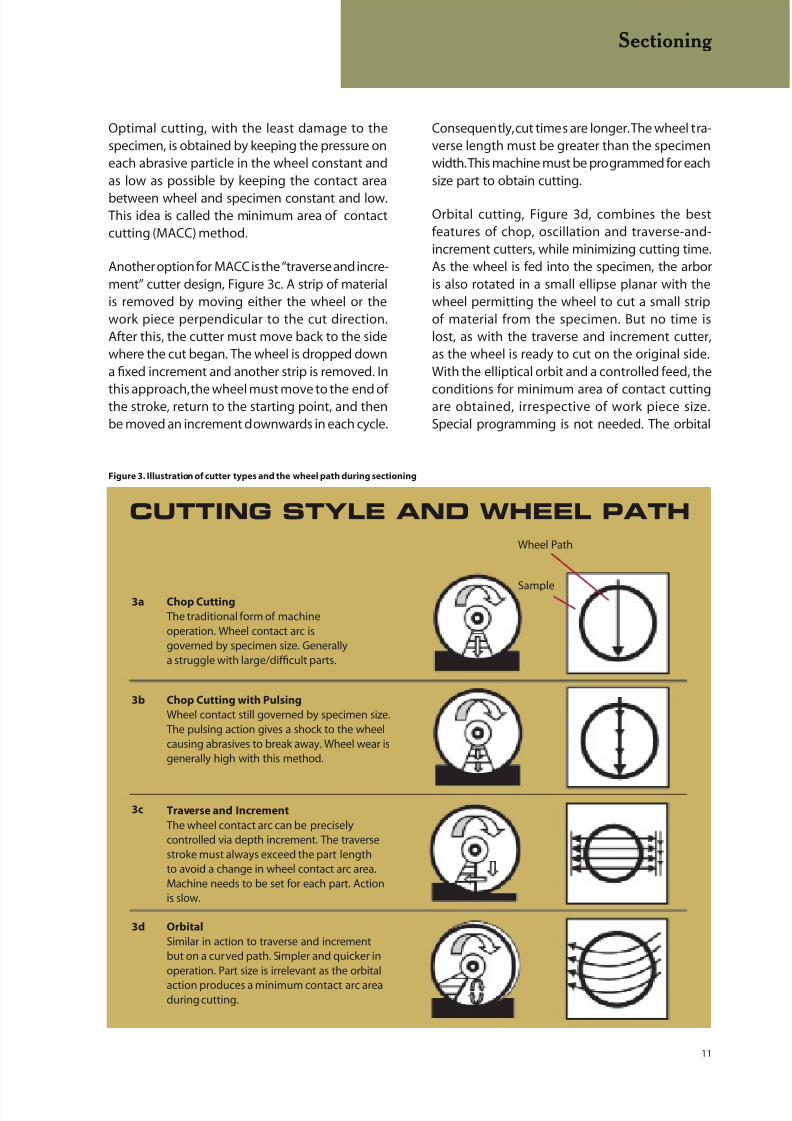
Chop Cutting with Pulsing
Wheel contact still governed by specimen size.The pulsing action gives a shock to the wheelcausing abrasives to break away. Wheel wear isgenerally high with this method.
3b
Chop Cutting
The traditional form of machineoperation. Wheel contact arc isgoverned by specimen size. Generallya struggle with large/difficult parts.
3a
Traverse and Increment The wheel contact arc can be preciselycontrolled via depth increment. The traversestroke must always exceed the part lengthto avoid a change in wheel contact arc area.Machine needs to be set for each part. Actionis slow.
3c
Orbital
Similar in action to traverse and incrementbut on a curved path. Simpler and quicker inoperation. Part size is irrelevant as the orbital
action produces a minimum contact arc areaduring cutting.
3d
CUTTING STYLE AND WHEEL PATH
Optimal cutting, with the least damage to thespecimen, is obtained by keeping the pressure oneach abrasive particle in the wheel constant andas low as possible by keeping the contact area
between wheel and specimen constant and low.This idea is called the minimum area of contactcutting (MACC) method.
Another option for MACC is the “traverse and incre-ment” cutter design, Figure 3c. A strip of materialis removed by moving either the wheel or thework piece perpendicular to the cut direction.After this, the cutter must move back to the sidewhere the cut began. The wheel is dropped downa fixed increment and another strip is removed. In
this approach, the wheel must move to the end ofthe stroke, return to the starting point, and thenbe moved an increment downwards in each cycle.
Consequently, cut times are longer. The wheel tra-verse length must be greater than the specimenwidth. This machine must be programmed for eachsize part to obtain cutting.
Orbital cutting, Figure 3d, combines the bestfeatures of chop, oscillation and traverse-and-increment cutters, while minimizing cutting time.As the wheel is fed into the specimen, the arboris also rotated in a small ellipse planar with thewheel permitting the wheel to cut a small stripof material from the specimen. But no time islost, as with the traverse and increment cutter,as the wheel is ready to cut on the original side.With the elliptical orbit and a controlled feed, the
conditions for minimum area of contact cuttingare obtained, irrespective of work piece size.Special programming is not needed. The orbital
Figure 3. Illustration of cutter types and the wheel path during sectioning
Sectioning
8/20/2019 Buehler Summet, Sample Prep and Analysis
http://slidepdf.com/reader/full/buehler-summet-sample-prep-and-analysis 12/136
12
cutting concept is available in the Delta cutterfrom Buehler. These also feature Smartcut, whichwill sense motor overloading during a cut, if itoccurs, and reduce the feed rate automatically.
When it is safe to return to the original feed rate,Smartcut will do so.
Precision Saws
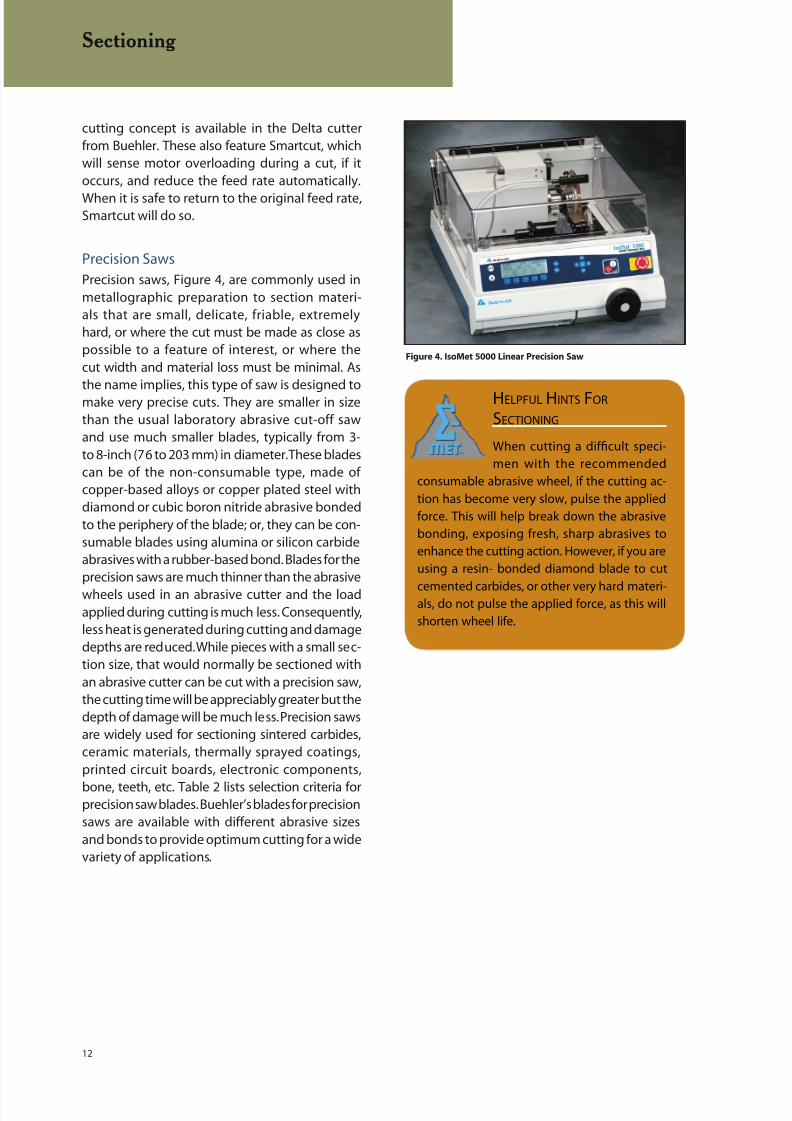
Precision saws, Figure 4, are commonly used inmetallographic preparation to section materi-als that are small, delicate, friable, extremelyhard, or where the cut must be made as close aspossible to a feature of interest, or where thecut width and material loss must be minimal. Asthe name implies, this type of saw is designed tomake very precise cuts. They are smaller in sizethan the usual laboratory abrasive cut-off sawand use much smaller blades, typically from 3-to 8-inch (76 to 203 mm) in diameter. These bladescan be of the non-consumable type, made ofcopper-based alloys or copper plated steel withdiamond or cubic boron nitride abrasive bondedto the periphery of the blade; or, they can be con-sumable blades using alumina or silicon carbideabrasives with a rubber-based bond. Blades for theprecision saws are much thinner than the abrasive
wheels used in an abrasive cutter and the loadapplied during cutting is much less. Consequently,less heat is generated during cutting and damagedepths are reduced. While pieces with a small sec-tion size, that would normally be sectioned withan abrasive cutter can be cut with a precision saw,the cutting time will be appreciably greater but thedepth of damage will be much less. Precision sawsare widely used for sectioning sintered carbides,ceramic materials, thermally sprayed coatings,printed circuit boards, electronic components,
bone, teeth, etc. Table 2 lists selection criteria forprecision saw blades. Buehler’s blades for precisionsaws are available with different abrasive sizesand bonds to provide optimum cutting for a widevariety of applications.
Sectioning
Figure 4. IsoMet 5000 Linear Precision Saw
HELPFUL HINTS FOR
SECTIONING
When cutting a difficult speci-
men with the recommended
consumable abrasive wheel, if the cutting ac-
tion has become very slow, pulse the applied
force. This will help break down the abrasive
bonding, exposing fresh, sharp abrasives to
enhance the cutting action. However, if you are
using a resin- bonded diamond blade to cut
cemented carbides, or other very hard materi-als, do not pulse the applied force, as this will
shorten wheel life.

8/20/2019 Buehler Summet, Sample Prep and Analysis
http://slidepdf.com/reader/full/buehler-summet-sample-prep-and-analysis 13/136
13
Table 2. Selection Criteria for Precision Saw Blades
3″ x 0.006″ 4″ x 0.012″ 5″ x 0.015″ 6″ x 0.020″ 7″ x 0.025″ 8″ x 0.035″ (75mm x (100mm x (125mm x (150mm x (180mm x (200mm x
BLADE SERIES 0.2mm) 0.3mm) 0.4mm) 0.5mm) 0.6mm) 0.9mm)
Diamond Wafering Blades
Series 30HC Diamond, for use X** X** Xwith plastics, polymers, and rubber
Series 20HC Diamond, for aggressive X* X Xgeneral sectioning of ferrous andnonferrous materials includingtitanium alloys
Series 15HC Diamond, for general X X X X X Xuse with ferrous and nonferrousalloys, copper, aluminum, metalmatrix, composites, PC boards,thermal spray coatings, titaniumalloys, bone, teeth, and tungsten carbide
Series 20LC Diamond, for use with X* Xhard/tough materials structural
ceramics, boron carbide, boronnitride, and silicon carbide
Series 15LC Diamond, for use with X X X X X Xhard/brittle materials structuralceramics, boron carbide, boronnitride, and silicon carbide
Series 10LC Diamond, for use with X X X* Xmedium to soft ceramics, electronicpackages, unmounted integratedcircuits, GaAs, AIN and glass fiberreinforced composites, barium titanate,rare earth oxides, and computer chips
Series 5LC Diamond, for use with X Xsoft friable ceramics, electronicpackages, unmounted integratedcircuits, composites with finereinforcing media, CaF2, MgF2,and carbon composites
IsoCut Wafering Blades
Low Concentration Cubic Boron Nitride X X X X X X(CBN) abrasive blades work well formany tough materials givingsignificantly shorter cut times
For iron, carbon steels, high alloy X X X X X Xsteels, cobalt alloys, nickel super-alloys, and lead alloys
High Concentration Cubic Boron Nitride X X X X X X(CBN) for use with Iron and Cobalt BaseAlloys, Nickel Base Super Alloys, and LeadBased Alloys
General Usage Abrasive Cut-off Bond/Wheels 0.03″ (0.8mm) thick Abrasive
For ferrous materials, stainless R/Al2O3 Xsteels, cast irons, andthermal spray coatings
For tough nonferrous metals, R/SiC Xaluminum, copper, titanium,uranium, zirconium
AcuThin Abrasive Cut-off Bond/Wheels 0.019″ (0.5mm) thick Abrasive
For sectioning small, delicatespecimens or where minimaldeformation and kerf loss is theprimary concern
Tool, hard steel, ≥ 45 HRC R/Al2O3 X
Medium hard, soft steel ≤ 45 HRC R/Al2O3 X
* Alternate blade thickness of 0.020″ (0.5 mm) ** Alternate blade thickness of 0.030″ (0.8 mm)
For a complete listing of Buehler consumable supplies for use with the Isomet Precision Saws, please refer to Buehler’s Consumables Buyers Guide.
Sectioning
8/20/2019 Buehler Summet, Sample Prep and Analysis
http://slidepdf.com/reader/full/buehler-summet-sample-prep-and-analysis 14/136
14
MOUNTING OF SPECIMENS
The primary purpose of mounting metallo-graphic specimens is for convenience in handling
specimens of difficult shapes or sizes during thesubsequent steps of metallographic prepara-tion and examination. A secondary purpose is toprotect and preserve extreme edges or surfacedefects during metallographic preparation. Themethod of mounting should in no way be injuriousto the microstructure of the specimen. Pressureand heat are the most likely sources of injuriouseffects.
Phenolic plastics were introduced to metal-lography in 1928 for encapsulating specimensby hot compression mounting. Prior to thattime, specimens were prepared unmounted, ormounted in flours of sulfur, wax or low-meltingpoint alloys, such as Wood’s metal. These “mount-ing compounds” were not without their problems.Introduction of polymers was a big improvementover these methods. Subsequently, many polymerswere evaluated for use as mounting compounds,as they were introduced to the market. Develop-ment of castable resins in the 1950’s added newresins to the metallographer’s tool chest. The sim-
plicity of mounting without using a press, and theirlow curing temperatures, made castable resins anattractive alternative.
Clamp Mounting
Clamps have been used for many years tomount cross sections of thin sheet specimens.Several specimens can be clamped conveniently
in sandwich form making this a quick, convenientmethod for mounting thin sheet specimens.When done properly, edge retention is excellent,and seepage of fluids from crevices betweenspecimens does not occur. The outer clampedges should be beveled to minimize damageto polishing cloths. If clamps are improperly usedso that gaps exist between specimens, fluids andabrasives can become entrapped and will seep outobscuring edges and can cause cross contamina-tion. This problem can be minimized by proper
tightening of clamps, by use of plastic spacersbetween specimens, or by coating specimen sur-faces with epoxy before tightening.
Compression Mounting
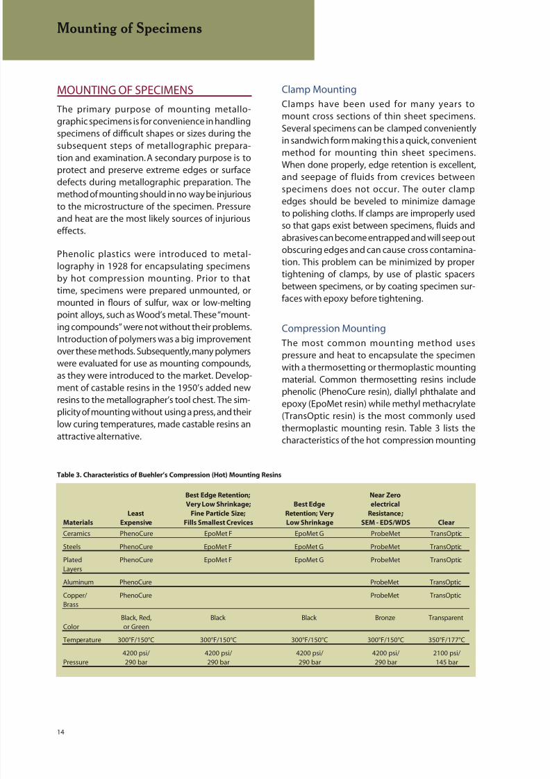
The most common mounting method usespressure and heat to encapsulate the specimenwith a thermosetting or thermoplastic mountingmaterial. Common thermosetting resins includephenolic (PhenoCure resin), diallyl phthalate andepoxy (EpoMet resin) while methyl methacrylate(TransOptic resin) is the most commonly usedthermoplastic mounting resin. Table 3 lists thecharacteristics of the hot compression mounting
Mounting of Specimens
Table 3. Characteristics of Buehler’s Compression (Hot) Mounting Resins
Best Edge Retention; Near Zero
Very Low Shrinkage; Best Edge electrical
Least Fine Particle Size; Retention; Very Resistance;
Materials Expensive Fills Smallest Crevices Low Shrinkage SEM - EDS/WDS Clear
Ceramics PhenoCure EpoMet F EpoMet G ProbeMet TransOptic
Steels PhenoCure EpoMet F EpoMet G ProbeMet TransOptic
Plated PhenoCure EpoMet F EpoMet G ProbeMet TransOpticLayers
Aluminum PhenoCure ProbeMet TransOptic
Copper/ PhenoCure ProbeMet TransOpticBrass
Black, Red, Black Black Bronze TransparentColor or Green
Temperature 300°F/150°C 300°F/150°C 300°F/150°C 300°F/150°C 350°F/177°C
4200 psi/ 4200 psi/ 4200 psi/ 4200 psi/ 2100 psi/Pressure 290 bar 290 bar 290 bar 290 bar 145 bar
8/20/2019 Buehler Summet, Sample Prep and Analysis
http://slidepdf.com/reader/full/buehler-summet-sample-prep-and-analysis 15/136
15
resins. Both thermosetting and thermoplasticmaterials require heat and pressure during themolding cycle; but, after curing, mounts madeof thermoplastic resins must be cooled under
pressure to at least 70 °C while mounts made ofthermosetting materials may be ejected fromthe mold at the maximum molding temperature.However, cooling thermosetting resins under pres-sure to near ambient temperature before ejectionwill significantly reduce shrinkage gap formation.Never rapidly cool a thermosetting resin mountwith water after hot ejection from the moldingtemperature. This causes the metal to pull awayfrom the resin producing shrinkage gaps thatpromote poor edge retention, see Figure 5, be-
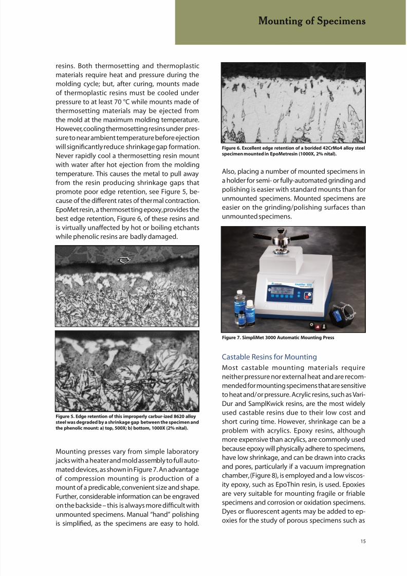
cause of the different rates of thermal contraction.EpoMet resin, a thermosetting epoxy, provides thebest edge retention, Figure 6, of these resins andis virtually unaffected by hot or boiling etchantswhile phenolic resins are badly damaged.
Mounting presses vary from simple laboratory jacks with a heater and mold assembly to full auto-mated devices, as shown in Figure 7. An advantageof compression mounting is production of amount of a predicable, convenient size and shape.Further, considerable information can be engraved
on the backside – this is always more difficult withunmounted specimens. Manual “hand” polishingis simplified, as the specimens are easy to hold.
Also, placing a number of mounted specimens ina holder for semi- or fully-automated grinding andpolishing is easier with standard mounts than for
unmounted specimens. Mounted specimens areeasier on the grinding/polishing surfaces thanunmounted specimens.
Castable Resins for Mounting
Most castable mounting materials requireneither pressure nor external heat and are recom-mended for mounting specimens that are sensitiveto heat and/or pressure. Acrylic resins, such as Vari-
Dur and SamplKwick resins, are the most widelyused castable resins due to their low cost andshort curing time. However, shrinkage can be aproblem with acrylics. Epoxy resins, althoughmore expensive than acrylics, are commonly usedbecause epoxy will physically adhere to specimens,have low shrinkage, and can be drawn into cracksand pores, particularly if a vacuum impregnationchamber, (Figure 8), is employed and a low viscos-ity epoxy, such as EpoThin resin, is used. Epoxiesare very suitable for mounting fragile or friable
specimens and corrosion or oxidation specimens.Dyes or fluorescent agents may be added to ep-oxies for the study of porous specimens such as
Figure 5. Edge retention of this improperly carbur-ized 8620 alloy
steel was degraded by a shrinkage gap between the specimen and
the phenolic mount: a) top, 500X; b) bottom, 1000X (2% nital).
Mounting of Specimens
Figure 6. Excellent edge retention of a borided 42CrMo4 alloy steel
specimen mounted in EpoMet resin (1000X, 2% nital).
Figure 7. SimpliMet 3000 Automatic Mounting Press

8/20/2019 Buehler Summet, Sample Prep and Analysis
http://slidepdf.com/reader/full/buehler-summet-sample-prep-and-analysis 16/136
16
thermal spray coated specimens. Most epoxiesare cured at room temperature, and curing timescan vary from 2 to 8 hours. Some can be cured atslightly elevated temperatures in less time, as longas the higher temperature does not adverselyaffect the specimen. Table 4 lists the characteristicsof Buehler’s castable resins.
Cast epoxy resins provide better edge reten-tion than cast acrylic resins, mainly due to thebetter adhesion of epoxy to the specimen andtheir lower shrinkage. Acrylics usually do not
bond to the specimen and, because they shrinkmore during curing, a gap is inevitability formedbetween specimen and mount. When a shrink-age gap is present, edge retention is usuallypoor. To improve edge retention with castablemounts, the specimen can be plated, for example,with electroless nickel using the EdgeMet kit, orFlat Edge Filler particles can be added to the resin.To obtain electrical conductivity, Conductive Fillerparticles can be added to the castable resin.
When preparing castable resin mounts, particu-larly epoxy mounts by manual (“hand”) methods,the metallographer will observe that the surfacetension between the mount and the working
Table 4. Characteristics of Buehler’s Castable Resins
Peak Shore D Cure Recommended
Name Type Temperature Hardness* Time Mold Comments
EpoThin Epoxy 80 °F 78 Best Edge 9 Any Low viscosity, low shrinkage,(27 °C) Retention hours transparent, best for vacuum
impregnation
EpoxiCure Epoxy 82 °F 82 Best Edge 6 Any Moderate hardness, transparent,(28 °C) Retention hours low shrinkage
EpoxiCure NC Epoxy 82 °F 82 Excellent Edge 6 Any General purpose epoxy; viscosity(28 °C) Retention hours 400-600 cps at 77 °F, (25 °C) good
adherence to specimen; can be usedto vacuum impregnate voids(viscosity can be reduced bywarming to 122 ° F (50 °C)); goodfor heat-sensitive specimens (verylow exotherm during polymerization)
EpoKwick Epoxy 185 °F 82 Good 90 Sampl-Kup Faster epoxy, some shrinkage,(85 °C) Edge Retention minutes transparent
EpoColor Epoxy 175 °F 82 Good Edge 90 Sampl-Kup Dye-enhanced epoxy, displays red(79 °C) Retention minutes under darkfield and polarized light
EpoHeat Epoxy 295 °F 82 Best Edge 90 Any Fast, heat cure epoxy system with
(Transparent) (79 °C) Retention minutes low shrinkage and low viscosity (32cps at 176 °F (80 °C)). Excellent forimpregnation. Requires oven cure.Golden color.
VariDur 3000 Acrylic 252 °F 90 15-30 Any Minimal shrinkage, good edge(122 °C) minutes retention
VariDur Acrylic 170 °F 85 Fair Edge 10 Any Fast cure, harder acrylic opaque,(77 °C) Retention minutes abrasive resistant
SamplKwick Acrylic 175 °F 80 Poor 5-8 Any Very fast cure, translucent,(79 °C) Edge Retention minutes some shrinkage
VariKleer Acrylic 212 °F 84 10-15 Sampl-Kup Designed for use with a pressure(Transparent) (100 °C) minutes vessel, this general use acrylic
hardens crystal clear with minimalshrinkage. To achieve crystal clear
samples, reusable silicon or EPDMmolds should not be used.
* Hardness differences appear negligible but abrasion resistance has a significant effect on edge rounding
Mounting of Specimens
Figure 8. Vacuum Impregnation Equipment
8/20/2019 Buehler Summet, Sample Prep and Analysis
http://slidepdf.com/reader/full/buehler-summet-sample-prep-and-analysis 17/136
17
surface is much higher than with a compressionmount. This can make holding the mount morechallenging. If automated devices are used, themetallographer may hear “chatter” (noise) during
rough grinding due to the greater surface ten-sion. The chatter can be reduced or stopped bychanging to contra mode (head and platen rotatein opposite directions.)
Acrylics (and some epoxies) do generate consider-able heat during curing and this can be stronglyinfluenced by the molding technique used. Nelson
[4] measured the exotherm produced by polymer-izing an acrylic resin using two procedures: a glassmold on a glass plate (insulative) and an alumi-
num mold on an aluminum plate (conductive).Polymerization produced a maximum exothermof 132°C using the insulative approach but only42°C using the conductive approach. Note that132°C is not much less than the 150°C temperatureused in hot compression mounting! Nelson alsomeasured the exotherm produced when an epoxyresin was cured in a phenolic ring form placed ona pasteboard base. Although this was an insula-tive approach, the maximum temperature duringpolymerization was only 7 °C, a vast improvementover the acrylics.
Nelson’s work applies to specific acrylic andepoxy resins molded upon specific conditions.While the epoxy that he used exhibited a lowexotherm, this does not imply that all epoxyresins will exhibit such low exotherms in polym-erization. Epoxy resins that cure in short timeperiods develop much higher exotherms, thatcan exceed that of acrylic resins. In addition tothe speed of curing of the epoxy resin, other fac-tors do influence the magnitude of the exotherm
during polymerization. The larger the mass ofepoxy in the mount, the faster it will set and thegreater the exotherm. Indeed, very large mountscan generate enough heat to crack extensively.Heating the resin makes it less viscous andspeeds up curing, also generating more heatduring polymerization. The mold material alsocan influence curing time and temperature.For example, EpoxiCure cures fastest inSamplKup plastic molds, slower in phenolic ringforms, and still slower in the reuseable rubber
mounting cups. Consequently, the exotherm willbe greater when using the SamplKup type moldand lowest when using the EPDM mounting cups.All of these factors must be considered if the exo-therm must be minimized.
Edge Preservation
Edge preservation is a classic metallographicproblem and many “tricks” have been promoted(most pertaining to mounting, but some to grind-
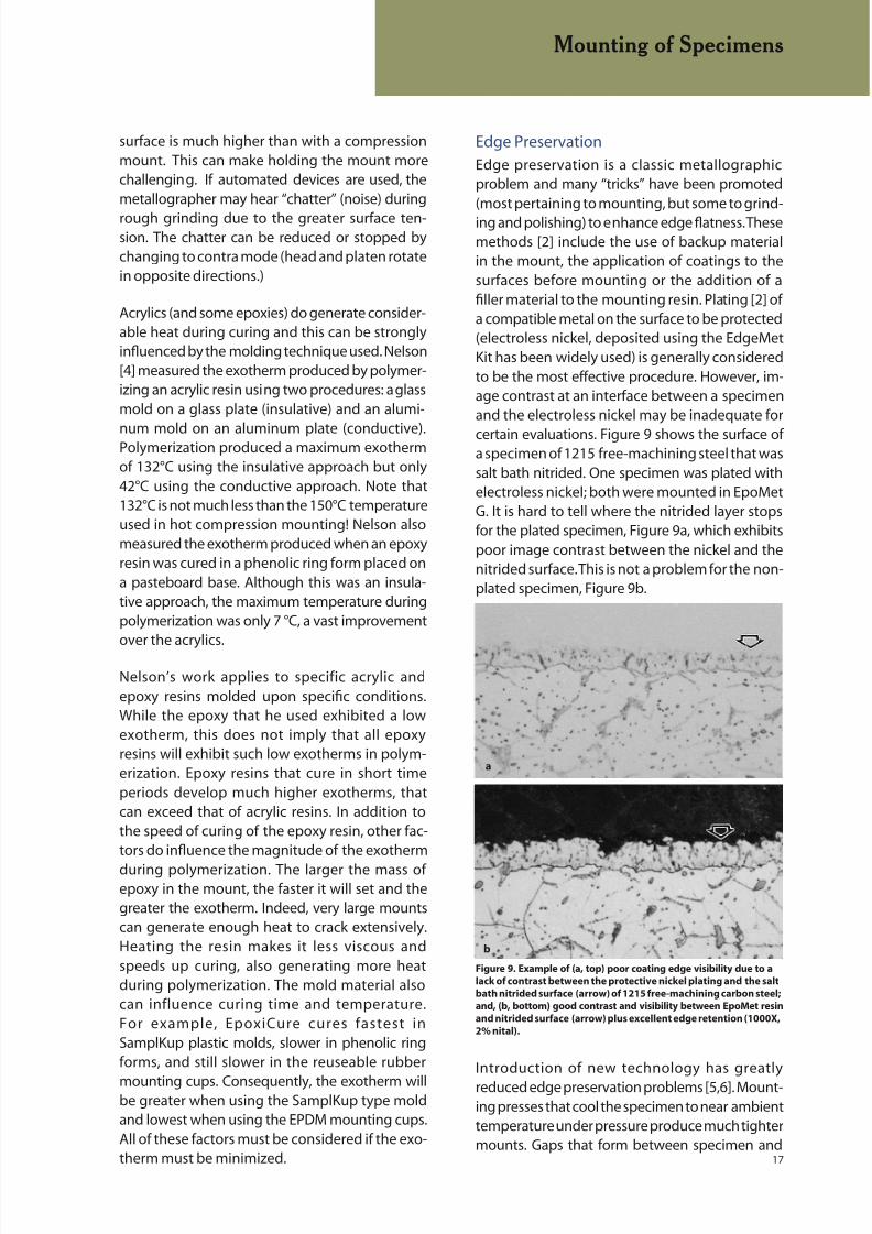
ing and polishing) to enhance edge flatness. Thesemethods [2] include the use of backup materialin the mount, the application of coatings to thesurfaces before mounting or the addition of afiller material to the mounting resin. Plating [2] ofa compatible metal on the surface to be protected(electroless nickel, deposited using the EdgeMetKit has been widely used) is generally consideredto be the most effective procedure. However, im-age contrast at an interface between a specimenand the electroless nickel may be inadequate for
certain evaluations. Figure 9 shows the surface ofa specimen of 1215 free-machining steel that wassalt bath nitrided. One specimen was plated withelectroless nickel; both were mounted in EpoMetG. It is hard to tell where the nitrided layer stopsfor the plated specimen, Figure 9a, which exhibitspoor image contrast between the nickel and thenitrided surface. This is not a problem for the non-plated specimen, Figure 9b.
Introduction of new technology has greatly
reduced edge preservation problems [5,6]. Mount-ing presses that cool the specimen to near ambienttemperature under pressure produce much tightermounts. Gaps that form between specimen and
Mounting of Specimens
Figure 9. Example of (a, top) poor coating edge visibility due to a
lack of contrast between the protective nickel plating and the salt
bath nitrided surface (arrow) of 1215 free-machining carbon steel;
and, (b, bottom) good contrast and visibility between EpoMet resin
and nitrided surface (arrow) plus excellent edge retention (1000X,
2% nital).
b
a
8/20/2019 Buehler Summet, Sample Prep and Analysis
http://slidepdf.com/reader/full/buehler-summet-sample-prep-and-analysis 18/136
18
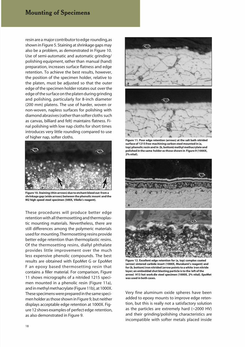
resin are a major contributor to edge rounding, asshown in Figure 5. Staining at shrinkage gaps mayalso be a problem, as demonstrated in Figure 10.Use of semi-automatic and automatic grinding/
polishing equipment, rather than manual (hand)preparation, increases surface flatness and edgeretention. To achieve the best results, however,the position of the specimen holder, relative tothe platen, must be adjusted so that the outeredge of the specimen holder rotates out over theedge of the surface on the platen during grindingand polishing, particularly for 8-inch diameter(200 mm) platens. The use of harder, woven ornon-woven, napless surfaces for polishing withdiamond abrasives (rather than softer cloths such
as canvas, billiard and felt) maintains flatness. Fi-nal polishing with low nap cloths for short timesintroduces very little rounding compared to useof higher nap, softer cloths.
These procedures will produce better edgeretention with all thermosetting and thermoplas-tic mounting materials. Nevertheless, there arestill differences among the polymeric materialsused for mounting. Thermosetting resins providebetter edge retention than thermoplastic resins.
Of the thermosetting resins, diallyl phthalateprovides little improvement over the muchless expensive phenolic compounds. The bestresults are obtained with EpoMet G or EpoMetF an epoxy based thermosetting resin thatcontains a filler material. For comparison, Figure11 shows micrographs of a nitrided 1215 speci-men mounted in a phenolic resin (Figure 11a),and in methyl methacrylate (Figure 11b), at 1000X.These specimens were prepared in the same speci-men holder as those shown in Figure 9, but neither
displays acceptable edge retention at 1000X. Fig-ure 12 shows examples of perfect edge retention,as also demonstrated in Figure 9.
Very fine aluminum oxide spheres have beenadded to epoxy mounts to improve edge reten-
tion, but this is really not a satisfactory solutionas the particles are extremely hard (~2000 HV)and their grinding/polishing characteristics areincompatible with softer metals placed inside
Mounting of Specimens
Figure 10. Staining (thin arrows) due to etchant bleed out from a
shrinkage gap (wide arrows) between the phenolic mount and the
M2 high speed steel specimen (500X, Vilella’s reagent).
Figure 11. Poor edge retention (arrows) at the salt bath nitrided
surface of 1215 free-machining carbon steel mounted in (a,
top) phenolic resin and in (b, bottom) methyl methacrylate and
polished in the same holder as those shown in Figure 9 (1000X,
2% nital).
a
b
Figure 12. Excellent edge retention for (a, top) complex coated
(arrow) sintered carbide insert (1000X, Murakami’s reagent) and
for (b, bottom) iron nitrided (arrow points to a white iron nitride
layer; an embedded shot blasting particle is to the left of the
arrow) H13 hot work die steel specimen (1000X, 2% nital). EpoMet
was used in both cases.
b
a
8/20/2019 Buehler Summet, Sample Prep and Analysis
http://slidepdf.com/reader/full/buehler-summet-sample-prep-and-analysis 19/136
19
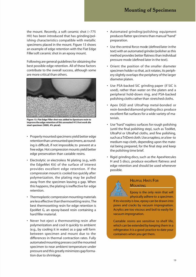
the mount. Recently, a soft ceramic shot (~775HV) has been introduced that has grinding/pol-ishing characteristics compatible with metallicspecimens placed in the mount. Figure 13 shows
an example of edge retention with the Flat EdgeFiller soft ceramic shot in an epoxy mount.
Following are general guidelines for obtaining thebest possible edge retention. All of these factorscontribute to the overall success, although someare more critical than others.
• Properly mounted specimens yield better edge
retention than unmounted specimens, as round-
ing is difficult, if not impossible, to prevent at afree edge. Hot compression mounts yield betteredge preservation than castable resins.
• Electrolytic or electroless Ni plating (e.g., with
the EdgeMet Kit) of the surface of interestprovides excellent edge retention. If thecompression mount is cooled too quickly afterpolymerization, the plating may be pulledaway from the specimen leaving a gap. Whenthis happens, the plating is ineffective for edgeretention.
• Thermoplastic compression mounting materials
are less effective than thermosetting resins. Thebest thermosetting resin for edge retention isEpoMet G, an epoxy-based resin containing ahard filler material.
• Never hot eject a thermosetting resin after
polymerization and cool it quickly to ambient(e.g., by cooling it in water) as a gap will formbetween specimen and mount due to thedifferences in thermal contraction rates. Fully
automated mounting presses cool the mountedspecimen to near ambient temperature underpressure and this greatly minimizes gap forma-tion due to shrinkage.
• Automated grinding/polishing equipment
produces flatter specimens than manual “hand”preparation.
• Use the central force mode (dened later in thetext) with an automated grinder/polisher as thismethod provides better flatness than individualpressure mode (defined later in the text).
• Orient the position of the smaller diameter
specimen holder so that, as it rotates, its periph-ery slightly overlaps the periphery of the largerdiameter platen.
• Use PSA-backed SiC grinding paper (if SiC is
used), rather than water on the platen and aperipheral hold-down ring, and PSA-backedpolishing cloths rather than stretched cloths.
• Apex DGD and UltraPrep metal-bonded or
resin-bonded diamond grinding discs produceexcellent flat surfaces for a wide variety of ma-terials.
• Use “hard” napless surfaces for rough polishing
(until the final polishing step), such as TexMet,UltraPol or UltraPad cloths, and fine polishing,such as a TriDent cloth. Use a napless, or a low- tomedium-nap cloth, depending upon the mate-
rial being prepared, for the final step and keepthe polishing time brief.
• Rigid grinding discs, such as the ApexHercules
H and S discs, produce excellent flatness andedge retention and should be used wheneverpossible.
Mounting of Specimens
Figure 13. Flat Edge Filler shot was added to Epoxicure resin to
improve the edge retention of this annealed H13 hot work die
steel specimen (500X, 4% picral).
HELPFUL HINTS FOR
MOUNTING
Epoxy is the only resin that will
physically adhere to a specimen.
If its viscosity is low, epoxy can be drawn into
pores and cracks by vacuum impregnation.
Acrylics are too viscous and boil to easily for
vacuum impregnation.
Castable resins are sensitive to shelf life,
which can be extended by keeping them in a
refrigerator. It is a good practice to date your
containers when you get them.
8/20/2019 Buehler Summet, Sample Prep and Analysis
http://slidepdf.com/reader/full/buehler-summet-sample-prep-and-analysis 20/136
20
depth is high and embedding of alumina abrasivein specimens can be a problem.
Other materials have also been used both for
the planar grinding stage or, afterwards, toreplace SiC paper. For very hard materialssuch as ceramics and sintered carbides, one, ormore, metal-bonded or resin-bonded diamonddisks (the traditional type) with grit sizes fromabout 240- to 9-µm can be used. The traditionalmetal- or resin-bonded diamond disc has diamondspread uniformly over its entire surface. ApexDGD and Apex DGD Color are also available asresin bonded diamond grinding discs covering avariety of material applications. An alternate type
of disc, the UltraPrep disc, has diamond particlesapplied in small spots to the disk surface, so thatsurface tension is lessened. UltraPrep metal-bonded discs are available in six diamond sizesfrom 125- to 6-µm while UltraPrep resin bondeddiscs are available in three diamond sizes from 30-to 3-µm. Another approach uses a stainless steelwoven mesh UltraPlan cloth on a platen chargedwith coarse diamond, usually in slurry form, forplanar grinding. Once planar surfaces have beenobtained, there are several single-step proceduresavailable for avoiding the finer SiC papers. Theseinclude the use of platens, thick woven polyestercloths, silk, or rigid grinding disks. With each ofthese, an intermediate diamond size, generally9- to 3-µm, is used.
Grinding Media
The grinding abrasives commonly used in thepreparation of metallographic specimens aresilicon carbide (SiC), aluminum oxide (Al 2O3),emery (Al2O3 - Fe3O4), composite ceramics and
diamond. Emery paper is rarely used today inmetallography due to its low cutting efficiency.SiC is more readily available as waterproofpaper than aluminum oxide. Alumina papers, suchas PlanarMet Al 120-grit paper, do have a bettercutting rate than SiC for some metals [3]. Theseabrasives are bonded to paper, polymeric or clothbacking materials of various weights in the formof sheets, discs and belts of various sizes. Limiteduse is made of standard grinding wheels withabrasives embedded in a bonding material. The
abrasives may be used also in powder form bycharging the grinding surfaces with the abrasivein a premixed slurry or suspension. SiC particles,particularly with the finer size papers, embed
GRINDING
Grinding should commence with the finest gritsize that will establish an initially flat surface and
remove the effects of sectioning within a fewminutes. An abrasive grit size of 180 to 240 (P180to P280) is coarse enough to use on specimensurfaces sectioned by an abrasive cut-off wheel.Hack-sawed, bandsawed, or other rough surfacesusually require abrasive grit sizes in the range of120- to 180-grit. The abrasive used for each suc-ceeding grinding operation should be one or twogrit sizes smaller than that used in the preced-ing step. A satisfactory fine grinding sequencemight involve SiC papers with grit sizes of 220- or240-, 320-, 400-, and 600-grit (P240 or P280, P400,P600 and P1200). This sequence is used in the“traditional” approach.
As with abrasive-wheel sectioning, all grindingsteps should be performed wet provided thatwater has no adverse effects on any constituentsof the microstructure. Wet grinding minimizesspecimen heating, and prevents the abrasive frombecoming loaded with metal removed from thespecimen being prepared.
Each grinding step, while producing damageitself, must remove the damage from the previ-ous step. The depth of damage decreases withthe abrasive size but so does the metal removalrate. For a given abrasive size, the depth ofdamage introduced is greater for soft materialsthan for hard materials.
For automated preparation using a multiple-specimen holder, the intital step is called planargrinding. This step must remove the damage from
sectioning while establishing a common planefor all of the specimens in the holder, so that eachspecimen is affected equally in subsequent steps.Silicon carbide and alumina abrasive papers arecommonly used for the planar grinding step andare very effective. Besides these papers, thereare a number of other options available. Oneoption is to planar grind the specimens with aconventional alumina grinding stone on a ma-chine such as the PlanarMet (see Figure 17b). Thisrequires a special purpose machine, as the stonemust rotate at a high speed, ≥1500 rpm, to cuteffectively. The stone must be dressed regularlywith a diamond tool to maintain flatness, damage
Grinding
8/20/2019 Buehler Summet, Sample Prep and Analysis
http://slidepdf.com/reader/full/buehler-summet-sample-prep-and-analysis 21/136
21
standards use the same methods for sizing theabrasives and the same standards to calibrate thesedevices (sieving for the coarsest grits, sedimen-tation grading for intermediate grits (240-600
or P280-P1200) , and the electr ical resistancemethod for very fine grit sizes). The grit sizenumbering systems differ above 180- (P180) grit,but equivalent sizes can be determined usingTable 5. As with many standards, they are notmandatory and manufacturers can, and do, makesome of their papers to different mean particle
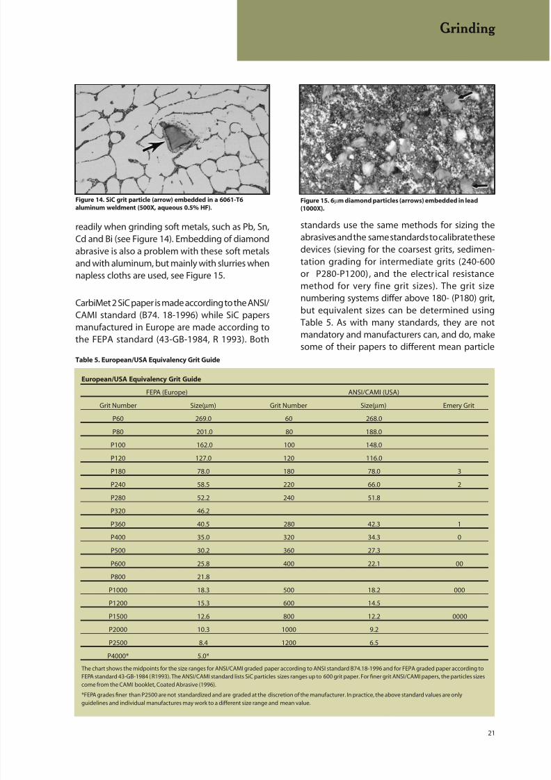
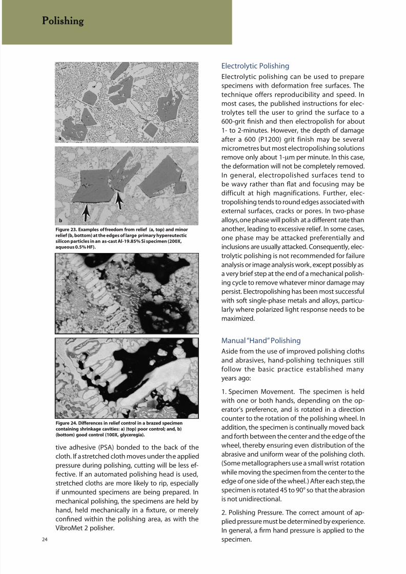
readily when grinding soft metals, such as Pb, Sn,Cd and Bi (see Figure 14). Embedding of diamondabrasive is also a problem with these soft metalsand with aluminum, but mainly with slurries when
napless cloths are used, see Figure 15.
CarbiMet 2 SiC paper is made according to the ANSI/CAMI standard (B74. 18-1996) while SiC papersmanufactured in Europe are made according tothe FEPA standard (43-GB-1984, R 1993). Both
Table 5. European/USA Equivalency Grit Guide
European/USA Equivalency Grit Guide
FEPA (Europe) ANSI/CAMI (USA)
Grit Number Size(µm) Grit Number Size(µm) Emery Grit
P60 269.0 60 268.0
P80 201.0 80 188.0
P100 162.0 100 148.0
P120 127.0 120 116.0
P180 78.0 180 78.0 3
P240 58.5 220 66.0 2
P280 52.2 240 51.8
P320 46.2
P360 40.5 280 42.3 1
P400 35.0 320 34.3 0
P500 30.2 360 27.3
P600 25.8 400 22.1 00
P800 21.8
P1000 18.3 500 18.2 000
P1200 15.3 600 14.5
P1500 12.6 800 12.2 0000
P2000 10.3 1000 9.2
P2500 8.4 1200 6.5
P4000* 5.0*
The chart shows the midpoints for the size ranges for ANSI/CAMI graded paper according to ANSI standard B74.18-1996 and for FEPA graded paper according toFEPA standard 43-GB-1984 ( R1993). The ANSI/CAMI standard lists SiC particles sizes ranges up to 600 grit paper. For finer grit ANSI/CAMI papers, the particles sizes
come from the CAMI booklet, Coated Abrasive (1996).
*FEPA grades finer than P2500 are not standardized and are graded at the discretion of the manufacturer. In practice, the above standard values are only
guidelines and individual manufactures may work to a different size range and mean value.
Figure 15. 6µm diamond particles (arrows) embedded in lead
(1000X).
Figure 14. SiC grit particle (arrow) embedded in a 6061-T6
aluminum weldment (500X, aqueous 0.5% HF).
Grinding

8/20/2019 Buehler Summet, Sample Prep and Analysis
http://slidepdf.com/reader/full/buehler-summet-sample-prep-and-analysis 22/136
22
sectioning damage. Manual grinding work is per-formed on rotating “wheels”; that is, motor-drivenplatens, Figure 17a and Figure 18, upon which the
grinding paper is attached.
Alternately, in the cases where large sections needto be ground to planarity or a high degree of stockremoval is necessary, then a planar grinder thatuses a grinding stone should be considered (figure17b). Such devices can quickly bring even quite
sizes than defined in these specifications. There is aphilosophical difference in the two systems. ANSI/CAMI papers use a wider particle size distribution(centered on the mean size) than FEPA papers. A
broader size range allows cutting to begin fasterat lower pressures than with a narrower size range,so less heat is generated and less damage results.However, the broader size range does produce awider range of scratch depths; but, these shouldbe removed by the next step in the preparationsequence. Generation of less damage to the struc-ture is considered to be more important than thesurface finish after a particular grinding step, as itis the residual damage in the specimen that mayprevent us from seeing the true microstructure at
the end of the preparation sequence.
Grinding Equipment
Stationary grinding papers, often used by students,but uncommon in industrial use, are supplied instrips or rolls, such as for use with the HandiMet2 roll grinder. The specimen is rubbed against thepaper from top to bottom. Grinding in one direc-tion is usually better for maintaining flatness thangrinding in both directions. This procedure can bedone dry for certain delicate materials, but water is
usually added to keep the specimen surface cooland to carry away the grinding debris.
Belt grinders, such as the SurfMet I (Figure 16), areusually present in most laboratories. An alterna-tive approach is to use a high speed disc grinder,such as the SuperMet grinder (Figure 17a). Thesetypes of devices use coarse abrasive papers from60- to 240-grit, and are mainly used for removingburrs from sectioning, for rounding edges that neednot be preserved for examination, for flattening cut
surfaces to be macro-etched, or for removing
Figure 17a. SuperMet grinder
Grinding
Figure 16. SurfMet I belt grinder
Figure 18. EcoMet 250 grinder/polisher
Figure 17b. PlanarMet stone grinder

8/20/2019 Buehler Summet, Sample Prep and Analysis
http://slidepdf.com/reader/full/buehler-summet-sample-prep-and-analysis 23/136
23
large sections of un-mounted material to a planarcondition with a good surface finish relativelyquickly and so are ideal for macro work
Lapping is an abrasive technique in which theabrasive particles roll freely on the surface of acarrier disc. During the lapping process, the discis charged with small amounts of a hard abrasivesuch as diamond or silicon carbide. Lapping diskscan be made of many different materials; cast ironand plastic are used most commonly. Lappingproduces a flatter specimen surface than grinding,but it does not remove metal in the same man-ner as grinding. Some platens, referred to as laps,are charged with diamond slurries. Initially the
diamond particles roll over the lap surface (justas with other grinding surfaces), but they soonbecome embedded and cut the surface produc-ing microchips.
POLISHING
Polishing is the final step, or steps, in producing adeformation-free surface that is flat, scratch free,and mirror-like in appearance. Such a surface isnecessary to observe the true microstructurefor subsequent metallographic interpretation,
both qualitative and quantitative. The polishingtechnique used should not introduce extraneousstructures such as disturbed metal (Figure 19), pit-ting (Figure 20), dragging out of inclusions, “comettailing” (Figure 21), staining (Figure 22) or relief
(height differences between different constituents,or between holes and constituents (Figure 23and 24). Polishing usually is conducted in severalstages. Traditionally, coarse polishing generallywas conducted with 6- or 3-µm diamond abrasivescharged onto napless or low-nap cloths. For hardmaterials, such as through hardened steels, ceram-ics and cemented carbides, an additional coarsepolishing step may be required. The initial coarsepolishing step may be followed by polishing with1-µm diamond on a napless, low nap, or mediumnap cloth. A compatible lubricant should be usedsparingly to prevent overheating or deformationof the surface. Intermediate polishing should beperformed thoroughly so that final polishing
may be of minimal duration. Manual, or “hand”polishing, is usually conducted using a rotatingwheel where the operator rotates the specimenin a circular path counter to the wheel rotationdirection.
Mechanical Polishing
The term “mechanical polishing” is frequentlyused to describe the various polishing proceduresinvolving the use of fine abrasives on cloth. Thecloth may be attached to a rotating wheel or a
vibratory polisher bowl. Historically, cloths havebeen either stretched over the wheel and heldin place with an adjustable clamp on the platenperiphery, or held in place with a pressure sensi-
Figure 21. “Comet tails” at large nitrides in an annealed H13 hot
work die steel specimen (200X, DIC).
Figure 22. Staining (arrow) on the surface of a of Ti-6% Al-2% Sn-
4% Zr-2% Mo prepared specimen (200X).
Polishing
Figure 19. (top) Preparation damage (arrows) in annealed CP
titanium (500X, DIC, Kroll’s reagent).
Figure 20. (bottom) Pitting (arrow) on the surface of a cold-drawn
brass (Cu-20% Zn) specimen (100X)
8/20/2019 Buehler Summet, Sample Prep and Analysis
http://slidepdf.com/reader/full/buehler-summet-sample-prep-and-analysis 24/136
24
tive adhesive (PSA) bonded to the back of thecloth. If a stretched cloth moves under the appliedpressure during polishing, cutting will be less ef-fective. If an automated polishing head is used,stretched cloths are more likely to rip, especiallyif unmounted specimens are being prepared. In
mechanical polishing, the specimens are held byhand, held mechanically in a fixture, or merelyconfined within the polishing area, as with theVibroMet 2 polisher.
Electrolytic Polishing
Electrolytic polishing can be used to preparespecimens with deformation free surfaces. Thetechnique offers reproducibility and speed. In
most cases, the published instructions for elec-trolytes tell the user to grind the surface to a600-grit finish and then electropolish for about1- to 2-minutes. However, the depth of damageafter a 600 (P1200) grit finish may be severalmicrometres but most electropolishing solutionsremove only about 1-µm per minute. In this case,the deformation will not be completely removed.In general, electropolished surfaces tend tobe wavy rather than flat and focusing may bedifficult at high magnifications. Further, elec-
tropolishing tends to round edges associated withexternal surfaces, cracks or pores. In two-phasealloys, one phase will polish at a different rate thananother, leading to excessive relief. In some cases,one phase may be attacked preferentially andinclusions are usually attacked. Consequently, elec-trolytic polishing is not recommended for failureanalysis or image analysis work, except possibly asa very brief step at the end of a mechanical polish-ing cycle to remove whatever minor damage maypersist. Electropolishing has been most successful
with soft single-phase metals and alloys, particu-larly where polarized light response needs to bemaximized.
Manual “Hand” Polishing
Aside from the use of improved polishing clothsand abrasives, hand-polishing techniques stillfollow the basic practice established manyyears ago:
1. Specimen Movement. The specimen is held
with one or both hands, depending on the op-erator’s preference, and is rotated in a directioncounter to the rotation of the polishing wheel. Inaddition, the specimen is continually moved backand forth between the center and the edge of thewheel, thereby ensuring even distribution of theabrasive and uniform wear of the polishing cloth.(Some metallographers use a small wrist rotationwhile moving the specimen from the center to theedge of one side of the wheel.) After each step, thespecimen is rotated 45 to 90° so that the abrasionis not unidirectional.
2. Polishing Pressure. The correct amount of ap-plied pressure must be determined by experience.In general, a firm hand pressure is applied to thespecimen.
Polishing
Figure 24. Differences in relief control in a brazed specimen
containing shrinkage cavities: a) (top) poor control; and, b)
(bottom) good control (100X, glyceregia).
b
a
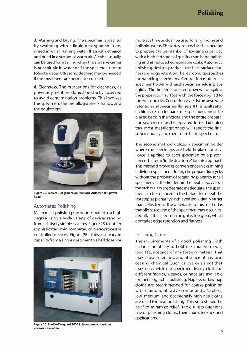
Figure 23. Examples of freedom from relief (a, top) and minor
relief (b, bottom) at the edges of large primary hypereutectic
silicon particles in an as-cast Al-19.85% Si specimen (200X,
aqueous 0.5% HF).
b
a
8/20/2019 Buehler Summet, Sample Prep and Analysis
http://slidepdf.com/reader/full/buehler-summet-sample-prep-and-analysis 25/136
25
3. Washing and Drying. The specimen is washedby swabbing with a liquid detergent solution,rinsed in warm running water, then with ethanol,and dried in a stream of warm air. Alcohol usually
can be used for washing when the abrasive carrieris not soluble in water or if the specimen cannottolerate water. Ultrasonic cleaning may be neededif the specimens are porous or cracked.
4. Cleanness. The precautions for cleanness, aspreviously mentioned, must be strictly observedto avoid contamination problems. This involvesthe specimen, the metallographer’s hands, andthe equipment.
more at a time and can be used for all grinding andpolishing steps. These devices enable the operatorto prepare a large number of specimens per daywith a higher degree of quality than hand polish-
ing and at reduced consumable costs. Automaticpolishing devices produce the best surface flat-ness and edge retention. There are two approachesfor handling specimens. Central force utilizes aspecimen holder with each specimen held in placerigidly. The holder is pressed downward againstthe preparation surface with the force applied tothe entire holder. Central force yields the best edgeretention and specimen flatness. If the results afteretching are inadequate, the specimens must beplaced back in the holder and the entire prepara-
tion sequence must be repeated. Instead of doingthis, most metallographers will repeat the finalstep manually and then re-etch the specimen.
The second method utilizes a specimen holderwhere the specimens are held in place loosely.Force is applied to each specimen by a piston,hence the term “individual force” for this approach.This method provides convenience in examiningindividual specimens during the preparation cycle,without the problem of regaining planarity for allspecimens in the holder on the next step. Also, ifthe etch results are deemed inadequate, the speci-men can be replaced in the holder to repeat thelast step, as planarity is achieved individually ratherthan collectively. The drawback to this method isthat slight rocking of the specimen may occur, es-pecially if the specimen height is too great, whichdegrades edge retention and flatness.
Polishing Cloths
The requirements of a good polishing cloth
include the ability to hold the abrasive media,long life, absence of any foreign material thatmay cause scratches, and absence of any pro-cessing chemical (such as dye or sizing) thatmay react with the specimen. Many cloths ofdifferent fabrics, weaves, or naps are availablefor metallographic polishing. Napless or low napcloths are recommended for coarse polishingwith diamond abrasive compounds. Napless,low, medium, and occasionally high nap clothsare used for final polishing. This step should be
brief to minimize relief. Table 6 lists Buehler’sline of polishing cloths, their characteristics andapplications.
Automated Polishing
Mechanical polishing can be automated to a highdegree using a wide variety of devices rangingfrom relatively simple systems, Figure 25, to rathersophisticated, minicomputer, or microprocessorcontrolled devices, Figure 26. Units also vary incapacity from a single specimen to a half dozen or
Polishing
Figure 25. EcoMet 300 grinder/polisher and AutoMet 300 power
head
Figure 26. BuehlerVanguard 2000 fully automatic specimen
preparation system

8/20/2019 Buehler Summet, Sample Prep and Analysis
http://slidepdf.com/reader/full/buehler-summet-sample-prep-and-analysis 26/136
26
Table 6. Cloth Selection Guide
Recommended
Premium µm Size Abrasive Cloth Usage
Cloths Range Types Characteristics Guide Applications
UltraPad 15 - 3 Diamond Hard Woven, Used to Replace FerrousNo Nap with High Multiple SiC Materials andMaterial Removal Grinding Steps Thermal
Spray Coatings
UltraPol* 15 - 1 Diamond Hard Woven, Excellent Surface Minerals, Coal,No Nap Finish Used to Retain and Ceramics,
Flatness in Medium Inclusion Retentionto Hard Specimens in Steels, and
Refractory Metals
Nylon* 15 - 1 Diamond Medium-Hard Used to Retain Ferrous Materials,Woven, No Nap Flatness and Sintered Carbides
Hard Phases and Cast Irons
TexMet P 15 - 3 Diamond Hardest Perforated Used for Material Ceramics, Carbides,
Non-woven Pad Removal and Petrographic, Hardfor High Material Flatness of Metals, Glass, Metal
Removal Hard Specimens Matrix Composites
TexMet 15 - 3 Diamond, Hard Non-woven Used for Harder Hard FerrousAl2O3 Pad used for Specimens and Materials
Durability Increased Flatness and Ceramics
TriDent* 9 - 1 Diamond Softer, Used to Maximize Ferrous andDurable, Flatness and Nonferrous Metals,
Woven Synthetic, Retain Phases while Microelectronics,No Nap Providing Excellent Coatings
Surface Finish
VerduTex* 15 - 1 Diamond Durable, Medium Used for Rough Ferrous and NonferrousHard Synthetic and Final Polishing Composite Material
Silk and Plastic
(CFK, GFK)
VelTex 9 - 1 Diamond Short-napped, Ideal for Steel. Nonferrous andSynthetic Final Polishing Soft Metals
Velvet
WhiteFelt 6 - 0.02 Diamond, Soft and General Usage Ferrous andAl2O3, SiO2 Durable Matted for Intermediate Nonferrous Materials
Wool Cloth to Fine Steps
MicroCloth 5 - 0.02 Diamond, Synthetic Cloth Most Popular Ferrous andAl2O3, SiO2 with Medium Nap General Nonferrous
Usage Final Metals, Ceramics,Polishing Cloth Composites, PCB’s,
Cast Irons, Cermets,Plastics, Electronics
MasterTex 1 - 0.05 Al2O3, SiO2 Soft Synthetic Softer Final Soft Nonferrous andVelvet with Polishing Cloth Microelectronic
Low Nap Packages
ChemoMet 1 - 0.02 Al2O3, SiO2 Soft Synthetic General Usage Titanium, StainlessPad, Micro-nap Pad that Removes Steels, Lead/Tin
Smear Metal Solders, Electronicfrom Tough Packages, Soft
Materials during NonferrousChemomechanical Metals, Plastics
Polishing
* Interchangable in many of the following methods
Polishing

8/20/2019 Buehler Summet, Sample Prep and Analysis
http://slidepdf.com/reader/full/buehler-summet-sample-prep-and-analysis 27/136
27
Polishing Abrasives
Polishing usually involves the use of one or moreof the following abrasives: diamond, aluminumoxide (Al2O3), and amorphous silicon dioxide
(SiO2) in collidal suspension. For certain materi-als, cerium oxide, chromium oxide, magnesiumoxide or iron oxide may be used, although theseare used infrequently. With the exception of dia-mond, these abrasives are normally suspended indistilled-water, but if the metal to be polished isnot compatible with water, other suspensions suchas ethylene glycol, alcohol, kerosene or glycerol,may be required. The diamond abrasive shouldbe extended only with the carrier recommendedby the manufacturer. Besides the water-based
diamond suspension, Buehler also offers oil-basedsuspensions that are needed to prepare materialssensitive to water.
Diamond abrasives were introduced to metallog-raphers commercially in the late 1940s. However,their use in metallography goes back to at leastthe late 1920s, as Hoyt [7] mentions a visit tothe Carboloy plant in West Lynn, Massachusetts,where he saw sapphire bearings being polishedwith diamond dust in an oil carrier. He used some
of this material to prepare sintered carbides andpublished this work in 1930. Diamond abrasiveswere first introduced in a carrier paste but lateraerosol and slurry forms were introduced. Virginnatural diamond was used initially, and is stillavailable as MetaDi diamond paste. Later, synthetic
diamond was introduced, first of the monocrys-talline form, similar in morphology to naturaldiamond, and then in polycrystalline form. MetaDiII diamond pastes and MetaDi suspensions use
synthetic monocrystalline diamond while MetaDiSupreme suspensions and paste use syntheticpolycrystalline diamonds. Figure 27 shows theshape differences between monocrystalline andpolycrystalline diamonds. Studies have shown thatcutting rates are higher for many materials usingpolycrystalline diamond compared to monocrys-talline diamond.
Colloidal silica was first used for polishing wafersof single crystal silicon where all of the damage
on the wafer surface must be eliminated beforea device can be grown on it. The silica is amor-phous and the solution has a basic pH of about9.5. The silica particles are actually nearly sphericalin shape, Figure 28, the polishing action is slow,
and is due to both chemical and mechanicalaction. Damage-free surfaces can be producedmore easily when using colloidal silica than withother abrasives (for final polishing). Etchants canrespond differently to surfaces polished with col-loidal silica. For example, an etchant that produces
a grain contrast etch when polished with aluminamay instead reveal the grain and twin boundarieswith a “flat” etch when polished with colloidal silica.Color etchants frequently respond better whencolloidal silica is used producing a more pleasingrange of colors and a crisper image. But, clean-ing of the specimen is more difficult. For manualwork, use a tuft of cotton soaked in a detergentsolution. For automated systems, stop addingabrasive about 10-15 seconds before the cycleends and. For the last 10 seconds, flush the cloth
surface with running water. Then, cleaning is sim-pler. Amorphous silica will crystallize if allowed toevaporate. Crystalline silica will scratch specimens,so this must be avoided. When opening a bottle,
Polishing
Figure 28. Amorphous silica particles in colloidal silica (TEM,
300,000X).
Figure 27. Comparison of monocrystalline (a, top) and
polycrystalline (b, bottom) synthetic diamond grain shapes (SEM,
450X).
b
a
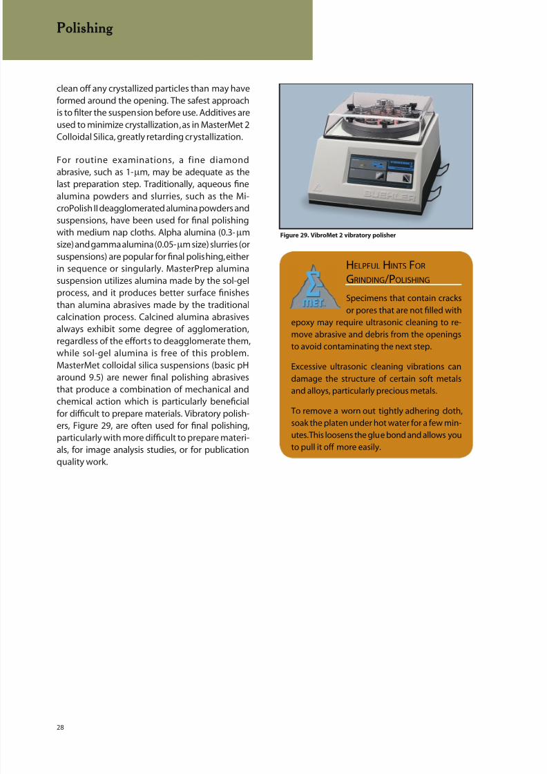
8/20/2019 Buehler Summet, Sample Prep and Analysis
http://slidepdf.com/reader/full/buehler-summet-sample-prep-and-analysis 28/136
28
clean off any crystallized particles than may haveformed around the opening. The safest approachis to filter the suspension before use. Additives areused to minimize crystallization, as in MasterMet 2
Colloidal Silica, greatly retarding crystallization.
For routine examinations, a fine diamondabrasive, such as 1-µm, may be adequate as thelast preparation step. Traditionally, aqueous finealumina powders and slurries, such as the Mi-croPolish II deagglomerated alumina powders andsuspensions, have been used for final polishingwith medium nap cloths. Alpha alumina (0.3-µmsize) and gamma alumina (0.05-µm size) slurries (orsuspensions) are popular for final polishing, either
in sequence or singularly. MasterPrep aluminasuspension utilizes alumina made by the sol-gelprocess, and it produces better surface finishesthan alumina abrasives made by the traditionalcalcination process. Calcined alumina abrasivesalways exhibit some degree of agglomeration,regardless of the efforts to deagglomerate them,while sol-gel alumina is free of this problem.MasterMet colloidal silica suspensions (basic pHaround 9.5) are newer final polishing abrasivesthat produce a combination of mechanical andchemical action which is particularly beneficialfor difficult to prepare materials. Vibratory polish-ers, Figure 29, are often used for final polishing,particularly with more difficult to prepare materi-als, for image analysis studies, or for publicationquality work.
Polishing
Figure 29. VibroMet 2 vibratory polisher
HELPFUL HINTS FOR
GRINDING /POLISHING
Specimens that contain cracks
or pores that are not filled with
epoxy may require ultrasonic cleaning to re-
move abrasive and debris from the openings
to avoid contaminating the next step.
Excessive ultrasonic cleaning vibrations can
damage the structure of certain soft metals
and alloys, particularly precious metals.
To remove a worn out tightly adhering cloth,soak the platen under hot water for a few min-
utes. This loosens the glue bond and allows you
to pull it off more easily.

8/20/2019 Buehler Summet, Sample Prep and Analysis
http://slidepdf.com/reader/full/buehler-summet-sample-prep-and-analysis 29/136
29
EXAMPLES OF PREPARATIONPROCEDURES
The “Traditional” Method
Over the past forty years, a general procedure hasbeen developed that is quite successful for prepar-ing most metals and alloys. This method is basedon grinding with silicon carbide waterproof papersthrough a series of grits, then rough polishing withone or more diamond abrasive sizes, followed byfine polishing with one or more alumina suspen-sions of different particle size. This procedure willbe called the “traditional” method, and is describedin Table 7.
This procedure is used for manual or automatedpreparation, although manual control of theforce applied to a specimen would not be asconsistent. Complementary motion means thatthe specimen holder is rotated in the samedirection as the platen, and does not apply tomanual preparation. Some machines can beset so that the specimen holder rotates in thedirection opposite to that of the platen, called“contra.” This provides a more aggressive actionbut was not part of the “traditional” approach
when automated. The traditional method is notrigid, as other polishing cloths may be substitutedand one or more of the polishing steps mightbe omitted. Times and pressures could be
varied, as well, to suit the needs of the work,or the material being prepared. This is the “art”of metallography.
Contemporary Methods
New concepts and new preparation materials havebeen introduced that enable metallographers toshorten the process while producing better, moreconsistent results. Much of this effort has centeredupon reducing or eliminating the use of siliconcarbide paper in the grinding steps. In all cases,an initial grinding step must be used, but thereare a wide range of materials that can be choseninstead of SiC paper. There is nothing wrong withthe use of SiC for the first step, except that it has ashort life. If an automated device is used that holdsa number of specimens rigidly (central force), thenthe first step must remove the sectioning damageon each specimen and bring all of the specimensin the holder to a common plane. The first step isoften called “Planar grinding”. SiC paper is mostoften used for this step although one more thansheet may be needed according to the surface areato be planed down and how much material needsto be ground back. If it is such that more than a fewsheets of SiC are needed then the use of a more
aggressive / more durable surface such as ZirMetpaper or diamond grinding discs (Apex DGD, ApexDGD Color, UltraPrep diamond discs or UltraPlanstainless steel mesh cloth (charged with diamond)
Table 7. The Traditional Procedure for Preparing Most Metals and Alloys
Abrasive/ Load Lb. (N)/ Base Speed Time
Surface Size Specimen (rpm)/Direction (min:sec)
CarbiMet 2 120- (P120) grit 6 (27) 240-300 Untilabrasive discs SiC water Comp. Plane(waterproof paper) cooled
CarbiMet 2 220- or 240- (P240 or P280) 6 (27) 240-300 1:00abrasive discs grit SiC water cooled Comp.
CarbiMet 2 320- (P400) grit 6 (27) 240-300 1:00abrasive discs SiC water cooled Comp.
CarbiMet 2 400- (P600) grit 6 (27) 240-300 1:00abrasive discs SiC water cooled Comp.
CarbiMet 2 600- (P1200) grit 6 (27) 240-300 1:00abrasive discs SiC water cooled Comp.
Canvas 6-µm MetaDi 6 (27) 120-150 2:00cloth diamond paste with Comp.
MetaDi fluid extender
Billiard or 1-µm diamond paste with 6 (27) 120-150 2:00Felt cloths MetaDi fluid extender Comp.
MicroCloth Aqueous 0.3-µm 6 (27) 120-150 2:00cloth α − alumina Comp.
MicroPolish slurry
MicroCloth Aqueous 0.05-µm 6 (27) 120-150 2:00cloth γ - alumina Comp.
MicroPolish slurry
Comp. = Complementary (platen and specimen holder both rotate in the same direction)
Examples of Preparation Procedures
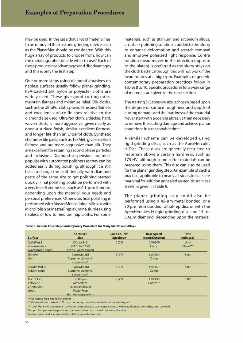
8/20/2019 Buehler Summet, Sample Prep and Analysis
http://slidepdf.com/reader/full/buehler-summet-sample-prep-and-analysis 30/136
30
may be used. In the case that a lot of material hasto be removed then a stone grinding device suchas the PlanarMet should be considered. With thishuge array of products to choose from, how can
the metallographer decide what to use? Each ofthese products has advantages and disadvantages,and this is only the first step.
One or more steps using diamond abrasives onnapless surfaces usually follow planar grinding.PSA-backed silk, nylon or polyester cloths arewidely used. These give good cutting rates,maintain flatness and minimize relief. Silk cloths,such as the UltraPol cloth, provide the best flatnessand excellent surface finishes relative to the
diamond size used. UltraPad cloth, a thicker, hard,woven cloth, is more aggressive, gives nearly asgood a surface finish, similar excellent flatness,and longer life than an UltraPol cloth. Syntheticchemotextile pads, such as TexMet, give excellentflatness and are more aggressive than silk. Theyare excellent for retaining second phase particlesand inclusions. Diamond suspensions are mostpopular with automated polishers as they can beadded easily during polishing; although it is stillbest to charge the cloth initially with diamondpaste of the same size to get polishing startedquickly. Final polishing could be performed witha very fine diamond size, such as 0.1-µm diamond,depending upon the material, your needs andpersonal preferences. Otherwise, final polishing isperformed with MasterMet colloidal silica or withMicroPolish or MasterPrep alumina slurries usingnapless, or low to medium nap cloths. For some
materials, such as titanium and zirconium alloys,an attack polishing solution is added to the slurryto enhance deformation and scratch removaland improve polarized light response. Contra
rotation (head moves in the direction oppositeto the platen) is preferred as the slurry stays onthe cloth better, although this will not work if thehead rotates at a high rpm. Examples of genericcontemporary preparation practices follow inTables 8 to 10. Specific procedures for a wide rangeof materials are given in the next section.
The starting SiC abrasive size is chosen based uponthe degree of surface roughness and depth ofcutting damage and the hardness of the material.
Never start with a coarser abrasive than necessaryto remove the cutting damage and achieve planarconditions in a reasonable time.
A similar scheme can be developed usingrigid grinding discs, such as the ApexHercules
H Disc. These discs are generally restricted tomaterials above a certain hardness, such as175 HV, although some softer materials can beprepared using them. This disc can also be usedfor the planar grinding step. An example of such apractice, applicable to nearly all steels (results are
marginal for solution annealed austenitic stainlesssteels) is given in Table 9.
The planar grinding step could also beperformed using a 45-µm metal bonded, or a30-µm resin bonded, UltraPrep disc or with theApexHercules H rigid grinding disc and 15- or30-µm diamond, depending upon the material.
Examples of Preparation Procedures
Table 8. Generic Four-Step Contemporary Procedure for Many Metals and Alloys
Abrasive/ Load Lb. (N)/ Base Speed Time
Surface Size Specimen (rpm)/Direction (min:sec)
CarbiMet 2 120- to 240- 6 (27) 240-300 Untilabrasive discs (P120 to P280) Comp. Plane***(waterproof paper) grit SiC water cooled
UltraPol 9-µm MetaDi 6 (27) 120-150 5:00cloth Supreme diamond Comp.
suspension*
TexMet Pad or 3-µm MetaDi 6 (27) 120-150 4:00TriDent cloth Supreme diamond Comp.
suspension*
MicroCloth, ~0.05-µm 6 (27) 120-150 2:00VelTex or MasterMet Contra**ChemoMet colloidal silica orcloths MasterPrep
alumina suspensions
* Plus MetaDi fluid extender as desired
** With heads that rotate at >100 rpm, contra may spray the abrasive above the splash guard
*** Until Plane = All specimens in the holder are ground to a common plane and the damage from sectioning has been removed
Comp. = Complementary (platen and specimen holder both rotate in the same direction)
Contra = platen and specimen holder rotate in opposite directions

8/20/2019 Buehler Summet, Sample Prep and Analysis
http://slidepdf.com/reader/full/buehler-summet-sample-prep-and-analysis 31/136
31
Rigid grinding discs contain no abrasive; theymust be charged during use and suspensions arethe easiest way to do this. Polycrystalline diamondsuspensions are favored over monocrystalline
synthetic diamond suspensions for most metalsand alloys due to their higher cutting rate.
The ApexHercules S rigid grinding disc, designedfor soft metals and alloys, is used in a similarmanner. This disc is quite versatile and can beused to prepare harder materials as well, althoughits wear rate will be greater than the H disc whenused to prepare very hard materials. A genericfour step practice is given below for soft metalsand alloys.
The planar grinding step can be performed withthe 30-µm resin bonded diamond disc, or witha second ApexHercules S disc and 15- or30-µm diamond, depending upon the metal or
alloy. For some very difficult metals and alloys,a 1-µm diamond step on a TriDent cloth (similar tostep 3, but for 3 minutes) could be added, and/ora brief vibratory polish (use the same cloths andabrasives as for step 4) may be needed to produceperfect publication quality images. Four steps maysuffice for routine work.
Examples of Preparation Procedures
Table 10. Four-Step Contemporary Procedure for Nonferrous Metals Using a Rigid Grinding Disc
Abrasive/ Load Lb. (N)/ Base Speed Time
Surface Size Specimen (rpm)/ Direction (min:sec)
CarbiMet 2 220- to 320- 5 (22) 240-300 Untilabrasive discs (P280 or P400) grit Comp. Planewaterproof paper SiC water cooled
ApexHercules S 6-µm MetaDi 5 (22) 120-150 5:00rigid grinding disc Supreme diamond Comp.
suspension*
TriDent 3-µm MetaDi 5 (22) 120-150 4:00cloth Supreme diamond Comp.
suspension*
MicroCloth, ~0.05-µm 5 (22) 120-150 2:00VelTex or MasterMet ContraChemoMet colloidal silicacloths or MasterPrep
alumina suspensions
*MetaDi fluid extender as desired
Comp.= Complementary (platen and specimen holder both rotate in the same direction)
Contra = Platen and specimen holder rotate in opposite directions
Table 9. Four-Step Contemporary Procedure for Steels Using a Rigid Grinding Disc
Abrasive/ Load Lb. (N)/ Base Speed Time
Surface Size Specimen (rpm)/Direction (min:sec)
CarbiMet 2 120- to 240- 6 (27) 240-300 Untilabrasive discs (P120 to P280) Comp. Planewaterproof paper grit SiC, water cooled
ApexHercules H 9-µm MetaDi 6 (27) 120-150 5:00rigid grinding disc Supreme diamond Comp.
suspension*
TexMet Pad or 3-µm MetaDi 6 (27) 120-150 4:00TriDent cloth Supreme diamond Comp.
suspension*
MicroCloth, ~0.05-µm 6 (27) 120-150 2:00
VelTex or MasterMet ContraChemoMet colloidal silicacloths or MasterPrep
alumina suspensions
*Plus MetaDi fluid extender as desired
Comp.= Complementary (platen and specimen holder both rotate in the same direction)
Contra = Platen and specimen holder rotate in opposite directions

8/20/2019 Buehler Summet, Sample Prep and Analysis
http://slidepdf.com/reader/full/buehler-summet-sample-prep-and-analysis 32/136
32
PROCEDURES FOR SPECIFICMATERIALS
Following are our recommendations for preparing
a wide range of materials arranged, in the case ofmetals, according to common characteristics, basi-cally in accordance with their classification in theperiodic table of the elements. This break downis further modified, especially in the case of ironbased alloys, as required due to the wide range ofproperties that can be experienced.
The periodic table of the elements categorizesmetallic, nonmetallic and metalloid elementsaccording to similarities in atomic structure andis a good starting point, aided by similarities inphysical properties and behavior, for groupingelements and their alloys that have reasonablysimilar preparation procedures. The periodic table(pg. 29) has the various groups color coded forconvenience.
Of course, metallographers prepare materialsother than metals. These have been groupedand sub-divided according to the nature of thesematerials, as follows:
• Sintered Carbides
• Ceramics
• Composites: Metal Matrix, Polymer Matrix and
Ceramic Matrix
• Printed Circuit Boards
• Microelectronic Devices
• Plastics and Polymers
The procedures discussed in this book were de-veloped and tested extensively using machineswith an 8-inch (200 mm) diameter platen with six1.25-inch (32 mm) diameter specimens in a 5-inch(125 mm) diameter holder. These proceduresproduced the same results when the specimenswere prepared using a 10-inch (250 mm) or a 12-inch (300 mm) diameter platen. When using the8-inch (200 mm) platen and a 5-inch (125 mm)diameter specimen holder, the machine’s headposition was adjusted so that the specimens rotateout over the outer periphery of the surface of theplaten. This procedure makes maximum use of theworking surface and improves edge retention. This
alignment practice is less critical with the largerdiameter platens when using the same diameterholder. However, if the 7-inch (175 mm) diameter
specimen holder is used with the 12-inch (300mm) diameter platen, the head position shouldbe adjusted so that the specimens rotate out overthe platen’s edge.
In general, it is difficult to make accurate predic-tions about variations in time and load when usingdifferent format platens and mount sizes. Differentmount sizes per se should not be used as the basisfor calculations as the area of the specimens withinthe mount is more important than the mountarea itself. For example, the same specimen crosssectional area could be present in 1-, 1.25- or 1.5-inch (25, 32 or 38 mm) diameter polymer mounts.Further, the number of specimens in the holder
can vary substantially. It is necessary to put atleast three mounts in a central-force holder toobtain a proper weight balance. But, two speci-mens could be dummy mounts (mounts withoutspecimens). In general, as the area of the specimenin the mount increases, as the diameter and thenumber of specimens increases, the time and pres-sure must increase to obtain the same degree ofpreparation perfection.
If the area of the mounts is used, rather than thearea of the embedded specimens, and we as-
sume that we are preparing six 1-inch (25 mm),six 1.25-inch (32 mm) or three 1.5-inch (38 mm)diameter specimens, then we can adjust the pres-sures relative to the standard values in the tables(for six 1.25-inch (32 mm) diameter specimens)using an 8 inch (200 mm) diameter platen formatmachine. A comparison of the cross-sectionalareas would suggest that for the six 1-inch (25mm) specimens, the pressures could be reducedto 65% of the standard values while for three 1.5-inch (38 mm) diameter specimens, the pressuresand times could be reduced to about 70% of the
standard values.
Changing the platen diameter increases the dis-tance that the specimens travel in a given time.For example, for the same rpm values, specimenstravel 1.25 and 1.5 times as far using a 10- or 12-inch (250 or 300 mm) diameter platen, respectively,compared to an 8-inch (200 mm) platen. This sug-gests that the times could be reduced to 80 or67% of that used for the 8-inch (200 mm) diameterplaten when using 10- or 12-inch (250 or 300 mm)diameter platens. While preparation times may be
shorter using a larger format machine, consumablecost is greater and larger machines are neededonly when the specimen throughput needs arevery high or with large specimens.
Procedures for Specific Materials
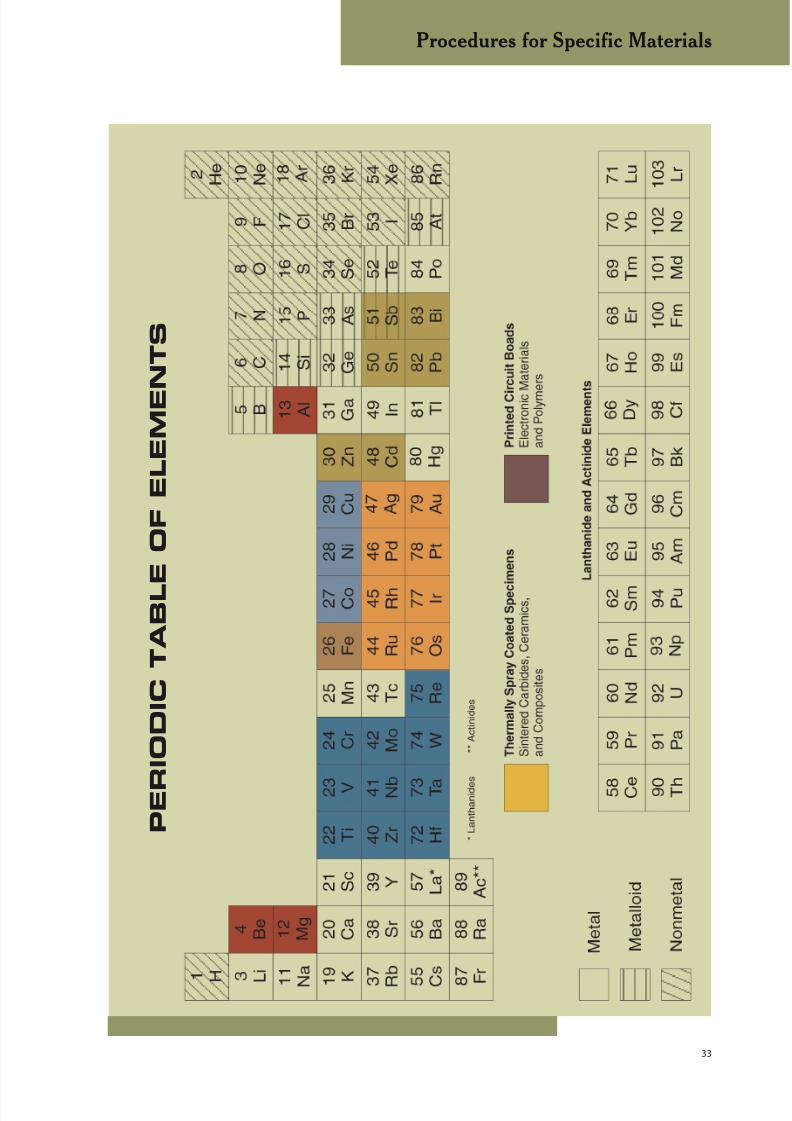
8/20/2019 Buehler Summet, Sample Prep and Analysis
http://slidepdf.com/reader/full/buehler-summet-sample-prep-and-analysis 33/136
33
P E R
I O D I C T A B L E O F E L E M E N T S
Procedures for Specific Materials
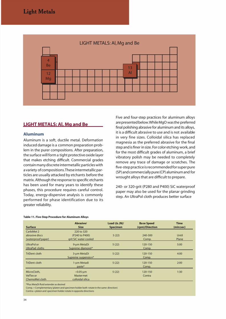
8/20/2019 Buehler Summet, Sample Prep and Analysis
http://slidepdf.com/reader/full/buehler-summet-sample-prep-and-analysis 34/136
34
4Be
12Mg
13Al
LIGHT METALS: Al, Mg and Be
LIGHT METALS: Al, Mg and Be
Aluminum
Aluminum is a soft, ductile metal. Deformationinduced damage is a common preparation prob-lem in the purer compositions. After preparation,the surface will form a tight protective oxide layerthat makes etching difficult. Commercial gradescontain many discrete intermetallic particles witha variety of compositions. These intermetallic par-ticles are usually attacked by etchants before thematrix. Although the response to specific etchantshas been used for many years to identify thesephases, this procedure requires careful control.Today, energy-dispersive analysis is commonlyperformed for phase identification due to itsgreater reliability.
Light Metals
Five and four-step practices for aluminum alloysare presented below. While MgO was the preferredfinal polishing abrasive for aluminum and its alloys,it is a difficult abrasive to use and is not availablein very fine sizes. Colloidal silica has replacedmagnesia as the preferred abrasive for the finalstep and is finer in size. For color etching work, andfor the most difficult grades of aluminum, a briefvibratory polish may be needed to completelyremove any trace of damage or scratches. The
five-step practice is recommended for super pure(SP) and commercially pure (CP) aluminum and forwrought alloys that are difficult to prepare.
240- or 320-grit (P280 and P400) SiC waterproofpaper may also be used for the planar grindingstep. An UltraPol cloth produces better surface
Table 11. Five-Step Procedure for Aluminum Alloys
Abrasive/ Load Lb. (N)/ Base Speed TimeSurface Size Specimen (rpm)/Direction (min:sec)
CarbiMet 2 220 to 320abrasive discs (P240 to P400) 5 (22) 240-300 Until(waterproof paper) grit SiC water cooled Comp. Plane
UltraPol or 9-µm MetaDi 5 (22) 120-150 5:00UltraPad cloths Supreme diamond* Comp.
TriDent cloth 3-µm MetaDi 5 (22) 120-150 4:00Supreme suspension* Comp.
TriDent cloth 1-µm Metadi 5 (22) 120-150 2:00paste* Comp.
MicroCloth, ~0.05-µm 5 (22) 120-150 1:30VelTex or Mastermet Contra
ChemoMet cloth colloidal silica*Plus MetaDi fluid extender as desired
Comp. = Complementary (platen and specimen holder both rotate in the same direction)Contra = platen and specimen holder rotate in opposite directions

8/20/2019 Buehler Summet, Sample Prep and Analysis
http://slidepdf.com/reader/full/buehler-summet-sample-prep-and-analysis 35/136
35
Light Metals
finishes than an UltraPad cloth, but the UltraPadcloth has a longer useful life. A ChemoMet clothis recommended when edge retention is critical.Pure aluminum and some alloys are susceptible
to embedment of fine diamond abrasive particles,especially when suspensions are used. If this oc-curs, switch to diamond in paste form, which ismuch less likely to cause embedding. SP and CPaluminum can be given a brief vibratory polish(same products as last step) to improve scratchcontrol, although this is generally not required.MasterPrep alumina suspension has been found tobe highly effective as a final polishing abrasive foraluminum alloys, however, the standard aluminaabrasives made by the calcination process are
unsuitable for aluminum.
napless cloths may also be used for the final stepwith colloidal silica and they will introduce lessrelief than a low or medium nap cloth, but maynot remove fine polishing scratches as well. For
very pure aluminum alloys, this procedure couldbe followed by vibratory polishing to improve thesurface finish, as these are quite difficult to preparetotally free of fine polishing scratches.
Dendritic segregation in as cast 206 aluminum revealed by color
etching with Weck’s reagent (polarized light, 200X).
For many aluminum alloys, excellent results canbe obtained using a four step procedure, such asshown below in Table 12. This procedure retains allof the intermetallic precipitates observed in alumi-num and its alloys and minimizes relief. Synthetic
Deformed, elongated grain structure of extruded 6061-F
aluminum after shearing revealed by anodizing with Barker’s
reagent (polarized light, 100X).
Table 12. Four-Step Procedure for Aluminum Alloys
Abrasive/ Load Lb. (N)/ Base Speed Time
Surface Size Specimen (rpm)/ Direction (min:sec)
CarbiMet 2 220- to 320- (P240 5 (22) 240-300 Untilabrasive discs to P400) grit SiC Comp. Plane(waterproof paper) water cooled
UltraPol 6-µm MetaDi 6 (27) 120-150 6:00cloth Supreme Comp.
diamondsuspension*
TriDent cloth 3-µm MetaDi 6 (27) 120-150 4:00Supreme diamond Comp.
suspension*
MicroCloth ~0.05-µm 6 (27) 120-150 2:00VelTex or MasterMet ContraChemoMet colloidal silicacloth or MasterPrep
alumina suspensions*Plus MetaDi fluid extender as desired
Comp. = Complementary (platen and specimen holder both rotate in the same direction)
Contra = platen and specimen holder rotate in opposite directions
HELPFUL HINTS FOR
ALUMINUM
Many low-alloy aluminum speci-
mens are difficult to polish to
a perfect finish using standard methods. A
vibratory polisher can be used quite effectivelywith MasterMet colloidal silica to produce
deformation-free, scratch-free sur faces for
anodizing or color etching and examination
with polarized light or Nomarski DIC.
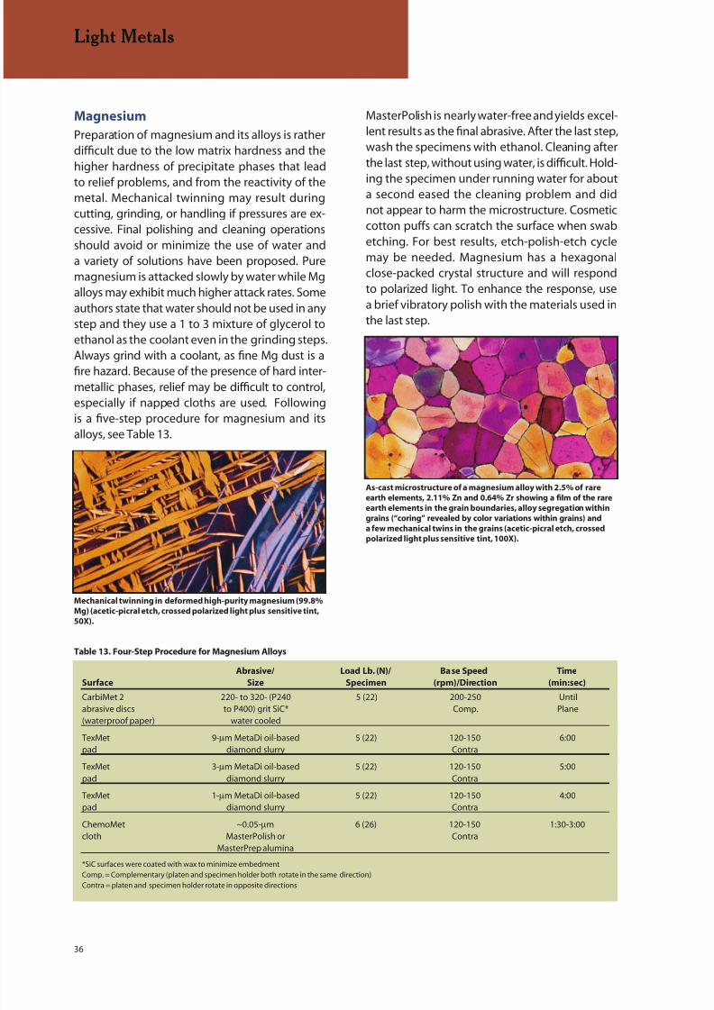
8/20/2019 Buehler Summet, Sample Prep and Analysis
http://slidepdf.com/reader/full/buehler-summet-sample-prep-and-analysis 36/136
36
Light Metals
Magnesium
Preparation of magnesium and its alloys is ratherdifficult due to the low matrix hardness and thehigher hardness of precipitate phases that lead
to relief problems, and from the reactivity of themetal. Mechanical twinning may result duringcutting, grinding, or handling if pressures are ex-cessive. Final polishing and cleaning operationsshould avoid or minimize the use of water anda variety of solutions have been proposed. Puremagnesium is attacked slowly by water while Mgalloys may exhibit much higher attack rates. Someauthors state that water should not be used in anystep and they use a 1 to 3 mixture of glycerol toethanol as the coolant even in the grinding steps.
Always grind with a coolant, as fine Mg dust is afire hazard. Because of the presence of hard inter-metallic phases, relief may be difficult to control,especially if napped cloths are used. Followingis a five-step procedure for magnesium and itsalloys, see Table 13.
MasterPolish is nearly water-free and yields excel-lent results as the final abrasive. After the last step,wash the specimens with ethanol. Cleaning afterthe last step, without using water, is difficult. Hold-
ing the specimen under running water for abouta second eased the cleaning problem and didnot appear to harm the microstructure. Cosmeticcotton puffs can scratch the surface when swabetching. For best results, etch-polish-etch cyclemay be needed. Magnesium has a hexagonalclose-packed crystal structure and will respondto polarized light. To enhance the response, usea brief vibratory polish with the materials used inthe last step.
Mechanical twinning in deformed high-purity magnesium (99.8%
Mg) (acetic-picral etch, crossed polarized light plus sensitive tint,
50X).
As-cast microstructure of a magnesium alloy with 2.5% of rare
earth elements, 2.11% Zn and 0.64% Zr showing a film of the rare
earth elements in the grain boundaries, alloy segregation within
grains (“coring” revealed by color variations within grains) and
a few mechanical twins in the grains (acetic-picral etch, crossedpolarized light plus sensitive tint, 100X).
Table 13. Four-Step Procedure for Magnesium Alloys
Abrasive/ Load Lb. (N)/ Base Speed Time
Surface Size Specimen (rpm)/Direction (min:sec)
CarbiMet 2 220- to 320- (P240 5 (22) 200-250 Until
abrasive discs to P400) grit SiC* Comp. Plane(waterproof paper) water cooled
TexMet 9-µm MetaDi oil-based 5 (22) 120-150 6:00pad diamond slurry Contra
TexMet 3-µm MetaDi oil-based 5 (22) 120-150 5:00pad diamond slurry Contra
TexMet 1-µm MetaDi oil-based 5 (22) 120-150 4:00pad diamond slurry Contra
ChemoMet ~0.05-µm 6 (26) 120-150 1:30-3:00cloth MasterPolish or Contra
MasterPrep alumina
*SiC surfaces were coated with wax to minimize embedment
Comp. = Complementary (platen and specimen holder both rotate in the same direction)
Contra = platen and specimen holder rotate in opposite directions

8/20/2019 Buehler Summet, Sample Prep and Analysis
http://slidepdf.com/reader/full/buehler-summet-sample-prep-and-analysis 37/136
37
Light Metals
Beryllium
Beryllium is also a difficult metal to prepare andpresents a health risk to the metallographer. Onlythose familiar with the toxicology of Be, and are
properly equipped to deal with these issues, shouldwork with the metal. The grinding dust is extremelytoxic. Wet cutting prevents air contamination butthe grit must be disposed of properly. As with Mg,Be is easily damaged in cutting and grinding form-ing mechanical twins. Light pressures are required.Although some authors claim that water cannotbe used, even when grinding Be, others report nodifficulties using water. Attack-polishing agentsare frequently used when preparing Be and manyare recommended [2]. Table 14 shows a four-step
practice for beryllium.
For the final step, mix hydrogen peroxide (30%concentration – avoid physical contact!) with theMasterMet colloidal silica in a ratio of one parthydrogen peroxide to five parts colloidal silica.
Oxalic acid solutions (5% concentration) have alsobeen used with alumina for attack polishing. Foroptimal polarized light response, follow this withvibratory polishing using a one-to-ten ratio ofhydrogen peroxide to colloidal silica.
Grain structure of wrought, P/M beryllium (unetched, cross-
polarized light, 100X).
Table 14. Four-Step Procedure for Beryllium
Abrasive/ Load Lb. (N)/ Base Speed Time
Surface Size Specimen (rpm)/Direction (min:sec)
CarbiMet 2 220- to 320- (P240 4 (18) 240-300 Untilabrasive discs to P400) grit SiC Comp. Plane(waterproof paper) water cooled
UltraPol 6-µm MetaDi 4 (18) 120-150cloth Supreme Comp. 5:00
diamondsuspension*
TriDent 3-µm MetaDi 4 (18) 120-150 4:00cloth Supreme Comp.
diamondsuspension*
MicroCloth ~0.05-µm 3 (13) 80-120 2:00VelTex or MasterMet ContraChemoMet colloidal silicacloth
*Plus MetaDi fluid extender as desired
Comp. = Complementary (platen and specimen holder both rotate in the same direction)
Contra = Platen and specimen holder rotate in opposite directions
HELPFUL HINTS FOR
MAGNESIUM
For polishing, apply diamond
paste and use lapping oil, or use
Buehler’s oil-based MetaDi diamond suspen-
sions, available down to a 0.10-µm size, with a
medium nap cloth.
HELPFUL HINTS FOR LIGHT
METALS
Small diamond abrasive sizes
are prone to embedment when
applied as a suspension or by spraying. Charge
the cloth using diamond paste to eliminate
embedding. Another technique is to use both
a fine diamond paste and MasterPrep alumina
suspension – simultaneously – to prevent em-
bedding.
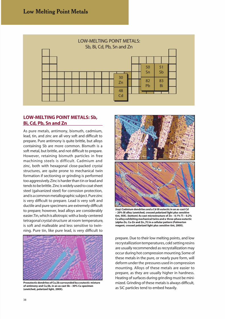
8/20/2019 Buehler Summet, Sample Prep and Analysis
http://slidepdf.com/reader/full/buehler-summet-sample-prep-and-analysis 38/136
38
Low Melting Point Metals
30Zn
48Cd
50Sn
51Sb
82Pb
83Bi
LOW-MELTING POINT METALS:Sb, Bi, Cd, Pb, Sn and Zn
LOW-MELTING POINT METALS: Sb,Bi, Cd, Pb, Sn and Zn
As pure metals, antimony, bismuth, cadmium,lead, tin, and zinc are all very soft and difficult toprepare. Pure antimony is quite brittle, but alloyscontaining Sb are more common. Bismuth is asoft metal, but brittle, and not difficult to prepare.However, retaining bismuth particles in freemachining steels is difficult. Cadmium and
zinc, both with hexagonal close-packed crystalstructures, are quite prone to mechanical twinformation if sectioning or grinding is performedtoo aggressively. Zinc is harder than tin or lead andtends to be brittle. Zinc is widely used to coat sheetsteel (galvanized steel) for corrosion protection,and is a common metallographic subject. Pure zincis very difficult to prepare. Lead is very soft andductile and pure specimens are extremely difficultto prepare; however, lead alloys are considerablyeasier. Tin, which is allotropic with a body-centeredtetragonal crystal structure at room temperature,is soft and malleable and less sensitive to twin-ning. Pure tin, like pure lead, is very difficult to
prepare. Due to their low melting points, and lowrecrystallization temperatures, cold setting resinsare usually recommended as recrystallization mayoccur during hot compression mounting. Some ofthese metals in the pure, or nearly pure form, willdeform under the pressures used in compressionmounting. Alloys of these metals are easier toprepare, as they are usually higher in hardness.
Heating of surfaces during grinding must be mini-mized. Grinding of these metals is always difficult,as SiC particles tend to embed heavily.
Proeutectic dendrites of Cu2Sb surrounded by a eutectic mixture
of antimony and Cu2Sb, in an as-cast Sb – 30% Cu specimen
(unetched, polarized light, 200X).
(top) Cadmium dendrites and a Cd-Bi eutectic in an as-cast Cd
– 20% Bi alloy (unetched, crossed polarized light plus sensitive
tint, 50X). (bottom) As-cast microstructure of Zn – 0.1% Ti – 0.2%
Cu alloy exhibiting mechanical twins and a three-phase eutectic
(alpha-Zn, Cu-Zn and Zn15Ti) in a cellular pattern (Palmertonreagent, crossed polarized light plus sensitive tint, 200X).

8/20/2019 Buehler Summet, Sample Prep and Analysis
http://slidepdf.com/reader/full/buehler-summet-sample-prep-and-analysis 39/136
39
Low Melting Point Metals
Many authors have recommended coating theSiC paper surface with bees wax, but this does notsolve the problem. Paraffin (candle wax) is muchbetter for reducing embedding. Embedding is
most common with the finer grit size papers. Dia-mond is not a very effective abrasive with thesemetals. Alumina works quite well. Following is aprocedure for these alloys, see Table 15.
For best results, follow this with a vibratory polishusing MasterMet colloidal silica on MicroClothpad for times up to 1-2 hours. This will improvepolarized light response for the hcp Cd and Znand the rhombohedral Bi. The 1-µm aluminastep will remove any embedded silicon carbide
particles much more effectively than a diamondabrasive step.
Table 15. Six-Step Procedure for Low-Melting Point Metals
Abrasive/ Load Lb. (N)/ Base Speed Time
Surface Size Specimen (rpm)/Direction (min:sec)
CarbiMet 2 320- (P400) grit SiC 4 (18) 150-250 Untilabrasive discs water cooled Comp. Plane(waterproof paper) (wax coated)*
CarbiMet 2 400- (P600) grit SiC 4 (18) 150-250 0:30abrasive water cooled Comp.discs (wax coated)*
CarbiMet 2 600- (P1200) grit SiC 4 (18) 150-250 0:30abrasive water cooled Comp.discs (wax coated)*
CarbiMet 2 MicroCut 800- (P1500) grit SiC 4 (18) 150-250 0:30abrasive water cooled Comp.discs (wax coated)*
MicroCloth or 1-µm 5 (22) 120-150 4:00-5:00VelTex MicroPolish II Comp.cloths deagglomerated
alumina suspension
MicroCloth or MasterPrep 4 (18) 80-150 4:00VelTex 0.05-µm alumina Contracloths suspension**
*Rub candle wax lightly across revolving disc prior to grinding**See vibratory polish recommendation in text
Comp. = Complementary (platen and specimen holder both rotate in the same direction)Contra = Platen and specimen holder rotate in opposite directions
HELPFUL HINTS FOR
LOW-MELTING POINT
METALS
Embedment of fine abrasive
particles is a common problem when preparing
soft, low-melting point specimens. To reduce
embedment of SiC abrasive particles, coat
the paper with wax before grinding. Johnson
(Wear , Vol. 16, 1970, p. 351-358) showed that
candle wax is far more effective than paraffin.
However, if the layer is applied too thickly, the
metal-removal rate in grinding will be reduced
drastically.
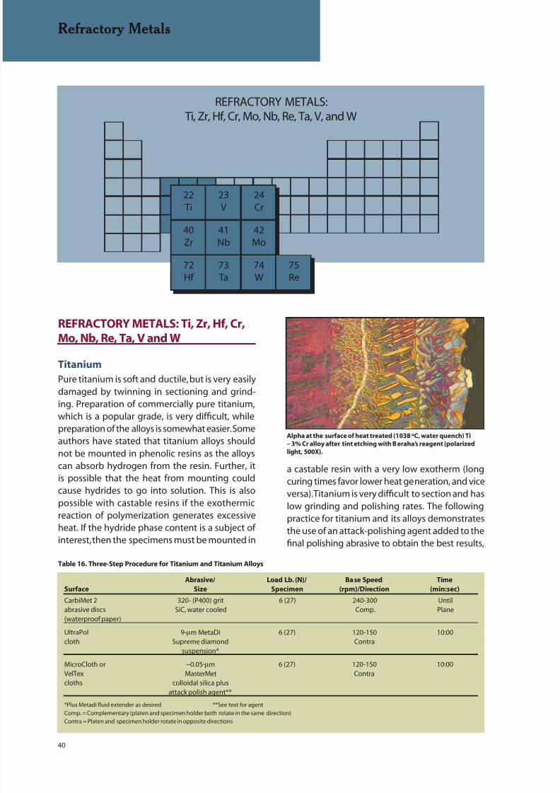
8/20/2019 Buehler Summet, Sample Prep and Analysis
http://slidepdf.com/reader/full/buehler-summet-sample-prep-and-analysis 40/136
40
Refractory Metals
50Sn
REFRACTORY METALS:Ti, Zr, Hf, Cr, Mo, Nb, Re, Ta, V, and W
22Ti
23V
24Cr
40Zr
41Nb
42Mo
72
Hf
73
Ta
74
W
75
Re
REFRACTORY METALS: Ti, Zr, Hf, Cr,Mo, Nb, Re, Ta, V and W
Titanium
Pure titanium is soft and ductile, but is very easilydamaged by twinning in sectioning and grind-ing. Preparation of commercially pure titanium,
which is a popular grade, is very difficult, whilepreparation of the alloys is somewhat easier. Someauthors have stated that titanium alloys shouldnot be mounted in phenolic resins as the alloyscan absorb hydrogen from the resin. Further, itis possible that the heat from mounting couldcause hydrides to go into solution. This is alsopossible with castable resins if the exothermicreaction of polymerization generates excessiveheat. If the hydride phase content is a subject ofinterest, then the specimens must be mounted in
a castable resin with a very low exotherm (longcuring times favor lower heat generation, and viceversa). Titanium is very difficult to section and haslow grinding and polishing rates. The followingpractice for titanium and its alloys demonstratesthe use of an attack-polishing agent added to thefinal polishing abrasive to obtain the best results,
Table 16. Three-Step Procedure for Titanium and Titanium Alloys
Abrasive/ Load Lb. (N)/ Base Speed Time
Surface Size Specimen (rpm)/Direction (min:sec)
CarbiMet 2 320- (P400) grit 6 (27) 240-300 Untilabrasive discs SiC, water cooled Comp. Plane(waterproof paper)
UltraPol 9-µm MetaDi 6 (27) 120-150 10:00cloth Supreme diamond Contra
suspension*
MicroCloth or ~0.05-µm 6 (27) 120-150 10:00VelTex MasterMet Contracloths colloidal silica plus
attack polish agent***Plus Metadi fluid extender as desired **See text for agent
Comp. = Complementary (platen and specimen holder both rotate in the same direction)
Contra = Platen and specimen holder rotate in opposite directions
Alpha at the surface of heat treated (1038 ºC, water quench) Ti
– 3% Cr alloy after tint etching with B eraha’s reagent (polarized
light, 500X).

8/20/2019 Buehler Summet, Sample Prep and Analysis
http://slidepdf.com/reader/full/buehler-summet-sample-prep-and-analysis 41/136
41
Refractory Metals
Table 17. Four-Step Procedure for Zirconium and Hafnium
Abrasive/ Load Lb. (N)/ Base Speed Time
Surface Size Specimen (rpm)/Direction (min:sec)
CarbiMet 2 320- (P400) 5 (22) 200-250 Until
abrasive discs grit SiC Comp. Plane(waterproof paper) water cooled
UltraPol or 9-µm MetaDi Supreme 5 (22) 150-200 5:00UltraPad cloths diamond suspension* Contra
TriDent cloth 3-µm MetaDi Supreme 5 (22) 150-200 3:00diamond suspension* Contra
MicroCloth, ~0.05-µm 6 (27) 120-150 7:00VelTex or MasterMet ContraChemoMet colloidal silica pluscloths attack polish agent**
*Plus MetaDi fluid extender as desired **See text for agent
Comp. = Complementary (platen and specimen holder both rotate in the same direction
Contra = Platen and specimen holder rotate in opposite directions
Basket-weave alpha-beta structure of as-cast Ti – 6% Al – 4% V
revealed by heat tinting (polarized light, 100X).
especially for commercially pure titanium, a ratherdifficult metal to prepare free of deformationfor color etching, heat tinting and/or polarizedlight examination of the grain structure. Attack
polishing solutions added to the abrasive slurryor suspension must be treated with great care toavoid burns. Use good, safe laboratory practicesand it is advisable to wear protective gloves. Thisthree step practice could be modified to four stepsby adding a 3- or 1-µm diamond step, but this isusually unnecessary, see Table 16.
A number of attack polishing agents have beenused. The simplest is a mixture of 10 mL hydrogenperoxide (30% concentration – avoid skin contact)
and 50 mL colloidal silica. Some metallographersadd either a small amount of Kroll’s reagent tothis mixture, or a few mL of nitric and hydrofluoricacids (avoid contact). These latter additions maycause the suspension to gel. In general, these acidadditions do little to improve the action of the hy-drogen peroxide (the safer 3% concentration is not
effective). Polarized light response of CP titaniumcan be improved by following this procedure witha brief vibratory polish using colloidal silica.
Zirconium and Hafnium
Pure zirconium and pure hafnium are soft, ductilehexagonal close-packed metals that can deformby mechanical twinning if handled aggressively insectioning and grinding. As with most refractorymetals, grinding and polishing removal rates arelow and eliminating all polishing scratches anddeformation can be difficult. It may even be pos-sible to form mechanical twins in compressionmounting. Both can contain very hard phasesthat make relief control more difficult. To improvepolarized light response, it is common practiceto chemically polish specimens after mechanicalpolishing. Alternatively, attack polishing additionscan be made to the final polishing abrasive slurry,or vibratory polishing may be employed. Table 17is a four-step procedure that can be followed byeither chemical polishing or vibratory polishing.
Several attack polishing agents have been usedfor Zr and Hf. One is a mixture of 1-2 parts hy-drogen peroxide (30% concentration – avoid
all skin contact) to 8 or 9 parts colloidal silica.Another is 5 mL of a chromium trioxide solution(20 g CrO3 to 100 mL water) added to 95 mLcolloidal silica or MasterpPrep alumina slurry.Additions of oxalic, hydrofluoric or nitric acids havealso been used. All of these attack polishing addi-
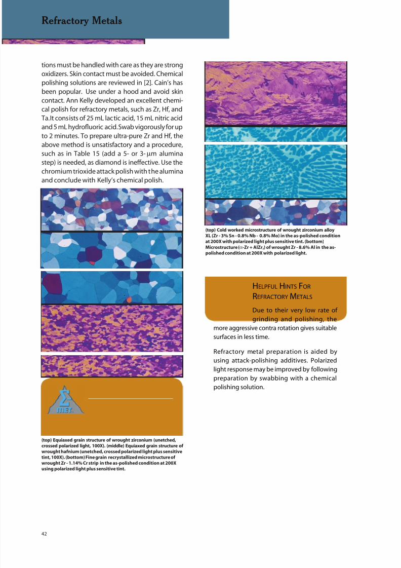
8/20/2019 Buehler Summet, Sample Prep and Analysis
http://slidepdf.com/reader/full/buehler-summet-sample-prep-and-analysis 42/136
42
Refractory Metals
(top) Equiaxed grain structure of wrought zirconium (unetched,
crossed polarized light, 100X). (middle) Equiaxed grain structure of
wrought hafnium (unetched, crossed polarized light plus sensitive
tint, 100X). (bottom) Fine grain recrystallized microstructure of
wrought Zr - 1.14% Cr strip in the as-polished condition at 200X
using polarized light plus sensitive tint.
HELPFUL HINTS FOR
REFRACTORY METALS
Due to their very low rate of
grinding and polishing, the
more aggressive contra rotation gives suitable
surfaces in less time.
Refractory metal preparation is aided by
using attack-polishing additives. Polarized
light response may be improved by following
preparation by swabbing with a chemical
polishing solution.
(top) Cold worked microstructure of wrought zirconium alloy
XL (Zr - 3% Sn - 0.8% Nb - 0.8% Mo) in the as-polished condition
at 200X with polarized light plus sensitive tint. (bottom)
Microstructure (α-Zr + AlZr3) of wrought Zr - 8.6% Al in the as-
polished condition at 200X with polarized light.
tions must be handled with care as they are strongoxidizers. Skin contact must be avoided. Chemicalpolishing solutions are reviewed in [2]. Cain’s hasbeen popular. Use under a hood and avoid skin
contact. Ann Kelly developed an excellent chemi-cal polish for refractory metals, such as Zr, Hf, andTa. It consists of 25 mL lactic acid, 15 mL nitric acidand 5 mL hydrofluoric acid. Swab vigorously for upto 2 minutes. To prepare ultra-pure Zr and Hf, theabove method is unsatisfactory and a procedure,such as in Table 15 (add a 5- or 3-µm aluminastep) is needed, as diamond is ineffective. Use thechromium trioxide attack polish with the aluminaand conclude with Kelly’s chemical polish.
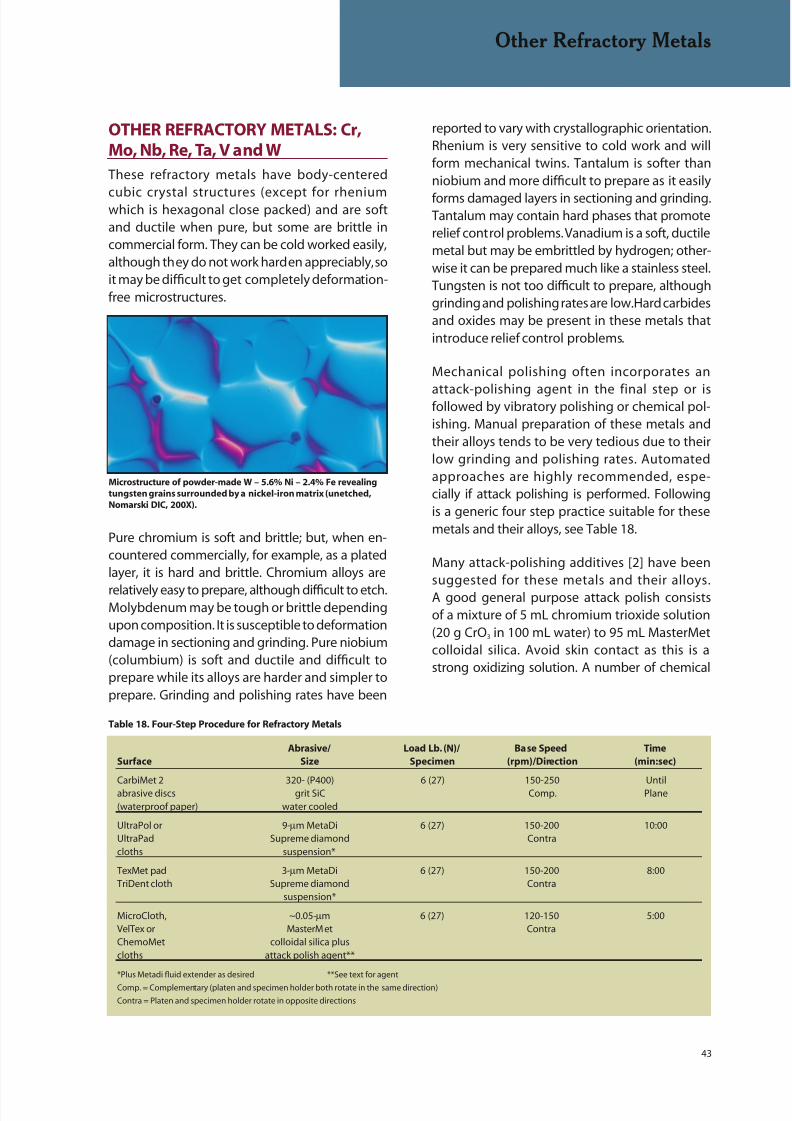
8/20/2019 Buehler Summet, Sample Prep and Analysis
http://slidepdf.com/reader/full/buehler-summet-sample-prep-and-analysis 43/136
43
Other Refractory Metals
OTHER REFRACTORY METALS: Cr,Mo, Nb, Re, Ta, V and W
These refractory metals have body-centered
cubic crystal structures (except for rheniumwhich is hexagonal close packed) and are softand ductile when pure, but some are brittle incommercial form. They can be cold worked easily,although they do not work harden appreciably, soit may be difficult to get completely deformation-free microstructures.
Pure chromium is soft and brittle; but, when en-countered commercially, for example, as a platedlayer, it is hard and brittle. Chromium alloys are
relatively easy to prepare, although difficult to etch.Molybdenum may be tough or brittle dependingupon composition. It is susceptible to deformationdamage in sectioning and grinding. Pure niobium(columbium) is soft and ductile and difficult toprepare while its alloys are harder and simpler toprepare. Grinding and polishing rates have been
Microstructure of powder-made W – 5.6% Ni – 2.4% Fe revealing
tungsten grains surrounded by a nickel-iron matrix (unetched,
Nomarski DIC, 200X).
Table 18. Four-Step Procedure for Refractory Metals
Abrasive/ Load Lb. (N)/ Base Speed Time
Surface Size Specimen (rpm)/Direction (min:sec)
CarbiMet 2 320- (P400) 6 (27) 150-250 Untilabrasive discs grit SiC Comp. Plane(waterproof paper) water cooled
UltraPol or 9-µm MetaDi 6 (27) 150-200 10:00UltraPad Supreme diamond Contracloths suspension*
TexMet pad 3-µm MetaDi 6 (27) 150-200 8:00TriDent cloth Supreme diamond Contra
suspension*
MicroCloth, ~0.05-µm 6 (27) 120-150 5:00VelTex or MasterMet ContraChemoMet colloidal silica pluscloths attack polish agent**
*Plus Metadi fluid extender as desired **See text for agent
Comp. = Complementary (platen and specimen holder both rotate in the same direction)
Contra = Platen and specimen holder rotate in opposite directions
reported to vary with crystallographic orientation.Rhenium is very sensitive to cold work and willform mechanical twins. Tantalum is softer thanniobium and more difficult to prepare as it easily
forms damaged layers in sectioning and grinding.Tantalum may contain hard phases that promoterelief control problems. Vanadium is a soft, ductilemetal but may be embrittled by hydrogen; other-wise it can be prepared much like a stainless steel.Tungsten is not too difficult to prepare, althoughgrinding and polishing rates are low. Hard carbidesand oxides may be present in these metals thatintroduce relief control problems.
Mechanical polishing often incorporates an
attack-polishing agent in the final step or isfollowed by vibratory polishing or chemical pol-ishing. Manual preparation of these metals andtheir alloys tends to be very tedious due to theirlow grinding and polishing rates. Automatedapproaches are highly recommended, espe-cially if attack polishing is performed. Followingis a generic four step practice suitable for thesemetals and their alloys, see Table 18.
Many attack-polishing additives [2] have beensuggested for these metals and their alloys.A good general purpose attack polish consistsof a mixture of 5 mL chromium trioxide solution(20 g CrO3 in 100 mL water) to 95 mL MasterMetcolloidal silica. Avoid skin contact as this is astrong oxidizing solution. A number of chemical
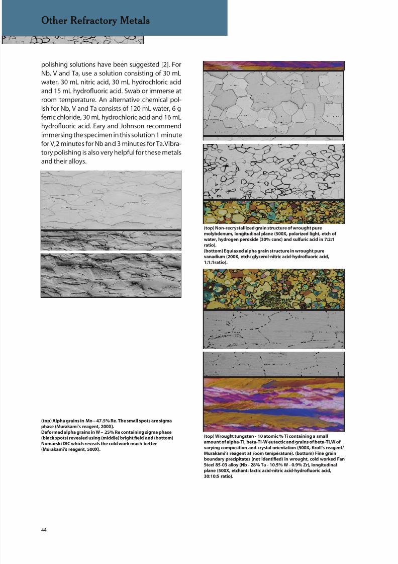
8/20/2019 Buehler Summet, Sample Prep and Analysis
http://slidepdf.com/reader/full/buehler-summet-sample-prep-and-analysis 44/136
44
Other Refractory Metals
(top) Alpha grains in Mo – 47.5% Re. The small spots are sigma
phase (Murakami’s reagent, 200X).
Deformed alpha grains in W – 25% Re containing sigma phase
(black spots) revealed using (middle) bright field and (bottom)
Nomarski DIC which reveals the cold work much better
(Murakami’s reagent, 500X).
(top) Non-recrystallized grain structure of wrought pure
molybdenum, longitudinal plane (500X, polarized light, etch of
water, hydrogen peroxide (30% conc) and sulfuric acid in 7:2:1
ratio).
(bottom) Equiaxed alpha grain structure in wrought pure
vanadium (200X, etch: glycerol-nitric acid-hydrofluoric acid,
1:1:1ratio).
(top) Wrought tungsten - 10 atomic % Ti containing a small
amount of alpha-Ti, beta-Ti-W eutectic and grains of beta-Ti,W of
varying composition and crystal orientation (500X, Kroll’s reagent/
Murakami’s reagent at room temperature). (bottom) Fine grain
boundary precipitates (not identified) in wrought, cold worked Fan
Steel 85-03 alloy (Nb - 28% Ta - 10.5% W - 0.9% Zr), longitudinal
plane (500X, etchant: lactic acid-nitric acid-hydrofluoric acid,
30:10:5 ratio).
polishing solutions have been suggested [2]. ForNb, V and Ta, use a solution consisting of 30 mLwater, 30 mL nitric acid, 30 mL hydrochloric acidand 15 mL hydrofluoric acid. Swab or immerse at
room temperature. An alternative chemical pol-ish for Nb, V and Ta consists of 120 mL water, 6 gferric chloride, 30 mL hydrochloric acid and 16 mLhydrofluoric acid. Eary and Johnson recommendimmersing the specimen in this solution 1 minutefor V, 2 minutes for Nb and 3 minutes for Ta. Vibra-tory polishing is also very helpful for these metalsand their alloys.

8/20/2019 Buehler Summet, Sample Prep and Analysis
http://slidepdf.com/reader/full/buehler-summet-sample-prep-and-analysis 45/136
45
Ferrous Metals
FERROUS METALS: Fe
26Fe
FERROUS METALS
Iron-based alloys account for a large portion ofall metals production. The range of compositionsand microstructures of iron-based alloys is farwider than any other system. Pure iron is softand ductile. Development of scratch-free anddeformation-free grain structures is difficult. Sheetsteels present the same problem, which can becomplicated by protective coatings of zinc, alu-minum or Zn-Al mixtures. In general, harder alloysare much easier to prepare. Cast irons may containgraphite, which must be retained in preparation.Inclusions are frequently evaluated and quantified.Volume fractions can vary from nearly 2% in a freemachining grade to levels barely detectable in apremium, double vacuum melt alloy. A wide rangeof inclusion, carbide and nitride phases has been
identified in steels. Addition of 12 or more percentchromium dramatically reduces the corrosionrate of steels, producing a wide range of stain-less steel alloys. Tool steels cover a wide range ofcompo sitions and can attain very high hardnesses.
Table 19. Four-Step Procedure for Hard Steels using the BuehlerHercules H disc
Abrasive/ Load Lb. (N)/ Base Speed Time
Surface Size Specimen (rpm)/Direction (min:sec)
Apex DGD or UltraPrep 45-µm 6 (27) 240-300 Untilmetal-bonded diamond, Comp. Planedisc water cooled
ApexHercules H 9-µm MetaDi Supreme 6 (27) 120-150 5:00rigid grinding disc diamond suspension* Comp.
TriDent cloth 3-µm MetaDi Supreme 6 (27) 120-150 3:00diamond suspension* Comp.
MicroCloth, MasterPrep 6 (27) 120-150 2:00VelTex or 0.05-µm alumina ContraChemoMet suspension,cloths or MasterMet
colloidal silica
*Plus Metadi fluid extender desired
Comp. = Complementary (platen and specimen holder both rotate in the same direction)Contra = Platen and specimen holder rotate in opposite directions
Lath martensitic microstructure of an unconsolidated powder
metallurgy steel gear containing substantial porosity (Klemm’s I
reagent, polarized light, 200X).

8/20/2019 Buehler Summet, Sample Prep and Analysis
http://slidepdf.com/reader/full/buehler-summet-sample-prep-and-analysis 46/136
46
Ferrous Metals
Table 20. Four-Step Procedure for Soft Steels using the BuehlerHercules S disc
Abrasive/ Load Lb. (N)/ Base Speed Time
Surface Size Specimen (rpm)/Direction (min:sec)
Apex DGD or UltraPrep 30-µm 6 (27) 240-300 Untilresin-bonded diamond, Comp. Planedisc water cooled
ApexHercules S 6-µm MetaDi 6 (27) 120-150 5:00rigid grinding disc Supreme diamond Comp.
suspension*
TriDent cloth 3-µm MetaDi 6 (27) 120-150 3:00Supreme diamond Comp.
suspension*
MicroCloth, MasterPrep 6 (27) 120-150 2:00VelTex or 0.05-µm alumina ContraChemoMet suspension,cloths or MasterMet
colloidal silica
*Plus MetaDi fluid extender as desired
Comp. = Complementary (platen and specimen holder both rotate in the same direction)
Contra = Platen and specimen holder rotate in opposite directions
Table 21. Three-Step Procedure for Steels
Abrasive/ Load Lb. (N)/ Base Speed Time
Surface Size Specimen (rpm)/Direction (min:sec)
CarbiMet 2 120- to 320- 6 (27) 240-300 Untilabrasive discs (P120 to P400) Comp. Plane(waterproof paper) grit SiC, water cooled
ApexHercules H or S 3-µm MetaDi 6 (27) 120-150 5:00rigid grinding disc Supreme Comp.
Diamond Suspension*
MicroCloth MasterPrep 0.05-µm 6 (27) 120-150 5:00VelTex or Alumina Suspension, ContraChemoMet or MasterMet
cloths Colloidal Silica
*Plus MetaDi
Fluid extender as desiredComp. = Complementary (platen and specimen holder rotate in the same direction)
Contra = Platen and specimen holder rotate in opposite directions
Preparation of ferrous metals and alloys is quitestraightforward using the contemporary methods.Edge retention (see guidelines on pages 13-15)and inclusion retention are excellent, especially
if automated equipment is used. The followingprocedures are recommended and are adequatefor the vast majority of ferrous metals and alloys.Table 9 presented a variation of the method givenin Table 19.
This practice is also useful for cast iron specimensincluding graphitic cast irons. 240 (P280) grit SiCpaper can be substituted for the UltraPrep discor another ApexHercules H disc can be used forplanar grinding with 30-µm MetaDi Supreme
diamond suspension. Due to their high silicon
content and the potential for staining problems, it isbest to use the MasterPrep alumina suspension forthe final polishing step.
For softer steels, use the 30-µm resin bonded Ultra-Prep disc, or 240- (P280) grit SiC paper, for step 1.The ApexHercules S disc can be used in place of theApexHercules H disc but this is not usually necessary.However, with either disc, use 6-µm MetaDi Supremefor the second step instead of 9-µm, as shown inTable 20.
This practice is well suited for solution annealedaustenitic stainless steels and for soft sheet steels.UltraPol or UltraPad cloths could be substitute for
the rigid grinding discs, if desired. For perfect pub-lication quality images, or for color etch ing, follow

8/20/2019 Buehler Summet, Sample Prep and Analysis
http://slidepdf.com/reader/full/buehler-summet-sample-prep-and-analysis 47/136
47
Ferrous Metals
Table 22. Four-Step Contemporary Procedure for Stainless Steels and Maraging Steels
Abrasive/ Load Lb. (N)/ Base Speed Time
Surface Size Specimen (rpm)/Direction (min:sec)
CarbiMet 2 120- to 240- (P120 6 (27) 240-300 Untilabrasive discs to P280) grit SiC, Comp. Plane(waterproof paper) water cooled
ApexHercules S 9-µm 6 (27) 120-150 5:00rigid grinding disc or MetaDi Comp.UltraPol cloth Supreme
DiamondSuspension*
TriDent cloth 3-µm 6 (27) 120-150 5:00MetaDi Comp.
Supremediamond
suspension*
MicroCloth, MasterPrep 6 (27) 120-150 2:30VelTex or 0.05-µm alumina ContraChemoMet suspension,cloths or MasterMet
colloidal silica
*Plus MetaDi fluid extender as desired
Comp. = Complementary (platen and specimen holder both rotate in the same direction)
Contra = Platen and specimen holder rotate in opposite directions
Microstructure of a duplex (ferrite tan, austenite white) stainless
steel held at 816º C for 48 hours which forms sigma phase (orange
particles) revealed by electrolytic etching with aqueous 20%
NaOH at 3 V dc, 9 s (500X).
this practice with a brief vibratory polish using thecloths and abrasives in the last step.
Many steels, particularly the harder steels, can be
prepared in three steps with excellent results. Arecommended practice is given in Table 21.
For soft alloys, use 240- or 320- (P280 or P400)grit SiC paper; for harder alloys use 120 (P120),180- (P180), or 240- (P280) grit SiC paper,depending upon the starting surface finish andthe hardness of the alloy. Planar grinding canalso be performed using 45-µm metal-bonded or30-µm resin-bonded UltraPrep diamond discs. Forsofter steels, use the ApexHercules S disc for best
results. The UltraPol cloth can also be used for thesecond step for steels of any hardness.
The following practice is recommended forstainless steels and maraging steels. For solu-tion annealed austenitic grades and for ferriticstainless grades and for annealed maraginggrades, use the ApexHercules S disc or the Ultra-Pol cloth for best results. Start with 120- (P120)grit SiC paper only if it is a very hard martensiticstainless steel, such as type 440C. For the mar-tensitic grades, planar grinding can be performedusing a 45-µm metal-bonded diamond UltraPrep
disc. For softer stainless steels, use the 30-µmresin-bonded diamond UltraPrep disc for planargrinding. Another alternative is a second ApexHercules disc, either H or S, depending upon
the hardness of the grade, and a 30-µm MetaDiSupreme polycrystalline diamond suspension.The solution annealed austenitic stainless steelsand the fully ferritic stainless steels are the mostdifficult to prepare. It may be helpful to add a 1-µmdiamond step on a TriDent cloth before the laststep, or to follow the last step with a brief vibra-tory polish using colloidal silica on MicroCloth ora ChemoMet cloth, see Table 22.
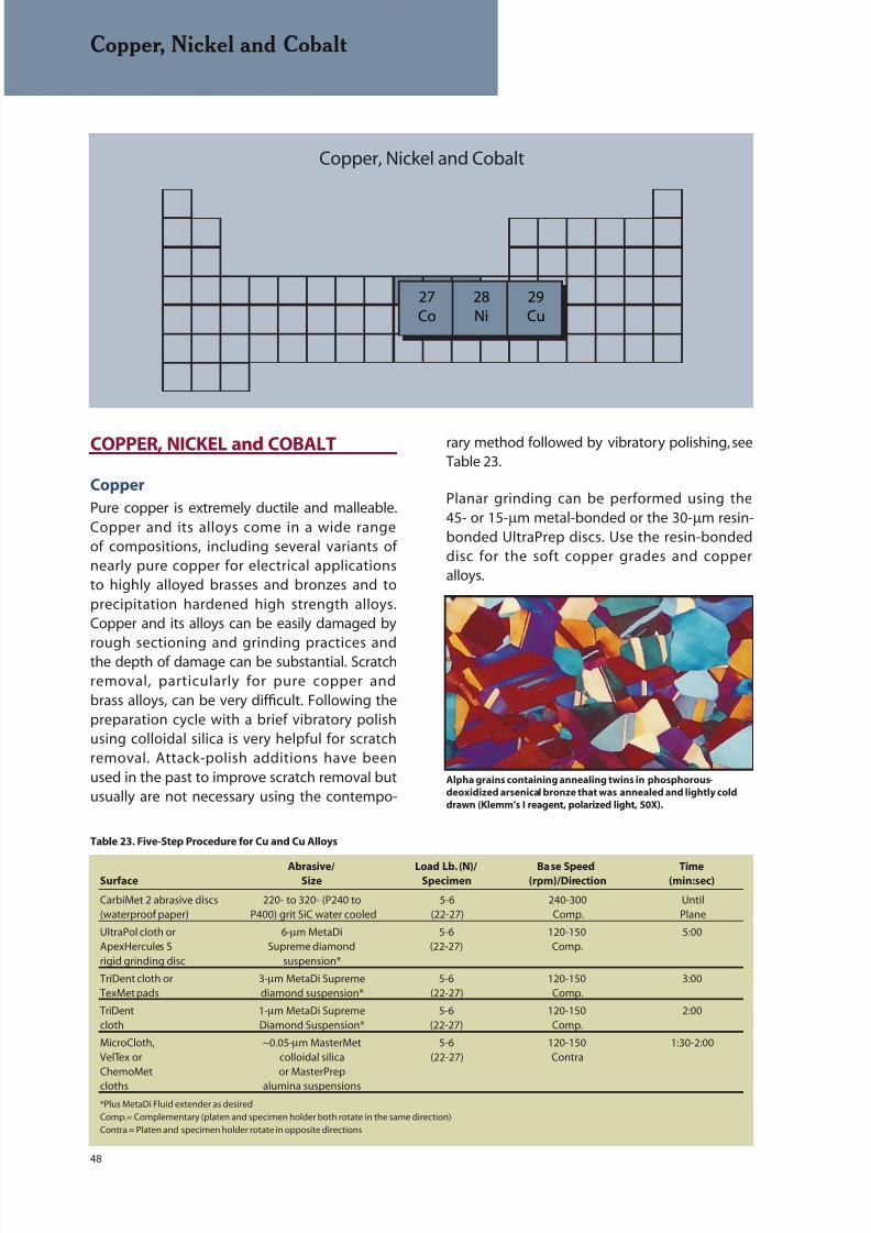
8/20/2019 Buehler Summet, Sample Prep and Analysis
http://slidepdf.com/reader/full/buehler-summet-sample-prep-and-analysis 48/136
48
Copper, Nickel and Cobalt
27Co
28Ni
29Cu
Copper, Nickel and Cobalt
COPPER, NICKEL and COBALT
Copper
Pure copper is extremely ductile and malleable.Copper and its alloys come in a wide rangeof compositions, including several variants ofnearly pure copper for electrical applicationsto highly alloyed brasses and bronzes and toprecipitation hardened high strength alloys.Copper and its alloys can be easily damaged by
rough sectioning and grinding practices andthe depth of damage can be substantial. Scratchremoval, particularly for pure copper andbrass alloys, can be very difficult. Following thepreparation cycle with a brief vibratory polishusing colloidal silica is very helpful for scratchremoval. Attack-polish additions have beenused in the past to improve scratch removal butusually are not necessary using the contempo-
rary method followed by vibratory polishing, seeTable 23.
Planar grinding can be performed using the45- or 15-µm metal-bonded or the 30-µm resin-bonded UltraPrep discs. Use the resin-bondeddisc for the soft copper grades and copperalloys.
Table 23. Five-Step Procedure for Cu and Cu Alloys
Alpha grains containing annealing twins in phosphorous-
deoxidized arsenical bronze that was annealed and lightly cold
drawn (Klemm’s I reagent, polarized light, 50X).
Abrasive/ Load Lb. (N)/ Base Speed TimeSurface Size Specimen (rpm)/Direction (min:sec)
CarbiMet 2 abrasive discs 220- to 320- (P240 to 5-6 240-300 Until
(waterproof paper) P400) grit SiC water cooled (22-27) Comp. Plane
UltraPol cloth or 6-µm MetaDi 5-6 120-150 5:00ApexHercules S Supreme diamond (22-27) Comp.rigid grinding disc suspension*
TriDent cloth or 3-µm MetaDi Supreme 5-6 120-150 3:00TexMet pads diamond suspension* (22-27) Comp.
TriDent 1-µm MetaDi Supreme 5-6 120-150 2:00cloth Diamond Suspension* (22-27) Comp.
MicroCloth, ~0.05-µm MasterMet 5-6 120-150 1:30-2:00VelTex or colloidal silica (22-27) ContraChemoMet or MasterPrep
cloths alumina suspensions
*Plus MetaDi Fluid extender as desired
Comp.= Complementary (platen and specimen holder both rotate in the same direction)
Contra = Platen and specimen holder rotate in opposite directions
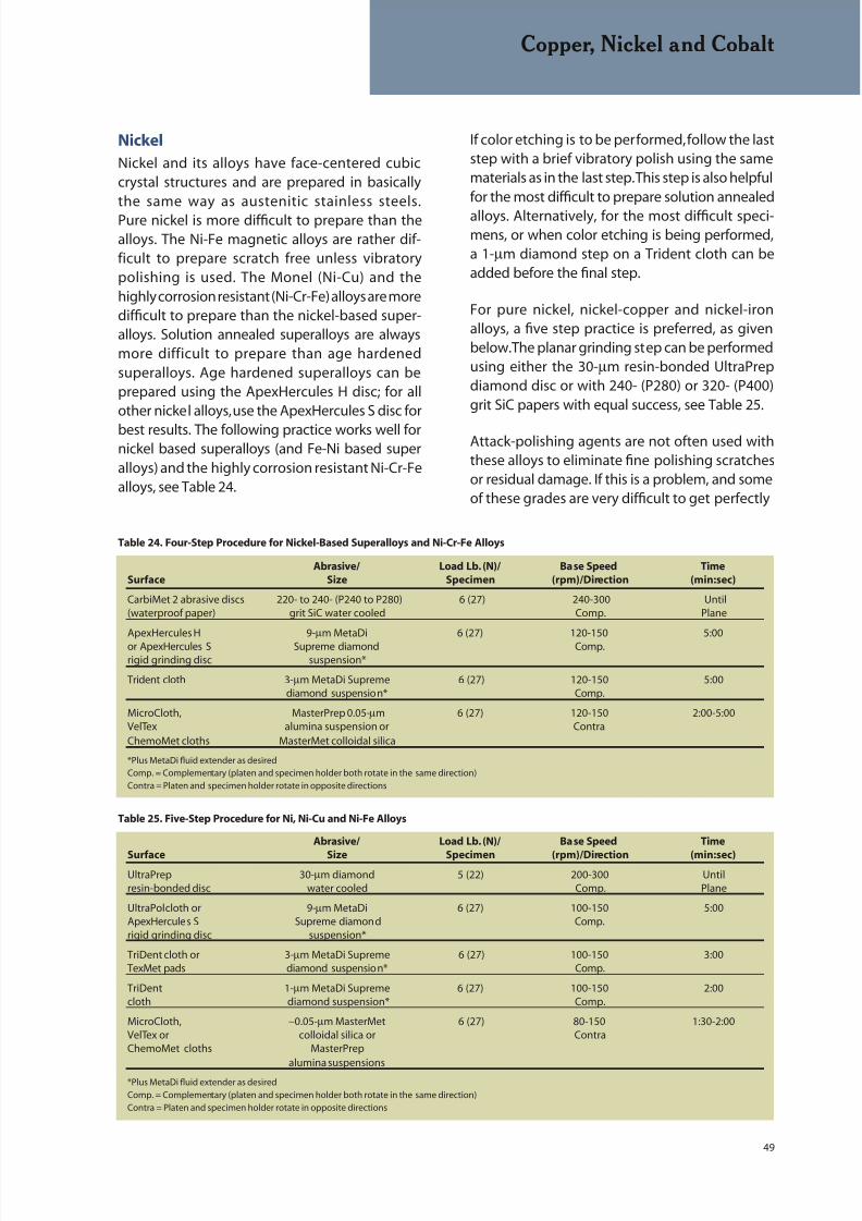
8/20/2019 Buehler Summet, Sample Prep and Analysis
http://slidepdf.com/reader/full/buehler-summet-sample-prep-and-analysis 49/136
49
Copper, Nickel and Cobalt
Nickel
Nickel and its alloys have face-centered cubiccrystal structures and are prepared in basicallythe same way as austenitic stainless steels.
Pure nickel is more difficult to prepare than thealloys. The Ni-Fe magnetic alloys are rather dif-ficult to prepare scratch free unless vibratorypolishing is used. The Monel (Ni-Cu) and thehighly corrosion resistant (Ni-Cr-Fe) alloys are moredifficult to prepare than the nickel-based super-alloys. Solution annealed superalloys are alwaysmore difficult to prepare than age hardenedsuperalloys. Age hardened superalloys can beprepared using the ApexHercules H disc; for allother nickel alloys, use the ApexHercules S disc for
best results. The following practice works well fornickel based superalloys (and Fe-Ni based superalloys) and the highly corrosion resistant Ni-Cr-Fealloys, see Table 24.
If color etching is to be performed, follow the laststep with a brief vibratory polish using the samematerials as in the last step. This step is also helpfulfor the most difficult to prepare solution annealed
alloys. Alternatively, for the most difficult speci-mens, or when color etching is being performed,a 1-µm diamond step on a Trident cloth can beadded before the final step.
For pure nickel, nickel-copper and nickel-ironalloys, a five step practice is preferred, as givenbelow. The planar grinding step can be performedusing either the 30-µm resin-bonded UltraPrepdiamond disc or with 240- (P280) or 320- (P400)grit SiC papers with equal success, see Table 25.
Attack-polishing agents are not often used withthese alloys to eliminate fine polishing scratchesor residual damage. If this is a problem, and someof these grades are very difficult to get perfectly
Table 25. Five-Step Procedure for Ni, Ni-Cu and Ni-Fe Alloys
Abrasive/ Load Lb. (N)/ Base Speed Time
Surface Size Specimen (rpm)/Direction (min:sec)
UltraPrep 30-µm diamond 5 (22) 200-300 Untilresin-bonded disc water cooled Comp. Plane
UltraPol cloth or 9-µm MetaDi 6 (27) 100-150 5:00ApexHercules S Supreme diamond Comp.rigid grinding disc suspension*
TriDent cloth or 3-µm MetaDi Supreme 6 (27) 100-150 3:00TexMet pads diamond suspension* Comp.
TriDent 1-µm MetaDi Supreme 6 (27) 100-150 2:00cloth diamond suspension* Comp.
MicroCloth, ∼0.05-µm MasterMet 6 (27) 80-150 1:30-2:00VelTex or colloidal silica or ContraChemoMet cloths MasterPrep
alumina suspensions
*Plus MetaDi fluid extender as desired
Comp. = Complementary (platen and specimen holder both rotate in the same direction)
Contra = Platen and specimen holder rotate in opposite directions
Table 24. Four-Step Procedure for Nickel-Based Superalloys and Ni-Cr-Fe Alloys
Abrasive/ Load Lb. (N)/ Base Speed Time
Surface Size Specimen (rpm)/Direction (min:sec)
CarbiMet 2 abrasive discs 220- to 240- (P240 to P280) 6 (27) 240-300 Until(waterproof paper) grit SiC water cooled Comp. Plane
ApexHercules H 9-µm MetaDi 6 (27) 120-150 5:00or ApexHercules S Supreme diamond Comp.rigid grinding disc suspension*
Trident cloth 3-µm MetaDi Supreme 6 (27) 120-150 5:00diamond suspension* Comp.
MicroCloth, MasterPrep 0.05-µm 6 (27) 120-150 2:00-5:00VelTex alumina suspension or ContraChemoMet cloths MasterMet colloidal silica
*Plus MetaDi fluid extender as desiredComp. = Complementary (platen and specimen holder both rotate in the same direction)
Contra = Platen and specimen holder rotate in opposite directions

8/20/2019 Buehler Summet, Sample Prep and Analysis
http://slidepdf.com/reader/full/buehler-summet-sample-prep-and-analysis 50/136
50
Copper, Nickel and Cobalt
free of scratches and deformation damage, a briefvibratory polish, using the same materials as in thelast step, will provide the needed improvement.MasterPrep alumina may give better results than
colloidal silica for the more pure nickel composi-tions.
Cobalt
Cobalt and its alloys are more difficult toprepare than nickel and its alloys. Cobalt is atough metal with a hexagonal close-packedcrystal structure and is sensitive to deformationdamage by mechanical twinning. Grindingand polishing rates are lower for Co than for Ni,Cu or Fe. Preparation of cobalt and its alloys is
somewhat similar to that of refractory met-als. Despite its hcp crystal structure, crossedpolarized light is not very useful for examiningcobalt alloys compared to other hcp metals andalloys. Following is a practice for preparing Co andits alloys, see Table 26.
Two steps of SiC paper may be needed to get thespecimens co-planar. If the cut surface is of goodquality, start with 320- (P400) grit paper. Cobaltand its alloys are more difficult to cut than most
steels, regardless of their hardness. Attack polish-ing has not been reported but chemical polishinghas been used after mechanical polishing. Morral(2) has recommended two chemical polishingsolutions: equal parts of acetic and nitric acids(immerse) or 40 mL lactic acid, 30 mL hydrochloricacid and 5 mL nitric acid (immerse). A wide varietyof Co-based alloys have been prepared with theabove method without need for chemical polish-ing. The 1-µm diamond step could be eliminatedfor routine work.
Alpha grains containing annealing twins of solution annealed and
double aged Waspaloy nickel-based superalloy (Beraha’s reagent,
100X).
Table 26. Five-Step Procedure for Cobalt
Abrasive/ Load Lb. (N)/ Base Speed Time
Surface Size Specimen (rpm)/Direction (min:sec)
CarbiMet 2 220- to 320- 6 (27) 250-300 Untilabrasive discs (P240 to P400) grit Contra Plane
(Waterproof Paper) SiC water cooled
UltraPol cloth or 9-µm MetaDi 6 (27) 100-150 5:00ApexHercules S Supreme diamond Contrarigid grinding disc suspension*
TexMet 3-µm MetaDi Supreme 6 (27) 100-150 5:00pad diamond suspension* Contra
TriDent cloth or 1-µm MetaDi Supreme 6 (27) 100-150 3:00TexMet pads diamond suspension* Contra
MicroCloth, ~0.05-µm MasterMet 6 (27) 80-120 2:00-3:00VelTex or colloidal silica or ContraChemoMet MasterPrepcloths alumina suspensions
*Plus Metadi fluid extender as desiredComp. = Complementary (platen and specimen holder both rotate in the same direction)
Contra = Platen and specimen holder rotate in opposite directions
Equiaxed grain structure of Elgiloy (Co – 20% Cr – 15% Fe – 15%
Ni – 7% Mo – 2% Mn – 0.15% C – 0.05% Be) after hot rolling and
annealing revealing annealing twins (Beraha’s reagent, crossed
polarized light plus sensitive tint, 100X).
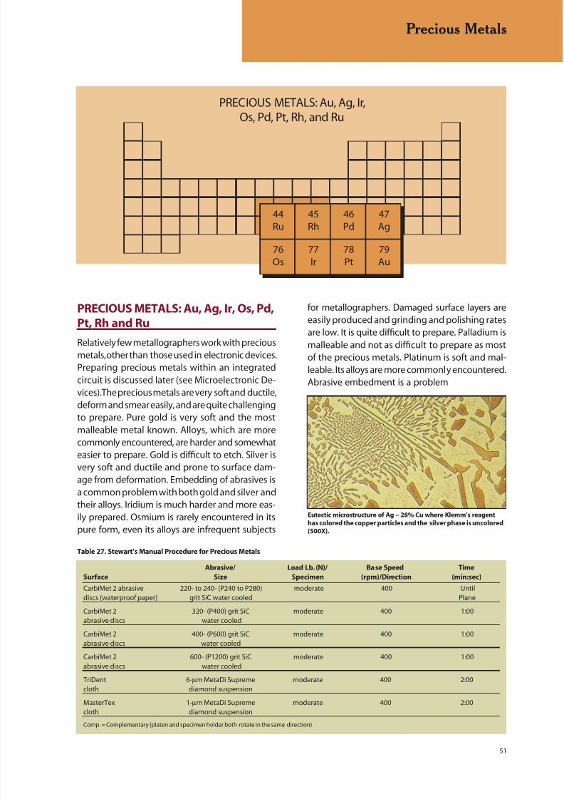
8/20/2019 Buehler Summet, Sample Prep and Analysis
http://slidepdf.com/reader/full/buehler-summet-sample-prep-and-analysis 51/136
51
Precious Metals
PRECIOUS METALS: Au, Ag, Ir,Os, Pd, Pt, Rh, and Ru
44Ru
45Rh
46Pd
47Ag
77Ir
78Pt
79Au
76Os
PRECIOUS METALS: Au, Ag, Ir, Os, Pd,Pt, Rh and Ru
Relatively few metallographers work with preciousmetals, other than those used in electronic devices.Preparing precious metals within an integratedcircuit is discussed later (see Microelectronic De-vices). The precious metals are very soft and ductile,deform and smear easily, and are quite challenging
to prepare. Pure gold is very soft and the mostmalleable metal known. Alloys, which are morecommonly encountered, are harder and somewhateasier to prepare. Gold is difficult to etch. Silver isvery soft and ductile and prone to surface dam-age from deformation. Embedding of abrasives isa common problem with both gold and silver andtheir alloys. Iridium is much harder and more eas-ily prepared. Osmium is rarely encountered in itspure form, even its alloys are infrequent subjects
for metallographers. Damaged surface layers areeasily produced and grinding and polishing ratesare low. It is quite difficult to prepare. Palladium ismalleable and not as difficult to prepare as mostof the precious metals. Platinum is soft and mal-leable. Its alloys are more commonly encountered.Abrasive embedment is a problem
Eutectic microstructure of Ag – 28% Cu where Klemm’s reagent
has colored the copper particles and the silver phase is uncolored
(500X).
Table 27. Stewart’s Manual Procedure for Precious Metals
Abrasive/ Load Lb. (N)/ Base Speed Time
Surface Size Specimen (rpm)/Direction (min:sec)
CarbiMet 2 abrasive 220- to 240- (P240 to P280) moderate 400 Untildiscs (waterproof paper) grit SiC water cooled Plane
CarbiMet 2 320- (P400) grit SiC moderate 400 1:00abrasive discs water cooled
CarbiMet 2 400- (P600) grit SiC moderate 400 1:00abrasive discs water cooled
CarbiMet 2 600- (P1200) grit SiC moderate 400 1:00abrasive discs water cooled
TriDent 6-µm MetaDi Supreme moderate 400 2:00cloth diamond suspension
MasterTex 1-µm MetaDi Supreme moderate 400 2:00cloth diamond suspension
Comp. = Complementary (platen and specimen holder both rotate in the same direction)

8/20/2019 Buehler Summet, Sample Prep and Analysis
http://slidepdf.com/reader/full/buehler-summet-sample-prep-and-analysis 52/136
52
Precious Metals
with Pt and its alloys. Rhodium is a hard metaland is relatively easy to prepare. Rh is sensitiveto surface damage in sectioning and grinding.Ruthenium is a hard, brittle metal that is not too
difficult to prepare.
Stewart (Tech-Notes, Vol. 2, Issue 5) has describeda method for preparing jewelry alloys. Invariably,these are small pieces, due to their cost, andmust be mounted. Stewart uses EpoMet G resinfor most specimens. If transparency is need, heuses TransOptic resin. Fragile beads and balls aremounted in castable resins. Grinding and polishingwas conducted at 400 rpm. His practice is shownin Table 27.
This can be followed by a brief vibratory polishusing colloidal silica on MasterTex, ChemoMet orMicroCloth pads to further enhance the qualityof the preparation; but, a 1-µm diamond finish isadequate for most work. Attack-polishing has beenused to prepare gold and its alloys and chemicalpolishing has been performed after mechanicalpolishing of silver, but neither practice is com-monly performed. Alternate etch-polish cyclesmay be needed to remove fine polishing scratches,especially for annealed specimens.
A procedure for an automated system wasdeveloped after experimentation with a num-ber of precious metal specimens. Most of thesemetals and alloys are quite soft, unless they havebeen cold worked, and they are susceptible toembedding of abrasives. In this method, only onesilicon carbide step is used. TexMet pads are used
for the diamond steps, as it will hold the abrasivein its surface well, which minimizes embedding.Only diamond paste is used, as slurries will be moreprone to embedding, as we observed in high gold
alloys. Use only a small amount of distilled wateras the lubricant. Do not get the cloth excessivelywet. Final polishing is with a ChemoMet I clothand MasterPrep alumina. Due to their excellentcorrosion resistance, colloidal silica is not effectiveas an abrasive for precious metals. The ChemoMetpad has many fine pores to hold the abrasive. Thecycle is given in Table 28.
For 18 karat gold and higher (≥75% Au), it is neces-sary to use an attack polish agent in the final step.
An aqueous solution of 5 g CrO3 in 100 mL waterworks well. Mix 10 mL of the attack polish agentwith 50 mL of MasterPrep suspension. This willthicken, so add about 20-30 mL water to makeit thinner. A 3 to 6 minute attack- polish step willremove the fine polishing scratches. Wear protec-tive gloves as the chromium trioxide solution is astrong oxidizer.
Table 28. Five-Step Automated Procedure for Precious Metals
Abrasive/ Load Lb. (N)/ Base Speed TimeSurface Size Specimen (rpm)/Direction (min:sec)
CarbiMet 2 220- to 320- (P240 to 3 (13) 150-240 Until
abrasive discs P400) grit water cooled Comp. Plane
TexMet 9-µm MetaDi II 3 (13) 150-240 5:00pad diamond paste* Comp.
TexMet 3-µm MetaDi II 3 (13) 150-240 3:00pad diamond paste* Comp.
TexMet 1-µm MetaDi II 3 (13) 150-240 2:00pad diamond paste* Comp.
ChemoMet MasterPrep 6 (26) 100-150 2:00cloth alumina suspension Comp.
* Use water as the lubricant, but keep the pad relatively dry
Comp. = Complementary (platen and specimen holder both rotate in the same direction)
Equiaxed grain structure of cold rolled and annealed 18-karat gold
(Neyoro 28A: 75% Au – 22% Ag – 3% Ni) revealing annealing twins
(equal parts 10% NaCN and 30% H2O2, 50X).
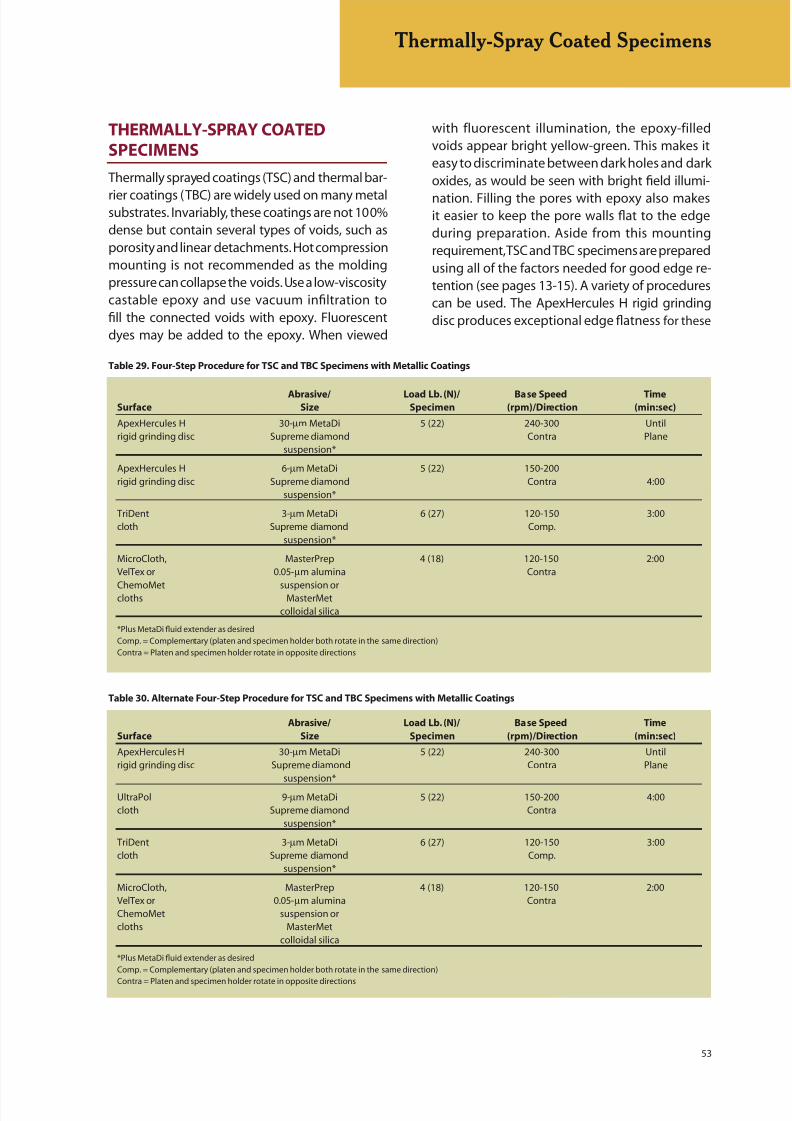
8/20/2019 Buehler Summet, Sample Prep and Analysis
http://slidepdf.com/reader/full/buehler-summet-sample-prep-and-analysis 53/136
53
Thermally-Spray Coated Specimens
THERMALLY-SPRAY COATEDSPECIMENS
Thermally sprayed coatings (TSC) and thermal bar-
rier coatings (TBC) are widely used on many metalsubstrates. Invariably, these coatings are not 100%dense but contain several types of voids, such asporosity and linear detachments. Hot compressionmounting is not recommended as the moldingpressure can collapse the voids. Use a low-viscositycastable epoxy and use vacuum infiltration tofill the connected voids with epoxy. Fluorescentdyes may be added to the epoxy. When viewed
Table 30. Alternate Four-Step Procedure for TSC and TBC Specimens with Metallic Coatings
Abrasive/ Load Lb. (N)/ Base Speed Time
Surface Size Specimen (rpm)/Direction (min:sec)
ApexHercules H 30-µm MetaDi 5 (22) 240-300 Untilrigid grinding disc Supreme diamond Contra Plane
suspension*
UltraPol 9-µm MetaDi 5 (22) 150-200 4:00cloth Supreme diamond Contra
suspension*
TriDent 3-µm MetaDi 6 (27) 120-150 3:00cloth Supreme diamond Comp.
suspension*
MicroCloth, MasterPrep 4 (18) 120-150 2:00VelTex or 0.05-µm alumina ContraChemoMet suspension orcloths MasterMet
colloidal silica
*Plus MetaDi fluid extender as desired
Comp. = Complementary (platen and specimen holder both rotate in the same direction)
Contra = Platen and specimen holder rotate in opposite directions
Table 29. Four-Step Procedure for TSC and TBC Specimens with Metallic Coatings
Abrasive/ Load Lb. (N)/ Base Speed TimeSurface Size Specimen (rpm)/Direction (min:sec)
ApexHercules H 30-µm MetaDi 5 (22) 240-300 Untilrigid grinding disc Supreme diamond Contra Plane
suspension*
ApexHercules H 6-µm MetaDi 5 (22) 150-200rigid grinding disc Supreme diamond Contra 4:00
suspension*
TriDent 3-µm MetaDi 6 (27) 120-150 3:00cloth Supreme diamond Comp.
suspension*
MicroCloth, MasterPrep 4 (18) 120-150 2:00VelTex or 0.05-µm alumina Contra
ChemoMet suspension orcloths MasterMetcolloidal silica
*Plus MetaDi fluid extender as desired
Comp. = Complementary (platen and specimen holder both rotate in the same direction)
Contra = Platen and specimen holder rotate in opposite directions
with fluorescent illumination, the epoxy-filledvoids appear bright yellow-green. This makes iteasy to discriminate between dark holes and darkoxides, as would be seen with bright field illumi-
nation. Filling the pores with epoxy also makesit easier to keep the pore walls flat to the edgeduring preparation. Aside from this mountingrequirement, TSC and TBC specimens are preparedusing all of the factors needed for good edge re-tention (see pages 13-15). A variety of procedurescan be used. The ApexHercules H rigid grindingdisc produces exceptional edge flatness for these

8/20/2019 Buehler Summet, Sample Prep and Analysis
http://slidepdf.com/reader/full/buehler-summet-sample-prep-and-analysis 54/136
54
specimens. Two four step procedures for TSC andTBC specimens using the Apex Hercules H rigidgrinding disc for specimens with metallic coatingsand one procedure for specimens with ceramic
coatings are given, see Tables 29-31.
The 30-µm resin bonded, or the 45-µm metalbonded UltraPrep diamond discs, can be substi-tuted for the planar grinding step. (Table 29 and30). UltraPol or UltraPad cloths can be used in the
second step. (Table 29 and 31).
Table 31. Four-Step Procedure for TSC and TBC Specimens with Ceramic Coatings
Abrasive/ Load Lb. (N)/ Base Speed Time
Surface Size Specimen (rpm)/Direction (min:sec)
Apex DGD or UltraPrep 45-µm disc 5 (22) 240-300 Untilmetal-bonded disc water cooled Contra Plane
ApexHercules H 9-µm 5 (22) 150-180 4:00rigid grinding disc MetaDi Contra
Supremediamond
suspension*
TexMet pad or 3-µm 6 (27) 120-150 3:00
TriDent cloth MetaDi Comp.Supremediamond
suspension*
MicroCloth, MasterPrep 8 (36) 120-150 2:30ValTex or 0.05-µm alumina ContraChemoMet suspension orcloths MasterMet
colloidal silica
*Plus MetaDi fluid extender as desired
Comp. = Complementary (platen and specimen holder both rotate in the same direction)Contra = Platen and specimen holder rotate in opposite directions
Thermally-Spray Coated Specimens
NiCrAlY thermally-spray coated steel specimen revealing a small
amount of porosity (black spots), linear detachments (elongated
black lines), and inclusions (gray particles) (unetched, 100X).
Microstructure of a steel substrate covered by two thermally-
sprayed layers, a NiAl bond coat and yittria-zirconia top
coat (unetched, 100X). The bond coat contains pores, linear
detachments and inclusions while the top coat is quite porous.
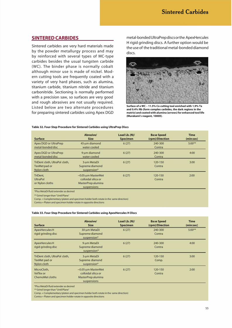
8/20/2019 Buehler Summet, Sample Prep and Analysis
http://slidepdf.com/reader/full/buehler-summet-sample-prep-and-analysis 55/136
55
SINTERED CARBIDES
Sintered carbides are very hard materials madeby the powder metallurgy process and may
by reinforced with several types of MC-typecarbides besides the usual tungsten carbide(WC). The binder phase is normally cobaltalthough minor use is made of nickel. Mod-ern cutting tools are frequently coated with avariety of very hard phases, such as alumina,titanium carbide, titanium nitride and titaniumcarbonitride. Sectioning is normally performedwith a precision saw, so surfaces are very goodand rough abrasives are not usually required.Listed below are two alternate proceduresfor preparing sintered carbides using Apex DGD
metal-bonded UltraPrep discs or the ApexHercules
H rigid grinding discs. A further option would bethe use of the traditional metal-bonded diamonddiscs.
Table 32. Four-Step Procedure for Sintered Carbides using UltraPrep Discs
Abrasive/ Load Lb. (N)/ Base Speed Time
Surface Size Specimen (rpm)/Direction (min:sec)
Apex DGD or UltraPrep 45-µm diamond 6 (27) 240-300 5:00**metal-bonded disc water cooled Contra
Apex DGD or UltraPrep 9-µm diamond 6 (27) 240-300 4:00metal-bonded disc water cooled Contra
TriDent cloth, UltraPol cloth, 3-µm MetaDi 6 (27) 120-150 3:00TexMet pad or Supreme diamond ContraNylon cloth suspension*
TriDent, ~0.05-µm MasterMet 6 (27) 120-150 2:00UltraPol colloidal silica or Contraor Nylon cloths MasterPrep alumina
suspensions
*Plus MetaDi fluid extender as desired
** Grind longer than “Until Plane”
Comp. = Complementary (platen and specimen holder both rotate in the same direction)
Contra = Platen and specimen holder rotate in opposite directions
Table 33. Four-Step Procedure for Sintered Carbides using ApexHercules H Discs
Abrasive/ Load Lb. (N)/ Base Speed Time
Surface Size Specimen (rpm)/Direction (min:sec)
ApexHercules H 30-µm MetaDi 6 (27) 240-300 5:00**rigid grinding disc Supreme diamond Contra
suspension*
ApexHercules H 9-µm MetaDi 6 (27) 240-300 4:00rigid grinding disc Supreme diamond Contra
suspension*
TriDent cloth, UltraPol cloth, 3-µm MetaDi 6 (27) 120-150 3:00TexMet pad or Supreme diamond Comp.Nylon cloth suspension*
MicroCloth, ~0.05-µm MasterMet 6 (27) 120-150 2:00VelTex or colloidal silica or ContraChemoMet cloths MasterPrep alumina
suspensions
*Plus MetaDi fluid extender as desired** Grind longer than “Until Plane”
Comp. = Complementary (platen and specimen holder both rotate in the same direction)
Contra = Platen and specimen holder rotate in opposite directions
Surface of a WC – 11.5% Co cutting tool enriched with 1.9% Ta
and 0.4% Nb (form complex carbides, the dark regions in the
matrix) and coated with alumina (arrows) for enhanced tool life
(Murakami’s reagent, 1000X).
Sintered Carbides
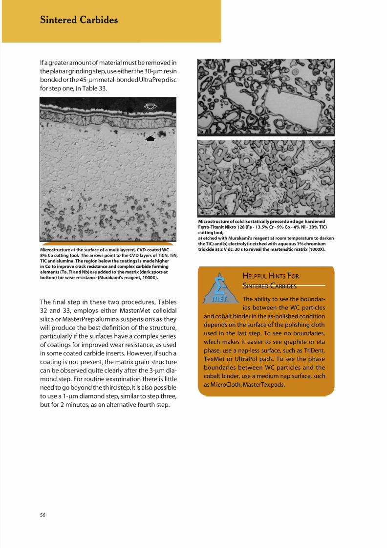
8/20/2019 Buehler Summet, Sample Prep and Analysis
http://slidepdf.com/reader/full/buehler-summet-sample-prep-and-analysis 56/136
56
If a greater amount of material must be removed inthe planar grinding step, use either the 30-µm resinbonded or the 45-µm metal-bonded UltraPrep discfor step one, in Table 33.
The final step in these two procedures, Tables32 and 33, employs either MasterMet colloidalsilica or MasterPrep alumina suspensions as theywill produce the best definition of the structure,particularly if the surfaces have a complex seriesof coatings for improved wear resistance, as usedin some coated carbide inserts. However, if such acoating is not present, the matrix grain structurecan be observed quite clearly after the 3-µm dia-mond step. For routine examination there is littleneed to go beyond the third step. It is also possibleto use a 1-µm diamond step, similar to step three,but for 2 minutes, as an alternative fourth step.
Sintered Carbides
Microstructure at the surface of a multilayered, CVD-coated WC -
8% Co cutting tool. The arrows point to the CVD layers of TiCN, TiN,
TiC and alumina. The region below the coatings is made higher
in Co to improve crack resistance and complex carbide forming
elements (Ta, Ti and Nb) are added to the matrix (dark spots at
bottom) for wear resistance (Murakami’s reagent, 1000X). HELPFUL HINTS FOR
SINTERED CARBIDES
The ability to see the boundar-
ies between the WC particles
and cobalt binder in the as-polished condition
depends on the surface of the polishing cloth
used in the last step. To see no boundaries,
which makes it easier to see graphite or eta
phase, use a nap-less surface, such as TriDent,
TexMet or UltraPol pads. To see the phase
boundaries between WC particles and the
cobalt binder, use a medium nap surface, such
as MicroCloth, MasterTex pads.
Microstructure of cold isostatically pressed and age hardened
Ferro-Titanit Nikro 128 (Fe - 13.5% Cr - 9% Co - 4% Ni - 30% TiC)
cutting tool;
a) etched with Murakami’s reagent at room temperature to darken
the TiC; and b) electrolytic etched with aqueous 1% chromium
trioxide at 2 V dc, 30 s to reveal the martensitic matrix (1000X).
b
a
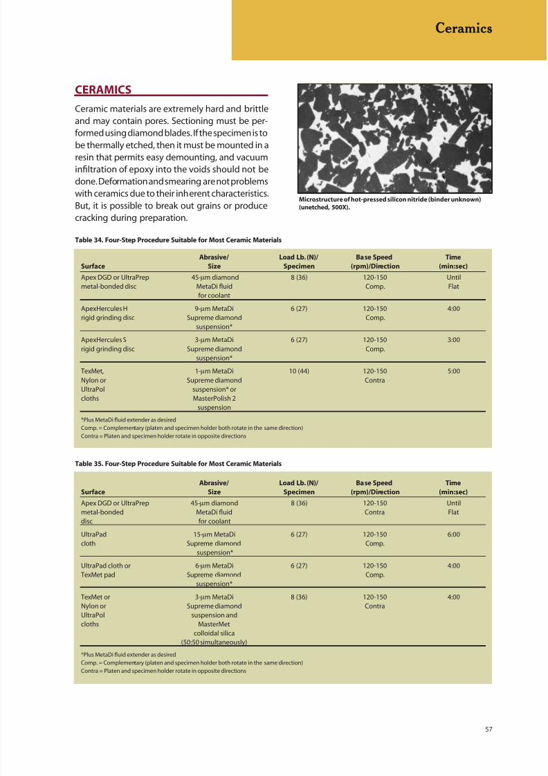
8/20/2019 Buehler Summet, Sample Prep and Analysis
http://slidepdf.com/reader/full/buehler-summet-sample-prep-and-analysis 57/136
57
CERAMICS
Ceramic materials are extremely hard and brittleand may contain pores. Sectioning must be per-
formed using diamond blades. If the specimen is tobe thermally etched, then it must be mounted in aresin that permits easy demounting, and vacuuminfiltration of epoxy into the voids should not bedone. Deformation and smearing are not problemswith ceramics due to their inherent characteristics.But, it is possible to break out grains or producecracking during preparation.
Ceramics
Table 34. Four-Step Procedure Suitable for Most Ceramic Materials
Abrasive/ Load Lb. (N)/ Base Speed Time
Surface Size Specimen (rpm)/Direction (min:sec)
Apex DGD or UltraPrep 45-µm diamond 8 (36) 120-150 Untilmetal-bonded disc MetaDi fluid Comp. Flat
for coolant
ApexHercules H 9-µm MetaDi 6 (27) 120-150 4:00rigid grinding disc Supreme diamond Comp.
suspension*
ApexHercules S 3-µm MetaDi 6 (27) 120-150 3:00rigid grinding disc Supreme diamond Comp.
suspension*
TexMet, 1-µm MetaDi 10 (44) 120-150 5:00Nylon or Supreme diamond ContraUltraPol suspension* orcloths MasterPolish 2
suspension*Plus MetaDi fluid extender as desired
Comp. = Complementary (platen and specimen holder both rotate in the same direction)
Contra = Platen and specimen holder rotate in opposite directions
Table 35. Four-Step Procedure Suitable for Most Ceramic Materials
Abrasive/ Load Lb. (N)/ Base Speed Time
Surface Size Specimen (rpm)/Direction (min:sec)
Apex DGD or UltraPrep 45-µm diamond 8 (36) 120-150 Untilmetal-bonded MetaDi fluid Contra Flatdisc for coolant
UltraPad 15-µm MetaDi 6 (27) 120-150 6:00
cloth Supreme diamond Comp.suspension*
UltraPad cloth or 6-µm MetaDi 6 (27) 120-150 4:00TexMet pad Supreme diamond Comp.
suspension*
TexMet or 3-µm MetaDi 8 (36) 120-150 4:00Nylon or Supreme diamond ContraUltraPol suspension andcloths MasterMet
colloidal silica(50:50 simultaneously)
*Plus MetaDi fluid extender as desired
Comp. = Complementary (platen and specimen holder both rotate in the same direction)
Contra = Platen and specimen holder rotate in opposite directions
Microstructure of hot-pressed silicon nitride (binder unknown)
(unetched, 500X).

8/20/2019 Buehler Summet, Sample Prep and Analysis
http://slidepdf.com/reader/full/buehler-summet-sample-prep-and-analysis 58/136
58
Ceramics
Pullouts are a major problem to control as theycan be misinterpreted as porosity. Mechanicalpreparation has been done successfully with laps,metal-bonded diamond discs, rigid grinding discs,
or hard cloths. SiC paper is rather ineffective withmost ceramics, as they are nearly as hard or ashard as the SiC abrasive. Consequently, diamondis commonly used for nearly all preparation steps.Automated preparation is highly recommendedwhen preparing ceramic materials as very highforces arise between the specimen and the work-ing surface, often too high for manual preparation.Listed are two generic procedures for preparingceramics using different approaches, see Tables34 and 35.
MasterPolish 2 suspension is specifically formu-lated for final polishing ceramic materials and willyield a better surface finish than 1-µm diamond.
HELPFUL HINTS FOR
CERAMICS
Cut specimens as close as pos-
sible to the desired examination
plane using a saw and blade that produces the
least possible amount of damage, producing
the best possible surface for subsequent prepa-
ration. Rough grinding is slow and tedious and
does considerable damage to the structure and
should be avoided as much as possible.
Coarse abrasives for grinding may be needed
at times. However, severe grain pull-outs can
result from use of coarse abrasives and it is
recommended to use the finest possible coarseabrasive for grinding.
(top) Microstructure of an alumina (matrix), zirconia (gray), silica
(white) refractory material (unetched, 200X). (bottom) Silicon - SiC
ceramic etched electrolytically with 10% oxalic acid (500X).
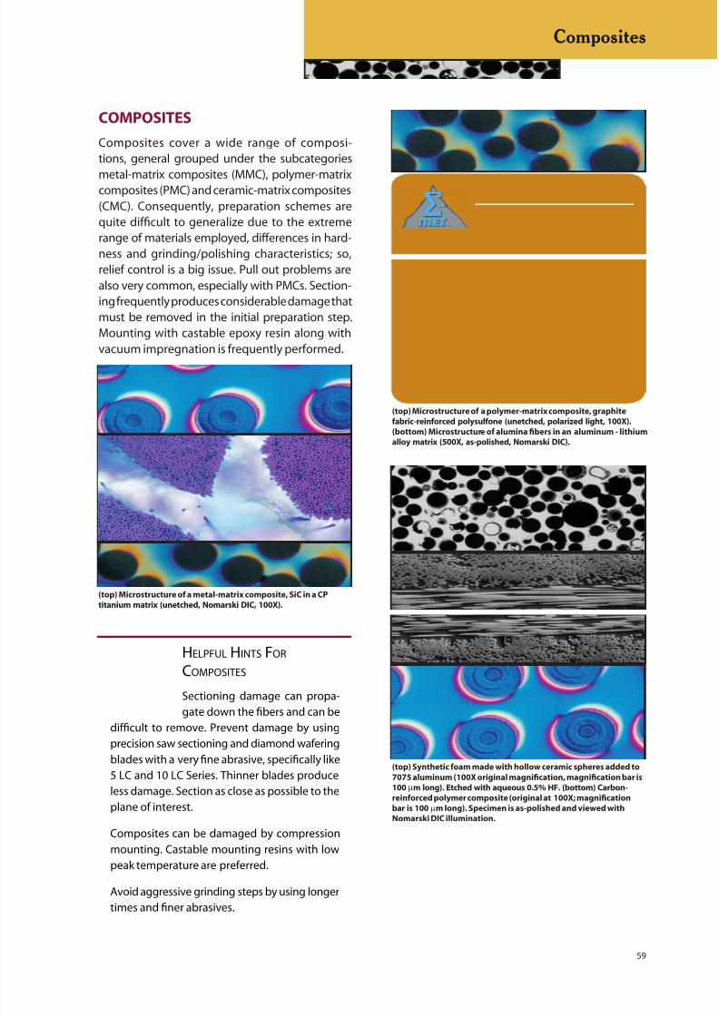
8/20/2019 Buehler Summet, Sample Prep and Analysis
http://slidepdf.com/reader/full/buehler-summet-sample-prep-and-analysis 59/136
59
COMPOSITES
Composites cover a wide range of composi-tions, general grouped under the subcategories
metal-matrix composites (MMC), polymer-matrixcomposites (PMC) and ceramic-matrix composites(CMC). Consequently, preparation schemes arequite difficult to generalize due to the extremerange of materials employed, differences in hard-ness and grinding/polishing characteristics; so,relief control is a big issue. Pull out problems arealso very common, especially with PMCs. Section-ing frequently produces considerable damage thatmust be removed in the initial preparation step.Mounting with castable epoxy resin along withvacuum impregnation is frequently performed.
Composites
(top) Microstructure of a polymer-matrix composite, graphite
fabric-reinforced polysulfone (unetched, polarized light, 100X).
(bottom) Microstructure of alumina fibers in an aluminum - lithium
alloy matrix (500X, as-polished, Nomarski DIC).
(top) Microstructure of a metal-matrix composite, SiC in a CP
titanium matrix (unetched, Nomarski DIC, 100X).
HELPFUL HINTS FOR
COMPOSITES
Sectioning damage can propa-
gate down the fibers and can bedifficult to remove. Prevent damage by using
precision saw sectioning and diamond wafering
blades with a very fine abrasive, specifically like
5 LC and 10 LC Series. Thinner blades produce
less damage. Section as close as possible to the
plane of interest.
Composites can be damaged by compression
mounting. Castable mounting resins with low
peak temperature are preferred.
Avoid aggressive grinding steps by using longertimes and finer abrasives.
(top) Synthetic foam made with hollow ceramic spheres added to
7075 aluminum (100X original magnification, magnification bar is
100 µm long). Etched with aqueous 0.5% HF. (bottom) Carbon-
reinforced polymer composite (original at 100X; magnification
bar is 100 µm long). Specimen is as-polished and viewed with
Nomarski DIC illumination.
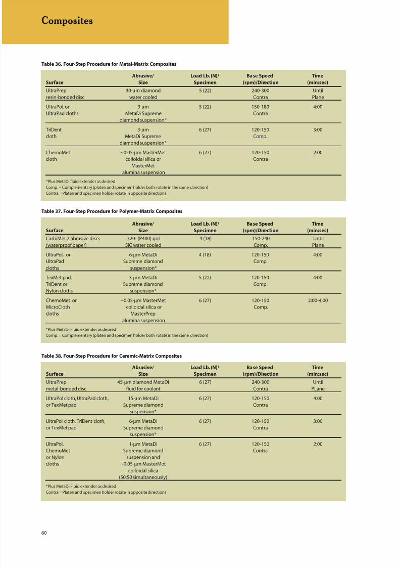
8/20/2019 Buehler Summet, Sample Prep and Analysis
http://slidepdf.com/reader/full/buehler-summet-sample-prep-and-analysis 60/136
60
Composites
Table 38. Four-Step Procedure for Ceramic-Matrix Composites
Abrasive/ Load Lb. (N)/ Base Speed Time
Surface Size Specimen (rpm)/Direction (min:sec)
UltraPrep 45-µm diamond MetaDi 6 (27) 240-300 Untilmetal-bonded disc fluid for coolant Contra PLane
UltraPol cloth, UltraPad cloth, 15-µm MetaDi 6 (27) 120-150 4:00or TexMet pad Supreme diamond Contra
suspension*
UltraPol cloth, TriDent cloth, 6-µm MetaDi 6 (27) 120-150 3:00or TexMet pad Supreme diamond Contra
suspension*
UltraPol, 1-µm MetaDi 6 (27) 120-150 2:00ChemoMet Supreme diamond Contraor Nylon suspension andcloths ~0.05-µm MasterMet
colloidal silica(50:50 simultaneously)
*Plus MetaDi Fluid extender as desired
Contra = Platen and specimen holder rotate in opposite directions
Table 37. Four-Step Procedure for Polymer-Matrix Composites
Abrasive/ Load Lb. (N)/ Base Speed Time
Surface Size Specimen (rpm)/Direction (min:sec)
CarbiMet 2 abrasive discs 320- (P400) grit 4 (18) 150-240 Until(waterproof paper) SiC water cooled Comp. Plane
UltraPol, or 6-µm MetaDi 4 (18) 120-150 4:00UltraPad Supreme diamond Comp.cloths suspension*
TexMet pad, 3-µm MetaDi 5 (22) 120-150 4:00TriDent or Supreme diamond Comp.Nylon cloths suspension*
ChemoMet or ~0.05-µm MasterMet 6 (27) 120-150 2:00-4:00MicroCloth colloidal silica or Comp.cloths MasterPrep
alumina suspension
*Plus MetaDi Fluid extender as desired
Comp. = Complementary (platen and specimen holder both rotate in the same direction)
Table 36. Four-Step Procedure for Metal-Matrix Composites
Abrasive/ Load Lb. (N)/ Base Speed Time
Surface Size Specimen (rpm)/Direction (min:sec)
UltraPrep 30-µm diamond 5 (22) 240-300 Until
resin-bonded disc water cooled Contra PlaneUltraPol, or 9-µm 5 (22) 150-180 4:00UltraPad cloths MetaDi Supreme Contra
diamond suspension*
TriDent 3-µm 6 (27) 120-150 3:00cloth MetaDi Supreme Comp.
diamond suspension*
ChemoMet ~0.05-µm MasterMet 6 (27) 120-150 2:00cloth colloidal silica or Contra
MasterMetalumina suspension
*Plus MetaDi fluid extender as desired
Comp. = Complementary (platen and specimen holder both rotate in the same direction)
Contra = Platen and specimen holder rotate in opposite directions
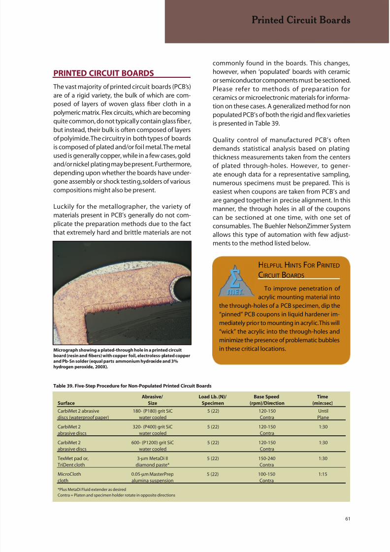
8/20/2019 Buehler Summet, Sample Prep and Analysis
http://slidepdf.com/reader/full/buehler-summet-sample-prep-and-analysis 61/136
61
PRINTED CIRCUIT BOARDS
The vast majority of printed circuit boards (PCB’s)
are of a rigid variety, the bulk of which are com-posed of layers of woven glass fiber cloth in apolymeric matrix. Flex circuits, which are becomingquite common, do not typically contain glass fiber,but instead, their bulk is often composed of layersof polyimide. The circuitry in both types of boardsis composed of plated and/or foil metal. The metalused is generally copper, while in a few cases, goldand/or nickel plating may be present. Furthermore,depending upon whether the boards have under-gone assembly or shock testing, solders of various
compositions might also be present.
Luckily for the metallographer, the variety ofmaterials present in PCB’s generally do not com-plicate the preparation methods due to the factthat extremely hard and brittle materials are not
commonly found in the boards. This changes,however, when ‘populated’ boards with ceramicor semiconductor components must be sectioned.Please refer to methods of preparation for
ceramics or microelectronic materials for informa-tion on these cases. A generalized method for nonpopulated PCB’s of both the rigid and flex varietiesis presented in Table 39.
Quality control of manufactured PCB’s oftendemands statistical analysis based on platingthickness measurements taken from the centersof plated through-holes. However, to gener-ate enough data for a representative sampling,numerous specimens must be prepared. This is
easiest when coupons are taken from PCB’s andare ganged together in precise alignment. In thismanner, the through holes in all of the couponscan be sectioned at one time, with one set ofconsumables. The Buehler NelsonZimmer Systemallows this type of automation with few adjust-ments to the method listed below.
Printed Circuit Boards
Table 39. Five-Step Procedure for Non-Populated Printed Circuit Boards
Abrasive/ Load Lb. (N)/ Base Speed Time
Surface Size Specimen (rpm)/Direction (min:sec)
CarbiMet 2 abrasive 180- (P180) grit SiC 5 (22) 120-150 Untildiscs (waterproof paper) water cooled Contra Plane
CarbiMet 2 320- (P400) grit SiC 5 (22) 120-150 1:30abrasive discs water cooled Contra
CarbiMet 2 600- (P1200) grit SiC 5 (22) 120-150 1:30abrasive discs water cooled Contra
TexMet pad or, 3-µm MetaDi II 5 (22) 150-240 1:30TriDent cloth diamond paste* Contra
MicroCloth 0.05-µm MasterPrep 5 (22) 100-150 1:15cloth alumina suspension Contra
*Plus MetaDi Fluid extender as desiredContra = Platen and specimen holder rotate in opposite directions
Micrograph showing a plated-through hole in a printed circuit
board (resin and fibers) with copper foil, electroless-plated copper
and Pb-Sn solder (equal parts ammonium hydroxide and 3%
hydrogen peroxide, 200X).
HELPFUL HINTS FOR PRINTED
CIRCUIT BOARDS
To improve penetration ofacrylic mounting material into
the through-holes of a PCB specimen, dip the
“pinned” PCB coupons in liquid hardener im-
mediately prior to mounting in acrylic. This will
“wick” the acrylic into the through-holes and
minimize the presence of problematic bubbles
in these critical locations.
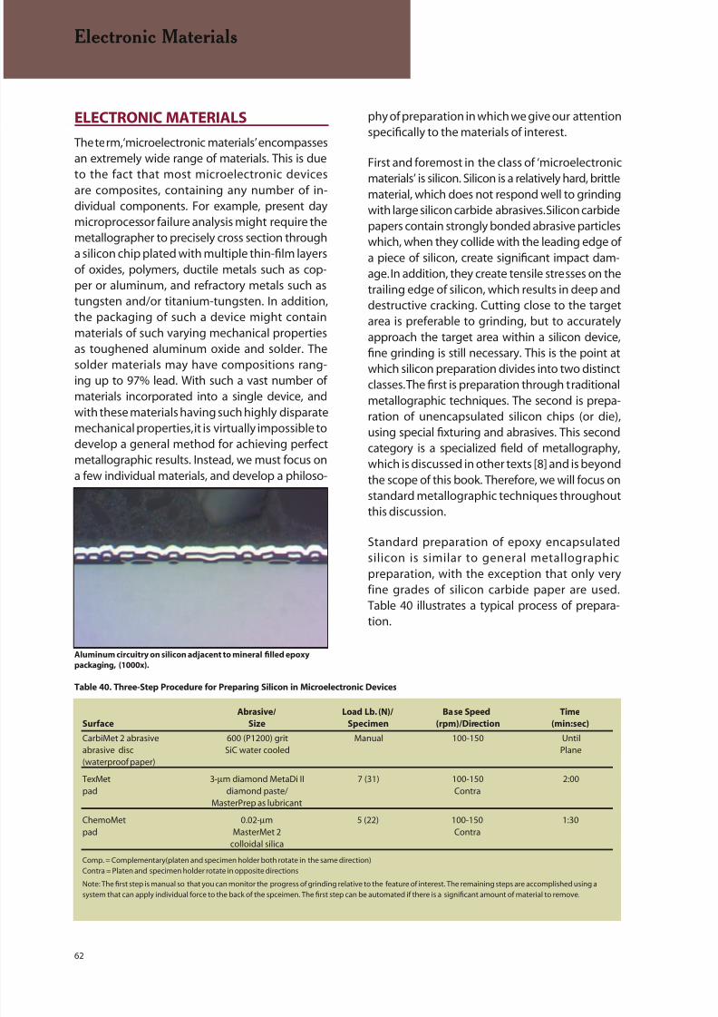
8/20/2019 Buehler Summet, Sample Prep and Analysis
http://slidepdf.com/reader/full/buehler-summet-sample-prep-and-analysis 62/136
62
ELECTRONIC MATERIALS
The term, ‘microelectronic materials’ encompassesan extremely wide range of materials. This is due
to the fact that most microelectronic devicesare composites, containing any number of in-dividual components. For example, present daymicroprocessor failure analysis might require themetallographer to precisely cross section througha silicon chip plated with multiple thin-film layersof oxides, polymers, ductile metals such as cop-per or aluminum, and refractory metals such astungsten and/or titanium-tungsten. In addition,the packaging of such a device might containmaterials of such varying mechanical propertiesas toughened aluminum oxide and solder. Thesolder materials may have compositions rang-ing up to 97% lead. With such a vast number ofmaterials incorporated into a single device, andwith these materials having such highly disparatemechanical properties, it is virtually impossible todevelop a general method for achieving perfectmetallographic results. Instead, we must focus ona few individual materials, and develop a philoso-
phy of preparation in which we give our attentionspecifically to the materials of interest.
First and foremost in the class of ‘microelectronic
materials’ is silicon. Silicon is a relatively hard, brittlematerial, which does not respond well to grindingwith large silicon carbide abrasives. Silicon carbidepapers contain strongly bonded abrasive particleswhich, when they collide with the leading edge ofa piece of silicon, create significant impact dam-age. In addition, they create tensile stresses on thetrailing edge of silicon, which results in deep anddestructive cracking. Cutting close to the targetarea is preferable to grinding, but to accuratelyapproach the target area within a silicon device,
fine grinding is still necessary. This is the point atwhich silicon preparation divides into two distinctclasses. The first is preparation through traditionalmetallographic techniques. The second is prepa-ration of unencapsulated silicon chips (or die),using special fixturing and abrasives. This secondcategory is a specialized field of metallography,which is discussed in other texts [8] and is beyondthe scope of this book. Therefore, we will focus onstandard metallographic techniques throughoutthis discussion.
Standard preparation of epoxy encapsulatedsilicon is similar to general metallographicpreparation, with the exception that only veryfine grades of silicon carbide paper are used.Table 40 illustrates a typical process of prepara-tion.
Electronic Materials
Table 40. Three-Step Procedure for Preparing Silicon in Microelectronic Devices
Abrasive/ Load Lb. (N)/ Base Speed TimeSurface Size Specimen (rpm)/Direction (min:sec)
CarbiMet 2 abrasive 600 (P1200) grit Manual 100-150 Untilabrasive disc SiC water cooled Plane(waterproof paper)
TexMet 3-µm diamond MetaDi II 7 (31) 100-150 2:00pad diamond paste/ Contra
MasterPrep as lubricant
ChemoMet 0.02-µm 5 (22) 100-150 1:30pad MasterMet 2 Contra
colloidal silica
Comp. = Complementary(platen and specimen holder both rotate in the same direction)
Contra = Platen and specimen holder rotate in opposite directions
Note: The first step is manual so that you can monitor the progress of grinding relative to the feature of interest. The remaining steps are accomplished using a
system that can apply individual force to the back of the spceimen. The first step can be automated if there is a significant amount of material to remove.
Aluminum circuitry on silicon adjacent to mineral filled epoxy
packaging, (1000x).
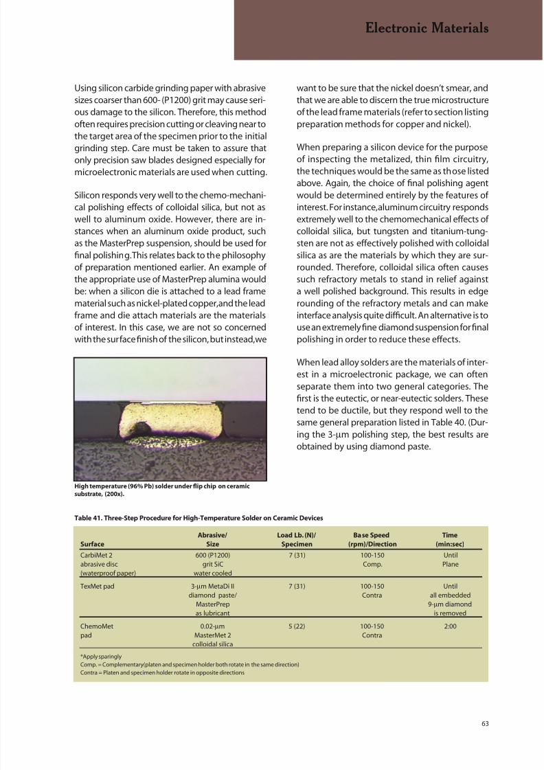
8/20/2019 Buehler Summet, Sample Prep and Analysis
http://slidepdf.com/reader/full/buehler-summet-sample-prep-and-analysis 63/136
63
Using silicon carbide grinding paper with abrasivesizes coarser than 600- (P1200) grit may cause seri-ous damage to the silicon. Therefore, this methodoften requires precision cutting or cleaving near to
the target area of the specimen prior to the initialgrinding step. Care must be taken to assure thatonly precision saw blades designed especially formicroelectronic materials are used when cutting.
Silicon responds very well to the chemo-mechani-cal polishing effects of colloidal silica, but not aswell to aluminum oxide. However, there are in-stances when an aluminum oxide product, suchas the MasterPrep suspension, should be used forfinal polishing. This relates back to the philosophy
of preparation mentioned earlier. An example ofthe appropriate use of MasterPrep alumina wouldbe: when a silicon die is attached to a lead framematerial such as nickel-plated copper, and the leadframe and die attach materials are the materialsof interest. In this case, we are not so concernedwith the surface finish of the silicon, but instead, we
want to be sure that the nickel doesn’t smear, andthat we are able to discern the true microstructureof the lead frame materials (refer to section listingpreparation methods for copper and nickel).
When preparing a silicon device for the purposeof inspecting the metalized, thin film circuitry,the techniques would be the same as those listedabove. Again, the choice of final polishing agentwould be determined entirely by the features ofinterest. For instance, aluminum circuitry respondsextremely well to the chemomechanical effects ofcolloidal silica, but tungsten and titanium-tung-sten are not as effectively polished with colloidalsilica as are the materials by which they are sur-
rounded. Therefore, colloidal silica often causessuch refractory metals to stand in relief againsta well polished background. This results in edgerounding of the refractory metals and can makeinterface analysis quite difficult. An alternative is touse an extremely fine diamond suspension for finalpolishing in order to reduce these effects.
When lead alloy solders are the materials of inter-est in a microelectronic package, we can oftenseparate them into two general categories. Thefirst is the eutectic, or near-eutectic solders. Thesetend to be ductile, but they respond well to thesame general preparation listed in Table 40. (Dur-ing the 3-µm polishing step, the best results areobtained by using diamond paste.
Electronic Materials
Table 41. Three-Step Procedure for High-Temperature Solder on Ceramic Devices
Abrasive/ Load Lb. (N)/ Base Speed Time
Surface Size Specimen (rpm)/Direction (min:sec)
CarbiMet 2 600 (P1200) 7 (31) 100-150 Untilabrasive disc grit SiC Comp. Plane(waterproof paper) water cooled
TexMet pad 3-µm MetaDi II 7 (31) 100-150 Untildiamond paste/ Contra all embedded
MasterPrep 9-µm diamondas lubricant is removed
ChemoMet 0.02-µm 5 (22) 100-150 2:00pad MasterMet 2 Contra
colloidal silica
*Apply sparingly
Comp. = Complementary(platen and specimen holder both rotate in the same direction)
Contra = Platen and specimen holder rotate in opposite directions
High temperature (96% Pb) solder under flip chip on ceramic
substrate, (200x).
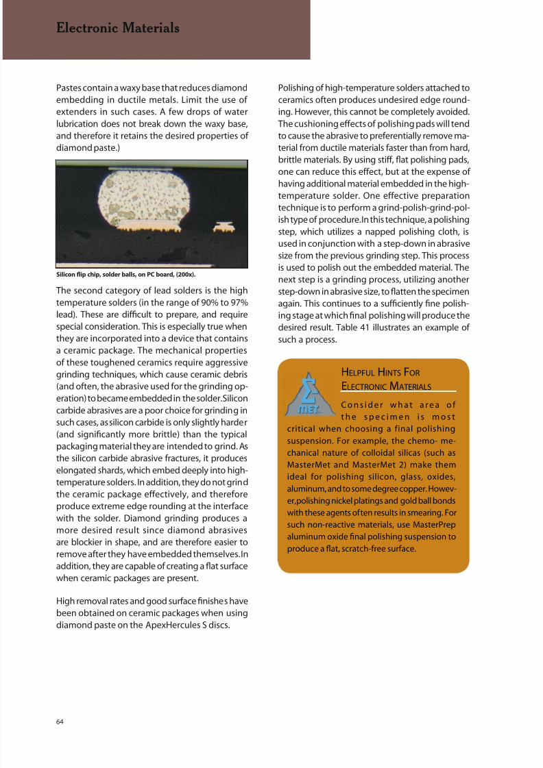
8/20/2019 Buehler Summet, Sample Prep and Analysis
http://slidepdf.com/reader/full/buehler-summet-sample-prep-and-analysis 64/136
64
Pastes contain a waxy base that reduces diamondembedding in ductile metals. Limit the use ofextenders in such cases. A few drops of waterlubrication does not break down the waxy base,
and therefore it retains the desired properties ofdiamond paste.)
The second category of lead solders is the hightemperature solders (in the range of 90% to 97%lead). These are difficult to prepare, and requirespecial consideration. This is especially true whenthey are incorporated into a device that containsa ceramic package. The mechanical propertiesof these toughened ceramics require aggressivegrinding techniques, which cause ceramic debris(and often, the abrasive used for the grinding op-eration) to became embedded in the solder. Siliconcarbide abrasives are a poor choice for grinding insuch cases, as silicon carbide is only slightly harder(and significantly more brittle) than the typicalpackaging material they are intended to grind. Asthe silicon carbide abrasive fractures, it produceselongated shards, which embed deeply into high-temperature solders. In addition, they do not grindthe ceramic package effectively, and thereforeproduce extreme edge rounding at the interfacewith the solder. Diamond grinding produces amore desired result since diamond abrasives
are blockier in shape, and are therefore easier toremove after they have embedded themselves. Inaddition, they are capable of creating a flat surfacewhen ceramic packages are present.
High removal rates and good surface finishes havebeen obtained on ceramic packages when usingdiamond paste on the ApexHercules S discs.
Polishing of high-temperature solders attached toceramics often produces undesired edge round-ing. However, this cannot be completely avoided.The cushioning effects of polishing pads will tend
to cause the abrasive to preferentially remove ma-terial from ductile materials faster than from hard,brittle materials. By using stiff, flat polishing pads,one can reduce this effect, but at the expense ofhaving additional material embedded in the high-temperature solder. One effective preparationtechnique is to perform a grind-polish-grind-pol-ish type of procedure. In this technique, a polishingstep, which utilizes a napped polishing cloth, isused in conjunction with a step-down in abrasivesize from the previous grinding step. This process
is used to polish out the embedded material. Thenext step is a grinding process, utilizing anotherstep-down in abrasive size, to flatten the specimenagain. This continues to a sufficiently fine polish-ing stage at which final polishing will produce thedesired result. Table 41 illustrates an example ofsuch a process.
Electronic Materials
HELPFUL HINTS FOR
ELECTRONIC MATERIALS
C o n s i d e r w h a t a r e a o ft h e s p e c i m e n i s m o s t
critical when choosing a final polishing
suspension. For example, the chemo- me-
chanical nature of colloidal silicas (such as
MasterMet and MasterMet 2) make them
ideal for polishing silicon, glass, oxides,
aluminum, and to some degree copper. Howev-
er, polishing nickel platings and gold ball bonds
with these agents often results in smearing. For
such non-reactive materials, use MasterPrep
aluminum oxide final polishing suspension toproduce a flat, scratch-free surface.
Silicon flip chip, solder balls, on PC board, (200x).
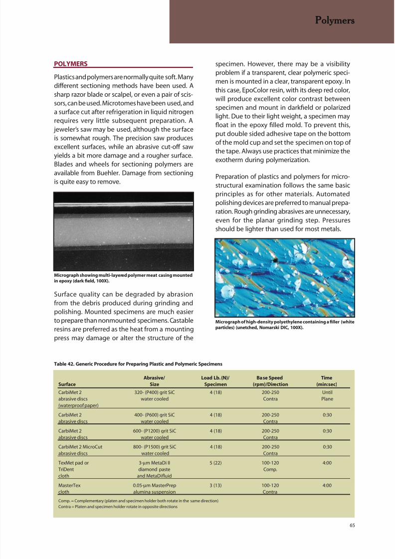
8/20/2019 Buehler Summet, Sample Prep and Analysis
http://slidepdf.com/reader/full/buehler-summet-sample-prep-and-analysis 65/136
65
POLYMERS
Plastics and polymers are normally quite soft. Manydifferent sectioning methods have been used. A
sharp razor blade or scalpel, or even a pair of scis-sors, can be used. Microtomes have been used, anda surface cut after refrigeration in liquid nitrogenrequires very little subsequent preparation. A
jeweler’s saw may be used, although the surfaceis somewhat rough. The precision saw producesexcellent surfaces, while an abrasive cut-off sawyields a bit more damage and a rougher surface.Blades and wheels for sectioning polymers areavailable from Buehler. Damage from sectioningis quite easy to remove.
Surface quality can be degraded by abrasionfrom the debris produced during grinding andpolishing. Mounted specimens are much easierto prepare than nonmounted specimens. Castableresins are preferred as the heat from a mountingpress may damage or alter the structure of the
specimen. However, there may be a visibilityproblem if a transparent, clear polymeric speci-men is mounted in a clear, transparent epoxy. Inthis case, EpoColor resin, with its deep red color,
will produce excellent color contrast betweenspecimen and mount in darkfield or polarizedlight. Due to their light weight, a specimen mayfloat in the epoxy filled mold. To prevent this,put double sided adhesive tape on the bottomof the mold cup and set the specimen on top ofthe tape. Always use practices that minimize theexotherm during polymerization.
Preparation of plastics and polymers for micro-structural examination follows the same basic
principles as for other materials. Automatedpolishing devices are preferred to manual prepa-ration. Rough grinding abrasives are unnecessary,even for the planar grinding step. Pressuresshould be lighter than used for most metals.
Table 42. Generic Procedure for Preparing Plastic and Polymeric Specimens
Abrasive/ Load Lb. (N)/ Base Speed Time
Surface Size Specimen (rpm)/Direction (min:sec)
CarbiMet 2 320- (P400) grit SiC 4 (18) 200-250 Untilabrasive discs water cooled Contra Plane(waterproof paper)
CarbiMet 2 400- (P600) grit SiC 4 (18) 200-250 0:30abrasive discs water cooled Contra
CarbiMet 2 600- (P1200) grit SiC 4 (18) 200-250 0:30abrasive discs water cooled Contra
CarbiMet 2 MicroCut 800- (P1500) grit SiC 4 (18) 200-250 0:30abrasive discs water cooled Contra
TexMet pad or 3-µm MetaDi II 5 (22) 100-120 4:00TriDent diamond paste Comp.cloth and MetaDi fluid
MasterTex 0.05-µm MasterPrep 3 (13) 100-120 4:00
cloth alumina suspension Contra
Comp. = Complementary (platen and specimen holder both rotate in the same direction)
Contra = Platen and specimen holder rotate in opposite directions
Polymers
Micrograph of high-density polyethylene containing a filler (white
particles) (unetched, Nomarski DIC, 100X).
Micrograph showing multi-layered polymer meat casing mounted
in epoxy (dark field, 100X).

8/20/2019 Buehler Summet, Sample Prep and Analysis
http://slidepdf.com/reader/full/buehler-summet-sample-prep-and-analysis 66/136
66
Water is generally used as the coolant, althoughsome plastics and polymers may react withwater. In such cases, use a fluid that will notreact with the particular plastic or polymer.
Embedding can be a problem with plastics andpolymers. ASTM E 2015 (Standard Guide forPreparation of Plastics and Polymeric Specimensfor Microstructural Examination) describesprocedures for preparing several types of plasticsand polymers. Table 42 contains a generic proce-dure for preparing many plastic and polymericmaterials. Depending upon the material and thesurface roughness after sectioning, it may be pos-sible to start grinding with 400- (P600) or even600- (P1200) grit SiC paper.
If flatness is critical, the final step can be altered.Use a TexMet pad with MasterPrep alumina abra-sive slurry at 10 lbs. pressure (44N) per specimen,120 rpm, contra rotation, for 3 minutes.
HELPFUL HINTS FOR
POLYMERS
Plastics often have little con-trast from the mounting media
when viewed under a microscope. This makes
thickness measurement and discerning edges
difficult. Mounting in EpoColor dye enhanced
epoxy will resolve this situation by producing
excellent color contrast between the speci-
mens and mount.
Polymers and plastics may react with fluids dur-
ing sectioning and preparation. Always check
your particular polymer and choose the proper
fluid, usually a water, or oil based solution toavoid a reaction.
Polymers
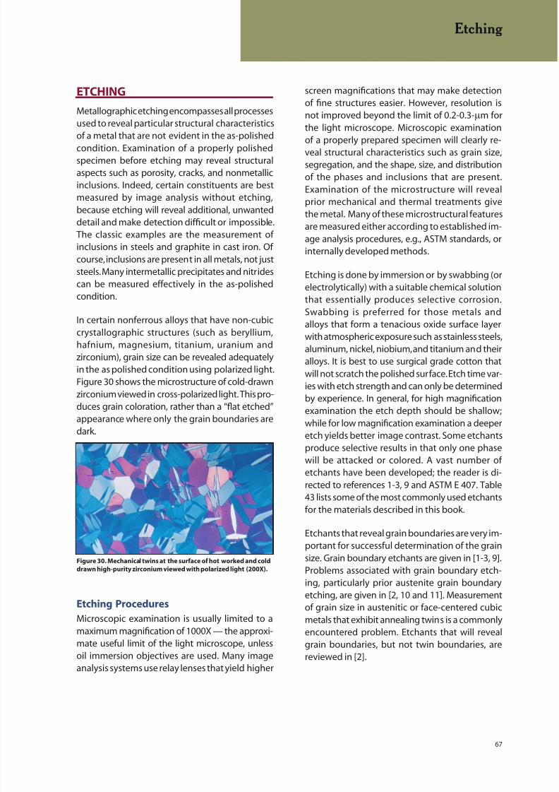
8/20/2019 Buehler Summet, Sample Prep and Analysis
http://slidepdf.com/reader/full/buehler-summet-sample-prep-and-analysis 67/136
67
screen magnifications that may make detectionof fine structures easier. However, resolution isnot improved beyond the limit of 0.2-0.3-µm forthe light microscope. Microscopic examination
of a properly prepared specimen will clearly re-veal structural characteristics such as grain size,segregation, and the shape, size, and distributionof the phases and inclusions that are present.Examination of the microstructure will revealprior mechanical and thermal treatments givethe metal. Many of these microstructural featuresare measured either according to established im-age analysis procedures, e.g., ASTM standards, orinternally developed methods.
Etching is done by immersion or by swabbing (orelectrolytically) with a suitable chemical solutionthat essentially produces selective corrosion.Swabbing is preferred for those metals andalloys that form a tenacious oxide surface layerwith atmospheric exposure such as stainless steels,aluminum, nickel, niobium, and titanium and theiralloys. It is best to use surgical grade cotton thatwill not scratch the polished surface. Etch time var-ies with etch strength and can only be determinedby experience. In general, for high magnificationexamination the etch depth should be shallow;while for low magnification examination a deeperetch yields better image contrast. Some etchantsproduce selective results in that only one phasewill be attacked or colored. A vast number ofetchants have been developed; the reader is di-rected to references 1-3, 9 and ASTM E 407. Table43 lists some of the most commonly used etchantsfor the materials described in this book.
Etchants that reveal grain boundaries are very im-portant for successful determination of the grain
size. Grain boundary etchants are given in [1-3, 9].Problems associated with grain boundary etch-ing, particularly prior austenite grain boundaryetching, are given in [2, 10 and 11]. Measurementof grain size in austenitic or face-centered cubicmetals that exhibit annealing twins is a commonlyencountered problem. Etchants that will revealgrain boundaries, but not twin boundaries, arereviewed in [2].
ETCHING
Metallographic etching encompasses all processesused to reveal particular structural characteristics
of a metal that are not evident in the as-polishedcondition. Examination of a properly polishedspecimen before etching may reveal structuralaspects such as porosity, cracks, and nonmetallicinclusions. Indeed, certain constituents are bestmeasured by image analysis without etching,because etching will reveal additional, unwanteddetail and make detection difficult or impossible.The classic examples are the measurement ofinclusions in steels and graphite in cast iron. Ofcourse, inclusions are present in all metals, not juststeels. Many intermetallic precipitates and nitridescan be measured effectively in the as-polishedcondition.
In certain nonferrous alloys that have non-cubiccrystallographic structures (such as beryllium,hafnium, magnesium, titanium, uranium andzirconium), grain size can be revealed adequatelyin the as polished condition using polarized light.Figure 30 shows the microstructure of cold-drawnzirconium viewed in cross-polarized light. This pro-duces grain coloration, rather than a “flat etched”
appearance where only the grain boundaries aredark.
Etching Procedures
Microscopic examination is usually limited to amaximum magnification of 1000X — the approxi-mate useful limit of the light microscope, unlessoil immersion objectives are used. Many imageanalysis systems use relay lenses that yield higher
Etching
Figure 30. Mechanical twins at the surface of hot worked and cold
drawn high-purity zirconium viewed with polarized light (200X).

8/20/2019 Buehler Summet, Sample Prep and Analysis
http://slidepdf.com/reader/full/buehler-summet-sample-prep-and-analysis 68/136
68
color either the anodic or cathodic constituent in amicrostructure. Tint etchants are listed and illus-trated in several publications [1-3, 16-21].
A classic example of the different behavior ofetchants is given in Figure 31 where low-carbonsheet steel has been etched with the standardnital and picral etchants, and also a color tint etch.Etching with 2% nital reveals the ferrite grainboundaries and cementite. Note that many of theferrite grain boundaries are missing or quite faint;a problem that degrades the accuracy of grain sizeratings. Etching with 4% picral reveals the cement-ite aggregates (one could not call this pearlite as itis too nonlamellar in appearance and some of the
cementite exists as simple grain boundary films)but no ferrite grain boundaries. If one is interestedin the amount and nature of the cementite (whichcan influence formability), then the picral etch isfar superior to the nital etch as picral revealed onlythe cementite. Tint etching with Beraha’s solution(Klemm’s I could also be used) colored the grainsaccording to their crystallographic orientation.With the development of color image analyzers,this image can now be used quite effectively toprovide accurate grain size measurements sinceall of the grains are colored.
Figure 32 shows a somewhat more complexexample of selective etching. The micrographshows the ferrite-cementite-iron phosphide ter-nary eutectic in gray iron. Etching sequentiallywith picral and nital revealed the eutectic, Figure32a, surrounded by pearlite. Etching with boilingalkaline sodium picrate, Figure 32b, colored the
cementite phase only, including in the surround-ing pearlite (a higher magnification is required to
see the very finely spaced cementite that is morelightly colored). Etching with boiling Murakami’sreagent, Figure 32c, colors the iron phosphidedarkly and will lightly color the cementite after
Etching
Selective Etching
Image analysis work is facilitated if the etchantchosen improves the contrast between the fea-ture of interest and everything else. Thousands
of etchants have been developed over the years,but only a small number of these are selective innature. Although the selection of the best etchant,and its proper use, is a very critical phase of theimage analysis process, only a few publicationshave addressed this problem [12-14]. Selectiveetchants, that is, etchants that preferentiallyattack or color a specific phase, are listed in[1-3, 9, 13 and 14] and illustrated in 13 and 14.Stansbury [15] has described how potentiostaticetching works and has listed many preferential
potentiostatic etching methods. The potentiostatoffers the ultimate in control over the etching pro-cess and is an outstanding tool for this purpose.Many tint etchants act selectively in that they
b
Figure 31. Microstructure of low-carbon sheet steel etched with
(a, top) 2% nital, (b, middle) 4% picral; and (c, bottom) Beraha’s
reagent (100 mL water, 10 g Na 2S2O3 and 3 g K2S2O5) at 100X.
c
a
Figure 32a. The ternary eutectic (α-Fe3C-Fe3P) in gray cast iron
revealed by etching (a, top) in picral and nital to “outline” the
phases
a
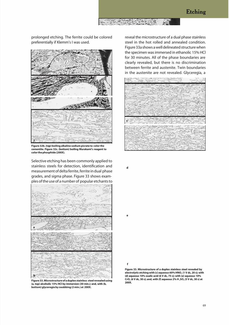
8/20/2019 Buehler Summet, Sample Prep and Analysis
http://slidepdf.com/reader/full/buehler-summet-sample-prep-and-analysis 69/136
69
prolonged etching. The ferrite could be coloredpreferentially if Klemm’s I was used.
Selective etching has been commonly applied tostainless steels for detection, identification and
measurement of delta ferrite, ferrite in dual phasegrades, and sigma phase. Figure 33 shows exam-ples of the use of a number of popular etchants to
reveal the microstructure of a dual phase stainlesssteel in the hot rolled and annealed condition.Figure 33a shows a well delineated structure whenthe specimen was immersed in ethanolic 15% HCl
for 30 minutes. All of the phase boundaries areclearly revealed, but there is no discriminationbetween ferrite and austenite. Twin boundariesin the austenite are not revealed. Glyceregia, a
Etching
Figure 32b. (top) boiling alkaline sodium picrate to color the
cementite. Figure 32c. (bottom) boiling Murakami’s reagent to
color the phosphide (200X).
c
b
Figure 33. Microstructure of a duplex stainless steel revealed using
(a, top) alcoholic 15% HCl by immersion (30 min.); and, with (b,bottom) glyceregia by swabbing (2 min.) at 200X.
b
a
Figure 33. Microstructure of a duplex stainless steel revealed by
electrolytic etching with (c) aqueous 60% HNO3 (1 V dc, 20 s); with
(d) aqueous 10% oxalic acid (6 V dc, 75 s); with (e) aqueous 10%
CrO3 (6 V dc, 30 s); and, with (f) aqueous 2% H 2SO4 (5 V dc, 30 s) at
200X.
f
c
d
e
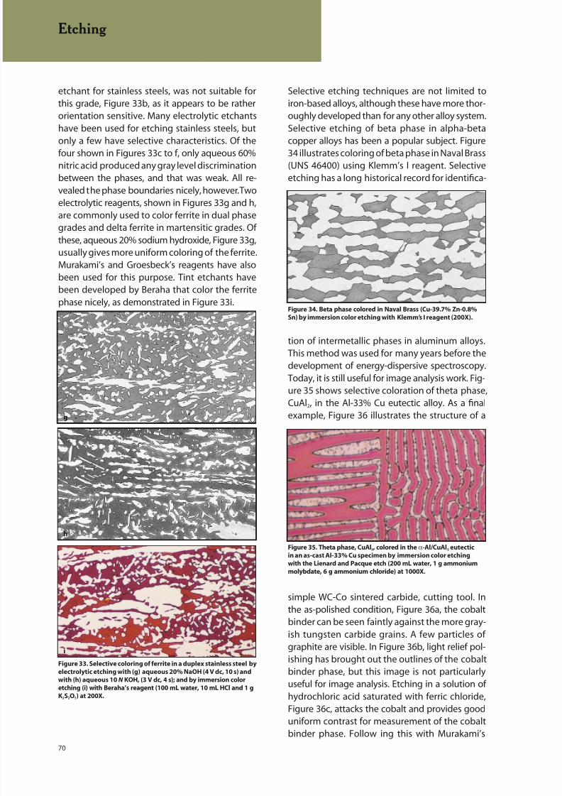
8/20/2019 Buehler Summet, Sample Prep and Analysis
http://slidepdf.com/reader/full/buehler-summet-sample-prep-and-analysis 70/136
70
etchant for stainless steels, was not suitable forthis grade, Figure 33b, as it appears to be ratherorientation sensitive. Many electrolytic etchantshave been used for etching stainless steels, but
only a few have selective characteristics. Of thefour shown in Figures 33c to f, only aqueous 60%nitric acid produced any gray level discriminationbetween the phases, and that was weak. All re-vealed the phase boundaries nicely, however. Twoelectrolytic reagents, shown in Figures 33g and h,are commonly used to color ferrite in dual phasegrades and delta ferrite in martensitic grades. Ofthese, aqueous 20% sodium hydroxide, Figure 33g,usually gives more uniform coloring of the ferrite.Murakami’s and Groesbeck’s reagents have also
been used for this purpose. Tint etchants havebeen developed by Beraha that color the ferritephase nicely, as demonstrated in Figure 33i.
Selective etching techniques are not limited toiron-based alloys, although these have more thor-oughly developed than for any other alloy system.Selective etching of beta phase in alpha-beta
copper alloys has been a popular subject. Figure34 illustrates coloring of beta phase in Naval Brass(UNS 46400) using Klemm’s I reagent. Selectiveetching has a long historical record for identifica-
Figure 34. Beta phase colored in Naval Brass (Cu-39.7% Zn-0.8%
Sn) by immersion color etching with Klemm’s I reagent (200X).
tion of intermetallic phases in aluminum alloys.This method was used for many years before thedevelopment of energy-dispersive spectroscopy.Today, it is still useful for image analysis work. Fig-ure 35 shows selective coloration of theta phase,CuAl2, in the Al-33% Cu eutectic alloy. As a final
example, Figure 36 illustrates the structure of a
simple WC-Co sintered carbide, cutting tool. Inthe as-polished condition, Figure 36a, the cobaltbinder can be seen faintly against the more gray-ish tungsten carbide grains. A few particles ofgraphite are visible. In Figure 36b, light relief pol-ishing has brought out the outlines of the cobaltbinder phase, but this image is not particularlyuseful for image analysis. Etching in a solution of
hydrochloric acid saturated with ferric chloride,Figure 36c, attacks the cobalt and provides gooduniform contrast for measurement of the cobaltbinder phase. Follow ing this with Murakami’s
Figure 35. Theta phase, CuAl2, colored in the α-Al/CuAl2 eutectic
in an as-cast Al-33% Cu specimen by immersion color etchingwith the Lienard and Pacque etch (200 mL water, 1 g ammonium
molybdate, 6 g ammonium chloride) at 1000X.
Figure 33. Selective coloring of ferrite in a duplex stainless steel by
electrolytic etching with (g) aqueous 20% NaOH (4 V dc, 10 s) and
with (h) aqueous 10 N KOH, (3 V dc, 4 s); and by immersion color
etching (i) with Beraha’s reagent (100 mL water, 10 mL HCl and 1 g
K2S2O5) at 200X.
h
g
i
Etching
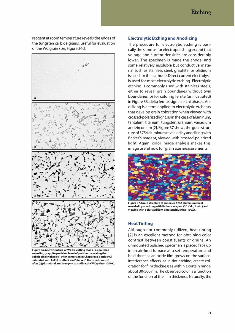
8/20/2019 Buehler Summet, Sample Prep and Analysis
http://slidepdf.com/reader/full/buehler-summet-sample-prep-and-analysis 71/136
71
Electrolytic Etching and Anodizing
The procedure for electrolytic etching is basi-cally the same as for electropolishing except thatvoltage and current densities are considerably
lower. The specimen is made the anode, andsome relatively insoluble but conductive mate-rial such as stainless steel, graphite, or platinumis used for the cathode. Direct current electrolysisis used for most electrolytic etching. Electrolyticetching is commonly used with stainless steels,either to reveal grain boundaries without twinboundaries, or for coloring ferrite (as illustrated)in Figure 33, delta ferrite, sigma or chi phases. An-odizing is a term applied to electrolytic etchantsthat develop grain coloration when viewed with
crossed-polarized light, as in the case of aluminum,tantalum, titanium, tungsten, uranium, vanadiumand zirconium [2]. Figure 37 shows the grain struc-ture of 5754 aluminum revealed by anodizing withBarker’s reagent, viewed with crossed-polarizedlight. Again, color image analysis makes thisimage useful now for grain size measurements.
Heat Tinting
Although not commonly utilized, heat tinting
[2] is an excellent method for obtaining colorcontrast between constituents or grains. Anunmounted polished specimen is placed face upin an air-fired furnace at a set temperature andheld there as an oxide film grows on the surface.Interference effects, as in tint etching, create col-oration for film thicknesses within a certain range,about 30-500 nm. The observed color is a functionof the function of the film thickness. Naturally, the
reagent at room temperature reveals the edges ofthe tungsten carbide grains, useful for evaluationof the WC grain size, Figure 36d.
Figure 36. Microstructure of WC-Co cutting tool: a) as-polished
revealing graphite particles; b) relief polished revealing the
cobalt binder phase; c) after immersion in Chaporova’s etch (HCl
saturated with FeCl3) to attack and “darken” the cobalt; and, d)
after (c) plus Murakami’s reagent to outline the WC grains (1000X).
b
a
c
d
Etching
Figure 37. Grain structure of annealed 5754 aluminum sheet
revealed by anodizing with Barker’s reagent (30 V dc, 2 min.) and
viewing with polarized light plus sensitive tint (100X).
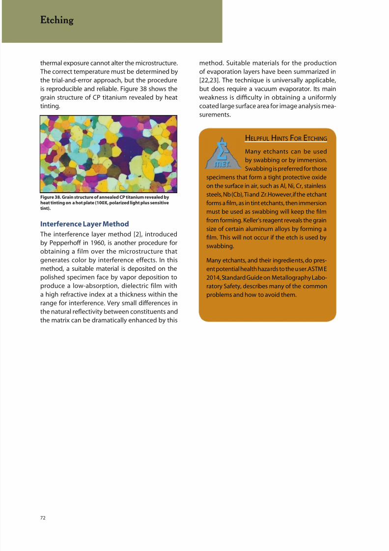
8/20/2019 Buehler Summet, Sample Prep and Analysis
http://slidepdf.com/reader/full/buehler-summet-sample-prep-and-analysis 72/136
72
HELPFUL HINTS FOR E TCHING
Many etchants can be used
by swabbing or by immersion.
Swabbing is preferred for those
specimens that form a tight protective oxide
on the surface in air, such as Al, Ni, Cr, stainless
steels, Nb (Cb), Ti and Zr. However, if the etchantforms a film, as in tint etchants, then immersion
must be used as swabbing will keep the film
from forming. Keller’s reagent reveals the grain
size of certain aluminum alloys by forming a
film. This will not occur if the etch is used by
swabbing.
Many etchants, and their ingredients, do pres-
ent potential health hazards to the user. ASTM E
2014, Standard Guide on Metallography Labo-
ratory Safety, describes many of the common
problems and how to avoid them.
thermal exposure cannot alter the microstructure.The correct temperature must be determined bythe trial-and-error approach, but the procedureis reproducible and reliable. Figure 38 shows the
grain structure of CP titanium revealed by heattinting.
Interference Layer Method
The interference layer method [2], introducedby Pepperhoff in 1960, is another procedure forobtaining a film over the microstructure thatgenerates color by interference effects. In thismethod, a suitable material is deposited on thepolished specimen face by vapor deposition toproduce a low-absorption, dielectric film witha high refractive index at a thickness within therange for interference. Very small differences inthe natural reflectivity between constituents andthe matrix can be dramatically enhanced by this
Figure 38. Grain structure of annealed CP titanium revealed by
heat tinting on a hot plate (100X, polarized light plus sensitive
tint).
method. Suitable materials for the productionof evaporation layers have been summarized in[22,23]. The technique is universally applicable,but does require a vacuum evaporator. Its main
weakness is difficulty in obtaining a uniformlycoated large surface area for image analysis mea-surements.
Etching
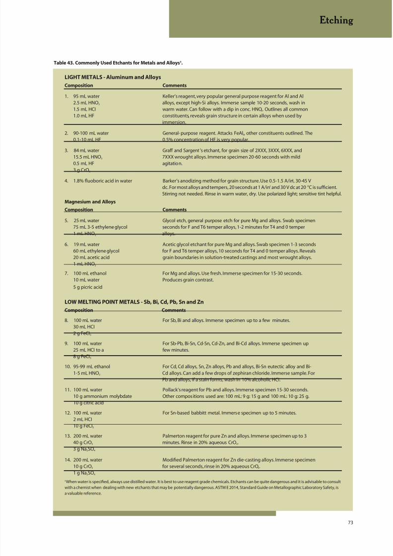
8/20/2019 Buehler Summet, Sample Prep and Analysis
http://slidepdf.com/reader/full/buehler-summet-sample-prep-and-analysis 73/136
73
Table 43. Commonly Used Etchants for Metals and Alloys3.
LIGHT METALS - Aluminum and Alloys
Composition Comments
1. 95 mL water Keller’s reagent, very popular general purpose reagent for Al and Al2.5 mL HNO3 alloys, except high-Si alloys. Immerse sample 10-20 seconds, wash in1.5 mL HCI warm water. Can follow with a dip in conc. HNO3. Outlines all common1.0 mL HF constituents, reveals grain structure in certain alloys when used by
immersion.
2. 90-100 mL water General-purpose reagent. Attacks FeAl3, other constituents outlined. The0.1-10 mL HF 0.5% concentration of HF is very popular.
3. 84 mL water Graff and Sargent’s etchant, for grain size of 2XXX, 3XXX, 6XXX, and15.5 mL HNO3 7XXX wrought alloys. Immerse specimen 20-60 seconds with mild0.5 mL HF agitation.3 g CrO3
4. 1.8% fluoboric acid in water Barker’s anodizing method for grain structure. Use 0.5-1.5 A/in2, 30-45 Vdc. For most alloys and tempers, 20 seconds at 1 A/in2 and 30 V dc at 20 °C is sufficient.
Stirring not needed. Rinse in warm water, dry. Use polarized light; sensitive tint helpful.Magnesium and Alloys
Composition Comments
5. 25 mL water Glycol etch, general purpose etch for pure Mg and alloys. Swab specimen75 mL 3-5 ethylene glycol seconds for F and T6 temper alloys, 1-2 minutes for T4 and 0 temper1 mL HNO3 alloys.
6. 19 mL water Acetic glycol etchant for pure Mg and alloys. Swab specimen 1-3 seconds60 mL ethylene glycol for F and T6 temper alloys, 10 seconds for T4 and 0 temper alloys. Reveals20 mL acetic acid grain boundaries in solution-treated castings and most wrought alloys.1 mL HNO3
7. 100 mL ethanol For Mg and alloys. Use fresh. Immerse specimen for 15-30 seconds.10 mL water Produces grain contrast.
5 g picric acid
LOW MELTING POINT METALS - Sb, Bi, Cd, Pb, Sn and Zn
Composition Comments
8. 100 mL water For Sb, Bi and alloys. Immerse specimen up to a few minutes.30 mL HCI2 g FeCI3
9. 100 mL water For Sb-Pb, Bi-Sn, Cd-Sn, Cd-Zn, and Bi-Cd alloys. Immerse specimen up25 mL HCI to a few minutes.8 g FeCI3
10. 95-99 mL ethanol For Cd, Cd alloys, Sn, Zn alloys, Pb and alloys, Bi-Sn eutectic alloy and Bi-1-5 mL HNO3 Cd alloys. Can add a few drops of zephiran chloride. Immerse sample. For
Pb and alloys, if a stain forms, wash in 10% alcoholic HCI.
11. 100 mL water Pollack’s reagent for Pb and alloys. Immerse specimen 15-30 seconds.10 g ammonium molybdate Other compositions used are: 100 mL: 9 g: 15 g and 100 mL: 10 g: 25 g.10 g citric acid
12. 100 mL water For Sn-based babbitt metal. Immerse specimen up to 5 minutes.2 mL HCI10 g FeCI3
13. 200 mL water Palmerton reagent for pure Zn and alloys. Immerse specimen up to 340 g CrO3 minutes. Rinse in 20% aqueous CrO3.3 g Na2SO4
14. 200 mL water Modified Palmerton reagent for Zn die-casting alloys. Immerse specimen10 g CrO3 for several seconds, rinse in 20% aqueous CrO3.1 g Na2SO4
3When water is specified, always use distilled water. It is best to use reagent grade chemicals. Etchants can be quite dangerous and it is advisable to consult
with a chemist when dealing with new etchants that may be potentially dangerous. ASTM E 2014, Standard Guide on Metallographic Laboratory Safety, isa valuable reference.
Etching

8/20/2019 Buehler Summet, Sample Prep and Analysis
http://slidepdf.com/reader/full/buehler-summet-sample-prep-and-analysis 74/136
74
Table 43. Commonly Used Etchants for Metals and Alloys3.
REFRACTORY METALS: Ti, Zr, Hf, Cr, Mo, Re, Nb, Ta, W and V
Composition Comments
15. 100 mL water Kroll’s reagent for Ti alloys. Swab specimen 3-10 seconds or immerse1-3 mL HF specimen 10-30 seconds.2-6 mL HNO3
16. 200 mL water For Ti, Zr and alloys. Swab or immerse specimen. Higher concentrat ions1 mL HF can be used but are prone to staining problems.
17. 30 mL lactic acid For Ti alloys. Swab specimen up to 30 seconds. Decomposes, do not store.15 mL HNO3 Good for alpha-beta alloys.30 mL HF
18. 30 mL HCI For Zr, Hf, and alloys. Swab specimen 3-10 seconds, or immerse specimen15 mL HNO3 up to 120 seconds.30 mL HF
19. 45 mL H2O (H2O2 or glycerol) Cain’s chemical polish and etch for Hf, Zr, and alloys. Can dilute aqueous45 mL HNO3 solution with 3-5 parts water to stain the structure (swab specimen) after
8-10 mL HF chemical polishing. Chemically polish and etch specimen by swabbing 5-20 seconds. Use polarized light.
20. 60 mL HCI Aqua regia. For Cr and alloys. Immerse or swab specimen up to 1 minute.20 mL HNO3 Use under a hood with care, do not store.
21. 30 mL HCI Modified “Glyceregia”. For Cr and alloys. Immerse specimen up to a few45 mL glycerol minutes.15 mL HNO3
22. 100 mL water Murakami’s reagent. For Cr, Mo, Re, Ta-Mo, W, V and alloys. Use fresh, can10 g KOH or NaOH immerse sample for up to 1 minute.10 g K 3Fe(CN)6
23. 70 mL water For Mo alloys. Immerse specimen 2 minutes. Wash with water and dry;20 mL H2O2 (30%) immersion produces colors, swabbing produces grain-boundary etch.10 mL H2SO4
24. 10-20 mL glycerol For Mo and Mo-Ti alloys. Immerse specimen for up to 5 minutes.10 mL HNO3
10 mL HF
25. 100 mL water For Mo-Re alloys. Use at 20 °C by immersion.5 g K 3Fe(CN)6
2 g KOH
26. 50 mL acetic acid For Nb, Ta and alloys. Swab specimen 10-30 seconds.20 mL HNO3 5 mL HF
27. 50 mL water DuPont Nb reagent. For Nb-Hf and Nb alloys.14 mL H2SO4
5 mL HNO3
28. 50 mL water For Nb-Zr and Nb-Zr-Re alloys. Swab specimen.
50 mL HNO3 1 mL HF
29. 30 mL lactic acid For Re and W-Re alloys. Swab specimen.10 mL HNO3 5 mL HF
30. 10 mL HF For V and alloys; grain-boundary etch for Ta alloys. Swab specimen. Equal10 mL HNO3 parts used for Ta and high Ta alloys.10-30 mL glycerol
IRON and STEEL
Composition Comments
31. 90-99 mL methanol or ethanol Nital. Most common etchant for Fe, carbon and alloy steels, cast iron.1-10 mL HNO3 Reveals alpha grain boundaries and constituents. Excellent for martensitic
structures. The 2% solution is most common, 5-10% used for high alloysteels (do not store). Use by immersion or swabbing of sample for up toabout 60 seconds.
Etching
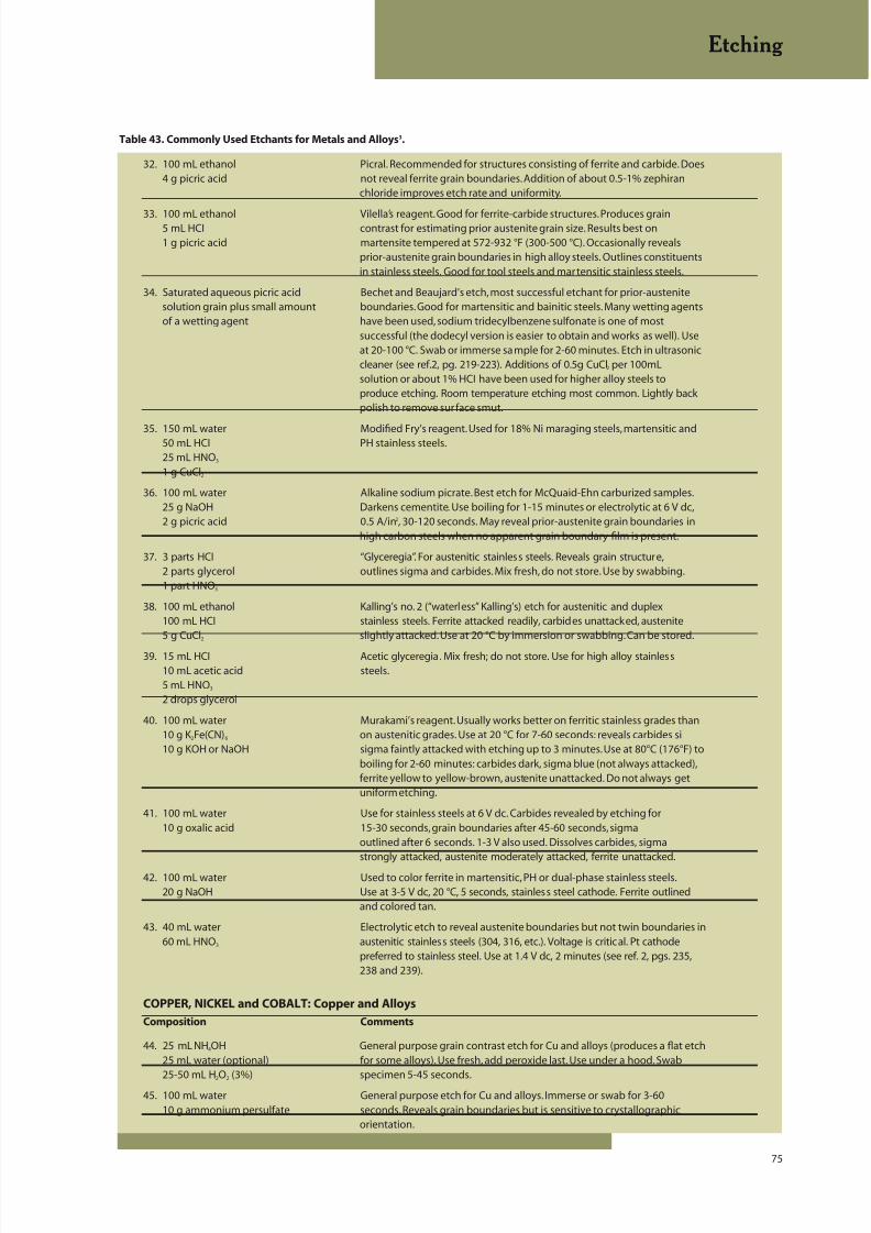
8/20/2019 Buehler Summet, Sample Prep and Analysis
http://slidepdf.com/reader/full/buehler-summet-sample-prep-and-analysis 75/136
75
32. 100 mL ethanol Picral. Recommended for structures consisting of ferrite and carbide. Does4 g picric acid not reveal ferrite grain boundaries. Addition of about 0.5-1% zephiran
chloride improves etch rate and uniformity.
33. 100 mL ethanol Vilella’s reagent. Good for ferrite-carbide structures. Produces grain5 mL HCI contrast for estimating prior austenite grain size. Results best on1 g picric acid martensite tempered at 572-932 °F (300-500 °C). Occasionally reveals
prior-austenite grain boundaries in high alloy steels. Outlines constituentsin stainless steels. Good for tool steels and martensitic stainless steels.
34. Saturated aqueous picric acid Bechet and Beaujard’s etch, most successful etchant for prior-austenitesolution grain plus small amount boundaries. Good for martensitic and bainitic steels. Many wetting agentsof a wetting agent have been used, sodium tridecylbenzene sulfonate is one of most
successful (the dodecyl version is easier to obtain and works as well). Useat 20-100 °C. Swab or immerse sample for 2-60 minutes. Etch in ultrasoniccleaner (see ref.2, pg. 219-223). Additions of 0.5g CuCl2 per 100mLsolution or about 1% HCI have been used for higher alloy steels toproduce etching. Room temperature etching most common. Lightly backpolish to remove surface smut.
35. 150 mL water Modified Fry’s reagent. Used for 18% Ni maraging steels, martensitic and50 mL HCI PH stainless steels.25 mL HNO3 1 g CuCl2
36. 100 mL water Alkaline sodium picrate. Best etch for McQuaid-Ehn carburized samples.25 g NaOH Darkens cementite. Use boiling for 1-15 minutes or electrolytic at 6 V dc,2 g picric acid 0.5 A/in2, 30-120 seconds. May reveal prior-austenite grain boundaries in
high carbon steels when no apparent grain boundary film is present.
37. 3 parts HCI “Glyceregia”. For austenitic stainless steels. Reveals grain structure,2 parts glycerol outlines sigma and carbides. Mix fresh, do not store. Use by swabbing.1 part HNO3
38. 100 mL ethanol Kalling’s no. 2 (“waterless” Kalling’s) etch for austenitic and duplex100 mL HCI stainless steels. Ferrite attacked readily, carbides unattacked, austenite5 g CuCl2 slightly attacked. Use at 20 °C by immersion or swabbing. Can be stored.
39. 15 mL HCI Acetic glyceregia. Mix fresh; do not store. Use for high alloy stainless10 mL acetic acid steels.5 mL HNO3 2 drops glycerol
40. 100 mL water Murakami’s reagent. Usually works better on ferritic stainless grades than10 g K 2Fe(CN)6 on austenitic grades. Use at 20 °C for 7-60 seconds: reveals carbides si10 g KOH or NaOH sigma faintly attacked with etching up to 3 minutes. Use at 80°C (176°F) to
boiling for 2-60 minutes: carbides dark, sigma blue (not always attacked),ferrite yellow to yellow-brown, austenite unattacked. Do not always getuniform etching.
41. 100 mL water Use for stainless steels at 6 V dc. Carbides revealed by etching for10 g oxalic acid 15-30 seconds, grain boundaries after 45-60 seconds, sigma
outlined after 6 seconds. 1-3 V also used. Dissolves carbides, sigmastrongly attacked, austenite moderately attacked, ferrite unattacked.
42. 100 mL water Used to color ferrite in martensitic, PH or dual-phase stainless steels.20 g NaOH Use at 3-5 V dc, 20 °C, 5 seconds, stainless steel cathode. Ferrite outlined
and colored tan.
43. 40 mL water Electrolytic etch to reveal austenite boundaries but not twin boundaries in60 mL HNO3 austenitic stainless steels (304, 316, etc.). Voltage is critical. Pt cathode
preferred to stainless steel. Use at 1.4 V dc, 2 minutes (see ref. 2, pgs. 235,238 and 239).
COPPER, NICKEL and COBALT: Copper and Alloys
Composition Comments
44. 25 mL NH4OH General purpose grain contrast etch for Cu and alloys (produces a flat etch25 mL water (optional) for some alloys). Use fresh, add peroxide last. Use under a hood. Swab
25-50 mL H2O2 (3%) specimen 5-45 seconds.45. 100 mL water General purpose etch for Cu and alloys. Immerse or swab for 3-60
10 g ammonium persulfate seconds. Reveals grain boundaries but is sensitive to crystallographicorientation.
Table 43. Commonly Used Etchants for Metals and Alloys3.
Etching

8/20/2019 Buehler Summet, Sample Prep and Analysis
http://slidepdf.com/reader/full/buehler-summet-sample-prep-and-analysis 76/136
76
Table 43. Commonly Used Etchants for Metals and Alloys3.
46. 100 mL water General purpose etch for Cu and alloys, particularly Cu-Be alloys.3 g ammonium persulfate1 mL NH4OH
47. 70 mL water Excellent general purpose etch, reveals grain boundaries well. Immerse5 g Fe(NO3)3 specimen 10-30 seconds.25 mL HCI
Nickel and Alloys
Composition Comments
48. 5 g FeCl3 Carapella’s etch for Ni and Ni-Cu (Monel) alloys. Use by immersion2 mL HCI or swabbing.99 mL ethanol
49. 40-80 mL ethanol Kalling’s no.2 etch (“waterless” Kalling’s) for Ni-Cu alloys and superalloys.40 mL HCI Immerse or swab specimen up to a few minutes.2 g CuCI2
50. 50 mL water Marble’s reagent for Ni, Ni-Cu, and Ni-Fe alloys and superalloys. Immerse
50 mL HCI or swab sample 5-60 seconds. Reveals grain structure of superalloys.10 g CuSO4
51. 15 mL HCI “Glyceregia”, for superalloys and Ni-Cr alloys. Swab specimen for 5-6010 mL glycerol seconds. Mix fresh. Do not store. Use under a hood.5 mL HNO3
52. 60 mL glycerol Modified Glyceregia for superalloys. Reveals precipitates. Use under hood;50 mL HCI do not store. Add HNO3 last. Discard when dark yellow. Immerse or swab10 mL HNO3 specimen 10-60 seconds.
Cobalt and Alloys
Composition Comments
53. 60 mL HCI For Co and alloys. Mix fresh and age 1 hour before use. Immerse spe15 mL water specimen for up to 30 seconds. Do not store.15 mL acetic acid
15 mL HNO3
54. 200 mL ethanol General etch for Co and alloys. Immerse specimen 2-4 minutes.7.5 mL HF2.5 mL HNO3
55. 50 mL water Marble’s reagent, for Co high temperature alloys. Immerse or swab spe50 mL HCI specimen for up to 1 minute.10 g CuSO4
56. 80 mL lactic acid For Co alloys. Use by swabbing.10 mL H2O2 (30%)10 mL HNO3
PRECIOUS METALS: Au, Ag, Ir, Os, Pd, Pt, Rh and Ru
Composition Comments
57. 60 mL HCI For gold, silver, palladium and high noble metal alloys. Use under hood.40 mL HNO3 Immerse specimen up to 60 seconds. Equal parts of each acid also used.
58. 60 mL HCI Aqua regia for pure gold, Pt and alloys, some Rh alloys. Use boiling for up20 mL HNO3 to 30 minutes.
59. 1-5 g CrO3 For Au, Ag, Pd and alloys. Swab or immerse specimen up to 60 seconds.100 mL HCI
60. 30 mL water For pure Pt. Use hot, immerse specimen up to 5 minutes.25 mL HCI5 mL HNO3
61. Conc. HCI For Rh and alloys. Use at 5 V ac, 1-2 minutes, graphite cathode,Pt lead wires.
Etching
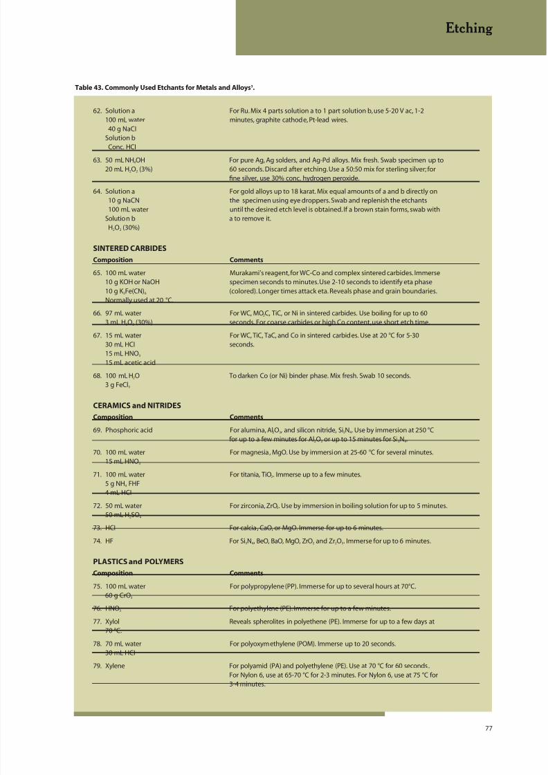
8/20/2019 Buehler Summet, Sample Prep and Analysis
http://slidepdf.com/reader/full/buehler-summet-sample-prep-and-analysis 77/136
77
Table 43. Commonly Used Etchants for Metals and Alloys3.
62. Solution a For Ru. Mix 4 parts solution a to 1 part solution b, use 5-20 V ac, 1-2
100 mL water minutes, graphite cathode, Pt-lead wires.40 g NaCI
Solution bConc. HCI
63. 50 mL NH4OH For pure Ag, Ag solders, and Ag-Pd alloys. Mix fresh. Swab specimen up to20 mL H2O2 (3%) 60 seconds. Discard after etching. Use a 50:50 mix for sterling silver; for
fine silver, use 30% conc. hydrogen peroxide.
64. Solution a For gold alloys up to 18 karat. Mix equal amounts of a and b directly on10 g NaCN the specimen using eye droppers. Swab and replenish the etchants100 mL water until the desired etch level is obtained. If a brown stain forms, swab with
Solution b a to remove it.H2O2 (30%)
SINTERED CARBIDES
Composition Comments
65. 100 mL water Murakami’s reagent, for WC-Co and complex sintered carbides. Immerse10 g KOH or NaOH specimen seconds to minutes. Use 2-10 seconds to identify eta phase10 g K 3Fe(CN)6 (colored). Longer times attack eta. Reveals phase and grain boundaries.Normally used at 20 °C.
66. 97 mL water For WC, MO2C, TiC, or Ni in sintered carbides. Use boiling for up to 603 mL H2O2 (30%) seconds. For coarse carbides or high Co content, use short etch time.
67. 15 mL water For WC, TiC, TaC, and Co in sintered carbides. Use at 20 °C for 5-3030 mL HCI seconds.15 mL HNO3 15 mL acetic acid
68. 100 mL H2O To darken Co (or Ni) binder phase. Mix fresh. Swab 10 seconds.3 g FeCl3
CERAMICS and NITRIDESComposition Comments
69. Phosphoric acid For alumina, Al2O3, and silicon nitride, Si3N4. Use by immersion at 250 °Cfor up to a few minutes for Al2O3 or up to 15 minutes for Si3N4.
70. 100 mL water For magnesia, MgO. Use by immersion at 25-60 °C for several minutes.15 mL HNO3
71. 100 mL water For titania, TiO2. Immerse up to a few minutes.5 g NH4 FHF4 mL HCI
72. 50 mL water For zirconia, ZrO2. Use by immersion in boiling solution for up to 5 minutes.50 mL H2SO4
73. HCI For calcia, CaO, or MgO. Immerse for up to 6 minutes.
74. HF For Si3N4, BeO, BaO, MgO, ZrO2 and Zr2O3. Immerse for up to 6 minutes.
PLASTICS and POLYMERS
Composition Comments
75. 100 mL water For polypropylene (PP). Immerse for up to several hours at 70°C.60 g CrO3
76. HNO3 For polyethylene (PE). Immerse for up to a few minutes.
77. Xylol Reveals spherolites in polyethene (PE). Immerse for up to a few days at70 °C.
78. 70 mL water For polyoxymethylene (POM). Immerse up to 20 seconds.30 mL HCI
79. Xylene For polyamid (PA) and polyethylene (PE). Use at 70 °C for 60 seconds.For Nylon 6, use at 65-70 °C for 2-3 minutes. For Nylon 6, use at 75 °C for3-4 minutes.
Etching
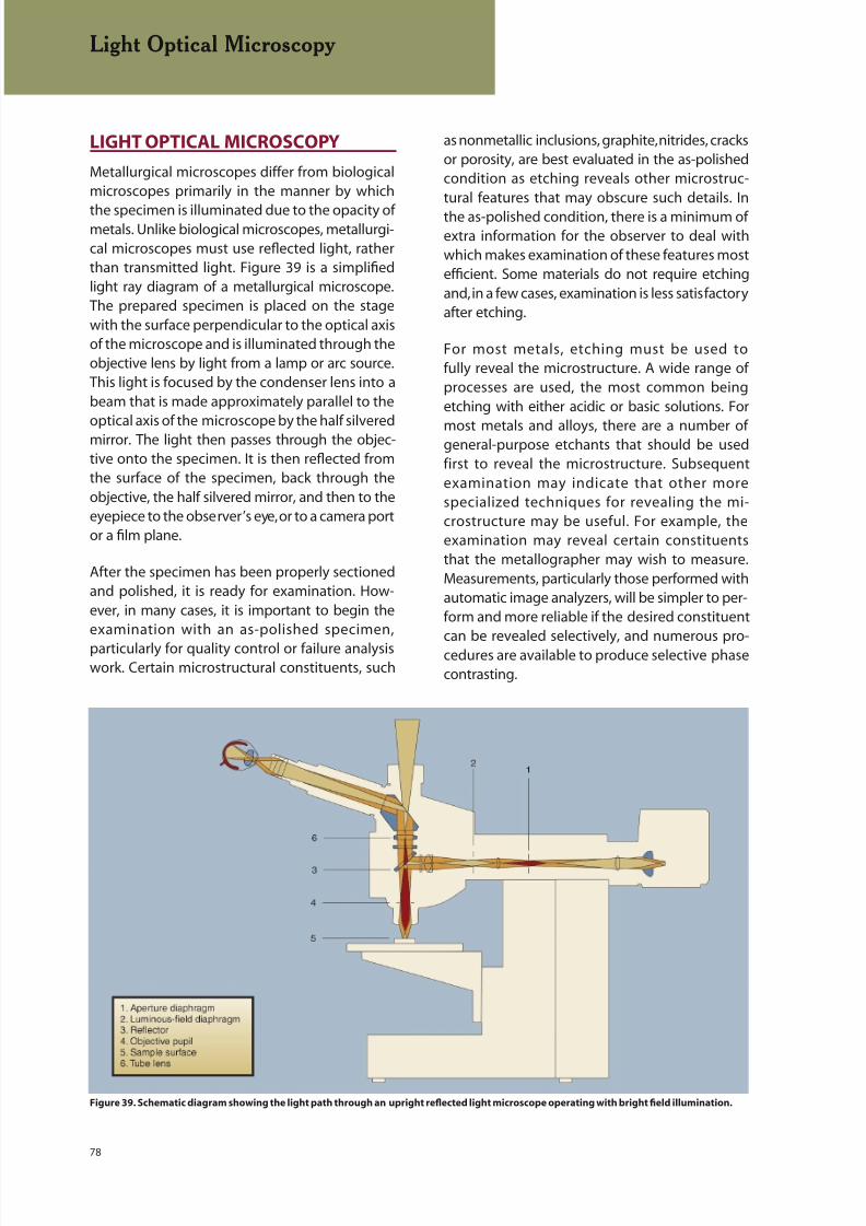
8/20/2019 Buehler Summet, Sample Prep and Analysis
http://slidepdf.com/reader/full/buehler-summet-sample-prep-and-analysis 78/136
78
LIGHT OPTICAL MICROSCOPY
Metallurgical microscopes differ from biologicalmicroscopes primarily in the manner by which
the specimen is illuminated due to the opacity ofmetals. Unlike biological microscopes, metallurgi-cal microscopes must use reflected light, ratherthan transmitted light. Figure 39 is a simplifiedlight ray diagram of a metallurgical microscope.The prepared specimen is placed on the stagewith the surface perpendicular to the optical axisof the microscope and is illuminated through theobjective lens by light from a lamp or arc source.This light is focused by the condenser lens into abeam that is made approximately parallel to theoptical axis of the microscope by the half silveredmirror. The light then passes through the objec-tive onto the specimen. It is then reflected fromthe surface of the specimen, back through theobjective, the half silvered mirror, and then to theeyepiece to the observer’s eye, or to a camera portor a film plane.
After the specimen has been properly sectionedand polished, it is ready for examination. How-ever, in many cases, it is important to begin theexamination with an as-polished specimen,
particularly for quality control or failure analysiswork. Certain microstructural constituents, such
as nonmetallic inclusions, graphite, nitrides, cracksor porosity, are best evaluated in the as-polishedcondition as etching reveals other microstruc-tural features that may obscure such details. In
the as-polished condition, there is a minimum ofextra information for the observer to deal withwhich makes examination of these features mostefficient. Some materials do not require etchingand, in a few cases, examination is less satisfactoryafter etching.
For most metals, etching must be used tofully reveal the microstructure. A wide range ofprocesses are used, the most common beingetching with either acidic or basic solutions. For
most metals and alloys, there are a number ofgeneral-purpose etchants that should be usedfirst to reveal the microstructure. Subsequentexamination may indicate that other morespecialized techniques for revealing the mi-crostructure may be useful. For example, theexamination may reveal certain constituentsthat the metallographer may wish to measure.Measurements, particularly those performed withautomatic image analyzers, will be simpler to per-form and more reliable if the desired constituentcan be revealed selectively, and numerous pro-cedures are available to produce selective phasecontrasting.
Light Optical Microscopy
Figure 39. Schematic diagram showing the light path through an upright reflected light microscope operating with bright field illumination.

8/20/2019 Buehler Summet, Sample Prep and Analysis
http://slidepdf.com/reader/full/buehler-summet-sample-prep-and-analysis 79/136
79
The Light Microscope
When Henry Clifton Sorby made his first examina-tion of the microstructure of iron on 28 July 1863,he was using a transmitted light petrographic mi-
croscope made by Smith, Beck and Beck of Londonthat he had purchased in 1861. Although capableof magnifications up to 400X, most of his exami-nations were conducted at 30, 60 or 100X and hisfirst micrographs were produced at only 9X. Theobjective lenses of this microscope were equippedwith Lieberkühns silvered concave reflectors forfocusing light on opaque specimens.
Sorby quickly realized that reflected lightproduced with the Lieberkühns reflectors was
inadequate and he developed two alternatemethods for this purpose. Subsequently, othersdeveloped vertical illuminators using prisms orplane glass reflectors and Sorby’s systems werenot further developed. In 1886, Sorby reported onthe use of “very high power” (650X) for the study ofpearlite. This was accomplished using a 45º coverglass vertical illuminator made for him by Beck.
For many years, photomicroscopy was conductedusing specially built reflected microscopes known
as metallographs. These devices represented the“top-of-the-line” in metallurgical microscopesand were essential for quality work. In the late1960’s and early 1970’s, manufacturers developedmetallographs that were easier to use from theeyepiece viewing position. The temperamentalcarbon arc light sources were replaced by xenonarc lamps. The unwieldy bellows systems for alter-ing magnification were replaced by zoom systems.Vertical illuminators, previously using single posi-tion objectives, were equipped with four to sixposition rotatable nosepiece turrets to minimizeobjective handling. The light path was deflected sothat the film plane was conveniently near at hand.Universal type vertical illuminators and objectivelenses were introduced so that the illuminationmode could be readily switched from bright fieldto darkfield, polarized light or differential interfer-ence contrast. Such systems were very attractive inthat separate vertical illuminators and objectiveswere no longer needed for each illumination modeand handling was eliminated. Exposure meterswere also added at this time, chiefly as a result of
the rising popularity of instant films where suchdevices are needed to minimize film wastage. But,
by the late 1970s, these large metallographs hadbecome very expensive, too expensive for mostlaboratories.
In 1979, microscope manufacturers began tointroduce very high quality, reasonably priced,compact metallographs. These microscopescan be obtained with a wide variety of objec-tive lens types and auxiliary accessories to meetthe metallographer’s needs. They are availablewith universal vertical illuminators that permiteasy switching from one illumination mode toanother using the same set of objective lenses.Furthermore, the manufacturers have introducednew glass compositions and lens formulations,
generally by computer-aided design, for improvedimage contrast and brightness. Tungsten- hal-ogen filament lamps have largely replacedxenon arc lamps as the preferred light source.
Microscope Components
Light Sources The amount of light lost duringpassage from the source through a reflectingtype microscope is appreciable because of theintricate path the light follows. For this reason, itis generally preferable that the intensity of the
source be high, especially for photomicroscopy.Several types of light sources are used includ-ing tungsten-filament lamps, tungsten-halogenlamps, quartz-halogen lamps, and xenon arc bulbs.Tungsten-filament lamps generally operate at lowvoltage and high current. They are widely used forvisual examination because of their low cost andease of operation.
Tungsten-halogen lamps are the most popularlight source today due to their high light inten-
sity. They produce good color micrographs whentungsten-corrected films are employed. Lightintensity can be varied easily to suit the view-ing conditions by adjusting a rheostat, a distinctadvantage over arc lamps.
Xenon arc lamps produce extremely high intensitylight, and their uniform spectra and daylight colortemperature makes them suitable for color pho-tomicrography. The first xenon lamps producedozone, but modern units have overcome this
problem. Light output is constant and can only bereduced using neutral density filters.
Light Optical Microscopy
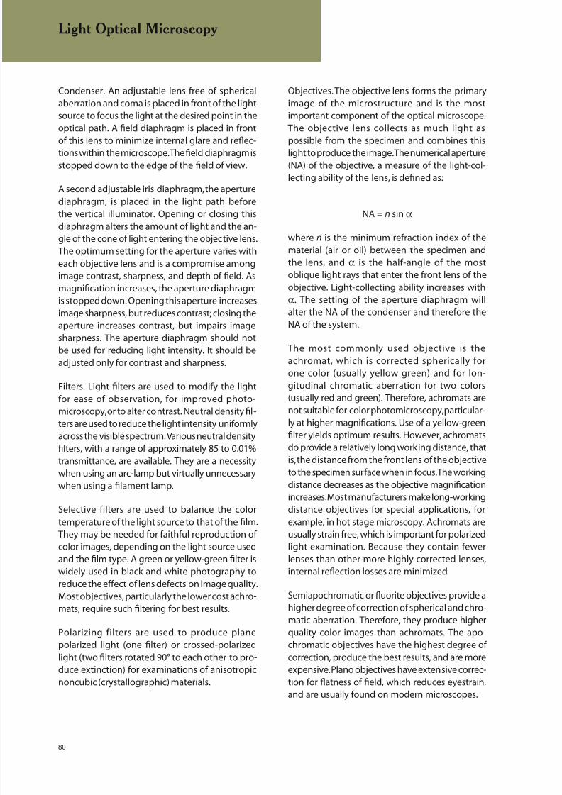
8/20/2019 Buehler Summet, Sample Prep and Analysis
http://slidepdf.com/reader/full/buehler-summet-sample-prep-and-analysis 80/136
80
Condenser. An adjustable lens free of sphericalaberration and coma is placed in front of the lightsource to focus the light at the desired point in theoptical path. A field diaphragm is placed in front
of this lens to minimize internal glare and reflec-tions within the microscope. The field diaphragm isstopped down to the edge of the field of view.
A second adjustable iris diaphragm, the aperturediaphragm, is placed in the light path beforethe vertical illuminator. Opening or closing thisdiaphragm alters the amount of light and the an-gle of the cone of light entering the objective lens.The optimum setting for the aperture varies witheach objective lens and is a compromise among
image contrast, sharpness, and depth of field. Asmagnification increases, the aperture diaphragmis stopped down. Opening this aperture increasesimage sharpness, but reduces contrast; closing theaperture increases contrast, but impairs imagesharpness. The aperture diaphragm should notbe used for reducing light intensity. It should beadjusted only for contrast and sharpness.
Filters. Light filters are used to modify the lightfor ease of observation, for improved photo-microscopy, or to alter contrast. Neutral density fil-ters are used to reduce the light intensity uniformlyacross the visible spectrum. Various neutral densityfilters, with a range of approximately 85 to 0.01%transmittance, are available. They are a necessitywhen using an arc-lamp but virtually unnecessarywhen using a filament lamp.
Selective filters are used to balance the colortemperature of the light source to that of the film.They may be needed for faithful reproduction ofcolor images, depending on the light source used
and the film type. A green or yellow-green filter iswidely used in black and white photography toreduce the effect of lens defects on image quality.Most objectives, particularly the lower cost achro-mats, require such filtering for best results.
Polarizing filters are used to produce planepolarized light (one filter) or crossed-polarizedlight (two filters rotated 90° to each other to pro-duce extinction) for examinations of anisotropicnoncubic (crystallographic) materials.
Objectives. The objective lens forms the primaryimage of the microstructure and is the mostimportant component of the optical microscope.The objective lens collects as much light as
possible from the specimen and combines thislight to produce the image. The numerical aperture(NA) of the objective, a measure of the light-col-lecting ability of the lens, is defined as:
NA = n sin α
where n is the minimum refraction index of thematerial (air or oil) between the specimen andthe lens, and α is the half-angle of the most
oblique light rays that enter the front lens of theobjective. Light-collecting ability increases withα. The setting of the aperture diaphragm willalter the NA of the condenser and therefore theNA of the system.
The most commonly used objective is theachromat, which is corrected spherically forone color (usually yellow green) and for lon-gitudinal chromatic aberration for two colors(usually red and green). Therefore, achromats arenot suitable for color photomicroscopy, particular-ly at higher magnifications. Use of a yellow-greenfilter yields optimum results. However, achromatsdo provide a relatively long working distance, thatis, the distance from the front lens of the objectiveto the specimen surface when in focus. The workingdistance decreases as the objective magnificationincreases. Most manufacturers make long-workingdistance objectives for special applications, forexample, in hot stage microscopy. Achromats areusually strain free, which is important for polarizedlight examination. Because they contain fewer
lenses than other more highly corrected lenses,internal reflection losses are minimized.
Semiapochromatic or fluorite objectives provide ahigher degree of correction of spherical and chro-matic aberration. Therefore, they produce higherquality color images than achromats. The apo-chromatic objectives have the highest degree ofcorrection, produce the best results, and are moreexpensive. Plano objectives have extensive correc-tion for flatness of field, which reduces eyestrain,
and are usually found on modern microscopes.
Light Optical Microscopy
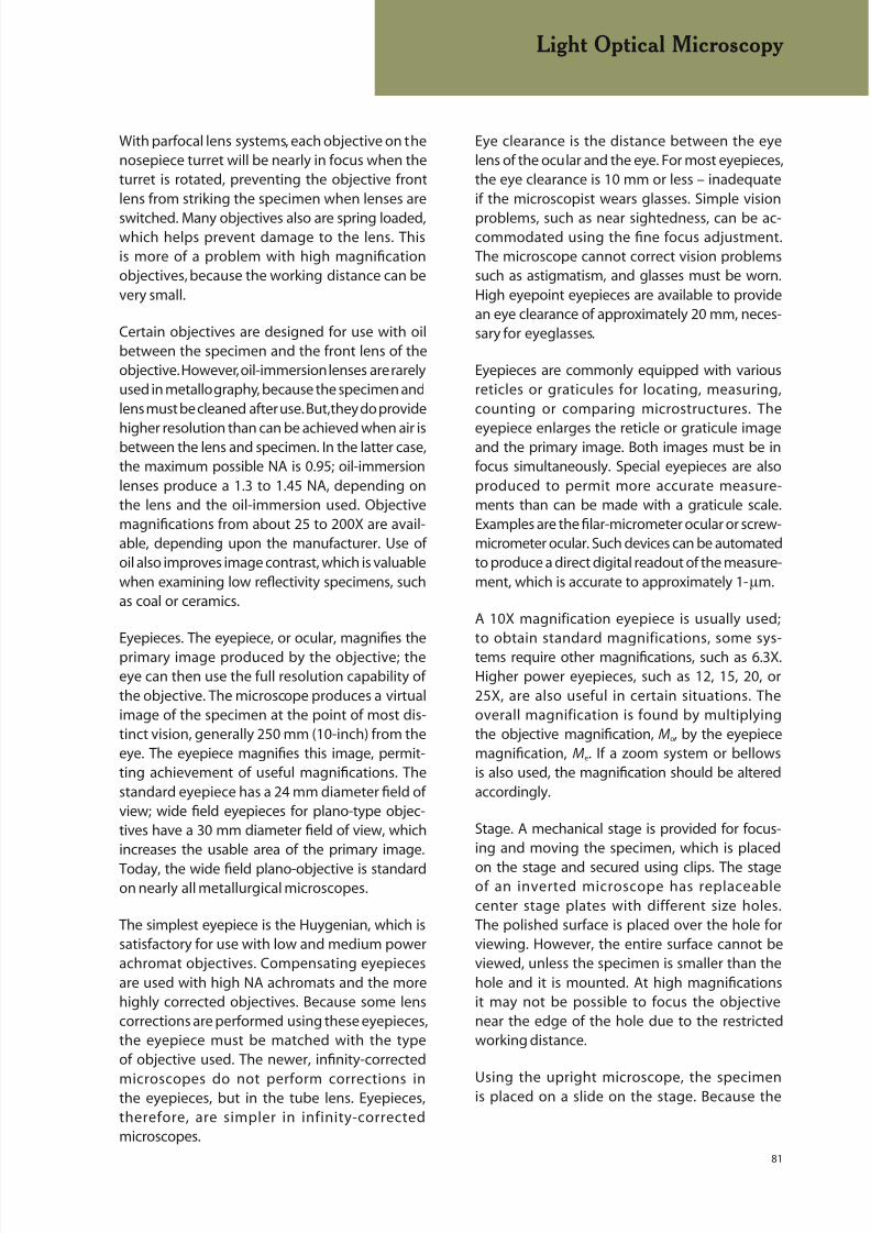
8/20/2019 Buehler Summet, Sample Prep and Analysis
http://slidepdf.com/reader/full/buehler-summet-sample-prep-and-analysis 81/136
81
With parfocal lens systems, each objective on thenosepiece turret will be nearly in focus when theturret is rotated, preventing the objective frontlens from striking the specimen when lenses are
switched. Many objectives also are spring loaded,which helps prevent damage to the lens. Thisis more of a problem with high magnificationobjectives, because the working distance can bevery small.
Certain objectives are designed for use with oilbetween the specimen and the front lens of theobjective. However, oil-immersion lenses are rarelyused in metallography, because the specimen andlens must be cleaned after use. But, they do provide
higher resolution than can be achieved when air isbetween the lens and specimen. In the latter case,the maximum possible NA is 0.95; oil-immersionlenses produce a 1.3 to 1.45 NA, depending onthe lens and the oil-immersion used. Objectivemagnifications from about 25 to 200X are avail-able, depending upon the manufacturer. Use ofoil also improves image contrast, which is valuablewhen examining low reflectivity specimens, suchas coal or ceramics.
Eyepieces. The eyepiece, or ocular, magnifies theprimary image produced by the objective; theeye can then use the full resolution capability ofthe objective. The microscope produces a virtualimage of the specimen at the point of most dis-tinct vision, generally 250 mm (10-inch) from theeye. The eyepiece magnifies this image, permit-ting achievement of useful magnifications. Thestandard eyepiece has a 24 mm diameter field ofview; wide field eyepieces for plano-type objec-tives have a 30 mm diameter field of view, whichincreases the usable area of the primary image.
Today, the wide field plano-objective is standardon nearly all metallurgical microscopes.
The simplest eyepiece is the Huygenian, which issatisfactory for use with low and medium powerachromat objectives. Compensating eyepiecesare used with high NA achromats and the morehighly corrected objectives. Because some lenscorrections are performed using these eyepieces,the eyepiece must be matched with the typeof objective used. The newer, infinity-corrected
microscopes do not perform corrections inthe eyepieces, but in the tube lens. Eyepieces,therefore, are simpler in infinity-correctedmicroscopes.
Eye clearance is the distance between the eyelens of the ocular and the eye. For most eyepieces,the eye clearance is 10 mm or less – inadequateif the microscopist wears glasses. Simple vision
problems, such as near sightedness, can be ac-commodated using the fine focus adjustment.The microscope cannot correct vision problemssuch as astigmatism, and glasses must be worn.High eyepoint eyepieces are available to providean eye clearance of approximately 20 mm, neces-sary for eyeglasses.
Eyepieces are commonly equipped with variousreticles or graticules for locating, measuring,counting or comparing microstructures. The
eyepiece enlarges the reticle or graticule imageand the primary image. Both images must be infocus simultaneously. Special eyepieces are alsoproduced to permit more accurate measure-ments than can be made with a graticule scale.Examples are the filar-micrometer ocular or screw-micrometer ocular. Such devices can be automatedto produce a direct digital readout of the measure-ment, which is accurate to approximately 1-µm.
A 10X magnification eyepiece is usually used;to obtain standard magnifications, some sys-tems require other magnifications, such as 6.3X.Higher power eyepieces, such as 12, 15, 20, or25X, are also useful in certain situations. Theoverall magnification is found by multiplyingthe objective magnification, Mo, by the eyepiecemagnification, Me. If a zoom system or bellowsis also used, the magnification should be alteredaccordingly.
Stage. A mechanical stage is provided for focus-ing and moving the specimen, which is placed
on the stage and secured using clips. The stageof an inverted microscope has replaceablecenter stage plates with different size holes.The polished surface is placed over the hole forviewing. However, the entire surface cannot beviewed, unless the specimen is smaller than thehole and it is mounted. At high magnificationsit may not be possible to focus the objectivenear the edge of the hole due to the restrictedworking distance.
Using the upright microscope, the specimenis placed on a slide on the stage. Because the
Light Optical Microscopy
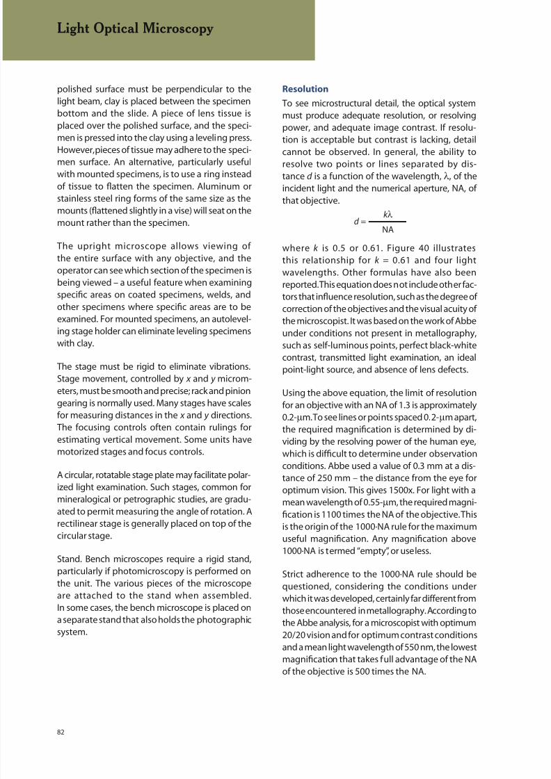
8/20/2019 Buehler Summet, Sample Prep and Analysis
http://slidepdf.com/reader/full/buehler-summet-sample-prep-and-analysis 82/136
82
polished surface must be perpendicular to thelight beam, clay is placed between the specimenbottom and the slide. A piece of lens tissue isplaced over the polished surface, and the speci-
men is pressed into the clay using a leveling press.However, pieces of tissue may adhere to the speci-men surface. An alternative, particularly usefulwith mounted specimens, is to use a ring insteadof tissue to flatten the specimen. Aluminum orstainless steel ring forms of the same size as themounts (flattened slightly in a vise) will seat on themount rather than the specimen.
The upright microscope allows viewing ofthe entire surface with any objective, and the
operator can see which section of the specimen isbeing viewed – a useful feature when examiningspecific areas on coated specimens, welds, andother specimens where specific areas are to beexamined. For mounted specimens, an autolevel-ing stage holder can eliminate leveling specimenswith clay.
The stage must be rigid to eliminate vibrations.Stage movement, controlled by x and y microm-eters, must be smooth and precise; rack and piniongearing is normally used. Many stages have scalesfor measuring distances in the x and y directions.The focusing controls often contain rulings forestimating vertical movement. Some units havemotorized stages and focus controls.
A circular, rotatable stage plate may facilitate polar-ized light examination. Such stages, common formineralogical or petrographic studies, are gradu-ated to permit measuring the angle of rotation. Arectilinear stage is generally placed on top of thecircular stage.
Stand. Bench microscopes require a rigid stand,particularly if photomicroscopy is performed onthe unit. The various pieces of the microscopeare attached to the stand when assembled.In some cases, the bench microscope is placed ona separate stand that also holds the photographicsystem.
Resolution
To see microstructural detail, the optical systemmust produce adequate resolution, or resolvingpower, and adequate image contrast. If resolu-
tion is acceptable but contrast is lacking, detailcannot be observed. In general, the ability toresolve two points or lines separated by dis-tance d is a function of the wavelength, λ, of theincident light and the numerical aperture, NA, ofthat objective.
where k is 0.5 or 0.61. Figure 40 illustratesthis relationship for k = 0.61 and four light
wavelengths. Other formulas have also beenreported. This equation does not include other fac-tors that influence resolution, such as the degree ofcorrection of the objectives and the visual acuity ofthe microscopist. It was based on the work of Abbeunder conditions not present in metallography,such as self-luminous points, perfect black-whitecontrast, transmitted light examination, an idealpoint-light source, and absence of lens defects.
Using the above equation, the limit of resolution
for an objective with an NA of 1.3 is approximately0.2-µm. To see lines or points spaced 0.2-µm apart,the required magnification is determined by di-viding by the resolving power of the human eye,which is difficult to determine under observationconditions. Abbe used a value of 0.3 mm at a dis-tance of 250 mm – the distance from the eye foroptimum vision. This gives 1500x. For light with amean wavelength of 0.55-µm, the required magni-fication is 1100 times the NA of the objective. Thisis the origin of the 1000·NA rule for the maximumuseful magnification. Any magnification above1000·NA is termed “empty”, or useless.
Strict adherence to the 1000·NA rule should bequestioned, considering the conditions underwhich it was developed, certainly far different fromthose encountered in metallography. According tothe Abbe analysis, for a microscopist with optimum20/20 vision and for optimum contrast conditionsand a mean light wavelength of 550 nm, the lowestmagnification that takes full advantage of the NAof the objective is 500 times the NA.
k λ
NAd =
Light Optical Microscopy

8/20/2019 Buehler Summet, Sample Prep and Analysis
http://slidepdf.com/reader/full/buehler-summet-sample-prep-and-analysis 83/136
83
when longer wavelength light is used, as shownin Figure 41.
Imaging Modes
Most microscopical studies of metals are madeusing bright field illumination. In addition to thistype of illumination, several special techniques(oblique illumination, dark field illumination,differential interference contrast microscopyand polarized light microscopy) have particularapplications for metallographic studies.
Nearly all microscopes using reflected or trans-mitted light employ Köhler illumination becauseit provides the most intense, most even illumina-tion possible with standard light sources. Thereflected light microscope has two adjustablediaphragms: the aperture diaphragm and the fielddiaphragm, located between the lamp housingand the objective. Both are adjusted to improveillumination and the image. To obtain Köhler illu-mination, the image of the field diaphragm must
be brought into focus on the specimen plane.This normally occurs automatically when the
This establishes a useful minimum magnificationto use with a given objective. It has been suggestedthat the upper limit of useful magnification for theaverage microscopist is 2200·NA, not 1000·NA.
Depth of Field
Depth of field is the distance along the opticalaxis over which image details are observed withacceptable clarity. Those factors that influenceresolution also affect depth of field, but in theopposite direction. Therefore, a compromise mustbe reached between these two parameters, whichis more difficult as magnification increases. Thisis one reason light etching is preferred for high-magnification examination. The depth of field, d f ,can be estimated from:
where n is the refractive index of the mediumbetween the specimen and the objective (n ~
1.0 for air), λ is the wavelength of light, and NA isthe numerical aperture. This equation shows thatdepth of field increases as the NA decreases and
Figure 40. Influence of objective numerical aperture and light wavelength on the resolution of the light microscope.
λ (n2 −NA2)½
NA2d f =
Light Optical Microscopy
RESOLUTION CHART
Sodium (589 nm)
Green (546 nm)
Blue (436 nm)
Ultraviolet(365 nm)

8/20/2019 Buehler Summet, Sample Prep and Analysis
http://slidepdf.com/reader/full/buehler-summet-sample-prep-and-analysis 84/136
84
microstructural image is brought into focus.The filament image must also be focused onthe aperture diaphragm plane. This producesuniform illumination of the specimen imaged atthe intermediate image plane and magnified bythe eyepiece.
Bright Field. In bright field illumination, thesurface of the specimen is normal to the opticalaxis of the microscope, and white light is used. Aray diagram for bright-field illumination is illus-
trated in Figure 42. Light that passes through theobjective and strikes a region of the speci-men surface that is perpendicular to the beamwill be reflected back up the objective throughthe eyepieces to the eyes where it will appearto be bright or white. Light that strikes grainboundaries, phase boundaries, and otherfeatures not perpendicular to the optical axis willbe scattered at an angle and will not be collectedby the objective. These regions will appear tobe dark or black in the image. Bright field isthe most common mode of illumination usedby metallographers.
Oblique Illumination. The surface relief of ametallographic specimen can be revealed usingoblique illumination. This involves offsetting thecondenser lens system or, as is more usually done,moving the condenser aperture to a positionslightly off the optical axis. Although it shouldbe possible to continually increase the contrastachieved by oblique illumination by moving thecondenser farther and farther from the optical axis,the numerical aperture of a lens is reduced when
Figure 41. Influence of the objective numerical aperture and light wavelength on the depth of field of the light microscope.
Sodium (589 nm)
Green (546 nm)
Blue (436 nm)
Index of Refraction = 1.0
DEPTH OF FIELD CHART
Light Optical Microscopy
Figure 42. Schematic diagram showing the light path in bright field
illumination.
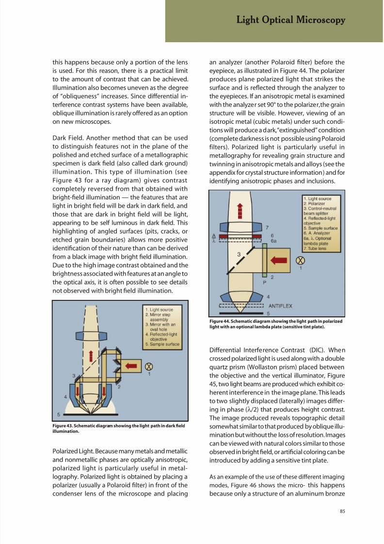
8/20/2019 Buehler Summet, Sample Prep and Analysis
http://slidepdf.com/reader/full/buehler-summet-sample-prep-and-analysis 85/136
85
an analyzer (another Polaroid filter) before theeyepiece, as illustrated in Figure 44. The polarizerproduces plane polarized light that strikes thesurface and is reflected through the analyzer to
the eyepieces. If an anisotropic metal is examinedwith the analyzer set 90° to the polarizer, the grainstructure will be visible. However, viewing of anisotropic metal (cubic metals) under such condi-tions will produce a dark, “extinguished” condition(complete darkness is not possible using Polaroidfilters). Polarized light is particularly useful inmetallography for revealing grain structure andtwinning in anisotropic metals and alloys (see theappendix for crystal structure information) and foridentifying anisotropic phases and inclusions.
Differential Interference Contrast (DIC). Whencrossed polarized light is used along with a doublequartz prism (Wollaston prism) placed betweenthe objective and the vertical illuminator, Figure
45, two light beams are produced which exhibit co-herent interference in the image plane. This leadsto two slightly displaced (laterally) images differ-ing in phase (λ/2) that produces height contrast.The image produced reveals topographic detailsomewhat similar to that produced by oblique illu-mination but without the loss of resolution. Imagescan be viewed with natural colors similar to thoseobserved in bright field, or artificial coloring can beintroduced by adding a sensitive tint plate.
As an example of the use of these different imagingmodes, Figure 46 shows the micro- this happensbecause only a structure of an aluminum bronze
this happens because only a portion of the lensis used. For this reason, there is a practical limitto the amount of contrast that can be achieved.Illumination also becomes uneven as the degree
of “obliqueness” increases. Since differential in-terference contrast systems have been available,oblique illumination is rarely offered as an optionon new microscopes.
Dark Field. Another method that can be usedto distinguish features not in the plane of thepolished and etched surface of a metallographicspecimen is dark field (also called dark ground)illumination. This type of illumination (seeFigure 43 for a ray diagram) gives contrast
completely reversed from that obtained withbright-field illumination — the features that arelight in bright field will be dark in dark field, andthose that are dark in bright field will be light,appearing to be self luminous in dark field. Thishighlighting of angled surfaces (pits, cracks, oretched grain boundaries) allows more positiveidentification of their nature than can be derivedfrom a black image with bright field illumination.Due to the high image contrast obtained and thebrightness associated with features at an angle tothe optical axis, it is often possible to see detailsnot observed with bright field illumination.
Polarized Light. Because many metals and metallicand nonmetallic phases are optically anisotropic,polarized light is particularly useful in metal-
lography. Polarized light is obtained by placing apolarizer (usually a Polaroid filter) in front of thecondenser lens of the microscope and placing
Light Optical Microscopy
Figure 44. Schematic diagram showing the light path in polarized
light with an optional lambda plate (sensitive tint plate).
Figure 43. Schematic diagram showing the light path in dark field
illumination.

8/20/2019 Buehler Summet, Sample Prep and Analysis
http://slidepdf.com/reader/full/buehler-summet-sample-prep-and-analysis 86/136
86
specimen that was water quenched from thebeta field forming martensite. The specimen wasprepared but not etched. A minor amount of reliefwas introduced in final polishing. Figure 46a showsthe surface in bright field illumination. Due tothe relief present, a faint image of the structure isvisible. Dark field, Figure 46c, and differential inter-ference contrast, Figure 46d, make use of this reliefto reveal much more detail than in bright field.
Light Optical Microscopy
However, as the martensite is noncubic in crystalstructure, it responds well to crossed- polarizedlight, Figure 46b. Of course, not every material canbe examined using all four illumination modes, but
there are many cases where two or more modescan be effectively utilized to reveal more informa-tion than given by bright field alone.
Figure 46. Martensitic microstructure of heat treated, eutectoid
aluminum bronze (Cu–11.8% Al) in the unetched condition viewed
using: a) bright field illumination, b) polarized light
Figure 46. Martensitic microstructure of heat treated, eutectoid
aluminum bronze (Cu–11.8% Al) in the unetched condition viewed
using: c) dark field illumination; and, d) differential interference
contrast illumination (200X).
a
b
c
d
HELPFUL HINTS FOR LIGHT
OPTICAL MICROSCOPY
It can be difficult to determine
which objective you are using
with an inverted microscope due to the limited
view from above, as the magnification value
may not be easily observed. However, eachobjective has a color-coded ring on it that is
usually visible. The colors and corresponding
magnifications are: red – 5X, yellow – 10X, green
– 20X, blue – 50X, and white – 100X.
Figure 45. Schematic diagram showing the light path for
differential interference contrast (DIC) illumination.
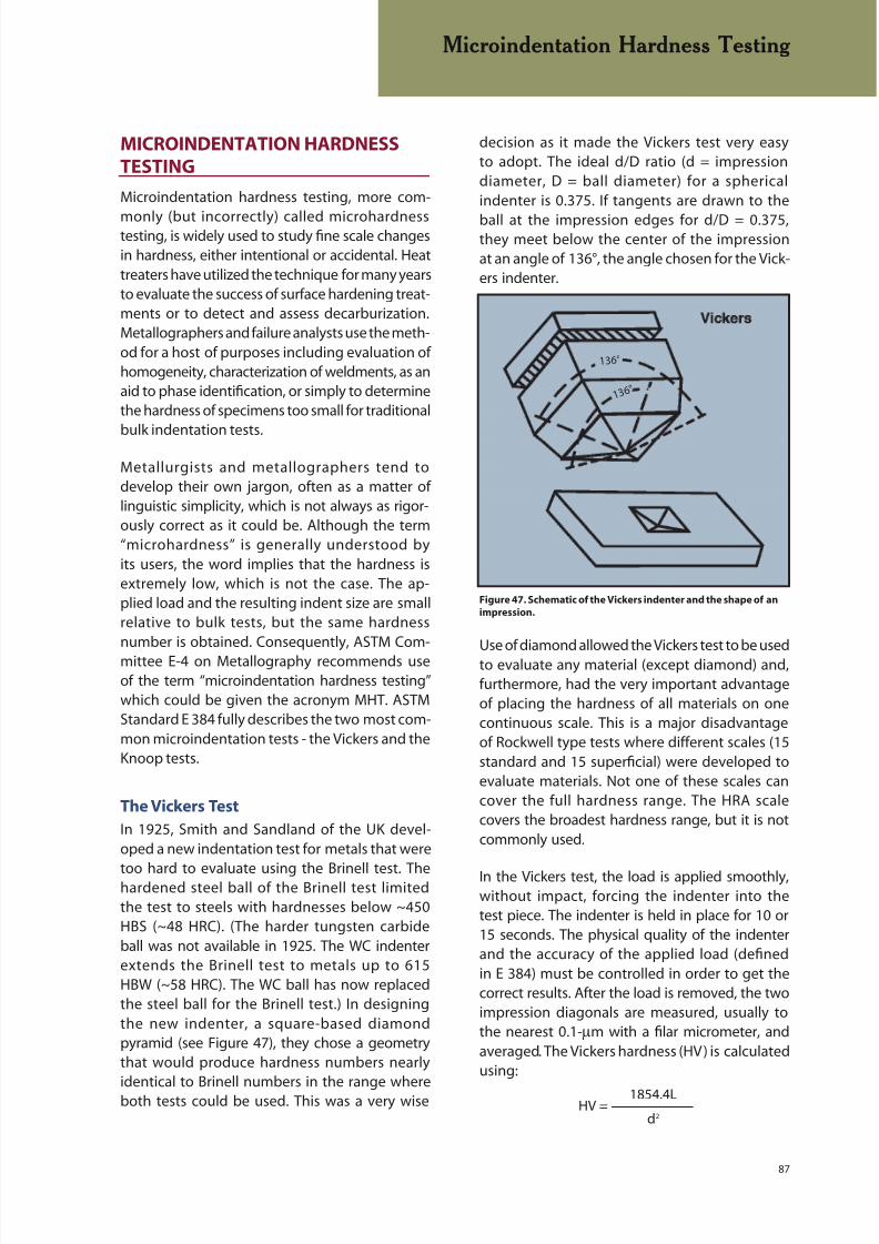
8/20/2019 Buehler Summet, Sample Prep and Analysis
http://slidepdf.com/reader/full/buehler-summet-sample-prep-and-analysis 87/136
87
MICROINDENTATION HARDNESSTESTING
Microindentation hardness testing, more com-
monly (but incorrectly) called microhardnesstesting, is widely used to study fine scale changesin hardness, either intentional or accidental. Heattreaters have utilized the technique for many yearsto evaluate the success of surface hardening treat-ments or to detect and assess decarburization.Metallographers and failure analysts use the meth-od for a host of purposes including evaluation ofhomogeneity, characterization of weldments, as anaid to phase identification, or simply to determinethe hardness of specimens too small for traditional
bulk indentation tests.
Metallurgists and metallographers tend todevelop their own jargon, often as a matter oflinguistic simplicity, which is not always as rigor-ously correct as it could be. Although the term“microhardness” is generally understood byits users, the word implies that the hardness isextremely low, which is not the case. The ap-plied load and the resulting indent size are smallrelative to bulk tests, but the same hardnessnumber is obtained. Consequently, ASTM Com-mittee E-4 on Metallography recommends useof the term “microindentation hardness testing”which could be given the acronym MHT. ASTMStandard E 384 fully describes the two most com-mon microindentation tests - the Vickers and theKnoop tests.
The Vickers Test
In 1925, Smith and Sandland of the UK devel-oped a new indentation test for metals that were
too hard to evaluate using the Brinell test. Thehardened steel ball of the Brinell test limitedthe test to steels with hardnesses below ~450HBS (~48 HRC). (The harder tungsten carbideball was not available in 1925. The WC indenterextends the Brinell test to metals up to 615HBW (~58 HRC). The WC ball has now replacedthe steel ball for the Brinell test.) In designingthe new indenter, a square-based diamondpyramid (see Figure 47), they chose a geometrythat would produce hardness numbers nearlyidentical to Brinell numbers in the range whereboth tests could be used. This was a very wise
decision as it made the Vickers test very easyto adopt. The ideal d/D ratio (d = impressiondiameter, D = ball diameter) for a sphericalindenter is 0.375. If tangents are drawn to the
ball at the impression edges for d/D = 0.375,they meet below the center of the impressionat an angle of 136°, the angle chosen for the Vick-ers indenter.
Use of diamond allowed the Vickers test to be usedto evaluate any material (except diamond) and,furthermore, had the very important advantageof placing the hardness of all materials on onecontinuous scale. This is a major disadvantageof Rockwell type tests where different scales (15standard and 15 superficial) were developed toevaluate materials. Not one of these scales cancover the full hardness range. The HRA scalecovers the broadest hardness range, but it is notcommonly used.
In the Vickers test, the load is applied smoothly,without impact, forcing the indenter into thetest piece. The indenter is held in place for 10 or15 seconds. The physical quality of the indenterand the accuracy of the applied load (definedin E 384) must be controlled in order to get thecorrect results. After the load is removed, the twoimpression diagonals are measured, usually tothe nearest 0.1-µm with a filar micrometer, andaveraged. The Vickers hardness (HV) is calculatedusing:
Microindentation Hardness Testing
Figure 47. Schematic of the Vickers indenter and the shape of an
impression.
136 °
1 3 6 °
1854.4L
d2HV =
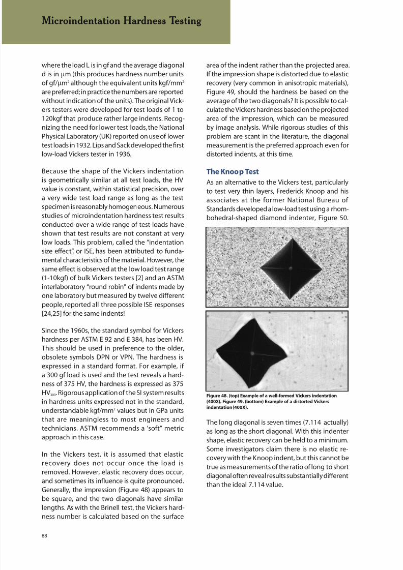
8/20/2019 Buehler Summet, Sample Prep and Analysis
http://slidepdf.com/reader/full/buehler-summet-sample-prep-and-analysis 88/136
88
where the load L is in gf and the average diagonald is in µm (this produces hardness number unitsof gf/µm2 although the equivalent units kgf/mm2 are preferred; in practice the numbers are reported
without indication of the units). The original Vick-ers testers were developed for test loads of 1 to120kgf that produce rather large indents. Recog-nizing the need for lower test loads, the NationalPhysical Laboratory (UK) reported on use of lowertest loads in 1932. Lips and Sack developed the firstlow-load Vickers tester in 1936.
Because the shape of the Vickers indentationis geometrically similar at all test loads, the HVvalue is constant, within statistical precision, over
a very wide test load range as long as the testspecimen is reasonably homogeneous. Numerousstudies of microindentation hardness test resultsconducted over a wide range of test loads haveshown that test results are not constant at verylow loads. This problem, called the “indentationsize effect”, or ISE, has been attributed to funda-mental characteristics of the material. However, thesame effect is observed at the low load test range(1-10kgf) of bulk Vickers testers [2] and an ASTMinterlaboratory “round robin” of indents made byone laboratory but measured by twelve differentpeople, reported all three possible ISE responses[24,25] for the same indents!
Since the 1960s, the standard symbol for Vickershardness per ASTM E 92 and E 384, has been HV.This should be used in preference to the older,obsolete symbols DPN or VPN. The hardness isexpressed in a standard format. For example, ifa 300 gf load is used and the test reveals a hard-ness of 375 HV, the hardness is expressed as 375HV300. Rigorous application of the SI system results
in hardness units expressed not in the standard,understandable kgf/mm2 values but in GPa unitsthat are meaningless to most engineers andtechnicians. ASTM recommends a ‘soft” metricapproach in this case.
In the Vickers test, it is assumed that elasticrecovery does not occur once the load isremoved. However, elastic recovery does occur,and sometimes its influence is quite pronounced.Generally, the impression (Figure 48) appears to
be square, and the two diagonals have similarlengths. As with the Brinell test, the Vickers hard-ness number is calculated based on the surface
area of the indent rather than the projected area.If the impression shape is distorted due to elasticrecovery (very common in anisotropic materials),Figure 49, should the hardness be based on the
average of the two diagonals? It is possible to cal-culate the Vickers hardness based on the projectedarea of the impression, which can be measuredby image analysis. While rigorous studies of thisproblem are scant in the literature, the diagonalmeasurement is the preferred approach even fordistorted indents, at this time.
The Knoop Test
As an alternative to the Vickers test, particularlyto test very thin layers, Frederick Knoop and his
associates at the former National Bureau ofStandards developed a low-load test using a rhom-bohedral-shaped diamond indenter, Figure 50.
The long diagonal is seven times (7.114 actually)as long as the short diagonal. With this indentershape, elastic recovery can be held to a minimum.Some investigators claim there is no elastic re-covery with the Knoop indent, but this cannot betrue as measurements of the ratio of long to shortdiagonal often reveal results substantially differentthan the ideal 7.114 value.
Microindentation Hardness Testing
Figure 48. (top) Example of a well-formed Vickers indentation
(400X). Figure 49. (bottom) Example of a distorted Vickers
indentation (400X).
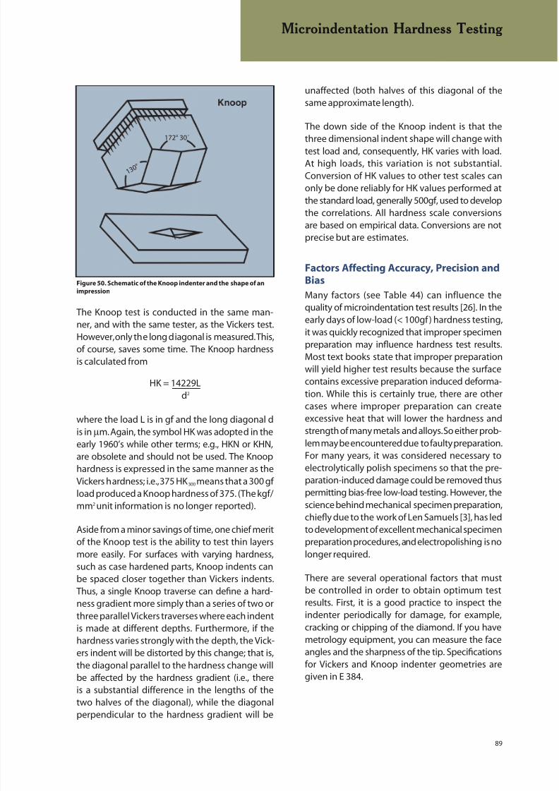
8/20/2019 Buehler Summet, Sample Prep and Analysis
http://slidepdf.com/reader/full/buehler-summet-sample-prep-and-analysis 89/136
89
The Knoop test is conducted in the same man-ner, and with the same tester, as the Vickers test.However, only the long diagonal is measured. This,of course, saves some time. The Knoop hardnessis calculated from
HK = 14229L d2
where the load L is in gf and the long diagonal dis in µm. Again, the symbol HK was adopted in theearly 1960’s while other terms; e.g., HKN or KHN,are obsolete and should not be used. The Knoophardness is expressed in the same manner as theVickers hardness; i.e., 375 HK 300 means that a 300 gfload produced a Knoop hardness of 375. (The kgf/mm2 unit information is no longer reported).
Aside from a minor savings of time, one chief meritof the Knoop test is the ability to test thin layers
more easily. For surfaces with varying hardness,such as case hardened parts, Knoop indents canbe spaced closer together than Vickers indents.Thus, a single Knoop traverse can define a hard-ness gradient more simply than a series of two orthree parallel Vickers traverses where each indentis made at different depths. Furthermore, if thehardness varies strongly with the depth, the Vick-ers indent will be distorted by this change; that is,the diagonal parallel to the hardness change willbe affected by the hardness gradient (i.e., there
is a substantial difference in the lengths of thetwo halves of the diagonal), while the diagonalperpendicular to the hardness gradient will be
unaffected (both halves of this diagonal of thesame approximate length).
The down side of the Knoop indent is that the
three dimensional indent shape will change withtest load and, consequently, HK varies with load.At high loads, this variation is not substantial.Conversion of HK values to other test scales canonly be done reliably for HK values performed atthe standard load, generally 500gf, used to developthe correlations. All hardness scale conversionsare based on empirical data. Conversions are notprecise but are estimates.
Factors Affecting Accuracy, Precision and
Bias
Many factors (see Table 44) can influence thequality of microindentation test results [26]. In theearly days of low-load (< 100gf) hardness testing,it was quickly recognized that improper specimenpreparation may influence hardness test results.Most text books state that improper preparationwill yield higher test results because the surfacecontains excessive preparation induced deforma-tion. While this is certainly true, there are othercases where improper preparation can create
excessive heat that will lower the hardness andstrength of many metals and alloys. So either prob-lem may be encountered due to faulty preparation.For many years, it was considered necessary toelectrolytically polish specimens so that the pre-paration-induced damage could be removed thuspermitting bias-free low-load testing. However, thescience behind mechanical specimen preparation,chiefly due to the work of Len Samuels [3], has ledto development of excellent mechanical specimenpreparation procedures, and electropolishing is no
longer required.
There are several operational factors that mustbe controlled in order to obtain optimum testresults. First, it is a good practice to inspect theindenter periodically for damage, for example,cracking or chipping of the diamond. If you havemetrology equipment, you can measure the faceangles and the sharpness of the tip. Specificationsfor Vickers and Knoop indenter geometries aregiven in E 384.
Microindentation Hardness Testing
Figure 50. Schematic of the Knoop indenter and the shape of an
impression
1 3 0 °
172° 30´
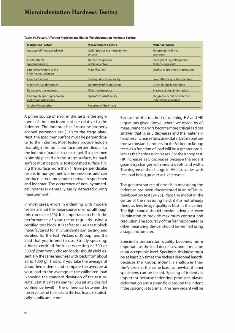
8/20/2019 Buehler Summet, Sample Prep and Analysis
http://slidepdf.com/reader/full/buehler-summet-sample-prep-and-analysis 90/136
90
A prime source of error in the tests is the align-ment of the specimen surface relative to theindenter. The indenter itself must be properlyaligned perpendicular (±1°) to the stage plate.Next, the specimen surface must be perpendicu-lar to the indenter. Most testers provide holdersthat align the polished face perpendicular tothe indenter (parallel to the stage). If a specimenis simply placed on the stage surface, its backsurface must be parallel to its polished surface. Tilt-ing the surface more than 1° from perpendicular
results in nonsymmetrical impressions and canproduce lateral movement between specimenand indenter. The occurrence of non- symmetri-cal indents is generally easily detected duringmeasurement.
In most cases, errors in indenting with moderntesters are not the major source of error, althoughthis can occur [26]. It is important to check theperformance of your tester regularly using acertified test block. It is safest to use a test blockmanufactured for microindentation testing andcertified for the test (Vickers or Knoop) and theload that you intend to use. Strictly speaking,a block certified for Vickers testing at 300 or500 gf (commonly chosen loads) should yield es-sentially the same hardness with loads from about50 to 1000 gf. That is, if you take the average ofabout five indents and compare the average atyour load to the average at the calibrated load(knowing the standard deviation of the test re-sults), statistical tests can tell you (at any desiredconfidence level) if the difference between the
mean values of the tests at the two loads is statisti-cally significant or not.
Because of the method of defining HV and HK(equations given above) where we divide by d2,measurement errors become more critical as d getsmaller; that is, as L decreases and the material’shardness increases (discussed later). So departurefrom a constant hardness for the Vickers or Knooptests as a function of load will be a greater prob-lem as the hardness increases. For the Knoop test,HK increases as L decreases because the indentgeometry changes with indent depth and width.The degree of the change in HK also varies with
test load being greater as L decreases.
The greatest source of error is in measuring theindent as has been documented in an ASTM in-terlaboratory test [24,25]. Place the indent in thecenter of the measuring field, if it is not alreadythere, as lens image quality is best in the center.The light source should provide adequate, evenillumination to provide maximum contrast andresolution. The accuracy of the filar micrometer, orother measuring device, should be verified using
a stage micrometer.
Specimen preparation quality becomes moreimportant as the load decreases, and it must beat an acceptable level. Specimen thickness mustbe at least 2.5 times the Vickers diagonal length.Because the Knoop indent is shallower thanthe Vickers at the same load, somewhat thinnerspecimens can be tested. Spacing of indents isimportant because indenting produces plasticdeformation and a strain field around the indent.If the spacing is too small, the new indent will be
Table 44. Factors Affecting Precision and Bias in Microindentation Hardness Testing
Instrument Factors Measurement Factors Material Factors
Accuracy of the applied load Calibration of the measurement Heterogenity of thesystem specimen
Inertia effects, Numerical aperture Strength of crystallographicspeed of loading of the objective texture, if present
Lateral movement of the Magnification Quality of specimen preparationindenter or specimen
Indentation time Inadequate image quality Low reflectivity or transparency
Indenter shap deviations Uniformity of illumination Creep during indentation
Damage to the indenter Distortion in optics Fracture during indentation
Inadequate spacing between Operator’s visual acuity Oil, grease or dirt on indenterindents or form edges indenter or specimen
Angle of indentation Focusing of the image
Microindentation Hardness Testing

8/20/2019 Buehler Summet, Sample Prep and Analysis
http://slidepdf.com/reader/full/buehler-summet-sample-prep-and-analysis 91/136
91
affected by the strain field around the last indent.ASTM recommends a minimum spacing (centerto edge of adjacent indent) of 2.5 times the Vick-ers diagonal. For the Knoop test where the long
diagonals are parallel, the spacing is 2.5 timesthe short diagonal. The minimum recommendedspacing between the edge of the specimen andthe center of the indent should be 2.5 times. Again,Knoop indents can be placed closer to the surfacethan Vickers indents.
Several studies have stated that the resolutionof the optical system is the major factor limit-ing measurement precision. They state that thiscauses indents to be undersized by a constant
amount. However, as undersizing would in-crease the measured hardness, not decrease it,resolution limits pe r se cannot explain thisproblem. For the Knoop indent, the chiefproblem is image contrast at the indent tipsthat results in undersized indents. This problem,plus the variable indent shape, both result inincreasing HK with decreasing test load. For theVickers test, one would assume that undersizing oroversizing would be equally likely; but, experiencesuggests that oversizing is much more commonlyencountered for low loads and small indents.
Automation
Microindentation hardness testing is tedious,so anything that can be done to simplify test-ing is valuable, especially for laboratories thatdo substantial testing. Many adjuncts to indentmeasurement have been tried and a variety ofsuch systems are available. There has been con-siderable interest in applying image analyzers tothe indent measurement task. Further, with stage
automation, it is possible to automate the indent-ing process itself, and with the same equipment.Figure 51 shows the Buehler OmniMet MHT auto-mated microindentation hardness testing system.This system can be used in the fully automatic,semiautomatic or manual mode, depending uponthe nature of the testing. OmniMet MHT featuresa tracing function which allows the operator tooutline the exterior of a specimen,. rapidly setmultiple indent paths, document the placementof hardness profiles, and automatically generate
reports with a profile map, creating a visual recordof the entire measurement.
An automated system can be programmed tomake any number of indents in either a definedpattern (x number of equally spaced indents,or x number between two chosen points) or arandom pattern (locations selected at randomwith a mouse). Curved patterns may be used, not
just straight-line patterns. The system then makesthe indents at the requested load and locations,measures each indent, calculates the hardness(and desired conversions to other scales), andprints/plots the results. Statistical analysis can alsobe preformed.
In general, Vickers indents are easier to mea-sure by image analysis than Knoop indents dueto the lower contrast at the tips of the Knoopindents (leads to undersizing and higher HKvalues). Metal flow (plastic deformation) aroundthe indent edges can interfere with measurementprecision. Vickers indents, like the ones shown inFigure 48, exhibit excellent contrast and shapeand are easily measured. If the magnificationis too high (and this may be influenced by the
numerical aperture of the objective) for a givenindent size, image contrast suffers and correctdetection of the indent will be very difficult. On theother hand, if the indent is very small on the screen,it will be hard for the system to detect it automati-cally. In this case, use a higher magnification, or usethe semiautomatic measurement mode if this isnot possible. The operator fits a box around theindent with a mouse to measure the indent.
Microindentation hardness testing is a very
valuable tool for the materials engineer but itmust be used with care and a full understanding ofthe potential problems that can occur. Always try
Microindentation Hardness Testing
Figure 51. OmniMet MHT
8/20/2019 Buehler Summet, Sample Prep and Analysis
http://slidepdf.com/reader/full/buehler-summet-sample-prep-and-analysis 92/136
92
to use the highest possible load depending uponthe indent spacing or closeness to edges. Try tokeep indents greater than 20-µm in diameter, asrecommended in ASTM standard E384. If you have
not read E384, or it has been some time since youread it (all ASTM standards must be reviewed andrevised, if necessary, every five years), get the latestcopy and go over it. The Precision and Bias section(and appendix X1 of E384) contains a wealth ofpractical advice. Automation of indentation andmeasurement is possible and, for laboratories thatdo substantial testing, greatly reduces operatorfatigue while reducing testing times.
HELPFUL HINTS FOR
MICROINDENTATION
HARDNESS TESTING
If you suspect that the test
results obtained on a specimen are question-
able, verify the tester using a certified test
block. When testing thin coatings, use the
Knoop indenter with the long axis parallel
to the surface. If you have a specimen where
the hardness changes rapidly, Vickers indents
may be distorted badly in the direction of the
hardness gradient. Switch to a Knoop indenter
and place the long axis perpendicular to the
hardness gradient.
Microindentation Hardness Testing

8/20/2019 Buehler Summet, Sample Prep and Analysis
http://slidepdf.com/reader/full/buehler-summet-sample-prep-and-analysis 93/136
93
Image Capture and Analysis
IMAGE CAPTURE AND ANALYSIS
The progress in computer and video technologyhas created a movement toward electronic image
acquisition. These images can be used in softwareapplications such as word processing or desktoppublishing programs allowing for fast reportgeneration and electronic distribution. In addition,associated data can be stored with the images in adatabase allowing for easy retrieval of informationthrough searches.
When adding imaging capabilities to the labo-ratory, it is important to consider your goals.Oftentimes, images are just another step in thedocumentation process. For example, in a failureinvestigation it is useful to capture the image of acomplete component before the sectioning pro-cess. Or, an image of the microstructure might beattached to a report as an indication of a pass/failcondition. Additional functionality of an imag-ing system might include a scale marker overlayand point-to-point or other operator interactivemeasurements. Fully automated image analysisincludes detection of the features of interestbased on grey level or color differences as wellas morphological characteristics such as size and
shape. Automated imaging applications are basedon a fundamental series of steps shown in Table45. Depending on your goals, some or all of thesesteps may be utilized.
Aligned with these imaging goals, Buehler offers aseries of upgradeable OmniMet imagin products(Figure 52). The OmniMet Capture Basic Systemprovides digital or analog image capture, manualinteractive measurements (length, parallel width,area, curve (string lenth), text annotation and scale
bars), basic report generation in Microsoft® Word,and databasing of saved images and measure-
ments. The OmniMet Capture Advanced systemexpands upon the Capture Basic capabilities byincluding additional interactive measurements(radius, angle, and counting), adding a results
window, and allowing the exporting of data toMicrosoft® Excel. The OmniMet Express and Om-niMet Enterprise products include automatedmeasurement capabilities in addition to themanual measurements found in the Capture prod-ucts. OmniMet Express can incorporate a varietyof application specific metallographic analysismodules. OmniMet Enterprise is a full featuredsystem including a routine builder which enablesthe user to generate custom analysis solutions tomeet their specific needs.
Image Capture
Image capture is a term used to describe imageacquisition by means of a camera and framegrabber or a digital camera. Because of the manychoices of camera types, a video microscopysystem must be flexible. Analog CCD cameras,black and white or color, or digital CCD or CMOSare most frequently used. Component video (Y/C
or S-Video) and composite video signals and anumber of color video standards such as NTSC,
Table 45. Primary Imaging Steps
Imaging Steps Description
Capture Capture, load, or import an image
Clarification Develop the necessary contrast and clarity for detecting the features of interest
Thresholding Detect the features of interest
Binary Operations Clean-up any detection discrepancies, categorize features, and overlay grids
Measurements Conduct field or feature measurements
Data Analysis Evaluate statistics and relevance of the measurements
Archive Store images, annotations, and associated measurements in a database
Distribution Printing or electronic distribution of images and results
Figure 52. OmniMet Digital Imaging System

8/20/2019 Buehler Summet, Sample Prep and Analysis
http://slidepdf.com/reader/full/buehler-summet-sample-prep-and-analysis 94/136
94
Image Capture and Analysis
PAL and SECAM are generally supported. Imagesacquired in the materials laboratory are optimizedin real time by adjusting brightness, contrast, andcolor saturation. The analog output camera signal
is then digitized utilizing an analog input framegrabber board.
Alternatively, digital cameras may be integratedwith an IEE 1394 firewire or USB connection. Sincethe late 1990’s digital video cameras have becomethe preferred choice for scientific imaging applica-tions. This is largely accounted for by two factors:1) higher pixel densities in the acquired imagespotentially provide higher spatial resolution and2) the cost range of digital cameras has merged
with the combined cost of an analog camera andspecialized capture board. Capturing an imagewith a digital camera is often a two-stage process,first a preview image is viewed for focusing andselecting the field of interest and then a snapshotof the image is taken. The preview image windowdisplays the image at a lower pixel density andthe refresh rate of the camera will determinethe amount of lag time between the operatoradjusting the microscope and the new imagebeing displayed. In order to be comparable to ananalog camera, the refresh rate should approach25 frames per second.
The resulting image files are based on two primaryformats, bit-map and vector. The majority of scien-tific imaging programs are based on bit-mappedimages. Bit-mapped graphics are essentially grids,consisting of rows and columns of pixels. Whenthe image is zoomed to observe details, the indi-vidual pixels will become visible. Pixels, or pictureelements, are the smallest part of an image that acomputer, printer or monitor display can control.
An image on a monitor consists of hundreds ofthousands of pixels, arranged in such a mannerthat they appear to be connected. Figure 53displays a cast iron image with a small segment
zoomed such that the pixels are observed.
Each pixel in a bitmap is stored in one or moredata bits. If an image is monochromatic (black and
white), then one bit is enough to store informationfor one pixel. If an image is colored or uses variousshades of grey, then additional bits are required tostore color and shading information. Table 46 listssome of the more common bit depths referred toin imaging software and camera literature.
When working in grayscale, 256 values are usedto represent each shade of grey, starting withblack at 0 and transitioning to white at 255. Forexample, the information stored for the image inFigure 53 would be a combination of the x and ypositions and a number from 0 to 255. For colorimages there are two common models used tonumerically represent color, RGB and HLS. Eachrequires storing three values, in addition to the xand y position of the pixel, in order to recreate theimage. In general, you will notice the file sizes forcolor images are larger than grey scale images ofthe same pixel density.
The RGB model is based on three primary colors– red, green and blue – that can be combined in
various proportions to produce different colors.This scheme is considered additive because, whencombined in equal portions, the result is white.Likewise, an absence of all three is black. The threeprimary colors are each measured as a value from0-255. The colors produced by combining thethree primaries are a result of the relative valuesof each primary. For example, pure red has a redvalue of 255, a green value of 0, and a blue valueof 0. Yellow has a red value of 255, a green value of255, and a blue value of 0. This system is modeled
as a cube with three independent directions: red,green, and blue, spanning the available space. Thebody diagonal of the cube contains luminance, in
Table 46. Bit Depth
Bits
1 21 or 2 tones, black and white
8 28 or 256 grey scale shades
24 224 or 16.7 million colors
32 232 or 4.29 billion colors
Figure 53. A small segment of an image zoomed to display the
individual pixels..

8/20/2019 Buehler Summet, Sample Prep and Analysis
http://slidepdf.com/reader/full/buehler-summet-sample-prep-and-analysis 95/136
95
other words, colorless information about how lightor dark the signal is.
The HLS model uses the concept of Hue, Lumi-
nance, and Saturation. Hue is the color tone. Forexample, an etchant might highlight the differentphases as unique shades of brown or blue. Satu-ration is complementary to the hue. It describeshow brilliant or pure – as opposed to washedout or grayish a particular color is. Luminance iscorrelated with the light intensity and viewed ascomparable to the greyscale values where zero isblack and 255 is white. The HLS color space can beviewed as a double cone, in which the z-axis of thecone is the grayscale progression from black to
white, distance from the central axis is the satura-tion, and the direction or angle is the hue.
The illustration in Figure 54 represents pixels ofnine different color values. These values are shownin Table 47 for the greyscale, RGB, and HLS models.When the pixels are not true grayscale tones, thegreyscale number is not given.
Resolution is primarily the imaging system’s abil-ity to reproduce object detail by resolving closelyspaced features. In digital microscopy, the resolu-tion is examined in terms of both the microscopelimitations and the pixel array of the camera. Theclarity and definition of a digital image dependslargely on the total number of pixels used to createit. Typical pixel array densities range from 640 x 480to 5120 x 4096. Multiplying the two numbers givesyou the total number of pixels used to create theimage. Because a large number of pixels leads tosharper images, you might conclude that it is al-ways desirable to capture images with the largestpixel array possible. That is not necessarily always
Image Capture and Analysis
Table 47. Values based on color models
HLS Method RGB Method
Pixels Greyscale Hue Luminance Saturation Red Green Blue
1 192 0 192 0 192 192 192
2 150 0 150 0 150 150 150
3 128 0 128 0 128 128 128
4 0 127 255 255 0 0
5 85 127 255 0 255 0
6 170 127 255 0 0 255
7 60 98 100 255 255 08 310 36 79 148 31 129
9 25 100 176 169 113 31
true. The problem with large array images is thatthey consume a lot of storage space. As a result,these images are not recommended for posting onweb sites or email use. It is important to take into
account what you intend to do with your imageswhen selecting the appropriate camera.
In order to perform measurements, the image orthe image source must first be calibrated. Calibra-tion is achieved by assigning a known distance toa pixel count. When using a light microscope thisis accomplished with a stage micrometer. Each ofthe objectives will have its own unique calibrationfactor. If the aspect ratio of the camera pixels is un-known, it can be determined by calibrating in both
the x and y direction. If the aspect ratio is known,then calibration only needs to be completed in the
Figure 54. A representation of nine pixels with different color
values.
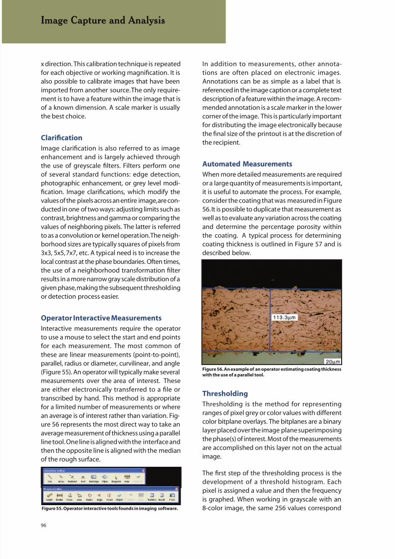
8/20/2019 Buehler Summet, Sample Prep and Analysis
http://slidepdf.com/reader/full/buehler-summet-sample-prep-and-analysis 96/136
96
In addition to measurements, other annota-tions are often placed on electronic images.Annotations can be as simple as a label that isreferenced in the image caption or a complete text
description of a feature within the image. A recom-mended annotation is a scale marker in the lowercorner of the image. This is particularly importantfor distributing the image electronically becausethe final size of the printout is at the discretion ofthe recipient.
Automated Measurements
When more detailed measurements are requiredor a large quantity of measurements is important,it is useful to automate the process. For example,consider the coating that was measured in Figure56. It is possible to duplicate that measurement aswell as to evaluate any variation across the coatingand determine the percentage porosity withinthe coating. A typical process for determiningcoating thickness is outlined in Figure 57 and isdescribed below.
ThresholdingThresholding is the method for representingranges of pixel grey or color values with differentcolor bitplane overlays. The bitplanes are a binarylayer placed over the image plane superimposingthe phase(s) of interest. Most of the measurementsare accomplished on this layer not on the actualimage.
The first step of the thresholding process is thedevelopment of a threshold histogram. Each
pixel is assigned a value and then the frequencyis graphed. When working in grayscale with an8-color image, the same 256 values correspond
x direction. This calibration technique is repeatedfor each objective or working magnification. It isalso possible to calibrate images that have beenimported from another source. The only require-
ment is to have a feature within the image that isof a known dimension. A scale marker is usuallythe best choice.
Clarification
Image clarification is also referred to as imageenhancement and is largely achieved throughthe use of greyscale filters. Filters perform oneof several standard functions: edge detection,photographic enhancement, or grey level modi-fication. Image clarifications, which modify thevalues of the pixels across an entire image, are con-ducted in one of two ways: adjusting limits such ascontrast, brightness and gamma or comparing thevalues of neighboring pixels. The latter is referredto as a convolution or kernel operation. The neigh-borhood sizes are typically squares of pixels from3x3, 5x5, 7x7, etc. A typical need is to increase thelocal contrast at the phase boundaries. Often times,the use of a neighborhood transformation filterresults in a more narrow gray scale distribution of agiven phase, making the subsequent thresholding
or detection process easier.
Operator Interactive Measurements
Interactive measurements require the operatorto use a mouse to select the start and end pointsfor each measurement. The most common ofthese are linear measurements (point-to-point),parallel, radius or diameter, curvilinear, and angle(Figure 55). An operator will typically make severalmeasurements over the area of interest. These
are either electronically transferred to a file ortranscribed by hand. This method is appropriatefor a limited number of measurements or wherean average is of interest rather than variation. Fig-ure 56 represents the most direct way to take anaverage measurement of thickness using a parallelline tool. One line is aligned with the interface andthen the opposite line is aligned with the medianof the rough surface.
Image Capture and Analysis
Figure 55. Operator interactive tools founds in imaging software.
Figure 56. An example of an operator estimating coating thickness
with the use of a parallel tool.
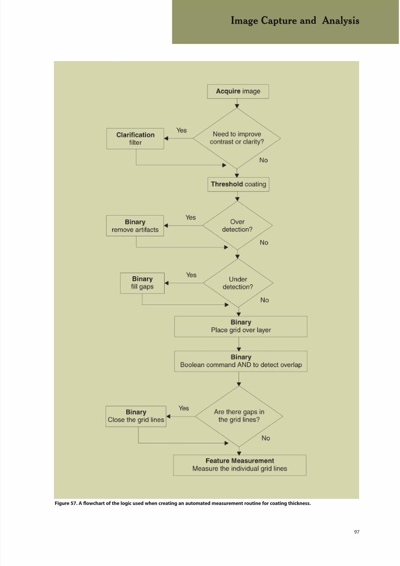
8/20/2019 Buehler Summet, Sample Prep and Analysis
http://slidepdf.com/reader/full/buehler-summet-sample-prep-and-analysis 97/136
97
Image Capture and Analysis
Figure 57. A flowchart of the logic used when creating an automated measurement routine for coating thickness.
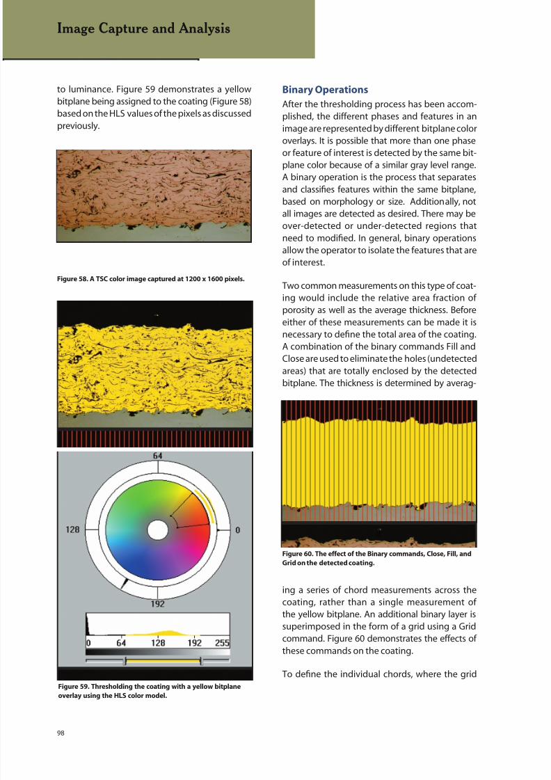
8/20/2019 Buehler Summet, Sample Prep and Analysis
http://slidepdf.com/reader/full/buehler-summet-sample-prep-and-analysis 98/136
98
Binary Operations
After the thresholding process has been accom-plished, the different phases and features in animage are represented by different bitplane color
overlays. It is possible that more than one phaseor feature of interest is detected by the same bit-plane color because of a similar gray level range.A binary operation is the process that separatesand classifies features within the same bitplane,based on morphology or size. Additionally, notall images are detected as desired. There may beover-detected or under-detected regions thatneed to modified. In general, binary operationsallow the operator to isolate the features that areof interest.
Two common measurements on this type of coat-ing would include the relative area fraction ofporosity as well as the average thickness. Beforeeither of these measurements can be made it isnecessary to define the total area of the coating.A combination of the binary commands Fill andClose are used to eliminate the holes (undetectedareas) that are totally enclosed by the detectedbitplane. The thickness is determined by averag-
ing a series of chord measurements across thecoating, rather than a single measurement ofthe yellow bitplane. An additional binary layer issuperimposed in the form of a grid using a Gridcommand. Figure 60 demonstrates the effects ofthese commands on the coating.
To define the individual chords, where the grid
Image Capture and Analysis
Figure 58. A TSC color image captured at 1200 x 1600 pixels.
Figure 60. The effect of the Binary commands, Close, Fill, and
Grid on the detected coating.
Figure 59. Thresholding the coating with a yellow bitplane
overlay using the HLS color model.
to luminance. Figure 59 demonstrates a yellowbitplane being assigned to the coating (Figure 58)based on the HLS values of the pixels as discussedpreviously.

8/20/2019 Buehler Summet, Sample Prep and Analysis
http://slidepdf.com/reader/full/buehler-summet-sample-prep-and-analysis 99/136
99
overlaps the coating, a Boolean command isemployed. Boolean operations perform logicalfunctions between bitplanes. The two most com-mon are OR and AND. AND takes those portions
of two bitplanes that overlap and integratesthem into a single destination bitplane. In thecoating, for example, AND considers only those
segments of the red grid bitplane that overlapthe yellow coating bitplane. Figure 61 shows thered chords which result from the AND command.OR combines two source bitplanes together to
form a single destination bitplane. For example, iftwo different inclusion types, oxides and sulfides,are detected initially, they can be combined tomeasure the total inclusion content.
One of the most powerful binary functions is theability to categorize individual features basedon shape or size. It can be a single specification(>5-µm) or multiple specifications (>2 and <5)separated by an AND or an OR. If a maximum allow-able pore size is specified, all pores that exceed thatlimit can be flagged. The limit itself can be based
on average diameter, maximum diameter, area,aspect ratio, etc. Additionally, the shape of the poremay have some significance. For example, in castmaterials, a gas bubble tends to be circular while ashrinkage cavity will have a more complex shape.Common shape factors examine the relationshipbetween the perimeter and area of the feature.For this coating, the pores were separated fromthe elongated oxides to insure that the porositylevel was not overestimated.
Returning to Figure 61, where grid lines are placedacross the coating, the length of all the individual
Image Capture and Analysis
Figure 61. The chords that result from the overlapping coating
and grid lines.
Figure 62. The histogram of results representing the chords
shown in Figure 61.
grid lines can be measured. The data can be shownas a histogram offering the minimum, maximum,mean and standard deviation of the measure-ments across the coating (Figure 62).
Most measurements fall into one of two categories:field or feature-specific measurements. The gridlines across the coating are typical of feature mea-surements. Each individual feature is measured andthen plotted based on frequency in the histogramand contributes to the overall statistics. In the case
of grain or particle size measurements, features onthe edge of the image are eliminated because thecomplete size of the feature is unknown.
Field measurements are performed on the entirefield of view or a framed portion of the image,providing the sum of the individual measurementsin the selected area. Statistical information for fieldmeasurements is only generated if multiple fieldsare analyzed. This can be employed to observemicrostructural variations within different fields of
a specimen. A fairly common field measurementis area percentage. An area percentage measure-ment results from dividing the number of pixelsin the bitplane of interest by the total number ofpixels in the image. In the case of the coating, thereis a need to measure the area percent porosity rela-tive to the coating area and not the entire imagearea. This is calculated by dividing the number ofpixels in the bitplane of interest, i.e. the pores in thecoating, by the total number of pixels representingthe coating.

8/20/2019 Buehler Summet, Sample Prep and Analysis
http://slidepdf.com/reader/full/buehler-summet-sample-prep-and-analysis 100/136
100
Image Capture and Analysis
HELPFUL HINTS FOR IMAGE
CAPTURE AND ANALYSIS
Determine the required pixel
density of a camera system
based on the size of the features of interest
and acceptable file size
When distributing an image, always add a
scale bar
When saving images for analysis at a later
time, verify that the image is stored as cap-
tured, i.e., without any filters applied.
Common Applications
Throughout the past 20 years of Buehler’s involve-ment in image analysis, a number of applicationsstand out and may be of interest to most image
analysis users. Below is a listing of these applica-tions:
Grain Size. Image analysis provides a rapid andaccurate means for determining grain size ac-cording to ASTM E112. Even if etching is unableto produce complete grain boundaries, or if thereare twins that could skew the data, binary modifi-cations can be employed to make corrections. If aspecification cites maximum grain size limitations,the excessively large grains may be transferred to
a different bitplane color to provide visual andnumerical feedback.
Porosity. Porosity is detrimental to the physicalproperties of most engineering materials. Imageanalysis is able to characterize the pores accordingto the total number of pores, number per unit area,maximum size, average size and the size distribu-tion in the form of a histogram.
Linear Measurements. Simple point-to-point
measurements are widely used for making occa-sional measurements; however, in cases where ahigh quantity of measurements and more statisticsare required, automated image analysis is timesaving. A coating or layer is detected based onthe pixel values and then, after binary isolationof the coating, grid lines are superimposed. Us-ing Boolean logic to evaluate the common pixelsbetween the layer and grid lines, the result is manychords representing the thickness at given pointsin the coating.
Feature Shape and Size.The shape of the graphiteconstituent in ductile irons is critical. Ductile ironwas developed such that the graphite would occurin the form of spherical nodules with the resultof dramatically improved mechanical properties.However, variations in chemistry and other factorscan cause the nodules to be irregular, leading tosome degradation of the properties. The ability tomonitor the graphite shape or determine “nodular-
ity” is another ability of image analysis. These sametechniques are applicable to any constituent thatcan be detected.
Phase Percentage. The area percent of variousphases in a microstructure influences the proper-ties. The tensile strength of grey iron, for example,is directly related to the percentage of pearlite inits microstructure. In addition, in a single image,multiple phases can be detected, measured andpresented in one graph. For example, when evalu-ating the inclusion content of steels, it would beuseful to examine the overall inclusion content aswell as isolating particular inclusion types, such asoxides and sulfides.

8/20/2019 Buehler Summet, Sample Prep and Analysis
http://slidepdf.com/reader/full/buehler-summet-sample-prep-and-analysis 101/136
101
Laboratory Safety
LABORATORY SAFETY
The metallographic laboratory is a relatively safeworking environment; however, there are dangers
inherent to the job. Included in these dangers isexposure to heat, acids, bases, oxidizers and sol-vents. Specimen preparation devices, such as drillpresses, shears and cutoff saws, also present haz-ards. In general, these dangers can be minimizedif the metallographer consults documents such asASTM E 2014 (Standard Guide on MetallographicLaboratory Safety) and relevant Material SafetyData Sheets (MSDS) before working with unfamil-iar chemicals. Common sense, caution, training inbasic laboratory skills, a laboratory safety program,access to safety reference books – these are someof the ingredients of a recipe for laboratory safety.Table 48 lists the main requirements for a compre-hensive safety program.
Safe working habits begin with good housekeep-ing. A neat, orderly laboratory promotes safeworking habits, while a sloppy, messy work areainvites disaster. Good working habits includesuch obvious, commonsense items as washingthe hands after handling chemicals or before eat-ing. Simple carelessness can cause accidents (see
Figure 63). For example, failure to clean glasswareafter use can cause an accident for the next user.Another common problem is burns due to failureto properly clean acid spills or splatter.
Most reagents, chemical or electrolytic polishingelectrolytes, and solvents should be used under aventilation hood designed for use with chemicals.Many of these chemicals used in metallo- graphycan cause serious damage on contact. It is best toassume that all chemicals are toxic and all vaporsor fumes will be toxic if inhaled or will be damag-ing to the eyes. A hood will prevent the workingarea from being contaminated with these fumes.However, you will not be protected when yourhead is inside the hood. In most cases, a protectiveplastic or shatterproof glass shield can be drawnacross the front of the hood for further protectionfrom splattering or any unexpected reactions.
All laboratories should be equipped with a showerand eyewash for emergency use. This equipmentshould be near the work area so that the injuredcan reach it quickly and easily. Fire alarms and fire
Figure 63. Carelessness in the laboratory can result in dangerous
chemical spills and a clean-up nightmare.
1. Emergency Responsea. First Respondersb. Emergency Phone Numbersc. First Aidd. Spills
2. Chemical Procurement, Distribution, and Storagea. MSDS Managementb. Labeling/Storage
3. Laboratory SOPsa. Handling Chemicalsb. Mixing Chemicalsc. Rulesd. Hygiene
4. Employee Health and Exposurea. Personal Protective Equipmentb. Monitoring of exposure levelsc. Medical Evaluationsd. Additional protections for employees working withparticularly hazardous substances (carcinogens, toxins)
5. Disposal of Hazardous Materialsa. Etchants and Chemicalsb. Recirculating Tanksc. Lubricants and Abrasives
6. Equipment Use (JSAs)a. Sectioningb. Mountingc. Grinding and Polishingd. Electropolishinge. Etching
7. Facilitya. Facility and Equipment Maintenanceb. Housecleaningc. Fume Hood Air Flowd. Fire Extinguishers and Fire Protectione. Spill Responsef. Showers and Eye Washesg. Air Lines and Filtersh. Plumbingi. Electricals
8. Employee Traininga. Safetyb. Indications and Symptoms of Exposure
c. Job Functions9. Scheduled and Documented Safety Inspections and
Meetings
Table 48. Elements of a Comprehensive Metallography Laboratory Safety Plan
8/20/2019 Buehler Summet, Sample Prep and Analysis
http://slidepdf.com/reader/full/buehler-summet-sample-prep-and-analysis 102/136
102
Laboratory Safety
extinguishers (CO2 type) should be available andtested periodically. A good first aid kit and a chemi-cal spill treatment kit should be readily available.
Laboratory Equipment
Specimen preparation devices used in metal-lographic laboratories are generally quite safe touse. Information supplied by the manufacturerusually describes safe operating procedures. It isgood laboratory practice to prepare a job safetyanalysis (JSA) detailing potential hazards anddescribing the safe operating procedure for eachpiece of equipment. This information should beprovided to all users and it must be revised andreviewed periodically.
Band saws or abrasive cutoff saws are commonlyused by metallographers. The cutting area of bandsaws is exposed and potentially dangerous. Yourhands should never be used to guide the workpiece during cutting. A guiding device or block ofwood should always be used between the workpiece and your hands. After cutting is completed,the saw should be turned off before pieces nearthe blade are removed. Samples should behandled carefully, because considerable heat can
be generated. In addition, sharp burrs are oftenpresent, which should be carefully removed byfiling or grinding. Abrasive cutoff saws are safer touse because the cutting area is closed off duringuse. The chief danger is from flying pieces froma broken wheel. Fortunately, the closed covercontains these pieces within the cutting chamber.Wheel breakage usually occurs when the part isnot firmly clamped in place or if excessive pressureis applied, a bad practice from the standpoint ofspecimen damage as well.
Dust produced during grinding of metals is alwaysdangerous. For certain metals, like beryllium, mag-nesium, lead, manganese, and silver, the dusts areextremely toxic. Wet grinding is preferred both fordust control and for preventing thermal damageto the specimen. Bench grinders must be firmlymounted to prevent sudden movement. Caremust be exercised to avoid grinding one’s fingersor striking the edge of a grinding belt, which willcause painful lacerations. With nearly all materi-
als, wet grinding is preferred and produces bestresults. For routine handling of dangerous metals,grinding should be done wet under a ventilation
hood. Waste must be handled carefully and dis-posed of properly. Radioactive materials requirespecial remote- handling facilities and elaboratesafety precautions.
A drill press is frequently used in the laboratory.Drilling holes in thin sections requires secureclamping; otherwise the sample can be grabbedby the drill and spun around, inflicting seriouslacerations. Hair, ties, and shirt cuffs can becometangled in a drill, inflicting serious injuries. Safetyglasses should always be worn when using drillpresses or when cutting or grinding. Mountingpresses or laboratory heat-treatment furnacespresent potential burn hazards. It is a good
practice to place a “hot” sign in front of a labora-tory furnace when it is in use. Gloves should beworn when working with these devices. Modernmounting presses that cool the cured resin backto near room temperature dramatically reduce thepotential for burns.
It is occasionally necessary to heat solutions dur-ing their preparation or use. Although Bunsenburners are commonly employed for this purpose,it is much safer to use a hot plate or water bath andthus avoid the use of an open flame. If a Bunsenburner is used, the flame should never be applieddirectly to a flask, beaker, or dish. Plain- or asbes-tos-centered wire gauze should always be placedbetween the flame and the container.
Personal Protective Equipment (PPE)
Metallographer must take certain precautionsto insure their personal safety. A laboratory coatis useful for protecting the operator’s clothing,and should be changed regularly and cleaned
professionally. When handling caustics, a rub-berized or plastic coated apron provides betterprotection. Gloves should be worn when handlingbulk samples, working with hot material, or usinghazardous solutions. Lightweight surgeons’ glovesare very popular, because the operator retainsthe ability to “feel.” Many metallographers wearthese to protect their skin when mounting withepoxies, and polishing with oxide suspensions.When using these gloves with chemicals, alwaysinspect for holes, as they are easily punctured.
Thick rubber gloves are often used for handlingspecimens during macroetching, chemicalpolish ing, pickling, etc. The gloves should al-
8/20/2019 Buehler Summet, Sample Prep and Analysis
http://slidepdf.com/reader/full/buehler-summet-sample-prep-and-analysis 103/136
103
Laboratory Safety
ways be checked first for small holes or cracks,because gloves can impart a false sense of security.The operator’s hands generally perspire whenusing rubber gloves and it is sometimes difficult
to tell if the moisture is due solely to perspirationor to leakage. Safety glasses should be worn dur-ing processes that generate particulate matter.Goggles are appropriate for use with chemicals,and a chemical face shield is recommended whenhandling large quantities of hazardous liquids. Theappropriate PPE will be specified on the MSDS formost laboratory chemicals and products.
Chemicals, Storage and Handling
Many of the chemicals used in metallographyare toxic, corrosive, flammable, or potentiallyexplosive. Whenever possible, purchase smallquantities that are likely to be used within a rea-sonably short time. Flammable solvents should bestored in fireproof steel cabinets. Acids and basesshould be stored separately, again in fireproof steelcabinets. Strong oxidants must not be stored alongwith acids, bases or flammable solvents.
Reagent-grade chemicals or solvents of highestpurity are recommended. Although more expen-
sive, the amounts used are small and the gain insafety and reliability compensates for the cost dif-ference. Chemicals may deteriorate during storage.Exposure to light can accelerate deterioration ofsome chemicals. Hence, they should be stored ina closed metal cabinet.
Etchants
Most laboratories mix commonly used reagents inquantities of 250 to 1000 mL and then store them
as stock reagents. Many reagents can be safelyhandled in this manner. It is best to store only thosereagents that are used regularly. Glass-stopperedbottles are commonly used as stock reagentbottles. If these bottles are opened regularly, thestopper will not become “frozen”. However, if theyare used infrequently, a frozen stopper often re-sults. Holding the neck of the bottle under a streamof hot water will usually loosen them. If thermalexpansion does not free the stopper, the stoppercan be gently tapped with a piece of wood. Glassbottles with plastic screw-on tops can be used solong as the solution does not attack the plastic.
These bottles are useful for holding solutions, suchas nital, that can build up gas pressure within atightly stoppered bottle. A small hole can be drilledthrough the cap top to serve as a pressure relief
vent. Tightly stoppered bottles of nital and someother solutions have exploded as the result ofpressure buildup. Be certain that the reagent is safeto store and store only small quantities. All bottlesshould be clearly labeled. Polyethylene bottles arerequired for etchants containing hydrofluoric acid,which attacks glass.
Most recipes for etchants or electrolytes listthe ingredients by weight if they are solids andby volume if they are liquids. In a few cases, all
amounts are given in weight percentages. In mostcases, reagent compositions are not extremelycritical. An ordinary laboratory balance providesadequate weighing accuracy, while graduated cyl-inders provide acceptable accuracy for volumetricmeasurements. These devices should be cleanedafter use to prevent accidents to the next user. Forweight measurements, a clean piece of filter paper,or a cup, should be placed on the balance pan tohold the chemical, to protect the pan surface, andto facilitate transfer to the mixing beaker. A largegraduated beaker is usually employed for mixingsolutions.
With many etchants, the mixing order is impor-tant, especially when dangerous chemicals areused. When water is specified, distilled watershould always be used, because most tap wa-ter contains minerals or may be chlorinated orfluorinated. Tap water can produce poor results orunexpected problems. Cold water should alwaysbe used, never warm or hot water, which cancause a reaction to become violent. In mixing, one
should start with the solvents, such as water andalcohol; then dissolve the specified salts. A mag-netic stirring device is of great value, as shown inFigure 64. Then, the dangerous chemicals, such asacids, should be added carefully and slowly whilethe solution is being stirred. Whenever sulfuricacid (H2SO4) is specified, it should be added last.It should be added slowly, while stirring, and itshould be cooled, if necessary, to minimize heat-ing. Never just pour one liquid into another, asshown in Figure 65. If sulfuric acid is added to
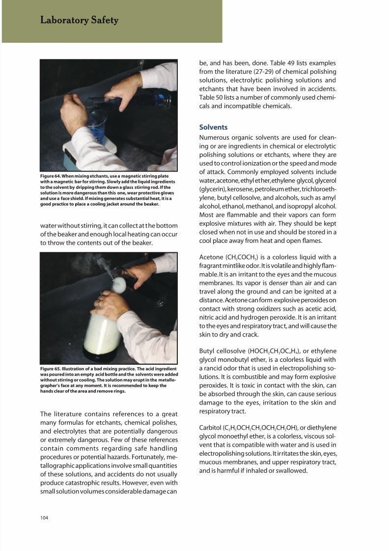
8/20/2019 Buehler Summet, Sample Prep and Analysis
http://slidepdf.com/reader/full/buehler-summet-sample-prep-and-analysis 104/136
104
water without stirring, it can collect at the bottomof the beaker and enough local heating can occurto throw the contents out of the beaker.
The literature contains references to a greatmany formulas for etchants, chemical polishes,and electrolytes that are potentially dangerousor extremely dangerous. Few of these referencescontain comments regarding safe handlingprocedures or potential hazards. Fortunately, me-tallographic applications involve small quantitiesof these solutions, and accidents do not usually
produce catastrophic results. However, even withsmall solution volumes considerable damage can
Laboratory Safety
Figure 64. When mixing etchants, use a magnetic stirring plate
with a magnetic bar for stirring. Slowly add the liquid ingredients
to the solvent by dripping them down a glass stirring rod. If the
solution is more dangerous than this one, wear protective glovesand use a face shield. If mixing generates substantial heat, it is a
good practice to place a cooling jacket around the beaker.
Figure 65. Illustration of a bad mixing practice. The acid ingredient
was poured into an empty acid bottle and the solvents were added
without stirring or cooling. The solution may erupt in the metallo-
grapher’s face at any moment. It is recommended to keep thehands clear of the area and remove rings.
be, and has been, done. Table 49 lists examplesfrom the literature (27-29) of chemical polishingsolutions, electrolytic polishing solutions andetchants that have been involved in accidents.
Table 50 lists a number of commonly used chemi-cals and incompatible chemicals.
Solvents
Numerous organic solvents are used for clean-ing or are ingredients in chemical or electrolyticpolishing solutions or etchants, where they areused to control ionization or the speed and modeof attack. Commonly employed solvents includewater, acetone, ethyl ether, ethylene glycol, glycerol(glycerin), kerosene, petroleum ether, trichloroeth-ylene, butyl cellosolve, and alcohols, such as amylalcohol, ethanol, methanol, and isopropyl alcohol.Most are flammable and their vapors can formexplosive mixtures with air. They should be keptclosed when not in use and should be stored in acool place away from heat and open flames.
Acetone (CH3COCH3) is a colorless liquid with afragrant mintlike odor. It is volatile and highly flam-mable. It is an irritant to the eyes and the mucousmembranes. Its vapor is denser than air and can
travel along the ground and can be ignited at adistance. Acetone can form explosive peroxides oncontact with strong oxidizers such as acetic acid,nitric acid and hydrogen peroxide. It is an irritantto the eyes and respiratory tract, and will cause theskin to dry and crack.
Butyl cellosolve (HOCH2CH2OC4H9), or ethyleneglycol monobutyl ether, is a colorless liquid witha rancid odor that is used in electropolishing so-lutions. It is combustible and may form explosive
peroxides. It is toxic in contact with the skin, canbe absorbed through the skin, can cause seriousdamage to the eyes, irritation to the skin andrespiratory tract.
Carbitol (C2H5OCH2CH2OCH2CH2OH), or diethyleneglycol monoethyl ether, is a colorless, viscous sol-vent that is compatible with water and is used inelectropolishing solutions. It irritates the skin, eyes,mucous membranes, and upper respiratory tract,and is harmful if inhaled or swallowed.

8/20/2019 Buehler Summet, Sample Prep and Analysis
http://slidepdf.com/reader/full/buehler-summet-sample-prep-and-analysis 105/136
105
Laboratory Safety
Table 49. Chemical and Electrolytic Polishing Solutions and Etchants Known to be Dangerous
Solution Use Problems
5 parts Lactic Acid Chemical polishing Lactic and nitric acids react autocatalytically.5 parts HNO3 solution for Zr Explosion can occur if stored.
2 parts Water1 part HF
50 parts Lactic Acid Chemical polishing Lactic and nitric acids react autocatalytically.30 parts HNO3 solution for Ta, Nb Explosion can occur if stored.2 parts HF and alloys
3 parts Perchloric Acid Electropolishing Mixture is unstable and can, and has, exploded, with1 part Acetic Anhydride solution for Al heating, or in the presence of organic compounds
adding to the potential hazard.
60-90 parts Perchloric Acid Electropolishing Solution will explode at room temperature.40-10 parts Butyl Cellosolve solution Solutions with ≤30% HCIO4 will be safe if T is <20°C.
100g CrO3 Electropolishing CrO3 was dissolved in water, cooled to about 20°C;200mL Water solution the acetic anhydride was added very slowing with
700mL Acetic Anhydride stirring. The solution became warm to the touch.About 20 seconds later it erupted from the beaker.
1 part HNO3 Electropolishing Mixture is unstable and cannot be stored2 parts Methanol solution for Muntz
(Cu-40% Zn) metal
20mL HF Etchant for Nb, Ta, This etchant is unstable. At 20°C, it reacted after 1810mL HNO3 Ti, V, Zr hours. At 30-35°C, it reacted after 8 hours with30mL Glycerol violence. At 100°C, it will react after 1 minute.
20-30mL HCI Etchant for Ni and Two incidents occurred when a violent reaction10mL HNO3 stainless steels resulted producing NO2 and a spray of acid30mL Glycerol after the etch was left standing for 2-3 hours.
40mL Acetic Acid Etchant for Ni A closed bottled exploded about 4 hours after
40mL Acetone it was mixed. Authors state that solutions40mL HNO3 without the acetic acid also cannot be stored.
10mL HNO3 Etchant The solution reacted spontaneously about 2 minutes10mL Acetic Acid after mixing with evolution of heat and fumes (nitrous20mL Acetone and nitric oxides). The mixed acids were poured into
the acetone. The beaker was externally cooled.
50mL Nitric Acid Etchant Mixtures have exploded violently after mixing950mL Isopropyl Alcohol or about 20 minutes after mixing.
Table 50. Some Incompatible Chemicals
Chemical Use in Metallography Do Not Mix With the Following:
Acetic Acid Chemical polishing Chromic acid, glycol, hydroxol compounds,electrolytic polishing nitric acid, peroxides, permanganates
Acetone Degreasing, cleaning, Concentrated solutions of nitric andetchants sulfuric acid
Chromic Acid Electropolishing Acetic acid, flammable liquid, glycerol
Hydrogen Peroxide Chemical polishing, etchants Flammable liquid, organic materials
Nitric Acid (conc) Chemical polishing, etchants Acetic acid, chromic acid, flammable liquids,isopropyl alcohol
Perchloric Acid Electropolishing Acetic anhydride, alcohol, some organics,oil, grease
Sulfuric Acid Etchants Methyl alcohol, potassium chlorate,potassium perchlorate and potassium
permanganate
8/20/2019 Buehler Summet, Sample Prep and Analysis
http://slidepdf.com/reader/full/buehler-summet-sample-prep-and-analysis 106/136
106
Laboratory Safety
Ethylene glycol (HOCH2CH2OH) is a colorless, hy-groscopic liquid with a sweet taste (but do notswallow as it is poisonous) that reacts with strongoxidants and strong bases. It is flammable. The
substance irritates the eyes, skin, and the respira-tory tract.
Glycerol (glycerin) (CH2OHCHOHCH2OH) is a color-less or pale yellow, odorless, hygroscopic, syrupyliquid with a sweet, warm taste. It is relativelynontoxic and nonvolatile but can cause iritis (in-flammation of the iris). It is combustible and is amoderate fire hazard. Glycerol should never beused in anhydrous solutions containing nitricand sulfuric acids, because nitroglycerin can form.
Glycerol should not be used with strong oxidizingagents, such as chromium trioxide and potassiumpermanganate, as an explosion may occur. Glycerolis often added to aqua regia (glyceregia). This mix-ture decomposes readily and should be discardedimmediately after use. This etchant should not beallowed to stand for more than about 15 minutesafter mixing.
Kerosene is occasionally employed in grindingsamples and with diamond paste as a lubricant.Only the deodorized form should be used. It isflammable, but the vapors do not readily explode.Contact defattens the skin and can cause derma-titis, irritation or infections.
Trichloroethylene (CHCl:CCl2) is a stable, col-orless liquid with a chloroform-like odor.Effective laboratory ventilation is necessary. Atambient temperatures it is nonflammable andnonexplosive, but becomes hazardous at higher temp-eratures. In the presence of strong alkalies, withwhich it can react, it can form explosive mixtures.
In the presence of moisture, the substance can bedecomposed by light to corrosive hydrochloricacid. It is carcinogenic to humans, and toxic wheninhaled or ingested, which may cause acute poi-soning.
Amyl alcohol (CH3(CH2)4OH), or 1-Pentanol, is acolorless liquid with noxious odor. It is flammableand the vapors may form explosive mixtures atelevated temperatures. The substance reactsviolently with strong oxidants and attacks alka-
line metals. The fumes are irritating to the eyes,upper respiratory tract, and skin. The substance istoxic through ingestion, inhalation, or absorptionthrough the skin.
Ethyl alcohol (CH3CH2OH), or ethanol, is a colorless,inoffensive solvent commonly used in metallog-raphy. Ethanol is miscible with water and rapidlyabsorbs up to 5% water from the air. The denatured
version is less expensive and contains 5% absolutemethanol and is suitable for any recipe requiringethyl alcohol. It is a dangerous fire hazard, andits vapors are irritating to the eyes and upperrespiratory tract. High concentrations of its vaporcan produce intoxication. Because ethanol is com-pletely burned in the body, it is not a cumulativepoison like methanol.
Methyl alcohol (CH3OH) is an excellent, non-hy-groscopic solvent, but it is a cumulative poison.
Ingestion, inhalation or absorption through theskin in toxic levels can damage the central nervoussystem, kidneys, liver, heart, and other organs.Blindness has resulted from severe poisoning. Itis particularly dangerous because repeated low-level exposures can also cause acute poisoning asa result of accumulation. Ethanol should be usedwhenever possible. When using methanol, alwayswork under a ventilation hood. Mixtures of metha-nol and sulfuric acid can form dimethyl sulfate,which is extremely toxic. Solutions of methanoland nitric acid are more stable than mixtures ofnitric acid and higher alcohols.
Isopropyl alcohol [CH3CH(OH)CH3], also knownas 2-propanol, is a clear, colorless liquid that,like ethanol, does not accumulate in the body,although it does have a strong narcotic effect.It is a flammable liquid and is a dangerous firehazard. Metallographers have used it as a substi-tute for ethanol but isopropyl alcohol has quitedifferent characteristics and should not be used.Fatal injuries and explosions have been reported
due to its use.
Acids
Inorganic and organic acids are common con-stituents in chemical and electrolytic polishingsolutions and in etchants. The inorganic, or mineralacids, including the very familiar acids such ashydrochloric, nitric, perchloric, phosphoric, andsulfuric, are highly corrosive and poisonous.Theyshould be stored in a cool, well-ventilated location
away from potential fire hazards and, of course,away from open flames. They should not be storedin a location that receives direct sunlight. When thepure acids contact metals, most liberate hydrogen
8/20/2019 Buehler Summet, Sample Prep and Analysis
http://slidepdf.com/reader/full/buehler-summet-sample-prep-and-analysis 107/136
107
Laboratory Safety
gas – a fire and explosion hazard. The organic acidsare naturally occurring substances in sour milk,fruits, and plants and include the following acids:acetic, lactic, citric, oxalic, and tartaric.
Hydrochloric acid (HCl), commonly used in metal-lography, is a colorless gas or fuming liquid witha sharp, choking odor. It is very dangerous to theeyes and irritating to the nose and throat. It attacksthe skin strongly causing severe burns.
Nitric acid (HNO3), also commonly used in met-allography, is a colorless or yellowish fumingliquid, highly toxic and dangerous to the eyes. Ifit contacts organic material or other easily oxi-
dizable materials, it can cause fires and possiblyexplosions. When it reacts with other materials,toxic oxides of nitrogen are produced. The oxides,which vary with the conditions, include nitrousacid, nitrogen dioxide, nitric oxide, nitrous oxide,and hydroxylamine. A commonly encounteredproblem involves pouring nitric acid into a gradu-ated cylinder that contains some methanol orethanol from prior use. The brown fumes givenoff are quite harmful. Mixtures of nitric acid andalcohols higher than ethanol should not be stored.Mixtures of concentrated nitric and sulfuric acidsare extremely dangerous, while strong mixtures ofnitric acid and glycerin or glycols can be explosive.Aqua regia, a mixture of one part nitric acid andtwo to four parts hydrochloric acid, forms severalproducts including nitrosyl chloride, an exception-ally toxic gas. Aqua regia is a popular etchant butmust be used with care under a hood.
Ethanol with additions of up to 3% nitric acid (nital)can be safely mixed and stored in small quantities.Higher concentrations result in pressure buildup in
tightly stoppered bottles. Explosions of 5% nitricacid in ethanol have occurred as a result of failureto relieve the pressure. If higher concentrationsare desired, they can be mixed daily, placed in anopen dish, and used safely. Discard the etchantat the end of the day. Mixtures of methanol withup to 5% nitric acid are safe to use and store insmall quantities. Mixtures of methanol with morethan 5% nitric acid if heated are subject to vio-lent decomposition. Mixtures of 33% nitric acidin methanol have decomposed suddenly and
violently.
Never add nitric acid to isopropyl alcohol. Ander-son (27) reported that a litre bottle of 5% nitricacid in isopropyl alcohol was mixed and placed in acabinet. Although this had been done many times
in the past without problems, twenty minuteslater the bottle exploded destroying the cabinet,other stored bottles, and throwing debris up to20 feet away. Anderson (27) also reported that ametallographer was pouring a freshly mixed litreof 5% nitric acid in isopropyl alcohol into anotherbottle when it exploded. The person died withinthree hours without being able to tell anyone whathappened. As with the other explosion, this sameprocedure had been performed many times pre-viously without mishap. Anderson recommends
avoiding use of isopropyl alcohol completely.
Most metallographers consider nital to be verysafe to use, and indeed it is. However, even withsuch an apparently safe solution, one can haveaccidents. One such accident occurred whenan employee, not a skilled metallographer, wasreplenishing a stock of 5% nitric acid in ethanolusing a procedure that he had claimed to have per-formed many times previously (he was not taughtthe safe way to mix nital as it was a union chemist’s
job to mix nital i.e., not his job). The worker beganby adding the desired volume of concentratednitric acid into the container that contained a smallresidual amount of stale 5% nital. To his surprise,the contents began “boiling” and spewing out ofthe container along with dense, brown fumes. Theacid splashed the worker, resulting in burns on hisforehead, face and eyes. The small amount of agednitric acid solution (the concentration may havebeen increased due to evaporation of the alcohol),present in the container when the fresh acid wasadded, created a dangerous chemical reaction. An
experiment also showed that a similar reaction canoccur when nitric acid is poured into a graduatedcylinder containing only remnants of ethanol ormethanol.
Sulfuric acid (H2SO4) is a colorless, oily liquid thatis highly corrosive, a strong oxidizing agent, anddangerously reactive. It reacts violently with basesand is corrosive to most metals forming flam-mable/explosive hydrogen gas. It reacts violentlywith water and organic materials with evolution
of heat. Upon heating, toxic sulfur oxides are
8/20/2019 Buehler Summet, Sample Prep and Analysis
http://slidepdf.com/reader/full/buehler-summet-sample-prep-and-analysis 108/136
108
Laboratory Safety
formed. slowly to water with constant stirring. Ifadded without stirring, it will produce a pocket ofsteam in the bottom of the vessel, throwing thecontents out of the vessel. Concentrated sulfuric
acid can cause severe, deep burns on contact withthe skin, and permanent vision loss on contactwith the eyes. Tissue is destroyed by the acid’sdehydrating action. Lungs may be affected bylong-term or chronic exposure to aerosol. Skin le-sions, tooth erosion, and conjunctivitis are otherlong-term effects.
Hydrofluoric acid (HF) is a clear, colorless, fumingliquid or gas with a sharp, penetrating odor. It isvery dangerous to the eyes, skin, and upper respi-
ratory tract. The substance can be absorbed intothe body by inhalation, through the skin and byingestion. A harmful concentration of the gas inair can be reached quickly, making it very danger-ous to handle. Exposure by ingestion, inhalationor contact, can be fatal. Undissociated HF posesa unique threat in that it can destroy soft tissuesand result in decalcification of the bone. Moreover,the effects may be delayed. Laboratories whereHF is used should stock an antidote kit to be usedin case of exposure. Although it is a relativelyweak mineral acid, HF will attack glass or siliconcompounds, and should be measured, mixed,and stored in polyethylene vessels. HF reacts withmany compounds, including metals, and will liber-ate explosive hydrogen gas.
Orthophosphoric acid (H3PO4), a colorless thick liq-uid or hygroscopic crystal, is a medium strong acid.It is corrosive to the skin, eyes and respiratory tract.Phosphoric acid decomposes on contact with al-cohols, aldehydes, cyanides, sulfides, ketones, andcan react with halogenated organic compounds
forming organophosphorus nerve-gas type com-pounds that are extremely toxic. It reacts violentlywith bases, and will generate hydrogen gas whenit reacts with metals.
Perchloric acid (HClO4) is a colorless, fuming,hygroscopic liquid. It is extremely unstable inconcentrated form and may explode by shock orconcussion when dry or drying, so commerciallyavailable perchloric acids come in concentrationsof 65 to 72%. In this form, contact with perchloric
acid will cause irritation and burns, while its fumesare highly irritating to the mucous membranes.Contact with organic, or other easily oxidized
material, can form highly unstable perchlorates,which can ignite and cause explosions. Regularuse of perchloric acid requires that the ventila-tion system must be specifically designed and
maintained for perchloric acid. Special fume hoodswith a waterfall-type fume washer will removethe perchlorate fumes before they can enter theexhaust system.
Perchloric acid is very useful in electropolishingsolutions. Never electropolish samples mountedin phenolic (Bakelite) or other plastics in perchloricacid solutions as explosions can result. The mixtureof perchloric acid and acetic anhydride, whichwas developed by Jacquet, is difficult to prepare
and highly explosive. Jacquet has reviewed theaccidents involving perchloric acid and has de-scribed safety procedures (30). The worst accidentoccurred on February 20, 1947, in an electroplatingfactory in Los Angeles. In this accident 17 peoplewere killed and 150 were injured (29). Medard,Jacquet, and Sartorius have prepared a ternarydiagram showing safe com- positions of perchlo-ric acid, acetic anhydride, and water, Figure 66.Anderson, however, states that accidents have stilloccurred with solutions in the “safe” region of thisdiagram (27). Electropolishing solutions composedof perchloric acid and acetic anhydride are notrecommended. Many companies forbid the use ofsuch mixtures, and some cities have banned theiruse. Electropolishing solutions of perchloric acidand alcohol, with or without organic additions, andmixtures of perchloric acid and glacial acetic acidare safe to use. Nevertheless, in using these “safe”mixtures, one should follow the formula instruc-tions carefully, mix only small quantities, keep thetemperature under control, and avoid evaporation.These solutions should not be stored.
Mixtures of acetic acid and 5-10% perchloricacid have been commonly used to electropolishiron-based alloys and are reasonably safe. Donot use these solutions to electropolish bis-muth, arsenic or tin, as explosions have occurred.Anderson suggests that arsenic, antimony, andtin may also be incompatible with perchloricelectrolytes (27). Do not store these electrolytes. Discard them when they become colored bydissolved metallic ions (from electropolishing).
Always keep these solutions cool; increasing thetemperature increases the oxidizing power ofperchloric acid.
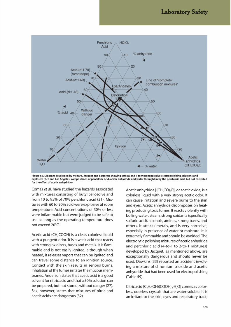
8/20/2019 Buehler Summet, Sample Prep and Analysis
http://slidepdf.com/reader/full/buehler-summet-sample-prep-and-analysis 109/136
109
Laboratory Safety
Comas et al . have studied the hazards associatedwith mixtures consisting of butyl cellosolve andfrom 10 to 95% of 70% perchloric acid (31). Mix-tures with 60 to 90% acid were explosive at roomtemperature. Acid concentrations of 30% or lesswere inflammable but were judged to be safe touse as long as the operating temperature doesnot exceed 20°C.
Acetic acid (CH3COOH) is a clear, colorless liquidwith a pungent odor. It is a weak acid that reactswith strong oxidizers, bases and metals. It is flam-mable and is not easily ignited, although whenheated, it releases vapors that can be ignited andcan travel some distance to an ignition source.Contact with the skin results in serious burns.Inhalation of the fumes irritates the mucous mem-branes. Anderson states that acetic acid is a goodsolvent for nitric acid and that a 50% solution can
be prepared, but not stored, without danger (27).Sax, however, states that mixtures of nitric andacetic acids are dangerous (32).
Acetic anhydride [(CH3CO)2O], or acetic oxide, is acolorless liquid with a very strong acetic odor. Itcan cause irritation and severe burns to the skinand eyes. Acetic anhydride decomposes on heat-ing producing toxic fumes. It reacts violently withboiling water, steam, strong oxidants (specificallysulfuric acid), alcohols, amines, strong bases, andothers. It attacks metals, and is very corrosive,
especially in presence of water or moisture. It isextremely flammable and should be avoided. Theelectrolytic polishing mixtures of acetic anhydrideand perchloric acid (4-to-1 to 2-to-1 mixtures)developed by Jacquet, as mentioned above, areexceptionally dangerous and should never beused. Dawkins (33) reported an accident involv-ing a mixture of chromium trioxide and aceticanhydride that had been used for electropolishing(Table 49).
Citric acid [C3H4(OH)(COOH)3·H2O] comes as color-less, odorless crystals that are water-soluble. It isan irritant to the skin, eyes and respiratory tract;
Figure 66. Diagram developed by Médard, Jacquet and Sartorius showing safe (A and 1 to 9) nonexplosive electropolishing solutions and
explosive (C, E and Los Angeles) compositions of perchloric acid, acetic anhydride and water (brought in by the perchloric acid, but not corrected
for the effect of acetic anhydride).
8/20/2019 Buehler Summet, Sample Prep and Analysis
http://slidepdf.com/reader/full/buehler-summet-sample-prep-and-analysis 110/136
110
no unusual problems are encountered except foroccasional allergic reactions.
Lactic acid (CH3CHOHCOOH) is a yellow or colorless
thick liquid. It is damaging to the eyes.
Oxalic acid (COOHCOOH·2H2O) comes astransparent, colorless crystals. It is poisonous if in-gested and irritating to the upper respiratorytract and digestive system if inhaled. Skin contactproduces caustic action and will discolor andembrittle the fingernails. It is not compatiblewith nitric acid, as it reacts violently with strongoxidants. It can also form explosive compoundsdue to reacts with silver.
Picric acid [(NO2)3C6H2OH], or 2,4,6-trinitrophenol,comes as yellow crystals that are wet with 10 to35% water. When picric acid is dry, it is a danger-ous explosive. It is toxic and stains the skin andis incompatible with all oxidizable substances.Picrates, which are metal salts of picric acid, areexplosive. When picrates are dry, they can detonatereadily, possibly spontaneously. Purchase in smallquantities, keep it moist, and store it in a safe, coolplace. If it starts to dry out, add a small amount ofwater to keep it moist. The maximum solubilitiesof picric acid in water and in ethanol are about1.3 and 8 g per 100 mL, respectively. Picral can bestored safely. During use, the solution should notbe allowed to dry out. The etching residue shouldbe discarded at the end of the day to avoid poten-tial explosions.
Bases
Bases, such as ammonium hydroxide (NH4OH),potassium hydroxide (KOH), and sodium
hydroxide (NaOH), are commonly used in metallo-graphy, chiefly in etchants.
Ammonium hydroxide is a colorless liquid with astrong, obnoxious odor. Solutions are extremelycorrosive and irritating to the skin, eyes, andmucous membranes. It reacts exothermicallywith sulfuric acid and other strong mineral acids,producing boiling solutions.
Sodium and potassium hydroxides are strong bas-es, available as white deliquescent pellets that aresoluble in water. They can rapidly absorb carbondioxide and water from the air. Solutions stored in
flasks with ground glass stoppers may leak air andfreeze the stoppers, making re-opening difficult.Dissolving NaOH or KOH in water will generateconsiderable heat. Do not dissolve either in hot
water. Never pour water onto these hydroxides;always add the pellets slowly to the water. Alkalimetal hydroxides react violently with acid, and arecorrosive in moist air to metals like zinc, aluminum,tin and lead forming flammable/explosive hydro-gen gas. They are very corrosive to skin, eyes andrespiratory tract. Long-term exposure may leadto dermatitis. Potassium hydroxide is somewhatmore corrosive than sodium hydroxide.
Other Chemicals
Hydrogen peroxide (H2O2) is available as a liquid inconcentrations of either 3 or 30%. The 3% solutionis reasonably safe to use, while the 30% solution isa very powerful oxidant whose effect on the skinis about as harmful as that produced by contactwith sulfuric acid. Hydrogen peroxide by itself isnot combustible, but if brought in contact withcombustible materials, it can produce violentcombustion. Hydrogen peroxide is very damagingto the eyes. Because release of oxygen can causehigh pressures to develop within the container,
the container caps are vented.
Bromine (Br2), a fuming reddish brown liquid witha pungent, suffocating odor, is commonly usedin deep-etching solutions. It is very corrosive,reacting violently with easily oxidized substances,including some metals. Bromine is a dangerous liq-uid that should only be handled by well-qualifiedpersonnel. Its vapors are extremely irritating to theeyes, skin, and mucous membranes. Skin contactproduces deep, penetrating burns that are slow to
heal. Contact with organic matter can cause fires.
Chromic acid (H2CrO4) is formed when chromiumtrioxide (CrO3) is dissolved in water. CrO3 is used inelectropolishing solutions (see previous commentand Table 49 about explosive nature of mixtureswith acetic anhydride). Dilute aqueous solutionsare widely used for attack polishing. It is a powerfuloxidant; always wear gloves when using it for at-tack polishing or use automatic devices and avoidcontact potential. Chronic or long-term inhalation
exposure may produce asthma-like reactions.
Laboratory Safety
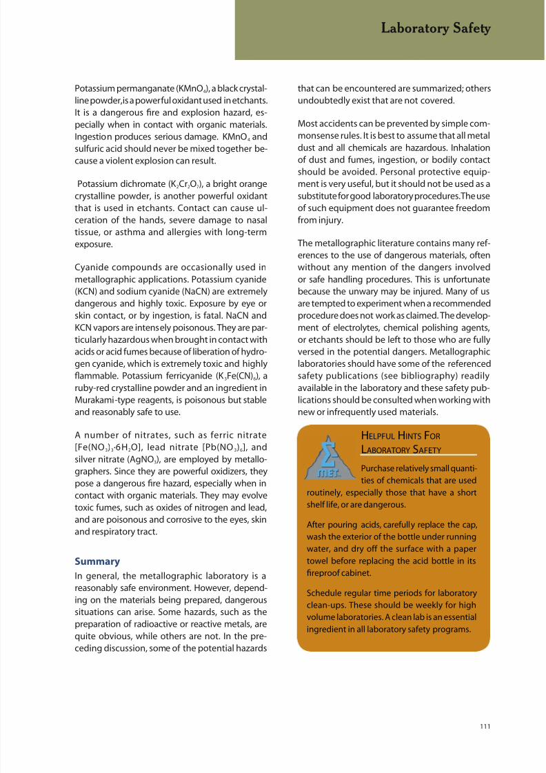
8/20/2019 Buehler Summet, Sample Prep and Analysis
http://slidepdf.com/reader/full/buehler-summet-sample-prep-and-analysis 111/136
111
Potassium permanganate (KMnO4), a black crystal-line powder, is a powerful oxidant used in etchants.It is a dangerous fire and explosion hazard, es-pecially when in contact with organic materials.
Ingestion produces serious damage. KMnO4 andsulfuric acid should never be mixed together be-cause a violent explosion can result.
Potassium dichromate (K 2Cr2O7), a bright orangecrystalline powder, is another powerful oxidantthat is used in etchants. Contact can cause ul-ceration of the hands, severe damage to nasaltissue, or asthma and allergies with long-termexposure.
Cyanide compounds are occasionally used inmetallographic applications. Potassium cyanide(KCN) and sodium cyanide (NaCN) are extremelydangerous and highly toxic. Exposure by eye orskin contact, or by ingestion, is fatal. NaCN andKCN vapors are intensely poisonous. They are par-ticularly hazardous when brought in contact withacids or acid fumes because of liberation of hydro-gen cyanide, which is extremely toxic and highlyflammable. Potassium ferricyanide (K 3Fe(CN)6), aruby-red crystalline powder and an ingredient inMurakami-type reagents, is poisonous but stableand reasonably safe to use.
A number of nitrates, such as ferric nitrate[Fe(NO3)3·6H2O], lead nitrate [Pb(NO3)6], andsilver nitrate (AgNO3), are employed by metallo-graphers. Since they are powerful oxidizers, theypose a dangerous fire hazard, especially when incontact with organic materials. They may evolvetoxic fumes, such as oxides of nitrogen and lead,and are poisonous and corrosive to the eyes, skinand respiratory tract.
Summary
In general, the metallographic laboratory is areasonably safe environment. However, depend-ing on the materials being prepared, dangeroussituations can arise. Some hazards, such as thepreparation of radioactive or reactive metals, arequite obvious, while others are not. In the pre-ceding discussion, some of the potential hazards
Laboratory Safety
that can be encountered are summarized; othersundoubtedly exist that are not covered.
Most accidents can be prevented by simple com-
monsense rules. It is best to assume that all metaldust and all chemicals are hazardous. Inhalationof dust and fumes, ingestion, or bodily contactshould be avoided. Personal protective equip-ment is very useful, but it should not be used as asubstitute for good laboratory procedures. The useof such equipment does not guarantee freedomfrom injury.
The metallographic literature contains many ref-erences to the use of dangerous materials, often
without any mention of the dangers involvedor safe handling procedures. This is unfortunatebecause the unwary may be injured. Many of usare tempted to experiment when a recommendedprocedure does not work as claimed. The develop-ment of electrolytes, chemical polishing agents,or etchants should be left to those who are fullyversed in the potential dangers. Metallographiclaboratories should have some of the referencedsafety publications (see bibliography) readilyavailable in the laboratory and these safety pub-lications should be consulted when working withnew or infrequently used materials.
HELPFUL HINTS FOR
LABORATORY SAFETY
Purchase relatively small quanti-
ties of chemicals that are used
routinely, especially those that have a short
shelf life, or are dangerous.
After pouring acids, carefully replace the cap,
wash the exterior of the bottle under running
water, and dry off the surface with a paper
towel before replacing the acid bottle in its
fireproof cabinet.
Schedule regular time periods for laboratory
clean-ups. These should be weekly for high
volume laboratories. A clean lab is an essential
ingredient in all laboratory safety programs.

8/20/2019 Buehler Summet, Sample Prep and Analysis
http://slidepdf.com/reader/full/buehler-summet-sample-prep-and-analysis 112/136
112
SUMMARY
Preparation of metallographic specimens is basedupon scientific principles that are easily under-
stood. Sectioning creates damage that must beremoved by the grinding and polishing steps ifthe true structure is to be examined. Each section-ing process exhibits a certain amount of damage,thermal and/or mechanical. Consequently, choosea procedure that produces the least possible dam-age and use the correct wheel or blade. Grindingalso causes damage, with the depth of damagedecreasing as the abrasive size decreases. Materi-als respond differently to the same size abrasive,so one cannot generalize on removal depths.
Removal rates also decrease as the abrasive sizedecreases. Through an understanding of these fac-tors, good, reproducible preparation procedures,such as presented in this guide, can be established
for the materials being prepared. Automation inspecimen preparation offers much more thanreduced labor. Specimens properly prepared us-ing automated devices consistently exhibit muchbetter flatness, edge retention, relief control andfreedom from artifacts such as scratches, pullout, smearing and comet tailing, than specimensprepared manually.
Summary
8/20/2019 Buehler Summet, Sample Prep and Analysis
http://slidepdf.com/reader/full/buehler-summet-sample-prep-and-analysis 113/136
113
REFERENCES
1. Metallography and Microstructures,Vol. 9, Metals Handbook, 9th ed., American Society
for Metals, Metals Park, OH, 1985.2. G. F. Vander Voort, Metallography:Principles and Practice, ASM International, MaterialsPark, OH, 1999.
3. L. E. Samuels, Metallographic Polishingby Mechanical Methods, 3rd Ed., AmericanSociety for Metals, Metals Park, OH, 1982.
4. J. A. Nelson, “Heating of MetallographicSpecimens Mounted in ‘Cold Setting’ Resins”,Practical Metallography, Vol. 7, 1970,pp. 188-191.
5. G. F. Vander Voort, “Trends in SpecimenPreparation,” Advanced Materials &Processes, Vol. 157, February 2000,pp. 45-49.
6. G. F. Vander Voort, “Metallography forEdge Retention in Surface Treated SinteredCarbides and Steels,” Industrial Heating,Vol. 67, March 2000, pp. 85-90.
7. S. L. Hoyt, Men of Metals, ASM, Metals Park, OH,1979, pp. 99-100.
8. J. Benedict, R. Anderson and S. J. Klepeis, “RecentDevelopments in the Use of the Tripod Polisher forTEM Specimen Preparation,” Specimen Preparationfor Transmission Electron Microscopy of Materials –III, Materials Research Society, Pittsburgh, PA, 1992,Vol. 254, pp. 121-140.
9. G. Petzow and V. Carle, Metallographic Etching, 2nd ed., ASM International, Materials Park, OH, 1999.
10. G. F. Vander Voort, “Grain Size Measurement,”Practical Applications of QuantitativeMetallography, STP 839, American Society for
Testing and Materials, Philadelphia, 1984,pp. 85-131.
11. G. F. Vander Voort, “Wetting Agents inMetallography,” Materials Characterization, Vol. 35,No. 2, September 1995, pp. 135-137.
12. A. Skidmore and L. Dillinger, “EtchingTechniques for Quantimet Evaluation,”Microstructures, Vol. 2, Aug./Sept. 1971,pp. 23-24.
13. G. F. Vander Voort, “Etching Techniquesfor Image Analysis,” Microstructural Science, Vol. 9,
Elsevier North-Holland, NY, 1981,pp. 135-154.
14. G. F. Vander Voort, “Phase Identificationby Selective Etching,” Applied Metallography, VanNostrand Reinhold Co., NY, 1986,pp. 1-19.
15. E. E. Stansbury, “Potentiostatic Etching,” AppliedMetallography, Van Nostrand Reinhold Co., NY,1986, pp. 21-39.
16. E. Beraha and B. Shpigler, ColorMetallography, American Society for Metals, MetalsPark, OH, 1977.
17. G. F. Vander Voort, “Tint Etching,”Metal Progress, Vol. 127, March 1985,pp. 31-33, 36-38, 41.
18. E. Weck and E. Leistner, MetallographicInstructions for Colour Etching by Immersion, Part I:Klemm Colour Etching, Vol. 77, Deutscher Verlag fürSchweisstechnik GmbH, Düsseldorf, 1982.
19. E. Weck and E. Leistner, MetallographicInstructions for Colour Etching by Immersion, PartII: Beraha Colour Etchants and Their Different Vari-ants, Vol. 77/II, Deutscher Verlag fürSchweisstechnik GmbH, Düsseldorf, 1983.
20. E. Weck and E. Leistner, MetallographicInstructions for Colour Etching by Immersion, PartIII: Nonferrous Metals, Cemented Carbides andFerrous Metals, Nickel Base and Cobalt Base Alloys,Vol. 77/III, Deutscher Verlag für SchweisstechnikGmbH, Düsseldorf, 1986.
21. P. Skocovsky, Colour Contrast inMetallographic Microscopy, Slovmetal,Ž ilina, 1993.
22. H. E. Bühler and H. P. Hougardy, Atlas ofInterference Layer Metallography, DeutscheGesellschaft für Metallkunde, Oberursel, Germany,1980.
23. H. E. Bühler and I. Aydin, “Applications of the
Interference Layer Method,” AppliedMetallography, Van Nostrand Reinhold Co., NY,1986, pp. 41-51.
24. G. F. Vander Voort, “Results of an ASTME-4 Round-Robin on the Precision and Bias ofMeasurements of Microindentation HardnessImpressions,” Factors that Affect thePrecision of Mechanical Tests, ASTM STP 1025,ASTM, Philadelphia, 1989, pp. 3-39.
References
8/20/2019 Buehler Summet, Sample Prep and Analysis
http://slidepdf.com/reader/full/buehler-summet-sample-prep-and-analysis 114/136
114
References
25. G. F. Vander Voort, “Operator Errors in theMeasurement of Microindentation Hardness,”Accreditation Practices for Inspections, Tests, andLaboratories, ASTM STP 1057, ASTM, Philadelphia,
1989, pp. 47-77.26. G. F. Vander Voort and Gabriel M. Lucas, “Microindentation Hardness Testing,” AdvancedMaterials & Processes, Vol. 154, No. 3, September1998, pp. 21-25.
27. R. L. Anderson, “Safety in MetallographicLaboratory,” Westinghouse Research LaboratoryScience Paper, No. 65 – 1P30 – METLL – P2, March29, 1965.
28. G. F. Vander Voort, Metallography: Principlesand Practice, ASM International, Materials Park, OH.,
1999, pp. 148-159.
29. R. C. Nester and G. F. Vander Voort, “Safety in theMetallographic Laboratory,” Standardization News,Vol. 20, May 1992,pp. 34-39.
30. P. A. Jacquet, “The Safe Use of Perchloric-AceticElectropolishing Baths,” Met. Finish, Vol. 47, 1949,pp. 62-69.
31. S. M. Comas, R. Gonzalez Palacin and D. Vassallo,“Hazards Associated with PerchloricAcid-Butylcellosolve Polishing Solutions,”Metallography, Vol. 7, 1974, pp. 47-57.
32. N. I. Sax, Dangerous Properties of IndustrialMaterials, 5th ed., Van Nostrand Reinhold Co., Inc.,N.Y., 1979.
33. A.E. Dawkins, “Chromic Acid-Acetic Anhydride‘Explosion,’” J. Iron and Steel Institute, Vol. 182, 1956,p. 388.
Selected Bibliography of Books onLaboratory Safety
ASTM E-2014, “ Standard Guide on MetallographicLaboratory Safety”.
N. Van Houten, Laboratory Safety Standards forIndustry, Research, Academe, Sci. Tech. Pubs., LakeIsabella, CA. 1990.
E. Gershey, A. Wilkerson and E. Party,Laboratory Safety in Practice, Van NostrandReinhold, N.Y., 1991.
A. A. Fuscaldo et al. (eds), Laboratory Safety: Theory& Practice, Academic Press, San Diego, CA. 1980.
S. B. Pal (ed.), Handbook of Laboratory Health &Safety Measures, Kluwer Academic, Norwell, MA.,1985.
Norman V. Steere (ed.), Handbook of LaboratorySafety, 2nd ed., CRC Press, Boca Raton, FL., 1971.
A. Keith Furr (ed.), Handbook of Laboratory Safety,3rd ed., CRC Press, Boca Raton, FL., 1989.
L. J. Diberardinis et al., Guidelines for LaboratoryDesign: Health & Safety Considerations, J. Wiley &Sons, N.Y., 1987.
S. R. Rayburn, The Foundations of Laboratory Safety,Brock-Springer Series in Contemporary Bioscience,Springer-Verlag, N.Y., 1989.
C. A. Kelsey and A. F. Gardner (eds.), Radiation Safetyfor Laboratory Technicians, Warren H. Green, Inc.,St. Louis, MO., 1983.
N. I. Sax, Dangerous Properties of Industrial
Materials, 5th ed., Van Nostrand Reinhold Co., N.Y.,1979.
Prudent Practices for Handling HazardousChemicals in Laboratories, National Academy Press,Washington, D.C., 1981.
Prudent Practices for Disposal of Chemicals fromLaboratories, National Academy Press, Washington,D.C., 1983.
N. Proctor and J. Hughes, Chemical Hazards in theWorkplace, J. B. Lippincott Co., Philadelphia, 1978.
F. A. Patty (ed.), Industrial Hygiene and Toxicology,Volume II – Toxicology, 3rd ed., Wiley-Interscience,N.Y., 1980.
L. Bretherick, Handbook of Reactive ChemicalHazards, 2nd ed., Butterworths, London, 1979.
R. J. Lewis, Sr. (ed.), Hawley’s Condensed ChemicalDictionary, 12th ed., Van Nostrand Reinhold, NewYork, 1993.
Useful Web sites on laboratory safety:
http://ull.chemistry.uakron.edu
http://www.hhmi.org/research/labsafe/lcss/lcss.html
http://www.cdc.gov/niosh/ipcsneng/nengsyn.html
http://www.state.nj.us/health/eoh/rtkweb/ rtkhsfs.htm
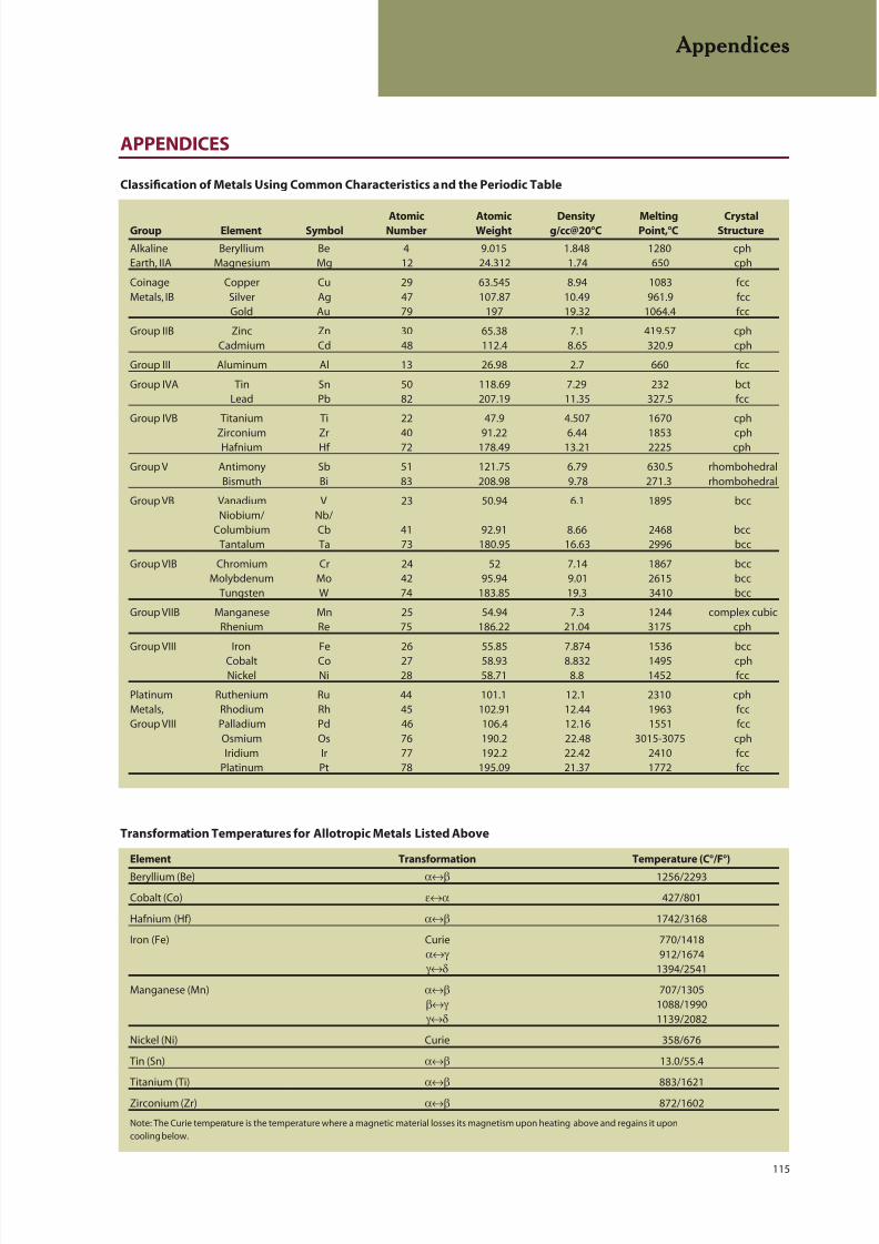
8/20/2019 Buehler Summet, Sample Prep and Analysis
http://slidepdf.com/reader/full/buehler-summet-sample-prep-and-analysis 115/136
115
APPENDICES
Appendices
Atomic Atomic Density Melting CrystalGroup Element Symbol Number Weight g/cc@20°C Point,°C Structure
Alkaline Beryllium Be 4 9.015 1.848 1280 cphEarth, IIA Magnesium Mg 12 24.312 1.74 650 cph
Coinage Copper Cu 29 63.545 8.94 1083 fccMetals, IB Silver Ag 47 107.87 10.49 961.9 fcc
Gold Au 79 197 19.32 1064.4 fcc
Group IIB Zinc Zn 30 65.38 7.1 419.57 cphCadmium Cd 48 112.4 8.65 320.9 cph
Group III Aluminum Al 13 26.98 2.7 660 fcc
Group IVA Tin Sn 50 118.69 7.29 232 bctLead Pb 82 207.19 11.35 327.5 fcc
Group IVB Titanium Ti 22 47.9 4.507 1670 cph
Zirconium Zr 40 91.22 6.44 1853 cphHafnium Hf 72 178.49 13.21 2225 cph
Group V Antimony Sb 51 121.75 6.79 630.5 rhombohedralBismuth Bi 83 208.98 9.78 271.3 rhombohedral
Group VB Vanadium V 23 50.94 6.1 1895 bccNiobium/ Nb/
Columbium Cb 41 92.91 8.66 2468 bccTantalum Ta 73 180.95 16.63 2996 bcc
Group VIB Chromium Cr 24 52 7.14 1867 bccMolybdenum Mo 42 95.94 9.01 2615 bcc
Tungsten W 74 183.85 19.3 3410 bcc
Group VIIB Manganese Mn 25 54.94 7.3 1244 complex cubicRhenium Re 75 186.22 21.04 3175 cph
Group VIII Iron Fe 26 55.85 7.874 1536 bccCobalt Co 27 58.93 8.832 1495 cphNickel Ni 28 58.71 8.8 1452 fcc
Platinum Ruthenium Ru 44 101.1 12.1 2310 cphMetals, Rhodium Rh 45 102.91 12.44 1963 fccGroup VIII Palladium Pd 46 106.4 12.16 1551 fcc
Osmium Os 76 190.2 22.48 3015-3075 cphIridium Ir 77 192.2 22.42 2410 fcc
Platinum Pt 78 195.09 21.37 1772 fcc
Classification of Metals Using Common Characteristics and the Periodic Table
Transformation Temperatures for Allotropic Metals Listed Above
Element Transformation Temperature (C°/F°)
Beryllium (Be) α↔β 1256/2293
Cobalt (Co) ε↔α 427/801
Hafnium (Hf) α↔β 1742/3168
Iron (Fe) Curie 770/1418α↔γ 912/1674 γ↔δ 1394/2541
Manganese (Mn) α↔β 707/1305β↔γ 1088/1990 γ↔δ 1139/2082
Nickel (Ni) Curie 358/676
Tin (Sn) α↔β 13.0/55.4
Titanium (Ti) α↔β 883/1621
Zirconium (Zr) α↔β 872/1602
Note: The Curie temperature is the temperature where a magnetic material losses its magnetism upon heating above and regains it upon
cooling below.
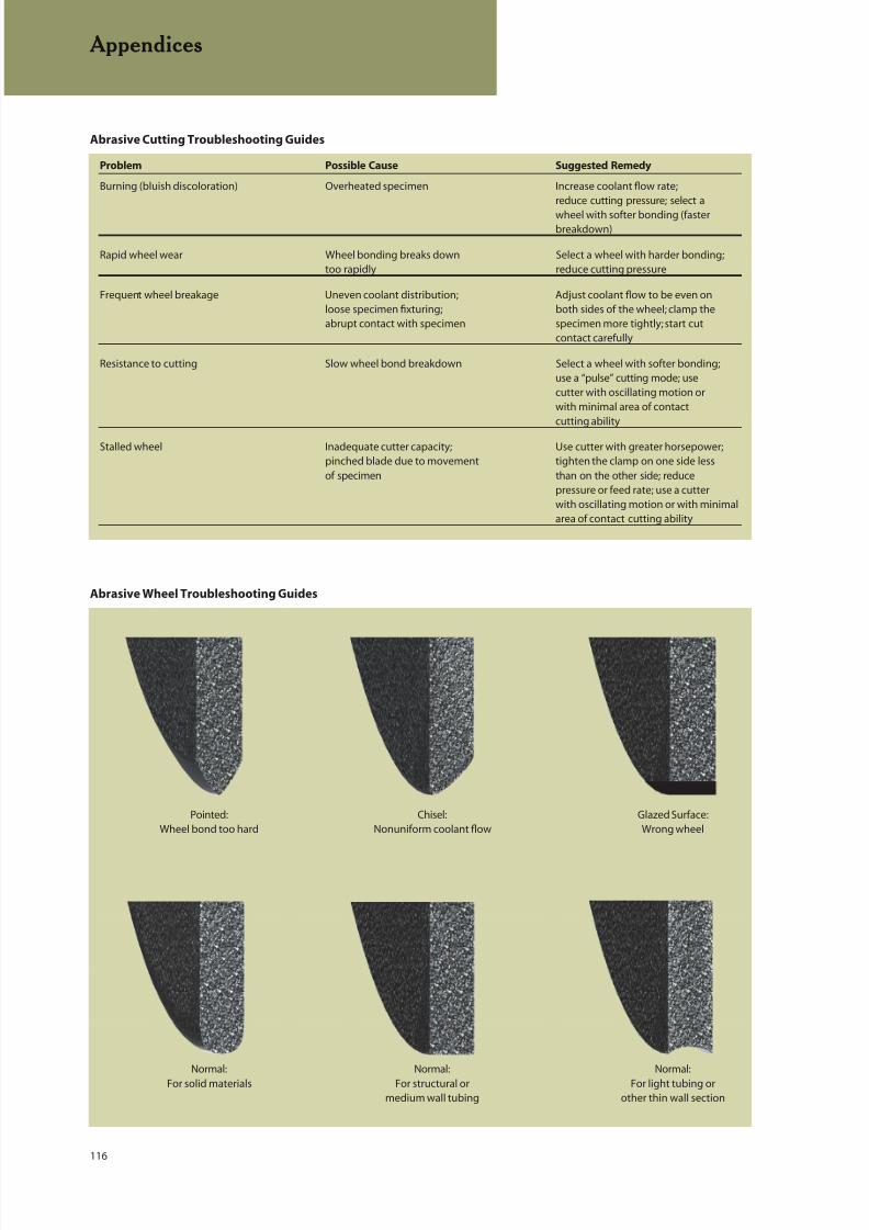
8/20/2019 Buehler Summet, Sample Prep and Analysis
http://slidepdf.com/reader/full/buehler-summet-sample-prep-and-analysis 116/136
116
Appendices
Abrasive Cutting Troubleshooting Guides
Problem Possible Cause Suggested Remedy
Burning (bluish discoloration) Overheated specimen Increase coolant flow rate;reduce cutting pressure; select a
wheel with softer bonding (fasterbreakdown)
Rapid wheel wear Wheel bonding breaks down Select a wheel with harder bonding;too rapidly reduce cutting pressure
Frequent wheel breakage Uneven coolant distribution; Adjust coolant flow to be even onloose specimen fixturing; both sides of the wheel; clamp theabrupt contact with specimen specimen more tightly; start cut
contact carefully
Resistance to cutting Slow wheel bond breakdown Select a wheel with softer bonding;use a “pulse” cutting mode; usecutter with oscillating motion orwith minimal area of contactcutting ability
Stalled wheel Inadequate cutter capacity; Use cutter with greater horsepower;pinched blade due to movement tighten the clamp on one side lessof specimen than on the other side; reduce
pressure or feed rate; use a cutterwith oscillating motion or with minimalarea of contact cutting ability
Pointed:Wheel bond too hard
Chisel:Nonuniform coolant flow
Glazed Surface:Wrong wheel
Normal:For structural or
medium wall tubing
Normal:For solid materials
Normal:For light tubing or
other thin wall section
Abrasive Wheel Troubleshooting Guides

8/20/2019 Buehler Summet, Sample Prep and Analysis
http://slidepdf.com/reader/full/buehler-summet-sample-prep-and-analysis 117/136
117
Appendices
Compression (Hot) Mounting Troubleshooting Guide
Thermosetting Resins (Epoxies, Diallyl Phthalates, and Phenolics)
Defect Probable Cause Suggested Remedy
Radial splits Specimen cross sectional area Use a larger mold size; decreaseor cracks too large; specimen with the specimen size; bevel sharp
sharp corners corners, if possible
Shrinkage gaps Specimen surfaces dirty; specimen Clean and dry specimens carefully;cooled quickly after polymerization; after polymerization, cool underwrong resin used pressure to near ambient; use
Epomet G or Epomet F resins
Circumferential cracks Resin contained moisture Keep resins dry during storage;keep containers closed when notusing; dry resin by baking at38-49°C (100-120°F)
Bulging or soft mount Inadequate curing Increase polymerization time(polymerization) time and pressure
Mount appears Time at temperature too short; Increase polymerization time,grainy and unfused temperature for polymerization temperature and pressure
too low; molding pressure too low
Thermoplastic Resins (Acrylics)
Defect Probable Cause Suggested Remedy
Cottonball Incomplete polymerization of resin; Use less resin; use longernot enough time at temperaure heating and cooling periods;
use controlled linear cooling
Crazing Relief of internal stresses Cool mount to a lower temperatureupon ejection of mount before ejection; use controlled
linear cooling
Comparison of Six Edge Retention Compression Mounting Compounds
Micrographs showing the as-forged surface of a hardened modified 5130 alloy steel part mounted using a variety of resins showing different
degrees of edge retention. The specimens were polished simultaneously in the same holder and were etched with 2% nital. The magnification
bars are 20 µm long. Best results were obtained with EpoMet, ProbeMet and EpoxiCure resin with the Conductive Filler particles.
PhenoCure phenolic resin EpoMet thermosetting epoxy resin ProbeMet Cu-filled conductive resin
KonductoMet C-filled conductive resin EpoxiCure cast epoxy resin with Conductive
Filler particles
SamplKwick cast acrylic resin with
Conductive Filler particles

8/20/2019 Buehler Summet, Sample Prep and Analysis
http://slidepdf.com/reader/full/buehler-summet-sample-prep-and-analysis 118/136
118
Appendices
Name Typical Cure Time Uses and Restrictions
SamplKwick 5-8 minutes Least expensive resin; used for mounting printed circuit boardsAcrylic Resin and polymers; good for x-ray diffraction work (no peak interferences);
high shrinkage (not recommended for edge retention)
VariKleer 10-15 minutes Designed for use with a pressure vessel, this general use acrylichardens crystal clear with minimal shrinkage. To achieve crystal clearsamples, reusable silicon or EPDM molds should bot be used.
VariDur 3000 15-30 minutes Minimal shrinkage, good edge retention
VariDur 10 minutes Inexpensive; (good edge rentention for acrylic); used with many metalsAcrylic Resin when the edge detail is not important
EpoKwick 90 minutes Fast curing epoxy; more shrinkage than other epoxies; viscosity 250-Epoxy Resin 400 cps at 25 °C; not recommended for vacuum infiltration of voids due
to fast curing time; physically adheres to specimen; gives acceptableedge retention; good for most specimens
EpoColor 90 minutes Provides color contrast between mount and specimen that can beEpoxy Resin helpful when studying edges; viscosity 400-700 cps at 25 °C; good
for most specimens; but not recommended for vacuum impregnation
EpoxiCure 6 hours General purpose epoxy; viscosity 400-600 cps at 25 °C, goodEpoxy Resin adherence to specimen; can be used to vacuum impregnate
voids (viscosity can be reduced by warming to 50 °C); good for heat-sensitive specimens (very low exotherm during polymerization)
EpoxiCure NC 5 hours General purpose epoxy - No hazard shipping fees.
EpoHeat 90 minutes Fast, heat cure epoxy system with low shrinkage and low viscosityLow Viscosity Epoxy (32 cps at 176 °F (80 °C)). Excellent for impregnation. Requires oven
cure. Golden color.
EpoThin 9 hours Lowest viscosity (can be further reduced by warming resin to 50 °C)
Epoxy Resin and best penetration of voids during vacuum impregnation; goodadherence to specimen; good for heat-sensitive specimens(lowest exotherm during polymerization)
Curing time is not a precise quantity as it can be influenced by the nature of the mold (how well, or how poorly, the exothermic heat of polymerization is extract-
ed), by the volume of the cast resin used, by the volume and nature of the specimen being encapsulated, by the temperature of the mix, by room temperature
and air circulation and by the age of the resin and hardener (i.e., curing time is longer for products beyond their normal shelf life). The values listed are typical formetallic specimens cast in 1.25-inch (30-mm) diameter Sampl-Kup molds at 21 °C (70 °F) using fresh resin and hardener.
Castable Mounting Resin Selection Guide
Greek Letter Name English Equivalent
Α, α Alpha A, a
Β, β Beta B, b
Γ, γ Gamma G, g
∆, δ Delta D, d
Ε, ε Epsilon E, e
Ζ, ζ Zeta Z, z
Η,η Eta E, e
Θ, θ Theta Th
Ι, ι Iota I, i
Κ, κ Kappa K, k
Λ, λ Lambda L, l
Μ, µ Mu M, m
Greek Alphabet and its English Equivalents
Greek Letter Name English Equivalent
Ν, ν Nu N, n
Ξ, ξ Xi X, x
Ο, ο Omicron O, o
Π, π Pi P, p
Ρ, ρ Rho R, r
Σ, σ Sigma S, s
Τ, τ Tau T, t
Υ, υ Upsilon U, u
Φ, ϕ Phi Ph
Χ, χ Chi Ch
Ψ, ψ Psi Ps
Ω, ω Omega O, o
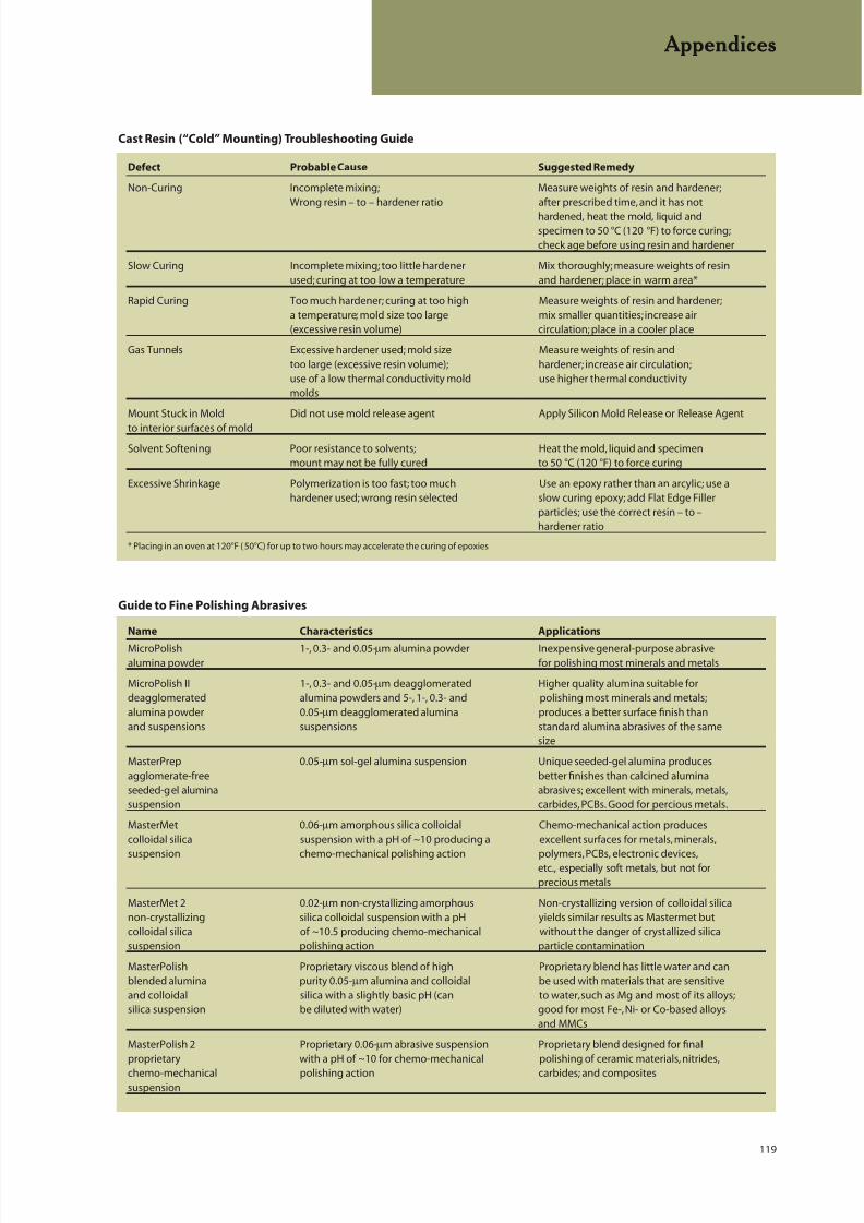
8/20/2019 Buehler Summet, Sample Prep and Analysis
http://slidepdf.com/reader/full/buehler-summet-sample-prep-and-analysis 119/136
119
Appendices
Cast Resin (“Cold” Mounting) Troubleshooting Guide
Defect Probable Cause Suggested Remedy
Non-Curing Incomplete mixing; Measure weights of resin and hardener;Wrong resin – to – hardener ratio after prescribed time, and it has not
hardened, heat the mold, liquid andspecimen to 50 °C (120 °F) to force curing;check age before using resin and hardener
Slow Curing Incomplete mixing; too little hardener Mix thoroughly; measure weights of resinused; curing at too low a temperature and hardener; place in warm area*
Rapid Curing Too much hardener; curing at too high Measure weights of resin and hardener;a temperature; mold size too large mix smaller quantities; increase air(excessive resin volume) circulation; place in a cooler place
Gas Tunnels Excessive hardener used; mold size Measure weights of resin andtoo large (excessive resin volume); hardener; increase air circulation;use of a low thermal conductivity mold use higher thermal conductivitymolds
Mount Stuck in Mold Did not use mold release agent Apply Silicon Mold Release or Release Agent
to interior surfaces of moldSolvent Softening Poor resistance to solvents; Heat the mold, liquid and specimen
mount may not be fully cured to 50 °C (120 °F) to force curing
Excessive Shrinkage Polymerization is too fast; too much Use an epoxy rather than an arcylic; use ahardener used; wrong resin selected slow curing epoxy; add Flat Edge Filler
particles; use the correct resin – to –hardener ratio
* Placing in an oven at 120°F ( 50°C) for up to two hours may accelerate the curing of epoxies
Name Characteristics Applications
MicroPolish 1-, 0.3- and 0.05-µm alumina powder Inexpensive general-purpose abrasivealumina powder for polishing most minerals and metals
MicroPolish II 1-, 0.3- and 0.05-µm deagglomerated Higher quality alumina suitable fordeagglomerated alumina powders and 5-, 1-, 0.3- and polishing most minerals and metals;alumina powder 0.05-µm deagglomerated alumina produces a better surface finish thanand suspensions suspensions standard alumina abrasives of the same
size
MasterPrep 0.05-µm sol-gel alumina suspension Unique seeded-gel alumina producesagglomerate-free better finishes than calcined aluminaseeded-gel alumina abrasives; excellent with minerals, metals,suspension carbides, PCBs. Good for percious metals.
MasterMet 0.06-µm amorphous silica colloidal Chemo-mechanical action producescolloidal silica suspension with a pH of ~10 producing a excellent surfaces for metals, minerals,
suspension chemo-mechanical polishing action polymers, PCBs, electronic devices,etc., especially soft metals, but not forprecious metals
MasterMet 2 0.02-µm non-crystallizing amorphous Non-crystallizing version of colloidal silicanon-crystallizing silica colloidal suspension with a pH yields similar results as Mastermet butcolloidal silica of ~10.5 producing chemo-mechanical without the danger of crystallized silicasuspension polishing action particle contamination
MasterPolish Proprietary viscous blend of high Proprietary blend has little water and canblended alumina purity 0.05-µm alumina and colloidal be used with materials that are sensitiveand colloidal silica with a slightly basic pH (can to water, such as Mg and most of its alloys;silica suspension be diluted with water) good for most Fe-, Ni- or Co-based alloys
and MMCs
MasterPolish 2 Proprietary 0.06-µm abrasive suspension Proprietary blend designed for finalproprietary with a pH of ~10 for chemo-mechanical polishing of ceramic materials, nitrides,
chemo-mechanical polishing action carbides; and compositessuspension
Guide to Fine Polishing Abrasives
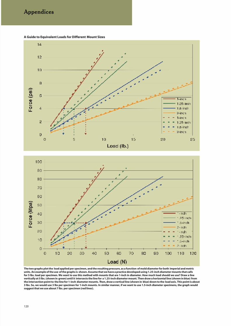
8/20/2019 Buehler Summet, Sample Prep and Analysis
http://slidepdf.com/reader/full/buehler-summet-sample-prep-and-analysis 120/136
120
Appendices
A Guide to Equivalent Loads for Different Mount Sizes
The two graphs plot the load applied per specimen, and the resulting pressure, as a function of mold diameter for both Imperial and metric
units. An example of the use of the graphs is shown. Assume that we have a practice developed using 1.25-inch diameter mounts that calls
for 5 lbs. load per specimen. We want to use this method with mounts that are 1-inch in diameter. How much load should we use? Draw a line
vertically at 5 lbs. (shown in green) until it intersects the line for a 1.25-inch diameter mount. Then draw a horizontal line (shown in blue) from
the intersection point to the line for 1-inch diameter mounts. Then, draw a vertical line (shown in blue) down to the load axis. This point is about
3 lbs. So, we would use 3 lbs per specimen for 1-inch mounts. In similar manner, if we want to use 1.5-inch diameter specimens, the graph wouldsuggest that we use about 7 lbs. per specimen (red lines).

8/20/2019 Buehler Summet, Sample Prep and Analysis
http://slidepdf.com/reader/full/buehler-summet-sample-prep-and-analysis 121/136
121
Appendices
Preparation Troubleshooting Guide
Troubleshooting Definitions
Comet Tails: Dull, broad depressed lines emanating from a hard particle or from a hole in a specimen in a pattern that resembles the tailof a comet. The hard particles may be nonmetallic inclusions or nitrides. This appears to be a material-specific phenomenon as repeated
efforts to produce this defect in randomly chosen specimens fail. Historically, with manually-prepared specimens, it was claimed to becaused by unidirectional grinding; however, repeated efforts to create comet tails with only unidirectional grinding fail. Comet tails havebeen observed on susceptible specimens prepared with automated machines using only complementary grinding and polishing withspecific combinations of head and platen speeds. In a specimen prone to comet tailing, using contra rotation in the final step will enhancethe problem compared to complementary rotation.
Edge Rounding: The edge or edges of a specimen are abraded at a faster rate than the interior leading to a change in flatness at the edgesuch that the edge cannot be brought into focus along with the interior with the light microscope (this condition is more critical as themagnification is raised due to the higher numerical aperture of the objective which reduces the depth of focus).
Embedding: Hard abrasive particles that become fixed in the surface of the softer specimen. This is a common problem with the lowmelting point alloys (e.g., Pb, Sn, Bi, Cd, Zn), aluminum (mainly fine diamond), and precious metals, but has been observed with refractorymetals such as titanium.
Pull Out: Removal of second phase particles (either softer or harder than the matrix) during preparation. Pull out may be enhanced if the
interface between the particle and matrix is weak or if the particle is particularly brittle.
Relief: Excessive height differences between second-phase particles and the matrix due to differences in grinding and polishing ratesbetween the matrix and the particles. Soft particles abrade faster than the matrix and are recessed below the matrix while the reverse isobserved for hard particles.
Scratches: A linear cut along the surface of a specimen due to contact with a correctly oriented abrasive particle; a groove caused by theabrasion process. The width and depth of the cut is a function of the size of the abrasive particle, its angle to the specimen surface, theapplied pressure, and other factors. Scratches become a problem when they are excessively coarse for the abrasive size used, indicatinga problem with the preparation method. Very fine scratches may not be a problem in routine examination for grain size or inclusions butcould be a problem in failure analysis if critical fine detail is obscured.
Smear: Matrix flow over voids, cracks, or second phase particles that make detection of these features and measurement of their extentdifficult or impossible.
Stain: A contamination residue on the surface of a specimen, that may form around second-phase particles due to interactions betweenthe specimen and abrasives and/or lubricants, or may form on the matrix due to inadequate cleaning or drying or may form due to interac-tions between the specimen and solvents after preparation or etching.
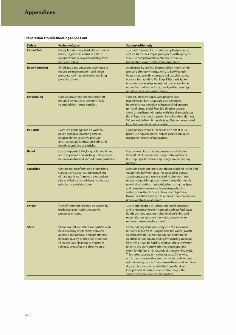
8/20/2019 Buehler Summet, Sample Prep and Analysis
http://slidepdf.com/reader/full/buehler-summet-sample-prep-and-analysis 122/136
122
Appendices
Defect Probable Cause Suggested Remedy
Comet Tails Poorly bonded very hard phase in softer Use hard, napless cloths; reduce applied pressure;matrix; or, pores in matrix results in reduce step times; impregnate pores with epoxy or
unidirectional grooves emanating from wax; use complementary rotation. In manualparticles or hole. preparation, avoid unidirectional grinding.
Edge Rounding Shrinkage gaps between specimen and Avoid gaps by cooling thermosetting mount undermount are main problem and, when pressure after polymerization. Use EpoMet resinpresent, avoid napped cloths and long (least prone to shrinkage gaps); of castable resins,polishing times. epoxy is best (adding Flat Edge Filler particles to
epoxy improves edge retention); use central forcerather than individual force; use ApexHercules rigidgrinding discs; use napless cloths.
Embedding Hard abrasive tends to embed in soft Coat SiC abrasive paper with paraffin waxmetals; finer particles are more likely (candlewax is best, soaps are also effective);to embed than larger particles. beeswax is less effective; reduce applied pressure
rpm and times; avoid finer SiC abrasive papers;avoid using diamond slurries with fine diamond sizes
(for M 3-mm diamond, paste embeds less than slurries).SiC embedded in soft metals (e.g., Pb) can be removedby polishing with alumina slurries.
Pull Outs Excessive grinding time on worn SiC Grind no more than 60 seconds on a sheet of SiCpaper; excessive polishing time on paper; use napless cloths; reduce applied pressure,napped cloths; excessive pressure; use proper degree of lubrication.and inadequate lubrication lead to pullout of second-phase particles.
Relief Use of napped cloths, long polishing times, Use napless cloths, higher pressures and shorterand low pressure create height differences times. If relief is observed using contra rotation inbetween matrix and second-phase particles. last step, repeat the last step using complementary
rotation.
Scratches Contamination of grinding or polishing Maintain clean operating conditions, washing hands andsurfaces by coarser abrasives; pull out equipment between steps; for cracked or porous
of hard particles from matrix or broken specimens, use ultrasonic cleaning after each steppieces of brittle materials; or inadequate (especially polishing); execute each step thoroughlygrinding or polishing times (avoid short cutting methods); when using the Apex
and pressures can leave a heavy magnetic discsystem, store the discs in a clean scratch pattern.Drawer or cabinet and scrub surfaces if contaminationis believed to have occurred.
Smear Flow of softer metals may be caused by Use proper degree of lubrication, lower pressuresinadequate lubrication, excessive and rpms; use a medium napped cloth on final step;pressures or rpms. lightly etch the specimen after final polishing and
repeat the last step; use the vibratory polisher toremove smeared surface metal.
Stain Stains around second-phase particles can Some staining issues are unique to the specimenbe induced by interactions between but most result from using impure tap water (switch
abrasive and particle, perhaps affected to distilled water; sometimes de-ionized water isby water quality; or they can occur due needed) or inadequate drying. When using colloidalto inadequate cleaning, or improper silica, which can be hard to remove, direct the watersolvents used after the abrasive step. jet onto the cloth and wash the specimens (and
cloth) for the last 6-10 seconds of the polishing cycle.This makes subsequent cleaning easy. Otherwise,scrub the surface with water containing a detergentsolution using cotton. Then, rinse with alcohol and blowdry with hot air, such as with the TorraMet dryer.Compressed air systems can contain impurities,such as oils, that can stain the surface.
Preparation Troubleshooting Guide Cont.

8/20/2019 Buehler Summet, Sample Prep and Analysis
http://slidepdf.com/reader/full/buehler-summet-sample-prep-and-analysis 123/136
123
ASTM Metallography Standards
ASTM METALLOGRAPHYSTANDARDS
A247: Visual Classification of Graphite in the
Microstructure of Cast IronA892: Defining and Rating the Microstructure of
High Carbon Bearing Steels
B390: Evaluating Apparent Grain Size and
Distribution of Cemented Tungsten Carbides
B588: Measurement of the Thickness of Transparent
or Opaque Coatings by Double-Beam Interference
Microscope Technique
B657: Metallographic Determination of
Microstructure in Cemented Tungsten Carbide
B681: Measurement of Thickness of Anodic
Coatings on Aluminum and of Other Transparent
Coatings on Opaque Surfaces Using the
Light-Section Microscope
B748: Measurement of the Thickness of
Metallic Coatings by Measurement of Cross
Section with a Scanning Electron Microscope
B795: Determining the Percentage of Alloyed or
Unalloyed Iron Contamination Present in Powder
Forged Steel Parts
B796: Nonmetallic Inclusion Level of Powder
Forged Steel Parts
B847: Measurement of Metal and Oxide Coating
Thickness by Microscopical Examination of a Cross
section
C664: Thickness of Diffusion Coating
E3: Preparation of Metallographic Specimens
E7: Standard Terminology Relating to
Metallography
E45 Determining the Inclusion Content
of Steel
E82: Determining the Orientation of a
Metal Crystal
E112: Determining Average Grain Size
E340: Macroetching Metals and Alloys
E381: Macroetch Testing Steel Bars, Billets, Blooms,
and Forgings
E384: Microindentation Hardness of Materials
E407: Microetching Metals and Alloys
E562: Determining Volume Fraction by Systematic
Manual Point Count
E766: Calibrating the Magnification of a Scanning
Electron Microscope
E768: Preparing and Evaluating Specimens for
Automatic Inclusion Assessment of Steel
E807: Metallographic Laboratory Evaluation
E883: Reflected-Light Photomicrography
E930: Estimating the Largest Grain Observed in a
Metallographic Section (ALA Grain Size)
E975: X-Ray Determination of Retained Austenite in
Steel with Near Random Crystallographic
Orientation
E986: Scanning Electron Microscope Beam Size
Characterization
E1077: Estimating the Depth of Decarburization of
Steel Specimens
E1122: Obtaining JK Inclusion Ratings Using
Automatic Image Analysis
E1180: Preparing Sulfur Prints for Macrostructural
Examination
E1181: Characterizing Duplex Grain Sizes
E1245: Determining the Inclusion or Second-Phase
Constituent Content of Metals by Automatic Image
Analysis
E1268: Assessing the Degree of Banding or
Orientation of Microstructures
E1351: Production and Evaluation of Field
Metallographic Replicas
E1382: Determining Average Grain Size Using
Semiautomatic and Automatic Image Analysis
E1508: Quantitative Analysis by Energy-DispersiveSpectroscopy
E1558: Electrolytic Polishing of Metallographic
Specimens
E1920: Metallographic Preparation of Thermal
Spray Coatings
E1951: Calibrating Reticles and Light Microscope
Magnifications
E2014: Metallographic Laboratory Safety
E2015: Preparation of Plastics and PolymericSpecimens for Microstructural Examination
F1854: Stereological Evaluation of Porous Coatings
on Medical Implants
8/20/2019 Buehler Summet, Sample Prep and Analysis
http://slidepdf.com/reader/full/buehler-summet-sample-prep-and-analysis 124/136
124
ASTM/ISO Standards
ASTM HARDNESS TESTINGSTANDARDS
B578: Microhardness of Electroplated Coatings
B721: Microhardness and Case Depth of PowderMetallurgy Parts
C730: Knoop Indentation Hardness of Glass
C849: Knoop Indentation Hardness of Ceramic
Whitewares
C1326: Knoop Indentation Hardness of Advanced
Ceramics
C1327: Vickers Indentation Hardness of Advanced
Ceramics
E10: Brinell Hardness of Metallic Materials
E18: Rockwell Hardness and Rockwell Superficial
Hardness of Metallic Materials
E92: Vickers Hardness of Metallic Materials
E140: Standard Hardness Conversion Tables for
Metals
E448: Scleroscope Hardness Testing of Metallic
Materials
E1842: Macro-Rockwell Hardness Testing of Metallic
Materials
ISO METALLOGRAPHY STANDARDS
ISO643: Steels – Micrographic Determination of the
Ferritic or Austenitic Grain Size
ISO945: Cast Iron: Designation of Microstructure of
Graphite
ISO1083: Spheroidal Graphite Cast Iron –
Classification
ISO1463: Metallic and Oxide Coatings –
Measurement of Coating Thickness – Microscopical
Method
ISO2624: Copper and Copper Alloys – Estimation of
Average Grain Size
ISO2639: Steel – Determination and Verification of
the Effective Depth of Carburized and Hardened
Cases
ISO3754: Steel – Determination of Effective Depth
of Hardening After Flame or Induction Hardening
ISO3763: Wrought Steels – Macroscopic Methodsfor Assessing the Content of Non-Metallic
Inclusions
ISO3887: Steel, Non-Alloy and Low Alloy –
Determination of Depth of Decarburization
ISO4499: Hardmetals: Metallographic
Determination of Microstructure
ISO4524-1: Metallic Coatings – Test Methods for
Electrodeposited Gold and Gold Alloy Coatings –
Part 1: Determination of Coating Thickness
ISO4964: Steel – Hardness Conversions
ISO4967: Steel – Determination of Content of
Non-Metallic Inclusions – Micrographic Method
Using Standard Diagrams
ISO4968: Steel – Macrographic Examination by
Sulphur Print (Baumann Method)
ISO4970: Steel – Determination of Total or EffectiveThickness of Thin Surface-Hardened Layers
ISO5949: Tool Steels and Bearing Steels –
Micrographic Method for Assessing the
Distribution of Carbides Using Reference
Photomicrographs
ISO9042: Steels – Manual Point Counting Method
for Statistically Estimating the Volume Fraction of a
Constituent with a Point Grid
ISO9220: Metallic Coatings – Measurement of
Coating Thickness – Scanning Electron MicroscopeMethod
ISO14250: Steel – Metallographic Characterization
of Duplex Grain Size and Distribution

8/20/2019 Buehler Summet, Sample Prep and Analysis
http://slidepdf.com/reader/full/buehler-summet-sample-prep-and-analysis 125/136
125
ISO/Other Nattional Standards
ISO HARDNESS STANDARDS
ISO1355: Metallic Materials – Hardness Test –
Calibration of Standardized Blocks to be Used for
Rockwell Superficial Hardness Testing Machines(Scales 15N, 30N, 45N, 15T, 30T and 45T)
ISO4516: Metallic and Related Coatings – Vickers
and Knoop Microhardness Tests
ISO4545: Metallic Materials – Hardness Test –
Knoop Test
ISO4546: Metallic Materials – Hardness Test –
Verification of Knoop Hardness Testing Machines
ISO4547: Metallic Materials – Hardness Test –
Calibration of Standardized Blocks to be Used for
Knoop Hardness Testing Machines
ISO6441-1: Paints and Varnishes – Determination of
Microindentation Harness – Part 1: Knoop Hardness
by Measurement of Indentation Length
ISO6441-1: Paints and Varnishes – Determination of
Microindentation Harness – Part 2: Knoop Hardness
by Measurement of Indentation Depth Under Load
ISO6507-1: Metallic Materials – Hardness Test –
Vickers Test – Part I: HV 5 to HV 100
ISO6507-2: Metallic Materials – Hardness Test –Vickers Test – Part 2: HV 0, 2 to Less Than HV 5
ISO6508: Metallic Materials – Hardness Test –
Rockwell Test (Scales A, B, C, D, E, F, G, H, K)
ISO9385: Glass and Glass-Ceramics – Knoop
Hardness Test
ISO10250: Metallic Materials – Hardness Testing –
Tables of Knoop Hardness Values for Use in Tests
Made on Flat Surfaces
ISO14271: Vickers Hardness Testing of Resistance
Spot, Projection and Seam Welds (low load andmicrohardness)
OTHER NATIONAL STANDARDS
France
NFA04-10: Determination of the Ferritic and
Austenitic Grain Size of Steels
Germany
DIN50150: Testing of Steel and Cast Steel;
Conversion Table for Vickers Hardness, Brinell
Hardness, Rockwell Hardness and Tensile Strength
DIN50192: Determination of the Depth of
Decarburization
DIN50600: Testing of Metallic Materials;
Metallographic Micrographs; Picture Scales
and Formats
DIN50601: Metallographic Examination;
Determination of the Ferritic or Austenitic
Grain Size
DIN50602: Metallographic Examination;
Microscopic Examination of Special Steels Using
Standard Diagrams to Assess the Content of
Non-Metallic Inclusions
SEP1510: Microscopic Test of Steels for Grain Size
by Comparison with Standard Charts
SEP1570: Microscopical Examination of SpecialSteels for Non-Metallic Inclusions Using Standard
Micrograph Charts
SEP1572: Microscopic Testing of Free-Cutting Steels
for Non-Metallic Sulphide Inclusions by Means of a
Series of Pictures
Italy
UNI3137: Extraction and Preparation of Samples
UNI3138: Macrographic Analysis
UNI3245: Microscopic Examination of Ferrous
Materials - Determination of Austenitic or Ferritic
Grain Size of Plain Carbon and Low-Alloy Steels
UNI4227: Determination of Metallographic
Structures
UNI4389: Nonferrous Metals and Their Alloys:
Determination of the Dimension of Their Crystal
Grains

8/20/2019 Buehler Summet, Sample Prep and Analysis
http://slidepdf.com/reader/full/buehler-summet-sample-prep-and-analysis 126/136
126
Other National Standards
Japan
JISB7724: Brinell Hardness – Verification of Testing
Machine
JISB7725: Vickers Hardness – Verification of TestingMachines
JISB7730: Rockwell Hardness Test – Calibration of
Standardized Blocks
JISB7734: Knoop Hardness Test – Verification of
Testing Machines
JISB7735: Vickers Hardness Test – Calibration of the
Reference Blocks
JISB7736: Brinell Hardness Test – Calibration of
Standardized Blocks
JISG0551: Methods of Austenite Grain Size Test for
Steel
JISG0552: Method of Ferrite Grain Size Test
for Steel
JISG0553: Macrostructure Detecting Method for
Steel, Edition 1
JISH0501: Methods for Estimating Average Grain
Size of Wrought Copper and Copper Alloys
JISR1610: Testing Method for Vickers Hardness of
High Performance Ceramics
JISR1623: Test Method for Vickers Hardness of Fine
Ceramics at Elevated Temperatures
JISZ2243: Brinell Hardness Test – Test Method
JISZ2244: Vickers Hardness Test – Test Method
JISZ2245: Rockwell Hardness Test – Test Method
JISZ2251: Knoop Hardness Test – Test Method
JISZ2252: Test Methods for Vickers Hardness at
Elevated Temperatures
Poland
PN-57/H-04501: Macroscopic Examination of Steel.
The Deep Etching Test.
PN-61/H-04502: Reagents for Macrostructure Tests
of Iron Alloys
PN-61/H-04503: Reagents for Microstructure Tests
of Iron Alloys
PN-63/H-04504: Microstructure Testing of Steel
Products. Iron Carbide. Ghost Structure.Widmanstätten’s Structure.
PN-66/H-04505: Microstructure of Steel Products.
Templates and Evaluation.
PN-75/H-04512: Nonferrous Metals. Reagents for
Revealing Microstructure.
PN-75/H-04661: Gray, Spheroidal Graphite and
Malleable Cast Iron. Metallographic Examination.
Evaluation of Microstructure
PN-76/H-04660: Cast Steel and Iron. Microscopic
Examination. Sampling and Preparation of Test
Pieces.
PN-84/H-04507/01: Metals. Metallographic Testing
of Grain Size. Microscopic Methods for
Determination of Grain Size.
PN-84/H-04507/02: Metals. Metallographic Testingof Grain Size. Methods of Revealing the
Prior-Austenitic Grains in Non-Austenitic Steels.
PN-84/H-04507/03: Metals. Metallographic Testing
of Grain Size. Macroscopic Method of Revealing the
Prior-Austenitic Grain Size by the Fracture Method.
PN-84/H-04507/04: Metals. Metallographic Testing
of Grain Size. A Method of Testing for Overheating
of Steel.
PN-87/H-04514: Steel, Cast Steel, Cast Iron.
Macrostructure Examination. Baumann’s Test.
Russia
GOST801: Standard for Ball and Roller Bearing Steel
GOST1778: Metallographic Methods of
Determination of Nonmetallic Inclusions
GOST5639: Grain Size Determination
Sweden
SIS111101: Estimating the Average Grain Size ofMetals
SIS111102: Estimating the Austenitic Grain Size of
Ferritic and Martensitic Steels
SIS111111: Methods for Assessing the Slag
Inclusion Content in Steel: Microscopic Methods
SIS111114: Determination of Slag Inclusions –
Microscopic Methods – Manual Representation

8/20/2019 Buehler Summet, Sample Prep and Analysis
http://slidepdf.com/reader/full/buehler-summet-sample-prep-and-analysis 127/136
127
Other National Standards
Sweden (continued)
SIS111116: Steel – Method for Estimation of the
Content of Non-Metallic Inclusions – Microscopic
Methods – Jernkontoret’s Inclusion Chart II for the
Assessment of Non-Metallic Inclusions
SIS110340: Hardness Test – Vickers Test HV 0, 2 to
HV 100 – Direct Verification of Testing Machines
SIS1103 41: Hardness Test – Vickers Test HV 0,2 to
HV 100 – Indirect Verification of Testing Machines
Using Standardized Blocks
SIS1103 42: Hardness Test – Vickers Test HV 0,2 to
HV 100 – Direct Verification of Standardizing
Machine for Calibration of Standardized Blocks
SIS110343: Hardness Test – Vickers Test HV 0,2 toHV 100 – Calibration of Standardized Blocks
SIS112516: Metallic Materials – Hardness Test –
Vickers Test HV 5 to HV 100
SIS112517: Metallic Materials – Hardness Test –
Vickers Test HV 0,2 to Less Than HV 5
SIS117020: Determination of the Depth of
Decarburization in Steel
United Kingdom
BS860: Tables for Comparison of Hardness Scales.
BS4490: Methods for Micrographic Determination
of the Grain Size of SteelBS5710: Macroscopic Assessment of the
Non-Metallic Inclusion Content of Wrought Steels
BS6285: Macroscopic Assessment of Steel by
Sulphur Print
BS6286: Measurement of Total or Effective
Thickness of Thin Surface-Hardened Layers in Steel
BS6479: Determination and Verification of Effective
Depth of Carburized and Hardened Cases in Steel
BS6481: Determination of Effective Depth of
Hardening of Steel after Flame or Induction
Hardening
BS6533: Macroscopic Examination of Steel by
Etching with Strong Mineral Acids
BS6617: Determination of Decarburisation in Steel

8/20/2019 Buehler Summet, Sample Prep and Analysis
http://slidepdf.com/reader/full/buehler-summet-sample-prep-and-analysis 128/136
128
REGISTERED TRADEMARKS OFBUEHLER LTD.:
Apex
ApexHerculesAutoMet
Buehler
CarbiMet 2
ChemoMet
DuoMet
EcoMet
EdgeMet Kit
EpoHeat
EpoKwick
EpoMet
EpoThin
EpoxiCure
FluorMet
HandiMet
IsoCut
IsoMet
KonductoMet
MasterMet
MasterPolishMasterPrep
MasterTex
MetaDi
MetaDi Supreme
MicroCloth
MicroPolish
NanoCloth
NelsonZimmer
OmniMet
OscilliMet
PlanarMet
ProbeMet
SamplKup
SamplKwick
SimpliMet
SuperMet
SurfMet
TexMet
TorraMet
VariDur
VibroMet
UNREGISTERED TRADEMARKS OFBUEHLER LTD.:
AcuThin
DeltaEpoColor
PhenoCure
Phoenix Beta
Phoenix Vector
TransOptic
TriDent
UltraPad
UltraPlan
UltraPol
UltraPrep
WhiteFelt
Buehler Trademarks

8/20/2019 Buehler Summet, Sample Prep and Analysis
http://slidepdf.com/reader/full/buehler-summet-sample-prep-and-analysis 129/136
129
Index
A
Abrasive cut-off machines:
chop cutters, 10
minimum area of contact cutting, 11 orbital cutting, 11-12
oscillating cutting, 11
pulse cutting mode, 10-11
traverse-and-increment cutting, 11-12
Abrasive cut-off wheels:
bond strength, 9
recommendations, 10
thickness, 9
troubleshooting guide, 116
Abrasive sectioning, 7, 9-12, 116
Acids, 107-110
Acrylic resins, 15-17, 117-119
Alumina, 20, 27, 28, 35, 40
Alumina grinding paper, 20, 29
Aluminum and alloys:
etchants, 70, 71, 73
preparation, 34-35
ASTM Standards, 123-124
Attack polishing:
Au, 52
Be, 37
Co, 50
Hf, 41-42
Nb, V and Ta, 43-44
safety, 41
Ti, 41
Zr, 41-42
B
Bases, 110
Beryllium
preparation, 37
Bright field illumination, 83,84,86
Buehler trademarks, 130
C
Castable resins:
acrylic resins, 15-17, 118, 119
Conductive Filler particles, 16
epoxy resins, 15-17, 118, 119
exotherm, 16-17
Flat Edge Filler particles, 16,18,19
recommendations, 16, 148
troubleshooting guide, 119
Central force, 19, 29
Ceramics:
etchants, 77
preparation, 57-60
Chemical polish, 41-42
Clamp mounting, 14
Cobalt and alloys:
etchants, 76
preparation, 50
Cold mounting (see castable resins)
Colloidal silica, 27-28, 34, 120
“Comet tails,” 23, 121-122
Composites:
preparation, 59-60Compression mounting, 14-15, 17-19, 53, 117
Conductive mounts, 16, 117
Contra rotation, 29, 30-31
Coolant flow, 9
Copper and alloys:
etchants, 70, 75-76
preparation, 48
Cutting damage, 7-9, 116
DDamage, sectioning, 7-9, 116
Dark field illumination, 65, 85, 86
Diamond, 27, 28
Differential interference contrast, 23, 43, 44, 59, 65,
85, 86
Digital imaging:
acquisition, 93
archiving, 93
calibration, 95-96
cameras, 93-94
clarification, 96
color, 94
pixels, 94, 95, 96
resolution, 95
E
Edge preservation, 14, 15, 17-19, 121-122
Electronic materials:
preparation, 62-64
Embedded abrasive, 20, 21, 35, 39, 64, 121-122Epoxy resin, 15-17, 117-119

8/20/2019 Buehler Summet, Sample Prep and Analysis
http://slidepdf.com/reader/full/buehler-summet-sample-prep-and-analysis 130/136
130
Index
E (CONT.)
Etchants, 27, 73-77
chemicals, 110-111
dangerous solutions, 105, 107, 108, 109 mixing, 103-104
storage, 103
Etching, 67-77, 78
anodizing, 71
electrolytic, 71
heat tinting, 71-72
interference layer method, 72
procedure, 67
selective etching, 68-71
F
Ferrous metals:
etchants, 68-70, 74-75
preparation, 31, 45-47
Fluorescent dyes, 16, 53
G
Grain size measurement, 7, 99-100
Grinding:
alumina paper, 20 diamond, 19, 20
embedding, 20,21
emery paper, 20
machines, 22
planar, 20
SiC paper, 20
H
Hafnium and alloys:
etchants, 74 preparation, 41-42
I
Image analysis
binary operations, 98-99
feature-specific measurements, 99
field measurements, 99
measurements, 96, 99-100
thresholding, 96, 99-100
Inclusion measurement, 7
Individual force, 19
Iron and steel:
etchants, 68-70, 74-75
preparation, 31, 45-47
ISO standards, 124-125
K-L
Knoop hardness, 88-89
Light microscopy, 78-86
Low-melting point metals:
etchants, 73
preparation, 37-38, 62-64
M
Magnesium and alloys:
etchants, 73 preparation, 36
Magnesium oxide, 34
Metals:
allotropic transformations, 116
periodic table, 33
properties, 116
Method Development, 7
Microindentation hardness:
accuracy, precision, bias, 89-92
automation, 91-92
indentation size effect, 88
Knoop test, 88-89
Vickers test, 84-88
Microscope, reflected light:
condenser, 80
depth of field, 83-84
diaphragms, 80
“empty” magnification, 82-83
eye clearance, 81 eye pieces, 81
filters, 80
graticules, 81
illumination modes, 79, 83-86
Köhler illumination, 83-84
light sources, 77, 79
magnification, 81, 82
numerical aperture, 80, 82, 83
objective lens, 77, 79, 80
ray diagram, 78
resolution, 82, 83
reticles, 81

8/20/2019 Buehler Summet, Sample Prep and Analysis
http://slidepdf.com/reader/full/buehler-summet-sample-prep-and-analysis 131/136
131
Index
M (CONT.)Microscope, reflected light (cont):
stage, 78, 81-89
stand, 82working distance, 80, 81
Mounting:
castable resins, 14, 15-17
clamp mounting, 14
compression mounting, 14-15, 17-19, 117
conductive resins, 16, 117
edge retention (preservation), 14, 15, 17-19,
117, 121-122
electroless nickel plating, 17, 19
low-melting point metals, 38 phenolic resins, 14
presses, 17, 19
purposes, 14
recommendations, 14, 16
shrinkage gaps, 14, 15, 17, 18, 19
thermoplastic resins, 14-15, 18, 117
thermosetting resins, 14-15, 17-19, 117
troubleshooting guides, 117
Mount size, 21
NNickel and alloys:
etchants, 76
preparation, 49
Nomarski DIC, 19, 43, 44, 59, 65, 85, 86
O-POblique illumination, 84-85
Other National Standards, 125-127
Periodic table of the elements, 33Polarized light, 9, 35, 36, 37, 38, 40, 41, 42, 45, 48, 50,
59, 67, 71, 85, 86
Polishing:
abrasives, 27-28, 120
automated, 25
cloths, 19, 24, 25-26, 28
electrolytic, 24
head position, 19, 32
lubricants, 27
manual, 24 recommendations, 120
vibratory, 27, 35-36, 37, 39, 41
Polymers:
etchants, 77
preparation
(see also: castable resins)
Precision saws, 12-13
Precious metals:
etchants, 76-77
Preparation, 51-52
Preparation method development:
6, 8, 29, 31, 32
Preparation problems:
“comet tails,” 23, 121-122
disturbed metal, 23
edge retention (preservation), 14, 15, 17-19, 117,121-122
embedded abrasive, 20, 21, 35, 39, 64,
121-122
excessive relief, 23, 24, 121-122
pitting, 23
pull outs, 9, 121-122
scratches, 121-122
smear, 63, 64, 121-122
troubleshooting guide, 121-122
water sensitivity, 36, 37Preparation procedures
contemporary methods, 29-31
Al and alloys, 34-35
Be, 37
ceramics, 57-58
Co and alloys, 50
composites, 59-60
Cu and alloys, 48
electronic devices, 62-64
Fe and alloys, 45-47
Hf and alloys, 41-42
low-melting point alloys, 38-38, 62-64
Mg and alloys, 36
Ni and alloys, 49
polymers, 65-66
precious metals, 51-52
printed circuit boards, 61
Refractory metals, 40-44
Sintered carbides, 55-56 Ti and alloys, 40-41
TSC and TBC coated metals, 53-54
Zr and alloys, 41-42

8/20/2019 Buehler Summet, Sample Prep and Analysis
http://slidepdf.com/reader/full/buehler-summet-sample-prep-and-analysis 132/136
132
Index
O-P (CONT.)specific procedures, 32-66
development, 32
load, 32 platen size, 32
time, 32
“traditional” method, 29
Printed circuit boards:
etchant, 61
preparation, 61
Pull outs, 7, 121-122
R
Refractory metals: etchants, 74
preparation, 40-44
Relief, 8, 23, 24
Rigid grinding discs, 19, 30-31, 45-47, 49-50, 53-54,
55, 57, 63
S
Safety:
acids, 107
bases, 110
chemical storage, 103
dust, 102
equipment operation, 102
fume hoods, 101
MSDS, 101, 103
personal protective equipment, 102-103
publications, 114
safety plan, 101
solvents, 104, 106
web sites, 114Sampling, 7
Sectioning, 9-13
Sectioning damage, 7, 8, 9
Sectioning planes, 7
Shrinkage gaps, 14, 15, 17, 18, 19, 122
Silicon
preparation, 62-63
Silicon carbide paper, 20-22
ANSI/CAMI grit size, 21-22
FEPA grit size, 21-22
Silicon dioxide, 27
Sintered carbides:
etchants, 70-71, 77
preparation, 55-56
Smartcut, 12
Solvents, 104, 106
Sorby, Sir Henry Clifton, 81
Specimen preparation:
goals, 6, 10
Methods
Contemporary, 29-31
Specific materials, 32-66
traditional, 29
(see: preparation procedures) Problems, 7, 121-122
(see: preparation problems)
Stains, staining, 17, 18, 23, 121-122
Standards, metallography and hardness,
123-127
Steels (see: Fe and alloys or Irons and steels)
T
Thermally spray-coated metals
preparation, 53-54Thermoplastic resins, 14-15, 18
Thermosetting resins, 14-15, 17-19
Titanium and alloys:
etchants, 74
heat tinting, 72
preparation, 40-41
Trademarks, Buehler Ltd., 128
U-Z
Ultrasonic cleaning, 28Vacuum impregnation, 15-16, 53, 57, 59
Vickers hardness, 87-88
Water-sensitive materials, 27, 36, 37, 120
Worldwide Sales Offices, 132-135
Zirconium and alloys:
etchants, 74
preparation, 41-42

8/20/2019 Buehler Summet, Sample Prep and Analysis
http://slidepdf.com/reader/full/buehler-summet-sample-prep-and-analysis 133/136
133
Worldwide Sales Offices
BUEHLER HEADQUARTERS41 Waukegan Road, P. O. Box 1Lake Bluff, Illinois 60044-1699
Tel: (847) 295-6500 • Fax: (847) 295-7979
Sales: 1-800-BUEHLER (800-283-4537)www.buehler.com
INTERNATIONALArgentina - Buenos Aires
ARO S.A.Tel: (54) (11) 4331.5766Fax: (54) (11) 4331.3572
Australia - Victoria
Biolab DavidsonsTel: (61) (3) 9580.4366Fax: (61) (3) 9580.6499
Austria - Wolfsgraben
Andreas GrimasTel: (43) 2233.78610Fax: (43) 2233.78619
Bahrain- Saudi Arabia
Abdulla FouadTel: (966) 2639.4455Fax: (966) 2639.6725
Bangladesh - Dhaka
Sensor InternationalTel: (88) 028.629.621
Fax: (88) 028.629.946Brazil - Sao Paulo
Instrumental Instrumentos de Medicao LTDATel: (55) (11) 5011.0901Fax: (55) (11) 5012.4650
Bulgaria - Sofia
EVIT BulgariaTel: (359) (2) 983.3338Fax:(359) (2) 983.3338
Canada - Ontario
Buehler Canada
Tel: (905) 430.4684Fax: (905) 430.4647
Chile - Vina del Mar
G. Busch & Cia. Ltda.Tel: (56) (32) 2692064Fax: (56) (32) 2692064
China
Hong Kong - China
Buehler Asia/Pacific
Tel: (852) 2307.0909Fax: (852) 2307.0233
Buehler - Beijing
Tel: (86) (10) 8844.9599Fax: (86) (10) 8561.5320
Buehler - ChengDu
Tel: (86) (28) 8619.9419
Fax: (86) (28) 8619.9419
Buehler - GuangZhou Tel: (86) (20) 3839.5933Fax: (86) (20) 8365.2222
Buehler - Shanghai Tel: (86) (21) 6468.2199Fax: (86) (21) 6333.0809
Buehler - Shen Yang Tel: (86) (24) 2325.5656Fax: (86) (24) 2396.1702
Buehler - Nanjing Tel: (86) (25) 5186.0487Fax: (86) (25) 8375.1010
Buehler - Wuhan Tel: (86) (27) 8360.2980Fax: (86) (27) 8362.9193
Buehler - Xian Tel: (86) (29) 8836.4931Fax: (86) (29) 8837.7035
Colombia - Bogota
Arotec Colombiana S.A.Tel: (57) (1) 288.7799Fax: (57) (1) 285.3604
Costa Rica - San Jose Capris S.A.Tel: (506) 232.9111Fax: (506) 232.8525
Croatia - ZagrebArting Zagreb d.o.o NDTTel: (385) (1) 346.0065Fax: (385) (1) 346.0067
Czech Republic - Praha
Hanyko Praha S.R.O.Tel: (420) (251) 550.017Fax: (420) (257) 187.611
Ecuador - Quito
Sistec (Sistemas Tecnologicos)Tel: (593) (2) 253.1118
Fax: (593) (2) 253.1118Egypt - Cairo
GSC2000 (Egypt)Tel: (20) 2781.0165Fax: (20) 2585.5326
Estonia - Tallinn
Deltalab,c/o Tallinn Technical UniversityTel: (372) 539.94294Fax: (372) 6203.153
Finland - Helsinki Knorring OY A.B.Tel: (358) (9) 56041Fax: (358) (9) 565.2463
France - Dardilly
Buehler FranceTel: (33) 800 897.371

8/20/2019 Buehler Summet, Sample Prep and Analysis
http://slidepdf.com/reader/full/buehler-summet-sample-prep-and-analysis 134/136
134
Worldwide Sales Offices
Fax: (33) 800 880.527
Germany - Düsseldorf
Buehler GmbHTel: (49) (211) 974100
Fax: (49) (211) 974.1079Greece - Koropi
B. Caravitis S.A.Tel: (30) (210) 602.8317Fax: (30) (210) 664.4886
Hungary - Budapest
Grimas HmbHTel: (36) (1) 420.5883Fax: (36) (1) 276.0557
India - Agra
Censico International Private, Ltd.
Tel: (91) (562) 2524777Fax: (91) (562) 28520222
Ireland - Dublin
Labquip Ltd.Tel: (353) (1) 6434586Fax: (353) (1) 6434611
Israel - Givataim
MicrotechTel: (972) (3) 573.1122Fax: (972) (3) 573.1123
Italy – Firenze
Nikon Instruments, S.p.a.Tel: (39) 055.300920Fax: (39) 005.300993
Japan - Tokyo
Sankei Co., Ltd.
Tel: (81) (3) 5805.0514Fax: (81) (3) 5805.0524
Osaka
Tel: (81) (6) 6327.3850Fax: (81) (6) 6327.1993
Shizuoka Pref.
Tel: (81) (54) 287.6722
Fax: (81) (54) 287.6907Tsukuba
Tel: (81) (298) 52.3061Fax: (81) (298) 52.3063
Yokohama
Tel: (81) (467) 41.1221Fax: (81) (467) 48.3610
Jordan - Amman
SMS Scientific & Medical Supplies Co.Tel: (962) (6) 462.4907Fax: (962) (6) 462.8258
Kuwait - SafatAl-Sedan Trading & Contracting Co.Tel: (965) 483.4510 ext. 242
Fax: (965) 484.0629
Lithuania and Baltics- Vilnius
AMTESTTel: (370) (5) 238.8272
Fax: (370) (5) 238.8271Malaysia - Seri Kambangan
CLMO Technology SDN. BHD.Tel: (60) (3) 8942.1238Fax: (60) (3) 8948.1661
Malta - Marsa
Attard & Co., Ltd.Tel: (356) (21) 237555Fax: (356) (21) 220186
Mexico - Mexico D.F.
Microanalisis S.A. de C.V.
Tel: (52) (55) 5660.9828Fax: (52) (55) 5660.9831
New Zealand - Auckland Biolab Ltd.Tel: (64) (9) 980.6700Fax: (64) (9) 980.6788
Norway - Moss
Micronova ASTel: (47) 69241230Fax: (47) 69241229
Pakistan – Karachi
FACO TradingTel: (92) (21) 452.3096Fax: (92) (21) 452.6898
Peru - Lima
Cimatec S.A.Tel: (51) (1) 336.5151Fax: (51) (1) 336.5279
Philippines - Rizal
Mr. Edzel EstarisTel: (63) (917) 501.6347
Poland - Katowice
TestingTel: (48) (32) 757.4597Fax: (48) (32) 757.4815
Portugal - Porto
Gravimeta, Lda.Tel: (351) (226) 184.232Fax: (351) (226) 184.619
Qatar - Doha
AL-Obeidly Trading TechnologyTel: (974) 632.8509Fax: (974) 436.0323
Romania - Bucarest
Total Control S.R.L.Tel: (40) (21) 619.3054

8/20/2019 Buehler Summet, Sample Prep and Analysis
http://slidepdf.com/reader/full/buehler-summet-sample-prep-and-analysis 135/136
135
Worldwide Sales Offices
Fax: (40) (21) 212.3151
Russian - Moscow
S-InstrumentsTel: (7) (095) 203.1125
Fax: (7) (095) 203.1067Russian - St. Petersburg
RVS Company Ltd.Tel: (7) (812) 786.9516Fax: (7) (812) 252.0136
Russian - St. Petersburg
NienschanzTel: (7) (812) 326.1090 ext. 2184Fax: (7) (812) 325.5864
Serbia & Montenegro - Belgrade
Trimid d.o.oTel: (381) (11) 444.4149
Fax: (381) (11) 3440416Slovakia - Bratislava
MITAR s.r.oTel: (421) (2) 6428.8474Fax: (421) (2) 6428.8484
Slovenia - Kamnik
Team Trade d.o.oTel: (386) (1) 8310.700Fax: (386) (1) 8313.496
South Africa - Johannesburg
Apollo Scientific ccTel: (27) (11) 466.7666Fax: (27) (11) 466.7672
South Korea - Kyung-Ki
Key One Engineering Co., Ltd.Tel: (82) (31) 783.2199Fax: (82) (31) 783.2499
Spain - Llanera
Biometa Tecnologia y Systemas, S.A.L.Tel: (34) (902) 244343Fax: (34) (985) 269169
Sultanate of Oman
Business International Group LLC
Tel: (968) 771.4752Fax: (968) 771.3924
Sweden - Sundbyberg
Mikron ABTel: (46) (8) 564.82140Fax: (46) (8) 564.82141
Switzerland - Schlieren
Prufmaschinen AG PrufagTel: (41) 44 746.4030Fax: (46) 44 746.4039
Taiwan - Taipei
Sanpany Instruments Co. Ltd.
Tel: (886) (2) 2392.3433
Fax: (886) (2) 2392.3463
Thailand - Bangkok
Jebsen & Jessen Marketing (T) Ltd.Tel: (66) (2) 787.8118
Fax: (66) (2) 787.8109Turkey - Istanbul
MegaTel: (90) (216) 326.4535Fax: (90) (216) 326.3286
Ukraine - Kiev
Innovation TechnologyTel: (38) (093) 154.8832Fax: (38) (044) 468.9161
United Arab Emirates - Dubai
GSC2000 (UAE)Tel: (971) (4) 881.5270
Fax: (971) (4) 881.6778United Kingdom - Coventry
Buehler UK Tel: (44) 800 707.6273Fax: (44) 2476.582159
Uruguay - Montevideo
Analitica SRLTel: (598) (2) 600.3468Fax: (598) (2) 600.3776
Venezuela - Caracas
Dequimem C.A.Tel: (58) (212) 242.7512Fax: (58) (212) 241.6354
Vietnam - Hochiminh City
Ms. Do Thi ThuyTel: (84) 8822.7160Fax: (84) 9413.43696

8/20/2019 Buehler Summet, Sample Prep and Analysis
http://slidepdf.com/reader/full/buehler-summet-sample-prep-and-analysis 136/136
In today’s competitive world,
material scientists and
metallographers need to find
effective solutions to preparation
issues quickly. For over 67 years
Buehler has been providing
technical solutions to the
materials industry on specimen
preparation theory, best lab
practices, and material
applications. In response to this
need and to further our quest
for excellence in customer service, Buehler’s staff of professional material scientists have written BUEHLER®
SUM-MET™ The Science Behind Materials Preparation - A Guide to Materials Preparation.
BUEHLER® SUM-MET™ is a summation of Buehler’s knowledge base in metallurgical and materials applications and
includes step-by-step information on sectioning, mounting, and grinding/polishing. BUEHLER® SUM-MET™ gives
extensive theory and information on preparing specific materials, etching, microscopy, microhardness testing, imaging,
lab safety, consumables usage and troubleshooting.
This book on CD is supplemented with the free Buehler e-Club on-line materials database at www.buehler.com.
h l f l b ll h d d d d
Buehler is the Science Behind Materials Preparation & Analysis™