Basic Antenna Theory and Concepts
ICS 620 Communication Technologies
Class #11
Introduction An antenna is an electrical conductor or
system of conductors Transmission - radiates electromagnetic energy
into space Reception - collects electromagnetic energy
from space In two-way communication, the same
antenna can be used for transmission and reception
Antenna Definition
An antenna is a circuit element that provides a transition form a guided wave on a transmission line to a free space wave and it provides for the collection of electromagnetic energy.
Antenna research from Miller & Beasley, 2002

Antenna Definition-cont’d
In transmit systems the RF signal is generated, amplified, modulated and applied to the antenna
In receive systems the antenna collects electromagnetic waves that are “cutting” through the antenna and induce alternating currents that are used by the receiver

Reciprocity
An antenna ability to transfer energy form the atmosphere to its receiver with the same efficiency with which it transfers energy from the transmitter into the atmosphere
Antenna characteristics are essentially the same regardless of whether an antenna is sending or receiving electromagnetic energy

Polarization Polarization is the direction of the electric
field and is the same as the physical attitude of the antenna A vertical antenna will transmit a vertically
polarized wave The receive and transmit antennas need to
possess the same polarization

Types of Antennas Isotropic antenna (idealized)
Radiates power equally in all directions Dipole antennas
Half-wave dipole antenna (or Hertz antenna) Quarter-wave vertical antenna (or Marconi
antenna) Parabolic Reflective Antenna


beamwidth
antenna
• A
Power 3dB down from maximum point A
Max power
2 dipole
Directional Antenna
Radiated energy is focused in a specific direction

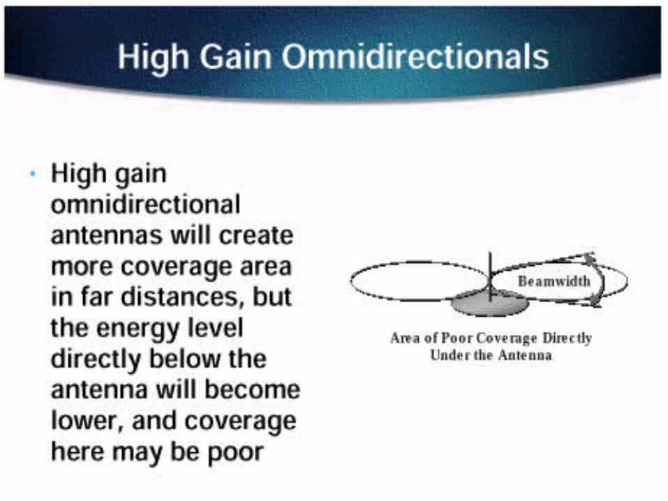
Beamwidth
Beamwidth is the angular separation of the half-power points of the radiated pattern


Half-wave Dipole (Hertz) Antenna
An antenna having a physical length that is one-half wavelength of the applied frequency is called a Hertz antenna or a half-wave dipole antenna. Hertz antennas are not found at frequencies below 2MHz because of the physical size needed of the antenna to represent a half-wave

Vertical (Marconi) Antenna
Vertical Antennas are used for frequencies under 2 MHz. It uses a conducting path to ground that acts as ¼ wavelength portion the antenna above the ground. The above ground structure represents a /4 wavelength
Vertical (Marconi) Antenna – cont’d
Poor grounding conditions of the earth/soil surrounding the antenna can result in serious signal attenuation. This problem is alleviated by installing a counterpoise

Counterpoise
Counterpoise is a grounding grid established where the earth grounding cannot satisfy electrical requirements for circuit completion. It is designed to be non-resonant at the operating frequency

Counterpoise-cont’d
supports
antenna
radius = ¼

Antenna Array
Antenna array is a group of antennas or antenna elements arranged to provide the desired directional characteristics. Generally any combination of elements can form an array. However, equal elements in a regular geometry are usually used.

Yagi-Uda Antenna
The Yagi-Uda antenna is a simple form of a directional antenna based off of a reflector placed /4 from the dipole antenna’s placement. Complex analysis to define the radiated patterns are experimental rather than theoretical calculations

Yagi-Uda Antenna-cont’d
reflector/2
dipole antenna
/4

antenna
2 dipole radiated signal without reflector
2 dipole radiated signal with reflector
Radiated Directed Signal

The Antenna Formula
c 186,000 misec
•c is the speed of light is the wavelength of the signal use 3 x 10⁸ when dealing in meters for the speed of light
frequency of the signal
The Antenna Formula - applied
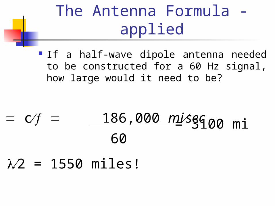
If a half-wave dipole antenna needed to be constructed for a 60 Hz signal, how large would it need to be?
c 186,000 misec
60= 3100 mi
2 = 1550 miles!

Radiation & Induction Fields The mechanics launching radio
frequencies from an antenna are not full understood. The RF fields that are created around the antenna have specific properties that affect the signals transmission. The radiated field field is known as the (surprisingly!) radiation field

Radiation & Induction Fields-cont’d There are two induction fields or
areas where signals collapse and radiate from the antenna. They are known as the near field and far field. The distance that antenna inductance has on the transmitted signal is directly proportional to antenna height and the dimensions of the wave
R 2D2

Radiation & Induction Fields-cont’d
R 2D2
Where: R = the distance from the antenna
D = dimension of the antenna
= wavelength of the transmitted signal

Radiation Resistance
Radiation Resistance is the portion of the antenna’s impedance that results in power radiated into space (i.e., the effective resistance that is related to the power radiated by the antenna. Radiation resistance varies with antenna length. Resistance increases as the increases

Effective Radiated Power (ERP)
ERP is the power input value and the gain of the antenna multiplied together dBi = isotropic radiator gain dBd = dipole antenna gain

Radiation Pattern Radiation pattern is an indication of
radiated field strength around the antenna. Power radiated from a /2 dipole occurs at right angles to the antenna with no power emitting from the ends of the antenna. Optimum signal strength occurs at right angles or 180° from opposite the antenna

Radiation Patterns Radiation pattern
Graphical representation of radiation properties of an antenna
Depicted as two-dimensional cross section Beam width (or half-power beam width)
Measure of directivity of antenna Reception pattern
Receiving antenna’s equivalent to radiation pattern

Radiation Pattern for Vertical Antennas
antenna
/4
/2

Antenna Gain Antenna gain
Power output, in a particular direction, compared to that produced in any direction by a perfect omnidirectional antenna (isotropic antenna)
Effective area Related to physical size and shape of antenna
Antenna Gain
Antenna gain is the measure in dB how much more power an antenna will radiate in a certain direction with respect to that which would be radiated by a reference antenna
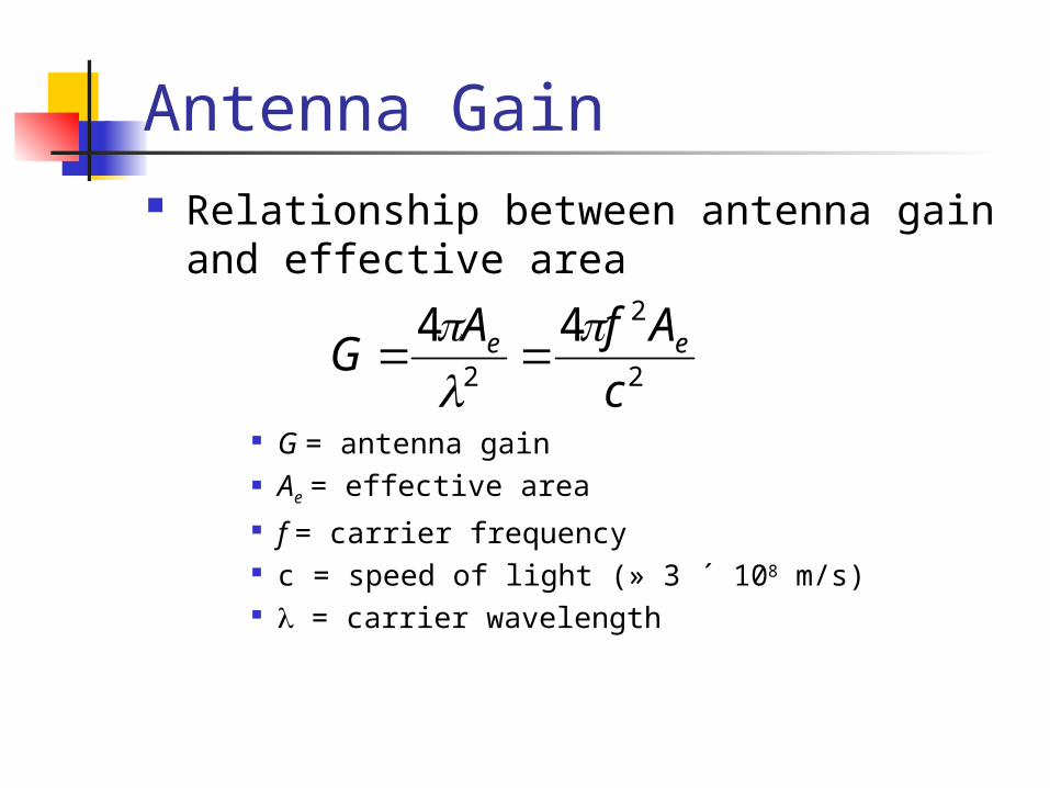
Antenna Gain Relationship between antenna gain and effective
area
G = antenna gain Ae = effective area f = carrier frequency c = speed of light (» 3 ´ 108 m/s) = carrier wavelength
2
2
2
44
c
AfAG ee


Propagation Modes Ground-wave propagation Sky-wave propagation Line-of-sight propagation

Ground Wave Propagation
Ground Wave Propagation Follows contour of the earth Can Propagate considerable distances Frequencies up to 2 MHz Example
AM radio

Sky Wave Propagation

Sky Wave Propagation Signal reflected from ionized layer of atmosphere
back down to earth Signal can travel a number of hops, back and forth
between ionosphere and earth’s surface Reflection effect caused by refraction Examples
Amateur radio CB radio

Line-of-Sight Propagation
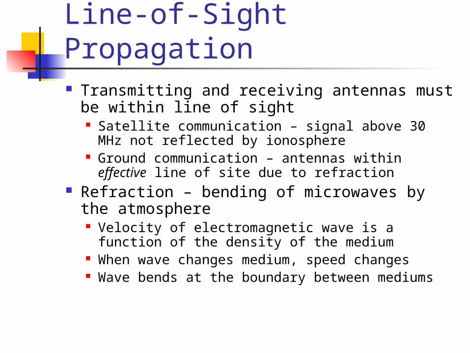
Line-of-Sight Propagation Transmitting and receiving antennas must be within
line of sight Satellite communication – signal above 30 MHz not reflected
by ionosphere Ground communication – antennas within effective line of
site due to refraction Refraction – bending of microwaves by the atmosphere
Velocity of electromagnetic wave is a function of the density of the medium
When wave changes medium, speed changes Wave bends at the boundary between mediums
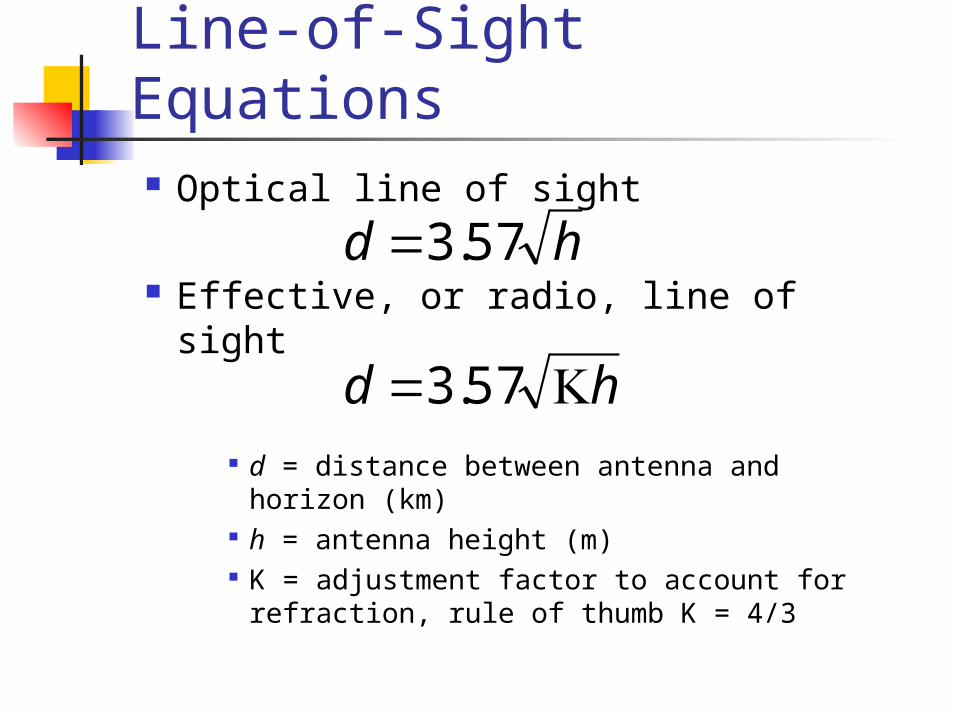
Line-of-Sight Equations Optical line of sight
Effective, or radio, line of sight
d = distance between antenna and horizon (km) h = antenna height (m) K = adjustment factor to account for refraction,
rule of thumb K = 4/3
hd 57.3
hd 57.3

Line-of-Sight Equations Maximum distance between two antennas
for LOS propagation:
h1 = height of antenna one
h2 = height of antenna two
2157.3 hh

LOS Wireless Transmission Impairments
Attenuation and attenuation distortion Free space loss Noise Atmospheric absorption Multipath Refraction Thermal noise
Thermal Noise Thermal noise due to agitation of electrons Present in all electronic devices and
transmission media Cannot be eliminated Function of temperature Particularly significant for satellite
communication

Noise Terminology Intermodulation noise – occurs if signals with
different frequencies share the same medium Interference caused by a signal produced at a frequency
that is the sum or difference of original frequencies Crosstalk – unwanted coupling between signal
paths Impulse noise – irregular pulses or noise spikes
Short duration and of relatively high amplitude Caused by external electromagnetic disturbances, or
faults and flaws in the communications system

Other Impairments Atmospheric absorption – water vapor and
oxygen contribute to attenuation Multipath – obstacles reflect signals so that
multiple copies with varying delays are received
Refraction – bending of radio waves as they propagate through the atmosphere

Multipath Propagation

Multipath Propagation Reflection - occurs when signal encounters a
surface that is large relative to the wavelength of the signal
Diffraction - occurs at the edge of an impenetrable body that is large compared to wavelength of radio wave
Scattering – occurs when incoming signal hits an object whose size in the order of the wavelength of the signal or less

The Effects of Multipath Propagation
Multiple copies of a signal may arrive at different phases If phases add destructively, the signal level
relative to noise declines, making detection more difficult
Intersymbol interference (ISI) One or more delayed copies of a pulse may
arrive at the same time as the primary pulse for a subsequent bit
Types of Fading Fast fading Slow fading Flat fading Selective fading Rayleigh fading Rician fading

Error Compensation Mechanisms Forward error correction Adaptive equalization Diversity techniques

Forward Error Correction Transmitter adds error-correcting code to data
block Code is a function of the data bits
Receiver calculates error-correcting code from incoming data bits If calculated code matches incoming code, no error
occurred If error-correcting codes don’t match, receiver attempts
to determine bits in error and correct

Adaptive Equalization Can be applied to transmissions that carry analog
or digital information Analog voice or video Digital data, digitized voice or video
Used to combat intersymbol interference Involves gathering dispersed symbol energy back
into its original time interval Techniques
Lumped analog circuits Sophisticated digital signal processing algorithms

Antenna Height
Antenna height above the ground is directly related to radiation resistance. Ground reflections causing out-of-phase signals to be radiated to receiving antennas will degrade the transmission. Physical length and electrical length of most antennas are approximately 95% of the physical length. Ideal antenna height is usually based on trial and error procedures
Smart Antennas

Smart Antennas smart antennas are base station
antennas with a pattern that is not fixed, but adapts to the current radio conditions
smart antennas have the possibility for a large increase in capacity: an increase of three times for TDMA systems and five times for CDMA systems has been reported.

Smart Antennas-cont’d Major drawbacks and cost factors
include increased transceiver complexity and more complex radio resource management

Smart Antennas-cont’d The idea of smart antennas is to
use base station antenna patterns that are not fixed, but adapt to the current radio conditions. This can be visualized as the antenna directing a beam toward the communication partner only

Smart Antennas-cont’d Smart antennas add a new way of
separating users, namely by space, through SDMA (space division multiple access)
By maximizing the antenna gain in the desired direction and simultaneously placing minimal radiation pattern in the directions of the interferers, the quality of the communication link can be significantly improved

Elements of a Smart Antenna
Smart antennas consists of a number of radiating elements, a combining/dividing network and a control unit
Phased Array Antenna
Phased Array antennas are a combination of antennas in which there is a control of the phase and power of the signal applied at each antenna resulting in a wide variety of possible radiation patterns
Types of Intelligent Antennas
Switched lobe (SL): This is also called switched beam. It is the simplest technique, and comprises only a basic switching function between separate directive antennas or predefined beams of an array. The setting that gives the best performance, usually in terms of received power, is chosen
Intelligent Antennas-cont’d
Dynamically phased array (PA): By including a direction of arrival (DoA) algorithm for the signal received from the user, continuous tracking can be achieved and it can be viewed as a generalization of the switched lobe concept
Intelligent Antennas-cont’d
Adaptive array (AA): In this case, a DoA algorithm for determining the direction toward interference sources (e.g., other users) is added. The radiation pattern can then be adjusted to null out the interferers. In addition, by using special algorithms and space diversity techniques, the radiation pattern can be adapted to receive multipath signals which can be combined. These techniques will maximize the signal to interference ratio (SIR)


SMDA
Space Division Multiple Access (SDMA) implies that more than one user can be allocated to the same physical communications channel simultaneously in the same cell, only separated by angle. In a TDMA system, two users will be allocated to the same time slot and carrier frequency at the same time and in the same cell
SMDA-cont’d
In systems providing full SDMA, there will be much more intracell handovers than in conventional TDMA or CDMA systems, and more monitoring by the network is necessary

Antenna Installation Considerations
Safety standard operating procedure
priority Grounding
lightning strikes static charges
Surge protection lightning searches for a second path
to ground
Antenna Installation Considerations-cont’d
Adaptive array antenna placement needs to be considered differently than current technologies serving the mobile environment. They need to be place so they have a greater angular approach to the receiving units. Existing tower placement with close proximity to roads and highways would need to be reconsidered.


Antenna Installation Considerations
Base, mast, and supporting structure needs clearance, serviceability (access), and complies with state, federal, and municipal guidelines