TOSHIBA Barcode Printer
B-852 SERIES
Owner’s Manual Mode d’emploi Bedienungsanleitung Manual de instrucciones Gebruikershandleiding Manuale Utente Manual do Utilizador


ENGLISH VERSION EO1-33055
TABLE OF CONTENTS
Page
1. PRODUCT OVERVIEW ........................................................................................................ E1-1 1.1 Introduction .................................................................................................................. E1-1 1.2 Features ...................................................................................................................... E1-1 1.3 Unpacking .................................................................................................................... E1-1 1.4 Accessories ................................................................................................................ E1-2 1.5 Appearance ................................................................................................................. E1-3 1.5.1 Dimensions .................................................................................................................. E1-3 1.5.2 Front View .................................................................................................................... E1-3 1.5.3 Rear View ..................................................................................................................... E1-3 1.5.4 Operation Panel ........................................................................................................... E1-4 1.5.5 Interior .......................................................................................................................... E1-4 1.6 Options ................................................................................................................................... E1-5 2. PRINTER SETUP ................................................................................................................. E2-1 2.1 Installation ................................................................................................................... E2-2 2.2 Assembling the Accessories ........................................................................................ E2-3 2.3.1 Assembling the Supply Holder Frame ......................................................................... E2-3 2.3 Connecting the Power Cord ......................................................................................... E2-4 2.4 Loading the Media ....................................................................................................... E2-5 2.4.1 Installing the Media onto the Supply Holder Unit ........................................................ E2-5 2.4.2 Installing the Supply Holder onto the Supply Holder Frame ....................................... E2-7 2.4.3 Loading Media into the Printer ..................................................................................... E2-7 2.5 Setting Sensor Positions ............................................................................................ E2-10 2.5.1 Setting the Feed Gap Sensor .................................................................................... E2-10 2.5.2 Setting the Black Mark Sensor .................................................................................. E2-10 2.6 Loading the Ribbon .................................................................................................... E2-11 2.7 Connecting the Cables to Your Printer ....................................................................... E2-12 2.8 Turning the Printer ON/OFF ....................................................................................... E2-13 2.8.1 Turning ON the Printer ............................................................................................... E2-13 2.8.2 Turning OFF the Printer ............................................................................................. E2-13 2.9 Setting an Operating Environment ............................................................................. E2-14 2.9.1 Parameter Setting ...................................................................................................... E2-15 2.9.2 Dump Mode Setting ................................................................................................... E2-27 2.9.3 BASIC Expansion Mode ............................................................................................ E2-29 2.9.4 Automatic Calibration ................................................................................................. E2-30 2.9.5 LAN Setting ................................................................................................................ E2-31 2.9.6 Real Time Clock Setting ............................................................................................ E2-32 2.9.7 IP Address Setting (TCP/IP) ...................................................................................... E2-34 2.10 Installing the Printer Drivers ....................................................................................... E2-40 2.11 Test Print ................................................................................................................... E2-41 2.12 Position and Print Tone Fine Adjustment .................................................................. E2-43 2.13 Threshold Setting ....................................................................................................... E2-50

ENGLISH VERSION EO1-33055
3. ON LINE MODE ................................................................................................................... E3-1 3.1 Operation Panel ........................................................................................................... E3-1 3.2 Operation ..................................................................................................................... E3-2 3.3 Reset ........................................................................................................................... E3-2 4. MAINTENANCE ................................................................................................................... E4-1 4.1 Cleaning ...................................................................................................................... E4-1 4.1.1 Print Head/Platen/Sensors .......................................................................................... E4-1 4.1.2 Covers and Panels ....................................................................................................... E4-2 4.1.3 Optional Cutter Module ................................................................................................ E4-2 5. TROUBLESHOOTING ......................................................................................................... E5-1 5.1 Error Messages ........................................................................................................... E5-1 5.2 Possible Problems ....................................................................................................... E5-3 5.3 Removing Jammed Media ........................................................................................... E5-5 6. PRINTER SPECIFICATIONS .............................................................................................. E6- 1
7. SUPPLY SPECIFICATIONS ................................................................................................ E7- 1 7.1 Media .......................................................................................................................... E7- 1 7.1.1 Media Type ....................................................................................................... E7- 1 7.1.2 Detection Area of the Transmissive Sensor ...................................................... E7- 2 7.1.3 Detection Area of the Reflective Sensor ............................................................ E7- 2 7.1.4 Effective Print Area ........................................................................................... E7- 3 7.2 Ribbon ........................................................................................................................ E7- 4 7.3 Recommended Media and Ribbon Types ................................................................... E7- 4 7.4 Care/Handling of Media and Ribbon ........................................................................... E7- 5
APPENDIX 1 MESSAGES AND LEDS .................................................................................... EA1-1
APPENDIX 2 INTERFACE ....................................................................................................... EA2-1
APPENDIX 3 PRINT SAMPLES ............................................................................................... EA3-1
APPENDIX 4 GLOSSARIES .................................................................................................... EA4-1
INDEX
CAUTION! 1. This manual may not be copied in whole or in part without prior written permission of TOSHIBA
TEC. 2. The contents of this manual may be changed without notification. 3. Please refer to your local Authorised Service representative with regard to any queries you may
have in this manual.
This is a Class A product. In a domestic environment this product may cause radio interference in which case the user may be required to take adequate measures.
WARNING!

1. PRODUCT OVERVIEW ENGLISH VERSION EO1-33055
1.1 Introduction
E1- 1
1. PRODUCT OVERVIEW1.1 Introduction 1.2 Features 1.3 Unpacking
Thank you for choosing the TOSHIBA B-852 series label/tag printer. This Owner’s Manual contains from general set-up through how to confirm the printer operation using a test print, and should be read carefully to help gain maximum performance and life from your printer. For most queries please refer to this manual and keep it safe for future reference. Please contact your TOSHIBA TEC representative for further information concerning this manual. The B-852 printer has the following features: • A 8.3 inch wide print head is installed in such a compact body that the
size of the printer body (except the Supply Holder Unit) is about 1/3 of the B-SX6T or B-SX8T printer.
• The print head block which can be fully opened realizes great operability.
• Various kinds of media can be used since the black mark sensors are located above and under the media passage, respectively, and the media sensors can be moved from the center to the left edge of the media.
• When the optional interface board is installed, Web functions such as remote maintenance and other advanced network functions are available.
• Superior hardware, including the specially developed 11.8 dots/mm (300 dots/inch) thermal print head which will allow very clear print at a printing speed of 50.8 mm/sec. (2 inches/sec.) or 101.6 mm/sec. (4 inches/sec.).
• Besides the optional cutter module, there is also an optional Expansion I/O Interface Board, Serial Interface Board, and Real Time Clock.
Unpack the printer as per the Unpacking Instructions supplied with the printer.
NOTES: • Check for damage or
scratches on the printer. However, please note that TOSHIBA TEC shall have no liability for any damage of any kind sustained during transportation of the product.
• Keep the cartons and pads for future transportation of the printer.

1. PRODUCT OVERVIEW ENGLISH VERSION EO1-33055
1.4 Accessories
E1- 2
1.4 Accessories
When unpacking the printer, please make sure all accessories are supplied with the printer. Start-up CD-ROM (1 pc.)
Power Cord QQ (1 pc.) Power Cord QP (1 pc.)
Print Head Cleaner (1 pc.) Supply Holder Unit (1 pc.)
Supply Holder Frame (L) Supply Holder Frame (R) (1 pc.) (1 pc.)
Supply Holder Base (1 pc.) Wing Bolt M-4x6 (2 pcs.)
Cable Clamp (1 pc.) Screw (1 pc.)
Supply Loading Instructions Safety Precautions (1 sheet) (1 sheet) Quality Control Report Warranty Disclaimer Sheet (1 sheet) (QQ) (1sheet) (QQ)
CAUTION! Be sure to use TOSHIBA TEC approved print head cleaner. Failure to do this may shorten the print head life.
<Contents> • Bar code print application (Bartender ultra lite) • Windows Driver • Owner’s Manual • Specifications (Programming, Key operation, etc.) • Product information (Catalogue)

1. PRODUCT OVERVIEW ENGLISH VERSION EO1-33055
1.5 Appearance
E1- 3
1.5 Appearance 1.5.1 Dimensions 1.5.2 Front View 1.5.3 Rear View
The names of the parts or units introduced in this section are used in the following chapters.
NOTE: Depth is 470 mm (18.5 inches) when the optional Cutter Module is installed on the printer.
Dimensions in inches +(mm)
15.2 (385) 7.1 (181)
16.8 (427)
10.4
(265
)
10.4
(265
)
Supply Holder Frame
Supply Holder Unit
Option: Expansion I/O Interface Connector Serial Interface Connector
Parallel Interface Connector (Centronics)
USB port
LAN Connector
LCD Message Display
Operation Panel
Power Switch Media Outlet
Top Cover
Head Pressure Adjust Lever
Caution Label

1. PRODUCT OVERVIEW ENGLISH VERSION EO1-33055
1.5 Appearance
E1- 4
1.5.4 Operation Panel 1.5.5 Interior
Please see Section 3.1 for further information about the Operation Panel.
LCD Message Display ON LINE LED
(Green)
ERROR LED (Red)
[PAUSE] key
POWER LED (Green)
[FEED] key
[RESTART] key
Print Head
Print Head Block
Head Block Release Lever
Ribbon Holder
Paper Guide
Black Mark/ Feed Gap Sensor
Platen
Supply Loading Instructions
Supply Path Label
Caution Label

1. PRODUCT OVERVIEW ENGLISH VERSION EO1-33055
1.6 Options
E1- 5
1.6 Options
Option Name Type Description Cutter module B-7208-QM-R A stop and cut swing cutter. Expansion I/O interface board
B-SA704-IO-QM-R Installing this board in the printer allows a connection with an external device with the exclusive interface, such as the keyboard module.
Serial Interface board B-SA704-RS-QM-R Installing this PC board provides an RS232C interface port.
Real time clock B-SA704-RTC-QM-R This module holds the current time: year, month, day, hour, minute, second
NOTE:
Available from your nearest TOSHIBA TEC representative or TOSHIBA TEC Head Quarters.

2. PRINTER SETUP ENGLISH VERSION EO1-33055
2. PRINTER SETUP
E2- 1
2. PRINTER SETUP This section outlines the procedures to setup your printer prior to its operation. The section includes precautions, loading media and ribbon, connecting cables, setting the operating environment of the printer, and performing an online print test.
Reference Procedure Setup Flow
After referring to the Safety Precautions in this manual, install the printer on a safe and stable location.
Connect a power cord to the power inlet of the printer, then, to an AC outlet.
Load a label stock or tag stock.
Adjust the position of feed gap sensor or black mark sensor according to the media to be used.
In case of thermal transfer printing, load the ribbon.
Connect the printer to a host computer or a network.
Set the printer parameters in the system mode.
Installation
Connecting the power cord
Loading the media
Setting the operating environment
Media sensor position alignment
Loading the ribbon
Connecting to a host computer
Make a print test in your operating environment and check the print result.
Print test
2.1 Installation
2.3 Connecting the Power Cord
2.4 Loading the Media
2.5 Setting Sensor Positions
2.6 Loading the Ribbon
2.7 Connecting the Printer to Your Host Computer
2.9 Setting an Operating Environment
2.11 Print Test
Automatic threshold setting
Manual threshold setting
If necessary, install the printer driver in your host computer.
2.10 Installing the Printer Drivers
If the print start position cannot be detected properly when pre-printed label is used, set the threshold automatically.
If the print start position cannot be detected properly even an automatic threshold setting is performing, manually set the threshold.
2.13 Threshold Setting
2.13 Threshold Setting
Turn on the printer power. Turning the power ON 2.8 Turning the Printer ON/OFF
Position and Print Tone Fine adjustment
If necessary, fine adjust the print start position, cut/strip position, print tone, etc.
2.12 Position and Print Tone Fine Adjustment
Assemble the supply holder stand, and attach it to the rear of the printer.
Assembling the supply holder frame
2.2 Assembling the Supply Holder Frame
Installing the printer driver

2. PRINTER SETUP ENGLISH VERSION EO1-33055
2.1 Installation
E2- 2
2.1 Installation
To insure the best operating environment, and to assure the safety of the operator and the equipment, please observe the following precautions.
• Operate the printer on a stable, level, operating surface in a location free from excessive humidity, high temperature, dust, vibration or direct sunlight.
• Keep your work environment static free. Static discharge can cause damage to delicate internal components.
• Make sure that the printer is connected to a clean source of AC Power and that no other high voltage devices that may cause line noise interference are connected to the same mains.
• Assure that the printer is connected to the AC mains with a three-prong power cable that has the proper ground (earth) connection.
• Do not operate the printer with the cover open. Be careful not to allow fingers or articles of clothing to get caught into any of the moving parts of the printer especially the optional cutter mechanism.
• Make sure to turn off the printer power and to remove the power cord from the printer whenever working on the inside of the printer such as changing the ribbon or loading the media, or when cleaning the printer.
• For best results, and longer printer life, use only TOSHIBA TEC recommended media and ribbons.
• Store the media and ribbons in accordance with their specifications. • This printer mechanism contains high voltage components; therefore
you should never remove any of the covers of the machine as you may receive an electrical shock. Additionally, the printer contains many delicate components that may be damaged if accessed by unauthorised personnel.
• Clean the outside of the printer with a clean dry cloth or a clean cloth slightly dampened with a mild detergent solution.
• Use caution when cleaning the thermal print head as it may become very hot while printing. Wait until it has had time to cool before cleaning. Use only the TOSHIBA TEC recommended print head cleaner to clean the print head.
• Do not turn off the printer power or remove the power plug while the printer is printing or while the ON LINE lamp is blinking.
2. PRINTER SETUP ENGLISH VERSION EO1-33055
2.2 Assembling the Accessories
E2- 3
2.2 Assembling the Accessories
2.2.1 Assembling the Supply
Holder Frame
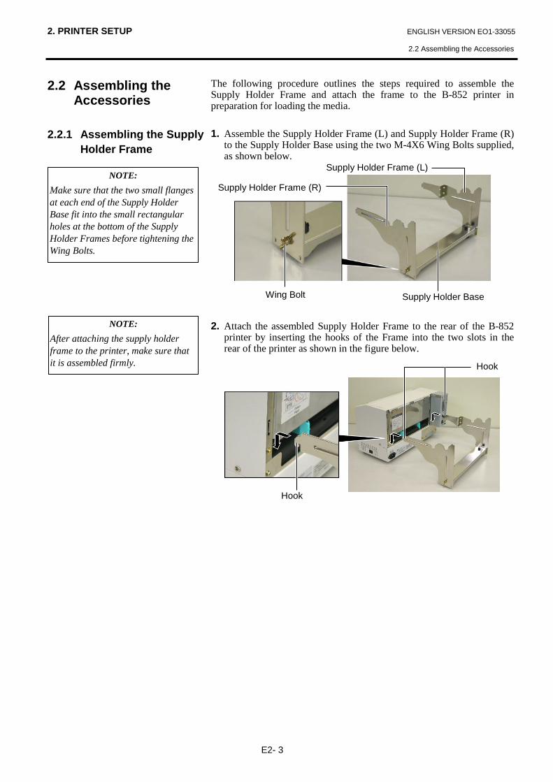
The following procedure outlines the steps required to assemble the Supply Holder Frame and attach the frame to the B-852 printer in preparation for loading the media. 1. Assemble the Supply Holder Frame (L) and Supply Holder Frame (R)
to the Supply Holder Base using the two M-4X6 Wing Bolts supplied, as shown below.
2. Attach the assembled Supply Holder Frame to the rear of the B-852
printer by inserting the hooks of the Frame into the two slots in the rear of the printer as shown in the figure below.
NOTE: Make sure that the two small flanges at each end of the Supply Holder Base fit into the small rectangular holes at the bottom of the Supply Holder Frames before tightening the Wing Bolts.
NOTE: After attaching the supply holder frame to the printer, make sure that it is assembled firmly.
Supply Holder Base
Supply Holder Frame (L)
Supply Holder Frame (R)
Wing Bolt
Hook
Hook

2. PRINTER SETUP ENGLISH VERSION EO1-33055
2.3 Connecting the Power Cord
E2- 4
2.3 Connecting the Power Cord
1. Make sure that the printer power switch is in the off position.
2. Connect the Power Cord to the printer as shown in the figure below.
3. Plug the other end of the Power Cord into a grounded outlet as shown
in the figure below.
[Example of US Type(QQ model)] [Example of EU Type(QP model)]
CAUTION! 1. Make sure that the printer
power switch is turned to the off position before connecting the power cord to prevent possible electric shock or damage to the printer.
2. Use only the power cord supplied with the printer. Use of any other cord may cause electric shock or fire.
3. Connect the power cord to a three-prong outlet only, with the third prong being a good ground (earth) connection.
Power Switch
Power Connector
Power Cord Power Cord

2. PRINTER SETUP ENGLISH VERSION EO1-33055
2.4 Loading the Media
E2- 5
2.4 Loading the Media 2.4.1 Installing the Media
onto the Supply Holder Unit
The following procedure will outline the steps required to install the media onto the Supply Holder Unit and adjust its position in the Supply Holder Frame at the rear of the B-852 printer. The procedure will then show the steps to properly load the media into the printer so that it feeds straight and true through the printer. The figure below shows the assembled Supply Holder Unit and the paragraphs that follow show the step-by-step procedures to disassemble the Supply Holder Unit, install the media onto the Supply Shaft, then reassembling the Supply Holder Unit so that the auto centering mechanism will automatically center the media on the Supply Shaft.
Disassembling the Supply Holder Unit 1. Position the Supply Holder Unit as shown in the above diagram so
that the Non-removable Supply Holder is at the right. 2. Rotate the Green Supply Holder Locking Knob in the direction of
arrow (counterclockwise) to loosen the Removable Supply Holder. 3. Slide the Removable Supply Holder in the direction of arrow to
remove it from the Supply Shaft. 4. Rotate the green Supply Holder Locking Knob in the direction of
arrow (counterclockwise) to loosen the Non-removable Supply Holder.
5. Slide the Non-removable Supply Holder all the way to the end of the Supply Shaft until it stops.
Non-removable Supply Holder
Removable Supply Holder
Green Supply Holder Locking Knob
NOTES: 1. The Non-removable Supply
Holder is the one that slides in the wide slot while the Removable Supply Holder is the one that slides in the narrow slot.
2. Do not turn the Supply Holder Locking Knob anti-clockwise too far, or it may come off the Supply Holder.
Wide Slot Narrow Slot
Supply Shaft
Stopper

2. PRINTER SETUP ENGLISH VERSION EO1-33055
2.4 Loading the Media
E2- 6
2.4.1 Installing the Media onto the Supply Holder Unit (Cont.)
The diagram below, and the steps that follow, show the procedures for installing the Media onto the Supply Shaft and reassembling the Supply Holder Unit. Be sure to follow the step-by-step procedure exactly or the auto centering mechanism may not work properly.
Installing the Media and reassembling the Supply Holder 1. Place the media roll onto the Supply Shaft with the media feeding
from the bottom as shown in the diagram above. 2. Align the tab of the Removable Supply Holder with the Slot in the
Supply Shaft, then reinstall the Removable Supply Holder by sliding it onto the Supply Shaft as shown in the figure above.
3. Holding the reassembled Supply Holder Unit in your right hand, apply pressure only to the reinstalled Removable Supply Holder to push it in the direction of arrow , causing the auto centering mechanism to center the media on the Supply Shaft.
4. Tighten the green Supply Holder Locking Knob for the Removable Supply Holder by turning it in the direction of arrow .
5. Tighten the green Supply Holder Locking Knob for the Non-removable Supply Holder by turning it in the direction of arrow .
NOTES: 1. This Supply Holder accepts four
sizes of media core: 38 mm, 40 mm, 42 mm and 76.2 mm.. When using a media roll of 38 mm, 40 mm, or 42 mm, remove the spacers from the Supply Holders by pushing both hooks of the Spacer. Keep the removed Spacers safe.
2. Use only inside wound label
stock. Outside wound label stock may not feed properly. Use outside wound label stock at your own risk.
3. Do not over-tighten the green Supply Holder Locking Knob.
If you turn the Removable Supply Holder side down after loading the media, the media may drop by weight. You might be injured by the dropped media.
WARNING!
CAUTION! When installing the media roll, do not push on the Non-removable Supply Holder as this will result in the media roll not being properly centred.
Non-removable Supply Holder
Removable Supply Holder
Green Supply Holder Locking Knob
Media Roll
Supply Shaft
Print Side
Slot
Tab
Spacer
Supply Holder
2. PRINTER SETUP ENGLISH VERSION EO1-33055
2.4 Loading the Media
E2- 7
2.4.2 Installing the Supply Holder Unit onto the Supply Holder Frame
2.4.3 Loading Media into the Printer
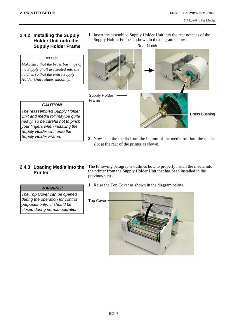
1. Insert the assembled Supply Holder Unit into the rear notches of the Supply Holder Frame as shown in the diagram below.
2. Now feed the media from the bottom of the media roll into the media slot at the rear of the printer as shown.
The following paragraphs outlines how to properly install the media into the printer from the Supply Holder Unit that has been installed in the previous steps.
1. Raise the Top Cover as shown in the diagram below.
CAUTION! The reassembled Supply Holder Unit and media roll may be quite heavy, so be careful not to pinch your fingers when installing the Supply Holder Unit onto the Supply Holder Frame.
Top Cover
NOTE: Make sure that the brass bushings of the Supply Shaft are seated into the notches so that the entire Supply Holder Unit rotates smoothly.
Supply Holder Frame
Brass Bushing
Rear Notch
The Top Cover can be opened during the operation for control purposes only. It should be closed during normal operation.
WARNING!
2. PRINTER SETUP ENGLISH VERSION EO1-33055
2.4 Loading the Media
E2- 8
2.4.3 Loading Media into the Printer (Cont.)
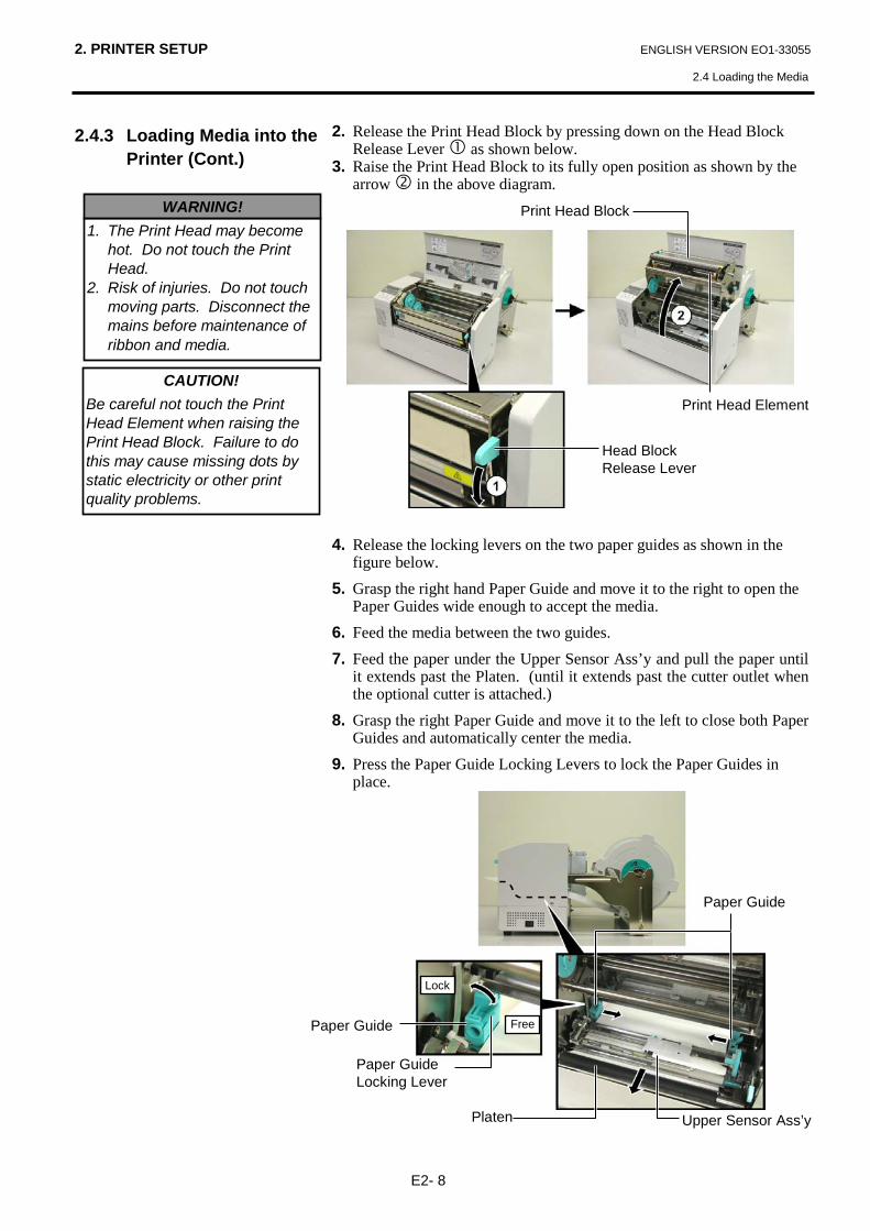
2. Release the Print Head Block by pressing down on the Head Block Release Lever as shown below.
3. Raise the Print Head Block to its fully open position as shown by the arrow in the above diagram.
4. Release the locking levers on the two paper guides as shown in the
figure below. 5. Grasp the right hand Paper Guide and move it to the right to open the
Paper Guides wide enough to accept the media. 6. Feed the media between the two guides. 7. Feed the paper under the Upper Sensor Ass’y and pull the paper until
it extends past the Platen. (until it extends past the cutter outlet when the optional cutter is attached.)
8. Grasp the right Paper Guide and move it to the left to close both Paper Guides and automatically center the media.
9. Press the Paper Guide Locking Levers to lock the Paper Guides in place.
CAUTION! Be careful not touch the Print Head Element when raising the Print Head Block. Failure to do this may cause missing dots by static electricity or other print quality problems.
1. The Print Head may become hot. Do not touch the Print Head.
2. Risk of injuries. Do not touch moving parts. Disconnect the mains before maintenance of ribbon and media.
WARNING! Print Head Block
Print Head Element
Head Block Release Lever
Paper Guide
Platen
Paper Guide Locking Lever
Upper Sensor Ass’y
Paper Guide
Lock
Free
2. PRINTER SETUP ENGLISH VERSION EO1-33055
2.4 Loading the Media
E2- 9
2.4.3 Loading Media into the Printer (Cont.)
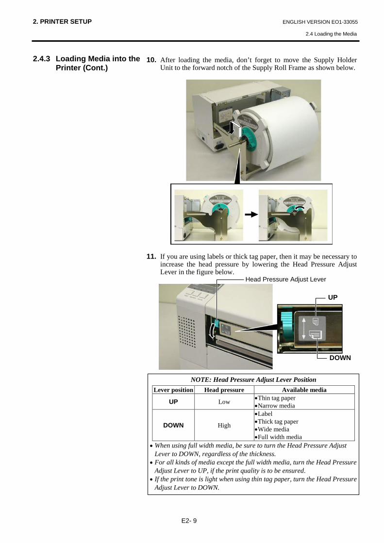
10. After loading the media, don’t forget to move the Supply Holder Unit to the forward notch of the Supply Roll Frame as shown below.
11. If you are using labels or thick tag paper, then it may be necessary to
increase the head pressure by lowering the Head Pressure Adjust Lever in the figure below.
Head Pressure Adjust Lever
UP
DOWN
NOTE: Head Pressure Adjust Lever Position Lever position Head pressure Available media
UP Low •Thin tag paper •Narrow media
DOWN High
•Label •Thick tag paper •Wide media •Full width media
• When using full width media, be sure to turn the Head Pressure Adjust Lever to DOWN, regardless of the thickness.
• For all kinds of media except the full width media, turn the Head Pressure Adjust Lever to UP, if the print quality is to be ensured.
• If the print tone is light when using thin tag paper, turn the Head Pressure Adjust Lever to DOWN.

2. PRINTER SETUP ENGLISH VERSION EO1-33055
2.5 Setting Sensor Positions
E2-10
2.5 Setting Sensor Positions
2.5.1 Setting the Feed Gap Sensor
2.5.2 Setting the Black Mark
Sensor
After loading the media, as outlined in the previous paragraphs, it will usually be necessary to set the Media Sensors used to detect the print start position for label or tag printing.
1. With the Print Head Block raised as described in section 2.4.3, pass the labels under the Upper Sensor Ass’y as shown in the figure below.
2. Rotate the Green Sensor Adjust Gear to move the Sensor Ass’y to the left or right to center the arrow ( ↑ ) over the label.
3. With the sensor set to the center of the labels, it will be guaranteed to detect the gap between labels even if the labels are round.
1. If the Black Mark is printed on the top of the tag media then simply
rotate the Green Sensor Adjust Gear to move the Sensor Ass’y so that the Black Mark Indicator ( ) is directly in line with the Black Mark on the top of the paper.
2. If the Black Mark is printed on the bottom of the tag media then fold the media back to be able to see the Black Mark and its relationship to the Sensor Ass’y as shown in the figure below.
Upper Sensor Ass’y Green Sensor Adjust Gear
Upper Sensor Ass’y
Green Sensor Adjust Gear

2. PRINTER SETUP ENGLISH VERSION EO1-33055
2.6 Loading the Ribbon
E2-11
2.6 Loading the Ribbon
1. Raise the Top Cover and release and raise the Print Head Block as described in section 2.4.3, steps 1 and 2.
2. Hold the Ribbon Supply Roll in your left hand and the Ribbon Take up Roll in your right hand.
3. Install the Ribbon Supply Roll into the Print Head Block as shown in the figure below and described in the following paragraphs.
4. Step 1, engage the end of the Ribbon Supply Roll Core to the Ribbon Core Guide and push to compress the Ribbon Spring.
5. Step 2, engage the opposite end of the Ribbon Supply Roll Core to the Green Ribbon Winding Core releasing pressure to relax the Ribbon Spring.
6. Rotate the Green Ribbon Winding Core to lock the Ribbon Supply Roll into position.
7. Repeat steps 4 through 6 with the Ribbon Take up Roll, locking it in
place also. 8. Take up any slack in the ribbon by rotating the green Ribbon Winding
Core on the take up in the direction of arrow . 9. Close the Print Head Block and lock it in place by pressing at
locations and in the figure below.
NOTE: Be sure to remove any slack in the ribbon. Printing with a wrinkled ribbon will lower the print quality.
• The Print Head may become hot. Do not touch the Print Head. • The Top Cover can be opened during the operation for control purposes only. It should be closed during normal operation. • Risk of injuries. Do not touch moving parts. Disconnect the mains before maintenance of ribbon and media.
WARNING!
Ribbon Core Guide
Green Ribbon Winding Core
Ribbon Spring
Ribbon Take-up Roll
Ribbon Supply Roll
Green Ribbon Winding Core

2. PRINTER SETUP ENGLISH VERSION EO1-33055
2.7 Connecting the Cables to Your Printer
E2-12
2.7 Connecting the Cables to Your Printer
The following paragraphs outline how to connect your host computer to the printer, and will also show how to make cable connections to other devices. Depending on the system configuration you use to print labels, there are 5 possibilities for connecting the printer to your host computer. These are: • A parallel cable connection between the printer’s standard parallel
connector and your host computer’s parallel port (LPT). • An Ethernet connection using the standard LAN board. • A USB cable connection between the printer’s standard USB
connector and your host computer’s USB port. (Conforming to USB 2.0 Full Speed)
• A serial cable connection between the printer’s optional RS-232C serial connector and one of your host computer’s COM ports. <Option>
For details of each interface, refer to APPENDIX 2. After connecting the necessary interface cables, set an operating environment of the printer. Refer to Section 2.9.1 Parameter Setting. The diagram below shows all the possible cable connections to the current version of the printer.
Expansion I/O Connector
Serial I/F Connector
USB Connector
Parallel Connector
LAN Connector
Expansion I/O and Serial I/F (Option)
CAUTION! Do not directly connect the LAN cable wired outside of a building to the LAN port provided on this product, as the LAN port on this product is intended for indoor connection. To connect such LAN cable to the product, be sure to use any communication equipment, like a router, a hub, or a modem which is located within the same building as the product.
NOTE: When using the Parallel interface, fix the Parallel Interface Cable to the printer back with the supplied Cable Clamp and the SMW-3x8 screw.
Cable Clamp
Screw
Parallel Interface Cable

2. PRINTER SETUP ENGLISH VERSION EO1-33055
2.8 Turning the Printer ON/OFF
E2-13
2.8 Turning the Printer ON/OFF
2.8.1 Turning ON the Printer 2.8.2 Turning OFF the Printer
When the printer is connected to your host computer it is good practice to turn the printer ON before turning on your host computer and turn OFF your host computer before turning off the printer. 1. To turn ON the printer power, press the power switch as shown in the
diagram below. Note that ( ) is the power ON side of the switch.
2. Check that the ON LINE message appears in the LCD Message
Display and that the ON LINE and POWER LED lights are illuminated.
1. Before turning off the printer power switch verify that the ON LINE
message appears in the LCD Message Display and that the ON LINE LED light is on and is not flashing.
2. To turn OFF the printer power press the power switch as shown in the diagram below. Note that () is the power OFF side of the switch.
CAUTION!
Use the power switch to turn the printer On/Off. Plugging or unplugging the power cord to turn the printer On/Off may cause fire, an electric shock, or damage to the printer.
NOTE: If an error message appears in the display instead of the ON LINE message or the ERROR LED lamp is illuminated, go to Chapter 5.1, Error Messages.
Power Switch
CAUTION! • Do not turn off the printer power
while the media is being printed as this may cause a paper jam or damage to the printer.
• Do not turn off the printer power while the ON LINE light is blinking as this may cause damage to your computer.
Power Switch

2. PRINTER SETUP ENGLISH VERSION EO1-33055
2.9 Setting an Operating Environment
E2-14
2.9 Setting an Operating Environment
Depending on the settings of your host computer or an interface to be used, it may be necessary to change the printer parameter settings. Follow the procedures described below to change the printer parameter settings in the System Mode to correspond to your environment. How to enter the System Mode 1. Turn on the printer and confirm that “ONLINE” appears on the LCD
Message Display. 2. Press the [PAUSE] key to pause the printer. 3. Hold down the [RESTART] key for three seconds until “<1>RESET”
is displayed. The System Mode consists of the following menus. <1>RESET This menu is used to clear print data sent from a
PC and return the printer to an idle state. Refer to Section 3.3 Reset.
<2>PARAMETER SET
This menu is used to set the printer parameters. Refer to Section 2.9.1 Parameter Setting.
<3>ADJUST SET This menu is used to make a fine adjustment of a print start position, cut position, etc. Refer to Section 2.12 Position and Print Tone Fine Adjustment.
<4>DUMP MODE This menu is used to print the data in the receive buffer for debug. Refer to Section 2.9.2 Dump Mode Setting.
<5>EXPAND MODE This menu is used to start the program for BASIC mode. Refer to Section 2.9.3 BASIC Expansion Mode.
<6>AUTO CALIB This menu is used to enable or disable the automatic calibration function. Refer to Section 2.9.4 Automatic Caliburation.
<7>LAN This menu is used to enable or disable the LAN communication and SNMP. Refer to Section 2.9.5 LAN Setting.
<8>RTC SET This menu is used to set the date and time of the real time clock, enable or disable the low battery check, and choose a real time renewal timing. Refer to Section 2.9.6 Real Time Clock Setting.
NOTE: Incorrect settings can cause the printer to function erroneously. If you have any problems with the parameter settings, please contact your nearest TOSHIBA TEC service representative. For the settings this manual does not cover, please contact your nearest TOSHIBA TEC service representative, or refer to the B-852 Series Key Operation Specification.
NOTES: 1. System Mode menus can be selected with the [RESTART] or [FEED] key. 2. To enter each of the above System Mode menus, press the [PAUSE] key
when the menu is displayed. 3. If the [PAUSE] key is pressed with “<1>RESET” being displayed, the
printer will turn to an idle state and the message will change to “ONLINE”
[FEED]
[FEED]
[FEED]
[FEED]
[FEED]
[RESTART]
[RESTART]
[RESTART]
[RESTART]
[RESTART]
<1>RESET
<2>PARAMETER SET
<3>ADJUST SET
<4>DUMP MODE
<5>EXPAND MODE
ON LINE
PAUSE
[PAUSE]
Hold down [RESTART] for 3 sec.
[FEED]
[FEED]
[FEED]
[RESTART]
[RESTART]
[RESTART]
<6>AUTO CALIB
<7>LAN
<8>RTC SET
LCD Message Display
FEED key RESTART key PAUSE key

2. PRINTER SETUP ENGLISH VERSION EO1-33055
2.9 Setting an Operating Environment
E2-15
2.9.1 Parameter Setting
While “<2>PARAMETER SET” is displayed on the LCD Message Display, press the [PAUSE] key to enter the Parameter Setting Mode. The Parameter Setting Mode contains the following sub menus. Each time the [PAUSE] key is pressed, the sub menus are displayed sequentially.
(1) Character code selection (2) Character zero selection (3) Baud rate selection (4) Data length selection (5) Stop bit length selection (6) Parity selection (7) Flow control code selection (8) LCD language selection (9) Auto forward wait selection (10) Control code selection (11) FEED key function selection (12) KANJI code selection (13) EURO code selection (14) Auto print head check selection (15) Centronics ACK/BUSY timing selection (16) Web printer function selection (17) Input prime selection (18) Expansion I/O interface selection (19) Plug & Play selection (20) Label end/ribbon end selection (21) Maxi code specification selection
2. PRINTER SETUP ENGLISH VERSION EO1-33055
2.9 Setting an Operating Environment
E2-16
2.9.1 Parameter Setting (Cont.)
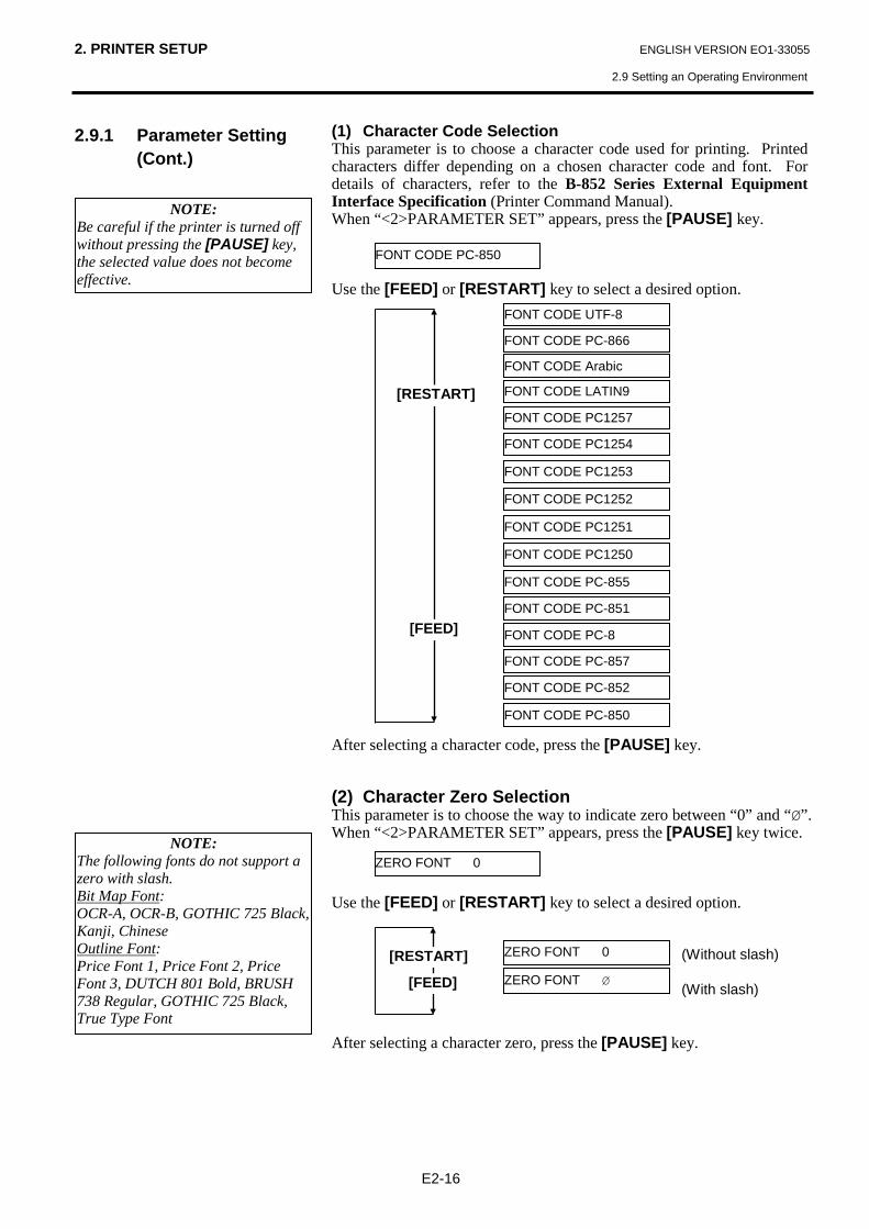
(1) Character Code Selection This parameter is to choose a character code used for printing. Printed characters differ depending on a chosen character code and font. For details of characters, refer to the B-852 Series External Equipment Interface Specification (Printer Command Manual). When “<2>PARAMETER SET” appears, press the [PAUSE] key. Use the [FEED] or [RESTART] key to select a desired option. After selecting a character code, press the [PAUSE] key. (2) Character Zero Selection This parameter is to choose the way to indicate zero between “0” and “Ø”. When “<2>PARAMETER SET” appears, press the [PAUSE] key twice. Use the [FEED] or [RESTART] key to select a desired option. After selecting a character zero, press the [PAUSE] key.
NOTE: Be careful if the printer is turned off without pressing the [PAUSE] key, the selected value does not become effective.
FONT CODE PC-850
[RESTART]
[FEED]
ZERO FONT 0
ZERO FONT 0
ZERO FONT Ø
[RESTART]
[FEED]
(Without slash) (With slash)
NOTE: The following fonts do not support a zero with slash. Bit Map Font: OCR-A, OCR-B, GOTHIC 725 Black, Kanji, Chinese Outline Font: Price Font 1, Price Font 2, Price Font 3, DUTCH 801 Bold, BRUSH 738 Regular, GOTHIC 725 Black, True Type Font
FONT CODE PC-850
FONT CODE PC-852
FONT CODE PC-857
FONT CODE PC-8
FONT CODE PC-851
FONT CODE PC-855
FONT CODE PC1250
FONT CODE PC1251
FONT CODE PC1252
FONT CODE PC1253
FONT CODE PC1254
FONT CODE LATIN9
FONT CODE Arabic
FONT CODE PC-866
FONT CODE UTF-8
FONT CODE PC1257

2. PRINTER SETUP ENGLISH VERSION EO1-33055
2.9 Setting an Operating Environment
E2-17
2.9.1 Parameter Setting (Cont.)
<Reference> Properties screen of Serial (COM) port under Windows98
(3) Baud Rate Selection This parameter is to choose a baud rate of the RS-232C interface. When the printer communicates with a host computer by serial interface, be sure to match the setting with the host. When “<2>PARAMETER SET” appears, press the [PAUSE] key until the following display appears. Use the [FEED] or [RESTART] key to select a desired option. After selecting a baud rate, press the [PAUSE] key. (4) Data Length Selection This parameter is to choose a communication data length of the RS-232C interface. 7 bits is used when transmitting alphanumeric data only. 8 bits is used to when transmitting special characters. Be sure to match a setting with a host computer. When “<2>PARAMETER SET” appears, press the [PAUSE] key until the following display appears. Use the [FEED] or [RESTART] key to select a desired option. After selecting a data length, press the [PAUSE] key.
SPEED 9600bps
[RESTART]
[FEED]
SPEED 19200 bps
SPEED 9600 bps
SPEED 4800 bps
SPEED 2400 bps
SPEED 115200 bps
SPEED 38400 bps
DATA LENG. 8bits
DATA LENG. 7bits
DATA LENG. 8bits
[RESTART]
[FEED]

2. PRINTER SETUP ENGLISH VERSION EO1-33055
2.9 Setting an Operating Environment
E2-18
2.9.1 Parameter Setting (Cont.)
(5) Stop Bit Length Selection This parameter is to choose a stop bit length of the RS-232C interface. Be sure to match a setting with a host computer. When “<2>PARAMETER SET” appears, press the [PAUSE] key until the following display appears. Use the [FEED] or [RESTART] key to select a desired option. After selecting a stop bit length, press the [PAUSE] key. (6) Parity Selection This parameter is to choose the parity of the RS-232C interface. When “<2>PARAMETER SET” appears, press the [PAUSE] key until the following display appears. Use the [FEED] or [RESTART] key to select a desired option. After selecting the parity, press the [PAUSE] key. (7) Flow Control Code Selection This parameter is to choose a flow control code of the RS-232C interface. When “<2>PARAMETER SET” appears, press the [PAUSE] key until the following display appears. Use the [FEED] or [RESTART] key to select a desired option. After selecting a flow control code, press the [PAUSE] key.
STOP BIT 1bit
STOP BIT 2bits
STOP BIT 1bit
[RESTART]
[FEED]
XON+READY AUTO
[RESTART]
[FEED]
XON+READY AUTO
XON/XOFF AUTO
READY/BUSY
XON/XOFF
READY/BUSY RTS
XON/XOFF mode
XON/XOFF+READY/BUSY (DTR) mode
READY/BUSY (DTR) mode XON/XOFF mode
RTS mode
PARITY NONE
PARITY EVEN
PARITY ODD [RESTART]
[FEED] PARITY NONE
NOTE: The following is the detailed descriptions for each transmission control code. 1) XON/XOFF AUTO At the power on time, the printer
outputs XON. At the power off time, the printer outputs XOFF.
2) XON+READY AUTO At the power on time, the printer
outputs XON. At the power off time, the printer outputs XOFF.
3) READY/BUSY At the power on time, the DTR
signal output from the printer turns to High level (READY). At the power off time, the printer does not output XOFF.
4) ON/XOFF At the power on time, the printer
outputs XON. At the power off time, the printer does not output XOFF.
5) READY/BUSY RTS At the power on time, the RTS signal
output from the printer turns to High level (READY). At the power off time, the printer does not output XOFF.
NOTES: 1. When using the hardware flow
control, the control signals and data must be in pairs between the printer and the PC. Printer Host TD → RD RD ←- TD RTS → CTS CTS ←- RTS DSR → DTR DTR ←- DSR Refer to the RS-232C connector’s pin layout in APPENDIX 2. Check if the printer and the PC is properly connectable with your cable
2. Be careful that there are two types of RS-232C cable; straight cable and cross cable. Use a straight cable for this printer.

2. PRINTER SETUP ENGLISH VERSION EO1-33055
2.9 Setting an Operating Environment
E2-19
2.9.1 Parameter Setting (Cont.)
(8) LCD Language Selection This parameter is to choose a language in which the LCD message is displayed. When “<2>PARAMETER SET” appears, press the [PAUSE] key until the following display appears. Use the [FEED] or [RESTART] key to select a desired option. After selecting a language, press the [PAUSE] key. (9) Auto Forward Wait Selection This parameter is to choose whether to activate the Auto Forward Wait function or not. This function, used in the cut mode, automatically feeds the media forward for about 19 mm if there is more than 1-second idle time after printing, to prevent the top edge of the media from curling. When “<2>PARAMETER SET” appears, press the [PAUSE] key until the following display appears. Use the [FEED] or [RESTART] key to select a desired option. After selecting an auto forward wait, press the [PAUSE] key.
LCD ENGLISH
[RESTART]
[FEED]
ENGLISH
ITALIAN
JAPANESE
SPANISH
DUTCH
FRENCH
GERMAN
FORWARD WAIT OFF
[RESTART]
[FEED] FORWARD WAIT OFF Not activated
FORWARD WAIT ON Activated
NOTES: 1. If the printer is not used for a few
days, the top edge of the media may become curly, which may cause a paper jam. The Auto Forward Wait Function prevents this problem since the media feed amount is increased so that the media stops past the platen.
2. When the Stop Position Fine Adjustment Value is set in + direction, the media will stop past the media outlet. When the value is set in – direction, the media will stop inside the media outlet.
3. This setting will be useful to fine adjust the cut position of labels.

2. PRINTER SETUP ENGLISH VERSION EO1-33055
2.9 Setting an Operating Environment
E2-20
2.9.1 Parameter Setting (Cont.)
When ON is selected, pressing the [PAUSE] key will result that the LCD Message Display shows the stop position fine adjustment value setting screen. [FEED] key: Pressing the [FEED] key one time causes a –0.1mm change,
up to –5.0 mm. [RESTART] key: Pressing the [RESTART] key one time causes a +0.1mm
change, up to +5.0 mm. After selecting an auto forward wait, press the [PAUSE] key. (10) Control Code Selection This parameter is to choose a Control Code. When “<2>PARAMETER SET” appears, press the [PAUSE] key until the following display appears. Use the [FEED] or [RESTART] key to select a desired option. When “CODE MANUAL” is selected and the [PAUSE] key is pressed, the LCD display will show the setting screen of CONTROL CODE1 to CONTROL CODE3 as follows.
POSITION +5.0mm
POSITION +0.0mm [RESTART]
[FEED] POSITION -5.0mm
POSITION +0.0mm
CODE AUTO
CODE AUTO
CODE ESC,LF,NUL [RESTART]
[FEED] CODE{|}
CODE MANUAL
Automatic selection
Manual selection
Manual selection
Control codes should be specified.
CONTROL CODE1 1B
[RESTART]
[FEED]
CONTROL CODE1 FF
CONTROL CODE1 FE
CONTROL CODE1 01
CONTROL CODE1 00
CONTROL CODE1 FD
CONTROL CODE1 02
2. PRINTER SETUP ENGLISH VERSION EO1-33055
2.9 Setting an Operating Environment
E2-21
2.9.1 Parameter Setting (Cont.)
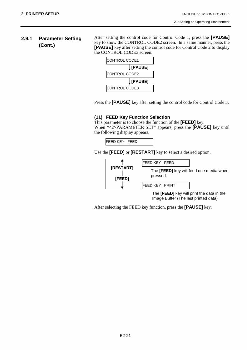
After setting the control code for Control Code 1, press the [PAUSE] key to show the CONTROL CODE2 screen. In a same manner, press the [PAUSE] key after setting the control code for Control Code 2 to display the CONTROL CODE3 screen. Press the [PAUSE] key after setting the control code for Control Code 3. (11) FEED Key Function Selection This parameter is to choose the function of the [FEED] key. When “<2>PARAMETER SET” appears, press the [PAUSE] key until the following display appears. Use the [FEED] or [RESTART] key to select a desired option. After selecting the FEED key function, press the [PAUSE] key.
CONTROL CODE1
CONTROL CODE2
CONTROL CODE3
[PAUSE]
[PAUSE]
FEED KEY FEED
FEED KEY FEED
FEED KEY PRINT
[RESTART]
[FEED]
The [FEED] key will feed one media when pressed.
The [FEED] key will print the data in the Image Buffer (The last printed data)

2. PRINTER SETUP ENGLISH VERSION EO1-33055
2.9 Setting an Operating Environment
E2-22
2.9.1 Parameter Setting (Cont.)
(12) KANJI Code Selection This parameter is to choose a KANJI code. When “<2>PARAMETER SET” appears, press the [PAUSE] key until the following display appears. Use the [FEED] or [RESTART] key to select a desired option. After selecting a Kanji code, press the [PAUSE] key. (13) EURO Code Selection This parameter is to choose a Euro code (€). When “<2>PARAMETER SET” appears, press the [PAUSE] key until the following display appears. Use the [FEED] or [RESTART] key to select a desired option. After selecting a Euro code, press the [PAUSE] key.
NOTE: Kanji code selection is not supported by the QQ/QP model as the Kanji ROMs are not installed.
EURO CODE B0 NOTE:
Pressing the [FEED] or [RESTART] key causes 1 byte change in the Euro Code value.
[RESTART]
[FEED]
EURO CODE 20
EURO CODE 21
EURO CODE FE
EURO CODE FF
KANJI CODE TYPE1
KANJI CODE TYPE1
KANJI CODE TYPE2
[RESTART]
[FEED]
Windows code
Original code

2. PRINTER SETUP ENGLISH VERSION EO1-33055
2.9 Setting an Operating Environment
E2-23
2.9.1 Parameter Setting (Cont.)
(14) Auto Print Head Check Selection This parameter is to choose whether to perform the Auto Print Head Check function at the power on time. When “<2>PARAMETER SET” appears, press the [PAUSE] key until the following display appears. Use the [FEED] or [RESTART] key to select a desired option. After selecting auto print head check, press the [PAUSE] key. (15) Centronics Interface ACK/BUSY Timing Selection This parameter is to choose an ACK/BUSY timing of the Centronics interface. “TYPE1” has been chosen as default, but if a communication error occurs or a communication is not properly made, change to “TYPE2”. When “<2>PARAMETER SET” appears, press the [PAUSE] key until the following display appears”. Use the [FEED] or [RESTART] key to select a desired option. After selecting an ACK/BUSY timing, press the [PAUSE] key.
NOTES: 1. It will take about 2 seconds to
perform an Auto Print Head check.
2. It is recommended that this function should be activated when high quality printing such as bar codes printing is required. Otherwise, choose OFF.
3. When a broken element is found, the printer stops, displaying “HEAD ERROR”. The error state can be cleared by pressing the [RESTART] key, but if the broken element affects bar code readability or actual operations, please replace the print head with a proper one.
ACK/BUSY TYPE1
ACK/BUSY TYPE1
ACK/BUSY TYPE2
[RESTART]
[FEED]
A rise of ACK signal and a release of BUSY occur at the same time.
A fall of ACK signal and a release of BUSY occur at the same time.
AUTO HD CHK OFF
AUTO HD CHK OFF
AUTO HD CHK ON
[RESTART]
[FEED]
Auto print head broken element check is not performed.
Auto print head broken element check is performed.

2. PRINTER SETUP ENGLISH VERSION EO1-33055
2.9 Setting an Operating Environment
E2-24
2.9.1 Parameter Setting (Cont.)
(16) Web Printer Function Selection This parameter is to choose whether to use the printer as a web printer. When “<2>PARAMETER SET” appears, press the [PAUSE] key until the following display appears. Use the [FEED] or [RESTART] key to select a desired option. After selecting the Web printer function, press the [PAUSE] key. (17) Input Prime Selection This parameter is to choose whether to enable a reset operation when INIT signal is ON. Normally, when the printer receives a reset request signal (nInit signal) from the host via Centronics interface, the printer will be reset and turn to the idle state. When the INPUT PRIME parameter is set to OFF, the printer is reset but does not turn to idle. When this parameter is set to ON, the host sends an INIT signal and the printer turns to idle each time the printer is turned on. If you would like to avoid this processing, set this parameter to OFF. When “<2>PARAMETER SET” appears, press the [PAUSE] key until the following display appears. Use the [FEED] or [RESTART] key to select a desired option. After selecting the Input Prime, press the [PAUSE] key.
NOTE: When “WEB PRINTER ON” is selected, the status of the printer connected in a network can be checked through the Web browser.
WEB PRINTER OFF
WEB PRINTER OFF
WEB PRINTER ON
[RESTART]
[FEED]
Unavailable
Available
INPUT PRIME ON
INPUT PRIME ON
INPUT PRIME OFF
[RESTART]
[FEED]
Available
Unavailable

2. PRINTER SETUP ENGLISH VERSION EO1-33055
2.9 Setting an Operating Environment
E2-25
2.9.1 Parameter Setting (Cont.)
(18) Expansion I/O Interface Type Selection This parameter is to choose a type of the Expansion I/O interface operating mode. This parameter should be set depending on the expansion I/O control specification of the device to be connected via the expansion I/O interface. For details, refer to the External Equipment Interface Specification. When “<2>PARAMETER SET” appears, press the [PAUSE] key until the following display appears. Use the [FEED] or [RESTART] key to select a desired option. After selecting an Expansion I/O Interface type, press the [PAUSE] key. (19) Plug & Play Selection This parameter is to choose whether to enable a Plug & Play function. When “<2>PARAMETER SET” appears, press the [PAUSE] key until the following display appears. Use the [FEED] or [RESTART] key to select a desired option. After selecting a Plug & Play, press the [PAUSE] key.
EX.I/O TYPE1
EX.I/O TYPE1
EX.I/O TYPE2
[RESTART]
[FEED]
TYPE1: Standard mode
TYPE2: Inline mode
NOTE: If the printer and the PC are connected by USB, plug & play will be automatically enabled, regardless of the setting of this parameter.
PLUG & PLAY OFF
PLUG & PLAY OFF
PLUG & PLAY ON
[RESTART]
[FEED]
Unavailable
Available

2. PRINTER SETUP ENGLISH VERSION EO1-33055
2.9 Setting an Operating Environment
E2-26
2.9.1 Parameter Setting (Cont.)
(20) Label End/Ribbon End Selection This parameter is to choose a printing process when a label end or ribbon end is detected. When “<2>PARAMETER SET” appears, press the [PAUSE] key until the following display appears. Use the [FEED] or [RESTART] key to select a desired option. After selecting a Label End type, press the [PAUSE] key. (21) Maxi Code Specification Selection This parameter is to choose a Maxi code specification. When “<2>PARAMETER SET” appears, press the [PAUSE] key until the following display appears. Use the [FEED] or [RESTART] key to select a desired option. After selecting a Maxi code specification, press the [PAUSE] key.
LBL/RBN END TYP1
LBL/RBN END TYP1
LBL/RBN END TYP2
[RESTART]
[FEED]
TYPE1: When a label/ribbon end is detected in the middle of printing, printing is immediately paused.
TYPE2: When a label/ribbon end is detected in the middle of printing, the printer prints the half-finished label as far as possible, and stops when the next label is at the home position.
MAXI CODE TYPE1
MAXI CODE TYPE1
MAXI CODE TYPE2
[RESTART]
[FEED]
TYPE1: Compatible specification with the B-X series
TYPE2: Specification for specific home delivery company

2. PRINTER SETUP ENGLISH VERSION EO1-33055
2.9 Setting an Operating Environment
E2-27
2.9.2 Dump Mode Setting
While “<4>DUMP MODE” is displayed on the LCD Message Display, press the [PAUSE] key to enter the Dump Mode. In the Dump Mode, data in the receive buffer are printed. Data are expressed in hexadecimal values. This operation allows the user to verify programming commands or debug the program. When “<4>DUMP MODE” appears, press the [PAUSE] key.
Use the [FEED] or [RESTART] key to choose a receive buffer to be dumped. After selecting the receive buffer, press the [PAUSE] key. Use the [FEED] or [RESTART] key to select a printing method. After selecting a printing method, press the [PAUSE] key.
BUFFER RS-232C
NOW PRINTING...
<4>DUMP MODE
ON LINE
Turn off the power, and then on.
[PAUSE]
BUFFER RS-232C
BUFFER NETWORK [RESTART]
[FEED]
BUFFER BASIC 1
BUFFER CENTRO.
BUFFER BASIC 2
BUFFER USB
PRINT ON DEMAND
PRINT ON DEMAND [RESTART]
[FEED]
Prints 166 lines of data (approx. 50cm), then stops. * To print the subsequent data, choose a printing method again and press the [PAUSE] key.
Prints all data in the receive buffer, then stops.
PRINT ALL
BASIC Interpreter (Interface → Interpreter buffer)
BASIC Interpreter (Interpreter → Printer buffer)
NOTES: 1. When “ON DEMAND” is
selected, it is required to choose a printing method again and press the [PAUSE] key to print the subsequent data until the all data has been printed.
2 If an error occurs during dumping, the printer will display an error message and stop printing. The error can be cleared by pressing the [PAUSE] key, and then the display will show “<4>DUMP MODE” again.
After a recovery from the error the printer will not start printing automatically.
2. PRINTER SETUP ENGLISH VERSION EO1-33055
2.9 Setting an Operating Environment
E2-28
2.9.2 Dump Mode Setting (Cont.)
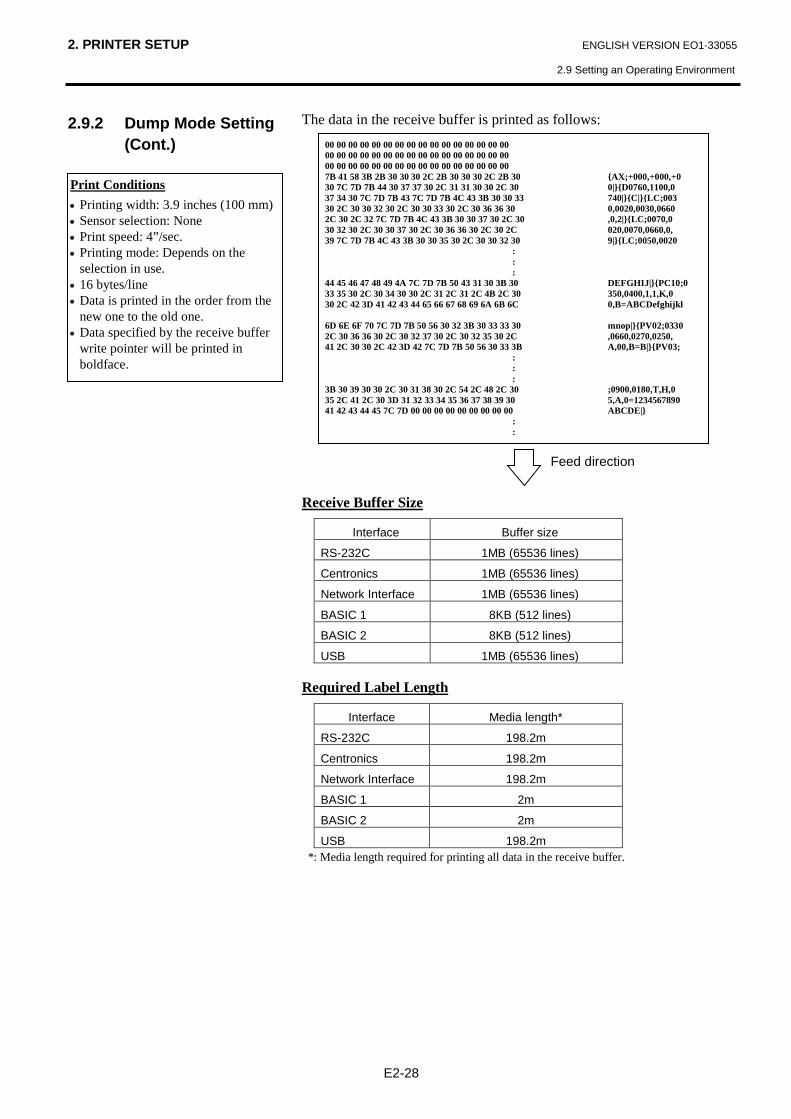
The data in the receive buffer is printed as follows: Receive Buffer Size
Interface Buffer size
RS-232C 1MB (65536 lines)
Centronics 1MB (65536 lines)
Network Interface 1MB (65536 lines)
BASIC 1 8KB (512 lines)
BASIC 2 8KB (512 lines)
USB 1MB (65536 lines) Required Label Length
Interface Media length*
RS-232C 198.2m
Centronics 198.2m
Network Interface 198.2m
BASIC 1 2m
BASIC 2 2m
USB 198.2m *: Media length required for printing all data in the receive buffer.
00 00 00 00 00 00 00 00 00 00 00 00 00 00 00 00 00 00 00 00 00 00 00 00 00 00 00 00 00 00 00 00 00 00 00 00 00 00 00 00 00 00 00 00 00 00 00 00 7B 41 58 3B 2B 30 30 30 2C 2B 30 30 30 2C 2B 30 {AX;+000,+000,+0 30 7C 7D 7B 44 30 37 37 30 2C 31 31 30 30 2C 30 0|}{D0760,1100,0 37 34 30 7C 7D 7B 43 7C 7D 7B 4C 43 3B 30 30 33 740|}{C|}{LC;003 30 2C 30 30 32 30 2C 30 30 33 30 2C 30 36 36 30 0,0020,0030,0660 2C 30 2C 32 7C 7D 7B 4C 43 3B 30 30 37 30 2C 30 ,0,2|}{LC;0070,0 30 32 30 2C 30 30 37 30 2C 30 36 36 30 2C 30 2C 020,0070,0660,0, 39 7C 7D 7B 4C 43 3B 30 30 35 30 2C 30 30 32 30 9|}{LC;0050,0020
: : :
44 45 46 47 48 49 4A 7C 7D 7B 50 43 31 30 3B 30 DEFGHIJ|}{PC10;0 33 35 30 2C 30 34 30 30 2C 31 2C 31 2C 4B 2C 30 350,0400,1,1,K,0 30 2C 42 3D 41 42 43 44 65 66 67 68 69 6A 6B 6C 0,B=ABCDefghijkl 6D 6E 6F 70 7C 7D 7B 50 56 30 32 3B 30 33 33 30 mnop|}{PV02;0330 2C 30 36 36 30 2C 30 32 37 30 2C 30 32 35 30 2C ,0660,0270,0250, 41 2C 30 30 2C 42 3D 42 7C 7D 7B 50 56 30 33 3B A,00,B=B|}{PV03;
: : :
3B 30 39 30 30 2C 30 31 38 30 2C 54 2C 48 2C 30 ;0900,0180,T,H,0 35 2C 41 2C 30 3D 31 32 33 34 35 36 37 38 39 30 5,A,0=1234567890 41 42 43 44 45 7C 7D 00 00 00 00 00 00 00 00 00 ABCDE|}
: :
Feed direction
Print Conditions • Printing width: 3.9 inches (100 mm) • Sensor selection: None • Print speed: 4”/sec. • Printing mode: Depends on the
selection in use. • 16 bytes/line • Data is printed in the order from the
new one to the old one. • Data specified by the receive buffer
write pointer will be printed in boldface.
2. PRINTER SETUP ENGLISH VERSION EO1-33055
2.9 Setting an Operating Environment
E2-29
2.9.3 BASIC Expansion Mode
While “<5>EXPAND MDOE” is displayed on the LCD Message Display, press the [PAUSE] key to enter the BASIC Expansion Mode. In the BASIC Expansion Mode, it is possible to execute the BASIC expansion mode program under the following conditions. • The BASIC expansion mode program has already been loaded. • The BASIC enable setting mode is selected.
The basic expansion mode ends when the basic expansion program is exited. When “<5>EXPAND MODE” appears, press the [PAUSE] key. When the [PAUSE] key is pressed, BASIC program is executed.
<5>EXPAND MODE
NOTE: For the BASIC enable setting mode, refer to the B-852 Series Key Operation Specification stored in the CD-ROM.

2. PRINTER SETUP ENGLISH VERSION EO1-33055
2.9 Setting an Operating Environment
E2-30
2.9.4 Automatic Calibration
While “<6>AUTO CALIB” is displayed on the LCD Message Display, press the [PAUSE] key to enter the Automatic Calibration Mode. In the Automatic Calibration Mode, whether to activate the automatic calibration at a power on time or not is selectable. When the automatic calibration is activated, the printer feeds the media for about 160 mm each time the power is turned on or the Top Cover is opened, to detect a print start position. When “<6>AUTO CALIB” appears, press the [PAUSE] key. Use the [FEED] or [RESTART] key to select a desired option. After selecting the automatic calibration, press the [PAUSE] key.
OFF
OFF
ON REFLECT
[RESTART]
[FEED]
Not activated Activated (Feed gap sensor) ON TRANS.
Activated (Black mark sensor)
NOTES: 1. This function is available only when the media pitch is 10.0 mm to 150.0
mm. 2. When this function is activated, the media length, effective print length,
and sensor type specified in the command are ignored. 3. When the printer cannot find a print start position properly, it will
continue to feed the media for up to 500.0 mm. If that does not work, the printer will stop, resulting in a paper jam.
4. During an automatic calibration, the printer also feeds the ribbon. 5. An automatic forward feed is not performed immediately after an
automatic calibration, even if the auto forward wait parameter is set to ON.

2. PRINTER SETUP ENGLISH VERSION EO1-33055
2.9 Setting an Operating Environment
E2-31
2.9.5 LAN Setting While “<7>LAN” is displayed on the LCD Message Display, press the [PAUSE] key to enter the LAN Setting Mode. In the LAN Setting Mode, whether to enable the LAN communication and SNMP or not is selectable. When “<7>LAN” appears, press the [PAUSE] key. Use the [FEED] or [RESTART] key to select a desired option. After selecting the LAN setting, press the [PAUSE] key.
ON SNMP ON
OFF
ON SNMP OFF
[RESTART]
[FEED]
LAN is disabled.
LAN and SNMP are enabled ON SNMP ON
LAN is enabled but SNMP is disabled.

2. PRINTER SETUP ENGLISH VERSION EO1-33055
2.9 Setting an Operating Environment
E2-32
2.9.6 Real Time Clock Setting
While “<8>RTC SET” is displayed on the LCD Message Display, press the [PAUSE] key to enter the Real Time Clock Setting Mode. The Real Time Clock Setting Mode contains the following sub menus. Each time the [PAUSE] key is pressed, the sub menus are displayed sequentially.
(1) Date setting (Year, Month, Day) (2) Time setting (Hour, Minute, Second) (3) Low battery check setting
(4) RTC data renewal timing setting (1) Date Setting This parameter is to set the Year, Month, and Day, in order. When “<8>RTC SET” appears, press the [PAUSE] key. Press the [PAUSE] key to set the date.
After selecting the date, press the [PAUSE] key. (2) Time Setting This parameter is to set the Hour, Minute, and Second, in order. Press the [PAUSE] key to set the time.
After selecting the time, press the [PAUSE] key.
DATE 05/01/01
DATE Y 06/01/01
DATE M 06/03/01
DATE D 06/03/01
[PAUSE]
[PAUSE]
NOTE: Use the [FEED] or [RESTART] key to set the value.
NOTE: The Real Time Clock Setting is effective only when an optional Real Time Clock, B-SA704-RTC-QM-R, is installed.
TIME 00/00/00
TIME H 10/01/01
TIME M 10/30/01
TIME S 10/30/00
[PAUSE]
[PAUSE]
Year
Month
Day
Hour
Minute
Second
2. PRINTER SETUP ENGLISH VERSION EO1-33055
2.9 Setting an Operating Environment
E2-33
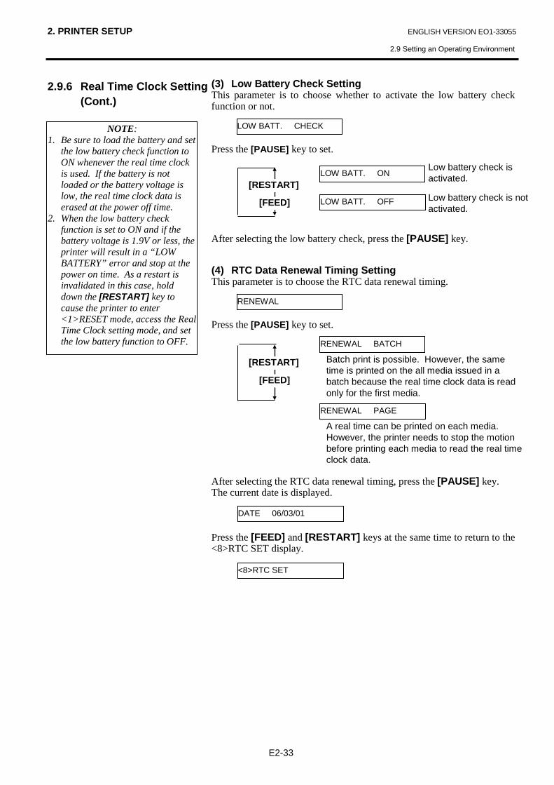
2.9.6 Real Time Clock Setting (Cont.)
(3) Low Battery Check Setting This parameter is to choose whether to activate the low battery check function or not. Press the [PAUSE] key to set. After selecting the low battery check, press the [PAUSE] key. (4) RTC Data Renewal Timing Setting This parameter is to choose the RTC data renewal timing. Press the [PAUSE] key to set. After selecting the RTC data renewal timing, press the [PAUSE] key. The current date is displayed. Press the [FEED] and [RESTART] keys at the same time to return to the <8>RTC SET display.
LOW BATT. CHECK
LOW BATT. ON [RESTART]
[FEED]
Low battery check is activated.
Low battery check is not activated.
LOW BATT. OFF
RENEWAL
RENEWAL BATCH
[RESTART]
[FEED]
Batch print is possible. However, the same time is printed on the all media issued in a batch because the real time clock data is read only for the first media.
A real time can be printed on each media. However, the printer needs to stop the motion before printing each media to read the real time clock data.
RENEWAL PAGE
NOTE: 1. Be sure to load the battery and set
the low battery check function to ON whenever the real time clock is used. If the battery is not loaded or the battery voltage is low, the real time clock data is erased at the power off time.
2. When the low battery check function is set to ON and if the battery voltage is 1.9V or less, the printer will result in a “LOW BATTERY” error and stop at the power on time. As a restart is invalidated in this case, hold down the [RESTART] key to cause the printer to enter <1>RESET mode, access the Real Time Clock setting mode, and set the low battery function to OFF.
DATE 06/03/01
<8>RTC SET

2. PRINTER SETUP ENGLISH VERSION EO1-33055
2.9 Setting an Operating Environment
E2-34
2.9.7 IP Address Setting (TCP/IP)
When the printer is connected to a PC through TCP/IP by using a LAN cable, it is necessary to set an IP address in the System Mode for system administrators. The System Mode for system administrators consists of the following menus. <1>DIAG. Vx.x This menu is used to check and print the printer
system information and maintenance counter status.
<2>PARAMETER SET
This menu is used to set the printer parameters.
<3>ADJUST SET This menu is used to make a fine adjustment of a print start position, cut position, etc.
<4>TEST PRINT This menu is used to perform print tests.
<5>SENSOR ADJ. This menu is used to check the sensor statuses and adjust each sensor.
<6>RAM CLEAR This menu is used to perform a RAM clear. DO NOT USE this menu.
<7>IP ADDRESS This menu is used to set an IP address.
<8>BASIC This menu is used to enable the printer to use Basic program.
<9>FOR FACTORY This menu is intended for an in-process inspection. Do not use this menu.
[FEED]
[FEED]
[FEED]
[FEED]
[FEED]
[FEED]
[FEED]
[RESTART]
[RESTART]
[RESTART]
[RESTART]
[RESTART]
[RESTART]
[RESTART]
[RESTART]
<1>DIAG. Vx.x
<2>PARAMETER SET
<3>ADJUST SET
<4>TEST PRINT
<5>SENSOR ADJ.
<6>RAM CLEAR
<7>IP ADDRESS
<8>BASIC
[FEED]
<9>FOR FACTORY
[RESTART]
[FEED]
Power OFF
While holding down the [FEED] and [PAUSE] keys, turn on the printer.

2. PRINTER SETUP ENGLISH VERSION EO1-33055
2.9 Setting an Operating Environment
E2-35
2.9.7 IP Address Setting (TCP/IP) (Cont.)
In this section, how to set the IP address is described. First, you need to access the System Mode for system administrators. 1. While holding down the [FEED] and [PAUSE] keys, turn on the
printer. 2. When “<1>DIAG” appears on the LCD Message Display, release the
[FEED] and [PAUSE] keys. Now, the printer is in the System Mode for system administrators. 3. Press the [FEED] or [RESTART] key until “<7>IP ADDRESS”
appears on the LCD Message Display. 4. Press the [PAUSE] key to enter the IP Address Setting Mode. The IP Address Setting Mode contains the following sub menus. To enter each sub menu, press the [PAUSE] key.
PRINTER IP ADRES
GATEWAY IP ADRES
SUBNET MASK
SOCKET PORT
DHCP
[RESTART] [FEED]
[RESTART] [FEED]
[RESTART] [FEED]
[RESTART] [FEED]
[RESTART] [FEED]
DHCP CLIENT ID
[RESTART] [FEED]
DHCP HOST NAME
[RESTART] [FEED]
2. PRINTER SETUP ENGLISH VERSION EO1-33055
2.9 Setting an Operating Environment
E2-36
2.9.7 IP Address Setting (TCP/IP) (Cont.)
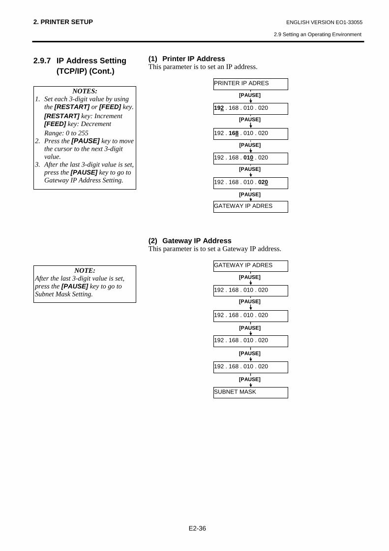
(1) Printer IP Address This parameter is to set an IP address.
(2) Gateway IP Address This parameter is to set a Gateway IP address.
PRINTER IP ADRES
192 . 168 . 010 . 020
192 . 168 . 010 . 020
192 . 168 . 010 . 020
192 . 168 . 010 . 020
[PAUSE]
[PAUSE]
[PAUSE]
GATEWAY IP ADRES
[PAUSE]
[PAUSE]
GATEWAY IP ADRES
192 . 168 . 010 . 020
192 . 168 . 010 . 020
192 . 168 . 010 . 020
192 . 168 . 010 . 020
[PAUSE]
[PAUSE]
[PAUSE]
SUBNET MASK
[PAUSE]
[PAUSE] NOTE:
After the last 3-digit value is set, press the [PAUSE] key to go to Subnet Mask Setting.
NOTES: 1. Set each 3-digit value by using
the [RESTART] or [FEED] key. [RESTART] key: Increment [FEED] key: Decrement Range: 0 to 255 2. Press the [PAUSE] key to move
the cursor to the next 3-digit value.
3. After the last 3-digit value is set, press the [PAUSE] key to go to Gateway IP Address Setting.
2. PRINTER SETUP ENGLISH VERSION EO1-33055
2.9 Setting an Operating Environment
E2-37
2.9.7 IP Address Setting (TCP/IP) (Cont.)
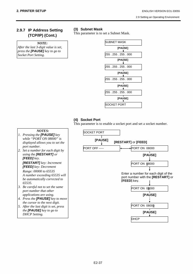
(3) Subnet Mask This parameter is to set a Subnet Mask.
(4) Socket Port This parameter is to enable a socket port and set a socket number.
SUBNET MASK
255 . 255 . 255 . 000
255 . 255 . 255 . 000
255 . 255 . 255 . 000
255 . 255 . 255 . 000
[PAUSE]
[PAUSE]
[PAUSE]
SOCKET PORT
[PAUSE]
[PAUSE] NOTE:
After the last 3-digit value is set, press the [PAUSE] key to go to Socket Port Setting.
NOTES: 1. Pressing the [PAUSE] key
while “PORT ON 08000” is displayed allows you to set the port number.
2. Set a number for each digit by using the [RESTART] or [FEED] key.
[RESTART] key: Increment [FEED] key: Decrement Range: 00000 to 65535 A number exceeding 65535 will
be automatically corrected to 65535.
3. Be careful not to set the same port number that other applications are using.
4. Press the [PAUSE] key to move the cursor to the next digit.
5. After the last digit is set, press the [PAUSE] key to go to DHCP Setting.
PORT ON 08000
DHCP
PORT ON 08000 PORT OFF -----
PORT ON 08000
PORT ON 08000
SOCKET PORT
[RESTART] or [FEED]
[PAUSE]
[PAUSE]
Enter a number for each digit of the port number with the [RESTART] or [FEED] key.
[PAUSE]
[PAUSE]

2. PRINTER SETUP ENGLISH VERSION EO1-33055
2.9 Setting an Operating Environment
E2-38
2.9.7 IP Address Setting (TCP/IP) (Cont.)
(5) DHCP This parameter is to enable DHCP.
(6) DHCP Client ID This parameter is to set a DHCP client ID.
NOTE: Pressing the [PAUSE] key while “DHCP ON” is displayed allows you to set a DHCP client ID. DHCP ON
DHCP CLIENT ID
DHCP
DHCP OFF
[PAUSE]
[PAUSE] [RESTART] or [FEED]
NOTES: 1. Code used to enter a DHCP
client ID is selectable between ASCII code (alphanumeric) and Hex code.
2. Set a character or value for each byte by using the [RESTART] or [FEED] key.
[RESTART] key: Increment [FEED] key: Decrement 3. Press the [PAUSE] key to enter
the next byte. Repeat this until 16th byte is entered.
4. A DHCP ID can be used to check what IP address is assigned to which client on a DHCP server. If a DHCP ID is not assigned, MAC address of a network device (LAN card or LAN interface board) will be notified to the server as a DHCP ID instead. A DHCP ID is a 16-byte character string. As “FFH” (hex. code) is recognized as a terminator, if the top byte of DHCP ID is “FFH”, it is considered that a DHCP ID is not assigned.
Hex. Code
DHCP CLIENT ID
<7>IP ADDRESS MODE ASCII
4142434445464748
[PAUSE]
[PAUSE]
[FEED] or [RESTART]
[PAUSE]
ABCDEFGHIJKLMNOP
[PAUSE]
[PAUSE]
ASCII Code
Enter a character or a value for each of 1st byte to 16th byte sequentially using the [FEED] or [RESTART] key.

2. PRINTER SETUP ENGLISH VERSION EO1-33055
2.9 Setting an Operating Environment
E2-39
2.9.7 IP Address Setting (TCP/IP) (Cont.)
(7) DHCP Host Name This parameter is to set a DHCP host name.
ASCII code and Hex. code correspondence table
Upper 4 bits Lower 4 bits
2 3 4 5 6 7
0 SP 0 @ P ` p 1 ! 1 A Q a q 2 “ 2 B R b r 3 # 3 C S c s 4 $ 4 D T d t 5 % 5 E U e u 6 & 6 F V f v 7 ‘ 7 G W g w 8 ( 8 H X h x 9 ) 9 I Y i y A * : J Z j z B + ; K [ k { C , < L \ l | D - = M ] m } E . > N ^ n F / ? O _ o
SP = Space (Example) To enter “TOSHIBA” in Hex. code: 54 4F 53 48 49 42 41 When the system mode settings have been completed, turn off the printer.
DHCP HOST NAME
MODE ASCII
[PAUSE]
[PAUSE]
<7>IP ADDRESS
Enter a character or a value for each of 1st byte to 16th byte sequentially using the [FEED] or [RESTART] key.
NOTE: After the 16th byte of the DHCP host name is set, press the [PAUSE] key. At this time, the display will turn to “<7>IP ADDRESS”.
[PAUSE]

2. PRINTER SETUP ENGLISH VERSION EO1-33055
2.10 Installing the Printer Drivers
E2-40
2.10 Installing the Printer Drivers Once you install the TOSHIBA printer driver on your Windows host computer, you can use the TOSHIBA bar code printer in the same way you would a laser or ink jet printer. You can use the printer by connecting a USB or LAN cable to your host computer.
The installation procedure of the printer driver differs depending on the printer model and the connection method. The Printer driver and installation manual can be downloaded from the Toshiba TEC Web-site
http://www.toshibatec.com/cnt/download_overseas/
If an older version of the printer driver has been already installed, you must uninstall it and restart the computer before installing a newer version.

2. PRINTER SETUP ENGLISH VERSION EO1-33055
2.11 Print Test
E2-41
2.11 Print Test
After your operating environment has been set, perform a print test. 1. Perform a print test by using the Printer Driver or an Issue Command. The printer driver’s Properties screen allows you to set the
communication conditions, media size, and other printing conditions in accordance with your operating environment. For details, refer to the Help for the Windows Printer Drivers screen.
Example: Stock tab display of the Printer Driver’s Properties Screen
Print Method: Direct thermal or thermal transfer is selectable. Sensor: Media sensor type is selectable. Issue Mode: Batch or strip is selectable. Cut: Whether to use the cutter or not is selectable. Fine Adjustment: Adjustment values for the feed amount, cut/strip
position, etc. can be set.
2. Confirm the print test result.
• When a print start position, cut/strip position, or print tone needs to be adjusted: ⇒ Section 2.12 Position and Print Tone Fine Adjustment
• When pre-printed media is used, and if a print start position is not
properly detected: ⇒ Section 2.13 Threshold Setting
Print Method Sensor
Issue Mode Cut
Print Speed
Label Gap
Fine Adjustment

2. PRINTER SETUP ENGLISH VERSION EO1-33055
2.11 Print Test
E2-42
2.11 Print Test (Cont.)
It is necessary to set the issue mode, cut position, etc. for the Printer Driver or TPCL (TEC Printer Command Language) in accordance with your printing condition. For details of the TPCL, refer to the B-852 Series External Equipment Interface Specification stored in the CD-ROM. Regarding how to use the Printer Driver, refer to the Help for the Windows Printer Drivers screen. To gain maximum performance and life from the Cutter Module, periodic cleaning is required. Before starting a cleaning, be sure to TURN OFF the printer to avoid risk of injury. For details of cleaning, refer to Section 4.1.3 Optional Cutter Module.
When using an optional Cutter Module
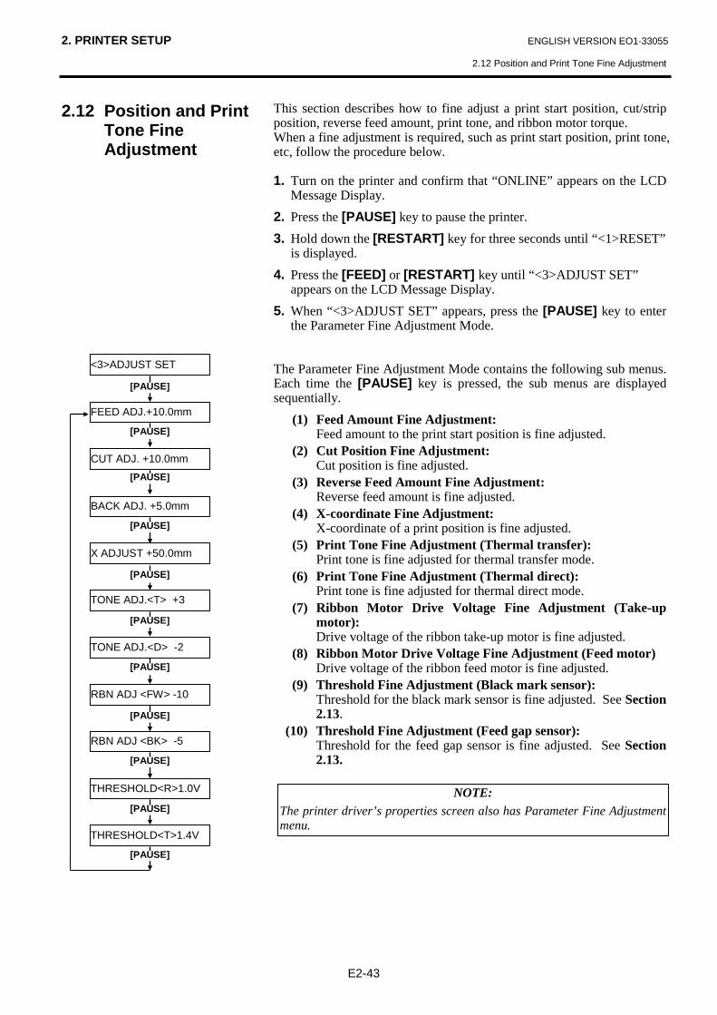
2. PRINTER SETUP ENGLISH VERSION EO1-33055
2.12 Position and Print Tone Fine Adjustment
E2-43
2.12 Position and Print Tone Fine Adjustment
This section describes how to fine adjust a print start position, cut/strip position, reverse feed amount, print tone, and ribbon motor torque. When a fine adjustment is required, such as print start position, print tone, etc, follow the procedure below. 1. Turn on the printer and confirm that “ONLINE” appears on the LCD
Message Display. 2. Press the [PAUSE] key to pause the printer. 3. Hold down the [RESTART] key for three seconds until “<1>RESET”
is displayed. 4. Press the [FEED] or [RESTART] key until “<3>ADJUST SET”
appears on the LCD Message Display. 5. When “<3>ADJUST SET” appears, press the [PAUSE] key to enter
the Parameter Fine Adjustment Mode. The Parameter Fine Adjustment Mode contains the following sub menus. Each time the [PAUSE] key is pressed, the sub menus are displayed sequentially. (1) Feed Amount Fine Adjustment: Feed amount to the print start position is fine adjusted. (2) Cut Position Fine Adjustment: Cut position is fine adjusted. (3) Reverse Feed Amount Fine Adjustment: Reverse feed amount is fine adjusted. (4) X-coordinate Fine Adjustment: X-coordinate of a print position is fine adjusted. (5) Print Tone Fine Adjustment (Thermal transfer): Print tone is fine adjusted for thermal transfer mode. (6) Print Tone Fine Adjustment (Thermal direct): Print tone is fine adjusted for thermal direct mode. (7) Ribbon Motor Drive Voltage Fine Adjustment (Take-up
motor): Drive voltage of the ribbon take-up motor is fine adjusted. (8) Ribbon Motor Drive Voltage Fine Adjustment (Feed motor) Drive voltage of the ribbon feed motor is fine adjusted. (9) Threshold Fine Adjustment (Black mark sensor): Threshold for the black mark sensor is fine adjusted. See Section
2.13. (10) Threshold Fine Adjustment (Feed gap sensor): Threshold for the feed gap sensor is fine adjusted. See Section
2.13. NOTE:
The printer driver’s properties screen also has Parameter Fine Adjustment menu.
[PAUSE]
FEED ADJ.+10.0mm
CUT ADJ. +10.0mm
BACK ADJ. +5.0mm
X ADJUST +50.0mm
TONE ADJ.<T> +3
TONE ADJ.<D> -2
RBN ADJ <FW> -10
RBN ADJ <BK> -5
THRESHOLD<R>1.0V
THRESHOLD<T>1.4V
<3>ADJUST SET
[PAUSE]
[PAUSE]
[PAUSE]
[PAUSE]
[PAUSE]
[PAUSE]
[PAUSE]
[PAUSE]
[PAUSE]
[PAUSE]

2. PRINTER SETUP ENGLISH VERSION EO1-33055
2.12 Position and Print Tone Fine Adjustment
E2-44
2.12 Position and Print Tone Fine Adjustment (Cont.)
After selecting a fine adjustment value, press the [PAUSE] key.
Print Start Position Fine Adjustment
[RESTART]
[FEED]
FEED ADJ.+50.0mm
FEED ADJ.+49.9mm
FEED ADJ.+0.0mm
FEED ADJ.-49.9mm
FEED ADJ.-50.0mm
FEED ADJ.+0.1mm
FEED ADJ.-0.1mm
FEED ADJ.+10.0mm
NOTES: Choose a desired value by using the [RESTART] or [FEED] key. Pressing the [FEED] key one time causes a –0.1mm change, up to –50.0 mm. Pressing the [RESTART] key one time causes a +0.1mm change, up to +50.0 mm.
One label Print Start Position
Print Start Position
3mm
3mm
Feed Direction
Feed Direction
Print Start Position One label
Feed Direction One label
• Example of Print Start Position Fine Adjustment When setting +3.0 mm Compared with “+0.0mm” position, the print start
position is shifted forward. When setting +0.0 mm When setting –3.0 mm Compared with “+0.0mm” position, the print start
position is shifted backward.

2. PRINTER SETUP ENGLISH VERSION EO1-33055
2.12 Position and Print Tone Fine Adjustment
E2-45
2.12 Position and Print Tone Fine Adjustment (Cont.)
After selecting a fine adjustment value, press the [PAUSE] key.
Cut Position Fine Adjustment
CUT ADJ. +10.0mm
[RESTART]
[FEED]
CUT ADJ.+50.0mm
CUT ADJ.+49.9mm
CUT ADJ.+0.0mm
CUT ADJ.-49.9mm
CUT ADJ.-50.0mm
CUT ADJ.+0.1mm
CUT ADJ.-0.1mm
NOTES: Choose a desired value by using the [RESTART] or [FEED] key. Pressing the [FEED] key one time causes a –0.1mm change, up to –50.0 mm. Pressing the [RESTART] key one time causes a +0.1mm change, up to +50.0 mm.
Cut Position
Cut Position
Feed Direction
3mm
3mm
Feed Direction
Feed Direction
Cut Position
• Example of Cut Position Fine Adjustment When setting +3.0 mm Compared with “+0.0mm” position, the cut position
is shifted forward. When setting +0.0 mm When setting –3.0 mm Compared with “+0.0mm” position, the cut position
is shifted backward.
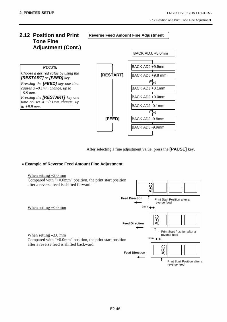
2. PRINTER SETUP ENGLISH VERSION EO1-33055
2.12 Position and Print Tone Fine Adjustment
E2-46
2.12 Position and Print Tone Fine Adjustment (Cont.)
After selecting a fine adjustment value, press the [PAUSE] key.
Reverse Feed Amount Fine Adjustment
NOTES: Choose a desired value by using the [RESTART] or [FEED] key. Pressing the [FEED] key one time causes a –0.1mm change, up to –9.9 mm. Pressing the [RESTART] key one time causes a +0.1mm change, up to +9.9 mm.
• Example of Reverse Feed Amount Fine Adjustment When setting +3.0 mm Compared with “+0.0mm” position, the print start position
after a reverse feed is shifted forward. When setting +0.0 mm When setting –3.0 mm Compared with “+0.0mm” position, the print start position
after a reverse feed is shifted backward.
[RESTART]
[FEED]
BACK ADJ.+9.9mm
BACK ADJ.+9.8 mm
BACK ADJ.+0.0mm
BACK ADJ.-9.8mm
BACK ADJ.-9.9mm
BACK ADJ.-0.1mm
BACK ADJ.+0.1mm
BACK ADJ. +5.0mm
3mm
Print Start Position after a reverse feed
Print Start Position after a reverse feed
3mm
Feed Direction
Feed Direction
Print Start Position after a reverse feed
Feed Direction

2. PRINTER SETUP ENGLISH VERSION EO1-33055
2.12 Position and Print Tone Fine Adjustment
E2-47
2.12 Position and Print Tone Fine Adjustment (Cont.)
After selecting a fine adjustment value, press the [PAUSE] key.
X Coordinate Fine Adjustment
NOTES: Choose a desired value by using the [RESTART] or [FEED] key. Pressing the [FEED] key one time causes a –0.1mm change, up to –99.9 mm. Pressing the [RESTART] key one time causes a +0.1mm change, up to +99.9 mm.
• Example of X Coordinate Fine Adjustment When setting –50.0 mm Compared with “+0.0mm” position, the print position
is shifted to the left. When setting +0.0 mm When setting +50.0 mm Compared with “+0.0mm” position, the print position
is shifted to the right.
X ADJUST +5.0mm
[RESTART]
[FEED]
X ADJUST +99.9mm
X ADJUST +99.8mm
X ADJUST +0.0mm
X ADJUST -99.8mm
X ADJUST -99.9mm
X ADJUST -0.1mm
X ADJUST +0.1mm
ABC
Feed Direction
ABC
ABC
50.0mm
50.0mm
Top Down Printing X
Y
Bottom First Printing X
Y

2. PRINTER SETUP ENGLISH VERSION EO1-33055
2.12 Position and Print Tone Fine Adjustment
E2-48
2.12 Position and Print Tone Fine Adjustment (Cont.)
Thermal Transfer Print After selecting a fine adjustment value or to skip this menu, press the [PAUSE] key. Thermal Direct Print After selecting a fine adjustment value or to skip this menu, press the [PAUSE] key.
Print Tone Fine Adjustment
NOTES: Choose a desired value by using the [RESTART] or [FEED] key. Pressing the [FEED] key one time causes a –1 tone change, up to –10 tones. Pressing the [RESTART] key one time causes a +1 tone change, up to +10 tones.
TONE ADJ.<T> +3
[RESTART]
[FEED]
TONE ADJ<T>. +10
TONE ADJ<T>. +9
TONE ADJ<T>. +0
TONE ADJ<T>. -9
TONE ADJ<T>. -10
Darker
Lighter
Standard
TONE ADJ<D>. +10
TONE ADJ<D>. +9
TONE ADJ<D>. +0
TONE ADJ<D>. -9
TONE ADJ<D>. -10
[RESTART]
[FEED]
Darker
Lighter
Standard
TONE ADJ.<D> -2

2. PRINTER SETUP ENGLISH VERSION EO1-33055
2.12 Position and Print Tone Fine Adjustment
E2-49
2.12 Position and Print Tone Fine Adjustment (Cont.)
When the ribbon is slack or wrinkled and printing is affected, fine adjust the ribbon motor torque by using the following procedure. Take-up Motor (RBN ADJ <FW>) After selecting a fine adjustment value or to skip this menu, press the [PAUSE] key. Feed Motor (RBN ADJ <BK>) After selecting a fine adjustment value or to skip this menu, press the [PAUSE] key.
Ribbon Motor Voltage Fine Adjustment
[RESTART]
[FEED]
RBN ADJ<FW> +6
RBN ADJ<FW> +5
RBN ADJ<FW> +4
RBN ADJ<FW> -14
RBN ADJ<FW> -15
Motor Torque
High
Low
RBN ADJ<FW> -10
RBN ADJ<BK> +10
RBN ADJ<BK> +9
RBN ADJ<BK> +8
RBN ADJ<BK> -14
RBN ADJ<BK> -15
Motor Torque
High
Low
[RESTART]
[FEED]
RBN ADJ<BK> -5
NOTES: Choose a desired value by using the [RESTART] or [FEED] key. Pressing the [FEED] key one time causes a –1 step change, up to –15 steps. Pressing the [RESTART] key one time causes a +1 step change, up to +6 steps.
NOTES: Choose a desired value by using the [RESTART] or [FEED] key. Pressing the [FEED] key one time causes a –1 step change, up to –15 steps. Pressing the [RESTART] key one time causes a +1 step change, up to +10 steps.

2.PRINTER SETUP ENGLISH VERSION EO1-33055
2.13 Threshold Setting
E2-50
2.13 Threshold Setting
To maintain a constant print position the printer uses the media sensor to detect a print start position according to the difference of voltage between a print area and a gap or black mark. When the media is pre-printed, the darker (or more dense) inks can interfere with this process causing paper jam errors. To get around this problem, first, try an automatic threshold setting. If the problem still occurs, then, the threshold voltage needs to be manually set. 1. Turn the power ON. The printer is in online mode.
2. Load a pre-printed media roll. When using a label stock, move the Feed Gap Sensor so that it is in
line with the centre of the label. When using a tag stock, move the Black Mark Sensor so that it is in
line with the centre of a black mark.
3. Press the [PAUSE] key.
4. The printer enters the pause mode.
5. Press and hold the [PAUSE] key in the pause state until the following screen appears.
6. The sensor type is displayed. 7. Select the sensor to be adjusted by using the [FEED] key. 8. Press and hold the [PAUSE] key until more than 1.5 labels (tags)
have been issued. The media will continue to be fed until the [PAUSE] key is released.
(An automatic threshold setting for the selected sensor is completed by this operation.)
9. Press the [RESTART] key. 10. The printer returns to online mode. Send an issue command from the host computer to the printer.
NOTES: 1. Failure to feed more than 1.5
labels may result in an incorrect threshold setting.
2. While the Top Cover is raised, the [PAUSE] key does not work
3. A paper end error cannot be detected during paper feed.
Automatic threshold setting procedure
REFLECTIVE
TRANSMISSIVE
Black mark sensor Feed gap sensor
[FEED]
TRANSMISSIVE
ON LINE
PAUSE

2.PRINTER SETUP ENGLISH VERSION EO1-33055
2.13 Threshold Setting
E2-51
2.13 Threshold Setting (Cont.)
If a paper jam error still occurs even after an automatic threshold setting has been performed, manually set the threshold voltage. To make a threshold value manually set in this section effective, select the Transmissive Sensor (when using manual threshold value) or Reflective Sensor (when using manual threshold value) within software commands or the printer driver. 1. While holding down the [FEED] and [PAUSE] keys, turn on the
printer. 2. When “<1>DIAG.” appears on the LCD Message Display, release the
[FEED] and [PAUSE] keys. Now, the printer is in the System Mode for system administrators. 3. Press the [FEED] or [RESTART] key until “<5>SENSOR ADJ.”
appears on the LCD Message Display. 4. Press the [PAUSE] key to enter the Sensor Adjustment Mode. The Sensor Adjustment Mode contains sub menus for displaying the current status of each sensor and for storing “media level” voltage and “no media level” voltage. Each time the [PAUSE] key is pressed, the sub menus are displayed sequentially. (1) Sensor Status Display: Temperatures being detected by the Print Head Thermistor and
the Ambient Thermistor are displayed. (2) Upper Black Mark Sensor Status Display: Voltage being detected by the upper Black Mark Sensor is
displayed. (3) Upper Black Mark Sensor Adjustment: Using the media actually used, a “media level” voltage is stored. (4) Lower Black Mark Sensor Status Display: Voltage being detected by the lower Black Mark Sensor is
displayed. (5) Lower Black Mark Sensor Adjustment: Using the media actually used, a “media level” voltage is stored. (6) Feed Gap Sensor Status Display: Voltage being detected by the Feed Gap Sensor is displayed. (7) Feed Gap Sensor Adjustment: Using the media actually used, a “media level” voltage is stored. (8) Lower Black Mark Sensor/Feed Gap Sensor Status Display
(No media): “No media level” voltage detected by the lower Black Mark
Sensor/Feed Gap Sensor is displayed. (9) Lower Black Mark Sensor/Feed Gap Sensor Adjustment (No
media): “No media level” voltage is stored.
Manual threshold setting procedure
[PAUSE]
[H]28°C [A]28°C
[REF. <U>] 3.5V
[REF. <U>] 4.8V*
[TRANS.] 2.4V
[TRANS.] 4.1V*
[PE]R0.1V T4.8V
[PE]R0.1V T4.8V*
<5>SENSOR ADJ.
[PAUSE]
[FEED] or [RESTART]
[PAUSE]
[FEED] or [RESTART]
[PAUSE]
[PAUSE]
[FEED] or [RESTART]
[REF. <L>] 4.8V
[REF. <L>] 4.8V*
[PAUSE]
[FEED] or [RESTART]
<5>SENSOR ADJ.
[H]28°C [A]28°C
<1>DIAG.

2.PRINTER SETUP ENGLISH VERSION EO1-33055
2.13 Threshold Setting
E2-52
2.13 Threshold Setting (Cont.)
When using the Black Mark Sensor (1) While “<5>SENSOR ADJ.” is displayed, press the [PAUSE] key
until the message appears. The displayed value is a real-time voltage being detected by the Black
Mark Sensor. (2) Measure a voltage at a blank part of media and a black mark,
respectively. At this time, write down the midpoint between both voltages. (This value is used later for a threshold setting.)
(Example) Print area = 4.8V, Black mark = 2.4V Midpoint = 3.6V
(3) Press and hold the [RESTART] or [FEED] key for about 3 seconds
aligning a blank part of print area with the Black Mark Sensor. (4) When storing a “media level” voltage is completed, an asterisk “*”is
displayed on the right side of a voltage. Press the [PAUSE] key. (5) A real-time voltage being detected by the Feed Gap Sensor is
displayed. When using the Feed Gap Sensor (1)Measure a voltage at a blank part of label and a label gap, respectively.
At this time, write down the midpoint of both voltages. (This value is used later for a threshold setting.)
(Example) Print area = 2.4V, Gap = 4.0V Midpoint = 3.2V
(2) Press and hold the [RESTART] or [FEED] key for about 3 seconds
aligning a blank part of print area with the Feed Gap Sensor. (3) When storing a “media level” voltage is completed, an asterisk “*”is
displayed on the right side of a voltage. Press the [PAUSE] key. (4) The display changes as shown on the left.
NOTES: 1. When measuring a voltage of a blank area, be careful not to align a
pre-print with the sensor by mistake. 2. Confirm that there is at least 0.7V difference between the two values.
If the difference in voltage is less than 0.7V, a print start position cannot be detected. In that case, please consider changing the media type.
3. Make sure that the Top Cover is closed when measuring the voltages.
[REF. <U>] 3.5V
[REF. <U>] 4.8V*
[TRANS.] 2.4V
NOTES: 1. When measuring a voltage at a blank area, be careful not to align a
pre-print with the sensor by mistake. 2. Confirm that there is at least 0.7V difference between the two values.
If the difference in voltage is less than 0.7V, a print start position cannot be detected. In that case, please consider changing the media type.
3. Make sure that the Top Cover is closed when measuring the voltages.
[TRANS.] 2.4V
[TRANS.] 2.4V*
[PE]R0.1V T4.8V
Voltage at a black mark
Voltage at a print area
Midpoint (Threshold voltage)
Voltage at a label gap
Voltage at a print area
Midpoint (Threshold voltage)
[REF. <U> 3.5V

2.PRINTER SETUP ENGLISH VERSION EO1-33055
2.13 Threshold Setting
E2-53
2.13 Threshold Setting (Cont.)
Storing a “No Media Level” Voltage The following is how to set a “No media level” voltage that is used to detect a paper end. If a “NO PAPER” is displayed even if the media has not run out yet, this voltage needs to be set again. (1) Remove any media from the Black Mark Sensor/Feed Gap Sensor. (2) A real-time voltages being detected by the lower Black Mark Sensor
and Feed Gap Sensor are displayed. (3) Press and hold the [RESTART] or [FEED] key for about 3 seconds. (4) When storing a “no media level” voltage is completed, an asterisk
“*”is displayed on the right side of a voltage. Press the [PAUSE] key. (5) The message returns to “<5>SENSOR ADJ.”. Manual Threshold Setting Then, set the calculated threshold voltage in the Parameter Fine Adjustment mode. (1) While “<5>SENSOR ADJ.” is displayed, press the [FEED] or
[RESTART] key until “<3>ADJUST SET” is displayed. (2)Press the [PAUSE] key to enter the Parameter Fine Adjustment Mode.
Feed Gap Sensor
Lower Black Mark Sensor
FEED ADJ.+10.0mm
<3>ADJUST SET
[PE]R0.1VT4.8V*
<5>SENSOR ADJ.
[PE]R0.1V T4.8V
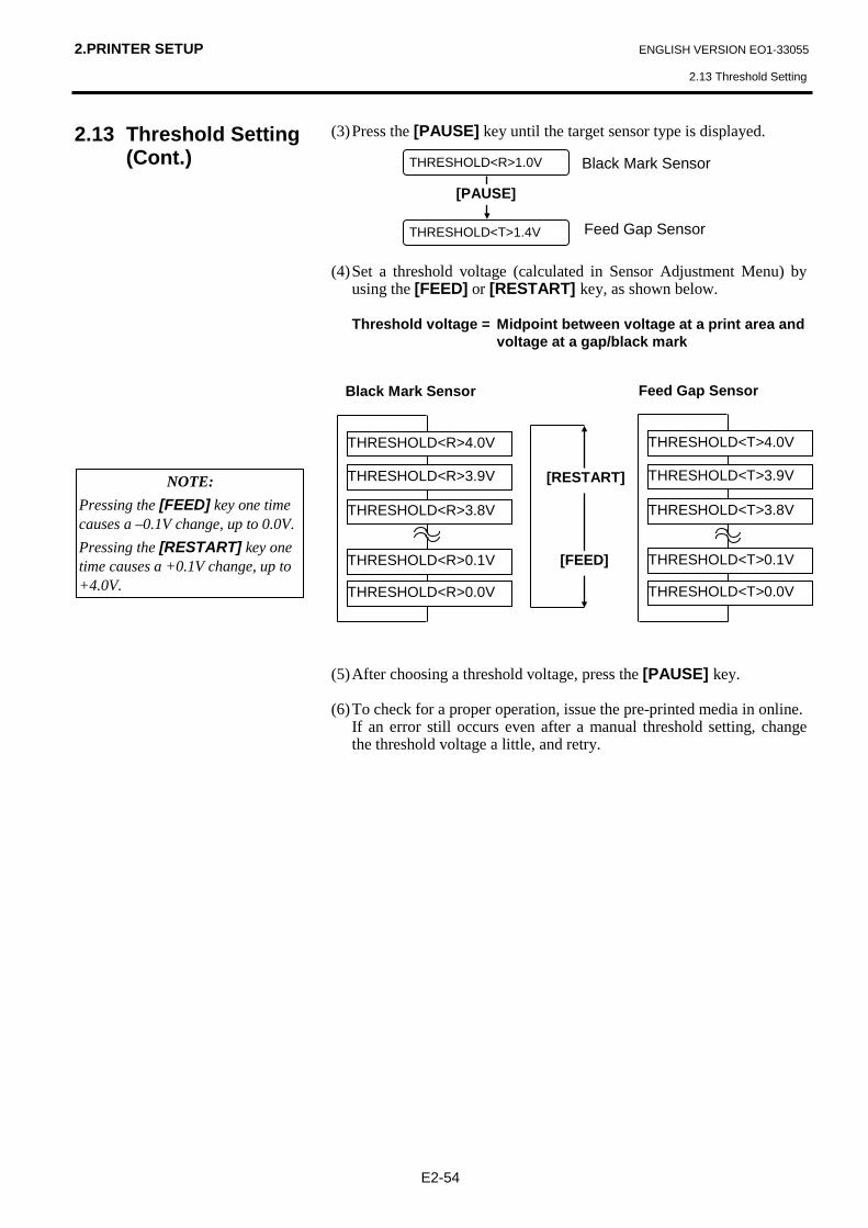
2.PRINTER SETUP ENGLISH VERSION EO1-33055
2.13 Threshold Setting
E2-54
2.13 Threshold Setting (Cont.)
(3) Press the [PAUSE] key until the target sensor type is displayed. (4) Set a threshold voltage (calculated in Sensor Adjustment Menu) by
using the [FEED] or [RESTART] key, as shown below. Threshold voltage = Midpoint between voltage at a print area and
voltage at a gap/black mark (5) After choosing a threshold voltage, press the [PAUSE] key. (6) To check for a proper operation, issue the pre-printed media in online. If an error still occurs even after a manual threshold setting, change
the threshold voltage a little, and retry.
NOTE: Pressing the [FEED] key one time causes a –0.1V change, up to 0.0V. Pressing the [RESTART] key one time causes a +0.1V change, up to +4.0V.
Black Mark Sensor
Feed Gap Sensor
[RESTART]
[FEED]
THRESHOLD<R>4.0V
THRESHOLD<R>3.9V
THRESHOLD<R>3.8V
THRESHOLD<R>0.1V
THRESHOLD<R>0.0V
Black Mark Sensor
THRESHOLD<T>4.0V
THRESHOLD<T>3.9V
THRESHOLD<T>3.8V
THRESHOLD<T>0.1V
THRESHOLD<T>0.0V
Feed Gap Sensor
[PAUSE]
THRESHOLD<T>1.4V
THRESHOLD<R>1.0V

3. ON LINE MODE ENGLISH VERSION EO1-33055
3.1 Operation Panel
E3- 1
3. ON LINE MODE 3.1 Operation Panel
This chapter describes usage and purpose of the keys on the Operation Panel in On Line Mode. When the printer is in On Line Mode and connected to a host computer, normal operation of printing images on labels or tags can be accomplished. • The figure below illustrates the Operation Panel and key functions.
The LCD Message Display shows messages in alphanumeric characters and symbols to indicate the printer’s status. Up to 16 characters can be displayed on one line. There are three LED lights on the Operation Panel.
LED Illuminates when… Flashes when… POWER The printer is turned on. ----- ON LINE The printer is ready to
print. The printer is communicating with your computer.
ERROR Any error occurs with the printer.
-----
There are three keys on the Operation Panel.
PAUSE Used to stop printing temporarily. RESTART Used to restart printing. FEED Used to feed the media.
NOTE: Use the [RESTART] key to resume printing after a pause condition, or after clearing an error.
LCD Message Display
ON LINE LED (Green)
ERROR LED (Red)
[PAUSE] key
POWER LED (Green)
[FEED] key
[RESTART] key

3. ON LINE MODE ENGLISH VERSION EO1-33055
3.2 Operation
E3- 2
3.2 Operation
3.3 Reset
When the printer is turned on, the “ON LINE” message appears on the LCD Message Display. It is shown during standby or normal printing. 1. The printer is turned on, standing by, or printing. 2. If any error occurs during printing, an error message appears. The
printer stops printing automatically. (The number on the right column shows the number of unprinted media.)
3. To clear the error, press the [RESTART] key. The printer resumes
printing. 4. If the [PAUSE] key is pressed during printing, the printer stops
printing temporarily. (The number on the right column shows the number of unprinted media.)
5. When the [RESTART] key is pressed, the printer resumes printing. Reset operation clears the print data sent to the printer from the computer,
and returns the printer to an idle condition. 1. The printer is turned on, standing by, or printing. 2. To stop printing, or clear the data sent from the computer, press the
[PAUSE] key. The printer stops printing. 3. Press and hold the [RESTART] key for 3 seconds or longer. 4. Press the [PAUSE] key. The data sent from the computer will be
cleared, and the printer returns to an idle condition.
ON LINE
NO PAPER 125
ON LINE
PAUSE 52
ON LINE
NOTE: If the [RESTART] key is held for less than 3 seconds when the printer is in an error or pause state, the printer restarts printing. However, when a communication error or command error occurs, the printer returns to an idle condition.
ON LINE
PAUSE 52
ON LINE
<1>RESET

4. MAINTENANCE ENGLISH VERSION EO1-33055
4.1 Cleaning
E4- 1
4. MAINTENANCE 4.1 Cleaning 4.1.1 Print Head/Platen/ Sensors
This chapter describes how to perform normal maintenance. To maintain the printer performance and quality print, please clean the printer regularly, or whenever media or ribbon is replaced.
The following sections describe periodic cleaning of the unit. 1. Turn off the printer. Open the Top Cover. 2. Press the Head Block Release Lever to release the Print Head Block. 3. Raise the Print Head Block and remove the ribbon. 4. Clean the Print Head Element with the supplied Print Head Cleaner.
5. Hold the Sensor Lift Tab and lift the Upper Sensor Ass’y. 6. Wipe the Feed Gap Sensor and Black Mark Sensor with a dry soft
cloth. 7. Wipe the Platen with a soft cloth slightly moistened with ethyl alcohol.
WARNING! 1. Be sure to disconnect the
Power Cord before performing maintenance. Failure to do this may cause an electric shock.
2. To avoid injury, be careful not to pinch or jam your fingers while opening or closing the cover and Print Head Block.
3. The Print Head may become hot. Do not touch the Print Head.
4. Do not pour water directly onto the printer.
CAUTION! 1. Do not allow any hard objects
to touch the print head or platen, as this may cause damage to them.
2. Do not use any volatile solvent including thinner and benzene, as this may cause discoloration to the cover, print failure, or breakdown of the printer.
3. Do not touch the print head element with bare hands, as static may damage the print head.
4. Be sure to use the print head cleaner enclosed with this printer. Failure to do this may shorten the print head life.
NOTE: Please purchase the Print Head Cleaner from the authorised TOSHIBA TEC service representative.
Print Head Element
Print Head Cleaner (P/No.: 24089500013)
Print Head
Sensor Lift Tab
Platen Feed Gap Sensor and Black Mark Sensor

4. MAINTENANCE ENGLISH VERSION EO1-33055
4.1 Cleaning
E4- 2
4.1.2 Covers and Panels 4.1.3 Optional Cutter Module
Wipe the Cover and Front Panel with a dry soft cloth. Wipe off dirt with a soft cloth slightly moistened with water.
1. Remove the Plastic Head Screw and to detach the Cutter Cover. 2. Remove the jammed paper and trash, if any. 3. Clean the Cutter Blade with a dry cloth.
CAUTION! Do not use any volatile solvent including thinner and benzene, as this may cause discoloration or distortion of the cover.
WARNING! 1. Be sure to turn the power off
before cleaning the Cutter Module.
2. The Cutter is sharp, so care should be taken not to injure yourself when cleaning.
Swing Cutter
Cutter Unit
Plastic Head Screw
Fixed Cutter
Cutter Cover Plastic Head Screw

5. TROUBLESHOOTING ENGLISH VERSION EO1-33055
5.1 Error Messages
E5- 1
5. TROUBLESHOOTING This chapter lists the error messages and possible problems and their solutions. 5.1 Error Messages
Error Messages Problems/Causes Solutions HEAD OPEN The print head block is opened in Online
Mode. Close the print head block. Then press the [RESTART] key.
HEAD OPEN **** Feed or printing has been attempted with the Print Head Block open.
Close the print head block. Then press the [RESTART] key.
COMMS ERROR A communication error has occurred. Make sure the interface cable is firmly connected to the computer, and the computer is turned on.
PAPER JAM **** 1.The media is jammed at the media path. The media is not fed smoothly.
1. Remove the jammed media, and clean the Platen. Then reload the media properly. Finally press the [RESTART] key.
⇒ Section 5.3. 2. A wrong media sensor is selected for
the media being loaded.
2. Turn the printer off and then on. Then select the media sensor supporting the media being loaded. Finally resend the print job.
3. The Black Mark Sensor is not aligned to the Black Mark on the media.
3. Adjust the sensor position. Then press the [RESTART] key.
⇒ Section 2.5. 4. Size of the loaded media is not
consistent with the programmed size.
4. Turn the printer off and then on. Replace the loaded media with one which matches the programmed size, or select a programmed size that matches the loaded media. Finally resend the print job.
5. The Feed Gap Sensor cannot distinguish the print area from a label gap.
5. Refer to Section 2.13 to set the threshold. If this does not solve the problem, turn off the printer, and call an authorised service representative.
CUTTER ERROR **** (Only when the Cutter Module is installed on the printer.)
The media is jammed in the Cutter. Remove the jammed media. Then press the [RESTART] key. If this does not solve the problem, turn off the printer, and call an authorised service representative. ⇒ Section 4.1.3
NOTES: • If an error is not cleared by pressing the [RESTART] key, turn the printer off and then on. • After the printer is turned off, all print data in the printer is cleared. • “****” indicates the number of unprinted media. Up to 9999 (in pieces).
WARNING! If a problem cannot be solved by taking actions described in this chapter, do not attempt to repair the printer. Turn off and unplug the printer. Then contact an authorised TOSHIBA TEC service representative for assistance.

5. TROUBLESHOOTING ENGLISH VERSION EO1-33055
5.1 Error Messages
E5- 2
5.1 Error Messages (Cont.) Error Messages Problems/Cause Solutions
NO PAPER **** 1. The media has run out.
1. Load new media. Then press the [RESTART] key.
⇒ Section 2.4 2. The media is not loaded properly.
2. Load the media properly. Then press the [RESTART] key.
⇒ Section 2.4 3. The media is slack. 3. Take up any slack in the media.
RIBBON ERROR **** 1. The ribbon is not fed properly.
1. Remove the ribbon, and check the status of the ribbon. Replace the ribbon, if necessary. If the problem is not solved, turn off the printer, and call an authorised service representative.
2. The ribbon has run out. 2. Load a new ribbon. Then press the [RESTART] key.
⇒ Section 2.6 EXCESS HEAD TEMP The print head is overheated. Turn off the printer, and allow it to cool
down (about 3 minutes). If this does not solve the problem, call an authorised service representative.
HEAD ERROR There is a problem with the Print Head. Replace the Print Head. Then press the [RESTART] key.
POWER FAILURE A momentary power failure has occurred.
Check the power source which supplies power to the printer. If the rating is not correct, or if the printer shares the same power outlet with other electrical appliances that consume large amounts of power, change the outlet.
SYSTEM ERROR 1. The printer is used in a location where it is subject to noise. Or, there are power cords of other electrical appliances near the printer or interface cable.
1. Keep the printer and the interface cables away from the source of noise.
2. The Power Cord of the printer is not grounded.
2. Ground the Power Cord.
3. The printer shares the same power source with any other electrical appliances.
3. Provide an exclusive power source for the printer.
4. An application software used on your host computer has an error or malfunction.
4. Confirm the host computer operates properly.
FLASH WRITE ERR. An error has occurred in writing to the flash ROM.
Turn the printer off, and then on again.
FORMAT ERROR An error has occurred in formatting the flash ROM.
Turn the printer off, and then on again.
FLASH CARD FULL Saving failed because of an insufficient capacity of the flash ROM.
Turn the printer off, and then on again.
EEPROM ERROR Data cannot be read from/written to a backup EEPROM properly.
Turn the printer off, and then on again.
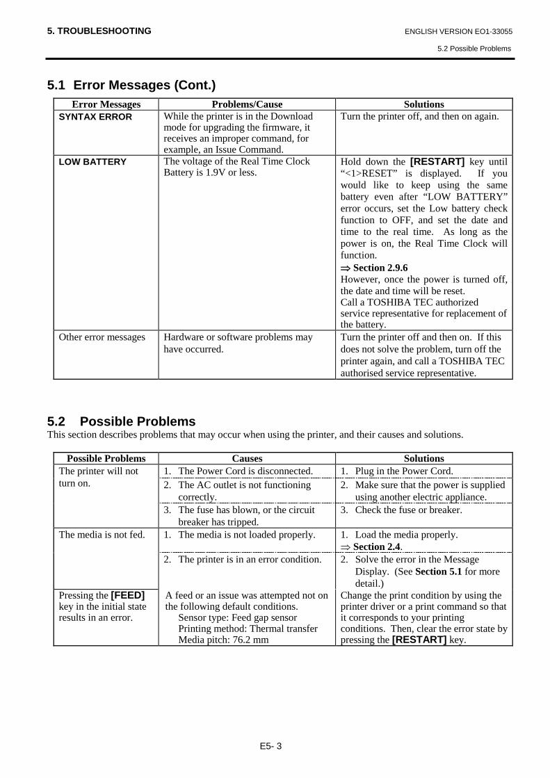
5. TROUBLESHOOTING ENGLISH VERSION EO1-33055
5.2 Possible Problems
E5- 3
5.1 Error Messages (Cont.) Error Messages Problems/Cause Solutions
SYNTAX ERROR While the printer is in the Download mode for upgrading the firmware, it receives an improper command, for example, an Issue Command.
Turn the printer off, and then on again.
LOW BATTERY The voltage of the Real Time Clock Battery is 1.9V or less.
Hold down the [RESTART] key until “<1>RESET” is displayed. If you would like to keep using the same battery even after “LOW BATTERY” error occurs, set the Low battery check function to OFF, and set the date and time to the real time. As long as the power is on, the Real Time Clock will function. ⇒ Section 2.9.6 However, once the power is turned off, the date and time will be reset. Call a TOSHIBA TEC authorized service representative for replacement of the battery.
Other error messages Hardware or software problems may have occurred.
Turn the printer off and then on. If this does not solve the problem, turn off the printer again, and call a TOSHIBA TEC authorised service representative.
5.2 Possible Problems This section describes problems that may occur when using the printer, and their causes and solutions.
Possible Problems Causes Solutions The printer will not turn on.
1. The Power Cord is disconnected. 1. Plug in the Power Cord. 2. The AC outlet is not functioning
correctly. 2. Make sure that the power is supplied
using another electric appliance. 3. The fuse has blown, or the circuit
breaker has tripped. 3. Check the fuse or breaker.
The media is not fed. 1. The media is not loaded properly. 1. Load the media properly. ⇒ Section 2.4.
2. The printer is in an error condition. 2. Solve the error in the Message Display. (See Section 5.1 for more detail.)
Pressing the [FEED] key in the initial state results in an error.
A feed or an issue was attempted not on the following default conditions.
Sensor type: Feed gap sensor Printing method: Thermal transfer Media pitch: 76.2 mm
Change the print condition by using the printer driver or a print command so that it corresponds to your printing conditions. Then, clear the error state by pressing the [RESTART] key.

5. TROUBLESHOOTING ENGLISH VERSION EO1-33055
5.2 Possible Problems
E5- 4
5.2 Possible Problems (Cont.) Possible Problems Causes Solutions
Nothing is printed on the media.
1. The media is not loaded properly. 1. Load the media properly. ⇒ Section 2.4.
2. The ribbon is not loaded properly. 2. Load the ribbon properly. ⇒ Section 2.6
3. A print head is not installed properly.
3. Install the Print Head properly. Close the Print Head Block.
4. The ribbon and media are not matched.
4. Select an appropriate ribbon for the media type being used.
The printed image is blurred.
1. The ribbon and media are not matched.
1. Select an appropriate ribbon for the media type being used.
2. The Print Head is not clean. 2. Clean the print head using the supplied Print Head Cleaner.
⇒ Section 4.1.1 The Cutter does not cut.
1. The Cutter Cover is not attached properly.
1. Attach the Cutter Cover properly.
2. The media is jammed in the Cutter. 2. Remove the jammed paper. ⇒ Section 4.1.3
3. The Cutter Blade is dirty. 3. Clean the Cutter Blade. ⇒ Section 4.1.3
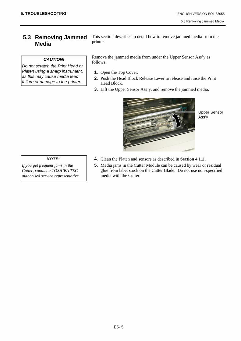
5. TROUBLESHOOTING ENGLISH VERSION EO1-33055
5.3 Removing Jammed Media
E5- 5
5.3 Removing Jammed Media
This section describes in detail how to remove jammed media from the printer. Remove the jammed media from under the Upper Sensor Ass’y as follows: 1. Open the Top Cover. 2. Push the Head Block Release Lever to release and raise the Print
Head Block. 3. Lift the Upper Sensor Ass’y, and remove the jammed media.
4. Clean the Platen and sensors as described in Section 4.1.1 . 5. Media jams in the Cutter Module can be caused by wear or residual
glue from label stock on the Cutter Blade. Do not use non-specified media with the Cutter.
CAUTION! Do not scratch the Print Head or Platen using a sharp instrument, as this may cause media feed failure or damage to the printer.
NOTE: If you get frequent jams in the Cutter, contact a TOSHIBA TEC authorised service representative.
Upper Sensor Ass’y

6. PRINTER SPECIFICATIONS ENGLISH VERSION EO1-33055
6. PRINTER SPECIFICATIONS
E6- 1
6. PRINTER SPECIFICATIONS This section describes the printer specifications.
Model Item B-852-TS22-QQ-R B-852-TS22-QP-R
Dimension (W × D × H) 385 mm × 181 mm* × 243 mm (15.2” × 7.1”* × 9.6”) *: Depth is 16.8” (427 mm) when the supply holder is installed.
Weight 34.4 lb (15.6 kg) (Media and ribbon are not included.)
Operating temperature range 5°C to 40°C (41°F to 104°F)
Relative humidity 25% to 85% RH (no condensation)
Input voltage AC100 – 120V, 60 Hz AC220 – 240V, 50 Hz
Power consumption
During a print job 2.5 A, 190 W maximum 1.1 A, 217 W maximum
During standby 0.16 A, 15 W maximum 0.1 A, 20 W maximum
Resolution 11.8 dots/mm (300 dpi)
Printing method Thermal transfer or Thermal direct
Printing speed
50.8mm/sec. (2 inches/sec.) 101.6 mm/sec (4 inches/sec.)
Available media width (including backing paper)
100 mm to 242 mm (3.9 inches to 9.5 inches)
Maximum effective print width 8.5” (216.8 mm)
Issue mode Batch Cut (Cut mode is enabled only when the optional cutter module is installed)
LCD Message display 16 characters × 1 line
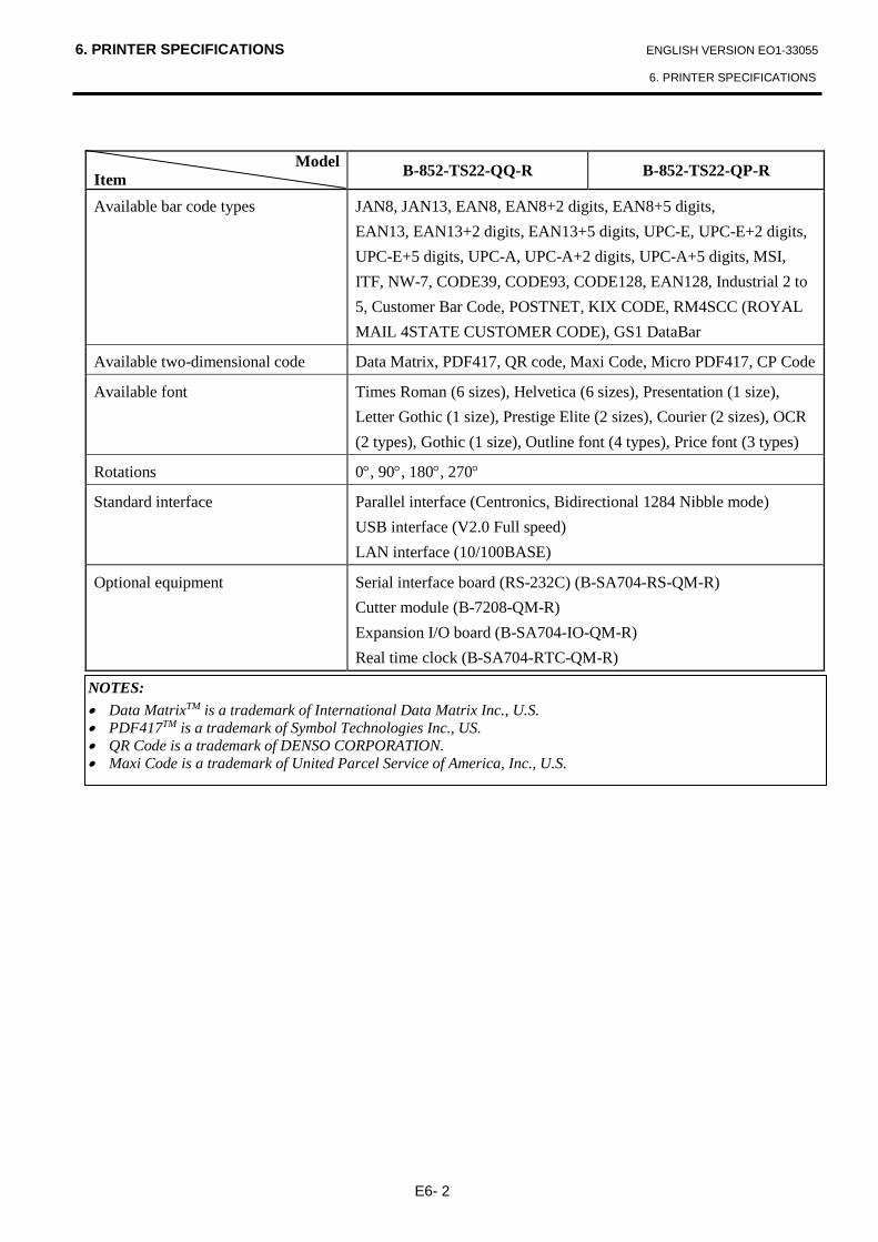
6. PRINTER SPECIFICATIONS ENGLISH VERSION EO1-33055
6. PRINTER SPECIFICATIONS
E6- 2
Model
Item B-852-TS22-QQ-R B-852-TS22-QP-R
Available bar code types
JAN8, JAN13, EAN8, EAN8+2 digits, EAN8+5 digits, EAN13, EAN13+2 digits, EAN13+5 digits, UPC-E, UPC-E+2 digits, UPC-E+5 digits, UPC-A, UPC-A+2 digits, UPC-A+5 digits, MSI, ITF, NW-7, CODE39, CODE93, CODE128, EAN128, Industrial 2 to 5, Customer Bar Code, POSTNET, KIX CODE, RM4SCC (ROYAL MAIL 4STATE CUSTOMER CODE), GS1 DataBar
Available two-dimensional code Data Matrix, PDF417, QR code, Maxi Code, Micro PDF417, CP Code
Available font
Times Roman (6 sizes), Helvetica (6 sizes), Presentation (1 size), Letter Gothic (1 size), Prestige Elite (2 sizes), Courier (2 sizes), OCR (2 types), Gothic (1 size), Outline font (4 types), Price font (3 types)
Rotations 0°, 90°, 180°, 270°
Standard interface Parallel interface (Centronics, Bidirectional 1284 Nibble mode) USB interface (V2.0 Full speed) LAN interface (10/100BASE)
Optional equipment Serial interface board (RS-232C) (B-SA704-RS-QM-R) Cutter module (B-7208-QM-R) Expansion I/O board (B-SA704-IO-QM-R) Real time clock (B-SA704-RTC-QM-R)
NOTES: • Data MatrixTM is a trademark of International Data Matrix Inc., U.S. • PDF417TM is a trademark of Symbol Technologies Inc., US. • QR Code is a trademark of DENSO CORPORATION. • Maxi Code is a trademark of United Parcel Service of America, Inc., U.S.
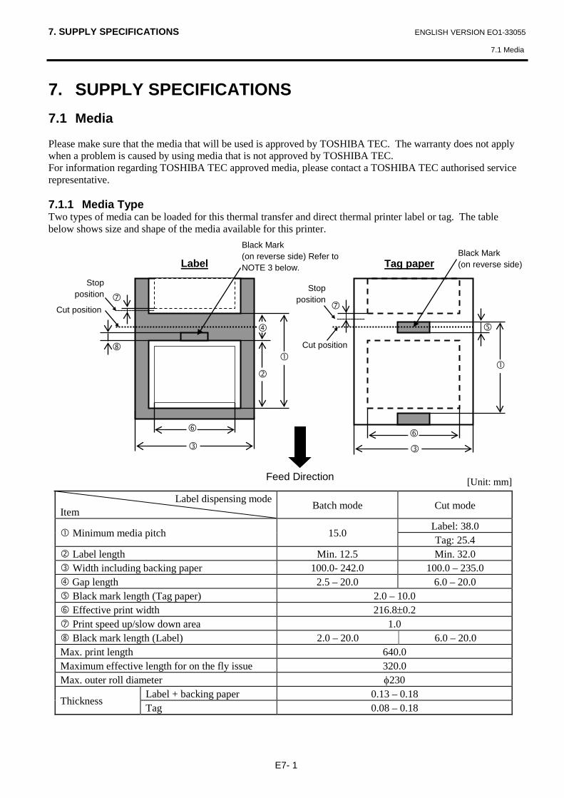
7. SUPPLY SPECIFICATIONS ENGLISH VERSION EO1-33055
7.1 Media
E7- 1
7. SUPPLY SPECIFICATIONS 7.1 Media Please make sure that the media that will be used is approved by TOSHIBA TEC. The warranty does not apply when a problem is caused by using media that is not approved by TOSHIBA TEC. For information regarding TOSHIBA TEC approved media, please contact a TOSHIBA TEC authorised service representative. 7.1.1 Media Type Two types of media can be loaded for this thermal transfer and direct thermal printer label or tag. The table below shows size and shape of the media available for this printer. [Unit: mm]
Label dispensing mode Item Batch mode Cut mode
Minimum media pitch 15.0 Label: 38.0 Tag: 25.4
Label length Min. 12.5 Min. 32.0 Width including backing paper 100.0- 242.0 100.0 – 235.0 Gap length 2.5 – 20.0 6.0 – 20.0 Black mark length (Tag paper) 2.0 – 10.0 Effective print width 216.8±0.2 Print speed up/slow down area 1.0 Black mark length (Label) 2.0 – 20.0 6.0 – 20.0 Max. print length 640.0 Maximum effective length for on the fly issue 320.0 Max. outer roll diameter φ230
Thickness Label + backing paper 0.13 – 0.18 Tag 0.08 – 0.18
Label
Tag paper
Cut position
Cut position
Stop position
Stop position
Feed Direction
Black Mark (on reverse side)
Black Mark (on reverse side) Refer to NOTE 3 below.

7. SUPPLY SPECIFICATIONS ENGLISH VERSION EO1-33055
7.1 Media
E7- 2
7.1.1 Media Type (Cont.) 7.1.2 Detection Area of the Transmissive Sensor The transmissive sensor is movable from the center to the left edge of media. The transmissive sensor detects a gap between labels, as illustrated below. 7.1.3 Detection Area of the Reflective Sensor The reflective sensor is movable from the center to the left edge of media. The reflection factor of the black mark must be 10% or lower with a waveform length of 950 nm. The reflective sensor should be aligned with the center of the black mark.
NOTES:
1. To ensure print quality and print head life use only TOSHIBA TEC specified media. 2. When using the cutter ensure that label length plus inter-label gap length exceeds 38 mm.
(i.e. label pitch should be greater than 38 mm.) 3. When marking black marks on label rolls, the following requirements must be satisfied. When the gap length is less than 4 mm: The black mark length should be longer than the gap length. When the gap length is 4 mm or more: The black mark should not overlap the gap for more than 4 mm and the following label. Black marks should be printed on reverse side of the gaps. Also, they should contact or overlap the
preceding label’s bottom end line. 4. “On the fly issue” means that the printer can feed and print without stopping between labels.
Sensor position Area to be detected. Center of media
Print side
Min. 12 mm
Label Gap Label
Min. 2.0 mm (Min. 6.0 mm when using
the cutter module.)
Sensor is movable within this range.
Media feed direction
Sensor should be positioned at the center of the black mark.
Center of media
Min. 10 mm Media feed direction
Min. 2.0 mm
Sensor is movable within this range.
Detecting the black marks on the back.
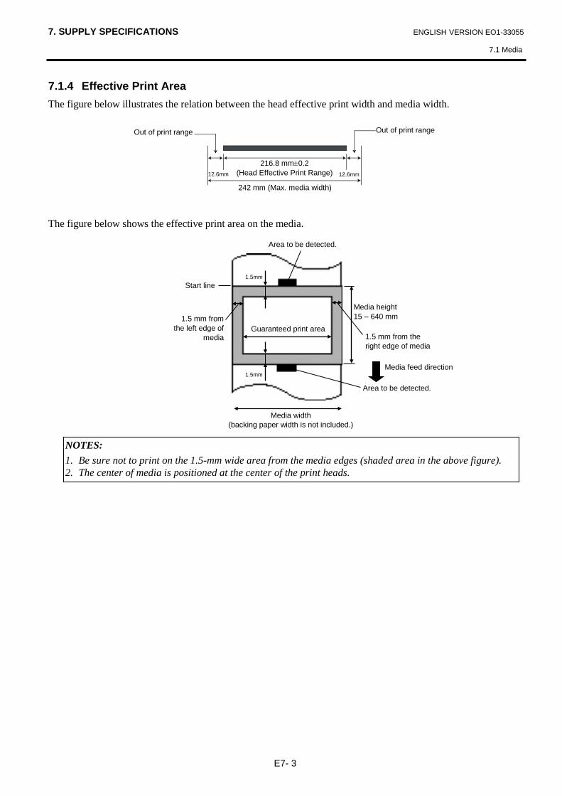
7. SUPPLY SPECIFICATIONS ENGLISH VERSION EO1-33055
7.1 Media
E7- 3
7.1.4 Effective Print Area The figure below illustrates the relation between the head effective print width and media width. The figure below shows the effective print area on the media.
12.6mm
242 mm (Max. media width)
216.8 mm±0.2 (Head Effective Print Range)
Out of print range Out of print range
12.6mm
NOTES: 1. Be sure not to print on the 1.5-mm wide area from the media edges (shaded area in the above figure). 2. The center of media is positioned at the center of the print heads.
Start line
Area to be detected.
Area to be detected.
Media feed direction
1.5 mm from the left edge of
media
Media width (backing paper width is not included.)
Media height 15 – 640 mm
1.5 mm from the right edge of media
1.5mm
1.5mm
Guaranteed print area

7. SUPPLY SPECIFICATIONS ENGLISH VERSION EO1-33055
7.2 Ribbon
E7- 4
7.2 Ribbon Please make sure that the ribbon being used is approved by TOSHIBA TEC. The warranty does not apply to any problem caused by using non-approved ribbons. For information regarding TOSHIBA TEC approved ribbon, please contact a sales representative.
Type Spool type Width 120 – 220 mm
Recommended width is 120, 160 and 220 mm. Length 300 m Outside Diameter φ72 mm (max.)
The table below shows the correlation between ribbon width and media width (backing paper is not included).
Ribbon width Media width 120 mm 100 – 110 mm 160 mm 110 – 150 mm 220 mm 150 – 242 mm
7.3 Recommended Media and Ribbon Types
Media type Description Vellum paper and labels General use for low cost applications. Coated paper Matt coated paper
General use including applications that require small letters and/or symbols. Glossy coated paper Used where a high-grade finish is required
Plastic films Synthetic film (Polypropylene, etc.) This water-proof and solvent-resistant material has high physical strength and low-temperature resistance, but poor heat resistance (dependant upon material). This material can be used for labels stuck to recyclable containers, so it can be recycled in the same process.
PET film This water-proof and solvent-resistant material has high physical strength, and low-temperature resistance as well as heat resistance. This material is used for many applications, especially where high durability is required. Mode/serial plate labels, caution labels, etc.
Polyimide This material gives the best performance on heat resistance (greater than PET film). It is often used for PCB labels as it can withstand passage through a solder bath.
NOTES: 1. To ensure print quality and print head life use only TOSHIBA TEC specified ribbons. 2. To avoid ribbon wrinkles use a ribbon that is wider than the media by 10 mm or more. However, too
much difference in width between the two may cause wrinkles.

7. SUPPLY SPECIFICATIONS ENGLISH VERSION EO1-33055
7.3 Recommended Media and Ribbon Types
E7- 5
7.3 Recommended Media and Ribbon Types (Cont.) Ribbon type Description
Vellum wax ribbon This ribbon is mainly used for vellum paper and labels. It has a very high ink density to cope with uneven printing surface
Standard wax ribbon Good match for coated paper (Matt coat and glossy coat). Smear-less ribbon (Wax resin ribbon) Good match for coated paper. The printed image will resist water and
light rubbing. Scratch and solvent resistance ribbon Very good match for plastic films (synthetic paper, PET, polyimide,
etc.) Scratch and solvent resistance Heat resistance with PET and polyimide.
Combination of Media and Ribbon
Media type Ribbon type Vellum paper and label Coated paper Plastic films
Vellum wax ribbon Standard wax ribbon Smear-less ribbon (wax-resin ribbon)
Scratch/solvent resistance ribbon
: Good match 7.4 Care/Handling of the Media and Ribbon
• Do not store the media and ribbon for longer than the manufacturer’s recommended shelf life. • Store media rolls on the flat end. Do not store them on the curved sides as this might flatten that side
causing erratic media advance and poor print quality. • Store the media in plastic bags and always reseal after opening. Unprotected media can get dirty and the
extra abrasion from the dust and dirt particles will shorten the print head life. • Store the media and ribbon in a cool, dry place. Avoid areas where they would be exposed to direct
sunlight, high temperature, high humidity, dust or gas. • The thermal paper used for direct thermal printing must not have specifications which exceed Na+ 800
ppm, K+ 250 ppm and Cl- 500 ppm. • Some ink used on pre-printed media may contain ingredients which shorten the print head’s product life.
Do not use labels pre-printed with ink which contain hard substances such as carbonic calcium (CaCO3) and kaolin (Al2O3, 2SiO2, 2H2O).
For further information, please contact your local distributor or your media and ribbon manufacturers.
CAUTION! Be sure to read carefully and understand the Supply Manual. Use only media and ribbons which meet specified requirements. Use of non-specified media and ribbons may shorten the head life and result in problems with bar code readability or print quality. All media and ribbons should be handled with care to avoid any damage to the media, ribbons or printer. Read the guideline in this section carefully.

APPENDIX 1 MESSAGES AND LEDS ENGLISH VERSION EO1-33055
APPENDIX 1 MESSAGES AND LEDS
EA1- 1
APPENDIX 1 MESSAGES AND LEDS Appendix 1 describes the LCD messages displayed on the operation panel. Symbols in the message 1: : The LED is illuminated. : The LED is flashing. : The LED is unlit. 2: ****: the number of unprinted media. Up to 9999 (in pieces) 3: ###: Flash memory card remaining memory for PC save area: 0 to 895 (in K bytes) 4: &&&&: Remaining flash memory capacity for storing writable characters 0 to 3147 (in K bytes)
No. LCD Message LED Indication
Printer Status Restoration
by RESTART key Yes/No
Acceptance of Status Request
Reset Command Yes/No
POWER ONLINE ERROR
1 ON LINE In online mode ----- Yes
ON LINE In online mode (The printer in communication)
----- Yes
2 HEAD OPEN The print head block is opened in online mode.
----- Yes
3 PAUSE **** The printer is paused. Yes Yes
4 COMMS ERROR A parity, overrun, or framing error has occurred during communication through the RS-232C.
Yes Yes
5 PAPER JAM **** The media is jammed during paper feed. Yes Yes
6 CUTTER ERROR**** A problem has occurred with the cutter module.
Yes Yes
7 NO PAPER **** The media has run out, or the media is not loaded on the supply holder properly.
Yes Yes
8 RIBBON ERROR**** The ribbon has run out, or has been torn. A problem has occurred with the sensor that determines the torque for the ribbon motor.
Yes Yes
9 HEAD OPEN **** Feed or printing was attempted with the print head block open.
Yes Yes
10 HEAD ERROR There is a problem with the print head Yes Yes 11 EXCESS HEAD TEMP The print head is overheated. No Yes
12 SAVING ###&&&& In writable character or PC command save mode
----- Yes
13 FLASH WRITE ERR. An error has occurred while writing to flash memory.
No Yes
14 FORMAT ERROR An erase error has occurred in formatting the flash memory.
No Yes
15 FLASH CARD FULL Data cannot be stored because the flash memory.
No Yes
16 POWER FAILURE A power failure has occurred. No No 17 MEM. INTIAL… A flash memory card is being initialised. ----- -----
18 EEPROM ERROR Data cannot be read from/written to a backup EEPROM properly
No No

APPENDIX 1 MESSAGES AND LEDS ENGLISH VERSION EO1-33055
APPENDIX 1 MESSAGES AND LEDS
EA1- 2
No. LCD Message LED Indication
Printer Status
Restoration by RESTART key Yes/No
Acceptance of Status Request
Reset Command Yes/No
POWER ONLINE ERROR
19 SYSTEM ERROR
When the following abnormal operations are performed, a system error occurs: (a) Command fetch from an odd address (b) Access to word data at an odd
address (c) Access to long-word data at an odd
address (d) Access to the area of 80000000H to
FFFFFFFFH in the logic space in user mode.
(e) An undefined instruction in an area other than a delay slot was decoded.
(f) An undefined instruction in a delay slot was decoded.
(g) An instruction to rewrite a delay slot was decoded.
No No
20 LAN INITIAL... 100BASE LAN is being initialised. ----- ----- 21 DHCP INITIAL... DHCP CLIENT is being initialised. ----- -----
22 LOW BATTERY The voltage of the Real Time Clock Battery is 1.9V or less
No Yes
23 Display of error message (See Notes.) A command error has occurred in
analyzing the command. Yes Yes
NOTE: When an error message listed above appears on the LCD message display, please refer to Section 5
TROUBLESHOOTING for solution.

APPENDIX 1 MESSAGES AND LEDS ENGLISH VERSION EO1-33055
APPENDIX 1 MESSAGES AND LEDS
EA1- 3
NOTES: • If a command error is found in the command received, 16 bytes of the command error, starting from the command
code, will be displayed. (However, [LF] and [NUL] will not be displayed.) Example 1 [ESC] T20 E30 [LF] [NUL] Command error The following message appears. Example 2 [ESC] XR; 0200, 0300, 0450, 1200, 1, [LF] [NUL] Command error The following message appears. Example 3 [ESC] PC001; 0A00, 0300, 2, 2, A, 00, B [LF] [NUL] Command error The following message appears. • When the error command is shown, “? (3FH)” appears for codes other than codes 20H to 7FH and A0H to DFH. • For details, please refer to the B-852 Series External Equipment Interface Specification.
T20E30
XR;0200,0300,045
PC001;0A00,0300,

APPENDIX 2 INTERFACE ENGLISH VERSION EO1-33055
APPENDIX 2 INTERFACE
EA2- 1
APPENDIX 2 INTERFACE Parallel interface (Centronics)
Mode: Conforming to IEEE1284 Compatible mode (SPP mode), Nibble mode
Data input method: 8 bit parallel Control signal:
Data input code: ASCII code
European 8 bit code Graphic 8 bit code JIS8 code Shift JIS Kanji code JIS Kanji code
Receive buffer: 1M byte
SPP Mode Nibble Mode nStrobe HostClk nAck PtrClk Busy PtrBusy Perror AckDataReq Select Xflag nAutoFd HostBusy nInit nInit nFault nDataAvail nSelectIn IEEE1284Active
NOTE: To prevent radiation and reception of electrical noise, the interface cables must meet the following requirements: • In case of a parallel interface cable or serial interface cable, fully shielded and fitted with metal or metallised
connector housings. • Keep as short as possible. • Should not be bundled tightly with power cords. • Should not be tied to power line conduits. • A parallel interface cable to be used should conform to IEEE1284.

APPENDIX 2 INTERFACE ENGLISH VERSION EO1-33055
APPENDIX 2 INTERFACE
EA2- 2
Connector:
PIN No. Signal SPP Mode Nibble Mode
1 nStrobe HostClk 2 Data 1 Data 1 3 Data 2 Data 2 4 Data 3 Data 3 5 Data 4 Data 4 6 Data 5 Data 5 7 Data 6 Data 6 8 Data 7 Data 7 9 Data 8 Data 8 10 nAck PtrClk 11 Busy PtrBusy 12 PError AckDataReq 13 Select Xflag 14 nAutoFd HostBusy 15 NC NC 16 0V 0V 17 CHASSIS GND CHASSIS GND 18 +5V (For detection) +5V (For detection) 19 TWISTED PAIR GND(PIN1) TWISTED PAIR GND(PIN1) 20 TWISTED PAIR GND(PIN2) TWISTED PAIR GND(PIN2) 21 TWISTED PAIR GND(PIN3) TWISTED PAIR GND(PIN3) 22 TWISTED PAIR GND(PIN4) TWISTED PAIR GND(PIN4) 23 TWISTED PAIR GND(PIN5) TWISTED PAIR GND(PIN5) 24 TWISTED PAIR GND(PIN6) TWISTED PAIR GND(PIN6) 25 TWISTED PAIR GND(PIN7) TWISTED PAIR GND(PIN7) 26 TWISTED PAIR GND(PIN8) TWISTED PAIR GND(PIN8) 27 TWISTED PAIR GND(PIN9) TWISTED PAIR GND(PIN9) 28 TWISTED PAIR GND(PIN10) TWISTED PAIR GND(PIN10) 29 TWISTED PAIR GND(PIN11) TWISTED PAIR GND(PIN11) 30 TWISTED PAIR GND(PIN31) TWISTED PAIR GND(PIN31) 31 nInit nInit 32 nFault NDataAvail 33 0V 0V 34 NC NC 35 NC NC 36 nSelectIn IEEE1284Active
IEEE1284-B Connector
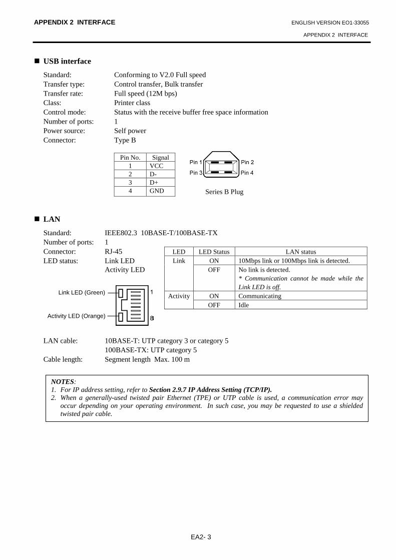
APPENDIX 2 INTERFACE ENGLISH VERSION EO1-33055
APPENDIX 2 INTERFACE
EA2- 3
USB interface
Standard: Conforming to V2.0 Full speed Transfer type: Control transfer, Bulk transfer Transfer rate: Full speed (12M bps) Class: Printer class Control mode: Status with the receive buffer free space information Number of ports: 1 Power source: Self power Connector: Type B
Pin No. Signal 1 VCC 2 D- 3 D+ 4 GND
LAN
Standard: IEEE802.3 10BASE-T/100BASE-TX Number of ports: 1 Connector: RJ-45 LED status: Link LED Activity LED LAN cable: 10BASE-T: UTP category 3 or category 5 100BASE-TX: UTP category 5 Cable length: Segment length Max. 100 m
LED LED Status LAN status Link ON 10Mbps link or 100Mbps link is detected.
OFF No link is detected. * Communication cannot be made while the Link LED is off.
Activity ON Communicating OFF Idle
NOTES: 1. For IP address setting, refer to Section 2.9.7 IP Address Setting (TCP/IP). 2. When a generally-used twisted pair Ethernet (TPE) or UTP cable is used, a communication error may
occur depending on your operating environment. In such case, you may be requested to use a shielded twisted pair cable.
Link LED (Green)
Activity LED (Orange)
Series B Plug
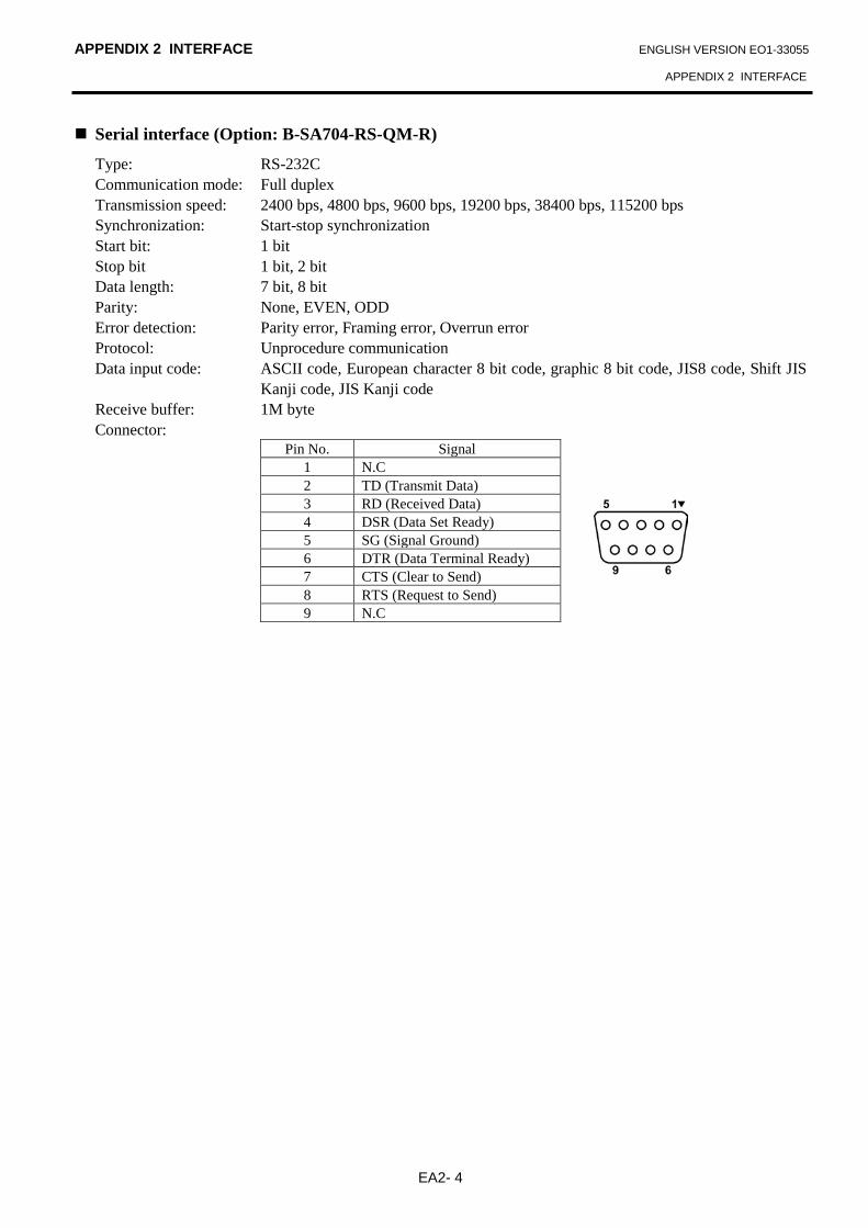
APPENDIX 2 INTERFACE ENGLISH VERSION EO1-33055
APPENDIX 2 INTERFACE
EA2- 4
Serial interface (Option: B-SA704-RS-QM-R)
Type: RS-232C Communication mode: Full duplex Transmission speed: 2400 bps, 4800 bps, 9600 bps, 19200 bps, 38400 bps, 115200 bps Synchronization: Start-stop synchronization Start bit: 1 bit Stop bit 1 bit, 2 bit Data length: 7 bit, 8 bit Parity: None, EVEN, ODD Error detection: Parity error, Framing error, Overrun error Protocol: Unprocedure communication Data input code: ASCII code, European character 8 bit code, graphic 8 bit code, JIS8 code, Shift JIS
Kanji code, JIS Kanji code Receive buffer: 1M byte Connector:
Pin No. Signal 1 N.C 2 TD (Transmit Data) 3 RD (Received Data) 4 DSR (Data Set Ready) 5 SG (Signal Ground) 6 DTR (Data Terminal Ready) 7 CTS (Clear to Send) 8 RTS (Request to Send) 9 N.C

APPENDIX 2 INTERFACE ENGLISH VERSION EO1-33055
APPENDIX 2 INTERFACE
EA2- 5
Expansion I/O Interface (Option: B-SA704-IO-QM-R)
Input Signal IN0 to IN5 Output Signal OUT0 to OUT6 Connector FCN-781P024-G/P or equivalent (External Device Side) Connector FCN-685J0024 or equivalent (Printer Side) Input Circuit
Output Circuit
Operating environment Temperature: 0 to 40 °C Humidity: 20 to 90% (No Condensation)
Pin Signal I/O Function Pin Signal I/O Function 1 IN0 Input FEED 13 OUT6 Output 2 IN1 Input PRINT 14 N.C. ----- 3 IN2 Input PAUSE 15 COM1 Common (Power) 4 IN3 Input 16 N.C. ----- 5 IN4 Input 17 N.C. ----- 6 IN5 Input 18 N.C. ----- 7 OUT0 Output FEED 19 N.C. ----- 8 OUT1 Output PRINT 20 N.C. ----- 9 OUT2 Output PAUSE 21 COM2 Common (Ground)
10 OUT3 Output ERROR 22 N.C. ----- 11 OUT4 Output 23 N.C. ----- 12 OUT5 Output POWER ON 24 N.C. -----
N.C.: No Connection
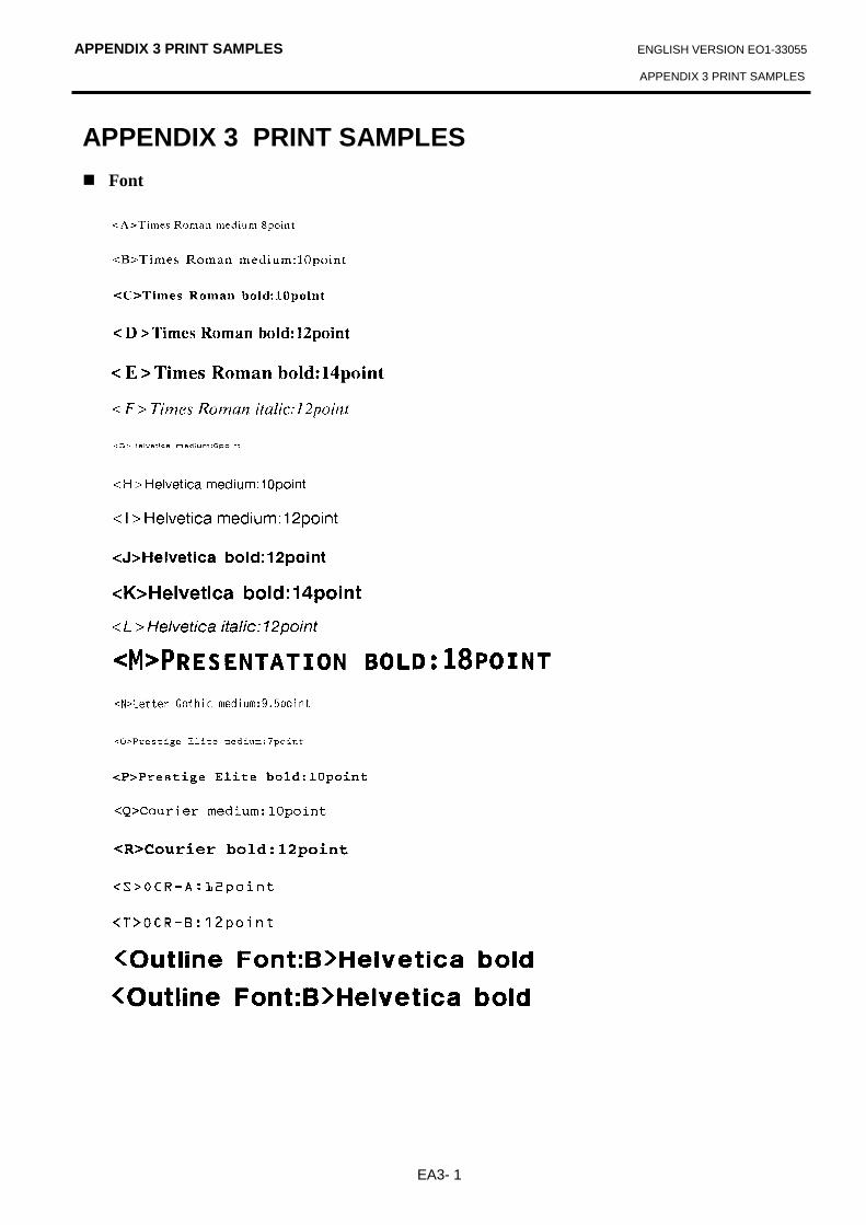
APPENDIX 3 PRINT SAMPLES ENGLISH VERSION EO1-33055
APPENDIX 3 PRINT SAMPLES
EA3- 1
APPENDIX 3 PRINT SAMPLES Font

APPENDIX 3 PRINT SAMPLES ENGLISH VERSION EO1-33055
APPENDIX 3 PRINT SAMPLES
EA3- 2
APPENDIX 3 PRINT SAMPLES (Cont.) Bar codes
0: JAN8, EAN8 1: MSI 2: Interleaved 2 of 5 3: CODE39 (Standard) 4: NW7 5: JAN13, EAN13 6: UPC-E 7: EAN13+2 digits 8: EAN13+5 digits A:CODE128 B: CODE39 (Full ASCII) C: CODE93 G: UPC-E+2 digits H: UPC-E+5 digits I: EAN8+2 digits J: EAN8+5 digits

APPENDIX 3 PRINT SAMPLES ENGLISH VERSION EO1-33055
APPENDIX 3 PRINT SAMPLES
EA3- 3
APPENDIX 3 PRINT SAMPLES (Cont.) K: UPC-A L: UPC-A+2 digits M: UPC-A+5 digits N: UCC/EAN128 O: Industrial 2 of 5 P: PDF417 Q: Data Matrix R: Customer bar code S: Customer bar code of high priority T: QR code U: POSTNET V: RM4SCC W: KIX Code X: Micro PDF417 Z: MaxiCode
APPENDIX 4 GLOSSARIES ENGLISH VERSION EO1-33055
APPENDIX 4 GLOSSARIES
EA4-1
APPENDIX 4 GLOSSARIES
Bar code A code which represents alphanumeric characters by using a series of black and white stripes in different widths. Bar codes are used in various industrial fields: Manufacturing, Hospitals, Libraries, Retail, Transportation, Warehousing, etc. Reading bar codes is a fast and accurate means of capturing data while keyboard entry tends to be slow and inaccurate. Batch mode Issue mode that continuously prints media until the specified number of media has been printed. Black mark A mark printed on the media so that the printer can maintain a constant print position by detecting this mark. Black mark sensor A reflective sensor which detects the difference of potential between the black mark and print area to find the print start position. Cut mode Printer mode of operation where an optional cutter module is installed to automatically cut media from the supply roll after they are printed. The print command can specify to cut every media or to cut after a set number of media have been printed. Cutter module A device used to cut the media. DPI Dot Per Inch The unit used to express print density. Expansion I/O interface An optional interface circuit that may be installed into the B-852 printer to allow the printer to be connected to an external device such as a wrapping machine and to receive feed, print start, and pause signals from the external device and to send back print, pause, and error status signals to the external device.
Feed gap sensor A transmissive sensor which detects the difference of potential between the gap between labels and the label to find the print position of the label. Font A complete set of alphanumeric characters in one style of type. E.g. Helvetica, Courier, Times Gap Clearance between labels IPS Inch per second The unit used to express print speed. LCD Liquid Crystal Display Installed on the operation panel and displays operation modes, error message and so on. Label A type of media with adhesive backing. Media Material on which data is printed by the printer. Label, tag paper, fanfold paper, perforated paper, etc. Plug and Play When Plug and Play is enabled, the PC will automatically identify the printer (if the PC supports Plug & Play), optimize the system resource (IRQ and DMA), and display a message prompting a printer driver installation. Pre-printed media A type of media on which characters, logos, and other designs have been already printed. Print head element The thermal print head consists of a single line of tiny resistive elements and when current is allowed to flow through each element it heats up causing a small dot to be burned onto thermal paper or a small dot of ink to be transferred from a thermal ribbon to ordinary paper.
APPENDIX 4 GLOSSARIES ENGLISH VERSION EO1-33055
APPENDIX 4 GLOSSARIES
EA4-2
Print speed The speed at which printing occurs. This speed is expressed in units of ips (inches per second). Reflective sensor See Black mark sensor. Resolution The degree of detail to which an image can be duplicated. The minimum unit of divided image is called a pixel. As the resolution becomes higher, the number of pixels increased, resulting in more detailed image Ribbon An inked film used to transfer an image onto the media. In the thermal transfer printing, it is heated by the thermal print head, causing an image to be transferred onto the media Supply Media and ribbon Supply holder This unit holds a media roll at the rear of the printer so that the media is fed toward the print head. Tag A type of media having no adhesive backing but black marks to indicate the print area. Usually tags are made of cardboard or other durable material. Thermal direct printing A printing method using no ribbon, but thermal media which reacts to heat. The thermal print head heats the thermal media directly, causing print image to be printed on the media. Thermal print head A print head using thermal transfer or thermal direct printing method. Thermal transfer printing A printing method that the thermal print head heats an ink or resin coating on the ribbon against the media, causing the ink/resin to transfer onto the media.
Threshold setting A sensor setting operation to have the printer maintain a constant print position of pre-printed media. Transmissive sensor See Feed gap sensor. USB (Universal Serial Bus) An interface that is used to connect peripherals, such as a printer, keyboard, mouse. The USB allows disconnection of a USB device without turning off the power. Web printer The web printer function allows you to browse the printer status on the PC, issue media, check or change the settings, or download the firmware to the printer. For details, refer to the Network Specification.

INDEX ENGLISH VERSION EO1-33055
INDEX
INDEX B Backing paper 7-1 Bar code 6-2, A3-2, A4-1 Batch mode 7-1, A4-1 Black mark 2-10, 7-1, 7-2, A4-1 Black mark length 7-1 Black mark sensor 1-4, 2-10, 2-68, 2-72, 4-1, A4-1 C Centronics 1-3, 2-23, A2-1 Cut mode 6-1, 7-1, A4-1 Cut position fine adjustment 2-63 Cutter module 1-1, 1-5, 2-60, 4-2, 6-2, A4-1 D DHCP 2-38 DHCP client ID 2-38 DHCP host name 2-39 E Effective print width 6-1, 7-1, 7-3 ERROR LED 1-4, 3-1, A1-1 Error message 5-1 Expansion I/O interface 1-3, 2-12, 2-25, A2-6,
A4-1 Expansion I/O interface board 1-1, 1-5, 6-2 F Feed gap sensor 1-4, 2-10, 2-68, 2-70, 4-1, A4-1 G Gap between labels 7-2 Gap length 7-1 Gateway IP address 2-36 Guaranteed print area 7-3 H Head block release lever 1-4, 2-8 Head pressure adjust lever 1-3, 2-9 I Input voltage 6-1 Interface 6-2, A2-1 IP address 2-35, A2-3 Issue mode 2-59, 6-1 J Jammed media 5-5
L Label 2-9, 7-1, 7-2, A4-1 Label length 7-1 LAN interface 6-2 LCD language 2-19 LCD message display 1-3, 1-4, 3-1, 6-1, A1-2 M Media 2-5, 7-1, 7-5, A4-1 Media pitch 7-1 O ONLINE LED 1-4, 3-1, A1-1 Operation Panel 1-3, 1-4, 3-1 P Paper guide 1-4, 2-8 Parallel interface 1-3, 2-12, 6-2, A2-1 Platen 1-4, 2-8, 4-1 Power consumption 6-1 Power cord 1-2, 2-4 POWER LED 1-4, 3-1, A1-1 Power switch 1-3, 2-4, 2-13 Pre-printed media 2-59, 2-68, A4-1 Print head 1-4, 4-1 Print head block 1-4, 2-8, 4-1 Print head cleaner 1-2, 4-1, 5-4 Print length 7-1 Print start position fine adjustment 2-62 Print tone fine adjustment 2-66 Printing method 6-1 Printing speed 1-1, 6-1 R Real time clock 1-1, 1-5, 2-32, 6-2 Reflective sensor 7-2 Resolution 6-1, A4-2 Ribbon 2-11, 7-4, 7-5, A4-2 Ribbon holder 1-4 Ribbon supply roll 2-11 Ribbon take up roll 2-11 Ribbon width 7-4 RS-232C 1-12, 2-17, 2-18, 6-2, A2-4

INDEX ENGLISH VERSION EO1-33055
INDEX
S Sensor adjust gear 2-10 Serial interface 1-3, A2-4 Serial interface board 1-1, 1-5, 6-2 Socket port 2-37 Subnet mask 2-37 Supply Holder Frame 1-2, 1-3, 2-3, 2-7 Supply Holder Locking Knob 2-5, 2-6 Supply Holder Unit 1-2, 1-3, 2-5, 2-7 T Tag 2-9, 2-10, 7-1, A4-2 Thermal direct 2-66, 6-1, A4-2 Thermal transfer 2-66, 6-1, A4-2 Transmissive sensor 7-2 U USB 1-3, 2-12, 6-2, A2-3, A4-2 W Web printer 2-24

© 2006-2019 TOSHIBA TEC CORPORATION All Rights Reserved 1-11-1, Osaki, Shinagawa-ku, Tokyo 141-8562, JAPAN
EN EO1-33055K