HI-1079 JULY 1979
• aze Ine
VIDEO DISPLAY TERMINAL REFERENCE MANUAL
Hazeltine Corporation COMPUT ER TE RMINAL EQUI PMENT
GRE ENLAWN. N. Y. 11740 (516)5 49- 8800 TEL EX 96-1 435

HI-1079
SAFETY SUMMARY
I WARNING I Dangerous voltages (12,000 vdc, 500 vdc and 100 to 240 vac) are present in the Video Display Terminal. Some voltage may remain present in monitor circuits after power is removed (see diagram below). Use caution when working on internal circuits. Do not work alone.
The terminal power cord should always be unplugged before the cover is re moved. Use caution when handling the cathode-ray tube (eg, wear safety goggles) to avoid risk of implosion. The internal phosphor coating is toxic ; if the tube breaks and skin or eyes are exposed to phosphor, rinse with water immediately and consult a physician.
EI
P2
MONITOR CIRCUITS
c: HIGH VOLTAGE MAY REMAIN AFTER POWER PLUG IS DISCONNECTED
MONITOR AREA OF CIRCUIT BOARD FLYBACK (LIGHT GREEN) TRANSFORMER ANODE
Copyright 1979 by Hazeltine Corporation
,

Section
1
2
3
4
5
HI-1079
CONTENTS
Safety Sununary • " . Inside Front Cover
Introduction
Installation 2.1 Set-up and Connections
2.1.1 Interface Connection 2.1.2 Auxiliary Input/Output Connection 2.1.3 Power Cord. 2.1.4 Cleaning .•.
2.2 Turn-on and Warm-up. 2.2.1 Power Turn-on 2.2.2 Warm-up
Controls and Keyboard 3.1 Controls and Indicator Under Access Panel.
3.1.1 Baud Rate ..... Parity . . . . . . . . Half or Full Duplex
3.1. 2 3.1. 3 3.1. 4 3.1. 5 3.1. 6
Automatic Line Feed or Carriage Return Font . • . Lead-In
3.1.7 Wraparound ..
3.2
3.1.8 Contrast Control. 3.1.9 Power on Indicator Keyboard . . . . . . . . • 3.2.1 Alphanumeric (qwerty) Cluster 3.2.2 Numeric Cluster ..... . 3.2.3 Additional Keyboard Commands
Operation . " .•. 4.1 Operation in Full Duplex 4.2 Operation in Half Duplex 4.3 Scrolling .... 4.4 Remote Commands . 4.5 Foreground/Background. 4.6 User Defined Functions 4.7 Timing Considerations. 4.8 Auxiliary Input/Output Port (Option)
Communications Interface 5.1 ASCI I . • • . . . . 5.2 Asynchronous Data • 5.3 Full Duplex/Half Duplex 5.4 EIA Interface .....
5.4.1 EIA Input/Output Connector 5.4.2 Auxiliary Input/Output Connector
5.5 Current Loop Interface (Option)
i
(Option)
1
1-1
2-1 2-1 2-1 2-1 2-2 2-2 2-2 2-2 2-2
3-1 3-1 3-1 3-1 3-1 3-3 3-3 3-3 3-3 3-4 3-4 3-4 3-4 3-4 3-4
4-1 4-1 4-1 4-1 4-2 4-5 4-7 4-7 4-7
5-1 5-1 5-1 5-1 5-1 5-1 5-2 5-2

Section
5
6
Appendix
A
B
C
Figure
2-1 3-1 3-2 4-1 5-1 6-1 6-2 6-3 6-4 6-5 6-6
5.6 5.7
HI-I079
CONTENTS (Cont)
Hardwired Interface . • • . Data Sets • • • • • • • • • 5.7.1 103A or 212A modems 5.7.2 202 Modem
Servicing . • • • • 6.1 Introduction 6.2 Troubleshooting ••
6.2.1 Preliminary Steps 6.2.2 Troubleshooting Procedure
6.3 6.4 6.5 6.6 6.7
6.8
Access •• • . • • Changing Fuse • • • • Touch Up Alignment . • • • • Complete Alignment Removal and Replacement of Circuit Board 6. 7. 1 Removal • • . • • • • • • • • • • • 6.7.2 Replacement • • . • • • • • • • Changing Voltage Taps (International Model Only)
ASCII Character Code Chart •
Cursor Address Chart
Summary of Remote Commands •
ILLUSTRATIONS
Terminal, Rear View • • • • • Controls Under Access Panel Keyboard • • • • • Display Example • • • • • • Current Loop Interface • • • Rear and Bottom View of Terminal • Terminal, Open, Ready for Servicing Location of Fuses Display Faults • • • • • • • • • • • Location of Adjustments International Terminal Power Connections •
ii
5-3 5-4 5-4 5-4
6-1 6-1 6-1 6-2 6-2 6-2 6-3 6-5 6-7 6-8 6-8 6-9 6-9
A-l
B-1
C-1
2-1 3-2 3-2 4-7 5-3 6-2 6-4 6-5 6-6 6-7 6-10

-
HI-1079
are provided to help isolate problems and minimize unnecessary replacement of circuit boards.
6.2.1 Preliminary Steps
Before deciding that the terminal is malfunctioning, check the following:
• Power cord plugged into a working outlet, power switch ON and cover on.
• Check that input/output connector at rear of unit is tight.
• Check that CONTRAST control under access panel (paragraph 3.1) is properly adjusted and interface switches are set properly for the system (see notes for paragraph 3.1. 2) .
• If possible, substitute another terminal to confirm or absolve the terminal (versus interface) as the cause of the problem.
CAPTIVE SCREWS (2)
6.2.2 Troubleshooting Procedure
a. Disconnect the electric power, wait 5 minutes, and open the unit as described in paragraph 6.3.
b. Refer to table 6-1 and answer the questions about the symptoms. The chart leads through the appropriate troubleshooting steps.
6.3 ACCESS
To gain access to internal components proceed as follows:
a. Disconnect the power cord plug from the ac power socket.
b. Lay the terminal on its side and loosen two captive screws in the base (figure 6~1).
c. Set the terminal upright and loosen two captive screws at the top rear.
d. Carefully lift the cover (with the cathode-ray tube (crt)) off the base and set it immediately to the right of the base. There is enough slack in the wiring to lay the cover on its side alongside the base as shown in figure 6-2.
Figure 6-1. Rear and Bottom View of Terminal
6-2

HI-1079
SECTION I
INTRODUCTION
The Hazeltine 1420 Video Display Terminal is a product of advanced microprocessor and large scale integrated circuit technology which offers quiet, reliable, and economical operation. The single circuit board design enhances reliability and ease of servicing. Speed, silence, and flexibility, combined with the operator oriented features of the terminal, summarized in table 1-1, improve the efficiency of both the software and programmer in data input/output applications.
This manual covers both the Domestic (115 v, 60 Hz) and International (100 to 240 v, 50 or 60 Hz) versions of the terminal. The terminal is also available in a European version compatible with CCITT-v.24 interfaces. A maintenance manual (HI-1082) for the terminal may be purchased from Hazeltine.
This manual describes the features and operation of the terminal, organized as follows:
• Installation and turn-on instructions are in Section 2.
• Data for operators, describing switch setting requirements and keyboard functions is in Section 3.
• Data for programmers, describing the modes of operation and use of the many remote commands is in Section 4.
• Interface details for installation planning are in Section 5.
• Servicing and adjustment instructions are in Section 6.
This manual is published and distributed by Hazeltine Corporation, Computer Terminal Equipment Product Line. The information presented herein may not reflect the latest changes in the product. Confirmation and any required clarification of this information can be obtained from Hazeltine.
Tel:
Hazeltine Corporation Industrial Products Division Greenlawn, New York 11740
(516) 549-8800 Telex: 96-1435
1-1

DISPLAY FORMAT
Screen
Capacity
Character Format
Character Set
Display
Refresh Rate
TV Line Standard
Memory
INTERFACE
Input/Output
Parity
Character
Modes
HI-I079
Table 1-1. Technical Summary
12 inch (30.5 cm) diagonal, P4 phosphor (gray)
80 characters/line x 24 lines (1920 characters)
5 x 8 dot matrix in 7 x 10 dot window, block cursor. Character shows through cursor in reverse video when superimposed.
95 displayable ASCII. All 128 ASCII codes can be keyed and transmitted
White on black background, two intensities plus blink
60 Hz, no interlace (50 Hz for International Model)
260 lines/frame, 240 lines displayed
2048 x 8 Random Access Memory
EIA RS-232C at 110, 300, 600, 1200, 1800, 2400, 4800, or 9600 baud (switch selected). Optional 20 rnA current loop
Odd, Even, One or Zero (switch selected)
Eleven bits (start, seven bit ASCII, parity, two stop bits) Received characters may have any number of stop bits
Half Duplex or Full Duplex (switch selected)
PHYSICAL/ENVIRONMENTAL DATA
Size and Weight
Power Required
Temperature Range
Humidity Range
REMOTE COMMANDS
Cursor
Display
Keyboard
ADDITIONAL FEATURES
Numeric Keypad and Function Mode
Typamatic Keyboard
Break Key
Tab Stops
Auxiliary Input/ Output Port (Option)
15-1/2 inches (39.4 em) wide, 13-1/2 inches (34.3 em) high, 20-1/2 inches (52.2 em) deep, 28 pounds (12.7 kg)
104 to 125 v, 60 Hz ±1%,75 watts (100 to 140 or 200 to 240 v, 50 Hz ±l% for International)
10° to 40°C (5d'~ to 104°F) operating; - 20° to 65°C (4° to 150°F) storage
5% to 90%, non-condensing
Up down, right, left, home, direct cursor address, columnar tab, field tab, send cursor address
Clear screen, clear foreground fields, high-intensity, blink, or blank foreground fields, low intensity follows, display test pattern, clear to end
-of line, clear to end of screen, insert line, delete line
Lock, unlock, sound alarm, enter/exit function mode
15 key numeric cluster. 12 Keys generate ESCape sequences in function mode
Alphanumeric and incremental cursor control keys repeat at 15 char/second rate when held down for 3/4 second.
Inserts 200 to 250 ms break in transmitted data
Tab stops every eighth column
RS-232C input/output with remote enable, enable without display, and disable commands.
C79035
1-2

HI-1079
SECTION 2
INSTALLATION
2.1 SET-UP AND CONNECTIONS
Following unpacking, place the unit so that free air circulates around the rear, base and top. Ensure that cables are free of kinks or tight bends.
2.1.1 Interface Connection
The standard Electronic Industries Association (EIA) input/output connector (figure 2-1), located on the rear of the terminal, provides the
EIA INPUT/OUTPUT CONNECTOR
POWER ON-OFF SWITCH
connection to the data set or acoustic coupler. The interface is compatible with EIA Standard RS-232C.
2.1.2 Auxiliary Input/Output Connection
If the terminal is equipped with the optional auxiliary input/output feature, the auxiliary input/output connector (figure 2-1) may be used to connect a compatible RS-232 device such as a serial printer.
AUXILIARY INPUT/OUTPUT CONNECTOR (OPTION)
c-
7905056
Figure 2-1. Terminal, Rear View
2-1

HI-l079
2.1.3 Power Cord
The power cord must be plugged into a properly grounded power outlet. Do not use adapters which would prevent the terminal unit from being properly grounded.
On international units, check the identification plate on the back of the terminal to ensure that the terminal is set for the appropriate voltage.
2.1.4 Cleaning
Dirt and smudges can be removed from the cabinet with common household spray cleaner and a soft cloth. The faceplate should be cleaned only with a soft, damp cloth or tissue to avoid scratching.
2.2 TURN-ON AND WARM-UP
A terminal brought in from a substantially colder environment should be allowed at least 1 hour to reach room temperature prior to power tumon.
2-2
2.2.1 Power Turn-on
The power on/off switch is located at the rear of the terminal. When power is turned on, a cursor should appear on the display within 3 minutes.
a. If random characters appear on the screen and do not clear when the CLEAR key is depressed, or if there is no response to keyboard entries, switch power off, wait l5.seconds, and switch power on one more time. If the problem occurs a second time, refer to Section 6.
b. If there is no display after the unit has warmed up for a reasonable time (not more than 3 minutes), adjust the CONTRAST control located under the access panel above the keyboard. If there is still no display, refer to Section 6.
2.2.2 Warm-Up
Allow 30 seconds for display warm-up. At the end of this period the terminal is ready to operate.

HI-I079
SECTION 3
CONTROLS AND KEYBOARD
3.1 CONTROLS AND INDICATOR UNDER ACCESS PANEL
switches used for selecting the input/output interface .characteristics of the terminal are accessible to the operator without having to open the terminal. To gain access to these switches, remove the access panel above the keyboard by pulling up. The function of each control is described in the following paragraphs.
3.1.1 Baud Rate
The three BAUD RATE switches are used to select one of eight communication speeds from 110 to 9600 baud. The switch settings for each available speed are shown in figure 3-1.
3.1. 2 Parity
The PARITY switches are used to select the parity compatible with the system. The switch settings for each parity condition are shown in figure 3-1. The four possibilities are:
Parity
Odd
Even
1
Operation.
Checks for odd parity on received data and generates odd parity on data sent.
Checks for even parity on received data and generates even parity on data sent.
The parity bit of each transmitted character is set to a one. No parity check is made on data received.
3-1
Parity Operation
o The parity bit of each transmitted character is set to a zero. No parity check is made on data received.
NOTE
1. Baud rate and parity are determined by the switch settings at the time the terminal is turned on. To make a change after the terminal is turned on, reset the switches for the desired speed and parity and press the BREAK key (figure 3-2) to initiate the change.
2. If a character is received with a parity error when Even or Odd parity is selected, a ? symbol will be displayed at the cursor position.
3.1.3 Communication Mode
a. Full Duplex
The off position of this switch selects the full duplex mode of communication which is typically used when the communications system is capable of simultaneous two-way transmission. In this mode, data entered from the keyboard is sent directly to the computer system. Upon reaching the computer, the data is typically "echoed" back to the terminal at the discretion of the program (ie, it may not be desirable to echo back special codes, passwords, etc). If modems are used, they must

HI-1079
BAUD RATE 1. ~ 5 TiD t t t 300 ~ t t 600 t ~ t 1200 ~ ~ t 1800 t t
rl 2400 ~ t LEAD IN (6) CURSOR (2) 1l MODE (5) ~ r ON LINE (n" 4800 t ~ ESC t WRAPAROUND t HALF DUPLEX t ON t 9600 ~ ~ tv ~ NO WRAP ~ FULL DUPLEX ~ OFF ~
I \ I 12345678 12345678
uuu~~[J~~ u[J[J~~~~[J o CONTRAST
~ PAR ITY Z .ll. ________ -.-J1 ODD t EVEN ~
1 t o ~
FONT (4) UPPER & LOWER UP CASE ONLY "ON LINE SWITCH FUNCTIONAL
ON EUROPEAN UNITS ONLY
Figure 3-1. Controls Under Access Panel
Figure 3-2. Keyboard
3-2
lAUTO LF/CR (6) AUTO LF ~
CARRIAGE RET t
f:r\7 1;\8
1:;\4 t ~5
+- HOME
~I f;\2
10\0 ... f;I\,
+ -
7906112
~9
~6 -. ~3
~. ENTER
7905051

HI-1079
be set for full duplex operation. Only received or "echoed" data is displayed or acted upon by the terminal.
b. Half Duplex
The on position of this switch selects the half duplex mode of communication. In this mode, data entered from the keyboard is sent directly to the computer system and is treated as received data by the terminal via an internal connection. Echoing, as in full duplex mode, is not required; if used, it may cause each transmitted character to be displayed twice.
3.1.4 Automatic Line Feed or Carriage Return
a. AUTO LF (Automatic Line Feed)
When this switch is in the on position, all received carriage returns automatically cause the cursor to move to the first character position of the next line (new line function). The CR code is not stored in the display memory. If the cursor was on the last displayable character row, carriage returns will scroll the display (refer to section 4.4 for a description of scrolling). Received line feed characters are ignored.
b. CR (Carriage Return)
When this switch is in the off position all received carriage returns move the cursor to the first character position of the same line. The CR code is not stored in the display memory. Received line feed characters move the cursor down one line. If the cursor was on the last displayable character row, line feed characters cause the display to scroll (refer to section 4.4 for a description of scrolling). The LF code is not stored in the display memory.
3-3
3.1. 5 Font
a. UP (Upper case)
The on position of this switch selects upper case only operation. All lower case alpha characters generated from the keyboard are converted to upper case for transmission and display. All received lower case alpha characters are displayed as upper case. In this position, the ALL CAPS key is logically disabled.
b. U/L CASE (Upper and lower case)
The off position of this switch selects the full 128 character ASCII codes for transmission and 95 character alpha/numeric character set for display. In this position, the ALL CAPS key in the down position may be used for upper case operation.
3.1. 6 Lead-In
This switch must be set to match the lead-in code selected for remote commands, as described in paragraph 4-6. If ESCape is selected as the lead-in - will be displayed when received.
3.1.7 Wraparound
If wraparound mode is selected (on position), whenever a character is entered in the last (80th) column of a row, either from the keyboard or as received data, the cursor moves to the first column of the next row without requiring a carriage return or line feed. If the cursor was on the bottom row, the display scrolls up.
If no wraparound is selected (off position), when the cursor reaches the last (80th) column it remains there until a carriage return or line feed (or other cursor movement command) is received. If data continues to be entered, either from the keyboard or as received data, the

HI-1079
characters are entered in the 80th character position sequentially, each character replacing the previous one.
3.1.8 Contrast Control
This control, located to the right of the switchs, permits a wide range of contrast adjustment to facilitate viewing the display under a variety of lighting conditions.
3.1.9 Power On Indicator
The power on indicator lights (red) whenever the terminal is on. In addition, the indicator blinks if the keyboard is locked out or the terminal is in the function mode.
3.2. KEYBOARD
3.2.1 Alphanumeric (qwerty) Cluster
The alphanumeric keys operate in the same manner as a typewriter keyboard. The lower case letter, or lower symbol on the key, is transmitted when the key is struck. When either SHIFT key is held down while an alphanumeric key is struck, the upper case letter, or the upper symbol on the key is transmitted. The CTRL (control) key operates like the SHIFT key in that it must be held down while another key is typed to accomplish its function. The CTRL and SHIFT keys, used in conjunction with the alphanumeric keys, permit transmission of anyone of the 128 ASCII codes (Appendix A) . Appendix B lists the keystroke combination required for every ASCII
3-4
code. If the ASCII code does not correspond to a displayable character (codes in columns 0 and 1 Appendix A, and DEL are not displayable) nothing will be displayed on the screen. Table 3-2 lists the character(s) transmitted and the function performed by the non-alphanumeric keys on the keyboard.
3.2.2 Numeric Cluster
In normal operation, the numeric pad keys duplicate the corresponding keys in the alphanumeric cluster (the ENTER key causing a carriage return), and are provided for convenience in entering numerical data. If the terminal is placed in the function mode by remote command or by pressing the FCTN key, keys 0 through 9, comma and period become user defined function keys and transmit the ESCape sequences described in paragraph 4.6.
3.2.3 Additional Keyboard Commands
Table 3-1 lists commands which can be entered from the keyboard, but for which no individual key is provided. In addition, any of the remote commands listed in Appendix C except Enable Auxiliary Output No Display, will be performed by the terminal if the appropriate character sequence is entered from the keyboard. If the keyboard lock sequence (Lead-in CRTL U) is entered, the keyboard will be locked out, and may be unlocked locally only by switching terminal power off and then on to reset the terminal.

Keystrokes
Lead-in Cy
Lead-in cB
Lead-in cDEL
Lead-in cA
Lead-in "
Lead-in Cz
Lead-in Cs
Lead-in Co
Lead-in Cx
Lead-in /
Lead-in ?
HI-1079
Table 3-1. Additional Keyboard Commands
Command
Background Follows
Select Blank Foreground Field
Select High Intensity Foreground Field
Select Blinking Foreground Field
Display Test Pattern
Insert Line
Delete Line
Clear to End of Line
Clear to End of Screen
Description
All subsequent data will be entered as a background field until cancelled by one of the three following "foreground" commands. Data in a background field will be displayed in low intensity, will not be cleared by a CLEAR FIELD entry, and will be tabbed over by a TAB entry.
All subsequent data will be entered as a foreground field until cancelled by a Background Follows command, and all foreground data will be blank on the display but retained in memory.
All subsequent data will be entered as a foreground field until cancelled by a Background Follows command, and all foreground data will be displayed at high intensity.
All subsequent data will be entered as a foreground field until cancelled by a Background Follows command, and all foreground data will blink (2/3 second on, 1/3 second off) •
A test pattern of all O's will be displayed with the cursor in the home position.
Row cursor is on and all rows below it scroll down one row. New row of all spaces appears on display with cursor in first column.
.Row cursor is on is deleted and all rows below it scroll up on row. Cursor moves to first column of same row.
All characters from cursor position to end of line, including character under cursor, are cleared to foreground spaces.
All characters from cursor position to end of screen, including character under cursor, are cleared to foreground spaces.
NOTE
The remaining commands are applicable only if the auxiliary input/ output port is installed.
Enable Aux Output with Display
Disable Aux Output Port
All subsequent data will be available at the auxiliary input/output port.
Data will not be output at the auxiliary input/output port. The terminal defaults to this condition.
Lead-in = ESC or 'V as selected
A superscript c or s indicates holding the CTRL and/or SHIFT key down while typing the character.
3-5
C79059

Key stroke
ALL CAPS
HOME
BACKSPACE or +
....
+
..
Table 3-2.
Transmitted Char(s)
None
BS
None
None
None
See remarks
L-I DC2
BS
DLE
L-I FF
L-I VT
See remarks
L-I = ESC or ",as selected
HI-I079
Keyboard Operations
Operation in half duplex or in full duplex when echoed
Alternate action key. When set (down) all alphabet keys generate upper case
Cursor moves to upper left corner
Cursor moves left one character
Cursor moves right one character
Cursor moves up one row
Cursor moves down one row
Same as corresponding keys in alphanumeric cluster except after FCTN
is struck
3-6
C79047

HI-1079
Table 3-2. Keyboard Operations (Cant)
Remarks
Only the alphabetic keys are affected. Received lower case characters will be displayed as lower case. If the Upper Case mode has been switch selected 3.1 ALL CAPS is overridden
Cursor Up, Down, Right and Left will not be executed if the result would put the cursor off the screen (CR or LF will be executed at the bottom of the screen, with the display scrolling up as necessary). Cursor right and left wrap around at edge of screen. Cursor right differs from space in that characters are not replaced by spaces for cursor right
ENTER key duplicates RETURN key in normal mode. There is no Function Mode sequence for + - or ENTER
3-7
C79048


HI-1079
SECTION 4
OPERATION
4.1 OPERATION IN FULL DUPLEX
The full duplex mode of communication is used with systems capable of simultaneous two-way transmission, and permits more computer control of the display. Data and commands entered at the keyboard are transmitted directly to the computer without display. The display is affected only by data and commands received by or "echoed" back to the terminal. The cursor movement (HOME, i, etc) and CLEAR keys also generate codes which are transmitted to the computer, and performed only when echoed back to the terminal. In the full duplex mode, the terminal's "Request to Send" output is high (true) when the first character is entered and remains high until power is shut off.
4.2 OPERATION IN HALF DUPLEX
The half duplex mode of communication is used when the system is not capable of simultaneous two-way transmission, or "echoed" back operation is undesirable. Data keyed from the keyboard is transmitted and displayed simultaneously. The cursor movement (except BACK SPACE) and CLEAR keys do not generate codes for transmission in half duplex mode (see table 3-1). Half duplex transmission via a modem is accomplished by the following modem control sequence:
1. When a character is entered at the keyboard, the terminal outputs a "Request to Send" signal to the modem.
2. The terminal checks for a "Data Set Ready" signal from the modem.
4-1
3. Upon sensing the Data Set Ready signal, the terminal waits, if necessary, for a "Clear to Send" signal from the modem.
4. Upon sensing the "Clear to Send" signal, the terminal transmits the character via the modem. The terminal's "Request to Send" signal remains present, and entered characters are transmitted, until one of the following three "turn around" characters is entered: Carriage Return, End of Text (ASCII ETX, keystroke CTRL C) or End of Transmission (ASCII EOT, keystroke CTRL D) .
5. After transmission of the "turn around" character, the terminal resets its "Request to Send" signal and the modem switches to the receive mode. The sequence begins again when the next character is typed.
Note that if the terminal does not sense a "Data Set Ready" signal in step 2 above, it transmits the character regardless of the presence or absence of "Clear to Send". This permits direct hard-wired connection to a computer or other device without simulation of modem control signals.
4. 3 SCROLLING
If a displayable ASCII code is received at the last character position of the bottom row, and the WRAPAROUND switch is in the on position (para 3.1.7), the display moves up one row, the top row of data is removed, and the cursor moves to the first character position (left margin) of the new bottom row. This operation is referred to hereafter as scrolling and requires no fill

HI-I079
characters at any baud rate for a minimum of 24 consecutive scrolls. Scrolling also occurs when the cursor is on the bottom row and a line feed (CR selected, para 3.1.4) or carriage return (AUTO LF selected) is received.
a tilde (ASCII ~, column 7, row 14; decimal 126) or an escape (ASCII ESC, column 1, row 11; decimal 27). The ~/ESC switch (para 3.1.6) must be set to agree with the lead-in code selected. The lead-in code is not displayed when received and does not advance the cursor. The command code must follow the lead-in without intervening characters (including DEL or NUL characters). If the code following the lead-in code is not one of the valid command codes requiring a leadin (a second lead-in is invalid) both the lead-in character and the following character will be ignored. The remote commands are listed and described in detail below.
4.4 REMOTE COMMANDS
The remote command features of the terminal provide the user with the capability of controlling the terminal via the CPU software. For the terminal to execute a remote command, the command code must be preceded by a lead-in code (except as noted). The lead-in code may be either
Conunand
Lead-In ASCII
Sound Alarm
No BEL
Horizontal Tab
No SO
Field Tab
No HT
Line Feed
No LF
Carriage Return
No CR
Home Cursor
Yes DC2
Description
On receipt of the Sound Alarm conunand the terminal sounds an audible alarm for approximately 1/4 second.
On receipt of the Horizontal Tab conunand, the cursor tabs to the next tab stop on the present row. Tab stops are located in columns 0, 8, 16, 24 ... (steps of 8) .•. 72 (numbering columns from ° to 79). If there are no more tab stops in the present row the cursor moves to the first column (no. 0) of the next row, or to the home position if it was on the bottom row.
On receipt of the Field Tab command the cursor tabs to the first character position in the next foreground field. If there is no new foreground field down-screen from the present cursor position, the search is continued from the home position. If home position is foreground, it is considered a new foreground field. If there is no new field on the display, the cursor ends up in. the original location.
On receipt of the Line Feed command, the cursor moves down one row in the same column; if it was on the bottom row, the display scrolls up. If the AUTO LF/CR switch is set to AUTO LF (para 3.1.4), Line Feed commands are ignored.
On receipt of the Carriage Return conunand, the cursor moves to the first column position of the present row. If the AUTO LF/CR switch is set to AUTO LF (para 3.1.4) the cursor also moves down one row; if it was on the bottom row, the display scrolls up.
On receipt of the Home Cursor command, the cursor moves to the upper left (home) character position. The display is unchanged.
C79052
4-2

Command
Lead-In ASCII
Cursor Up
Yes FF
cursor Down
Yes VT
Cursor Right
No DLE
Cursor Left
No BS
Direct Cursor Address
Yes DCl, X, Y
Send Cursor Address
Yes ENQ
Send Character at Cursor Position
Yes
HI-I079
Description
On receipt of the Cursor Up command, the cursor moves up one row in the same column. If the cursor is on the top row it does not move.
On receipt of the Cursor Down command, the cursor moves down one row in the same column. If the cursor is on the bottom row, it does not move.
On receipt of the Cursor Right command, the cursor moves right one column in the same row. If the cursor is in the right hand column (no. 79), it moves to the first column of the next row unless it is on the bottom row.
On receipt of the Cursor Left (Backspace) command, the cursor moves left one column in the same row. If the cursor is in the left hand column (no. 0) it moves to the last column and up one row unless it is on the top row.
The Direct Cursor Address command is a four character sequence:
Lead-in DCl Xcoordinate Ycoordinate
The 80 character. columns are designated X and range from 0 to 79. The rows are designated Y, and range from 0 to 23.
Decimal Address Column (X) Decimal Address Row (Y)
o through 78 o through 78 o through 22 0 through 22
79 through 95 79 23 through 31 23
96 through 127 o through 31 32 through 54 o through 22 (dec -32)
(dec -96) 55 through 63 23
64 through 86 o through 22 (dec -64)
87 through 95 23
96 through 118 o through 22 (dec -96)
119 through 127 23
The four characters in the sequence must be received without intervening characters, including NUL characters. Appendix B lists all possible addresses and the key strokes for generating them.
On receipt of the Send Cursor Address command, the terminal responds with the sequence'!
X coordinate, Y coordinate, Carriage Return
The coordinate system is the same as described for Direct Cursor Address above. The coordinates transmitted are listed in Appendix B. In the full duplex mode of operation the terminal is capable of receiving data while the coordinates are being transmitted. In half duplex operation, the terminal is capable of receiving data after the CR is transmitted. The keyboard is locked out during transmission.
On receipt of this command, the terminal transmits the character at the present cursor position followed by a Carriage Return. The cursor is not advanced. When used in conjunction with the cursor up, down, right, left, and direct cursor address commands, this permits reading any character previously entered on the display.
C79053
4-3
Corrnnand
Lead-In ASCII
Clear Screen
Yes FS
Clear Foreground
Yes GS
Clear to End of Line
Yes SI
Clear to End of Screen
Yes CAN
Insert Line
Yes SUB
Delete Line
Yes DC3
Background Follows
Yes EM
Select Blinking Foreground Field
Yes SOH
Select High Intensity Foreground Field
Yes US
Select Blank Foreground Field
Yes STX
Keyboard Lock
Yes NAK
Keyboard Unlock
Yes ACK
Display Test Pattern
Yes
Enter Function Mode
Yes >
Exit from Function Mode
Yes <
HI-1079
Description
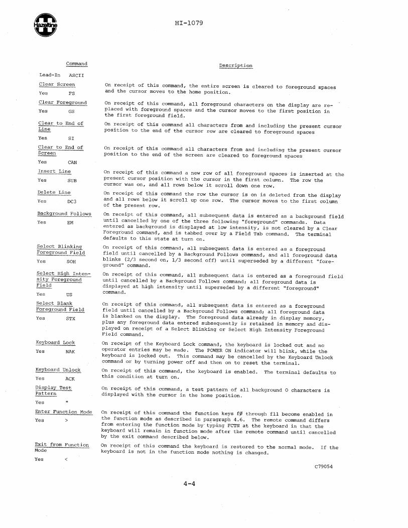
On receipt of this corrnnand, the entire screen is cleared to foreground spaces and the cursor moves to the home position.
On receipt of this corrnnand, all foreground characters on the display are replaced with foreground spaces and the cursor moves to the first position in the first foreground field.
On receipt of this corrnnand all characters from and including the present cursor position to the end of the cursor row are cleared to foreground spaces
On receipt of this corrnnand all characters from and including the present cursor position to the end of the screen are cleared to foreground spaces
On receipt of this corrnnand a new row of all foreground spaces is inserted at the present cursor position with the cursor in the first column. The row the cursor was on, and all rows below it scroll down one row.
On receipt of this corrnnand the row the cursor is on is deleted from the display and all rows below it scroll up one row. The cursor moves to the first column of the present row.
On receipt of this corrnnand, all subsequent data is entered as a background field until cancelled by one of the three following "foreground" corrnnands. Data entered as background is displayed at low intensity, is not cleared by a Clear Foreground corrnnand, and is tabbed over by a Field Tab corrnnand. The terminal defaults to this state at turn on.
On receipt of this corrnnand, all subsequent data is entered as a foreground field until cancelled by a Background Follows corrnnand, and all foreground data blinks (2/3 second on, 1/3 second off) until superseded by a different "foreground" corrnnand.
On receipt of this corrnnand, all subsequent data is entered as a foreground field until cancelled by a Background Follows corrnnand; all foreground data is displayed at high intensity until superseded by a different "foreground" corrnnand.
On receipt of this corrnnand, all subsequent data is entered as a foreground field until cancelled by a Background Follows corrnnand; all foreground data is blanked on the display. The foreground data already in display memory, plus any foreground data entered subsequently is retained in memory and displayed on receipt of a Select Blinking or Select High Intensity Foreground Field corrnnand.
On receipt of the Keyboard Lock corrnnand, the keyboard is locked out and no operator entries may be made. The POWER ON indicator will blink, while the keyboard is locked out. This corrnnand may be cancelled by the Keyboard Unlock corrnnand or by turning power off and then on to reset the terminal.
On receipt of this corrnnand, the keyboard is enabled. The terminal defaults to this condition at turn on.
On receipt of this corrnnand, a test pattern of all background a characters is displayed with the cursor in the home position.
On receipt of this corrnnand the function keys f~ through fll become enabled in the function mode as described in paragraph 4.6. The remote corrnnand differs from entering the function mode by typing FCTN at the keyboard in that the keyboard will remain in function mode after the remotecorrnnand until cancelled by the exit corrnnand described below.
On receipt of this corrnnand the keyboard is restored to the normal mode. If the keyboard is not in the function mode nothing is changed.
C79054
4-4

HI-1079
Command Description
Lead-In ASCII NOTE
The following three commands are applicable only to terminals with the auxiliary input/output port option
Enable Auxiliary Output With Dis-
On receipt of this command, all data received via the terminal Input/Output
~ Yes
port is displayed and is output at the auxiliary input/output port. In half duplex operation, keyboard entries are transmitted via the terminal input/output port and are output via the auxiliary port.
Enable Auxiliary Output-No Display
Yes *
The Enable Auxiliary Output-No Display command permits transmission to an auxiliary device without affecting the display. On receipt of this command, data received via the terminal input/output port is output at the auxiliary input/output port without processing or display by the terminal. The keyboard is locked out while in this mode and the POWER ON indicator blinks. The only inputs to which the terminal responds are a Disable Auxiliary Port or an Enable Auxiliary Port with Display command.
Disable Auxiliary Output
Yes ?
On receipt of this command the auxiliary output is disabled and no data is output at the auxiliary port. Input remains enabled. The terminal defaults to this condition at turn on.
4.5 FOREGROUND/BACKGROUND
All data is entered in display memory as either a foreground field or a background field, depending on the most recent command as described in paragraph 4.6. The terminal defaults to the background state at turn-on. Data in a background field is always displayed in low intensity, is tabbed over by a Field Tab command (TAB at keyboard) and is not cleared by a Clear Field command.
Data in a foreground field is displayed as high intensity, blinking, or blank, depending on the most recent command (para 4.6). All foreground data is cleared by a Clear Foreground command or by depressing the CLEAR FIELD key. These features may be used to highlight data, enhance graphics, or in form fill applications. The form fill application is best described by an example. Figure 4-1 shows a command sequence and the resulting display.
4-5
C79046
After the specified sequence is entered the cursor ends up in the first foreground position as shown. The operator may then enter the first field of data (name) and use the Field Tab (keystroke = TAB) which causes the cursor to tab over the next background field (employee no) and stop at the first foreground space following it, continuing until the form is completed. The form would appear in background (low) intensity, and operator entries in high intensity. A clear Foreground command (CLEAR FIELD at keyboard or Lead-in GS from computer) then clears the operator entries but leaves the form intact for another entry.
Alternatively, if multiple blocks of data sharing a common format are to be displayed, the same features may be used to transmit the form only once. If the sequence described

HI-l079
SEQUENCE ENTERED
ESC NAK ESC FS ESC DCl b b ESC EM NAME space ESC DCl B d EMPLOYEE NO Space ESC DCl DEL d DEPT Space ESC DCl b f ADDRESS Space ESC DCl h h Space Space ESC DCl h j Space Space DCl h 1 Space Space ESC DCl DEL 1 ZIP Space ESC DC2 ESC US HT ESC ACK
OPERATION
Keyboard lock, clear screen, direct cursor address - col 2/row 2, background follows, "NAME", col 2/ row 4, "EMPLOYEE NO", col 3l/row 4, "DEPT", col 2 /row 6, "ADDRESS", col 8/row 8, space space, col 8/row 10, space space, col 8/row 12, space space, col 31/row 12, "ZIP", Home, select high intensity foreground field, field tab, unlock keyboard
(The example assumes ESCape has been selected as remote command lead-in. Substitute - in all cases if selected as lead-in.)
RESULTING DISPLAY
/ ~= BACKGROUND
Figure 4-1. Display Example
4-6
7905055

HI-I079
above were followed by: Jones, J. F. HT 1645 HT Personnel HT 145 Main Street HT HT HT Greenlawn, N. Y. HT 11743 the data would be displayed next to the appropriate form entries. A new block of data could then be transmitted to the same form by preceding it with Clear Foreground and Field Tab commands.
NOTE
1. Foreground and Background commands are not stored in display memory. Each character is coded as foreground or background when entered.
2. All character positions are cleared to foreground spaces at turn on and after a Clear command. A position can be changed to background field only by entering a background character (including space) in it. Commands which move the cursor over a field (Tab, Cursor Right, etc) do not change the nature of the field.
4.6 USER DEFINED FUNCTIONS
The terminal provides for transmission of twelve user-defined function codes without affecting the display. Pressing the FCTN key followed by one of the twelve numeric pad keys labled fO through fll, causes the terminal to transmit a sequence of three ASCII characters: ESCape, the code for the normal key character (0 through 9, comma or period), Carriage Return. Any number of functions may be accommodated by using multiple codes. The FCTN key must be pressed before each function code; eg, to transmit function 3-2, type FCTN, f3, FCTN, f2. The cursor does
4-7
not advance and nothing is displayed when the sequence is transmitted. If the sequence is echoed a carriage return is performed. Once the FCTN key is pressed, all keys except the twelve function keys are locked out and the POWER ON indicator blinks until one of the function keys is pressed. If the FCTN key is pressed in error, it may be cancelled by pressing it again.
4.7 TIMING CONSIDERATIONS
At 9600 baud only, fill characters (NUL or DEL) or time out are required after an Insert Line or Delete Line command to prevent overruning the input queue (10 fill characters or 10 ms in worst case). These are the only single commands which require fill characters, but sequences of remote commands may also require fill characters. Refer to the Application Note on Hazeltine 1420 Timing Considerations if timing problems are encountered.
4.8 AUXILIARY INPUT/OUTPUT PORT (OPTION)
A user installable auxiliary input/ output (I/O) port is available for the terminal. It permits connection of an EIA RS-232 serial peripheral device to the terminal. Output to the peripheral device is controlled by remote command as described in paragraph 4.4. Input is controlled by the peripheral device via the Auxiliary Request to Send signal, and will be channelled to the terminal I/O Transmitted Data (BA) line. The Clear to Send signal (CB) from a modem will be relayed to the peripheral device as Auxiliary Clear to Send. If no modem is present, Auxiliary Clear to Send will be held at a high level (true).


HI-I079
SECTION 5
COMMUNICATIONS INTERFACE
5.1 ASCII
The Hazeltine 1420 terminal communicates via the ASCII code shown in Appendix A. A parity bit, as selected, is added to make an eightbit code.
5.2 ASYNCHRONOUS DATA
The format for received and transmitted data is asynchronous serial ASCII. Each transmitted character is preceded by a start bit and followed by two stop bits. Received characters may have any number of stop bits. The parity bit can be selected (see Section 3) to be even, odd, always one, or always zero. If a character is received with incorrect parity (with odd or even parity selected), a question mark (?) is displayed on the screen at the cursor position. This indicates to the terminal operator that erroneous data was received. switches are provided (see Section 3) to select one of eight transmission rates from 110 to 9600 baud.
5.3 FULL DUPLEX/HALF DUPLEX
Full duplex operation requires the ability to communicate in two directions simultaneously. For telecommunications, this means that the modem involved is capable of simultaneous bi-directional data transmission and reception. Half duplex operation requires that communications alternate between transmit and
Start Bit Bit Bit Bit
Bit 1 2 3 4
Bit
5
receive. For telecommunications, this means that the modem involved is switched between the transmit mode and receive mode by the terminal. Operation of the Hazeltine 1420 requires that communications take place at the same baud rate for both receive and transmit.
5.4 EIA INTERFACE
5.4.1 EIAInput/Output Connector
The standard EIA input/output connector located on the rear of the terminal (figure 2-1) provides the connection to the appropriate data set or acoustic coupler. The signals conform to EIA Standard RS-232C; these are listed below.
Pin Direction Desig-Number of Signal nation Function
1 AA Protective Ground (Chassis)
2 From Ter- BA Transmit-minal ted Data
3 To Ter- BB Received minal Data*
4 From Ter- CA Request to minal Send
5 To Ter- CB Clear to minal Send
*If the current loop option is installed a small switch on the circuit board next to the input! output connector must be set toward the connector for current loop operation and away from the connector for EIA operation.
Bit Bit Parity Stop Stop
6 7 Bit Bit Bit
TRANSMITTED DATA FORMAT
5-1

Q) HI-I079
Pin Direction Desig-Number of Signal nation Function
6 To Terminal CC Data Set Ready
7 AB Signal Ground
8 To Terminal CF Data Car-rier Detect
13 From Ter- 16X Baud minal Rate Clock
18 To Terminal + Current Loop Input*
19 To Terminal - Current Loop Input*
20 From Ter- CD Data Ter-minal minal Ready
21 From Ter- Current minal Loop Output*
22 From Ter- Current minal Loop. Output*
*No co-nnection if current loop option is not installed
5.4.2 Auxiliary Input/Output Connector (Option)
The auxiliary input/output port is an option that can be installed by the user. It permits serial output of received and transmitted data, at the data I/O baud rate, to an RS-232C compatible auxiliary device such as a printer, recorder, or another terminal. It also permits display and transmission of serial data input from an auxiliary device. Output and display may be controlled by remote commands described in paragraph 4.6. Additional information is furnished with the modification instructions.
If installed, the auxiliary input/ output connector is located on the lower rear of the terminal (figure
5-2
2-1). It provides the EIA RS-232C voltage level signals listed below:
Desig-Pin Direction Number of Signal nation Function
1
2
3
4
5
6
7
8
AA Protective
To Terminal Aux BB
From Ter- Aux minal BA To Terminal Aux
From Terminal From Terminal
From Terminal
CA
Aux CB Aux CC AB
Aux CF
Ground (Chassis) Auxiliary Data In Auxiliary Data Out Auxiliary Request to Send Clear to Send See Note
Signal Ground See Note
NOTE: Aux CC and Aux CF are true (high) whenever the terminal is on.
5.5 CURRENT LOOP INTERFACE (OPTION)
The current loop interface converts the standard EIA RS232 voltage level interface to a 20 ~ current switching interface. The current loop interface switching states are "mark" (current flow) or "space" (no current flow). The output data controls a circuit closure. In the "mark" condition, the circuit is closed while in the "space" condition the circuit is open. Figure 5-1 shows the external current loop configuration for either a four-wire (full duplex) facility or two-wire (half duplex) facility.

HI-1079
FOUR-WIRE (FULL DUPLEX)
vs/
EIA CONNECTOR PIN NUMBERS
2/
25
18
19
TWO-WIRE (HALF DUPLEX)
vs
ErA CONNECTOR. PIN NUMB£RS
r-----------------~ 21
~2.5
~/B 1'1
Note that the current loop connections must follow the polarities indicated and that there is a 50 volt open circuit limitation on voltages applied to the current loop interface. The current source must be external to the terminal.
Figure 5-1. Current Loop Interface 7706024
The maximum ratings are: 5.6 HARDWIRE INTERFACE
Current: 30 rnA maximum
Open Loop Voltage: 50 V maximum
Cable Interface: 1000 ft maximum 9600 baud
5-3
The terminal can be connected directly to a computer by connecting pins 2, 3 and 7 from the EIA connector on the rear panel. Note that pins 2 and 3 may have to be crossed with the corresponding pins on the computer. No wiring changes are required at the terminal to simulate

HI-1079
the presence of a modern. Refer to your computer supplier for any special wiring at the computer interface.
5.7 DATA SETS
5.7.1 103A or 2l2A Moderns
The terminal connects directly to a l03A or 2l2A modern through an optional interface cable which is available from Hazeltine.
5.7.2 202 Modern
The1;erminal connects to a 202 modern through an interface cable which is available from Hazeltine. The following procedure should be followed for prop~r operation with a half duplex 202 modern.
5-4
a. After the first key is depressed, the terminal conditions the modern for transmission. This can take up to 1/5 of a second. A very fast typist should take care to ensure that the first character reaches the screen before additional entries are mode.
b. To complete the transmission to the computer system, either a carriage return (RETURN), ETX (CTRL C) or EOT (CTRL D) must be entered as a termination character. The termination character used is determined by the computer software. Upon sending the termination character, the 202 modern switches into the receive mode.
c. Depressing the next character for transmission returns operation to step a.

HI-1079
SECTION 6
SERVICING
6.1 INTRODUCTION
Hazeltine will repair units returned to the factory under the conditions contained in the description of "Warranty Service" and "Non-Warranty Service" supplied with the terminal.
For customers who elect the alternative of troubleshooting to the circuit board level, this section provides instructions for gaining access to internal components, changing the fuse, removing and replacing the printed circuit board, and aligning the monitor. Some of the procedures require a second terminal or spare circuit board, without which accurate diagnosis may not be possible.
[ WARNING I Do not attempt to service the terminal until you have read and understood the procedures described herein and are prepared to adhere to them strictly.
Dangerous voltage (12,000 vdc, 500 vdc and 100 to 240 vac) are present in the Video Display Terminal. Some voltage may remain present in the monitor circuits (see figure 6-2) after power is disconnected. Use caution when working on internal circuits. Do not work alone.
The terminal power cord should always be unplugged before the cover is removed. Use caution when handling the cathode-ray tube (eg, wear safety goggles) to avoid risk of implosion. The
6-1
internal phosphor coating is toxic; if the tube breaks and skin or eyes are exposed to phosphor, rinse with water immediately and consult a physician.
Any person who elects to use these procedures thereby agrees and acknowledges. that Hazeltine Corporation will not be liable for any damages due to failure to follow exactly the instructions contained herein. Said customer also agrees to indemnify Hazeltine Corporation against any claim brought by an employee or subcontractor of customer as a result of the failure to follow, in whole or in part, the instructions contained herein.
The terminal is equipped with a safety interlock which interrupts power when the cover is removed. All diagnoses and adj.ustments which require power can be accomplished with the cover on and no attempt should be made to defeat the interlock.
6.2 TROUBLESHOOTING
In the unlikely event of a problem, the single circuit board design of the Hazeltine 1420 coupled with the instructions herein makes troubleshooting very simple. Almost all problems are corrected by realigning the monitor circuits or replacing the circuit board, These should be within the capability of the average user who understands and strictly follows the instructions herein. Servicing beyond this level should be performed only by a qualified technician. The following guidelines

HI-I079
are provided to help isolate problems and minimize unnecessary replacement of circuit boards.
6.2.1 Preliminary Steps
Before deciding that the terminal is malfunctioning, check the following:
• Power cord plugged into a working outlet, power switch ON and cover on.
• Check that input/output connector at rear of unit is tight.
• Check that CONTRAST control under access panel (paragraph 3.1) is properly adjusted and interface switches are set properly for the system (see notes for paragraph 3.1. 2) .
• If possible, substitute another terminal to confirm or absolve the terminal (versus interface) as the cause of the problem.
CAPTIVE SCREWS (2)
6.2.2 Troubleshooting Procedure
a. Disconnect the electric power, wait 5 minutes, and open the unit as described in paragraph 6.3.
b. Refer to table 6-1 and answer the questions about the symptoms. The chart leads through the appropriate troubleshooting steps.
6.3 ACCESS
To gain access to internal components proceed as follows:
a. Disconnect the power cord plug from the ac power socket.
b. Lay the terminal on its side and loosen two captive screws in the base (figure 6-1).
c. Set the terminal upright and loosen two captive screws at the top rear.
d. Carefully lift the cover (with the cathode-ray tube (crt)) off the base and set it immediately to the right of the base. There is enough slack in the wiring to lay the cover on its side alongside the base as shown in figure 6-2.
CAPTIVE SCREWS (2)
Figure 6-1. Rear and Bottom Vie'w of Terminal
6-2

HI-1079
Table 6-1. Troubleshooting Chart
YES, DISCONNECT POWER AND IS THE TERMINAL DEAD ARE TUBE NO REPLACE FUSE (PARA 6.~) DEAD? (NO DISPLAY .. FILAMENTS ... IF REPLACEMENT fUSE NO OPERATION) LIT? BLOWS, REPLACE CIRCUIT
BOARD (PARA 6.7)(SEE NOTE)
NO 1YES
REPLACE CIRCUIT BOARD (PARA 6.7)
(SEE NOTE) ,I.
YES, NOT EVEN ADJUST BRIGHTNESS (PARA 6.S)
IS DISPLAY BLANK? A CURSOR . IF THIS DOES NOT CORRECT .. PROBLEM, REPLACE CIRCUIT
BOARD (PARA 6.7) (SEE 'NOTE)
NO
,. IS DISPLAY DISTORTED YES SET POWER SWITCH YES ALIGN MONITOR ... OFf AND ON. OR OUT Of fOCUS? . -. (PARA 6.S OR 6.6) DOES FAULT PERSIST?
(SEE NOTE)
NO NO
" , FAULT CORRECTED
REPLACE CIRCUIT BOARD (PARA 6.7)
(SEE NOTE)
6.4 CHANGING FUSE
NOTE
Prior to rem1v1ng cover, look through the slots in the rear to see if the crt filaments are lit. If they are lit, the problem is not a blown fuse.
a. Open the unit as described in paragraph 6.3.
b. Loosen the two hold-down screws securing the circuit board to the base (figure 6-2).
6-3
NOTE: IF THE INDICATED ACTION DOES NOT CORRECT THE PROBLEM, RETURN THE ENTIRE TERMINAL FOR REPAIR
7805095
c. Grasp the circuit board under the keyboard area and lift up about 1/2 inch; then slide the circuit board forward just enough for the keyhole slots to clear the ho1ddown screw heads, and lift the board gently from the base.
I WARNING I Double check that the power cord is disconnected before changing fuse.
d. The fuse or fuses are located on a bracket assembly at the right

HI-1079
rear of the base (figure 6-3.) They may be removed by pulling up by hand, or with a fuse puller tool available in most automotive shops.
e. Install the new fuse by pressing into the clamps.
Use only type 3AG 1 ampere slo-blo fuses for 100 to 140 volt operation or 1/2 ampere slo-blo fuses for 200 to 240 volt operation. The use of a larger fuse may result in damage to the equipment.
f. Slide circuit board onto the base and seat the holes in the board over the bosses on the base.
g. Secure the two hold down screws loosened in step b.
h. Connect the power cable, place the cover on the base, and set the power switch to ON. If the replacement fuse blows, refer to paragraph 6-2.
i. If the replacement fuse has not blown, disconnect the power cord and reassemble the unit by reversing the procedure of paragraph 6.3.
MONITOR CIRCUITS
EI
P2
c: HIGH VOLTAGE MAY REMAIN AFTER :l POWER PLUG IS DISCONNECTED
MONITOR AREA OF CIRCUIT BOARD FLYBACK CRT (LIGHT GREEN) TRANSFORMER ANODE
I
Figure 6-2. Terminal, Open, Ready for Servicing
6-4

HI-1079
MONITOR CIRCUITS I HIGH VOLTAGE MAY REMAIN IN THIS AREA AFTER POWER IS DISCONNECTED i
INTERNATIONAL MODEL (TWO FUSES)
FUSE
Figure 6-3. Location of Fuses
6.5 TOUCH UP ALIGNMENT
a. Connect the power cord and set the power switch to ON.
b. Set the HALF/FULL duplex switch for HALF duplex.
c. Type ~ or ESC (whichever the ESC/~ switch is set for) followed by" A full screen of O's should be displayed.
Problem (See figure 6-4)
Display too dark or too bright Display out of focus Display too wide or too narrow Display too high or not high enough Display rolls or part of top or
bottom character row missing Some character rows larger or smaller
than others
6-5
d. Find the problem(s) in the left column below, and adjust the control listed in the right column to correct the problem.
Do not use a metal tool to make adjustments. A plastic alignment tool such as General Electronic's part number GC8606 is recommended.
BRIGHTNESS FOCUS
Adjustment (See figure 6-5)
WIDTH (Norm is 8-1/2 in) HEIGHT (Norn is 5-3/4 in) V HOLD
V LIN

HI-1079
Figure 6-4. Display Faults
6-6
OUT OF FOCUS
ADJUST "FOCUS"
ADJUST "VERT LIN"
DISPLAY ROLLS UP OR DOWN ADJUST "V HOLD"

HI-I079
•
VERT LIN VERT HOLD HEIGHT WIDTH FOCUS BRIGHTNESS
7805096
Figure 6-5. Location of Adjustments
6.6 COMPLETE ALIGNMENT
Only the touch up alignment procedure given in paragraph 6.5 should be needed in normal services. However, if a circuit board or crt is replaced and complete realignment is required, follow the procedure below:
a. Connect the power cord and set the power switch to ON.
b. Set the HALF/FULL duplex switch for HALF duplex.
c. Type 'V or ESC (whichever the ESC/'V switch is set for) followed by ".
d. Adjust BRIGHTNESS control (see figure 6-5 for locations) until a raster is just visible on the screen (fine horizontal lines just brighter than the background).
e. Adjust BRIGHTNESS control until the raster just disappears (background lines cannot be seen)
f. If the display is tilted, perform steps (1) through (5) below. Otherwise skip to step g.
6-7
I WARNING I Dangerous voltages (12,000 vdc, 500 vdc and 100 to 240 vac) are present in the Video Display Terminal. Some voltage may remain present in monitor circuits after power is removed (see figure 6-2). Use caution when working on internal circuits. Do not work alone.
The terminal power cord should always be unplugged before the cover is removed. Use caution when handling the cathode-ray tube (eg, wear safety goggles) to avoid risk of implosion. The internal phosphor coating is toxic; if the tube breaks and skin or eyes are exposed to phosphor, rinse with water immediately and consult a physician.
(1) Note the direction and amount of tilt.
(2) Disconnect the power plug and open the unit as described in paragraph 6.3.

HI-I079
(3) Wait 5 minutes and then loosen the screw securing the clamp on the neck of the tube (figure 6-2) .
(4) Rotate the yoke in the direction and distance necessary to correct the tilt noted in step (1) and tighten the screws. (The display will rotate the same distance and direction as the yoke is rotated. )
(5) Place the cover on the base, plug in the power plug, set the power switch to ON and check the display. Repeat steps (1) through (4) if necessary.
(6) Set the power switch to off and reassemble the unit by reversing the procedure of paragraph 6.3.
g. If display is rolling up or down, adjust vertical hold potentiometer until display is steady.
h. Adjust height control for a 5-3/4 inch (14-1/2 cm) high display.
i. Adjust width control for an 8-1/2 inch (21-1/2 cm) wide display.
j. Adjust contrast control for optimum display.
k. Adjust focus control for best overall focus.
1. Adjust vertical linearity control for best overall linearity (all character rows as close to equal height as possible).
6-8
6.7 REMOVAL AND REPLACEMENT OF CIRCUIT BOARD
WARNING I Double check that the power cord is disconnected before working on internal components. Do not touch any components on the light green area of the circuit board (right rear quarter). Sufficient voltage may remain in this area after power is disconnected to cause a shock.
6.7.1 Removal
a. Open the terminal as described in paragraph 6.3.
b. Disconnect connector P2 at the left rear of the circuit board (figure 6-2). This is done by squeezing the sides of the connector to release the latch and pulling straight up.
c. Disconnect P3 at the right rear of the circuit board in the same manner.
d. If auxiliary input/output connector J5 is installed disconnect it from the center rear of the circuit board by pulling straight back.
e. Disconnect the single green wire from terminal El of the circuit by pulling straight up on the metal clip; do not pull on the wire itself.

HI-I079
f. Loosen the two hold-down screws securing the board to the base.
g. Grasp the circuit board under the keyboard area and lift about 1/2 inch, then remove the board by sliding straight forward.
6.7.2 Replacement
a. Set the HALF/FULL duplex switch to HALF (see Section 3).
The terminal must not be turned on unless P3 is connected to the terminal board or damage to the terminal may result.
b. Set connectors P2, and P3 (and J5 if option is installed) clear of the circuit board mounting area.
c. Set the circuit board in place and align the holes in the board with the bosses on the base.
d. Secure the board to the base with two hold-down screws.
e. Connect connector P2 to the circuit board connector at the left rear. The connectors are keyed so they cannot be installed backwards.
f. Connect connector P3 at the right rear of the terminal.
g. If the auxiliary input/output port option is installed connect J5 to the connector at the center rear edge of the circuit board.
h. Connect the single green wire to terminal El (figure 6-2) by pressing the clip onto the terminal.
6-9
i. Set the cover on the base, connect the power cord and set the power swtich to ON. Check that the cursor is displayed on the screen within 3 minutes.
NOTE
It may be necessary to adjust the BRIGHTNESS control (figure 6-5) in order to see the display.
j. Type ESC or ~ (whichever the ESC/~ switch is set to) and ". A full screen of O's should be displayed.
k. Check the display for focus and distortion. If minor distortion is present, refer to paragraph 6.5 and adjust as required. If major distortion is present, perform the alignment procedure described in paragraph 6.6.
1. When a satisfactory display is obtained, disconnect the power cord and tighten the four captive screws which secure the cover to the base (figure 6-1).
6.8 CHANGING VOLTAGE TAPS (International Model Only)
The international model terminal may be modified to operate with 100, 115, 220 or 240 volt +10% mains as follows:
a. Disconnect the power cord and remove the circuit board as described in paragraphs 6.3 and 6.7.
b. Refer to the voltage tap decal on the back of the base (figure 6-6) for the tap for the desired voltage.
c. Loosen the screw securing the power lead to the terminal strip (figure 6-6) and move the wire to the terminal tap for the desired voltage.

VOLTAGE TAP
HI-1079
GROUND STRAP (SHOWN FOR SIGNAL GND ISOLATED)
TERMINAL STRIP
Figure 6-6. International Terminal Power Connections
The fuses must be 1/2 ampere slo-blo for 220 or 240 volt operation and 1 ampere sloblo for 100 or 115 volt operation. Use of the wrong fuse . rating may result in damage to the equipment.
6-10
d. Check the fuses for the proper rating and change them as necessary.
e. Replace the circuit board as described in paragraph 6.7.2.
f. Mark the new voltage rating on the nameplate at t~e rear of the terminal.

HI-1079
APPENDIX A
ASCII CHARACTER CODE CHART
COLUMN 0 1 2
b8 p p p
BITS b7 a 0 0
b6 0 0 1
~ b4 b3 b2 0 1 0 ROW bl
0 0 0 0 0 NUL OLE SP 1 0 0 0 , SOH DCI !
2 0 0 , 0 STX DC2 II
3 0 0 1 1 ETX DC3 #
4 0 , 0 0 EOT DC4 $ 5 0 1 0 , ENQ NAK %
6 0 , , 0 ACK SYN & 7 0 , , , BEL ETB , 8 , 0 0 0 BS CAN (
9 1 0 0 1 HT EM )
A , 0 , 0 LF SUB * B , 0 , , VT ESC + C , , 0 0 FF FS , 0 , , 0 , CR GS -E , 1 , 0 SO RS • F , , , , SI US /
p = PARITY BIT
NOTE: Some terminals, including other Hazeltine terminals, use different terminology, or different symbols for some codes. The listing to the right indicates the Hazeltine 1420 character which will probably produce the equivalent result.
A-l
3 4 5
p p p
0 1 1
1 0 0
, 0 , 0 @ P
1 A Q
2 B R
3 C S
4 0 T
5 E U
6 F V
7 G W
8 H X
9 I Y
· J Z • · K [ , < L "-= M ]
> N " ? 0 -
Symbol
XON
XOFF
t
+-
• RUB OUT
6 7
p p
1 1
1 , 0 1
, P
a q
b r
c s
d t
e u
f v
9 w
h x
i Y
j z
k { I 1
I
m } n --0 DEL
H1420
DCl (cQ)
DC3 (cS)
/\
, DEL

HI-1079
APPENDIX B
CURSOR ADDRESS CHART
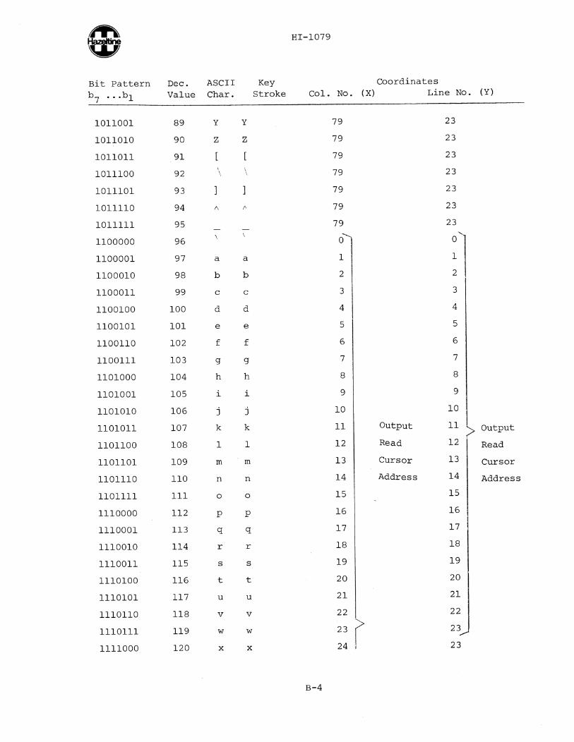
This table provides row (Y) and column (X) coordinate information for direct cursor address and read cursor address. To address the cursor it is necessary to precede the X and Y coordinates by a lead in followed by a
Bit Pattern Dec. ASCII b7 '" b1 Value Char.
0000000
0000001
0000010
0000011
0000100
0000101
0000110
0000111
0001000
0001001
0001010
0001011
0001100
0001101
0001110
0001111
0010000
0010001
0010010
0010011
0010100
0010101
0010110
0010111
o 1
2
3
4
5
6
7
8
9
10
11
12
13
14
15
16
17
18
19
20
21
22
23
NUL
SOH
STX
ETX
EOT
ENQ
ACK
BEL
BS
HT
LF
VT
FF
CR
SO
SI
DLE
DC1
DC2
DC3
DC4
NAK
SYN
ETB
cS2
cA
Cc cD
cE
cF
Key Stroke
cG
BACKSPACE
TAB
LF
cU
DC1 code. It is recommended that use of codes in column 0 and 1 of the ASCII Chart (Appendix I) be avoided. For read cursor address, the terminal will transmit the row and column coordinates indicated by the brackets.
Coordinates Col. No. (X) Line No. (Y)
B-1
o 1
2
3
4
5
6
7
8
9
10
11
12
13
14
15
16
17
18
19
20
21
22
23
o 1
2
3
4
5
6
7
8
9
10
11
12
13
14
15
16
17
18
19
20
21
22
23

~ HI-l079
'D Bit Pattern Dec. ASCII Key Coordinates b7 ... bl Value Char. Stroke Col. No. (X) Line No. (Y)
0011000 24 CAN Cx 24 23
0011001 25 EM cy 25 23
0011010 26 SUB cZ 26 23
0011011 27 *ESC ESC 27 23
0011100 28 FS c, 28 23
0011101 29 GS c] 29 23
0011110 30 RS cs, 30 23
0011111 31 US c DEL 31 23
0100000 32 SP SP 32 0
0100001 33 33 1
0100010 34 " " 34 2
0100011 35 # # 35 3
0100100 36 $ $ 36 4
0100101 37 % % 37 5
0100110 38 & & 38 6
0100111 39 39 7
0101000 40 ( ( 40 8
0101001 41 ) ) 41 9
0101010 42 * * 42 10
0101011 43 + + 43 11
0101100 44 44 12
0101101 45 45 13
0101110 46 46 14
0101111 47 / / 47 15
0110000 48 0 0 48 16
0110001 49 1 1 49 Output 17
0110010 50 2 2 50 Read 18
0110011 51 3 3 51 Cursor 19
0110100 52 4 4 52 Address 20
0110101 53 5 5 53 21
0110110 54 6 6 54 22
0110111 55 7 7 55 23
0111000 56 8 8 56 23
*Lead-in Code
B-2

$ HI-l079
Bit Pattern Dec. ASCII Key Coordinates b7 ••. bl Value Char. Stroke Col. No. (X) Line No. (Y)
0111001 57 9 9 57 23
0111010 58 58 23
0111011 59 59 23
0111100 60 < < 60 23
0111101 61 61 23
0111110 62 > > 62 23
0111111 63 ? ? 63 23
1000000 64 @ @ 64 0
1000001 65 A A 65 1
1000010 66 B B 66 2
1000011 67 C C 67 3
1000100 68 D D 68 4
1000101 69 E E 69 5
1000110 70 F F 70 6
1000111 71 G G 71 Output 7
1001000 72 H H 72 Read 8
1001001 73 I I 73 Cursor 9
1001010 74 J J 74 Address 10
1001011 75 K K 75 11
1001100 76 L L 76 12
1001101 77 M M 77 13
1001110 78 N N 78 14
1001111 79 0 0 79 15
1010000 80 P P 79 16
1010001 81 Q Q 79 17
1010010 82 R R 79 18
1010011 83 S S 79 19
1010100 84 T T 79 20
1010101 85 U U 79 21
1010110 86 V V 79 22
1010111 87 W W 79 23
1011000 88 X X 79 23
B-3
~ HI-1079 q:; Bit Pattern Dec. ASCII Key Coordinates b 7 •.. b 1 Value Char. Stroke Col. No. ( X) Line No. (Y)
1011001 89 Y Y 79 23
1011010 90 Z Z 79 23
1011011 91 79 23
1011100 92 \ \ \ 79 23
1011101 93 ] 79 23
1011110 94 1\ t· 79 23
1011111 95 79 23
1100000 96 \ 0
n 1100001 97 a a 1
1100010 98 b b 2
1100011 99 c c 3 3
1100100 100 d d 4 4
1100101 101 e e 5 5
1100110 102 f f 6 6
1100111 103 g g 7 7
1101000 104 h h 8 8
1101001 105 i i 9 9
1101010 106 j j 10 10
1101011 107 k k 11 Output 11 Output
1101100 108 1 1 12 Read 12 Read
1101101 109 m m 13 Cursor 13 Cursor
1101110 110 n n 14 Address 14 Address
110llll 111 0 0 15 15
1110000 ll2 P P 16 16
ll10001 ll3 q q 17 17
lll0010 ll4 r r 18 18
ll100ll ll5 s s 19 19
ll10100 ll6 t t 20 20
ll10101 ll7 u u 21 21
lll0ll0 ll8 v v 22 22
ll101ll ll9 w w 23 23
1l1l000 120 x x 24 23
B-4

$ HI-I079
Bit Pattern Dec. ASCII Key Coordinates
b7 . .. b 1 Value Char. Stroke Col. No. (X) Line No. (Y)
1111001 121 Y Y 25 23
1111010 122 z z 26 23
1111011 123 { { 27 23
1111100 124 28 23
1111101 125 } } 29 23
1111110 126 * ~
30 23
1111111 127 DEL DEL 31 23
-----*Lead-in Code
B-5

() I
I:-'
Lead-In ASCII Dec Octal Function
• SOH 1 001 Select Blinking Field
• STX 2 002 Select Blank Field
• ENQ 5 005 Send Cursor Address
• ACK 6 006 Keyboard Unlock··
BEL 7 007 Sound Alarm
BS 8 010 Cursor Left
• HT 9 011 Field Tab
LF 10 012 Line Feed
*
Lead-In
• • • • • • • • •
ASCII
DC3
NAK
CAN
EM
SUB
FS
GS
US
Dec
19
21
24
25
26
28
29
31
Octal Function
023 Delete Line
025 Keyboard Lock
030 Clear to End of Screen
031 Background Follows ••
032
034
035
037
Insert Line
Clear Screen
Clear Foreground
Select High Intensity Field
VT 11 013 Cursor Down 33
34
42
47
63
60
62
041
042
052
057
077
074
076
Send Character at Cursor posit.ion FF 12 014 Cursor Up • • Display Test Pattern CR 13 015
• SO 14 016
• SI 15 017
Carriage Return
Horizontal Tab
Clear to End of Line
• • •
• /
?
Enable Aux Output No Display
Enable Aux OUtput with Display
Disable Aux Output·· DLE 16 020 Cursor Right • < Exit Function Mode DCl 17 021 Direct Cursor Address • > • Enter Function Mode
• DC2 18 022 Home Cursor
*Lead-in required: ASCII ESCape (decimal 27, octal 033), or tilde (decimal 126, octal 176), as selected by switch (para 3.1.f). ··Default state at turn on
NOTES:
1. If a remote command lead-in is followed by any character not listed above, both the lead-in and the following character will be ignored.
2. Any ASCII control code (columns 0 and 1, Appendix A) which is not preceded by a remote command lead-in will be ignored, except for the seven listed above as not requiring a lead-in (and ESCape if selected as the lead-in code).
3. The Direct Cursor Address command must be followed immediately by the X and Y coordinates as listed in Appendix B.
4. Response to carriage return and line feed depends on the setting of the AUTO LF/CR switch (para 3.1 d).
C79055
(f)
! ~ 0
~ I-rj
61 CD ::s :s: 0. 0 .... 8 X t:tj
() ()
~ t:J (f)

Hazeltine and the Pursuit of Excellence ... in Information Electronics
Ii." Hazeltine "N
Hazeltine Corporation, Computer Terminal Equipment, Greenlawn, New York 11740 (516) 549-8800 Telex 96-1435