Atmel AVR4907: ASF - USB Device CDC Application
Features • USB 2.0 compliance
- Chapter 9 compliance - Full Speed (12Mbit/s), High Speed (480Mbit/s) data rates
• Basic USB CDC implementation - RX and TX streams - Data 8 or 9 bits
• Control available - DCD signal - DSR signal - Framing error - Parity error - Overrun
• Remote wakeup support • USB bus powered support • Real time (O.S. compliance, interrupt driven) • Support 8-bit and 32-bit AVR®
1 Introduction The aim of this document is to provide an easy way to integrate a USB CDC device application on a new or existing project.
Atmel Microcontrollers Application Note
Rev. 8447A-AVR-11/11
2 Atmel AVR4907 8447A-AVR-11/11
2 Abbreviations ASF: AVR Software Framework
CD: Composite Device: a USB device with more than one interface
CDC: Communication Device Class
FS: USB Full Speed
HS: USB High Speed
UDC: USB device Controller
UDD: USB device Descriptor
UDI: USB device Interface
USB: Universal Serial Bus
SOF: Start of Frame
Atmel AVR4907
38447A-AVR-11/11
3 Overview This document includes four sections for all types of requirements when building a USB device CDC application:
• Quick start Describes how to start a ready to use CDC device example
• Example description Describes a CDC device example
• Building a USB device CDC Describes how to add a USB device CDC interface in a project
• Building a USB device CDC linked on standard I/O Describes how to add a USB device CDC interface linked on standard I/O Standard I/O: stdio library, example printf()
• CDC in a USB Composite Device Describes how to integrate a CDC interface in a composite device project
For all these sections, it is recommended to know the main modules organization of a CDC application:
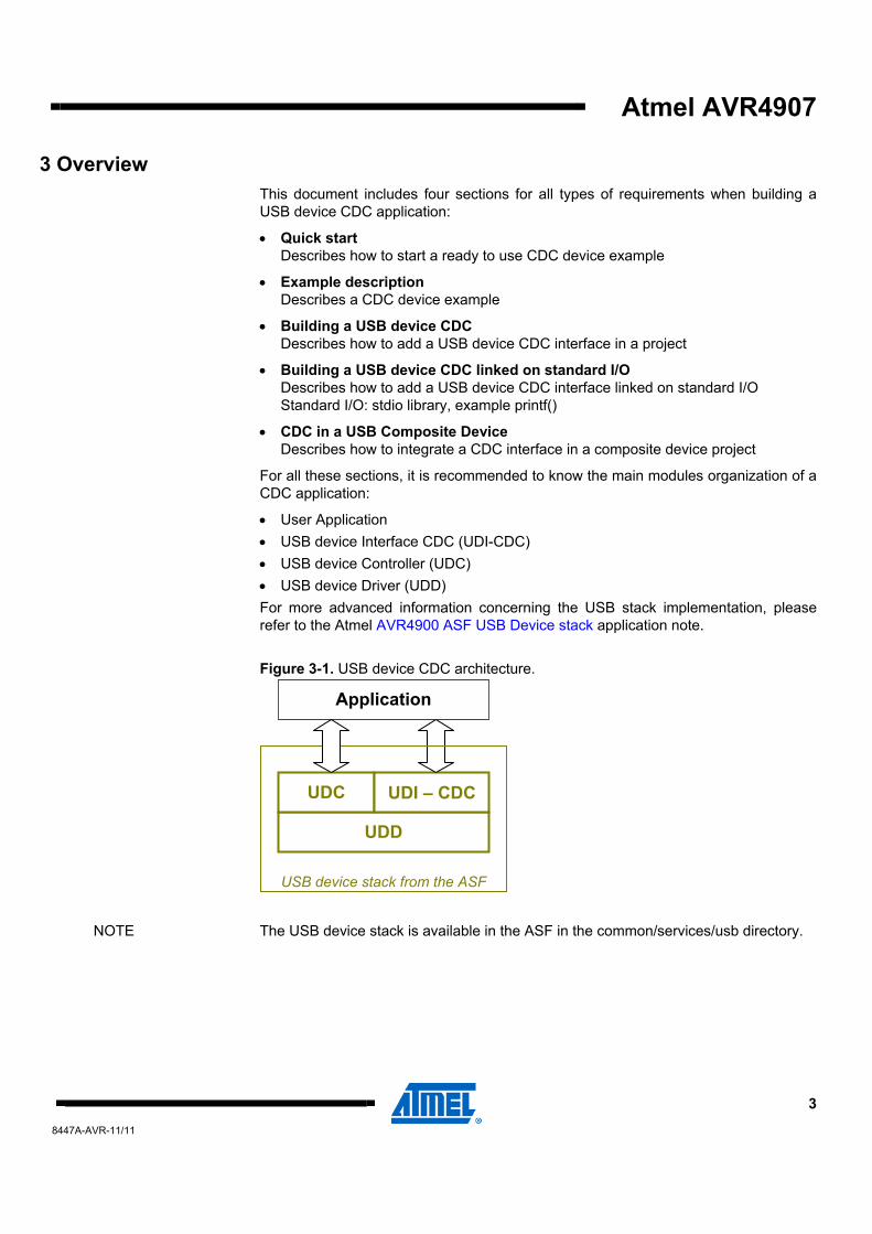
• User Application • USB device Interface CDC (UDI-CDC) • USB device Controller (UDC) • USB device Driver (UDD) For more advanced information concerning the USB stack implementation, please refer to the Atmel AVR4900 ASF USB Device stack application note.
Figure 3-1. USB device CDC architecture.
NOTE The USB device stack is available in the ASF in the common/services/usb directory.
UDD
UDC UDI – CDC
Application
USB device stack from the ASF
4 Atmel AVR4907 8447A-AVR-11/11
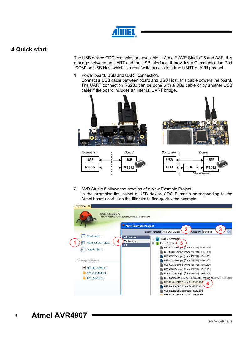
4 Quick start The USB device CDC examples are available in Atmel® AVR Studio® 5 and ASF. It is a bridge between an UART and the USB interface. It provides a Communication Port “COM” on USB Host which is a read/write access to a true UART of AVR product.
1. Power board, USB and UART connection. Connect a USB cable between board and USB Host, this cable powers the board. The UART connection RS232 can be done with a DB9 cable or by another USB cable if the board includes an internal UART bridge.
2. AVR Studio 5 allows the creation of a New Example Project. In the examples list, select a USB device CDC Example corresponding to the Atmel board used. Use the filter list to find quickly the example.
Computer
USB
RS232 RS232
USB
Board Computer
USB
USB RS232
USB
USB
Board
Internal bridge
2 3
4 5
6
1
Atmel AVR4907
58447A-AVR-11/11
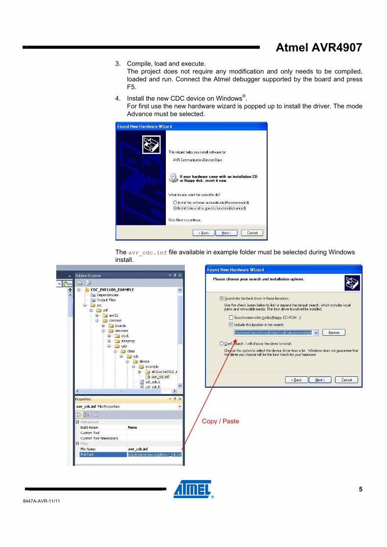
3. Compile, load and execute. The project does not require any modification and only needs to be compiled, loaded and run. Connect the Atmel debugger supported by the board and press F5.
4. Install the new CDC device on Windows®. For first use the new hardware wizard is popped up to install the driver. The mode Advance must be selected.
The avr_cdc.inf file available in example folder must be selected during Windows install.
Copy / Paste
6 Atmel AVR4907 8447A-AVR-11/11
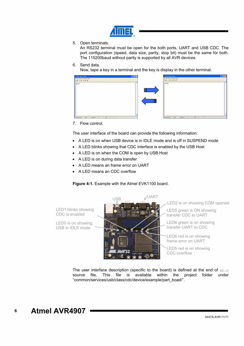
5. Open terminals. An RS232 terminal must be open for the both ports, UART and USB CDC. The port configuration (speed, data size, parity, stop bit) must be the same for both. The 115200baud without parity is supported by all AVR devices.
6. Send data. Now, tape a key in a terminal and the key is display in the other terminal.
7. Flow control.
The user interface of the board can provide the following information:
• A LED is on when USB device is in IDLE mode and is off in SUSPEND mode • A LED blinks showing that CDC interface is enabled by the USB Host • A LED is on when the COM is open by USB Host • A LED is on during data transfer • A LED means an frame error on UART • A LED means an CDC overflow
Figure 4-1. Example with the Atmel EVK1100 board.
The user interface description (specific to the board) is defined at the end of ui.c source file. This file is available within the project folder under “common/services/usb/class/cdc/device/example/part_boad/”.
LED1 blinks showing CDC is enabled
LED0 is on showing USB in IDLE mode
LED2 is on showing COM opened
LED5 green is ON showing transfer CDC to UART
LED6 green is on showing transfer UART to CDC
LED6 red is on showing frame error on UART
LED5 red is on showing CDC overflow
UARTUSB
Atmel AVR4907
78447A-AVR-11/11
5 Example description
5.1 Example content The ASF provides a USB device CDC example for various Atmel AVR products. All these examples share common files and implement a UART bridge.
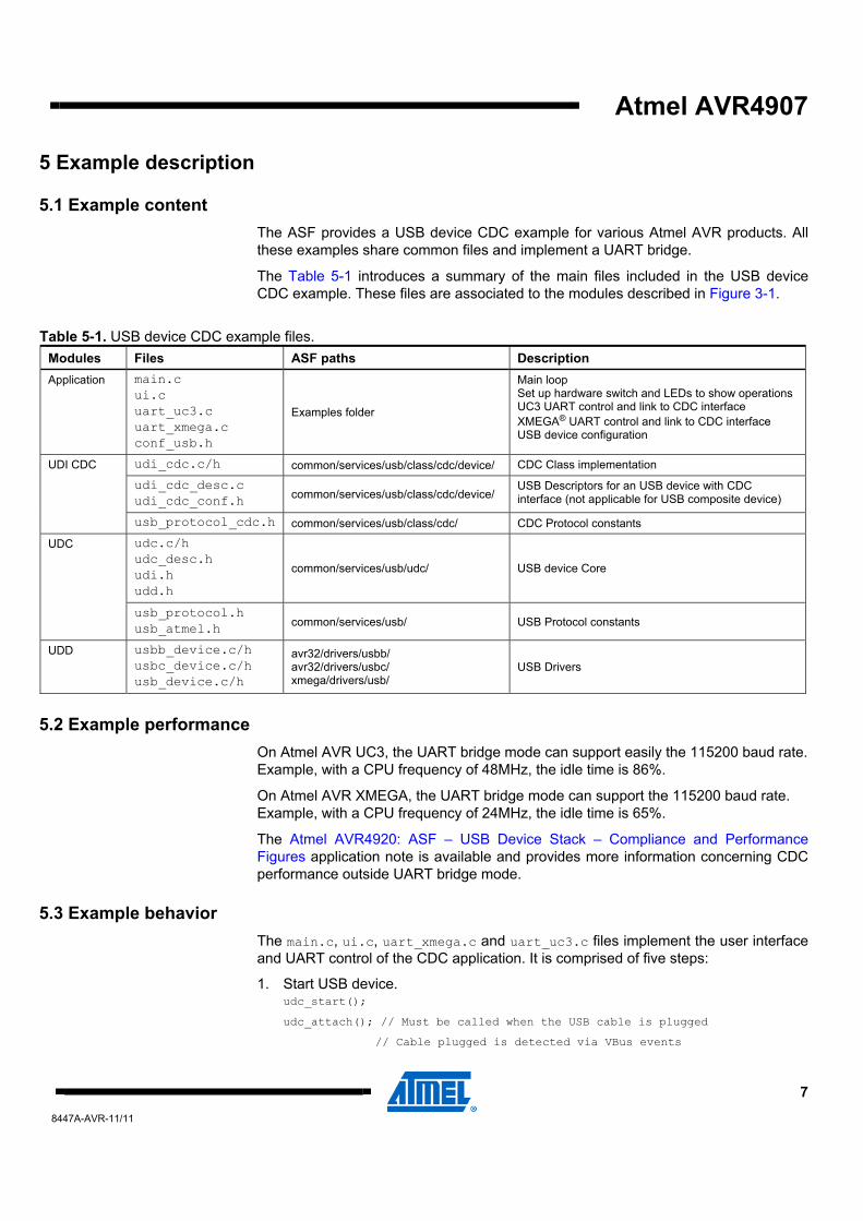
The Table 5-1 introduces a summary of the main files included in the USB device CDC example. These files are associated to the modules described in Figure 3-1.
Table 5-1. USB device CDC example files. Modules Files ASF paths Description Application main.c
ui.c uart_uc3.c uart_xmega.c conf_usb.h
Examples folder
Main loop Set up hardware switch and LEDs to show operationsUC3 UART control and link to CDC interface XMEGA® UART control and link to CDC interface USB device configuration
udi_cdc.c/h common/services/usb/class/cdc/device/ CDC Class implementation
udi_cdc_desc.c udi_cdc_conf.h common/services/usb/class/cdc/device/
USB Descriptors for an USB device with CDC interface (not applicable for USB composite device)
UDI CDC
usb_protocol_cdc.h common/services/usb/class/cdc/ CDC Protocol constants
udc.c/h udc_desc.h udi.h udd.h
common/services/usb/udc/ USB device Core
UDC
usb_protocol.h usb_atmel.h common/services/usb/ USB Protocol constants
UDD usbb_device.c/h usbc_device.c/h usb_device.c/h
avr32/drivers/usbb/ avr32/drivers/usbc/ xmega/drivers/usb/
USB Drivers
5.2 Example performance On Atmel AVR UC3, the UART bridge mode can support easily the 115200 baud rate. Example, with a CPU frequency of 48MHz, the idle time is 86%.
On Atmel AVR XMEGA, the UART bridge mode can support the 115200 baud rate. Example, with a CPU frequency of 24MHz, the idle time is 65%.
The Atmel AVR4920: ASF – USB Device Stack – Compliance and Performance Figures application note is available and provides more information concerning CDC performance outside UART bridge mode.
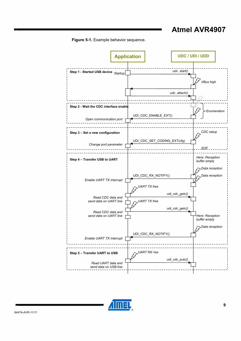
5.3 Example behavior The main.c, ui.c, uart_xmega.c and uart_uc3.c files implement the user interface and UART control of the CDC application. It is comprised of five steps:
1. Start USB device. udc_start();
udc_attach(); // Must be called when the USB cable is plugged
// Cable plugged is detected via VBus events
8 Atmel AVR4907 8447A-AVR-11/11
2. Wait the enable of CDC interface via callback. UDI_CDC_ENABLE_EXT() // Authorize and open UART communication port
3. Set a new configuration of communication port. UDI_CDC_SET_CODING_EXT(cfg) // Configuration of UART communication port
4. Transfer data from USB bus. UDI_CDC_RX_NOTIFY() // Notify that CDC reception buffer is not empty, then the UART TX interrupt is enabled
udi_cdc_getc() // Routine to read CDC buffer reception. It is a short function which can be called in UART TX interrupt routine
5. Transfer data to USB bus. udi_cdc_putc() // Routine to put data to CDC buffer emission. It is a short function which can be called in UART RX interrupt routine
Atmel AVR4907
98447A-AVR-11/11
Figure 5-1. Example behavior sequence.
Application
udc_start()
UDC / UDI / UDD
udc_attach()
VBus high
UDI_CDC_ENABLE_EXT()
CDC setup
SOF
Data reception
Data reception
UDI_CDC_SET_CODING_EXT(cfg)
Startup
Change port parameter
UDI_CDC_RX_NOTIFY()
Open communication port
Enable UART TX interrupt
Enumeration
Read CDC data and send data on UART line
Step 1 - Started USB device
Step 2 - Wait the CDC interface enable
Step 3 – Set a new configuration
Step 4 – Transfer USB to UART
udi_cdc_getc()
UART TX free
udi_cdc_getc()
UART TX free
Read CDC data and send data on UART line
Data reception
UDI_CDC_RX_NOTIFY() Enable UART TX interrupt
Here: Reception buffer empty
Here: Reception buffer empty
Step 5 – Transfer UART to USB
Read UART data and send data on USB line
udi_cdc_putc()
UART RX rise
10 Atmel AVR4907 8447A-AVR-11/11
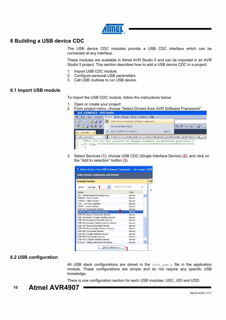
6 Building a USB device CDC The USB device CDC modules provide a USB CDC interface which can be connected at any interface.
These modules are available in Atmel AVR Studio 5 and can be imported in an AVR Studio 5 project. This section describes how to add a USB device CDC in a project:
1. Import USB CDC module. 2. Configure personal USB parameters. 3. Call USB routines to run USB device.
6.1 Import USB module To import the USB CDC module, follow the instructions below:
1. Open or create your project: 2. From project menu, choose “Select Drivers from AVR Software Framework”.
3. Select Services (1), choose USB CDC (Single Interface Device) (2), and click on the “Add to selection” button (3).
6.2 USB configuration All USB stack configurations are stored in the conf_usb.h file in the application module. These configurations are simple and do not require any specific USB knowledge.
There is one configuration section for each USB modules: UDC, UDI and UDD.
1
2
3
Atmel AVR4907
118447A-AVR-11/11
The UDC configuration possibilities are described in the Atmel AVR4900: ASF – USB Device Stack application note in the Section 7.1.1: USB device configuration”.
The UDD configuration possibilities are described in the Atmel AVR4900: ASF – USB Device Stack application note in the Section 7.1.3: USB drivers’ configuration”.
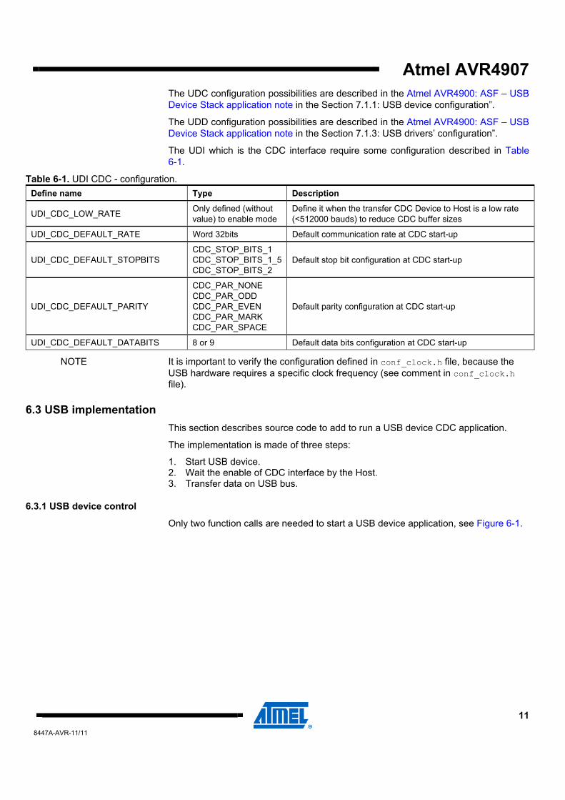
The UDI which is the CDC interface require some configuration described in Table 6-1.
Table 6-1. UDI CDC - configuration. Define name Type Description
UDI_CDC_LOW_RATE Only defined (without value) to enable mode
Define it when the transfer CDC Device to Host is a low rate (<512000 bauds) to reduce CDC buffer sizes
UDI_CDC_DEFAULT_RATE Word 32bits Default communication rate at CDC start-up
UDI_CDC_DEFAULT_STOPBITS CDC_STOP_BITS_1 CDC_STOP_BITS_1_5CDC_STOP_BITS_2
Default stop bit configuration at CDC start-up
UDI_CDC_DEFAULT_PARITY
CDC_PAR_NONE CDC_PAR_ODD CDC_PAR_EVEN CDC_PAR_MARK CDC_PAR_SPACE
Default parity configuration at CDC start-up
UDI_CDC_DEFAULT_DATABITS 8 or 9 Default data bits configuration at CDC start-up
NOTE It is important to verify the configuration defined in conf_clock.h file, because the USB hardware requires a specific clock frequency (see comment in conf_clock.h file).
6.3 USB implementation This section describes source code to add to run a USB device CDC application.
The implementation is made of three steps:
1. Start USB device. 2. Wait the enable of CDC interface by the Host. 3. Transfer data on USB bus.
6.3.1 USB device control
Only two function calls are needed to start a USB device application, see Figure 6-1.
12 Atmel AVR4907 8447A-AVR-11/11
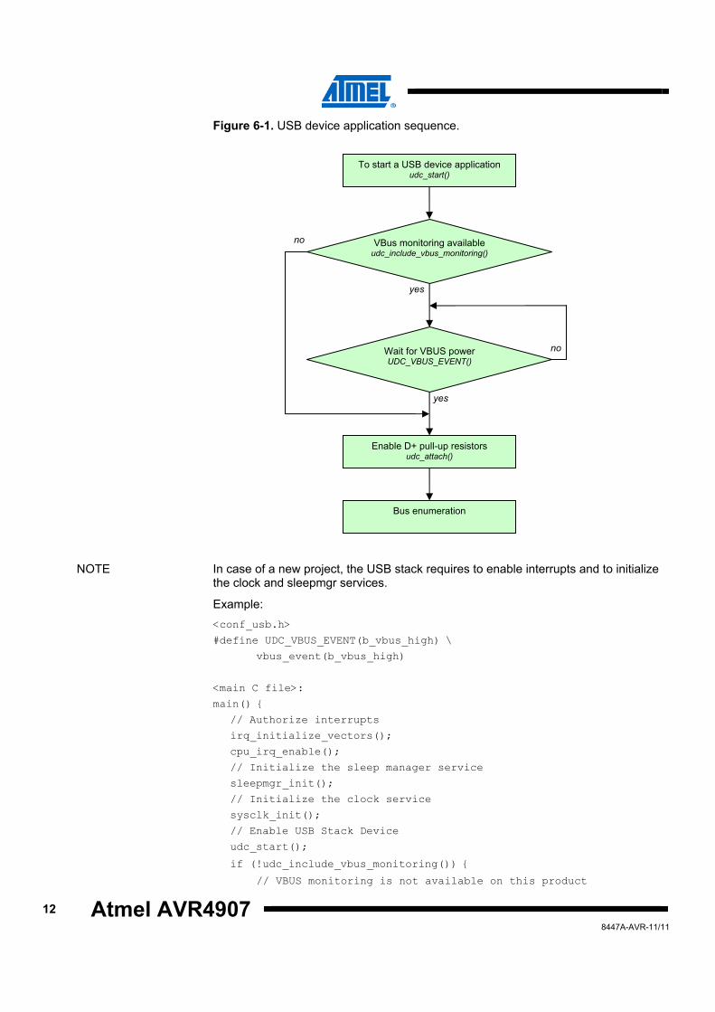
Figure 6-1. USB device application sequence.
NOTE In case of a new project, the USB stack requires to enable interrupts and to initialize
the clock and sleepmgr services.
Example: <conf_usb.h>
#define UDC_VBUS_EVENT(b_vbus_high) \
vbus_event(b_vbus_high)
<main C file>:
main() {
// Authorize interrupts
irq_initialize_vectors();
cpu_irq_enable();
// Initialize the sleep manager service
sleepmgr_init();
// Initialize the clock service
sysclk_init();
// Enable USB Stack Device
udc_start();
if (!udc_include_vbus_monitoring()) {
// VBUS monitoring is not available on this product
To start a USB device application udc_start()
VBus monitoring available udc_include_vbus_monitoring()
Wait for VBUS power UDC_VBUS_EVENT()
Enable D+ pull-up resistors udc_attach()
Bus enumeration
no
no
yes
yes
Atmel AVR4907
138447A-AVR-11/11
// thereby VBUS has to be considered as present
vbus_event (true);
} }
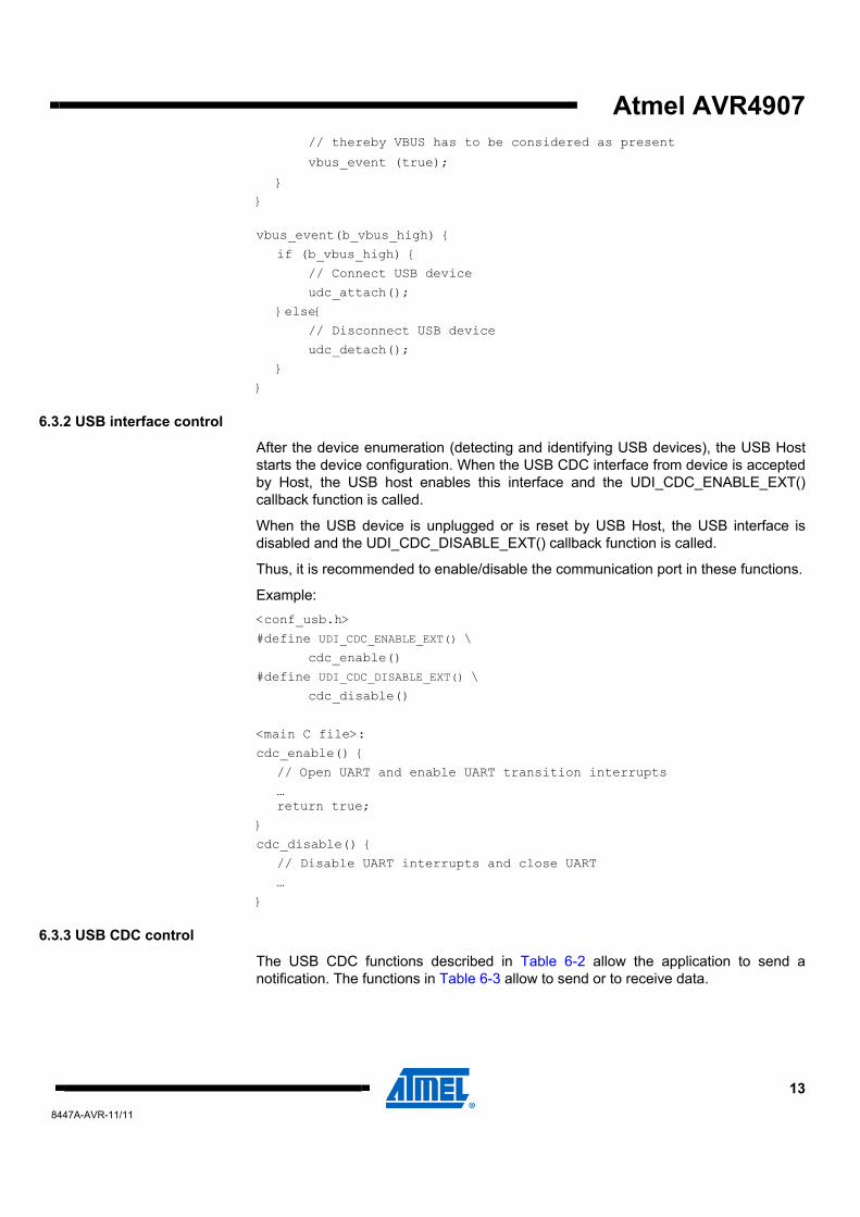
vbus_event(b_vbus_high) {
if (b_vbus_high) {
// Connect USB device
udc_attach();
}else{
// Disconnect USB device
udc_detach();
}
}
6.3.2 USB interface control
After the device enumeration (detecting and identifying USB devices), the USB Host starts the device configuration. When the USB CDC interface from device is accepted by Host, the USB host enables this interface and the UDI_CDC_ENABLE_EXT() callback function is called.
When the USB device is unplugged or is reset by USB Host, the USB interface is disabled and the UDI_CDC_DISABLE_EXT() callback function is called.
Thus, it is recommended to enable/disable the communication port in these functions.
Example: <conf_usb.h>
#define UDI_CDC_ENABLE_EXT() \
cdc_enable()
#define UDI_CDC_DISABLE_EXT() \
cdc_disable()
<main C file>:
cdc_enable() {
// Open UART and enable UART transition interrupts
… return true;
}
cdc_disable() {
// Disable UART interrupts and close UART
…
}
6.3.3 USB CDC control
The USB CDC functions described in Table 6-2 allow the application to send a notification. The functions in Table 6-3 allow to send or to receive data.
14 Atmel AVR4907 8447A-AVR-11/11
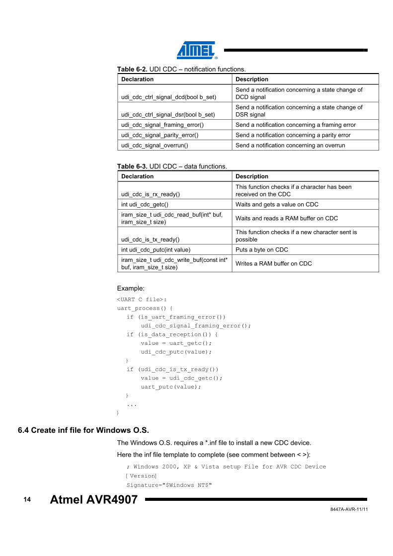
Table 6-2. UDI CDC – notification functions. Declaration Description
udi_cdc_ctrl_signal_dcd(bool b_set) Send a notification concerning a state change of DCD signal
udi_cdc_ctrl_signal_dsr(bool b_set) Send a notification concerning a state change of DSR signal
udi_cdc_signal_framing_error() Send a notification concerning a framing error
udi_cdc_signal_parity_error() Send a notification concerning a parity error
udi_cdc_signal_overrun() Send a notification concerning an overrun
Table 6-3. UDI CDC – data functions. Declaration Description
udi_cdc_is_rx_ready() This function checks if a character has been received on the CDC
int udi_cdc_getc() Waits and gets a value on CDC
iram_size_t udi_cdc_read_buf(int* buf, iram_size_t size) Waits and reads a RAM buffer on CDC
udi_cdc_is_tx_ready() This function checks if a new character sent is possible
int udi_cdc_putc(int value) Puts a byte on CDC
iram_size_t udi_cdc_write_buf(const int* buf, iram_size_t size) Writes a RAM buffer on CDC
Example: <UART C file>:
uart_process() {
if (is_uart_framing_error())
udi_cdc_signal_framing_error();
if (is_data_reception()) {
value = uart_getc();
udi_cdc_putc(value);
}
if (udi_cdc_is_tx_ready())
value = udi_cdc_getc();
uart_putc(value);
}
...
}
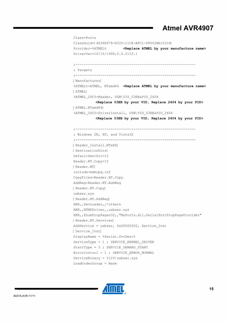
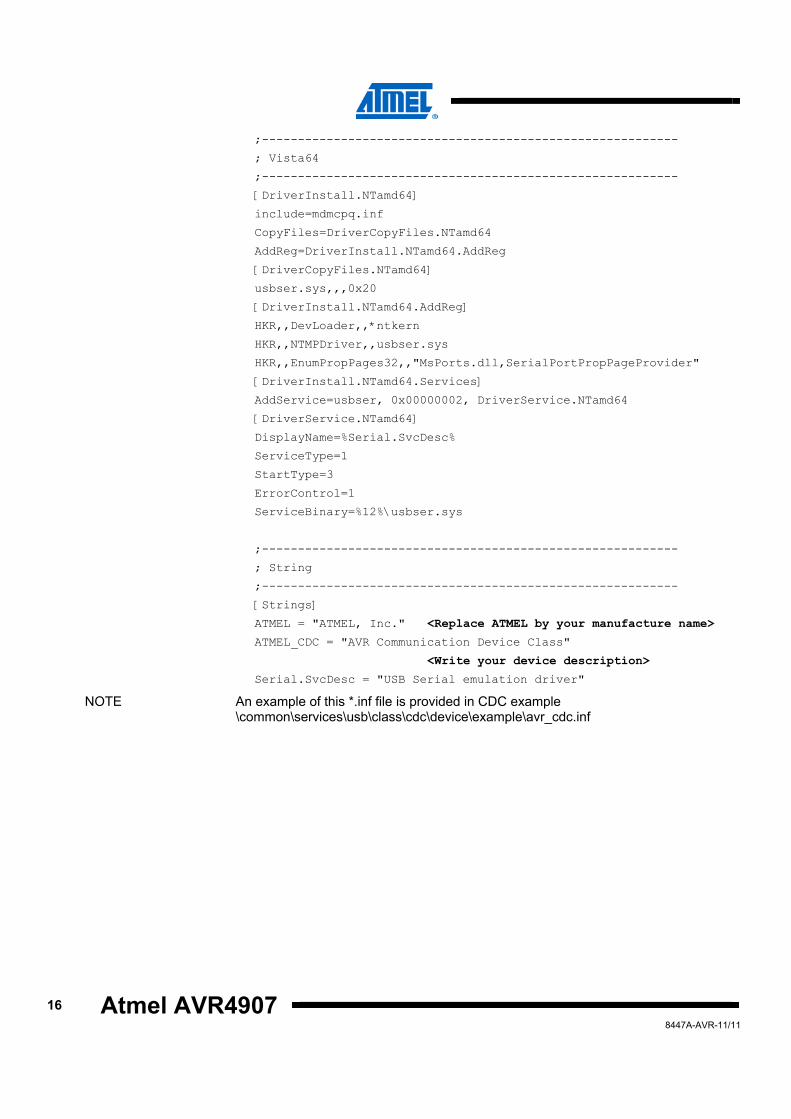
6.4 Create inf file for Windows O.S. The Windows O.S. requires a *.inf file to install a new CDC device.
Here the inf file template to complete (see comment between < >):
; Windows 2000, XP & Vista setup File for AVR CDC Device
[Version]
Signature="$Windows NT$"
Atmel AVR4907
158447A-AVR-11/11
Class=Ports
ClassGuid={4D36E978-E325-11CE-BFC1-08002BE10318}
Provider=%ATMEL% <Replace ATMEL by your manufacture name>
DriverVer=10/15/1999,5.0.2153.1
;----------------------------------------------------------
; Targets
;----------------------------------------------------------
[Manufacturer]
%ATMEL%=ATMEL, NTamd64 <Replace ATMEL by your manufacture name>
[ATMEL]
%ATMEL_CDC%=Reader, USB\VID_03EB&PID_2404
<Replace 03EB by your VID, Replace 2404 by your PID>
[ATMEL.NTamd64]
%ATMEL_CDC%=DriverInstall, USB\VID_03EB&PID_2404
<Replace 03EB by your VID, Replace 2404 by your PID>
;----------------------------------------------------------
; Windows 2K, XP, and Vista32
;----------------------------------------------------------
[Reader_Install.NTx86]
[DestinationDirs]
DefaultDestDir=12
Reader.NT.Copy=12
[Reader.NT]
include=mdmcpq.inf
CopyFiles=Reader.NT.Copy
AddReg=Reader.NT.AddReg
[Reader.NT.Copy]
usbser.sys
[Reader.NT.AddReg]
HKR,,DevLoader,,*ntkern
HKR,,NTMPDriver,,usbser.sys
HKR,,EnumPropPages32,,"MsPorts.dll,SerialPortPropPageProvider"
[Reader.NT.Services]
AddService = usbser, 0x00000002, Service_Inst
[Service_Inst]
DisplayName = %Serial.SvcDesc%
ServiceType = 1 ; SERVICE_KERNEL_DRIVER
StartType = 3 ; SERVICE_DEMAND_START
ErrorControl = 1 ; SERVICE_ERROR_NORMAL
ServiceBinary = %12%\usbser.sys
LoadOrderGroup = Base
16 Atmel AVR4907 8447A-AVR-11/11
;----------------------------------------------------------
; Vista64
;----------------------------------------------------------
[DriverInstall.NTamd64]
include=mdmcpq.inf
CopyFiles=DriverCopyFiles.NTamd64
AddReg=DriverInstall.NTamd64.AddReg
[DriverCopyFiles.NTamd64]
usbser.sys,,,0x20
[DriverInstall.NTamd64.AddReg]
HKR,,DevLoader,,*ntkern
HKR,,NTMPDriver,,usbser.sys
HKR,,EnumPropPages32,,"MsPorts.dll,SerialPortPropPageProvider"
[DriverInstall.NTamd64.Services]
AddService=usbser, 0x00000002, DriverService.NTamd64
[DriverService.NTamd64]
DisplayName=%Serial.SvcDesc%
ServiceType=1
StartType=3
ErrorControl=1
ServiceBinary=%12%\usbser.sys
;----------------------------------------------------------
; String
;----------------------------------------------------------
[Strings]
ATMEL = "ATMEL, Inc." <Replace ATMEL by your manufacture name>
ATMEL_CDC = "AVR Communication Device Class"
<Write your device description>
Serial.SvcDesc = "USB Serial emulation driver"
NOTE An example of this *.inf file is provided in CDC example \common\services\usb\class\cdc\device\example\avr_cdc.inf
Atmel AVR4907
178447A-AVR-11/11
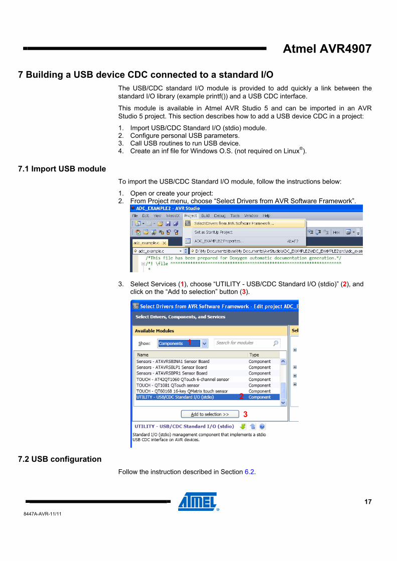
7 Building a USB device CDC connected to a standard I/O The USB/CDC standard I/O module is provided to add quickly a link between the standard I/O library (example printf()) and a USB CDC interface.
This module is available in Atmel AVR Studio 5 and can be imported in an AVR Studio 5 project. This section describes how to add a USB device CDC in a project:
1. Import USB/CDC Standard I/O (stdio) module. 2. Configure personal USB parameters. 3. Call USB routines to run USB device. 4. Create an inf file for Windows O.S. (not required on Linux®).
7.1 Import USB module To import the USB/CDC Standard I/O module, follow the instructions below:
1. Open or create your project: 2. From Project menu, choose “Select Drivers from AVR Software Framework”.
3. Select Services (1), choose “UTILITY - USB/CDC Standard I/O (stdio)” (2), and click on the “Add to selection” button (3).
7.2 USB configuration Follow the instruction described in Section 6.2.
1
2
3
18 Atmel AVR4907 8447A-AVR-11/11
7.3 USB implementation Follow the instruction described in Section 6.3 except sections 6.3.2 and 6.3.3, which are already implemented in USB/CDC standard I/O module.
7.4 Create inf file for Windows O.S. Follow the instruction described in Section 6.4.
Atmel AVR4907
198447A-AVR-11/11
8 CDC in a USB composite device The information required to build a composite device is available in the Atmel AVR4902 ASF - USB Composite Device application note. A familiarity with this application note is mandatory.
This section introduced only the specific information required to build a composite device with a CDC interface.
8.1 USB configuration In addition to the USB configuration described in Section 6.2, the following values must be defined in the conf_usb.h file:
USB_DEVICE_EP_CTRL_SIZE Endpoint control size.
This must be:
• 8, 16, 32 or 64 for full speed device (8 is recommended to save RAM) • 64 for a high speed device UDI_CDC_DATA_EP_IN IN bulk endpoint number used by the CDC interface to send data (TX).
UDI_CDC_DATA_EP_OUT OUT bulk endpoint number used by the CDC interface to receive data (RX).
UDI_CDC_COMM_EP IN interrupt endpoint number used by the CDC interface to send communication events.
UDI_CDC_COMM_IFACE_NUMBER Interface number of the CDC communication interface.
UDI_CDC_DATA_IFACE_NUMBER Interface number of the CDC data interface.
USB_DEVICE_MAX_EP Total number of endpoints in the application. This must include three endpoints for CDC interface.
8.2 USB descriptor The addition of CDC interfaces in device descriptors requires adding an Interface Association Descriptor (IAD) to associate the CDC communication interface descriptor with CDC data interface descriptor.
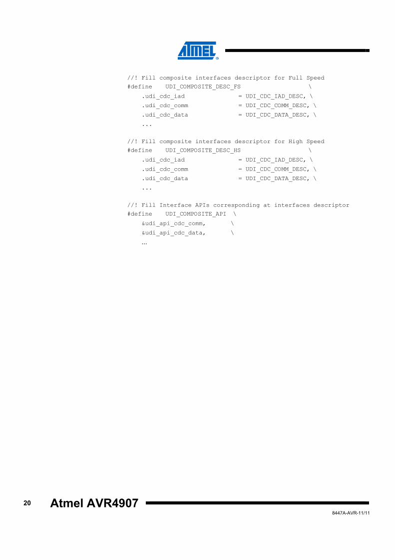
The USB device Descriptor of composite device, defined in conf_usb.h file, must include a CDC communication interface, a CDC data interface descriptor, and an interface Association Descriptor:
//! Define structure of composite interfaces descriptor
#define UDI_COMPOSITE_DESC_T \
usb_iad_desc_t udi_cdc_iad; \
udi_cdc_comm_desc_t udi_cdc_comm; \
udi_cdc_data_desc_t udi_cdc_data; \ ...
20 Atmel AVR4907 8447A-AVR-11/11
//! Fill composite interfaces descriptor for Full Speed
#define UDI_COMPOSITE_DESC_FS \
.udi_cdc_iad = UDI_CDC_IAD_DESC, \
.udi_cdc_comm = UDI_CDC_COMM_DESC, \
.udi_cdc_data = UDI_CDC_DATA_DESC, \
...
//! Fill composite interfaces descriptor for High Speed
#define UDI_COMPOSITE_DESC_HS \
.udi_cdc_iad = UDI_CDC_IAD_DESC, \
.udi_cdc_comm = UDI_CDC_COMM_DESC, \
.udi_cdc_data = UDI_CDC_DATA_DESC, \
...
//! Fill Interface APIs corresponding at interfaces descriptor
#define UDI_COMPOSITE_API \
&udi_api_cdc_comm, \
&udi_api_cdc_data, \
...
Atmel AVR4907
218447A-AVR-11/11
9 Table of contents Features............................................................................................... 1 1 Introduction ...................................................................................... 1 2 Abbreviations ................................................................................... 2 3 Overview........................................................................................... 3 4 Quick start ........................................................................................ 4 5 Example description........................................................................ 7
5.1 Example content.................................................................................................. 7 5.2 Example performance ......................................................................................... 7 5.3 Example behavior................................................................................................ 7
6 Building a USB device CDC .......................................................... 10 6.1 Import USB module ........................................................................................... 10 6.2 USB configuration ............................................................................................. 10 6.3 USB implementation.......................................................................................... 11
6.3.1 USB device control .................................................................................................. 11 6.3.2 USB interface control............................................................................................... 13 6.3.3 USB CDC control .................................................................................................... 13
6.4 Create inf file for Windows O.S. ........................................................................ 14 7 Building a USB device CDC connected to a standard I/O .......... 17
7.1 Import USB module ........................................................................................... 17 7.2 USB configuration ............................................................................................. 17 7.3 USB implementation.......................................................................................... 18 7.4 Create inf file for Windows O.S. ........................................................................ 18
8 CDC in a USB composite device .................................................. 19 8.1 USB configuration ............................................................................................. 19 8.2 USB descriptor .................................................................................................. 19
9 Table of contents ........................................................................... 21
8447A-AVR-11/11
Atmel Corporation 2325 Orchard Parkway San Jose, CA 95131 USA Tel: (+1)(408) 441-0311 Fax: (+1)(408) 487-2600 www.atmel.com
Atmel Asia Limited Unit 01-5 & 16, 19F BEA Tower, Milennium City 5 418 Kwun Tong Road Kwun Tong, Kowloon HONG KONG Tel: (+852) 2245-6100 Fax: (+852) 2722-1369
Atmel Munich GmbH Business Campus Parkring 4 D-85748 Garching b. Munich GERMANY Tel: (+49) 89-31970-0 Fax: (+49) 89-3194621
Atmel Japan 16F, Shin Osaki Kangyo Bldg. 1-6-4 Osaki Shinagawa-ku Tokyo 104-0032 JAPAN Tel: (+81) 3-6417-0300 Fax: (+81) 3-6417-0370
© 2011 Atmel Corporation. All rights reserved.
Atmel®, Atmel logo and combinations thereof, AVR®, AVR Studio®, XMEGA®, and others are registered trademarks or trademarks of Atmel Corporation or its subsidiaries. Windows® and others are registered trademarks or trademarks of Microsoft Corporation in U.S. and or other countries. Other terms and product names may be trademarks of others. Disclaimer: The information in this document is provided in connection with Atmel products. No license, express or implied, by estoppel or otherwise, to any intellectual property right is granted by this document or in connection with the sale of Atmel products. EXCEPT AS SET FORTH IN THE ATMEL TERMS AND CONDITIONS OF SALES LOCATED ON THE ATMEL WEBSITE, ATMEL ASSUMES NO LIABILITY WHATSOEVER AND DISCLAIMS ANY EXPRESS, IMPLIED OR STATUTORY WARRANTY RELATING TO ITS PRODUCTS INCLUDING, BUT NOT LIMITED TO, THE IMPLIED WARRANTY OF MERCHANTABILITY, FITNESS FOR A PARTICULAR PURPOSE, OR NON-INFRINGEMENT. IN NO EVENT SHALL ATMEL BE LIABLE FOR ANY DIRECT, INDIRECT, CONSEQUENTIAL, PUNITIVE, SPECIAL OR INCIDENTAL DAMAGES (INCLUDING, WITHOUT LIMITATION, DAMAGES FOR LOSS AND PROFITS, BUSINESS INTERRUPTION, OR LOSS OF INFORMATION) ARISING OUT OF THE USE OR INABILITY TO USE THIS DOCUMENT, EVEN IF ATMEL HAS BEEN ADVISED OF THE POSSIBILITY OF SUCH DAMAGES. Atmel makes no representations or warranties with respect to the accuracy or completeness of the contents of this document and reserves the right to make changes to specifications and product descriptions at any time without notice. Atmel does not make any commitment to update the information contained herein. Unless specifically provided otherwise, Atmel products are not suitable for, and shall not be used in, automotive applications. Atmel products are not intended, authorized, or warranted for use as components in applications intended to support or sustain life.