Maße / Dimensions in mm Z – 12/2012
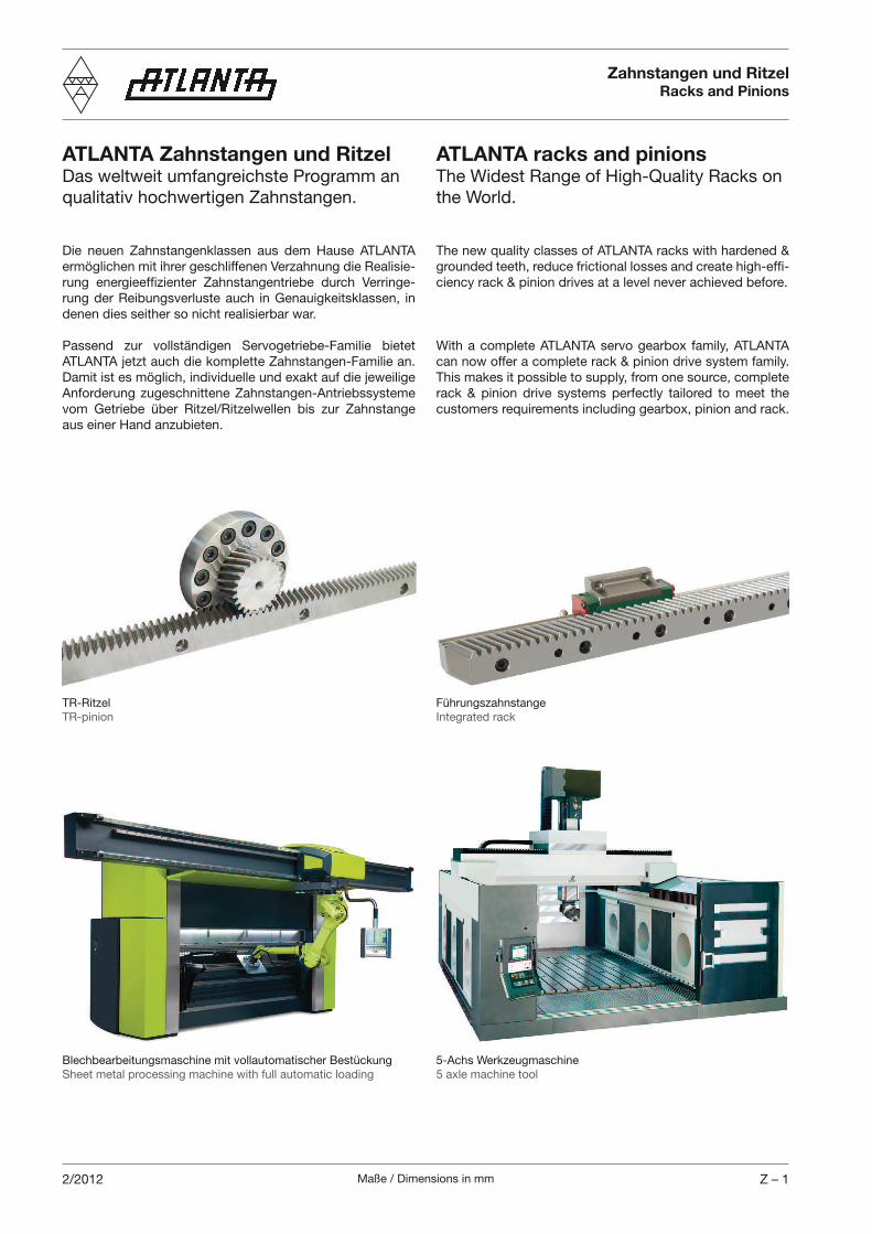
ATLANTA Zahnstangen und RitzelDas weltweit umfangreichste Programm an
qualitativ hochwertigen Zahnstangen.
Die neuen Zahnstangenklassen aus dem Hause ATLANTA
ermöglichen mit ihrer geschliffenen Verzahnung die Realisie-
rung energieeffizienter Zahnstangentriebe durch Verringe-
rung der Reibungsverluste auch in Genauigkeitsklassen, in
denen dies seither so nicht realisierbar war.
Passend zur vollständigen Servogetriebe-Familie bietet
ATLANTA jetzt auch die komplette Zahnstangen-Familie an.
Damit ist es möglich, individuelle und exakt auf die jeweilige
Anforderung zugeschnittene Zahnstangen-Antriebssysteme
vom Getriebe über Ritzel/Ritzelwellen bis zur Zahnstange
aus einer Hand anzubieten.
ATLANTA racks and pinionsThe Widest Range of High-Quality Racks on
the World.
The new quality classes of ATLANTA racks with hardened &
grounded teeth, reduce frictional losses and create high-effi-
ciency rack & pinion drives at a level never achieved before.
With a complete ATLANTA servo gearbox family, ATLANTA
can now offer a complete rack & pinion drive system family.
This makes it possible to supply, from one source, complete
rack & pinion drive systems perfectly tailored to meet the
customers requirements including gearbox, pinion and rack.
Zahnstangen und RitzelRacks and Pinions
Führungszahnstange
Integrated rack
TR-Ritzel
TR-pinion
5-Achs Werkzeugmaschine
5 axle machine tool
Blechbearbeitungsmaschine mit vollautomatischer Bestückung
Sheet metal processing machine with full automatic loading
Maße / Dimensions in mmZ – 2 2/2012
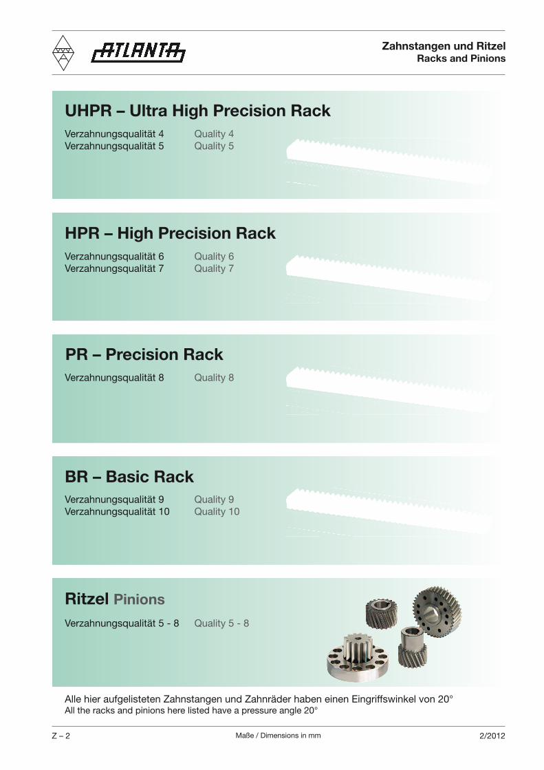
UHPR – Ultra High Precision Rack
HPR – High Precision Rack
PR – Precision Rack
BR – Basic Rack
Verzahnungsqualität 4 Quality 4
Verzahnungsqualität 5 Quality 5
Ritzel Pinions
Verzahnungsqualität 6 Quality 6
Verzahnungsqualität 7 Quality 7
Verzahnungsqualität 8 Quality 8
Verzahnungsqualität 9 Quality 9
Verzahnungsqualität 10 Quality 10
Verzahnungsqualität 5 - 8 Quality 5 - 8
Zahnstangen und RitzelRacks and Pinions
Alle hier aufgelisteten Zahnstangen und Zahnräder haben einen Eingriffswinkel von 20°All the racks and pinions here listed have a pressure angle 20°
Maße / Dimensions in mm ZA – 12/2012
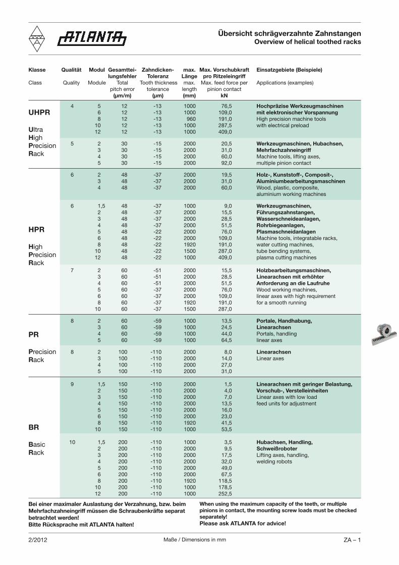
Übersicht schrägverzahnte ZahnstangenOverview of helical toothed racks
Klasse Qualität Modul Gesamttei- Zahndicken- max. Max. Vorschubkraft Einsatzgebiete (Beispiele) lungsfehler Toleranz Länge pro RitzeleingriffClass Quality Module Total Tooth thickness max. Max. feed force per Applications (examples) pitch error tolerance length pinion contact (µm/m) (µm) (mm) kN
4 5 12 -13 1000 76,5 Hochpräzise Werkzeugmaschinen 6 12 -13 1000 109,0 mit elektronischer Vorspannung 8 12 -13 960 191,0 High precision machine tools 10 12 -13 1000 287,5 with electrical preload 12 12 -13 1000 409,0
5 2 30 -15 2000 20,5 Werkzeugmaschinen, Hubachsen, 3 30 -15 2000 31,0 Mehrfachzahneingriff 4 30 -15 2000 60,0 Machine tools, lifting axes, 5 30 -15 2000 92,0 multiple pinion contact
6 2 48 -37 2000 19,5 Holz-, Kunststoff-, Composit-, 3 48 -37 2000 31,0 Aluminiumbearbeitungsmaschinen 4 48 -37 2000 60,0 Wood, plastic, composite, aluminium working machines
6 1,5 48 -37 1000 9,0 Werkzeugmaschinen, 2 48 -37 2000 15,5 Führungszahnstangen, 3 48 -37 2000 28,5 Wasserschneideanlagen, 4 48 -37 2000 51,5 Rohrbiegeanlagen, 5 48 -22 2000 76,0 Plasmaschneidanlagen 6 48 -22 2000 109,0 Machine tools, integratable racks, 8 48 -22 1920 191,0 water cutting machines, 10 48 -22 1500 287,0 tube bending systems, 12 48 -22 1000 409,0 plasma cutting machines 7 2 60 -51 2000 15,5 Holzbearbeitungsmaschinen, 3 60 -51 2000 28,5 Linearachsen mit erhöhter 4 60 -51 2000 51,5 Anforderung an die Laufruhe 5 60 -37 2000 76,0 Wood working machines, 6 60 -37 2000 109,0 linear axes with high requirement 8 60 -37 1920 191,0 for a smooth running 10 60 -37 1500 287,0
8 2 60 -59 1000 13,5 Portale, Handhabung, 3 60 -59 1000 24,5 Linearachsen 4 60 -59 1000 44,0 Portals, handling 5 60 -59 1000 64,5 linear axes
8 2 100 -110 2000 8,0 Linearachsen 3 100 -110 2000 14,0 Linear axes 4 100 -110 2000 27,0 5 100 -110 2000 31,0
9 1,5 150 -110 2000 1,5 Linearachsen mit geringer Belastung, 2 150 -110 2000 4,0 Vorschub-, Verstelleinheiten 3 150 -110 2000 7,0 Linear axes with low load 4 150 -110 2000 13,5 feed units for adjustment 5 150 -110 2000 16,0 6 150 -110 2000 23,0 8 150 -110 1920 41,5 10 150 -110 1000 53,5
10 1,5 200 -110 1000 3,5 Hubachsen, Handling, 2 200 -110 2000 9,5 Schweißroboter 3 200 -110 2000 17,5 Lifting axes, handling, 4 200 -110 2000 32,0 welding robots 5 200 -110 2000 49,0 6 200 -110 2000 67,5 8 200 -110 1920 118,5 10 200 -110 1000 178,5 12 200 -110 1000 252,5
UHPR
UltraHighPrecisionRack
HPR
HighPrecisionRack
PR
PrecisionRack
BR
BasicRack
Bei einer maximaler Auslastung der Verzahnung, bzw. beim Mehrfachzahneingriff müssen die Schraubenkräfte separat betrachtet werden!Bitte Rücksprache mit ATLANTA halten!
When using the maximum capacity of the teeth, or multiple pinions in contact, the mounting screw loads must be checked separately!Please ask ATLANTA for advice!
Maße / Dimensions in mmZA – 2 2/2012
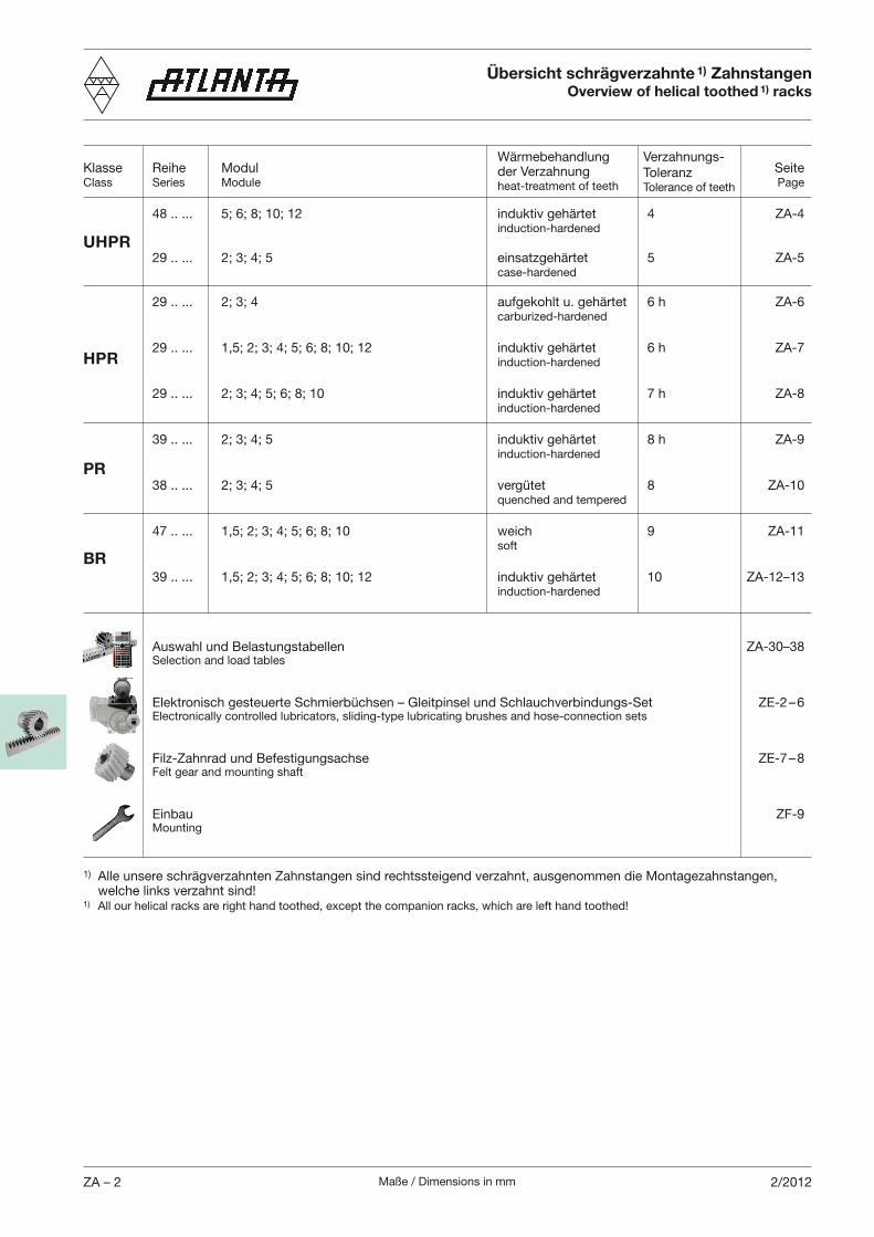
Übersicht schrägverzahnte 1) ZahnstangenOverview of helical toothed 1) racks
Klasse Reihe Modul SeiteClass Series Module Page
48 .. ... 5; 6; 8; 10; 12 induktiv gehärtet 4 ZA-4 induction-hardened
29 .. ... 2; 3; 4; 5 einsatzgehärtet 5 ZA-5 case-hardened
29 .. ... 2; 3; 4 aufgekohlt u. gehärtet 6 h ZA-6 carburized-hardened
29 .. ... 1,5; 2; 3; 4; 5; 6; 8; 10; 12 induktiv gehärtet 6 h ZA-7 induction-hardened
29 .. ... 2; 3; 4; 5; 6; 8; 10 induktiv gehärtet 7 h ZA-8 induction-hardened
39 .. ... 2; 3; 4; 5 induktiv gehärtet 8 h ZA-9 induction-hardened
38 .. ... 2; 3; 4; 5 vergütet 8 ZA-10 quenched and tempered
47 .. ... 1,5; 2; 3; 4; 5; 6; 8; 10 weich 9 ZA-11 soft
39 .. ... 1,5; 2; 3; 4; 5; 6; 8; 10; 12 induktiv gehärtet 10 ZA-12–13 induction-hardened
Auswahl und Belastungstabellen ZA-30–38 Selection and load tables
Elektronisch gesteuerte Schmierbüchsen – Gleitpinsel und Schlauchverbindungs-Set ZE-2 – 6 Electronically controlled lubricators, sliding-type lubricating brushes and hose-connection sets
Filz-Zahnrad und Befestigungsachse ZE-7 – 8 Felt gear and mounting shaft
Einbau ZF-9 Mounting
Wärmebehandlung der Verzahnungheat-treatment of teeth
Verzahnungs-ToleranzTolerance of teeth
UHPR
HPR
PR
BR
1) Alle unsere schrägverzahnten Zahnstangen sind rechtssteigend verzahnt, ausgenommen die Montagezahnstangen, welche links verzahnt sind!1) All our helical racks are right hand toothed, except the companion racks, which are left hand toothed!
Maße / Dimensions in mm ZA – 31/2012
Reihe Modul Seite Series Module Page
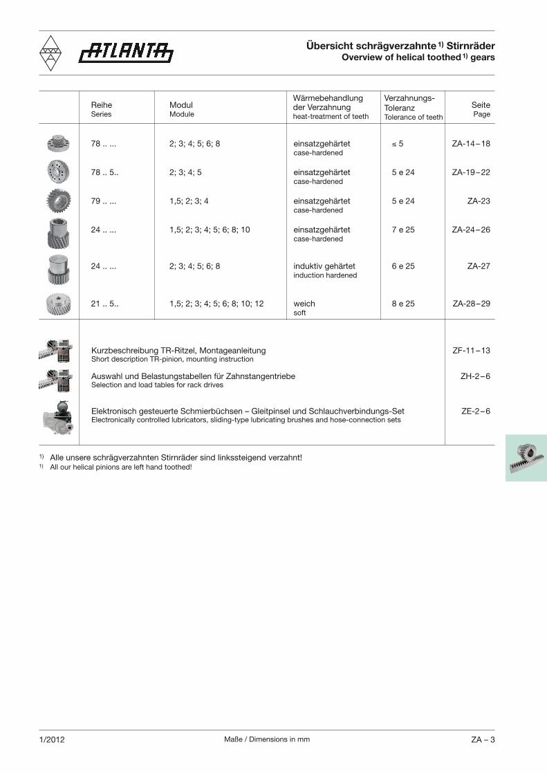
78 .. ... 2; 3; 4; 5; 6; 8 einsatzgehärtet 5 ZA-14 – 18 case-hardened
78 .. 5.. 2; 3; 4; 5 einsatzgehärtet 5 e 24 ZA-19 – 22 case-hardened
79 .. ... 1,5; 2; 3; 4 einsatzgehärtet 5 e 24 ZA-23 case-hardened
24 .. ... 1,5; 2; 3; 4; 5; 6; 8; 10 einsatzgehärtet 7 e 25 ZA-24 – 26 case-hardened 24 .. ... 2; 3; 4; 5; 6; 8 induktiv gehärtet 6 e 25 ZA-27 induction hardened
21 .. 5.. 1,5; 2; 3; 4; 5; 6; 8; 10; 12 weich 8 e 25 ZA-28 – 29 soft
Kurzbeschreibung TR-Ritzel, Montageanleitung ZF-11 – 13 Short description TR-pinion, mounting instruction
Auswahl und Belastungstabellen für Zahnstangentriebe ZH-2 – 6 Selection and load tables for rack drives
Elektronisch gesteuerte Schmierbüchsen – Gleitpinsel und Schlauchverbindungs-Set ZE-2 – 6 Electronically controlled lubricators, sliding-type lubricating brushes and hose-connection sets
Übersicht schrägverzahnte 1) StirnräderOverview of helical toothed 1) gears
Wärmebehandlung der Verzahnungheat-treatment of teeth
Verzahnungs-ToleranzTolerance of teeth
1) Alle unsere schrägverzahnten Stirnräder sind linkssteigend verzahnt!1) All our helical pinions are left hand toothed!
Maße / Dimensions in mmZA – 4 1/2012
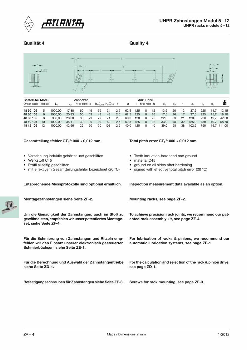
UHPR Zahnstangen Modul 5 – 12UHPR racks module 5 – 12
48 50 105 5 1000,00 17,38 60 49 39 34 2,5 62,5 125 8 12 13,5 20 13 37,5 925 11,7 12,1548 60 105 6 1000,00 20,93 50 59 49 43 2,5 62,5 125 8 16 17,5 26 17 37,5 925 15,7 18,1048 80 105 8 960,00 28,00 36 79 79 71 2,5 60,0 120 8 25 22,0 33 21 120,0 720 19,7 42,5048 10 105 10 1000,00 35,11 30 99 99 89 2,5 62,5 125 8 32 33,0 48 32 125,0 750 19,7 68,7048 12 105 12 1000,00 42,56 25 120 120 108 2,5 40,0 125 8 40 39,0 58 38 102,5 750 19,7 111,00
Bestell-Nr. Modul Zähnezahl Anz. Bohr.Order code Module L1 L2 N° of teeth b hk h0 f a I N° of holes h d1 d2 t a1 I1 d3
0- 0,018
Qualität 4 Quality 4
0- 0,018
Total pitch error GTf /1000 0,012 mm.Gesamtteilungsfehler GTf /1000 0,012 mm.
Entsprechende Messprotokolle sind optional erhältlich. Inspection measurement data available as an option.
Um die Genauigkeit der Zahnstangen, auch im Stoß zu gewährleisten, empfehlen wir unser patentiertes Montage-set, siehe Seite ZF-4.
To achieve precision rack joints, we recommend our pat-ented rack assembly kit, see page ZF-4.
Montagezahnstangen siehe Seite ZF-2. Mounting racks, see page ZF-2.
Für die Schmierung von Zahnstangen und Ritzeln emp-fehlen wir den Einsatz unserer elektronisch gesteuerten Schmierbüchsen, siehe Seite ZE-1.
For lubrication of racks & pinions, we recommend our automatic lubrication systems, see page ZE-1.
Für die Berechnung und Auswahl der Zahnstangentriebe siehe Seite ZD-1.
For the calculation and selection of the rack & pinion drive, see page ZD-1.
Befestigungsschrauben für Zahnstangen siehe Seite ZF-3. Screws for rack mounting, see page ZF-3.
Maße / Dimensions in mm ZA – 51/2012
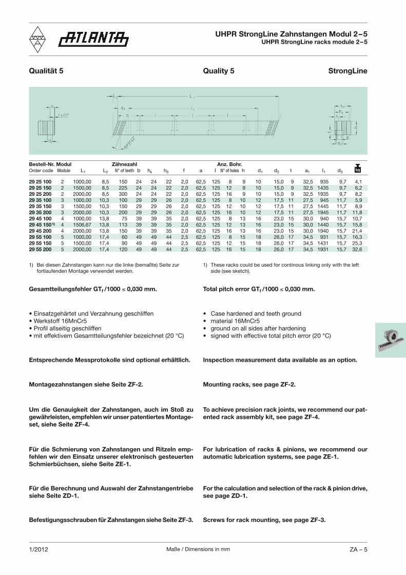
29 25 100 2 1000,00 8,5 150 24 24 22 2,0 62,5 125 8 9 10 15,0 9 32,5 935 9,7 4,129 25 150 2 1500,00 8,5 225 24 24 22 2,0 62,5 125 12 9 10 15,0 9 32,5 1435 9,7 6,229 25 200 2 2000,00 8,5 300 24 24 22 2,0 62,5 125 16 9 10 15,0 9 32,5 1935 9,7 8,229 35 100 3 1000,00 10,3 100 29 29 26 2,0 62,5 125 8 10 12 17,5 11 27,5 945 11,7 5,929 35 150 3 1500,00 10,3 150 29 29 26 2,0 62,5 125 12 10 12 17,5 11 27,5 1445 11,7 8,929 35 200 3 2000,00 10,3 200 29 29 26 2,0 62,5 125 16 10 12 17,5 11 27,5 1945 11,7 11,829 45 100 4 1000,00 13,8 75 39 39 35 2,0 62,5 125 8 13 16 23,0 15 30,0 940 15,7 10,729 45 150 1) 4 1506,67 13,8 113 39 39 35 2,0 62,5 125 12 13 16 23,0 15 30,0 1440 15,7 15,829 45 200 4 2000,00 13,8 150 39 39 35 2,0 62,5 125 16 13 16 23,0 15 30,0 1940 15,7 21,429 55 100 5 1000,00 17,4 60 49 49 44 2,5 62,5 125 8 15 18 26,0 17 34,5 931 15,7 16,329 55 150 5 1500,00 17,4 90 49 49 44 2,5 62,5 125 12 15 18 26,0 17 34,5 1431 15,7 25,329 55 200 5 2000,00 17,4 120 49 49 44 2,5 62,5 125 16 15 18 26,0 17 34,5 1931 15,7 32,6
Bestell-Nr. Modul Zähnezahl Anz. Bohr.Order code Module L1 L2 N° of teeth b hk h0 f a I N° of holes h d1 d2 t a1 I1 d3
1) Bei diesen Zahnstangen kann nur die linke (bemaßte) Seite zur fortlaufenden Montage verwendet werden.
1) These racks could be used for continous linking only with the left side (see sketch).
UHPR StrongLine Zahnstangen Modul 2 – 5UHPR StrongLine racks module 2 – 5
Qualität 5 Quality 5 StrongLine
Total pitch error GTf /1000 0,030 mm.Gesamtteilungsfehler GTf /1000 0,030 mm.
Entsprechende Messprotokolle sind optional erhältlich. Inspection measurement data available as an option.
Um die Genauigkeit der Zahnstangen, auch im Stoß zu gewährleisten, empfehlen wir unser patentiertes Montage-set, siehe Seite ZF-4.
To achieve precision rack joints, we recommend our pat-ented rack assembly kit, see page ZF-4.
Montagezahnstangen siehe Seite ZF-2. Mounting racks, see page ZF-2.
Für die Schmierung von Zahnstangen und Ritzeln emp-fehlen wir den Einsatz unserer elektronisch gesteuerten Schmierbüchsen, siehe Seite ZE-1.
For lubrication of racks & pinions, we recommend our automatic lubrication systems, see page ZE-1.
Für die Berechnung und Auswahl der Zahnstangentriebe siehe Seite ZD-1.
For the calculation and selection of the rack & pinion drive, see page ZD-1.
Befestigungsschrauben für Zahnstangen siehe Seite ZF-3. Screws for rack mounting, see page ZF-3.
Maße / Dimensions in mmZA – 6 2/2012
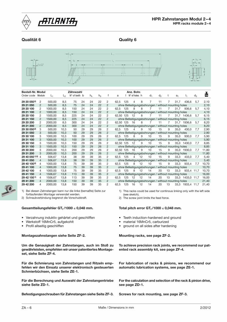
Bestell-Nr. Modul Zähnezahl Anz. Bohr.Order code Module L1 L2 N° of teeth b hk h0 f a I N° of holes h d1 d2 t a1 I1 d3
29 20 050 2) 2 500,00 8,5 75 24 24 22 2 62,5 125 4 8 7 11 7 31,7 436,6 5,7 2,1029 21 050 2 500,00 8,5 75 24 24 22 2 ohne Befestigungsbohrungen / without mounting holes 2,1029 20 100 2 1000,00 8,5 150 24 24 22 2 62,5 125 8 8 7 11 7 31,7 936,6 5,7 4,1029 21 100 2 1000,00 8,5 150 24 24 22 2 ohne Befestigungsbohrungen / without mounting holes 4,1029 20 150 2 1500,00 8,5 225 24 24 22 2 62,50 125 12 8 7 11 7 31,7 1436,6 5,7 6,1529 21 150 2 1500,00 8,5 225 24 24 22 2 ohne Befestigungsbohrungen / without mounting holes 6,1529 20 200 2 2000,00 8,5 300 24 24 22 2 62,50 125 16 8 7 11 7 31,7 1936,6 5,7 8,2029 21 200 2 2000,00 8,5 300 24 24 22 2 ohne Befestigungsbohrungen / without mounting holes 8,2029 30 050 2) 3 500,00 10,3 50 29 29 26 2 62,5 125 4 9 10 15 9 35,0 430,0 7,7 2,9029 31 050 3 500,00 10,3 50 29 29 26 2 ohne Befestigungsbohrungen / without mounting holes 2,9029 30 100 3 1000,00 10,3 100 29 29 26 2 62,5 125 8 9 10 15 9 35,0 930,0 7,7 5,9029 31 100 3 1000,00 10,3 100 29 29 26 2 ohne Befestigungsbohrungen / without mounting holes 5,9029 30 150 3 1500,00 10,3 150 29 29 26 2 62,50 125 12 9 10 15 9 35,0 1430,0 7,7 8,8529 31 150 3 1500,00 10,3 150 29 29 26 2 ohne Befestigungsbohrungen / without mounting holes 8,8529 30 200 3 2000,00 10,3 200 29 29 26 2 62,50 125 16 9 10 15 9 35,0 1930,0 7,7 11,8029 31 200 3 2000,00 10,3 200 29 29 26 2 ohne Befestigungsbohrungen / without mounting holes 11,8029 40 050 1) 2) 4 506,67 13,8 38 39 39 35 2 62,5 125 4 12 10 15 9 33,3 433,0 7,7 5,4029 41 050 4 506,67 13,8 38 39 39 35 2 ohne Befestigungsbohrungen / without mounting holes 5,4029 40 100 2) 4 1000,00 13,8 75 39 39 35 2 62,5 125 8 12 10 15 9 33,3 933,4 7,7 10,7029 41 100 4 1000,00 13,8 75 39 39 35 2 ohne Befestigungsbohrungen / without mounting holes 10,7029 42 100 4 1000,00 13,8 75 39 39 35 2 62,5 125 8 12 14 20 13 33,3 933,4 11,7 10,7029 41 150 4 1506,67 13,8 113 39 39 35 2 ohne Befestigungsbohrungen / without mounting holes 16,0029 42 150 1) 4 1506,67 13,8 113 39 39 35 2 62,5 125 12 12 14 20 13 33,3 1433,0 11,7 16,0029 41 200 4 2000,00 13,8 150 39 39 35 2 ohne Befestigungsbohrungen / without mounting holes 21,4029 42 200 4 2000,00 13,8 150 39 39 35 2 62,5 125 16 12 14 20 13 33,3 1933,4 11,7 21,40
HPR Zahnstangen Modul 2 – 4HPR racks module 2 – 4
Qualität 6 Quality 6
1) Bei diesen Zahnstangen kann nur die linke (bemaßte) Seite zur fortlaufenden Montage verwendet werden.
2) Schraubverbindung begrenzt die Vorschubkraft.
1) This racks could be used for continous linking only with the left side (see sketch).
2) The screw joint limits the feed force.
Total pitch error GTf /1000 0,048 mm.Gesamtteilungsfehler GTf /1000 0,048 mm.
Um die Genauigkeit der Zahnstangen, auch im Stoß zu gewährleisten, empfehlen wir unser patentiertes Montage-set, siehe Seite ZF-4.
To achieve precision rack joints, we recommend our pat-ented rack assembly kit, see page ZF-4.
Montagezahnstangen siehe Seite ZF-2. Mounting racks, see page ZF-2.
Für die Schmierung von Zahnstangen und Ritzeln emp-fehlen wir den Einsatz unserer elektronisch gesteuerten Schmierbüchsen, siehe Seite ZE-1.
For lubrication of racks & pinions, we recommend our automatic lubrication systems, see page ZE-1.
Für die Berechnung und Auswahl der Zahnstangentriebe siehe Seite ZD-1.
For the calculation and selection of the rack & pinion drive, see page ZD-1.
Befestigungsschrauben für Zahnstangen siehe Seite ZF-3. Screws for rack mounting, see page ZF-3.
Maße / Dimensions in mm ZA – 72/2012
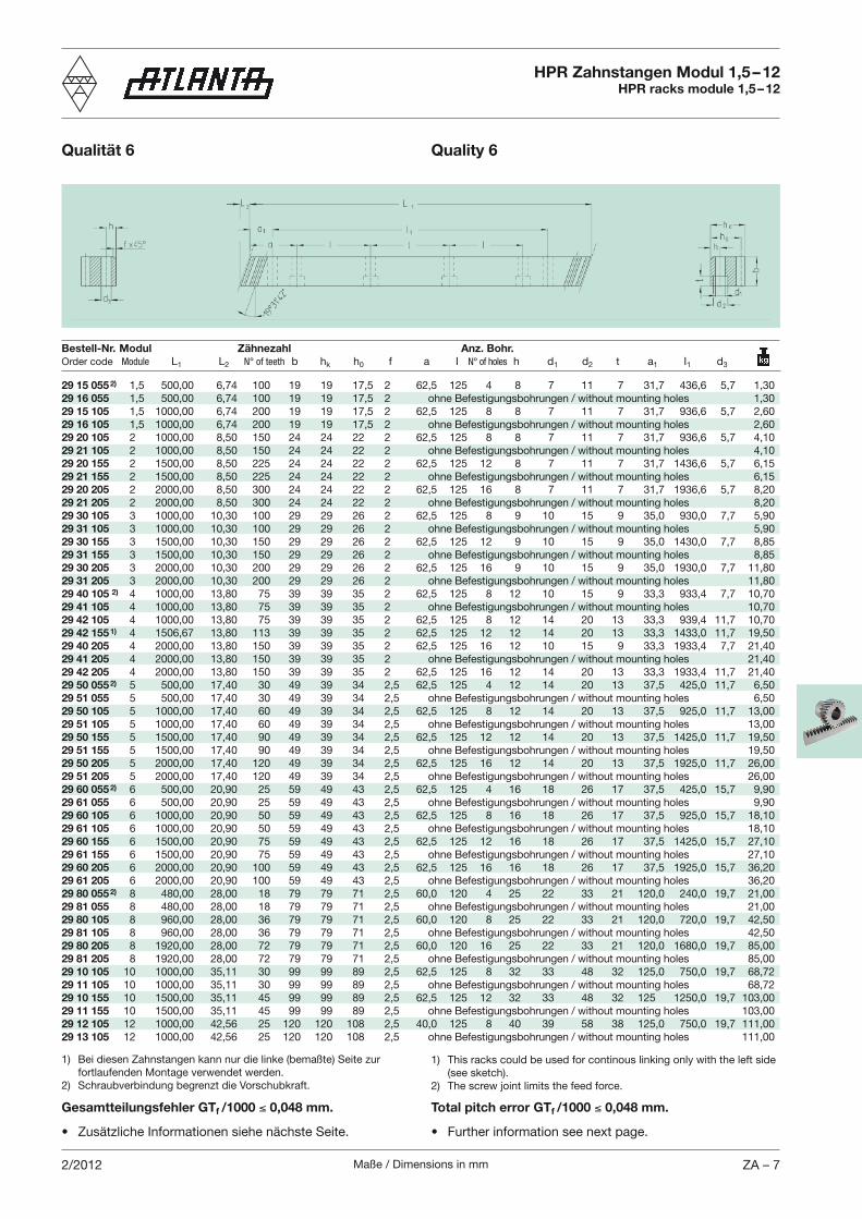
29 15 055 2) 1,5 500,00 6,74 100 19 19 17,5 2 62,5 125 4 8 7 11 7 31,7 436,6 5,7 1,3029 16 055 1,5 500,00 6,74 100 19 19 17,5 2 ohne Befestigungsbohrungen / without mounting holes 1,3029 15 105 1,5 1000,00 6,74 200 19 19 17,5 2 62,5 125 8 8 7 11 7 31,7 936,6 5,7 2,6029 16 105 1,5 1000,00 6,74 200 19 19 17,5 2 ohne Befestigungsbohrungen / without mounting holes 2,6029 20 105 2 1000,00 8,50 150 24 24 22 2 62,5 125 8 8 7 11 7 31,7 936,6 5,7 4,1029 21 105 2 1000,00 8,50 150 24 24 22 2 ohne Befestigungsbohrungen / without mounting holes 4,1029 20 155 2 1500,00 8,50 225 24 24 22 2 62,5 125 12 8 7 11 7 31,7 1436,6 5,7 6,1529 21 155 2 1500,00 8,50 225 24 24 22 2 ohne Befestigungsbohrungen / without mounting holes 6,1529 20 205 2 2000,00 8,50 300 24 24 22 2 62,5 125 16 8 7 11 7 31,7 1936,6 5,7 8,2029 21 205 2 2000,00 8,50 300 24 24 22 2 ohne Befestigungsbohrungen / without mounting holes 8,2029 30 105 3 1000,00 10,30 100 29 29 26 2 62,5 125 8 9 10 15 9 35,0 930,0 7,7 5,9029 31 105 3 1000,00 10,30 100 29 29 26 2 ohne Befestigungsbohrungen / without mounting holes 5,9029 30 155 3 1500,00 10,30 150 29 29 26 2 62,5 125 12 9 10 15 9 35,0 1430,0 7,7 8,8529 31 155 3 1500,00 10,30 150 29 29 26 2 ohne Befestigungsbohrungen / without mounting holes 8,8529 30 205 3 2000,00 10,30 200 29 29 26 2 62,5 125 16 9 10 15 9 35,0 1930,0 7,7 11,8029 31 205 3 2000,00 10,30 200 29 29 26 2 ohne Befestigungsbohrungen / without mounting holes 11,8029 40 105 2) 4 1000,00 13,80 75 39 39 35 2 62,5 125 8 12 10 15 9 33,3 933,4 7,7 10,7029 41 105 4 1000,00 13,80 75 39 39 35 2 ohne Befestigungsbohrungen / without mounting holes 10,7029 42 105 4 1000,00 13,80 75 39 39 35 2 62,5 125 8 12 14 20 13 33,3 939,4 11,7 10,7029 42 155 1) 4 1506,67 13,80 113 39 39 35 2 62,5 125 12 12 14 20 13 33,3 1433,0 11,7 19,5029 40 205 4 2000,00 13,80 150 39 39 35 2 62,5 125 16 12 10 15 9 33,3 1933,4 7,7 21,4029 41 205 4 2000,00 13,80 150 39 39 35 2 ohne Befestigungsbohrungen / without mounting holes 21,4029 42 205 4 2000,00 13,80 150 39 39 35 2 62,5 125 16 12 14 20 13 33,3 1933,4 11,7 21,4029 50 055 2) 5 500,00 17,40 30 49 39 34 2,5 62,5 125 4 12 14 20 13 37,5 425,0 11,7 6,5029 51 055 5 500,00 17,40 30 49 39 34 2,5 ohne Befestigungsbohrungen / without mounting holes 6,5029 50 105 5 1000,00 17,40 60 49 39 34 2,5 62,5 125 8 12 14 20 13 37,5 925,0 11,7 13,0029 51 105 5 1000,00 17,40 60 49 39 34 2,5 ohne Befestigungsbohrungen / without mounting holes 13,0029 50 155 5 1500,00 17,40 90 49 39 34 2,5 62,5 125 12 12 14 20 13 37,5 1425,0 11,7 19,5029 51 155 5 1500,00 17,40 90 49 39 34 2,5 ohne Befestigungsbohrungen / without mounting holes 19,5029 50 205 5 2000,00 17,40 120 49 39 34 2,5 62,5 125 16 12 14 20 13 37,5 1925,0 11,7 26,0029 51 205 5 2000,00 17,40 120 49 39 34 2,5 ohne Befestigungsbohrungen / without mounting holes 26,0029 60 055 2) 6 500,00 20,90 25 59 49 43 2,5 62,5 125 4 16 18 26 17 37,5 425,0 15,7 9,9029 61 055 6 500,00 20,90 25 59 49 43 2,5 ohne Befestigungsbohrungen / without mounting holes 9,9029 60 105 6 1000,00 20,90 50 59 49 43 2,5 62,5 125 8 16 18 26 17 37,5 925,0 15,7 18,1029 61 105 6 1000,00 20,90 50 59 49 43 2,5 ohne Befestigungsbohrungen / without mounting holes 18,1029 60 155 6 1500,00 20,90 75 59 49 43 2,5 62,5 125 12 16 18 26 17 37,5 1425,0 15,7 27,1029 61 155 6 1500,00 20,90 75 59 49 43 2,5 ohne Befestigungsbohrungen / without mounting holes 27,1029 60 205 6 2000,00 20,90 100 59 49 43 2,5 62,5 125 16 16 18 26 17 37,5 1925,0 15,7 36,2029 61 205 6 2000,00 20,90 100 59 49 43 2,5 ohne Befestigungsbohrungen / without mounting holes 36,2029 80 055 2) 8 480,00 28,00 18 79 79 71 2,5 60,0 120 4 25 22 33 21 120,0 240,0 19,7 21,0029 81 055 8 480,00 28,00 18 79 79 71 2,5 ohne Befestigungsbohrungen / without mounting holes 21,0029 80 105 8 960,00 28,00 36 79 79 71 2,5 60,0 120 8 25 22 33 21 120,0 720,0 19,7 42,5029 81 105 8 960,00 28,00 36 79 79 71 2,5 ohne Befestigungsbohrungen / without mounting holes 42,5029 80 205 8 1920,00 28,00 72 79 79 71 2,5 60,0 120 16 25 22 33 21 120,0 1680,0 19,7 85,0029 81 205 8 1920,00 28,00 72 79 79 71 2,5 ohne Befestigungsbohrungen / without mounting holes 85,0029 10 105 10 1000,00 35,11 30 99 99 89 2,5 62,5 125 8 32 33 48 32 125,0 750,0 19,7 68,7229 11 105 10 1000,00 35,11 30 99 99 89 2,5 ohne Befestigungsbohrungen / without mounting holes 68,7229 10 155 10 1500,00 35,11 45 99 99 89 2,5 62,5 125 12 32 33 48 32 125 1250,0 19,7 103,0029 11 155 10 1500,00 35,11 45 99 99 89 2,5 ohne Befestigungsbohrungen / without mounting holes 103,0029 12 105 12 1000,00 42,56 25 120 120 108 2,5 40,0 125 8 40 39 58 38 125,0 750,0 19,7 111,0029 13 105 12 1000,00 42,56 25 120 120 108 2,5 ohne Befestigungsbohrungen / without mounting holes 111,00
Bestell-Nr. Modul Zähnezahl Anz. Bohr.Order code Module L1 L2 N° of teeth b hk h0 f a I N° of holes h d1 d2 t a1 I1 d3
HPR Zahnstangen Modul 1,5 – 12HPR racks module 1,5 – 12
Qualität 6 Quality 6
1) Bei diesen Zahnstangen kann nur die linke (bemaßte) Seite zur fortlaufenden Montage verwendet werden.
2) Schraubverbindung begrenzt die Vorschubkraft.
1) This racks could be used for continous linking only with the left side (see sketch).
2) The screw joint limits the feed force.
Total pitch error GTf /1000 0,048 mm.Gesamtteilungsfehler GTf /1000 0,048 mm.
Maße / Dimensions in mmZA – 8 2/2012
Bestell-Nr. Modul Zähnezahl Anz. Bohr.Order code Module L1 L2 N° of teeth b hk h0 f a I N° of holes h d1 d2 t a1 I1 d3
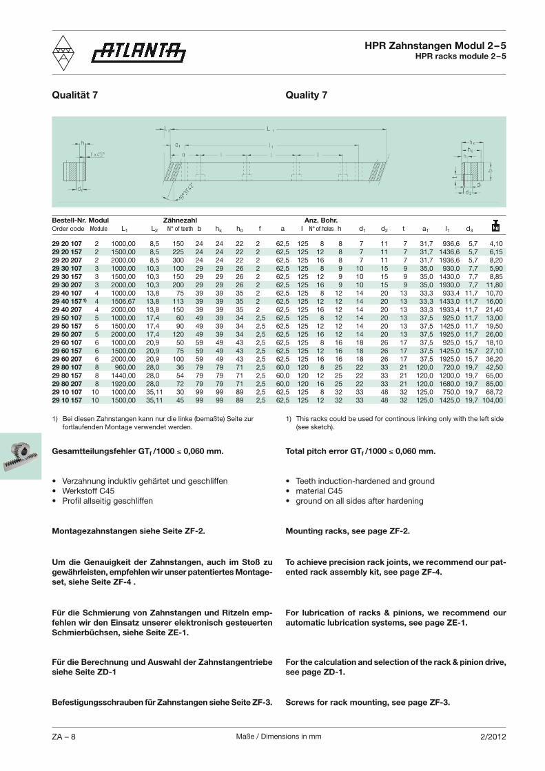
HPR Zahnstangen Modul 2 – 5HPR racks module 2 – 5
Qualität 7 Quality 7
29 20 107 2 1000,00 8,5 150 24 24 22 2 62,5 125 8 8 7 11 7 31,7 936,6 5,7 4,1029 20 157 2 1500,00 8,5 225 24 24 22 2 62,5 125 12 8 7 11 7 31,7 1436,6 5,7 6,1529 20 207 2 2000,00 8,5 300 24 24 22 2 62,5 125 16 8 7 11 7 31,7 1936,6 5,7 8,2029 30 107 3 1000,00 10,3 100 29 29 26 2 62,5 125 8 9 10 15 9 35,0 930,0 7,7 5,9029 30 157 3 1500,00 10,3 150 29 29 26 2 62,5 125 12 9 10 15 9 35,0 1430,0 7,7 8,8529 30 207 3 2000,00 10,3 200 29 29 26 2 62,5 125 16 9 10 15 9 35,0 1930,0 7,7 11,8029 40 107 4 1000,00 13,8 75 39 39 35 2 62,5 125 8 12 14 20 13 33,3 933,4 11,7 10,7029 40 157 1) 4 1506,67 13,8 113 39 39 35 2 62,5 125 12 12 14 20 13 33,3 1433,0 11,7 16,0029 40 207 4 2000,00 13,8 150 39 39 35 2 62,5 125 16 12 14 20 13 33,3 1933,4 11,7 21,4029 50 107 5 1000,00 17,4 60 49 39 34 2,5 62,5 125 8 12 14 20 13 37,5 925,0 11,7 13,0029 50 157 5 1500,00 17,4 90 49 39 34 2,5 62,5 125 12 12 14 20 13 37,5 1425,0 11,7 19,5029 50 207 5 2000,00 17,4 120 49 39 34 2,5 62,5 125 16 12 14 20 13 37,5 1925,0 11,7 26,0029 60 107 6 1000,00 20,9 50 59 49 43 2,5 62,5 125 8 16 18 26 17 37,5 925,0 15,7 18,1029 60 157 6 1500,00 20,9 75 59 49 43 2,5 62,5 125 12 16 18 26 17 37,5 1425,0 15,7 27,1029 60 207 6 2000,00 20,9 100 59 49 43 2,5 62,5 125 16 16 18 26 17 37,5 1925,0 15,7 36,2029 80 107 8 960,00 28,0 36 79 79 71 2,5 60,0 120 8 25 22 33 21 120,0 720,0 19,7 42,5029 80 157 8 1440,00 28,0 54 79 79 71 2,5 60,0 120 12 25 22 33 21 120,0 1200,0 19,7 65,0029 80 207 8 1920,00 28,0 72 79 79 71 2,5 60,0 120 16 25 22 33 21 120,0 1680,0 19,7 85,0029 10 107 10 1000,00 35,11 30 99 99 89 2,5 62,5 125 8 32 33 48 32 125,0 750,0 19,7 68,7229 10 157 10 1500,00 35,11 45 99 99 89 2,5 62,5 125 12 32 33 48 32 125,0 1425,0 19,7 104,00
1) Bei diesen Zahnstangen kann nur die linke (bemaßte) Seite zur fortlaufenden Montage verwendet werden.
1) This racks could be used for continous linking only with the left side (see sketch).
Total pitch error GTf /1000 0,060 mm.Gesamtteilungsfehler GTf /1000 0,060 mm.
Um die Genauigkeit der Zahnstangen, auch im Stoß zu gewährleisten, empfehlen wir unser patentiertes Montage-set, siehe Seite ZF-4 .
To achieve precision rack joints, we recommend our pat-ented rack assembly kit, see page ZF-4.
Montagezahnstangen siehe Seite ZF-2. Mounting racks, see page ZF-2.
Für die Schmierung von Zahnstangen und Ritzeln emp-fehlen wir den Einsatz unserer elektronisch gesteuerten Schmierbüchsen, siehe Seite ZE-1.
For lubrication of racks & pinions, we recommend our automatic lubrication systems, see page ZE-1.
Für die Berechnung und Auswahl der Zahnstangentriebe siehe Seite ZD-1
For the calculation and selection of the rack & pinion drive, see page ZD-1.
Befestigungsschrauben für Zahnstangen siehe Seite ZF-3. Screws for rack mounting, see page ZF-3.
Maße / Dimensions in mm ZA – 91/2012
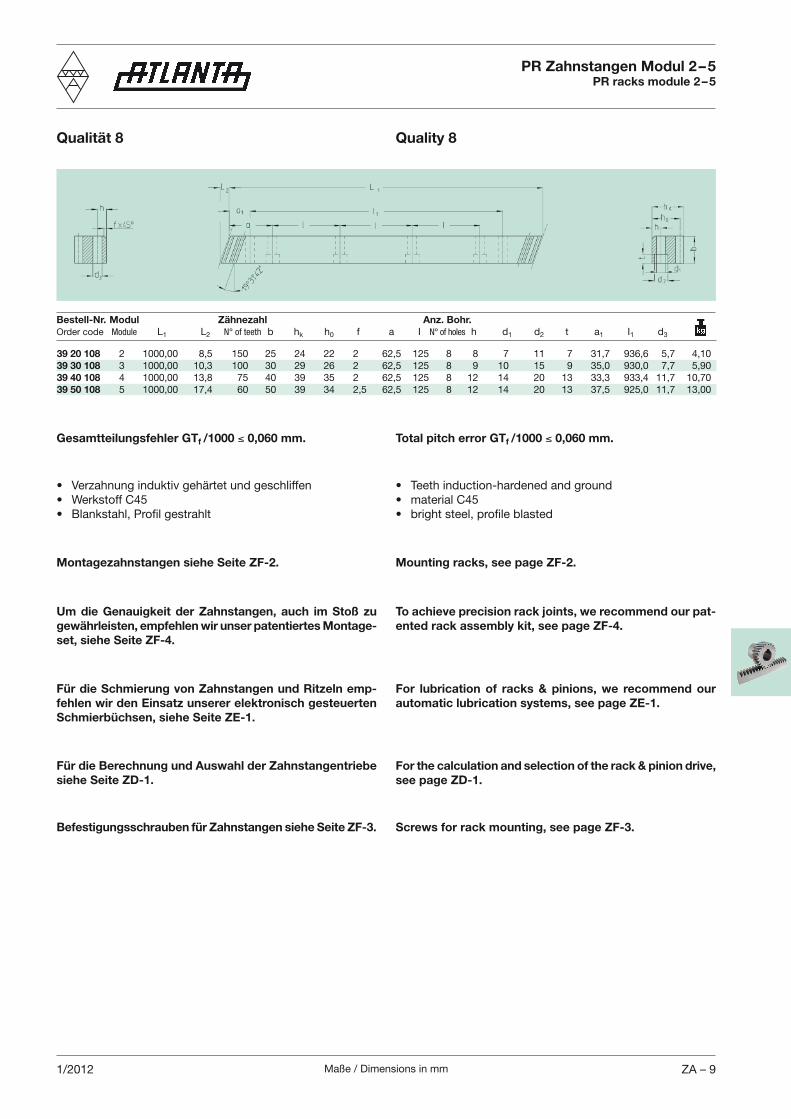
39 20 108 2 1000,00 8,5 150 25 24 22 2 62,5 125 8 8 7 11 7 31,7 936,6 5,7 4,1039 30 108 3 1000,00 10,3 100 30 29 26 2 62,5 125 8 9 10 15 9 35,0 930,0 7,7 5,9039 40 108 4 1000,00 13,8 75 40 39 35 2 62,5 125 8 12 14 20 13 33,3 933,4 11,7 10,7039 50 108 5 1000,00 17,4 60 50 39 34 2,5 62,5 125 8 12 14 20 13 37,5 925,0 11,7 13,00
Total pitch error GTf /1000 0,060 mm.Gesamtteilungsfehler GTf /1000 0,060 mm.
Um die Genauigkeit der Zahnstangen, auch im Stoß zu gewährleisten, empfehlen wir unser patentiertes Montage-set, siehe Seite ZF-4.
To achieve precision rack joints, we recommend our pat-ented rack assembly kit, see page ZF-4.
Montagezahnstangen siehe Seite ZF-2. Mounting racks, see page ZF-2.
Für die Schmierung von Zahnstangen und Ritzeln emp-fehlen wir den Einsatz unserer elektronisch gesteuerten Schmierbüchsen, siehe Seite ZE-1.
For lubrication of racks & pinions, we recommend our automatic lubrication systems, see page ZE-1.
Bestell-Nr. Modul Zähnezahl Anz. Bohr.Order code Module L1 L2 N° of teeth b hk h0 f a I N° of holes h d1 d2 t a1 I1 d3
PR Zahnstangen Modul 2 – 5PR racks module 2 – 5
Qualität 8 Quality 8
Für die Berechnung und Auswahl der Zahnstangentriebe siehe Seite ZD-1.
For the calculation and selection of the rack & pinion drive, see page ZD-1.
Befestigungsschrauben für Zahnstangen siehe Seite ZF-3. Screws for rack mounting, see page ZF-3.
Maße / Dimensions in mmZA – 10 1/2012
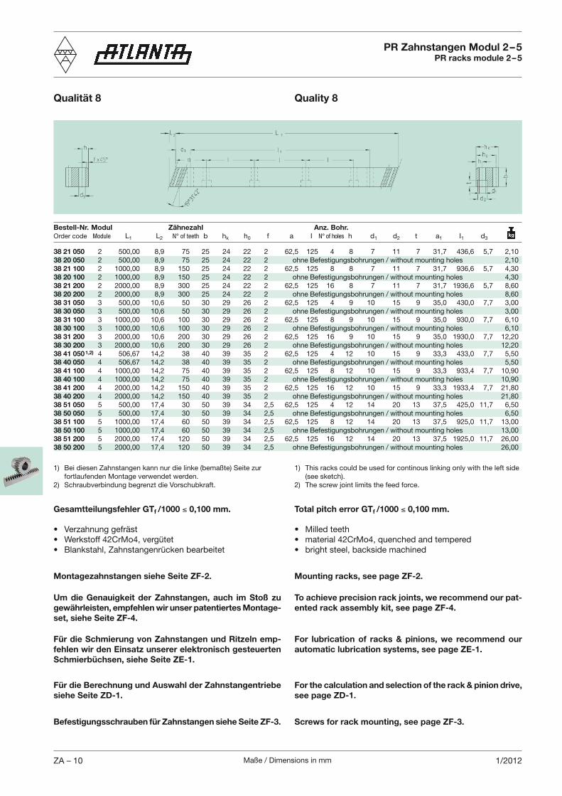
38 21 050 2 500,00 8,9 75 25 24 22 2 62,5 125 4 8 7 11 7 31,7 436,6 5,7 2,1038 20 050 2 500,00 8,9 75 25 24 22 2 ohne Befestigungsbohrungen / without mounting holes 2,1038 21 100 2 1000,00 8,9 150 25 24 22 2 62,5 125 8 8 7 11 7 31,7 936,6 5,7 4,3038 20 100 2 1000,00 8,9 150 25 24 22 2 ohne Befestigungsbohrungen / without mounting holes 4,3038 21 200 2 2000,00 8,9 300 25 24 22 2 62,5 125 16 8 7 11 7 31,7 1936,6 5,7 8,6038 20 200 2 2000,00 8,9 300 25 24 22 2 ohne Befestigungsbohrungen / without mounting holes 8,6038 31 050 3 500,00 10,6 50 30 29 26 2 62,5 125 4 9 10 15 9 35,0 430,0 7,7 3,0038 30 050 3 500,00 10,6 50 30 29 26 2 ohne Befestigungsbohrungen / without mounting holes 3,0038 31 100 3 1000,00 10,6 100 30 29 26 2 62,5 125 8 9 10 15 9 35,0 930,0 7,7 6,1038 30 100 3 1000,00 10,6 100 30 29 26 2 ohne Befestigungsbohrungen / without mounting holes 6,1038 31 200 3 2000,00 10,6 200 30 29 26 2 62,5 125 16 9 10 15 9 35,0 1930,0 7,7 12,2038 30 200 3 2000,00 10,6 200 30 29 26 2 ohne Befestigungsbohrungen / without mounting holes 12,2038 41 050 1,2) 4 506,67 14,2 38 40 39 35 2 62,5 125 4 12 10 15 9 33,3 433,0 7,7 5,5038 40 050 4 506,67 14,2 38 40 39 35 2 ohne Befestigungsbohrungen / without mounting holes 5,5038 41 100 4 1000,00 14,2 75 40 39 35 2 62,5 125 8 12 10 15 9 33,3 933,4 7,7 10,9038 40 100 4 1000,00 14,2 75 40 39 35 2 ohne Befestigungsbohrungen / without mounting holes 10,9038 41 200 4 2000,00 14,2 150 40 39 35 2 62,5 125 16 12 10 15 9 33,3 1933,4 7,7 21,8038 40 200 4 2000,00 14,2 150 40 39 35 2 ohne Befestigungsbohrungen / without mounting holes 21,8038 51 050 5 500,00 17,4 30 50 39 34 2,5 62,5 125 4 12 14 20 13 37,5 425,0 11,7 6,5038 50 050 5 500,00 17,4 30 50 39 34 2,5 ohne Befestigungsbohrungen / without mounting holes 6,5038 51 100 5 1000,00 17,4 60 50 39 34 2,5 62,5 125 8 12 14 20 13 37,5 925,0 11,7 13,0038 50 100 5 1000,00 17,4 60 50 39 34 2,5 ohne Befestigungsbohrungen / without mounting holes 13,0038 51 200 5 2000,00 17,4 120 50 39 34 2,5 62,5 125 16 12 14 20 13 37,5 1925,0 11,7 26,0038 50 200 5 2000,00 17,4 120 50 39 34 2,5 ohne Befestigungsbohrungen / without mounting holes 26,00
Bestell-Nr. Modul Zähnezahl Anz. Bohr.Order code Module L1 L2 N° of teeth b hk h0 f a I N° of holes h d1 d2 t a1 I1 d3
PR Zahnstangen Modul 2 – 5PR racks module 2 – 5
Qualität 8 Quality 8
Total pitch error GTf /1000 0,100 mm.Gesamtteilungsfehler GTf /1000 0,100 mm.
Um die Genauigkeit der Zahnstangen, auch im Stoß zu gewährleisten, empfehlen wir unser patentiertes Montage-set, siehe Seite ZF-4.
To achieve precision rack joints, we recommend our pat-ented rack assembly kit, see page ZF-4.
Montagezahnstangen siehe Seite ZF-2. Mounting racks, see page ZF-2.
Für die Schmierung von Zahnstangen und Ritzeln emp-fehlen wir den Einsatz unserer elektronisch gesteuerten Schmierbüchsen, siehe Seite ZE-1.
For lubrication of racks & pinions, we recommend our automatic lubrication systems, see page ZE-1.
1) Bei diesen Zahnstangen kann nur die linke (bemaßte) Seite zur fortlaufenden Montage verwendet werden.
2) Schraubverbindung begrenzt die Vorschubkraft.
1) This racks could be used for continous linking only with the left side (see sketch).
2) The screw joint limits the feed force.
Für die Berechnung und Auswahl der Zahnstangentriebe siehe Seite ZD-1.
For the calculation and selection of the rack & pinion drive, see page ZD-1.
Befestigungsschrauben für Zahnstangen siehe Seite ZF-3. Screws for rack mounting, see page ZF-3.
Maße / Dimensions in mm ZA – 112/2012
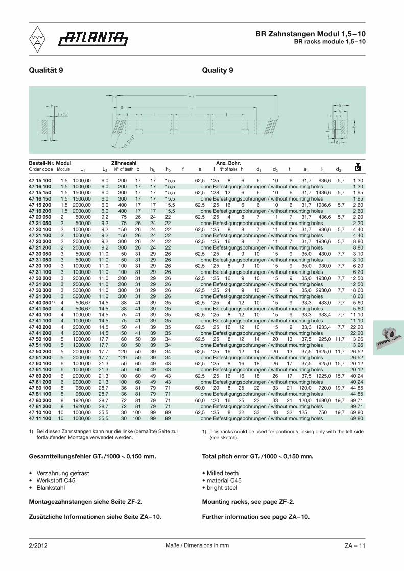
47 15 100 1,5 1000,00 6,0 200 17 17 15,5 62,5 125 8 6 6 10 6 31,7 936,6 5,7 1,3047 16 100 1,5 1000,00 6,0 200 17 17 15,5 ohne Befestigungsbohrungen / without mounting holes 1,3047 15 150 1,5 1500,00 6,0 300 17 17 15,5 62,5 128 12 6 6 10 6 31,7 1436,6 5,7 1,9547 16 150 1,5 1500,00 6,0 300 17 17 15,5 ohne Befestigungsbohrungen / without mounting holes 1,9547 15 200 1,5 2000,00 6,0 400 17 17 15,5 62,5 125 16 6 6 10 6 31,7 1936,6 5,7 2,6047 16 200 1,5 2000,00 6,0 400 17 17 15,5 ohne Befestigungsbohrungen / without mounting holes 2,6047 20 050 2 500,00 9,2 75 26 24 22 62,5 125 4 8 7 11 7 31,7 436,6 5,7 2,2047 21 050 2 500,00 9,2 75 26 24 22 ohne Befestigungsbohrungen / without mounting holes 2,2047 20 100 2 1000,00 9,2 150 26 24 22 62,5 125 8 8 7 11 7 31,7 936,6 5,7 4,4047 21 100 2 1000,00 9,2 150 26 24 22 ohne Befestigungsbohrungen / without mounting holes 4,4047 20 200 2 2000,00 9,2 300 26 24 22 62,5 125 16 8 7 11 7 31,7 1936,6 5,7 8,8047 21 200 2 2000,00 9,2 300 26 24 22 ohne Befestigungsbohrungen / without mounting holes 8,8047 30 050 3 500,00 11,0 50 31 29 26 62,5 125 4 9 10 15 9 35,0 430,0 7,7 3,1047 31 050 3 500,00 11,0 50 31 29 26 ohne Befestigungsbohrungen / without mounting holes 3,1047 30 100 3 1000,00 11,0 100 31 29 26 62,5 125 8 9 10 15 9 35,0 930,0 7,7 6,2047 31 100 3 1000,00 11,0 100 31 29 26 ohne Befestigungsbohrungen / without mounting holes 6,2047 30 200 3 2000,00 11,0 200 31 29 26 62,5 125 16 9 10 15 9 35,0 1930,0 7,7 12,5047 31 200 3 2000,00 11,0 200 31 29 26 ohne Befestigungsbohrungen / without mounting holes 12,5047 30 300 3 3000,00 11,0 300 31 29 26 62,5 125 24 9 10 15 9 35,0 2930,0 7,7 18,6047 31 300 3 3000,00 11,0 300 31 29 26 ohne Befestigungsbohrungen / without mounting holes 18,6047 40 050 1) 4 506,67 14,5 38 41 39 35 62,5 125 4 12 10 15 9 33,3 433,0 7,7 5,6047 41 050 4 506,67 14,5 38 41 39 35 ohne Befestigungsbohrungen / without mounting holes 5,6047 40 100 4 1000,00 14,5 75 41 39 35 62,5 125 8 12 10 15 9 33,3 933,4 7,7 11,1047 41 100 4 1000,00 14,5 75 41 39 35 ohne Befestigungsbohrungen / without mounting holes 11,1047 40 200 4 2000,00 14,5 150 41 39 35 62,5 125 16 12 10 15 9 33,3 1933,4 7,7 22,2047 41 200 4 2000,00 14,5 150 41 39 35 ohne Befestigungsbohrungen / without mounting holes 22,2047 50 100 5 1000,00 17,7 60 50 39 34 62,5 125 8 12 14 20 13 37,5 925,0 11,7 13,2647 51 100 5 1000,00 17,7 60 50 39 34 ohne Befestigungsbohrungen / without mounting holes 13,2647 50 200 5 2000,00 17,7 120 50 39 34 62,5 125 16 12 14 20 13 37,5 1925,0 11,7 26,5247 51 200 5 2000,00 17,7 120 50 39 34 ohne Befestigungsbohrungen / without mounting holes 26,5247 60 100 6 1000,00 21,3 50 60 49 43 62,5 125 8 16 18 26 17 37,5 925,0 15,7 20,1247 61 100 6 1000,00 21,3 50 60 49 43 ohne Befestigungsbohrungen / without mounting holes 20,1247 60 200 6 2000,00 21,3 100 60 49 43 62,5 125 16 16 18 26 17 37,5 1925,0 15,7 40,2447 61 200 6 2000,00 21,3 100 60 49 43 ohne Befestigungsbohrungen / without mounting holes 40,2447 80 100 8 960,00 28,7 36 81 79 71 60,0 120 8 25 22 33 21 120,0 720,0 19,7 44,8547 81 100 8 960,00 28,7 36 81 79 71 ohne Befestigungsbohrungen / without mounting holes 44,8547 80 200 8 1920,00 28,7 72 81 79 71 60,0 120 16 25 22 33 21 120,0 1680,0 19,7 89,7147 81 200 8 1920,00 28,7 72 81 79 71 ohne Befestigungsbohrungen / without mounting holes 89,7147 10 100 10 1000,00 35,5 30 100 99 89 62,5 125 8 32 33 48 32 125 750 19,7 69,8047 11 100 10 1000,00 35,5 30 100 99 89 ohne Befestigungsbohrungen / without mounting holes 69,80
Bestell-Nr. Modul Zähnezahl Anz. Bohr.Order code Module L1 L2 N° of teeth b hk h0 f a I N° of holes h d1 d2 t a1 I1 d3
BR Zahnstangen Modul 1,5 – 10BR racks module 1,5 – 10
Qualität 9 Quality 9
1) Bei diesen Zahnstangen kann nur die linke (bemaßte) Seite zur fortlaufenden Montage verwendet werden.
1) This racks could be used for continous linking only with the left side (see sketch).
Total pitch error GTf /1000 0,150 mm.Gesamtteilungsfehler GTf /1000 0,150 mm.
Montagezahnstangen siehe Seite ZF-2. Mounting racks, see page ZF-2.
Zusätzliche Informationen siehe Seite ZA – 10. Further information see page ZA – 10.
Maße / Dimensions in mmZA – 12 2/2012
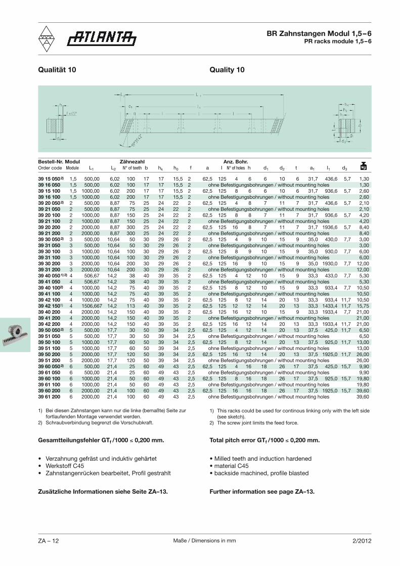
39 15 050 2) 1,5 500,00 6,02 100 17 17 15,5 2 62,5 125 4 6 6 10 6 31,7 436,6 5,7 1,3039 16 050 1,5 500,00 6,02 100 17 17 15,5 2 ohne Befestigungsbohrungen / without mounting holes 1,3039 15 100 1,5 1000,00 6,02 200 17 17 15,5 2 62,5 125 8 6 6 10 6 31,7 936,6 5,7 2,6039 16 100 1,5 1000,00 6,02 200 17 17 15,5 2 ohne Befestigungsbohrungen / without mounting holes 2,6039 20 050 2) 2 500,00 8,87 75 25 24 22 2 62,5 125 4 8 7 11 7 31,7 436,6 5,7 2,1039 21 050 2 500,00 8,87 75 25 24 22 2 ohne Befestigungsbohrungen / without mounting holes 2,1039 20 100 2 1000,00 8,87 150 25 24 22 2 62,5 125 8 8 7 11 7 31,7 936,6 5,7 4,2039 21 100 2 1000,00 8,87 150 25 24 22 2 ohne Befestigungsbohrungen / without mounting holes 4,2039 20 200 2 2000,00 8,87 300 25 24 22 2 62,5 125 16 8 7 11 7 31,7 1936,6 5,7 8,4039 21 200 2 2000,00 8,87 300 25 24 22 2 ohne Befestigungsbohrungen / without mounting holes 8,4039 30 050 2) 3 500,00 10,64 50 30 29 26 2 62,5 125 4 9 10 15 9 35,0 430,0 7,7 3,0039 31 050 3 500,00 10,64 50 30 29 26 2 ohne Befestigungsbohrungen / without mounting holes 3,0039 30 100 3 1000,00 10,64 100 30 29 26 2 62,5 125 8 9 10 15 9 35,0 930,0 7,7 6,0039 31 100 3 1000,00 10,64 100 30 29 26 2 ohne Befestigungsbohrungen / without mounting holes 6,0039 30 200 3 2000,00 10,64 200 30 29 26 2 62,5 125 16 9 10 15 9 35,0 1930,0 7,7 12,0039 31 200 3 2000,00 10,64 200 30 29 26 2 ohne Befestigungsbohrungen / without mounting holes 12,0039 40 050 1) 2) 4 506,67 14,2 38 40 39 35 2 62,5 125 4 12 10 15 9 33,3 433,0 7,7 5,3039 41 050 4 506,67 14,2 38 40 39 35 2 ohne Befestigungsbohrungen / without mounting holes 5,3039 40 1002) 4 1000,00 14,2 75 40 39 35 2 62,5 125 8 12 10 15 9 33,3 933,4 7,7 10,5039 41 100 4 1000,00 14,2 75 40 39 35 2 ohne Befestigungsbohrungen / without mounting holes 10,5039 42 100 4 1000,00 14,2 75 40 39 35 2 62,5 125 8 12 14 20 13 33,3 933,4 11,7 10,5039 42 1501) 4 1506,667 14,2 113 40 39 35 2 62,5 125 12 12 14 20 13 33,3 1433,4 11,7 15,7539 40 200 4 2000,00 14,2 150 40 39 35 2 62,5 125 16 12 10 15 9 33,3 1933,4 7,7 21,0039 41 200 4 2000,00 14,2 150 40 39 35 2 ohne Befestigungsbohrungen / without mounting holes 21,0039 42 200 4 2000,00 14,2 150 40 39 35 2 62,5 125 16 12 14 20 13 33,3 1933,4 11,7 21,0039 50 050 2) 5 500,00 17,7 30 50 39 34 2,5 62,5 125 4 12 14 20 13 37,5 425,0 11,7 6,5039 51 050 5 500,00 17,7 30 50 39 34 2,5 ohne Befestigungsbohrungen / without mounting holes 6,5039 50 100 5 1000,00 17,7 60 50 39 34 2,5 62,5 125 8 12 14 20 13 37,5 925,0 11,7 13,0039 51 100 5 1000,00 17,7 60 50 39 34 2,5 ohne Befestigungsbohrungen / without mounting holes 13,0039 50 200 5 2000,00 17,7 120 50 39 34 2,5 62,5 125 16 12 14 20 13 37,5 1925,0 11,7 26,0039 51 200 5 2000,00 17,7 120 50 39 34 2,5 ohne Befestigungsbohrungen / without mounting holes 26,0039 60 050 2) 6 500,00 21,4 25 60 49 43 2,5 62,5 125 4 16 18 26 17 37,5 425,0 15,7 9,9039 61 050 6 500,00 21,4 25 60 49 43 2,5 ohne Befestigungsbohrungen / without mounting holes 9,9039 60 100 6 1000,00 21,4 50 60 49 43 2,5 62,5 125 8 16 18 26 17 37,5 925,0 15,7 19,8039 61 100 6 1000,00 21,4 50 60 49 43 2,5 ohne Befestigungsbohrungen / without mounting holes 19,8039 60 200 6 2000,00 21,4 100 60 49 43 2,5 62,5 125 16 16 18 26 17 37,5 1925,0 15,7 39,6039 61 200 6 2000,00 21,4 100 60 49 43 2,5 ohne Befestigungsbohrungen / without mounting holes 39,60
Bestell-Nr. Modul Zähnezahl Anz. Bohr.Order code Module L1 L2 N° of teeth b hk h0 f a I N° of holes h d1 d2 t a1 I1 d3
BR Zahnstangen Modul 1,5 – 6PR racks module 1,5 – 6
Qualität 10 Quality 10
1) Bei diesen Zahnstangen kann nur die linke (bemaßte) Seite zur fortlaufenden Montage verwendet werden.
2) Schraubverbindung begrenzt die Vorschubkraft.
1) This racks could be used for continous linking only with the left side (see sketch).
2) The screw joint limits the feed force.
Total pitch error GTf /1000 0,200 mm.Gesamtteilungsfehler GTf /1000 0,200 mm.
Zusätzliche Informationen siehe Seite ZA–13. Further information see page ZA–13.
Maße / Dimensions in mm ZA – 132/2012
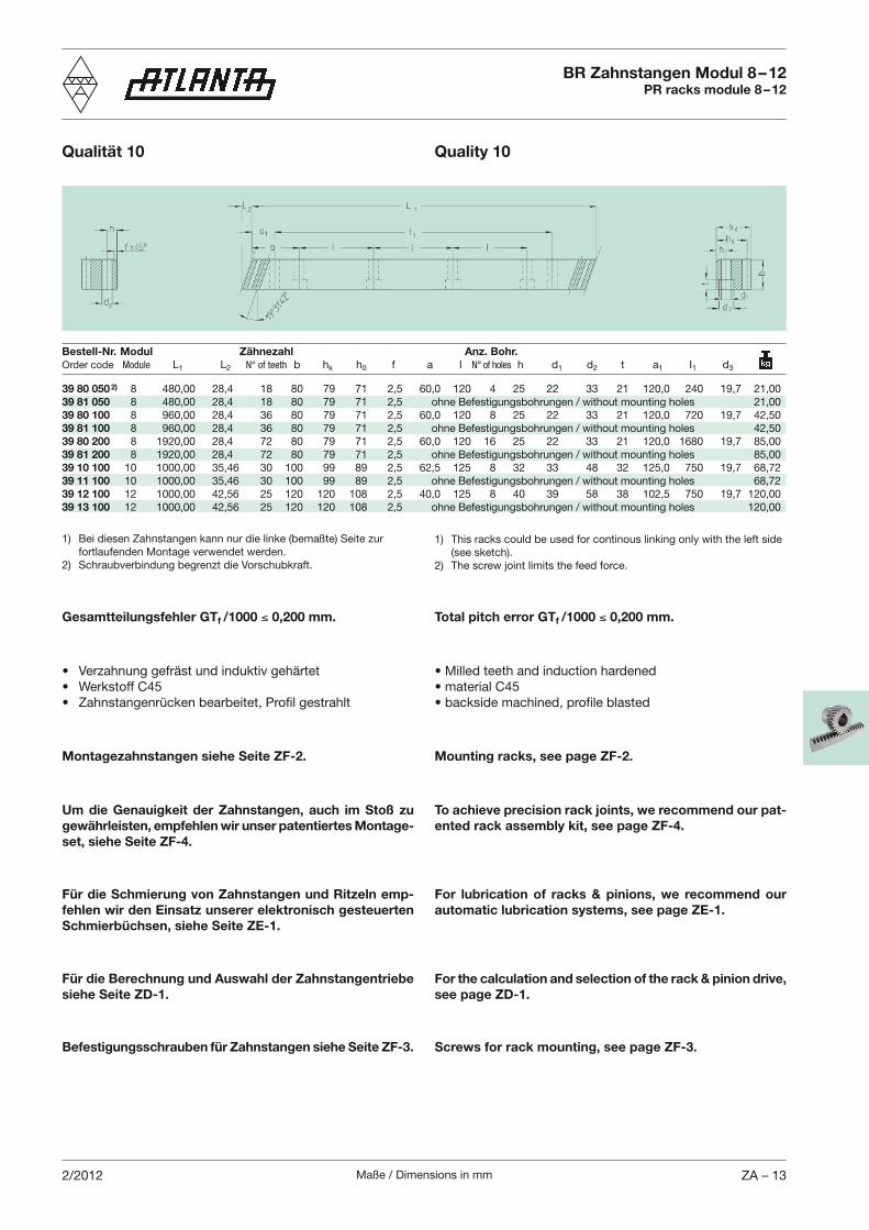
39 80 050 2) 8 480,00 28,4 18 80 79 71 2,5 60,0 120 4 25 22 33 21 120,0 240 19,7 21,0039 81 050 8 480,00 28,4 18 80 79 71 2,5 ohne Befestigungsbohrungen / without mounting holes 21,0039 80 100 8 960,00 28,4 36 80 79 71 2,5 60,0 120 8 25 22 33 21 120,0 720 19,7 42,5039 81 100 8 960,00 28,4 36 80 79 71 2,5 ohne Befestigungsbohrungen / without mounting holes 42,5039 80 200 8 1920,00 28,4 72 80 79 71 2,5 60,0 120 16 25 22 33 21 120,0 1680 19,7 85,0039 81 200 8 1920,00 28,4 72 80 79 71 2,5 ohne Befestigungsbohrungen / without mounting holes 85,0039 10 100 10 1000,00 35,46 30 100 99 89 2,5 62,5 125 8 32 33 48 32 125,0 750 19,7 68,7239 11 100 10 1000,00 35,46 30 100 99 89 2,5 ohne Befestigungsbohrungen / without mounting holes 68,7239 12 100 12 1000,00 42,56 25 120 120 108 2,5 40,0 125 8 40 39 58 38 102,5 750 19,7 120,0039 13 100 12 1000,00 42,56 25 120 120 108 2,5 ohne Befestigungsbohrungen / without mounting holes 120,00
Bestell-Nr. Modul Zähnezahl Anz. Bohr.Order code Module L1 L2 N° of teeth b hk h0 f a I N° of holes h d1 d2 t a1 I1 d3
BR Zahnstangen Modul 8 – 12PR racks module 8 – 12
Qualität 10 Quality 10
1) Bei diesen Zahnstangen kann nur die linke (bemaßte) Seite zur fortlaufenden Montage verwendet werden.
2) Schraubverbindung begrenzt die Vorschubkraft.
1) This racks could be used for continous linking only with the left side (see sketch).
2) The screw joint limits the feed force.
Total pitch error GTf /1000 0,200 mm.Gesamtteilungsfehler GTf /1000 0,200 mm.
Um die Genauigkeit der Zahnstangen, auch im Stoß zu gewährleisten, empfehlen wir unser patentiertes Montage-set, siehe Seite ZF-4.
To achieve precision rack joints, we recommend our pat-ented rack assembly kit, see page ZF-4.
Montagezahnstangen siehe Seite ZF-2. Mounting racks, see page ZF-2.
Für die Schmierung von Zahnstangen und Ritzeln emp-fehlen wir den Einsatz unserer elektronisch gesteuerten Schmierbüchsen, siehe Seite ZE-1.
For lubrication of racks & pinions, we recommend our automatic lubrication systems, see page ZE-1.
Für die Berechnung und Auswahl der Zahnstangentriebe siehe Seite ZD-1.
For the calculation and selection of the rack & pinion drive, see page ZD-1.
Befestigungsschrauben für Zahnstangen siehe Seite ZF-3. Screws for rack mounting, see page ZF-3.
Maße / Dimensions in mmZA – 14 1/2012
Weitere Zähnezahl auf Anfrage, min. Zähnezahl 12, max. Zähnezahl 16 / Further number of teeth on request, min. number of teeth 12, max. number of teeth 16
Weitere Zähnezahl auf Anfrage, min. Zähnezahl 12, max. Zähnezahl 23 / Further number of teeth on request, min. number of teeth 12, max. number of teeth 23
Weitere Zähnezahl auf Anfrage, min. Zähnezahl 12, max. Zähnezahl 14 / Further number of teeth on request, min. number of teeth 12, max. number of teeth 14
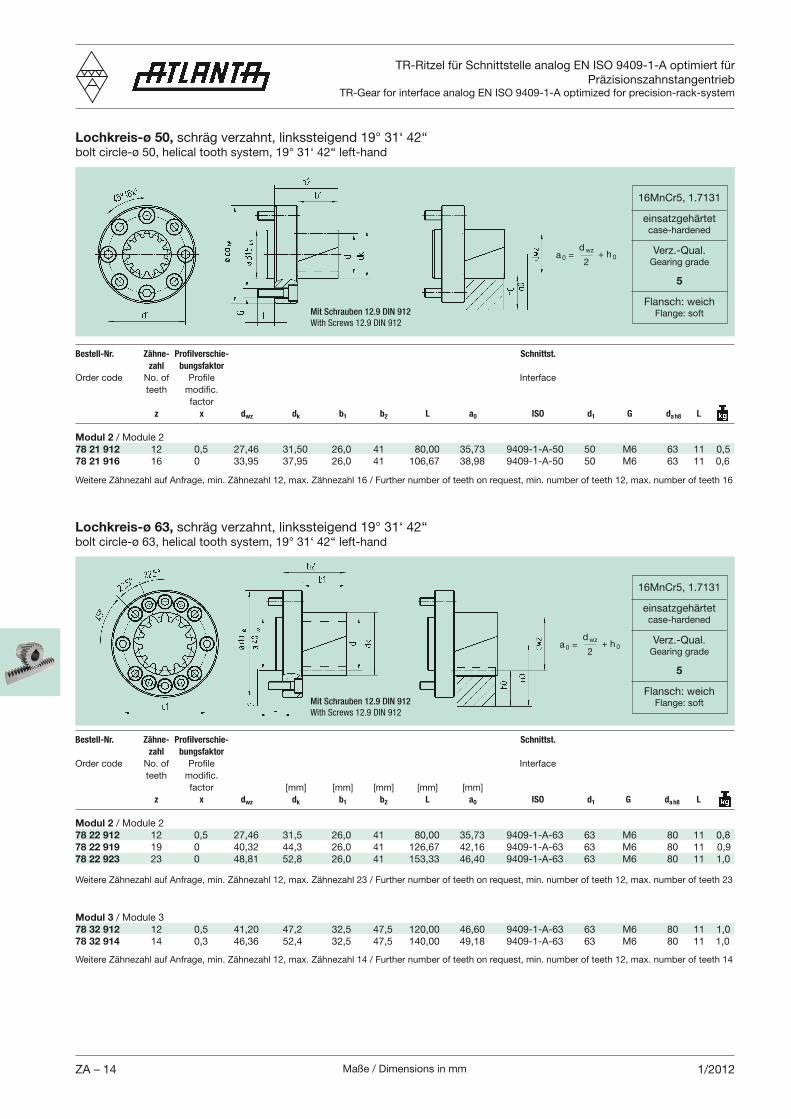
TR-Ritzel für Schnittstelle analog EN ISO 9409-1-A optimiert für Präzisionszahnstangentrieb
TR-Gear for interface analog EN ISO 9409-1-A optimized for precision-rack-system
Lochkreis-ø 50,
Bestell-Nr. Zähne- Profilverschie- Schnittst.
zahl bungsfaktor
factor z x dwz dk b1 b2 L a0 ISO d1 G da h8 L
Modul 2 / Module 278 21 912 12 0,5 27,46 31,50 26,0 41 80,00 35,73 9409-1-A-50 50 M6 63 11 0,578 21 916 16 0 33,95 37,95 26,0 41 106,67 38,98 9409-1-A-50 50 M6 63 11 0,6
16MnCr5, 1.7131
einsatzgehärtetcase-hardened
Verz.-Qual.Gearing grade
5
Flansch: weichFlange: softMit Schrauben 12.9 DIN 912
With Screws 12.9 DIN 912
a 0 =d wz
2+ h 0
Lochkreis-ø 63,
Bestell-Nr. Zähne- Profilverschie- Schnittst.
zahl bungsfaktor
factor [mm] [mm] [mm] [mm] [mm] z x dwz dk b1 b2 L a0 ISO d1 G da h8 L
Modul 2 / Module 278 22 912 12 0,5 27,46 31,5 26,0 41 80,00 35,73 9409-1-A-63 63 M6 80 11 0,878 22 919 19 0 40,32 44,3 26,0 41 126,67 42,16 9409-1-A-63 63 M6 80 11 0,978 22 923 23 0 48,81 52,8 26,0 41 153,33 46,40 9409-1-A-63 63 M6 80 11 1,0
16MnCr5, 1.7131
einsatzgehärtetcase-hardened
Verz.-Qual.Gearing grade
5
Flansch: weichFlange: softMit Schrauben 12.9 DIN 912
With Screws 12.9 DIN 912
a 0 =d wz
2+ h 0
Modul 3 / Module 378 32 912 12 0,5 41,20 47,2 32,5 47,5 120,00 46,60 9409-1-A-63 63 M6 80 11 1,078 32 914 14 0,3 46,36 52,4 32,5 47,5 140,00 49,18 9409-1-A-63 63 M6 80 11 1,0
Maße / Dimensions in mm ZA – 151/2012
Weitere Zähnezahl auf Anfrage, min. Zähnezahl 12, max. Zähnezahl 29 / Further number of teeth on request, min. number of teeth 12, max. number of teeth 29
Weitere Zähnezahl auf Anfrage, min. Zähnezahl 12, max. Zähnezahl 19 / Further number of teeth on request, min. number of teeth 12, max. number of teeth 19
Weitere Zähnezahl auf Anfrage, min. Zähnezahl 12, max. Zähnezahl 13 / Further number of teeth on request, min. number of teeth 12, max. number of teeth 13
TR-Ritzel für Schnittstelle analog EN ISO 9409-1-A optimiert für Präzisionszahnstangentrieb
TR-Gear for interface analog EN ISO 9409-1-A optimized for precision-rack-system
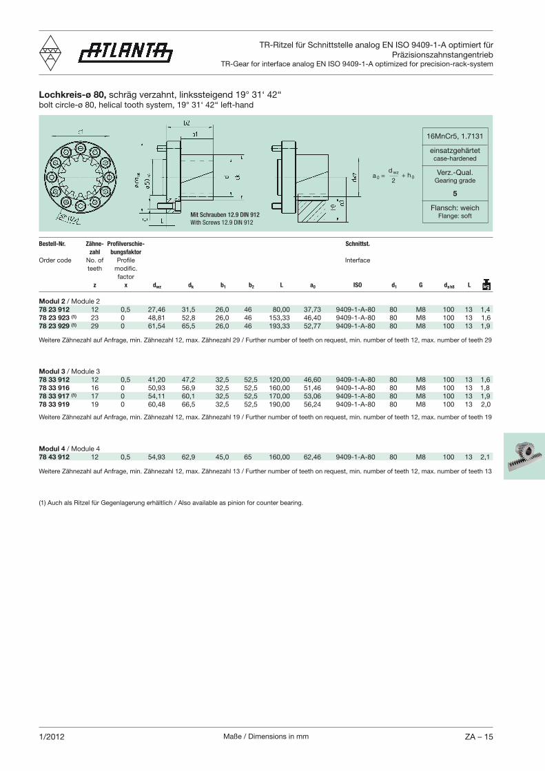
Lochkreis-ø 80,
Bestell-Nr. Zähne- Profilverschie- Schnittst.
zahl bungsfaktor
factor z x dwz dk b1 b2 L a0 ISO d1 G da h8 L
Modul 2 / Module 278 23 912 12 0,5 27,46 31,5 26,0 46 80,00 37,73 9409-1-A-80 80 M8 100 13 1,478 23 923 (1) 23 0 48,81 52,8 26,0 46 153,33 46,40 9409-1-A-80 80 M8 100 13 1,678 23 929 (1) 29 0 61,54 65,5 26,0 46 193,33 52,77 9409-1-A-80 80 M8 100 13 1,9
16MnCr5, 1.7131
einsatzgehärtetcase-hardened
Verz.-Qual.Gearing grade
5
Flansch: weichFlange: softMit Schrauben 12.9 DIN 912
With Screws 12.9 DIN 912
a 0 =d wz
2+ h 0
(1) Auch als Ritzel für Gegenlagerung erhältlich / Also available as pinion for counter bearing.
Modul 4 / Module 478 43 912 12 0,5 54,93 62,9 45,0 65 160,00 62,46 9409-1-A-80 80 M8 100 13 2,1
Modul 3 / Module 378 33 912 12 0,5 41,20 47,2 32,5 52,5 120,00 46,60 9409-1-A-80 80 M8 100 13 1,678 33 916 16 0 50,93 56,9 32,5 52,5 160,00 51,46 9409-1-A-80 80 M8 100 13 1,878 33 917 (1) 17 0 54,11 60,1 32,5 52,5 170,00 53,06 9409-1-A-80 80 M8 100 13 1,978 33 919 19 0 60,48 66,5 32,5 52,5 190,00 56,24 9409-1-A-80 80 M8 100 13 2,0
Maße / Dimensions in mmZA – 16 2/2012
Weitere Zähnezahl auf Anfrage, min. Zähnezahl 12, max. Zähnezahl 32 / Further number of teeth on request, min. number of teeth 12, max. number of teeth 32
Weitere Zähnezahl auf Anfrage, min. Zähnezahl 12, max. Zähnezahl 23 / Further number of teeth on request, min. number of teeth 12, max. number of teeth 23
Weitere Zähnezahl auf Anfrage, min. Zähnezahl 12, max. Zähnezahl 18 / Further number of teeth on request, min. number of teeth 12, max. number of teeth 18
Weitere Zähnezahl auf Anfrage, min. Zähnezahl 12, max. Zähnezahl 15 / Further number of teeth on request, min. number of teeth 12, max. number of teeth 15
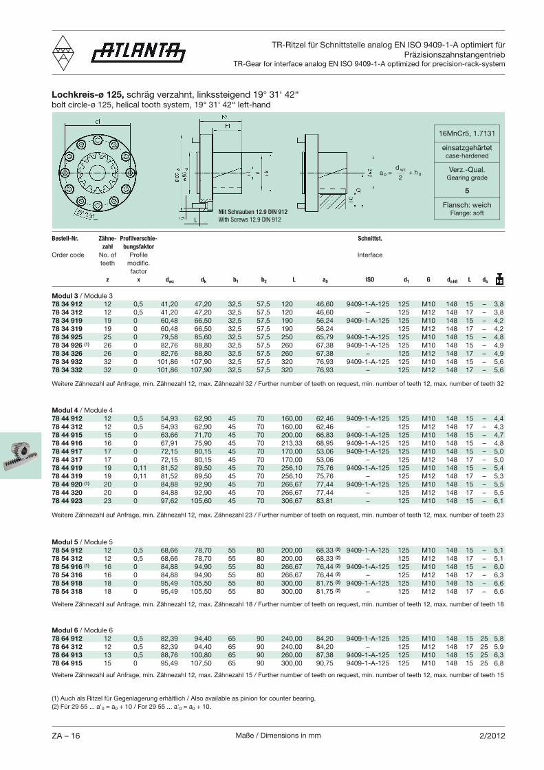
TR-Ritzel für Schnittstelle analog EN ISO 9409-1-A optimiert für
PräzisionszahnstangentriebTR-Gear for interface analog EN ISO 9409-1-A optimized for precision-rack-system
Lochkreis-ø 125, schräg verzahnt, linkssteigend 19° 31‘ 42‘‘bolt circle-ø 125, helical tooth system, 19° 31‘ 42‘‘ left-hand
Bestell-Nr. Zähne- Profilverschie- Schnittst.
zahl bungsfaktor
Order code No. of Profile Interface
teeth modific.
factor
z x dwz dk b1 b2 L a0 ISO d1 G da h8 L db
Modul 3 / Module 3
78 34 912 12 0,5 41,20 47,20 32,5 57,5 120 46,60 9409-1-A-125 125 M10 148 15 – 3,8
78 34 312 12 0,5 41,20 47,20 32,5 57,5 120 46,60 – 125 M12 148 17 – 3,8
78 34 919 19 0 60,48 66,50 32,5 57,5 190 56,24 9409-1-A-125 125 M10 148 15 – 4,2
78 34 319 19 0 60,48 66,50 32,5 57,5 190 56,24 – 125 M12 148 17 – 4,2
78 34 925 25 0 79,58 85,60 32,5 57,5 250 65,79 9409-1-A-125 125 M10 148 15 – 4,8
78 34 926 (1) 26 0 82,76 88,80 32,5 57,5 260 67,38 9409-1-A-125 125 M10 148 15 – 4,9
78 34 326 26 0 82,76 88,80 32,5 57,5 260 67,38 – 125 M12 148 17 – 4,9
78 34 932 32 0 101,86 107,90 32,5 57,5 320 76,93 9409-1-A-125 125 M10 148 15 – 5,6
78 34 332 32 0 101,86 107,90 32,5 57,5 320 76,93 – 125 M12 148 17 – 5,6
16MnCr5, 1.7131
einsatzgehärtetcase-hardened
Verz.-Qual.Gearing grade
5
Flansch: weichFlange: softMit Schrauben 12.9 DIN 912
With Screws 12.9 DIN 912
a 0 =d wz
2+ h 0
Modul 6 / Module 6
78 64 912 12 0,5 82,39 94,40 65 90 240,00 84,20 9409-1-A-125 125 M10 148 15 25 5,8
78 64 312 12 0,5 82,39 94,40 65 90 240,00 84,20 – 125 M12 148 17 25 5,9
78 64 913 13 0,5 88,76 100,80 65 90 260,00 87,38 9409-1-A-125 125 M10 148 15 25 6,3
78 64 915 15 0 95,49 107,50 65 90 300,00 90,75 9409-1-A-125 125 M10 148 15 25 6,8
Modul 5 / Module 5
78 54 912 12 0,5 68,66 78,70 55 80 200,00 68,33 (2) 9409-1-A-125 125 M10 148 15 – 5,1
78 54 312 12 0,5 68,66 78,70 55 80 200,00 68,33 (2) – 125 M12 148 17 – 5,1
78 54 916 (1) 16 0 84,88 94,90 55 80 266,67 76,44 (2) 9409-1-A-125 125 M10 148 15 – 6,0
78 54 316 16 0 84,88 94,90 55 80 266,67 76,44 (2) – 125 M12 148 17 – 6,3
78 54 918 18 0 95,49 105,50 55 80 300,00 81,75 (2) 9409-1-A-125 125 M10 148 15 – 6,6
78 54 318 18 0 95,49 105,50 55 80 300,00 81,75 (2) – 125 M12 148 17 – 6,6
Modul 4 / Module 4
78 44 912 12 0,5 54,93 62,90 45 70 160,00 62,46 9409-1-A-125 125 M10 148 15 – 4,4
78 44 312 12 0,5 54,93 62,90 45 70 160,00 62,46 – 125 M12 148 17 – 4,3
78 44 915 15 0 63,66 71,70 45 70 200,00 66,83 9409-1-A-125 125 M10 148 15 – 4,7
78 44 916 16 0 67,91 75,90 45 70 213,33 68,95 9409-1-A-125 125 M10 148 15 – 4,8
78 44 917 17 0 72,15 80,15 45 70 170,00 53,06 9409-1-A-125 125 M10 148 15 – 5,0
78 44 317 17 0 72,15 80,15 45 70 170,00 53,06 – 125 M12 148 17 – 5,0
78 44 919 19 0,11 81,52 89,50 45 70 256,10 75,76 9409-1-A-125 125 M10 148 15 – 5,4
78 44 319 19 0,11 81,52 89,50 45 70 256,10 75,76 – 125 M12 148 17 – 5,3
78 44 920 (1) 20 0 84,88 92,90 45 70 266,67 77,44 9409-1-A-125 125 M10 148 15 – 5,5
78 44 320 20 0 84,88 92,90 45 70 266,67 77,44 – 125 M12 148 17 – 5,5
78 44 923 23 0 97,62 105,60 45 70 306,67 83,81 – 125 M10 148 15 – 6,1
(1) Auch als Ritzel für Gegenlagerung erhältlich / Also available as pinion for counter bearing.
(2) Für 29 55 ... a'0 = a0 + 10 / For 29 55 ... a'0 = a0 + 10.
Maße / Dimensions in mm ZA – 171/2012
Weitere Zähnezahl auf Anfrage, min. Zähnezahl 12, max. Zähnezahl 25 / Further number of teeth on request, min. number of teeth 12, max. number of teeth 25
Weitere Zähnezahl auf Anfrage, min. Zähnezahl 12, max. Zähnezahl 20 / Further number of teeth on request, min. number of teeth 12, max. number of teeth 20
Weitere Zähnezahl auf Anfrage, min. Zähnezahl 12, max. Zähnezahl 16 / Further number of teeth on request, min. number of teeth 12, max. number of teeth 16
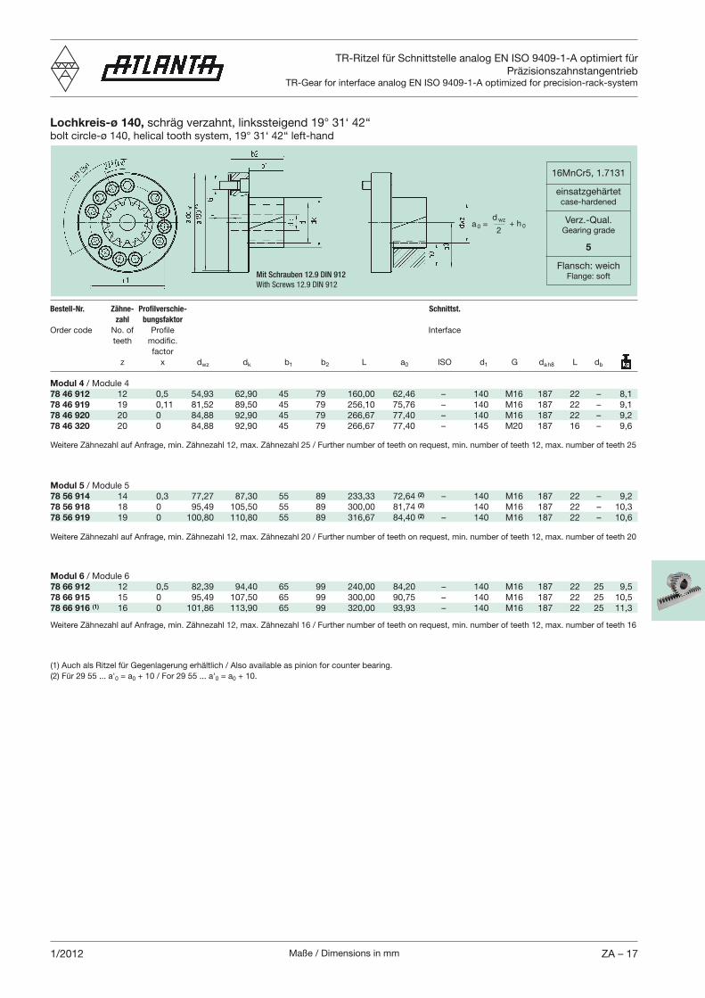
TR-Ritzel für Schnittstelle analog EN ISO 9409-1-A optimiert für Präzisionszahnstangentrieb
TR-Gear for interface analog EN ISO 9409-1-A optimized for precision-rack-system
Lochkreis-ø 140,
Bestell-Nr. Zähne- Profilverschie- Schnittst.
zahl bungsfaktor
factor z x dwz dk b1 b2 L a0 ISO d1 G da h8 L db
Modul 4 / Module 478 46 912 12 0,5 54,93 62,90 45 79 160,00 62,46 – 140 M16 187 22 – 8,178 46 919 19 0,11 81,52 89,50 45 79 256,10 75,76 – 140 M16 187 22 – 9,178 46 920 20 0 84,88 92,90 45 79 266,67 77,40 – 140 M16 187 22 – 9,278 46 320 20 0 84,88 92,90 45 79 266,67 77,40 – 145 M20 187 16 – 9,6
16MnCr5, 1.7131
einsatzgehärtetcase-hardened
Verz.-Qual.Gearing grade
5
Flansch: weichFlange: softMit Schrauben 12.9 DIN 912
With Screws 12.9 DIN 912
a 0 =d wz
2+ h 0
Modul 6 / Module 678 66 912 12 0,5 82,39 94,40 65 99 240,00 84,20 – 140 M16 187 22 25 9,578 66 915 15 0 95,49 107,50 65 99 300,00 90,75 – 140 M16 187 22 25 10,578 66 916 (1) 16 0 101,86 113,90 65 99 320,00 93,93 – 140 M16 187 22 25 11,3
Modul 5 / Module 5 78 56 914 14 0,3 77,27 87,30 55 89 233,33 72,64 (2) – 140 M16 187 22 – 9,278 56 918 18 0 95,49 105,50 55 89 300,00 81,74 (2) 140 M16 187 22 – 10,378 56 919 19 0 100,80 110,80 55 89 316,67 84,40 (2) – 140 M16 187 22 – 10,6
(1) Auch als Ritzel für Gegenlagerung erhältlich / Also available as pinion for counter bearing.(2) Für 29 55 ... a'0 = a0 + 10 / For 29 55 ... a'0 = a0 + 10.
Maße / Dimensions in mmZA – 18 1/2012
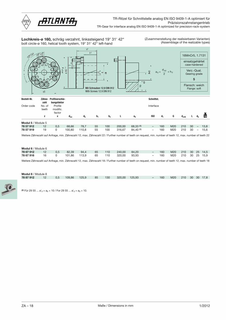
TR-Ritzel für Schnittstelle analog EN ISO 9409-1-A optimiert für Präzisionszahnstangentrieb
TR-Gear for interface analog EN ISO 9409-1-A optimized for precision-rack-system
(Zusammenstellung der realisierbaren Varianten)(Assemblage of the realizable types)
Lochkreis-ø 160,
16MnCr5, 1.7131
einsatzgehärtetcase-hardened
Verz.-Qual.Gearing grade
5
Flansch: weichFlange: softMit Schrauben 12.9 DIN 912
With Screws 12.9 DIN 912
a 0 =d wz
2+ h 0
Weitere Zähnezahl auf Anfrage, min. Zähnezahl 12, max. Zähnezahl 22 / Further number of teeth on request, min. number of teeth 12, max. number of teeth 22
Weitere Zähnezahl auf Anfrage, min. Zähnezahl 12, max. Zähnezahl 18 / Further number of teeth on request, min. number of teeth 12, max. number of teeth 18
Bestell-Nr. Zähne- Profilverschie- Schnittst.
zahl bungsfaktor
factor z x dwz dk b1 b2 L a0 ISO d1 G da h8 L db
Modul 5 / Module 5 78 57 912 12 0,5 68,66 78,7 55 100 200,00 68,33 (1) – 160 M20 210 30 – 13,878 57 919 19 0 100,80 110,8 55 100 316,67 84,40 (1) – 160 M20 210 30 – 15,6
(2) Für 29 55 ... a'0 = a0 + 10 / For 29 55 ... a'0 = a0 + 10.
Modul 8 / Module 878 87 912 12 0,5 109,86 125,9 85 130 320,00 125,93 – 160 M20 210 30 30 17,8
Modul 6 / Module 678 67 912 12 0,5 82,39 94,4 65 110 240,00 84,20 – 160 M20 210 30 25 14,578 67 916 16 0 101,86 113,9 65 110 320,00 93,93 – 160 M20 210 30 25 15,9
Maße / Dimensions in mm ZA – 191/2012
schräg verzahnt, helical tooth system,
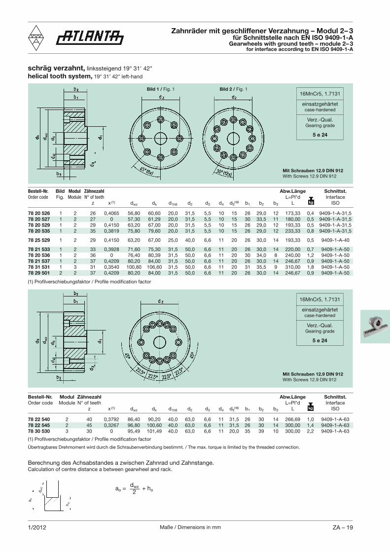
78 20 526 1 2 26 0,4065 56,80 60,60 20,0 31,5 5,5 10 15 26 29,0 12 173,33 0,4 9409-1-A-31,578 20 527 1 2 27 0 57,30 61,29 20,0 31,5 5,5 10 15 30 33,5 11 180,00 0,5 9409-1-A-31,578 20 529 1 2 29 0,4150 63,20 67,00 20,0 31,5 5,5 10 15 26 29,0 12 193,33 0,5 9409-1-A-31,578 20 535 1 2 35 0,3819 75,80 79,60 20,0 31,5 5,5 10 15 26 29,0 12 233,33 0,8 9409-1-A-31,5
78 25 529 1 2 29 0,4150 63,20 67,00 25,0 40,0 6,6 11 20 26 30,0 14 193,33 0,5 9409-1-A-40
78 21 533 1 2 33 0,3928 71,60 75,30 31,5 50,0 6,6 11 20 26 30,0 14 220,00 0,7 9409-1-A-5078 20 536 1 2 36 0 76,40 80,39 31,5 50,0 6,6 11 20 30 34,0 8 240,00 1,2 9409-1-A-5078 21 537 1 2 37 0,4209 80,20 84,00 31,5 50,0 6,6 11 20 26 30,0 14 246,67 0,9 9409-1-A-5078 31 531 1 3 31 0,3540 100,80 106,60 31,5 50,0 6,6 11 20 31 35,5 9 310,00 1,8 9409-1-A-5078 29 501 2 2 37 0,4209 80,20 84,00 31,5 50,0 6,6 11 20 26 30,0 14 246,67 0,9 9409-1-A-50
78 22 540 2 40 0,3792 86,40 90,20 40,0 63,0 6,6 11 31,5 26 30 14 266,69 1,0 9409-1-A-6378 22 545 2 45 0,3267 96,80 100,60 40,0 63,0 6,6 11 31,5 26 30 14 300,00 1,4 9409-1-A-6378 30 530 3 30 0 95,49 101,49 40,0 63,0 6,6 11 20,0 35 39 10 300,00 2,2 9409-1-A-63
Bestell-Nr. Bild Modul Zähnezahl Abw.Länge Schnittst.Order code Fig. Module N° of teeth L=PI*d Interface z x (1) dwz dk d1h6 d2 d3 d4 d5
H6 b1 b2 b3 L ISO
Zahnräder mit geschliffener Verzahnung – Modul 2– 3für Schnittstelle nach EN ISO 9409-1-A
Gearwheels with ground teeth – module 2– 3for interface according to EN ISO 9409-1-A
Übertragbares Drehmoment wird durch die Schraubenverbindung bestimmt. / The max. torque is limited by the threaded connection.
Berechnung des Achsabstandes a zwischen Zahnrad und Zahnstange.Calculation of centre distance a between gearwheel and rack.
16MnCr5, 1.7131
einsatzgehärtetcase-hardened
Verz.-Qual.Gearing grade
5 e 24
Mit Schrauben 12.9 DIN 912With Screws 12.9 DIN 912
16MnCr5, 1.7131
einsatzgehärtetcase-hardened
Verz.-Qual.Gearing grade
5 e 24
Mit Schrauben 12.9 DIN 912With Screws 12.9 DIN 912
d5
d5
Bestell-Nr. Modul Zähnezahl Abw.Länge Schnittst.
z x (1) dwz dk d1h6 d2 d3 d4 d5H6 b1 b2 b3 L ISO
Bild 1 / Fig. 1 Bild 2 / Fig. 1
a o
ao =dwz
2+ ho
ho
dw
z
dw
zd
wz
Maße / Dimensions in mmZA – 20 1/2012
schräg verzahnt, helical tooth system,
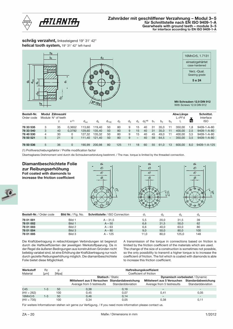
Zahnräder mit geschliffener Verzahnung – Modul 3– 5für Schnittstelle nach EN ISO 9409-1-A
Gearwheels with ground teeth – module 3– 5for interface according to EN ISO 9409-1-A
Übertragbares Drehmoment wird durch die Schraubenverbindung bestimmt. / The max. torque is limited by the threaded connection.
78 33 535 3 35 0,3652 113,60 119,40 50 80 9 15 40 31 35,0 11 350,00 1,8 9409-1-A-8078 33 540 3 40 0,3792 129,60 135,40 50 80 9 15 40 31 35,0 11 400,00 2,5 9409-1-A-8078 40 530 4 30 0 127,32 135,32 50 80 9 15 40 45 49,0 11 400,00 3,5 9409-1-A-8078 50 521 5 21 0 111,40 121,40 50 80 9 – 40 59 64,5 – 350,00 3,5 9409-1-A-80
78 50 536 5 36 0 190,99 200,98 80 125 11 18 60 55 61,0 13 600,00 8,0 9409-1-A-125
16MnCr5, 1.7131
einsatzgehärtetcase-hardened
Verz.-Qual.Gearing grade
5 e 24
d5
Bestell-Nr. Modul Zähnezahl Abw.Länge Schnittst.
z x (1) dwz dk d1h6 d2 d3 d4 d5H6 b1 b2 b3 L ISO
Mit Schrauben 12.9 DIN 912With Screws 12.9 DIN 912
Werkstoff Rz p Haftreibungskoeffizient
Statisch / Static Dynamisch vorbelastet / Dynamic Mittelwert aus 5 Versuchen Standardabweichung Mittelwert aus 5 Versuchen Standardabweichung Average from 5 testresults Standarddeviation Average from 5 testresults Standarddeviation
C45 1-3 50 0,38 0,16 – - (HV = 262) 100 0,45 0,07 0,41 0,0516MnCr5 1-3 50 0,46 0,14 – - (HV = 735) 100 0,34 0,05 0,38 0,11
Diamantbeschichtete Folie zur Reibungs erhöhungFoil coated with diamonds to increase the friction coefficient
Bestell-Nr. / Order code Bild Nr. / Fig. No. Schnittstelle / ISO Connection d1 d2 d3 d4
78 01 001 Bild 1 A – 31,5 5,5 20,0 31,5 3978 01 002 Bild 1 A – 50 6,6 31,5 50,0 6278 01 003 Bild 2 A – 63 6,6 40,0 63,0 8078 01 004 Bild 3 A – 80 9,0 50,0 80,0 10078 01 005 Bild 3 A – 125 11,0 80,0 125,0 148
Die Kraftübertragung in reibschlüssigen Verbindungen ist begrenzt
der Regel die äußeren Bedingungen aus konstruktiven Gründen nicht beliebig variabel sind, ist eine Erhöhung der Kraftübertragung nur noch durch gezielte Reibungserhöhung möglich. Die diamantbeschichtete Folie bietet diese Möglichkeit.
A transmission of the torque in connections based on friction is
The change of the size of a construction is sometimes not possible, so the only possibility to transmit a higher torque is to increase the
Für weitere Informationen stehen wir gerne zur Verfügung. / If you need more information please contact us.
dw
z
Maße / Dimensions in mm ZA – 211/2012
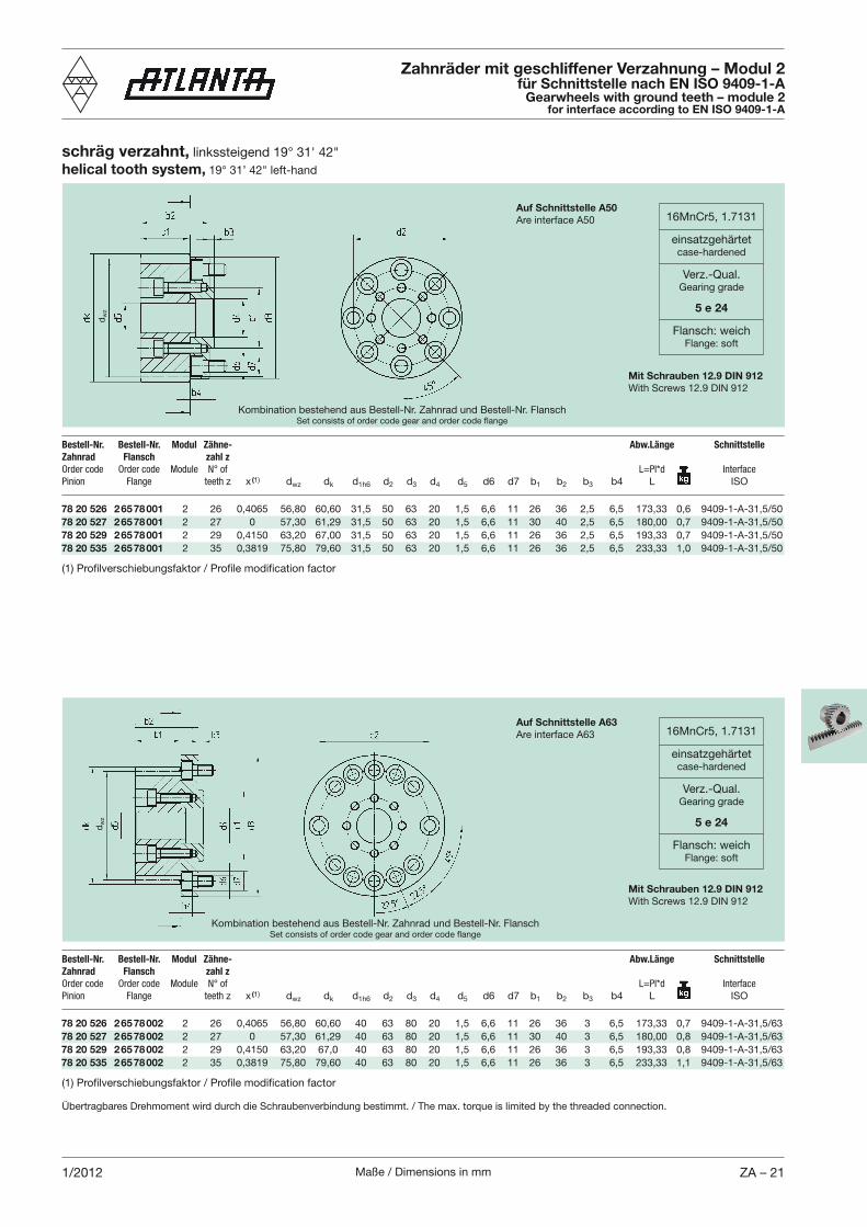
schräg verzahnt, helical tooth system,
78 20 526 2 65 78 001 2 26 0,4065 56,80 60,60 31,5 50 63 20 1,5 6,6 11 26 36 2,5 6,5 173,33 0,6 9409-1-A-31,5/5078 20 527 2 65 78 001 2 27 0 57,30 61,29 31,5 50 63 20 1,5 6,6 11 30 40 2,5 6,5 180,00 0,7 9409-1-A-31,5/5078 20 529 2 65 78 001 2 29 0,4150 63,20 67,00 31,5 50 63 20 1,5 6,6 11 26 36 2,5 6,5 193,33 0,7 9409-1-A-31,5/5078 20 535 2 65 78 001 2 35 0,3819 75,80 79,60 31,5 50 63 20 1,5 6,6 11 26 36 2,5 6,5 233,33 1,0 9409-1-A-31,5/50
Bestell-Nr. Bestell-Nr. Modul Zähne- Abw.Länge Schnittstelle
Zahnrad Flansch zahl z
Order code Order code Module N° of L=PI*d Interface
Pinion Flange teeth z x (1) dwz dk d1h6 d2 d3 d4 d5 d6 d7 b1 b2 b3 b4 L ISO
Zahnräder mit geschliffener Verzahnung – Modul 2für Schnittstelle nach EN ISO 9409-1-A
Gearwheels with ground teeth – module 2for interface according to EN ISO 9409-1-A
16MnCr5, 1.7131
einsatzgehärtetcase-hardened
Verz.-Qual.Gearing grade
5 e 24
Flansch: weichFlange: soft
Mit Schrauben 12.9 DIN 912With Screws 12.9 DIN 912
78 20 526 2 65 78 002 2 26 0,4065 56,80 60,60 40 63 80 20 1,5 6,6 11 26 36 3 6,5 173,33 0,7 9409-1-A-31,5/6378 20 527 2 65 78 002 2 27 0 57,30 61,29 40 63 80 20 1,5 6,6 11 30 40 3 6,5 180,00 0,8 9409-1-A-31,5/6378 20 529 2 65 78 002 2 29 0,4150 63,20 67,0 40 63 80 20 1,5 6,6 11 26 36 3 6,5 193,33 0,8 9409-1-A-31,5/6378 20 535 2 65 78 002 2 35 0,3819 75,80 79,60 40 63 80 20 1,5 6,6 11 26 36 3 6,5 233,33 1,1 9409-1-A-31,5/63
Bestell-Nr. Bestell-Nr. Modul Zähne- Abw.Länge Schnittstelle
Zahnrad Flansch zahl z
Order code Order code Module N° of L=PI*d Interface
Pinion Flange teeth z x (1) dwz dk d1h6 d2 d3 d4 d5 d6 d7 b1 b2 b3 b4 L ISO
16MnCr5, 1.7131
einsatzgehärtetcase-hardened
Verz.-Qual.Gearing grade
5 e 24
Flansch: weichFlange: soft
Mit Schrauben 12.9 DIN 912With Screws 12.9 DIN 912
Übertragbares Drehmoment wird durch die Schraubenverbindung bestimmt. / The max. torque is limited by the threaded connection.
Kombination bestehend aus Bestell-Nr. Zahnrad und Bestell-Nr. FlanschSet consists of order code gear and order code flange
Auf Schnittstelle A50Are interface A50
Auf Schnittstelle A63Are interface A63
Kombination bestehend aus Bestell-Nr. Zahnrad und Bestell-Nr. FlanschSet consists of order code gear and order code flange
dw
zd
wz
Maße / Dimensions in mmZA – 22 1/2012
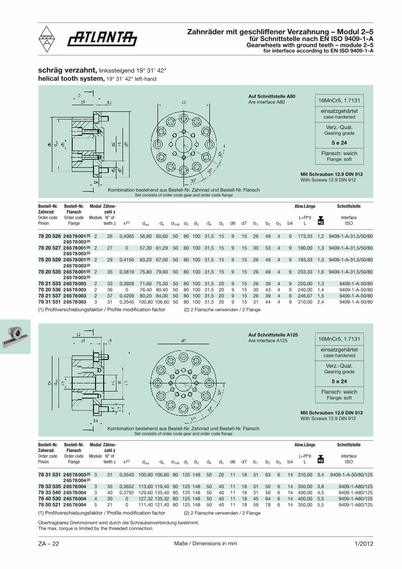
schräg verzahnt, helical tooth system,
78 20 526 2 65 78 001 (2) 2 26 0,4065 56,80 60,60 50 80 100 31,5 15 9 15 26 49 4 9 173,33 1,2 9409-1-A-31,5/50/80 2 65 78 003 (2)
78 20 527 2 65 78 001 (2) 2 27 0 57,30 61,29 50 80 100 31,5 15 9 15 30 53 4 9 180,00 1,3 9409-1-A-31,5/50/80 2 65 78 003 (2)
78 20 529 2 65 78 001 (2) 2 29 0,4150 63,20 67,00 50 80 100 31,5 15 9 15 26 49 4 9 193,33 1,3 9409-1-A-31,5/50/80 2 65 78 003 (2)
78 20 535 2 65 78 001 (2) 2 35 0,3819 75,80 79,60 50 80 100 31,5 15 9 15 26 49 4 9 233,33 1,6 9409-1-A-31,5/50/80 2 65 78 003 (2)
78 21 533 2 65 78 003 2 33 0,3928 71,60 75,30 50 80 100 31,5 20 9 15 26 39 4 9 220,00 1,3 9409-1-A-50/8078 20 536 2 65 78 003 2 36 0 76,40 80,40 50 80 100 31,5 20 9 15 30 43 4 9 240,00 1,4 9409-1-A-50/8078 21 537 2 65 78 003 2 37 0,4209 80,20 84,00 50 80 100 31,5 20 9 15 26 39 4 9 246,67 1,5 9409-1-A-50/8078 31 531 2 65 78 003 3 31 0,3540 100,80 106,60 50 80 100 31,5 20 9 15 31 44 4 9 310,00 2,4 9409-1-A-50/80
Bestell-Nr. Bestell-Nr. Modul Zähne- Abw.Länge Schnittstelle
Zahnrad Flansch zahl z
Order code Order code Module N° of L=PI*d Interface
Pinion Flange teeth z x (1) dwz dk d1h6 d2 d3 d4 d5 d6 d7 b1 b2 b3 b4 L ISO
Zahnräder mit geschliffener Verzahnung – Modul 2–5für Schnittstelle nach EN ISO 9409-1-A
Gearwheels with ground teeth – module 2–5for interface according to EN ISO 9409-1-A
16MnCr5, 1.7131
einsatzgehärtetcase-hardened
Verz.-Qual.Gearing grade
5 e 24
Flansch: weichFlange: soft
Mit Schrauben 12.9 DIN 912With Screws 12.9 DIN 912
Auf Schnittstelle A80Are interface A80
78 31 531 2 65 78 003 (2) 3 31 0,3540 100,80 106,60 80 125 148 50 20 11 18 31 63 6 14 310,00 3,4 9409-1-A-50/80/125 2 65 78 004 (2)
78 33 535 2 65 78 004 3 35 0,3652 113,60 119,40 80 125 148 50 40 11 18 31 50 6 14 350,00 3,8 9409-1-A80/12578 33 540 2 65 78 004 3 40 0,3792 129,60 135,40 80 125 148 50 40 11 18 31 50 6 14 400,00 4,5 9409-1-A80/12578 40 530 2 65 78 004 4 30 0 127,32 135,32 80 125 148 50 40 11 18 45 64 6 14 400,00 5,5 9409-1-A80/12578 50 521 2 65 78 004 5 21 0 111,40 121,40 80 125 148 50 40 11 18 59 78 6 14 350,00 5,5 9409-1-A80/125
Bestell-Nr. Bestell-Nr. Modul Zähne- Abw.Länge Schnittstelle
Zahnrad Flansch zahl z
Order code Order code Module N° of L=PI*d Interface
Pinion Flange teeth z x (1) dwz dk d1h6 d2 d3 d4 d5 d6 d7 b1 b2 b3 b4 L ISO
16MnCr5, 1.7131
einsatzgehärtetcase-hardened
Verz.-Qual.Gearing grade
5 e 24
Flansch: weichFlange: soft
Mit Schrauben 12.9 DIN 912With Screws 12.9 DIN 912
Auf Schnittstelle A125Are interface A125
Übertragbares Drehmoment wird durch die Schraubenverbindung bestimmt.The max. torque is limited by the threaded connection.
Kombination bestehend aus Bestell-Nr. Zahnrad und Bestell-Nr. FlanschSet consists of order code gear and order code flange
Kombination bestehend aus Bestell-Nr. Zahnrad und Bestell-Nr. FlanschSet consists of order code gear and order code flange
2) 2 Flansche verwenden / 2 Flange
2) 2 Flansche verwenden / 2 Flange
dw
zd
wz
Maße / Dimensions in mm ZA – 231/2012
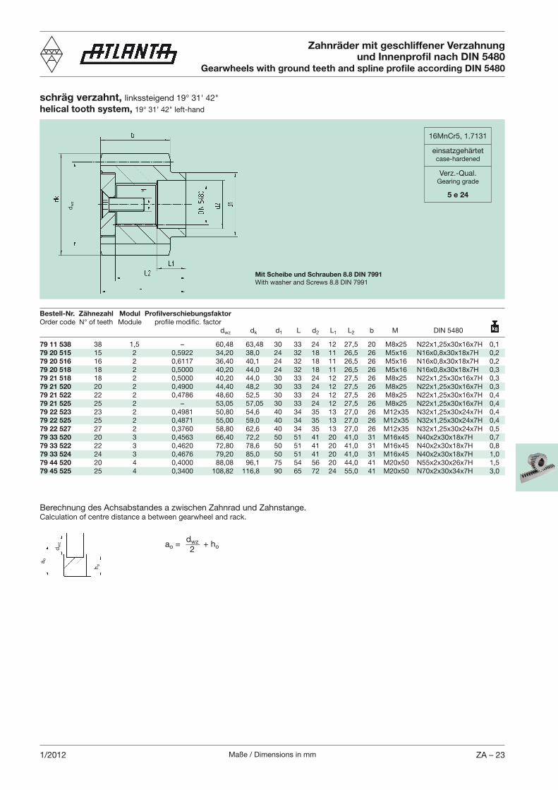
Zahnräder mit geschliffener Verzahnung und Innenprofil nach DIN 5480
Gearwheels with ground teeth and spline profile according DIN 5480
Bestell-Nr. Zähnezahl Modul Profilverschiebungsfaktor
dwz dk d1 L d2 L1 L2 b M DIN 5480
79 11 538 38 1,5 – 60,48 63,48 30 33 24 12 27,5 20 M8x25 N22x1,25x30x16x7H 0,179 20 515 15 2 0,5922 34,20 38,0 24 32 18 11 26,5 26 M5x16 N16x0,8x30x18x7H 0,279 20 516 16 2 0,6117 36,40 40,1 24 32 18 11 26,5 26 M5x16 N16x0,8x30x18x7H 0,279 20 518 18 2 0,5000 40,20 44,0 24 32 18 11 26,5 26 M5x16 N16x0,8x30x18x7H 0,379 21 518 18 2 0,5000 40,20 44,0 30 33 24 12 27,5 26 M8x25 N22x1,25x30x16x7H 0,379 21 520 20 2 0,4900 44,40 48,2 30 33 24 12 27,5 26 M8x25 N22x1,25x30x16x7H 0,379 21 522 22 2 0,4786 48,60 52,5 30 33 24 12 27,5 26 M8x25 N22x1,25x30x16x7H 0,479 21 525 25 2 – 53,05 57,05 30 33 24 12 27,5 26 M8x25 N22x1,25x30x16x7H 0,479 22 523 23 2 0,4981 50,80 54,6 40 34 35 13 27,0 26 M12x35 N32x1,25x30x24x7H 0,479 22 525 25 2 0,4871 55,00 59,0 40 34 35 13 27,0 26 M12x35 N32x1,25x30x24x7H 0,479 22 527 27 2 0,3760 58,80 62,6 40 34 35 13 27,0 26 M12x35 N32x1,25x30x24x7H 0,579 33 520 20 3 0,4563 66,40 72,2 50 51 41 20 41,0 31 M16x45 N40x2x30x18x7H 0,779 33 522 22 3 0,4620 72,80 78,6 50 51 41 20 41,0 31 M16x45 N40x2x30x18x7H 0,879 33 524 24 3 0,4676 79,20 85,0 50 51 41 20 41,0 31 M16x45 N40x2x30x18x7H 1,079 44 520 20 4 0,4000 88,08 96,1 75 54 56 20 44,0 41 M20x50 N55x2x30x26x7H 1,579 45 525 25 4 0,3400 108,82 116,8 90 65 72 24 55,0 41 M20x50 N70x2x30x34x7H 3,0
16MnCr5, 1.7131
einsatzgehärtetcase-hardened
Verz.-Qual.Gearing grade
5 e 24
Mit Scheibe und Schrauben 8.8 DIN 7991With washer and Screws 8.8 DIN 7991
schräg verzahnt, helical tooth system,
Berechnung des Achsabstandes a zwischen Zahnrad und Zahnstange.Calculation of centre distance a between gearwheel and rack.
a o
ao =dwz
2+ ho
ho
dw
z
dw
z
Maße / Dimensions in mmZA – 24 2/2012
b2
dk
dN
b1
0,01 A u 0,5 B
B
d1 A
d
t
b2
dk
b1
d
0,05 A
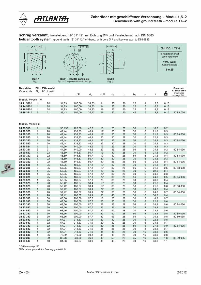
schräg verzahnt, H6 und Passfedernut nach DIN 6885helical tooth system, H6 and keyway acc. to DIN 6885
Zahnräder mit geschliffener Verzahnung – Modul 1,5–2Gearwheels with ground teeth – module 1.5–2
16MnCr5, 1.7131
einsatzgehärtetcase-hardened
Verz.-Qual.Gearing grade
6 e 25
Modul / Module 2
24 26 518 1 18 38,197 120,00 42,2 16 25 28 30 5 18,3 0,224 29 520 1 20 42,44 133,33 46,4 19* 30 28 30 6 21,8 0,324 29 320 3 20 42,44 133,33 46,4 19* 30 28 56 6 21,8 0,3 80 83 03024 22 520 1 20 42,44 133,33 46,4 20 30 28 30 6 22,8 0,324 20 320 3 20 42,44 133,33 46,4 22* 36 28 56 6 24,8 0,3 80 84 03624 23 520 1 20 42,44 133,33 46,4 22 30 28 30 6 24,8 0,324 26 521 1 21 44,56 140,00 48,6 16 25 28 30 5 18,3 0,324 20 321 3 21 44,56 140,00 48,6 22 36 28 56 6 24,8 0,2 80 84 03624 29 522 1 22 46,69 146,67 50,7 19* 30 28 30 6 21,8 0,224 29 322 3 22 46,69 146,67 50,7 19* 30 28 56 6 21,8 0,4 80 83 03024 20 522 1 22 46,69 146,67 50,7 22* 30 28 30 6 24,8 0,324 20 322 3 22 46,69 146,67 50,7 22* 36 28 56 6 24,8 0,4 80 84 03624 29 525 1 25 53,05 166,67 57,1 19* 30 28 30 6 21,8 0,424 29 325 3 25 53,05 166,67 57,1 19* 30 28 56 6 21,8 0,5 80 83 03024 22 525 1 25 53,05 166,67 57,1 20 30 28 30 6 22,8 0,424 20 525 1 25 53,05 166,67 57,1 22* 30 28 30 6 24,8 0,3 24 20 325 3 25 53,05 166,67 57,1 22* 36 28 56 6 24,8 0,5 80 84 03624 23 525 1 25 53,05 166,67 57,1 25 36 28 30 8 28,3 0,424 29 528 1 28 59,42 186,67 63,4 19* 30 28 30 6 21,8 0,4 24 29 328 3 28 59,42 186,67 63,4 19* 30 28 56 6 21,8 0,6 80 83 03024 20 528 1 28 59,42 186,67 63,4 22* 30 28 30 6 24,8 0,4 24 20 328 3 28 59,42 186,67 63,4 22* 36 28 56 6 24,8 0,7 80 84 03624 25 528 1 28 59,42 186,67 63,4 35 48 28 30 10 38,3 0,424 26 530 1 30 63,66 200,00 67,7 16 25 28 30 5 18,3 0,724 22 530 1 30 63,66 200,00 67,7 20 30 28 30 6 22,8 0,624 20 330 3 30 63,66 200,00 67,7 22 36 28 56 6 24,8 0,6 80 84 03624 23 530 1 30 63,66 200,00 67,7 25 36 28 30 8 28,3 0,824 24 530 1 30 63,66 200,00 67,7 30* 45 28 30 8 33,3 0,624 22 330 3 30 63,66 200,00 67,7 30 50 28 60 8 33,3 0,8 80 85 05024 23 330 3 30 63,66 200,00 67,7 32 55 28 65 10 35,3 0,8 80 80 05524 22 532 1 32 67,91 213,33 71,9 20 30 28 30 6 22,8 0,824 20 532 1 32 67,91 213,33 71,9 22* 30 28 30 6 24,8 0,7 24 20 332 3 32 67,91 213,33 71,9 22* 36 28 56 6 27,8 0,9 80 84 03624 23 532 1 32 67,91 213,33 71,9 25 36 28 30 8 28,3 0,724 25 532 1 32 67,91 213,33 71,9 35 48 28 30 10 38,3 0,624 25 536 1 36 76,39 240,00 80,4 35 48 28 30 10 38,3 0,824 23 339 3 39 82,76 260,00 86,8 32 55 28 65 10 35,3 1,3 80 80 05524 25 540 1 40 84,88 266,67 88,9 35 48 28 30 10 38,3 1,1
Bestell-Nr. Bild Zähnezahl
z d d*PI dk d1H6 dN b1 b2 u t
Bild 1Fig. 1
Bild 3Fig. 3
Spannsatzlt. Seite GH-1
shrink-discon page GH-1
Bild 1 + 3 Mitte ZahnlückeFig. 1 + 3 Keyway middle of tooth gap
dN
h8
* G6 bzw./resp. H71) Verzahnungsqualität / Gearing grade 6 f 24
Modul / Module 1,5
24 11 520 1) 1 20 31,83 100,00 34,83 11 25 20 22 4 12,8 0,1324 14 520 1) 1 20 31,83 100,00 34,83 14 25 20 22 5 16,3 0,1324 16 520 1) 1 20 31,83 100,00 34,83 16 25 20 22 5 18,3 0,1324 16 321 1) 3 21 33,42 105,00 36,42 16 30 20 46 5 18,3 0,15 80 83 030
Maße / Dimensions in mm ZA – 251/2012
b2
dk
dN
b1
0,01 A u 0,5 B
B
d1 A
d
t
b2
dk
b1
d
0,05 A
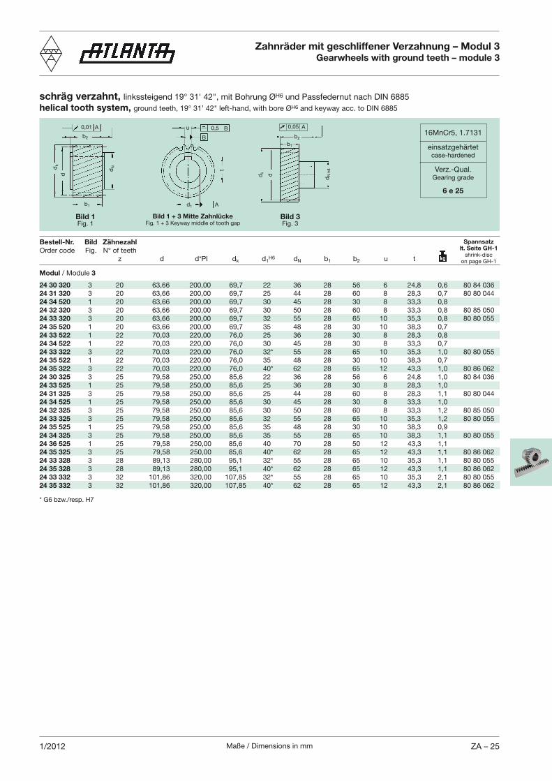
schräg verzahnt, H6 und Passfedernut nach DIN 6885helical tooth system, H6 and keyway acc. to DIN 6885
Zahnräder mit geschliffener Verzahnung – Modul 3Gearwheels with ground teeth – module 3
16MnCr5, 1.7131
einsatzgehärtetcase-hardened
Verz.-Qual.Gearing grade
6 e 25
Bestell-Nr. Bild Zähnezahl
z d d*PI dk d1H6 dN b1 b2 u t
Bild 1Fig. 1
Bild 3Fig. 3
Spannsatzlt. Seite GH-1
shrink-discon page GH-1
Bild 1 + 3 Mitte ZahnlückeFig. 1 + 3 Keyway middle of tooth gap
dN
h8
* G6 bzw./resp. H7
Modul / Module 3
24 30 320 3 20 63,66 200,00 69,7 22 36 28 56 6 24,8 0,6 80 84 03624 31 320 3 20 63,66 200,00 69,7 25 44 28 60 8 28,3 0,7 80 80 04424 34 520 1 20 63,66 200,00 69,7 30 45 28 30 8 33,3 0,824 32 320 3 20 63,66 200,00 69,7 30 50 28 60 8 33,3 0,8 80 85 05024 33 320 3 20 63,66 200,00 69,7 32 55 28 65 10 35,3 0,8 80 80 05524 35 520 1 20 63,66 200,00 69,7 35 48 28 30 10 38,3 0,724 33 522 1 22 70,03 220,00 76,0 25 36 28 30 8 28,3 0,824 34 522 1 22 70,03 220,00 76,0 30 45 28 30 8 33,3 0,724 33 322 3 22 70,03 220,00 76,0 32* 55 28 65 10 35,3 1,0 80 80 05524 35 522 1 22 70,03 220,00 76,0 35 48 28 30 10 38,3 0,724 35 322 3 22 70,03 220,00 76,0 40* 62 28 65 12 43,3 1,0 80 86 06224 30 325 3 25 79,58 250,00 85,6 22 36 28 56 6 24,8 1,0 80 84 03624 33 525 1 25 79,58 250,00 85,6 25 36 28 30 8 28,3 1,024 31 325 3 25 79,58 250,00 85,6 25 44 28 60 8 28,3 1,1 80 80 04424 34 525 1 25 79,58 250,00 85,6 30 45 28 30 8 33,3 1,024 32 325 3 25 79,58 250,00 85,6 30 50 28 60 8 33,3 1,2 80 85 05024 33 325 3 25 79,58 250,00 85,6 32 55 28 65 10 35,3 1,2 80 80 05524 35 525 1 25 79,58 250,00 85,6 35 48 28 30 10 38,3 0,924 34 325 3 25 79,58 250,00 85,6 35 55 28 65 10 38,3 1,1 80 80 05524 36 525 1 25 79,58 250,00 85,6 40 70 28 50 12 43,3 1,124 35 325 3 25 79,58 250,00 85,6 40* 62 28 65 12 43,3 1,1 80 86 06224 33 328 3 28 89,13 280,00 95,1 32* 55 28 65 10 35,3 1,1 80 80 05524 35 328 3 28 89,13 280,00 95,1 40* 62 28 65 12 43,3 1,1 80 86 06224 33 332 3 32 101,86 320,00 107,85 32* 55 28 65 10 35,3 2,1 80 80 05524 35 332 3 32 101,86 320,00 107,85 40* 62 28 65 12 43,3 2,1 80 86 062
Maße / Dimensions in mmZA – 26 2/2012
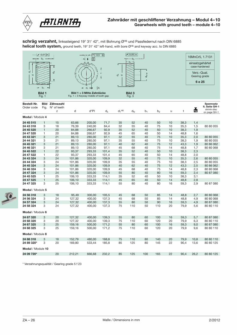
schräg verzahnt, l H6 und Passfedernut nach DIN 6885helical tooth system, H6 and keyway acc. to DIN 6885
16MnCr5, 1.7131
einsatzgehärtetcase-hardened
Verz.-Qual.Gearing grade
6 e 25
Modul / Module 4
24 45 515 1 15 63,66 200,00 71,7 35 52 40 50 10 38,3 1,424 43 318 3 18 76,39 240,00 84,4 32 55 40 75 10 35,3 1,5 80 80 05524 45 520 1 20 84,88 266,67 92,9 35 52 40 50 10 38,3 1,924 47 520 1 20 84,88 266,67 92,9 45 65 40 50 14 48,8 1,624 43 321 3 21 89,13 280,00 97,1 32 55 40 75 10 35,3 2,0 80 80 05524 44 321 3 21 89,13 280,00 97,1 35 55 40 75 10 38,3 1,9 80 80 05524 45 321 3 21 89,13 280,00 97,1 40 62 40 75 12 43,3 1,9 80 86 06224 46 321 3 21 89,13 280,00 97,1 45 68 40 75 14 48,8 1,7 80 80 06824 45 522 1 22 93,37 293,33 101,4 35 52 40 50 10 38,3 2,324 47 522 1 22 93,37 293,33 101,4 45 65 40 50 14 48,8 2,024 43 324 3 24 101,86 320,00 109,9 32 55 40 75 10 35,3 2,6 80 80 05524 44 324 3 24 101,86 320,00 109,9 35 55 40 75 10 38,3 2,5 80 80 05524 45 324 3 24 101,86 320,00 109,9 40 62 40 75 12 43,3 2,5 80 86 06224 46 324 3 24 101,86 320,00 109,9 45 68 40 75 14 48,8 2,3 80 80 06824 47 324 3 24 101,86 320,00 109,9 55 80 40 80 16 59,3 2,4 80 87 08024 45 525 1 25 106,10 333,33 114,1 35 52 40 50 10 38,3 3,124 47 525 1 25 106,10 333,33 114,1 45 65 40 50 14 48,8 2,824 47 325 3 25 106,10 333,33 114,1 55 80 40 80 16 59,3 2,9 80 87 080
Modul / Module 5
24 56 318 3 18 95,49 300,00 105,5 45 68 50 85 14 48,8 2,7 80 80 06824 56 324 3 24 127,32 400,00 137,3 45 68 50 85 14 48,8 4,9 80 80 06824 57 324 3 24 127,32 400,00 137,3 55 80 50 90 16 59,3 4,9 80 87 08024 58 324 3 24 127,32 400,00 137,3 75 110 50 110 20 79,9 5,6 80 80 110
Modul / Module 6
24 67 320 3 20 127,32 400,00 139,3 55 80 60 100 16 59,3 5,7 80 87 08024 68 320 3 20 127,32 400,00 139,3 75 110 60 120 20 79,9 6,3 80 80 11024 67 325 3 25 159,16 500,00 171,2 55 80 60 100 16 59,3 9,0 80 87 08024 68 325 3 25 159,16 500,00 171,2 75 110 60 120 20 79,9 9,6 80 80 110
Modul / Module 8
24 88 318 3 18 152,79 480,00 168,8 75 110 80 140 20 79,9 10,8 80 80 11024 89 320* 3 20 169,80 533,44 185,8 85 125 80 145 22 90,4 13,6 80 80 125
Modul / Module 10
24 09 720* 20 212,21 666,68 232,2 85 125 100 165 22 90,4 26,2 80 80 125
Bestell-Nr. Bild Zähnezahl
z d d*PI dk d1H6 dN b1 b2 u t
Zahnräder mit geschliffener Verzahnung – Modul 4–10Gearwheels with ground teeth – module 4–10
Spannsatzlt. Seite GH-1
shrink-discon page GH-1
b2
dk
dN
b1
0,01 A u 0,5 B
B
d1 A
d
t
Bild 1Fig. 1
Bild 3Fig. 3
b2
dk
dN
b1
d
0,05 A
Bild 1 + 3 Mitte ZahnlückeFig. 1 + 3 Keyway middle of tooth gap
dN
h8
* Verzahnungsqualität / Gearing grade 5 f 23
Maße / Dimensions in mm ZA – 271/2012
Bestell-Nr. Modul Zähnezahl
k dN b1 b2
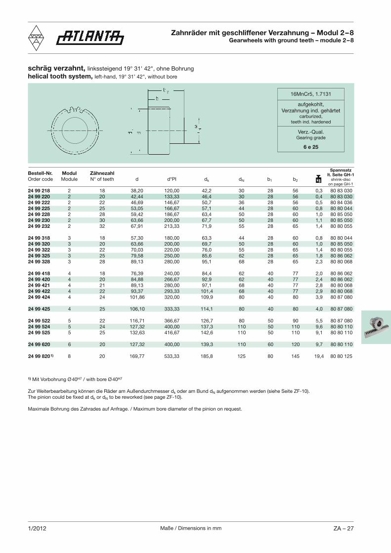
Zahnräder mit geschliffener Verzahnung – Modul 2 – 8Gearwheels with ground teeth – module 2 – 8
16MnCr5, 1.7131
aufgekohlt,Verzahnung ind. gehärtet
carburized,teeth ind. hardened
Verz.-Qual.Gearing grade
6 e 25
schräg verzahnt, helical tooth system,
24 99 218 2 18 38,20 120,00 42,2 30 28 56 0,3 80 83 03024 99 220 2 20 42,44 133,33 46,4 30 28 56 0,4 80 83 03024 99 222 2 22 46,69 146,67 50,7 36 28 56 0,5 80 84 03624 99 225 2 25 53,05 166,67 57,1 44 28 60 0,8 80 80 04424 99 228 2 28 59,42 186,67 63,4 50 28 60 1,0 80 85 05024 99 230 2 30 63,66 200,00 67,7 50 28 60 1,1 80 85 05024 99 232 2 32 67,91 213,33 71,9 55 28 65 1,4 80 80 055
24 99 318 3 18 57,30 180,00 63,3 44 28 60 0,8 80 80 04424 99 320 3 20 63,66 200,00 69,7 50 28 60 1,0 80 85 05024 99 322 3 22 70,03 220,00 76,0 55 28 65 1,4 80 80 05524 99 325 3 25 79,58 250,00 85,6 62 28 65 1,8 80 86 06224 99 328 3 28 89,13 280,00 95,1 68 28 65 2,3 80 80 068
24 99 418 4 18 76,39 240,00 84,4 62 40 77 2,0 80 86 06224 99 420 4 20 84,88 266,67 92,9 62 40 77 2,4 80 86 06224 99 421 4 21 89,13 280,00 97,1 68 40 77 2,8 80 80 06824 99 422 4 22 93,37 293,33 101,4 68 40 77 2,9 80 80 06824 99 424 4 24 101,86 320,00 109,9 80 40 80 3,9 80 87 080
24 99 425 4 25 106,10 333,33 114,1 80 40 80 4,0 80 87 080
24 99 522 5 22 116,71 366,67 126,7 80 50 90 5,5 80 87 08024 99 524 5 24 127,32 400,00 137,3 110 50 110 9,6 80 80 11024 99 525 5 25 132,63 416,67 142,6 110 50 110 9,1 80 80 110
24 99 620 6 20 127,32 400,00 139,3 110 60 120 9,7 80 80 110
24 99 820 1) 8 20 169,77 533,33 185,8 125 80 145 19,4 80 80 125
1) H7 H7
Zur Weiterbearbeitung können die Räder am Außendurchmesser dk oder am Bund dN aufgenommen werden (siehe Seite ZF-10).
k or dN to be reworked (see page ZF-10).
Maximale Bohrung des Zahrades auf Anfrage. / Maximum bore diameter of the pinion on request.
Spannsatzlt. Seite GH-1
shrink-discon page GH-1
Maße / Dimensions in mmZA – 28 1/2012
schräg verzahnt, helical tooth system,
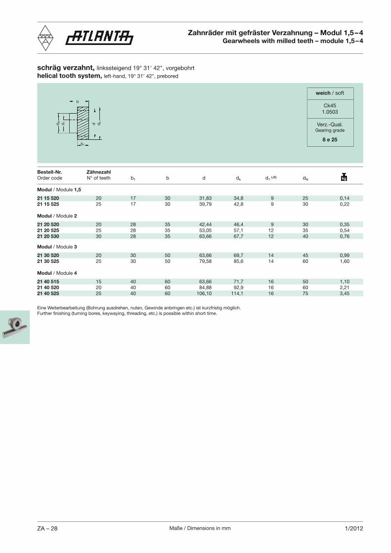
Zahnräder mit gefräster Verzahnung – Modul 1,5 – 4Gearwheels with milled teeth – module 1,5 – 4
Modul / Module 1,5
21 15 520 20 17 30 31,83 34,8 9 25 0,1421 15 525 25 17 30 39,79 42,8 9 30 0,22
Modul / Module 2
21 20 520 20 28 35 42,44 46,4 9 30 0,3521 20 525 25 28 35 53,05 57,1 12 35 0,5421 20 530 30 28 35 63,66 67,7 12 40 0,76
Modul / Module 3
21 30 520 20 30 50 63,66 69,7 14 45 0,9921 30 525 25 30 50 79,58 85,6 14 60 1,60
Modul / Module 4
21 40 515 15 40 60 63,66 71,7 16 50 1,1021 40 520 20 40 60 84,88 92,9 16 60 2,2121 40 525 25 40 60 106,10 114,1 16 75 3,45
Bestell-Nr. Zähnezahl
1 b d dk d1 (J8) dN
weich / soft
Ck451.0503
Verz.-Qual.Gearing grade
8 e 25
dN d1
dkd
b
b1
Eine Weiterbearbeitung (Bohrung ausdrehen, nuten, Gewinde anbringen etc.) ist kurzfristig möglich.
Maße / Dimensions in mm ZA – 291/2012
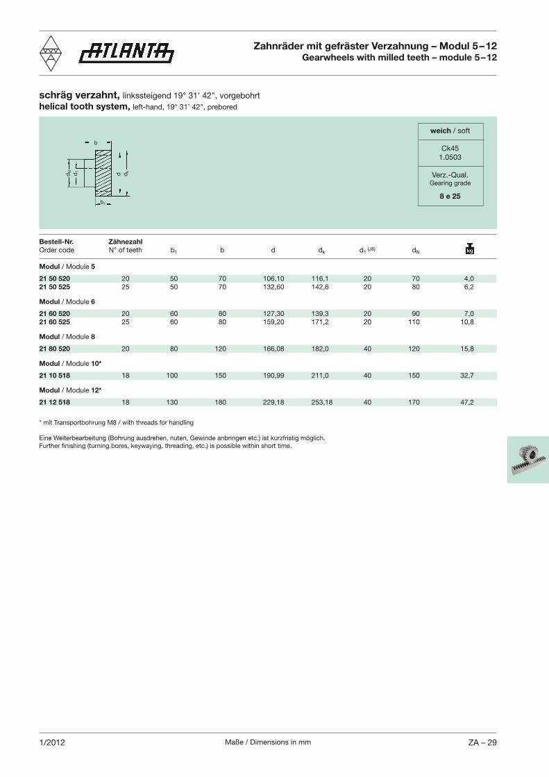
* mit Transportbohrung M8 / with threads for handling
Eine Weiterbearbeitung (Bohrung ausdrehen, nuten, Gewinde anbringen etc.) ist kurzfristig möglich.
schräg verzahnt, helical tooth system,
Zahnräder mit gefräster Verzahnung – Modul 5 – 12Gearwheels with milled teeth – module 5 – 12
Modul / Module 5
21 50 520 20 50 70 106,10 116,1 20 70 4,021 50 525 25 50 70 132,60 142,6 20 80 6,2
Modul / Module 6
21 60 520 20 60 80 127,30 139,3 20 90 7,021 60 525 25 60 80 159,20 171,2 20 110 10,8
Modul / Module 8
21 80 520 20 80 120 166,08 182,0 40 120 15,8
Modul / Module 10*
21 10 518 18 100 150 190,99 211,0 40 150 32,7
Modul / Module 12*
21 12 518 18 130 180 229,18 253,18 40 170 47,2
Bestell-Nr. Zähnezahl
1 b d dk d1 (J8) dN
weich / soft
Ck451.0503
Verz.-Qual.Gearing grade
8 e 25
dN d1
dkd
b
b1
Maße / Dimensions in mmZA – 30 1/2012
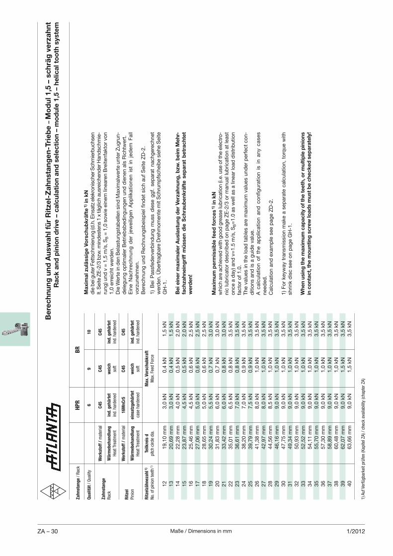
Be
rec
hn
un
g u
nd
Au
swa
hl f
ür
Rit
zel-
Za
hn
sta
ng
en
-Tri
eb
e –
Mo
du
l 1,5
– s
ch
räg
ve
rza
hn
t R
ac
k a
nd
pin
ion
dri
ve –
ca
lcu
lati
on
an
d s
ele
cti
on
– m
od
ule
1,5
– h
elic
al t
oo
th s
yste
m
1) A
uf Ve
rfügbarke
it prüfen (Kap
itel ZA) / ch
eck av
ailability (ch
apter ZA)
Za
hn
sta
ng
e / Rac
k H
PR
BR
Qu
ali
tät / Quality
6
9
1
0
W
erk
sto
ff /
material
C4
5
C4
5
C4
5Z
ah
nst
an
ge
Rac
k W
ärm
eb
eh
an
dlu
ng
in
d. g
eh
ärt
et
weic
h
ind
. geh
ärt
et
Hea
t Trea
tmen
t ind. h
arden
ed
soft
ind. h
arden
ed
W
erk
sto
ff /
material
16
Mn
Cr5
C
45
C
45
Rit
zel
Pinion
Wä
rmeb
eh
an
dlu
ng
ein
satz
geh
ärt
et
weic
h
ind
. geh
ärt
et
Hea
t Trea
tmen
t ca
se harden
ed
soft
ind. h
arden
ed
Rit
zelz
äh
neza
hl 1
) Te
ilk
reis
d
Ma
x. V
ors
ch
ub
kra
ft
No. of pinion tee
th 1)
pitch circle dia.
Max
. Fee
d Force
12
19,1
0 m
m
3,0
kN
0,4
kN
1,5
kN
13
20,6
9 m
m
3,0
kN
0,4
kN
1,5
kN
14
22,2
8 m
m
4,0
kN
0,5
kN
2,0
kN
15
23,8
7 m
m
4,5
kN
0,5
kN
2,0
kN
16
25,4
6 m
m
4,5
kN
0,6
kN
2,5
kN
17
27,0
6 m
m
5,0
kN
0,6
kN
2,5
kN
18
28,6
5 m
m
5,0
kN
0,6
kN
2,5
kN
19
30,2
4 m
m
5,5
kN
0,7
kN
3,0
kN
20
31,8
3 m
m
6,0
kN
0,7
kN
3,0
kN
21
33,4
2 m
m
6,0
kN
0,8
kN
3,0
kN
22
35,0
1 m
m
6,5
kN
0,8
kN
3,5
kN
23
36,6
1 m
m
7,0
kN
0,8
kN
3,5
kN
24
38,2
0 m
m
7,0
kN
0,9
kN
3,5
kN
25
39,7
9 m
m
7,5
kN
0,9
kN
3,5
kN
26
41,3
8 m
m
8,0
kN
1,0
kN
3,5
kN
27
42,9
7 m
m
8,0
kN
1,0
kN
3,5
kN
28
44,5
6 m
m
8,5
kN
1,0
kN
3,5
kN
29
46,1
6 m
m
9,0
kN
1,0
kN
3,5
kN
30
47,7
5 m
m
9,0
kN
1,0
kN
3,5
kN
31
49,3
4 m
m
9,0
kN
1,0
kN
3,5
kN
32
50,9
3 m
m
9,0
kN
1,0
kN
3,5
kN
33
52,5
2 m
m
9,0
kN
1,0
kN
3,5
kN
34
54,1
1 m
m
9,0
kN
1,0
kN
3,5
kN
35
55,7
0 m
m
9,0
kN
1,0
kN
3,5
kN
36
57,3
0 m
m
9,0
kN
1,0
kN
3,5
kN
37
58,8
9 m
m
9,0
kN
1,0
kN
3,5
kN
38
60,4
8 m
m
9,0
kN
1,0
kN
3,5
kN
39
62,0
7 m
m
9,0
kN
1,5
kN
3,5
kN
40
63,6
6 m
m
9,0
kN
1,5
kN
3,5
kN
Ma
xim
um
pe
rmis
sib
le f
ee
d f
orc
es
1) i
n k
Nw
hic
h a
re a
chie
ved
with
go
od
gre
ase
lub
rica
tion (i
.e. u
se o
f the
elec
tro
-nic
lub
rica
tor
des
crib
ed o
n p
age
ZE
-2/3
or
man
ual
lub
rica
tion a
t le
ast
once
a d
ay) a
nd
v=
1.5
m/s
, SB=
1.0
as
wel
l as
a lin
ear
load
dis
trib
utio
n
fact
or
of
1.0
.T
he
valu
es in
the
load
tab
les
are
max
imum
val
ues
und
er p
erfe
ct c
on-
diti
ons
and
is a
guid
e va
lue.
nee
ded
.C
alcu
latio
n a
nd
exa
mp
le s
ee p
age
ZD
-2.
1)
Fo
r ke
yway
tra
nsm
issi
on m
ake
a se
par
ate
calc
ula
tion,
torq
ue
with
sh
rink
dis
c se
e o
n p
age
GH
-1.
Wh
en
usi
ng
th
e m
axi
mu
m c
ap
ac
ity
of
the
te
eth
, or
mu
ltip
le p
inio
ns
in c
on
tac
t, t
he
mo
un
tin
g s
cre
w lo
ad
s m
ust
be
ch
ec
ke
d s
ep
ara
tely
!
Ma
xim
al z
ulä
ssig
e V
ors
ch
ub
krä
fte
1) in
kN
die
bei
gut
er F
etts
chm
ieru
ng (d
.h. E
insa
tz e
lekr
oni
sche
r Sch
mie
rbuc
hsen
lt.
Sei
te Z
E-2
/3 b
zw. m
ind
este
ns
1 x
täg
lich a
usr
eich
end
er H
and
schm
ie-
rung
) und
v =
1,5
m/s
, SB =
1,0
so
wie
ein
em li
nea
ren B
reite
nfa
kto
r vo
n
1,0
err
eich
t w
erd
en.
Die
Wer
te in
den
Bel
astu
ng
stab
elle
n s
ind
Max
imal
wer
te u
nte
r Z
ug
run-
del
egung
op
timal
er B
etrieb
sbed
ing
ung
en u
nd
die
nen
als
Ric
htw
ert.
Ein
e N
ach
rech
nu
ng
der
jew
eili
gen
Ap
plik
ati
on
en
ist
in
jed
em
Fall
vorz
uneh
men
.
1)
Bei
Pas
sfed
erve
rbin
dung
muss
die
se g
gf.
sep
arat
nac
hg
erec
hnet
w
erd
en. Ü
ber
trag
bar
e D
rehm
om
ente
mit
Sch
rum
pfs
chei
be
sieh
e S
eite
G
H-1
.
Be
i ein
er
ma
xim
ale
r A
usl
ast
un
g d
er
Ve
rza
hn
un
g, b
zw. b
eim
Me
hr-
fac
hza
hn
ein
gri
ff m
üss
en
die
Sc
hra
ub
en
krä
fte
se
pa
rat
be
tra
ch
tet
we
rde
n!
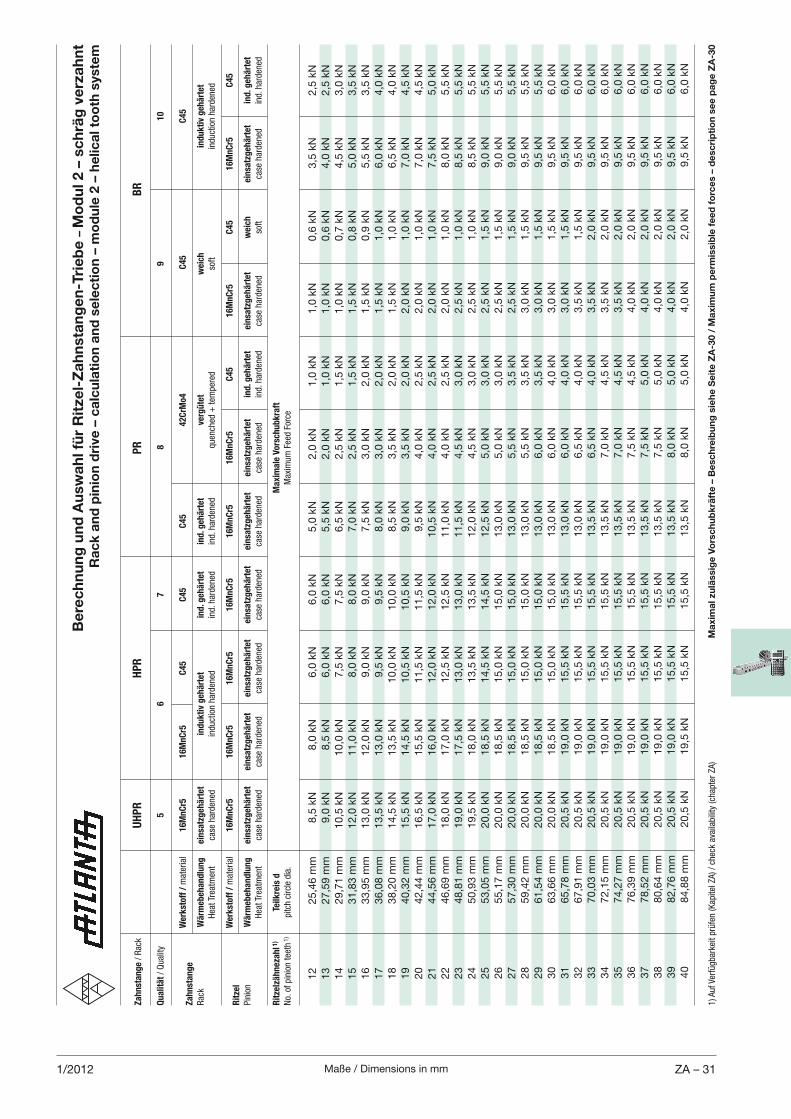
Maße / Dimensions in mm ZA – 311/2012
Za
hn
sta
ng
e / Rac
k
UH
PR
HP
R
P
R
BR
Qu
ali
tät / Quality
5
6
7
8
9
10
W
erk
sto
ff /
material
16
Mn
Cr5
1
6M
nC
r5
C4
5
C4
5
C4
5
42
CrM
o4
C
45
C
45
Za
hn
sta
ng
e
Rac
k W
ärm
eb
eh
an
dlu
ng
ein
satz
geh
ärt
et
ind
uk
tiv
geh
ärt
et
ind
. geh
ärt
et
ind
. geh
ärt
et
verg
üte
t w
eic
h
ind
uk
tiv
geh
ärt
et
Hea
t Trea
tmen
t ca
se harden
ed
induction harden
ed
ind. h
arden
ed
ind. h
arden
ed
quen
ched
+ tem
pered
so
ft
induction harden
ed
W
erk
sto
ff /
material
16
Mn
Cr5
1
6M
nC
r5
1
6M
nC
r5
1
6M
nC
r5
16
Mn
Cr5
1
6M
nC
r5
C4
5
16
Mn
Cr5
C
45
1
6M
nC
r5
C4
5R
itze
l
Pinion
Wä
rmeb
eh
an
dlu
ng
ein
satz
geh
ärt
et
ein
satz
geh
ärt
et
ein
satz
geh
ärt
et
ein
satz
geh
ärt
et
ein
satz
geh
ärt
et
ein
satz
geh
ärt
et
ind
. geh
ärt
et
ein
satz
geh
ärt
et
weic
h
ein
satz
geh
ärt
et
ind
. geh
ärt
et
Hea
t Trea
tmen
t ca
se harden
ed
case
harden
ed
ca
se harden
ed
ca
se harden
ed
case
harden
ed
case
harden
ed
ind. h
arden
ed
case
harden
ed
soft
case
harden
ed
ind. h
arden
ed
Rit
zelz
äh
neza
hl 1
) Te
ilk
reis
d
Ma
xim
ale
Vo
rsch
ub
kra
ft
No. of pinion tee
th 1)
pitch circle dia.
Max
imum Fee
d Force
12
25,4
6 m
m
8,5
kN
8,0
kN
6,0
kN
6,0
kN
5,0
kN
2,0
kN
1,0
kN
1,0
kN
0,6
kN
3,5
kN
2,5
kN
13
27,5
9 m
m
9,0
kN
8,5
kN
6,0
kN
6,0
kN
5,5
kN
2,0
kN
1,0
kN
1,0
kN
0,6
kN
4,0
kN
2,5
kN
14
29,7
1 m
m
10,5
kN
10,0
kN
7,5
kN
7,5
kN
6,5
kN
2,5
kN
1,5
kN
1,0
kN
0,7
kN
4,5
kN
3,0
kN
15
31,8
3 m
m
12,0
kN
11,0
kN
8,0
kN
8,0
kN
7,0
kN
2,5
kN
1,5
kN
1,5
kN
0,8
kN
5,0
kN
3,5
kN
16
33,9
5 m
m
13,0
kN
12,0
kN
9,0
kN
9,0
kN
7,5
kN
3,0
kN
2,0
kN
1,5
kN
0,9
kN
5,5
kN
3,5
kN
17
36,0
8 m
m
13,5
kN
13,0
kN
9,5
kN
9,5
kN
8,0
kN
3,0
kN
2,0
kN
1,5
kN
1,0
kN
6,0
kN
4,0
kN
18
38,2
0 m
m
14,5
kN
13,5
kN
10,0
kN
10,0
kN
8,5
kN
3,5
kN
2,0
kN
1,5
kN
1,0
kN
6,5
kN
4,0
kN
19
40,3
2 m
m
15,5
kN
14,5
kN
10,5
kN
10,5
kN
9,0
kN
3,5
kN
2,0
kN
2,0
kN
1,0
kN
7,0
kN
4,5
kN
20
42,4
4 m
m
16,5
kN
15,5
kN
11,5
kN
11,5
kN
9,5
kN
4,0
kN
2,5
kN
2,0
kN
1,0
kN
7,0
kN
4,5
kN
21
44,5
6 m
m
17,0
kN
16,0
kN
12,0
kN
12,0
kN
10,5
kN
4,0
kN
2,5
kN
2,0
kN
1,0
kN
7,5
kN
5,0
kN
22
46,6
9 m
m
18,0
kN
17,0
kN
12,5
kN
12,5
kN
11,0
kN
4,0
kN
2,5
kN
2,0
kN
1,0
kN
8,0
kN
5,5
kN
23
48,8
1 m
m
19,0
kN
17,5
kN
13,0
kN
13,0
kN
11,5
kN
4,5
kN
3,0
kN
2,5
kN
1,0
kN
8,5
kN
5,5
kN
24
50,9
3 m
m
19,5
kN
18,0
kN
13,5
kN
13,5
kN
12,0
kN
4,5
kN
3,0
kN
2,5
kN
1,0
kN
8,5
kN
5,5
kN
25
53,0
5 m
m
20,0
kN
18,5
kN
14,5
kN
14,5
kN
12,5
kN
5,0
kN
3,0
kN
2,5
kN
1,5
kN
9,0
kN
5,5
kN
26
55,1
7 m
m
20,0
kN
18,5
kN
15,0
kN
15,0
kN
13,0
kN
5,0
kN
3,0
kN
2,5
kN
1,5
kN
9,0
kN
5,5
kN
27
57,3
0 m
m
20,0
kN
18,5
kN
15,0
kN
15,0
kN
13,0
kN
5,5
kN
3,5
kN
2,5
kN
1,5
kN
9,0
kN
5,5
kN
28
59,4
2 m
m
20,0
kN
18,5
kN
15,0
kN
15,0
kN
13,0
kN
5,5
kN
3,5
kN
3,0
kN
1,5
kN
9,5
kN
5,5
kN
29
61,5
4 m
m
20,0
kN
18,5
kN
15,0
kN
15,0
kN
13,0
kN
6,0
kN
3,5
kN
3,0
kN
1,5
kN
9,5
kN
5,5
kN
30
63,6
6 m
m
20,0
kN
18,5
kN
15,0
kN
15,0
kN
13,0
kN
6,0
kN
4,0
kN
3,0
kN
1,5
kN
9,5
kN
6,0
kN
31
65,7
8 m
m
20,5
kN
19,0
kN
15,5
kN
15,5
kN
13,0
kN
6,0
kN
4,0
kN
3,0
kN
1,5
kN
9,5
kN
6,0
kN
32
67,9
1 m
m
20,5
kN
19,0
kN
15,5
kN
15,5
kN
13,0
kN
6,5
kN
4,0
kN
3,5
kN
1,5
kN
9,5
kN
6,0
kN
33
70,0
3 m
m
20,5
kN
19,0
kN
15,5
kN
15,5
kN
13,5
kN
6,5
kN
4,0
kN
3,5
kN
2,0
kN
9,5
kN
6,0
kN
34
72,1
5 m
m
20,5
kN
19,0
kN
15,5
kN
15,5
kN
13,5
kN
7,0
kN
4,5
kN
3,5
kN
2,0
kN
9,5
kN
6,0
kN
35
74,2
7 m
m
20,5
kN
19,0
kN
15,5
kN
15,5
kN
13,5
kN
7,0
kN
4,5
kN
3,5
kN
2,0
kN
9,5
kN
6,0
kN
36
76,3
9 m
m
20,5
kN
19,0
kN
15,5
kN
15,5
kN
13,5
kN
7,5
kN
4,5
kN
4,0
kN
2,0
kN
9,5
kN
6,0
kN
37
78,5
2 m
m
20,5
kN
19,0
kN
15,5
kN
15,5
kN
13,5
kN
7,5
kN
5,0
kN
4,0
kN
2,0
kN
9,5
kN
6,0
kN
38
80,6
4 m
m
20,5
kN
19,0
kN
15,5
kN
15,5
kN
13,5
kN
7,5
kN
5,0
kN
4,0
kN
2,0
kN
9,5
kN
6,0
kN
39
82,7
6 m
m
20,5
kN
19,0
kN
15,5
kN
15,5
kN
13,5
kN
8,0
kN
5,0
kN
4,0
kN
2,0
kN
9,5
kN
6,0
kN
40
84,8
8 m
m
20,5
kN
19,5
kN
15,5
kN
15,5
kN
13,5
kN
8,0
kN
5,0
kN
4,0
kN
2,0
kN
9,5
kN
6,0
kN
Be
rec
hn
un
g u
nd
Au
swa
hl f
ür
Rit
zel-
Za
hn
sta
ng
en
-Tri
eb
e –
Mo
du
l 2 –
sc
hrä
g v
erz
ah
nt
Ra
ck
an
d p
inio
n d
rive
– c
alc
ula
tio
n a
nd
se
lec
tio
n –
mo
du
le 2
– h
elic
al t
oo
th s
yste
m
1) A
uf Ve
rfügbarke
it prüfen (Kap
itel ZA) / ch
eck av
ailability (ch
apter ZA)
Ma
xim
al z
ulä
ssig
e V
ors
ch
ub
krä
fte
– B
esc
hre
ibu
ng
sie
he
Se
ite
ZA
-30 /
Ma
xim
um
pe
rmis
sib
le f
ee
d f
orc
es
– d
esc
rip
tio
n s
ee
pa
ge
ZA
-30
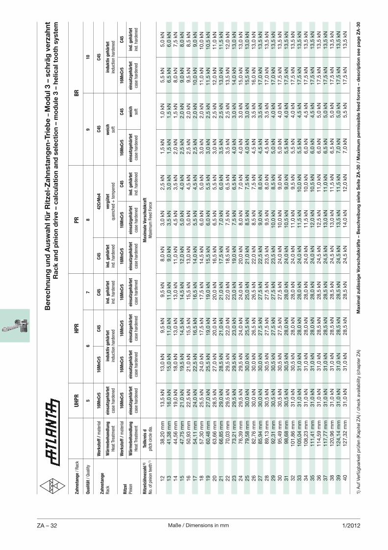
Maße / Dimensions in mmZA – 32 1/2012
Be
rec
hn
un
g u
nd
Au
swa
hl f
ür
Rit
zel-
Za
hn
sta
ng
en
-Tri
eb
e –
Mo
du
l 3 –
sc
hrä
g v
erz
ah
nt
Ra
ck
an
d p
inio
n d
rive
– c
alc
ula
tio
n a
nd
se
lec
tio
n –
mo
du
le 3
– h
elic
al t
oo
th s
yste
m
Za
hn
sta
ng
e / Rac
k
UH
PR
HP
R
P
R
BR
Qu
ali
tät / Quality
5
6
7
8
9
10
W
erk
sto
ff /
material
16
Mn
Cr5
1
6M
nC
r5
C4
5
C4
5
C4
5
42
CrM
o4
C
45
C
45
Za
hn
sta
ng
e
Rac
k W
ärm
eb
eh
an
dlu
ng
ein
satz
geh
ärt
et
ind
uk
tiv
geh
ärt
et
ind
. geh
ärt
et
ind
. geh
ärt
et
verg
üte
t w
eic
h
ind
uk
tiv
geh
ärt
et
Hea
t Trea
tmen
t ca
se harden
ed
induction harden
ed
ind. h
arden
ed
ind. h
arden
ed
quen
ched
+ tem
pered
so
ft
induction harden
ed
W
erk
sto
ff /
material
16
Mn
Cr5
1
6M
nC
r5
1
6M
nC
r5
1
6M
nC
r5
16
Mn
Cr5
1
6M
nC
r5
C4
5
16
Mn
Cr5
C
45
1
6M
nC
r5
C4
5R
itze
l
Pinion
Wä
rmeb
eh
an
dlu
ng
ein
satz
geh
ärt
et
ein
satz
geh
ärt
et
ein
satz
geh
ärt
et
ein
satz
geh
ärt
et
ein
satz
geh
ärt
et
ein
satz
geh
ärt
et
ind
. geh
ärt
et
ein
satz
geh
ärt
et
weic
h
ein
satz
geh
ärt
et
ind
. geh
ärt
et
Hea
t Trea
tmen
t ca
se harden
ed
case
harden
ed
ca
se harden
ed
ca
se harden
ed
case
harden
ed
case
harden
ed
ind. h
arden
ed
case
harden
ed
soft
case
harden
ed
ind. h
arden
ed
Rit
zelz
äh
neza
hl 1
) Te
ilk
reis
d
Ma
xim
ale
Vo
rsch
ub
kra
ft
No. of pinion tee
th 1)
pitch circle dia.
Max
imum Fee
d Force
12
38,2
0 m
m
13,5
kN
13,0
kN
9,5
kN
9,5
kN
8,0
kN
3,0
kN
2,5
kN
1,5
kN
1,0
kN
5,5
kN
5,0
kN
13
41,3
8 m
m
16,0
kN
15,0
kN
11,0
kN
11,0
kN
9,0
kN
3,5
kN
3,0
kN
1,5
kN
1,5
kN
6,5
kN
6,0
kN
14
44,5
6 m
m
19,0
kN
18,0
kN
13,0
kN
13,0
kN
11,0
kN
4,5
kN
3,5
kN
2,0
kN
1,5
kN
8,0
kN
7,5
kN
15
47,7
5 m
m
21,0
kN
19,5
kN
14,5
kN
14,5
kN
12,0
kN
5,0
kN
4,0
kN
2,5
kN
2,0
kN
9,0
kN
8,0
kN
16
50,9
3 m
m
22,5
kN
21,0
kN
15,5
kN
15,5
kN
13,0
kN
5,0
kN
4,5
kN
2,5
kN
2,0
kN
9,5
kN
8,5
kN
17
54,1
1 m
m
24,0
kN
22,5
kN
16,5
kN
16,5
kN
14,0
kN
5,5
kN
4,5
kN
2,5
kN
2,0
kN
10,0
kN
9,0
kN
18
57,3
0 m
m
25,5
kN
24,0
kN
17,5
kN
17,5
kN
14,5
kN
6,0
kN
5,0
kN
3,0
kN
2,0
kN
11,0
kN
10,0
kN
19
60,4
8 m
m
27,0
kN
25,5
kN
19,0
kN
19,0
kN
15,5
kN
6,0
kN
5,5
kN
3,0
kN
2,5
kN
11,5
kN
10,5
kN
20
63,6
6 m
m
28,5
kN
27,0
kN
20,0
kN
20,0
kN
16,5
kN
6,5
kN
5,5
kN
3,0
kN
2,5
kN
12,0
kN
11,0
kN
21
66,8
5 m
m
29,0
kN
28,5
kN
21,0
kN
21,0
kN
17,5
kN
7,0
kN
6,0
kN
3,5
kN
2,5
kN
13,0
kN
11,5
kN
22
70,0
3 m
m
29,5
kN
29,5
kN
22,0
kN
22,0
kN
18,5
kN
7,5
kN
6,5
kN
3,5
kN
2,5
kN
13,5
kN
12,0
kN
23
73,2
1 m
m
29,5
kN
29,5
kN
23,0
kN
23,0
kN
19,0
kN
7,5
kN
6,5
kN
4,0
kN
3,0
kN
14,0
kN
13,0
kN
24
76,3
9 m
m
29,5
kN
29,5
kN
24,0
kN
24,0
kN
20,0
kN
8,0
kN
7,0
kN
4,0
kN
3,0
kN
15,0
kN
13,0
kN
25
79,5
8 m
m
30,0
kN
30,0
kN
25,5
kN
25,0
kN
21,0
kN
8,5
kN
7,5
kN
4,0
kN
3,0
kN
15,5
kN
13,0
kN
26
82,7
6 m
m
30,0
kN
30,0
kN
26,5
kN
26,5
kN
22,0
kN
8,5
kN
7,5
kN
4,5
kN
3,5
kN
16,0
kN
13,0
kN
27
85,9
4 m
m
30,0
kN
30,0
kN
27,5
kN
27,5
kN
22,5
kN
9,0
kN
8,0
kN
4,5
kN
3,5
kN
17,0
kN
13,5
kN
28
89,1
3 m
m
30,5
kN
30,5
kN
27,5
kN
27,5
kN
23,5
kN
9,5
kN
8,0
kN
4,5
kN
3,5
kN
17,0
kN
13,5
kN
29
92,3
1 m
m
30,5
kN
30,5
kN
27,5
kN
27,5
kN
23,5
kN
10,0
kN
8,5
kN
5,0
kN
4,0
kN
17,0
kN
13,5
kN
30
95,4
9 m
m
30,5
kN
30,5
kN
27,5
kN
27,5
kN
24,0
kN
10,0
kN
9,0
kN
5,0
kN
4,0
kN
17,5
kN
13,5
kN
31
98,6
8 m
m
30,5
kN
30,5
kN
28,0
kN
28,0
kN
24,0
kN
10,5
kN
9,0
kN
5,5
kN
4,0
kN
17,5
kN
13,5
kN
32
101,8
6 m
m
31,0
kN
30,5
kN
28,0
kN
28,0
kN
24,0
kN
11,0
kN
9,5
kN
5,5
kN
4,0
kN
17,5
kN
13,5
kN
33
105,0
4 m
m
31,0
kN
31,0
kN
28,0
kN
28,0
kN
24,0
kN
11,5
kN
10,0
kN
5,5
kN
4,5
kN
17,5
kN
13,5
kN
34
108,2
3 m
m
31,0
kN
31,0
kN
28,0
kN
28,0
kN
24,0
kN
11,5
kN
10,0
kN
6,0
kN
4,5
kN
17,5
kN
13,5
kN
35
111,4
1 m
m
31,0
kN
31,0
kN
28,0
kN
28,0
kN
24,0
kN
12,0
kN
10,5
kN
6,0
kN
4,5
kN
17,5
kN
13,5
kN
36
114,5
9 m
m
31,0
kN
31,0
kN
28,5
kN
28,5
kN
24,5
kN
12,5
kN
11,0
kN
6,0
kN
5,0
kN
17,5
kN
13,5
kN
37
117,7
7 m
m
31,0
kN
31,0
kN
28,5
kN
28,5
kN
24,5
kN
13,0
kN
11,0
kN
6,5
kN
5,0
kN
17,5
kN
13,5
kN
38
120,9
6 m
m
31,0
kN
31,0
kN
28,5
kN
28,5
kN
24,5
kN
13,0
kN
11,5
kN
6,5
kN
5,0
kN
17,5
kN
13,5
kN
39
124,1
4 m
m
31,0
kN
31,0
kN
28,5
kN
28,5
kN
24,5
kN
13,5
kN
11,5
kN
7,0
kN
5,0
kN
17,5
kN
13,5
kN
40
127,3
2 m
m
31,0
kN
31,0
kN
28,5
kN
28,5
kN
24,5
kN
14,0
kN
12,0
kN
7,0
kN
5,5
kN
17,5
kN
13,5
kN
1) A
uf
Ver
füg
bar
keit
prü
fen (K
apite
l ZA
) / c
hec
k av
aila
bili
ty (c
hap
ter
ZA
)M
axi
ma
l zu
läss
ige
Vo
rsc
hu
bk
räft
e –
Be
sch
reib
un
g s
ieh
e S
eit
e Z
A-3
0 /
Ma
xim
um
pe
rmis
sib
le f
ee
d f
orc
es
– d
esc
rip
tio
n s
ee
pa
ge
ZA
-30
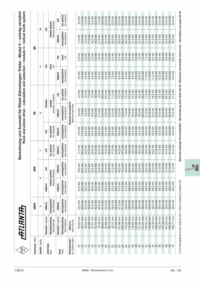
Maße / Dimensions in mm ZA – 331/2012
Za
hn
sta
ng
e / Rac
k
UH
PR
HP
R
P
R
BR
Qu
ali
tät / Quality
5
6
7
8
9
10
W
erk
sto
ff /
material
16
Mn
Cr5
1
6M
nC
r5
C4
5
C4
5
C4
5
42
CrM
o4
C
45
C
45
Za
hn
sta
ng
e
Rac
k W
ärm
eb
eh
an
dlu
ng
ein
satz
geh
ärt
et
ind
uk
tiv
geh
ärt
et
ind
. geh
ärt
et
ind
. geh
ärt
et
verg
üte
t w
eic
h
ind
uk
tiv
geh
ärt
et
Hea
t Trea
tmen
t ca
se harden
ed
induction harden
ed
ind. h
arden
ed
ind. h
arden
ed
quen
ched
+ tem
pered
so
ft
induction harden
ed
W
erk
sto
ff /
material
16
Mn
Cr5
1
6M
nC
r5
1
6M
nC
r5
1
6M
nC
r5
16
Mn
Cr5
1
6M
nC
r5
C4
5
16
Mn
Cr5
C
45
1
6M
nC
r5
C4
5R
itze
l
Pinion
Wä
rmeb
eh
an
dlu
ng
ein
satz
geh
ärt
et
ein
satz
geh
ärt
et
ein
satz
geh
ärt
et
ein
satz
geh
ärt
et
ein
satz
geh
ärt
et
ein
satz
geh
ärt
et
ind
. geh
ärt
et
ein
satz
geh
ärt
et
weic
h
ein
satz
geh
ärt
et
ind
. geh
ärt
et
Hea
t Trea
tmen
t ca
se harden
ed
case
harden
ed
ca
se harden
ed
ca
se harden
ed
case
harden
ed
case
harden
ed
ind. h
arden
ed
case
harden
ed
soft
case
harden
ed
ind. h
arden
ed
Rit
zelz
äh
neza
hl 1
) Te
ilk
reis
d
Ma
xim
ale
Vo
rsch
ub
kra
ft
No. of pinion tee
th 1)
pitch circle dia.
Max
imum Fee
d Force
12
50,9
3 m
m
25,5
kN
24,0
kN
18,0
kN
17,5
kN
15,0
kN
6,0
kN
5,0
kN
3,0
kN
2,0
kN
11,0
kN
9,5
kN
13
55,1
7 m
m
30,0
kN
28,0
kN
20,5
kN
20,5
kN
17,5
kN
7,0
kN
5,5
kN
3,5
kN
2,5
kN
13,0
kN
11,0
kN
14
59,4
2 m
m
34,5
kN
32,5
kN
24,0
kN
24,0
kN
20,5
kN
8,0
kN
6,5
kN
4,0
kN
3,0
kN
15,0
kN
12,5
kN
15
63,6
6 m
m
39,5
kN
37,0
kN
27,5
kN
27,5
kN
23,5
kN
9,5
kN
7,5
kN
4,5
kN
3,5
kN
17,0
kN
14,5
kN
16
67,9
1 m
m
42,5
kN
39,5
kN
29,5
kN
29,5
kN
25,0
kN
10,0
kN
8,0
kN
5,0
kN
3,5
kN
18,5
kN
15,5
kN
17
72,1
5 m
m
45,0
kN
42,0
kN
31,5
kN
31,0
kN
26,5
kN
10,5
kN
8,5
kN
5,5
kN
4,0
kN
19,5
kN
16,5
kN
18
76,3
9 m
m
48,0
kN
45,0
kN
33,5
kN
33,0
kN
28,5
kN
11,5
kN
9,0
kN
5,5
kN
4,0
kN
21,0
kN
17,5
kN
19
80,6
4 m
m
51,0
kN
47,5
kN
35,5
kN
35,0
kN
30,0
kN
12,0
kN
10,0
kN
6,0
kN
4,5
kN
22,5
kN
19,0
kN
20
84,8
8 m
m
54,0
kN
50,0
kN
37,0
kN
37,0
kN
31,5
kN
13,0
kN
10,5
kN
6,5
kN
4,5
kN
23,5
kN
20,0
kN
21
89,1
3 m
m
55,5
kN
53,0
kN
39,0
kN
39,0
kN
33,5
kN
13,5
kN
11,0
kN
7,0
kN
5,0
kN
25,0
kN
21,0
kN
22
93,3
7 m
m
56,0
kN
55,5
kN
41,0
kN
41,0
kN
35,0
kN
14,0
kN
11,5
kN
7,0
kN
5,0
kN
26,0
kN
22,0
kN
23
97,6
2 m
m
56,5
kN
56,5
kN
43,0
kN
43,0
kN
37,0
kN
15,0
kN
12,0
kN
7,5
kN
5,5
kN
27,5
kN
23,0
kN
24
101,8
6 m
m
57,0
kN
57,0
kN
45,0
kN
45,0
kN
38,5
kN
15,5
kN
12,5
kN
8,0
kN
5,5
kN
28,5
kN
23,5
kN
25
106,1
0 m
m
57,5
kN
57,5
kN
47,0
kN
47,0
kN
40,0
kN
16,0
kN
13,0
kN
8,0
kN
6,0
kN
30,0
kN
23,5
kN
26
110,3
5 m
m
58,0
kN
57,5
kN
49,0
kN
49,0
kN
42,0
kN
17,0
kN
13,5
kN
8,5
kN
6,0
kN
30,5
kN
24,0
kN
27
114,5
9 m
m
58,0
kN
58,0
kN
49,5
kN
49,5
kN
42,0
kN
17,5
kN
14,5
kN
9,0
kN
6,5
kN
31,0
kN
24,0
kN
28
118,8
4 m
m
58,5
kN
58,5
kN
49,5
kN
49,5
kN
42,0
kN
18,5
kN
15,0
kN
9,5
kN
6,5
kN
31,0
kN
24,0
kN
29
123,0
8 m
m
58,5
kN
58,5
kN
50,0
kN
50,0
kN
42,5
kN
19,0
kN
15,5
kN
9,5
kN
7,0
kN
31,0
kN
24,0
kN
30
127,3
2 m
m
58,5
kN
58,5
kN
50,0
kN
50,0
kN
42,5
kN
19,5
kN
16,0
kN
10,0
kN
7,0
kN
31,0
kN
24,0
kN
31
131,5
7 m
m
59,0
kN
59,0
kN
50,0
kN
50,0
kN
42,5
kN
20,5
kN
16,5
kN
10,5
kN
7,5
kN
31,0
kN
24,5
kN
32
135,8
1 m
m
59,0
kN
59,0
kN
50,5
kN
50,5
kN
43,0
kN
21,0
kN
17,0
kN
11,0
kN
7,5
kN
31,5
kN
24,5
kN
33
140,0
6 m
m
59,0
kN
59,0
kN
50,5
kN
50,5
kN
43,0
kN
22,0
kN
17,5
kN
11,0
kN
8,0
kN
31,5
kN
24,5
kN
34
144,3
0 m
m
59,5
kN
59,5
kN
50,5
kN
50,5
kN
43,0
kN
22,5
kN
18,0
kN
11,5
kN
8,0
kN
31,5
kN
24,5
kN
35
148,5
4 m
m
59,5
kN
59,5
kN
51,0
kN
51,0
kN
43,5
kN
23,0
kN
19,0
kN
12,0
kN
8,5
kN
31,5
kN
24,5
kN
36
152,7
9 m
m
59,5
kN
59,5
kN
51,0
kN
51,0
kN
43,5
kN
24,0
kN
19,5
kN
12,0
kN
8,5
kN
31,5
kN
24,5
kN
37
157,0
3 m
m
59,5
kN
59,5
kN
51,0
kN
51,0
kN
43,5
kN
24,5
kN
20,0
kN
12,5
kN
9,0
kN
31,5
kN
24,5
kN
38
161,2
8 m
m
59,5
kN
59,5
kN
51,5
kN
51,5
kN
43,5
kN
25,5
kN
20,5
kN
13,0
kN
9,0
kN
32,0
kN
24,5
kN
39
165,5
2 m
m
60,0
kN
59,5
kN
51,5
kN
51,5
kN
43,5
kN
26,0
kN
21,0
kN
13,5
kN
9,5
kN
32,0
kN
24,5
kN
40
169,7
7 m
m
60,0
kN
60,0
kN
51,5
kN
51,5
kN
44,0
kN
27,0
kN
21,5
kN
13,5
kN
10,0
kN
32,0
kN
24,5
kN
Be
rec
hn
un
g u
nd
Au
swa
hl f
ür
Rit
zel-
Za
hn
sta
ng
en
-Tri
eb
e –
Mo
du
l 4 –
sc
hrä
g v
erz
ah
nt
Ra
ck
an
d p
inio
n d
rive
– c
alc
ula
tio
n a
nd
se
lec
tio
n –
mo
du
le 4
– h
elic
al t
oo
th s
yste
m
Ma
xim
al z
ulä
ssig
e V
ors
ch
ub
krä
fte
– B
esc
hre
ibu
ng
sie
he
Se
ite
ZA
-30 /
Ma
xim
um
pe
rmis
sib
le f
ee
d f
orc
es
– d
esc
rip
tio
n s
ee
pa
ge
ZA
-30
1) A
uf
Ver
füg
bar
keit
prü
fen (K
apite
l ZA
) / c
hec
k av
aila
bili
ty (c
hap
ter
ZA
)
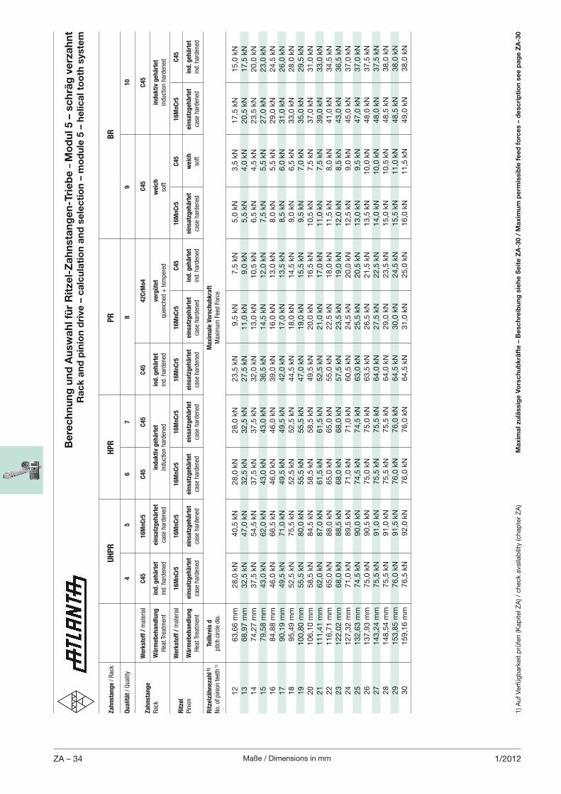
Maße / Dimensions in mmZA – 34 1/2012
Be
rec
hn
un
g u
nd
Au
swa
hl f
ür
Rit
zel-
Za
hn
sta
ng
en
-Tri
eb
e –
Mo
du
l 5 –
sc
hrä
g v
erz
ah
nt
Ra
ck
an
d p
inio
n d
rive
– c
alc
ula
tio
n a
nd
se
lec
tio
n –
mo
du
le 5
– h
elic
al t
oo
th s
yste
m
Ma
xim
al z
ulä
ssig
e V
ors
ch
ub
krä
fte
– B
esc
hre
ibu
ng
sie
he
Se
ite
ZA
-30 /
Ma
xim
um
pe
rmis
sib
le f
ee
d f
orc
es
– d
esc
rip
tio
n s
ee
pa
ge
ZA
-30
Za
hn
sta
ng
e / Rac
k
UH
PR
HP
R
P
R
BR
Qu
ali
tät / Quality
4
5
6
7
8
9
10
W
erk
sto
ff /
material
C4
5
16
Mn
Cr5
C
45
C
45
C
45
42
CrM
o4
C
45
C
45
Za
hn
sta
ng
e
Rac
k W
ärm
eb
eh
an
dlu
ng
in
d. g
eh
ärt
et
ein
satz
geh
ärt
et
ind
uk
tiv
geh
ärt
et
ind
. geh
ärt
et
verg
üte
t w
eic
h
ind
uk
tiv
geh
ärt
et
Hea
t Trea
tmen
t ind. h
arden
ed
case
harden
ed
induction harden
ed
ind. h
arden
ed
quen
ched
+ tem
pered
so
ft
induction harden
ed
W
erk
sto
ff /
material
16
Mn
Cr5
1
6M
nC
r5
1
6M
nC
r5
1
6M
nC
r5
16
Mn
Cr5
1
6M
nC
r5
C4
5
16
Mn
Cr5
C
45
1
6M
nC
r5
C4
5R
itze
l
Pinion
Wä
rmeb
eh
an
dlu
ng
ein
satz
geh
ärt
et
ein
satz
geh
ärt
et
ein
satz
geh
ärt
et
ein
satz
geh
ärt
et
ein
satz
geh
ärt
et
ein
satz
geh
ärt
et
ind
. geh
ärt
et
ein
satz
geh
ärt
et
weic
h
ein
satz
geh
ärt
et
ind
. geh
ärt
et
Hea
t Trea
tmen
t ca
se harden
ed
case
harden
ed
ca
se harden
ed
ca
se harden
ed
case
harden
ed
case
harden
ed
ind. h
arden
ed
case
harden
ed
soft
case
harden
ed
ind. h
arden
ed R
itze
lzä
hn
eza
hl 1
) Te
ilk
reis
d
Ma
xim
ale
Vo
rsch
ub
kra
ft
No. of pinion tee
th 1)
pitch circle dia.
Max
imum Fee
d Force
12
63,6
6 m
m
28,0
kN
40,5
kN
28,0
kN
28,0
kN
23,5
kN
9,5
kN
7,5
kN
5,0
kN
3,5
kN
17,5
kN
15,0
kN
13
68,9
7 m
m
32,5
kN
47,0
kN
32,5
kN
32,5
kN
27,5
kN
11,0
kN
9,0
kN
5,5
kN
4,0
kN
20,5
kN
17,5
kN
14
74,2
7 m
m
37,5
kN
54,5
kN
37,5
kN
37,5
kN
32,0
kN
13,0
kN
10,5
kN
6,5
kN
4,5
kN
23,5
kN
20,0
kN
15
79,5
8 m
m
43,0
kN
62,0
kN
43,0
kN
43,0
kN
36,5
kN
14,5
kN
12,0
kN
7,5
kN
5,5
kN
27,0
kN
23,0
kN
16
84,8
8 m
m
46,0
kN
66,5
kN
46,0
kN
46,0
kN
39,0
kN
16,0
kN
13,0
kN
8,0
kN
5,5
kN
29,0
kN
24,5
kN
17
90,1
9 m
m
49,5
kN
71,0
kN
49,5
kN
49,5
kN
42,0
kN
17,0
kN
13,5
kN
8,5
kN
6,0
kN
31,0
kN
26,0
kN
18
95,4
9 m
m
52,5
kN
75,5
kN
52,5
kN
52,5
kN
44,5
kN
18,0
kN
14,5
kN
9,0
kN
6,5
kN
33,0
kN
28,0
kN
19
100,8
0 m
m
55,5
kN
80,0
kN
55,5
kN
55,5
kN
47,0
kN
19,0
kN
15,5
kN
9,5
kN
7,0
kN
35,0
kN
29,5
kN
20
106,1
0 m
m
58,5
kN
84,5
kN
58,5
kN
58,5
kN
49,5
kN
20,0
kN
16,5
kN
10,5
kN
7,5
kN
37,0
kN
31,0
kN
21
111,4
1 m
m
62,0
kN
87,0
kN
61,5
kN
61,5
kN
52,5
kN
21,0
kN
17,0
kN
11,0
kN
7,5
kN
39,0
kN
33,0
kN
22
116,7
1 m
m
65,0
kN
88,0
kN
65,0
kN
65,0
kN
55,0
kN
22,5
kN
18,0
kN
11,5
kN
8,0
kN
41,0
kN
34,5
kN
23
122,0
2 m
m
68,0
kN
88,5
kN
68,0
kN
68,0
kN
57,5
kN
23,5
kN
19,0
kN
12,0
kN
8,5
kN
43,0
kN
36,5
kN
24
127,3
2 m
m
71,0
kN
89,5
kN
71,0
kN
71,0
kN
60,5
kN
24,5
kN
20,0
kN
12,5
kN
9,0
kN
45,0
kN
37,0
kN
25
132,6
3 m
m
74,5
kN
90,0
kN
74,5
kN
74,5
kN
63,0
kN
25,5
kN
20,5
kN
13,0
kN
9,5
kN
47,0
kN
37,0
kN
26
137,9
3 m
m
75,0
kN
90,5
kN
75,0
kN
75,0
kN
63,5
kN
26,5
kN
21,5
kN
13,5
kN
10,0
kN
48,0
kN
37,5
kN
27
143,2
4 m
m
75,5
kN
91,0
kN
75,5
kN
75,5
kN
64,0
kN
27,5
kN
22,5
kN
14,0
kN
10,0
kN
48,0
kN
37,5
kN
28
148,5
4 m
m
75,5
kN
91,0
kN
75,5
kN
75,5
kN
64,0
kN
29,0
kN
23,5
kN
15,0
kN
10,5
kN
48,5
kN
38,0
kN
29
153,8
5 m
m
76,0
kN
91,5
kN
76,0
kN
76,0
kN
64,5
kN
30,0
kN
24,5
kN
15,5
kN
11,0
kN
48,5
kN
38,0
kN
30
159,1
6 m
m
76,5
kN
92,0
kN
76,0
kN
76,0
kN
64,5
kN
31,0
kN
25,0
kN
16,0
kN
11,5
kN
49,0
kN
38,0
kN
1) A
uf
Ver
füg
bar
keit
prü
fen (K
apite
l ZA
) / c
hec
k av
aila
bili
ty (c
hap
ter
ZA
)
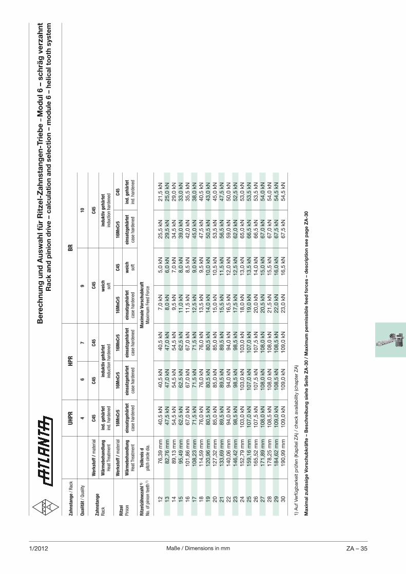
Maße / Dimensions in mm ZA – 351/2012
Be
rec
hn
un
g u
nd
Au
swa
hl f
ür
Rit
zel-
Za
hn
sta
ng
en
-Tri
eb
e –
Mo
du
l 6 –
sc
hrä
g v
erz
ah
nt
Ra
ck
an
d p
inio
n d
rive
– c
alc
ula
tio
n a
nd
se
lec
tio
n –
mo
du
le 6
– h
elic
al t
oo
th s
yste
m
1) A
uf
Ver
füg
bar
keit
prü
fen (K
apite
l ZA
) / c
hec
k av
aila
bili
ty (c
hap
ter
ZA
)
Za
hn
sta
ng
e / Rac
k
UH
PR
HP
R
B
R
Qu
ali
tät / Quality
4
6
7
9
10
W
erk
sto
ff /
material
C4
5
C4
5
C4
5
C4
5
C4
5Z
ah
nst
an
ge
Rac
k W
ärm
eb
eh
an
dlu
ng
in
d. g
eh
ärt
et
ind
uk
tiv
geh
ärt
et
weic
h
ind
uk
tiv
geh
ärt
et
Hea
t Trea
tmen
t ind. h
arden
ed
induction harden
ed
soft
induction harden
ed
W
erk
sto
ff /
material
16
Mn
Cr5
1
6M
nC
r5
1
6M
nC
r5
1
6M
nC
r5
C4
5
16
Mn
Cr5
C
45
Rit
zel
Pinion
Wä
rmeb
eh
an
dlu
ng
ein
satz
geh
ärt
et
ein
satz
geh
ärt
et
ein
satz
geh
ärt
et
ein
satz
geh
ärt
et
weic
h
ein
satz
geh
ärt
et
ind
. geh
ärt
et
Hea
t Trea
tmen
t ca
se harden
ed
case
harden
ed
ca
se harden
ed
ca
se harden
ed
soft
case
harden
ed
ind. h
arden
ed
Rit
zelz
äh
neza
hl 1
) Te
ilk
reis
d
M
axim
ale
Vo
rsch
ub
kra
ft
No. of pinion tee
th 1)
pitch circle dia.
Max
imum Fee
d Force
12
76,3
9 m
m
40,5
kN
40,5
kN
40,5
kN
7,0
kN
5,0
kN
25,5
kN
21,5
kN
13
82,7
6 m
m
47,5
kN
47,0
kN
47,0
kN
8,0
kN
6,0
kN
29,5
kN
25,0
kN
14
89,1
3 m
m
54,5
kN
54,5
kN
54,5
kN
9,5
kN
7,0
kN
34,5
kN
29,0
kN
15
95,4
9 m
m
62,5
kN
62,5
kN
62,5
kN
11,0
kN
8,0
kN
39,0
kN
33,0
kN
16
101,8
6 m
m
67,0
kN
67,0
kN
67,0
kN
11,5
kN
8,5
kN
42,0
kN
35,5
kN
17
108,2
3 m
m
71,5
kN
71,5
kN
71,5
kN
12,5
kN
9,0
kN
45,0
kN
38,0
kN
18
114,5
9 m
m
76,0
kN
76,0
kN
76,0
kN
13,5
kN
9,5
kN
47,5
kN
40,5
kN
19
120,9
6 m
m
80,5
kN
80,5
kN
80,5
kN
14,0
kN
10,0
kN
50,5
kN
43,0
kN
20
127,3
2 m
m
85,0
kN
85,0
kN
85,0
kN
15,0
kN
10,5
kN
53,5
kN
45,0
kN
21
133,6
9 m
m
89,5
kN
89,5
kN
89,5
kN
15,5
kN
11,5
kN
56,5
kN
47,5
kN
22
140,0
6 m
m
94,0
kN
94,0
kN
94,0
kN
16,5
kN
12,0
kN
59,0
kN
50,0
kN
23
146,4
2 m
m
98,5
kN
98,5
kN
98,5
kN
17,5
kN
12,5
kN
62,0
kN
52,5
kN
24
152,7
9 m
m
103,0
kN
103,0
kN
103,0
kN
18,0
kN
13,0
kN
65,0
kN
53,0
kN
25
159,1
6 m
m
107,0
kN
107,0
kN
107,0
kN
19,0
kN
13,5
kN
66,5
kN
53,5
kN
26
165,5
2 m
m
107,5
kN
107,5
kN
107,5
kN
20,0
kN
14,0
kN
66,5
kN
53,5
kN
27
171,8
9 m
m
108,0
kN
108,0
kN
108,0
kN
20,5
kN
15,0
kN
67,0
kN
54,0
kN
28
178,2
5 m
m
108,5
kN
108,0
kN
108,0
kN
21,5
kN
15,5
kN
67,0
kN
54,0
kN
29
184,6
2 m
m
109,0
kN
108,5
kN
108,5
kN
22,0
kN
16,0
kN
67,5
kN
54,5
kN
30
190,9
9 m
m
109,0
kN
109,0
kN
109,0
kN
23,0
kN
16,5
kN
67,5
kN
54,5
kN
Ma
xim
al z
ulä
ssig
e V
ors
ch
ub
krä
fte
– B
esc
hre
ibu
ng
sie
he
Se
ite
ZA
-30 /
Ma
xim
um
pe
rmis
sib
le f
ee
d f
orc
es
– d
esc
rip
tio
n s
ee
pa
ge
ZA
-30
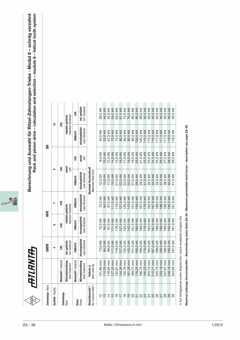
Maße / Dimensions in mmZA – 36 1/2012
Be
rec
hn
un
g u
nd
Au
swa
hl f
ür
Rit
zel-
Za
hn
sta
ng
en
-Tri
eb
e –
Mo
du
l 8 –
sc
hrä
g v
erz
ah
nt
Ra
ck
an
d p
inio
n d
rive
– c
alc
ula
tio
n a
nd
se
lec
tio
n –
mo
du
le 8
– h
elic
al t
oo
th s
yste
m
1) A
uf
Ver
füg
bar
keit
prü
fen (K
apite
l ZA
) / c
hec
k av
aila
bili
ty (c
hap
ter
ZA
)
Za
hn
sta
ng
e / Rac
k
UH
PR
HP
R
B
R
Qu
ali
tät / Quality
4
6
7
9
10
W
erk
sto
ff /
material
C4
5
C4
5
C4
5
C4
5
C4
5Z
ah
nst
an
ge
Rac
k W
ärm
eb
eh
an
dlu
ng
in
d. g
eh
ärt
et
ind
uk
tiv
geh
ärt
et
weic
h
ind
uk
tiv
geh
ärt
et
Hea
t Trea
tmen
t ind. h
arden
ed
induction harden
ed
soft
induction harden
ed
W
erk
sto
ff /
material
16
Mn
Cr5
1
6M
nC
r5
1
6M
nC
r5
1
6M
nC
r5
C4
5
16
Mn
Cr5
C
45
Rit
zel
Pinion
Wä
rmeb
eh
an
dlu
ng
ein
satz
geh
ärt
et
ein
satz
geh
ärt
et
ein
satz
geh
ärt
et
ein
satz
geh
ärt
et
weic
h
ein
satz
geh
ärt
et
ind
. geh
ärt
et
Hea
t Trea
tmen
t ca
se harden
ed
case
harden
ed
ca
se harden
ed
ca
se harden
ed
soft
case
harden
ed
ind. h
arden
ed
Rit
zelz
äh
neza
hl 1
) Te
ilk
reis
d
M
axim
ale
Vo
rsch
ub
kra
ft
No. of pinion tee
th 1)
pitch circle dia.
Max
imum Fee
d Force
12
101,8
6 m
m
73,0
kN
72,5
kN
72,5
kN
12,5
kN
9,0
kN
45,5
kN
38,5
kN
13
110,3
5 m
m
84,5
kN
84,5
kN
84,5
kN
15,0
kN
10,5
kN
53,0
kN
44,5
kN
14
118,8
4 m
m
98,0
kN
97,5
kN
97,5
kN
17,0
kN
12,5
kN
61,5
kN
52,0
kN
15
127,3
2 m
m
111,5
kN
111,5
kN
111,5
kN
19,5
kN
14,0
kN
70,0
kN
59,5
kN
16
135,8
1 m
m
119,5
kN
119,5
kN
119,5
kN
21,0
kN
15,0
kN
75,0
kN
63,5
kN
17
144,3
0 m
m
127,5
kN
127,5
kN
127,5
kN
22,5
kN
16,0
kN
80,0
kN
67,5
kN
18
152,7
9 m
m
135,5
kN
135,5
kN
135,5
kN
24,0
kN
17,0
kN
85,0
kN
72,0
kN
19
161,2
8 m
m
143,5
kN
143,5
kN
143,5
kN
25,5
kN
18,0
kN
90,0
kN
76,5
kN
20
169,7
7 m
m
151,5
kN
151,5
kN
151,5
kN
27,0
kN
19,5
kN
95,5
kN
80,5
kN
21
178,2
5 m
m
160,0
kN
160,0
kN
159,5
kN
28,5
kN
20,5
kN
100,5
kN
85,0
kN
22
186,7
4 m
m
168,0
kN
168,0
kN
167,5
kN
29,5
kN
21,5
kN
105,5
kN
89,0
kN
23
195,2
3 m
m
176,0
kN
176,0
kN
176,0
kN
31,0
kN
22,5
kN
110,5
kN
92,5
kN
24
203,7
2 m
m
184,0
kN
184,0
kN
184,0
kN
32,5
kN
23,5
kN
115,5
kN
93,0
kN
25
212,2
1 m
m
187,0
kN
187,0
kN
187,0
kN
34,0
kN
24,5
kN
116,5
kN
93,5
kN
26
220,7
0 m
m
188,0
kN
188,0
kN
188,0
kN
35,5
kN
25,5
kN
117,0
kN
94,0
kN
27
229,1
8 m
m
189,0
kN
189,0
kN
188,5
kN
37,0
kN
26,5
kN
117,5
kN
94,5
kN
28
237,6
7 m
m
189,5
kN
189,5
kN
189,5
kN
38,5
kN
27,5
kN
117,5
kN
95,0
kN
29
246,1
6 m
m
190,5
kN
190,5
kN
190,5
kN
40,0
kN
28,5
kN
118,0
kN
95,0
kN
30
254,6
5 m
m
191,0
kN
191,0
kN
191,0
kN
41,5
kN
29,5
kN
118,5
kN
95,5
kN
Ma
xim
al z
ulä
ssig
e V
ors
ch
ub
krä
fte
– B
esc
hre
ibu
ng
sie
he
Se
ite
ZA
-30 /
Ma
xim
um
pe
rmis
sib
le f
ee
d f
orc
es
– d
esc
rip
tio
n s
ee
pa
ge
ZA
-30
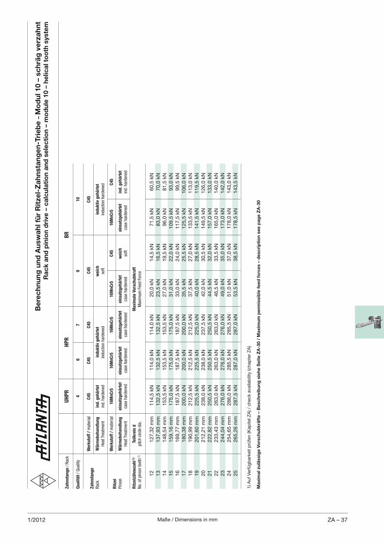
Maße / Dimensions in mm ZA – 371/2012
1) A
uf
Ver
füg
bar
keit
prü
fen (K
apite
l ZA
) / c
hec
k av
aila
bili
ty (c
hap
ter
ZA
)
Za
hn
sta
ng
e / Rac
k
UH
PR
HP
R
B
R
Qu
ali
tät / Quality
4
6
7
9
10
W
erk
sto
ff /
material
C4
5
C4
5
C4
5
C4
5
C4
5Z
ah
nst
an
ge
Rac
k W
ärm
eb
eh
an
dlu
ng
in
d. g
eh
ärt
et
ind
uk
tiv
geh
ärt
et
weic
h
ind
uk
tiv
geh
ärt
et
Hea
t Trea
tmen
t ind. h
arden
ed
induction harden
ed
soft
induction harden
ed
W
erk
sto
ff /
material
16
Mn
Cr5
1
6M
nC
r5
1
6M
nC
r5
1
6M
nC
r5
C4
5
16
Mn
Cr5
C
45
Rit
zel
Pinion
Wä
rmeb
eh
an
dlu
ng
ein
satz
geh
ärt
et
ein
satz
geh
ärt
et
ein
satz
geh
ärt
et
ein
satz
geh
ärt
et
weic
h
ein
satz
geh
ärt
et
ind
. geh
ärt
et
Hea
t Trea
tmen
t ca
se harden
ed
case
harden
ed
ca
se harden
ed
ca
se harden
ed
soft
case
harden
ed
ind. h
arden
ed
Rit
zelz
äh
neza
hl 1
) Te
ilk
reis
d
M
axim
ale
Vo
rsch
ub
kra
ft
No. of pinion tee
th 1)
pitch circle dia.
Max
imum Fee
d Force
12
127,3
2 m
m
114,5
kN
114,0
kN
114,0
kN
20,0
kN
14,5
kN
71,5
kN
60,5
kN
13
137,9
3 m
m
132,5
kN
132,5
kN
132,5
kN
23,5
kN
16,5
kN
83,0
kN
70,0
kN
14
148,5
4 m
m
153,5
kN
153,5
kN
153,5
kN
27,0
kN
19,5
kN
96,0
kN
81,5
kN
15
159,1
6 m
m
175,0
kN
175,0
kN
175,0
kN
31,0
kN
22,0
kN
109,5
kN
93,0
kN
16
169,7
7 m
m
187,5
kN
187,5
kN
187,5
kN
33,0
kN
24,0
kN
117,5
kN
99,5
kN
17
180,3
8 m
m
200,0
kN
200,0
kN
200,0
kN
35,5
kN
25,5
kN
125,5
kN
106,0
kN
18
190,9
9 m
m
212,5
kN
212,5
kN
212,5
kN
37,5
kN
27,0
kN
133,5
kN
113,0
kN
19
201,6
0 m
m
225,5
kN
225,5
kN
225,0
kN
40,0
kN
28,5
kN
141,5
kN
119,5
kN
20
212,2
1 m
m
238,0
kN
238,0
kN
237,5
kN
42,0
kN
30,5
kN
149,5
kN
126,0
kN
21
222,8
2 m
m
250,5
kN
250,5
kN
250,5
kN
44,5
kN
32,0
kN
157,0
kN
133,0
kN
22
233,4
3 m
m
263,0
kN
263,0
kN
263,0
kN
46,5
kN
33,5
kN
165,0
kN
140,0
kN
23
244,0
4 m
m
276,0
kN
276,0
kN
276,0
kN
49,0
kN
35,0
kN
173,0
kN
142,0
kN
24
254,6
5 m
m
286,0
kN
285,5
kN
285,5
kN
51,0
kN
37,0
kN
178,0
kN
143,0
kN
25
265,2
6 m
m
287,5
kN
287,0
kN
287,0
kN
53,5
kN
38,5
kN
178,5
kN
143,5
kN
Ma
xim
al z
ulä
ssig
e V
ors
ch
ub
krä
fte
– B
esc
hre
ibu
ng
sie
he
Se
ite
ZA
-30 /
Ma
xim
um
pe
rmis
sib
le f
ee
d f
orc
es
– d
esc
rip
tio
n s
ee
pa
ge
ZA
-30
Be
rec
hn
un
g u
nd
Au
swa
hl f
ür
Rit
zel-
Za
hn
sta
ng
en
-Tri
eb
e –
Mo
du
l 10 –
sc
hrä
g v
erz
ah
nt
Ra
ck
an
d p
inio
n d
rive
– c
alc
ula
tio
n a
nd
se
lec
tio
n –
mo
du
le 1
0 –
he
lica
l to
oth
sys
tem
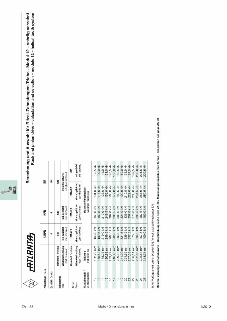
Maße / Dimensions in mmZA – 38 1/2012
Be
rec
hn
un
g u
nd
Au
swa
hl f
ür
Rit
zel-
Za
hn
sta
ng
en
-Tri
eb
e –
Mo
du
l 12 –
sc
hrä
g v
erz
ah
nt
Ra
ck
an
d p
inio
n d
rive
– c
alc
ula
tio
n a
nd
se
lec
tio
n –
mo
du
le 1
2 –
he
lica
l to
oth
sys
tem
1) A
uf
Ver
füg
bar
keit
prü
fen (K
apite
l ZA
) / c
hec
k av
aila
bili
ty (c
hap
ter
ZA
)
Za
hn
sta
ng
e / Rac
k
UH
PR
HP
R
BR
Qu
ali
tät / Quality
4
6
10
W
erk
sto
ff /
material
C4
5
C4
5
C4
5Z
ah
nst
an
ge
Rac
k W
ärm
eb
eh
an
dlu
ng
in
d. g
eh
ärt
et
ind
. geh
ärt
et
i
nd
uk
tiv
geh
ärt
et
Hea
t Trea
tmen
t ind. h
arden
ed
ind. h
arden
ed
in
duction harden
ed
W
erk
sto
ff /
material
16
Mn
Cr5
1
6M
nC
r5
1
6M
nC
r5
C
45
R
itze
l
Pinion
Wä
rmeb
eh
an
dlu
ng
ein
satz
geh
ärt
et
ein
satz
geh
ärt
et
ein
satz
geh
ärt
et
in
d. g
eh
ärt
et
Hea
t Trea
tmen
t ca
se harden
ed
case
harden
ed
ca
se harden
ed
ind. h
arden
ed
Rit
zelz
äh
neza
hl 1
) Te
ilk
reis
d
M
axim
ale
Vo
rsch
ub
kra
ft
No. of p
inion teeth 1)
pitch circle dia.
M
axim
um Fee
d Force
12
152,7
9 m
m
163,0
kN
163,0
kN
101,0
kN
85,5
kN
13
165,5
2 m
m
189,5
kN
189,5
kN
117,5
kN
99,0
kN
14
178,2
5 m
m
219,0
kN
219,0
kN
136,0
kN
115,0
kN
15
190,9
9 m
m
249,5
kN
249,5
kN
155,0
kN
131,0
kN
16
203,7
2 m
m
267,5
kN
267,0
kN
166,0
kN
140,5
kN
17
216,4
5 m
m
285,5
kN
285,5
kN
177,0
kN
150,0
kN
18
229,1
8 m
m
303,0
kN
303,0
kN
188,5
kN
159,5
kN
19
241,9
2 m
m
321,5
kN
321,0
kN
199,5
kN
169,0
kN
20
254,6
5 m
m
339,5
kN
339,0
kN
210,5
kN
178,5
kN
21
267,3
8 m
m
357,5
kN
357,0
kN
222,0
kN
187,5
kN
22
280,1
1 m
m
375,5
kN
375,0
kN
233,0
kN
197,5
kN
23
292,8
5 m
m
394,0
kN
393,5
kN
244,5
kN
200,0
kN
24
305,5
8 m
m
407,5
kN
407,5
kN
251,0
kN
201,5
kN
25
318,3
1 m
m
409,0
kN
409,0
kN
252,5
kN
202,5
kN
Ma
xim
al z
ulä
ssig
e V
ors
ch
ub
krä
fte
– B
esc
hre
ibu
ng
sie
he
Se
ite
ZA
-30 /
Ma
xim
um
pe
rmis
sib
le f
ee
d f
orc
es
– d
esc
rip
tio
n s
ee
pa
ge
ZA
-30
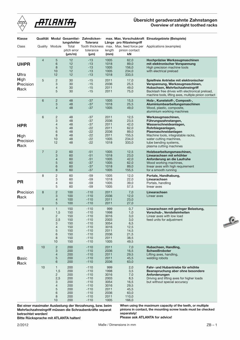
Maße / Dimensions in mm ZB – 12/2012
Übersicht geradverzahnte ZahnstangenOverview of straight toothed racks
Klasse Qualität Modul Gesamttei- Zahndicken- max. Max. Vorschubkraft Einsatzgebiete (Beispiele) lungsfehler Toleranz Länge pro RitzeleingriffClass Quality Module Total Tooth thickness max. Max. feed force per Applications (examples) pitch error tolerance length pinion contact (µm/m) (µm) (mm) kN
4 5 12 -13 1005 62,0 Hochpräzise Werkzeugmaschinen 6 12 -13 1018 89,0 mit elektronischer Vorspannung 8 12 -13 1005 156,0 High precision machine tools 10 12 -13 1005 234,0 with electrical preload 12 12 -13 1018 333,5
5 2 30 -15 2011 17,0 Spielfreie Antriebe mit elektronischer 3 30 -15 2036 25,5 Verspannung, Werkzeugmaschinen, 4 30 -15 2011 49,0 Hubachsen, Mehrfachzahneingriff 5 30 -15 2011 75,0 Backlash free drives with electronical preload, machine tools, lifting axes, multiple pinion contact
6 2 48 -37 1005 15,5 Holz-, Kunststoff-, Composit-, 3 48 -37 1018 25,5 Aluminiumbearbeitungsmaschinen 4 48 -37 1005 49,0 Wood, plastic, composite, aluminium working machines
6 2 48 -37 2011 12,5 Werkzeugmaschinen, 3 48 -37 2036 23,5 Führungszahnstangen, 4 48 -37 2011 42,0 Wasserschneideanlagen, 5 48 -22 2011 62,0 Rohrbiegeanlagen, 6 48 -22 2036 89,0 Plasmaschneidanlagen 8 48 -22 2011 155,5 Machine tools, integratable racks, 10 48 -22 1005 234,0 water cutting machines, 12 48 -22 1018 333,0 tube bending systems, plasma cutting machines
7 2 60 -51 1005 12,5 Holzbearbeitungsmaschinen, 3 60 -51 1018 23,0 Linearachsen mit erhöhter 4 60 -51 1005 42,0 Anforderung an die Laufruhe 5 60 -37 1005 62,0 Wood working machines, 6 60 -37 1018 89,0 linear axes with high requirement 8 60 -37 1005 155,5 for a smooth running
8 2 60 -59 1005 12,0 Portale, Handhabung, 3 60 -59 1018 22,0 Linearachsen 4 60 -59 1005 39,0 Portals, handling 5 60 -59 1005 57,5 linear axes
8 2 100 -110 2011 7,0 Linearachsen 3 100 -110 2036 12,0 Linear axes 4 100 -110 2011 23,0 5 100 -110 2011 27,0
9 1 150 -110 999 0,7 Linearachsen mit geringer Belastung, 1,5 150 -110 1998 1,0 Vorschub-, Verstelleinheiten 2 150 -110 3016 3,0 Linear axes with low load 2,5 150 -110 2003 3,0 feed units for adjustment 3 150 -110 3054 6,5 4 150 -110 3016 12,5 5 150 -110 2011 14,5 6 150 -110 2036 21,5 8 150 -110 2011 38,5 10 150 -110 1005 49,5
10 2 200 -110 2011 7,0 Hubachsen, Handling, 3 200 -110 2036 16,5 Schweißroboter 4 200 -110 2011 29,5 Lifting axes, handling, 5 200 -110 2011 45,5 welding robots 6 200 -110 2036 63,0
10 1 200 -110 999 2,0 Fahr- und Hubantriebe für erhöhte 1,5 200 -110 1998 3,5 Beanspruchung aber ohne besondere 2 200 -110 3016 7,0 Anforderungen 2,5 200 -110 2003 8,5 Driving and lifting axes for higher loads 3 200 -110 3054 16,5 but without special accuracy 4 200 -110 3016 29,5 5 200 -110 2011 45,5 6 200 -110 2036 63,0 8 200 -110 2011 110,0 10 200 -110 1005 166,0
UHPR
UltraHighPrecisionRack
HPR
HighPrecisionRack
PR
PrecisionRack
BR
BasicRack
Bei einer maximaler Auslastung der Verzahnung, bzw. beim Mehrfachzahneingriff müssen die Schraubenkräfte separat betrachtet werden!Bitte Rücksprache mit ATLANTA halten!
When using the maximum capacity of the teeth, or multiple pinions in contact, the mounting screw loads must be checked separately!Please ask ATLANTA for advice!
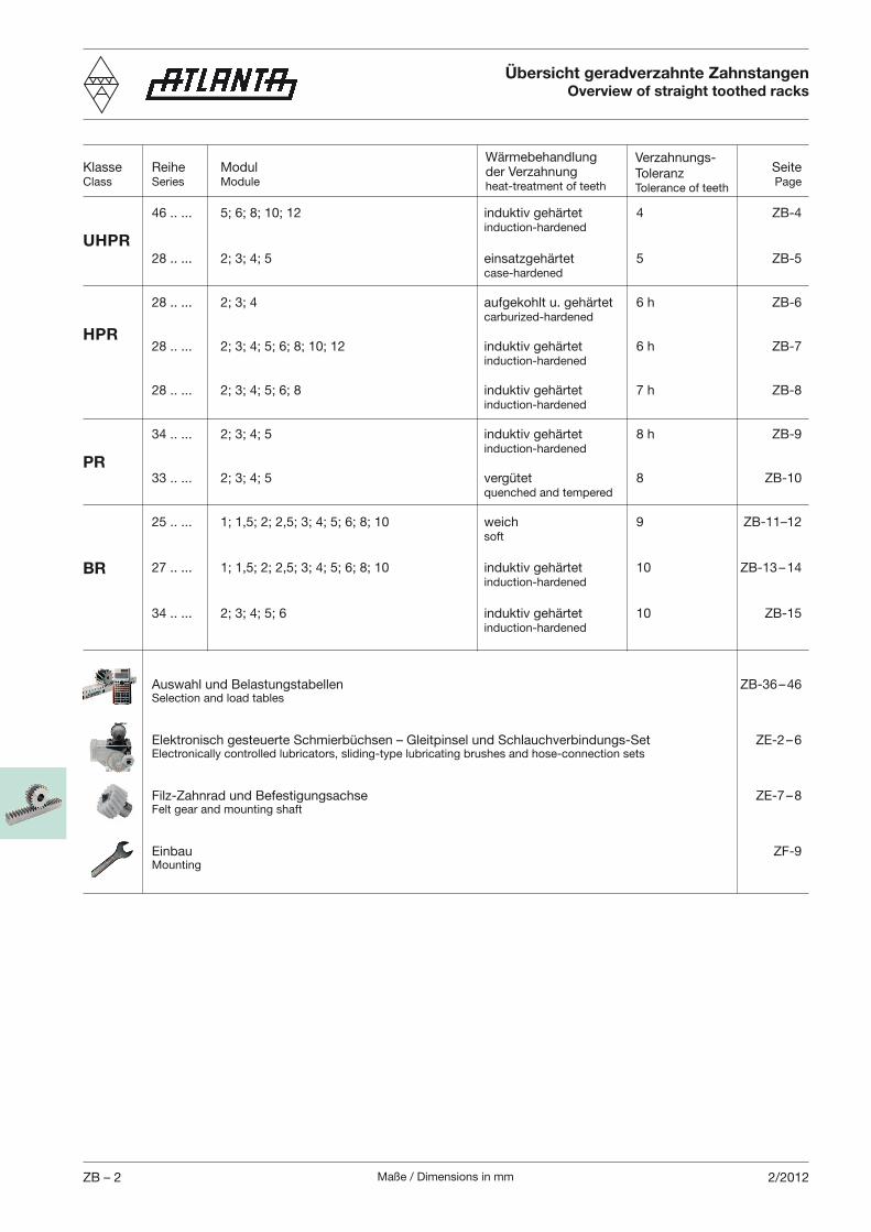
Maße / Dimensions in mmZB – 2 2/2012
Übersicht geradverzahnte ZahnstangenOverview of straight toothed racks
Klasse Reihe Modul SeiteClass Series Module Page
46 .. ... 5; 6; 8; 10; 12 induktiv gehärtet 4 ZB-4 induction-hardened
28 .. ... 2; 3; 4; 5 einsatzgehärtet 5 ZB-5 case-hardened
28 .. ... 2; 3; 4 aufgekohlt u. gehärtet 6 h ZB-6 carburized-hardened
28 .. ... 2; 3; 4; 5; 6; 8; 10; 12 induktiv gehärtet 6 h ZB-7 induction-hardened
28 .. ... 2; 3; 4; 5; 6; 8 induktiv gehärtet 7 h ZB-8 induction-hardened
34 .. ... 2; 3; 4; 5 induktiv gehärtet 8 h ZB-9 induction-hardened
33 .. ... 2; 3; 4; 5 vergütet 8 ZB-10 quenched and tempered
25 .. ... 1; 1,5; 2; 2,5; 3; 4; 5; 6; 8; 10 weich 9 ZB-11–12 soft
27 .. ... 1; 1,5; 2; 2,5; 3; 4; 5; 6; 8; 10 induktiv gehärtet 10 ZB-13 – 14 induction-hardened
34 .. ... 2; 3; 4; 5; 6 induktiv gehärtet 10 ZB-15 induction-hardened
Auswahl und Belastungstabellen ZB-36 – 46 Selection and load tables
Elektronisch gesteuerte Schmierbüchsen – Gleitpinsel und Schlauchverbindungs-Set ZE-2 – 6 Electronically controlled lubricators, sliding-type lubricating brushes and hose-connection sets
Filz-Zahnrad und Befestigungsachse ZE-7 – 8 Felt gear and mounting shaft
Einbau ZF-9 Mounting
Wärmebehandlung der Verzahnungheat-treatment of teeth
Verzahnungs-ToleranzTolerance of teeth
UHPR
HPR
PR
BR
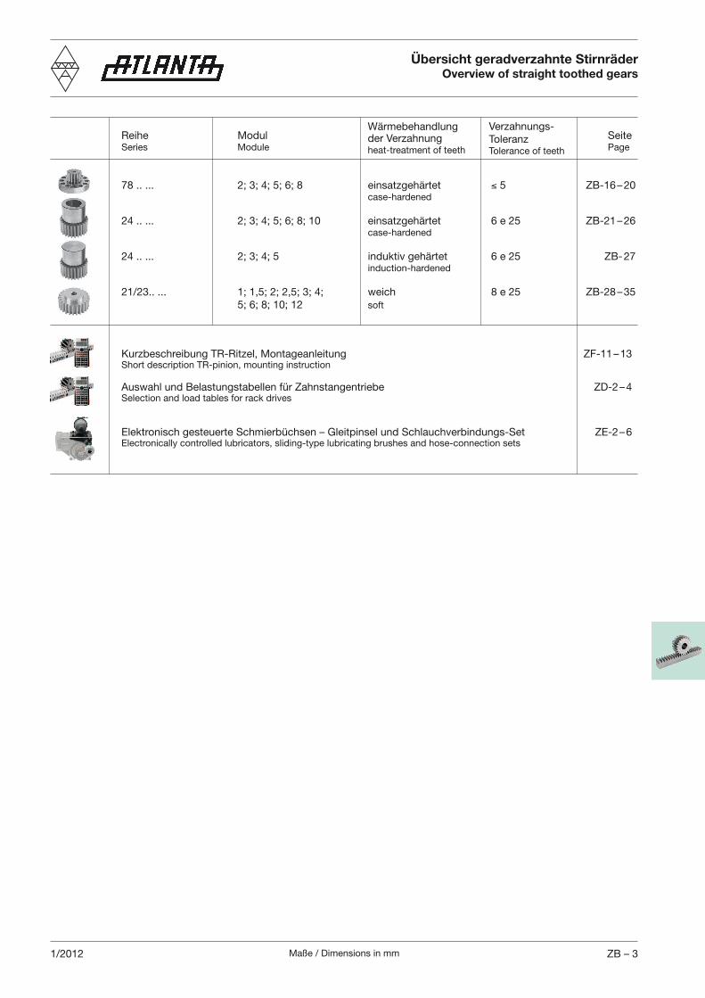
Maße / Dimensions in mm ZB – 31/2012
Übersicht geradverzahnte StirnräderOverview of straight toothed gears
Wärmebehandlung der Verzahnungheat-treatment of teeth
Verzahnungs-ToleranzTolerance of teeth
Reihe Modul Seite Series Module Page
78 .. ... 2; 3; 4; 5; 6; 8 einsatzgehärtet 5 ZB-16 – 20 case-hardened 24 .. ... 2; 3; 4; 5; 6; 8; 10 einsatzgehärtet 6 e 25 ZB-21 – 26 case-hardened 24 .. ... 2; 3; 4; 5 induktiv gehärtet 6 e 25 ZB- 27 induction-hardened 21/23.. ... 1; 1,5; 2; 2,5; 3; 4; weich 8 e 25 ZB-28 – 35 5; 6; 8; 10; 12 soft
Kurzbeschreibung TR-Ritzel, Montageanleitung ZF-11 – 13 Short description TR-pinion, mounting instruction
Auswahl und Belastungstabellen für Zahnstangentriebe ZD-2 – 4 Selection and load tables for rack drives
Elektronisch gesteuerte Schmierbüchsen – Gleitpinsel und Schlauchverbindungs-Set ZE-2 – 6 Electronically controlled lubricators, sliding-type lubricating brushes and hose-connection sets
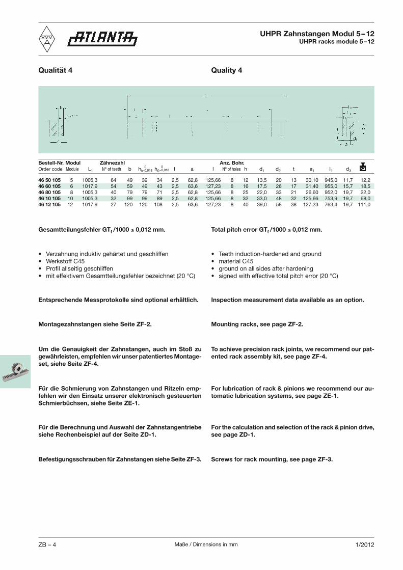
Maße / Dimensions in mmZB – 4 1/2012
UHPR Zahnstangen Modul 5 – 12UHPR racks module 5 – 12
Bestell-Nr. Modul Zähnezahl Anz. Bohr.Order code Module L1 N° of teeth b hk h0 f a I N° of holes h d1 d2 t a1 I1 d3
0- 0,018
Qualität 4 Quality 4
0- 0,018
Total pitch error GTf /1000 0,012 mm.Gesamtteilungsfehler GTf /1000 0,012 mm.
Entsprechende Messprotokolle sind optional erhältlich. Inspection measurement data available as an option.
Um die Genauigkeit der Zahnstangen, auch im Stoß zu gewährleisten, empfehlen wir unser patentiertes Montage-set, siehe Seite ZF-4.
To achieve precision rack joints, we recommend our pat-ented rack assembly kit, see page ZF-4.
Montagezahnstangen siehe Seite ZF-2. Mounting racks, see page ZF-2.
Für die Schmierung von Zahnstangen und Ritzeln emp-fehlen wir den Einsatz unserer elektronisch gesteuerten Schmierbüchsen, siehe Seite ZE-1.
For lubrication of rack & pinions we recommend our au-tomatic lubrication systems, see page ZE-1.
46 50 105 5 1005,3 64 49 39 34 2,5 62,8 125,66 8 12 13,5 20 13 30,10 945,0 11,7 12,246 60 105 6 1017,9 54 59 49 43 2,5 63,6 127,23 8 16 17,5 26 17 31,40 955,0 15,7 18,546 80 105 8 1005,3 40 79 79 71 2,5 62,8 125,66 8 25 22,0 33 21 26,60 952,0 19,7 22,046 10 105 10 1005,3 32 99 99 89 2,5 62,8 125,66 8 32 33,0 48 32 125,66 753,9 19,7 68,046 12 105 12 1017,9 27 120 120 108 2,5 63,6 127,23 8 40 39,0 58 38 127,23 763,4 19,7 111,0
Für die Berechnung und Auswahl der Zahnstangentriebe siehe Rechenbeispiel auf der Seite ZD-1.
For the calculation and selection of the rack & pinion drive, see page ZD-1.
Befestigungsschrauben für Zahnstangen siehe Seite ZF-3. Screws for rack mounting, see page ZF-3.
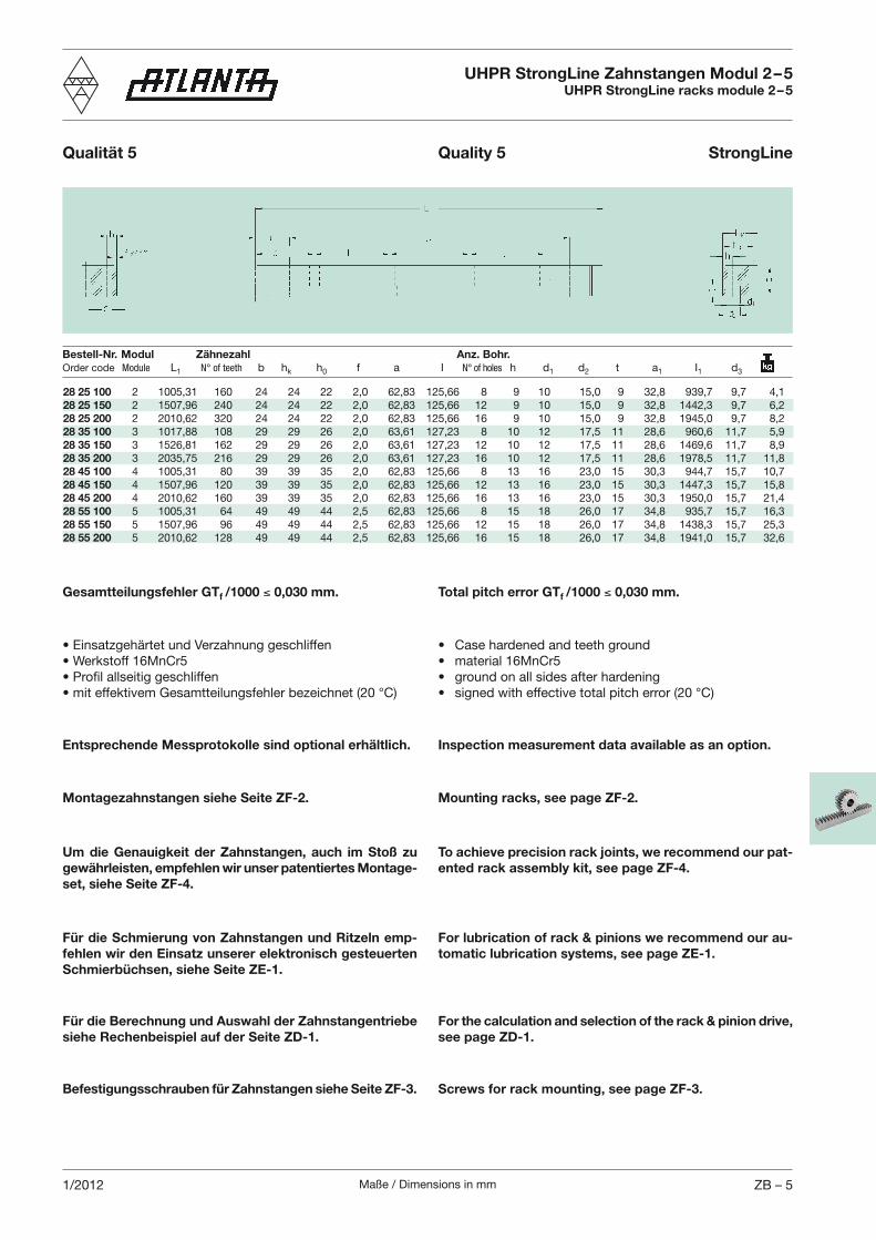
Maße / Dimensions in mm ZB – 51/2012
28 25 100 2 1005,31 160 24 24 22 2,0 62,83 125,66 8 9 10 15,0 9 32,8 939,7 9,7 4,128 25 150 2 1507,96 240 24 24 22 2,0 62,83 125,66 12 9 10 15,0 9 32,8 1442,3 9,7 6,228 25 200 2 2010,62 320 24 24 22 2,0 62,83 125,66 16 9 10 15,0 9 32,8 1945,0 9,7 8,228 35 100 3 1017,88 108 29 29 26 2,0 63,61 127,23 8 10 12 17,5 11 28,6 960,6 11,7 5,928 35 150 3 1526,81 162 29 29 26 2,0 63,61 127,23 12 10 12 17,5 11 28,6 1469,6 11,7 8,928 35 200 3 2035,75 216 29 29 26 2,0 63,61 127,23 16 10 12 17,5 11 28,6 1978,5 11,7 11,828 45 100 4 1005,31 80 39 39 35 2,0 62,83 125,66 8 13 16 23,0 15 30,3 944,7 15,7 10,728 45 150 4 1507,96 120 39 39 35 2,0 62,83 125,66 12 13 16 23,0 15 30,3 1447,3 15,7 15,828 45 200 4 2010,62 160 39 39 35 2,0 62,83 125,66 16 13 16 23,0 15 30,3 1950,0 15,7 21,428 55 100 5 1005,31 64 49 49 44 2,5 62,83 125,66 8 15 18 26,0 17 34,8 935,7 15,7 16,328 55 150 5 1507,96 96 49 49 44 2,5 62,83 125,66 12 15 18 26,0 17 34,8 1438,3 15,7 25,328 55 200 5 2010,62 128 49 49 44 2,5 62,83 125,66 16 15 18 26,0 17 34,8 1941,0 15,7 32,6
Bestell-Nr. Modul Zähnezahl Anz. Bohr.Order code Module L1 N° of teeth b hk h0 f a I N° of holes h d1 d2 t a1 I1 d3
UHPR StrongLine Zahnstangen Modul 2 – 5UHPR StrongLine racks module 2 – 5
Qualität 5 Quality 5 StrongLine
Total pitch error GTf /1000 0,030 mm.Gesamtteilungsfehler GTf /1000 0,030 mm.
Entsprechende Messprotokolle sind optional erhältlich. Inspection measurement data available as an option.
Um die Genauigkeit der Zahnstangen, auch im Stoß zu gewährleisten, empfehlen wir unser patentiertes Montage-set, siehe Seite ZF-4.
To achieve precision rack joints, we recommend our pat-ented rack assembly kit, see page ZF-4.
Montagezahnstangen siehe Seite ZF-2. Mounting racks, see page ZF-2.
Für die Schmierung von Zahnstangen und Ritzeln emp-fehlen wir den Einsatz unserer elektronisch gesteuerten Schmierbüchsen, siehe Seite ZE-1.
For lubrication of rack & pinions we recommend our au-tomatic lubrication systems, see page ZE-1.
Für die Berechnung und Auswahl der Zahnstangentriebe siehe Rechenbeispiel auf der Seite ZD-1.
For the calculation and selection of the rack & pinion drive, see page ZD-1.
Befestigungsschrauben für Zahnstangen siehe Seite ZF-3. Screws for rack mounting, see page ZF-3.
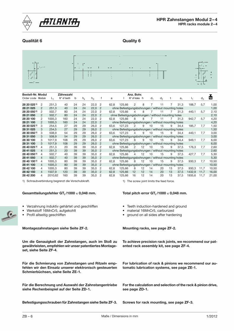
Maße / Dimensions in mmZB – 6 1/2012
HPR Zahnstangen Modul 2 – 4HPR racks module 2 – 4
Qualität 6 Quality 6
Bestell-Nr. Modul Zähnezahl Anz. Bohr.Order code Module L1 N° of teeth b hk h0 f a I N° of holes h d1 d2 t a1 I1 d3
Total pitch error GTf /1000 0,048 mm.Gesamtteilungsfehler GTf /1000 0,048 mm.
Um die Genauigkeit der Zahnstangen, auch im Stoß zu gewährleisten, empfehlen wir unser patentiertes Montage-set, siehe Seite ZF-4.
To achieve precision rack joints, we recommend our pat-ented rack assembly kit, see page ZF-4.
Montagezahnstangen siehe Seite ZF-2. Mounting racks, see page ZF-2.
Für die Schmierung von Zahnstangen und Ritzeln emp-fehlen wir den Einsatz unserer elektronisch gesteuerten Schmierbüchsen, siehe Seite ZE-1.
For lubrication of rack & pinions we recommend our au-tomatic lubrication systems, see page ZE-1.
1) Schraubverbindung begrenzt die Vorschubkraft. 1) The screw joint limits the feed force.
28 20 025 1) 2 251,3 40 24 24 22,0 2 62,8 125,66 2 8 7 11 7 31,3 188,7 5,7 1,0028 21 025 2 251,3 40 24 24 22,0 2 ohne Befestigungsbohrungen / without mounting holes 1,0028 20 050 1) 2 502,7 80 24 24 22,0 2 62,8 125,66 4 8 7 11 7 31,3 440,1 5,7 2,1028 21 050 2 502,7 80 24 24 22,0 2 o hne Befestigungsbohrungen / without mounting holes 2,1028 20 100 2 1005,3 160 24 24 22,0 2 62,8 125,66 8 8 7 11 7 31,3 942,7 5,7 4,2028 21 100 2 1005,3 160 24 24 22,0 2 ohne Befestigungsbohrungen / without mounting holes 4,2028 30 025 1) 3 254,5 27 29 29 26,0 2 63,6 127,23 2 9 10 15 9 34,4 185,7 7,7 1,5028 31 025 3 254,5 27 29 29 26,0 2 ohne Befestigungsbohrungen / without mounting holes 1,5028 30 050 1) 3 508,9 54 29 29 26,0 2 63,6 127,23 4 9 10 15 9 34,4 440,1 7,7 3,0028 31 050 3 508,9 54 29 29 26,0 2 ohne Befestigungsbohrungen / without mounting holes 3,0028 30 100 3 1017,9 108 29 29 26,0 2 63,6 127,23 8 9 10 15 9 34,4 949,1 7,7 6,0028 31 100 3 1017,9 108 29 29 26,0 2 ohne Befestigungsbohrungen / without mounting holes 6,0028 40 025 1) 4 251,3 20 39 39 35,0 2 62,8 125,66 2 12 10 15 9 37,5 176,3 7,7 2,6028 41 025 4 251,3 20 39 39 35,0 2 ohne Befestigungsbohrungen / without mounting holes 2,6028 40 050 1) 4 502,7 40 39 39 35,0 2 62,8 125,66 4 12 10 15 9 37,5 427,7 7,7 5,3028 41 050 4 502,7 40 39 39 35,0 2 ohne Befestigungsbohrungen / without mounting holes 5,3028 40 100 1) 4 1005,3 80 39 39 35,0 2 62,8 125,66 8 12 10 15 9 37,5 930,3 7,7 10,5028 41 100 4 1005,3 80 39 39 35,0 2 ohne Befestigungsbohrungen / without mounting holes 10,5028 42 100 4 1005,3 80 39 39 35,0 2 62,8 125,66 8 12 14 20 13 37,5 930,3 11,7 10,5028 42 150 4 1507,9 120 39 39 35,0 2 62,8 125,66 12 12 14 20 13 37,5 1432,9 11,7 16,0028 42 200 4 2010,62 160 39 39 35,0 2 62,8 125,66 16 12 14 20 13 37,5 1935,6 11,7 21,00
Für die Berechnung und Auswahl der Zahnstangentriebe siehe Rechenbeispiel auf der Seite ZD-1.
For the calculation and selection of the rack & pinion drive, see page ZD-1.
Befestigungsschrauben für Zahnstangen siehe Seite ZF-3. Screws for rack mounting, see page ZF-3.
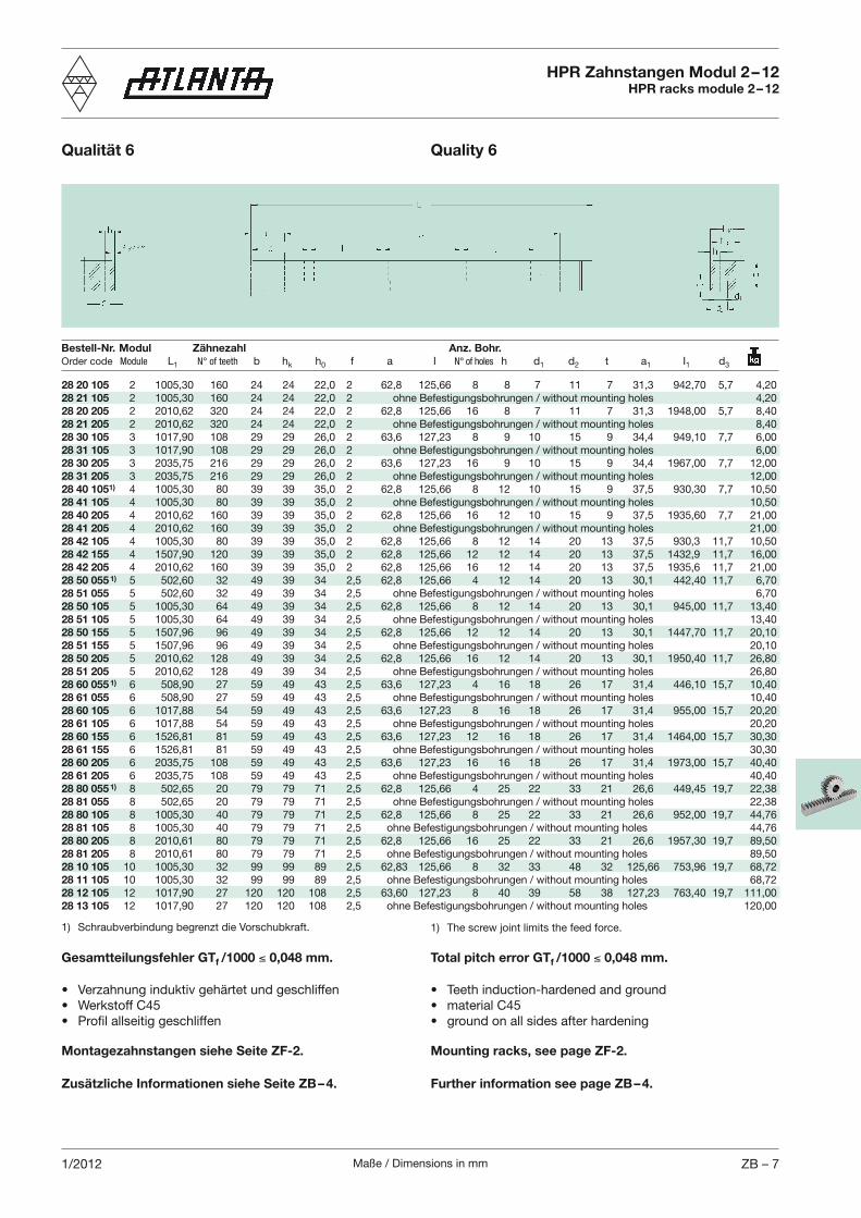
Maße / Dimensions in mm ZB – 71/2012
Bestell-Nr. Modul Zähnezahl Anz. Bohr.Order code Module L1 N° of teeth b hk h0 f a I N° of holes h d1 d2 t a1 I1 d3
HPR Zahnstangen Modul 2 – 12HPR racks module 2 – 12
Qualität 6 Quality 6
Total pitch error GTf /1000 0,048 mm.Gesamtteilungsfehler GTf /1000 0,048 mm.
Montagezahnstangen siehe Seite ZF-2. Mounting racks, see page ZF-2.
Zusätzliche Informationen siehe Seite ZB – 4. Further information see page ZB – 4.
1) Schraubverbindung begrenzt die Vorschubkraft. 1) The screw joint limits the feed force.
28 20 105 2 1005,30 160 24 24 22,0 2 62,8 125,66 8 8 7 11 7 31,3 942,70 5,7 4,2028 21 105 2 1005,30 160 24 24 22,0 2 ohne Befestigungsbohrungen / without mounting holes 4,2028 20 205 2 2010,62 320 24 24 22,0 2 62,8 125,66 16 8 7 11 7 31,3 1948,00 5,7 8,4028 21 205 2 2010,62 320 24 24 22,0 2 ohne Befestigungsbohrungen / without mounting holes 8,4028 30 105 3 1017,90 108 29 29 26,0 2 63,6 127,23 8 9 10 15 9 34,4 949,10 7,7 6,0028 31 105 3 1017,90 108 29 29 26,0 2 ohne Befestigungsbohrungen / without mounting holes 6,0028 30 205 3 2035,75 216 29 29 26,0 2 63,6 127,23 16 9 10 15 9 34,4 1967,00 7,7 12,0028 31 205 3 2035,75 216 29 29 26,0 2 ohne Befestigungsbohrungen / without mounting holes 12,0028 40 1051) 4 1005,30 80 39 39 35,0 2 62,8 125,66 8 12 10 15 9 37,5 930,30 7,7 10,5028 41 105 4 1005,30 80 39 39 35,0 2 ohne Befestigungsbohrungen / without mounting holes 10,5028 40 205 4 2010,62 160 39 39 35,0 2 62,8 125,66 16 12 10 15 9 37,5 1935,60 7,7 21,0028 41 205 4 2010,62 160 39 39 35,0 2 ohne Befestigungsbohrungen / without mounting holes 21,0028 42 105 4 1005,30 80 39 39 35,0 2 62,8 125,66 8 12 14 20 13 37,5 930,3 11,7 10,5028 42 155 4 1507,90 120 39 39 35,0 2 62,8 125,66 12 12 14 20 13 37,5 1432,9 11,7 16,0028 42 205 4 2010,62 160 39 39 35,0 2 62,8 125,66 16 12 14 20 13 37,5 1935,6 11,7 21,0028 50 055 1) 5 502,60 32 49 39 34 2,5 62,8 125,66 4 12 14 20 13 30,1 442,40 11,7 6,7028 51 055 5 502,60 32 49 39 34 2,5 ohne Befestigungsbohrungen / without mounting holes 6,7028 50 105 5 1005,30 64 49 39 34 2,5 62,8 125,66 8 12 14 20 13 30,1 945,00 11,7 13,4028 51 105 5 1005,30 64 49 39 34 2,5 ohne Befestigungsbohrungen / without mounting holes 13,4028 50 155 5 1507,96 96 49 39 34 2,5 62,8 125,66 12 12 14 20 13 30,1 1447,70 11,7 20,1028 51 155 5 1507,96 96 49 39 34 2,5 ohne Befestigungsbohrungen / without mounting holes 20,1028 50 205 5 2010,62 128 49 39 34 2,5 62,8 125,66 16 12 14 20 13 30,1 1950,40 11,7 26,8028 51 205 5 2010,62 128 49 39 34 2,5 ohne Befestigungsbohrungen / without mounting holes 26,8028 60 055 1) 6 508,90 27 59 49 43 2,5 63,6 127,23 4 16 18 26 17 31,4 446,10 15,7 10,4028 61 055 6 508,90 27 59 49 43 2,5 ohne Befestigungsbohrungen / without mounting holes 10,4028 60 105 6 1017,88 54 59 49 43 2,5 63,6 127,23 8 16 18 26 17 31,4 955,00 15,7 20,2028 61 105 6 1017,88 54 59 49 43 2,5 ohne Befestigungsbohrungen / without mounting holes 20,2028 60 155 6 1526,81 81 59 49 43 2,5 63,6 127,23 12 16 18 26 17 31,4 1464,00 15,7 30,3028 61 155 6 1526,81 81 59 49 43 2,5 ohne Befestigungsbohrungen / without mounting holes 30,3028 60 205 6 2035,75 108 59 49 43 2,5 63,6 127,23 16 16 18 26 17 31,4 1973,00 15,7 40,4028 61 205 6 2035,75 108 59 49 43 2,5 ohne Befestigungsbohrungen / without mounting holes 40,4028 80 055 1) 8 502,65 20 79 79 71 2,5 62,8 125,66 4 25 22 33 21 26,6 449,45 19,7 22,3828 81 055 8 502,65 20 79 79 71 2,5 ohne Befestigungsbohrungen / without mounting holes 22,3828 80 105 8 1005,30 40 79 79 71 2,5 62,8 125,66 8 25 22 33 21 26,6 952,00 19,7 44,7628 81 105 8 1005,30 40 79 79 71 2,5 o hne Befestigungsbohrungen / without mounting holes 44,7628 80 205 8 2010,61 80 79 79 71 2,5 62,8 125,66 16 25 22 33 21 26,6 1957,30 19,7 89,5028 81 205 8 2010,61 80 79 79 71 2,5 o hne Befestigungsbohrungen / without mounting holes 89,5028 10 105 10 1005,30 32 99 99 89 2,5 62,83 125,66 8 32 33 48 32 125,66 753,96 19,7 68,7228 11 105 10 1005,30 32 99 99 89 2,5 o hne Befestigungsbohrungen / without mounting holes 68,7228 12 105 12 1017,90 27 120 120 108 2,5 63,60 127,23 8 40 39 58 38 127,23 763,40 19,7 111,0028 13 105 12 1017,90 27 120 120 108 2,5 o hne Befestigungsbohrungen / without mounting holes 120,00
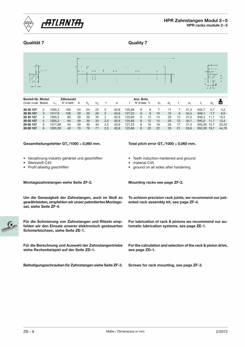
Maße / Dimensions in mmZB – 8 2/2012
Bestell-Nr. Modul Zähnezahl Anz. Bohr.Order code Module L1 N° of teeth b hk h0 f a I N° of holes h d1 d2 t a1 I1 d3
HPR Zahnstangen Modul 2 – 5HPR racks module 2 – 5
Qualität 7 Quality 7
Total pitch error GTf /1000 0,060 mm.Gesamtteilungsfehler GTf /1000 0,060 mm.
Um die Genauigkeit der Zahnstangen, auch im Stoß zu gewährleisten, empfehlen wir unser patentiertes Montage-set, siehe Seite ZF-4.
To achieve precision rack joints, we recommend our pat-ented rack assembly kit, see page ZF-4.
Montagezahnstangen siehe Seite ZF-2. Mounting racks see page ZF-2.
Für die Schmierung von Zahnstangen und Ritzeln emp-fehlen wir den Einsatz unserer elektronisch gesteuerten Schmierbüchsen, siehe Seite ZE-1.
For lubrication of rack & pinions we recommend our au-tomatic lubrication systems, see page ZE-1.
28 20 107 2 1005,3 160 24 24 22 2 62,8 125,66 8 8 7 11 7 31,3 942,7 5,7 4,228 30 107 3 1017,9 108 29 29 26 2 63,6 127,23 8 9 10 15 9 34,4 949,1 7,7 6,028 40 107 4 1005,3 80 39 39 35 2 62,8 125,66 8 12 14 20 13 37,5 930,3 11,7 10,528 50 107 5 1005,3 64 49 39 34 2,5 62,8 125,66 8 12 14 20 13 30,1 945,0 11,7 13,428 60 107 6 1017,88 54 59 49 43 2,5 63,6 127,23 8 16 18 26 17 31,4 955,00 15,7 20,2028 80 107 8 1005,30 40 79 79 71 2,5 62,8 125,66 8 25 22 33 21 26,6 952,00 19,7 44,76
Für die Berechnung und Auswahl der Zahnstangentriebe siehe Rechenbeispiel auf der Seite ZD-1.
For the calculation and selection of the rack & pinion drive, see page ZD-1.
Befestigungsschrauben für Zahnstangen siehe Seite ZF-3. Screws for rack mounting, see page ZF-3.
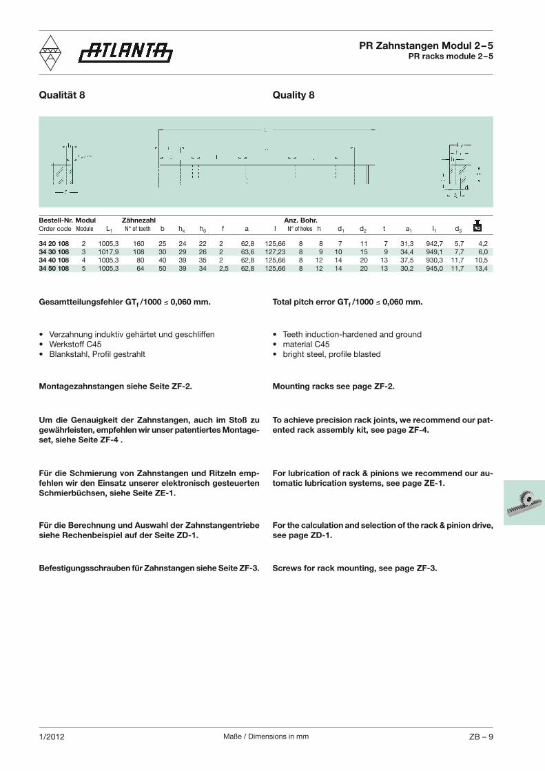
Maße / Dimensions in mm ZB – 91/2012
Bestell-Nr. Modul Zähnezahl Anz. Bohr.Order code Module L1 N° of teeth b hk h0 f a I N° of holes h d1 d2 t a1 I1 d3
Total pitch error GTf /1000 0,060 mm.Gesamtteilungsfehler GTf /1000 0,060 mm.
Um die Genauigkeit der Zahnstangen, auch im Stoß zu gewährleisten, empfehlen wir unser patentiertes Montage-set, siehe Seite ZF-4 .
To achieve precision rack joints, we recommend our pat-ented rack assembly kit, see page ZF-4.
Montagezahnstangen siehe Seite ZF-2. Mounting racks see page ZF-2.
Für die Schmierung von Zahnstangen und Ritzeln emp-fehlen wir den Einsatz unserer elektronisch gesteuerten Schmierbüchsen, siehe Seite ZE-1.
For lubrication of rack & pinions we recommend our au-tomatic lubrication systems, see page ZE-1.
PR Zahnstangen Modul 2 – 5PR racks module 2 – 5
Qualität 8 Quality 8
34 20 108 2 1005,3 160 25 24 22 2 62,8 125,66 8 8 7 11 7 31,3 942,7 5,7 4,234 30 108 3 1017,9 108 30 29 26 2 63,6 127,23 8 9 10 15 9 34,4 949,1 7,7 6,034 40 108 4 1005,3 80 40 39 35 2 62,8 125,66 8 12 14 20 13 37,5 930,3 11,7 10,534 50 108 5 1005,3 64 50 39 34 2,5 62,8 125,66 8 12 14 20 13 30,2 945,0 11,7 13,4
Für die Berechnung und Auswahl der Zahnstangentriebe siehe Rechenbeispiel auf der Seite ZD-1.
For the calculation and selection of the rack & pinion drive, see page ZD-1.
Befestigungsschrauben für Zahnstangen siehe Seite ZF-3. Screws for rack mounting, see page ZF-3.
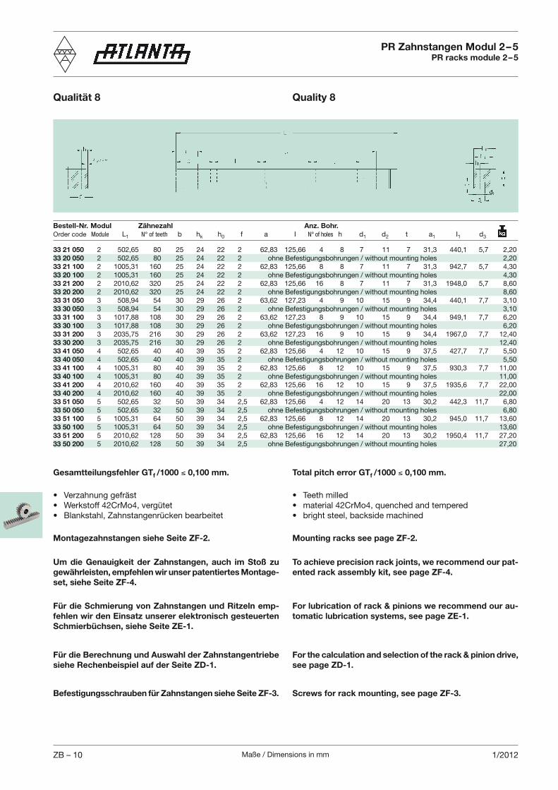
Maße / Dimensions in mmZB – 10 1/2012
Bestell-Nr. Modul Zähnezahl Anz. Bohr.Order code Module L1 N° of teeth b hk h0 f a I N° of holes h d1 d2 t a1 I1 d3
PR Zahnstangen Modul 2 – 5PR racks module 2 – 5
Qualität 8 Quality 8
Total pitch error GTf /1000 0,100 mm.Gesamtteilungsfehler GTf /1000 0,100 mm.
Um die Genauigkeit der Zahnstangen, auch im Stoß zu gewährleisten, empfehlen wir unser patentiertes Montage-set, siehe Seite ZF-4.
To achieve precision rack joints, we recommend our pat-ented rack assembly kit, see page ZF-4.
Montagezahnstangen siehe Seite ZF-2. Mounting racks see page ZF-2.
Für die Schmierung von Zahnstangen und Ritzeln emp-fehlen wir den Einsatz unserer elektronisch gesteuerten Schmierbüchsen, siehe Seite ZE-1.
For lubrication of rack & pinions we recommend our au-tomatic lubrication systems, see page ZE-1.
Für die Berechnung und Auswahl der Zahnstangentriebe siehe Rechenbeispiel auf der Seite ZD-1.
For the calculation and selection of the rack & pinion drive, see page ZD-1.
33 21 050 2 502,65 80 25 24 22 2 62,83 125,66 4 8 7 11 7 31,3 440,1 5,7 2,2033 20 050 2 502,65 80 25 24 22 2 ohne Befestigungsbohrungen / without mounting holes 2,2033 21 100 2 1005,31 160 25 24 22 2 62,83 125,66 8 8 7 11 7 31,3 942,7 5,7 4,3033 20 100 2 1005,31 160 25 24 22 2 ohne Befestigungsbohrungen / without mounting holes 4,3033 21 200 2 2010,62 320 25 24 22 2 62,83 125,66 16 8 7 11 7 31,3 1948,0 5,7 8,6033 20 200 2 2010,62 320 25 24 22 2 ohne Befestigungsbohrungen / without mounting holes 8,6033 31 050 3 508,94 54 30 29 26 2 63,62 127,23 4 9 10 15 9 34,4 440,1 7,7 3,1033 30 050 3 508,94 54 30 29 26 2 ohne Befestigungsbohrungen / without mounting holes 3,1033 31 100 3 1017,88 108 30 29 26 2 63,62 127,23 8 9 10 15 9 34,4 949,1 7,7 6,2033 30 100 3 1017,88 108 30 29 26 2 ohne Befestigungsbohrungen / without mounting holes 6,2033 31 200 3 2035,75 216 30 29 26 2 63,62 127,23 16 9 10 15 9 34,4 1967,0 7,7 12,4033 30 200 3 2035,75 216 30 29 26 2 ohne Befestigungsbohrungen / without mounting holes 12,4033 41 050 4 502,65 40 40 39 35 2 62,83 125,66 4 12 10 15 9 37,5 427,7 7,7 5,5033 40 050 4 502,65 40 40 39 35 2 ohne Befestigungsbohrungen / without mounting holes 5,5033 41 100 4 1005,31 80 40 39 35 2 62,83 125,66 8 12 10 15 9 37,5 930,3 7,7 11,0033 40 100 4 1005,31 80 40 39 35 2 ohne Befestigungsbohrungen / without mounting holes 11,0033 41 200 4 2010,62 160 40 39 35 2 62,83 125,66 16 12 10 15 9 37,5 1935,6 7,7 22,0033 40 200 4 2010,62 160 40 39 35 2 ohne Befestigungsbohrungen / without mounting holes 22,0033 51 050 5 502,65 32 50 39 34 2,5 62,83 125,66 4 12 14 20 13 30,2 442,3 11,7 6,8033 50 050 5 502,65 32 50 39 34 2,5 ohne Befestigungsbohrungen / without mounting holes 6,8033 51 100 5 1005,31 64 50 39 34 2,5 62,83 125,66 8 12 14 20 13 30,2 945,0 11,7 13,6033 50 100 5 1005,31 64 50 39 34 2,5 ohne Befestigungsbohrungen / without mounting holes 13,6033 51 200 5 2010,62 128 50 39 34 2,5 62,83 125,66 16 12 14 20 13 30,2 1950,4 11,7 27,2033 50 200 5 2010,62 128 50 39 34 2,5 ohne Befestigungsbohrungen / without mounting holes 27,20
Befestigungsschrauben für Zahnstangen siehe Seite ZF-3. Screws for rack mounting, see page ZF-3.
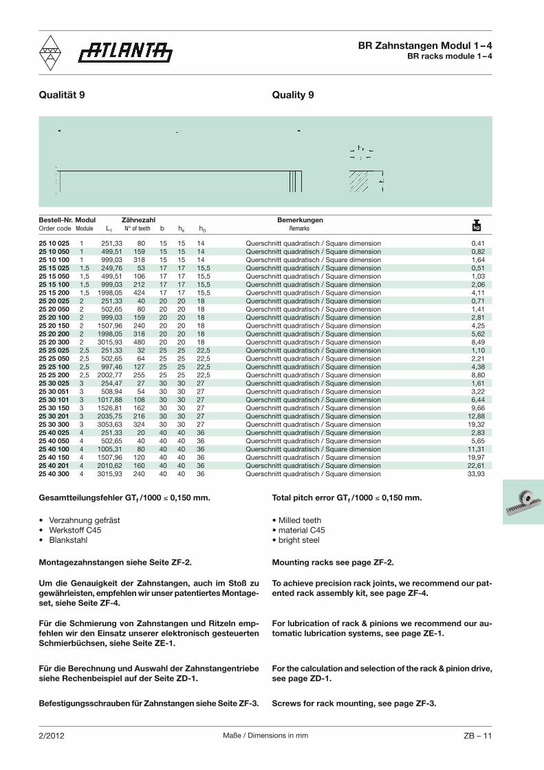
Maße / Dimensions in mm ZB – 112/2012
BR Zahnstangen Modul 1 – 4BR racks module 1 – 4
Qualität 9 Quality 9
Total pitch error GTf /1000 0,150 mm.Gesamtteilungsfehler GTf /1000 0,150 mm.
Montagezahnstangen siehe Seite ZF-2. Mounting racks see page ZF-2.
Bestell-Nr. Modul Zähnezahl BemerkungenOrder code Module L1 N° of teeth b hk h0 Remarks
Um die Genauigkeit der Zahnstangen, auch im Stoß zu gewährleisten, empfehlen wir unser patentiertes Montage-set, siehe Seite ZF-4.
To achieve precision rack joints, we recommend our pat-ented rack assembly kit, see page ZF-4.
Für die Schmierung von Zahnstangen und Ritzeln emp-fehlen wir den Einsatz unserer elektronisch gesteuerten Schmierbüchsen, siehe Seite ZE-1.
For lubrication of rack & pinions we recommend our au-tomatic lubrication systems, see page ZE-1.
Für die Berechnung und Auswahl der Zahnstangentriebe siehe Rechenbeispiel auf der Seite ZD-1.
For the calculation and selection of the rack & pinion drive, see page ZD-1.
Befestigungsschrauben für Zahnstangen siehe Seite ZF-3. Screws for rack mounting, see page ZF-3.
25 10 025 1 251,33 80 15 15 14 Querschnitt quadratisch / Square dimension 0,4125 10 050 1 499,51 159 15 15 14 Querschnitt quadratisch / Square dimension 0,8225 10 100 1 999,03 318 15 15 14 Querschnitt quadratisch / Square dimension 1,6425 15 025 1,5 249,76 53 17 17 15,5 Querschnitt quadratisch / Square dimension 0,5125 15 050 1,5 499,51 106 17 17 15,5 Querschnitt quadratisch / Square dimension 1,0325 15 100 1,5 999,03 212 17 17 15,5 Querschnitt quadratisch / Square dimension 2,0625 15 200 1,5 1998,05 424 17 17 15,5 Querschnitt quadratisch / Square dimension 4,1125 20 025 2 251,33 40 20 20 18 Querschnitt quadratisch / Square dimension 0,7125 20 050 2 502,65 80 20 20 18 Querschnitt quadratisch / Square dimension 1,4125 20 100 2 999,03 159 20 20 18 Querschnitt quadratisch / Square dimension 2,8125 20 150 2 1507,96 240 20 20 18 Querschnitt quadratisch / Square dimension 4,2525 20 200 2 1998,05 318 20 20 18 Querschnitt quadratisch / Square dimension 5,6225 20 300 2 3015,93 480 20 20 18 Querschnitt quadratisch / Square dimension 8,4925 25 025 2,5 251,33 32 25 25 22,5 Querschnitt quadratisch / Square dimension 1,1025 25 050 2,5 502,65 64 25 25 22,5 Querschnitt quadratisch / Square dimension 2,2125 25 100 2,5 997,46 127 25 25 22,5 Querschnitt quadratisch / Square dimension 4,3825 25 200 2,5 2002,77 255 25 25 22,5 Querschnitt quadratisch / Square dimension 8,8025 30 025 3 254,47 27 30 30 27 Querschnitt quadratisch / Square dimension 1,6125 30 051 3 508,94 54 30 30 27 Querschnitt quadratisch / Square dimension 3,2225 30 101 3 1017,88 108 30 30 27 Querschnitt quadratisch / Square dimension 6,4425 30 150 3 1526,81 162 30 30 27 Querschnitt quadratisch / Square dimension 9,6625 30 201 3 2035,75 216 30 30 27 Querschnitt quadratisch / Square dimension 12,8825 30 300 3 3053,63 324 30 30 27 Querschnitt quadratisch / Square dimension 19,3225 40 025 4 251,33 20 40 40 36 Querschnitt quadratisch / Square dimension 2,8325 40 050 4 502,65 40 40 40 36 Querschnitt quadratisch / Square dimension 5,6525 40 100 4 1005,31 80 40 40 36 Querschnitt quadratisch / Square dimension 11,3125 40 150 4 1507,96 120 40 40 36 Querschnitt quadratisch / Square dimension 19,9725 40 201 4 2010,62 160 40 40 36 Querschnitt quadratisch / Square dimension 22,6125 40 300 4 3015,93 240 40 40 36 Querschnitt quadratisch / Square dimension 33,93
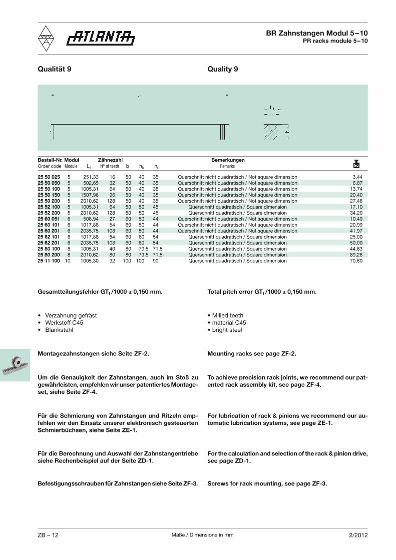
Maße / Dimensions in mmZB – 12 2/2012
BR Zahnstangen Modul 5 – 10PR racks module 5 – 10
Qualität 9 Quality 9
Total pitch error GTf /1000 0,150 mm.Gesamtteilungsfehler GTf /1000 0,150 mm.
Um die Genauigkeit der Zahnstangen, auch im Stoß zu gewährleisten, empfehlen wir unser patentiertes Montage-set, siehe Seite ZF-4.
To achieve precision rack joints, we recommend our pat-ented rack assembly kit, see page ZF-4.
Montagezahnstangen siehe Seite ZF-2. Mounting racks see page ZF-2.
Für die Schmierung von Zahnstangen und Ritzeln emp-fehlen wir den Einsatz unserer elektronisch gesteuerten Schmierbüchsen, siehe Seite ZE-1.
For lubrication of rack & pinions we recommend our au-tomatic lubrication systems, see page ZE-1.
Bestell-Nr. Modul Zähnezahl BemerkungenOrder code Module L1 N° of teeth b hk h0 Remarks
Für die Berechnung und Auswahl der Zahnstangentriebe siehe Rechenbeispiel auf der Seite ZD-1.
For the calculation and selection of the rack & pinion drive, see page ZD-1.
25 50 025 5 251,33 16 50 40 35 Querschnitt nicht quadratisch / Not square dimension 3,4425 50 050 5 502,65 32 50 40 35 Querschnitt nicht quadratisch / Not square dimension 6,8725 50 100 5 1005,31 64 50 40 35 Querschnitt nicht quadratisch / Not square dimension 13,7425 50 150 5 1507,96 96 50 40 35 Querschnitt nicht quadratisch / Not square dimension 20,4025 50 200 5 2010,62 128 50 40 35 Querschnitt nicht quadratisch / Not square dimension 27,4825 52 100 5 1005,31 64 50 50 45 Querschnitt quadratisch / Square dimension 17,1025 52 200 5 2010,62 128 50 50 45 Querschnitt quadratisch / Square dimension 34,2025 60 051 6 508,94 27 60 50 44 Querschnitt nicht quadratisch / Not square dimension 10,4925 60 101 6 1017,88 54 60 50 44 Querschnitt nicht quadratisch / Not square dimension 20,9925 60 201 6 2035,75 108 60 50 44 Querschnitt nicht quadratisch / Not square dimension 41,9725 62 101 6 1017,88 54 60 60 54 Querschnitt quadratisch / Square dimension 25,0025 62 201 6 2035,75 108 60 60 54 Querschnitt quadratisch / Square dimension 50,0025 80 100 8 1005,31 40 80 79,5 71,5 Querschnitt quadratisch / Square dimension 44,6325 80 200 8 2010,62 80 80 79,5 71,5 Querschnitt quadratisch / Square dimension 89,2625 11 100 10 1005,30 32 100 100 90 Querschnitt quadratisch / Square dimension 70,60
Befestigungsschrauben für Zahnstangen siehe Seite ZF-3. Screws for rack mounting, see page ZF-3.
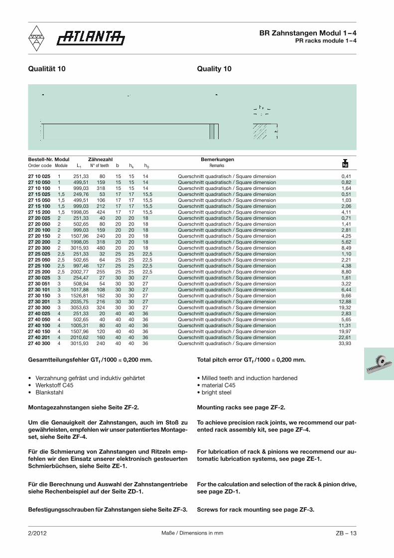
Maße / Dimensions in mm ZB – 132/2012
Bestell-Nr. Modul Zähnezahl BemerkungenOrder code Module L1 N° of teeth b hk h0 Remarks
BR Zahnstangen Modul 1 – 4PR racks module 1 – 4
Qualität 10 Quality 10
Total pitch error GTf /1000 0,200 mm.Gesamtteilungsfehler GTf /1000 0,200 mm.
Montagezahnstangen siehe Seite ZF-2. Mounting racks see page ZF-2.
Um die Genauigkeit der Zahnstangen, auch im Stoß zu gewährleisten, empfehlen wir unser patentiertes Montage-set, siehe Seite ZF-4.
To achieve precision rack joints, we recommend our pat-ented rack assembly kit, see page ZF-4.
Für die Schmierung von Zahnstangen und Ritzeln emp-fehlen wir den Einsatz unserer elektronisch gesteuerten Schmierbüchsen, siehe Seite ZE-1.
For lubrication of rack & pinions we recommend our au-tomatic lubrication systems, see page ZE-1.
Für die Berechnung und Auswahl der Zahnstangentriebe siehe Rechenbeispiel auf der Seite ZD-1.
For the calculation and selection of the rack & pinion drive, see page ZD-1.
Befestigungsschrauben für Zahnstangen siehe Seite ZF-3. Screws for rack mounting see page ZF-3.
27 10 025 1 251,33 80 15 15 14 Querschnitt quadratisch / Square dimension 0,4127 10 050 1 499,51 159 15 15 14 Querschnitt quadratisch / Square dimension 0,8227 10 100 1 999,03 318 15 15 14 Querschnitt quadratisch / Square dimension 1,6427 15 025 1,5 249,76 53 17 17 15,5 Querschnitt quadratisch / Square dimension 0,5127 15 050 1,5 499,51 106 17 17 15,5 Querschnitt quadratisch / Square dimension 1,0327 15 100 1,5 999,03 212 17 17 15,5 Querschnitt quadratisch / Square dimension 2,0627 15 200 1,5 1998,05 424 17 17 15,5 Querschnitt quadratisch / Square dimension 4,1127 20 025 2 251,33 40 20 20 18 Querschnitt quadratisch / Square dimension 0,7127 20 050 2 502,65 80 20 20 18 Querschnitt quadratisch / Square dimension 1,4127 20 100 2 999,03 159 20 20 18 Querschnitt quadratisch / Square dimension 2,8127 20 150 2 1507,96 240 20 20 18 Querschnitt quadratisch / Square dimension 4,2527 20 200 2 1998,05 318 20 20 18 Querschnitt quadratisch / Square dimension 5,6227 20 300 2 3015,93 480 20 20 18 Querschnitt quadratisch / Square dimension 8,4927 25 025 2,5 251,33 32 25 25 22,5 Querschnitt quadratisch / Square dimension 1,1027 25 050 2,5 502,65 64 25 25 22,5 Querschnitt quadratisch / Square dimension 2,2127 25 100 2,5 997,46 127 25 25 22,5 Querschnitt quadratisch / Square dimension 4,3827 25 200 2,5 2002,77 255 25 25 22,5 Querschnitt quadratisch / Square dimension 8,8027 30 025 3 254,47 27 30 30 27 Querschnitt quadratisch / Square dimension 1,6127 30 051 3 508,94 54 30 30 27 Querschnitt quadratisch / Square dimension 3,2227 30 101 3 1017,88 108 30 30 27 Querschnitt quadratisch / Square dimension 6,4427 30 150 3 1526,81 162 30 30 27 Querschnitt quadratisch / Square dimension 9,6627 30 201 3 2035,75 216 30 30 27 Querschnitt quadratisch / Square dimension 12,8827 30 300 3 3053,63 324 30 30 27 Querschnitt quadratisch / Square dimension 19,3227 40 025 4 251,33 20 40 40 36 Querschnitt quadratisch / Square dimension 2,8327 40 050 4 502,65 40 40 40 36 Querschnitt quadratisch / Square dimension 5,6527 40 100 4 1005,31 80 40 40 36 Querschnitt quadratisch / Square dimension 11,3127 40 150 4 1507,96 120 40 40 36 Querschnitt quadratisch / Square dimension 19,9727 40 201 4 2010,62 160 40 40 36 Querschnitt quadratisch / Square dimension 22,6127 40 300 4 3015,93 240 40 40 36 Querschnitt quadratisch / Square dimension 33,93
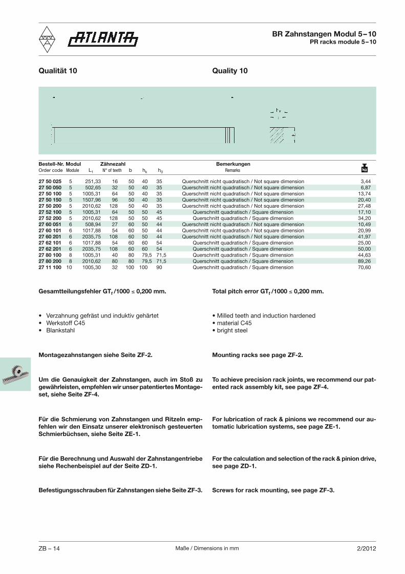
Maße / Dimensions in mmZB – 14 2/2012
Total pitch error GTf /1000 0,200 mm.Gesamtteilungsfehler GTf /1000 0,200 mm.
Um die Genauigkeit der Zahnstangen, auch im Stoß zu gewährleisten, empfehlen wir unser patentiertes Montage-set, siehe Seite ZF-4.
To achieve precision rack joints, we recommend our pat-ented rack assembly kit, see page ZF-4.
Montagezahnstangen siehe Seite ZF-2. Mounting racks see page ZF-2.
Für die Schmierung von Zahnstangen und Ritzeln emp-fehlen wir den Einsatz unserer elektronisch gesteuerten Schmierbüchsen, siehe Seite ZE-1.
For lubrication of rack & pinions we recommend our au-tomatic lubrication systems, see page ZE-1.
Bestell-Nr. Modul Zähnezahl BemerkungenOrder code Module L1 N° of teeth b hk h0 Remarks
BR Zahnstangen Modul 5 – 10PR racks module 5 – 10
Qualität 10 Quality 10
Für die Berechnung und Auswahl der Zahnstangentriebe siehe Rechenbeispiel auf der Seite ZD-1.
For the calculation and selection of the rack & pinion drive, see page ZD-1.
27 50 025 5 251,33 16 50 40 35 Querschnitt nicht quadratisch / Not square dimension 3,4427 50 050 5 502,65 32 50 40 35 Querschnitt nicht quadratisch / Not square dimension 6,8727 50 100 5 1005,31 64 50 40 35 Querschnitt nicht quadratisch / Not square dimension 13,7427 50 150 5 1507,96 96 50 40 35 Querschnitt nicht quadratisch / Not square dimension 20,4027 50 200 5 2010,62 128 50 40 35 Querschnitt nicht quadratisch / Not square dimension 27,4827 52 100 5 1005,31 64 50 50 45 Querschnitt quadratisch / Square dimension 17,1027 52 200 5 2010,62 128 50 50 45 Querschnitt quadratisch / Square dimension 34,2027 60 051 6 508,94 27 60 50 44 Querschnitt nicht quadratisch / Not square dimension 10,4927 60 101 6 1017,88 54 60 50 44 Querschnitt nicht quadratisch / Not square dimension 20,9927 60 201 6 2035,75 108 60 50 44 Querschnitt nicht quadratisch / Not square dimension 41,9727 62 101 6 1017,88 54 60 60 54 Querschnitt quadratisch / Square dimension 25,0027 62 201 6 2035,75 108 60 60 54 Querschnitt quadratisch / Square dimension 50,0027 80 100 8 1005,31 40 80 79,5 71,5 Querschnitt quadratisch / Square dimension 44,6327 80 200 8 2010,62 80 80 79,5 71,5 Querschnitt quadratisch / Square dimension 89,2627 11 100 10 1005,30 32 100 100 90 Querschnitt quadratisch / Square dimension 70,60
Befestigungsschrauben für Zahnstangen siehe Seite ZF-3. Screws for rack mounting, see page ZF-3.
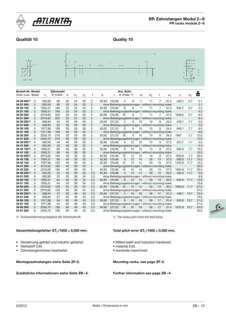
Maße / Dimensions in mm ZB – 152/2012
Bestell-Nr. Modul Zähnezahl Anz. Bohr.Order code Module L1 N° of teeth b hk h0 f a I N° of holes h d1 d2 t a1 I1 d3
1) Schraubverbindung begrenzt die Vorschubkraft. 1) The screw joint limits the feed force.
34 20 050 1) 2 502,65 80 25 24 22 2 62,83 125,66 4 8 7 11 7 31,3 440,1 5,7 2,134 21 050 2 502,65 80 25 24 22 2 ohne Befestigungsbohrungen / without mounting holes 2,134 20 100 2 1005,31 160 25 24 22 2 62,83 125,66 8 8 7 11 7 31,3 942,7 5,7 4,234 21 100 2 1005,31 160 25 24 22 2 ohne Befestigungsbohrungen / without mounting holes 4,234 20 200 2 2010,62 320 25 24 22 2 62,83 125,66 16 8 7 11 7 31,3 1948,0 5,7 8,434 21 200 2 2010,62 320 25 24 22 2 ohne Befestigungsbohrungen / without mounting holes 8,434 30 050 1) 3 508,94 54 30 29 26 2 63,62 127,23 4 9 10 15 9 34,4 440,1 7,7 3,034 31 050 3 508,94 54 30 29 26 2 ohne Befestigungsbohrungen / without mounting holes 3,034 30 100 3 1017,88 108 30 29 26 2 63,62 127,23 8 9 10 15 9 34,4 949,1 7,7 6,034 31 100 3 1017,88 108 30 29 26 2 ohne Befestigungsbohrungen / without mounting holes 6,034 30 200 3 2035,75 216 30 29 26 2 63,62 127,23 16 9 10 15 9 34,4 1967 7,7 12,034 31 200 3 2035,75 216 30 29 26 2 ohne Befestigungsbohrungen / without mounting holes 12,034 40 050 1) 4 502,65 40 40 39 35 2 62,83 125,66 4 12 10 15 9 37,5 427,7 7,7 5,334 41 050 4 502,65 40 40 39 35 2 ohne Befestigungsbohrungen / without mounting holes 5,334 40 100 1) 4 1005,31 80 40 39 35 2 62,83 125,66 8 12 10 15 9 37,5 930,3 7,7 10,234 41 100 4 1005,31 80 40 39 35 2 ohne Befestigungsbohrungen / without mounting holes 10,234 40 200 1) 4 2010,62 160 40 39 35 2 62,83 125,66 16 12 10 15 9 37,5 1935,6 7,7 20,534 42 100 4 1005,31 80 40 39 35 2 62,83 125,66 8 12 14 20 13 37,5 930,3 11,7 10,234 42 150 4 1507,96 120 40 39 35 2 62,83 125,66 12 12 14 20 13 37,5 1432,9 11,7 15,334 41 200 4 2010,62 160 40 39 35 2 ohne Befestigungsbohrungen / without mounting holes 20,534 42 200 4 2010,62 160 40 39 35 2 62,83 125,66 16 12 14 20 13 37,5 1935,6 11,7 20,534 50 050 1) 5 502,65 32 50 39 34 2,5 62,83 125,66 4 12 14 20 13 30,2 442,3 11,7 6,934 51 050 5 502,65 32 50 39 34 2,5 ohne Befestigungsbohrungen / without mounting holes 6,934 50 100 5 1005,31 64 50 39 34 2,5 62,83 125,66 8 12 14 20 13 30,2 945,0 11,7 13,834 51 100 5 1005,31 64 50 39 34 2,5 ohne Befestigungsbohrungen / without mounting holes 13,834 50 200 5 2010,62 128 50 39 34 2,5 62,83 125,66 16 12 14 20 13 30,2 1950,3 11,7 27,534 51 200 5 2010,62 128 50 39 34 2,5 ohne Befestigungsbohrungen / without mounting holes 27,534 60 050 1) 6 508,94 27 60 49 43 2,5 63,62 127,23 4 16 18 26 17 31,4 446,1 15,7 10,534 61 050 6 508,94 27 60 49 43 2,5 ohne Befestigungsbohrungen / without mounting holes 10,534 60 100 6 1017,88 54 60 49 43 2,5 63,62 127,23 8 16 18 26 17 31,4 955,0 15,7 21,034 61 100 6 1017,88 54 60 49 43 2,5 ohne Befestigungsbohrungen / without mounting holes 21,034 60 200 6 2035,75 108 60 49 43 2,5 63,62 127,23 16 16 18 26 17 31,4 1972,9 15,7 42,034 61 200 6 2035,75 108 60 49 43 2,5 ohne Befestigungsbohrungen / without mounting holes 42,0
BR Zahnstangen Modul 2 – 6PR racks module 2 – 6
Qualität 10 Quality 10
Total pitch error GTf /1000 0,200 mm.Gesamtteilungsfehler GTf /1000 0,200 mm.
Montagezahnstangen siehe Seite ZF-2. Mounting racks, see page ZF-2.
Zusätzliche Informationen siehe Seite ZB – 4. Further information see page ZB – 4.
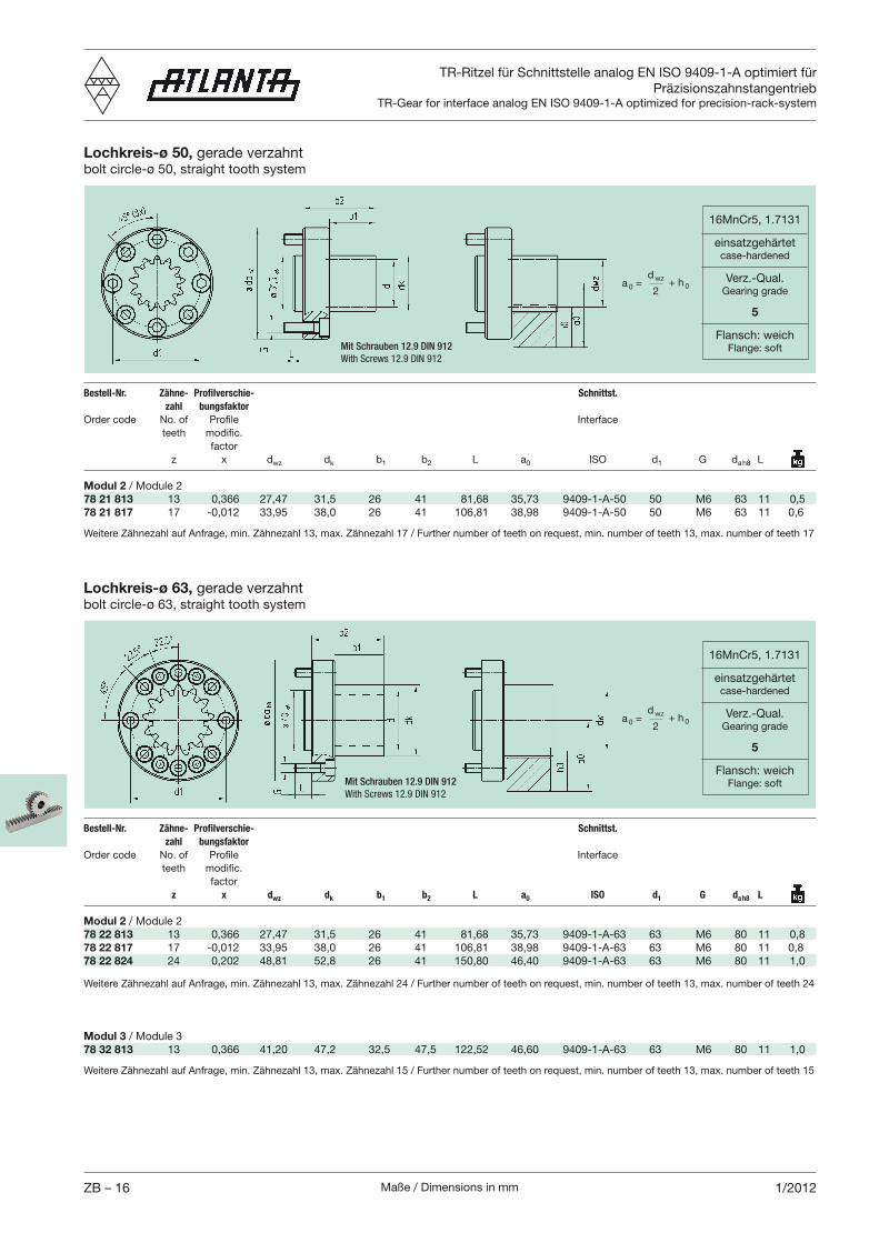
Maße / Dimensions in mmZB – 16 1/2012
TR-Ritzel für Schnittstelle analog EN ISO 9409-1-A optimiert für Präzisionszahnstangentrieb
TR-Gear for interface analog EN ISO 9409-1-A optimized for precision-rack-system
Lochkreis-ø 50, gerade verzahntbolt circle-ø 50, straight tooth system
Bestell-Nr. Zähne- Profilverschie- Schnittst.
zahl bungsfaktor
factor z x dwz dk b1 b2 L a0 ISO d1 G da h8 L
Modul 2 / Module 278 21 813 13 0,366 27,47 31,5 26 41 81,68 35,73 9409-1-A-50 50 M6 63 11 0,578 21 817 17 -0,012 33,95 38,0 26 41 106,81 38,98 9409-1-A-50 50 M6 63 11 0,6
16MnCr5, 1.7131
einsatzgehärtetcase-hardened
Verz.-Qual.Gearing grade
5
Flansch: weichFlange: softMit Schrauben 12.9 DIN 912
With Screws 12.9 DIN 912
a 0 =d wz
2+ h 0
Lochkreis-ø 63, gerade verzahntbolt circle-ø 63, straight tooth system
Bestell-Nr. Zähne- Profilverschie- Schnittst.
zahl bungsfaktor
factor z x dwz dk b1 b2 L a0 ISO d1 G da h8 L
Modul 2 / Module 278 22 813 13 0,366 27,47 31,5 26 41 81,68 35,73 9409-1-A-63 63 M6 80 11 0,878 22 817 17 -0,012 33,95 38,0 26 41 106,81 38,98 9409-1-A-63 63 M6 80 11 0,878 22 824 24 0,202 48,81 52,8 26 41 150,80 46,40 9409-1-A-63 63 M6 80 11 1,0
16MnCr5, 1.7131
einsatzgehärtetcase-hardened
Verz.-Qual.Gearing grade
5
Flansch: weichFlange: softMit Schrauben 12.9 DIN 912
With Screws 12.9 DIN 912
a 0 =d wz
2+ h 0
Weitere Zähnezahl auf Anfrage, min. Zähnezahl 13, max. Zähnezahl 17 / Further number of teeth on request, min. number of teeth 13, max. number of teeth 17
Weitere Zähnezahl auf Anfrage, min. Zähnezahl 13, max. Zähnezahl 24 / Further number of teeth on request, min. number of teeth 13, max. number of teeth 24
Weitere Zähnezahl auf Anfrage, min. Zähnezahl 13, max. Zähnezahl 15 / Further number of teeth on request, min. number of teeth 13, max. number of teeth 15
Modul 3 / Module 378 32 813 13 0,366 41,20 47,2 32,5 47,5 122,52 46,60 9409-1-A-63 63 M6 80 11 1,0
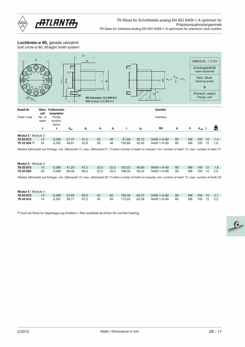
Maße / Dimensions in mm ZB – 172/2012
TR-Ritzel für Schnittstelle analog EN ISO 9409-1-A optimiert für Präzisionszahnstangentrieb
TR-Gear for interface analog EN ISO 9409-1-A optimized for precision-rack-system
Lochkreis-ø 80, gerade verzahntbolt circle-ø 80, straight tooth system
Bestell-Nr. Zähne- Profilverschie- Schnittst.
zahl bungsfaktor
factor z x dwz dk b1 b2 L a0 ISO d1 G da h8 L
Modul 2 / Module 278 23 813 13 0,366 27,47 31,5 26 46 81,68 35,73 9409-1-A-80 80 M8 100 13 1,478 23 824 (1) 24 0,202 48,81 52,8 26 46 150,80 46,40 9409-1-A-80 80 M8 100 13 1,6
16MnCr5, 1.7131
einsatzgehärtetcase-hardened
Verz.-Qual.Gearing grade
5
Flansch: weichFlange: softMit Schrauben 12.9 DIN 912
With Screws 12.9 DIN 912
a 0 =d wz
2+ h 0
Modul 4 / Module 478 43 813 13 0,366 54,93 62,9 45 65 163,36 62,47 9409-1-A-80 80 M8 100 13 2,178 43 814 14 0,397 59,17 67,2 45 65 175,93 64,59 9409-1-A-80 80 M8 100 13 2,2
Modul 3 / Module 3 78 33 813 13 0,366 41,20 47,2 32,5 52,5 122,52 46,60 9409-1-A-80 80 M8 100 13 1,678 33 820 20 0,080 60,48 66,5 32,5 52,5 188,50 56,24 9409-1-A-80 80 M8 100 13 2,0
Weitere Zähnezahl auf Anfrage, min. Zähnezahl 13, max. Zähnezahl 31 / Further number of teeth on request, min. number of teeth 13, max. number of teeth 31
Weitere Zähnezahl auf Anfrage, min. Zähnezahl 13, max. Zähnezahl 20 / Further number of teeth on request, min. number of teeth 13, max. number of teeth 20
(1) Auch als Ritzel für Gegenlagerung erhältlich / Also available as pinion for counter bearing.
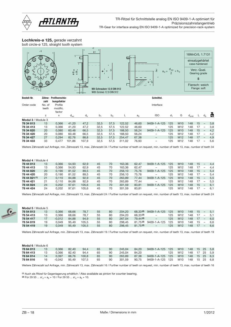
Maße / Dimensions in mmZB – 18 1/2012
TR-Ritzel für Schnittstelle analog EN ISO 9409-1-A optimiert für Präzisionszahnstangentrieb
TR-Gear for interface analog EN ISO 9409-1-A optimized for precision-rack-system
Lochkreis-ø 125, gerade verzahntbolt circle-ø 125, straight tooth system
Bestell-Nr. Zähne- Profilverschie- Schnittst.
zahl bungsfaktor
factor z x dwz dk b1 b2 L a0 ISO d1 G da h8 L db
Modul 3 / Module 378 34 813 13 0,366 41,20 47,2 32,5 57,5 122,52 46,60 9409-1-A-125 125 M10 148 15 – 3,878 34 413 13 0,366 41,20 47,2 32,5 57,5 122,52 46,60 – 125 M12 148 17 – 3,878 34 820 20 0,080 60,48 66,5 32,5 57,5 188,50 56,24 9409-1-A-125 125 M10 148 15 – 4,278 34 420 20 0,080 60,48 66,5 32,5 57,5 188,50 56,24 – 125 M12 148 17 – 4,278 34 427 27 0,294 82,76 88,8 32,5 57,5 254,47 67,38 – 125 M12 148 17 – 4,978 34 433 33 0,477 101,86 107,9 32,5 57,5 311,02 76,93 – 125 M12 148 17 – 5,6
16MnCr5, 1.7131
einsatzgehärtetcase-hardened
Verz.-Qual.Gearing grade
5
Flansch: weichFlange: softMit Schrauben 12.9 DIN 912
With Screws 12.9 DIN 912
a 0 =d wz
2+ h 0
Weitere Zähnezahl auf Anfrage, min. Zähnezahl 13, max. Zähnezahl 34 / Further number of teeth on request, min. number of teeth 13, max. number of teeth 34
Modul 6 / Module 678 64 813 13 0,366 82,40 94,4 65 90 245,04 84,20 9409-1-A-125 125 M10 148 15 25 5,878 64 413 13 0,366 82,40 94,4 65 90 245,04 84,20 – 125 M12 148 17 25 5,978 64 814 14 0,397 88,76 100,8 65 90 263,89 87,38 9409-1-A-125 125 M10 148 15 25 6,378 64 816 16 -0,042 95,49 107,5 65 90 301,59 90,75 9409-1-A-125 125 M10 148 15 25 6,8
Modul 5 / Module 578 54 813 13 0,366 68,66 78,7 55 80 204,20 68,33 (2) 9409-1-A-125 125 M10 148 15 – 5,178 54 413 13 0,366 68,66 78,7 55 80 204,20 68,33 (2) – 125 M12 148 17 – 5,178 54 417 17 -0,012 84,88 94,9 55 80 267,04 79,44 (2) – 125 M12 148 17 – 6,078 54 819 19 0,049 95,49 105,5 55 80 298,45 81,75 (2) 9409-1-A-125 125 M10 148 15 – 6,678 54 419 19 0,049 95,49 105,5 55 80 298,45 81,75 (2) – 125 M12 148 17 – 6,6
Modul 4 / Module 478 44 813 13 0,366 54,93 62,9 45 70 163,36 62,47 9409-1-A-125 125 M10 148 15 – 4,478 44 413 13 0,366 54,93 62,9 45 70 163,36 62,47 – 125 M12 148 17 – 4,478 44 820 20 0,190 81,52 89,5 45 70 256,10 75,76 9409-1-A-125 125 M10 148 15 – 5,478 44 420 20 0,190 81,52 89,5 45 70 256,10 75,76 – 125 M12 148 17 – 5,478 44 821 (1) 21 0,110 84,88 92,9 45 70 263,89 77,44 9409-1-A-125 125 M10 148 15 – 5,578 44 421 21 0,110 84,88 92,9 45 70 263,89 77,44 – 125 M12 148 17 – 5,578 44 824 24 0,202 97,61 105,6 45 70 301,59 83,81 9409-1-A-125 125 M10 148 15 – 6,178 44 424 24 0,202 97,61 105,6 45 70 301,59 83,81 – 125 M12 148 17 – 6,1
Weitere Zähnezahl auf Anfrage, min. Zähnezahl 13, max. Zähnezahl 24 / Further number of teeth on request, min. number of teeth 13, max. number of teeth 24
(1) Auch als Ritzel für Gegenlagerung erhältlich / Also available as pinion for counter bearing.(2) Für 29 55 ... a'0 = a0 + 10 / For 29 55 ... a'0 = a0 + 10.
Weitere Zähnezahl auf Anfrage, min. Zähnezahl 13, max. Zähnezahl 19 / Further number of teeth on request, min. number of teeth 13, max. number of teeth 19
Weitere Zähnezahl auf Anfrage, min. Zähnezahl 13, max. Zähnezahl 16 / Further number of teeth on request, min. number of teeth 13, max. number of teeth 16
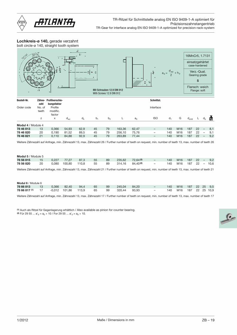
Maße / Dimensions in mm ZB – 191/2012
TR-Ritzel für Schnittstelle analog EN ISO 9409-1-A optimiert für Präzisionszahnstangentrieb
TR-Gear for interface analog EN ISO 9409-1-A optimized for precision-rack-system
Lochkreis-ø 140, gerade verzahntbolt circle-ø 140, straight tooth system
Bestell-Nr. Zähne- Profilverschie- Schnittst.
zahl bungsfaktor
factor z x dwz dk b1 b2 L a0 ISO d1 G da h8 L db
Modul 4 / Module 478 46 813 13 0,366 54,93 62,9 45 79 163,36 62,47 – 140 M16 187 22 – 8,178 46 820 20 0,190 81,52 89,5 45 79 256,10 75,76 – 140 M16 187 22 – 9,178 46 821 21 0,110 84,88 92,9 45 79 263,89 77,44 – 140 M16 187 22 – 9,2
16MnCr5, 1.7131
einsatzgehärtetcase-hardened
Verz.-Qual.Gearing grade
5
Flansch: weichFlange: softMit Schrauben 12.9 DIN 912
With Screws 12.9 DIN 912
a 0 =d wz
2+ h 0
Modul 6 / Module 678 66 813 13 0,366 82,40 94,4 65 99 245,04 84,20 – 140 M16 187 22 25 9,578 66 817 (1) 17 -0,012 101,86 113,9 65 99 320,44 93,93 – 140 M16 187 22 25 10,9
Modul 5 / Module 578 56 815 15 0,227 77,27 87,3 55 89 235,62 72,64 (2) – 140 M16 187 22 – 9,278 56 820 20 0,080 100,80 110,8 55 89 314,16 84,40 (2) – 140 M16 187 22 – 10,6
Weitere Zähnezahl auf Anfrage, min. Zähnezahl 13, max. Zähnezahl 26 / Further number of teeth on request, min. number of teeth 13, max. number of teeth 26
Weitere Zähnezahl auf Anfrage, min. Zähnezahl 13, max. Zähnezahl 21 / Further number of teeth on request, min. number of teeth 13, max. number of teeth 21
Weitere Zähnezahl auf Anfrage, min. Zähnezahl 13, max. Zähnezahl 17 / Further number of teeth on request, min. number of teeth 13, max. number of teeth 17
(1) Auch als Ritzel für Gegenlagerung erhältlich / Also available as pinion for counter bearing.(2) Für 29 55 ... a'0 = a0 + 10 / For 29 55 ... a'0 = a0 + 10.
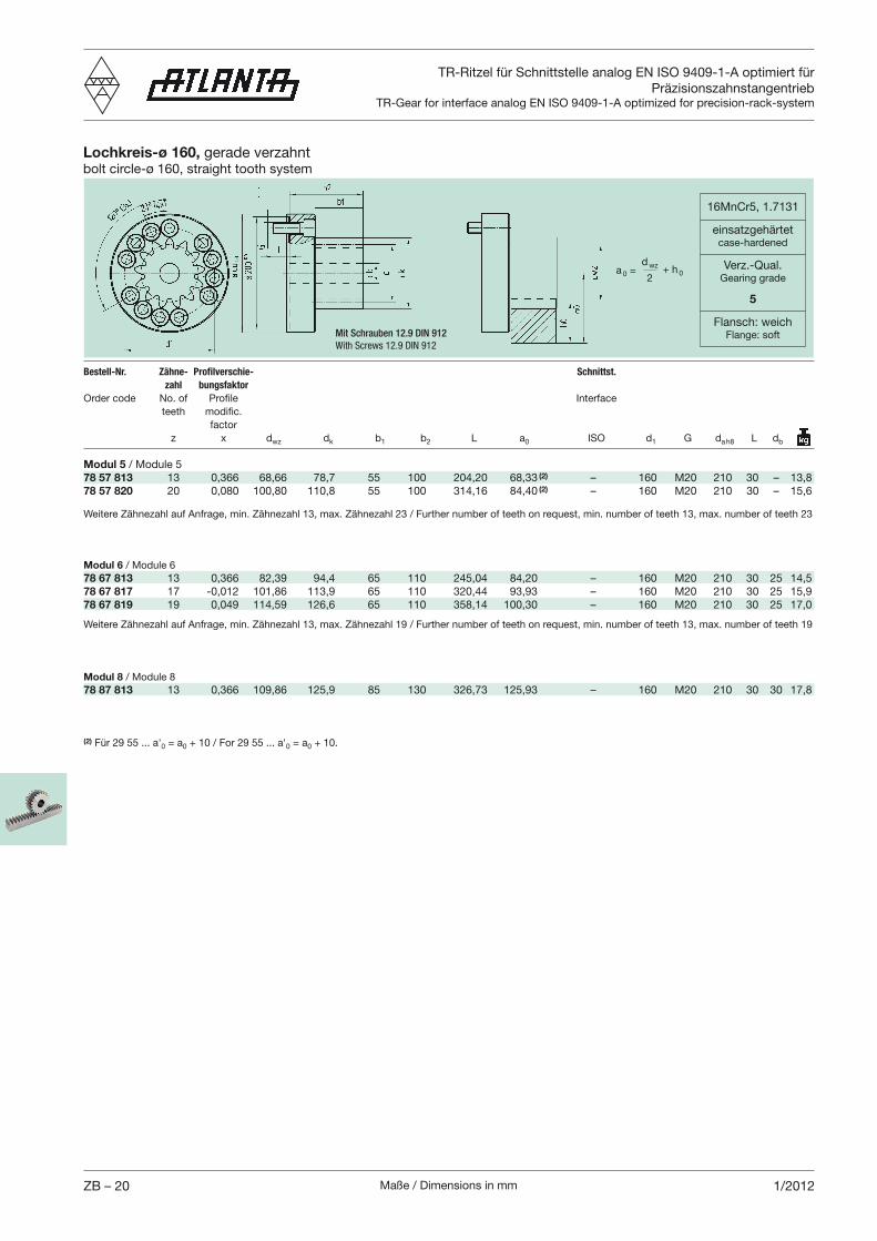
Maße / Dimensions in mmZB – 20 1/2012
TR-Ritzel für Schnittstelle analog EN ISO 9409-1-A optimiert für Präzisionszahnstangentrieb
TR-Gear for interface analog EN ISO 9409-1-A optimized for precision-rack-system
Lochkreis-ø 160, gerade verzahntbolt circle-ø 160, straight tooth system
Bestell-Nr. Zähne- Profilverschie- Schnittst.
zahl bungsfaktor
factor z x dwz dk b1 b2 L a0 ISO d1 G da h8 L db
Modul 5 / Module 578 57 813 13 0,366 68,66 78,7 55 100 204,20 68,33 (2) – 160 M20 210 30 – 13,878 57 820 20 0,080 100,80 110,8 55 100 314,16 84,40 (2) – 160 M20 210 30 – 15,6
16MnCr5, 1.7131
einsatzgehärtetcase-hardened
Verz.-Qual.Gearing grade
5
Flansch: weichFlange: softMit Schrauben 12.9 DIN 912
With Screws 12.9 DIN 912
a 0 =d wz
2+ h 0
(2) Für 29 55 ... a'0 = a0 + 10 / For 29 55 ... a'0 = a0 + 10.
Weitere Zähnezahl auf Anfrage, min. Zähnezahl 13, max. Zähnezahl 23 / Further number of teeth on request, min. number of teeth 13, max. number of teeth 23
Weitere Zähnezahl auf Anfrage, min. Zähnezahl 13, max. Zähnezahl 19 / Further number of teeth on request, min. number of teeth 13, max. number of teeth 19
Modul 8 / Module 878 87 813 13 0,366 109,86 125,9 85 130 326,73 125,93 – 160 M20 210 30 30 17,8
Modul 6 / Module 678 67 813 13 0,366 82,39 94,4 65 110 245,04 84,20 – 160 M20 210 30 25 14,578 67 817 17 -0,012 101,86 113,9 65 110 320,44 93,93 – 160 M20 210 30 25 15,978 67 819 19 0,049 114,59 126,6 65 110 358,14 100,30 – 160 M20 210 30 25 17,0
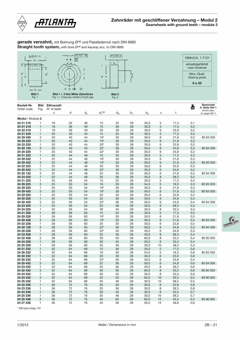
Maße / Dimensions in mm ZB – 211/2012
b2
dk
dN
b1
0,01 A u 0,2 B
B
d1 A
d
t
gerade verzahnt, mit Bohrung ØH6 und Passfedernut nach DIN 6885Straight tooth system, with bore ØH6 and keyway acc. to DIN 6885
Bestell-Nr. Bild Zähnezahl
z d dk d1H6 dN b1 b2 u t
Zahnräder mit geschliffener Verzahnung – Modul 2Gearwheels with ground teeth – module 2
Spannsatzlt. Seite GH-1
shrink-discon page GH-1
Bild 1 + 3 Nut Mitte ZahnlückeFig. 1 + 3 Keyway middle of tooth gap
Bild 1Fig. 1
16MnCr5, 1.7131
einsatzgehärtetcase-hardened
Verz.-Qual.Gearing grade
6 e 25
Bild 3Fig. 3
b2
dk
dN
h8
b1
d
0,05 A
Modul / Module 2
24 21 216 1 16 32 36 15 25 28 30,0 5 17,3 0,124 21 218 1 18 36 40 15 28 28 30,0 5 17,3 0,224 22 218 1 18 36 40 20 28 28 30,0 6 22,8 0,224 21 220 1 20 40 44 15 25 28 30,0 5 17,3 0,224 29 420 3 20 40 44 19* 30 28 56,0 6 21,8 0,2 80 83 03024 29 220 1 20 40 44 19* 30 28 30,0 6 21,8 0,224 22 220 1 20 40 44 20* 30 28 30,0 6 22,8 0,224 20 120 3 20 40 44 22* 36 28 56,0 6 24,8 0,3 80 84 03624 20 220 1 20 40 44 22* 30 28 30,0 6 24,8 0,224 21 222 1 22 44 48 15 25 28 30,0 5 17,3 0,324 29 222 1 22 44 48 19* 30 28 30,0 6 21,8 0,324 29 422 3 22 44 48 19* 30 28 56,0 6 21,8 0,3 80 83 03024 22 222 1 22 44 48 20 30 28 30,0 6 22,8 0,324 20 222 1 22 44 48 22* 30 28 30,0 6 24,8 0,224 20 122 3 22 44 48 22 36 28 56,0 6 27,8 0,2 80 84 03624 23 222 1 22 44 48 25 36 28 30,0 8 28,3 0,224 21 225 1 25 50 54 15 25 28 30,0 5 17,3 0,424 26 225 3 25 50 54 16 30 28 54,0 5 18,3 0,3 80 83 03024 29 225 1 25 50 54 19* 30 28 30,0 6 21,8 0,324 29 425 3 25 50 54 19* 30 28 56,0 6 21,8 0,3 80 83 03024 22 225 1 25 50 54 20 30 28 30,0 6 22,8 0,424 20 225 1 25 50 54 22 30 28 30,0 6 24,8 0,324 20 425 3 25 50 54 22* 36 28 56,0 6 24,8 0,4 80 84 03624 23 225 1 25 50 54 25 36 28 30,0 8 28,3 0,324 24 225 1 25 50 54 30 45 28 30,0 8 33,3 0,324 21 228 1 28 56 60 15 25 28 30,0 5 17,3 0,524 29 228 1 28 56 60 19* 30 28 30,0 6 21,8 0,524 29 428 3 28 56 60 19* 30 28 56,0 6 21,8 0,5 80 83 03024 22 228 1 28 56 60 20 30 28 30,0 6 22,8 0,524 20 128 3 28 56 60 22* 36 28 56,0 6 24,8 0,3 80 84 03624 20 228 1 28 56 60 22* 30 28 30,0 6 24,8 0,324 23 228 1 28 56 60 25 36 28 30,0 8 28,3 0,424 22 428 3 28 56 60 30 50 28 60,0 8 33,3 0,4 80 85 05024 24 228 1 28 56 60 30 45 28 30,0 8 33,3 0,4 24 25 228 1 28 56 60 35 48 28 30,0 10 38,3 0,324 21 232 1 32 64 68 15 36 28 30,0 5 17,3 0,6 24 26 232 3 32 64 68 16 30 28 54,0 5 18,3 0,6 80 83 03024 22 232 1 32 64 68 20 30 28 30,0 6 22,8 0,624 20 232 1 32 64 68 22* 30 28 30,0 6 24,8 0,424 20 432 3 32 64 68 22 36 28 56,0 6 24,8 0,6 80 84 03624 23 232 1 32 64 68 25 36 28 30,0 8 28,3 0,624 22 432 3 32 64 68 30 50 28 60,0 8 33,3 0,6 80 85 05024 24 232 1 32 64 68 30 45 28 30,0 8 33,3 0,6 24 23 432 3 32 64 68 32 55 28 65,0 10 35,3 0,5 80 80 05524 25 232 1 32 64 68 35 48 28 30,0 10 38,3 0,524 22 236 1 36 72 76 20 30 28 30,0 6 22,8 0,824 23 236 1 36 72 76 25 36 28 30,0 8 28,3 0,824 24 236 1 36 72 76 30 45 28 30,0 8 33,3 0,724 25 236 1 36 72 76 35 48 28 30,0 10 38,3 0,724 25 436 3 36 72 76 40 62 28 65,0 12 43,3 0,5 80 86 06224 27 236 1 36 72 76 45 58 28 30,0 14 48,8 0,6
* G6 bzw./resp. H7
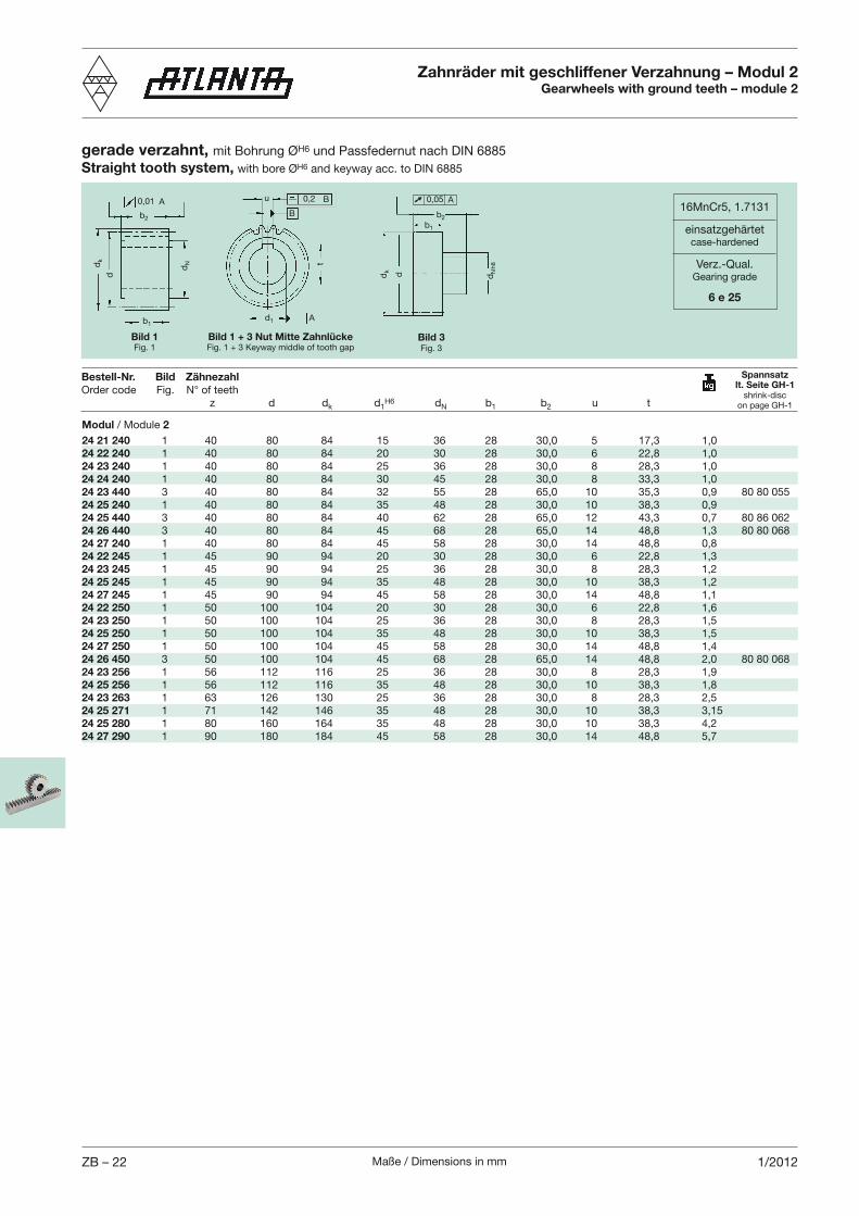
Maße / Dimensions in mmZB – 22 1/2012
b2
dk
dN
b1
0,01 A u 0,2 B
B
d1 A
d
t
gerade verzahnt, mit Bohrung ØH6 und Passfedernut nach DIN 6885Straight tooth system, with bore ØH6 and keyway acc. to DIN 6885
Bestell-Nr. Bild Zähnezahl
z d dk d1H6 dN b1 b2 u t
Zahnräder mit geschliffener Verzahnung – Modul 2Gearwheels with ground teeth – module 2
Spannsatzlt. Seite GH-1
shrink-discon page GH-1
Bild 1 + 3 Nut Mitte ZahnlückeFig. 1 + 3 Keyway middle of tooth gap
Bild 1Fig. 1
16MnCr5, 1.7131
einsatzgehärtetcase-hardened
Verz.-Qual.Gearing grade
6 e 25
Bild 3Fig. 3
b2
dk
dN
h8
b1
d
0,05 A
Modul / Module 2
24 21 240 1 40 80 84 15 36 28 30,0 5 17,3 1,024 22 240 1 40 80 84 20 30 28 30,0 6 22,8 1,024 23 240 1 40 80 84 25 36 28 30,0 8 28,3 1,024 24 240 1 40 80 84 30 45 28 30,0 8 33,3 1,024 23 440 3 40 80 84 32 55 28 65,0 10 35,3 0,9 80 80 05524 25 240 1 40 80 84 35 48 28 30,0 10 38,3 0,924 25 440 3 40 80 84 40 62 28 65,0 12 43,3 0,7 80 86 06224 26 440 3 40 80 84 45 68 28 65,0 14 48,8 1,3 80 80 06824 27 240 1 40 80 84 45 58 28 30,0 14 48,8 0,8 24 22 245 1 45 90 94 20 30 28 30,0 6 22,8 1,324 23 245 1 45 90 94 25 36 28 30,0 8 28,3 1,224 25 245 1 45 90 94 35 48 28 30,0 10 38,3 1,224 27 245 1 45 90 94 45 58 28 30,0 14 48,8 1,124 22 250 1 50 100 104 20 30 28 30,0 6 22,8 1,624 23 250 1 50 100 104 25 36 28 30,0 8 28,3 1,524 25 250 1 50 100 104 35 48 28 30,0 10 38,3 1,524 27 250 1 50 100 104 45 58 28 30,0 14 48,8 1,424 26 450 3 50 100 104 45 68 28 65,0 14 48,8 2,0 80 80 06824 23 256 1 56 112 116 25 36 28 30,0 8 28,3 1,924 25 256 1 56 112 116 35 48 28 30,0 10 38,3 1,824 23 263 1 63 126 130 25 36 28 30,0 8 28,3 2,524 25 271 1 71 142 146 35 48 28 30,0 10 38,3 3,1524 25 280 1 80 160 164 35 48 28 30,0 10 38,3 4,224 27 290 1 90 180 184 45 58 28 30,0 14 48,8 5,7
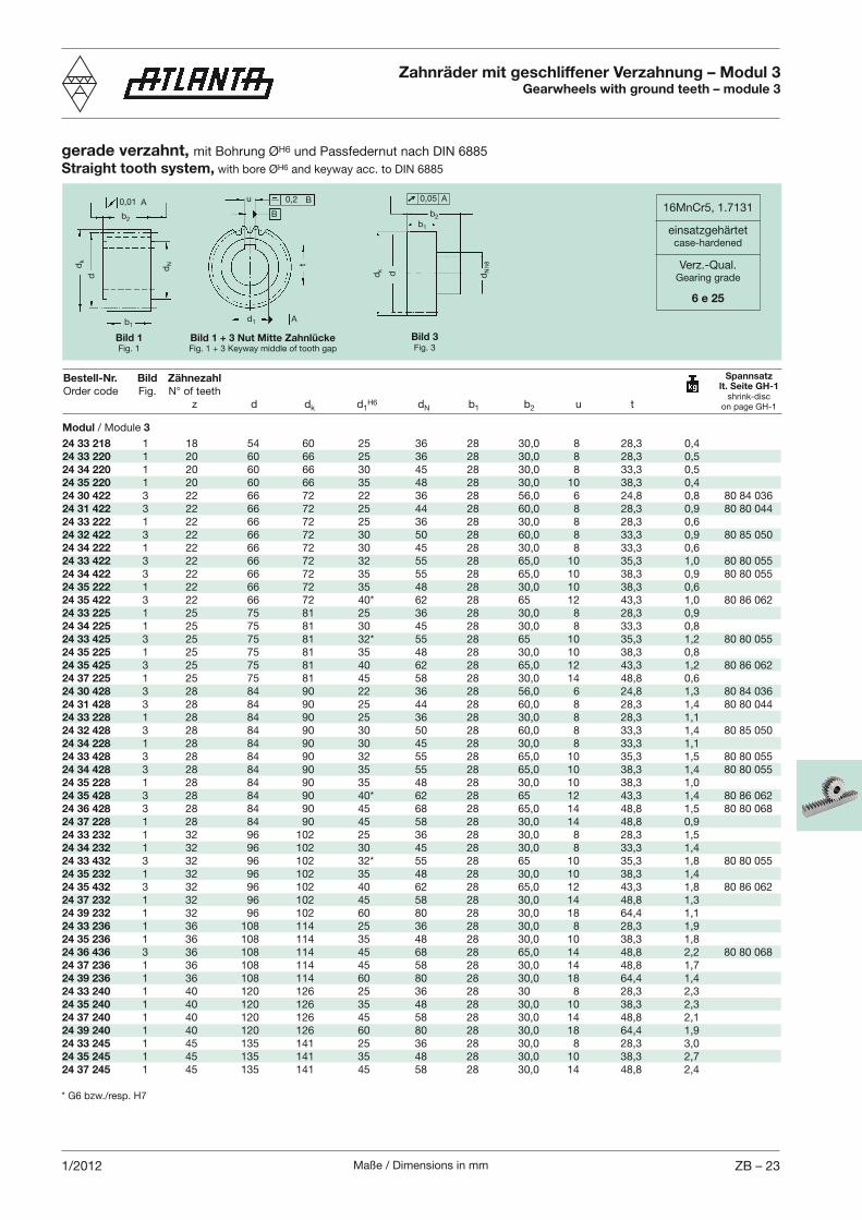
Maße / Dimensions in mm ZB – 231/2012
b2
dk
dN
b1
0,01 A u 0,2 B
B
d1 A
d
t
gerade verzahnt, mit Bohrung ØH6 und Passfedernut nach DIN 6885Straight tooth system, with bore ØH6 and keyway acc. to DIN 6885
Bestell-Nr. Bild Zähnezahl
z d dk d1H6 dN b1 b2 u t
Zahnräder mit geschliffener Verzahnung – Modul 3Gearwheels with ground teeth – module 3
16MnCr5, 1.7131
einsatzgehärtetcase-hardened
Verz.-Qual.Gearing grade
6 e 25
Spannsatzlt. Seite GH-1
shrink-discon page GH-1
Bild 1 + 3 Nut Mitte ZahnlückeFig. 1 + 3 Keyway middle of tooth gap
Bild 1Fig. 1
Bild 3Fig. 3
b2
dk
dN
h8
b1
d
0,05 A
Modul / Module 3
24 33 218 1 18 54 60 25 36 28 30,0 8 28,3 0,424 33 220 1 20 60 66 25 36 28 30,0 8 28,3 0,524 34 220 1 20 60 66 30 45 28 30,0 8 33,3 0,524 35 220 1 20 60 66 35 48 28 30,0 10 38,3 0,424 30 422 3 22 66 72 22 36 28 56,0 6 24,8 0,8 80 84 03624 31 422 3 22 66 72 25 44 28 60,0 8 28,3 0,9 80 80 04424 33 222 1 22 66 72 25 36 28 30,0 8 28,3 0,6 24 32 422 3 22 66 72 30 50 28 60,0 8 33,3 0,9 80 85 05024 34 222 1 22 66 72 30 45 28 30,0 8 33,3 0,6 24 33 422 3 22 66 72 32 55 28 65,0 10 35,3 1,0 80 80 05524 34 422 3 22 66 72 35 55 28 65,0 10 38,3 0,9 80 80 05524 35 222 1 22 66 72 35 48 28 30,0 10 38,3 0,6 24 35 422 3 22 66 72 40* 62 28 65 12 43,3 1,0 80 86 06224 33 225 1 25 75 81 25 36 28 30,0 8 28,3 0,924 34 225 1 25 75 81 30 45 28 30,0 8 33,3 0,824 33 425 3 25 75 81 32* 55 28 65 10 35,3 1,2 80 80 05524 35 225 1 25 75 81 35 48 28 30,0 10 38,3 0,824 35 425 3 25 75 81 40 62 28 65,0 12 43,3 1,2 80 86 06224 37 225 1 25 75 81 45 58 28 30,0 14 48,8 0,624 30 428 3 28 84 90 22 36 28 56,0 6 24,8 1,3 80 84 03624 31 428 3 28 84 90 25 44 28 60,0 8 28,3 1,4 80 80 04424 33 228 1 28 84 90 25 36 28 30,0 8 28,3 1,1 24 32 428 3 28 84 90 30 50 28 60,0 8 33,3 1,4 80 85 05024 34 228 1 28 84 90 30 45 28 30,0 8 33,3 1,1 24 33 428 3 28 84 90 32 55 28 65,0 10 35,3 1,5 80 80 05524 34 428 3 28 84 90 35 55 28 65,0 10 38,3 1,4 80 80 05524 35 228 1 28 84 90 35 48 28 30,0 10 38,3 1,0 24 35 428 3 28 84 90 40* 62 28 65 12 43,3 1,4 80 86 06224 36 428 3 28 84 90 45 68 28 65,0 14 48,8 1,5 80 80 06824 37 228 1 28 84 90 45 58 28 30,0 14 48,8 0,9 24 33 232 1 32 96 102 25 36 28 30,0 8 28,3 1,524 34 232 1 32 96 102 30 45 28 30,0 8 33,3 1,424 33 432 3 32 96 102 32* 55 28 65 10 35,3 1,8 80 80 05524 35 232 1 32 96 102 35 48 28 30,0 10 38,3 1,424 35 432 3 32 96 102 40 62 28 65,0 12 43,3 1,8 80 86 06224 37 232 1 32 96 102 45 58 28 30,0 14 48,8 1,324 39 232 1 32 96 102 60 80 28 30,0 18 64,4 1,124 33 236 1 36 108 114 25 36 28 30,0 8 28,3 1,924 35 236 1 36 108 114 35 48 28 30,0 10 38,3 1,824 36 436 3 36 108 114 45 68 28 65,0 14 48,8 2,2 80 80 06824 37 236 1 36 108 114 45 58 28 30,0 14 48,8 1,7 24 39 236 1 36 108 114 60 80 28 30,0 18 64,4 1,424 33 240 1 40 120 126 25 36 28 30 8 28,3 2,324 35 240 1 40 120 126 35 48 28 30,0 10 38,3 2,324 37 240 1 40 120 126 45 58 28 30,0 14 48,8 2,124 39 240 1 40 120 126 60 80 28 30,0 18 64,4 1,924 33 245 1 45 135 141 25 36 28 30,0 8 28,3 3,024 35 245 1 45 135 141 35 48 28 30,0 10 38,3 2,724 37 245 1 45 135 141 45 58 28 30,0 14 48,8 2,4
* G6 bzw./resp. H7
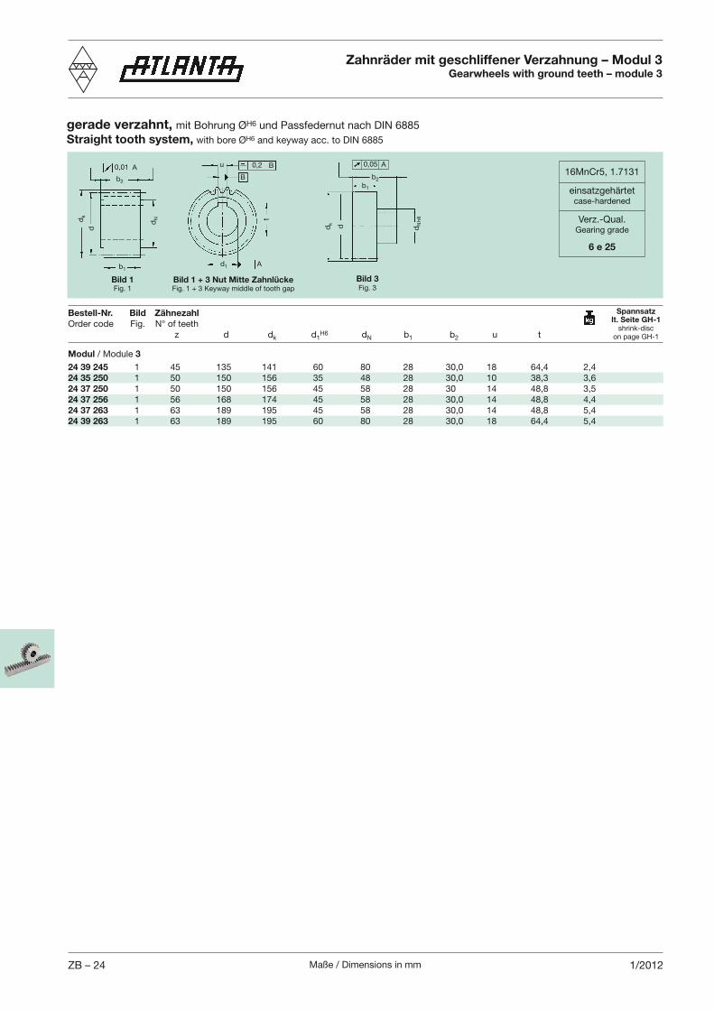
Maße / Dimensions in mmZB – 24 1/2012
b2
dk
dN
b1
0,01 A u 0,2 B
B
d1 A
d
t
gerade verzahnt, mit Bohrung ØH6 und Passfedernut nach DIN 6885Straight tooth system, with bore ØH6 and keyway acc. to DIN 6885
Bestell-Nr. Bild Zähnezahl
z d dk d1H6 dN b1 b2 u t
Zahnräder mit geschliffener Verzahnung – Modul 3Gearwheels with ground teeth – module 3
16MnCr5, 1.7131
einsatzgehärtetcase-hardened
Verz.-Qual.Gearing grade
6 e 25
Spannsatzlt. Seite GH-1
shrink-discon page GH-1
Bild 1 + 3 Nut Mitte ZahnlückeFig. 1 + 3 Keyway middle of tooth gap
Bild 1Fig. 1
Bild 3Fig. 3
b2
dk
dN
h8
b1
d
0,05 A
Modul / Module 3
24 39 245 1 45 135 141 60 80 28 30,0 18 64,4 2,424 35 250 1 50 150 156 35 48 28 30,0 10 38,3 3,624 37 250 1 50 150 156 45 58 28 30 14 48,8 3,524 37 256 1 56 168 174 45 58 28 30,0 14 48,8 4,424 37 263 1 63 189 195 45 58 28 30,0 14 48,8 5,424 39 263 1 63 189 195 60 80 28 30,0 18 64,4 5,4
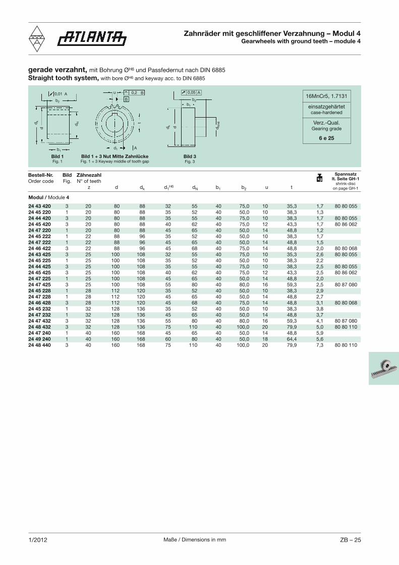
Maße / Dimensions in mm ZB – 251/2012
b2
dk
dN
b1
0,01 A u 0,2 B
B
d1 A
d
t
gerade verzahnt, mit Bohrung ØH6 und Passfedernut nach DIN 6885Straight tooth system, with bore ØH6 and keyway acc. to DIN 6885
Bestell-Nr. Bild Zähnezahl
z d dk d1H6 dN b1 b2 u t
Zahnräder mit geschliffener Verzahnung – Modul 4Gearwheels with ground teeth – module 4
16MnCr5, 1.7131
einsatzgehärtetcase-hardened
Verz.-Qual.Gearing grade
6 e 25
Spannsatzlt. Seite GH-1
shrink-discon page GH-1
Bild 1Fig. 1
Modul / Module 4
24 43 420 3 20 80 88 32 55 40 75,0 10 35,3 1,7 80 80 05524 45 220 1 20 80 88 35 52 40 50,0 10 38,3 1,324 44 420 3 20 80 88 35 55 40 75,0 10 38,3 1,7 80 80 05524 45 420 3 20 80 88 40 62 40 75,0 12 43,3 1,7 80 86 06224 47 220 1 20 80 88 45 65 40 50,0 14 48,8 1,224 45 222 1 22 88 96 35 52 40 50,0 10 38,3 1,724 47 222 1 22 88 96 45 65 40 50,0 14 48,8 1,524 46 422 3 22 88 96 45 68 40 75,0 14 48,8 2,0 80 80 06824 43 425 3 25 100 108 32 55 40 75,0 10 35,3 2,6 80 80 05524 45 225 1 25 100 108 35 52 40 50,0 10 38,3 2,224 44 425 3 25 100 108 35 55 40 75,0 10 38,3 2,5 80 80 05524 45 425 3 25 100 108 40 62 40 75,0 12 43,3 2,5 80 86 06224 47 225 1 25 100 108 45 65 40 50,0 14 48,8 2,024 47 425 3 25 100 108 55 80 40 80,0 16 59,3 2,5 80 87 08024 45 228 1 28 112 120 35 52 40 50,0 10 38,3 2,924 47 228 1 28 112 120 45 65 40 50,0 14 48,8 2,724 46 428 3 28 112 120 45 68 40 75,0 14 48,8 3,1 80 80 06824 45 232 1 32 128 136 35 52 40 50,0 10 38,3 3,824 47 232 1 32 128 136 45 65 40 50,0 14 48,8 3,724 47 432 3 32 128 136 55 80 40 80,0 16 59,3 4,1 80 87 08024 48 432 3 32 128 136 75 110 40 100,0 20 79,9 5,0 80 80 11024 47 240 1 40 160 168 45 65 40 50,0 14 48,8 5,924 49 240 1 40 160 168 60 80 40 50,0 18 64,4 5,624 48 440 3 40 160 168 75 110 40 100,0 20 79,9 7,3 80 80 110
Bild 1 + 3 Nut Mitte ZahnlückeFig. 1 + 3 Keyway middle of tooth gap
Bild 3Fig. 3
b2
dk
dN
h8
b1
d
0,05 A
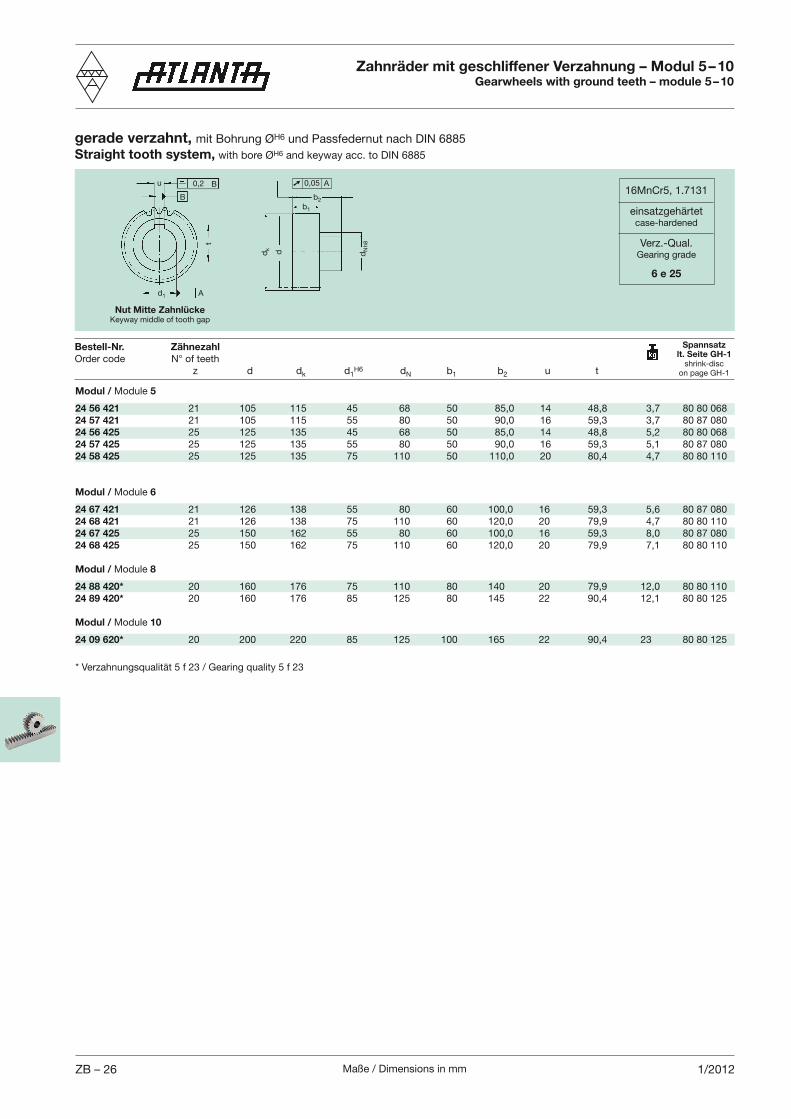
Maße / Dimensions in mmZB – 26 1/2012
u 0,2 B
B
d1 A
t
gerade verzahnt, mit Bohrung ØH6 und Passfedernut nach DIN 6885Straight tooth system, with bore ØH6 and keyway acc. to DIN 6885
Bestell-Nr. Zähnezahl
z d dk d1H6 dN b1 b2 u t
Zahnräder mit geschliffener Verzahnung – Modul 5 – 10Gearwheels with ground teeth – module 5 – 10
16MnCr5, 1.7131
einsatzgehärtetcase-hardened
Verz.-Qual.Gearing grade
6 e 25
Spannsatzlt. Seite GH-1
shrink-discon page GH-1
Modul / Module 5
24 56 421 21 105 115 45 68 50 85,0 14 48,8 3,7 80 80 06824 57 421 21 105 115 55 80 50 90,0 16 59,3 3,7 80 87 08024 56 425 25 125 135 45 68 50 85,0 14 48,8 5,2 80 80 06824 57 425 25 125 135 55 80 50 90,0 16 59,3 5,1 80 87 08024 58 425 25 125 135 75 110 50 110,0 20 80,4 4,7 80 80 110
Modul / Module 6
24 67 421 21 126 138 55 80 60 100,0 16 59,3 5,6 80 87 08024 68 421 21 126 138 75 110 60 120,0 20 79,9 4,7 80 80 11024 67 425 25 150 162 55 80 60 100,0 16 59,3 8,0 80 87 08024 68 425 25 150 162 75 110 60 120,0 20 79,9 7,1 80 80 110
Modul / Module 8
24 88 420* 20 160 176 75 110 80 140 20 79,9 12,0 80 80 11024 89 420* 20 160 176 85 125 80 145 22 90,4 12,1 80 80 125
Modul / Module 10
24 09 620* 20 200 220 85 125 100 165 22 90,4 23 80 80 125
Nut Mitte ZahnlückeKeyway middle of tooth gap
b2
dk
dN
h8
b1
d
0,05 A
* Verzahnungsqualität 5 f 23 / Gearing quality 5 f 23
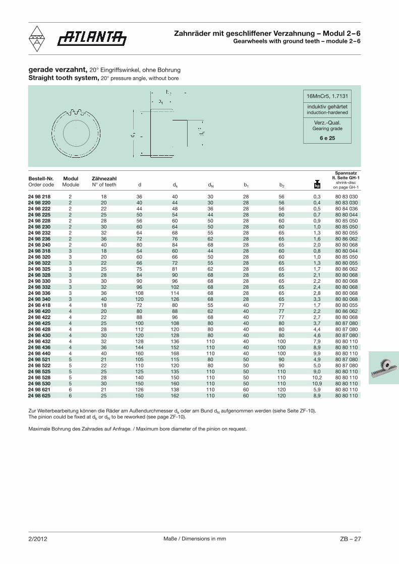
Maße / Dimensions in mm ZB – 272/2012
gerade verzahnt, Straight tooth system,
Zahnräder mit geschliffener Verzahnung – Modul 2 – 6Gearwheels with ground teeth – module 2 – 6
24 98 218 2 18 36 40 30 28 56 0,3 80 83 03024 98 220 2 20 40 44 30 28 56 0,4 80 83 03024 98 222 2 22 44 48 36 28 56 0,5 80 84 03624 98 225 2 25 50 54 44 28 60 0,7 80 80 04424 98 228 2 28 56 60 50 28 60 0,9 80 85 05024 98 230 2 30 60 64 50 28 60 1,0 80 85 05024 98 232 2 32 64 68 55 28 65 1,3 80 80 05524 98 236 2 36 72 76 62 28 65 1,6 80 86 06224 98 240 2 40 80 84 68 28 65 2,0 80 80 06824 98 318 3 18 54 60 44 28 60 0,8 80 80 04424 98 320 3 20 60 66 50 28 60 1,0 80 85 05024 98 322 3 22 66 72 55 28 65 1,3 80 80 05524 98 325 3 25 75 81 62 28 65 1,7 80 86 06224 98 328 3 28 84 90 68 28 65 2,1 80 80 06824 98 330 3 30 90 96 68 28 65 2,2 80 80 06824 98 332 3 32 96 102 68 28 65 2,4 80 80 06824 98 336 3 36 108 114 68 28 65 2,8 80 80 06824 98 340 3 40 120 126 68 28 65 3,3 80 80 06824 98 418 4 18 72 80 55 40 77 1,7 80 80 05524 98 420 4 20 80 88 62 40 77 2,2 80 86 06224 98 422 4 22 88 96 68 40 77 2,7 80 80 06824 98 425 4 25 100 108 80 40 80 3,7 80 87 08024 98 428 4 28 112 120 80 40 80 4,4 80 87 08024 98 430 4 30 120 128 80 40 80 4,6 80 87 08024 98 432 4 32 128 136 110 40 100 7,9 80 80 11024 98 436 4 36 144 152 110 40 100 8,9 80 80 11024 98 440 4 40 160 168 110 40 100 9,9 80 80 11024 98 521 5 21 105 115 80 50 90 4,9 80 87 08024 98 522 5 22 110 120 80 50 90 5,0 80 87 08024 98 525 5 25 125 135 110 50 110 9,0 80 80 11024 98 528 5 28 140 150 110 50 110 10,2 80 80 11024 98 530 5 30 150 160 110 50 110 10,9 80 80 11024 98 621 6 21 126 138 110 60 120 5,9 80 80 11024 98 625 6 25 150 162 110 60 120 8,9 80 80 110
Bestell-Nr. Modul Zähnezahl
k dN b1 b2
Zur Weiterbearbeitung können die Räder am Außendurchmesser dk oder am Bund dN aufgenommen werden (siehe Seite ZF-10).
k or dN to be reworked (see page ZF-10).
Maximale Bohrung des Zahrades auf Anfrage. / Maximum bore diameter of the pinion on request.
16MnCr5, 1.7131
induktiv gehärtetinduction-hardened
Verz.-Qual.Gearing grade
6 e 25
Spannsatzlt. Seite GH-1
shrink-discon page GH-1
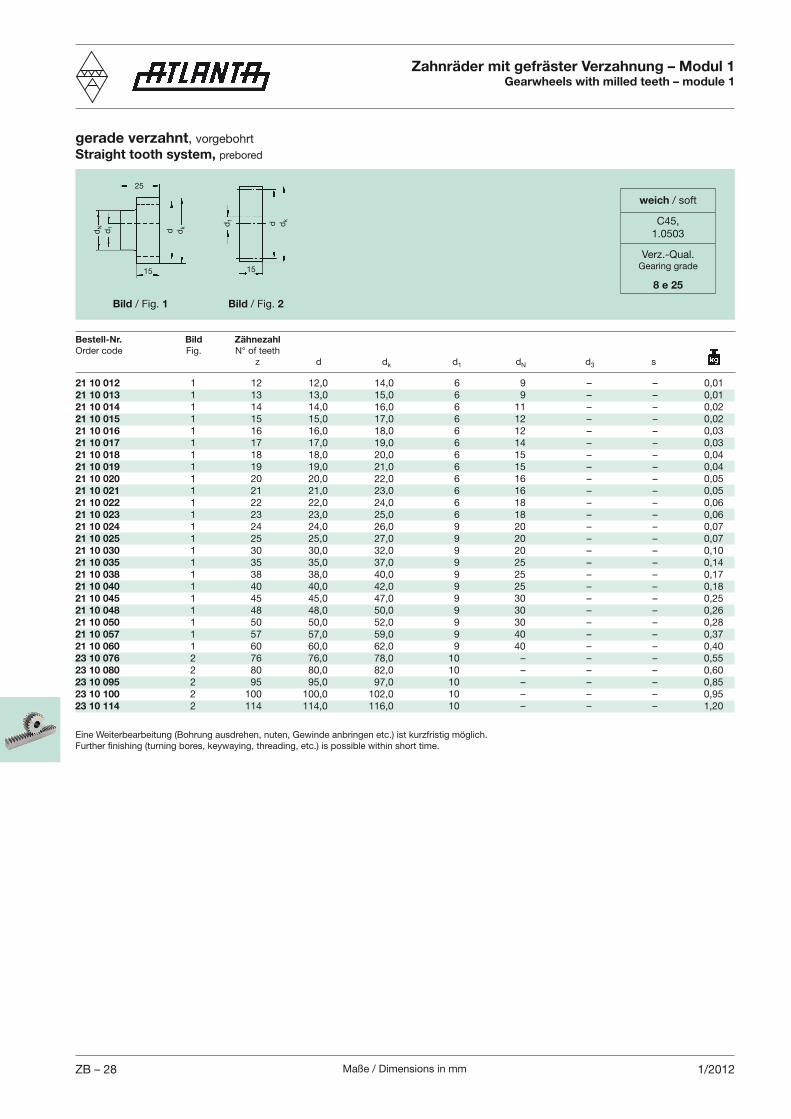
Maße / Dimensions in mmZB – 28 1/2012
Zahnräder mit gefräster Verzahnung – Modul 1Gearwheels with milled teeth – module 1
21 10 012 1 12 12,0 14,0 6 9 – – 0,0121 10 013 1 13 13,0 15,0 6 9 – – 0,0121 10 014 1 14 14,0 16,0 6 11 – – 0,0221 10 015 1 15 15,0 17,0 6 12 – – 0,0221 10 016 1 16 16,0 18,0 6 12 – – 0,0321 10 017 1 17 17,0 19,0 6 14 – – 0,0321 10 018 1 18 18,0 20,0 6 15 – – 0,0421 10 019 1 19 19,0 21,0 6 15 – – 0,0421 10 020 1 20 20,0 22,0 6 16 – – 0,0521 10 021 1 21 21,0 23,0 6 16 – – 0,0521 10 022 1 22 22,0 24,0 6 18 – – 0,0621 10 023 1 23 23,0 25,0 6 18 – – 0,0621 10 024 1 24 24,0 26,0 9 20 – – 0,0721 10 025 1 25 25,0 27,0 9 20 – – 0,0721 10 030 1 30 30,0 32,0 9 20 – – 0,1021 10 035 1 35 35,0 37,0 9 25 – – 0,1421 10 038 1 38 38,0 40,0 9 25 – – 0,1721 10 040 1 40 40,0 42,0 9 25 – – 0,1821 10 045 1 45 45,0 47,0 9 30 – – 0,2521 10 048 1 48 48,0 50,0 9 30 – – 0,2621 10 050 1 50 50,0 52,0 9 30 – – 0,2821 10 057 1 57 57,0 59,0 9 40 – – 0,3721 10 060 1 60 60,0 62,0 9 40 – – 0,4023 10 076 2 76 76,0 78,0 10 – – – 0,5523 10 080 2 80 80,0 82,0 10 – – – 0,6023 10 095 2 95 95,0 97,0 10 – – – 0,8523 10 100 2 100 100,0 102,0 10 – – – 0,9523 10 114 2 114 114,0 116,0 10 – – – 1,20
gerade verzahnt, vorgebohrtStraight tooth system, prebored
Bestell-Nr. Bild Zähnezahl
z d dk d1 dN d3 s
dN d1
dkd
dkdd1
Bild / Fig. 1 Bild / Fig. 2
25
15 15
Eine Weiterbearbeitung (Bohrung ausdrehen, nuten, Gewinde anbringen etc.) ist kurzfristig möglich.
weich / soft
C45,1.0503
Verz.-Qual.Gearing grade
8 e 25
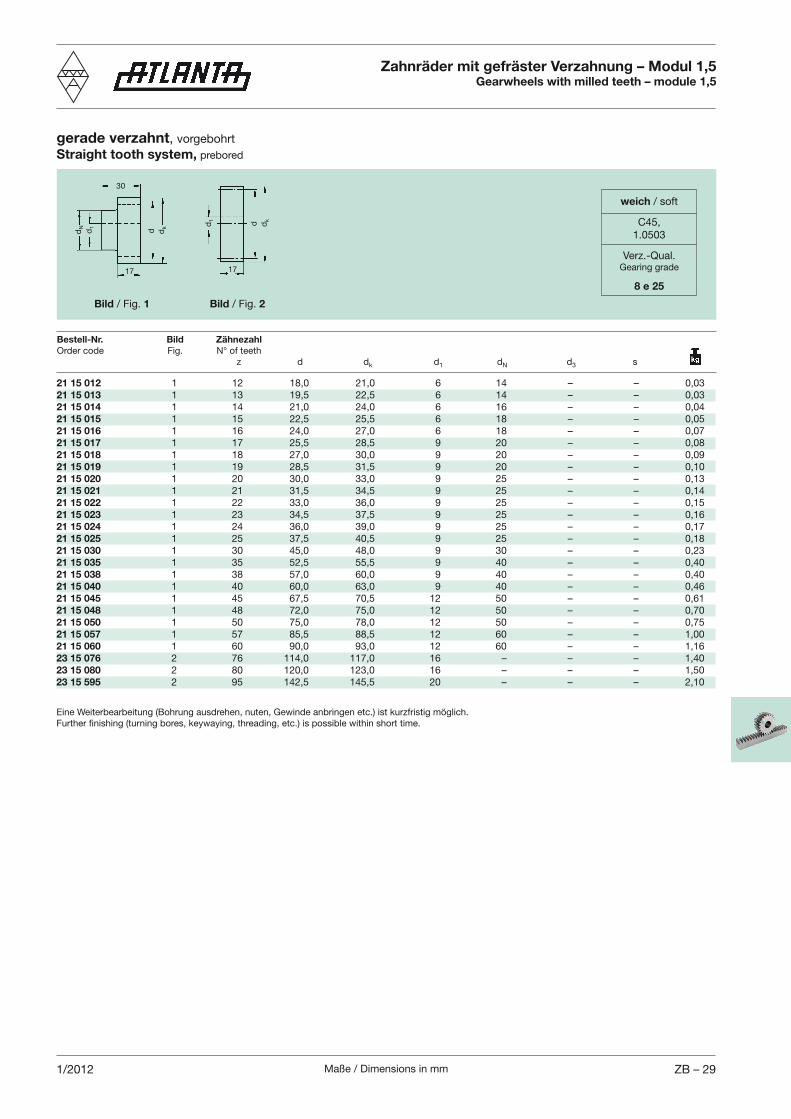
Maße / Dimensions in mm ZB – 291/2012
Bestell-Nr. Bild Zähnezahl
z d dk d1 dN d3 s
dN d1
dkd
dkdd1
Bild / Fig. 1 Bild / Fig. 2
30
17 17
21 15 012 1 12 18,0 21,0 6 14 – – 0,0321 15 013 1 13 19,5 22,5 6 14 – – 0,0321 15 014 1 14 21,0 24,0 6 16 – – 0,0421 15 015 1 15 22,5 25,5 6 18 – – 0,0521 15 016 1 16 24,0 27,0 6 18 – – 0,0721 15 017 1 17 25,5 28,5 9 20 – – 0,0821 15 018 1 18 27,0 30,0 9 20 – – 0,0921 15 019 1 19 28,5 31,5 9 20 – – 0,1021 15 020 1 20 30,0 33,0 9 25 – – 0,1321 15 021 1 21 31,5 34,5 9 25 – – 0,1421 15 022 1 22 33,0 36,0 9 25 – – 0,1521 15 023 1 23 34,5 37,5 9 25 – – 0,1621 15 024 1 24 36,0 39,0 9 25 – – 0,1721 15 025 1 25 37,5 40,5 9 25 – – 0,1821 15 030 1 30 45,0 48,0 9 30 – – 0,2321 15 035 1 35 52,5 55,5 9 40 – – 0,4021 15 038 1 38 57,0 60,0 9 40 – – 0,4021 15 040 1 40 60,0 63,0 9 40 – – 0,4621 15 045 1 45 67,5 70,5 12 50 – – 0,6121 15 048 1 48 72,0 75,0 12 50 – – 0,7021 15 050 1 50 75,0 78,0 12 50 – – 0,7521 15 057 1 57 85,5 88,5 12 60 – – 1,0021 15 060 1 60 90,0 93,0 12 60 – – 1,1623 15 076 2 76 114,0 117,0 16 – – – 1,4023 15 080 2 80 120,0 123,0 16 – – – 1,5023 15 595 2 95 142,5 145,5 20 – – – 2,10
Eine Weiterbearbeitung (Bohrung ausdrehen, nuten, Gewinde anbringen etc.) ist kurzfristig möglich.
Zahnräder mit gefräster Verzahnung – Modul 1,5Gearwheels with milled teeth – module 1,5
gerade verzahnt, vorgebohrtStraight tooth system, prebored
weich / soft
C45,1.0503
Verz.-Qual.Gearing grade
8 e 25
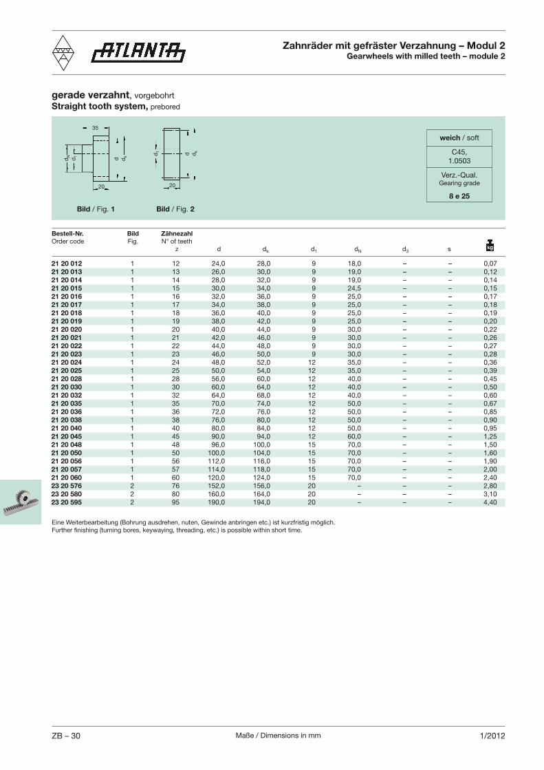
Maße / Dimensions in mmZB – 30 1/2012
21 20 012 1 12 24,0 28,0 9 18,0 – – 0,0721 20 013 1 13 26,0 30,0 9 19,0 – – 0,1221 20 014 1 14 28,0 32,0 9 19,0 – – 0,1421 20 015 1 15 30,0 34,0 9 24,5 – – 0,1521 20 016 1 16 32,0 36,0 9 25,0 – – 0,1721 20 017 1 17 34,0 38,0 9 25,0 – – 0,1821 20 018 1 18 36,0 40,0 9 25,0 – – 0,1921 20 019 1 19 38,0 42,0 9 25,0 – – 0,2021 20 020 1 20 40,0 44,0 9 30,0 – – 0,2221 20 021 1 21 42,0 46,0 9 30,0 – – 0,2621 20 022 1 22 44,0 48,0 9 30,0 – – 0,2721 20 023 1 23 46,0 50,0 9 30,0 – – 0,2821 20 024 1 24 48,0 52,0 12 35,0 – – 0,3621 20 025 1 25 50,0 54,0 12 35,0 – – 0,3921 20 028 1 28 56,0 60,0 12 40,0 – – 0,4521 20 030 1 30 60,0 64,0 12 40,0 – – 0,5021 20 032 1 32 64,0 68,0 12 40,0 – – 0,6021 20 035 1 35 70,0 74,0 12 50,0 – – 0,6721 20 036 1 36 72,0 76,0 12 50,0 – – 0,8521 20 038 1 38 76,0 80,0 12 50,0 – – 0,9021 20 040 1 40 80,0 84,0 12 50,0 – – 0,9521 20 045 1 45 90,0 94,0 12 60,0 – – 1,2521 20 048 1 48 96,0 100,0 15 70,0 – – 1,5021 20 050 1 50 100,0 104,0 15 70,0 – – 1,6021 20 056 1 56 112,0 116,0 15 70,0 – – 1,9021 20 057 1 57 114,0 118,0 15 70,0 – – 2,0021 20 060 1 60 120,0 124,0 15 70,0 – – 2,4023 20 576 2 76 152,0 156,0 20 – – – 2,8023 20 580 2 80 160,0 164,0 20 – – – 3,1023 20 595 2 95 190,0 194,0 20 – – – 4,40
Bestell-Nr. Bild Zähnezahl
z d dk d1 dN d3 s
dN d1
dkd
dkdd1
35
20 20
Eine Weiterbearbeitung (Bohrung ausdrehen, nuten, Gewinde anbringen etc.) ist kurzfristig möglich.
Bild / Fig. 1 Bild / Fig. 2
Zahnräder mit gefräster Verzahnung – Modul 2Gearwheels with milled teeth – module 2
gerade verzahnt, vorgebohrtStraight tooth system, prebored
weich / soft
C45,1.0503
Verz.-Qual.Gearing grade
8 e 25

Maße / Dimensions in mm ZB – 311/2012
Bestell-Nr. Bild Zähnezahl
z d dk d1 dN d3 s
dN d1
dkd
dkdd1
40
25 25
21 25 012 1 12 30,0 35,0 9 20,0 – – 0,1621 25 013 1 13 32,5 37,5 9 20,0 – – 0,1821 25 014 1 14 35,0 40,0 9 25,0 – – 0,2221 25 015 1 15 37,5 42,5 9 25,0 – – 0,2521 25 016 1 16 40,0 45,0 9 30,0 – – 0,3121 25 017 1 17 42,5 47,5 9 30,0 – – 0,3521 25 018 1 18 45,0 50,0 9 35,0 – – 0,4121 25 019 1 19 47,5 52,5 12 35,0 – – 0,4321 25 020 1 20 50,0 55,0 12 35,0 – – 0,4721 25 021 1 21 52,5 57,5 12 35,0 – – 0,5021 25 022 1 22 55,0 60,0 12 40,0 – – 0,5321 25 023 1 23 57,5 62,5 12 40,0 – – 0,6221 25 024 1 24 60,0 65,0 12 40,0 – – 0,6621 25 025 1 25 62,5 67,5 12 45,0 – – 0,7521 25 030 1 30 75,0 80,0 12 50,0 – – 0,9721 25 035 1 35 87,5 92,5 12 60,0 – – 1,4921 25 038 1 38 95,0 100,0 12 60,0 – – 1,7221 25 040 1 40 100,0 105,0 12 70,0 – – 1,8421 25 045 1 45 112,5 117,5 15 70,0 – – 2,3621 25 048 1 48 120,0 125,0 15 80,0 – – 2,7521 25 050 1 50 125,0 130,0 15 80,0 – – 2,9421 25 057 1 57 142,5 147,5 15 90,0 – – 3,6721 25 060 1 60 150,0 155,0 15 90,0 – – 4,0023 25 580 2 80 200,0 205,0 25 – – – 6,10
Eine Weiterbearbeitung (Bohrung ausdrehen, nuten, Gewinde anbringen etc.) ist kurzfristig möglich.
Bild / Fig. 1 Bild / Fig. 2
Zahnräder mit gefräster Verzahnung – Modul 2,5Gearwheels with milled teeth – module 2,5
gerade verzahnt, vorgebohrtStraight tooth system, prebored
weich / soft
C45,1.0503
Verz.-Qual.Gearing grade
8 e 25
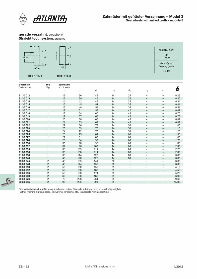
Maße / Dimensions in mmZB – 32 1/2012
21 30 012 1 12 36 42 14 25 – – 0,2521 30 013 1 13 39 45 14 25 – – 0,3021 30 014 1 14 42 48 14 25 – – 0,3421 30 015 1 15 45 51 14 35 – – 0,4121 30 016 1 16 48 54 14 35 – – 0,5121 30 017 1 17 51 57 14 42 – – 0,6721 30 018 1 18 54 60 14 45 – – 0,7021 30 019 1 19 57 63 14 45 – – 0,7521 30 020 1 20 60 66 14 45 – – 0,8221 30 021 1 21 63 69 14 45 – – 0,8921 30 022 1 22 66 72 14 50 – – 1,0521 30 023 1 23 69 75 14 50 – – 1,1021 30 024 1 24 72 78 14 50 – – 1,2021 30 025 1 25 75 81 14 60 – – 1,3521 30 027 1 27 81 87 14 60 – – 1,6021 30 028 1 28 84 90 14 60 – – 1,7021 30 030 1 30 90 96 14 60 – – 1,8021 30 032 1 32 96 102 14 60 – – 2,0021 30 035 1 35 105 111 14 80 – – 2,7021 30 036 1 36 108 114 14 80 – – 2,8021 30 038 1 38 114 120 14 80 – – 3,0021 30 040 1 40 120 126 14 80 – – 3,3023 30 545 2 45 135 141 20 – – – 3,3023 30 548 2 48 144 150 20 – – – 3,8023 30 550 2 50 150 156 25 – – – 4,1023 30 552 2 52 156 162 25 – – – 4,5023 30 556 2 56 168 174 25 – – – 5,2023 30 560 2 60 180 186 25 – – – 6,0023 30 576 2 76 228 234 25 – – – 9,6023 30 595 2 95 285 291 25 – – – 15,00
Bestell-Nr. Bild Zähnezahl
z d dk d1 dN d3 s
dN d1
dkd
dkdd1
50
30 30
Eine Weiterbearbeitung (Bohrung ausdrehen, nuten, Gewinde anbringen etc.) ist kurzfristig möglich.
Bild / Fig. 1 Bild / Fig. 2
Zahnräder mit gefräster Verzahnung – Modul 3Gearwheels with milled teeth – module 3
gerade verzahnt, vorgebohrtStraight tooth system, prebored
weich / soft
C45,1.0503
Verz.-Qual.Gearing grade
8 e 25
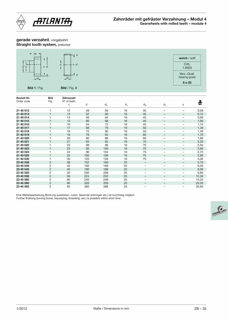
Maße / Dimensions in mm ZB – 331/2012
dN d1
dkd
dkdd1
60
40 40
21 40 012 1 12 48 56 16 35 – – 0,5821 40 013 1 13 52 60 16 35 – – 0,7221 40 014 1 14 56 64 16 45 – – 0,9021 40 015 1 15 60 68 16 45 – – 1,0021 40 016 1 16 64 72 16 45 – – 1,1021 40 017 1 17 68 76 16 50 – – 1,3021 40 018 1 18 72 80 16 50 – – 1,4021 40 019 1 19 76 84 16 60 – – 1,7021 40 020 1 20 80 88 16 60 – – 1,8021 40 021 1 21 84 92 16 70 – – 2,2021 40 022 1 22 88 96 16 70 – – 2,5021 40 023 1 23 92 100 16 75 – – 2,6021 40 024 1 24 96 104 16 75 – – 2,7521 40 025 1 25 100 108 16 75 – – 2,9021 40 030 1 30 120 128 16 75 – – 4,0023 40 538 2 38 152 160 25 – – – 5,7023 40 540 2 40 160 168 25 – – – 6,3023 40 545 2 45 180 188 25 – – – 8,0023 40 550 2 50 200 208 25 – – – 9,8023 40 556 2 56 224 232 25 – – – 12,3023 40 560 2 60 240 248 25 – – – 14,2023 40 580 2 80 320 328 25 – – – 25,2023 40 595 2 95 380 388 25 – – – 35,60
Eine Weiterbearbeitung (Bohrung ausdrehen, nuten, Gewinde anbringen etc.) ist kurzfristig möglich.
Bild 1 / Fig. Bild / Fig. 2
gerade verzahnt, vorgebohrtStraight tooth system, prebored
Zahnräder mit gefräster Verzahnung – Modul 4Gearwheels with milled teeth – module 4
Bestell-Nr. Bild Zähnezahl
z d dk d1 dN d3 s
weich / soft
C45,1.0503
Verz.-Qual.Gearing grade
8 e 25
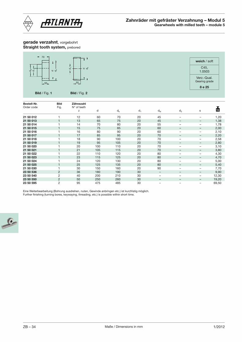
Maße / Dimensions in mmZB – 34 1/2012
21 50 012 1 12 60 70 20 45 – – 1,2021 50 013 1 13 65 75 20 45 – – 1,3821 50 014 1 14 70 80 20 55 – – 1,7821 50 015 1 15 75 85 20 60 – – 2,0021 50 016 1 16 80 90 20 60 – – 2,1021 50 017 1 17 85 95 20 70 – – 2,2021 50 018 1 18 90 100 20 70 – – 2,5821 50 019 1 19 95 105 20 70 – – 2,8021 50 020 1 20 100 110 20 70 – – 3,1021 50 021 1 21 105 115 20 70 – – 3,8021 50 022 1 22 110 120 20 80 – – 4,3021 50 023 1 23 115 125 20 80 – – 4,7021 50 024 1 24 120 130 20 80 – – 5,0021 50 025 1 25 125 135 20 80 – – 5,4021 50 030 1 30 150 160 20 90 – – 7,7023 50 536 2 36 180 190 30 – – – 9,9023 50 540 2 40 200 210 30 – – – 12,3023 50 550 2 50 250 260 30 – – – 19,2023 50 595 2 95 475 485 30 – – – 69,50
dN d1
dkd
dkdd1
70
50 50
Eine Weiterbearbeitung (Bohrung ausdrehen, nuten, Gewinde anbringen etc.) ist kurzfristig möglich.
Bild / Fig. 1 Bild / Fig. 2
gerade verzahnt, vorgebohrtStraight tooth system, prebored
Zahnräder mit gefräster Verzahnung – Modul 5Gearwheels with milled teeth – module 5
Bestell-Nr. Bild Zähnezahl
z d dk d1 dN d3 s
weich / soft
C45,1.0503
Verz.-Qual.Gearing grade
8 e 25
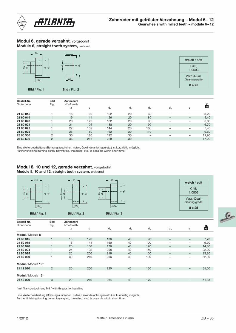
Maße / Dimensions in mm ZB – 351/2012
21 60 015 1 15 90 102 20 60 – – 3,2021 60 019 1 19 114 126 20 80 – – 5,4021 60 020 1 20 120 132 20 90 – – 6,0021 60 021 1 21 126 138 20 90 – – 6,7021 60 022 1 22 132 144 20 100 – – 7,4021 60 025 1 25 150 162 20 110 – – 9,6023 60 530 2 30 180 192 30 – – – 11,9023 60 536 2 36 216 228 30 – – – 17,20
dN d1
dkd
dkdd1
80
60 60
Eine Weiterbearbeitung (Bohrung ausdrehen, nuten, Gewinde anbringen etc.) ist kurzfristig möglich.
Bestell-Nr. Bild Zähnezahl
z d dk d1 dN d3 s
Modul / Module 8
21 80 015 1 15 120 136 40 90 – – 7,7021 80 018 1 18 144 160 40 100 – – 9,9021 80 020 1 20 160 176 40 120 – – 14,8021 80 024 1 24 192 208 40 150 – – 22,0021 80 025 1 25 200 216 40 150 – – 23,8021 80 030 1 30 240 256 40 190 – – 32,00
Modul / Module 10*
21 11 020 2 20 200 220 40 150 – – 35,00
Modul / Module 12*
21 12 020 3 20 240 264 40 170 – – 51,33
dN d1
dkd
80
120
* mit Transportbohrung M8 / with threads for handling
Eine Weiterbearbeitung (Bohrung ausdrehen, nuten, Gewinde anbringen etc.) ist kurzfristig möglich.
Bild / Fig. 1 Bild / Fig. 2
Modul 6, gerade verzahnt, vorgebohrtModule 6, straight tooth system, prebored
Zahnräder mit gefräster Verzahnung – Modul 6 – 12Gearwheels with milled teeth – module 6 – 12
Modul 8, 10 und 12, gerade verzahnt, vorgebohrtModule 8, 10 and 12, straight tooth system, prebored
Bestell-Nr. Bild Zähnezahl
z d dk d1 dN d3 s
Bild / Fig. 1 Bild / Fig. 2
dN d1
dkd
100
150
Bild / Fig. 3
dN d1 d
kd
120
180
weich / soft
C45,1.0503
Verz.-Qual.Gearing grade
8 e 25
weich / soft
C45,1.0503
Verz.-Qual.Gearing grade
8 e 25
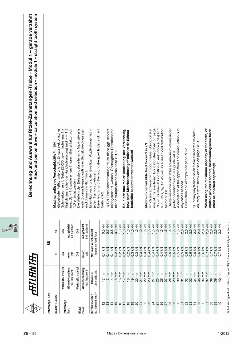
Maße / Dimensions in mmZB – 36 1/2012
1) A
uf
Ver
füg
bar
keit
prü
fen (K
apite
l ZB
) / c
hec
k av
aila
bili
ty (c
hap
ter
ZB
)
Be
rec
hn
un
g u
nd
Au
swa
hl f
ür
Rit
zel-
Za
hn
sta
ng
en
-Tri
eb
e –
Mo
du
l 1 –
ge
rad
e v
erz
ah
nt
Ra
ck
an
d p
inio
n d
rive
– c
alc
ula
tio
n a
nd
se
lec
tio
n –
mo
du
le 1
– s
tra
igh
t to
oth
sys
tem
Za
hn
sta
ng
e / Rac
k
BR
Qu
ali
tät / Quality
9
10
W
erk
sto
ff /
material
C4
5
C4
5Z
ah
nst
an
ge
Rac
k W
ärm
eb
eh
an
dlu
ng
w
eic
h
ind
. geh
ärt
et
Hea
t Trea
tmen
t so
ft
ind. h
arden
ed
W
erk
sto
ff /
material
C4
5
C4
5R
itze
l
Pinion
Wä
rmeb
eh
an
dlu
ng
w
eic
h
ind
. geh
ärt
et
Hea
t Trea
tmen
t so
ft
ind. h
arden
ed
Rit
zelz
äh
neza
hl 1
) Te
ilk
reis
d
Ma
xim
ale
Vo
rsch
ub
kra
ft
No. of pinion tee
th 1)
pitch circle dia.
Max
imum Fee
d Force
12
12 m
m
0,1
kN
0,6
kN
13
13 m
m
0,1
kN
0,7
kN
14
14 m
m
0,1
kN
0,8
kN
15
15 m
m
0,2
kN
0,9
kN
16
16 m
m
0,2
kN
1,0
kN
17
17 m
m
0,2
kN
1,0
kN
18
18 m
m
0,2
kN
1,0
kN
19
19 m
m
0,3
kN
1,0
kN
20
20 m
m
0,3
kN
1,0
kN
21
21 m
m
0,3
kN
1,0
kN
22
22 m
m
0,3
kN
1,5
kN
23
23 m
m
0,4
kN
1,5
kN
24
24 m
m
0,4
kN
1,5
kN
25
25 m
m
0,4
kN
1,5
kN
26
26 m
m
0,4
kN
1,5
kN
27
27 m
m
0,4
kN
1,5
kN
28
28 m
m
0,5
kN
1,5
kN
29
29 m
m
0,5
kN
1,5
kN
30
30 m
m
0,5
kN
1,5
kN
31
31 m
m
0,5
kN
2,0
kN
32
32 m
m
0,6
kN
2,0
kN
33
33 m
m
0,6
kN
2,0
kN
34
34 m
m
0,6
kN
2,0
kN
35
35 m
m
0,6
kN
2,0
kN
36
36 m
m
0,6
kN
2,0
kN
37
37 m
m
0,7
kN
2,0
kN
38
38 m
m
0,7
kN
2,0
kN
39
39 m
m
0,7
kN
2,0
kN
40
40 m
m
0,7
kN
2,0
kN
Ma
xim
um
pe
rmis
sib
le f
ee
d f
orc
es
1) i
n k
Nw
hic
h a
re a
chie
ved
with
go
od
gre
ase
lub
rica
tion (
i.e.
use
of
the e
lectr
on
ic l
ub
ricato
r d
esc
rib
ed
on
pag
e Z
E-2
/3 o
r m
anual
lub
rica
tion a
t le
ast
once
a d
ay)
and
v=
1.5
m/s
, S
B=
1.0
as
wel
l as
a lin
ear
load
dis
trib
utio
n
fact
or
of
1.0
.T
he
valu
es in
the
load
tab
les
are
max
imum
val
ues
und
er
per
fect
co
nd
itio
ns
and
is a
guid
e va
lue.
any
case
s nee
ded
.C
alcu
latio
n a
nd
exa
mp
le s
ee p
age
ZD
-2.
1) F
or
keyw
ay tra
nsm
issi
on m
ake
a se
par
ate
calc
ula
ti-o
n, to
rque
with
shrink
dis
c se
e o
n p
age
GH
-1
Wh
en
usi
ng
th
e m
axi
mu
m c
ap
ac
ity
of
the
te
eth
, o
r m
ult
iple
pin
ion
s in
co
nta
ct, t
he
mo
un
tin
g s
crew
load
s m
ust
be
ch
ec
ke
d s
ep
ara
tely
!
Ma
xim
al z
ulä
ssig
e V
ors
ch
ub
krä
fte
1) in
kN
die
bei
gute
r Fet
tsch
mie
rung
(d.h
. Ein
satz
ele
kro
nis
cher
S
chm
ierb
uch
sen lt
. S
eite
ZE
-2/3
bzw
. m
ind
este
ns
1 x
tä
glic
h a
usr
eich
end
er H
and
schm
ieru
ng
) und
v =
1,5
m
/s,
SB =
1,0
so
wie
ein
em lin
eare
n B
reite
nfa
kto
r vo
n
1,0
err
eich
t w
erd
en.
Die
Wer
te in
den
Bel
astu
ng
stab
elle
n s
ind
Max
imal
wer
te
unte
r Zug
rund
eleg
ung
op
timal
er B
etrieb
sbed
ing
ung
en
und
die
nen
als
Ric
htw
ert.
Ein
e N
achre
chnung
der
jew
eilig
en A
pp
likat
ionen
ist
in
jed
em F
all v
orz
uneh
men
.
Sei
te Z
D-2
.
1)
Bei
Pas
sfed
erve
rbin
dung
muss
die
se g
gf.
sep
arat
nac
hg
erec
hnet
wer
den
. Ü
ber
trag
bar
e D
rehm
om
ente
m
it S
chru
mp
fsch
eib
e si
ehe
Sei
te G
H-1
.
Be
i e
ine
r m
axi
ma
ler
Au
sla
stu
ng
de
r V
erz
ah
nu
ng
, b
zw. b
eim
Meh
rfa
ch
zah
ne
ing
riff
mü
ssen
die
Sch
rau
-b
en
krä
fte
se
pa
rat
be
tra
ch
tet
we
rde
n!
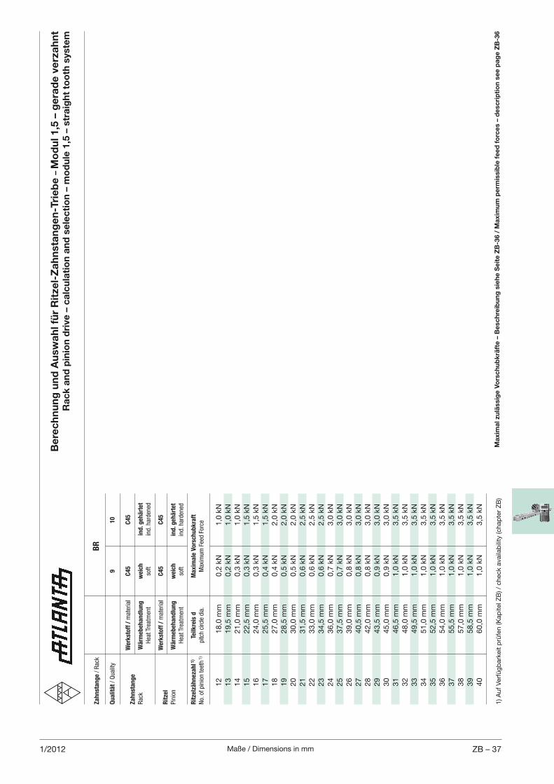
Maße / Dimensions in mm ZB – 371/2012
1) A
uf
Ver
füg
bar
keit
prü
fen (K
apite
l ZB
) / c
hec
k av
aila
bili
ty (c
hap
ter
ZB
)
Za
hn
sta
ng
e / Rac
k
BR
Qu
ali
tät / Quality
9
10
W
erk
sto
ff /
material
C4
5
C4
5Z
ah
nst
an
ge
Rac
k W
ärm
eb
eh
an
dlu
ng
w
eic
h
ind
. geh
ärt
et
Hea
t Trea
tmen
t so
ft
ind. h
arden
ed
W
erk
sto
ff /
material
C4
5
C4
5R
itze
l
Pinion
Wä
rmeb
eh
an
dlu
ng
w
eic
h
ind
. geh
ärt
et
Hea
t Trea
tmen
t so
ft
ind. h
arden
ed
Rit
zelz
äh
neza
hl 1
) Te
ilk
reis
d
Ma
xim
ale
Vo
rsch
ub
kra
ft
No. of pinion tee
th 1)
pitch circle dia.
Max
imum Fee
d Force
12
18,0
mm
0,2
kN
1,0
kN
13
19,5
mm
0,2
kN
1,0
kN
14
21,0
mm
0,3
kN
1,0
kN
15
22,5
mm
0,3
kN
1,5
kN
16
24,0
mm
0,3
kN
1,5
kN
17
25,5
mm
0,4
kN
1,5
kN
18
27,0
mm
0,4
kN
2,0
kN
19
28,5
mm
0,5
kN
2,0
kN
20
30,0
mm
0,5
kN
2,0
kN
21
31,5
mm
0,6
kN
2,5
kN
22
33,0
mm
0,6
kN
2,5
kN
23
34,5
mm
0,6
kN
2,5
kN
24
36,0
mm
0,7
kN
3,0
kN
25
37,5
mm
0,7
kN
3,0
kN
26
39,0
mm
0,8
kN
3,0
kN
27
40,5
mm
0,8
kN
3,0
kN
28
42,0
mm
0,8
kN
3,0
kN
29
43,5
mm
0,9
kN
3,0
kN
30
45,0
mm
0,9
kN
3,0
kN
31
46,5
mm
1,0
kN
3,5
kN
32
48,0
mm
1,0
kN
3,5
kN
33
49,5
mm
1,0
kN
3,5
kN
34
51,0
mm
1,0
kN
3,5
kN
35
52,5
mm
1,0
kN
3,5
kN
36
54,0
mm
1,0
kN
3,5
kN
37
55,5
mm
1,0
kN
3,5
kN
38
57,0
mm
1,0
kN
3,5
kN
39
58,5
mm
1,0
kN
3,5
kN
40
60,0
mm
1,0
kN
3,5
kN
Be
rec
hn
un
g u
nd
Au
swa
hl f
ür
Rit
zel-
Za
hn
sta
ng
en
-Tri
eb
e –
Mo
du
l 1,5
– g
era
de
ve
rza
hn
t R
ac
k a
nd
pin
ion
dri
ve –
ca
lcu
lati
on
an
d s
ele
cti
on
– m
od
ule
1,5
– s
tra
igh
t to
oth
sys
tem
Ma
xim
al z
ulä
ssig
e V
ors
ch
ub
krä
fte
– B
esc
hre
ibu
ng
sie
he
Se
ite
ZB
-36 /
Ma
xim
um
pe
rmis
sib
le f
ee
d f
orc
es
– d
esc
rip
tio
n s
ee
pa
ge
ZB
-36
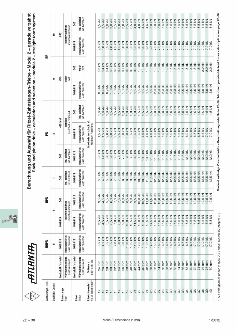
Maße / Dimensions in mmZB – 38 1/2012
Be
rec
hn
un
g u
nd
Au
swa
hl f
ür
Rit
zel-
Za
hn
sta
ng
en
-Tri
eb
e –
Mo
du
l 2 –
ge
rad
e v
erz
ah
nt
Ra
ck
an
d p
inio
n d
rive
– c
alc
ula
tio
n a
nd
se
lec
tio
n –
mo
du
le 2
– s
tra
igh
t to
oth
sys
tem
Za
hn
sta
ng
e / Rac
k
UH
PR
HP
R
P
R
BR
Qu
ali
tät / Quality
5
6
7
8
9
10
W
erk
sto
ff /
material
16
Mn
Cr5
1
6M
nC
r5
C4
5
C4
5
C4
5
42
CrM
o4
C
45
C
45
Za
hn
sta
ng
e
Rac
k W
ärm
eb
eh
an
dlu
ng
ein
satz
geh
ärt
et
ind
uk
tiv
geh
ärt
et
ind
. geh
ärt
et
ind
. geh
ärt
et
verg
üte
t w
eic
h
ind
uk
tiv
geh
ärt
et
Hea
t Trea
tmen
t ca
se harden
ed
induction harden
ed
ind. h
arden
ed
ind. h
arden
ed
quen
ched
+ tem
pered
so
ft
induction harden
ed
W
erk
sto
ff /
material
16
Mn
Cr5
1
6M
nC
r5
16
Mn
Cr5
1
6M
nC
r5
16
Mn
Cr5
1
6M
nC
r5
C4
5
16
Mn
Cr5
C
45
1
6M
nC
r5
C4
5R
itze
l
Pinion
Wä
rmeb
eh
an
dlu
ng
ein
satz
geh
ärt
et
ein
satz
geh
ärt
et
ein
satz
geh
ärt
et
ein
satz
geh
ärt
et
ein
satz
geh
ärt
et
ein
satz
geh
ärt
et
ind
. geh
ärt
et
ein
satz
geh
ärt
et
weic
h
ein
satz
geh
ärt
et
ind
. geh
ärt
et
Hea
t Trea
tmen
t ca
se harden
ed
case
harden
ed
case
harden
ed
case
harden
ed
case
harden
ed
case
harden
ed
ind. h
arden
ed
case
harden
ed
soft
case
harden
ed
ind. h
arden
ed
Rit
zelz
äh
neza
hl 1
) Te
ilk
reis
d
Ma
xim
ale
Vo
rsch
ub
kra
ft
No. of pinion tee
th 1)
pitch circle dia.
Max
imum Fee
d Force
12
24 m
m
3,5
kN
3,5
kN
3,5
kN
3,5
kN
3,5
kN
1,5
kN
1,0
kN
0,8
kN
0,3
kN
2,5
kN
1,5
kN
13
26 m
m
4,5
kN
4,5
kN
4,5
kN
4,5
kN
4,0
kN
1,5
kN
1,0
kN
0,9
kN
0,4
kN
3,0
kN
1,5
kN
14
28 m
m
5,5
kN
5,5
kN
5,5
kN
5,5
kN
5,0
kN
2,0
kN
1,0
kN
0,9
kN
0,4
kN
3,5
kN
2,0
kN
15
30 m
m
6,5
kN
6,5
kN
6,0
kN
6,0
kN
6,0
kN
2,0
kN
1,5
kN
1,0
kN
0,5
kN
4,0
kN
2,0
kN
16
32 m
m
7,0
kN
7,0
kN
7,0
kN
7,0
kN
6,5
kN
2,5
kN
1,5
kN
1,0
kN
0,6
kN
4,5
kN
2,5
kN
17
34 m
m
8,0
kN
8,0
kN
7,5
kN
7,5
kN
7,0
kN
2,5
kN
1,5
kN
1,0
kN
0,7
kN
4,5
kN
3,0
kN
18
36 m
m
9,0
kN
9,0
kN
8,0
kN
8,0
kN
7,5
kN
3,0
kN
2,0
kN
1,0
kN
0,7
kN
5,0
kN
3,0
kN
19
38 m
m
10,0
kN
10,0
kN
8,5
kN
8,5
kN
8,0
kN
3,0
kN
2,0
kN
1,0
kN
0,8
kN
5,0
kN
3,5
kN
20
40 m
m
10,5
kN
10,5
kN
9,0
kN
9,0
kN
8,5
kN
3,5
kN
2,0
kN
1,5
kN
0,8
kN
5,5
kN
3,5
kN
21
42 m
m
11,5
kN
11,5
kN
9,5
kN
9,5
kN
9,0
kN
3,5
kN
2,0
kN
1,5
kN
0,9
kN
5,5
kN
4,0
kN
22
44 m
m
12,0
kN
12,0
kN
10,0
kN
10,0
kN
9,5
kN
3,5
kN
2,5
kN
1,5
kN
1,0
kN
6,0
kN
4,0
kN
23
46 m
m
13,0
kN
13,0
kN
10,5
kN
10,5
kN
10,0
kN
4,0
kN
2,5
kN
1,5
kN
1,0
kN
6,0
kN
4,5
kN
24
48 m
m
13,5
kN
13,5
kN
11,0
kN
11,0
kN
10,5
kN
4,0
kN
2,5
kN
1,5
kN
1,0
kN
6,5
kN
4,5
kN
25
50 m
m
14,5
kN
14,5
kN
11,5
kN
11,5
kN
11,0
kN
4,0
kN
2,5
kN
1,5
kN
1,0
kN
6,5
kN
5,0
kN
26
52 m
m
15,0
kN
15,0
kN
12,0
kN
12,0
kN
11,0
kN
4,5
kN
3,0
kN
2,0
kN
1,0
kN
7,0
kN
5,0
kN
27
54 m
m
16,0
kN
15,0
kN
12,0
kN
12,0
kN
11,5
kN
4,5
kN
3,0
kN
2,0
kN
1,0
kN
7,0
kN
5,0
kN
28
56 m
m
16,5
kN
15,0
kN
12,0
kN
12,0
kN
11,5
kN
5,0
kN
3,0
kN
2,0
kN
1,0
kN
7,0
kN
5,5
kN
29
58 m
m
16,5
kN
15,0
kN
12,5
kN
12,5
kN
11,5
kN
5,0
kN
3,0
kN
2,0
kN
1,0
kN
7,0
kN
5,5
kN
30
60 m
m
16,5
kN
15,0
kN
12,5
kN
12,5
kN
11,5
kN
5,0
kN
3,5
kN
2,0
kN
1,5
kN
7,0
kN
5,5
kN
31
62 m
m
16,5
kN
15,0
kN
12,5
kN
12,5
kN
11,5
kN
5,5
kN
3,5
kN
2,0
kN
1,5
kN
7,0
kN
5,5
kN
32
64 m
m
16,5
kN
15,5
kN
12,5
kN
12,5
kN
11,5
kN
5,5
kN
3,5
kN
2,5
kN
1,5
kN
7,0
kN
5,5
kN
33
66 m
m
16,5
kN
15,5
kN
12,5
kN
12,5
kN
11,5
kN
5,5
kN
3,5
kN
2,5
kN
1,5
kN
7,0
kN
5,5
kN
34
68 m
m
16,5
kN
15,5
kN
12,5
kN
12,5
kN
12,0
kN
6,0
kN
3,5
kN
2,5
kN
1,5
kN
7,0
kN
5,5
kN
35
70 m
m
16,5
kN
15,5
kN
12,5
kN
12,5
kN
12,0
kN
6,0
kN
4,0
kN
2,5
kN
1,5
kN
7,0
kN
5,5
kN
36
72 m
m
17,0
kN
15,5
kN
12,5
kN
12,5
kN
12,0
kN
6,5
kN
4,0
kN
2,5
kN
1,5
kN
7,0
kN
5,5
kN
37
74 m
m
17,0
kN
15,5
kN
12,5
kN
12,5
kN
12,0
kN
6,5
kN
4,0
kN
2,5
kN
1,5
kN
7,0
kN
5,5
kN
38
76 m
m
17,0
kN
15,5
kN
12,5
kN
12,5
kN
12,0
kN
6,5
kN
4,0
kN
3,0
kN
2,0
kN
7,0
kN
5,5
kN
39
78 m
m
17,0
kN
15,5
kN
12,5
kN
12,5
kN
12,0
kN
7,0
kN
4,5
kN
3,0
kN
2,0
kN
7,0
kN
5,5
kN
40
80 m
m
17,0
kN
15,5
kN
12,5
kN
12,5
kN
12,0
kN
7,0
kN
4,5
kN
3,0
kN
2,0
kN
7,0
kN
5,5
kN
1) A
uf
Ver
füg
bar
keit
prü
fen (K
apite
l ZB
) / c
hec
k av
aila
bili
ty (c
hap
ter
ZB
)M
axi
ma
l zu
läss
ige
Vo
rsc
hu
bk
räft
e –
Be
sch
reib
un
g s
ieh
e S
eit
e Z
B-3
6 /
Ma
xim
um
pe
rmis
sib
le f
ee
d f
orc
es
– d
esc
rip
tio
n s
ee
pa
ge
ZB
-36
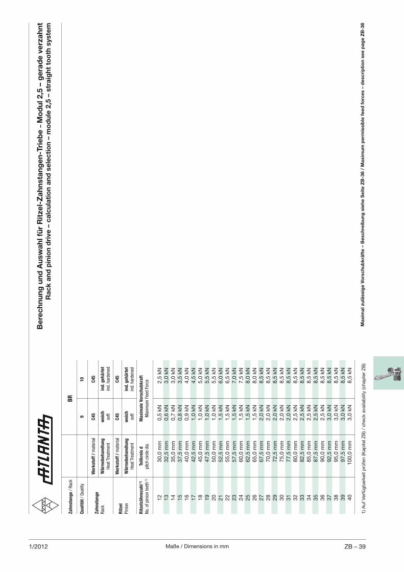
Maße / Dimensions in mm ZB – 391/2012
Be
rec
hn
un
g u
nd
Au
swa
hl f
ür
Rit
zel-
Za
hn
sta
ng
en
-Tri
eb
e –
Mo
du
l 2,5
– g
era
de
ve
rza
hn
t R
ac
k a
nd
pin
ion
dri
ve –
ca
lcu
lati
on
an
d s
ele
cti
on
– m
od
ule
2,5
– s
tra
igh
t to
oth
sys
tem
Za
hn
sta
ng
e / Rac
k
BR
Qu
ali
tät / Quality
9
10
W
erk
sto
ff /
material
C4
5
C4
5Z
ah
nst
an
ge
Rac
k W
ärm
eb
eh
an
dlu
ng
w
eic
h
ind
. geh
ärt
et
Hea
t Trea
tmen
t so
ft
ind. h
arden
ed
W
erk
sto
ff /
material
C4
5
C4
5R
itze
l
Pinion
Wä
rmeb
eh
an
dlu
ng
w
eic
h
ind
. geh
ärt
et
Hea
t Trea
tmen
t so
ft
ind. h
arden
ed
Rit
zelz
äh
neza
hl 1
) Te
ilk
reis
d
Ma
xim
ale
Vo
rsch
ub
kra
ft
No. of pinion tee
th 1)
pitch circle dia.
Max
imum Fee
d Force
12
30,0
mm
0,5
kN
2,5
kN
13
32,5
mm
0,6
kN
3,0
kN
14
35,0
mm
0,7
kN
3,0
kN
15
37,5
mm
0,8
kN
3,5
kN
16
40,0
mm
0,9
kN
4,0
kN
17
42,5
mm
1,0
kN
4,5
kN
18
45,0
mm
1,0
kN
5,0
kN
19
47,5
mm
1,0
kN
5,5
kN
20
50,0
mm
1,0
kN
5,5
kN
21
52,5
mm
1,5
kN
6,0
kN
22
55,0
mm
1,5
kN
6,5
kN
23
57,5
mm
1,5
kN
7,0
kN
24
60,0
mm
1,5
kN
7,5
kN
25
62,5
mm
1,5
kN
8,0
kN
26
65,0
mm
1,5
kN
8,0
kN
27
67,5
mm
2,0
kN
8,5
kN
28
70,0
mm
2,0
kN
8,5
kN
29
72,5
mm
2,0
kN
8,5
kN
30
75,0
mm
2,0
kN
8,5
kN
31
77,5
mm
2,0
kN
8,5
kN
32
80,0
mm
2,5
kN
8,5
kN
33
82,5
mm
2,5
kN
8,5
kN
34
85,0
mm
2,5
kN
8,5
kN
35
87,5
mm
2,5
kN
8,5
kN
36
90,0
mm
2,5
kN
8,5
kN
37
92,5
mm
3,0
kN
8,5
kN
38
95,0
mm
3,0
kN
8,5
kN
39
97,5
mm
3,0
kN
8,5
kN
40
100,0
mm
3,0
kN
8,5
kN
1) A
uf
Ver
füg
bar
keit
prü
fen (K
apite
l ZB
) / c
hec
k av
aila
bili
ty (c
hap
ter
ZB
)M
axi
ma
l zu
läss
ige
Vo
rsc
hu
bk
räft
e –
Be
sch
reib
un
g s
ieh
e S
eit
e Z
B-3
6 /
Ma
xim
um
pe
rmis
sib
le f
ee
d f
orc
es
– d
esc
rip
tio
n s
ee
pa
ge
ZB
-36
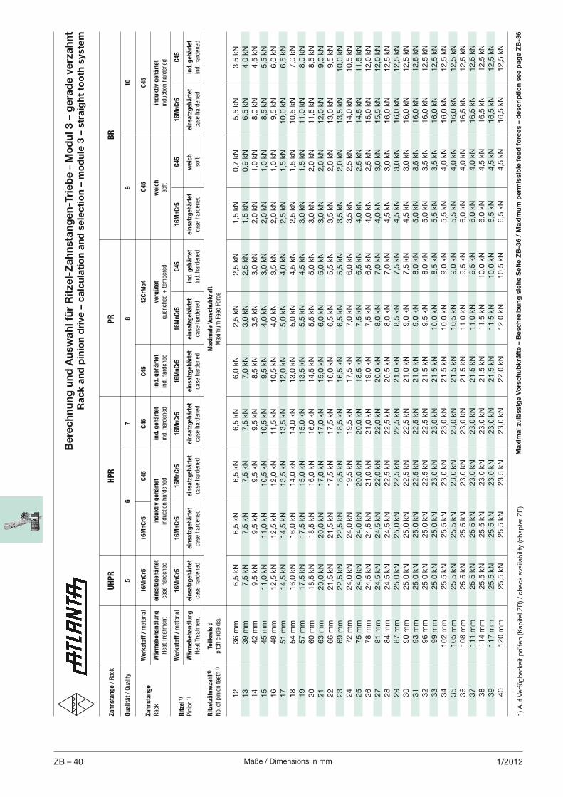
Maße / Dimensions in mmZB – 40 1/2012
Za
hn
sta
ng
e / Rac
k
UH
PR
HP
R
P
R
BR
Qu
ali
tät / Quality
5
6
7
8
9
10
W
erk
sto
ff /
material
16
Mn
Cr5
1
6M
nC
r5
C4
5
C4
5
C4
5
42
CrM
o4
C
45
C
45
Za
hn
sta
ng
e
Rac
k W
ärm
eb
eh
an
dlu
ng
ein
satz
geh
ärt
et
ind
uk
tiv
geh
ärt
et
ind
. geh
ärt
et
ind
. geh
ärt
et
verg
üte
t w
eic
h
ind
uk
tiv
geh
ärt
et
Hea
t Trea
tmen
t ca
se harden
ed
induction harden
ed
ind. h
arden
ed
ind. h
arden
ed
quen
ched
+ tem
pered
so
ft
induction harden
ed
W
erk
sto
ff /
material
16
Mn
Cr5
1
6M
nC
r5
16
Mn
Cr5
1
6M
nC
r5
16
Mn
Cr5
1
6M
nC
r5
C4
5
16
Mn
Cr5
C
45
1
6M
nC
r5
C4
5R
itze
l 1)
Pinion 1)
Wä
rmeb
eh
an
dlu
ng
ein
satz
geh
ärt
et
ein
satz
geh
ärt
et
ein
satz
geh
ärt
et
ein
satz
geh
ärt
et
ein
satz
geh
ärt
et
ein
satz
geh
ärt
et
ind
. geh
ärt
et
ein
satz
geh
ärt
et
weic
h
ein
satz
geh
ärt
et
ind
. geh
ärt
et
Hea
t Trea
tmen
t ca
se harden
ed
case
harden
ed
case
harden
ed
case
harden
ed
case
harden
ed
case
harden
ed
ind. h
arden
ed
case
harden
ed
soft
case
harden
ed
ind. h
arden
ed
Rit
zelz
äh
neza
hl 1
) Te
ilk
reis
d
Ma
xim
ale
Vo
rsch
ub
kra
ft
No. of pinion tee
th 1)
pitch circle dia.
Max
imum Fee
d Force
12
36 m
m
6,5
kN
6,5
kN
6,5
kN
6,5
kN
6,0
kN
2,5
kN
2,5
kN
1,5
kN
0,7
kN
5,5
kN
3,5
kN
13
39 m
m
7,5
kN
7,5
kN
7,5
kN
7,5
kN
7,0
kN
3,0
kN
2,5
kN
1,5
kN
0,9
kN
6,5
kN
4,0
kN
14
42 m
m
9,5
kN
9,5
kN
9,5
kN
9,5
kN
8,5
kN
3,5
kN
3,0
kN
2,0
kN
1,0
kN
8,0
kN
4,5
kN
15
45 m
m
11,0
kN
11,0
kN
10,5
kN
10,5
kN
9,5
kN
4,0
kN
3,0
kN
2,0
kN
1,0
kN
8,5
kN
5,5
kN
16
48 m
m
12,5
kN
12,5
kN
12,0
kN
11,5
kN
10,5
kN
4,0
kN
3,5
kN
2,0
kN
1,0
kN
9,5
kN
6,0
kN
17
51 m
m
14,5
kN
14,5
kN
13,5
kN
13,5
kN
12,0
kN
5,0
kN
4,0
kN
2,5
kN
1,5
kN
10,0
kN
6,5
kN
18
54 m
m
16,0
kN
16,0
kN
14,0
kN
14,0
kN
13,0
kN
5,0
kN
4,5
kN
2,5
kN
1,5
kN
10,5
kN
7,0
kN
19
57 m
m
17,5
kN
17,5
kN
15,0
kN
15,0
kN
13,5
kN
5,5
kN
4,5
kN
3,0
kN
1,5
kN
11,0
kN
8,0
kN
20
60 m
m
18,5
kN
18,5
kN
16,0
kN
16,0
kN
14,5
kN
5,5
kN
5,0
kN
3,0
kN
2,0
kN
11,5
kN
8,5
kN
21
63 m
m
20,0
kN
20,0
kN
17,0
kN
17,0
kN
15,0
kN
6,0
kN
5,0
kN
3,0
kN
2,0
kN
12,0
kN
9,0
kN
22
66 m
m
21,5
kN
21,5
kN
17,5
kN
17,5
kN
16,0
kN
6,5
kN
5,5
kN
3,5
kN
2,0
kN
13,0
kN
9,5
kN
23
69 m
m
22,5
kN
22,5
kN
18,5
kN
18,5
kN
16,5
kN
6,5
kN
5,5
kN
3,5
kN
2,0
kN
13,5
kN
10,0
kN
24
72 m
m
24,0
kN
24,0
kN
19,5
kN
19,5
kN
17,5
kN
7,0
kN
6,0
kN
3,5
kN
2,5
kN
14,0
kN
10,5
kN
25
75 m
m
24,0
kN
24,0
kN
20,0
kN
20,0
kN
18,5
kN
7,5
kN
6,5
kN
4,0
kN
2,5
kN
14,5
kN
11,5
kN
26
78 m
m
24,5
kN
24,5
kN
21,0
kN
21,0
kN
19,0
kN
7,5
kN
6,5
kN
4,0
kN
2,5
kN
15,0
kN
12,0
kN
27
81 m
m
24,5
kN
24,5
kN
22,0
kN
22,0
kN
20,0
kN
8,0
kN
7,0
kN
4,0
kN
3,0
kN
15,5
kN
12,0
kN
28
84 m
m
24,5
kN
24,5
kN
22,5
kN
22,5
kN
20,5
kN
8,0
kN
7,0
kN
4,5
kN
3,0
kN
16,0
kN
12,5
kN
29
87 m
m
25,0
kN
25,0
kN
22,5
kN
22,5
kN
21,0
kN
8,5
kN
7,5
kN
4,5
kN
3,0
kN
16,0
kN
12,5
kN
30
90 m
m
25,0
kN
25,0
kN
22,5
kN
22,5
kN
21,0
kN
9,0
kN
7,5
kN
4,5
kN
3,0
kN
16,0
kN
12,5
kN
31
93 m
m
25,0
kN
25,0
kN
22,5
kN
22,5
kN
21,0
kN
9,0
kN
8,0
kN
5,0
kN
3,5
kN
16,0
kN
12,5
kN
32
96 m
m
25,0
kN
25,0
kN
22,5
kN
22,5
kN
21,5
kN
9,5
kN
8,0
kN
5,0
kN
3,5
kN
16,0
kN
12,5
kN
33
99 m
m
25,0
kN
25,0
kN
23,0
kN
23,0
kN
21,5
kN
10,0
kN
8,5
kN
5,5
kN
3,5
kN
16,0
kN
12,5
kN
34
102 m
m
25,5
kN
25,5
kN
23,0
kN
23,0
kN
21,5
kN
10,0
kN
9,0
kN
5,5
kN
4,0
kN
16,0
kN
12,5
kN
35
105 m
m
25,5
kN
25,5
kN
23,0
kN
23,0
kN
21,5
kN
10,5
kN
9,0
kN
5,5
kN
4,0
kN
16,0
kN
12,5
kN
36
108 m
m
25,5
kN
25,5
kN
23,0
kN
23,0
kN
21,5
kN
11,0
kN
9,5
kN
6,0
kN
4,0
kN
16,5
kN
12,5
kN
37
111 m
m
25,5
kN
25,5
kN
23,0
kN
23,0
kN
21,5
kN
11,0
kN
9,5
kN
6,0
kN
4,0
kN
16,5
kN
12,5
kN
38
114 m
m
25,5
kN
25,5
kN
23,0
kN
23,0
kN
21,5
kN
11,5
kN
10,0
kN
6,0
kN
4,5
kN
16,5
kN
12,5
kN
39
117 m
m
25,5
kN
25,5
kN
23,0
kN
23,0
kN
21,5
kN
11,5
kN
10,0
kN
6,5
kN
4,5
kN
16,5
kN
12,5
kN
40
120 m
m
25,5
kN
25,5
kN
23,5
kN
23,0
kN
22,0
kN
12,0
kN
10,5
kN
6,5
kN
4,5
kN
16,5
kN
12,5
kN
1) A
uf
Ver
füg
bar
keit
prü
fen (K
apite
l ZB
) / c
hec
k av
aila
bili
ty (c
hap
ter
ZB
)
Be
rec
hn
un
g u
nd
Au
swa
hl f
ür
Rit
zel-
Za
hn
sta
ng
en
-Tri
eb
e –
Mo
du
l 3 –
ge
rad
e v
erz
ah
nt
Ra
ck
an
d p
inio
n d
rive
– c
alc
ula
tio
n a
nd
se
lec
tio
n –
mo
du
le 3
– s
tra
igh
t to
oth
sys
tem
Ma
xim
al z
ulä
ssig
e V
ors
ch
ub
krä
fte
– B
esc
hre
ibu
ng
sie
he
Se
ite
ZB
-36 /
Ma
xim
um
pe
rmis
sib
le f
ee
d f
orc
es
– d
esc
rip
tio
n s
ee
pa
ge
ZB
-36
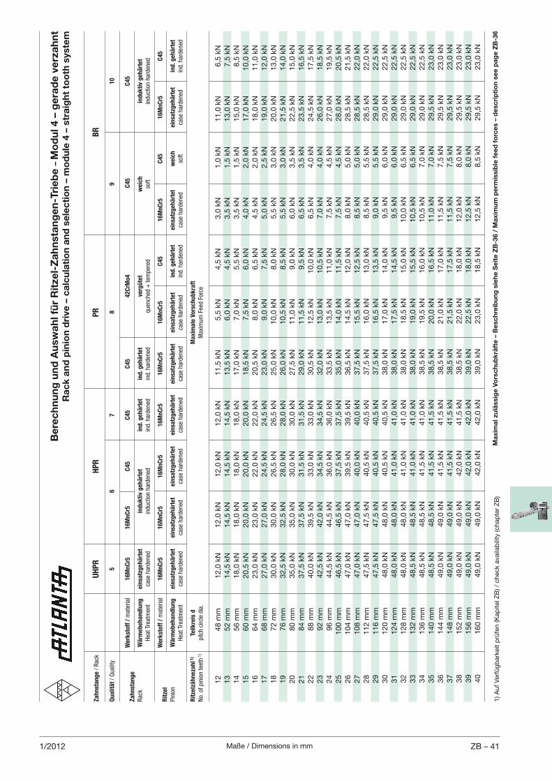
Maße / Dimensions in mm ZB – 411/2012
Be
rec
hn
un
g u
nd
Au
swa
hl f
ür
Rit
zel-
Za
hn
sta
ng
en
-Tri
eb
e –
Mo
du
l 4 –
ge
rad
e v
erz
ah
nt
Ra
ck
an
d p
inio
n d
rive
– c
alc
ula
tio
n a
nd
se
lec
tio
n –
mo
du
le 4
– s
tra
igh
t to
oth
sys
tem
Za
hn
sta
ng
e / Rac
k
UH
PR
HP
R
P
R
BR
Qu
ali
tät / Quality
5
6
7
8
9
10
W
erk
sto
ff /
material
16
Mn
Cr5
1
6M
nC
r5
C4
5
C4
5
C4
5
42
CrM
o4
C
45
C
45
Za
hn
sta
ng
e
Rac
k W
ärm
eb
eh
an
dlu
ng
ein
satz
geh
ärt
et
ind
uk
tiv
geh
ärt
et
ind
. geh
ärt
et
ind
. geh
ärt
et
verg
üte
t w
eic
h
ind
uk
tiv
geh
ärt
et
Hea
t Trea
tmen
t ca
se harden
ed
induction harden
ed
ind. h
arden
ed
ind. h
arden
ed
quen
ched
+ tem
pered
so
ft
induction harden
ed
W
erk
sto
ff /
material
16
Mn
Cr5
1
6M
nC
r5
16
Mn
Cr5
1
6M
nC
r5
16
Mn
Cr5
1
6M
nC
r5
C4
5
16
Mn
Cr5
C
45
1
6M
nC
r5
C4
5R
itze
l
Pinion
Wä
rmeb
eh
an
dlu
ng
ein
satz
geh
ärt
et
ein
satz
geh
ärt
et
ein
satz
geh
ärt
et
ein
satz
geh
ärt
et
ein
satz
geh
ärt
et
ein
satz
geh
ärt
et
ind
. geh
ärt
et
ein
satz
geh
ärt
et
weic
h
ein
satz
geh
ärt
et
ind
. geh
ärt
et
Hea
t Trea
tmen
t ca
se harden
ed
case
harden
ed
case
harden
ed
case
harden
ed
case
harden
ed
case
harden
ed
ind. h
arden
ed
case
harden
ed
soft
case
harden
ed
ind. h
arden
ed
Rit
zelz
äh
neza
hl 1
) Te
ilk
reis
d
Ma
xim
ale
Vo
rsch
ub
kra
ft
No. of pinion tee
th 1)
pitch circle dia.
Max
imum Fee
d Force
12
48 m
m
12,0
kN
12,0
kN
12,0
kN
12,0
kN
11,5
kN
5,5
kN
4,5
kN
3,0
kN
1,0
kN
11,0
kN
6,5
kN
13
52 m
m
14,5
kN
14,5
kN
14,5
kN
14,5
kN
13,5
kN
6,0
kN
4,5
kN
3,5
kN
1,5
kN
13,0
kN
7,5
kN
14
56 m
m
18,0
kN
18,0
kN
18,0
kN
18,0
kN
17,0
kN
7,0
kN
5,5
kN
3,5
kN
1,5
kN
15,0
kN
8,5
kN
15
60 m
m
20,5
kN
20,0
kN
20,0
kN
20,0
kN
18,5
kN
7,5
kN
6,0
kN
4,0
kN
2,0
kN
17,0
kN
10,0
kN
16
64 m
m
23,0
kN
23,0
kN
22,0
kN
22,0
kN
20,5
kN
8,0
kN
6,5
kN
4,5
kN
2,0
kN
18,0
kN
11,0
kN
17
68 m
m
27,0
kN
27,0
kN
24,5
kN
24,5
kN
23,0
kN
9,0
kN
7,5
kN
5,0
kN
2,5
kN
19,0
kN
12,0
kN
18
72 m
m
30,0
kN
30,0
kN
26,5
kN
26,5
kN
25,0
kN
10,0
kN
8,0
kN
5,5
kN
3,0
kN
20,0
kN
13,0
kN
19
76 m
m
32,5
kN
32,5
kN
28,0
kN
28,0
kN
26,0
kN
10,5
kN
8,5
kN
5,5
kN
3,0
kN
21,5
kN
14,0
kN
20
80 m
m
35,0
kN
35,0
kN
30,0
kN
30,0
kN
27,5
kN
11,0
kN
9,0
kN
6,0
kN
3,5
kN
22,5
kN
15,0
kN
21
84 m
m
37,5
kN
37,5
kN
31,5
kN
31,5
kN
29,0
kN
11,5
kN
9,5
kN
6,5
kN
3,5
kN
23,5
kN
16,5
kN
22
88 m
m
40,0
kN
39,5
kN
33,0
kN
33,0
kN
30,5
kN
12,5
kN
10,0
kN
6,5
kN
4,0
kN
24,5
kN
17,5
kN
23
92 m
m
42,5
kN
42,0
kN
34,5
kN
34,5
kN
32,0
kN
13,0
kN
10,5
kN
7,0
kN
4,0
kN
26,0
kN
18,5
kN
24
96 m
m
44,5
kN
44,5
kN
36,0
kN
36,0
kN
33,5
kN
13,5
kN
11,0
kN
7,5
kN
4,5
kN
27,0
kN
19,5
kN
25
100 m
m
46,5
kN
46,5
kN
37,5
kN
37,5
kN
35,0
kN
14,0
kN
11,5
kN
7,5
kN
4,5
kN
28,0
kN
20,5
kN
26
104 m
m
47,0
kN
47,0
kN
39,5
kN
39,5
kN
36,5
kN
14,5
kN
12,0
kN
8,0
kN
5,0
kN
28,5
kN
21,5
kN
27
108 m
m
47,0
kN
47,0
kN
40,0
kN
40,0
kN
37,5
kN
15,5
kN
12,5
kN
8,5
kN
5,0
kN
28,5
kN
22,0
kN
28
112 m
m
47,5
kN
47,5
kN
40,5
kN
40,5
kN
37,5
kN
16,0
kN
13,0
kN
8,5
kN
5,5
kN
28,5
kN
22,0
kN
29
116 m
m
47,5
kN
47,5
kN
40,5
kN
40,5
kN
37,5
kN
16,5
kN
13,5
kN
9,0
kN
5,5
kN
29,0
kN
22,5
kN
30
120 m
m
48,0
kN
48,0
kN
40,5
kN
40,5
kN
38,0
kN
17,0
kN
14,0
kN
9,5
kN
6,0
kN
29,0
kN
22,5
kN
31
124 m
m
48,0
kN
48,0
kN
41,0
kN
41,0
kN
38,0
kN
17,5
kN
14,5
kN
9,5
kN
6,0
kN
29,0
kN
22,5
kN
32
128 m
m
48,0
kN
48,0
kN
41,0
kN
41,0
kN
38,0
kN
18,5
kN
15,0
kN
10,0
kN
6,5
kN
29,0
kN
22,5
kN
33
132 m
m
48,5
kN
48,5
kN
41,0
kN
41,0
kN
38,0
kN
19,0
kN
15,5
kN
10,5
kN
6,5
kN
29,0
kN
22,5
kN
34
136 m
m
48,5
kN
48,5
kN
41,5
kN
41,0
kN
38,5
kN
19,5
kN
16,0
kN
10,5
kN
7,0
kN
29,0
kN
22,5
kN
35
140 m
m
48,5
kN
48,5
kN
41,5
kN
41,5
kN
38,5
kN
20,0
kN
16,5
kN
11,0
kN
7,0
kN
29,5
kN
23,0
kN
36
144 m
m
49,0
kN
49,0
kN
41,5
kN
41,5
kN
38,5
kN
21,0
kN
17,0
kN
11,5
kN
7,5
kN
29,5
kN
23,0
kN
37
148 m
m
49,0
kN
49,0
kN
41,5
kN
41,5
kN
38,5
kN
21,5
kN
17,5
kN
11,5
kN
7,5
kN
29,5
kN
23,0
kN
38
152 m
m
49,0
kN
49,0
kN
42,0
kN
41,5
kN
38,5
kN
22,0
kN
18,0
kN
12,0
kN
8,0
kN
29,5
kN
23,0
kN
39
156 m
m
49,0
kN
49,0
kN
42,0
kN
42,0
kN
39,0
kN
22,5
kN
18,0
kN
12,5
kN
8,0
kN
29,5
kN
23,0
kN
40
160 m
m
49,0
kN
49,0
kN
42,0
kN
42,0
kN
39,0
kN
23,0
kN
18,5
kN
12,5
kN
8,5
kN
29,5
kN
23,0
kN
1) A
uf
Ver
füg
bar
keit
prü
fen (K
apite
l ZB
) / c
hec
k av
aila
bili
ty (c
hap
ter
ZB
)M
axi
ma
l zu
läss
ige
Vo
rsc
hu
bk
räft
e –
Be
sch
reib
un
g s
ieh
e S
eit
e Z
B-3
6 /
Ma
xim
um
pe
rmis
sib
le f
ee
d f
orc
es
– d
esc
rip
tio
n s
ee
pa
ge
ZB
-36
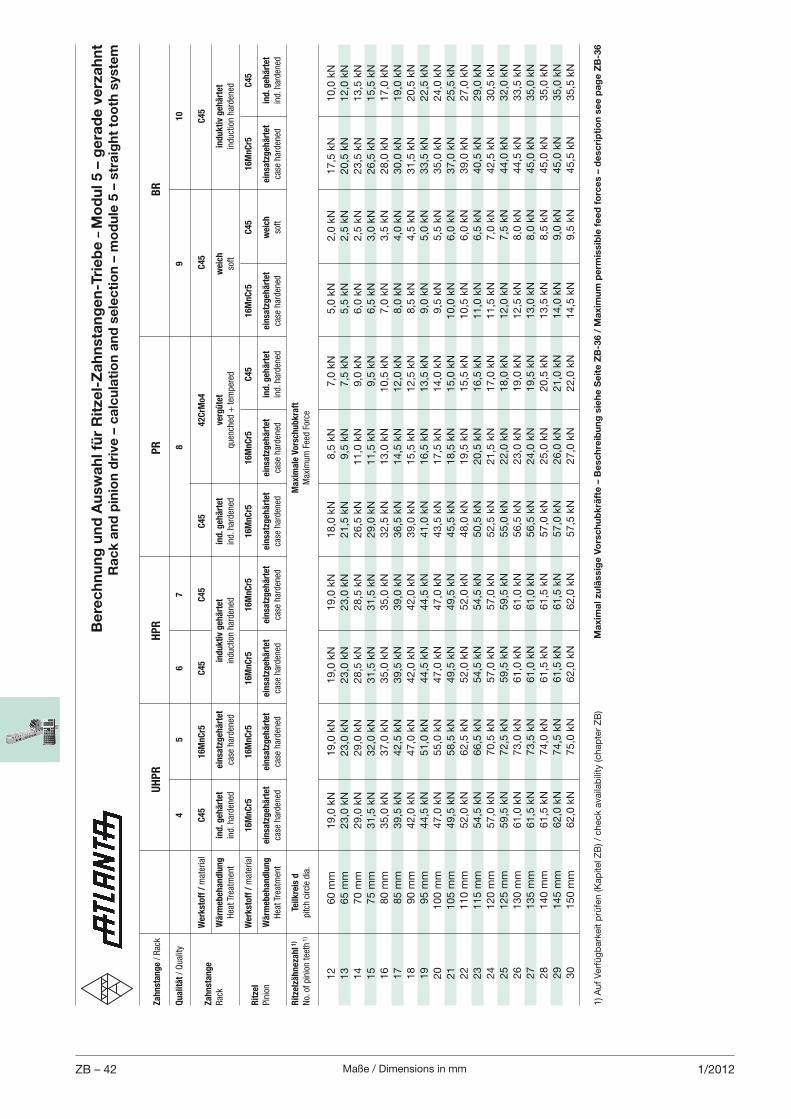
Maße / Dimensions in mmZB – 42 1/2012
1) A
uf
Ver
füg
bar
keit
prü
fen (K
apite
l ZB
) / c
hec
k av
aila
bili
ty (c
hap
ter
ZB
)
Be
rec
hn
un
g u
nd
Au
swa
hl f
ür
Rit
zel-
Za
hn
sta
ng
en
-Tri
eb
e –
Mo
du
l 5 –
ge
rad
e v
erz
ah
nt
Ra
ck
an
d p
inio
n d
rive
– c
alc
ula
tio
n a
nd
se
lec
tio
n –
mo
du
le 5
– s
tra
igh
t to
oth
sys
tem
Za
hn
sta
ng
e / Rac
k
UH
PR
HP
R
P
R
BR
Qu
ali
tät / Quality
4
5
6
7
8
9
10
W
erk
sto
ff /
material
C4
5
16
Mn
Cr5
C
45
C
45
C
45
4
2C
rMo
4
C4
5
C4
5Z
ah
nst
an
ge
Rac
k W
ärm
eb
eh
an
dlu
ng
in
d. g
eh
ärt
et
ein
satz
geh
ärt
et
ind
uk
tiv
geh
ärt
et
ind
. geh
ärt
et
verg
üte
t w
eic
h
ind
uk
tiv
geh
ärt
et
Hea
t Trea
tmen
t ind. h
arden
ed
case
harden
ed
induction harden
ed
ind. h
arden
ed
quen
ched
+ tem
pered
so
ft
induction harden
ed
W
erk
sto
ff /
material
16
Mn
Cr5
1
6M
nC
r5
16
Mn
Cr5
1
6M
nC
r5
16
Mn
Cr5
1
6M
nC
r5
C4
5
16
Mn
Cr5
C
45
16
Mn
Cr5
C
45
Rit
zel
Pinion
Wä
rmeb
eh
an
dlu
ng
ein
satz
geh
ärt
et
ein
satz
geh
ärt
et
ein
satz
geh
ärt
et
ein
satz
geh
ärt
et
ein
satz
geh
ärt
et
ein
satz
geh
ärt
et
ind
. geh
ärt
et
ein
satz
geh
ärt
et
weic
h
ein
satz
geh
ärt
et
ind
. geh
ärt
et
Hea
t Trea
tmen
t ca
se harden
ed
case
harden
ed
case
harden
ed
case
harden
ed
case
harden
ed
case
harden
ed
ind. h
arden
ed
case
harden
ed
soft
case
harden
ed
ind. h
arden
ed
Rit
zelz
äh
neza
hl 1
) Te
ilk
reis
d
Ma
xim
ale
Vo
rsch
ub
kra
ft
No. of pinion tee
th 1)
pitch circle dia.
Max
imum Fee
d Force
12
60 m
m
19,0
kN
19,0
kN
19,0
kN
19,0
kN
18,0
kN
8,5
kN
7,0
kN
5,0
kN
2,0
kN
17,5
kN
10,0
kN
13
65 m
m
23,0
kN
23,0
kN
23,0
kN
23,0
kN
21,5
kN
9,5
kN
7,5
kN
5,5
kN
2,5
kN
20,5
kN
12,0
kN
14
70 m
m
29,0
kN
29,0
kN
28,5
kN
28,5
kN
26,5
kN
11,0
kN
9,0
kN
6,0
kN
2,5
kN
23,5
kN
13,5
kN
15
75 m
m
31,5
kN
32,0
kN
31,5
kN
31,5
kN
29,0
kN
11,5
kN
9,5
kN
6,5
kN
3,0
kN
26,5
kN
15,5
kN
16
80 m
m
35,0
kN
37,0
kN
35,0
kN
35,0
kN
32,5
kN
13,0
kN
10,5
kN
7,0
kN
3,5
kN
28,0
kN
17,0
kN
17
85 m
m
39,5
kN
42,5
kN
39,5
kN
39,0
kN
36,5
kN
14,5
kN
12,0
kN
8,0
kN
4,0
kN
30,0
kN
19,0
kN
18
90 m
m
42,0
kN
47,0
kN
42,0
kN
42,0
kN
39,0
kN
15,5
kN
12,5
kN
8,5
kN
4,5
kN
31,5
kN
20,5
kN
19
95 m
m
44,5
kN
51,0
kN
44,5
kN
44,5
kN
41,0
kN
16,5
kN
13,5
kN
9,0
kN
5,0
kN
33,5
kN
22,5
kN
20
100 m
m
47,0
kN
55,0
kN
47,0
kN
47,0
kN
43,5
kN
17,5
kN
14,0
kN
9,5
kN
5,5
kN
35,0
kN
24,0
kN
21
105 m
m
49,5
kN
58,5
kN
49,5
kN
49,5
kN
45,5
kN
18,5
kN
15,0
kN
10,0
kN
6,0
kN
37,0
kN
25,5
kN
22
110 m
m
52,0
kN
62,5
kN
52,0
kN
52,0
kN
48,0
kN
19,5
kN
15,5
kN
10,5
kN
6,0
kN
39,0
kN
27,0
kN
23
115 m
m
54,5
kN
66,5
kN
54,5
kN
54,5
kN
50,5
kN
20,5
kN
16,5
kN
11,0
kN
6,5
kN
40,5
kN
29,0
kN
24
120 m
m
57,0
kN
70,5
kN
57,0
kN
57,0
kN
52,5
kN
21,5
kN
17,0
kN
11,5
kN
7,0
kN
42,5
kN
30,5
kN
25
125 m
m
59,5
kN
72,5
kN
59,5
kN
59,5
kN
55,0
kN
22,0
kN
18,0
kN
12,0
kN
7,5
kN
44,0
kN
32,0
kN
26
130 m
m
61,0
kN
73,0
kN
61,0
kN
61,0
kN
56,5
kN
23,0
kN
19,0
kN
12,5
kN
8,0
kN
44,5
kN
33,5
kN
27
135 m
m
61,5
kN
73,5
kN
61,0
kN
61,0
kN
56,5
kN
24,0
kN
19,5
kN
13,0
kN
8,0
kN
45,0
kN
35,0
kN
28
140 m
m
61,5
kN
74,0
kN
61,5
kN
61,5
kN
57,0
kN
25,0
kN
20,5
kN
13,5
kN
8,5
kN
45,0
kN
35,0
kN
29
145 m
m
62,0
kN
74,5
kN
61,5
kN
61,5
kN
57,0
kN
26,0
kN
21,0
kN
14,0
kN
9,0
kN
45,0
kN
35,0
kN
30
150 m
m
62,0
kN
75,0
kN
62,0
kN
62,0
kN
57,5
kN
27,0
kN
22,0
kN
14,5
kN
9,5
kN
45,5
kN
35,5
kN
Ma
xim
al z
ulä
ssig
e V
ors
ch
ub
krä
fte
– B
esc
hre
ibu
ng
sie
he
Se
ite
ZB
-36 /
Ma
xim
um
pe
rmis
sib
le f
ee
d f
orc
es
– d
esc
rip
tio
n s
ee
pa
ge
ZB
-36
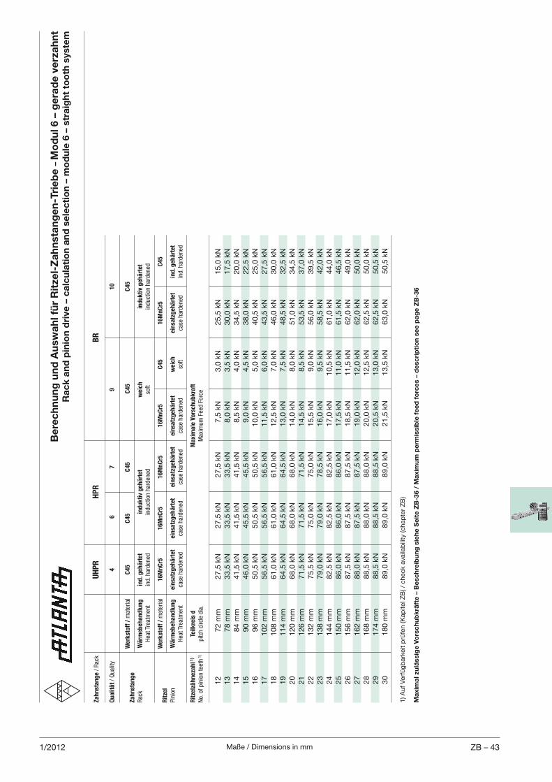
Maße / Dimensions in mm ZB – 431/2012
Be
rec
hn
un
g u
nd
Au
swa
hl f
ür
Rit
zel-
Za
hn
sta
ng
en
-Tri
eb
e –
Mo
du
l 6 –
ge
rad
e v
erz
ah
nt
Ra
ck
an
d p
inio
n d
rive
– c
alc
ula
tio
n a
nd
se
lec
tio
n –
mo
du
le 6
– s
tra
igh
t to
oth
sys
tem
Za
hn
sta
ng
e / Rac
k
UH
PR
HP
R
B
R
Qu
ali
tät / Quality
4
6
7
9
10
W
erk
sto
ff /
material
C4
5
C4
5
C4
5
C4
5
C4
5Z
ah
nst
an
ge
Rac
k W
ärm
eb
eh
an
dlu
ng
in
d. g
eh
ärt
et
in
du
kti
v g
eh
ärt
et
weic
h
ind
uk
tiv
geh
ärt
et
Hea
t Trea
tmen
t ind. h
arden
ed
induction harden
ed
soft
induction harden
ed
W
erk
sto
ff /
material
16
Mn
Cr5
1
6M
nC
r5
16
Mn
Cr5
1
6M
nC
r5
C4
5
16
Mn
Cr5
C
45
Rit
zel
Pinion
Wä
rmeb
eh
an
dlu
ng
ein
satz
geh
ärt
et
ein
satz
geh
ärt
et
ein
satz
geh
ärt
et
ein
satz
geh
ärt
et
weic
h
ein
satz
geh
ärt
et
ind
. geh
ärt
et
Hea
t Trea
tmen
t ca
se harden
ed
case
harden
ed
case
harden
ed
case
harden
ed
soft
case
harden
ed
ind. h
arden
ed
Rit
zelz
äh
neza
hl 1
) Te
ilk
reis
d
M
axim
ale
Vo
rsch
ub
kra
ft
No. of pinion tee
th 1)
pitch circle dia.
Max
imum Fee
d Force
12
72 m
m
27,5
kN
27,5
kN
27,5
kN
7,5
kN
3,0
kN
25,5
kN
15,0
kN
13
78 m
m
33,5
kN
33,5
kN
33,5
kN
8,0
kN
3,5
kN
30,0
kN
17,5
kN
14
84 m
m
41,5
kN
41,5
kN
41,5
kN
8,5
kN
4,0
kN
34,5
kN
20,0
kN
15
90 m
m
46,0
kN
45,5
kN
45,5
kN
9,0
kN
4,5
kN
38,0
kN
22,5
kN
16
96 m
m
50,5
kN
50,5
kN
50,5
kN
10,0
kN
5,0
kN
40,5
kN
25,0
kN
17
102 m
m
56,5
kN
56,5
kN
56,5
kN
11,5
kN
6,0
kN
43,5
kN
27,5
kN
18
108 m
m
61,0
kN
61,0
kN
61,0
kN
12,5
kN
7,0
kN
46,0
kN
30,0
kN
19
114 m
m
64,5
kN
64,5
kN
64,5
kN
13,0
kN
7,5
kN
48,5
kN
32,5
kN
20
120 m
m
68,0
kN
68,0
kN
68,0
kN
14,0
kN
8,0
kN
51,0
kN
34,5
kN
21
126 m
m
71,5
kN
71,5
kN
71,5
kN
14,5
kN
8,5
kN
53,5
kN
37,0
kN
22
132 m
m
75,5
kN
75,0
kN
75,0
kN
15,5
kN
9,0
kN
56,0
kN
39,5
kN
23
138 m
m
79,0
kN
79,0
kN
78,5
kN
16,0
kN
9,5
kN
58,5
kN
42,0
kN
24
144 m
m
82,5
kN
82,5
kN
82,5
kN
17,0
kN
10,5
kN
61,0
kN
44,0
kN
25
150 m
m
86,0
kN
86,0
kN
86,0
kN
17,5
kN
11,0
kN
61,5
kN
46,5
kN
26
156 m
m
87,5
kN
87,5
kN
87,5
kN
18,5
kN
11,5
kN
62,0
kN
49,0
kN
27
162 m
m
88,0
kN
87,5
kN
87,5
kN
19,0
kN
12,0
kN
62,0
kN
50,0
kN
28
168 m
m
88,5
kN
88,0
kN
88,0
kN
20,0
kN
12,5
kN
62,5
kN
50,0
kN
29
174 m
m
88,5
kN
88,5
kN
88,5
kN
20,5
kN
13,0
kN
62,5
kN
50,5
kN
30
180 m
m
89,0
kN
89,0
kN
89,0
kN
21,5
kN
13,5
kN
63,0
kN
50,5
kN
1) A
uf
Ver
füg
bar
keit
prü
fen (K
apite
l ZB
) / c
hec
k av
aila
bili
ty (c
hap
ter
ZB
)
Ma
xim
al z
ulä
ssig
e V
ors
ch
ub
krä
fte
– B
esc
hre
ibu
ng
sie
he
Se
ite
ZB
-36 /
Ma
xim
um
pe
rmis
sib
le f
ee
d f
orc
es
– d
esc
rip
tio
n s
ee
pa
ge
ZB
-36
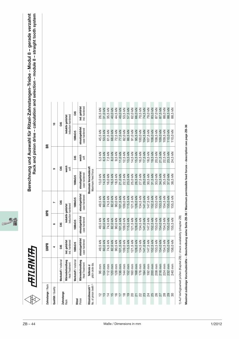
Maße / Dimensions in mmZB – 44 1/2012
Be
rec
hn
un
g u
nd
Au
swa
hl f
ür
Rit
zel-
Za
hn
sta
ng
en
-Tri
eb
e –
Mo
du
l 8 –
ge
rad
e v
erz
ah
nt
Ra
ck
an
d p
inio
n d
rive
– c
alc
ula
tio
n a
nd
se
lec
tio
n –
mo
du
le 8
– s
tra
igh
t to
oth
sys
tem
Za
hn
sta
ng
e / Rac
k
UH
PR
HP
R
B
R
Qu
ali
tät / Quality
4
6
7
9
10
W
erk
sto
ff /
material
C4
5
C4
5
C4
5
C4
5
C4
5Z
ah
nst
an
ge
Rac
k W
ärm
eb
eh
an
dlu
ng
in
d. g
eh
ärt
et
in
du
kti
v g
eh
ärt
et
weic
h
ind
uk
tiv
geh
ärt
et
Hea
t Trea
tmen
t ind. h
arden
ed
induction harden
ed
soft
induction harden
ed
W
erk
sto
ff /
material
16
Mn
Cr5
1
6M
nC
r5
16
Mn
Cr5
1
6M
nC
r5
C4
5
16
Mn
Cr5
C
45
Rit
zel
Pinion
Wä
rmeb
eh
an
dlu
ng
ein
satz
geh
ärt
et
ein
satz
geh
ärt
et
ein
satz
geh
ärt
et
ein
satz
geh
ärt
et
weic
h
ein
satz
geh
ärt
et
ind
. geh
ärt
et
Hea
t Trea
tmen
t ca
se harden
ed
case
harden
ed
case
harden
ed
case
harden
ed
soft
case
harden
ed
ind. h
arden
ed
Rit
zelz
äh
neza
hl 1
) Te
ilk
reis
d
M
axim
ale
Vo
rsch
ub
kra
ft
No. of pinion tee
th 1)
pitch circle dia.
Max
imum Fee
d Force
12
96 m
m
49,5
kN
49,5
kN
49,5
kN
13,0
kN
5,5
kN
45,5
kN
26,5
kN
13
104 m
m
60,0
kN
60,0
kN
60,0
kN
14,5
kN
6,5
kN
53,5
kN
31,0
kN
14
112 m
m
74,5
kN
74,5
kN
74,5
kN
16,0
kN
7,5
kN
61,5
kN
35,5
kN
15
120 m
m
82,0
kN
82,0
kN
82,0
kN
16,5
kN
8,0
kN
68,0
kN
40,0
kN
16
128 m
m
90,5
kN
90,0
kN
90,0
kN
18,5
kN
9,5
kN
72,5
kN
44,5
kN
17
136 m
m
101,5
kN
101,5
kN
101,5
kN
21,0
kN
11,0
kN
77,5
kN
49,0
kN
18
144 m
m
109,0
kN
109,0
kN
109,0
kN
22,5
kN
12,5
kN
82,0
kN
53,5
kN
19
152 m
m
115,5
kN
115,5
kN
115,5
kN
23,5
kN
13,5
kN
86,5
kN
57,5
kN
20
160 m
m
121,5
kN
121,5
kN
121,5
kN
25,0
kN
14,5
kN
91,0
kN
62,0
kN
21
168 m
m
128,0
kN
128,0
kN
128,0
kN
26,5
kN
15,5
kN
95,5
kN
66,0
kN
22
176 m
m
134,5
kN
134,5
kN
134,5
kN
27,5
kN
16,5
kN
100,0
kN
70,5
kN
23
184 m
m
141,0
kN
141,0
kN
141,0
kN
29,0
kN
17,5
kN
104,5
kN
74,5
kN
24
192 m
m
147,5
kN
147,5
kN
147,5
kN
30,5
kN
18,5
kN
107,5
kN
79,0
kN
25
200 m
m
152,5
kN
152,5
kN
152,5
kN
31,5
kN
19,5
kN
108,0
kN
83,0
kN
26
208 m
m
153,5
kN
153,0
kN
153,0
kN
33,0
kN
20,5
kN
108,5
kN
87,0
kN
27
216 m
m
154,0
kN
154,0
kN
153,5
kN
34,5
kN
21,5
kN
109,0
kN
87,5
kN
28
224 m
m
154,5
kN
154,5
kN
154,5
kN
35,5
kN
22,5
kN
109,5
kN
88,0
kN
29
232 m
m
155,0
kN
155,0
kN
155,0
kN
37,0
kN
23,5
kN
110,0
kN
88,5
kN
30
240 m
m
156,0
kN
155,5
kN
155,5
kN
38,5
kN
24,5
kN
110,0
kN
88,5
kN
1) A
uf
Ver
füg
bar
keit
prü
fen (K
apite
l ZB
) / c
hec
k av
aila
bili
ty (c
hap
ter
ZB
)
Ma
xim
al z
ulä
ssig
e V
ors
ch
ub
krä
fte
– B
esc
hre
ibu
ng
sie
he
Se
ite
ZB
-36 /
Ma
xim
um
pe
rmis
sib
le f
ee
d f
orc
es
– d
esc
rip
tio
n s
ee
pa
ge
ZB
-36
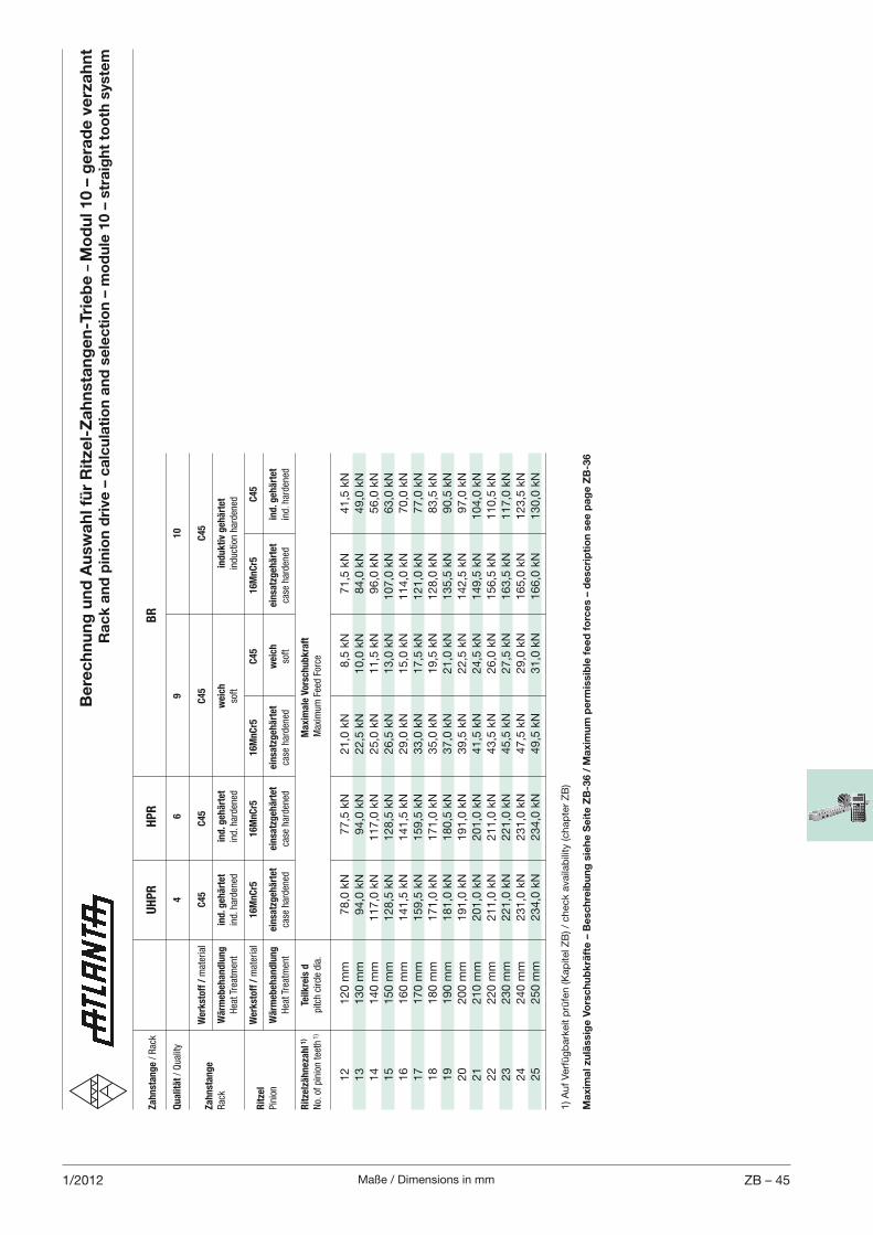
Maße / Dimensions in mm ZB – 451/2012
Be
rec
hn
un
g u
nd
Au
swa
hl f
ür
Rit
zel-
Za
hn
sta
ng
en
-Tri
eb
e –
Mo
du
l 10 –
ge
rad
e v
erz
ah
nt
Ra
ck
an
d p
inio
n d
rive
– c
alc
ula
tio
n a
nd
se
lec
tio
n –
mo
du
le 1
0 –
str
aig
ht
too
th s
yste
m
Za
hn
sta
ng
e / Rac
k
UH
PR
HP
R
B
R
Qu
ali
tät / Quality
4
6
9
10
W
erk
sto
ff /
material
C4
5
C4
5
C4
5
C4
5Z
ah
nst
an
ge
Rac
k W
ärm
eb
eh
an
dlu
ng
in
d. g
eh
ärt
et
ind
. geh
ärt
et
weic
h
ind
uk
tiv
geh
ärt
et
Hea
t Trea
tmen
t ind. h
arden
ed
ind. h
arden
ed
soft
induction harden
ed
W
erk
sto
ff /
material
16
Mn
Cr5
1
6M
nC
r5
16
Mn
Cr5
C
45
1
6M
nC
r5
C4
5R
itze
l
Pinion
Wä
rmeb
eh
an
dlu
ng
ein
satz
geh
ärt
et
ein
satz
geh
ärt
et
ein
satz
geh
ärt
et
weic
h
ein
satz
geh
ärt
et
ind
. geh
ärt
et
Hea
t Trea
tmen
t ca
se harden
ed
case
harden
ed
case
harden
ed
soft
case
harden
ed
ind. h
arden
ed
Rit
zelz
äh
neza
hl 1
) Te
ilk
reis
d
Ma
xim
ale
Vo
rsch
ub
kra
ft
No. of pinion tee
th 1)
pitch circle dia.
Max
imum Fee
d Force
12
120 m
m
78,0
kN
77,5
kN
21,0
kN
8,5
kN
71,5
kN
41,5
kN
13
130 m
m
94,0
kN
94,0
kN
22,5
kN
10,0
kN
84,0
kN
49,0
kN
14
140 m
m
117,0
kN
117,0
kN
25,0
kN
11,5
kN
96,0
kN
56,0
kN
15
150 m
m
128,5
kN
128,5
kN
26,5
kN
13,0
kN
107,0
kN
63,0
kN
16
160 m
m
141,5
kN
141,5
kN
29,0
kN
15,0
kN
114,0
kN
70,0
kN
17
170 m
m
159,5
kN
159,5
kN
33,0
kN
17,5
kN
121,0
kN
77,0
kN
18
180 m
m
171,0
kN
171,0
kN
35,0
kN
19,5
kN
128,0
kN
83,5
kN
19
190 m
m
181,0
kN
180,5
kN
37,0
kN
21,0
kN
135,5
kN
90,5
kN
20
200 m
m
191,0
kN
191,0
kN
39,5
kN
22,5
kN
142,5
kN
97,0
kN
21
210 m
m
201,0
kN
201,0
kN
41,5
kN
24,5
kN
149,5
kN
104,0
kN
22
220 m
m
211,0
kN
211,0
kN
43,5
kN
26,0
kN
156,5
kN
110,5
kN
23
230 m
m
221,0
kN
221,0
kN
45,5
kN
27,5
kN
163,5
kN
117,0
kN
24
240 m
m
231,0
kN
231,0
kN
47,5
kN
29,0
kN
165,0
kN
123,5
kN
25
250 m
m
234,0
kN
234,0
kN
49,5
kN
31,0
kN
166,0
kN
130,0
kN
1) A
uf
Ver
füg
bar
keit
prü
fen (K
apite
l ZB
) / c
hec
k av
aila
bili
ty (c
hap
ter
ZB
)
Ma
xim
al z
ulä
ssig
e V
ors
ch
ub
krä
fte
– B
esc
hre
ibu
ng
sie
he
Se
ite
ZB
-36 /
Ma
xim
um
pe
rmis
sib
le f
ee
d f
orc
es
– d
esc
rip
tio
n s
ee
pa
ge
ZB
-36
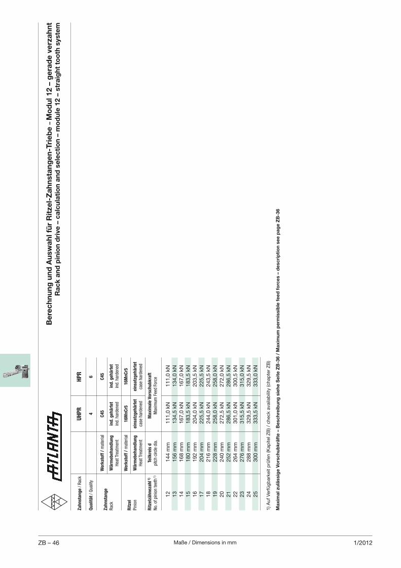
Maße / Dimensions in mmZB – 46 1/2012
Za
hn
sta
ng
e / Rac
k U
HP
R
HP
R
Qu
ali
tät / Quality
4
6
W
erk
sto
ff /
material
C4
5
C4
5Z
ah
nst
an
ge
Rac
k W
ärm
eb
eh
an
dlu
ng
in
d. g
eh
ärt
et
ind
. geh
ärt
et
Hea
t Trea
tmen
t ind. h
arden
ed
ind. h
arden
ed
W
erk
sto
ff /
material
16
Mn
Cr5
1
6M
nC
r5R
itze
l
Pinion
Wä
rmeb
eh
an
dlu
ng
ein
satz
geh
ärt
et
ein
satz
geh
ärt
et
Hea
t Trea
tmen
t ca
se harden
ed
case
harden
ed
Rit
zelz
äh
neza
hl 1
) Te
ilk
reis
d
Ma
xim
ale
Vo
rsch
ub
kra
ft
No. of pinion tee
th 1)
pitch circle dia.
Max
imum Fee
d Force
12
144 m
m
111,0
kN
111,0
kN
13
156 m
m
134,5
kN
134,0
kN
14
168 m
m
167,0
kN
167,0
kN
15
180 m
m
183,5
kN
183,5
kN
16
192 m
m
204,0
kN
203,5
kN
17
204 m
m
225,5
kN
225,5
kN
18
216 m
m
244,0
kN
243,5
kN
19
228 m
m
258,0
kN
258,0
kN
20
240 m
m
272,5
kN
272,0
kN
21
252 m
m
286,5
kN
286,5
kN
22
264 m
m
301,0
kN
300,5
kN
23
276 m
m
315,5
kN
315,0
kN
24
288 m
m
329,5
kN
329,5
kN
25
300 m
m
333,5
kN
333,0
kN
Be
rec
hn
un
g u
nd
Au
swa
hl f
ür
Rit
zel-
Za
hn
sta
ng
en
-Tri
eb
e –
Mo
du
l 12 –
ge
rad
e v
erz
ah
nt
Ra
ck
an
d p
inio
n d
rive
– c
alc
ula
tio
n a
nd
se
lec
tio
n –
mo
du
le 1
2 –
str
aig
ht
too
th s
yste
m
1) A
uf
Ver
füg
bar
keit
prü
fen (K
apite
l ZB
) / c
hec
k av
aila
bili
ty (c
hap
ter
ZB
)
Ma
xim
al z
ulä
ssig
e V
ors
ch
ub
krä
fte
– B
esc
hre
ibu
ng
sie
he
Se
ite
ZB
-36 /
Ma
xim
um
pe
rmis
sib
le f
ee
d f
orc
es
– d
esc
rip
tio
n s
ee
pa
ge
ZB
-36
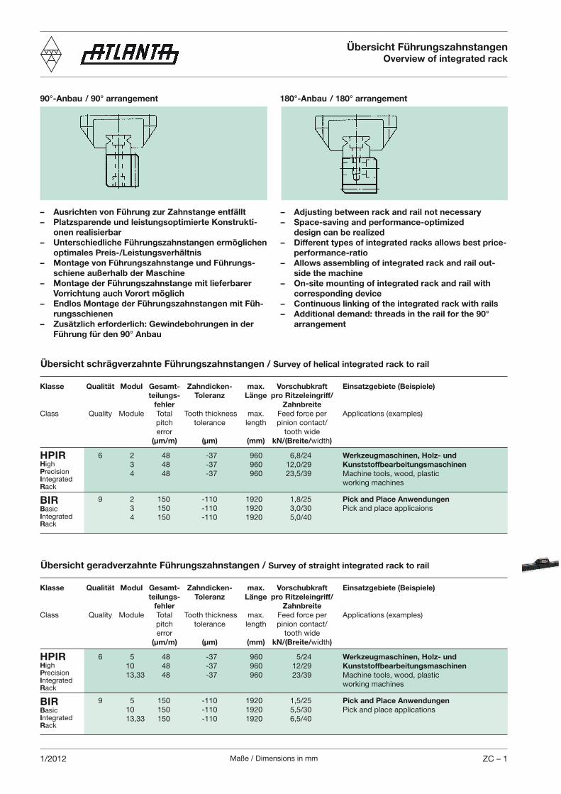
Maße / Dimensions in mm ZC – 11/2012
Übersicht schrägverzahnte Führungszahnstangen / Survey of helical integrated rack to rail
– Adjusting between rack and rail not necessary– Space-saving and performance-optimized design can be realized– Different types of integrated racks allows best price-
performance-ratio– Allows assembling of integrated rack and rail out-
side the machine– On-site mounting of integrated rack and rail with
corresponding device – Continuous linking of the integrated rack with rails– Additional demand: threads in the rail for the 90°
arrangement
– Ausrichten von Führung zur Zahnstange entfällt– Platzsparende und leistungsoptimierte Konstrukti-
onen realisierbar– Unterschiedliche Führungszahnstangen ermöglichen optimales Preis-/Leistungsverhältnis– Montage von Führungszahnstange und Führungs-
schiene außerhalb der Maschine– Montage der Führungszahnstange mit lieferbarer
Vorrichtung auch Vorort möglich– Endlos Montage der Führungszahnstangen mit Füh-
rungsschienen– Zusätzlich erforderlich: Gewindebohrungen in der
Führung für den 90° Anbau
90°-Anbau / 90° arrangement 180°-Anbau / 180° arrangement
Klasse Qualität Modul Gesamt- Zahndicken- max. Vorschubkraft Einsatzgebiete (Beispiele) teilungs- Toleranz Länge pro Ritzeleingriff/ fehler ZahnbreiteClass Quality Module Total Tooth thickness max. Feed force per Applications (examples) pitch tolerance length pinion contact/ error tooth wide (µm/m) (µm) (mm) kN/(Breite/width)
6 2 48 -37 960 6,8/24 Werkzeugmaschinen, Holz- und 3 48 -37 960 12,0/29 Kunststoffbearbeitungsmaschinen 4 48 -37 960 23,5/39 Machine tools, wood, plastic working machines
9 2 150 -110 1920 1,8/25 Pick and Place Anwendungen 3 150 -110 1920 3,0/30 Pick and place applicaions 4 150 -110 1920 5,0/40
HPIRHighPrecisionIntegratedRack
BIRBasicIntegratedRack
Übersicht geradverzahnte Führungszahnstangen / Survey of straight integrated rack to rail
Klasse Qualität Modul Gesamt- Zahndicken- max. Vorschubkraft Einsatzgebiete (Beispiele) teilungs- Toleranz Länge pro Ritzeleingriff/ fehler ZahnbreiteClass Quality Module Total Tooth thickness max. Feed force per Applications (examples) pitch tolerance length pinion contact/ error tooth wide (µm/m) (µm) (mm) kN/(Breite/width)
6 5 48 -37 960 5/24 Werkzeugmaschinen, Holz- und 10 48 -37 960 12/29 Kunststoffbearbeitungsmaschinen 13,33 48 -37 960 23/39 Machine tools, wood, plastic working machines
9 5 150 -110 1920 1,5/25 Pick and Place Anwendungen 10 150 -110 1920 5,5/30 Pick and place applications 13,33 150 -110 1920 6,5/40
HPIRHighPrecisionIntegratedRack
BIRBasicIntegratedRack
Übersicht FührungszahnstangenOverview of integrated rack
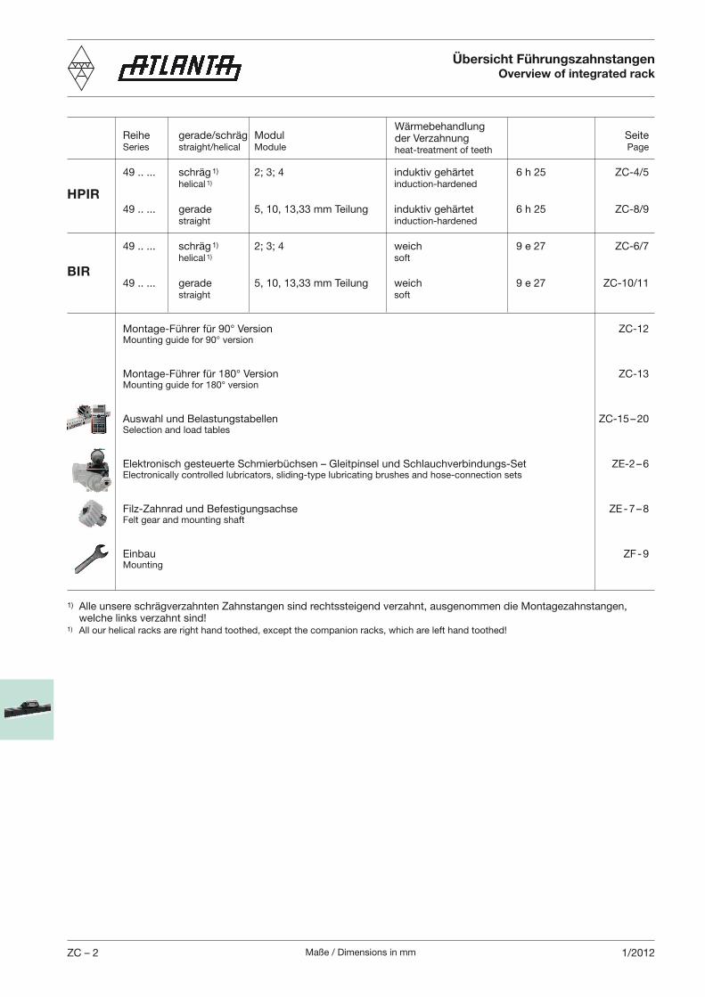
Maße / Dimensions in mmZC – 2 1/2012
HPIR
BIR
Reihe gerade/schräg Modul Seite Series straight/helical Module Page
49 .. ... schräg 1) 2; 3; 4 induktiv gehärtet 6 h 25 ZC-4/5 helical 1) induction-hardened
49 .. ... gerade 5, 10, 13,33 mm Teilung induktiv gehärtet 6 h 25 ZC-8/9 straight induction-hardened
49 .. ... schräg 1) 2; 3; 4 weich 9 e 27 ZC-6/7 helical 1) soft
49 .. ... gerade 5, 10, 13,33 mm Teilung weich 9 e 27 ZC-10/11 straight soft
Montage-Führer für 90° Version ZC-12 Mounting guide for 90° version
Montage-Führer für 180° Version ZC-13 Mounting guide for 180° version
Auswahl und Belastungstabellen ZC-15 – 20 Selection and load tables
Elektronisch gesteuerte Schmierbüchsen – Gleitpinsel und Schlauchverbindungs-Set ZE-2 – 6 Electronically controlled lubricators, sliding-type lubricating brushes and hose-connection sets
Filz-Zahnrad und Befestigungsachse ZE - 7 – 8 Felt gear and mounting shaft
Einbau ZF - 9 Mounting
Wärmebehandlung der Verzahnungheat-treatment of teeth
Übersicht FührungszahnstangenOverview of integrated rack
1) Alle unsere schrägverzahnten Zahnstangen sind rechtssteigend verzahnt, ausgenommen die Montagezahnstangen, welche links verzahnt sind!1) All our helical racks are right hand toothed, except the companion racks, which are left hand toothed!
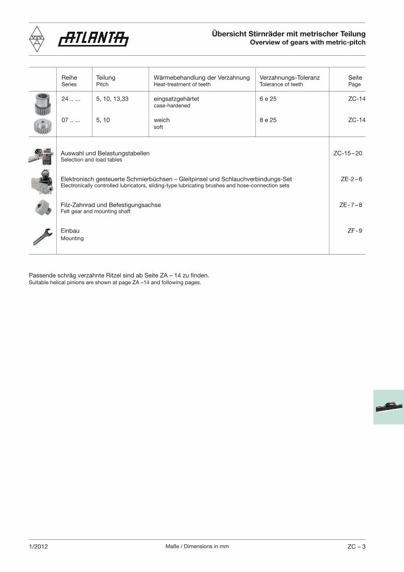
Maße / Dimensions in mm ZC – 31/2012
Übersicht Stirnräder mit metrischer TeilungOverview of gears with metric-pitch
Reihe Teilung Wärmebehandlung der Verzahnung Verzahnungs-Toleranz Seite Series Pitch Heat-treatment of teeth Tolerance of teeth Page
24 .. ... 5, 10, 13,33 eingsatzgehärtet 6 e 25 ZC-14 case-hardened
07 .. ... 5, 10 weich 8 e 25 ZC-14 soft
Auswahl und Belastungstabellen ZC-15 – 20 Selection and load tables
Elektronisch gesteuerte Schmierbüchsen – Gleitpinsel und Schlauchverbindungs-Set ZE-2 – 6 Electronically controlled lubricators, sliding-type lubricating brushes and hose-connection sets
Filz-Zahnrad und Befestigungsachse ZE - 7 – 8 Felt gear and mounting shaft
Einbau ZF - 9 Mounting
Passende schräg verzahnte Ritzel sind ab Seite ZA – 14 zu finden.Suitable helical pinions are shown at page ZA –14 and following pages.
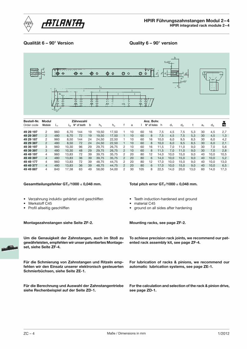
Maße / Dimensions in mmZC – 4 1/2012
HPIR Führungszahnstangen Modul 2 – 4HPIR integrated rack module 2 – 4
Qualität 6 – 90° Version Quality 6 – 90° version
Total pitch error GTf /1000 0,048 mm.Gesamtteilungsfehler GTf /1000 0,048 mm.
Um die Genauigkeit der Zahnstangen, auch im Stoß zu gewährleisten, empfehlen wir unser patentiertes Montage-set, siehe Seite ZF-4.
To achieve precision rack joints, we recommend our pat-ented rack assembly kit, see page ZF-4.
Montagezahnstangen siehe Seite ZF-2. Mounting racks, see page ZF-2.
Für die Schmierung von Zahnstangen und Ritzeln emp-fehlen wir den Einsatz unserer elektronisch gesteuerten Schmierbüchsen, siehe Seite ZE-1.
For lubrication of racks & pinions, we recommend our automatic lubrication systems, see page ZE-1.
Für die Berechnung und Auswahl der Zahnstangentriebe siehe Rechenbeispiel auf der Seite ZD-1.
For the calculation and selection of the rack & pinion drive, see page ZD-1.
Bestell-Nr. Modul Zähnezahl Anz. Bohr.Order code Module L1 L2 N° of teeth b hk ho f a I N° of holes h d1 d2 t a1 d3
d3
L1
a1
a
fx45°
d2hk
h0
19°31'4
2"
b
d1
h
t
l l ll
ll
f x45°
h
49 29 197 2 960 6,70 144 19 19,50 17,50 1 10 60 16 7,5 4,5 7,5 5,3 30 4,5 2,749 29 397 2 480 6,70 72 19 19,50 17,50 1 10 60 8 7,5 4,5 7,5 5,3 30 4,5 1,349 29 187 2 960 8,50 144 24 24,50 22,50 1 10 60 16 10,0 6,0 9,5 8,5 30 6,0 4,249 29 387 2 480 8,50 72 24 24,50 22,50 1 10 60 8 10,0 6,0 9,5 8,5 30 6,0 2,149 39 197 3 960 10,30 96 29 29,75 26,75 2 10 60 16 11,5 7,0 11,0 9,0 30 7,0 5,649 39 397 3 480 10,30 48 29 29,75 26,75 2 10 60 8 11,5 7,0 11,0 9,0 30 7,0 2,849 49 197 4 960 13,83 72 39 39,75 35,75 2 20 80 12 14,0 10,0 15,0 9,0 40 10,0 10,549 49 397 4 480 13,83 36 39 39,75 35,75 2 20 80 6 14,0 10,0 15,0 9,0 40 10,0 5,249 49 177 4 960 13,83 72 39 48,75 44,75 2 20 80 12 17,0 10,0 15,0 9,0 40 10,0 13,049 49 377 4 480 13,83 36 39 48,75 44,75 2 20 80 6 17,0 10,0 15,0 9,0 40 10,0 6,549 49 887 4 840 17,38 63 49 58,00 54,00 2 30 105 8 22,5 14,0 20,0 13,0 60 14,0 17,3
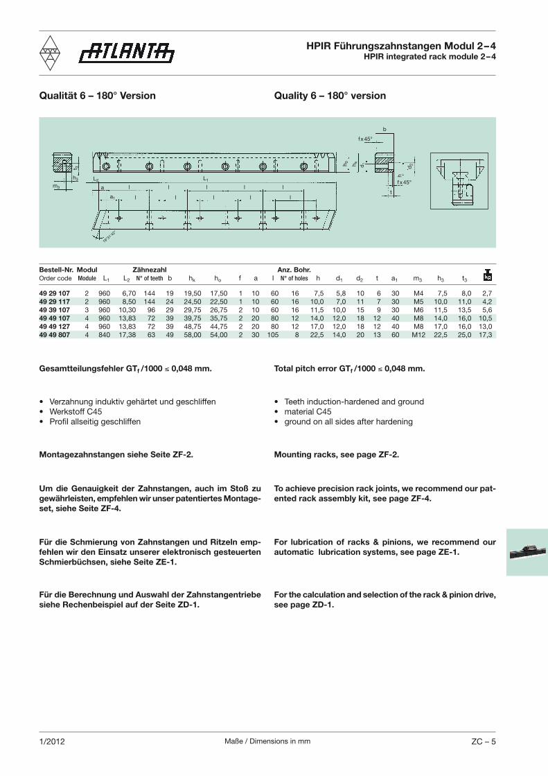
Maße / Dimensions in mm ZC – 51/2012
HPIR Führungszahnstangen Modul 2 – 4HPIR integrated rack module 2 – 4
Qualität 6 – 180° Version Quality 6 – 180° version
Total pitch error GTf /1000 0,048 mm.Gesamtteilungsfehler GTf /1000 0,048 mm.
Um die Genauigkeit der Zahnstangen, auch im Stoß zu gewährleisten, empfehlen wir unser patentiertes Montage-set, siehe Seite ZF-4.
To achieve precision rack joints, we recommend our pat-ented rack assembly kit, see page ZF-4.
Montagezahnstangen siehe Seite ZF-2. Mounting racks, see page ZF-2.
Für die Schmierung von Zahnstangen und Ritzeln emp-fehlen wir den Einsatz unserer elektronisch gesteuerten Schmierbüchsen, siehe Seite ZE-1.
For lubrication of racks & pinions, we recommend our automatic lubrication systems, see page ZE-1.
Für die Berechnung und Auswahl der Zahnstangentriebe siehe Rechenbeispiel auf der Seite ZD-1.
For the calculation and selection of the rack & pinion drive, see page ZD-1.
t 3
L1
a1
a
fx45°
d2h
kh0
b
d1
L2
tl
l
l
l
l
l l
l
l
l
f x45°h3
m3
h
Bestell-Nr. Modul Zähnezahl Anz. Bohr.Order code Module L1 L2 N° of teeth b hk ho f a I N° of holes h d1 d2 t a1 m3 h3 t3
49 29 107 2 960 6,70 144 19 19,50 17,50 1 10 60 16 7,5 5,8 10 6 30 M4 7,5 8,0 2,749 29 117 2 960 8,50 144 24 24,50 22,50 1 10 60 16 10,0 7,0 11 7 30 M5 10,0 11,0 4,249 39 107 3 960 10,30 96 29 29,75 26,75 2 10 60 16 11,5 10,0 15 9 30 M6 11,5 13,5 5,649 49 107 4 960 13,83 72 39 39,75 35,75 2 20 80 12 14,0 12,0 18 12 40 M8 14,0 16,0 10,549 49 127 4 960 13,83 72 39 48,75 44,75 2 20 80 12 17,0 12,0 18 12 40 M8 17,0 16,0 13,049 49 807 4 840 17,38 63 49 58,00 54,00 2 30 105 8 22,5 14,0 20 13 60 M12 22,5 25,0 17,3
19°31'4
2"
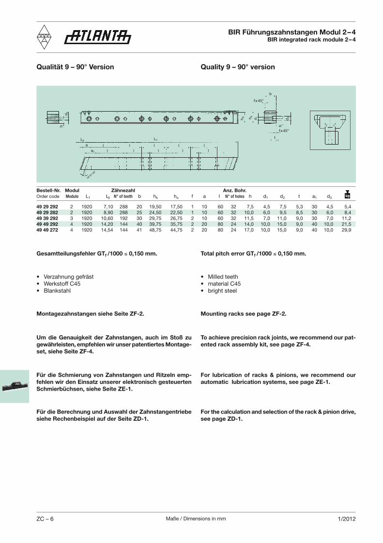
Maße / Dimensions in mmZC – 6 1/2012
Total pitch error GTf /1000 0,150 mm.Gesamtteilungsfehler GTf /1000 0,150 mm.
Um die Genauigkeit der Zahnstangen, auch im Stoß zu gewährleisten, empfehlen wir unser patentiertes Montage-set, siehe Seite ZF-4.
To achieve precision rack joints, we recommend our pat-ented rack assembly kit, see page ZF-4.
Montagezahnstangen siehe Seite ZF-2. Mounting racks see page ZF-2.
Für die Schmierung von Zahnstangen und Ritzeln emp-fehlen wir den Einsatz unserer elektronisch gesteuerten Schmierbüchsen, siehe Seite ZE-1.
For lubrication of racks & pinions, we recommend our automatic lubrication systems, see page ZE-1.
Für die Berechnung und Auswahl der Zahnstangentriebe siehe Rechenbeispiel auf der Seite ZD-1.
For the calculation and selection of the rack & pinion drive, see page ZD-1.
49 29 292 2 1920 7,10 288 20 19,50 17,50 1 10 60 32 7,5 4,5 7,5 5,3 30 4,5 5,449 29 282 2 1920 8,90 288 25 24,50 22,50 1 10 60 32 10,0 6,0 9,5 8,5 30 6,0 8,449 39 292 3 1920 10,60 192 30 29,75 26,75 2 10 60 32 11,5 7,0 11,0 9,0 30 7,0 11,249 49 292 4 1920 14,20 144 40 39,75 35,75 2 20 80 24 14,0 10,0 15,0 9,0 40 10,0 21,549 49 272 4 1920 14,54 144 41 48,75 44,75 2 20 80 24 17,0 10,0 15,0 9,0 40 10,0 29,9
d3
L1
a1
a
fx45°
d2hk
h0
b
d1
h
L2t
ll
ll
ll l
ll
l
f x45°
h
BIR Führungszahnstangen Modul 2 – 4BIR integrated rack module 2 – 4
Qualität 9 – 90° Version Quality 9 – 90° version
Bestell-Nr. Modul Zähnezahl Anz. Bohr.Order code Module L1 L2 N° of teeth b hk ho f a I N° of holes h d1 d2 t a1 d3
19°31'4
2"
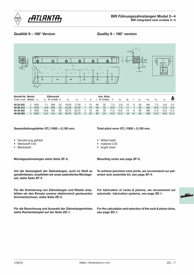
Maße / Dimensions in mm ZC – 71/2012
Gesamtteilungsfehler GTf /1000 0,150 mm.
Um die Genauigkeit der Zahnstangen, auch im Stoß zu gewährleisten, empfehlen wir unser patentiertes Montage-set, siehe Seite ZF-4.
To achieve precision rack joints, we recommend our pat-ented rack assembly kit, see page ZF-4.
Montagezahnstangen siehe Seite ZF-2. Mounting racks see page ZF-2.
Für die Schmierung von Zahnstangen und Ritzeln emp-fehlen wir den Einsatz unserer elektronisch gesteuerten Schmierbüchsen, siehe Seite ZE-2.
For lubrication of racks & pinions, we recommend our automatic lubrication systems, see page ZE-1.
Für die Berechnung und Auswahl der Zahnstangentriebe siehe Rechenbeispiel auf der Seite ZD-1.
For the calculation and selection of the rack & pinion drive, see page ZD-1.
Total pitch error GTf /1000 0,150 mm.
t 3
L1
a1
a
fx45°
d2
hk
h0
b
d1
L2
t
l
l
l
l
l
l l
l
l
l
f x45°h3
m3
h
49 29 202 2 1920 7,1 288 20 19,50 17,50 1 10 60 32 7,5 5,8 10 6 30 M4 7,5 8,0 5,449 29 212 2 1920 8,9 288 25 24,50 22,50 1 10 60 32 10,0 7,0 11 7 30 M5 10,0 11,0 8,449 39 202 3 1920 10,6 192 30 29,75 26,75 2 10 60 32 11,5 10,0 15 9 30 M6 11,5 13,5 11,249 49 202 4 1920 14,2 144 40 39,75 35,75 2 20 80 24 14,0 12,0 18 12 40 M8 14,0 16,0 21,5
BIR Führungszahnstangen Modul 2 – 4BIR integrated rack module 2 – 4
Qualität 9 – 180° Version Quality 9 – 180° version
Bestell-Nr. Modul Zähnezahl Anz. Bohr.Order code Module L1 L2 N° of teeth b hk ho f a I N° of holes h d1 d2 t a1 m3 h3 t3
19°31'4
2"
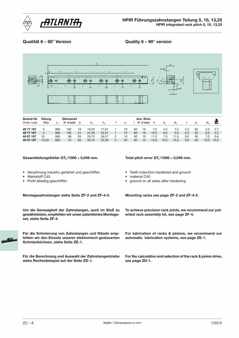
Maße / Dimensions in mmZC – 8 1/2012
HPIR Führungszahnstangen Teilung 5, 10, 13,33HPIR integrated rack pitch 5, 10, 13,33
Qualität 6 – 90° Version Quality 6 – 90° version
Total pitch error GTf /1000 0,048 mm.Gesamtteilungsfehler GTf /1000 0,048 mm.
Um die Genauigkeit der Zahnstangen, auch im Stoß zu gewährleisten, empfehlen wir unser patentiertes Montage-set, siehe Seite ZF-4.
To achieve precision rack joints, we recommend our pat-ented rack assembly kit, see page ZF-4.
Montagezahnstangen siehe Seite ZF-2 und ZF-4-5. Mounting racks see page ZF-2 and ZF-4-5.
Für die Schmierung von Zahnstangen und Ritzeln emp-fehlen wir den Einsatz unserer elektronisch gesteuerten Schmierbüchsen, siehe Seite ZE-1.
For lubrication of racks & pinions, we recommend our automatic lubrication systems, see page ZE-1.
Für die Berechnung und Auswahl der Zahnstangentriebe siehe Rechenbeispiel auf der Seite ZD-1.
For the calculation and selection of the rack & pinion drive, see page ZD-1.
49 77 197 5 960 192 19 19,50 17,91 1 10 60 16 7,5 4,5 7,5 5,3 30 4,5 2,749 77 187 5 960 192 24 24,50 22,91 1 10 60 16 10,0 6,0 9,5 8,5 30 6,0 4,249 97 197 10 960 96 29 29,75 26,57 2 10 60 16 11,5 7,0 11,0 9,0 30 7,0 5,649 47 197 13,33 960 72 39 39,75 35,50 2 20 80 12 14,0 10,0 15,0 9,0 40 10,0 10,5
d3
L1
a1
afx45°
d2hkh0
b
d1
h
t
l
l
l
l
l
l l
l
l
lf x45°
h
Bestell-Nr. Teilung Zähnezahl Anz. Bohr.Order code Pitch L1 N° of teeth b hk ho f a I N° of holes h d1 d2 t a1 d3
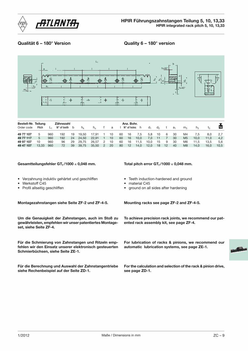
Maße / Dimensions in mm ZC – 91/2012
HPIR Führungszahnstangen Teilung 5, 10, 13,33HPIR integrated rack pitch 5, 10, 13,33
Qualität 6 – 180° Version Quality 6 – 180° version
Total pitch error GTf /1000 0,048 mm.Gesamtteilungsfehler GTf /1000 0,048 mm.
Um die Genauigkeit der Zahnstangen, auch im Stoß zu gewährleisten, empfehlen wir unser patentiertes Montage-set, siehe Seite ZF-4.
To achieve precision rack joints, we recommend our pat-ented rack assembly kit, see page ZF-4.
Montagezahnstangen siehe Seite ZF-2 und ZF-4-5. Mounting racks see page ZF-2 and ZF-4-5.
Für die Schmierung von Zahnstangen und Ritzeln emp-fehlen wir den Einsatz unserer elektronisch gesteuerten Schmierbüchsen, siehe Seite ZE-1.
For lubrication of racks & pinions, we recommend our automatic lubrication systems, see page ZE-1.
Für die Berechnung und Auswahl der Zahnstangentriebe siehe Rechenbeispiel auf der Seite ZD-1.
For the calculation and selection of the rack & pinion drive, see page ZD-1.
49 77 107 5 960 192 19 19,50 17,91 1 10 60 16 7,5 5,8 10 6 30 M4 7,5 8,0 2,749 77 117 5 960 192 24 24,50 22,91 1 10 60 16 10,0 7,0 11 7 30 M5 10,0 11,0 4,249 97 107 10 960 96 29 29,75 26,57 2 10 60 16 11,5 10,0 15 9 30 M6 11,5 13,5 5,649 47 107 13,33 960 72 39 39,75 35,50 2 20 80 12 14,0 12,0 18 12 40 M8 14,0 16,0 10,5
t 3
L1
a1
a fx45°
d2h
k
h0
b
d1
t
l
l
l
l
l
l l
l
l
l f x45°h3
m3
h
Bestell-Nr. Teilung Zähnezahl Anz. Bohr. Order code Pitch L1 N° of teeth b hk ho f a I N° of holes h d1 d2 t a1 m3 h3 t3
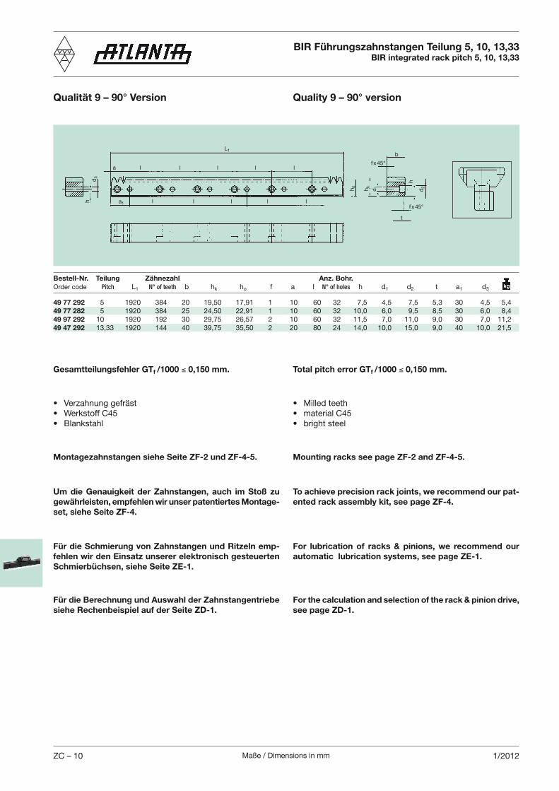
Maße / Dimensions in mmZC – 10 1/2012
Total pitch error GTf /1000 0,150 mm.Gesamtteilungsfehler GTf /1000 0,150 mm.
Um die Genauigkeit der Zahnstangen, auch im Stoß zu gewährleisten, empfehlen wir unser patentiertes Montage-set, siehe Seite ZF-4.
To achieve precision rack joints, we recommend our pat-ented rack assembly kit, see page ZF-4.
Montagezahnstangen siehe Seite ZF-2 und ZF-4-5. Mounting racks see page ZF-2 and ZF-4-5.
Für die Schmierung von Zahnstangen und Ritzeln emp-fehlen wir den Einsatz unserer elektronisch gesteuerten Schmierbüchsen, siehe Seite ZE-1.
For lubrication of racks & pinions, we recommend our automatic lubrication systems, see page ZE-1.
Für die Berechnung und Auswahl der Zahnstangentriebe siehe Rechenbeispiel auf der Seite ZD-1.
For the calculation and selection of the rack & pinion drive, see page ZD-1.
49 77 292 5 1920 384 20 19,50 17,91 1 10 60 32 7,5 4,5 7,5 5,3 30 4,5 5,449 77 282 5 1920 384 25 24,50 22,91 1 10 60 32 10,0 6,0 9,5 8,5 30 6,0 8,449 97 292 10 1920 192 30 29,75 26,57 2 10 60 32 11,5 7,0 11,0 9,0 30 7,0 11,249 47 292 13,33 1920 144 40 39,75 35,50 2 20 80 24 14,0 10,0 15,0 9,0 40 10,0 21,5
d3
L1
a1
afx45°
d2hkh0
b
d1
h
t
l
l
l
l
l
l l
l
l
lf x45°
h
BIR Führungszahnstangen Teilung 5, 10, 13,33BIR integrated rack pitch 5, 10, 13,33
Qualität 9 – 90° Version Quality 9 – 90° version
Bestell-Nr. Teilung Zähnezahl Anz. Bohr.Order code Pitch L1 N° of teeth b hk ho f a I N° of holes h d1 d2 t a1 d3
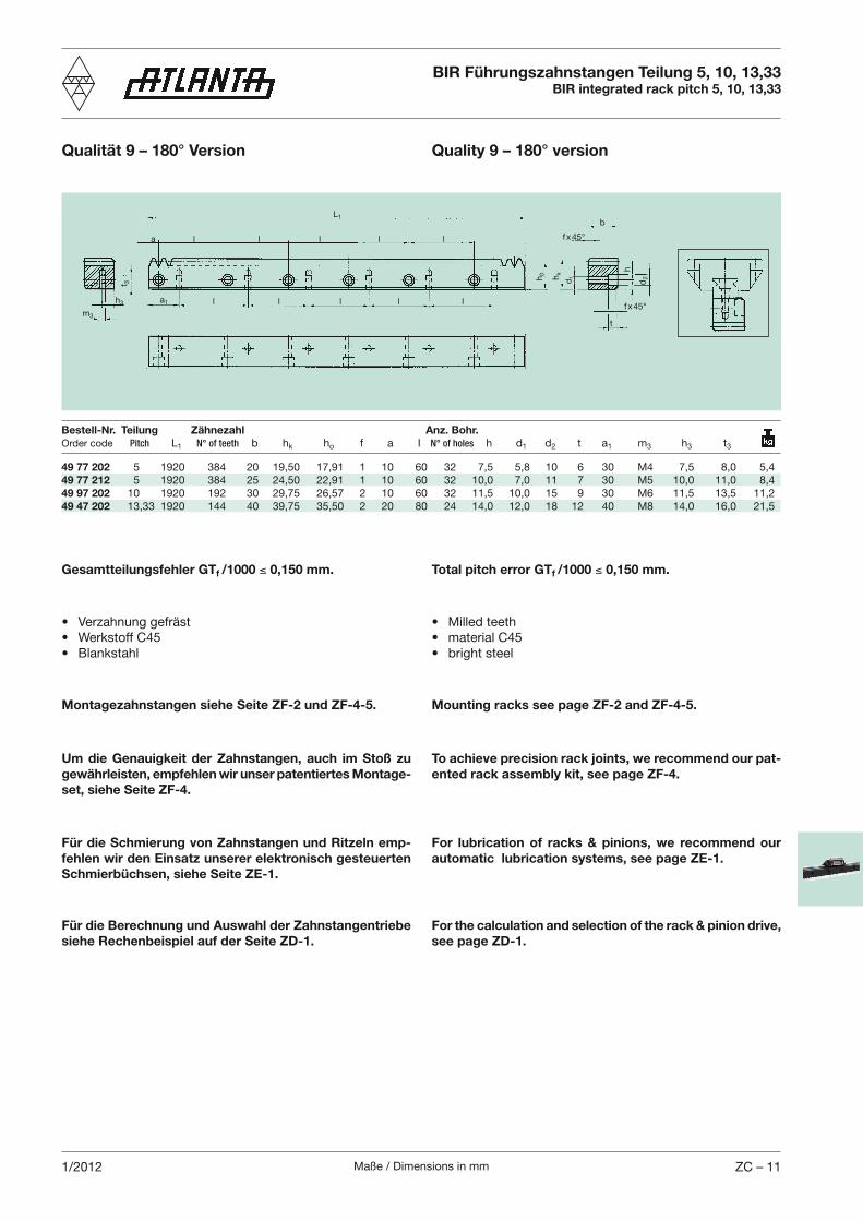
Maße / Dimensions in mm ZC – 111/2012
Gesamtteilungsfehler GTf /1000 0,150 mm.
Um die Genauigkeit der Zahnstangen, auch im Stoß zu gewährleisten, empfehlen wir unser patentiertes Montage-set, siehe Seite ZF-4.
To achieve precision rack joints, we recommend our pat-ented rack assembly kit, see page ZF-4.
Montagezahnstangen siehe Seite ZF-2 und ZF-4-5. Mounting racks see page ZF-2 and ZF-4-5.
Für die Schmierung von Zahnstangen und Ritzeln emp-fehlen wir den Einsatz unserer elektronisch gesteuerten Schmierbüchsen, siehe Seite ZE-1.
For lubrication of racks & pinions, we recommend our automatic lubrication systems, see page ZE-1.
Für die Berechnung und Auswahl der Zahnstangentriebe siehe Rechenbeispiel auf der Seite ZD-1.
For the calculation and selection of the rack & pinion drive, see page ZD-1.
Total pitch error GTf /1000 0,150 mm.
49 77 202 5 1920 384 20 19,50 17,91 1 10 60 32 7,5 5,8 10 6 30 M4 7,5 8,0 5,449 77 212 5 1920 384 25 24,50 22,91 1 10 60 32 10,0 7,0 11 7 30 M5 10,0 11,0 8,449 97 202 10 1920 192 30 29,75 26,57 2 10 60 32 11,5 10,0 15 9 30 M6 11,5 13,5 11,249 47 202 13,33 1920 144 40 39,75 35,50 2 20 80 24 14,0 12,0 18 12 40 M8 14,0 16,0 21,5
t 3
L1
a1
a fx45°
d2h
k
h0
b
d1
t
l
l
l
l
l
l l
l
l
lf x45°
h3
m3
h
BIR Führungszahnstangen Teilung 5, 10, 13,33BIR integrated rack pitch 5, 10, 13,33
Qualität 9 – 180° Version Quality 9 – 180° version
Bestell-Nr. Teilung Zähnezahl Anz. Bohr. Order code Pitch L1 N° of teeth b hk ho f a I N° of holes h d1 d2 t a1 m3 h3 t3
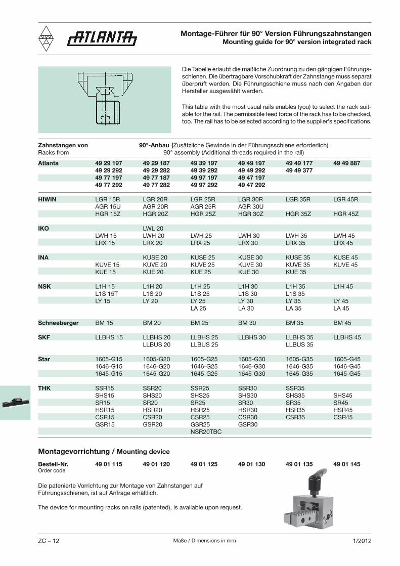
Maße / Dimensions in mmZC – 12 1/2012
Die patenierte Vorrichtung zur Montage von Zahnstangen auf Führungsschienen, ist auf Anfrage erhältlich.
The device for mounting racks on rails (patented), is available upon request.
Bestell-Nr. 49 01 115 49 01 120 49 01 125 49 01 130 49 01 135 49 01 145Order code
Montagevorrichtung / Mounting device
Montage-Führer für 90° Version FührungszahnstangenMounting guide for 90° version integrated rack
This table with the most usual rails enables (you) to select the rack suit-able for the rail. The permissible feed force of the rack has to be checked, too. The rail has to be selected according to the supplier's specifications.
Die Tabelle erlaubt die maßliche Zuordnung zu den gängigen Führungs-schienen. Die übertragbare Vorschubkraft der Zahnstange muss separat überprüft werden. Die Führungs schiene muss nach den Angaben der Hersteller ausgewählt werden.
Zahnstangen von 90°-Anbau (Zusätzliche Gewinde in der Führungsschiene erforderlich)Racks from 90° assembly (Additional threads required in the rail)
Atlanta 49 29 197 49 29 187 49 39 197 49 49 197 49 49 177 49 49 887 49 29 292 49 29 282 49 39 292 49 49 292 49 49 377 49 77 197 49 77 187 49 97 197 49 47 197 49 77 292 49 77 282 49 97 292 49 47 292
HIWIN LGR 15R LGR 20R LGR 25R LGR 30R LGR 35R LGR 45R AGR 15U AGR 20R AGR 25R AGR 30U HGR 15Z HGR 20Z HGR 25Z HGR 30Z HGR 35Z HGR 45Z
IKO LWL 20 LWH 15 LWH 20 LWH 25 LWH 30 LWH 35 LWH 45 LRX 15 LRX 20 LRX 25 LRX 30 LRX 35 LRX 45
INA KUSE 20 KUSE 25 KUSE 30 KUSE 35 KUSE 45 KUVE 15 KUVE 20 KUVE 25 KUVE 30 KUVE 35 KUVE 45 KUE 15 KUE 20 KUE 25 KUE 30 KUE 35
NSK L1H 15 L1H 20 L1H 25 L1H 30 L1H 35 L1H 45 L1S 15T L1S 20 L1S 25 L1S 30 L1S 35 LY 15 LY 20 LY 25 LY 30 LY 35 LY 45 LA 25 LA 30 LA 35 LA 45
Schneeberger BM 15 BM 20 BM 25 BM 30 BM 35 BM 45
SKF LLBHS 15 LLBHS 20 LLBHS 25 LLBHS 30 LLBHS 35 LLBHS 45 LLBUS 20 LLBUS 25 LLBUS 35
Star 1605-G15 1605-G20 1605-G25 1605-G30 1605-G35 1605-G45 1646-G15 1646-G20 1646-G25 1646-G30 1646-G35 1646-G45 1645-G15 1645-G20 1645-G25 1645-G30 1645-G35 1645-G45
THK SSR15 SSR20 SSR25 SSR30 SSR35 SHS15 SHS20 SHS25 SHS30 SHS35 SHS45 SR15 SR20 SR25 SR30 SR35 SR45 HSR15 HSR20 HSR25 HSR30 HSR35 HSR45 CSR15 CSR20 CSR25 CSR30 CSR35 CSR45 GSR15 GSR20 GSR25 GSR30 NSR20TBC
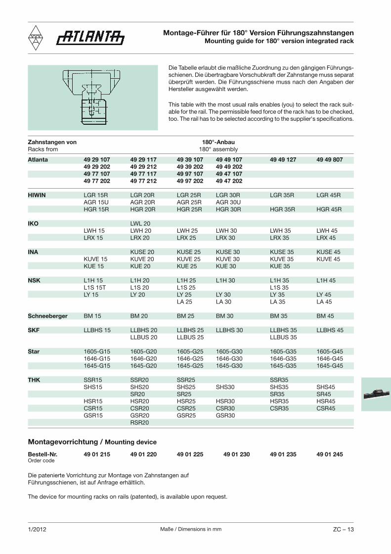
Maße / Dimensions in mm ZC – 131/2012
Die patenierte Vorrichtung zur Montage von Zahnstangen auf Führungsschienen, ist auf Anfrage erhältlich.
The device for mounting racks on rails (patented), is available upon request.
Bestell-Nr. 49 01 215 49 01 220 49 01 225 49 01 230 49 01 235 49 01 245Order code
Montagevorrichtung / Mounting device
Montage-Führer für 180° Version FührungszahnstangenMounting guide for 180° version integrated rack
This table with the most usual rails enables (you) to select the rack suit-able for the rail. The permissible feed force of the rack has to be checked, too. The rail has to be selected according to the supplier's specifications.
Die Tabelle erlaubt die maßliche Zuordnung zu den gängigen Führungs-schienen. Die übertragbare Vorschubkraft der Zahnstange muss separat überprüft werden. Die Führungs schiene muss nach den Angaben der Hersteller ausgewählt werden.
Zahnstangen von 180°-AnbauRacks from 180° assembly
Atlanta 49 29 107 49 29 117 49 39 107 49 49 107 49 49 127 49 49 807 49 29 202 49 29 212 49 39 202 49 49 202 49 77 107 49 77 117 49 97 107 49 47 107 49 77 202 49 77 212 49 97 202 49 47 202
HIWIN LGR 15R LGR 20R LGR 25R LGR 30R LGR 35R LGR 45R AGR 15U AGR 20R AGR 25R AGR 30U HGR 15R HGR 20R HGR 25R HGR 30R HGR 35R HGR 45R
IKO LWL 20 LWH 15 LWH 20 LWH 25 LWH 30 LWH 35 LWH 45 LRX 15 LRX 20 LRX 25 LRX 30 LRX 35 LRX 45
INA KUSE 20 KUSE 25 KUSE 30 KUSE 35 KUSE 45 KUVE 15 KUVE 20 KUVE 25 KUVE 30 KUVE 35 KUVE 45 KUE 15 KUE 20 KUE 25 KUE 30 KUE 35
NSK L1H 15 L1H 20 L1H 25 L1H 30 L1H 35 L1H 45 L1S 15T L1S 20 L1S 25 L1S 35 LY 15 LY 20 LY 25 LY 30 LY 35 LY 45 LA 25 LA 30 LA 35 LA 45
Schneeberger BM 15 BM 20 BM 25 BM 30 BM 35 BM 45
SKF LLBHS 15 LLBHS 20 LLBHS 25 LLBHS 30 LLBHS 35 LLBHS 45 LLBUS 20 LLBUS 25 LLBUS 35
Star 1605-G15 1605-G20 1605-G25 1605-G30 1605-G35 1605-G45 1646-G15 1646-G20 1646-G25 1646-G30 1646-G35 1646-G45 1645-G15 1645-G20 1645-G25 1645-G30 1645-G35 1645-G45
THK SSR15 SSR20 SSR25 SSR35 SHS15 SHS20 SHS25 SHS30 SHS35 SHS45 SR20 SR25 SR35 SR45 HSR15 HSR20 HSR25 HSR30 HSR35 HSR45 CSR15 CSR20 CSR25 CSR30 CSR35 CSR45 GSR15 GSR20 GSR25 GSR30 RSR20
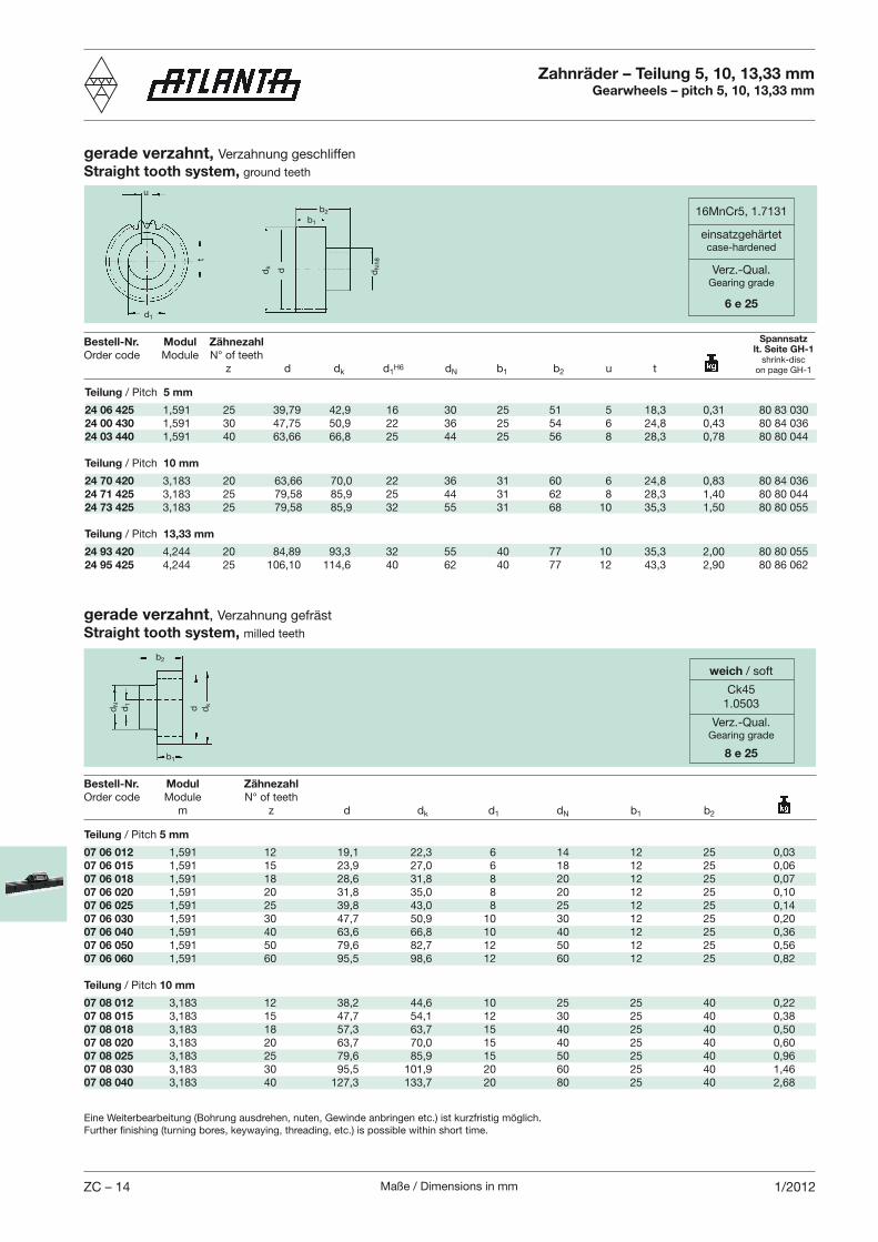
Maße / Dimensions in mmZC – 14 1/2012
weich / soft
Ck451.0503
Verz.-Qual.Gearing grade
8 e 25
u
d1
t
gerade verzahnt, Verzahnung geschliffenStraight tooth system, ground teeth
Zahnräder – Teilung 5, 10, 13,33 mmGearwheels – pitch 5, 10, 13,33 mm
16MnCr5, 1.7131
einsatzgehärtetcase-hardened
Verz.-Qual.Gearing grade
6 e 25
b2
dk
dN
h8
b1
d
Bestell-Nr. Modul Zähnezahl Order code Module N° of teeth m z d dk d1 dN b1 b2
b2
b1
dN d1
dkd
Teilung / Pitch 5 mm
07 06 012 1,591 12 19,1 22,3 6 14 12 25 0,0307 06 015 1,591 15 23,9 27,0 6 18 12 25 0,0607 06 018 1,591 18 28,6 31,8 8 20 12 25 0,0707 06 020 1,591 20 31,8 35,0 8 20 12 25 0,1007 06 025 1,591 25 39,8 43,0 8 25 12 25 0,1407 06 030 1,591 30 47,7 50,9 10 30 12 25 0,2007 06 040 1,591 40 63,6 66,8 10 40 12 25 0,3607 06 050 1,591 50 79,6 82,7 12 50 12 25 0,5607 06 060 1,591 60 95,5 98,6 12 60 12 25 0,82
Teilung / Pitch 10 mm
07 08 012 3,183 12 38,2 44,6 10 25 25 40 0,2207 08 015 3,183 15 47,7 54,1 12 30 25 40 0,3807 08 018 3,183 18 57,3 63,7 15 40 25 40 0,5007 08 020 3,183 20 63,7 70,0 15 40 25 40 0,6007 08 025 3,183 25 79,6 85,9 15 50 25 40 0,9607 08 030 3,183 30 95,5 101,9 20 60 25 40 1,4607 08 040 3,183 40 127,3 133,7 20 80 25 40 2,68
Eine Weiterbearbeitung (Bohrung ausdrehen, nuten, Gewinde anbringen etc.) ist kurzfristig möglich.Further finishing (turning bores, keywaying, threading, etc.) is possible within short time.
gerade verzahnt, Verzahnung gefrästStraight tooth system, milled teeth
Teilung / Pitch 5 mm
24 06 425 1,591 25 39,79 42,9 16 30 25 51 5 18,3 0,31 80 83 03024 00 430 1,591 30 47,75 50,9 22 36 25 54 6 24,8 0,43 80 84 03624 03 440 1,591 40 63,66 66,8 25 44 25 56 8 28,3 0,78 80 80 044
Teilung / Pitch 10 mm
24 70 420 3,183 20 63,66 70,0 22 36 31 60 6 24,8 0,83 80 84 03624 71 425 3,183 25 79,58 85,9 25 44 31 62 8 28,3 1,40 80 80 04424 73 425 3,183 25 79,58 85,9 32 55 31 68 10 35,3 1,50 80 80 055
Teilung / Pitch 13,33 mm
24 93 420 4,244 20 84,89 93,3 32 55 40 77 10 35,3 2,00 80 80 05524 95 425 4,244 25 106,10 114,6 40 62 40 77 12 43,3 2,90 80 86 062
Bestell-Nr. Modul Zähnezahl Order code Module N° of teeth z d dk d1
H6 dN b1 b2 u t
Spannsatzlt. Seite GH-1
shrink-discon page GH-1
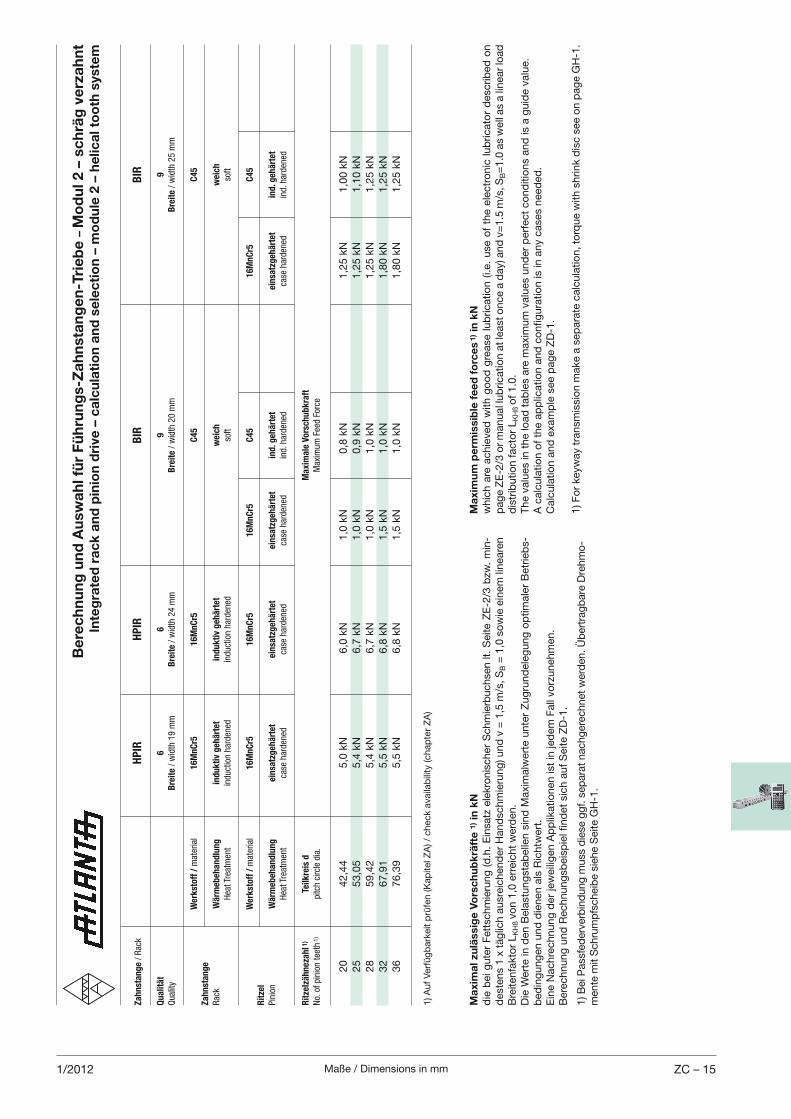
Maße / Dimensions in mm ZC – 151/2012
Berechnung und Auswahl für Führungs-Zahnstangen-Triebe –
Modul 2 – schräg verzahnt
Integrated rack and pinion drive – calculation and selection – module 2 – helical tooth system
Za
hn
sta
ng
e /
Rac
k
HP
IR
HP
IR
B
IR
BIR
Qu
ali
tät
6
6
9
9
Qual
ity
B
reit
e /
wid
th 1
9 m
m
Bre
ite /
wid
th 2
4 m
m
B
reit
e /
wid
th 2
0 m
m
Bre
ite /
wid
th 2
5 m
m
W
erk
sto
ff /
mat
eria
l 1
6M
nC
r5
16
Mn
Cr5
C4
5
C4
5
Za
hn
sta
ng
e
Rac
k W
ärm
eb
eh
an
dlu
ng
in
du
kti
v g
eh
ärt
et
ind
uk
tiv
geh
ärt
et
w
eic
h
weic
h
H
eat Tr
eatm
ent
induct
ion h
arden
ed
induct
ion h
arden
ed
so
ft
soft
W
erk
sto
ff /
mat
eria
l 1
6M
nC
r5
16
Mn
Cr5
1
6M
nC
r5
C4
5
1
6M
nC
r5
C4
5
Rit
zel
Pin
ion
Wä
rmeb
eh
an
dlu
ng
ein
satz
geh
ärt
et
ein
satz
geh
ärt
et
ein
satz
geh
ärt
et
ind
. geh
ärt
et
ein
satz
geh
ärt
et
ind
. geh
ärt
et
H
eat Tr
eatm
ent
case
har
den
ed
case
har
den
ed
case
har
den
ed
ind. h
arden
ed
ca
se h
arden
ed
ind. h
arden
ed
Rit
zelz
äh
neza
hl 1
) Te
ilk
reis
d
M
axim
ale
Vo
rsch
ub
kra
ft
No.
of
pin
ion t
eeth
1)
pitc
h ci
rcle
dia
.
Max
imum
Fee
d F
orce
20
42,4
4
5,0
kN
6,0
kN
1,0
kN
0,8
kN
1,2
5 k
N
1,0
0 k
N
25
53,0
5
5,4
kN
6,7
kN
1,0
kN
0,9
kN
1,2
5 k
N
1,1
0 k
N
28
59,4
2
5,4
kN
6,7
kN
1,0
kN
1,0
kN
1,2
5 k
N
1,2
5 k
N
32
67,9
1
5,5
kN
6,8
kN
1,5
kN
1,0
kN
1,8
0 k
N
1,2
5 k
N
36
76,3
9
5,5
kN
6,8
kN
1,5
kN
1,0
kN
1,8
0 k
N
1,2
5 k
N
1) A
uf
Ver
füg
bar
keit
prü
fen (K
apite
l ZA
) / c
hec
k av
aila
bili
ty (c
hap
ter
ZA
)
Maximum permissible feed forces 1) in kN
whic
h a
re a
chie
ved
with
go
od
gre
ase
lub
rica
tion (
i.e.
use
of
the
elec
tro
nic
lub
rica
tor
des
crib
ed o
n
pag
e Z
E-2
/3 o
r m
anual
lub
rica
tion a
t le
ast o
nce
a d
ay) a
nd
v=
1.5
m/s
, SB=
1.0
as
wel
l as
a lin
ear
load
d
istr
ibutio
n f
acto
r L
KH
ß o
f 1.0
.T
he
valu
es in
the
load
tab
les
are
max
imum
val
ues
und
er p
erfe
ct c
ond
itio
ns
and
is a
guid
e va
lue.
A c
alcu
latio
n o
f th
e ap
plic
atio
n a
nd
co
nfig
ura
tion is
in a
ny
case
s nee
ded
.C
alcu
latio
n a
nd
exa
mp
le s
ee p
age
ZD
-1.
1) F
or
keyw
ay t
ransm
issi
on m
ake
a se
par
ate
calc
ula
tion, t
orq
ue
with
shrink
dis
c se
e o
n p
age
GH
-1.
Maximal zulässige Vorschubkräfte 1) in kN
die
bei
gute
r F
etts
chm
ieru
ng
(d
.h.
Ein
satz
ele
kro
nis
cher
Sch
mie
rbuch
sen lt
. S
eite
ZE
-2/3
bzw
. m
in-
des
tens
1 x
täg
lich a
usr
eich
end
er H
and
schm
ieru
ng
) und
v =
1,5
m/s
, SB =
1,0
so
wie
ein
em li
nea
ren
Bre
itenfa
kto
r L
KH
ß v
on 1
,0 e
rrei
cht
wer
den
.D
ie W
erte
in d
en B
elas
tung
stab
elle
n s
ind
Max
imal
wer
te u
nte
r Z
ug
rund
eleg
ung
op
timal
er B
etrieb
s-b
edin
gung
en u
nd
die
nen
als
Ric
htw
ert.
Ein
e N
achre
chnung
der
jew
eilig
en A
pp
likat
ionen
ist
in je
dem
Fal
l vo
rzuneh
men
.B
erec
hnung
und
Rec
hnung
sbei
spie
l find
et s
ich a
uf
Sei
te Z
D-1
.
1) B
ei P
assf
eder
verb
ind
ung
muss
die
se g
gf. s
epar
at n
achg
erec
hnet
wer
den
. Üb
ertr
agb
are
Dre
hm
o-
men
te m
it S
chru
mp
fsch
eib
e si
ehe
Sei
te G
H-1
.
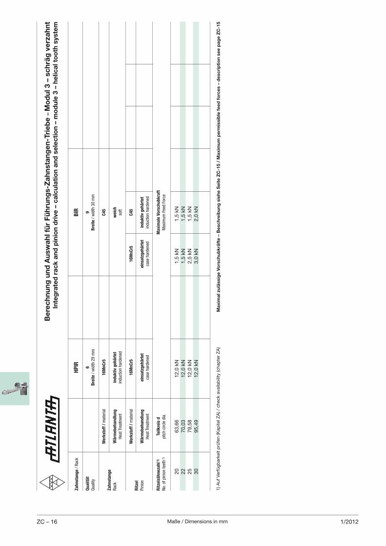
Maße / Dimensions in mmZC – 16 1/2012
Berechnung und Auswahl für Führungs-Zahnstangen-Triebe –
Modul 3 – schräg verzahnt
Integrated rack and pinion drive – calculation and selection – module 3 – helical tooth system
Za
hn
sta
ng
e /
Rac
k
HP
IR
BIR
Qu
ali
tät
6
9
Qual
ity
B
reit
e /
wid
th 2
9 m
m
Bre
ite /
wid
th 3
0 m
m
W
erk
sto
ff /
mat
eria
l 1
6M
nC
r5
C4
5
Za
hn
sta
ng
e
Rac
k W
ärm
eb
eh
an
dlu
ng
in
du
kti
v g
eh
ärt
et
weic
h
H
eat Tr
eatm
ent
induct
ion h
arden
ed
soft
W
erk
sto
ff /
mat
eria
l 1
6M
nC
r5
1
6M
nC
r5
C4
5
Rit
zel
Pin
ion
Wä
rmeb
eh
an
dlu
ng
ein
satz
geh
ärt
et
ein
satz
geh
ärt
et
ind
uk
tiv
geh
ärt
et
H
eat Tr
eatm
ent
case
har
den
ed
ca
se h
arden
ed
induct
ion h
arden
ed
Rit
zelz
äh
neza
hl 1
) Te
ilk
reis
d
M
axim
ale
Vo
rsch
ub
kra
ft
No.
of
pin
ion t
eeth
1)
pitc
h ci
rcle
dia
.
Max
imum
Fee
d F
orce
20
63,6
6
12,0
kN
1,5
kN
1,5
kN
22
70,0
3
12,0
kN
1,5
kN
1,5
kN
25
79,5
8
12,0
kN
2,5
kN
1,5
kN
30
95,4
9
12,0
kN
3,0
kN
2,0
kN
1) A
uf
Ver
füg
bar
keit
prü
fen (K
apite
l ZA
) / c
hec
k av
aila
bili
ty (c
hap
ter
ZA
)Maximal zulässige Vorschubkräfte – Beschreibung siehe Seite ZC-15 / Maximum permissible feed forces – description see page ZC-15
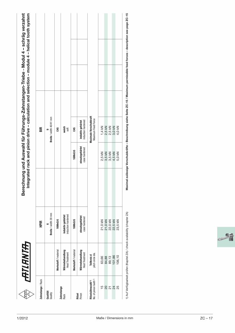
Maße / Dimensions in mm ZC – 171/2012
Berechnung und Auswahl für Führungs-Zahnstangen-Triebe –
Modul 4 – schräg verzahnt
Integrated rack and pinion drive – calculation and selection – module 4 – helical tooth system
1) A
uf
Ver
füg
bar
keit
prü
fen (K
apite
l ZA
) / c
hec
k av
aila
bili
ty (c
hap
ter
ZA
)
Za
hn
sta
ng
e /
Rac
k
HP
IR
BIR
Qu
ali
tät
6
9
Qual
ity
B
reit
e /
wid
th 3
9 m
m
Bre
ite /
wid
th 4
0/4
1 m
m
W
erk
sto
ff /
mat
eria
l 1
6M
nC
r5
C4
5
Za
hn
sta
ng
e
Rac
k W
ärm
eb
eh
an
dlu
ng
in
du
kti
v g
eh
ärt
et
weic
h
H
eat Tr
eatm
ent
induct
ion h
arden
ed
soft
W
erk
sto
ff /
mat
eria
l 1
6M
nC
r5
1
6M
nC
r5
C4
5
Rit
zel
Pin
ion
Wä
rmeb
eh
an
dlu
ng
ein
satz
geh
ärt
et
ein
satz
geh
ärt
et
ind
uk
tiv
geh
ärt
et
H
eat Tr
eatm
ent
case
har
den
ed
ca
se h
arden
ed
induct
ion h
arden
ed
Rit
zelz
äh
neza
hl 1
) Te
ilk
reis
d
M
axim
ale
Vo
rsch
ub
kra
ft
No.
of
pin
ion t
eeth
1)
pitc
h ci
rcle
dia
.
Max
imum
Fee
d F
orce
15
63,6
6
21,0
kN
2,5
kN
1,4
kN
20
84,8
8
21,0
kN
3,5
kN
2,5
kN
21
89,1
3
22,0
kN
3,5
kN
2,5
kN
24
101,8
6
22,5
kN
4,5
kN
3,0
kN
25
106,1
0
23,5
kN
5,0
kN
4,0
kN
Maximal zulässige Vorschubkräfte – Beschreibung siehe Seite ZC-15 / Maximum permissible feed forces – description see page ZC-15
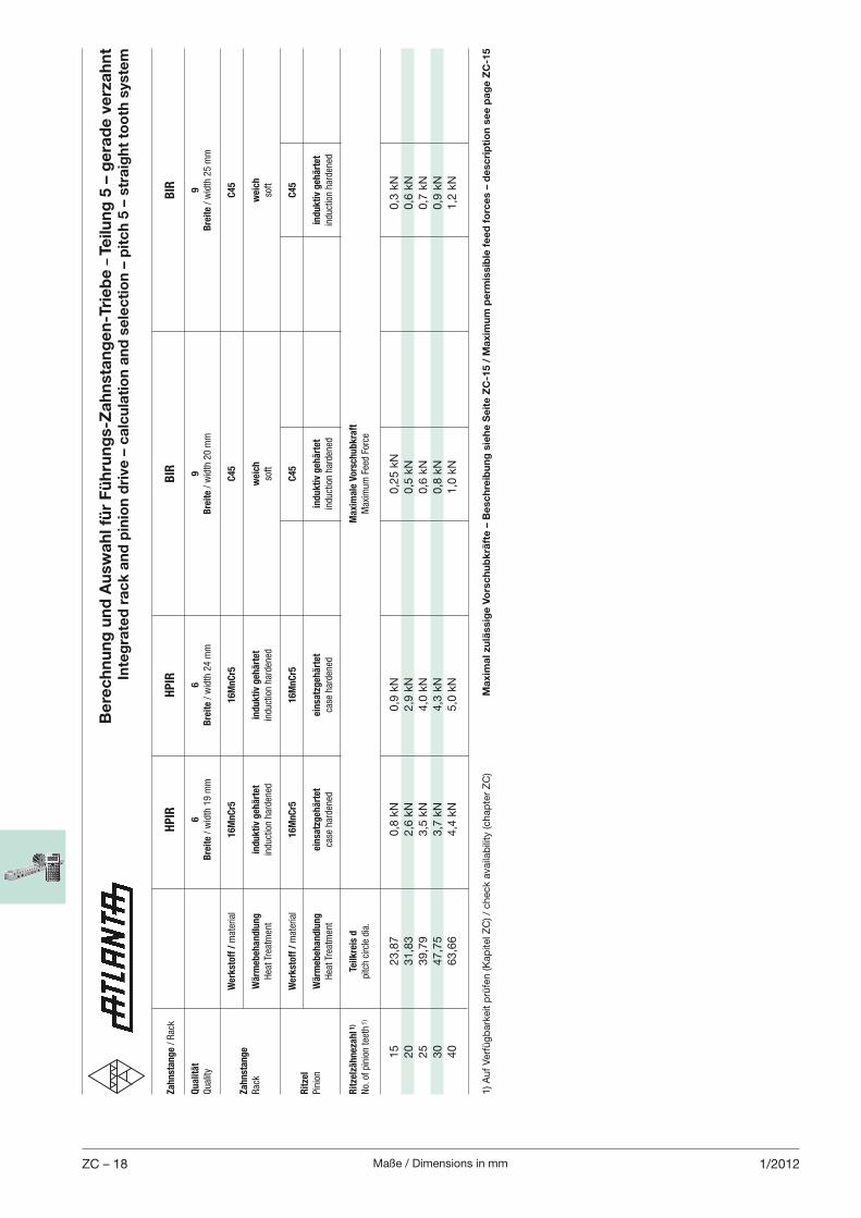
Maße / Dimensions in mmZC – 18 1/2012
Berechnung und Auswahl für Führungs-Zahnstangen-Triebe –
Teilung 5 – gerade verzahnt
Integrated rack and pinion drive – calculation and selection – pitch 5 – straight tooth system
Za
hn
sta
ng
e /
Rac
k
HP
IR
HP
IR
B
IR
BIR
Qu
ali
tät
6
6
9
9
Qual
ity
B
reit
e /
wid
th 1
9 m
m
Bre
ite /
wid
th 2
4 m
m
B
reit
e /
wid
th 2
0 m
m
Bre
ite /
wid
th 2
5 m
m
W
erk
sto
ff /
mat
eria
l 1
6M
nC
r5
16
Mn
Cr5
C4
5
C4
5
Za
hn
sta
ng
e
Rac
k W
ärm
eb
eh
an
dlu
ng
in
du
kti
v g
eh
ärt
et
ind
uk
tiv
geh
ärt
et
w
eic
h
weic
h
H
eat Tr
eatm
ent
induct
ion h
arden
ed
induct
ion h
arden
ed
so
ft
soft
W
erk
sto
ff /
mat
eria
l 1
6M
nC
r5
16
Mn
Cr5
C4
5
C4
5
Rit
zel
Pin
ion
Wä
rmeb
eh
an
dlu
ng
ein
satz
geh
ärt
et
ein
satz
geh
ärt
et
in
du
kti
v g
eh
ärt
et
ind
uk
tiv
geh
ärt
et
H
eat Tr
eatm
ent
case
har
den
ed
case
har
den
ed
in
duct
ion h
arden
ed
induct
ion h
arden
ed
Rit
zelz
äh
neza
hl 1
) Te
ilk
reis
d
M
axim
ale
Vo
rsch
ub
kra
ft
No.
of
pin
ion t
eeth
1)
pitc
h ci
rcle
dia
.
Max
imum
Fee
d F
orce
15
23,8
7
0,8
kN
0,9
kN
0,2
5 k
N
0,3
kN
20
31,8
3
2,6
kN
2,9
kN
0,5
kN
0,6
kN
25
39,7
9
3,5
kN
4,0
kN
0,6
kN
0,7
kN
30
47,7
5
3,7
kN
4,3
kN
0,8
kN
0,9
kN
40
63,6
6
4,4
kN
5,0
kN
1,0
kN
1,2
kN
1) A
uf
Ver
füg
bar
keit
prü
fen (K
apite
l ZC
) / c
hec
k av
aila
bili
ty (c
hap
ter
ZC
)Maximal zulässige Vorschubkräfte – Beschreibung siehe Seite ZC-15 / Maximum permissible feed forces – description see page ZC-15
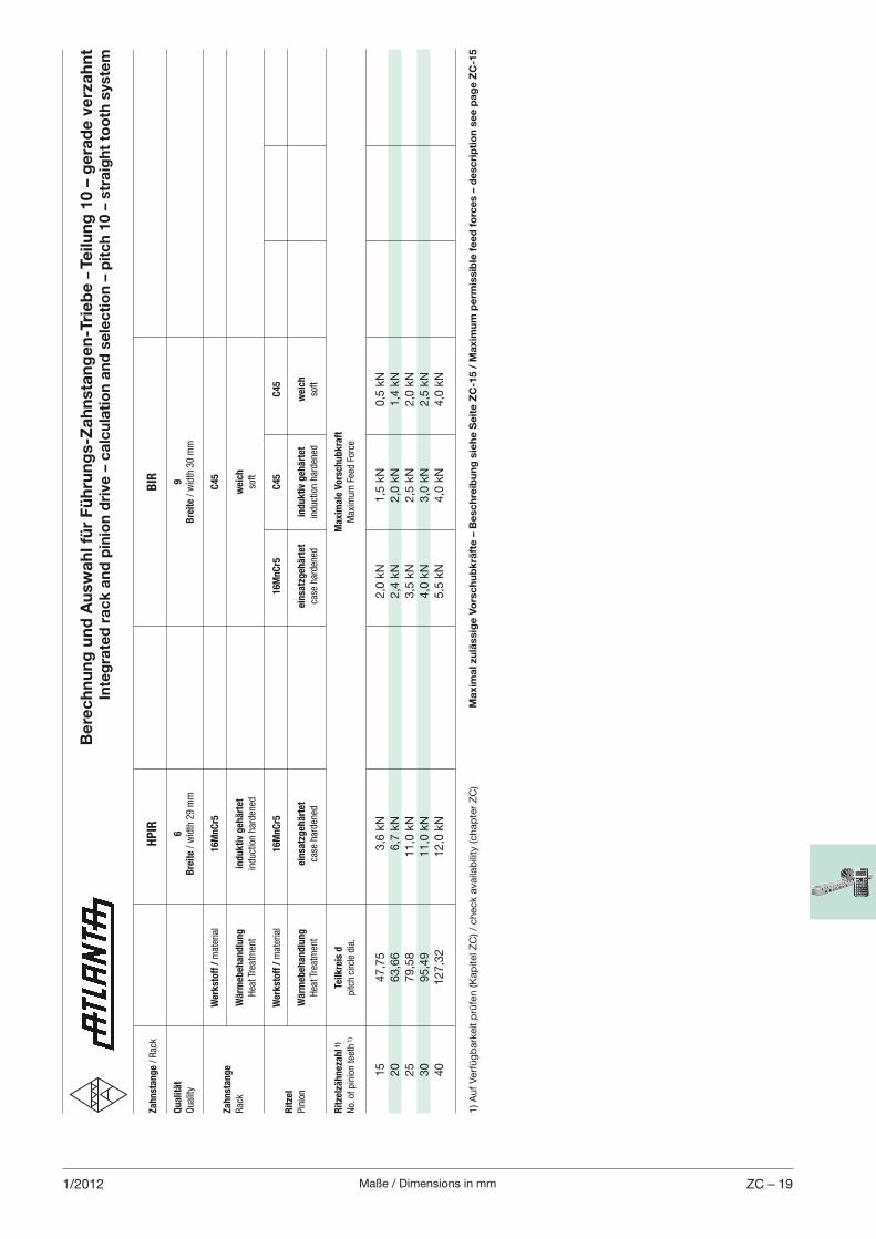
Maße / Dimensions in mm ZC – 191/2012
Za
hn
sta
ng
e /
Rac
k
HP
IR
BIR
Qu
ali
tät
6
9
Qual
ity
B
reit
e /
wid
th 2
9 m
m
Bre
ite /
wid
th 3
0 m
m
W
erk
sto
ff /
mat
eria
l 1
6M
nC
r5
C4
5
Za
hn
sta
ng
e
Rac
k W
ärm
eb
eh
an
dlu
ng
in
du
kti
v g
eh
ärt
et
weic
h
H
eat Tr
eatm
ent
induct
ion h
arden
ed
soft
W
erk
sto
ff /
mat
eria
l 1
6M
nC
r5
1
6M
nC
r5
C4
5
C4
5
Rit
zel
Pin
ion
Wä
rmeb
eh
an
dlu
ng
ein
satz
geh
ärt
et
ein
satz
geh
ärt
et
ind
uk
tiv
geh
ärt
et
weic
h
H
eat Tr
eatm
ent
case
har
den
ed
ca
se h
arden
ed
induct
ion h
arden
ed
soft
Rit
zelz
äh
neza
hl 1
) Te
ilk
reis
d
M
axim
ale
Vo
rsch
ub
kra
ft
No.
of
pin
ion t
eeth
1)
pitc
h ci
rcle
dia
.
Max
imum
Fee
d F
orce
15
47,7
5
3,6
kN
2,0
kN
1,5
kN
0,5
kN
20
63,6
6
6,7
kN
2,4
kN
2,0
kN
1,4
kN
25
79,5
8
11,0
kN
3,5
kN
2,5
kN
2,0
kN
30
95,4
9
11,0
kN
4,0
kN
3,0
kN
2,5
kN
40
127,3
2
12,0
kN
5,5
kN
4,0
kN
4,0
kN
Berechnung und Auswahl für Führungs-Zahnstangen-Triebe –
Teilung 10 – gerade verzahnt
Integrated rack and pinion drive – calculation and selection – pitch 10 – straight tooth system
1) A
uf
Ver
füg
bar
keit
prü
fen (K
apite
l ZC
) / c
hec
k av
aila
bili
ty (c
hap
ter
ZC
)Maximal zulässige Vorschubkräfte – Beschreibung siehe Seite ZC-15 / Maximum permissible feed forces – description see page ZC-15
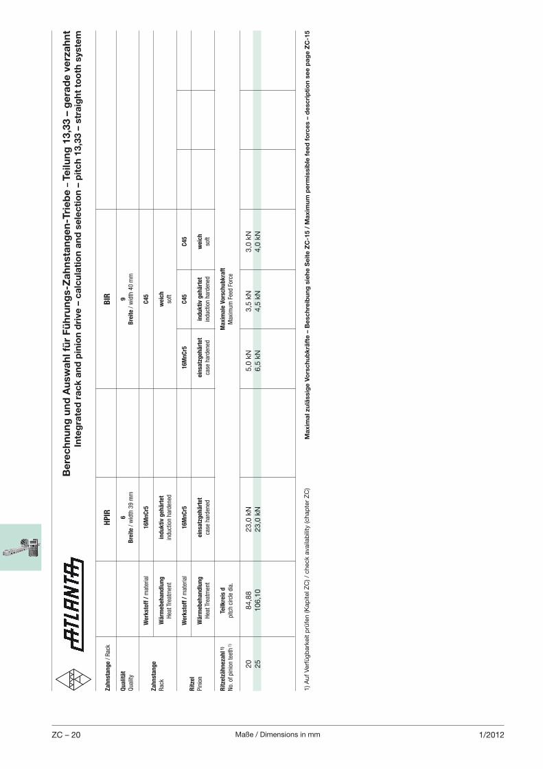
Maße / Dimensions in mmZC – 20 1/2012
Berechnung und Auswahl für Führungs-Zahnstangen-Triebe –
Teilung 13,33 – gerade verzahnt
Integrated rack and pinion drive – calculation and selection – pitch 13,33 – straight tooth system
1) A
uf
Ver
füg
bar
keit
prü
fen (K
apite
l ZC
) / c
hec
k av
aila
bili
ty (c
hap
ter
ZC
)
Za
hn
sta
ng
e /
Rac
k
HP
IR
BIR
Qu
ali
tät
6
9
Qual
ity
B
reit
e /
wid
th 3
9 m
m
Bre
ite /
wid
th 4
0 m
m
W
erk
sto
ff /
mat
eria
l 1
6M
nC
r5
C4
5
Za
hn
sta
ng
e
Rac
k W
ärm
eb
eh
an
dlu
ng
in
du
kti
v g
eh
ärt
et
weic
h
H
eat Tr
eatm
ent
induct
ion h
arden
ed
soft
W
erk
sto
ff /
mat
eria
l 1
6M
nC
r5
1
6M
nC
r5
C4
5
C4
5
Rit
zel
Pin
ion
Wä
rmeb
eh
an
dlu
ng
ein
satz
geh
ärt
et
ein
satz
geh
ärt
et
ind
uk
tiv
geh
ärt
et
weic
h
H
eat Tr
eatm
ent
case
har
den
ed
ca
se h
arden
ed
induct
ion h
arden
ed
soft
Rit
zelz
äh
neza
hl 1
) Te
ilk
reis
d
M
axim
ale
Vo
rsch
ub
kra
ft
No.
of
pin
ion t
eeth
1)
pitc
h ci
rcle
dia
.
Max
imum
Fee
d F
orce
20
84,8
8
23,0
kN
5,0
kN
3,5
kN
3,0
kN
25
106,1
0
23,0
kN
6,5
kN
4,5
kN
4,0
kN
Maximal zulässige Vorschubkräfte – Beschreibung siehe Seite ZC-15 / Maximum permissible feed forces – description see page ZC-15
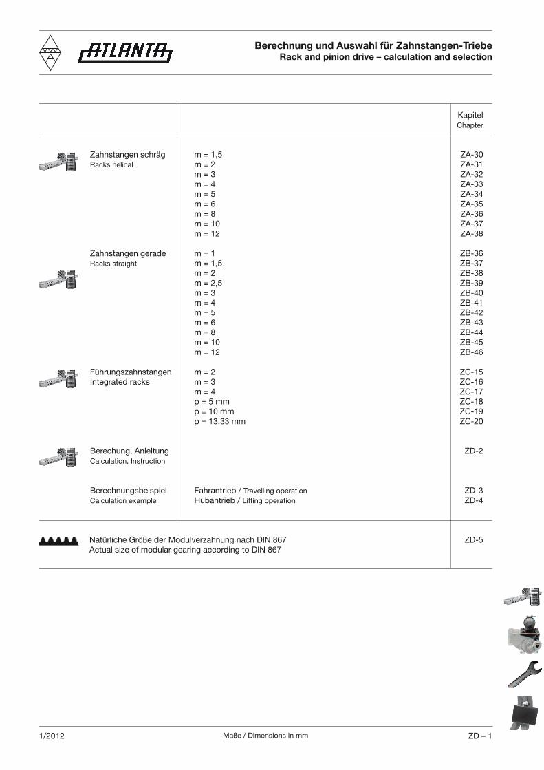
Maße / Dimensions in mm ZD – 11/2012
Kapitel
Chapter
Zahnstangen schräg m = 1,5 ZA-30
Racks helical m = 2 ZA-31
m = 3 ZA-32
m = 4 ZA-33
m = 5 ZA-34
m = 6 ZA-35
m = 8 ZA-36
m = 10 ZA-37
m = 12 ZA-38
Zahnstangen gerade m = 1 ZB-36
Racks straight m = 1,5 ZB-37
m = 2 ZB-38
m = 2,5 ZB-39
m = 3 ZB-40
m = 4 ZB-41
m = 5 ZB-42
m = 6 ZB-43
m = 8 ZB-44
m = 10 ZB-45
m = 12 ZB-46
Führungszahnstangen m = 2 ZC-15
Integrated racks m = 3 ZC-16
m = 4 ZC-17
p = 5 mm ZC-18
p = 10 mm ZC-19
p = 13,33 mm ZC-20
Berechung, Anleitung ZD-2
Calculation, Instruction
Berechnungsbeispiel Fahrantrieb / Travelling operation ZD-3
Calculation example Hubantrieb / Lifting operation ZD-4
Natürliche Größe der Modulverzahnung nach DIN 867 ZD-5
Actual size of modular gearing according to DIN 867
Berechnung und Auswahl für Zahnstangen-TriebeRack and pinion drive – calculation and selection
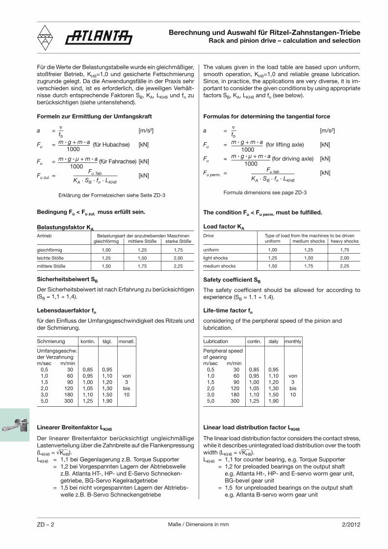
Maße / Dimensions in mmZD – 2 2/2012
Berechnung und Auswahl für Ritzel-Zahnstangen-TriebeRack and pinion drive – calculation and selection
Für die Werte der Belastungstabelle wurde ein gleichmäßiger,
stoßfreier Betrieb, KHß=1,0 und gesicherte Fettschmierung
zugrunde gelegt. Da die Anwendungsfälle in der Praxis sehr
verschieden sind, ist es erforderlich, die jeweiligen Verhält-
nisse durch entsprechende Faktoren SB, KA, LKHß und fn zu
berücksichtigen (siehe untenstehend).
Formeln zur Ermittlung der Umfangskraft
a = [m/s²]
Fu = m · g + m · a (für Hubachse) [kN] 1000
Fu = m · g · µ + m · a (für Fahrachse) [kN]
1000
Fu zul. = [kN]
Erklärung der Formelzeichen siehe Seite ZD-3
Bedingung Fu < Fu zul. muss erfüllt sein.
Belastungsfaktor KA
Antrieb Belastungsart der anzutreibenden Maschinen
gleichförmig mittlere Stöße starke Stöße
gleichförmig 1,00 1,25 1,75
leichte Stöße 1,25 1,50 2,00
mittlere Stöße 1,50 1,75 2,25
Sicherheitsbeiwert SB
Der Sicherheitsbeiwert ist nach Erfahrung zu berücksichtigen
(SB 1,1 1,4).
tb
Fu Tab
KA · SB · fn · LKHß
Lebensdauerfaktor fn
für den Einfluss der Umfangsgeschwindigkeit des Ritzels und
der Schmierung.
Schmierung kontin. tägl. monatl.
Umfangsgeschw.
der Verzahnung
m/sec m/min
0,5 30 0,85 0,95
1,0 60 0,95 1,10 von
1,5 90 1,00 1,20 3
2,0 120 1,05 1,30 bis
3,0 180 1,10 1,50 10
5,0 300 1,25 1,90
The values given in the load table are based upon uniform,
smooth operation, KHß=1,0 and reliable grease lubrication.
Since, in practice, the applications are very diverse, it is im-
portant to consider the given conditions by using appropriate
factors SB, KA, LKHß and fn (see below).
Formulas for determining the tangential force
a = [m/s²]
Fu = m · g + m · a (for lifting axle) [kN]
1000
Fu = m · g · µ + m · a (for driving axle) [kN]
1000
Fu perm. = [kN]
Formula dimensions see page ZD-3
The condition Fu < Fu perm. must be fulfilled.
Load factor KA
Drive Type of load from the machines to be driven
uniform medium shocks heavy shocks
uniform 1,00 1,25 1,75
light shocks 1,25 1,50 2,00
medium shocks 1,50 1,75 2,25
Safety coefficient SB
The safety coefficient should be allowed for according to
experience (SB = 1.1 1.4).
tb
Life-time factor fn
considering of the peripheral speed of the pinion and
lubrication.
Lubrication contin. daily monthly
Peripheral speed
of gearing
m/sec m/min
0,5 30 0,85 0,95
1,0 60 0,95 1,10 von
1,5 90 1,00 1,20 3
2,0 120 1,05 1,30 bis
3,0 180 1,10 1,50 10
5,0 300 1,25 1,90
Linearer Breitenfaktor LKHß
Der linearer Breitenfaktor berücksichtigt ungleichmäßige
Lasten verteilung über die Zahnbreite auf die Flankenpressung
(LKHß = KHß).
LKHß = 1,1 bei Gegenlagerung z.B. Torque Supporter
= 1,2 bei Vorgespannten Lagern der Abtriebswelle
z.B. Atlanta HT-, HP- und E-Servo Schnecken-
getriebe, BG-Servo Kegelradgetriebe
= 1,5 bei nicht vorgespannten Lagern der Abtriebs-
welle z.B. B-Servo Schneckengetriebe
Linear load distribution factor LKHß
The linear load distribution factor considers the contact stress,
while it describes unintegrated load distribution over the tooth
width (LKHß = KHß).
LKHß = 1,1 for counter bearing, e.g. Torque Supporter
= 1,2 for preloaded bearings on the output shaft
e.g. Atlanta Ht-, HP- and E-servo worm gear unit,
BG-bevel gear unit
= 1,5 for unpreloaded bearings on the output shaft
e.g. Atlanta B-servo worm gear unit
Fu tab
KA · SB · fn · LKHß
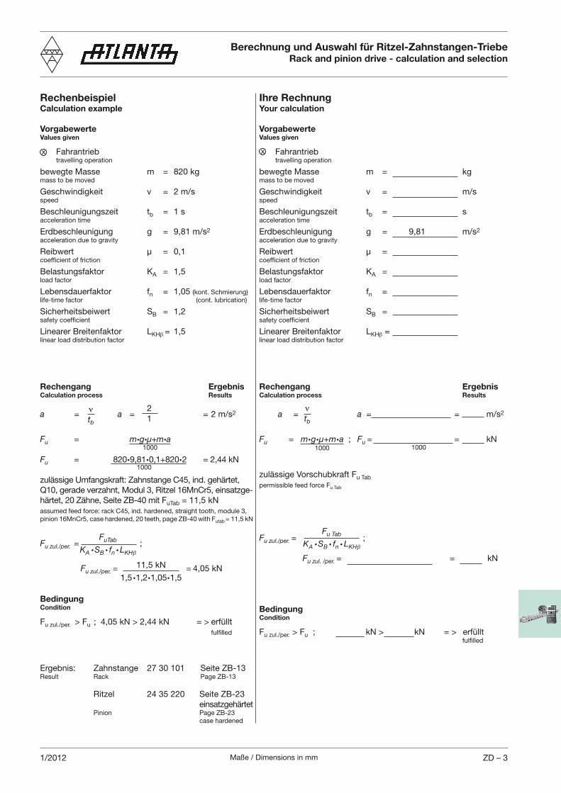
Maße / Dimensions in mm ZD – 31/2012
Ihre RechnungYour calculation
VorgabewerteValues given
Fahrantrieb travelling operation
bewegte Masse m = kgmass to be moved
Geschwindigkeit v = m/sspeed
Beschleunigungszeit tb = sacceleration time
Erdbeschleunigung g = 9,81 m/s2
acceleration due to gravity
Reibwert µ = coefficient of friction
Belastungsfaktor KA = load factor
Lebensdauerfaktor fn = life-time factor
Sicherheitsbeiwert SB = safety coefficient
Linearer Breitenfaktor LKH = linear load distribution factor
Rechengang ErgebnisCalculation process Results
a = a = = m/s2
Fu = m·g·µ+m·a ; Fu = = kN
zulässige Vorschubkraft Fu Tab
permissible feed force Fu Tab
Fu zul./per. = ;
Fu zul. /per. = = kN
BedingungCondition
Fu zul./per. > Fu ; kN > kN = > erfüllt fulfilled
Berechnung und Auswahl für Ritzel-Zahnstangen-TriebeRack and pinion drive - calculation and selection
tb
RechenbeispielCalculation example
VorgabewerteValues given
Fahrantrieb travelling operation
bewegte Masse m = 820 kgmass to be moved
Geschwindigkeit v = 2 m/sspeed
Beschleunigungszeit tb = 1 sacceleration time
Erdbeschleunigung g = 9,81 m/s2
acceleration due to gravity
Reibwert µ = 0,1coefficient of friction
Belastungsfaktor KA = 1,5load factor
Lebensdauerfaktor fn = 1,05 (kont. Schmierung)
life-time factor (cont. lubrication)
Sicherheitsbeiwert SB = 1,2safety coefficient
Linearer Breitenfaktor LKH = 1,5linear load distribution factor
Rechengang ErgebnisCalculation process Results
a = a = = 2 m/s2
Fu = m·g·µ+m·a
Fu = 820·9,81·0,1+820·2 = 2,44 kN
zulässige Umfangskraft: Zahnstange C45, ind. gehärtet,
Q10, gerade verzahnt, Modul 3, Ritzel 16MnCr5, einsatzge-
härtet, 20 Zähne, Seite ZB-40 mit FuTab = 11,5 kN
assumed feed force: rack C45, ind. hardened, straight tooth, module 3,
pinion 16MnCr5, case hardened, 20 teeth, page ZB-40 with Futab = 11,5 kN
Fu zul./per. = ;
Fu zul./per. = = 4,05 kN
BedingungCondition
Fu zul./per. > Fu ; 4,05 kN > 2,44 kN = > erfüllt
fulfilled
Ergebnis: Zahnstange 27 30 101 Seite ZB-13Result Rack Page ZB-13
Ritzel 24 35 220 Seite ZB-23
einsatzgehärtet Pinion Page ZB-23
case hardened
x
tb
FuTab
KA · SB · fn · LKH
2
1
11,5 kN
1,5·1,2·1,05·1,5
x
Fu Tab
KA · SB · fn · LKH
1000
1000
1000 1000
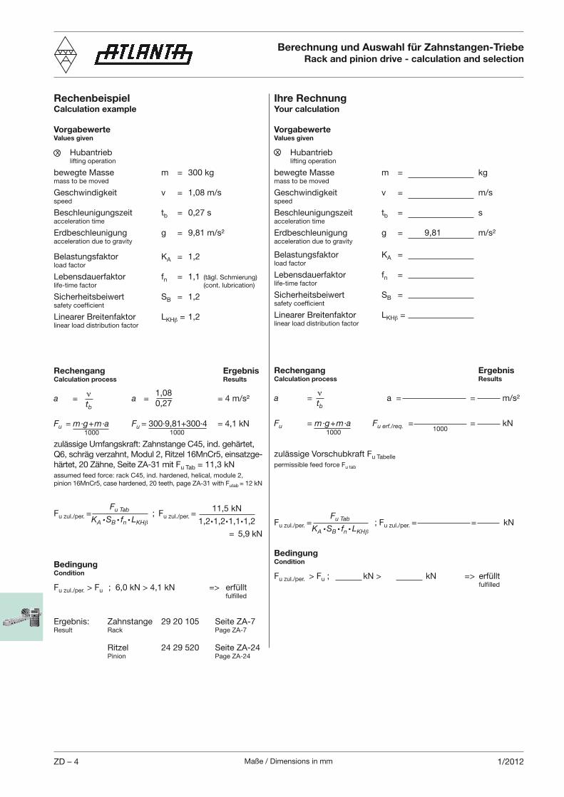
Maße / Dimensions in mmZD – 4 1/2012
Ihre RechnungYour calculation
VorgabewerteValues given
Hubantrieb lifting operation
bewegte Masse m = kgmass to be moved
Geschwindigkeit v = m/sspeed
Beschleunigungszeit tb = sacceleration time
Erdbeschleunigung g = 9,81 m/s²acceleration due to gravity
Belastungsfaktor KA = load factor
Lebensdauerfaktor fn = life-time factor
Sicherheitsbeiwert SB = safety coefficient
Linearer Breitenfaktor LKH = linear load distribution factor
Rechengang ErgebnisCalculation process Results
a = a = = m/s²
Fu = m·g+m·a Fu erf./req. = = kN
zulässige Vorschubkraft Fu Tabelle
permissible feed force Fu tab
Fu zul./per. = ; Fu zul./per. = = kN
BedingungCondition
Fu zul./per. > Fu ; kN > kN => erfüllt fulfilled
RechenbeispielCalculation example
VorgabewerteValues given
Hubantrieb lifting operation
bewegte Masse m = 300 kgmass to be moved
Geschwindigkeit v = 1,08 m/sspeed
Beschleunigungszeit tb = 0,27 sacceleration time
Erdbeschleunigung g = 9,81 m/s²acceleration due to gravity
Belastungsfaktor KA = 1,2 load factor
Lebensdauerfaktor fn = 1,1 (tägl. Schmierung)
life-time factor (cont. lubrication)
Sicherheitsbeiwert SB = 1,2safety coefficient
Linearer Breitenfaktor LKH = 1,2linear load distribution factor
Rechengang ErgebnisCalculation process Results
a = a = = 4 m/s²
Fu = m·g+m·a Fu = 300·9,81+300·4 = 4,1 kN
zulässige Umfangskraft: Zahnstange C45, ind. gehärtet,
Q6, schräg verzahnt, Modul 2, Ritzel 16MnCr5, einsatzge-
härtet, 20 Zähne, Seite ZA-31 mit Fu Tab = 11,3 kN
assumed feed force: rack C45, ind. hardened, helical, module 2,
pinion 16MnCr5, case hardened, 20 teeth, page ZA-31 with Futab = 12 kN
Fu zul./per. = ; Fu zul./per. =
= 5,9 kN
BedingungCondition
Fu zul./per. > Fu ; 6,0 kN > 4,1 kN => erfüllt fulfilled
Ergebnis: Zahnstange 29 20 105 Seite ZA-7Result Rack Page ZA-7
Ritzel 24 29 520 Seite ZA-24 Pinion Page ZA-24
Berechnung und Auswahl für Zahnstangen-TriebeRack and pinion drive - calculation and selection
tb
x
tb
1,08
0,27
x
Fu Tab
KA · SB · fn · LKHFu Tab
KA · SB · fn · LKH
1000 1000 10001000
11,5 kN
1,2·1,2·1,1·1,2
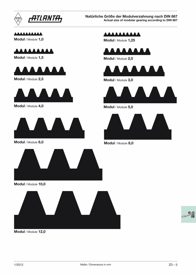
Maße / Dimensions in mm ZD – 51/2012
Natürliche Größe der Modulverzahnung nach DIN 867Actual size of modular gearing according to DIN 867
Modul / Module 1,0 Modul / Module 1,25
Modul / Module 1,5 Modul / Module 2,0
Modul / Module 2,5 Modul / Module 3,0
Modul / Module 4,0 Modul / Module 5,0
Modul / Module 6,0 Modul / Module 8,0
Modul / Module 10,0
Modul / Module 12,0

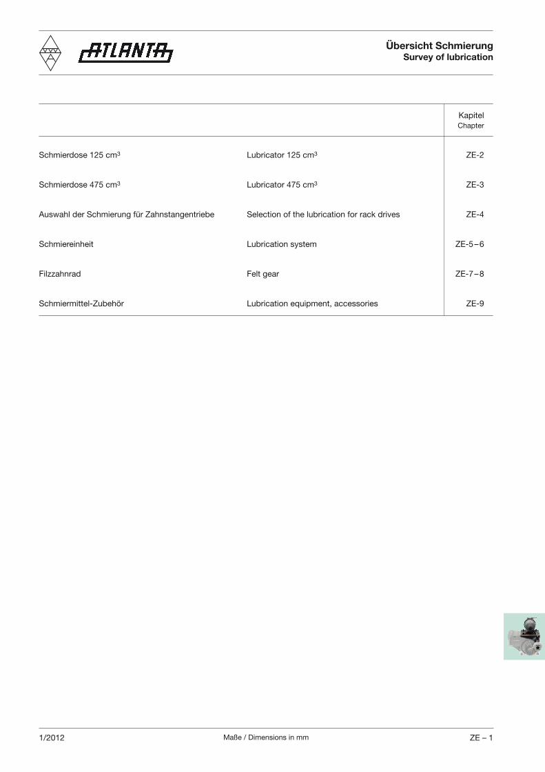
Maße / Dimensions in mm ZE – 11/2012
Kapitel Chapter
Schmierdose 125 cm3 Lubricator 125 cm3 ZE-2
Schmierdose 475 cm3 Lubricator 475 cm3 ZE-3
Auswahl der Schmierung für Zahnstangentriebe Selection of the lubrication for rack drives ZE-4
Schmiereinheit Lubrication system ZE-5 – 6
Filzzahnrad Felt gear ZE-7 – 8
Schmiermittel-Zubehör Lubrication equipment, accessories ZE-9
Übersicht SchmierungSurvey of lubrication

Maße / Dimensions in mmZE – 2 1/2012
65 91 000 1 Komplett einbaufertige Schmierbüchse mit Spezialfett Klüber Lubricator, completely ready for mounting, filled with special Microlube GB0, einschließlich Rohrschelle zur Befestigung grease Klüber Microlube GB0, including pipe clamp for attaching und Reduzierstück G1/4“auf G1/8“ it and reducer G1/4“ to G1/8“ 0,5065 91 0041) 1 Komplett einbaufertige Schmierbüchse mit Spezialfett Klüber Lubricator, completely ready for mounting, filled with special grease Structovis AHD, einschließlich Rohrschelle zur Befestigung Klüber Structovis AHD, including pipe clamp for attaching und Reduzierstück G1/4“auf G1/8“ it and reducer G1/4“ to G1/8“ 0,5065 91 006 1 Komplett einbauferige Schmierbüchse mit Spezialfett Lubricator, completely ready for mounting, filled with spezial Klüber Microlube GB0, einschließlich Rohrschelle zur grease Klüber Microlube GB0, including pipe clamp for attaching Befestigung und Reduzierstück G1/4“ auf G1/8“ it and reducer G1/4“ to G1/8“ with ATEX-conformity, mit ATEX-Konformität, ohne Synchronisation without synchronization 0,5065 91 009 1 Komplett einbaufertige Schmierbüchse ohne Fettfüllung, ein- Lubricator, completely ready for mounting, without grease, schließlich Rohrschelle zur Befestigung und Reduzierstück including pipe clamp for attaching it and reducer G1/4“ G1/4“auf G1/8“ to G1/8“ 0,4065 91 050 2 Komplett einbaufertige Schmierbüchse mit Spezialfett Klüber Lubricator, completely ready for mounting, filled with special grease Microlube GB0, mit elektr. Meldung der Endposition, mit Klüber Microlube GB0, with electr. detection of end position, Kontaktkabel zur Synchronisation der Maschinenlaufzeit, with contact cable for synchronization of machine einschließlich Rohrschelle zur Befestigung und Reduzier- operating time, incl. pipe clamp for attaching it, and reducer stück G1/4“auf G1/8“ G1/4" to G1/8" 0,6065 91 0541) 2 Komplett einbaufertige Schmierbüchse mit Spezialfett Klüber Lubricator, completely ready for mounting, filled with special grease Structovis AHD, mit elektr. Meldung der Endposition, mit Klüber Structovis AHD, with electr. detection of end position, Kontaktkabel zur Synchronisation der Maschinenlaufzeit, with contact cable for synchronization of machine einschließlich Rohrschelle zur Befestigung und Reduzier- operating time, incl. pipe clamp for attaching it, and reducer stück G1/4“auf G1/8“ G1/4" to G1/8" 0,6065 91 059 2 Komplett einbaufertige Schmierbüchse ohne Fettfüllung, mit Lubricator, completely ready for mounting, without grease, with elektr. Meldung der Endposition und Kontaktkabel zur electr. detection of end position, with contact cable for Synchronisation der Maschinenlaufzeit, einschließlich Rohr- synchronization of machine operating time, incl. pipe clamp schelle zur Befestigung und Reduzierstück G1/4“auf G1/8“ for attaching it, and reducer G1/4" to G1/8" 0,4065 91 061 2 Komplett einbaufertige Schmierbüchse mit Spezialfett Klüber Lubricator, completely ready for mounting, filled with special grease Microlube GB0, mit externer Stromversorgung, mit elektr. Klüber Microlube GB0, with external power supply, with electr. Meldung der Endposition, mit 5 m Anschlusskabel zur Syn- detection of end position, with 5 m connecting cable for chronisation der Maschinenlaufzeit, einschließlich Rohr- synchronization of machine operating time, incl. pipe clamp schelle zur Befestigung und Reduzierstück G1/4“auf G1/8“ for attaching it, and reducer G1/4" to G1/8" 0,6065 91 064 2 Komplett einbaufertige Schmierbüchse mit Klüber Lubricator, completely ready for mounting, filled with spezial Structovis AHD, mit externer Stromversorgung, mit elektr. grease Klüber Structovis AHD, with external power supply, Meldung der Endposition, mit 5 m Anschlusskabel zur with electr. detection of end position, with 5 m connecting cable Synchronisation der Maschinenlaufzeit, einschließlich Rohr- for synchronization of machine operating time, incl. pipe clamp schelle zur Befestigung und Reduzierstück G1/4“ auf G1/8“ for attaching it, and reducer G1/4“ to G1/8“ 0,6065 91 001 3 Stickstoff-Druckkammer für Ersatzfüllung Nitrogen pressure chamber for replacement filling (mit Batterien) als Austauschteil (with batteries) as spare part 0,0865 91 003 4 Kontaktkabel 0,15 m für Synchronisation der Contact cable 0,15 m for synchronization with machine Maschinenlaufzeit für Bestell-Nr. 65 91 000/004/009 operating time for order code 65 91 000/004/009 0,0165 91 030 5 Montageschlüssel zum Öffnen der Schmierbüchse Assembly wrench for opening the lubricator 0,1265 91 031 6 Montageeinsatz zum Öffnen der Schmierbüchse Mounting late for opening the lubricator 0,15
Zahnstangentriebe – Schmiermittel, ZubehörRack and pinion drives – Lubricating equipment, Accessories
Bestell-Nr. Bild Bezeichnung DescriptionOrder code Fig.
Elektronisch gesteuerte Schmierbüchsen – 125 cm3 Electronically controlled lubricators – 125 cm3
Bild/Fig. 3Bild/Fig. 2
40
95
Ø6,
6
SW 17
Ø68
47
14
2
Ø 79
Bild/Fig. 1
95,2
24 dick/thickness
79,5
95
,2
Bild/Fig. 4
24
0
3 dick/thickness
15,2
7290
60
Bild/Fig. 5
Die Funktion beruht auf dem Fettpressen-Prinzip. Nach der Inbetriebnahme wird elektronisch ein Stickstoffgas erzeugt, das einen Kolben bewegt. Die Fettfüllung von 125 cm3 oder 475 cm3 wird mit konstantem Druck entsprechend der gewählten Dosierung gleichmäßig (nicht pulsierend) herausgepresst. Je nach Bedarf kann für eine Fettfüllung ein Entleerungszeitraum von 1-2-3-6-12 oder 18 Monate über Mikroschalter gewählt werden. Die Fettmenge kann auch noch nach der Inbetriebnahme durch Ändern der Mikroschalter-Stellung angepasst werden. Eine ausführliche Montage- und Betriebsanleitung liegt jeder Lieferung bei.
Das transparente, in allen Lagen montierbare Gehäuse, ermöglicht jederzeit eine Sichtkontrolle über die noch zur Verfügung stehende Fettmenge. Nach vollständiger Entleerung ist eine Weiterverwendung durch eine erneute Befüllung möglich. Lediglich die Stickstoffkammer (Bild 3 – 125 cm3, Bild 9 – 475 cm3) und die Batterien müssen ersetzt werden. Eine Dauerblink leuchte, gespeist durch 2 (125 cm3) bzw. 4 (475 cm3) handelsübliche 1,5 V Batterien, bestätigt die Aktivierung der Schmier-dose. Das Kontaktkabel, angeschlossen an einen potenzialfreien Schalter oder Schütz (ohne Fremdstrom), er möglicht die Synchronisation mit der Maschinenlaufzeit. Bei Artikelnr. 65 91 061 (125 cm3) bzw. 65 91 057 (475 cm3) ermöglicht das Anschlusskabel zusätzlich noch eine externe Stromversorgung mit 3 V DC. Durch die Bestromung eines Magnet-Sensors (Bild 2 – 125 cm3, Bild 8 – 475 cm3) mit max 200 mA bei 30 V DC, wird die Meldung der Endposition (Leerzustand) an eine gelbe LED direkt am Sensor, oder extern an einen Signalgeber bzw. Ihre Steuerung abgegeben.
1) Beim Einsatz von Structovis AHD empfehlen wir die Schmierdose tiefer als die Schmierstelle anzuordnen, oder das Rückschlagventil Artikelnr. 65 91 025 einzusetzen.
6
Bild/Fig. 6G1/8"
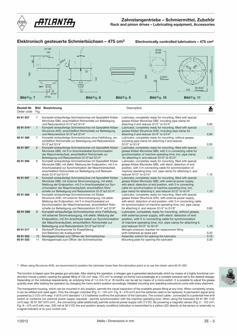
Maße / Dimensions in mm ZE – 31/2012
65 91 007 7 Komplett einbaufertige Schmierbüchse mit Spezialfett Klüber Lubricator, completely ready for mounting, filled with special Microlube GB0, einschließlich Rohrschelle zur Befestigung grease Klüber Microlube GB0, including pipe clamp for und Reduzierstück G1/2“auf G1/4“ attaching it and reducer G1/2“ to G1/4“ 0,9065 91 0141) 7 Komplett einbaufertige Schmierbüchse mit Spezialfett Klüber Lubricator, completely ready for mounting, filled with special Structovis AHD, einschließlich Rohrschelle zur Befestigung grease Klüber Structovis AHD, including pipe clamp for und Reduzierstück G1/2“auf G1/4“ attaching it and reducer G1/2“ to G1/4“ 0,9065 91 069 7 Komplett einbaufertige Schmierbüchse ohne Fettfüllung, ein- Lubricator, completely ready for mounting, without grease, schließlich Rohrschelle zur Befestigung und Reduzierstück including pipe clamp for attaching it and reducer G1/2“auf G1/4“ G1/2“ to G1/4“ 0,5065 91 067 8 Komplett einbaufertige Schmierbüchse mit Spezialfett Klüber Lubricator, completely ready for mounting, filled with special Microlube GB0, mit 5 m Anschlusskabel Synchronisation grease Klüber Microlube GB0, with 5 m connecting cable for der Maschinenlaufzeit, einschließlich Rohrschelle zur synchronization of machine operating time, incl. pipe clamp Befestigung und Reduzierstück G1/2“auf G1/4“ for attaching it, and reducer G1/2" to G1/4" 1,0065 91 056 8 Komplett einbaufertige Schmierbüchse mit Spezialfett Klüber Lubricator, completely ready for mounting, filled with special Microlube GB0, mit elektr. Meldung der Endposition, mit 5 m grease Klüber Microlube GB0, with electr. detection of end Anschlusskabel zur Synchronisation der Maschinenlaufzeit, position, with 5 m connecting cable for synchronization of einschließlich Rohrschelle zur Befestigung und Reduzier- machine operating time, incl. pipe clamp for attaching it, and stück G1/2“auf G1/4“ reducer G1/2" to G1/4" 1,1065 91 057 8 Komplett einbaufertige Schmierbüchse mit Spezialfett Klüber Lubricator, completely ready for mounting, filled with special Microlube GB0, mit externer Stromversorgung, mit elektr. grease Klüber Microlube GB0, with external power supply, Meldung der Endposition, mit 5 m Anschlusskabel zur Syn- with electr. detection of end position, with 5 m connecting chronisation der Maschinenlaufzeit, einschließlich Rohr- cable for synchronization of machine operating time, incl. schelle zur Befestigung und Reduzierstück G1/2“auf G1/4“ pipe clamp for attaching it, and reducer G1/2" to G1/4" 1,1065 91 068 8 Komplett einbaufertige Schmierbüchse mit Klüber Lubricator, completely ready for mounting, filled with spezial Structovis AHD, mit externer Stromversorgung, mit elektr. grease Klüber Structovis AHD, with external power supply, Meldung der Endposition, mit 5 m Anschlusskabel zur with electr. detection of end position, with 5 m connecting cable Synchronisation der Maschinenlaufzeit, einschließlich Rohr- for synchronization of machine operating time, incl. pipe clamp schelle zur Befestigung und Reduzierstück G1/4“ auf G1/8“ for attaching it, and reducer G1/4“ to G1/8“ 0,6065 91 058 8 Komplett einbaufertige Schmierbüchse ohne Fettfüllung, Lubricator, completely ready for mounting, without grease, mit externer Stromversorgung, mit elektr. Meldung der with external power supply, with electr. detection of end Endposition, mit 5m Anschluss-kabel zur Synchronisation position, with 5 m connecting cable for synchronization der Maschinenlaufzeit, einschließlich Rohrschelle zur of machine operating time, incl. pipe clamp for attaching it, Befestigung und Reduzierstück G1/2”auf G1/4” and reducer G1/2” to G1/4” 1,1065 91 017 9 Stickstoff-Druckkammer für Ersatzfüllung Nitrogen pressure chamber for replacement filling (mit Batterien) als Austauschteil (with batteries) as spare part 0,2065 91 032 10 Montageschlüssel zum Öffnen der Schmierbüchse Assembly wrench for opening the lubricator 0,1865 91 033 11 Montageeinsatz zum Öffnen der Schmierbüchse Mounting plate for opening the lubricator 0,30
Zahnstangentriebe – Schmiermittel, ZubehörRack and pinion drives – Lubricating equipment, Accessories
Bestell-Nr. Bild Bezeichnung DescriptionOrder code Fig.
Elektronisch gesteuerte Schmierbüchsen – 475 cm3 Electronically controlled lubricators – 475 cm3
Bild/Fig. 8
60
Ø 120
Ø 8,5
Ø104
18
0
105
Bild/Fig. 7
135
Bild/Fig. 9
20
Bild/Fig. 10 Bild/Fig. 11G1/4"
14
3
Ø120 Ø90
13
5
30 dick/thickness
Ø130Ø105
28
0
3 dick/thickness
67
The function is based upon the grease gun principle. After starting the operation, a nitrogen gas is generated electronically which by means of a highly functional con-struction moves a piston causing the grease filling of 125 cm3 resp. 475 cm3 to emerge uni-formly (not pulsatingly) at a constant pressure set to the desired dosage. Depending on the individual requirements, an emptying time of 1-2-3-6-12 or 18 months can be set by means of a micro-switch. It is possible to adjust the grease quantity even after starting the operation by changing the micro-switch position accordingly. Detailed mounting and operating instructions come with every shipment.
The transparent housing, which can be mounted in any position, permits the visual inspection of the available grease filling at any time. When completely empty, it can be refilled and used again. Only the nitrogen chamber (Fig. 3 – 125 cm3, Fig. 9 – 475 cm3) and the batteries need to be replaced. A permanent signal lamp powered by 2 (125 cm3) resp. 4 (475 cm3) standard 1.5 V batteries confirms the activation of the lubricator. The contact cable - connected to a potential-free limit switch or contactor (no external power supply required) - permits synchronization with the machine operating time. When using the lubricator 65 91 061 (125 cm3) resp. 65 91 057 (475 cm3) , the connecting cable additionally permits external power supply with 3 V DC. By powering a magnetic sensor (Fig. 2 – 125 cm3, Fig. 8 – 475 cm3) with max. 200 mA at 30 V DC the end position (empty condition) indication is transmitted to a yellow LED directly at the sensor or externally to a signal indicator or to your control unit.
1) When using Structovis AHD, we recommend to position the lubricator lower than the lubrication point or to use the check valve 65 91 025.
SW27
8
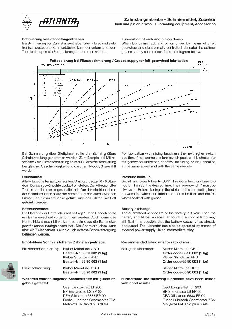
Maße / Dimensions in mmZE – 4 2/2012
Schmierung von ZahnstangentriebenBei Schmierung von Zahnstangentrieben über Filzrad und elek-tronisch gesteuerte Schmierbüchse kann der untenstehenden Tabelle die optimale Fettdosierung entnommen werden.
Lubrication of rack and pinion drivesWhen lubricating rack and pinion drives by means of a felt gearwheel and electronically controlled lubricator the optimal grease supply can be seen from the diagram below.
Zahnstangentriebe – Schmiermittel, ZubehörRack and pinion drives – Lubricating equipment, Accessories
Bei Schmierung über Gleitpinsel sollte die nächst größere Schalterstellung genommen werden. Zum Beispiel bei Mikro-schalter 4 für Filzradschmierung sollte für Gleitpinselschmierung bei gleicher Geschwindigkeit und gleichem Modul, 3 gewählt werden.
DruckaufbauAlle Mikroschalter auf „on“ stellen. Druckaufbauzeit 6 - 8 Stun-den . Danach gewünschte Laufzeit einstellen. Der Mikroschalter 7 muss dabei immer eingeschaltet sein. Vor der Inbetriebnahme der Schmierbüchse sollte der Verbindungsschlauch zwischen Filzrad und Schmierbüchse gefüllt- und das Filzrad mit Fett getränkt werden.
BatteriewechselDie Garantie der Batterielaufzeit beträgt 1 Jahr. Danach sollte ein Batteriewechsel vorgenommen werden. Auch wenn das Kontroll-Licht noch blinkt kann es sein dass die Batterieka-pazität schon nachgelassen hat. Die Schmierbüchse kann über ein Zwischenrelais auch durch externe Stromversorgung betrieben werden.
For lubrication with sliding brush use the next higher switch position. If, for example, micro-switch position 4 is chosen for felt-gearwheel lubrication, choose 3 for sliding-brush lubrication at the same speed and with the same module.
Pressure build-upSet all micro-switches to „ON“. Pressure build-up time 6-8 hours. Then set the desired time. The micro-switch 7 must be always on. Before starting up the lubricator the connecting hose between felt wheel and lubricator should be filled and the felt wheel soaked with grease.
Battery exchangeThe guaranteed service life of the battery is 1 year. Then the battery should be replaced. Although the control lamp may still flash it is possible that the battery capacity has already decreased. The lubricator can also be operated by means of external power supply via an intermediate relay.
Empfohlene Schmierstoffe für Zahnstangentriebe:
Filzzahnradschmierung: Klüber Microlube GB 0 Bestell-Nr. 65 90 002 (1 kg) Klüber Structovis AHD Bestell-Nr. 65 90 003 (1 kg)
Pinselschmierung: Klüber Microlube GB 0 Bestell-Nr. 65 90 002 (1 kg)
Weiterhin wurden folgende Schmierstoffe mit gutem Er-gebnis getestet: Oest Langzeitfett LT 200 BP Energrease LS EP 00 DEA Glissando 6833 EP 00 Fuchs Lubritech Gearmaster ZSA Molykote G-Rapid plus 3694
Recommended lubricants for rack drives:
Felt-gear lubrication: Klüber Microlube GB 0 Order code 65 90 002 (1 kg) Klüber Structovis AHD Order code 65 90 003 (1 kg)
Klüber Microlube GB 0 Order code 65 90 002 (1 kg)
Furthermore the following lubricants have been tested with good results. Oest Langzeitfett LT 200 BP Energrease LS EP 00 DEA Glissando 6833 EP 00 Fuchs Lubritech Gearmaster ZSA Molykote G-Rapid plus 3694
Fettdosierung bei Filzradschmierung / Grease supply for felt-gearwheel lubrication
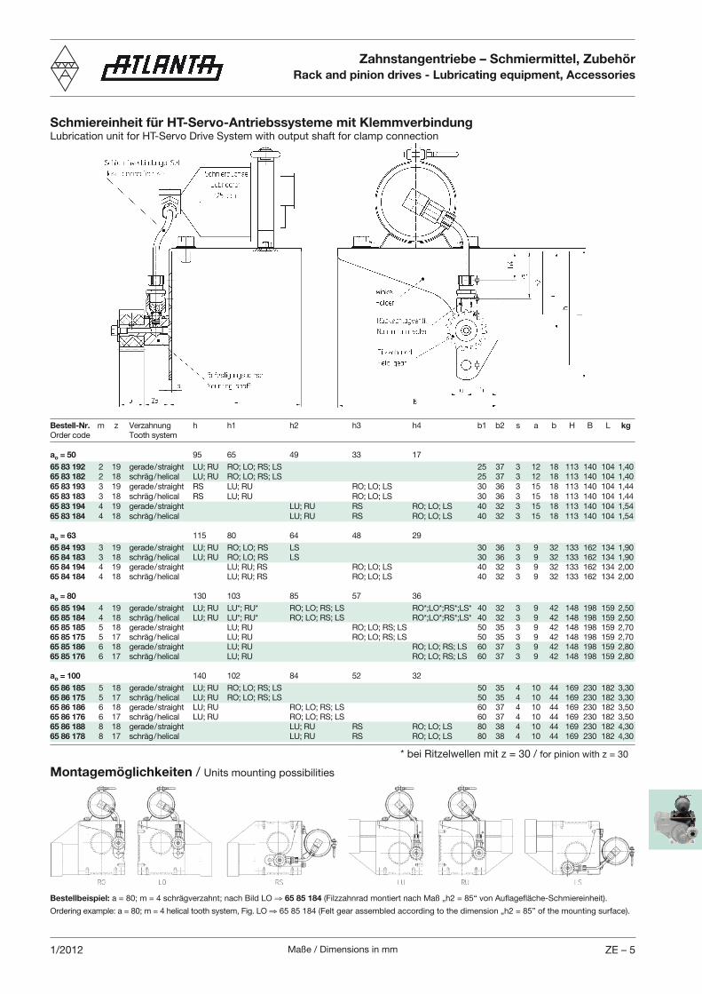
Maße / Dimensions in mm ZE – 51/2012
Zahnstangentriebe – Schmiermittel, ZubehörRack and pinion drives - Lubricating equipment, Accessories
Schmiereinheit für HT-Servo-Antriebssysteme mit KlemmverbindungLubrication unit for HT-Servo Drive System with output shaft for clamp connection
Bestell-Nr. m z Verzahnung h h1 h2 h3 h4 b1 b2 s a b H B L kgOrder code Tooth system
ao = 50 95 65 49 33 17
65 83 192 2 19 gerade / straight LU; RU RO; LO; RS; LS 25 37 3 12 18 113 140 104 1,4065 83 182 2 18 schräg / helical LU; RU RO; LO; RS; LS 25 37 3 12 18 113 140 104 1,4065 83 193 3 19 gerade / straight RS LU; RU RO; LO; LS 30 36 3 15 18 113 140 104 1,4465 83 183 3 18 schräg / helical RS LU; RU RO; LO; LS 30 36 3 15 18 113 140 104 1,4465 83 194 4 19 gerade / straight LU; RU RS RO; LO; LS 40 32 3 15 18 113 140 104 1,5465 83 184 4 18 schräg / helical LU; RU RS RO; LO; LS 40 32 3 15 18 113 140 104 1,54
ao = 63 115 80 64 48 29
65 84 193 3 19 gerade / straight LU; RU RO; LO; RS LS 30 36 3 9 32 133 162 134 1,9065 84 183 3 18 schräg / helical LU; RU RO; LO; RS LS 30 36 3 9 32 133 162 134 1,9065 84 194 4 19 gerade / straight LU; RU; RS RO; LO; LS 40 32 3 9 32 133 162 134 2,0065 84 184 4 18 schräg / helical LU; RU; RS RO; LO; LS 40 32 3 9 32 133 162 134 2,00
ao = 80 130 103 85 57 36
65 85 194 4 19 gerade / straight LU; RU LU*; RU* RO; LO; RS; LS RO*;LO*;RS*;LS* 40 32 3 9 42 148 198 159 2,5065 85 184 4 18 schräg / helical LU; RU LU*; RU* RO; LO; RS; LS RO*;LO*;RS*;LS* 40 32 3 9 42 148 198 159 2,5065 85 185 5 18 gerade / straight LU; RU RO; LO; RS; LS 50 35 3 9 42 148 198 159 2,7065 85 175 5 17 schräg / helical LU; RU RO; LO; RS; LS 50 35 3 9 42 148 198 159 2,7065 85 186 6 18 gerade / straight LU; RU RO; LO; RS; LS 60 37 3 9 42 148 198 159 2,8065 85 176 6 17 schräg / helical LU; RU RO; LO; RS; LS 60 37 3 9 42 148 198 159 2,80 ao = 100 140 102 84 52 32
65 86 185 5 18 gerade / straight LU; RU RO; LO; RS; LS 50 35 4 10 44 169 230 182 3,3065 86 175 5 17 schräg / helical LU; RU RO; LO; RS; LS 50 35 4 10 44 169 230 182 3,3065 86 186 6 18 gerade / straight LU; RU RO; LO; RS; LS 60 37 4 10 44 169 230 182 3,5065 86 176 6 17 schräg / helical LU; RU RO; LO; RS; LS 60 37 4 10 44 169 230 182 3,5065 86 188 8 18 gerade / straight LU; RU RS RO; LO; LS 80 38 4 10 44 169 230 182 4,3065 86 178 8 17 schräg / helical LU; RU RS RO; LO; LS 80 38 4 10 44 169 230 182 4,30
Montagemöglichkeiten / Units mounting possibilities
Bestellbeispiel: a = 80; m = 4 schrägverzahnt; nach Bild LO 65 85 184 (Filzzahnrad montiert nach Maß „h2 = 85“ von Auflagefläche-Schmiereinheit).
Ordering example: a = 80; m = 4 helical tooth system, Fig. LO 65 85 184 (Felt gear assembled according to the dimension „h2 = 85” of the mounting surface).
* bei Ritzelwellen mit z = 30 / for pinion with z = 30
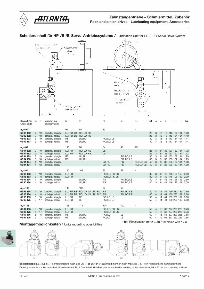
Maße / Dimensions in mmZE – 6 1/2012
Zahnstangentriebe – Schmiermittel, ZubehörRack and pinion drives - Lubricating equipment, Accessories
Schmiereinheit für HP-/E-/B-Servo-Antriebssysteme / Lubrication Unit for HP-/E-/B-Servo Drive System
Bestell-Nr. m z Verzahnung h h1 h2 h3 h4 b1 s a b H B L kgOrder code Tooth system
ao = 50 95 65 33 - -
65 93 192 2 19 gerade / straight LU; RU; LS RO; LO; RS 25 3 15 18 113 134 104 1,4065 93 182 2 18 schräg / helical LU; RU; LS RO; LO; RS 25 3 15 18 113 134 104 1,4065 93 193 3 19 gerade / straight RS LU; RU RO; LO; LS 30 3 15 18 113 134 104 1,4465 93 183 3 18 schräg / helical RS LU; RU RO; LO; LS 30 3 15 18 113 134 104 1,44 ao = 63 115 80 64 48 29
65 94 192 2 19 gerade / straight LU; RU RO; LO; RS LS 25 3 9 32 133 162 134 1,7265 94 182 2 18 schräg / helical LU; RU RO; LO; RS LS 25 3 9 32 133 162 134 1,7265 94 193 3 19 gerade / straight RS LU; RU RO; LO; LS 30 3 9 32 133 162 134 1,7965 94 183 3 18 schräg / helical RS LU; RU RO; LO; LS 30 3 9 32 133 162 134 1,7965 94 194 4 19 gerade / straight LU; RU RS RO; LO; LS 40 3 9 32 133 162 134 1,9065 94 184 4 18 schräg / helical LU; RU RS RO; LO; LS 40 3 9 32 133 162 134 1,90
ao = 80 130 103 85 57 -
65 95 193 3 19 gerade / straight LU; RU RO; LO; RS; LS 30 3 9 42 148 198 159 2,3965 95 183 3 18 schräg / helical LU; RU RO; LO; RS; LS 30 3 9 42 148 198 159 2,3965 95 194 4 19 gerade / straight LU; RU RS RO; LO; LS 40 3 9 42 148 198 159 2,5065 95 184 4 18 schräg / helical LU; RU RS RO; LO; LS 40 3 9 42 148 198 159 2,50 ao = 100 140 102 84 52 -
65 96 194 4 19 gerade / straight LU; RU; RS RO; LO; LS; LU*; RU* RS* RO*;LO*;LS* 40 4 11 44 169 230 182 2,6065 96 184 4 18 schräg / helical LU; RU; RS RO; LO; LS; LU*; RU* RS* RO*;LO*;LS* 40 4 11 44 169 230 182 2,6065 96 185 5 18 gerade / straight LU; RU RS RO; LO; LS 50 4 11 44 169 230 182 3,3065 96 175 5 17 schräg / helical LU; RU RS RO; LO; LS 50 4 11 44 169 230 182 3,30 ao = 125 198 171 128 102 -
65 97 185 5 18 gerade / straight LU; RU RO; LO; RS; LS 50 4 15 63 227 290 225 3,7365 97 175 5 17 schräg / helical LU; RU RO; LO; RS; LS 50 4 15 63 227 290 225 3,7365 97 186 6 18 gerade / straight RS LU; RU RO; LO LS 60 4 15 63 227 290 225 3,8865 97 176 6 17 schräg / helical RS LU; RU RO; LO LS 60 4 15 63 227 290 225 3,88
Montagemöglichkeiten / Units mounting possibilities
Bestellbeispiel: a = 80; m = 4 schrägverzahnt; nach Bild LO 65 95 184 (Filzzahnrad montiert nach Maß „h3 = 57“ von Auflagefläche-Schmiereinheit).
Ordering example: a = 80; m = 4 helical tooth system, Fig. LO 65 95 184 (Felt gear assembled according to the dimension „h3 = 57” of the mounting surface).
* bei Ritzelwellen mit z = 30 / for pinion with z = 30
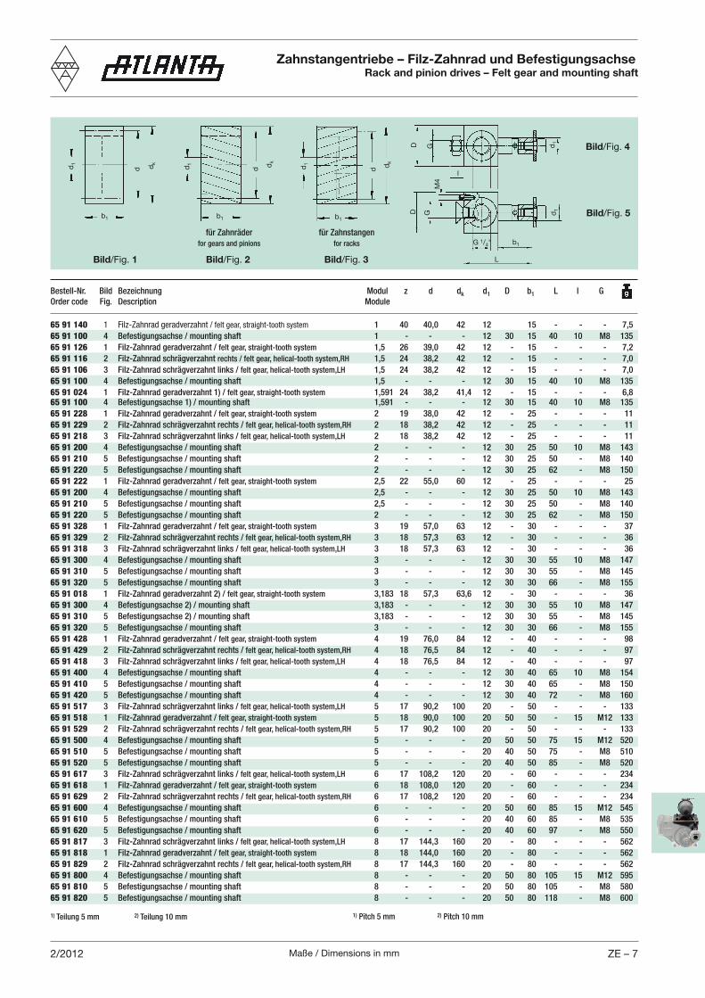
Maße / Dimensions in mm ZE – 72/2012
Zahnstangentriebe – Filz-Zahnrad und BefestigungsachseRack and pinion drives – Felt gear and mounting shaft
b1
d1
dk
d
L
d1
b1G 1/4"
Bild/Fig. 5
Bild/Fig. 1
b1
dk
dd1
Bild/Fig. 2
b1
Bild/Fig. 3
d1 dk
d
GD
l
für Zahnräder
for gears and pinions
für Zahnstangen
for racks
Bild/Fig. 4
D G d1
M4
Bestell-Nr. Bild Bezeichnung Modul z d dk d1 D b1 L l G
Order code Fig. Description Module
1) Teilung 5 mm 2) Teilung 10 mm 1) Pitch 5 mm 2) Pitch 10 mm
65 91 140 1 Filz-Zahnrad geradverzahnt / felt gear, straight-tooth system 1 40 40,0 42 12 15 - - - 7,5
65 91 100 4 Befestigungsachse / mounting shaft 1 - - - 12 30 15 40 10 M8 135
65 91 126 1 Filz-Zahnrad geradverzahnt / felt gear, straight-tooth system 1,5 26 39,0 42 12 - 15 - - - 7,2
65 91 116 2 Filz-Zahnrad schrägverzahnt rechts / felt gear, helical-tooth system,RH 1,5 24 38,2 42 12 - 15 - - - 7,0
65 91 106 3 Filz-Zahnrad schrägverzahnt links / felt gear, helical-tooth system,LH 1,5 24 38,2 42 12 - 15 - - - 7,0
65 91 100 4 Befestigungsachse / mounting shaft 1,5 - - - 12 30 15 40 10 M8 135
65 91 024 1 Filz-Zahnrad geradverzahnt 1) / felt gear, straight-tooth system 1,591 24 38,2 41,4 12 - 15 - - - 6,865 91 100 4 Befestigungsachse 1) / mounting shaft 1,591 - - - 12 30 15 40 10 M8 135
65 91 228 1 Filz-Zahnrad geradverzahnt / felt gear, straight-tooth system 2 19 38,0 42 12 - 25 - - - 11
65 91 229 2 Filz-Zahnrad schrägverzahnt rechts / felt gear, helical-tooth system,RH 2 18 38,2 42 12 - 25 - - - 11
65 91 218 3 Filz-Zahnrad schrägverzahnt links / felt gear, helical-tooth system,LH 2 18 38,2 42 12 - 25 - - - 11
65 91 200 4 Befestigungsachse / mounting shaft 2 - - - 12 30 25 50 10 M8 143
65 91 210 5 Befestigungsachse / mounting shaft 2 - - - 12 30 25 50 - M8 140
65 91 220 5 Befestigungsachse / mounting shaft 2 - - - 12 30 25 62 - M8 150
65 91 222 1 Filz-Zahnrad geradverzahnt / felt gear, straight-tooth system 2,5 22 55,0 60 12 - 25 - - - 25
65 91 200 4 Befestigungsachse / mounting shaft 2,5 - - - 12 30 25 50 10 M8 143
65 91 210 5 Befestigungsachse / mounting shaft 2,5 - - - 12 30 25 50 - M8 140
65 91 220 5 Befestigungsachse / mounting shaft 2 - - - 12 30 25 62 - M8 150
65 91 328 1 Filz-Zahnrad geradverzahnt / felt gear, straight-tooth system 3 19 57,0 63 12 - 30 - - - 37
65 91 329 2 Filz-Zahnrad schrägverzahnt rechts / felt gear, helical-tooth system,RH 3 18 57,3 63 12 - 30 - - - 36
65 91 318 3 Filz-Zahnrad schrägverzahnt links / felt gear, helical-tooth system,LH 3 18 57,3 63 12 - 30 - - - 36
65 91 300 4 Befestigungsachse / mounting shaft 3 - - - 12 30 30 55 10 M8 147
65 91 310 5 Befestigungsachse / mounting shaft 3 - - - 12 30 30 55 - M8 145
65 91 320 5 Befestigungsachse / mounting shaft 3 - - - 12 30 30 66 - M8 155
65 91 018 1 Filz-Zahnrad geradverzahnt 2) / felt gear, straight-tooth system 3,183 18 57,3 63,6 12 - 30 - - - 36
65 91 300 4 Befestigungsachse 2) / mounting shaft 3,183 - - - 12 30 30 55 10 M8 147
65 91 310 5 Befestigungsachse 2) / mounting shaft 3,183 - - - 12 30 30 55 - M8 145
65 91 320 5 Befestigungsachse / mounting shaft 3 - - - 12 30 30 66 - M8 155
65 91 428 1 Filz-Zahnrad geradverzahnt / felt gear, straight-tooth system 4 19 76,0 84 12 - 40 - - - 98
65 91 429 2 Filz-Zahnrad schrägverzahnt rechts / felt gear, helical-tooth system,RH 4 18 76,5 84 12 - 40 - - - 97
65 91 418 3 Filz-Zahnrad schrägverzahnt links / felt gear, helical-tooth system,LH 4 18 76,5 84 12 - 40 - - - 97
65 91 400 4 Befestigungsachse / mounting shaft 4 - - - 12 30 40 65 10 M8 154
65 91 410 5 Befestigungsachse / mounting shaft 4 - - - 12 30 40 65 - M8 150
65 91 420 5 Befestigungsachse / mounting shaft 4 - - - 12 30 40 72 - M8 160
65 91 517 3 Filz-Zahnrad schrägverzahnt links / felt gear, helical-tooth system,LH 5 17 90,2 100 20 - 50 - - - 133
65 91 518 1 Filz-Zahnrad geradverzahnt / felt gear, straight-tooth system 5 18 90,0 100 20 50 50 - 15 M12 133
65 91 529 2 Filz-Zahnrad schrägverzahnt rechts / felt gear, helical-tooth system,RH 5 17 90,2 100 20 - 50 - - - 133
65 91 500 4 Befestigungsachse / mounting shaft 5 - - - 20 50 50 75 15 M12 520
65 91 510 5 Befestigungsachse / mounting shaft 5 - - - 20 40 50 75 - M8 510
65 91 520 5 Befestigungsachse / mounting shaft 5 - - - 20 40 50 85 - M8 520
65 91 617 3 Filz-Zahnrad schrägverzahnt links / felt gear, helical-tooth system,LH 6 17 108,2 120 20 - 60 - - - 234
65 91 618 1 Filz-Zahnrad geradverzahnt / felt gear, straight-tooth system 6 18 108,0 120 20 - 60 - - - 234
65 91 629 2 Filz-Zahnrad schrägverzahnt rechts / felt gear, helical-tooth system,RH 6 17 108,2 120 20 - 60 - - - 234
65 91 600 4 Befestigungsachse / mounting shaft 6 - - - 20 50 60 85 15 M12 545
65 91 610 5 Befestigungsachse / mounting shaft 6 - - - 20 40 60 85 - M8 535
65 91 620 5 Befestigungsachse / mounting shaft 6 - - - 20 40 60 97 - M8 550
65 91 817 3 Filz-Zahnrad schrägverzahnt links / felt gear, helical-tooth system,LH 8 17 144,3 160 20 - 80 - - - 562
65 91 818 1 Filz-Zahnrad geradverzahnt / felt gear, straight-tooth system 8 18 144,0 160 20 - 80 - - - 562
65 91 829 2 Filz-Zahnrad schrägverzahnt rechts / felt gear, helical-tooth system,RH 8 17 144,3 160 20 - 80 - - - 562
65 91 800 4 Befestigungsachse / mounting shaft 8 - - - 20 50 80 105 15 M12 595
65 91 810 5 Befestigungsachse / mounting shaft 8 - - - 20 50 80 105 - M8 580
65 91 820 5 Befestigungsachse / mounting shaft 8 - - - 20 50 80 118 - M8 600
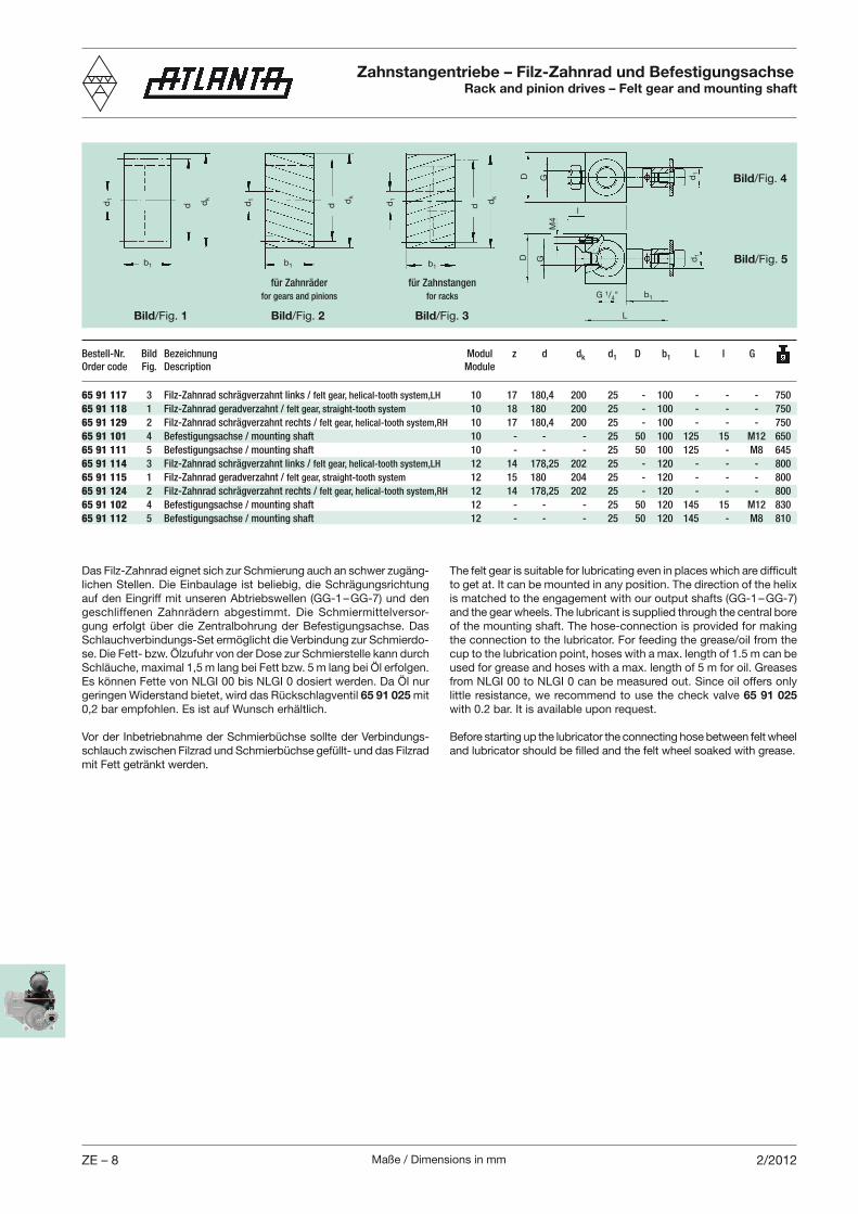
Maße / Dimensions in mmZE – 8 2/2012
Zahnstangentriebe – Filz-Zahnrad und BefestigungsachseRack and pinion drives – Felt gear and mounting shaft
b1
d1
dk
d
L
d1
b1G 1/4"
Bild/Fig. 5
Bild/Fig. 1
b1
dk
dd1
Bild/Fig. 2
b1
Bild/Fig. 3
d1 dk
d
GD
l
für Zahnräder
for gears and pinions
für Zahnstangen
for racks
Bild/Fig. 4
D G d1
M4
65 91 117 3 Filz-Zahnrad schrägverzahnt links / felt gear, helical-tooth system,LH 10 17 180,4 200 25 - 100 - - - 750
65 91 118 1 Filz-Zahnrad geradverzahnt / felt gear, straight-tooth system 10 18 180 200 25 - 100 - - - 750
65 91 129 2 Filz-Zahnrad schrägverzahnt rechts / felt gear, helical-tooth system,RH 10 17 180,4 200 25 - 100 - - - 750
65 91 101 4 Befestigungsachse / mounting shaft 10 - - - 25 50 100 125 15 M12 650
65 91 111 5 Befestigungsachse / mounting shaft 10 - - - 25 50 100 125 - M8 645
65 91 114 3 Filz-Zahnrad schrägverzahnt links / felt gear, helical-tooth system,LH 12 14 178,25 202 25 - 120 - - - 800
65 91 115 1 Filz-Zahnrad geradverzahnt / felt gear, straight-tooth system 12 15 180 204 25 - 120 - - - 800
65 91 124 2 Filz-Zahnrad schrägverzahnt rechts / felt gear, helical-tooth system,RH 12 14 178,25 202 25 - 120 - - - 800
65 91 102 4 Befestigungsachse / mounting shaft 12 - - - 25 50 120 145 15 M12 830
65 91 112 5 Befestigungsachse / mounting shaft 12 - - - 25 50 120 145 - M8 810
Bestell-Nr. Bild Bezeichnung Modul z d dk d1 D b1 L l G
Order code Fig. Description Module
Das Filz-Zahnrad eignet sich zur Schmierung auch an schwer zugäng-lichen Stellen. Die Einbaulage ist beliebig, die Schrägungsrichtung auf den Eingriff mit unseren Abtriebswellen (GG-1 – GG-7) und den geschliffenen Zahnrädern abgestimmt. Die Schmiermittelversor-gung erfolgt über die Zentralbohrung der Befestigungsachse. Das Schlauchverbindungs-Set ermöglicht die Verbindung zur Schmierdo-se. Die Fett- bzw. Ölzufuhr von der Dose zur Schmierstelle kann durch Schläuche, maximal 1,5 m lang bei Fett bzw. 5 m lang bei Öl erfolgen. Es können Fette von NLGI 00 bis NLGI 0 dosiert werden. Da Öl nur geringen Widerstand bietet, wird das Rückschlagventil 65 91 025 mit 0,2 bar empfohlen. Es ist auf Wunsch erhältlich.
Vor der Inbetriebnahme der Schmierbüchse sollte der Verbindungs-schlauch zwischen Filzrad und Schmierbüchse gefüllt- und das Filzrad mit Fett getränkt werden.
The felt gear is suitable for lubricating even in places which are difficult to get at. It can be mounted in any position. The direction of the helix is matched to the engagement with our output shafts (GG-1 – GG-7) and the gear wheels. The lubricant is supplied through the central bore of the mounting shaft. The hose-connection is provided for making the connection to the lubricator. For feeding the grease/oil from the cup to the lubrication point, hoses with a max. length of 1.5 m can be used for grease and hoses with a max. length of 5 m for oil. Greases from NLGI 00 to NLGI 0 can be measured out. Since oil offers only little resistance, we recommend to use the check valve 65 91 025 with 0.2 bar. It is available upon request.
Before starting up the lubricator the connecting hose between felt wheel and lubricator should be filled and the felt wheel soaked with grease.
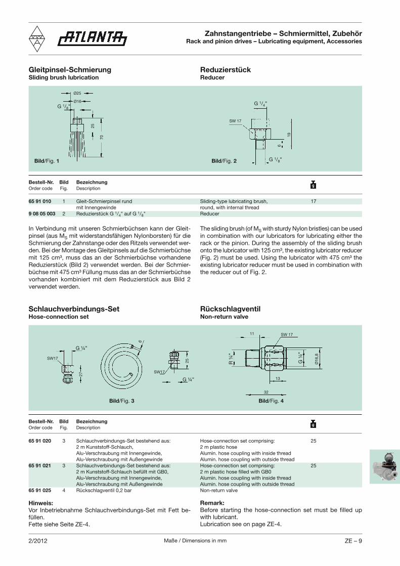
Maße / Dimensions in mm ZE – 92/2012
Zahnstangentriebe – Schmiermittel, ZubehörRack and pinion drives – Lubricating equipment, Accessories
Ø25
G 1/8ӯ16
25
Bild/Fig. 1
70
Bestell-Nr. Bild BezeichnungOrder code Fig. Description
65 91 010 1 Gleit-Schmierpinsel rund Sliding-type lubricating brush, 17 mit Innengewinde round, with internal thread9 08 05 003 2 Reduzierstück G 1/4" auf G 1/8" Reducer
In Verbindung mit unseren Schmierbüchsen kann der Gleit-pinsel (aus MS mit widerstandsfähigen Nylonborsten) für die Schmierung der Zahnstange oder des Ritzels verwendet wer-den. Bei der Montage des Gleitpinsels auf die Schmierbüchse mit 125 cm³, muss das an der Schmierbüchse vorhandene Reduzierstück (Bild 2) verwendet werden. Bei der Schmier-büchse mit 475 cm³ Füllung muss das an der Schmierbüchse vorhanden kombiniert mit dem Reduzierstück aus Bild 2 verwendet werden.
Gleitpinsel-SchmierungSliding brush lubrication
The sliding brush (of MS with sturdy Nylon bristles) can be used in combination with our lubricators for lubricating either the rack or the pinion. During the assembly of the sliding brush onto the lubricator with 125 cm³, the existing lubricator reducer (Fig. 2) must be used. Using the lubricator with 475 cm³ the existing lubricator reducer must be used in combination with the reducer out of Fig. 2.
SW17
G ¼”
27
25
G ¼”
SW17
6
Bild/Fig. 3
Bestell-Nr. Bild BezeichnungOrder code Fig. Description
65 91 020 3 Schlauchverbindungs-Set bestehend aus: Hose-connection set comprising: 25 2 m Kunststoff-Schlauch, 2 m plastic hose Alu-Verschraubung mit Innengewinde, Alumin. hose coupling with inside thread Alu-Verschraubung mit Außengewinde Alumin. hose coupling with outside thread65 91 021 3 Schlauchverbindungs-Set bestehend aus: Hose-connection set comprising: 25 2 m Kunststoff-Schlauch befüllt mit GB0, 2 m plastic hose filled with GB0 Alu-Verschraubung mit Innengewinde, Alumin. hose coupling with inside thread Alu-Verschraubung mit Außengewinde Alumin. hose coupling with outside thread65 91 025 4 Rückschlagventil 0,2 bar Non-return valve
Hinweis:Vor Inbetriebnahme Schlauchverbindungs-Set mit Fett be-füllen.Fette siehe Seite ZE-4.
Schlauchverbindungs-SetHose-connection set
19
G 1/8”
SW 17
G 1/4”
6
Bild/Fig. 2
ReduzierstückReducer
RückschlagventilNon-return valve
Bild/Fig. 4
G ¼
”
Ø1
6,8
R ¼
”
11
13
32
Remark:Before starting the hose-connection set must be filled up with lubricant.Lubrication see on page ZE-4.
SW 17

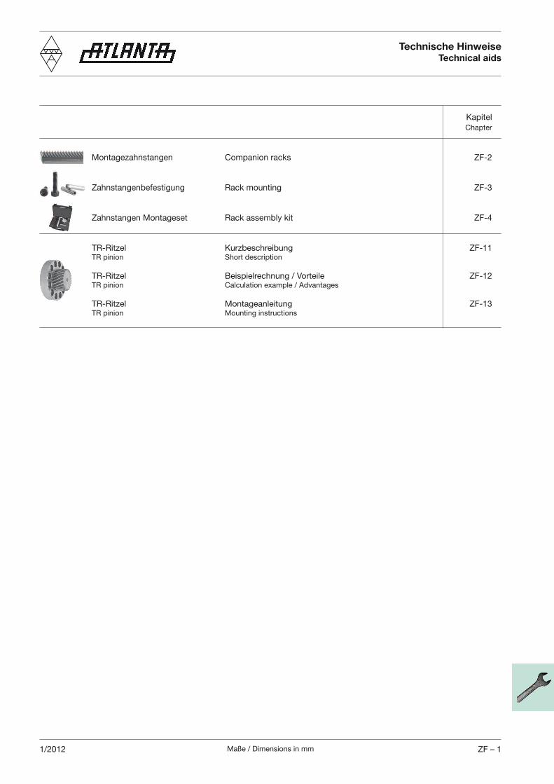
Maße / Dimensions in mm ZF – 11/2012
Kapitel Chapter
Montagezahnstangen Companion racks ZF-2
Zahnstangenbefestigung Rack mounting ZF-3
Zahnstangen Montageset Rack assembly kit ZF-4
TR-Ritzel Kurzbeschreibung ZF-11 TR pinion Short description
TR-Ritzel Beispielrechnung / Vorteile ZF-12 TR pinion Calculation example / Advantages
TR-Ritzel Montageanleitung ZF-13 TR pinion Mounting instructions
Technische HinweiseTechnical aids
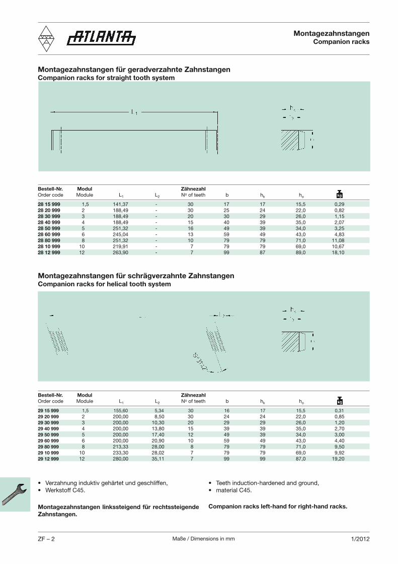
Maße / Dimensions in mmZF – 2 1/2012
MontagezahnstangenCompanion racks
Bestell-Nr. Modul Zähnezahl
Order code Module L1 L2 No of teeth b hk ho
28 15 999 1,5 141,37 - 30 17 17 15,5 0,2928 20 999 2 188,49 - 30 25 24 22,0 0,8228 30 999 3 188,49 - 20 30 29 26,0 1,1528 40 999 4 188,49 - 15 40 39 35,0 2,0728 50 999 5 251,32 - 16 49 39 34,0 3,2528 60 999 6 245,04 - 13 59 49 43,0 4,8328 80 999 8 251,32 - 10 79 79 71,0 11,0828 10 999 10 219,91 - 7 79 79 69,0 10,6728 12 999 12 263,90 - 7 99 87 89,0 18,10
Montagezahnstangen linkssteigend für rechtssteigende
Zahnstangen.
Companion racks left-hand for right-hand racks.
Montagezahnstangen für geradverzahnte ZahnstangenCompanion racks for straight tooth system
Bestell-Nr. Modul Zähnezahl
Order code Module L1 L2 No of teeth b hk ho
29 15 999 1,5 155,60 5,34 30 16 17 15,5 0,3129 20 999 2 200,00 8,50 30 24 24 22,0 0,8529 30 999 3 200,00 10,30 20 29 29 26,0 1,2029 40 999 4 200,00 13,80 15 39 39 35,0 2,7029 50 999 5 200,00 17,40 12 49 39 34,0 3,0029 60 999 6 200,00 20,90 10 59 49 43,0 4,4029 80 999 8 213,33 28,00 8 79 79 71,0 9,5029 10 999 10 233,30 28,02 7 79 79 69,0 9,9229 12 999 12 280,00 35,11 7 99 99 87,0 19,20
Montagezahnstangen für schrägverzahnte ZahnstangenCompanion racks for helical tooth system
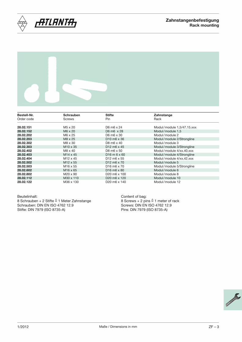
Maße / Dimensions in mm ZF – 31/2012
ZahnstangenbefestigungRack mounting
28.02.151
28.02.152 M6 x 20 D6 m6 x 28 Modul / module 1,528.02.202 M6 x 25 D6 m6 x 30 Modul / module 228.02.203 M8 x 25 D10 m6 x 36 Modul / module 2/Strongline28.02.302 M8 x 30 D8 m6 x 40 Modul / module 328.02.303 M10 x 35 D12 m6 x 45 Modul / module 3/Strongline28.02.402
28.02.403 M14 x 45 D16 m 6 x 60 Modul / module 4/Strongline28.02.404
28.02.502 M12 x 55 D12 m6 x 70 Modul / module 528.02.503 M16 x 55 D16 m6 x 70 Modul / module 5/Strongline28.02.602 M16 x 65 D16 m6 x 80 Modul / module 628.02.802 M20 x 90 D20 m6 x 100 Modul / module 828.02.112 M30 x 110 D20 m6 x 120 Modul / module 1028.02.122 M36 x 130 D20 m6 x 140 Modul / module 12
Bestell-Nr. Schrauben Stifte Zahnstange
Order code Screws Pin Rack
Beutelinhalt:8 Schrauben + 2 Stifte =̂ 1 Meter Zahnstange
Stifte: DIN 7979 (ISO 8735-A)
Content of bag:8 Screws + 2 pins =̂ 1 meter of rack
Pins: DIN 7979 (ISO 8735-A)
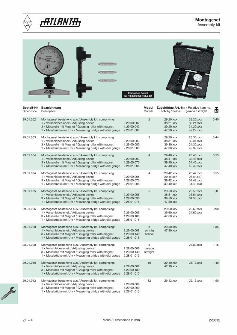
Maße / Dimensions in mmZF – 4 2/2012
MontagesetAssembly kit
Montageset bestehend aus / Assembly kit, comprising:
Montageset bestehend aus / Assembly kit, comprising: 1 x Verschiebeeinheit / Adjusting device 3 x Messrolle mit Magnet / Gauging roller with magnet 1 x Messbrücke mit Uhr / Measuring bridge with dial gauge
Montageset bestehend aus / Assembly kit, comprising: 1 x Verschiebeeinheit / Adjusting device 3 x Messrolle mit Magnet / Gauging roller with magnet 1 x Messbrücke mit Uhr / Measuring bridge with dial gauge
Montageset bestehend aus / Assembly kit, comprising: 1 x Verschiebeeinheit / Adjusting device 3 x Messrolle mit Magnet / Gauging roller with magnet 1 x Messbrücke mit Uhr / Measuring bridge with dial gauge
Montageset bestehend aus / Assembly kit, comprising: 1 x Verschiebeeinheit / Adjusting device 3 x Messrolle mit Magnet / Gauging roller with magnet 1 x Messbrücke mit Uhr / Measuring bridge with dial gauge
Montageset bestehend aus / Assembly kit, comprising: 1 x Verschiebeeinheit / Adjusting device 3 x Messrolle mit Magnet / Gauging roller with magnet 1 x Messbrücke mit Uhr / Measuring bridge with dial gauge
Montageset bestehend aus / Assembly kit, comprising: 1 x Verschiebeeinheit / Adjusting device 3 x Messrolle mit Magnet / Gauging roller with magnet helical 1 x Messbrücke mit Uhr / Measuring bridge with dial gauge
Montageset bestehend aus / Assembly kit, comprising: 1 x Verschiebeeinheit / Adjusting device gerade 3 x Messrolle mit Magnet / Gauging roller with magnet 1 x Messbrücke mit Uhr / Measuring bridge with dial gauge
Montageset bestehend aus / Assembly kit, comprising: 1 x Verschiebeeinheit / Adjusting device 3 x Messrolle mit Magnet / Gauging roller with magnet 1 x Messbrücke mit Uhr / Measuring bridge with dial gauge
Montageset bestehend aus / Assembly kit, comprising: 1 x Verschiebeeinheit / Adjusting device 3 x Messrolle mit Magnet / Gauging roller with magnet 1 x Messbrücke mit Uhr / Measuring bridge with dial gauge
Bestell-Nr. Bezeichnung Modul Zugehörige Art.-Nr. Order code Description Module schräg / helical gerade / straight
Deutsches Patent
Nr. 10 2006 008 461.6-52
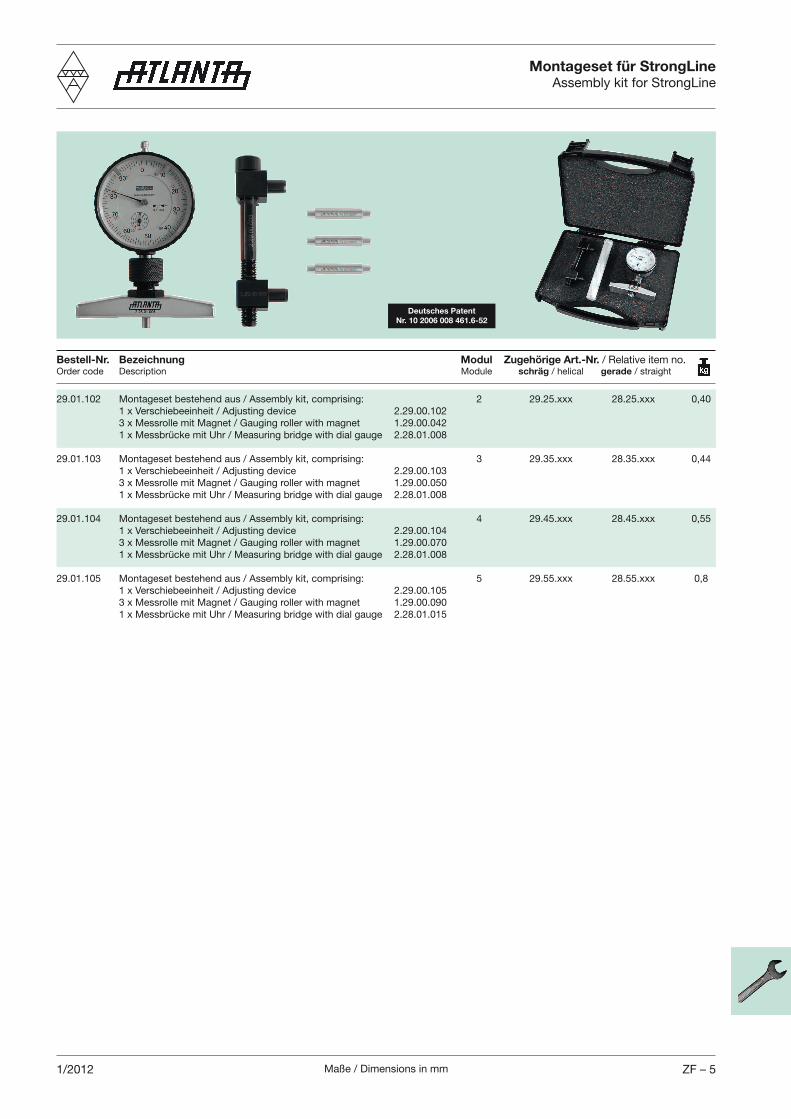
Maße / Dimensions in mm ZF – 51/2012
Montageset für StrongLineAssembly kit for StrongLine
Montageset bestehend aus / Assembly kit, comprising:
Montageset bestehend aus / Assembly kit, comprising: 1 x Verschiebeeinheit / Adjusting device 3 x Messrolle mit Magnet / Gauging roller with magnet 1 x Messbrücke mit Uhr / Measuring bridge with dial gauge
Montageset bestehend aus / Assembly kit, comprising: 1 x Verschiebeeinheit / Adjusting device 3 x Messrolle mit Magnet / Gauging roller with magnet 1 x Messbrücke mit Uhr / Measuring bridge with dial gauge
Montageset bestehend aus / Assembly kit, comprising: 1 x Verschiebeeinheit / Adjusting device 3 x Messrolle mit Magnet / Gauging roller with magnet 1 x Messbrücke mit Uhr / Measuring bridge with dial gauge
Bestell-Nr. Bezeichnung Modul Zugehörige Art.-Nr. Order code Description Module schräg / helical gerade / straight
Deutsches Patent
Nr. 10 2006 008 461.6-52
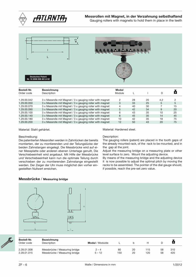
Maße / Dimensions in mmZF – 6 1/2012
gauging roller with magnet 2 28 20 4,2 23 x gauging roller with magnet 3 33 25 5 53 x gauging roller with magnet 4 40 30 7 153 x gauging roller with magnet 5 42 34 9 203 x gauging roller with magnet 6 43 35 10 253 x gauging roller with magnet 8 45 35 14 453 x gauging roller with magnet 10 42 35 18 753 x gauging roller with magnet 12 50 43 20 75
Beschreibung:Die patentierten Messrollen werden in Zahnlücken der bereits montierten, der zu montierenden und der Teilungslücke der
-ner Messplatte oder anderen ebenen Unterlage genullt, Die
und Verschiebeeinheit kann nun die optimale Teilung durch verschieben der zu montierenden Zahnstange eingestellt
-
Messbrücke / Measuring bridge
Measuring bridge 2 – 4 80 20 115 58 310Measuring bridge 5 – 12 150 20 120 58 420
Messrollen mit Magnet, in der Verzahnung selbsthaftendGauging rollers with magnets to hold them in place in the teeth
Bestell-Nr. Bezeichnung Modul
Order code Description Module L l D
Bestell-Nr. Bezeichnung
Order code Description Modul
Description:The gauging rollers (patent) are placed in the tooth gaps of the already mounted rack, of the rack to be mounted, and in
Adjust the measuring bridge on a measuring plate or other
By means of the measuring bridge and the adjusting device it is now possible to adjust the optimal pitch by moving the
Deutsches Patent
Nr. 10 2006 008 461.6-52
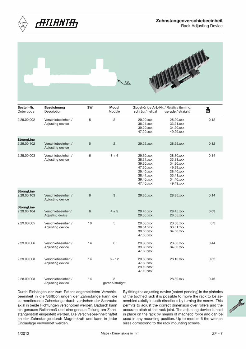
Maße / Dimensions in mm ZF – 71/2012
5 Adjusting device
StrongLine
5 Adjusting device
Adjusting device
StrongLine
6 Adjusting device
StrongLine
Adjusting device
Adjusting device
Adjusting device
0,82 Adjusting device
Adjusting device gerade/straight
-beeinheit in die Stiftbohrungen der Zahnstange kann die zu montierende Zahnstange durch verdrehen der Schraube
ein genaues Rollenmaß und eine genaue Teilung am Zahn-
an der Zahnstange durch Magnetkraft und kann in jeder
ZahnstangenverschiebeeinheitRack Adjusting Device
Bestell-Nr. Bezeichnung SW Modul Zugehörige Art.-Nr.
Order code Description Module schräg / helical gerade / straight
By fitting the adjusting device (patent pending) in the pinholes of the toothed rack it is possible to move the rack to be as-
permits to adjust the correct dimension over rollers and the
in place on the rack by means of magnetic force and can be
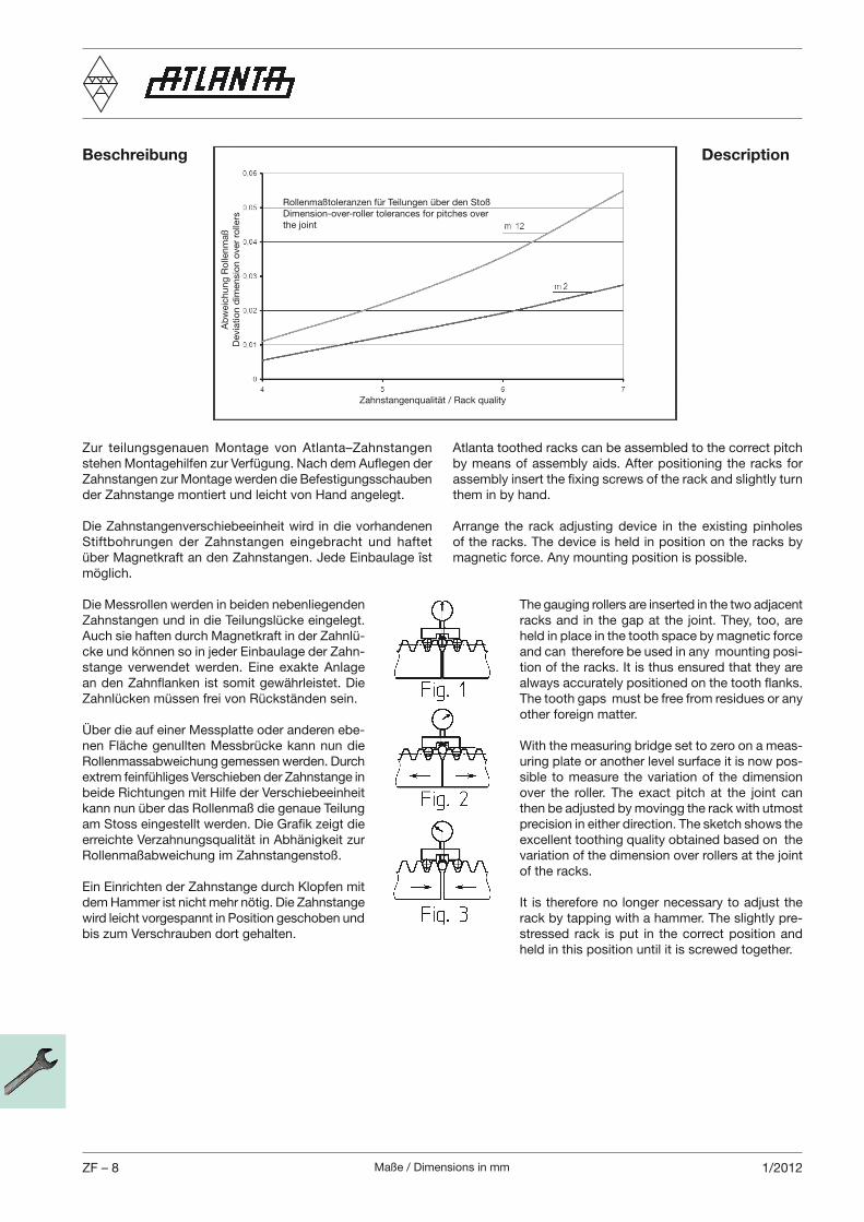
Maße / Dimensions in mmZF – 8 1/2012
Zur teilungsgenauen Montage von Atlanta–Zahnstangen
Zahnstangen zur Montage werden die Befestigungsschauben
Die Zahnstangenverschiebeeinheit wird in die vorhandenen Stiftbohrungen der Zahnstangen eingebracht und haftet
Die Messrollen werden in beiden nebenliegenden
Auch sie haften durch Magnetkraft in der Zahnlü--
Über die auf einer Messplatte oder anderen ebe-
extrem feinfühliges Verschieben der Zahnstange in
kann nun über das Rollenmaß die genaue Teilung
Ein Einrichten der Zahnstange durch Klopfen mit
wird leicht vorgespannt in Position geschoben und
Atlanta toothed racks can be assembled to the correct pitch
assembly insert the fixing screws of the rack and slightly turn
Arrange the rack adjusting device in the existing pinholes
The gauging rollers are inserted in the two adjacent
held in place in the tooth space by magnetic force and can therefore be used in any mounting posi-
The tooth gaps must be free from residues or any
-uring plate or another level surface it is now pos-sible to measure the variation of the dimension
then be adjusted by movingg the rack with utmost
excellent toothing quality obtained based on the variation of the dimension over rollers at the joint
It is therefore no longer necessary to adjust the -
stressed rack is put in the correct position and
Beschreibung Description
Ab
wei
chu
ng
Ro
llen
maß
Dev
iatio
n d
imen
sio
n o
ver
rolle
rs Dimension-over-roller tolerances for pitches over the joint
Rollenmaßtoleranzen für Teilungen über den Stoß
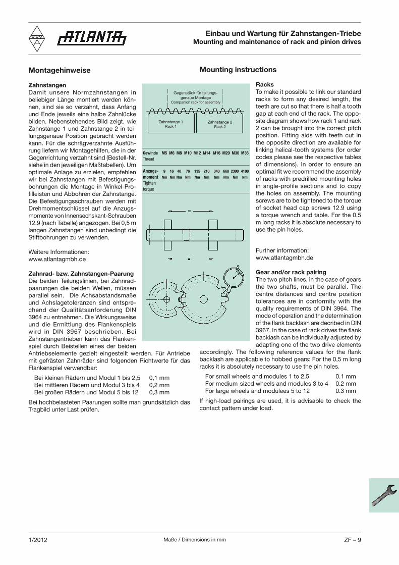
Maße / Dimensions in mm ZF – 91/2012
Montagehinweise
Zahnstangen
Damit unsere Normzahnstangen in -
nen, sind sie so ver zahnt, dass Anfang und Ende jeweils eine halbe Zahnlücke
Zahnstange 1 und Zahnstange 2 in tei-lungsgenaue Position gebracht werden
-rung liefern wir Montagehilfen, die in der
optimale Anlage zu erzielen, empfehlen wir bei Zahnstangen mit Befestigungs-
-
Die Befestigungsschrauben werden mit Drehmomentschlüssel auf die Anzugs-momente von Innensechskant-Schrauben
langen Zahnstangen sind unbedingt die
Zahnrad- bzw. Zahnstangen-Paarung
Die beiden Teilungslinien, bei Zahnrad-
und Achslagetoleranzen sind entspre-
und die Ermittlung des Flankenspiels
Zahn stangentrieben kann das Flanken-spiel durch Beistellen eines der beiden
Flankenspiel verwendbar:
Einbau und Wartung für Zahnstangen-TriebeMounting and maintenance of rack and pinion drives
Mounting instructions
Racks
To make it possible to link our standard racks to form any desired length, the teeth are cut so that there is half a tooth
-site diagram shows how rack 1 and rack 2 can be brought into the correct pitch
the opposite direction are available for linking helical-tooth systems (for order codes please see the respec tive tables
optimal fit we recommend the assembly of racks with predrilled mounting holes in angle-profile sections and to copy
screws are to be tightened to the torque
m long racks it is absolute necessary to
Further information:
Gear and/or rack pairing
The two pitch lines, in the case of gears
centre distances and centre position tolerances are in conformity with the
mode of operation and the determination
backlash can be individually adjusted by adapting one of the two drive elements
backlash are appli cable to hobbed gears: For the 0,5 m long
If high-load pairings are used, it is advisable to check the
Gegenstück für teilungs-genaue Montage
Companion rack for assembly
Zahnstange 1Rack 1
Zahnstange 2Rack 2
Gewinde M5 M6 M8 M10 M12 M14 M16 M20 M30 M36
Thread
Anzugs- 9 16 40 76 135 210 340 660 2300 4100
moment Nm Nm Nm Nm Nm Nm Nm Nm Nm Nm
Tighten
torque
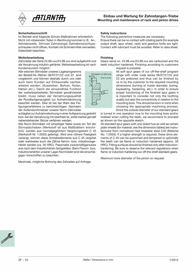
Maße / Dimensions in mmZF – 10 1/2012
Sicherheitsvorschrift
Im Betrieb sind folgende Schutz-Maßnahmen erforderlich:
Abtriebswelle, Stirnrad Zahnstange) Getriebeverschluss-
Weiterbearbeitung
auch beim Kunden auf Ein baumaße nachbe-
die Rundlaufgenauigkeit zur Aufnahmebohrung -
schlagfrei zur Aufnahmebohrung in einer Aufspannung gedreht
-lich), werden aus normalgeglühtem Vergütungsstahl C 45
-
-
Safety instructions
The following preventive measures are necessary:Ensure there can be no contact with rotating parts (for example
Finishing
All soft spur gears of our off-the-shelf program range with order code series 06/07/21/22 and 23 are prebored and thus can be finished by us or by the customer to the required mounting dimensions (turning of inside diameter, boring,
proper functioning of the finished spur gears it is important to consider not only the toothing quality but also the concentricity in relation to the
Since the outside diameter of our standard gears is turned in one operation true to the mounting bore and/or hobbed when cutting the teeth, we recommend to proceed
All standard spur gears with one-sided hub as well as certain plate wheels (for material, see the dimension tables) are manu-factured from norma lized heat treatable steel C45 (Material
-ments of C 45 can be quenched and tempered or optionally
Einbau und Wartung für Zahnstangen-TriebeMounting and maintenance of rack and pinion drives
True to bore
Schlagfrei zur Bohrung
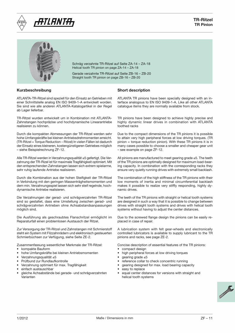
Maße / Dimensions in mm ZF – 111/2012
TR-RitzelTR Pinion
Kurzbeschreibung
ATLANTA-TR-Ritzel sind speziell für den Einsatz an Getrieben mit
Sie sind wie alle anderen ATLANTA-Katalogartikel in der Regel
TR-Ritzel wurden entwickelt um in Kombination mit ATLANTA-
Durch die kompakten Abmessungen der TR-Ritzel werden sehr
-
den entsprechenden Zahnstangen lassen sich extrem spielarme,
Durch die Kombination aus der hohen Steifigkeit der TR-Ritzel
-
sind so gestaltet, dass eine Umstellung zwischen gerad- und
Zur Versorgung der TR-Ritzel und Zahnstangen mit Schmierstoff
Zusammenfassung wesentlicher Merkmale der TR-Ritzel:
5
Varianten
Short description
ATLANTA TR pinions have been specially designed with an in-
TR pinions have been designed to achieve highly precise and highly dynamic linear drives in combination with ATLANTA toothed racks
Due to the compact dimensions of the TR pinions it is possible
many cases possible to choose a smaller and cheaper gear unit
All pinions are manufactured to meet gearing grade of the TR pinions are optimally designed for maximum load-bear-
The combination of the high stiffness of the TR pinions with their low moments of inertia and minimal circumferential backlash
-
The teeth of the TR pinions with straight or helical tooth systems are designed in such a way that it is possible to change between drives with straight tooth systems and drives with helical tooth
-
A lubrication system with felt gear-wheels and electronically controlled lubricators is available to supply lubricant to the TR
Concise description of essential features of the TR pinions:
5
helical tooth systems
Gerade verzahnte TR-Ritzel auf Seite ZB-16 – ZB-20Straight tooth TR pinion on page ZB-16 – ZB-20
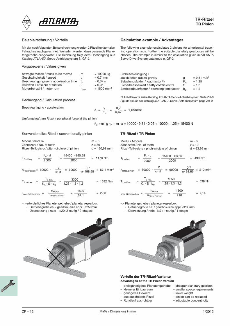
Maße / Dimensions in mmZF – 12 1/2012
Beispielrechnung / Vorteile
Mit der nachfolgenden Beispielrechnung werden 2 Ritzel horizontalen -
Vorgabewerte / Values given
bewegte Masse / mass to be moved m = 10000 kgGeschwindigkeit / speed v = 0,7 m/sBeschleunigungszeit / acceleration time tb = 0,67 sReibwert / efficient of friction µ = 0,05Motordrehzahl / motor rpm nMot = 1500 min-1
Rechengang / Calculation process
Beschleunigung / acceleration
Umfangskraft am Ritzel / peripheral force at the pinion
Konventionelles Ritzel / conventionally pinion
Modul / module m = 5
Ritzel-Teilkreis-ø / pitch-circle-ø of pinion d = 190,98 mm
Calculation example / Advantages
The following example recalculates 2 pinions for a horizontal travel-
Erdbeschleunigung / acceleration due to gravity g = 9,81 m/s2
Belastungsfaktor / load factor (1) KA = 1,25Sicherheitsbeiwert / safty coefficient (1) S = 1,3Betriebsdauerfaktor / operating time factor bB = 1,2
(1)
TR-Ritzel / TR Pinion
Modul / Module m = 5
Ritzel-Teilkreis-ø / pitch-circle ø of pinion d = 63,66 mm
=> Planetengetriebe / planetary-gearbox
- Übersetzung / ratio i=7 (1-stufig / 1-stage)
=> erforderliches Planetengetriebe / planetary-gearbox
- Übersetzung / ratio i=20 (2-stufig / 2-stages)
Vorteile der TR-Ritzel-Variante
Advantages of the TR Pinion version
– preisgünstigeres Planetengetriebe – cheaper planetary gearbox– kleinerer Einbauraum – smaller space requirements– geringeres Gewicht – lower weight– austauschbares Ritzel – pinion can be replaced– Rundlauf ausrichtbar – adjustable concentricity
TR-RitzelTR Pinion
a = = = 1,05m/s²vtb
0,70,67
Fu = m · g · µ + m · a = 10000 · 9,81 · 0,05 + 10000 · 1,05 = 15400 N
T2 erf/req = = = 1470 Nm
nRitzel/pinion = 60000 · = 60000 = 67,1 min-1
T2 zul/per = = = 1692 Nm
imax-Getr/gearbox = = = 22,3
Fu · d
2000
15400 · 190,98
2000
v · d
0,7 · 198,98
T
KA · S · bB
3300 1,25 · 1,3 · 1,2
nMotor nRitzel / pinion
1500
67,1
T2 erf/req = = = 490 Nm
nRitzel/pinion = 60000 · = 60000 · = 210 min-1
T2 zul/per = = = 538 Nm
imax-Getr/gearbox = = = 7,14
Fu · d
2000
15400 · 63,66
2000
v · d
0,7 · 63,66
T
KA · S · bB
1050
1,25 · 1,3 · 1,2
nMotor nRitzel / pinion
1500
210
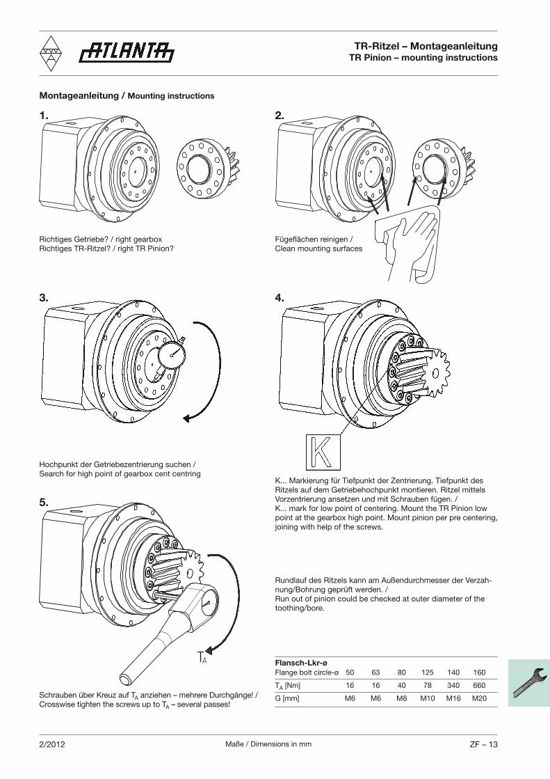
Maße / Dimensions in mm ZF – 132/2012
Montageanleitung / Mounting instructions
TR-Ritzel – MontageanleitungTR Pinion – mounting instructions
Richtiges Getriebe? / right gearboxRichtiges TR-Ritzel? / right TR Pinion?
Search for high point of gearbox cent centring
Schrauben über Kreuz auf TACrosswise tighten the screws up to TA
Clean mounting surfaces
Flansch-Lkr-ø
Flange bolt circle-ø 50 63 80 125 140 160
TA [Nm] 16 16 40 78 340 660
G [mm] M6 M6 M8 M10 M16 M20
1. 2.
3. 4.
5.
Rundlauf des Ritzels kann am Außendurchmesser der Verzah-
Run out of pinion could be checked at outer diameter of the