From
AND
Assembly manual
Welcome to the latest in 3D Turbine flying!
Building on our experience with the Intrepid Turbine and Wren 54 Turbine engine, we have brought you a smaller, lighter, more
aerobatic capable helicopter in the 44 Magnum.
Wren has developed an absolute beauty of a New Turbine, the Wren
44 Heli. The engine is completely assembled by Wren, and any warranty or concerns with it should be directed to them at Wren
Turbines USA.

WARNING!
The radio controlled model helicopter built from this kit is not a toy and is not meant for children. It is a flying machine capable of causing property damage and serious bodily
harm to both the operator/assembler and/or spectator if not built and operated correctly and responsibly. Rotating components, especially the main rotor blades, are an ever-
present danger. Model helicopters operate differently than model cars and airplanes. Helicopters by their nature are not positively stable, meaning that even if properly assembled and adjusted, helicopters will not recover from an unwanted flight attitude, nor will they hold any particular orientation without constant control inputs from the pilot.
IT IS YOUR EXCLUSIVE RESPONSIBILITY TO PROPERLY BUILD, MAINTAIN
AND OPERATE THIS HELICOPTER. Bergen R/C Helicopters has spent considerable time making this product reliable and easy to build, but only the
operator can insure that it is safe. Because the safe operation of this
helicopter is beyond the control of the Manufacturer and distributor, the
owner/operator assumes all risk of use.

Construction Manual
Acknowledgments
Bergen R/C Helicopters wishes to thank our friends and customers for their
continuing support during the development of the Intrepid Helicopter.
The Instruction Manual and illustrations were completed with the input of
numerous customers and staff. We wish to recognize Gary Wright, who had
been the test pilot and helicopter guru in its early years. We would also like
to recognize Mike DeMetz for his continuous support and knowledge in electronics and maintenance.
Staff
Chris Bergen; Chief Executive Officer Larry Bergen; Retired, Consulting
Maryann Pratt; Office Management
Mike Bergen; Programmer, Engineer
Todd Gillespie; Machinist
Alex Anglemeyer; Machinist Kyle Bergen; Machinist
Bergen R/C Helicopters LLC
1101 Follett Drive
Cassopolis, MI 49031
Voice: (269) 445-2060
Fax: (269) 445-2250 Web: www.bergenrc.com
Email: [email protected]

Introduction
The first of its kind, interchangeable modular engineered helicopter to accommodate the
beginner to a FAI expert…
An idea in 1994 to manufacture an interchangeable, modular type helicopter, led to
research and development in 1995. Focusing on quality, engineering details, and price,
a prototype was produced. After extensive test flights and fine-tuning, the INTREPID
HELICOPTER is now what you see today. The first of its kind, strength combined with simplicity for easy maintenance and flying. We have continued to test and improve upon
the original design, adding different powerplants, strengthening components as it
became necessary.
Although beginners can successfully build and fly their INTREPID 44 Magnum, the process can be made significantly easier with the help of an experienced modeler and
instructor pilot. We recommend that all beginners join the Academy of Model
Aeronautics (AMA). The AMA is a non-profit organization that provides services for
modelers. The AMA can help you locate a model aircraft club in your area with an
instructor pilot (you can also check with your local hobby shop). Membership benefits include a monthly magazine and liability insurance. Many flying clubs require an AMA
modeler’s license to operate a model on their flying field. A Turbine waiver is also
required to fly a Turbine at an AMA sanctioned field or event. For more information on
the AMA contact:
Academy of Model Aeronautics 5151 East Memorial Drive
Muncie, IN 47302 Phone: (317) 287-1256

Consumer Warranty
IMPORTANT! Before building the Intrepid 44 Magnum Helicopter kit, read and fully understand the following warranty, and review the entire Construction Manual. By building and/or flying this helicopter you indicate your acceptance of the following warranty terms and conditions, and further agree to build and operate this helicopter in safe and responsible manner.
If you find any term or condition unacceptable, or if you feel that this helicopter is just not suited to you, you may return it to your place of purchase in NEW and UNUSED condition within thirty (30) days of the date of purchase for a refund of the purchase price less shipping and handling. Partially assembled kits, and kits with opened parts packs or missing parts cannot be returned for a refund.
Warranty: 1. Bergen warrants to the first consumer Purchaser that the INTREPID 44 Magnum helicopter substantially conforms to its published description when used as intended as a hobby product, and will be free from defects in materials and workmanship for a period of 90 days after the date of purchase. Bergen R/C will repair or replace (at his option) any defective part, and supply any missing part at no charge to the Purchaser within this period. We make no warranty, express or implied. This warranty does not apply to parts damaged by improper assembly, modification, abnormal service or handling, or crashes.
2. To take advantage of this warranty, the Purchaser must provide proof of purchase, and ship any defective part (at Purchaser’s cost) to Bergen R/C for repair or replacement.
3. It is the responsibility of the Purchaser to properly assemble, maintain and operate this helicopter in accordance with manufacture’s instructions, AMA safety codes, local laws and ordinances, and COMMON SENSE. It is also the responsibility of the Purchaser, when operating this helicopter, never to operate it in any way, which might endanger persons or property including the Purchaser. Purchaser is advised to carry appropriate liability insurance such as that commonly provided to modelers by the AMA.
4. THIS WARRANTY SPECIFICALLY EXCLUDES THE IMPLIED WARRANTIES OF MERCHANTABILITY AND FITNESS FOR A PARTICULAR PURPOSE. The selection of this helicopter for a particular application or use (beyond hobby/entertainment) is the sole responsibility of the Purchaser. Any advice supplied by any representative of Bergen R/C pertaining to any particular application is given freely as an opinion and is not meant to bind Bergen R/C or in any other way modify this warranty.
1. Not withstanding the paragraph above, this warranty is in addition to whatever implied warranties may be granted to the Purchaser by law. To the extent permitted by law, all implied warranties, including the warranties of merchantability and fitness for a particular purpose are limited to a period of (1) year from the date of purchase. Some states do not allow limitations on how long an implied warranty last, so the above limitation may not apply.
2. This warranty shall be the sole and exclusive remedy available to the Purchaser. Correction of defects, in the manner and for the period of time specified above, shall

constitute complete fulfillment of all liabilities and responsibilities of Bergen R/C to the Purchaser, and shall constitute full satisfaction of all claims, whether based on contract, negligence, strict liability or otherwise. Bergen R/C shall not be liable for any cost or expenses incurred in; the replacement of any effective or non-conforming parts, and IN NO EVENT SHALL BERGEN R/C BE LIABLE FOR INCIDENTAL OR CONSEQUENTIAL DAMAGES, OR ANY DAMAGES DUE TO THE USE OR INABILITY TO USE THIS PRODUCT. Bergen R/C shall not be liable, or in any way responsible, for any damages related to modifications, repairs, attempted repairs, or crashes. IN NO EVENT SHALL BERGEN R/C’s OBLIGATIONS TO THE PURCHASER EXCEED THE ORIGINAL PURCHASE PRICE PAID BY THE PURCHASER.
3. Some states do not allow exclusion of incidental or consequential damages, so the above exclusion may not apply. This warranty gives the Purchaser specific legal rights. The Purchaser may also have other rights, which vary, from state to state.
4. No modification or amendment to this warranty will be effective unless reduced to writing and signed by an authorized representative of Bergen R/C Management.
If you do not understand any aspect of this warranty, you may contact Bergen R/C Helicopters for clarification. IF YOU DO NOT AGREE WITH ANY ASPECT OF THIS
WARRANTY, RETURN THE UNASSEMBLED HELICOPTER TO YOUR MANUFACTURER FOR A REFUND.
Bergen R/C Helicopters believes that information contained within its published materials is accurate as of the date of publication, and is not responsible for inadvertent errors or omissions. Bergen R/C reserves the right to make changes and improvements in its products without notice.
If you do not understand any aspect of this warranty, you may contact
Bergen R/C Helicopters for clarification. IF YOU DO NOT AGREE WITH ANY ASPECT OF THIS
WARRANTY, RETURN THE UNASSEMBLED HELICOPTER TO YOUR MANUFACTURER FOR A REFUND.
Bergen R/C Helicopters believes that information contained within its published materials is accurate as of the date of publication, and is not responsible for inadvertent errors or omissions. Bergen reserves the right to
make changes and improvements in its products without notice.
Chris and Larry Bergen
Bergen R/C Helicopters

Inventory
Please do a complete inventory before starting your build of the 44 Magnum. If
any discrepancies are noted, contact us for replacement parts.
BAG 1
1 46-003 LANDING GEAR SET WHITE
4 5141 3 X 18 SHCS *
4 5105 3M LOCK NUTS *
4 5110 3M WASHERS *
Bag 2
MAY BE MOUNTED ON ENGINE
1 1465 MOTOR MOUNT
1 T1350 PLASTIC FAN
2 5065 4X16 SHCS
1 1367 OS/SX COLLETS
4 5060 4X12 SHCS
6 5020 3x12 SHCS
1 1290 DELRIN BUSHING SET
6 231b SPECIAL WASHERS
Bag 3
1 441481b LOWER FRAME (RIGHT)
1 441482b LOWER FRAME (LEFT)
2 1555 SKID BAR
1 1516 BATTERY TRAY modified
4 1525 BATTERY TRAY SPACER
4 5015 3 X 10 SHCS *
2 TURBINE MOUNT STANDOFFS
6 5010 3X8 SHCS *
2 5110 3M WASHER *
2 5105 3M LOCKNUTS *
2 MEDIUM ZIP TIES
1 HEAT DEFLECTOR BLANKET
12 5090 3X8 FHCS *
8 5010 3X8 SHCS *
1 1514 BATTERY TRAY PLATE
2 3x12 SHCS *
2 1934 18M STANDOFF
2 5097 3X12 SS *
BAG 4
1 1250 MAIN SHAFT BEARING BLOCK
ASSEMBLY
3040 1 10X19X7 BEARING
1255 1 BEARING BLOCK ONLY
2 1475 UPPER FRAMES
3 SETS 1665 TAILBOOM CLAMPS

1 1535 RUDDER SERVO MOUNT
2 1450 G-10 SPACERS
4 tur 105 SMALL TANK SADDLES
4 5030 3x16 SHCS *
4 5105 3M LOCK NUT *
1 1525 BATTERY TRAY SPACERS
1 280 ELEVATOR CONTROL YOKE
280A 1 ELEVATOR YOKE
280B 2 ELEVATOR CONTROL YOKE A-ARM
280C 2 ELEVATOR YOKE ARM PIN
1956 2 BALL LINKS
5102 2 3X12 SS
5095 2 3X4 SS
3086 4 3X7X3F BEARING
1 1600 ELEVATOR CONTROL SHAFT LONG
1 1605 ELEVATOR CONTROL SHAFT SHORT
2 1620 COLLECTIVE AXLE
4 3034 6X12X4F BEARING
4 5001 3X4 SHCS *
2 5015 3X10 SHCS *
4 5050 3X35 SHCS *
4 5105 3M LOCK NUT *
2 5110 3M WASHER *
10 5045 3X30 SHCS *
5 5170 26M FRAME SPACER
10 5165 16.5 FRAME SPACER
2 1937 MAL 90 STEPPED STANDOFF
2 5015 3X10 SHCS *
1 1545 GYRO MOUNT
1 1550 BATTERY MONITOR MOUNT
2 1546 GYRO MOUNT BLOCK 3 HOLE
12 5010 3X8 SHCS *
1 5090 3X8 FHSCS *
1 9010 DELRIN COUPLER
1 9005 OUTPUT SHAFT
1 1210 COUPLER PIN
1 5095 3X4 SS *
6 5110 3M LOCKNUTS *
3 5050 3X35 SHCS *
3 5055 3X40 SHCS *
2 FUEL TANK PLATES
1 270 FRONT TRANSMISSION SUPPORT
ASSY
270A 1 BEARING BLOCK ASSY
3040 1 10X19X7 BEARING
270D 1 BEARING BLOCK ONLY
270E 1 BEARING BLOCK SUPPORT CRADLE
270B 1 BEARING BLOCK CRADLE W/O
BEARINGS

5025 1 3X5 PANHEAD
3056 2 5X13X4 FLANGE BEARING
270C 1 PINION SPACER
1 1745 PINION GEAR
BAG 5
1 1240 MAIN SHAFT COLLAR W/4-40X1/2
AMERICAN BOLT
2 1245 SPLIT MAIN SHAFT COLLAR
ASSEMBLY
1246 2 SPLIT MAIN SHAFT COLLAR
127A 2 SPECIAL SHCS
1 TURBINE CLUTCH
1285 1 START SHAFT
CLUTCH SHOE
1 clutchbell only
3045 1 6x19x6 BEARING
1 PINION GEAR
1 CLUTCHBELL ONLY
1 1260 TRIPLE BEARING BLOCK
3045 2 6x19x6 BEARING
3050 1 10x19x5 BEARING
1261 1 TRIPLE BEARING BLOCK W/O
BEARINGS
1 1286 START SHAFT COLLAR
2 5094 3X3 SS *
4 5010 3X8 SHCS *
1 1265 AUTO HUB ASSEMBLY
4 5110 3M WASHERS *
4 5308 3X8 SPECIAL LOW HEAD CAP SCREWS *
1 200 DRIVEN TAIL SYSTEM
BAG 6
1 1185 WASHOUT HUB ASSEMBLY
2 1201 WASHOUT MIXING ARM
4 3086 3X7X3F BEARING
1 1215 SWASH PLATE ASSEMBLY
2 5140 3X16 W/6M SHOULDER *
4 5155 3M BRASS WASHER *
4 5095 3X4 SS *
2 1205 RADIUS LINK
2 1210 RADIUS LINK PIN
6 5190 SHORT BALL *
4 5195 MEDIUM BALL *

BAG 7
2 1616 COLLECTIVE ARM
8 3031 5X8X2.5F BEARING
1 1625 COLLECTIVE BELLCRANK TRIPLE
1 1630 COLLECTIVE BELLCRANK SINGLE
1 1540 AILERON SERVO MOUNT
3 1645 CONTROL ARM JAMNUT
1 1651 ELEVATOR X CONTROL ARM
1 1610 ELEVATOR CONTROL ARM
2 5030 3X16 SHCS *
1 5035 3X20 SHCS *
4 5200 LONG BALLS *
7 5010 3X8 SHCS *
7 5110 3M WASHERS *
2 1641 AILERON BELL CRANK
2 5001 3X4 SHCS *
12 5190 SHORT BALLS *
BAG 8
1 1155 SEESAW TUBE
2 3020 4X10X4 BEARING
2 1160 SEESAW END CAPS
2 1175 FLYBAR CONTROL ARM
2 5205 3X5 PAN HEAD *
2 1151 BELL MIXER ARM
4 3086 3X7X3F BEARING
1 1106 HEAD BLOCK
2 3015 3X10X4 BEARING
1 1131 HEAD AXLE W SNAP RINGS
4 1136H OR S NEW DAMPENING O’RING HARD OR
SOFT
4 5095 3X4 SS *
2 1165 4M SPECIAL WASHER *
2 1183 FLYBAR PADDLE
6 5190 SHORT BALL *
6 5155 3M BRASS WASHER *
2 5136 3X12M W/6M SHOULDER *
2 5115 3M NUT *
2 1111 BLADE GRIP ASSEMBLY W/BEARING
INSTALLED
1116 2 BLADE GRIP W/O BEARING
3005 4 8X16X5 BEARING
2 3006 8X16X5.5 THRUST
2 1126 BLADE GRIP PITCH ARM
2 1140 8MX.015 SHIM DAMPENING WASHER
2 1145 8MX.008 SHIM DAMPENING WASHER
2 1147 8X1M SHIM DAMPENING WASHER
2 5151 4X25 W/18M SHOULDER *
2 5106 4M LOCK NUT *
4 5005 3X6 SHCS *

2 5010 3X8 SHCS *
2 5030 3X16 SHCS *
1 5035 3X20 SHCS *
2 5072 5X16 SHCS *
2 5111 5X10X2 SPACER WASHER *
BAG 9
36 1956 BALL LINKS 2.5
8 1947 PLASTIC SERVO MOUNT TABS
2 1948 WIRE CLIP
2 1985 ELEVATOR LINKAGE 130M
2 1990 ELEVATOR LINKAGE 50M
4 1995 COLLECTIVE LINKAGE 30M
2 2005 AILERON LINKAGE 85M
4 2010 SWASH PLATE LINKAGE 40M
2 2020 PITCH LINKAGE 75M
2 2025 FLYBAR LINKAGE SHORT 14M
7 5137 3/16 BALL W/2M HOLE *
7 5207 2X10 PHSMS *
14 5120 2M NUT *
BAG 10A
ASSEMBLY 1
TAIL ROTOR BLADE GRIPS
1 231 TAIL ROTOR BLADE GRIP KIT
TWIN 1815 1 TAIL ROTOR MAIN HUB 6M
231A 2 BLADE GRIP W/BEARINGS
3054 4 5X10X4 BEARING
3052 2 5X10X4 TRUST BEARING
5110 2 3M WASHER
5015 2 3X6 SHCS
5146 2 3X19 W/11 SHOULDER SHCS
5112 2 10M OD SPACER
231B 4 BLADE GRIP SPACER
5105 2 3M LOCK NUT
5094 1 3X4 SS
ASSEMBLY 2
PITCH BELLCRANK #240
1 240 PITCH BELLCRANK KIT
240B 1 BELLCRANK MODIFIED
240A 1 DELRIN INSERT
240C 1 ALUMINUM SPACER
3086 2 3X7X3 FLANGE BEARING
5140 1 3X16 W/6 SHOULDER SHCS
5155 2 3M BRASS WASHER
5195 1 MEDIUM BALL
5105 1 3M LOCKNUT

ASSEMBLY 3
PITCH SLIDER
1 M1960 PITCH SLIDER ASSY
M1786 1 PITCH SLIDER HUB
3036 2 6X10X3 FLANGE BEARING
1792 1 PITCH SLIDER TUBE (NEW)
1793 1 PITCH SLIDER SPACER (THICK)
1794 1 PITCH SLIDER SPACER (THIN)
1801 1 ALUMINUM PITCH PLATE
5137 2 3/16 BALL W/2M HOLE
5076 2 2X8 SHCS
5120 2 2M NUT
5195 1 MEDIUM BALL
2 1961 TAIL SPECIAL BALL LINKS
2 1806 PIVOT PLATE ARM EYELET
2 1811 PIVOT PLATE SHOULDER BOLT 4x4
ASSEMBLY 4
ALUMINUM TAIL ROTOR GEAR BOX
1 M1000 TAIL ROTOR GEAR BOX
M1000A 1 GEAR BOX ONLY
5094 1 3X3 SS
5095 2 3X4 SS
M1000B 1 PITCH ARM BRACKET
M1000C 1 ALUMINUM SPACER
3071 1 10X15X4 FLANGE BEARING
3055 3 5X13X4 BEARING
1000E 1 10M PIN
1210 1 12M PIN
M1000F 1 OUTPUT SHAFT W/GEAR AND PIN
TWIN 1000I 1 INPUT SHAFT
M1000D 1 OUTPUT SHAFT
M1000J 1 BRASS SPACER TUBE
5025 1 3X5 PAN HEAD SCREW
5001 2 3X4 SHCS
5090 2 3X8 FLAT HEAD CAP SCREWS
ASSEMBLY 5
2 SETS 1665 TAILBOOM CLAMPS
1 1667 HORIZONTAL FIN CLAMP
MISC BAG
2 109D COLLARS FOR TORQUE TUBE DRIVE
1 6015 TAIL ROTOR BLADES
2 109-A BEARING CARRIER
3090 2 .375X.625X1.56 BEARING
109I 4 O’RINGS
109B 2 DELRIN CARRIER
8 5050 3X35 SHCS *
3 5055 3X40 SHCS *
10 5110 3M WASHERS *

13 5105 3M LOCKNUTS *
2 5010 3X8 SHCS *
12 5094 3X3 SS *
4 1945 CANOPY GROMMET
2 5020 3X12 SHCS *
2 5110 3M WASHERS *
1 9015 DOGBONE
1 9020 DOGBONE PIN
1 5095 3X4 SS *
4 1946 THUMB SCREWS
BAG 10B
1 1170 FLYBAR
1 1676 33" TAIL BOOM
1 1682 PUSH ROD CARBON FIBER
1983 2 PUSHROD ENDS
1956 2 BALL LINK 2.5
5035 2 3X20 SHCS
5105 2 3M LOCKNUT
1 2117 ARROW DRIVE SHAFT
1 1709 TAILBOOM SUPPORT SET
1710 2 TAIL BOOM SUPPORT STRUTS
1715 4 TAILBOOM SUPPORT STRUT ENDS
1 M1832 MAGNUM VERTICAL FIN
1 M1835 MAGNUM HORIZONTAL FIN
1 1525 BATTERY TRAY SPACERS
BAG 11
2 TUR 155 TURBINE FUEL TANKS
2 T FITTINGS
2 1860 DOUBLE FITTINGS
2 1850 CLUNKS
2 BRASS FITTINGS
2 1865 FUEL NUT
2 CLAMPS
40" 1915 FUEL LINE
4 1879 TIE WRAPS
1917 MAGNUM FIBERGLASS CANOPY
Items noted with an “*” are found in the hardware bag.
Items in red are included in the assembly of the part above it.
Please complete the inventory FIRST, using the pics from your CD which has the pics of all the parts included by part# and description.

A note about this manual. Considerable time and care has been taken creating this manual, however, improvements can always be made. If you have some
positive suggestions, please let us know.
If you need to see a close up of any particular picture, just double click on it.
That will give you the full size picture. A few things can also be found on the CD. All of the pictures used in this manual, a complete listing of all the parts,
by part number, description, AND picture.
Use these pics to do a complete inventory of your kit to ENSURE that we as
humans did not forget to include something in your kit. When you have
completed the inventory, notify us IMMEDIATELY of any discrepancies, we will
get them out to you ASAP. When the inventory is complete, sign and date the registration sheet and send it back to us in the prepaid envelope. This also lets
us know that you have everything!!
If any part of this manual is unclear to you, assistance is not far away. Call us
at 269-445-2060, post a query on Helifreak.com, or email at
[email protected]. We WANT you to be successful; we WANT you to show
off your new pride and joy, so that your friends will want one also!! ☺
With all of that said, let’s get started. You may notice different colors used
throughout the manual, landing gear, frames, fasteners, etc. All of these
colors are options that we offer to personalize YOUR heli.
Some additional items you will need to operate and fly your 44 Magnum.
Propane, which is actually a propane/butane mix, available from Coleman in
most camping supply stores. This is used as a starting gas for the Turbine.
Turbine oil, usually available at your local FBO that services Full Scale jet
airplanes. Wren also approves using synthetic 2-stroke oil, such as used in gassers, as long as it has a TCW3 rating. I have not tested it’s use, so cannot
comment on how it may affect the longevity of your Turbine or bearings there
in. Mix a 1 quart can with 5 gallons of Kerosene or Jet-A.

Main rotor blades.
We suggest 710/720mm blades with a 14mm root and a 4mm bolt hole.

We like to begin with the landing gear as it provides a solid base with which to
work from. So, from Bag #1, Slide the aluminum tubes through the plastic crossovers, using heat from a hairdryer or monokote gun to loosen up the
plastic. It can take A LOT of heat to get them to slide easily, repeat the heating
process as necessary. Install the end plugs, tapping them into place with a soft
mallet. (Or old Rawhide hammer☺) The crossovers are angled; you have the choice of leaning them forward or aft as shown here.
Using the skid bars from Bag 2, center them on the top of the plastic
crossovers and drill a 1/8th” hole, 2 holes in each crossover. To help prevent the “squats” in the future, you can also drill a hole in the center and put an
additional countersunk bolt in this location.

These next few steps may already be completed for you IF you bought your
engine through Bergen R/C.
From bag #2
Install the aluminum motor mount to the Gearbox, using 4 ea 4X12 SHCS with
loctite. Note the orientation of the holes in the motor mount.
You’ll need an Allen wrench that has been cut down a little to fit behind the exhaust. Ensure the motor mount is completely seated against the gearbox
when all the screws are drawn up tight. Note that the motor mount sits
slightly higher than the gearbox flanges when installed correctly. If not,
remove and turn the motor mount over.

We install a cooling fan onto the gearbox, not necessarily to cool anything,
but we need the drive hub for the clutch system. The fan also does help to move
air around the gearbox area. Remove the nut, but leave the washer in place against the bearing.
Slide the split collar onto the shaft, seating it against the washer. Pull up on the shaft to remove any up and down play, pushing down on the split collar at
the same time. Put a drop of oil on the outer surface of the split collar, this
will help get the fan seated properly in the next steps.
Place the fan onto the split collar and put another drop of oil onto the
tapered nut.

Put loctite on the threads of the tapered nut and thread it onto the shaft. We
offer a spanner wrench to hold the fan while tightening the nut, or you can
make one yourself.
Hold the spanner wrench and tighten the Nut down with a ½” socket wrench.
Tighten this down FULLY, as it is a real pain to get access to later on if it comes
loose…☺ It is not absolutely necessary to dial indicate this hub, but if you feel the need, what we’re looking for is less than .002 of run out.
Install the Delrin Bushings onto the fan hub. Note that one end of the steel
bushing is chamfered; this chamfer goes against the head of the 4X16 SHCS.
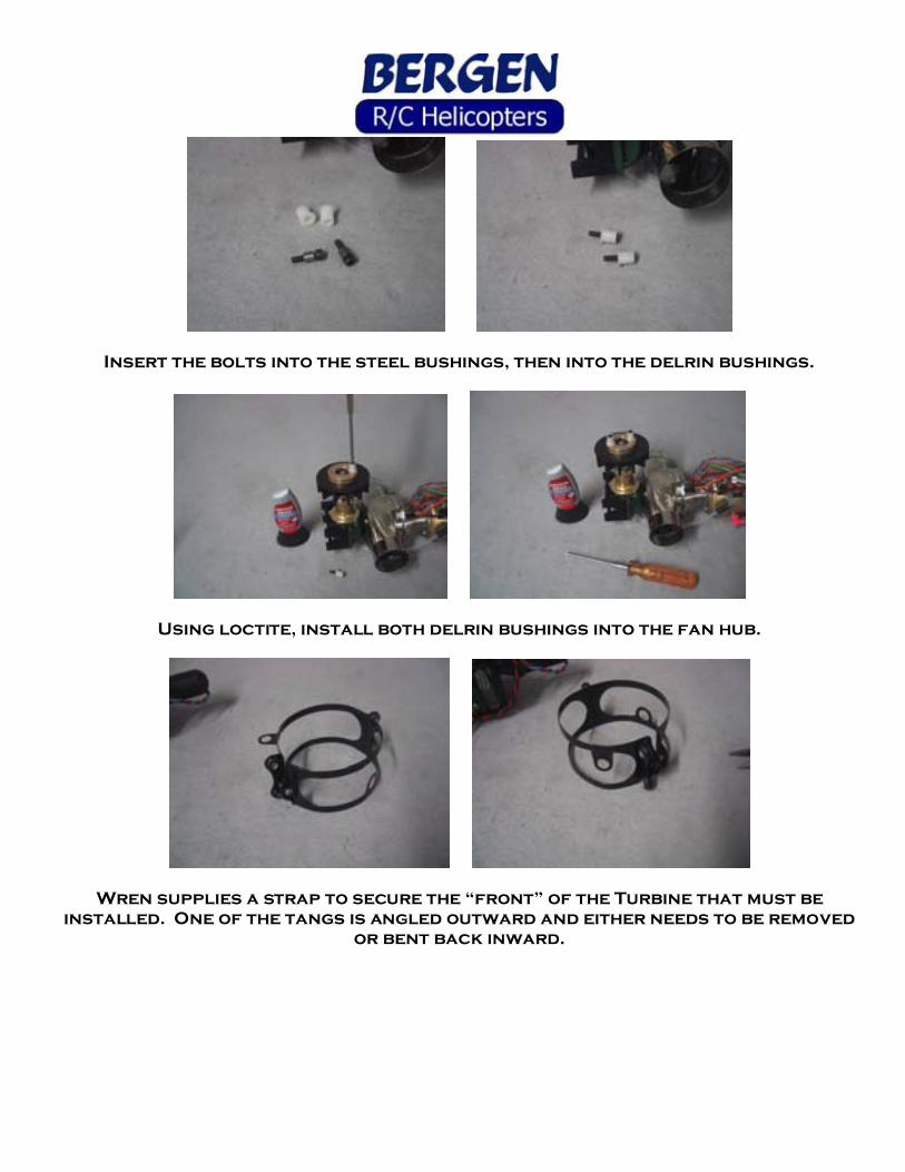
Insert the bolts into the steel bushings, then into the delrin bushings.
Using loctite, install both delrin bushings into the fan hub.
Wren supplies a strap to secure the “front” of the Turbine that must be
installed. One of the tangs is angled outward and either needs to be removed
or bent back inward.

Remove the glow plug and wrap the strap around the turbine so the tang with
the hole lines up with the glow plug hole. You may have to disconnect some of the fuel lines to install the strap, just be sure to reconnect them afterwards.
Secure the strap with the supplied 3mm SHCS. It may be helpful to install the
glow plug and ground wire BEFORE tightening the strap.
What’s needed here is to get the lower set of grommets as close to center as
possible. They will NOT sit exactly on center, that’s OK. The method of
attachment to the frames allows some tolerance off center. Remove the steel
bushings inside the rubber grommets, they’re not needed.

Begin assembling the lower frame set, From Bag #3, noting that the frames are
handed. The countersunk holes at the bottom of the frame go on the outside.
Using 3 ea 3X12 SHCS and 3 ea 1 mm thick washers, bolt the frames to the motor mount. Leave the bolts loose for now, as we will need to adjust the height of
the engine in a later step.
Repeat for the opposite side frame, again using 3 ea 3X12 SHCS and 3 ea 1mm
thick washer. Locate 2 ea skid bars and 4 ea 3X8 FHCS.
Place the skid bars in between the frames, up into the milled slots, and secure
with the countersunk screws, on both sides. It is NOT necessary to loctite these screws. Get all screws started before tightening them down.

Locate 4 ea 3X18 SHCS, 4 ea 3m washers, and 4 each 3m Locknuts, and your
landing gear, previously assembled. Secure the landing gear to the skid bars,
with a washer and nut on the bottom.
The front battery tray and heat deflector plate are assembled with 4 ea
battery tray spacers and 8 ea 3X8 FHCS, with loctite.
Locate the heat deflector blanket, which is silver on one side and white on the
other. Spray 3m adhesive onto the plate and the white side of the blanket.
Allow it to dry for a short period.

Put the 2 glued surfaces together. Locate the 2 ea fwd canopy mounts, 2 ea
3X12 SS, and 4 ea 3X8 SHCS.
Use 2 ea of the 3X8 SHCS with loctite, to secure the rear of the heat deflector
plate inside the lower frames over the exhaust area. Line up the forward holes
with the tray spacers but do NOT install any screws in them.
Install the front battery tray with the other 2 ea 3X8 SHCS in the rear holes,
with loctite.
Install the 2 ea 3X12 SS in the forward hole and into the front battery tray spacer. Leave enough sticking out to then install the front canopy mounts,
using loctite.

Use the crosshole to tighten the canopy mount.
Now is a good time to install the elevator servo while access is easy. Install the grommets per servo instructions but do NOT install any brass eyelets.
Locate 2 ea plastic servo mount tabs in bag 11, and 4 ea servo screws. For
Futaba servos we offer 2.5mm SHCS and washers to be used in place of the smaller Futaba screw.
Install the servo mount tab into the rubber grommets from the bottom of the servo, and then install the servo from INSIDE the frames. The servo output
spline is to the rear of the heli. Secure with the 4 ea servo screws and
washers. Be sure to center the servo in the hole, so that the only contact with
the frame is by the rubber grommets.
You’ll find a short piece of hose connecting the green propane line and the clear fuel line going into the Turbine, remove it and install the supplied tubing
from the engine bags, the clear hose going into the silver fuel filter, the green
hose into the Festo connector.

Route all the wires and hoses forward, over the heat deflector plate, on the
inside of the frames, and secure with zip ties at the locations provided. This will ensure that all of these lines stay clear of the spinning fan.
I like to use self sticking Velcro to secure the radio gear to the battery tray. Use the top as well as the bottom surface to mount all the equipment. I
commonly use the rough part of the Velcro on the heli, and the soft side on the
equipment. These next Photos and text are suggestions, there are many ways to mount radio gear and equipment, use some common sense and make it as neat as
possible.
Add a strip of Velcro in this area to secure the Propane bottle.

Install a piece of 8” long Tygon tubing onto the UAT, available from BVM or Bh
Hanson. Add a small piece of velcro (soft side) onto both sides of the UAT.
Using a piece of ½” Velcro, make a loop going through the slots provided in the
frames then insert the UAT up into the loop of velcro. Draw it tight inside against the frame. The Velcro strips on the inside frame and UAT will help
secure it in place.

Attach the soft Velcro to the bottom of these components, fuel valve, propane
valve, ECU, and Wren Li-po battery (if used).

Locate the fuel pump and bracket, installing the bolts with loctite.
Install the rubber grommets in to the bracket as well. Note the two types of fittings installed on the pump. The festo fitting is the OUTPUT; the barbed
fitting is the INPUT. Do not remove the tubing from the barbed fitting; you will
slide the Tygon tubing OVER the 4mm tubing already installed.
I’ve installed the fuel pump in the unused servo hole, drilling 2 ea 1/8th” holes
and securing with 2 ea 3X10 SHCS, 3m washers, and 3m Locknuts. AS an
alternative method, install just the plate first, making it easier to get the nuts installed, THEN bolt the pump to the plate. (Brian’s suggestion)

Set the 2 valves onto the Velcro in the open area beside the servo and pump. Plug the Green line from the Turbine into the OUTPUT side of the propane valve
and the clear tubing into the output side of the Fuel valve. Use a short piece of
clear tubing from the Fuel pump to the input side of the Fuel valve. Route the
Tygon line from the UAT to the pump, sliding it over the 4mm tube, and secure with a zip tie.
Set the ECU and plug in all the wiring per the Wren Manual, bundling up the wiring to be neat and tidy.
Install an appx 7” long piece of green propane tubing to the Propane canister
fitting, and a short 2-3” piece with the brass quick disconnect to the other side.

Add a stripe of Soft Velcro to the side of the can, matching the rough piece
installed earlier on the frame. Slide 2 zip ties through the slots in the frame.
Velcro the bottle in place, and secure with the Zip ties. The brass fitting can be
tucked behind the zip ties when not being used to fill the propane tank.
Plug the longer green tube into the input side of the propane valve.

Set the Wren Li-po just fwd of the ECU, connecting the wires and bundling them
for neatness.
Put Velcro on your Rx Battery as well.
Mount the Rx pack and regulator if any, under the battery tray. As you can see,
there’s plenty of room for a larger battery or extra weight if needed.

Insert the Turbine mount standoffs through the grommets under the “front” of
the turbine, securing with 4 ea 3X8 SHCS and loctite.
Begin assembling the upper frames from Bag #4, by installing the 6X12X4
flanged bearings in the frames. The flange goes to the inside of the frames.
Remember to make a right hand and a left hand frame. After ensuring the
flanges are completely seated, put a drop of thin CA glue around the perimeter to secure them in the frames.

Locate the main shaft bearing blocks and collective axles. Using 4 ea 3X35
SHCS, locate the bearing blocks on one side frame. Note the orientation of the
bearings, and the lower block. Install the axles into the flanged bearings.
Slide the opposite side frame onto the axles and bolts, thread the 3M locknuts
on loosely at this point.
Gather the gyro mounting plate, 3 hole blocks, and hardware, 6 ea 3X8 SHCS and 1 ea 3X8 FlatHead Cap Screw (FHCS). Install the 3 hole blocks loosely,
noting the orientation of the holes. Install the gyro mounting plate on top of
the 3 hole blocks. Note the FHCS in the front, on top. Go back and tighten the side bolts. These blocks are made of delrin, therefore loctite is not needed.
However, if you feel the need, you can put a drop of CA glue on the bolts when
installing.

Assemble the drive system next, from Bag #5. Slide the clutch w/shaft into the clutch bell, add the triple bearing block, sliding the bottom bearing onto the
pinion. Install the retaining collar, securing with 3X3 setscrews and loctite.
Everything should spin freely.
Install the clutch assembly into the frames using 4 ea 3X8 SHCS and 3M
washers, loosely at this point. Assemble the elevator yoke next back in bag #4, with the 2 elevator yoke shafts. Note that this step MAY already be completed
for you.
Note the two shafts are different lengths; one has flats on only one side. Install the shafts into the elevator yoke using 3X4 SHCS and 3m washer. Draw
the flats on the shafts into the broach with the bolts.

Installing the opposite side may require a ball ended Allen wrench. Use loctite
on these bolts. Slide the elevator yoke in, between the frames from the rear,
angling it in.
You want to have the long shaft sticking out on the right side of the frames.
Using 2 ea 3X8 SHCS and loctite, install the rear canopy mounts in the upper of the 2 holes behind the mainshaft bearing blocks.

The constant driven tail system in bag 5 consists of 2 aluminum hubs, 2 machined
delrin gears, the autorotation hub and main shaft.
Look at the 2 sides of the main gear. One side is chamfered, this is the top, the
other side has a sharp edge, this is the side that the large hub sits inside of.
Install the hub into the gear using 10 ea 2X8 SHCS, installing all of them loosely then tightening each one a little bit at time to prevent warping the
gear. The crown gear and hub are assembled with 6 ea 3X8 FHCS.

Install 2 of the screws opposite each other, loosely for now, then install the
remainder, snugging them down slowly a little at a time to again prevent warping the gear.
Thread the 2 ea 3X10 SHCS into the two sides of the hub, but do not tighten
them.
Install the autohub into the main gear hub using 4 ea lowhead 3X8 SHCS. Notice
one end of the autohub is longer, this is the top, and is inserted into the gear hub from the bottom.

Put a dab of grease in the underside of the crown gear hub, place the 10X16X1
washer in it, then dab a little more grease onto the washer. During an autorotation the crown gear hub is turning while the autohub is not, this
grease is just a little lubrication to help with that interface.
You can install the main gear in one of 2 ways, with the clutch installed, which
we will show now or remove the clutch, shown later.
With the 2 parts of the main gear stacked together, set them in place under the lower mainshaft bearing block.
Note that the mainshaft has a divot or hole about 1 ½” away from one end. This
is the bottom end of the main shaft. Insert the mainshaft into the upper mainshaft bearing. The upper and lower mainshaft bearing blocks should still
be loose at this time to help line up the bearings while installing the mainshaft.

Install one of the split collars on to the mainshaft, with the step on the collar
towards the bearing. Slide the mainshaft farther down, and install the second
split collar, below the elevator yoke, with the step facing down, towards the
bottom mainshaft bearing. Slide the mainshaft down through the lower bearing.
Continue sliding the mainshaft through the crown gear hub, and the autohub, until about 3/8” sticks out the bottom of the autohub. Line up the threaded
hole in the crown gear hub with the divot on the mainshaft, then thread the 4X6
SS into the hole. Do NOT tighten down on this setscrew, ONLY use it to locate the hub on the main shaft.
Install and snug down the 2 ea 3X12 SHCS, then go back and tighten them down
fully. Also go back and apply loctite and fully tighten the SS in the divot on
the main shaft.

Install the bottom mainshaft collar with the 4-40 SHCS, stepped side down.
While pulling UP on the mainshaft to seat the crown gear hub against the
bottom bearing, push DOWN on the lower collar and tighten.
Push the upper split collar up to the top bearing and secure. It is important to
use hardened allen drivers on the screws in these split collars. Do NOT use loctite on these screws, and do not over torque them. It is unnecessary and
will only lead to stripping out the heads.
Now you can tighten the upper and lower mainshaft bearing block bolts as well.
An alternative method, and probably easier, is to remove the clutch assy from
the upper frames.
Install the crown gear hub onto the mainshaft, locating the 4X6 SS into the divot on the mainshaft. Do NOT tighten this setscrew, only use it to locate the
hub onto the shaft

Now tighten the 2 ea 3X12SHCS Pinch bolts, securing the hub to the mainshaft.
Now you can go back, loctite, and tighten the SS in the divot.
Slide the autohub and large gear onto the mainshaft, not forgetting the
10X16X1 washer on top of the autohub. Install the bottom mainshaft collar, with the step down, and secure with the 4-40 SHCS.
Insert the top of the mainshaft through the bottom mainshaft bearing, install
split collars above and below the elevator yoke, with the step towards the
bearings, then up through the upper mainshaft bearing. Pull up on the mainshaft, seating the crown gear hub against the lower bearing, push down
on the lower split collar and tighten the pinch bolt.

Push up on the upper split collar, seating it against the bearing, then tighten
the pinch bolt. These bolts do NOT require loctite, but DO use a hardened allen
driver. Reinstall the clutch assy, leaving the 4 bolts loose for now.
Assemble the front transmission from Bag #4 next. Slide the output shaft into
the delrin coupler until the thru holes line up. One end of the shaft has a
divot; the other has a thru hole. Slide the cross pin thru the coupler and shaft.
Secure the cross pin with a 3X4 setscrew threaded into the rear of the shaft, with loctite. Slide this assembly through the bearing in the rear of the cage
and slide the brass tube over the shaft.

Install the tail drive pinion on the shaft, and push the shaft all the way
forward into the front bearing. Look through the threaded hole in the pinion,
looking for the divot in the shaft. Secure the pinion on the shaft with a 3X4 setscrew into the divot on the shaft,
with loctite. A second setscrew is not necessary, and may cause a clearance
problem with the screws on the main gear. You should not be able to move the shaft in and out after tightening the setscrew, but it should spin freely.
Remove the rear bolt from the lower main shaft bearing block. Install the front transmission into the frames from the rear. Note the “ears” on the front
of the cage match the tongue on the lower main shaft bearing block. Reinstall
the bolt securing the front of the cage, loosely. Also install 2 ea 3X8 SHCS
into the rear of the cage, loosely (one on each side, preferably the bottom hole). You can set the tail pinion mesh now by pushing down on the cage at this
point shown by the Allen driver in the picture. You will want very little or NO
backlash with no tightness while spinning the main gear.
When you’re happy with the mesh tighten the thru bolt securely, and tighten
the 2 ea rear bolts.
Now install the remaining 2 ea 3X8 SHCS, with loctite, securing the rear of the cage to the frames. Remove, loctite, and reinstall the previously tightened 2
ea bolts.

Locate the rudder servo mount, 3 ea tail boom clamps, 3 ea 3X35 SHCS, 3 ea 3X 40 SHCS, and 6 ea 3m locknuts. Using your favorite tail servo, install a pair of
plastic servo mount tabs into the grommets, from the bottom, and place it into
the rudder servo mount.
If using a Futaba servo, then it’s suggested to use 4 ea 2.5mm SHCS and 4 ea 2.5mm washers to secure the servo. The stock JR servo screws are acceptable.
Install the 3 ea Tail boom clamps sets and the rudder servo mount with the 3 ea
3X35 SHCS in the top 3 holes, and the 3X40 SHCS in the bottom 3 holes also holding the servo mount.
Install 6 ea 3mm locknuts onto the 6 SHCS, but do NOT tighten just yet.

Build the swashplate next from bag 6, start with the outer ring, installing short balls into each leg, with loctite.
Install 4 ea medium balls onto the inner ring, again with loctite. While doing
this, ensure that the eyeball bearing in the center remains free to turn and
twist. Slide the completed swashplate onto the mainshaft and snap the
elevator yoke ball links onto two of the outer balls.
The washout unit assembly starts with the washout arms. Install 2 ea 3X7X3
flanged bearings into each arm, then install the radius links with a pin and
secure with a 3X3 setscrew and loctite. Use the radius links marked (L) for left
hand. This gives you ”retarded” swashplate timing for stability in a hover.

Install a short ball on the opposite end, with loctite, noting the orientation.
With a 3X16 w 6mm shoulder, and a brass washer as a spacer install the arm
onto the washout unit, again noting the orientation. Tighten the bolt until the
arm is free of slop, but not so tight that the bearings get “notchy”. It should be able to spin freely. Secure the bolt with a 3X3 setscrew inserted into the hole
on the opposite side, tightening it against the bolt. Check for slop and free
play, readjust the tightness of the bolt if needed and resecure with the setscrew. Repeat for opposite arm.
If necessary to space the arm away from the hub, place 2 brass washers on the bolt between the bearing and the hub. Slide the washout unit on to the
mainshaft and snap the radius links onto 2 of the balls on the inner
swashplate.
Now the explanation of the alternate links.
Line up the balls that you snapped the radius links onto with the outer balls of the swashplate, preferably the ones to the sides. Look at the flybar, noting
the angle, that it is NOT pointing straight out away from the heli. This is the
"retarded" setting, and in general, gives you a more stable hover and less
cyclic action.

If you opt to use the other links, then your assy will look like this. Note the
washout arms are flipped over and the bolt is installed in the other hole. Now
if you line up the swashplate balls and look at the flybar.
The angle is now "advanced". This gives a less stable hover, but more cyclic
action. The porkchops are handed, meaning they only snap onto the ball in one direction, seen in the photo.
All of this is also called swashplate timing, and in the higher end radios can be
adjusted electronically in a specific mode or by mixing in some aileron with elevator, and elevator with aileron.
If you prefer to have your swashplate timing set to 0 and have pure aileron and
elevator movement, then use the first, suggested setup and mix it out in your
radio.

Assemble the control arms, from bag 7, starting with the “Popsicle sticks”, by installing a short ball on each one. For maximum collective, install it in the
innermost hole.
Install short balls, 1 in the triple bellcrank, one in the single bellcrank, and 2 in the elevator arm. Install 2 ea long balls in the triple bellcrank, and in the
elevator “X” arm. Take a close note of the orientation on the “X” arm and where
the balls go!
Install 2 ea short balls in the “X” arm, on the opposite side from the long balls. Install 2 ea short balls in each aileron bellcrank, noting that you are making a
right and a left.

Another view of the aileron bellcranks. Install the 5 X 8 X 2.5 Flanged
bearings, one in each “Popsicle stick” 2 in each aileron bellcrank, and 2 in the
“X” arm.
Insert the jamnuts through the bearings, from the “boss” side, then thread a
SHCS through the jamnuts. The “X” arm gets a 3 X 20; the aileron bellcranks get 3 X16’s.
Using loctite, thread the bolt into the popsicle stick, then tighten the jamnut against the popsicle stick. By loosening the jamnut and tightening or loosening
the bolt, you can adjust the tension on the bearing, giving a free spinning AND
slop free bellcrank. Then again tighten the jamnut. Repeat for other side.

Install the triple bellcrank on the collective axle behind the collective servo
on the left side. Install the single bellcrank on the same axle, but on the right
side.
Secure them with a 3X8 SHCS and 3M washers with loctite. It may be necessary to use the bolts to “draw” the bellcrank onto the axle.
Make sure the short balls on each bellcrank are pointing to the rear.
Install one Popsicle stick on the left side, matching the flats on the upper
collective axle with the broach in the Popsicle stick. Install a 3X8 SHCS and
3M washer with loctite into the axle to secure the Popsicle stick. A 3X4 SHCS and 3M washer threads into the short shaft on the elevator yoke, securing the
rear end. The left side can be identified by the position of the balls on the
aileron bell crank in the SECOND picture (the first one is wrong…☺).

Install the right side Popsicle stick on the collective axle and long shaft in the elevator yoke.
The “X” arm get installed by threading the bolt into the upper collective axle.
Again, set the tension on the bearings by holding the jamnut and tightening the bolt, then tightening both at the same time to secure to the Popsicle stick. The
idea is to get a free spinning bellcrank with no play. Spend a little time here to
get it just right.
The elevator bellcrank is installed on the long shaft of the elevator yoke, the
long arm of the bellcrank points up. Use a 3X4 SHCS and 3M washer, with
loctite. The bellcrank should be perpendicular to the elevator yoke, with the
balls pointed out.

Install the aileron servo into the Aileron servo mount. Install the rubber
grommets and eyelets that come with the servo from the bottom side. This is the
only servo to use these eyelets.
Snap the plastic servo mount tabs into the aileron servo mount, from the bottom. Slide the servo into the mount so that the “ears” fit into the cutout
area of the mount. Also note the servo output shaft is forward, or towards
the curved front of the servo mount.
Secure the servo with the JR self-tapping screws or 2.5X10 mm SHCS and 2.5 washers. Install the aileron servo assy in between the Popsicle sticks and
secure with 4 ea 3X8 SHCS threading into the servo mount. It is only necessary
to put washers under the rear bolts. Instead of loctite, we suggest using CA
(superglue) to secure these bolts.

Build the rotor head next, out of bag 8, starting with the head axle. Note the “heim” ball in the center.
Insert the axle into the head then slide the one piece dampeners onto the axle,
seating them into the head. This may require a little lubrication. The dampeners
will NOT sit flush with the head. Center the assy as best you can, it will make the next steps a little easier.
The shim set includes 2 ea of .008, 2 ea of .015, 2 ea of .040, and 2 ea snap rings. If you want to fly hard 3D, then install one of each size shim on to the head
axle. For softer flying, such as a camera ship, then try just the .040 and the
.008 shim on each side. As a minimum, you MUST use the .040 shim.
Look closely at the snap ring. You will see one side has a sharp edge, the other side is somewhat rounded. This is from the stamping process when it is made.
You want the SHARP edge facing outward when installed on the head axle. This
will aid in keeping the snap rings in the grooves on the head axle. Use a set of snap ring pliers to aid in installation, available at any automotive parts store.

A tool to make getting the snap rings seated easier is a piece of metal tube, say from a piece of broken landing gear, long enough to allow the head axle bolt
to press the snap ring to the groove in the head axle.
You may also be able to press the snap rings into place using the blade grips if only using the “soft” setup.
There are 2 sizes of bearings associated with the seesaw tube. The 4X10X4
bearing (4mm ID) goes into the end of the tube.

Using the 3X10X4 bearings (3mm ID) make 2 assemblies of a 3X8 SHCS and 2 3mm brass washers.
Insert the seesaw into the head with the milled slot facing the direction shown
in the picture.
with a drop of loctite on the bolt, Insert the bearing assy into the head,
threading the bolt into the seesaw and drawing the bearing into the head.
Once seated, tap the assy in below flush to aid in getting the opposite bearing installed.
Install the opposite side bearing assy in the same manner, drawing it in while tightening the bolt. Now tap it in flush, effectively setting both sides flush
with the headblock.

Install 2 ea 3X5 panhead screws, with loctite, just above each bearing as a retainer. When both screws are tight, the seesaw should rotate freely.
The seesaw endcaps are installed flush with the end of the seesaw, and
secured with 3X4 setscrews and loctite in the short leg. The setscrew sits in the milled groove of the seesaw tube to prevent the endcap from rotating.
Install a short ball on the long leg of each endcap, with loctite.

Slide a blade grip with radial bearings installed onto each side of the head axle. Locate the 3 piece thrust bearings and 2 ea 5X16 SHCS and “Special”
washer.
Grease the ballcage of the thrust bearing set, then install the thrust washer with the LARGE ID first, grooved side outward.
Install the ballcage with the open face inwards, then install the thrust washer with the SMALL ID, grooved side inward.

Install both 5X16 SHCS bolts and washer with loctite and tighten, using 2
allen wrenches tightening against each other. Ensure the blade grips spin
freely.
Assemble the Bell/Hiller mixer with 2 ea 3X7X3 bearings, a “special” 3X12mm bolt w 6mm shank, brass washer as a spacer, and the blade grip pitch arm.
Install the assembled bell/hiller mixer by threading the bolt into the middle hole on the pitch arm (recommended). This hole gives a 0 Delta offset, the other
two holes give a positive or negative delta offset for those so inclined to
experiment. Set the tension on the bearings, tightening the bolt to give a free
spinning yet slop free movement, then tighten the nut on the back. Check the movement and readjust as necessary. Repeat for the second pitch arm.

Notice that one side of the bell mixer arm is longer than the other. You also
have 2 holes on either side to attach the short control balls. These
adjustments offer how much effect the flybar has on your rotor system.
These adjustments will be discussed later in the manual. For a standard configuration we suggest the setup as shown. You will want to install the
balls before attaching the pitch arm to the blade grip.
Attach the pitch arm to the blade grip using 2 ea 3X6 SHCS and loctite. Make
sure the pitch arm is square and straight to the blade grip. The milled area of
the pitch arm will help maintain this relationship. Repeat for opposite blade grip.
Your completed head should look like this.

Place the rotorhead onto the mainshaft, locating it with the 3X20 SHCS as a
“jesus” bolt. Do NOT tighten this bolt just yet… tighten the 2 ea 3X16 SHCS pinch bolts, alternating sides, tightening a bit at a time. These bolts are what
actually hold the head to the mainshaft, the “jesus” bolt is strictly for
location. Now go back and tighten the “jesus” bolt.
Insert the flybar from bag 10B through the seesaw bearings, then install a
“special” washer as a spacer before installing the flybar arms, one on each side of course.
Roughly center the flybar in the seesaw and lightly tighten the flybar arms with 3X4 setscrews, while leveling the flybar arms to each other by sighting
across the head.

Measure both sides of the flybar, ensuring they are EXACTLY the same, moving
it in and out as necessary. We do NOT put flats on the fly bar to prevent a
stress riser, meaning this would typically be where the flybar would BREAK in
flight…When you are happy with the measurement AND the flybar arms are level to each other, then go back and loctite the setscrews, one at a time,
holding the flybar arms in place.
Install the flybar paddles, using the front hole, and count 19-21 turns onto
the flybar. This will ensure proper thread length into the paddle.
Measure the distance between the flybar arm and the paddles, making sure
both sides are identical. Also ensure that the paddles are level to the flybar
arms AND to each other by sighting across the head.

Now’s a good time to mount your gyro, we suggest the use of Zeal tape over the
stock double sided tape for enhanced vibration dampening. Zeal tape is available from us at Bergen R/C. Cut a small square just a bit smaller than
the gyro sensor and stick it securely to the gyro.
Mount the gyro onto the shelf provided, fwd of the aileron servo.
Now we’ll join the upper and lower frames. Locate the 5 ea threaded frame
spacers from Bag #4, 10 ea unthreaded frame spacers, and 10 ea 3X30 SHCS.

Line up the holes in the clutch with the delrin bushings on the fan hub and seat
the clutch down onto the hub.
Start at the rear most set of holes, slide a threaded frame spacer in between
the upper frames, an unthreaded spacer between the uppers and lowers, and
install a 3X30 SHCS, threading into the innermost frame spacer. Repeat on the opposite side with another unthreaded frame spacer and a 3X30 SHCS.
Now move to the front of the frames, installing threaded frame spacer in between the upper frames, then securing to the lowers with unthreaded frame
spacers and 3X30 SHCS.

Note the gap between the top of the fan hub and the bottom of the clutch.
Make sure the 6 ea engine mount bolts are still loose, and move the engine and
mount up to decrease the gap.
With the gap set closer, typically only the thickness of the delrin bushing
flange, and tighten the 6 ea motor mount bolts. Remove them one at a time, add loctite, and reinstall.
Move the triple bearing block to set the gear mesh. We want the mesh set so
there is NO or very little backlash between the pinion and the main gear.
Loctite and tighten the 4 ea SHCS, securing the triple bearing block.

Assemble 2 ea tank mounting plates by adding 2 ea tank saddles with 2 ea 3X16
SHCS and 2 ea 3mm locknuts. Be sure to make a right and a left.
Glue one of the round G10 spacers to the backside of each tank mounting plate using CA (superglue). With 2 ea 3X30 SHCS,
and 2 ea unthreaded frame spacers, bolt it to the frames, into the 2 remaining
threaded frame spacers. Also run a 3X10 SHCS in through the tang at the bottom, going into the battery tray spacer bolted onto the heat deflector
plate.

On the opposite side tank mounting plate, bolt a battery tray spacer on the
inside, where the round G10 spacer was glued to it. Use a 3X10 SHCS and
loctite.
Using 2 ea 3X30 SHCS and 2 ea unthreaded frame spacers, install the opposite
side tank mounting plate. Note the battery tray spacer goes between the
clutch bell and autohub.
Install and loctite a 3X10 SHCS in the lower tang of the tank mounting plate, into the battery tray spacer of the heat deflector plate. Install and loctite a
3X10 SHCS in to the battery tray spacer on the other side.

Plug all you servo and power wires into your receiver, not forgetting the
throttle servo wire from the ECU. Bundle up all the wires nice and neat, and
secure the Rx to the battery tray with Velcro.
Attach a fueling hose to the UAT, 4-6” long, and plug the end. Make a “T” hose
with 3 pieces of appx 2.5” long Tygon and a plastic “T” fitting.
Slide the “T” hose onto the last fitting on the UAT, with one leg sticking out
each side of the frames. Tuck it under the hose going to the fuel pump, which
will help keep it out of the cooling fan. Slide 2 ea large tye wraps through the slots of the tank mounting plates.

Assemble the fuel tanks with 2ea brass fittings, double end fittings, nuts,
clunks, and 2 ea 3-4” long pieces of Tygon tubing.
Assemble the clunk lines as shown and secure with small tye wraps.
Mark both bottles at the top of the back end for the vent fittings. Also mark up near the neck, to the side, making a left and a right.

Using a #21 drill bit, drill the 4 holes you marked.
Clean out any filings and deburr the holes on the inside. Install the vent
fittings, sealing them and securing them with JB weld as you thread them into
the holes.
Install the clunk lines using a pair of pliers to insert the double fitting
through the hole from the inside. With the fitting threaded all the way through, verify the clunk sits on the bottom of the tank at about the mid point
of the tank. If needed, rotate the hose on the fitting to get it to sit on the
bottom of the tank.

Install the nuts over the fittings, securing and sealing with JB weld on the threads. Install the caps on the bottles after making sure they are clean on
the inside.
Set the tanks in the saddles, with the vent fitting at the top, and the double fitting in toward the frames. Secure with the large zip tyes, pulling them tight
to the saddles.
Make another “T” hose with 3 ea 7” long pieces of Tygon tubing and a plastic
“T”. Set the “T” in the middle of the frames at the rear, and slide the Tygon
tubing over the vent fittings.

Setting up your helicopter begins in your RADIO. With our Pure Mechanical,
single servo system, we use NO mixes. So to begin, set your radio to an S-1, H-1, or single servo swashplate function. Make sure all subtrims are at 0, all mixes
are turned OFF. ATV’s or travel adjusts should be set as follows;
Pitch 100% Aileron 100%
Elevator 100%
Rudder 80% for now
Throttle 100%
For Futaba servo users, use these servo wheel hole dimensions for the control
balls. Drill holes in the servo wheels using a #50 drill bit. For the collective servo use the triple bellcrank as a template for the holes. JR servos users, the
existing holes in the wheels are close enough for our purposes.
Make sure your pitch curve in the radio is set for a 0,50,100 curve, meaning a
straight line from 0 at the bottom to 100 at the top. With the radio and helicopter on, set your throttle/pitch stick at EXACTLY EXACTLY EXACTLY EXACTLY half. Place a small
servo wheel onto the collective servo, positioning it so that the “6 pack” of
holes is at top and bottom. What we’re looking for is that the holes are
exactly straight up and down. If not, then rotate the wheel 180 degrees, and try again. If it’s still not perfect, try another wheel. JR makes different
numbered wheels (the number is on the back and very faint), 1, 2, 3, 4, and “M”.

Use a Large wheel on the aileron servo, again centering it EXACTLYEXACTLYEXACTLYEXACTLY. The first
pic shows it slightly off, the second pic has the wheel rotated 180 degrees and
perfectly centered.
Here you can see the numbers (Blackened with a sharpie).
The elevator servo wheel is set up slightly different in that you want to center it from the “X” arm using a straight edge. Using a small wheel, see how the
straightedge passes through the center of the “3 pack”, the servo screw hole
AND the center of the “X” arm bolt.

Do the same with the tail servo wheel, rotating it until one set of holes is exactly straight up and down.
We HIGHLY recommend the use of the plastic servo WHEELS vs. metal wheels or
the plastic stars or crosses. The plastic wheels are strong enough with our
push pull system, but will break in the event of a crash, saving the GEARS in
your servo. A metal wheel will cause you to replace gears when you crash…☺
The black tic marks on the servo wheels show which holes we suggest using for
proper setup in a true push pull system. Notice that they are OFFSET slightly
from straight vertical, or in the case of the elevator, the angle from the “X” arm.
On the aileron servo large wheel we ARE going straight across….

From bag 9, make up 7 ea control ball assy’s using a 2X10 PHS, ball with hole,
and 2mm nut. Install these control balls into each servo wheel at the marked holes and secure with another 2mm nut on the opposite side, with loctite.
Next up are all the pushrods for the control system. Yes there are quite a few
of them but with a few simple rules, it’s NOT that complicated. The plastic links are what are normally referred to as “Rocket City” links, considered by many
to be the best in the industry, for their durability and for the fact that you can
do half turn adjustments to fine tune your controls and tracking.
Start off with the collective servo to triple bellcrank using the 30mm rods, making the linkages 51mm from center to center or 58mm from end to end.
These dimensions are appx; you may need one turn either way to get the setup
perfect, with the idea that both links are IDENTICAL in length. Note that the Servo wheel balls AND the balls on the triple bellcrank are both straight up
and down.

The linkage from the triple AND single bellcrank on the opposite side to the
popsicle sticks use the 40mm rod and are 70mm long center to center or 77mm
end to end. Make sure the Popsicle sticks are exactly horizontal with power on
and collective at exactly half. The aileron servo to aileron bellcrank rods uses the 85mm rod and is 101mm
center to center or 108mm end to end.
Make slight adjustments to the length of the rod so that the ball on the
outside of the aileron bellcrank lines up EXACTLY over the bolt going to the
elevator yoke axle. This is done with power ON to ensure the servo is centered…
Then use the 40mm long rod to make the linkage from the aileron bellcrank to
the swashplate 57mm long center to center or 64mm long end to end. The elevator yoke “A” arms also need to be 57mm from the center of the pin to the
center of the hole in the ball link.
Elevator servo to “X” arm linkage is made from the 130mm long rod and is
148mm long center to center or 155mm long end to end. Note the orientation of the “X” arm with the LONG leg straight up. With power on, adjust the rods as
needed to get this leg to point straight up.

From the “X” arm to the elevator arm use rods 50mm long, making them 70mm
center to center or 77mm end to end. This arm should also be exactly straight up and down.
From the washout arms to the Flybar arms, use the rods 30mm long, making
them 47mm center to center or 54mm end to end. The washout arms should exactly horizontal.
From the swashplate to the bell/hiller mixer use 75mm long rods, making them
97mm center to center or 104mm end to end. For the linkages from the seesaw
to the bell mixer, you need to break out your x-acto knife and cut 4 ball links to make them 18mm long.
Thread these links onto 2 ea 3 X12 SS, making them 30mm center to center or
37mm end to end, with a half twist and install them. With both of the rods
attached to the bell/hiller mixer, they should also be exactly level.

For Pitch setup purposes we offer a flybar lock w/flag to lock the flybar
level to the rotor head.
Which is used in conjunction with a pitch gauge, such as this one available from
Miniature Aircraft USA.
With the collective stick at half, verify that the pitch on the blades is at 0
degrees. If not, go back and find which bellcrank is NOT exactly level, horizontal, or vertical. You should also be able to achieve +- 12 degrees of
pitch at top and bottom stick. This may require increasing the pitch ATV or
travel adjust in the radio.

A head button is available and is installed using 2 ea 3X12 SHCS and loctite.
Building the tail system will require a couple of additional tools, a 12” ruler
and a wooden dowel 3/8” dia and 33” long. Windex is needed to install the
Torque Tube bearing carriers. We use as it makes a good lubricant THEN
totally evaporates, locking the bearing carriers into place in the boom. Mark your wooden dowel at 10”, this is for the fwd bearing carrier.
Mark it again 12” farther back or a total of 22”. This is for the rear bearing
carrier. We’re going to install the bearing carriers from the FRONT end of the boom, the end WITHOUT holes. Also install the bearing carriers with the delrin
insert towards the front.

Spray a little bit of Windex onto the o-rings, and press the bearing carrier into
the boom.
Use the dowel to push the bearing carrier all the way into the boom to the rear or 22” mark. Lubricate the fwd bearing carrier with Windex and install it into
the boom as well.
Push this bearing carrier in up to the 10” or front mark. While working on the
next step, the Windex will evaporate, allowing the rubber o-rings to secure the bearing carriers in place in the Boom. If you ever need to remove the bearing
carriers, squirt more Windex into the boom and push them out with the wooden
dowel.

Cut 1” off of one end of the arrow shaft. This is important to get rid of the end of the arrow shaft that is NOT formed to the correct size. Now measure and
cut the arrow shaft at 31”
Assemble the dogbone by inserting the pin, centering it, and securing it with a 3X4 SS and loctite, installed from inside the dogbone.
Insert the dogbone into one end of the arrow shaft, and slide one collar over
both pieces. Install 2 ea 3X3 SS, leaving one hole open.

Using a #46 drill bit, in the hole left open in the collar, drill THROUGH the arrow shaft and INTO the dogbone, leaving a divot. Disassemble the joint and
inspect your divot. You want it deep enough that the setscrew will sit into it
when assembled.
Reassemble and install a 3X3 ss with loctite in the hole with the divot, seating
the setscrew in the divot. Remove the other 2 setscrews, loctite, and reinstall in the collar.
Insert the TT in from the front end of the boom and through the bearing carriers. Push the TT all the way through until the rear off the TT sticks out
the back of the boom.

Slide the remaining Collar over the TT, the insert the input shaft of the tail
gearbox in the TT. Again secure it with 2 ea 3X3 SS.
Again using the open hole in the collar, drill through the TT and into the input
shaft with the #46 drill bit, creating a divot. Disassemble and inspect the divot to ensure it’s deep enough for the setscrew to set into it.
Reassemble the parts, and loctite a 3X3 setscrew into the hole with the divot,
then the remaining 2 setscrews. Remove the 2 ea 3X4 SHCS from the gearbox
then slide it into the tail boom, lining up the holes for the Bolts. If they don’t quite line up, rotate the gearbox 180 degrees and try again.

Loctite and start BOTH 3X4 SHCS into the gearbox, then tighten both of them.
These bolts do NOT require gorilla torque; all that will accomplish is pulling
the threads out. If that happens, we can helicoil the gearbox. Slide the
horizontal fin clamp onto the Tail boom.
Insert the tail boom into the boom clamps at the rear of the heli; pushing it ALL the way in, ensuring the dogbone has engaged the delrin coupler. The end of
the boom should go past the most forward boom clamp. Now pull the boom
BACK out by 1mm. This is important to remove any rearward pressure on the tt drive system.
Level the gearbox by rotating the complete tail boom assy and tighten the 6
nuts and bolts going through the boom clamps. It is NOT necessary to close the gap on the clamps, nor is it necessary to put tape, sandpaper, or screws into the
boom to hold it in place.

Assemble the boom supports, noting that the plastic ends are threaded into the
aluminum supports.
Use JB weld to glue the ends into the boom supports. Ensure that the ends are parallel to each other. Secure one end to the bottom rear of the lower frames
with 2ea 3X12 SHCS, 3m washers, and a battery tray spacer between the
frames, with loctite.
Secure the rear of the boom supports with a 3X35 SHCS, 2 ea 3m washers, and a 3m locknut, but don’t tighten the bolt just yet. Install the horizontal fin onto
the clamp with 2 ea 3X8 SHCS. Use CA (superglue) as a loctite on these 2 bolts.

Level the horizontal fin, then tighten the bolt securing the clamp and boom supports. Gather up the vertical fin, 4 ea 3X35 SHCS, 4 ea 3m locknuts, and 2
sets of boom clamps.
Note the orientation of the fin, place the 4 bolts in the 4 holes and slide 2 of the boom clamps onto the bolts. Place the fin and clamps onto the boom and
slide the remaining 2 clamps onto the bolts.
Make sure the vertical fin is exactly vertical and tighten the 4 ea 3m locknuts onto the bolts. Again, it is NOT necessary to close the gap between the clamps,
only to tighten them.

Assemble the tail pitch bellcrank by installing 2 ea 3X7X3 flanged bearings with a spacer in between the bearings.
The bearings should sit down in the bellcrank with only the flange above the
surface. It may be necessary to sand the spacer down slightly to achieve this. Install the special bolt, a 3X16 w 6mm shoulder then place 2 ea brass washers
on the bolt.
Install a medium ball on to the bellcrank, for most gyro applications; the inner
hole gives the proper travel amount. Install the bellcrank onto the tail
gearbox, threading the bolt into the bellcrank arm.

Set the tension on the bearings by tightening the bolt, then locking it in place
with a 3m locknut. The bellcrank should spin freely with no notchyness and no
slop.
The tail pitch slider is a preassembled unit; slide it onto the output shaft, making sure to insert the ball into the delrin cup. Operate the mechanism by
moving the bellcrank by hand making sure the operation is smooth and free.
The shaft may have a coating on it from the precision grinding process, and can
be cleaned off with formula 409. A drop of oil on the shaft will also help. Check the fit of the ball into the delrin cup and ream as necessary. Proper
operation here will greatly affect how well your tail rotor/gyro/servo
system works.

The tail rotor hub is borrowed from our Industrial birds, capable of swinging 130mm tail blades with NO problem. Note the divot on the tail output shaft.
Install the tail hub onto the tail output shaft with ONE, and only ONE 3X4 setscrew and loctite. The tip of the setscrew MUST sit into the divot on the
output shaft. Only one setscrew IS more secure than 2 setscrews 180 degrees
apart in this application.
The aluminum tail blade grips already have the radial bearings installed, so begin by inserting the 4X4 stainless shoulder bolt in the eyelet. A drop of oil
here is also a good idea.

Place a small drop of loctite on the threads of the shoulder bolt and screw into the horn on the tail blade grip, being VERY careful NOT to get loctite into
the joint. This will make the joint stiff and your tail rotor system will NOT
function properly, causing servos to overheat, tail wags, sticking, etc.
The tail blades grips and associated hardware must be installed in the proper
order for proper operation, note the 10mm spacer installed BEFORE the thrust bearings. Also be sure to grease the ball cage of the thrust bearings.
One of the thrust bearing washers has a larger inner diameter than the other,
you can identify them by placing them onto the tail rotor hub, noting which one has more play.
Slide a tail blade grip onto the tail rotor hub, then install the 10mm spacer, the
larger ID thrust bearing washer, the greased ball cage, then the small inner diameter thrust bearing washer. Secure the assy with a 3X10 SHCS and 3m
washer, with loctite. Do not over torque this bolt, it is not necessary. Repeat
for opposite blade grip.

You will notice about 1mm of in and out play, this is normal and necessary, do
NOT add shims to remove it.
Locate the “special” tail links. These do require a slight modification in
trimming off the ribs off of each side and cutting them down to 17mm long.
Thread the links all the way onto the eyelets, then snap the ends onto the
balls installed on the pitch slider. Note the direction of the blade grips in the
pics.

The tail blades included in your kit are from KB Dream designs and may vary
slightly in design and color from the picture. The tail blades are installed with a 1mm washer on both sides. It maybe a tight fit, that’s OK!
Install the tail blade grip bolt and secure with a 3m locknut. Only tighten enough to barely hold the blades in place. Not the direction of the tail blades
leading edge.
The tail pushrod is made from a carbon fiber rod. Assemble the aluminum ends
with a 3X18 SHCS, 3m locknut and ball links. Install the bolt from INSIDE the
end, securing with a nut.

Tighten the nut sufficiently to prevent the bolt from turning then thread the ball link onto the stud.
Assemble the other end the same way, and then glue ONE end on to the carbon fiber rod.
Snap this end onto the tail servo wheel ball; making sure the ball is pointed
straight down with power on and gyro in rate or non-HH mode. Snap the loose push rod end onto the medium ball on the tail pitch bellcrank. Mark the point
on the carbon fiber rod where it needs cutting so it fits into the push rod end
assy. When measuring for this, make sure the tail pitch bell crank is at 90 degrees and the tail pitch slider is centered on the output shaft. Glue the end
onto the cut carbon fiber rod and let dry overnight.

Adjust the length of the pushrod ONLY to center the pitch slider on the output
shaft, between the gearbox and the tail rotor hub. Adjust the two plastic links so the arm on the tail blade grip is straight out, centered on the ss hole in the
hub.
Use a piece of ½” Velcro, wrap it around the boom, then around the tail
pushrod. Only put a small amount of tension on the pushrod with the velcro.
This velcro support will help to keep the pushrod from vibrating like a banjo string.
Tuck the velcro strap up under the front of the horizontal fin. This will help
keep the pushrod from hitting the boom supports.

Install each main blade with a 4X25 SHCS w/18mm shoulder and 4mm Locknut.
Note the leading edge direction.
We suggest tightening the blades so that they will NOT move if the heli is laid
on it’s side and shaken. If your blades require spacers (12mm root), then install one spacer on top AND one on the bottom of the blade.
The fiberglass canopy is the last thing that needs “building”. We do suggest painting it prior to cutting, as the ears may be too fragile for a lot of sanding
pressure. On the top of the canopy you should be able to find a slightly raised
area showing the area to be cut out.

Also mark around the inside perimeter, leaving only a ¼” or less of a lip. Rough
cut out the area with a dremel tool cut off disk.
Then use a large sanding drum to finish the cutout areas. The “ears” on the top
are required to clear the pushrods going up to the swashplate.
At the 4 dimples, drill an 1/8th” hole, and place the canopy on the helicopter.
Use the canopy thumbscrews to secure the canopy to the helicopter. Make sure
there is clearance all the way around, taking your dremel to any areas that
are too close. Open up the holes to 5/16th” by running the drill BACKWARDS to prevent cracking the paint or canopy. Install the rubber grommets, gluing
them on the inside with a drop of ca (superglue) will help them last longer.

For the following steps you have to know that the throttle is not reversed.
The second screen on the ECU shows the signal pulse from the receiver. Of course the Tx needs to be on. A low signal number is less than 1000. A high
signal number is 1900 or more. If the throttle signal corresponds to your stick
movements, then proceed to the next step. If not then reverse your throttle in the radio.
The Wren manual tells how to teach the ECU your transmitter settings. We use
a slightly modified method.
The HDT says “Full Stick, Full Trim”. Move the throttle stick all the way up,
leaving it there, then move the throttle TRIM all the way up, leaving it there.
Push the + button.
The HDT says “Stick Down, Trim Down”. Move the throttle stick all the way down, leaving it there. Move the throttle trim all the way down, leaving it
there.
Push the + button.
The HDT says stick down, trim up. Leave the throttle stick all the way down, but move the throttle trim to the HALFWAY point.
Push the + button.
If you scroll to the front or “home” page, you should see the HDT says “Ready”.
You should also see a light on the ECU itself. This is your indication that the
start sequence is armed. Lowering the trim turns the light off, and the HDT says “Low Trim”.
The starting procedure will now be to move the throttle trim to the halfway
point, raise and then lower the throttle stick. The turbine will start and come up to an idle. Call this “Ground Idle”.
Move the throttle trim all the way up, which increase the Turbine RPM to what is called “Flight Idle”. At this point the main rotor blades will have started to
spin indicating that the clutch has also engaged.
Start raising the throttle stick, increasing the Turbine RPM and the Rotor
RPM. At this point your 44 Magnum will operate just like a Gasser, raising the
throttle curve at the hover will raise your Rotor RPM.

You will need an optical tachometer, and a friend to help tach the rotorhead.
Adjust the hover point on your throttle curve to give you a minimum of 1650-
1700 headspeed in a hover in NORMAL mode. A typical curve would be something like 0, 25,50,75,100. Adjusting the 75% point (assuming you hover at ¾ stick)
will raise the hover rpm. Adjust the other points to give a nice smooth curve to
the graph.
Idle up 1 should be setup with a “V” curve, with a hovering headspeed of 1750-
1850 RPM. Your “V” curve may look like 100, 79, 65, 79, 100.
Idle up 2 should also be setup with a “V” curve, giving a hovering headspeed of
1850-1950 RPM. This “V” curve may look like 100, 90, 82, 90, 100.
Current AMA Turbine regulations state that a maximum headspeed of 2000 RPM
shall not be exceeded.
Verify the Max Turbine RPM setting using the HDT as explained in the Wren manual, setting it at 175,000 as a start. If you find it difficult to obtain or
maintain the given headspeeds with reasonable throttle curve settings of appx
75% or less in normal mode, up to 80-85% in idle ups, then increase the max RPM setting to 180,000 RPM. Increases of Turbine RPM settings will also raise the
Rotor RPM’s, so a reduction in the throttle curves may also be necessary to
obtain desired headspeeds.
Increases in Max Turbine RPM’s also increase wear and tear on the Turbine and
bearings, so only increase these settings as necessary. You will also find an
increase in fuel consumption with higher max rpm settings.
The Turbine does have a “break in” period of appx 2 hours of run time. After
these 2 hours, you may be able to reduce the max RPM’s while being able to maintain headspeeds through maneuvers.
While setting up initial headspeeds, the ECU also needs to “see” max power for
a few seconds, so that it recognizes where full power is. This can be accomplished by full power climb outs from a hover (do this in idle up only or
the tail may blow out on you…), or during Fast Forward Flight with the throttle
stick all the way at the top.