Assembly Manual
K3NG open source Arduino Rotor Controller PC interface
edition | v. 1.0 August 2012 by OK1HRA | available at www.hamshop.cz
Block diagram
This is an Arduino based rotator interface that emulates the Yaesu
GS-232A or GS-232B interface. It allows the rotator to be interfaced
to Ham Radio Deluxe or other programs that support the Yaesu
rotator command set. With the addition of a proper capacity power
supply and two relays, this unit could also serve as a total
replacement for a rotator control unit. It can also be interfaced with
non-Yaesu rotators, including homebrew units.
Firmware is Open Source by K3NG.
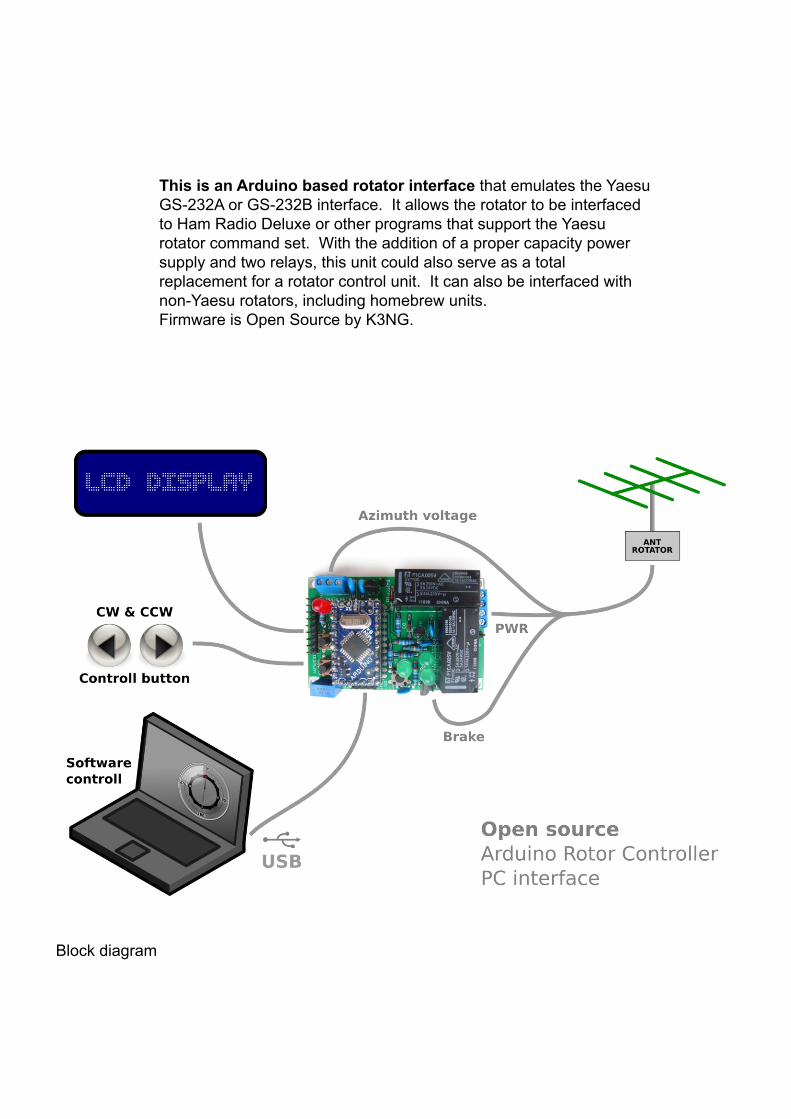
Schematic diagram
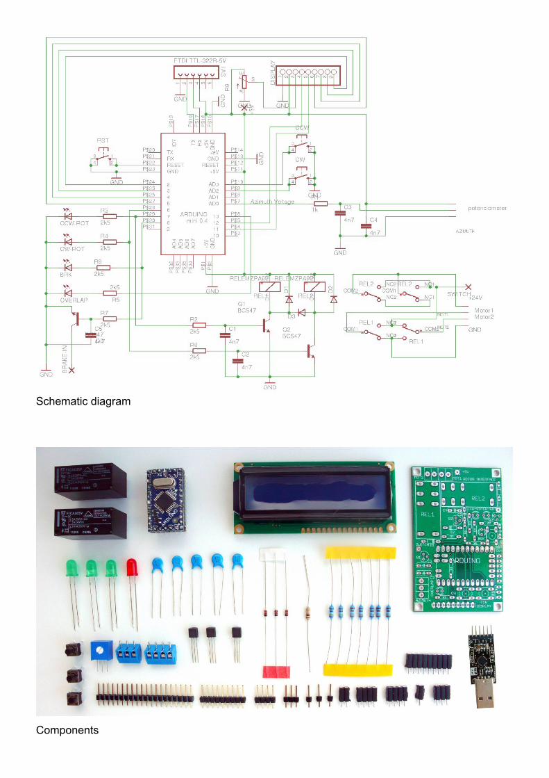
Components

PCB
1. Connecting arduino mini and usb interface
□ solder pin connector for arduino mini
□ four pin connector for usb
□ nine pins for LCD display
□ reset switch
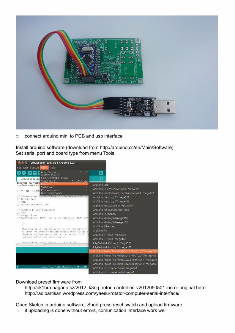
□ connect arduino mini to PCB and usb interface
Install arduino software (download from http://arduino.cc/en/Main/Software)
Set serial port and board type from menu Tools
Download preset firmware from
http://ok1hra.nagano.cz/2012_k3ng_rotor_controller_v2012050501.ino or original here
http://radioartisan.wordpress.com/yaesu-rotator-computer-serial-interface/
Open Sketch in arduino software. Short press reset switch and upload firmware.
□ if uploading is done without errors, comunication interface work well
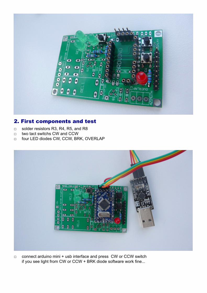
2. First components and test
□ solder resistors R3, R4, R5, and R8
□ two tact switchs CW and CCW
□ four LED diodes CW, CCW, BRK, OVERLAP
□ connect arduino mini + usb interface and press CW or CCW switch
if you see light from CW or CCW + BRK diode software work fine...

3. Finalize
□ solder resistors R1, R2, R6, R7, trimer R9
□ three diodes D1, D2, D3
□ five capacitors C1, C2, C3, C4, C5
□ three tranzistors Q1, Q2, Q3
□ three single pins 5V, SWITCH, BRAKE
□ two terminal AZIMUTH, MOTOR
□ two relays REL1, REL2

4. Connection and settings
□ connect LCD display
□ your rotator or potentiometer
□ usb interface
□ in arduino software select menu Tools/Serial monitor, set 9600 baud and Cariage return.
Callibrate rotator by instructions in firmware source code. Find section Quick Start.
□ use your favorite software or download PstRotator here
www.qsl.net/yo3dmu/index_Page346.htm
□ have fun :)
5. Options
□ you can customize open source firmware (display text, new function, etc.)
□ single pin BRAKE is available for controll brake in your rotator via relay
□ pin 5V can be used for external power supply, if you like use it, disconnect 5V drom usb
interface
□ if you don`t need reverse polarity switching by relays, but you need separate switchs for cw
and ccw, use pin SWITCH for GND and remove diode D3 This option is useful when you
keep your rotor control box and this board is connected paralel to this box.
□ switchs CW and CCW can be used for manual rotation, switch reset is used only for
programing arduino mini
Assembly Manual
K3NG Arduino Rotor Controller PC interface
edition | v. 1.0 August 2012 by OK1HRA | available at www.hamshop.cz