Architecture-Led Safety Process
Peter H. Feiler Julien Delange David P. Gluch John D. McGregor
December 2016
TECHNICAL REPORT CMU/SEI-2016-TR-012
Software Solutions Division
Distribution Statement A: Approved for Public Release; Distribution is Unlimited
http://www.sei.cmu.edu
CMU/SEI-2016-TR-012 | SOFTWARE ENGINEERING INSTITUTE | CARNEGIE MELLON UNIVERSITY
Distribution Statement A: Approved for Public Release; Distribution is Unlimited
Copyright 2016 Carnegie Mellon University
This material is based upon work funded and supported by the Department of Defense under Contract
No. FA8721-05-C-0003 with Carnegie Mellon University for the operation of the Software Engineer-
ing Institute, a federally funded research and development center.
Any opinions, findings and conclusions or recommendations expressed in this material are those of the
author(s) and do not necessarily reflect the views of the United States Department of Defense.
This report was prepared for the
SEI Administrative Agent
AFLCMC/PZM
20 Schilling Circle, Bldg 1305, 3rd floor
Hanscom AFB, MA 01731-2125
NO WARRANTY. THIS CARNEGIE MELLON UNIVERSITY AND SOFTWARE ENGINEERING
INSTITUTE MATERIAL IS FURNISHED ON AN “AS-IS” BASIS. CARNEGIE MELLON
UNIVERSITY MAKES NO WARRANTIES OF ANY KIND, EITHER EXPRESSED OR IMPLIED,
AS TO ANY MATTER INCLUDING, BUT NOT LIMITED TO, WARRANTY OF FITNESS FOR
PURPOSE OR MERCHANTABILITY, EXCLUSIVITY, OR RESULTS OBTAINED FROM USE
OF THE MATERIAL. CARNEGIE MELLON UNIVERSITY DOES NOT MAKE ANY
WARRANTY OF ANY KIND WITH RESPECT TO FREEDOM FROM PATENT, TRADEMARK,
OR COPYRIGHT INFRINGEMENT.
[Distribution Statement A] This material has been approved for public release and unlimited distribu-
tion. Please see Copyright notice for non-US Government use and distribution.
Internal use:* Permission to reproduce this material and to prepare derivative works from this material
for internal use is granted, provided the copyright and “No Warranty” statements are included with all
reproductions and derivative works.
External use:* This material may be reproduced in its entirety, without modification, and freely distrib-
uted in written or electronic form without requesting formal permission. Permission is required for any
other external and/or commercial use. Requests for permission should be directed to the Software En-
gineering Institute at [email protected].
* These restrictions do not apply to U.S. government entities.
DM-0004328

CMU/SEI-2016-TR-012 | SOFTWARE ENGINEERING INSTITUTE | CARNEGIE MELLON UNIVERSITY i
Distribution Statement A: Approved for Public Release; Distribution is Unlimited
Table of Contents
Acknowledgments iv
Abstract v
1 Introduction 1
2 Architecture-Led Processes and ALSA 2
3 ALSA Practices 5 3.1 Example System 8
4 Identify Operational Safety Risks 10 4.1 Top-Level Hazards (Functional Hazard Assessment) 11 4.2 Top-Level Accident and System-Level Hazards (STPA) 12 4.3 Architecture Models 13
5 Identify Operational Hazards and Hazard Contributors 15 5.1 System Partitioning 15 5.2 Operational Context as a Control System 17 5.3 Interface Error Analysis 18 5.4 Top-Level Interaction Error Models 19 5.5 Component Error Definition and Propagations 20 5.6 Error Models and Hazards 22 5.7 Engine System Error Models 23 5.8 FADEC Software 26 5.9 Fault Behaviors of Components 27
6 Identify Safety Requirements 30
7 Develop Safety Architecture Design 31
8 Summary 32
Appendix A Background on Safety Process Techniques 33 8.1 ARP 4754A and ARP 4761 33 8.2 The System-Theoretical Process Analysis (STPA) 37
Appendix B ALSA (EMV2) Error Ontology 40 8.3 Relationship of ALSA and STPA 42
Appendix C AADL Error Model Language Ontology 43
Appendix D Terminology 46
References/Bibliography 51

CMU/SEI-2016-TR-012 | SOFTWARE ENGINEERING INSTITUTE | CARNEGIE MELLON UNIVERSITY ii
Distribution Statement A: Approved for Public Release; Distribution is Unlimited
List of Figures
Figure 1: Double V Model of Development and Assurance 2
Figure 2: System Theoretic Framework for Accident Causality Analysis [Leveson 2012] 3
Figure 3: ACVIP ALRS/ALSA Process Steps ALSA Process Overview 5
Figure 4: Iterations Through the System Hierarchy. 7
Figure 5 Process Artifacts 8
Figure 6: FADEC Fuel Flow Control Example [Garg 2012] 9
Figure 7: Aircraft Function Tree—First Level [SAE 1996] 11
Figure 8: Top-Level System Partitioning 16
Figure 9: Major Engine System Components 17
Figure 10: Monitored and Controlled Variables 18
Figure 11: Interface Error Analysis and Modeling 19
Figure 12: Error Behavior and State Interfaces and Interactions 20
Figure 13: Engine System Implementation 24
Figure 14: Dual Redundant FADEC Fuel Flow Control Architecture 26
Figure 15: Three State Error Machine 29
Figure 16: ARP Guideline Documents Relevant to Safety [SAE 2010] 33
Figure 17: Development Life Cycle from ARP 4754A [SAE 2010] 34
Figure 18: Integration of Safety Processes with the Development Processes [SAE 2010] 34
Figure 19: Safety Assessment Process Model [SAE 2010] 35
Figure 20: Overview of the Safety Assessment [SAE 1996] 36
Figure 21: Summary of STPA Practices 37
Figure 22: Generic Safety Control Structure [Leveson 2013] 38
Figure 23: Potential Control Flaws-Causal Factors: from Leveson [Leveson 2012] and modified according to Leveson [Leveson 2013] 39
Figure 24: Service Type Errors [SAE 2009] 45
Figure 25: Value Related Errors [SAE 2009] 45
Figure 26: Timing Related Errors [SAE 2012b] 45

CMU/SEI-2016-TR-012 | SOFTWARE ENGINEERING INSTITUTE | CARNEGIE MELLON UNIVERSITY iii
Distribution Statement A: Approved for Public Release; Distribution is Unlimited
List of Tables
Table 1: An Output Table for an FHA (partial) 11
Table 2: Accident and System-Level Hazards 12
Table 3: Hazard-Safety Requirements Table (System-Level) 13
Table 4: Top-Level Interface Errors and Hazards 20
Table 5: Error Propagations 21
Table 6: FADEC Error Library (excerpt) 22
Table 7: Error States of the Engine System 22
Table 8: Hazards Property 23
Table 9: Hazard Table Generated from AADL Model 23
Table 10: FADEC and Engine Type Specifications with Error Propagations 24
Table 11: Engine System EMV2 Declarations 25
Table 12: Engine System Interface Errors 25
Table 13: Processor to Bus Access Error Declarations 27
Table 14: Error Ontology Major Error Types 40
Table 15: Service, Value, and Timing Errors 40
Table 16: Replication, Concurrency, and Access Control Errors 41
Table 17: EMV2 Error Types and STPA Control Action Hazard Guide 42
Table 18: Comparative Table of Safety and Reliability Terms 47

CMU/SEI-2016-TR-012 | SOFTWARE ENGINEERING INSTITUTE | CARNEGIE MELLON UNIVERSITY iv
Distribution Statement A: Approved for Public Release; Distribution is Unlimited
Acknowledgments
The authors would like to thank all the people who contributed to this report by reviewing it, pro-posing additions, making comments, or providing general feedback. The work presented in this report was completed as part of the Architecture-Led Incremental System Assurance (ALISA) project. We would like to extend our appreciation to all of the members of the ALISA team, whose insights, provided in numerous technical discussions, directly or indirectly contributed to this work.

CMU/SEI-2016-TR-012 | SOFTWARE ENGINEERING INSTITUTE | CARNEGIE MELLON UNIVERSITY v
Distribution Statement A: Approved for Public Release; Distribution is Unlimited
Abstract
Architecture-Led Safety Analysis (ALSA) is a safety analysis method that uses early architecture knowledge to supplement traditional safety analysis techniques to identify faults as early as possi-ble. The method begins by creating a definition of the operational environment within which the system under design will operate. ALSA uses the early architecture knowledge of the system and standardized error guide words to identify hazards in the system. These hazards are analyzed us-ing knowledge of the architecture and safety requirements, intended to mitigate the hazards, that are added to the system’s requirements. ALSA continues its analysis down the full depth of the system implementation hierarchy. As additional implementation details are defined, the hazard analysis is applied to the subcomponents. ALSA also cuts across many of the phases in the devel-opment lifecycle. The hazard analysis feeds the requirements definition, architecture definition, and verification and validation phases.
CMU/SEI-2016-TR-012 | SOFTWARE ENGINEERING INSTITUTE | CARNEGIE MELLON UNIVERSITY 1
Distribution Statement A: Approved for Public Release; Distribution is Unlimited
1 Introduction
Architecture-Led Safety Analysis (ALSA) is a safety analysis method that uses early architecture knowledge to supplement traditional safety analysis techniques to identify faults as early as possi-ble. The method begins by creating a definition of the operational environment within which the system under design will operate. ALSA uses the early architecture knowledge of the system and standardized error guide words to identify hazards in the system. These hazards are analyzed us-ing knowledge of the architecture and safety requirements, intended to mitigate the hazards, that are added to the system’s requirements. ALSA continues its analysis down the full depth of the system implementation hierarchy. As additional implementation details are defined, the hazard analysis is applied to the subcomponents. ALSA also cuts across many of the phases in the devel-opment lifecycle. The hazard analysis feeds the requirements definition, architecture definition, and verification and validation phases.

CMU/SEI-2016-TR-012 | SOFTWARE ENGINEERING INSTITUTE | CARNEGIE MELLON UNIVERSITY 2
Distribution Statement A: Approved for Public Release; Distribution is Unlimited
2 Architecture-Led Processes and ALSA
The double V model shown in Figure 1 establishes the relationship between architecture-led de-velopment and assurance processes, with Architecture-Led Processes as central to all engineering activities. Within Architecture-Led Processes, architecture modeling and analysis, coupled with automated code generation, are the foundation for the overall development and upgrade of soft-ware-dependent systems. These processes encompass Architecture Led Requirements Specifica-tion (ALRS), Architecture-Led Assurance practices, Architecture-Centric Virtual Integration Practice (ACVIP), and Architecture-Led Safety Analysis (ALSA) [Feiler 2015]. The ALRS draws on the requirements engineering management (REM) handbook [FAA 2009]. The ACVIP con-sists of these steps: define the operational context, develop the requirement specification, and de-velop and finalize the architecture specification.
Figure 1: Double V Model of Development and Assurance
The architecture-led processes use the architecture as a central source of information, including extracting patterns, given the premise that systems within a given domain often follow very simi-lar architecture patterns. For example, most real-time control systems are based on the feedback control loop architectural style. The awareness and use of established patterns allows, even very early in requirements analysis, specific requirements to be associated with specific architecture features. This pattern knowledge supports mini-iterations between requirements and architecture activities (e.g., knowing that there is a need for sensing allows the definition of more detailed re-quirements for sensing subsystems and the preliminary definition of architectural features to meet those requirements). A similar relationship exists between the architecture definition and imple-mentation activities, in that code reuse is prefaced with architecture pattern reuse. Together these mini-iterations enable a rapid traverse from safety requirements through the architecture to imple-mentation.
Architecture-Led Safety Analysis (ALSA) processes span the entire spectrum of development and assurance activities. They begin with the identification of operational safety risks (hazards) as part

CMU/SEI-2016-TR-012 | SOFTWARE ENGINEERING INSTITUTE | CARNEGIE MELLON UNIVERSITY 3
Distribution Statement A: Approved for Public Release; Distribution is Unlimited
of defining the operational context for a system as a whole and continue as a top-down assessment that is conducted throughout subsystems, usually in layers of dependencies, that are aggregated into a system hierarchy.
ALSA is performed considering a set of stakeholder and system requirement specifications as well as working within a socio-technical framework for hazard analysis. The socio-technical framework represents a new model of accident causation and is the basis for a new type of hazard analysis. Figure 2 illustrates a general model of socio-technical control, originally developed by Rasmussen and adapted by Nancy Leveson of MIT for the Systems-Theoretic Accident Model and Processes (STAMP) method of accident causality analysis [Rasmussen 2000, Leveson 2012]. The ALSA focuses on the operating processes within the System Theoretic Framework, as high-lighted in Figure 2.
The objective of the architecture-led safety analysis (ALSA) approach is to systematically identify hazards and hazard contributors in systems, in particular in embedded software systems. The im-plementation of the ALSA process borrows from several methods as appropriate to the application system and the certifications required for that system.
Figure 2: System Theoretic Framework for Accident Causality Analysis [Leveson 2012]
These methods include the system safety analysis best practices (SAE ARP 4754A and ARP4761) as well as the System-Theoretical Process Analysis (STPA). The ARP 4754A and ARP4761 pro-vide recommended practices within the aerospace industry for showing compliance with certifica-tion regulations such as U.S. Federal Aviation Administration (FAA) airworthiness regulations for transport category aircraft and international airworthiness regulations [SAE 1996, 2010]. The

CMU/SEI-2016-TR-012 | SOFTWARE ENGINEERING INSTITUTE | CARNEGIE MELLON UNIVERSITY 4
Distribution Statement A: Approved for Public Release; Distribution is Unlimited
ARP 4754 and ARP4761 describe Functional Hazard Assessment (FHA), Failure Mode and Ef-fect Analysis (FMEA), Fault Tree Analysis (FTA), and Common Cause Analysis (CCA) among others as tools to assess the safety of a system. The System-Theoretical Process Analysis (STPA) is a new approach to hazard analysis that is based upon the Systems-Theoretic Accident Model and Processes (STAMP) causality model [Leveson 2012, 2013, 2014].
The ARP 4754A and ARP4761 are established practices in the aircraft industry. While STPA shows promise [Leveson 2014, Procter 2014], it is in the research phases of development. STPA as well as the blended practices and processes described here are yet to be extensively evaluated by the aircraft safety industry.
There are application- and discipline-specific perspectives on safety terminology. For our pur-poses, we adopt a modification of the definition from Leveson that a hazard is a “system [or sub-system] state or set of conditions that, together with a particular set of worst-case environmental conditions, will lead to an accident (loss)” [Leveson 2012]. Again from Leveson we define an ac-cident as “an undesired or unplanned event that results in a loss, including loss of human life or human injury, property damage, environmental pollution, mission loss, etc.” [Leveson 2012]. We define a safety risk in the sense of a risk described by Gluch, where a risk is a value judgment (concern and likelihood) made upon the potential implications of current conditions that suggests a possible transition into an undesirable condition (consequence)” [Gluch 1994]. For a safety risk, current conditions are hazards and potential consequences are accidents. Appendix D presents ad-ditional definitions for the safety related terms used in this report.

CMU/SEI-2016-TR-012 | SOFTWARE ENGINEERING INSTITUTE | CARNEGIE MELLON UNIVERSITY 5
Distribution Statement A: Approved for Public Release; Distribution is Unlimited
3 ALSA Practices
Figure 3 highlights the ALSA safety and hazard analysis practices within the Architecture-Centric Virtual Integration Process. The ACVIP consists of these major steps:
1. define the operational context
2. develop the requirement specification
3. develop the architecture specification
4. finalize the architecture specification
As shown in Figure 3, the ACVIP explicitly recognizes that the architecture development of a sys-tem begins (at least implicitly) at the outset of a development effort, beginning concurrently with defining the operational context and continuing through to the development of a final architecture specification. Implicit assumptions and often explicit architecture decisions are made while defin-ing such artifacts as mission drivers, stakeholder goals, and system requirements. Consequently, we have shown architecture design specification as concurrent with requirements development with an iterative interaction between them (i.e., requirements insight benefits architecture devel-opment and architecture development provides additional perspective and insight for requirement definition). This interaction is indicated by the dotted line in Figure 3. As the system development matures, hazards, their contributors, and additional safety requirements are defined in concert with the development of the architecture specification.
• Specification of functional and physical system architecture
• Decomposition of requirements
• Develop Safety Architecture Design
Develop Architecture Specification
Finalize Architecture Specification
Define OperationalContext
• System overview
• Critical mission drivers
• Concept of Operation
• Stakeholder goals for system
• Identify Operational Safety Risks
Develop Requirement Specification
• Model-based specification of concepts
• Role and boundary of system
• System requirement specification and coverage
• Identify Operational Hazards
& Hazard Contributors
• Identify Safety Requirements
• Virtual Integration and Architecture Analysis
Figure 3: ACVIP ALRS/ALSA Process Steps ALSA Process Overview
The ALSA process (as well as the ACVIP) is iterative and tightly coupled in that it is necessary to go back and make changes or additions to previous steps. As shown in Figure 4, the Creation of Safety Requirements and Developing Safety Architecture Design are shown concurrently with the identification steps. While in the earlier phases of development few safety requirements may be identified or design decisions made, as the hazard and contributor identification process contin-ues, requirements are created to mitigate the hazards. This also presents the opportunity to capture safety architecture designs and design alternatives to address the hazards, especially as the archi-tecture design matures. An advantage of considering the safety requirements and safety architec-ture design alternatives early is that these can help to support (and, in safety-critical systems, to guide) the overall system architecture requirements generation and design effort. Overall, these

CMU/SEI-2016-TR-012 | SOFTWARE ENGINEERING INSTITUTE | CARNEGIE MELLON UNIVERSITY 6
Distribution Statement A: Approved for Public Release; Distribution is Unlimited
are incremental and iterative efforts throughout, requiring coordination among safety and general system development.
The ALSA process is conducted throughout the system hierarchy. It begins with the identification of operational safety risks (hazards) as part of defining the operational context for a system. It continues through lower subsystems down to the component level of the architecture. This pro-cess is shown in Figure 4. There is interplay and feedback among the identification processes within various layers. The hazards, contributors, or requirements at a higher level are detailed in lower levels and hazards, contributors, or requirements identified at one level may prompt the re-organization of a hazard, contributor, or requirement at a higher level. This can also occur such that the execution of the process at a lower level may prompt the identification of a safety risk at the top-level operational context.
The hazards and contributors at lower levels are manifested as safety hazards arising from interac-tions among components at the system level. For example, hazards at an aircraft engine level, such as loss of thrust, contribute to hazards at the higher aircraft level. Similarly, hazards associ-ated with engine components such as the fuel valve and fuel valve actuator contribute to the en-gine-level hazard of loss of thrust. The hazard and hazard contributor identification processes (as well as any associated identification of safety requirements) are conducted iteratively through the architecture realization of the system hierarchy—detailing, identifying and correlating hazards and hazard contributors. These processes provide information for developing safety requirements, architecture design and architecture finalization.
With this perspective, hazards can be identified at lower levels of a system. These can be consid-ered as refinements of system-level hazards, may represent distinct hazardous conditions on their own, and may be useful in understanding system-level hazards.
Note that it can be counterproductive to the effectiveness of the process to expend effort differen-tiating between what is a hazard (e.g., a refinement of a higher level hazard or new lower level hazard) and what is a hazard contributor as one descends the system hierarchy. We do not offer a definitive differentiation, only that at some point there will be conditions that on their own are not clearly hazardous but contribute to hazardous conditions at a higher level of the system architec-ture (e.g., a leaky fuel valve or a fuel fill cap not closed may be considered a hazard in that it can result in a fire or an explosion, whereas a stuck at zero temperature sensor may not be considered a priori hazardous except in the context of its functioning within a system).What is critical is the identification and analysis of the factors contributing to system-level catastrophic hazards, what-ever term is used for them.
In Figure 4, the identify operational safety risks step is shaded in the intermediate and lower lev-els, indicating that the process is not explicitly conducted at those levels, since safety considera-tions relate to the complete system. However, implicitly risks may be identified that contribute to system hazards at higher levels.

CMU/SEI-2016-TR-012 | SOFTWARE ENGINEERING INSTITUTE | CARNEGIE MELLON UNIVERSITY 7
Distribution Statement A: Approved for Public Release; Distribution is Unlimited
system-level
Finalize Safety Architecture
Design
Develop Safety Architecture DesignCreate Safety Requirements
Identify Operational Safety Risks
Identify Operational
Hazards
IdentifyHazard
Contributors
Finalize Safety Architecture
Design
Develop Safety Architecture DesignCreate Safety Requirements
Identify Operational Safety Risks
Identify Operational
Hazards
IdentifyHazard
Contributors
Lowest-level
arch
itect
ure
leve
ls
Finalize Safety Architecture
Design
Develop Safety Architecture DesignCreate Safety Requirements
Identify Operational Safety Risks
Identify Operational
Hazards
IdentifyHazard
Contributors
intermediate-levels
Figure 4: Iterations through the System Hierarchy.
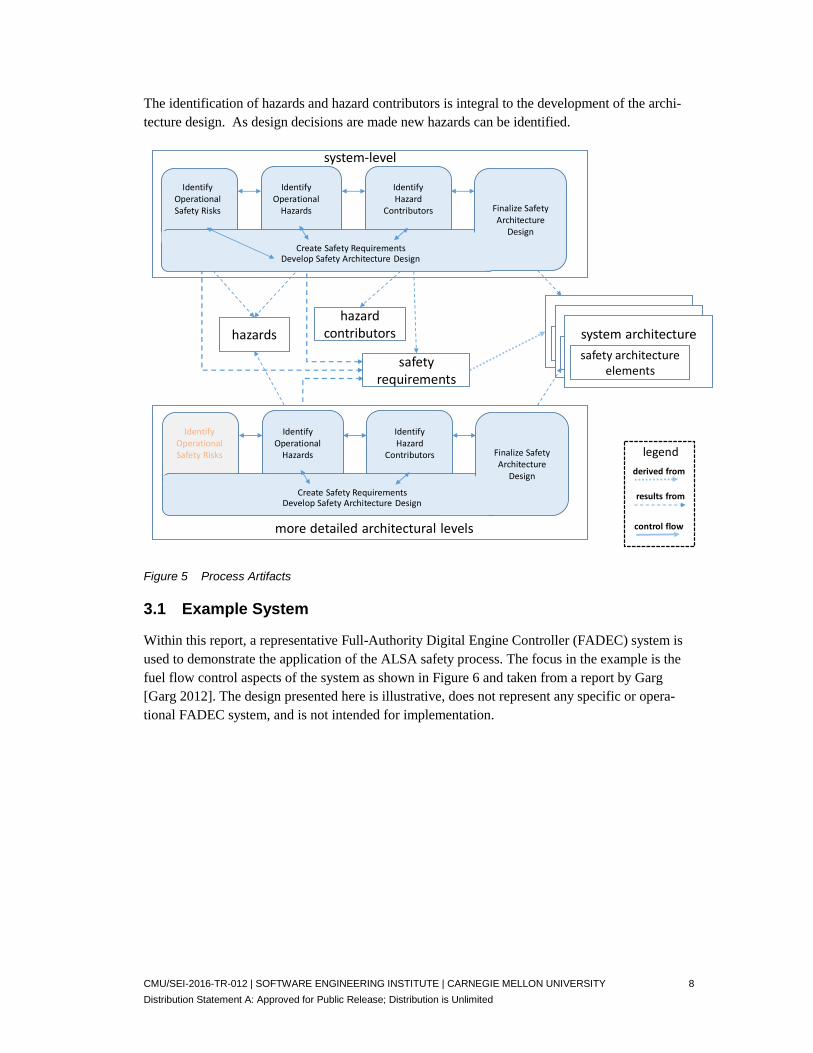
The artifacts created as part of the process are shown in Figure 5. Hazards and their contributing factors (contributors) at multiple levels of the system hierarchy are identified. These are used as the basis for defining safety requirements for the system. These requirements are used to guide the overall system architecture design and may result in safety-specific architectural elements that are incorporated into the system architecture.
While there are distinguishable identification steps within the process, as noted earlier, each of these identification steps can involve the development of safety requirements as well, as shown in Figure 5. For example, in identifying safety risks, it can be effective to define appropriate safety requirements to mitigate the identified risks. Similarly, as hazards and their contributors are iden-tified, requirements can be defined to address them. If desired (e.g., when different personnel or expertise are needed), requirements generation can be deferred until after the identification of haz-ard contributors. However, we encourage the creation of at least a few key safety requirements during hazard identification processes. These requirements can be reviewed and, as appropriate, integrated into later requirement generation activities.
The hazard identification steps are distinguished by increasingly detailing hazards by the identifi-cation and analysis of their contributing architectural factors. This is done throughout the architec-ture levels of the system. As noted earlier, this incremental and iterative process has the flexibility to expand different subsystems to different levels. For example, it can be advantageous to first pursue the hazard contributors of the flight and engine control systems and later to assess hazards on other aspects of aircraft. Similarly, the identification of a hazard contributor may result in re-consideration of the system architecture design as well as a reconsideration of hazards at higher architecture levels.
CMU/SEI-2016-TR-012 | SOFTWARE ENGINEERING INSTITUTE | CARNEGIE MELLON UNIVERSITY 8
Distribution Statement A: Approved for Public Release; Distribution is Unlimited
The identification of hazards and hazard contributors is integral to the development of the archi-tecture design. As design decisions are made new hazards can be identified.
system-level
hazards
safety requirements
system architecturesafety architecture
elements
more detailed architectural levels
hazardcontributors
Finalize Safety Architecture
Design
Develop Safety Architecture DesignCreate Safety Requirements
Identify Operational Safety Risks
Identify Operational
Hazards
IdentifyHazard
Contributors
Finalize Safety Architecture
Design
Develop Safety Architecture DesignCreate Safety Requirements
Identify Operational Safety Risks
Identify Operational
Hazards
IdentifyHazard
Contributors legendderived from
results from
control flow
system architecturesafety architecture
elements
system architecturesafety architecture
elements
Figure 5 Process Artifacts
3.1 Example System
Within this report, a representative Full-Authority Digital Engine Controller (FADEC) system is used to demonstrate the application of the ALSA safety process. The focus in the example is the fuel flow control aspects of the system as shown in Figure 6 and taken from a report by Garg [Garg 2012]. The design presented here is illustrative, does not represent any specific or opera-tional FADEC system, and is not intended for implementation.

CMU/SEI-2016-TR-012 | SOFTWARE ENGINEERING INSTITUTE | CARNEGIE MELLON UNIVERSITY 9
Distribution Statement A: Approved for Public Release; Distribution is Unlimited
* Power Lever Angle (PLA)
*
Figure 6: FADEC Fuel Flow Control Example [Garg 2012]
We consider the focus of the problem (i.e., the system) to be the aircraft engine. Nominally, a safety analysis is conducted for the complete aircraft. This example is illustrative of the ALSA ap-proach and is not intended to represent a comprehensive safety assessment. In practice, these tech-niques are utilized by experts in the technical and safety aspects of the system being analyzed.
In applying the ALSA process, we assume that you are familiar with the AADL and the AADL Error Model Annex and their application [SAE 2012a, Feiler 2012, SAE 2006, Delange 2014].

CMU/SEI-2016-TR-012 | SOFTWARE ENGINEERING INSTITUTE | CARNEGIE MELLON UNIVERSITY 10
Distribution Statement A: Approved for Public Release; Distribution is Unlimited
4 Identify Operational Safety Risks
This initial step identifies operational system-level accidents (losses), incidents, and contributory system-level hazards. It also establishes the system operational context. This step requires signifi-cant stakeholder engagement, especially safety engineering, operational, and mission expertise.
The specific procedures, techniques, and outputs of this step may take various forms depending on the preference and norms of an organization and or requisite certifications for a system. For ex-ample, the ARP 4754A and ARP4761 provide guidance for this initial step employing techniques such as the FHA. Overall, the ARP 4754A and ARP4761 provide recommended practices within the aerospace industry for showing compliance with certification regulations, such as U.S. Federal Aviation Administration (FAA) airworthiness regulations for transport category aircraft and inter-national airworthiness regulations [SAE 1996, 2010].
In other domains, the certification agencies can provide guidance in this step (e.g., medical de-vices: ASTM’s F2761 standard [ASTM 2013]). Similarly, the techniques from a new approach to hazard analysis, the System-Theoretical Process Analysis (STPA), can be used in this step. The STPA is based upon the Systems-Theoretic Accident Model and Processes (STAMP) causality model [Leveson 2012, 2013, 2014].
The outcomes of this step are safety-specific risk findings (e.g., accidents, incidents, safety con-cerns, and top-level system hazards) associated with the operation of the system in its environ-ment.
In the early sessions with stakeholders (e.g., developing mission drivers, concept of operation, and stakeholder goals), requirements and architecture options are discussed. These can come from business, technical, or pragmatic considerations (e.g., certification requirements). Our point is that early on in the development effort an architecture perspective can be important in identifying safety risks and hazards as well as facilitating requirements and design decisions. This initial rep-resentation can be extended and detailed as requirements are developed and analyzed, and become the basis, using virtual integration practices, for conducting requirements analyses and design tradeoffs [Feiler 2009d].
Various techniques can be used for identifying system-level hazards in the ALSA process. For this example, we demonstrate the activities and results of two approaches.
1. Section 4.1 shows an aircraft-level FHA [SAE 1996, 2010] 2. Section 4.2 shows the system-level analysis beginning with accident identification, as de-
scribed in STPA [Leveson 2012]. The technique used is often based upon requirements for certification in a specific industry (e.g., aerospace applications).
What is critical is to employ a comprehensive, systematic approach and include a broad represen-tation of system stakeholders.
CMU/SEI-2016-TR-012 | SOFTWARE ENGINEERING INSTITUTE | CARNEGIE MELLON UNIVERSITY 11
Distribution Statement A: Approved for Public Release; Distribution is Unlimited
4.1 Top-Level Hazards (Functional Hazard Assessment)
Within ARP 4761 practices, Functional Hazard Assessments (FHAs) are conducted for the com-plete aircraft and system levels. The FHA is used to identify and classify the failure condition(s) associated with the aircraft functions and combinations of those functions. The failure condition classifications establish the safety objectives (i.e., the requisite failure probability levels). For this example, we focus on the hazard descriptions arising out of an FHA.
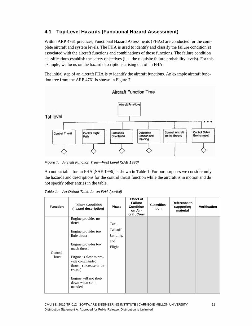
The initial step of an aircraft FHA is to identify the aircraft functions. An example aircraft func-tion tree from the ARP 4761 is shown in Figure 7.
Figure 7: Aircraft Function Tree—First Level [SAE 1996]
An output table for an FHA [SAE 1996] is shown in Table 1. For our purposes we consider only the hazards and descriptions for the control thrust function while the aircraft is in motion and do not specify other entries in the table.
Table 1: An Output Table for an FHA (partial)
Function Failure Condition
(hazard description) Phase
Effect of Failure
Condition on Air-
craft/Crew
Classifica-tion
Reference to supporting
material Verification
Control Thrust
Engine provides no thrust Engine provides too little thrust Engine provides too much thrust Engine is slow to pro-vide commanded thrust (increase or de-crease) Engine will not shut-down when com-manded
Taxi,
Takeoff,
Landing,
and
Flight

CMU/SEI-2016-TR-012 | SOFTWARE ENGINEERING INSTITUTE | CARNEGIE MELLON UNIVERSITY 12
Distribution Statement A: Approved for Public Release; Distribution is Unlimited
Function Failure Condition
(hazard description) Phase
Effect of Failure
Condition on Air-
craft/Crew
Classifica-tion
Reference to supporting
material Verification
Engine cannot be con-trolled—Loss of En-gine Thrust Control (LOTC)
4.2 Top-Level Accident and System-Level Hazards (STPA)
In this section, we employ the foundational steps of the STPA [Leveson 2012, 2013], to identify system-level (engine) hazards. As before, we assume the operational conditions are that the en-gine has started and the aircraft is in motion. We draw on STPA artifacts for documenting the re-sults [Leveson 2013]. Table 2 lists some of the system-level hazards for an aircraft engine as con-tributors to aircraft accidents. These align with the FHA control thrust hazards shown in Table 1. If an assessment of the FADEC is part of a larger safety assessment (e.g., an assessment of the air-craft) engine hazards may already have been defined.
Table 2: Accident and System-Level Hazards
Accident System-Level (operational) Hazards A-1: Loss of life or serious injury due to aircraft engine
A-2: Catastrophic damage to aircraft or other property due to aircraft engine
H0: Ineffective thrust to maintain controlled flight or safe taxi H1: Engine provides no thrust H2: Engine provides too little thrust H3: Engine provides too much thrust H4: Engine is slow to provide thrust (increase or decrease) H5: Engine will not shutdown when commanded H6: Complete Loss of Engine Thrust Control (LOTC)
The operational system-level hazards in Table 2 establish the top-level hazards for the engine. These are detailed in subsequent steps. At this point, top-level safety requirements (termed safety constraints [Leveson 2012], i.e., requirements that prevent hazards or accidents) are identified. The top-level safety requirements for the engine hazards are shown in Table 3. In our example, safety requirements are defined in concert with hazard identification because it can be more effec-tive to define the requirements when an experienced engineer (or engineers) with the requisite ex-pertise is focused on the specific details of a hazard and immersed in the overall safety context, rather than another engineer defining requirements later.
Safety requirements are integrated into a comprehensive set of system requirements for the sys-tem. Safety requirements help guide the architecture and detailed design process. This integration with the overall system design is part of the Develop Safety Requirements step of the ALSA pro-cess, which is conducted concurrently with the identification processes.

CMU/SEI-2016-TR-012 | SOFTWARE ENGINEERING INSTITUTE | CARNEGIE MELLON UNIVERSITY 13
Distribution Statement A: Approved for Public Release; Distribution is Unlimited
Table 3: Hazard-Safety Requirements Table (System-Level)
Hazards Safety Requirements H1: Engine provides no thrust SC1: Thrust must be provided at all times when
commanded H2: Engine provides too little thrust H3: Engine provides too much thrust
SC2: Thrust level must be provided at the com-manded level
H4: Engine is slow to provide commanded thrust
SC3: Engine must provide commanded thrust in xxx seconds
H5: Engine will not shutdown when com-manded
(The relevant safety constraints arising out of this include SC2 and SC4.2)
H6: Engine cannot be controlled - Loss of Engine Thrust Control (LOTC)
SC4: Engine must respond to all commands SC4.1: Engine must start when commanded SC4.2: Engine must shutdown when commanded
4.3 Architecture Models
It is often the case that during the hazard identification activities of ALSA, requirements are im-plicitly assumed or identified, and often implicit architecture assumptions or alternatives are iden-tified or architecture decisions are made. For example, a requirement may be developed that a combat aircraft will include an ejection set for the pilot. It is at this point that a top-level system operational architecture model can begin to be developed and would include an ejection system (possibly with alternative design concepts identified).
For our FADEC example, a possible top-level description for the aircraft system is shown in Fig-ure 8. In the terms of STPA, this is a system-level control structure for the engine system. Control structures provide a partitioned safety perspective on the architecture. This perspective posits that a lack of safety is due to the inadequate enforcement of safety constraints on the system (i.e., safety is a control problem, not a failure problem) [Leveson 2012]. Control structures can be iden-tified throughout the hierarchy, each defining a distinct perspective to assess hazards and hazard contributors. This enables a top-down analysis throughout the levels of the architecture hierarchy.
Within ALSA, beginning at the system-level and continuing throughout the architecture hierar-chy, distinct perspectives consisting of representations of components as interacting error state machine models are assessed to identify hazards and their contributors. One type of perspective is a control perspective of the STPA. This perspective is key to the system theoretical view of STPA, where control actions are assessed to establish unsafe control actions.
Other perspectives include architecture styles that can be addressed in the ALSA approach, such as data flow, call-return, and repository [Clements 2011]. These define patterns that can be identi-fied within an architecture and used to stratify the architecture hierarchy and guide hazard analy-sis. Certain patterns are more prevalent in one application than in another (e.g., aircraft systems have significant numbers of control patterns; satellite systems will have some control as well as data flow and repository patterns).
In the ALSA approach, critical function data flow paths (critical function paths) are assessed. Spe-cifically, you assess the terminal interaction (last inter-component segment) of the flow against the error ontology, using a tabular format similar to that used to identify unsafe control actions in

CMU/SEI-2016-TR-012 | SOFTWARE ENGINEERING INSTITUTE | CARNEGIE MELLON UNIVERSITY 14
Distribution Statement A: Approved for Public Release; Distribution is Unlimited
STPA. This approach represents a generalization of the control perspective of STPA in that, in the case of a control signal flow, you first assess the final control command to the actuator. However, in other application architecture patterns (e.g., transaction processing), you consider the final in-teraction of the critical control path. For example, consider a transaction processing that delivers an airline ticket to a customer. You then use the complete critical function path to analyze (simi-lar to step 2 in STPA and the analysis in CASE [Procter 2016]) the causes of an errant delivery interaction.

CMU/SEI-2016-TR-012 | SOFTWARE ENGINEERING INSTITUTE | CARNEGIE MELLON UNIVERSITY 15
Distribution Statement A: Approved for Public Release; Distribution is Unlimited
5 Identify Operational Hazards and Hazard Contributors
In the closely coupled steps of “identify operational hazards” and “identify contributors,” you in-crementally extend the hazard analysis into lower levels of the system architectural hierarchy. If you have identified top-level hazards as part of identifying operational safety risks (e.g., as in Sec-tions 4.1 and 4.2), this step begins the identification of subsystem hazards or the refinement of the system-level hazards. If system-level hazards have not been defined, this step begins by identify-ing the system-level hazards. In extending the analysis to lower levels, it is necessary that addi-tional details or working assumptions about the architecture are available and possibly alternative architecture designs for consideration have been defined.
Within the ACVIP, the architecture development is conducted concurrently and iteratively with hazard identification. Often, this is incremental as well, especially for large systems where a criti-cal subsystem is engineered earlier in the overall development. As is the case with the identifica-tion of safety risks, where top-level safety requirements can be identified, in this step additional safety requirements can be defined. It can be easier to clearly state a safety requirement while identifying and describing the hazard. In a safety-critical system, these steps are integral to and guide the requirement and design phases.
Hazards analysis techniques (e.g., from ARP 4761, such as fault tree analysis, event tree analysis, and HAZOP) as well as the STPA can be used in these steps.
Conducting this step involves three elements:
1. Systematically identifying exceptional conditions and their propagation to other systems components that represent hazards. You do this by considering the interfaces and interac-tions between components and the error types that can be propagated through them.
2. Systematically addressing how systems respond to incoming propagations (external influ-ences). You do this by detailing incoming and outgoing component errors and specifying whether errors impact a component, whether they are passed through (perhaps transformed), and the paths that pass through the component interfaces and interactions.
3. Systematically defining the error response of systems and components using error state models.
In addition to external influences, two principal considerations in hazard analysis are exceptional conditions within architecture elements (characterized using the ALSA error ontology) and mis-matched assumptions (mismatched assumption-guarantee contracts between systems) about their interactions. Exceptional conditions and mismatched assumptions can lead to hazardous (unde-sired) states of a system.
5.1 System Partitioning
In the initial activities of this step, you clearly define and represent the boundaries of the system and its subsystems in an architecture model, identifying the types of errors that can propagate among them. Principal considerations in this step are the boundary between the system and its en-vironment (i.e., external influences that can affect the system) and the interactions between archi-tectural elements. This partitioning enables the identification of internal and external influences

CMU/SEI-2016-TR-012 | SOFTWARE ENGINEERING INSTITUTE | CARNEGIE MELLON UNIVERSITY 16
Distribution Statement A: Approved for Public Release; Distribution is Unlimited
for each element. You then use the system architecture (or architecture alternatives) to further de-fine a subsystem hierarchically, explicitly including the interfaces between elements.
For the FADEC example, we choose to partition the relevant system into cockpit (including the pilot), a separate autopilot, and the remainder of the physical aircraft. External elements in the en-vironment may impact the system via sensors or other input (e.g., light entering the aircraft can cause electrical system disruption or damage within the aircraft).
The system-level diagram shown in Figure 8 reflects an architecture where the pilot and autopilot commands to the aircraft’s FADEC are separate and parallel. Speed feedback (this is the turbine fan_speed shown in Figure 9) is provided to both the Pilot_Cockpit system and autopilot. Alterna-tive architectures can be envisioned, for example, a serial architecture where the pilot inputs a command directly into the autopilot. In the alternative architecture, there may be a pilot controlled mode, where the pilot command is passed through to the FADEC.
Figure 8: Top-Level System Partitioning
The engine system within the aircraft system implementation is shown in Figure 9. For clarity, other internal aircraft components are not included. The FADEC within the engine system can be commanded by either a pilot or autopilot input and the FADEC does a signal selection based upon the operational mode. The engine receives a command from the FADEC and provides engine tur-bine fan speed back to the FADEC.

CMU/SEI-2016-TR-012 | SOFTWARE ENGINEERING INSTITUTE | CARNEGIE MELLON UNIVERSITY 17
Distribution Statement A: Approved for Public Release; Distribution is Unlimited
Figure 9: Major Engine System Components
5.2 Operational Context as a Control System
A common way of viewing a system in its operational context is as a control system that involves interactions via Monitored and Controlled Variables. This approach—documented in the FAA Requirement Engineering Management Handbook [FAA 2009]—has its roots in a report by Par-nas and Madey [Parnas 1991]. These variables can be used to represent states that characterize nominal and unsafe system conditions and interactions. To operationalize this view we introduce sensors and actuators to represent the monitored and controlled variables. This is illustrated in Figure 10 where there are systems under our control and others that, while they may affect the system, can only be observed (e.g., other aircraft, weather, and the terrain).

CMU/SEI-2016-TR-012 | SOFTWARE ENGINEERING INSTITUTE | CARNEGIE MELLON UNIVERSITY 18
Distribution Statement A: Approved for Public Release; Distribution is Unlimited
Environment
MonitoredVariables
System
ControlledVariables
System under control
Control System
Sensors Actuators
Autonomous Entities
Figure 10: Monitored and Controlled Variables
This control perspective is similar to the STPA approach and is appropriate for application sys-tems that are predominantly control. The ALSA approach does not require a control loop. It is a layered hierarchical approach that focuses on analyzing interfaces between architecture elements within and between layers, beginning with the top level architectural abstraction and progressing through the hierarchy. These interfaces encompass data and control flow connections, inter-com-ponent dependencies (including software-hardware and hardware-hardware) dependencies, and outside influences. Distinct interaction perspectives are based upon identifying architecture pat-terns within the hierarchy. For example, one interaction pattern is closed loop control, as is the case for our example. As noted earlier, others such as data flow or repository patterns can also be identified and analyzed.
5.3 Interface Error Analysis
Within ALSA, hazard and hazard contributor analysis is conducted by assessing interfaces, em-ploying the error ontology as a guide to identifying potential interface errors, and characterizing the components involved with EMV2 models of the errors (types) propagated into and out of the components, based upon their interfacing errors. The assessment of these error types, their propa-gations, and their impact on the states of the architecture are used to identify hazard contributors, detail aspects of previously identified hazards, and define new hazards. These analyses are done throughout all of the levels of the architecture through to the core executable components of the system, as shown in Figure 11.
For non-control system applications, the critical function path (CFP) is used, where the analysis begins at the terminal interaction of the path. The CFP is based upon the dominant architecture pattern and system application. For example, in a client-server implementation of a transaction processing system, at the highest architecture level the terminal interaction might be the delivery of the service to client. At lower levels of the architecture (e.g., detailing the client architecture), the internal path of the client’s processing of data (services) provided by the terminal interaction is assessed. This begins at the terminal interaction of the detailed path within the server. This ap-

CMU/SEI-2016-TR-012 | SOFTWARE ENGINEERING INSTITUTE | CARNEGIE MELLON UNIVERSITY 19
Distribution Statement A: Approved for Public Release; Distribution is Unlimited
proach is similar to the component-based assessment of SAFE [Procter 2016]. The analysis con-tinues through the hierarchy and backwards through the critical function path as needed to assure the desired coverage.
For our example, support in conducting these analyses is provided by the OSATE tool and the AADL and AADL error model annex (EMV2) languages. In Figure 11, we identify AADL error libraries and the AADL architecture model. Both of these are used to capture the results of the ALSA process.
AADLError LibraryAADL
Error LibraryAADLError Library
System Level
Subsystems First LevelSubsystems First Level
Subsystems First Level
Core Component LevelCore Component Level
Core Component Level
Subsystems Second LevelSubsystems Second Level
Subsystems Second Level
Create/Update Libraries
Assess Interfaces
Characterize Components Update AADL
ModelAADL Architecture
Model includingError Models
Figure 11: Interface Error Analysis and Modeling
The interaction analyses and component error models are developed at each hierarchical level as the architecture is detailed. For our example, we start with the top level as shown in Figure 8 and continue through each subcomponent (components within a layer), analyzing each subsystem through to the core executable components of the system. The analysis of component interactions and component error models are completed through the architecture hierarchy, in concert with the evolution of the architecture design.
5.4 Top-Level Interaction Error Models
As shown in Figure 8, the Pilot_Cockpit system provides control commands to the Autopilot and the Aircraft. We consider the port connections between the elements and choose the error types: no data is sent (service omission), bad data is sent, and data is sent late. The assumption is that the data is a single content record sent on some schedule. As the details of the communication be-tween the components are better defined, the amount of acceptable delay can be defined and the model adjusted to accommodate these details. This information is summarized in Table 4.
The columns are labeled with the relevant error categories from the error ontology. The number of columns in an errors-hazard table will vary, depending upon the number of error types that are identified in the details associated with each hierarchical level. For example, the replication errors category is included since there is the possibility of asymmetric errors in the speed feedback to the pilot_cockpit and to the autopilot; whereas concurrency and access errors are not included.

CMU/SEI-2016-TR-012 | SOFTWARE ENGINEERING INSTITUTE | CARNEGIE MELLON UNIVERSITY 20
Distribution Statement A: Approved for Public Release; Distribution is Unlimited
Table 4: Top-Level Interface Errors and Hazards
Component interface Service Errors Value Errors Timing Errors Replication Errors
Pilot_Cockpit
to
AutoPilot
No command to autopilot (may not be a hazard – need details on assumptions of the autopilot system)
Bad Value input into Autopilot
Late Delivery
(since this is speci-fied as a message, potential timing er-rors require addi-tional analysis)
Pilot_Cockpit to Aircraft No command to aircraft
Bad Value input into Aircraft
Late Delivery
Autopilot to Aircraft No command Bad Value Late Delivery
Aircraft to Pilot_Cockpit No Data Bad Value Late Delivery Potential for asym-metric missing, value, or timing Aircraft to Autopilot No Data Bad Value Late Delivery
We use this table as a presentation format for error information, but in using the AADL and EMV2, we annotate the AADL specification with error and hazard information. The AADL speci-fication is the authoritative engineering representation for the architecture, and reports in the form of Table 4 can be generated from that specification (e.g., Table 9).
5.5 Component Error Definition and Propagations
Within AADL, you address the errors associated with interfaces by defining the errors that may be propagated into or out of the components engaged through those interfaces. These errors can be based upon those that may contribute to (cause) the hazards that have been identified and/or may be based upon error (fault) models of the component. As shown in Figure 12, there are four categories of propagations: control/constraint inputs, functional inputs, resource dependencies, and functional outputs. For this approach, you define the error types associated with the compo-nent and define the errors that are propagated out based upon the components role within the ar-chitecture. In doing so, you use the error ontology guide tables shown in Table 14, Table 15, and Table 16.
Incoming propagationsInput assumptions
Outgoing propagationsOutput guarantees
Incoming propagationsResource assumptions
Incoming propagationsControl assumptions
Figure 12: Error Behavior and State Interfaces and Interactions

CMU/SEI-2016-TR-012 | SOFTWARE ENGINEERING INSTITUTE | CARNEGIE MELLON UNIVERSITY 21
Distribution Statement A: Approved for Public Release; Distribution is Unlimited
Within the EMV2, you define the error types associated with a component by referencing the er-ror libraries that define the relevant error types. You may want to create a library, or you can add the error types to a library you have already defined. Within the component declaration, you iden-tify the propagations for the component.
The relevant portions of an AADL specification for the model of Figure 8 are shown in Table 5. Each of the components are annotated with EMV2 subclauses declaring the incoming and out-going error propagations that are expected, based upon the error interaction assessment.
Table 5: Error Propagations1
system pilot_cockpit extends Top_Level_Pkg::Pilot_Cockpit annex EMV2{** use types FADEC_Error_Library; error propagations PLA_Cmd: out propagation {No_Data,Bad_Data,Late_Data}; autopilot_control: out propagation {No_Data,Bad_Data,Late_Data}; speed_feedback: in propagation {No_Data,Bad_Data,Late_Data,Asymmet-ricSpeedFeedback}; end propagations; **}; end pilot_cockpit; system autopilot extends Top_Level_Pkg::Autopilot annex EMV2 {** use types FADEC_Error_library; error propagations PLA_autoCmd: out propagation {No_Data,Bad_Data,Late_Data}; Speed_feedback: in propagation {No_Data,Bad_Data,Late_Data, Asymmet-ricSpeedFeedback}; autopilot_control: in propagation {No_Data,Bad_Data,Late_Data}; end propagations; **}; end autopilot; system aircraft extends Top_Level_Pkg::Aircraft annex EMV2 {** use types FADEC_Error_library; error propagations autopilot_PLA_Cmd: in propagation {No_Data,Bad_Data,Late_Data}; Speed_feedback: out propagation {No_Data,Bad_Data,Late_Data,Asymmet-ricSpeedFeedback}; pilot_PLA_Cmd: in propagation {No_Data,Bad_Data,Late_Data}; end propagations; **};
end aircraft;
1 Since the EMV2 and associated tools (e.g., OSATE) are being revised and extended, some of the AADL-EMV2 models may need modification to comply with syntax or other changes in future versions of the tools.
CMU/SEI-2016-TR-012 | SOFTWARE ENGINEERING INSTITUTE | CARNEGIE MELLON UNIVERSITY 22
Distribution Statement A: Approved for Public Release; Distribution is Unlimited
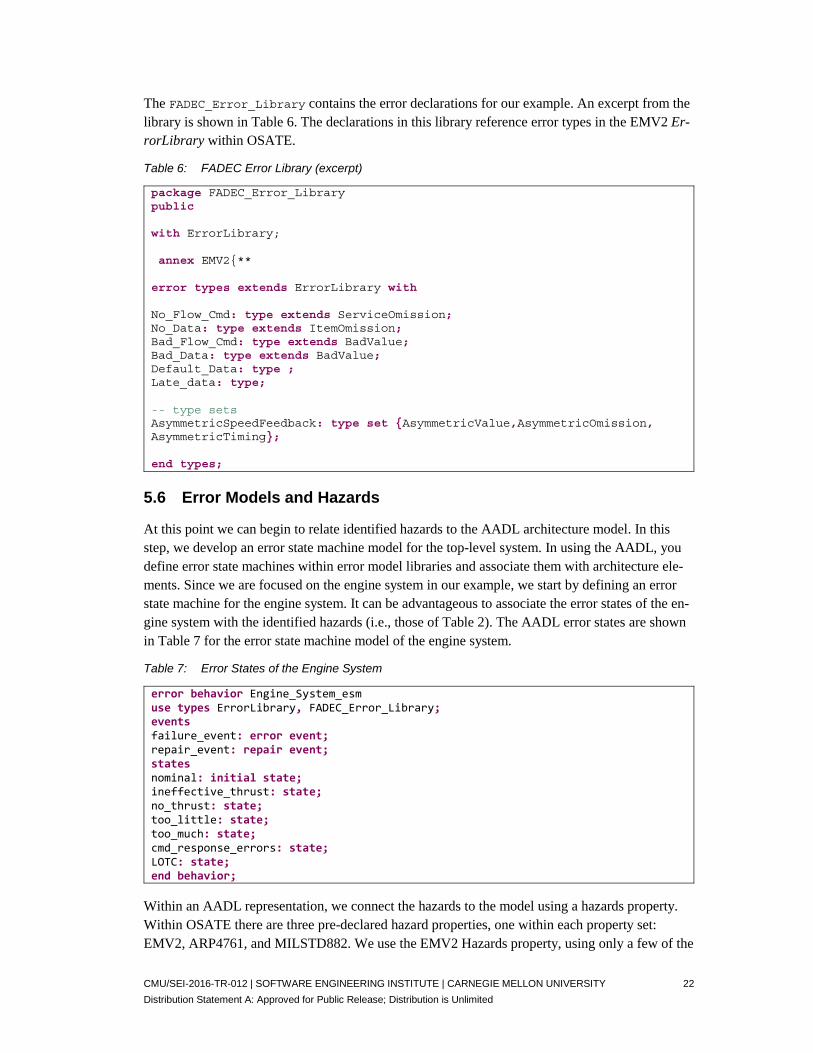
The FADEC_Error_Library contains the error declarations for our example. An excerpt from the library is shown in Table 6. The declarations in this library reference error types in the EMV2 Er-rorLibrary within OSATE.
Table 6: FADEC Error Library (excerpt)
package FADEC_Error_Library public with ErrorLibrary; annex EMV2{** error types extends ErrorLibrary with No_Flow_Cmd: type extends ServiceOmission; No_Data: type extends ItemOmission; Bad_Flow_Cmd: type extends BadValue; Bad_Data: type extends BadValue; Default_Data: type ; Late_data: type; -- type sets AsymmetricSpeedFeedback: type set {AsymmetricValue,AsymmetricOmission, AsymmetricTiming}; end types;
5.6 Error Models and Hazards
At this point we can begin to relate identified hazards to the AADL architecture model. In this step, we develop an error state machine model for the top-level system. In using the AADL, you define error state machines within error model libraries and associate them with architecture ele-ments. Since we are focused on the engine system in our example, we start by defining an error state machine for the engine system. It can be advantageous to associate the error states of the en-gine system with the identified hazards (i.e., those of Table 2). The AADL error states are shown in Table 7 for the error state machine model of the engine system.
Table 7: Error States of the Engine System
error behavior Engine_System_esmuse types ErrorLibrary, FADEC_Error_Library; events failure_event: error event; repair_event: repair event; states nominal: initial state; ineffective_thrust: state; no_thrust: state; too_little: state; too_much: state; cmd_response_errors: state; LOTC: state; end behavior;
Within an AADL representation, we connect the hazards to the model using a hazards property. Within OSATE there are three pre-declared hazard properties, one within each property set: EMV2, ARP4761, and MILSTD882. We use the EMV2 Hazards property, using only a few of the

CMU/SEI-2016-TR-012 | SOFTWARE ENGINEERING INSTITUTE | CARNEGIE MELLON UNIVERSITY 23
Distribution Statement A: Approved for Public Release; Distribution is Unlimited
properties’ attributes, as shown in Table 8. The cross reference attribute is used to provide an ex-plicit connection to the hazard H0 identified in Table 2, as well as a short description and severity level value (level 1 signifies very critical). There are other attributes that can be included in the Hazards property [SAE 2012b].
Table 8: Hazards Property
EMV2::hazards => ( [ CrossReference => "Hazard H0"; Description => "Ineffective thrust to maintain controlled flight or safe taxi"; Severity => 1; ] ) applies to Engine_System.ineffective_thrust;
As noted previously, the most effective approach is to maintain all information within an AADL model and to generate the hazard tables, and so on, from the model. Table 9 shows an example table generated from the AADL error model. It shows that the engine system is a subcomponent of the aircraft and links the hazards to the engine system component.
Table 9: Hazard Table Generated from AADL Model
Component Hazard Description Crossreference Severityaircraft/Engine_System "Ineffective thrust to maintain controlled flight or safe taxi" "Hazard H0" 1aircraft/Engine_System "No thrust is provided when required." "Hazard H1" 1aircraft/Engine_System "Too little thrust is provided when required." "Hazard H2" 1aircraft/Engine_System "Too much thrust is provided when required." "Hazard H3" 1aircraft/Engine_System "Engine is slow to provide thrust (increase or decrease)." "Hazard H4" 1aircraft/Engine_System "Engine will not shutdown when commanded." "Hazard H5" 1aircraft/Engine_System "Complete Loss of Engine Thrust Control (LOTC)." "Hazard H6" 1
5.7 Engine System Error Models
Next, we delve into more of the details of the engine system implementation. For the purposes of our example, we defer annotating the interfaces associated with the aircraft implementation, since the three external data interfaces for the engine system and aircraft are the same. (See Figure 9.) Later, for additional analyses (e.g., error flow path analysis), error propagations can be added and the dependency of the engine system on the external data bus can be addressed.
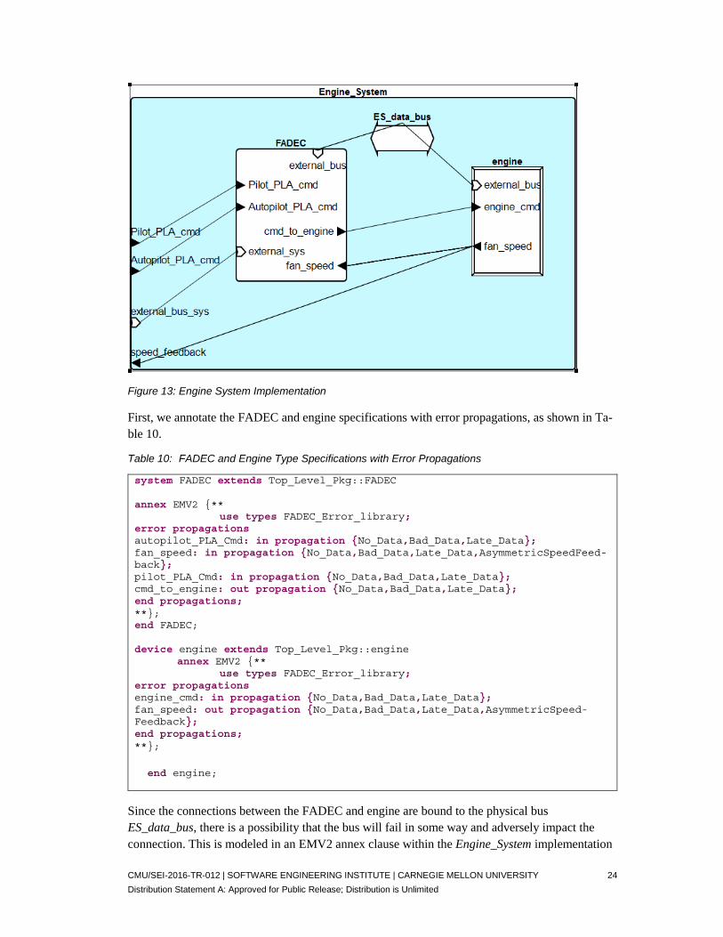
Figure 13 expands on Figure 9 by including the buses that support the communication between the FADEC system and engine. In developing the Error-Hazard table for the interfaces, we in-clude the fact that the communication paths are bound to the hardware buses. For example, the command to the engine from the FADEC and the fan speed back to the FADEC are carried by the engine system data bus (ES_data_bus). This dependency between components requires considera-tion in analyzing hazards.
CMU/SEI-2016-TR-012 | SOFTWARE ENGINEERING INSTITUTE | CARNEGIE MELLON UNIVERSITY 24
Distribution Statement A: Approved for Public Release; Distribution is Unlimited
Figure 13: Engine System Implementation
First, we annotate the FADEC and engine specifications with error propagations, as shown in Ta-ble 10.
Table 10: FADEC and Engine Type Specifications with Error Propagations
system FADEC extends Top_Level_Pkg::FADEC annex EMV2 {** use types FADEC_Error_library; error propagations autopilot_PLA_Cmd: in propagation {No_Data,Bad_Data,Late_Data}; fan_speed: in propagation {No_Data,Bad_Data,Late_Data,AsymmetricSpeedFeed-back}; pilot_PLA_Cmd: in propagation {No_Data,Bad_Data,Late_Data}; cmd_to_engine: out propagation {No_Data,Bad_Data,Late_Data}; end propagations; **}; end FADEC; device engine extends Top_Level_Pkg::engine annex EMV2 {** use types FADEC_Error_library; error propagations engine_cmd: in propagation {No_Data,Bad_Data,Late_Data}; fan_speed: out propagation {No_Data,Bad_Data,Late_Data,AsymmetricSpeed-Feedback}; end propagations; **};
end engine;
Since the connections between the FADEC and engine are bound to the physical bus ES_data_bus, there is a possibility that the bus will fail in some way and adversely impact the connection. This is modeled in an EMV2 annex clause within the Engine_System implementation
CMU/SEI-2016-TR-012 | SOFTWARE ENGINEERING INSTITUTE | CARNEGIE MELLON UNIVERSITY 25
Distribution Statement A: Approved for Public Release; Distribution is Unlimited
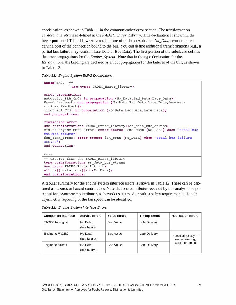
specification, as shown in Table 11 in the communication error section. The transformation es_data_bus_etrans is defined in the FADEC_Error_Library. This declaration is shown in the lower portion of Table 11, where a total failure of the bus results in a No_Data error on the re-ceiving port of the connection bound to the bus. You can define additional transformations (e.g., a partial bus failure may result in Late Data or Bad Data). The first portion of the subclause defines the error propagations for the Engine_System. Note that in the type declaration for the ES_data_bus, the binding are declared as an out propagation for the failures of the bus, as shown in Table 13.
Table 11: Engine System EMV2 Declarations
annex EMV2 {** use types FADEC_Error_library; error propagations autopilot_PLA_Cmd: in propagation {No_Data,Bad_Data,Late_Data}; Speed_feedback: out propagation {No_Data,Bad_Data,Late_Data,Asymmet-ricSpeedFeedback}; pilot_PLA_Cmd: in propagation {No_Data,Bad_Data,Late_Data}; end propagations; connection error use transformations FADEC_Error_library::es_data_bus_etrans; cmd_to_engine_conn_error: error source cmd_conn {No_Data} when "total bus failure occurs"; fan_conn_error: error source fan_conn {No_Data} when "total bus failure occurs"; end connection;
**}; -- excerpt from the FADEC_Error_library type transformations es_data_bus_etrans use types FADEC_Error_Library; all -[{busfailure}]-> {No_Data}; end transformations;
A tabular summary for the engine system interface errors is shown in Table 12. These can be cap-tured as hazards or hazard contributors. Note that one contributor revealed by this analysis the po-tential for asymmetric contributors to hazardous states. As result, a safety requirement to handle asymmetric reporting of the fan speed can be identified.
Table 12: Engine System Interface Errors
Component interface Service Errors Value Errors Timing Errors Replication Errors
FADEC to engine No Data
(bus failure)
Bad Value Late Delivery
Engine to FADEC No Data
(bus failure)
Bad Value Late Delivery Potential for asym-
metric missing, value, or timing
Engine to aircraft No Data
(bus failure)
Bad Value Late Delivery

CMU/SEI-2016-TR-012 | SOFTWARE ENGINEERING INSTITUTE | CARNEGIE MELLON UNIVERSITY 26
Distribution Statement A: Approved for Public Release; Distribution is Unlimited
5.8 FADEC Software
At this point, we look at a detailed design of the FADEC. Since “FADEC systems are usually im-plemented as dual redundant channels with identical FADEC computers and dual redundant sen-sors and actuators,” [DEC 2016] we extend the architecture shown in Figure 14. In this, we create a dual redundant system architecture with inputs from both the pilot and autopilot, as shown in Figure 14. In this architecture, there is a signal selection of the input and conversion to PLA lev-els, the PLA level is broadcast to each of the duel redundant fuel control channels, and the output is sent to a command manager component that provides error detection and signal selection. The redundancy management policy is such that one channel is primary. Internal error detection is done via self-checking within both channels and via checking of the output values of each channel by the command manager. Figure 14 is an Architecture Analysis and Design Language (AADL) graphical representation of the software design. The limits unit is modeled as a device. Each re-dundant fuel control component and each self-checking component is modeled as a process. The signal selection and command manager are modeled as separate processes that are bound to a sep-arate processor from the fuel control functions. The fuel controller and self-checking software for each channel are bound to a dedicated core processor and there is a dedicated data bus for each of the redundant channels. For clarity, only the bindings to the redundancy management processor are shown in the graphic. The limits unit and redundancy management processor require access to both redundant buses.
Figure 14: Dual Redundant FADEC Fuel Flow Control Architecture
In assessing the interfaces and interactions for the FADEC fuel flow control architecture, there are data interactions through ports, software to hardware bindings, and physical connections between processors and buses. We have discussed modeling the hazards and errors associated with port connections and software bindings. Table 13 shows an excerpt from an AADL error model ad-dressing the physical connection hazards between the core processor and data bus for each chan-nel of the dual redundant control architecture of Figure 14.
The type declaration for the FADEC processor includes an error annex subclause that identifies the requires bus access feature Data_Bus as an in propagation point for a bus_short error type.

CMU/SEI-2016-TR-012 | SOFTWARE ENGINEERING INSTITUTE | CARNEGIE MELLON UNIVERSITY 27
Distribution Statement A: Approved for Public Release; Distribution is Unlimited
This is declaring that a bus short is expected to propagate into the processor (in propagation dec-laration) and result in a processor failure on all out propagation points of the processor (the error path flows declaration).
The type declaration for the data bus includes the access out propagation declaration of the error type bus_short, indicating that the out propagation is through the bus access connection to the processor. The bindings declaration indicates that the three error types associated with the bus are expected to be propagated out along any of the bindings to the bus: for example, via the connec-tions between the processors and the command manager. The hazards include the occurrence and propagation of a bus short to other components.
Table 13: Processor to Bus Access Error Declarations
processor FADEC_Processor features Data_Bus: requires bus access Data_Bus.Basic; annex EMV2 {** use types FADEC_Error_Library; error propagations Data_Bus: in propagation {bus_short}; flows bus_short_error: error path Data_Bus {bus_short} -> all {processor_failure}; end propagations; **}; end FADEC_Processor; bus Data_Bus annex EMV2{** use types FADEC_Error_Library; use behavior FADEC_Error_Library::simple_two_state; error propagations bindings: out propagation {busfailure, partial_failure, bus_short}; access: out propagation {bus_short}; flows bus_fail_short: error source access {bus_short}; binding_impact_error: error source bindings {busfailure, par-tial_failure,bus_short}; -- bus_fail_short: error source bus_connection_point {bus_short}; end propagations; propagation paths bus_connection_point: propagation point; end paths; **};
end Data_Bus;
5.9 Fault Behaviors of Components
We have focused on the identification of interactions hazards (i.e., where errors originate and their propagation among components).

CMU/SEI-2016-TR-012 | SOFTWARE ENGINEERING INSTITUTE | CARNEGIE MELLON UNIVERSITY 28
Distribution Statement A: Approved for Public Release; Distribution is Unlimited
You represent the states of the error state machine based upon internal error conditions and transi-tions among them based upon internal and external influences. You generally define an error state machine model for each element in the architecture (identified generically as a system). In doing so, it is useful to consider the interaction perspective across well-defined boundaries for each sys-tem, as shown in Figure 12. Hazards can result from internal exceptional conditions (AKA fault and errors) or from external influences. The external influences can be anticipated or unexpected. The anticipated external influences are identified in Figure 12 as incoming propagations and as constraints and controls imposed upon the system. Errors can propagate out of a system via output propagation (e.g., output via data ports), interactions with supporting resources (e.g., processor supporting software execution), or via interactions with controlling or constraining elements. In using the ALSA approach, you can model the state error behavior of the element and the antici-pated influences. You can also model unanticipated influences (e.g., a cosmic ray entering the system and changing the state of a bit in a register or heat propagating into a component).
While a comprehensive safety engineering effort would encompass all elements of the aircraft, for our purposes we are focused on the engine system consisting of the FADEC and the engine to il-lustrate the use of ALSA.
The lower portion of Figure 9 is a graphical representation of an AADL model of the engine sys-tem. In developing the error state machines and overall error model, we use the AADL Error Model Annex (EMV2) and include the error model in the larger AADL system architecture model.
First we define the error types that can occur and the error states for system elements. We use the AADL Error Model error type ontology as a guide (reference ALSA Error Ontology tables in the appendix). For this system, we focus on service, value, and timing errors. For example, we recog-nize that the FADEC may fail completely providing no output (service) or may provide bad val-ues and initially include these types and define a three state error model for the FADEC. We also show that a repair event can occur. The three state model AADL model and associated state dia-gram are shown in Figure 15. The transitions are labeled with events.
error behavior Basic_Three_State use types ErrorLibrary, FADEC_Error_Library; events Bad_Data: error event {Bad_Data} if "occurrences resulting in bad values being computed"; No_Data: error event {No_Data} if "occurrences resulting in no data com-puted"; Repairs: error event if "repairs are made"; states nominal: initial state; -- component is operating normally B_Data: state ; -- component is computing and outputting bad values Failed: state ; -- component is not outputting data transitions Data_Bad: nominal -[Bad_Data]-> B_Data; Major_Fail: nominal -[No_Data]-> Failed; Fault2: B_Data -[No_Data]-> Failed; Recovery1: Failed -[Repairs]-> nominal; Recovery2: B_Data -[Repairs]-> nominal;

CMU/SEI-2016-TR-012 | SOFTWARE ENGINEERING INSTITUTE | CARNEGIE MELLON UNIVERSITY 29
Distribution Statement A: Approved for Public Release; Distribution is Unlimited
end behavior;
nominal
Failed B_data
Bad_DataNo_Data
Repairs
Figure 15: Three State Error Machine
This is an iterative, incremental, and flexible process. For example, we may find that a transient or a timing error may occur. In this case, we can define a new state machine adding additional states.

CMU/SEI-2016-TR-012 | SOFTWARE ENGINEERING INSTITUTE | CARNEGIE MELLON UNIVERSITY 30
Distribution Statement A: Approved for Public Release; Distribution is Unlimited
6 Identify Safety Requirements
Operational safety hazards and errors sources and other contributors to those hazards are used to establish safety requirements—statements about the desired operation and capabilities of a system that address safety hazards. Leveson uses the term safety constraints to specify system behaviors that prevent accidents and hazards [Leveson 2014]. As we have shown, safety requirements can be identified throughout the ALSA process and arise out of hazards and hazard contributors. Con-sider the example in Table 13, the identification of the hazard that bus short can occur and can propagate to the processor. This leads to a requirement to provide electrical isolation of the data bus from the processor to prevent damage to the processor. In the event of a data bus short the processor can continue to function providing services through other channels (perhaps redundant channels) as shown in Figure 14.
Note that the realization of the occurrence and impact of data bus electrical shorts would prompt design consideration across the entire architecture. This is often the case in these efforts. For ex-ample, we see such realization when the identification of an asymmetrical transfer hazard, as with the fan speed feedback in Table 4, prompts investigations and identifications of other potential asymmetrical hazards (e.g., Table 12 and Figure 14 where sensor values are delivered to two pro-cessors). These may generate a global requirement to avoid (e.g., through redesign) or mitigate asymmetrical transfer hazards across the architecture. Thus, there is an extensive interplay among hazard identification, requirement definitions, and architectural and detailed design. This interplay extends within and between architecture layers (i.e., for all of the process iterations shown in Fig-ure 4).

CMU/SEI-2016-TR-012 | SOFTWARE ENGINEERING INSTITUTE | CARNEGIE MELLON UNIVERSITY 31
Distribution Statement A: Approved for Public Release; Distribution is Unlimited
7 Develop Safety Architecture Design
This step establishes architectural elements that address safety requirements (safety constraints). It encompasses defining mitigations for hazards and detectable and reportable exceptional condi-tions and the identification of isolation enforcement, mitigation, and recovery mechanisms. Espe-cially for safety-critical systems, the safety requirements (constraints) identified in earlier steps in the process guide the engineering of the system. They significantly influence (often dictating) ar-chitecture and detailed design tradeoff decisions and overall system assurance activities.
In ALSA, the development of a safety architecture is synergistic with the hazard analysis process and the general architecture design efforts. Consequently, this aspect of the ALSA process encom-passes detailing detectable and reportable exceptional conditions and identifying isolation en-forcement, mitigation, and recovery mechanisms as appropriate. For example, the dual-redundant architecture of the FADEC system represents a mitigation of the safety hazards associated with the loss or malfunction of thrust control for the aircraft.

CMU/SEI-2016-TR-012 | SOFTWARE ENGINEERING INSTITUTE | CARNEGIE MELLON UNIVERSITY 32
Distribution Statement A: Approved for Public Release; Distribution is Unlimited
8 Summary
Beginning with the identification of operational safety risks (hazards), the Architecture-Led Safety Analysis (ALSA) process spans the entire spectrum of development and assurance activi-ties. The initial phases are part of defining the operational context for a system as a whole and consider the set of stakeholder and system requirement specifications. The process continues as a top-down assessment conducted throughout subsystems, usually in layers of dependencies that are aggregated into a system hierarchy.
ALSA involves assessing the interaction paths between architecture components through increas-ingly detailed levels of the architecture hierarchy, considering the potential EMV2 errors that may apply to the interconnections. The critical function path through a system identifies the interac-tions that are assessed for hazards using the EMV2 ontology and beginning with the terminal in-teraction of the path. The assessment is conducted throughout the system architecture hierarchy.
Within ALSA, you consider system interaction scenarios where each component representation is based upon an assumed architecture model of the system and assumed operational paradigms (al-gorithms) that are premised upon that model. Collectively these dictate the component’s operation (e.g., the algorithms and process model for the controller in STPA). For some components this may be quite simple (e.g., a sensor is premised on providing a 12-bit digital value of a single ana-log physical attribute). Similarly, the assumed architecture model establishes assume-guarantee relationships for component interactions (e.g., a sensor is guaranteed to output a 12-bit digital value and the receiving control component assumes a 12-bit digital value will be delivered).
Each component interaction can be affected by one of the EMV2 error types via its interaction with other components. Note that the EMV2 ontology is not a compendium of faults that arise within a component (i.e., is not a component internal fault model). These are errors output by or received by a component that result in violations of assume-guarantee contracts across an interac-tion. The impact on the receipt of one of these error types may be faulty (erroneous) component behavior and the potential transmission of errors from the impacted component.
ALSA practices are most effectively employed within a comprehensive safety-guided (safety-driven) design approach. In this design approach, safety requirements (safety constraints) are the principal consideration for the system, driving the overall architecture development and defining safety-specific architecture elements (e.g., redundant hardware, highly reliable communication, and low workload interface designs).
The process described in this technical report is a subject of continuing research. We expect to re-vise and extend this work based upon the application and evaluation of the approach.

CMU/SEI-2016-TR-012 | SOFTWARE ENGINEERING INSTITUTE | CARNEGIE MELLON UNIVERSITY 33
Distribution Statement A: Approved for Public Release; Distribution is Unlimited
Appendix A Background on Safety Process Techniques
This appendix provides an overview of the SAE aerospace recommended practices 4754A and ARP 4761 and the System-Theoretical Process Analysis (STPA).
8.1 ARP 4754A and ARP 4761
The document summary shown in Figure 16 provides an overview of the relationships between the various SAE Aerospace Recommended Practice (ARP) documents that provide guidelines for safety assessment, electronic hardware, and software lifecycle processes, and the system develop-ment process as described in ARP 4754A.
Figure 16: ARP Guideline Documents Relevant to Safety [SAE 2010]
ARP 4754A provides Guidelines for the Development of Civil Aircraft and Systems. Figure 17 shows the iterative development lifecycle taken from Figure 3 in Guidelines for Development of Civil Aircraft and Systems [SAE 2010].

CMU/SEI-2016-TR-012 | SOFTWARE ENGINEERING INSTITUTE | CARNEGIE MELLON UNIVERSITY 34
Distribution Statement A: Approved for Public Release; Distribution is Unlimited
Figure 17: Development Life Cycle from ARP 4754A [SAE 2010]
The interaction of safety processes with the development process is shown in Figure 18, which is taken from Figure 5 in Guidelines for Development of Civil Aircraft and Systems [SAE 2010].
Figure 18: Integration of Safety Processes with the Development Processes [SAE 2010]
The safety assessment process model taken from ARP 4754A is shown in Figure 19 [SAE 2010].

CMU/SEI-2016-TR-012 | SOFTWARE ENGINEERING INSTITUTE | CARNEGIE MELLON UNIVERSITY 35
Distribution Statement A: Approved for Public Release; Distribution is Unlimited
Figure 19: Safety Assessment Process Model [SAE 2010]
ARP 4761 provides Guidelines and Methods for Conducting the Safety Assessment Process on Civil Airborne Systems and Equipment. An overview of the safety process and its connection to the development cycle are shown in Figure 20, which is taken from ARP4761 [SAE 1996]. Within ARP 4761 practices, a safety assessment process involves conducting a functional hazard assessment (FHA), Preliminary System Safety Assessment (PSSA), and a System Safety Assess-ment (SSA). The process includes requirements generation and verification. FHAs are conducted for the complete aircraft and aircraft systems. The FHA is used to identify and classify the failure condition(s) associated with the aircraft functions and their combinations. The failure condition classifications establish the safety objectives (i.e., the requisite failure probability levels). The
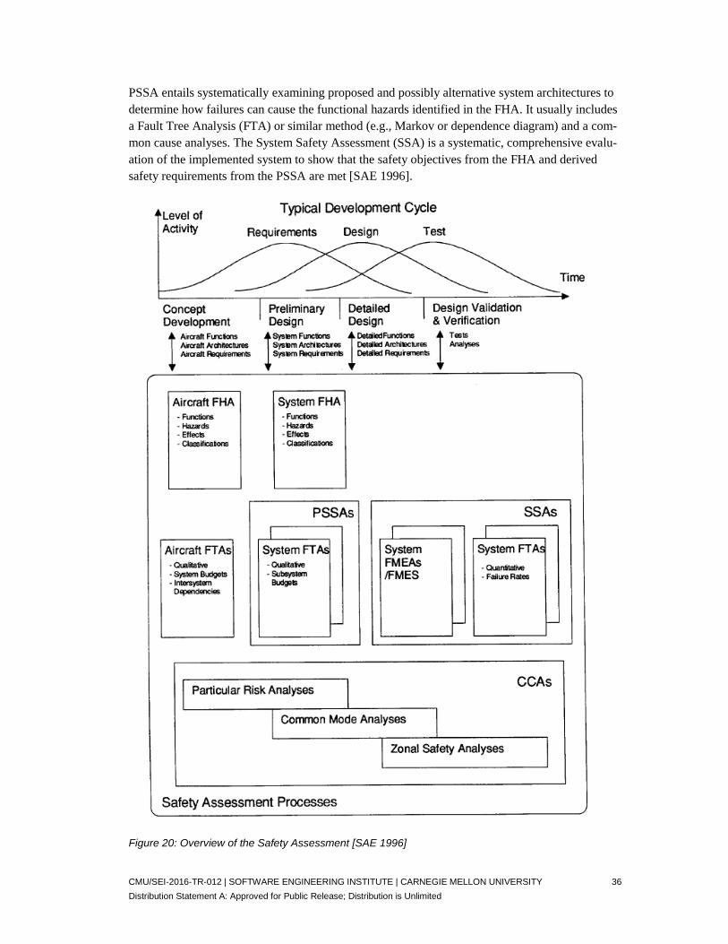
CMU/SEI-2016-TR-012 | SOFTWARE ENGINEERING INSTITUTE | CARNEGIE MELLON UNIVERSITY 36
Distribution Statement A: Approved for Public Release; Distribution is Unlimited
PSSA entails systematically examining proposed and possibly alternative system architectures to determine how failures can cause the functional hazards identified in the FHA. It usually includes a Fault Tree Analysis (FTA) or similar method (e.g., Markov or dependence diagram) and a com-mon cause analyses. The System Safety Assessment (SSA) is a systematic, comprehensive evalu-ation of the implemented system to show that the safety objectives from the FHA and derived safety requirements from the PSSA are met [SAE 1996].
Figure 20: Overview of the Safety Assessment [SAE 1996]

CMU/SEI-2016-TR-012 | SOFTWARE ENGINEERING INSTITUTE | CARNEGIE MELLON UNIVERSITY 37
Distribution Statement A: Approved for Public Release; Distribution is Unlimited
8.2 The System-Theoretical Process Analysis (STPA)
Within the System-Theoretical Process Analysis (STPA), potential accidents and associated haz-ards are identified for a system.
A summary of the STPA practices is shown in Figure 21. The practices are evolving and the sum-mary is a composite drawn from a number of sources [Leveson 2012, 2013, 2014]. The approach is based upon the Systems-Theoretic Accident Model and Processes (STAMP) causality model, where safety is viewed as an issue of the control and enforcement of safety constraints. With this perspective, accidents result from inadequate control or enforcement of safety constraints [Leveson 2012, 2013, 2014].
The initial steps entail defining the system, top-level hazards and safety constraints and establish-ing the engineering foundations for the implementation of the method. The core of the method consists of two principal steps of identifying unsafe control actions and identifying their causes (causal factors). The completion of these steps establishes how potentially hazardous control ac-tions can occur. An outcome of the process is the definition of the safety requirements (safety constraints). Thus, the method can be used as part of a comprehensive safety-guided design prac-tice [Leveson 2012].
STPA Practices
Identify unsafe control actions
Identify causal factors/scenarios• Identify controller process models • Analyze controller, control path,
feedback path, process
System Level AnalysisIdentify • accidents• hazards• safety constraints
Define Control Structures• system level• iterative & hierarchical
Unsafe Control Actions (tables)• Not Providing Causes Hazard• Providing Causes Hazard• Incorrect Timing/Order• Stopped Too Soon/Applied Too Long
• Control Structures
Establishing the System and engineering foundations
Identifying • Unsafe Control Actions• Causes of Unsafe Control Actions• How potentially hazardous
control actions could occur
processoutputartifact
Legend
Safety Requirements(safety constraints)
• accidents• hazards
• Causal Scenarios (causal factors)
referenceartifact
Control Flaws-Causal Factors
Generic SafetyControl Structure
Process is iterative
Control Actions Contexts (tables)
Figure 21: Summary of STPA Practices
The generic safety control structures are shown in Figure 22. This is used as a reference to define the broad safety control environment for a specific application.

CMU/SEI-2016-TR-012 | SOFTWARE ENGINEERING INSTITUTE | CARNEGIE MELLON UNIVERSITY 38
Distribution Statement A: Approved for Public Release; Distribution is Unlimited
Figure 22: Generic Safety Control Structure [Leveson 2013]
The dashed outline shown in Figure 22 identifies the focus for an operational safety/hazard analy-sis—the operating process (e.g., pilots and aircraft). The analysis of the operating process is not completely independent of the broader considerations, as evidenced by the interfaces with other elements of the system development and systems operations, shown in Figure 22.
The potential control flaws-causal factors diagram, shown in Figure 23, is used to guide the safety/hazard analysis. It provides a framework but the annotations in the diagram should not be taken as “guidewords.” The goal of using the diagram is to find scenarios and combinations of problems that could lead to unsafe control as well as failures or inadequate operation of individual components [Leveson 2013].

CMU/SEI-2016-TR-012 | SOFTWARE ENGINEERING INSTITUTE | CARNEGIE MELLON UNIVERSITY 39
Distribution Statement A: Approved for Public Release; Distribution is Unlimited
Figure 23: Potential Control Flaws-Causal Factors: from Leveson [Leveson 2012] and modified accord-ing to Leveson [Leveson 2013]

CMU/SEI-2016-TR-012 | SOFTWARE ENGINEERING INSTITUTE | CARNEGIE MELLON UNIVERSITY 40
Distribution Statement A: Approved for Public Release; Distribution is Unlimited
Appendix B ALSA (EMV2) Error Ontology
The major error types used in the ALSA process and taken from the error ontology described in the SAE Architecture Analysis and Design Language (AADL) Annex Volume 3: Annex E: Error Model Language (EMV2) [SAE 2012b] are summarized in Table 14.
Table 14: Error Ontology Major Error Types
Error Type Description
Service Errors
Service errors are anomalies in the number of items delivered by a service. These are partitioned into item delivered unexpected (com-mission errors) of items and expected items not delivered (omission errors).
Value Errors
Value errors are anomalies in the content (value) of individual ser-vice items, of a sequence of services items, and of a service as a whole.
Timing Errors Timing errors are anomalies in the timing of individual service items, of a sequence of service items, and the service as a whole.
Replication Errors Replication errors are anomalies in the delivery of replicated ser-vices.
Concurrency Errors Concurrency errors are anomalies in the behavior of concurrent systems (e.g., race conditions, deadlock, and starvation).
Access Control Errors
Access control errors are anomalies in the operation of access con-trol services (e.g., authorization, authentication).
Table 15 and Table 16 present a tabular format for identifying and documenting hazards using the ALSA (EMV2) error ontology as guidance. Reference Appendix C AADL Error Model Lan-guage Ontology for additional descriptions of these error types.
Table 15: Service, Value, and Timing Errors
Errors IDs Hazard Description
Service Errors
Commission Unexpected services provided Unexpected service item(s) provided Sequence Commission o Early service start o Late service termination
Omission No service items Delivered One service Item Not Delivered Sequence Omission o Late service start o Early service termination o Transient service omission o Bounded Omission Interval o Bounded Omission Sequence - not in tree

CMU/SEI-2016-TR-012 | SOFTWARE ENGINEERING INSTITUTE | CARNEGIE MELLON UNIVERSITY 41
Distribution Statement A: Approved for Public Release; Distribution is Unlimited
Errors IDs Hazard Description
Value Errors
Item Value Error (incorrect value, value cor-ruption) Detectable error o Out of range Below range Above range
o Out of bounds (outside acceptable set) Undetectable value error
Sequence value error Bounded value change Stuck value Out of order
Service value error Out of calibration
Timing Errors
Item timing Early item delivery Late item delivery
Sequence Timing (Rate Error) High rate Low rate Rate jitter
Service Timing Early service Delayed service
Table 16: Replication, Concurrency, and Access Control Errors
Errors IDs Hazard Description
Replication Errors
Asymmetric Replication Error Asymmetric timing (inconsistent timing) Asymmetric value (inconsistent value) o Approximate value error o Exact value error
Asymmetric Omission (inconsistent omission) o Service omission o Item omission
Symmetric Replication Error Symmetric value error Symmetric omission error Symmetric timing error
Concurrency Errors
Race Condition o Read-Write o Write-Write
Mutual Exclusion Errors o Deadlock o Starvation
Access Control Errors
Authorization Error Authentication Error

CMU/SEI-2016-TR-012 | SOFTWARE ENGINEERING INSTITUTE | CARNEGIE MELLON UNIVERSITY 42
Distribution Statement A: Approved for Public Release; Distribution is Unlimited
8.3 Relationship of ALSA and STPA
In general, we agree with Procter and Hatcliff in that port connections provide a path for control actions, described by Leveson, that can impact the state of interconnected architecture elements [Procter 2014, Leveson 2012]. We also include the impact on the state machines of elements in-terconnected via non-port interactions such as access connections, bindings, and other non-archi-tecture specified interactions (e.g., heat radiation).
Similar to that noted by Procter, the EMV2 error ontology provides a set of types for describing and detailing the unsafe control action causal categories described by Leveson [Procter 2014, Leveson 2012]. This is shown in Table 17, where EMV2 error ontology types are mapped into the STPA unsafe control action table. We can consider these as detailed guide words to facilitate haz-ard identification under each unsafe control action category.
Table 17: EMV2 Error Types and STPA Control Action Hazard Guide
Control
Action
Not providing
causes hazard
Providing causes
hazard
Too early/too
late causes
hazard
Stopping too
soon/applying
too long
causes hazard
Service Omission Item Omission Sequence Omis-sion (late/transi-ent/early termina-tion/bounded omission/bounded Omission Se-quence)
Item Commission Service Commission Service Value Error (out of cal-ibration) Item Value Error (out of bounds, out of range (be-low/above) ) Sequence Value Error (Stuck Value, Out of Order, Bounded Value Change)
Service Timing Error (early/delayed) Item Timing Error (early/late)
Sequence Commis-sion (early start, transient, late termi-nation) Sequence Timing Error (high, low, jit-ter)

CMU/SEI-2016-TR-012 | SOFTWARE ENGINEERING INSTITUTE | CARNEGIE MELLON UNIVERSITY 43
Distribution Statement A: Approved for Public Release; Distribution is Unlimited
Appendix C AADL Error Model Language Ontology
This is a listing of the Annex E: Error Model Language (EMV2) error types with their descrip-tions [SAE 2012b].
Service Errors
Service Omissions are errors where no service items are delivered.
Item Omissions are errors where one service item is not delivered.
Sequence Omissions are errors associated with the delivery or timing of a sequence of service items. They include the following:
Late Service Start is an error where no service items are provided for a period of time at the beginning of the service.
Early Service Termination is an error where no service items are provided after at least one service item has been delivered.
Transient Service Omission is an error where a certain number of consecutive service item omissions occur before delivery of service items resumes.
Bounded Omission Interval is an error where a service item omission is followed by a second service item omission before k correct service items are delivered. A parameter k specifies the expected minimum interval between two item omissions.
Bounded Omission Sequence is an error where a certain number of consecutive service item omissions occur. A parameter k specifies the number of consecutive item omissions. For exam-ple, cyclic redundancy check (CRC) on satellite transmission allows some lost packets, but be-yond the limit of the CRC, further packet loss causes loss of communication.
Item Commission is an error where an extra service item is provided that is not expected.
Service Commission errors involve delivery of services that are not expected.
Sequence Commission Errors involve service errors associated with the timing of the delivery of a sequence of service items.
Early Service Start is an error where extra service items are provided for a time interval be-fore the beginning of the expected service.
Transient Service Commission represents an error where a certain number of consecutive service item omissions occur before delivery of service items resumes. This represents tran-sient item omission sequences.
Late Service Termination is an error where extra service items are provided after the service end time.
Service Value Errors
Service Value Errors are value errors related to the service as a whole (e.g., Out Of Calibration).

CMU/SEI-2016-TR-012 | SOFTWARE ENGINEERING INSTITUTE | CARNEGIE MELLON UNIVERSITY 44
Distribution Statement A: Approved for Public Release; Distribution is Unlimited
Out Of Calibration is an error where the actual values of a sequence differ by more than a tolerance but roughly constant offset C from the correct value.
Item Value Error is any type of erroneous value for an individual service item.
Out Of Bounds (detectable) is an error where a service item value falls outside an acceptable set of values as determined by an application domain function (e.g., the stable control bounds of a control algorithm).
Out of Range (detectable) is an error where a service item value falls outside the range of ex-pected values for the service. There are two types
Above Range error
Below Range error
Value Error (undetectable)
Sequence Value Error (Stuck Value, Out of Order, Bounded Value Change) Sequence Value Er-ror are value errors related to the sequence of service items.
Stuck Value is an error where a service delivers service items whose value stays constant starting with a given service item.
Out Of Order are errors where a service delivers a service item in a time slot other than its expected time-slot.
Bounded Value Change is an error where a service delivers service items whose value changes by more than an expected value.
Timing Related Errors
Service Timing Errors are timing errors relating to the service as a whole.
Early Service are errors where a service delivers all service items early with a constant time shift, but otherwise correctly.
Delayed Service are errors where a service delivers all service items late with a constant time delay, but otherwise correctly.
Item Timing Error are errors where a service item is delivered outside its expected time range
Early Delivery are errors where a service item is delivered before the expected time range.
Late Delivery are errors where a service item is delivered after the expected time range.
Sequence Timing Error (Rate Error) are errors associated with the inter-arrival time of service items (i.e., the time interval between deliveries of successive service items).
High Rate errors are when the inter-arrival time of all service items is less than the expected inter-arrival time.
Low Rate errors are when the inter-arrival time of all service items is greater than the ex-pected inter-arrival time.
Rate Jitter are errors where a service delivers service items at a rate that varies from the ex-pected rate by more than an acceptable tolerance.

CMU/SEI-2016-TR-012 | SOFTWARE ENGINEERING INSTITUTE | CARNEGIE MELLON UNIVERSITY 45
Distribution Statement A: Approved for Public Release; Distribution is Unlimited
The hierarchical structure of the error types is shown in Figure 24 through Figure 26.
Figure 24: Service Type Errors [SAE 2009]
Figure 25: Value Related Errors [SAE 2009]
Figure 26: Timing Related Errors [SAE 2012b]

CMU/SEI-2016-TR-012 | SOFTWARE ENGINEERING INSTITUTE | CARNEGIE MELLON UNIVERSITY 46
Distribution Statement A: Approved for Public Release; Distribution is Unlimited
Appendix D Terminology
Throughout this document we use the relevant terminology as defined in the AADL Error Annex standard [SAE 2012b] as well as the definitions included below.
Accident: An undesired or unplanned event that results in a loss, including loss of human life or human injury, property damage, environmental pollution, mission loss, etc. [Leveson 2012].
Safety Risk: a value judgment (concern and likelihood) made upon the potential implications of current conditions (hazard) that suggests a possible transition into an undesirable condi-tion (accident or harm).
A comparative compilation of definitions for safety and reliability related terms is presented in Table 18.

CMU/SEI-2016-TR-012 | SOFTWARE ENGINEERING INSTITUTE | CARNEGIE MELLON UNIVERSITY 47
Distribution Statement A: Approved for Public Release; Distribution is Unlimited
Table 18: Comparative Table of Safety and Reliability Terms
Term ALISA (AADL Error Model) [SAE 2012b]
ARP 4761[SAE 1996]
STPA (STAMP) [Leveson 2012]
IEEE 24765
accident
reference the STPA definition. An undesired or unplanned event
that results in a loss, including loss of human life or human in-jury, property damage, environ-mental pollution, mission loss, etc.
an unplanned event or series of events that results in death, injury, illness, environmental damage, or damage to or loss of equipment or property. IEEE Std 1228-1994 (R2002) IEEE Standard for Soft-ware Safety Plans.3.1.1
hazard
any exceptional system state or exceptional condition on inter-acting system components or el-ements of the operational envi-ronment that potentially result in harm.
In EMV2 hazards are repre-sented by a multi-valued prop-erty that can be associated with the error source, error state, and error propagation.
A potentially unsafe con-dition resulting from fail-ures, malfunctions, exter-nal events, errors, or a combination thereof.
A system state or set of conditions that, together with a particular set of worst-case environment condi-tions, will lead to an accident (loss).
1. an intrinsic property or condition that has the potential to cause harm or damage. IEEE Std 1012-2004 IEEE Standard for Software Verifica-tion and Validation.3.1.11.
2. a source of potential harm or a situation with a potential for harm in terms of human injury, dam-age to health, property, or the environment, or some combination of these. IEEE Std 1012-2004 IEEE Standard for Software Verification and Val-idation.3.1.11
error
The term error encompasses mistakes by humans resulting in incorrect design or code, defects in a process that can lead to in-correct design or operational system, the effect of incorrect system behavior, and a charac-terization of incorrect behavior as an indication of a failure. In other words, error is the most general and comprehensive term for dealing with architecture er-ror modeling.—based upon ISO/IEC/IEEE 24765:2010
1. An occurrence arising as a result of an incorrect action or decision by per-sonnel operating or main-taining a system. (JAA AMJ 25.1309)
2. A mistake in specifica-tion, design, or implemen-tation.
1. a human action that produces an incorrect re-sult, such as software containing a fault.
2. an incorrect step, process, or data definition.
3. an incorrect result.
4. the difference between a computed, observed, or measured value or condition and the true, spec-ified, or theoretically correct value or condition

CMU/SEI-2016-TR-012 | SOFTWARE ENGINEERING INSTITUTE | CARNEGIE MELLON UNIVERSITY 48
Distribution Statement A: Approved for Public Release; Distribution is Unlimited
Term ALISA (AADL Error Model) [SAE 2012b]
ARP 4761[SAE 1996]
STPA (STAMP) [Leveson 2012]
IEEE 24765
fault
A fault is a root (phenomenolog-ical) cause of an error that can potentially result in a failure, i.e., an anomalous undesired change in the structure or data within a component. A fault may cause that component to eventu-ally not perform according to its nominal specification and result in malfunction or loss of func-tion, i.e., result in a failure.
EMV2v represents different types of faults as error types. In the error propagation abstrac-tion, the presence of the fault in a component is expressed as an error source with the appropriate error type as the origin. In a component error behavior ab-straction, a fault is expressed as an error event with an error type. An instance of an error event represents the activation of a fault, i.e., a failure.—based upon ISO/IEC/IEEE 24765:2010
An undesired anomaly in an item or system.
1. a manifestation of an error in software. 2. an in-correct step, process, or data definition in a com-puter program. 3. a defect in a hardware device or component. Syn: bug --- NOTE: A fault, if en-countered, may cause a failure.
failure
is a deviation in behavior from a nominal specification resulting in malfunction and loss of func-tion, i.e., a component no longer functions as intended. This may be due to an activated fault within the component, due to er-ror propagation from another component, or due to excep-tional conditions when interact-ing with other components. The
A loss of function or a malfunction of a system or a part thereof. Note: This differs from the ARP 4754 definition and conforms to the AC/AMJ 25.1309 defi-nition.
the non-performance or inability of a component (or system) to perform its intended function. In-tended function (and thus failure) is defined with respect to the component’s behavior require-ments.
Alternatively, a change to the sys-tem or a part in it (e.g., a crack)
1. termination of the ability of a product to per-form a required function or its inability to perform within previously specified limits. ISO/IEC 25000:2005, Software Engineering — Software product Quality Requirements and Evaluation (SQuaRE) — Guide to SQuaRE.4.20.
2. an event in which a system or system compo-nent does not perform a required function within specified limits

CMU/SEI-2016-TR-012 | SOFTWARE ENGINEERING INSTITUTE | CARNEGIE MELLON UNIVERSITY 49
Distribution Statement A: Approved for Public Release; Distribution is Unlimited
Term ALISA (AADL Error Model) [SAE 2012b]
ARP 4761[SAE 1996]
STPA (STAMP) [Leveson 2012]
IEEE 24765
deviation can be characterized by type of failure, persistence, and degree of severity. The de-gree to which a failure affects nominal behavior is referred to as severity of the failure.
In EMV2, failures are repre-sented as occurrence instances of error sources and instances of er-ror events. Error event instances cause transitions to an error state, which represents the com-ponent failure mode. An error source identifies an outgoing er-ror propagation including error type, reflecting that the failure mode of a component (error state) can affect components it interacts with. The propagation paths are determined by the AADL core model—based upon ISO/IEC/IEEE 24765:2010
such that it no longer meets its re-quirements.

CMU/SEI-2016-TR-012 | SOFTWARE ENGINEERING INSTITUTE | CARNEGIE MELLON UNIVERSITY 50
Distribution Statement A: Approved for Public Release; Distribution is Unlimited

CMU/SEI-2016-TR-012 | SOFTWARE ENGINEERING INSTITUTE | CARNEGIE MELLON UNIVERSITY 51
Distribution Statement A: Approved for Public Release; Distribution is Unlimited
References/Bibliography
URLs are valid as of the publication date of this document.
[ASTM 2013] American Society for Testing and Materials. ASTM F2761 – 09(2013), Medical Devices and Medical Systems – Essential safety requirements for equipment composing the patient-centric in-tegrated clinical environment (ICE) –Part 1: General requirements and conceptual model. 2013. http://www.astm.org/Standards/F2761.htm
[Clements 2011] Clements, P.; Bachman Felix; Bass, Len; Garlan, David; Ivers, James; Little, Reed; Merson, Paulo; Nord, Robert; & Stafford, Judith. Documenting Software Architectures: Views and Beyond, 2nd ed. Addison-Wesley. 2011.
[DEC 2016] Distributed Engine Controls Working Group Consortium. History of Distributed Engine Controls for Propulsion Systems. http://www.decwg.org/pages/history.html (Accessed October 24, 2016)
[Delange 2014] Delange, Julien; Feiler, Peter; Gluch, David; & Hudak, John. AADL Fault Modeling and Analysis Within an ARP4761 Safety Assessment (CMU/SEI-2014-TR-020). Software Engineering Institute, Carnegie Mellon University. 2014. http://resources.sei.cmu.edu/library/asset-view.cfm?as-setid=311884
[de Niz 2012] de Niz, D.; Feiler, P. H.; Gluch, D. P.; & Wrage L. A Virtual Upgrade Validation Method for Soft-ware-Reliant Systems. CMU/SEI-2012-TR-005. Software Engineering Institute, Carnegie Mellon University. 2012. http://resources.sei.cmu.edu/library/asset-view.cfm?assetid=10115
[FAA 2009] Federal Aviation Administration. Requirements Engineering Management Handbook DOT/FAA/AR-08/32. 2009. http://www.faa.gov/aircraft/air_cert/design_approvals/air_software/media/AR-08-32.pdf
[Feiler 2009a] Feiler, P. Modeling the Implementations of State-Based System Architectures. Pages 377-382. In Proceedings of the 14th IEEE International Conference on Engineering Complex Computer Sys-tems. Potsdam, Germany. June 2009.
[Feiler 2009b] Feiler, P.; Hansson J.; de Niz, D.; & Wrage, L. System Architecture Virtual Integration: An Industrial Case Study. CMU/SEI-2009-TR-017. Software Engineering Institute, Carnegie Mellon University. November 2009. http://resources.sei.cmu.edu/library/asset-view.cfm?assetid=9145

CMU/SEI-2016-TR-012 | SOFTWARE ENGINEERING INSTITUTE | CARNEGIE MELLON UNIVERSITY 52
Distribution Statement A: Approved for Public Release; Distribution is Unlimited
[Feiler 2009c] Peter H. Feiler. Challenges in Validating Safety-Critical Embedded Systems. Pages 109-116. In Proceedings of SAE International AeroTech Congress. Seattle WA. November 2009.
[Feiler 2009d] Feiler, P.; Hansson, J. de Niz, D.; & Wrage, L. System Architecture Virtual Integration: An Indus-trial Case Study. CMU/SEI-2009-TR-017. Software Engineering Institute, Carnegie Mellon Uni-versity. 2009. http://resources.sei.cmu.edu/library/asset-view.cfm?assetid=9145
[Feiler 2012] Feiler, Peter H. & Gluch, David P. Model-Based Engineering with AADL: An Introduction to the SAE Architecture Analysis & Design Language. Addison-Wesley. 2012.
[Feiler 2015] Peter H. Feiler. Requirements and Architecture Specification of the Joint Multi-Role (JMR) Joint Common Architecture (JCA) Demonstration System. CMU/SEI-2015-SR-031. Software Engineer-ing institute, Carnegie Mellon University. 2015. http://resources.sei.cmu.edu/library/asset-view.cfm?assetid=447184
[Garg 2012] Garg, Sanjay. Fundamentals of Aircraft Turbine Engine Control. NASA. 2012 http://www.grc.nasa.gov/WWW/cdtb/aboutus/Fundamentals_of_Engine_Control.pdf
[Galin 2004] Galin, D. Software Quality Assurance: From Theory to Implementation. Pearson/Addison-Wes-ley. 2004.
[Gluch 1994] Gluch, David. P. A Construct for Describing Software Development Risks. CMU/SEI-94-TR-14. Software Engineering Institute, Carnegie Mellon University. 1994. http://resources.sei.cmu.edu/li-brary/asset-view.cfm?assetid=12203
[Hofmeister 2000] Hofmeister, Christine; Nord, Robert; Soni, Dlip. Applied Software Architecture. Addison-Wesley. 2000.
[Im 2008] Im, Kyungsoo & McGregor, John. Debugging Software Architectures. Clemson University School of Computing. 2008. http://resources.sei.cmu.edu/asset_files/presenta-tion/2008_017_001_23286.pdf
[Im 2010] Im, Kyungsoo. Debugging Techniques for Locating Defects in Software Architectures [Doctoral Diss.]. Clemson University. 2010. http://etd.lib.clemson.edu/documents/1306855520/Im_clem-son_0050D_10926.pdf

CMU/SEI-2016-TR-012 | SOFTWARE ENGINEERING INSTITUTE | CARNEGIE MELLON UNIVERSITY 53
Distribution Statement A: Approved for Public Release; Distribution is Unlimited
[ISO 2010] International Organization for Standardization/ International Electrotechnical Commission/Insti-tute of Electrical and Electronics Engineers. ISO/IEC/IEEE 24765:2010 Systems and software en-gineering -- Vocabulary. 2010. http://www.iso.org/iso/catalogue_detail.htm?csnumber=50518
[ISO 2011] International Organization for Standardization/International Electrotechnical Commission ISO/IEC 25010:2011 Systems and software engineering -- Systems and software Quality Require-ments and Evaluation (SQuaRE) -- System and software quality models. ISO. 2011. http://www.iso.org/iso/catalogue_detail.htm?csnumber=35733
[ISO 2011] International Organization for Standardization/ International Electrotechnical Commission/Insti-tute of Electrical and Electronics Engineers. ISO/IEC/IEEE 42010:2011 Systems and software en-gineering -- Architecture description (latest edition of the original IEEE Std 1471:2000). Recom-mended Practice for Architectural Description of Software-intensive Systems. 2011.
[Jackson 2007] Jackson, Daniel; Thomas, Martyn; & Millett, Lynette I., eds. Software for Dependable Systems: Sufficient Evidence? National Research Council of the National Sciences. 2007.
[Leveson 2012] Leveson, Nancy, G. Engineering a Safer World: Systems Thinking Applied to Safety. The MIT Press. 2012.
[Leveson 2013] Leveson, Nancy & Thomas, John. An STPA Primer, Version 1 (Updated June 2015). http://psas.scripts.mit.edu/home/wp-content/uploads/2015/06/STPA-Primer-v1.pdf
[Leveson 2014] Leveson, Nancy; Fleming, Cody; & Thomas, John. A Comparison of STPA and the ARP 4761 Safety Assessment Process. Massachusetts Institute of Technology. 2014.
[Medvidovic 1999] Medvidovic N.; Rosenblum D.S.; & Taylor R.N. A Language and Environment for Architecture-Based Software Development and Evolution. Pages 44-53. In Proceedings of the 21st Interna-tional Conference on Software Engineering (ICSE’99). Los Angeles, CA. May 1999.
[NIST 2002] National Institute of Standards and Technology. The Economic Impacts of Inadequate Infrastructure for Software Testing (Planning Report 02-3). NIST. 2002.
[Paige 2009] Paige, Richard F.; Rose, Louis M.; Xiaocheng Ge; Kolovos, Dimitrios S. Kolovos; & Brooke, Phillip J. 2009. FPTC: Automated Safety Analysis for Domain-Specific Languages. In Models in Software Engineering, Michel R. Chaudron, ed. Lecture Notes in Computer Science. Volume

CMU/SEI-2016-TR-012 | SOFTWARE ENGINEERING INSTITUTE | CARNEGIE MELLON UNIVERSITY 54
Distribution Statement A: Approved for Public Release; Distribution is Unlimited
5421. Pages 229-242. Springer-Verlag, Berlin, Heidelberg. http://link.springer.com/chap-ter/10.1007%2F978-3-642-01648-6_25#page-2
[Parnas 1991] Parnas, D. & Madey, J. Functional Documentation for Computer Systems Engineering (Version 2). Technical Report CRL 237. McMaster University. 1991.
[Powell 1992] Powell, D. Failure Mode Assumptions and Assumption Coverage. Pages 386-395. Digest of Pa-pers: Twenty-Second International Symposium on Fault-Tolerant Computing (FTCS-22). Boston, MA. July 1992. http://ieeexplore.ieee.org/xpl/mostRecentIssue.jsp?punumber=420
[Procter 2014] Procter, S & Hatcliff, J. An architecturally-integrated, systems-based hazard analysis for medical applications. Pages 124-133. Formal Methods and Models for Codesign (MEMOCODE 2014) collocated with Twelfth ACM/IEEE International Conference on Formal Methods and Models for System Design. Lausanne, Switzerland. October 2014.
[Procter 2016] Procter, S. A Development and Assurance Process for Medical Application Platforms Platform Apps [Doctoral Diss.] Kansas State University. 2016. https://krex.k-state.edu/dspace/handle/2097/32861
[Rasmussen 2000] Rasmussen, Jens & Svending, Inge. Risk Management in a Dynamic Society. Swedish Rescue Services Agency. 2000. https://www.msb.se/RibData/Filer/pdf/16252.pdf
[Roshandel 2003] Roshandel, Roshanak; Schmerl, Bradley; Medvidovic, Nenad; Garlan, David; Zhang, Dehua. Using Multiple Views to Model and Analyze Software Architecture: An Experience Report. Technical Report USC-CSE-2003-508. University of Southern California, Center for Software Engineering. 2003.
[Roshandel 2006] Roshandel, Roshanak, Calculating Architectural Reliability via Modeling and Analysis. [Doctoral Diss.] University of Southern California. 2006.
[SAE 2012a] SAE International. SAE AS-5506B:2012, Architecture Analysis & Design Language (AADL). September 2012. (Original publication in 2004.) http://standards.sae.org/as5506b/
[SAE 2012b] SAE International. SAE Architecture Analysis and Design Language (AADL) Annex Volume 3, Standards document AS5506E. DRAFT 10/29/2012. October 2012.
CMU/SEI-2016-TR-012 | SOFTWARE ENGINEERING INSTITUTE | CARNEGIE MELLON UNIVERSITY 55
Distribution Statement A: Approved for Public Release; Distribution is Unlimited
[SAE 2011] SAE International. SAE AS-5506/2:2011, SAE Architecture Analysis and Design Language (AADL) Annex Volume 2: Annex B: Data Modeling Annex; Annex D: Behavior Model Annex; An-nex F: ARINC653 Annex. 2011.
[SAE 2010] SAE International. Guidelines for Development of Civil Aircraft and Systems. 2010. http://stand-ards.sae.org/arp4754a/
[SAE 2009] SAE International. Architecture Analysis & Design Language (AADL), Standards document AS5506A. November 2004, Revised January 2009. http://www.sae.org/tech-nical/standards/AS5506A
[SAE 2006] SAE International. SAE AS-5506/1:2006, SAE Architecture Analysis and Design Language (AADL) Annex Volume 1: Annex A: Graphical AADL Notation, Annex C: AADL Meta-Model and Interchange Formats, Annex D: Language Compliance and Application Program Interface, An-nex E: Error Model Annex. 2006. Revision Error Model V2 in ballot for 2014 publication.
[SAE 1996] SAE International. ARP4761: Guidelines and Methods for Conducting the Safety Assessment Pro-cess on Civil Airborne Systems and Equipment. http://standards.sae.org/arp4761/
[Thomas 2012] Thomas, J.; de Lmos, F. L.; Leveson, N. Evaluating the Safety of Digital Instrumentation and Control Systems in Nuclear Power Plants. MIT Research Report: NRC-HQ-11-6-04-0060. Massachusetts Institute of Technology. 2012.
[Walter 2003] Walter C. & Suri, N. The Customizable Fault/Error Model for Dependable Distributed Systems. Theoretical Computer Science. Number 290. 2003. Pages 1223-1251. http://another-sample.net/the-customizable-fault-error-model-for-dependable-distributed-systems
[Weiss 2006] Weiss, K. A.; Dulac, N.; Chiesi, S.; Daouk, M.; Zipkin, D.; & Leveson, N. Engineering Space-craft Mission Software using a Model-Based and Safety-Driven Design Methodology. Journal of Aerospace Computing, Information, and Communication. Volume 3. Issue 11. November 2006. Pages 562-586.

CMU/SEI-2016-TR-012 | SOFTWARE ENGINEERING INSTITUTE | CARNEGIE MELLON UNIVERSITY
Distribution Statement A: Approved for Public Release; Distribution is Unlimited
REPORT DOCUMENTATION PAGE Form Approved OMB No. 0704-0188
Public reporting burden for this collection of information is estimated to average 1 hour per response, including the time for reviewing instructions, search-ing existing data sources, gathering and maintaining the data needed, and completing and reviewing the collection of information. Send comments regard-ing this burden estimate or any other aspect of this collection of information, including suggestions for reducing this burden, to Washington Headquarters Services, Directorate for information Operations and Reports, 1215 Jefferson Davis Highway, Suite 1204, Arlington, VA 22202-4302, and to the Office of Management and Budget, Paperwork Reduction Project (0704-0188), Washington, DC 20503.
1. AGENCY USE ONLY
(Leave Blank)
2. REPORT DATE
December 2016
3. REPORT TYPE AND DATES COVERED
Final
4. TITLE AND SUBTITLE
Architecture-Led Safety Process
5. FUNDING NUMBERS
FA8721-05-C-0003
6. AUTHOR(S)
Peter H. Feiler, Julien Delange, David P. Gluch, John D. McGregor
7. PERFORMING ORGANIZATION NAME(S) AND ADDRESS(ES)
Software Engineering Institute Carnegie Mellon University Pittsburgh, PA 15213
8. PERFORMING ORGANIZATION REPORT NUMBER
CMU/SEI-2016-TR-012
9. SPONSORING/MONITORING AGENCY NAME(S) AND ADDRESS(ES)
AFLCMC/PZE/Hanscom Enterprise Acquisition Division 20 Schilling Circle Building 1305 n Hanscom AFB, MA 01731-2116
10. SPONSORING/MONITORING AGENCY REPORT NUMBER
n/a
11. SUPPLEMENTARY NOTES
12A DISTRIBUTION/AVAILABILITY STATEMENT
Unclassified/Unlimited, DTIC, NTIS
12B DISTRIBUTION CODE
13. ABSTRACT (MAXIMUM 200 WORDS)
Architecture-Led Safety Analysis (ALSA) is a safety analysis method that uses early architecture knowledge to supplement traditional safety analysis techniques to identify faults as early as possible. The method begins by creating a definition of the operational environ-ment within which the system under design will operate. ALSA uses the early architecture knowledge of the system and standardized error guide words to identify hazards in the system. These hazards are analyzed using knowledge of the architecture and safety require-ments, intended to mitigate the hazards, that are added to the system’s requirements. ALSA continues its analysis down the full depth of the system implementation hierarchy. As additional implementation details are defined, the hazard analysis is applied to the subcompo-nents. ALSA also cuts across many of the phases in the development lifecycle. The hazard analysis feeds the requirements definition, architecture definition, and verification and validation phases.
14. SUBJECT TERMS
architecture–led processes, ALSA, operational safety risks, operational hazards, safety archi-tecture design, AADL Error Model Language Ontology
15. NUMBER OF PAGES
63
16. PRICE CODE
17. SECURITY CLASSIFICATION OF REPORT
Unclassified
18. SECURITY CLASSIFICATION OF THIS PAGE
Unclassified
19. SECURITY CLASSIFICATION OF ABSTRACT
Unclassified
20. LIMITATION OF ABSTRACT
UL NSN 7540-01-280-5500 Standard Form 298 (Rev. 2-89) Prescribed by ANSI Std. Z39-18
298-102