Mike LewanMike Lewan11 and Dave Coxand Dave Cox22
1U.S. Geological Survey and 2Babcock & Brown Energy, Inc.Denver, CO
Applying Hydrous Pyrolysis Applying Hydrous Pyrolysis to to In SituIn Situ OilOil--shale Retortingshale Retorting

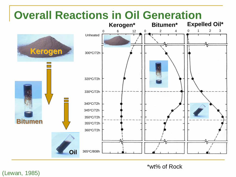
P
P
P
Generated Gases
Expelled Oil
SourceRock
200-500g0.5-2 cm
Water300-500g
He orvacuum0-25 psia
Before
After
Spent Rock
(Lewan et al., 1979)
ΔΔΔ572 to 686ºF1 to 3 days
What is hydrous pyrolysis What is hydrous pyrolysis and why consider it?and why consider it?

50
250
450
650
850
1050
1250
10
120
230
340
450
560
670Open
AnhydrousPyrolysis
OpenOpenAnhydrousAnhydrousPyrolysisPyrolysis
min.min.
ClosedAnhydrousPyrolysis
ClosedClosedAnhydrousAnhydrousPyrolysisPyrolysishourshours
Tem
pera
ture
(ºF)
Tem
pera
ture
(ºC
)
HydrousPyrolysisHydrousHydrousPyrolysisPyrolysis
daysdays
NatureNatureNature10106 6 yearsyears
CP
CP
vaporliquid
vaporliquid
H2O
nC15
Pressure (PSIA)10 100 1,000 10,000
Pyrolysis Conditions
Bitumen* Expelled Oil*0 6 12 0 2 4 0 1 2 3
Unheated
300oC/72h
Kerogen*
320oC/72h
330oC/72h
340oC/72h
345oC/72h
350oC/72h
355oC/72h
360oC/72h
365oC/808h
KerogenKerogen
OilOil
BitumenBitumenBitumen
*wt% of Rock(Lewan, 1985)
Overall Reactions in Oil Generation

PolarsPolars100%100%
SaturatesSaturates100%100%
AromaticsAromatics100%100%
Uinta Basin OilsUinta Basin Oils(Mueller, 1998)(Mueller, 1998)
Fisher Assay Oil(API = 21.9)
Fisher Assay OilFisher Assay Oil(API = 21.9)(API = 21.9)
Hydrous Pyrolysis Oil (API = 31.6)
Hydrous Pyrolysis Oil Hydrous Pyrolysis Oil (API = 31.6)(API = 31.6)
(Lewan and Ruble, 2008)
Mahogany Shale Oil (C15+)

0
15
30
45
0 15 30 45 60
1:1
Fisher Assay Fisher Assay (gal/ton)(gal/ton)
HydrousHydrousPyrolysisPyrolysis
(gal/ton)(gal/ton)
W. UintaW. UintaMahoganyMahogany
ColoradoColoradoMahoganyMahogany
HP = 0.81 FAHP = 0.81 FA
Green River MahoganyHydrous Pyrolysis vs. Fisher Assay

Hydrous
SteamSteam
DryDryDry
TotalTotalBitumenBitumenOilOilGasGas
Hydrogen SourceHydrogen Source
Immiscible OilImmiscible Oil
Yie
ld (w
t% ro
ck)
Rock
Water
Expelled OilExpelled Expelled OilOil
Quartz Reactor
Line
Increased char
662662ººF (350F (350ººC)/72hC)/72h
(Lewan, 1998)
Importance of Water

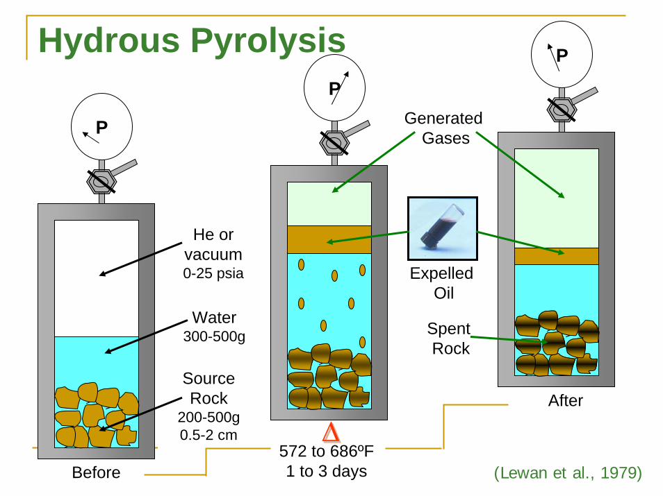
P
P
P
Generated Gases
Expelled Oil
SourceRock
200-500g0.5-2 cm
Water300-500g
He orvacuum0-25 psia
Before
After
Spent Rock
(Lewan et al., 1979)
ΔΔΔ572 to 686ºF1 to 3 days
Hydrous Pyrolysis

immature unheatedimmature unheated
Photomicrograph ofPhotomicrograph ofWoodford Shale afterWoodford Shale after
hydrous pyrolysishydrous pyrolysis572572ººF/72hF/72h
(300(300ººC)C)
KerogenKerogenKerogen
BitumenBitumenBitumen
Photomicrograph ofPhotomicrograph ofWoodford Shale beforeWoodford Shale beforehydrous pyrolysis andhydrous pyrolysis and
after 482after 482ººC/72hC/72h(250(250ººC)C)
(Lewan, 1987)
Bitumen ImpregnationBitumen Impregnationof Rock Matrixof Rock Matrix

-4
-3
-2
-1
0
1
2
0 100 200 300 400
32 192 352 512 672
Water in OilsWater in Oils
Oils in WaterOils in Water
(a) plant oils(b) aromatic HC(c) aliphatic HC
crude oil andrefined oil fractions
X
C1-C10C6-C10C10-C15C14-C20C19-C25C24-C34
Crude oilCrude oilDistillation Distillation FractionsFractions(Price, 1981)(Price, 1981)
compiled by Lewan (1998)
Temperature (ºC)
Temperature (ºF)Solubility(Log Mole %)
P
P
P
Generated Gases
Expelled Oil
SourceRock
200-500g0.5-2 cm
Water300-500g
He orvacuum0-25 psia
Before
After
Spent Rock
(Lewan et al., 1979)
ΔΔΔ572 to 686ºF1 to 3 days
Hydrous Pyrolysis

OilShale
Over-Burden
HeatingWell
Collection Well
GasFront
OilFront
BitumenFront
Simple Schematic Simple Schematic of Enhanced Natural of Enhanced Natural
Oil GenerationOil Generation(ENOG)(ENOG)

PhysiochemicalPhysiochemicalEngineeringEconomicsEnvironmental
ConsiderationsConsiderations??
??
OilShale
Over-Burden
HeatingWell
Collection Well
Enhanced Natural Oil Generation
Can ENOG be an effective method for in situ retorting?
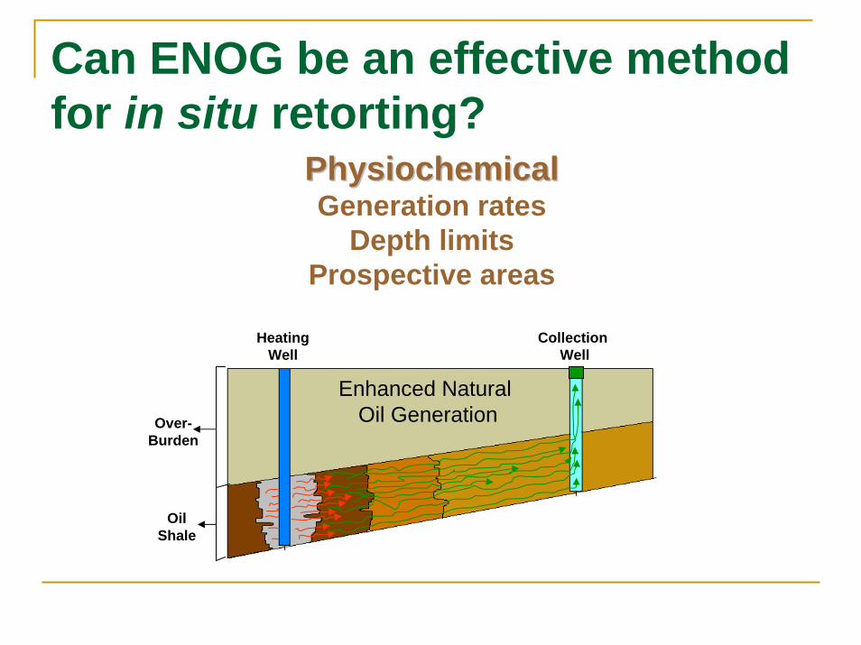
PhysiochemicalPhysiochemicalGeneration rates
Depth limitsProspective areas
OilShale
Over-Burden
HeatingWell
Collection Well
Enhanced Natural Oil Generation
Can ENOG be an effective method for in situ retorting?

Sufficient temperatures for Sufficient temperatures for retorting to occur in a retorting to occur in a
reasonable amount of timereasonable amount of time(days to months). (days to months).
15
12
9
6
3
0
-3
450 400 350 300 250 200 150
842 742 642 542 442 342
1 minute
1 hour
1 day
1 month
1 year
5 millennia
1 week
1 decade
1 century
1 million years
95%
50%
5%
100 million years
Temperature (Temperature (ººC)C)
Log
Tim
e (h
)*Lo
g Ti
me
(h)*
Temperature (Temperature (ººF)F)
*Based on HP kinetics from Ruble et al. (2001)
626 to 680626 to 680ººF (330 to 360F (330 to 360ººC).C).
Generation Rates

Sufficient depth to maintainSufficient depth to maintaina confining pressure for a confining pressure for
the presence of waterthe presence of waterat retorting temperatures ofat retorting temperatures of626 to 680626 to 680ººF (330 to 360F (330 to 360ººC). C).
4,500
3,750
3,000
2,250
1,500
750
0
50 150 250 350 450 550 650 750
10 70 130 190 250 310 370
Temperature (Temperature (ººF)F)
Dep
th (f
eet)*
Dep
th (f
eet)*
Temperature (Temperature (ººC)C)
Water
CP
*Based on frac gradient 0.8 psi/ft
Steam
2,350 ft2,350 ft
3,370 ft3,370 ft
Depth Limits

Depths between 2,500 and 6,000+ feetDepths between 2,500 and 6,000+ feet
Organic richness/yield (gal/ton)Organic richness/yield (gal/ton)
Thickness of oil shale strataThickness of oil shale strata
Immature to marginally matureImmature to marginally mature
Prospect Sites

30004000
7000
8000
40003000
2000
1000
0
9000
10000
Overburden Thickness (ft)Overburden Thickness (ft)Top of the MahoganyTop of the Mahogany
Uinta Basin, UtahUinta Basin, Utah
15 miles
(L.N.R. Roberts, 2006)
60005000
ENOG Prospective AreaMahogany Oil Shale, Uinta Basin, Utah
4500
4000
3500
30002500
2000
1500
1000
500
<10
500
1000
15002000
2500
60 miles
4500
3500
1000
1500
2000
500
2500
4000
3000
5000
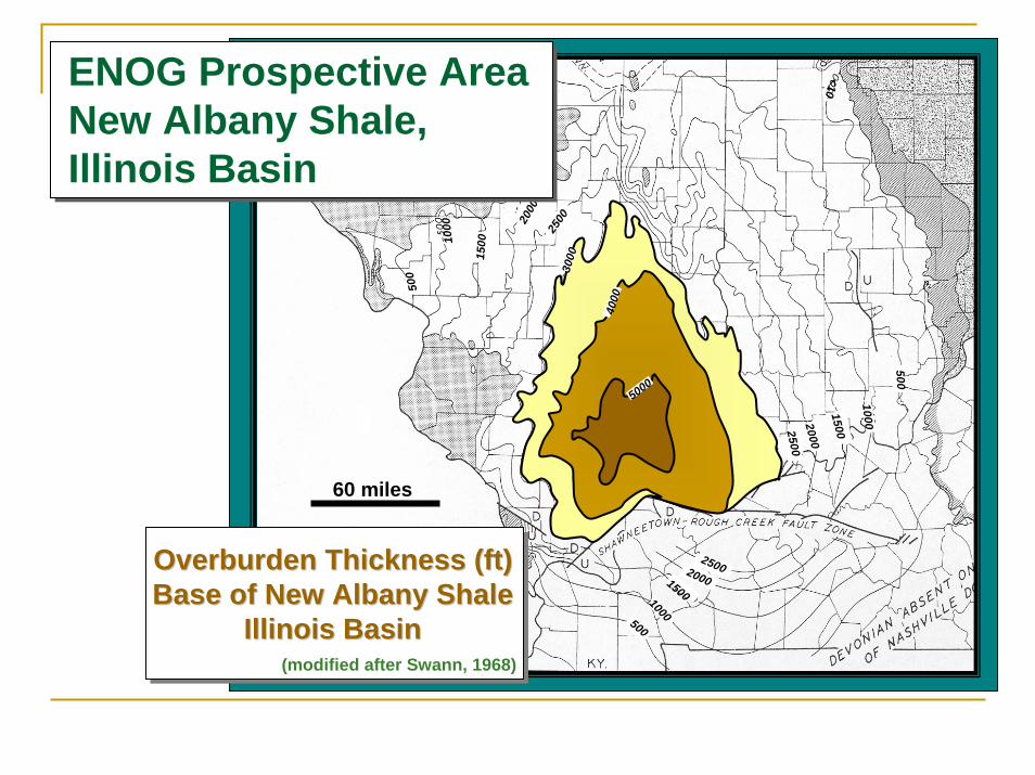
Overburden Thickness (ft)Overburden Thickness (ft)Base of New Albany ShaleBase of New Albany Shale
Illinois BasinIllinois Basin(modified after Swann, 1968)
2000
2500
ENOG Prospective AreaNew Albany Shale, Illinois Basin

Engineering/EconomicsWell Spacing
Drilling programProject Implementation
BOTE Economics
OilShale
Over-Burden
HeatingWell
Collection Well
Enhanced Natural Oil Generation
Can ENOG be an effective method for in situ retorting?

Oil shale is a poor Oil shale is a poor heat conductor, heat conductor,
which causes heat which causes heat transfer to betransfer to be
a key limitation on a key limitation on in situ in situ retorting.retorting.
Chart shows Chart shows conduction heating conduction heating results with a single results with a single
heating well.*heating well.*
Tem
pera
ture
(Te
mpe
ratu
re ( ººF)F)
Distance from Heating Well (ft)Distance from Heating Well (ft)
100
200
300
400
500
600
700
800
900
1,000
10 years 3 years
1 year 3 months
1 month 1 day
Heating Time:
0.5 1 2 5 10 20 50 100
1 day1 yr3 yr10 yr100 yr
Time for95% HC
Generation
*For 1-D radial conduction, constant flux, diffusivity α = 0.5 ft²/day, conductivity k = 0.73 Btu/hr-ft-ºFThe flux needed to reach 750ºF at the well in 3 yrs is 699 Btu/hr/ft, or 1025 kw for a 5000 ft lateral
Heat Transfer

With multiple heat With multiple heat wells, wells, interwellinterwell
temperatures risetemperatures risesignificantly.significantly.
The chart shows The chart shows conduction heating conduction heating
effects for wells effects for wells 20 feet 20 feet apart.*apart.*
Tem
pera
ture
(Te
mpe
ratu
re (ºF)F)
Distance from Heating Well (ft)Distance from Heating Well (ft)
*For 1-D radial conduction, constant flux, diffusivity α = 0.5 ft²/day, conductivity k = 0.73 Btu/hr-ft-ºFThe flux needed to reach 750ºF at the well in 3 yrs is 270 Btu/hr/ft, or 396 kw for a 5000 ft lateral
100
200
300
400
500
600
700
800
900
1,000
3 years 2 years
1 year 3 months
1 month 1 day
Heating Time:
0.5 1 2 5 10
1 day1 yr3 yr10 yr100 yr
Time for95% HC
Generation
Well Spacing Optimization Depends on Heat Transfer

Heat Wells
Prod Wells
•• Horizontal wells will likely be more efficient. Horizontal wells will likely be more efficient. •• 5000 ft laterals cost about $15000 ft laterals cost about $1±± million, or $200/ft of shale contacted. million, or $200/ft of shale contacted. •• Vertical wells cost $0.2 Vertical wells cost $0.2 ±± million each and contact 100 ft of oilmillion each and contact 100 ft of oil
shale, for a unit well cost of about $2,000 per ft contacteshale, for a unit well cost of about $2,000 per ft contacted. d.
•• Heating at close well spacing mayHeating at close well spacing maylead to induced fracturing,lead to induced fracturing,so it may be possibleso it may be possibleto use fewer productionto use fewer productionwells.wells.
xx
zz
yy
Drilling Program

There are tradeoffs between many key variables:There are tradeoffs between many key variables:1.1. Closer well spacing causes faster response but at greater capitaCloser well spacing causes faster response but at greater capital costl cost2.2. The number and location of producing wells will need to be optimThe number and location of producing wells will need to be optimizedized3.3. Some water injection wells may be necessarySome water injection wells may be necessary4.4. Faster response may also be achievable via increased heat flux, Faster response may also be achievable via increased heat flux, but at greater but at greater
operating cost and more waste heatoperating cost and more waste heat5.5. A A ““tailedtailed”” heat flux may be more efficient, with greater flux initially foheat flux may be more efficient, with greater flux initially followed by llowed by
lower heat injection laterlower heat injection later
Other considerations include:Other considerations include:•• Optimal horizontal length Optimal horizontal length –– may be limited by heater technologymay be limited by heater technology•• Optimal hole size for heater placementOptimal hole size for heater placement•• What heaters can be used? They will likely have to be specificaWhat heaters can be used? They will likely have to be specifically developed.lly developed.•• Production methodologies. The producing wells may actually flowProduction methodologies. The producing wells may actually flow to surface.to surface.•• WorkoversWorkovers may not be possible.may not be possible.•• Lot of heat left over following production; much may be recovereLot of heat left over following production; much may be recovered.d.
Project Implementation

-- 10, 20, 30 or 40 ft 10, 20, 30 or 40 ft interwellinterwell spacingspacing-- 25 25 gptgpt richnessrichness-- 5000 ft laterals total cost $1.5 million 5000 ft laterals total cost $1.5 million -- Operating costs total $0.10/kwhOperating costs total $0.10/kwh-- $100 per barrel oil price$100 per barrel oil price-- 75% recovery of generated oil75% recovery of generated oil-- 25% royalty and production taxes25% royalty and production taxes-- All calculations are before income taxAll calculations are before income tax-- Heat entire volume to 600 Heat entire volume to 600 ººF F -- 100% thermal efficiency100% thermal efficiency-- Production occurs during 80Production occurs during 80--120% of heating time120% of heating time-- 2.0 g/cc average density2.0 g/cc average density
Back-Of-The-Envelope (BOTE) Economic Assumptions:

InterwellInterwell Spacing (ft)Spacing (ft)
BOTE Economics
BOTE Economics
Net Cash Flow, million $Rate of Return
Total Cost, $/bblOil Prod., 1000 bbl
0
50
100
150
200
250
10 20 30 40-1 2 6 11
23 20 14
168
60 40 334
36
125
223
0.8
3
6.8
12
<0
Heating Time(yrs)

CONCLUSIONS
1.1. Hydrous pyrolysis is applicable to Hydrous pyrolysis is applicable to Enhanced Natural Oil Generation (ENOG).Enhanced Natural Oil Generation (ENOG).
2. ENOG is applicable at depths greater than 2,500 ft.
3.3. ENOG should provide quality oils with ENOG should provide quality oils with yields about 80% of Fisher Assaysyields about 80% of Fisher Assays
4. Heat transfer is a controlling factor in the application and efficiency of ENOG
5.5. Horizontal wells will be more capital Horizontal wells will be more capital efficient than vertical wells at ENOG depthsefficient than vertical wells at ENOG depths