507
* Reprinted from a 1994 Elliott Company sales bulletin. The reference information contained herein is providedas an assist to developing your application. However, Elliott reserves the right to modify the design or construc-tion of the equipment described and to furnish it, as altered, without further reference to the illustrations or infor-mation contained herein.
APPENDIX B
SHORTCUT CALCULATIONS ANDGRAPHICAL COMPRESSOR SELECTION PROCEDURES
B.1 SELECTION GUIDE FOR ELLIOTT MULTISTAGE CENTRIFUGAL COMPRESSORS*
A Practical Guide to Compressor Technology, Second Edition, By Heinz P. BlochCopyright © 2006 John Wiley & Sons, Inc.
APPNB.qxd 7/29/06 2:33 PM Page 507
508 APPENDIX B
APPNB.qxd 7/29/06 2:33 PM Page 508
SHORTCUT CALCULATIONS AND SELECTION PROCEDURES 509
APPNB.qxd 7/29/06 2:33 PM Page 509
510 APPENDIX B
APPNB.qxd 7/29/06 2:33 PM Page 510
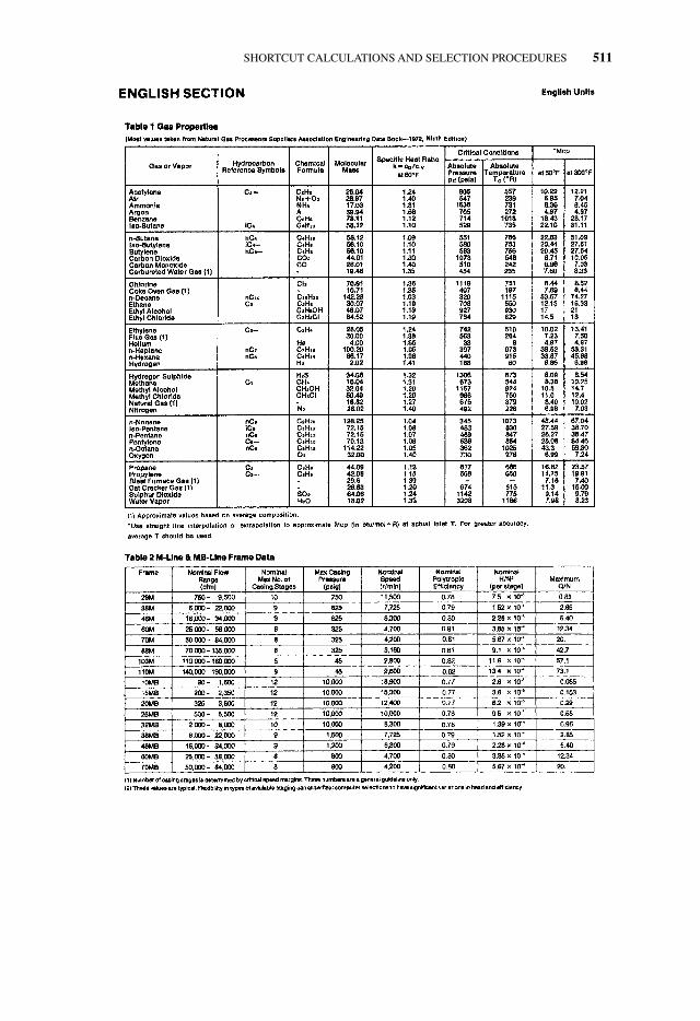
SHORTCUT CALCULATIONS AND SELECTION PROCEDURES 511
APPNB.qxd 7/29/06 2:33 PM Page 511
512 APPENDIX B
APPNB.qxd 7/29/06 2:33 PM Page 512
SHORTCUT CALCULATIONS AND SELECTION PROCEDURES 513
APPNB.qxd 7/29/06 2:33 PM Page 513
514 APPENDIX B
APPNB.qxd 7/29/06 2:33 PM Page 514
APPNB.qxd 7/29/06 2:33 PM Page 515
516 APPENDIX B
APPNB.qxd 7/29/06 2:33 PM Page 516
SHORTCUT CALCULATIONS AND SELECTION PROCEDURES 517
APPNB.qxd 7/29/06 2:33 PM Page 517
518 APPENDIX B
APPNB.qxd 7/29/06 2:33 PM Page 518
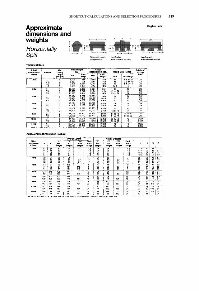
SHORTCUT CALCULATIONS AND SELECTION PROCEDURES 519
APPNB.qxd 7/29/06 2:34 PM Page 519
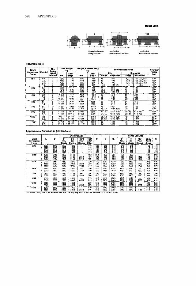
520 APPENDIX B
APPNB.qxd 7/29/06 2:34 PM Page 520
SHORTCUT CALCULATIONS AND SELECTION PROCEDURES 521
B.2 QUICK SELECTION METHODS FOR MULTISTAGE COMPRESSORS*
Among the many purely graphical methods of rapidly selecting multistage compressors isone developed around 1965 by Don Hallock of the Elliott Company, Jeannette, Pa. To usethese charts, the following quantities must be known:
1. W—weight flow, in lb/min or scfm (standard ft3/min).
2. P1—inlet pressure, in psia
3. Rp—pressure ratio (discharge psia/inlet psia)
4. t1—inlet temp., in °F
5. M—mole weight
6. K—ratio of specific heats
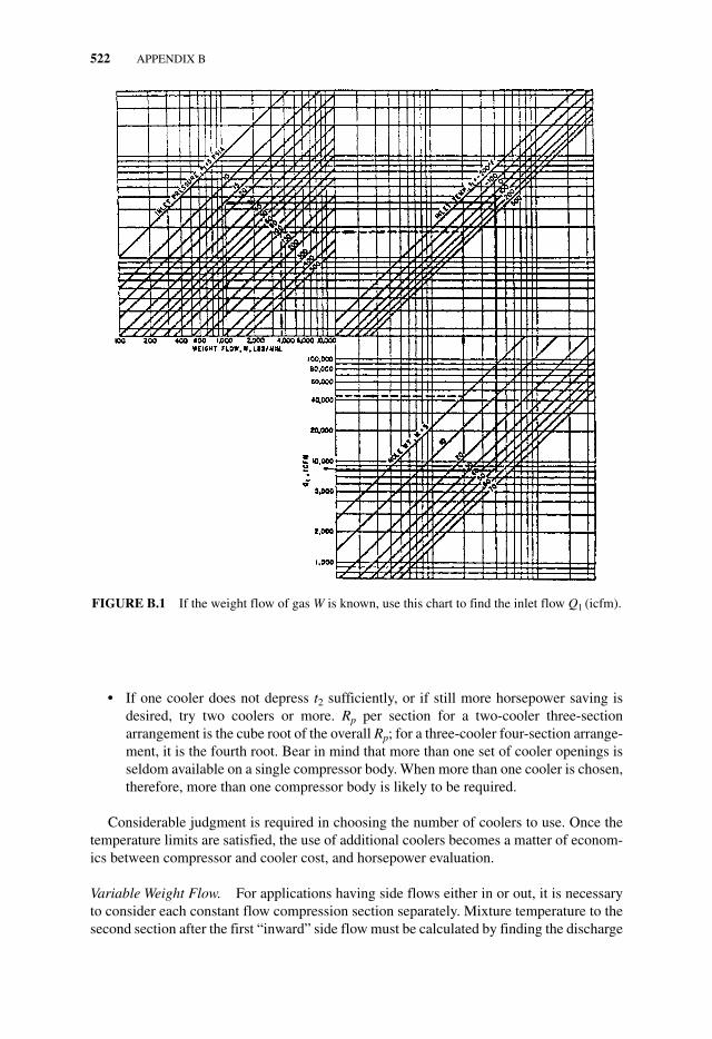
Determine the Inlet cfm, Q1. If W is known, use Fig. B.1, proceeding through P1, t1, andM to find Q1.
If scfm is known, use Fig. B.2, proceeding through P1, t1, and “temperature standard” tofind Q1.
Determine the Head H. On Fig. B.3, enter Rp and proceed through K, t1, and M as shown.If head H exceeds 80,000 to 90,000, more than one compressor body will be required.
Determine the Number of Stages Required. On Fig. B.4, enter head H and proceed throughM to read the number of stages required. Round this off to the next-higher even number.
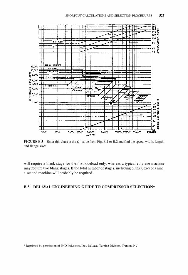
Determine the Speed and Size of the Machine. On Fig. B.5, enter Q1 and read the maxi-mum width in inches. Proceed to the stepped lines and read the rpm and flange sizes.Proceed through the number of stages and read the length of the machine in inches. In theexample shown, the icfm is 45,000 and the gas is between propane and chlorine in moleweight. The speed is shown to be 4000 rpm and the flanges are 36 and 24 in. A slightlyhigher flow requires 3500 rpm and 42- and 30-in. flanges.
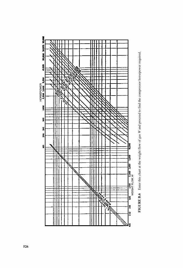
Determine the Horsepower Requirement. On Fig. B.6, enter W, proceed through Q1 andH, and read HP. If W is not known, work backward from Q1 on Fig. B.1 to find W beforeusing Fig. B.6.
For uncooled, constant weight flow compression, such as alkylation, wet gas, recycle, orair under 50 psia, the foregoing is sufficient to determine price, size, and driver require-ment. For cooled or variable weight flow compression, proceed as follows:
Cooled Compression. Assume one cooler and two compression sections, each sectionhandling a pressure ratio equal to the square root of the overall pressure ratio.
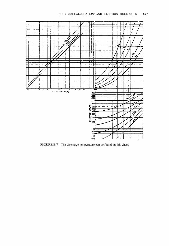
● Determine discharge temperature t2 from Fig. B.7, proceeding through Rp, Q1, K, and t1.● Assuming that this t2 is satisfactory, proceed through all the figures for each of the
separate sections. Speed and width of the compressor will be dictated by the first sec-tions. The total horsepower is the sum of the sections.
* Developed and contributed by Don Hallock, Elliott Company, Jeannette, Pa. Adapted by permission of HP andthe Elliott Company. Originally published in the October 1965 issue of Hydrocarbon Processing.
APPNB.qxd 7/29/06 2:34 PM Page 521
522 APPENDIX B
● If one cooler does not depress t2 sufficiently, or if still more horsepower saving isdesired, try two coolers or more. Rp per section for a two-cooler three-sectionarrangement is the cube root of the overall Rp; for a three-cooler four-section arrange-ment, it is the fourth root. Bear in mind that more than one set of cooler openings isseldom available on a single compressor body. When more than one cooler is chosen,therefore, more than one compressor body is likely to be required.
Considerable judgment is required in choosing the number of coolers to use. Once thetemperature limits are satisfied, the use of additional coolers becomes a matter of econom-ics between compressor and cooler cost, and horsepower evaluation.
Variable Weight Flow. For applications having side flows either in or out, it is necessaryto consider each constant flow compression section separately. Mixture temperature to thesecond section after the first “inward” side flow must be calculated by finding the discharge
FIGURE B.1 If the weight flow of gas W is known, use this chart to find the inlet flow Q1 (icfm).
APPNB.qxd 7/29/06 2:34 PM Page 522
SHORTCUT CALCULATIONS AND SELECTION PROCEDURES 523
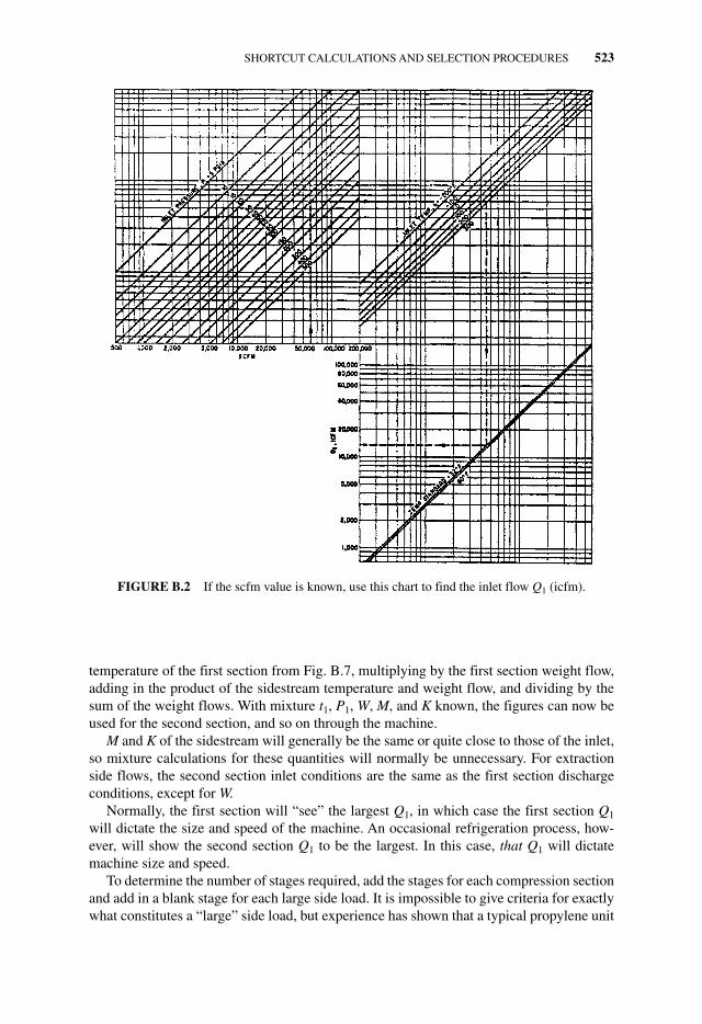
temperature of the first section from Fig. B.7, multiplying by the first section weight flow,adding in the product of the sidestream temperature and weight flow, and dividing by thesum of the weight flows. With mixture t1, P1, W, M, and K known, the figures can now beused for the second section, and so on through the machine.
M and K of the sidestream will generally be the same or quite close to those of the inlet,so mixture calculations for these quantities will normally be unnecessary. For extractionside flows, the second section inlet conditions are the same as the first section dischargeconditions, except for W.
Normally, the first section will “see” the largest Q1, in which case the first section Q1
will dictate the size and speed of the machine. An occasional refrigeration process, how-ever, will show the second section Q1 to be the largest. In this case, that Q1 will dictatemachine size and speed.
To determine the number of stages required, add the stages for each compression sectionand add in a blank stage for each large side load. It is impossible to give criteria for exactlywhat constitutes a “large” side load, but experience has shown that a typical propylene unit
FIGURE B.2 If the scfm value is known, use this chart to find the inlet flow Q1 (icfm).
APPNB.qxd 7/29/06 2:34 PM Page 523
524 APPENDIX B
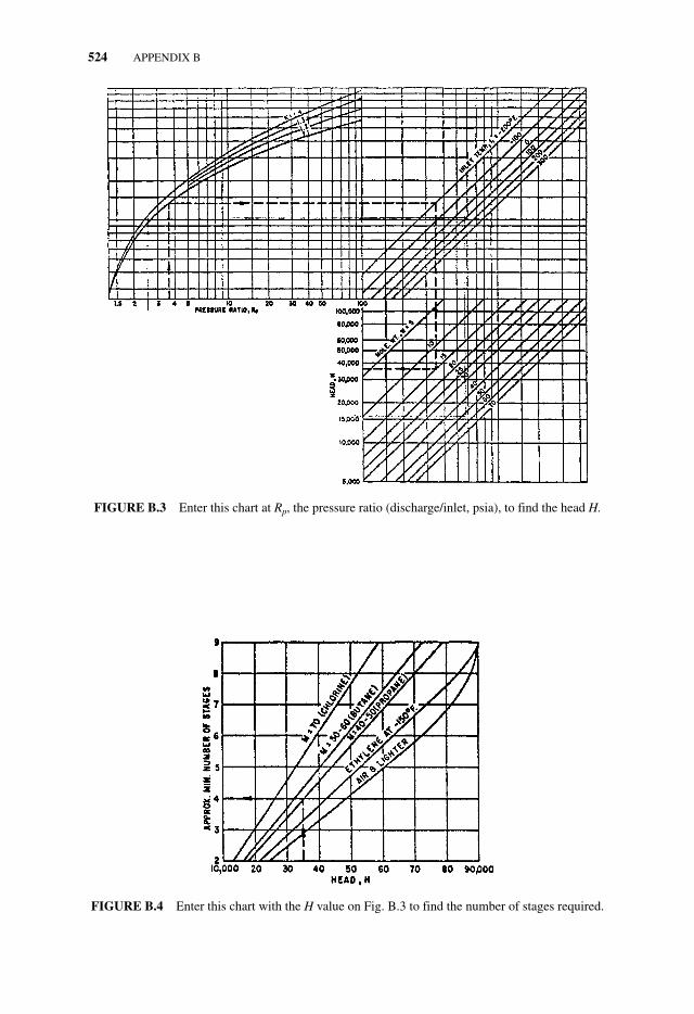
FIGURE B.3 Enter this chart at Rp, the pressure ratio (discharge/inlet, psia), to find the head H.
FIGURE B.4 Enter this chart with the H value on Fig. B.3 to find the number of stages required.
APPNB.qxd 7/29/06 2:34 PM Page 524
SHORTCUT CALCULATIONS AND SELECTION PROCEDURES 525
will require a blank stage for the first sideload only, whereas a typical ethylene machinemay require two blank stages. If the total number of stages, including blanks, exceeds nine,a second machine will probably be required.
B.3 DELAVAL ENGINEERING GUIDE TO COMPRESSOR SELECTION*
FIGURE B.5 Enter this chart at the Q1 value from Fig. B.1 or B.2 and find the speed, width, length,and flange sizes.
* Reprinted by permission of IMO Industries, Inc., DeLaval Turbine Division, Trenton, N.J.
APPNB.qxd 7/29/06 2:34 PM Page 525
526
FIG
UR
E B
.6E
nter
this
cha
rt a
t the
wei
ght f
low
of
gas
Wan
d pr
ocee
d to
fin
d th
e co
mpr
esso
r ho
rsep
ower
req
uire
d.
APPNB.qxd 7/29/06 2:34 PM Page 526
SHORTCUT CALCULATIONS AND SELECTION PROCEDURES 527
FIGURE B.7 The discharge temperature can be found on this chart.
APPNB.qxd 7/29/06 2:34 PM Page 527
528 APPENDIX B
APPNB.qxd 7/29/06 2:34 PM Page 528
SHORTCUT CALCULATIONS AND SELECTION PROCEDURES 529
APPNB.qxd 7/29/06 2:34 PM Page 529
530 APPENDIX B
APPNB.qxd 7/29/06 2:34 PM Page 530
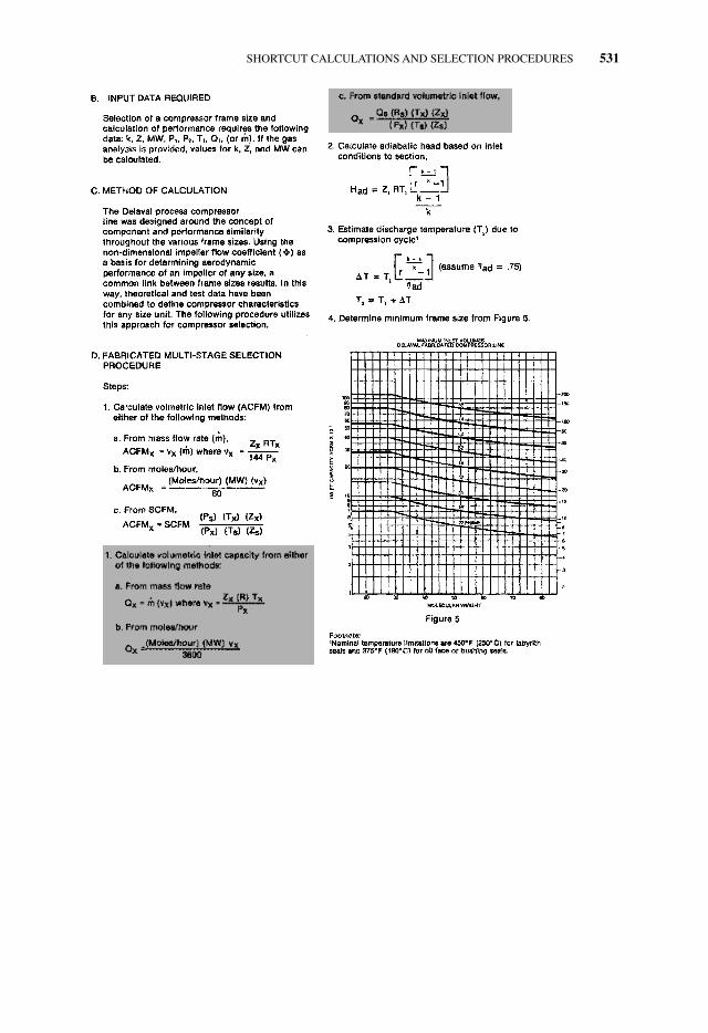
SHORTCUT CALCULATIONS AND SELECTION PROCEDURES 531
APPNB.qxd 7/29/06 2:34 PM Page 531
532 APPENDIX B
APPNB.qxd 7/29/06 2:34 PM Page 532
SHORTCUT CALCULATIONS AND SELECTION PROCEDURES 533
APPNB.qxd 7/29/06 2:34 PM Page 533
534 APPENDIX B
APPNB.qxd 7/29/06 2:35 PM Page 534
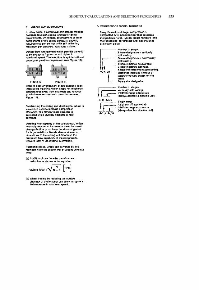
SHORTCUT CALCULATIONS AND SELECTION PROCEDURES 535
APPNB.qxd 7/29/06 2:35 PM Page 535
536 APPENDIX B
APPNB.qxd 7/29/06 2:35 PM Page 536
SHORTCUT CALCULATIONS AND SELECTION PROCEDURES 537
APPNB.qxd 7/29/06 2:35 PM Page 537
538 APPENDIX B
APPNB.qxd 7/29/06 2:35 PM Page 538
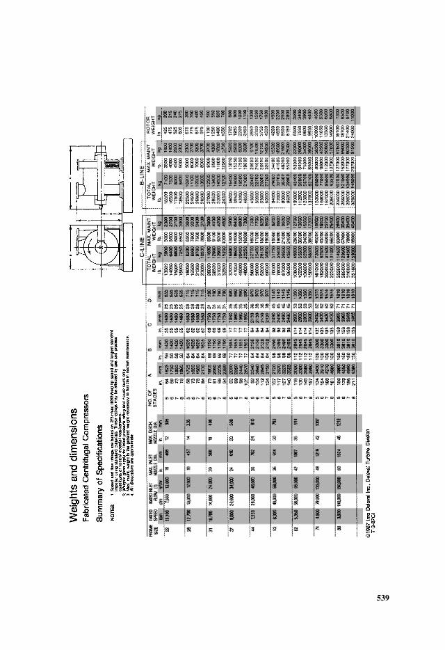
539
APPNB.qxd 7/29/06 2:35 PM Page 539
540 APPENDIX B
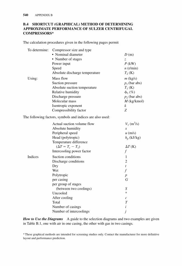
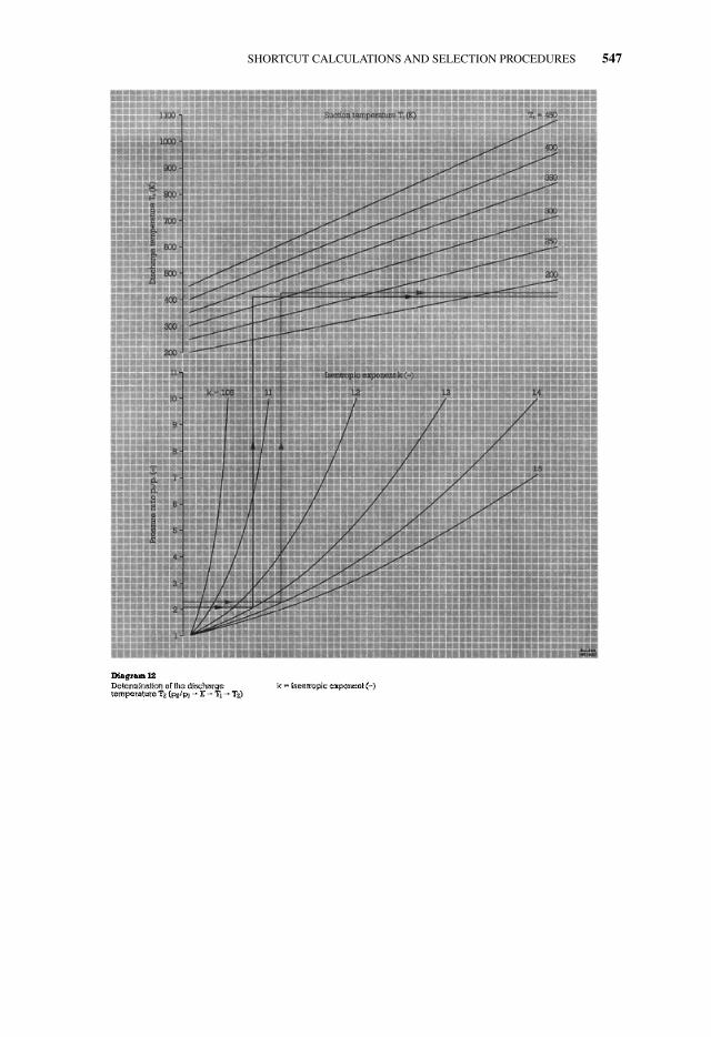
B.4 SHORTCUT (GRAPHICAL) METHOD OF DETERMININGAPPROXIMATE PERFORMANCE OF SULZER CENTRIFUGALCOMPRESSORS*
The calculation procedures given in the following pages permit
To determine: Compressor size and type● Nominal diameter D (m)● Number of stages zPower input P (kW)Speed n (r/min)Absolute discharge temperature T2 (K)
Using: Mass flow m (kg/s)Suction pressure p1 (bar abs)Absolute suction temperature T1 (K)Relative humidity �1 (%)Discharge pressure p2 (bar abs)Molecular mass M (kg/kmol)Isentropic exponent kCompressibility factor Z
The following factors, symbols and indices are also used:
Actual suction volume flow V1 (m3/s)Absolute humidity xPeripheral speed u (m/s)Head (polytropic) hp (kJ/kg)Temperature difference
(�T � Tc � T1) �T (K)Intercooling power factor f
Indices Suction conditions 1Discharge conditions 2Dry tWet fPolytropic pper casing Gper group of stages
(between two coolings) SUncooled *After cooling cTotal TNumber of casings iNumber of intercoolings j
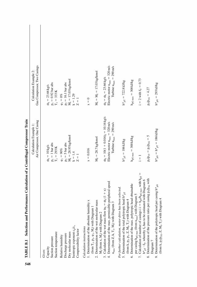
How to Use the Diagrams A guide to the selection diagrams and two examples are givenin Table B.1, one with air in one casing, the other with gas in two casings.
* These graphical methods are intended for screening studies only. Contact the manufacturer for more definitivelayout and performance prediction.
APPNB.qxd 7/29/06 2:35 PM Page 540
SHORTCUT CALCULATIONS AND SELECTION PROCEDURES 541
APPNB.qxd 7/29/06 2:36 PM Page 541
542 APPENDIX B
APPNB.qxd 7/29/06 2:36 PM Page 542
SHORTCUT CALCULATIONS AND SELECTION PROCEDURES 543
APPNB.qxd 7/29/06 2:36 PM Page 543
544 APPENDIX B
APPNB.qxd 7/29/06 2:36 PM Page 544
SHORTCUT CALCULATIONS AND SELECTION PROCEDURES 545
APPNB.qxd 7/29/06 2:37 PM Page 545
546 APPENDIX B
APPNB.qxd 7/29/06 2:37 PM Page 546
SHORTCUT CALCULATIONS AND SELECTION PROCEDURES 547
APPNB.qxd 7/29/06 2:37 PM Page 547
548
TAB
LE
B.1
Sele
ctio
n an
d P
erfo
rman
ce C
alcu
lati
on o
f a
Cen
trif
ugal
Com
pres
sor
Tra
in
Cal
cula
tion
Exa
mpl
e 1:
Cal
cula
tion
Exa
mpl
e 2:
Air
Com
pres
sor,
One
Cas
ing
Gas
Com
pres
sor,
Two
Cas
ings
Giv
en:
Cap
acity
m. t�
10kg
/sm. t
�23
.66
kg/s
Suct
ion
pres
sure
p 1�
1 ba
r ab
sp 1
�0.
92 b
ar a
bsSu
ctio
n te
mpe
ratu
reT
1�
293
KT
1�
333
K
Rel
ativ
e hu
mid
ity�
1�
90%
�1
�0%
Dis
char
ge p
ress
ure
p 2�
5 ba
r ab
sp 2
�16
.1 b
ar a
bsD
ry m
olec
ular
mas
sM
t�
28.9
5kg
/km
olM
t�
17.0
3kg
/km
olIs
entr
opic
exp
onen
t cp/
c vk
�1.
4k
�1.
29C
ompr
essi
bilit
y fa
ctor
Z�
1Z
�1
Cal
cula
tion
inst
ruct
ions
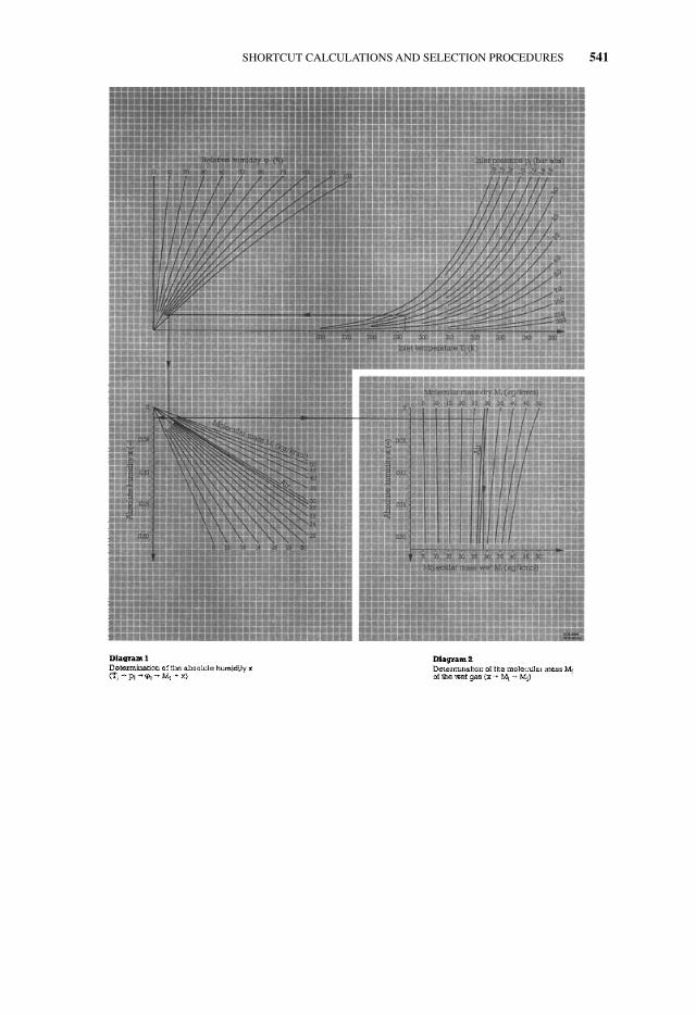
1.D
eter
min
atio
n of
the
abso
lute
hum
idity
xx
�0.
016
x�
0(f
rom
T1,
p1,
�1,
Mt)
with
Dia
gram
12.
Det
erm
inat
ion
of th
e w
et m
olec
ular
mas
sM
f�
28.7
kg/k
mol
Mt�
Mf�
17.0
3kg
/km
olM
f(f
rom
x, M
t) w
ith D
iagr
am 2
3.C
alcu
latio
n of
the
wet
mas
s fl
ow . m
f�
. m
t(1
�x)
m. f�
10(1
�0.
016)
f�
10.1
6kg
/sm. f
�m. t
�23
.66
kg/s
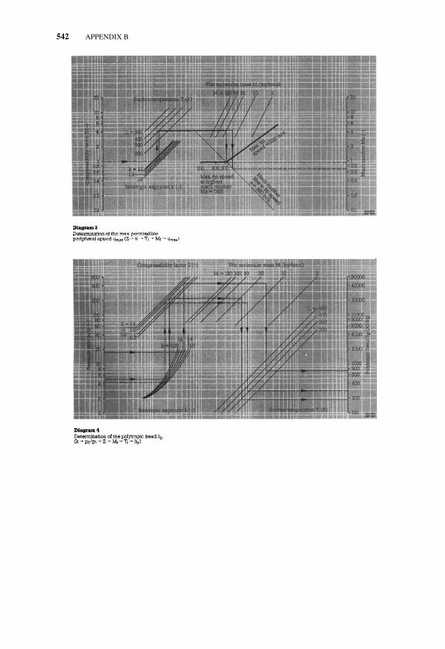
4.D
eter
min
atio
n of
the
max
. per
mis
sibl
e pe
riph
eral
spe
edE
lect
ric
mot
or u
max
�32
0m
/sE
lect
ric
mot
or u
max
�32
0m
/su m
ax(f
rom
Z, k
, T1,
Mf)
with
Dia
gram
3T
urbi
ne u
max
�29
0m
/sT
urbi
ne u
max
�29
0m
/s
For
furt
her
calc
ulat
ion,
mot
or d
rive
has
bee
n se
lect
ed.
5.D
eter
min
atio
n of
the
tota
l pol
ytro
pic
head
h* p
Th*
pT�
186
kJ/k
gh*
pT�
722.
8kJ
/kg
(fro
m k
, p2,
p1,
Z, M
f, T
1) w
ith D
iagr
am 4
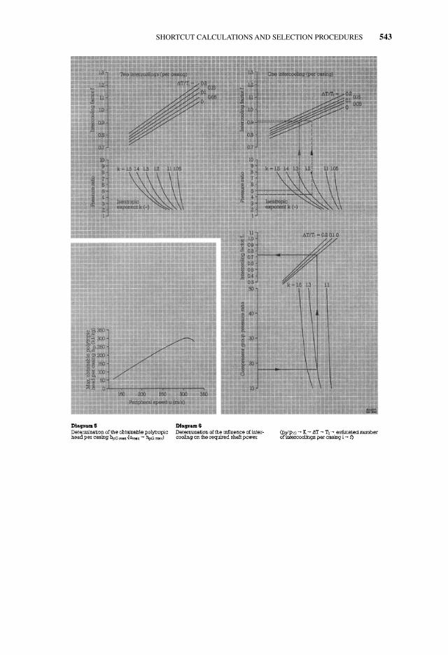
6.D
eter
min
atio
n of
the
max
. pol
ytro
pic
head
obt
aina
ble
h pG
max
�30
0kJ
/kg
h pG
max
�30
0kJ
/kg
per
casi
ng h
pG m
ax(f
rom
um
ax)
with
Dia
gram
57.
Cal
cula
tion
of n
umbe
r of
cas
ings
i i�
h pT/h
pG m
ax, w
ith h
pT�
i�1
i�2
with
fT
�0.
73h*
pT�
f T, w
here
by f
Tha
s to
be
estim
ated
with
Dia
gram
6
8.D
eter
min
atio
n of
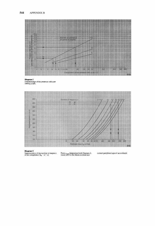
the
pres
sure
rat
io p
er c
asin
g p 2
/p1G
with
p 2
/p1T
�p 2
/p1G
�5
p 2/p
1G�
4.27
Dia
gram
79.
Det
erm
inat
ion
of th
e po
lytr
opic
hea
d pe
r ca
sing
h* p
Gh*
pG�
h*pT
�18
6kJ
/kg
h*pG
�29
3kJ
/kg
(fro
m k
, p2/
p 1G
, Z, M
f, T
1) w
ith D
iagr
am 4
APPNB.qxd 7/29/06 2:37 PM Page 548
549
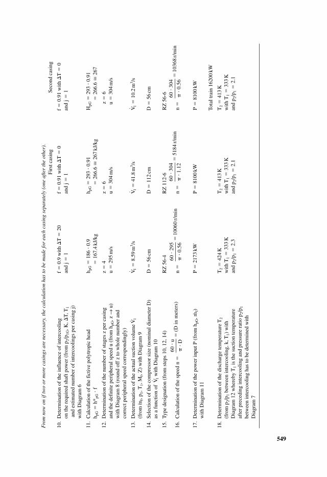
Fro
m n
ow o
n if
two
or m
ore
casi
ngs
are
nece
ssar
y, th
e ca
lcul
atio
n ha
s to
be
mad
e fo
r ea
ch c
asin
g se
para
tely
(on
e af
ter
the
othe
r).
Firs
t cas
ing
Seco
nd c
asin
g
10.
Det
erm
inat
ion
of th
e in
flue
nce
of in
terc
oolin
g f
�0.
9 w
ith �
T�
20
f�
0.91
with
�T
�0
f�
0.91
with
�T
�0
on th
e re
quir
ed s
haft
pow
er (
from
p2/
p 1G
, K, �
T, T
1an
d j�
1an
d j�
1an
d j�
1an
d es
timat
ed n
umbe
r of
inte
rcoo
lings
per
cas
ing
j)w
ith D
iagr
am 6
11.
Cal
cula
tion
of th
e fi
ctiv
e po
lytr
opic
hea
dh p
G�
186
�0.
9h p
G�
293
� 0.
91H
pG�
293
� 0.
91h p
G�
h*pG
�f
�16
7.4
kJ/k
g�
266.
6 �
267
kJ/k
g�
266.
6 �
267
12.
Det
erm
inat
ion
of th
e nu
mbe
r of
sta
ges
z pe
r ca
sing
z�
4z
�6
z�
6an
d th
e de
fini
te p
erip
hera
l spe
ed u
(fr
om h
pG, z
→u)
u�
295
m/s
u�
304
m/s
u�
304
m/s
with
Dia
gram
8 (
roun
d of
f z
to w
hole
num
ber
and
corr
ect p
erip
hera
l spe
ed c
orre
spon
ding
ly)
13.
Det
erm
inat
ion
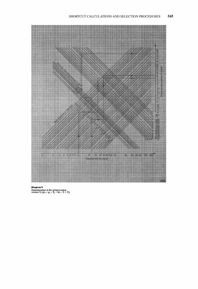
of th
e ac
tual
suc
tion
volu
me
V. 1V. 1
�8.
59m
3 /sV. 1
�41
.8m
3 /sV. 1
�10
.2m
3 /s(f
rom
. mf,
p 1, T
1, M
f, Z
) w
ith D
iagr
am 9
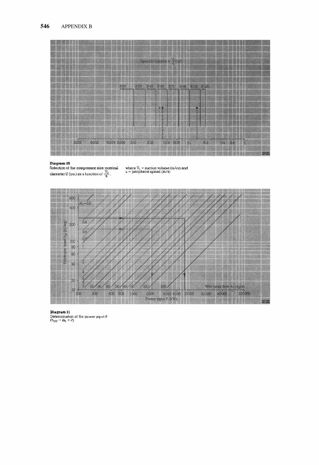
14.
Sele
ctio
n of
the
com
pres
sor
size
(no
min
al d
iam
eter
D)
D�
56cm
D�
112
cmD
�56
cmas
a f
unct
ion
of V
. 1w
ith D
iagr
am 1
0
15.
Type
des
igna
tion
(fro
m s
teps
10,
12,
14)
RZ
56-
4R
Z 1
12-6
RZ
56-
6
16.
Cal
cula
tion
of th
e sp
eed
n�
n�
n�
n�
17.
Det
erm
inat
ion
of th
e po
wer
inpu
t P (
from
hpG
, m. f)
P�
2173
kWP
�81
00kW
P�
8100
kWw
ith D
iagr
am 1
1
Tota
l tra
in 1
6200
kW
18.
Det
erm
inat
ion
of th
e di
scha
rge
tem
pera
ture
T2
T2
�42
4K
T2
�41
3K
T2
�41
3K
(fro
m p
2/p 1
betw
een
inte
rcoo
ling,
k, T
1) w
ithw
ith T
1�
333
Kw
ith T
1�
333
Kw
ith T
1�
333
KD
iagr
am 1
2 w
here
by T
1is
the
suct
ion
tem
pera
ture
and
p 2/p
1�
2.3
and
p 2/p
1�
2.1
and
p 2/p
1�
2.1
afte
r pr
eced
ing
inte
rcoo
ling
and
pres
sure
rat
io p
2/p 1
betw
een
inte
rcoo
ling
has
to b
e de
term
ined
with
Dia
gram
7
60
304
0.
5610
368
r/m
in�
��
�60
30
4
1.
1251
84r/
min
�
��
�60
29
5
0.
5610
060
r/m
in�
��
�60
u
D
(D i
n m
eter
s)�
��
�
APPNB.qxd 7/29/06 2:37 PM Page 549