Appendix B
Object-Oriented Analysis and Design

SAD/APPENDIX_B 2
Learning Objectives Understand the basic
characteristics and objectives of the object-oriented approach to software development
Identify the component elements of object-oriented software design
SAD/APPENDIX_B 3
Learning Objectives Understand the Unified Modeling
Language (UML) and its relationship to object-oriented design
Explore the various diagrams and their applications contained within the UML
SAD/APPENDIX_B 4
Introduction Object-oriented approach to
software development Views the system as a collection of
self-contained modules, or objects, that carry with them both the processes necessary to execute their intended role and the data necessary for that execution
SAD/APPENDIX_B 5
The Concepts of Object-Orientation
Object Any person, place, thing, or event
about which we wish to store data or capture its behavior
Attributes Current state Behavior Unique Identifier (UID)

SAD/APPENDIX_B 6
Figure B-1. Objects, Attributes, Methods, and Instances
SAD/APPENDIX_B 7
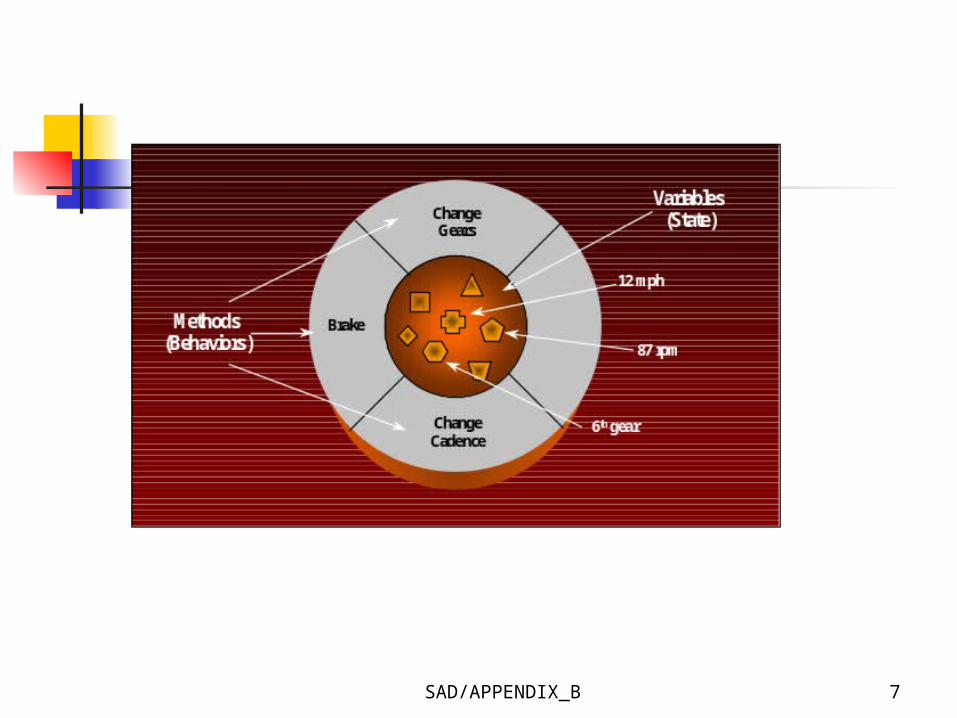
Figure B-2. Software Object Representation of a Bicycle

SAD/APPENDIX_B 8
The Concepts of Object-Orientation
Object Encapsulation
Object encapsulates both data and implementation
The user can view the object as a black box
Modularity Information Hiding
SAD/APPENDIX_B 9
The Concepts of Object-Orientation
Class Blueprint or prototype that defines
the variables and the methods common to all objects of a certain kind
Generalized description for objects that are similar in nature or share many of the same characteristics
SAD/APPENDIX_B 10
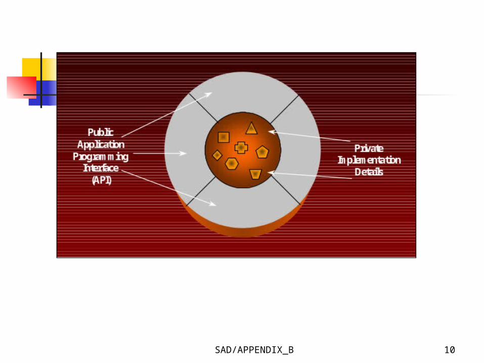
Figure B-3. Blueprint Concept of a Software Object
SAD/APPENDIX_B 11
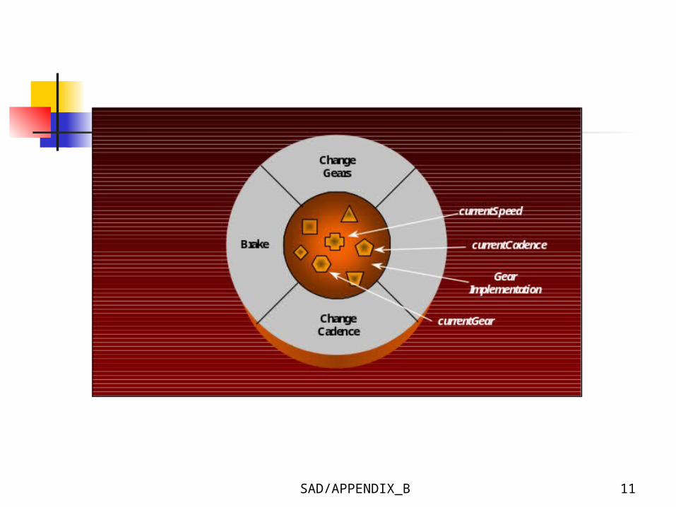
Figure B-4. Example of Object Class Implementations
SAD/APPENDIX_B 12
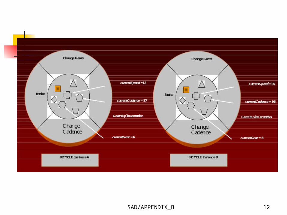
Figure B-5. Instance Objects Created From BICYCLE Class

SAD/APPENDIX_B 13
Figure B-6. Example of Instance Derived From Object Class
SAD/APPENDIX_B 14
The Concepts of Object-Orientation
Hierarchical Inheritance Each subclass inherits state and
methods from the superclass Subclass can add variables and
methods to the ones they inherit from the superclass

SAD/APPENDIX_B 15
Figure B-7. Hierarchical Inheritance – Superclass and Subclasses
SAD/APPENDIX_B 16
The Concepts of Object-Orientation
Messages Objects interact and communicate
with each other by sending messages Additional information can be passed
along with the message (parameter)
SAD/APPENDIX_B 17
Figure B-8. Example of Object Messaging
SAD/APPENDIX_B 18
The Concepts of Object-Orientation
Polymorphism A message to one object could invoke
different behavior than the same message to a different object
The requesting object does not need any information with regard to how that behavior is accomplished

SAD/APPENDIX_B 19
Unified Modeling Language Within a system-intensive process, a
method is applied as a process to derive or evolve a system.
As a language, it is used for communication. That is, a means to capture knowledge (semantics) about a subject and express knowledge (syntax) regarding the subject for the purpose of communication. The subject is the system under discussion.
SAD/APPENDIX_B 20
Unified Modeling Language As a modeling language, it focuses on
understanding a subject via the formulation of a model of the subject (and its related context). The model embodies knowledge regarding the subject, and the appropriate application of this knowledge constitutes intelligence.
Regarding unification, it unifies the information systems and technology industry’s best engineering practices across types of systems (software and non-software), domains (business versus software), and life-cycle processes.
SAD/APPENDIX_B 21
Unified Modeling Language As it applies to specifying
systems, it can be used to communicate "what" is required of a system, and "how" a system may be realized.
As it applies to visualizing systems, it can be used to visually depict a system before it is realized.
SAD/APPENDIX_B 22
Unified Modeling Language As it applies to constructing
systems, it can be used to guide the realization of a system similar to a "blueprint".
As it applies to documenting systems, it can be used for capturing knowledge about a system throughout its life-cycle.
SAD/APPENDIX_B 23
Unified Modeling Language UML is NOT
A visual programming language, but a visual modeling language
A tool or repository specification, but a modeling language specification
A process, but it enables processes
SAD/APPENDIX_B 24
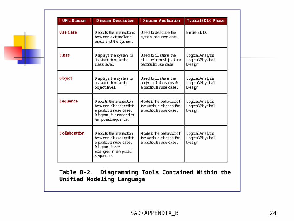
UML Diagram Diagram Description Diagram Application Typical SDLC Phase
Use Case
Depicts the interactions between external end users and the system.
Used to describe the system requirements.
Entire SDLC
Class
Displays the system in its static form at the class level.
Used to illustrate the class relationships for a particular use case.
Logical Analysis Logical/Physical Design
Object
Displays the system in its static form at the object level.
Used to illustrate the object relationships for a particular use case.
Logical Analysis Logical/Physical Design
Sequence
Depicts the interaction between classes within a particular use case. Diagram is arranged in temporal sequence.
Models the behavior of the various classes for a particular use case.
Logical Analysis Logical/Physical Design
Collaboration
Depicts the interaction between classes within a particular use case. Diagram is not arranged in temporal sequence.
Models the behavior of the various classes for a particular use case.
Logical Analysis Logical/Physical Design
Table B-2. Diagramming Tools Contained Within the Unified Modeling Language

SAD/APPENDIX_B 25
UML Diagram Diagram Description Diagram Application Typical SDLC Phase
Statechart
Depicts the various sequence of states that a particular object can assume, the events that can cause transition from one state to another, and the actions that can occur as a result of a state change.
Focuses on the behavior of a single class for a particular use case.
Logical Analysis Logical/Physical Design
Activity
Depicts a specific business process and provides a view of the flows inside a use case or among several classes.
Provides a graphical representation of the flow of activities for a particular use case.
Logical Analysis Logical/Physical Design
Component
Displays the physical components (files) in a software application along with their location.
Used to depict the physical structure of a given software application.
Physical Design Implementation
Deployment
Depicts the structure of the entire run-time system by identifying how the various code modules are distributed across platforms.
Used to illustrate the associations between the code modules in a software application and the hardware components necessary to support them.
Physical Design Implementation
Table B-2. Diagramming Tools Contained Within the Unified Modeling Language
SAD/APPENDIX_B 26
The Use Case Model Use case diagram is the central
building block of the UML Provide high level description of
what the system must do
SAD/APPENDIX_B 27
The Use Case Model Actor
Any person, organization, or computer system, external to the system but interacting with it
Represent a role that an end user can play
Use cases Represent a sequence of steps, either
manual or automated, that define the completion of a single business task
SAD/APPENDIX_B 28
The Use Case Model Actors are illustrated as stick figures, use
cases as ovals, association as a solid line with no directionality, and the system as a box surrounding the use case diagram
Use case can use another use case. They are connected using a hollow arrowhead contains the word uses or extends, surrounded by pointers, << >>.
SAD/APPENDIX_B 29
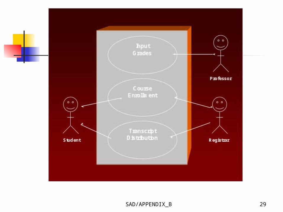
Figure B-9. Simple Use Case Diagram

SAD/APPENDIX_B 30
Class Diagram Provide a static structure of all the
classes that exist within the system
Three perspectives in drawing and interpreting class diagrams Conceptual perspective Specification perspective Implementation perspective
SAD/APPENDIX_B 31
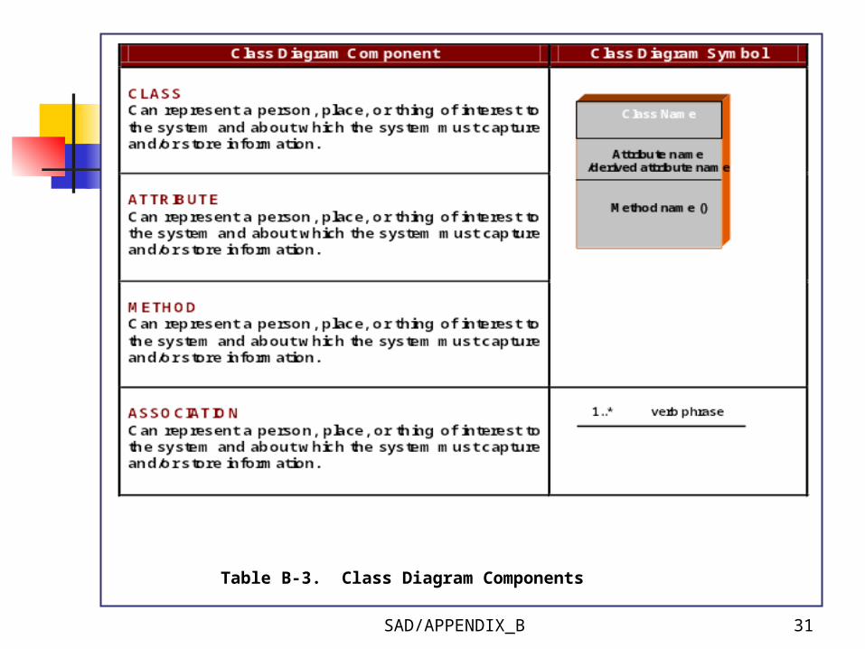
Table B-3. Class Diagram Components
SAD/APPENDIX_B 32
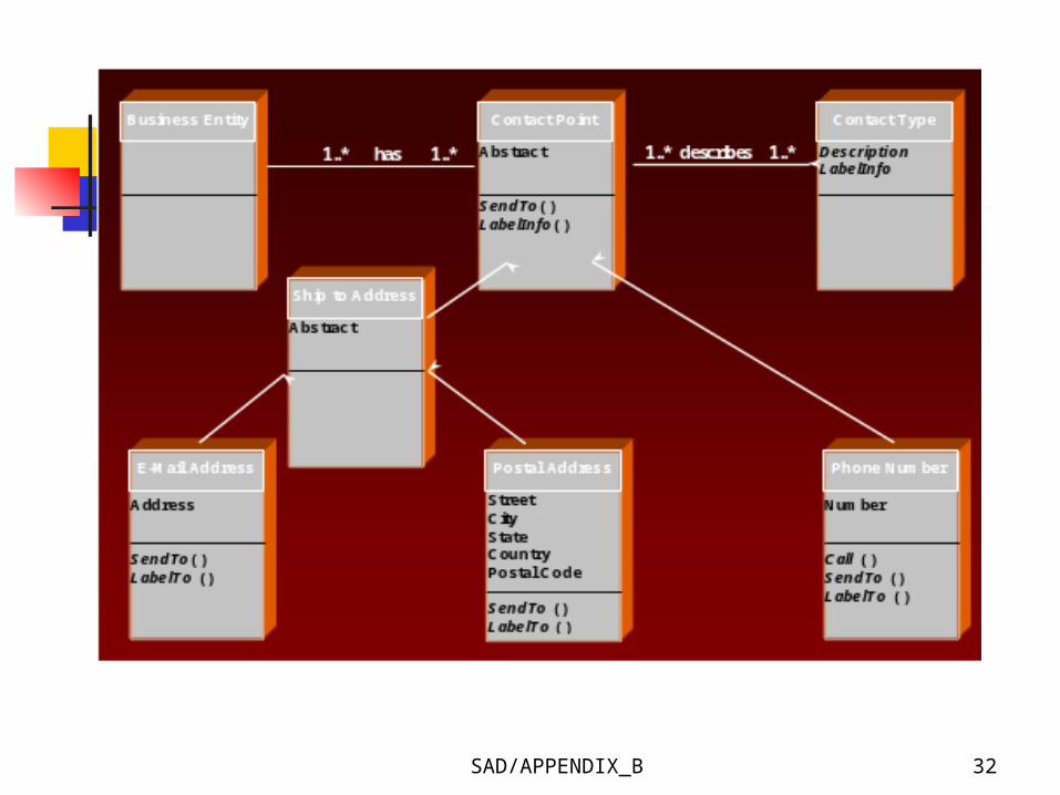
Figure B-10. Example Class Diagram for a Contact Maintenance System
SAD/APPENDIX_B 33
Statechart Diagram Describe a single object that can
have different states during its lifetime
Show how the object reacts from one state to another in response to a given event
SAD/APPENDIX_B 34
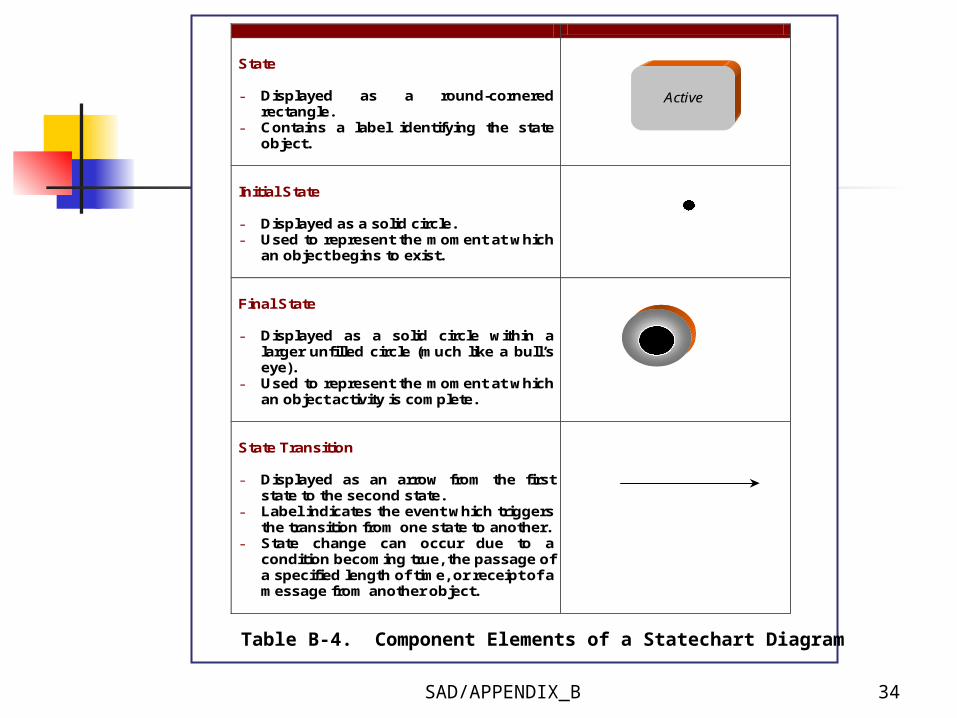
State - Displayed as a round-cornered
rectangle. - Contains a label identifying the state
object.
Initial State - Displayed as a solid circle. - Used to represent the moment at which
an object begins to exist.
Final State - Displayed as a solid circle within a
larger unfilled circle (much like a bull’s eye).
- Used to represent the moment at which an object activity is complete.
State Transition - Displayed as an arrow from the first
state to the second state. - Label indicates the event which triggers
the transition from one state to another. - State change can occur due to a
condition becoming true, the passage of a specified length of time, or receipt of a message from another object.
Active
Table B-4. Component Elements of a Statechart Diagram
SAD/APPENDIX_B 35
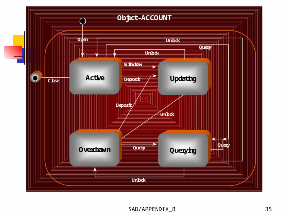
Figure B-12. Statechart Diagram for a Bank Account
SAD/APPENDIX_B 36
Activity Diagram Focus on the flow of operations
driven by internal processing as opposed to external events
Does not make explicit which object executes which activities or in what way the messaging works between them
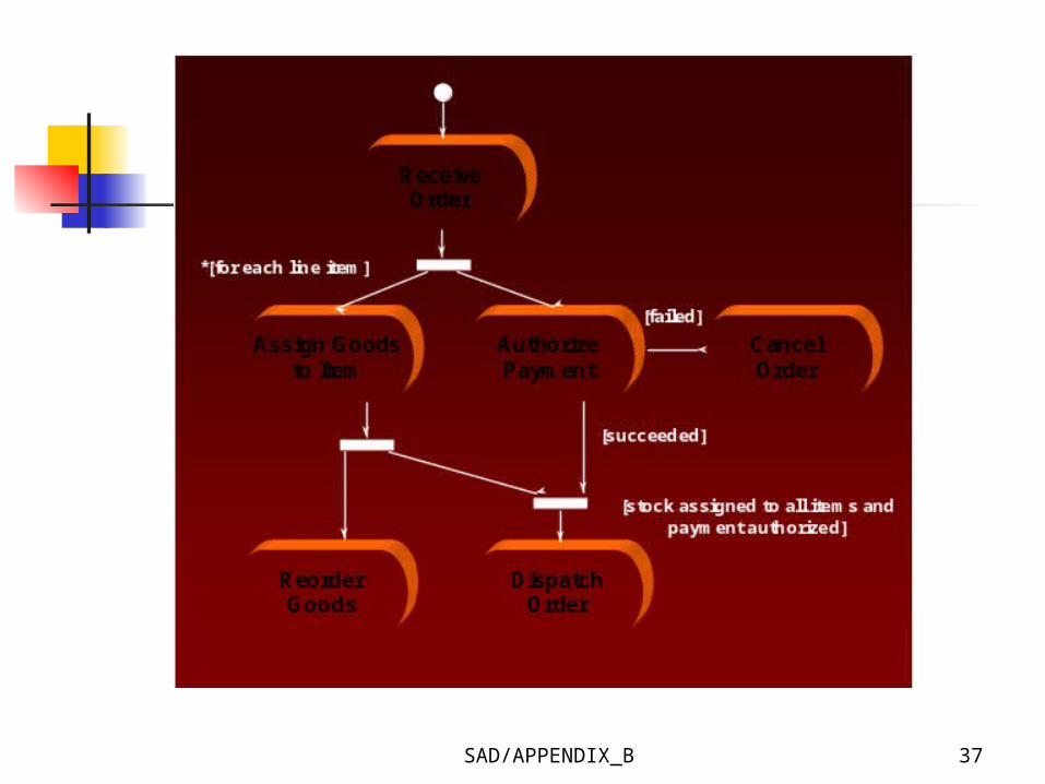
SAD/APPENDIX_B 37
Figure B-13. Activity Diagram for Order Process
SAD/APPENDIX_B 38
Interaction Diagram Describe how objects within a set
of objects interact with each other Describe how a group of objects
collaborate in some behavior – typically a single use-case
Sequence Diagram Collaboration Diagram
SAD/APPENDIX_B 39
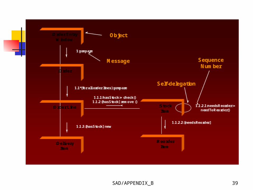
Figure B-15. Collaboration Form of Interaction Diagram

SAD/APPENDIX_B 40
Implementation Diagram Component Diagram
Illustrate the physical nature of the system in terms of actual components
Show the dependencies among the software components

SAD/APPENDIX_B 41
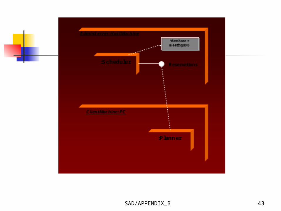
Implementation Diagram Deployment Diagram
Show the configuration of runtime processing elements and the software components, processes, and objects that live on them
Represent how the hardware and software units are configured and deployed

SAD/APPENDIX_B 42
Figure B-16. Example of a Simple Component Implementation Diagram
SAD/APPENDIX_B 43
Figure B-17. Deployment Implementation Diagram

SAD/APPENDIX_B 44
Advantages of the Object-oriented Approach
Advantages Based on very intuitive set of
concepts High modularity Code re-use
SAD/APPENDIX_B 45
Disadvantages of the Object-oriented Approach
Disadvantages Perception of inefficiency (single
processor)
- End -
SAD/APPENDIX_B 46
Summary The object-oriented approach is a new
and highly promising method that may one day become the standard for designing and development complex software system.
You should make every effort to pursue your exploration of the topic and plan on becoming skillful in its application.
Appendix B
End of Chapter


![Object-oriented Programming with PHP · Object-oriented Programming with PHP [2 ] Object-oriented programming Object-oriented programming is a popular programming paradigm where concepts](https://static.cupdf.com/doc/110x72/5e1bb46bfe726d12f8517bf0/object-oriented-programming-with-php-object-oriented-programming-with-php-2-object-oriented.jpg)