ANSI/CEA709 (EN14908) Standards
August 2006
04H1122
Vijay Dhingra
2
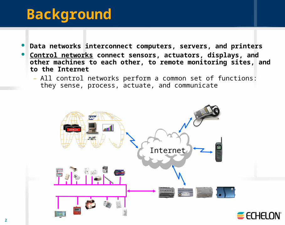
Data networks interconnect computers, servers, and printers Control networks connect sensors, actuators, displays, and other
machines to each other, to remote monitoring sites, and to the Internet– All control networks perform a common set of functions: they sense,
process, actuate, and communicate
Internet
Background

3
Control Network Technology Requirements
Robust, reliable communications – Peer-to-peer protocol supports multiple media, efficient
addressing and authentication – No single point of failure in the control system– Predictable, autonomous applications regardless of
network traffic Open standards based and Interoperable products
Large Ecosystem of cost effective solution– Best of breed products in commercial and home market
Confidence and leverage in a future proof environment
4
Multiple Media Support
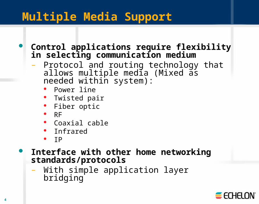
Control applications require flexibility in selecting communication medium– Protocol and routing technology that allows multiple
media (Mixed as needed within system): Power line Twisted pair Fiber optic RF Coaxial cable Infrared IP
Interface with other home networking standards/protocols– With simple application layer bridging

5
LONWORKS Control Networks
Flat Peer-Peer Network Architecture– Eliminate complex cabling– Lower installation and maintenance costs– Eliminate proprietary & closed gateways, and central
controllers– Simplify HMI development
Open– Choose interoperable components from multiple vendors

ANSI/CEA-709.1-BControl Networking Protocol
7
ANSI/CEA-709.1-B Protocol
An open standard protocol for control applications– Control applications have different requirements than data
applications– TCP/IP is an example of a data networking protocol– Reference document available from Global Engineering
Protocol implementations are available from multiple vendors– Protocol can be ported to any processor – Echelon’s implementation is called the LonTalk® protocol– Echelon’s Neuron® firmware includes the LonTalk protocol– Echelon development systems include a royalty-free unlimited license
to use the Neuron firmware implementation
8
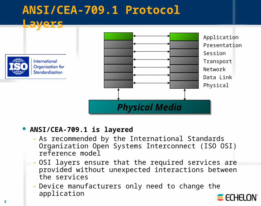
ANSI/CEA-709.1 Protocol Layers
ANSI/CEA-709.1 is layered– As recommended by the International Standards
Organization Open Systems Interconnect (ISO OSI) reference model
– OSI layers ensure that the required services are provided without unexpected interactions between the services
– Device manufacturers only need to change the application
Application
Presentation
Session
Transport
Network
Data Link
Physical
Physical MediaPhysical Media

9
ANSI/CEA-709.1 Protocol Layers
OSI Layer Purpose Services Provided
7 Application Application Compatibility Network Configuration; Network Diagnostics; File Transfer; Application Configuration, Specification, Diagnostics, & Management; Alarming; Data Logging; Scheduling;Time & Date Management
6 Presentation Data Interpretation Network Variables; Application Messages; Foreign Frame Transmission; Standard Types
5 Session Control Request-Response; Authentication
4 Transport End-to-End Reliability Acknowledged & Unacknowledged Message Delivery; Duplicate Detection
3 Network Message Delivery Unicast & Multicast Addressing; Routers
2 Link Media Access and Framing Framing; Data Encoding; CRC Error Checking; Predictive CSMA; Collision Avoidance; Priority & Collision Detection
1 Physical Electrical Interconnect Media-Specific Interfaces and Modulation Schemes (twisted pair, power line, radio frequency, coaxial cable,
infrared, fiber optic)
10
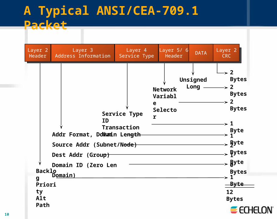
A Typical ANSI/CEA-709.1 Packet
BacklogPriorityAlt Path
12 Bytes
Layer 2Header
Layer 3Address Information
Layer 4Service Type
Layer 5/ 6Header
Layer 2 CRC
DATA
Addr Format, Domain Length
Source Addr (Subnet/Node)
Dest Addr (Group)
Domain ID (Zero Len Domain)
Service Type IDTransaction Num
Network VariableSelector
2 BytesUnsigned
Long 2 Bytes
2 Bytes
1 Byte
1 Byte
1 Byte
2 Bytes
1 Byte
0 Bytes

11
Layer 1—Physical Layer
Electrical interconnect– Transmission of raw bits over a communication channel
12
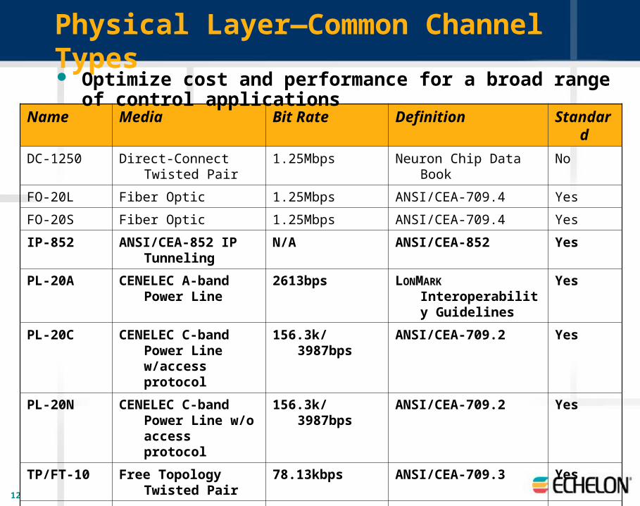
Physical Layer—Common Channel Types
Name Media Bit Rate Definition Standard
DC-1250 Direct-Connect Twisted Pair 1.25Mbps Neuron Chip Data Book No
FO-20L Fiber Optic 1.25Mbps ANSI/CEA-709.4 Yes
FO-20S Fiber Optic 1.25Mbps ANSI/CEA-709.4 Yes
IP-852 ANSI/CEA-852 IP Tunneling
N/A ANSI/CEA-852 Yes
PL-20A CENELEC A-band Power Line
2613bps LONMARK Interoperability Guidelines
Yes
PL-20C CENELEC C-band Power Line w/access protocol
156.3k/3987bps ANSI/CEA-709.2 Yes
PL-20N CENELEC C-band Power Line w/o access protocol
156.3k/3987bps ANSI/CEA-709.2 Yes
TP/FT-10 Free Topology Twisted Pair
78.13kbps ANSI/CEA-709.3 Yes
TP/RS485-39 RS-485 Twisted Pair 39.06kbps EIA/TIA-232-E Yes
TP/XF-1250 Transformer-Isolated Twisted Pair
1.25Mbps LONMARK Interoperability Guidelines
Yes
Optimize cost and performance for a broad range of control applications

13
Typical Channel Capacities
PL-20x Channels– PL-20N ~20 packets/sec– PL-20C ~18 packets/sec– PL-20A ~11packets/sec
TP/FT-10 Channel– Peak: ~225 packets/sec– Sustained: ~180 packets/sec
TP/XF-1250 Channel– Peak: ~720 packets/sec– Sustained: ~576 packets/sec
IP-852 Channels– ~10,000 packets/sec– Supports aggregation
TP/FT-10
TP/XF-1250
PL-20x
IP-852
14
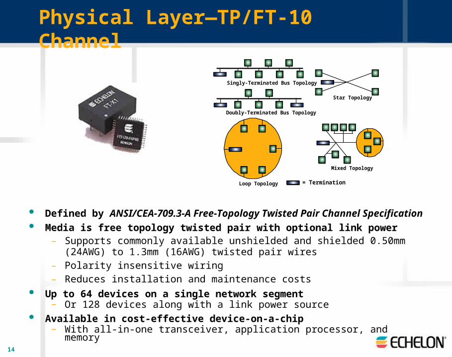
Physical Layer—TP/FT-10 Channel
Defined by ANSI/CEA-709.3-A Free-Topology Twisted Pair Channel Specification Media is free topology twisted pair with optional link power
– Supports commonly available unshielded and shielded 0.50mm (24AWG) to 1.3mm (16AWG) twisted pair wires
– Polarity insensitive wiring– Reduces installation and maintenance costs
Up to 64 devices on a single network segment– Or 128 devices along with a link power source
Available in cost-effective device-on-a-chip– With all-in-one transceiver, application processor, and memory
Singly-Terminated Bus Topology
Star Topology
Loop Topology
Mixed Topology
= Termination
Doubly-Terminated Bus Topology
16
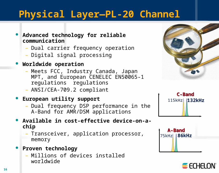
Physical Layer—PL-20 Channel
Advanced technology for reliable communication– Dual carrier frequency operation – Digital signal processing
Worldwide operation– Meets FCC, Industry Canada, Japan MPT, and
European CENELEC EN50065-1 regulations regulations
– ANSI/CEA-709.2 compliant European utility support
– Dual frequency DSP performance in the A-Band for AMR/DSM applications
Available in cost-effective device-on-a-chip– Transceiver, application processor, memory
Proven technology– Millions of devices installed worldwide
A-BandA-Band75kHz 86kHz
115kHz 132kHzC-BandC-Band
17
Layer 2—Link Layer
Media access and framing– Ensures efficient use of a single communications channel – Raw bits of the physical layer are broken up into data
frames– Link layer defines when a device can transmit a data frame – Also defines how destination devices receive the data
frames and detect transmission errors Features
– CRC error checking – Media access—predictive p-persistent CSMA– Priority– Collision avoidance

18
Link Layer—Media Access
Predictive p-persistent CSMA
Channel access is always randomized over time slots
Number of time slots are varied based on collision avoidance algorithm– 16 to 1008 slots
Non-priority Slots
Packet Packet
Busy Channel Packet Cycle
19
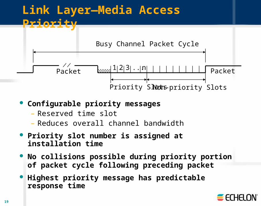
Link Layer—Media Access Priority
Configurable priority messages– Reserved time slot– Reduces overall channel bandwidth
Priority slot number is assigned at installation time
No collisions possible during priority portion of packet cycle following preceding packet
Highest priority message has predictable response time
Packet Packet1 2 3 n...
Priority Slots
Busy Channel Packet Cycle
Non-priority Slots

20
Link Layer—Media Access Benefits
Linear response time over 99% of channel bandwidth– Critical for open media such as power line
Remove and attach devices without halting communications
Predictable performance for high-priority messages

21
Link Layer—709.1 MAC vs. Ethernet
from: Computer Networks, Andrew S. Tanenbaum, Fourth Edition, 2003.

22
Layer 3—Network Layer
Message delivery– How data frames are routed from a source
device to one or more destination devices Physical address
– 48-bit Neuron ID—used for initial configuration
Logical addresses– Domain Identifies subsystem on
open media or large system– Subnet Subset of a domain typically
associated with a channel– Node Identifies device within subnet– Group Additional device identifiers
independent of subnet
1271 SUBNET 1
1271 SUBNET 2
1271 SUBNET 3
1271 SUBNET 4
1271 SUBNET 255
GROUP 1
DOMAIN (32,385 Devices)

23
Network Layer—Addressing Modes
Address Mode Address Format Destination Address Size
(bytes)
Domain-wide Broadcast
Domain (Subnet = 0) All devices inthe domain
3
Subnet-wide Broadcast Domain, Subnet All devices inthe subnet
3
Unicast Domain, Subnet, Node
Specific devicewithin a subnet
4
Multicast Domain, Group All devices inthe group
3
Neuron ID Domain, Neuron-ID Specific device 9
Optimize bandwidth with multiple addressing modes
Application communications only requires 3- or 4-byte network addresses
Send messages to many devices using only a single 3-byte network address

24
Network Layer—Capacity
18,446,744,073,726,329,086 domains
255 subnets per domain
127 devices per subnet
32,385 devices per domain
256 groups per domain
64 devices per acknowledged group
32,385 devices per unacknowledged group
Room to grow from a few devices to millions
25
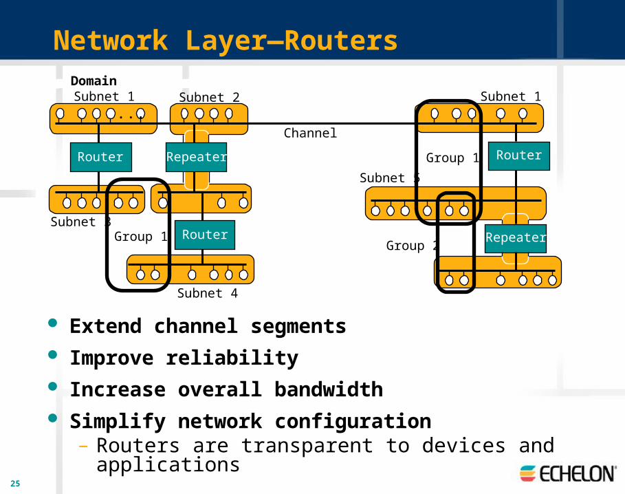
Network Layer—Routers
Extend channel segments Improve reliability Increase overall bandwidth Simplify network configuration
– Routers are transparent to devices and applications
Domain
...
RepeaterRouter
Channel
Router
Group 1
Subnet 1
RepeaterRouter
Subnet 2
Subnet 3
Subnet 4
Subnet 1
Subnet 5
Group 1
Group 2
26
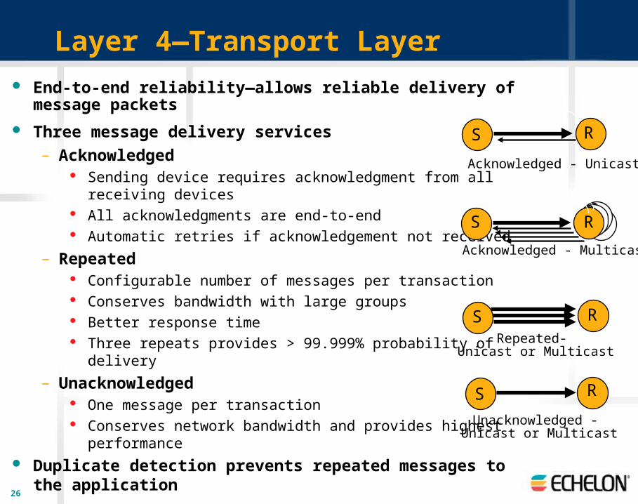
Layer 4—Transport Layer
End-to-end reliability—allows reliable delivery of message packets
Three message delivery services– Acknowledged
Sending device requires acknowledgment from all receiving devices
All acknowledgments are end-to-end Automatic retries if acknowledgement not received
– Repeated Configurable number of messages per transaction Conserves bandwidth with large groups Better response time Three repeats provides > 99.999% probability of delivery
– Unacknowledged One message per transaction Conserves network bandwidth and provides highest performance
Duplicate detection prevents repeated messages to the application
S R
S RRRR
S
S R
Acknowledged - Unicast
Acknowledged - Multicast
Repeated- Unicast or Multicast
Unacknowledged - Unicast or Multicast
R
27
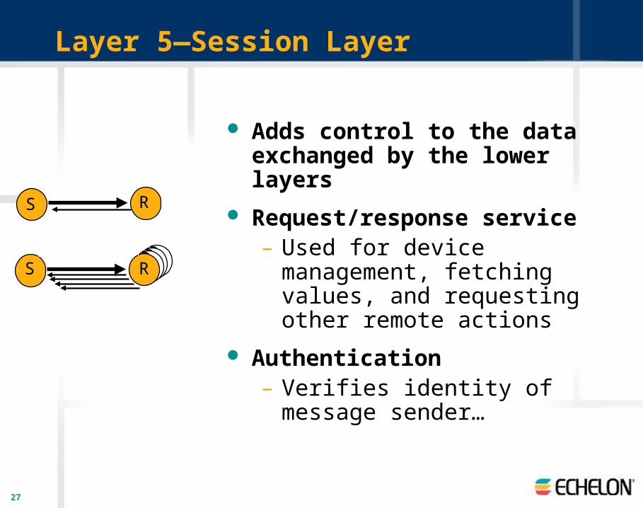
Layer 5—Session Layer
Adds control to the data exchanged by the lower layers
Request/response service– Used for device management, fetching
values, and requesting other remote actions
Authentication– Verifies identity of message sender…
S R
SRRR
R

28
Session Layer—Authentication
Verifies identity of message sender
Uses a 48-bit secret key known by each device
Sender must provide correct reply to 64-bit random challenge from the receiver
Sender ReceiverAuthenticated Message
64 bit Random Challenge
Key used to transform challenge
Challenge Response
Key used to compare response to value transformed locally.
Acknowledgment
29
23
Room Temp
Set Point
Temp
Set Point
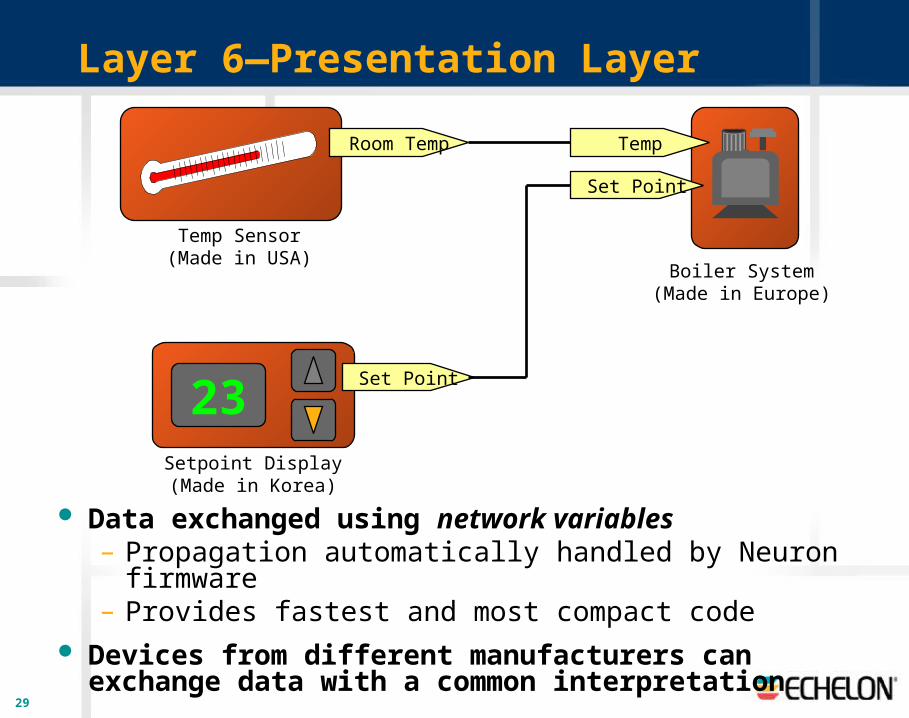
Temp Sensor(Made in USA)
Setpoint Display(Made in Korea)
Boiler System(Made in Europe)
Layer 6—Presentation Layer
Data exchanged using network variables– Propagation automatically handled by Neuron firmware– Provides fastest and most compact code
Devices from different manufacturers can exchange data with a common interpretation
30
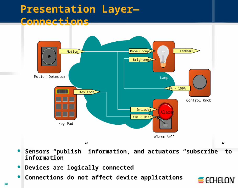
Presentation Layer—Connections
Sensors “publish” information, and actuators “subscribe” to information
Devices are logically connected
Connections do not affect device applications
Motion Detector
Key Pad
Control Knob
0% - 100%
Motion
Lamp
Brightness
Room Occupied
Alarm Bell
Key Code
Feedback
AlarmArm / Disarm
Intruder
31
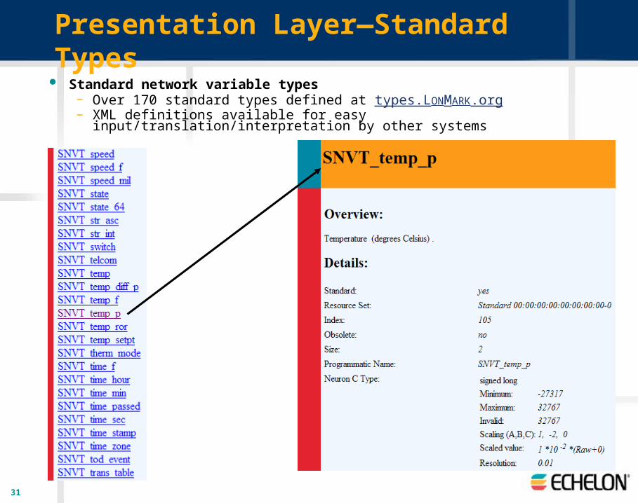
Presentation Layer—Standard Types Standard network variable types
– Over 170 standard types defined at types.LONMARK.org– XML definitions available for easy input/translation/interpretation by other systems
32
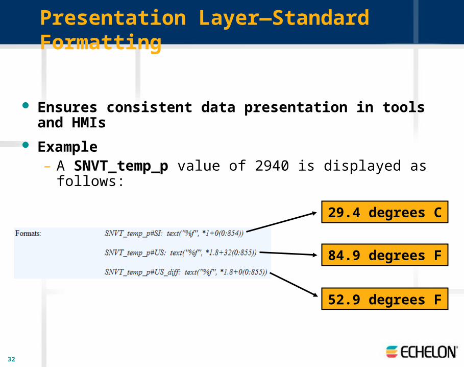
Presentation Layer—Standard Formatting
Ensures consistent data presentation in tools and HMIs
Example– A SNVT_temp_p value of 2940 is displayed as follows:
29.4 degrees C
84.9 degrees F
52.9 degrees F
33
Layer 7—Application Layer
Defines standard network services that use data exchanged by the lower layers – Network configuration and diagnostics– File transfer– Application configuration, diagnostics, management, and
specification– Standard profiles
Alarming Data logging Scheduling More than 60 others

34
Application Layer—Application Configuration
Configuration properties characterize the behavior of a device in the system – Types define data encoding, scaling, units, default value, range, and behavior– Standard configuration property types defined at types.LONMARK.org– XML definitions available for easy input/translation/interpretation by other systems

35
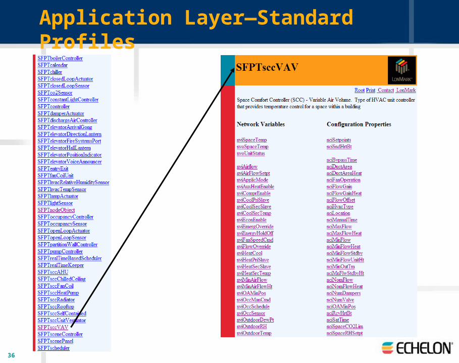
Application Layer—Application Specification
Functional block– Portion of a device’s application
that performs a task – Receives configuration and
operational data inputs– Processes the data– Sends operational data outputs
Node Object
Mandatory Network Variables
Configuration Properties
Optional Network Variables
nvoStatusSNVT_obj_status
nv2
nvoAlarm2SNVT_alarm_2
nv10
nvoDateResyncSNVT_switch
nv11
nvoAlarmSNVT_alarm
nv4
nvoFileStatSNVT_file_status
nv6
nvoFileDirectorySNVT_address
nv8
nviRequestSNVT_obj_request
nv1
nviTimeSetSNVT_time_stamp
nv3
nviDateEventSNVT_date_event
nv9
nviFileReqSNVT_file_req
nv5
nviFilePosSNVT_file_pos
nv7
nvoLogStatSNVT_log_status
nv13nviLogReqSNVT_log_req
nv12
Mandatory OptionalDevice Major VersionDevice Minor VersionFunctional Block Major VersionFunctional Block Minor VersionLocationMaximum Status Send TimeMinimum Send Time (Send Throttle)Network Configuration Source
36
Application Layer—Standard Profiles