NFPA STYLE
AIR CYLINDERS &MEDIUM DUTY HYDRAULIC
1 1/2” TO 8” BORE AIR 250 PSI HYDRAULIC 1500 PSI
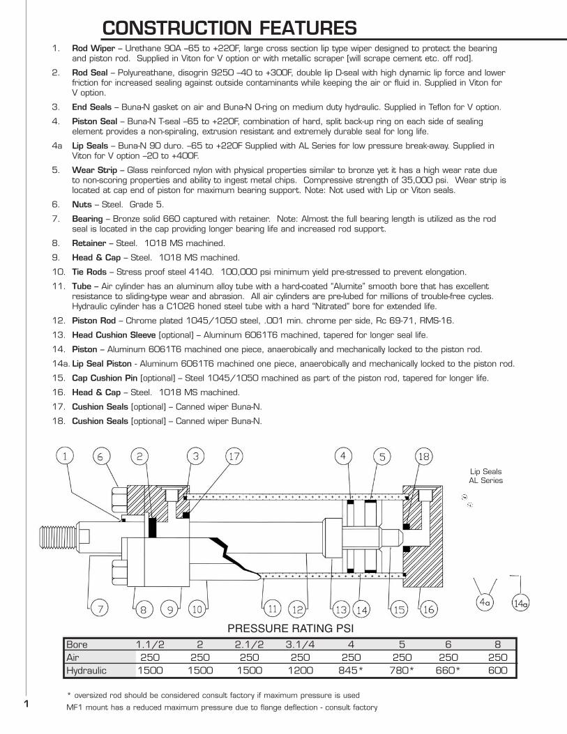
CONSTRUCTION FEATURES1. Rod Wiper – Urethane 90A –65 to +220F, large cross section lip type wiper designed to protect the bearing
and piston rod. Supplied in Viton for V option or with metallic scraper [will scrape cement etc. off rod].
2. Rod Seal – Polyureathane, disogrin 9250 –40 to +300F, double lip D-seal with high dynamic lip force and lower friction for increased sealing against outside contaminants while keeping the air or fluid in. Supplied in Viton for V option.
3. End Seals – Buna-N gasket on air and Buna-N O-ring on medium duty hydraulic. Supplied in Teflon for V option.
4. Piston Seal – Buna-N T-seal –65 to +220F, combination of hard, split back-up ring on each side of sealing element provides a non-spiraling, extrusion resistant and extremely durable seal for long life.
4a Lip Seals – Buna-N 90 duro. –65 to +220F Supplied with AL Series for low pressure break-away. Supplied in Viton for V option –20 to +400F.
5. Wear Strip – Glass reinforced nylon with physical properties similar to bronze yet it has a high wear rate due to non-scoring properties and ability to ingest metal chips. Compressive strength of 35,000 psi. Wear strip is located at cap end of piston for maximum bearing support. Note: Not used with Lip or Viton seals.
6. Nuts – Steel. Grade 5.
7. Bearing – Bronze solid 660 captured with retainer. Note: Almost the full bearing length is utilized as the rod seal is located in the cap providing longer bearing life and increased rod support.
8. Retainer – Steel. 1018 MS machined.
9. Head & Cap – Steel. 1018 MS machined.
10. Tie Rods – Stress proof steel 4140. 100,000 psi minimum yield pre-stressed to prevent elongation.
11. Tube – Air cylinder has an aluminum alloy tube with a hard-coated “Alumite” smooth bore that has excellent resistance to sliding-type wear and abrasion. All air cylinders are pre-lubed for millions of trouble-free cycles. Hydraulic cylinder has a C1026 honed steel tube with a hard “Nitrated” bore for extended life.
12. Piston Rod – Chrome plated 1045/1050 steel, .001 min. chrome per side, Rc 69-71, RMS-16.
13. Head Cushion Sleeve [optional] – Aluminum 6061T6 machined, tapered for longer seal life.
14. Piston – Aluminum 6061T6 machined one piece, anaerobically and mechanically locked to the piston rod.
14a. Lip Seal Piston - Aluminum 6061T6 machined one piece, anaerobically and mechanically locked to the piston rod.
15. Cap Cushion Pin [optional] – Steel 1045/1050 machined as part of the piston rod, tapered for longer life.
16. Head & Cap – Steel. 1018 MS machined.
17. Cushion Seals [optional] – Canned wiper Buna-N.
18. Cushion Seals [optional] – Canned wiper Buna-N.
Bore 1.1/2 2 2.1/2 3.1/4 4 5 6 8Air 250 250 250 250 250 250 250 250Hydraulic 1500 1500 1500 1200 845* 780* 660* 600
* oversized rod should be considered consult factory if maximum pressure is used
MF1 mount has a reduced maximum pressure due to flange deflection - consult factory1
Lip SealsAL Series
PRESSURE RATING PSI
2
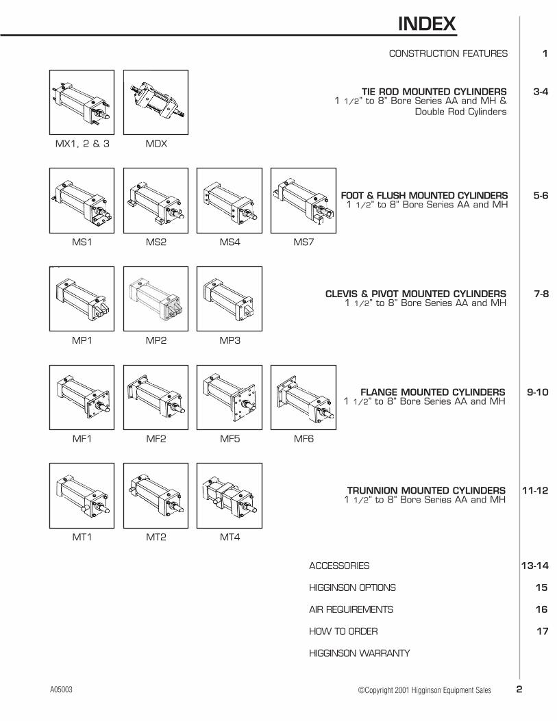
INDEX
©Copyright 2001 Higginson Equipment Sales
MX1, 2 & 3 MDX
MS1 MS2 MS4 MS7
MP1 MP2 MP3
MF1 MF2 MF5 MF6
MT1 MT2 MT4
TIE ROD MOUNTED CYLINDERS 3-41 1/2” to 8” Bore Series AA and MH &
Double Rod Cylinders
CONSTRUCTION FEATURES 1
FOOT & FLUSH MOUNTED CYLINDERS 5-61 1/2” to 8” Bore Series AA and MH
CLEVIS & PIVOT MOUNTED CYLINDERS 7-81 1/2” to 8” Bore Series AA and MH
FLANGE MOUNTED CYLINDERS 9-101 1/2” to 8” Bore Series AA and MH
TRUNNION MOUNTED CYLINDERS 11-121 1/2” to 8” Bore Series AA and MH
ACCESSORIES 13-14
HIGGINSON OPTIONS 15
AIR REQUIREMENTS 16
HOW TO ORDER 17
HIGGINSON WARRANTY
A05003

3
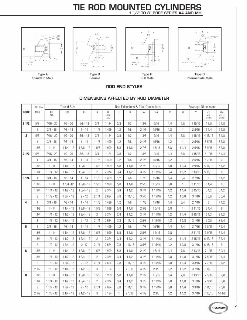
TIE ROD MOUNTED CYLINDERS1 1/2” TO 8” BORE SERIES AA AND MH
NFPA STYLE MX1 (CODE 06) NFPA STYLE MDX1 (CODE 20)
NFPAMOUNTING MOUNTING DESCRIPTION
CODE STYLE
06 MX1 Tie rods extended both ends (above left)18 MX2 Tie rods extended cap end (use MX1 Dimensions)19 MX3 Tie rods extended head end (use MX1 Dimensions)20* MDX1 Tie rods extended both ends (above right)20* MDX3 Tie rods extended one end (use MDX1 Dimensions)
*Specified Mount in Description
BOREAA BB DD E EE F G J K R LB LD P
(NPTF) ADD STROKE
1 1/2 2.02 1 1/4 - 28 2 3/8 3/8 1 1/2 1 1/4 1.43 4 4 7/8 2 1/4
2 2.60 1 1/8 5/16 - 24 2 1/2 3/8 3/8 1 1/2 1 5/16 1.84 4 4 7/8 2 1/4
2 1/2 3.10 1 1/8 5/16 - 24 3 3/8 3/8 1 1/2 1 5/16 2.19 4 1/8 5 2 3/8
3 1/4 3.90 1 3/8 3/8 - 24 3 3/4 1/2 5/8 1 3/4 1 1/4 3/8 2.76 4 7/8 6 2 5/8
4 4.70 1 3/8 3/8 - 24 4 1/2 1/2 5/8 1 3/4 1 1/4 3/8 3.32 4 7/8 6 2 5/8
5 5.80 1 13/16 1/2 - 20 5 1/2 1/2 5/8 1 3/4 1 1/4 7/16 4.10 5 1/8 6 1/4 2 7/8
6 6.90 1 13/16 1/2 - 20 6 1/2 3/4 3/4 2 1 1/2 7/16 4.88 5 3/4 7 3 1/8
8 9.10 2 5/16 5/8 - 18 8 1/2 3/4 3/4 2 1 1/2 9/16 6.44 5 7/8 7 1/8 3 1/4
ENVELOPE AND MOUNTING DIMENSIONS NOT AFFECTED BY ROD DIAMETER
MOUNTING DESCRIPTION
4
TIE ROD MOUNTED CYLINDERS1 1/2” TO 8” BORE SERIES AA AND MH
Type AStandard Male
Type BFemale
Type FFull Male
Type DIntermediate Male
ROD DIA. Thread Size Rod Extensions & Pilot Dimensions Envelope Dimensions
BORE MM KK CC FF A B C D LA NA V W Y ZB ZMSTD. +.000 ADD ADD 2X
-.002 STROKE STROKE
1 1/2 5/8 7/16 - 20 1/2 - 20 5/8 - 18 3/4 1.124 3/8 1/2 1 3/8 9/16 1/4 5/8 1 15/16 4 7/8 6 1/8
1 3/4 - 16 7/8 - 14 1 - 14 1 1/8 1.499 1/2 7/8 2 1/8 15/16 1/2 1 2 5/16 5 1/4 6 7/8
2 5/8 7/16 - 20 1/2 - 20 5/8 - 18 3/4 1.124 3/8 1/2 1 3/8 9/16 1/4 5/8 1 15/16 4 15/16 6 1/8
1 3/4 - 16 7/8 - 14 1 - 14 1 1/8 1.499 1/2 7/8 2 1/8 15/16 1/2 1 2 5/16 5 5/16 6 7/8
1 3/8 1 - 14 1 1/4 - 12 1 3/8 - 12 1 5/8 1.999 5/8 1 1/8 2 7/8 1 5/16 5/8 1 1/4 2 9/16 5 9/16 7 3/8
2 1/2 5/8 7/16 - 20 1/2 - 20 5/8 - 18 3/4 1.124 3/8 1/2 1 3/8 9/16 1/4 5/8 1 15/16 5 1/16 6 1/4
1 3/4 - 16 7/8 - 14 1 - 14 1 1/8 1.499 1/2 7/8 2 1/8 15/16 1/2 1 2 5/16 5 7/16 7
1 3/8 1 - 14 1 1/4 - 12 1 3/8 - 12 1 5/8 1.999 5/8 1 1/8 2 7/8 1 5/16 5/8 1 1/4 2 9/16 5 11/16 7 1/2
1 3/4 1 1/4 - 12 1 1/2 - 12 1 3/4 - 12 2 2.374 3/4 1 1/2 3 1/2 1 11/16 3/4 1 1/2 2 13/16 5 15/16 8
3 1/4 1 3/4 - 16 7/8 - 14 1 - 14 1 1/8 1.499 1/2 7/8 1 7/8 15/16 1/4 3/4 2 7/16 6 7 1/2
1 3/8 1 - 14 1 1/4 -12 1 3/8 - 12 1 5/8 1.999 5/8 1 1/8 2 5/8 1 5/16 3/8 1 2 11/16 6 1/4 8
1 3/4 1 1/4 - 12 1 1/2 - 12 1 3/4 - 12 2 2.374 3/4 1 1/2 3 1/4 1 11/16 1/2 1 1/4 2 15/16 6 1/2 8 1/2
2 1 1/2 - 12 1 3/4 - 12 2 - 12 2 1/4 2.624 7/8 1 11/16 3 5/8 1 15/16 1/2 1 3/8 3 1/16 6 5/8 8 3/4
4 1 3/4 - 16 7/8 - 14 1 - 14 1 1/8 1.499 1/2 7/8 1 7/8 15/16 1/4 3/4 2 7/16 6 7 1/2
1 3/8 1 - 14 1 1/4 - 12 1 3/8 - 12 1 5/8 1.999 5/8 1 1/8 2 5/8 1 5/16 3/8 1 2 11/16 6 1/4 8
1 3/4 1 1/4 - 12 1 1/2 - 12 1 3/4 - 12 2 2.374 3/4 1 1/2 3 1/4 1 11/16 1/2 1 1/4 2 15/16 6 1/2 8 1/2
2 1 1/2 - 12 1 3/4 - 12 2 - 12 2 1/4 2.624 7/8 1 11/16 3 5/8 1 15/16 1/2 1 3/8 3 1/16 6 5/8 8 3/4
5 1 3/4 - 16 7/8 - 14 1 - 14 1 1/8 1.499 1/2 7/8 1 7/8 15/16 1/4 3/4 2 7/16 6 5/16 7 3/4
1 3/8 1 - 14 1 1/4 - 12 1 3/8 - 12 1 5/8 1.999 5/8 1 1/8 2 5/8 1 5/16 3/8 1 2 11/16 6 9/16 8 1/4
1 3/4 1 1/4 - 12 1 1/2 - 12 1 3/4 - 12 2 2.374 3/4 1 1/2 3 1/4 1 11/16 1/2 1 1/4 2 15/16 6 13/16 8 3/4
2 1 1/2 - 12 1 3/4 - 12 2 -12 2 1/4 2.624 7/8 1 11/16 3 5/8 1 15/16 1/2 1 3/8 3 1/16 6 15/16 9
6 1 3/8 1 - 14 1 1/4 - 12 1 3/8 - 12 1 5/8 1.999 5/8 1 1/8 2 1/2 1 5/16 1/4 7/8 2 13/16 7 1/16 8 3/4
1 3/4 1 1/4 - 12 1 1/2 - 12 1 3/4 - 12 2 2.374 3/4 1 1/2 3 1/8 1 11/16 3/8 1 1/8 3 1/16 7 5/16 9 1/4
2 1 1/2 - 12 1 3/4 - 12 2 - 12 2 1/4 2.624 7/8 1 11/16 3 1/2 1 15/16 3/8 1 1/4 3 3/16 7 7/16 9 1/2
2 1/2 1 7/8 - 12 2 1/4 - 12 2 1/2 - 12 3 3.124 1 2 1/16 4 1/2 2 3/8 1/2 1 1/2 3 7/16 7 11/16 10
8 1 3/8 1 - 14 1 1/4 - 12 1 3/8 - 12 1 5/8 1.999 5/8 1 1/8 2 1/2 1 5/16 1/4 7/8 2 13/16 7 5/16 8 7/8
1 3/4 1 1/4 - 12 1 1/2 - 12 1 3/4 - 12 2 2.374 3/4 1 1/2 3 1/8 1 11/16 3/8 1 1/8 3 1/16 7 9/16 9 3/8
2 1 1/2 - 12 1 3/4 - 12 2 - 12 2 1/4 2.624 7/8 1 11/16 3 1/2 1 15/16 3/8 1 1/4 3 3/16 7 11/16 9 5/8
2 1/2 1 7/8 - 12 2 1/4 - 12 2 1/2 - 12 3 3.124 1 2 1/16 4 1/2 2 3/8 1/2 1 1/2 3 7/16 7 15/16 10 1/8
DIMENSIONS AFFECTED BY ROD DIAMETER
ROD END STYLES
5
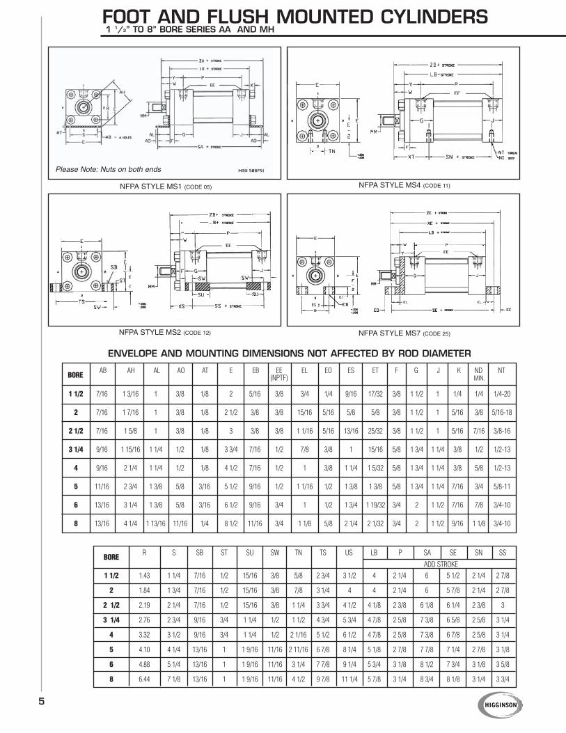
NFPA STYLE MS1 (CODE 05)
Please Note: Nuts on both ends
NFPA STYLE MS4 (CODE 11)
NFPA STYLE MS2 (CODE 12) NFPA STYLE MS7 (CODE 25)
FOOT AND FLUSH MOUNTED CYLINDERS1 1/2” TO 8” BORE SERIES AA AND MH
BOREAB AH AL AO AT E EB EE EL EO ES ET F G J K ND NT
(NPTF) MIN.
BORER S SB ST SU SW TN TS US LB P SA SE SN SS
ADD STROKE
1 1/2 1.43 1 1/4 7/16 1/2 15/16 3/8 5/8 2 3/4 3 1/2 4 2 1/4 6 5 1/2 2 1/4 2 7/8
2 1.84 1 3/4 7/16 1/2 15/16 3/8 7/8 3 1/4 4 4 2 1/4 6 5 7/8 2 1/4 2 7/8
2 1/2 2.19 2 1/4 7/16 1/2 15/16 3/8 1 1/4 3 3/4 4 1/2 4 1/8 2 3/8 6 1/8 6 1/4 2 3/8 3
3 1/4 2.76 2 3/4 9/16 3/4 1 1/4 1/2 1 1/2 4 3/4 5 3/4 4 7/8 2 5/8 7 3/8 6 5/8 2 5/8 3 1/4
4 3.32 3 1/2 9/16 3/4 1 1/4 1/2 2 1/16 5 1/2 6 1/2 4 7/8 2 5/8 7 3/8 6 7/8 2 5/8 3 1/4
5 4.10 4 1/4 13/16 1 1 9/16 11/16 2 11/16 6 7/8 8 1/4 5 1/8 2 7/8 7 7/8 7 1/4 2 7/8 3 1/8
6 4.88 5 1/4 13/16 1 1 9/16 11/16 3 1/4 7 7/8 9 1/4 5 3/4 3 1/8 8 1/2 7 3/4 3 1/8 3 5/8
8 6.44 7 1/8 13/16 1 1 9/16 11/16 4 1/2 9 7/8 11 1/4 5 7/8 3 1/4 8 3/4 8 1/8 3 1/4 3 3/4
1 1/2 7/16 1 3/16 1 3/8 1/8 2 5/16 3/8 3/4 1/4 9/16 17/32 3/8 1 1/2 1 1/4 1/4 1/4-20
2 7/16 1 7/16 1 3/8 1/8 2 1/2 3/8 3/8 15/16 5/16 5/8 5/8 3/8 1 1/2 1 5/16 3/8 5/16-18
2 1/2 7/16 1 5/8 1 3/8 1/8 3 3/8 3/8 1 1/16 5/16 13/16 25/32 3/8 1 1/2 1 5/16 7/16 3/8-16
3 1/4 9/16 1 15/16 1 1/4 1/2 1/8 3 3/4 7/16 1/2 7/8 3/8 1 15/16 5/8 1 3/4 1 1/4 3/8 1/2 1/2-13
4 9/16 2 1/4 1 1/4 1/2 1/8 4 1/2 7/16 1/2 1 3/8 1 1/4 1 5/32 5/8 1 3/4 1 1/4 3/8 5/8 1/2-13
5 11/16 2 3/4 1 3/8 5/8 3/16 5 1/2 9/16 1/2 1 1/16 1/2 1 3/8 1 3/8 5/8 1 3/4 1 1/4 7/16 3/4 5/8-11
6 13/16 3 1/4 1 3/8 5/8 3/16 6 1/2 9/16 3/4 1 1/2 1 3/4 1 19/32 3/4 2 1 1/2 7/16 7/8 3/4-10
8 13/16 4 1/4 1 13/16 11/16 1/4 8 1/2 11/16 3/4 1 1/8 5/8 2 1/4 2 1/32 3/4 2 1 1/2 9/16 1 1/8 3/4-10
ENVELOPE AND MOUNTING DIMENSIONS NOT AFFECTED BY ROD DIAMETER
ES
6
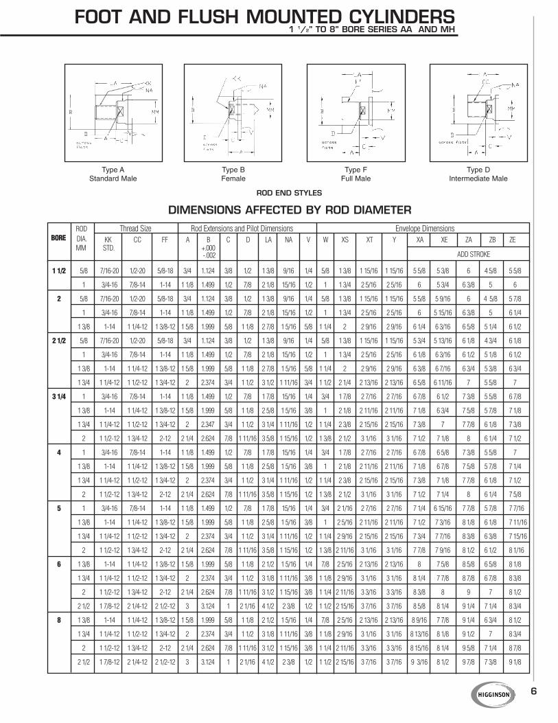
FOOT AND FLUSH MOUNTED CYLINDERS1 1/2” TO 8” BORE SERIES AA AND MH
Type AStandard Male
Type BFemale
Type FFull Male
Type DIntermediate Male
DIMENSIONS AFFECTED BY ROD DIAMETER
ROD END STYLES
ROD Thread Size Rod Extensions and Pilot Dimensions Envelope DimensionsBORE DIA. KK CC FF A B C D LA NA V W XS XT Y XA XE ZA ZB ZE
MM STD. +.000-.002 ADD STROKE
1 1/2 5/8 7/16-20 1/2-20 5/8-18 3/4 1.124 3/8 1/2 1 3/8 9/16 1/4 5/8 1 3/8 1 15/16 1 15/16 5 5/8 5 3/8 6 4 5/8 5 5/8
1 3/4-16 7/8-14 1-14 1 1/8 1.499 1/2 7/8 2 1/8 15/16 1/2 1 1 3/4 2 5/16 2 5/16 6 5 3/4 6 3/8 5 6
2 5/8 7/16-20 1/2-20 5/8-18 3/4 1.124 3/8 1/2 1 3/8 9/16 1/4 5/8 1 3/8 1 15/16 1 15/16 5 5/8 5 9/16 6 4 5/8 5 7/8
1 3/4-16 7/8-14 1-14 1 1/8 1.499 1/2 7/8 2 1/8 15/16 1/2 1 1 3/4 2 5/16 2 5/16 6 5 15/16 6 3/8 5 6 1/4
1 3/8 1-14 1 1/4-12 1 3/8-12 1 5/8 1.999 5/8 1 1/8 2 7/8 1 5/16 5/8 1 1/4 2 2 9/16 2 9/16 6 1/4 6 3/16 6 5/8 5 1/4 6 1/2
2 1/2 5/8 7/16-20 1/2-20 5/8-18 3/4 1.124 3/8 1/2 1 3/8 9/16 1/4 5/8 1 3/8 1 15/16 1 15/16 5 3/4 5 13/16 6 1/8 4 3/4 6 1/8
1 3/4-16 7/8-14 1-14 1 1/8 1.499 1/2 7/8 2 1/8 15/16 1/2 1 1 3/4 2 5/16 2 5/16 6 1/8 6 3/16 6 1/2 5 1/8 6 1/2
1 3/8 1-14 1 1/4-12 1 3/8-12 1 5/8 1.999 5/8 1 1/8 2 7/8 1 5/16 5/8 1 1/4 2 2 9/16 2 9/16 6 3/8 6 7/16 6 3/4 5 3/8 6 3/4
1 3/4 1 1/4-12 1 1/2-12 1 3/4-12 2 2.374 3/4 1 1/2 3 1/2 1 11/16 3/4 1 1/2 2 1/4 2 13/16 2 13/16 6 5/8 6 11/16 7 5 5/8 7
3 1/4 1 3/4-16 7/8-14 1-14 1 1/8 1.499 1/2 7/8 1 7/8 15/16 1/4 3/4 1 7/8 2 7/16 2 7/16 6 7/8 6 1/2 7 3/8 5 5/8 6 7/8
1 3/8 1-14 1 1/4-12 1 3/8-12 1 5/8 1.999 5/8 1 1/8 2 5/8 1 5/16 3/8 1 2 1/8 2 11/16 2 11/16 7 1/8 6 3/4 7 5/8 5 7/8 7 1/8
1 3/4 1 1/4-12 1 1/2-12 1 3/4-12 2 2.347 3/4 1 1/2 3 1/4 1 11/16 1/2 1 1/4 2 3/8 2 15/16 2 15/16 7 3/8 7 7 7/8 6 1/8 7 3/8
2 1 1/2-12 1 3/4-12 2-12 2 1/4 2.624 7/8 1 11/16 3 5/8 1 15/16 1/2 1 3/8 2 1/2 3 1/16 3 1/16 7 1/2 7 1/8 8 6 1/4 7 1/2
4 1 3/4-16 7/8-14 1-14 1 1/8 1.499 1/2 7/8 1 7/8 15/16 1/4 3/4 1 7/8 2 7/16 2 7/16 6 7/8 6 5/8 7 3/8 5 5/8 7
1 3/8 1-14 1 1/4-12 1 3/8-12 1 5/8 1.999 5/8 1 1/8 2 5/8 1 5/16 3/8 1 2 1/8 2 11/16 2 11/16 7 1/8 6 7/8 7 5/8 5 7/8 7 1/4
1 3/4 1 1/4-12 1 1/2-12 1 3/4-12 2 2.374 3/4 1 1/2 3 1/4 1 11/16 1/2 1 1/4 2 3/8 2 15/16 2 15/16 7 3/8 7 1/8 7 7/8 6 1/8 7 1/2
2 1 1/2-12 1 3/4-12 2-12 2 1/4 2.624 7/8 1 11/16 3 5/8 1 15/16 1/2 1 3/8 2 1/2 3 1/16 3 1/16 7 1/2 7 1/4 8 6 1/4 7 5/8
5 1 3/4-16 7/8-14 1-14 1 1/8 1.499 1/2 7/8 1 7/8 15/16 1/4 3/4 2 1/16 2 7/16 2 7/16 7 1/4 6 15/16 7 7/8 5 7/8 7 7/16
1 3/8 1-14 1 1/4-12 1 3/8-12 1 5/8 1.999 5/8 1 1/8 2 5/8 1 5/16 3/8 1 2 5/16 2 11/16 2 11/16 7 1/2 7 3/16 8 1/8 6 1/8 7 11/16
1 3/4 1 1/4-12 1 1/2-12 1 3/4-12 2 2.374 3/4 1 1/2 3 1/4 1 11/16 1/2 1 1/4 2 9/16 2 15/16 2 15/16 7 3/4 7 7/16 8 3/8 6 3/8 7 15/16
2 1 1/2-12 1 3/4-12 2-12 2 1/4 2.624 7/8 1 11/16 3 5/8 1 15/16 1/2 1 3/8 2 11/16 3 1/16 3 1/16 7 7/8 7 9/16 8 1/2 6 1/2 8 1/16
6 1 3/8 1-14 1 1/4-12 1 3/8-12 1 5/8 1.999 5/8 1 1/8 2 1/2 1 5/16 1/4 7/8 2 5/16 2 13/16 2 13/16 8 7 5/8 8 5/8 6 5/8 8 1/8
1 3/4 1 1/4-12 1 1/2-12 1 3/4-12 2 2.374 3/4 1 1/2 3 1/8 1 11/16 3/8 1 1/8 2 9/16 3 1/16 3 1/16 8 1/4 7 7/8 8 7/8 6 7/8 8 3/8
2 1 1/2-12 1 3/4-12 2-12 2 1/4 2.624 7/8 1 11/16 3 1/2 1 15/16 3/8 1 1/4 2 11/16 3 3/16 3 3/16 8 3/8 8 9 7 8 1/2
2 1/2 1 7/8-12 2 1/4-12 2 1/2-12 3 3.124 1 2 1/16 4 1/2 2 3/8 1/2 1 1/2 2 15/16 3 7/16 3 7/16 8 5/8 8 1/4 9 1/4 7 1/4 8 3/4
8 1 3/8 1-14 1 1/4-12 1 3/8-12 1 5/8 1.999 5/8 1 1/8 2 1/2 1 5/16 1/4 7/8 2 5/16 2 13/16 2 13/16 8 9/16 7 7/8 9 1/4 6 3/4 8 1/2
1 3/4 1 1/4-12 1 1/2-12 1 3/4-12 2 2.374 3/4 1 1/2 3 1/8 1 11/16 3/8 1 1/8 2 9/16 3 1/16 3 1/16 8 13/16 8 1/8 9 1/2 7 8 3/4
2 1 1/2-12 1 3/4-12 2-12 2 1/4 2.624 7/8 1 11/16 3 1/2 1 15/16 3/8 1 1/4 2 11/16 3 3/16 3 3/16 8 15/16 8 1/4 9 5/8 7 1/4 8 7/8
2 1/2 1 7/8-12 2 1/4-12 2 1/2-12 3 3.124 1 2 1/16 4 1/2 2 3/8 1/2 1 1/2 2 15/16 3 7/16 3 7/16 9 3/16 8 1/2 9 7/8 7 3/8 9 1/8

7
CLEVIS AND PIVOT MOUNTED CYLINDERS1 1/2” TO 8” BORE SERIES AA AND MH
NFPA STYLE MP1 (CODE 09)
(PIVOT PIN INCLUDED)
NFPA STYLE MP3 (CODE 13)
(PIVOT PIN INCLUDED)
NFPA STYLE MP2 (CODE 10)
(PIVOT PIN INCLUDED)
BORECB CD CW E EE F G J K L LR M MR LB P
+.000 (NPTF)ADD STROKE-.002
1 1/2 3/4 .501 1/2 2 3/8 3/8 1 1/2 1 1/4 3/4 3/4 1/2 5/8 4 2 1/4
2 3/4 .501 1/2 2 1/2 3/8 3/8 1 1/2 1 5/16 3/4 3/4 1/2 5/8 4 2 1/4
2 1/2 3/4 .501 1/2 3 3/8 3/8 1 1/2 1 5/16 3/4 3/4 1/2 5/8 4 1/8 2 3/8
3 1/4 1 1/4 .751 5/8 3 3/4 1/2 5/8 1 3/4 1 1/4 3/8 1 1/4 1 3/4 15/16 4 7/8 2 5/8
4 1 1/4 .751 5/8 4 1/2 1/2 5/8 1 3/4 1 1/4 3/8 1 1/4 1 3/4 15/16 4 7/8 2 5/8
5 1 1/4 .751 5/8 5 1/2 1/2 5/8 1 3/4 1 1/4 7/16 1 1/4 1 3/4 15/16 5 1/8 2 7/8
6 1 1/2 1.001 3/4 6 1/2 3/4 3/4 2 1 1/2 7/16 1 1/2 1 1/4 1 1 3/16 5 3/4 3 1/8
8 1 1/2 1.001 3/4 8 1/2 3/4 3/4 2 1 1/2 9/16 1 1/2 1 1/4 1 1 3/16 5 7/8 3 1/4
ENVELOPE AND MOUNTING DIMENSIONS NOT AFFECTED BY ROD DIAMETER

8
CLEVIS AND PIVOT MOUNTED CYLINDERS1 1/2” TO 8” BORE SERIES AA AND MH
Type AStandard Male
Type BFemale
Type FFull Male
Type DIntermediate Male
1 1/2 5/8 7/16-20 1/2-20 5/8-18 3/4 1.124 3/8 1/2 1 3/8 9/16 1/4 5/8 1 15/16 5 3/8 5 3/4 5 7/8 6 1/4
1 3/4-16 7/8-14 1-14 1 1/8 1.499 1/2 7/8 2 1/8 15/16 1/2 1 2 5/16 5 3/4 6 1/8 6 1/4 6 5/8
2 5/8 7/16-20 1/2-20 5/8-18 3/4 1.124 3/8 1/2 1 3/8 9/16 1/4 5/8 1 15/16 5 3/8 5 3/4 5 7/8 6 1/4
1 3/4-16 7/8-14 1-14 1 1/8 1.499 1/2 7/8 2 1/8 15/16 1/2 1 2 5/16 5 3/4 6 1/8 6 1/4 6 5/8
1 3/8 1-14 1 1/4-12 1 3/8-12 1 5/8 1.999 5/8 1 1/8 2 7/8 1 5/16 5/8 1 1/4 2 9/16 6 6 3/8 6 1/2 6 7/8
2 1/2 5/8 7/16-20 1/2-20 5/8-18 3/4 1.124 3/8 1/2 1 3/8 9/16 1/4 5/8 1 15/16 5 1/2 5 7/8 6 6 3/8
1 3/4-16 7/8-14 1-14 1 1/8 1.499 1/2 7/8 2 1/8 15/16 1/2 1 2 5/16 5 7/8 6 1/4 6 3/8 6 3/4
1 3/8 1-14 1 1/4-12 1 3/8-12 1 5/8 1.999 5/8 1 1/8 2 7/8 1 5/16 5/8 1 1/4 2 9/16 6 1/8 6 1/2 6 5/8 7
1 3/4 1 1/4-12 1 1/2-12 1 3/4-12 2 2.374 3/4 1 1/2 3 1/2 1 11/16 3/4 1 1/2 2 13/16 6 3/8 6 3/4 6 7/8 7 1/4
3 1/4 1 3/4-16 7/8-14 1-14 1 1/8 1.499 1/2 7/8 1 7/8 15/16 1/4 3/4 2 7/16 6 7/8 7 1/2 7 5/8 8 1/4
1 3/8 1-14 1 1/4-12 1 3/8-12 1 5/8 1.999 5/8 1 1/8 2 5/8 1 5/16 3/8 1 2 11/16 7 1/8 7 3/4 7 7/8 8 1/2
1 3/4 1 1/4-12 1 1/2-12 1 3/4-12 2 2.374 3/4 1 1/2 3 1/4 1 11/16 1/2 1 1/4 2 15/16 7 3/8 8 8 1/8 8 3/4
2 1 1/2-12 1 3/4-12 2-12 2 1/4 2.624 7/8 1 11/16 3 5/8 1 15/16 1/2 1 3/8 3 1/16 7 1/2 8 1/8 8 1/4 8 7/8
4 1 3/4-16 7/8-14 1-14 1 1/8 1.499 1/2 7/8 1 7/8 15/16 1/4 3/4 2 7/16 6 7/8 7 1/2 7 5/8 8 1/4
1 3/8 1-14 1 1/4-12 1 3/8-12 1 5/8 1.999 5/8 1 1/8 2 5/8 1 5/16 3/8 1 2 11/16 7 1/8 7 3/4 7 7/8 8 1/2
1 3/4 1 1/4-12 1 1/2-12 1 3/4-12 2 2.374 3/4 1 1/2 3 1/4 1 11/16 1/2 1 1/4 2 15/16 7 3/8 8 8 1/8 8 3/4
2 1 1/2-12 1 3/4-12 2-12 2 1/4 2.624 7/8 1 11/16 3 5/8 1 15/16 1/2 1 3/8 3 1/16 7 1/2 8 1/8 8 1/4 8 7/8
5 1 3/4-16 7/8-14 1-14 1 1/8 1.499 1/2 7/8 1 7/8 15/16 1/4 3/4 2 7/16 7 1/8 7 3/4 7 7/8 8 1/2
1 3/8 1-14 1 1/4-12 1 3/8-12 1 5/8 1.999 5/8 1 1/8 2 5/8 1 5/16 3/8 1 2 11/16 7 3/8 8 8 1/8 8 3/4
1 3/4 1 1/4-12 1 1/2-12 1 3/4-12 2 2.374 3/4 1 1/2 3 1/4 1 11/16 1/2 1 1/4 2 15/16 7 5/8 8 1/4 8 3/8 9
2 1 1/2-12 1 3/4-12 2-12 2 1/4 2.624 7/8 1 11/16 3 5/8 1 15/16 1/2 1 3/8 3 1/16 7 3/4 8 3/8 8 1/2 9 1/8
6 1 3/8 1-14 1 1/4-12 1 3/8-12 1 5/8 1.999 5/8 1 1/8 2 1/2 1 5/16 1/4 7/8 2 13/16 8 1/8 8 7/8 9 1/8 9 7/8
1 3/4 1 1/4-12 1 1/2-12 1 3/4-12 2 2.374 3/4 1 1/2 3 1/8 1 11/16 3/8 1 1/8 3 1/16 8 3/8 9 1/8 9 3/8 10 1/8
2 1 1/2-12 1 3/4-12 2-12 2 1/4 2.624 7/8 1 11/16 3 1/2 1 15/16 3/8 1 1/4 3 3/16 8 1/2 9 1/4 9 1/2 10 1/4
2 1/2 1 7/8-12 2 1/4-12 2 1/2-12 3 3.124 1 2 1/16 4 1/2 2 3/8 1/2 1 1/2 3 7/16 8 3/4 9 1/2 9 3/4 10 1/2
8 1 3/8 1-14 1 1/4-12 1 3/8-12 1 5/8 1.999 5/8 1 1/8 2 1/2 1 5/16 1/4 7/8 2 13/16 8 1/4 9 9 1/4 10
1 3/4 1 1/4-12 1 1/2-12 1 3/4-12 2 2.374 3/4 1 1/2 3 1/8 1 11/16 3/8 1 1/8 3 1/16 8 1/2 9 1/4 9 1/2 10 1/4
2 1 1/2-12 1 3/4-12 2-12 2 1/4 2.624 7/8 1 11/16 3 1/2 1 15/16 3/8 1 1/4 3 3/16 8 5/8 9 3/8 9 5/8 10 3/8
2 1/2 1 7/8-12 2 1/4-12 2 1/2-12 3 3.124 1 2 1/16 4 1/2 2 3/8 1/2 1 1/2 3 7/16 8 7/8 9 5/8 9 7/8 10 5/8
Thread Size Rod Extensions and Pilot Dimensions Envelope DimensionsBORE ROD DIA. KK CC FF A B C D LA NA V W Y XC XD ZC ZD
MM STD. +.000ADD STROKE-.002
DIMENSIONS AFFECTED BY ROD DIAMETER
ROD END STYLES
9
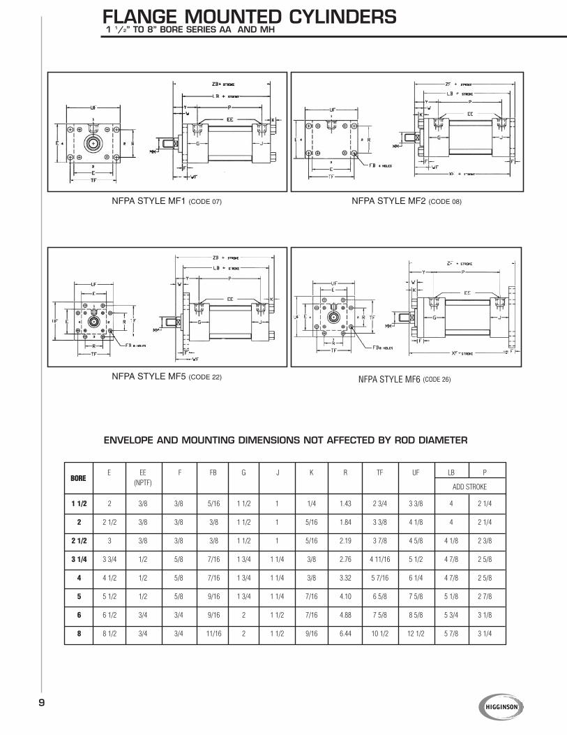
FLANGE MOUNTED CYLINDERS1 1/2” TO 8” BORE SERIES AA AND MH
NFPA STYLE MF1 (CODE 07) NFPA STYLE MF2 (CODE 08)
NFPA STYLE MF5 (CODE 22) NFPA STYLE MF6 (CODE 26)
1 1/2 2 3/8 3/8 5/16 1 1/2 1 1/4 1.43 2 3/4 3 3/8 4 2 1/4
2 2 1/2 3/8 3/8 3/8 1 1/2 1 5/16 1.84 3 3/8 4 1/8 4 2 1/4
2 1/2 3 3/8 3/8 3/8 1 1/2 1 5/16 2.19 3 7/8 4 5/8 4 1/8 2 3/8
3 1/4 3 3/4 1/2 5/8 7/16 1 3/4 1 1/4 3/8 2.76 4 11/16 5 1/2 4 7/8 2 5/8
4 4 1/2 1/2 5/8 7/16 1 3/4 1 1/4 3/8 3.32 5 7/16 6 1/4 4 7/8 2 5/8
5 5 1/2 1/2 5/8 9/16 1 3/4 1 1/4 7/16 4.10 6 5/8 7 5/8 5 1/8 2 7/8
6 6 1/2 3/4 3/4 9/16 2 1 1/2 7/16 4.88 7 5/8 8 5/8 5 3/4 3 1/8
8 8 1/2 3/4 3/4 11/16 2 1 1/2 9/16 6.44 10 1/2 12 1/2 5 7/8 3 1/4
BOREE EE F FB G J K R TF UF LB P
(NPTF) ADD STROKE
ENVELOPE AND MOUNTING DIMENSIONS NOT AFFECTED BY ROD DIAMETER
10
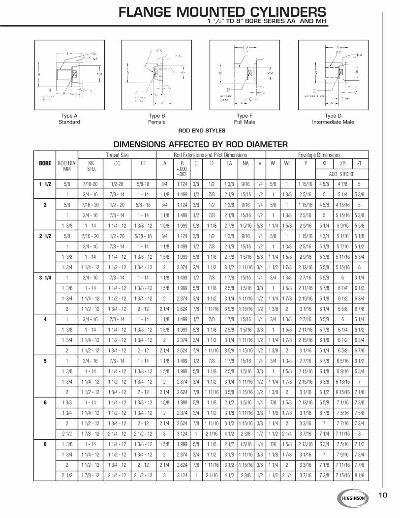
FLANGE MOUNTED CYLINDERS1 1/2” TO 8” BORE SERIES AA AND MH
Type AStandard
Type BFemale
Type FFull Male
Type DIntermediate Male
1 1/2 5/8 7/16-20 1/2-20 5/8-18 3/4 1.124 3/8 1/2 1 3/8 9/16 1/4 5/8 1 1 15/16 4 5/8 4 7/8 5
1 3/4 - 16 7/8 - 14 1 - 14 1 1/8 1.499 1/2 7/8 2 1/8 15/16 1/2 1 1 3/8 2 5/16 5 5 1/4 5 3/8
2 5/8 7/16 - 20 1/2 - 20 5/8 - 18 3/4 1.124 3/8 1/2 1 3/8 9/16 1/4 5/8 1 1 15/16 4 5/8 4 15/16 5
1 3/4 - 16 7/8 - 14 1 - 14 1 1/8 1.499 1/2 7/8 2 1/8 15/16 1/2 1 1 3/8 2 5/16 5 5 15/16 5 3/8
1 3/8 1 - 14 1 1/4 - 12 1 3/8 - 12 1 5/8 1.999 5/8 1 1/8 2 7/8 1 5/16 5/8 1 1/4 1 5/8 2 9/16 5 1/4 5 9/16 5 5/8
2 1/2 5/8 7/16 - 20 1/2 - 20 5/18 - 18 3/4 1.124 3/8 1/2 1 3/8 9/16 1/4 5/8 1 1 15/16 4 3/4 5 1/16 5 1/8
1 3/4 - 16 7/8 - 14 1 - 14 1 1/8 1.499 1/2 7/8 2 1/8 15/16 1/2 1 1 3/8 2 5/16 5 1/8 5 7/16 5 1/2
1 3/8 1 - 14 1 1/4 - 12 1 3/8 - 12 1 5/8 1.999 5/8 1 1/8 2 7/8 1 5/16 5/8 1 1/4 1 5/8 2 9/16 5 3/8 5 11/16 5 3/4
1 3/4 1 1/4 - 12 1 1/2 - 12 1 3/4 - 12 2 2.374 3/4 1 1/2 3 1/2 1 11/16 3/4 1 1/2 1 7/8 2 13/16 5 5/8 5 15/16 6
3 1/4 1 3/4 - 16 7/8 - 14 1 - 14 1 1/8 1.499 1/2 7/8 1 7/8 15/16 1/4 3/4 1 3/8 2 7/16 5 5/8 6 6 1/4
1 3/8 1 - 14 1 1/4 - 12 1 3/8 - 12 1 5/8 1.999 5/8 1 1/8 2 5/8 1 5/16 3/8 1 1 5/8 2 11/16 5 7/8 6 1/4 6 1/2
1 3/4 1 1/4 - 12 1 1/2 - 12 1 3/4 - 12 2 2.374 3/4 1 1/2 3 1/4 1 11/16 1/2 1 1/4 1 7/8 2 15/16 6 1/8 6 1/2 6 3/4
2 1 1/2 - 12 1 3/4 - 12 2 - 12 2 1/4 2.624 7/8 1 11/16 3 5/8 1 15/16 1/2 1 3/8 2 3 1/16 6 1/4 6 5/8 6 7/8
4 1 3/4 - 16 7/8 - 14 1 - 14 1 1/8 1.499 1/2 7/8 1 7/8 15/16 1/4 3/4 1 3/8 2 7/16 5 5/8 6 6 1/4
1 3/8 1 - 14 1 1/4 - 12 1 3/8 - 12 1 5/8 1.999 5/8 1 1/8 2 5/8 1 5/16 3/8 1 1 5/8 2 11/16 5 7/8 6 1/4 6 1/2
1 3/4 1 1/4 - 12 1 1/2 - 12 1 3/4 - 12 2 2.374 3/4 1 1/2 3 1/4 1 11/16 1/2 1 1/4 1 7/8 2 15/16 6 1/8 6 1/2 6 3/4
2 1 1/2 - 12 1 3/4 - 12 2 - 12 2 1/4 2.624 7/8 1 11/16 3 5/8 1 15/16 1/2 1 3/8 2 3 1/16 6 1/4 6 5/8 6 7/8
5 1 3/4 - 16 7/8 - 14 1 - 14 1 1/8 1.499 1/2 7/8 1 7/8 15/16 1/4 3/4 1 3/8 2 7/16 5 7/8 6 5/16 6 1/2
1 3/8 1 - 14 1 1/4 - 12 1 3/8 - 12 1 5/8 1.999 5/8 1 1/8 2 5/8 1 5/16 3/8 1 1 5/8 2 11/16 6 1/8 6 9/16 6 3/4
1 3/4 1 1/4 - 12 1 1/2 - 12 1 3/4 - 12 2 2.374 3/4 1 1/2 3 1/4 1 11/16 1/2 1 1/4 1 7/8 2 15/16 6 3/8 6 13/16 7
2 1 1/2 - 12 1 3/4 - 12 2 - 12 2 1/4 2.624 7/8 1 11/16 3 5/8 1 15/16 1/2 1 3/8 2 3 1/16 6 1/2 6 15/16 7 1/8
6 1 3/8 1 - 14 1 1/4 - 12 1 3/8 - 12 1 5/8 1.999 5/8 1 1/8 2 1/2 1 5/16 1/4 7/8 1 5/8 2 13/16 6 5/8 7 1/16 7 3/8
1 3/4 1 1/4 - 12 1 1/2 - 12 1 3/4 - 12 2 2.374 3/4 1 1/2 3 1/8 1 11/16 3/8 1 1/8 1 7/8 3 1/16 6 7/8 7 5/16 7 5/8
2 1 1/2 - 12 1 3/4 - 12 2 - 12 2 1/4 2.624 7/8 1 11/16 3 1/2 1 15/16 3/8 1 1/4 2 3 3/16 7 7 7/16 7 3/4
2 1/2 1 7/8 - 12 2 1/4 - 12 2 1/2 - 12 3 3.124 1 2 1/16 4 1/2 2 3/8 1/2 1 1/2 2 1/4 3 7/16 7 1/4 7 11/16 8
8 1 3/8 1 - 14 1 1/4 - 12 1 3/8 - 12 1 5/8 1.999 5/8 1 1/8 2 1/2 1 5/16 1/4 7/8 1 5/8 2 13/16 6 3/4 7 5/16 7 1/2
1 3/4 1 1/4 - 12 1 1/2 - 12 1 3/4 - 12 2 2.374 3/4 1 1/2 3 1/8 1 11/16 3/8 1 1/8 1 7/8 3 1/16 7 7 9/16 7 3/4
2 1 1/2 - 12 1 3/4 - 12 2 - 12 2 1/4 2.624 7/8 1 11/16 3 1/2 1 15/16 3/8 1 1/4 2 3 3/16 7 1/8 7 11/16 7 7/8
2 1/2 1 7/8 - 12 2 1/4 - 12 2 1/2 - 12 3 3.124 1 2 1/16 4 1/2 2 3/8 1/2 1 1/2 2 1/4 3 7/16 7 3/8 7 15/16 8 1/8
Thread Size Rod Extensions and Pilot Dimensions Envelope DimensionsBORE ROD DIA. KK CC FF A B C D LA NA V W WF Y XF ZB ZF
MM STD. +.000ADD STROKE-.002
DIMENSIONS AFFECTED BY ROD DIAMETER
ROD END STYLES

11
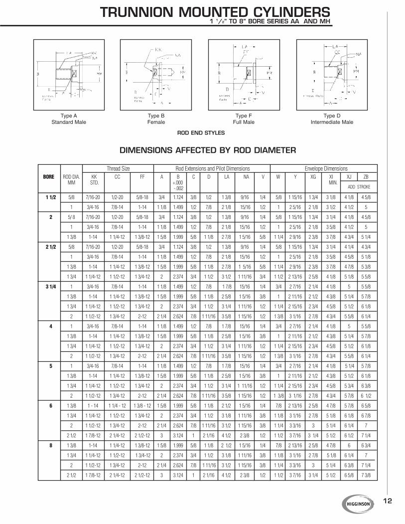
TRUNNION MOUNTED CYLINDERS1 1/2” TO 8” BORE SERIES AA AND MH
NFPA STYLE MT1 (CODE 14)
NFPA STYLE MT4 (CODE 24)
NFPA STYLE MT2 (CODE 23)
E EE F G J K TD TG TL TM TW UM UT LB PBORE (NPTF) +.000
ADD STROKE-.001
1 1/2 2 3/8 3/8 1 1/2 1 1/4 1.000 2 1/2 1 2 1/2 1 1/4 4 1/2 4 4 2 1/4
2 2 1/2 3/8 3/8 1 1/2 1 5/16 1.000 3 1 3 1 1/2 5 4 1/2 4 2 1/4
2 1/2 3 3/8 3/8 1 1/2 1 5/16 1.000 3 1/2 1 3 1/2 1 1/2 5 1/2 5 4 1/8 2 3/8
3 1/4 3 3/4 1/2 5/8 1 3/4 1 1/4 3/8 1.000 4 1/4 1 4 1/2 2 6 1/2 5 3/4 4 7/8 2 5/8
4 4 1/2 1/2 5/8 1 3/4 1 1/4 3/8 1.000 5 1 5 1/4 2 7 1/4 6 1/2 4 7/8 2 5/8
5 5 1/2 1/2 5/8 1 3/4 1 1/4 7/16 1.000 6 1 6 1/4 2 8 1/4 7 1/2 5 1/8 2 7/8
6 6 1/2 3/4 3/4 2 1 1/2 7/16 1.375 7 1 3/8 7 5/8 2 1/2 10 3/8 9 1/4 5 3/4 3 1/8
8 8 1/2 3/4 3/4 2 1 1/2 9/16 1.375 9 1/2 1 3/8 9 3/4 2 1/2 12 1/2 11 1/4 5 7/8 3 1/4
ENVELOPE AND MOUNTING DIMENSIONS NOT AFFECTED BY ROD DIAMETER
Note: Front trunnion not available on 1 1/2” + 2” bore with oversize rod. Head cushions not available on 1 1/2” bore with oversize rod.
12
TRUNNION MOUNTED CYLINDERS1 1/2” TO 8” BORE SERIES AA AND MH
Type AStandard Male
Type BFemale
Type FFull Male
Type DIntermediate Male
1 1/2 5/8 7/16-20 1/2-20 5/8-18 3/4 1.124 3/8 1/2 1 3/8 9/16 1/4 5/8 1 15/16 1 3/4 3 1/8 4 1/8 4 5/8
1 3/4-16 7/8-14 1-14 1 1/8 1.499 1/2 7/8 2 1/8 15/16 1/2 1 2 5/16 2 1/8 3 1/2 4 1/2 5
2 5/ 8 7/16-20 1/2-20 5/8-18 3/4 1.124 3/8 1/2 1 3/8 9/16 1/4 5/8 1 15/16 1 3/4 3 1/4 4 1/8 4 5/8
1 3/4-16 7/8-14 1-14 1 1/8 1.499 1/2 7/8 2 1/8 15/16 1/2 1 2 5/16 2 1/8 3 5/8 4 1/2 5
1 3/8 1-14 1 1/4-12 1 3/8-12 1 5/8 1.999 5/8 1 1/8 2 7/8 1 5/16 5/8 1 1/4 2 9/16 2 3/8 3 7/8 4 3/4 5 1/4
2 1/2 5/8 7/16-20 1/2-20 5/8-18 3/4 1.124 3/8 1/2 1 3/8 9/16 1/4 5/8 1 15/16 1 3/4 3 1/4 4 1/4 4 3/4
1 3/4-16 7/8-14 1-14 1 1/8 1.499 1/2 7/8 2 1/8 15/16 1/2 1 2 5/16 2 1/8 3 5/8 4 5/8 5 1/8
1 3/8 1-14 1 1/4-12 1 3/8-12 1 5/8 1.999 5/8 1 1/8 2 7/8 1 5/16 5/8 1 1/4 2 9/16 2 3/8 3 7/8 4 7/8 5 3/8
1 3/4 1 1/4-12 1 1/2-12 1 3/4-12 2 2.374 3/4 1 1/2 3 1/2 1 11/16 3/4 1 1/2 2 13/16 2 5/8 4 1/8 5 1/8 5 5/8
3 1/4 1 3/4-16 7/8-14 1-14 1 1/8 1.499 1/2 7/8 1 7/8 15/16 1/4 3/4 2 7/16 2 1/4 4 1/8 5 5 5/8
1 3/8 1-14 1 1/4-12 1 3/8-12 1 5/8 1.999 5/8 1 1/8 2 5/8 1 5/16 3/8 1 2 11/16 2 1/2 4 3/8 5 1/4 5 7/8
1 3/4 1 1/4-12 1 1/2-12 1 3/4-12 2 2.374 3/4 1 1/2 3 1/4 1 11/16 1/2 1 1/4 2 15/16 2 3/4 4 5/8 5 1/2 6 1/8
2 1 1/2-12 1 3/4-12 2-12 2 1/4 2.624 7/8 1 11/16 3 5/8 1 15/16 1/2 1 3/8 3 1/16 2 7/8 4 3/4 5 5/8 6 1/4
4 1 3/4-16 7/8-14 1-14 1 1/8 1.499 1/2 7/8 1 7/8 15/16 1/4 3/4 2 7/16 2 1/4 4 1/8 5 5 5/8
1 3/8 1-14 1 1/4-12 1 3/8-12 1 5/8 1.999 5/8 1 1/8 2 5/8 1 5/16 3/8 1 2 11/16 2 1/2 4 3/8 5 1/4 5 7/8
1 3/4 1 1/4-12 1 1/2-12 1 3/4-12 2 2.374 3/4 1 1/2 3 1/4 1 11/16 1/2 1 1/4 2 15/16 2 3/4 4 5/8 5 1/2 6 1/8
2 1 1/2-12 1 3/4-12 2-12 2 1/4 2.624 7/8 1 11/16 3 5/8 1 15/16 1/2 1 3/8 3 1/16 2 7/8 4 3/4 5 5/8 6 1/4
5 1 3/4-16 7/8-14 1-14 1 1/8 1.499 1/2 7/8 1 7/8 15/16 1/4 3/4 2 7/16 2 1/4 4 1/8 5 1/4 5 7/8
1 3/8 1-14 1 1/4-12 1 3/8-12 1 5/8 1.999 5/8 1 1/8 2 5/8 1 5/16 3/8 1 2 11/16 2 1/2 4 3/8 5 1/2 6 1/8
1 3/4 1 1/4-12 1 1/2-12 1 3/4-12 2 2.374 3/4 1 1/2 3 1/4 1 11/16 1/2 1 1/4 2 15/16 2 3/4 4 5/8 5 3/4 6 3/8
2 1 1/2-12 1 3/4-12 2-12 2 1/4 2.624 7/8 1 11/16 3 5/8 1 15/16 1/2 1 3/8 3 1/16 2 7/8 4 3/4 5 7/8 6 1/2
6 1 3/8 1 - 14 1 1/4 - 12 1 3/8 - 12 1 5/8 1.999 5/8 1 1/8 2 1/2 1 5/16 1/4 7/8 2 13/16 2 5/8 4 7/8 5 7/8 6 5/8
1 3/4 1 1/4-12 1 1/2-12 1 3/4-12 2 2.374 3/4 1 1/2 3 1/8 1 11/16 3/8 1 1/8 3 1/16 2 7/8 5 1/8 6 1/8 6 7/8
2 1 1/2-12 1 3/4-12 2-12 2 1/4 2.624 7/8 1 11/16 3 1/2 1 15/16 3/8 1 1/4 3 3/16 3 5 1/4 6 1/4 7
2 1/2 1 7/8-12 2 1/4-12 2 1/2-12 3 3.124 1 2 1/16 4 1/2 2 3/8 1/2 1 1/2 3 7/16 3 1/4 5 1/2 6 1/2 7 1/4
8 1 3/8 1-14 1 1/4-12 1 3/8-12 1 5/8 1.999 5/8 1 1/8 2 1/2 1 5/16 1/4 7/8 2 13/16 2 5/8 4 7/8 6 6 3/4
1 3/4 1 1/4-12 1 1/2-12 1 3/4-12 2 2.374 3/4 1 1/2 3 1/8 1 11/16 3/8 1 1/8 3 1/16 2 7/8 5 1/8 6 1/4 7
2 1 1/2-12 1 3/4-12 2-12 2 1/4 2.624 7/8 1 11/16 3 1/2 1 15/16 3/8 1 1/4 3 3/16 3 5 1/4 6 3/8 7 1/4
2 1/2 1 7/8-12 2 1/4-12 2 1/2-12 3 3.124 1 2 1/16 4 1/2 2 3/8 1/2 1 1/2 3 7/16 3 1/4 5 1/2 6 5/8 7 3/8
Thread Size Rod Extensions and Pilot Dimensions Envelope DimensionsBORE ROD DIA. KK CC FF A B C D LA NA V W Y XG XI XJ ZB
MM STD. +.000 MIN.ADD STROKE-.002
DIMENSIONS AFFECTED BY ROD DIAMETER
ROD END STYLES
13
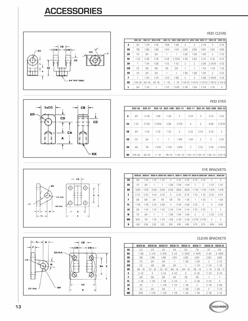
ROD CLEVIS
ROD EYES
EYE BRACKETS
CLEVIS BRACKETS
ACCESSORIES
BDC-05 BDC-07 BDC-07M BDC-10 BDC-10M BDC-13 BDC-13M BDC-17 BDC-20 BDC-25
A 3/4 1 1/8 1 1/8 1 5/8 1 5/8 2 2 2 1/4 3 3 1/2
CB .765 1.265 1.265 1.515 1.515 2.032 2.032 2.531 2.531 3.032
CD 1/2 3/4 3/4 1 1 1 3/8 1 3/8 1 3/4 2 2 1/2
CE 1 1/2 2 3/8 2 1/8 3 1/8 2 15/16 4 1/8 3 3/4 4 1/2 5 1/2 6 1/2
CH 1 1 1/4 1 3/8 1 1/2 1 1/2 2 2 2 3/8 2 15/16 3 1/2
CW 1/2 5/8 5/8 3/4 3/4 1 1 1 1/4 1 1/4 1 1/2
ER 1/2 3/4 3/4 1 1 1 3/8 1 3/8 1 3/4 2 2 1/2
F 1 1 1/4 1 1/4 1 1/2 1 5/8 2 2 2 3/8 2 15/16 3 1/2
KK 7/16 -20 3/4 -16 3/4 -16 1 -14 1 -14 1 1/4-12 1 1/4-12 1 1/2-12 1 7/8-12 2 1/4-12
L 3/4 1 1/4 1 1 1/2 1 5/16 2 1/8 1 3/4 2 1/4 2 1/2 3
BDE-05 BDE-07 BDE-10 BDE-10M BDE-13 BDE-17 BDE-20 BDE-20M BDE-25
A 3/4 1/ 1/8 1 5/8 1 1/8 2 2 1/4 3 2 1/4 3 1/2
CA 1 1/2 2 1/16 2 13/16 2 3/8 3 7/16 4 5 4 3/8 5 13/16
CB 3/4 1 1/4 1 1/2 1 1/2 2 2 1/2 2 1/2 2 1/2 3
CD 1/2 3/4 1 1 1 3/8 1 3/4 2 2 2 1/2
ER 5/8 7/8 1 3/16 1 7/16 1 9/16 2 2 1/2 2 7/8 2 13/16
KK 7/16 -20 3/4 -16 1 -14 7/8 -14 1 1/4 - 12 1 1/2 - 12 1 7/8 - 12 1 3/4 - 12 2 1/4 -12
BDEB-05 BDEB-07 BDEB-10 BDEB-10H BDEB-13 BDEB-17 BDEB-17H BDEB-20 BDEB-20H BDEB-25 BDEB-25H
CB 3/4 1 1/4 1 1/2 1 1/2 2 2 1/2 2 1/2 2 1/2 2 1/2 3 3
CD 1/2 3/4 1 1 1 3/8 1 3/4 1 3/4 2 2 2 1/2 2 1/2
DD 13/32 17/32 21/32 21/32 21/32 29/32 29/32 1 1/16 1 1/16 1 3/16 1 3/16
E 2 1/2 3 1/2 4 1/2 4 1/2 5 6 1/2 6 1/2 7 1/2 7 1/2 8 1/2 8 1/2
F 3/8 5/8 3/4 7/8 7/8 7/8 1 1/8 1 1 1/2 1 1 3/4
FL 1 1/8 1 7/8 2 1/4 2 3/8 3 3 1/8 3 3/8 3 1/2 4 4 4 3/4
LR 3/4 1 1/4 1 1/2 1 1/2 2 1/8 2 1/4 2 1/4 2 1/2 2 1/2 3 3
M 1/2 3/4 1 1 1 3/8 1 3/4 1 3/4 2 2 2 1/2 2 1/2
MR 9/16 7/8 1 1/4 1 1/4 1 5/8 2 1/8 2 1/8 2 7/16 2 7/16 3 3
R 1.63 2.56 3.25 3.25 3.81 4.95 4.95 5.75 5.75 6.59 6.59
BDCB-05 BDCB-06 BDCB-07 BDCB-10 BDCB-13 BDCB-17 BDCB-20 BDCB-25
AA 2.3 2.9 3.6 4.6 5.4 7.0 8.1 9.3
BA 1 5/8 2 1/16 2 9/16 3 1/4 3 13/16 4 15/16 5 3/4 6 19/32
CB .765 1.265 1.265 1.515 2.032 2.531 2.531 3.032
CD 1/2 3/4 3/4 1 1 3/8 1 3/4 2 2 1/2
CW 1/2 5/8 5/8 3/4 1 1 1/4 1 1/4 1 1/2
DD 3/8 - 24 1/2 - 20 1/2 - 20 5/8 - 18 5/8 - 18 7/8 - 14 1 - 14 1 1/8 - 12
E 2 1/2 3 3 1/2 4 1/2 5 6 1/2 7 1/2 8 1/2
F 3/8 5/8 5/8 3/4 7/8 7/8 1 1
FL 1 1/8 1 7/8 1 7/8 2 1/4 3 3 1/8 3 1/2 4
LR 1/2 1 1 1/16 1 1/4 1 7/8 2 2 1/8 2 5/8
M 1/2 3/4 3/4 1 1 3/8 1 3/4 2 2 1/2
MR 9/16 1 1/16 1 1/16 1 1/8 1 3/4 1 7/8 2 1/8 2 1/2
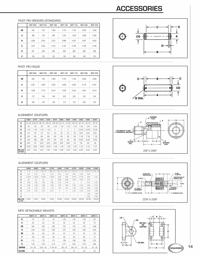
PIVOT PIN GROOVES (STANDARD)
PIVOT PIN HOLES
ALIGNMENT COUPLERS
ALIGNMENT COUPLERS
MP2 DETACHABLE MOUNTS
14
ACCESSORIES
BDP-05G BDP-07G BDP-10G BDP-13G BDP-17G BDP-20G BDP-25G
CD .500 .750 1.000 1.375 1.750 2.000 2.500
A .468 .704 .940 1.291 1.650 1.886 2.360
B 2.094 2.875 3.375 4.485 5.547 5.547 6.625
C 1.875 2.625 3.125 4.187 5.188 5.188 6.188
D .041 .048 .048 .056 .068 .068 .086
E .109 .125 .125 .149 .180 .180 .219
BDP-05H BDP-07H BDP-10H BDP-13H BDP-17H BDP-20H BDP-25H
CD .500 .750 1.000 1.375 1.750 2.000 2.500
A 2.281 3.094 3.594 4.656 5.656 5.719 6.781
B 1.938 2.719 3.219 4.250 5.250 5.281 6.313
C .172 .188 .188 .203 .203 .219 .234
D .106 .140 .140 .173 .173 .204 .219
250F 312F 375C 375F 437F 500C 500F 625F 750C 750F 875F
A 1/4 -28 5/16 -24 3/8 -16 3/8 -24 7/16 -20 1/2 -13 1/2 -20 5/8 -18 3/4 -10 3/4 -16 7/8 -14
B 7/8 7/8 7/8 7/8 1 1/4 1 1/4 1 1/4 1 1/4 1 3/4 1 3/4 1 3/4
C 1 1/4 1 1/4 1 1/4 1 1/4 2 2 2 2 2 5/16 2 5/16 2 5/16
D 1/4 1/4 1/4 1/4 1/2 1/2 1/2 1/2 5/16 5/16 5/16
E 5/8 5/8 5/8 5/8 3/4 3/4 3/4 3/4 1 1/8 1 1/8 1 1/8
F .245 .308 .369 .370 5/8 5/8 5/8 5/8 31/32 31/32 31/32
G 3/16 1/4 5/16 5/16 9/16 9/16 9/16 1/2 7/8 7/8 7/8
H 13/16 13/16 13/16 13/16 1 1/8 1 1/8 1 1/8 1 1/8 1 1/2 1 1/2 1 1/2
Max Pull 4,000 4,000 5,000 5,000 10,000 14,000 14,000 14,000 34,000 34,000 34,000at Yield
1000C 1000F 1250F 1375F 1500F 1750F 1875F 2000F 2250F 2500F
A 1 - 8 1 - 14 1 1/4 - 12 1 3/8 - 12 1 1/2 - 12 1 3/4 - 12 1 7/8 - 12 2 - 12 2 1/4 - 12 2 1/2 - 12
B 2 1/2 2 1/2 2 1/2 2 1/2 3 1/4 3 1/4 3 3/4 3 3/4 6 3/4 7
C 2 15/16 2 15/16 2 15/16 2 15/16 4 3/8 4 3/8 5 7/16 5 7/16 6 3/8 6 1/2
D 1/2 1/2 1/2 1/2 13/16 13/16 11/16 11/16 3 1/4 4
E 1 5/8 1 5/8 1 5/8 1 5/8 2 1/4 2 1/4 3 3 3 1/2 3 1/2
F 1 3/8 1 3/8 1 3/8 1 3/8 1 3/4 1 3/4 2 1/4 2 1/4 2 3/4 3 1/4
G 1 1/4 1 1/4 1 1/4 1 1/4 1 1/2 1 1/2 1 7/8 1 7/8 2 3/8 2 7/8
H 2 1/4 2 1/4 2 1/4 2 1/4 3 3 3 1/2 3 1/2 2 7/8 3 3/8
J - - - - - - - - 1 5/8 1 5/8
K - - - - - - - - 3 3/4 3 7/8
Max Pull 64,000 64,000 64,000 64,000 120,000 120,000 240,000 240,000 397,000 495,000at Yield
BMP2-15 BMP2-2 BMP2-25 BMP2-32 BMP2-4 BMP2-5 BMP2-6
B .76 .76 .76 1.26 1.26 1.26 1.51
C .50 .50 .50 .62 .62 .62 .75
CD .502 .502 .502 .752 .752 .752 1.002
D 2.00 2.50 3.00 3.75 4.50 5.50 6.50
ER .62 .62 .62 .87 .87 .87 1.12
F .38 .38 .38 .63 .63 .63 .75
FL 1.13 1.13 1.13 1.88 1.88 1.88 2.25
G 1.43 1.84 2.19 2.77 3.32 4.10 4.88
TAPPED 1/4 - 28 5/16 - 24 5 /16 -24 3/8 - 24 3/8 - 24 1/2 - 20 1/2 - 20
B-D DIA. .28 .34 .34 .41 .41 .53 .53
250F to 2000F
2250F to 2500F

15
OPTIONSReed and Electronic Sensors
Proximity sensors are used to sense position on air cylinders only from 1.1/2 to 8" bore. A magnet is required onthe piston. (use M in our model number code see pg. 17). All switches feature a Canfield patented self-adjustingclamp that grips the tie rod for easy positioning and has a 2-metre lead. Three standard types are shown; howevermany more enclosures and connector options are available.
Part Number Type Function Switching Switching Switching Switching Voltage
Voltage Current Power Speed Drop
749-000-004 Reed, MOV normally open 5 - 240 VDC/VAC 1 Amp max. 30 watts max. 0.6ms operate 3 volts
LED, 2 wire SPST 50/60 Hz .005 Amp min. 0.05ms release
749-000-031 electronic, sourcing normally open 6 - 24 VDC 1 Amp max. 24 watts max 1.5u operate 0.5 volts
LED, 3 wire PNP output 0.5u release
749-000-032 electronic, sinking normally open 6 - 24 VDC 1 Amp max. 24 watts max 1.5u operate 0.5 volts
LED, 3 wire NPN output 0.5u release
ROD BOOTSProvide maximum protection against rod scoring from chips,abrasive particles and other damaging objects. Manufactured ofrugged neoprene coated nylon fabric to give millions of trouble freecycles in temperature ranges of –40 F to 220 F. To calculate theextra rod (rod extension) needed use the following formula; Stroke X.0625. Also check the boot OD against the cylinder "E" dimension forMS mounts to make sure you have enough clearance. Other bootsizes and materials are available. Consult factory.
Rod Size 5/8 1 13/8 13/4 2 21/2
Boot OD 3 33/8 33/4 41/8 45/8 51/8
TANDEM CYLINDER SPRING RETRACT
Available in 1 1/2” to 3 1/4" bore.3" maximum stroke.
Consult factory for more details.
Bore A B
1 1/2 0.75 0.30
2 0.75 0.30
2 1/2 0.75 0.30
3 1/4 0.70 0.13
4 0.70 0.13
5 0.55 0
6 0.40 0
8 0.25 0
BORE SIZE ROD SIZE 65PSI 80PSI 100PSI1.50 5/8 190 234 2922.0 5/8 368 452 5662.50 5/8 598 736 9203.25 1.0 978 1198 15024.0 1.0 1532 1882 23565.0 1.0 2452 3012 37706.0 1 3/8 3482 4268 5356
BORE SIZE 65PSI 80PSI 100PSI1.50 230 284 3542.0 408 502 6282.50 638 786 9823.25 1080 1328 16604.0 1364 2012 25145.0 2554 3142 39286.0 3676 4524 5654
AIR IN RETRACTS ROD AIR IN EXTENDS ROD
PUSHPULL
16
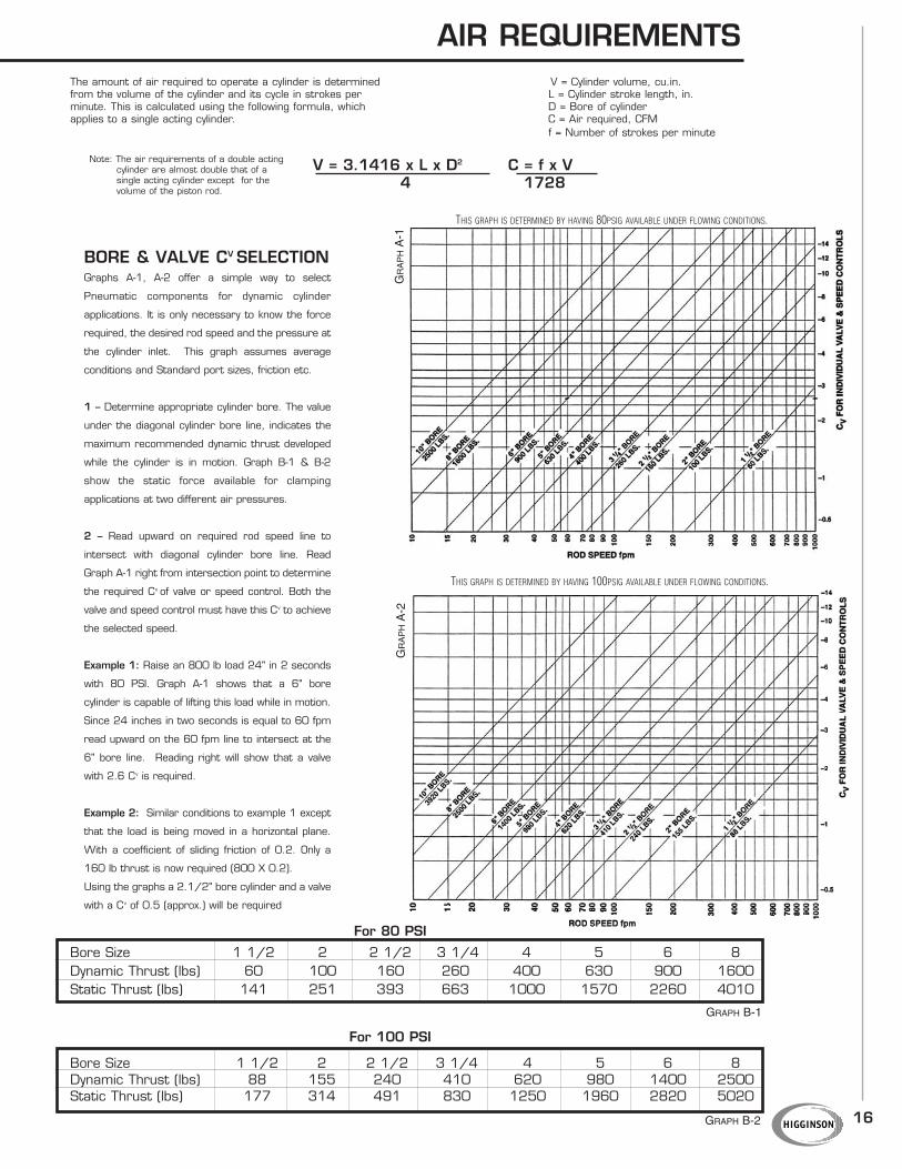
AIR REQUIREMENTSThe amount of air required to operate a cylinder is determined V = Cylinder volume, cu.in.from the volume of the cylinder and its cycle in strokes per L = Cylinder stroke length, in.minute. This is calculated using the following formula, which D = Bore of cylinderapplies to a single acting cylinder. C = Air required, CFM
f = Number of strokes per minute
V = 3.1416 x L x D2 C = f x V 4 1728
For 80 PSI
Bore Size 1 1/2 2 2 1/2 3 1/4 4 5 6 8Dynamic Thrust (lbs) 60 100 160 260 400 630 900 1600Static Thrust (lbs) 141 251 393 663 1000 1570 2260 4010
For 100 PSI
Bore Size 1 1/2 2 2 1/2 3 1/4 4 5 6 8Dynamic Thrust (lbs) 88 155 240 410 620 980 1400 2500Static Thrust (lbs) 177 314 491 830 1250 1960 2820 5020
GRAPH B-1
GRAPH B-2
BORE & VALVE CV SELECTIONGraphs A-1, A-2 offer a simple way to select
Pneumatic components for dynamic cylinder
applications. It is only necessary to know the force
required, the desired rod speed and the pressure at
the cylinder inlet. This graph assumes average
conditions and Standard port sizes, friction etc.
1 – Determine appropriate cylinder bore. The value
under the diagonal cylinder bore line, indicates the
maximum recommended dynamic thrust developed
while the cylinder is in motion. Graph B-1 & B-2
show the static force available for clamping
applications at two different air pressures.
2 – Read upward on required rod speed line to
intersect with diagonal cylinder bore line. Read
Graph A-1 right from intersection point to determine
the required Cv of valve or speed control. Both the
valve and speed control must have this Cv to achieve
the selected speed.
Example 1: Raise an 800 lb load 24" in 2 seconds
with 80 PSI. Graph A-1 shows that a 6" bore
cylinder is capable of lifting this load while in motion.
Since 24 inches in two seconds is equal to 60 fpm
read upward on the 60 fpm line to intersect at the
6" bore line. Reading right will show that a valve
with 2.6 Cv is required.
Example 2: Similar conditions to example 1 except
that the load is being moved in a horizontal plane.
With a coefficient of sliding friction of 0.2. Only a
160 lb thrust is now required (800 X 0.2).
Using the graphs a 2.1/2" bore cylinder and a valve
with a Cv of 0.5 (approx.) will be required
Note: The air requirements of a double acting cylinder are almost double that of a single acting cylinder except for the volume of the piston rod.
THIS GRAPH IS DETERMINED BY HAVING 100PSIG AVAILABLE UNDER FLOWING CONDITIONS.
GR
AP
HA
-2G
RA
PH
A-1
THIS GRAPH IS DETERMINED BY HAVING 80PSIG AVAILABLE UNDER FLOWING CONDITIONS.
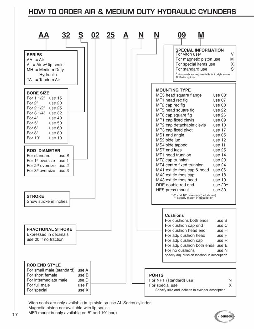
HOW TO ORDER AIR & MEDIUM DUTY HYDRAULIC CYLINDERS
AA 32 S 02 25 A N N 09 M
SERIESAA = AirAL = Air w/ lip sealsMH = Medium Duty
HydraulicTA = Tandem Air
BORE SIZEFor 1 1/2" use 15For 2" use 20For 2 1/2" use 25For 3 1/4" use 32For 4" use 40For 5" use 50For 6" use 60For 8" use 80For 10" use 10
ROD DIAMETERFor standard use SFor 1st oversize use 1For 2nd oversize use 2For 3rd oversize use 3
STROKEShow stroke in inches
FRACTIONAL STROKEExpressed in decimalsuse 00 if no fraction
CushionsFor cushions both ends use BFor cushion cap end use CFor cushion head end use HFor adj. cushion head use FFor adj. cushion cap use RFor adj. cushion both ends use EFor no cushions use Nspecify adj. cushion location in description
ROD END STYLEFor small male (standard) use AFor short female use BFor intermediate male use DFor full male use FFor special use X
PORTSFor NPT (standard) use NFor special use X
Specify size and location in cylinder description
SPECIAL INFORMATIONFor viton use1 VFor magnetic piston use MFor special items use XFor standard use S1 Viton seals are only available in lip style so useAL Series cylinder
MOUNTING TYPEME3 head square flange use 03*
MF1 head rec flg use 07MF2 cap rec flg use 08MF5 head square flg use 22MF6 cap square flg use 26MP1 cap fixed clevis use 09MP2 cap detachable clevis use 10MP3 cap fixed pivot use 17MS1 end angle use 05MS2 side lug use 12MS4 side tapped use 11MS7 end lugs use 25MT1 head trunnion use 14MT2 cap trunnion use 23MT4 centre fixed trunnion use 24MX1 ext tie rods cap & head use 06MX2 ext tie rods cap use 18MX3 ext tie rods head use 19DRE double rod end use 20**
HES press mount use 30* 8” and 10” bore only (not shown)
** specify mount in description
17
Viton seals are only available in lip style so use AL Series cylinder.Magnetic piston not available with lip seals.ME3 mount is only available on 8" and 10" bore.

HIGGINSON WARRANTY
Higginson warrants for one year from date of delivery
that this product is free from any component defect due
to faulty material or workmanship. Higginson assumes
no responsibility for damage or faulty performance
caused by misuse, careless handling or where repairs
have been made or attempted by others. No other
warranties written, or verbal, are authorized. The sole
remedy for breach of this warranty and the sole
obligation of Higginson hereunder is the repair or
replacement of the defective component at Higginson’s
option. Higginson shall have no liability whatsoever at
anytime for any personal injury or property damages,
or for any special, indirect, or consequential damages
of any kind how ever arising.
This warranty is strictly limited to its terms and is in lieu
of any and all other warranties and conditions, written
or oral, whether expressed or implied.
This catalogue is printed in Canada on recycled paper.

HIGGINSON EQUIPMENT SALESB U R L I N G T O N , O N T A R I O
Phone: 905-335-2211 • Toll Free: 1-877-CALL-HESFax: 905-335-8756 • Toll Free Fax: 1-800-858-0893
W W W . H I G G I N S O N . C A
DISTRIBUTED BY: