1
1
) j'i, ... „< r ^ .....
B. S.
19 11
TTNW.O.VrUUENTO.T6


Digitized by the Internet Archive
in 2013
http://archive.org/details/discussionofdesiOOhach
A DISCUSSION OF THE DESIGN
r OF SMALL
AMMONIA COMPRESSORSBY
George John Ernst Hachmeister
THESISFOR THE
DEGREE OF BACHELOR OF SCIENCE
MECHANICAL ENGINEERING
College of Engineering
University of Illinois
1911
ran

Hi!
w
UNIVERSITY OF ILLINOIS
#y y<7 19//
THIS IS TO CERTIFY THAT THE THESIS PREPARED UNDER MY SUPERVISION BY
, <JL A/ <7
ENTITLED
IS APPROVED BY ME AS FULFILLING THIS PART OF THE REQUIREMENTS FOR THE
DEGREE OF S < £
Approved: *-.</
Instructor in Charge.
<r^5^p HEAD OF DEPARTMENT OF ,
197627


1
CONTENTS.
INTRODUCTION PAGE 2I
TX ARTIFICIAL REFRIGERATION.
1* General principles 01 refrigeration. 3
2(a) Fluids used in refrigerating machines.
2(b) Table of properties of refrigerating media.
II SYSTEMS OF REFRIGERATION. 7
1* Absorption system*
2* Compression system
(1-2)A Brine
(1-2)B Direct-expansion
III AMMONIA COMPRESSORS. 13
1(a) Wet compression
1(b) Dry compression
2* Discussion of various types of ammonia compressors.
3(a) Capacity of ammonia compressors.
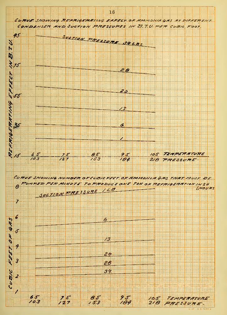
3(b) Curve showing refrigerating effect of ammonia gas at different
condenser and suction pressures in B.T.U. per cubic foot.
3(c) Curve showing number of cuoic feet of amrronia gas that must be
pumped per minute at different condenser and suction pressures
to produce one ton of refrigeration in twenty-four hours.
IV DESIGN OF A SMALL AMMONIA COMPRESSOR. 17


8
A DISCUSSION OF THE DESIGN OF SMALL AMMONIA COMPRESSORS.
INTRODUCTION.
The object of refrigeration is to produce low temperatures for the preser-
vation of foods and other perishable products. This object is attained by bring-
ing the air in the rooms in which the objects to be cooled are Kept in contact
with a colder body which abstracts heat from the air.
In the case ot natural refrigeration a mass of ice forms the cold body. The
air coming into contact witn the ice melts it and abstracts the latent heat of
melting. In artirically coolea rooms the air is cooled by coming into contact
with cold pipes which contain brine or some refrigerating medium whicb is being
expanded in them.
The growing demand for a lower temperature than can be obtained with ice led
to the development of two classes of ice machines: those which utilize the low-
ering of temperature that accompanies the erpansiog of some compressed gas and
those that make use of the thermal erf'ect that results from the volatization of
some liquid.
Carre constructed a machine of the first type in 1849 which was not a success.
In 1863 Kirk patented a machine and Windhausen built one in 1870 both of which ac-
tually froze ice.
The first machine that took advantage of the latent heat of a liquid as a re-
frigerant was oui It oy Perkins in 1857, this used ether as a refrigerant. Pour-
teen years later Van der Weyde sUDstituaeo gasoline for ether.
Professor Linde really solved the problem of mechanical refrigeration in 1876
when he introduced tne first successful ammonia compressor.
3
ARTIFICIAL REFRIGERATION*
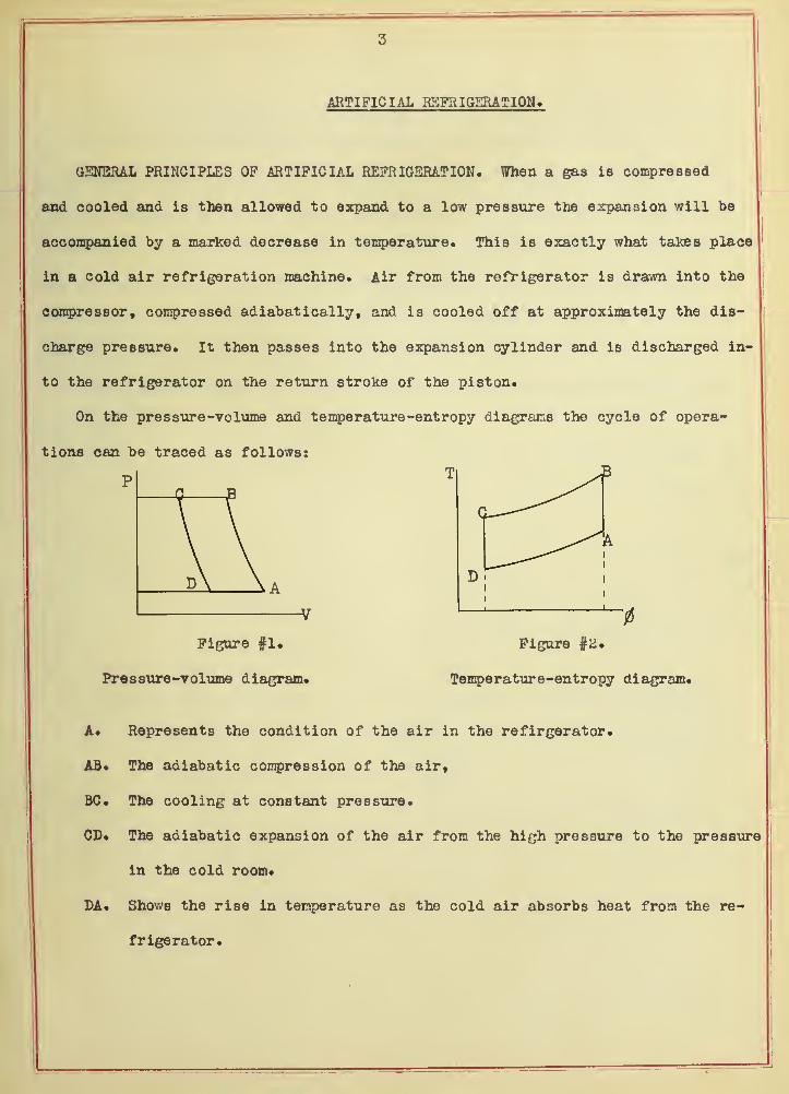
GENERAL PRINCIPLES OF ARTIFICIAL REFRIGERATION. When a gas is compressed
and cooled and is then allowed to expand to a low pressure the expansion will be
accompanied by a marked decrease in temperature. This is exactly what takes place
in a cold air refrigeration machine. Air from the refrigerator is drawn into the
compressor, compressed adiabatically, and is cooled off at approximately the dis-
charge pressure. It then passes into the expansion cylinder and is discharged in-
to the refrigerator on the return stroke of the piston.
On the pressure -volume and temperature -entropy diagrams the cycle of opera-
tions can be traced as follows:
P
Figure #1,
Pressure-volume diagram.
Figure #2.
Temperature-entropy diagram.
A. Represents the condition of the air in the refirgerator.
AB. The adiabatic compression of the air,
BC. The cooling at constant pressure.
CD. The adiabatic expansion of the air from the high pressure to the pressure
in the cold room.
DA. Shows the rise in temperature as the cold air absorbs heat from the re-
frigerator.


4
B
D 0/k
|\
! \
Ai
i
i
In vapor compression machines a gas is used which when compressed and cooled
in a condenser becomes a liquid. Upon reducing the pressure on the liquid it va-
porizes with a great decrease in temperature. The refrigerating medium is drawn
from the expansion coils into the compressor at a low temperature and pressure and
is compressed to a higher pressure and discharged into the condenser. Here the
heat of compression is carried off by cooling water and the refrigerant liquifies
and is stored in a receiver. The liquid is then expanded to a gas at a low pres-
sure. The pressure being regulated by a valve through which the liquid passes.
Figure #3 represents the cycle of operations on the temperature -entropy dia-
gram!
T /A Represents the state of the vapor in
the cooling coils as it is drawn into
the compressor.
AB The adiabatic compression of the vapor
to the condenser pressure.
BC The codling of the gas to a saturated
state.
CD The further cooling as it condenses.
DE Shows the expansion to the lower pres-
sure.
EA The heating of the vapor in the cooling
coils as it abstracts heat from the
air*
i
Figure #3.
Temperature -entropy diagram.


5
FLUIDS USED IN ARTIFICIAL REFRIGERATION. The fluid employed as a refrigerant
must have the following characteristics:
(1) It must be able to stand the temperatures and pressures employed without
disintegrating of freezing.
(2) Its capacity for heat must be large in order to carry off the heat ex-
tracted.
(3) The point of vaporization must be low and the resulting volume not too
large.
(4) Its pressures and temperatures must be practicle.
(5) The relation of the latent heat to the specific heat should be high.
Air has the advantage of being very abundant and fullfils the first con-
dition but its capacity for heat is small. The machine therefore must be large
to produce the refrigerating effect required.
Ether and sulphur dioxide at Oo F. , have a pressure below that of the at-
mosphere which makes it possible for air to leak into the plant and therefore
destroys the efficiency of the machine.
Carbon dioxide has the advantage over ammonia as a refirgerant because its
volume during vaporization increases only 1/33 as much as ammonia does. It has
the disadvantage that the pressure employed is about ten times higher than that
of ammonia.
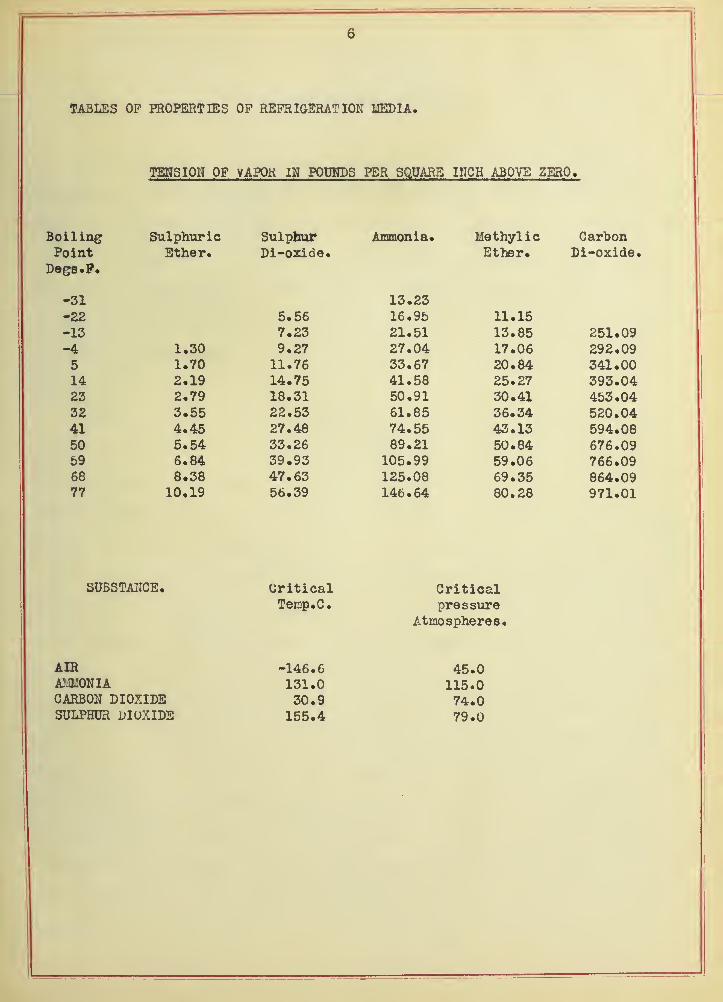
A table of the properties or refrigerating media can be found on the next
page and does not need any further explanation.

6
TABLES OF PROPERTIES OP REFRIGERATION MEDIA.
TENSION OF VAPOR IN POUNDS PER SQUARE INCH ABOVE ZERO.
Boil inp* ?hi 1 Whin* i ft Ammfin 1 o . Mfttlrvl i ftX*J.W W4XV X X w
Point L4 Vilv X • X/ X VAX U u • Ether.X4 W iJU X •
J-'v^D • 1* •
-31 13.23-22 5.56 16.95 11.15-13 7.23 21.51 13.85-4 1.30 9.27 27.04 17.065 1.70 11.76 33.67 20.8414 2.19 14.75 41.58 25.2723 2.79 18.31 50.91 30.4132 3.55 22.53 61.85 36.3441 4.45 27.48 74.55 43.1350 5.54 33.26 89.21 50.8459 6.84 39.93 105.99 59.0668 8*38 47.63 125.08 69.3577 10.19 56.39 146.64 80.28
CarbonLi-oxide.
251.09292.09341.00393.04453.04520.04594.08676.09766.09864.09971.01
SUBSTANCE. CriticalTernp.C.
Criticalpressure
Atmospheres.
AIRAM0NIACARBON DIOXIDESULPHUR DIOXIDE
-146.6131.030.9155.4
45.0115.074.079.0

7
SYSTEMS OP KEKKIGSHATIOH.
ABSOKPTIUw SYSTEM. In absorption plants a refrigerant is used which is
readily absorbed by some other fluid and the resulting fluid when heated must ea-
sily drive off the refrigerant in a gaseous state. As water has a great effinity
for ammonia a solution of tne two is used in absorption machines. This solution
called aqua ammonia usually by weight of anhydrous ammonia is heated in a gen-
erator or still* As the temperature of the aqua ammonia increases the percentage
of anhydrous ammonia held in solution decreases ana thus some of the ammonia is
driven off in a gaseous state.
Aqueous vapor is also driven off with the ammonia and to prevent this from
passing through into the condenser it is made to pass through an analyzer where
the discharged gas is partially cooled off and some of the water vapor is con-
densed. The water vapor that remains with the ammonia gas is finally condensed
in the rectifier and drains back to the still or generator. The rectifier is real-
ly a condenser with insufficient cooling surface to liquify the ammonia. The pure
ammonia gas now enters the condenser and is liquified and is stored in a receiver
or storage tank. Prom the receiver it passes through a regulating or expansion
value and expands into a gas and absorbs heat from its surroundings. The expanded
ammonia now enters the absorber where it comes in contact with the weak liquir
(aqua ammonia which has had most of the ammonia driven out of it in the generator
J
and is absorbed by it. The heat that is generated by the combining of the two is
carried off by water passing through pipes in the absorber. The weak liquid as it
becomes stronger is pumped back to the generator on its way passing through- the ex-
changer and the analyzer. In the exchanger the weak liquir on its way to the ab-
sorber gives up some of its heat to the strong liquir being pumped into the gen-
erator.


8
The diagram below shows the flow of the ammonia and the various parts of an
absorption plant.
Figure #4.
Diagram of an absorption plant*
The same type of ammonia condenser may be used in either a compression or
absorption plant. The four most used are:
Atmospheric condensers consist of a flat coil of pipes placed so that one
pipe is above the other. The ammonia gas enters at the top and the liquid is
drained off at the bottom. These condensers are put out on the roof and have a
trough above them which distributes the water over the pipes.
Submerged condensers consist of a coil of pipes submerged in a tank of water
As in the atmospheric type the ammonia gas enters at the top and the liquid is
drawn off at the bottom.
Double pipe condensers as the name implies consist of inner and outer pipes
placed one above the other. The water enters at the bottom and flows up the gas
enters at the top and is drawn off at the bottom.
Shell condensers are built of a shell and contain one or more coils through
which water flows from the bottom to the top. The ammonia enters at the top and

9
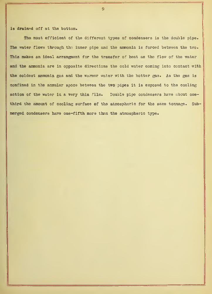
is drained off at the bottom.
The most efficient of the different types of condensers is the double pipe.
The water flows through the inner pipe and the ammonia is forced between the two.
This make 8 an ideal arrangment for the transfer of heat as the flow of the water
and the ammonia are in opposite directions the cold water coming into contact with
the coldest ammonia gas and the warmer water with the hotter gas. As the gas is
confined in the annular space between the two pipes it is exposed to the cooling
action of the water in a very thin film. Double pipe condensers have about one-
third the amount of cooling surface of the atmospheric for the same tonnage. Sub-
merged condensers have one-fifth more than the atmospheric type.

10
COMPRESSION SYSTEM. Ammonia in expanding from a liquid to a gas extracts
heat from its surroundings so the simplest form of a refrigerating plant would
consist of a coil connected to a cylinder of ammonia. The liquid trickling through]
the valve in the cylinder would expand in the coils and pass out in the atmosphere
This of course would be a very expensive plant to operate as the average cost of
ammonia is about twenty-five cents per pound and 510 pounds must be evaporated to
produce one ton of refrigeration per day. To cut down this waste a compressor and
condenser is added to reliquify the expanded ammonia. The cycle of operations of
a compression plant is as follows:
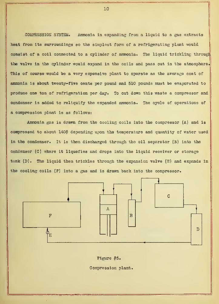
Ammonia gas is drawn from the cooling coils into the compressor (A) and is
compressed to about 140# depending upon the temperature and quantity of water used
in the condenser. It is then discharged through the oil separator (B) into the
condenser (C) where it liquefies and drops into the liquid receiver or storage
tank (D). The liquid then trickles through the expansion valve (E) and expands in
the cooling coils (P) into a gas and is drawn back into the compressor.
Figure #5.
Compression plant.

11
BRINE SYSTEM, In this system the expanding ammonia is used to cool brine
which is circulated through pipes in the rooms to be cooled. The brine may be
cooled by either of two methods:
(1) by the use of a brine cooler,
(2) by submerging an expansion coil in the brine tank,
A brine cooler generally called a double pipe brine cooler is made like a
double pipe condenser; the brine is pumped through the inner pipe and the ammonia
is expanded in the annular space between the two pipes. To take advantage of the
cooling effect of the outside pipe the cooler is either submerged in the brine tani
or is placed in one of the rooms to be cooled. The advantage of putting it in a
room is that it is always accessable for inspection and repairs.
The disadvantage of using an expansion coil submerged in brine is that only
the outside of pipe has the refrigerating effect.
The brine circulating coils in the cold storage rooms should be arranged so
that the air can circulate freely between them and placed far enough apart so that
they cannot freeze together. This is one fault that is frequently found in small
plants.
In rooms where goods are stored that are not effected by the dripping of the
pipes the coils are placed flat against the ceiling, otherwise they are hung on the
walls and a drip-pan is provided to catch the water which has been frozen on the
coils in the shape of frost. The advantage of brine system plants is that there is
no ammonia in the storage rooms and there is always a supply of cold brine to cir-
culate after the compressor has been shut down.
12
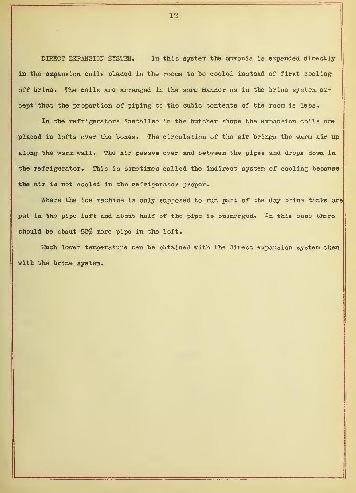
DIRECT EXPAKSION SYSTEM. In this system the ammonia is expanded directly
in the expansion coils placed in the rooms to be cooled instead of first cooling
off brine. The coils are arranged in the same manner as in the brine system ex-
cept that the proportion of piping to the cubic contents of the room is less.
In the refrigerators installed in the butcher shops the expansion coils are
placed in lofts over the boxes. The circulation of the air brings the warm air up
along the warm wall. The air passes over and between the pipes and drops down in
the refrigerator. This is sometimes called the indirect system of cooling because
the air is not cooled in the refrigerator proper.
Where the ice machine is only supposed to run part of the day brine tanks are
put in the pipe loft and about half of the pipe is submerged. In this case there
should be about 50$ more pipe in the loft.
Much lower temperature can be obtained with the direct expansion system than
with the brine system.

13
AMMONIA COMPRESSORS.
As long as ammonia vapor is in a humid or saturated condition temperatures
and pressures are functions of one another that is to a given temperature belongs
a certain pressure. On the other hand when it is in a dry or superheated condition!
its temperature may be very much higher than that corresponding to its pressure
where it in a humid state.
WET COMPRESSION MACHINES. In this type of machine the ammonia gas is drawn
into the compressor in a wet or saturated state and the heat of compression is ta-
ken care of by the unexpanded ammonia which enters with the ammonia vapor. No wa-
ter jacket or other cooling device is used to carry away the heat of compression.
When a compressor of this type is started a jet of liquid ammonia is injected
into the cylinders until the ammonia from the coils comes back in a saturated state
.
DRY COMPRESSION MACHINES. This type of compressor is fitted with a water
jacket to abstract the heat of compression and the gas from the coils is in a dry
state. As the gas entering the cylinder is very much colder than the jacket water
no heat can be transmitted to it until the temperature inside of the cylinder is
much higher than the temperature of the cooling water. For this reason the com-
pression curve of a dry gas machine follows the adiabatic line during the first pari
of the stroke and then approaches the isothermal toward the end of the stroke.
Most ice machines are now run with wet vapor especially the horizontal types
and very many vertical types. Thus fact tends to prove that wet compression is
more efficient than dry compression. As liquid ammonia is a slight lubricant by
itself the wet system of compression recommends itself for this one reason alone*


14
DISCUSSION OP VARIOUS TYPES OP A1MONIA COMPRESSORS. Ammonia compressors are
divided into two chief classes; single acting and double acting. As a rule the
single acting are vertical and the double acting are horizontal machines. This is
not a fixed rule as there are several makes of single acting horizontal compressors
on the market and also a few of the double acting vertical type.
The two points designers of ammonia compressors lay most stress on are: the
clearance in the cylinder and the stuffing box. A slow speed compressor to be ef-
ficient must have very little clearance on account of the re-expansion of the gas
that takes place, which increases with the amount of clearance in the cylinder. In
small high speed machines the amount of clearance should be greater because these
compressors are always of the enclosed type, they elevate more oil past the piston,
and some of this oil would be discharged with every stroke. Other reasons that the
high speed compressors should have more clearance are:
1. The oil which elevates past the piston will cause pounding if there is no',
sufficient clearance.
2. Small machines get hardly any attention when they are in operation and
very often liquid ammonia enters with the gas drawn into the compressor and the heac
of the machine is liable to break unless the discharge valve is large enough.
3. Ammonia is not a very active liquid, and tneret'ore as the piston speed in-
creases the re-expansion in tne cylinder decreases.
Tne clearance that snould be allowed a high speed compressor should be about
l/l6 inch. Slow speed machines generally aim to have less than 1/32 inch.

15
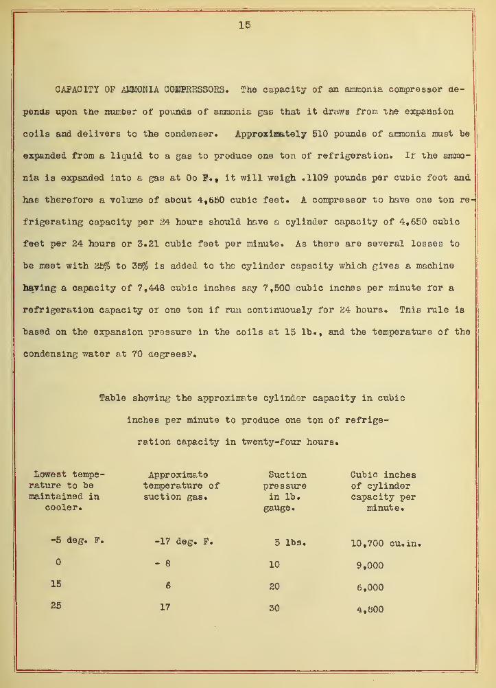
CAPACITY OP A1XOKIA COEPRESSORS. The capacity of an ammonia compressor de-
pends upon the numDer of povinds of ammonia gas that it draws from the expansion
coils and delivers to the condenser. Approximately 510 pounds of ammonia must be
expanded from a liquid to a gas to produce one ton of refrigeration. Ir the ammo-
nia is expanded into a gas at Oo P. t it will weigh .1109 pounds per cubic foot and
has therefore a volume of about 4,650 cubic feet. A compressor to have one ton re-
frigerating capacity per 24 hours should have a cylinder capacity of 4,650 cubic
feet per 24 hours or 3.21 cubic feet per minute. As there are several losses to
be meet with 2b$ to 35$ is added to the cylinder capacity which gives a machine
having a capacity of 7,448 cubic inches say 7,500 cubic inches per minute for a
refrigeration capacity of one ton if run continuously for 24 hours. This rule is
based on the expansion pressure in the coils at 15 lb., and the temperature of the
condensing water at 70 degrees!?.
Table showing the approximate cylinder capacity in cubic
inches per minute to produce one ton of refrige-
ration capacity in twenty-four hours*
Lowest tempe-rature to bemaintained in
cooler.
Approximatetemperature ofsuction gas.
Suctionpressurein lb.
gauge.
Cubic inchesof cylindercapacity per
minute.
-5 deg. P.
15
25
-17 deg. P.
- 8
6
17
5 lbs.
10
20
30
10,700 cu.in.
9,000
6,000
4,800

16
-
E
1 h ;l
/3
—
±
;;5
1Pit
06-;Z7
mi
iien
/J—
—
2o
i
i
«5£3:
if
t:
r
— , 1 r
yo3 tfct
/: _i

17
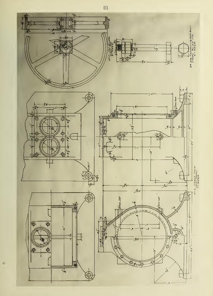
DESIGN OF A SMALL AMMONIA COMPRESSOR.
The design of the small ammonia compressor here included is intended to full-
fil the requirements of a machine such as is used in butcher shops and other pla-
ces where it is not expedient to employ an engineer to operate the plant. From
the experience of the writer with plants of from two to ten tons refrigerating
capacity these small machines are run without any care or attention and in some
instances the outboard bearing is never oiled. The expansion valve is opened
when the plant is started and hardly ever regulated during the entire day. There-
fore a small ammonia compressor must be built as near foolproof as possible. The
bearings must be large so that the owner of the machine will not have to take up
the bearings very often and he will generally send for a man that is familiar with
refrigerating machinery which will lay up his plant for some time.
The following are the most important points to be considered in the design of
a small ammonia machine.
1. The crank shaft should be large and hard as it will otherwise be ground
by the scale in the piping which finds its way back into the crank case.
2. The crank pin bearings hould be of a good grade of babbit and should have
a bearing area at least 75$ of the piston area.
3. The length of the connecting rod should be about two and a-half times the
stroke.
4. The intake and discharge valves should be large and therefore the gas must
be drawn in through the piston as the cylinder head is too small to put both valves
in.
5. The piston should be of the double piston type to prevent the oil from ele-
vating past the rings.

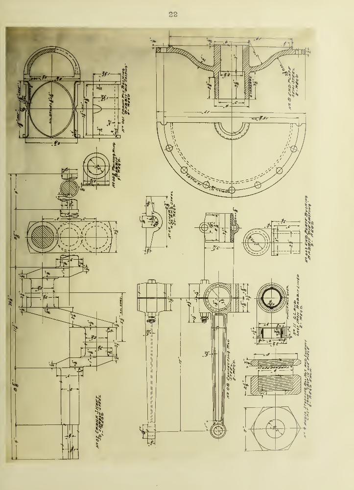
IS
6. The stuffing box must be so designed that it is impossible to draw up one
side more than the other. The gland should be lined with babbit to prevent it from
heating up should it wear against one side.
7. The cylinder should have a savety head, or what is still better, the dis-
charge valve should be as large as the piston.
8. The crank case should be provided with a sediment chamber or well.
9* The water jacket should be open to prevent the cylinders from cracking
should the machine be running with frost back to the machine and the jacket water
shut off.
A machine of similar design was built some ten months ago and installed in a
large retail market and has been running ten hours daily without any repairs of any
kind. It is impossible to hear the valved work ten feet away from the compressor.
This machine is held by four one-half inch bolts leaded four inches in a concrete
floor.
The water jacket is left off of the drawings as this is generally cut and fit-
ted to each cylinder in the tin-shop. It should have a one and one-quarter by one-
eighth inch iron band at the top and fitted with a one-quarter inch inlet flange at
the bottom and half-inch outlet flange at the top.
The babbit should not contain any metal that is effected by ammonia, and the
bearings should be cast accurate.
It is advisable to pickle the castings and forgings before machining to prevent
any scale from getting in the bearing.

19


22


-
231
BILL OF MATERIALS.
No. Name No. Req'd. Mater ial
.
Remarks.
lX Cylinders iX DCUU steel
2 Cyl. head 2 It H
Piston
4 Valve cage It II
Piston ring oo If It
Crank case 1X
7 Ply wheel p uexou iron
8 End plate p Qd yyl 3 nfrtAl
9 Stuffing box nut p v^cts it xi on
* ** lock nut p >i n
11 w " gland 2 •• »t
Babbit lined
01 Valve stem» p oiee x
o? 9e n
03 Discharge valve p H
04 " n snrinc p tt
Sue t i on n wmMw » i wu na II
06 Wrist pin 2 it
Ground
07 Crank shaft 1 it
Ground pins
08 Connecting rod 2 it
Drop forging
09 Liners tt
#30 B.W.G.
010 Connecting rod bolt 4 it
A.L.A.M. Std.


24
No. Name No. Req'd. Material. Remarks.
uui oranK pin Dusmng A Babbit Die—cast Ida
uu<< iracKing ring 4 M
003 End plate "bushing 2 " Die-casting.\
STANDARD PARTS.
r or No. Size & kind. T5Awn >*Yreinerna.rKS.
4 5/8"x4^ Bolts A. ij.il . 1.1 • UUU
HttI t "nrl at* 8 3/4"xl^»» Capscrews U.S. qtri
.
8 3/4"k2m " tt q q+d.U . O . O liU •
ritiu. [Jiaty 32 5/8"xl-£" » TT q q+rt »
8 3/4"x6" »» TT <3 qfA
4 l/8"xl» Bolts
Valve stem 2 l/8'»x3/4» Split pins