Unrestricted © Siemens AG 2013 All rights reserved.
4th Generation VLC courtesy of Edison2
#SEU13
601 - Assembly Design in Solid Edge: A Hands-on Experience Mark Thompson, Solid Edge Field Support, Siemens PLM Software

Unrestricted © Siemens AG 2013 All rights reserved.
Page 2 Siemens PLM Software
4th Generation VLC
courtesy of Edison2
Agenda: 601 - Assembly Design in Solid Edge: A
Hands-on Experience
Who am I?
What you will learn
Assembly Hands-On

Unrestricted © Siemens AG 2013 All rights reserved.
Page 3 Siemens PLM Software
About: Mark Thompson
Mark Thompson
Solid Edge Field Support
Siemens PLM Software
Mark has been in the Mechanical CAD industry for 25 years. Mark spent his first
year in the CAD/CAM support group and then moved to the technical marketing
group where he has been ever since. Mark has been promoting Solid Edge
since its first release in 1996. Mark’s responsibilities include the creation of
demonstration material for internal application engineers and channel partners,
customer presentations, update training material, and support for the field
personnel. Prior to coming to work in the mechanical CAD industry Mark spent
14 years as a machinist/tool maker. Mark enjoys his job, the people he works
with, and the satisfaction of working with a great product like Solid Edge!
Unrestricted © Siemens AG 2013 All rights reserved.
Page 4 Siemens PLM Software
What you will learn
This is a hands-on session where we will visit exciting new Solid Edge ST6
assembly enhancements that will make you more productive while building
assembly structures. You will experience new ways of adding part features from
the assembly level as well as new modeling improvements while in-place-
activated into components of the assembly. We will also explore a more
productive way to work with very large assemblies. You will walk away with a
better understanding of the tools available to help accelerate your design
process.
Unrestricted © Siemens AG 2013 All rights reserved.
Page 5 Siemens PLM Software
Assembly Hands-On
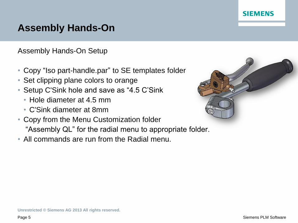
Assembly Hands-On Setup
• Copy “Iso part-handle.par” to SE templates folder
• Set clipping plane colors to orange
• Setup C'Sink hole and save as “4.5 C’Sink
• Hole diameter at 4.5 mm
• C'Sink diameter at 8mm
• Copy from the Menu Customization folder
“Assembly QL” for the radial menu to appropriate folder.
• All commands are run from the Radial menu.
Unrestricted © Siemens AG 2013 All rights reserved.
Page 6 Siemens PLM Software
Assembly Hands-On
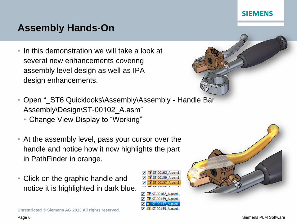
• In this demonstration we will take a look at
several new enhancements covering
assembly level design as well as IPA
design enhancements.
• Open “_ST6 Quicklooks\Assembly\Assembly - Handle Bar
Assembly\Design\ST-00102_A.asm”
• Change View Display to “Working”
• At the assembly level, pass your cursor over the
handle and notice how it now highlights the part
in PathFinder in orange.
• Click on the graphic handle and
notice it is highlighted in dark blue.

Unrestricted © Siemens AG 2013 All rights reserved.
Page 7 Siemens PLM Software
Assembly Hands-On
• If you select a part that resides in a
sub-assembly, it will highlight the part
in dark blue, but also show the
parent(s) in light blue.
• Placing the cursor on the
component will highlight it
in the orange colors.
• Great new tools to locate components in an assembly!
• Change Display config to "2-Create Clamp“
Unrestricted © Siemens AG 2013 All rights reserved.
Page 8 Siemens PLM Software
Assembly Hands-On
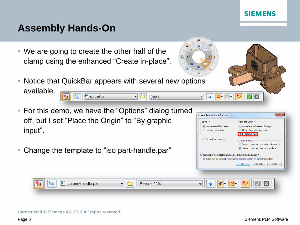
• We are going to create the other half of the
clamp using the enhanced “Create in-place”.
• Notice that QuickBar appears with several new options
available.
• For this demo, we have the “Options” dialog turned
off, but I set “Place the Origin” to “By graphic
input”.
• Change the template to “iso part-handle.par”

Unrestricted © Siemens AG 2013 All rights reserved.
Page 9 Siemens PLM Software
Assembly Hands-On
• Notice also the other options available, such as material definition, ground,
origin, and key points.
• Also notice when using “By graphic input”, it places a coordinate
system on the cursor.
• Locate the top hole on the clamp.
• Sometimes you set the cursor
on the face first to orient the triad
before selecting the hole.
• Notice the PromptBar with option to re-orient the triad.
• Select the “N” key twice to re-orient the triad.
Unrestricted © Siemens AG 2013 All rights reserved.
Page 10 Siemens PLM Software
Assembly Hands-On
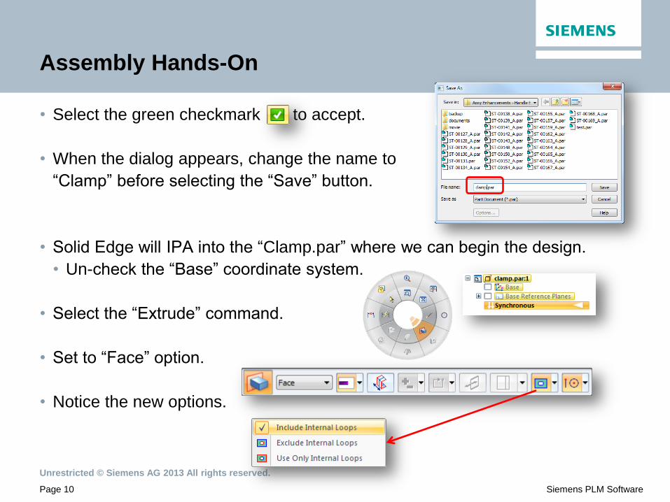
• Select the green checkmark to accept.
• When the dialog appears, change the name to
“Clamp” before selecting the “Save” button.
• Solid Edge will IPA into the “Clamp.par” where we can begin the design.
• Un-check the “Base” coordinate system.
• Select the “Extrude” command.
• Set to “Face” option.
• Notice the new options.

Unrestricted © Siemens AG 2013 All rights reserved.
Page 11 Siemens PLM Software
Assembly Hands-On
• To show these option, select the top face of the
inside clamp as shown and accept.
• By default as you drag out, you will notice it
uses “Include Internal Loops” which was what
we offered in ST5.
• While dragging the face outward,
change to the new option called
“Exclude Internal Loops”.
• Finally, show the “Use Only Internal Loops” option.

Unrestricted © Siemens AG 2013 All rights reserved.
Page 12 Siemens PLM Software
Assembly Hands-On
• Don’t create the extrude, but instead select the “Revolve” command.
• The same options apply, so select the same top face, but make sure to set
to “Exclude Internal Loops” as shown.
• Accept with a RMB, then
select the cylinder for the axis
of rotation for the revolve.
• Rotate down and select the corner key point
to create the revolved feature.

Unrestricted © Siemens AG 2013 All rights reserved.
Page 13 Siemens PLM Software
Assembly Hands-On
• Select the “Extrude” command,
but set the option to “Use Only
Internal Loops” and select
the top and bottom faces as shown.
• Drag out the extrusion, but press the
spacebar to change to remove
material, and then click to create holes.
• In PathFinder, click the check boxes to
turn on the two socket head cap screws.
Unrestricted © Siemens AG 2013 All rights reserved.
Page 14 Siemens PLM Software
Assembly Hands-On
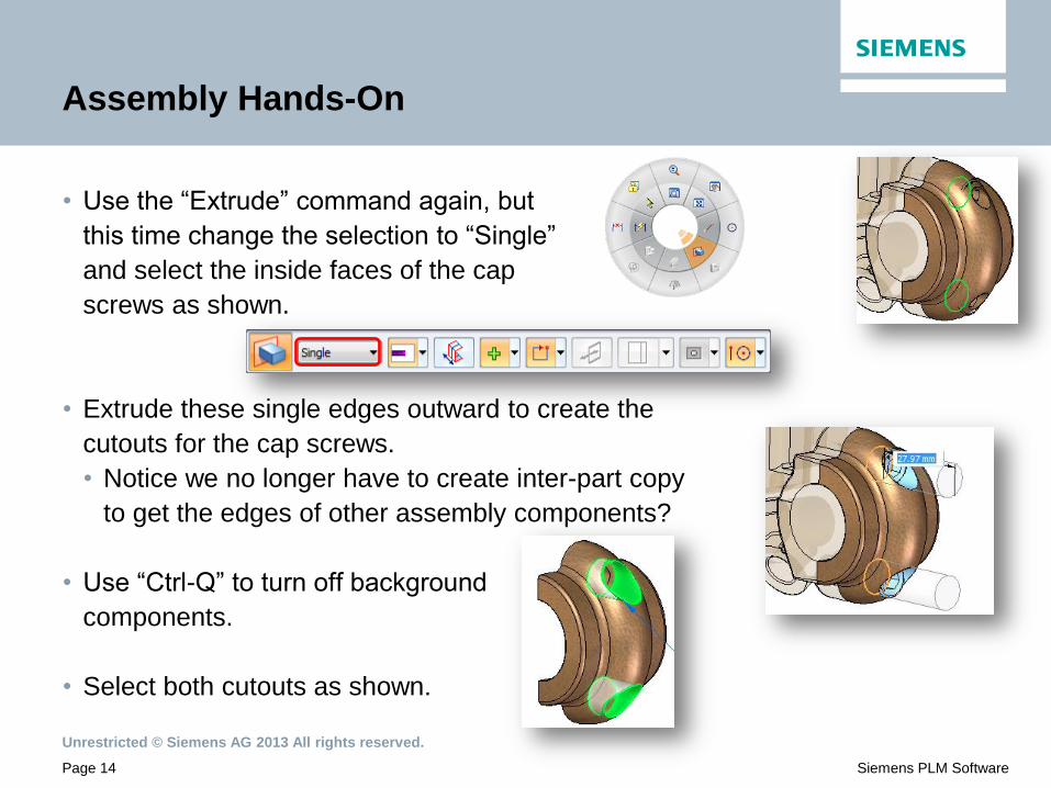
• Use the “Extrude” command again, but
this time change the selection to “Single”
and select the inside faces of the cap
screws as shown.
• Extrude these single edges outward to create the
cutouts for the cap screws.
• Notice we no longer have to create inter-part copy
to get the edges of other assembly components?
• Use “Ctrl-Q” to turn off background
components.
• Select both cutouts as shown.

Unrestricted © Siemens AG 2013 All rights reserved.
Page 15 Siemens PLM Software
Assembly Hands-On
• Run “Recognize Holes” found under the “Hole” command.
• When the dialog appears, select the option to change the diameters.
• Change the “Counterbore diameter” to 10.5 to give the
cap screws some clearance.
• Click “OK” to create holes.

Unrestricted © Siemens AG 2013 All rights reserved.
Page 16 Siemens PLM Software
Assembly Hands-On
• Add 2 “Rounds” at .5 mm on the two hole edges.
• Use “Ctrl-Q” to turn the background components
back on.
• Use “Close and Return” to get
back to the top level assembly.
• Change the display config to “Edit Handle”.
• Window area on the bolt as shown
• Set clipping planes just to show
bolt in hole, then turn back off.

Unrestricted © Siemens AG 2013 All rights reserved.
Page 17 Siemens PLM Software
Assembly Hands-On
• From PathFinder, turn off the bolt.
• Select bolt to locate it in PathFinder, then uncheck it.
• Open the “Part Library” window and point out the new
option to “Return to Home” button.
• Quick way to get to the folder where the assembly was
opened from.
• In the parts library, locate “ST-00131.par” which is a
bearing and drag it into the graphic window to place
in the assembly using a mate and axil align.
• Select the bushing and run “Capture Fit”.
Unrestricted © Siemens AG 2013 All rights reserved.
Page 18 Siemens PLM Software
Assembly Hands-On
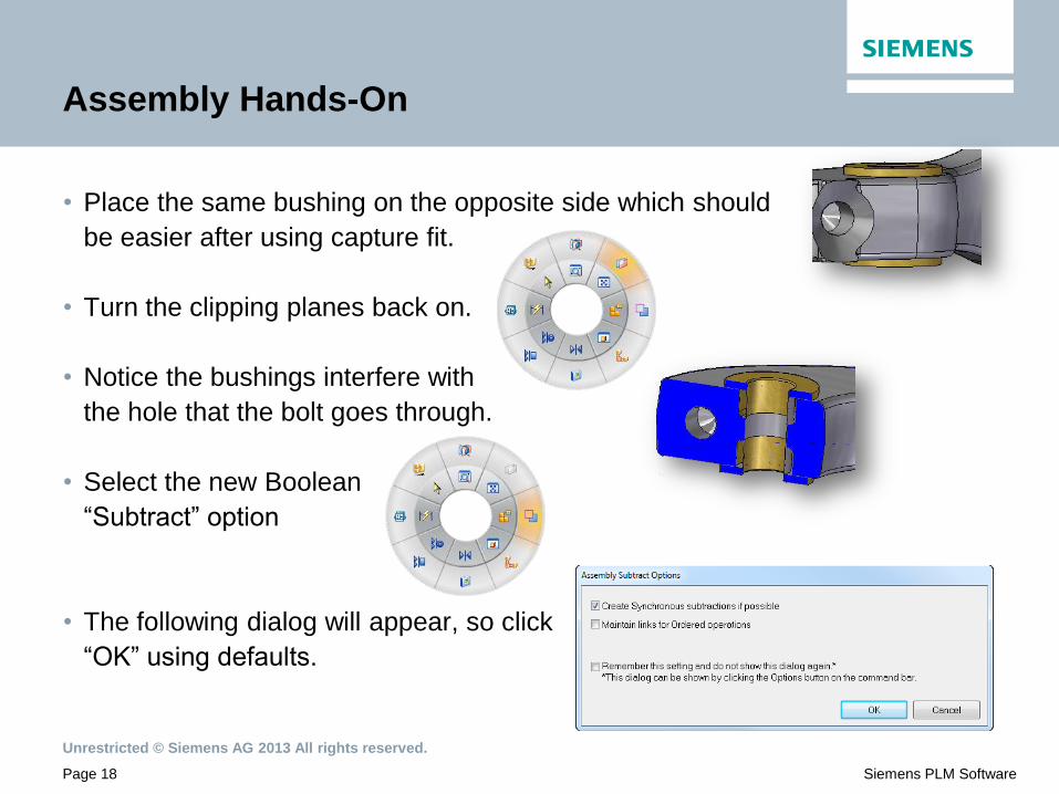
• Place the same bushing on the opposite side which should
be easier after using capture fit.
• Turn the clipping planes back on.
• Notice the bushings interfere with
the hole that the bolt goes through.
• Select the new Boolean
“Subtract” option
• The following dialog will appear, so click
“OK” using defaults.

Unrestricted © Siemens AG 2013 All rights reserved.
Page 19 Siemens PLM Software
Assembly Hands-On
• QuickBar instructs to select the “Target”
part first, so select the handle (ST-00157.par).
• RMB or green checkmark to accept.
• Now select the “Tool” part(s), which are the bushings.
• RMB or green checkmark to accept.
• This option allows the user to
quickly remove the material where
the bushings interfere with the handle.

Unrestricted © Siemens AG 2013 All rights reserved.
Page 20 Siemens PLM Software
Assembly EnhancHands-On
• Turn off the bushings, the bolt, and also the clipping planes.
• Use “Ctrl-T” to get to a top view and window area on the hole.
• Select the “Smart Dimension”.
• On the bottom right of QuickBar ,we have a new option to create PMI
dimensions directly in the model just like we do with Sync part features.
• You must turn this option on, then push them into the part file.
Unrestricted © Siemens AG 2013 All rights reserved.
Page 21 Siemens PLM Software
Assembly Hands-On
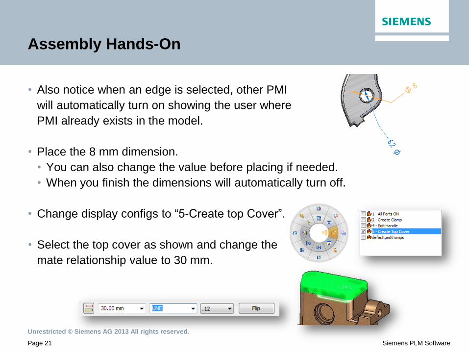
• Also notice when an edge is selected, other PMI
will automatically turn on showing the user where
PMI already exists in the model.
• Place the 8 mm dimension.
• You can also change the value before placing if needed.
• When you finish the dimensions will automatically turn off.
• Change display configs to “5-Create top Cover”.
• Select the top cover as shown and change the
mate relationship value to 30 mm.
Unrestricted © Siemens AG 2013 All rights reserved.
Page 22 Siemens PLM Software
Assembly Hands-On
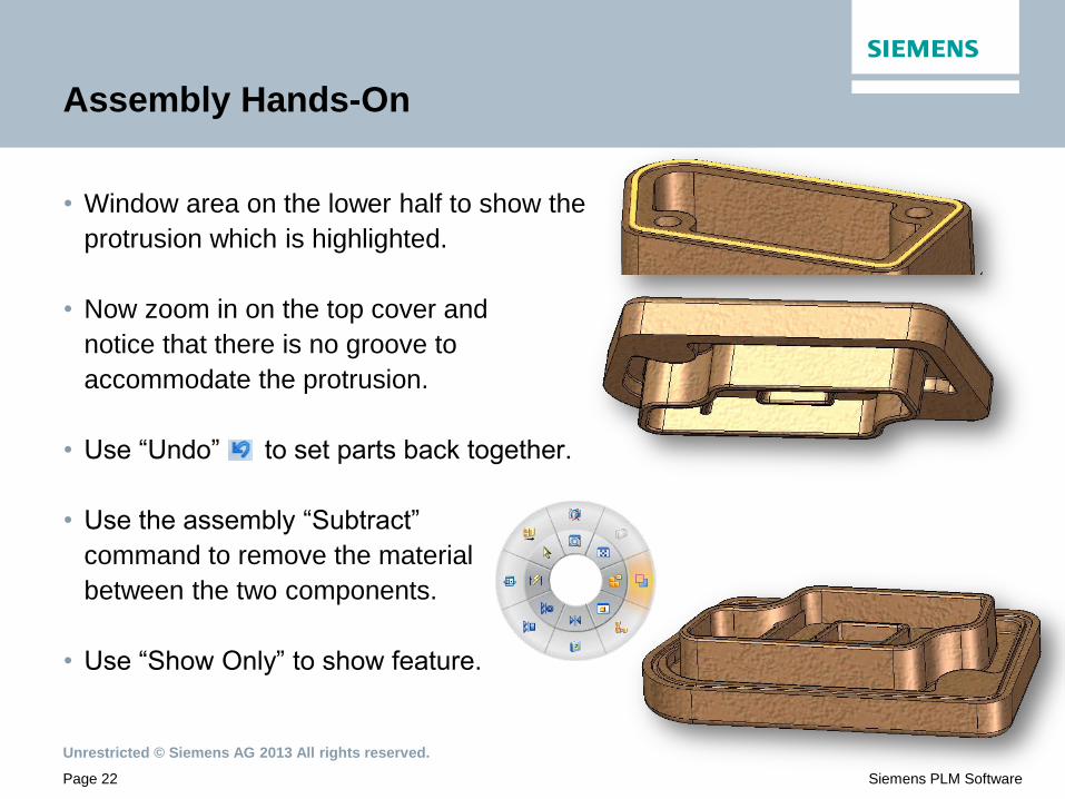
• Window area on the lower half to show the
protrusion which is highlighted.
• Now zoom in on the top cover and
notice that there is no groove to
accommodate the protrusion.
• Use “Undo” to set parts back together.
• Use the assembly “Subtract”
command to remove the material
between the two components.
• Use “Show Only” to show feature.
Unrestricted © Siemens AG 2013 All rights reserved.
Page 23 Siemens PLM Software
Assembly Hands-On
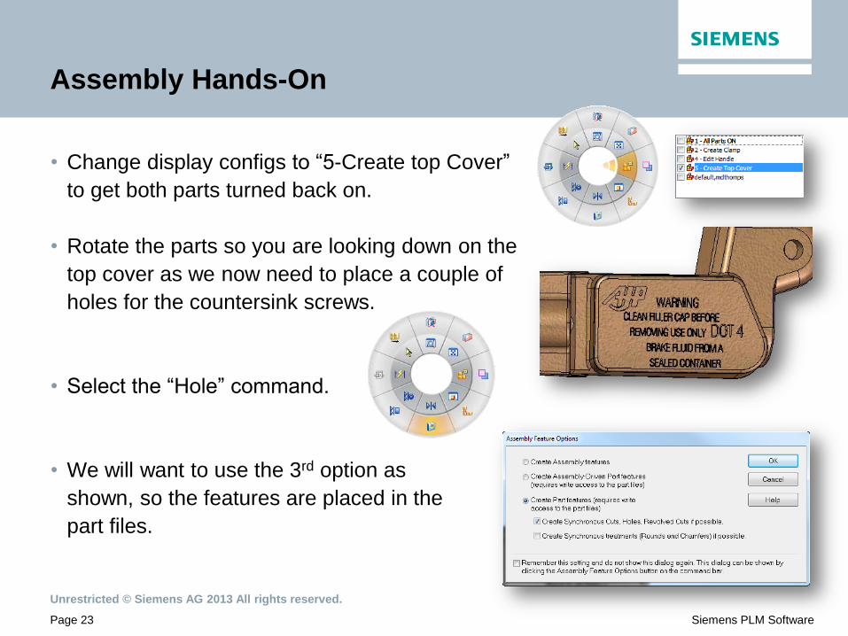
• Change display configs to “5-Create top Cover”
to get both parts turned back on.
• Rotate the parts so you are looking down on the
top cover as we now need to place a couple of
holes for the countersink screws.
• Select the “Hole” command.
• We will want to use the 3rd option as
shown, so the features are placed in the
part files.
Unrestricted © Siemens AG 2013 All rights reserved.
Page 24 Siemens PLM Software
Assembly Hands-On
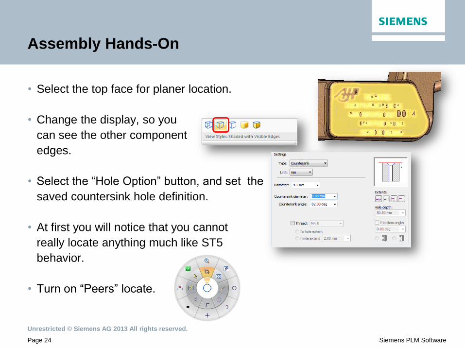
• Select the top face for planer location.
• Change the display, so you
can see the other component
edges.
• Select the “Hole Option” button, and set the
saved countersink hole definition.
• At first you will notice that you cannot
really locate anything much like ST5
behavior.
• Turn on “Peers” locate.

Unrestricted © Siemens AG 2013 All rights reserved.
Page 25 Siemens PLM Software
Assembly Hands-On
• Notice now how easy it is to place features using
this option in ST6.
• Place the two countersunk holes.
• Turn shading back on.
• Close the sketch environment.
• Extend holes, click the red X, then
select only the top to extend holes
through.

Unrestricted © Siemens AG 2013 All rights reserved.
Page 26 Siemens PLM Software
Assembly Hands-On
• Turn on the countersink screws to show
how they look in the new holes.
• Change display configs
to “All Parts ON”.
• Rotate the handle as shown.
• Select from PathFinder ST-00150.par,
and then select “Edit” to IPA into the part.
Unrestricted © Siemens AG 2013 All rights reserved.
Page 27 Siemens PLM Software
Assembly Hands-On
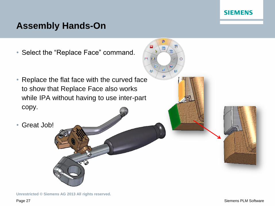
• Select the “Replace Face” command.
• Replace the flat face with the curved face
to show that Replace Face also works
while IPA without having to use inter-part
copy.
• Great Job!

Unrestricted © Siemens AG 2013 All rights reserved.
Page 28 Siemens PLM Software
• The “Tab” command has also been enhanced for ST6.
• When a user IPA’s into a sheet metal part, they can quickly select the new
“Tab” command (action-object) to create a tab from the same selection types
(single, chain, face) that we previously discussed.
• The advantage of this is a user can now quickly create a sheet metal tab by
selecting a face from another part without having to create a sketch.
• Open “Slider.asm” from the “SM Tab” folder
Tab Command while In Place Activated
Unrestricted © Siemens AG 2013 All rights reserved.
Page 29 Siemens PLM Software
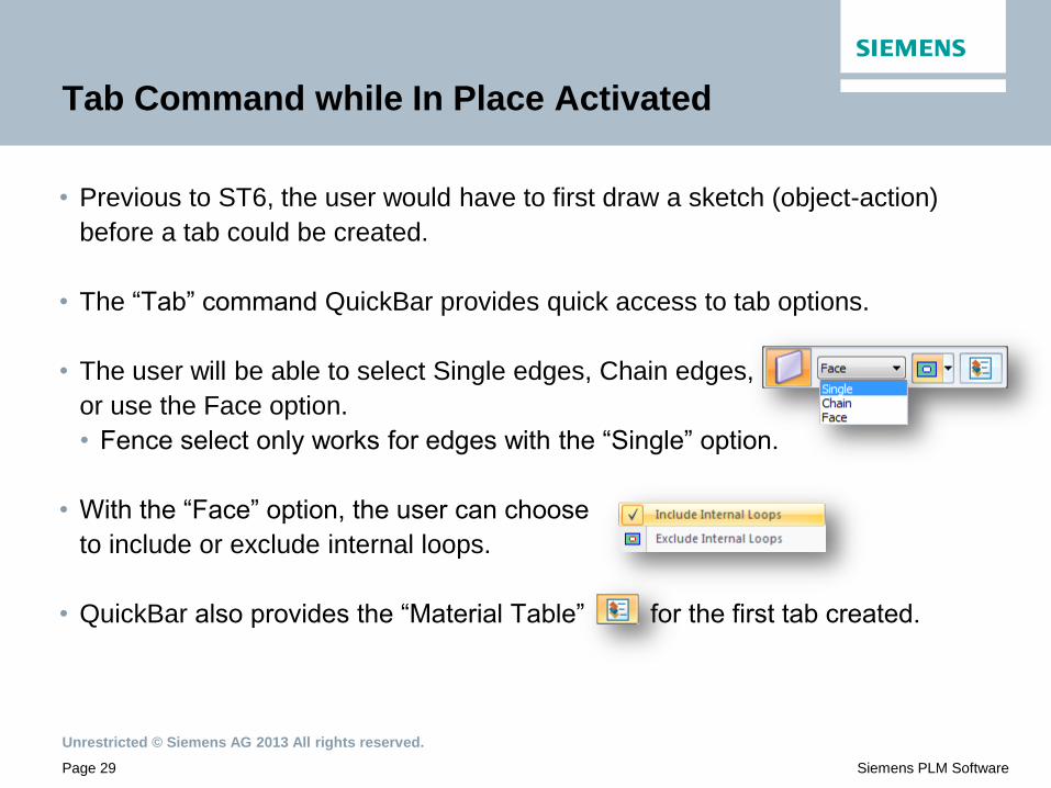
• Previous to ST6, the user would have to first draw a sketch (object-action)
before a tab could be created.
• The “Tab” command QuickBar provides quick access to tab options.
• The user will be able to select Single edges, Chain edges,
or use the Face option.
• Fence select only works for edges with the “Single” option.
• With the “Face” option, the user can choose
to include or exclude internal loops.
• QuickBar also provides the “Material Table” for the first tab created.
Tab Command while In Place Activated

Unrestricted © Siemens AG 2013 All rights reserved.
Page 30 Siemens PLM Software
• When a user IPA’s into a sheet metal file, they can
select the “Tab” command which defaults to “Face”
select mode.
• Using the default mode which is “Include Internal Loops”,
and then selecting a face which in this case has 2 holes,
the results will be a tab with those holes added to the tab.
• Obviously the material properties can be changed, but this gives the user very
fast results.
Tab Command while In Place Activated

Unrestricted © Siemens AG 2013 All rights reserved.
Page 31 Siemens PLM Software
• The next option to “Exclude Internal Loops” gives the user
an option to leave out the internals holes/cutouts.
• A user can select multiple coplanar faces and regions from occurrences and
other bodies as well as faces and regions that are contiguous.
• If a region is selected that is not coplanar
with any previously created sheet metal
walls, then an error message will appear.
Tab Command while In Place Activated

Unrestricted © Siemens AG 2013 All rights reserved.
Page 32 Siemens PLM Software
Assembly Dynamic Edit
• A user can now dynamically edit ordered features without having to in-place
activate (IPA) into the part/sheetmetal file.
• All features that support dynamic edit in part will support dynamic edit from
assembly.
• This can be achieved by entering face selection mode (ctrl + spacebar) in
assembly, select the feature and then select Dynamic Edit.
• Open “Screw Compressor.asm” from the
“Dynamic Edit “ folder.
Unrestricted © Siemens AG 2013 All rights reserved.
Page 33 Siemens PLM Software
Assembly Dynamic Edit
• The dimensions of the feature being edited will
be displayed in the assembly.
• Dynamically edit the rib thickness and change to 4mm.
• Dynamic edit is exited exactly like the part environment.
• Clicking in Space
• Clearing the select set (ESC Key etc.)
• Running another command
• Unlike Part the user can only dynamic edit a single feature at a time.
• When multiple part features are selected the dynamic edit user interface is
not shown.

Unrestricted © Siemens AG 2013 All rights reserved.
Page 34 Siemens PLM Software
Assembly Dynamic Edit
• Assembly Part Features now
support Sync modeling creation
methods.
• The method to create Sync
modeling operations is to create
ordered features and then move
them to Sync in the target file.
ST5
ST6
Unrestricted © Siemens AG 2013 All rights reserved.
Page 35 Siemens PLM Software
Assembly Dynamic Edit
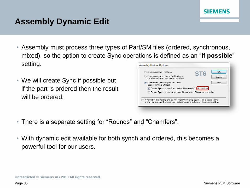
• Assembly must process three types of Part/SM files (ordered, synchronous,
mixed), so the option to create Sync operations is defined as an “If possible”
setting.
• We will create Sync if possible but
if the part is ordered then the result
will be ordered.
• There is a separate setting for “Rounds” and “Chamfers”.
• With dynamic edit available for both synch and ordered, this becomes a
powerful tool for our users.
ST6

Unrestricted © Siemens AG 2013 All rights reserved.
Page 36 Siemens PLM Software
Assembly Dynamic Edit
• This chart best explains what occurs when using these new options.
Unrestricted © Siemens AG 2013 All rights reserved.
Page 37 Siemens PLM Software
Simplify Assembly Hands-On
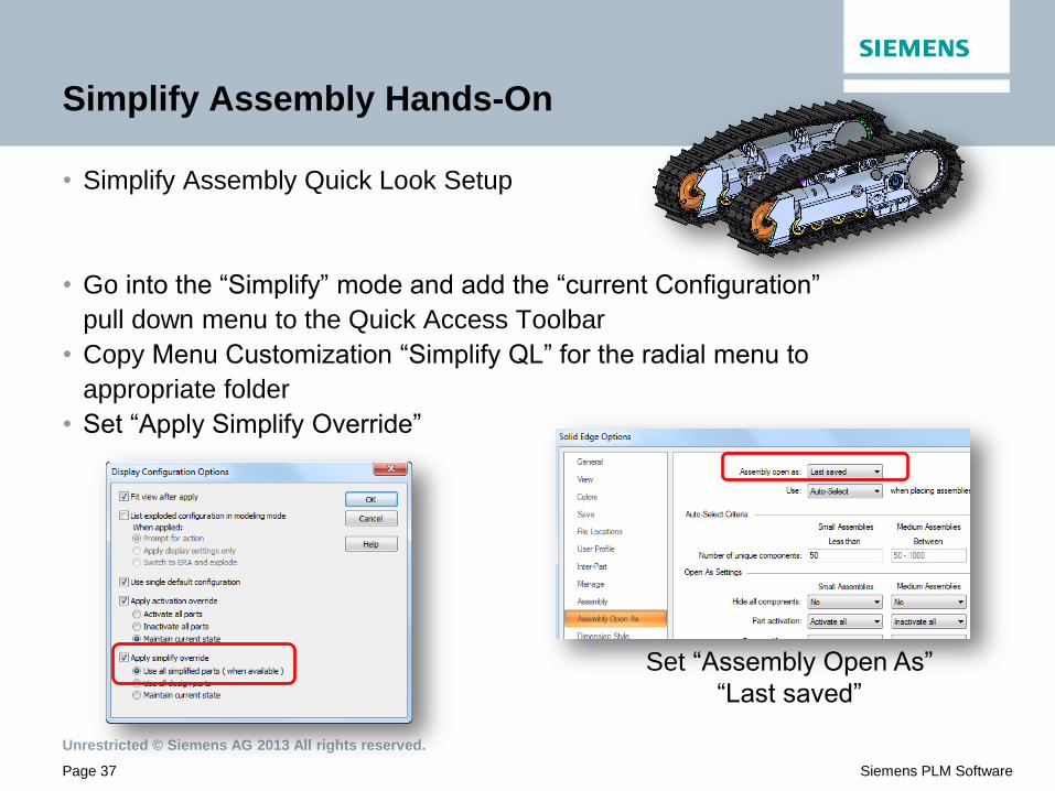
• Simplify Assembly Quick Look Setup
• Go into the “Simplify” mode and add the “current Configuration”
pull down menu to the Quick Access Toolbar
• Copy Menu Customization “Simplify QL” for the radial menu to
appropriate folder
• Set “Apply Simplify Override”
Set “Assembly Open As”
“Last saved”

Unrestricted © Siemens AG 2013 All rights reserved.
Page 38 Siemens PLM Software
Simplify Assembly Hands-On
• In this QuickLook demonstration, we will take a look at the improved “Simplify”
environment using the bulldozer assembly.
• Open B-000015.asm
• View this assembly’s statistics and notice it has 1620
total parts and 177 unique parts.

Unrestricted © Siemens AG 2013 All rights reserved.
Page 39 Siemens PLM Software
Simplify Assembly Hands-On
• Select the “Tools” tab, then select
the option to enter the “Simplify” environ.
• In this assembly there is already a simplified assembly
created, so we can simply RMB on the simplified
assembly and select “Edit” from the menu.
• Once in the simplified assembly, you can see that
there are already simplified bodies created, so RMB
on the embedded part file and use
“Show Only” to show those bodies.
• From the Quick Access menu
change the display configuration to “All Pulleys”.
Unrestricted © Siemens AG 2013 All rights reserved.
Page 40 Siemens PLM Software
Simplify Assembly Hands-On
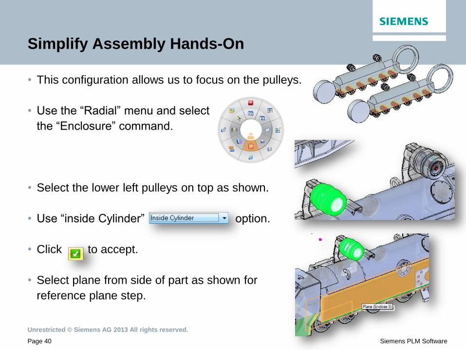
• This configuration allows us to focus on the pulleys.
• Use the “Radial” menu and select
the “Enclosure” command.
• Select the lower left pulleys on top as shown.
• Use “inside Cylinder” option.
• Click to accept.
• Select plane from side of part as shown for
reference plane step.

Unrestricted © Siemens AG 2013 All rights reserved.
Page 41 Siemens PLM Software
Simplify Assembly Hands-On
• Use the radial menu and select “Duplicate Body” to duplicate this
enclosure on the other three pulleys.
• Select the enclosure
as shown to duplicate.
• Accept it with a RMB.
• Now select the outside pulley in the
second step and accept it.
• Then “Select All Matching Occurrences”
option to highlight and accept the others.

Unrestricted © Siemens AG 2013 All rights reserved.
Page 42 Siemens PLM Software
Simplify Assembly Hands-On
• Once they are simplified, we can change our focus
to the lower pulleys.
• Select the “Enclosure” command.
• On the QuickBar, select “Inside Cylinder” from the pull down
menu.
• Rotate the view 180 to better see
the lower pulleys, and then select
the two pulleys.

Unrestricted © Siemens AG 2013 All rights reserved.
Page 43 Siemens PLM Software
Simplify Assembly Hands-On
• After selecting these two pulleys, click on the green checkmark
to accept.
• Then select the side
wheel face as a
reference plane to
create the enclosure.
• The next step would be to duplicate this enclosure
on other common occurrences.
• Select the “Duplicate Body” command.

Unrestricted © Siemens AG 2013 All rights reserved.
Page 44 Siemens PLM Software
Simplify Assembly Hands-On
• The QuickBar will appear and prompt the user to identify the
enclosure that will be duplicated.
• Select the enclose we just created.
• Then click on the green checkmark to accept
the selection.
• Now we are ready to select the “From Step”.
• Select both the original pulley as
well as the next pulley to the right.

Unrestricted © Siemens AG 2013 All rights reserved.
Page 45 Siemens PLM Software
Simplify Assembly Hands-On
• The reason for selecting both pulleys is that these pulleys are slightly different
in design, but we still want to enclose all of them in the design.
• The next option in QuickBar is to
select the “To Step”.
• This option allows the user to select where to duplicate by selecting other
components, but we will use the “Select All Matching Occurrences”
option.
• Notice all the pulleys are
highlighted using this option.
• Click to accept!
Unrestricted © Siemens AG 2013 All rights reserved.
Page 46 Siemens PLM Software
Simplify Assembly Hands-On
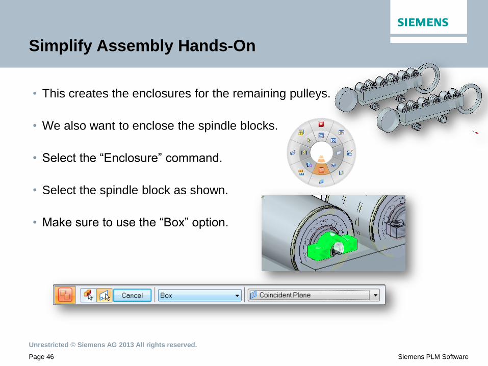
• This creates the enclosures for the remaining pulleys.
• We also want to enclose the spindle blocks.
• Select the “Enclosure” command.
• Select the spindle block as shown.
• Make sure to use the “Box” option.

Unrestricted © Siemens AG 2013 All rights reserved.
Page 47 Siemens PLM Software
Simplify Assembly Hands-On
• Use the side of the cylinder just created for the
reference plane step.
• The simplified block
gets created.
• We will also use “Duplicate Body” on this block.
• Select the simplified block
as shown.

Unrestricted © Siemens AG 2013 All rights reserved.
Page 48 Siemens PLM Software
Simplify Assembly Hands-On
• Then select the spindle block as
the “From” component.
• Then select “Select All Matching Occurrences”
• Accept to create the duplicate bodies.

Unrestricted © Siemens AG 2013 All rights reserved.
Page 49 Siemens PLM Software
Simplify Assembly Hands-On
• Change display configurations to “Track Only”
which turns the tracks back on so that we
can create our final enclosure.
• Window area on the top center track between
the top pulleys as shown.

Unrestricted © Siemens AG 2013 All rights reserved.
Page 50 Siemens PLM Software
Simplify Assembly Hands-On
• Run the “Enclosure” command from the radial menu.
• Select one of the track
occurrences and the
two supporting components
under that occurrence.
• Use the “Box” option
• Accept with a RMB.
• Use one of the previously created simplified
bodies for the reference plane step.
Unrestricted © Siemens AG 2013 All rights reserved.
Page 51 Siemens PLM Software
Simplify Assembly Hands-On
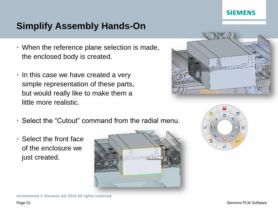
• When the reference plane selection is made,
the enclosed body is created.
• In this case we have created a very
simple representation of these parts,
but would really like to make them a
little more realistic.
• Select the “Cutout” command from the radial menu.
• Select the front face
of the enclosure we
just created.
Unrestricted © Siemens AG 2013 All rights reserved.
Page 52 Siemens PLM Software
Simplify Assembly Hands-On
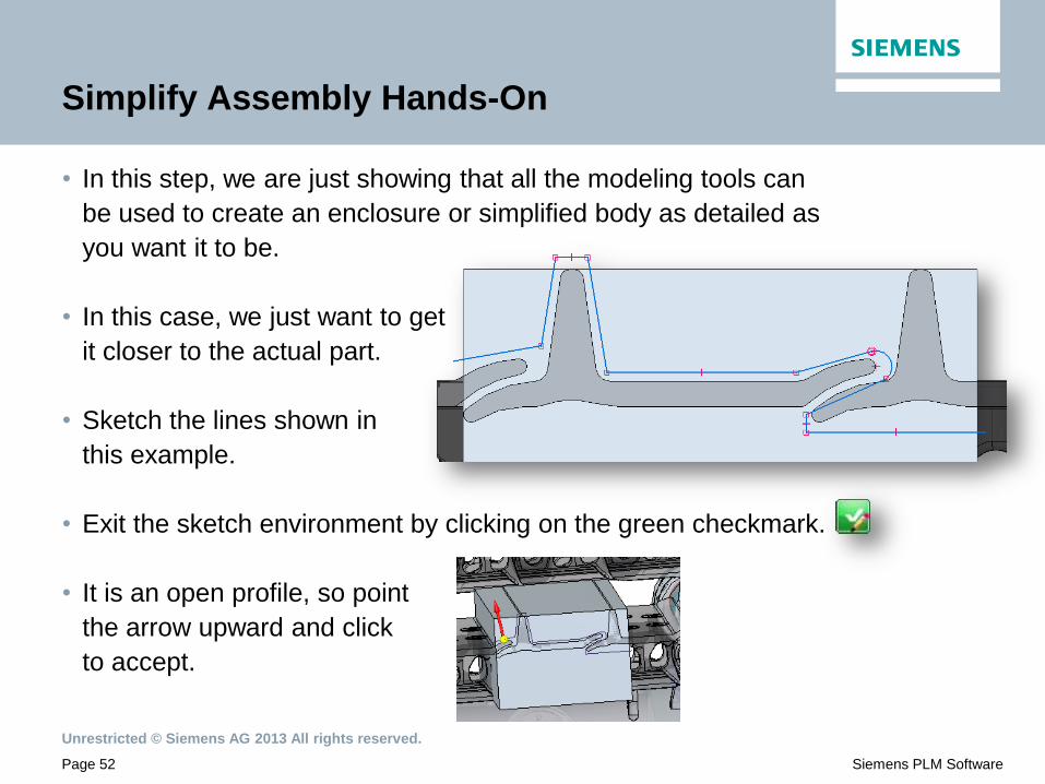
• In this step, we are just showing that all the modeling tools can
be used to create an enclosure or simplified body as detailed as
you want it to be.
• In this case, we just want to get
it closer to the actual part.
• Sketch the lines shown in
this example.
• Exit the sketch environment by clicking on the green checkmark.
• It is an open profile, so point
the arrow upward and click
to accept.

Unrestricted © Siemens AG 2013 All rights reserved.
Page 53 Siemens PLM Software
Simplify Assembly Hands-On
• Move the cursor into the screen to extend the
cutout through the part and click to accept.
• Use the radial menu to
select the “Round”
command.
• Set the “Radius” at 50 mm.
• Round the three edges shown.
Unrestricted © Siemens AG 2013 All rights reserved.
Page 54 Siemens PLM Software
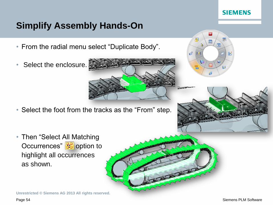
Simplify Assembly Hands-On
• From the radial menu select “Duplicate Body”.
• Select the enclosure.
• Select the foot from the tracks as the “From” step.
• Then “Select All Matching
Occurrences” option to
highlight all occurrences
as shown.
Unrestricted © Siemens AG 2013 All rights reserved.
Page 55 Siemens PLM Software
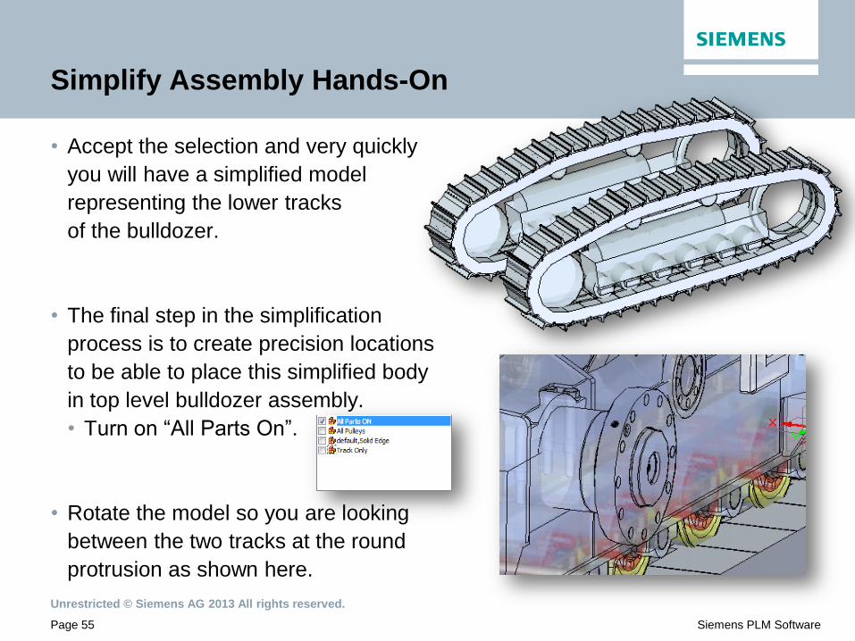
Simplify Assembly Hands-On
• Accept the selection and very quickly
you will have a simplified model
representing the lower tracks
of the bulldozer.
• The final step in the simplification
process is to create precision locations
to be able to place this simplified body
in top level bulldozer assembly.
• Turn on “All Parts On”.
• Rotate the model so you are looking
between the two tracks at the round
protrusion as shown here.
Unrestricted © Siemens AG 2013 All rights reserved.
Page 56 Siemens PLM Software
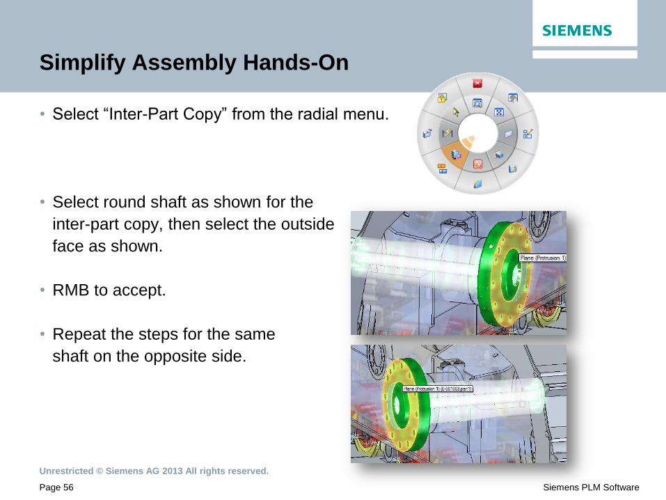
Simplify Assembly Hands-On
• Select “Inter-Part Copy” from the radial menu.
• Select round shaft as shown for the
inter-part copy, then select the outside
face as shown.
• RMB to accept.
• Repeat the steps for the same
shaft on the opposite side.
Unrestricted © Siemens AG 2013 All rights reserved.
Page 57 Siemens PLM Software
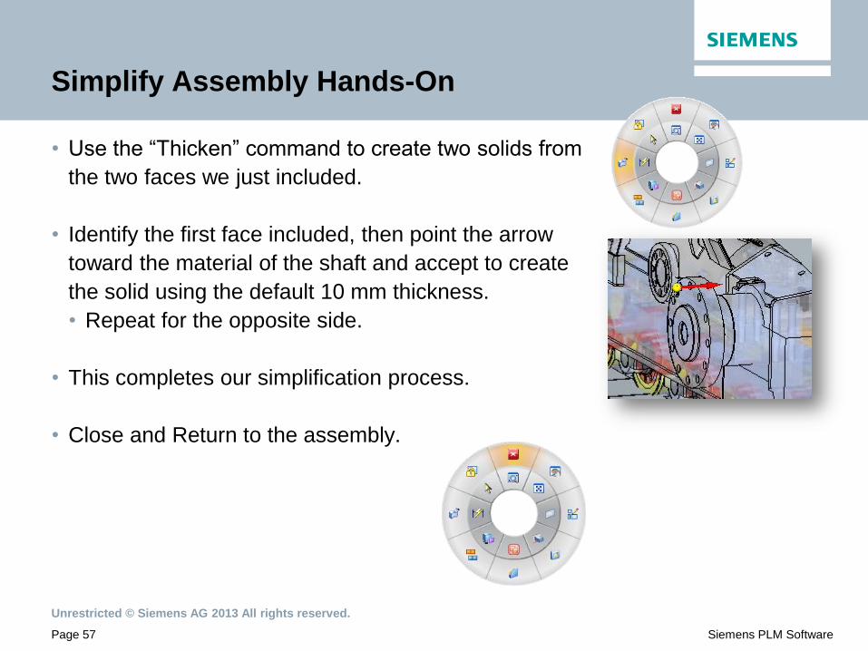
Simplify Assembly Hands-On
• Use the “Thicken” command to create two solids from
the two faces we just included.
• Identify the first face included, then point the arrow
toward the material of the shaft and accept to create
the solid using the default 10 mm thickness.
• Repeat for the opposite side.
• This completes our simplification process.
• Close and Return to the assembly.

Unrestricted © Siemens AG 2013 All rights reserved.
Page 58 Siemens PLM Software
Simplify Assembly Hands-On
• RMB on the
simplified assembly
in PathFinder and
select “Show Only”
to view only the
simplified body.
• You now have a simplified representation of the
track assembly that can be used in a top level assembly.
• SAVE and Close.
• The following are the steps to place in a top level assembly.
Unrestricted © Siemens AG 2013 All rights reserved.
Page 59 Siemens PLM Software
Simplify Assembly Hands-On
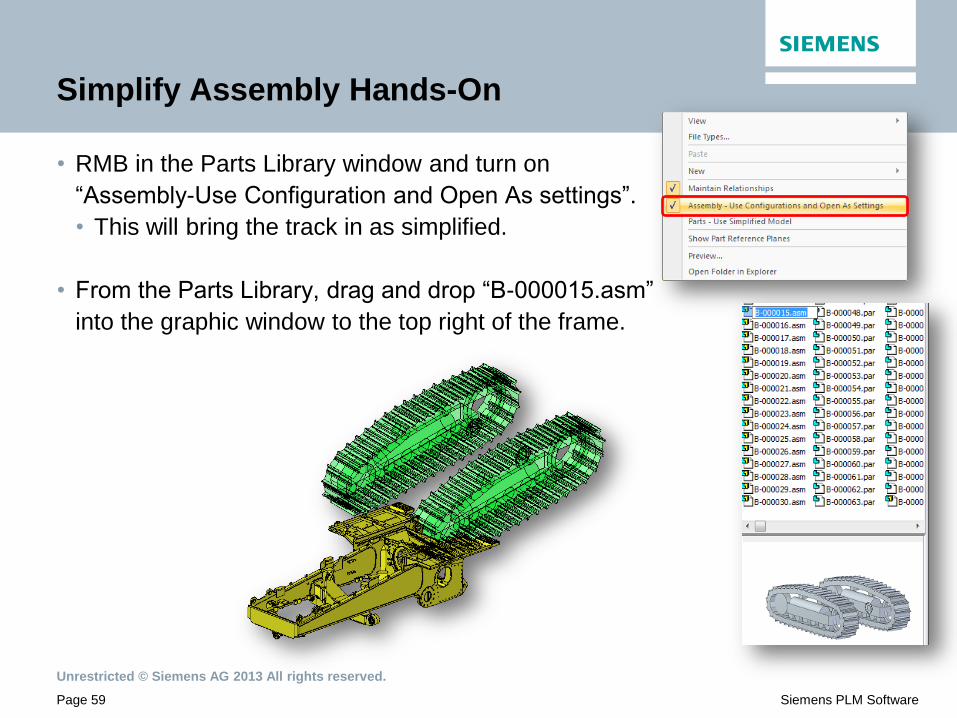
• RMB in the Parts Library window and turn on
“Assembly-Use Configuration and Open As settings”.
• This will bring the track in as simplified.
• From the Parts Library, drag and drop “B-000015.asm”
into the graphic window to the top right of the frame.
Unrestricted © Siemens AG 2013 All rights reserved.
Page 60 Siemens PLM Software
Simplify Assembly Hands-On
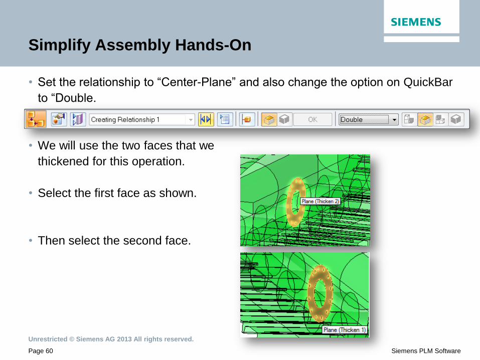
• Set the relationship to “Center-Plane” and also change the option on QuickBar
to “Double.
• We will use the two faces that we
thickened for this operation.
• Select the first face as shown.
• Then select the second face.
Unrestricted © Siemens AG 2013 All rights reserved.
Page 61 Siemens PLM Software
Simplify Assembly Hands-On
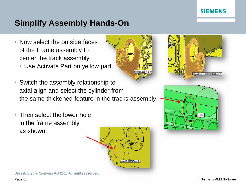
• Now select the outside faces
of the Frame assembly to
center the track assembly.
• Use Activate Part on yellow part.
• Switch the assembly relationship to
axial align and select the cylinder from
the same thickened feature in the tracks assembly.
• Then select the lower hole
in the frame assembly
as shown.
Unrestricted © Siemens AG 2013 All rights reserved.
Page 62 Siemens PLM Software
Simplify Assembly Hands-On
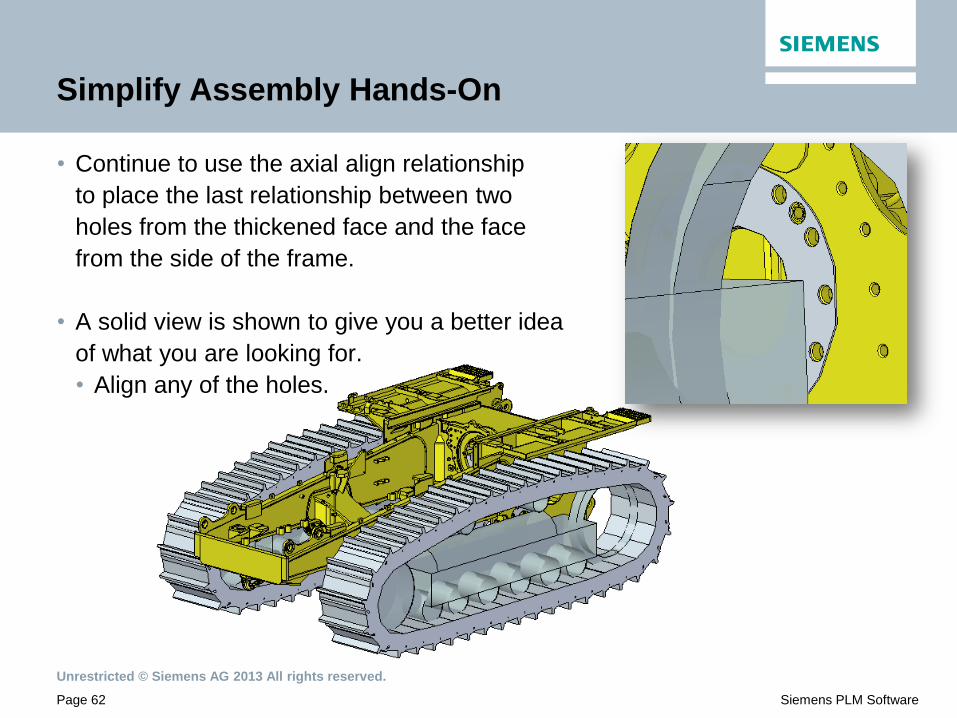
• Continue to use the axial align relationship
to place the last relationship between two
holes from the thickened face and the face
from the side of the frame.
• A solid view is shown to give you a better idea
of what you are looking for.
• Align any of the holes.

Unrestricted © Siemens AG 2013 All rights reserved.
Page 63 Siemens PLM Software
Simplify Assembly Hands-On
• Select the “Take a Snapshot” to capture the current settings.
• Change the display configuration, select both
“All Simplified Assemblies” and “Assy Snapshot”
so all components stay on.
Unrestricted © Siemens AG 2013 All rights reserved.
Page 64 Siemens PLM Software
Simplify Assembly Hands-On
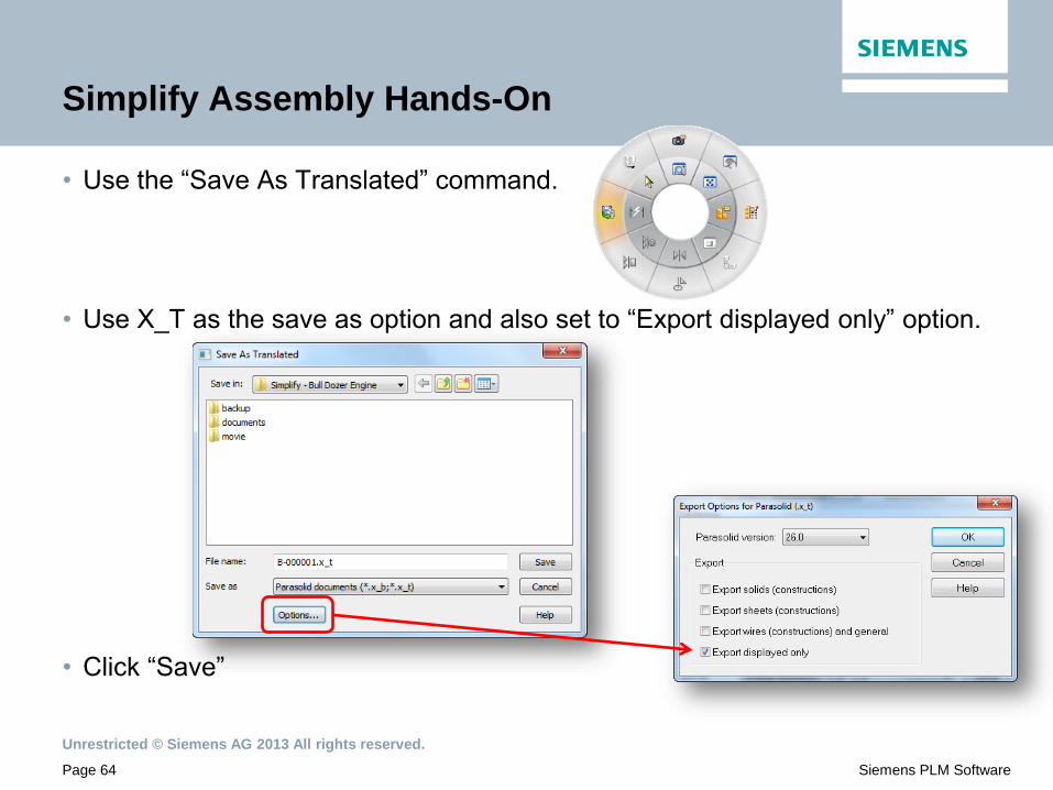
• Use the “Save As Translated” command.
• Use X_T as the save as option and also set to “Export displayed only” option.
• Click “Save”

Unrestricted © Siemens AG 2013 All rights reserved.
Page 65 Siemens PLM Software
Simplify Assembly Hands-On
• Use File:open and open the newly created X_T file into a Part template.
• Now you have a single part file that
represents the simplified bulldozer.