

This page is intentionally left blank.

AdvancedMachining Processes
Nontraditional and Hybrid Machining Processes
Hassan El-HofyProduction Engineering Department
Alexandria University, Egypt
McGraw-HillNew York Chicago San Francisco Lisbon London Madrid
Mexico City Milan New Delhi San Juan Seoul Singapore Sydney Toronto

Copyright © 2005 by The McGraw-Hill Companies. All rights reserved. Manufactured in the United States of America. Except as permitted under the United States Copyright Act of 976, no part of this publication may be reproduced or distributed in any form or by any means, or stored in a database or retrieval system, without the prior written permission of the publisher. 0-07-146694-0 The material in this eBook also appears in the print version of this title: 0-07-145334-2. All trademarks are trademarks of their respective owners. Rather than put a trademark symbol after every occurrence of a trademarked name, we use names in an editorial fashion only, and to the benefit of the trademark owner, with no intention of infringement of the trademark. Where such designations appear in this book, they have been printed with initial caps. McGraw-Hill eBooks are available at special quantity discounts to use as premiums and sales promotions, or for use in corporate training programs. For more information, please contact George Hoare, Special Sales, at [email protected] or (212) 904-4069. TERMS OF USE This is a copyrighted work and The McGraw-Hill Companies, Inc. (“McGraw-Hill”) and its licensors reserve all rights in and to the work. Use of this work is subject to these terms. Except as permitted under the Copyright Act of 1976 and the right to store and retrieve one copy of the work, you may not decompile, disassemble, reverse engineer, reproduce, modify, create derivative works based upon, transmit, distribute, disseminate, sell, publish or sublicense the work or any part of it without McGraw-Hill’s prior consent. You may use the work for your own noncommercial and personal use; any other use of the work is strictly prohibited. Your right to use the work may be terminated if you fail to comply with these terms. THE WORK IS PROVIDED “AS IS.” McGRAW-HILL AND ITS LICENSORS MAKE NO GUARANTEES OR WARRANTIES AS TO THE ACCURACY, ADEQUACY OR COMPLETENESS OF OR RESULTS TO BE OBTAINED FROM USING THE WORK, INCLUDING ANY INFORMATION THAT CAN BE ACCESSED THROUGH THE WORK VIA HYPERLINK OR OTHERWISE, AND EXPRESSLY DISCLAIM ANY WARRANTY, EXPRESS OR IMPLIED, INCLUDING BUT NOT LIMITED TO IMPLIED WARRANTIES OF MERCHANTABILITY OR FITNESS FOR A PARTICULAR PURPOSE. McGraw-Hill and its licensors do not warrant or guarantee that the functions contained in the work will meet your requirements or that its operation will be uninterrupted or error free. Neither McGraw-Hill nor its licensors shall be liable to you or anyone else for any inaccuracy, error or omission, regardless of cause, in the work or for any damages resulting therefrom. McGraw-Hill has no responsibility for the content of any information accessed through the work. Under no circumstances shall McGraw-Hill and/or its licensors be liable for any indirect, incidental, special, punitive, consequential or similar damages that result from the use of or inability to use the work, even if any of them has been advised of the possibility of such damages. This limitation of liability shall apply to any claim or cause whatsoever whether such claim or cause arises in contract, tort or otherwise. DOI: 10.1036/0071466940

Dedicated to my wife Soaad El-Hofy

This page is intentionally left blank.

vii
Contents
Preface xiAcknowledgments xviiList of Acronyms xixList of Symbols xxiii
Chapter 1. Material Removal Processes 1
1.1 Introduction 11.2 History of Machining 11.3 Traditional Machining 5
1.3.1 Machining by cutting 51.3.2 Machining by abrasion 6
1.4 Nontraditional Machining 81.4.1 Single-action nontraditional machining 91.4.2 Hybrid machining 10
References 13
Chapter 2. Mechanical Processes 15
2.1 Ultrasonic Machining 152.1.1 Introduction 152.1.2 The machining system 152.1.3 Material removal process 222.1.4 Factors affecting material removal rate 242.1.5 Dimensional accuracy and surface quality 262.1.6 Applications 28
2.2 Water Jet Machining 322.2.1 Introduction 322.2.2 The machining system 322.2.3 Process parameters 342.2.4 Applications 352.2.5 Advantages and disadvantages of WJM 38
2.3 Abrasive Jet Machining 392.3.1 Introduction 392.3.2 Machining system 392.3.3 Material removal rate 402.3.4 Applications 422.3.5 Advantages and limitations of AJM 42
vii
For more information about this title, click here
viii
2.4 Abrasive Water Jet Machining 432.4.1 Introduction 432.4.2 The machining system 442.4.3 Process capabilities 45
2.5 Ice Jet Machining 462.5.1 Introduction 462.5.2 Process description 46
2.6 Magnetic Abrasive Finishing 482.6.1 Introduction 482.6.2 The machining system 482.6.3 Material removal process 492.6.4 Applications 50
References 52
Chapter 3. Chemical Processes 55
3.1 Chemical Milling 553.1.1 Introduction 553.1.2 Tooling for CHM 573.1.3 Process parameters 613.1.4 Material removal rate 613.1.5 Accuracy and surface finish 623.1.6 Advantages 633.1.7 Limitations 643.1.8 Applications 64
3.2 Photochemical Milling 663.2.1 Introduction 663.2.2 Process description 663.2.3 Applications 673.2.4 Advantages 68
3.3 Electropolishing 703.3.1 Introduction 703.3.2 Process parameters 733.3.3 Applications 733.3.4 Process limitations 74
References 75
Chapter 4. Electrochemical Processes 77
4.1 Electrochemical Machining 774.1.1 Introduction 774.1.2 Principles of electrolysis 774.1.3 Theory of ECM 784.1.4 ECM equipment 794.1.5 Basic working principles 844.1.6 Process characteristics 874.1.7 Process control 954.1.8 Applications 974.1.9 Micro-ECM 98
4.1.10 Advantages and disadvantages of ECM 984.1.11 Environmental impacts 99
4.2 Electrochemical Drilling 1004.3 Shaped Tube Electrolytic Machining 102
viii Contents

ix
4.4 Electrostream (Capillary) Drilling 1054.5 Electrochemical Jet Drilling 1084.6 Electrochemical Deburring 109
References 112
Chapter 5. Thermal Processes 115
5.1 Electrodischarge Machining 1155.1.1 Introduction 1155.1.2 Mechanism of material removal 1155.1.3 The machining system 1205.1.4 Material removal rates 1255.1.5 Surface integrity 1275.1.6 Heat-affected zone 1295.1.7 Applications 1305.1.8 Process control 1375.1.9 EDM automation 138
5.1.10 Environmental impact 1395.2 Laser Beam Machining 140
5.2.1 Introduction 1405.2.2 Material removal mechanism 1415.2.3 Applications 1445.2.4 Advantages and limitations 156
5.3 Electron Beam Machining 1575.3.1 Introduction 1575.3.2 Basic equipment and removal mechanism 1575.3.3 Applications 1635.3.4 Advantages and disadvantages 165
5.4 Plasma Beam Machining 1665.4.1 Introduction 1665.4.2 Machining systems 1665.4.3 Material removal rate 1695.4.4 Accuracy and surface quality 1695.4.5 Applications 1715.4.6 Advantages and disadvantages 172
5.5 Ion Beam Machining 1725.5.1 Introduction 1725.5.2 Material removal rate 1735.5.3 Accuracy and surface effects 1755.5.4 Applications 176
References 177
Chapter 6. Hybrid Electrochemical Processes 181
6.1 Introduction 1816.2 Electrochemical Grinding 182
6.2.1 Introduction 1826.2.2 Material removal rate 1836.2.3 Accuracy and surface quality 1876.2.4 Applications 1886.2.5 Advantages and disadvantages 188
6.3 Electrochemical Honing 1896.3.1 Introduction 1896.3.2 Process characteristics 189
Contents ix
6.3.3 Applications 1916.4 Electrochemical Superfinishing 192
6.4.1 Introduction 1926.4.2 Material removal process 1936.4.3 Process accuracy 195
6.5 Electrochemical Buffing 1966.5.1 Introduction 1966.5.2 Material removal process 196
6.6 Ultrasonic-Assisted ECM 1976.6.1 Introduction 1976.6.2 Material removal process 198
6.7 Laser-Assisted ECM 199References 201
Chapter 7. Hybrid Thermal Processes 203
7.1 Introduction 2037.2 Electroerosion Dissolution Machining 2047.3 Electrodischarge Grinding 2127.4 Abrasive Electrodischarge Machining 2167.5 EDM with Ultrasonic Assistance 2187.6 Electrochemical Discharge Grinding 2217.7 Brush Erosion-Dissolution Mechanical Machining 224
References 226
Chapter 8. Material Addition Processes 229
8.1 Introduction 2298.2 Liquid-Based Techniques 230
8.2.1 Stereolithography 2308.2.2 Holographic interference solidification 2328.2.3 Beam interference solidification 2328.2.4 Solid ground curing 2338.2.5 Liquid thermal polymerization 2358.2.6 Fused deposition modeling 2358.2.7 Multijet modeling 2388.2.8 Ballistic particles manufacturing 2398.2.9 Shape deposition manufacturing 240
8.3 Powder-Based Processes 2418.3.1 Selective laser sintering 2418.3.2 Laser engineered net shaping 2428.3.3 Three-dimensional printing 243
8.4 Solid-Based Techniques 2448.4.1 Solid foil polymerization 2448.4.2 Laminated object modeling 245
References 246
Index 249
x Contents
xi
Preface
Machining processes produce finished products with a high degree ofaccuracy and surface quality. Conventional machining utilizes cuttingtools that must be harder than the workpiece material. The use ofdifficult-to-cut materials encouraged efforts that led to the introductionof the nonconventional machining processes that are well-establishedin modern manufacturing industries.
Single-action nontraditional machining processes are classified onthe basis of the machining action causing the material removal from theworkpiece. For each process, the material removal mechanism, machin-ing system components, process variables, technological characteristics,and industrial applications are presented.
The need for higher machining productivity, product accuracy, and sur-face quality led to the combination of two or more machining actions toform a new hybrid machining process. Based on the major mechanismcausing the material removal process, two categories of hybrid machin-ing processes are introduced. A review of the existing hybrid machiningprocesses is given together with current trends and research directions.For each hybrid machining process the method of material removal,machining system, process variables, and applications are discussed.
This book provides a comprehensive reference for nontraditionalmachining processes as well as for the new hybrid machining ones. It isintended to be used for degree and postgraduate courses in production,mechanical, manufacturing, and industrial engineering. It is also usefulto engineers working in the field of advanced machining technologies.
In preparing the text, I paid adequate attention to presenting thesubject in a simple and easy to understand way. Diagrams are simpleand self-explanatory. I express my gratitude to all authors of variousbooks, papers, Internet sites, and other literature which have beenreferred to in this book. I will be glad to receive comments and sugges-tions for enhancing the value of this book in future editions.
Copyright © 2005 by The McGraw-Hill Companies, Inc. Click here for terms of use.
Outline of the book
The following subjects and chapters are organized as a journey towardunderstanding the characteristics of nonconventional and hybridmachining processes. The book is written in eight chapters:
Chapter 1: Material Removal Processes
Chapter 2: Mechanical Processes
Chapter 3: Chemical Processes
Chapter 4: Electrochemical Processes
Chapter 5: Thermal Processes
Chapter 6: Hybrid Electrochemical Processes
Chapter 7: Hybrid Thermal Processes
Chapter 8: Material Addition Processes
In Chap. 1, the history and progress of machining is introduced. Thedifference between traditional and nontraditional machining is explained.Examples for conventional machining by cutting and abrasion are given.Single-action nontraditional machining is classified according to thesource of energy causing the material removal process. Hybrid machin-ing occurs as a result of combining two or more machining phases.Hybrid machining is categorized according to the main material removalmechanism occurring during machining.
Chapter 2 covers a wide range of mechanical nontraditional machin-ing processes such as ultrasonic machining (USM), water jet machin-ing (WJM), abrasive water jet machining (AWJM), ice jet machining(IJM), as well as magnetic abrasive finishing (MAF). In these processesthe mechanical energy is used to force the abrasives, water jets, and icejets that cause mechanical abrasion (MA) to the workpiece material.
In Chap. 3, the chemical machining processes such as chemical milling(CHM), photochemical machining (PCM), and electrolytic polishing (EP)are discussed. In these processes the material is mainly removedthrough chemical dissolution (CD) occurring at certain locations of theworkpiece surface.
Chapter 4 deals with electrochemical machining (ECM) and relatedapplications that include electrochemical drilling (ECDR), shaped tubeelectrolytic machining (STEM), electrostream (ES), electrochemical jetdrilling (ECJD), and electrochemical deburring (ECB). The electro-chemical dissolution (ECD) controls the rate of material removal.
Machining processes that are based on the thermal machining actionare described in Chap. 5. These include electrodischarge machining(EDM), laser beam machining (LBM), electron beam machining (EBM),plasma beam machining (BPM), and ion beam machining (IBM). In most
xii Preface

Preface xiii
of these processes, material is removed from the workpiece by meltingand evaporation. Thermal properties of the machined parts affect therate of material removal.
Hybrid electrochemical machining processes are dealt with in Chap. 6.Some of these processes are mainly electrochemical with mechanicalassistance using mechanical abrasion such as electrochemical grinding(ECG), electrochemical honing (ECH), electrochemical superfinishing(ECS), and electrochemical buffing (ECB). The introduction of ultrasonicassistance enhances the electrochemical dissolution action duringultrasonic-assisted ECM (USMEC). Laser beams activate electro-chemical reactions and hence the rate of material removal during laser-assisted electrochemical machining (ECML).
Chapter 7 covers the hybrid thermal machining processes. Electro-chemical dissolution (ECD) enhances the electrodischarge erosion action(EDE) during electroerosion dissolution machining (EEDM). Mechanicalabrasion encourages the thermal erosion process during electrodischargegrinding (EDG) and abrasive-assisted electrodischarge machining(AEDG and AEDM). Ultrasonic assistance encourages the dischargingprocess during ultrasonic-assisted EDM (EDMUS). Triple-action hybridmachining occurs by combining both electrochemical dissolution (ECD)and mechanical abrasion to the main erosion phase during electro-chemical discharge grinding (ECDG).
Material addition processes are covered in Chap. 8. These include awide range of rapid prototyping techniques that are mainly classifiedas liquid-, powder-, and solid-based techniques.
Advantages of the book
1. Covers both the nonconventional and hybrid machining processes
2. Classifies the nonconventional machining processes on the basis ofthe machining phase causing the material removal (mechanical, ther-mal, chemical, and electrochemical processes)
3. Classifies the hybrid machining processes based on the major mech-anism and hence the machining phase causing the material removalfrom the workpiece into hybrid thermal and hybrid electrochemicalprocesses
4. Presents clearly the principles of material removal mechanisms innonconventional machining as well as hybrid machining
5. Explains the role of each machining phase (causing the materialremoval) on the process behavior
6. Describes the machining systems, their main components, and howthey work

7. Discusses the role of machining variables on the technological charac-teristics of each process (removal rate, accuracy, and surface quality)
8. Introduces the material addition processes that use the same prin-ciples adopted in material removal by nonconventional processes
This book is intended to help
1. Undergraduates enrolled in production, industrial, manufacturing,and mechanical engineering programs
2. Postgraduates and researchers trying to understand the theories ofmaterial removal by the modern machining processes
3. Engineers and high-level technicians working in the area of advancedmachining industries
Why did I write the book?
This book presents 28 years of experience including research and teach-ing of modern machining methods at many universities around theworld. My career started early in the academic year 1975–1976 througha senior project related to the effect of some parameters on the oversizeof holes produced by ECM. Afterward, I finished my M.S. degree in thefield of accuracy of products by electrolytic sinking in the Departmentof Production Engineering at Alexandria University. As an assistantlecturer I helped to teach about conventional and nonconventionalmachining.
I spent 4 years on a study leave in the U.K. working toward my Ph.D.at Aberdeen University and 1 year at Edinburgh University. Duringthat time I finished my thesis in the field of hybrid electrochemicalarc wire machining (ECAM) under the supervision of ProfessorJ. McGeough. That work was supported by the Wolfson Foundationand the British Technology Group. I had the Overseas Research Student(ORS) award for three successive years which supported me during myresearch work. Working on a large research team and sharing discus-sions in regular meetings, I gained more experience related to manyadvanced and hybrid machining applications such as hybrid ECM-EDM,ECAM drilling, and electrochemical cusp removal. I was a regular steer-ing committee member for the CAPE conference organized by ProfessorMcGeough. I edited two chapters and shared in the writing of chapter 1of his book Micromachining of Engineering Materials.
Throughout my academic career in which I started out as a lecturerand moved up to being a full professor of modern machining processes,I have taught all subjects related to machining in many universitiesaround the world. I have published about 50 research papers related to
xivxiv Preface

nonconventional as well as hybrid machining processes. During mywork in Qatar University I was responsible for teaching the advancedmachining techniques course. Collecting all materials that I had in abook therefore came to my mind. I have been working on this task sincethe year 2001.
Hassan El-HofyAlexandria, Egypt
xvPreface xv

This page is intentionally left blank.

Acknowledgments
There are many people who have contributed to the development of thisbook that I cannot name. First of all, I would like to thank ProfessorsH. Youssef and M. H. Ahmed at the University of Alexandria, Egypt,Professors H. Rahmatallh, S. Soliman and O. Saad at the University ofQatar for their support, suggestions and encouragement.
The editorial and production staff at McGraw Hill have my heartfeltgratitude for their efforts in ensuring that the text is accurate and aswell designed as possible.
My greatest thanks have to be reserved to my wife Soaad anddaughters Noha, Assmaa, and Lina for their support and interestthroughout the preparation of the text. Special thanks have to be offeredto my son Mohamed for his discussions, suggestions, and the splendidartwork in many parts of the book.
It is with great pleasure that I acknowledge the help of many organ-izations that gave me permission to reproduce numerous illustrationsand photographs in this book:
Acu-Line Corporation, Seattle, WA ASM International, Materials Park, OH ASME International, New York, NY Extrude Hone, Irwin, PA IEE, Stevenage, UK Jet Cut Incorporation, Waterloo, ON, Canada Jet-Edge, St. Michael, MN LCSM-EFPL, Swiss Federal Institute of Technology, Lausanne,
Switzerland Precision Engineering Journal, Elsevier, Oxford, UK TU/e, Eindhoven University of Technology, Netherlands Vectron Deburring, Elyria, OH
xvii
Copyright © 2005 by The McGraw-Hill Companies, Inc. Click here for terms of use.

This page is intentionally left blank.
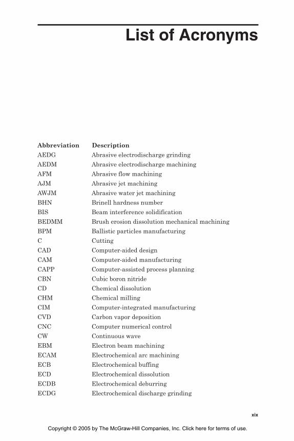
List of Acronyms
Abbreviation Description
AEDG Abrasive electrodischarge grinding
AEDM Abrasive electrodischarge machining
AFM Abrasive flow machining
AJM Abrasive jet machining
AWJM Abrasive water jet machining
BHN Brinell hardness number
BIS Beam interference solidification
BEDMM Brush erosion dissolution mechanical machining
BPM Ballistic particles manufacturing
C Cutting
CAD Computer-aided design
CAM Computer-aided manufacturing
CAPP Computer-assisted process planning
CBN Cubic boron nitride
CD Chemical dissolution
CHM Chemical milling
CIM Computer-integrated manufacturing
CVD Carbon vapor deposition
CNC Computer numerical control
CW Continuous wave
EBM Electron beam machining
ECAM Electrochemical arc machining
ECB Electrochemical buffing
ECD Electrochemical dissolution
ECDB Electrochemical deburring
ECDG Electrochemical discharge grinding
xix
Copyright © 2005 by The McGraw-Hill Companies, Inc. Click here for terms of use.

Abbreviation Description
ECDM Electrochemical discharge machining
ECDR Electrochemical drilling
ECG Electrochemical grinding
ECH Electrochemical honing
ECJD Electrochemical jet drilling
ECM Electrochemical machining
ECML Laser-assisted electrochemical machining
ECS Electrochemical superfinishing
EDE Electrodischarge erosion
EDG Electrodischarge grinding
EDM Electrodischarge machining
EDMUS Electrodischarge machining with ultrasonic assistance
EDT Electrodischarge texturing
EEDM Electroerosion dissolution machining
EP Electropolishing
ES Electrostream
FDM Fused deposition modeling
FJ Fluid jet
G Grinding
HAZ Heat-affected zone
HF Hone forming
HIS Holographic interference solidification
IBM Ion beam machining
IJM Ice jet machining
LAE Laser-assisted chemical etching
LAJECM Laser-assisted jet ECM
LAN Local area network
LBM Laser beam machining
LBT Laser beam texturing
LENS Laser engineered net shaping
LOM Laminated object modeling
LTP Liquid thermal polymerization
MA Mechanical abrasion
MAF Magnetic abrasive finishing
MJM Multijet modeling
MMC Metal matrix composites
MPEDM Mechanical pulse electrodischarge machining
xx List of Acronyms

Abbreviation Description
MRR Material removal rate
MS Mechanical scrubbing
MUSM Micro-ultrasonic machining
NC Numerical control
ND-YAG Neodymium-doped yitrium-aluminum-garnet
PAM Plasma arc machining
PBM Plasma beam machining
PCB Photochemical blanking
PCD Polycrystalline diamond
PECM Pulse electrochemical machining
PF Photoforming
PCM Photochemical milling
PM Pulsed mode
RP Rapid prototyping
RUM Rotary ultrasonic machining
SB Shot blasting
SDM Shape deposition manufacturing
SFF Solid free-form fabrication
SFP Solid foil polymerization
SGC Solid ground curing
SLA Stereolithography
SLS Selective laser sintering
STEM Shaped tube electrolytic machining
TEM Thermal energy method
US Ultrasonic
USM Ultrasonic machining
USMEC Ultrasonic-assisted electrochemical machining
VRR Volumetric removal rate
WJM Water jet machining
List of Acronyms xxi

This page is intentionally left blank.

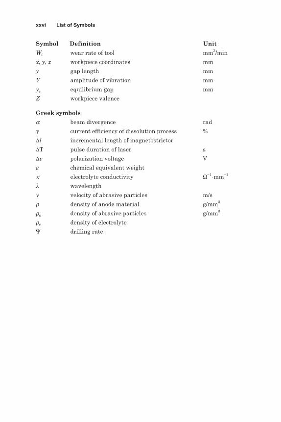
List of Symbols
Symbol Definition Unit
a tool feed rate mm/min
A atomic weight
A/Z chemical equivalent g
A/Z.F electrochemical equivalent g/C
Ab area of laser beam at focal point mm2
C electrochemical machining constant mm2/s
C/ye metal removal rate per unit area mm/min
Cd diametrical overcut mm
Cl constant depending on material and
conversion efficiency
Cs speed of sound in magnetostrictor material m/s
d CHM undercut mm
D EDM depth mm
D/Lc corner wear ratio mm
D/Le end wear ratio
D/Ls side wear ratio
d/T etch factor
da mean diameter of abrasive particles µm
db beam diameter at contact with
workpiece (slot width) mm
ds spot size diameter mm
dt tool diameter mm
dw produced hole diameter mm
dy/dt workpiece rate of change of position mm/min
E Young’s modulus MPa
m coefficient of magnetostriction elongation
xxiii
Copyright © 2005 by The McGraw-Hill Companies, Inc. Click here for terms of use.

Symbol Definition Unit
Em magnitudes of magnetic energy
ev number of pulses
Ev vaporization energy of material W/mm3
Ew magnitudes of mechanical energy
F frequency of oscillation Hz
f frequency of changes in magnetic field Hz
F Faraday’s constant C/g per-ion
Fl focal length of lens cm
fp frequency of pulses Hz
fr resonance frequency Hz
g depth of hole required
ge depth of hole removed per pulse mm
gw wheel-workpiece gap
h thickness of material mm
H magnetic field intensity
H0 surface fracture strength BHN
Hrms surface roughness µm
Hw hardness of workpiece material N/mm2
i EDM current A
I electrolyzing current A
Ie beam emission current mA
Ip pulse current A
J current density A/mm–2
K constant
Kh constant µm/µJ
Km coefficient of magnetomechanical coupling
Kp coefficient of loss
l original length of magnetostrictor
L slot length mm
Lc corner wear mm
Le end wear mm
Lp laser power W
Ls side wear mm
m amount of mass dissolved g
n density of target material atoms per cm3
ne number of pulses
N number of abrasives impacting per unit area
xxiv List of Symbols

Symbol Definition Unit
NM relative machinability
P density of magnetostrictor material kg/m3
Pd power density W/cm2
Pr pulse power W
qc specific removal rate for pure metals mm3/(min⋅A)
QECD removal rate of electrochemical dissolution mm3/min
QECG total removal rate in ECG mm3/min
Ql linear removal rate mm/min
QMA removal rate of mechanical abrasion mm3/min
Qv volumetric removal rate mm3/min
R mean radius of grit mm
Ra average roughness µm
Rt maximum peak to valley roughness µm
Rw wear ratio
S static stress on tool kg/mm2
s(q) IBM yield atoms per ion
t machining time min
T CHM depth of cut mm
ti pulse interval µs
tm machining time
tp pulse duration µs
Tr ratio of workpiece to tool electrode
melting points
Tt melting point of tool electrode °CTw melting point of workpiece material °CU mean velocity
V gap voltage V
V(q) etch rate atoms per min/mA cm2
Va beam accelerating voltage kV
Ve volume of electrode consumed mm3
Vg grinding wheel penetration speed mm3/min
VRR material removal rate mm3/min
Vs machining rate mm2/min
Vw volume of workpiece removed mm3
Vw / Ve volume wear ratio
W pulse energy µJ
List of Symbols xxv
Symbol Definition Unit
Wt wear rate of tool mm3/min
x, y, z workpiece coordinates mm
y gap length mm
Y amplitude of vibration mm
ye equilibrium gap mm
Z workpiece valence
Greek symbols
a beam divergence rad
g current efficiency of dissolution process %
∆l incremental length of magnetostrictor
∆T pulse duration of laser s
∆v polarization voltage V
e chemical equivalent weight
k electrolyte conductivity Ω−1⋅mm−1
l wavelength
n velocity of abrasive particles m/s
r density of anode material g/mm3
ra density of abrasive particles g/mm3
re density of electrolyte
Ψ drilling rate
xxvi List of Symbols

AdvancedMachining Processes

This page is intentionally left blank.

Chapter
1Material Removal Processes
1.1 Introduction
Parts manufactured by casting, forming, and various shaping processesoften require further operations before they are ready for use or assem-bly. In many engineering applications, parts have to be interchangeablein order to function properly and reliably during their expected servicelives; thus control of the dimensional accuracy and surface finish of theparts is required during manufacture. Machining involves the removalof some material from the workpiece (machining allowance) in order toproduce a specific geometry at a definite degree of accuracy and surfacequality.
1.2 History of Machining
From the earliest of times methods of cutting materials have beenadopted using hand tools made from bone, stick, or stone. Later, handtools made of elementary metals such as bronze and iron were employedover a period of almost one million years. Indeed up to the seventeenthcentury, tools continued to be either hand operated or mechanicallydriven by very elementary methods. By such methods, wagons, ships, andfurniture, as well as the basic utensils for everyday use, were manufac-tured. The introduction of water, steam, and, later, electricity as usefulsources of energy led to the production of power-driven machine toolswhich rapidly replaced manually driven tools in many applications.
Based on these advances and together with the metallurgical devel-opment of alloy steels as cutting tool materials, a new machine toolindustry began to arise in the eighteenth and nineteenth centuries. Amajor original contribution to this new industry came from JohnWilkinson in 1774. He constructed a precision machine for boring engine
1
Copyright © 2005 by The McGraw-Hill Companies, Inc. Click here for terms of use.

cylinders, thereby overcoming a problem associated with the firstmachine tools, which were powered by steam. Twenty-three years later,Henry Maudslay made a further advancement in machining when hedevised a screw-cutting engine lathe. James Nasmyth invented thesecond basic machine tool for shaping and planing; these techniques areused to machine flat surfaces, grooves, shoulders, T-slots, and angularsurfaces using single-point cutting tools. The familiar drilling machineis the third category of machine tools; it cuts holes with a twist drill.
Whitney in about 1818 introduced the first milling machine to cutgrooves, dovetails, and T-slots as well as flat surfaces. The first univer-sal milling machine, constructed in 1862 by J. R. Brown, was employedto cut helical flutes of twist drills. In the late nineteenth century, thegrinding machine was introduced. An advanced form of this technologyis the lapping process used to produce a high-quality surface finish anda very tight tolerance, as small as ±0.00005 millimeters (mm) comparedto the ±0.0025 mm achieved during grinding. Band saws and circulardiscsaws are used for cutting shapes in metal plates, for making exter-nal and internal contours, and for making angular cuts.
A notable development includes the turret lathe made in the middleof the nineteenth century for the automatic production of screws.Another significant advance came in 1896, when F. W. Fellows built amachine that could produce any kind of gear. An example of the signif-icance of early achievements in grinding technology came from C. N.Norton’s work in reducing the time needed to grind a car crankshaft from5 hours (h) to 15 minutes (min). Multiple-station vertical lathes, gangdrills, production millers, and special-purpose machines (for example,for broaching, honing, and boring) are other noteworthy examples ofadvances in machine tool technology (McGeough, 1988). In the laterpart of the nineteenth century and in the twentieth century, machinetools became increasingly powered by electricity rather than steam.The basic machine tools underwent further refinement; for instance,multiple-point cutters for milling machines were introduced. Even withthese advances, conventional machine tool practice still relies on theprinciple whereby the tool must be made of a material that is harderthan the workpiece that is to be cut.
During machining by these conventional methods the operator isgiven a drawing of the finished part. He or she determines the machin-ing strategy, sets up the machine, and selects tooling, speeds, and feeds.The operator manipulates the machine control to cut the part thatpasses inspection. Under such circumstances, the product accuracy andsurface quality are not satisfactory. Further developments for theseconventional machines came by the introduction of copying techniques,cams, and automatic mechanisms that reduced labor and, consequently,raised the product accuracy.
2 Chapter One

The introduction of numerical control (NC) technology in 1953 openedwide doors to computer numerical control (CNC) and direct numericalcontrol (DNC) machining centers that enhanced the product accuracyand uniformity. Developments in machining processes and their machinetools have continued throughout the last 50 years due to the rapidenhancements in the electronics and computer industries. Ingeniousdesigns of conventional machine tools have enabled complex shapes tobe produced at an accuracy of ±1 micrometers (µm). As shown in Fig. 1.1,the most recent developments in conventional machining include pre-cision jig borers, jig grinding, and superfinishing machines. These madethe accuracy level of ±1 µm possible. Such a high level of accuracy canbe measured using pneumatic or electronic instruments as well as opti-cal comparators. Future trends may also include precision grinding andlapping machines as well as precision diamond lathes.
Material Removal Processes 3
Figure 1.1 Machining accuracies (Tanigushi, 1983).
100
10
1
0.1
0.01
0.001
0.0001
(1 nm)
0.3 nm
(10−6 in)
(10−3 in)
(0.1 nm)
Mac
hini
ng a
ccur
acy,
µm
Normalmachining
Precisionmachining
Ultraprecisionmachining
Atomic latticeseparation
1940 1960 1980 2000
Equipment and machine tools
Turning and milling machines
Grinding machinesCNC machining centers
Lapping and honingJig boring and grinding
Optical lens grinding machinesPrecision grindingSuperfinishingDiamond grinding and turning
High-precision mask alignersUltraprecision diamond turning
Turning and milling machines
Electron beam and soft x-raylithographyIon beam machining
Molecular beam epitaxyIon implantation
Materials synthesizing

In modern machining practice, harder, stronger, and tougher materi-als that are more difficult to cut are frequently used. More attention is,therefore, directed toward machining processes where the mechanicalproperties of the workpiece material are not imposing any limits on thematerial removal process. In this regard, the nonconventional machiningtechniques came into practice as a possible alternative concerning machin-ability, shape complexity, surface integrity, and miniaturization require-ments. Innovative machining techniques or modifications to the existingmethod by combining different machining processes were needed. Hybridmachining made use of the combined or mutually enhanced advantagesand avoided the adverse effects of the constituent processes producedwhen they are individually applied.
For a while, there were trends toward reducing the workpiece size anddimensions after it became possible to drill ultrasmall-diameter holes(10–100 µm) in hard materials using the available machining processes.Micromachining has recently become, an important issue for furtherreduction of workpiece size and dimensions. It refers to the technologyand practice of making three-dimensional shapes, structures, anddevices with dimensions on the order of micrometers. One of the maingoals of the development of micromachining is to integrate microelec-tronics circuitry into micromachined structures and produce completelyintegrated systems.
Recent applications of micromachining include silicon micromachin-ing, excimer lasers, and photolithography. Machines such as precisiongrinders may be capable of producing an accuracy level of ±0.01 µmthat can also be measured using laser instruments, and optical fibers.Future trends in micromachining include laser and electron beam lithog-raphy and superhigh-precision grinding, lapping, and polishingmachines. In such cases high-precision laser beam measuring instru-ments are used as indicated by McGeough (2002).
The desired high-precision nanomachining requirements can be obtainedby removing atoms or molecules rather than chips as in the case of ionbeam machining. Nanomachining was introduced by Tanigushi (1983) tocover the miniaturization of components and tolerances in the range fromthe submicron level down to that of an individual atom or molecule between100 nanometers (nm) and 0.1 nm. The need for such a small scale arosefor the high performance and efficiency required in many fields such asmicroelectronics and in the automobile and aircraft manufacturing indus-tries. The achievable accuracy of nanomachining has increased by almosttwo orders of magnitude in the last decade. Nanomachining processesinclude atom, molecule, or ion beam machining, and atom or moleculedeposition. These techniques can achieve ±1-nm tolerances that can bemeasured using a scanning electron microscope (SEM), a transmissionelectron microscope, an ion analyzer, or electron diffraction equipment.
4 Chapter One

1.3 Traditional Machining
As mentioned earlier, machining removes certain parts of the work-pieces to change them to final parts. Traditional, also termed conven-tional, machining requires the presence of a tool that is harder than theworkpiece to be machined. This tool should be penetrated in the work-piece to a certain depth. Moreover, a relative motion between the tooland workpiece is responsible for forming or generating the requiredshape. The absence of any of these elements in any machining processsuch as the absence of tool-workpiece contact or relative motion, makesthe process a nontraditional one. Traditional machining can be classi-fied according to the machining action of cutting (C) and mechanicalabrasion (MA) as shown in Fig. 1.2.
1.3.1 Machining by cutting
During machining by cutting, the tool is penetrated in the work mate-rial to the depth of the cut. A relative (main and feed) motion determinesthe workpiece geometry required. In this regard, turning produces cylin-drical parts, shaping and milling generate flat surfaces, while drilling
Material Removal Processes 5
Material removal processes
Traditional machining Nontraditional machining
Cutting (C) Mechanical abrasion (MA)
Circularshapes
TurningBoringDrilling
Variousshapes
MillingPlaningShaping
BroachingSawingFiling
Gear formingGear generating
Bondedabrasives
GrindingHoning
Coated abrasives
Looseabrasives
PolishingBuffing
CHMECMECGEDMLBMAJMWJMPBMUSM
Figure 1.2 Material removal processes.

produces holes of different diameters. Tools have a specific number ofcutting edges of a known geometry. The cutting action removes themachining allowance in the form of chips, which are visible to the nakedeye. During machining by cutting, the shape of the workpiece may beproduced by forming when the cutting tool possesses the finished con-tour of the workpiece. A relative motion is required to produce the chip(main motion) in addition to the tool feed in depth as shown in Fig. 1.3a.The accuracy of the surface profile depends mostly on the accuracy ofthe form-cutting tool. A surface may also be generated by several motionsthat accomplish the chip formation process (main motion) and the move-ment of the point of engagement along the surface (feed motion). Fig. 1.3bprovides a typical example of surface generation by cutting. Slot milling,shown in Fig. 1.3c, adopts the combined form and generation cuttingprinciples.
The resistance of the workpiece material to machining by cuttingdepends on the temperature generated at the machining zone. High-speed hot machining is now recognized as one of the key manufactur-ing techniques with high productivity. As the temperature rises, thestrength decreases while the ductility increases. It is quite logical toassume that the high temperature reduces the cutting forces and energyconsumption and enhances the machinability of the cut material. Hotmachining has been employed to improve the machinability of glassand engineering ceramics. El-Kady et al. (1998) claimed that workpieceheating is intended not only to reduce the hardness of the material butalso to change the chip formation mechanism from a discontinuous chipto a continuous one, which is accompanied by improvement of the sur-face finish. Todd and Copley (1997) built a laser-assisted prototype toimprove the machinability of difficult-to-cut materials on traditionalturning and milling centers. The laser beam was focused onto the work-piece material just above the machining zone. The laser-assisted turn-ing reduced the cutting force and tool wear and improved the geometricalcharacteristics of the turned parts.
1.3.2 Machining by abrasion
The term abrasion machining usually describes processes whereby themachining allowance is removed by a multitude of hard, angular abra-sive particles or grains (also called grits), which may or may not bebonded to form a tool of definite geometry. In contrast to metal cuttingprocesses, during abrasive machining, the individual cutting edges arerandomly oriented and the depth of engagement (the undeformed chipthickness) is small and not equal for all abrasive grains that are simul-taneously in contact with the workpiece. The cutting edges (abrasives)are used to remove a small machining allowance by the MA action
6 Chapter One

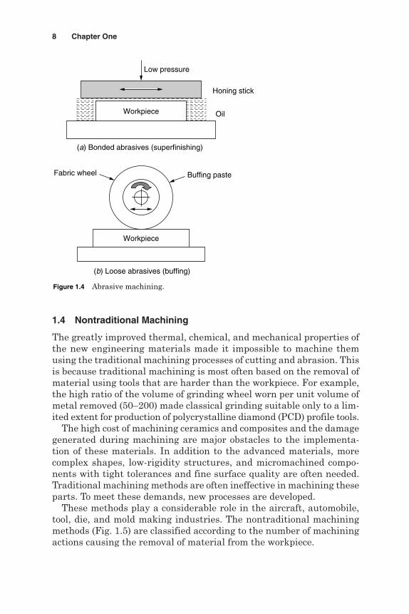
during the finishing processes. The material is removed in the form ofminute chips, which are invisible in most cases (Kaczmarek, 1976). TheMA action is adopted during grinding, honing, and superfinishingprocesses that employ either solid grinding wheels or sticks in the formof bonded abrasives (Fig. 1.4a). Furthermore, in lapping, polishing, andbuffing, loose abrasives are used as tools in a liquid machining mediaas shown in Fig. 1.4b.
Material Removal Processes 7
Figure 1.3 Metal cutting processes.
Feed
(a) Form cutting (shaping)
Depth of cut
Feed
Chip area
(b) Generation cutting (turning)
Feed
(c) Form and generation cutting (slot milling)
1.4 Nontraditional Machining
The greatly improved thermal, chemical, and mechanical properties ofthe new engineering materials made it impossible to machine themusing the traditional machining processes of cutting and abrasion. Thisis because traditional machining is most often based on the removal ofmaterial using tools that are harder than the workpiece. For example,the high ratio of the volume of grinding wheel worn per unit volume ofmetal removed (50–200) made classical grinding suitable only to a lim-ited extent for production of polycrystalline diamond (PCD) profile tools.
The high cost of machining ceramics and composites and the damagegenerated during machining are major obstacles to the implementa-tion of these materials. In addition to the advanced materials, morecomplex shapes, low-rigidity structures, and micromachined compo-nents with tight tolerances and fine surface quality are often needed.Traditional machining methods are often ineffective in machining theseparts. To meet these demands, new processes are developed.
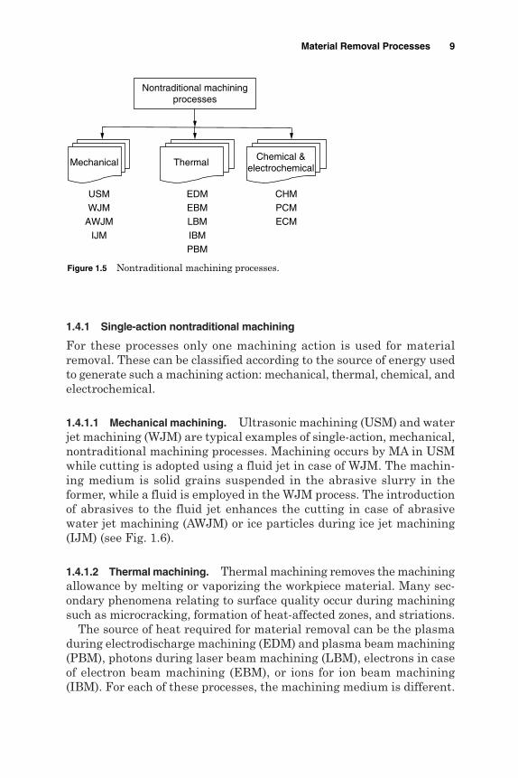
These methods play a considerable role in the aircraft, automobile,tool, die, and mold making industries. The nontraditional machiningmethods (Fig. 1.5) are classified according to the number of machiningactions causing the removal of material from the workpiece.
8 Chapter One
(a) Bonded abrasives (superfinishing)
(b) Loose abrasives (buffing)
Honing stick
Fabric wheel
Low pressure
Oil
Workpiece
Buffing paste
Workpiece
Figure 1.4 Abrasive machining.
1.4.1 Single-action nontraditional machining
For these processes only one machining action is used for materialremoval. These can be classified according to the source of energy usedto generate such a machining action: mechanical, thermal, chemical, andelectrochemical.
1.4.1.1 Mechanical machining. Ultrasonic machining (USM) and waterjet machining (WJM) are typical examples of single-action, mechanical,nontraditional machining processes. Machining occurs by MA in USMwhile cutting is adopted using a fluid jet in case of WJM. The machin-ing medium is solid grains suspended in the abrasive slurry in theformer, while a fluid is employed in the WJM process. The introductionof abrasives to the fluid jet enhances the cutting in case of abrasivewater jet machining (AWJM) or ice particles during ice jet machining(IJM) (see Fig. 1.6).
1.4.1.2 Thermal machining. Thermal machining removes the machiningallowance by melting or vaporizing the workpiece material. Many sec-ondary phenomena relating to surface quality occur during machiningsuch as microcracking, formation of heat-affected zones, and striations.
The source of heat required for material removal can be the plasmaduring electrodischarge machining (EDM) and plasma beam machining(PBM), photons during laser beam machining (LBM), electrons in caseof electron beam machining (EBM), or ions for ion beam machining(IBM). For each of these processes, the machining medium is different.
Material Removal Processes 9
Nontraditional machiningprocesses
Mechanical ThermalChemical &
electrochemical
USMWJM
AWJMIJM
EDMEBMLBMIBMPBM
CHMPCMECM
Figure 1.5 Nontraditional machining processes.

While electrodischarge occurs in a dielectric liquid for EDM, ion andlaser beams are achieved in a vacuum during IBM and LBM as shownin Fig. 1.7.
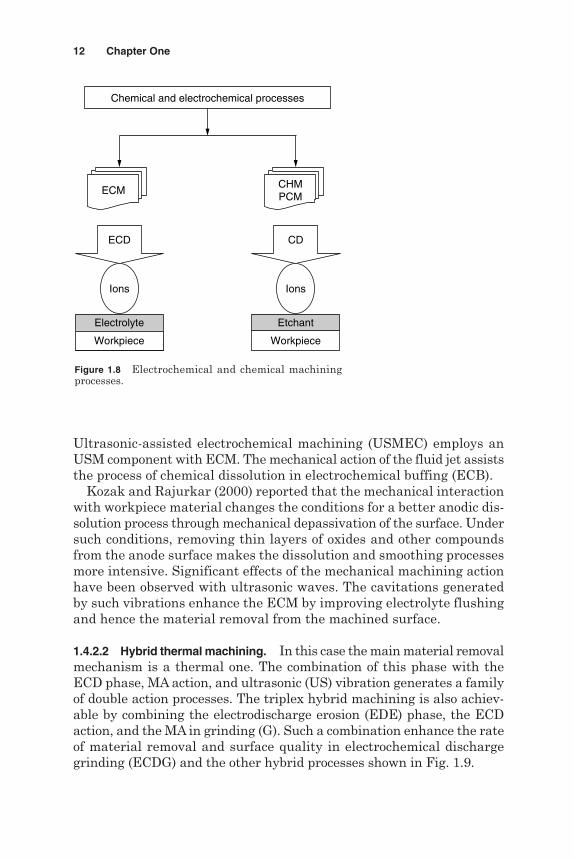
1.4.1.3 Chemical and electrochemical machining. Chemical milling(CHM) and photochemical machining (PCM), also called chemical blank-ing (PCB), use a chemical dissolution (CD) action to remove the machin-ing allowance through ions in an etchant. Electrochemical machining(ECM) uses the electrochemical dissolution (ECD) phase to remove themachining allowance using ion transfer in an electrolytic cell (Fig. 1.8).
1.4.2 Hybrid machining
Technological improvement of machining processes can be achieved bycombining different machining actions or phases to be used on the mate-rial being removed. A mechanical conventional single cutting or MAaction process can be combined with the respective machining phasesof electrodischarge (ED) in electrodischarge machining (EDM) or ECDin ECM. The reason for such a combination and the development of ahybrid machining process is mainly to make use of the combined advan-tages and to avoid or reduce some adverse effects the constituentprocesses produce when they are individually applied. The perform-ance characteristics of a hybrid process are considerably different fromthose of the single-phase processes in terms of productivity, accuracy, andsurface quality (www.unl.edu.nmrc/outline.htm).
10 Chapter One
Mechanical nontraditional processes
USM WJM
Cutting(C)
Abrasives
Abrasion(MA)
Fluid
Workpiece
Slurry
Workpiece
Jet
Figure 1.6 Mechanical machining processes.

Depending on the major machining phase involved in the materialremoval, hybrid machining can be classified into hybrid chemical andelectrochemical processes and hybrid thermal machining.
1.4.2.1 Hybrid chemical and electrochemical processes. In this family ofhybrid machining processes, the major material removal phase is eitherCD or ECD. Such a machining action can be combined with the ther-mal assistance by local heating in case of laser-assisted electro-chemical machining (ECML). In other words, the introduction of themechanical abrasion action assists the ECD machining phase duringelectrochemical grinding (ECG) and electrochemical superfinishing (ECS).
Material Removal Processes 11
Figure 1.7 Thermal nonconventional processes.
LBM
Laserbeam
Thermal nontraditional machiningprocesses
Air
Workpiece
EDM
Discharges
Dielectric
Workpiece
Electronbeam
EBM
Vacuum
Workpiece
PBM IBM
Plasmabeam
Ionbeam
Plasma Ions
Vacuum
Workpiece
Gas
Workpiece
PhotonsPlasma Electrons
Ultrasonic-assisted electrochemical machining (USMEC) employs anUSM component with ECM. The mechanical action of the fluid jet assiststhe process of chemical dissolution in electrochemical buffing (ECB).
Kozak and Rajurkar (2000) reported that the mechanical interactionwith workpiece material changes the conditions for a better anodic dis-solution process through mechanical depassivation of the surface. Undersuch conditions, removing thin layers of oxides and other compoundsfrom the anode surface makes the dissolution and smoothing processesmore intensive. Significant effects of the mechanical machining actionhave been observed with ultrasonic waves. The cavitations generatedby such vibrations enhance the ECM by improving electrolyte flushingand hence the material removal from the machined surface.
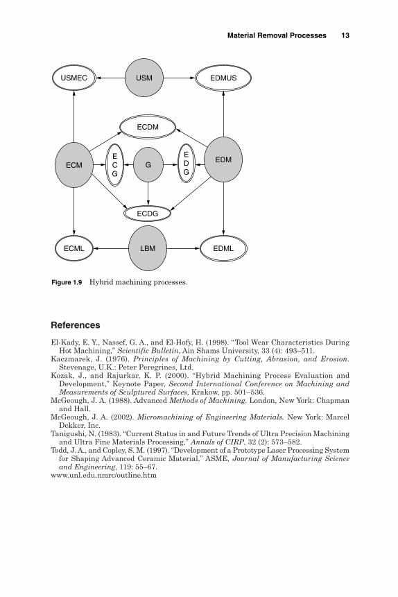
1.4.2.2 Hybrid thermal machining. In this case the main material removalmechanism is a thermal one. The combination of this phase with theECD phase, MA action, and ultrasonic (US) vibration generates a familyof double action processes. The triplex hybrid machining is also achiev-able by combining the electrodischarge erosion (EDE) phase, the ECDaction, and the MA in grinding (G). Such a combination enhance the rateof material removal and surface quality in electrochemical dischargegrinding (ECDG) and the other hybrid processes shown in Fig. 1.9.
12 Chapter One
Figure 1.8 Electrochemical and chemical machiningprocesses.
ECD
Ions
Chemical and electrochemical processes
ECM
CD
Ions
Etchant
Workpiece
CHMPCM
Electrolyte
Workpiece
References
El-Kady, E. Y., Nassef, G. A., and El-Hofy, H. (1998). “Tool Wear Characteristics DuringHot Machining,” Scientific Bulletin, Ain Shams University, 33 (4): 493–511.
Kaczmarek, J. (1976). Principles of Machining by Cutting, Abrasion, and Erosion.Stevenage, U.K.: Peter Peregrines, Ltd.
Kozak, J., and Rajurkar, K. P. (2000). “Hybrid Machining Process Evaluation andDevelopment,” Keynote Paper, Second International Conference on Machining andMeasurements of Sculptured Surfaces, Krakow, pp. 501–536.
McGeough, J. A. (1988). Advanced Methods of Machining. London, New York: Chapmanand Hall.
McGeough, J. A. (2002). Micromachining of Engineering Materials. New York: MarcelDekker, Inc.
Tanigushi, N. (1983). “Current Status in and Future Trends of Ultra Precision Machiningand Ultra Fine Materials Processing,” Annals of CIRP, 32 (2): 573–582.
Todd, J. A., and Copley, S. M. (1997). “Development of a Prototype Laser Processing Systemfor Shaping Advanced Ceramic Material,” ASME, Journal of Manufacturing Scienceand Engineering, 119: 55–67.
www.unl.edu.nmrc/outline.htm
Material Removal Processes 13
Figure 1.9 Hybrid machining processes.
USMEC USM EDMUS
ECDM
ECMEDME
CG
EDG
G
ECDG
ECML LBM EDML

This page is intentionally left blank.

Chapter
2Mechanical Processes
2.1 Ultrasonic Machining
2.1.1 Introduction
Ultrasonic machining (USM) is the removal of hard and brittle materi-als using an axially oscillating tool at ultrasonic frequencies [18–20 kilo-hertz (kHz)]. During that oscillation, the abrasive slurry of B4C or SiCis continuously fed into the machining zone between a soft tool (brassor steel) and the workpiece. The abrasive particles are, therefore, ham-mered into the workpiece surface and cause chipping of fine particlesfrom it. The oscillating tool, at amplitudes ranging from 10 to 40 µm,imposes a static pressure on the abrasive grains and feeds down as thematerial is removed to form the required tool shape (Fig. 2.1). Balamuthfirst discovered USM in 1945 during ultrasonic grinding of abrasivepowders. The industrial applications began in the 1950s when the newmachine tools appeared. USM is characterized by the absence of anydeleterious effect on the metallic structure of the workpiece material.
2.1.2 The machining system
The machining system, shown in Figs. 2.2 and 2.3, is composed mainlyfrom the magnetostrictor, concentrator, tool, and slurry feeding arrange-ment. The magnetostrictor is energized at the ultrasonic frequency andproduces small-amplitude vibrations.
Such a small vibration is amplified using the constrictor (mechanicalamplifier) that holds the tool. The abrasive slurry is pumped betweenthe oscillating tool and the brittle workpiece. A static pressure is appliedin the tool-workpiece interface that maintains the abrasive slurry.
15
Copyright © 2005 by The McGraw-Hill Companies, Inc. Click here for terms of use.

2.1.2.1 The magnetostrictor. The magnetostrictor used in USM, shown inFig. 2.4, has a high-frequency winding wound on a magnetostrictor coreand a special polarizing winding around an armature. The magne-tostriction effect was first discovered by Joule at Manchester in 1874.Accordingly, a magnetic field undergoing ultrasonic frequencies causes
16 Chapter Two
US vibration
USphase
Tool
Abrasives
Static load
Workpiece
USM
Figure 2.1 USM components.
Coolingwater
Magnetostrictiontransducer
Coolingwater
Leads totransducer
winding
Tool
Concentrator
Workpiece
Abrasive slurry
Figure 2.2 Main elements of an ultrasonic machiningsystem.

Mechanical Processes 17
Tool
Static pressure
USM
Machiningchamber
Constrictor
MagnetostrictorType
Feeding mode
Amplitude
Frequency
Workpiece holding system
Abrasive slurry
Figure 2.3 USM system components.
High-frequencywinding
Armature
Magnetostrictor
Amplitude transformerattachment
Magnetostrictorcore
Polarizingwinding
Figure 2.4 Magnetostriction transducer (Kaczmarek, 1976).

corresponding changes in a ferromagnetic object placed within its regionof influence. This effect is used to oscillate the USM tool, which is mountedat the end of a magnetostrictor, at ultrasonic frequencies (18 to 20 kHz).The method of operation of a magnetostrictor can be explained as follows.
The coefficient of magnetostriction elongation m is
m
where ∆l is the incremental length of the magnetostrictor core and l isthe original length of the magnetostrictor core, both in millimeters.Materials having high magnetostrictive elongation are recommended tobe used for a magnetostrictor. Figure 2.5 shows the relationship betweenthe magnetic field intensity H and m. Accordingly,
The elongation is independent of the sign of the magnetic field. The variation of the magnetic field intensity changes in elongation at
double the frequency (2f ). Changes in elongation are not sinusoidal (full wave rectified) as is the
case for the field intensity.
If the transducer is magnetized with a direct current, as shown inFig. 2.6, sinusoidal changes in elongation are obtained. The maximum elon-gation Amax in the magnetostrictor of length l equal to half of the wave-length l (Fig. 2.7) will occur at a distance of l/4 from the center. Hence,
λ = Cf
s
= ∆ll
18 Chapter Two
Fundamental excitedfrequency, 2f
+H−H Ot
t
Frequency f ofexcitation field
m = ∆II
Figure 2.5 Magnetostrictor excited by a variable magneticfield without magnetizing (Kaczmarek, 1976).

where Cs is the speed of sound in the magnetostrictor material [metersper second (m/s)] and f is the frequency of the changes in the magneticfield (1/s). Also,
where E is Young’s modulus [megapascals (Mpa)] and P is the densityof the magnetostrictor material [kilograms per cubic meter (kg/m3)].
λ = 1f
EP
Mechanical Processes 19
+HHo
−H O t
t
Excited frequency, f
m = ∆II
Figure 2.6 Magnetostriction due to a variable magnetic fieldafter polarization (Kaczmarek, 1976).
Figure 2.7 Variation in a wave of elongation along the length of themagnetostrictor (Kaczmarek, 1976).
−Amax
+Amax
l4
l4
l2

In order to obtain the maximum amplification and a good efficiency,the magnetostrictor must, therefore, be designed to operate at reso-nance where its natural frequency must be equal to the frequency of themagnetic field. The resonance frequency fr becomes
Since the magnetostrictor material converts the magnetic energy to amechanical one, a higher coefficient of magnetomechanical coupling,Km, is essential.
where for magnetostrictive materials, shown in Table 2.1, Ew is themechanical energy and Em is the magnetic energy.
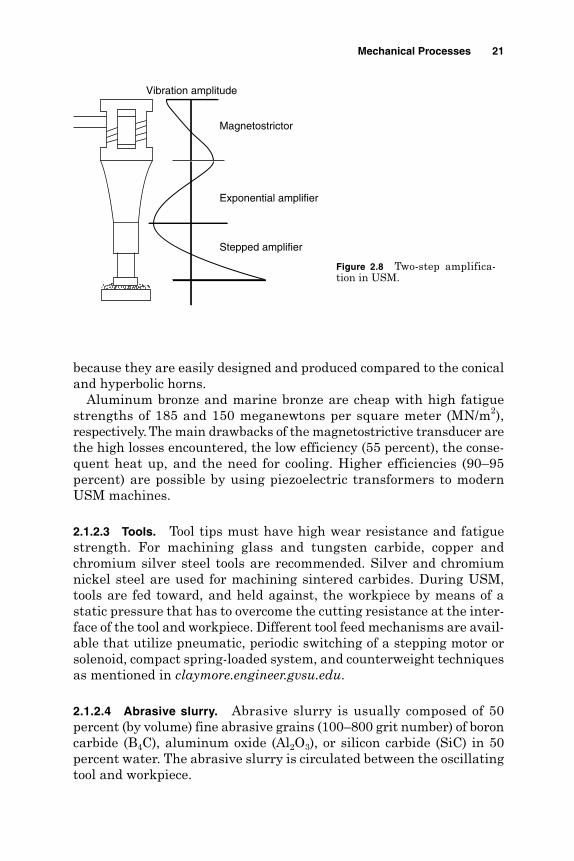
2.1.2.2 Mechanical amplifier. The elongation obtained at the resonancefrequency fr using a magnetostrictor of length l = 0.5l is usually 0.001to 0.1 µm, which is too small for practical machining applications. Thevibration amplitude is increased by fitting an amplifier (acoustic horn)into the output end of the magnetostrictor. Larger amplitudes, typi-cally 40 to 50 µm, are found to be suitable for practical applications.Depending on the final amplitude required, the amplitude amplificationcan be achieved by one or more acoustic horns (Fig. 2.8). In order to havethe maximum amplitude of vibration (resonance) the length of the con-centrator is made multiples of one-half the wavelength of sound l in theconcentrator (horn) material. The choice of the shape of the acoustic horncontrols the final amplitude. Five acoustic horns (cylindrical, stepped,exponential, hyperbolic cosine, and conical horns) have been reportedby Youssef (1976). Exponential and stepped types are frequently used
KEEm
w
m
=
fl
E
Pr = 1
2
20 Chapter Two
TABLE 2.1 Properties of Magnetostrictive Materials
Coefficient of Coefficient of magnetostrictive magnetomechanical
Material type elongation Em (× 106) coupling Km
Alfer (13% Al, 87% Fe) 40 0.28Hypernik (50% Ni, 50% Fe) 25 0.20Permalloy (40% Ni, 60% Fe) 25 0.17Permendur (49% Co, 2% V, 9 0.2049% Fe)
SOURCE: McGeough (1988).
Mechanical Processes 21
because they are easily designed and produced compared to the conicaland hyperbolic horns.
Aluminum bronze and marine bronze are cheap with high fatiguestrengths of 185 and 150 meganewtons per square meter (MN/m2),respectively.The main drawbacks of the magnetostrictive transducer arethe high losses encountered, the low efficiency (55 percent), the conse-quent heat up, and the need for cooling. Higher efficiencies (90–95percent) are possible by using piezoelectric transformers to modernUSM machines.
2.1.2.3 Tools. Tool tips must have high wear resistance and fatiguestrength. For machining glass and tungsten carbide, copper andchromium silver steel tools are recommended. Silver and chromiumnickel steel are used for machining sintered carbides. During USM,tools are fed toward, and held against, the workpiece by means of astatic pressure that has to overcome the cutting resistance at the inter-face of the tool and workpiece. Different tool feed mechanisms are avail-able that utilize pneumatic, periodic switching of a stepping motor orsolenoid, compact spring-loaded system, and counterweight techniquesas mentioned in claymore.engineer.gvsu.edu.
2.1.2.4 Abrasive slurry. Abrasive slurry is usually composed of 50percent (by volume) fine abrasive grains (100–800 grit number) of boroncarbide (B4C), aluminum oxide (Al2O3), or silicon carbide (SiC) in 50percent water. The abrasive slurry is circulated between the oscillatingtool and workpiece.
Stepped amplifier
Exponential amplifier
Vibration amplitude
Magnetostrictor
Figure 2.8 Two-step amplifica-tion in USM.
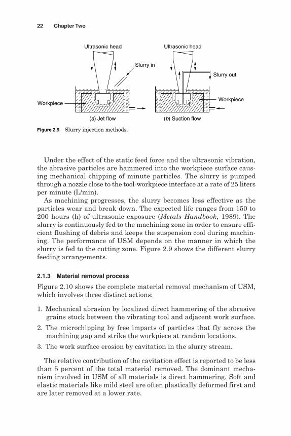
Under the effect of the static feed force and the ultrasonic vibration,the abrasive particles are hammered into the workpiece surface caus-ing mechanical chipping of minute particles. The slurry is pumpedthrough a nozzle close to the tool-workpiece interface at a rate of 25 litersper minute (L/min).
As machining progresses, the slurry becomes less effective as theparticles wear and break down. The expected life ranges from 150 to200 hours (h) of ultrasonic exposure (Metals Handbook, 1989). Theslurry is continuously fed to the machining zone in order to ensure effi-cient flushing of debris and keeps the suspension cool during machin-ing. The performance of USM depends on the manner in which theslurry is fed to the cutting zone. Figure 2.9 shows the different slurryfeeding arrangements.
2.1.3 Material removal process
Figure 2.10 shows the complete material removal mechanism of USM,which involves three distinct actions:
1. Mechanical abrasion by localized direct hammering of the abrasivegrains stuck between the vibrating tool and adjacent work surface.
2. The microchipping by free impacts of particles that fly across themachining gap and strike the workpiece at random locations.
3. The work surface erosion by cavitation in the slurry stream.
The relative contribution of the cavitation effect is reported to be lessthan 5 percent of the total material removed. The dominant mecha-nism involved in USM of all materials is direct hammering. Soft andelastic materials like mild steel are often plastically deformed first andare later removed at a lower rate.
22 Chapter Two
(a) Jet flow
Ultrasonic head
Workpiece
Ultrasonic head
Workpiece
Slurry in
Slurry out
(b) Suction flow
Figure 2.9 Slurry injection methods.

In case of hard and brittle materials such as glass, the machining rateis high and the role played by free impact can also be noticed. Whenmachining porous materials such as graphite, the mechanism of ero-sion is introduced. The rate of material removal, in USM, depends,first of all, on the frequency of tool vibration, static pressure, the sizeof the machined area, and the abrasive and workpiece material. Thematerial removal rate and hence the machinability by USM dependson the brittleness criterion which is the ratio of shearing to breakingstrength of a material. According to Table 2.2 glass has a highermachinability than that of a metal of similar hardness. Moreover,because of the low brittleness criterion of steel, which is softer, it is usedas a tool material. Figure 2.11 summarizes the important parametersthat affect the performance of USM, which are mainly related to the tool,workpiece material, abrasives, machining conditions, and the ultrasonicmachine (Jain and Jain, 2001).
In USM, the material removal rate (MRR) can generally be describedusing the following formula (www2.cerm.wvn.edu/):
MRR = 5.9F
S
HR Y
0
0.5 0.5
Mechanical Processes 23
Static feed and vibration
Side gap
Frontal gap
Frontal wear
Free impact
Cavitation erosionLocalized hammering
Bottom wearTool
Workpiece
SlurrySlurry
Figure 2.10 Material removal mechanisms in USM (Thoe et al., 1995).
TABLE 2.2 Relative Machinability Ratings for SomeMaterials by USM
Work material Relative removal rate, %
Glass 100Brass 66Tungsten 4.8Titanium 4.0Steel 3.9Chrome steel 1.4

where F = frequency of oscillationS = static stress on tool, kg/mm2
H0 = surface fracture strength, Brinell hardness number (BHN)R = mean radius of grit, mmY = amplitude of vibration, mm
2.1.4 Factors affecting material removal rate
2.1.4.1 Tool oscillation. The amplitude of the tool oscillation has thegreatest effect of all the process variables. The material removal rateincreases with a rise in the amplitude of the tool vibration. The vibra-tion amplitude determines the velocity of the abrasive particles at theinterface between the tool and workpiece. Under such circumstances thekinetic energy rises, at larger amplitudes, which enhances the mechan-ical chipping action and consequently increases the removal rate. Agreater vibration amplitude may lead to the occurrence of splashing,which causes a reduction of the number of active abrasive grains andresults in a decrease in the material removal rate.
According to Kaczmarek (1976) with regard to the range of grain sizesused in practice, the amplitude of oscillation varies within the limits of0.04 to 0.08 mm. The increase of feed force induces greater chipping
24 Chapter Two
Material removal rateSurface quality
Accuracy
Chippingrate
Workpiece• Ductility• Hardness• Compression strength• Tensile strength
Tool• Hardness• Wearability• Accuracy• Fatigue strength• Mounting
Working conditions
• Frequency• Amplitude• Pressure• Depth• Area
Abrasive slurry• Type• Size• Carrier liquid• Feeding method• Concentration
Machine
• Stiffness• Rigidity• Feed accuracy
Figure 2.11 Factors affecting USM performance.

forces by each grain, which raises the overall removal rate. Regardingthe effect of vibration frequency on the removal rate, it has been reportedby McGeough (1988) that the increase in vibration frequency reducesthe removal rate. This trend may be related to the small chipping timeallowed for each grain such that a lower chipping action prevails caus-ing a decrease in the removal rate.
2.1.4.2 Abrasive grains. Both the grain size and the vibration ampli-tude have a similar effect on the removal rate. According to McGeough(1988), the removal rate rises at greater grain sizes until the size reachesthe vibration amplitude, at which stage, the material removal ratedecreases. When the grain size is large compared to the vibration ampli-tude, there is a difficulty of abrasive renewal in the machining gap.Because of its higher hardness, B4C achieves higher removal rates thansilicon carbide (SiC) when machining a soda glass workpiece. The rateof material removal obtained with silicon carbide is about 15 percentlower when machining glass, 33 percent lower for tool steel, and about35 percent lower for sintered carbide.
Water is commonly used as the abrasive carrying liquid for the abra-sive slurry while benzene, glycerol, and oils are alternatives. The increaseof slurry viscosity reduces the removal rate. The improved flow of slurryresults in an enhanced machining rate. In practice a volumetric con-centration of about 30 to 35 percent of abrasives is recommended. Achange of concentration occurs during machining as a result of the abra-sive dust settling on the machine table. The actual concentration should,therefore, be checked at certain time intervals. The increase of abrasiveconcentration up to 40 percent enhances the machining rate. More cut-ting edges become available in the machining zone, which raises thechipping rate and consequently the overall removal rate.
2.1.4.3 Workpiece impact-hardness. The machining rate is affected bythe ratio of the tool hardness to the workpiece hardness. In this regard,the higher the ratio, the lower will be the material removal rate. For thisreason soft and tough materials are recommended for USM tools.
2.1.4.4 Tool shape. The machining rate is affected by the tool shapeand area. An increase in the tool area decreases the machining ratedue to the problem of adequately distributing the abrasive slurry overthe entire machining zone. It has been reported by McGeough (1988)that, for the same machining area, a narrow rectangular shape yieldsa higher machining rate than a square cross-sectional one. The risein the static feed pressure enhances the machining rate up to a lim-iting condition, beyond which no further increase occurs. The reasonbehind such a trend is related to the disturbance of the oscillation
Mechanical Processes 25

behavior of the tool at higher forces where lateral vibrations are expectedto occur.
According to Kaczmarek (1976), at pressures lower than the opti-mum, the force pressing the grains into the material is too small andthe volume removed by a particular grain diminishes. Beyond the opti-mum pressure, damping is too strong and the tool ceases to break awayfrom the grains, thus preventing them from changing position, whichreduces the removal rate. Measurements also showed a decrease in thematerial removal rate with an increase in the hole depth. The reasonfor this is that the deeper the tool reaches, the more difficult and sloweris the exchange of abrasives from underneath the tool.
2.1.5 Dimensional accuracy and surface quality
2.1.5.1 Dimensional accuracy. Generally the form accuracy of machinedparts suffers from the following disturbing factors, which cause oversize,conicity, and out of roundness.
Side wear of the tool Abrasive wear Inaccurate feed of the tool holder Form error of the tool Unsteady and uneven supply of abrasive slurry around the oscillating
tool
Overcut. The process accuracy is measured through the overcut (over-size) produced during drilling of holes. The hole oversize measures thedifference between the hole diameter, measured at the top surface, andthe tool diameter. The side gap between the tool and the machined holeis necessary to enable the abrasives to flow to the machining zone underthe oscillating tool. Hence the grain size of the abrasives represents themain factor, which affects the overcut produced. The overcut is consid-ered to be about two to four times greater than the mean grain size whenmachining glass and tungsten carbide. It is about three times greaterthan the mean grain size of B4C (mesh numbers 280–600). However, themagnitude of the overcut depends on many other process variablesincluding the type of workpiece material and the method of tool feed. Ingeneral USM accuracy levels are limited to ±0.05 mm.
Conicity. The overcut is usually greater at the entry side than at theexit one due to the cumulative abrasion effect of the fresh and sharp grainparticles. As a result of such an effect, a hole conicity of approximately
26 Chapter Two

0.2° arises when drilling a 20-mm-diameter hole to a depth of 10 mm ingraphite. The conicity can be reduced by
Direct injection of the abrasive slurry into the machining zone The use of tools having negatively tapering walls The use of high static pressure that produces finer abrasives, which
in turn reduces the amount of tool wear and the resulting conicity The use of wear-resistant tool materials The use of an undersized tool in the first cut and a final tool of the
required size, which will cut faster and reduce the conicity
Out of roundness. The out of roundness arises by the lateral vibra-tions of the tool. Such vibrations may arise due to the out of perpen-dicularity of the tool face and the tool centerline and when the acousticparts of the machine are misaligned. Typical roundness errors areabout 40 to 140 µm and 20 to 60 µm, respectively, for glass and graphitematerials.
2.1.5.2 Surface quality. The surface finish is closely related to themachining rate in USM. Table 2.3 shows the relationship between gritnumber and grit size. The larger the grit size, the faster the cutting butthe coarser the surface finish. A surface finish of 0.38 to 0.25 µm can beexpected using abrasives of grit number 240. However, other factorssuch as tool surface, amplitude of tool vibration, and material beingmachined also affect the surface finish. The larger the grit (smaller thegrain size), the smoother becomes the produced surface. As mentionedearlier, the larger chipping marks formed on brittle machined materi-als create rougher surfaces than that obtained in the case of machinedhard alloy steel. The amplitude of tool oscillation has a smaller effecton the surface finish. As the amplitude is raised the individual grainsare pressed further into the workpiece surface thus causing deeper
Mechanical Processes 27
TABLE 2.3 Grit Number, Grit Size, and SurfaceRoughness for USM
Grit number Grit size, mm Roughness, µm
180 0.086 0.55240 0.050 0.51320 0.040 0.45400 0.030 0.40600 0.014 0.28800 0.009 0.21

craters and hence a rougher surface finish. Other process variables suchas static pressure have a little effect on the surface finish.
Smoother surfaces can also be obtained when the viscosity of theliquid carrier of the abrasive slurry is reduced. It is evident that the sur-face irregularities of the sidewall surfaces of the cavities are consider-ably larger than those of the bottom. This results from the sidewallsbeing scratched by grains entering and leaving the machining zone.Cavitation damage to the machined surface occurs when the tool par-ticles penetrate deeper into the workpiece. Under such circumstancesit is more difficult to replenish adequately the slurry in these deeperregions and thus a rougher surface is produced.
2.1.6 Applications
USM should be applied for shallow cavities cut in hard and brittle mate-rials having a surface area less than 1000 mm2.
2.1.6.1 Drilling and coring. Amodified version of USM is shown in Fig. 2.12where a tool bit is rotated against the workpiece in a similar fashion toconventional drilling. The process is, therefore, called rotary ultrasonicmachining (RUM). Cruz et al. (1995) used the process for machiningnonmetallic materials such as glass, alumina, ceramic, ferrite, quartz,zirconium oxide, ruby, sapphire, beryllium oxide, and some compositematerials. RUM ensures high removal rates, lower tool pressures for del-icate parts, improved deep hole drilling, less breakout or through holes,and no core seizing during core drilling.
The process allows the uninterrupted drilling of small-diameter holes,while conventional drilling necessitates a tool retraction, which increasesthe machining time. The penetration rate depends on the size and depth
28 Chapter Two
Slurry
Finishedworkpiece
Coring Drilling
Cutoff
Slurry
1000 rpm
Ultrasonicvibration
Figure 2.12 Rotary USM.

of the cavity. Small holes require more time as the rate of machiningdecreases with the depth of penetration due to the difficulty in main-taining a continuous supply of new slurry at the tool face. Generally adepth-to-diameter ratio of 2.5 is achievable by RUM.
2.1.6.2 Ultrasonic sinking and contour machining. During USM sink-ing, the material removal is difficult when the machined depth exceeds5 to 7 mm or when the active section of the tool becomes important.Under such conditions the removal of the abrasive grits at the interfacebecomes difficult and hence the material removal process is impossible.Moreover the manufacture of such a tool is generally complex and costly.Contouring USM (Fig. 2.13) employs simple tools that are moved inaccordance to the contour required (Benkirane et al., 1995). Figure 2.14shows a three-dimensional shape machined by USM sinking wherethe shaped tool is used to produce a negative replica in the workpiece.
Mechanical Processes 29
Ultrasonic sinking
Tool
Workpiece
SlurryCavity
X
Numerical controltool feed
Workpiece
Tool pathSlurry
Z
Y
Contour machining
US vibration + static feed
Figure 2.13 Ultrasonic sinking and contour machining.
Figure 2.14 (a) Silicon nitride turbine blades (sinking), and(b) CFC acceleration lever and holes (contour USM) (Benkiraneet al., 1995).

The same figure also shows holes and contours machined using a USMcontour machining.
2.1.6.3 Production of EDM electrodes. Gilmore (1995) used USM to pro-duce graphite EDM electrodes as shown in Fig. 2.15. Typical ultrasonicmachining speeds, in graphite, range from 0.4 to 1.4 centimeters perminute (cm/min). The surface roughness ranges from 0.2 to 1.5 µm andaccuracies of ±10 µm are typical. Small machining forces permit themanufacture of fragile graphite EDM electrodes.
30 Chapter Two
Before
After
Figure 2.16 Ultrasonic polishingof CNC machined parts (Gilmore,1995).
Figure 2.15 Graphite EDM electrodes machined by USM(Gilmore, 1995).

2.1.6.4 Ultrasonic polishing. Ultrasonic polishing occurs by vibrating abrittle tool material such as graphite or glass into the workpiece at anultrasonic frequency and a relatively low vibration amplitude. The fineabrasive particles, in the slurry, abrade the high spots of the workpiecesurface, typically removing 0.012 mm of material or less. Using such atechnique Gilmore (1995) reported the surface finish to be as low as0.3 µm. Figure 2.16 shows the ultrasonic polishing that lasted 1.5 to2 min to remove the machining marks left by a computer numerical con-trol (CNC) engraving operation.
2.1.6.5 Micro-ultrasonic machining. Micro-ultrasonic machining (MUSM)is a method that utilizes workpiece vibration. According to Egashira andMasuzana (1999) vibrating the workpiece allows for freer tool systemdesign because it does not include the set of transducer, horn, and cone.In addition, the complete system is much more simple and compactthan conventional USM (Fig. 2.17). Using such a method microholes of5-µm diameter on quartz, glass, and silicon have been produced usingtungsten carbide (WC) alloy microtools.
Mechanical Processes 31
US vibration
Z
Tool rotation
Microtool
Slurry
Workpiece
Transducer
X
Numerical controltool feed
Y
Figure 2.17 Micro-ultrasonic machining.

However the high wear resistance of sintered diamond (SD) tools madeit possible to machine multiple holes using a single tool. Similarly MUSMis used for machining three-dimensional shapes as shown in Fig. 2.18.
2.1.6.6 Other applications
Cutting off parts made from semiconductors at high removal ratescompared to conventional machining methods
Engraving on glass as well as hardened steel and sintered carbide Parting and machining of precious stones including diamond
2.2 Water Jet Machining
2.2.1 Introduction
The key element in water jet machining (WJM) is a water jet, whichtravels at velocities as high as 900 m/s (approximately Mach 3). Whenthe stream strikes a workpiece surface, the erosive force of waterremoves the material rapidly. The water, in this case, acts like a saw andcuts a narrow groove in the workpiece material.
2.2.2 The machining system
Figure 2.19 shows the WJM system and the main parts of which it iscomposed.
2.2.2.1 Hydraulic pump. The hydraulic pump is powered from a 30-kilowatt (kW) electric motor and supplies oil at pressures as high as 117bars in order to drive a reciprocating plunger pump termed an intensi-fier. The hydraulic pump offers complete flexibility for water jet cuttingand cleaning applications. It also supports single or multiple cutting sta-tions for increased machining productivity.
32 Chapter Two
Figure 2.18 Micro-ultrasonic machined cavity (Masuzawaand Tonshof, 1997).
500 µm
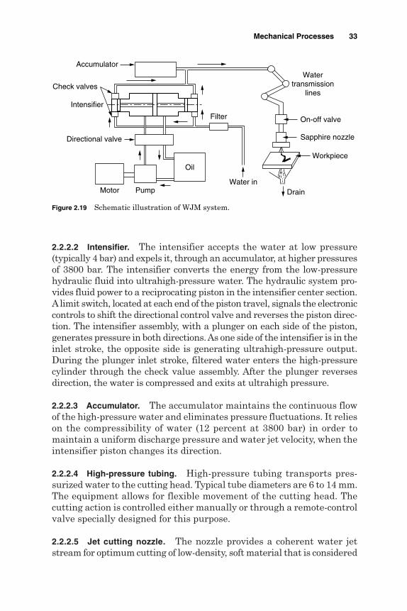
2.2.2.2 Intensifier. The intensifier accepts the water at low pressure(typically 4 bar) and expels it, through an accumulator, at higher pressuresof 3800 bar. The intensifier converts the energy from the low-pressurehydraulic fluid into ultrahigh-pressure water. The hydraulic system pro-vides fluid power to a reciprocating piston in the intensifier center section.Alimit switch, located at each end of the piston travel, signals the electroniccontrols to shift the directional control valve and reverses the piston direc-tion. The intensifier assembly, with a plunger on each side of the piston,generates pressure in both directions. As one side of the intensifier is in theinlet stroke, the opposite side is generating ultrahigh-pressure output.During the plunger inlet stroke, filtered water enters the high-pressurecylinder through the check value assembly. After the plunger reversesdirection, the water is compressed and exits at ultrahigh pressure.
2.2.2.3 Accumulator. The accumulator maintains the continuous flowof the high-pressure water and eliminates pressure fluctuations. It relieson the compressibility of water (12 percent at 3800 bar) in order tomaintain a uniform discharge pressure and water jet velocity, when theintensifier piston changes its direction.
2.2.2.4 High-pressure tubing. High-pressure tubing transports pres-surized water to the cutting head. Typical tube diameters are 6 to 14 mm.The equipment allows for flexible movement of the cutting head. Thecutting action is controlled either manually or through a remote-controlvalve specially designed for this purpose.
2.2.2.5 Jet cutting nozzle. The nozzle provides a coherent water jetstream for optimum cutting of low-density, soft material that is considered
Mechanical Processes 33
Accumulator
On-off valve
Intensifier
Sapphire nozzle
Workpiece
DrainPump
Directional valve
Check valves
Watertransmission
lines
Water inMotor
Filter
Oil
Figure 2.19 Schematic illustration of WJM system.

unmachinable by conventional methods. Nozzles are normally madefrom synthetic sapphire. About 200 h of operation are expected from anozzle, which becomes damaged by particles of dirt and the accumula-tion of mineral deposits on the orifice due to erosive water hardness. Alonger nozzle life can be obtained through multistage filtration, whichremoves undesired solids of size greater than 0.45 µm. The compactdesign of the water jet cutting head promotes integration with motioncontrol systems ranging from two-axis (XY ) tables to sophisticated multi-axis robotic installations.
2.2.2.6 Catcher. The catcher acts as a reservoir for collecting themachining debris entrained in the water jet. Moreover, it reduces thenoise levels [105 decibels (dB)] associated with the reduction in thevelocity of the water jet from Mach 3 to subsonic levels.
2.2.3 Process parameters
Jet nozzle. The standoff distance, shown in Fig. 2.20, is the gap betweenthe jet nozzle (0.1–0.3 mm diameter) and the workpiece (2.5–6 mm).However for materials used in printed circuit boards, it may be increasedto 13 to 19 mm. For a nozzle of 0.12-mm diameter and cutting rate of1.1 millimeters per second (mm/s), McGeough (1988) reported the decreaseof the depth of cut at a larger standoff distance. When cutting fiber-reinforcedplastics, reports showed that the increase in machining rate and use of thesmall nozzle diameter increased the width of the damaged layer.
Jet fluid. Typical pressures reported by McGeough (1988) are 150 to 1000MPa, which provide 8 to 80 kW of power. For a given nozzle diameter, the
34 Chapter Two
Water
Sapphirenozzle
Jet velocity
Jet diameter
Workpiece
Standoff distance
Nozzle feed
Figure 2.20 WJMterminology.

increase in pressure allows more power to be used in the machiningprocess, which in turn increases the depth of the cut. Jet velocitiesrange between 540 to 1400 m/s. The quality of cutting improves athigher pressures by widening the diameter of the jet and by loweringthe traverse speed. Under such conditions, materials of greater thick-nesses and densities can be cut. Moreover, the larger the pump pressure,the greater will be the depth of the cut. The fluid used must possess lowviscosity to minimize the energy losses and be noncorrosive, nontoxic,common, and inexpensive. Water is commonly used for cutting alloysteels. Alcohol is used for cutting meat, while cooking oils are recom-mended for cutting frozen foods. Figure 2.21 summarizes differentparameters affecting the performance of WJM.
Target material. Brittle materials will fracture, while ductile ones willcut well. Material thicknesses range from 0.8 to 25 mm or more. Table 2.4shows the cutting rates for different material thicknesses.
2.2.4 Applications
WJM is used on metals, paper, cloth, leather, rubber, plastics, food, andceramics. It is a versatile and cost-effective cutting process that can beused as an alternative to traditional machining methods. It completelyeliminates heat-affected zones, toxic fumes, recast layers, work hard-ening, and thermal stresses. It is the most flexible and effective cleaning
Mechanical Processes 35
Figure 2.21 Factors affecting WJM performance.
Material removal rateSurface quality
Accuracy
Jet cuttingrate
Jet fluid
• Type• Velocity• Flow rate• Pressure• Viscosity
Jet nozzle
• Diameter• Standoff distance
• Type• Thickness• Feed rate
Workpiece

solution available for a variety of industrial needs. In general the cutsurface has a sandblast appearance. Moreover, harder materials exhibita better edge finish. Typical surface finishes ranges from 1.6 µm rootmean square (RMS) to very coarse depending on the application.Tolerances are in the range of ±25 µm on thin material. Both the pro-duced surface roughness and tolerance depend on the machining speed.
2.2.4.1 Cutting. WJM is limited to fiberglass and corrugated wood.Figure 2.22 shows a typical example of water jet cutting of marble,while Fig. 2.23 shows a typical application in the food industry.
2.2.4.2 Drilling. The process drills precision-angled and -shaped holesin a variety of materials for which other processes such as EDM or EBMare too expensive or too slow.
2.2.4.3 Machining of fiber-reinforced plastics. In this case the thermalmaterial damage is negligible. The tool, being effectively pointed, accu-rately cuts contours. The main drawback is the deflection of the water
36 Chapter Two
Figure 2.22 Water jet cutting example (www.jetcutinc.com/).
TABLE 2.4 Typical Water Jet Cutting Rates forVarious Materials
Material Thickness, mm Feed rate, m/min
Leather 2.2 20Vinyl chloride 3.0 0.5Polyester 2.0 150Kevlar 3.0 3Graphite 2.3 5Gypsum board 10 6Corrugated board 7 200Pulp sheet 2 120Plywood 6 1
SOURCE: Tlusty (1999).

jet by the fiber embedded in the matrix, which protrudes after machining.The feed rate attainable depends on the surface quality required. Table 2.5shows the limiting feed rates for water jet cutting of fiber-reinforcedplastics.
2.2.4.4 Cutting of rocks. Water jet cutting of a 51-mm-deep slot in gran-ite using two oscillating jets at 275 MPa during 14 passes at a 25.4-mm/sfeed rate has been reported by McGeough (1988). Moreover an oscillat-ing nozzle system operating at the same feed rate and pressure of 172MPa, with the standoff distance adjusted every pass was used to cut a178-mm-deep slot in sandstone.
2.2.4.5 Deburring. The method uses large pressures to remove largeburrs (3 mm height) in 12-mm-diameter drilled holes in a hollowmolybdenum-chromium steel shaft at 15 s using 700-bar pressure anda flow rate of 27 L/min. In this method burrs are broken off by the
Mechanical Processes 37
Figure 2.23 Water jet cutting of tomatoes (www.jetedge.com/).
TABLE 2.5 Limiting Feed Rates for WJC of Fiber-Reinforced Plasticswith 3500-bar Pressure, 0.1-mm Nozzle, and 2-mm Distance
Material Thickness, mm Feed rate, m/min
Glass fiber-reinforced 2.2 1.8–6.0polymers (GFRP) (laminate) 3.0 1.4–5.0
5.0 0.7–6.0
Aramid fiber-reinforced 1.0 10.0polymers (AFRP) (weave) 2.0 2.4–4.0
SOURCE: McGeough (1988).

impact of water. A higher pressure (4000 bar) and a lower flow rate (2.5L/min) are used to remove burrs from nonmetallic materials.
2.2.4.6 Cutting of printed circuit boards. Using a small-diameter water jetmounted near to the part edge, a printed circuit board (PCB) can be cut ata speed that exceeds 8 m/min, to the accuracy of ±0.13 mm. Boards of var-ious shapes for use in portable radios and cassette players can be cut usingcomputer numerical control (CNC) technology.
2.2.4.7 Surface treatment. The process finds many applications including:
Removing deposits and residues without toxic chemicals, which elim-inates costly cleanup and disposal problems
Surface cleaning of pipes and castings, decorative finishing, nucleardecontamination, food utensil cleaning, degreasing, polishing, prepa-ration for precise inspection, and surface texturing
Economical surface preparation and coating removal Removing corrosion, spray residue, soluble salts, chemicals, and sur-
face damage prior to recoating or painting
2.2.4.8 Wire stripping. The process can remove the wire insulatingmaterial without damaging the metal or removing the tinning on thecopper wire. The processing time can be decreased to about 20 percentof the manual stripping method (Metals Handbook, 1989).
2.2.5 Advantages and disadvantagesof WJM
Advantages
It has multidirectional cutting capacity. No heat is produced. Cuts can be started at any location without the need for predrilled holes. Wetting of the workpiece material is minimal. There is no deflection to the rest of the workpiece. The burr produced is minimal. The tool does not wear and, therefore, does not need sharpening. The process is environmentally safe. Hazardous airborne dust contamination and waste disposal problems
that are common when using other cleaning methods are eliminated.
38 Chapter Two

There is multiple head processing. Simple fixturing eliminates costly and complicated tooling, which
reduces turnaround time and lowers the cost. Grinding and polishing are eliminated, reducing secondary operation
costs. The narrow kerf allows tight nesting when multiple parts are cut from
a single blank. It is ideal for roughing out material for near net shape. It is ideal for laser reflective materials such as copper and aluminum. It allows for more accurate cutting of soft material. It cuts through very thick material such as 383 mm in titanium and
307 mm in Inconel.
Disadvantages
Hourly rates are relatively high. It is not suitable for mass production because of high maintenance
requirements.
2.3 Abrasive Jet Machining
2.3.1 Introduction
In abrasive jet machining (AJM) a focused stream of abrasive grains ofAl2O3 or SiC carried by high-pressure gas or air at a high velocity is madeto impinge on the work surface through a nozzle of 0.3- to 0.5-mm diam-eter. The process differs from sandblasting (SB) in that AJM has smaller-diameter abrasives and a more finely controlled delivery system. Theworkpiece material is removed by the mechanical abrasion (MA) actionof the high-velocity abrasive particles. AJM machining is best suited formachining holes in superhard materials. It is typically used to cut,clean, peen, deburr, deflash, and etch glass, ceramics, or hard metals.
2.3.2 Machining system
In the machining system shown in Fig. 2.24, a gas (nitrogen, CO2, or air)is supplied under a pressure of 2 to 8 kg/cm2. Oxygen should never be usedbecause it causes a violent chemical reaction with workpiece chips orabrasives. After filtration and regulation, the gas is passed through amixing chamber that contains abrasive particles and vibrates at 50 Hz.From the mixing chamber, the gas, along with the entrained abrasive par-ticles (10–40 µm), passes through a 0.45-mm-diameter tungsten carbide
Mechanical Processes 39
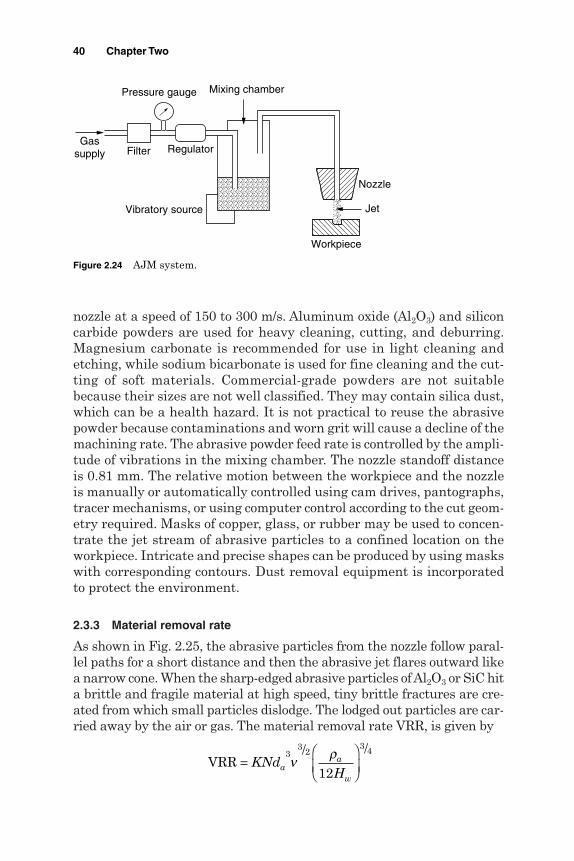
nozzle at a speed of 150 to 300 m/s. Aluminum oxide (Al2O3) and siliconcarbide powders are used for heavy cleaning, cutting, and deburring.Magnesium carbonate is recommended for use in light cleaning andetching, while sodium bicarbonate is used for fine cleaning and the cut-ting of soft materials. Commercial-grade powders are not suitablebecause their sizes are not well classified. They may contain silica dust,which can be a health hazard. It is not practical to reuse the abrasivepowder because contaminations and worn grit will cause a decline of themachining rate. The abrasive powder feed rate is controlled by the ampli-tude of vibrations in the mixing chamber. The nozzle standoff distanceis 0.81 mm. The relative motion between the workpiece and the nozzleis manually or automatically controlled using cam drives, pantographs,tracer mechanisms, or using computer control according to the cut geom-etry required. Masks of copper, glass, or rubber may be used to concen-trate the jet stream of abrasive particles to a confined location on theworkpiece. Intricate and precise shapes can be produced by using maskswith corresponding contours. Dust removal equipment is incorporatedto protect the environment.
2.3.3 Material removal rate
As shown in Fig. 2.25, the abrasive particles from the nozzle follow paral-lel paths for a short distance and then the abrasive jet flares outward likea narrow cone. When the sharp-edged abrasive particles of Al2O3 or SiC hita brittle and fragile material at high speed, tiny brittle fractures are cre-ated from which small particles dislodge. The lodged out particles are car-ried away by the air or gas. The material removal rate VRR, is given by
VRR =
KNd
Haa
w
33 2
3 4
12ν ρ
40 Chapter Two
Nozzle
Workpiece
Jet
Gassupply Filter
Pressure gauge
Regulator
Vibratory source
Mixing chamber
Figure 2.24 AJM system.

where K = constantN = number of abrasive particles impacting/unit areada = mean diameter of abrasive particles, µmra = density of abrasive particles, kg/mm3
Hw = hardness number of the work materialn = speed of abrasive particles, m/s
The material removal rate, cut accuracy, surface roughness, and nozzlewear are influenced by the size and distance of the nozzle; composition,strength, size, and shape of abrasives; flow rate; and composition, pres-sure, and velocity of the carrier gas. The material removal rate is mainlydependent on the flow rate and size of abrasives. Larger grain sizesproduce greater removal rates. At a particular pressure, the volumet-ric removal rate increases with the abrasive flow rate up to an optimumvalue and then decreases with any further increase in flow rate. Thisis due to the fact that the mass flow rate of the gas decreases with anincrease in the abrasive flow rate and hence the mixing ratio increasescausing a decrease in the removal rate because of the decreasing energyavailable for material removal.
The typical material removal rate is 16.4 mm3/min when cutting glass.Cutting rates for metals vary from 1.6 to 4.1 mm3/min. For harder ceram-ics, cutting rates are about 50 percent higher than those for glass. Theminimum width of cut can be 0.13 mm. Tolerances are typically ±0.13 mmwith ±0.05 mm possible using good fixation and motion control. The pro-duced surface has a random or matte texture. Surface roughnesses of 0.2to 1.5 µm using 10 and 50 µm particles, respectively, can be attained.Taper is present in deep cuts. High nozzle pressures result in a greaterremoval rate, but the nozzle life is decreased. Table 2.6 summarizes theoverall process characteristics.
Mechanical Processes 41
Air and abrasivesstream
Sapphire nozzle
Jet velocity (150−300 m/s)
Jet diameter (0.3−0.5 mm)
Workpiece
Standoff distance (0.8 mm)
Figure 2.25 AJM terminology.

2.3.4 Applications
1. Drilling holes, cutting slots, cleaning hard surfaces, deburring, pol-ishing, and radiusing
2. Deburring of cross holes, slots, and threads in small precision partsthat require a burr-free finish, such as hydraulic valves, aircraft fuelsystems, and medical appliances
3. Machining intricate shapes or holes in sensitive, brittle, thin, ordifficult-to-machine materials
4. Insulation stripping and wire cleaning without affecting the conductor
5. Micro-deburring of hypodermic needles
6. Frosting glass and trimming of circuit boards, hybrid circuit resistors,capacitors, silicon, and gallium
7. Removal of films and delicate cleaning of irregular surfaces becausethe abrasive stream is able to follow contours
2.3.5 Advantages and limitations of AJM
Advantages
Because AJM is a cool machining process, it is best suited for machin-ing brittle and heat-sensitive materials like glass, quartz, sapphire,and ceramics.
42 Chapter Two
TABLE 2.6 AJM Process Characteristics
AbrasivesType Al2O3 or SiC (used once)Size Around 25 µmFlow rate 3–20 g/min
MediumType Air or CO2
Velocity 150–300 m/sPressure 2–8 kg/cm2
Flow rate 28 L/minNozzle
Material Tungsten carbide or sapphireShape Circular, 0.3–0.5 mm diameter
Rectangular (0.08 × 0.51 mm to 6.61 × 0.51 mm)Tip distance 0.25–15 mmLife WC (12–30 h), sapphire (300 h)Operating angle Vertical to 60° off verticalArea 0.05–0.2 mm2
Tolerance ±0.05 mmSurface roughness 0.15–0.2 µm (10-µm particles)
0.4–0.8 µm (25-µm particles)1.0–1.5 µm (20-µm particles)

The process is used for machining superalloys and refractory materials. It is not reactive with any workpiece material. No tool changes are required. Intricate parts of sharp corners can be machined. The machined materials do not experience hardening. No initial hole is required for starting the operation as required by
wire EDM. Material utilization is high. It can machine thin materials.
Limitations
The removal rate is slow. Stray cutting can’t be avoided (low accuracy of ±0.1 mm). The tapering effect may occur especially when drilling in metals. The abrasive may get impeded in the work surface. Suitable dust-collecting systems should be provided. Soft materials can’t be machined by the process. Silica dust may be a health hazard. Ordinary shop air should be filtered to remove moisture and oil.
2.4 Abrasive Water Jet Machining
2.4.1 Introduction
WJM is suitable for cutting plastics, foods, rubber insulation, automo-tive carpeting and headliners, and most textiles. Harder materials suchas glass, ceramics, concrete, and tough composites can be cut by addingabrasives to the water jet during abrasive water jet machining (AWJM),which was first developed in 1974 to clean metal prior to surface treat-ment of the metal. The addition of abrasives to the water jet enhancedthe material removal rate and produced cutting speeds between 51 and460 mm/min. Generally, AWJM cuts 10 times faster than the conven-tional machining methods of composite materials. Zheng et al. (2002)claimed that the abrasive water jet is hundreds, if not thousands, oftimes more powerful than the pure water jet.
AWJM uses a low pressure of 4.2 bar to accelerate a large volume ofa water (70 percent) and abrasive (30 percent) mixture up to a velocityof 30 m/s. Silicon carbides, corundum, and glass beads of grain size
Mechanical Processes 43

10 to 150 µm are often used as abrasive materials (Fig. 2.26). Using sucha method, burrs of 0.35 mm height and 0.02 mm width left in steel com-ponent after grinding are removed by the erosive effect of the abrasiveswhile water acts as an abrasive carrier that dampens its impact effecton the surface. The introduction of compressed air to the water jetenhances the deburring action.
2.4.2 The machining system
In AWJM, the water jet stream accelerates abrasive particles, not thewater, to cause the material removal. After the pure water jet is created,abrasives are added using either the injection or suspension methodsshown in Fig. 2.27. The important parameters of the abrasives are thematerial structure and hardness, the mechanical behavior, grain shape,grain size, and distribution.
The basic machining system of AWJM incorporates the followingelements.
Water delivery Abrasive hopper and feeder Intensifier Filters Mixing chamber Cutting nozzles Catcher
44 Chapter Two
Control valve and variable mixer
Nozzle
Water70%
Abrasives30%
Workpiece
Jet
Figure 2.26 AWJM elements.

2.4.3 Process capabilities
Typical process variables include pressure, nozzle diameter, standoffdistance, abrasive type, grit number, and workpiece feed rate. Anabrasive water jet cuts through 356.6-mm-thick slabs of concrete or76.6-mm-thick tool steel plates at 38 mm/min in a single pass. Theproduced surface roughness ranges between 3.8 and 6.4 µm, while tol-erances of ±0.13 mm are obtainable. Repeatability of ±0.04 mm,squareness of 0.043 mm/m, and straightness of 0.05 mm per axis areexpected. Foundry sands are frequently used for cutting of gates andrisers. However, garnet, which is the most common abrasive material,is 30 percent more effective than sand.
During machining of glass a cutting rate of 16.4 mm3/min is achieved,which is 4 to 6 times that for metals. Surface roughness depends on theworkpiece material, grit size, and type of abrasives. A material with ahigh removal rate produces large surface roughness. For this reason,fine grains are used for machining soft metals to obtain the same rough-ness as hard ones. The decrease of surface roughness, at a smallergrain size, is related to the reduced depth of cut and the undeformedchip cross section. In addition the larger the number of grains per unitslurry volume, the more that fall on a unit surface area.
A carrier liquid consisting of water with anticorrosive additives hasa much greater density than air. This contributes to higher accelera-tion of the grains with a consequent higher grain speed and increasedmetal removal rate. Moreover, the carrier liquid spreads over the surface
Mechanical Processes 45
Side feed
Pressure generation
Abrasive reservoir
Water nozzle
Focusing tube
Machining head
Water
Workpiece
Water
Abrasive storage
SlurrySuspension
Suspension nozzle
Central feed
Figure 2.27 Injection and suspension jets.
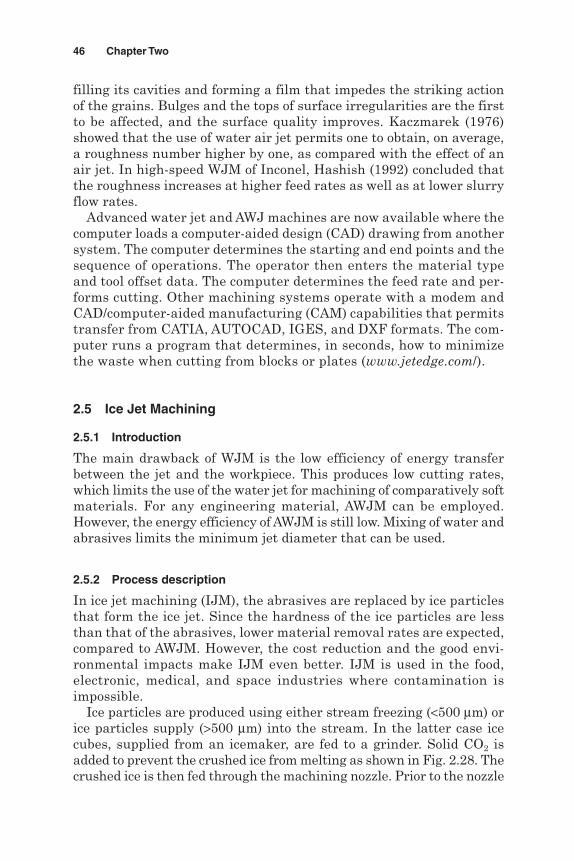
filling its cavities and forming a film that impedes the striking actionof the grains. Bulges and the tops of surface irregularities are the firstto be affected, and the surface quality improves. Kaczmarek (1976)showed that the use of water air jet permits one to obtain, on average,a roughness number higher by one, as compared with the effect of anair jet. In high-speed WJM of Inconel, Hashish (1992) concluded thatthe roughness increases at higher feed rates as well as at lower slurryflow rates.
Advanced water jet and AWJ machines are now available where thecomputer loads a computer-aided design (CAD) drawing from anothersystem. The computer determines the starting and end points and thesequence of operations. The operator then enters the material typeand tool offset data. The computer determines the feed rate and per-forms cutting. Other machining systems operate with a modem andCAD/computer-aided manufacturing (CAM) capabilities that permitstransfer from CATIA, AUTOCAD, IGES, and DXF formats. The com-puter runs a program that determines, in seconds, how to minimizethe waste when cutting from blocks or plates (www.jetedge.com/).
2.5 Ice Jet Machining
2.5.1 Introduction
The main drawback of WJM is the low efficiency of energy transferbetween the jet and the workpiece. This produces low cutting rates,which limits the use of the water jet for machining of comparatively softmaterials. For any engineering material, AWJM can be employed.However, the energy efficiency of AWJM is still low. Mixing of water andabrasives limits the minimum jet diameter that can be used.
2.5.2 Process description
In ice jet machining (IJM), the abrasives are replaced by ice particlesthat form the ice jet. Since the hardness of the ice particles are lessthan that of the abrasives, lower material removal rates are expected,compared to AWJM. However, the cost reduction and the good envi-ronmental impacts make IJM even better. IJM is used in the food,electronic, medical, and space industries where contamination isimpossible.
Ice particles are produced using either stream freezing (<500 µm) orice particles supply (>500 µm) into the stream. In the latter case icecubes, supplied from an icemaker, are fed to a grinder. Solid CO2 isadded to prevent the crushed ice from melting as shown in Fig. 2.28. Thecrushed ice is then fed through the machining nozzle. Prior to the nozzle
46 Chapter Two
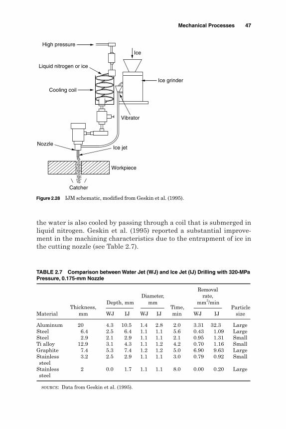
the water is also cooled by passing through a coil that is submerged inliquid nitrogen. Geskin et al. (1995) reported a substantial improve-ment in the machining characteristics due to the entrapment of ice inthe cutting nozzle (see Table 2.7).
Mechanical Processes 47
Ice grinder
Vibrator
Cooling coil
Liquid nitrogen or ice
Nozzle
Workpiece
Ice jet
High pressure
Catcher
Ice
Figure 2.28 IJM schematic, modified from Geskin et al. (1995).
TABLE 2.7 Comparison between Water Jet (WJ) and Ice Jet (IJ) Drilling with 320-MPaPressure, 0.175-mm Nozzle
RemovalDiameter, rate,
Depth, mm mm mm3/min
Material mm WJ IJ WJ IJ min WJ IJ size
Aluminum 20 4.3 10.5 1.4 2.8 2.0 3.31 32.3 LargeSteel 6.4 2.5 6.4 1.1 1.1 5.6 0.43 1.09 LargeSteel 2.9 2.1 2.9 1.1 1.1 2.1 0.95 1.31 SmallTi alloy 12.9 3.1 4.3 1.1 1.2 4.2 0.70 1.16 SmallGraphite 7.4 5.3 7.4 1.2 1.2 5.0 6.90 9.63 LargeStainless 3.2 2.5 2.9 1.1 1.1 3.0 0.79 0.92 Smallsteel
Stainless 2 0.0 1.7 1.1 1.1 8.0 0.00 0.20 Largesteel
SOURCE: Data from Geskin et al. (1995).
Thickness, Time, Particle

2.6 Magnetic Abrasive Finishing
2.6.1 Introduction
Magnetic field–assisted polishing is a nonconventional process in whichthe machining forces are controlled by a magnetic field. Accordingly,finish polishing is achieved without the need for expensive, rigid, ultra-precision, vibration- and error-free machine tools by incorporating themagnetic polishing elements necessary into the existing machine tools.There are two types of magnetic field–assisted polishing: magnetic abra-sive finishing (MAF), which uses a brush of magnetic abrasives forfinish machining, and magnetic float polishing (magnetic fluid grinding),which uses magnetic fluid that is a colloidal dispersion of subdomainmagnetic particles in a liquid carrier with abrasives. Although MAForiginated in the United States during the forties, it was in the formerU.S.S.R. and Bulgaria that much of the development took place in thelate fifties and sixties. During the eighties the Japanese followed thework and conducted research for various polishing applications.
2.6.2 The machining system
Figure 2.29 shows a schematic diagram of MAF apparatus. A cylindri-cal workpiece is clamped into the chuck of the spindle that provides therotating motion. The workpiece can be a magnetic (steel) or a nonmag-netic (ceramic) material; the magnetic field lines go through the work-piece. Axial vibratory motion is introduced in the magnetic field by theoscillating motion of the magnetic poles relative to the workpiece. Amixture of fine abrasives held in a ferromagnetic material (magneticabrasive conglomerate, Fig. 2.30) is introduced between the workpieceand the magnetic heads where the finishing process is exerted by themagnetic field. Typically the sizes of the magnetic abrasive conglomer-ates are 50 to 100 microns and the abrasives are in the 1 to 10 micron
48 Chapter Two
Vibratory motion
Rotary motion
Magnetic abrasives
N S
Figure 2.29 MAF schematic.
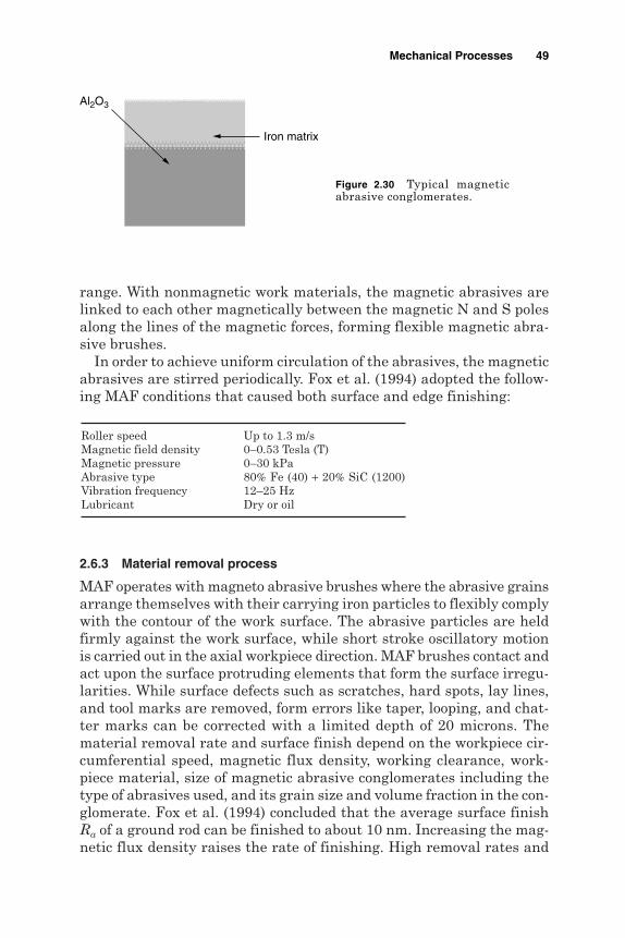
range. With nonmagnetic work materials, the magnetic abrasives arelinked to each other magnetically between the magnetic N and S polesalong the lines of the magnetic forces, forming flexible magnetic abra-sive brushes.
In order to achieve uniform circulation of the abrasives, the magneticabrasives are stirred periodically. Fox et al. (1994) adopted the follow-ing MAF conditions that caused both surface and edge finishing:
2.6.3 Material removal process
MAF operates with magneto abrasive brushes where the abrasive grainsarrange themselves with their carrying iron particles to flexibly complywith the contour of the work surface. The abrasive particles are heldfirmly against the work surface, while short stroke oscillatory motionis carried out in the axial workpiece direction. MAF brushes contact andact upon the surface protruding elements that form the surface irregu-larities. While surface defects such as scratches, hard spots, lay lines,and tool marks are removed, form errors like taper, looping, and chat-ter marks can be corrected with a limited depth of 20 microns. Thematerial removal rate and surface finish depend on the workpiece cir-cumferential speed, magnetic flux density, working clearance, work-piece material, size of magnetic abrasive conglomerates including thetype of abrasives used, and its grain size and volume fraction in the con-glomerate. Fox et al. (1994) concluded that the average surface finishRa of a ground rod can be finished to about 10 nm. Increasing the mag-netic flux density raises the rate of finishing. High removal rates and
Roller speed Up to 1.3 m/sMagnetic field density 0–0.53 Tesla (T)Magnetic pressure 0–30 kPaAbrasive type 80% Fe (40) + 20% SiC (1200)Vibration frequency 12–25 HzLubricant Dry or oil
Mechanical Processes 49
Iron matrix
Al2O3
Figure 2.30 Typical magneticabrasive conglomerates.

the best finish were obtained with an increase in the axial vibrationamplitude and frequency. The axial vibration and rotational speed hasto be taken into consideration for obtaining the best cross pattern thatwould give the best finish and high removal rate. Singh and his team(2004) recommended a high voltage level (11.5 V), low working gap (1.25mm), high rotational speed (180 rpm), and large mesh number forimproving the surface quality.
2.6.4 Applications
2.6.4.1 Polishing of balls and rollers. Conventional finishing of ceramicballs, for bearing applications, uses low polishing speeds and diamondabrasives as a polishing medium. The long processing time and the useof expensive diamond abrasives result in high processing costs. Diamondabrasives at high loads can result in deep pits, scratches, and microcracks.Consequently the high processing cost and the lack of the machiningsystem reliability form possible limitations. To minimize the surfacedamage, gentle polishing conditions are required, namely, low levels ofcontrolled force and abrasives not much harder than the work material.
A recent development in MAF involves the use of a magnetic field tosupport abrasive slurries in polishing ceramic balls and bearing rollers(Fig. 2.31). A magnetic field, containing abrasive grains and extremelyfine ferromagnetic particles in a certain fluid such as water or kerosene,fills the chamber within a guide ring. The ceramic balls are between adrift shaft and a float.
The abrasive grains, ceramic balls, and the float (made from non-magnetic material) are suspended by the magnetic forces. The balls arepreset against the rotating drive shaft and are polished by the mechan-ical abrasion action. Since the forces applied by the abrasive grains are
50 Chapter Two
Ball
Drive shaft
Abrasives andmagnetic fluid
FloatN S N S N S N S N S N S
Figure 2.31 Magnetic finishing of balls (Kalpakjian, 1997).

extremely small and controllable, the polishing action is very fine. Theprocess is economical, and the surfaces produced have little or no defects.
2.6.4.2 Finishing of inner tube surface. Clean gas and liquid piping sys-tems need to have highly finished inner surfaces that prevent contami-nant from accumulating. When the pipe is slender, it is hard to producesmooth inner surfaces in a cost-effective way. Electrolytic finishing hasmany problems associated with the high cost of controlling the processconditions and disposing of electrolyte without environmental pollution.Figure 2.32 shows the two-dimensional schematic view of the internalfinishing of a nonferromagnetic tube using MAF. The magnetic abrasives,inside the tubes, are converged toward the finishing zone by the mag-netic field, generating the magnetic force needed for finishing. By rotat-ing the tube at a higher speed, the magnetic abrasives make the innersurface smoother. Figure 2.33 shows the case of ferromagnetic tube fin-ishing where the magnetic fluxes mostly flow into the tube (instead ofthrough the inside of the tube) due to their high magnetic permeability.Under such conditions, the abrasives hardly remain in the finishingzone when the tube is rotated. Geskin et al. (1995) achieved mirror fin-ishing and removed burrs without lowering the accuracy of the shape.
Mechanical Processes 51
Figure 2.32 Magnetic finishing of nonmagnetic tubes.
S pole N pole
Line of magnetic force
Rotation + vibrations
Nonferromagnetic tube
Magnetic abrasives
Figure 2.33 Magnetic finishing of magnetic tubes.
S poleN pole
Line of magnetic force
Rotation + vibrations
Magnetic abrasives
Ferromagnetic tube

2.6.4.3 Other MAF applications. The process can be applied in manyother fields, as described by Khayry (2000), Umehara et al. (1997), andHitomi and Shinmura (1995):
1. Polishing of fine components such as printed circuit boards
2. The removal of oxide layers and protective coatings
3. Chamfering and deburring of gears and cams
4. Automatic polishing of complicated shapes
5. Polishing of flat surfaces
For more details, see the following Internet sites:
www.iijnet.or.jp/MMC/nv.19/fig31.gif
www.jstp,or/jstp_E/Publs/paper/memboo7.html
khai.itl.net.ua/eng/ttc/204/
www.manufacturingcenter.com/tooling/archives/0600/
www.riken.go.jp/lab-www/library/publication/review/
References
Benkirane, Y., Kamoun, H., and Kremer, D. (1995). “Investigation on Ultrasonic AbrasiveMaterial Removal Mechanisms—Analytical and Experimental Study,” Int. Symp. forElectro Machining XI, Lausanne, Switzerland, pp. 891–900.
catt.bus.okstate.edu/catt2/projects/PhaseIII/finisclaymore.engineer.gvsu.edu/~jackh/eod/manufact/abrasiv/abrasive-2-html#pgfld524546claymoreengineer.gvsu-edu/~Jackh/eod/manufact/abra.Cruz, C., Kozak, J., and Rajurkar, K. P. (1995). “Study of Rotary Ultrasonic Machining of
Cryogenically Treated Ceramics,” Int. Symp. for Electro Machining XI, Lausanne,Switzerland, pp. 911–920.
Egashira, K., and Masuzawa, T. (1999). “Micro Ultrasonic Machining by the Applicationof Workpiece Vibration,” Annals of CIRP, 48(1):131–134.
El-Hofy, H. (1996). “Surface Generation in Non-conventional Machining,” MDP-6 Conf.,Cairo, pp. 203–213.
Fox, M., Agrwal, A., Shinmura, T., and Komanduri, R. (1994). “Magnetic Finishing ofRollers,” Annals of CIRP, 43(1):181–184.
Geskin, E. S., Tismentsky, L., Bokhroi, E., and Li, F. (1995). “Investigation of Ice JetMachining, Int. Symp. for Electro Machining XI, Lausanne, Switzerland, pp. 883–890.
Gilmore, R. (1995). “Ultrasonic Machining and Polishing,” Int. Symp. for Electro MachiningXI, Lausanne, Switzerland, pp. 941–951.
Hashish, M. (1992). “Machining with High Velocity Water Jet,” PEDAC-5 Conf.,Alexandria, pp. 461–471.
Hitomi, Y., and Shinmura, T. (1995). “Magnetic Abrasive Finishing of Inner Surfaces ofTubes,” Int. Symp. for Electro Machining XI, Lausanne, Switzerland, pp. 963–976.
Jain, N. K., and Jain, V. K. (2001). “Modeling of Material Removal in Mechanical TypeAdvanced Machining Processes, a State of the Art,” Journal of Machine Tools andManufacture, 41:573–635.
Kaczmarek, J. (1976). Principles of Machining by Cutting, Abrasion and Erosion.Stevenage, U.K.: Peter Peregrines, Ltd.
52 Chapter Two
Kalpakjian, S. (1997). Manufacturing Process for Engineering Materials. Reading; MA:Addison-Wesley.
khai.itl.net.ua/eng/ttc/204/Khayry, A. B. (2000). “Aspect of Surface and Edge Finishing by Magneto Abrasive Particles.”
Second Int. Conf. on Advanced Manufacturing Technology, Malaysia, pp. 77–83.Masuzawa, T., and Tonshof, H. K. (1997). “Three-Dimensional Micro Machining by
Machine Tools,” Annals of CIRP, 46(2):821–828.McGeough, J. (1988). Advanced Methods of Machining. London, New York: Chapman and
Hall.Metals Handbook. (1989). Vol. 16, Machining. Materials Park; OH: ASM International.Singh, D. K., Jain, V. K., and Raghuram, V. (2004). “Parametric Study of Magnetic Abrasive
Finishing (MAF) Process,” Int. Symp. for Electro Machining XIV, On-site Conf. Proc.Edinburgh, U.K. (Journal of Materials Processing Technology).
Thoe, T. B., Aspinwal, D. K., and Wise, M. L. (1995). “Towards Ultrasonic ContourMachining,” Int. Symp. for Electro Machining XI, Lausanne, Switzerland, pp. 953–962.
Umehara, N., Kato, K., and Suziki, K. (1997). “Magnetic Dispersion of Micro ParticlesUsing Magnetic Fluid Application to Texturing Process for Magnetic Rigid Disc,” Annalsof CIRP, 46(1):155–158.
www.jetcutinc.com/ www.jetedge.com/www.okstate.edu/MAE/maerl/proj2.htm www.riken.go.jp/lab-www/library/publication/review/www.manufacturingcenter.com/tooling/archives/0600/www.iijnet.or.jp/MMC/nv.19/fig31.gifwww.jstp,or/jstp_E/Publs/paper/memboo7.htmlwww.nedians.8m.com/ www2.cerm.wvn.edu/~imse304/raghav/ragav.htmYoussef, H. (1976). Theory of Metal Cutting, Dar-El-Maaref, Egypt.Zheng, X., Chen, E., Steele, P., and Grothers, P. (2002). “Shape Machining of Aerospace
Composite Components Using Not-Traditional Abrasive Waterjet Cutting Process,”Sixth AMST’02 conference, Italy, pp. 507–514.
Mechanical Processes 53

This page is intentionally left blank.
Chapter
3Chemical Processes
3.1 Chemical Milling
3.1.1 Introduction
Chemical milling (CHM) is the controlled chemical dissolution (CD) ofthe workpiece material by contact with a strong reagent. Special coat-ings called maskants protect areas from which the metal is not to beremoved. The process is used to produce pockets and contours and toremove materials from parts having a high strength-to-weight ratio.CHM consists of the following steps:
1. Preparing and precleaning the workpiece surface. This provides goodadhesion of the masking material and assures the absence of con-taminants that might interfere with the machining process.
2. Masking using readily strippable mask, which is chemically impreg-nable and adherent enough to stand chemical abrasion during etching.
3. Scribing of the mask, which is guided by templates to expose theareas that receive CHM. The type of mask selected depends on thesize of the workpiece, the number of parts to be made, and the desiredresolution of details. Silk-screen masks are preferred for shallowcuts requiring close dimensional tolerances.
4. The workpiece is then etched and rinsed, and the mask is removedbefore the part is finished.
During CHM (Fig. 3.1), the depth of the etch is controlled by the timeof immersion. In order to avoid uneven machining, the chemicals thatimpinge on the surface being machined should be fresh. The chemicalsused are very corrosive and, therefore, must be handled with adequatesafety precautions. Both the vapors and the effluents must be suitably
55
Copyright © 2005 by The McGraw-Hill Companies, Inc. Click here for terms of use.

controlled for environmental protection. Agitation of the workpiece andfluid is usual; however, excessive solution flow may result in channel-ing, grooves, or ridges. Inclination of the workpiece may prevent chan-neling from gas bubbles. Bellows (1977) and the Metals Handbook (1989)reported that dishing of the machined surface occurs due to the unevenheat distribution resulting from the chemical action. Typical reagenttemperatures range from 37 to 85°C. Faster etching rates occur at highertemperatures, but must be controlled within ±5°C of the desired tem-perature in order to attain uniform machining.
When the mask is used, the machining action proceeds both inwardlyfrom the mask opening and laterally beneath the mask thus creatingthe etch factor shown in Fig. 3.2. The etch factor is the ratio of theundercut d to the depth of etch T. This ratio must be considered when
56 Chapter Three
Hanger Stirrer
Heating
Cooling
Mask
Workpiece
Undercut
Chemical reagent
Figure 3.1 CHM setup.
Knife angle
Before etching
After etching
Undercut d
Depth of etch T
Figure 3.2 Etch factor afterCHM.

scribing the mask using templates. A typical etch factor of 1:1 occurs ata cut depth of 1.27 mm. Deeper cuts can reduce this ratio to 1:3. The radiiof the fillet produced will be approximately equal to the depth of etch.For simultaneous machining of multiple parts, racks or handling fix-tures are frequently used to facilitate the submersion of the work in thechemical reagent and for subsequent rinsing. After rinsing the chemi-cals from the workpiece, the demasking is accomplished by hand strip-ping, mechanical brushing, or chemical stripping. Some chemicals leavea film of smut on the machined surface, which can be removed by otherchemicals or frequently by brushing.
CHM will not eliminate surface irregularities, dents, scratches, orwaviness. Successive steps of mask removal and immersion as shownin Fig. 3.3 can achieve stepped cuts. Tapered cuts (Fig. 3.4), can also beproduced without masking the workpiece by controlling the depth andrate of immersion or withdrawal and the number of immersions.Continuous tapers, as great as 0.060 mm/mm for aluminum and0.010 mm/mm for steel alloys, have been machined on a productionbasis (Metals Handbook, 1989).
3.1.2 Tooling for CHM
Tooling for CHM is relatively inexpensive and simple to modify. Four dif-ferent types of tools are required: maskants, etchants, scribing tem-plates, and accessories.
Chemical Processes 57
Scribe mask
First etching
Re-scribe mask
First + second etching
Second etching
Figure 3.3 Contour cuts by CHM.

3.1.2.1 Maskants. Maskants are generally used to protect parts of theworkpiece where CD action is not needed. Synthetic or rubber basematerials are frequently used. Table 3.1 shows the different maskantsand etchants for several materials together with the etch rate and etchfactor. Maskants should, however, possess the following properties:
1. Be tough enough to withstand handling
2. Adhere well to the workpiece surface
3. Scribe easily
4. Be inert to the chemical reagent used
58 Chapter Three
Immersion Constantwithdrawal rate
Steppedwithdrawal rate
Figure 3.4 Machining tapers and steps by CHM.
TABLE 3.1 Maskants and Etchants for Different Workpiece Materials
Etch rate,Workpiece Etchant Maskant mm/min Etch factor
Aluminum FeCl3 Polymers 0.013–0.025 1.5–2.0NaOH Polymers 0.020–0.030
Magnesium HNO3 Polymers 1.0–2.0 1.0Copper FeCl3 Polymers 2.0 2.5–3.0
CuCl3 1.2Steel HCl:HNO3 Polymers 0.025 2.0
FeCl3 0.025Titanium HF Polymers 0.025 1.0
HF:HNO3
Nickel FeCl3 Polyethylene 0.13–0.038 1.0–3.0Silicon HNO3:HF:H2O Polymers Very slow
SOURCE: Tlusty (1999).

5. Be able to withstand the heat generated by etching
6. Be removed easily and inexpensively after etching
Multiple coats of maskant are frequently used to increase the etchantresistance and avoid the formation of pinholes on the machined surfaces.When thicker, rougher dip or spray coatings are used, deeper cuts thatrequire long exposure time to the etchant can be achieved. Dip, brush,spray, roller, and electrocoating as well as adhesive tapes can be usedto apply masks.
Spraying the mask on the workpiece through silk screen, on whichthe desired design is imposed, combines the maskant application withthe scribing operation since no peeling is required. The product qual-ity is, therefore, improved as is the ability to generate finer details.However, the thin coating layer applied when using silk screens will notresist etching for a long time as will the cut-and-peel method.Photoresist masks, which are used in photochemical milling (PCM), alsocombine both the coating and scribing operations. The relatively thincoats applied as dip or spray coats will not withstand rough handlingor long exposure times to the etchant. However, photoresist masksensure high accuracy, ease of repetition for multiple-part etching, andease of modification. The accuracy obtained for lateral dimensionsdepends on the complexity of the masking. Typical tolerances for thedifferent masks are as follows:
Cut-and-peel masks ±0.179 mm Silk-screen resist ±0.077 mm Photoresist ±0.013 mm
3.1.2.2 Etchants. Etchants (see Table 3.1) are acid or alkaline solu-tions maintained within a controlled range of chemical composition andtemperature. Their main technical goals are to achieve the following:
1. Good surface finish
2. Uniformity of metal removal
3. Control of selective and intergranular attack
4. Control of hydrogen absorption in the case of titanium alloys
5. Maintenance of personal safety
6. Best price and reliability for the materials to be used in the con-struction of the process tank
7. Maintainance of air quality and avoidance of possible environmen-tal problems
Chemical Processes 59

8. Low cost per unit weight dissolved
9. Ability to regenerate the etchant solution and/or readily neutralizeand dispose of its waste products
3.1.2.3 Scribing templates. Scribing templates are used to define theareas for exposure to the chemical machining action. The most commonworkpiece scribing method is to cut the mask with a sharp knife followedby careful peeling of the mask from the selected areas. Layout lines orsimple templates of metal or fiberglass guide the scribing process. Theetch factor allowance must be included in any method used for the scrib-ing operation. The negative (used in PCM) or its layout and the templateor the silk screen must allow for the degree of undercutting expectedduring etching. Figure 3.5 shows numerical control (NC) laser scribingof masks for CHM of a large surface area.
3.1.2.4 Accessories. Accessories include tanks, hooks, brackets, racks,and fixtures. These are used for single- or-multiple-piece handling intoand out of the etchants and rinses.
60 Chapter Three
Maskedsurface
Laser(capacitive position
transducer)
Laser power:75 kW for 400-µm-thick mask
Lens
Air (cooling)CO2 laser
Mask
Aluminum
Constant
Figure 3.5 Laser cutting of masks for CHM of large surfaces(Tlusty, 1999).

3.1.3 Process parameters
CHM process parameters include the reagent solution type, concentra-tion, properties, mixing, operating temperature, and circulation. Theprocess is also affected by the maskant and its application. These param-eters will have direct impacts on the workpiece regarding the following:
1. Etch factor (d/T )
2. Etching and machining rate
3. Production tolerance
4. Surface finish
To machine high-quality and low-cost parts using CHM, we must con-sider the heat treatment state of the workpiece, the grain size and rangeof the workpiece material, the size and finish control prior to CHM, thedirection of rolling and weld joints, and the degree of cold work.
3.1.4 Material removal rate
The material removal or etch rate depends upon the chemical and met-allurgical uniformity of the workpiece and the uniformity of the solu-tion temperature. As shown in Figs. 3.6 and 3.7, castings, having thelargest grain size, show the roughest surface together with the lowest
Chemical Processes 61
Alu
min
um a
lloy
Mol
ybde
num
Col
ubiu
m
Ste
els
Mag
nesi
um a
lloy
Nic
kel a
lloy
Tita
nium
Tan
taliu
m
Material type
0
1
2
3
4
5
6
Sur
face
rou
ghne
ss R
a, µ
m Casting
Forging
Sheet
Figure 3.6 CHM average roughness of some alloys after removing 0.25 to0.4 mm (El-Hofy, 1995 ).

machining rate. Rolled metal sheets have the highest machining rateaccompanied by the best surface quality. Etching rates were high forhard metals and were low for softer ones (Metals Handbook, 1989).Generally, the high etch rate is accompanied by a low surface roughnessand, hence, narrow machining tolerances.
3.1.5 Accuracy and surface finish
In CHM, the metal is dissolved by the CD action. This machining phasetakes place both at the individual grain surfaces as well as at the grainboundaries. Fine grain size and homogenous metallurgical structureare, therefore, necessary, for fine surface quality of uniform appear-ance. Surfaces machined by CHM do not have a regular lay pattern.Based on the grain size, orientation, heat treatment, and previouslyinduced stresses, every material has a basic surface finish that resultsfrom CHM for a certain period of time. While surface imperfections willnot be eliminated by CHM, any prior surface irregularities, waviness,dents, or scratches will be slightly altered and reproduced in themachined surface.
The machining rate affects the surface roughness and hence the tol-erance produced. Generally, slow etching will produce a surface finishsimilar to the original one. Figure 3.7 shows typical surface roughnessesfor different materials. The orientation of the areas being etched with
62 Chapter Three
Figure 3.7 Surface roughness and etch rate of some alloys after remov-ing 0.25 to 0.4 mm (El-Hofy, 1995).
Alu
min
um a
lloy
Mol
ybde
num
Col
ubiu
m
Ste
els
Nic
kel a
lloys
Tita
nium
Tan
taliu
m
Material type
0
0.5
1
1.5
2
2.5
3S
urfa
ce r
ough
ness
Ra,
µm
0
10
20
30
40
50
Etch rate, µm
/min
RoughnessEtch rate

respect to the rolling direction or the direction of the grain in the work-piece is also important for good CHM surfaces. The depth of cut toler-ance increases when machining larger depths at high machining rates.Aluminum and magnesium alloys can be controlled more closely thansteel, nickel, or titanium alloys. An etching rate of 0.025 mm/mm withtolerances of ±10 percent of the cut width can be achieved depending onthe workpiece material and depth of cut.
The surface roughness is also influenced by the initial workpieceroughness. It increases as the metal ion concentration rises in theetchant. For low machining depths, <200 µm, the roughness sharplyincreases with the depth of cut, while at higher depths a slight changein the roughness is evident. Figure 3.7 shows the dependence of the sur-face roughness and etch rate on the workpiece material. Typically, sur-face roughnesses of 0.1 to 0.8 µm, depending on the initial roughness,can be obtained. However, under special conditions, roughnesses of0.025 to 0.05 µm become possible (Machining Data Handbook, 1997).
CHM can affect the mechanical properties of the machined partswhen the surface layers have different mechanical properties from thoseof the base metal. The removal of such layers results in a change in theaverage mechanical properties of the finished parts. In this regard sur-face conditions such as a titanium oxide layer (alpha case), decarbur-ized layer, and recast structure are easily removed by CHM, resultingin an improvement in the properties of the finished parts. Some loss offatigue properties has been reported after CHM of aluminum; however,shot peening or grit blasting can restore it.
3.1.6 Advantages
The process has the following advantages:
Weight reduction is possible on complex contours that are difficult tomachine using conventional methods.
Simultaneous material removal, from all surfaces, improves produc-tivity and reduces wrapping.
No burrs are formed. No stress is introduced to the workpiece, which minimizes the part dis-
tortion and makes machining of delicate parts possible. A continuous taper on contoured sections is achievable. The capital cost of equipment, used for machining large components,
is relatively low. Design changes can be implemented quickly. A less skilled operator is needed.
Chemical Processes 63

Tooling costs are minor. The good surface quality in addition to the absence of burrs eliminates
the need for finishing operations. Multiple parts having fine details can be machined by the gang method. Decorative finishes and extensive thin-web areas are possible. There are low scrap rates (3 percent).
3.1.7 Limitations
CHM does have limitations and areas of disadvantage:
Only shallow cuts are practical: up to 12.27 mm for sheets and plates,3.83 mm on extrusions, and 6.39 mm on forgings.
Handling and disposal of chemicals can be troublesome. Hand masking, scribing, and stripping can be time-consuming, repet-
itive, and tedious. Surface imperfections are reproduced in the machined parts. Metallurgical homogeneous surfaces are required for best results. Deep narrow cuts are difficult to produce. Fillet radii are fixed by the depth of cut. Porous castings yield uneven etched surfaces. Welded areas frequently etch at rates that differ from the base metal. Material removal from one side of residually stressed material can
result in a considerable distortion. The absence of residual stresses on the chemically machined surfaces
can produce unfavorable fatigue strength compared with the processesthat induce compressive residual stresses.
Hydrogen pickup and intergranular attack are a problem with somematerials.
The straightness of the walls is subject to fillet and undercutting lim-itations.
Scribing accuracy is limited and complex designs become expensive. Steep tapers are not practical.
3.1.8 Applications
All the common metals including aluminum, copper, zinc, steel, lead, andnickel can be chemically machined. Many exotic metals such as titanium,
64 Chapter Three

molybdenum, and zirconium, as well as nonmetallic materials includ-ing glass, ceramics, and some plastics, can also be used with the process.CHM applications range from large aluminum airplane wing parts tominute integrated circuit chips. The practical depth of cut rangesbetween 2.54 to 12.27 mm. Shallow cuts in large thin sheets are of themost popular application especially for weight reduction of aerospacecomponents. Multiple designs can be machined from the same sheet atthe same time. CHM is used to thin out walls, webs, and ribs of partsthat have been produced by forging, casting, or sheet metal forming, asshown in Fig. 3.8. Further process applications related to improving sur-face characteristics include the following:
1. Elimination of alpha case from titanium forgings and superplastic-formed parts
2. Elimination of the decarburized layer from low alloy steel forg-ings
3. Elimination of the recast layer from parts machined by EDM
4. Removal of sharp burrs from conventionally machined parts of com-plex shapes
5. Removal of a thin surface from forgings and castings prior to pene-tration inspection below the surface (required for the detection ofhidden defects)
Chemical Processes 65
Forged parts
Machined surfaceFinished by CHM
Formed shapes
Critical area
2.03 mm 0.76 mm
Figure 3.8 Thinning of parts by CHM (Tlusty, 1999).

3.2 Photochemical Milling
3.2.1 Introduction
Photochemical milling (PCM) is a variation of chemical milling (CHM)where the chemically resistant mask is applied to the workpiece by pho-tographic techniques. The two processes are quite similar because theyboth use chemicals to remove metal by the CD action and some of thesteps required in both cases are similar. CHM is usually used on three-dimensional parts originally formed by another manufacturing process,such as forging and casting of irregular shapes. As with photochemicalmachining, areas not to be machined are masked from the CD action ofthe chemical solution. Photochemical machining, therefore, creates newparts from thin materials, rather than simply smoothing or alteringparts formed by other manufacturing methods. The process is sometimescalled photochemical blanking (PCB) since flat, thin gauge complexparts can be machined to high precision in thicknesses ranging from0.013 to 1.5 mm. Sometimes photochemical machining is used to surface-etch components with lettering or graphics where the etchant works itsway to only a certain depth in the material. As in the case of chemicalmilling, the depth of etch is controlled by the time a component isimmersed in a particular etchant. Neither photochemical machiningnor chemical milling should be confused with photo forming (PF), whichis the process of electroplating metals over a mandrel. The photo formedcomponents are removed from the mandrel after the proper thicknessof material has been deposited.
3.2.2 Process description
Figure 3.9 shows the flow diagram of the PCM process. The first stepincludes the production of the required shape on a photographic film orglass plate, termed the photo-tool. Computer-aided design (CAD) art-work creates the required part shape, which is used as the primaryimage for the photo-tool. The sheet metal is chemically cleaned, andcoated with a light-sensitive photoresist film. The photoresist will adhereto the part surface and act as a stencil resist protecting the surfaceduring etching. In some cases, the photoresist is a liquid and the parthas to be dip coated and dried. Most often, photo-tools are used in pre-cisely registered pairs—one on the top, one on the bottom, with thematerial to be machined sandwiched in between. This permits the mate-rial to be etched from both sides, thus minimizing undercutting of thephotoresist and producing straighter sidewalls.
The resist laminated, or coated, metal is then placed under the photo-tool and exposed, in a vacuum, to an ultraviolet light source. This trans-fers the image precisely onto the resist and, after developing, becomes
66 Chapter Three

a replica of the desirable geometry. The exposed image is then developedby immersion or spraying. Each photoresist has its own developing solu-tion, such as water, alkaline solution, hydrocarbons, or solvents. Theexposed material is then washed to remove the unexposed photoresiston the areas to be chemically etched as illustrated by Allen (1993).
The imaged metal passes through the acid etch spray or dip where itis selectively dissolved away. Various etchants are available for differ-ent materials. The right choice of etchant depends on issues such as cost,quality, depth of etch, and rate of material removal. Figure 3.10 showsthe main steps of photochemical machining. After applying etchants byspraying or immersion, the parts are rinsed and dried. Protective resistis removed from machined parts with chemicals or with mechanicaltechniques along with chemicals.
3.2.3 Applications
Aluminum, copper, zinc, steel, lead, nickel, titanium, molybdenum,zirconium, glass, ceramics, and some plastics are photochemicallymachined. Very high tempered or brittle materials are excellent candi-dates for photochemical machining because traditional machining causesbreakage or stress-concentration points. The process also works well onspringy materials, which are difficult to punch. PCM lends itself for
Chemical Processes 67
Part drawing/CAD data
Photographic processing
Photoresist stencil on metal
Etching
Photoresist stripping
Finished part
Metal selected and cleaned
Photoresist coating
Sensitized metalPhoto-tool
Figure 3.9 PCM flow diagram.

decorative and graphics industries where signs and labels are producedas shown in Fig. 3.11. Materials undergoing PCM must be thin, with athickness between 0.013 and 1.5 mm. The materials must also be flat sothat they can later be bent to shape and assembled into other compo-nents. In this regard, etching fold lines to flat components for fabricationof boxes and enclosures is a typical PCM application. Products made byphotochemical machining are generally found in the electronic, auto-motive, aerospace, telecommunication, computer, medical, and otherindustries. Typical components (Fig. 3.12), include filters and screens,gaskets, lead frames, contacts, connectors, probes, and flat springs.Figure 3.13 shows different photochemically machined patterns.
3.2.4 Advantages
In addition to the general advantages of CHM, PCM ensures the fol-lowing merits:
68 Chapter Three
Metal cleaned
Metal coated with photoresist both sides
Resist developed
Partially etched
Fully etched
Photographic negativesLight
Resist exposed through negatives (double sided)
Figure 3.10 PCM steps (Tlusty, 1999).

A relatively low cost per unit, especially at low production volumes ofcomplex designs because the tooling used is very inexpensive com-pared to shearing punches and dies.
Lead times are often small compared to that required by processes thatrequire hard tooling.
Chemical Processes 69
Figure 3.11 PCM of decorative and artistic designs (www.aculineetch.com/).
Figure 3.12 Typical PCM blanks(www.chemart.com/ ).
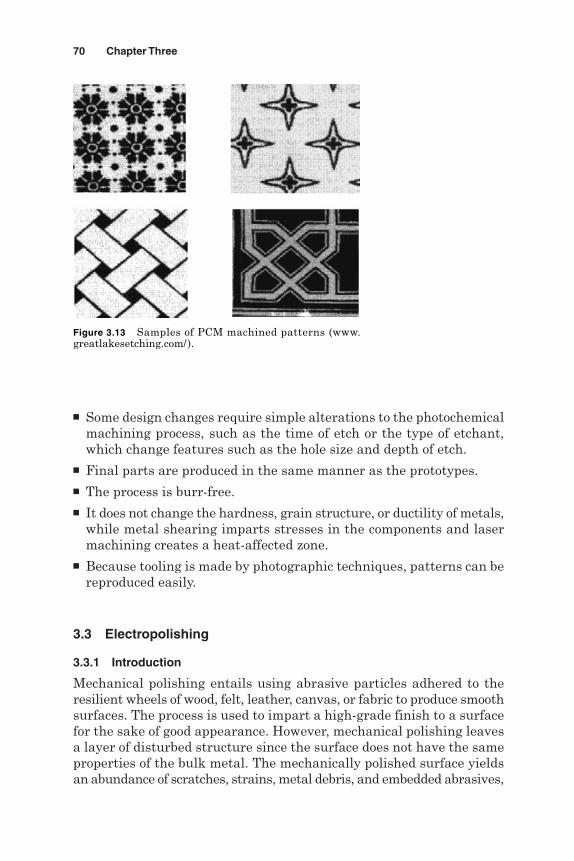
Some design changes require simple alterations to the photochemicalmachining process, such as the time of etch or the type of etchant,which change features such as the hole size and depth of etch.
Final parts are produced in the same manner as the prototypes. The process is burr-free. It does not change the hardness, grain structure, or ductility of metals,
while metal shearing imparts stresses in the components and lasermachining creates a heat-affected zone.
Because tooling is made by photographic techniques, patterns can bereproduced easily.
3.3 Electropolishing
3.3.1 Introduction
Mechanical polishing entails using abrasive particles adhered to theresilient wheels of wood, felt, leather, canvas, or fabric to produce smoothsurfaces. The process is used to impart a high-grade finish to a surfacefor the sake of good appearance. However, mechanical polishing leavesa layer of disturbed structure since the surface does not have the sameproperties of the bulk metal. The mechanically polished surface yieldsan abundance of scratches, strains, metal debris, and embedded abrasives,
70 Chapter Three
Figure 3.13 Samples of PCM machined patterns (www.greatlakesetching.com/).
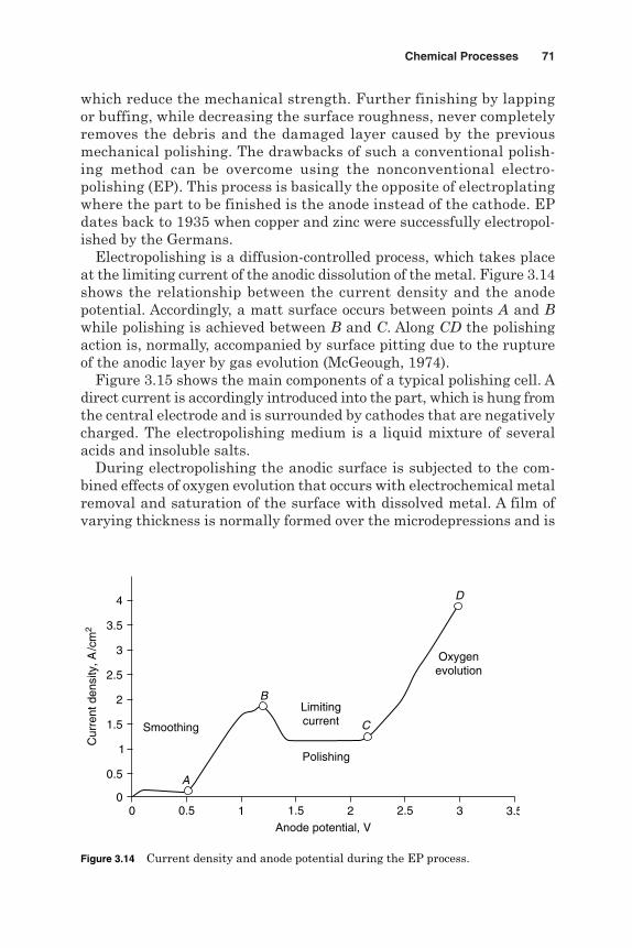
which reduce the mechanical strength. Further finishing by lappingor buffing, while decreasing the surface roughness, never completelyremoves the debris and the damaged layer caused by the previousmechanical polishing. The drawbacks of such a conventional polish-ing method can be overcome using the nonconventional electro-polishing (EP). This process is basically the opposite of electroplatingwhere the part to be finished is the anode instead of the cathode. EPdates back to 1935 when copper and zinc were successfully electropol-ished by the Germans.
Electropolishing is a diffusion-controlled process, which takes placeat the limiting current of the anodic dissolution of the metal. Figure 3.14shows the relationship between the current density and the anodepotential. Accordingly, a matt surface occurs between points A and Bwhile polishing is achieved between B and C. Along CD the polishingaction is, normally, accompanied by surface pitting due to the ruptureof the anodic layer by gas evolution (McGeough, 1974).
Figure 3.15 shows the main components of a typical polishing cell. Adirect current is accordingly introduced into the part, which is hung fromthe central electrode and is surrounded by cathodes that are negativelycharged. The electropolishing medium is a liquid mixture of severalacids and insoluble salts.
During electropolishing the anodic surface is subjected to the com-bined effects of oxygen evolution that occurs with electrochemical metalremoval and saturation of the surface with dissolved metal. A film ofvarying thickness is normally formed over the microdepressions and is
Chemical Processes 71
Anode potential, V
Polishing
Smoothing
Oxygenevolution
Limitingcurrent C
D
A
B
3.5
2.5
1.5
0.5
00 10.5 21.5 32.5 3.5
1
2
3
4
Cur
rent
den
sity
, A/c
m2
Figure 3.14 Current density and anode potential during the EP process.
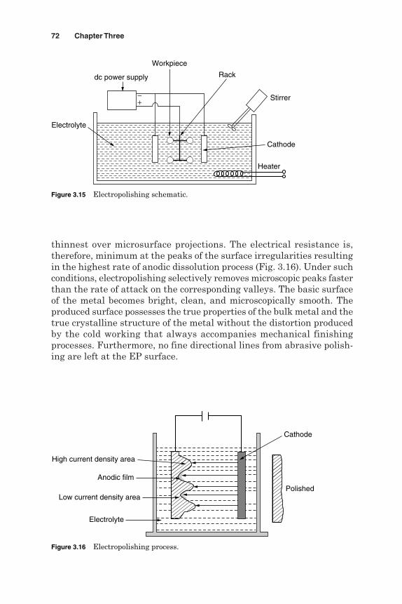
thinnest over microsurface projections. The electrical resistance is,therefore, minimum at the peaks of the surface irregularities resultingin the highest rate of anodic dissolution process (Fig. 3.16). Under suchconditions, electropolishing selectively removes microscopic peaks fasterthan the rate of attack on the corresponding valleys. The basic surfaceof the metal becomes bright, clean, and microscopically smooth. Theproduced surface possesses the true properties of the bulk metal and thetrue crystalline structure of the metal without the distortion producedby the cold working that always accompanies mechanical finishingprocesses. Furthermore, no fine directional lines from abrasive polish-ing are left at the EP surface.
72 Chapter Three
Heater
Stirrer
dc power supply
Cathode
Rack
Workpiece
Electrolyte
+−
Figure 3.15 Electropolishing schematic.
High current density area
Low current density area
Anodic film
Polished
Cathode
Electrolyte
Figure 3.16 Electropolishing process.

3.3.2 Process parameters
EP is affected by many parameters that have a direct impact on theproduced surface quality and process productivity. These include thefollowing:
1. Workpiece material and condition
2. Original surface roughness
3. Current density
4. Applied voltage
5. Acid type, temperature, and agitation
During EP it is recommended that you use a proper electrolyte, main-tain its temperature and chemical composition, and supply a ripple-free DC power at the correct voltage. Table 3.2 presents suitableelectrolyte conditions and current densities for electropolishing of dif-ferent metals and alloys.
3.3.3 Applications
For economical and high-quality electropolishing, cold rolled metals arethe most important materials. Cast items usually maintain the textureof the sand mold. They have coarse grains and include alloying ele-ments (phosphorus, lead, and silicon) that improve metal fluidity.Such a coarse texture is not removed by electropolishing; however, thesurface can be made brilliant. In general, coarse grain structures andphosphorus-, lead-, and silicon-rich phases produce rough surfaces.
Chemical Processes 73
TABLE 3.2 Electrolytes and Current Densities for EP of Different Metals
Metal Electrolyte Current density, A/cm2
Carbon steel 182 mL HCLO4, 0.04–0.06765 mL acetic anhydride,50 mL H2O
Stainless steel 60% H3PO4, 20% H2SO4, 1.8 at 80°C20% H2O
37% H3PO4, 56% glycerine, 1.0 at 120°C7% H2O
Copper H3PO4 0.04Alpha brass H3PO4Cr11, NaCr2 O2, 0.14–0.35 at 50°C
H2SO4, HF, Cr2H2, COOHPhosphor bronze 33% HNO3 0.75–1.5Cupronickel 67% CH2OHNickel 75% H2SO4 0.25Aluminum NCIO3 0.04–0.08Magnesium 37% H2PO4, 63% C2H3OH 0.005

The EP process finds many applications which have been reported bywww.globalstainlesstech.com/ and Brown (1998):
1. Preparing surfaces for electroplating, which creates an opportunityfor the best possible adherence.
2. Producing the ultimate finish for clean-room tables, chairs, andwaste containers.
3. Polishing light fixtures of electrical conduits; outlet boxes; and med-ical, surgical, and food processing equipment.
4. Deburring and breaking sharp edges resulted from hand filing andhoning and grinding of cutting tools.
5. Metallographic examination.
6. Removing scale or distortions caused by annealing, nitriding, car-burizing, welding, or soldering.
7. Removing skin that remains on metals after casting or forging, whichallows for subsequent machining operations with less effort, time,and tool wear.
8. Removing hardened and stressed surface layers, which improve thesurface life of a part.
9. Improving adhesion for coatings such as paint and plasma spraying.
10. Smoothing of the surface to increase reflectivity and thus creatinga bright appearance.
11. Removing burrs, occlusions, and other metalworking marks, whichmakes it easier to clean the surface and avoid microbiological con-taminants.
12. Micromachining of metals and alloys.
13. Polishing a large number of parts simultaneously.
3.3.4 Process limitations
The process cannot smear over and cover up defects such as seams andnonmetallic inclusions in the metal.
Multiphase alloys in which one phase is relatively resistant to anodicdissolution are usually not amenable to electropolishing.
Rough scratches are not removed even by a considerable amount ofelectropolishing.
Metals containing a high percentage of silicon, lead, and sulfur canbe troublesome.
74 Chapter Three
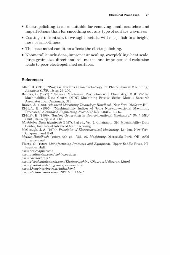
Electropolishing is more suitable for removing small scratches andimperfections than for smoothing out any type of surface waviness.
Coatings, in contrast to wrought metals, will not polish to a bright-ness or smoothness.
The base metal condition affects the electropolishing. Nonmetallic inclusions, improper annealing, overpickling, heat scale,
large grain size, directional roll marks, and improper cold reductionleads to poor electropolished surfaces.
References
Allen, D. (1993). “Progress Towards Clean Technology for Photochemical Machining,”Annals of CIRP, 42(1):179–200.
Bellows, G. (1977). “Chemical Machining, Production with Chemistry,” MDC 77-102,Machinability Data Centre (MDC) Machining Process Series Metcut ResearchAssociates Inc., Cincinnati, OH.
Brown, J. (1998). Advanced Machining Technology Handbook. New York: McGraw-Hill.El-Hofy, H. (1995). “Machinability Indices of Some Non-conventional Machining
Processes,” Alexandria Engineering Journal (AEJ), 34(3):231–245.El-Hofy, H. (1996). “Surface Generation in Non-conventional Machining,” Sixth MDP
Conf., Cairo, pp. 203–213.Machining Data Handbook (1997). 3rd ed., Vol. 2, Cincinnati, OH: Machinability Data
Center, Institute of Advanced Manufacturing.McGeough, J. A. (1974). Principles of Electrochemical Machining. London, New York:
Chapman and Hall.Metals Handbook (1989). 9th ed., Vol. 16, Machining. Meterials Park, OH: ASM
International.Tlusty, G. (1999). Manufacturing Processes and Equipment. Upper Saddle River, NJ:
Prentice-Hall.www.acctechpm.com/www.aculineetch.com/etchingep.htmlwww.chemart.com/www.globalstainlesstech.com/Electropolishing/Diagram1/diagram1.htmlwww.greatlakesetching.com/patterns.htmlwww.Lkengineering.com/index.htmlwww.photo-sciences.comw:1000/start.html
Chemical Processes 75

This page is intentionally left blank.

Chapter
4Electrochemical Processes
4.1 Electrochemical Machining
4.1.1 Introduction
Electrochemical machining (ECM) is a modern machining process thatrelies on the removal of workpiece atoms by electrochemical dissolution(ECD) in accordance with the principles of Faraday (1833). Gusseffintroduced the first patent on ECM in 1929, and the first significantdevelopment occurred in the 1950s, when the process was used formachining high-strength and heat-resistant alloys.
4.1.2 Principles of electrolysis
Electrolysis occurs when an electric current passes between two elec-trodes dipped into an electrolyte solution. The system of the electrodesand the electrolyte is referred to as the electrolytic cell. The chemicalreactions, which occur at the electrodes, are called the anodic or cathodicreactions. ED of the anodic workpiece forms the basis for ECM of metals.The amount of metal dissolved (removed by machining) or deposited iscalculated from Faraday’s laws of electrolysis, which state that
1. The amount of mass dissolved (removed by machining), m, is directlyproportional to the amount of electricity.
m ∝ It
2. The amount of different substances dissolved, m, by the same quan-tity of electricity (It) is proportional to the substances’ chemical equiv-alent weight e.
m ∝ e
77
Copyright © 2005 by The McGraw-Hill Companies, Inc. Click here for terms of use.

and
e =
where I = electrolyzing current, At = machining time, mine = chemical equivalent weight, gA = atomic weightZ = workpiece valence
4.1.3 Theory of ECM
ECM uses a direct current at a high density of 0.5 to 5 A/mm2 and a lowvoltage of 10 to 30 V. The machining current passes through the elec-trolytic solution that fills the gap between an anodic workpiece and apreshaped cathodic tool. The electrolyte is forced to flow through theinterelectrode gap at high velocity, usually more than 5 m/s, to inten-sify the mass and charge transfer through the sublayer near the anode.The electrolyte removes the dissolution products, such as metal hydrox-ides, heat, and gas bubbles, generated in the interelectrode gap.McGeough (1988) claimed that when a potential difference is appliedacross the electrodes, several possible reactions occur at the anode andthe cathode. Figure 4.1 illustrates the dissolution reaction of iron in asodium chloride (NaCl) water solution as an electrolyte. The result ofelectrolyte dissociation and NaCl dissolution leads to
H2O → H+ + OH−
NaCl → Νa+ + Cl−
A
Z
78 Chapter Four
Electrolyte
Cathode (−)
2H+ + 2e = H2
Fe+2(OH) = Fe(OH)2
Anode (+)
Fe(OH)2
Gas (H2)
Figure 4.1 Electrochemical reactions during ECM of iron.

The negatively charged anions OH− and Cl− move toward the anode, andthe positively charged cations of H+ and Na+ are directed to the cathode.
At the anode, Fe changes to Fe++ by losing two electrons.
Fe → Fe++ + 2e
At the cathode, the reaction involves the generation of hydrogen gas andthe hydroxyl ions.
2H2O + 2e → H2 + 2(OH)−
The outcome of these electrochemical reactions is that iron ions combinewith other ones to precipitate out as iron hydroxide, Fe(OH)2.
Fe + 2H2O → Fe(OH)2 + H2
The ferrous hydroxide may react further with water and oxygen to formferric hydroxide, Fe(OH)3.
4Fe(OH)2 + 2H2O + O2 → 4Fe(OH)3
With this metal-electrolyte combination, electrolysis has involved thedissolution of iron, from the anode, and the generation of hydrogen, atthe cathode (McGeough, 1974).
4.1.4 ECM equipment
Figure 4.2 shows the main components of the ECM machine: the feedcontrol system, electrolyte supply system, power supply unit, and work-piece holding device. As shown in Fig. 4.3, the feed control system isresponsible for feeding the tool at a constant rate during equilibriummachining. The power supply drives the machining current at a con-stant dc (continuous or pulsed) voltage. The electrolyte-feeding unit sup-plies the electrolyte solution at a given rate, pressure, and temperature.Facilities for electrolyte filtration, temperature control, and sludgeremoval are also included. ECM machines are capable of performing awide range of operations such as duplicating, sinking, and drilling.Semiautomatic and fully automated facilities are used for large-sizemachining, such as deburring in the automotive industry. ECMmachines, in contrast to conventional machine tools, are designed tostand up to corrosion attack by using nonmetallic materials. For highstrength or rigidity, metals with nonmetallic coatings are recommendedat www.unl.edu/.
Electrochemical Processes 79
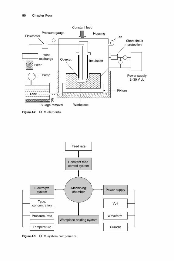
80 Chapter Four
FlowmeterPressure gauge
Constant feed
Fixture
Sludge removal
Pump
Filter
Heatexchange
Housing
Overcut
Workpiece
Insulation
Fan
Power supply2−30 V dc
Short circuitprotection
+
−
Tank
Figure 4.2 ECM elements.
Feed rate
Constant feedcontrol system
Machiningchamber
Power supplyElectrolyte
system
Type,concentration
Pressure, rate
Temperature
Workpiece holding system
Volt
Waveform
Current
Figure 4.3 ECM system components.

4.1.4.1 Power supply. The dc power supply for ECM has the followingfeatures:
1. Voltage of 2 to 30 volts (V) (pulsed or continuous)
2. Current ranges from 50 to 10,000 amperes (A), which allow currentdensities of 5 to 500 A/cm2
3. Continuous adjustment of the gap voltage
4. Control of the machining current in case of emergency
5. Short circuit protection in a matter of 0.001 s
6. High power factor, high efficiency, small size and weight, and low cost
4.1.4.2 Electrolytes. The main functions of the electrolytes in ECM are to
1. Create conditions for anodic dissolution of workpiece material
2. Conduct the machining current
3. Remove the debris of the electrochemical reactions from the gap
4. Carry away the heat generated by the machining process
5. Maintain a constant temperature in the machining region
The electrolyte solution should, therefore, be able to (www.unl.edu/)
1. Ensure a uniform and high-speed anodic dissolution
2. Avoid the formation of a passive film on the anodic surface (elec-trolytes containing anions of Cl, SO4, NO3, ClO3, and OH are oftenrecommended)
3. Not deposit on the cathode surface, so that the cathode shape remainsunchanged (potassium and sodium electrolytes are used)
4. Have a high electrical conductivity and low viscosity to reduce thepower loss due to electrolyte resistance and heat generation and toensure good flow conditions in the extremely narrow interelectrode gap
5. Be safe, nontoxic, and less erosive to the machine body
6. Maintain its stable ingredients and pH value, during the machiningperiod
7. Have small variation in its conductivity and viscosity due to tem-perature rise
8. Be inexpensive and easily available
The most common electrolytes used are sodium chloride (NaCl), sodiumnitrate (NaNO3), and, sodium hydroxide. Industrial ECM operationsusually involve using mixed electrolytes to meet multiple requirements
Electrochemical Processes 81
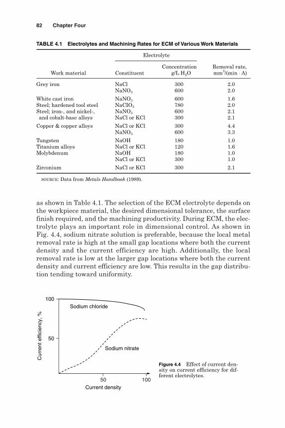
as shown in Table 4.1. The selection of the ECM electrolyte depends onthe workpiece material, the desired dimensional tolerance, the surfacefinish required, and the machining productivity. During ECM, the elec-trolyte plays an important role in dimensional control. As shown inFig. 4.4, sodium nitrate solution is preferable, because the local metalremoval rate is high at the small gap locations where both the currentdensity and the current efficiency are high. Additionally, the localremoval rate is low at the larger gap locations where both the currentdensity and current efficiency are low. This results in the gap distribu-tion tending toward uniformity.
82 Chapter Four
Current density
Cur
rent
effi
cien
cy, %
50
100
Sodium nitrate
Sodium chloride
50 100
Figure 4.4 Effect of current den-sity on current efficiency for dif-ferent electrolytes.
TABLE 4.1 Electrolytes and Machining Rates for ECM of Various Work Materials
Electrolyte
Concentration Removal rate,Work material Constituent g/L H2O mm3/(min ⋅ A)
Grey iron NaCl 300 2.0NaNO3 600 2.0
White cast iron NaNO3 600 1.6Steel; hardened tool steel NaCIO3 780 2.0Steel; iron-, and nickel-, NaNO3 600 2.1and cobalt-base alloys NaCl or KCl 300 2.1
Copper & copper alloys NaCl or KCl 300 4.4NaNO3 600 3.3
Tungsten NaOH 180 1.0Titanium alloys NaCl or KCl 120 1.6Molybdenum NaOH 180 1.0
NaCl or KCl 300 1.0
Zirconium NaCl or KCl 300 2.1
SOURCE: Data from Metals Handbook (1989).

The current efficiency in ECM depends on the anodic material and theelectrolyte. When the pulsed voltage is applied instead of the commonlyused continuous voltage, proper use of pulse parameters (e.g., pulse on-times) can significantly improve the current efficiency and surface qual-ity. Depending on the tool shape and type of the machining operation,several methods of supplying electrolyte to the machining gap are shownin Fig. 4.5. The choice of the electrolyte supply method depends on thepart geometry, machining method, required accuracy, and surface finish.Typical electrolyte conditions include a temperature of 22 to 45°C, apressure between 100 to 200 kPa, and a velocity of 25 to 50 m/s.
4.1.4.3 Tools. The design of a suitable tool for a desired workpieceshape, and dimension forms a major problem. The workpiece shape isexpected to be greater than the tool size by an oversize. In determiningthe geometry of the tool to be used under steady-state conditions, manyvariables should be specified in advance such as the required shape ofthe surface to be machined, tool feed rate, gap voltage, electrochemicalmachinability of the work material, electrolyte conductivity, and anodicand cathodic polarization voltages. With computer integrated manu-facturing, cathodes are produced at a lower cost and greater accuracy.Computer-aided design (CAD) systems are used first to design a cathodictool. This design is programmed for CNC production by milling andturning. After ECM, the coordinate measuring machine inspects theworkpiece produced by this tool and sends data back to the CAD com-puter-aided manufacturing (CAM) unit for analysis of the results.
Electrochemical Processes 83
Straight flow Straight flow with back pressure
Cross flowReverse flow
Workpiece(+)
Workpiece(+)
Tool (−) Tool (−)
Tool (−) Tool (−)
Figure 4.5 Modes of electrolyte feeding in ECM.

Iterations of the cathodic tool are made so that the optimum tool designis selected.
The material used for ECM tools should be electrically conductiveand easily machinable to the required geometry. The various materialsused for this purpose include copper, brass, stainless steel, titanium, andcopper tungsten. Tool insulation controls the side electrolyzing currentand hence the amount of oversize. Spraying or dipping is generally thesimplest method of applying insulation. Durable insulation shouldensure a high electrical receptivity, uniformity, smoothness, heat resist-ance, chemical resistance to the electrolyte, low water absorption, andresistance against wear in the machine guides and fixtures. Teflon, ure-thane, phenol, epoxy, and powder coatings are commonly used for toolinsulation (Metals Handbook, 1989).
4.1.5 Basic working principles
The simplest case to consider is that of plane-parallel electrodes normalto the feed direction as described by Tipton (1971) and shown in Fig. 4.6.Consider an electrolyte of conductivity k and density re that flows at amean velocity u, in the direction of increasing x, in a channel. The chan-nel is assumed to extend to the left of the origin x = 0 where the tool andworkpiece start, so that the flow has reached a steady state and the inletconditions can be neglected. All properties of the system are assumedto be independent of the z direction. The position of the workpiece sur-face relative to the tool and hence the gap thickness is represented bythe coordinate y. The workpiece surface moves away from the tool sur-face in the direction of increasing y at a rate proportional to the currentdensity J and equal to
γ ερ
γ ε κρ
J
F
v v
F y= −( )∆
84 Chapter Four
Workpiece
xTool
v
y
zu
Constant feed
a
Figure 4.6 Working gap with plane-parallel electrodesat a constant gap voltage.

At the feed rate a, in the direction of decreasing y, the workpiece rateof change of position dy/dt can be written as
where g = current efficiency of the dissolution process, %F = Faraday’s constant, 96,500 C/g per ionk = electrolyte conductivity, Ω−1mm−1
r = density of anode material, g/mm3
e = chemical equivalent weightv = applied voltage, V
∆v = overvoltage, V
The current efficiency g is defined as the ratio of the observed amountof metal dissolved to the theoretical amount predicted from Faraday’slaws for the same specified conditions of electrochemical equivalence,current, etc. Apparent current efficiency values may be due to
1. The choice of wrong valence
2. Passivation of the anodic surface
3. Grain boundary attack, which causes the removal of metal grains byelectrolyte forces
4. Gas evolution at the anode surface
It is convenient to write the machining constant C for the particularworkpiece-electrolyte combination (m2 ⋅ min−1) as
Then,
Integrating
dty
C aydy
t
y
y
0 0
∫ ∫=−
dy
dt
C
ya= −
Cv v
F= −γ ε κ
ρ( )∆
dy
dt
v v
F ya= − −γ ε κ
ρ( )∆
Electrochemical Processes 85
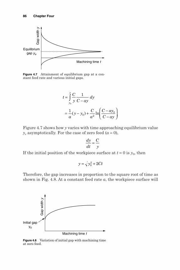
Figure 4.7 shows how y varies with time approaching equilibrium valueye asymptotically. For the case of zero feed (a = 0),
If the initial position of the workpiece surface at t = 0 is y0, then
Therefore, the gap increases in proportion to the square root of time asshown in Fig. 4.8. At a constant feed rate a, the workpiece surface will
y y Ct= +02 2
dy
dt
C
y=
tCy C ay
dy
ay y
Ca
C ayC ay
y
y
=−
= − + −−
∫0
1
10 2
0( ) ln
86 Chapter Four
Machining time t
Gap
wid
th y
Equilibriumgap ye
Figure 4.7 Attainment of equilibrium gap at a con-stant feed rate and various initial gaps.
Machining time t
Gap
wid
th y
Initial gapy0
Figure 4.8 Variation of initial gap with machining timeat zero feed.
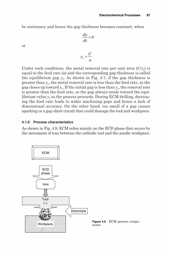
be stationary and hence the gap thickness becomes constant, when
or
Under such conditions, the metal removal rate per unit area (C/ye) isequal to the feed rate (a) and the corresponding gap thickness is calledthe equilibrium gap ye. As shown in Fig. 4.7, if the gap thickness isgreater than ye, the metal removal rate is less than the feed rate, so thegap closes up toward ye. If the initial gap is less than ye, the removal rateis greater than the feed rate, so the gap always tends toward the equi-librium value ye as the process proceeds. During ECM drilling, decreas-ing the feed rate leads to wider machining gaps and hence a lack ofdimensional accuracy. On the other hand, too small of a gap causessparking or a gap short circuit that could damage the tool and workpiece.
4.1.6 Process characteristics
As shown in Fig. 4.9, ECM relies mainly on the ECD phase that occurs bythe movement of ions between the cathodic tool and the anodic workpiece.
yC
ae =
dy
dt= 0
Electrochemical Processes 87
ECDphase
Tool(−)
Ions
Workpiece
Electrolyte−−++
ECM
Figure 4.9 ECM process compo-nents.

4.1.6.1 Material removal rate. Faraday’s laws describe the rate of materialremoval. For pure metals, the specific removal rate qc [mm3/(min ⋅ A)] isgiven by Kaczmarek (1976):
For a machining current I, the volumetric removal rate Qv (mm3/min)is given by
Qv = qcI
The linear removal Ql (mm/min) is a function of the current density J:
Ql = qcJ
where
The specific removal qc describes how effectively the machining currentis utilized for the material removal from the workpiece. The higher thevalue, the better is the removal rate per unit ampere. Since most metalsdissolve at different valences, the exact determination of the theoreti-cal removal rate becomes difficult due to the random phenomena occur-ring in the interelectrode gap. Confusion may arise when the incorrectvalence state is attributed to the dissolution process. In this regard, ata low potential difference, nickel usually dissolves in a divalent state innitrate and chloride solutions. This mode of dissolution switches to thetrivalent state at higher potential differences. Similarly copper has beenobserved to dissolve in a single valence in chloride solutions and in adivalent state in nitrate solutions. The apparent valence of copper dis-solution changes also with the mode of dissolution. In nitrate and sul-fate solutions, copper dissolves with a valence of 2. For conditions oftranspassive dissolution, this valence has been found to be between 1and 2 (1.6 at 60 A/cm2). ECM is mostly carried out on hard materialsand alloys. For an alloy containing n components of varying percentagesthe prediction of the removal rate becomes more difficult. The volu-metric removal rate Qv for that particular alloy is given by Kaczmarek(1976).
Q I q iv ci
i n
==
=
∑1
Jv v
y= −( )∆ κ
qc = 6096 500
ερ,
88 Chapter Four

The linear removal rate Ql is given by
For better ECM indices, higher accuracy, and a better surface finish, it isessential to choose the proper chemical composition of the electrolyte andthe proper current density. Amulticomponent electrolyte should be utilizedso that for each element of the alloy there will be a corresponding compo-nent in the electrolyte solution. In practical ECM the electrolyte is chosenbased on the largest component present in the alloy (Kaczmarek, 1976).Low values of current efficiency may indicate a failure to choose the opti-mum machining conditions that lead to high removal rates and accuratedimensions. Current losses may occur as a result of changes in the elec-trolyte properties. A poorly chosen electrolyte forms, either a thin layer ofelevated gas or an oxide film on the anode surface. The oxide film is dif-ficult to remove and, therefore, increases the polarization resistance.Figure 4.10 arranges some alloys with respect to the theoretical removalrate assuming a current efficiency of 100 percent. Steel 4340 has the high-est rate of material removal, while lithium alloy L605 has the lowest one.
Khayry (1989) suggested nickel as a free-cutting material in ECMsince it can be machined at 100 percent current efficiency using a lowcurrent density of 25 A/cm2. If the current density is increased (250A/cm2), the efficiency is reduced to 85 to 90 percent due to gas evolution.
Q J q ici
i n
l1
==
=
∑
Electrochemical Processes 89
4340
ste
el
17−4
PH
A-2
86
M25
2
Udi
met
500
Ren
e 41
Udi
met
700
L605
Work material
0
50
100
150
200
250
Rem
oval
rat
e 10
−2 c
m3 /
min
218202
192180 180 177 177 175
Figure 4.10 Theoretical removal rates for ECM of alloys assuming 100 percentcurrent efficiency and a current density of 1.53 A/mm2 (El-Hofy, 1995).
When machining titanium, in NaCl electrolyte, a current efficiency of10 to 20 percent is obtainable. When this solution is replaced by somemixture of florid-based electrolytes, higher efficiencies are obtained at60 V that break down the tenacious oxide film formed on the machinedsurface. However, McGeough (1988) reported that this tough, light, andcorrosion-resistant layer is what makes titanium so useful in the air-craft engine industry. With low electrolyte flow rates the current effi-ciency is reduced due to the accumulation of machining products withinthe gap that impedes further dissolution of the metal. Additionally, thebuildup of cathodically generated gases can lead to short circuitingbetween the tool and workpiece, which terminates the machining processand damages both the tool and workpiece.
Electrolyte concentration is also an important factor that determinesthe gap resistance and controls the machining current. In some casesthe removal rate and hence the machinability can be enhanced by heat-ing the electrolyte because this increases the electrolyte’s specific con-ductivity. In practice, the electrolyte temperature must not exceed 60 to70°C using temperature regulators.
Electrolyte circulation and replenishment are recommended for rais-ing the electrolyte discharging voltage and keeping the pH number ata moderate level of 4 to 10. The electrolytes used in practice make it pos-sible to employ a working voltage up to 20 V (Metals Handbook, 1989).Figure 4.11 shows the relative machinability index of some alloys basedon the machining speed obtainable at a constant current density.
4.1.6.2 Accuracy of ECM. A small gap width represents a high degreeof process accuracy. As can be seen in Fig. 4.12, the accuracy of machinedparts depends on the current density, which is affected by
1. Material equivalent and gap voltage
2. Feed rate and gap phenomena including passivation
3. Electrolyte properties including rate, pH, temperature, concentration,pressure, type, and velocity
For high process accuracy, machining conditions leading to narrowmachining gaps are recommended. These include use of
1. A high feed rate
2. High-conductivity electrolytes
3. Passivating electrolytes, such as NaNO3, that have a low throwingpower
4. Tool insulation that limits the side-machining action
90 Chapter Four

The control of dimensions in ECM can be explained using Fig. 4.13.If the passage of current is only required between RS and BC, a straycurrent will pass from RS to BA and CD. The current density is less inthe directions B to A and C to D. Surface polishing occurs along BC,while the lower current density along BA and CD leads to etching andpitting. Under such conditions, machining takes place in the regionswhere it is undesired thus leading to a lack of dimensional control. A sim-ilar situation occurs in the side gap during electrochemical drilling anddie sinking processes.
The extent to which the current strays in this fashion is related to thethrowing power of the electrolyte. Fine dimensional control was obtainedwhen using sodium chlorate (NaCIO3) electrolyte due to the very lowelectrolyte throwing power, which is linked to the passivation of theanode in the local current density region. Adding passivating agents suchas benzotriazol (Azimidobenzene, C6H5N3) and potassium dichromate(K2Cr2O7) to NaCl solution reduces the large throwing power of NaCl.Under such conditions, a passive film was found over the machined sur-face that improved the dimensional control of the machined parts.
Electrochemical Processes 91
Figure 4.11 Relative machinability for different materials at constant cur-rent density (El-Hofy, 1995).
10092.4
84.7 84.777
6963
4336.5
Zirc
oniu
m
Tita
nium
Nic
kel
Alu
min
um
Low
car
bon
stee
l
Ste
el
Sta
inle
ss s
teel
Tun
gste
n
Mol
ybde
num
Work material
0
20
40
60
80
100
120R
elat
ive
mac
hina
bilit
y in
dex,
%

El-Mehdawy (1977) reported that during machining of steel usingNaCl solution, the rate of passive film formation is controlled by the cur-rent density and electrolyte flow rate. At a high current density, a fasterrate of passive film formation occurs due to the rapid precipitation of theanode products over the machined surface. The increase of electrolyteflow rate reduces the concentration of these products and hence therate of the film formation.
92 Chapter Four
Accuracy,surface quality,machinability
Currentdensity
Gap widthMaterial
equivalent,grains
Volt
Gapphenomena,
gas, passivation
Feed
Electrolyte
Type
Conc. Pressure Rate
Velocity
pH
Temp.
Figure 4.12 Parameters affecting ECM accuracy, surface quality, and pro-ductivity.
A B
P
C D
Q T U
R S
Figure 4.13 Dimensional controlin ECM.
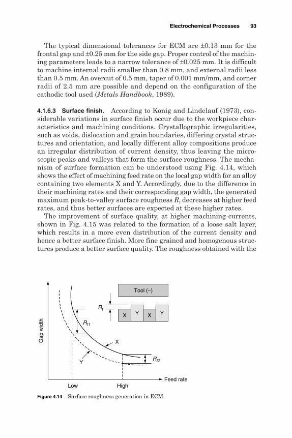
The typical dimensional tolerances for ECM are ±0.13 mm for thefrontal gap and ±0.25 mm for the side gap. Proper control of the machin-ing parameters leads to a narrow tolerance of ±0.025 mm. It is difficultto machine internal radii smaller than 0.8 mm, and external radii lessthan 0.5 mm. An overcut of 0.5 mm, taper of 0.001 mm/mm, and cornerradii of 2.5 mm are possible and depend on the configuration of thecathodic tool used (Metals Handbook, 1989).
4.1.6.3 Surface finish. According to Konig and Lindelauf (1973), con-siderable variations in surface finish occur due to the workpiece char-acteristics and machining conditions. Crystallographic irregularities,such as voids, dislocation and grain boundaries, differing crystal struc-tures and orientation, and locally different alloy compositions producean irregular distribution of current density, thus leaving the micro-scopic peaks and valleys that form the surface roughness. The mecha-nism of surface formation can be understood using Fig. 4.14, whichshows the effect of machining feed rate on the local gap width for an alloycontaining two elements X and Y. Accordingly, due to the difference intheir machining rates and their corresponding gap width, the generatedmaximum peak-to-valley surface roughness Rt decreases at higher feedrates, and thus better surfaces are expected at these higher rates.
The improvement of surface quality, at higher machining currents,shown in Fig. 4.15 was related to the formation of a loose salt layer,which results in a more even distribution of the current density andhence a better surface finish. More fine grained and homogenous struc-tures produce a better surface quality. The roughness obtained with the
Electrochemical Processes 93
Feed rate
Gap
wid
th
Tool (−)
YXYX
Rt
Rt2
Rt1
Y
X
Low High
Figure 4.14 Surface roughness generation in ECM.

larger grain size of the annealed carbon steel (Fig. 4.16), was possibly dueto the reduced number of grain boundaries present on such a surface.
The surface roughness of a machined part varies from 0.3 to 1.9 µm forthe frontal gap area and can be as rough as 5 µm or more for the side gaparea. Some metals can be polished in simple salt solutions if the currentdensity is high. Microscopic surface defects such as intergranular attackmay be caused by the selective ECM dissolution of certain constituents ofthe alloy. Such defects are usually associated with low current densitiesand intermetallic precipitates at grain boundaries. Intergranular attackcan usually be avoided by proper selection of electrolyte and machining
94 Chapter Four
0.45 carbon steel
Annealed
NormalizedHardened
250 50 75
Current density, A/cm2
1
2
3
4
Sur
face
rou
ghne
ss R
a, µ
m
Figure 4.16 Effect of heat treatment on surface roughnessfor steel (Kaczmarek, 1976).
(a) I = 44 A, Ra = 0.41 µm (b) I = 105 A, Ra = 0.29 µm
(c) I = 130 A, Ra = 0.175 µm
Figure 4.15 The appearance of different ECM surfaces at variouscurrents for NC6 heat-treated tool steel (Kaczmarek, 1976).

parameters. In general the following ECM effects are summarized inMetals Handbook (1989):
Large grains cause a rougher finish than fine grains. Insoluble inclusions such as graphite in cast iron increase roughness
and create machining problems. Variations in workpiece composition, as in the case of hardened steel,
cause differences in local machining rates. Precipitation of intermetallic compounds at grain boundaries leads to
serious intergranular attack.
Masuzawa et al. (1991) reported that for nonpassivating electrodesystems, the reduction in electrolyte concentration and the increase ofits temperature improve the quality of surfaces. For passivating systems,low electrolyte concentration and a rise in its temperature increase theformation of a protective layer that causes deterioration to the surfacequality. A further increase in current density breaks up this layer so thatthere is a decrease in the percentage of the covered surface areas wherethe reaction of a nonremoving effect occurs and a smoother surface isproduced. Etched matt surfaces of roughness 0.9 to 1.4 µm at a currentdensity of 15.5 A/cm2 and electrolyte flow rates of 28 m/s have been pro-duced on Nimonic 80 using NaCl solution. At a current density of 46.5 A/cm2
and an electrolyte flow rate of 28.5 m/s, the roughness was 0.2 µm.The coarse finish with surface roughness of 5.2 µm obtained with
cast iron machined in 20% w/w NaCl, current densities ranging from3.7 to 15.5 A/cm2, and flow rates of 0.4 to 1.4 m3/s has been mainlyattributed to partial passivation. Marks of partial passivation werealso observed by McGeough (1974) in case of 0.78% C quenched andtempered steels at an electrolyte velocity of 16.5 m/s. These marks werebroken down as the velocity was increased from 29 to 45 m/s, andhence the surface carried polished striations.
4.1.7 Process control
During ECM many of the selected machining conditions must be keptunchanged as they have a direct impact on the process accuracy and sur-face finish. The gap voltage affects the produced oversize, which in turnalters the dimensions of the machined workpiece. Surface roughnessdepends on current density, which is affected by the tool feed rate, gap volt-age, work material, gap phenomenon, and electrolyte conditions includ-ing type, concentration, temperature, pressure, pH level, and conductivity.
During ECM, machining conditions leading to high process accuracyare associated with smaller surface roughness and greater machiningproductivity. High current densities are, therefore, recommended.
Electrochemical Processes 95
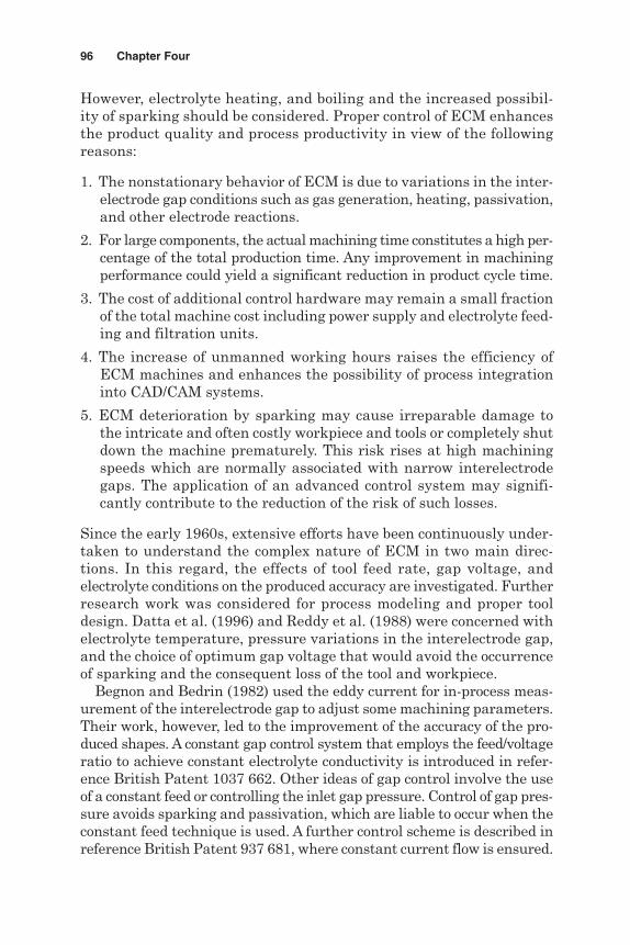
However, electrolyte heating, and boiling and the increased possibil-ity of sparking should be considered. Proper control of ECM enhancesthe product quality and process productivity in view of the followingreasons:
1. The nonstationary behavior of ECM is due to variations in the inter-electrode gap conditions such as gas generation, heating, passivation,and other electrode reactions.
2. For large components, the actual machining time constitutes a high per-centage of the total production time. Any improvement in machiningperformance could yield a significant reduction in product cycle time.
3. The cost of additional control hardware may remain a small fractionof the total machine cost including power supply and electrolyte feed-ing and filtration units.
4. The increase of unmanned working hours raises the efficiency ofECM machines and enhances the possibility of process integrationinto CAD/CAM systems.
5. ECM deterioration by sparking may cause irreparable damage tothe intricate and often costly workpiece and tools or completely shutdown the machine prematurely. This risk rises at high machiningspeeds which are normally associated with narrow interelectrodegaps. The application of an advanced control system may signifi-cantly contribute to the reduction of the risk of such losses.
Since the early 1960s, extensive efforts have been continuously under-taken to understand the complex nature of ECM in two main direc-tions. In this regard, the effects of tool feed rate, gap voltage, andelectrolyte conditions on the produced accuracy are investigated. Furtherresearch work was considered for process modeling and proper tooldesign. Datta et al. (1996) and Reddy et al. (1988) were concerned withelectrolyte temperature, pressure variations in the interelectrode gap,and the choice of optimum gap voltage that would avoid the occurrenceof sparking and the consequent loss of the tool and workpiece.
Begnon and Bedrin (1982) used the eddy current for in-process meas-urement of the interelectrode gap to adjust some machining parameters.Their work, however, led to the improvement of the accuracy of the pro-duced shapes. A constant gap control system that employs the feed/voltageratio to achieve constant electrolyte conductivity is introduced in refer-ence British Patent 1037 662. Other ideas of gap control involve the useof a constant feed or controlling the inlet gap pressure. Control of gap pres-sure avoids sparking and passivation, which are liable to occur when theconstant feed technique is used. A further control scheme is described inreference British Patent 937 681, where constant current flow is ensured.
96 Chapter Four

Elsayed (1989) recommended the use of constant current flow to con-trol the machining gap. Setting and maintaining a small stable gap sizein pulsed electrochemical machining (PECM) is important for betterdimensional control. A high-speed data acquisition system is used toacquire the pulse current signal for developing an on-line monitoringstrategy where the signal variance was correlated to the interelectrodegap size by Rajurkar et al. (1995). A control model that considers thedynamic nature of the process and achieves the desired conditions hasbeen introduced by Rajurkar and Schnacker (1988).
Sorkhel and Bhattacharyya (1994) developed a setup with a computer-controlled stepper motor drive control unit for providing variable andautomatic feed rates besides autosensing of the ECM gap conditionsduring machining. Based on the electrical responses received fromthe machining gap, control of the tool feed rate and electrolyte flowconditions have been considered.
Kozak et al. (1995) introduced an ECM process with numerically con-trolled movement of the tool electrode. This eliminates the expensive toolshape and raises the machining accuracy. An intelligent knowledge-based system for a ready, on-line knowledge consultancy to select appro-priate ECM conditions is described by Amalnik and McGeough (1996)and Khayry (1996).
4.1.8 Applications
ECM has been used in a wide variety of industrial applications rangingfrom cavity sinking to deburring. The ability to machine high-strengthalloys and hardened steel has led to many cost-saving applicationswhere other processes are impractical. Typical applicators for the ECMprocess are shown in Fig. 4.17.
Electrochemical Processes 97
Figure 4.17 ECM components (www.unl.edu/).
El-Hofy_CH04.qxd 1/27/05 4:41 PM Page 97
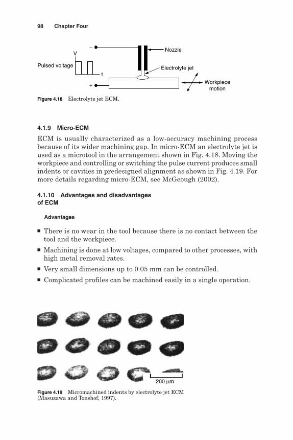
4.1.9 Micro-ECM
ECM is usually characterized as a low-accuracy machining processbecause of its wider machining gap. In micro-ECM an electrolyte jet isused as a microtool in the arrangement shown in Fig. 4.18. Moving theworkpiece and controlling or switching the pulse current produces smallindents or cavities in predesigned alignment as shown in Fig. 4.19. Formore details regarding micro-ECM, see McGeough (2002).
4.1.10 Advantages and disadvantagesof ECM
Advantages
There is no wear in the tool because there is no contact between thetool and the workpiece.
Machining is done at low voltages, compared to other processes, withhigh metal removal rates.
Very small dimensions up to 0.05 mm can be controlled. Complicated profiles can be machined easily in a single operation.
98 Chapter Four
Pulsed voltage
Nozzle
Electrolyte jet
Workpiecemotion
+
−
t
V
Figure 4.18 Electrolyte jet ECM.
Figure 4.19 Micromachined indents by electrolyte jet ECM(Masuzawa and Tonshof, 1997).
Because of the low temperature developed, no thermal damage occursto the workpiece structure.
Hard conductive materials can be machined. The surface finish can be maintained at 0.1 to 1.25 µm Ra. Because of its high capital cost, ECM is only suitable for mass pro-
duction work. Labor requirements are low.
Disadvantages
A huge amount of energy is consumed (about 100 times that requiredfor turning or drilling steel).
Metal removal rates are slow compared with conventional methods. ECM can only be applied to electrically conductive workpiece materials. There are difficulties in safely removing and disposing of the explo-
sive hydrogen gas generated during machining. The workpiece needs to be cleaned and oiled immediately after
machining. There are difficulties with handling and containing the electrolyte,
which may attack the equipment. It is not easy to duplicate the shape of the tool electrode in the workpiece
with a high degree of accuracy because of the side machining effect. The process can’t produce sharp internal or external edges. The pumping of high-pressure electrolyte into the narrow machin-
ing gap gives rise to large forces acting on the tool and the workpiece.
4.1.11 Environmental impacts
Occupational health dangers are very limited if ECM is applied underappropriate conditions. Electrolyte splashing, contamination of the eyesand skin, and the free expansion of harmful or toxic vapors must beavoided (Fig. 4.20). The crucial impacts on the environment come fromthe electrolyte and the ECM slurry. During ECM deburring and diesinking, NaNO3 fulfills the requirements of high removal rate and sur-face quality. However, through the dissolution of metals containingchrome and due to a nitrate reduction at the tool cathode, the mediumaccumulates toxic chromate and ammonia. These chemical compoundsare absorbed into the metal hydroxides in the ECM slurry. Slurriesresulting from electrolyte maintenance precipitate solid matters, andsolutions of electrolytes have to be disposed off (Tonshof et al., 1996).
Electrochemical Processes 99

4.2 Electrochemical Drilling
Electrochemical drilling (ECDR) produces diameters ranging from 1 to20 mm, using feed rates from 1 to 5 mm/min. As shown in Fig. 4.21, atubular electrode is used as the cathodic tool. The electrolyte is pumpedfrom the center of the tool and exits through the side-machining gap,formed between the walls of the tool and the drilled hole. Machiningoccurs at high current densities in the frontal interelectrode gap betweenthe tool face and the workpiece. Side electrochemical dissolution acts lat-erally between the sidewalls of the tool and the component. The producedhole diameter is therefore greater than the tool by an overcut Cd, which
100 Chapter Four
Metal hydroxides
Tool
Workpiece (+)
Electrolyte splash
Chromate, nitrate,and ammonia
Toxic vapor
Skin irritation
Figure 4.20 Possible impacts of ECM.
Workpiece (+)
Tool land
Insulation
Side gap
Tool feed
Central spike
Electrolyte
Figure 4.21 ECDR configuration.

can be calculated, as shown in Fig. 4.22, by
Cd = dw – dt
where dt is the tool diameter and dw is the workpiece diameter.For high machining accuracy and smaller diametral oversize, high feed
rates are recommended. Under such conditions, high removal rates andbetter surface quality are also ensured. The method of electrolyte feed-ing affects the overcut. In this regard, the reverse electrolyte flow modeunder back pressure of 0.6 to 2 MPa, shown in Fig. 4.22, reduces theovercut. This procedure flushes away the gaseous products of electroly-sis from the machining gap without reaching the side-machining zone.
The increase in gap pressure raises the electrolyte conductivity, whichenhances the dissolution process due to the increase of machining current.The high pressure reduces the size of hydrogen gas bubbles, whichaccording to Rumyantsev and Davydov (1984), raises the electrolyte con-ductivity. Electrolyte back pressure also eliminates the flow lines in themachined surface. The major disadvantage of such systems, besides thetooling cost, is the increase of hydraulic forces.
Soliman et al. (1986) and Rashed et al. (1986) concluded that the useof proper tool insulation reduces the side-machining effect, which inturn limits the widening of the side gap. Passivating electrolytes suchas NaNO3 can produce smaller overcuts, which enhance the processaccuracy. The electrolyte flow rate has a pronounced effect on overcut.The use of a rotating tool during ECDR can reduce the roundness errorsince it ensures homogenous electrolyte flow conditions in the side gap.
In ECDR the passage of current through the interelectrode gap resultsin the anodic dissolution at a rate that is governed by Faraday’s laws of
Electrochemical Processes 101
Insulation
Electrolyte inlet
Pressure chamber
Electrolyte inlet
dt
dw
Workpiece
Figure 4.22 Hole drilling using back pressure.

electrolysis. Youssef et al. (1989) noticed that the machining currentincreases linearly with the tool feed rate. Sparking takes place at a crit-ical feed rate where the speed of tool advance toward the workpiece isgreater than the anodic dissolution rate. Under such circumstances, thefrontal gap decreases to a critical value at which sparking occurs, caus-ing damage to both the tool and workpiece. The experimental work ofRashed et al. (1976) recommended the use of a gap voltage between 20 to25 V in order to save energy and reduce the production cost. Theydescribed the diametral oversize Cd by the following empirical equation:
Cd = 0.225V 0.74−0.056a
where V is the gap voltage (V) and a is the tool feed rate (mm min–1).During ECDR a considerable part of the machining current is lost in
the side gap. For this reason the ratio of the experimental removal rateto the theoretical one represents the current efficiency. Current effi-ciencies lower than 100 percent may be related to gas evolution and theformation of passive oxide film that limits the dissolution process. Onthe other hand, current efficiencies greater than 100 percent weremainly related to the granular detachment, from the anode, due to theelectrolytic grain boundary attack. EC hole drilling is not restricted tocircular holes since a tool having any cross section can produce a cor-responding shape in the workpiece.
4.3 Shaped Tube Electrolytic Machining
Shaped tube electrolytic machining (STEM) is based on the dissolutionprocess when an electric potential difference is imposed between the anodicworkpiece and a cathodic tool. Because of the presence of this electricfield the electrolyte, often a sulfuric acid, causes the anode surface tobe removed. After the metal ions are dissolved in the solution, they areremoved by the electrolyte flow. As shown in Fig. 4.23 and according to
102 Chapter Four
Titanium tube (−)Insulating coating
Workpiece (+)
Electrolyte
Figure 4.23 STEM schematic.
McGeough (1988), the tool is a conducting cylinder with an insulatingcoating on the outside and is moved toward the workpiece at a certainfeed rate while a voltage is applied across the machining gap. In this waya cylindrically shaped hole is obtained.
STEM is, therefore, a modified variation of the ECM that uses acidelectrolytes. Rumyantsev and Davydov (1984) reported that theprocess is capable of producing small holes with diameters of 0.76 to1.62 mm and a depth-to-diameter ratio of 180:1 in electrically con-ductive materials. It is difficult to machine such small holes usingnormal ECM as the insoluble precipitates produced obstruct the flowpath of the electrolyte.
The machining system configuration is similar to that used in ECM.However, it must be acid resistant, be of less rigidity, and have aperiodically reverse polarity power supply. The cathodic tool electrodeis made of titanium, its outer wall having an insulating coating to permitonly frontal machining of the anodic workpiece. The normal operatingvoltage is 8 to 14 V dc, while the machining current reaches 600 A. TheMetals Handbook (1989) reports that when a nitric acid electrolyte solu-tion (15% v/v, temperature of about 20°C) is pumped through the gap(at 1 L/min, 10 V, tool feed rate of 2.2 mm/min) to machine a 0.58-mm-diameter hole with 133 mm depth, the resulting diametral overcut is0.265 mm, and the hole conicity is 0.01/133.
The process also uses a 10% concentration sulfuric acid to prevent thesludge from clogging the tiny cathode and ensure an even flow of electrolytethrough the tube. A periodic reversal of polarity, typically at 3 to 9 s pre-vents the accumulation of the undissolved machining products on thecathode drill surface. The reverse voltage can be taken as 0.1 to 1times the forward machining voltage. In contrast to the EDM, EBM,and LBM processes, STEM does not leave a heat-affected layer, whichis liable to develop microcracks (www.win.tue.nl/).
Process parameters
Electrolyte
Type Sulfuric, nitric, and hydrochloric acids
Concentration 10–25% weight in water
Temperature 38°C (sulfuric acid)
21°C (others)
Pressure 275–500 kPa
Voltage
Forward 8–14 V
Reverse 0.1–1 times the forward
Electrochemical Processes 103

Time
Forward 5–7 s
Reverse 25–77 ms
Feed rate 0.75–3 mm/min
Process capabilities
Hole size 0.5–6 mm diameter at an aspect ratio of 150
Hole tolerances 0.5-mm diameter ±0.050 mm
1.5-mm diameter ±0.075 mm
60-mm diameter ±0.100 mm
Hole depth ±0.050 mm
Because the process uses acid electrolytes, its use is limited to drillingholes in stainless steel or other corrosion-resistant materials in jetengines and gas turbine parts such as
Turbine blade cooling holes Fuel nozzles Any holes where EDM recast is not desirable Starting holes for wire EDM Drilling holes for corrosion-resistant metals of low conventional
machinability Drilling oil passages in bearings where EDM causes cracks
Figure 4.24 shows the shape of turbulators that are machined by inter-mittent drill advance during STEM. The turbulators are normally usedfor enhancing the heat transfer in turbine engine-cooling holes(www.win.tue.nl/).
Advantages
The depth-to-diameter ratio can be as high as 300. A large number of holes (up to 200) can be drilled in the same run. Nonparallel holes can be machined. Blind holes can be drilled. No recast layer or metallurgical defects are produced. Shaped and curved holes as well as slots can be produced.
104 Chapter Four

Limitations
The process is used for corrosion-resistant metals. STEM is slow if single holes are to be drilled. A special workplace and environment are required when handling acid. Hazardous waste is generated. Complex machining and tooling systems are required.
4.4 Electrostream (Capillary) Drilling
Electrostream (ES) (capillary) drilling is a special ECM techniqueused for producing fine holes that are too deep to produce by EDM andtoo small to drill by STEM. The cathodic tool used is made from aglass nozzle (0.025–0.50 mm diameter), which is smaller than the
Electrochemical Processes 105
Figure 4.24 Turbulated cooling holes produced by STEM(www.win.tue.nl/).

required diameter. The ES process differs from STEM, which uses acoated titanium tube as a cathodic tool.
To conduct the machining current through the acid electrolyte that fillsthe interelectrode gap, a platinum wire electrode is fitted inside theglass nozzle (Fig. 4.25). Solutions of sulfuric, nitric, or hydrochloric acidwith a concentration of 12 to 20 wt % are common electrolytes used. Thetype electrolyte used depends on the condition of the workpiece. In thisregard, hydrochloric solution is used for aluminum and its related alloys,while sulfuric acid solution is recommended for Hastelloy, Inconel, Renealloys, and carbon and stainless steels.
The electrolyte temperature is normally 40°C for sulfuric acid and20°C for the rest. Electrolyte pressures between 275 and 400 kPa arerecommended. During machining, the electrolyte stream is negativelycharged and squirted against the anodic workpiece. The acid tempera-ture, pressure, concentration, and flow rate must be carefully monitoredfor satisfactory machining. A gap voltage of 70 to 150 V is employed,which is 10 times greater than that of normal ECM.
Banard (1978) drilled small rows of cooling holes (0.127–1.27 mmdiameter) in turbine blades, with depth-to-diameter ratios up to 50 to 1,which is higher than those produced by conventional drilling. The processis also used to produce cooling ducts running at an angle of 45° to thesurface of the blade and having a diameter less than 0.8 mm as shownin Figs. 4.26 and 4.27. Wire EDM start holes of less than 0.5 mm canalso be drilled using ES.
Process capabilities. Feed rates for ES drilling range from 0.75 to2.5 mm/min. The feed rate depends on the material to be machinedirrespective of the number of holes to be drilled simultaneously. Similarto ECM, higher removal rates are associated with larger feed rates and
106 Chapter Four
Electrolyte supply
Wire (−)
Glass nozzle
Workpiece (+)
Figure 4.25 ES drilling schematic.
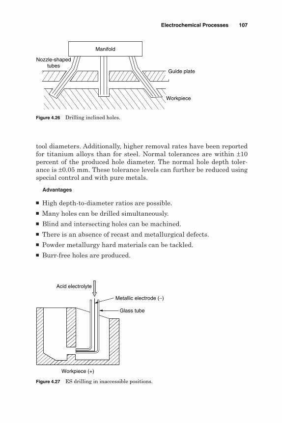
tool diameters. Additionally, higher removal rates have been reportedfor titanium alloys than for steel. Normal tolerances are within ±10percent of the produced hole diameter. The normal hole depth toler-ance is ±0.05 mm. These tolerance levels can further be reduced usingspecial control and with pure metals.
Advantages
High depth-to-diameter ratios are possible. Many holes can be drilled simultaneously. Blind and intersecting holes can be machined. There is an absence of recast and metallurgical defects. Powder metallurgy hard materials can be tackled. Burr-free holes are produced.
Electrochemical Processes 107
Manifold
Guide plate
Workpiece
Nozzle-shapedtubes
Figure 4.26 Drilling inclined holes.
Acid electrolyte
Workpiece (+)
Metallic electrode (−)
Glass tube
Figure 4.27 ES drilling in inaccessible positions.

Limitations
Can only be used with corrosion-resistant metals. Hazardous waste is generated. The process is slow when drilling a single hole. The handling of acid requires a special environment and precautions. Oblique entry is difficult.
4.5 Electrochemical Jet Drilling
Electrochemical jet drilling (ECJD) is mainly used for fine hole drillingat a diameter-to-depth ratio of 1:12 which is lower than that obtainedin ES (capillary) drilling (1:100). As shown in Fig. 4.28, the process doesnot require the entry of the tool as in the case of ES drilling. The process,therefore, avoids the use of fragile tooling. The jet of a dilute acid elec-trolyte causes dissolution, and enough room is required for the elec-trolyte to exit, preferably in the form of spray. A typical voltage in therange of 400 to 800 V is considered optimum.
According to Banard (1978), the lower limit of the hole size is deter-mined by the smallest hole that can be drilled in the cathodic nozzle, thepressure required to pump the electrolyte in the form of a jet, and theamount of overcut. The produced hole diameter depends on the elec-trolyte throwing power. Generally, holes produced by ECJD are fourtimes the diameter of the electrolyte jet. In ES capillary drilling the holediameter/capillary diameter ratio is normally less than 2. He reporteda ratio of 3:4 using 0.1 M HCl, 0.5-mm jet diameter, 5-mm nozzle dis-tance from workpiece, and an electrolyte pressure of 7 × 10⁵ Nm−2.
108 Chapter Four
Nozzle(−)
Electrolyte jet
Anodic workpiece(+) Discharges
Outlet spray
Figure 4.28 Electrochemical jet drilling.

The taper for ECJD is about 5 to 10 included angles, whereas tapers ofzero are obtainable in ES capillary drilling.
4.6 Electrochemical Deburring
When machining metal components, it is necessary to cross-drill holesto interconnect bores. Hydraulic valve bodies are a typical examplewhere many drilled passages are used to direct the fluid flow. Theintersection of these bores creates burrs, which must be removed(Fig. 4.29) to avoid the possibility of them breaking off and severelydamaging the system. Figure 4.30 shows conventionally cut parts thatrequire deburring. Manual removal of burrs is tedious and time-con-suming. In the 1970s the thermal energy method (TEM) was intro-duced to remove burrs in hard-to-reach places. In this method, burrsare hit by 2760°C blast of heat for milliseconds, which burns them away,leaving everything else including threads, dimensions, surface finish,and the physical properties of the part intact. Parts subjected to TEMshould be cleaned of oil and metal chips to avoid the formation of carbonsmut or the vaporization of chips.
Burrs can be removed using several other methods including vibra-tory and barrel finishing, tumbling, water blasting, and the applicationof ultrasound and abrasive slurry. Abrasive flow machining (AFM) pro-vides a reliable and accurate method of deburring for the aerospace andmedical industries. AFM can reach inaccessible areas and machine mul-tiple holes, slots, or edges in one operation. It was originally devisedin the 1950s for deburring of hydraulic valve spools and bodies andpolishing of extrusion dies. The drawbacks of these methods includelack of reliability, low metal removal rates, and contamination ofsurfaces with grit.
In electrochemical deburring (ECDB), the anodic part to be deburredis placed in a fixture, which positions the cathodic electrode in closeproximity to the burrs. The electrolyte is then directed, under pressure,to the gap between the cathodic deburring tool and the burr. On theapplication of the machining current, the burr dissolves forming acontrolled radius. Since the gap between the burr and the electrode
Electrochemical Processes 109
Burrs
Figure 4.29 Burrs formed atintersections of holes.
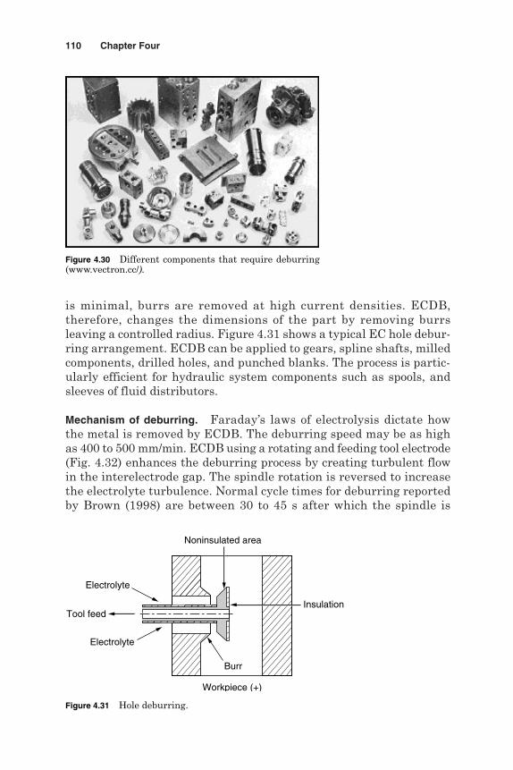
is minimal, burrs are removed at high current densities. ECDB,therefore, changes the dimensions of the part by removing burrsleaving a controlled radius. Figure 4.31 shows a typical EC hole debur-ring arrangement. ECDB can be applied to gears, spline shafts, milledcomponents, drilled holes, and punched blanks. The process is partic-ularly efficient for hydraulic system components such as spools, andsleeves of fluid distributors.
Mechanism of deburring. Faraday’s laws of electrolysis dictate howthe metal is removed by ECDB. The deburring speed may be as highas 400 to 500 mm/min. ECDB using a rotating and feeding tool electrode(Fig. 4.32) enhances the deburring process by creating turbulent flowin the interelectrode gap. The spindle rotation is reversed to increasethe electrolyte turbulence. Normal cycle times for deburring reportedby Brown (1998) are between 30 to 45 s after which the spindle is
110 Chapter Four
Figure 4.30 Different components that require deburring(www.vectron.cc/).
Tool feed
Electrolyte
Noninsulated area
Workpiece (+)
Insulation
Electrolyte
Burr
Figure 4.31 Hole deburring.

retracted and the part is removed. In simple deburring when the toolis placed over the workpiece, a burr height of 0.5 mm can be removedto a radius of 0.05 to 0.2 mm leaving a maximum surface roughnessof 2 to 4 µm.
When burrs are removed from intersections of passages in a housing,the electrolyte is directed and maintained under a pressure of 0.3 to0.5 MPa using a special tool. That tool has as many working areas aspractical so that several intersections are deburred at a time. Proper toolinsulation guarantees the flow of current in areas nearby the burr. Thedeburring tool should also have a similar contour of the work part thusleaving a 0.1 to 0.3 mm interelectrode gap. Moreover the tool tip shouldoverlap the machined area by 1.5 to 2 mm in order to produce a properradius. The choice of the electrolyte plays an important role in the debur-ring process. Table 4.2 presents different electrolytes and the operating
Electrochemical Processes 111
Rotation + feed
Tool (−)
Electrolyte flow
Electrolytecirculating slots
Workpiece (+)
Electrolyte flow
Burrs
Figure 4.32 Electrochemical deburring using a rotating tool.
TABLE 4.2 Machining Conditions for Deburring of Different Materials
Applied CurrentMaterial Electrolyte voltage, V density, A/cm2 Time, s
Carbon steel and 5–15% NaNO3
low-carbon steel 2–2.5 NaNO2
Copper alloys 5–15% NaNO3 12–24 5–10 5–100Aluminum alloys 5–20% NaNO3
Stainless steels 5% NaNO3
+0.5% NaCl
SOURCE: Rumyantsev and Davydov (1984).

conditions for ECDB of some materials. ECDB power units supply amaximum current of 50 A. However, power units having 500 A are usedto remove burrs generated by turning and facing operations on largeforged parts. Figure 4.33 shows an EC deburring application.
Advantages
Elimination of costly hand deburring Increase of product quality and reliability Ensures the removal of burrs at the required accuracy, uniformity,
proper radius, and clean edge Reduced personnel and labor cost Can be automated for higher productivity
References
Amalnik, M. S., and McGeough, J. (1996). “Intelligent Concurrent ManufacturabilityEvaluation for Design for Electrochemical Machining,” Journal of Material ProcessingTechnology, 61:130–139.
British Patent 937 681. A system for maintaining a constant current flow between tooland workpiece.
British Patent 1037 662. Control of the ratio of feed rate to the applied voltage in orderto achieve a constant predetermined working gap.
Banard, J. (1978). “Fine Hole Drilling Using Electrochemical Machining,” MTDR Conf.Proc., pp. 503–510.
Begnon, C., and Bedrin, C. (1982). “Application of Eddy Currents to the In ProcessMeasurement of the Gap in ECM,” Anals of CIRP, 31(1):115–118.
Brown, J. (1998). Advanced Machining Technology Handbook. New York: McGraw-Hill.
112 Chapter Four
Figure 4.33 EC deburring applications (www.extrudehone.com/cation).
Datta, M, Shenoy, R. V., and Romatkiw, L. T. (1996). “Recent Advances in the Study ofElectrochemical Micromachining,” ASME, Journal of Engineering for Industry,118:29–36.
El-Hofy, H. (1995). “Machinability Indices for Some Non-conventional MachiningProcesses,” Alexandria Engineering Journal (AEJ). 34(3):231–245.
El-Hofy, H. (1996). “Surface Generation in Non-conventional Machining,” MDP-6, Conf.,Cairo, pp. 203–213.
El-Mehdawy, Y. (1977). Accuracy of Electrolytic Sinking, M.S. Thesis, AlexandriaUniversity.
El-Sayed, E. M. (1989). Towards Better Control of Electrochemical Machining (ECM)Parameters by Computer Interfacing, M.S. Thesis, King Saud University, Riyadh.
Kaczmarek, J. (1976). Principles of Machining by Cutting, Abrasion and Erosion,Stevenage, U.K.: Peter Peregrines Ltd.
Khayry, A. (1989). “Towards a Machinability System for Electrochemical Machining.”CAPE-5 Conf. Proc., Edinburgh, pp. 343–350.
Khayry, A. (1996). “A Knowledge-Based System for Electrochemical Machining Procedure,”Journal of Material Processing Technology, 58:121–130.
Konig, W., and Lindelauf, P. (1973). “Surface Generation in Electrochemical Machining,”Annals of CIRP, 29(1):97–100.
Kozak, J., Dabrowiski, L., Rusazj, A., and Slawinski, R. (1995). “Computer Simulation onNumerically Controlled Electrochemical Machining (ECM-NC) with a Spherical ToolElectrode,” CAPE-11 Conf., pp. 205–210.
Machining Data Handbook. (1997). 3d. ed., Vol. 2. Cincinnati, OH: Machinability DataCenter, Institute of Advanced Manufacturing.
Masuzawa, T., and Tonshof, H. K. (1997). “Three Dimensional Micro Machining by MachineTools,” Annals of CIRP, 42(2):621–628.
Masuzawa, T., et al. (1991). “Electrochemical Surface Finishing of Tungsten CarbideAlloys,” Annals of CIRP, 40(1):199–202.
McGeough, J. (1974). Principles of Electrochemical Machining. London: Chapman andHall.
McGeough, J. (1988). Advanced Methods of Machining, London. New York: Chapman andHall, London.
McGeough, J. (2002). Micromachining of Engineering Materials. New York: Marcel Dekker,Inc.
Metals Handbook. (1989). Vol. 16, Machining, Materials Park, OH: ASM International.Rajurkar, K. P., and Schnacker, C. L. (1988). “Some Aspects of ECM Performance and
Control,” Annals of CIRP, 37(1):183–186.Rajurkar, K. P., Wei, B., Kozak, J., and McGeough, J. (1995). “Modeling and Monitoring
Inter Electrode Gap in Pulse Electrochemical Machining,” Annals of CIRP,44(1):177–180.
Rashed, A. F., Youssef, H., and El-Mehdawy, Y. (1976). “Effect of Gap Voltage and Currentin Electrolytic Sinking,” Bulletin of the Faculty of Engineering, Alexandria University,XV-1:705–736.
Rashed, A. F., Youssef, H., and El-Hofy, H. (1986). “Effect of Some Process Parameterson the Side Machining During Electrolytic Sinking,” PEDAC-3 Conf., Alexandria,pp. 733–746.
Reddy, M. S., Jain, V. K., and Lai, G. K. (1988). “Tool Design for ECM: Correction FactorMethod,” ASME, Journal of Engineering for Industry, 110:111–118.
Rumyantsev, E., and Davydov, A. (1984). Electrochemical Machining of Metals. Moscow:Mir Publishers.
Soliman, S. M., Youssef, H., and El-Hofy, H. (1986). “A Study of the Side Machining inElectrolytic Sinking,” PEDAC-3 Conf., Alexandria, pp. 717–733.
Sorkhel, S. K., and Bhattacharyya, B. (1994). “Parametric Control for Optimal Quality ofWorkpiece Surface in ECM,” Journal of Material Processing Technology, 40:271–286.
Tipton, H. (1971). “The Determination of the Shape of Tools for Use in ElectrochemicalMachining,” MTIRA Report No. 40.
Tonshof, K., Egger, K. R., and Kloclco, F. (1996). “Environmental and Safety Aspects ofElectro Physical and Electrochemical Processes,” Annals of CIRP, 45(2):553–567.
Electrochemical Processes 113

Youssef, H., El-Hofy, H., and El-Mehdawy, Y. (1989). “Sparking Phenomena and HoleOversize by ECM, Effect of Some Process Parameters,” Alexandria Engineering Journal(AEJ), 28(4):247–259.
www.extrudehone.com/cationwww.unl.edu/nmrc/ecm1.htmwww.vectron.cc/electro.htmlwww.win.tue.nl/~scg/drilling/noot.html#part2
114 Chapter Four
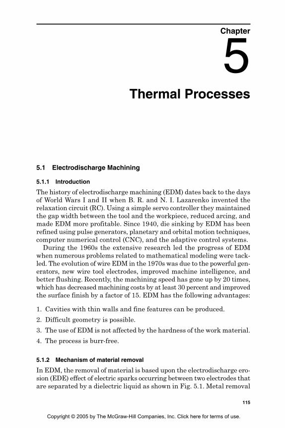
Chapter
5Thermal Processes
5.1 Electrodischarge Machining
5.1.1 Introduction
The history of electrodischarge machining (EDM) dates back to the daysof World Wars I and II when B. R. and N. I. Lazarenko invented therelaxation circuit (RC). Using a simple servo controller they maintainedthe gap width between the tool and the workpiece, reduced arcing, andmade EDM more profitable. Since 1940, die sinking by EDM has beenrefined using pulse generators, planetary and orbital motion techniques,computer numerical control (CNC), and the adaptive control systems.
During the 1960s the extensive research led the progress of EDMwhen numerous problems related to mathematical modeling were tack-led. The evolution of wire EDM in the 1970s was due to the powerful gen-erators, new wire tool electrodes, improved machine intelligence, andbetter flushing. Recently, the machining speed has gone up by 20 times,which has decreased machining costs by at least 30 percent and improvedthe surface finish by a factor of 15. EDM has the following advantages:
1. Cavities with thin walls and fine features can be produced.
2. Difficult geometry is possible.
3. The use of EDM is not affected by the hardness of the work material.
4. The process is burr-free.
5.1.2 Mechanism of material removal
In EDM, the removal of material is based upon the electrodischarge ero-sion (EDE) effect of electric sparks occurring between two electrodes thatare separated by a dielectric liquid as shown in Fig. 5.1. Metal removal
115
Copyright © 2005 by The McGraw-Hill Companies, Inc. Click here for terms of use.
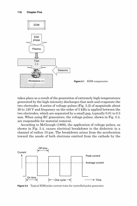
takes place as a result of the generation of extremely high temperaturesgenerated by the high-intensity discharges that melt and evaporate thetwo electrodes. A series of voltage pulses (Fig. 5.2) of magnitude about20 to 120 V and frequency on the order of 5 kHz is applied between thetwo electrodes, which are separated by a small gap, typically 0.01 to 0.5mm. When using RC generators, the voltage pulses, shown in Fig. 5.3,are responsible for material removal.
According to McGeough (1988), the application of voltage pulses, asshown in Fig. 5.4, causes electrical breakdown to the dielectric in achannel of radius 10 µm. The breakdown arises from the accelerationtoward the anode of both electrons emitted from the cathode by the
116 Chapter Five
Figure 5.1 EDM components.
EDEphase
Workpiece (+)
Tool(−)
Plasma
Dielectric
EDM
Figure 5.2 Typical EDM pulse current train for controlled pulse generator.
Peak currentCurrent
Time
Off time
On timeOne cycle
Average current

applied field and the stray electrons present in the gap. These electronscollide with neutral atoms of the dielectric, thereby creating positive ionsand further electrons, which in turn are accelerated respectively towardthe cathode and anode.
When the electrons and the positive ions reach the anode and cath-ode, they give up their kinetic energy in the form of heat. Temperaturesof about 8000 to 12,000°C and heat fluxes up to 1017 W/m2 are attained.With a very short duration spark of typically between 0.1 to 2000 µs thetemperature of the electrodes can be raised locally to more than their
Thermal Processes 117
Figure 5.3 Variation of voltage with time using an RC generator.
Time
Volt
Discharge voltage
Charging time Discharging time
One cycle
Figure 5.4 Voltage and current waveforms during EDM.
Time
Time
Volt
Current
On time
One cycle
Off timeIgnition delay
IonizationSpark volt
Breakdown volt
Peak current
Average currentSparkenergy

normal boiling points. Owing to the evaporation of the dielectric, thepressure on the plasma channel rises rapidly to values as high as 200atmospheres. Such great pressures prevent the evaporation of thesuperheated metal.
At the end of the pulse, the pressure drops suddenly and the super-heated metal evaporates explosively. Metal is thus removed from theelectrodes as shown in Fig. 5.5.
Fresh dielectric fluid rushes in, flushing the debris away and quench-ing the surface of the workpiece. Unexpelled molten metal solidifies toform what is known as the recast layer. The expelled metal solidifies intotiny spheres dispersed in the dielectric liquid along with bits from theelectrode. The remaining vapor rises to the surface. Without a sufficientoff time, debris would collect making the spark unstable. This situationcreates an arc, which damages the electrode and the workpiece. The rela-tion between the amount of material removed from the anode and cath-ode depends on the respective contribution of the electrons and positiveions to the total current flow. The electron current predominates in theearly stages of the discharge. Since the positive ions are roughly 104
times more massive than electrons, they are less easily mobilized thanthe electrons. Consequently the erosion of the anode workpiece shouldbe greater than that of the cathode. At the end of the EDM action, theplasma channel increases in width, and the current density across theinterelectrode gap decreases. With the fraction of the current due tothe electrons diminishing, the contributions from the positive ionsrise, and proportionally more metal is then eroded from the cathode. Thehigh frequency of voltage pulses supplied, together with the forwardservo-controlled tool motion, toward the workpiece, enables sparking tobe achieved along the entire length of the electrodes. Figure 5.4 showsthe voltage and current waveforms during EDM. Figure 5.6 shows theperiodic discharges occurring when using an RC generator in EDM.
118 Chapter Five
Figure 5.5 EDM spark description.
Workpiece (+)
Solidified metal
Dielectric flow
Recast layer Heat-affected zone
Crater
Plasma channel
Vapor
Tool wear
Liquid metal
+
++
+
−
−−
−
−
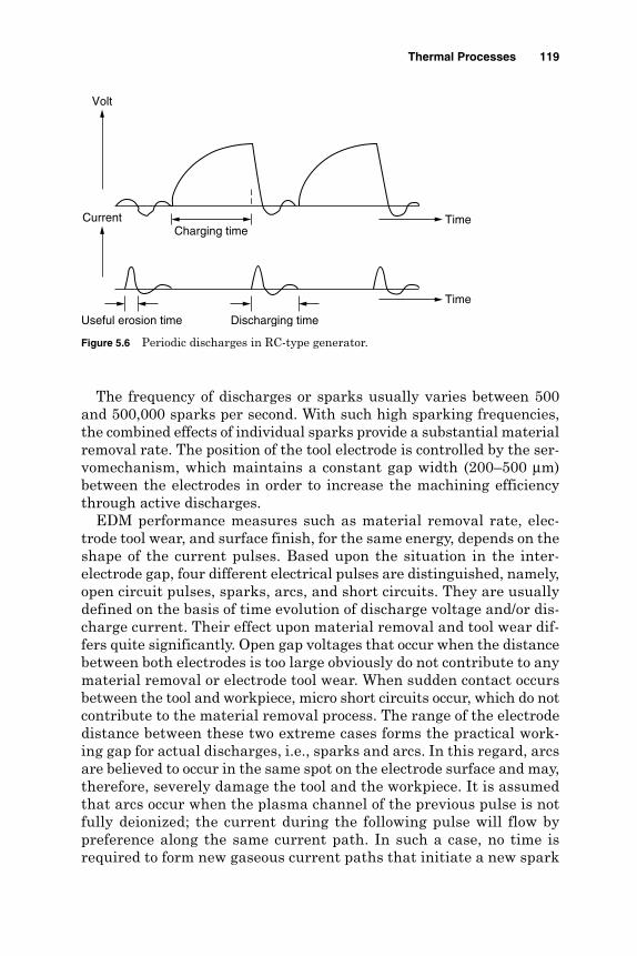
The frequency of discharges or sparks usually varies between 500and 500,000 sparks per second. With such high sparking frequencies,the combined effects of individual sparks provide a substantial materialremoval rate. The position of the tool electrode is controlled by the ser-vomechanism, which maintains a constant gap width (200–500 µm)between the electrodes in order to increase the machining efficiencythrough active discharges.
EDM performance measures such as material removal rate, elec-trode tool wear, and surface finish, for the same energy, depends on theshape of the current pulses. Based upon the situation in the inter-electrode gap, four different electrical pulses are distinguished, namely,open circuit pulses, sparks, arcs, and short circuits. They are usuallydefined on the basis of time evolution of discharge voltage and/or dis-charge current. Their effect upon material removal and tool wear dif-fers quite significantly. Open gap voltages that occur when the distancebetween both electrodes is too large obviously do not contribute to anymaterial removal or electrode tool wear. When sudden contact occursbetween the tool and workpiece, micro short circuits occur, which do notcontribute to the material removal process. The range of the electrodedistance between these two extreme cases forms the practical work-ing gap for actual discharges, i.e., sparks and arcs. In this regard, arcsare believed to occur in the same spot on the electrode surface and may,therefore, severely damage the tool and the workpiece. It is assumedthat arcs occur when the plasma channel of the previous pulse is notfully deionized; the current during the following pulse will flow bypreference along the same current path. In such a case, no time isrequired to form new gaseous current paths that initiate a new spark
Thermal Processes 119
Figure 5.6 Periodic discharges in RC-type generator.
Charging time
Discharging timeUseful erosion time
Current
Volt
Time
Time
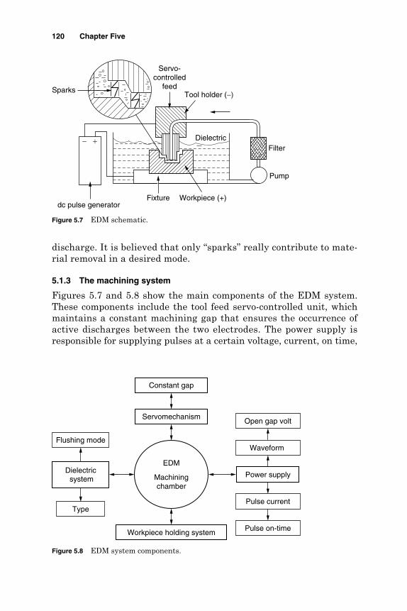
discharge. It is believed that only “sparks” really contribute to mate-rial removal in a desired mode.
5.1.3 The machining system
Figures 5.7 and 5.8 show the main components of the EDM system.These components include the tool feed servo-controlled unit, whichmaintains a constant machining gap that ensures the occurrence ofactive discharges between the two electrodes. The power supply isresponsible for supplying pulses at a certain voltage, current, on time,
120 Chapter Five
Figure 5.7 EDM schematic.
Workpiece (+)
Servo-controlled
feed
DielectricFilter
Pump
Fixturedc pulse generator
Tool holder (−)Sparks
− +
Figure 5.8 EDM system components.
Constant gap
Servomechanism
EDM
Machiningchamber
Power supplyDielectricsystem
Type
Flushing mode
Workpiece holding system
Open gap volt
Waveform
Pulse current
Pulse on-time

and off time. The dielectric circulation unit flushes the dielectric fluidto the interelectrode gap after being filtered from the machining debris.
5.1.3.1 EDM electrodes
Material. Metals with a high melting point and good electrical con-ductivity are usually chosen as tool materials for EDM. Graphite is themost common electrode material since it has fair wear characteristicsand is easily machinable and small flush holes can be drilled intographite electrodes. Copper has good EDM wear and better conductiv-ity. It is generally used for better finishes in the range of 0.5 µm Ra.Copper tungsten and silver tungsten are used for making deep slotsunder poor flushing conditions especially in tungsten carbides. It offershigh machining rates as well as low electrode wear. Copper graphite isgood for cross-sectional electrodes. It has better electrical conductivitythan graphite while the corner wear is higher. Brass ensures stablesparking conditions and is normally used for specialized applicationssuch as drilling of small holes where the high electrode wear is accept-able (Metals Handbook, 1989).
Movements. In addition to the servo-controlled feed, the tool electrodemay have an additional rotary or orbiting motion. Electrode rotation helpsto solve the flushing difficulty encountered when machining small holeswith EDM. In addition to the increase in cutting speed, the quality of thehole produced is superior to that obtained using a stationary electrode.Electrode orbiting produces cavities having the shape of the electrode.The size of the electrode and the radius of the orbit (2.54-mm maximum)determine the size of the cavities. Electrode orbiting improves flushing bycreating a pumping effect of the dielectric liquid through the gap.
Polarity. Electrode polarity depends on both the workpiece and elec-trode materials. Table 5.1 shows the possible electrode polarity for dif-ferent workpiece and tool combinations.
Thermal Processes 121
TABLE 5.1 Electrode Polarities for Different Workpiece Materials
Work material
Electrode Tungsten Ni-basematerial Steel carbide Copper Aluminum alloys
Graphite +, − − − + +, −Copper + +, − − + +Cu-W + +, − − + +Steel +, − + − − −Brass − − + −
SOURCE: Metals Handbook (1989).
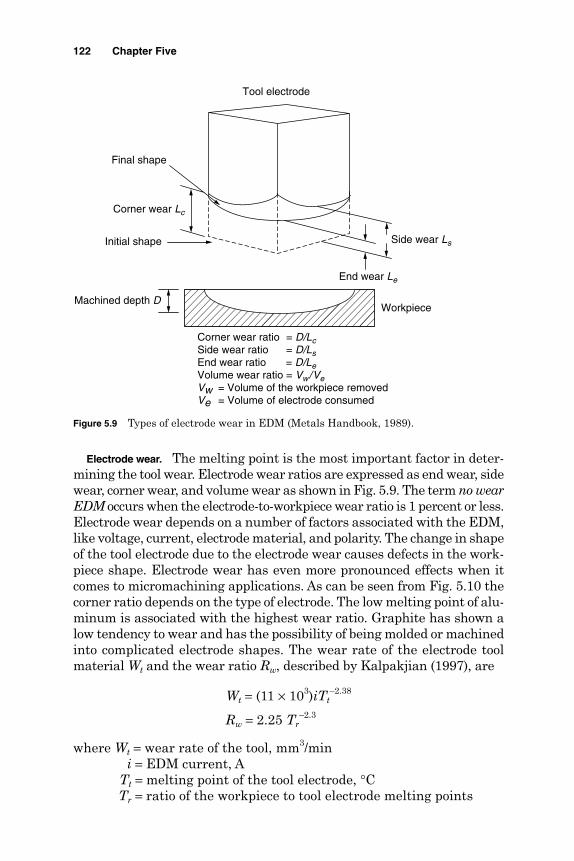
Electrode wear. The melting point is the most important factor in deter-mining the tool wear. Electrode wear ratios are expressed as end wear, sidewear, corner wear, and volume wear as shown in Fig. 5.9. The term no wearEDM occurs when the electrode-to-workpiece wear ratio is 1 percent or less.Electrode wear depends on a number of factors associated with the EDM,like voltage, current, electrode material, and polarity. The change in shapeof the tool electrode due to the electrode wear causes defects in the work-piece shape. Electrode wear has even more pronounced effects when itcomes to micromachining applications. As can be seen from Fig. 5.10 thecorner ratio depends on the type of electrode. The low melting point of alu-minum is associated with the highest wear ratio. Graphite has shown alow tendency to wear and has the possibility of being molded or machinedinto complicated electrode shapes. The wear rate of the electrode toolmaterial Wt and the wear ratio Rw, described by Kalpakjian (1997), are
Wt = (11 × 103)iTt–2.38
Rw = 2.25 Tr–2.3
where Wt = wear rate of the tool, mm3/mini = EDM current, A
Tt = melting point of the tool electrode, °CTr = ratio of the workpiece to tool electrode melting points
122 Chapter Five
Figure 5.9 Types of electrode wear in EDM (Metals Handbook, 1989).
Corner wear Lc
End wear Le
Side wear LsInitial shape
Final shape
Machined depth DWorkpiece
Tool electrode
Corner wear ratio = D/LcSide wear ratio = D/LsEnd wear ratio = D/LeVolume wear ratio = Vw/VeVw = Volume of the workpiece removedVe = Volume of electrode consumed

5.1.3.2 Dielectric fluids. The main functions of the dielectric fluid are to
1. Flush the eroded particles from the machining gap
2. Provide insulation between the electrode and the workpiece
3. Cool the section that was heated by the discharging effect
The main requirements of the EDM dielectric fluids are adequate vis-cosity, high flash point, good oxidation stability, minimum odor, lowcost, and good electrical discharge efficiency (www.unl.edu/nmrc/). Formost EDM operations kerosene is used with certain additives that pre-vent gas bubbles and de-odoring. Silicon fluids and a mixture of thesefluids with petroleum oils have given excellent results. Other dielectricfluids with a varying degree of success include aqueous solutions of eth-ylene glycol, water in emulsions, and distilled water.
Flushing of the dielectric plays a major role in the maintenance ofstable machining and the achievement of close tolerance and high sur-face quality. Inadequate flushing can result in arcing, decreased electrodelife, and increased production time. Four methods of introducing dielec-tric fluid to the machining gap are considered at www.unl.edu/nmrc/.
Normal flow. In the majority of EDM applications, the dielectric fluidis introduced, under pressure, through one or more passages in the tooland is forced to flow through the gap between the tool and the workpiece.
Thermal Processes 123
Figure 5.10 Corner wear ratios for different electrode materials (El-Hofy, 1995).
Alu
min
um
(+
)
Zin
c-tin
(−)
Bra
ss (
−)
Copper
(−)
Ste
el (
+)
Gra
phite
(+
)
Copper-
tungst
en (
+)
Silv
er-
tungst
en (
−)
Electrode material
0
100
200
300
400
500
600
700
800 C
orn
er
wear
ratio
%
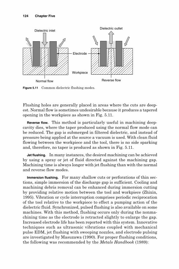
Flushing holes are generally placed in areas where the cuts are deep-est. Normal flow is sometimes undesirable because it produces a taperedopening in the workpiece as shown in Fig. 5.11.
Reverse flow. This method is particularly useful in machining deep-cavity dies, where the taper produced using the normal flow mode canbe reduced. The gap is submerged in filtered dielectric, and instead ofpressure being applied at the source a vacuum is used. With clean fluidflowing between the workpiece and the tool, there is no side sparkingand, therefore, no taper is produced as shown in Fig. 5.11.
Jet flushing. In many instances, the desired machining can be achievedby using a spray or jet of fluid directed against the machining gap.Machining time is always longer with jet flushing than with the normaland reverse flow modes.
Immersion flushing. For many shallow cuts or perforations of thin sec-tions, simple immersion of the discharge gap is sufficient. Cooling andmachining debris removal can be enhanced during immersion cuttingby providing relative motion between the tool and workpiece (Zhixin,1995). Vibration or cycle interruption comprises periodic reciprocationof the tool relative to the workpiece to effect a pumping action of thedielectric fluid. Synchronized, pulsed flushing is also available on somemachines. With this method, flushing occurs only during the nonma-chining time as the electrode is retracted slightly to enlarge the gap.Increased electrode life has been reported with this system. Innovativetechniques such as ultrasonic vibrations coupled with mechanicalpulse EDM, jet flushing with sweeping nozzles, and electrode pulsingare investigated by Masuzawa (1990). For proper flushing conditions,the following was recommended by the Metals Handbook (1989):
124 Chapter Five
Figure 5.11 Common dielectric flushing modes.
Normal flow Reverse flow
Electrode
Workpiece
Dielectric outletDielectric inlet
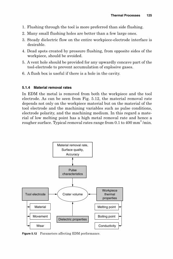
1. Flushing through the tool is more preferred than side flushing.
2. Many small flushing holes are better than a few large ones.
3. Steady dielectric flow on the entire workpiece-electrode interface isdesirable.
4. Dead spots created by pressure flushing, from opposite sides of theworkpiece, should be avoided.
5. A vent hole should be provided for any upwardly concave part of thetool-electrode to prevent accumulation of explosive gases.
6. A flush box is useful if there is a hole in the cavity.
5.1.4 Material removal rates
In EDM the metal is removed from both the workpiece and the toolelectrode. As can be seen from Fig. 5.12, the material removal ratedepends not only on the workpiece material but on the material of thetool electrode and the machining variables such as pulse conditions,electrode polarity, and the machining medium. In this regard a mate-rial of low melting point has a high metal removal rate and hence arougher surface. Typical removal rates range from 0.1 to 400 mm3 /min.
Thermal Processes 125
Figure 5.12 Parameters affecting EDM performance.
Material removal rate,Surface quality,
Accuracy
Crater volume
Melting point
Boiling point
Material
Movement
ConductivityWear
Workpiecethermal
propertiesTool electrode
Pulsecharacteristics
Dielectric properties

The results of Fig. 5.13 quote machining rates and surface roughnessfor different materials. Figures 5.14 and 5.15 explain the effect of pulseenergy (current) and duration on the crater size and hence the removalrate. The material removal rate, or volumetric removal rate (VRR), inmm3/min, was described by Kalpakjian (1997):
VRR = (4 × 10⁴)iTw–1.23
where i is the EDM current (A) and Tw is the melting point of the work-piece material (°C).
126 Chapter Five
Figure 5.13 EDM removal rates and roughness for different materials (El-Hofy, 1995).
Aluminum Steel C-Cr Copper Carbide15% CO
Graphite
Work material
0
0.1
0.2
0.3
0.4
0.5
0.6
0.7R
emov
al r
ate,
cm
3 /m
in
0
0.2
0.4
0.6
0.8
1
Sur
face
rou
ghne
ss, R
z
Removal rateSurface roughness
Figure 5.14 Effect of pulse current (energy) on removal rate and sur-face roughness.
Pulse current
5 A10 A
15 A
Spark
Crater
Tool
Workpiece
Time259 µs259 µs259 µs

5.1.5 Surface integrity
The spark-machined surface consists of a multitude of overlapping cratesthat are formed by the action of microsecond-duration spark discharges.These craters depend on the physical and the mechanical properties of thematerial and the composition of the machining medium as well as on thedischarge energy and duration as shown in Figs. 5.14 and 5.15. The inte-gral effect of many thousands of discharges per second leads to the for-mation of the corresponding workpiece profile with a specified accuracyand surface finish. The depth of the resulting craters usually representsthe peak to valley (maximum) surface roughness Rt. The maximum depthof the damaged layer can be taken as 2.5 times the average surface rough-ness Ra. According to Delpreti (1977) and Motoki and Lee (1968) the max-imum peak to valley height, Rt, was considered to be 10 times Ra.
The average roughness can be expressed in terms of pulse current ip
(A) and pulse duration tp (µs) by
Ra = 0.0225 ip0.29 tp
0.38
A similar observation has been reported by Benhadad et al. (1991) andDauw and Brown (1990). Stavitskaya and Stravinski (1979) claimedalso that the machined surface roughness, which is formed by mutualoverlap of craters, is a third of the crater depth. Hence,
where Kh = 0.4 to 0.75 µm/µJ0.33 and W is the pulse energy (µJ).
RK W
ah=2 0.33
12
Thermal Processes 127
Figure 5.15 Effect of pulse on-time (energy) on removal rate and sur-face roughness.
Pulse current
Spark
Crater
Tool
Workpiece
Time300 µs200 µs100 µs
15 A

Surface roughness increases linearly with an increase in the materialremoval rate. Jeswani (1978) reported that graphite electrodes producerougher surfaces than metal ones. Crookall and Khor (1974) relatedthe crater volume/metal removal per discharge to surface roughnessHrms while Jeswani (1977) expressed the roughness in terms of the fre-quency of pulses fp and power Pr by
Jeswani added also that as the pulse energy is decreased, the surfacefinish improves and consequently, the depth at which all formed cratersdisappear from the machined surface (free polishing depth) is reduced.This depth was found to lie between 3 to 6 times Hrms and is importantwhen polishing dies and molds and when the residual stresses are tobe removed from the machined surfaces. Masuzawa and Saki (1978)adopted a quick electrochemical finishing technique, using a mate elec-trode. Accordingly, a reduction of surface roughness from 22 µm Rmax to8 µm has been reported together with the removal of the heat-affectedlayer. In contrast, the matte appearance of the machined surfaces hasbeen found satisfactory in some applications of electrodischarge tex-turing (EDT).
Kuneida and Furuoya (1991) claimed that the introduction of oxygengas into the discharge gap provides extra power by the reaction ofoxygen, which in turn increased the melting of the workpiece and cre-ated greater expulsive forces that increased the metal removal rate andsurface roughness. When EDM is used for cusp removal, the siliconpowder has been suspended in the working fluid, during the stage offinish EDM. Consequently, Mohri and Saito (1991) reported a changeof surface roughness from 45 µm to 10 µm Rmax. The choice of the cor-rect dielectric flow, in the gap, has a significant effect in reducing thesurface roughness by 50 percent, increasing the machining rate, and low-ering the thermal effects in the workpiece surface.
The Machining Data Handbook (1997) recommended dielectricshaving low viscosity for EDM of smooth surfaces. Benhadad et al. (1991)indicated that for Al-Li alloys, the tensile strength of the machinedparts are reduced by increased surface roughness. This reduction wasenhanced by increased pulse current. The heat-affected layer reached200 µm compared to 80 µm for steel due to deference in their thermalconductivity. Normal tolerances are about ±25 µm with ±5 µm obtainedby proper choice of process variables.
HPf
r
prms =
267
0 258.
128 Chapter Five
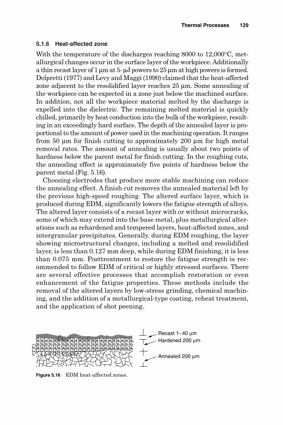
5.1.6 Heat-affected zone
With the temperature of the discharges reaching 8000 to 12,000°C, met-allurgical changes occur in the surface layer of the workpiece. Additionallya thin recast layer of 1 µm at 5- µJ powers to 25 µm at high powers is formed.Delpretti (1977) and Levy and Maggi (1990) claimed that the heat-affectedzone adjacent to the resolidified layer reaches 25 µm. Some annealing ofthe workpiece can be expected in a zone just below the machined surface.In addition, not all the workpiece material melted by the discharge isexpelled into the dielectric. The remaining melted material is quicklychilled, primarily by heat conduction into the bulk of the workpiece, result-ing in an exceedingly hard surface. The depth of the annealed layer is pro-portional to the amount of power used in the machining operation. It rangesfrom 50 µm for finish cutting to approximately 200 µm for high metalremoval rates. The amount of annealing is usually about two points ofhardness below the parent metal for finish cutting. In the roughing cuts,the annealing effect is approximately five points of hardness below theparent metal (Fig. 5.16).
Choosing electrodes that produce more stable machining can reducethe annealing effect. A finish cut removes the annealed material left bythe previous high-speed roughing. The altered surface layer, which isproduced during EDM, significantly lowers the fatigue strength of alloys.The altered layer consists of a recast layer with or without microcracks,some of which may extend into the base metal, plus metallurgical alter-ations such as rehardened and tempered layers, heat-affected zones, andintergranular precipitates. Generally, during EDM roughing, the layershowing microstructural changes, including a melted and resolidifiedlayer, is less than 0.127 mm deep, while during EDM finishing, it is lessthan 0.075 mm. Posttreatment to restore the fatigue strength is rec-ommended to follow EDM of critical or highly stressed surfaces. Thereare several effective processes that accomplish restoration or evenenhancement of the fatigue properties. These methods include theremoval of the altered layers by low-stress grinding, chemical machin-ing, and the addition of a metallurgical-type coating, reheat treatment,and the application of shot peening.
Thermal Processes 129
Figure 5.16 EDM heat-affected zones.
Recast 1−40 µmHardened 200 µm
Annealed 200 µm

5.1.7 Applications
EDM has become an indispensable process in the modern manufactur-ing industry. It produces complex shapes to a high degree of accuracyin difficult-to-machine materials such as heat-resistant alloys, super-alloys, and carbides. The incorporation of EDM within a computer-integrated manufacturing (CIM) system reduced the length of time thatthe unit operation, without stops for maintenance, is required.Micromachining of holes, slots, and dies; procedures for surface depo-sition; modification; texturing; milling; and mechanical pulsing are typ-ical applications.
5.1.7.1 Drilling. EDM drilling uses a tubular tool electrode where thedielectric is flushed down the interior hole of the tube in order to removemachining debris. When solid rods are used; the dielectric is fed to themachining zone by either suction or injection through pre-drilled holes.Irregular, tapered, curved, as well as inclined holes can be produced byEDM. McGeough (1988) reported typical feed rates of 0.1 mm/min whendrilling 0.1 to 0.5 mm diameters, leaving an overcut of 0.01 to 0.05 mm.Creating cooling channels in turbine blades made of hard alloys is a typ-ical application of EDM drilling. The use of a computerized NC systemenabled large numbers of holes to be accurately located.
5.1.7.2 Sawing. ED sawing, shown in Fig. 5.17, is an EDM variationthat employs either a special steel band or disc. The process cuts any elec-trically conductive material at a rate that is twice that of the conventionalabrasive sawing method. The cut produced has a smaller kerf besidesbeing free from burrs. Cutting of billets and bars is a typical application.
130 Chapter Five
Figure 5.17 ED sawing schematic.
Band sawing Disc sawing
Steel band
Dielectric supply
Workpiece
Feed
Kerf
Disc thickness
Feed
Deionizedwater
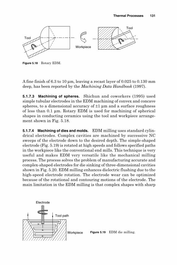
A fine finish of 6.3 to 10 µm, leaving a recast layer of 0.025 to 0.130 mmdeep, has been reported by the Machining Data Handbook (1997).
5.1.7.3 Machining of spheres. Shichun and coworkers (1995) usedsimple tubular electrodes in the EDM machining of convex and concavespheres, to a dimensional accuracy of ±1 µm and a surface roughnessof less than 0.1 µm. Rotary EDM is used for machining of sphericalshapes in conducting ceramics using the tool and workpiece arrange-ment shown in Fig. 5.18.
5.1.7.4 Machining of dies and molds. EDM milling uses standard cylin-drical electrodes. Complex cavities are machined by successive NCsweeps of the electrode down to the desired depth. The simple-shapedelectrode (Fig. 5.19) is rotated at high speeds and follows specified pathsin the workpiece like the conventional end mills. This technique is veryuseful and makes EDM very versatile like the mechanical millingprocess. The process solves the problem of manufacturing accurate andcomplex-shaped electrodes for die sinking of three-dimensional cavitiesshown in Fig. 5.20. EDM milling enhances dielectric flushing due to thehigh-speed electrode rotation. The electrode wear can be optimizedbecause of the rotational and contouring motions of the electrode. Themain limitation in the EDM milling is that complex shapes with sharp
Thermal Processes 131
Figure 5.18 Rotary EDM.
Tool
Workpiece
Tool
Figure 5.19 EDM die milling.
Electrode
Workpiece
Tool path
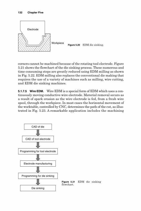
corners cannot be machined because of the rotating tool electrode. Figure5.21 shows the flowchart of the die sinking process. These numerous andtime-consuming steps are greatly reduced using EDM milling as shownin Fig. 5.22. EDM milling also replaces the conventional die making thatrequires the use of a variety of machines such as milling, wire cutting,and EDM die sinking machines.
5.1.7.5 Wire EDM. Wire EDM is a special form of EDM which uses a con-tinuously moving conductive wire electrode. Material removal occurs asa result of spark erosion as the wire electrode is fed, from a fresh wirespool, through the workpiece. In most cases the horizontal movement ofthe worktable, controlled by CNC, determines the path of the cut, as illus-trated in Fig. 5.23. A remarkable application includes the machining
132 Chapter Five
Figure 5.20 EDM die sinking.
Electrode
Workpiece
Figure 5.21 EDM die sinkingflowchart.
CAD of die
CAD of tool electrode
Programming for tool electrode
Electrode manufacturing
Programming for die sinking
Die sinking
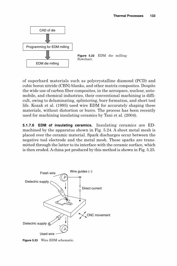
of superhard materials such as polycrystalline diamond (PCD) andcubic boron nitride (CBN) blanks, and other matrix composites. Despitethe wide use of carbon fiber composites, in the aerospace, nuclear, auto-mobile, and chemical industries, their conventional machining is diffi-cult, owing to delaminating, splintering, burr formation, and short toollife. Kozak et al. (1995) used wire EDM for accurately shaping thesematerials, without distortion or burrs. The process has been recentlyused for machining insulating ceramics by Tani et al. (2004).
5.1.7.6 EDM of insulating ceramics. Insulating ceramics are ED-machined by the apparatus shown in Fig. 5.24. A sheet metal mesh isplaced over the ceramic material. Spark discharges occur between thenegative tool electrode and the metal mesh. These sparks are trans-mitted through the latter to its interface with the ceramic surface, whichis then eroded. A china pot produced by this method is shown in Fig. 5.25.
Thermal Processes 133
Figure 5.22 EDM die millingflowchart.
CAD of die
Programming for EDM milling
EDM die milling
Figure 5.23 Wire EDM schematic.
Direct current
Fresh wire
Used wire
Wire guides (−)
CNC movement
Dielectric supply
Dielectric supply

5.1.7.7 Texturing. Texturing is applied to the steel sheets during thefinal stages of cold rolling. Shot blasting (SB) is an inexpensive, con-ventional texturing method in which hard steel shot is fired at highvelocities, roughening the surface on impact. Limitations of SB includeits lack of control and consistency of texturing, and the need for pro-tection of other parts of the equipment holding the roll. As the steel rollsbecome harder, an increasingly limited range of roughness and peakcounts have emerged as a further drawback for SB as indicated byPawleski et al. (1994) and Ahmed and Knight (1988). EDT, is a varia-tion of EDM where the material removal and surface and subsurfacemodifications are low. EDT proved to be the most popular since thehardness of the roll is not a limitation. Using the new method, textur-ing is achieved by passing high-intensity electrical sparks of shortduration across the gap between the roll (workpiece) and a tool elec-trode, through which a liquid dielectric (e.g., paraffin) is flushed(Aspinwal et al., 1991). Each spark creates a small crater by the dis-charge of its energy in a local melting and vaporization of the roll mate-rial. By selecting the appropriate process variables such as pulsecurrent, duration and pause times, electrode polarity and material,
134 Chapter Five
Figure 5.24 EDM of insulating ceramics (Fukuzawa et al.,1995).
Electrode (−)
Ceramics
Metal meshDielectric
Figure 5.25 China pot machinedby EDM. (Fukuzawa et al., 1995).
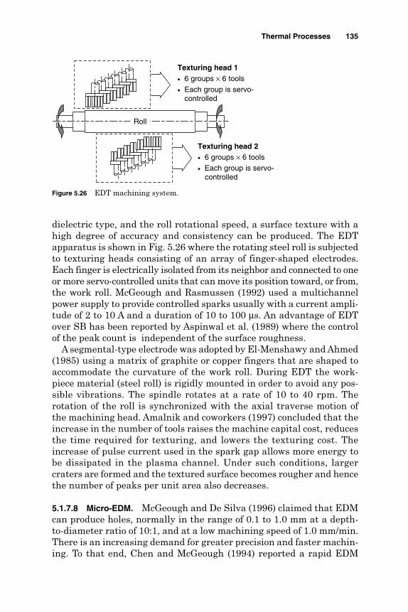
dielectric type, and the roll rotational speed, a surface texture with ahigh degree of accuracy and consistency can be produced. The EDTapparatus is shown in Fig. 5.26 where the rotating steel roll is subjectedto texturing heads consisting of an array of finger-shaped electrodes.Each finger is electrically isolated from its neighbor and connected to oneor more servo-controlled units that can move its position toward, or from,the work roll. McGeough and Rasmussen (1992) used a multichannelpower supply to provide controlled sparks usually with a current ampli-tude of 2 to 10 A and a duration of 10 to 100 µs. An advantage of EDTover SB has been reported by Aspinwal et al. (1989) where the controlof the peak count is independent of the surface roughness.
A segmental-type electrode was adopted by El-Menshawy and Ahmed(1985) using a matrix of graphite or copper fingers that are shaped toaccommodate the curvature of the work roll. During EDT the work-piece material (steel roll) is rigidly mounted in order to avoid any pos-sible vibrations. The spindle rotates at a rate of 10 to 40 rpm. Therotation of the roll is synchronized with the axial traverse motion ofthe machining head. Amalnik and coworkers (1997) concluded that theincrease in the number of tools raises the machine capital cost, reducesthe time required for texturing, and lowers the texturing cost. Theincrease of pulse current used in the spark gap allows more energy tobe dissipated in the plasma channel. Under such conditions, largercraters are formed and the textured surface becomes rougher and hencethe number of peaks per unit area also decreases.
5.1.7.8 Micro-EDM. McGeough and De Silva (1996) claimed that EDMcan produce holes, normally in the range of 0.1 to 1.0 mm at a depth-to-diameter ratio of 10:1, and at a low machining speed of 1.0 mm/min.There is an increasing demand for greater precision and faster machin-ing. To that end, Chen and McGeough (1994) reported a rapid EDM
Thermal Processes 135
Figure 5.26 EDT machining system.
Texturing head 1• 6 groups × 6 tools• Each group is servo- controlled
Texturing head 2• 6 groups × 6 tools• Each group is servo- controlled
Roll

technique for drilling accurate holes, 0.5 to 1.0 mm in diameter and 100mm deep at a rate of 20 mm/min. Fujino et al. (1995) drilled microholesof diameter 300 µm through tungsten carbide alloy, with a 0.2-mmcopper tungsten electrode. Using low-viscosity dielectrics Allen andHuang (1995) described multielectrode drilling of holes with diametersas small as 5 µm. Masuzawa and coworkers (1994) developed a combinedelectroforming and wire EDM method for micronozzle fabrication. In afurther work by Allen and Lecheheb (1996), ink-jet orifices, 75 µm indiameter, were machined in thin stainless steel foils using small energylevels. The principle of wire electrodischarge grinding (WEDG) is illus-trated in Fig. 5.27. The material removal mechanism is the same as inEDM. The tool electrode is a metal wire, which slides slowly at 5 to 10 mm/min along a groove in a wire guide. This wire movement makesthe process free from the tool wear problems of EDM. By feeding therotating workpiece in the downward direction, a micropin (Fig. 5.28) has
136 Chapter Five
Figure 5.27 Principles of WEDG.
Wire guidesWire
Workpiece
A
Section A-A
A
Figure 5.28 Micropin produced byWEDG (Masuzawa and Tonshof,1997 ).
100 µm
φ 5 µm

been produced by Masuzawa and Tonshof (1997). A novel method formicropin fabrication, using machined holes as tools, has been devel-oped by Yamazaki et al. (2004). Micro-EDM machines with WEDG facil-ities are already in the market, and small hole diameters of 5 µm areavailable (Fig. 5.29). Using shaped electrodes, holes and cavities withvarious shapes can also be produced. Figure 5.30 shows a cavity withsharp corners, machined using a 50-µm square section electrode.
5.1.8 Process control
EDM monitoring and control have evolved from fundamental researchinto modeling single discharges, through stochastic models (dynamicdata-dependent systems) to more application-oriented on-line sys-tems such as adaptive control, expert systems, fuzzy logic, and arti-ficial neural networks. Avoidance of abnormal electrical discharges inEDM remains a major difficulty in advances of the process, despitethe arrival of the radio-frequency methods devised by El-Menshawyand coworkers (1985). Early EDM adaptive control systems involvedbasically checking for a “no-load” voltage condition from the dischargegap voltage waveforms. If an electrical discharge without no-loadvoltage is present for a defined time, the off time for the pulse isincreased to avoid these unwanted, abnormal discharges; only whenan improvement in machining is achieved is the off time againreduced. Even with modern advances in feedback control, a consistent
Thermal Processes 137
Figure 5. 29 Microholes producedby EDM (Masuzawa and Tonshof,1997 ).
Figure 5.30 A microcavity withsharp corners by micro-EDM(Masuzawa and Tonshof, 1997 ).
quality of EDM has remained difficult to master, at least until thefuzzy adaptive control concepts had been introduced by Lauwers andKruth (1995). The latter is basically an expert system, performed bya skilled operator.
In brief, the quality of machining is determined from fuzzy rulesobtained from experimental knowledge for recognizing instability inmachining. Information provided by a signal processor is then used todecide on the appropriate electromachining conditions. Dauw and VanCoppenolle (1995) describe current industrial equipment that incorporatesfuzzy controllers. Artificial neural networks are a further new tool inEDM control, especially when combined with fuzzy logic. The neural netsare already used in EDM for monitoring and off-line process planning byLauwers and Kruth (1995). In a simple application, pulse duration andcurrent are used as inputs, and normal and abnormal (undesired) pulsesare classified in the output stage. In the neural net, machining depth,roughness, and accuracy are correlated with machining conditions at theoutput stage. Industrial versions of neural networks are now available.
5.1.9 EDM automation
The introduction of EDM into advanced manufacturing systems withhigh levels of computer integration and automated material handlinghas progressed at a much slower rate than the integration of conven-tional machining processes such as milling and turning. Recent devel-opments in communications control and CAD/CAM systems for EDMhas created the potential for bringing EDM into the mainstream ofautomated machining operations in modern manufacturing systems.EDM is suited for CIM for many reasons mentioned by Dauw and VanCoppenolle (1995). The level of automation currently exists in EDMunits. The relatively low production rate for EDM compared to tradi-tional machining processes is related to the availability of advancedsoftware in the areas of CAD, computer-aided process planning (CAPP),and machining. These three techniques can be dealt with independ-ently, but have to be integrated for complete success of CIM to be guar-anteed. There is a growing shortage of highly skilled EDM operators,for whom a fairly good understanding of the physical process is a pre-requisite. CIM integration can free EDM from its island of automation,achieving more efficient and cost-effective production. Tool design isperformed by the classical approach using drawing rulers and tapes orthrough CAD systems.
The manufacture of the tool electrode is then performed using severalproduction processes including milling and turning. Finally, the tool arrivesat the EDM machine in its chuck holder, perhaps with the assistance of aflexible tool and workpiece transportation system, which in turn may have
138 Chapter Five
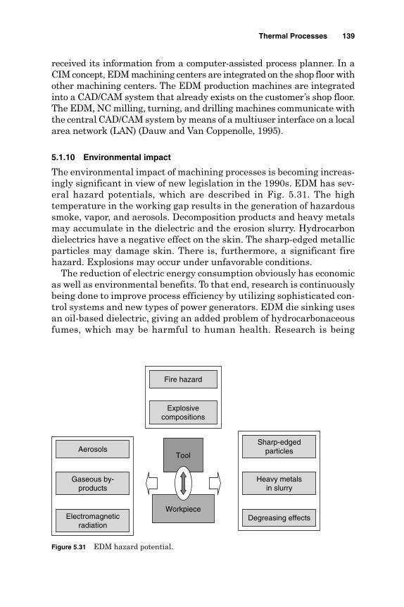
received its information from a computer-assisted process planner. In aCIM concept, EDM machining centers are integrated on the shop floor withother machining centers. The EDM production machines are integratedinto a CAD/CAM system that already exists on the customer’s shop floor.The EDM, NC milling, turning, and drilling machines communicate withthe central CAD/CAM system by means of a multiuser interface on a localarea network (LAN) (Dauw and Van Coppenolle, 1995).
5.1.10 Environmental impact
The environmental impact of machining processes is becoming increas-ingly significant in view of new legislation in the 1990s. EDM has sev-eral hazard potentials, which are described in Fig. 5.31. The hightemperature in the working gap results in the generation of hazardoussmoke, vapor, and aerosols. Decomposition products and heavy metalsmay accumulate in the dielectric and the erosion slurry. Hydrocarbondielectrics have a negative effect on the skin. The sharp-edged metallicparticles may damage skin. There is, furthermore, a significant firehazard. Explosions may occur under unfavorable conditions.
The reduction of electric energy consumption obviously has economicas well as environmental benefits. To that end, research is continuouslybeing done to improve process efficiency by utilizing sophisticated con-trol systems and new types of power generators. EDM die sinking usesan oil-based dielectric, giving an added problem of hydrocarbonaceousfumes, which may be harmful to human health. Research is being
Thermal Processes 139
Figure 5.31 EDM hazard potential.
Electromagneticradiation
Gaseous by-products
Aerosols
Degreasing effects
Heavy metalsin slurry
Sharp-edgedparticles
Workpiece
Explosivecompositions
Fire hazard
Tool

carried out to improve extraction facilities and to reduce emissions byusing an alternative dielectric. Unlike die sinking, wire cutting utilizesdeionized water as the dielectric. Although the fumes are not as toxic,the long-term effects on the environment due to ozone and chlorineemissions have to be borne in mind. Furthermore, wastewater canprove increasingly difficult to dispose of as environmental laws are fur-ther tightened. Environmentally friendly and high-capacity dielectricregeneration for wire EDM has been devised by Levy (1993). The waysto EDM “clean technology” is reviewed by Tonshof et al. (1996).
5.2 Laser Beam Machining
5.2.1 Introduction
Modern machining methods are established to fabricate difficult-to-machinematerials such as high-strength thermal-resistant alloys; various kinds ofcarbides, fiber-reinforced composite materials, Stellites, and ceramics.Conventional machining of such materials produces high cutting forcesthat, in some particular cases, may not be sustained by the workpiece.Laser beam machining (LBM) offers a good solution that is indeed moreassociated with material properties such as thermal conductivity and spe-cific heat as well as melting and boiling temperatures.
Laser is the abbreviation of light amplification by stimulated emis-sion of radiation. A highly collimated, monochromatic, and coherentlight beam is generated and focused to a small spot. High power densi-ties (106 W/mm2) are then obtained. A large variety of lasers are avail-able in the market including solid-state, ion, and molecular types ineither continuous wave (CW) or pulsed mode (PM) of operation as shownin Table 5.2. Lasers are widely used in many industrial applicationsincluding plating, heat treatment, cladding, alloying, welding, andmachining. The LBM system is shown in Fig. 5.32.
140 Chapter Five
TABLE 5.2 Different Types of Lasers
Laser type Wavelength, nm Typical performance
Solid Ruby 694 Pulsed, 5 WNd-YAG 1064 Pulsed, CW, 1–800 WNd-glass 1064 Pulsed, CW, 2 mW
Semiconductor GaAs 800–900 Pulsed, CW, 2–10 mW
Molecular CO2 10.6 µm Pulsed, CW, <15 kW
Ion Ar+ 330–530 Pulsed, CW, 1 W–5 kWExcimer 200–500 Pulsed
Neutral gas He-Ne 633 CW, 20 mW

5.2.2 Material removal mechanism
As presented in Fig. 5.33, the unreflected light is absorbed, thus heat-ing the surface of the specimen. On sufficient heat the workpiece startsto melt and evaporates. The physics of laser machining is very complex
Thermal Processes 141
Figure 5.32 LBM schematic.
Position table
CNC control
Workpiece
Focal length
Lens
Flash lightEllipticalreflecting cavity
Total reflecting mirror
Partial mirror
Lasing material
Figure 5.33 Physical processesoccurring during LBM.
Thermal conductionLaser beam
(a) Absorption and heating
Solid
Liquid
Solid-liquid interfaceLaser beam
(b) Melting
Material removed
WorkpieceLaser beam
(c) Vaporization
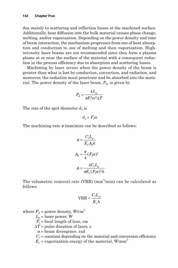
due mainly to scattering and reflection losses at the machined surface.Additionally, heat diffusion into the bulk material causes phase change,melting, and/or vaporization. Depending on the power density and timeof beam interaction, the mechanism progresses from one of heat absorp-tion and conduction to one of melting and then vaporization. High-intensity laser beams are not recommended since they form a plasmaplume at or near the surface of the material with a consequent reduc-tion in the process efficiency due to absorption and scattering losses.
Machining by laser occurs when the power density of the beam isgreater than what is lost by conduction, convection, and radiation, andmoreover, the radiation must penetrate and be absorbed into the mate-rial. The power density of the laser beam, Pd, is given by
The size of the spot diameter ds is
ds = Fla
The machining rate f (mm/min) can be described as follows:
The volumetric removal rate (VRR) (mm3/min) can be calculated asfollows:
where Pd = power density, W/cm2
Lp = laser power, WFl = focal length of lens, cm
∆T = pulse duration of laser, sa = beam divergence, rad
Cl = constant depending on the material and conversion efficiencyEv = vaporization energy of the material, W/mm3
VRR =C L
E hl p
v
φ
π α
φπ α
=
=
=
C L
E A h
A F
C L
E F h
l p
v b
b l
l p
v l
4
4
2
2
( )
( )
PL
F Tdp
l
=42 2π α ∆
142 Chapter Five

Ab = area of laser beam at focal point, mm2
h = thickness of material, mmds = spot size diameter, mm
In LBM the workpiece material is removed through several effects includ-ing reflection, absorption, and conduction of light that is followed by melt-ing and evaporation. The behavior of the work material with respect tothese effects determines the material removal rate. Reflectivity dependson the wavelength, the properties of material, the surface finish, its levelof oxidation and temperature.
At a given wavelength, the higher the reflectivity of the material, thelower is the removal rate, and vice versa. In this regard most metalsreflect about 90 percent of incident radiation at low power densities. Thelevel of reflectivity can substantially be reduced, and the material machin-ability is enhanced by modifying the surface conditions. The unreflectedlight is then absorbed, which in metals raises the electrons to a higherenergy state. The energy absorbed by electrons is rapidly passed to thelattice. On sufficient heat the workpiece starts to melt and evaporates.The minimum laser energies required to vaporize plastics are lower thanthat for metals. The thermal properties of these materials indicate thatthe machinability is enhanced for materials of low thermal conductivity,diffusivity, and melting point. Most nonmetals have low thermal con-ductivity and absorb CO2 laser of 10.6-µm wavelength. Therefore, plas-tic materials can be readily melted by a low-power CO2 laser.
Since metals have higher reflectivity and thermal conductivity, nonmetalsmachine at higher speeds than do metallic ones (Fig. 5.34). Moreover toachieve the same machining speed, greater power density lasers should be
Thermal Processes 143
Work material
0 200 400 600 800 1000 1200
Cutting speed, mm2/s
Art boardRubber sheet (sorbo)
Acrylic sheetABS plastic
Rubber sheet (dense)Leather
Resin bonded fiberglass
PTFEAsbestos board (dense)
PlywoodQuartz
TitaniumMild steel
Hardened tool steelStainless steel
Melinex film (mylar)
Figure 5.34 Cutting speeds in CO2 LBM (El-Hofy, 1995).

used for metallic materials. The smaller depth of altered layer associatedwith high machining rates is an advantage of LBM.
In gas-assisted laser the heat of the torch causes the initial meltingand oxidation of metal. Machining is achieved by the release of the heatfrom the oxidation process. The flow of gas stream also contributes byremoving the oxide from the machining area. Using such a method,titanium of 0.5 mm thickness has been cut with a CO2 laser of 135 W at15 m/min, thus leaving a heat-affected layer of 0.375 mm. A plate of10-mm thickness of the same material has been also cut at 2.4 m/min,as has copper having 0.025-mm thickness with chlorine as the reactivegas. It should be borne in mind that the smaller the diameter of the gasnozzle and the narrower its distance from the workpiece surface, thebetter is the quality of the cut. Gas pressure also plays a significant partin the determination of the quality and the rate of machining. Figure 5.35shows the relative machinability index for a wide range of materials. Anindex of 100 is taken for Ti.6Al.6V.2Sn, which cuts at the highest speedas shown in Fig. 5.36.
5.2.3 Applications
5.2.3.1 Drilling. Composite materials and some exotic alloys havebeen widely used in the fabrication of both structural and nonstruc-tural members of the airframes and engines of aircrafts. Superalloysare used frequently for the fabrication of aero-engine gas-path com-ponents such as blades, guide vans, after-burners, and castings wherea temperature of 2000°C can be reached.
Advanced ceramics and titanium alloys are being developed and used.Such materials need advanced technologies in their fabrication and
144 Chapter Five
Ti.6
Al.6
V.2
Sn
Silv
er
TI.6
Al.4
V
Gol
d
Cop
per
Alu
min
um
Bra
ss
Tita
nium
Sta
inle
ss s
teel
Nic
kel
Mild
ste
el
Har
dene
d to
ol s
teel
Hay
nes
188
Has
tello
y X
Ren
e 41
TD
. Ni.
Cr
Chr
omiu
m
Work material
0
20
40
60
80
120
100
Mac
hina
bilit
y ra
ting,
%
Figure 5.35 Machinability of some materials in LBM (El-Hofy, 1995).
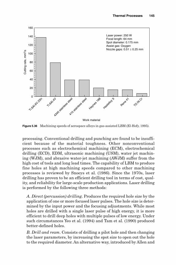
processing. Conventional drilling and punching are found to be insuffi-cient because of the material toughness. Other nonconventionalprocesses such as electrochemical machining (ECM), electrochemicaldrilling (ECD), EDM, ultrasonic machining (USM), water jet machin-ing (WJM), and abrasive water-jet machining (AWJM) suffer from thehigh cost of tools and long lead times. The capability of LBM to producefine holes at high machining speeds compared to other machiningprocesses is reviewed by Snoeys et al. (1986). Since the 1970s, laserdrilling has proven to be an efficient drilling tool in terms of cost, qual-ity, and reliability for large-scale production applications. Laser drillingis performed by the following three methods:
A. Direct (percussion) drilling. Produces the required hole size by theapplication of one or more focused laser pulses. The hole size is deter-mined by the input power and the focusing adjustments. While mostholes are drilled with a single laser pulse of high energy, it is moreefficient to drill deep holes with multiple pulses of low energy. Undersuch circumstances Yeo et al. (1994) and Tam et al. (1990) producedbetter-defined holes.
B. Drill and ream. Consists of drilling a pilot hole and then changingthe laser parameters, by increasing the spot size to open out the holeto the required diameter. An alternative way, introduced by Allen and
Thermal Processes 145
Ti.6Al.6
V.2Sn
Ti.6Al.4
V
4340
stain
less s
teel
410
stainl
ess s
teel
Hayne
s 188
Haste
lloy X
Rene
41
TD.Ni.C
r
Work material
0
20
40
60
80
100
120
140
160C
uttin
g ra
te, m
m2 /
s
Laser power: 250 WFocal length: 64 mmSpot diameter: 0.175 mmAssist gas: OxygenNozzle gaps: 0.51 ± 0.25 mm
Figure 5.36 Machining speeds of aerospace alloys in gas-assisted LBM (El-Hofy, 1995).
Huang (1997), is to drill a pilot hole using a laser beam and thenapply EDM to obtain the true size.
C. Trepanning. Used for large holes by either moving the part or rotat-ing the laser beam system of delivery or lens. Because of the lowenergy of each pulse, the recast layer and out-of-cylindericity arereduced. The process, however, provides easier control of the hole sizeby rotating the diameter of the beam.
Hole quality characteristics. Diameter and depth. Using LBM it is eco-nomically effective to drill holes up to 1.5 mm in diameter. For large diam-eters, the trepanning method is recommended. The geometricalcharacteristics of laser-drilled holes are described in terms of their aspectratio (depth-to-diameter ratio at midspan of the hole). The aspect ratiodepends on the optical characteristics of the beam and on the optical andthermal properties of the material. In deep hole drilling of 0.25 to 1.0 mmin diameter, typical aspect ratios of more than 10:1 have been reported byYeo et al. (1994). An aspect ratio of 50:1 and drilling tolerance of ±5 to 20percent of diameter has been reported in the Machining Data Handbook(1997).
Taper and barreling. The degree of taper that ranges from 5 to 20 per-cent of the hole diameter decreases with an increase in the hole depth.The taper depends on the pulse duration and energy, number of pulses,and design of the optical system. In general, the shorter the pulseduration the greater will be the taper. According to Yeo et al. (1994)barreling, formed by the ejection of material from the local sites of thecavity, can be reduced by decreasing the pressure of the assist gas.
Recast layer and microcracking. Selecting a low-power density that effec-tively expels molten and vaporized material from the machining zone canreduce the recast layer. Using a short pulse duration and a low-repetitionrate to minimize heating in the surrounding material can reduce micro-cracking. Generally, the smaller depth of the altered layer associated withhigh cutting rates is an advantage of LBM.
Entrance angle. The laser beam is capable of drilling holes with anentrance angle that varies from 10° up to normal incidence at 90° withacceptable hole characteristics. As the entrance angle with respect tothe surface becomes smaller, the effective surface power density isreduced. Under such circumstances, it is necessary to increase thepower of the laser or improve the quality of the beam.
Drilling time. Deep hole drilling up to 17 mm can be accomplishedby operating the laser beam in the rapid-pulsed mode so that the totaltime is proportional to the amount of energy delivered per pulse. Yeoet al. (1994) found that holes with a similar aspect ratio can be drilledin a similar machining time (an aspect ratio of 20:1 requires 7 s).
146 Chapter Five

Parameters affecting the quality of holes. Table 5.3 lists the laser beamdrilling capabilities, while Fig. 5.37 presents the various factors thataffect the quality of drilled holes.
Pulse energy. It is recommended that the required peak power shouldbe obtained by increasing the pulse energy while keeping the pulseduration constant. Drilling of holes with longer pulses causes enlarge-ment of the hole entrance.
Thermal Processes 147
TABLE 5.3 Laser Drilling Capabilities
Hole feature Range
Diameter 0.005–1.27 mm, larger in trepanningDepth 1.7 mmAngle 15–90°Taper 5–20% hole diameterDepth/diameter ratio 50:1Drilling depth (trepanned) 6.4 mmTolerances ±5–20 % diameterMinimum corner radious 0.25 mm
Quality of holes
LBM
Environment• Humidity• Temperature
Working material• Type• Surface reflectivity• Thickness
Focusing lens• Focal length• Focal position
Assist gas• Type• Pressure• Nozzle design
Laser pulse• Pulse shape• Frequency• Wavelength• Beam divergence• Duration• Energy• Transverse modes
Figure 5.37 Parameters affecting the quality of laser-drilled holes.

Pulse duration. The range of pulse durations suitable for hole drillingis found to be from 0.1 to 2.5 ms. High pulse energy (20 J) and shortpulse duration are found suitable for deep hole drilling in aerospacematerials.
Assist gases. The gas jet is normally directed with the laser beam intothe interaction region to remove the molten material from the machin-ing region and obtain a clean cut. Assist gases also shield the lensfrom the expelled material by setting up a high-pressure barrier at thenozzle opening. Pure oxygen causes rapid oxidation and exothermicreactions, causing better process efficiency. The selection of air, oxygen,or an inert gas depends on the workpiece material and thickness. Aninert gas such as helium or argon should be used if a cut edge of a betterquality is required. It should be borne in mind that the smaller thediameter of the gas nozzle and the narrower its distance from theworkpiece surface, the better is the quality of the cut. Gas pressure alsoplays a significant part in the determination of quality and rate ofmachining.
Material properties and environment. These include the surface char-acteristics such as reflectivity and absorption coefficient of the bulkmaterial. Additionally, thermal conductivity and diffusivity, density,specific heat, and latent heat are also considered. In this regard, theminimum laser energy required to vaporize plastic is generally lowerthan that for metals. The removal rate is enhanced for materials oflow thermal conductivity, diffusivity, and melting point.
Gagilano et al. (1969) used a pulsed ruby laser for piercing holes in dia-mond wire drawing dies of 1.4-mm diameter. Two hundred and fiftypulses of energy 2 to 3 J, duration 0.6 ms, and 1 pulse per second wereused to perform an opening of 0.46 mm in the die. In case of drilling withmultiple pulses, an aspect ratio of 40:1 for a 0.127-mm-diameter holethrough 12.5-mm-thick material has been reported by Bellows and Kohls(1983). They also found that the depth of holes produced increases ini-tially as the diameter widens, up to a limit beyond which the penetra-tion depth decreases. They draw attention to small hole-drillingapplications such as fuel filters, carburetor nozzles, and jet engine bladecooling holes.
A neodymium-doped yttrium-aluminum-garnet (Nd-YAG) laser, fittedwith CNC, on five independent axes for positioning components weigh-ing up to 1 kg, has been used in the aircraft engine industry by Corfe(1983). Accordingly, holes in gas turbine components and nozzle guidevans, 8 mm long and with an aspect ratio of 10:1, were produced, thusrealizing savings of 20 to 30 percent over EDM. Figure 5.38 shows laser-drilled cooling holes in a turbine vane.
148 Chapter Five

Boehme (1983) pointed out that pulsed solid-state lasers produce holediameters between 0.1 and 0.5 mm at a rate of 0.1 to 10 holes per second,the depth-to-diameter ratio lying in the range 1:1 to 10:1. During laserhole drilling, optical pumping arises from the internal reflections of laserlight as the hole becomes progressively deeper. The maximum hole depthachievable is, therefore, diminished by the energy lost due to reflection,from the hole wall, and also by the decrease of the hole aperture. Anotherdetrimental effect to laser machining is the production of plume vaporwithin the cavity that absorbs laser energy; as a result, a shallower holeis produced. Under such circumstances, repeated pulses are recom-mended by McGeough (1988) to overcome such process limitations.
The problems of limited maximum hole depth, noncylindrical profile,and the presence of excessive recast material are, normally, associatedwith conventional lasers. Lau et al. (1994) introduced the ultrasonic-assisted laser machining technique not only to increase the hole depthbut also to improve the quality of holes produced in aluminum-basedmetal matrix composites (MMC). Using such a method, the hole depthwas increased by 20 percent in addition to the reduced degree of holetapering.
5.2.3.2 Cutting and grooving. Powers in the range of 200 W to 1 kW arerecommended for cutting through steel. Oxygen-jet assistance is foundto be suitable for most metals, as the gas liberates additional energy bythe exothermal chemical reactions occurring in the machining region.Boehme (1983) described the use of a 500-W CO2 laser in conjunction witha CNC system for cutting steel plates of thickness up to 5 mm.Accordingly, the cutting speed has been found to decrease with anincrease in the workpiece thickness. CNC laser cutting has also been usedin the production of clothes. Accordingly a system incorporating a 400-W
Thermal Processes 149
Figure 5.38 Cooling holes in turbine vane (Corfe, 1983).
laser beam, guided by movable mirrors, is used to cut a 2-m-wide movingfabric at a rate of 80 m/min. The required styles are held in the memorybank of the computer. Cutting of flat quarts of thickness 5 to 100 mmhas also been performed by traversing 100 to 250 W continuous outputCO2N2He laser focused to a diameter of 25 to 100 µm across the mate-rial. Furthermore, McGeough (1988) reported that a 300-W laser beamof the same type can be used to cut through 3.1-mm-thick steel plate at1.02 mm/min, leaving a heat-affected layer of 0.5 mm width. Laser cut-ting of electrical sheets offered an alternative machining method thatavoids the high wear of conventional cutting tools mainly caused by thehigh silica content (1.4%) of the material. The high flexibility of a CNClaser-workstation in combination with a CAD/CAM system gave theadvantage of the prototype and short-run production of sheet blanks ofcomplex geometry such as rotor and stator blanks. Using such a method,laser cutting of electrical sheets became possible at high speeds of 8 m/minwhen using a 500-W CO2 laser and a 0.65-mm-thick sheet with an excel-lent cut quality. A burr height of less than 20 µm at the bottom of the cuthas been reported by Tonshof and Dickmann (1989).
Fiber composites are sensitive to conventional cutting and drilling dueto their inhomogenous and unisotropic nature. Delaminating, splintering,the presence of burrs, and short tool life caused by the abrasive natureof the fibers are typical problems. In laser cutting of composites, the effectof material anisotropy such as the fiber arrangement is of less importance.Lau et al. (1990) used Nd-YAG laser for cutting carbon fiber compositematerials at faster rates than EDM and the cut surface is less heteroge-neous. Compressed-air assistance provided a larger depth of cut thanargon; however, argon gave smooth and less thermal damage to the cut.They added that, the fiber orientation affected the depth of cut besidesthe width of the heat-affected zone. Standard (coaxial) oxygen-assistedlaser cutting of stainless steel sheets does not provide satisfactory per-formance. The oxide dross that clings to the bottom edges of the cut formsa hard burr, thus limiting the thickness to be cut by 3 mm. For machin-ing of larger thickness, the machining speed is, consequently, lowered andthe finished edge is similar to an oxyacetylene flame cut. The main obsta-cles in laser machining of stainless steel are due to the low fluidity of themelt and partially the high melting point of chromium oxide (Cr2O3) thatalso restrains oxygen diffusion in the molten cutting front.
In order to solve the problems associated with laser cutting of stain-less steel, Hsu and Molian (1995) developed a laser machining techniquethat employs dual gas jets (shown in Fig. 5.39) to remove the viscousstage in the molten cutting front and, thereby, allowing stainless steelto be cut faster, cleaner, and thicker. For a better understanding ofprocess behavior and to achieve and maintain high-quality machiningprocesses, developments in the area of monitoring, diagnosis, regulations,
150 Chapter Five

and modeling become essential. In this regard Yilbas (1996) studied theformation of strias by monitoring the high emission, from the uppersurface of the workpiece, during laser cutting using fiber-optic cableand a fast-response photo detector.
Recently Ueda et al. (1997) and Spur et al. (1997) investigated thetemperature of a workpiece irradiated with a CO2 pulsed laser in orderto determine suitable conditions for cleavage cutting of brittle materi-als. In an attempt to control the heat conduction in the workpiece mate-rial during laser grooving, Chryssolouris et al. (1993) adopted the useof a water jet in tandem with the laser beam thus reducing the heat-affected zone by 70 percent.
5.2.3.3 Texturing and structuring. Textured steel and aluminum stripsor sheets are widely used particularly among car manufacturers.Texturing facilitates lubrication during metal forming and preventsadherence of sheets during annealing. The process is applied to the roll,from which the steel or aluminum sheet takes its surface pattern duringthe final stages of cold rolling. LBM has replaced the conventional SBmethod. Accordingly, the product designers can accurately specify thetexture putting in mind that the hardness of the roll is not a limitation.In laser beam texturing (LBT), a beam of light from a high-energy gaslaser is mechanically chopped into pulses before focusing onto the workroll surface. The high energy causes local melting of the roll, which withgas jet assistance, results in the formation of a discrete crater. The rollis rotated and the laser beam moved axially along the roll in a manneranalogous to conventional turning. The depth and size of the crater canbe controlled by the energy and dwell time of the beam. Simao and coworkers (1994) concluded that LBT can produce regular patterns due tothe periodic nature of the process. Figure 5.40 shows typical examples of
Thermal Processes 151
Impinging angleOff-axial O2 nozzle
Coaxial O2 nozzle
Film thickness
O2
Figure 5.39 Off-axial gas-assisted laser cutting (Hsu and Molian, 1995).
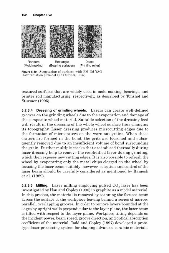
textured surfaces that are widely used in mold making, bearings, andprinter roll manufacturing, respectively, as described by Tonshof andSturmer (1995).
5.2.3.4 Dressing of grinding wheels. Lasers can create well-definedgrooves on the grinding wheels due to the evaporation and damage ofthe composite wheel material. Suitable selection of the dressing feedwill result in the dressing of the whole wheel surface thus changingits topography. Laser dressing produces microcutting edges due tothe formation of microcraters on the worn-out grains. When thesecraters are formed in the bond, the grits are loosened and subse-quently removed due to an insufficient volume of bond surroundingthe grain. Further multiple cracks that are induced thermally duringlaser dressing help to remove the resolidified layer during grinding,which then exposes new cutting edges. It is also possible to refresh thewheel by evaporating only the metal chips clogged on the wheel byfocusing the laser beam suitably; however, selection and control of thelaser beam should be carefully considered as mentioned by Rameshet al. (1989).
5.2.3.5 Milling. Laser milling employing pulsed CO2 laser has beeninvestigated by Hsu and Copley (1990) in graphite as a model material.In this process, the material is removed by scanning the focused beamacross the surface of the workpiece leaving behind a series of narrow,parallel, overlapping grooves. In order to remove layers bounded at theedges by upright walls perpendicular to the layer plane, the laser beamis tilted with respect to the layer plane. Workpiece tilting depends onthe incident power, beam speed, groove direction, and optical absorptioncoefficient of the material. Todd and Copley (1997) developed a proto-type laser processing system for shaping advanced ceramic materials.
152 Chapter Five
Random(Mold making)
Rectangle(Bearing surfaces)
Doses(Printing roller)
Figure 5.40 Structuring of surfaces with PM Nd-YAGlaser radiation (Tonshof and Sturmer, 1995).

This prototype is a fully automated, five-axis, closed-loop controlledlaser shaping system that accurately and cost effectively produces com-plex shapes in the above-mentioned material.
5.2.3.6 Fine cutting and drilling. Tabata et al. (1996) reported that CWCO2 lasers are widely used for fine cutting of steel plates in the auto-motive, electric, and electronic industries; office equipment; householdappliances; industrial machine parts; construction equipment parts;and construction materials. In fine cutting the thickness of the steelplate varies from 0.5 to 16 mm, allowing a cutting speed to vary from6 to 1.0 m/min, respectively. As depicted in Fig. 5.41, the achieved finecuts were of narrow width and the cutting surface was clean and smooth.They also added that high-power Nd-YAG lasers with high-beam qual-ity can be used for steel plate cutting in place of CO2 lasers. The Nd-YAGlasers can also machine nonferrous metals such as copper, brass, andaluminum alloys more efficiently than CO2 laser since Nd-YAG laser isless reflective to such metals. Plates of thickness from 0.2 to 2 mm arefinely cut with the output of 200 W. Acutting speed of 5 m/s for 1-mm-thickplate has been also reported. The slit width and surface cleanliness arealmost similar to CO2 laser processing.
Cao and Huang (1995) invented a new technique for microsize(< 0.07 mm) laser machining, with varying curved wall surfaces dia-mond wire drawing dies using CW Nd-YAG laser. Repetition fre-quency, laser power, and feed step of the laser head along the z axisare the most critical parameters. Microhole drilling, in a single pulse,using a pulse slab Nd-YAG laser has been reported by Rohde andVerboven (1995). Accordingly, holes with diameters of 35 µm in asteel plate of 1.2 mm and diameters of 6 µm in 0.03 mm steel foil havebeen obtained (Fig. 5.42).
Thermal Processes 153
Office equipment Automobile parts
Construction equipment
Figure 5.41 CO2 laser cutting samples.

The rectangular spot slab laser beam can also create a slit, using asingle pulse. Industrial applications for food industries are sieves withslits of 0.06 mm × 2 mm in stainless steel of 0.5 mm thickness at a rateof 100 slits per second. Several pulses are used to create a hole in per-cussion drilling mode. A 60-µm-diameter hole has been obtained in100 MnCrV4 steel plate of 4 mm thickness with an aspect ratio of 65:1using four to five pulses. Micro blind holes of 30-µm diameter with amaximum aspect ratio 12:1 to 800 µm with aspect ratio 4:1 have alsobeen reported by Rohde and Verboven (1995). It is accordingly recom-mended to adjust the pulse duration and frequency to evacuate themolten material from the path of the laser beam.
The trepan technique drills holes of diameters larger than the laserbeam diameter and offers smaller conicity and higher repeatability ofthe hole diameter. Using such a method, holes inclined to the surfaceinto fuel-injection nozzles have become possible. Microcutting of 1-mm-thick steel plate leaving a kerf of 85 µm at the entrance side and 60 µmat the exit side and leaving a taper of 1.25 percent have been reported.
5.2.3.7 Marking of computer keyboard. Ricciardi et al. (1996) developedan excimer laser-based technique for marking computer keyboards withhigh speed and flexibility of the production line that avoids the use oftoxic solutions in the marking process. Laser marking does not involvethe introduction of any foreign materials or exert any mechanicalstresses on the workpiece. The practical advantages of excimer lasersin marking processes are due to the short laser wavelength and pulseduration. High photon energy induces photochemical reactions in thematerial, resulting in a color change with negligible side effects. Thelaser marking cell is able to meet the requirements with nominalthroughput of one keyboard every 15 s.
5.2.3.8 Trimming of electronic components. Lasers of high power density,small spot size, and short pulse length are useful devices for modificationof electronic components, often by selective evaporation. By proper
154 Chapter Five
35 µm hole in 1.2 mm 6 µm in 0.03 mm
Figure 5.42 Fine drilling of holes in steel.

monitoring, the device can be trimmed or adjusted by the requiredamount. Trimming of resistors composed of chromium-silicon oxide,deposited on the surface of a silicon chip, has been achieved using an argon-ion laser operated at a power density of 0.8 MW/cm2 with a pulse width ofless than 10 µs. Energy from the laser was used to heat the resistor film toabout 1000°C thereby altering its resistance value (McGeough, 1988).
5.2.3.9 Controlled fracturing. Laser energy can also be used to fracture orbreak, in a controlled fashion, delicate items such as electronic circuits orcomponents. The absorption of the beam, focused on a small area of thesurface, creates thermal gradients which in turn lead to the formation ofmechanical stresses that are sufficient to cause shearing of the materialover a region so small that the fracture does not propagate in an uncon-trolled manner. Using such a technique, high alumina ceramic, 0.46 mmthick, has been fractured in this way with a 100-W CW CO2N2He laser.
5.2.3.10 Dynamic balancing of gyro components. Laser trimming canachieve highly accurate balancing; with material removal at a rate ofmilligrams per pulse, shallow holes are produced. The dynamic balancingis simplified by utilization of a signal from the points of the imbalanceto trigger the laser pulse.
5.2.3.11 Scribing. Brittle materials like silicon, glass, and ceramic maybe effectively separated or shaped by laser scribing. With this tech-nique, material is removed by laser along a specific path on the surfaceof the workpiece. When the material is sufficiently stressed, a fractureoccurrs along the scribed path. Silicon transistor wafers have been suc-cessfully scribed with a repetitively Q-switched Nd-YAG laser of peakpower 300 W, pulsed, at a rate of 400 pulses per second and of duration300 ns. The rate of scribing reported by McGeough (1988) is 1.5 m/min.
5.2.3.12 Micromachining. Tonshof et al. (1993) investigated the applicationof excimer laser radiation in a multiaxis CNC micromachining unit withmodular design. The unit is used to generate microstructures in ceramic andpolymer surfaces. Using such an arrangement, it was possible to producemicromechanical parts of these materials in the fiber-reinforced plastics.
5.2.3.13 Laser-assisted EDM. Allen and Huang (1997) developed a novelcombination of machining processes to fabricate small holes. Before themicro-EDM of holes, copper vapor laser radiation was used to obtain anarray of small holes first. These holes were then finished by micro-EDM. Their method showed that the machining speed of micro-EDMhad been increased and electrode tool wear was markedly reduced whilethe surface quality remained unchanged.
Thermal Processes 155

In general, LBM offers a wide range of machining applications andcan tackle different engineering materials. The choice of the type oflaser therefore depends on the application required in addition to thematerial being machined. Table 5.4 provides a laser beam selectionguide.
5.2.4 Advantages and limitations
Advantages
Tool wear and breakage are not encountered. Holes can be located accurately by using an optical laser system for
alignment. Very small holes with a large aspect ratio can be produced. A wide variety of hard and difficult-to-machine materials can be
tackled. Machining is extremely rapid and the setup times are economical. Holes can be drilled at difficult entrance angles (10° to the surface). Because of its flexibility, the process can be automated easily such as
the on-the-fly operation for thin gauge material, which requires oneshot to produce a hole.
The operating cost is low.
Limitations
High equipment cost. Tapers are normally encountered in the direct drilling of holes. A blind hole of precise depth is difficult to achieve with a laser.
156 Chapter Five
TABLE 5.4 Laser Beam Selection Guide
Application Laser type
Drilling Small holes, 0.25 mm Ruby, Nd-Glass, Nd-YAGLarge holes, 1.52 mm Ruby, Nd-Glass, Nd-YAGLarge holes, trepanned Nd-YAG, CO2
Drilling, percussion Ruby, Nd-YAG
Cutting Thick cutting CO2 + gas assistanceThin slitting, metals Nd-YAGThin slitting, plastics CO2
Plastics CO2
Materials Metals Ruby, Nd-Glass, Nd-YAGOrganics and nonmetals Pulsed CO2
Ceramics Pulsed CO2 , Nd-YAG
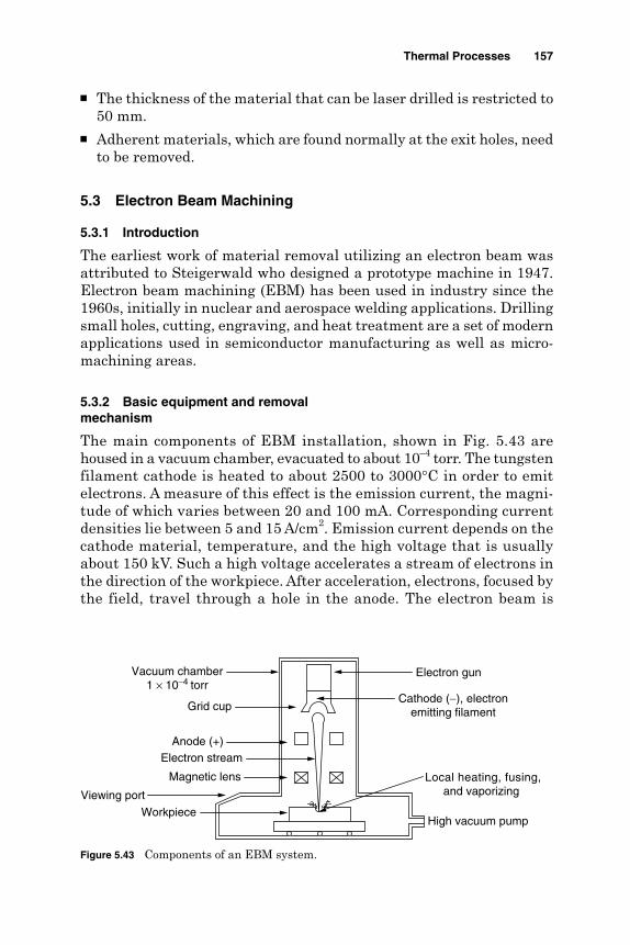
The thickness of the material that can be laser drilled is restricted to50 mm.
Adherent materials, which are found normally at the exit holes, needto be removed.
5.3 Electron Beam Machining
5.3.1 Introduction
The earliest work of material removal utilizing an electron beam wasattributed to Steigerwald who designed a prototype machine in 1947.Electron beam machining (EBM) has been used in industry since the1960s, initially in nuclear and aerospace welding applications. Drillingsmall holes, cutting, engraving, and heat treatment are a set of modernapplications used in semiconductor manufacturing as well as micro-machining areas.
5.3.2 Basic equipment and removalmechanism
The main components of EBM installation, shown in Fig. 5.43 arehoused in a vacuum chamber, evacuated to about 10–4 torr. The tungstenfilament cathode is heated to about 2500 to 3000°C in order to emitelectrons. A measure of this effect is the emission current, the magni-tude of which varies between 20 and 100 mA. Corresponding currentdensities lie between 5 and 15 A/cm2. Emission current depends on thecathode material, temperature, and the high voltage that is usuallyabout 150 kV. Such a high voltage accelerates a stream of electrons inthe direction of the workpiece. After acceleration, electrons, focused bythe field, travel through a hole in the anode. The electron beam is
Thermal Processes 157
High vacuum pump
Local heating, fusing,and vaporizing
Electron gun
Cathode (−), electronemitting filament
Anode (+)
Magnetic lens
Grid cup
Viewing port
Vacuum chamber1 × 10−4 torr
Electron stream
Workpiece
Figure 5.43 Components of an EBM system.

then refocused by a magnetic or electronic lens system so that thebeam is directed under control toward the workpiece. The electronsmaintain the velocity (228 × 103 km/s) imparted by the accelerationvoltage until they strike the workpiece, over a well-defined area, typ-ically 0.25 mm in diameter.
The kinetic energy of the electrons is then rapidly transmitted intoheat, causing a corresponding rapid increase in the temperature of theworkpiece, to well above its boiling point, thus causing material removalby evaporation. With power densities of 1.55 MW/mm2 involved inEBM, virtually all engineering materials can be machined by thismachining technique. Accurate manipulation of the workpiece coupledwith the precise control of the beam is reported by McGeough (1988) toyield a machining process that can be fully automated.
The way in which the focused beam penetrates the workpiece is notcompletely understood, owing to the complexity of the mechanisminvolved. However, it is believed that the workpiece surface is meltedby a combination of electron pressure and surface tension. The meltedliquid is rapidly ejected and vaporized, thus causing material removalrates of about 10 mm3/min. A pulsed electron beam at 104 Hz reducesthe temperature of the workpiece outside the region being machined. Anearly attraction of EBM was the comparatively large depth-to-widthratio (100:1) with applications in fine hole drilling becoming feasible. Theabsence of mechanical contact and the suitability for automatic controlenhance the process capabilities, but the necessity to work in a vacuumlengthens the floor-to-floor cycle time.
The number of pulses required to remove a hole of depth g can bedescribed by
The machining time tm can be given by
The drilling rate Ψ (mm/min) can therefore be calculated by
Ψ =gf
np
e
tnf
ft t
me
p
pp i
=
=+1
ngge
e
=
158 Chapter Five

According to Kaczmarek (1976), the number of pulses ne can simply bedescribed as a function of the accelerating voltage Va and the emissioncurrent Ie by
Hence, the drilling rate Ψ (mm/min) and the volumetric removal rate(VRR) become
In case of slotting a depth g and length L, the slotting time tm is
The slotting rate h (mm/min) becomes
The VRR (mm3/min) can be calculated by
where ge = depth of hole removed per pulse, mmg = depth of hole or slot required, mmfp = frequency of pulses, s–1
tp = pulse time, µsti = pulse interval, µs
db = beam diameter in contact with the workpiece (slot width),mm
Va = beam accelerating voltage, kVIe = beam emission current, mAK = constantL = slot length, mm
The depth of penetration depends on the beam diameter, power density,and the accelerating voltage. Moreover the depth of eroded materialper pulse depends on the density of the workpiece material as well ason the beam diameter. Practically, the number of pulses that produce agiven hole depth is usually found to decrease with an increase in theacceleration voltage. For a fixed set of process conditions, the number
VRR = Kd gf I Vb p e a2
η = Kd f I Vb p e a
t
Lf dm
e
b b
= ⋅⋅
η
Ψ =
=
Kgf I V
Kd gf I V
b e a
b b e aVRRπ4
2
nKI V
ee a
= 1
Thermal Processes 159
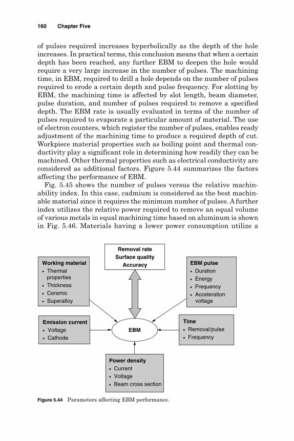
of pulses required increases hyperbolically as the depth of the holeincreases. In practical terms, this conclusion means that when a certaindepth has been reached, any further EBM to deepen the hole wouldrequire a very large increase in the number of pulses. The machiningtime, in EBM, required to drill a hole depends on the number of pulsesrequired to erode a certain depth and pulse frequency. For slotting byEBM, the machining time is affected by slot length, beam diameter,pulse duration, and number of pulses required to remove a specifieddepth. The EBM rate is usually evaluated in terms of the number ofpulses required to evaporate a particular amount of material. The useof electron counters, which register the number of pulses, enables readyadjustment of the machining time to produce a required depth of cut.Workpiece material properties such as boiling point and thermal con-ductivity play a significant role in determining how readily they can bemachined. Other thermal properties such as electrical conductivity areconsidered as additional factors. Figure 5.44 summarizes the factorsaffecting the performance of EBM.
Fig. 5.45 shows the number of pulses versus the relative machin-ability index. In this case, cadmium is considered as the best machin-able material since it requires the minimum number of pulses. A furtherindex utilizes the relative power required to remove an equal volumeof various metals in equal machining time based on aluminum is shownin Fig. 5.46. Materials having a lower power consumption utilize a
160 Chapter Five
Removal rateSurface quality
Accuracy
EBM
Working material• Thermal properties• Thickness• Ceramic• Superalloy
Emission current• Voltage• Cathode
Power density• Current• Voltage• Beam cross section
Time• Removal/pulse• Frequency
EBM pulse• Duration• Energy• Frequency• Acceleration voltage
Figure 5.44 Parameters affecting EBM performance.
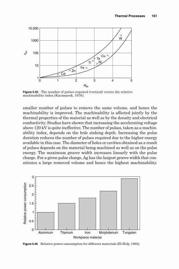
smaller number of pulses to remove the same volume, and hence themachinability is improved. The machinability is affected jointly by thethermal properties of the material as well as by the density and electricalconductivity. Studies have shown that increasing the accelerating voltageabove 120 kV is quite ineffective. The number of pulses, taken as a machin-ability index, depends on the hole sinking depth. Increasing the pulseduration reduces the number of pulses required due to the higher energyavailable in this case. The diameter of holes or cavities obtained as a resultof pulses depends on the material being machined as well as on the pulseenergy. The maximum groove width increases linearly with the pulsecharge. For a given pulse charge, Ag has the largest groove width that con-stitutes a large removed volume and hence the highest machinability.
Thermal Processes 161
10,000
1000
100
10
10 1 2 3 4 5
NM
n ev
××
×
××
×
×
×W
CuTa
NiTi
FeZn
Cd
Figure 5.45 The number of pulses required (vertical) versus the relativemachinability index (Kaczmarek, 1976).
Aluminum Titanium Iron Molybdenum Tungsten
Workpiece material
0
0.5
1
1.5
2
2.5
3
Rel
ativ
e po
wer
con
sum
ptio
n
Figure 5.46 Relative power consumption for different materials (El-Hofy, 1995).

Practically, cavity diameters in the range of 35 to 40 µm are obtainablewith out-of-roundness from 3 to 6 µm in more than 50 percent of thecases. The diameter of the altered layer is proportional to the hole diam-eter which is reported to be 40 to 75 µm for a hole of 20 to 55 µm.Conditions leading to larger removal rates and high machinability arereported to be accompanied by a larger layer thickness and, moreover,a greater surface roughness.
The effect of pulse numbers on the accelerating voltage showed thatincreasing the hole depth requires a much greater rise in the numberat low voltage, due mainly to a relative rise in heat losses resultingfrom the conduction and melting of the adjacent metal layers. For a givennumber of pulses, little improvement in material removal rate isobtained by increasing the accelerating voltage above 120 kV. Theincrease of pulse duration raises the pulse energy available, which inturn reduces the number of pulses required to obtain the requiredmachining result. Kaczmarek (1976) quoted an optimum working dis-tance at which a minimum number of pulses are required. He pointedout that a focal point just below the upper surface of the workpiece issometimes the most effective. The drilling rate by EBM (in holes persecond) decreases with an increase in the thickness of the workpiece aswell as in the diameter of the hole to be produced.
The surface quality produced by EBM depends on the type of material.In this regard, the surface roughness increases with pulse charge for nickel,carbon, gold, and tungsten. Estimates of surface roughness for small holesand cuts are near to 1 µm Ra. Surface layers of material treated by EBMare affected by the temperature of the focused beam, illustrated by thewhite layer ring surrounding the hole, shown in Fig. 5.47. The diameterof the damaged layer increases with pulse duration and hole diameter. Atypical heat-affected zone can be as much as 0.25 mm in EBM, which canbe detrimental to the structural integrity of highly stressed componentsand, for such components, should be removed.
162 Chapter Five
Diameter of damaged layer
Cavity
0.01 mm
Figure 5.47 Cross section of cavity by single EBM pulsein chromium molybdenum steel (Kaczmarek, 1976).

5.3.3 Applications
5.3.3.1 Drilling. Steigerwald and Mayer (1967) considered that for suc-cessful application, improved reproducibility, greater working speeds,and deeper holes of accurately controlled shapes are all needed. Boehme(1983) discussed drilling applications with an electron beam machinefitted with a system for numerically controlling the beam power, focusand pulse duration, and mechanical motion. Cylindrical, conical, andbarrel-shaped holes of various diameters can be drilled with consistentaccuracy at rates of several thousand holes per second. Holes at aninclination angle of about 15° were also possible. Boehme (1983) claimedthat the largest diameter and depth of holes that can be accuratelydrilled by EBM are, respectively, 1.5 mm and 10 mm and that the aspectdepth-to-diameter ratio is normally in the range of 1:1 to 1:15. Fordeeper holes, in the range of 2.5 to 7.5 mm, Steigerwald and Mayer(1967) emphasized the need for a stable power supply that can emit therequired groups of pulses and that, for a well-controlled beam of closelydefined diameter, the angle of aperture has a strong bearing on theshape of the hole produced. Holes of about 19 mm were produced. Drew(1976) showed EB-drilled holes in a superalloy turbine blade at anglesof 60° to 90°.
5.3.3.2 Perforation of thin sheets. For perforation by EBM to be eco-nomically acceptable, 104 to 105 holes per second have to be produced.Thus single pulses lasting only a few microseconds are needed. In someapplications the sheet or foil is stretched on a rotating drum, which issimultaneously shifted in the direction of its axis. Rows of perforationsfollowing a helical line are thereby produced. Manipulators capable oflinear and rotating movements in four axes are used for EBM perfora-tion of jet engine components. Foil made of a synthetic material hasbeen perforated with 620 holes per square millimeter for filter applica-tion at a rate of one hole every 10 µs. EBM perforation can be applied tothe production of filters and masks of color television tubes. Other appli-cations for perforation lie in sieve manufacture, for sound insulationand in glass fiber production.
5.3.3.3 Slotting. Rectangular slots of 0.2 by 6.35 mm in 1.57-mm-thickstainless steel plate are produced in 5 min using 140 kV, 120 µA, a pulsewidth of 80 µs, and a frequency of 50 Hz. The rate of slotting dependson the workpiece thickness. In this regard 0.05-mm-thick stainless steelwas cut at a rate of 100 m/min, while 0.18-mm-thick stainless steel wascut at 50 m/min using similar machining conditions.
5.3.3.4 Integrated circuit fabrication. Birnie and Champney (1967) drew theattention to use of electron beam technology in scribing thin film circuits
Thermal Processes 163

for the electronic industry. A detailed account for the manufacture ofintegrated circuits has been presented by Yew et al. (1994). The beamis positioned accurately by means of deflection coils at the locationwhere a pattern is to be written, by exposing a film of electron resistcoated on either a chrome mask blank or wafer, for the production of thelithographic definition required. An electron beam of energy about10 to 20 kV can either break the bonds between the polymer moleculesor cause cross-linking in the polymers.
With the onset of either of these conditions, the solubility changeswhen the resist film is immersed in the developer, usually a solventfor the resist. Because of the difference in solubility between the orig-inal and exposed resist polymers, a differential material removaloccurs. A fine pattern of polymer is thus obtained, which is used asan active mask to avoid unwanted etching of the integrated circuitmask. Pattern generation can be carried out by a vector scan.Accordingly, the electron beam is deflected only to the locations atwhich the electron resist is to be exposed. As soon as the deflectionsystem completes the positioning of the beam, at the required place,the electron beam action is started. With the raster scan method,described by McGeough (1988), the chip pattern is divided into sub-fields. The electron beam in a raster, like that employed with the tel-evision, scans each subfield. The electron beam is turned on and offalong each raster line as needed. The required pattern is fully formedby the combined effects of electron beam exposure and subsequentresist development. Fig. 5.48 shows a typical application where EBMis used for a miniature electronic hybrid circuit engravement with a40-µm-wide trace. Direct wafer processing by EBM is necessary forfeature sizes below one or two microns. Line width as small as sev-eral hundredth of an angstrom can also be written with electron beamtechniques at speeds as high as 20 MHz. Direct wafer processing elec-tron beam systems are capable of producing 22 wafers per hour.
164 Chapter Five
Figure 5.48 Hybrid circuit engraved with 40 µmtraces at speeds > 5 m/s.

Electron beams can also be used to engrave ceramic as well as vapor-deposited metallic layers on substrate. EBM, process parameters andgeneral capabilities are shown in Table 5.5.
5.3.4 Advantages and disadvantages
Advantages
Drilling is possible at high rates (up to 4000 holes per second). No difficulty is encountered with acute angles. Drilling parameters can easily be changed during machining. No limitation is imposed by workpiece hardness, ductility, and sur-
face reflectivity. No mechanical distortion occurs to the workpiece since there is no con-
tact. The process is capable of achieving high accuracy and repeatability
of 0.1 mm for position of holes and 5 percent for the hole diameter. The process produces the best surface finish compared to other
processes. The cost is relatively small compared to other processes used to pro-
duce very small holes.
Thermal Processes 165
TABLE 5.5 EBM Process Parameters and Capabilities
EBM parameter Level
Acceleration voltage 50–60 kVBeam current 100–100 µABeam power 0.5-50 kWPulse time 4-64,000 µsPulse frequency 0.1-16,000 HzVacuum 0.01-0.0001 mm mercurySpot size 0.013-0.025 mmDeflection range 6.4 mm2
Beam intensity 1.55 × 10⁵–1.55 × 10⁹ W/cm2
Depth of cut Up to 6.4 mmNarrowest cut 0.025 mm in 0.025-mm-thick metalHole range 0.025 mm in 0.02-mm-thick metal
1.0 mm in 5-mm-thick metal
Hole taper 1°–2° typicalHole angle to surface 20°–90°Removal rate 40 mm3/sPenetration rate 0.25 mm/sPerforation rate Up to 5000 holes/sTolerance ± 10% depth of cutSurface roughness 1 µm Ra

Disadvantages
High capital equipment cost Long production time due to the time needed to generate a vacuum The presence of a thin recast layer Need for auxiliary backing material
5.4 Plasma Beam Machining
5.4.1 Introduction
When the temperature of a gas is raised to about 2000°C, the gas mole-cules become dissociated into separate atoms. At higher temperatures,30,000°C, these atoms become ionized. The gas in this stage is termedplasma. Machining by plasma was adopted in the early 1950s as an alter-native method for oxy-gas flame cutting of stainless steel, aluminum,and other nonferrous metals. During that time the process limitationsregarding the low cutting speed, poor machining quality, and the unreli-able equipment were clear. Recently machining of both metallic and non-conductive materials has become much more attractive. An importantfeature of plasma beam machining (PBM), is that it is the only fabricat-ing method that works faster in stainless steel than it does in mild steel.
5.4.2 Machining systems
In plasma machining a continuous arc is generated between a hot tung-sten cathode and the water-cooled copper anode. A gas is introducedaround the cathode and flows through the anode. The temperature, inthe narrow orifice around the cathode, reaches 28,000°C, which isenough to produce a high-temperature plasma arc. Under these condi-tions, the metal being machined is very rapidly melted and vaporized. Thestream of ionized gases flushes away the machining debris as a fine spraycreating flow lines on the machined surface. The general characteristicsof PBM are shown in Table 5.6. The removal rates by this method are
166 Chapter Five
TABLE 5.6 PBM Characteristics
Parameter Level
Velocity of plasma jet 500 m/sMaterial removal rate 150 cm3/minSpecific energy 100 W/(cm3 ⋅min)Power range 2–200 kWVoltage 30–250 VCurrent Up to 600 AMachining speed 0.1–7.5 m/minMaximum plate thickness 200 mm

substantially higher than those of conventional single-point turningoperation. Plasma machining systems are divided into plasma arc,plasma jet, shielded plasma, and air plasma.
5.4.2.1 Plasma arc. As shown in Fig. 5.49, the arc is struck from the rearelectrode of the plasma torch to the conductive workpiece causing tem-peratures as high as 33,300°C. The double arcing effect between the nozzleand the workpiece damages the electrode and the workpiece. High heattransfer rates are found to occur during plasma arc due to the transfer ofall the anode heat to the workpiece. Owing to the greater efficiency ofplasma arc systems, they are often used for machining metals. Plasma arcdoes not depend on a chemical reaction between the gas and the workmetal. Because the temperature is high, the process is suitable for any elec-trically conductive material including those that are resistant to oxy-fuelgas cutting.
5.4.2.2 Plasma jet. In this system, shown in Fig. 5.50, the nontrans-ferred arc is operated within the torch itself. Only ionized gas (plasma)is emitted as a jet causing temperature as high as 16,600°C. Since the
Thermal Processes 167
Electrode
HF coil
Power supply
Workpiece
Arc circuit
Nozzle
Plasma gas
+
−
Figure 5.49 Transferred plasma arc system.
Electrode
HF coil
Power supply
Workpiece
Nozzle
Plasma gas
+
−
Figure 5.50 Nontransferred plasma jet system.
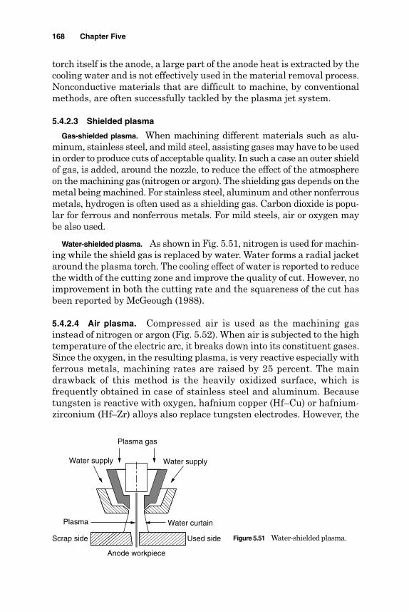
torch itself is the anode, a large part of the anode heat is extracted by thecooling water and is not effectively used in the material removal process.Nonconductive materials that are difficult to machine, by conventionalmethods, are often successfully tackled by the plasma jet system.
5.4.2.3 Shielded plasma
Gas-shielded plasma. When machining different materials such as alu-minum, stainless steel, and mild steel, assisting gases may have to be usedin order to produce cuts of acceptable quality. In such a case an outer shieldof gas, is added, around the nozzle, to reduce the effect of the atmosphereon the machining gas (nitrogen or argon). The shielding gas depends on themetal being machined. For stainless steel, aluminum and other nonferrousmetals, hydrogen is often used as a shielding gas. Carbon dioxide is popu-lar for ferrous and nonferrous metals. For mild steels, air or oxygen maybe also used.
Water-shielded plasma. As shown in Fig. 5.51, nitrogen is used for machin-ing while the shield gas is replaced by water. Water forms a radial jacketaround the plasma torch. The cooling effect of water is reported to reducethe width of the cutting zone and improve the quality of cut. However, noimprovement in both the cutting rate and the squareness of the cut hasbeen reported by McGeough (1988).
5.4.2.4 Air plasma. Compressed air is used as the machining gasinstead of nitrogen or argon (Fig. 5.52). When air is subjected to the hightemperature of the electric arc, it breaks down into its constituent gases.Since the oxygen, in the resulting plasma, is very reactive especially withferrous metals, machining rates are raised by 25 percent. The maindrawback of this method is the heavily oxidized surface, which isfrequently obtained in case of stainless steel and aluminum. Becausetungsten is reactive with oxygen, hafnium copper (Hf–Cu) or hafnium-zirconium (Hf–Zr) alloys also replace tungsten electrodes. However, the
168 Chapter Five
Plasma gas
Water supply Water supply
Water curtain
Scrap side Used side
Anode workpiece
Plasma
Figure 5.51 Water-shielded plasma.

life of these electrodes becomes shorter. Electrically conductive materialssuch as stainless and chrome nickel alloy steels, aluminum, and coppercan be machined by air plasma. Since air is used for machining andshielding purposes, the machining cost is about half that of gas- or water-shielded plasma. When a gas mixture of 80% nitrogen and 20% oxygenis used, the machining rate of mild steel is increased by about 25 percent.
5.4.3 Material removal rate
During PBM absorbing the heat energy from the plasma jet directed to theworkpiece activates metal removal. The plasma torch blows the molten andevaporated metal away as a fine spray or vapor. The resulting cuttingrates and hence the machinability depend on the workpiece beingmachined as well as the type of the cutting and shielding gases that deter-mine the maximum temperature transfer rates. The maximum machin-ing speed, as an index of machinability for dual gas plasma of carbonsteel, stainless steel, and aluminum, is shown in Fig. 5.53. Figure 5.54shows the power consumption factor needed in plasma beam rough turn-ing of some alloys. A low factor indicates either low energy required orhigh removal rates. The machining speed is found to decrease withincreasing the thickness of the metal or the cut width in case of bevel-ing. As the power is increased, the efficient removal of melted metal isfound to need a corresponding rise in the gas flow rate. During plasmamachining of 12-mm-thick steel plate using 220 kW the machining speedis 2500 mm/min, which is 5 times greater than that for oxy-gas cutting.
5.4.4 Accuracy and surface quality
The edges of the workpieces cut by PBM are often beveled. McGeough(1988) reported that the right side of the plasma arc relative to the
Thermal Processes 169
Air (plasma gas)
Hafnium copperelectrode
Workpiece
Nozzle
Plasma
Figure 5.52 Air plasma.

cutting direction produces a square edge to within ±3°. The left-handedge is beveled to about 15° due to the clockwise swirling of the machin-ing gas. Owing to the high rate of heat transfer the depth of fused metalextends to about 0.18 mm below the cut surface. The high machiningspeed does not allow the heat to penetrate more than a few microns from
170 Chapter Five
Inconel Rene 41 Stainless steel Hastalloy C
Workpiece material
0
0.1
0.2
0.3
0.4
0.5
Pow
er c
onsu
mpt
ion,
kw
/(cm
3 . m
in)
Figure 5.54 Power consumption in plasma beam rough turning(El-Hofy, 1995).
0 10 20 30 40
Workpiece thickness, mm
0
1
2
3
4M
axim
um s
peed
, m/m
in
Carbon steel
Stainless steel
Aluminum
N2 gas at 70 cfh, 30 psiSecond gas CO2, 210 cfh, 40 psi
Figure 5.53 Machinability of different material in gas-shielded plasma(El-Hofy, 1995).
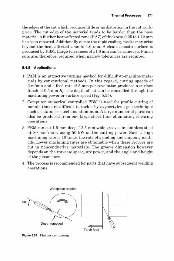
the edges of the cut which produces little or no distortion in the cut work-piece. The cut edge of the material tends to be harder than the basematerial. A further heat-affected zone (HAZ) of thickness 0.25 to 1.12 mmhas been reported. Additionally due to the rapid cooling, cracks may arisebeyond the heat-affected zone to 1.6 mm. A clean, smooth surface isproduced by PBM. Large tolerances of ±1.6 mm can be achieved. Finishcuts are, therefore, required when narrow tolerances are required.
5.4.5 Applications
1. PAM is an attractive turning method for difficult-to-machine mate-rials by conventional methods. In this regard, cutting speeds of 2 m/min and a feed rate of 5 mm per revolution produced a surfacefinish of 0.5 mm Rt. The depth of cut can be controlled through themachining power or surface speed (Fig. 5.55).
2. Computer numerical controlled PBM is used for profile cutting ofmetals that are difficult to tackle by oxyacetylene gas techniquesuch as stainless steel and aluminum. A large number of parts canalso be produced from one large sheet thus eliminating shearingoperations.
3. PBM can cut 1.5-mm-deep, 12.5-mm-wide grooves in stainless steelat 80 mm3/min, using 50 kW as the cutting power. Such a highmachining rate is 10 times the rate of grinding and chipping meth-ods. Lower machining rates are obtainable when these grooves arecut in nonconductive materials. The groove dimension howeverdepends on the traverse speed, arc power, and the angle and heightof the plasma arc.
4. The process is recommended for parts that have subsequent weldingoperations.
Thermal Processes 171
Torch feed
Workpiece rotation
Depth removed
30°
Figure 5.55 Plasma arc turning.
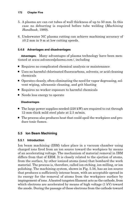
5. A plasma arc can cut tubes of wall thickness of up to 50 mm. In thiscase no deburring is required before tube welding (MachiningHandbook, 1989).
6. Underwater NC plasma cutting can achieve machining accuracy of±0.2 mm in 9 m at low cutting speeds.
5.4.6 Advantages and disadvantages
Advantages. Many advantages of plasma technology have been men-tioned at www.advancedplasma.com/, including
Requires no complicated chemical analysis or maintenance Uses no harmful chlorinated fluorocarbons, solvents, or acid cleaning
chemicals Operates cleanly, often eliminating the need for vapor degreasing, sol-
vent wiping, ultrasonic cleaning, and grit blasting Requires no worker exposure to harmful chemicals Needs less energy to operate
Disadvantages
The large power supplies needed (220 kW) are required to cut through12-mm-thick mild steel plate at 2.5 m/min.
The process also produces heat that could spoil the workpiece and pro-duce toxic fumes.
5.5 Ion Beam Machining
5.5.1 Introduction
Ion beam machining (IBM) takes place in a vacuum chamber usingcharged ions fired from an ion source toward the workpiece by meansof an accelerating voltage. The mechanism of material removal in IBMdiffers from that of EBM. It is closely related to the ejection of atoms,from the surface, by other ionized atoms (ions) that bombard the workmaterial. The process is, therefore, called ion etching, ion milling, or ionpolishing. The machining system, shown in Fig. 5.56, has an ion sourcethat produces a sufficiently intense beam, with an acceptable spread inits energy for the removal of atoms from the workpiece surface byimpingement of ions. Aheated tungsten filament acts as the cathode, fromwhich electrons are accelerated by means of high voltage (1 kV) towardthe anode. During the passage of these electrons from the cathode toward
172 Chapter Five

the anode, they interact with argon atoms in the plasma source, toproduce argon ions.
Ar + e− → Ar+ + 2e
A magnetic field is produced between the cathode and anode thatmakes the electrons spiral. The path length of the electrons is, there-fore, increased through the argon gas, which, in turn, increases theionization process. The produced ions are then extracted from theplasma toward the workpiece, which is mounted on a water-cooledtable having a tilting angle of 0° to 80°. Machining variables such asacceleration voltage, flux, and angle of incidence are independentlycontrolled.
5.5.2 Material removal rate
As shown in Fig. 5.57, if the ions strike the machined surface obliquely,atom ejection is likely to occur from the primary collision. Under suchconditions the incident momentum vector is reported to have the great-est influence on the ejection process (McGeough, 1988). The sputteringyield, that is, the number of atoms yielded per incident ion, may be oneorder of magnitude greater for oblique cutting than normal incidence.The material is, therefore, removed by the transfer of momentum fromthe incident ions to atoms on the surface of the material. The atom,removed from the surface, is also deflected away from the material.Energies greater than the binding energy of 5 to 10 eV are needed toeffect removal of atoms. At higher energies sufficient momentum may
Thermal Processes 173
Cathode
Controlling electrode
Ion beam
Electron knocked out
To vacuum pump
Intermediate electrode
Anode aperture
Extractor anode
Working chamberElectrostatic lens
Workpiece
Table
Figure 5.56 IBM system components.

cause the removal of several atoms from the surface (cascade-typeeffect). Furthermore, the incident ion will become implemented deeperinto the material, damaging it, by displacement of atoms. In IBMmaterial is removed by the transfer of momentum from the incidentions to the atoms, in the surface of the material. As a result an atomis removed from the surface, while the ion is deflected away from thematerial. The amount of yield and hence the machining rate dependon material being machined, the type of ions and their energy, theangle of incidence and, in some cases, the gas pressure as describedby McGeough (1988) as
where V(q) = etch rate, atoms per min/(mA ⋅cm−2)n = density of target material, atoms per cm3
S(q) = yield, atoms per ion
The cos(q) term takes into account the reduced current densities atangles away from normal incidence. The yield and hence the machin-ing rate depend on the binding energy of atoms in the material beingmachined. The amount of yield varies with the introduction of gases,which react with the surface of the material, varying its bindingenergy and hence the rate of material removal. The amount of yieldand hence the machining rate present suitable indices of machin-ability in IBM. Figure 5.58 and 5.59 arrange some materials indescending order with respect to their machinability index. Metallicmaterials seem to have higher machinability than nonmetallic ones.
VS
n( )
( . ) ( ) ( )θ θ θ= ×9 6 1025 cos
174 Chapter Five
Cascade ofatoms
Implanted ion
(b)(a)
Figure 5.57 Mechanism of material removal at (a) low and (b) high energylevels (McGeough, 1988).

5.5.3 Accuracy and surface effects
Small dimensions as 10 to 100 nm are possible using IBM. The slope ofthe sidewalls of the machined surface and its surface finish are deter-mined by the angle of incidence of the ion beam. Accuracy levels of ±1.0percent, with a repeatability of ±1 percent have been reported byMcGeough (1988). Surface texturing produces a cone-and-ridge-like con-figuration on the order of 1 µm in size. However, smoothing to a surfacefinish less than 1 µm can be obtained.
Thermal Processes 175
Silv
er
Gol
d
Man
gane
se
Alu
min
um
Chr
omiu
m
Fe 2
O3
SiO
2
Sili
con
SiC
Car
bon
Work material
0
0.5
1
1.5
2
2.5
3
Rem
oval
rat
e, n
m/s Current density: 1 mA/cm2
Figure 5.59 Variation removal rate with work material in IBM (El-Hofy, 1995).
Silv
er
Ga
As
Gol
d
Cer
amic
Ktfr
phot
ores
ist
Sili
con
Workpiece material
0
5
10
15
20 R
emov
al r
ate,
µm
/h
Pressure: 0.0003 torrVoltage: 1 kVCurrent: 0.85 mA/cm2
Beam diameter: 5 cm
Figure 5.58 Removal rates for different materials (El-Hofy, 1995).

5.5.4 Applications
1. IBM is used in smoothing of laser mirrors as well as reducing thethickness of thin films without affecting their surface finish. In thisregard thinning of samples of silicon to a thickness of 10 to 15 µm hasbeen reported using argon ions impinging at normal incidence byMcGeough (1988).
2. Using two opposing beams, a thin circular region on a rotating samplecan produce samples for transmission electron microscopy.
3. Polishing and shaping of optical surfaces by direct sputtering of pre-forms in glass, silica, and diamond is performed using patterningmasks.
4. The process can produce closely packed textured cones in differentmaterials including copper, nickel, stainless steel, silver, and gold(Fig. 5.60). Sputter etching can also create microscopic surface tex-ture using the sputter deposition of a lower yield material on thesurface.
5. Atomically clean surfaces can be produced by IBM that are used inthe adhesion of gold films to silicon and aluminum oxide substrate.Higher ion energies can be used to remove a layer of the surfaceoxide.
6. IBM can mill a line width of 0.2 µm, which is used in the fabricationof bubble memory devices of depth-to-width ratios of 2:1 (McGeough,1988). Problems associated with the alternative chemical etchingmethod such as the lack of undercutting are avoided since maskingis only needed to shadow the beam.
7. Further applications regarding two-dimensional polymer base dif-fraction grating by IBM can be seen in the website www.blkbox.com/while ion beam deposition (IBD) in the website www.skion.com/.
176 Chapter Five
10 µm
(a) Nickel (b) Copper
Figure 5.60 Scanning electron photomicrographs (McGeough, 1988).

References
Ahmed, M. S., and Knight, J. A. (1988). “Roll texturing by EDT.” Mechanical Working andSteel Processing Conf. Proc., pp. 405–413.
Allen, D., and Lecheheb, A. (1996). “Micro Electrodischarge Machining of Ink Jet Nozzle,Optimum Selection of Material and Machining Parameters,” Journal of MaterialsProcessing Technology, 58:53–66.
Allen, D., and Huang, S. X. (1995). “An Investigation into Multi-electrode EDM of MicroHoles,” ISEM-11, pp. 389–392.
Allen, D., and Huang, S. X. (1997). “The Reduction of Tool Wear and Machining Time forMicro-EDM of Micro Holes by Using Copper Vapour Laser Machining as a RoughingProcess,” International Journal of Electrical Machining (IJEM), Tokyo, 2:9–11.
Amalnik, M., McGeough, J., and El-Hofy, H. (1997). “An Intelligent Knowledge BasedSystem for Manufacturability Evaluation of Design for EDT,” 32nd MATADOR Conf.,Manchester, pp. 418–424.
Aspinwal, D. K., Wise, M. L. H., Stout, K. J., Goh, T. H. A., Zhao, F. L., and El-Menshawy,M. F. (1991). “Electrical Discharge Texturing,” Int. J. of Machine Tools andManufacturing, 32:183–191.
Aspinwal, D. K., Zhao, F.L., El-Menshawy, M. F. (1989). “Electrical Discharge Texturing(EDT) of Steel Rolls,” Surface Topography, 2:123–141.
Bellows, G., and Kohls, J. B. (1983). “Drilling without Drill,” American Mechanist, SpecialReport 743, pp. 183–185.
Benhadad, M. A., McGeough, J. A., and Barker, M. B. (1991). “Electrodischarge Machiningof Al-Li Alloys and Its Effect on Surface Roughness, Hardness and Tensile Strength,”Processing of Advanced Materials, VI(314):123–123.
Birnie, J., and Champney, M. (1967). “The Contribution of Electron Beams to Machiningand Forming in Electrical Methods of Machining and Forming,” IEE Conf., Publ. No.36, pp. 210–221.
Boehme, D. (1983). “Perforation Welding and Surface Treatment with Electron and LaserBeam,” ISEM-7, pp. 190–199.
Chen, X. K., and McGeough, J. (1994). “Fast Drilling of Small Deep Holes by EDM,” TenthInt. Conf. on Computer-Aided Production Engineering (CAPE-10), Palermo, pp. 188–195.
Chryssolouris, G., Sheng, P., and Anastasia, N. (1993) “Laser Grooving of CompositeMaterials with the Aid of Water Jet,” Trans. of ASME, Journal of Engineering forIndustry, 115:62–72.
Corfe, A. (1983). “Why a Laser Is Better Than EDM for Drilling,” The Production Engineer,62(110):13–14.
Crookall, J. R., and Khor, B. C. (1974). “Electro Discharge Machined Surface,” 15th MTDRConf., pp. 373–334.
Dauw, D. F., and Van Coppenolle, B. (1995). “On the Evolution of EDM Research,” ISEM-11.Lausanne Switzerland, pp. 117–142.
Dauw, D. F., and Brown, C. A. (1990). “Surface Topography Investigations by FractalAnalysis of Spark Eroded Electrically Conductive Ceramics,” Annals of CIRP,39(1):161–165.
Delpreti, M. R. (1977). “Physical and Chemical Characteristics of Super Facial Layers,”Proc. of ISEM-5, pp. 209–212.
Devries, M., Duffie, N., Kruth, J., Dauw, D., and Shumacher, B. (1990). “Integration ofEDM within a CIM Environment,” Annals of CIRP, 39(2):1–8.
Drew, J. (1976). “Electron Beam Tackle Tough Machining Jobs,” Machine Design, 26:94–98.El-Hofy, H. (1995). “Machinability Indices for Some Non-conventional Machining
Processes,” Alexandria Engineering Journal (AEJ), 34(3):231–245.El-Hofy, H., De Silva, A., and McGeough, J. A. (1997). “Technological Advances in EDM,”
PEDAC-6 Conf., Alexandria, pp. 941–954.El-Menshawy, M. F., and Ahmed, M. S. (1985). “Monitoring and Control of Electro-discharge
Texturing Process for Steel Cold Mill Work Rolls,” NAMRIC-13, Berkeley, USA, pp. 470–475.Fengguo, C., and Jianyu, H. (1995). “Technique of Precise Laser Machining for Diamond
Wire Drawing Dies,” ISEM-11 Conf., pp. 629–637.Fujino, M, Okamoto, N., and Masuzawa, T. (1995). “Development of Multipurpose Micro
Processing Machine,” ISEM-11, pp. 613–620.
Thermal Processes 177
Fukuzawa, Y., Tani, T., Ito, Y., Ichinose, Y., and Mohri, N. (1995). “EDM of InsulatorCeramics with a Sheet of Metal Mesh,” ISEM-11, pp. 173–179.
Gagilano, F. P., et al. (1969). “Lasers in Industry,” IEEE, 57(2):114–147.Hsu, M. J., and Molian, P. A. (1995). “Off-axial Gas Jet Assisted Laser Cutting of 6.35 mm
Thick Stainless Steel,” ASME, Journal of Engineering for Industry, 117:272–276.Hsu, R. K., and Copley, S. M. (1990). “Producing Three-dimensional Shapes by Laser
Milling,” Trans. ASME, Journal of Engineering for Industry, 112:375–379.Jeswani, M. L. (1977). “Study of Surface Finish in EDM,” ME Journal, 57:329–333.Jeswani, M. L. (1978). “Roughness and Wear Characteristics of Spark Eroded Surfaces,”
Wear, 51:227–236.Kaczmarek, J. (1976). Principles of Machining by Cutting, Abrasion and Erosion.
Stevenage, U.K.: Peter Pergrenius Ltd.Kalpakjian, S. (1997). Manufacturing Processes for Engineering Materials, 3rd ed. Reading,
MA: Addison Wesley.Kuneida, M., and Furuoya, S. (1991). “Improvements of EDM Efficiency by Supplying
Oxygen Gas into Gap,” Annals of CIRP, 40(1):215–218.Kozak, J., Dabrowski, L., Rozenek, M., and Cepiak, J. (1995). “Wire EDM of Multi Layer
Metal Matrix Composite and Laminate Structures,” ISEM-11, pp. 427–436.Lau, W. S., Lee, W. P., and Pans, S. Q. (1990). “Pulsed Nd: YAG Laser Cutting of Carbon
Fiber Composite Materials,” Annals of CIRP, 39(1):179–182.Lau, W. S., Yue, T. M., and Wang, M. (1994). “Computer Aided Laser Drilling of Aluminium-
Based Metal Matrix Composites,” Annals of CIRP, 43(1):177–180.Lauwers, B., and Kruth, J. (1995). “A Computer Aided Process Planning System for
Electrical Discharge Machining,” ISEM-11, Lausanne, Switzerland, pp. 261–278(JSEM/CIRP).
Levy, G. N. (1993). “Environmentally Friendly and High-capacity Dielectric Regenerationfor Wire EDM,” Annals of CIRP, 42(1):227–230.
Levy, G. N., and Maggi, F. (1990). “WED Machinability Comparison of Different SteelGrades,” Annals of CIRP, 39(1):183–186.
Machining Data Handbook. (1997). 3rd ed. Cincinnati, OH: Machinability Data Center,Institute of Advanced Manufacturing.
Masuzawa, T., and Saki, S. (1978). “Quick Finishing of WEDM Products Using Mate-electrode,” Annals of CIRP, 36(1):123–326.
Masuzawa, T., Kuo, C. L., and Fujino, M. (1994). “A Combined Electrical MachiningProcess for Micro Nozzle Fabrication,” Annals of CIRP, 43(1):189–192.
Masuzawa, T. (1990). “Improved Jet Flushing for EDM,” Annals of CIRP, 41(1):197–199.Masuzawa, T., and Tonshof, H. (1997). “Three Dimensional Micro Machining by m/c Tools,
Annals of CIRP, 46(2):621–628.McGeough, J. A., and De Silva, A. (1996). “Research Directions and Applications of
Unconventional Machining,” Proc. of Advanced Manufacturing Processes, Systems &Technologies (AMPST), pp. 3–15.
McGeough, J. A. (1988). Advanced Methods of Machining, London, New York: Chapmanand Hall.
McGeough, J. A. (2002). Micromachining of Engineering Materials, New York: MarcelDekker.
McGeough, J. A., and Rasmussen, H. (1992). “A Model for the Surface Texturing of SteelRolls by Electro Discharge Machining,” NAMRIC Conf., pp. 155–164.
Metals Handbook. (1989). Vol. 16, Machining, Meterials Park, OH: ASM International.Mohri, N., and Saito, M. (1991). “A New Process of Finish Machining on Free Surface by
EDM Methods,” Annals of CIRP, 40(1):207–230.Morita, A., Imai, Y., Maruyama, H., and Kobyashi, K. (1997). “Fuzzy Controller in EDM,”
ISEM-9 Conf. (JESM/CIRP), Nagoya, Japan, pp. 236–240.Motoki, M., and Lee, C. (1968). “Electro Spark Machining Using Trapezoidal Power
Supply,” Electrochemical Eng. in Japan, 8(3):12–20.Pawleski, O., Rasp, W., Zwick., W., Nettelbeck, H. J., and Steinhoff, K. (1994). “The
Influence of Different Work Roll Texturing Systems on the Development of SurfaceStructure in the Temper Rolling Process of Steel Sheet Used in Automotive Industry,”Journal of Material Processing Technology, 45:215–222.
178 Chapter Five
Ramesh Babu, N., Radhakrishnan, V., and Murti, Y. V. (1989). “Investigation on LaserDressing of Grinding Wheels—Preliminary Study,” ASME, Journal of Engineering forIndustry, 111:244–252.
Ricciardi, G., Gantello, M., and Savant-Aira, G. (1996). “Marking of Computer Keyboardsby Means of Excimer Lasers,” Annals of CIRP, 45(1):191–196.
Rohde, H., and Verboven, P. (1995). “Precision Cutting and Drilling with a Laser Nd:YAG Slab Laser,” ISEM-11 Conf. Proc., pp. 777–784.
Shichun, D., et al. (1995). “A New Technology for Machining Spheres by Rotary, EDM,”ISEM-11, pp. 921–827.
Simao, J., El-Menshawy, F., Aspinwal, D., Wise, M., and Kockoll, L. (1994). “SimulatedLaser Texturing Using a Modified Electrical Discharge Arrangement,” Proc. SeventhInt. Conf. of Production/Precision Engineering (ICPE) and Fourth Int. Conf. on HighTechnology (JSPE) Chiba, Japan, pp. 558–563.
Snoeys, R., Staelens, F., and Dekeyser, W. (1986). “Current Trends in Non-conventionalMaterial Removal Processes,” Annals of CIRP, 35(2):467–480.
Spur, G., Appel, S., and Liebelt, S. (1997). “Non-linear Modelling and Simulation of LaserCutting and Grooving of Fiber Reinforced Thermo Plastics.” 32nd MATADOR Conf.,Manchester, pp. 381–386.
Stavitskaya, N. B., and Stravinsky, B. L. (1979). “Fundamental Features of PrecisionSpark Machining,” Electr. Obrab. Mater., 4:5–15.
Steigerwald, K., and Meyer, E. (1967). “New Developments in Electron Beam MachiningMethods.” Electrical Methods of Machining and Forming. IEE, Conf. Publ. No. 38, pp.252–258.
Tabata, N., Yagi, S., and Hishu, M. (1996). “Present and Future of Lasers for Fine Cuttingof Metal Plate,” Journal of Material Processing Technology, 62:309–314.
Tam, S. C., Williams, R., Yang, L. J., Jana, S., Lim, L. E., and Lau, M. W. (1990). “LaserProcessing of Air Craft Components,” Journal of Materials Processing Technology,32:177–194.
Tani, T., Fukuzawa, Y., and Mohri, N. (2004). “Machining Phenomena in WEDM ofInsulating Ceramics,” ISEM-XIV On-site Conf. Proc. Edinburgh, U.K. (Journal ofMaterials Processing Technology).
Todd, J. A., and Copley, S. M. (1997). “Development of a Prototype Laser ProcessingSystem for Shaping Advanced Ceramic Materials.” ASME, Journal of ManufacturingScience and Engineering, 119:55–67.
Tonshof, H. K., and Dickmann, K. (1989). “Influence of Surface/Subsurface Damage onMagnetic Properties of Laser Cut Electrical Steel Sheets,” Annals of CIRP,38(2):695–699.
Tonshof, H. K., and Sturmer, M. (1995). “Machining Using High Energy Radiation,” ISEM-XIConf. Switzerland, pp. 49–60.
Tonshof, H. K., Hesse, D., Mommsen, J. (1993). “Micro Machining Using Excimer Laser,”Annals of CIRP, 42(1):247–251.
Tonshof, K., Egger, R., and Kloclco, F. (1996). “Environmental and Safety Aspects ofElectrophysical and Electrochemical Processes,” Annals of CIRP, 45(2):553–567.
Ueda, T., Yamada, K., and Nakayama, K. (1997). “Temperature of Workpiece MaterialIrradiated with CO2 Laser,” Annals of CIRP, 46(1):117–122.
Yamazaki, M., Suzuki, T., Mori, N., and Kunieda, M. (2004). “EDMing of Microrods by SelfDrilled Holes,” ISEM-XIV On-site Conf. Proc., Edinburgh, U.K. (Journal of MaterialsProcessing Technology).
Yeo, C., Tam, S., Jana, S., and Lau, M. (1994). “A Technical Review of Laser Drilling ofAerospace Materials,” Journal of Materials Processing Technology, 42:15–49.
Yilbas, B. S. (1996). “Experimental Investigation Into CO2 Laser Cutting Parameters,”Journal of Materials Processing Technology, 58:323–330.
www.advancedplasma.com/www.blkbox.com/~chase/polymer/www, skion.com/html/technology.htmwww.unl.edu/nmrc/outline.htmZhixin, J. (1995). “Study on Mechanical Pulse EDM,” Precision Engineering Journal,
117(2):89–93.
Thermal Processes 179

This page is intentionally left blank.

Chapter
6Hybrid Electrochemical
Processes
6.1 Introduction
In the hybrid electrochemical machining processes, the major materialremoval mechanism is either chemical dissolution (CD) or electro-chemical dissolution (ECD). These machining processes are enhancedby using mechanical machining action or thermal assistance. The com-bination of these phases leads to high material removal rates andimproved surface quality.
In the case of the thermally assisted processes using a laser beam(LB), the local heating of the interelectrode gap enhances the dissolu-tion process in laser-assisted chemical etching (LAE) or laser-assistedelectrochemical machining (ECML) during which the current densityrises and the dissolution phase becomes more intensive leading to amore productive machining process.
The introduction of a mechanical machining phase assists electro-chemical machining (ECM) removal rates by changing the interelec-trode gap conditions for the enhanced dissolution process. Under suchconditions mechanical depassivation of the machined surface, by remov-ing thin layers of oxides and other compounds from the anode, isensured. This makes the surface dissolution and hence the smoothen-ing process more intensive (www.unl.edu/nmrc/hybrid/).
As can be seen in Fig. 6.1, mechanical abrasion (MA) is combinedwith ECM to form many hybrid processes such as electrochemical grind-ing (ECG), electrochemical honing (ECH), and electrochemical superfin-ishing (ECS).
Furthermore, ultrasonic-assisted electrochemical machining (USMEC)employs an ultrasonic (US) machining component with ECD to improve
181
Copyright © 2005 by The McGraw-Hill Companies, Inc. Click here for terms of use.

electrolyte flushing and hence the material removal rate. The mechan-ical action of the fluid jet (FJ) enhances the CD during electrochemicalbuffing (ECB).
6.2 Electrochemical Grinding
6.2.1 Introduction
Electrochemical grinding (ECG) utilizes a negatively charged abrasivegrinding wheel, electrolyte solution, and a positively charged work-piece, as shown in Fig. 6.2. The process is, therefore, similar to ECMexcept that the cathode is a specially constructed grinding wheelinstead of a cathodic shaped tool like the contour to be machined byECM. The insulating abrasive material (diamond or aluminum oxide)of the grinding wheel is set in a conductive bonding material. In ECG,the nonconducting abrasive particles act as a spacer between thewheel conductive bond and the anodic workpiece. Depending on thegrain size of these particles, a constant interelectrode gap (0.025 mmor less) through which the electrolyte is flushed can be maintained.
182 Chapter Six
US
LB
MA
FJ
USMEC
ECML
ECGECHECS
ECB ECD
Figure 6.1 Hybrid electrochemical processes.
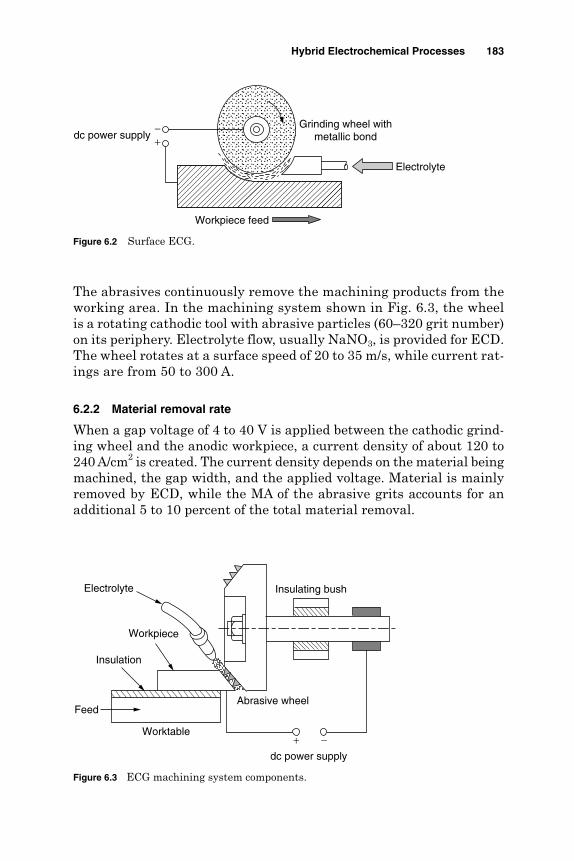
The abrasives continuously remove the machining products from theworking area. In the machining system shown in Fig. 6.3, the wheelis a rotating cathodic tool with abrasive particles (60–320 grit number)on its periphery. Electrolyte flow, usually NaNO3, is provided for ECD.The wheel rotates at a surface speed of 20 to 35 m/s, while current rat-ings are from 50 to 300 A.
6.2.2 Material removal rate
When a gap voltage of 4 to 40 V is applied between the cathodic grind-ing wheel and the anodic workpiece, a current density of about 120 to240 A/cm2 is created. The current density depends on the material beingmachined, the gap width, and the applied voltage. Material is mainlyremoved by ECD, while the MA of the abrasive grits accounts for anadditional 5 to 10 percent of the total material removal.
Hybrid Electrochemical Processes 183
Electrolyte
Workpiece feed
dc power supplyGrinding wheel with
metallic bond−+
Figure 6.2 Surface ECG.
Insulating bush
Abrasive wheel
Electrolyte
Insulation
Worktable
Feed
dc power supply
Workpiece
+ −
Figure 6.3 ECG machining system components.
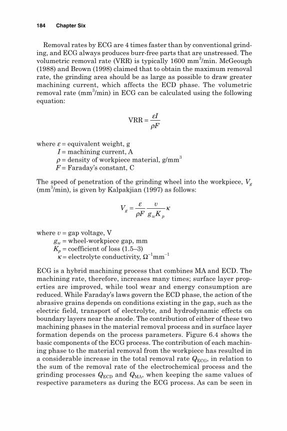
Removal rates by ECG are 4 times faster than by conventional grind-ing, and ECG always produces burr-free parts that are unstressed. Thevolumetric removal rate (VRR) is typically 1600 mm3/min. McGeough(1988) and Brown (1998) claimed that to obtain the maximum removalrate, the grinding area should be as large as possible to draw greatermachining current, which affects the ECD phase. The volumetricremoval rate (mm3/min) in ECG can be calculated using the followingequation:
where e = equivalent weight, gI = machining current, A
r = density of workpiece material, g/mm3
F = Faraday’s constant, C
The speed of penetration of the grinding wheel into the workpiece, Vg
(mm3/min), is given by Kalpakjian (1997) as follows:
where v = gap voltage, Vgw = wheel-workpiece gap, mmKp = coefficient of loss (1.5–3)
k = electrolyte conductivity, Ω–1mm–1
ECG is a hybrid machining process that combines MA and ECD. Themachining rate, therefore, increases many times; surface layer prop-erties are improved, while tool wear and energy consumption arereduced. While Faraday’s laws govern the ECD phase, the action of theabrasive grains depends on conditions existing in the gap, such as theelectric field, transport of electrolyte, and hydrodynamic effects onboundary layers near the anode. The contribution of either of these twomachining phases in the material removal process and in surface layerformation depends on the process parameters. Figure 6.4 shows thebasic components of the ECG process. The contribution of each machin-ing phase to the material removal from the workpiece has resulted ina considerable increase in the total removal rate QECG, in relation tothe sum of the removal rate of the electrochemical process and thegrinding processes QECD and QMA, when keeping the same values ofrespective parameters as during the ECG process. As can be seen in
VF
v
g Kg
w p
= ερ
κ
VRR = ερ
IF
184 Chapter Six
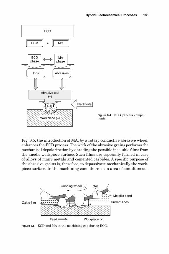
Fig. 6.5, the introduction of MA, by a rotary conductive abrasive wheel,enhances the ECD process. The work of the abrasive grains performs themechanical depolarization by abrading the possible insoluble films fromthe anodic workpiece surface. Such films are especially formed in caseof alloys of many metals and cemented carbides. A specific purpose ofthe abrasive grains is, therefore, to depassivate mechanically the work-piece surface. In the machining zone there is an area of simultaneous
Hybrid Electrochemical Processes 185
+
Electrolyte
ECDphase
MAphase
Abrasive tool(−)
ECM MG
Ions Abrasives
ECG
Workpiece (+)Figure 6.4 ECG process compo-nents.
Feed Workpiece (+)
Grinding wheel (−) Grit
Metallic bond
Current linesOxide film
Figure 6.5 ECD and MA in the machining gap during ECG.

ECD and MA of the workpiece surface, where the gap width is lessthan the height of the grain part projecting over the binder. Anotherarea of pure electrochemical removal where the abrasive grains do nottouch the workpiece surface exists at the entry and exit sides of thewheel.
The increase in performance of the ECG process results from interac-tions between MA, ECD, and changes in surface layer properties of mate-rial in the machining area. The increase in longitudinal feed rate andwheel speed and the decrease in voltage result in a smaller gap width and,consequently, in an increase in the MA contribution to the metal removalprocess. Adecrease in the feed rate is followed by a considerable reductionin cutting forces, down to the values near zero at the transition to “pure”ECD. Machining conditions at which the MA disappears depend on theelectrical parameters, electrochemical machinability of the material in agiven electrolyte, and grinding wheel features, especially grain size andheight. Generally slow feed rates produce larger overcut, poor surfacefinish, and wider tolerances, while excessive wheel wear occurs as a resultof a feed rate that is too fast. Use of expensive diamond grinding wheelsconsiderably reduces the grinding forces which in turn significantly reducesthe abrasive wear and provides notable savings in machining costs. TheMA phase increases the process productivity, dimensional accuracy, andsurface integrity while also reducing energy consumption. When machin-ing steels, MA plays a secondary role since it accounts for only 15 percentof the removal rate. In case of sintered carbides, that contribution reaches30 percent (Kaczmarek, 1976).
For the electrolytic dissolution part, ECM variables such as materialtype, electrolyte, and current density determine the rate of materialremoval. For high machining rates, the greatest current density is to beemployed. However, such current density is limited by the anodic dis-solution rate for a particular alloy-electrolyte system and the boilingpoint of the electrolyte (Machining Data Handbook, 1997). The inter-action between the abrasion action and electrolytic dissolution affectsthe removal rate of the machined material. By increasing the wheelunit pressure while removing a thicker layer, it reduces the size of themachining gap that allows for higher current density. In contrast, thelarger the grain size, the wider is the machining gap and, consequently,the lower is the current density. Under such conditions the machiningrate is impaired despite the partial increase in the abrasion rate.
Rumyantsev and Davydov (1984) showed also an optimum wheelspeed where the removal rate and hence the machining speed are max-imum. Figure 6.6 shows the maximum attainable feed rate, as an indexof machinability. Accordingly, aluminum and copper alloys have thehighest machinability, while stainless steel and carbides have the lowestone (El-Hofy, 1995).
186 Chapter Six
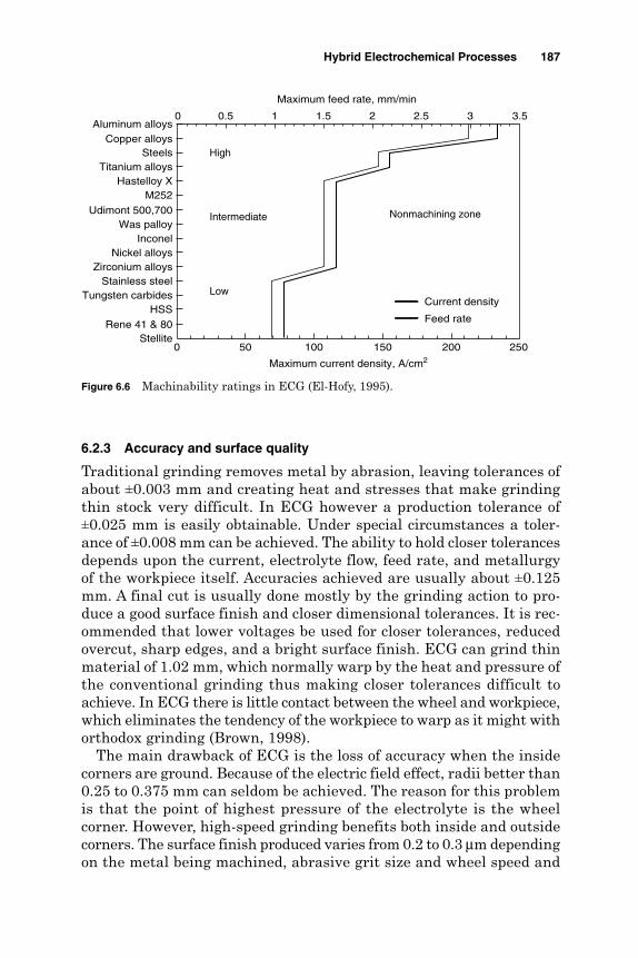
6.2.3 Accuracy and surface quality
Traditional grinding removes metal by abrasion, leaving tolerances ofabout ±0.003 mm and creating heat and stresses that make grindingthin stock very difficult. In ECG however a production tolerance of±0.025 mm is easily obtainable. Under special circumstances a toler-ance of ±0.008 mm can be achieved. The ability to hold closer tolerancesdepends upon the current, electrolyte flow, feed rate, and metallurgyof the workpiece itself. Accuracies achieved are usually about ±0.125mm. A final cut is usually done mostly by the grinding action to pro-duce a good surface finish and closer dimensional tolerances. It is rec-ommended that lower voltages be used for closer tolerances, reducedovercut, sharp edges, and a bright surface finish. ECG can grind thinmaterial of 1.02 mm, which normally warp by the heat and pressure ofthe conventional grinding thus making closer tolerances difficult toachieve. In ECG there is little contact between the wheel and workpiece,which eliminates the tendency of the workpiece to warp as it might withorthodox grinding (Brown, 1998).
The main drawback of ECG is the loss of accuracy when the insidecorners are ground. Because of the electric field effect, radii better than0.25 to 0.375 mm can seldom be achieved. The reason for this problemis that the point of highest pressure of the electrolyte is the wheelcorner. However, high-speed grinding benefits both inside and outsidecorners. The surface finish produced varies from 0.2 to 0.3 µm dependingon the metal being machined, abrasive grit size and wheel speed and
Hybrid Electrochemical Processes 187
Aluminum alloysCopper alloys
SteelsTitanium alloys
Hastelloy XM252
Udimont 500,700Was palloy
InconelNickel alloys
Zirconium alloysStainless steel
Tungsten carbidesHSS
Rene 41 & 80Stellite
0 50 100 150 200 250
Maximum current density, A/cm2
0 0.5 1 1.5 2 2.5 3 3.5
Maximum feed rate, mm/min
Nonmachining zone
High
Intermediate
LowCurrent density
Feed rate
Figure 6.6 Machinability ratings in ECG (El-Hofy, 1995).

feed rate. For better surface quality a finish pass at a low voltage of3 to 5 V and relatively high speed (250–500 mm/min) is recommended(Shpitalni, 1981).
6.2.4 Applications
The ECG process is particularly effective for
1. Machining parts made from difficult-to-cut materials, such as sin-tered carbides, creep-resisting (Inconel, Nimonic) alloys, titaniumalloys, and metallic composites.
2. Applications similar to milling, grinding, cutting off, sawing, andtool and cutter sharpening.
3. Production of tungsten carbide cutting tools, fragile parts, and thin-walled tubes.
4. Removal of fatigue cracks from steel structures under seawater. Insuch an application holes about 25 mm in diameter, in steel 12 to25 mm thick, have been produced by ECG at the ends of fatiguecracks to stop further development of the cracks and to enable theremoval of specimens for metallurgical inspection.
5. Producing specimens for metal fatigue and tensile tests.
6. Machining of carbides and a variety of high-strength alloys.
The process is not adapted to cavity sinking, and therefore it is unsuit-able for the die-making industry.
6.2.5 Advantages and disadvantages
Advantages
Absence of work hardening Elimination of grinding burrs Absence of distortion of thin fragile or thermosensitive parts Good surface quality Production of narrow tolerances Longer grinding wheel life
Disadvantages
Higher capital cost than conventional machines Process limited to electrically conductive materials
188 Chapter Six

Corrosive nature of electrolyte Requires disposal and filtering of electrolyte
6.3 Electrochemical Honing
6.3.1 Introduction
Electrochemical honing (ECH) combines the high removal character-istics of ECD and MA of conventional honing. The process has muchhigher removal rates than either conventional honing or internalcylindrical grinding. In ECH the cathodic tool is similar to the con-ventional honing tool, with several rows of small holes to enable theelectrolyte to be introduced directly to the interelectrode gap. Theelectrolyte provides electrons through the ionization process, acts asa coolant, and flushes away chips that are sheared off by MA andmetal sludge that results from ECD action. The majority of materialis removed by the ECD phase, while the abrading stones removeenough metal to generate a round, straight, geometrically true cylin-der. During machining, the MA removes the surface oxides that areformed on the work surface by the dissolution process. The removalof such oxides enhances further the ECD phase as it presents a freshsurface for further electrolytic dissolution. Sodium nitrate solution(240 g/L) is used instead of the more corrosive sodium chloride (120g/L) or acid electrolytes. An electrolyte temperature of 38°C, pres-sure of 1000 kPa, and flow rate of 95 L/min can be used. ECH employsdc current at a gap voltage of 6 to 30 V, which ensures a current den-sity of 465 A/cm2 [Randlett et al. (1968)]. Improper electrolyte distri-bution in the machining gap may lead to geometrical errors in theproduced bore.
6.3.2 Process characteristics
The machining system shown in Fig. 6.7 employs a reciprocating abrasivestone (with metallic bond) carried on a spindle, which is made cathodic andseparated from the workpiece by a rapidly flowing electrolyte. In such anarrangement, the abrasive stones are used to maintain the gap size of 0.076to 0.250 mm and, moreover, depassivate the machining surface due to theECD phase occurring through the bond. A different tooling system (Fig.6.8) can be used where the cathodic tool carries nonconductive honingsticks that are responsible for the MA. The machine spindle that rotatesand reciprocates is responsible for the ECD process.
The material removal rate for ECH is 3 to 5 times faster than thatof conventional honing and 4 times faster than that of internal cylin-drical grinding. Tolerances in the range of ±0.003 mm are achievable,
Hybrid Electrochemical Processes 189

while surface roughnesses in the range of 0.2 to 0.8 µm Ra are possible. Tocontrol the surface roughness, MA is allowed to continue for a few secondsafter the current has been turned off. Such a method leaves a light com-pressive residual stress in the surface. The surface finish generated by theECH process is the conventional cross-hatched cut surface that is acceptedand used for sealing and load-bearing surfaces. However, for stress-free sur-faces and geometrically accurate bores, the last few seconds of MA actionshould be allowed for the pure ECD process.
190 Chapter Six
Conductivehoning stones
Electrolyte passage
Cathodic tool rotates and reciprocates
Workpiece(+)
Figure 6.7 ECH schematic.
Electrolyte inlet
Workpiece (+)
(−)
Tool rotates andreciprocates
Nonconductivehoning stones
Electrolyte outlet
Pressure chamber
Fixture
Figure 6.8 ECH machining system components.

6.3.3 Applications
As a result of the rotating and reciprocating honing motions, theprocess markedly reduces the errors in roundness through the rotarymotion. Moreover, through tool reciprocation both taper and wavinesserrors are also reduced as shown in Fig. 6.9. Because of the light stonepressure used, heat distortion is avoided. The presence of the ECDphase introduces no stresses and automatically deburrs the part. ECHcan be used for hard and conductive materials that are susceptible toheat and distortion. The process can tackle pinion gears of high-alloysteel as well as holes in cast tool steel components. Hone forming (HF)
Hybrid Electrochemical Processes 191
Removing roundness error
Correcting straightness error
Correcting small tapers
(a) Before ECH (b) After ECH
Figure 6.9 ECH effects on bore errors.

is an application that combines the honing and electrodepositionprocesses. It is used to simultaneously abrade the work surface anddeposit metal. In some of its basic principles the method is the rever-sal of ECH. According to the Metals Handbook (1989), this method isused in case of salvaging parts that became out-of-tolerance and recon-ditioning worn surfaces by metal deposition and abrasion of the newdeposited layers.
6.4 Electrochemical Superfinishing
6.4.1 Introduction
Conventional superfinishing by vibration grinding is a microfinishingoperation in which the surface mirco-irregularities are removed by thecontinuous and slow reciprocation of abrasive sticks that move along theworkpiece length. The sticks oscillate concurrently with short and rapidstrokes with a continuously revolving workpiece as shown in Fig. 6.10.This process is however known to sustain some of the surface micro-irregularities such as waviness and out of roundness.
In electrochemical superfinishing (ECS), the combination of elec-trolytic dissolution (ECD) and mechanical scrubbing (MS) improves theperformance of the conventional superfinishing process. As a result ofsuch a combination, the dissolution process assists the small stockremoval rate due to the mechanical chipping action. Higher stockremoval rates become achievable using either a separate cathodic toolelectrode, as shown in Fig. 6.11, or a diamond abrasive stick with ametallic bond, as shown in Fig. 6.12.
The high stock removal capabilities combined with the ability togenerate close dimensions gave high merits to the ECS process in allfields of industry. The need for initial grinding, which is requiredbefore conventional superfinishing, is avoided. ECS can be used whenother processes fail to yield high removal rates or generate the requiredsize in difficult-to-machine alloys as well as tool steel. Applying ECS
192 Chapter Six
Abrasive tool oscillation + reciprocation
Work rotation
Figure 6.10 Vibratory superfinishing schematic.

to parts that are susceptible to heat and distortion is advantageousbecause the bulk of the metal is removed electrochemically in an elec-trolyte-cooled atmosphere. The problem of thermal distortion, nor-mally found in conventional superfinishing, is therefore eliminated.Burr-free components can also be obtained as a result of the ECDprocess.
6.4.2 Material removal process
In ECS the dissolution action is accompanied by the formation of a pro-tective oxide film on the anodic surface. The MA scrubs away any highspots protruding from the ideal configuration. These spots, with freshmetal contacting the electrolyte, will be subjected to a heavier ECDphase compared to areas still covered with the protective film as shown
Hybrid Electrochemical Processes 193
Oscillation
Tool
Electrolyte
dc power supply+−
Abrasive stick
Rotating workpiece
Figure 6.11 Superfinishing using separate EC electrode(Youssef, 1971).
Light pressure + reciprocation + oscillation
Metallic bondedabrasive stick (−)
Electrolyte
Workpiece (+)
Figure 6.12 ECS using metallic bond diamond stick(Youssef, 1971).
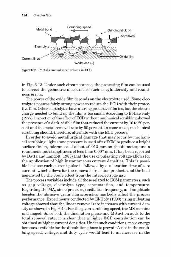
in Fig. 6.13. Under such circumstances, the protecting film can be usedto correct the geometric inaccuracies such as cylindericity and round-ness errors.
The power of the oxide film depends on the electrolyte used. Some elec-trolytes possess fairly strong power to reduce the ECD with their protec-tive film. Other electrolytes have a strong protective film too, but the electriccharge needed to build up the film is too small. According to El-Lawendy(1977), inspection of the effect of ECD without mechanical scrubbing showedthe presence of a dark, visible film that reduced the current by 10 to 20 per-cent and the metal removal rate by 50 percent. In some cases, mechanicalscrubbing should, therefore, alternate with the ECD process.
In order to avoid metallurgical damage that may occur by mechani-cal scrubbing, light stone pressure is used after ECM to produce a brightsurface finish, tolerances of about ±0.013 mm on the diameter, and aroundness and straightness of less than 0.007 mm. It has been reportedby Datta and Landolt (1983) that the use of pulsating voltage allows forthe application of high instantaneous current densities. This is possi-ble because each current pulse is followed by a relaxation time of zerocurrent, which allows for the removal of reaction products and the heatgenerated by the Joule effect from the interelectrode gap.
The process variables include all those related to ECM parameters, suchas gap voltage, electrolyte type, concentration, and temperature.Regarding the MA, stone pressure, oscillation frequency, and amplitudebesides the abrasive grain characteristics markedly affect the processperformance. Experiments conducted by El-Hofy (1990) using pulsatingvoltage showed that the linear removal rate increases with current den-sity as shown in Fig. 6.14. For the given scrubbing speed, the MS remainsunchanged. Since both the dissolution phase and MS action adds to thetotal removal rate, it is clear that a higher ECD contribution can beobtained at higher current densities. Under such conditions, more energybecomes available for the dissolution phase to prevail. A rise in the scrub-bing speed, voltage, and duty cycle would lead to an increase in the
194 Chapter Six
Scrubbing speed
Abrasives
Current lines
Metal bond
Oxide film
Grinding stick (−)
Electrolyte
Workpiece (+)
Figure 6.13 Metal removal mechanisms in ECG.

removal rate. The high energy available enhances the oxide film removalprocess with a consequent rise in the dissolution phase. The percentagecontribution of the dissolution phase varies between 0 at 20 percentduty cycle to about 95 percent when using a 100 percent duty cycle. Asthe scrubbing speed increases, the percentage of the MA phase increases.
6.4.3 Process accuracy
Regarding the workpiece out-of-roundness, Fig. 6.15 shows a reduction ofroundness error from 24 to 8 µm during 2 min of machining using 19 V,a 67 percent duty cycle, and a scrubbing speed of 18.55 m/min. Similarly, sur-face roughness has been decreased from 2.25 to 0.65 µm Ra (El-Hofy, 1990).
Hybrid Electrochemical Processes 195
0 30 60 90 120 150
Current density, A/cm2
0
10
20
30
40
50
60
70R
emov
al r
ate,
µm
/min
MS componentECD component
Figure 6.14 ECS removal rates at different current densities(El-Hofy, 1990).
Before ECS After ECS
Figure 6.15 Effect of ECS on out-of-roundness profiles.

6.5 Electrochemical Buffing
6.5.1 Introduction
Mechanical buffing is a slow finishing process used for achieving smooth,bright, and mirrorlike surfaces. The process is carried out under dry con-ditions, which raises dust and makes the working environmental con-ditions unsuitable. Electrochemical buffing (ECB), shown in Fig. 6.16,uses a carbon fiber cloth that rubs the anodic specimen against a revolv-ing cathode fiber buff. Electrolytes of NaCl or NaNO3 are supplied to themachining zone using a suitable pump. The machining current flowsfrom the workpiece to the cathode through the carbon cloth. TypicalECB conditions have been reported by Hoshino et al. (1995):
Electrolyte type NaCl 150 g/L + NaNO3 10 g/L
NaCl, 100–500 g/L
Current density 0.1–7 A/cm2
Buffing speed 1–6 m/s
Contact pressure 100–600 g
Electrolyte flow rate 1–10 L/min
6.5.2 Material removal process
ECD of the anodic specimen mainly takes place on the surface of thespecimen where it is rubbed by the carbon cloth buff. The current den-sity, the type of electrolyte, and the workpiece material control the pol-ishing speed. For high-speed polishing, an NaCl electrolyte is usedwhere high current density is ensured. The addition of Al2O3 abrasives
196 Chapter Six
dc power supply
Workpiece
Carbon wheel
Stainless cathode
Electrolyte
Electrolyte
+ −
Figure 6.16 ECB schematic.
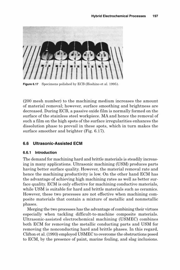
(200 mesh number) to the machining medium increases the amountof material removal; however, surface smoothing and brightness aredecreased. During ECB, a passive oxide film is normally formed on thesurface of the stainless steel workpiece. MA and hence the removal ofsuch a film on the high spots of the surface irregularities enhances thedissolution phase to prevail in these spots, which in turn makes thesurface smoother and brighter (Fig. 6.17).
6.6 Ultrasonic-Assisted ECM
6.6.1 Introduction
The demand for machining hard and brittle materials is steadily increas-ing in many applications. Ultrasonic machining (USM) produces partshaving better surface quality. However, the material removal rate andhence the machining productivity is low. On the other hand ECM hasthe advantage of achieving high machining rates as well as better sur-face quality. ECM is only effective for machining conductive materials,while USM is suitable for hard and brittle materials such as ceramics.However, these two processes are not effective when machining com-posite materials that contain a mixture of metallic and nonmetallicphases.
Merging the two processes has the advantage of combining their virtuesespecially when tackling difficult-to-machine composite materials.Ultrasonic-assisted electrochemical machining (USMEC) combinesboth ECM for removing the metallic conducting parts and USM forremoving the nonconducting hard and brittle phases. In this regard,Clifton et al. (1993) employed USMEC to overcome the obstructions posedto ECM, by the presence of paint, marine fouling, and slag inclusions.
Hybrid Electrochemical Processes 197
Figure 6.17 Specimens polished by ECB (Hoshino et al. 1995).
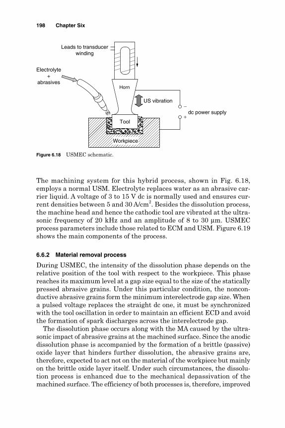
The machining system for this hybrid process, shown in Fig. 6.18,employs a normal USM. Electrolyte replaces water as an abrasive car-rier liquid. A voltage of 3 to 15 V dc is normally used and ensures cur-rent densities between 5 and 30 A/cm2. Besides the dissolution process,the machine head and hence the cathodic tool are vibrated at the ultra-sonic frequency of 20 kHz and an amplitude of 8 to 30 µm. USMECprocess parameters include those related to ECM and USM. Figure 6.19shows the main components of the process.
6.6.2 Material removal process
During USMEC, the intensity of the dissolution phase depends on therelative position of the tool with respect to the workpiece. This phasereaches its maximum level at a gap size equal to the size of the staticallypressed abrasive grains. Under this particular condition, the noncon-ductive abrasive grains form the minimum interelectrode gap size. Whena pulsed voltage replaces the straight dc one, it must be synchronizedwith the tool oscillation in order to maintain an efficient ECD and avoidthe formation of spark discharges across the interelectrode gap.
The dissolution phase occurs along with the MA caused by the ultra-sonic impact of abrasive grains at the machined surface. Since the anodicdissolution phase is accompanied by the formation of a brittle (passive)oxide layer that hinders further dissolution, the abrasive grains are,therefore, expected to act not on the material of the workpiece but mainlyon the brittle oxide layer itself. Under such circumstances, the dissolu-tion process is enhanced due to the mechanical depassivation of themachined surface. The efficiency of both processes is, therefore, improved
198 Chapter Six
Leads to transducerwinding
Electrolyte+
abrasives
US vibration
Horn
Tool
dc power supply+
−
Workpiece
Figure 6.18 USMEC schematic.
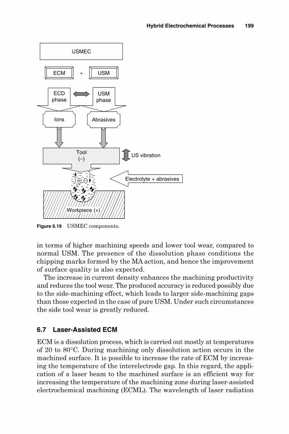
in terms of higher machining speeds and lower tool wear, compared tonormal USM. The presence of the dissolution phase conditions thechipping marks formed by the MA action, and hence the improvementof surface quality is also expected.
The increase in current density enhances the machining productivityand reduces the tool wear. The produced accuracy is reduced possibly dueto the side-machining effect, which leads to larger side-machining gapsthan those expected in the case of pure USM. Under such circumstancesthe side tool wear is greatly reduced.
6.7 Laser-Assisted ECM
ECM is a dissolution process, which is carried out mostly at temperaturesof 20 to 80°C. During machining only dissolution action occurs in themachined surface. It is possible to increase the rate of ECM by increas-ing the temperature of the interelectrode gap. In this regard, the appli-cation of a laser beam to the machined surface is an efficient way forincreasing the temperature of the machining zone during laser-assistedelectrochemical machining (ECML). The wavelength of laser radiation
Hybrid Electrochemical Processes 199
+
US vibration
Electrolyte + abrasives
ECDphase
USMphase
Tool(−)
ECM USM
Ions Abrasives
USMEC
Workpiece (+)
−+
Figure 6.19 USMEC components.

should be chosen in such a way as to minimize the energy adsorbed bythe electrolyte layer, which should be as thin as possible. The heat of thelaser beam causes many physical and chemical phenomena on themachined surface as well as on the surface layer of the material (Fig. 6.20).
The laser radiation affects the rate of electrochemical reactions by sev-eral mechanisms. Local heating of the workpiece area subjected to thelaser beam leads to changes in the equilibrium or steady-state potential(open circuit potential). It increases the rate of the reaction that proceedsunder the charge-transfer control, accelerates the mass transfer, changesthe current efficiency, decreases the metal passivity degree, and finallyincreases the concentration of current carriers during ECM of semicon-ductors. The effect of laser radiation on the current efficiency of the anodicdissolution is not well understood. If the current efficiency increases withtemperature, an increase of the degree of process localization will be espe-cially pronounced. In contrast, a marked decrease of the current efficiencywith an increase in temperature may present an impenetrable barrier tothe use of laser in some cases of ECM. The formation of a high-adsorptivelayer of dissolution products may be a barrier to the use of ECML.
The experimental work of Zybura-Skrabalak and Ruszaj (2000) showedthat with a temperature increase from 20 to 40°C, the current density
200 Chapter Six
Electrolyte Laser-assisting photons
ECDphase
ECM
Ions
Workpiece (+)
Laser beam
Tool (−)
Insulation
ECML
Figure 6.20 ECML schematic.

and the intensity of dissolution increase from 0.6 to 1.8 mm3/(min ⋅A).Laser assistance of ECM can be effectively used for improvement in themicromachining processes by increasing the material removal rate ofnormal ECM by 10 times. It causes localization of the anodic dissolution,especially when the passivation process occurs during electrochemicaldissolution. One way to further increase the localization of laser actionis to use pulse radiation. An increase of the electrolyte flow rate has asimilar effect. The prospective application of ECML can be useful in theshaping of small elements (5–500 µm) with high accuracy (1–10 µm) forthe electronic and space industries especially when the elements aremade from difficult-to-machine materials such as alloys, composites,and ceramics. Pajak and coworkers (2004) reported that laser-assistedjet ECM (LAJECM) improves the machining efficiency and precision ofsmall holes compared to that of single-jet ECM.
References
Brown, J. (1998). Advanced Machining Technology Handbook. New York: McGraw-Hill.Clifton, D., Imai, Y., and McGeough, J. (1993). “Some Ultrasonic Effects in Machining
Materials Encountered in the Offshore Industries,” 30th MTDR Conf., pp. 119–123.Datta, M., and Landolt, D. (1983). “Electrochemical Saw Using Pulsating Voltage,” Journal
of Applied Electrochemistry, 13:795–801.El-Hofy, H. (1990). “Characteristics of Pulsed EC-Superfinishing,” Alexandria Engineering
Journal (AEJ ), 29(1):83–100.El-Hofy, H. (1995). “Machinability Indices for Some Non Conventional Machining
Processes,” Alexandria Engineering Journal (AEJ ), 34(3):231–245.El-Lawendy, M. (1977). “Electrochemical Super Finishing,” M.Sc. Thesis, Alexandria
University.Hoshino, S., and Ogawa, K. (1995). “Electrochemical Buffing Using Carbon Fiber Cloth,”
ISEM 11, pp. 577–583.Kaczmarek, J. (1976). Principles of Machining by Cutting, Abrasion and Erosion,
Stevanage, U.K.: Peter Peregrines.Kalpakjian, S. (1997). Manufacturing Processes for Engineering Materials, Menlo Park,
CA: Addison Wesley.Machining Data Handbook. (1997). 3rd ed. Cincinnati, OH: Machinability Data Center,
Institute of Advanced Manufacturing.McGeough, J. A. (1988). Advanced Methods of Machining. London. New York: Chapman
and Hall.Metals Handbook. (1989). Vol. 16, Machining. Materials Park, OH: ASM International.Pajak, P. T., DeSilva, A., McGeough, J., and Harrison, D. (2004). “Modeling the Aspects
of Precision and Efficiency in Laser Assisted Jet Electrochemical Machining (LAJECM),”ISEM XIV, On-site Conf. Proc., Edinburgh, U.K. (Journal of Materials ProcessingTechnology).
Randlett, E., et al. (1968). “Electrochemical Honing (ECH),” Technical Paper MR68–815, 9 pp.Rumyantsev, E., and Davydov, A. (1984). Electrochemical Machining of Metals. Moscow:
MIR Publishers.Shpitalni, M., et al. (1981). “Adaptive Control System for Optimising the ECG Process
under the Over Cut Constraint,” Annals of CIRP, 30(1):97–102.Youssef, H. A. (1971). “Electrolytic Superfinishing of Sintered Carbides,” Faculty of
Engineering Bulletin, Alexandria University, X:209–231.Zybura-Skrabalak, M., and Ruszaj, A. (2000). “Investigation Aiming to Increase the Rate
of Electrochemical Dissolution Process,” CAPE-2000 Conf., Edinburgh, U.K., pp.163–174.
www.unl.edu/nmrc/hybrid/hybrid_machining.htm
Hybrid Electrochemical Processes 201

This page is intentionally left blank.
Chapter
7Hybrid Thermal Processes
7.1 Introduction
In hybrid thermal machining; the major material removal mechanismis a thermal one which normally leads to melting and evaporation of theworkpiece material. Thermal machining can be assisted using electro-chemical dissolution (ECD) and/or mechanical abrasion (MA). This com-bination leads to high removal rates and improved product quality.
In electrochemically assisted processes, the combination of the elec-trodischarge erosion (EDE) phase with the ECD phase forms the newelectrochemical discharge machining (ECDM), [also known as elec-troerosion dissolution machining (EEDM) or electrochemical arc machin-ing (ECAM)] process that occurs in electrolyte solutions using pulsedvoltage. Here the dissolution phase enhances the discharging processwhich adds to the material removal.
Mechanically assisted processes combine the mechanical abrasionaction with the thermal one in case of electrodischarge grinding (EDG)and abrasive electrodischarge machining (AEDM), which employ solidor loose abrasives in dielectric liquids. Electrodischarge machiningwith ultrasonic assistance (EDMUS) introduces ultrasonic vibrationto the tool that enhances the electrodischarging action. The cavitationgenerated by such a vibration enhances EDM by improving the dielec-tric flushing, and hence the material removal from the surface craters,during microdrilling and production of slots and grooves.
A triplex hybrid machining adds to the material removal and is alsoachievable by combining the EDE phase to the ECD and MA processesin electrochemical discharge grinding (ECDG). Similarly, electrochem-ical dissolution and mechanical friction provide reasonable assistanceto the discharging process during brush erosion-dissolution mechanical
203
Copyright © 2005 by The McGraw-Hill Companies, Inc. Click here for terms of use.

machining (BEDMM). Figure 7.1 shows the various hybrid thermalmachining processes.
7.2 Electroerosion Dissolution Machining
Novel methods of machining hard metals, which are difficult to cut byconventional methods, continue to attract attention. Electrochemicalmachining and electrodischarge machining have proven to be veryuseful. However, drawbacks such as the expense of tooling for machin-ing large cavities, the high cost of machining systems, low rates of metalremoval, and the presence of a recast layer, which often has to beremoved in EDM, have hindered wider acceptance of these techniques.
EEDM (also called ECDM or ECAM) is a new development, whichcombines features of both ECD and EDE. It utilizes electrical dis-charges in electrolytes for material removal. Such a combination allowshigh metal removal rates to be achieved. EEDM has found a widerange of applications in the field of wire cutting, hole drilling, and fin-ishing of dies and molds by El-Hofy and McGeough (1988), Crichtonand McGeough (1984), and Levy et al. (1983). Further applicationsregarding machining of composites using NaOH electrolyte have beenreported by Jain et al. (1991).
The EEDM process is a further development of pulsed electrochemi-cal machining (PECM) where, according to Saushkin, et al. (1982), athigh input power, phenomena that limit further dissolution may arise.Under such circumstances, the machining medium changes to a gas-vapor mixture that interferes with the ion transfer in the electric field.
204 Chapter Seven
ECDG
ECDEDEMA
US
EDG/AEDM ECDM/EEDM
EDMUS
Figure 7.1 Hybrid thermal machining processes.

If the field strength is high enough to cause gap breakdown, the natureof charge transfer is altered causing the combined action of EEDM.Such a machining process is associated with a glow appearing in theinterelectrode gap. The glow and the subsequent breakdown of the inter-electrode gaps were localized at points where the gas content and tem-perature of the working medium are likely to be highest.
The machining system for EEDM wire cutting is shown in Fig. 7.2.It adopts pulsed voltage and liquid electrolytes as the machiningmedium that ensures the occurrence of ECD along with the dischargephase (El-Hofy, 1995). A further arrangement used in hole drilling byKhayry and El-Hofy (1990) is shown in Fig. 7.3. A full wave rectifiedvoltage is applied during the vibration of the workpiece or the tool at100 Hz and an amplitude and phase shift with respect to the voltageas shown in Fig. 7.4. The tool feed, vibration amplitude, and phase
Hybrid Thermal Processes 205
Wire guides
Fresh wire
Used wire
Electrolyte supply
Electrolyte supply Coaxial nozzle
dc power supply
CNC movement
−+
Figure 7.2 Electroerosion dissolution wire machining.
Vibration Linear feed
Tool rotation
Electrolyte inlet
Tool (−)
Workpiece (+)
Electrolyte outlet
Figure 7.3 EEDM drilling.
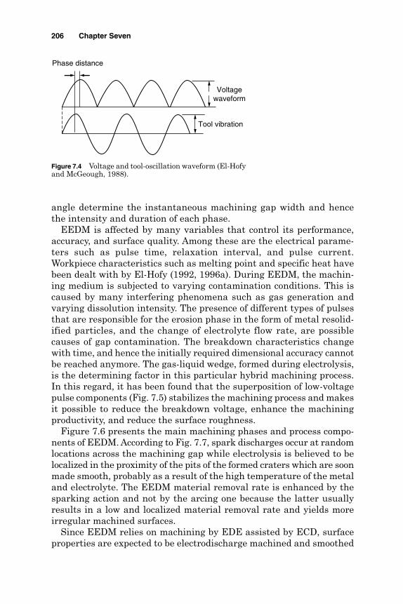
angle determine the instantaneous machining gap width and hencethe intensity and duration of each phase.
EEDM is affected by many variables that control its performance,accuracy, and surface quality. Among these are the electrical parame-ters such as pulse time, relaxation interval, and pulse current.Workpiece characteristics such as melting point and specific heat havebeen dealt with by El-Hofy (1992, 1996a). During EEDM, the machin-ing medium is subjected to varying contamination conditions. This iscaused by many interfering phenomena such as gas generation andvarying dissolution intensity. The presence of different types of pulsesthat are responsible for the erosion phase in the form of metal resolid-ified particles, and the change of electrolyte flow rate, are possiblecauses of gap contamination. The breakdown characteristics changewith time, and hence the initially required dimensional accuracy cannotbe reached anymore. The gas-liquid wedge, formed during electrolysis,is the determining factor in this particular hybrid machining process.In this regard, it has been found that the superposition of low-voltagepulse components (Fig. 7.5) stabilizes the machining process and makesit possible to reduce the breakdown voltage, enhance the machiningproductivity, and reduce the surface roughness.
Figure 7.6 presents the main machining phases and process compo-nents of EEDM. According to Fig. 7.7, spark discharges occur at randomlocations across the machining gap while electrolysis is believed to belocalized in the proximity of the pits of the formed craters which are soonmade smooth, probably as a result of the high temperature of the metaland electrolyte. The EEDM material removal rate is enhanced by thesparking action and not by the arcing one because the latter usuallyresults in a low and localized material removal rate and yields moreirregular machined surfaces.
Since EEDM relies on machining by EDE assisted by ECD, surfaceproperties are expected to be electrodischarge machined and smoothed
206 Chapter Seven
Phase distance
Voltagewaveform
Tool vibration
Figure 7.4 Voltage and tool-oscillation waveform (El-Hofyand McGeough, 1988).
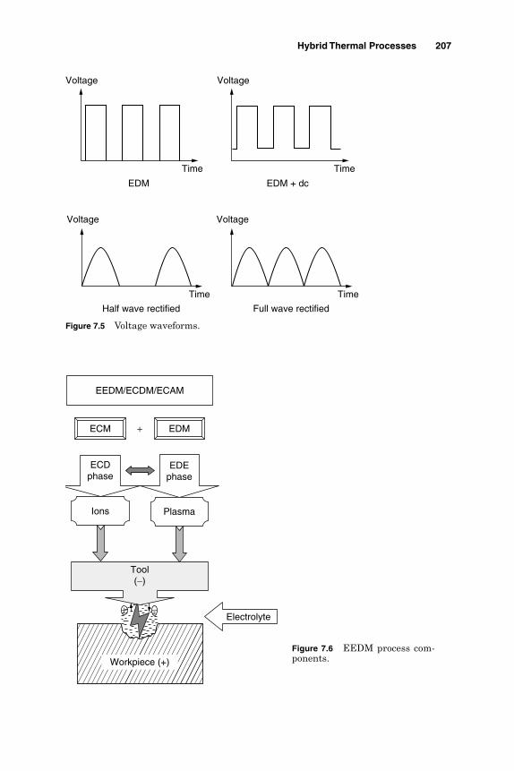
Hybrid Thermal Processes 207
EDM
Voltage
Time
EDM + dc
Voltage
Time
Half wave rectified
Time
Voltage
Full wave rectified
Time
Voltage
Figure 7.5 Voltage waveforms.
Workpiece (+)
+
Electrolyte
ECDphase
EDEphase
Tool(−)
ECM EDM
Ions Plasma
EEDM/ECDM/ECAM
−+
Figure 7.6 EEDM process com-ponents.

by the ECD action, or electrochemically machined with the surface con-ditioned by electrodischarge craters (El-Hofy and Khayry, 1995). In thisregard Levy et al. (1983) noticed that the depth of the thermally affectedlayer was comparatively low at low discharge intensity due to the ECDoccurring at high current density. Moreover, in hole drilling, the damagedlayer was extended to only one-third of the hole depth from the exit side.
The thickness of the heat-affected layer was reported to be 290 µm.Khayry (1984) and Levey et al. (1983) reported the existence of micro-cracks. Some alloying of the surface layers with the tool material wasalso observed at high voltages, which may enhance the mechanical prop-erties of the material.
The increase of the machining rate raises the volumetric removal rate(VRR) due to the enhanced erosion process. Such an increase reachesa maximum level and then decreases probably due to the narrow inter-electrode gap and the rise in the gap contamination level together withthe percentage of gas-vapor mixture. The machining rate increaseswith the electrolyte flow velocity. At small machining rates, the effectof flow velocity on the VRR is greatly reduced as a result of the wideinterelectrode gaps that exist under such machining conditions.Consequent gap short circuiting and the termination of the machiningprocess follow a large increase in machining rate. PECM prevails atlower feed rates that avoid gap breakdown and the occurrence of dis-charges (McGeough and coworkers, 1983). Between PECM and theshorting limit, the possible EEDM zone covers a wider range of machin-ing rates as the electrolyte flow velocity is raised (El-Hofy, 1996b).PECM occurs at a gap pressure of 0.1 MPa and a current density of10 A/cm2. The increase in gap pressure, electrolyte velocity, and cur-rent density enhances the erosion process. It should be borne in mindthat a rise in the machining voltage allows for more energy to be avail-able for an intensified dissolution process, gas generation, and conse-quently the discharging action. During EEDM drilling, the specificmaterial removal rate increases with the gap voltage. According to
208 Chapter Seven
Metal chips
Tool (-)
W.P ( + )
Electrolyte
Dissolved metal
Gas Spark
Workpiece (+)
Tool (−)
Figure 7.7 Surface formations in EEDM (El-Hofy and Khayry, 1995).
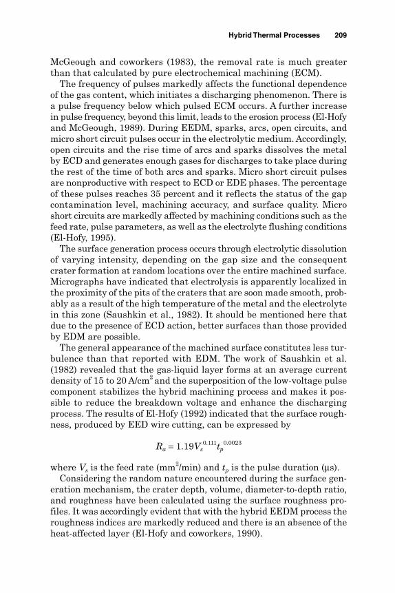
McGeough and coworkers (1983), the removal rate is much greaterthan that calculated by pure electrochemical machining (ECM).
The frequency of pulses markedly affects the functional dependenceof the gas content, which initiates a discharging phenomenon. There isa pulse frequency below which pulsed ECM occurs. A further increasein pulse frequency, beyond this limit, leads to the erosion process (El-Hofyand McGeough, 1989). During EEDM, sparks, arcs, open circuits, andmicro short circuit pulses occur in the electrolytic medium. Accordingly,open circuits and the rise time of arcs and sparks dissolves the metalby ECD and generates enough gases for discharges to take place duringthe rest of the time of both arcs and sparks. Micro short circuit pulsesare nonproductive with respect to ECD or EDE phases. The percentageof these pulses reaches 35 percent and it reflects the status of the gapcontamination level, machining accuracy, and surface quality. Microshort circuits are markedly affected by machining conditions such as thefeed rate, pulse parameters, as well as the electrolyte flushing conditions(El-Hofy, 1995).
The surface generation process occurs through electrolytic dissolutionof varying intensity, depending on the gap size and the consequentcrater formation at random locations over the entire machined surface.Micrographs have indicated that electrolysis is apparently localized inthe proximity of the pits of the craters that are soon made smooth, prob-ably as a result of the high temperature of the metal and the electrolytein this zone (Saushkin et al., 1982). It should be mentioned here thatdue to the presence of ECD action, better surfaces than those providedby EDM are possible.
The general appearance of the machined surface constitutes less tur-bulence than that reported with EDM. The work of Saushkin et al.(1982) revealed that the gas-liquid layer forms at an average currentdensity of 15 to 20 A/cm2 and the superposition of the low-voltage pulsecomponent stabilizes the hybrid machining process and makes it pos-sible to reduce the breakdown voltage and enhance the dischargingprocess. The results of El-Hofy (1992) indicated that the surface rough-ness, produced by EED wire cutting, can be expressed by
Ra = 1.19Vs0.111tp
0.0023
where Vs is the feed rate (mm2/min) and tp is the pulse duration (µs).Considering the random nature encountered during the surface gen-
eration mechanism, the crater depth, volume, diameter-to-depth ratio,and roughness have been calculated using the surface roughness pro-files. It was accordingly evident that with the hybrid EEDM process theroughness indices are markedly reduced and there is an absence of theheat-affected layer (El-Hofy and coworkers, 1990).
Hybrid Thermal Processes 209

The increase in electrolyte flow velocity during EEDM raises the sur-face roughness. Higher electrolyte flow velocities increase the ignitiondelay time of pulses. Under such circumstances, more time is allowedfor the dissolution process to occur at higher voltages. Consequently,larger quantities of gas are generated and cause severe discharges,larger craters are formed, and rougher surfaces are produced. Kuneidaand Furuoya (1991) found that the stock removal rate is increased dueto the enlarged volume of discharge craters and the more frequent occur-rence of discharges caused by the oxygen gas in the EDM gap.
The increase in feed rate reduces the size of the interelectrode gap,which intensifies the dissolution phase (since more gas evolves andencourages the discharging action) and leaves larger craters on themachined surface. The increase in machining rate would, therefore,lead to a rise in surface roughness as described in Fig. 7.8. The increaseof pulse energy ensures the presence of more energy for an efficient dis-solution phase through the machining gap, and hence larger rates ofremoval and rougher surfaces are expected.
The machinability of metals and alloys by EEDM depends on theirbehavior with respect to the two machining actions. For efficient EEDM,the discharging process dominates the material removal process and isassisted by the dissolution phase of 40 to 60 percent.
The discharges cause thermal depolarization by eroding the oxidelayer formed on the anode surface, which, in turn, further enhancesthe dissolution process. Figure 7.9 shows the relative machinabilityindex that is normalized to 2017 aluminum alloy. This index has beenderived on the basis of the VRR at a given machining speed.
210 Chapter Seven
0 5 10 15 20 25
Machining speed, mm2/min
0
5
10
15
20
25S
urfa
ce r
ough
ness
Ra,
µm
0
20
40
60
80
100
Dep
th o
f whi
te la
yer,
µmEEDM Ra EDM Ra HAZ in EDM
Figure 7.8 Effect of machining speed on the surface roughness and the damagedlayer in EDM and EEDM.

A highly machinable material produces greater removal rates. For agiven machining speed, as the removal rate increases, the interelectrodegap becomes wider and machining occurs at a stable mode (Fig. 7.10).Under such circumstances faster rates could be achieved and a higherproductivity is also ensured. The low machinability of graphite, limitedthe machining rates to much lower speeds than those experimented incase of the aluminum alloy (El-Hofy, 1992). Similar to EDM the increasein the removal rate and, hence, machinability is associated with the pro-duction of a rough surface. Figure 7.11 shows the shapes of drilledholes by ECM, EDM, and EEDM. Accordingly accurate shapes can be
Hybrid Thermal Processes 211
AL.2017 Steel Inco 901 St. St. 316 Graphite
Work material
0
20
40
60
80
100
120
Rel
ativ
e m
achi
nabi
lity
inde
x, %
100
79.7 77.8
58.4
21.8
Figure 7.9 Machinability index for some materials normalized to 2017 aluminum(El-Hofy, 1995).
Aluminum2017
Steel Inco 901 St. St. 316 Graphite
Work material
0
5
10
15
20
25
30
Rem
oval
rat
e, m
m3 /
min
0
20
40
60
80
100
Inst
abili
ty in
dex,
V/m
m
Instability index Removal rate
Figure 7.10 Machinability and stability in EEDM (El-Hofy, 1995).
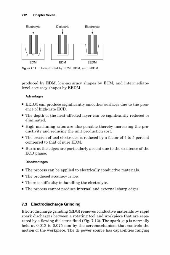
produced by EDM, low-accuracy shapes by ECM, and intermediate-level accuracy shapes by EEDM.
Advantages
EEDM can produce significantly smoother surfaces due to the pres-ence of high-rate ECD.
The depth of the heat-affected layer can be significantly reduced oreliminated.
High machining rates are also possible thereby increasing the pro-ductivity and reducing the unit production cost.
The erosion of tool electrodes is reduced by a factor of 4 to 5 percentcompared to that of pure EDM.
Burrs at the edges are particularly absent due to the existence of theECD phase.
Disadvantages
The process can be applied to electrically conductive materials. The produced accuracy is low. There is difficulty in handling the electrolyte. The process cannot produce internal and external sharp edges.
7.3 Electrodischarge Grinding
Electrodischarge grinding (EDG) removes conductive materials by rapidspark discharges between a rotating tool and workpiece that are sepa-rated by a flowing dielectric fluid (Fig. 7.12). The spark gap is normally held at 0.013 to 0.075 mm by the servomechanism that controls themotion of the workpiece. The dc power source has capabilities ranging
212 Chapter Seven
Electrolyte
ECM
Dielectric
EDM
Electrolyte
EEDM
Figure 7.11 Holes drilled by ECM, EDM, and EEDM.

from 30 to 100 A, 2 to 500 kHz, and 30 to 400 V. The conductive wheel,usually made of graphite, rotates at 30 to 180 m/min in a dielectric bathof filtered hydrocarbon oil. The workpiece is usually connected to the positive terminal of the dc power supply. As can be seen from Fig. 7.12,the workpiece is machined using a stream of electric sparks. Each sparkdischarge melts or vaporizes a small amount of metal from the workpiecesurface. Higher machining currents produce faster rates of machining,rougher finishes, and a deeper heat-affected zone (HAZ) in the workpiece.Less current is used for the production of smoother and less damaged sur-faces. Additionally, higher pulse frequencies makes smoother surfaces.
Wheel wear ranges from 100:1 to 0.1:1 with an average of 3:1 depend-ing upon the current density, workpiece material, wheel material, dielec-tric, and sharpness of corner details. Material removal rates range from0.16 to 2.54 cm3/min. Surface finishes in the range of 1.6 to 3.2 µm Ra arepossible. Figure 7.13 shows the relationship between removal rate and
Hybrid Thermal Processes 213
Nonabrasivemetallic wheel
dc power supply
Servo-controlled feed
Dielectric Sparks+
−
t
u
Workpiece
Figure 7.12 EDG schematic.
0 0.2 0.4 0.6 0.8 1
Removal rate, cm3/h
0
0.5
1
1.5
2
2.5
3
3.5
Sur
face
rou
ghne
ss R
a, µ
m
Figure 7.13 Removal rate and surface roughness in EDG (El-Hofy, 1995).
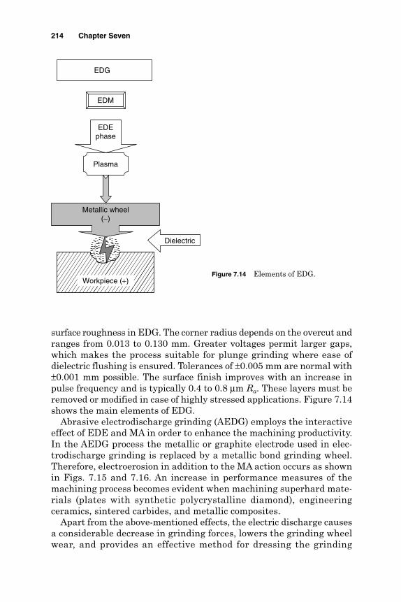
surface roughness in EDG. The corner radius depends on the overcut andranges from 0.013 to 0.130 mm. Greater voltages permit larger gaps,which makes the process suitable for plunge grinding where ease ofdielectric flushing is ensured. Tolerances of ±0.005 mm are normal with±0.001 mm possible. The surface finish improves with an increase inpulse frequency and is typically 0.4 to 0.8 µm Ra. These layers must beremoved or modified in case of highly stressed applications. Figure 7.14shows the main elements of EDG.
Abrasive electrodischarge grinding (AEDG) employs the interactiveeffect of EDE and MA in order to enhance the machining productivity.In the AEDG process the metallic or graphite electrode used in elec-trodischarge grinding is replaced by a metallic bond grinding wheel.Therefore, electroerosion in addition to the MA action occurs as shownin Figs. 7.15 and 7.16. An increase in performance measures of themachining process becomes evident when machining superhard mate-rials (plates with synthetic polycrystalline diamond), engineeringceramics, sintered carbides, and metallic composites.
Apart from the above-mentioned effects, the electric discharge causesa considerable decrease in grinding forces, lowers the grinding wheelwear, and provides an effective method for dressing the grinding
214 Chapter Seven
Workpiece (+)
EDEphase
EDM
Plasma
EDG
Metallic wheel(−)
Dielectric
Figure 7.14 Elements of EDG.

wheel during the machining process. The relative material removalrate for the EDG and AEDG processes was compared to the materialremoval rate of the electrodischarge process (under the sameconditions). Accordingly, the increase in productivity of the EDGprocess is attributed to improvements in hydrodynamic conditions ofdielectric flow. This improvement results from the rotation of the wheelelectrode and, partly, by its radial oscillations. Further improvementin EDG performance characteristics can be achieved with the use ofvibrating electrodes.
Introducing mechanical effects into the AEDG process (Fig. 7.17)leads to a further increase in the metal removal rate by about 5 timesthat of the EDM process and about twice that of the EDG process. Asthe number of wheel revolutions increases, the effect of abrasive action
Hybrid Thermal Processes 215
Metallic bondabrasive wheel
dc power supply
Servo-controlled feed
Dielectric Sparks+
−
t
u
Workpiece
Figure 7.15 AEDG machining system components.
Metallicbond (−)
Abrasive grain
Spark
Wheel rotation
Dielectric
Workpiece (+)
Workpiece feed
Figure 7.16 Material removal mechanisms in AEDG.
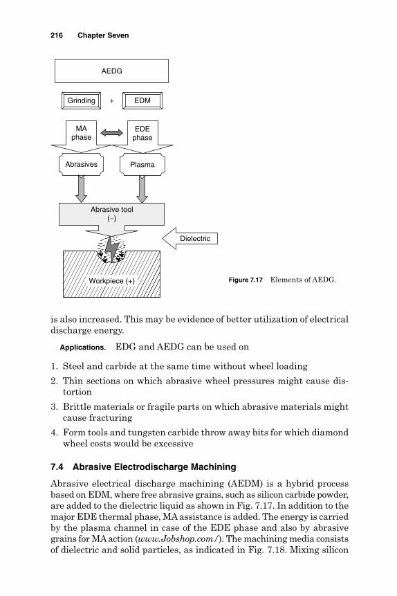
is also increased. This may be evidence of better utilization of electricaldischarge energy.
Applications. EDG and AEDG can be used on
1. Steel and carbide at the same time without wheel loading
2. Thin sections on which abrasive wheel pressures might cause dis-tortion
3. Brittle materials or fragile parts on which abrasive materials mightcause fracturing
4. Form tools and tungsten carbide throw away bits for which diamondwheel costs would be excessive
7.4 Abrasive Electrodischarge Machining
Abrasive electrical discharge machining (AEDM) is a hybrid processbased on EDM, where free abrasive grains, such as silicon carbide powder,are added to the dielectric liquid as shown in Fig. 7.17. In addition to themajor EDE thermal phase, MA assistance is added. The energy is carriedby the plasma channel in case of the EDE phase and also by abrasivegrains for MAaction (www.Jobshop.com/). The machining media consistsof dielectric and solid particles, as indicated in Fig. 7.18. Mixing silicon
216 Chapter Seven
Workpiece (+)
+
Dielectric
MAphase
EDEphase
Abrasive tool(−)
Grinding EDM
Abrasives Plasma
AEDG
Figure 7.17 Elements of AEDG.
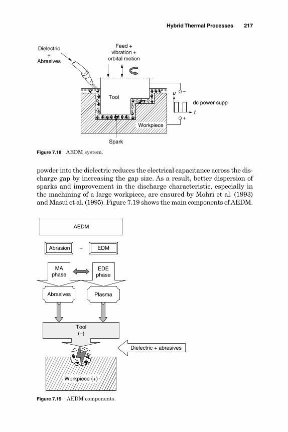
powder into the dielectric reduces the electrical capacitance across the dis-charge gap by increasing the gap size. As a result, better dispersion ofsparks and improvement in the discharge characteristic, especially inthe machining of a large workpiece, are ensured by Mohri et al. (1993)and Masui et al. (1995). Figure 7.19 shows the main components of AEDM.
Hybrid Thermal Processes 217
dc power suppl
W.P.
Dielectric+
Abrasives
Spark
Feed +vibration +
orbital motion
t
u −
+
Tool
Workpiece
Figure 7.18 AEDM system.
Workpiece (+)
+
Dielectric + abrasives
MAphase
EDEphase
Tool(−)
Abrasion EDM
Abrasives Plasma
AEDM
Figure 7.19 AEDM components.

The introduction of mixed powders as working media allows AEDMto produce complex shapes having a mirror finish and an affected layer,which is uniform and free from cracks. AEDM is widely used to producedies without the need to remove the heat-affected layer using mechan-ical polishing. The process is, therefore, widely used for producing plas-tic molding dies.
AEDM is also adopted to modify the surface characteristics of toolsteels. The fine tungsten carbide powder, added to the dielectric, addsalloying elements and hence enhances the hardness and corrosionresistance of tools and dies. It also improves their tribological featuresand changes the surface roughness (Masui et al., 1995). Mohri andcoworkers (1993) deposited aluminum on steel and titanium carbide onaluminum using, respectively, aluminum and titanium-based alloyelectrodes. Powders such as silicon and tungsten have been used toharden and increase the corrosion resistance of steel workpieces.
7.5 EDM with Ultrasonic Assistance
The need for machining hard and brittle material is steadily increasingin many applications. Traditional machining as well as some of the non-conventional machining processes present several problems related to toollife and produced surface cracks. EDM can be applied to conductive hardand brittle material of electrical resistivity below 100 Ω⋅cm. Amajor draw-back of the process is the low efficiency of sparking and the formation ofopen circuit, arc, and short circuit pulses, which are nonproductive withrespect to the material removal rate. On the other hand ultrasonic machin-ing can tackle hard and brittle materials, which have difficulty with-standing the cutting forces during conventional machining. At lowmachining rates, parts having a good surface finish can be produced usingUSM. The interaction between machining mechanisms of EDM and USvibration in one machining process (EDMUS) has a greater productivitythan the sum of the productivities of the individual EDM and USM at thesame machining conditions. The new process is adapted for rapid pro-duction of graphite electrodes for EDM (www.Jobshop.com/) where cut-ting, drilling, and engraving can be done easily. The machining systemfor EDMUS is shown in Fig. 7.20. It is similar to that used in USM withthe dielectric (deionized water) replacing the abrasive slurry as themachining medium. The ultrasonic vibration of the tool or workpiecetogether with the low-cost dc power supply generates the dischargesacross the machining gap.
The material removal mechanism employs the electrodischarge phasefor melting and evaporation of the workpiece material, by the plasmachannel, in a similar way to normal EDM as shown in Fig. 7.21. Theintensity of the discharging action depends on the working conditions such
218 Chapter Seven

Hybrid Thermal Processes 219
Leads to transducerwinding
Dielectric
Horn
dc power supply
+
−
Workpiece
Tool t
u
US vibration
Figure 7.20 EDMUS schematic.
as gap voltage, amplitude, and frequency of ultrasonic vibration as wellas the gap flushing conditions. Because of the ultrasonic vibrations of thetool, its front surface moves down toward the workpiece surface and the electric field intensity increases. The electric field, however, causes
Workpiece
EDEphase
EDM
Plasma
EDMUS
Dielectric
US vibrationTool(−)
Figure 7.21 EDMUS components.

the ultrafine particles (metal debris ejected from the formed crates) inthe machining medium to be suspended and form a bridge across thegap. At a very small gap size, deionization or breakdown of the work-ing fluid occurs and the plasma channel is formed. When the tool frontmoves up, the gap voltage rises, current drops, and the plasma channelcollapses, at large gap sizes. The process begins again when the toolmoves down.
Zhixin et al. (1995) used ultrasonic vibrations as a gap flushingmethod in mechanical pulse electrodischarge machining (MPEDM).Accordingly, cavitation bubbles and the ultrasonic field force preventthe sedimentation of the debris particles in the working fluid. Thehigh-frequency pumping action improves the working fluid circula-tion by pushing the debris away and sucking fresh fluid into themachining gap. These stoutly increase the discharge efficiency andgive higher erosion rates. The flushing action has been reported toincrease with vibration amplitudes. Murti and Philip (1987) addedthat with the application of ultrasonic vibration the machining rateand surface finish improved significantly, and although the tool wearrate increased, the wear ratio was not influenced significantly. Hewedy(1995) reported that the increase of tool vibration up to 100 µmenhanced the erosion rate due to the improved flushing action andhence the sparking efficiency. The presence of too much debris in theelectrode gap causes continued arcing and short circuits which makesthe process unstable (Masuzawa, et al., 1992). The dielectric must,therefore, contain an appropriate amount of debris since a medium thatis too clean is another reason for gap short circuiting and the conse-quent machining troubles.
The breakdown distance of the electric field is greatly influenced bythe contamination level of the machining medium. The gap distance,therefore, changes from one place to another according to the local con-tamination level. Such a change causes dimensional errors in thecopying process. If the concentration is made uniform anywhere in theinterelectrode gap, the machining gap becomes uniform and an accuratecopy is ensured. Ideal flushing must, therefore, maintain a constantand uniform debris concentration. In this regard, jet flushing with noz-zles, sweeping along the interelectrode gap, has been introduced byMasuzawa et al. (1992) and proved to be effective in precision EDM.Schumacher (1990) concluded that the gap contamination througheroded debris influences ignition delay as well as the discharge locationin the gap. Erden (1979) investigated the role of dielectric fluid veloc-ity in EDM. Wells and Willey (1975) recommended a dielectric flowvelocity of 6 m/s, which reduced the electrode wear by a factor of 2 andthe surface roughness by up to 50 percent, increased the machiningrate, and reduced the thermal effects in the eroded workpiece surface.
220 Chapter Seven
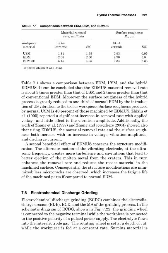
Table 7.1 shows a comparison between EDM, USM, and the hybridEDMUS. It can be concluded that the EDMUS material removal rateis about 3 times greater than that of USM and 2 times greater than thatof conventional EDM. Moreover the surface roughness of the hybridprocess is greatly reduced to one-third of normal EDM by the introduc-tion of US vibration to the tool or workpiece. Surface roughness producedby normal USM is 40 percent of those machined by EDMUS. Zhixin etal. (1995) reported a significant increase in removal rate with appliedvoltage and little effect to the vibration amplitude. Additionally, thework of Zhang et al. (1997) and Zhang and coworkers (2004) showed alsothat using EDMUS, the material removal rate and the surface rough-ness both increase with an increase in voltage, vibration amplitude,and discharge current.
A second beneficial effect of EDMUS concerns the structure modifi-cation. The alternate motion of the vibrating electrode, at the ultra-sonic frequency, creates more turbulence and cavitations that lead tobetter ejection of the molten metal from the craters. This in turnenhances the removal rate and reduces the recast material in themachined surface. Consequently, the structure modifications are mini-mized; less microcracks are observed, which increases the fatigue lifeof the machined parts if compared to normal EDM.
7.6 Electrochemical Discharge Grinding
Electrochemical discharge grinding (ECDG) combines the electrodis-charge erosion (EDE), ECD, and the MA of the grinding process. In theschematic diagram of ECDG, shown in Fig. 7.22, the grinding wheelis connected to the negative terminal while the workpiece is connectedto the positive polarity of a pulsed power supply. The electrolyte flowsinto the interelectrode gap. The rotating wheel is set at a depth of cut,while the workpiece is fed at a constant rate. Surplus material is
Hybrid Thermal Processes 221
TABLE 7.1 Comparisons between EDM, USM, and EDMUS
Material removal Surface roughnessrate, mm3/min Ra, µm
Workpiece SG-4 SG-4material ceramic SiC ceramic SiC
USM 1.81 1.95 0.93 0.95EDM 2.68 2.50 7.90 6.8EDMUS 5.15 4.95 2.34 2.36
SOURCE: Zhixin et al. (1995).

removed from the workpiece surface by the anodic dissolution ECDphase, the MA action of abrasives or diamond grains, and the erosionphase due to the spark discharges. Figure 7.23 shows the main mate-rial removal mechanisms involved in the ECDG process.
222 Chapter Seven
Workpiece (+)
Dielectric
ECDphase
EDEphase
ECM EDM
Ions Plasma
Electrolyte
Grinding
MAphase
Abrasives
ECDG
+ +
Abrasive tool(−)
+ −
Figure 7.23 Material removal mechanisms in ECDG.
dc power supplyElectrolyte supply
Conductive abrasive wheel
Bond
ED-spark
ECD current
AbrasionWorkpiece feed
u
t+
−
Figure 7.22 ECDG schematic diagram.

The process occurs due to the application of pulsed voltage in elec-trolytic solutions. The most common electrolytes are solutions of NaNO3,NaNO2, NaPO4, and KNO3. It is customary to use ECDG electrolyteswith surfactants, corrosion inhibitors, and complex forming agents.
The surfactants enhance the effect of abrasive or diamond grains.Chromates and bichromates are common corrosion inhibitors. Thecomplex forming agents (potassium or sodium salts of tartaric orcitric acid) stabilize anodic dissolution because they convert the reaction products into soluble components (Rumyantsev and Davydov,1984). The gas evolution occurring during the dissolution phaseenhances the discharging action and hence the material removalrate. The increase of feed rate and wheel penetration depth enhancesthe discharge phase contribution in the overall material removal,which, in turn, reduces the overall energy consumption. This isrelated to the fact that the specific energy consumption is lower inEDM than ECM.
During machining, every discharge causes evaporation of a smallmetal portion into the electrolyte solution where the solidified metal isflushed away by the electrolyte flow. The higher the pulse energy, thedeeper the crater formed, the larger the machining productivity, and therougher the machined surface. Discharges occur frequently at randomlocations in the interelectrode gap. Moreover the ECD phase dissolvesthe rest of the surface electrochemically. Under such conditions thecraters formed by the discharge action are smoothed and, consequently,the surface roughness is reduced.
The erosion phase plays a considerable role in the material removalprocess. Spark discharges cause depassivation of the oxide layer formedon the workpiece surface during ECM, which enhances the dissolutionphase. The discharges occurring destroy the glazed layer on the wheelsurface; hence, new grains appear which further activates the MA actionand the depassivation process.
The machinability of materials by ECDG depends on the proper-ties of the workpiece material under mechanical, electrochemical,and thermal effects. The contribution of each phase is difficult todetermine due to the nonuniformity of the wheel electric propertiesand the variation of the local gaps between the wheel and workpiece.The debris, metal deposits, and gases that exist in the interelectrodegap cause random variations in the gap resistance and hence thecurrent density. The contribution of each machining phase, therefore,depends on the process variables and the instantaneous gap phe-nomenon under these conditions. Additionally the intensity, location,and duration of each machining phase vary in a random manner thatmakes the assessment of the material removal rate an even morecomplicated task. For efficient machining, however, the electrolyte
Hybrid Thermal Processes 223
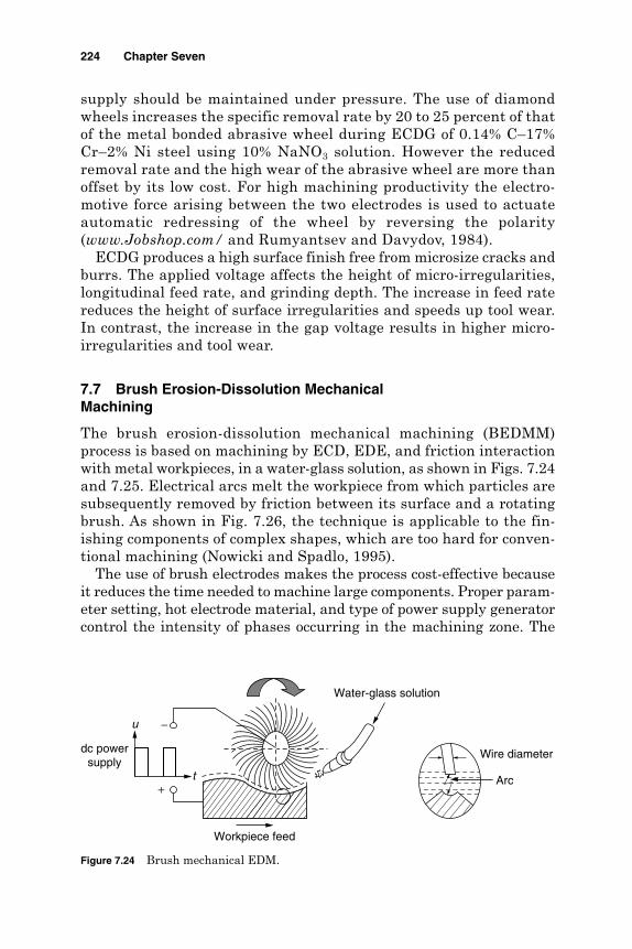
supply should be maintained under pressure. The use of diamondwheels increases the specific removal rate by 20 to 25 percent of thatof the metal bonded abrasive wheel during ECDG of 0.14% C–17%Cr–2% Ni steel using 10% NaNO3 solution. However the reducedremoval rate and the high wear of the abrasive wheel are more thanoffset by its low cost. For high machining productivity the electro-motive force arising between the two electrodes is used to actuateautomatic redressing of the wheel by reversing the polarity(www.Jobshop.com/ and Rumyantsev and Davydov, 1984).
ECDG produces a high surface finish free from microsize cracks andburrs. The applied voltage affects the height of micro-irregularities,longitudinal feed rate, and grinding depth. The increase in feed ratereduces the height of surface irregularities and speeds up tool wear.In contrast, the increase in the gap voltage results in higher micro-irregularities and tool wear.
7.7 Brush Erosion-Dissolution MechanicalMachining
The brush erosion-dissolution mechanical machining (BEDMM)process is based on machining by ECD, EDE, and friction interactionwith metal workpieces, in a water-glass solution, as shown in Figs. 7.24and 7.25. Electrical arcs melt the workpiece from which particles aresubsequently removed by friction between its surface and a rotatingbrush. As shown in Fig. 7.26, the technique is applicable to the fin-ishing components of complex shapes, which are too hard for conven-tional machining (Nowicki and Spadlo, 1995).
The use of brush electrodes makes the process cost-effective becauseit reduces the time needed to machine large components. Proper param-eter setting, hot electrode material, and type of power supply generatorcontrol the intensity of phases occurring in the machining zone. The
224 Chapter Seven
Water-glass solution
Workpiece feed
dc powersupply
Wire diameter
u
t
−
+Arc
Figure 7.24 Brush mechanical EDM.
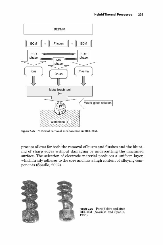
process allows for both the removal of burrs and flushes and the blunt-ing of sharp edges without damaging or undercutting the machinedsurface. The selection of electrode material produces a uniform layer,which firmly adheres to the core and has a high content of alloying com-ponents (Spadlo, 2002).
Hybrid Thermal Processes 225
Figure 7.26 Parts before and afterBEDMM (Nowicki and Spadlo,1995).
Workpiece (+)
ECDphase
EDEphase
ECM EDM
Ions Plasma
DielectricWater-glass solution
Friction
MAphase
Brush
BEDMM
+ +
Metal brush tool(−)
+ −
Figure 7.25 Material removal mechanisms in BEDMM.

References
Crichton, I., and McGeough, J. A. (1984). “Theoretical, Experimental and ComputationalAspects in Electrochemical Arc Machining,” Annals of CIRP, 33(2):1–4.
El-Hofy, H. (1985). “Fundamental Study of Electrochemical Arc Wire Cutting,” Ph.D.Thesis, Aberdeen University, U.K.
El-Hofy, H. (1992). “Electro Erosion Dissolution Machining of Graphite, Inco 901, 2017Al. and Steels,” 5th PEDAC Conf., Alexandria, pp. 489–501.
El-Hofy, H. (1995). “Machinability Indices for Some Non Conventional MachiningProcesses,” Alexandria Engineering Journal, 34(3): 231–245.
El-Hofy, H. (1996a). “Assessment of Machinability in Electro Erosion DissolutionMachining,” Alexandria Engineering Journal, 35(2):43–49.
El-Hofy, H. (1996b). “The Role of Electrolyte Flow Velocity in EEDM,” AlexandriaEngineering Journal, 35(2):139–14.
El-Hofy, H., and Khayry, A. (1995). “Comparative Study on Produced Geometry andSurface Integrity by Electrochemical Machining, Electro Discharge Machining, andElectro Erosion Dissolution Machining,” Proc. of IEMS 5, University of Central Florida,pp. 515–327.
El-Hofy, H., and McGeough, J. A. (1988). “Evaluation of an Apparatus for ECAM WireCutting,” ASME, Journal of Engineering for Industry, 110:119–123.
El-Hofy, H., and McGeough, J. A. (1989). “Effect of Pulse Duty Cycle on Stock RemovalRate and Accuracy in ECDM,” PEDAC-4 Conf., Alexandria, pp. 355–362.
El-Hofy, H., El-Makky, M., and El-Wardany, T. (1990). “Surface Generation in ElectroErosion Dissolution Machining,” Alexandria Engineering Journal, 29(4):301–305.
Erden, A. (1979). “Investigation on the Role of Dielectric Fluid Velocity in EDM,” 2ndPEDD Conf., Ain Shams University, Cairo, pp. 769–776.
Hewedy, M. (1995). “The Influence of Electrode Vibration in the Performance of EDMProcess,” Engineering Research Journal, Helwan University, Cairo, 2:32–42.
Jain, V. K., et al. (1991). “Experimental Investigations into Traveling Wire ElectrochemicalSpark Machining (TW-ECSM) of Composites,” Journal of Engineering for Industry,113:75–84.
Khayry, A. (1984). “Stochastic and Experimental Studies of Drilling by ElectrochemicalArc Machining,” Ph.D. Thesis, Aberdeen University, U.K.
Khayry, A., and El-Hofy, H. (1990). “Aspects of Stainless Steel Die Sinking by ElectroErosion Dissolution Machining,” Transactions of SME (NAMRI XVIII), pp. 273–243.
Kuneida, M., and Furuoya, S. (1991). “Improvement of EDM Efficiency by SupplyingOxygen Gas into Gap,” Annals of CIRP, 40(1):215–218.
Levy, M., McGeough, J., and Munro, W. (1983). “Investigation of Surface Finishing ofDies and Moulds in Electrochemical Arc Machining,” ISEM-7, pp. 265–275.
Machining Data Handbook. (1997). Vol. 2. Cincinnati, OH: Machinability Data Center,Institute of Advanced Manufacturing Sciences.
Masui, K., Demizu, K., Sato, Y., and Sone, T. (1995). “Surface Modification of Tool Steelsby Alloying Method Using EDM Processes,” ISEM-11, pp. 419–426.
Masuzawa, T., et al. (1992). “Improved Jet Flushing for EDM,” Annals of CIRP,41(1):239–242.
McGeough, J., Khayry, A., and Munro, W. (1983). “Theoretical and ExperimentalInvestigations of the Relative Effects of Spark Erosion and Electrochemical Dissolutionin Electrochemical Arc Machining,” Annals of CIRP, 32(1):113–118.
Mohri, M., Saito, N., and Tsunekawa, Y. (1993). “Metal Surface Modification by EDM withComposite Electrode,” Annals of CIRP, 42(1):219–222.
Murti, V. S., and Philip, P. K. (1987). “A Comparative Analysis of Machining Characteristicsin Ultrasonic Assisted EDM by Response Surface Methodology,” Int. Journal of ProductResearch, 25(2):259–272.
Nowicki, B., and Spadlo, S. (1995). “Brush Electrodischarge Mechanical Machining,”ISEM-11, pp. 209–216.
Rajurkar, K. P., Wei, B., Kozak, J., and Nooka, S. R. (1995). “Abrasive ElectrodischargeGrinding of Advanced Materials,” ISEM-11, pp. 863–869.
Rumyantsev, E., and Davydov, A. (1984). Electrochemical Machining of Metals,” Moscow:Mir Publishers.
226 Chapter Seven

Saushkin, B., et al. (1982). “Special Features of Combined Electrochemical and ElectroErosion Machining of Elongate Machine Parts,” Electrochemistry in IndustrialProcessing and Biology 105, part 3, 8–14.
Schumacher, B. (1990). “About the Role of Debris in the Gap During EDM,” Annals ofCIRP, 39(1):197–199.
Spadlo, S. (2002). “Computer Studies of Brush Electrodischarge Machining with Electrodeof Alloy Steel and Tungsten,” 16th Int. Conf. on Advanced Manufacturing Systems andTechnology Proceedings (AMST03), Udine, Italy, pp. 515–524.
Thermal Machining Processes. (1979). Dearborn, MI: SME.Wells, P., and Willey, P. (1975). “The Effects of Variation in Dielectric Flow Rate in the Gap
on Wear Ratio and Surface Finish During EDM,” IEE Conf. on Electrical Methods ofMachining, Forming and Cutting, pp. 110–117.
www.Jobshop.com/techinfo/electdischagrggrindingdef.shtml.www.unl.edu/nmrc/hybrid/hybrid_machining.htm.Zhang, J. A., Lee, T. C., Lau, W. S., and Ai, X. (1997). “Spark Erosion with Ultrasonic
Frequency,” Journal of Material Processing Technology, 68:83–88.Zhang, Q. H., Zhang. J. H., Ren, S. F., Deng, J. X., and Ai, X. (2004). “Study on Technology
of Ultrasonic Vibrations Aided Electrical Discharge Machining in Gas,” ISEM XIV On-site Conf. Proc., Edinburgh, U.K. (Journal of Materials Processing Technology).
Zhixin, J., et al. (1995). “Study on Mechanical Pulse Electrodischarge Machining,”Precision Engineering, 17(2):89–93.
Hybrid Thermal Processes 227

This page is intentionally left blank.

Chapter
8Material Addition Processes
8.1 Introduction
Rapid prototyping (RP) is a group of modern manufacturing technolo-gies that are used to produce three-dimensional prototypes from CADrepresentations. These methods are generally similar to each other inthat they add and bond materials in a layered fashion to form objects.These techniques are also referred to as solid free-form fabrication(SFF). RP applies similar physical and chemical phenomena to pro-gressively add materials as those used for selective material removalduring the so-called nontraditional machining processes, dealt with inthe previous chapters and summarized in Table 8.1. Most of the RPprocesses are still in the precommercial development stage. While objectsizes range from microscopic to entire buildings, materials range frompaper and plastic to metals and ceramics. Applications include toys,aerospace, and advanced medicines. One of the success factors of RP isrelated to its ability to produce complex net and near net shaped partsin materials that are hard to machine conventionally, like difficult-to-machine metals, ceramics, and composites.
Advantages of rapid prototyping
Builds complex three-dimensional geometrical shapes Is automated based on CAD models Uses a generic fabrication machine that does not require part specific
tooling Requires a minimum of or no human intervention Produces accurate prototypes in a short time at a minimum cost
229
Copyright © 2005 by The McGraw-Hill Companies, Inc. Click here for terms of use.

Classification of RP techniques. Kruth (1991) classified the RP techniquesaccording to the raw material used into
1. Liquid-based techniques
2. Powder-based techniques
3. Solid-based processes
Some of these methods depend on solidifying a liquid polymer by theimpact of light or laser or by the curing of powders to create the proto-type. Other processes are based on melting, deposition, and resolidifi-cation of plastic or resin materials.
8.2 Liquid-Based Techniques
8.2.1 Stereolithography
Stereolithography (SLA) is the most common RP technique that employslayer-by-layer manufacturing based on photopolymerization. Solidificationhappens by photopolymerization that results from the impact of a laserlight on the upper surface of the liquid. Light polymerization of theliquid is limited to a layer thickness of a few tenths of a millimeterbelow the surface. Illumination and hence polymerization of the surfaceliquid is restricted to a pattern that corresponds to the part’s cross section. Once the layer is completely traced, it is lowered by a small dis-tance into the liquid and a second layer is traced right on top of the first.The self-adhesive property of the material causes the layers to bond toone another and eventually form a complete, three-dimensional object
230 Chapter Eight
TABLE 8.1 Physical and Chemical Phenomena on Material Removal and MaterialAddition Processes
Phenomena Material removal Material addition
Chemical processes CHM Stereolithography (SLA)ECM Photopolymerization
Laser-induced carbon vapordeposition (CVD)
Thermal processes LBM Selective laser sintering (SLS)PBM Plasma spraying*EBM Electron beam (EB) sintering*EDM Electrodischarge (ED) deposition*
Liquid jet WJM 3-D ink-jet printing
Solid jet AJM Powder jet laser cladding
Ultrasonic processes USM N/A
*Not applied commercially.SOURCE: Kruth et al. (1998).
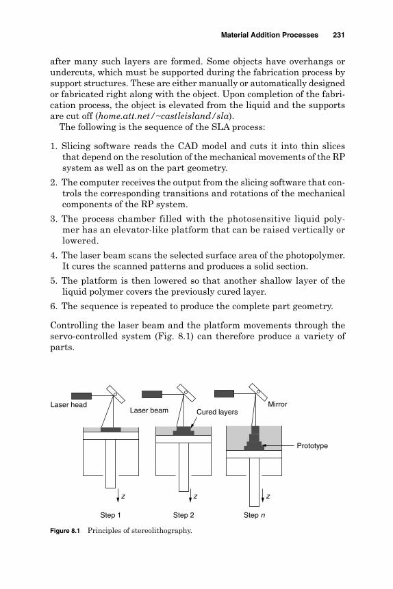
after many such layers are formed. Some objects have overhangs orundercuts, which must be supported during the fabrication process bysupport structures. These are either manually or automatically designedor fabricated right along with the object. Upon completion of the fabri-cation process, the object is elevated from the liquid and the supportsare cut off (home.att.net/~castleisland/sla).
The following is the sequence of the SLA process:
1. Slicing software reads the CAD model and cuts it into thin slicesthat depend on the resolution of the mechanical movements of the RPsystem as well as on the part geometry.
2. The computer receives the output from the slicing software that con-trols the corresponding transitions and rotations of the mechanicalcomponents of the RP system.
3. The process chamber filled with the photosensitive liquid poly-mer has an elevator-like platform that can be raised vertically orlowered.
4. The laser beam scans the selected surface area of the photopolymer.It cures the scanned patterns and produces a solid section.
5. The platform is then lowered so that another shallow layer of theliquid polymer covers the previously cured layer.
6. The sequence is repeated to produce the complete part geometry.
Controlling the laser beam and the platform movements through theservo-controlled system (Fig. 8.1) can therefore produce a variety ofparts.
Material Addition Processes 231
Step nStep 2
Prototype
Laser head
Step 1
Laser beamMirror
z z z
Cured layers
Figure 8.1 Principles of stereolithography.

Advantages of SLA
It has a high accuracy of ±0.1 mm and produces a good surface finish. It produces semitransparent materials that can be processed for opti-
cal clarity. The process is fully automated.
Disadvantages of SLA
There is a limited range of materials that can be used. It has relatively high cost compared to other RP methods. Working with liquids can be messy. Parts often require postcuring operation.
8.2.2 Holographic interferencesolidification
Holographic interference solidification (HIS) is based on photopoly-merization. The idea is that projecting a holographic image of a modelin a vat of liquid photosensitive monomer could solidify a whole three-dimensional surface at once, rather than to build it up point by point.This process saves the prototyping time. Reported applications includethe production of lost wax models for copper EDM electrodes.
8.2.3 Beam interference solidification
Beam interference solidification (BIS) is the most versatile polymer-based RP process. In beam interference solidification (Fig. 8.2) part cre-ation occurs by point-by-point solidification of the liquid at theintersection of two laser beams having different frequencies. All theliquid hit by laser beam 1 is excited so that it polymerizes upon the impactof laser beam 2. Forming the part in the z axis no longer needs to bedone in layers. Initializing the laser beam movements in any set of
232 Chapter Eight
Laser head (2)
Cured point
Laser head (1)
PolymerFigure 8.2 Beam interference soli-dification.

x, y, z coordinates makes it possible to trace the part in three dimen-sions rather than in two in a small prototyping time (mtiac.alion-science.com). The process has a limited industrial application becauseof the following problems:
1. Light absorption (drop of intensity with depth)
2. Shade effects of parts already solidified
3. Beam intersection problems due to the light diffraction caused by localtemperature variation or solidification
8.2.4 Solid ground curing
A schematic diagram for solid ground curing (SGC) is shown in Fig. 8.3.Accordingly, the process has two main cycles, the photomask generationcycle and a layer fabrication cycle. It takes about 2 min to complete alloperations to make a single layer. The following steps are followedduring SGC (claymore.engineer.gvsu.edu):
1. CAD files are sliced.
2. A layer of photosensitive polymer is first sprayed onto the platform.
3. A photomask is prepared (for each layer) using electrophotography(xerography).
4. The mask plate is then placed on top of the platform and objectunder construction.
5. Ultraviolet light is exposed onto the layer, which solidifies completely.
Material Addition Processes 233
Figure 8.3 Solid ground curing steps.
1 Mask preparation2 Photopolymer resin application3 UV light exposure4 Aerodynamic wiper5 Wax application6 Wax cooling7 Milling8 Prototype
1
2
3
4 5 6 7
8
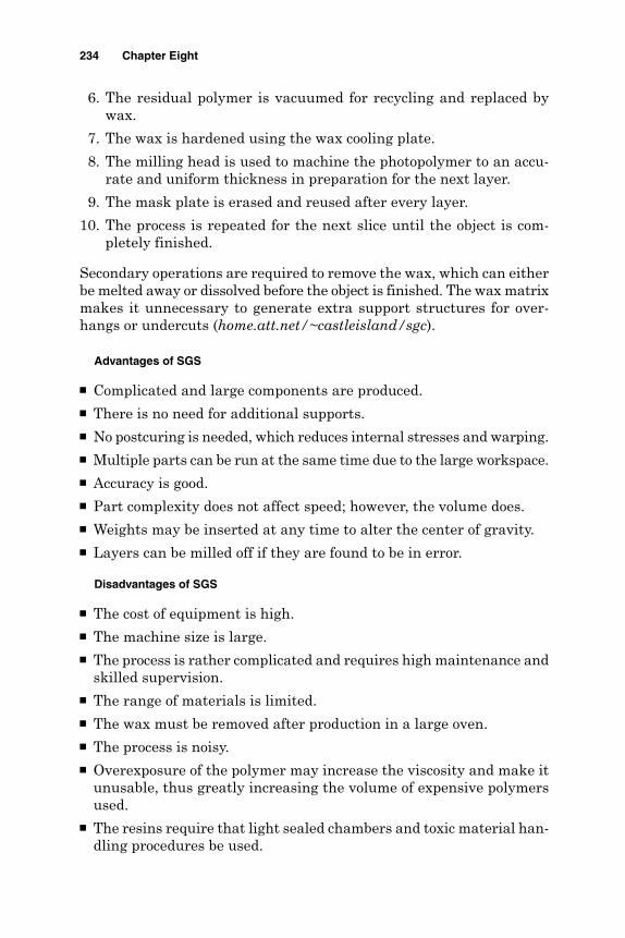
6. The residual polymer is vacuumed for recycling and replaced bywax.
7. The wax is hardened using the wax cooling plate.
8. The milling head is used to machine the photopolymer to an accu-rate and uniform thickness in preparation for the next layer.
9. The mask plate is erased and reused after every layer.
10. The process is repeated for the next slice until the object is com-pletely finished.
Secondary operations are required to remove the wax, which can eitherbe melted away or dissolved before the object is finished. The wax matrixmakes it unnecessary to generate extra support structures for over-hangs or undercuts (home.att.net/~castleisland/sgc).
Advantages of SGS
Complicated and large components are produced. There is no need for additional supports. No postcuring is needed, which reduces internal stresses and warping. Multiple parts can be run at the same time due to the large workspace. Accuracy is good. Part complexity does not affect speed; however, the volume does. Weights may be inserted at any time to alter the center of gravity. Layers can be milled off if they are found to be in error.
Disadvantages of SGS
The cost of equipment is high. The machine size is large. The process is rather complicated and requires high maintenance and
skilled supervision. The range of materials is limited. The wax must be removed after production in a large oven. The process is noisy. Overexposure of the polymer may increase the viscosity and make it
unusable, thus greatly increasing the volume of expensive polymersused.
The resins require that light sealed chambers and toxic material han-dling procedures be used.
234 Chapter Eight
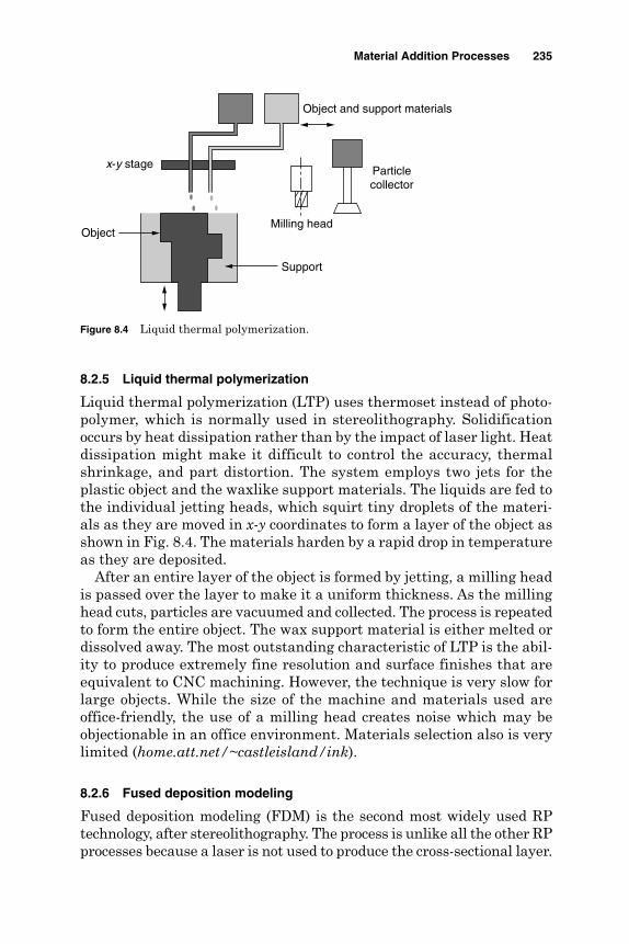
8.2.5 Liquid thermal polymerization
Liquid thermal polymerization (LTP) uses thermoset instead of photo-polymer, which is normally used in stereolithography. Solidificationoccurs by heat dissipation rather than by the impact of laser light. Heatdissipation might make it difficult to control the accuracy, thermalshrinkage, and part distortion. The system employs two jets for theplastic object and the waxlike support materials. The liquids are fed tothe individual jetting heads, which squirt tiny droplets of the materi-als as they are moved in x-y coordinates to form a layer of the object asshown in Fig. 8.4. The materials harden by a rapid drop in temperatureas they are deposited.
After an entire layer of the object is formed by jetting, a milling headis passed over the layer to make it a uniform thickness. As the millinghead cuts, particles are vacuumed and collected. The process is repeatedto form the entire object. The wax support material is either melted ordissolved away. The most outstanding characteristic of LTP is the abil-ity to produce extremely fine resolution and surface finishes that areequivalent to CNC machining. However, the technique is very slow forlarge objects. While the size of the machine and materials used areoffice-friendly, the use of a milling head creates noise which may beobjectionable in an office environment. Materials selection also is verylimited (home.att.net/~castleisland/ink).
8.2.6 Fused deposition modeling
Fused deposition modeling (FDM) is the second most widely used RPtechnology, after stereolithography. The process is unlike all the other RPprocesses because a laser is not used to produce the cross-sectional layer.
Material Addition Processes 235
Figure 8.4 Liquid thermal polymerization.
Particlecollector
Milling head
Object and support materials
x-y stage
Object
Support
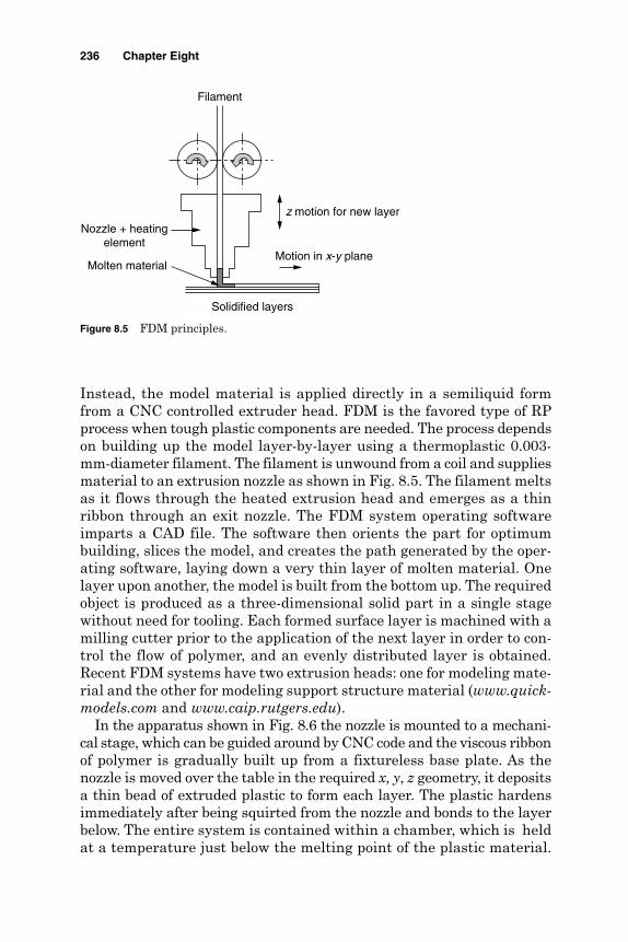
Instead, the model material is applied directly in a semiliquid formfrom a CNC controlled extruder head. FDM is the favored type of RPprocess when tough plastic components are needed. The process dependson building up the model layer-by-layer using a thermoplastic 0.003-mm-diameter filament. The filament is unwound from a coil and suppliesmaterial to an extrusion nozzle as shown in Fig. 8.5. The filament meltsas it flows through the heated extrusion head and emerges as a thinribbon through an exit nozzle. The FDM system operating softwareimparts a CAD file. The software then orients the part for optimumbuilding, slices the model, and creates the path generated by the oper-ating software, laying down a very thin layer of molten material. Onelayer upon another, the model is built from the bottom up. The requiredobject is produced as a three-dimensional solid part in a single stagewithout need for tooling. Each formed surface layer is machined with amilling cutter prior to the application of the next layer in order to con-trol the flow of polymer, and an evenly distributed layer is obtained.Recent FDM systems have two extrusion heads: one for modeling mate-rial and the other for modeling support structure material (www.quick-models.com and www.caip.rutgers.edu).
In the apparatus shown in Fig. 8.6 the nozzle is mounted to a mechani-cal stage, which can be guided around by CNC code and the viscous ribbonof polymer is gradually built up from a fixtureless base plate. As thenozzle is moved over the table in the required x, y, z geometry, it depositsa thin bead of extruded plastic to form each layer. The plastic hardensimmediately after being squirted from the nozzle and bonds to the layerbelow. The entire system is contained within a chamber, which is heldat a temperature just below the melting point of the plastic material.
236 Chapter Eight
Figure 8.5 FDM principles.
z motion for new layer
Nozzle + heatingelement
Motion in x-y plane
Solidified layers
Molten material
Filament
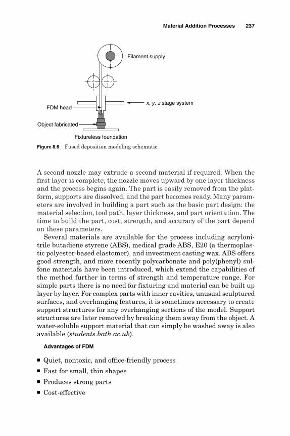
A second nozzle may extrude a second material if required. When thefirst layer is complete, the nozzle moves upward by one layer thicknessand the process begins again. The part is easily removed from the plat-form, supports are dissolved, and the part becomes ready. Many param-eters are involved in building a part such as the basic part design: thematerial selection, tool path, layer thickness, and part orientation. Thetime to build the part, cost, strength, and accuracy of the part dependon these parameters.
Several materials are available for the process including acryloni-trile butadiene styrene (ABS), medical grade ABS, E20 (a thermoplas-tic polyester-based elastomer), and investment casting wax. ABS offersgood strength, and more recently polycarbonate and poly(phenyl) sul-fone materials have been introduced, which extend the capabilities ofthe method further in terms of strength and temperature range. Forsimple parts there is no need for fixturing and material can be built uplayer by layer. For complex parts with inner cavities, unusual sculpturedsurfaces, and overhanging features, it is sometimes necessary to createsupport structures for any overhanging sections of the model. Supportstructures are later removed by breaking them away from the object. Awater-soluble support material that can simply be washed away is alsoavailable (students.bath.ac.uk).
Advantages of FDM
Quiet, nontoxic, and office-friendly process Fast for small, thin shapes Produces strong parts Cost-effective
Material Addition Processes 237
Figure 8.6 Fused deposition modeling schematic.
Fixtureless foundation
Object fabricated
FDM headx, y, z stage system
Filament supply
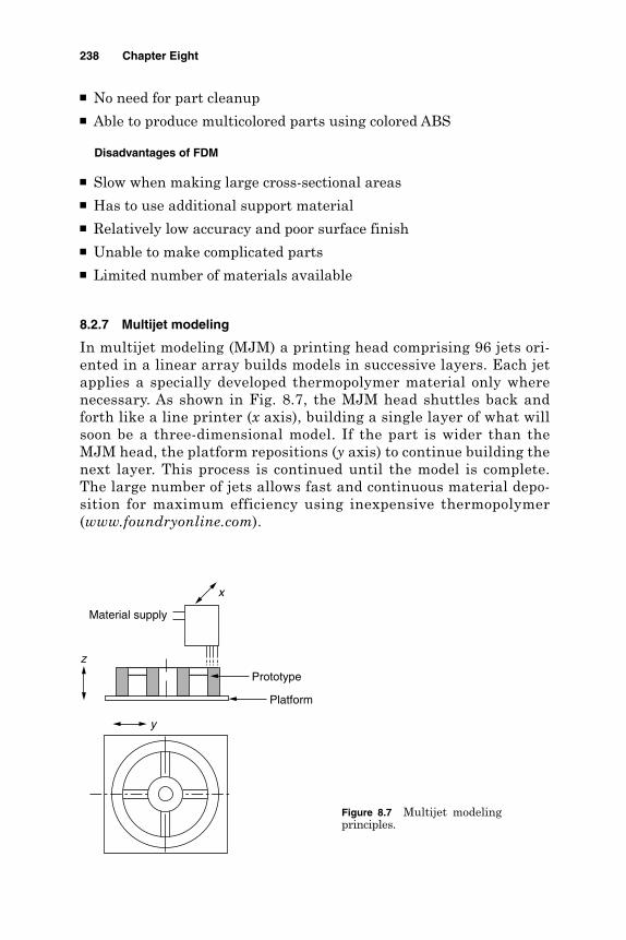
No need for part cleanup Able to produce multicolored parts using colored ABS
Disadvantages of FDM
Slow when making large cross-sectional areas Has to use additional support material Relatively low accuracy and poor surface finish Unable to make complicated parts Limited number of materials available
8.2.7 Multijet modeling
In multijet modeling (MJM) a printing head comprising 96 jets ori-ented in a linear array builds models in successive layers. Each jetapplies a specially developed thermopolymer material only wherenecessary. As shown in Fig. 8.7, the MJM head shuttles back andforth like a line printer (x axis), building a single layer of what willsoon be a three-dimensional model. If the part is wider than theMJM head, the platform repositions (y axis) to continue building thenext layer. This process is continued until the model is complete.The large number of jets allows fast and continuous material depo-sition for maximum efficiency using inexpensive thermopolymer(www.foundryonline.com).
238 Chapter Eight
Figure 8.7 Multijet modelingprinciples.
Material supply
x
y
z
Platform
Prototype

8.2.8 Ballistic particles manufacturing
In ballistic particles manufacturing (BPM), a stream of molten materialis ejected from a nozzle. The material separates into droplets, which hitthe substrate and immediately cold weld to form a part (Fig. 8.8). Thematerial stream may be a drop-on-demand system or continuous jetusing a piezoelectric transducer that excites the nozzle at 60 Hz. Thenozzle excitation forces ensure the production of a stream of small, reg-ular droplets with uniform spacing and distance (ime.ucla.edu).
PBM parameters include temperature and velocity of the dropletsand the electronic charge they require when the stream is ejected,which is used to guide the droplets to the surface. The temperature con-trols the speed at which the molten metal droplets solidify. Furthermore,the deformation and placement accuracy of the droplet depends on itsvelocity.
This process uses CAD-generated three-dimensional solid model datato direct the stream of material (waxes, plastics, photocurable polymers,ceramics, or metals) at a target, building three-dimensional objects inmuch the same manner that an ink-jet printer produces two-dimensionalimages. The object is built using a three-axis robotic system controllinga piezoelectric ink-jet mechanism for shooting particles of the materialonto a target and producing multiple cross sections. A second materialsupports any overhanging structures on the part. When the product iscomplete, it is placed in a bath that dissolves the support material. Alimitation here is that the support material cannot be completelyenclosed by the construction wax (Hauber, 1988).
Advantages of BPM
No postproduction finishing is required. Tolerances of ±0.01 mm can be achieved.
Material Addition Processes 239
Figure 8.8 Ballistic particles man-ufacturing.
Support material nozzle
Molten particles
Part material nozzle
Prototype
Support

The ability to perform in microgravity and vacuum environments provides the production of parts in space and for advanced materialsresearch.
The method can however be extended to other materials that easilymelt and solidify such as thermoplastics and metals.
Wax models for investment casting can be produced without the needfor dies.
It allows the application of different materials or colors within a singlepart.
Decreased turnaround time, increased productivity, and improvedmaterial properties make the BPM technology economically attractive.
The method produces rapidly solidified microstructures in situ. Near full density and net shape parts in a unit operation are possible.
8.2.9 Shape deposition manufacturing
Shape deposition manufacturing (SDM) is a new fabrication methodologyfor automatically building up material layers to form three-dimensional,complex-shaped, multimaterial structures. The process combines theadvantages of solid free-form fabrication (i.e., easy to plan and does notrequire special fixturing, arbitrarily complex shapes, and heterogeneousstructures) with the advantages of conventional machining (i.e., high accu-racy, good surface finish, and wide-scale availability of existing three- andfive-axis CNC milling machines). In addition to the rapid prototyping ofcomplex shapes, selective additive material processing enables the fabri-cation of multimaterial structures and permits prefabricated componentsto be embedded within the growing shapes. The goal of SDM is, therefore,to automatically manufacture parts that are strong, geometrically accu-rate, and have a good surface finish (www-2.cs.cmu.edu). Figure 8.9 showsthe manufacturing steps, which are as follows:
240 Chapter Eight
Figure 8.9 Shape deposition manufacturing.
Support material Part material Milling head
Deposit Remove

1. A CAD model is first decomposed into thin layer representations.
2. A layered segment is deposited as near-net shapes. The thickness ofthat layer depends on the local part geometry and the depositionprocess constraints.
3. A layer of sacrificial support structure is simultaneously built up tosupport and create a fixture for the growing shape.
4. The layers are machined to a net shape before additional material isdeposited.
5. The sequence for depositing and machining the part and supportmaterials is repeated to form the entire shape.
6. After the entire part is built up, the sacrificial support material isremoved to reveal the final part.
8.3 Powder-Based Processes
8.3.1 Selective laser sintering
Selective laser sintering (SLS) is a free-form fabrication method basedon sintering of the metallic or nonmetallic powders selectively into anindividual object. As shown in Fig. 8.10, a thin layer of fusible powder islaid down and heated to just below its melting point by infrared heatingpanels at the side of the chamber. Then a laser beam guided on the basisof a three-dimensional CAD system of the part to be produced, sintersand fuses the desired pattern of the first layer of the object in the powder.
Material Addition Processes 241
Figure 8.10 Selective laser sintering.
Laser
Scanner system
Roller
Object
Powder delivery Sintering

Next this first fused layer descends, the roller spreads out another layerof powder, and the process repeats. SLS relies on the supporting strengthof the powder around the partially fused object. Therefore, supportcolumns for any overhanging parts of the component are not needed. Avariety of materials can be used including polymers, epoxy, wax, metals,and ceramic with the appropriate binder. After the object is fully formed,the piston is raised to elevate it. Excess powder is simply brushed awayand a final manual finishing may be carried out. Although surface fin-ishes and accuracy are not quite as good as with stereolithography, thematerial properties can be quite close to those of the intrinsic ones. Themethod has also been extended to provide direct fabrication of metaland ceramic objects and tools (home.att.net/~castleisland/SLS).
Advantages of SLS
It produces the toughest components compared to other RP techniques. A wide range of materials can be used, including metal, plastic, ceram-
ics, wax, nylon, elastomers, and polycarbornate. A relatively short production time (approximately 1 in/h) is possible. No postcuring processes are needed. No additional support is required during the building process. Leftover powder can be reused. Different parts can be built right on top of others.
Disadvantages of SLS
A rough surface finish is produced due to the stair-step effect. The time needed to heat up the powder and cool down the model after
it has been completed is approximately 8 to 10 h. Toxic gases are produced especially when plastic materials are fused. Components are less detailed than those produced by stereolithogra-
phy due to a high processing temperature and high shrinkage.
8.3.2 Laser engineered net shaping
As shown in Fig. 8.11, a high-power laser is used to melt metal powder sup-plied coaxially to the focus of the laser beam through a deposition head. Thex-y table is moved in raster fashion to fabricate each layer of the object.Typically the head is moved up vertically as each layer is completed. Thelaser beam is delivered to the work by a simple right-angle mirror. Metalpowders are delivered and distributed around the circumference of thehead either by gravity or by using an inert, pressurized carrier gas, which
242 Chapter Eight

can also be used to shield the melt pool from atmospheric oxygen. It alsoprovides better control of properties and promotes layer-to-layer adhesionthrough better surface wetting (home.att.net/~castleisland/len).
A variety of materials can be used such as stainless steel, Inconel,copper, and aluminum. Of particular interest are reactive materialssuch as titanium. Most systems use powder materials, but there has alsobeen work done with material provided as fine wires. In this case thematerial is fed off-axis to the laser beam.
The building area is usually contained within a chamber both to isolatethe process from the ambient surroundings and to shield the operatorsfrom possible exposure to fine powders and the laser beam. The laser powerused varies greatly, from a few hundred watts to 20 kW or more, depend-ing on the particular material, feed rate, and other parameters.
Objects fabricated are near net shape, but generally will require finishmachining. They are fully dense with good grain structure and have prop-erties similar to, or even better than, the intrinsic materials. Laser engi-neered net shaping (LENS) has fewer material limitations than SLS,doesn’t require secondary firing operations as some of those processes do,and can also be used to repair parts as well as fabricate them. Initial appli-cations are concentrated on the fabrication and repair of injection mold-ing tools and the fabrication of large titanium and other exotic metalparts for aerospace applications.
8.3.3 Three-dimensional printing
Three-dimensional printing combines the features of SLS and BPM,(Fig. 8.12). Powder material is deposited in successive layers, as in SLS.The process starts by depositing a layer of powder object material at thetop of a fabrication chamber. To accomplish this, a measured quantity ofpowder is first dispensed from a similar supply chamber by a piston moving
Material Addition Processes 243
Figure 8.11 LENS process.
MirrorLaser
Powdermaterial supply
Shroud gas inlet
x-y table
Focused beam
Prototype

upward incrementally. The roller then distributes and compresses thepowder at the top of the fabrication chamber. The multichannel jettinghead subsequently deposits a liquid adhesive in a two-dimensional patternonto the layer of the powder, which becomes bonded in the areas wherethe adhesive is deposited to form a layer of the object.
Once a layer is completed, the fabrication piston moves down by thethickness of a layer, and the process is repeated until the entire object isformed within the powder bed. After completion, the object is elevated andthe extra powder brushed away leaving the object. No external supportsare required during fabrication since the powder bed supports overhangs.After building up the whole part, a heat treatment is applied by curing at120°C for 2 h. In case of ceramic parts, a final firing at 1000 to 1500°C isrequired to give the part its full mechanical and refractory strength.
Three-dimensional printing offers the advantages of speedy fabrica-tion and low materials cost. In fact, it’s probably the fastest of all RPmethods. Recently color output has also become available. However,there are limitations on resolution, surface finish, part fragility, andavailable materials. The closest competitor to this process is probablyfused deposition modeling (FDM).
8.4 Solid-Based Techniques
8.4.1 Solid foil polymerization
This process applies solid-to-solid, rather than liquid-to-solid, poly-merization. The part is built up using semipolymerized plastic foils progressively stacked on top of each other. Upon exposure to ultraviolet
244 Chapter Eight
Figure 8.12 Three-dimensionalprinting.
Liquidadhesive supply
Ink-jet head
Powder bedRoller
Powder delivery Fabrication
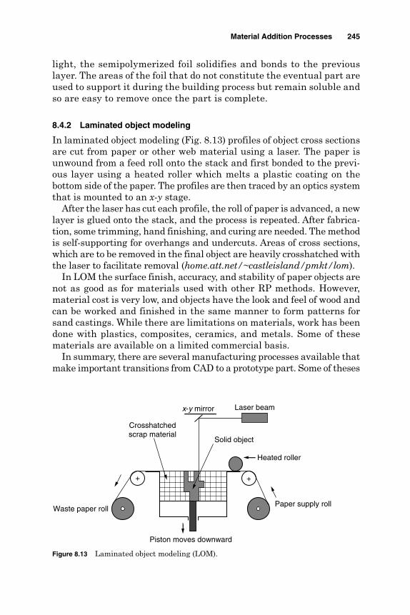
light, the semipolymerized foil solidifies and bonds to the previouslayer. The areas of the foil that do not constitute the eventual part areused to support it during the building process but remain soluble andso are easy to remove once the part is complete.
8.4.2 Laminated object modeling
In laminated object modeling (Fig. 8.13) profiles of object cross sectionsare cut from paper or other web material using a laser. The paper isunwound from a feed roll onto the stack and first bonded to the previ-ous layer using a heated roller which melts a plastic coating on thebottom side of the paper. The profiles are then traced by an optics systemthat is mounted to an x-y stage.
After the laser has cut each profile, the roll of paper is advanced, a newlayer is glued onto the stack, and the process is repeated. After fabrica-tion, some trimming, hand finishing, and curing are needed. The methodis self-supporting for overhangs and undercuts. Areas of cross sections,which are to be removed in the final object are heavily crosshatched withthe laser to facilitate removal (home.att.net/~castleisland/pmkt/lom).
In LOM the surface finish, accuracy, and stability of paper objects arenot as good as for materials used with other RP methods. However,material cost is very low, and objects have the look and feel of wood andcan be worked and finished in the same manner to form patterns forsand castings. While there are limitations on materials, work has beendone with plastics, composites, ceramics, and metals. Some of thesematerials are available on a limited commercial basis.
In summary, there are several manufacturing processes available thatmake important transitions from CAD to a prototype part. Some of theses
Material Addition Processes 245
Waste paper roll
Laser beamx-y mirror
Heated roller
Paper supply roll
Crosshatchedscrap material
Solid object
Piston moves downward
+ +
Figure 8.13 Laminated object modeling (LOM).

are in daily commercial use such as SLA, SLS, LOM, and FDM, whilemore are still in the research and development stage like three-dimensional printing, SGC, and SDM. Currently SLA is the most usedRP technique especially for generation of the master patterns for castingand injection molding (McGeough, 2002). After SLA and SLS, FDM, andLOM have the most validity. Figure 8.14 shows the accuracy levels for thedifferent RP techniques.
References
Elsabaa, I., Soliman, E., and Khayry, A. (2001). “A Comparative Study of Rapid PrototypingTechniques,” Alexandria Engineering Journal, 40(3):335–346.
Hauber, D. (1988). “Automatic Production of PBM Parts Directly from a Computer AidedDesign Model,” International Journal of Powder Metallurgy, 24(4):337–342.
home.att.net/~castleisland/fdm_int.htmhome.att.net/~castleisland/ink_int.htmhome.att.net/~castleisland/len_int.htmhome.att.net/~castleisland/pmkt/lom_int.htmhome.att.net/~castleisland/sgc.htmhome.att.net/~castleisland/sla_int.htmhome.att.net/~castleisland/SLS_int.htmime.ucla.edu/~luoh/bpm-web.htmKruth, J. P. (1991). “Material Increase Manufacturing by Rapid Prototyping Techniques.”
Annals of CIRP, 40(2):603–614.Kruth, J. P., Leu, M. C., and Nakagawa, T. (1998). “Progress in Additive Manufacturing
and Rapid Prototyping,” Annals of CIRP, 47(2):525–540.McGeough, J. A. (2002). Micromachining of Engineering Materials. New York: Marcel
Dekker, Inc.mtiac.alionscience.com/pubs/rp/rp42.htm
246 Chapter Eight
Figure 8.14 Accuracy levels for RP techniques (Wright, 2001).
Sinterstation2000 (SLS)Sinterstation2500 (SLS)
SGC 5600 (SGC)
SGC 4600 (SGC)
LOM-2030H (LOM)
FDM 2000 (FDM)
SLA-250 (SLA)
SLA-350 (SLA)
SLA-500 (SLA)
Mac
hine
(R
P p
roce
ss)
0 0.001 0.002 0.003 0.004 0.005 0.006 0.007 0.008 0.009 0.01
Accuracy, in/in
0.005
0.005
0.005
0.003
0.003
0.003
0.006
0.006
0.01

mtiac.alionscience.com/pubs/rp/rp47.htmSachs, E., et al. (1993). “Three-dimensional Printing: the Physics and Implications of
Additive Manufacturing,” Annals of CIRP, 40(1):257–260.students.bath.ac.uk/en2hlt/FDM2.htmWright, P. K., (2001). 21st Century Manufacturing. Upper Saddle River, NJ: Prentice Hall.claymore.engineer.gvsu.edu/eod/manufact/manufact-310.htmlwww.bsu.edu/classes/flowers2/lom1.htmwww.caip.rutgers.edu/~kbhiggin/VDF/FDM.html#introwww-2.cs.cmu.edu/~sdm/www.foundry on line.comwww.quickmodels.com/prod03.htm
Material Addition Processes 247

This page is intentionally left blank.

Index
Abrasive machining:conglomerates, 48, 49electrodischarge machining, 203, 216flow machining, 109grain, 6, 15, 21, 22, 24, 25, 39, 49, 50,
184–186, 194, 198, 215, 216grit, 29, 183, 189jet machining, 34, 49 slurry, 9, 16, 17, 21, 24–28, 109, 218water jet machining, 9, 43, 54, 145
Accuracy:of ECM, 90levels, 26, 175, 246 of machined parts, 26, 90
Air plasma, 167, 168, 169, 180 Anodic dissolution, 12, 71, 72, 74, 81,
101, 102, 222, 223Anodic film, 72Anodic workpiece, 77, 78, 102, 103, 106,
108, 182, 183, 185Aspect ratio, 104, 146, 148, 154, 155
Back pressure, 83, 101Ballistic particles manufacturing,
239, 243Beam interference solidification,
232, 248 Brass, 15, 23, 54, 73, 84, 121, 123,
144, 153Brush erosion-dissolution mechanical
machining, 224
Capillary drilling, 105, 108, 109Cast iron, 82, 95Cathode, 71, 72, 78, 79, 81, 83, 99, 103,
116–118, 152, 160, 166, 172, 173,182, 196
Cathodic reactions, 77
Cathodic tool, 78, 83, 87, 93, 100, 102,103, 105, 106, 183, 189, 190, 192, 198
Ceramics, 6, 8, 35, 39, 41–43, 52, 65, 67,131, 133, 134, 140, 144, 156,177–179,197, 201, 214, 229, 239, 242, 245
Chemical blanking, 10, 66Chemical dissolution, 10–12, 55, 62, 181,
182Chemical etching, 176, 181Chemical milling, 10, 55, 56, 66Chemical processes, 12, 55Chromium, 21, 37, 144, 150, 162, 175Composites, 8, 43, 133, 149, 150, 178, 188,
201, 204, 214, 226, 229, 245Computer-aided design, 46, 66Computer-integrated manufacturing, 83,
130, 138Computer keyboard, 154, 179Computer numerical control, 3, 31,
132, 171Constant current, 90, 91, 96, 97, 112Constant feed, 80, 85, 86, 96Constant gap, 85, 96, 119, 120Continuous wave, 140Contour machining, 29, 30, 53Copper, 21, 38–40, 58, 64, 67, 71, 73, 82,
84, 88, 111, 121, 123, 126, 135, 136,144, 153, 155, 166, 168, 169, 176,186, 187, 232, 243
Coring, 28Crater, 27, 118, 125, 126–128, 134,
151, 152, 203, 206, 208–210,221, 223
Cubic boron nitride, 133Current:
density, 71, 72, 73, 82, 84, 88–95, 118,175, 181, 183, 186, 187, 189, 194–196,199, 200, 208, 209, 213, 223
249
Copyright © 2005 by The McGraw-Hill Companies, Inc. Click here for terms of use.
Current: (Conti.)efficiency, 82–85, 89, 90, 102, 200flow, 96, 97, 112, 118, 196 lines, 185, 194
Cutting:of printed circuit boards, 38rate, 34–36, 41, 45, 46, 146, 168, 169of rocks, 37speed, 43, 121, 143, 149, 153, 166,
171, 172
DC power supply, 72, 81, 183, 193, 195,198, 205, 213, 215, 217–219, 222, 224
Deburring, 37, 40, 42, 44, 52, 74, 79, 97,99, 109–112, 172
Dielectric fluid, 118, 121, 123, 124, 212,220, 226
Dielectric flushing, 124, 131, 203, 214Dielectric liquid, 103, 203Dielectric type, 134Die sinking, 91, 99, 115, 131, 132, 139,
140, 226Dies and molds, 128, 131, 204Dissolution phase, 10, 181, 194, 195,
197–199, 203, 210, 223Dressing of grinding wheels, 152, 179Dynamic balancing, 155
ECD phase, 87, 184, 189, 191, 193, 200,203, 212, 222, 223
ECG process, 184–186, 188, 201ECM:
accuracy, 92equipment, 79process, 87, 97
EDE phase, 12, 116, 203, 207, 209, 214,216, 217, 219, 222, 225
EDM:automation, 138dielectric, 120, 123electrodes, 30, 121, 232milling, 131–133with ultrasonic assistance, 218
EEDM wire cutting, 205 Electrochemical processes:
arc machining, 203, 226buffing, 12, 182, 196, 201deburring, 109, 111discharge grinding, 13, 203, 221discharge machining, 203dissolution, 10, 11, 27, 100, 181, 183,
184, 186, 196, 198, 201, 203,221, 224, 226
drilling, 91, 100, 145
grinding, 11, 181, 182, 184honing, 181, 189, 201jet drilling, 108machining, 10–12, 75, 77, 78, 88, 97,
112, 113, 145,181, 182, 197, 199, 201,204, 208, 226
superfinishing, 12, 181, 192Electrode:
material, 121–123, 132, 224, 225polarity, 121, 125, 134 wear, 121, 122, 131, 220
Electrodischarge:erosion, 12, 115, 203, 206, 221, 224grinding, 136, 203, 212, 214, 226machining, 9, 10, 15, 130, 145, 177,
203, 204, 216,220, 227texturing, 128, 134
Electroerosion dissolution machining,203, 204
Electrolysis, 77, 79, 101, 102, 110,206, 209
Electrolyte:concentration, 82, 90, 95feeding, 79, 83, 96, 101flow rate, 90, 92, 95, 101, 196, 201, 206type, 92, 103, 194, 196velocity, 95, 208
Electrolyzing current, 78, 84Electron beam machining, 9, 157, 160, 179Electropolishing, 70–75Electrostream drilling, 106, 108Environmental impacts, 46, 99 Equilibrium gap, 86, 87Erosion phase, 206, 222, 223Etch factor, 56–58, 60, 61Etch rate, 58, 61–63, 174Etchant, 10, 12, 57–60, 63, 66, 67, 70Evaporation, 118, 143, 152, 154, 158, 203,
218, 223
Faraday’s laws, 77, 85, 88, 101, 110, 184Feed rate, 35–37, 40, 45, 46, 80, 83, 84,
86, 87, 90, 93, 95–97, 100, 101–105,112, 130, 171, 186–188, 208–210, 223,224, 243
Fiber-reinforced plastics, 34, 36, 37, 155Flushing, 12, 22, 115, 118, 120, 121,
123–125, 178, 182, 203, 209, 214,219, 220, 226
Fused deposition modeling, 235, 237, 244
Gap:pressure, 96, 101, 208short circuit, 87, 208, 220
250 Index

voltage, 81, 83, 85, 90, 95, 96, 102, 106,113, 119, 137, 183, 184, 189, 194, 208,219, 220, 224
width, 90, 92, 93, 115, 119, 183, 186, 205Graphite, 23, 27, 30, 31, 36, 47, 95,
121–123, 126, 128, 135, 152, 211,213, 214, 218, 228
Grinding: action, 187, 221process, 184stick, 194wheels, 7, 152, 179, 186
Grooving, 149, 151, 177, 179
Heat-affected zone, 9, 35, 70, 118, 129,150, 162, 171, 213
History of machining, 1Holographic interference solidification,
232Hybrid electrochemical processes, 182Hybrid thermal machining, 11, 12,
203, 204Hydraulic pump, 32Hydrogen, 59, 64, 79, 99, 101, 168
Ice jet machining, 9, 46, 52Ignition delay, 117, 210, 220Insulating ceramics, 133, 134, 179 Integrated circuit, 65, 163, 164Intensifier, 32, 33, 44Ion beam machining, 3, 4, 9, 172, 174Iron, 1, 49, 78, 79, 82, 95, 161
Jet:cutting nozzle, 33diameter, 34, 41, 46, 108machining, 9, 32, 34, 35, 39, 41, 43, 46,
52, 145velocity, 33, 34, 41
Laminated object modeling, 245Laser-assisted electrochemical
machining, 11, 181, 199 Laser beam:
drilling, 147machining, 9, 140, 144, 146
texturing, 151Liquid-based techniques, 230Liquid thermal polymerization, 235
Machinability, 4, 6, 23, 75, 83, 89–92,104, 113, 143, 144, 160–162, 169,170, 174, 177, 178, 186, 187, 201,210, 211, 223, 226
Machining:by abrasion, 6 by cutting, 5, 6, 13, 52, 113, 178, 201of fiber-reinforced plastics, 36of spheres, 131system, 15, 16, 32, 39, 44, 46, 48, 50,
102, 120, 135, 166, 167, 172, 183,189, 190, 198, 204, 205, 215, 218
Magnetic finishing of: balls, 50magnetic tubes, 50nonmagnetic tubes, 51rollers, 52
Magnetostrictor, 15–21MA phase, 185, 222, 225Maskant, 55, 57–59, 61Mechanical abrasion, 5, 9–12, 22, 39, 50,
181, 184–186, 189, 190, 193, 194,197–199, 203, 214, 221–223
Mechanical amplifier, 15, 20Mechanical machining, 9, 10, 12, 181,
203, 224, 226 Mechanical pulse electrodischarge
machining, 220, 227Mechanism of material removal, 115,
172, 174Metallic bond, 183, 185, 189, 192, 193,
214, 215Metal matrix composites, 149, 178Micro-ECM, 98, 137, 155, 177Micro-EDM, 135Micromachining, 4, 13, 74, 113, 122, 130,
155, 157, 178, 201, 246Micro ultrasonic machining, 31, 52Multijet modeling, 238
Nickel, 21, 58, 61, 62–64, 67, 73, 82, 88,89, 91, 144, 162, 169, 176 187
Nitric acid, 103 Nontraditional machining, 5, 8, 9,
11, 229Numerical control, 3, 29, 31, 132, 171
Overcut, 26, 80, 83, 100, 101, 103, 108,130, 186, 187, 214
Oxide film, 89, 90, 102, 185,193–195, 197
Oxygen, 39, 71, 79, 128, 148–150, 168,169, 178, 210, 226, 243
Passivation, 12, 85, 90–92, 95, 96, 181,198, 201, 223
Photochemical milling, 59, 66Photoresist, 59, 66–68, 175
Index 251

Plasma:arc, 166, 167, 169, 171, 172beam, 9, 166, 169, 170channel, 118, 119, 135, 216, 218, 220 jet, 166–169
Polishing, 4, 5, 7, 30, 31, 38, 39, 42, 48,50–52, 70–75, 91, 109, 128, 172, 176,196, 218
Powder-based processes, 241Printed circuit boards, 34, 38, 52Process:
accuracy, 26, 90, 95, 101, 195 capabilities, 45, 104, 106, 158characteristics, 41, 42, 87, 189control, 95, 137description, 46, 66parameters, 34, 61, 73, 103, 113, 114,
165, 184, 198Pulse:
charge, 161, 162 current, 97, 98, 116, 120, 126–128, 134,
135, 206duration, 127, 138, 142, 146–148, 154,
160, 161, 163, 209electrochemical machining, 113, 208 energy, 126–128, 147, 148, 161, 162,
210, 223frequency, 160, 165, 209, 214 on-time, 120, 127
Pulsed power supply, 221
Rapid prototyping, 229, 232, 235,240, 246
Recast layer, 35, 65, 104, 118, 129, 131,146, 166, 204
Resolidified layer, 129, 152Rotary ultrasonic machining, 28, 52
Sapphire, 28, 33, 34, 41, 42Sawing, 5, 130, 188 Scribing template, 57, 60Selective laser sintering, 230, 241, 243 Servo controlled feed, 121, 213, 215 Shape deposition manufacturing, 240 Shaped tube electrolytic machining, 102Shielded plasma, 167–170Short circuit, 80, 81, 87, 90, 119, 208, 209,
218, 220Shot blasting, 134, 151Slotting, 159, 160, 163Slurry injection methods, 22Smoothing, 12, 66, 71, 74, 75, 175,
176, 197
Sodium chloride, 78, 81, 82, 189Sodium nitrate, 81, 82, 189Solid-based processes, 230Solid foil polymerization, 244Solid free-form fabrication, 229, 240 Solid ground curing, 233Spark:
erosion, 132, 226gap, 135, 212machining, 178, 179, 226
Standoff distance, 34, 37, 40, 41, 45Steels, 1, 35, 61, 62, 95, 106, 111, 168,
169, 186, 187, 218, 226Stereolithography, 230, 231, 235, 242Surface:
effects, 175formation, 93, 208integrity, 4, 127, 186, 226quality, 1, 2, 8–10, 12, 24, 26, 27, 35, 37,
46, 50, 62, 64, 73, 83, 92, 93, 95, 99,101, 123, 125, 160, 162, 169, 181,187, 188, 197, 199, 206, 209
reflectivity, 147, 165roughness, 27, 30, 36, 41, 42, 45, 62, 63,
71, 73, 93–95, 111, 126–128, 131, 135,162, 165, 177, 190, 195, 206, 209,210, 213, 218, 220, 221, 223
treatment, 38, 43, 177
Texturing, 38, 53, 128, 130, 134, 135, 151,175, 177, 178, 179
Theory of ECM, 78Thermal energy method, 109 Thermal properties,125, 143, 146,
160, 161Thermal machining, 9, 11, 12, 203,
204, 227Thinning of parts, 65Three-dimensional printing, 243, 244, 246Titanium, 23, 39, 58, 59, 61–65, 67, 82,
84, 90, 91, 103, 106, 107, 143, 144,161, 187, 188, 218, 243
Tool:design, 83, 96, 113, 138electrode, 97, 99, 103, 110, 113, 115,
119, 121feed rate, 83, 95–97, 102, 103insulation, 84, 90, 101, 111material, 1, 23, 27, 31, 121, 122, 208oscillation, 24, 27, 192, 198, 206shape, 15, 25, 83, 97wear, 6, 13, 27, 74, 118, 119, 122, 136,
155, 156, 177, 184, 199, 220, 224
252 Index

Tooling for CHM, 57Traditional machining, 5, 8, 35, 67,138, 218Traditional grinding, 187Trimming of electronic components, 154Tungsten, 21, 23, 26, 39, 42, 82, 84, 91,
113, 121, 123, 136, 157, 161, 162, 166,168, 172, 187, 188, 216, 218
Turbine blade, 29, 104, 106, 130, 163Turning, 3, 5–7, 83, 99, 112, 138, 139,
151, 167, 169–171
Ultrasonic accuracy, 26Ultrasonic-assisted electrochemical
machining, 12, 181, 197Ultrasonic contour machining, 53Ultrasonic machining, 9, 12, 15, 28, 31,
52, 145, 197, 218Ultrasonic machining system, 16Ultrasonic polishing, 30, 31Ultrasonic sinking, 29
Ultrasonic vibration, 22, 28, 124, 203,218–220, 227
Vaporization, 109, 134, 141, 142Volumetric removal rate, 41, 88, 126, 142,
159, 184, 208, 210
Wire:cutting, 132, 140, 204, 205, 209, 226EDM, 43, 104, 106, 115, 132, 133, 136,
140, 178electrodischarge grinding, 136stripping, 38
Workpiece:impact hardness, 25 material, 4, 6, 9, 12, 15, 23, 26, 32, 38,
39, 43, 45, 49, 55, 58, 61, 63, 73, 81,82, 99, 121, 125, 126, 129, 135, 143,145, 151, 159, 160, 161, 169, 170,175, 179, 184, 196, 203, 213, 223
shape, 83, 122
Index 253

This page is intentionally left blank.

ABOUT THE AUTHOR
Hassan El-Hofy is a professor in the Mechanical EngineeringDepartment of Qatar University and an associate editor forQatar Engineering Journal. He is also the chairman of theCollege Accreditation Committee (ABET) for the MechanicalEngineering Department and has 50 research papers relatedto nonconventional as well as hybrid machining processes.
Copyright © 2005 by The McGraw-Hill Companies, Inc. Click here for terms of use.

This page is intentionally left blank.


![[Ingenieria] mcgraw hill_-_fundamentos_de_robotica_(barrientos,_peñin,_balaguer,aracil)](https://static.cupdf.com/doc/110x72/55aae5fb1a28ab8a1b8b483a/ingenieria-mcgraw-hill-fundamentosderoboticabarrientospeninbalagueraracil.jpg)


![P R O J E K A T185.166.125.151/sites/default/files/manual/IZVESTAJ_nepolj[1].zem._2005...METODOLOGIJA ISTRAŢIVANJA Rad na projektu ”Monitoring kvaliteta životne sredine na teritoriji](https://static.cupdf.com/doc/110x72/5e0f95d510f3411dec6fadff/p-r-o-j-e-k-a-t185166125151sitesdefaultfilesmanualizvestajnepolj1zem2005metodologija.jpg)