2019 UTSR Project Review Meeting
PI: Bugra Ertas, PhD
Senior Principal Engineer, Mechanical Systems
GE Research Center
11/6/2019
Novel Modular Heat Engines with sCO2 Bottoming Cycle Utilizing Advanced Oil-Free Turbomachinery DOE FE0031617: Phase 1
EXTENDED PROJECT TEAMDoug Hofer, GE Rahul Bidkar, GEJoey Zierer, GE RK Singh, GEDave Torrey, GE Brittany Tom, SWRILibing Wang, GE Arron McClung, SWRIXiaohua Zhang, GE Vandana Rallabandi, GE

Motivation and Objectives
• Perform Conceptual Design of Turbomachinery
• Define bearing requirements
• Perform Bearing Conceptual Design
• Identify risks with immersed generator
• Perform economic analysis of sCO2 WHR unit
• Currently compressor station underutilize WHR
• sCO2 WHR bottoming cycle
• 40% simple cycle → (+) 50% combined cycle
• Savings in fuel costs/CO2 emissions
• Improve compressor station profits

WHR Turbomachinery Drivetrain Concepts• Current high-power drivetrain configs.
• Oil-bearings for shaft support• Gearbox for high-speed to low-speed power
transmission• CO2 leakage
• Oil-Free non-Hermetic Concept• All bearings → gas bearings → lower power
loss→ design simplification• Still requires oil system for gearbox• CO2 leakage
• Oil-Free Hermetic Concept• All bearings → process gas bearings • Mechanically decoupled system → No GB• No CO2 leakage → completely hermetic• Requires a high speed line and low speed line• Low speed line has 2 modes
• 60Hz power generation → grid• >60Hz NG compressor drive

Conceptual Design Process

Thermodynamic Cycle
• Cascaded Brayton Cycle• PGT25+G4 GT used for study (LM2500 engine
platform) • ~34MW @ ~40% simple cycle efficiency• Max GT exhaust temperature → 510 C @ 89 kg/s• Efficiency debit from WHR system accounted for
• Cycle has two distinct loops• High temp loop → low speed line• Low temp loop → high speed line • High/Low temp recuperators

Turbomachinery Aero-Design
• Trade-Off Analysis• Flow path root diameter • Number of stages• Stage height• Speed• While checking rotordynamics
• Low speed Expander speeds• NG centrif. compressor survey• 60Hz power generation
HIG
H-S
PEE
DLO
W-S
PEE
D
8.5MW
27KRPM
12KRPMNG COMP.DRIVE
3.6KRPMPOWERGEN TOGRID
1MW
Electromagnetic Design
27KRPM12KRPM
• PM Synchronous machine• High torque density and efficiency• 3 Phase electric power generation• Samarium-Cobalt PM; 160M/s surface speed• Torque correlation used to initially get L
• FEA used for electromagnetics/thermals
• Analysis Output• Losses
• Stator and rotor core• Copper losses• Windage
Magnetic Gap Shear stress (13kPa-300Kpa)

High-Speed Drivetrain Rotordynamics
• Lateral Rotordynamic Model• 3 bearing machine architecture• Stacked-tie-bolt rotor construction• Single stage overhung centrif. compressor• 3 stage axial expander (integral to shaft for stiffness)• Direct drive/rigidly coupled PM starter/generator
• Undamped Critical Speed Map• Used to position critical speeds• Anchoring of bearing stiffness values• Ensuring tie bolt frequency > MCOS• Cross-check 1G shaft deflections • Operation above 3rd critical speed
below 4th critical speed

Damped Rotordynamic Eigenvalues & Unbalance Response
• Calculation of damped forward whirl mode eigenvalues
• Log dec and Frequency calcs for varyingbearing damping values
• Complement w/synchronous responseto rotor unbalance
• Diminishing return for vibration responsewith damping increase
• Balance log dec values with dynamicbearing loads

Low Speed Expander TurbineFoil Design
• Low temps from WHR application advantageous
• Low cost material selection
• Can consider dove-tailed foil designs
• T-Root bucket design
• 1st Stage worst case FEA model
• Stiffness diameter of shaft defined through this analysis→ feeds into rotordynamics

Low Speed Drivetrain12krpm Expander
Low Speed Drivetrain12krpm PM Generator

Oil-Free Hermetic High-Speed Drivetrain: 27KRPM
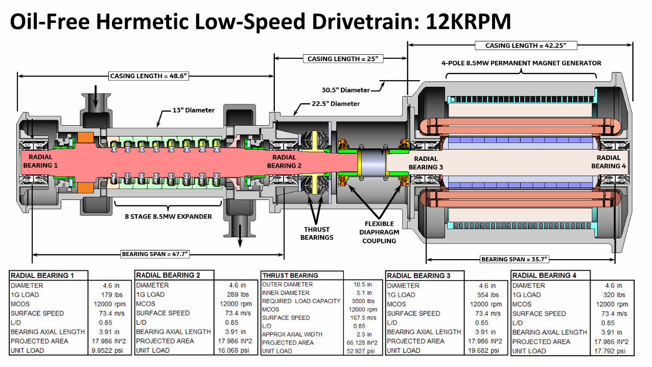
Oil-Free Hermetic Low-Speed Drivetrain: 12KRPM

Immersed CO2 GeneratorCavity Thermal Stability
Gas Bearing DOE: WindageLeakage, Load Capacity
RADIAL BEARING PAD THRUST BEARING PAD
• Heat generation from PM EM needsto be addressed
• CFD thermal analysis; 1/12 stator-rotor sector
• Weak link→electrical insulation
• Mitigated using: Stator (H2O) cooling jacketand Magnetic gap cooling (CO2),
• Bearing CFD analysis using real gas props. includes- Setting desired running gap under load- Use orifice map DOE and inlet pressures- Calculation of leakage and windage
• Gas bearing show an order of magnitude lessheat generation compared to oil-bearings

Compressor Station WHR Economics
• sCO2 WHR performance• 41% → 51.3% cycle efficiency increase• Fuel consumption/MWh reduction by 20%• CO2 emissions/MWh reduction by 20%• System cost 10-15M; 3-4 breakeven years• Emission-free WHR
• EPA’s New source review: stations innon-attainment areas hesitant to upgrade
• WHR concept offers compressor stations options: 60Hz power gen or compressor drive
• Comparison to ORC*• Power conversion rate ~2X• Break even years cut by half
* Sweetser, M., Leslie, N., “Subcontractor Report: National Account Energy Alliance Final Report for the Basin Electric Project at Northern Border
Pipeline Company’s Compressor Station #7, North Dakota.” ORNL/TM-2007/158. Oak Ridge National Laboratory, Oak Ridge, TN (2007)

Conclusions
• sCO2 WHR unit shows to increase efficiency from 41% → 51.3%with investment break even years = 3-4
• sCO2 Compared to ORC WHR: Power conversion rate increasenearly 2X and break even years cut in half
• Risks:• High-speed drive train: lightly loaded bearings but required to
traverse third critical speed (bending mode)
• Low-speed drive train: Highly loaded bearings but operatesbelow third critical speed (bending mode)
• Generator cavity thermal balance/stability