3GPP
TSG-RAN R3 meeting #8 TSGR3 #8 (99)D56Abiko, Japan, 25-29 October 1999
Source: EditorTitle: UMTS 25.433: NBAP Specification V1.3.2Agenda Item: 16Document for: Approval___________________________________________________________________________
3GPP
TS RAN 25.433 V1.3.21.2.2(1999-10)Technical Specification
3rd Generation Partnership Project (3GPP);Technical Specification Group (TSG) RAN
NBAP Specification
[UMTS <spec>]
<
3GPP
TS RAN 25.433 V1.3.21.2.2(1999-10)3[UMTS <spec>]
Reference<Workitem> (<Shortfilename>.PDF)
Keywords<keyword[, keyword]>
3GPP
Postal address
Office address
Individual copies of this deliverablecan be downloaded from
http://www.3gpp.org
Copyright Notification
No part may be reproduced except as authorized by written permission.The copyright and the foregoing restriction extend to reproduction in all media.
©All rights reserved.
3GPP
TS RAN 25.433 V1.3.21.2.2(1999-10)4[UMTS <spec>]
ContentsIntellectual Property Rights ......................................................................................................................... 9914
Foreword...................................................................................................................................................... 9914
1 Scope ................................................................................................................................................. 9914
2 References ......................................................................................................................................... 9914
3 Definitions, symbols and abbreviations ............................................................................................ 99143.1 Definitions ......................................................................................................................................................... 99143.2 Symbols ............................................................................................................................................................. 99143.3 Abbreviations..................................................................................................................................................... 9914
4 General........................................................................................................................................... 101015
5 NBAP Services .............................................................................................................................. 1010155.1 Parallel Transactions...................................................................................................................................... 101015
6 Services expected from signalling transport.................................................................................. 111116
7 Functions of NBAP ....................................................................................................................... 111116
8 Elementary NBAP procedures....................................................................................................... 1111168.1 NBAP Common Procedures .......................................................................................................................... 1111168.1.1 Common Transport Channels Management ............................................................................................. 1111168.1.1.1 Common Transport Channel Configuration Procedures .......................................................................... 1212178.1.1.1.1 Common Transport Channel Setup..................................................................................................... 1212178.1.1.1.2 Common Transport Channel Reconfigure .......................................................................................... 1313188.1.1.1.3 Common Transport Channel Delete ................................................................................................... 1414198.1.2 Radio Resource Management................................................................................................................... 1414198.1.2.1 Block Resource ........................................................................................................................................ 1415208.1.2.2 Node B Restarted ..................................................................................................................................... 1515208.1.2.2.1 NodeB Restart Indication ................................................................................................................... 1515208.1.2.2.2 Audit Required ................................................................................................................................... 1616218.1.2.3 RNC Restarted ......................................................................................................................................... 1616218.1.2.3.1 RNC Restart Indication ...................................................................................................................... 1616218.1.2.3.2 Audit 1717228.1.3 Iub Link Management .............................................................................................................................. 1818238.1.4 Radio Network Performance Measurement ............................................................................................. 1818238.1.4.1 Common Measurement Initiation Request ............................................................................................... 1818238.1.4.2 Common Measurement Termination initiated by RNC ............................................................................ 2121268.1.4.3 Common Measurement Termination initiated by NodeB......................................................................... 2121268.1.4.4 Common Measurement Report ................................................................................................................ 2122278.1.5 Cell Configuration Management .............................................................................................................. 2222278.1.5.1 Cell Setup................................................................................................................................................. 2222278.1.5.2 Cell Reconfiguration ................................................................................................................................ 2324298.1.5.3 Cell Deletion ............................................................................................................................................ 2425308.1.6 Resource Event Management................................................................................................................... 2525308.1.6.1 Resource Status Indication....................................................................................................................... 2526308.1.7 System Information Update Procedure .................................................................................................... 2728338.1.8 Radio Link Setup ..................................................................................................................................... 2829348.1.9 Neighbour Cell Measurement (for TDD)................................................................................................. 2929348.1.10 Synchronisation Adjustment (for TDD)................................................................................................... 3030358.1.11 Synchronisation Recovery (for TDD) ...................................................................................................... 3031368.2 NBAP Dedicated Procedures......................................................................................................................... 3131368.2.1 Radio Link Addition ................................................................................................................................ 3131368.2.2 Radio Link Reconfiguration (Synchronized) ........................................................................................... 3232378.2.3 Radio Link Reconfiguration (Unsynchronised)........................................................................................ 3334398.2.4 Radio Link Deletion................................................................................................................................. 3536418.2.5 DL Power Control (for FDD only)........................................................................................................... 3536418.2.6 Radio Network Performance Measurement ............................................................................................. 363742
3GPP
TS RAN 25.433 V1.3.21.2.2(1999-10)5[UMTS <spec>]
8.2.6.1 Dedicated Measurement Initiation Request.............................................................................................. 3637428.2.6.2 Dedicated Measurement Termination initiated by CRNC........................................................................ 3839448.2.6.3 Dedicated Measurement Termination initiated by Node B ...................................................................... 3840448.2.6.4 Dedicated Measurement Reporting Procedure......................................................................................... 3940458.2.7 Radio Link Failure ................................................................................................................................... 3940458.2.8 Radio Link Restore .................................................................................................................................. 404146
9 Elements for NBAP communication ............................................................................................. 4041469.1 Message functional definition and content .................................................................................................... 4041469.1.1 Message Contents .................................................................................................................................... 4041469.1.2 COMMON TRANSPORT CHANNEL SETUP REQUEST ................................................................... 4042479.1.2.1 FDD Message........................................................................................................................................... 4142479.1.2.2 TDD Message .......................................................................................................................................... 4243489.1.3 COMMON TRANSPORT CHANNEL SETUP RESPONSE ................................................................. 4345509.1.4 COMMON TRANSPORT CHANNEL SETUP FAILURE..................................................................... 4445509.1.5 COMMON TRANSPORT CHANNEL RECONFIGURATION REQUEST .......................................... 4446519.1.5.1 FDD Message........................................................................................................................................... 4446519.1.5.2 TDD Message .......................................................................................................................................... 4546519.1.6 COMMON TRANSPORT CHANNEL RECONFIGURATION RESPONSE ........................................ 4547529.1.7 COMMON TRANSPORT CHANNEL RECONFIGURATION FAILURE............................................ 4547529.1.8 COMMON TRANSPORT CHANNEL DELETION REQUEST............................................................ 4547529.1.9 COMMON TRANSPORT CHANNEL DELETION RESPONSE.......................................................... 4647529.1.10 BLOCK RESOURCE REQUEST ........................................................................................................... 4648539.1.11 BLOCK RESOURCE RESPONSE ......................................................................................................... 4648539.1.12 BLOCK RESOURCE FAILURE............................................................................................................. 4648539.1.13 NODE B RESTART INDICATION......................................................................................................... 4748539.1.14 AUDIT REQUIRED INDICATION ........................................................................................................ 4748539.1.15 RNC RESTART INDICATION ............................................................................................................... 4749549.1.16 RNC RESTART COMPLETION INDICATION..................................................................................... 4749549.1.17 AUDIT REQUEST .................................................................................................................................. 4749549.1.18 AUDIT RESPONSE ................................................................................................................................ 4849549.1.19 COMMON MEASUREMENT INITIATION REQUEST....................................................................... 4849549.1.20 COMMON MEASUREMENT INITIATION RESPONSE..................................................................... 4951569.1.21 COMMON MEASUREMENT INITIATION FAILURE ........................................................................ 4951569.1.22 COMMON MEASUREMENT TERMINATION REQUEST................................................................. 4951569.1.23 COMMON MEASUREMENT FAILURE INDICATION....................................................................... 5051569.1.24 COMMON MEASUREMENT REPORT................................................................................................ 5052579.1.25 CELL SETUP REQUEST ....................................................................................................................... 5052579.1.25.1 FDD Message..................................................................................................................................... 5052579.1.25.2 TDD Message..................................................................................................................................... 5153589.1.26 CELL SETUP RESPONSE ..................................................................................................................... 5153589.1.27 CELL SETUP FAILURE......................................................................................................................... 5153589.1.28 CELL RECONFIGURATION REQUEST .............................................................................................. 5254599.1.28.1 FDD Message..................................................................................................................................... 5254599.1.28.2 TDD Message..................................................................................................................................... 5254599.1.29 CELL RECONFIGURATION RESPONSE ............................................................................................ 5254599.1.30 CELL RECONFIGURATION FAILURE................................................................................................ 5254599.1.31 CELL DELETION REQUEST................................................................................................................ 5355609.1.32 CELL DELETION RESPONSE.............................................................................................................. 5355609.1.33 RESOURCE STATUS INDICATION ..................................................................................................... 5355609.1.34 SYSTEM INFORMATION UPDATE REQUEST .................................................................................. 5557629.1.35 SYSTEM INFORMATION UPDATE RESPONSE ................................................................................ 5557629.1.36 SYSTEM INFORMATION UPDATE FAILURE.................................................................................... 5557629.1.37 RADIO LINK SETUP REQUEST .......................................................................................................... 5658639.1.37.1 FDD message ..................................................................................................................................... 5658639.1.37.2 TDD message ..................................................................................................................................... 5759649.1.38 RADIO LINK SETUP RESPONSE ........................................................................................................ 5860659.1.38.1 FDD message ..................................................................................................................................... 5861669.1.38.2 TDD Message..................................................................................................................................... 5961669.1.39 RADIO LINK SETUP FAILURE............................................................................................................ 5962679.1.39.1 FDD Message..................................................................................................................................... 596267
3GPP
TS RAN 25.433 V1.3.21.2.2(1999-10)6[UMTS <spec>]
9.1.39.2 TDD Message..................................................................................................................................... 6062679.1.40 NEIGHBOUR CELL MEASUREMENT REQUEST (TDD only) ......................................................... 6063689.1.41 NEIGHBOUR CELL MEASUREMENT RESPONSE (TDD only) ....................................................... 6163689.1.42 NEIGHBOUR CELL MEASUREMENT FAILURE (TDD only)........................................................... 6163689.1.43 SYNCHRONISATION ADJUSTMENT REQUEST (TDD only) .......................................................... 6164699.1.44 SYNCHRONISATION ADJUSTMENT RESPONSE (TDD only) ........................................................ 6264699.1.45 SYNCHRONISATION ADJUSTMENT FAILURE (TDD only)............................................................ 6264699.1.46 NODE B OUT OF SYNC INDICATION� (TDD only) .......................................................................... 6265709.1.47 SYNCHRONISATION RESTART REQUEST (TDD only) ................................................................... 6265709.1.48 RADIO LINK ADDITION REQUEST ................................................................................................... 6365709.1.48.1 FDD Message..................................................................................................................................... 6365709.1.48.2 TDD Message..................................................................................................................................... 6366719.1.49 RADIO LINK ADDITION RESPONSE ................................................................................................. 6467729.1.49.1 FDD message ..................................................................................................................................... 6467729.1.49.2 TDD Message..................................................................................................................................... 6567729.1.50 RADIO LINK ADDITION FAILURE..................................................................................................... 6568739.1.50.1 FDD Message..................................................................................................................................... 6568739.1.50.2 TDD Message..................................................................................................................................... 6668739.1.51 RADIO LINK RECONFIGURATION PREPARE .................................................................................. 6669749.1.51.1 FDD Message..................................................................................................................................... 6669749.1.51.2 TDD Message..................................................................................................................................... 6769749.1.52 RADIO LINK RECONFIGURATION READY...................................................................................... 6871769.1.53 RADIO LINK RECONFIGURATION COMMIT................................................................................... 6971769.1.53.1 FDD Message..................................................................................................................................... 6971769.1.53.2 TDD Message..................................................................................................................................... 6972779.1.54 RADIO LINK RECONFIGURATION FAILURE................................................................................... 6972779.1.55 RADIO LINK RECONFIGURATION CANCEL ................................................................................... 6972779.1.56 RADIO LINK RECONFIGURATION REQUEST ................................................................................. 7073789.1.56.1 FDD Message..................................................................................................................................... 7073789.1.56.2 TDD Message..................................................................................................................................... 7073789.1.57 RADIO LINK RECONFIGURATION RESPONSE ............................................................................... 7174799.1.58 RADIO LINK DELETION REQUEST................................................................................................... 7175809.1.59 RADIO LINK DELETION RESPONSE................................................................................................. 7275809.1.60 DL POWER CONTROL REQUEST (FDD only) ................................................................................... 7275809.1.61 DEDICATED MEASUREMENT INITIATION REQUEST................................................................... 7275809.1.62 DEDICATED MEASUREMENT INITIATION RESPONSE................................................................. 7377829.1.63 DEDICATED MEASUREMENT INITIATION FAILURE .................................................................... 7477829.1.64 DEDICATED MEASUREMENT TERMINATION REQUEST............................................................. 7477829.1.65 DEDICATED MEASUREMENT FAILURE INDICATION................................................................... 7477829.1.66 DEDICATED MEASUREMENT REPORT............................................................................................ 7478839.1.67 RADIO LINK FAILURE INDICATION ................................................................................................. 7578839.1.68 RADIO LINK RESTORE INDICATION................................................................................................ 7578839.1.69 RESET (FFS)........................................................................................................................................... 7679849.1.70 RESET ACKNOWLEDGE (FFS) ........................................................................................................... 7679849.1.71 CONFUSION (FFS) ................................................................................................................................ 7679849.2 Information Element Functional Definition and Contents ............................................................................. 7679849.2.1 FDD/TDD commonly used parameters.................................................................................................... 7679849.2.1.1 Absolute Threshold.................................................................................................................................. 7679849.2.1.2 Add/Delete Indicator................................................................................................................................ 767984Availability Status ..................................................................................................................................................... 7679849.2.1.4 Binding ID ............................................................................................................................................... 7680859.2.1.5 Communication Control Port ID .............................................................................................................. 7680859.2.1.6 Configuration Generation ID ................................................................................................................... 7780859.2.1.7 CRNC Communication Context ID.......................................................................................................... 7780859.2.1.8 DCH Combination Indicator .................................................................................................................... 7780859.2.1.9 DCH Frame Handling Priority ................................................................................................................. 7780859.2.1.10 DCH ID .............................................................................................................................................. 7780859.2.1.11 DL Transport Format Combination Set .............................................................................................. 7781869.2.1.12 DL Transport Format Set.................................................................................................................... 7781869.2.1.13 Fall Time ............................................................................................................................................ 778186
3GPP
TS RAN 25.433 V1.3.21.2.2(1999-10)7[UMTS <spec>]
9.2.1.14 Frame Offset....................................................................................................................................... 7781869.2.1.15 Frequency Number ............................................................................................................................. 7781869.2.1.16 Hysteresis Time .................................................................................................................................. 7781869.2.1.17 Indication Type (FFS) ........................................................................................................................ 7881869.2.1.18 Local Cell ID...................................................................................................................................... 7881869.2.1.19 Maximum DL Power .......................................................................................................................... 7881869.2.1.20 Maximum DL Power Capability......................................................................................................... 7882879.2.1.21 Measurement Characteristic ............................................................................................................... 7882879.2.1.22 Measurement ID ................................................................................................................................. 7882879.2.1.23 Measurement Object........................................................................................................................... 7882879.2.1.24 Measurement Type ............................................................................................................................. 7882879.2.1.25 Message discriminator........................................................................................................................ 7882879.2.1.26 Message Type..................................................................................................................................... 7882879.2.1.27 MIB_SG ............................................................................................................................................. 7982879.2.1.28 MIB_SG_POS.................................................................................................................................... 7982879.2.1.29 MIB_SG_REP.................................................................................................................................... 7983889.2.1.30 Minimum DL Power........................................................................................................................... 7983889.2.1.31 Node B Communication Context ID .................................................................................................. 7983889.2.1.32 Number Channel Elements ................................................................................................................. 7983889.2.1.33 Payload CRC presence ....................................................................................................................... 7983889.2.1.34 Priority Indicator ................................................................................................................................ 7983889.2.1.35 Relative Threshold ............................................................................................................................. 7983889.2.1.36 Report Characteristics ........................................................................................................................ 7983889.2.1.37 Resource Operational State ................................................................................................................ 7983889.2.1.38 Reporting Frequency .......................................................................................................................... 8084899.2.1.39 Rising Time ........................................................................................................................................ 8084899.2.1.40 RL Failure Cause................................................................................................................................ 8084899.2.1.41 RL ID ................................................................................................................................................. 8084899.2.1.42 Shutdown Timer ................................................................................................................................. 8084899.2.1.43 SIB_SG .............................................................................................................................................. 8084899.2.1.44 SIB_SG_POS ..................................................................................................................................... 8084899.2.1.45 SIB_SG_REP ..................................................................................................................................... 8084899.2.1.46 Time Reference .................................................................................................................................. 8084899.2.1.47 ToAWE............................................................................................................................................... 8084899.2.1.48 ToAWS............................................................................................................................................... 8085909.2.1.49 Transaction ID.................................................................................................................................... 8185909.2.1.50 Transmit Offset................................................................................................................................... 8185909.2.1.51 Transport Layer Address .................................................................................................................... 8185909.2.1.52 UC-ID................................................................................................................................................. 8185909.2.1.53 UL FP mode ....................................................................................................................................... 8185909.2.1.54 UL interference level.......................................................................................................................... 8185909.2.1.55 UL Transport Format Combination Set .............................................................................................. 8185909.2.1.56 UL Transport Format Set.................................................................................................................... 8186919.2.1.57 Value................................................................................................................................................... 8186919.2.2 FDD specific parameters.......................................................................................................................... 8186919.2.2.1 Chip Offset............................................................................................................................................... 8186919.2.2.2 CPICH Power .......................................................................................................................................... 8286919.2.2.3 Diversity Control Field ............................................................................................................................ 8286919.2.2.4 Diversity Indication.................................................................................................................................. 8286919.2.2.5 DL Channelisation Code Number ............................................................................................................ 8286919.2.2.6 DL Reference Power................................................................................................................................ 8286919.2.2.7 DL Scrambling Code ............................................................................................................................... 8286919.2.2.8 Length of DL Channelisation Code.......................................................................................................... 8287929.2.2.9 Length of UL Channelisation Code.......................................................................................................... 8287929.2.2.10 Max Transmission Power ................................................................................................................... 8287929.2.2.11 Primary SCH Power ........................................................................................................................... 8387929.2.2.12 Propagation Delay .............................................................................................................................. 8387929.2.2.13 Reference RL ID ................................................................................................................................ 8387929.2.2.14 Secondary SCH Power ....................................................................................................................... 8387929.2.2.15 TFCI used flag.................................................................................................................................... 838792
3GPP
TS RAN 25.433 V1.3.21.2.2(1999-10)8[UMTS <spec>]
9.2.2.16 UL Eb/No Target ................................................................................................................................ 8387929.2.2.17 UL Scrambling Code.......................................................................................................................... 8388939.2.3 TDD specific Parameters ......................................................................................................................... 8388939.2.3.1 CCTrCH Activation CFN......................................................................................................................... 8388939.2.3.2 CCTrCH Duration.................................................................................................................................... 838893CCTrCH ID 8488939.2.3.4 Cell Parameter.......................................................................................................................................... 8488939.2.3.5 Channelisation Code Number .................................................................................................................. 8488939.2.3.6 Chip Offset Adjustment ........................................................................................................................... 8488939.2.3.7 DPCH ID ................................................................................................................................................. 8488939.2.3.8 Measured Chip Offset .............................................................................................................................. 8489949.2.3.9 Measured UC-ID...................................................................................................................................... 8489949.2.3.10 Measuring UC-ID............................................................................................................................... 8489949.2.3.11 Midamble shift ................................................................................................................................... 8489949.2.3.12 PCCPCH Time Slot (i) ....................................................................................................................... 8589949.2.3.13 PSCH and PCCPCH Allocation ......................................................................................................... 8589949.2.3.14 PSCH and PCCPCH Time Slot (k) .................................................................................................... 8589949.2.3.15 PSCH Power....................................................................................................................................... 8590959.2.3.16 Repetition Length ............................................................................................................................... 8590959.2.3.17 Repetition Period................................................................................................................................ 859095Scrambling Code 8590959.2.3.19 Superframe Offset .............................................................................................................................. 8590959.2.3.20 Supporting CCTrCH ID ..................................................................................................................... 8690959.2.3.21 Sync Midamble................................................................................................................................... 8690959.2.3.22 TFCI Presence.................................................................................................................................... 8690959.2.3.23 Time Slot ............................................................................................................................................ 8691969.2.3.24 Time Slot Direction ............................................................................................................................ 8691969.2.3.25 Time Slot Status ................................................................................................................................. 8691969.2.3.26 Toffset................................................................................................................................................. 8691969.3 Message and Information element abstract syntax (with ASN.1) .................................................................. 8691969.3.1 PDU Description for NBAP..................................................................................................................... 8691969.3.2 NBAP PDU Content Definitions.............................................................................................................. 8893989.3.3 NBAP Information Elements ................................................................................................................... 8994999.4 Message transfer syntax............................................................................................................................... 90951009.5 Timers........................................................................................................................................................ 95101106
10 Handling of unknown, unforeseen and erroneous protocol data............................................... 9510110610.1 Error reporting procedure............................................................................................................. 95101106
10.2 Error reporting message ............................................................................................................... 9610210710.2.1 ERROR REPORTING......................................................................................................................... 9610210710.3 L3 information parameter ............................................................................................................ 96102107
11 Annex A (normative):................................................................................................................ 96102107
12 Annex B (informative): ............................................................................................................. 96102107
13 Annex C (informative): List of Outstanding Issues................................................................... 97103108
14 Annex D (Informative) .............................................................................................................. 98104109
15 History ..................................................................................................................................... 100106111
3GPP
TS RAN 25.433 V1.3.21.2.2(1999-10)9[UMTS <spec>]
Intellectual Property Rights
ForewordThis Technical Specification has been produced by the 3rd Generation Partnership Project, Technical SpecificationGroup <TSG name>.The contents of this TS may be subject to continuing work within the 3GPP and may change following formalTSG approval. Should the TSG modify the contents of this TS, it will be re-released with an identifying change ofrelease date and an increase in version number as follows:
Version m.t.ewhere:
m indicates [major version number]x the second digit is incremented for all changes of substance, i.e. technical enhancements, corrections,
updates, etc.y the third digit is incremented when editorial only changes have been incorporated into the specification.
1 ScopeThe present document specifies the standards for NBAP specification to be used over Iub Interface.
2 ReferencesThe following documents contain provisions which, through reference in this text, constitute provisions of thepresent document.
• References are either specific (identified by date of publication, edition number, version number, etc.)or non-specific.
• For a specific reference, subsequent revisions do not apply.• For a non-specific reference, the latest version applies.• A non-specific reference to an ETS shall also be taken to refer to later versions published as an EN
with the same number.[1] 25.401, UTRAN Overall Description[2] 25.426 UTRAN Iur and Iub Interface Data Transport & Transport Signalling for DCH Data
Streams[3] CCITT Recommendation X.731 Information Technology – Open Systems Interconnection –
Systems Management: State Management function (01/92)[4] TS25.215 Physical layer – Measurements (FDD)[5] TS25.225 Physical layer – Measurements (TDD)[6] CCITT Recommendation X.731 Information Technology – Open Systems Interconnection –
Systems Management: State Management function (01/92)
3 Definitions, symbols and abbreviations[Editor’s note: This chapter is almost stable]
3.1 Definitions NBAP (Node B Application Part) is defined as Radio Network Layer Protocol applied the interface betweenControlling RNC and NodeB, namely Iub Interface.
3.2 Symbols
3.3 AbbreviationsAAL2 ATM Adaptation Layer type 2ASN.1 Abstract Syntax Notation One
3GPP
TS RAN 25.433 V1.3.21.2.2(1999-10)10[UMTS <spec>]
ATM Asynchronous Transfer ModeBCCH Broadcast Control ChannelCCPCH Common Control Physical ChannelCFN Connection Frame NumberCRNC Controlling Radio Network ControllerDCH Dedicated ChannelDL DownlinkDPCCH Dedicated Physical Control ChannelDPCH Dedicated Physical ChannelDPDCH Dedicated Physical Data ChannelDRNC Drift Radio Network ControllerFDD Frequency Division DuplexFP Frame ProtocolL1 Layer 1L2 Layer 2NBAP Node B Application PartO&M Operation and ManagementQoS Quality of ServiceRL Radio LinkRNC Radio Network ControllerRRC Radio Resource ControlSRNC Serving Radio Network ControllerTDD Time Division DuplexTFC Transport Format CombinationTFCI Transport Format Combination IndicatorTFCS Transport Format Combination SetTFS Transport Format SetUE User EquipmentUL UplinkUTRAN UMTS Terrestrial Radio Access Network
4 General[Editor´s note: This chapter should describe requirements on protocol capabilities, principles, etc.]
Node B Application Part, NBAP, includes common procedures and dedicated procedures. It covers proceduresfor paging distribution, broadcast system information, request / complete / release of dedicated resources andmanagement of logical resources (logical O&M [1]).
Note that the issue of transport layer addressing is FFS.
5 NBAP Services The NBAP offers the following services:
[Editor’s note: Contents are missing]
5.1 Parallel Transactions Unless explicitly indicated in the procedure description, at any instance in time one protocol peer shall haveinitiated maximum one ongoing dedicated NBAP procedure related to a certain NodeB communication context.
3GPP
TS RAN 25.433 V1.3.21.2.2(1999-10)11[UMTS <spec>]
6 Services expected from signalling transport [Editor’s note: Contents are missing]
7 Functions of NBAP [Editor’s note: This chapter is almost stable]The following procedures are included in NBAP:• Common Transport Channels Management• Radio Resource Management• Iub Link Management• Radio Network Performance Management• Cell Configuration Management• Resource Event Management• System Information Update• Radio Link Setup• Radio Link Addition• Radio Link Reconfiguration (synchronised)• Radio Link Reconfiguration (unsynchronised)• Radio Link Deletion• DL Power Control• Measurement reporting• Radio Link failure• Radio Link Restore
[Editor’s note: A couple of procedures for Logical O&M are probably missing]
8 Elementary NBAP procedures
NBAP procedures are divided into common procedures and dedicated procedures.
• NBAP common procedures are procedures that request initiation of a UE context for a specific UE in Node Bor are not related to a specific UE. NBAP common procedures also incorporate logical O&M [1] procedures.
• NBAP dedicated procedures are procedures that are related to a specific UE context in Node B. This UEcontext is identified by a UE context identity.
The two types of procedures may be carried on separate signalling links.
8.1 NBAP Common Procedures
8.1.1 Common Transport Channels Management This procedure provides the capability to activate common channel resources such as [cell broadcast channelsand] random access channels. The ability to control, for example, paging retransmission should also be provided.Information on common channel performance (eg overload) should be provided by node B to the RNC. Anyfailures impacting on the common channel resources at Node B should be signalled to the RNC via the ResourceEvent Management procedure (section 8.1.6).
3GPP
TS RAN 25.433 V1.3.21.2.2(1999-10)12[UMTS <spec>]
8.1.1.1 Common Transport Channel Configuration Procedures The Procedures for Common Transport Channel Configuration:
• Common Transport Channel Setup (e.g. FACH, PCCH, BCCH, RACH, DSCH (TDD) and USCH(TDD))
• Common Transport Channel Reconfigure
• Common Transport Channel Delete
8.1.1.1.1 Common Transport Channel Setup The RNC initiates a definition of common transport channels in a cell within Node B, which defines the orderedchannels and takes them into service. This procedure also establishes the associated physical channel. The resultis communicated back to the RNC.
For the procedure to be executed successfully the following is needed:
• The cell context, to which the common transport channels are to be defined, has to be defined within Node B,i.e. the cell Setup procedure has to be successfully executed for the cell in question.
• Node B equipment has previously been defined and configured to support the requested channels on theImplementation Specific O&M interface.
• A Node B control port is available for communication between the RNC and the Node B, for the procedure tobe executed successfully.
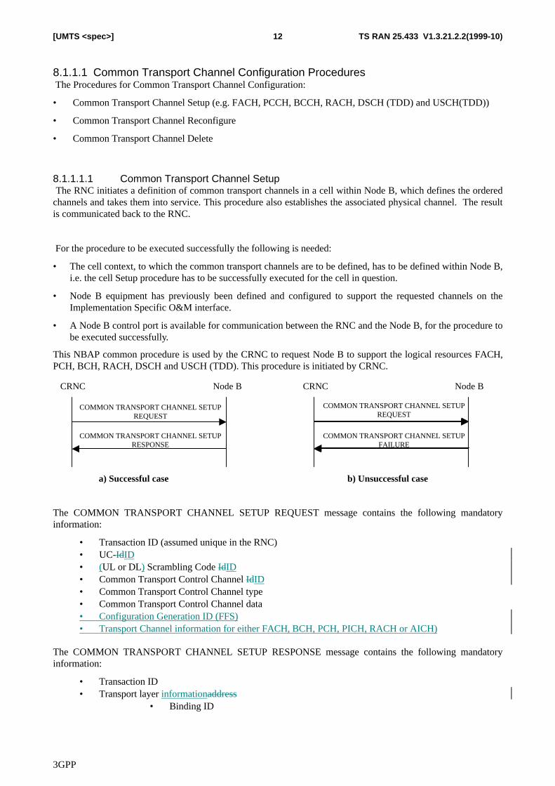
This NBAP common procedure is used by the CRNC to request Node B to support the logical resources FACH,PCH, BCH, RACH, DSCH and USCH (TDD). This procedure is initiated by CRNC.
CRNC Node B
COMMON TRANSPORT CHANNEL SETUP REQUEST
COMMON TRANSPORT CHANNEL SETUP RESPONSE
CRNC Node B
a) Successful case b) Unsuccessful case
COMMON TRANSPORT CHANNEL SETUP REQUEST
COMMON TRANSPORT CHANNEL SETUP FAILURE
The COMMON TRANSPORT CHANNEL SETUP REQUEST message contains the following mandatoryinformation:
• Transaction ID (assumed unique in the RNC)• UC-IdID• (UL or DL) Scrambling Code IdID• Common Transport Control Channel IdID• Common Transport Control Channel type• Common Transport Control Channel data• Configuration Generation ID (FFS)• Transport Channel information for either FACH, BCH, PCH, PICH, RACH or AICH)
The COMMON TRANSPORT CHANNEL SETUP RESPONSE message contains the following mandatoryinformation:
• Transaction ID• Transport layer informationaddress
• Binding ID
3GPP
TS RAN 25.433 V1.3.21.2.2(1999-10)13[UMTS <spec>]
The COMMON TRANSPORT CHANNEL SETUP FAILURE message contains the following mandatoryinformation:
• Transaction ID• Failure Cause
8.1.1.1.2 Common Transport Channel Reconfigure The RNC initiates a change of the configuration of common transport channels in Node B, which reconfiguresthe channels. This procedure also reconfigures the associated physical channel. The result is communicated backto the RNC.
For the procedure to be executed successfully the following is needed:
• The transport common channel(s) exist in the cell within the Node B
• Node B equipment has previously been defined and configured to support the changed channels on theImplementation Specific O&M interface
• A Node B control port is available for communication between the RNC and the Node B, for the procedureto be executed successfully
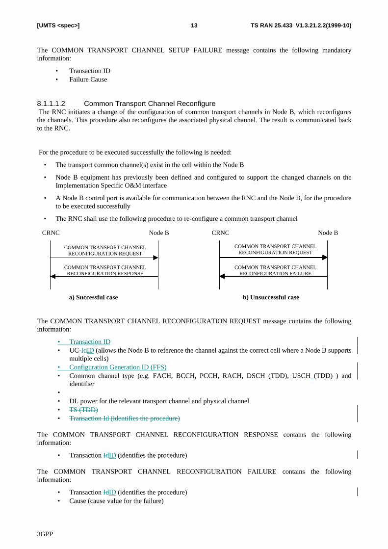
• The RNC shall use the following procedure to re-configure a common transport channel
CRNC Node B
COMMON TRANSPORT CHANNEL RECONFIGURATION REQUEST
COMMON TRANSPORT CHANNEL RECONFIGURATION RESPONSE
CRNC Node B
a) Successful case b) Unsuccessful case
COMMON TRANSPORT CHANNEL RECONFIGURATION REQUEST
COMMON TRANSPORT CHANNEL RECONFIGURATION FAILURE
The COMMON TRANSPORT CHANNEL RECONFIGURATION REQUEST message contains the followinginformation:
• Transaction ID• UC-IdID (allows the Node B to reference the channel against the correct cell where a Node B supports
multiple cells)• Configuration Generation ID (FFS)• Common channel type (e.g. FACH, BCCH, PCCH, RACH, DSCH (TDD), USCH (TDD) ) and
identifier• • DL power for the relevant transport channel and physical channel• TS (TDD)• Transaction Id (identifies the procedure)
The COMMON TRANSPORT CHANNEL RECONFIGURATION RESPONSE contains the followinginformation:
• Transaction IdID (identifies the procedure)
The COMMON TRANSPORT CHANNEL RECONFIGURATION FAILURE contains the followinginformation:
• Transaction IdID (identifies the procedure)• Cause (cause value for the failure)
3GPP
TS RAN 25.433 V1.3.21.2.2(1999-10)14[UMTS <spec>]
8.1.1.1.3 Common Transport Channel Delete The RNC initiates the deletion of common transport channel(s) in a cell within Node B, which deletes therequested channels. The result is communicated back to the RNC.
For the procedure to be executed successfully the following is needed:
• The common transport channel(s) exist in the cell within the Node B.
• A Node B control port is available for communication between the RNC and the Node B.
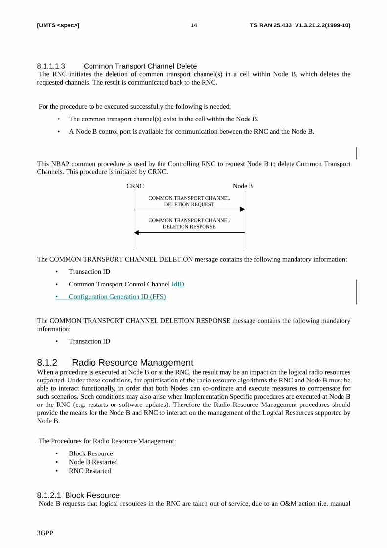
This NBAP common procedure is used by the Controlling RNC to request Node B to delete Common TransportChannels. This procedure is initiated by CRNC.
CRNC Node B
COMMON TRANSPORT CHANNEL DELETION REQUEST
COMMON TRANSPORT CHANNEL DELETION RESPONSE
The COMMON TRANSPORT CHANNEL DELETION message contains the following mandatory information:
• Transaction ID
• Common Transport Control Channel IdID
• Configuration Generation ID (FFS)
The COMMON TRANSPORT CHANNEL DELETION RESPONSE message contains the following mandatoryinformation:
• Transaction ID
8.1.2 Radio Resource ManagementWhen a procedure is executed at Node B or at the RNC, the result may be an impact on the logical radio resourcessupported. Under these conditions, for optimisation of the radio resource algorithms the RNC and Node B must beable to interact functionally, in order that both Nodes can co-ordinate and execute measures to compensate forsuch scenarios. Such conditions may also arise when Implementation Specific procedures are executed at Node Bor the RNC (e.g. restarts or software updates). Therefore the Radio Resource Management procedures shouldprovide the means for the Node B and RNC to interact on the management of the Logical Resources supported byNode B.
The Procedures for Radio Resource Management:
• Block Resource• Node B Restarted• RNC Restarted
8.1.2.1 Block Resource Node B requests that logical resources in the RNC are taken out of service, due to an O&M action (i.e. manual
3GPP
TS RAN 25.433 V1.3.21.2.2(1999-10)15[UMTS <spec>]
intervention for example due to that a piece of equipment, that supports a logical resource in the RNC, shall beupgraded). The RNC answers when the logical resource is taken out of service and the O&M action can continuein Node B.
For the procedure to be executed successfully the following is needed:
• A configured cell exists in Node B (downlink and uplink common channels can be defined in thecell).
• A Node B control port is available for communication between the RNC and the Node B.
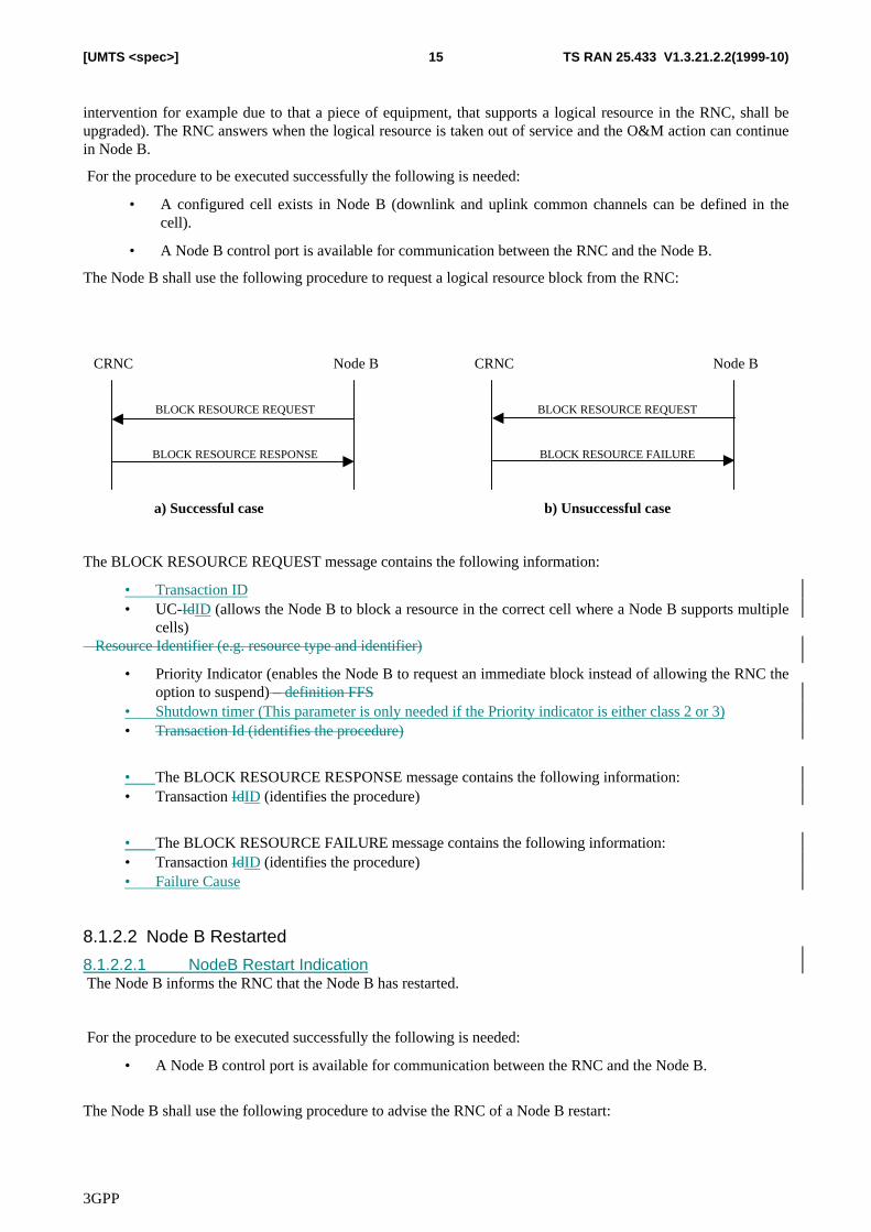
The Node B shall use the following procedure to request a logical resource block from the RNC:
CRNC Node B
BLOCK RESOURCE REQUEST
BLOCK RESOURCE RESPONSE
CRNC Node B
a) Successful case b) Unsuccessful case
BLOCK RESOURCE REQUEST
BLOCK RESOURCE FAILURE
The BLOCK RESOURCE REQUEST message contains the following information:
• Transaction ID• UC-IdID (allows the Node B to block a resource in the correct cell where a Node B supports multiple
cells)� Resource Identifier (e.g. resource type and identifier)
• Priority Indicator (enables the Node B to request an immediate block instead of allowing the RNC theoption to suspend) – definition FFS
• Shutdown timer (This parameter is only needed if the Priority indicator is either class 2 or 3)• Transaction Id (identifies the procedure)
• The BLOCK RESOURCE RESPONSE message contains the following information:• Transaction IdID (identifies the procedure)
• The BLOCK RESOURCE FAILURE message contains the following information:• Transaction IdID (identifies the procedure)• Failure Cause
8.1.2.2 Node B Restarted
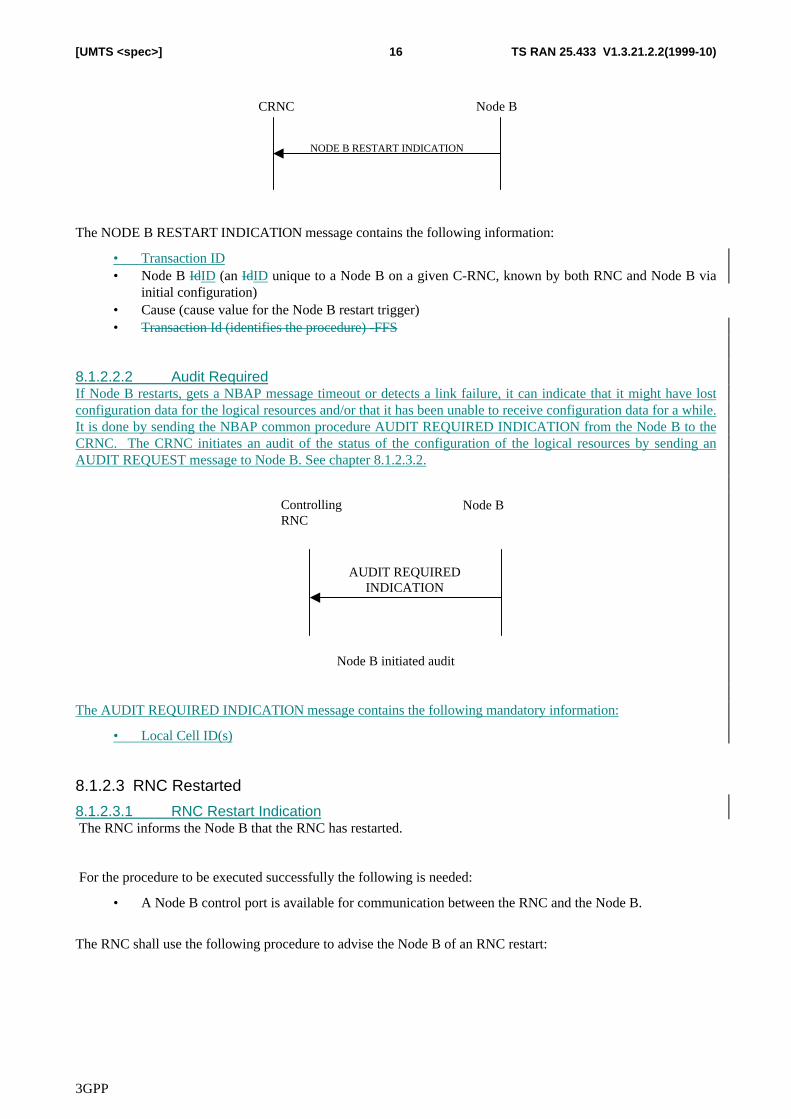
8.1.2.2.1 NodeB Restart Indication The Node B informs the RNC that the Node B has restarted.
For the procedure to be executed successfully the following is needed:
• A Node B control port is available for communication between the RNC and the Node B.
The Node B shall use the following procedure to advise the RNC of a Node B restart:
3GPP
TS RAN 25.433 V1.3.21.2.2(1999-10)16[UMTS <spec>]
CRNC Node B
NODE B RESTART INDICATION
The NODE B RESTART INDICATION message contains the following information:
• Transaction ID• Node B IdID (an IdID unique to a Node B on a given C-RNC, known by both RNC and Node B via
initial configuration)• Cause (cause value for the Node B restart trigger)• Transaction Id (identifies the procedure) -FFS
8.1.2.2.2 Audit RequiredIf Node B restarts, gets a NBAP message timeout or detects a link failure, it can indicate that it might have lostconfiguration data for the logical resources and/or that it has been unable to receive configuration data for a while.It is done by sending the NBAP common procedure AUDIT REQUIRED INDICATION from the Node B to theCRNC. The CRNC initiates an audit of the status of the configuration of the logical resources by sending anAUDIT REQUEST message to Node B. See chapter 8.1.2.3.2.
Controlling RNC
Node B
AUDIT REQUIRED INDICATION
Node B initiated audit
The AUDIT REQUIRED INDICATION message contains the following mandatory information:
• Local Cell ID(s)
8.1.2.3 RNC Restarted
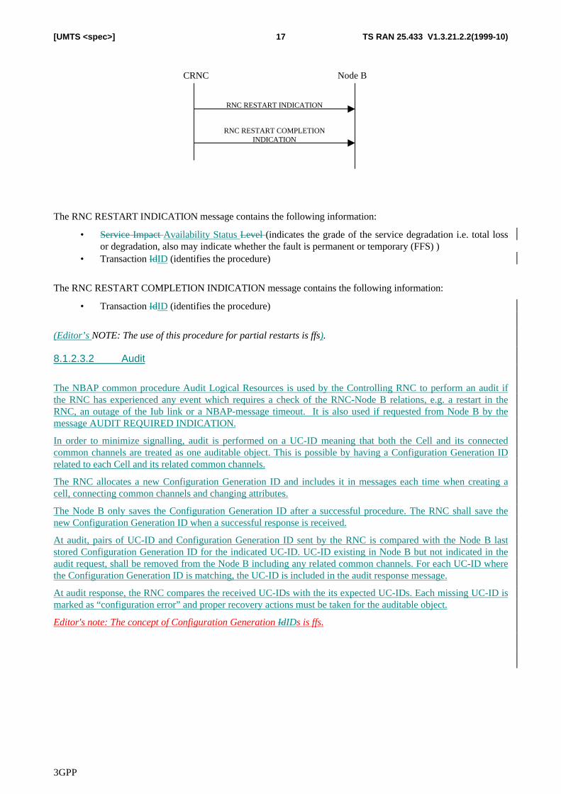
8.1.2.3.1 RNC Restart Indication The RNC informs the Node B that the RNC has restarted.
For the procedure to be executed successfully the following is needed:
• A Node B control port is available for communication between the RNC and the Node B.
The RNC shall use the following procedure to advise the Node B of an RNC restart:
3GPP
TS RAN 25.433 V1.3.21.2.2(1999-10)17[UMTS <spec>]
CRNC Node B
RNC RESTART INDICATION
RNC RESTART COMPLETIONINDICATION
The RNC RESTART INDICATION message contains the following information:
• Service Impact Availability Status Level (indicates the grade of the service degradation i.e. total lossor degradation, also may indicate whether the fault is permanent or temporary (FFS) )
• Transaction IdID (identifies the procedure)
The RNC RESTART COMPLETION INDICATION message contains the following information:
• Transaction IdID (identifies the procedure)
(Editor’s NOTE: The use of this procedure for partial restarts is ffs).
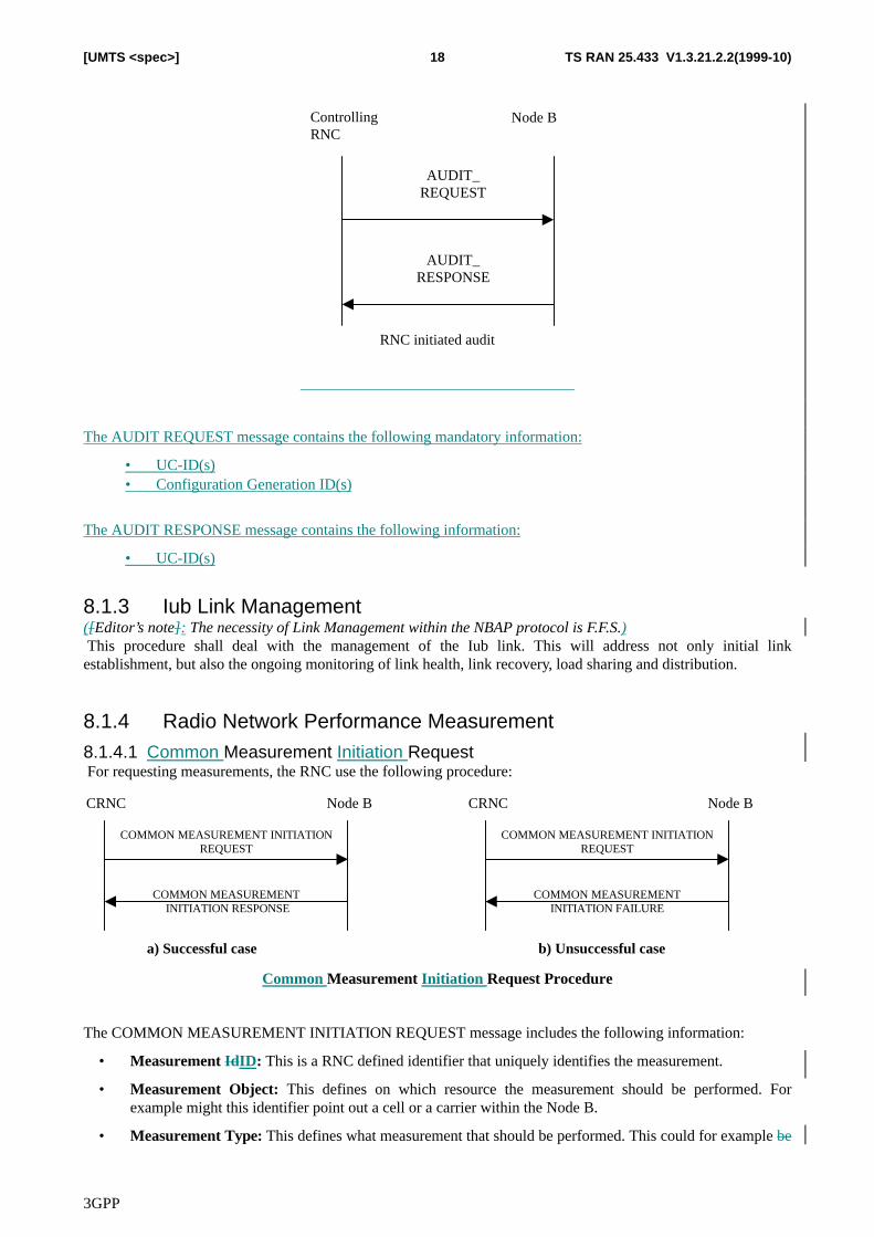
8.1.2.3.2 Audit
The NBAP common procedure Audit Logical Resources is used by the Controlling RNC to perform an audit ifthe RNC has experienced any event which requires a check of the RNC-Node B relations, e.g. a restart in theRNC, an outage of the Iub link or a NBAP-message timeout. It is also used if requested from Node B by themessage AUDIT REQUIRED INDICATION.
In order to minimize signalling, audit is performed on a UC-ID meaning that both the Cell and its connectedcommon channels are treated as one auditable object. This is possible by having a Configuration Generation IDrelated to each Cell and its related common channels.
The RNC allocates a new Configuration Generation ID and includes it in messages each time when creating acell, connecting common channels and changing attributes.
The Node B only saves the Configuration Generation ID after a successful procedure. The RNC shall save thenew Configuration Generation ID when a successful response is received.
At audit, pairs of UC-ID and Configuration Generation ID sent by the RNC is compared with the Node B laststored Configuration Generation ID for the indicated UC-ID. UC-ID existing in Node B but not indicated in theaudit request, shall be removed from the Node B including any related common channels. For each UC-ID wherethe Configuration Generation ID is matching, the UC-ID is included in the audit response message.
At audit response, the RNC compares the received UC-IDs with the its expected UC-IDs. Each missing UC-ID ismarked as “configuration error” and proper recovery actions must be taken for the auditable object.
Editor's note: The concept of Configuration Generation IdIDs is ffs.
3GPP
TS RAN 25.433 V1.3.21.2.2(1999-10)18[UMTS <spec>]
ControllingRNC
Node B
RNC initiated audit
AUDIT_REQUEST
AUDIT_RESPONSE
The AUDIT REQUEST message contains the following mandatory information:
• UC-ID(s)• Configuration Generation ID(s)
The AUDIT RESPONSE message contains the following information:
• UC-ID(s)
8.1.3 Iub Link Management([Editor’s note]: The necessity of Link Management within the NBAP protocol is F.F.S.) This procedure shall deal with the management of the Iub link. This will address not only initial linkestablishment, but also the ongoing monitoring of link health, link recovery, load sharing and distribution.
8.1.4 Radio Network Performance Measurement8.1.4.1 Common Measurement Initiation Request For requesting measurements, the RNC use the following procedure:
CRNC Node B
COMMON MEASUREMENT INITIATIONREQUEST
COMMON MEASUREMENT INITIATION RESPONSE
CRNC Node B
COMMON MEASUREMENT INITIATIONREQUEST
COMMON MEASUREMENTINITIATION FAILURE
a) Successful case b) Unsuccessful case
Common Measurement Initiation Request Procedure
The COMMON MEASUREMENT INITIATION REQUEST message includes the following information:
• Measurement IdID: This is a RNC defined identifier that uniquely identifies the measurement.
• Measurement Object: This defines on which resource the measurement should be performed. Forexample might this identifier point out a cell or a carrier within the Node B.
• Measurement Type: This defines what measurement that should be performed. This could for example be
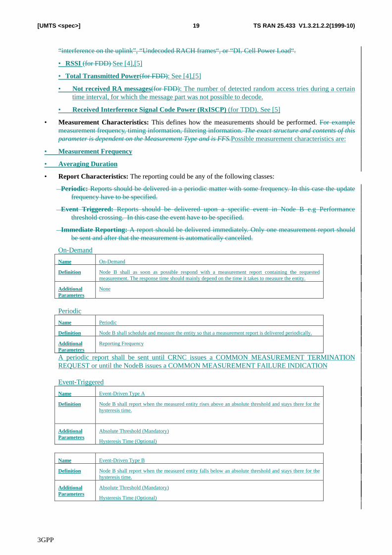
3GPP
TS RAN 25.433 V1.3.21.2.2(1999-10)19[UMTS <spec>]
“interference on the uplink”, “Undecoded RACH frames“, or “DL Cell Power Load“.
• RSSI (for FDD) See [4],[5]
• Total Transmitted Power(for FDD): See [4],[5]
• Not received RA messages(for FDD): The number of detected random access tries during a certaintime interval, for which the message part was not possible to decode.
• Received Interference Signal Code Power (RxISCP) (for TDD). See [5]
• Measurement Characteristics: This defines how the measurements should be performed. For examplemeasurement frequency, timing information, filtering information. The exact structure and contents of thisparameter is dependent on the Measurement Type and is FFS.Possible measurement characteristics are:
• Measurement Frequency
• Averaging Duration
• Report Characteristics: The reporting could be any of the following classes:
� Periodic: Reports should be delivered in a periodic matter with some frequency. In this case the updatefrequency have to be specified.
� Event Triggered: Reports should be delivered upon a specific event in Node B e.g Performancethreshold crossing. In this case the event have to be specified.
� Immediate Reporting: A report should be delivered immediately. Only one measurement report shouldbe sent and after that the measurement is automatically cancelled.
On-Demand
Name On-Demand
Definition Node B shall as soon as possible respond with a measurement report containing the requestedmeasurement. The response time should mainly depend on the time it takes to measure the entity.
AdditionalParameters
None
Periodic
Name Periodic
Definition Node B shall schedule and measure the entity so that a measurement report is delivered periodically.
AdditionalParameters
Reporting Frequency
A periodic report shall be sent until CRNC issues a COMMON MEASUREMENT TERMINATIONREQUEST or until the NodeB issues a COMMON MEASUREMENT FAILURE INDICATION
Event-Triggered
Name Event-Driven Type A
Definition Node B shall report when the measured entity rises above an absolute threshold and stays there for thehysteresis time.
AdditionalParameters
Absolute Threshold (Mandatory)
Hysteresis Time (Optional)
Name Event-Driven Type B
Definition Node B shall report when the measured entity falls below an absolute threshold and stays there for thehysteresis time.
AdditionalParameters
Absolute Threshold (Mandatory)
Hysteresis Time (Optional)
3GPP
TS RAN 25.433 V1.3.21.2.2(1999-10)20[UMTS <spec>]
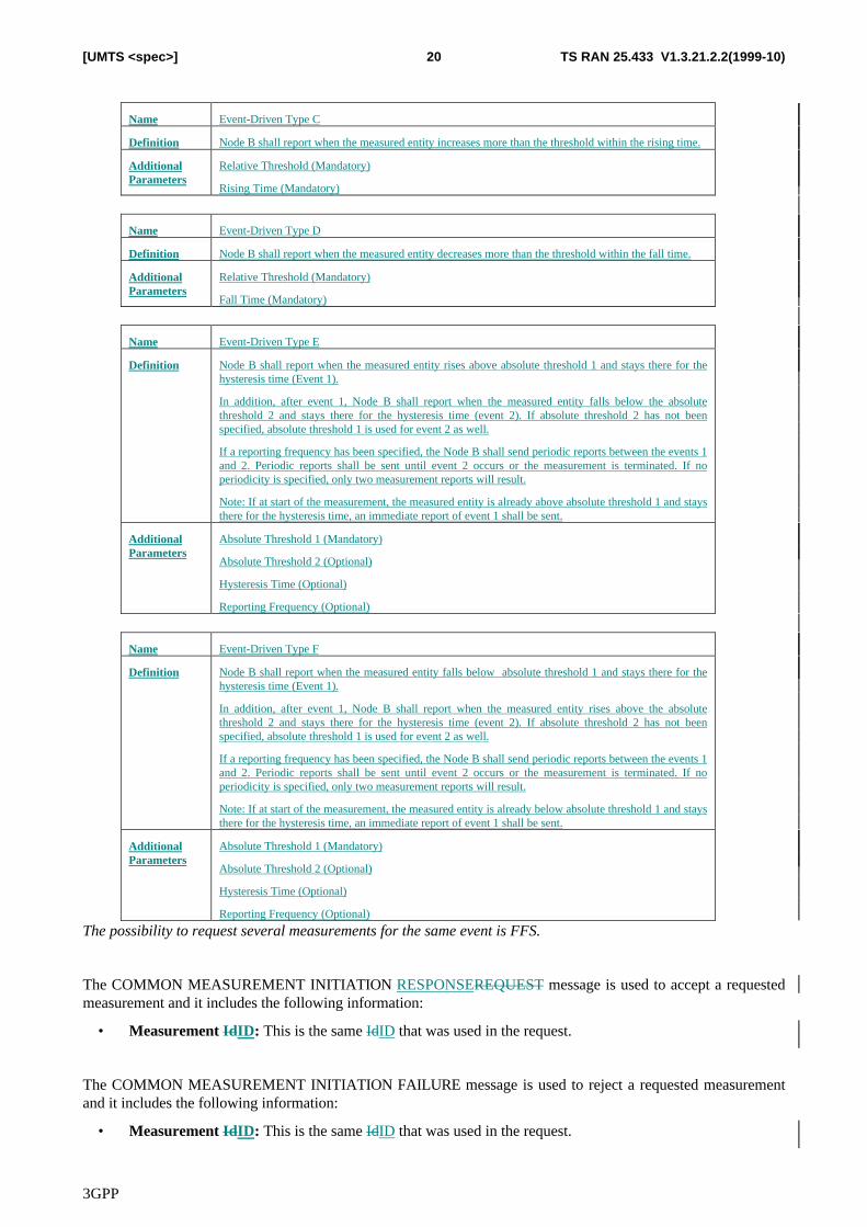
Name Event-Driven Type C
Definition Node B shall report when the measured entity increases more than the threshold within the rising time.
AdditionalParameters
Relative Threshold (Mandatory)
Rising Time (Mandatory)
Name Event-Driven Type D
Definition Node B shall report when the measured entity decreases more than the threshold within the fall time.
AdditionalParameters
Relative Threshold (Mandatory)
Fall Time (Mandatory)
Name Event-Driven Type E
Definition Node B shall report when the measured entity rises above absolute threshold 1 and stays there for thehysteresis time (Event 1).
In addition, after event 1, Node B shall report when the measured entity falls below the absolutethreshold 2 and stays there for the hysteresis time (event 2). If absolute threshold 2 has not beenspecified, absolute threshold 1 is used for event 2 as well.
If a reporting frequency has been specified, the Node B shall send periodic reports between the events 1and 2. Periodic reports shall be sent until event 2 occurs or the measurement is terminated. If noperiodicity is specified, only two measurement reports will result.
Note: If at start of the measurement, the measured entity is already above absolute threshold 1 and staysthere for the hysteresis time, an immediate report of event 1 shall be sent.
AdditionalParameters
Absolute Threshold 1 (Mandatory)
Absolute Threshold 2 (Optional)
Hysteresis Time (Optional)
Reporting Frequency (Optional)
Name Event-Driven Type F
Definition Node B shall report when the measured entity falls below absolute threshold 1 and stays there for thehysteresis time (Event 1).
In addition, after event 1, Node B shall report when the measured entity rises above the absolutethreshold 2 and stays there for the hysteresis time (event 2). If absolute threshold 2 has not beenspecified, absolute threshold 1 is used for event 2 as well.
If a reporting frequency has been specified, the Node B shall send periodic reports between the events 1and 2. Periodic reports shall be sent until event 2 occurs or the measurement is terminated. If noperiodicity is specified, only two measurement reports will result.
Note: If at start of the measurement, the measured entity is already below absolute threshold 1 and staysthere for the hysteresis time, an immediate report of event 1 shall be sent.
AdditionalParameters
Absolute Threshold 1 (Mandatory)
Absolute Threshold 2 (Optional)
Hysteresis Time (Optional)
Reporting Frequency (Optional)
The possibility to request several measurements for the same event is FFS.
The COMMON MEASUREMENT INITIATION RESPONSEREQUEST message is used to accept a requestedmeasurement and it includes the following information:
• Measurement IdID: This is the same IdID that was used in the request.
The COMMON MEASUREMENT INITIATION FAILURE message is used to reject a requested measurementand it includes the following information:
• Measurement IdID: This is the same IdID that was used in the request.
3GPP
TS RAN 25.433 V1.3.21.2.2(1999-10)21[UMTS <spec>]
• Cause: This states the cause for the reject. The exact content of this parameter is FFS.
• Processor overload
• Hardware failure
• Measurement not supported
• Unspecified failure
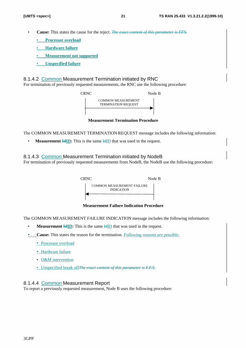
8.1.4.2 Common Measurement Termination initiated by RNCFor termination of previously requested measurements, the RNC use the following procedure:
CRNC Node B
COMMON MEASUREMENTTERMINATION REQUEST
Measurement Termination Procedure
The COMMON MEASUREMENT TERMINATION REQUEST message includes the following information:
• Measurement IdID: This is the same IdID that was used in the request.
8.1.4.3 Common Measurement Termination initiated by NodeBFor termination of previously requested measurements from NodeB, the NodeB use the following procedure:
CRNC Node B
COMMON MEASUREMENT FAILUREINDICATION
Measurement Failure Indication Procedure
The COMMON MEASUREMENT FAILURE INDICATION message includes the following information:
• Measurement IdID: This is the same IdID that was used in the request.
• Cause: This states the reason for the termination. Following reasons are possible:
• Processor overload
• Hardware failure
• O&M intervention
• Unspecified break offThe exact content of this parameter is F.F.S.
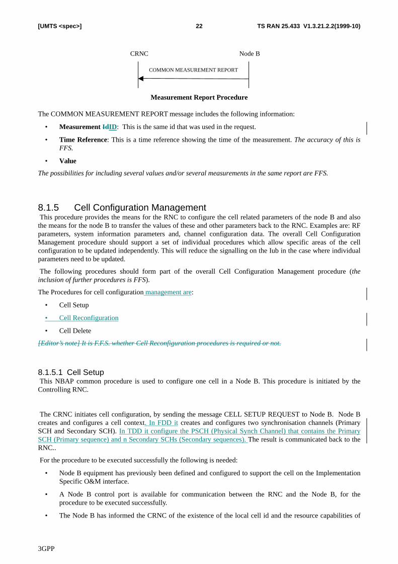
8.1.4.4 Common Measurement ReportTo report a previously requested measurement, Node B uses the following procedure:
3GPP
TS RAN 25.433 V1.3.21.2.2(1999-10)22[UMTS <spec>]
CRNC Node B
COMMON MEASUREMENT REPORT
Measurement Report Procedure
The COMMON MEASUREMENT REPORT message includes the following information:
• Measurement IdID: This is the same id that was used in the request.
• Time Reference: This is a time reference showing the time of the measurement. The accuracy of this isFFS.
• Value
The possibilities for including several values and/or several measurements in the same report are FFS.
8.1.5 Cell Configuration Management This procedure provides the means for the RNC to configure the cell related parameters of the node B and alsothe means for the node B to transfer the values of these and other parameters back to the RNC. Examples are: RFparameters, system information parameters and, channel configuration data. The overall Cell ConfigurationManagement procedure should support a set of individual procedures which allow specific areas of the cellconfiguration to be updated independently. This will reduce the signalling on the Iub in the case where individualparameters need to be updated.
The following procedures should form part of the overall Cell Configuration Management procedure (theinclusion of further procedures is FFS).
The Procedures for cell configuration management are:
• Cell Setup
• Cell Reconfiguration
• Cell Delete
[Editor’s note] It is F.F.S. whether Cell Reconfiguration procedures is required or not.
8.1.5.1 Cell Setup This NBAP common procedure is used to configure one cell in a Node B. This procedure is initiated by theControlling RNC.
The CRNC initiates cell configuration, by sending the message CELL SETUP REQUEST to Node B. Node Bcreates and configures a cell context. In FDD it creates and configures two synchronisation channels (PrimarySCH and Secondary SCH). In TDD it configure the PSCH (Physical Synch Channel) that contains the PrimarySCH (Primary sequence) and n Secondary SCHs (Secondary sequences). The result is communicated back to theRNC..
For the procedure to be executed successfully the following is needed:
• Node B equipment has previously been defined and configured to support the cell on the ImplementationSpecific O&M interface.
• A Node B control port is available for communication between the RNC and the Node B, for theprocedure to be executed successfully.
• The Node B has informed the CRNC of the existence of the local cell id and the resource capabilities of
3GPP
TS RAN 25.433 V1.3.21.2.2(1999-10)23[UMTS <spec>]
the cell via the Node B Resource Notification procedure.
CRNC Node B
CELL SETUPRESPONSE
a) Successful case
CELL SETUP REQUEST
CRNC Node B
CELL SETUP FAILURE
a) Unsuccessful case
CELL SETUP REQUEST
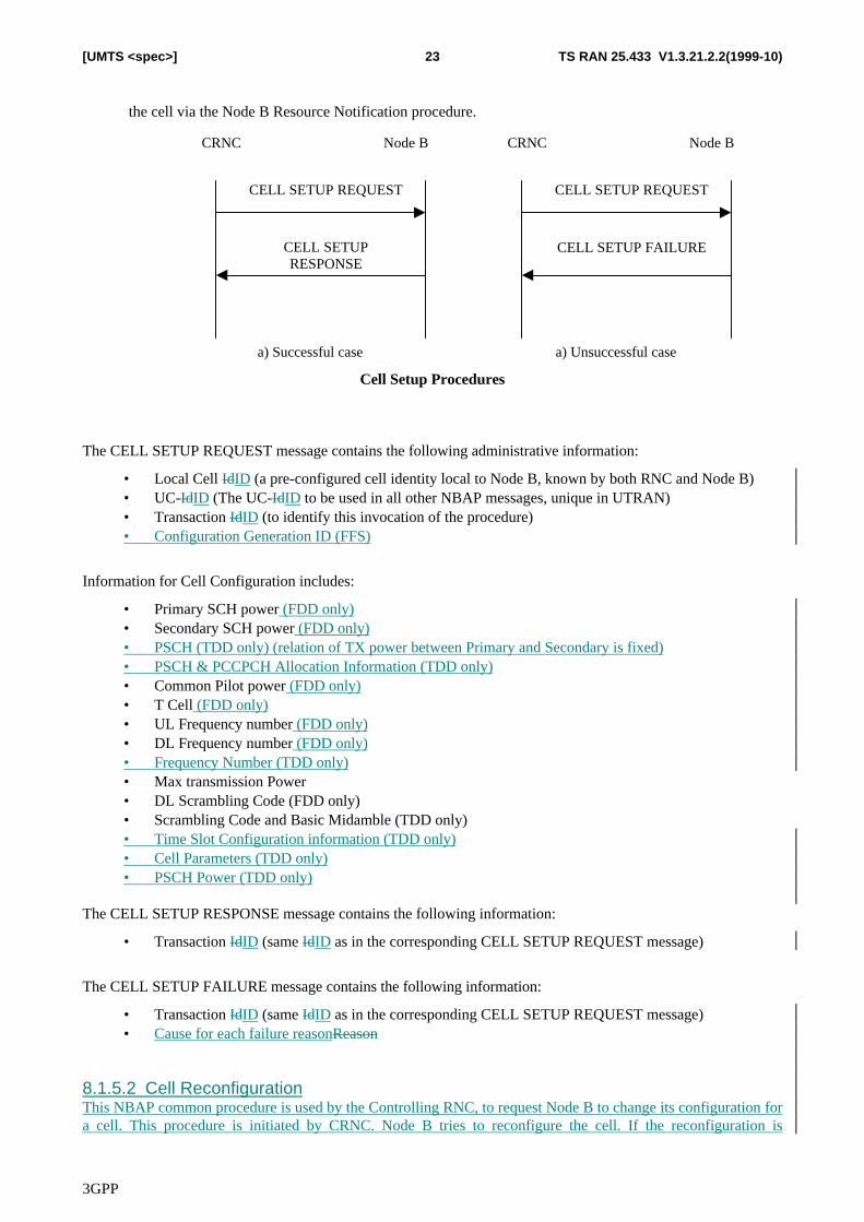
Cell Setup Procedures
The CELL SETUP REQUEST message contains the following administrative information:
• Local Cell IdID (a pre-configured cell identity local to Node B, known by both RNC and Node B)• UC-IdID (The UC-IdID to be used in all other NBAP messages, unique in UTRAN)• Transaction IdID (to identify this invocation of the procedure)• Configuration Generation ID (FFS)
Information for Cell Configuration includes:
• Primary SCH power (FDD only)• Secondary SCH power (FDD only)• PSCH (TDD only) (relation of TX power between Primary and Secondary is fixed)• PSCH & PCCPCH Allocation Information (TDD only)• Common Pilot power (FDD only)• T Cell (FDD only)• UL Frequency number (FDD only)• DL Frequency number (FDD only)• Frequency Number (TDD only)• Max transmission Power• DL Scrambling Code (FDD only)• Scrambling Code and Basic Midamble (TDD only)• Time Slot Configuration information (TDD only)• Cell Parameters (TDD only)• PSCH Power (TDD only)
The CELL SETUP RESPONSE message contains the following information:
• Transaction IdID (same IdID as in the corresponding CELL SETUP REQUEST message)
The CELL SETUP FAILURE message contains the following information:
• Transaction IdID (same IdID as in the corresponding CELL SETUP REQUEST message)• Cause for each failure reasonReason
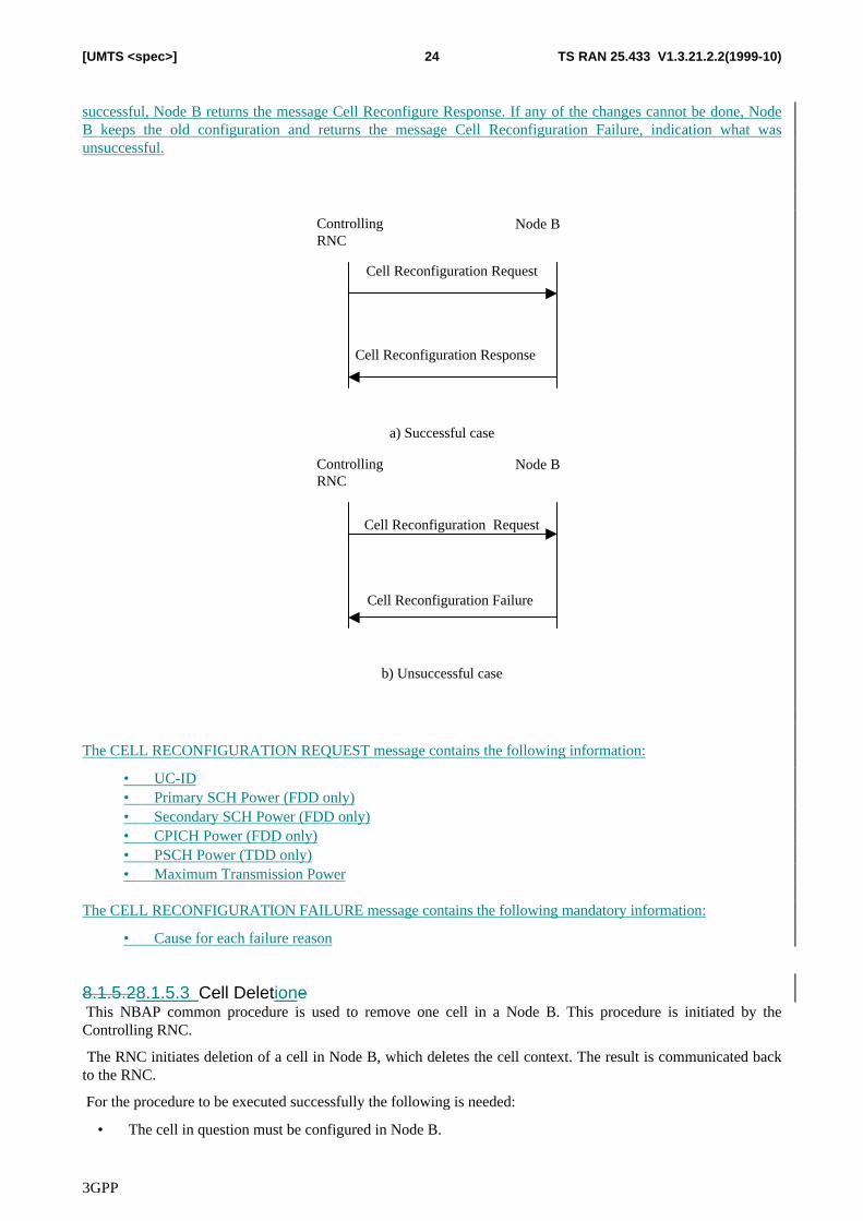
8.1.5.2 Cell ReconfigurationThis NBAP common procedure is used by the Controlling RNC, to request Node B to change its configuration fora cell. This procedure is initiated by CRNC. Node B tries to reconfigure the cell. If the reconfiguration is
3GPP
TS RAN 25.433 V1.3.21.2.2(1999-10)24[UMTS <spec>]
successful, Node B returns the message Cell Reconfigure Response. If any of the changes cannot be done, NodeB keeps the old configuration and returns the message Cell Reconfiguration Failure, indication what wasunsuccessful.
Controlling RNC
Node B
Cell Reconfiguration Request
Cell Reconfiguration Response
a) Successful case
Controlling RNC
Node B
Cell Reconfiguration Request
Cell Reconfiguration Failure
b) Unsuccessful case
The CELL RECONFIGURATION REQUEST message contains the following information:
• UC-ID• Primary SCH Power (FDD only)• Secondary SCH Power (FDD only)• CPICH Power (FDD only)• PSCH Power (TDD only)• Maximum Transmission Power
The CELL RECONFIGURATION FAILURE message contains the following mandatory information:
• Cause for each failure reason
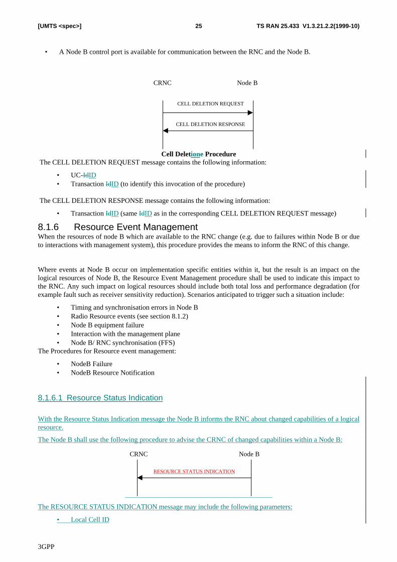
8.1.5.28.1.5.3 Cell Deletione This NBAP common procedure is used to remove one cell in a Node B. This procedure is initiated by theControlling RNC.
The RNC initiates deletion of a cell in Node B, which deletes the cell context. The result is communicated backto the RNC.
For the procedure to be executed successfully the following is needed:
• The cell in question must be configured in Node B.
3GPP
TS RAN 25.433 V1.3.21.2.2(1999-10)25[UMTS <spec>]
• A Node B control port is available for communication between the RNC and the Node B.
CRNC Node B
CELL DELETION RESPONSE
CELL DELETION REQUEST
Cell Deletione Procedure The CELL DELETION REQUEST message contains the following information:
• UC-IdID• Transaction IdID (to identify this invocation of the procedure)
The CELL DELETION RESPONSE message contains the following information:
• Transaction IdID (same IdID as in the corresponding CELL DELETION REQUEST message)
8.1.6 Resource Event ManagementWhen the resources of node B which are available to the RNC change (e.g. due to failures within Node B or dueto interactions with management system), this procedure provides the means to inform the RNC of this change.
Where events at Node B occur on implementation specific entities within it, but the result is an impact on thelogical resources of Node B, the Resource Event Management procedure shall be used to indicate this impact tothe RNC. Any such impact on logical resources should include both total loss and performance degradation (forexample fault such as receiver sensitivity reduction). Scenarios anticipated to trigger such a situation include:
• Timing and synchronisation errors in Node B• Radio Resource events (see section 8.1.2)• Node B equipment failure• Interaction with the management plane• Node B/ RNC synchronisation (FFS)
The Procedures for Resource event management:
• NodeB Failure• NodeB Resource Notification
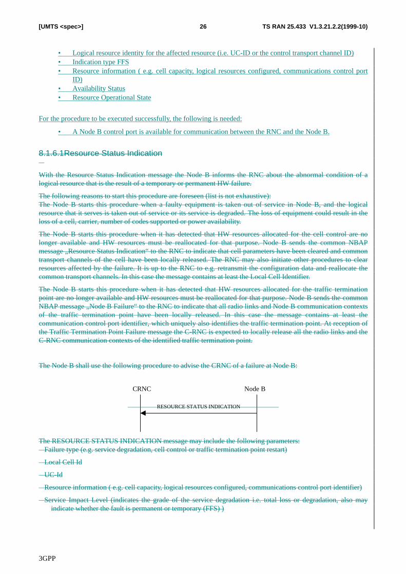
8.1.6.1 Resource Status Indication
With the Resource Status Indication message the Node B informs the RNC about changed capabilities of a logicalresource.
The Node B shall use the following procedure to advise the CRNC of changed capabilities within a Node B:
CRNC Node B
RESOURCE STATUS INDICATION
The RESOURCE STATUS INDICATION message may include the following parameters:
• Local Cell ID
3GPP
TS RAN 25.433 V1.3.21.2.2(1999-10)26[UMTS <spec>]
• Logical resource identity for the affected resource (i.e. UC-ID or the control transport channel ID)• Indication type FFS• Resource information ( e.g. cell capacity, logical resources configured, communications control port
ID)• Availability Status• Resource Operational State
For the procedure to be executed successfully, the following is needed:
• A Node B control port is available for communication between the RNC and the Node B.
8.1.6.1Resource Status Indication�
With the Resource Status Indication message the Node B informs the RNC about the abnormal condition of alogical resource that is the result of a temporary or permanent HW failure.
The following reasons to start this procedure are foreseen (list is not exhaustive):The Node B starts this procedure when a faulty equipment is taken out of service in Node B, and the logicalresource that it serves is taken out of service or its service is degraded. The loss of equipment could result in theloss of a cell, carrier, number of codes supported or power availability.
The Node B starts this procedure when it has detected that HW resources allocated for the cell control are nolonger available and HW resources must be reallocated for that purpose. Node B sends the common NBAPmessage „Resource Status Indication“ to the RNC to indicate that cell parameters have been cleared and commontransport channels of the cell have been locally released. The RNC may also initiate other procedures to clearresources affected by the failure. It is up to the RNC to e.g. retransmit the configuration data and reallocate thecommon transport channels. In this case the message contains at least the Local Cell Identifier.
The Node B starts this procedure when it has detected that HW resources allocated for the traffic terminationpoint are no longer available and HW resources must be reallocated for that purpose. Node B sends the commonNBAP message „Node B Failure“ to the RNC to indicate that all radio links and Node B communication contextsof the traffic termination point have been locally released. In this case the message contains at least thecommunication control port identifier, which uniquely also identifies the traffic termination point. At reception ofthe Traffic Termination Point Failure message the C-RNC is expected to locally release all the radio links and theC-RNC communication contexts of the identified traffic termination point.
The Node B shall use the following procedure to advise the CRNC of a failure at Node B:
CRNC Node B
RESOURCE STATUS INDICATION
The RESOURCE STATUS INDICATION message may include the following parameters:� Failure type (e.g. service degradation, cell control or traffic termination point restart)
� Local Cell Id
� UC-Id
� Resource information ( e.g. cell capacity, logical resources configured, communications control port identifier)
� Service Impact Level (indicates the grade of the service degradation i.e. total loss or degradation, also mayindicate whether the fault is permanent or temporary (FFS) )
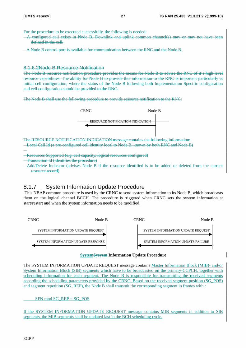
3GPP
TS RAN 25.433 V1.3.21.2.2(1999-10)27[UMTS <spec>]
For the procedure to be executed successfully, the following is needed:� A configured cell exists in Node B. Downlink and uplink common channel(s) may or may not have been
defined in the cell.
� A Node B control port is available for communication between the RNC and the Node B.
8.1.6.2Node B Resource NotificationThe Node B resource notification procedure provides the means for Node B to advise the RNC of it’s high levelresource capabilities. The ability for Node B to provide this information to the RNC is important particularly atinitial cell configuration, where the status of the Node B following both Implementation Specific configurationand cell configuration should be provided to the RNC.
The Node B shall use the following procedure to provide resource notification to the RNC:
CRNC Node B
RESOURCE NOTIFICATION INDICATION
The RESOURCE NOTIFICATION INDICATION message contains the following information:� Local Cell Id (a pre-configured cell identity local to Node B, known by both RNC and Node B)�� Resources Supported (e.g. cell capacity, logical resources configured)� Transaction Id (identifies the procedure)� Add/Delete Indicator (advises Node B if the resource identified is to be added or deleted from the current
resource record)
8.1.7 System Information Update Procedure This NBAP common procedure is used by the CRNC to send system information to its Node B, which broadcaststhem on the logical channel BCCH. The procedure is triggered when CRNC sets the system information atstart/restart and when the system information needs to be modified.
SYSTEM INFORMATION UPDATE RESPONSE
CRNC Node B
SYSTEM INFORMATION UPDATE REQUEST
SYSTEM INFORMATION UPDATE FAILURE
CRNC Node B
SYSTEM INFORMATION UPDATE REQUEST
SystemSysyem Information Update Procedure
The SYSTEM INFORMATION UPDATE REQUEST message contains Master Information Block (MIB)- and/orSystem Information Block (SIB) segments which have to be broadcasted on the primary-CCPCH, together withscheduling information for each segment. The Node B is responsible for transmitting the received segmentsaccording the scheduling parameters provided by the CRNC. Based on the received segment position (SG_POS)and segment repetition (SG_REP), the Node B shall transmit the corresponding segment in frames with :
SFN mod SG_REP = SG_POS
If the SYSTEM INFORMATION UPDATE REQUEST message contains MIB segments in addition to SIBsegments, the MIB segments shall be updated last in the BCH scheduling cycle.
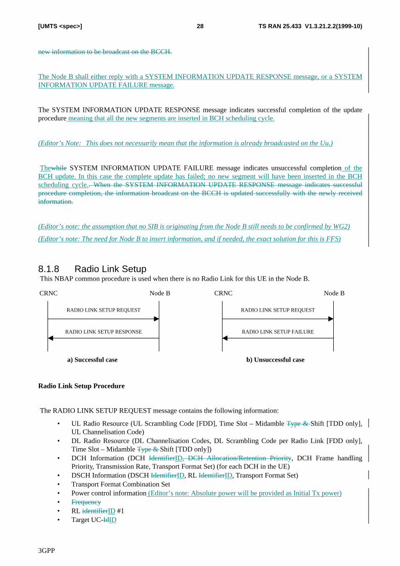
3GPP
TS RAN 25.433 V1.3.21.2.2(1999-10)28[UMTS <spec>]
new information to be broadcast on the BCCH.
The Node B shall either reply with a SYSTEM INFORMATION UPDATE RESPONSE message, or a SYSTEMINFORMATION UPDATE FAILURE message.
The SYSTEM INFORMATION UPDATE RESPONSE message indicates successful completion of the updateprocedure meaning that all the new segments are inserted in BCH scheduling cycle.
(Editor’s Note: This does not necessarily mean that the information is already broadcasted on the Uu.)
Thewhile SYSTEM INFORMATION UPDATE FAILURE message indicates unsuccessful completion of theBCH update. In this case the complete update has failed; no new segment will have been inserted in the BCHscheduling cycle.. When the SYSTEM INFORMATION UPDATE RESPONSE message indicates successfulprocedure completion, the information broadcast on the BCCH is updated successfully with the newly receivedinformation.
(Editor’s note: the assumption that no SIB is originating from the Node B still needs to be confirmed by WG2)
(Editor’s note: The need for Node B to insert information, and if needed, the exact solution for this is FFS)
8.1.8 Radio Link Setup This NBAP common procedure is used when there is no Radio Link for this UE in the Node B.
CRNC Node B
RADIO LINK SETUP REQUEST
RADIO LINK SETUP RESPONSE
CRNC Node B
RADIO LINK SETUP REQUEST
RADIO LINK SETUP FAILURE
a) Successful case b) Unsuccessful case
Radio Link Setup Procedure
The RADIO LINK SETUP REQUEST message contains the following information:
• UL Radio Resource (UL Scrambling Code [FDD], Time Slot – Midamble Type & Shift [TDD only],UL Channelisation Code)
• DL Radio Resource (DL Channelisation Codes, DL Scrambling Code per Radio Link [FDD only],Time Slot – Midamble Type & Shift [TDD only])
• DCH Information (DCH IdentifierID, DCH Allocation/Retention Priority, DCH Frame handlingPriority, Transmission Rate, Transport Format Set) (for each DCH in the UE)
• DSCH Information (DSCH IdentifierID, RL IdentifierID, Transport Format Set)• Transport Format Combination Set• Power control information (Editor’s note: Absolute power will be provided as Initial Tx power)• Frequency• RL identifierID #1• Target UC-IdID
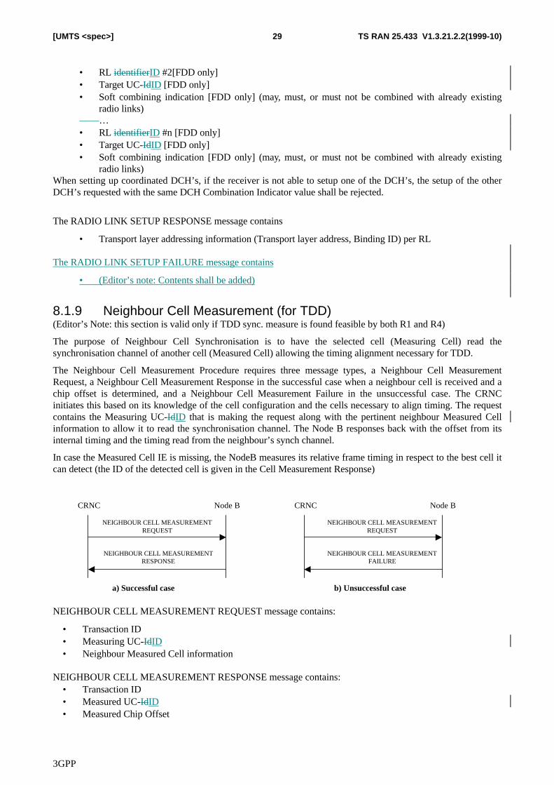
3GPP
TS RAN 25.433 V1.3.21.2.2(1999-10)29[UMTS <spec>]
• RL identifierID #2[FDD only]• Target UC-IdID [FDD only]• Soft combining indication [FDD only] (may, must, or must not be combined with already existing
radio links) …• RL identifierID #n [FDD only]• Target UC-IdID [FDD only]• Soft combining indication [FDD only] (may, must, or must not be combined with already existing
radio links)When setting up coordinated DCH’s, if the receiver is not able to setup one of the DCH’s, the setup of the otherDCH’s requested with the same DCH Combination Indicator value shall be rejected.
The RADIO LINK SETUP RESPONSE message contains
• Transport layer addressing information (Transport layer address, Binding ID) per RL
The RADIO LINK SETUP FAILURE message contains
• (Editor’s note: Contents shall be added)
8.1.9 Neighbour Cell Measurement (for TDD)(Editor’s Note: this section is valid only if TDD sync. measure is found feasible by both R1 and R4)
The purpose of Neighbour Cell Synchronisation is to have the selected cell (Measuring Cell) read thesynchronisation channel of another cell (Measured Cell) allowing the timing alignment necessary for TDD.
The Neighbour Cell Measurement Procedure requires three message types, a Neighbour Cell MeasurementRequest, a Neighbour Cell Measurement Response in the successful case when a neighbour cell is received and achip offset is determined, and a Neighbour Cell Measurement Failure in the unsuccessful case. The CRNCinitiates this based on its knowledge of the cell configuration and the cells necessary to align timing. The requestcontains the Measuring UC-IdID that is making the request along with the pertinent neighbour Measured Cellinformation to allow it to read the synchronisation channel. The Node B responses back with the offset from itsinternal timing and the timing read from the neighbour’s synch channel.
In case the Measured Cell IE is missing, the NodeB measures its relative frame timing in respect to the best cell itcan detect (the ID of the detected cell is given in the Cell Measurement Response)
CRNC Node B
NEIGHBOUR CELL MEASUREMENTREQUEST
NEIGHBOUR CELL MEASUREMENTRESPONSE
CRNC Node B
NEIGHBOUR CELL MEASUREMENTREQUEST
NEIGHBOUR CELL MEASUREMENTFAILURE
a) Successful case b) Unsuccessful case
NEIGHBOUR CELL MEASUREMENT REQUEST message contains:
• Transaction ID• Measuring UC-IdID• Neighbour Measured Cell information
NEIGHBOUR CELL MEASUREMENT RESPONSE message contains:• Transaction ID• Measured UC-IdID• Measured Chip Offset
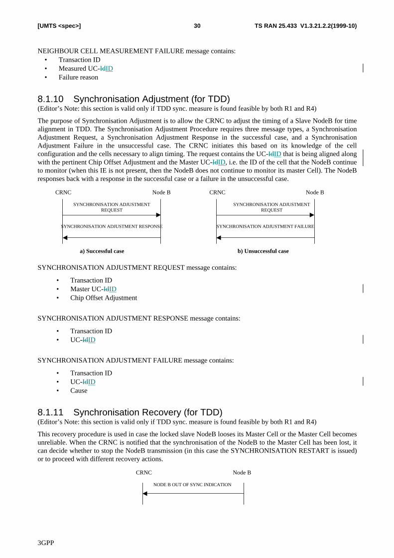
3GPP
TS RAN 25.433 V1.3.21.2.2(1999-10)30[UMTS <spec>]
NEIGHBOUR CELL MEASUREMENT FAILURE message contains:• Transaction ID• Measured UC-IdID• Failure reason
8.1.10 Synchronisation Adjustment (for TDD)(Editor’s Note: this section is valid only if TDD sync. measure is found feasible by both R1 and R4)
The purpose of Synchronisation Adjustment is to allow the CRNC to adjust the timing of a Slave NodeB for timealignment in TDD. The Synchronisation Adjustment Procedure requires three message types, a SynchronisationAdjustment Request, a Synchronisation Adjustment Response in the successful case, and a SynchronisationAdjustment Failure in the unsuccessful case. The CRNC initiates this based on its knowledge of the cellconfiguration and the cells necessary to align timing. The request contains the UC-IdID that is being aligned alongwith the pertinent Chip Offset Adjustment and the Master UC-IdID, i.e. the ID of the cell that the NodeB continueto monitor (when this IE is not present, then the NodeB does not continue to monitor its master Cell). The NodeBresponses back with a response in the successful case or a failure in the unsuccessful case.
CRNC Node B
SYNCHRONISATION ADJUSTMENTREQUEST
SYNCHRONISATION ADJUSTMENT RESPONSE
CRNC Node B
SYNCHRONISATION ADJUSTMENTREQUEST
SYNCHRONISATION ADJUSTMENT FAILURE
a) Successful case b) Unsuccessful case
SYNCHRONISATION ADJUSTMENT REQUEST message contains:
• Transaction ID• Master UC-IdID• Chip Offset Adjustment
SYNCHRONISATION ADJUSTMENT RESPONSE message contains:
• Transaction ID• UC-IdID
SYNCHRONISATION ADJUSTMENT FAILURE message contains:
• Transaction ID• UC-IdID• Cause
8.1.11 Synchronisation Recovery (for TDD)(Editor’s Note: this section is valid only if TDD sync. measure is found feasible by both R1 and R4)
This recovery procedure is used in case the locked slave NodeB looses its Master Cell or the Master Cell becomesunreliable. When the CRNC is notified that the synchronisation of the NodeB to the Master Cell has been lost, itcan decide whether to stop the NodeB transmission (in this case the SYNCHRONISATION RESTART is issued)or to proceed with different recovery actions.
CRNC Node B
NODE B OUT OF SYNC INDICATION
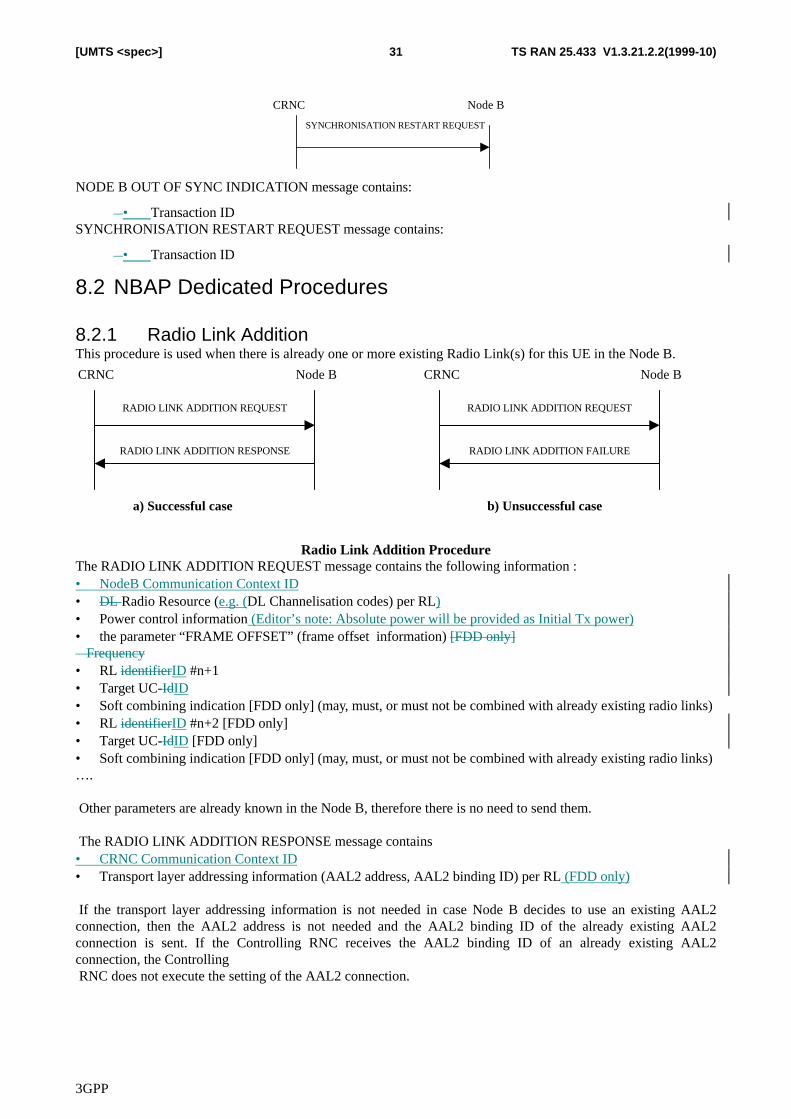
3GPP
TS RAN 25.433 V1.3.21.2.2(1999-10)31[UMTS <spec>]
CRNC Node B
SYNCHRONISATION RESTART REQUEST
NODE B OUT OF SYNC INDICATION message contains:
� • Transaction IDSYNCHRONISATION RESTART REQUEST message contains:
� • Transaction ID
8.2 NBAP Dedicated Procedures
8.2.1 Radio Link AdditionThis procedure is used when there is already one or more existing Radio Link(s) for this UE in the Node B.
CRNC Node B
RADIO LINK ADDITION REQUEST
RADIO LINK ADDITION RESPONSE
CRNC Node B
RADIO LINK ADDITION REQUEST
RADIO LINK ADDITION FAILURE
a) Successful case b) Unsuccessful case
Radio Link Addition ProcedureThe RADIO LINK ADDITION REQUEST message contains the following information :• NodeB Communication Context ID• DL Radio Resource (e.g. (DL Channelisation codes) per RL)• Power control information (Editor’s note: Absolute power will be provided as Initial Tx power)• the parameter “FRAME OFFSET” (frame offset information) [FDD only]� Frequency• RL identifierID #n+1• Target UC-IdID• Soft combining indication [FDD only] (may, must, or must not be combined with already existing radio links)• RL identifierID #n+2 [FDD only]• Target UC-IdID [FDD only]• Soft combining indication [FDD only] (may, must, or must not be combined with already existing radio links)….
Other parameters are already known in the Node B, therefore there is no need to send them.
The RADIO LINK ADDITION RESPONSE message contains• CRNC Communication Context ID• Transport layer addressing information (AAL2 address, AAL2 binding ID) per RL (FDD only)
If the transport layer addressing information is not needed in case Node B decides to use an existing AAL2connection, then the AAL2 address is not needed and the AAL2 binding ID of the already existing AAL2connection is sent. If the Controlling RNC receives the AAL2 binding ID of an already existing AAL2connection, the Controlling RNC does not execute the setting of the AAL2 connection.
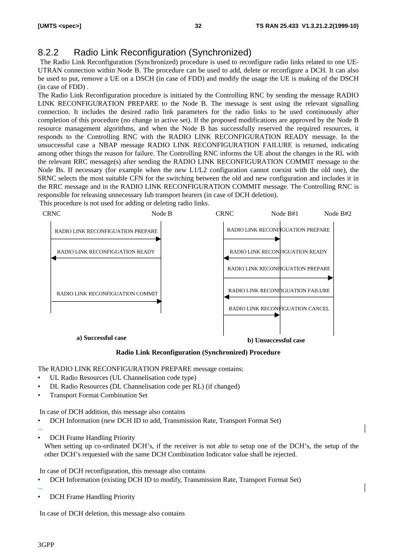
3GPP
TS RAN 25.433 V1.3.21.2.2(1999-10)32[UMTS <spec>]
8.2.2 Radio Link Reconfiguration (Synchronized) The Radio Link Reconfiguration (Synchronized) procedure is used to reconfigure radio links related to one UE-UTRAN connection within Node B. The procedure can be used to add, delete or reconfigure a DCH. It can alsobe used to put, remove a UE on a DSCH (in case of FDD) and modify the usage the UE is making of the DSCH(in case of FDD) .The Radio Link Reconfiguration procedure is initiated by the Controlling RNC by sending the message RADIOLINK RECONFIGURATION PREPARE to the Node B. The message is sent using the relevant signallingconnection. It includes the desired radio link parameters for the radio links to be used continuously aftercompletion of this procedure (no change in active set). If the proposed modifications are approved by the Node Bresource management algorithms, and when the Node B has successfully reserved the required resources, itresponds to the Controlling RNC with the RADIO LINK RECONFIGURATION READY message. In theunsuccessful case a NBAP message RADIO LINK RECONFIGURATION FAILURE is returned, indicatingamong other things the reason for failure. The Controlling RNC informs the UE about the changes in the RL withthe relevant RRC message(s) after sending the RADIO LINK RECONFIGURATION COMMIT message to theNode Bs. If necessary (for example when the new L1/L2 configuration cannot coexist with the old one), theSRNC selects the most suitable CFN for the switching between the old and new configuration and includes it inthe RRC message and in the RADIO LINK RECONFIGURATION COMMIT message. The Controlling RNC isresponsible for releasing unnecessary Iub transport bearers (in case of DCH deletion). This procedure is not used for adding or deleting radio links.
CRNC Node B
RADIO LINK RECONFIGUATION PREPARE
RADIO LINK RECONFIGUATION READY
CRNC Node B#2
RADIO LINK RECONFIGUATION PREPARE
RADIO LINK RECONFIGUATION READY
a) Successful case b) Unsuccessful case
Node B#1
RADIO LINK RECONFIGUATION PREPARE
RADIO LINK RECONFIGUATION FAILURE
RADIO LINK RECONFIGUATION CANCEL
RADIO LINK RECONFIGUATION COMMIT
Radio Link Reconfiguration (Synchronized) Procedure
The RADIO LINK RECONFIGURATION PREPARE message contains:• UL Radio Resources (UL Channelisation code type)• DL Radio Resources (DL Channelisation code per RL) (if changed)• Transport Format Combination Set
In case of DCH addition, this message also contains• DCH Information (new DCH ID to add, Transmission Rate, Transport Format Set)�
• DCH Frame Handling PriorityWhen setting up co-ordinated DCH’s, if the receiver is not able to setup one of the DCH’s, the setup of theother DCH’s requested with the same DCH Combination Indicator value shall be rejected.
In case of DCH reconfiguration, this message also contains• DCH Information (existing DCH ID to modify, Transmission Rate, Transport Format Set)�
• DCH Frame Handling Priority
In case of DCH deletion, this message also contains
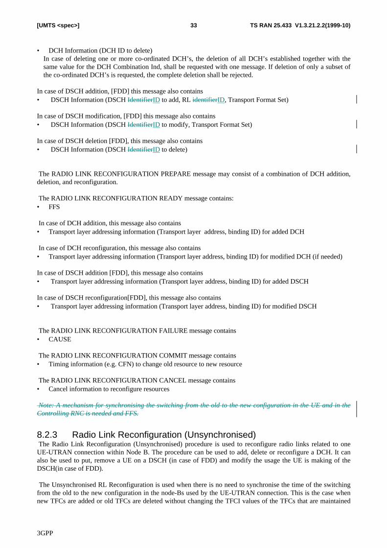
3GPP
TS RAN 25.433 V1.3.21.2.2(1999-10)33[UMTS <spec>]
• DCH Information (DCH ID to delete)In case of deleting one or more co-ordinated DCH’s, the deletion of all DCH’s established together with thesame value for the DCH Combination Ind, shall be requested with one message. If deletion of only a subset ofthe co-ordinated DCH’s is requested, the complete deletion shall be rejected.
In case of DSCH addition, [FDD] this message also contains• DSCH Information (DSCH IdentifierID to add, RL identifierID, Transport Format Set)
In case of DSCH modification, [FDD] this message also contains• DSCH Information (DSCH IdentifierID to modify, Transport Format Set)
In case of DSCH deletion [FDD], this message also contains• DSCH Information (DSCH IdentifierID to delete)
The RADIO LINK RECONFIGURATION PREPARE message may consist of a combination of DCH addition,deletion, and reconfiguration.
The RADIO LINK RECONFIGURATION READY message contains:• FFS
In case of DCH addition, this message also contains• Transport layer addressing information (Transport layer address, binding ID) for added DCH
In case of DCH reconfiguration, this message also contains• Transport layer addressing information (Transport layer address, binding ID) for modified DCH (if needed)
In case of DSCH addition [FDD], this message also contains• Transport layer addressing information (Transport layer address, binding ID) for added DSCH
In case of DSCH reconfiguration[FDD], this message also contains• Transport layer addressing information (Transport layer address, binding ID) for modified DSCH
The RADIO LINK RECONFIGURATION FAILURE message contains• CAUSE
The RADIO LINK RECONFIGURATION COMMIT message contains• Timing information (e.g. CFN) to change old resource to new resource
The RADIO LINK RECONFIGURATION CANCEL message contains• Cancel information to reconfigure resources
Note: A mechanism for synchronising the switching from the old to the new configuration in the UE and in theControlling RNC is needed and FFS.
8.2.3 Radio Link Reconfiguration (Unsynchronised) The Radio Link Reconfiguration (Unsynchronised) procedure is used to reconfigure radio links related to oneUE-UTRAN connection within Node B. The procedure can be used to add, delete or reconfigure a DCH. It canalso be used to put, remove a UE on a DSCH (in case of FDD) and modify the usage the UE is making of theDSCH(in case of FDD).
The Unsynchronised RL Reconfiguration is used when there is no need to synchronise the time of the switchingfrom the old to the new configuration in the node-Bs used by the UE-UTRAN connection. This is the case whennew TFCs are added or old TFCs are deleted without changing the TFCI values of the TFCs that are maintained
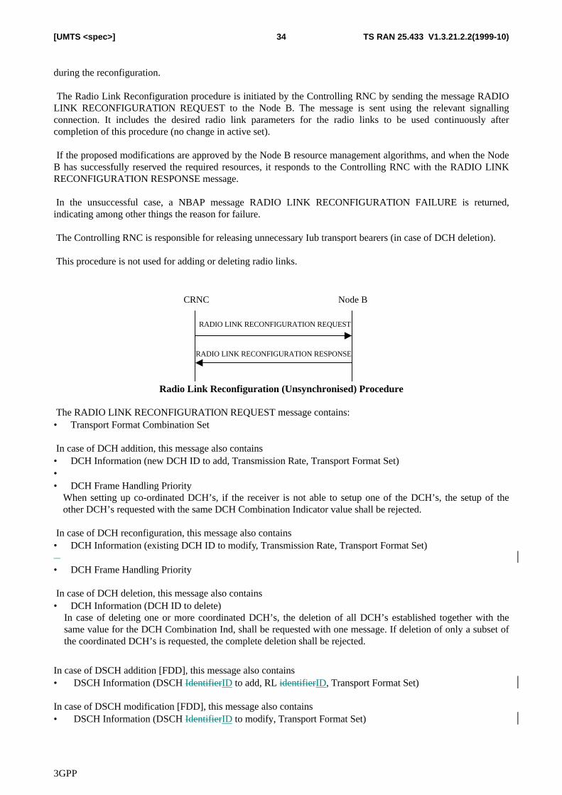
3GPP
TS RAN 25.433 V1.3.21.2.2(1999-10)34[UMTS <spec>]
during the reconfiguration.
The Radio Link Reconfiguration procedure is initiated by the Controlling RNC by sending the message RADIOLINK RECONFIGURATION REQUEST to the Node B. The message is sent using the relevant signallingconnection. It includes the desired radio link parameters for the radio links to be used continuously aftercompletion of this procedure (no change in active set).
If the proposed modifications are approved by the Node B resource management algorithms, and when the NodeB has successfully reserved the required resources, it responds to the Controlling RNC with the RADIO LINKRECONFIGURATION RESPONSE message.
In the unsuccessful case, a NBAP message RADIO LINK RECONFIGURATION FAILURE is returned,indicating among other things the reason for failure.
The Controlling RNC is responsible for releasing unnecessary Iub transport bearers (in case of DCH deletion).
This procedure is not used for adding or deleting radio links.
CRNC Node B
RADIO LINK RECONFIGURATION REQUEST
RADIO LINK RECONFIGURATION RESPONSE
Radio Link Reconfiguration (Unsynchronised) Procedure
The RADIO LINK RECONFIGURATION REQUEST message contains:• Transport Format Combination Set
In case of DCH addition, this message also contains• DCH Information (new DCH ID to add, Transmission Rate, Transport Format Set)• • DCH Frame Handling Priority
When setting up co-ordinated DCH’s, if the receiver is not able to setup one of the DCH’s, the setup of theother DCH’s requested with the same DCH Combination Indicator value shall be rejected.
In case of DCH reconfiguration, this message also contains• DCH Information (existing DCH ID to modify, Transmission Rate, Transport Format Set)�
• DCH Frame Handling Priority
In case of DCH deletion, this message also contains• DCH Information (DCH ID to delete)
In case of deleting one or more coordinated DCH’s, the deletion of all DCH’s established together with thesame value for the DCH Combination Ind, shall be requested with one message. If deletion of only a subset ofthe coordinated DCH’s is requested, the complete deletion shall be rejected.
In case of DSCH addition [FDD], this message also contains• DSCH Information (DSCH IdentifierID to add, RL identifierID, Transport Format Set)
In case of DSCH modification [FDD], this message also contains• DSCH Information (DSCH IdentifierID to modify, Transport Format Set)
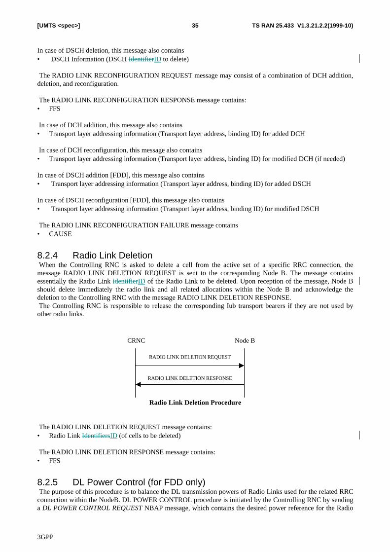
3GPP
TS RAN 25.433 V1.3.21.2.2(1999-10)35[UMTS <spec>]
In case of DSCH deletion, this message also contains• DSCH Information (DSCH IdentifierID to delete)
The RADIO LINK RECONFIGURATION REQUEST message may consist of a combination of DCH addition,deletion, and reconfiguration.
The RADIO LINK RECONFIGURATION RESPONSE message contains:• FFS
In case of DCH addition, this message also contains• Transport layer addressing information (Transport layer address, binding ID) for added DCH
In case of DCH reconfiguration, this message also contains• Transport layer addressing information (Transport layer address, binding ID) for modified DCH (if needed)
In case of DSCH addition [FDD], this message also contains• Transport layer addressing information (Transport layer address, binding ID) for added DSCH
In case of DSCH reconfiguration [FDD], this message also contains• Transport layer addressing information (Transport layer address, binding ID) for modified DSCH
The RADIO LINK RECONFIGURATION FAILURE message contains• CAUSE
8.2.4 Radio Link Deletion When the Controlling RNC is asked to delete a cell from the active set of a specific RRC connection, themessage RADIO LINK DELETION REQUEST is sent to the corresponding Node B. The message containsessentially the Radio Link identifierID of the Radio Link to be deleted. Upon reception of the message, Node Bshould delete immediately the radio link and all related allocations within the Node B and acknowledge thedeletion to the Controlling RNC with the message RADIO LINK DELETION RESPONSE. The Controlling RNC is responsible to release the corresponding Iub transport bearers if they are not used byother radio links.
CRNC Node B
RADIO LINK DELETION REQUEST
RADIO LINK DELETION RESPONSE
Radio Link Deletion Procedure
The RADIO LINK DELETION REQUEST message contains:• Radio Link IdentifiersID (of cells to be deleted)
The RADIO LINK DELETION RESPONSE message contains:• FFS
8.2.5 DL Power Control (for FDD only) The purpose of this procedure is to balance the DL transmission powers of Radio Links used for the related RRCconnection within the NodeB. DL POWER CONTROL procedure is initiated by the Controlling RNC by sendinga DL POWER CONTROL REQUEST NBAP message, which contains the desired power reference for the Radio
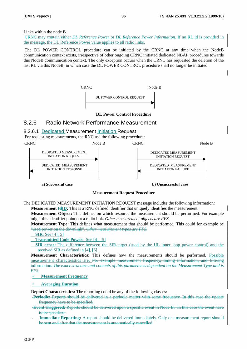
3GPP
TS RAN 25.433 V1.3.21.2.2(1999-10)36[UMTS <spec>]
Links within the node B. CRNC may contain either DL Reference Power or DL Reference Power Information. If no RL id is provided inthe message, the DL Reference Power value applies to all radio links.
The DL POWER CONTROL procedure can be initiated by the CRNC at any time when the NodeBcommunication context exists, irrespective of other ongoing CRNC initiated dedicated NBAP procedures towardsthis NodeB communication context. The only exception occurs when the CRNC has requested the deletion of thelast RL via this NodeB, in which case the DL POWER CONTROL procedure shall no longer be initiated.
CRNC Node B
DL POWER CONTROL REQUEST
DL Power Control Procedure
8.2.6 Radio Network Performance Measurement8.2.6.1 Dedicated Measurement Initiation Request For requesting measurements, the RNC use the following procedure:
CRNC Node B
DEDICATED MEASUREMENTINITIATION REQUEST
DEDICATED MEASUREMENTINITIATION RESPONSE
CRNC Node B
a) Successful case b) Unsuccessful case
DEDICATED MEASUREMENTINITIATION REQUEST
DEDICATED MEASUREMENTINITIATION FAILURE
Measurement Request Procedure
The DEDICATED MEASUREMENT INITIATION REQUEST message includes the following information:� Measurement IdID: This is a RNC defined identifier that uniquely identifies the measurement.� Measurement Object: This defines on which resource the measurement should be performed. For example
might this identifier point out a radio link. Other measurement objects are FFS.� Measurement Type: This defines what measurement that should be performed. This could for example be
“used power on the downlink”. Other measurement types are FFS.� SIR: See [4],[5]� Transmitted Code Power: See [4], [5]� SIR error: The difference between the SIR-target (used by the UL inner loop power control) and the
received SIR as defined in [4], [5].� Measurement Characteristics: This defines how the measurements should be performed. Possible
measurement characteristics are: For example measurement frequency, timing information, and filteringinformation. The exact structure and contents of this parameter is dependent on the Measurement Type and isFFS.• Measurement Frequency
• Averaging Duration
� Report Characteristics: The reporting could be any of the following classes:-Periodic: Reports should be delivered in a periodic matter with some frequency. In this case the update
frequency have to be specified.-Event Triggered: Reports should be delivered upon a specific event in Node B. In this case the event have
to be specified.- Immediate Reporting: A report should be delivered immediately. Only one measurement report should
be sent and after that the measurement is automatically cancelled
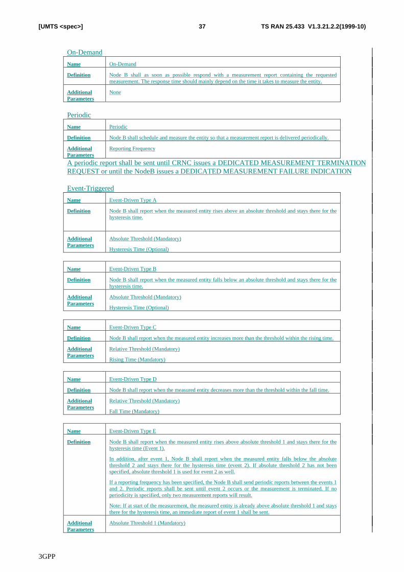
3GPP
TS RAN 25.433 V1.3.21.2.2(1999-10)37[UMTS <spec>]
On-Demand
Name On-Demand
Definition Node B shall as soon as possible respond with a measurement report containing the requestedmeasurement. The response time should mainly depend on the time it takes to measure the entity.
AdditionalParameters
None
Periodic
Name Periodic
Definition Node B shall schedule and measure the entity so that a measurement report is delivered periodically.
AdditionalParameters
Reporting Frequency
A periodic report shall be sent until CRNC issues a DEDICATED MEASUREMENT TERMINATIONREQUEST or until the NodeB issues a DEDICATED MEASUREMENT FAILURE INDICATION
Event-Triggered
Name Event-Driven Type A
Definition Node B shall report when the measured entity rises above an absolute threshold and stays there for thehysteresis time.
AdditionalParameters
Absolute Threshold (Mandatory)
Hysteresis Time (Optional)
Name Event-Driven Type B
Definition Node B shall report when the measured entity falls below an absolute threshold and stays there for thehysteresis time.
AdditionalParameters
Absolute Threshold (Mandatory)
Hysteresis Time (Optional)
Name Event-Driven Type C
Definition Node B shall report when the measured entity increases more than the threshold within the rising time.
AdditionalParameters
Relative Threshold (Mandatory)
Rising Time (Mandatory)
Name Event-Driven Type D
Definition Node B shall report when the measured entity decreases more than the threshold within the fall time.
AdditionalParameters
Relative Threshold (Mandatory)
Fall Time (Mandatory)
Name Event-Driven Type E
Definition Node B shall report when the measured entity rises above absolute threshold 1 and stays there for thehysteresis time (Event 1).
In addition, after event 1, Node B shall report when the measured entity falls below the absolutethreshold 2 and stays there for the hysteresis time (event 2). If absolute threshold 2 has not beenspecified, absolute threshold 1 is used for event 2 as well.
If a reporting frequency has been specified, the Node B shall send periodic reports between the events 1and 2. Periodic reports shall be sent until event 2 occurs or the measurement is terminated. If noperiodicity is specified, only two measurement reports will result.
Note: If at start of the measurement, the measured entity is already above absolute threshold 1 and staysthere for the hysteresis time, an immediate report of event 1 shall be sent.
AdditionalParameters
Absolute Threshold 1 (Mandatory)
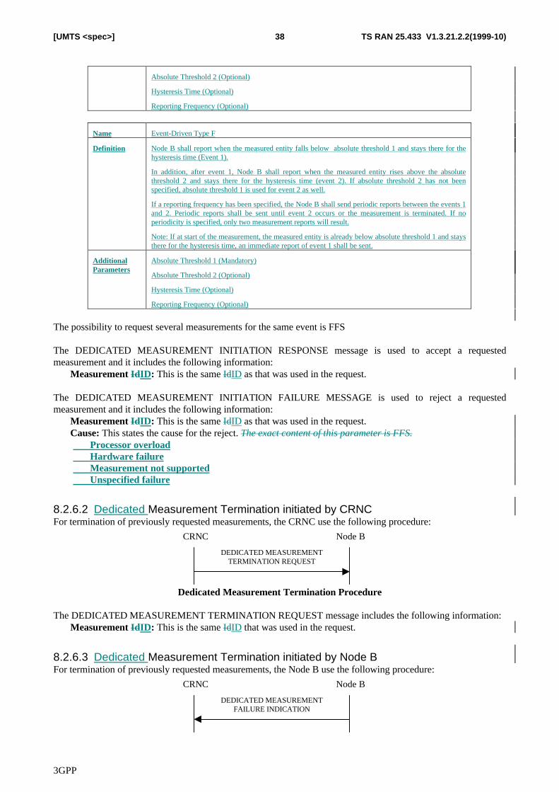
3GPP
TS RAN 25.433 V1.3.21.2.2(1999-10)38[UMTS <spec>]
Absolute Threshold 2 (Optional)
Hysteresis Time (Optional)
Reporting Frequency (Optional)
Name Event-Driven Type F
Definition Node B shall report when the measured entity falls below absolute threshold 1 and stays there for thehysteresis time (Event 1).
In addition, after event 1, Node B shall report when the measured entity rises above the absolutethreshold 2 and stays there for the hysteresis time (event 2). If absolute threshold 2 has not beenspecified, absolute threshold 1 is used for event 2 as well.
If a reporting frequency has been specified, the Node B shall send periodic reports between the events 1and 2. Periodic reports shall be sent until event 2 occurs or the measurement is terminated. If noperiodicity is specified, only two measurement reports will result.
Note: If at start of the measurement, the measured entity is already below absolute threshold 1 and staysthere for the hysteresis time, an immediate report of event 1 shall be sent.
AdditionalParameters
Absolute Threshold 1 (Mandatory)
Absolute Threshold 2 (Optional)
Hysteresis Time (Optional)
Reporting Frequency (Optional)
The possibility to request several measurements for the same event is FFS
The DEDICATED MEASUREMENT INITIATION RESPONSE message is used to accept a requestedmeasurement and it includes the following information:� Measurement IdID: This is the same IdID as that was used in the request.
The DEDICATED MEASUREMENT INITIATION FAILURE MESSAGE is used to reject a requestedmeasurement and it includes the following information:� Measurement IdID: This is the same IdID as that was used in the request.� Cause: This states the cause for the reject. The exact content of this parameter is FFS.
� Processor overload� Hardware failure� Measurement not supported� Unspecified failure
8.2.6.2 Dedicated Measurement Termination initiated by CRNCFor termination of previously requested measurements, the CRNC use the following procedure:
CRNC Node B
DEDICATED MEASUREMENTTERMINATION REQUEST
Dedicated Measurement Termination Procedure
The DEDICATED MEASUREMENT TERMINATION REQUEST message includes the following information:� Measurement IdID: This is the same IdID that was used in the request.
8.2.6.3 Dedicated Measurement Termination initiated by Node BFor termination of previously requested measurements, the Node B use the following procedure:
CRNC Node B
DEDICATED MEASUREMENT FAILURE INDICATION
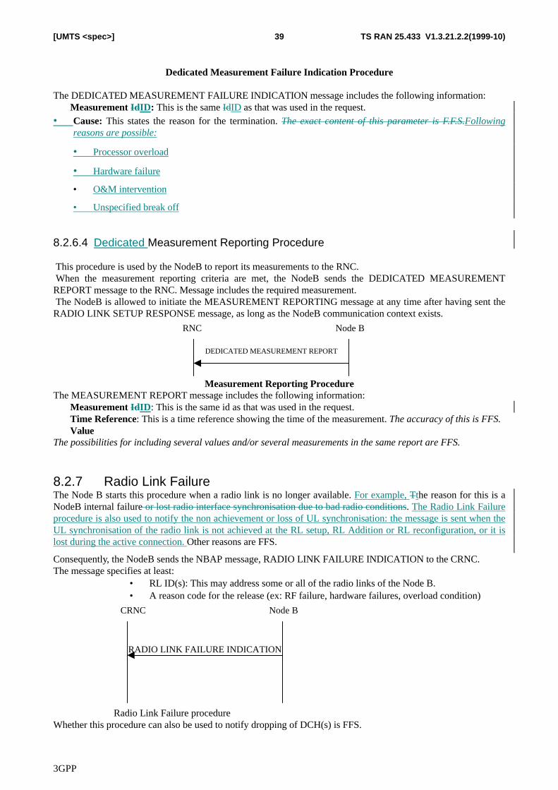
3GPP
TS RAN 25.433 V1.3.21.2.2(1999-10)39[UMTS <spec>]
Dedicated Measurement Failure Indication Procedure
The DEDICATED MEASUREMENT FAILURE INDICATION message includes the following information:� Measurement IdID: This is the same IdID as that was used in the request.• Cause: This states the reason for the termination. The exact content of this parameter is F.F.S.Following
reasons are possible:
• Processor overload
• Hardware failure
• O&M intervention
• Unspecified break off
8.2.6.4 Dedicated Measurement Reporting Procedure
This procedure is used by the NodeB to report its measurements to the RNC. When the measurement reporting criteria are met, the NodeB sends the DEDICATED MEASUREMENTREPORT message to the RNC. Message includes the required measurement. The NodeB is allowed to initiate the MEASUREMENT REPORTING message at any time after having sent theRADIO LINK SETUP RESPONSE message, as long as the NodeB communication context exists.
RNC Node B
DEDICATED MEASUREMENT REPORT
Measurement Reporting ProcedureThe MEASUREMENT REPORT message includes the following information:� Measurement IdID: This is the same id as that was used in the request.� Time Reference: This is a time reference showing the time of the measurement. The accuracy of this is FFS.� ValueThe possibilities for including several values and/or several measurements in the same report are FFS.
8.2.7 Radio Link FailureThe Node B starts this procedure when a radio link is no longer available. For example, Tthe reason for this is aNodeB internal failure or lost radio interface synchronisation due to bad radio conditions. The Radio Link Failureprocedure is also used to notify the non achievement or loss of UL synchronisation: the message is sent when theUL synchronisation of the radio link is not achieved at the RL setup, RL Addition or RL reconfiguration, or it islost during the active connection. Other reasons are FFS.
Consequently, the NodeB sends the NBAP message, RADIO LINK FAILURE INDICATION to the CRNC.The message specifies at least:
• RL ID(s): This may address some or all of the radio links of the Node B.• A reason code for the release (ex: RF failure, hardware failures, overload condition)
CRNC Node B
RADIO LINK FAILURE INDICATION
Radio Link Failure procedureWhether this procedure can also be used to notify dropping of DCH(s) is FFS.
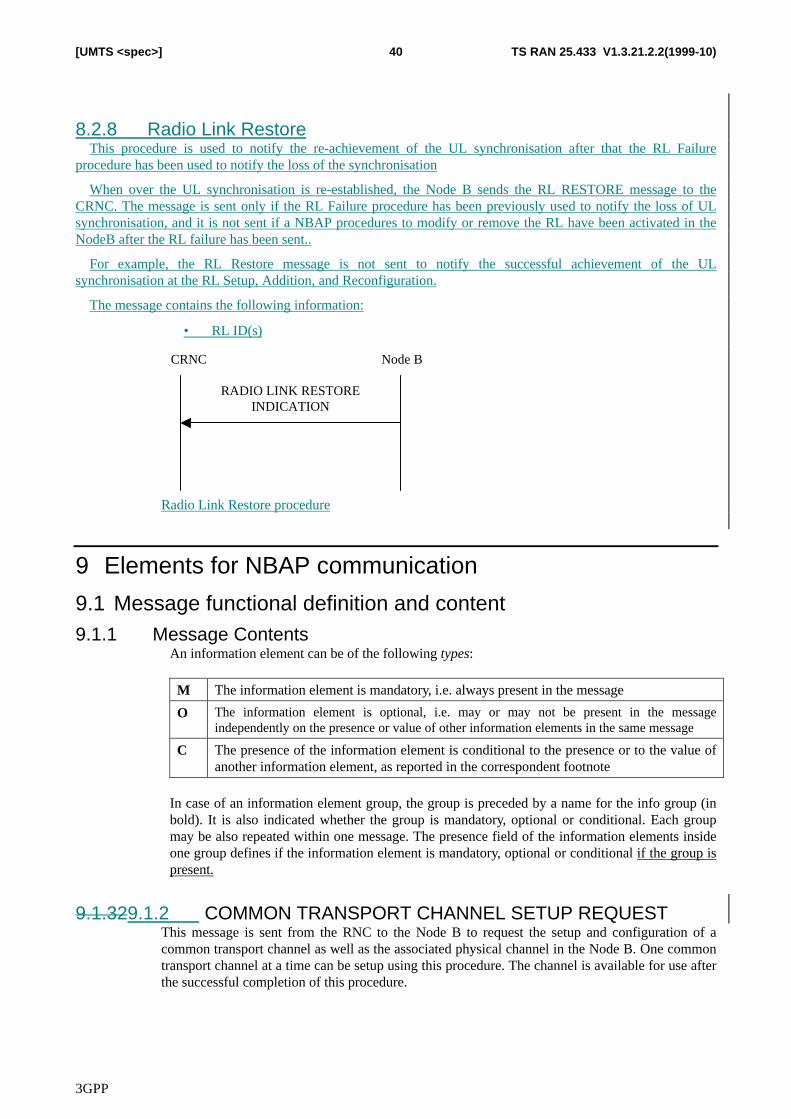
3GPP
TS RAN 25.433 V1.3.21.2.2(1999-10)40[UMTS <spec>]
8.2.8 Radio Link RestoreThis procedure is used to notify the re-achievement of the UL synchronisation after that the RL Failure
procedure has been used to notify the loss of the synchronisation
When over the UL synchronisation is re-established, the Node B sends the RL RESTORE message to theCRNC. The message is sent only if the RL Failure procedure has been previously used to notify the loss of ULsynchronisation, and it is not sent if a NBAP procedures to modify or remove the RL have been activated in theNodeB after the RL failure has been sent..
For example, the RL Restore message is not sent to notify the successful achievement of the ULsynchronisation at the RL Setup, Addition, and Reconfiguration.
The message contains the following information:
• RL ID(s)
CRNC Node B
RADIO LINK RESTORE INDICATION
Radio Link Restore procedure
9 Elements for NBAP communication
9.1 Message functional definition and content9.1.1 Message Contents
An information element can be of the following types:
M The information element is mandatory, i.e. always present in the message
O The information element is optional, i.e. may or may not be present in the messageindependently on the presence or value of other information elements in the same message
C The presence of the information element is conditional to the presence or to the value ofanother information element, as reported in the correspondent footnote
In case of an information element group, the group is preceded by a name for the info group (inbold). It is also indicated whether the group is mandatory, optional or conditional. Each groupmay be also repeated within one message. The presence field of the information elements insideone group defines if the information element is mandatory, optional or conditional if the group ispresent.
9.1.329.1.2 COMMON TRANSPORT CHANNEL SETUP REQUESTThis message is sent from the RNC to the Node B to request the setup and configuration of acommon transport channel as well as the associated physical channel in the Node B. One commontransport channel at a time can be setup using this procedure. The channel is available for use afterthe successful completion of this procedure.
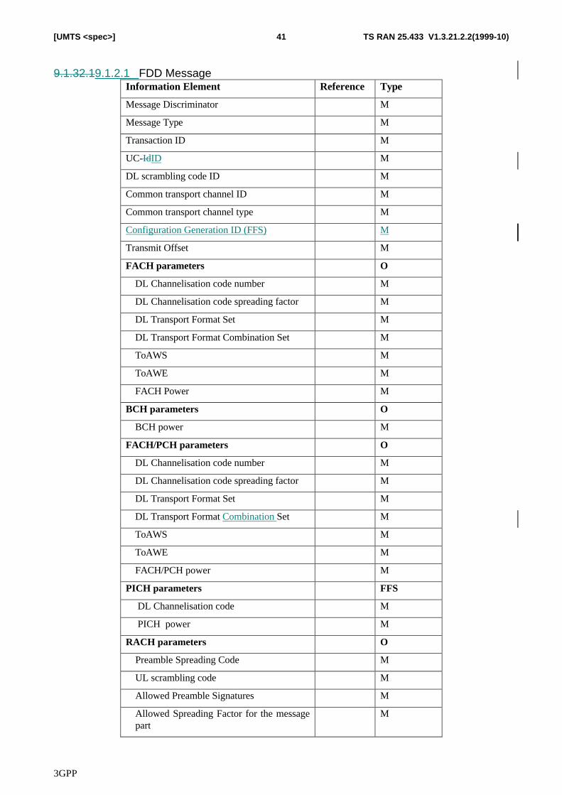
3GPP
TS RAN 25.433 V1.3.21.2.2(1999-10)41[UMTS <spec>]
9.1.32.19.1.2.1 FDD MessageInformation Element Reference Type
Message Discriminator M
Message Type M
Transaction ID M
UC-IdID M
DL scrambling code ID M
Common transport channel ID M
Common transport channel type M
Configuration Generation ID (FFS) M
Transmit Offset M
FACH parameters O
DL Channelisation code number M
DL Channelisation code spreading factor M
DL Transport Format Set M
DL Transport Format Combination Set M
ToAWS M
ToAWE M
FACH Power M
BCH parameters O
BCH power M
FACH/PCH parameters O
DL Channelisation code number M
DL Channelisation code spreading factor M
DL Transport Format Set M
DL Transport Format Combination Set M
ToAWS M
ToAWE M
FACH/PCH power M
PICH parameters FFS
DL Channelisation code M
PICH power M
RACH parameters O
Preamble Spreading Code M
UL scrambling code M
Allowed Preamble Signatures M
Allowed Spreading Factor for the messagepart
M
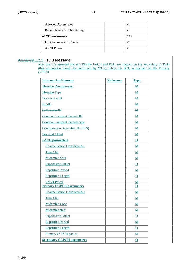
3GPP
TS RAN 25.433 V1.3.21.2.2(1999-10)42[UMTS <spec>]
Allowed Access Slot M
Preamble to Preamble timing M
AICH parameters FFS
DL Channelisation Code M
AICH Power M
9.1.32.29.1.2.2 TDD MessageNote that it’s assumed that in TDD the FACH and PCH are mapped on the Secondary CCPCH(this assumption should be confirmed by WG1), while the BCH is mapped on the PrimaryCCPCH.
Information Element Reference Type
Message Discriminator M
Message Type M
Transaction ID M
UC-ID M
Cell carrier ID M
Common transport channel ID M
Common transport channel type M
Configuration Generation ID (FFS) M
Transmit Offset M
FACH parameters O
Channelisation Code Number M
Time Slot M
Midamble Shift M
Superframe Offset O
Repetition Period M
Repetition Length O
FACH Power MPrimary CCPCH parameters O
Channelisation Code Number M
Time Slot M
Midamble Code M
Midamble shift M
Superframe Offset O
Repetition Period M
Repetition Length O
Primary CCPCH power M
Secondary CCPCH parameters O
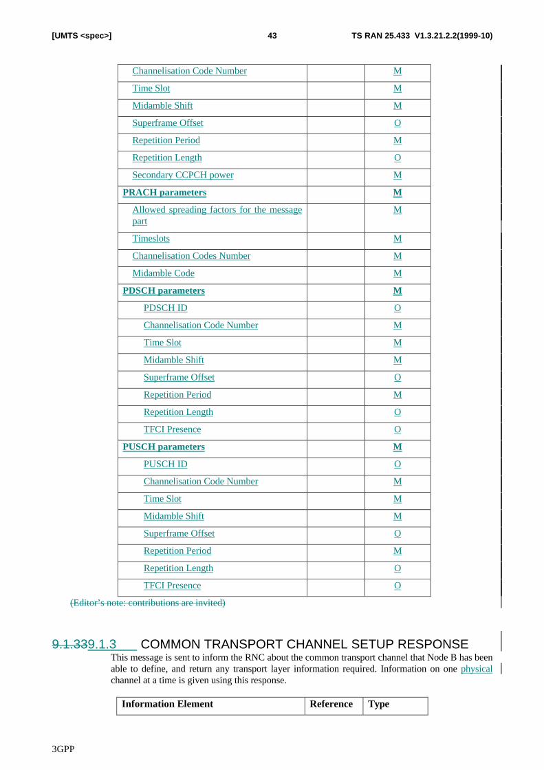
3GPP
TS RAN 25.433 V1.3.21.2.2(1999-10)43[UMTS <spec>]
Channelisation Code Number M
Time Slot M
Midamble Shift M
Superframe Offset O
Repetition Period M
Repetition Length O
Secondary CCPCH power M
PRACH parameters M
Allowed spreading factors for the messagepart
M
Timeslots M
Channelisation Codes Number M
Midamble Code M
PDSCH parameters M
PDSCH ID O
Channelisation Code Number M
Time Slot M
Midamble Shift M
Superframe Offset O
Repetition Period M
Repetition Length O
TFCI Presence O
PUSCH parameters M
PUSCH ID O
Channelisation Code Number M
Time Slot M
Midamble Shift M
Superframe Offset O
Repetition Period M
Repetition Length O
TFCI Presence O
(Editor’s note: contributions are invited)
9.1.339.1.3 COMMON TRANSPORT CHANNEL SETUP RESPONSEThis message is sent to inform the RNC about the common transport channel that Node B has beenable to define, and return any transport layer information required. Information on one physicalchannel at a time is given using this response.
Information Element Reference Type
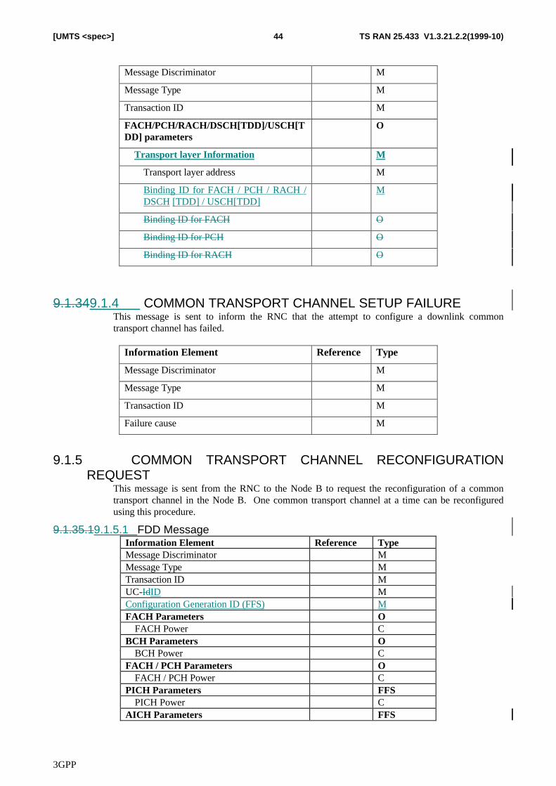
3GPP
TS RAN 25.433 V1.3.21.2.2(1999-10)44[UMTS <spec>]
Message Discriminator M
Message Type M
Transaction ID M
FACH/PCH/RACH/DSCH[TDD]/USCH[TDD] parameters
O
Transport layer Information M
Transport layer address M
Binding ID for FACH / PCH / RACH /DSCH [TDD] / USCH[TDD]
M
Binding ID for FACH O
Binding ID for PCH O
Binding ID for RACH O
9.1.349.1.4 COMMON TRANSPORT CHANNEL SETUP FAILUREThis message is sent to inform the RNC that the attempt to configure a downlink commontransport channel has failed.
Information Element Reference Type
Message Discriminator M
Message Type M
Transaction ID M
Failure cause M
9.1.5 COMMON TRANSPORT CHANNEL RECONFIGURATIONREQUEST
This message is sent from the RNC to the Node B to request the reconfiguration of a commontransport channel in the Node B. One common transport channel at a time can be reconfiguredusing this procedure.
9.1.35.19.1.5.1 FDD MessageInformation Element Reference TypeMessage Discriminator MMessage Type MTransaction ID MUC-IdID MConfiguration Generation ID (FFS) MFACH Parameters O
FACH Power CBCH Parameters O
BCH Power CFACH / PCH Parameters O
FACH / PCH Power CPICH Parameters FFS
PICH Power CAICH Parameters FFS
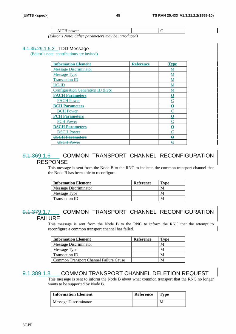
3GPP
TS RAN 25.433 V1.3.21.2.2(1999-10)45[UMTS <spec>]
AICH power C(Editor’s Note: Other parameters may be introduced)
9.1.35.29.1.5.2 TDD Message(Editor’s note: contributions are invited)
Information Element Reference TypeMessage Discriminator MMessage Type MTransaction ID MUC-ID MConfiguration Generation ID (FFS) MFACH Parameters O
FACH Power CBCH Parameters O
BCH Power CPCH Parameters O
PCH Power CDSCH Parameters O
DSCH Power CUSCH Parameters O
USCH Power C
9.1.369.1.6 COMMON TRANSPORT CHANNEL RECONFIGURATIONRESPONSE
This message is sent from the Node B to the RNC to indicate the common transport channel thatthe Node B has been able to reconfigure.
Information Element Reference TypeMessage Discriminator MMessage Type MTransaction ID M
9.1.379.1.7 COMMON TRANSPORT CHANNEL RECONFIGURATIONFAILURE
This message is sent from the Node B to the RNC to inform the RNC that the attempt toreconfigure a common transport channel has failed.
Information Element Reference TypeMessage Discriminator MMessage Type MTransaction ID MCommon Transport Channel Failure Cause M
9.1.389.1.8 COMMON TRANSPORT CHANNEL DELETION REQUESTThis message is sent to inform the Node B about what common transport that the RNC no longerwants to be supported by Node B.
Information Element Reference Type
Message Discriminator M
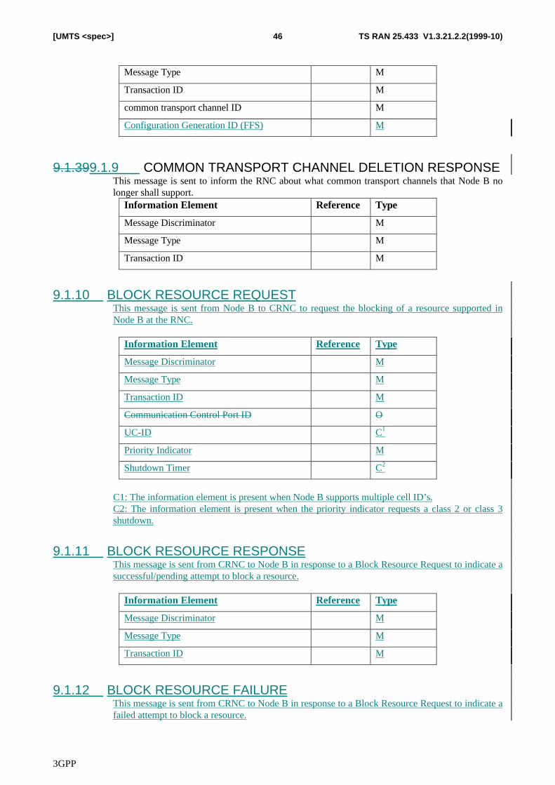
3GPP
TS RAN 25.433 V1.3.21.2.2(1999-10)46[UMTS <spec>]
Message Type M
Transaction ID M
common transport channel ID M
Configuration Generation ID (FFS) M
9.1.399.1.9 COMMON TRANSPORT CHANNEL DELETION RESPONSEThis message is sent to inform the RNC about what common transport channels that Node B nolonger shall support.
Information Element Reference Type
Message Discriminator M
Message Type M
Transaction ID M
9.1.10 BLOCK RESOURCE REQUESTThis message is sent from Node B to CRNC to request the blocking of a resource supported inNode B at the RNC.
Information Element Reference Type
Message Discriminator M
Message Type M
Transaction ID M
Communication Control Port ID O
UC-ID C1
Priority Indicator M
Shutdown Timer C2
C1: The information element is present when Node B supports multiple cell ID’s.C2: The information element is present when the priority indicator requests a class 2 or class 3shutdown.
9.1.11 BLOCK RESOURCE RESPONSEThis message is sent from CRNC to Node B in response to a Block Resource Request to indicate asuccessful/pending attempt to block a resource.
Information Element Reference Type
Message Discriminator M
Message Type M
Transaction ID M
9.1.12 BLOCK RESOURCE FAILUREThis message is sent from CRNC to Node B in response to a Block Resource Request to indicate afailed attempt to block a resource.
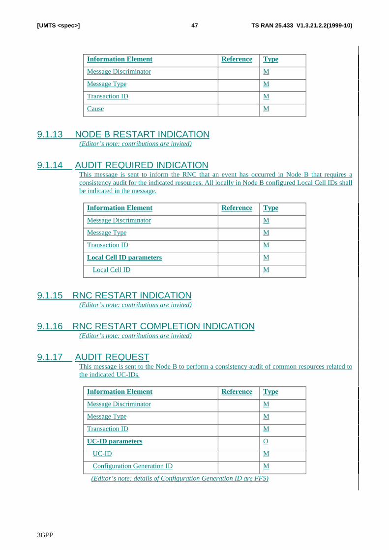
3GPP
TS RAN 25.433 V1.3.21.2.2(1999-10)47[UMTS <spec>]
Information Element Reference Type
Message Discriminator M
Message Type M
Transaction ID M
Cause M
9.1.13 NODE B RESTART INDICATION(Editor’s note: contributions are invited)
9.1.14 AUDIT REQUIRED INDICATIONThis message is sent to inform the RNC that an event has occurred in Node B that requires aconsistency audit for the indicated resources. All locally in Node B configured Local Cell IDs shallbe indicated in the message.
Information Element Reference Type
Message Discriminator M
Message Type M
Transaction ID M
Local Cell ID parameters M
Local Cell ID M
9.1.15 RNC RESTART INDICATION(Editor’s note: contributions are invited)
9.1.16 RNC RESTART COMPLETION INDICATION(Editor’s note: contributions are invited)
9.1.17 AUDIT REQUESTThis message is sent to the Node B to perform a consistency audit of common resources related tothe indicated UC-IDs.
Information Element Reference Type
Message Discriminator M
Message Type M
Transaction ID M
UC-ID parameters O
UC-ID M
Configuration Generation ID M
(Editor’s note: details of Configuration Generation ID are FFS)
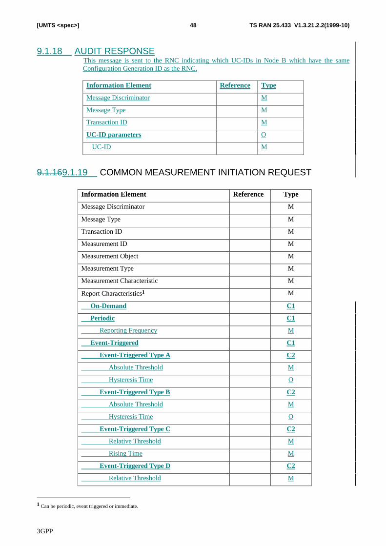
3GPP
TS RAN 25.433 V1.3.21.2.2(1999-10)48[UMTS <spec>]
9.1.18 AUDIT RESPONSEThis message is sent to the RNC indicating which UC-IDs in Node B which have the sameConfiguration Generation ID as the RNC.
Information Element Reference Type
Message Discriminator M
Message Type M
Transaction ID M
UC-ID parameters O
UC-ID M
9.1.169.1.19 COMMON MEASUREMENT INITIATION REQUEST
Information Element Reference Type
Message Discriminator M
Message Type M
Transaction ID M
Measurement ID M
Measurement Object M
Measurement Type M
Measurement Characteristic M
Report Characteristics1 M
On-Demand C1
Periodic C1
Reporting Frequency M
Event-Triggered C1
Event-Triggered Type A C2
Absolute Threshold M
Hysteresis Time O
Event-Triggered Type B C2
Absolute Threshold M
Hysteresis Time O
Event-Triggered Type C C2
Relative Threshold M
Rising Time M
Event-Triggered Type D C2
Relative Threshold M
1 Can be periodic, event triggered or immediate.
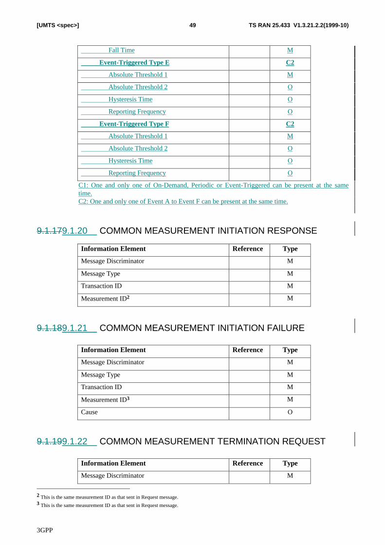
3GPP
TS RAN 25.433 V1.3.21.2.2(1999-10)49[UMTS <spec>]
Fall Time M
Event-Triggered Type E C2
Absolute Threshold 1 M
Absolute Threshold 2 O
Hysteresis Time O
Reporting Frequency O
Event-Triggered Type F C2
Absolute Threshold 1 M
Absolute Threshold 2 O
Hysteresis Time O
Reporting Frequency O
C1: One and only one of On-Demand, Periodic or Event-Triggered can be present at the sametime.C2: One and only one of Event A to Event F can be present at the same time.
9.1.179.1.20 COMMON MEASUREMENT INITIATION RESPONSE
Information Element Reference Type
Message Discriminator M
Message Type M
Transaction ID M
Measurement ID2 M
9.1.189.1.21 COMMON MEASUREMENT INITIATION FAILURE
Information Element Reference Type
Message Discriminator M
Message Type M
Transaction ID M
Measurement ID3 M
Cause O
9.1.199.1.22 COMMON MEASUREMENT TERMINATION REQUEST
Information Element Reference Type
Message Discriminator M
2 This is the same measurement ID as that sent in Request message.3 This is the same measurement ID as that sent in Request message.
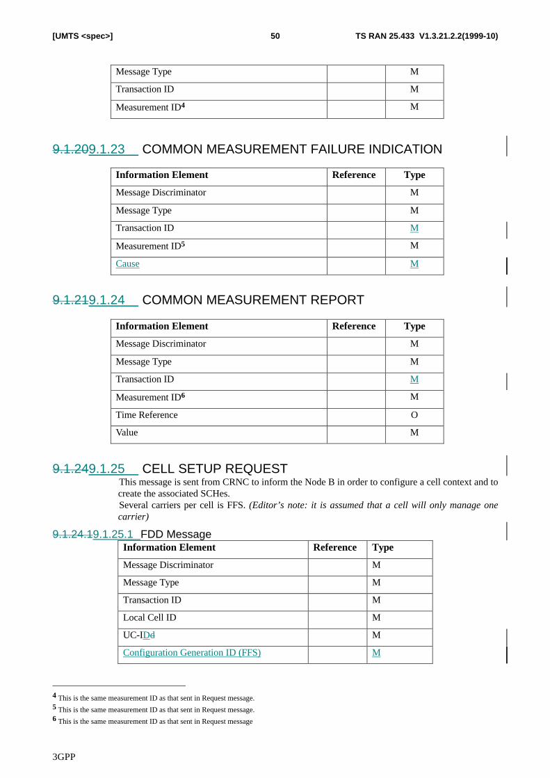
3GPP
TS RAN 25.433 V1.3.21.2.2(1999-10)50[UMTS <spec>]
Message Type M
Transaction ID M
Measurement ID4 M
9.1.209.1.23 COMMON MEASUREMENT FAILURE INDICATION
Information Element Reference Type
Message Discriminator M
Message Type M
Transaction ID M
Measurement ID5 M
Cause M
9.1.219.1.24 COMMON MEASUREMENT REPORT
Information Element Reference Type
Message Discriminator M
Message Type M
Transaction ID M
Measurement ID6 M
Time Reference O
Value M
9.1.249.1.25 CELL SETUP REQUESTThis message is sent from CRNC to inform the Node B in order to configure a cell context and tocreate the associated SCHes.Several carriers per cell is FFS. (Editor’s note: it is assumed that a cell will only manage onecarrier)
9.1.24.19.1.25.1 FDD MessageInformation Element Reference Type
Message Discriminator M
Message Type M
Transaction ID M
Local Cell ID M
UC-IDd M
Configuration Generation ID (FFS) M
4 This is the same measurement ID as that sent in Request message.5 This is the same measurement ID as that sent in Request message.6 This is the same measurement ID as that sent in Request message
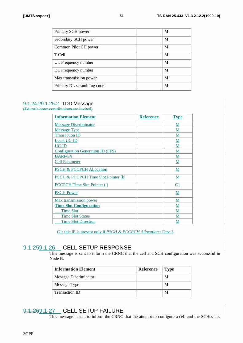
3GPP
TS RAN 25.433 V1.3.21.2.2(1999-10)51[UMTS <spec>]
Primary SCH power M
Secondary SCH power M
Common Pilot CH power M
T Cell M
UL Frequency number M
DL Frequency number M
Max transmission power M
Primary DL scrambling code M
9.1.24.29.1.25.2 TDD Message(Editor’s note: contributions are invited)
Information Element Reference Type
Message Discriminator MMessage Type MTransaction ID MLocal UC-ID MUC-ID MConfiguration Generation ID (FFS) MUARFCN MCell Parameter M
PSCH & PCCPCH Allocation M
PSCH & PCCPCH Time Slot Pointer (k) M
PCCPCH Time Slot Pointer (i) C1
PSCH Power M
Max transmission power MTime Slot Configuration M Time Slot M Time Slot Status M Time Slot Direction M
C1: this IE is present only if PSCH & PCCPCH Allocation=Case 3
9.1.259.1.26 CELL SETUP RESPONSEThis message is sent to inform the CRNC that the cell and SCH configuration was successful inNode B.
Information Element Reference Type
Message Discriminator M
Message Type M
Transaction ID M
9.1.269.1.27 CELL SETUP FAILUREThis message is sent to inform the CRNC that the attempt to configure a cell and the SCHes has
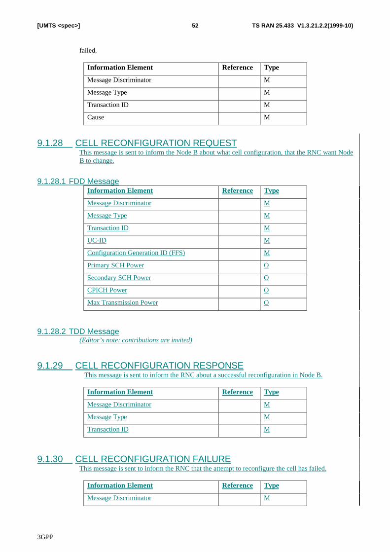
3GPP
TS RAN 25.433 V1.3.21.2.2(1999-10)52[UMTS <spec>]
failed.
Information Element Reference Type
Message Discriminator M
Message Type M
Transaction ID M
Cause M
9.1.28 CELL RECONFIGURATION REQUESTThis message is sent to inform the Node B about what cell configuration, that the RNC want NodeB to change.
9.1.28.1 FDD MessageInformation Element Reference Type
Message Discriminator M
Message Type M
Transaction ID M
UC-ID M
Configuration Generation ID (FFS) M
Primary SCH Power O
Secondary SCH Power O
CPICH Power O
Max Transmission Power O
9.1.28.2 TDD Message(Editor’s note: contributions are invited)
9.1.29 CELL RECONFIGURATION RESPONSEThis message is sent to inform the RNC about a successful reconfiguration in Node B.
Information Element Reference Type
Message Discriminator M
Message Type M
Transaction ID M
9.1.30 CELL RECONFIGURATION FAILUREThis message is sent to inform the RNC that the attempt to reconfigure the cell has failed.
Information Element Reference Type
Message Discriminator M
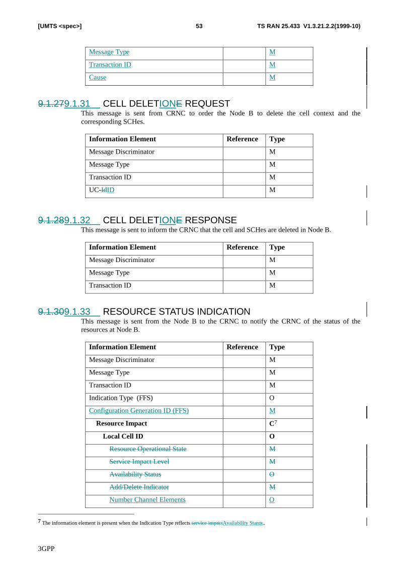
3GPP
TS RAN 25.433 V1.3.21.2.2(1999-10)53[UMTS <spec>]
Message Type M
Transaction ID M
Cause M
9.1.279.1.31 CELL DELETIONE REQUESTThis message is sent from CRNC to order the Node B to delete the cell context and thecorresponding SCHes.
Information Element Reference Type
Message Discriminator M
Message Type M
Transaction ID M
UC-IdID M
9.1.289.1.32 CELL DELETIONE RESPONSEThis message is sent to inform the CRNC that the cell and SCHes are deleted in Node B.
Information Element Reference Type
Message Discriminator M
Message Type M
Transaction ID M
9.1.309.1.33 RESOURCE STATUS INDICATIONThis message is sent from the Node B to the CRNC to notify the CRNC of the status of theresources at Node B.
Information Element Reference Type
Message Discriminator M
Message Type M
Transaction ID M
Indication Type (FFS) O
Configuration Generation ID (FFS) M
Resource Impact C7
Local Cell ID O
Resource Operational State M
Service Impact Level M
Availability Status O
Add/Delete Indicator M
Number Channel Elements O
7 The information element is present when the Indication Type reflects service impactAvailability Status..
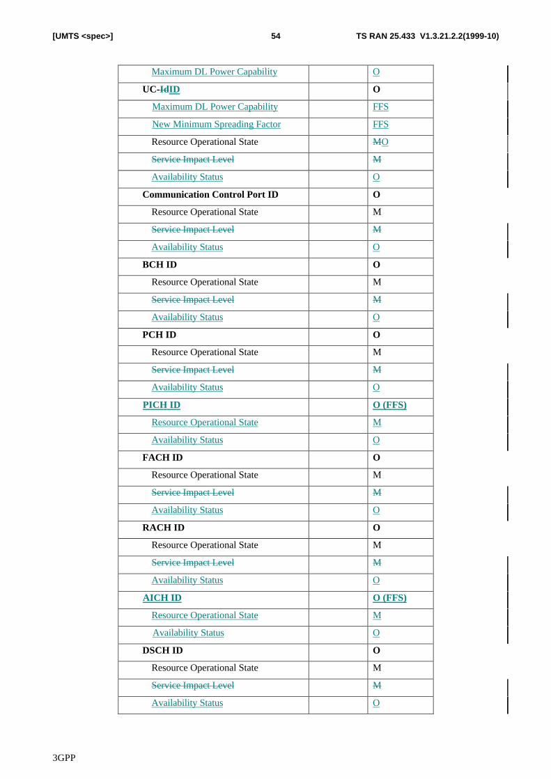
3GPP
TS RAN 25.433 V1.3.21.2.2(1999-10)54[UMTS <spec>]
Maximum DL Power Capability O
UC-IdID O
Maximum DL Power Capability FFS
New Minimum Spreading Factor FFS
Resource Operational State MO
Service Impact Level M
Availability Status O
Communication Control Port ID O
Resource Operational State M
Service Impact Level M
Availability Status O
BCH ID O
Resource Operational State M
Service Impact Level M
Availability Status O
PCH ID O
Resource Operational State M
Service Impact Level M
Availability Status O
PICH ID O (FFS)
Resource Operational State M
Availability Status O
FACH ID O
Resource Operational State M
Service Impact Level M
Availability Status O
RACH ID O
Resource Operational State M
Service Impact Level M
Availability Status O
AICH ID O (FFS)
Resource Operational State M
Availability Status O
DSCH ID O
Resource Operational State M
Service Impact Level M
Availability Status O
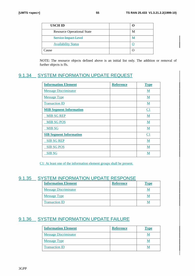
3GPP
TS RAN 25.433 V1.3.21.2.2(1999-10)55[UMTS <spec>]
USCH ID O
Resource Operational State M
Service Impact Level M
Availability Status O
Cause O
NOTE: The resource objects defined above is an initial list only. The addition or removal offurther objects is ffs.
9.1.34 SYSTEM INFORMATION UPDATE REQUEST
Information Element Reference Type
Message Discriminator M
Message Type M
Transaction ID M
MIB Segment Information C1
MIB SG REP M
MIB SG POS M
MIB SG M
SIB Segment Information C1
SIB SG REP M
SIB SG POS M
SIB SG M
C1: At least one of the information element groups shall be present.
9.1.35 SYSTEM INFORMATION UPDATE RESPONSEInformation Element Reference Type
Message Discriminator M
Message Type M
Transaction ID M
9.1.36 SYSTEM INFORMATION UPDATE FAILURE
Information Element Reference Type
Message Discriminator M
Message Type M
Transaction ID M
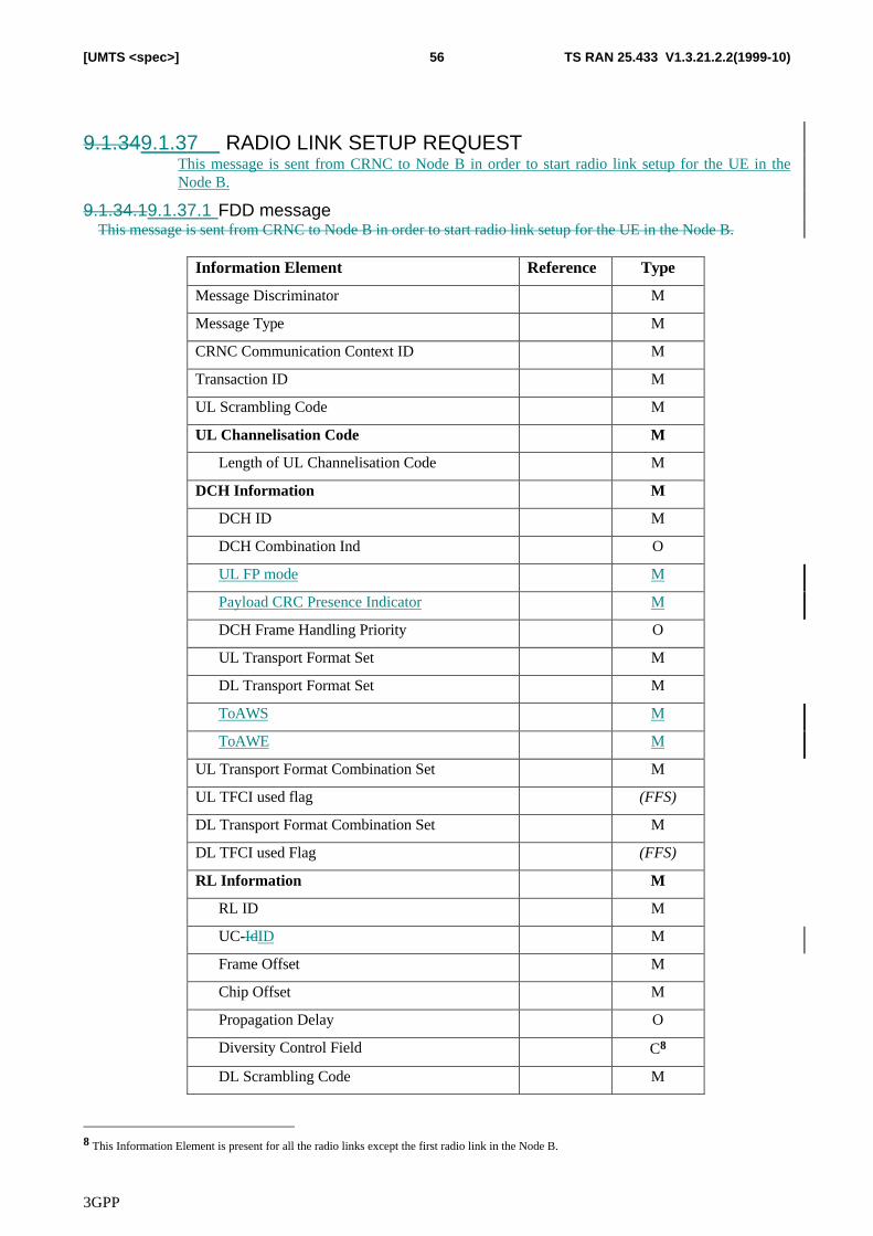
3GPP
TS RAN 25.433 V1.3.21.2.2(1999-10)56[UMTS <spec>]
9.1.349.1.37 RADIO LINK SETUP REQUESTThis message is sent from CRNC to Node B in order to start radio link setup for the UE in theNode B.
9.1.34.19.1.37.1 FDD messageThis message is sent from CRNC to Node B in order to start radio link setup for the UE in the Node B.
Information Element Reference Type
Message Discriminator M
Message Type M
CRNC Communication Context ID M
Transaction ID M
UL Scrambling Code M
UL Channelisation Code M
Length of UL Channelisation Code M
DCH Information M
DCH ID M
DCH Combination Ind O
UL FP mode M
Payload CRC Presence Indicator M
DCH Frame Handling Priority O
UL Transport Format Set M
DL Transport Format Set M
ToAWS M
ToAWE M
UL Transport Format Combination Set M
UL TFCI used flag (FFS)
DL Transport Format Combination Set M
DL TFCI used Flag (FFS)
RL Information M
RL ID M
UC-IdID M
Frame Offset M
Chip Offset M
Propagation Delay O
Diversity Control Field C8
DL Scrambling Code M
8 This Information Element is present for all the radio links except the first radio link in the Node B.
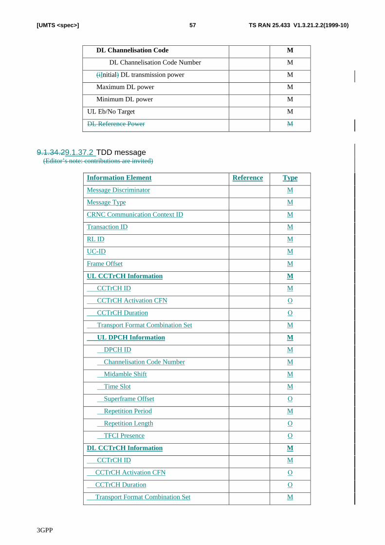
3GPP
TS RAN 25.433 V1.3.21.2.2(1999-10)57[UMTS <spec>]
DL Channelisation Code M
DL Channelisation Code Number M
(iInitial) DL transmission power M
Maximum DL power M
Minimum DL power M
UL Eb/No Target M
DL Reference Power M
9.1.34.29.1.37.2 TDD message(Editor’s note: contributions are invited)
Information Element Reference Type
Message Discriminator M
Message Type M
CRNC Communication Context ID M
Transaction ID M
RL ID M
UC-ID M
Frame Offset M
UL CCTrCH Information M
CCTrCH ID M
CCTrCH Activation CFN O
CCTrCH Duration O
Transport Format Combination Set M
UL DPCH Information M
DPCH ID M
Channelisation Code Number M
Midamble Shift M
Time Slot M
Superframe Offset O
Repetition Period M
Repetition Length O
TFCI Presence O
DL CCTrCH Information M
CCTrCH ID M
CCTrCH Activation CFN O
CCTrCH Duration O
Transport Format Combination Set M
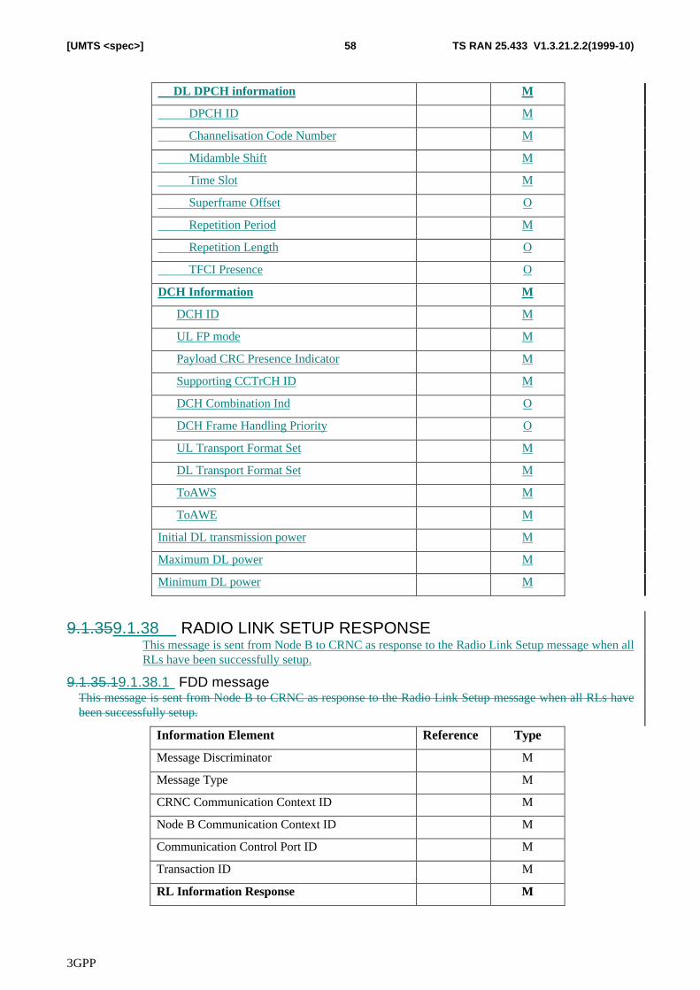
3GPP
TS RAN 25.433 V1.3.21.2.2(1999-10)58[UMTS <spec>]
DL DPCH information M
DPCH ID M
Channelisation Code Number M
Midamble Shift M
Time Slot M
Superframe Offset O
Repetition Period M
Repetition Length O
TFCI Presence O
DCH Information M
DCH ID M
UL FP mode M
Payload CRC Presence Indicator M
Supporting CCTrCH ID M
DCH Combination Ind O
DCH Frame Handling Priority O
UL Transport Format Set M
DL Transport Format Set M
ToAWS M
ToAWE M
Initial DL transmission power M
Maximum DL power M
Minimum DL power M
9.1.359.1.38 RADIO LINK SETUP RESPONSEThis message is sent from Node B to CRNC as response to the Radio Link Setup message when allRLs have been successfully setup.
9.1.35.19.1.38.1 FDD messageThis message is sent from Node B to CRNC as response to the Radio Link Setup message when all RLs havebeen successfully setup.
Information Element Reference Type
Message Discriminator M
Message Type M
CRNC Communication Context ID M
Node B Communication Context ID M
Communication Control Port ID M
Transaction ID M
RL Information Response M
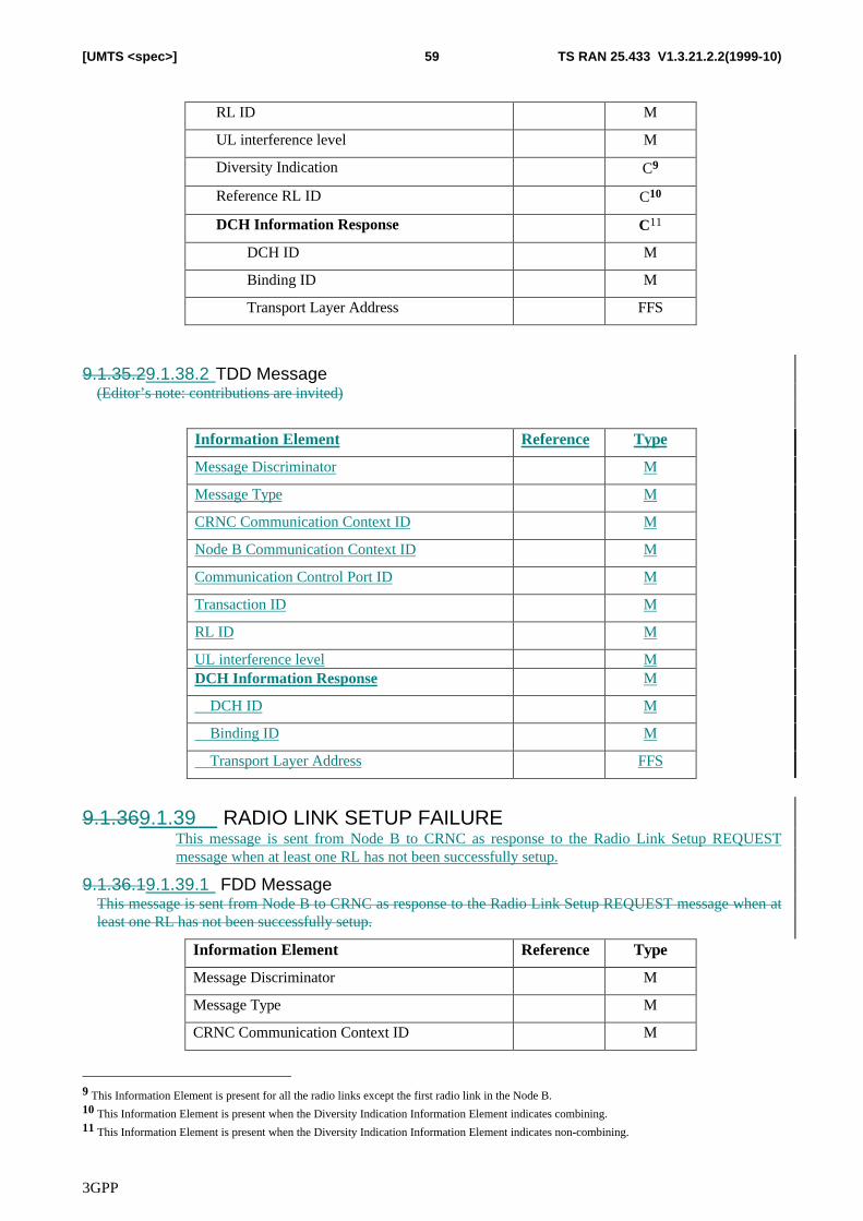
3GPP
TS RAN 25.433 V1.3.21.2.2(1999-10)59[UMTS <spec>]
RL ID M
UL interference level M
Diversity Indication C9
Reference RL ID C10
DCH Information Response C11
DCH ID M
Binding ID M
Transport Layer Address FFS
9.1.35.29.1.38.2 TDD Message(Editor’s note: contributions are invited)
Information Element Reference Type
Message Discriminator M
Message Type M
CRNC Communication Context ID M
Node B Communication Context ID M
Communication Control Port ID M
Transaction ID M
RL ID M
UL interference level MDCH Information Response M
DCH ID M
Binding ID M
Transport Layer Address FFS
9.1.369.1.39 RADIO LINK SETUP FAILUREThis message is sent from Node B to CRNC as response to the Radio Link Setup REQUESTmessage when at least one RL has not been successfully setup.
9.1.36.19.1.39.1 FDD MessageThis message is sent from Node B to CRNC as response to the Radio Link Setup REQUEST message when atleast one RL has not been successfully setup.
Information Element Reference Type
Message Discriminator M
Message Type M
CRNC Communication Context ID M
9 This Information Element is present for all the radio links except the first radio link in the Node B.10 This Information Element is present when the Diversity Indication Information Element indicates combining.11 This Information Element is present when the Diversity Indication Information Element indicates non-combining.
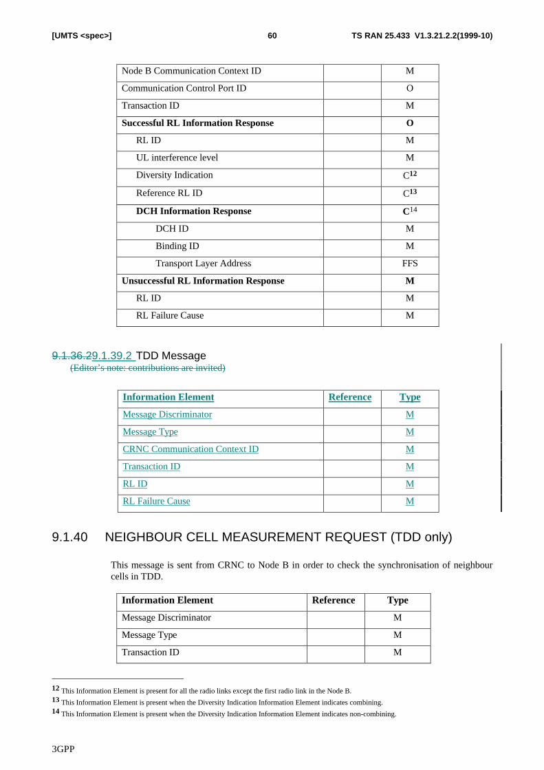
3GPP
TS RAN 25.433 V1.3.21.2.2(1999-10)60[UMTS <spec>]
Node B Communication Context ID M
Communication Control Port ID O
Transaction ID M
Successful RL Information Response O
RL ID M
UL interference level M
Diversity Indication C12
Reference RL ID C13
DCH Information Response C14
DCH ID M
Binding ID M
Transport Layer Address FFS
Unsuccessful RL Information Response M
RL ID M
RL Failure Cause M
9.1.36.29.1.39.2 TDD Message(Editor’s note: contributions are invited)
Information Element Reference Type
Message Discriminator M
Message Type M
CRNC Communication Context ID M
Transaction ID M
RL ID M
RL Failure Cause M
9.1.40 NEIGHBOUR CELL MEASUREMENT REQUEST (TDD only)
This message is sent from CRNC to Node B in order to check the synchronisation of neighbourcells in TDD.
Information Element Reference Type
Message Discriminator M
Message Type M
Transaction ID M
12 This Information Element is present for all the radio links except the first radio link in the Node B.13 This Information Element is present when the Diversity Indication Information Element indicates combining.14 This Information Element is present when the Diversity Indication Information Element indicates non-combining.
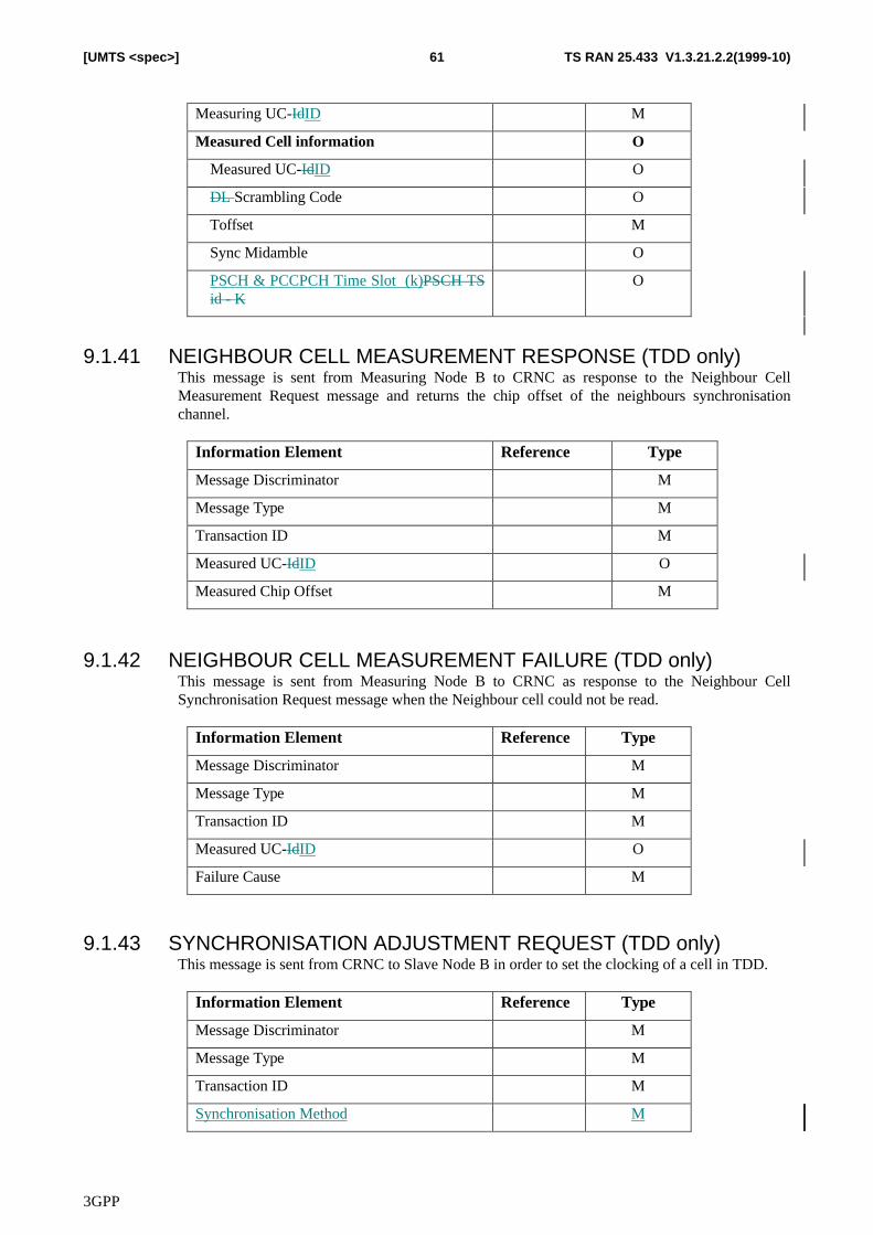
3GPP
TS RAN 25.433 V1.3.21.2.2(1999-10)61[UMTS <spec>]
Measuring UC-IdID M
Measured Cell information O
Measured UC-IdID O
DL Scrambling Code O
Toffset M
Sync Midamble O
PSCH & PCCPCH Time Slot (k)PSCH TSid - K
O
9.1.41 NEIGHBOUR CELL MEASUREMENT RESPONSE (TDD only)This message is sent from Measuring Node B to CRNC as response to the Neighbour CellMeasurement Request message and returns the chip offset of the neighbours synchronisationchannel.
Information Element Reference Type
Message Discriminator M
Message Type M
Transaction ID M
Measured UC-IdID O
Measured Chip Offset M
9.1.42 NEIGHBOUR CELL MEASUREMENT FAILURE (TDD only)This message is sent from Measuring Node B to CRNC as response to the Neighbour CellSynchronisation Request message when the Neighbour cell could not be read.
Information Element Reference Type
Message Discriminator M
Message Type M
Transaction ID M
Measured UC-IdID O
Failure Cause M
9.1.43 SYNCHRONISATION ADJUSTMENT REQUEST (TDD only)This message is sent from CRNC to Slave Node B in order to set the clocking of a cell in TDD.
Information Element Reference Type
Message Discriminator M
Message Type M
Transaction ID M
Synchronisation Method M
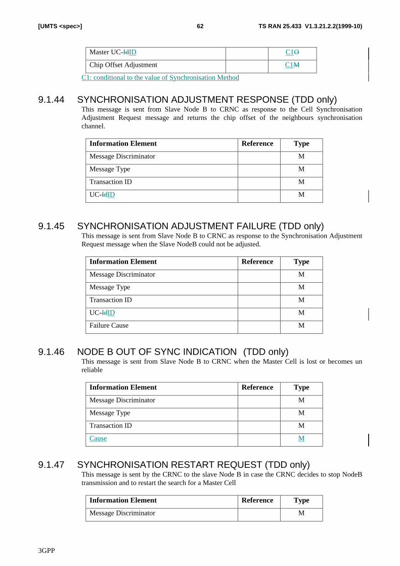
3GPP
TS RAN 25.433 V1.3.21.2.2(1999-10)62[UMTS <spec>]
Master UC-IdID C1O
Chip Offset Adjustment C1M
C1: conditional to the value of Synchronisation Method
9.1.44 SYNCHRONISATION ADJUSTMENT RESPONSE (TDD only)This message is sent from Slave Node B to CRNC as response to the Cell SynchronisationAdjustment Request message and returns the chip offset of the neighbours synchronisationchannel.
Information Element Reference Type
Message Discriminator M
Message Type M
Transaction ID M
UC-IdID M
9.1.45 SYNCHRONISATION ADJUSTMENT FAILURE (TDD only)This message is sent from Slave Node B to CRNC as response to the Synchronisation AdjustmentRequest message when the Slave NodeB could not be adjusted.
Information Element Reference Type
Message Discriminator M
Message Type M
Transaction ID M
UC-IdID M
Failure Cause M
9.1.46 NODE B OUT OF SYNC INDICATION� (TDD only)This message is sent from Slave Node B to CRNC when the Master Cell is lost or becomes unreliable
Information Element Reference Type
Message Discriminator M
Message Type M
Transaction ID M
Cause M
9.1.47 SYNCHRONISATION RESTART REQUEST (TDD only)This message is sent by the CRNC to the slave Node B in case the CRNC decides to stop NodeBtransmission and to restart the search for a Master Cell
Information Element Reference Type
Message Discriminator M
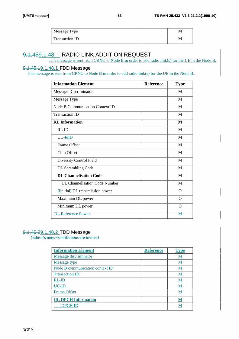
3GPP
TS RAN 25.433 V1.3.21.2.2(1999-10)63[UMTS <spec>]
Message Type M
Transaction ID M
9.1.459.1.48 RADIO LINK ADDITION REQUESTThis message is sent from CRNC to Node B in order to add radio link(s) for the UE in the Node B.
9.1.45.19.1.48.1 FDD MessageThis message is sent from CRNC to Node B in order to add radio link(s) for the UE in the Node B.
Information Element Reference Type
Message Discriminator M
Message Type M
Node B Communication Context ID M
Transaction ID M
RL Information M
RL ID M
UC-IdID M
Frame Offset M
Chip Offset M
Diversity Control Field M
DL Scrambling Code M
DL Channelisation Code M
DL Channelisation Code Number M
(Iinitial) DL transmission power O
Maximum DL power O
Minimum DL power O
DL Reference Power M
9.1.45.29.1.48.2 TDD Message(Editor’s note: contributions are invited)
Information Element Reference TypeMessage discriminator M
Message type M
Node B communication context ID M
Transaction ID M
RL-ID M
UC-ID MFrame Offset M
UL DPCH Information M DPCH ID M
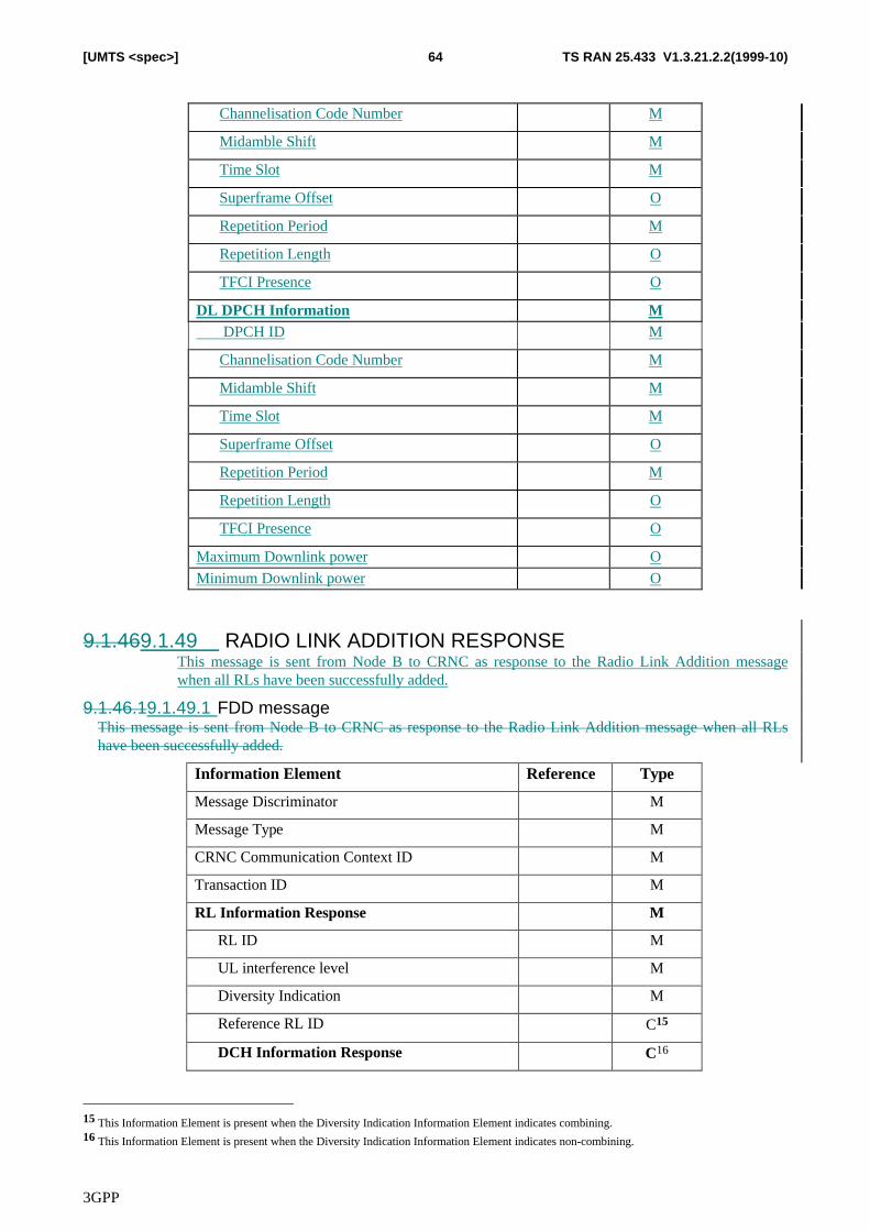
3GPP
TS RAN 25.433 V1.3.21.2.2(1999-10)64[UMTS <spec>]
Channelisation Code Number M
Midamble Shift M
Time Slot M
Superframe Offset O
Repetition Period M
Repetition Length O
TFCI Presence O
DL DPCH Information M DPCH ID M
Channelisation Code Number M
Midamble Shift M
Time Slot M
Superframe Offset O
Repetition Period M
Repetition Length O
TFCI Presence O
Maximum Downlink power O
Minimum Downlink power O
9.1.469.1.49 RADIO LINK ADDITION RESPONSEThis message is sent from Node B to CRNC as response to the Radio Link Addition messagewhen all RLs have been successfully added.
9.1.46.19.1.49.1 FDD messageThis message is sent from Node B to CRNC as response to the Radio Link Addition message when all RLshave been successfully added.
Information Element Reference Type
Message Discriminator M
Message Type M
CRNC Communication Context ID M
Transaction ID M
RL Information Response M
RL ID M
UL interference level M
Diversity Indication M
Reference RL ID C15
DCH Information Response C16
15 This Information Element is present when the Diversity Indication Information Element indicates combining.16 This Information Element is present when the Diversity Indication Information Element indicates non-combining.
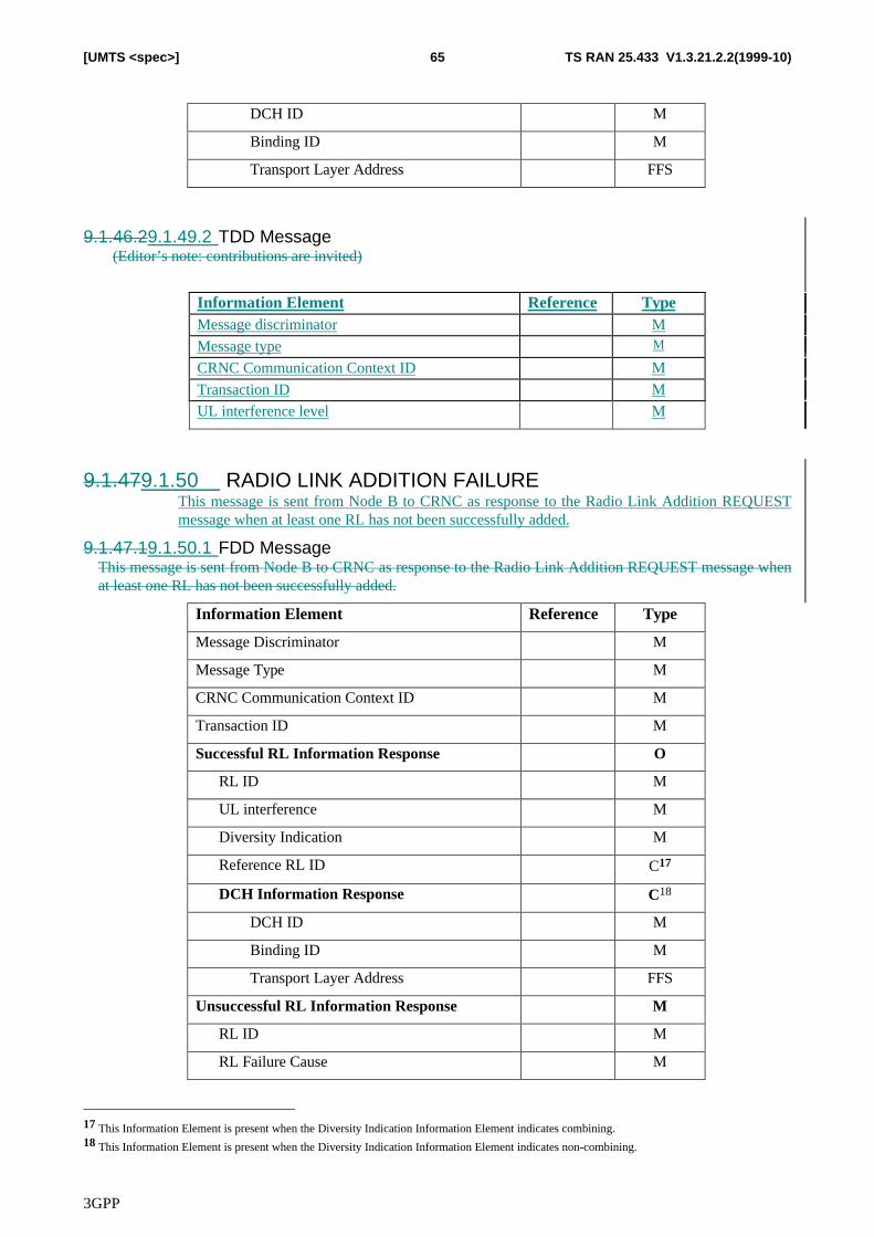
3GPP
TS RAN 25.433 V1.3.21.2.2(1999-10)65[UMTS <spec>]
DCH ID M
Binding ID M
Transport Layer Address FFS
9.1.46.29.1.49.2 TDD Message(Editor’s note: contributions are invited)
Information Element Reference TypeMessage discriminator M
Message type M
CRNC Communication Context ID M
Transaction ID M
UL interference level M
9.1.479.1.50 RADIO LINK ADDITION FAILUREThis message is sent from Node B to CRNC as response to the Radio Link Addition REQUESTmessage when at least one RL has not been successfully added.
9.1.47.19.1.50.1 FDD MessageThis message is sent from Node B to CRNC as response to the Radio Link Addition REQUEST message whenat least one RL has not been successfully added.
Information Element Reference Type
Message Discriminator M
Message Type M
CRNC Communication Context ID M
Transaction ID M
Successful RL Information Response O
RL ID M
UL interference M
Diversity Indication M
Reference RL ID C17
DCH Information Response C18
DCH ID M
Binding ID M
Transport Layer Address FFS
Unsuccessful RL Information Response M
RL ID M
RL Failure Cause M
17 This Information Element is present when the Diversity Indication Information Element indicates combining.18 This Information Element is present when the Diversity Indication Information Element indicates non-combining.

3GPP
TS RAN 25.433 V1.3.21.2.2(1999-10)66[UMTS <spec>]
9.1.47.29.1.50.2 TDD Message(Editor’s note: contributions are invited)
Information Element Reference TypeMessage discriminator M
Message type M
CRNC Communication Context ID M
Transaction ID M
RL Failure Cause M
9.1.489.1.51 RADIO LINK RECONFIGURATION PREPARE9.1.48.19.1.51.1 FDD Message
Information element Reference TypeMessage Discriminator M
Message type M
Node B Communication Context ID M
Transaction ID M
DCHs to modify O
DCH ID M
DCH Allocation/Retention Priority O
UL FP mode ODCH Frame Handling Priority O
Transport format set (DL) O
Transport format set (UL) O
ToAWS M
ToAWE M
DCHs to add O
DCH ID M
DCH Combination Ind O
UL FP mode M
Payload CRC Presence Indicator M
DCH Frame Handling Priority O
Transport format set (DL) M
Transport format set (UL) M
ToAWS M
ToAWE M
DCHs to delete O
DCH ID M
TFCS (DL) M
TFCS (UL) M
Uplink Scrambling code O
UL Channelisation Codes O
Channelisation code (UL) M
RL Information ORL ID M
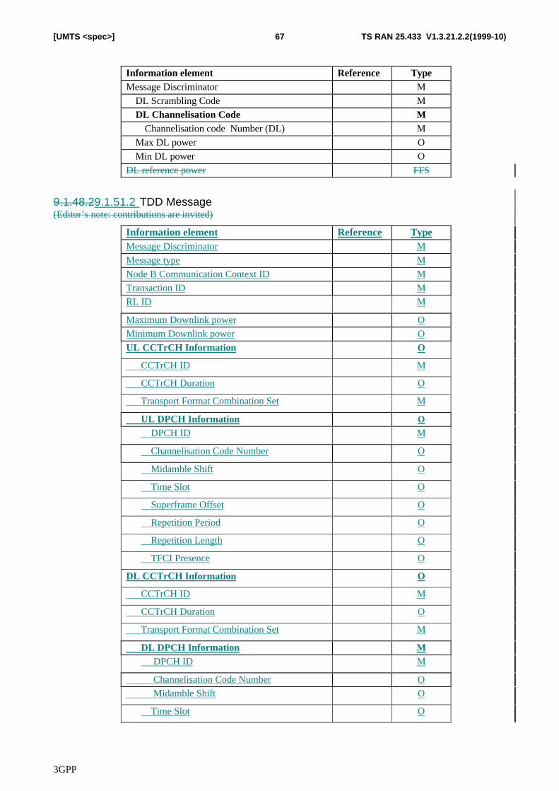
3GPP
TS RAN 25.433 V1.3.21.2.2(1999-10)67[UMTS <spec>]
Information element Reference TypeMessage Discriminator M
DL Scrambling Code M
DL Channelisation Code MChannelisation code Number (DL) M
Max DL power O
Min DL power O
DL reference power FFS
9.1.48.29.1.51.2 TDD Message(Editor’s note: contributions are invited)
Information element Reference TypeMessage Discriminator M
Message type M
Node B Communication Context ID M
Transaction ID MRL ID M
Maximum Downlink power O
Minimum Downlink power O
UL CCTrCH Information O
CCTrCH ID M
CCTrCH Duration O
Transport Format Combination Set M
UL DPCH Information O
DPCH ID M
Channelisation Code Number O
Midamble Shift O
Time Slot O
Superframe Offset O
Repetition Period O
Repetition Length O
TFCI Presence O
DL CCTrCH Information O
CCTrCH ID M
CCTrCH Duration O
Transport Format Combination Set M
DL DPCH Information M DPCH ID M
Channelisation Code Number O Midamble Shift O
Time Slot O

3GPP
TS RAN 25.433 V1.3.21.2.2(1999-10)68[UMTS <spec>]
Superframe Offset O
Repetition Period O
Repetition Length O
TFCI Presence O
DCHs to modify O
DCH ID M
Supporting CCTrCH ID O
UL FP mode O DCH Frame Handling Priority O
Transport format set (DL) O
Transport format set (UL) O
ToAWS M
ToAWE M
DCHs to add O
DCH ID M
Supporting CCTrCH ID O
UL FP mode M
Payload CRC Presence Indicator M
Supporting CCTrCH ID M
DCH Combination Ind O
DCH Frame Handling Priority OTransport format set (DL) M
Transport format set (UL) M
ToAWS M
ToAWE M
DCHs to delete O
DCH ID M
9.1.499.1.52 RADIO LINK RECONFIGURATION READY
Information element Reference TypeMessage Discriminator M
Message type M
CRNC Communication Context ID M
Transaction ID M
RLs to be reconfigured (synch) ORL ID M
DCH to be setup O
DCH ID M
Binding ID M
Transport Layer Address FFS
DCH to be modified ODCH ID M
Binding ID M
Transport Layer Address FFS
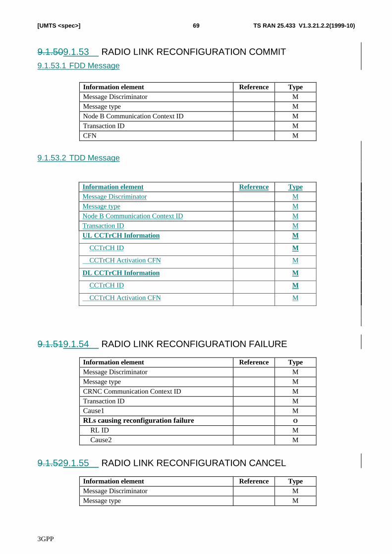
3GPP
TS RAN 25.433 V1.3.21.2.2(1999-10)69[UMTS <spec>]
9.1.509.1.53 RADIO LINK RECONFIGURATION COMMIT9.1.53.1 FDD Message
Information element Reference TypeMessage Discriminator M
Message type M
Node B Communication Context ID M
Transaction ID M
CFN M
9.1.53.2 TDD Message
Information element Reference TypeMessage Discriminator M
Message type M
Node B Communication Context ID M
Transaction ID M
UL CCTrCH Information M
CCTrCH ID M
CCTrCH Activation CFN M
DL CCTrCH Information M
CCTrCH ID M
CCTrCH Activation CFN M
9.1.519.1.54 RADIO LINK RECONFIGURATION FAILURE
Information element Reference TypeMessage Discriminator M
Message type M
CRNC Communication Context ID M
Transaction ID M
Cause1 M
RLs causing reconfiguration failure O
RL ID M
Cause2 M
9.1.529.1.55 RADIO LINK RECONFIGURATION CANCEL
Information element Reference TypeMessage Discriminator M
Message type M
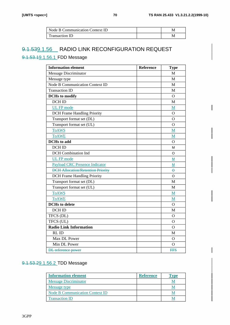
3GPP
TS RAN 25.433 V1.3.21.2.2(1999-10)70[UMTS <spec>]
Node B Communication Context ID M
Transaction ID M
9.1.539.1.56 RADIO LINK RECONFIGURATION REQUEST9.1.53.19.1.56.1 FDD Message
Information element Reference TypeMessage Discriminator M
Message type M
Node B Communication Context ID M
Transaction ID M
DCHs to modify O
DCH ID M
UL FP mode M
DCH Frame Handling Priority O
Transport format set (DL) O
Transport format set (UL) O
ToAWS M
ToAWE M
DCHs to add O
DCH ID M
DCH Combination Ind O
UL FP mode M
Payload CRC Presence Indicator M
DCH Allocation/Retention Priority O
DCH Frame Handling Priority O
Transport format set (DL) M
Transport format set (UL) M
ToAWS M
ToAWE M
DCHs to delete O
DCH ID M
TFCS (DL) O
TFCS (UL) O
Radio Link Information O
RL ID M
Max DL Power O
Min DL Power O
DL reference power FFS
9.1.53.29.1.56.2 TDD Message
Information element Reference TypeMessage Discriminator M
Message type M
Node B Communication Context ID M
Transaction ID M
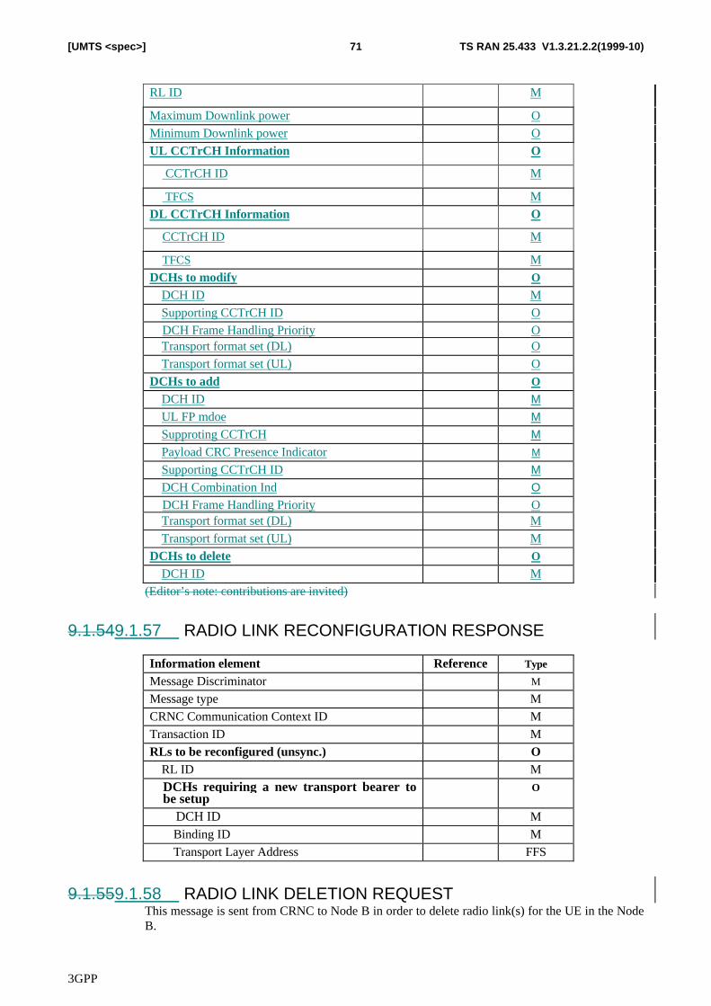
3GPP
TS RAN 25.433 V1.3.21.2.2(1999-10)71[UMTS <spec>]
RL ID M
Maximum Downlink power O
Minimum Downlink power O
UL CCTrCH Information O
CCTrCH ID M
TFCS M
DL CCTrCH Information O
CCTrCH ID M
TFCS M
DCHs to modify O
DCH ID M
Supporting CCTrCH ID ODCH Frame Handling Priority OTransport format set (DL) O
Transport format set (UL) O
DCHs to add O
DCH ID M
UL FP mdoe M
Supproting CCTrCH M
Payload CRC Presence Indicator M
Supporting CCTrCH ID M
DCH Combination Ind O
DCH Frame Handling Priority OTransport format set (DL) M
Transport format set (UL) M
DCHs to delete O
DCH ID M(Editor’s note: contributions are invited)
9.1.549.1.57 RADIO LINK RECONFIGURATION RESPONSE
Information element Reference Type
Message Discriminator M
Message type M
CRNC Communication Context ID M
Transaction ID M
RLs to be reconfigured (unsync.) ORL ID M
DCHs requiring a new transport bearer tobe setup
O
DCH ID M
Binding ID M
Transport Layer Address FFS
9.1.559.1.58 RADIO LINK DELETION REQUESTThis message is sent from CRNC to Node B in order to delete radio link(s) for the UE in the NodeB.
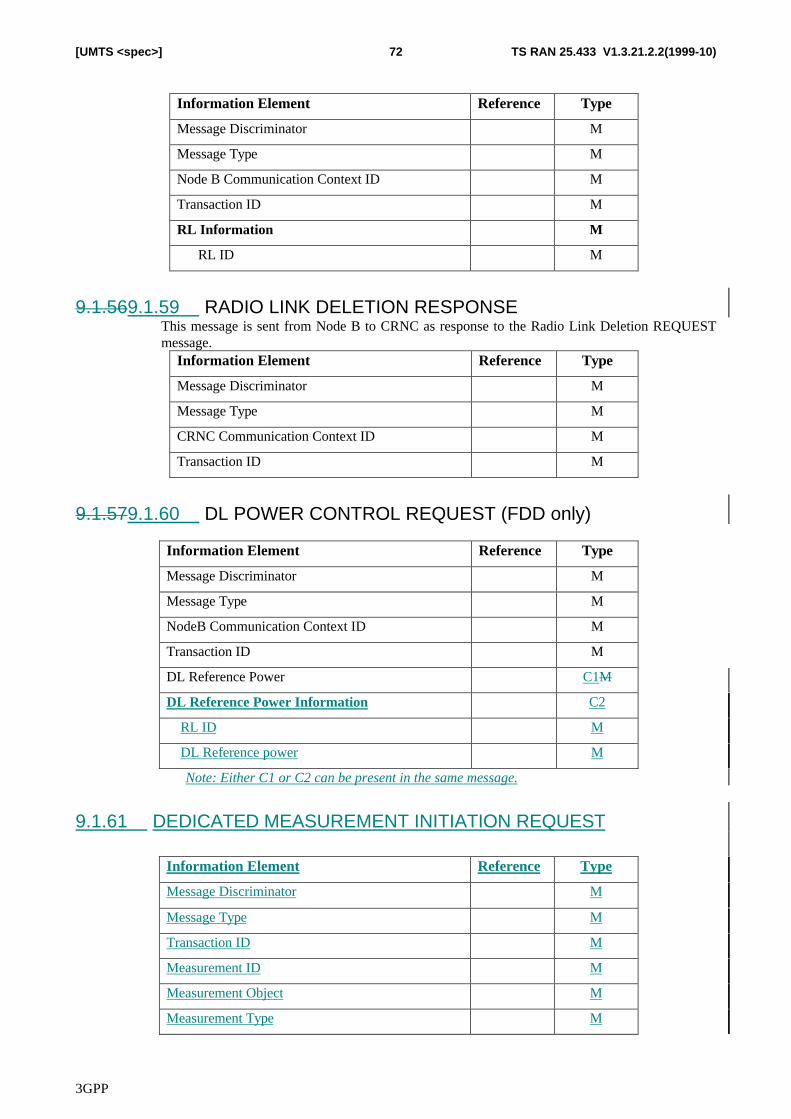
3GPP
TS RAN 25.433 V1.3.21.2.2(1999-10)72[UMTS <spec>]
Information Element Reference Type
Message Discriminator M
Message Type M
Node B Communication Context ID M
Transaction ID M
RL Information M
RL ID M
9.1.569.1.59 RADIO LINK DELETION RESPONSEThis message is sent from Node B to CRNC as response to the Radio Link Deletion REQUESTmessage.
Information Element Reference Type
Message Discriminator M
Message Type M
CRNC Communication Context ID M
Transaction ID M
9.1.579.1.60 DL POWER CONTROL REQUEST (FDD only)
Information Element Reference Type
Message Discriminator M
Message Type M
NodeB Communication Context ID M
Transaction ID M
DL Reference Power C1M
DL Reference Power Information C2
RL ID M
DL Reference power M
Note: Either C1 or C2 can be present in the same message.
9.1.61 DEDICATED MEASUREMENT INITIATION REQUEST
Information Element Reference Type
Message Discriminator M
Message Type M
Transaction ID M
Measurement ID M
Measurement Object M
Measurement Type M
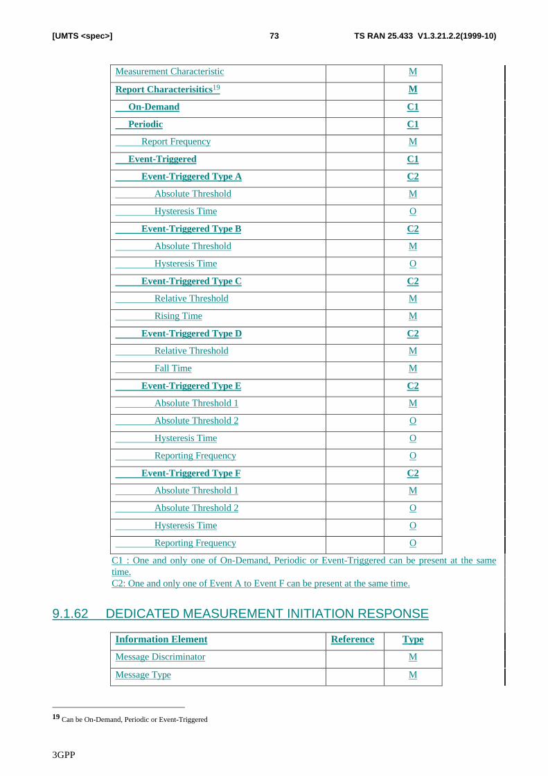
3GPP
TS RAN 25.433 V1.3.21.2.2(1999-10)73[UMTS <spec>]
Measurement Characteristic M
Report Characterisitics19 M
On-Demand C1
Periodic C1
Report Frequency M
Event-Triggered C1
Event-Triggered Type A C2
Absolute Threshold M
Hysteresis Time O
Event-Triggered Type B C2
Absolute Threshold M
Hysteresis Time O
Event-Triggered Type C C2
Relative Threshold M
Rising Time M
Event-Triggered Type D C2
Relative Threshold M
Fall Time M
Event-Triggered Type E C2
Absolute Threshold 1 M
Absolute Threshold 2 O
Hysteresis Time O
Reporting Frequency O
Event-Triggered Type F C2
Absolute Threshold 1 M
Absolute Threshold 2 O
Hysteresis Time O
Reporting Frequency O
C1 : One and only one of On-Demand, Periodic or Event-Triggered can be present at the sametime.C2: One and only one of Event A to Event F can be present at the same time.
9.1.62 DEDICATED MEASUREMENT INITIATION RESPONSE
Information Element Reference Type
Message Discriminator M
Message Type M
19 Can be On-Demand, Periodic or Event-Triggered
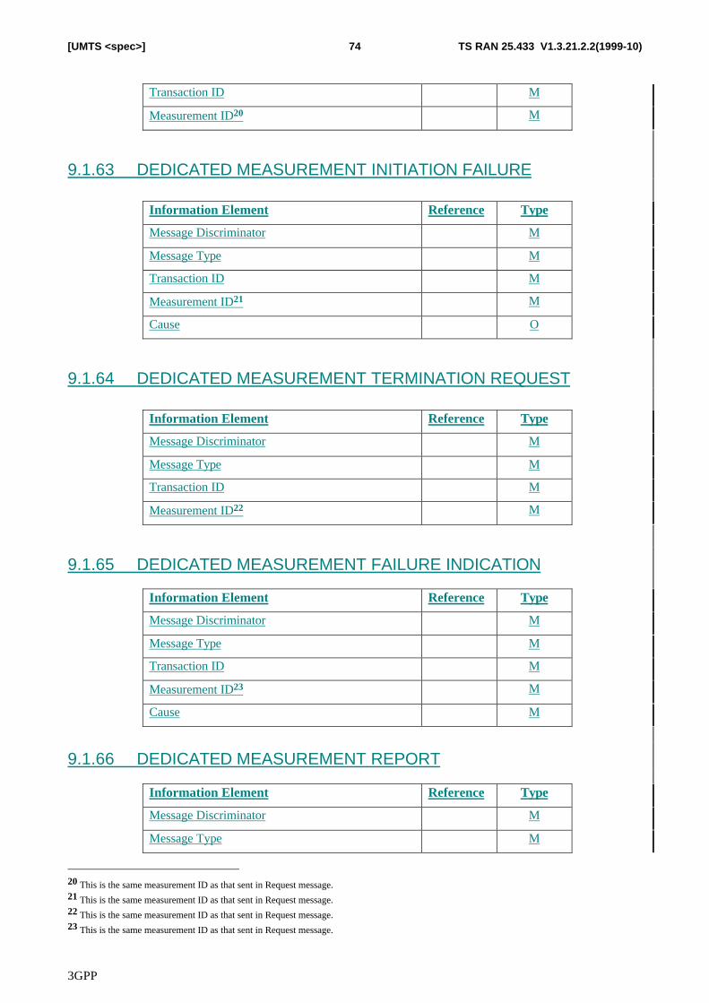
3GPP
TS RAN 25.433 V1.3.21.2.2(1999-10)74[UMTS <spec>]
Transaction ID M
Measurement ID20 M
9.1.63 DEDICATED MEASUREMENT INITIATION FAILURE
Information Element Reference Type
Message Discriminator M
Message Type M
Transaction ID M
Measurement ID21 M
Cause O
9.1.64 DEDICATED MEASUREMENT TERMINATION REQUEST
Information Element Reference Type
Message Discriminator M
Message Type M
Transaction ID M
Measurement ID22 M
9.1.65 DEDICATED MEASUREMENT FAILURE INDICATION
Information Element Reference Type
Message Discriminator M
Message Type M
Transaction ID M
Measurement ID23 M
Cause M
9.1.66 DEDICATED MEASUREMENT REPORT
Information Element Reference Type
Message Discriminator M
Message Type M
20 This is the same measurement ID as that sent in Request message.21 This is the same measurement ID as that sent in Request message.22 This is the same measurement ID as that sent in Request message.23 This is the same measurement ID as that sent in Request message.
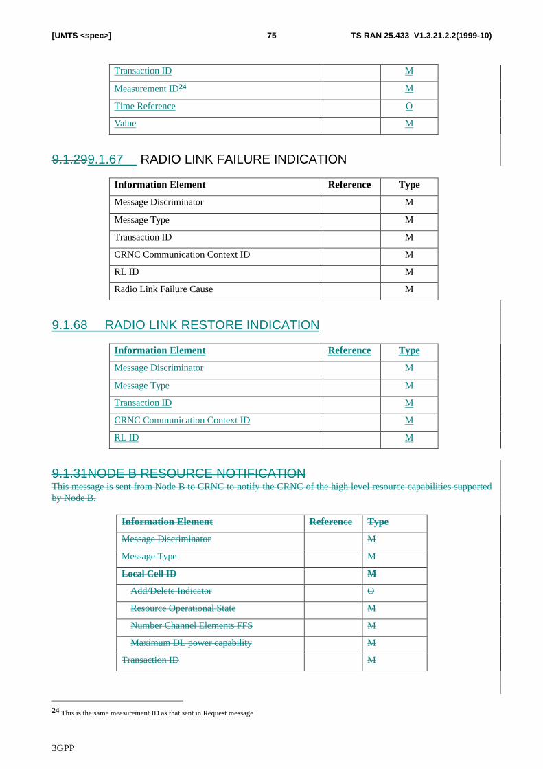
3GPP
TS RAN 25.433 V1.3.21.2.2(1999-10)75[UMTS <spec>]
Transaction ID M
Measurement ID24 M
Time Reference O
Value M
9.1.299.1.67 RADIO LINK FAILURE INDICATION
Information Element Reference Type
Message Discriminator M
Message Type M
Transaction ID M
CRNC Communication Context ID M
RL ID M
Radio Link Failure Cause M
9.1.68 RADIO LINK RESTORE INDICATION
Information Element Reference Type
Message Discriminator M
Message Type M
Transaction ID M
CRNC Communication Context ID M
RL ID M
9.1.31NODE B RESOURCE NOTIFICATIONThis message is sent from Node B to CRNC to notify the CRNC of the high level resource capabilities supportedby Node B.
Information Element Reference Type
Message Discriminator M
Message Type M
Local Cell ID M
Add/Delete Indicator O
Resource Operational State M
Number Channel Elements FFS M
Maximum DL power capability M
Transaction ID M
24 This is the same measurement ID as that sent in Request message
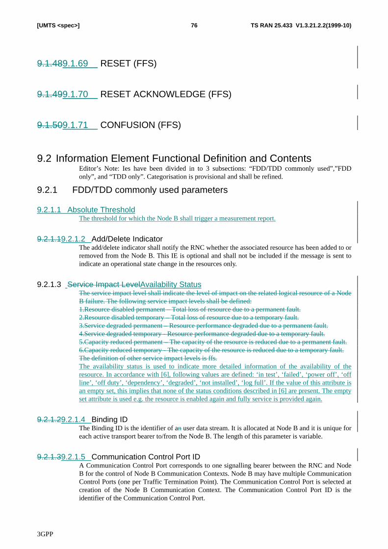
3GPP
TS RAN 25.433 V1.3.21.2.2(1999-10)76[UMTS <spec>]
9.1.489.1.69 RESET (FFS)
9.1.499.1.70 RESET ACKNOWLEDGE (FFS)
9.1.509.1.71 CONFUSION (FFS)
9.2 Information Element Functional Definition and ContentsEditor’s Note: Ies have been divided in to 3 subsections: “FDD/TDD commonly used”,”FDDonly”, and “TDD only”. Categorisation is provisional and shall be refined.
9.2.1 FDD/TDD commonly used parameters
9.2.1.1 Absolute ThresholdThe threshold for which the Node B shall trigger a measurement report.
9.2.1.19.2.1.2 Add/Delete IndicatorThe add/delete indicator shall notify the RNC whether the associated resource has been added to orremoved from the Node B. This IE is optional and shall not be included if the message is sent toindicate an operational state change in the resources only.
9.2.1.3 Service Impact LevelAvailability StatusThe service impact level shall indicate the level of impact on the related logical resource of a NodeB failure. The following service impact levels shall be defined:1.Resource disabled permanent – Total loss of resource due to a permanent fault.2.Resource disabled temporary – Total loss of resource due to a temporary fault.3.Service degraded permanent – Resource performance degraded due to a permanent fault.4.Service degraded temporary - Resource performance degraded due to a temporary fault.5.Capacity reduced permanent – The capacity of the resource is reduced due to a permanent fault.6.Capacity reduced temporary - The capacity of the resource is reduced due to a temporary fault.The definition of other service impact levels is ffs.The availability status is used to indicate more detailed information of the availability of theresource. In accordance with [6], following values are defined: ‘in test’, ‘failed’, ‘power off’, ‘offline’, ‘off duty’, ‘dependency’, ‘degraded’, ‘not installed’, ‘log full’. If the value of this attribute isan empty set, this implies that none of the status conditions described in [6] are present. The emptyset attribute is used e.g. the resource is enabled again and fully service is provided again.
9.2.1.29.2.1.4 Binding IDThe Binding ID is the identifier of an user data stream. It is allocated at Node B and it is unique foreach active transport bearer to/from the Node B. The length of this parameter is variable.
9.2.1.39.2.1.5 Communication Control Port IDA Communication Control Port corresponds to one signalling bearer between the RNC and NodeB for the control of Node B Communication Contexts. Node B may have multiple CommunicationControl Ports (one per Traffic Termination Point). The Communication Control Port is selected atcreation of the Node B Communication Context. The Communication Control Port ID is theidentifier of the Communication Control Port.
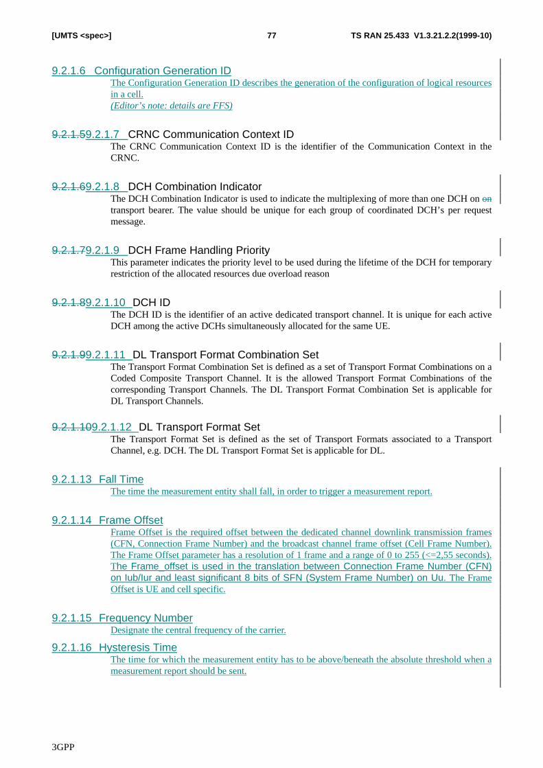
3GPP
TS RAN 25.433 V1.3.21.2.2(1999-10)77[UMTS <spec>]
9.2.1.6 Configuration Generation IDThe Configuration Generation ID describes the generation of the configuration of logical resourcesin a cell.(Editor’s note: details are FFS)
9.2.1.59.2.1.7 CRNC Communication Context IDThe CRNC Communication Context ID is the identifier of the Communication Context in theCRNC.
9.2.1.69.2.1.8 DCH Combination IndicatorThe DCH Combination Indicator is used to indicate the multiplexing of more than one DCH on ontransport bearer. The value should be unique for each group of coordinated DCH’s per requestmessage.
9.2.1.79.2.1.9 DCH Frame Handling PriorityThis parameter indicates the priority level to be used during the lifetime of the DCH for temporaryrestriction of the allocated resources due overload reason
9.2.1.89.2.1.10 DCH IDThe DCH ID is the identifier of an active dedicated transport channel. It is unique for each activeDCH among the active DCHs simultaneously allocated for the same UE.
9.2.1.99.2.1.11 DL Transport Format Combination SetThe Transport Format Combination Set is defined as a set of Transport Format Combinations on aCoded Composite Transport Channel. It is the allowed Transport Format Combinations of thecorresponding Transport Channels. The DL Transport Format Combination Set is applicable forDL Transport Channels.
9.2.1.109.2.1.12 DL Transport Format SetThe Transport Format Set is defined as the set of Transport Formats associated to a TransportChannel, e.g. DCH. The DL Transport Format Set is applicable for DL.
9.2.1.13 Fall TimeThe time the measurement entity shall fall, in order to trigger a measurement report.
9.2.1.14 Frame OffsetFrame Offset is the required offset between the dedicated channel downlink transmission frames(CFN, Connection Frame Number) and the broadcast channel frame offset (Cell Frame Number).The Frame Offset parameter has a resolution of 1 frame and a range of 0 to 255 (<=2,55 seconds).The Frame_offset is used in the translation between Connection Frame Number (CFN)on Iub/Iur and least significant 8 bits of SFN (System Frame Number) on Uu. The FrameOffset is UE and cell specific.
9.2.1.15 Frequency NumberDesignate the central frequency of the carrier.
9.2.1.16 Hysteresis TimeThe time for which the measurement entity has to be above/beneath the absolute threshold when ameasurement report should be sent.
3GPP
TS RAN 25.433 V1.3.21.2.2(1999-10)78[UMTS <spec>]
9.2.1.119.2.1.17 Indication Type (FFS)The indication type shall indicate the category of a failure with respect to its impact on the logicalresources supported at Node B. The following categories shall be defined:1. Service ImpactingAvailability Status – The failure has impacted on the logical resources
supported at Node B.2. Cell Control – The failure has impacted on the ability for the cell parameters to be
administered or O&M functions performed.The definition of other failure types is ffs.
9.2.1.129.2.1.18 Local Cell IDThe local cell ID represents resources in Node B that can be used for the configuration of a cell.
9.2.1.19 Maximum DL Power(Editor’s note: contents missing)
9.2.1.20 Maximum DL Power CapabilityThis parameter indicates the maximum DL power capability for a local cell within Node B.
9.2.1.139.2.1.21 Measurement CharacteristicDefines how the measurements should be performed, e.g. measurement frequency, timinginformation, filtering information.
9.2.1.149.2.1.22 Measurement IDRNC defined identifier that uniquely identifies the measurement.
9.2.1.159.2.1.23 Measurement ObjectDefines on which resource the measurement should be performed, e.g. cell. If more detailedinformation is necessary the measurement shall be performed as e.g. the timeslot indication in caseof TDD, this information belongs to the Measurement Object and is included within thisinformation element.
9.2.1.169.2.1.24 Measurement TypeDefines what measurements should be performed, e.g. the interference on UL.
9.2.1.179.2.1.25 Message discriminatorThis field is used to discriminate between Dedicated NBAP and Common NBAP messages.
9.2.1.189.2.1.26 Message TypeThe Message Type uniquely identifies the message being sent.
9.2.1.19Maximum DL Power CapabilityThis parameter indicates the maximum DL power capability for a local cell within Node B.
3GPP
TS RAN 25.433 V1.3.21.2.2(1999-10)79[UMTS <spec>]
9.2.1.27 MIB_SGSegment which is part of the Master Information Block.
9.2.1.28 MIB_SG_POSFirst position of the Master Information Block segment in the SFN cycle (MIB_SG_POS <MIB_SG_REP)
9.2.1.29 MIB_SG_REPRepetition distance for a Master Information Block segment. The segment shall be transmittedwhen SFN mod MIB_SG_REP = MIB_SG_POS.
9.2.1.30 Minimum DL Power(Editor’s: contents missing)
9.2.1.239.2.1.31 Node B Communication Context IDThe Node B Communication Context ID is the identifier of the Communication Context in theNode B, it corresponds to all the dedicated resources which are necessary for an UE using one ormore dedicated channels in a given Node B.
9.2.1.249.2.1.32 Number Channel ElementsThe number of channel elements is used to indicate to the RNC the maximum number ofsimultaneous user channels supported by a carrier. The exact definition of a channel element isFFS.
9.2.1.33 Payload CRC presence(Editor’s note: contents missing)
9.2.1.34 Priority IndicatorThe priority indicator is used to identify the immediacy with which the associated function shall beperformed. It is used to enable graceful shutdown of resources where operations impact on theseresources.
The following priority classes shall be supported in the priority indicator.
• Class 12 – High: High priority shutdown required (terminate resource immediately)• Class 23 – Normal: Standard priority shutdown required (attempt graceful resource
termination)• Class 3 – Low: Low priority shutdown required (terminate resource when idle)
9.2.1.35 Relative ThresholdThe distance that the measurement entity shall rise/fall, in order to trigger a measurement report.
9.2.1.259.2.1.36 Report CharacteristicsReporting can be any of the following:� Periodic: Reports shall be delivered with a periodicity which shall be defined.� Event: Reports shall be delivered upon a specified event in the node B.� Immediate: Reports shall be delivered immediately. Once the report is sent the measurement is
cancelled.
9.2.1.269.2.1.37 Resource Operational StateThe resource operational state is used to indicate the current operational state of the associated
3GPP
TS RAN 25.433 V1.3.21.2.2(1999-10)80[UMTS <spec>]
resource following a Node B failure. In accordance with [1], the resource operational state canhave the following values:1. Enabled2. DisabledNOTE: Where a resource is marked as disabled, then its child resources are implicitly disabled.
9.2.1.38 Reporting FrequencyThe frequency with which the Node B shall send measurement reports.
9.2.1.39 Rising TimeThe time the measurement entity shall rise on, in order to trigger a measurement report.
9.2.1.279.2.1.40 RL Failure CauseThe RL Failure Cause indicates the reason of unsuccessful radio link setup.
9.2.1.289.2.1.41 RL IDThe RL ID is the unique identifier for one RL associated with a UE
9.2.1.42 Shutdown TimerWhere a class 23 or class 4 shutdown has been requested, the shutdown timer shall indicate thelength of time available to the RNC to perform the shutdown of the resource. The range of theshutdown timer is ffs.
9.2.1.43 SIB_SGSegment which is part of a System Information Block.
9.2.1.44 SIB_SG_POSFirst position of the System Information Block segment in the SFN cycle (SIB_SG_POS <SIB_SG_REP).
9.2.1.45 SIB_SG_REPRepetition distance for a System Information Block segment. The segment shall be transmittedwhen SFN mod SIB_SG_REP = SIB_SG_POS.
9.2.1.33TFCI used flagIndicates whether TFCI shall be included in the DPCCH.
9.2.1.349.2.1.46 Time ReferenceTime Reference Sshows the time of the measurement (timestamp).
9.2.1.47 ToAWETOAWE is the window endpoint. DL data frames are expected to be received before this windowendpoint. TOAWE is defined with a positive value relative Latest Time of Arrival (LTOA). A dataframe arriving after TOAWS gives a Timing Adjustment Control frame response.The TOAWE is a CFN length parameter.The resolution is 1 ms, the range is: {0 .. CFN length –1 ms}
9.2.1.48 ToAWSTOAWS is the window startpoint. DL data frames are expected to be received after this windowstartpoint. TOAWS is defined with a positive value relative Time of Arrival Window Endpoint
3GPP
TS RAN 25.433 V1.3.21.2.2(1999-10)81[UMTS <spec>]
(TOAWE). A data frame arriving before TOAWS gives a Timing Adjustment Control frame response.The TOAWS is a CFN length parameter.The resolution is 1 ms, the range is: {0 .. CFN length/2 –1 ms}
9.2.1.359.2.1.49 Transaction IDThe Transaction ID is used to associate all the messages belonging to the same pending procedureof the same NBAP procedure type (e.g. Radio Link Addition), i.e. the Request-, Response-,Confirm-type of messages have the same Transaction ID. The messages belonging to differentpending procedures have different Transaction IdIDs.
9.2.1.50 Transmit Offset(Editor’s note: contents missing)
9.2.1.369.2.1.51 Transport Layer AddressTransport Layer Address defines the transport address of the NodeB. For details on the TransportAddress used see [2]. The addressing in UTRAN is FFS.The Transport Layer Address indicates the Node B transport address. The format of the TransportLayer Address is FFS.
9.2.1.379.2.1.52 UC-IdDThe UC-IDd is the identifier of a cell.
9.2.1.38UL Scrambling CodeThe UL Scrambling Code is the scrambling code used by UE. Every UE has its specific ULScrambling Code.(Editor’s note: this parameter may be only applicable to FDD)
9.2.1.53 UL FP mode(Editor’s note: contents missing)
9.2.1.54 UL interference levelThe UL interference level indicates the UL interference at a certain cell under DRNC. Thisparameter is transferred from DRNC to SRNC. This value will then be sent to UE by RRC so thatthe UE can calculate Initial UL power for itself.
9.2.1.399.2.1.55 UL Transport Format Combination SetThe Transport Format Combination Set is defined as a set of Transport Format Combinations on aCoded Composite Transport Channel. It is the allowed Transport Format Combinations of thecorresponding Transport Channels. The UL Transport Format Combination Set is applicable forUL Transport Channels.
9.2.1.409.2.1.56 UL Transport Format SetThe Transport Format Set is defined as the set of Transport Formats associated to a TransportChannel, e.g. DCH. The UL Transport Format Set is applicable for UL
9.2.1.419.2.1.57 Value“Value” Iincludes the reported data.
9.2.2 FDD specific parameters9.2.2.1 Chip Offset
The Chip Offset is defined as the radio timing offset inside a radio frame. The Chip Offset
3GPP
TS RAN 25.433 V1.3.21.2.2(1999-10)82[UMTS <spec>]
parameter has a resolution of 1 chip and a range of 0 to 38399 (< 10ms). The Chip_offsetis used as offset for the DL DPCH relative to the PCCPCH timing.
9.2.2.2 CPICH PowerCPICH power is the power that should be used for transmitting the CPICH in a cell.
9.2.2.3 Diversity Control FieldThe Diversity Control Field indicates if the current RL may, must or must not be combined withthe already existing RLs.
9.2.2.4 Diversity IndicationThe Diversity Indication indicates if the RL has been (ON) or has not been (OFF) combined withanother RL.
9.2.2.5 DL Channelisation Code Number for FDD useThe DL Channelisation Code is used to preserve the orthogonality between a cell’s different DLphysical channels, e.g. DPCH/CCPCH. The DL Channelisation Code Number indicates the DLChannelisation Code number for a specific DL physical channel a cell has.
9.2.2.6 DL Reference Power
Reference transmission power which is the CRNC requested downlink power to be used by thedownlink inner loop power control to eliminate the power drifting problem The usage is FFS.
9.2.2.7 DL Scrambling CodeDL scrambling code to be used by the RL. One cell may have multiple DL scrambling codesavailable.The DL Scrambling Code is the scrambling code used for each cell/RL. It is the same for allphysical channels in one cell, but different for different cells. One cell may have several DLScrambling Codes available.
9.2.2.8Frame OffsetFrame Offset is the required offset between the dedicated channel downlink transmission frames(CFN, Connection Frame Number) and the broadcast channel frame offset (Cell Frame Number).The Frame Offset parameter has a resolution of 1 frame and a range of 0 to 255 (<=2,55 seconds).The Frame_offset is used in the translation between Connection Frame Number (CFN)on Iub/Iur and least significant 8 bits of SFN (System Frame Number) on Uu. The FrameOffset is UE and cell specific.
9.2.2.99.2.2.8 Length of DL Channelisation Code for FDD useThe Length of UL Channelisation Code defines the level of the Channelisation code in the codetree. It is equivalent to the Spreading Factor.
9.2.2.109.2.2.9 Length of UL Channelisation Code for FDD useThe Length of UL Channelisation Code defines the level of the Channelisation code in the codetree. It is equivalent to the Spreading Factor.
9.2.2.10 Max Transmission PowerMax Transmission Power is maximum power for all downlink channels added together, that isallowed to be used simultaneously in a cell.

3GPP
TS RAN 25.433 V1.3.21.2.2(1999-10)83[UMTS <spec>]
9.2.2.11 Primary SCH PowerPrimary SCH power is the power that should be used for transmitting the primary SCH in a cell.
9.2.2.139.2.2.12 Propagation DelayPropagation delay (PD): It is the round tripone-way propagation delay of the radio signal from theBS to the MS and back to the BS in one chip resolution.
9.2.2.149.2.2.13 Reference RL IDThe Reference RL ID is the identifier of the radio link that the indicated radio link has beencombined with.
9.2.2.14 Secondary SCH PowerSecondary SCH power is the power that should be used for transmitting the secondary SCH in acell.
9.2.2.15 TFCI used flagTFCI used flag indicates whether TFCI shall be included in the DPCCH.
9.2.2.16 UL Eb/No TargetThe UL Eb/No Target indicates the UL Eb/No target to be used by the UL inner loop powercontrol.
9.2.2.17UL interference levelThe UL interference level indicates the UL interference at a certain cell under DRNC. Thisparameter is transferred from DRNC to SRNC. This value will then be sent to UE by RRC so thatthe UE can calculate Initial UL power for itself.
9.2.2.189.2.2.17 UL Scrambling CodeThe UL Scrambling Code is the scrambling code used by UE. Every UE has its specific ULScrambling Code.
9.2.3 TDD specific Parameters(Editor’s note: contributions are expected)
9.2.3.1 CCTrCH Activation CFNThe CFN of the frame in which the physical layer starts transmitting a CCTrCH
9.2.3.2 CCTrCH DurationThe CCTrCH Duration represents the number of frames for which the CCTrCH is activated.
Note: in case the Superframe Offset is not specified but only the CCTrCH Activation CFN, allDPCHs belonging to the same CCTrCH will start at the same time (i.e. at the CCTrCH ActivationCFN). In case neither the Superframe Offset nor the CCTrCH Activation CFN are specified, theSuperframe Offset for all DPCHs belonging to the same CCTrCH is assumed to be 0.
3GPP
TS RAN 25.433 V1.3.21.2.2(1999-10)84[UMTS <spec>]
9.2.3.3 CCCTrCH IDThe CCTrCH ID identifies unambiguously a CCTrCH inside a Radio Link.
9.2.3.4 Cell ParameterThe Cell Parameter identifies unambiguously the Code Groups, Scrambling Codes, Midamblesand Toffset (see table 9 of TS25.223)The range of this parameter is 0..127.
9.2.3.5 Channelisation Code code NUMBERNumberThe Channelisation Code Number indicates which Channelisation Code is used for a givenPhysical Channel. In TDD the Channelisation Code is an Orthogonal Variable Spreading Factorcode, that can have a spreading factor of 1, 2, 4, 8 or 16.The range of this parameter is 0 .. 30.
9.2.3.169.2.3.6 Chip Offset AdjustmentThe Chip Offset Adjustment represent the timing adjustment to be applied to achieve framesynchronisation.
9.2.3.109.2.3.7 DPCH IDThe DPCH ID identifies unambiguously a DPCH inside a Radio Link.
9.2.3.149.2.3.8 Measured Chip OffsetThe Measured Chip Offset represents the relative frame timing difference respect to the cell takenas reference (identified by the Measured Cell IdUC-ID)
9.2.3.9 Measured UC-IDThe Measured UC-ID identifies the cell taken as reference to measure the relative frame timingdifference
9.2.3.159.2.3.10 Measuring UCCell- IDdThe Measuring Cell IdUC-ID identifies the cell that performs the measurement of the relativeframe timing difference respect to the cell taken as reference (identified by the Measured CellIdUC-ID).
9.2.3.11 Midamble shiftIn TDD, different bursts transmitted simultaneously, using the same midamble code shall usedifferent Midamble Shifts.The 256 chip midamble supports 3 different time shifts, the 512 chips midamble may support 8 oreven 16 time shifts.The range of this parameter is 0 .. 15 for long midamble and 0 .. 2 for short midamble.
9.2.3.12Midamble TYPEIn TDD the midamble part of the burst can contain two different midamble types: a short one oflength 256 chips, or a long one of 512 chips. The data rate of the physical channel is depending onthe used midamble length.The values of this parameter are short and long.

3GPP
TS RAN 25.433 V1.3.21.2.2(1999-10)85[UMTS <spec>]
9.2.3.12 PCCPCH Time Slot (i)This IE is present only if PSCH & PCCPCH Allocation = Case 3.In that case this parameter assumes the value k=0…14.
9.2.3.13 PSCH and PCCPCH AllocationIn TDD the PSCH and PCCPCH are mapped on one or two downlink slots per frame. There arethree cases of PSCH and PCCPCH allocation as follows: Case 1) PSCH and PCCPCH allocated in a single TS#k Case 2) PSCH in two TS and PCCPCH in the same two TS: TS#k and TS#k+8 Case 3) PSCH in two TS, TS#k and TS#k+8, and the PCCPCH in TS#i, pointed by PSCH.The range of this parameter is therefore 1..3.
9.2.3.14 PSCH and PCCPCH Time Slot (k)When the value of PSCH and PCCPCH Allocation is:Case 1, then this parameters assume the value k=0….14Case 2 and Case 3, then this parameter assumes the value k=0…6
9.2.3.19PSCH TS id KThe timeslot in TDD that contains the Synchronisation channel.
9.2.3.15 PSCH PowerPSCH power is the power that should be used for transmitting the Physical Synch Channel in acell. Primary sequence (Primary SCH) and secondary sequences (Secondary SCH) aresuperimposed for transmission.Relation of TX power between Primary and Secondary is fixed, thus only one value is to beconfigured.
9.2.3.179.2.3.16 Repetition LengthIn TDD the Repetition Length represents the number of consecutive Radio Frames inside aRepetition Period in which the same Time Slot is assigned to the same Physical Channel.The values of this parameter are 1, 2, 4 and 8.
9.2.3.189.2.3.17 Repetition PeriodIn TDD, the Repetition Period represents the number of consecutive Radio Frames after which thesame assignment scheme of Time Slots to a Physical Channel is repeated. This means that if theTime Slot K is assigned to a physical channel in the Radio Frame J, it is assigned to the samephysical channel also in all the Radio Frames J+n*Repetition Period (where n is an integer).The Repetition Period is a submultiple of the Superframe length (72), i.e. 1, 2, 3, 4, 6, 8, 9, 12, 18,24, 36 or 72.
9.2.3.119.2.3.18 DL Scrambling Code for TDD useThe DL Scrambling Code is the scrambling code used for eachin a cell/RL.. It is the same for allphysical channels in one cell, but different for different cells.
9.2.3.209.2.3.19 Superframe OffsetIn TDD, the Superframe Offset represents the number of the first Radio Frame inside a Superframethat is assigned to a Physical Channel.The range of this parameter is 0 .. Repetition Period – 1.
3GPP
TS RAN 25.433 V1.3.21.2.2(1999-10)86[UMTS <spec>]
9.2.3.20 Supporting CCTrCH IDThe Supporting CCTrCH ID indicates on which CCTrCH is mapped a DCH.
9.2.3.189.2.3.21 Sync MidambleMidamble used for the of the TDD synchronisation channel for a neighbouring cell
9.2.3.239.2.3.22 TFCI PresenceThe TFCI PRESENCE parameter indicates whether the TFCI shall be included. This is importantfor CCTrCH, which have capacity on more than one physical channel.The values of this parameter are present and not present.
9.2.3.249.2.3.23 Time SlotIn TDD, the Time Slot represents the minimum time interval inside a Radio Frame that can beassigned to a Physical Channel.The range of this parameter is 0 .. 14.
9.2.3.24 Time Slot DirectionThis parameter indicates whether the TS in the cell is used in Uplink or Downlink direction.The values of this parameter are UL and DL.
9.2.3.25 Time Slot StatusThis parameter indicates whether the TS in the cell is active or not.The values of this parameter are Active and Not Active9.2.3.12UL Scrambling Code for TDD useThe DL Scrambling Code is the scrambling code used for each cell/RL. It is the same for allphysical channels in one cell, but different for different cells.
9.2.3.13Measured Cell IdThe Measured Cell Id identifies the cell taken as reference to measure the relative frame timingdifference.
9.2.3.179.2.3.26 ToffsetThe offset of the primary synchronisation code for a neighbouring cell
9.3 Message and Information element abstract syntax (with ASN.1)[Editor’s Note: ASN.1 shall be applied to describe the contents of each NBAP message. The applied version ofASN.1 is FFS]
9.3.1 PDU Description for NBAPChapter 12 **************************************************************--Chapter 12 PDU descriptions for NBAP.--Chapter 12 **************************************************************
NBAP-PDU-descriptions – { object identifier to be allocated }—DEFINITIONS AUTOMATIC TAGS ::=
BEGIN
Chapter 12 **************************************************************--Chapter 12 PDU content types from the PDU module.--Chapter 12 **************************************************************
3GPP
TS RAN 25.433 V1.3.21.2.2(1999-10)87[UMTS <spec>]
IMPORTSChapter 12 Imports PDU content types from NBAP PDU contents moduleChapter 12 *** TO BE DEFINED ***
ExampleMessageContents1,ExampleMessageContents2-v1,ExampleMessageContents2-v2,ExampleMessageContents3
FROM NBAP-PDU-contents;
Chapter 12 **************************************************************--Chapter 12 Table column structure.--Chapter 12 NBAP-PDU-DESCR associates a NBAP PDU structure with a PDUChapter 12 identifier.--Chapter 12 **************************************************************
NBAP-PDU-DESCR ::= CLASS {&PDUType,&versionID VersionID UNIQUE,&LogicalProcedure LogicalProcedure
}WITH SYNTAX {
PDU TYPE &PDUTypeVERSION NUMBER AND ID &versionIDLOGICAL PROCEDURE &LogicalProcedure
}
Chapter 12 *** TO BE DEFINED ***VersionID ::= SEQUENCE {
pduID INTEGER (0..63),versionNumber VersionNumber
}
Chapter 12 *** TO BE DEFINED ***VersionNumber ::= INTEGER (1 .. 255)
Chapter 12 *** TO BE DEFINED ***LogicalProcedure ::= ENUMERATED {
global,dedicated
}
Chapter 12 **************************************************************--Chapter 12 Table row definitions.--Chapter 12 NBAP PDU descriptions.--Chapter 12 **************************************************************
NBAP-PDUs NBAP-PDU-DESCR ::= {
Chapter 12 *** TO BE DEFINED ***
exampleMessage1 |exampleMessage2-v1 |exampleMessage2-v2 |exampleMessage3 |
Chapter 12 Additional PDU descriptions can be added in future
…}
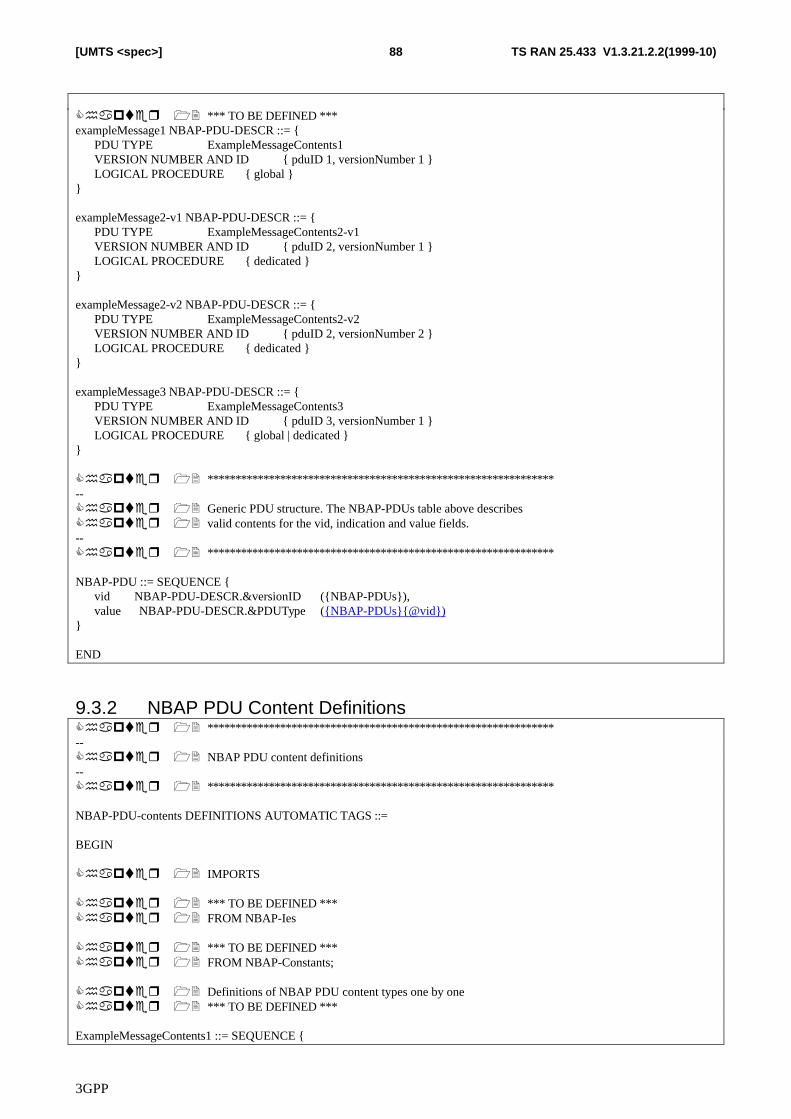
3GPP
TS RAN 25.433 V1.3.21.2.2(1999-10)88[UMTS <spec>]
Chapter 12 *** TO BE DEFINED ***exampleMessage1 NBAP-PDU-DESCR ::= {
PDU TYPE ExampleMessageContents1VERSION NUMBER AND ID { pduID 1, versionNumber 1 }LOGICAL PROCEDURE { global }
}
exampleMessage2-v1 NBAP-PDU-DESCR ::= {PDU TYPE ExampleMessageContents2-v1VERSION NUMBER AND ID { pduID 2, versionNumber 1 }LOGICAL PROCEDURE { dedicated }
}
exampleMessage2-v2 NBAP-PDU-DESCR ::= {PDU TYPE ExampleMessageContents2-v2VERSION NUMBER AND ID { pduID 2, versionNumber 2 }LOGICAL PROCEDURE { dedicated }
}
exampleMessage3 NBAP-PDU-DESCR ::= {PDU TYPE ExampleMessageContents3VERSION NUMBER AND ID { pduID 3, versionNumber 1 }LOGICAL PROCEDURE { global | dedicated }
}
Chapter 12 **************************************************************--Chapter 12 Generic PDU structure. The NBAP-PDUs table above describesChapter 12 valid contents for the vid, indication and value fields.--Chapter 12 **************************************************************
NBAP-PDU ::= SEQUENCE {vid NBAP-PDU-DESCR.&versionID ({NBAP-PDUs}),value NBAP-PDU-DESCR.&PDUType ({NBAP-PDUs}{@vid})
}
END
9.3.2 NBAP PDU Content DefinitionsChapter 12 **************************************************************--Chapter 12 NBAP PDU content definitions--Chapter 12 **************************************************************
NBAP-PDU-contents DEFINITIONS AUTOMATIC TAGS ::=
BEGIN
Chapter 12 IMPORTS
Chapter 12 *** TO BE DEFINED ***Chapter 12 FROM NBAP-Ies
Chapter 12 *** TO BE DEFINED ***Chapter 12 FROM NBAP-Constants;
Chapter 12 Definitions of NBAP PDU content types one by oneChapter 12 *** TO BE DEFINED ***
ExampleMessageContents1 ::= SEQUENCE {
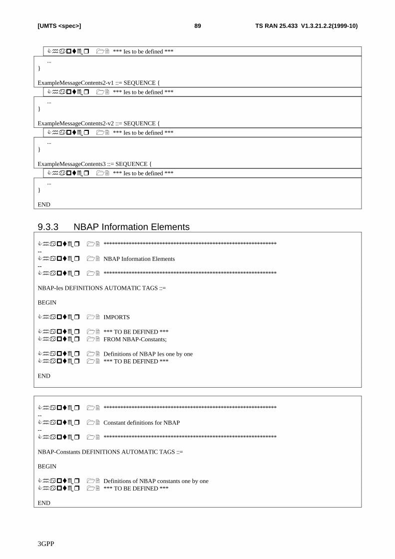
3GPP
TS RAN 25.433 V1.3.21.2.2(1999-10)89[UMTS <spec>]
Chapter 12 *** Ies to be defined ***
…}
ExampleMessageContents2-v1 ::= SEQUENCE {
Chapter 12 *** Ies to be defined ***
…}
ExampleMessageContents2-v2 ::= SEQUENCE {
Chapter 12 *** Ies to be defined ***
…}
ExampleMessageContents3 ::= SEQUENCE {
Chapter 12 *** Ies to be defined ***
…}
END
9.3.3 NBAP Information Elements
Chapter 12 **************************************************************--Chapter 12 NBAP Information Elements--Chapter 12 **************************************************************
NBAP-Ies DEFINITIONS AUTOMATIC TAGS ::=
BEGIN
Chapter 12 IMPORTS
Chapter 12 *** TO BE DEFINED ***Chapter 12 FROM NBAP-Constants;
Chapter 12 Definitions of NBAP Ies one by oneChapter 12 *** TO BE DEFINED ***
END
Chapter 12 **************************************************************--Chapter 12 Constant definitions for NBAP--Chapter 12 **************************************************************
NBAP-Constants DEFINITIONS AUTOMATIC TAGS ::=
BEGIN
Chapter 12 Definitions of NBAP constants one by oneChapter 12 *** TO BE DEFINED ***
END
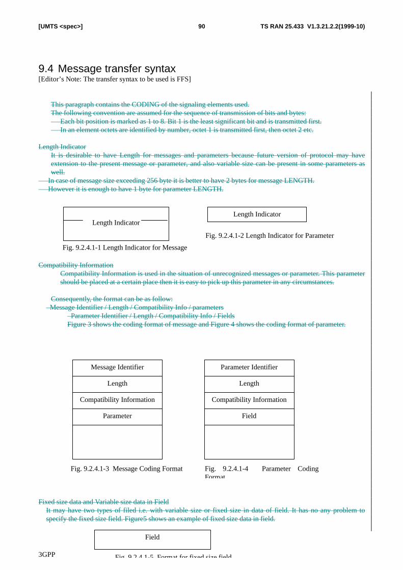
3GPP
TS RAN 25.433 V1.3.21.2.2(1999-10)90[UMTS <spec>]
9.4 Message transfer syntax[Editor’s Note: The transfer syntax to be used is FFS]
This paragraph contains the CODING of the signaling elements used.The following convention are assumed for the sequence of transmission of bits and bytes: Each bit position is marked as 1 to 8. Bit 1 is the least significant bit and is transmitted first. In an element octets are identified by number, octet 1 is transmitted first, then octet 2 etc.
Length IndicatorIt is desirable to have Length for messages and parameters because future version of protocol may haveextension to the present message or parameter, and also variable size can be present in some parameters aswell.
In case of message size exceeding 256 byte it is better to have 2 bytes for message LENGTH. However it is enough to have 1 byte for parameter LENGTH.
Compatibility InformationCompatibility Information is used in the situation of unrecognized messages or parameter. This parametershould be placed at a certain place then it is easy to pick up this parameter in any circumstances.
Consequently, the format can be as follow: Message Identifier / Length / Compatibility Info / parameters
Parameter Identifier / Length / Compatibility Info / FieldsFigure 3 shows the coding format of message and Figure 4 shows the coding format of parameter.
Fixed size data and Variable size data in FieldIt may have two types of filed i.e. with variable size or fixed size in data of field. It has no any problem tospecify the fixed size field. Figure5 shows an example of fixed size data in field.
Length IndicatorLength Indicator
Fig. 9.2.4.1-1 Length Indicator for Message
Fig. 9.2.4.1-2 Length Indicator for Parameter
Message Identifier
Length
Compatibility Information
Parameter
��
Fig. 9.2.4.1-3 Message Coding Format
Parameter Identifier
Length
Compatibility Information
Field
��
Fig. 9.2.4.1-4 Parameter CodingFormat
Field
Fig. 9.2.4.1-5 Format for fixed size field
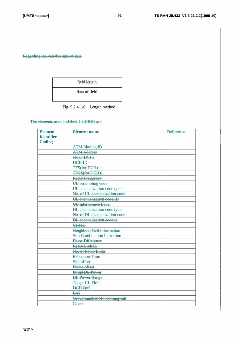
3GPP
TS RAN 25.433 V1.3.21.2.2(1999-10)91[UMTS <spec>]
Regarding the variable size of data
The elements used and their CODING are:
ElementIdentifierCoding
Element name Reference
ATM Binding IDATM AddressNo of DCHsDCH IDTFS(for DCH)TFCS(for DCHs)Radio FrequencyUL scrambling codeUL channelization code typeNo. of UL channelization codeUL channelization code IDUL Interference LevelDL channelization code typeNo. of DL channelization codeDL channelization code idCell IDNeighbour Cell InformationSoft Combination IndicationPhase DifferenceRadio Link IDNo. of Radio LinksExecution TimeSlot offsetFrame offsetInitial DL PowerDL Power RangeTarget UL Eb/IoDCH QoSLAIGroup number of incoming callCause
field length
data of field
Fig. 9.2.4.1-6 Length method
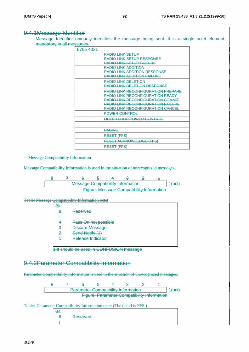
3GPP
TS RAN 25.433 V1.3.21.2.2(1999-10)92[UMTS <spec>]
9.4.1Message IdentifierMessage Identifier uniquely identifies the message being sent. It is a single octet element,mandatory in all messages.
8765 4321RADIO LINK SETUPRADIO LINK SETUP RESPONSERADIO LINK SETUP FAILURERADIO LINK ADDITIONRADIO LINK ADDITION RESPONSERADIO LINK ADDITION FAILURE
RADIO LINK DELETIONRADIO LINK DELETION RESPONSE
RADIO LINK RECONFIGURATION PREPARERADIO LINK RECONFIGURATION READYRADIO LINK RECONFIGURATION COMMITRADIO LINK RECONFIGURATION FAILURERADIO LINK RECONFIGURATION CANCELPOWER CONTROL
OUTER LOOP POWER CONTROL
PAGING
RESET (FFS)
RESET ACKNOWLEDGE (FFS)
RESET (FFS)
Message Compatibility Information
Message Compatibility Information is used in the situation of unrecognized messages.
8 7 6 5 4 3 2 1Message Compatibility Information 1(oct)
Figure: Message Compatibility Information
Table: Message Compatibility Information octet Bit
8 Reserved:4 Pass On not possible321
Discard MessageSend Notify (1)Release Indicator
1.It should be used in CONFUSION message
9.4.2Parameter Compatibility Information
Parameter Compatibility Information is used in the situation of unrecognized messages.
8 7 6 5 4 3 2 1Parameter Compatibility Information 1(oct)
Figure: Parameter Compatibility Information
Table: Parameter Compatibility Information octet (The detail is FFS.) Bit
8 Reserved:
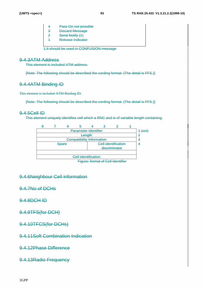
3GPP
TS RAN 25.433 V1.3.21.2.2(1999-10)93[UMTS <spec>]
4 Pass On not possible321
Discard MessageSend Notify (1)Release Indicator
1.It should be used in CONFUSION message
9.4.3ATM AddressThis element is included ATM address.
[Note: The following should be described the cording format. (The detail is FFS.)]
9.4.4ATM Binding ID
This element is included ATM Binding ID.
[Note: The following should be described the cording format. (The detail is FFS.)]
9.4.5Cell IDThis element uniquely identifies cell which a RNC and is of variable length containing.
8 7 6 5 4 3 2 1Parameter Identifier 1 (oct)
Length 2Compatibility Information 3
Spare Cell identificationdiscriminator
4
Cell IdentificationFigure: format of Cell Identifier
9.4.6Neighbour Cell information
9.4.7No of DCHs
9.4.8DCH ID
9.4.9TFS(for DCH)
9.4.10TFCS(for DCHs)
9.4.11Soft Combination Indication
9.4.12Phase Difference
9.4.13Radio Frequency
3GPP
TS RAN 25.433 V1.3.21.2.2(1999-10)94[UMTS <spec>]
9.4.14UL Interference level
9.4.15UL scrambling code
9.4.16UL channelization code type
9.4.17No. of UL channelization codes
9.4.18UL channelization code ID
9.4.19DL channelization code type
9.4.20No. of Radio Links
9.4.21Radio Link ID
9.4.22No. of DL channelization codes
9.4.23DL channelization code ID
9.4.24Execution Timer
9.4.25Initial DL Power
9.4.26DL Power RangeThis Information element defines the DL transmission power range to be used for the radio links usedfor the related RRC connection in the node-B.
9.4.27Target UL Eb/Io
9.4.28Slot Offset
9.4.29Frame Offset
9.4.30DCH QoS
9.4.31LAI
9.4.32Group number of incoming call
9.4.33Cause
This element is used to indicate the reason for a particular event to have occurred and is coded asshown below.
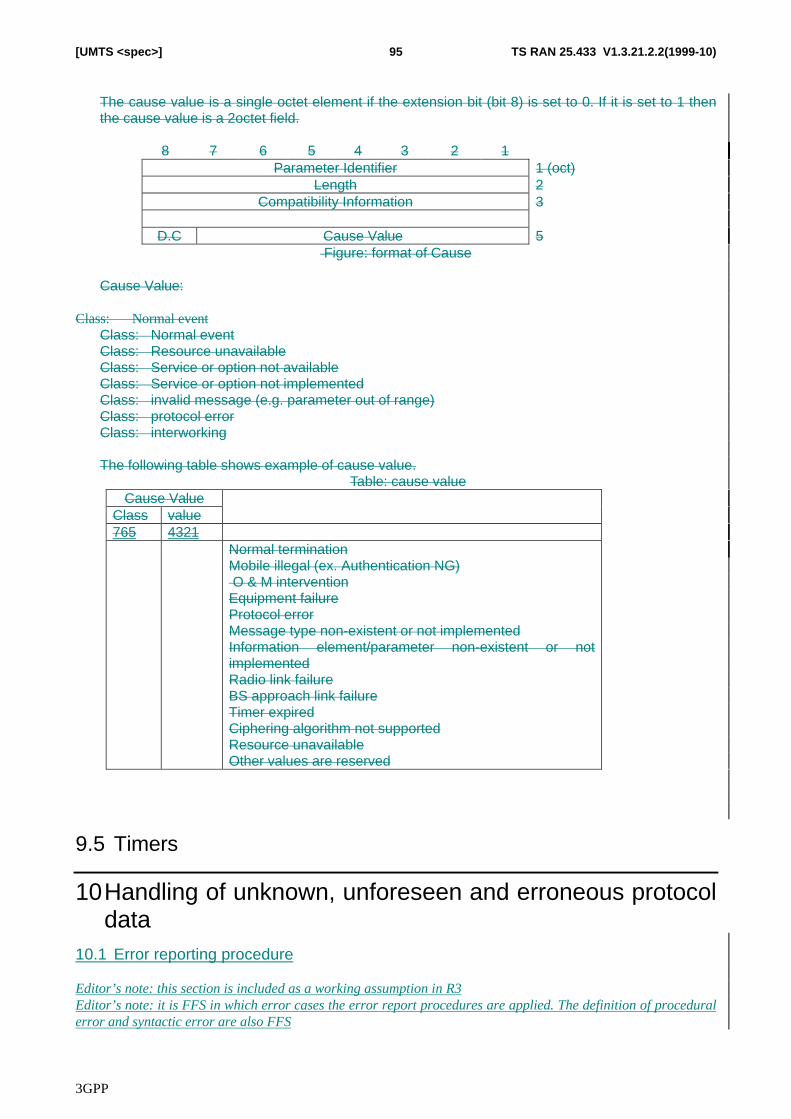
3GPP
TS RAN 25.433 V1.3.21.2.2(1999-10)95[UMTS <spec>]
The cause value is a single octet element if the extension bit (bit 8) is set to 0. If it is set to 1 thenthe cause value is a 2octet field.
8 7 6 5 4 3 2 1Parameter Identifier 1 (oct)
Length 2Compatibility Information 3
D.C Cause Value 5 Figure: format of Cause
Cause Value:
Class: Normal eventClass: Normal eventClass: Resource unavailableClass: Service or option not availableClass: Service or option not implementedClass: invalid message (e.g. parameter out of range)Class: protocol errorClass: interworking
The following table shows example of cause value.Table: cause value
Cause ValueClass value765 4321
Normal terminationMobile illegal (ex. Authentication NG) O & M interventionEquipment failureProtocol errorMessage type non-existent or not implementedInformation element/parameter non-existent or notimplementedRadio link failureBS approach link failureTimer expiredCiphering algorithm not supportedResource unavailableOther values are reserved
9.5 Timers
10 Handling of unknown, unforeseen and erroneous protocoldata
10.1 Error reporting procedure
Editor’s note: this section is included as a working assumption in R3Editor’s note: it is FFS in which error cases the error report procedures are applied. The definition of proceduralerror and syntactic error are also FFS
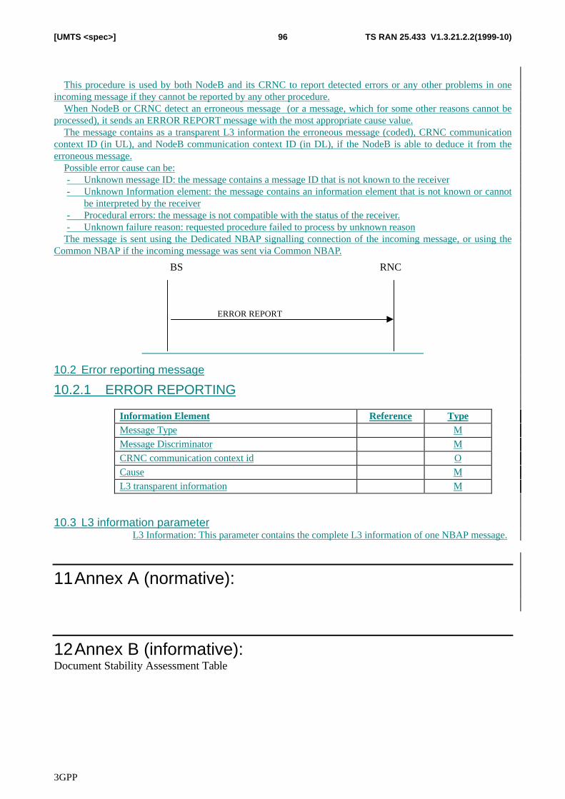
3GPP
TS RAN 25.433 V1.3.21.2.2(1999-10)96[UMTS <spec>]
This procedure is used by both NodeB and its CRNC to report detected errors or any other problems in oneincoming message if they cannot be reported by any other procedure.
When NodeB or CRNC detect an erroneous message (or a message, which for some other reasons cannot beprocessed), it sends an ERROR REPORT message with the most appropriate cause value.
The message contains as a transparent L3 information the erroneous message (coded), CRNC communicationcontext ID (in UL), and NodeB communication context ID (in DL), if the NodeB is able to deduce it from theerroneous message.
Possible error cause can be:- Unknown message ID: the message contains a message ID that is not known to the receiver- Unknown Information element: the message contains an information element that is not known or cannot
be interpreted by the receiver- Procedural errors: the message is not compatible with the status of the receiver.- Unknown failure reason: requested procedure failed to process by unknown reason
The message is sent using the Dedicated NBAP signalling connection of the incoming message, or using theCommon NBAP if the incoming message was sent via Common NBAP.
RNC
ERROR REPORT
BS
10.2 Error reporting message
10.2.1 ERROR REPORTING
Information Element Reference TypeMessage Type M
Message Discriminator M
CRNC communication context id O
Cause M
L3 transparent information M
10.3 L3 information parameterL3 Information: This parameter contains the complete L3 information of one NBAP message.
11 Annex A (normative):
12 Annex B (informative):Document Stability Assessment Table
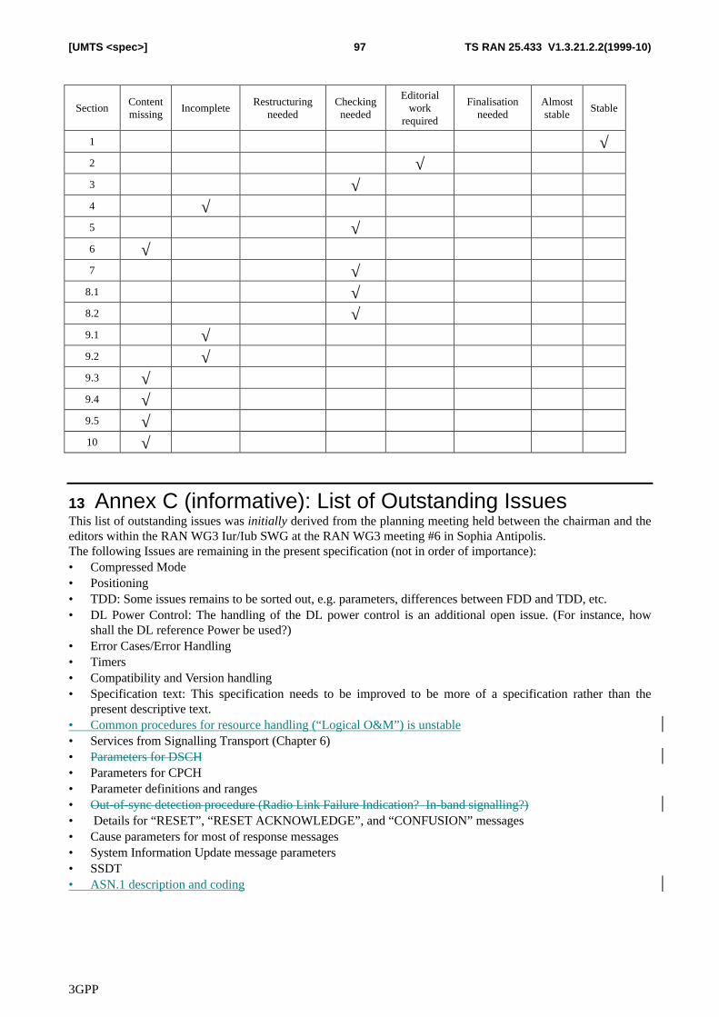
3GPP
TS RAN 25.433 V1.3.21.2.2(1999-10)97[UMTS <spec>]
SectionContentmissing
IncompleteRestructuring
neededCheckingneeded
Editorialwork
required
Finalisationneeded
Almoststable
Stable
1 √2 √3 √4 √5 √6 √7 √
8.1 √8.2 √9.1 √9.2 √9.3 √9.4 √9.5 √10 √
13 Annex C (informative): List of Outstanding IssuesThis list of outstanding issues was initially derived from the planning meeting held between the chairman and theeditors within the RAN WG3 Iur/Iub SWG at the RAN WG3 meeting #6 in Sophia Antipolis.The following Issues are remaining in the present specification (not in order of importance):• Compressed Mode• Positioning• TDD: Some issues remains to be sorted out, e.g. parameters, differences between FDD and TDD, etc.• DL Power Control: The handling of the DL power control is an additional open issue. (For instance, how
shall the DL reference Power be used?)• Error Cases/Error Handling• Timers• Compatibility and Version handling• Specification text: This specification needs to be improved to be more of a specification rather than the
present descriptive text.• Common procedures for resource handling (“Logical O&M”) is unstable• Services from Signalling Transport (Chapter 6)• Parameters for DSCH• Parameters for CPCH• Parameter definitions and ranges• Out-of-sync detection procedure (Radio Link Failure Indication? In-band signalling?)• Details for “RESET”, “RESET ACKNOWLEDGE”, and “CONFUSION” messages• Cause parameters for most of response messages• System Information Update message parameters• SSDT• ASN.1 description and coding
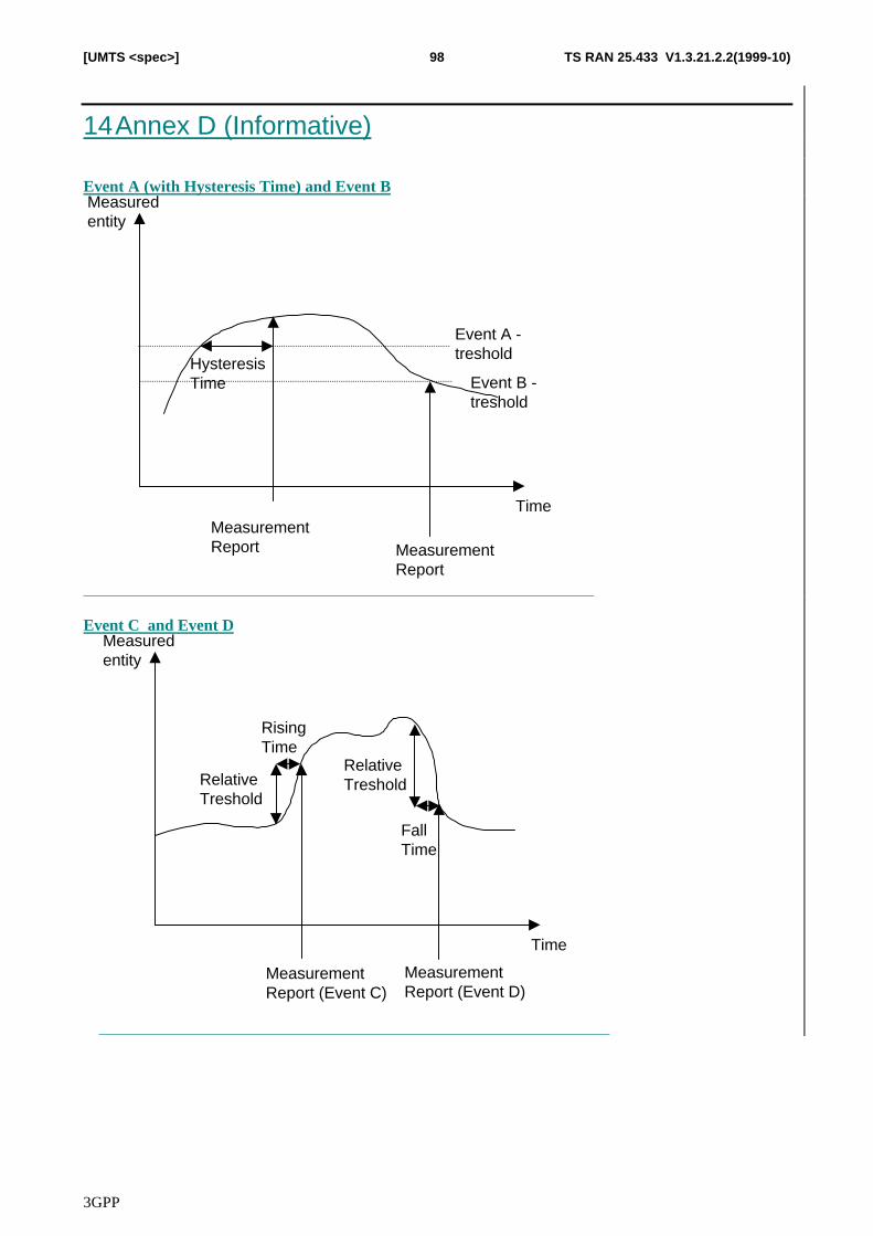
3GPP
TS RAN 25.433 V1.3.21.2.2(1999-10)98[UMTS <spec>]
14 Annex D (Informative)
Event A (with Hysteresis Time) and Event BMeasuredentity
TimeMeasurementReport
Event A -treshold
MeasurementReport
Event B -treshold
HysteresisTime
Event C and Event DMeasuredentity
Time
MeasurementReport (Event C)
RelativeTreshold
MeasurementReport (Event D)
RelativeTreshold
RisingTime
FallTime
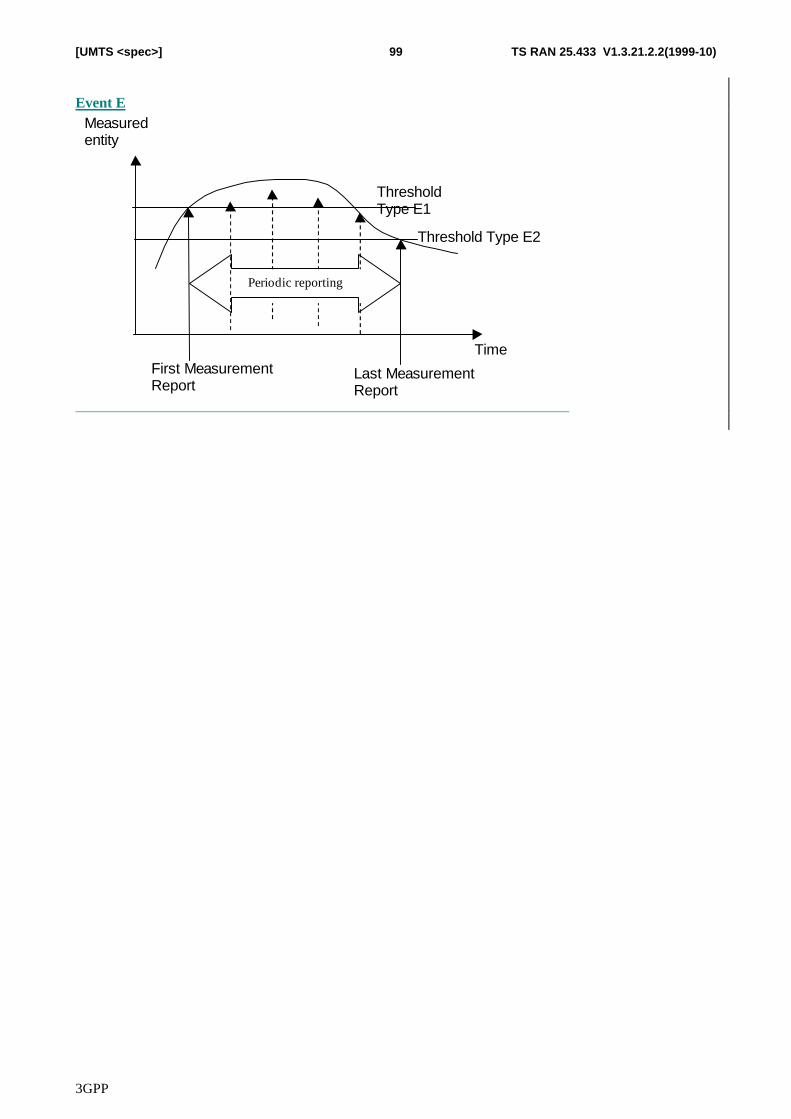
3GPP
TS RAN 25.433 V1.3.21.2.2(1999-10)99[UMTS <spec>]
Event EMeasuredentity
TimeFirst MeasurementReport
ThresholdType E1
Last MeasurementReport
Threshold Type E2
Periodic reporting
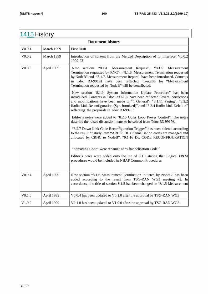
3GPP
TS RAN 25.433 V1.3.21.2.2(1999-10)100[UMTS <spec>]
1415 HistoryDocument history
V0.0.1 March 1999 First Draft
V0.0.2 March 1999 Introduction of content from the Merged Description of Iub Interface, V0.0.21999-03
V0.0.3 April 1999 New sections “8.1.4. Measurement Request”, “8.1.5. MeasurementTermination requested by RNC” , “8.1.6. Measurement Termination requestedby NodeB” and “8.1.7. Measurement Report” have been introduced. Contentsin Tdoc R3-99191 have been reflected. Contents for “MeasurementTermination requested by NodeB” will be contributed.
New section “8.1.9. System Information Update Procedure” has beenintroduced. Contents in Tdoc R99-192 have been reflected Several correctionsand modifications have been made to “4 General”, “8.1.11 Paging”, “8.2.2Radio Link Reconfiguration (Synchronized)”, and “8.2.4 Radio Link Deletion”reflecting the proposals in Tdoc R3-99193
Editor’s notes were added to “8.2.6 Outer Loop Power Control”. The notesdescribe the raised discussion items to be solved from Tdoc R3-99176.
“8.2.7 Down Link Code Reconfiguration Trigger” has been deleted accordingto the result of study item “ARC/2: DL Channelisation codes are managed andallocated by CRNC to NodeB”. “9.1.16 DL CODE RECONFIGURATION
“Spreading Code” were renamed to “Channelisation Code”
Editor’s notes were added onto the top of 8.1.1 stating that Logical O&Mprocedures would be included in NBAP Common Procedures
V0.0.4 April 1999 New section “8.1.6 Measurement Termination initiated by NodeB” has beenadded according to the result from TSG-RAN WG3 meeting #2. Inaccordance, the title of section 8.1.5 has been changed to “8.1.5 Measurement
V0.1.0 April 1999 V0.0.4 has been updated to V0.1.0 after the approval by TSG-RAN WG3
V1.0.0 April 1999 V0.1.0 has been updated to V1.0.0 after the approval by TSG-RAN WG3
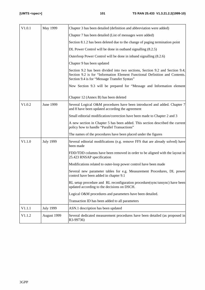
3GPP
TS RAN 25.433 V1.3.21.2.2(1999-10)101[UMTS <spec>]
V1.0.1 May 1999 Chapter 3 has been detailed (definition and abbreviation were added)
Chapter 7 has been detailed (List of messages were added)
Section 8.1.2 has been deleted due to the change of paging termination point
DL Power Control will be done in outband signalling (8.2.5)
Outerloop Power Control will be done in inband signalling (8.2.6)
Chapter 9 has been updated
Section 9.2 has been divided into two sections, Section 9.2 and Section 9.4;Section 9.2 is for “Information Element Functional Definition and Contents.Section 9.4 is for “Message Transfer Syntax”
New Section 9.3 will be prepared for “Message and Information element
Chapter 12 (Annex B) has been deleted
V1.0.2 June 1999 Several Logical O&M procedures have been introduced and added. Chapter 7and 8 have been updated according the agreement
Small editorial modification/correction have been made to Chapter 2 and 3
A new section in Chapter 5 has been added. This section described the currentpolicy how to handle “Parallel Transactions”
The names of the procedures have been placed under the figures
V1.1.0 July 1999 Several editorial modifications (e.g. remove FFS that are already solved) havebeen made
FDD/TDD columns have been removed in order to be aligned with the layout in25.423 RNSAP specification
Modifications related to outer-loop power control have been made
Several new parameter tables for e.g. Measurement Procedures, DL powercontrol have been added in chapter 9.1
RL setup procedure and RL reconfiguration procedure(sync/unsync) have beenupdated according to the decisions on DSCH.
Logical O&M procedures and parameters have been detailed.
Transaction ID has been added to all parameters
V1.1.1 July 1999 ASN.1 description has been updated
V1.1.2 August 1999 Several dedicated measurement procedures have been detailed (as proposed inR3-99736)
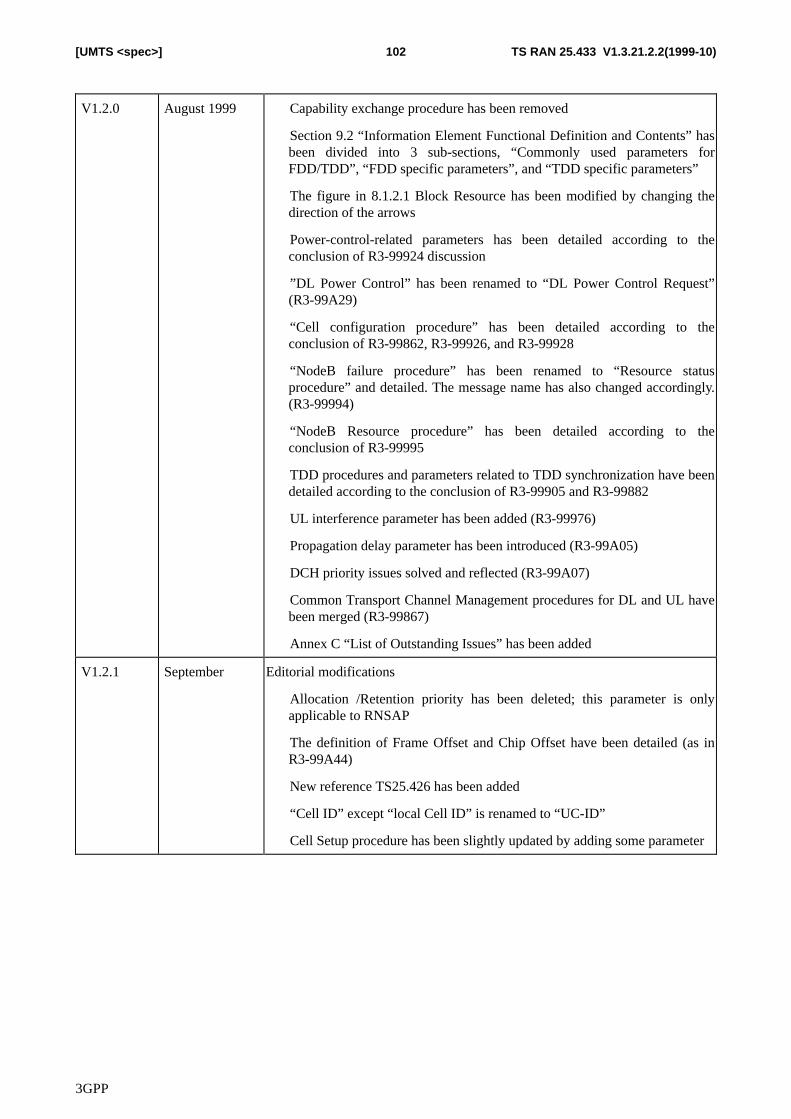
3GPP
TS RAN 25.433 V1.3.21.2.2(1999-10)102[UMTS <spec>]
V1.2.0 August 1999 � Capability exchange procedure has been removed
� Section 9.2 “Information Element Functional Definition and Contents” hasbeen divided into 3 sub-sections, “Commonly used parameters forFDD/TDD”, “FDD specific parameters”, and “TDD specific parameters”
� The figure in 8.1.2.1 Block Resource has been modified by changing thedirection of the arrows
� Power-control-related parameters has been detailed according to theconclusion of R3-99924 discussion
� ”DL Power Control” has been renamed to “DL Power Control Request”(R3-99A29)
� “Cell configuration procedure” has been detailed according to theconclusion of R3-99862, R3-99926, and R3-99928
� “NodeB failure procedure” has been renamed to “Resource statusprocedure” and detailed. The message name has also changed accordingly.(R3-99994)
� “NodeB Resource procedure” has been detailed according to theconclusion of R3-99995
� TDD procedures and parameters related to TDD synchronization have beendetailed according to the conclusion of R3-99905 and R3-99882
� UL interference parameter has been added (R3-99976)
� Propagation delay parameter has been introduced (R3-99A05)
� DCH priority issues solved and reflected (R3-99A07)
� Common Transport Channel Management procedures for DL and UL havebeen merged (R3-99867)
� Annex C “List of Outstanding Issues” has been added
V1.2.1 September Editorial modifications
� Allocation /Retention priority has been deleted; this parameter is onlyapplicable to RNSAP
� The definition of Frame Offset and Chip Offset have been detailed (as inR3-99A44)
� New reference TS25.426 has been added
� “Cell ID” except “local Cell ID” is renamed to “UC-ID”
� Cell Setup procedure has been slightly updated by adding some parameter
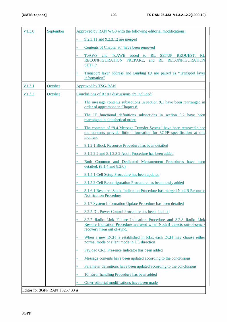
3GPP
TS RAN 25.433 V1.3.21.2.2(1999-10)103[UMTS <spec>]
V1.3.0 September Approved by RAN WG3 with the following editorial modifications:
• 9.2.3.11 and 9.2.3.12 are merged
• Contents of Chapter 9.4 have been removed
• ToAWS and ToAWE added to RL SETUP REQUEST, RLRECONFIGURATION PREPARE, and RL RECONFIGURATIONSETUP
• Transport layer address and Binding ID are paired as “Transport layerinformation”
V1.3.1 October Approved by TSG-RAN
V1.3.2 October Conclusions of R3 #7 discussions are included:
• The message contents subsections in section 9.1 have been rearranged inorder of appearance in Chapter 8.
• The IE functional definitions subsections in section 9.2 have beenrearranged in alphabetical order.
• The contents of “9.4 Message Transfer Syntax” have been removed sincethe contents provide little information for 3GPP specification at thismoment.
• 8.1.2.1 Block Resource Procedure has been detailed
• 8.1.2.2.2 and 8.1.2.3.2 Audit Procedure has been added
• Both Common and Dedicated Measurement Procedures have beendetailed. (8.1.4 and 8.2.6)
• 8.1.5.1 Cell Setup Procedure has been updated
• 8.1.5.2 Cell Reconfiguration Procedure has been newly added
• 8.1.6.1 Resource Status Indication Procedure has merged NodeB ResourceNotification Procedure
• 8.1.7 System Information Update Procedure has been detailed
• 8.2.5 DL Power Control Procedure has been detailed
• 8.2.7 Radio Link Failure Indication Procedure and 8.2.8 Radio LinkRestore Indication Procedure are used when NodeB detects out-of-sync /recovery from out of-sync.
• When a new DCH is established in RLs, each DCH may choose eithernormal mode or silent mode in UL direction
• Payload CRC Presence Indicator has been added
• Message contents have been updated according to the conclusions
• Parameter definitions have been updated according to the conclusions
• 10. Error handling Procedure has been added
• Other editorial modifications have been made
Editor for 3GPP RAN TS25.433 is:
3GPP
TS RAN 25.433 V1.3.21.2.2(1999-10)104[UMTS <spec>]
Nobutaka IshikawaNTT DoCoMo
Tel.: +81 468 40 3220Fax : +81 468 40 3840Email : [email protected]
This document is written in Microsoft Word 2000.


![3G TS 25.433 V1.0 - 株式会社QT · PDF file3GPP [UMTS ] 4 3G TS 25.433 V1.0 ... 9.1.4 Radio Link Setup Failure ... TFCI Transport Format Combination Indicator TFCS Transport Format](https://static.cupdf.com/doc/110x72/5a707a147f8b9aa2538c1791/3g-ts-25433-v10-qtwwwqtcjp3gppspecs25433-102pdfpdf.jpg)