7/28/2019 2 Kontrolleri ATS 021 En
http://slidepdf.com/reader/full/2-kontrolleri-ats-021-en 1/36
Automatic transfer switch ATS021
Installation and operating instructions34ATS021 / 1SDH000759R0002

7/28/2019 2 Kontrolleri ATS 021 En
http://slidepdf.com/reader/full/2-kontrolleri-ats-021-en 2/36

7/28/2019 2 Kontrolleri ATS 021 En
http://slidepdf.com/reader/full/2-kontrolleri-ats-021-en 3/36
3
1SDH000759R0002, L4106
Installation and operating instructions, ATS021Contents
Contents1. Introduction ....................................................................................................................... 41.1 Use of symbols ............... .............. ............... .............. ............... .............. ............... .............. ......... 41.2 Standards ............. ............... .............. ............... .............. ............... .............. ............... .............. .... 4
1.3 Safety notes ............. .............. ............... .............. ............... .............. ............... .............. ............... .51.4 Explanations of abbreviations and terms .............. .............. .............. ............... .............. .............. 6
2. Product overview .............................................................................................................. 72.1 Typical applications ............. .............. ............... .............. ............... .............. ............... .............. .... 72.2 Functions of automatic transfer switch ATS021 ............... .............. ............... .............. ............... .8
3. Description ..................................................................................................................... 103.1 Application scenarios ............... .............. ............... .............. ............... .............. ............... ........... 103.1.1 Automatic functions ............. .............. ............... .............. ............... .............. ............... .............. ..103.1.2 Manual functions .............. ............... .............. ............... .............. ............... .............. ............... .... 113.1.3 Test sequence ............... .............. .............. ............... .............. ............... .............. ............... ......... 11
3.1.4 Missing of both lines .............. ............... .............. ............... .............. ............... .............. .............. 123.1.5 Logic Enable/Disable input .............. .............. ............... .............. ............... .............. ............... .... 123.2 Parameter settings ............... .............. ............... .............. ............... .............. ............... .............. ..12
4. Operating ......................................................................................................................... 134.1 Automatic transfer switch ATS021 in Manual Mode ............... .............. .............. ............... ......... 134.2 Automatic transfer switch ATS021 in Automatic Mode .............. ............... .............. ............... .... 154.3 Selection of delay time and voltage threshold ............................................................................154.4 TEST sequence ............... .............. ............... .............. ............... .............. ............... .............. ....... 16
5. Installation ...................................................................................................................... 175.1 Parameter settings in automatic transfer switch ATS021 ...............................................................17
5.1.1 Parameter settings by DIP switches .............. ............... .............. ............... .............. ............... .... 185.2 Mounting the automatic transfer switch ATS021 ............... .............. ............... .............. .............. 205.2.1 Automatic transfer switch ATS021, door mounting ............. ............... .............. ............... ........... 205.2.2 Automatic transfer switch ATS021, DIN-rail mounting ............. .............. ............... .............. ....... 21
6. Connecting .................................................................................................................... 226.1 Power circuit .............. .............. ............... .............. .............. ............... .............. ............... ......... 226.2 Control circuit ............... .............. .............. ............... .............. ............... .............. ............... ......... 236.2.1 Control circuit of the automatic transfer switch ATS021 ............... .............. ............... .............. ..24
7. Using automatic transfer switch ATS021 ..................................................................... 267.1 Interface .............. .............. ............... .............. ............... .............. ............... .............. ............... .... 26
7.2 Con guration .............................................................................................................................267.2.1 Rotary Switches .............. .............. ............... .............. ............... .............. ............... .............. ....... 267.2.2 Keypad ............. ............... .............. ............... .............. ............... .............. ............... .............. ....... 277.2.3 LEDs .............. ............... .............. ............... .............. .............. ............... .............. ............... ......... 287.2.4 External transformer .............. ............... .............. ............... .............. ............... .............. .............. 297.3 TEST sequence ............... .............. ............... .............. ............... .............. ............... .............. ....... 30
8. Technical data of the automatic transfer switch ATS021 ............................................ 31
9. Troubleshooting .............................................................................................................. 329.1 Explanations of internal faults ATS021 ............. .............. ............... .............. ............... .............. ..32
7/28/2019 2 Kontrolleri ATS 021 En
http://slidepdf.com/reader/full/2-kontrolleri-ats-021-en 4/36
Installation and operating instructions, ATS021
1SDH000759R0002, L4106
4
1. Introduction
Hazardous voltage: warns about a situation where a hazardous voltage may causephysical injury to a person or damage to equipment.
General warning: warns about a situation where something other than electricalequipment may cause physical injury to a person or damage to equipment.
Caution: provides important information or warns about a situation that mayhave a detrimental effect on equipment.
Information: provides important information about the equipment.
1. IntroductionThis manual describes the installation and the basic operation of the automatic transfer switch ATS021used with circuit breakers.
1.1 Use of symbols
1.2 StandardsThe ATS021 are compliant with the following standards:
European Directive 73/23 “LVD – Low Voltage Directive”EN-IEC 50178 electronic equipment for use in power installationsEN-IEC 62103 electronic equipment for use in power installationsEN-IEC 60947-5-1 low voltage switchgear and control gear: control circuit devices and switchingelements
Electromagnetic compatibility EN 50081-2, EN 50082-2Environmental conditions IEC 68-2-1, IEC 68-2-2, and IEC 68-2-3
EN-IEC 61000-4-2: Electromagnetic compatibility (EMC) - Part 4: Testing and measurementtechniques
Section 2: Electrostatic discharge immunity test Basic EMC Publication (IEC 1000-4-2 [8KV air,4KV cont])
EN-IEC 61000-4-3, Electromagnetic compatibility (EMC) - Part 4: Testing and measurementtechniques Section 3: Radiated, radio-frequency, electromagnetic eld immunity test(IEC 1000-4-3 [level 3])EN-IEC 61000-4-4, Electromagnetic compatibility (EMC) - Part 4: Testing and measurementtechniques Section 4: Electrical fast transient/burst immunity test Basic EMC Publication(IEC 1000-4-4 [level 2/3])
EN-IEC 61000-4-5, Electromagnetic compatibility (EMC) - Part 4: Testing and measurementtechniques Section 5: Surge immunity test (IEC 1000-4-5 [level 1/2])

7/28/2019 2 Kontrolleri ATS 021 En
http://slidepdf.com/reader/full/2-kontrolleri-ats-021-en 5/36
5
1SDH000759R0002, L4106
Installation and operating instructions, ATS021
Even if the unit seems to be in stand by status, switch it OFF before operating oncircuit breakers. It may happen that the unit would operate the circuit breakers withoutwarning.
1. Introduction
EN-IEC 61000-4-6: Electromagnetic compatibility (EMC) - Part 4: Testing and measurementtechniques (IEC 1000-4-6 [level 3])
EN-IEC 61000-4-8: Electromagnetic compatibility (EMC) - Part 4: Testing and measurementtechniques (IEC 1000-4-8 [level 5])
EN-IEC 50093, Electromagnetic compatibility (EMC) - Part 4: Testing and measurement techniques
Section 11: Voltage dips, short interruptions and voltage variations immunity test (IEC1000-4-11,[100ms/5s] B, C criterion)
CISPR11 (30MHz...1GHz): Emission (Generic Standard, Industrial) – Radiated CISPR11 (0.15MHz…30MHz): Emission (Generic Standard, Industrial) – Conducted CISPR/CEI 1000-6-3: Part 6: Generic standards – Section 3: Emission standard for residential,
commercial and light-industrial environments IEC 60068-2-2: Environmental testing. Part 2: Tests. Test B: Dry heat
IEC 60068-2-6: Environmental testing. Part 2: Tests. Test Fc: vibration (sinusoidal) IEC 60068-2-27: Environmental testing. Part 2: Tests. Test Ea and guidance: shock
IEC 60068-2-30: Environmental testing. Part 2: Tests. Test Db and guidance: Damp heat, cyclicIEC 60068-2-1: Environmental testing. Part 2: Tests. Test A: cold (-20 °C ± 3 °C, 16 hours)
1.3 Safety notesIf there are doubts about safety use, the unit must put out of service.
The control unit ATS021 must be prevented from operating the circuit breaker beforeaccessing the circuit breakers
performing maintenance on circuit breakers or any electrical circuits powered by them performing any other operations where opening/closing the circuit breakers could be dangerous
During maintenance, it is advisable to lock the circuit breaker mechanically to the open position
Safe use is not possible if:1. The unit has been damaged during transport2. The unit shows visible signs of damage3. The unit does not work4. The unit has been stored for a long period

7/28/2019 2 Kontrolleri ATS 021 En
http://slidepdf.com/reader/full/2-kontrolleri-ats-021-en 6/36
Installation and operating instructions, ATS021
1SDH000759R0002, L4106
6
1. Introduction
1.4 Explanations of abbreviations and terms ATS: The control unit of automatic transfer switching equipment, in this document called
the automatic transfer switch
ATS021: The automatic transfer switch, standard version
CB: Circuit Breaker
DIP: Dual Inline Package
Emergency line: Power supply line, the secondary line used in emergency cases
Lim: Rotary switch; the selection of the operating mode: Manual / Automatic, and theselection of voltage threshold
Normal line: Power supply line, the primary line normally used
TGOFF: Generator stop delay, setting by DIP switches
Test sequence: A sequence to test the functionality of the ATS and the connected circuit breakers
Ts: Rotary switch; the delay time for automatic switching

7/28/2019 2 Kontrolleri ATS 021 En
http://slidepdf.com/reader/full/2-kontrolleri-ats-021-en 7/36
7
1SDH000759R0002, L4106
Installation and operating instructions, ATS0212. Product overview
2. Product overviewThe transfer switch concept is applied to any installations requiring switching from the main power circuitto another to ensure the supply of loads.
2.1 Typical applications A. Network line – GenSet lineIn case of loss of the main’s network, the ATS021 device manages the switching to the emergency lineequipped with a GenSet system.
Figure 2.2 Network line a - Network line b
Automatic transfer switch type ATS021 is designed for single- and three-phase distribution systems indiverse applications. ATS021 will control the switching between two power supplies. The ATS021 unitmeasures the voltage level of the normal line and controls the two main protection devices of the two
monitored lines in order to guarantee the continuity of the power supply.
Figure 2.1 Network line - GenSet line
B. Network line a – Network line bIn case of loss of the main’s network, the ATS021 device manages the switching to a second line usedas an emergency source.
G
K A 0 0 4 2 7
K A 0 0 4 2 8

7/28/2019 2 Kontrolleri ATS 021 En
http://slidepdf.com/reader/full/2-kontrolleri-ats-021-en 8/36
Installation and operating instructions, ATS021
1SDH000759R0002, L4106
8
2.2 Functions of automatic transfer switch ATS021
Figure 2.3 Automatic transfer switch ATS021
ATS021:
Analyzing the voltage, frequency, and phase balance. Includes the generator START / STOP command.
ATS021 has two sensors to monitor two three-phase power lines, both able to also work with singlephase.
Figure 2.4 ATS021 have the capability to monitor two three-phase power lines, both able to alsowork with single phase.
2. Product overview

7/28/2019 2 Kontrolleri ATS 021 En
http://slidepdf.com/reader/full/2-kontrolleri-ats-021-en 9/36
9
1SDH000759R0002, L4106
Installation and operating instructions, ATS021
With DIP switches, it can be chosen whether or not the N-line is connected. If ATS021 is used withoutthe N-line, the external transformer must be used.
Figure 2.5 If ATS021 is used without the N-line, the external transformer must be used.
2. Product overview

7/28/2019 2 Kontrolleri ATS 021 En
http://slidepdf.com/reader/full/2-kontrolleri-ats-021-en 10/36
Installation and operating instructions, ATS021
1SDH000759R0002, L4106
10
3. Description3.1 Application scenarios
ATS021 is connected to two incoming power lines; two scenarios are available:
Both lines are the secondary section of a medium-low voltage transformer (network a - network b).Line 2 is used in an emergency case.One normal line and an emergency generator line.
ATS021 monitors both power lines continuously and analyzes:frequency (0.9fn > f > 1.1fn)voltagephase balance (set by Lim parameter)
If the difference between the rated voltage and the measured voltage is greater than the threshold valueset by parameter Lim, the line is considered to have an anomaly. The same threshold value applies to thedifference between the highest and the lowest phase voltage. An invalid frequency (0.9fn > f > 1.1fn) alsocauses an anomaly.
3.1.1 Automatic functionsIf an anomaly occurs on line 1, ATS021 will perform the switching sequence:1. Delay TS (set by rotary switch Ts: 0, 5, 10, 15, 20, 25, 30 seconds)2. Start the generator3. When line 2 voltage is ON and no anomalies occur, send an opening command to CB1. If CB1 is still
closed after 5 seconds, the alarm “Open 1 Failure” is activated. The alarm is indicated by a blinking Alarm LED, and the CB1 LED will stay ON. The alarm is cleared and logic restarted by pressing theRESET button.
4. Fixed delay TF (3.5 seconds)5. Send a closing command to CB2. If CB2 is still open after 5 seconds, alarm “Close 2 Failure” is
activated. A blinking Alarm and CB2 LEDs indicates alarm. The alarm is cleared and logic isrestartedby pressing the RESET button.If CB1 is initially open, the switching sequence is started directly from step 4.
If line 1 voltage comes back without any anomalies, a back-switching sequence will be performed:1. Delay TS2. Send an opening command to CB2. If CB2 is still closed after 5 seconds, the alarm “Open 2 Failure”
is activated. A blinking Alarm LED indicates an alarm and the CB2 LED will stay on. The alarm iscleared and logic restarted by pressing the RESET button.
3. Fixed delay TF4. Send a closing command to CB1. If CB1 is still open after 5 seconds, “Close 1 Failure” is activated.
A blinking alarm and CB1 LEDs indicate an alarm. The alarm is cleared and logic restarted by
pressing the RESET button.5. Delay TGOFF (5, 10, 15, 20, 25, 30 seconds or 5 minutes)6. Stop the generatorIf CB2 is initially open, a back-switching sequence is started directly from step 4.
3 Description

7/28/2019 2 Kontrolleri ATS 021 En
http://slidepdf.com/reader/full/2-kontrolleri-ats-021-en 11/36
11
1SDH000759R0002, L4106
Installation and operating instructions, ATS021
Figure 3.1 Automatic Switching Sequences
3.1.2 Manual functionsCircuit breakers can be controlled by CB1 and CB2 buttons in MANUAL mode. Alarms are activated inthe same way as in automatic sequences if control fails.
CB1 button pressed:If CB1 is closed, send opening command to CB1If CB1 and CB2 are both open, send closing command to CB1
If CB1 is open and CB2 closed, no operationCB2 button pressed:
If CB2 is closed, send opening command to CB2If CB2 and CB1 are both open, send closing command to CB2If CB2 is open and CB1 closed, no operation
3.1.3 Test sequenceSwitching sequences can be simulated in a special TEST mode that can be entered by pressing theTEST button. Pressing the RESET button exits the TEST mode. More information, see page 16.
3 Description

7/28/2019 2 Kontrolleri ATS 021 En
http://slidepdf.com/reader/full/2-kontrolleri-ats-021-en 12/36
Installation and operating instructions, ATS021
1SDH000759R0002, L4106
12
3 Description
3.1.4 Missing of both linesIf the voltage of both lines drops, ATS021 will enter the POWERSAVE mode, which is indicated by ablinking Power LED. After TS delay, the generator is started, and the device will then wait for return ofvoltage in either line. If both lines are missing more than one minute, ATS021 will shut down.
During missing of the both lines the contact DO6 is activated.
3.1.5 Logic Enable/Disable inputWhen this digital input is inactivated by opening the short-circuit, the logic is enabled and the Alarm LEDis switched on.
3.2 Parameter settingsThe parameter settings of automatic transfer switch ATS021 are performed by the DIP switches (seepages 17-19) and by the rotary switches (see page 15). ATS021 has a total of eight (8) adjustableparameters:
Un Rated voltages, setting by DIP switches:Main voltage: 208 - 480 VacPhase voltage: 120 - 277 Vac
fn Rated frequency, setting by DIP switches: 50 Hz or 60 Hz
N N in use, setting by DIP switches
Ph Number of phases, setting by DIP switches: Single or three-phase
Gen Generator in use, setting by DIP switches
Tgoff Generator stop delay, setting by DIP switches: Same as switching delay Ts or Tgoff= 5 min
TS Switching delay, setting by Ts rotary switch: 0, 5, 10, 15, 20, 25, 30 s
THR Voltage threshold, setting by Lim rotary switch:In MANUAL Mode: ± 5, ± 10, ± 20, ± 30 %In AUTOMATIC Mode: ± 5, ± 10, ± 20, ± 30 %.

7/28/2019 2 Kontrolleri ATS 021 En
http://slidepdf.com/reader/full/2-kontrolleri-ats-021-en 13/36
13
1SDH000759R0002, L4106
Installation and operating instructions, ATS021
4. OperatingBefore using of the Automatic transfer switch ATS021, read carefully chapter 1 “Safety notes” in order toavoid malfunctions or dangerous operating conditions.
4.1 Automatic transfer switch ATS021 in Manual ModeThe automatic transfer switch ATS021 is selected to the Manual Mode by the Lim rotary switch on thefront panel.The operating mode and the voltage threshold are selected simultaneously by setting the Lim rotaryswitch to the desired position. The available selections in Manual Mode are: ± 5, ± 10, ± 20, ± 30 %.For example, when the Lim rotary switch is set to “20 MAN.”, the device is in the Manual Mode and thevoltage threshold is ±20 %. More information of the selection of voltage threshold, see pages 15 and 26.
Figure 4.1 Selecting the automatic transfer switch ATS021 to Manual Mode
4. Operating
Never open any covers on the product. There may be dangerous external controlvoltages inside the ATS_ automatic transfer switch even if the voltage is turned off.
Never handle control cables when the voltage of the ATS_ automatic transfer switch orexternal control circuits are connected.
Exercise suf cient caution when handling the unit.
K
A 0 0 4 9 5
0 s510
2030
T ES T
C B1C B2
RES ET
205
+
10
1020
530
30
M A N.%
A UT O 205
+ %20
530
30 10
10MAN.
AUTO
To select the operating line by the automatic transfer switch ATS021 in Manual Mode:a. Push the appropriate CB1 or CB2 keyb. When pushing the CB1 key (see the Figure 4.2/ j ), the circuit breaker CB1 will be in the ON position
(the status and the line indication, see the Figure 4.2/ k ) and the circuit breaker CB2 will be in theOFF position. When the circuit breaker CB1 is already in the ON position, the CB1 led is ON (see theFigure 4.2). During switching the CB1 led blinks 50% ON and 50% OFF. If the circuit breaker CB1 is
already in the ON position, pushing the CB1 key opens the circuit breaker.

7/28/2019 2 Kontrolleri ATS 021 En
http://slidepdf.com/reader/full/2-kontrolleri-ats-021-en 14/36
Installation and operating instructions, ATS021
1SDH000759R0002, L4106
14
0 s510
2030
T ES T
C B1C B2
I II
0 s510
2030
ON
C B1
T ES T
CB2
C B1
K
A 0 0 3 9 7
RES ET
205
+ %
10
1020
530
30
M A N.
A UT O
RESET
205
+ %
10
1020
530
30
M A N.
A UT O
1
2
4. Operating
Figure 4.2 Selecting the operating line, the circuit breaker status and the chosen line indication withLEDs in ATS021
Figure 4.3 Manual Mode control
c. When pushing the CB2 key, the the circuit breaker CB2 will be in the ON-position and the circuitbreaker CB1 will be in the OFF position.
e. If you push the CB1 key while the circuit breaker CB2 is in the ON position, nothing happens.Before pushing the CB1 key, you have to push the CB2 key to open the circuit breaker CB2.

7/28/2019 2 Kontrolleri ATS 021 En
http://slidepdf.com/reader/full/2-kontrolleri-ats-021-en 15/36
15
1SDH000759R0002, L4106
Installation and operating instructions, ATS021
Figure 4.4 Selecting the automatic transfer switch ATS021 to Automatic Mode
4. Operating
K A 0 0 4 9 6
0 s510
2030
T ES T
C B1C B2
RES ET
205
+
10
1020
530
30
M A N.%
A UT O 205
+ %205
30
301 0
1 0
MAN.
AUTO
4.2 Automatic transfer switch ATS021 in Automatic ModeThe automatic transfer switch ATS021 is selected to the Automatic Mode by the Lim rotary switch on thefront panel.The operating mode and the voltage threshold are selected simultaneously by setting the Lim rotary
switch to the desired position. The available selections in Automatic Mode are: ± 5, ± 10, ± 20, ± 30 %.For example, when the Lim rotary switch is set to “20 AUTO”, the device is in the Automatic Mode andthe voltage threshold is ±20 %. More information of the selection of voltage threshold, see pages 16 and26.
4.3 Selection of delay time and voltage thresholdThe delay time and the voltage threshold are set by the rotary switches in automatic transfer switch
ATS021.
Figure 4.5 Selection of delay time and voltage threshold in ATS021
Ts = Delay time for automatic switchingThe delay time is the time before activating the switching sequence and the back-switching sequence.
Available selections for the delay time are: 0, 5, 10, 15, 20, 25, 30 s.

7/28/2019 2 Kontrolleri ATS 021 En
http://slidepdf.com/reader/full/2-kontrolleri-ats-021-en 16/36
Installation and operating instructions, ATS021
1SDH000759R0002, L4106
16
Lim = Voltage thresholdIf difference between the rated voltage and measured voltage is greater than threshold value set byparameter Lim, the line is considered to have an anomaly. The same threshold value applies to differencebetween the highest and the lowest phase voltage. Available selections for voltage threshold are:
In MANUAL Mode: ± 5, ± 10, ± 20, ± 30 %
In AUTOMATIC Mode: ± 5, ± 10, ± 20, ± 30 %By setting the voltage threshold, the unbalance is also set to the same level. (NOTE: Max. +20% forthe main voltage 480 Vac and min. -20% for the main voltage 277 Vac). The operating mode and thevoltage threshold are selected simultaneously by setting the Lim rotary switch to the desired position.For example, when the Lim rotary switch is set to “20 MAN.”, the device is in the Manual Mode and thevoltage threshold is ±20 %.
4.4 TEST sequenceWhen pushing the TEST key, the automatic transfer switch (ATS021) enters the test sequence in which itis possible to simulate switching and back-switching sequences step-by-step, by pressing the TEST key.
ATS021 must be in MANUAL mode before entering the test sequence. Flashing all LEDs twice and thenblinking the Auto LED indicates TEST mode start. Exiting from test sequence is done by RESET key.
Steps in the TEST sequence are:1. Press TEST; generator starts (skipped if the generator is not in use)2. Press TEST; Open CB13. Press TEST; Close CB24. Press TEST; Open CB25. Press TEST; Close CB16. Press TEST; stop generator (skipped if the generator is not in use)Pressing TEST after that; sequence restarts. Alarms are activated in the sameway as in automatic sequences, if circuit breaker control fails. The user canstop the TEST sequence by pressing the RESET key. After stopping the TESTsequence the device returns to the default page and the settings are exactly thesame as they were before starting the TEST sequence.
Figure 4.6 TEST sequence to simulate the functions
4. Operating
Before starting the TEST sequence, please, make sure that CB1 is in closed positionand the both lines have the voltage on.

7/28/2019 2 Kontrolleri ATS 021 En
http://slidepdf.com/reader/full/2-kontrolleri-ats-021-en 17/36
17
1SDH000759R0002, L4106
Installation and operating instructions, ATS021
5. Installation5.1 Parameter settings in automatic transfer switch ATS021
Automatic transfer switch ATS021 has total of eight (8) adjustable parameters. The parameter settings of ATS021 are performed by the DIP switches (see next page) and by the rotary switches (see page 16).
Un Rated voltage, setting by DIP switches S23-1...3
fn Rated frequency, setting by DIP switch S23-4
N N in use, setting by DIP switch S24-1
Ph Number of phases, setting by DIP switch S24-2
Gen Generator in use, setting by DIP switch S24-3
Tgoff Generator stop delay , setting by DIP switch S24-4
TS Switching delay, setting by Ts rotary switch, see page 16
THR Voltage threshold, setting by Lim rotary switch, see page 16
5. Installation
Figure 5.1 Places of the DIP switches
Only an authorised electrician may perform the electrical installation and maintenanceof automatic transfer switches. Do not attempt any installation or maintenance actionswhen an automatic transfer switch is connected to the electrical mains. Before startingwork, make sure that the circuit breaker is de-energised.
If single phase is used, the neutral should be connected.

7/28/2019 2 Kontrolleri ATS 021 En
http://slidepdf.com/reader/full/2-kontrolleri-ats-021-en 18/36
Installation and operating instructions, ATS021
1SDH000759R0002, L4106
18
DIP switches S23DIP switches S23-1...3 to set the rated voltage of monitored lines
S23-1...3 Positions Un = main/phase voltage
OFF, OFF, OFF Un = 480/277 V
ON, OFF, OFF Un = 440/254 V
OFF, ON, OFF Un = 415/240 V
ON, ON, OFF Un = 400/230 V (default)
DIP-switch S23-4 to set rated frequency of the monitored lines
S23-4 Position Rated frequency fn
OFF 50Hz (default)
ON 60Hz
5.1.1 Parameter settings by DIP switchesS23 S24
Figure 5.2 DIP switches in ATS021, the positions are factory default settings
OFF, OFF, ON Un = 380/220 V
ON, OFF, ON Un = 230/130 V
OFF, ON, ON Un = 220/127 V
ON, ON, ON Un = 208/120 V

7/28/2019 2 Kontrolleri ATS 021 En
http://slidepdf.com/reader/full/2-kontrolleri-ats-021-en 19/36
19
1SDH000759R0002, L4106
Installation and operating instructions, ATS021
DIP switches S24DIP-switch S24-1 to set neutral
S24-1 Position Neutral N
OFF N used (default)
ON N not in use
DIP- switch S24-2 to set phase system
S24-2 Position Phase system
OFF three-phase (default)
ON single phase
DIP-switch S24-3 to set the gen use
S24-3 Position Generator
OFF not in use (default)
ON in use
DIP-switch S24-4 to set the generator stop delay Tgoff
S24-4 Position Tgoff
OFF Tgoff = TS (default)
ON Tgoff = 5 minutes
7/28/2019 2 Kontrolleri ATS 021 En
http://slidepdf.com/reader/full/2-kontrolleri-ats-021-en 20/36
Installation and operating instructions, ATS021
1SDH000759R0002, L4106
20
160
K A 0 0 4 8 0
174
9,5
114
115
91
139
5Ø
19,5
1
2
2a
2b
5. Installation
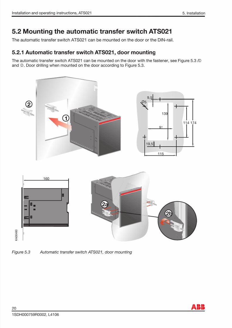
Figure 5.3 Automatic transfer switch ATS021, door mounting
5.2 Mounting the automatic transfer switch ATS021The automatic transfer switch ATS021 can be mounted on the door or the DIN-rail.
5.2.1 Automatic transfer switch ATS021, door mountingThe automatic transfer switch ATS021 can be mounted on the door with the fastener, see Figure 5.3 / j
and k . Door drilling when mounted on the door according to Figure 5.3.

7/28/2019 2 Kontrolleri ATS 021 En
http://slidepdf.com/reader/full/2-kontrolleri-ats-021-en 21/36
21
1SDH000759R0002, L4106
Installation and operating instructions, ATS021
K A 0 0 4 8 1
O N
D I P
1
2
3
4
3
4
35mm
EN 50022
3
2
1
174
9,5
114
115
97
145
5Ø
19,5
K A 0 0 4 8 2
Remove
K A 0 0 4 8 4
1 2
3
5.2.2 Automatic transfer switch ATS021, DIN-rail mountingThe automatic transfer switch ATS021 can be mounted on the 35 mm DIN-rail, see the Figure 5.4. Doordrilling, if needed, according to Figure 5.4.
Figure 5.4 Automatic transfer switch ATS021, DIN-rail mounting
5. Installation

7/28/2019 2 Kontrolleri ATS 021 En
http://slidepdf.com/reader/full/2-kontrolleri-ats-021-en 22/36
Installation and operating instructions, ATS021
1SDH000759R0002, L4106
22
6. Connecting
6. Connecting
Only an authorised electrician may perform the electrical installation and maintenanceof automatic transfer switches. Do not attempt any installation or maintenance actionswhen an automatic transfer switch is connected to the electrical mains. Before startingwork, make sure that the circuit breaker is de-energised.
6.1 Power circuitOperating voltage, setting with DIP-switchesMain voltage: 208Vac - 480Vac (± 20%)Phase voltage: 120Vac - 277Vac (± 20%)Frequency: 50Hz - 60Hz (± 10%)Phase setting with DIP switches: Single phase or Three-phase (default) .
If the automatic transfer switch ATS021 is used without neutral (three-phase connection), the externaltransformer must be used. The transformer will drop the main voltage to the phase voltage level. Neutralhas to be connected when using a single phase connection.
Figure 6.1 The external transformer must be used, if the automatic transfer switch ATS021 is used without neutral (three-phase connection). Neutral has to be connected when using a
single phase connection.

7/28/2019 2 Kontrolleri ATS 021 En
http://slidepdf.com/reader/full/2-kontrolleri-ats-021-en 23/36
23
1SDH000759R0002, L4106
Installation and operating instructions, ATS021
6.2 Control circuit
6. Connecting
When relay outputs are used with inductive loads (such as relays, contactors andmotors), they must be protected from voltage spikes using varistors, RC-protectors
(AC current) or DC current diodes (DC current).
Figure 6.2 Control circuit connections in ATS021

7/28/2019 2 Kontrolleri ATS 021 En
http://slidepdf.com/reader/full/2-kontrolleri-ats-021-en 24/36
Installation and operating instructions, ATS021
1SDH000759R0002, L4106
24
6.2.1 Control circuit of the automatic transfer switch ATS021
6. Connecting
Figure 6.3 Control circuit diagram ATS021

7/28/2019 2 Kontrolleri ATS 021 En
http://slidepdf.com/reader/full/2-kontrolleri-ats-021-en 25/36
25
1SDH000759R0002, L4106
Installation and operating instructions, ATS021
Connectors, ATS021
Table 6.1 Connectors / Outputs / Inputs
6. Connecting
Figure 6.4 Connectors, ATS021
Con-nector
Description
X11:1X11:2X11:3X11:4
Normal line LN1: L1Normal line LN1: L2Normal line LN1: L3Normal line LN1: N
X13:1X13:2
Normal line (power supply): LNormal line (power supply): N
X12:1X12:2X12:3X12:4
Emergency line LN2: L1Emergency line LN2: L2Emergency line LN2: L3Emergency line LN2: N
X14:1X14:2
Emergency line (power supply): LEmergency line (power supply): N
X21:1 CommonX21:2 DO1X21:3 DO2X22:1 CommonX22:2 DO3X22:3 DO4X23:1 DO5 startX23:2 CommonX23:3 DO5 stopX24:1 DO6 okX24:2 CommonX24:3 DO6 alarm
Con-nector
Description
X31:1X31:2X31:3X31:4
DI3DI1DI2DI supply
X61 Equipment earth
Output Description
D01 Output to open the protection device of thenormal line (normal open)
D02 Output to close the protection device of thenormal line (normal open)
D03 Output to open the protection device of theemergency line (normal open) (only breaker)
D04 Output to close the protection device of theemergency line (normal open) (only breaker)
D05 Output to control the startup of the generator(exchange)
D06 Signaling emergency / alarm (exchange)
Input Description
DI1 Protection device on normal line status input (0open, 1 close)
DI2 Protection device on emergency line statusinput (0 open, 1 close)
DI3 Logic enable/disable

7/28/2019 2 Kontrolleri ATS 021 En
http://slidepdf.com/reader/full/2-kontrolleri-ats-021-en 26/36
Installation and operating instructions, ATS021
1SDH000759R0002, L4106
26
7. Using automatic transfer switch ATS0217.1 Interface
Figure 7.1 Interface of ATS021
7.2 Con guration7.2.1 Rotary Switches
Figure 7.2 Selection of delay time and voltage threshold, the factory settings are shown in the gure
Ts = Delay time for automatic switchingThe delay time is the time before activating the switching sequence and the back-switching sequence.
Available selections for the delay time are: 0, 5, 10, 15, 20, 25, 30 s.
Lim = Voltage thresholdIf difference between the rated voltage and measured voltage is greater than threshold value set byparameter Lim, the line is considered to have an anomaly. The same threshold value applies to differencebetween the highest and the lowest phase voltage. Available selections for voltage threshold are:
In MANUAL Mode: ± 5, ± 10, ± 20, ± 30 %In AUTOMATIC Mode: ± 5, ± 10, ± 20, ± 30 %.
The MAX acceptable voltage threshold selection for 480 Vac voltage is + 20% and the MIN acceptablevoltage threshold selection for 208 Vac is - 20%. By setting the voltage threshold, the unbalance is alsoset to the same level. The operating mode and the voltage threshold are selected simultaneously bysetting the Lim rotary switch to the desired position. For example, when the Lim rotary switch is set to“20 MANUAL”, the device is in the manual mode and the voltage threshold is ±20%.
7. Using automatic transfer switch ATS021

7/28/2019 2 Kontrolleri ATS 021 En
http://slidepdf.com/reader/full/2-kontrolleri-ats-021-en 27/36
27
1SDH000759R0002, L4106
Installation and operating instructions, ATS021
7.2.2 Keypad
7. Using automatic transfer switch ATS021
Figure 7.3 Keypad on ATS021
RESET key An active alarm can reset by the RESET key.
TEST key Setting the automatic transfer switch to test sequence in which it is possible to simulate switching andback-switching sequences step-by-step, by pressing the TEST key. This is possible only if the automatictransfer switch is in manual mode. Exiting from test sequence is done by RESET key. See pages 16 and30.
CB1 key Setting in manual mode the circuit breaker CB1 to open/close position. When the circuit breaker CB1 willbe in the ON position then the circuit breaker CB2 will be in the OFF position.
CB2 key Setting in manual mode the circuit breaker CB2 to open/close position. When the circuit breaker CB2 willbe in the ON position then the circuit breaker CB1 will be in the OFF position.

7/28/2019 2 Kontrolleri ATS 021 En
http://slidepdf.com/reader/full/2-kontrolleri-ats-021-en 28/36
Installation and operating instructions, ATS021
1SDH000759R0002, L4106
28
7.2.3 LEDs
Line Status LED Indication
Voltage OK ON
No voltage OFF
Overvoltage Fast blinking (5 Hz)
Undervoltage Blinking (1 Hz, 50% ON / 50% OFF)
Invalid frequency Blinking (1 Hz, 90% ON / 10% OFF)
Unbalance Blinking (1Hz, 10% ON / 90% OFF)
Table 7.1 Line status indication
CB1 A red CB1 LED is ON, when the circuit breaker CB1 is in the ON position (the circuit breaker CB1 is ONand the circuit breaker CB2 is OFF), the LED is OFF otherwise. While the circuit breaker CB1 is openingor closing the CB1 led will blink. If the opening command fails, CB1 led will stay ON. If closing commandfails, CB1 led will blink.
CB2 A red CB2 LED is ON, when the circuit breaker CB2 is in the ON position (the circuit breaker CB2 is ONand the circuit breaker CB1 is OFF), the LED is OFF otherwise. While the circuit breaker CB2 is openingor closing the CB2 led will blink. If the opening command fails, CB2 led will stay ON. If closing command
fails, CB2 led will blink.
7. Using automatic transfer switch ATS021
Figure 7.4 LEDs on ATS021
LN 1 - CB1 A red LN 1 LED signals the status of the line LN 1 (normal line), when the circuit breaker CB1 is ON. Linestatus is explained in the table below.
LN 2 - CB2 A red LN 2 LED signals the status of the line LN 2 (emergency line), when the circuit breaker CB2 is ON.Line status is explained in the table below.

7/28/2019 2 Kontrolleri ATS 021 En
http://slidepdf.com/reader/full/2-kontrolleri-ats-021-en 29/36
29
1SDH000759R0002, L4106
Installation and operating instructions, ATS021
Alarm A red Alarm LED signals an external alarm (switching logic disabled or status of both breakers is closed). Alarm status is explained in the table below.
Table 7.2 Alarm status indication
Auto A green Auto LED signals the automatic or the manual mode. When the ATS021 is in automatic mode,the Auto LED is ON. When the device is in manual mode, the Auto LED is OFF. In test sequence the AutoLED is blinking.
Power A green Power LED signals the power status. When power is ON, the Power LED is ON. The ATS021 willremain in a standby state at least one minute after power failure. A blinking Power LED indicates standbymode.
7.2.4 External transformerExternal transformer must be used when
N-line is not connected
The transformer has to ful l the following requirements:Transformer has to be Main to Phase Voltage TransformerTransformer has to be isolativeEffective value has to be 40 VA
7. Using automatic transfer switch ATS021
Alarm Status LED Indication
External alarm (logic locked):- Both DI1 and DI2 active- DI3 inactive
ON
Switching logic alarm Blinking
No alarm OFF
When Alarm LED is ON or blinking, turn the Lim rotary switch to MAN positon, checkthe state of the automatic transfer switch and repair the possible fault situation beforeresetting the alarm. The automatic transfer switch is resetted by pushing the RESET
key.

7/28/2019 2 Kontrolleri ATS 021 En
http://slidepdf.com/reader/full/2-kontrolleri-ats-021-en 30/36
Installation and operating instructions, ATS021
1SDH000759R0002, L4106
30
7.3 TEST sequence
Figure 7.5 ATS021 is set to the TEST position by pushing the TEST key
By pushing the TEST key the automatic transfer switch ATS021 enters the test sequence. All the LEDsare rst blinking a couple of times to give the information that the LED is functioning.
In the TEST position it is possible to simulate switching and back-switching sequences step-by-stepby pressing the TEST key. This is possible only if the automatic transfer switch is in manual mode. Theuser can interrupt the simulation at any place and return to normal use of the device. Exiting from testsequence is done by RESET key. More information, see the page 16.
NOTE: In the TEST sequence the power circuit is switched on!
NOTE: After testing the user must ensure that the device is not left in the TEST position by accident.
7. Using automatic transfer switch ATS021

7/28/2019 2 Kontrolleri ATS 021 En
http://slidepdf.com/reader/full/2-kontrolleri-ats-021-en 31/36
31
1SDH000759R0002, L4106
Installation and operating instructions, ATS021
8. Technical data of the automatic transfer switch ATS021
8. Technical data
Table 8.1 Technical data of ATS021
ATS021 ValueOperating voltage
Main voltage 208Vac - 480 Vac ±20 %
Phase voltage 120Vac - 277 Vac ±20 %
Rated frequency 50 Hz, 60 Hz ±10 %
Rated impulse withstand voltage U imp 6 kV
Voltage and frequency sensing precision
Voltage 5 %
Frequency 1 %
Relay utilization category 8 A, AC1, 250 V
1/3 phase
Over voltage category III, U imp 6 kV
IP rating IP20 for the front panel
Temperature area -20... +60 °C
Transportation and storage temperature -40... +90 °C
Altitude Max. 2000 m
Humidity r.h. = 95 % T = 25...55 °C
with condensation 5 % - 98 %
without condensation 5 % - 90 %

7/28/2019 2 Kontrolleri ATS 021 En
http://slidepdf.com/reader/full/2-kontrolleri-ats-021-en 32/36
Installation and operating instructions, ATS021
1SDH000759R0002, L4106
32
9. Troubleshooting
9. Troubleshooting
Alarm Fault Action
ALARM_OPEN_1 The protection device on the normalline LN 1 does not open. After 5seconds the alarm LED starts blinkingand the CB1 LED turns ON.
The alarm can be reset by the RESET key. Ifthe alarm does not disappear, there is somemalfunction in the protection device and it has tobe changed.
ALARM_OPEN_2 The protection device on theemergency line LN 2 does not open.
After 5 seconds the alarm LED startsblinking and the CB2 LED turns ON.
The alarm can be reset by the RESET key. Ifthe alarm does not disappear, there is somemalfunction in the protection device and it has tobe changed.
ALARM_CLOSE_1 The protection device on the normalline LN 1 does not close. After 5seconds the alarm LED and the CB1LED are blinking.
The alarm can be reset by the RESET key. Ifthe alarm does not disappear, there is somemalfunction in the protection device and it has tobe changed.
ALARM_CLOSE_2 The protection device on the
emergency line LN 2 does not close. After 5 seconds the alarm LED andthe CB2 LED are blinking.
The alarm can be reset by the RESET key. If
the alarm does not disappear, there is somemalfunction in the protection device and it has tobe changed.
Table 9.1 Fault situations in ATS021
9.1 Explanations of internal faults ATS021When digital Input 1 and 2 are both active, logic is locked and the Alarm LED is ON.
When digital Input 3 is active, logic is locked and the Alarm LED is ON.

7/28/2019 2 Kontrolleri ATS 021 En
http://slidepdf.com/reader/full/2-kontrolleri-ats-021-en 33/36
33
1SDH000759R0002, L4106
Installation and operating instructions, ATS021Notes

7/28/2019 2 Kontrolleri ATS 021 En
http://slidepdf.com/reader/full/2-kontrolleri-ats-021-en 34/36
Installation and operating instructions, ATS021
1SDH000759R0002, L4106
34
Notes

7/28/2019 2 Kontrolleri ATS 021 En
http://slidepdf.com/reader/full/2-kontrolleri-ats-021-en 35/36

7/28/2019 2 Kontrolleri ATS 021 En
http://slidepdf.com/reader/full/2-kontrolleri-ats-021-en 36/36
P r i n
t e d b y :
M u
l t i p r i n
t , V a a s a
F i n l a n
d
P r o
d u c
t e d b y :
K A T A N N D o c u m e n
t F a c
t o r y
O y ,
V a a s a
F i n l a n
d
L.V. BreakersVia Baioni 35
ABB SACE S.p.A An ABB Group company
The technical data and dimensions are validat the time of printing. We reserve the right tosubsequent alterations.