Prestressed Concrete Structures Dr. Amlan K Sengupta and Prof. Devdas Menon
Indian Institute of Technology Madras
1.7 Prestressing Steel This section covers the following topics.
• Forms of Prestressing Steel
• Types of Prestressing Steel
• Properties of Prestressing Steel
• Codal Provisions of Steel
1.7.1 Forms of Prestressing Steel
The development of prestressed concrete was influenced by the invention of high
strength steel. It is an alloy of iron, carbon, manganese and optional materials. The
following material describes the types and properties of prestressing steel.
In addition to prestressing steel, conventional non-prestressed reinforcement is used for
flexural capacity (optional), shear capacity, temperature and shrinkage requirements.
The properties of steel for non-prestressed reinforcement are not covered in this section.
It is expected that the student of this course is familiar with the conventional
reinforcement.
Wires A prestressing wire is a single unit made of steel. The nominal diameters of the wires
are 2.5, 3.0, 4.0, 5.0, 7.0 and 8.0 mm. The different types of wires are as follows.
1) Plain wire: No indentations on the surface.
2) Indented wire: There are circular or elliptical indentations on the surface.
Strands A few wires are spun together in a helical form to form a prestressing strand. The
different types of strands are as follows.
1) Two-wire strand: Two wires are spun together to form the strand.
2) Three-wire strand: Three wires are spun together to form the strand.
3) Seven-wire strand: In this type of strand, six wires are spun around a central wire.
The central wire is larger than the other wires.

Prestressed Concrete Structures Dr. Amlan K Sengupta and Prof. Devdas Menon
Indian Institute of Technology Madras
Tendons A group of strands or wires are placed together to form a prestressing tendon. The
tendons are used in post-tensioned members. The following figure shows the cross
section of a typical tendon. The strands are placed in a duct which may be filled with
grout after the post-tensioning operation is completed (Figure 1-7.1).
Duct
Grout
Duct
Grout
Figure 1-7.1 Cross-section of a typical tendon
Cables A group of tendons form a prestressing cable. The cables are used in bridges.
Bars A tendon can be made up of a single steel bar. The diameter of a bar is much larger
than that of a wire. Bars are available in the following sizes: 10, 12, 16, 20, 22, 25, 28
and 32 mm.
The following figure shows the different forms of prestressing steel.
Reinforcing barsPrestressing wires, strands and barsReinforcing bars
Prestressing wires, strands and bars
Figure 1-7.2 Forms of reinforcing and prestressing steel
Prestressed Concrete Structures Dr. Amlan K Sengupta and Prof. Devdas Menon
Indian Institute of Technology Madras
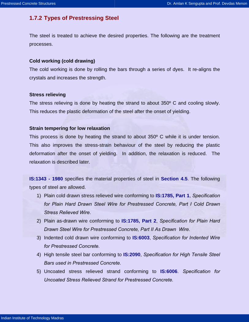
1.7.2 Types of Prestressing Steel
The steel is treated to achieve the desired properties. The following are the treatment
processes.
Cold working (cold drawing) The cold working is done by rolling the bars through a series of dyes. It re-aligns the
crystals and increases the strength.
Stress relieving The stress relieving is done by heating the strand to about 350º C and cooling slowly.
This reduces the plastic deformation of the steel after the onset of yielding.
Strain tempering for low relaxation This process is done by heating the strand to about 350º C while it is under tension.
This also improves the stress-strain behaviour of the steel by reducing the plastic
deformation after the onset of yielding. In addition, the relaxation is reduced. The
relaxation is described later.
IS:1343 - 1980 specifies the material properties of steel in Section 4.5. The following
types of steel are allowed.
1) Plain cold drawn stress relieved wire conforming to IS:1785, Part 1, Specification
for Plain Hard Drawn Steel Wire for Prestressed Concrete, Part I Cold Drawn
Stress Relieved Wire.
2) Plain as-drawn wire conforming to IS:1785, Part 2, Specification for Plain Hard
Drawn Steel Wire for Prestressed Concrete, Part II As Drawn Wire.
3) Indented cold drawn wire conforming to IS:6003, Specification for Indented Wire
for Prestressed Concrete.
4) High tensile steel bar conforming to IS:2090, Specification for High Tensile Steel
Bars used in Prestressed Concrete.
5) Uncoated stress relieved strand conforming to IS:6006. Specification for
Uncoated Stress Relieved Strand for Prestressed Concrete.
Prestressed Concrete Structures Dr. Amlan K Sengupta and Prof. Devdas Menon
Indian Institute of Technology Madras
1.7.3 Properties of Prestressing Steel
The steel in prestressed applications has to be of good quality. It requires the following
attributes.
1) High strength
2) Adequate ductility
3) Bendability, which is required at the harping points and near the anchorage
4) High bond, required for pre-tensioned members
5) Low relaxation to reduce losses
6) Minimum corrosion.
Strength of Prestressing Steel The tensile strength of prestressing steel is given in terms of the characteristic tensile
strength (fpk).
The characteristic strength is defined as the ultimate tensile strength of the coupon
specimens below which not more than 5% of the test results are expected to fall.
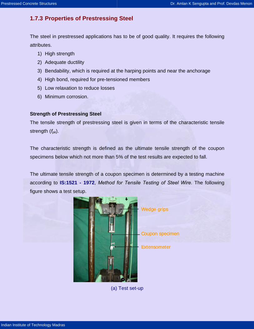
The ultimate tensile strength of a coupon specimen is determined by a testing machine
according to IS:1521 - 1972, Method for Tensile Testing of Steel Wire. The following
figure shows a test setup.
Extensometer
Wedge grips
Coupon specimen
Extensometer
Wedge grips
Coupon specimen
(a) Test set-up
Prestressed Concrete Structures Dr. Amlan K Sengupta and Prof. Devdas Menon
Indian Institute of Technology Madras
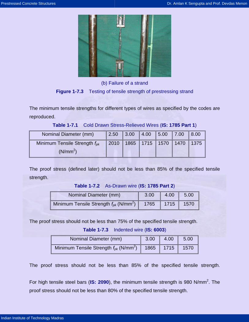
(b) Failure of a strand
Figure 1-7.3 Testing of tensile strength of prestressing strand
The minimum tensile strengths for different types of wires as specified by the codes are
reproduced.
Table 1-7.1 Cold Drawn Stress-Relieved Wires (IS: 1785 Part 1)
Nominal Diameter (mm) 2.50 3.00 4.00 5.00 7.00 8.00
Minimum Tensile Strength fpk
(N/mm2)
2010 1865 1715 1570 1470 1375
The proof stress (defined later) should not be less than 85% of the specified tensile
strength.
Table 1-7.2 As-Drawn wire (IS: 1785 Part 2)
Nominal Diameter (mm) 3.00 4.00 5.00
Minimum Tensile Strength fpk (N/mm2) 1765 1715 1570
The proof stress should not be less than 75% of the specified tensile strength.
Table 1-7.3 Indented wire (IS: 6003)
Nominal Diameter (mm) 3.00 4.00 5.00
Minimum Tensile Strength fpk (N/mm2) 1865 1715 1570
The proof stress should not be less than 85% of the specified tensile strength.
For high tensile steel bars (IS: 2090), the minimum tensile strength is 980 N/mm2. The
proof stress should not be less than 80% of the specified tensile strength.
Prestressed Concrete Structures Dr. Amlan K Sengupta and Prof. Devdas Menon
Indian Institute of Technology Madras
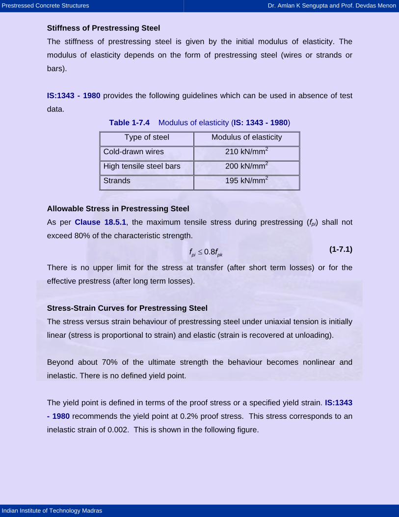
Stiffness of Prestressing Steel The stiffness of prestressing steel is given by the initial modulus of elasticity. The
modulus of elasticity depends on the form of prestressing steel (wires or strands or
bars).
IS:1343 - 1980 provides the following guidelines which can be used in absence of test
data.
Table 1-7.4 Modulus of elasticity (IS: 1343 - 1980)
Type of steel Modulus of elasticity
Cold-drawn wires 210 kN/mm2
High tensile steel bars 200 kN/mm2
Strands 195 kN/mm2
Allowable Stress in Prestressing Steel As per Clause 18.5.1, the maximum tensile stress during prestressing (fpi) shall not
exceed 80% of the characteristic strength.
≤pi pf 0.8 kf (1-7.1)
There is no upper limit for the stress at transfer (after short term losses) or for the
effective prestress (after long term losses).
Stress-Strain Curves for Prestressing Steel The stress versus strain behaviour of prestressing steel under uniaxial tension is initially
linear (stress is proportional to strain) and elastic (strain is recovered at unloading).
Beyond about 70% of the ultimate strength the behaviour becomes nonlinear and
inelastic. There is no defined yield point.
The yield point is defined in terms of the proof stress or a specified yield strain. IS:1343 - 1980 recommends the yield point at 0.2% proof stress. This stress corresponds to an
inelastic strain of 0.002. This is shown in the following figure.
Prestressed Concrete Structures Dr. Amlan K Sengupta and Prof. Devdas Menon
Indian Institute of Technology Madras
0.002
Proofstress
εp
fp
0.002
Proofstress
εp
fp
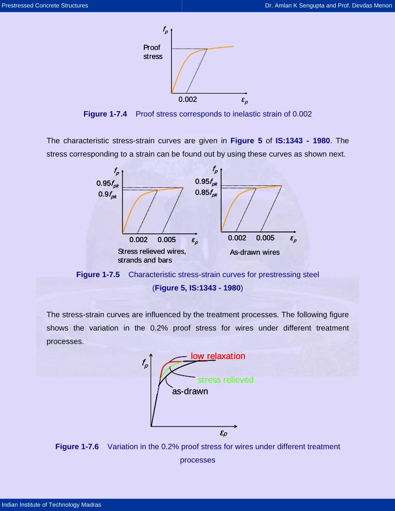
Figure 1-7.4 Proof stress corresponds to inelastic strain of 0.002
The characteristic stress-strain curves are given in Figure 5 of IS:1343 - 1980. The
stress corresponding to a strain can be found out by using these curves as shown next.
0.002 0.005
0.95fpk
0.9fpk
εp
fp
0.002 0.005
0.95fpk
0.85fpk
εp
fp
Stress relieved wires,strands and bars
As-drawn wires
0.002 0.005
0.95fpk
0.9fpk
εp
fp
0.002 0.005
0.95fpk
0.9fpk
εp
fp
0.002 0.005
0.95fpk
0.85fpk
εp
fp
0.002 0.005
0.95fpk
0.85fpk
εp
fp
Stress relieved wires,strands and bars
As-drawn wires
Figure 1-7.5 Characteristic stress-strain curves for prestressing steel
(Figure 5, IS:1343 - 1980)
The stress-strain curves are influenced by the treatment processes. The following figure
shows the variation in the 0.2% proof stress for wires under different treatment
processes.
low relaxation
stress relievedas-drawn
εp
fplow relaxation
stress relievedas-drawn
εp
fp
Figure 1-7.6 Variation in the 0.2% proof stress for wires under different treatment
processes

Prestressed Concrete Structures Dr. Amlan K Sengupta and Prof. Devdas Menon
Indian Institute of Technology Madras
The design stress-strain curves are calculated by dividing the stress beyond 0.8fpk by a
material safety factor γm =1.15. The following figure shows the characteristic and design
stress-strain curves.
0.8fpk
εp
fpCharacteristic curve
Design curve0.8fpk
εp
fpCharacteristic curve
Design curve
Figure 1-7.7 Characteristic and design stress-strain curves for
prestressing steel
Relaxation of Steel Relaxation of steel is defined as the decrease in stress with time under constant strain.
Due to the relaxation of steel, the prestress in the tendon is reduced with time. Hence,
the study of relaxation is important in prestressed concrete to calculate the loss in
prestress.
The relaxation depends on the type of steel, initial prestress and the temperature. The
following figure shows the effect of relaxation due to different types of loading conditions.
εp
fp
Fast loading
With sustained loadingEffect of relaxation
εp
fp
Fast loading
With sustained loadingEffect of relaxation
Figure 1-7.8 Effect of relaxation due to different types of loading conditions
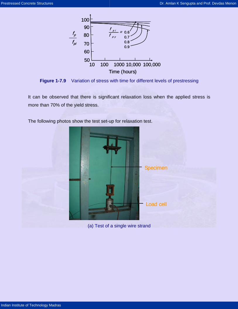
The following figure shows the variation of stress with time for different levels of
prestressing. Here, the instantaneous stress (fp) is normalised with respect to the initial
prestressing (fpi) in the ordinate. The curves are for different values of fpi/fpy, where fpy is
the yield stress.
Prestressed Concrete Structures Dr. Amlan K Sengupta and Prof. Devdas Menon
Indian Institute of Technology Madras
10090
80
70
60
5010 100 1000 10,000 100,000
Time (hours)
fpfpi
p i
p y
f=
f0.60.70.80.9
10090
80
70
60
5010 100 1000 10,000 100,000
Time (hours)
fpfpi
p i
p y
f=
f0.60.70.80.9
Figure 1-7.9 Variation of stress with time for different levels of prestressing
It can be observed that there is significant relaxation loss when the applied stress is
more than 70% of the yield stress.
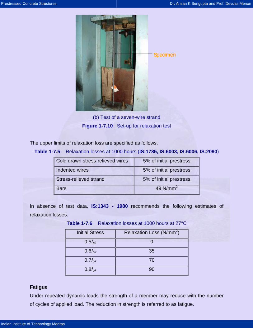
The following photos show the test set-up for relaxation test.
Load cell
Specimen
Load cell
Specimen
(a) Test of a single wire strand
Prestressed Concrete Structures Dr. Amlan K Sengupta and Prof. Devdas Menon
Indian Institute of Technology Madras
SpecimenSpecimen
(b) Test of a seven-wire strand
Figure 1-7.10 Set-up for relaxation test
The upper limits of relaxation loss are specified as follows.
Table 1-7.5 Relaxation losses at 1000 hours (IS:1785, IS:6003, IS:6006, IS:2090)
Cold drawn stress-relieved wires 5% of initial prestress
Indented wires 5% of initial prestress
Stress-relieved strand 5% of initial prestress
Bars 49 N/mm2
In absence of test data, IS:1343 - 1980 recommends the following estimates of
relaxation losses.
Table 1-7.6 Relaxation losses at 1000 hours at 27°C
Initial Stress Relaxation Loss (N/mm2)
0.5fpk 0
0.6fpk 35
0.7fpk 70
0.8fpk 90
Fatigue Under repeated dynamic loads the strength of a member may reduce with the number
of cycles of applied load. The reduction in strength is referred to as fatigue.
Prestressed Concrete Structures Dr. Amlan K Sengupta and Prof. Devdas Menon
Indian Institute of Technology Madras
In prestressed applications, the fatigue is negligible in members that do not crack under
service loads. If a member cracks, fatigue may be a concern due to high stress in the
steel at the location of cracks.
Specimens are tested under 2 x 10⁶ cycles of load to observe the fatigue. For steel,
fatigue tests are conducted to develop the stress versus number of cycles for failure (S-
N) diagram. Under a limiting value of stress, the specimen can withstand infinite number
of cycles. This limit is known as the endurance limit.
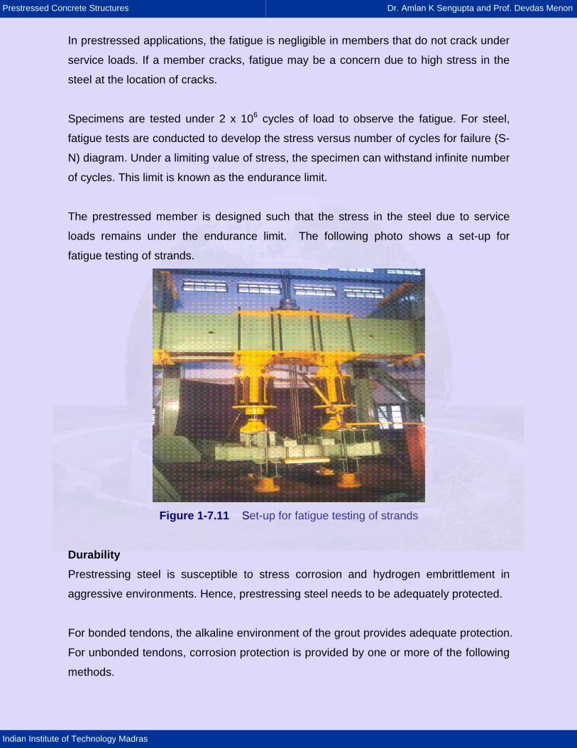
The prestressed member is designed such that the stress in the steel due to service
loads remains under the endurance limit. The following photo shows a set-up for
fatigue testing of strands.
Figure 1-7.11 Set-up for fatigue testing of strands
Durability Prestressing steel is susceptible to stress corrosion and hydrogen embrittlement in
aggressive environments. Hence, prestressing steel needs to be adequately protected.
For bonded tendons, the alkaline environment of the grout provides adequate protection.
For unbonded tendons, corrosion protection is provided by one or more of the following
methods.
Prestressed Concrete Structures Dr. Amlan K Sengupta and Prof. Devdas Menon
Indian Institute of Technology Madras
1) Epoxy coating
2) Mastic wrap (grease impregnated tape)
3) Galvanized bars
4) Encasing in tubes.
1.7.4 Codal Provisions of Steel The following topics are covered in IS:1343 - 1980 under the respective sections. These
provisions are not duplicated here.
Table 1-7.7 Topics and sections
Assembly of prestressing and reinforcing steel Section 11
Prestressing Section 12