Extreme Machines
One day seminar ▪ 25 April 2012 ▪ Rolls-Royce, Derby
Air Power: Achievements and Challenges in Electromagnetic Aircraft Launch
Tom Cox, Force Engineering [email protected]
Abstract - Aircraft launch using electromagnetic linear
machines has been studied in various forms for over 60
years. Now, with the latest generation aircraft carriers on
course to be equipped with electromagnetic catapults for
aircraft launch, this long anticipated application of linear
machines is finally close to being realised. Some of the
significant challenges and technical choices that have shaped
the design of linear motors for modern aircraft launch
systems will be detailed: starting from the origins of assisted
aircraft launch and the earliest systems developed in the
1940's, through to the current state of the art in aircraft
launch using electromagnetic machines.
I INTRODUCTION
Aircraft have been launched from ships for over 100 years. This
has evolved from unassisted takeoff and early spring and
compressed air systems through to steam catapults and finally to
the latest generation of electromagnetic launchers.
A working electromagnetic launch system was developed in
1945 but was viewed as too costly and heavy and the steam
catapult was used instead.
New advances in motor design and power electronics have lead
to improved launcher configurations with significant advantages
compared with steam catapults. There are currently major
projects in electromagnetic aircraft launch for carrier systems in
both the UK and The USA.
This paper explores some of the issues involved in linear
machines design for high speed electromagnetic aircraft launch.
II HISTORY OF AIRCRAFT LAUNCH
The first fixed wing aircraft launch from a ship occurred in
January 1911, when Eugene Ely successfully landed on, and
took off from, a temporary wooden landing strip mounted on the
USS Pennsylvania. The aircraft carrier rapidly evolved,
sometimes using compressed air or spring based launch systems,
but more commonly with aircraft that could take off from a
flight deck without assistance.
During the second world war, Westinghouse made the first
known electromagnetic aircraft launch system, the ‘Electropult’
launcher shown in Fig. 1 for launching aircraft from short island
runways.
The Electropult system used a short-stator single-sided induction
machine. This had a stator that was fed through brushes and
mounted on a wheeled vehicle, which could be linked to the
aircraft to be launched.
The stationary track was in the form of linear conductive bars in
iron slots. This enabled the secondary resistance and thrust
characteristic of the motor system to be varied during launch in
order to provide an improved launch performance.
Fig. 1. The Westinghouse Electropult stator on track
This system was capable of reaching 100m/s max speed over a
420m range. It was powered by an 1100hp aircraft engine
running a DC generator. This in turn powered a DC motor which
drove an AC generator attached to a 24 ton flywheel.
While this system successfully test launched aircraft from a land
based installation, it was never employed at sea due to
significant cost and weight issues.
It was also overtaken by the invention of the steam catapult,
which at the time was the superior technology. These however
have significant issues including excessive size & weight, lack
of feedback and fine control and the lack of steam subsystems
on some modern ships.
III. NEW ELECTROMAGNETIC LAUNCHERS
Over the past twenty years electromagnetic aircraft launch
technology has once again been under development in an effort
to replace steam catapults.
Two key technological developments have contributed to the
improvement of electromagnetic launchers compared to steam
catapults.
Power electronics provide a high level of control over motor
acceleration. Linear induction machines are supplied at
increasing frequencies to give small slip conditions and high
efficiencies.
Variations in linear motor topology and in particular the use of
double-sided machines reduce unwanted attraction force
between the secondary and the track and allow the use of a
simple and robust conductive rotor. Linear machines also allow
the stator to be constructed in a modular fashion, allowing for
significant redundancy and easy repair and replacement.
Two major projects to develop full scale aircraft launch systems
are currently in progress; EMALS at General Atomics USA
which will be used on the USS Gerald R. Ford (CVN-78) carrier
and EMCAT at Converteam UK which has been designed for
possible use in the Queen Elizabeth class carrier, and has
recently been demonstrated on a smaller scale as the EMKIT
UAV launcher.
Typical launch system specifications for both these systems,
based on a modern carrier plane (F-35/JSF):
• 100m launch track – deck length
• 80m/s take off speed
• 35T payload
• 1MN force
• Failsafe in operation with some redundancy
Both of these projects use a system layout similar to the
Electropult, with a primary generator, power storage, power
conditioning system and a linear motor. Whereas the Electropult
used a moving short primary fed through brushes, the modern
systems both use a static double sided primary with a moving
short secondary conductive plate, as shown in Fig. 2.
Fig. 2. Simplified layout of typical induction motor aircraft
launch system.
Both systems also use double sided Linear Induction Motors.
Issues with the use of synchronous rather than induction
machines for electromagnetic aircraft launch include the need
for high converter frequencies, challenges with high speed
control and the need for precise speed feedback, a risk of
permanent magnet demagnetization due to the high current
loading and strong magnetic fields employed and supply and
security issues with rare earth magnets.
The design of high speed LIMs is complex and time consuming.
Some of the significant challenges are:
• Significant transient forces and currents in rotor
• Rapidly accelerating rotor
• Discontinuous stator blocks, each shorter than the
rotor
• Discontinuous rotor, much shorter than the track
• The effect of entering unexcited stators at high speed
can be significant
• Transient FEA usually required for accurate prediction
of machine performance
Fig. 4. Force perturbations from a series connected winding
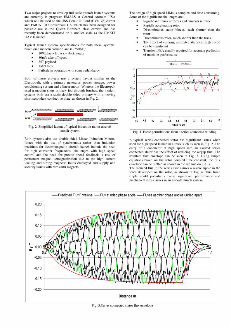
A typical series connected stator has significant issues when
used for high speed launch in a track such as seen in Fig. 2. The
entry of a conductor at high speed into an excited series
connected stator has the effect of reducing the airgap flux. The
resultant flux envelope can be seen in Fig. 3. Using simple
equations based on the rotor coupled time constant, the flux
envelope can be plotted as shown in the red line on Fig. 3.
The reduced flux in the series case causes a severe ripple in the
force developed on the rotor, as shown in Fig. 4. This force
ripple could potentially cause significant performance and
mechanical stress issues in an aircraft launch system.
-0.20
-0.15
-0.10
-0.05
0.00
0.05
0.10
0.15
0.20
0.2 0.4 0.6 0.8 1.0 1.2 1.4
Distance m
By
T
Predicted Flux Envelope Flux at 0deg phase angle Fluxes at other phase angles 60deg apart
Fig. 3.Series connected stator flux envelope
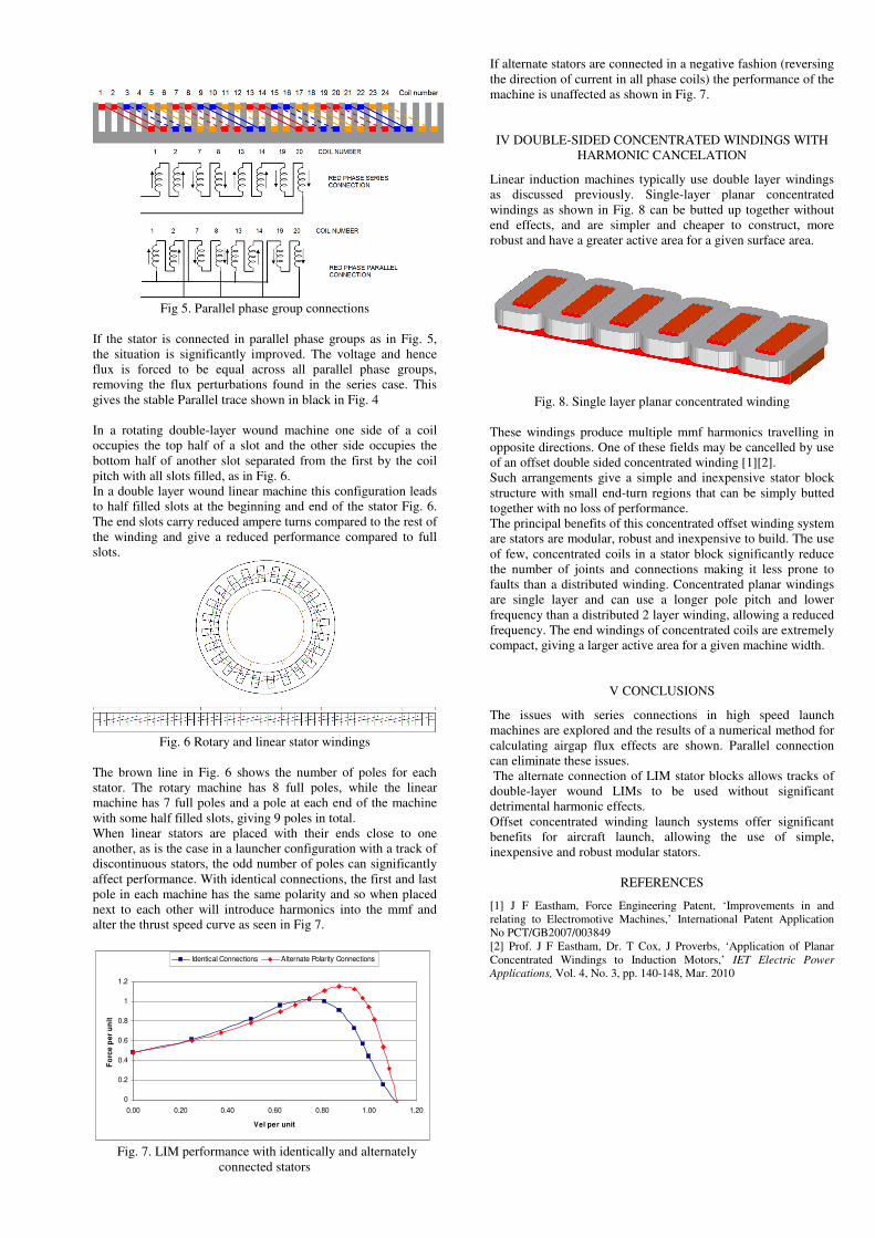
Fig 5. Parallel phase group connections
If the stator is connected in parallel phase groups as in Fig. 5,
the situation is significantly improved. The voltage and hence
flux is forced to be equal across all parallel phase groups,
removing the flux perturbations found in the series case. This
gives the stable Parallel trace shown in black in Fig. 4
In a rotating double-layer wound machine one side of a coil
occupies the top half of a slot and the other side occupies the
bottom half of another slot separated from the first by the coil
pitch with all slots filled, as in Fig. 6.
In a double layer wound linear machine this configuration leads
to half filled slots at the beginning and end of the stator Fig. 6.
The end slots carry reduced ampere turns compared to the rest of
the winding and give a reduced performance compared to full
slots.
Fig. 6 Rotary and linear stator windings
The brown line in Fig. 6 shows the number of poles for each
stator. The rotary machine has 8 full poles, while the linear
machine has 7 full poles and a pole at each end of the machine
with some half filled slots, giving 9 poles in total.
When linear stators are placed with their ends close to one
another, as is the case in a launcher configuration with a track of
discontinuous stators, the odd number of poles can significantly
affect performance. With identical connections, the first and last
pole in each machine has the same polarity and so when placed
next to each other will introduce harmonics into the mmf and
alter the thrust speed curve as seen in Fig 7.
0
0.2
0.4
0.6
0.8
1
1.2
0.00 0.20 0.40 0.60 0.80 1.00 1.20
Vel per unit
Fo
rce
pe
r u
nit
Identical Connections Alternate Polarity Connections
Fig. 7. LIM performance with identically and alternately
connected stators
If alternate stators are connected in a negative fashion (reversing
the direction of current in all phase coils) the performance of the
machine is unaffected as shown in Fig. 7.
IV DOUBLE-SIDED CONCENTRATED WINDINGS WITH
HARMONIC CANCELATION
Linear induction machines typically use double layer windings
as discussed previously. Single-layer planar concentrated
windings as shown in Fig. 8 can be butted up together without
end effects, and are simpler and cheaper to construct, more
robust and have a greater active area for a given surface area.
Fig. 8. Single layer planar concentrated winding
These windings produce multiple mmf harmonics travelling in
opposite directions. One of these fields may be cancelled by use
of an offset double sided concentrated winding [1][2].
Such arrangements give a simple and inexpensive stator block
structure with small end-turn regions that can be simply butted
together with no loss of performance.
The principal benefits of this concentrated offset winding system
are stators are modular, robust and inexpensive to build. The use
of few, concentrated coils in a stator block significantly reduce
the number of joints and connections making it less prone to
faults than a distributed winding. Concentrated planar windings
are single layer and can use a longer pole pitch and lower
frequency than a distributed 2 layer winding, allowing a reduced
frequency. The end windings of concentrated coils are extremely
compact, giving a larger active area for a given machine width.
V CONCLUSIONS
The issues with series connections in high speed launch
machines are explored and the results of a numerical method for
calculating airgap flux effects are shown. Parallel connection
can eliminate these issues.
The alternate connection of LIM stator blocks allows tracks of
double-layer wound LIMs to be used without significant
detrimental harmonic effects.
Offset concentrated winding launch systems offer significant
benefits for aircraft launch, allowing the use of simple,
inexpensive and robust modular stators.
REFERENCES
[1] J F Eastham, Force Engineering Patent, ‘Improvements in and
relating to Electromotive Machines,’ International Patent Application
No PCT/GB2007/003849
[2] Prof. J F Eastham, Dr. T Cox, J Proverbs, ‘Application of Planar
Concentrated Windings to Induction Motors,’ IET Electric Power
Applications, Vol. 4, No. 3, pp. 140-148, Mar. 2010