


11/14/ 2006 ICNP 2006 1
Virtual Surrounding Face Geocasting with Guaranteed Message Delivery for Ad Hoc and Sensor Networks
Jie Lian, Kshirasagar NaikUniversity of Waterloo, ON, Canada
Yunhao Liu, Lei ChenThe Hong Kong University of Science and Technology,
Hong Kong, China
11/14/ 2006 ICNP 2006 2
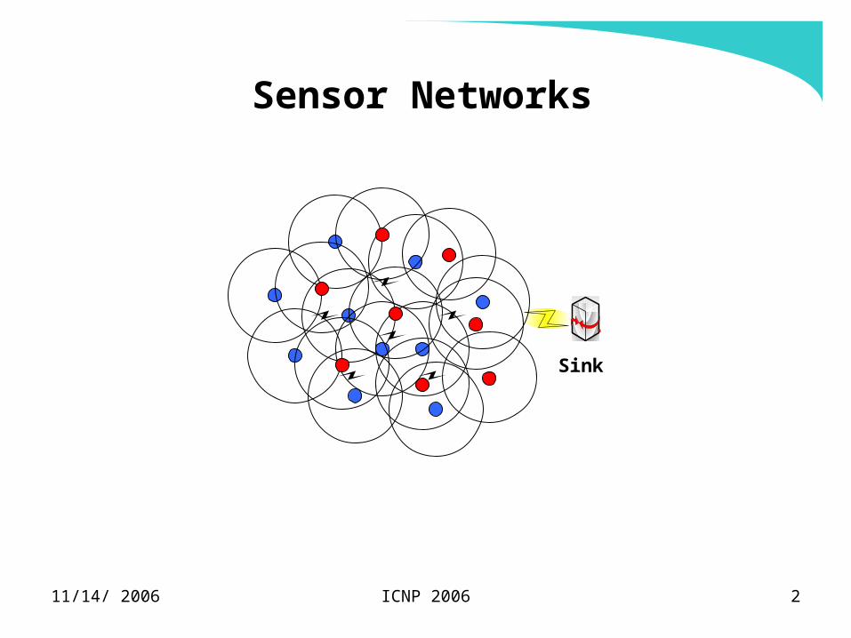
Sensor Networks
Sink

11/14/ 2006 ICNP 2006 3
Geocasting in Sensor Networks
end usersquery
respons
e
sink
sensor
11/14/ 2006 ICNP 2006 4
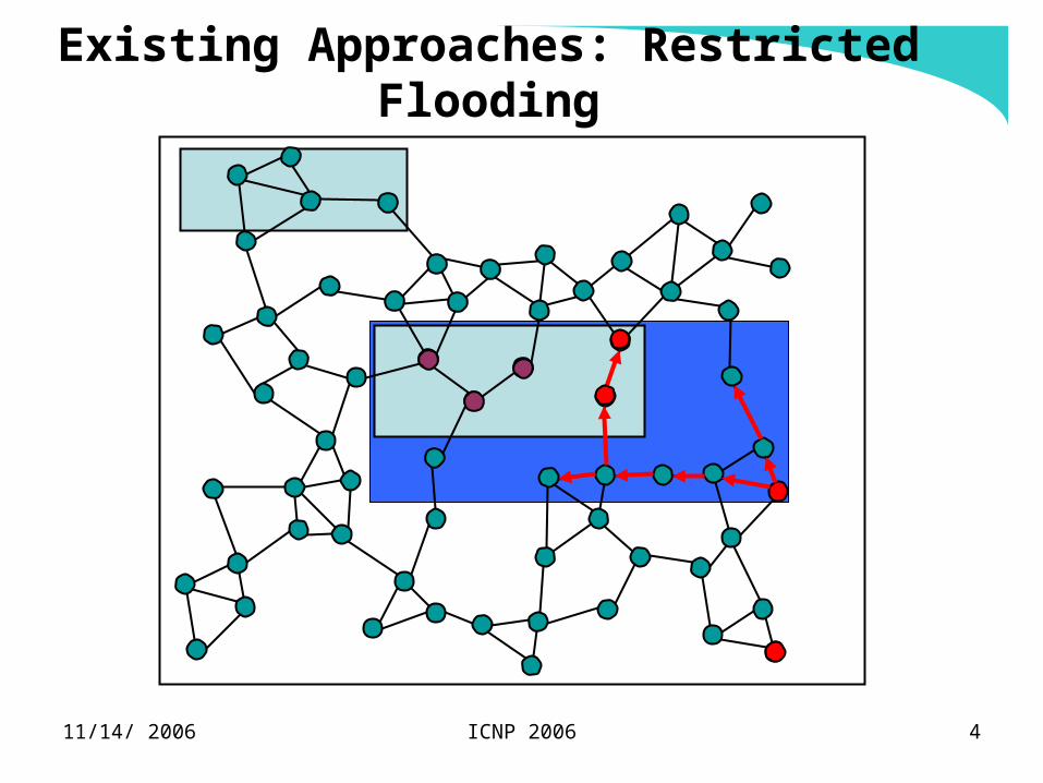
Existing Approaches: Restricted Flooding
11/14/ 2006 ICNP 2006 5
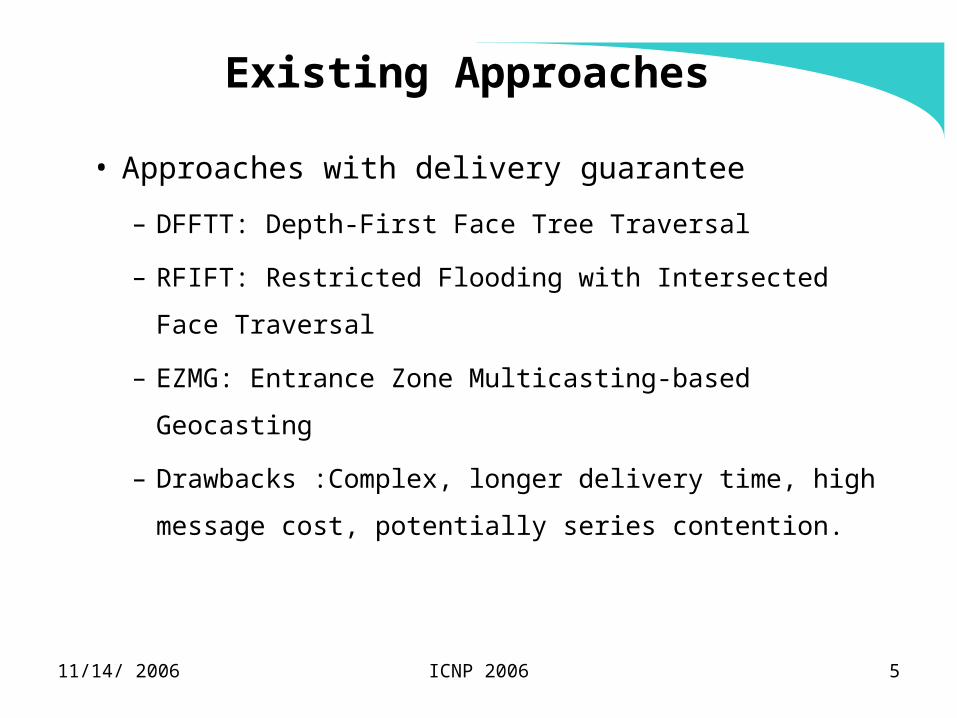
Existing Approaches
• Approaches with delivery guarantee
– DFFTT: Depth-First Face Tree Traversal
– RFIFT: Restricted Flooding with Intersected Face
Traversal
– EZMG: Entrance Zone Multicasting-based Geocasting
– Drawbacks :Complex, longer delivery time, high
message cost, potentially series contention.

11/14/ 2006 ICNP 2006 6
RFIFT Basic
s
Some concerns:• Cost• Potential collision• Delivery speed
11/14/ 2006 ICNP 2006 7
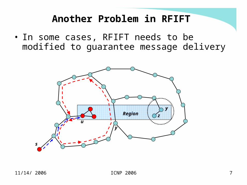
Another Problem in RFIFT
s
Region
uy
• In some cases, RFIFT needs to be modified to guarantee message delivery
y
z
11/14/ 2006 ICNP 2006 8
Our Goals
• Guaranteed message delivery
• Short delivery time
• Low transmission cost
• Avoid potential message collisions
• Reducing message complexity of RFIFT:
– (3n +k) 2n+k (hopefully!)

11/14/ 2006 ICNP 2006 9
Virtual Surround Face (VSF)
u
v

11/14/ 2006 ICNP 2006 10
Example of VSF Geocasting
su
w

11/14/ 2006 ICNP 2006 11
Termination Condition
y
s
Region g
MSG1
MSG2
h
f
MSG1(h, Right)
MSG2(f, Left)
11/14/ 2006 ICNP 2006 12
v
y
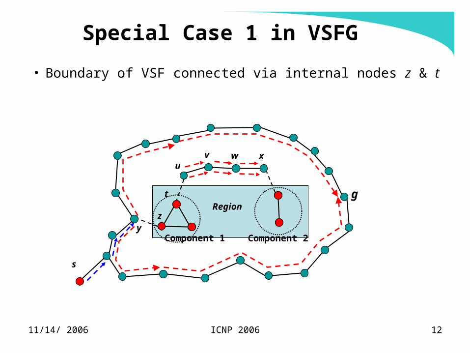
Special Case 1 in VSFG
• Boundary of VSF connected via internal nodes z & t
s
Region
xu
w
t g
z
Component 2Component 1
11/14/ 2006 ICNP 2006 13
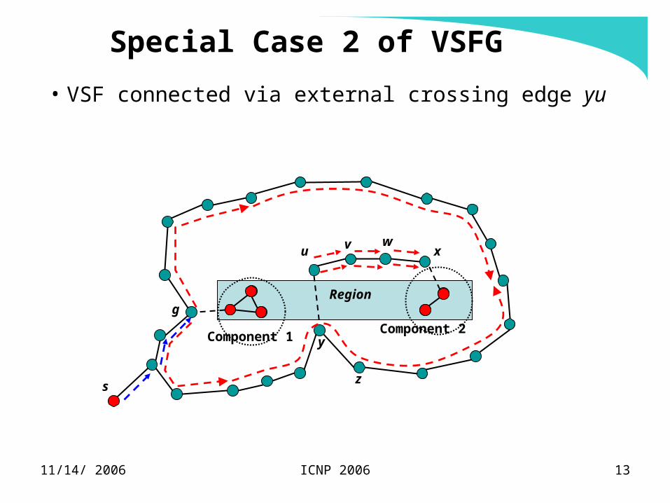
Special Case 2 of VSFG
• VSF connected via external crossing edge yu
v
s
Region
xuw
y
z
Component 2Component 1
g
11/14/ 2006 ICNP 2006 14
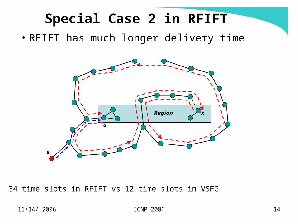
Special Case 2 in RFIFT
• RFIFT has much longer delivery time
s
Region x
u
34 time slots in RFIFT vs 12 time slots in VSFG
11/14/ 2006 ICNP 2006 15
Asymptotical bound of VSFG
• The message complexity of VSF traversal is
bounded by 2n, where n is the number of nodes
located on VSF boundary.
• The message complexity of face traversal in
RFIFT is bounded by 3n.
11/14/ 2006 ICNP 2006 16
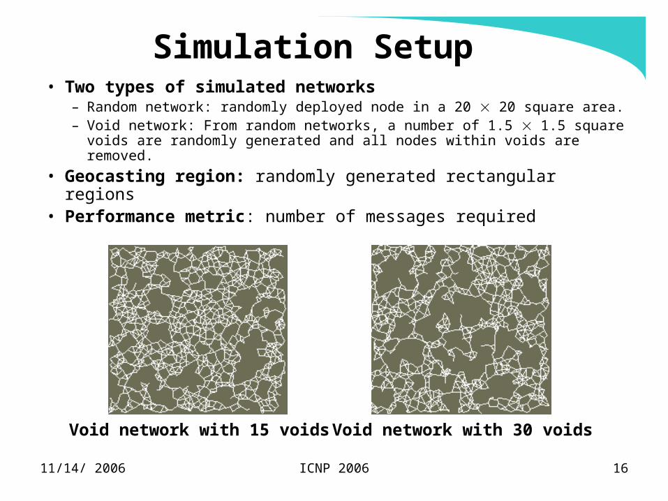
Simulation Setup• Two types of simulated networks
– Random network: randomly deployed node in a 20 20 square area.– Void network: From random networks, a number of 1.5 1.5 square
voids are randomly generated and all nodes within voids are removed.
• Geocasting region: randomly generated rectangular regions• Performance metric: number of messages required
Void network with 15 voids Void network with 30 voids
11/14/ 2006 ICNP 2006 17
0
5
10
15
20
25
0 10 20 30 40 50
Average degree of network
VSF
IFT
0
11
22
33
44
0 10 20 30 40 50
Average degree of network
VSF
IFT
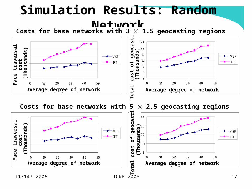
Simulation Results: Random Network
0
4
8
12
16
20
24
0 10 20 30 40 50
Average degree of network
VSF
IFT
0
3
6
9
12
15
0 10 20 30 40 50
Average degree of network
VSF
IFT
Average degree of network Average degree of network
Fac
e tr
aver
sal c
ost
(T
hou
san
ds)
Tot
al c
ost
of g
eoca
stin
g(T
hou
san
ds)
Average degree of network Average degree of network
Fac
e tr
aver
sal c
ost
(T
hou
san
ds)
Tot
al c
ost
of g
eoca
stin
g(T
hou
san
ds)
Costs for base networks with 5 2.5 geocasting regions
Costs for base networks with 3 1.5 geocasting regions
11/14/ 2006 ICNP 2006 18
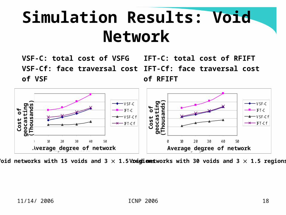
0
4
8
12
16
20
0 10 20 30 40 50
Average degree of network
VSF-C
IFT-C
VSF-Cf
IFT-Cf
0
4
8
12
16
20
0 10 20 30 40 50
Average degree of network
VSF-C
IFT-C
VSF-Cf
IFT-Cf
Simulation Results: Void Network
Average degree of network Average degree of network
Cos
t of
geo
cast
ing
(T
hou
san
ds)
Cos
t of
geo
cast
ing
(Th
ousa
nd
s)Void networks with 15 voids and 3 1.5 regions Void networks with 30 voids and 3 1.5 regions
VSF-C: total cost of VSFG
VSF-Cf: face traversal cost of VSF
IFT-C: total cost of RFIFT
IFT-Cf: face traversal cost of RFIFT
11/14/ 2006 ICNP 2006 19
Conclusion
• Design of VSF
• Guaranteed message delivery
• Fast delivery due to concurrent double directional
traversal
• Low transmission cost
• Low probability of collision occurrences
• Scalability
11/14/ 2006 ICNP 2006 20
Future Work
• Reducing face traversal cost by designing shortcut algorithm
• Designing localized dominating-set based flooding algorithm
to replace restricted flooding in VSFG.
• Analyzing the impact of location errors on VSFG and
providing respective solutions.
• Studying VSFG on realistic network model, not unit disk
graphs.
11/14/ 2006 ICNP 2006 21

11/14/ 2006 ICNP 2006 22
Termination Condition• Observation
– When a node starting a VSF traversal by using Right- and Left-hand simultaneously, the two traversal messages with eventually meet at a node on the boundary VSF.
• Precondition– A VSF node u receives a traversal message from node v MSG1(v, Rule1) but not been forwarded to next node yet.
– Node u receives another traversal message MSG(w, Rule2).
• Termination Condition– If the next visited node of MSG1 is w;
– If the next visited node of MSG2 is v;
– If Rule1 is not same as Rule2;
– Node u terminates the face traversal (discards MSG1 and MSG2).
11/14/ 2006 ICNP 2006 23
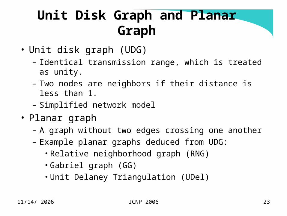
Unit Disk Graph and Planar Graph
• Unit disk graph (UDG)– Identical transmission range, which is treated as unity.
– Two nodes are neighbors if their distance is less than 1.
– Simplified network model
• Planar graph– A graph without two edges crossing one another
– Example planar graphs deduced from UDG:
• Relative neighborhood graph (RNG)
• Gabriel graph (GG)
• Unit Delaney Triangulation (UDel)
11/14/ 2006 ICNP 2006 24
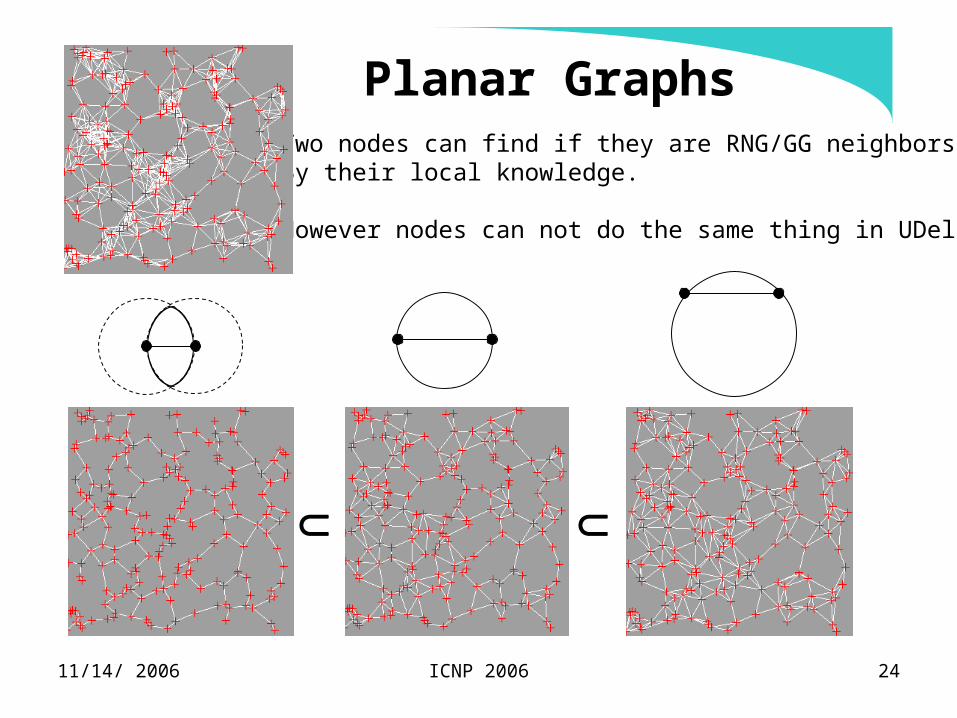
Planar GraphsUDG
GGRNG UDel
Two nodes can find if they are RNG/GG neighborsBy their local knowledge.
However nodes can not do the same thing in UDel.

11/14/ 2006 ICNP 2006 25
Face and Face Traversal in GG
• Four faces: F1, F2, F3, and F4, where F4 is an exterior face (open area)
• Traversing F1 by using Right-Hand rule starting from u
v
F3
F1
F4
u
z
w
x
y
F2
u1
u2 u3
u5
u6
u7
u8u9u10
u11
u12
u13
v1
v2v4
v3
u4
11/14/ 2006 ICNP 2006 26
VSF Geocasting
• VSF Forwarding– A source node s selects a geographical point in a geocasting region
closest to the source node as the destination reference point p.
– Node s transmits a geocasting message towards p by using location-based routing until a node u on the boundary of the VSF is found.
• VSF Traversal (Double direction traversal)– Node u as chosen above starts VSF traversal using Right-hand rule
and Left-hand rule simultaneously.
• VSF Restricted Flooding– Each node in the geocasting region overhearing a geocasting
message for the first time broadcasts the message.


