


1
ORIGINAL OPERATING INSTRUCTIONSSAVE THESE INSTRUCTIONS FOR FUTURE REFERENCE.
Version:20141208
Warning: For tools equipped with over load protection, when motor has shut down off due to over load, always run machine with no load for at least 3 minutes to reduce temperature before returning to operation to avoid burn out of the motor.
1 Speed Drilling System1 Speed Drilling System (N)Semi Auto Feed Drilling SystemSemi Auto Feed Drilling System(N)
2 Speed Drilling System4 Speed Drilling System4 Speed Swivel Base Drilling System4 Speed Variable Motor Speed Drilling System
2
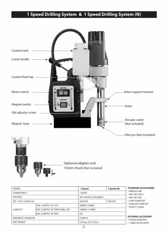
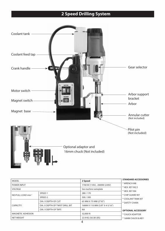
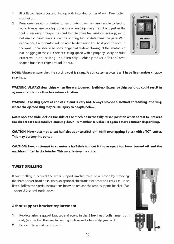
Coolant tank
Motor switch
Magnet switch
Crank handle
Coolant feed tap
Arbor
Arbor support bracket
Annular cutter (Not included)
Pilot pin (Not included)
Magnet base
Gib adjustor screw
Optional adaptor and 13mm chuck (Not included)
1 Speed Drilling System & 1 Speed Drilling System (N)
STANDARD ACCESSORIES* WRENCH M8* HEX. KEY M2.5* HEX. KEY M4* CHIP GUARD KIT* COOLANT TANK KIT* SAFETY CHAIN
OPTIONAL ACCESSORY* CHUCK ADAPTOR * 13MM CHUCK & KEY
MODEL 1 Speed 1 Speed (N)
POWER INPUT 1100 W
VOLTAGE See machine nameplate
NO / FULL LOAD min-1 620/350 550/330
DIA. X DEPTH OF CUT 35MM X 50MM
CAPACITY DIA. X DEPTH OF TWIST DRILL BIT 13MM X 110MM
DIA. X DEPTH OF TAPS NA
MAGNETIC ADHESION 15,000 N
NET WEIGHT 12.6 kg (27.72 Lbs )
3
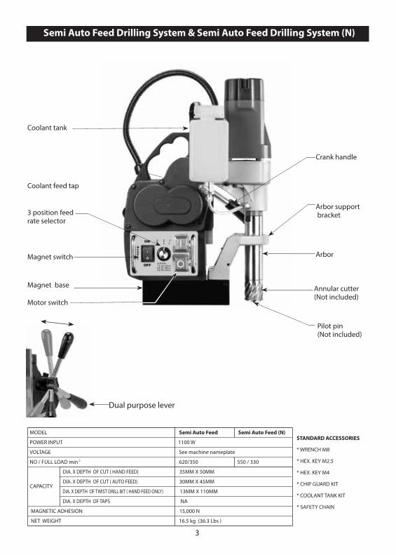
Dual purpose lever
Crank handle
Arbor
Arbor support bracket
Annular cutter (Not included)
Pilot pin (Not included)
Coolant tank
Motor switch
Magnet switch
Coolant feed tap
Magnet base
3 position feedrate selector
Semi Auto Feed Drilling System & Semi Auto Feed Drilling System (N)
STANDARD ACCESSORIES
* WRENCH M8
* HEX. KEY M2.5
* HEX. KEY M4
* CHIP GUARD KIT
* COOLANT TANK KIT
* SAFETY CHAIN
MODEL Semi Auto Feed Semi Auto Feed (N)
POWER INPUT 1100 W
VOLTAGE See machine nameplate
NO / FULL LOAD min-1 620/350 550 / 330
DIA. X DEPTH OF CUT ( HAND FEED) 35MM X 50MM
CAPACITY DIA. X DEPTH OF CUT ( AUTO FEED) 30MM X 45MM
DIA. X DEPTH OF TWIST DRILL BIT ( HAND FEED ONLY) 13MM X 110MM
DIA. X DEPTH OF TAPS NA
MAGNETIC ADHESION 15,000 N
NET WEIGHT 16.5 kg (36.3 Lbs )
4
Crank handle
Arbor
Arbor support bracket
Gear selector
Coolant tank
Motor switch
Magnet switch
Coolant feed tap
Magnet baseAnnular cutter (Not included)
Pilot pin (Not included)
Optional adaptor and 16mm chuck (Not included)
2 Speed Drilling System
MODEL 2 Speed
POWER INPUT 1700 W (110V), 2000W (220V)
VOLTAGE See machine nameplate
NO/FULL LOAD min-1 SPEED 1 280 / 170
SPEED 2 500 / 300
DIA. X DEPTH OF CUT 65 MM X 75 MM (2"X3")
CAPACITY: DIA. X DEPTH OF TWIST DRILL BIT 16MM X 110 MM (5/8" X 4-5/16")
DIA. X DEPTH OF TAPS NA
MAGNETIC ADHESION 32,000 N
NET WEIGHT 22.9 KG (50.38 LBS)
STANDARD ACCESSORIES
* WRENCH M8
* HEX. KEY M2.5
* HEX. KEY M4
* CHIP GUARD KIT
* COOLANT TANK KIT
* SAFETY CHAIN
OPTIONAL ACCESSORY
* CHUCK ADAPTOR
* 16MM CHUCK & KEY
5
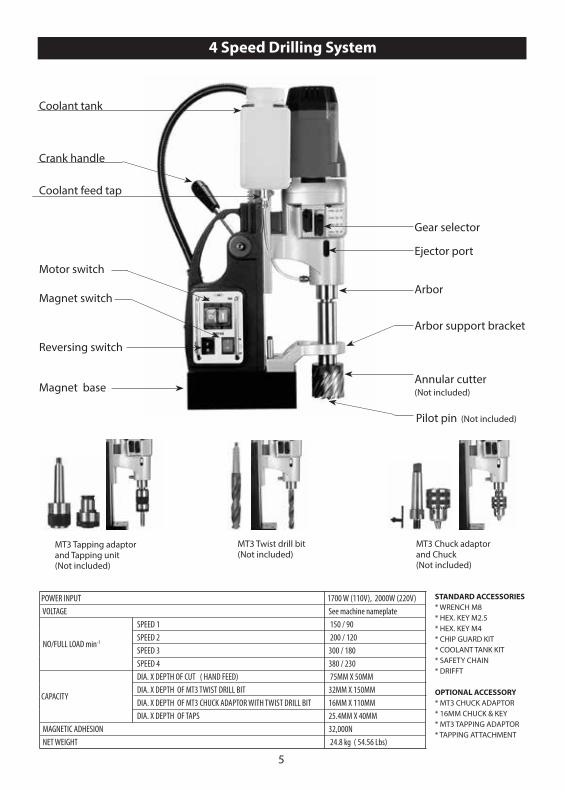
Magnet base
Coolant tank
Motor switch
Magnet switch
Coolant feed tap
Reversing switch
Crank handle
Arbor
Arbor support bracket
Annular cutter(Not included)
Gear selector
Ejector port
Pilot pin (Not included)
MT3 Twist drill bit (Not included)
MT3 Chuck adaptorand Chuck(Not included)
MT3 Tapping adaptorand Tapping unit(Not included)
4 Speed Drilling System
STANDARD ACCESSORIES* WRENCH M8* HEX. KEY M2.5* HEX. KEY M4* CHIP GUARD KIT* COOLANT TANK KIT* SAFETY CHAIN* DRIFFT
OPTIONAL ACCESSORY* MT3 CHUCK ADAPTOR * 16MM CHUCK & KEY* MT3 TAPPING ADAPTOR * TAPPING ATTACHMENT
POWER INPUT 1700 W (110V), 2000W (220V) VOLTAGE See machine nameplate SPEED 1 150 / 90 NO/FULL LOAD min-1
SPEED 2 200 / 120 SPEED 3 300 / 180 SPEED 4 380 / 230 DIA. X DEPTH OF CUT ( HAND FEED) 75MM X 50MM
CAPACITY DIA. X DEPTH OF MT3 TWIST DRILL BIT 32MM X 150MM
DIA. X DEPTH OF MT3 CHUCK ADAPTOR WITH TWIST DRILL BIT 16MM X 110MM DIA. X DEPTH OF TAPS 25.4MM X 40MM MAGNETIC ADHESION 32,000N NET WEIGHT 24.8 kg ( 54.56 Lbs)
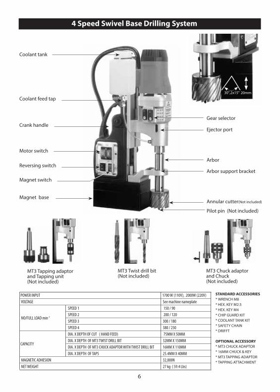
6
Magnet base
Coolant tank
Motor switch
Magnet switch
Coolant feed tap
Reversing switch
Crank handle
Arbor
Arbor support bracket
Annular cutter(Not included)
Gear selector
Ejector port
Pilot pin (Not included)
MT3 Twist drill bit (Not included)
MT3 Chuck adaptorand Chuck(Not included)
MT3 Tapping adaptorand Tapping unit(Not included)
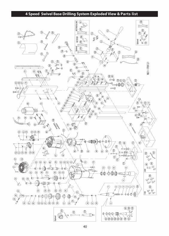
4 Speed Swivel Base Drilling System
30°,2x15° 20mm
STANDARD ACCESSORIES* WRENCH M8* HEX. KEY M2.5* HEX. KEY M4* CHIP GUARD KIT* COOLANT TANK KIT* SAFETY CHAIN* DRIFFT
OPTIONAL ACCESSORY* MT3 CHUCK ADAPTOR * 16MM CHUCK & KEY* MT3 TAPPING ADAPTOR * TAPPING ATTACHMENT
POWER INPUT 1700 W (110V), 2000W (220V) VOLTAGE See machine nameplate SPEED 1 150 / 90 NO/FULL LOAD min-1
SPEED 2 200 / 120 SPEED 3 300 / 180 SPEED 4 380 / 230 DIA. X DEPTH OF CUT ( HAND FEED) 75MM X 50MM
CAPACITY DIA. X DEPTH OF MT3 TWIST DRILL BIT 32MM X 150MM
DIA. X DEPTH OF MT3 CHUCK ADAPTOR WITH TWIST DRILL BIT 16MM X 110MM DIA. X DEPTH OF TAPS 25.4MM X 40MM MAGNETIC ADHESION 32,000N NET WEIGHT 27 kg ( 59.4 Lbs)
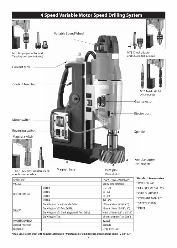
7
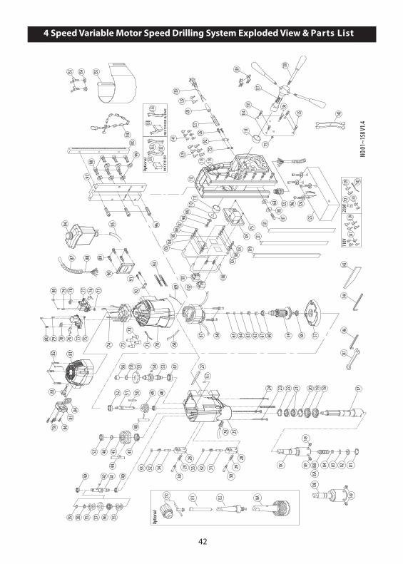
4 Speed Variable Motor Speed Drilling System
Magnet base
Coolant tank
Motor switch
Magnet switch
Coolant feed tap
Reversing switch Spindle
Annular cutter(Not included)
Gear selector
Ejector port
Pilot pin (Not included)
1-1/4 " (32.7mm) Weldon shank annular cutter arbor
MT3 Twist drill bit (Not included)
MT3 Tapping adaptor and Tapping unit (Not included)
MT3 Chuck adaptorand Chuck (Not included)
Variable Speed Wheel
* Max. Dia. x Depth of cut with Annular Cutters with 19mm Weldon or Quick-Release Arbor: 60mm x 50mm ( 2-3/8" x 2")
Standard Accessories
* WRENCH M8
* HEX. KEY M2.5 & M5
* CHIP GUARD KIT
* COOLANT TANK KIT
* SAFETY CHAIN
* DRIFT
POWER INPUT 1700 W (110V), 2000W (220V) VOLTAGE See machine nameplate SPEED 1 35 - 120 NO/FULL LOAD min-1
SPEED 2 70 - 220 SPEED 3 80 - 250 SPEED 4 140 - 450 Dia. X Depth of cut with Annular Cutters 120mm x 50mm (4-3/4" x 2")
CAPACITY Dia. X Depth of MT3 Twist Drill Bit 32mm x 150mm ( 1-1/4" x 6" )
Dia. X Depth of MT3 Chuck adaptor with Twist Drill bit 16mm x 110mm (5/8" x 4-5/16") Dia. X Depth of Taps 25.4mm x 40mm (1" x 1-9/16") MAGNETIC ADHESION 32,000N Overload Protection Standard NET WEIGHT 27 kg ( 59.4 Lbs)

8
WARNING! Read and understand all instruction before operating any drilling system. Failure to follow all instructions listed below may result in electrical shock, damage to drilling system and even personal injury.
GENERAL SAFETY INSTRUCTIONS
Work area
1. Keep your working area clean and well lighted. Cluttered benches and working stations causes accidents as well as dark spaces. Always ensure working stations are clean and well lit.
2. Do not operate power tools in explosive atmosphere, such as in the presence of flammable liquids, gases or extreme dust. Power tools create sparks that may ignite gases as well as flammable liquids. Dust may enter the ventilation system causing clogging and causing overheating.
3. Keep bystanders, children and visitors away from moving parts of the power tool. Any distractions can cause you to loose control of the power tool and an injury could take place.
Electrical Safety
1. Grounded tools must be plugged into an outlet properly installed and grounded in accordance with all codes and ordinances. Never remove the ground prong or modify the dance plug in any way. Do not use any adaptor plugs. Check with a qualified electrician if you are in doubt as to whether the outlet is properly grounded. If tools should electrically malfunction or break down, grounding provides a low resistance path to carry electricity away from the user.
2. Never carry a tool by the cord or hose and “yanking” the cord or the hose to disconnect it from the receptacle. Always carry the power tools properly and store in dry and dust free place.
3. Keep cords and hoses away from heat, oil and sharp edges. Damaged cords increase the risk of electric shock.
4. Don’t expose power tools to rain or wet conditions. Water entering a power tool will increase the risk of electric shock. When operating a power tool outside, use an outdoor extension cord marked .W-A. or. W.. These cords are rated for outdoor use and reduce the risk of electric shock.
Personal Safety
1. Stay alert, watch what you are doing and use common sense when operating a power tool. Do not use tool while tired or under the influence of drugs, alcohol, or medication. A moment of inattention while operating power tools may result in serious personal injury.
2. Dress properly. Do not wear loose clothing or jewelry. Contain long hair. Keep your hair, clothing, and gloves away from moving parts. Loose clothes, jewelry, or long hair can be caught in moving parts.
3. Avoid accidental starting. Be sure switch is off before plugging in. Carrying tools with your finger on the switch or plugging in tools that have the switch on invites accidents.
4. Remove adjusting keys or switches before turning the tool on. A wrench or a key that is left attached
9
to a rotating part of the tool may result in personal injury.
5. Do not overreach. Keep a proper footing and balance at all times. Proper footing and balance enables better control of the tool in unexpected situations.
6. Use safety equipment. Always wear eye protection. Dust mask, non-skid safety shoes, hardhat, or hearing protection must be used for appropriate conditions.
Tool use and care
1. Use clamps or other practical way to secure and support the work piece to a stable platform. Holding the work by hand or against your body is unstable and may lead to loss of control.
2. Do not force tool. Use the correct tool for your application. The correct tool will do the job better and safer at the rate for which it is designed.
3. Do not use tool if switch does not turn it on or off. Any tool that cannot be controlled with the switch is dangerous and must be repaired.
4. Disconnect the plug from the power source before making any adjustments, changing accessories, or storing the tool. Such preventive safety measures reduce the risk of starting the tool accidentally.Store idle ling tools out of reach of children and other untrained persons. Tools are dangerous in the hands of untrained users.
5. Maintain tools with care. Keep cutting tools sharp and clean. Properly maintained tools, with sharp cutting edges are less likely to bind and are easier to control.
6. Check for misalignment or binding of moving parts, breakage of parts, and any other condition that may affect the tools operation. If damaged, have the tool serviced before using. Poorly maintained tools cause many accidents.
7. Use only accessories that are recommended by the manufacturer for your model. Accessories that may be suitable for one tool may become hazardous when used on another tool.
Service
Only qualified repair personnel must perform tool service. Service or maintenance performed by unqualified personnel could result in a risk of injury.When servicing tool, use only identical replacement parts. Follow instructions in the Maintenance section of this manual. Use of unauthorized parts or failure to follow Maintenance Instructions may create a risk of electric shock or injury.
Symbols used in this manual
IMPORTANT: Some of the following symbols may be used on your tool. Please study them and learn their meaning. Proper interpretation of these symbols will allow you to operate the tool better and safer.

10
Terminology used in the manual
1. Warning: This term means that there is a risk of physical harm or death to the operator or people nearby.
2. Caution: This term means that there is a risk of damage to the machine, cutting tool or other equipment.
3. Note: These terms offer useful information relating to the operation of the machine or its maintenance.
SPECIFIC SAFETY RULES AND REGULATIONS
1. Always use safety chain. Mounting can release.
2. The magnet’s adhesion depends on the thickness of the work piece. Always ensure that the work piece is a minimum of 12mm (7/16 in.) thick. If it is not, then use a piece of steel plate at least12mm thick and larger than the magnet below the work piece to supplement the magnetic adhesion.
3. Metal chips and other debris will seriously hamper magnetic adhesion. Always ensure that the magnet is clean and free of rust and scale.
4. Other units used on the same receptacle will cause uneven voltage that could lead to the magnet releasing. Always use the tool alone on the receptacle.
5. It is hazardous to use the drill upside-down. Do not exceed 90 degrees from horizontal.
6. Avoid the magnet releasing. Ensure that the magnet has properly adhered to the work piece before beginning drilling.
7. Avoid operating annular cutters without coolant fluid. Always check coolant level before operating.
8. Do not operate with dull or damaged cutting tools. This may overload the motor.
9. Protect the motor. Never allow cutting fluid, water, or other contaminants to enter the motor.
10. Metal chips are often very sharp and hot. Never touch them with bare hands. Clean up with a magnetic chip collector and a chip hook or other appropriate tool.
Symbol Name Designation/Explanation
V Volt Voltage (potential)
A Amperes Current
Hz Hertz Frequency (cycles per second)
W Watt Power
kg Kilograms Weight
min Minutes Time
s Seconds Time
Diameter Size of drill bits
n0 No load speed Rotational speed, at no load
min-1 Revolutions per minute Revolutions, strokes, surface speed per minute.
0 Off position Zero speed, zero torque…
1, 2, 3, … Selector settings Speed setting,higher number means greater speed
~ Alternating current Type or a characteristic or current
Class I construction With electrical earth
Warning symbol Alerts user to warning messages
11
CAUTION: NEVER position machine on a work piece between the electrode and the ground of any arc type welder. Damage to the machine will result, as the welder will ground through the machine’s ground cable. When drilling stacked work materials, always stop to clear the slug after the first layer is drilled.
WARNING: Do not operate the machine on a workpiece which is being welded on at the same time. This may lead to damage to the machine and possible injury.
WARNING:NEVER attempt to use machine with incorrect current or abnormally low voltage. Check machine nameplate to ensure that correct voltage and Hz are used. When drilling non-ferrous (non-magnetic) work materials, only use a manufacturer- approved fixture such as a vacuum base adapte.
Magnet Base Duty Cycle
Do not leave the magnet base activated continuously for more than 60 minutes. If the magnet base is overheated, allow it to cool for 30 minutes before continuing.This machine is not intended for production-line type use.
CAUTION:Turn the magnet base off when not in use. Leaving the magnet base on continuously will damage it.
ASSEMBLY
Coolant tank assembly required. First attach clear tube to the bottom of the coolant tank. To do this, first loosen the nut and slide nut onto the tube. Then slide tube onto the nipple. Then tighten the nut. Slide tank hanger over the screw on the upper right hand side of slide and tighten. Finally insert the other end of the tube into the quick-release connector in the gearbox. Just directly push in to install. (To remove, first firmly push the red collar of the connector and pull the tube out.) Cutting coolant fluid is always required when using annular cutters. Open tank cover and fill. Check coolant fluid level often. Keep coolant tap closed when not in use.Chip guard must be used. To attach the chip guard, use the supplied butterfly bolts to bolt to the magnet. It is not necessary to remove guard to clean chips. Simply raise guard to its upper position.Safety chain must be used. Loop chain around the work piece and feed through the machine’s handle and clip in place.
MOUNTING ANNULAR CUTTERS
CAUTION: Never use a cutting tool that is larger than the maximum rated capacity of the machine.
1. To insert an annular cutter, first insert the pilot pin into the cutter. Then slide the cutter into the arbor, align the proper flat with the locking screw(s) and tighten securely with the supplied hex wrench.

12
CAUTION: Ensure that the locking screw is on a flat of the cutter and not just against the rounded shank.
2. Ensure that the oil feed tap is on and coolant feeds properly by pushing the pilot pin. If it feeds too quickly or slowly, adjust the tap accordingly. Keep the tap closed when not in use.
2-SPEED MODELS
GEAR SELECTION
On 2-speed models, before drilling select desired gear range by first pushing in on spring-loaded gear selector slider switch and then sliding selector up for high speed or down for low speed. (It may be necessary to turn the arbor slightly in order for the gears to mesh properly). Follow the recommended speed ranges on the cutting speed chart to set the proper speed and gear range.
2 SPEED GEAR CHARTGEAR NO LOAD min-1 FULL LOAD min-1 CUTTER SIZE 1 380 230 40~50mm (1~9/16 to 2 in.) 2 500 300 40mm (1~9/16 in.) or less.
NOTE: These speeds are general recommendations only. Actual speeds should be determined by the material and the cutting speed recommended by the cutting tool manufacturer. See the section below "RECOMMENDED SURFACE SPEEDS" and use the formula to calculate the best RPM.
CAUTION: Ensure that that gears engage fully.
CAUTION: ALWAYS ensure that the machine is fully stopped before attempting to change gears! NEVER change gears on a running machine!
OPERATION-GENERAL
WARNING: Always ensure that the magnet is adhered properly to the work piece before beginning drilling.
NOTE: If mounting to a curved surface beam, mount the machine parallel to the curve in the work piece.
WARNING: Avoid operating at more than 90 degrees from horizontal. When drilling at such an angle take precautions to prevent cutting coolant from entering the motor. Paste-type coolant should be used.
gear selector
13
1. First fit tool into arbor and line up with intended center of cut. Then switch magnet on.
2. Press green motor on button to start motor. Use the crank handle to feed to work. Always use very light pressure when beginning the cut and just as the tool is breaking through. The crank handle offers tremendous leverage; so do not use too much force. Allow the cutting tool to determine the pace. With experience, the operator will be able to determine the best pace to feed to the work. There should be some degree of audible slowing of the motor but not bogging in the cut. Correct cutting speed with a properly sharp annular cutter will produce long unbroken chips, which produce a “bird’s” nest. shaped bundle of chips around the cut.
NOTE: Always ensure that the cutting tool is sharp. A dull cutter typically will have finer and/or choppy shavings.
WARNING: ALWAYS clear chips when there is too much build-up. Excessive chip build-up could result in a jammed cutter or other hazardous situation.
WARNING: the slug ejects at end of cut and is very hot. Always provide a method of catching the slug, where the ejected slug may cause injury to people below.
Note: Lock the slide lock on the side of the machine in the fully raised position when at rest to prevent the slide from accidentally slamming down - remember to unlock it again before commencing drilling.
CAUTION: Never attempt to cut half-circles or to stitch drill (drill overlapping holes) with a TCT cutter. This may destroy the cutter.
CAUTION: Never attempt to re enter a half-finished cut if the magnet has been turned off and the machine shifted in the interim. This may destroy the cutter.
TWIST DRILLING
If twist drilling is desired, the arbor support bracket must be removed by removing the three socket-head bolts. Then an optional chuck adaptor arbor and chuck must be fitted. Follow the special instructions below to replace the arbor support bracket. (For 1 speed & 2 speed model only ).
Arbor support bracket replacement
1. Replace arbor support bracket and screw in the 3 hex head bolts finger tight only (ensure that the needle bearing is clean and adequately greased.)
2. Replace the annular cutter arbor.

14
WARNING: use extreme care to avoid contacting the rotating arbor shaft!
3. Double check to ensure that there is no binding anywhere throughout the stroke.
SPECIAL INSTRUCTIONS FOR AUTO-FEED MODELS
WARNING: NEVER attempt to use machine in auto feed mode when using twist drills. THIS WILL RESULT IN MAGNET LIFTING.
WARNING: NEVER use poor quality, incorrect sized or dull cutters in auto feed mode. THIS MAY RESULT IN MAGNET LIFTING.
The Auto-Feed Feature
A lever incorporated into the feed handle engages or disengages the feed drive gears. If the auto-feed mode is not engaged, the machine may be used in the same fashion as the manual machine as described above. Below are the additional instructions needed to operate in auto-mode.
IMPORTANT: When in manual mode, the three lever handles will be pointing outward slightly (out). When in auto-feed mode, the lever handles will be parallel with the side of the machine (in).
NOTE: Do not operate the auto machine banked to one side in the plane of the lever as this may allow the machine to slip into or out of auto-feed mode unexpectedly.
WARNING: Do not attempt to drill a work piece which is thicker than the maximum cutting depth of the cutter being used. Never exceed 30mm diameter cutters when using auto-feed mode.
THE FEED RANGE SELECTOR
There is a 3-position range selector switch on the switch panel which allows ideal feed rate for various sized cutters. Select the feed range which corresponds to the cutter diameter being used.
POSITION RANGE 1 14~20mm 2 21~24mm 3 25~30mm
AUTO-FEED OPERATION
1. Always begin drilling manually (with the handles pointing out) as described above in “OPERATION-GENERAL”.
15
2. Only after the cutter has begun cutting for a few seconds and has raised a chip should the auto feed be engaged.
NOTE: Do not cut manually for more than 10 seconds before shifting into auto feed. If manual cutting continues for more than 10 seconds, as soon as auto feed is engaged, rather than cutting, it will directly stop.
3. To engage auto-feed, push any of the lever handles in. The gears may not always line up perfectly. If the handle will not push in, simply raise the feed upward slightly and the lever will engage.
4. As a precaution, always keep one hand near to the motor shut off switch in order to shut off quickly in the event of any problem.
5. Once the hole is drilled, the machine will continue to feed for 3 seconds (to fully finish hole) and then will automatically shut off.
NOTE: This machine is equipped with safety override systems which will automatically engage: If the load exceeds maximum for 2 seconds or more, the motor and feed will stop and stay in that position. Only the magnet will stay on. This will alert the operator of an overload problem. If this happens repeatedly, stop operation and find the cause of the excessive load. It could be a bad cutter or other problem.
WARNING: WHENEVER THE MACHINE STOPS DUE TO OVERLOAD IN THIS WAY, RAISE THE CUTTER CLEAR OF THE WORKPIECE BEFORE RESTARTING
NOTE: when drilling very deep holes with long reach cutters, there is considerable build up of chips. This may interfere with operation and even cause the machine to stop from overload. In this situation, we recommend stopping to clear the chips after the first 25mm (1 inch) or so, then continuing to finish the cut.
45mm IS THE MAXIMUM DEPTH OF CUTTING WITH AUTO FEED.
NOTE: the maximum rated thickness of material with the auto feed function is 45mm. For drilling thickness up to 50mm, finish by hand feed.
WARNING: PAY ATTENTION TO THE CONDITION OF THE CUTTER. This is particularly important with an auto feed machine. A dull or damaged cutter may cause a dangerous situation.
WARNING: NEVER ATTEMPT TO DRILL MATERIAL THICKER THAN THE DEPTH CAPACITY OF THE CUTTER. If the cutter is allowed to “bottom out” the feed system may cause the magnet to lift (usually it will overload first).NOTE: In very light load conditions, such as when using very small cutters or drilling a very thin work piece, often the load drop will not be enough to signal the machine’s electronic control board to automatically stop. If this occurs, it does not indicate a malfunction.

16
SPECIAL INSTRUCTIONS FOR SWIVEL BASE EQUIPPED MODELS
The swivel base allows the drill to be precisely positioned under difficult circumstances.
To use: first position the magnet base in the desired position and turn magnet on.Loosen the Locking Lug, then swivel the machine body into the desired position. Finally lock the Locking Lug.
SPECIAL INSTRUCTIONS FOR 4-SPEED MT3 EQUIPPED MODELS
CHANGING TOOLS & ADAPTORS WITH MT3 SHANK
To insert a tool, turn the tool until the tang lines up and firmly push into place. It is helpful to tap with a soft-faced mallet to fully engage the taper. If it is properly in position, one will not be able to pull it back apart by hand. To remove, line up the ejector slot of the arbor with the ejector port in the gear case, slide the ejector drift into the slot and tap with a hammer to eject the tool.
CAUTION: When removing, take care that the cutting tool does not crash down and get damaged or injure anyone below.
MT3 ANNULAR CUTTER ADAPTOR
This machine is equipped with a unique annular cutter adaptor system with built-in coolant directly to the gearbox. No stop bar is needed.1. To install the annular cutter adaptor, first insert the taper end of the adaptor into the arbor of the machine as described above.2. Attach the coolant tank to the slide and ensure that the tube is attached properly.3. To insert an annular cutter, first insert the pilot pin. Then slide the cutter into the adaptor, align the proper flat with the locking screw(s) and tighten securely with the supplied hex wrench.4. Ensure that the oil feed tap is on and coolant feeds properly by pushing the pilot pin. If it feeds too quickly or slowly, adjust the tap accordingly. Keep the tap closed when not in use.
OPERATION
The operation instructions under “OPERATION-GENERAL” also apply to this machine. Please see the additional
30°,2x15° 20mm
17
instructions specific to the 4-speed Morse taper model below:
WARNING: NEVER operate 60mm (2-3/8 in.) or larger cutters unless the plate thickness is mini mum 20mm (13/16 in.) MAGNET LIFTING MAY RESULT. If the plate thickness is not enough, supplement the magnetic adhesion by adding a 10mm or thicker plate directly the magnet’s position under the work piece.
CAUTION: Machine is equipped with a reversing switch. Always ensure that direction of rotation is correct before operating. Operating in the wrong direction could result in damage to the cutter.
Select desired gear range by first popping the tab out of its detent and then sliding selectors up or down in the proper combination. Refer to the chart to achieve the correct combination for the desired speed. (It may be necessary to turn the arbor slightly in order for the gears to mesh properly). Follow the recommended speed ranges on the cutting speed chart to set the proper speed and gear range.
NOTE: These speeds are general recommendations only. The material should determine actual speeds and the cutting speed recommended by the cutting tool manufacturer. See the section below "RECOMMENDED SURFACE SPEEDS" and use the formula to calculate the best RPM.
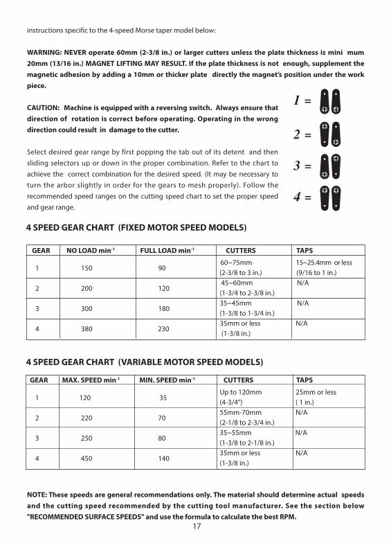
4 SPEED GEAR CHART (FIXED MOTOR SPEED MODELS)
GEAR NO LOAD min-1 FULL LOAD min-1 CUTTERS TAPS
1 150 90
60~75mm 15~25.4mm or less (2-3/8 to 3 in.) (9/16 to 1 in.)
2 200 120 45~60mm N/A
(1-3/4 to 2-3/8 in.)
3 300 180 35~45mm N/A
(1-3/8 to 1-3/4 in.)
4 380 230 35mm or less N/A
(1-3/8 in.)
4 SPEED GEAR CHART (VARIABLE MOTOR SPEED MODELS)
GEAR MAX. SPEED min-1 MIN. SPEED min-1 CUTTERS TAPS
1 120 35
Up to 120mm 25mm or less (4-3/4") ( 1 in.)
2 220 70 55mm-70mm N/A
(2-1/8 to 2-3/4 in.)
3 250 80 35~55mm N/A
(1-3/8 to 2-1/8 in.)
4 450 140 35mm or less N/A
(1-3/8 in.)
18
NOTE: the left and right side gear selectors have a different engagement design:
For The LEFT HAND SLIDER must ALWAYS ensure that the machine is FULLY STOPPED before attempting to change gears! NEVER change the Left hand slider gears on a running machine!
For the RIGHT HAND SLIDER the gears select by engagement dogs, similar to a motorcycle transmission design. These MUST BE SELECTED BY TURNING THE ARBOR to allow the dogs to engage.
CAUTION: Ensure that that gears engage fully.
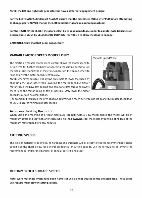
VARIABLE MOTOR SPEED MODELS ONLY
The electronic variable motor speed control allows the motor speed to be lowered for further flexibility for adjusting the cutting speed to suit the size of cutter and type of material. Simply turn the thumb wheel to raise or lower the motor speed electronically.NOTE: whenever possible, it is always preferable to lower the speed by changing the gear rather than lowering the motor speed. A slower motor speed will have less cooling and somewhat less torque so always try to keep the motor going as fast as possible. Only lower the motor speed if you have no other option.(For example: If you need the RPM at about 100/min, it is much better to use 1st gear at full motor speed than to use 3rd gear at minimum motor speed.)
Avoid overheating the motor: When using the machine at or near maximum capacity with a slow motor speed the motor will be at maximum stress and very hot. After each cut is finished, ALWAYS cool the motor by running at no load at the maximum motor speed for a few minutes.
CUTTING SPEEDS
The type of material to be drilled, its hardness and thickness will all greatly affect the recommended cutting speed. See the chart below for general guidelines for cutting speeds. Use the formula to determine the recommended RPM for the diameter of annular cutter being used:
RECOMMENDED SURFACE SPEEDS
Note: work materials which have been flame cut will be heat treated in the affected area. These areas will require much slower cutting speeds.
Variable Speed Wheel
19
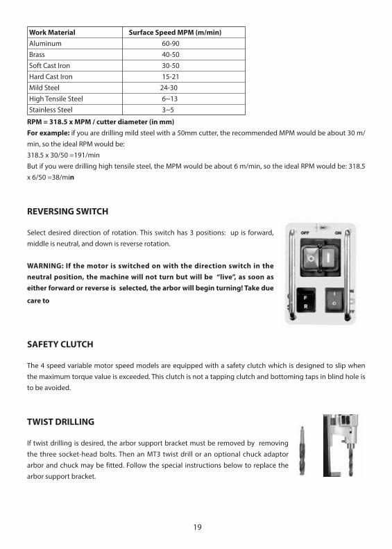
Work Material Surface Speed MPM (m/min)Aluminum 60-90Brass 40-50Soft Cast Iron 30-50Hard Cast Iron 15-21Mild Steel 24-30High Tensile Steel 6~13Stainless Steel 3~5
RPM = 318.5 x MPM / cutter diameter (in mm)For example: if you are drilling mild steel with a 50mm cutter, the recommended MPM would be about 30 m/min, so the ideal RPM would be:318.5 x 30/50 =191/min But if you were drilling high tensile steel, the MPM would be about 6 m/min, so the ideal RPM would be: 318.5 x 6/50 =38/min
REVERSING SWITCH
Select desired direction of rotation. This switch has 3 positions: up is forward, middle is neutral, and down is reverse rotation.
WARNING: If the motor is switched on with the direction switch in the neutral position, the machine will not turn but will be “live”, as soon as either forward or reverse is selected, the arbor will begin turning! Take due
care to
SAFETY CLUTCH
The 4 speed variable motor speed models are equipped with a safety clutch which is designed to slip when the maximum torque value is exceeded. This clutch is not a tapping clutch and bottoming taps in blind hole is to be avoided.
TWIST DRILLING
If twist drilling is desired, the arbor support bracket must be removed by removing the three socket-head bolts. Then an MT3 twist drill or an optional chuck adaptor arbor and chuck may be fitted. Follow the special instructions below to replace the arbor support bracket.

20
ARBOR SUPPORT BRACKET REPLACEMENT
1. Replace arbor support bracket and screw in the 3 hex head bolts finger tight only (ensure that the needle bearing is clean and adequately greased.)
2. Replace the annular cutter arbor and carefully tighten the bolts evenly to ensure proper alignment.
WARNING: use extreme care to avoid contacting the rotating arbor shaft! 3. Double check to ensure that there is no binding anywhere throughout the stroke.
NOTE: A pilot hole may be necessary when drilling with larger twist drills. If a MT3 twist drill is used, it may not be necessary to remove the arbor support bracket.
CHUCK
If a MT3 chuck adaptor & chuck are used, then the bracket must be removed. To replace, see the instructions above under “ARBOR SUPPORT BRACKET REPLACEMENT”.
TAPPING
CAUTION: To avoid damage to the tap, always very carefully line the tap up with the hole and ensure that the size of the hole is correct for the tap to be used.
CAUTION: To avoid damage to the tap or machine, be very careful to stop the machine in time to NOT allow the tap bottom out. The motor continues to coast for a while after being shut off, so plan for this and anticipate. This machine does NOT have a tapping clutch.
CAUTION: To avoid damage to the machine, ALWAYS allow the machine to come to a full stop before reversing rotation.
1. Select the proper speed according to the chart for the size of tap used.
2. Begin with forward direction of rotation with standard right hand threads. (Opposite with left-hand threads)
3. Allow the tap to determine the feed rate. A light touch on the feed handle is all that is needed once it is started in the hole.4. When the desired thread is tapped, hit the red motor stop switch. Allow the machine to come to a full stop. Then reverse direction and restart machine by pressing the green motor switch to remove tap. Guide the tap back out with the feed handle. Proper order of operations for normal tapping is as follows: magnet: on. direction: forward. motor: on. motor: off. THEN: direction: reverse. motor: on. motor: off - magnet: off.

21
MAINTENANCE
Every 50 hours of operation blow compressed air through the motor while running at no load to clean out accumulated dust. (If operating in especially dusty conditions, perform this operation more often.)
1. Keep the machine clean and free of chips.2. Check for loose fittings and tighten as needed.3. Ensure that the ventilation slots are clear so that motor can be cooled normally. Blow low-pressure
compressed air through the ventilation slots with the motor running to keep motor clean.
THE ARBOR SHAFT
Keep the arbor shaft free of dirt and lightly grease as needed. If the arbor support bearing is noisy, it may be dirty or have a chip lodged in it. Remove the arbor shaft to clean and re-grease the arbor support bearing.
THE GIBS (DOVETAIL SLIDES)
The gibes require adjustment if too loose. To adjust, loosen the lock nuts and adjust the adjustor screws evenly while moving the handle up and down. Adjust so that there is no free play, yet any binding anywhere in its range of travel. Then retighten the lock nuts. Periodically check, lubricate, and adjust as needed.
THE CARBON BRUSHES
The carbon brushes are a normal wearing part and must be replaced when they reach their wear limit.
Caution: Always replace the brushes as a pair.
To replace:1. Remove the 4 screws and remove the motor tail cover.2. Using pliers rotate the brush spring out of the way and slide the old
carbon brush out of the brush holder.3. Unscrew the screw to remove the brush lead. The old carbon brush
may now be lifted away.4. Install a new brush. Installation is the reverse of removal.5. Replace the motor tail cover.
AUTO STOP CARBON BRUSH
Due to the new auto stop carbon brush if the machine comes to a stop without any reason, the brushes have to be checked. The auto feature
TentionSpring
BrushHolder
Auto StopCarbonBrush

22
stops the machine before the carbon brushes are finished and protects the motor.
MAGNET TROUBLESHOOTING
Full magnet performance is absolutely essential for magnetic drill operation.If the magnet works, but does not hold well, it is likely that one of the coils has failed. If the magnet does not work at all, it is likely to be a failed rectifier. (It is highly unlikely that both magnet coils would fail at the same time)
NOTE: A faulty magnet coil can also damage the rectifier, so whenever there is a magnet problem, BOTH the magnet coils and rectifier must be checked.
WARNING: Never attempt to operate a magnetic drill with a faulty magnet!
CHECKING THE MAGNET (qualified technicians only)
If the magnet is not working well, it must be checked. Separate the wires of each indiviual coil and test the resistance of each coil separately. (note that 110V models are wired in parallel and 230V models are wired in series) The resistance of the coils of different sizes of magnets varies, but it should be in the region of hundreds of ohms. Most importantly, both coils must have very nearly the same resistance. If one of the coils has zero resistance, it means that it is shorted. If one of the coils has infinite resistance, it means that the circuit is broken. If either coil has a problem, the magnet must be replaced. A faulty magnet may also cause damage to the rectifier. Also check the rectifier when replacing a faulty magnet. (see below)
CHECKING THE RECTIFIER (Qualified technicians only)
The rectifier takes the AC household current and converts it to DC to power the magnet. If it fails, the magnet coils will not receive power. Disconnect the rectifier and test the resistance of both circuits of the rectifier between the AC and the DC sides. Note that polarity matters, so you can only take a reading if test probes are oriented correctly. Each side will be the opposite of the other. Both circuits should have very nearly the same resistance reading. If one of the circuits has zero resistance, it means that it is shorted. If one of the circuits has infinite resistance, it means that the circuit is broken.
If the replacement of the power supply cord is necessary, this has to be done by the manufacturer or their agent in order to avoid a safety hazard.
WARNING: All repairs must be entrusted to an authorized service center. Incorrectly performed repairs could lead to injury or death.
23
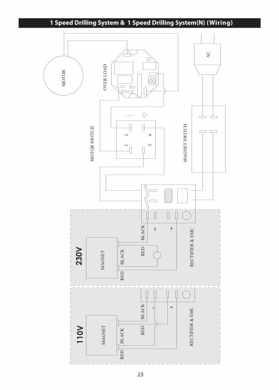
1 Speed Drilling System & 1 Speed Drilling System(N) (Wiring)
-
+
12 4
3
OV
ER
LO
AD
MA
GN
ET
RE
CT
IFIE
R &
EM
C
MA
GN
ET
SW
ITC
H
MO
TO
R S
WIT
CH
MO
TO
R
RE
DB
LA
CK
RE
DB
LA
CK
AC
-
+
MA
GN
ET
RE
DB
LA
CK
RE
DB
LA
CK
RE
CT
IFIE
R &
EM
C
110V
230V
24
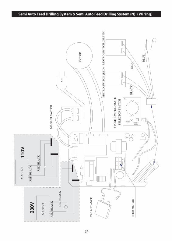
Semi Auto Feed Drilling System & Semi Auto Feed Drilling System (N) (Wiring)
MO
TR
O S
WIT
CH
(R
ED
)M
OT
RO
SW
ITC
H (
GR
EE
N)
MA
GE
NT
SW
ITC
H
FEE
D M
OT
OR
3 PO
SIT
ION
FE
ED
RA
TE
SEL
EC
TO
R S
WIT
CH
CA
PAC
ITA
NC
E
MA
GE
NT
MO
TO
R
AC
RE
DB
LA
CK
RE
DB
LA
CK
RE
DB
LA
CK
BL
UE
MA
GE
NT
RE
DB
LA
CK
RE
DB
LA
CK
230V
110V
25
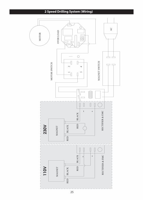
2 Speed Drilling System (Wiring)
+
12 4
3
OV
ER
LO
AD
MA
GN
ET
RE
CT
IFIE
R &
EM
C
MA
GN
ET
SW
ITC
H
MO
TO
R S
WIT
CH
MO
TO
R
RE
DB
LA
CK
RE
DB
LA
CK
AC
-
+
MA
GN
ET
RE
CT
IFIE
R &
EM
C
RE
DB
LA
CK
RE
DB
LA
CK
110V
230V
26
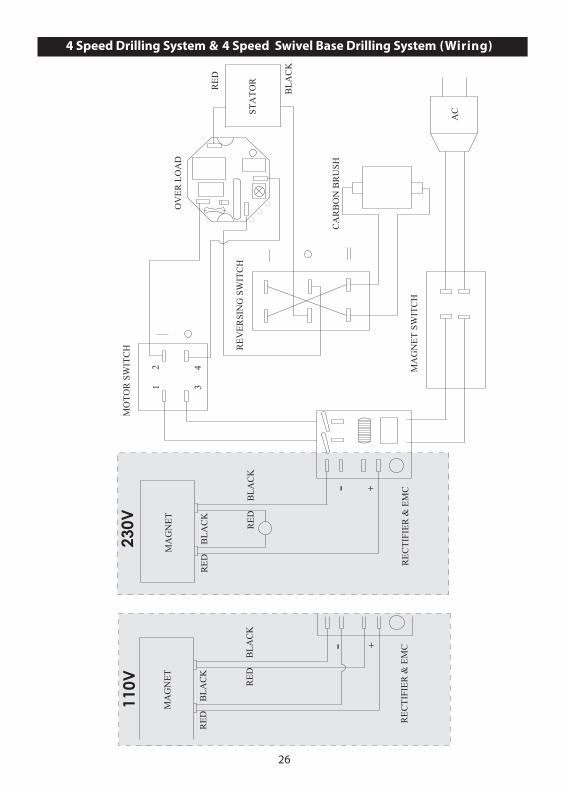
4 Speed Drilling System & 4 Speed Swivel Base Drilling System (Wiring)
-
+
RE
CT
IFIE
R &
EM
C
MA
GN
ET
OV
ER
LO
AD
MA
GN
ET
SW
ITC
H
CA
RB
ON
BR
USH
RE
VE
RSI
NG
SW
ITC
H
12 4
3
MO
TO
R S
WIT
CH
STA
TO
R
RE
DB
LA
CK
RE
DB
LA
CK
AC
RE
D
BL
AC
K
-
+
MA
GN
ET
RE
DB
LA
CK
RE
DB
LA
CK
RE
CT
IFIE
R &
EM
C
110V
230V
27
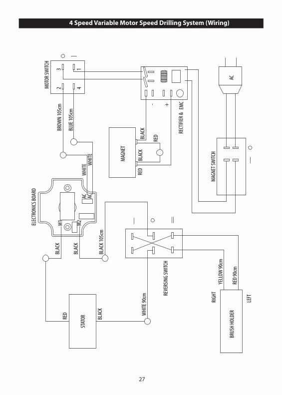
4 Speed Variable Motor Speed Drilling System (Wiring)
M1
M2
ACAC
- +
AC
STAT
OR
REVE
RSIN
G SW
ITCH
MOT
OR SW
ITCH
RECT
IFIER
& E
MC
MAGN
ET SW
ITCH
BRUS
H HO
LDER
RIGH
T
LEFT
MAGN
ET
ELEC
TRON
ICS BO
ARD
RED
BLAC
K
REDBL
ACK
RED
BLAC
K
BLAC
K
BLAC
K
BLAC
K 105
cm
WHI
TE 90
cm
BROW
N 10
5cm
BLUE
105c
m
RED
90cm
YELL
OW 90
cm
23
41
WHI
TE WHI
TE
28
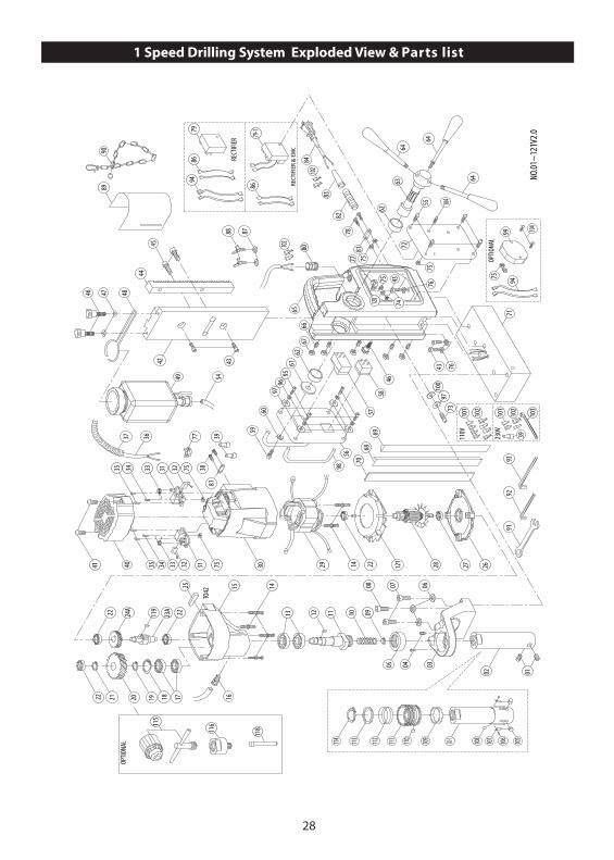
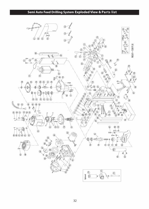
1 Speed Drilling System Exploded View & Parts list
43
44
29
9192
93
03
07
0910111213
1516
2223A
24A22
25171819202122
06
22 27
14
4245
2628
98
62
60
67
57
59
46
6162
66
76
65
70
58
73
63
4376
77
71
7281
43
82
75
75
78
83
8480
9089
88 87
48
49 54
3032 3133344041 7535
3881
39773637
7532313335 34
9597
96
TO42
55
6968
46 47
08
0405
56
0102
64
64
64
9710
0
NO.
01~
121V
2.0
8694
79
8679-
1
RECT
IFIE
R &
EM
C
RECT
IFIER
110V
230V
101
102
101
102
39
103
102
102
104
105106107108110 109111112113114 02-1
OPTIO
NAL
75
9994
104
75
11811
6
OPTIO
NAL
119
115
74120
14 121

29
NO. Parts Name Q'TY1 SET SCREW M8 x 7 22 ARBOR 1 2-1 QUICK RELEASE ARBOR SHAFT 1 3 ARBOR SUPPORT BRACKET 14 TRUSS HEAD SCREW M5 x 8 25 BEARING HK3516 16 SPRING WASHER M8 37 SOCKET CAP BOLT M8 x 55 28 SOCKET CAP BOLT M8 x 30 19 COOLANT SEAL 110 SPRING 111 SPINDLE 112 PARALLEL KEY 5 x 5 x 10 113 OIL SEAL Ø28 x Ø40 x 7 214 SCREW M5 x 60 615 GEAR CASE 116 PUSH LOCK FITTING 117 BEARING 6003 zz 218 INTERNAL CIRCLIP R-35 119 EXTERNAL CIRCLIP S-17 120 OUTPUT GEAR 52T 121 EXTERNAL CIRCLIP S-15 122 BEARING 608 zz 423A.) INPUT PINION 8T 124A.) INPUT GEAR 50T 125 PARALLEL KEY 4 x 4 x 30 126 GEAR PLATE 127 BEARING 609-2RS EZO 128 ARMATURE 7T 129 STATOR 130 MOTOR HOUSING 131 BRUSH HOLDER 232 CARBON BRUSH 7 x 11 x 17 233 BRUSH SPRING 234 SCREW M4 x 10 235 SCREW M4 x 12 436 MOTOR CABLE 1.25 x 2C x 65CM 137 CABLE PROTECTOR 40CM 138 SCREW M4 x 14 239 END SPLICE TERMINAL C4 340 MOTOR TAIL COVER 141 SCREW M4 x 25 242 SLIDE PLATE 230cm 143 SOCKET CAP BOLT M6 x 20 544 GEAR RACK 145 SOCKET CAP BOLT M8 x 16 246 THUMB SCREW M5 x 16 347 FLAT WASHER Ø5 x Ø12 x 1 248 COOLANT TANK BRACKET 149 COOLANT TANK ASSEMBLY 150~53 N/A -54 COOLANT TUBE 15cm 155 SCREW M4 x 8 456 SWITCH PANEL 157 MOTOR SWITCH 158 MAGNET SWITCH 159 SOCKET CAP BOLT M6 x 16 160 FLAT WASHER Ø6 x Ø25 x 1 161 FLAT WASHER Ø6 x Ø40 x 2.5 162 BUSHING Ø28 x Ø32 x 12 2
63 CRANK SPINDLE 164 CRANK LEVER 365 STAND BODY 166 GIB SET SCREW M5 x 20 567 GIB LOCK NUT M5 568 GIB WEAR STRIP - LEFT 169 GIB WEAR STRIP - RIGHT 170 GIB TENSIONER 260 x 11 x 2.3 171 ELECTROMAGNET 164 x 80 x 48 172 SIDE PANEL 173 SCREW M4 x 16 174 STAR WASHER M5 175 NUT M4 x 8 876 SPRING WASHER M6 377 CABLE CLAMP 278 SCREW M4 x 30 279 RECTIFIER 179-1 RECTIFIER & EMC 180 CABLE GLAND 181 CABLE CLIP 282 STRAIN RELIEF 7cm 183 CORD ARMOR 184 POWER SUPPLY CABLE 185 N/A -86 LEAD WIRE 287 FLAT WASHER Ø6 x Ø13 x 1 288 BUTTERFLY SCREW M6 x 10 289 CHIP GUARD 190 SAFETY CHAIN 191 COMBINATION WRENCH-M8 M8 192 L-HEX KEY-M2.5 M2.5 193 L-HEX KEY-M4 M4 194 LEAD WIRE 495 SOCKET CAP SCREW M4 x 16 496 SPRING WASHER M4 497 FLAT WASHER Ø4 x Ø10 x 1 598 SWITCH GUARD BAR 299 OVER LOAD PROTECTION (OPTIONAL ) 1100 RUBBER WASHER Ø4 x Ø11 x 1 1101 SPADE TERMINAL FDV1-250 4102 TERMINAL COVER 8103 ZIP TIE 1104 SCREW M4 x 25 3105 LOCK PIN 2106 SCREW M3 x 4 2107 LOCKING PIN SPRING 2108 CHECK BALL Ø8 1109 RUBBER RING 1110 COLLAR PIN 1111 QUICK-RELEASE COLLAR 1112 SPRING Ø39 x Ø43 x 3T x 30L 1113 SPRING SEAT RING Ø35.1 x Ø44.5 x 2 1114 EXTERNAL CIRCLIP S-35 1115 CHUCK (OPTIONAL) 1/2" 1116 CHUCK ADAPTOR (OPTIONAL) 1117 N/A -118 PILOT PIN (OPTIONAL) TCTx91LxØ8 1119 PARALLEL KEY 4 x 4 x 8 1120 EARTHING MARKING 1121 FAN BAFFLE 1
30
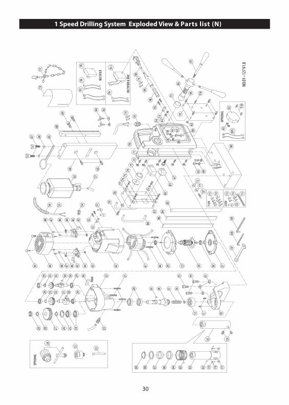
1 Speed Drilling System Exploded View & Parts list (N)
101112
1314151617181920
21
40
2223242526272829
29 29
29 29
29
3030
31323333 3435 36
TO64
37383941424344454647484950
48
51524345444647
53545556
62 57
54 4351
43
43
6364
63
63 89
656667
67
89
68
69
7071
7273
7475
7677
78
79
80
81
8283
8485
86
90
94
73
96
9398
99
101
103104
107108
109
110111
100
97
NO.
01~
127 V
1.8
106105
95
95-1
RECT
IFIER
& EM
C
RECT
IFIER
106
8777
112
110V
230V
113 113
53
114 114 115
114
114
116
OPTIO
NAL
43
9210
5
116
91
123
120
OPTIO
NAL
124125
117118119020506 04070809 03
121
88126
127

31
NO. Parts Name Q'TY1 N/A -2 CHECK BALL Ø8 13 QUICK RELEASE ARBOR SHAFT 14 QUICK-RELEASE COLLAR 15 COLLAR PIN 16 RUBBER RING Ø40 x Ø44 x 9 17 SPRING Ø2 x Ø39 x Ø43 x 30L x 3T 18 STEEL RING Ø35.1 x Ø44.5 x 2 19 EXTERNAL CIRCLIP S-35 110 ARBOR SUPPORT BRACKET 111 TRUSS HEAD SCREW M5 x 8 212 BEARING HK3516 113 SPRING WASHER M8 314 SOCKET CAP BOLT M8 x 55 215 SOCKET CAP BOLT M8 x 30 116 COOLANT SEAL 117 SPRING 118 SPINDLE 119 PARALLEL KEY 5 x 5 x 10 1 20 OIL SEAL Ø28 x Ø40 x 7 221 SCREW M5 x 70 422 GEAR CASE 123 PUSH LOCK FITTING 124 BEARING 6003 zz 225 INTERNAL CIRCLIP R-35 126 EXTERNAL CIRCLIP S-17 127 OUTPUT GEAR 37T 128 EXTERNAL CIRCLIP S-15 129 BEARING 608 zz 6 30 PARALLEL KEY 4 x 4 x 8 231 INTERMEDIATE GEAR PINION 12T 132 INTERMEDIATE GEAR 34T 133 EXTERNAL CIRCLIP S-10 234 INPUT PINION 9T 135 INPUT GEAR 30T 136 PARALLEL KEY 4 x 4 x 30 137 GEAR PLATE 138 BEARING 6001-LLU 139 ARMATURE 7T 140 SCREW M5 x 60 241 STATOR 142 MOTOR HOUSING 143 NUT M4 x 8 844 BRUSH HOLDER 245 CARBON BRUSH 7 x 11 x 17 246 BRUSH SPRING 247 SCREW M4 x 10 248 SCREW M4 x 12 449 MOTOR TAIL COVER 150 SCREW M4 x 25 251 CABLE CLIP 252 SCREW M4 x 14 253 END SPLICE TERMINAL C4 354 CABLE CLAMP 255 MOTOR CABLE 1.25 x 2C x 65CM 156 CABLE PROTECTOR 40cm 157 COOLANT TUBE 15cm 158~61 N/A - 62 COOLANT TANK ASSEMBLY 163 SOCKET CAP BOLT M6 x 20 564 SLIDE PLATE 238cm 165 COOLANT TANK BRACKET 1
66 FLAT WASHER Ø5 x Ø12 x 1 267 THUMB SCREW M5 x 16 368 GEAR RACK 169 SOCKET CAP BOLT M8 x 16 270 STAND BODY 171 GIB SET SCREW M5 x 20 572 GIB LOCK NUT M5 573 BUSHING Ø28 x Ø32 x 12 274 FLAT WASHER Ø6 x Ø40 x 2.5 175 SOCKET CAP SCREW M4 x 16 476 SPRING WASHER M4 477 FLAT WASHER Ø4 x Ø10 x 1 578 FLAT WASHER Ø6 x Ø25 x 1 179 SOCKET CAP BOLT M6 x 16 180 SWITCH GUARD BAR 281 SWITCH PANEL 182 MOTOR SWITCH 183 MAGNET SWITCH 184 GIB WEAR STRIP - LEFT 185 GIB WEAR STRIP - RIGHT 186 GIB TENSIONER 260 x 11 x 2.3 187 SCREW M4 x 16 188 STAR WASHER M5 189 SPRING WASHER M6 390 ELECTROMAGNET 164 x 80 x 48 191 SIDE PANEL 192 OVER LOAD PROTECTION (OPTIONAL) 193 SCREW M4 x 30 294 SCREW M4 x 8 495 RECTIFIER & EMC 195-1 RECTIFIER & EMC 196 CRANK SPINDLE 197 CRANK LEVER 398 STRAIN RELIEF 7cm 199 CORD ARMOR 1100 POWER SUPPLY CABLE 1101 CABLE GLAND 1102 N/A -103 FLAT WASHER Ø6 x Ø13 x 1 2104 BUTTERFLY SCREW M6 x 10 2105 LEAD WIRE 4106 LEAD WIRE 2107 M8 COMBINATION WRENCH M8 1108 M2.5 L-HEX WRENCH M2.5 1109 M4 L-HEX WRENCH M4 1110 CHIP GUARD 1111 SAFETY CHAIN 1112 RUBBER WASHER M4 1113 SPADE TERMINAL FDV1-250 4114 TERMINAL COVER 8115 ZIP TIE 1116 SCREW M4 x 25 3117 LOCK PIN 2118 SCREW M3 x 4 2119 LOCKING PIN SPRING 2120 CHUCK (OPTIONAL) 1/2" 1121 CHUCK ADAPTOR (OPTIONAL) 1122 N/A -123 PILOT PIN (OPTIONAL) TCTx91LxØ8 1124 SET SCREW M8 x 7 2125 ARBOR 1126 EARTHING MARKING 1127 FAN SHROUD 1
32
02 01030411
0607 05
19
18
2627A28A26
212223242526
17
29
32 26 17
33
36 353738
4041
31
09
10
08
08
121314
15
16
20
3439
53 54
59
64
43 60 6161
62
6566
6768
72 7366
7475
34137
777879
8081
34
82
83
8485
8687
84
8990
88
9192
9394
95
96
97
46101
102
103
104
105106
107108
109110
111112
111
111112
112
113
114115
116
117
118119120121
124122
123
100
98
99100
63-263-3
63
45 46 47444342
4850
3436353739 38
113
113
100
NO.
01~
138 V
1.8
TO50
6465
66
99100
115116
115116
114
114
127
49
51 52
126
128
128
110V
12523
0V47
128128 134
125
129
Optio
nal 133130
66
71
135
136
131
76
30
138
63-1
Semi Auto Feed Drilling System Exploded View & Parts list

33
NO. Parts Name Q'TY1 SET SCREW M8 x 7 22 ARBOR 13 ARBOR SUPPORT BRACKET 14 TRUSS HEAD SCREW M5 x 8 25 SPRING WASHER M8 36 SOCKET CAP BOLT M8 x 55 27 SOCKET CAP BOLT M8 x 30 18 SOCKET CAP BOLT M6 x 20 59 SPRING WASHER M6 310 ELECTROMAGNET 164 x 80 x 48 111 BEARING HK 3516 112 COOLANT SEAL 113 SPRING 114 SPINDLE 115 PARALLEL KEY 5 x 5 x 10 116 OIL SEAL Ø28 x Ø40 x 7 217 SCREW M5 x 60 618 PUSH LOCK FITTING 119 GEAR CASE 120 PARALLEL KEY 4 x 4 x 30 121 BEARING 6003 zz 222 INTERNAL CIRCLIP R-35 123 EXTERNAL CIRCLIP S-17 124 OUTPUT GEAR 52T 125 EXTERNAL CIRCLIP S-15 126 BEARING 608 zz 427A INPUT PINION 8T 128A INPUT GEAR 50T 129 GEAR PLATE 130 BEARING 609 zz 131 ARMATURE 7T 132 STATOR 133 MOTOR HOUSING 134 NUT M4 x 8 535 BRUSH HOLDER 7 x 11 236 CARBON BRUSH 7 x 11 x 17 237 SPRING 238 SCREW M4 x 10 239 SCREW M4 x 12 440 MOTOR TAIL COVER 141 SCREW M4 x 25 242 CABLE PROTECTOR 40CM 143 MOTOR CABLE 1.25 x 2C x 80CM 144 CABLE CLAMP 145 SCREW M4 x 14 246 CORD CLIP 247 END SPLICE TERMINAL C-4 348 GEAR RACK 149 SOCKET CAP BOLT M8 x 16 250 SLIDE PLATE 151 SOCKET CAP SCREW M5 x 16 252 FLAT WASHER Ø5 x Ø12 x 1 253 COOLANT TANK BRACKET 154 COOLANT TANK ASSEMBLY 155~58 N/A - 59 COOLANT TUBE 15CM 160 CABLE GLAND 161 BUSHING Ø28 x Ø32 x 12 262 STAND BODY 163 SPEED CONTROL BOARD 163-1 SCREW 163-2 SELECTOR SWITCH 163-3 NUT 164 SOCKET CAP SCREW M4 x 16 465 SPRING WASHER M4 466 FLAT WASHER Ø4 x Ø10 x 1 667 SWITCH PLATE 168 MAGNET SWITCH 1
69~70 N/A - 71 SWITCH GUARD 272 MOTOR ON SWITCH (GREEN) 173 MOTOR OFF SWITCH (RED) 174 NUT M5 675 SET SCREW M5 x 20 676 STAR WASHER M5 177 LIMIT SWITCH 178 PIN Ø2.2 x 10 279 GIB TENSIONER 260 x 11 x 2.3 180 GIB STRIP - RIGHT 260L 181 GIB STRIP - LEFT 260L 182 FEED MOTOR 183 FEED MOTOR GEAR BOX 184 BUSHING Ø8 x Ø12 x 6 285 FEED INTERMEDIATE GEAR 10T 186 PARALLEL KEY 4 x 4 x 10 187 FEED OUTPUT GEAR 80T 188 BEARING 6809 zz 189 ENGAGEMENT GEAR 63T 190 EXTERNAL CIRCLIP S-29 191 FEED SUPPORT BASE 192 FLAT HEAD SCREW M5 x 15 493 FLAT HEAD SCREW M5 x 30 494 AUTO FEED COVER 195 SCREW M5 x 20 596 CAPACITOR 197 ELECTRONICS BOARD 198 SIDE PLATE 199 SCREW M3.5 x 6 4100 SCREW M4 x 8 7101 SCREW M4 x 30 2102 CABLE PROTECTOR 7CM 1103 CORD ARMOR 1104 POWER SUPPLY CABLE 1105 SCREW M4 x 10 1106 SELECTOR CAM 1107 BALL Ø5 8108 CRANK SPINDLE 1109 SELECTOR ROD 1110 CRANK HUB 1111 SET SCREW M8 x 10 3112 DETEN UNIT M6 x 13 3113 SPRING PIN Ø4.2 x 25 3114 CRANK LEVER TIP 3115 CRANK LEVER 3116 CRANK GRIP 3117 HUB COVER 1118 FLAT WASHER Ø6 x Ø13 x 1 2119 BUTTERFLY SCREW M6 x 10 2120 CHIP GUARD 1121 SAFETY CHAIN 1122 COMBINATION WRENCH-M8 M8 1123 L-HEX KEY-M2.5 M2.5 1124 L-HEX KEY-M4 M4 1125 SPADE TERMINAL 4126 SCREW M4 x 16 1127 WASHER 4 x 11 x 1 1128 TERMINAL COVER 8129 HUB PLATE 1130 CHUCK ADAPTOR (OPTIONAL) 1131 CHUCK (OPTIONAL) 1/2" 1132 N/A -133 PILOT PIN (OPTIONAL) TCTx91LxØ8 1134 ZIP TIE 1135 PARALLEL KEY 4 x 4 x 8 1136 SWITCH COVER 2137 EARTHING MARKING 1138 FAN BAFFLE 1
34
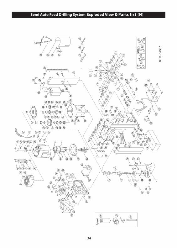
Semi Auto Feed Drilling System Exploded View & Parts list (N)
01101
102
114115
116117
116
116117
117
118
119120
121
122105
103
118
118
105
TO55
120121
120121
119
119
104105
02
0304
07 06 05
0910
08
11121314
15
16
171819
20212223242526
262728293026
2626 31273230
33
3526363738
3939
39
39
4040 41
414242
434344
44
454647 48 49 50 51 52
51
08
5354
58
59 64
48 6566
66
676869
70
71
72
71
7368-3
68-276
77 78
7980
141
8382
8485
86
87
8889
89
9091
92
93
9495
969798
99100
100
106107
108
109
110111
112113
126 125 123124 127128
129
NO.01
~14
2V1.5
132 130
56 57
55
133
133
110V
13123
0V52
133133 134
131
135
Optio
nal
137
139136
71
140
81
34
142
68-1

35
NO. Parts Name Q'TY1 SET SCREW M8 x 7 22 ARBOR 13 ARBOR SUPPORT BRACKET 14 TRUSS HEAD SCREW M5 x 8 25 SPRING WASHER M8 36 CAP BOLT M8 x 55 27 CAP BOLT M8 x 30 18 CAP BOLT M6 x 20 59 SPRING WASHER M6 310 MAGNET 111 BEARING HK 3516 112 COOLANT SEAL 113 SPRING 114 SPINDLE 115 WOODRUFF KEY 5 x 5 x 10 116 OIL SEAL Ø28 x Ø40 x 7 217 SCREW M5 x 70 418 PUSH LOCK FITTING 119 GEAR CASE 120 PARALLEL KEY 4 x 4 x 30 121 BEARING 6003 zz 222 INTERNAL CIRCLIP R-35 123 EXTERNAL CIRCLIP S-17 124 OUTPUT GEAR 37T 125 EXTERNAL CIR CLIP S-15 126 BEARING 608 zz 627 PARALLEL KEY 4 x 4 x 8 228 INTERMEDIATE GEAR PINION 12T 129 INTERMEDIATE GEAR 34T 130 EXTERNAL CIRCLIP S-10 231 INPUT PINION 9T 132 INPUT GEAR 30T 133 GEAR PLATE 134 BEARING 6001-LLU 135 ARMATURE 7T 136 SCREW M5 x 60 237 STATOR 138 MOTOR HOUSING 139 NUT M4 x 8 540 BRUSH HOLDER 7 x 11 241 CARBON BRUSH 7 x 11 x 17 242 SPRING 243 SCREW M4 x 10 244 SCREW M4 x 12 445 MOTOR TAIL COVER 146 SCREW M4 x 25 247 CABLE PROTECTOR 40CM 148 MOTOR CABLE 1.25 x 2C x 80CM 149 CABLE CLAMP 150 SCREW M4 x 14 251 CORD CLIP 252 WIRE CONNECTOR C-4 353 GEAR RACK 154 SCREW M8 x 16 255 SLIDE PLATE 156 SOCKET CAP BOLT M5 x 16 257 FLAT WASHER Ø5 x Ø12 x 1 258 COOLANT TANK BRACKET 159 COOLANT TANK ASSEMBLY 160~63 N/A -64 COOLANT TUBE 15CM 165 CABLE GLAND 166 BUSHING Ø28 x Ø32 x 12 267 STAND BODY 168 SPEED CONTROL BOARD 168-1 SCREW 168-2 SELECTOR SWITCH 168-3 NUT 169 SOCKET CAP SCREW M4 x 16 470 SPRING WASHER M4 4
71 FLAT WASHER Ø4 x Ø10 x 1 672 SWITCH PLATE 173 MAGNET SWITCH 174~75 N/A - 76 SWITCH GUARD 277 MOTOR ON SWITCH (GREEN) 178 MOTOR OFF SWITCH (RED) 179 NUT M5 680 SET SCREW M5 x 20 681 STAR WASHER M5 182 LIMIT SWITCH 183 PIN Ø2.2 x 10 284 GIB TENSIONER 260 x 11 x 2.3 185 GIB STRIP - RIGHT 186 GIB STRIP - LEFT 260L 187 FEED MOTOR 188 FEED MOTOR GEAR BOX 189 BUSHING Ø8 x Ø12 x 6 290 FEED INTERMEDIATE GEAR 10T 191 PARALLEL KEY 4 x 4 x 10 192 FEED OUTPUT GEAR 80T 193 BEARING 6809 zz 194 ENGAGEMENT GEAR 63T 195 EXTERNAL CIRCLIP S-29 196 FEED SUPPORT BASE 197 FLAT HEAD SCREW M5 x 15 498 FLAT HEAD SCREW M5 x 30 499 AUTO FEED COVER 1100 SCREW M5 x 20 5101 CAPACITOR 1102 ELECTRONICS BOARD 1103 SIDE PLATE 1104 SCREW M3.5 x 6 4105 SCREW M4 x 8 7106 SCREW M4 x 30 2107 CABLE PROTECTOR 7CM 1108 CORD ARMOR 1109 POWER SUPPLY CABLE 1110 SCREW M4 x 10 1111 SELECTOR CAM 1112 BALL Ø5 8113 CRANK SPINDLE 1114 SELECTOR ROD 1115 CRANK HUB 1116 SET SCREW M8 x 10 3117 DETENT UNIT M6 x 13 3118 SPRING PIN Ø4.2 x 25 3119 CRANK LEVER TIP 3120 CRANK LEVER 3121 CRANK GRIP 3122 HUB COVER 1123 FLAT WASHER Ø6 x Ø13 x 1 2124 BUTTERFLY SCREW M6 x 10 2125 CHIP GUARD 1126 SAFETY CHAIN 1127 M8 COMBINATION WRENCH M8 1128 M2.5 L-HEX WRENCH M2.5 1129 M4 L-HEX WRENCH M4 1130 SCREW M4 x 16 1131 SPADE TERMINAL 4132 RUBBER WASHER Ø4 x Ø11 x 1 1133 TERMINAL COVER 8134 ZIP TIE 1135 HUB PLATE 1136 CHUCK ADAPTOR(OPTIONAL) 1137 CHUCK(OPTIONAL) 1138 N/A 1139 PILOT PIN(OPTIONAL) TCTx91Lxφ8 1140 SWITCH PROTECTIVE COVER 2141 EARTHING MARKING 1142 FAN SHROUD 1
36
3
44
44
5387
4567119
1015 14 13 12
2223
21 20 19 18
1724
2526272825
32 132930313325
34 37 36 35 34
38394014 4142435051
525354
55
56
5859
6065
70
69
71
72
7374
75
7778
871
79
80134
8283
8485
8644 81
8889
90
96
98
10077
57
103
104
105
106107108
109
112
110
111
16
8
10
135
NO.
1~14
0 V1.9
TO69
97
666768
444645474849
47 464849 45 44
93 92 91
83
126
126
110V
230V
125126
52 125
126 127
124
Optio
nal
131
13313
0
114135
95
Optio
nal
44
95
RECT
IFIER
102
Optio
nal
RECT
IFIER
& EM
C 102-1
9494
44
113
129
128
136137138116119120 118121122123 139
140
76
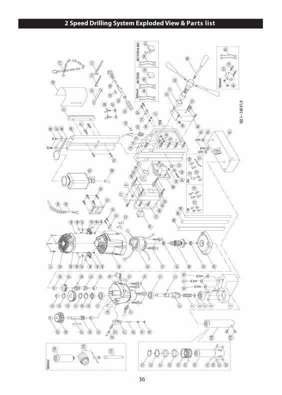
2 Speed Drilling System Exploded View & Parts list

37
NO. Parts Name Q'TY1~2 N/A -3 ARBOR SUPPORT BRACKET 14 TRUSS HEAD SCREW M4 x 6 25 BEARING HK 3516 16 COOLANT SEAL 17 SPRING 18 SPRING WASHER M8 49 SOCKET CAP BOLT M8 x 60 110 SOCKET CAP BOLT M8 x 70 211 SPINDLE 112 PARALLEL KEY 5 x 5 x 12 113 OIL SEAL Ø22 x Ø37 x 7 214 SCREW M5 x 60 615 GEAR CASE 116 PARALLEL KEY 4 x 4 x 30 117 PUSH LOCK FITTING 118 E-CLIP E-3 119 SPRING 120 DETENT PIN 121 SELECTOR TAB 122 SPRING 123 SHOULDER SCREW 124 SELECTOR FORK 125 BEARING HK 1010 326 INTERMEDIATE GEAR PINION 10T 127 PARALLEL KEY 5 x 5 x 50 128 INTERMEDIATE GEAR 30T x 33T 129 BEARING 6204 zz 130 INTERNAL CIRCLIP R-47 131 EXTERNAL CIRCLIP S-20 132 OUTPUT GEAR 39T 133 EXTERNAL CIRCLIP S-15 134 BEARING HK 0810 235 INPUT PINION 10T x 13T 136 PARALLEL KEY 5 x 5 x 8 137 INPUT GEAR 29T 138 GEAR PLATE 139 BEARING 6202-2RS 140 ARMATURE 141 BEARING 6200-LLU 142 STATOR 143 MOTOR HOUSING 144 NUT M4 x 8 1045 BRUSH HOLDER 7 x 17 x 17 246 CARBON BRUSH 7 x 17 x 17 247 BRUSH SPRING 248 SCREW M4 x 12 449 SCREW M4 x 10 250 MOTOR TAIL COVER 151 SCREW M4 x 20 452 END SPLICE TERMINAL C-4 353 CORD CLIP 254 SCREW M4 x 16 255 MOTOR COVER PLATE (PLASTIC) 156 FLAT HEAD SCREW M5 x 12 457 CABLE CLAMP 158 MOTOR CABLE 2.0 x 2C x 90CM 159 CABLE PROTECTOR 50CM 160 COOLANT TUBE 18CM 161~64 N/A - 65 COOLANT TANK ASSEMBLY 400cc 166 COOLANT TANK BRACKET 167 FLAT WASHER Ø5 x Ø12 x 1 268 THUMB SCREW 269 SLIDE PLATE 170 SOCKET CAP BOLT M8 x 20 271 SOCKET CAP BOLT M8 x 16 372 GEAR RACK 1
73 STAND BODY 174 SET SCREW M5 x 25 575 NUT M5 576 STAR WASHER M5 177 BUSHING Ø32 x Ø38 x 12 278 FLAT WASHER Ø8 x Ø40 x 2.5 179 MAGNET SWITCH 180 GUARD BAR 281 SCREW M4 x 16 182 SWITCH PANEL 183 FLAT WASHER Ø4 x Ø10 x 1 584 SPRING WASHER M4 485 SOCKET CAP SCREW M4 x 16 486 MOTOR SWITCH 187 SCREW M4 x 30 288 GIB STRIP-LEFT 189 GIB STRIP-RIGHT 190 GIB TENSIONER 191 MAGNET BASE 192 SPRING WASHER M6 393 SOCKET CAP BOLT M6 x 20 394 LEAD WIRE 295 LEAD WIRE 496 SIDE PLATE 197 SCREW M4 x 8 498 CRANK HANDLE 140mm 399 N/A -100 CRANK SPINDLE 1101 N/A -102 RECTIFIER 1102-1 RECTIFIER & EMC 1103 CABLE GLAND 1104 STRAIN RELIEF 7CM 1105 CORD ARMOR 1106 POWER SUPPLY CABLE 1107 FLAT WASHER Ø6 x Ø13 x 1 2108 BUTTERFLY SCREW M6 x 10 2109 CHIP GUARD 1110 SAFETY CHAIN 1111 M8 COMBINATION WRENCH M8 1112 M2.5 L-HEX KEY M2.5 1113 M4 L-HEX KEY M4 1114 OVER LOAD PROTECTION (OPTIONAL) 1115 N/A -116 CHECK BALL Ø8 1117 N/A -118 COLLAR 1119 COLLAR PIN 1120 RUBBER RING 1121 SPRING Ø2 x Ø39 x Ø43 x 3T x 30L 1122 STEEL RING Ø35.1 x Ø44.5 x 2 1123 EXTERNAL CIRCLIP S-35 1124 RUBBER WASHER Ø4 x Ø11 x 1 1125 SPADE TERMINAL 4126 TERMINAL COVER 8127 ZIP TIE 1128 ARBOR SHAFT 1129 SET SCREW M8 x 7 2130 CHUCK ADAPTOR (OPTIONAL) M27x3 -5/8"x16 1131 CHUCK (OPTIONAL) 5/8" 1132 N/A -133 PILOT PIN (OPTIONAL) TCTx112LxØ8 1134 SCREW M4 x 20 2135 SCREW M4 x 25 3136 LOCK PIN 11.7mm 2137 SCREW M3 x 4 2138 LOCKING PIN SPRING 2139 QUICK RELEASE ARBOR SHAFT 1140 EARTHING MARKING 1
38
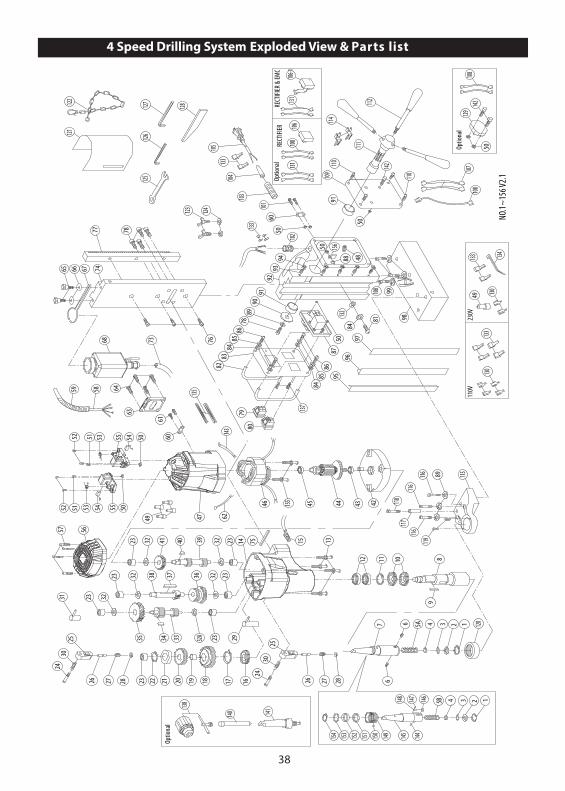
4 Speed Drilling System Exploded View & Parts list
82
1205A 1347
116 89 115
116
8
1199
117116
11842
1011
44 43155 45
95
80
84
1617
23333435
23
59
38
14 15
46
47
233637
23394041
143
79
6160
63
58 6423
23
93
107
98
100
48
81
9796
5087
94
99
91
111
110109
112
114
68
124123
90
8586
7889
83
76
9192
73
74
126
103
50
10160
78
121
125
77
128127122
32
32A
323232
32
75
2
282726
25
24
282726
25
2431
57 56
30
108
142
50 NO.
1~15
6 V2.1
30
13
62
110
181920212223
29
12
6
6
676665
5054 55535152
505455535152
84
8586
102
104
105
84
110V
230V
13013049
133
133 134
133
133
49
135
132
Optio
nal
129142
50
108
137
Optio
nal
138
140 141
146147148
144145149150151152153154
108131
106
RECT
IFIER
Optio
nal
RECT
IFIER
& EM
C
106-1
131
5B 134 2
50 156
88

39
80 MAGNET SWITCH 181 SCREW M4 x 16 182 GUARD BAR 283 SWITCH PANEL 184 FLAT WASHER Ø4 x Ø10 x 1 585 SPRING WASHER M4 486 SOCKET CAP SCREW M4 x 16 487 MOTOR SWITCH 188 STAR WASHER M5 1 89 SPRING WASHER M8 490 FLAT WASHER Ø8 x Ø40 x 2.5 191 BUSHING Ø32 x Ø38 x 12 292 STAND BODY 193 SET SCREW M5 x 25 594 NUT M5 595 GIB STRIP-LEFT 308mm 196 GIB STRIP-RIGHT 308mm 197 GIB STRIP TENSIONER 308 x 1.5 x 2.3 198 MAGNET BASE 199 SPRING WASHER M6 3100 SOCKET CAP BOLT M6 x 20 3101 SCREW M4 x 30 2102 CABLE GLAND 1103 STRAIN RELIEF 7CM 1104 CORD ARMOR 1105 POWER SUPPLY CABLE 1106 RECTIFIER & EMC(OPTIONAL) 1106-1.) RECTIFIER & EMC(OPTIONAL) 1107 WIRE LEADS 2108 WIRE LEADS 5109 SIDE COVER 1110 SCREW M4 x 8 4111 CRANK SPINDLE 1112 CRANK HANDLE 140mm 3113 N/A -114 THREE WAY CONNECTOR 2115 ARBOR SUPPORT BRACKET 1116 SOCKET CAP BOLT M8 x 25 3117 TRAVEL STOP 1118 SOCKET CAP BOLT M6 x 45 1119 TRUSS HEAD SCREW M4 x 8 2120 BEARING HK 3516 1121 CHIP GUARD 1122 SAFETY CHAIN 1123 BUTTERFLY SCREW M6 x 10 2124 FLAT WASHER Ø6 x Ø13 x 1 2125 M8 COMBINATION WRENCH M8 1126 M2.5 L-HEX KEY M2.5 1127 M4 L-HEX KEY M4 1128 DRIFT 1129 OVERLOAD(OPTIONAL) 1130 SPADE TERMINAL 4131 WIRE LEADS(OPTIONAL) 2132 RUBBER WASHER Ø4 x Ø11 x 1 1133 TERMINAL COVER 10134 ZIP TIE 1135 SILICON TUBE M4 x 12CM 2136 N/A -137 SCREW M4 x 20 2138 CHUCK(OPTIONAL) 5/8" 1139 N/A -140 PILOT PIN(OPTIONAL) TCTx112LxØ8 1141 MT3 CHUCK ADAPTOR(OPTIONAL) 1142 SCREW M4 x 25 3143 WIRE LEADS 1144 CHECK BALL Ø8 1145 QUICK-RELEASE ARBOR 1146 LOCK PIN 1147 SCREW M3 x 4 1148 LOCK PIN SPRING 1149 QUICK-RELEASE COLLAR 1150 COLLAR PIN 1151 RUBBER RING 1152 SPRING Ø2 x Ø39 x Ø43 x 30L x 3T 1153 STEEL RING Ø35.1 x Ø44.5 x 2 1154 EXTERNAL CIRCLIP S-35 1155 SCREW M5 x 60 2156 EARTHING MARKING 1
NO. Parts Name Q'TY1 INTERNAL CIRCLIP R-19 12 ARBOR WASHER Ø10 x Ø18.5 x 0.8 13 O-RING Ø12 x 4 14 COOLANT SEAL Ø12 x Ø10.2 x 15 15A SPRING Ø1.2 x Ø10 x Ø12.4 x 24T x 140L 15B SPRING Ø1.2 x Ø10 x Ø12.4 x 15T x 100L 16 SET SCREW M8 x 7 27 MT3 ARBOR 18 SPINDLE 19 PARALLEL KEY 5 x 5 x 40 110 OIL SEAL Ø40 x Ø55 x 7 211 INTERNAL CIRCLIP R-55 112 BEARING 6006 LLB 213 SCREW M5 x 65 414 GEAR CASE 75/KG 115 PUSH LOCK FITTING 116 OIL SEAL Ø30 x Ø45 x 5 117 EXTERNAL CIRCLIP S-30 118 LOW SPINDLE GEAR 21T 119 BUSHING Ø18 x Ø20 x 11.5 120 HIGH SPINDLE GEAR 25T 121 SPACER 122 INTERNAL CIRCLIP S-14 123 BEARING HK 1010 724 SHOULDER SCREW 225 SELECTOR TAB 226 DETENT PIN 227 SPRING Ø0.6 x Ø5.3 x Ø6.5 x 5T x 17L 228 E-CLIP E-3 229 FIRST SELECTOR FORK 130 SPRING Ø1 x Ø9 x Ø11 x 4T 231 SECOND SELECTOR FORK 132 FLAT WASHER 1024 532A THRUST WASHER Ø13 x Ø24 x 1 133 IDLER PINION 16T x 7T 134 PARALLEL KEY 5 x 5 x 10 135 IDLER GEAR 36T 136 INTERMEDIATE GEAR 28T x 30T 137 PARALLEL KEY 5 x 5 x 50 138 COUNTERSHAFT PINION 12T 139 INPUT PINION 10T x 12T 140 PARALLEL KEY 5 x 5 x 8 141 INPUT GEAR 29T 142 GEAR PLATE 143 BEARING 6202-2RS 144 ARMATURE 145 BEARING 6200-LLU 146 STATOR 147 MOTOR HOUSING 148 CABLE CLAMP 149 END SPLICE TERMINAL C4 550 NUT M4 x 8 1051 SCREW M4 x 10 252 SCREW M4 x 12 453 BRUSH SPRING 254 CARBON BRUSH 7 x 17 x 17 255 BRUSH HOLDER 7 x 17 x 17 256 MOTOR TAIL COVER 157 SCREW M4 x 20 458 MOTOR CABLE 2.0 x 4C x 86cm 159 CABLE PROTECTOR 50cm 160 CORD CLIP 261 SCREW M4 x 16 262 WIRE LEADS 163 MOTOR COVER PLATE (PLASTIC) 164 SCREW M5 x 12 465 THUMB SCREW M5 x 16 266 FLAT WASHER Ø5 x Ø12 x 1 267 COOLANT TANK BRACKET 168 COOLANT TANK ASSEMBLY 169~72 N/A - 73 COOLANT TUBE 18cm 174 SLIDE PLATE 348mm 175 PARALLEL KEY M4 x 4 x 30 176 SOCKET CAP BOLT M8 x 20 377 GEAR RACK 270cm 178 SOCKET CAP BOLT M8 x 16 579 REVERSING SWITCH 1
40
4 Speed Swivel Base Drilling System Exploded View & Parts list
82
1205 1347
170 89 115
170
811
99
117
170
118
42
1011
44 4345
95
80
84
1617
23333435
23
59
38
14 15
46
47
233637
23394041
155
79
6160
63
58 6423
23
93
48
81
9796
5087
50
94
68
124
123
90
8586
7889
83
76
9192
73
74
126
103
50
101
60
78
121
125
77
128127
122
32
32A
323232
32
75
2
282726
25
24
282726
25
2431
57 56
30
NO.1
~170
V 2.1
30
13
62
181920212223
29
12
6
6
676665
5054 55535152
505455535152
84
8586
102
104
105
107
91
111
110
109
112
114
108
156
110
100 99
98
130
131
132 133
134
78 100
140
141
142
135
76
76
110V
230V
143
143
49
146
146 14
7
146
49
148
8414
5
Optio
nal
129 15
650
108
50
150
Optio
nal
151
153 15
4
146
148
108
144
106
RECT
IFIER
Optio
nal
RECT
IFIER
& EM
C
106-1
144
159
160
161
157
158
162
163
164
165
166
167
168
169
88
6

41
86 SOCKET CAP SCREW M4 x 16 487 MOTOR SWITCH 188 STAR WASHER M5 189 SPRING WASHER M8 790 FLAT WASHER Ø8 x Ø40 x 2.5 191 BUSHING Ø32 x Ø38 x 12 292 STAND BODY 193 SET SCREW M5 x 25 594 NUT M5 595 GIB STRIP-LEFT 308mm 196 GIB STRIP-RIGHT 308mm 197 GIB STRIP TENSIONER 308 x 1.5 x 2.3 198 MAGNET 199 SPRING WASHER M6 4100 SOCKET CAP BOLT M6 x 20 6101 SCREW M4 x 30 2102 CABLE GLAND 1103 STRAIN RELIEF 7CM 1104 CORD ARMOR 1105 POWER SUPPLY CABLE 1106 RECTIFIER & EMC(OPTIONAL) 1106-1 RECTIFIER & EMC(OPTIONAL) 1107 WIRE LEADS 2108 WIRE LEADS 5109 SIDE COVER 1110 SCREW M4 x 8 4111 CRANK SPINDLE 1112 CRANK HANDLE 140mm 3113 N/A -114 THREE WAY CONNECTOR 2115 ARBOR SUPPORT BRACKET 1116 N/A -117 TRAVEL STOP 1118 SOCKET CAP BOLT M6 x 45 1119 TRUSS HEAD SCREW M4 x 8 2120 BEARING HK 3516 1121 CHIP GUARD 1122 SAFETY CHAIN 1123 BUTTERFLY SCREW M6 x 10 2124 FLAT WASHER Ø6 x Ø13 x 1 2125 M8 COMBINATION WRENCH M8 1126 M2.5 L-HEX KEY M2.5 1127 M4 L-HEX KEY M4 1128 DRIFT 1129 OVERLOAD 1130 NYLOCK NUT M22 1131 WASHER Ø30.1 x Ø40 x 5 1132 SWIVEL PLATE 1133 LOCKING POST 1134 LOCKING LUG 1135 MOUNTING PLATE 1136 SOCKET SET SCREW M8 x 7 1
137~139 N/A -140 M17 OPEN-END WRENCH M17 1141 CLIP 1142 SCREW M5 x 8 1143 SPADE TERMINAL 4144 WIRE LEADS 2145 RUBBER WASHER Ø4 x Ø11 x 1 1146 TERMINAL COVER 10147 ZIP TIE 1/1000148 SILICON TUBE M4 x 12CM 3 6/100149 N/A - 150 SCREW M4 x 20 2151 CHUCK(OPTIONAL) 5/8" 1152 N/A -153 PILOT PIN(OPTIONAL) 112L 1154 MT3 CHUCK ADAPTOR(OPTIONAL) 1155 WIRE LEADS 1156 SCREW M4 x 25 3157 CHECK BALL Ø8 1158 QUICK-RELEASE ARBOR 1159 LOCK PIN 2160 SCREW M3 x 4 2161 LOCKING PIN SPRING 2162 QUICK-RELEASE COLLAR 1163 COLLAR PIN 1164 RUBBER RING Ø40 x Ø44 x 9 1165 SPRING Ø2 x Ø39 x Ø43 x 30L x 3T 1166 STEEL RING Ø35.1 x Ø44.5 x 2 1167 EXTERNAL CIRCLIP S-35 1168 SCREW M5 x 60 2169 EARTHING MARKING 1170 SOCKET CAP BOLT M8 x 25 3
NO. Parts Name Q'TY1 INTERNAL CIRCLIP R-19 12 ARBOR WASHER Ø10 x Ø18.5 x 0.8 13 O-RING 12 x 4 14 COOLANT SEAL Ø10.2 x Ø12 x 15 15 SPRING Ø1.2 x Ø10 x Ø12.4 x 24T x 140L 16 SET SCREW M8 x 7 37 MT3 ARBOR 18 SPINDLE 19 PARALLEL KEY 5 x 5 x 40 110 OIL SEAL Ø40 x Ø55 x 7 211 INTERNAL CIRCLIP R-55 112 BEARING 6006-2LLB 213 SCREW M5 x 65 414 GEAR CASE 115 PUSH LOCK FITTING 116 OIL SEAL Ø30 x Ø45 x 5 117 EXTERNAL CIRCLIP S-30 118 LOW SPINDLE GEAR 21T 119 BUSHING Ø18 x Ø20 x 11.5 120 HIGH SPINDLE GEAR 25T 121 SPACER 122 INTERNAL CIRCLIP S-14 123 BEARING HK 1010 724 SHOULDER SCREW 225 SELECTOR TAB 226 DETENT PIN 227 SPRING Ø0.6 x Ø5.3 x Ø6.5 x 5T x 17L 228 E-CLIP E-3 229 FIRST SELECTOR FORK 130 SPRING Ø1.0 x Ø9 x Ø11 x 4T 231 SECOND SELECTOR FORK 132 THRUST WASHER 1024 532A THRUST WASHER Ø13xØ24x1 133 IDLER PINION 16T x 7T 134 PARALLEL KEY 5 x 5 x 10 135 IDLER GEAR 36T 136 INTERMEDIATE GEAR 28T x 30T 137 PARALLEL KEY 5 x 5 x 50 138 COUNTERSHAFT PINION 12T 139 INPUT PINION 10T x 12T 140 PARALLEL KEY 5 x 5 x 8 141 INPUT GEAR 29T 142 GEAR PLATE 143 BEARING 6202-2NSE 144 ARMATURE 145 BEARING 6200-LLU 146 STATOR 147 MOTOR HOUSING 148 CABLE CLAMP 149 END SPLICE TERMINAL C4 550 NUT M4 x 8 1051 SCREW M4 x 10 252 SCREW M4 x 12 453 BRUSH SPRING 254 CARBON BRUSH 7 x 17 x 17 255 BRUSH HOLDER 7 x 17 x 17 256 MOTOR TAIL COVER 157 SCREW M4 x 20 458 MOTOR CABLE 2.0 x 4C x 86cm 159 CABLE PROTECTOR 50cm 160 CORD CLIP 261 SCREW M4 x 16 262 WIRE LEADS 163 MOTOR COVER PLATE (PLASTIC) 164 SCREW M5 x 12 465 THUMB SCREW 266 FLAT WASHER Ø5 x Ø12 x 1 267 COOLANT TANK BRACKET 168 COOLANT TANK ASSEMBLY 169~72 N/A -73 COOLANT TUBE 18cm 174 SLIDE PLATE 348mm 175 PARALLEL KEY 4 x 4 x 30 176 SOCKET CAP BOLT M8 x 20 777 GEAR RACK 270cm 178 SOCKET CAP BOLT M8 x 20 679 REVERSING SWITCH 180 MAGNET SWITCH 181 SCREW M4 x 16 182 GUARD BAR 283 SWITCH PANEL 184 FLAT WASHER Ø4 x Ø10 x 1 585 SPRING WASHER M4 4
42
4 Speed Variable Motor Speed Drilling System Exploded View & Parts List
103
5759 5866 60
119
102
87
67
70
69101
7291
92
90
88 89
140
117
121121
75111
137
135134
139
110
106107
9899
104
96
111
97
146
127
75
12692
147
100
143144
148
71
82 81
136
75
68
135
7576 77787980
757677787980
105
128
130
33 32 34 33 32 31
171820212324
26 2528
2930
2829
3042 41 4040
43454652
44
48
40495052
54 53 47555651
NO.
01~
158 V
1.4
05B 04 03 02 01
19
27
99
98
109
158
138
110V
230V
141141
129129
72
142
129129
93
63
108
Optio
nal
105
RE
CT
IFIE
R
Opt
iona
l
RE
CT
IFIE
R &
EM
C
131A131B
132133133
22
94 95
125
96 124122
113 114
112
115 11675
71
37353839 36 35
6162636465
7374
83
8485
86
105106
107
141
153 154 155
149
156
157
10C
10B
152151150
149149
10A
05A

43
NO. Parts Name Q'TY1 INTERNAL CIRCLIP R-19 12 ARBOR WASHER 10 x 18.5 x 0.8 13 O-RING 12 x 4 14 COOLANT SEAL 12 x 10.2 x 15 15A SPRING-for 10B.) 1.2 x 10.1 x 12.5 x 15T x 100L 15B SPRING-for 10C.) 1.2 x 10 x 12.4 x 24T x 140L 16~9 N/A -10A 3/4" QUICK-RELEASE ARBOR-MT3 MT3(LOCKING PIN 12.3mm,11.7mm) 110B 1-1/4" CUTTER ARBOR-MT3 31.7mm 110C 3/4" CUTTER ARBOR-MT3 19MM 111~15 N/A -16 EXTERNAL CIRCLIP S-35 117 SPINDLE 118 OIL SEAL 40 x 58 x 8 119 OIL SEAL 40 x 55 x 7 120 INTERNAL CIRCLIP R-55 121 BALL BEARING 6006-LLB 222 EXTERNAL CIRCLIP S-30 123 SCREW M5 x 80 224 SCREW M5 x 150 225 GEAR CASE 126 PUSH LOCK FITTING 127 MOUNTING TENON M4 x 4 x 60 128 SELECTOR TAB 229 SPRING 1 x 9 x 11 x 4T 230 SHOULDER SCREW 231 DETENT PIN 132 SPRING 0.6 x 5.3 x 6.5 x 5T x 17L 233 E-CLIP E-3 234 DETENT PIN 135 DISC SPRING 12.4 x 27.9 436 TOOTH CLUTCH 137 CLUTCH GEAR 138 THRUST WASHER 12.1 x 18 x 1.6 139 EXTERNAL CIRCLIP E-10 140 BALL BEARING 608 zz 341 INPUT PINION M1.25 x 15T & 10T 142 PARALLEL KEY M5 x 5 x 10 143 OIL SEAL 28 x 38 x 7 144 FIRST SELECTOR FORK 145 SPINDLE GEAR M1.75 x 27T M2.0 x 29T 146 INTERNAL CIRCLIP S-25 147 BALL BEARING 6202 zz ZZ 148 SECOND SELECTOR FORK 149 INTERMEDIATE GEAR M1.25 x 27T & 32T 150 PARALLEL KEY 5 x 5 x 45 151 COUNTERSHAFT PINION 12T 152 BALL BEARING 6200 zz ZZ 253 IDLER PINION M1.75 x 17T M2.0 x 9T 154 PARALLEL KEY M5 x 5 x 8 155 IDLER GEAR M1.25 x 43T 156 NEEDLE BEARING TLA 1212 157 GEAR PLATE 158 BALL BEARING 6202-2NSE 159 ARMATURE 160 BALL BEARING 6200-LLU 161 SPACER 8 x 12 x 10.5 162 PICKUP MAGNET 8 x 15 x 5 163 PLASTIC WASHER 4 x 11 x 1 264 FLAT WASHER 4 x 10 x 1 165 SCREW M4 x 10 166 SCREW M5 x 60 267 STATOR 168 WIRE LEADS 169 WIRE LEADS 170 MOTOR HOUSING 171 ZIP TIE 2.5mmX160mm 272 END SPLICE CONNECTOR C4 573 ELECTRONICS UNIT(110V,220V) 174 SCREW M4 x 25 275 NUT M4 x 8 876 CARBON BRUSH 7 x 17 x 17 277 BRUSH HOLDER 7 x 17 x 17 278 BRUSH SPRING 279 SCREW M4 x 10 280 SCREW M4 x 12 481 MOTOR TAIL COVER 182 SCREW M4 x 30 4
NO. Parts Name Q'TY83 RHEOSTAT 184 THUMB WHEEL 185 SPEED ADJUSTOR COVER 186 FLAT HEAD SCREW M4 x 16 287 CABLE PROTECTOR 65cm 188 MOTOR CABLE 90cm 189 SCREW M5 x 10 490 COVER PLATE 191 SCREW M4 x 16 292 CORD CLIP 293 CABLE SHEATH M4 x 12CM 294 COOLANT TANK ASSEMBLY 195 COOLANT TUBE 40cm 196 SOCKET CAP BOLT M8 x 20 797 SLIDE 198 SOCKET CAP BOLT M8 x 16 799 SPRING WASHER M8 7100 GEAR RACK 270cm 1101 REVERSING SWITCH 1102 MAGNET SWITCH 1103 GUARD BAR 2104 SWITCH PANEL 1105 FLAT WASHER 4 x 10 x 1 5106 SPRING WASHER M4 4107 SOCKET CAP BOLT M4 x 16 4108 SCREW M4 x 20 2109 MOTOR SWITCH 1110 FLAT WASHER 8 x 40 x 2.5 1111 CRANK BUSHING 32 x 38 x 12 2112 STAND BODY 1113 SET SCREW M5 x 35 7114 NUT M5 7115 STAR WASHER M5 1116 EARTHING MARKING 1117 SCREW M4 x 16 1118 N/A -119 GIB STRIP-LEFT 394mm 1120 GIB STRIP-RIGHT 394mm 1121 GIB STRIP TENSIONER 394 x 15 x 1.2 1122 CABLE GLAND 1123 N/A -124 SPRING WASHER M6 4125 MAGNET BASE 1126 SCREW M4 x 30 2127 STRAIN RELIEF 7CM 1128 CORD ARMOR 1129 TERMINAL COVER 12130 POWER SUPPLY CABLE 1131A RECTIFIER & EMC(OPTIONAL) 1131B RECTIFIER & EMC(OPTIONAL) 1131B RECTIFIER & EMC(OPTIONAL) 1132 WIRE LEADS 2133 WIRE LEADS(OPTIONAL) 1015-16#18CM 2134 SIDE COVER 1135 SCREW M4 x 8 4136 SCREW M4 x 25 1137 CRANK PINION 1138 CRANK HANDLE 3139 3 WAY CONNECTOR 2140 WIRE LEADS 2141 SPADE TERMINAL 10142 ZIP TIE 1143 DRIFT 1144 L HEX KEY( OPTIONAL ) 5mm M5 1145 N/A -146 L HEX KEY 2.5mm M2.5 1147 M8 COMBINATION WRENCH M8 1148 SAFETY CHAIN 1149 SOCKET SET SCREW M10 x 10 2150 CHUCK(OPTIONAL) 5/8" 1151 PILOT PIN(OPTIONAL) TCTx112Lx8 1152 MT3 CHUCK ADAPTOR(OPTIONAL) 1153 BUTTERFLY BOLT M6 x 10 2154 FLAT WASHER 6 x 13 x 1 2155 CHIP GUARD 1156 FLAT HEAD SCREW M4 x 20 2157 PIN 5 x 10 1158 INTERNAL CIRCLIP S-20 1


![2 PETROL DRIVEN RAIL DRILLING MACHINE · 2013. 3. 12. · [1] ROTABROACH RAIL DRILLING MACHINE MODEL RD07A . Maximum hole cutting capacity 36mm dia. Arbor bore 19.05mm dia. (3/4")](https://static.cupdf.com/doc/110x72/60b96a85d56ad475d66ad0fe/2-petrol-driven-rail-drilling-2013-3-12-1-rotabroach-rail-drilling-machine.jpg)


