
1
James N. Bellinger
University of Wisconsin-Madison
27-November-2009
Status of Transfer Line Status of Transfer Line ReconstructionReconstruction
Status of Transfer Line Status of Transfer Line ReconstructionReconstruction
James N. Bellinger 27-November-2009

2James N. Bellinger 27-November-2009
Not in Person
• 27-November, the day after US Thanksgiving, is a mandatory furlough day for University of Wisconsin employees.
• To give us a salary cut without violating various labor contracts, management devised a “furlough” plan whereby everybody becomes an hourly employee for the week and is told to stay home for a day and not even think about working, logging in, etc.

3
Data
• Most of the Transfer Line lasers are well aligned.
• The best illuminated is Line 1, and the worst is Line 2
• The following shows Line 1
• All data used in this report is 3.8T from an event in October– One DCOPS reading failed and was replaced with
another from a run 8 hours earlier
James N. Bellinger 27-November-2009
4
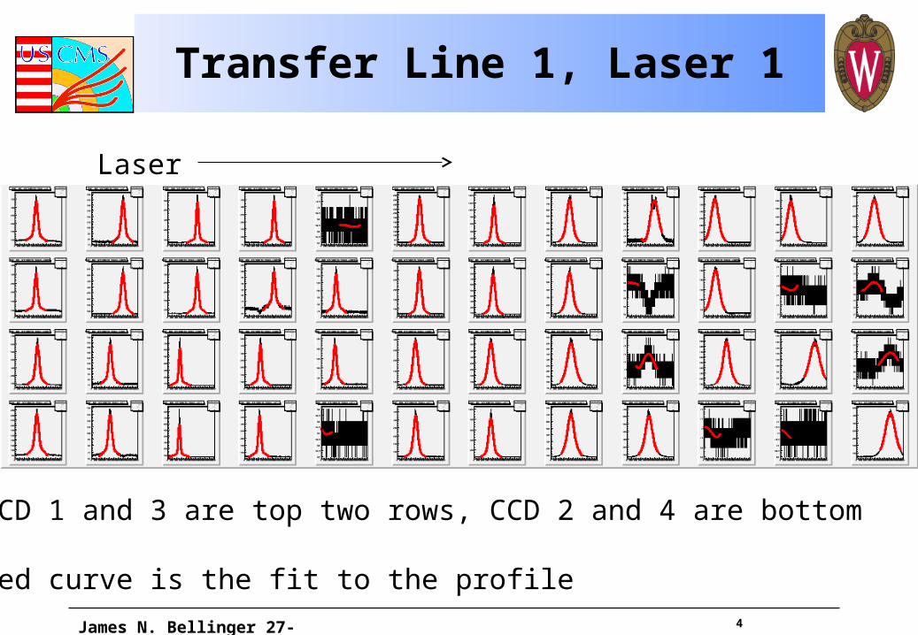
Transfer Line 1, Laser 1
James N. Bellinger 27-November-2009
CCD 1 and 3 are top two rows, CCD 2 and 4 are bottom
Red curve is the fit to the profile
Laser
5
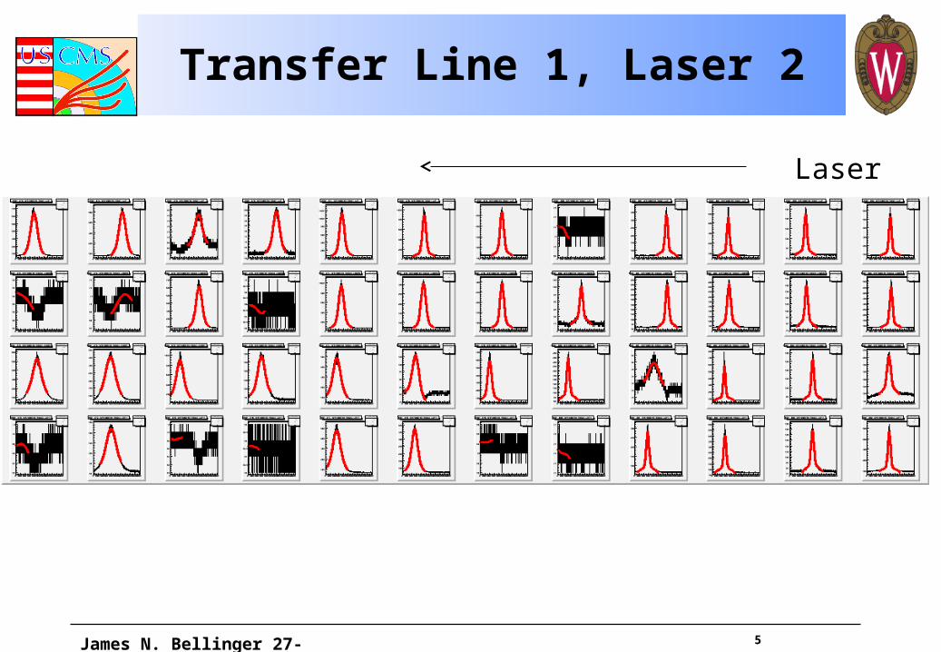
Transfer Line 1, Laser 2
James N. Bellinger 27-November-2009
Laser
6James N. Bellinger 27-November-2009
Photogrammetry and the Transfer Line
• The SLM DCOPS position wrt the disk center
• The disk centers when the disks were being closed
• The Transfer DCOPS position wrt the SLM
• The relative position of points on the Transfer Plate
– Also available from drawings: agreement was good enough that I use the drawings
7James N. Bellinger 27-November-2009
Locating the Transfer Line
• Link can give the outer MAB positions in (x,y,z) wrt a tracker body reference
• PG can give us an estimate of Z for the Endcaps
– Analog sensor reconstruction from the MAB on is not yet ready
• Combining these can give us (x,y,z) for measured chambers
8James N. Bellinger 27-November-2009
Validating the Transfer Line
• The relative PG positions at 0T can be compared to special runs taken at 0T. If the relative positions of the Transfer DCOPS are similar in both cases, we can assert that the two agree to within that error.
• The Link information gives us fixed points in space (9 instead of 12) to tie the Transfer Lines to the tracker. We can estimate disk rotations and compare to PG.
9James N. Bellinger 27-November-2009
Validating the Transfer Line: Problems
• Results: I reported earlier that I was not getting clear correlation between the relative positions of the DCOPS as found on the transfer lines and as measured in PG.
• We tuned our transfer line lasers for 3.8T, and don't have a great deal of good data at 0T. Recent data is not much use.
10James N. Bellinger 27-November-2009
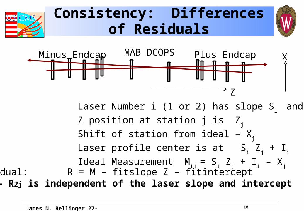
Consistency: Differences of Residuals
Laser Number i (1 or 2) has slope Si and intercept I
i
Z position at station j is Zj
Shift of station from ideal = Xj
Laser profile center is at Si Z
j + I
i
Ideal Measurement Mij = S
i Z
j + I
i – X
j
Z
X
Residual: R = M – fitslope Z – fitinterceptR1j – R2j is independent of the laser slope and intercept
Plus EndcapMinus Endcap MAB DCOPS
11
Consistency 2
• We can thus get some measure of how well we are able to measure a position by looking at the distribution of differences of residuals.
• Each station has a measurement (for Line 1)• Best fit for line through them for Laser1, then
Laser 2
• Subtract residuals using fit with Laser 1 from those with the fit with Laser 2
• Rejoice (or not)
James N. Bellinger 27-November-2009
12
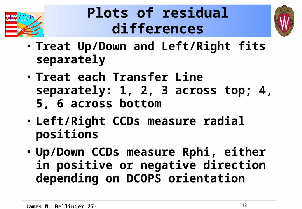
Plots of residual differences
• Treat Up/Down and Left/Right fits separately
• Treat each Transfer Line separately: 1, 2, 3 across top; 4, 5, 6 across bottom
• Left/Right CCDs measure radial positions
• Up/Down CCDs measure Rphi, either in positive or negative direction depending on DCOPS orientation
James N. Bellinger 27-November-2009
13
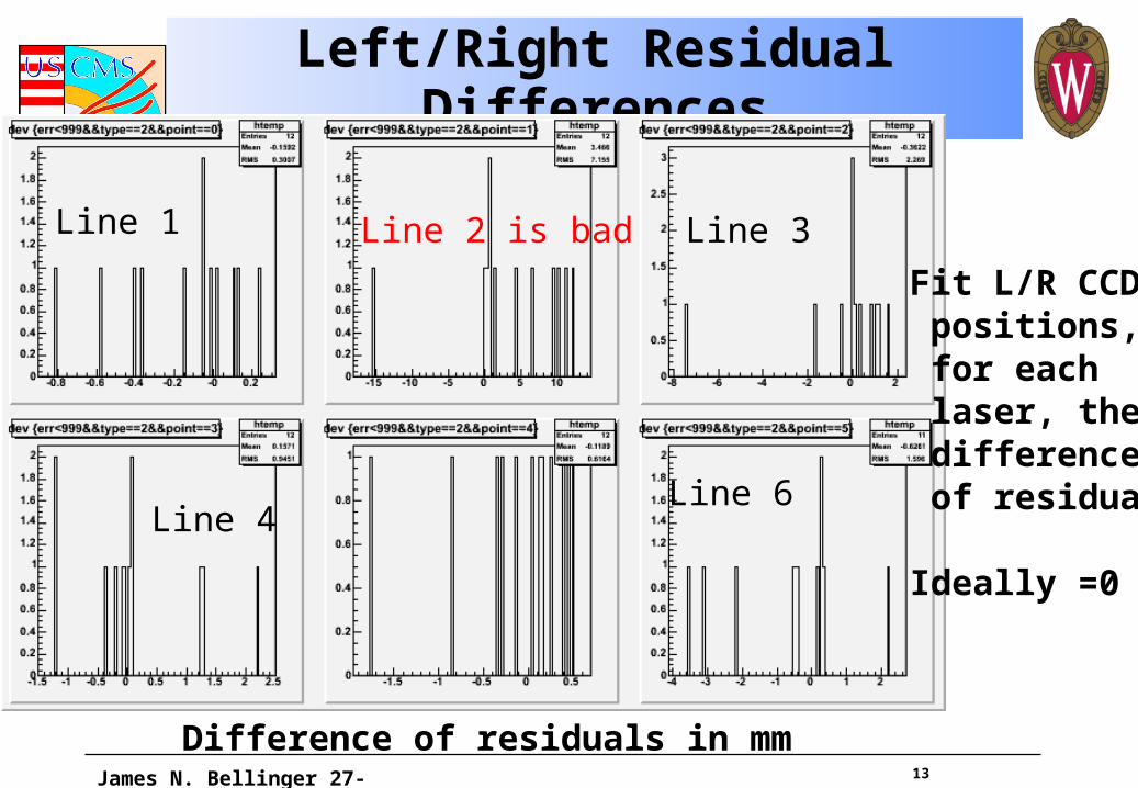
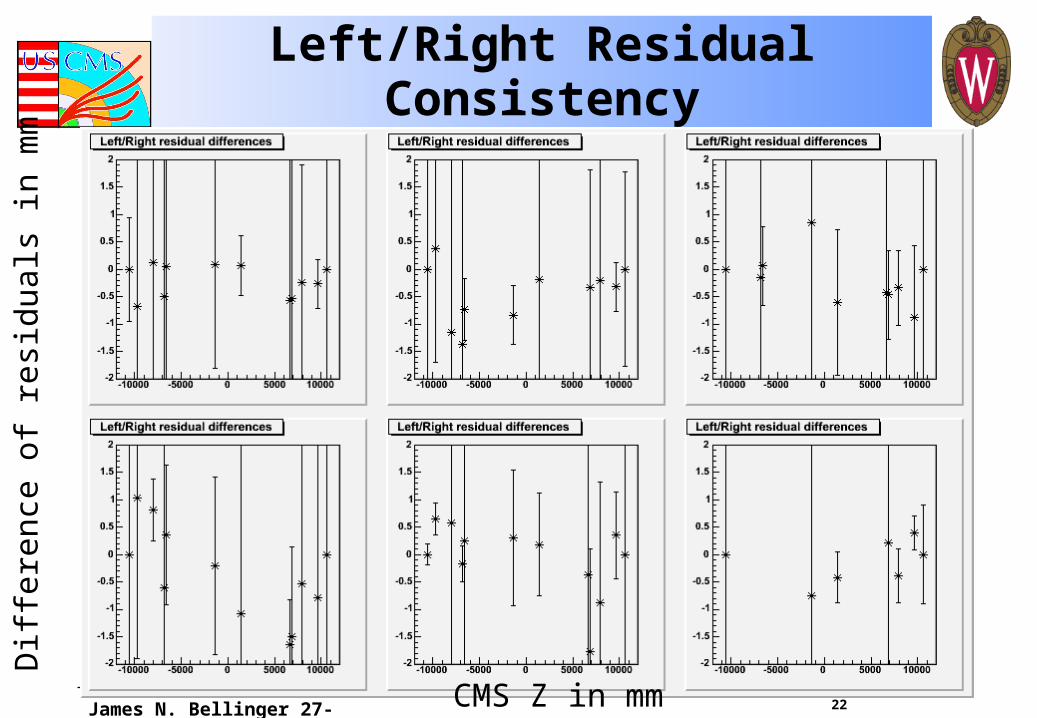
Left/Right Residual Differences
James N. Bellinger 27-November-2009
Fit L/R CCD positions, for each laser, then difference of residuals
Ideally =0
Line 2 is bad
Difference of residuals in mm
Line 1 Line 3
Line 4Line 6

14
Up/Down Residual Differences
James N. Bellinger 27-November-2009
Line 2 is bad
Difference of residuals in mm
Line 1
Line 5
15
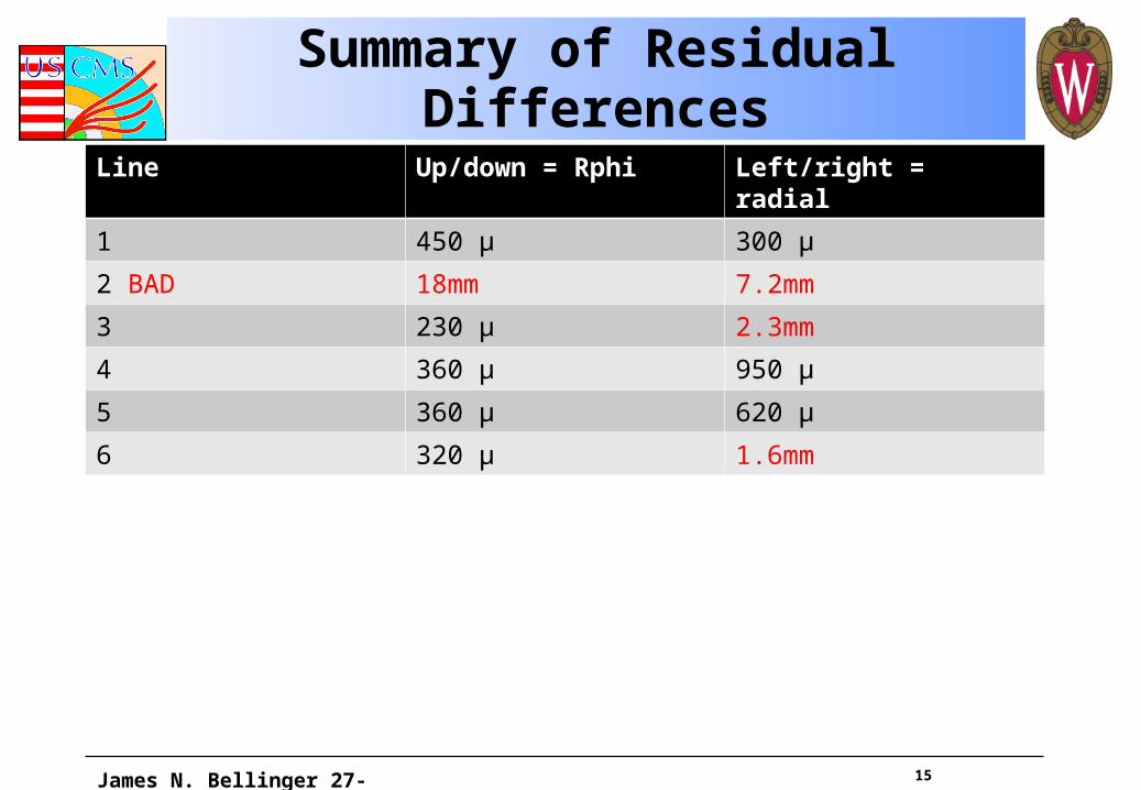
Summary of Residual Differences
Line Up/down = Rphi Left/right = radial
1 450 µ 300 µ
2 BAD 18mm 7.2mm
3 230 µ 2.3mm
4 360 µ 950 µ
5 360 µ 620 µ
6 320 µ 1.6mm
James N. Bellinger 27-November-2009
16
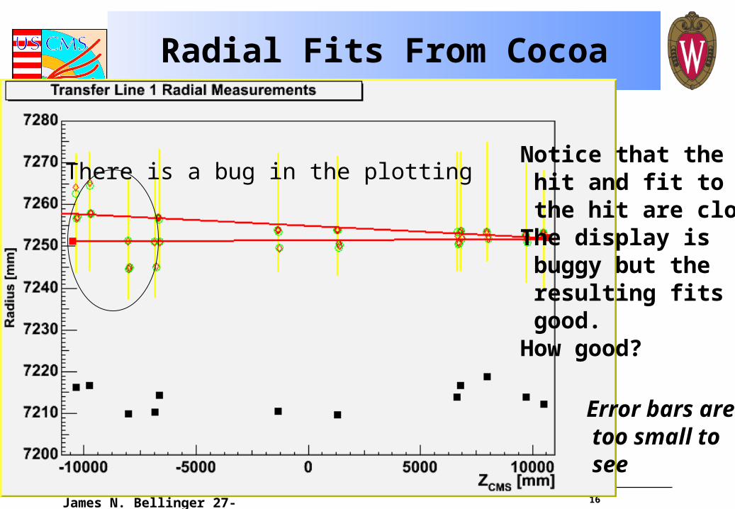
Radial Fits From Cocoa
James N. Bellinger 27-November-2009
There is a bug in the plottingNotice that the hit and fit to the hit are close.The display is buggy but the resulting fits are good.How good?
Error bars are too small to see
17
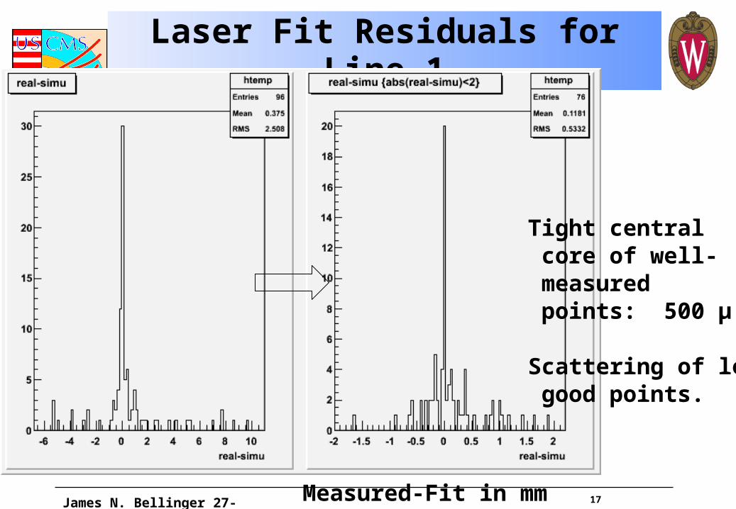
Laser Fit Residuals for Line 1
James N. Bellinger 27-November-2009
Tight central core of well- measured points: 500 µ
Scattering of less good points.
Measured-Fit in mm
18
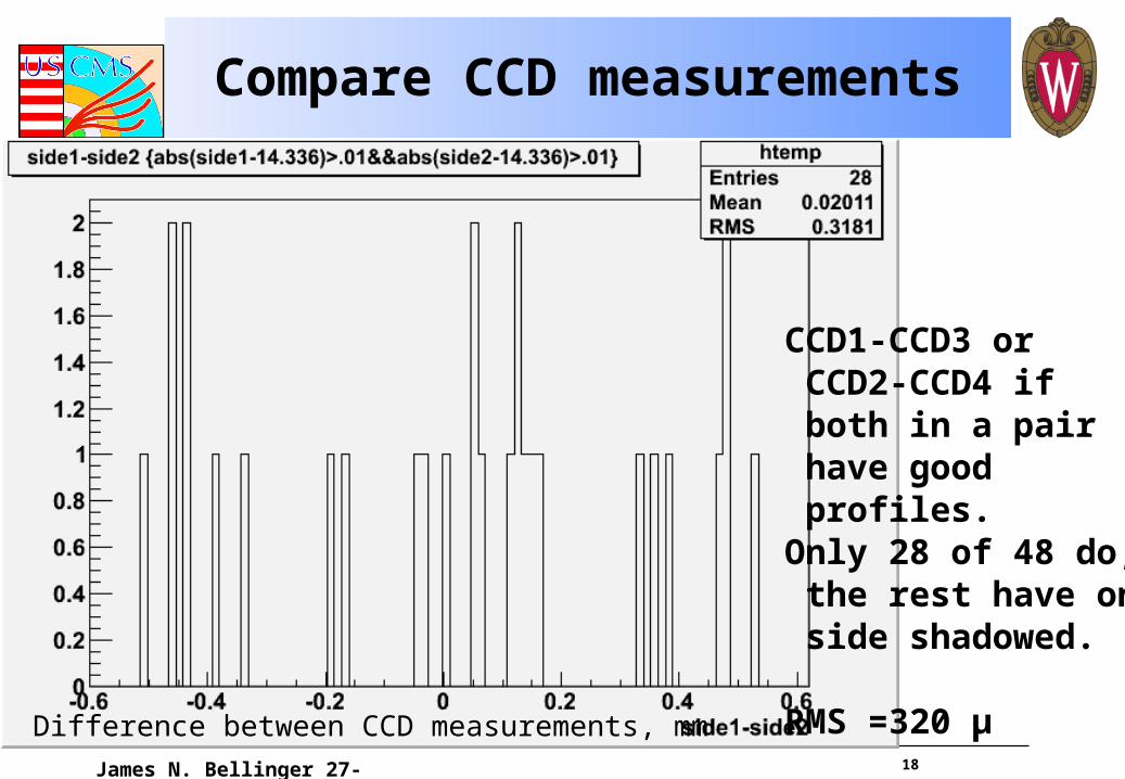
Compare CCD measurements
James N. Bellinger 27-November-2009
CCD1-CCD3 or CCD2-CCD4 if both in a pair have good profiles.Only 28 of 48 do, the rest have one side shadowed.
RMS =320 µDifference between CCD measurements, mm
19
Plan
• Take fit Transfer Point positions and plug these into the Endcap model– Verify that iteration works correctly
• Use Endcap models to find fit chamber (x,y)
• Need agreed-on plan for what to provide:– Only (x,y,z) for measured chambers
• How to do this with usual tools?
– Define some interpolation for the rest
• Find out what Inner MAB numbers are useful for the Barrel group
James N. Bellinger 27-November-2009
20
BACKUP MATERIAL
James N. Bellinger 27-November-2009
Recall that ME1 and Outer MAB Z-positions are very close. This makes them hard to distinguish in the ? vs Z plots
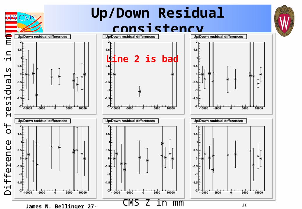
21
Up/Down Residual consistency
James N. Bellinger 27-November-2009
Line 2 is bad
CMS Z in mm
Dif
fere
nce
of r
esid
uals
in m
m
22
Left/Right Residual Consistency
James N. Bellinger 27-November-2009
Dif
fere
nce
of r
esid
uals
in m
m
CMS Z in mm
23
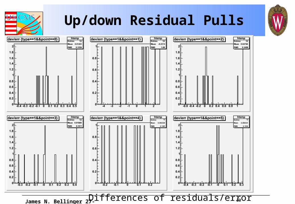
Up/down Residual Pulls
James N. Bellinger 27-November-2009 Differences of residuals/error
24
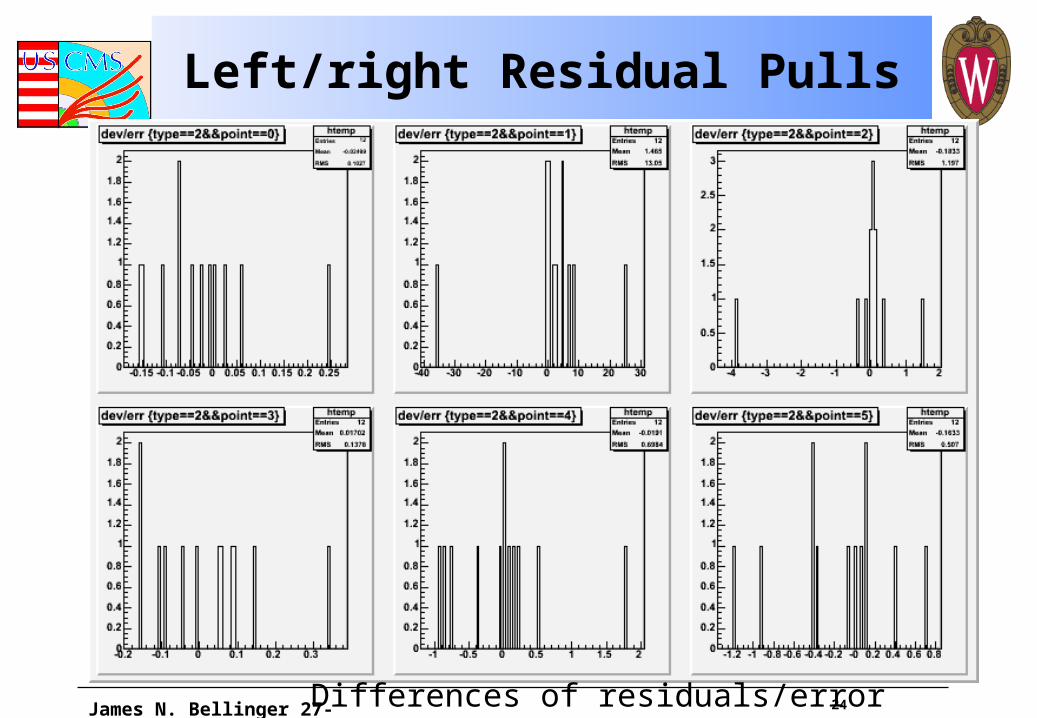
Left/right Residual Pulls
James N. Bellinger 27-November-2009 Differences of residuals/error
25
Good and Bad Lines
Transfer Line 1 is the best measured at 3.8T
Transfer Line 2 is the worst
Even Line 2 is mostly good!
James N. Bellinger 27-November-2009
26
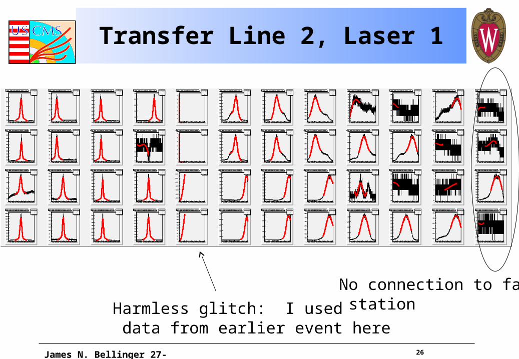
Transfer Line 2, Laser 1
James N. Bellinger 27-November-2009
No connection to far stationHarmless glitch: I used
data from earlier event here
27
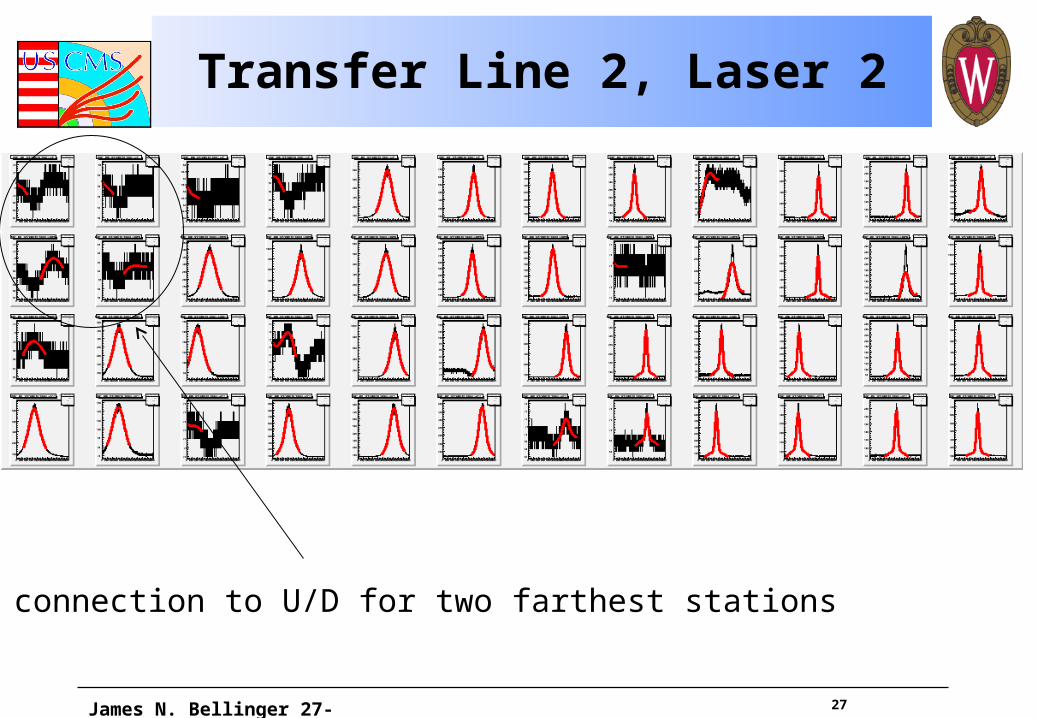
Transfer Line 2, Laser 2
James N. Bellinger 27-November-2009
No connection to U/D for two farthest stations
28
Lasers
Slight tweaking needed, otherwise in generally good shape
James N. Bellinger 27-November-2009


![The Power Issue [Eric Bellinger Edition]](https://static.cupdf.com/doc/110x72/568ca8f61a28ab186d9b7b40/the-power-issue-eric-bellinger-edition.jpg)