1
Fluke DAQ Software Visual Demo Guide2680A-APSW

Fluke DAQ Demo 2 Quick Demo Guide V1.0, 2002
About This Guide
• This guide is designed to give you a quick self-paced overview of Fluke DAQ software without having performing tedious step-by-step “exercises” common to traditional guides.
• This is intended to be a visual guide with emphasis placed on showing you where to accomplish certain tasks within the program.
• The items on each page are specific to the menu bar Icon shown in the upper right-hand corner of the page.
• We suggest you first view this guide and then work with the actual demo program. You may also keep this guide open and switch between the guide and the program as you progress.
Communication
Fluke DAQ Demo 3 Quick Demo Guide V1.0, 2002
Fluke DAQ Features
• Supports instrument configuration for up to 2,000 channels (tags).
• Intuitive interface• Works with 2680A Series and Fluke NetDAQ products• Supports:
– Instrument configuration and control– Trending, real-time and historical– File conversion to CSV format– Alarm annunciation and acknowledgment, DIO controls– Viewing data over the internet using standard browsers– Sending email on alarm
Fluke DAQ Demo 4 Quick Demo Guide V1.0, 2002
The Basic Requirements
• This Fluke DAQ Demo does not require a 2680 Series instrument. Numbers are randomly generated within the program to simulate data.
• You need a Pentium II class computer with 64 Meg RAM, Windows 98 or later and 100 MB free disk space
• Some functions are not available in the demo version
• At the end of this Visual Guide is a section covering setup of the 2686A-DEMO Kit intended for Representatives and Customers using 2686A demonstration hardware. If you have this hardware please refer to this section first for setup information. This section starts at slide # 18.
Fluke DAQ Demo 5 Quick Demo Guide V1.0, 2002
Installing Fluke DAQ
• Insert the Demonstration CD into your computer.
– Follow the installation directions.
– If Auto-run is disabled on your computer select the Start button, choose Run, (your drive letter) \ launch.exe and follow the instructions for installation.
– From your desk top shortcut or from the program menu double click on Fluke DAQ.
– If you have difficulty with this installation you may contact Fluke Corporation at 1-800-44-Fluke and ask for Data Acquisition Support.
Fluke DAQ Demo 6 Quick Demo Guide V1.0, 2002
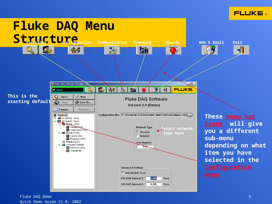
Fluke DAQ Menu StructureSecurity Configuration Communication Trending Alarms Web & Email Exit
These menu bar icons will give you a different sub-menu depending on what item you have selected in the Configuration menu
Select network type here
This is the starting default
Fluke DAQ Demo 7 Quick Demo Guide V1.0, 2002
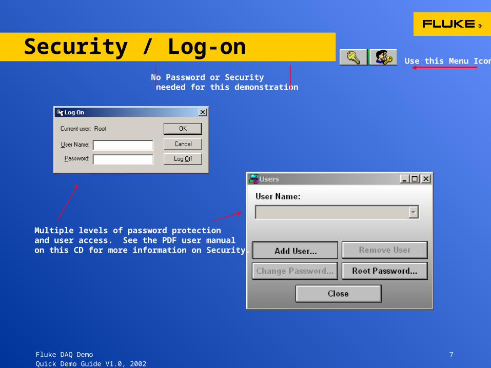
Security / Log-onNo Password or Security needed for this demonstration
Multiple levels of password protectionand user access. See the PDF user manual on this CD for more information on Security.
Use this Menu Icon
Fluke DAQ Demo 8 Quick Demo Guide V1.0, 2002
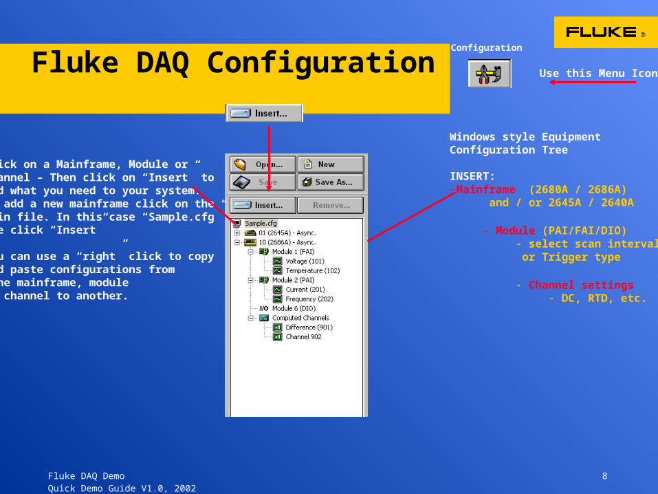
Fluke DAQ Configuration
Windows style Equipment Configuration Tree
INSERT:-Mainframe (2680A / 2686A)
and / or 2645A / 2640A
- Module (PAI/FAI/DIO)- select scan interval or Trigger type
- Channel settings- DC, RTD, etc.
Click on a Mainframe, Module or Channel – Then click on “Insert” to Add what you need to your system.to add a new mainframe click on the main file. In this case “Sample.cfg”The click “Insert”
You can use a “right” click to copy and paste configurations from one mainframe, module or channel to another.
Configuration
Use this Menu Icon

Fluke DAQ Demo 9 Quick Demo Guide V1.0, 2002
Configuration Flow
When you click on a chassis in the Configure Tree and then click “Insert” you get the Dialog box to insert a module type.
Click on a module you get # of channels dialog box
Click on a Channel and get a channel set-up dialog box.
Configuration
Use this Menu Icon
1
2
3
1
2
3
Fluke DAQ Demo 10 Quick Demo Guide V1.0, 2002
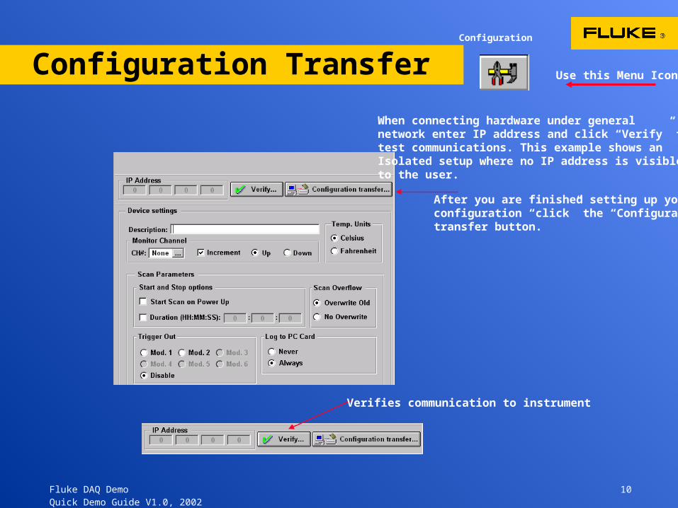
Configuration Transfer Use this Menu Icon
When connecting hardware under general network enter IP address and click “Verify” to test communications. This example shows an Isolated setup where no IP address is visible to the user.
After you are finished setting up your configuration “click” the “Configuration transfer button.
Configuration
Verifies communication to instrument
Fluke DAQ Demo 11 Quick Demo Guide V1.0, 2002
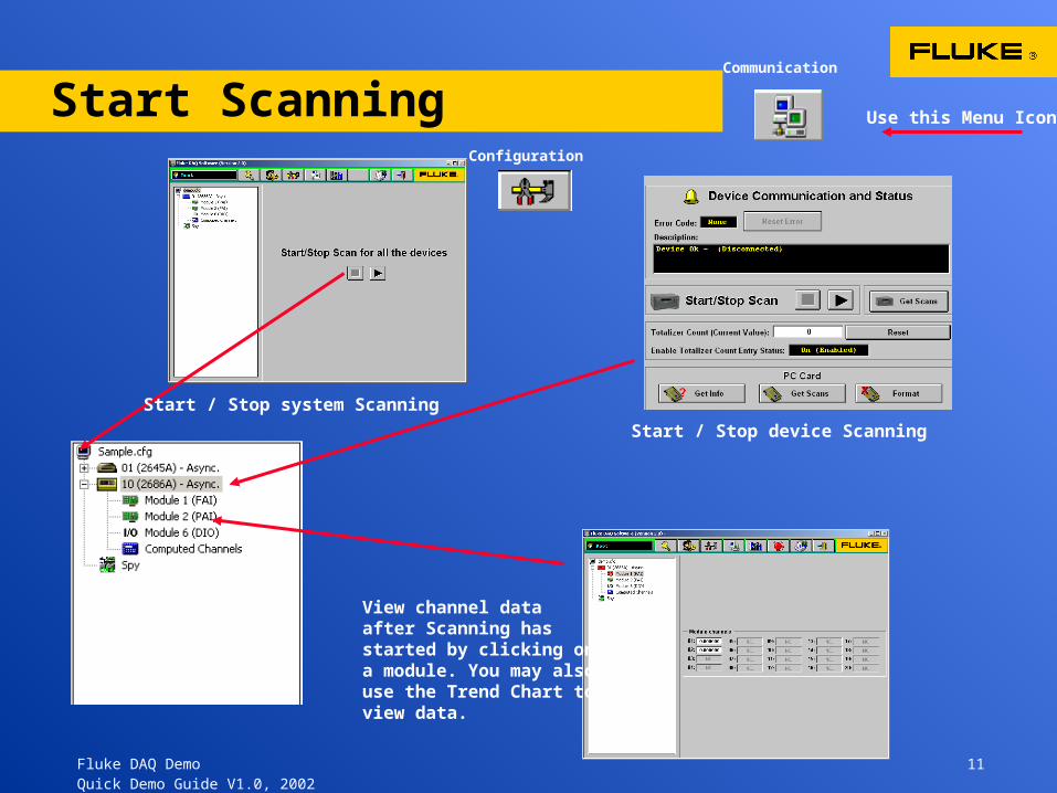
Start Scanning
Start / Stop device Scanning
View channel data after Scanning hasstarted by clicking ona module. You may also use the Trend Chart to view data.
Use this Menu Icon
Start / Stop system Scanning
Configuration
Communication
Fluke DAQ Demo 12 Quick Demo Guide V1.0, 2002
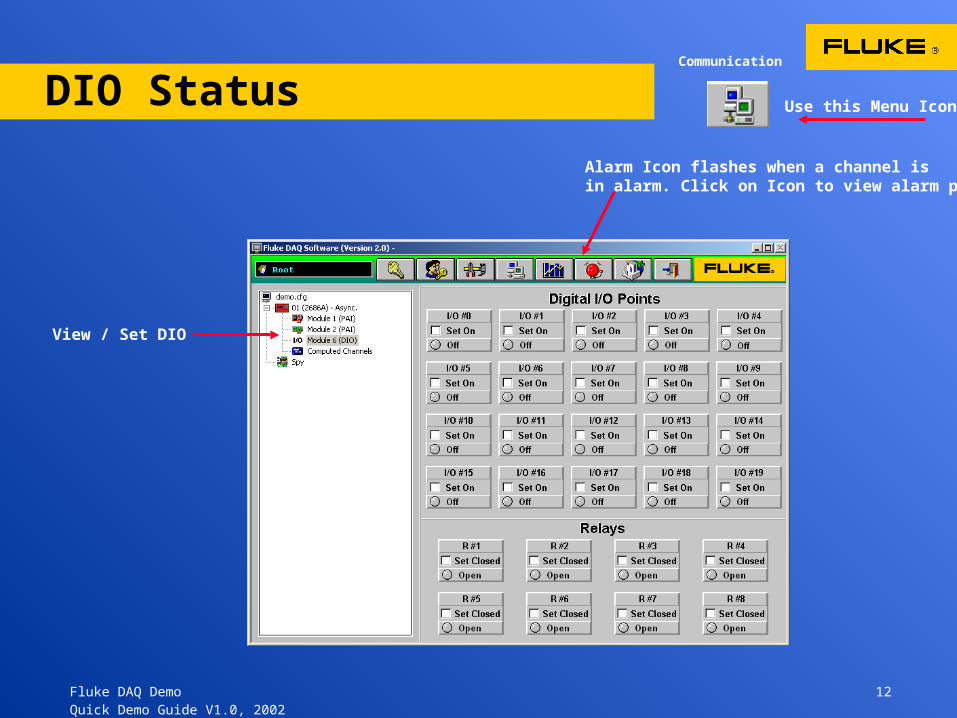
DIO Status Communication
View / Set DIO
Use this Menu Icon
Alarm Icon flashes when a channel is in alarm. Click on Icon to view alarm page.
Fluke DAQ Demo 13 Quick Demo Guide V1.0, 2002
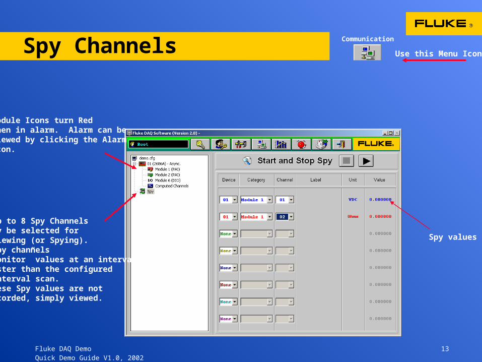
Spy Channels
Up to 8 Spy Channels may be selected for viewing (or Spying). Spy channels “Monitor” values at an interval faster than the configured interval scan. These Spy values are not recorded, simply viewed.
Module Icons turn Redwhen in alarm. Alarm can be viewed by clicking the Alarm Icon.
Communication
Use this Menu Icon
Spy values
Fluke DAQ Demo 14 Quick Demo Guide V1.0, 2002
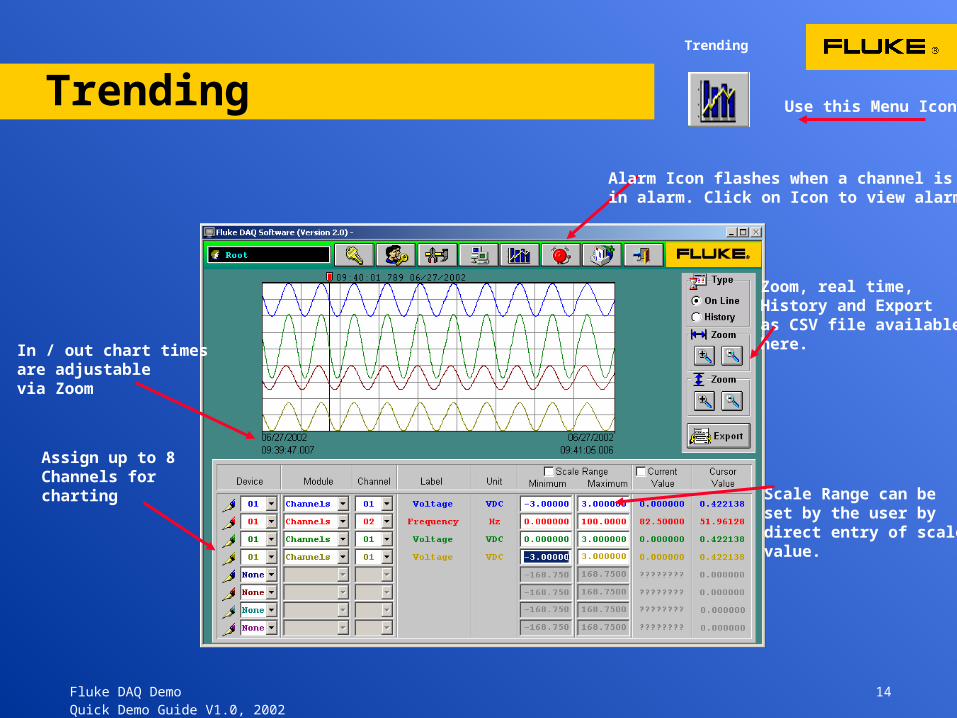
TrendingTrending
Assign up to 8 Channels for charting Scale Range can be
set by the user by direct entry of scale value.
Zoom, real time, History and Export as CSV file available here.In / out chart times
are adjustable via Zoom
Alarm Icon flashes when a channel is in alarm. Click on Icon to view alarm.
Use this Menu Icon
Fluke DAQ Demo 15 Quick Demo Guide V1.0, 2002
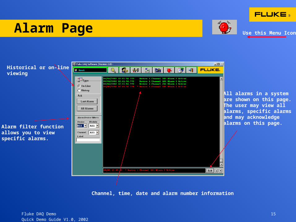
Alarm Page Use this Menu Icon
All alarms in a systemare shown on this page. The user may view all alarms, specific alarmsand may acknowledgealarms on this page.
Historical or on-lineviewing
Alarm filter function allows you to viewspecific alarms.
Channel, time, date and alarm number information
Fluke DAQ Demo 16 Quick Demo Guide V1.0, 2002
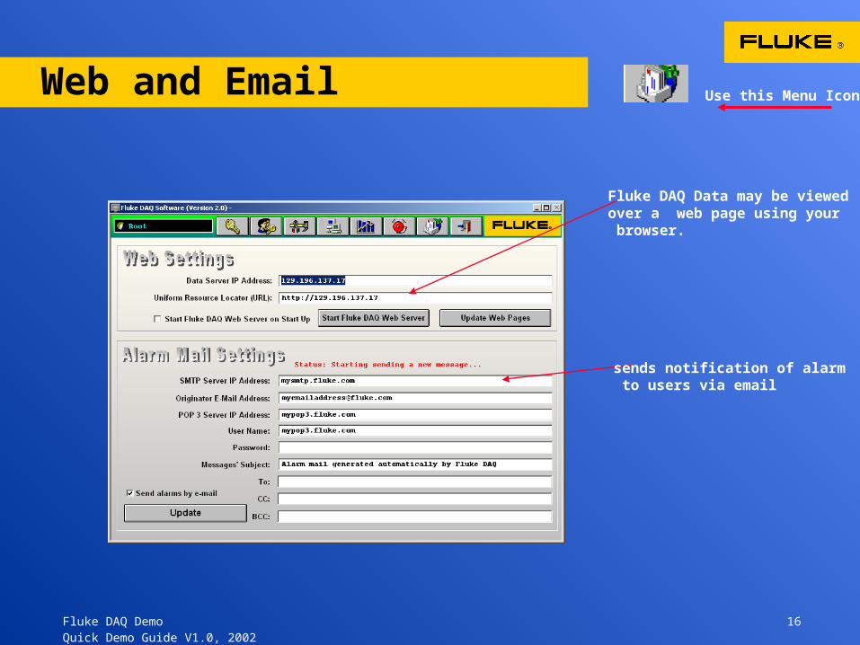
Web and Email
Fluke DAQ Data may be viewed over a web page using your browser.
sends notification of alarm to users via email
Use this Menu Icon
Fluke DAQ Demo 17 Quick Demo Guide V1.0, 2002
Thank You!
•Thank you for taking the time to view Fluke DAQ Data Acquisition software.
• If you have any questions please contact Fluke directly or your local Fluke Representative.
For further information on Fluke Data Acquisition products call 800-44-FLUKE orvisit www.fluke.com
USA: 800-44-FlukeCanada: 800-36-5853Europe / M-East / Africa (31 40) 2 675 200 From other countries +1 425 446 5500
Fluke DAQ Demo 18 Quick Demo Guide V1.0, 2002
Hardware Demo using the 2680A-DEMO Kit
The Following section offers basic instructions for the operation of the 2680A-DEMO Kit. This section shows how to setup the demonstration 2680A simulator hardware and connect the demonstrator to Fluke DAQ software on your laptop computer.
A 3-Com Ethernet card should be in the demo case and your Win 98 and Win 2000 operating systems should already have the drivers for this card and recognize the card upon booting up.
( for Representatives and Customers using the 2680A-DEMO Kit )
Fluke DAQ Demo 19 Quick Demo Guide V1.0, 2002
Hardware DEMO - First Steps
• Install an Ethernet card (3-Com Ethernet card provided in Demo Kit) and make Network communication changes shown on the next slide.
• Install Fluke DAQ Software from CD
• Initialize , read, erase PC card in the 2680A
• Connect the Demo Simulator to Slot # 1 and Slot # 6
• Connect the “RED” Ethernet cable between your computer and the 2686A.
• Open the “Sample” or “Demo”. cfg file.
• Select Isolated network
• Verify communications
• Start Scanning
• Exercise Visual Guide starting on slide #1
( for Representatives and Customers using the 2680A-DEMO Kit )

Fluke DAQ Demo 20 Quick Demo Guide V1.0, 2002
Setting Up Your Computer’s Network Settings
Set your computer’s Ethernet communications. This example is for Win 2000 but the basics are similar in other systems. The basic menu progressions are: Start > control panel > LAN connections > TCPIP settings > Properties. Set a specific IP address (198.178.246.101) and a subnet mask of 255.255.255.0.
Local area connection found in Window’s control panel under Network
Set IP and Subnet mask for Demo
Change tothis setting
Fluke DAQ Demo 21 Quick Demo Guide V1.0, 2002
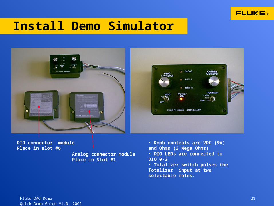
Install Demo Simulator
DIO connector modulePlace in slot #6
Analog connector modulePlace in Slot #1
• Knob controls are VDC (9V) and Ohms (3 Mega Ohms)• DIO LEDs are connected to DIO 0-2• Totalizer switch pulses the Totalizer input at two selectable rates.
Fluke DAQ Demo 22 Quick Demo Guide V1.0, 2002
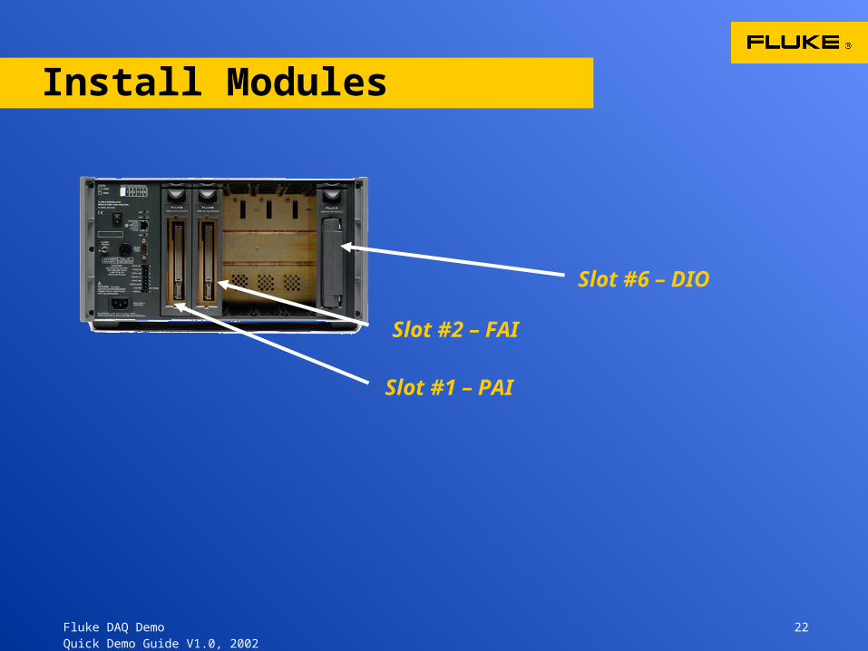
Install Modules
Slot #1 – PAI
Slot #2 – FAI
Slot #6 – DIO

Fluke DAQ Demo 23 Quick Demo Guide V1.0, 2002
Load Demo Configuration
Your demo simulator is connected to the system using the configuration shown below in “demo.cfg” or “sample.cfg” depending on version. Make certain your modules are in the correct slot. In this case the PAI is in slot #1 and the FAI in slot #2
Set for Vdc 30 Volt scale - (VDC Control on simulator)
Set for Ohms – 2W , 3M scale- (Ohms Control on simulator)
DIO 0, 1, 2 are available for you to set using the Alarms on channels 101 and 201
This computed channel is set to average channel 201and channel 101.
Exercise portions of the Fluke DAQ Program using this Visual Demo Guide as a reference