21 (3050) 177 163 196 181 17.2 (2500) 21 (3050) 17.2(2500) 21 (3050) Pump Type "PV2R" Series Single Pumps "PV2R4A" Series Single Pumps "PV2R" Series Double Pumps "PV2R24A/34A" Series Double Pumps Maximum Operating Pressure MPa (PSI) Page 1 2 5 10 20 50 100 200 500 800 Output Flow at 1200 r/min at No-Load Graphic Symbols .3 .5 1 2 5 10 20 50 100 200 L/min U.S.GPM PV2R1 PV2R2 PV2R3 PV2R4 (PV2R1) (PV2R2) (PV2R3) (PV2R3) (PV2R4) (PV2R2) Large Volume Fixed Displacedment Small Volume Large Volume Small Volume PV2R4A PV2R3 PV2R2 PV2R4A B VANE PUMPS 159

Welcome message from author
This document is posted to help you gain knowledge. Please leave a comment to let me know what you think about it! Share it to your friends and learn new things together.
Transcript

21
(3050)
177
163
196
181
17.2
(2500)
21 (3050)
17.2(2500)
21
(3050)
Pump Type
"PV2R" Series
Single Pumps
"PV2R4A" Series
Single Pumps
"PV2R" Series
Double Pumps
"PV2R24A/34A" Series
Double Pumps
Maximum
Operating
Pressure
MPa
(PSI)
Page
1 2 5 10 20 50 100 200 500 800
Output Flow at 1200 r/min at No-Load
Graphic
Symbols
.3 .5 1 2 5 10 20 50 100 200
L/min
U.S.GPM
PV2R1 PV2R2 PV2R3 PV2R4
(PV2R1) (PV2R2) (PV2R3)
(PV2R3) (PV2R4)(PV2R2)Large Volume
Fix
ed D
ispla
cedm
ent
Small Volume
Large Volume
Small Volume
PV2R4A
PV2R3PV2R2
PV2R4A
BVANE PUMPS
159

Water
Containing
Fluids
Water-Glycols
Water in Oil
Emulsions
Synthetic Fluids
Petroleum Base Oils
Standard pumps can be used without conditions.
However, if any type other than those in Table 2 is used, the maximum operating
pressure is limited.
Standard pumps can be used without conditions.
Use phosphate ester type fluids.
When phosphate ester type fluid is used, prefix "F-" to the model number because the special seals
(fluororubber) are required to be used.
Use anti-wear type oils or R & O (Rust and Oxidation inhibitor) type oils (equivalent to ISO VG32 or 46).
Commercial Trade NameFluid Manufacturer
Exxon Mobil
JAPAN ENERGY CORP.
NIPPON OIL CORPORATION
Showa Shell Sekiyu K. K.
MATSUMURA OIL RESEARCH CORP.
COSMO OIL LUBRICANTS CO. , LTD.
Mobil Nybac FR 200 D
JOMO Hydria G
HYRANDO FRX 46
Shell HFC Fluid 46
HYDOL HAW
COSMO FLUID HQ 46
COSMO FLUID GS 46
Petroleum Base Oils
Phosphate Esters
Water Glycols
Water in Oil Emulsions
FluidTemperature
°C (°F)
Viscosity 2 mm /s(SSU)
0-70 (32-158)
0-50 (32-122)
5-50 (41-122)
20-400 (100-1800)
Pump TypeStart-up Speed
r/min
Max. Viscosity 2 mm /s (SSU)
PV2R1
PV2R12
PV2R13
PV2R14
PV2R2
PV2R23
PV2R24
PV2R24A
950
750 100 (455)
200 (910)
600 100 (455)
950 200 (910)
Hydraulic Fluids
Type of hydraulic fluids1.
Hydraulic fluids (Table 1)
(Table 2)
Fluid viscosity and temperature2.
Fluid viscosity and temperature(Table 3)
Maximum viscosity for low start-up speed(Table 4)
Anti-wear type water-glycols
Control of contamination3.
Any type of hydraulic fluids listed in the Table 1 below can be used. However, the specifications of the pumps such
as maximum pressure and maximum pump speed may be changed according to the type of hydraulic fluids to be used.
For details, please refer to the specifications of the pump concerned.
Use the hydraulic fluids which satisfy the recommended viscosity and oil temperature given in the Table 3 below.
However, please note that if any of the pumps listed in the table 4 is started at low speed, the maximum fluid viscosity
is limited.
Contamination of hydraulic fluids results in pump failures and reduced pump lives. Carry out sufficient contamination
control for hydraulic fluids and keep contamination level within NAS class 12.
Also, use a 100 µm (150-mesh) tank filter on the suction side, more than 50 mm (2 in.) away from the tank bottom.
Fixed Vane Pumps160

Pump Type
Petroleum base oilPhosphate ester type fluid
Water containing fluid
Maximum
Minimum
Suction Pressure
"PV2R" Series
Single Pumps
"PV2R" Series
Double Pumps
PV2R13
PV2R23
PV2R33
PV2R14
PV2R24
PV2R34
PV2R24A
PV2R34A
PV2R3
PV2R4
PV2R4A
PV2R1
PV2R2
PV2R12
-20 kPa
(5.9 in. Hg Vacuum)
-20 kPa
(5.9 in. Hg Vacuum)
-20 kPa
(5.9 in. Hg Vacuum)
-20 kPa
(5.9 in. Hg Vacuum)
-16 kPa
(4.7 in. Hg Vacuum)
+30 kPa
(+4.3 PSIG)
Instructions
Alignment of shaft1.
Suction pressures2.
Precautions at starting3.
Other precautions4.
Employ a flexible coupling whenever possible, and avoid any stress from bending or thrust.
Maximum permissible misalignment is less than 0.1 mm (.004 inches) TIR and maximum permissible misangular is
less than 0.2°.
Set the suction pressure at pump inlet port at the value given in the table below. Furthermore, use the pipes in the
suction side having the diameter as indicated on the installation drawings. In case where the pump is installed on the
tank or at the position higher than the tank top cover, the height of the suction port of the pump should be less than 1
metre (3.3 ft.) from the oil level {less than 0.8 metre (2.6 ft.) in case of using phosphate ester fluids or water
containing fluids}.
At an initial operation or at an operation after a long rest, the pump may have difficulty in sucking up fluid. In such cases,
an air bleed valve should be installed beforehand on the discharge side (model No. ST1004-*-10*, see page 820), or
discharge air by slightly slackening the connection on the discharge side. At starting, operate the pump intermittently as
far as possible with no load.
For fluid viscosity at starting, see the item of "Hydraulic Fluids".
If a pump is used at speed below 1200 r/min, install the pump with the suction port upside so that the pump can suck up
fluid easily at starting.
In relation to the rotating speed of the pump, the minimum suction pressure may be restricted for a certain nominal
displacement. For details, please refer to the specifications of the pump concerned.
161
VANE PUMPS
Fix
ed
Van
eP
um
ps
B
Fixed Vane Pumps
''PV2R1'' Series
Single Pumps
''PV2R2'' Series
Single Pumps
''PV2R3'' Series
Single Pumps
''PV2R12'' Series
Double Pumps
''PV2R13'' Series
Double Pumps
''PV2R14'' Series
Double Pumps
''PV2R23'' Series
Double Pumps
''PV2R33'' Series
Double Pumps
''PV2R24'' Series
Double Pumps
''PV2R34'' Series
Double Pumps
Current
Model Numbers
New
Interchange-
ability in
Installation
Yes
Yes
Yes
Yes
Yes
Yes
Yes
Yes
Yes
Yes
Major ChangesName
PV2R1-*-*-RAA-42*
PV2R2-*-*-RAA-41*
PV2R3-*-*-RAA-31*
PV2R12-*-*-*-REAA-42*
PV2R13-*-*-*-RAAA-42*
PV2R14-*-*-*-RAAA-32*
PV2R23-*-*-*-REAA-41*
PV2R33-*-*-*-RAAA-31*
PV2R24-*-*-*-RAAA-31*
PV2R34-*-*-*-REAA-31*
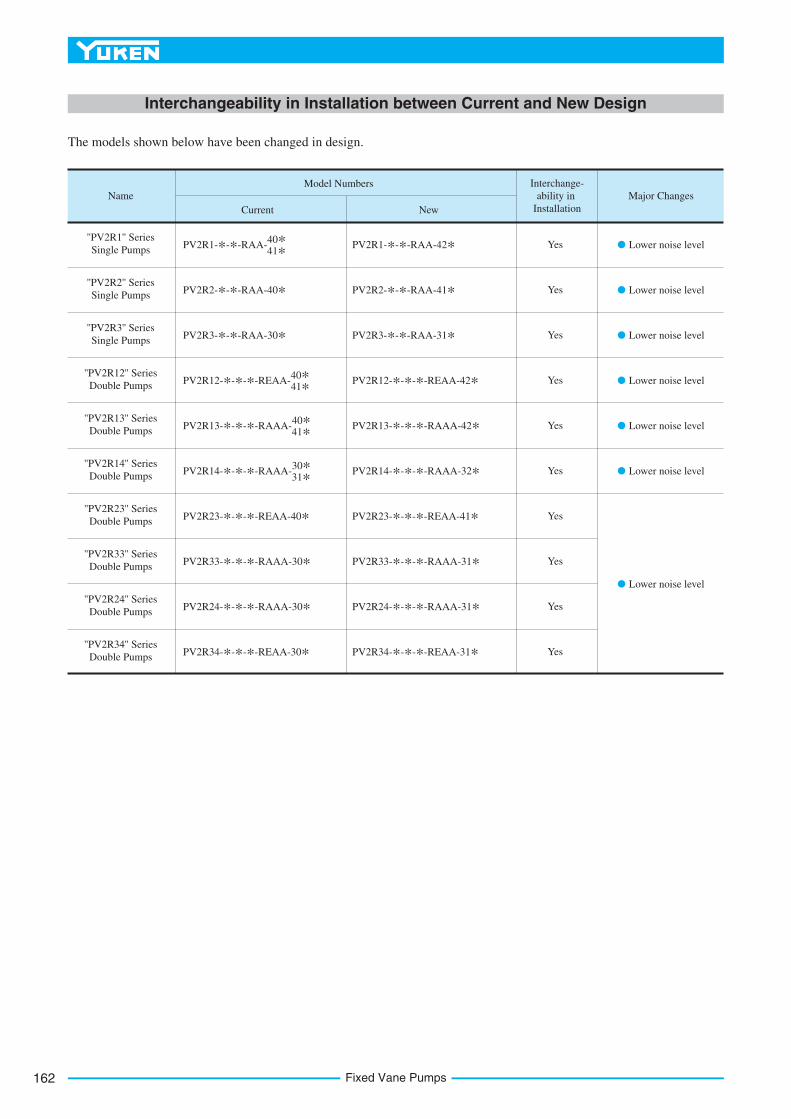
The models shown below have been changed in design.
Interchangeability in Installation between Current and New Design
PV2R1-*-*-RAA-40*
41*
PV2R2-*-*-RAA-40*
PV2R3-*-*-RAA-30*
PV2R12-*-*-*-REAA-40*
41*
PV2R13-*-*-*-RAAA-40*
41*
PV2R14-*-*-*-RAAA-30*
31*
PV2R23-*-*-*-REAA-40*
PV2R33-*-*-*-RAAA-30*
PV2R24-*-*-*-RAAA-30*
PV2R34-*-*-*-REAA-30*
Lower noise level
Lower noise level
Lower noise level
Lower noise level
Lower noise level
Lower noise level
Lower noise level
Fixed Vane Pumps162

163
VANE PUMPS
"PV
2R
"S
eri
es
Sin
gle
Van
eP
um
ps
B
"PV2R" Series Single Vane Pumps
2
Graphic Symbol
F-
Series
NumberSpecial Seals
F:
For phosphate ester type fluids (Omit if not required)
PV2R2
Nominal Displacement
3 cm /rev
Design
Standards
Design
Number
A:
Upwards
(Normal)
Refer to
42
41
31
30
PV2R1 -6 -L -R A -42 -*A
Type of
Mounting
Shaft
Rotation
Discharge Port
Position
Suction Port
Position
A:
Upwards
(Normal)
R:
Clockwise
(Normal)
L:
FootMounting
F:FlangeMounting
PV2R3
PV2R4
6, 8, 10, 1214, 17, 1923, 25, 31
PV2R1
41, 47, 5359, 65
76, 94, 116
136, 153, 184200, 237
Pump
Model
Numbers
PV2R1
PV2R2
PV2R3
PV2R4
Name
of
Port
Suction
Discharge
Suction
Discharge
Suction
Discharge
Suction
Discharge
Japanese
Standard "JIS"
F5-08-A-10
F5-04-A-10
F5-10-A-10
F5-06-A-10
F5-16-A-10
F5-10-A-10
F5-24-A-10
F5-12-A-10
European
Design
Standard
F5-08-A-1080
F5-04-A-1080
F5-10-A-1080
F5-06-A-1080
F5-16-A-1080
F5-10-A-1080
F5-12-A-1080
N. American
Design
Standard
Japanese Standard "JIS"
European Design
Standard
F5-08-B-10
F5-04-B-10
F5-10-B-10
F5-06-B-10
F5-16-B-10
F5-10-B-10
F5-24-B-10
F5-12-B-10
F5-08-B-1090
F5-04-B-1090
F5-10-B-1090
F5-06-B-1090
F5-16-B-1090
F5-10-B-1090
F5-24-B-1090
F5-12-B-1090
N. American
Design
Standard
Japanese Standard "JIS"
European Design
Standard
F5-08-C-10
F5-04-C-10
F5-10-C-10
F5-06-C-10
F5-16-C-10
F5-10-C-10
F5-24-C-10
F5-12-C-10
F5-08-C-1090
F5-04-C-1090
F5-10-C-1090
F5-06-C-1090
F5-16-C-1090
F5-10-C-1090
F5-24-C-1090
F5-12-C-1090
N. American
Design
Standard
Pipe Flange Kit Numbers
Threaded Connection Socket Welding Butt Welding
Model Number Designation
Pipe Flange Kits
1. Available to supply pump with anti-clockwise rotation.Consult Yuken for details.
Pipe flange kits are available. When ordering, specify the kit number from the table below.
2.Design Standards:None.....Japanese Standard "JIS"
80
90
.........
.........
European Design Standard
N. American Design Standard
Notes: Special seals (Viton seals) are required when phosphate ester type fluids are used. (Prefix "F-" to the pipe flange kit number when ordering.)
Details of the pipe flange kits are shown on page 824.
"PV2R" Series Single Vane Pumps
2
1
22
In case of using socket welding flanges, there is a case where the operating pressure should be set lower than the normal because of strength of the
flanges. Therefore, please pay cautious attention to the operating pressure when the socket welding flanges are used.
1.
As dimensions of the pipe flange mounting surface are conformed to SAE 4 Bolt Split Flange (Standard Pressure Series), pipe flanges conforming to
the SAE Standards can be used.
2.
These pumps are of high pressure and high performance, which have been developed especially for low noise operation.
To comply with a variety of applications including injection moulding machines, PV2R series single pumps provide the
output flow of such a wide range as from 5.8 to 237 cm3/rev (.354 to 14.46 cu.in./rev).
The intergral driving parts of the pumps are combined into a kit form and available for supply as a cartridge kit.
Therefore, the replacement of the driving parts can be done easily.
(Viewed from Shaft End)
1
"PV2R" Series Single Vane Pumps164
1
6
4
4
4
4
2
4
4
3
5
5
1.
2.
3.
4.
5.
6.
Model Numbers
Geometric Displacement
3 cm /rev (cu.in./rev)
Anti-Wear Type
R & O Type
Petroleum Base Oils
Anti-Wear Type Water
Glycols
Water Containing Fluids
Max. Operating Pressure MPa (PSI)
Synthetic Fluids
Water Glycols
Water in Oil
Emulsions
Phosphate Esters
Output Flow
& Input Power
Shaft Speed Range
r/min
Max. Min.
PV2R1-6
PV2R1-8
PV2R1-10
PV2R1-12
PV2R1-14
PV2R1-17
PV2R1-19
PV2R1-23
PV2R1-25
PV2R4-136
PV2R4-153
PV2R4-184
PV2R4-200
PV2R1-31
PV2R2-41
PV2R2-47
PV2R2-53
PV2R2-59
PV2R2-65
PV2R3-76
PV2R3-94
PV2R3-116
PV2R4-237
5.8 ( .354 )
8.0 ( .488 )
9.4 ( .574 )
12.2 ( .744 )
13.7 ( .836 )
16.6 ( 1.013 )
18.6 ( 1.135 )
22.7 ( 1.385 )
25.3 ( 1.544 )
31.0 ( 1.892 )
41.3 ( 2.52 )
47.2 ( 2.88 )
52.5 ( 3.20 )
58.2 ( 3.55 )
64.7 ( 3.95 )
76.4 ( 4.66 )
93.6 ( 5.71 )
136 ( 8.30 )
153 ( 9.34 )
184 ( 11.23 )
201 ( 12.27 )
237 ( 14.46 )
115.6 ( 7.05 )
21 (3050)
16 (2320)
21 (3050)
21 (3050)
21 (3050)
16 (2320)
17.5 (2540)
16 (2320)
14 (2030)
14 (2030)
14 (2030)
16 (2320)
16 (2320)
16 (2320)
16 (2320)
16 (2320)
14 (2030)
14 (2030)
14 (2030)
7 (1020)
7 (1020)
7 (1020)
7 (1020)
7 (1020)
7 (1020)
7 (1020)
7 (1020)
Refer to
Pages
170 - 172
Refer to
Pages
172 & 173
Refer to
Page 174
Refer to
Pages
174 & 175
750
600
600
600
1800 (1200)
1800 (1200)
1800 (1200)
1800 (1200)
1800 (1200)
1800 (1200)
Model NumbersFlange Mtg. Foot Mtg.
Approx. Mass kg (lbs.)
PVR2R1
PVR2R2
PVR2R3
PVR2R4
9.0 ( 19.8)
15.5 ( 34.2)
30.9 ( 68.1)
68.5 (151)
11.2 ( 24.7)
19.8 ( 43.7)
40.9 ( 90.2)
93.5 (206)
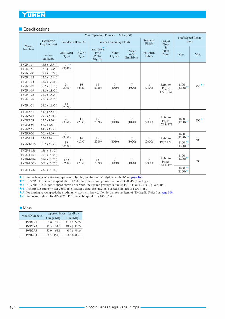
Specifications
For the brands of anti-wear type water-glycols , see the item of "Hydraulic Fluids" on page 160.
If PV2R3-116 is used at speed above 1700 r/min, the suction pressure is limited to 0 kPa (0 in. Hg.).
If PV2R4-237 is used at speed above 1700 r/min, the suction pressure is limited to -13 kPa (3.94 in. Hg. vacuum).
If phosphate ester or water containing fluids are used, the maximum speed is limited to 1200 r/min.
For starting at low speed, the maximum viscosity is limited. For details, see the item of "Hydraulic Fluids" on page 160.
For pressure above 16 MPa (2320 PSI), raise the speed over 1450 r/min.
Mass

165
VANE PUMPS
"PV
2R
"S
eri
es
Sin
gle
Van
eP
um
ps
B
"PV2R" Series Single Vane Pumps
DIMENSIONS INMILLIMETRES (INCHES)
Model Numbers
PV2R1-*-F-RAA-42
PV2R1-*-F-RAA-4290
M10
3/8-16 UNC
"C" Thd.
M8
5/16-18 UNC
"D" Thd.
14 (.55)
16 (.63)
E mm (Inches)
A
A
7 (.276)
13 (.51)
Discharge Port 15(.59) Dia.
Suction Port 28(1.10) Dia.
R9.5(R.37)
40(1.57)
R8(R.31)
4.7
94
.76
(.1
88
6)
(.1
87
4)
Key
Wid
th
52
.4(2
.06
3)
38
.1(1
.50
0)
17.5 (.689)
26.2 (1.031)
"D" Thd. "E" Deep 4 Places
"C" Thd. 17(.67) Deep 4 Places
25
(.98)
36
(1.42)
44.5 (1.75)
69.5 (2.74)
56 (2.20)
178.5 (7.03)
58
(2.2
8)
10
6.5
(4.1
9)
19
.05
(.7
50
0)
19
.02
(.7
48
8)
Dia
.
21
.24
(.8
36
) 2
1.0
8(.
83
0)
82
.55
8
2.5
0D
ia.
(3.2
50
) (3
.24
8)
11(.433) Dia. Through2 Places
95(3.74)
R12 (R.47)
18
(.7
1)
97
(3.8
2)
Sq
.
106 (4.173)
130 (5.12)
Port Position
56 (2.20)
69.5 (2.74)
178.5 (7.03)
50
(1.969)
56.5(2.22)
95 (3.74)
27.5(1.08)
3(.
12
)
95 (3.74)
72.5 (2.854)
180 (7.09)
72.5 (2.854)
12(.472) Dia. Through 24(.94) Dia. Spotface
4 Places
15
(.5
9)
80
(3.1
5)
14
5.5
(5.7
3)
56 (2.20)
Flange Mtg.: PV2R1-*-F-RAA-42/4290
Foot Mtg.: PV2R1-*-L-RAA-42/4290
For other dimensions, refer to "Flange Mtg.".
14
(.5
5)

"PV2R" Series Single Vane Pumps166
DIMENSIONS INMILLIMETRES (INCHES)
Model Numbers
PV2R2-*-F-RAA-41
PV2R2-*-F-RAA-4190
M10
7/16-14 UNC
"C" Thd.
M10
7/16-14 UNC
"D" Thd.
19 (.75)
20 (.79)
E mm (Inches)
A
A
9 (.354)
16 (.63)
Discharge Port 21(.83) Dia.
Suction Port 34(1.34) Dia.
R11(R.43)
49(1.93)
R9(R.35)
6.3
8
6.3
5(.
25
12
) (.
25
00
)
Key
Wid
th
58
.7(2
.31
1)
47
.6(1
.87
4)
22.2 (.874)
30.2 (1.189)
"D" Thd. 17(.67) Deep 4 Places
"C" Thd. "E" Deep 4 Places
(1.26)
47 (1.85)
59 (2.32)
87 (3.43)
80 (3.15)
222 (8.74)
70
(2.7
6)
13
2.5
(5.2
2)
25
.40
( 1.0
00
0)
25
.35
( .9
98
0)
Dia
.
28
.18
(1.1
09
) 2
8.0
0(1
.10
2)
10
1.6
0
10
1.5
5D
ia.
(4.0
00
) (3
.99
8)
13.5(.531) Dia. Through 2 Places
120(4.72)
R14 (R.55)
25
(.9
8)
12
5(4
.92
) S
q.
146 (5.748)
174 (6.85)
Port Position
80 (3.15)
87 (3.43)
222 (8.74)
60
(2.362)
73 (2.87)
115 (4.53)
38 (1.50)
3(.
12
)
120 (4.72)
95 (3.740)
230 (9.06)
14(.551) Dia. Through 28(1.10) Dia. Spotface 4 Places
15
(.5
9)
10
2(4
.02
)
18
9(7
.44
)
95 (3.740)
65(2.56)
32
Flange Mtg.: PV2R2-*-F-RAA-41/4190
Foot Mtg.: PV2R2-*-L-RAA-41/4190
For other dimensions, refer to "Flange Mtg.".
14
(.5
5)

167
VANE PUMPS
"PV
2R
"S
eri
es
Sin
gle
Van
eP
um
ps
B
"PV2R" Series Single Vane Pumps
DIMENSIONS INMILLIMETRES (INCHES)
Model Numbers
PV2R3-*-F-RAA-31
PV2R3-*-F-RAA-3190
M12
1/2-13 UNC
"C" Thd.
M10
7/16-14 UNC
"D" Thd.
19 (.75)
21 (.83)
E
Dimensions mm (Inches)
F
19 (.75)
20 (.79)
A
Port Position
A
9 (.354)
21 (.83)
Discharge Port 28(1.10) Dia.
Suction Port 51(2.01) Dia.
R13(R.51)
65(2.56)
R11(R.43)
7.9
7
7.9
4(.
31
38
) (.
31
26
)
Key
Wid
th
77
.8
(3.0
63
)
58
.7(2
.31
1)
30.2 (1.189)
42.9 (1.689)
"D" Thd. "F" Deep 4 Places
"C" Thd. "E" Deep 4 Places
40
(1.57)
63
(2.48)
75 (2.95)
112 (4.41)
90 (3.54)
274 (10.79)
90
(3.5
4)
17
3(6
.81
)
31
.75
(1.2
50
0)
31
.70
(1.2
48
0)
Dia
.
35
.32
(1.3
91
) 3
5.1
4(1
.38
3)
12
7.0
0
12
6.9
5D
ia.
(5.0
00
) (4
.99
8)
148
(5.83)
R16 (R.63)
31
(1.2
2)
16
6(6
.54
) S
q.
181 (7.126)
213 (8.39)
90 (3.54)
112 (4.41)
274 (10.79)
76.2
(3.000)
88 (3.46)
131 (5.16)
50 (1.97)
2(.
08
)
145 (5.71)
117.5 (4.626)
274 (10.79)
17.5(.689) Dia. Through 26(1.02) Dia. Spotface 4 Places
23
(.9
1)
10
9.5
(4.3
1) 21
7(8
.54
)
87(3.43)
17.5(.689) Dia. Through
2 Places
117.5 (4.626)
Flange Mtg.: PV2R3-*-F-RAA-31/3190
Foot Mtg.: PV2R3-*-L-RAA-31/3190
For other dimensions, refer to "Flange Mtg.".
22
(.8
7)

"PV2R" Series Single Vane Pumps168
DIMENSIONS INMILLIMETRES (INCHES)
Model Numbers
PV2R4-*-F-RAA-30
PV2R4-*-F-RAA-3090
M16
1/2-13 UNC
"C" Thd.
M12
5/8-11 UNC
"D" Thd.
19 (.75)
21 (.83)
E
Dimensions mm (Inches)
F
19 (.75)
21 (.83)
13 (.512)
25 (.98)
Discharge Port 36(1.42) Dia.
Suction Port 76(2.99) Dia.
R13(R.51)9
.56
9
.53
(.3
76
4)
(.3
75
2)
Key
Wid
th
10
6.4
(4.1
89
)
69
.9(2
.75
2)
35.7 (1.406)
"D" Thd. "F" Deep 4 Places
"C" Thd. "E" Deep 4 Places
56
(2.20)
76
(2.99)
135 (5.31)
110 (4.33)
354 (13.94)
11
5(4
.53
)
21
7(8
.54
)
38
.10
(1.5
00
0)
38
.05
(1.4
98
0)
Dia
.
42
.36
(1.6
68
)
42
.18
(1.6
61
)1
52
.40
1
52
.35
Dia
.
(6.0
00
) (5
.99
8)
21.5(.846) Dia. Through 39(1.54) Dia. Spotface (From Rear)
4 PlacesR22(R.87)
Port Position
110 (4.33)
135 (5.31)
354 (13.94)
114.3
(4.500)
99 (3.90)
185 (7.28)
60 (2.36)
3(.
12
)
280 (11.02)
187.3 (7.374)
438 (17.24)
22(.866) Dia. Through 43(1.69) Dia. Spotface
4 Places
30
(1.1
8)
18
7.3
(7.3
7)
32
7.3
(12
.89
)
A
61.9 (2.437)
R37(R1.46)
R15(R.59)
118(4.65)
92 (3.62)
24 (.94)
14
0(5
.51
)
273(10.75) Sq.
228.6(9.000)
A
187.3 (7.374)
22
8.6
(9.0
00
)
Flange Mtg.: PV2R4-*-F-RAA-30/3090
Foot Mtg.: PV2R4-*-L-RAA-30/3090
For other dimensions, refer to "Flange Mtg.".
29
(1.1
4)
169
VANE PUMPS
"PV
2R
"S
eri
es
Sin
gle
Van
eP
um
ps
B
"PV2R" Series Single Vane Pumps
No
ise
Lev
el
dB(A)60
55
0 3.5 14 21 MPa17.510.57(2000) (3000) (PSI)(1000)
50
45
40
1200 r/min
1000 r/min
1200 r/min
1000 r/min
0 3.5 14 21 MPa17.510.57(2000) (3000) (PSI)(1000)
No
ise
Lev
el
dB(A)60
55
50
45
40
1200 r/min
1000 r/min
0 3.5 14 21 MPa17.510.57(2000) (3000) (PSI)(1000)
0 3.5 14 21 MPa17.510.57(2000) (3000) (PSI)(1000)
0 3.5 14 21 MPa17.510.57(2000) (3000) (PSI)(1000)
No
ise
Lev
el
60
55
50
45
65dB(A)
No
ise
Lev
el 60
55
50
65dB(A)
No
ise
Lev
el
60
55
65
dB(A)70
0 3.5 14 21 MPa17.510.57(2000) (3000) (PSI)(1000)
No
ise
Lev
el
60
55
65
dB(A)70
0 3.5 14 21 MPa17.510.57(2000) (3000) (PSI)(1000)
No
ise
Lev
el 60
55
50
65dB(A)
0 3.5 14 21 MPa17.510.57(2000) (3000) (PSI)(1000)
No
ise
Lev
el
60
55
50
45
65dB(A)
Pressure
Pressure
Pressure
PressurePressure
Pressure
Pressure
Pressure
1200 r/min
1000 r/min
1200 r/min
1000 r/min
1200 r/min
1000 r/min
1000 r/min
1200 r/min 1200 r/min
1000 r/min
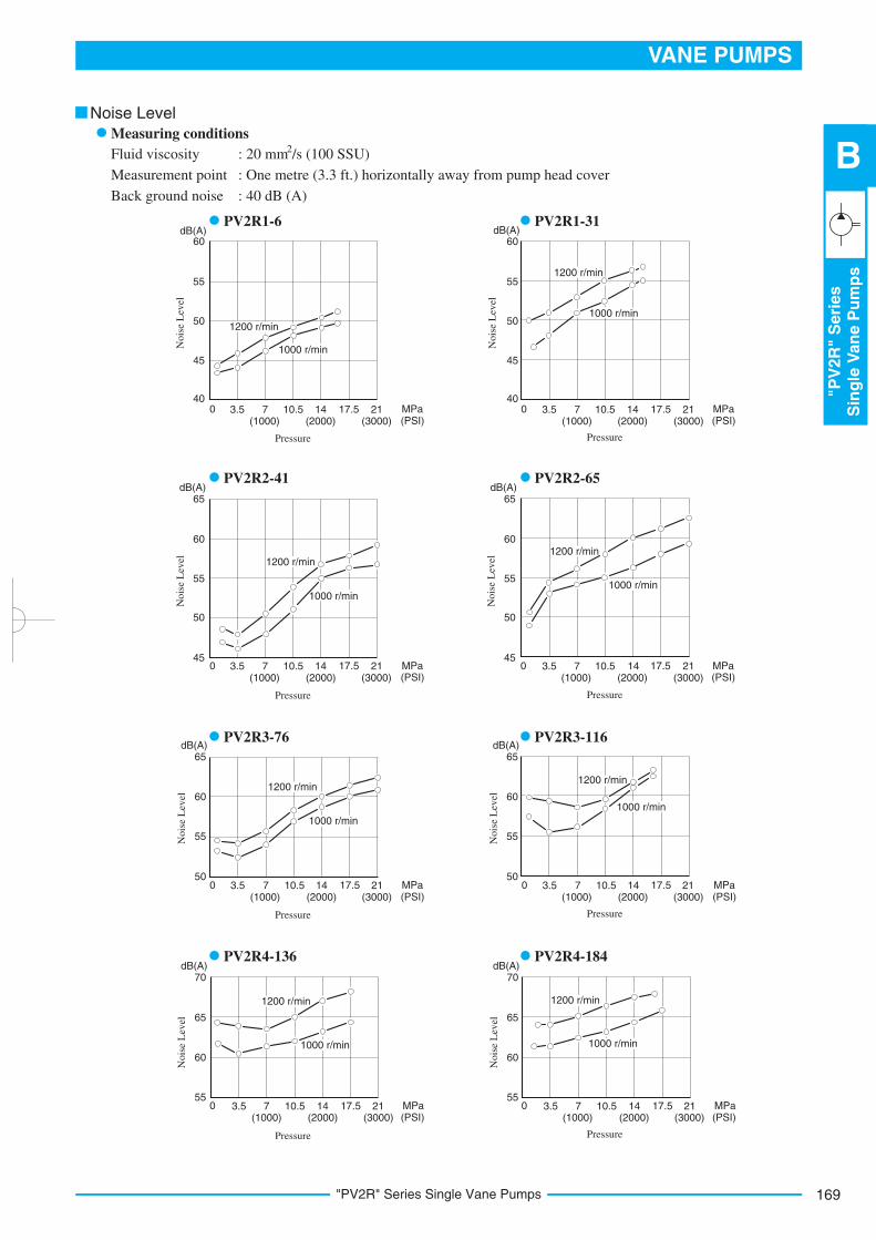
Fluid viscosity
Measurement point
Back ground noise
2 : 20 mm /s (100 SSU)
: One metre (3.3 ft.) horizontally away from pump head cover
: 40 dB (A)
Noise Level
Measuring conditions
PV2R1-6 PV2R1-31
PV2R2-41 PV2R2-65
PV2R3-76 PV2R3-116
PV2R4-136 PV2R4-184

"PV2R" Series Single Vane Pumps170
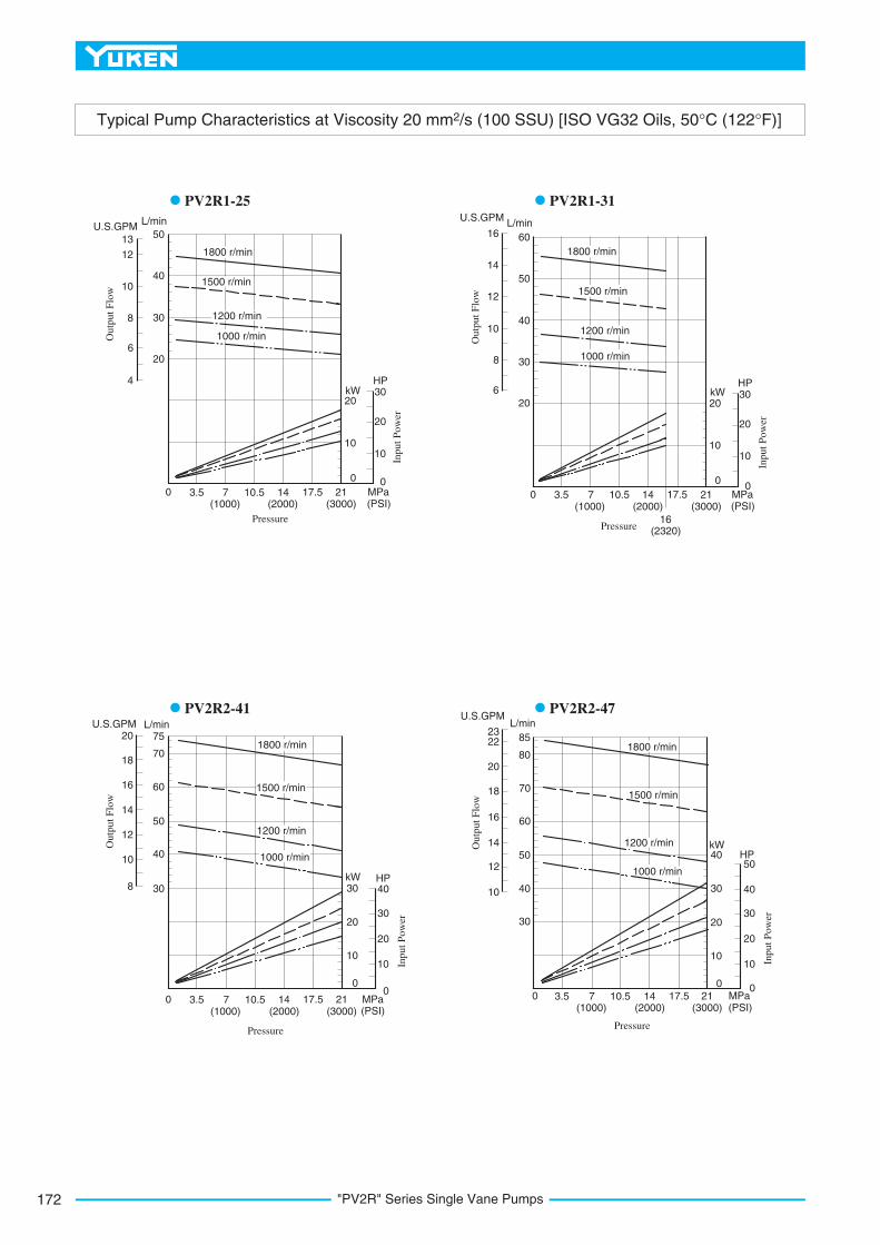
Typical Pump Characteristics at Viscosity 20 mm2/s (100 SSU) [ISO VG32 Oils, 50°C (122°F)]
0 3.5 14 21 MPa17.510.57(2000) (3000) (PSI)(1000)
Pressure16
(2320)
0 3.5 14 21 MPa17.510.57(2000) (3000) (PSI)(1000)
Pressure16
(2320)
0 3.5 14 21 MPa17.510.57(2000) (3000) (PSI)(1000)
Pressure
0 3.5 14 21 MPa17.510.57(2000) (3000) (PSI)(1000)
Pressure
Ou
tpu
t F
low
L/min11
9
5
3
10
8
7
6
4
U.S.GPM
2.8
2.4
2.0
1.6
1.2
.8
Ou
tpu
t F
low
L/min
11
9
5
10
8
7
6
U.S.GPM
3.8
3.4
3.0
2.6
2.2
1.4
12
13
14
15
1.8
Ou
tpu
t F
low
18
16
8
17
15
14
13
U.S.GPM
5.8
5.4
5.0
4.6
4.2
3.4
19
20
21
22
3.8
9
10
11
123.0
2.6
2.2
L/min
Ou
tpu
t F
low
U.S.GPM
4.4
4.0
3.6
3.2
2.8
2.0
2.4
1.6
14
12
13
11
10
15
16
17
18
L/min
9
8
7
6
6
5
4
3
2
10
8
6
0
2
4
kW HP
Inp
ut
Po
wer
6
5
4
3
2
10
8
6
0
2
4
kW HP
Inp
ut
Po
wer
710
6
5
4
3
2
10
8
6
0
2
4
kW HP
Inp
ut
Po
wer
710
8
9
10
12
14
6
5
4
3
2
10
8
6
0
2
4
kW HP
Inp
ut
Po
wer
710
8 11
1200 r/min
1000 r/min
1500 r/min
1800 r/min
1200 r/min
1000 r/min
1500 r/min
1800 r/min
1200 r/min
1000 r/min
1500 r/min
1800 r/min
1200 r/min
1000 r/min
1500 r/min
1800 r/min
PV2R1-6 PV2R1-8
PV2R1-10 PV2R1-12

171
VANE PUMPS
"PV
2R
"S
eri
es
Sin
gle
Van
eP
um
ps
B
"PV2R" Series Single Vane Pumps
Typical Pump Characteristics at Viscosity 20 mm2/s (100 SSU) [ISO VG32 Oils, 50°C (122°F)]
0 3.5 14 21 MPa17.510.57(2000) (3000) (PSI)(1000)
Pressure
12
10
8
6
4
20
16
12
0
4
8
kW HP
Inp
ut
Po
wer
0 3.5 14 21 MPa17.510.57(2000) (3000) (PSI)(1000)
Pressure
12
10
8
6
4
20
16
12
0
4
8
kW HP
Inp
ut
Po
wer
2014
0 3.5 14 21 MPa17.510.57(2000) (3000) (PSI)(1000)
Pressure
10
5
0
16
12
0
4
8
kWHP
Inp
ut
Po
wer
20
24
15
20
0 3.5 14 21 MPa17.510.57(2000) (3000) (PSI)(1000)
Pressure
10
5
0
16
12
0
4
8
kW HP
Inp
ut
Po
wer
2015
Ou
tpu
t F
low
L/min
28
24
16
12
26
22
20
18
14
U.S.GPM
7
6
5
4
2
310
Ou
tpu
t F
low
L/min
28
24
16
12
26
22
20
18
14
U.S.GPM
7
6
5
4
3
30
328
Ou
tpu
t F
low
L/min
40
35
25
15
30
U.S.GPM
10
7
6
5
4
45
11
8
9
20
Ou
tpu
t F
low
L/min
40
35
25
15
30
U.S.GPM
10
7
6
5
3
8
9
20
10
4
1200 r/min
1000 r/min
1500 r/min
1800 r/min
1200 r/min
1000 r/min
1500 r/min
1800 r/min
1200 r/min
1000 r/min
1500 r/min
1800 r/min
1200 r/min
1000 r/min
1500 r/min
1800 r/min
PV2R1-14 PV2R1-17
PV2R1-19 PV2R1-23
"PV2R" Series Single Vane Pumps172
Typical Pump Characteristics at Viscosity 20 mm2/s (100 SSU) [ISO VG32 Oils, 50°C (122°F)]
0 3.5 14 21 MPa17.510.57(2000) (3000) (PSI)(1000)
10
0
20
20
0
10
kWHP
Inp
ut
Po
wer
Ou
tpu
t F
low
L/min
50U.S.GPM
13
12
10
8
4
6
40
30
20
30
Pressure
0 3.5 14 21 MPa17.57(2000) (3000) (PSI)(1000)
10
0
20
20
0
10
kWHP
Inp
ut
Po
wer
30
Pressure
Ou
tpu
t F
low
L/min
60
U.S.GPM
16
14
12
10
6
8
50
40
30
20
16(2320)
0 3.5 14 21 MPa17.510.57(2000) (3000) (PSI)(1000)
10
0
30
20
0
10
kW HP
Inp
ut
Po
wer
Ou
tpu
t F
low
L/min75
U.S.GPM20
18
16
14
8
10
70
30
30
Pressure
20
40
0 3.5 14 21 MPa17.510.57(2000) (3000) (PSI)(1000)
10
0
30
20
0
10
kWHP
Inp
ut
Po
wer30
Pressure
20
40
4050
12
50
60
40
Ou
tpu
t F
low
L/min
85
U.S.GPM
23
20
18
16
10
12
80
40
14
60
70
50
22
30
1200 r/min
1000 r/min
1500 r/min
1800 r/min
1200 r/min
1000 r/min
1500 r/min
1800 r/min
1200 r/min
1000 r/min
1500 r/min
1800 r/min
1200 r/min
1000 r/min
1500 r/min
1800 r/min
PV2R1-25 PV2R1-31
PV2R2-41 PV2R2-47
10.5
173
VANE PUMPS
"PV
2R
"S
eri
es
Sin
gle
Van
eP
um
ps
B
"PV2R" Series Single Vane Pumps
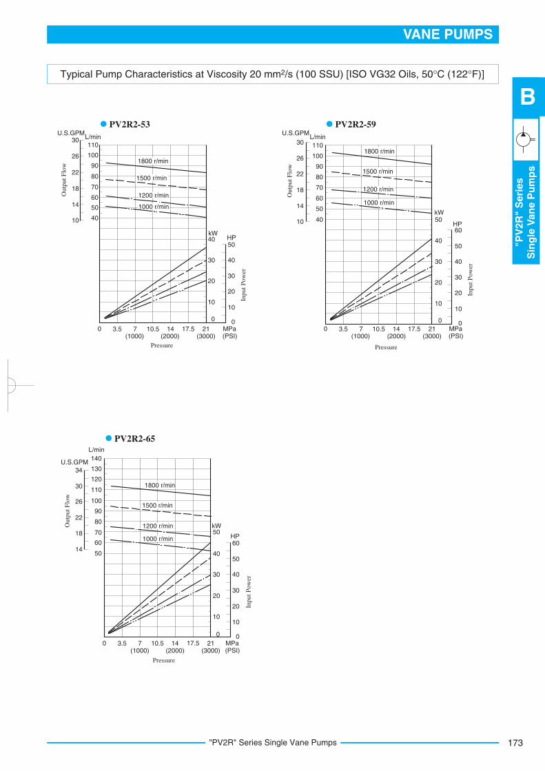
Typical Pump Characteristics at Viscosity 20 mm2/s (100 SSU) [ISO VG32 Oils, 50°C (122°F)]
Ou
tpu
t F
low
L/min
110
U.S.GPM30
26
22
18
10
14
40
50
60
70
80
90
100
Ou
tpu
t F
low
L/min
110
U.S.GPM
30
26
22
18
10
14
40
50
60
70
80
90
100
Ou
tpu
t F
low
L/min
110
U.S.GPM
30
26
22
18
1450
60
70
80
90
100
34
120
130
140
0 3.5 14 21 MPa17.510.57(2000) (3000) (PSI)(1000)
10
0
20
20
0
10
kWHP
Inp
ut
Po
wer
30
Pressure
0 3.5 14 21 MPa17.510.57(2000) (3000) (PSI)(1000)
Pressure
40
30 40
50
10
0
20
20
0
10
HP
Inp
ut
Po
wer
30
40
kW50
30 40
50
60
0 3.5 14 21 MPa17.510.57(2000) (3000) (PSI)(1000)
Pressure
10
0
20
20
0
10
kW
HP
Inp
ut
Po
wer
30
40
30 40
50
60
50
1200 r/min
1000 r/min
1500 r/min
1800 r/min
1200 r/min
1000 r/min
1500 r/min
1800 r/min
1200 r/min
1000 r/min
1500 r/min
1800 r/min
PV2R2-53 PV2R2-59
PV2R2-65

"PV2R" Series Single Vane Pumps174
Typical Pump Characteristics at Viscosity 20 mm2/s (100 SSU) [ISO VG32 Oils, 50°C (122°F)]
0 3.5 14 21 MPa17.510.57(2000) (3000) (PSI)(1000)
Pressure
100
20
40
0
20
kWHP
Inp
ut
Po
wer
6040
30
80
100
50
70
60
Ou
tpu
t F
low
L/min
170U.S.GPM
44
42
34
30
22
26
70
100
120
130
140
150
160
80
90
110
38
18
Ou
tpu
t F
low
L/min
170
U.S.GPM
56
52
44
40
36
100
120
130
140
150
160
90
110
48 180
190
200
210
32
28
24
Ou
tpu
t F
low
L/min
200
U.S.GPM
70
60
50
40
100
120
140
160
180
220
240
260
280
30
0 3.5 14 21 MPa17.510.57(2000) (3000) (PSI)(1000)
Pressure
100
20
40
0
20
kW HP
Inp
ut
Po
wer
6040
30
80
50
60
16(2320)
0 3.5 14 MPa17.510.57(500) (2000) (PSI)(2500)(1500)(1000)
Pressure
100
20
40
0
20
kW
HP
Inp
ut
Po
wer
6040
30
80
50
60
70
80100
120
1200 r/min
1000 r/min
1500 r/min
1800 r/min
1200 r/min
1000 r/min
1500 r/min
1800 r/min
1200 r/min
1000 r/min
1500 r/min
1800 r/min
Ou
tpu
t F
low
L/min
110
U.S.GPM
30
26
22
18
1450
60
70
80
90
100
34
38
120
130
140
0 3.5 14 21 MPa17.510.57(2000) (3000) (PSI)(1000)
Pressure
10
0
20
20
0
10
kW HP
Inp
ut
Po
wer
30
40
30 40
50
60
50
60
70
801200 r/min
1000 r/min
1500 r/min
1800 r/min
PV2R3-94
PV2R4-136PV2R3-116
PV2R3-76
175
VANE PUMPS
"PV
2R
"S
eri
es
Sin
gle
Van
eP
um
ps
B
"PV2R" Series Single Vane Pumps
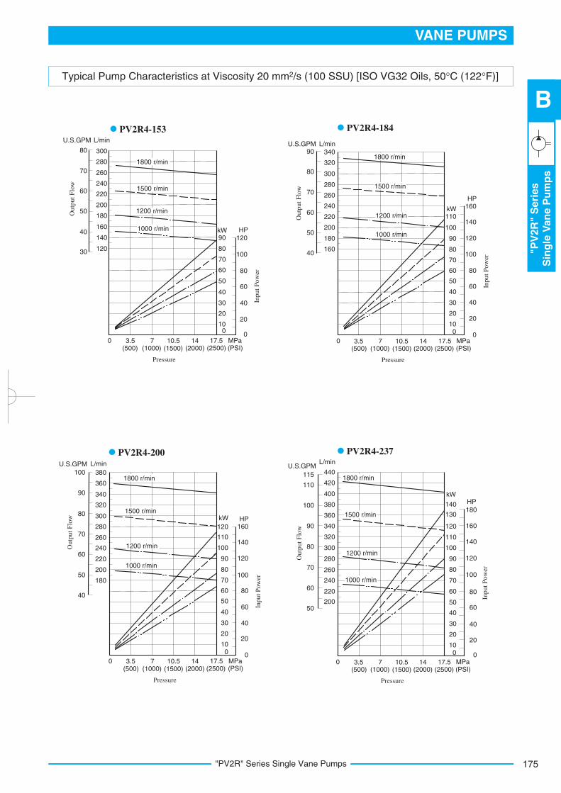
Typical Pump Characteristics at Viscosity 20 mm2/s (100 SSU) [ISO VG32 Oils, 50°C (122°F)]
0 3.5 14 MPa17.510.57(500) (2000) (PSI)(2500)(1500)(1000)
Pressure
100
20
40
0
20
kW
HP
Inp
ut
Po
wer
6040
30
80
100
50
70
60
80
90
100
110
160
140
120
0 3.5 14 MPa17.510.57(500) (2000) (PSI)(2500)(1500)(1000)
Pressure
100
20
40
0
20
kW HP
Inp
ut
Po
wer
6040
30
80
100
50
70
60
80
90
100
110
160
140
120
120
0 3.5 14 MPa17.510.57(500) (2000) (PSI)(2500)(1500)(1000)
Pressure
100
20
40
0
20
kWHP
Inp
ut
Po
wer
6040
30
80
100
50
70
60
80
90
100
110
160
140
120
120
130180
Ou
tpu
t F
low
L/min
340
U.S.GPM90
80
70
60
50
160
220
240
260
280
300
320
40
180
200
Ou
tpu
t F
low
L/min
340
U.S.GPM
90
80
70
60
50
220
240
260
280
300
320
40
180
200
100
360
380
Ou
tpu
t F
low
L/min
340
U.S.GPM
90
80
70
60
50
220
240
260
280
300
320
200
115
360
380
110
100
400
420
440
1200 r/min
1000 r/min
1500 r/min
1800 r/min
1200 r/min
1000 r/min
1500 r/min
1800 r/min
1200 r/min
1000 r/min
1500 r/min
1800 r/min
Ou
tpu
t F
low
L/min
220
U.S.GPM
80
70
60
50
40
120
140
160
180
200
240
260
280
300
30
0 3.5 14 MPa17.510.57(500) (2000) (PSI)(2500)(1500)(1000)
Pressure
100
20
40
0
20
kW HP
Inp
ut
Po
wer
6040
30
80
50
60
70
80
90
100
120
1200 r/min
1000 r/min
1500 r/min
1800 r/min
140
PV2R4-184
PV2R4-200 PV2R4-237
PV2R4-153

"PV2R" Series Single Vane Pumps176
Spare Parts List
Model Numbers
PV2R1-6-*-RAA-42*
PV2R1-8-*-RAA-42*
PV2R1-10-*-RAA-42*
PV2R1-12-*-RAA-42*
PV2R1-14-*-RAA-42*
PV2R1-17-*-RAA-42*
PV2R1-19-*-RAA-42*
PV2R1-23-*-RAA-42*
PV2R1-25-*-RAA-42*
PV2R1-31-*-RAA-42*
Cartridge Kit Numbers4 Model Numbers Cartridge Kit Numbers4
CPV2R1-6-R-42
CPV2R1-8-R-42
CPV2R1-10-R-42
CPV2R1-12-R-42
CPV2R1-14-R-42
CPV2R1-17-R-42
CPV2R1-19-R-42
CPV2R1-23-R-42
CPV2R1-25-R-42
CPV2R1-31-R-42
PV2R2-41-*-RAA-41*
PV2R2-47-*-RAA-41*
PV2R2-53-*-RAA-41*
PV2R2-59-*-RAA-41*
PV2R2-65-*-RAA-41*
PV2R3-76-*-RAA-31*
PV2R3-94-*-RAA-31*
PV2R3-116-*-RAA-31*
PV2R4-136-*-RAA-30*
PV2R4-153-*-RAA-30*
PV2R4-184-*-RAA-30*
PV2R4-200-*-RAA-30*
PV2R4-237-*-RAA-30*
CPV2R2-41-R-41
CPV2R2-47-R-41
CPV2R2-53-R-41
CPV2R2-59-R-41
CPV2R2-65-R-41
CPV2R3-76-R-31
CPV2R3-94-R-31
CPV2R3-116-R-31
CPV2R4-136-R-30
CPV2R4-153-R-30
CPV2R4-184-R-30
CPV2R4-200-R-30
CPV2R4-237-R-30
Item Name of PartsPV2R1 PV2R2 PV2R3 PV2R4
Part NumbersQty.
9
10
11
12
13
14
15
16
17
Oil Seal
O-Ring
O-Ring
O-Ring
O-Ring
O-Ring
Back Up Ring
Back Up Ring
Bearing
ISD 26 42 8
SO-NB-G80
SO-NB-G60
SO-NB-G30
6004
ISD 30 42 8
SO-NB-G105
SO-NB-G85
SO-NB-P46
6205
ISD 35 55 11
SO-NB-G135
SO-NB-G115
SO-NB-A231
6207
ISD 45 68 12
SO-NB-G145
SO-NB-P28
SO-NB-P22A
SO-NA-G130
SO-NA-G80
SO-BE-G130
SO-BB-G80
6209
1
1
1
1
1
1
1
1
1
13 14 15 16
Pump Model Numbers
PV2R1-*-*-RAA-42/4290
PV2R2-*-*-RAA-41/4190
PV2R3-*-*-RAA-31/3190
PV2R4-*-*-RAA-30/3090
Seal Kit Numbers
KS-PV2R1-40
KS-PV2R2-40
KS-PV2R3-30
KS-PV2R4-30
X
X
Y
YSection Y-Y
Section X-X
8 7 6 5
22
23
24
21 2 1 19 3 18
20
26
25
27
28
29
PV2R1-*-*-RAA-42/4290 PV2R2-*-*-RAA-41/4190 PV2R3-*-*-RAA-31/3190 PV2R4-*-*-RAA-30/3090
Cartridge Kits
Seals & Bearings
Note: Item Nos. and (o-rings) and and
(back up rings) are included in cartridge kit.
For pumps for phosphate ester type hydraulic fluids
different part Nos. are used. Please contact us.
When ordering seals, please specify the kit number
from the table right.
1)
2)
12
11
4 10 15 13 14 16 17 9
List of Seal Kits
177
VANE PUMPS
"PV
2R
4A
"S
eri
es
Sin
gle
Van
eP
um
ps
B
"PV2R4A" Series Single Vane Pumps
2
Graphic Symbol
F-
Series
NumberSpecial Seals
F:
For phosphate ester type fluids (Omit if not required)
Nominal
Displacement 3 cm /rev
Design
Standards
Design
Number
(Viewed from Shaft End)
Refer to
PV2R4A -138 -L -R A -10 -*A
Type of
Mounting
Shaft
Rotation
Discharge
Port
Position
Suction
Port
Position
A:Upwards(Normal)
A:Upwards(Normal)
R:Clockwise(Normal)
L:
FootMountingF:FlangeMounting
10PV2R4A 138, 162, 193
Pump
Model
Numbers
PV2R4A
Name
of
Port
Suction
Discharge
Japanese
Standard "JIS"
F5-24-A-10
F5-12-A-10
European
Design
Standard
F5-12-A-1080
N. American
Design
Standard
Japanese Standard "JIS"
European Design
Standard
F5-24-B-10
F5-12-B-10
F5-24-B-1090
F5-12-B-1090
N. American
Design
Standard
Japanese Standard "JIS"
European Design
Standard
F5-24-C-10
F5-12-C-10
F5-24-C-1090
F5-12-C-1090
N. American
Design
Standard
Pipe Flange Kit Numbers
Threaded Connection Socket Welding Butt Welding
Model Number Designation
Pipe Flange Kits
1. Available to supply pump with anti-clockwise rotation.Consult Yuken for details.
Pipe flange kits are available. When ordering, specify the kit number from the table below.
2.Design Standards:None.....Japanese Standard "JIS"
80
90
.........
.........
European Design Standard
N. American Design Standard
Notes: Special seals (Viton seals) are required when phosphate ester type fluids are used. (Prefix "F-" to the pipe flange kit number when ordering.)
Details of the pipe flange kits are shown on page 824.
"PV2R4A" Series Single Vane Pumps
2
1
22
In case of using socket welding flanges, there is a case where the operating pressure should be set lower than the normal because of strength of the
flanges. Therefore, please pay cautious attention to the operating pressure when the socket welding flanges are used.
1.
As dimensions of the pipe flange mounting surface are conformed to SAE 4 Bolt Split Flange (Standard Pressure Series), pipe flanges conforming to
the SAE Standards can be used.
2.
1
1
3
1.
2.
3.
Model Numbers
Geometric Displacement
3 cm /rev (cu.in./rev)
Anti-Wear Type
R & O Type
Petroleum Base Oils
Anti-Wear Type
Water-Glycols
Water Containing Fluids
Max. Operating Pressure MPa (PSI)
Synthetic Fluids
Water Glycols
Water in Oil
Emulsions
Phosphate Esters
Output Flow
& Input Power
Shaft Speed Range
r/min
Max. Min.
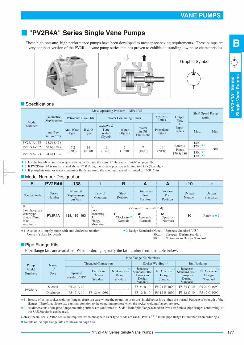
PV2R4A-138
PV2R4A-162
PV2R4A-193
138.5 ( 8.45)
162.6( 9.92)
194.4( 11.86)
17.2(2500)
14 (2030)
16 (2320)
14 (2030)
7 (1020)
7 (1020)
Refer to
Pages
179 & 180
600
1800 (1200)
3
21800 (1200)
Specifications
For the brands of anti-wear type water-glycols , see the item of "Hydraulic Fluids" on page 160.
If PV2R4A-193 is used at speed above 1700 r/min, the suction pressure is limited to 0 kPa (0 in. Hg.).
If phosphate ester or water containing fluids are used, the maximum speed is limited to 1200 r/min.
These high pressure, high performance pumps have been developed to meet space-saving requirements. These pumps are
a very compact version of the PV2R4, a vane pump series that has proven to exhibit outstanding low noise characteristics.

"PV2R4A" Series Single Vane Pumps178
DIMENSIONS INMILLIMETRES (INCHES)
Model Numbers
PV2R4A-*-F-RAA-10
PV2R4A-*-F-RAA-1090
M16
1/2-13 UNC
"C" Thd.
M12
5/8-11 UNC
"D" Thd.
29 (1.14)
21 (.83)
E
Dimensions mm (Inches)
F
22 (.87)
21 (.83)
Flange Mtg.: PV2R4A-*-F-RAA-10/1090
Foot Mtg.: PV2R4A-*-L-RAA-10/1090
For other dimensions, refer to "Flange Mtg.".
Approx. Mass......40 kg (88.2 lbs.)
Approx. Mass......50 kg (110 lbs.)
(1.97)50
(2.62)
66.5
(3.11)79
(5.0
00)
(4.9
98)
127.0
0126.9
5
Discharge Port 36(1.42) Dia.
R15(R.59)
R14(R.55)
(12.54)
(5.83)
(R.63)
(8.39)
(7.126)
(4.41)
(9.3
0) (5
.37)
(4.3
3)
(1.3
91)
(1.3
83)
(1.2
2)
(5.00)
35.7(1.406)
166(6
.54)
Suction Port 76(2.99) Dia.
69
.9(2
.75
2)
7.9
7(.
31
38
)
10
6.4
(4.1
89
) 7.9
4(.
31
26
)K
ey W
idth
35.3
235.1
4
Dia
.
148
R16
"C" Thd. "E" Deep
4 Places
17.5(.689) Dia. Through
2 Places
Port Position
17.5(.689) Dia. Through
26(1.02) Dia. Spotface
4 Places
"D" Thd. "F" Deep
4 Places
A
236.3
127
136.3
318.5
110
181
213
31
112
21(.83)
9(.354)
76(2.99)
(3.000) (3.62)
(5.16) (2.13)
76.2 92
131 54
(5.71)
(.08)
2
23
(4.626) (4.626)
(10.79)
(8.6
4)
(4.3
1)
(.87)
(.91)
117.5 117.5
145
274
219.5
61.9(2.437)
A
109.5
Dia
.31.7
5(1
.25
0)
31.7
0(1
.24
8)
118
(4.65)
22
179
VANE PUMPS
"PV
2R
4A
"S
eri
es
Sin
gle
Van
eP
um
ps
B
"PV2R4A" Series Single Vane Pumps
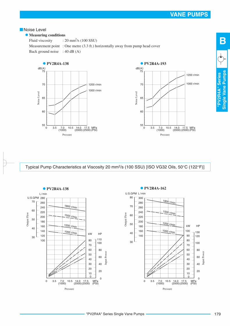
Fluid viscosity
Measurement point
Back ground noise
2 : 20 mm /s (100 SSU)
: One metre (3.3 ft.) horizontally away from pump head cover
: 40 dB (A)
Noise Level
Measuring conditions
PV2R4A-138 PV2R4A-193
7.00 3.5
60
17.514.010.555
65
70
75
No
ise
Lev
el
65
550 3.5
Pressure
7.0 MPa10.5
60
14.0 17.5
70
75
1200 r/min
1000 r/min
1200 r/min
1000 r/min
(1000) (2000) (2500)
No
ise
Lev
el
(1000) (2000) (2500)
Pressure
(PSI) (PSI)MPa
Typical Pump Characteristics at Viscosity 20 mm2/s (100 SSU) [ISO VG32 Oils, 50°C (122°F)]
PV2R4A-162PV2R4A-138
10.57.00 3.5 17.514.0
010
20
30
240
220
200
180
260
Ou
tpu
t F
low
L / min
70
Inp
ut
Po
wer
Inp
ut
Po
wer
50
kW
40
60
80
3.50 10.5 14.07.0 17.5
0
10
20
30
240
220
180
200
260
280
70
50
40
60
90
80
100
100
120
140
160
160
280 300
140
0
20
40
60
80
100
HP
HPkW
Pressure
(1000) (2000)(2500)MPa(PSI)
30
40
50
60
70
U.S.GPM
Ou
tpu
t F
low
30
40
50
60
70
80
(1000) (2000)(2500) (PSI)
Pressure
110
20
0
40
60
80
100
120
130
MPa
L / minU.S.GPM
1800 r/min
1500 r/min
1200 r/min
1000 r/min
1800 r/min
1500 r/min
1200 r/min
1000 r/min

"PV2R4A" Series Single Vane Pumps180
Spare Parts List
PV2R4A-*-*-RAA-10/1090
Typical Pump Characteristics at Viscosity 20 mm2/s (100 SSU) [ISO VG32 Oils, 50°C (122°F)]
PV2R4A-193L / minU.S.GPM
3.50 10.5 14.07.0 17.5
020
40
60
240
220
180
200
320
300
260
280
360
340
80
100
120
160
(1000) (2000)(2500) (PSI)
Pressure
Ou
tpu
t F
low
40
50
60
70
80
90
95
Inp
ut
Po
wer
kW
80
0
40
160
120
HP
MPa
Section X-X
1800 r/min
1500 r/min
1200 r/min
1000 r/min
42
12
16
7
9 1110 1 1513 5 38 6
X
X
Model Numbers Cartridge Kit Numbers4
Cartridge Kits
CPV2R4A-138-R-10
CPV2R4A-162-R-10
CPV2R4A-193-R-10
PV2R4A-138-*-RAA-10*PV2R4A-162-*-RAA-10*PV2R4A-193-*-RAA-10*
Item Name of Parts Part Numbers Qty.
8
9
10
11
15
Oil Seal
O-Ring
O-Ring
O-Ring
Bearing
ISD 45 68 12
SO-NB-G140
SO-NB-A250
SO-NB-G80
6209
1
1 1
1
1
1
Pump Model Numbers
PV2R4A-*-*-RAA-10/1090
Seal Kit Numbers
KS-PV2R4A-10
Seals & Bearings
List of Seal Kits
Note: 1) Item Nos. and (o-rings) are included in cartridge
kit.
2) For pumps for phosphate ester type hydraulic fluids
different part Nos. are used. Please contact us.
When ordering seals, please specify the kit number
from the table below.
10 11

181
VANE PUMPS
"PV
2R
"S
eri
es
Do
ub
leV
an
eP
um
ps
B
"PV2R" Series Double Vane Pumps
Graphic Symbol
"PV2R" Series Double Vane Pumps
2
1
1.
2.
Model Number Designation
-40
Design Number
*
Design Standards
Refer to
42
-L
Mounting
PV2R13 -6Small
Volume Pump
Nominal Displacement
PV2R12
Series Number
Special
seals for
phosphate
ester type
fluids
(Omit if not
required)
F:
F-
Special Seals
Design Standards: None
90
Japanese Standard "JIS" and European Design Standard
N. American Design Standard
...........
...............
3 cm /rev
Large Volume Pump
Nominal Displacement
-76
PV2R13
PV2R23
PV2R33
6, 8
10, 12
14, 17
19, 23
25, 31
26, 33
41, 47
53, 59
65
3 cm /rev
PV2R14
PV2R24
PV2R34
-R
Direction of
Rotation
A
Small Volume Pump
Discharge Port
Position
A
Large Volume Pump
Discharge Port
Position
A
Suction Port
Position
6, 8
10, 12
14, 17
19, 23
25, 31
76, 94
116
41, 47
53, 59
52, 60
66, 76
94, 11665
76, 94
116
76, 94
116
136, 153
184, 200
237
6, 8
10, 12
14, 17
19, 23
26, 33
41, 47
52, 60
66, 76
94, 116
Foot Mtg.
L:
Flange
Mtg.
F:
Clockwise
(Normal)
R:
(Viewed from Shaft End)
Left 45°
Upwards
(Normal)
E:
Upwards
(Normal)
A:
Left 45°
Upwards
(Normal)
E:
Upwards
(Normal)
A:
Upwards
(Normal)
A:
Left 45°
Upwards
(Normal)
E:
Upwards
(Normal)
A:
Upwards
(Normal)
A:
42
41
31
31
32
31
Available to supply pump with anti-clockwise rotation.
Consult Yuken for details.
These double pumps consist of two PV2R seires single pumps combined in tandem within a single housing and driven
by a common shaft. A Single suction port and two discharge ports are provided so that the output flow can be supplied
to separate circuits.

"PV2R" Series Double Vane Pumps182
1
2
33
1.
2.
3.
r/minShaft Speed
600
kW
Inp
ut
Po
wer
0
1000 1200 1500 1800
HP
20
40
60
80
100
120
0
20
40
60
80
100
120
140
160
Allowable Range
Allowable Range
PV2R12
PV2R33
Nominal Displacement
3 cm /rev Anti-Wear Type R & O Type
Petroleum Base Oils
Anti-Wear Type Water
Glycols
Water Containing Fluids
Max. Operating Pressure MPa (PSI)
Synthetic Fluids
Water GlycolsWater in Oil Emulsions
Phosphate Esters
21 (3050)
16 (2320)
6
8
10
12
14
17
19
23
25
31
21 (3050)
26
33
41
47
53
59
65
52
60
66
76
94
136
153
184
200
237
116
21 (3050)
21 (3050)
16 (2320)
14 (2030)
16 (2320)
21 (3050)
21 (3050)
17.5 (2540)
14 (2030)
14 (2030)
16 (2320)
14 (2030)
14 (2030)
14 (2030)
16 (2320)
16 (2320)
16 (2320)
16 (2320)
7 (1020)
7 (1020)
7 (1020)
7 (1020)
7 (1020)
7 (1020)
7 (1020)
7 (1020)
6
8
10
12
14
17
19
23
25
31
26
33
41
47
53
59
65
52
60
66
76
94
116
Nominal Displace-
ment, Small
Volume Pump
Nominal Displacement, Large Volume Pump
26, 33, 41, 47, 53, 59, 65
52, 60 66
76, 94 116
136, 153, 184, 200, 237
PV2R12
PV2R14
PV2R13
PV2R24
PV2R23
PV2R33
PV2R34
Specifications
Maximum Operating Pressure
Note: 1) For the relation between model (series) No. and
nominal displacement, see the table below.
2) As for PV2R12 and PV2R33 series, the sum of the input powers to small
volume pump and large volume pump is limited against shaft speed as
follows.
For pressures above 16 MPa (2320 PSI), raise the speed over 1450 r/min.
If nominal displacement "23", of the PV2R14 series is selected, the
maximum operating pressure is limited to 16 MPa (2320 PSI).
For the brands of anti-wear type water-glycols, see the item of "Hydraulic
Fluids" on page 160.
183
VANE PUMPS
"PV
2R
"S
eri
es
Do
ub
leV
an
eP
um
ps
B
"PV2R" Series Double Vane Pumps
2
2
2
1
2
2
2
3
3
3
3
3
3
3
3
3
3
1.
2.
3.
Model Numbers
PV2R12
PV2R13
PV2R23
PV2R33
PV2R14
PV2R24
PV2R34
Shaft Speed Range r/min
Petroleum Base OilsWater Containing Fluids
Phosphate Esters
Max. Min. Max. Min.
1800
1800
1800
1800 (1500)
1800
1800
1800
750
750
600
600
750
600
600
1200
1200
1200
1200
1200
1200
1200
750
750
600
600
750
600
600
Model Numbers
PV2R13-*-116
PV2R23-*-116
PV2R23-*-76
PV2R23-*-94
PV2R33-*-76
PV2R33-94-*
PV2R33-116-*
PV2R33-*-94
PV2R33-*-116
PV2R14-*-237
PV2R24-*-237
PV2R34-*-237
PV2R34-116-*
Min. Suction Pres. kPa (in. Hg Vacuum)
Less than 1700 r/min 1700 - 1800 r/min
-20 (5.9)
-20 (5.9)
-20 (5.9)
-20 (5.9)
-20 (5.9)
0 (0)
-7 (1.97)
0 (0)
-13 (3.94)
0 (0)
PV2R12
Model Numbers
PV2R13
PV2R33
PV2R14
PV2R23
PV2R24
PV2R34
Output Flow & Input Power
Small Volume Pump Large Volume Pump
Same as single pump "PV2R1", refer to pages 170 - 172.
Same as single pump "PV2R2", refer to pages 172 & 173. However, as for displace- ment of "26" and "33", refer to page 192.
Same as single pump "PV2R2", refer to pages 172 & 173.
Same as single pump "PV2R1", refer to pages
Same as single pump "PV2R3", refer to page 174.
Same as single pump "PV2R1", refer to pages
Same as single pump "PV2R2", refer to page
However, as for displace- ment of "26" and "33", refer to page 192.
Same as single pump "PV2R3", refer to page
However, as for displacement of "52", "60" and "66", refer to pages
Same as single pump "PV2R3", refer to page
However, as for displacement of "52", "60" and "66", refer to pages 192 & 193.
Same as single pump "PV2R3", refer to page
Same as single pump "PV2R3", refer to page
Same as single pump "PV2R4", refer to pages
Model Numbers
Mounting
Flange Mtg.
Foot Mtg.
Approx. Mass kg (lbs.)
PV2R12
25 (55.1)
29.3 (64.6)
PV2R13
45.6 (101)
55.6 (123)
PV2R23
51 (112)
61 (135)
PV2R33 PV2R14
75 (165)
100 (221)
PV2R24
78 (172)
103 (227)
PV2R34
98 (216)
123 (271)
84 (185)
94 (207)
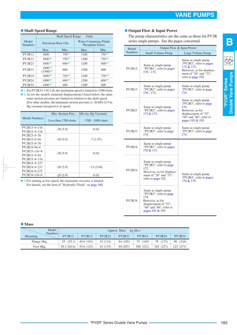
Shaft Speed Range
For PV2R33-116-116, the maximum speed is limited to 1500 r/min.
As for the models (nominal displacements) listed below, the mini-
mum suction pressure are limited in relation to the shaft speed.
[For other models, the minimum suction pressure is -20 kPa (5.9 in.
Hg vacuum) irrespective of speed.
For starting at low speed, the maximum viscosity is limited.
For details, see the item of "Hydraulic Fluids" on page 160.
Output Flow & Input Power
Mass
170 - 172.
170 & 171.
172
192 & 193.
174.
174.
174.
174.
174 & 175.
The pump characteristics are the same as those for PV2R
series single pumps. See the pages concerned.

"PV2R" Series Double Vane Pumps184
Pump
Model
Numbers
PV2R12
PV2R13
PV2R23
PV2R33
PV2R14
PV2R24
PV2R34
Name
of
Port Japanese
Standard "JIS"
European
Design
Standard
N. American
Design
Standard
Japanese Standard "JIS"
European Design
Standard
N. American
Design
Standard
Japanese Standard "JIS"
European Design
Standard
N. American
Design
Standard
Pipe Flange Kit Numbers
Threaded Connection Socket Welding Butt Welding
Suction
Large Discharge
Small Discharge
Suction
Large Discharge
Small Discharge
Suction
Large Discharge
Small Discharge
Suction
Large Discharge
Small Discharge
Suction
Large Discharge
Small Discharge
Suction
Large Discharge
Small Discharge
Suction
Large Discharge
Small Discharge
F5-16-A-10
F5-06-A-10
F5-04-A-10
F5-24-A-10
F5-10-A-10
F5-04-A-10
F5-24-A-10
F5-10-A-10
F5-06-A-10
F5-28-A-10
F5-10-A-10
F5-10-A-10
F5-28-A-10
F5-12-A-10
F5-04-A-10
F5-28-A-10
F5-12-A-10
F5-06-A-10
F5-32-A-10
F5-12-A-10
F5-10-A-10
F5-16-A-1080
F5-06-A-1080
F5-04-A-1080
F5-10-A-1080
F5-04-A-1080
F5-10-A-1080
F5-06-A-1080
F5-10-A-1080
F5-10-A-1080
F5-12-A-1080
F5-04-A-1080
F5-12-A-1080
F5-06-A-1080
F5-12-A-1080
F5-10-A-1080
F5-16-B-10
F5-06-B-10
F5-04-B-10
F5-24-B-10
F5-10-B-10
F5-04-B-10
F5-24-B-10
F5-10-B-10
F5-06-B-10
F5-28-B-10
F5-10-B-10
F5-10-B-10
F5-28-B-10
F5-12-B-10
F5-04-B-10
F5-28-B-10
F5-12-B-10
F5-06-B-10
F5-32-B-10
F5-12-B-10
F5-10-B-10
F5-16-B-1090
F5-06-B-1090
F5-04-B-1090
F5-24-B-1090
F5-10-B-1090
F5-04-B-1090
F5-24-B-1090
F5-10-B-1090
F5-06-B-1090
F5-28-B-1090
F5-10-B-1090
F5-10-B-1090
F5-28-B-1090
F5-12-B-1090
F5-04-B-1090
F5-28-B-1090
F5-12-B-1090
F5-06-B-1090
F5-32-B-1090
F5-12-B-1090
F5-10-B-1090
F5-16-C-10
F5-06-C-10
F5-04-C-10
F5-24-C-10
F5-10-C-10
F5-04-C-10
F5-24-C-10
F5-10-C-10
F5-06-C-10
F5-28-C-10
F5-10-C-10
F5-10-C-10
F5-28-C-10
F5-12-C-10
F5-04-C-10
F5-28-C-10
F5-12-C-10
F5-06-C-10
F5-32-C-10
F5-12-C-10
F5-10-C-10
F5-16-C-1090
F5-06-C-1090
F5-04-C-1090
F5-24-C-1090
F5-10-C-1090
F5-04-C-1090
F5-24-C-1090
F5-10-C-1090
F5-06-C-1090
F5-28-C-1090
F5-10-C-1090
F5-10-C-1090
F5-28-C-1090
F5-12-C-1090
F5-04-C-1090
F5-28-C-1090
F5-12-C-1090
F5-06-C-1090
F5-32-C-1090
F5-12-C-1090
F5-10-C-1090
Pipe Flange KitsPipe flange kits are available. When ordering, specify the kit the number from the table below.
Notes: Special seals (Viton seals) are required when phosphate ester type fluids are used. (Prefix "F-" to the pipe flange kit number when ordering.)
Details of the pipe flange kits are shown on page 824.
In case of using socket welding flanges, there is a case where the operating pressure should be set lower than the normal because of strength of the
flanges. Therefore, please pay cautious attention to the operating pressure when the socket welding flanges are used.
1.
As dimensions of the pipe flange mounting surface are conformed to SAE 4 Bolt Split Flange (Standard Pressure Series), pipe flanges conforming to
the SAE Standards can be used.
2.
2
1
22

185
VANE PUMPS
"PV
2R
"S
eri
es
Do
ub
leV
an
eP
um
ps
B
"PV2R" Series Double Vane Pumps
DIMENSIONS INMILLIMETRES (INCHES)
Model Numbers
PV2R12-*-*-F-REAA-42
PV2R12-*-*-F-REAA-4290
M12
1/2-13 UNC
"C" Thd.
M10
3/8-16 UNC
"D" Thd.
19 (.75)
21 (.83)
J
Dimensions mm (Inches)
K
14 (.55)
16 (.63)
M8
5/16-18 UNC
"E" Thd.
X
9 (.354)
16 (.63)
Large Volume Pump Discharge Port 21(.83) Dia.
Suction Port 53.5(2.11) Dia.
49(1.93)
R9(R.35)
6.3
8
6.3
5(.
25
12
) (.
25
00
)
Key
Wid
th
47
.6(1
.87
4)
22.2 (.874)
42.9 (1.689) "D" Thd. 17(.67) Deep
4 Places"C" Thd. "J" Deep
4 Places
40
(1.57)
55
(2.17)
67 (2.64)
95 (3.74)
326 (12.83)
75
(2.9
5)
14
3(5
.63
)
25
.40
( 1.0
00
0)
25
.35
( .9
98
0)
Dia
.
28
.18
(1.1
09
)
28
.00
(1.1
02
)1
01
.60
1
01
.55
Dia
.
(4.0
00
) (3
.99
8)
120 (4.72)
R14 (R.55)
25
(.9
8)
146 (5.748)
174 (6.85)
129 (5.08)
80 (3.15)
326 (12.83)
60
(2.362)
82 (3.23)
115 (4.35)
47
(1.85)
3
(.1
2)
120 (4.72)
95 (3.740)
230 (9.06)
14(.551) Dia. Through
28(1.10) Dia. Spotface 4 Places
15
(.5
9)
10
2(4
.02
) 18
9(7
.44
)
13.5(.531) Dia. Through 2 Places
A
Suction Port and
Large Volume Pump Discharge Port Position
R10 (R.39)
78
(3.07)
Small Volume Pump Discharge Port
15(.59) Dia.
80 (3.15)
129 (5.08)
70
(2.7
6)
View Arrow X
17.5
(.689
) 38.1 (1.500)
R8(R.31)
40(1.57)"E" Thd. "K" Deep
4 Places
E
58
(2.2
8)
Small Volume Pump
Discharge Port Position
A
95 (3.74)
95 (3.740)
12
5(4
.92
) S
q.
77
.8(3
.06
3)
97 S
q.
(3.8
2)
Flange Mtg.: PV2R12-*-*-F-REAA-42/4290
Foot Mtg.: PV2R12-*-*-L-REAA-42/4290
For other dimensions, refer to "Flange Mtg.".
14
(.55)

"PV2R" Series Double Vane Pumps186
DIMENSIONS INMILLIMETRES (INCHES)
Model Numbers
PV2R13-*-*-F-RAAA-42
PV2R13-*-*-F-RAAA-4290
M16
5/8-11 UNC
"C" Thd.
M10
7/16-14 UNC
"D" Thd.
19 (.75)
21 (.83)
F
Dimensions mm (Inches)
14 (.55)
16 (.63)
M8
5/16-18 UNC
"E" Thd.
19 (.75)
20 (.79)
H J
9 (.354)
21 (.83)
Large Volume Pump
Discharge Port
30(1.18) Dia.
Suction Port 78.5(3.09) Dia.
65(2.56)
R11(R.43)
7.9
7
7.9
4(.
31
38
) (.
31
26
)
Key
Wid
th
58
.7(2
.31
1)
30.2 (1.189)
61.9
(2.437) "D" Thd. "H" Deep 4 Places
"E" Thd. "J " Deep 4 Places
40
(1.57)
63
(2.48)
75 (2.95)
112 (4.41)
370 (14.57)
95
(3.7
4)
18
3(7
.20
)
31
.75
(1.2
50
0)
31
.70
(1.2
48
0)
Dia
.
35
.32
(1.3
91
)
35
.14
(1.3
83
)1
27
.00
1
26
.95
Dia
.
(5.0
00
) (4
.99
8)
148(5.83)
R16 (R.63)
31
(1.2
2)
16
6(6
.54
) S
q.
181 (7.126)
213 (8.39)
120.5 (4.74)
115.5 (4.55)
370 (14.57)
76.2
(3.000)
88 (3.46)
131 (5.16)
50
(1.97)
2
(.0
8)
145 (5.71)
117.5 (4.626)
274 (10.79)
17.5(.689) Dia. Through 26(1.02) Dia. Spotface 4 Places
23
(.9
1)
10
9.5
(4.3
1)
21
7(8
.54
)
17.5(.689) Dia. Through 2 Places
R15 (R.59)
118
(4.65)
Small Volume Pump Discharge Port
15(.59) Dia.
115.5 (4.55)
120.5 (4.74)
90
(3.5
4)
A112
(4.41)
R8(R.31)
38
.1
(1.5
00
)
97
(3
.82
)S
q.
40(1.57)1
06
.4(4
.18
9)
17.5 (.689)
"C" Thd. "F" Deep 4 Places
Port Position
A
58
(2.2
8)
117.5 (4.626)
Flange Mtg.: PV2R13-*-*-F-RAAA-42/4290
Foot Mtg.: PV2R13-*-*-L-RAAA-42/4290
For other dimensions, refer to "Flange Mtg.".
22
(.8
7)

187
VANE PUMPS
"PV
2R
"S
eri
es
Do
ub
leV
an
eP
um
ps
B
"PV2R" Series Double Vane Pumps
DIMENSIONS INMILLIMETRES (INCHES)
Model Numbers
PV2R23-*-*-F-REAA-41
PV2R23-*-*-F-REAA-4190
M16
5/8-11 UNC
"C" Thd.
M10
7/16-14 UNC
"D" Thd.
19 (.75)
21 (.83)
K
Dimensions mm (Inches)
L
19 (.75)
20 (.79)
M10
3/8-16 UNC
"J" Thd.
9 (.354)
21 (.83)
Large Volume Pump Discharge Port 30(1.18) Dia.
Suction Port 78.5(3.09) Dia.
65 (2.56)
R11 (R.43)
7.9
7
7.9
4(.
31
38
) (.
31
26
)
Key
Wid
th
58
.7(2
.31
1)
30.2 (1.189)
61.9
(2.437) "D" Thd. "L" Deep 4 Places"C" Thd. "K" Deep
4 Places
40
(1.57)
63
(2.48)
75 (2.95)
112 (4.41)
403 (15.87)
95
(3.7
4)
18
3(7
.20
)
31
.75
(1.2
50
0)
31
.70
(1.2
48
0)
Dia
.
35
.32
(1.3
91
)
35
.14
(1.3
83
)1
27
.00
1
26
.95
Dia
.
(5.0
00
) (4
.99
8)
148 (5.83)
R16
(R.63)
31
(1.2
2)
181 (7.126)
213 (8.39)
17.5(.689) Dia. Through 2 Places
A
Suction Port and Large Volume Pump Discharge Port Position
R15 (R.59)
118
(4.65)
Small Volume Pump Discharge Port
21(.83) Dia.
115.5 (4.55)
139.5 (5.49)
90
(3.5
4)
View Arrow X
22.2
(.874
) 47.6 (1.874)
R9(R.35)
49(1.93)
"J" Thd. 17(.67) Deep
4 Places
125
(4.9
2)E
70
(2.7
6)
Small Volume Pump Discharge Port
Position
X
16
6(6
.54
) S
q.
Sq.
139.5 (5.49)
115.5 (4.55)
403 (15.87)
76.2
(3.000)
88 (3.46)
131 (5.16)
50
(1.97)
2
(.0
8)
145 (5.71)
117.5 (4.626)
274 (10.79)
17.5(.689) Dia. Through
26(1.02) Dia. Spotface
4 Places
23
(.9
1)
10
9.5
(4.3
1)
21
7(8
.54
)
A112
(4.41)
117.5 (4.626)
10
6.4
(4
.18
9)
Flange Mtg.: PV2R23-*-*-F-REAA-41/4190
Foot Mtg.: PV2R23-*-*-L-REAA-41/4190
For other dimensions, refer to "Flange Mtg.".
22
(.8
7)
"PV2R" Series Double Vane Pumps188
DIMENSIONS INMILLIMETRES (INCHES)
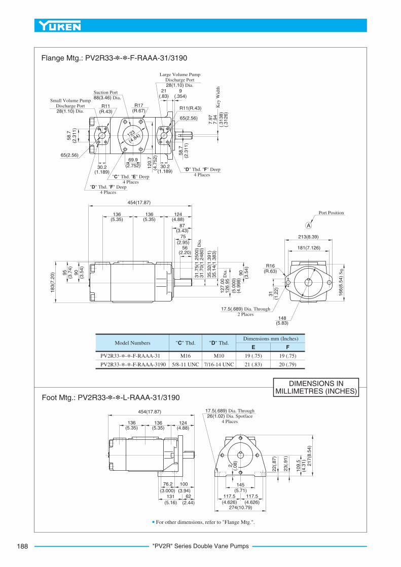
PV2R33-*-*-F-RAAA-31
PV2R33-*-*-F-RAAA-3190
M16
5/8-11 UNC
"C" Thd.
M10
7/16-14 UNC
"D" Thd.
19 (.75)
21 (.83)
E FModel Numbers
Dimensions mm (Inches)
19 (.75)
20 (.79)
A
Small Volume Pump Discharge Port
28(1.10) Dia.
Suction Port 88(3.46) Dia.
R11 (R.43)
"C" Thd. "E" Deep 4 Places
"D" Thd. "F" Deep 4 Places
Large Volume Pump Discharge Port 28(1.10) Dia.
R11(R.43)
"D" Thd. "F" Deep 4 Places
9 (.354)
21 (.83)
R17 (R.67)
65(2.56)
65(2.56) 58
.7(2
.31
1)
58
.7(2
.31
1)
12
0.7
(4.7
52
)69.9
(2.752)30.2 (1.189)
30.2 (1.189)
7.9
7
7.9
4
(.3
13
8)
(.3
12
6)
Key
Wid
th
123
(4.84)
Port Position
R16 (R.63)
213(8.39)
181(7.126)
31
(1.2
2)
148 (5.83)
16
6(6
.54
) S
q.
17.5(.689) Dia. Through 2 Places
454(17.87)
136 (5.35)
136 (5.35)
124 (4.88)
87 (3.43)
75
(2.95)56
(2.20)
31
.75
(1.2
50
0)
31
.70
(1.2
48
0)
Dia
.
35
.32
(1.3
91
) 3
5.1
4(1
.38
3)
12
7.0
0
12
6.9
5D
ia.
(5.0
00
) (4
.99
8)
90
(3.5
4)
95
(3.7
4)
90
(3.5
4)
18
3(7
.20
)
454(17.87)
136 (5.35)
136 (5.35)
124 (4.88)
76.2
(3.000)
131
(5.16)
62
(2.44)
100
(3.94)
17.5(.689) Dia. Through 26(1.02) Dia. Spotface
4 Places
117.5
(4.626)
117.5
(4.626)274(10.79)
145(5.71)
2
(.0
8)
10
9.5
(4.3
1)
23
(.9
1)
21
7(8
.54
)
Flange Mtg.: PV2R33-*-*-F-RAAA-31/3190
For other dimensions, refer to "Flange Mtg.".
Foot Mtg.: PV2R33-*-*-L-RAAA-31/3190
22
(.8
7)

189
VANE PUMPS
"PV
2R
"S
eri
es
Do
ub
leV
an
eP
um
ps
B
"PV2R" Series Double Vane Pumps
DIMENSIONS INMILLIMETRES (INCHES)
Model Numbers
PV2R14-*-*-F-RAAA-32
PV2R14-*-*-F-RAAA-3290
M16
5/8-11 UNC
"C" Thd. "D" Thd.
M12
1/2-13 UNC
M8
5/16-18 UNC
19 (.75)
21 (.83)
14 (.55)
16 (.63)
"E" Thd.F H J
Dimensions mm (Inches)
19 (.75)
21 (.83)
A
A
Large Volume Pump
Discharge Port
36(1.42) Dia.Suction Port 88(3.46) Dia.
Small Volume Pump Discharge Port
13(.51) Dia.
R17 (R.67)
R8(R.31)
13 (.512)
25 (.98)69.9
(2.752)
123
(4.84)
"D" Thd. "H" Deep
4 Places
9.5
6
9.5
3
(.3
76
4)
(.3
75
2)
Key
Wid
th
R13 (R.51)
35.7
(1.406)
40(1.57)17.5
(.689)
"C" Thd. "F" Deep
4 Places
"E" Thd. "J" Deep 4 Places
38
.1(1
.50
0)
97
(3.8
2)
Sq.
423(16.65)
146.5 (5.77)
119.5 (4.70)
135 (5.31)
76
(2.99)
56 (2.20)
38
.10
(1.5
00
0)
38
.05
(1.4
98
0)
Dia
.
42
.36
(1.6
68
) 4
2.1
8(1
.66
1)
15
2.4
0
15
2.3
5D
ia.
(6.0
00
) (5
.99
8)
14
0(5
.51
)
58
(2.2
8)
11
5(4
.53
)
21
7(8
.54
)
Port Position
R22 (R.87)
228.6(9.000)
22
8.6
(9.0
00
)
21.5(.846) Dia. Through
39(1.54) Dia. Spotface (From Rear)
4 Places
273(10.75) Sq.
423(16.65)
146.5 (5.77)
119.5 (4.70)
135 (5.31)
114.3
(4.500)
99
(3.90)
60
(2.36)
185
(7.28)
280(11.02)
187.3
(7.374)
187.3
(7.374)
438(17.24)
18
7.3
(7.3
7)
30
(1.1
8)
32
7.3
(12
.89
)
22(.866) Dia. Through 43(1.69) Dia. Spotface
4 Places
R37(R1.46)
3(.
12
)
For other dimensions, refer to "Flange Mtg.".
Flange Mtg.: PV2R14-*-*-F-RAAA-32/3290
Foot Mtg.: PV2R14-*-*-L-RAAA-32/3290
92 (3.62)
24(.94)
69
.9(2
.75
2)
29
(1.1
4)
12
0.7
(4.7
52
)
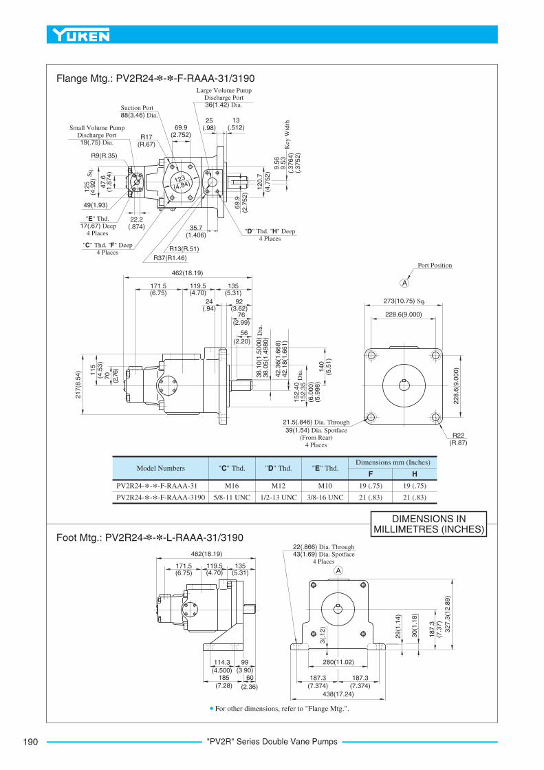
"PV2R" Series Double Vane Pumps190
DIMENSIONS INMILLIMETRES (INCHES)
Model Numbers
PV2R24-*-*-F-RAAA-31
PV2R24-*-*-F-RAAA-3190
M16
5/8-11 UNC
"C" Thd. "D" Thd.
M12
1/2-13 UNC
M10
3/8-16 UNC
19 (.75)
21 (.83)
"E" Thd.F H
Dimensions mm (Inches)
19 (.75)
21 (.83)
A
A
"D" Thd. "H" Deep 4 Places
123
(4.84)47
.6(1
.87
4)
12
5(4
.92
)S
q.
49(1.93)
"E" Thd. 17(.67) Deep
4 Places
"C" Thd. "F" Deep 4 Places
Small Volume Pump Discharge Port
19(.75) Dia.
R9(R.35)
Large Volume Pump Discharge Port 36(1.42) Dia.
Suction Port
88(3.46) Dia.
R17 (R.67)
13 (.512)
25 (.98)69.9
(2.752)
9.5
6
9.5
3(.
37
64
) (.
37
52
)
Key
Wid
th
462(18.19)
171.5 (6.75)
119.5 (4.70)
135 (5.31)
70
(2.7
6)
11
5(4
.53
)
76 (2.99)
56
(2.20)
21
7(8
.54
)
38
.10
(1.5
00
0)
38
.05
(1.4
98
0)
Dia
.
42
.36
(1.6
68
) 4
2.1
8(1
.66
1)
15
2.4
0
15
2.3
5D
ia.
(6.0
00
) (5
.99
8)
14
0(5
.51
)
Port Position
R22 (R.87)
228.6(9.000)
22
8.6
(9.0
00
)
21.5(.846) Dia. Through
39(1.54) Dia. Spotface (From Rear)
4 Places
273(10.75) Sq.
462(18.19)
171.5 (6.75)
119.5 (4.70)
135 (5.31)
114.3
(4.500)
99
(3.90)60
(2.36)
185
(7.28)
280(11.02)
187.3
(7.374)
187.3
(7.374)
438(17.24)
18
7.3
(7.3
7)
30
(1.1
8)
32
7.3
(12
.89
)
22(.866) Dia. Through 43(1.69) Dia. Spotface
4 Places
3(.
12
)
R13(R.51)
35.7
(1.406)
R37(R1.46)
22.2 (.874)
For other dimensions, refer to "Flange Mtg.".
Flange Mtg.: PV2R24-*-*-F-RAAA-31/3190
Foot Mtg.: PV2R24-*-*-L-RAAA-31/3190
92 (3.62)
24(.94)
12
0.7
(4.7
52
)
69
.9(2
.75
2)
29
(1.1
4)

191
VANE PUMPS
"PV
2R
"S
eri
es
Do
ub
leV
an
eP
um
ps
B
"PV2R" Series Double Vane Pumps
DIMENSIONS INMILLIMETRES (INCHES)
Model Numbers
PV2R34-*-*-F-REAA-31
PV2R34-*-*-F-REAA-3190
M16
5/8-11 UNC
"C" Thd. "D" Thd.
M12
1/2-13 UNC
M8
7/16-14 UNC
19 (.75)
21 (.83)
19 (.75)
20 (.79)
"J" Thd.K L N
Dimensions mm (Inches)
19 (.75)
21 (.83)
A
A
E
280(11.02)
187.3
(7.374)
187.3
(7.374)
438(17.24)
18
7.3
(7.3
7)
30
(1.1
8)
32
7.3
(12
.89
)
22(.866) Dia. Through 43(1.69) Dia. Spotface
4 Places
3(.
12
)
Suction Port and Large Volume
Pump Discharge
Port Position
R22(R.87)
228.6(9.000)
22
8.6
(9.0
00
)
21.5(.846) Dia. Through
39(1.54) Dia. Spotface (From Rear)
4 Places
273(10.75) Sq.
99
(3.90)
114.3
(4.500)185
(7.28)
60
(2.36)
518(20.39)
192 (7.56)
133 (5.24)
135 (5.31)
518(20.39)
192 (7.56)
133 (5.24)
135 (5.31)
76 (2.99)
56 (2.20)
X 11
5(4
.53
)
38
.10
(1.5
00
0)
38
.05
(1.4
98
0)
Dia
.
42
.36
(1.6
68
) 4
2.1
8(1
.66
1)
15
2.4
0
15
2.3
5D
ia.
(6.0
00
) (5
.99
8)
14
0(5
.51
)
152
(5.98)
(6.5
4)1
30
.2(5
.12
6)
Small Volume Pump Discharge Port
28(1.10) Dia.
Suction Port
100(3.94) Dia.
R17(R.67)
77.8 (3.063)
25 (.98)
13 (.512)
Large Volume Pump Discharge Port 36(1.42) Dia.
"C" Thd. "K" Deep 4 Places
R13(R.51)
35.7 (1.406)
R37(R1.46)
"D" Thd.
"L" Deep 4 Places
9.5
6
9.5
3
(.3
76
4)
(.3
75
2)
Key
Wid
th
69
.9(2
.75
2)
166 Sq. (1
.189
)30
.2
R11(R.43)
"J" Thd. "N" Deep 4 Places
65(2.56)
(2.311)
58.7
Small Volume Pump Discharge Port
Position
(3.5
4)90
View Arrow X
For other dimensions, refer to "Flange Mtg.".
Flange Mtg.: PV2R34-*-*-F-REAA-31/3190
Foot Mtg.: PV2R34-*-*-L-REAA-31/3190
92 (3.62)
24(.94)
29
(1.1
4)

"PV2R" Series Double Vane Pumps192
Typical Pump Characteristics at Viscosity 20 mm2/s (100 SSU) [ISO VG32 Oils, 50°C (122°F)]
0 3.5 14 21 MPa17.510.57(2000) (3000) (PSI)(1000)
Pressure
20
10
0
30
20
0
10
kWHP
Inp
ut
Po
wer
0 3.5 14 21 MPa17.510.57(2000) (3000) (PSI)(1000)
Pressure
20
10
0
30
20
0
10
kW HP
Inp
ut
Po
wer
30 40
0 3.5 14 21 MPa17.510.57(2000) (3000) (PSI)(1000)
Pressure
20
10
0
30
20
0
10
kW
HP
Inp
ut
Po
wer30 40
40
50
50
60
0 3.5 14 21 MPa17.510.57(2000) (3000) (PSI)(1000)
Pressure
20
10
0
30
20
0
10
kWHP
Inp
ut
Po
wer
30 40
4050
Ou
tpu
t F
low
50U.S.GPM
13
10
L/min
12
8
6
4
1040
30
20
Ou
tpu
t F
low
50
U.S.GPM
14
L/min
12
8
1040
30
206
16 60
Ou
tpu
t F
low
110U.S.GPM28
L/min
24
16
12
20
100
60
40
8
80
90
70
50
30
Ou
tpu
t F
low
110
U.S.GPM30
L/min
26
18
14
22
100
60
4010
80
90
70
50
30
1200 r/min
1000 r/min
1500 r/min
1800 r/min
1200 r/min
1000 r/min
1500 r/min
1800 r/min
1200 r/min
1000 r/min
1500 r/min
1800 r/min
1200 r/min
1000 r/min
1500 r/min
1800 r/min
PV2R12-*-26
PV2R24-26-*PV2R12-*-33
PV2R24-33-*
PV2R23-*-52PV2R34-52-*
PV2R23-*-60PV2R34-60-*

193
VANE PUMPS
"PV
2R
"S
eri
es
Do
ub
leV
an
eP
um
ps
B
"PV2R" Series Double Vane Pumps
Typical Pump Characteristics at Viscosity 20 mm2/s (100 SSU) [ISO VG32 Oils, 50°C (122°F)]O
utp
ut
Flo
w
140
U.S.GPM
32
40
L/min
28
20
16
12
24
120
100
80
130
110
90
70
60
50
20
10
0
70
20
0
10
kWHP
Inp
ut
Po
wer
60
50
40
30
30
40
50
0 3.5 14 21 MPa17.510.57(2000) (3000) (PSI)(1000)
Pressure
1200 r/min
1000 r/min
1500 r/min
1800 r/min
PV2R23-*-66
PV2R34-66-*
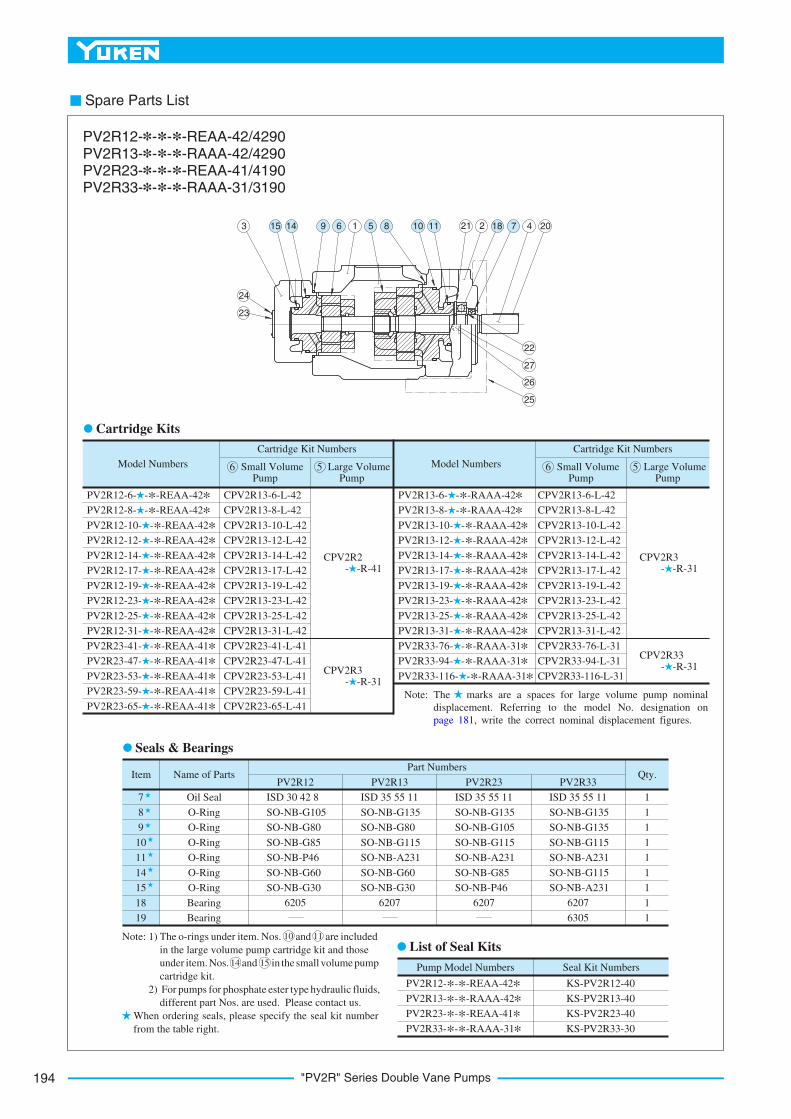
"PV2R" Series Double Vane Pumps194
Spare Parts List
Model Numbers
PV2R12-6- -*-REAA-42*
PV2R12-8- -*-REAA-42*
PV2R12-10- -*-REAA-42*
PV2R12-12- -*-REAA-42*
PV2R12-14- -*-REAA-42*
PV2R12-17- -*-REAA-42*
PV2R12-19- -* -REAA-42*
PV2R12-23- -*-REAA-42*
PV2R12-25- -*-REAA-42*
PV2R12-31- -*-REAA-42*
PV2R23-41- -*-REAA-41*
PV2R23-47- -*-REAA-41*
PV2R23-53- -*-REAA-41*
PV2R23-59- -*-REAA-41*
PV2R23-65- -*-REAA-41*
Cartridge Kit Numbers
CPV2R13-6-L-42
CPV2R13-8-L-42
CPV2R13-10-L-42
CPV2R13-12-L-42
CPV2R13-14-L-42
CPV2R13-17-L-42
CPV2R13-19-L-42
CPV2R13-23-L-42
CPV2R13-25-L-42
CPV2R13-31-L-42
CPV2R23-41-L-41
CPV2R23-47-L-41
CPV2R23-53-L-41
CPV2R23-59-L-41
CPV2R23-65-L-41
Item Name of PartsPV2R12 PV2R13 PV2R23 PV2R33
Part NumbersQty.
7
8
9
10
11
14
15
18
19
Oil Seal
O-Ring
O-Ring
O-Ring
O-Ring
O-Ring
O-Ring
Bearing
Bearing
1
1
1
1
1
1
1
1
1
Pump Model Numbers
PV2R12-*-*-REAA-42*
PV2R13-*-*-RAAA-42*
PV2R23-*-*-REAA-41*
PV2R33-*-*-RAAA-31*
Seal Kit Numbers
KS-PV2R12-40
KS-PV2R13-40
KS-PV2R23-40
KS-PV2R33-30
Small Volume Pump
Large Volume Pump
6 5
CPV2R2 - -R-41
CPV2R3 - -R-31
Model Numbers
PV2R13-6- -*-RAAA-42*
PV2R13-8- -*-RAAA-42*
PV2R13-10- -*-RAAA-42*
PV2R13-12- -*-RAAA-42*
PV2R13-14- -*-RAAA-42*
PV2R13-17- -*-RAAA-42* PV2R13-19- -*-RAAA-42* PV2R13-23- -*-RAAA-42*
PV2R13-25- -*-RAAA-42*
PV2R13-31- -*-RAAA-42*
PV2R33-76- -*-RAAA-31*
PV2R33-94- -*-RAAA-31*
PV2R33-116- -*-RAAA-31*
Cartridge Kit Numbers
CPV2R13-6-L-42
CPV2R13-8-L-42
CPV2R13-10-L-42
CPV2R13-12-L-42
CPV2R13-14-L-42
CPV2R13-17-L-42
CPV2R13-19-L-42
CPV2R13-23-L-42
CPV2R13-25-L-42
CPV2R13-31-L-42
CPV2R33-76-L-31
CPV2R33-94-L-31
CPV2R33-116-L-31
Small Volume Pump
Large Volume Pump
6 5
CPV2R3 - -R-31
CPV2R33 - -R-31
ISD 30 42 8
SO-NB-G105
SO-NB-G80
SO-NB-G85
SO-NB-P46
SO-NB-G60
SO-NB-G30
ISD 35 55 11
SO-NB-G135
SO-NB-G80
SO-NB-G115
SO-NB-A231
SO-NB-G60
SO-NB-G30
ISD 35 55 11
SO-NB-G135
SO-NB-G105
SO-NB-G115
SO-NB-A231
SO-NB-G85
SO-NB-P46
ISD 35 55 11
SO-NB-G135
SO-NB-G135
SO-NB-G115
SO-NB-A231
SO-NB-G115
SO-NB-A231
6205 6207 6207 6207
6305
3 1 21 2 4 20
24
23
22
27
26
25
PV2R12-*-*-*-REAA-42/4290 PV2R13-*-*-*-RAAA-42/4290 PV2R23-*-*-*-REAA-41/4190 PV2R33-*-*-*-RAAA-31/3190
Cartridge Kits
Seals & Bearings
Note: The
in the large volume pump cartridge kit and those
under
cartridge kit.
For pumps for phosphate ester type hydraulic fluids,
different part Nos. are used. Please contact us.
1)
2)
When ordering seals, please specify the seal kit number
from the table right.
15 14 9 6 5 8 10 11 18 7
Note: The marks are a spaces for large volume pump nominal
displacement. Referring to the model No. designation on
page 181, write the correct nominal displacement figures.
o-rings under item. Nos. and are included
item. Nos. and in the small volume pump
10 11
14 15
List of Seal Kits
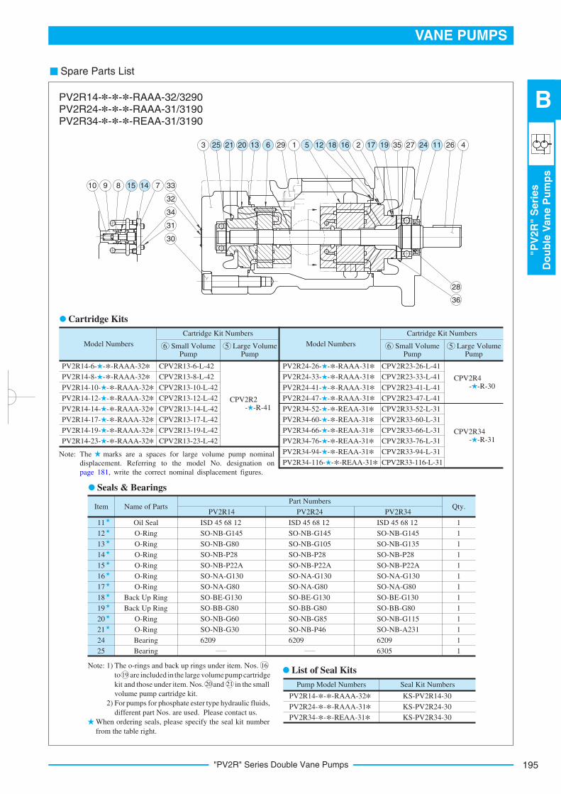
195
VANE PUMPS
"PV
2R
"S
eri
es
Do
ub
leV
an
eP
um
ps
B
"PV2R" Series Double Vane Pumps
Spare Parts List
Model Numbers
PV2R14-6- -*-RAAA-32*
PV2R14-8- -*-RAAA-32*
PV2R14-10- -*-RAAA-32*
PV2R14-12- -*-RAAA-32*
PV2R14-14- -*-RAAA-32*
PV2R14-17- -*-RAAA-32*
PV2R14-19- -*-RAAA-32*
PV2R14-23- -*-RAAA-32*
Cartridge Kit Numbers
CPV2R13-6-L-42
CPV2R13-8-L-42
CPV2R13-10-L-42
CPV2R13-12-L-42
CPV2R13-14-L-42
CPV2R13-17-L-42
CPV2R13-19-L-42
CPV2R13-23-L-42
Item Name of PartsPV2R14
Part NumbersQty.
11
12
13
14
15
16
17
18
19
20
21
24
25
Oil Seal
O-Ring
O-Ring
O-Ring
O-Ring
O-Ring
O-Ring
Back Up Ring
Back Up Ring
O-Ring
O-Ring
Bearing
Bearing
1
1
1
1
1
1
1
1
1
1
1
1
1
Pump Model Numbers
PV2R14-*-*-RAAA-32*
PV2R24-*-*-RAAA-31*
PV2R34-*-*-REAA-31*
Seal Kit Numbers
KS-PV2R14-30
KS-PV2R24-30
KS-PV2R34-30
Small Volume Pump
Large Volume Pump
6 5
CPV2R2 - -R-41
Model Numbers
PV2R24-26- -*-RAAA-31*
PV2R24-33- -*-RAAA-31*
PV2R24-41- -*-RAAA-31*
PV2R24-47- -*-RAAA-31*
PV2R34-52- -*-REAA-31*
PV2R34-60- -*-REAA-31*
PV2R34-66- -*-REAA-31*
PV2R34-76- -*-REAA-31*
PV2R34-94- -*-REAA-31*
PV2R34-116- -*-REAA-31*
Cartridge Kit Numbers
CPV2R23-26-L-41
CPV2R23-33-L-41
CPV2R23-41-L-41
CPV2R23-47-L-41
CPV2R33-52-L-31
CPV2R33-60-L-31
CPV2R33-66-L-31
CPV2R33-76-L-31
CPV2R33-94-L-31
CPV2R33-116-L-31
Small Volume Pump
Large Volume Pump
6 5
CPV2R34 - -R-31
ISD 45 68 12
SO-NB-G145
SO-NB-G80
SO-NB-P28
SO-NB-P22A
SO-NA-G130
SO-NA-G80
SO-BE-G130
SO-BB-G80
SO-NB-G60
SO-NB-G30
6209
CPV2R4 - -R-30
PV2R24 PV2R34
ISD 45 68 12
SO-NB-G145
SO-NB-G105
SO-NB-P28
SO-NB-P22A
SO-NA-G130
SO-NA-G80
SO-BE-G130
SO-BB-G80
SO-NB-G85
SO-NB-P46
6209
ISD 45 68 12
SO-NB-G145
SO-NB-G135
SO-NB-P28
SO-NB-P22A
SO-NA-G130
SO-NA-G80
SO-BE-G130
SO-BB-G80
SO-NB-G115
SO-NB-A231
6209
6305
10 9 8 7 33
32
34
31
30
3 29 1 2 35 27 26 4
28
36
PV2R14-*-*-*-RAAA-32/3290 PV2R24-*-*-*-RAAA-31/3190 PV2R34-*-*-*-REAA-31/3190
Cartridge Kits
Seals & Bearings
Note:
For pumps for phosphate ester type hydraulic fluids,
different part Nos. are used. Please contact us.
1)
2)
When ordering seals, please specify the seal kit number
from the table right.
15 14
25 21 20 13 6 5 12 18 16 17 19 24 11
Note: The marks are a spaces for large volume pump nominal
displacement. Referring to the model No. designation on
page 181, write the correct nominal displacement figures.
The o-rings and back up rings under item. Nos.
to are included in the large volume pump cartridge
kit and those under item. Nos. and in the small
volume pump cartridge kit.
16
19
20 21
List of Seal Kits

"PV2R24A/34A" Series Double Vane Pumps196
"PV2R24A/34A" Series Double Vane Pumps
These double pumps incorporate the new PV2R4A series pumps for the large volume side, a feature that permits discharge
to separate circuits.
1.
2.
Model Number Designation
-10
Design Number
*
Design Standards
2Refer to
-L
Mounting
PV2R24A -26Small
Volume Pump
Nominal Displacement
Series Number
Special
seals for
phosphate
ester type
fluids
(Omit if not
required)
F:
F-
Special Seals
Design Standards: None
90
Japanese Standard "JIS" and European Design Standard
N. American Design Standard
...........
...............
3 cm /rev
Large Volume Pump
Nominal Displacement
-193
PV2R24A
PV2R34A
3 cm /rev
-R
Direction of
Rotation
E
Small Volume Pump
Discharge Port
Position
A
Large Volume Pump
Discharge Port
Position
A
Suction Port
Position
138, 162
193
41,
26,
47
33
53, 59
65
76, 94
116
Foot Mtg.
L:
Flange
Mtg.
F:
1
Clockwise
(Normal)
R:
(Viewed from Shaft End)
Left 45°
Upwards
(Normal)
E:
Upwards
(Normal)
A:
Upwards
(Normal)
A:
Upwards
(Normal)
A:10
10
Available to supply pump with anti-clockwise rotation.
Consult Yuken for details.
Graphic Symbol
Pump
Model
Numbers
PV2R24A
PV2R34A
Name
of
Port Japanese
Standard "JIS"
European
Design
Standard
N. American
Design
Standard
Japanese Standard "JIS"
European Design
Standard
N. American
Design
Standard
Japanese Standard "JIS"
European Design
Standard
N. American
Design
Standard
Pipe Flange Kit Numbers
Threaded Connection Socket Welding Butt Welding
Suction
Large Discharge
Small Discharge
Suction
Large Discharge
Small Discharge
F5-28-A-10
F5-12-A-10
F5-06-A-10
F5-32-A-10
F5-12-A-10
F5-10-A-10
F5-12-A-1080
F5-06-A-1080
F5-12-A-1080
F5-10-A-1080
F5-28-B-10
F5-12-B-10
F5-06-B-10
F5-32-B-10
F5-12-B-10
F5-10-B-10
F5-28-B-1090
F5-12-B-1090
F5-06-B-1090
F5-32-B-1090
F5-12-B-1090
F5-10-B-1090
F5-28-C-10
F5-12-C-10
F5-06-C-10
F5-32-C-10
F5-12-C-10
F5-10-C-10
F5-28-C-1090
F5-12-C-1090
F5-06-C-1090
F5-32-C-1090
F5-12-C-1090
F5-10-C-1090
Pipe Flange KitsPipe flange kits are available. When ordering, specify the kit the number from the table below.
Notes: Special seals (Viton seals) are required when phosphate ester type fluids are used. (Prefix "F-" to the pipe flange kit number when ordering.)
Details of the pipe flange kits are shown on page 824.
In case of using socket welding flanges, there is a case where the operating pressure should be set lower than the normal because of strength of the
flanges. Therefore, please pay cautious attention to the operating pressure when the socket welding flanges are used.
1.
As dimensions of the pipe flange mounting surface are conformed to SAE 4 Bolt Split Flange (Standard Pressure Series), pipe flanges conforming to
the SAE Standards can be used.
2.
2
1
22

197
VANE PUMPS
"PV
2R
24A
/34A
"S
eri
es
Do
ub
leV
an
eP
um
ps
B
"PV2R24A/34A" Series Double Vane Pumps
1
ModelNumbers
Anti-Wear Type R & O Type
Petroleum Base Oils
Anti-Wear Type Water
Glycols
Water Containing Fluids
Max. Operating Pressure MPa (PSI)
Synthetic Fluids
Water GlycolsWater in Oil Emulsions
Phosphate Esters
21
(3050)
14
(2030)
14
(2030)
14
(2030)
21 (3050)
16(2320)
17.2(2500)
14
(2030)
16
(2320)
7
(1020)
7
(1020)
14
(2030)
16
(2320)
7
(1020)
7
(1020)
14
(2030)
16
(2320)
7
(1020)
7
(1020)
Specifications
Maximum Operating Pressure
PV2R24A-26
PV2R24A-33
PV2R24A-41
PV2R24A-47
PV2R24A-53
PV2R24A-59
PV2R24A-65
PV2R34A-76
PV2R34A-94
PV2R34A-116
PV2R24A/34A-*-138
PV2R24A/34A-*-162
PV2R24A/34A-*-193
Shaft Speed Range r/min
Petroleum Base OilsWater Containing Fluids
Phosphate Esters
Max. Min. Max. Min.
1800
1800
600
600
1200
1200
600
600
Approx. Masskg (lbs.)
Flange Mtg. Foot Mtg.
60
(132)
92.5
(204)
70
(154)
102.5
(226)
If the pump is used at speed above 1400 r/min, the suction pressure is limited to 0 kPa (0 in. Hg.).
Model Numbers
PV2R24A
PV2R34A
Output Flow & Input Power
Small Volume Pump Large Volume Pump
Same as single pump "PV2R2", refer to pages
However, as for displace- ment of "26" and "33", refer to page 192.
Same as single pump "PV2R4A", refer to pages
Output Flow & Input Power, Shaft Speed Range and Mass
172 & 173.
Same as single pump "PV2R3", refer to page 174.
179 & 180.

"PV2R24A/34A" Series Double Vane Pumps198
DIMENSIONS INMILLIMETRES (INCHES)
Model Numbers
PV2R24A-*-*-F-REAA-10
PV2R24A-*-*-F-REAA-1090
M16
5/8-11 UNC
"C" Thd. "D" Thd.
M14
1/2-13 UNC
M10
3/8-16 UNC
19 (.75)
21 (.83)
"E" Thd.F H
Dimensions mm (Inches)
22 (.87)
21 (.83)
Flange Mtg.: PV2R24A-*-*-F-REAA-10/1090
Foot Mtg.: PV2R24A-*-*-L-REAA-10/1090
For other dimensions, refer to "Flange Mtg.".
76.2 98(3.86)(3.000)
131 60(5.16) (2.36)
145(5.71)
117.5 117.5(4.626) (4.626)
274(10.79)
21(.83) (.354)
9
69
.9(2
.75
2)
35.7(1.406)
76(2.99)
12
0.7
(4.7
52
)
69.9
(2.752)
56
72.5
85(3.35)
(2.85)
(2.20)
137(5.39)132.5(5.22)
439(17.28)
31
213(8.39)
(7.126)181
(5.83)148
135.5
(5.3
3)
125 sq.(4.92)
70(2
.76)
22.2
(.874
)
(1.874)
47.6
22(.
87)
23(.
91)
109.5
(4.3
1)
244.5
(9.6
3)
A
Discharge Port
Large Volume Pump
"D" Thd. "H" Deep
Suction Port
4 Places
4 Places
4 Places
88(3.46) Dia.
"C" Thd. "F" Deep
R16(R.63)
17.5(.689) Dia. Through
Port Position
A
19(.75) Dia.
Discharge PortSmall Volume Pump
49
17(.67) Deep
4Places
(1.93)
E
"E" Thd.
Small Volume PumpDischarge Port Position
17.5(.689) Dia. Through
26(1.02) Dia. Spotface
4 Places
133(5.24)
110
(4.3
3)
235.5
(9.2
7)
2(.
08)
R17(R.67) R14(R.55)
Key
Wid
th9
.56
(.3
76
4)
9.5
3(.
37
52
)
42.3
6(1
.668)
42.1
8(1
.661)
(5.0
00)
(4.9
98)
Dia
.127.0
0126.9
5
160(6
.30)
Sq.
(1.2
2)
R9(R.35)
123
(4.84)123
(4.84)
Dia
.38.1
0(1
.5000)
38.0
5(1
.4980)
View Arrow X View Arrow Y
X
Y
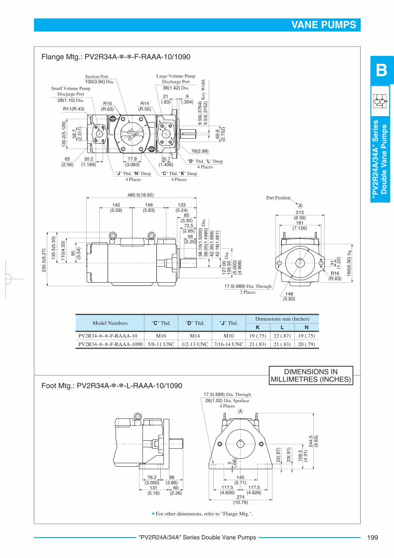
199
VANE PUMPS
"PV
2R
24A
/34A
"S
eri
es
Do
ub
leV
an
eP
um
ps
B
"PV2R24A/34A" Series Double Vane Pumps
DIMENSIONS INMILLIMETRES (INCHES)
Model Numbers
PV2R34-*-*-F-RAAA-10
PV2R34-*-*-F-RAAA-1090
M16
5/8-11 UNC
"C" Thd. "D" Thd.
M14
1/2-13 UNC
M10
7/16-14 UNC
19 (.75)
21 (.83)
19 (.75)
20 (.79)
"J" Thd.K L N
Dimensions mm (Inches)
22 (.87)
21 (.83)
For other dimensions, refer to "Flange Mtg.".
Flange Mtg.: PV2R34A-*-*-F-RAAA-10/1090
* *Foot Mtg.: PV2R34A- - -L-RAAA-10/1090
152
(5.98)
Suction Port 100(3.94) Dia.
Small Volume Pump
Discjarge Port
28(1.10) Dia.
"J" Thd. "N" Deep
4 Places
"C" Thd. "K" Deep
Port Position
4 Places
17.5(.689) Dia. Through
2 Places
"D" Thd. "L" Deep
4 Places
Large Volume Pump
Discharge Port
36(1.42) Dia.
R11(R.43)
77.8
(3.063)
30.2
(1.189)
65
(2.56)
35.7
(1.406)
76(2.99)
R14
(R.55)
21
(.83)
9
(.354)R16
(R.63)
480.5(18.92)
142(5.59)
131(5.16)
60(2.36)
76.2(3.000)
145(5.71)
117.5(4.626)
117.5(4.626)
274(10.79)
244.5
(9.6
3)
109.5
(4.3
1)
2(.
08)
23(.
91)
22(.
87)
98(3.86)
148(5.83)
133(5.24) 213
(8.39)181
(7.126)
A
A
85(3.35)
72.5(2.85)
56(2.20)
152
(5.98)
13
0.2
(5.1
26
)
235.5
(9.2
7)
135.5
(5.3
3)
110(4
.33)
90
(3.5
4)
9.5
3(.
37
52
)K
ey W
idth
9.5
6(.
37
64
)
69
.9
(2.7
52
)
Dia
.
(4.9
98)
(5.0
00)
126.9
5D
ia.
127.0
0
58
.7
(2.3
11
)
(5.83)148
R16(R.63)
31
160(6
.30)
Sq.
(1.2
2)
17.5(.689) Dia. Through
26(1.02) Dia. Spotface
4 Places
38.0
5(1
.4980)
38.1
0(1
.5000)
42.1
8(1
.661)
42.3
6(1
.668)

"PV2R24A/34A" Series Double Vane Pumps200
Spare Parts List
Model Numbers
PV2R24A-26- -*-REAA-10*
Cartridge Kit Numbers
CPV2R23-26-L-41
PV2R24A-33- -*-REAA-10* CPV2R23-33-L-41
PV2R24A-41- -*-REAA-10* CPV2R23-41-L-41
PV2R24A-47- -*-REAA-10* CPV2R23-47-L-41
PV2R24A-53- -*-REAA-10* CPV2R23-53-L-41
PV2R24A-59- -*-REAA-10* CPV2R23-59-L-41
PV2R24A-65- -*-REAA-10* CPV2R23-65-L-41
PV2R34A-76- -*-REAA-10* CPV2R33-76-L-31
PV2R34A-94- -*-REAA-10* CPV2R33-94-L-31
PV2R34A-116- -*-REAA-10* CPV2R33-116-L-31
Item Name of PartsPV2R24A PV2R34A
Part NumbersQty.
6
10
11
12
13
14
15
16
17
Bearing
Oil Seal
O-Ring
O-Ring
O-Ring
O-Ring
O-Ring
O-Ring
Bearing
1
1
1
1
1
1
1
1
1
Pump Model Numbers
PV2R24A-*-*-REAA-10* PV2R34A-*-*-RAAA-10*
Seal Kit Numbers
KS-PV2R24A-10
KS-PV2R34A-10
Small Volume Pump
Large Volume Pump
8 9
CPV2R4A- -R-10
CPV2R34A- -R-10
ISD 45 68 12
SO-NB-G140
SO-NB-G105
SO-NB-G85
SO-NB-P46
SO-NB-A250
SO-NB-G80
ISD 45 68 12
SO-NB-G140
SO-NB-G135
SO-NB-G115
SO-NB-A231
SO-NB-A250
SO-NB-G80
6305
PV2R24A-*-*-*-REAA-10/1090 PV2R34A-*-*-*-RAAA-10/1090
Cartridge Kits
Seals & Bearings List of Seal Kits
Note: The marks are a spaces for large volume pump nominal displacement. Referring to
the model No. designation on page 196, write correct nominal displacement figures.
6209 6209
When ordering seals, please specify the seal kit number from
the table above.
Note: 1) The o-rings under item. Nos. 15 and 16 are included in
the large volume pump catridge kit and those under item.
Nos. 13 and 14 in the small volume pump cartridge kit.
2) For pumps for phosphate ester type hydraulic fluids,
different part Nos. are used. Please contact us.
18
3 1 20 2
19
23
24
4
21
5
14
6
10
13 12 8 9 11 15 16
17
Related Documents