Copyright 2002, IADC/SPE Dril ling Conference This paper was prepared for presentation at the IADC/SPE Drilling Conference held in Dallas, Texas, 26–28 February 2002 This paper was selected for presentation by an IADC/SPE Program Committee following review of information contained in an abstract submitted by the author(s). Contents of the paper, as presented, have not been reviewed by the International Association of Drilling Contractors or the Society of Petroleum Engineers and are subject to correction by the author(s). The material, as presented, does not necessarily reflect any position of the IADC or SPE, their officers, or members. Papers presented at the IADC/SPE meetings are subject to publication review by Editorial Committees of the IADC and SPE. Electronic reproduction, distribution, or storage of any part of this paper for commercial purposes without the written consent of the Society of Petroleum Engineers is prohibited. Permission to reproduce in print is restricted to an abstract of not more than 300 words; illustrations may not be copied. The abstract must contain conspicuous acknowledgment of where and by whom the paper was presented. Write Librarian, SPE, P.O. Box 833836, Richardson, TX 75083-3836, U.S.A., fax 01-972-952-9435. Abstract An extended-reach [ERD] well was planned and successfully drilled in Block 16/26 of the U.K. Central North Sea with water-based drilling fluid in an area where wells have historically been drilled with mineral oil-based and ester-based drilling fluids. With increasingly stringent environmental regulations, the current utilization of mineral oil-based fluids is dependent upon shipping all cuttings back to shore for processing and subsequent disposal, resulting in high supplemental costs. Additionally, potential adverse weather conditions could temporarily preventing the transfer of cuttings from the platform to a supply vessel, thereby curtailing the drilling operations and further increasing drilling costs. The operator realized that significant savings to the current overall well costs could be realized if a water-based drilling fluid system were successfully used to drill the large- diameter hole interval that produced the highest volumes of cuttings. Introduction The drilling program for the Britannia development well B-17 called for the intermediate hole interval to be drilled from the 20-in. casing shoe at ± 3,500 ft MD (± 3,400 ft TVD) to a TD of ± 8,900 ft MD (± 7,600 ft TVD) with a final hole angle of 63 degrees. Selection of the proper drilling fluid system has heretofore been predicated on the use of mineral oil-based and ester-based drilling fluids which provide efficient and cost- effective drilling through highly reactive shales. Usage of mineral oil-based drilling fluids would require containment of the cuttings; however the containment facilities on this platform were considered inadequate for the large diameter hole size planned. The subject of this paper is to discuss the planning, preparation and drilling of the intermediate hole interval on Well B-17 with a water based drilling fluid. Several types of water-based systems have heretofore been used with little success. The need to develop a stable, shale-inhibiting water- based mud system was necessary since there would be a large quantity of cuttings generated in the large diameter interval. Due to the specific well plan, the success of achieving the objective would be dependent upon setting the 13 3/8-in. casing at the end of the build section. This would allow for the target productive zone to be drilled at the optimum angle of attack as predicted by wellbore stability modeling. Well Design and Planning The well discussed in this paper was drilled as an extended- reach platform development well. The planned wellpath is found in Fig. 1. Wellbore stability issues were raised in both the interval containing the kick-off point and in the following interval that contained the tangent section. Information pertinent to both intervals is presented in this paper. Only in the large-diameter interval immediately under the 20-in casing were hole cleaning and hydraulics issues considered particularly demanding. Hence, the hydraulic issues raised in this paper are pertinent only to the large-diameter interval. In this interval, after kicking-off, the angle was planned to build quickly to 40° and held there until near the end of the interval, where hole deviation was planned to increase to 65° from vertical. The choice of a suitable water-based system must be based on the following criteria: • shale inhibition and analysis • mud weight optimization • hole cleaning efficiency IADC/SPE 74545 Successfully Replacing Oil-Based Drilling Fluids with Water-Based Drilling Fluids: Case Study Demonstrates Value of Extensive Planning and Execution in Extended-Reach Well R. Stawaisz and S. Taylor, Britannia Operating Limited, T. Hemphill, SPE, and U. Tare, SPE, Halliburton Energy Services, K. Morton, SPE, Chevron Petroleum Technology Company, and T. Valentine, Flowco Integrated Drilling & Environmental Services Co. Ltd.

Welcome message from author
This document is posted to help you gain knowledge. Please leave a comment to let me know what you think about it! Share it to your friends and learn new things together.
Transcript
8/7/2019 Successfully Replacing Oil-Based Drilling Fluids With Water-Based Drilling Fluids Case
http://slidepdf.com/reader/full/successfully-replacing-oil-based-drilling-fluids-with-water-based-drilling 1/16
Copyright 2002, IADC/SPE Drilling Conference
This paper was prepared for presentation at the IADC/SPE Drilling Conference held in Dallas,Texas, 26–28 February 2002
This paper was selected for presentation by an IADC/SPE Program Committee followingreview of information contained in an abstract submitted by the author(s). Contents of the
paper, as presented, have not been reviewed by the International Association of DrillingContractors or the Society of Petroleum Engineers and are subject to correction by theauthor(s). The material, as presented, does not necessarily reflect any position of the IADC or SPE, their officers, or members. Papers presented at the IADC/SPE meetings are subject topublication review by Editorial Committees of the IADC and SPE. Electronic reproduction,distribution, or storage of any part of this paper for commercial purposes without the writtenconsent of the Society of Petroleum Engineers is prohibited. Permission to reproduce in print isrestricted to an abstract of not more than 300 words; illustrations may not be copied. Theabstract must contain conspicuous acknowledgment of where and by whom the paper waspresented. Write Librarian, SPE, P.O. Box 833836, Richardson, TX 75083-3836, U.S.A., fax01-972-952-9435.
AbstractAn extended-reach [ERD] well was planned and successfully
drilled in Block 16/26 of the U.K. Central North Sea withwater-based drilling fluid in an area where wells have
historically been drilled with mineral oil-based and ester-based
drilling fluids. With increasingly stringent environmentalregulations, the current utilization of mineral oil-based fluids
is dependent upon shipping all cuttings back to shore for
processing and subsequent disposal, resulting in high
supplemental costs. Additionally, potential adverse weather
conditions could temporarily preventing the transfer of cuttings from the platform to a supply vessel, thereby
curtailing the drilling operations and further increasing drilling
costs. The operator realized that significant savings to the
current overall well costs could be realized if a water-baseddrilling fluid system were successfully used to drill the large-
diameter hole interval that produced the highest volumes
of cuttings.
IntroductionThe drilling program for the Britannia development well B-17called for the intermediate hole interval to be drilled from the
20-in. casing shoe at ± 3,500 ft MD (± 3,400 ft TVD) to a TD
of ± 8,900 ft MD (± 7,600 ft TVD) with a final hole angle of
63 degrees. Selection of the proper drilling fluid system hasheretofore been predicated on the use of mineral oil-based and
ester-based drilling fluids which provide efficient and cost-
effective drilling through highly reactive shales. Usage of
mineral oil-based drilling fluids would require containment o
the cuttings; however the containment facilities on this platform were considered inadequate for the large diamete
hole size planned.The subject of this paper is to discuss the planning
preparation and drilling of the intermediate hole interval onWell B-17 with a water based drilling fluid. Several types of
water-based systems have heretofore been used with little
success. The need to develop a stable, shale-inhibiting water-
based mud system was necessary since there would be a large
quantity of cuttings generated in the large diameter intervalDue to the specific well plan, the success of achieving the
objective would be dependent upon setting the 13 3/8-incasing at the end of the build section. This would allow for the
target productive zone to be drilled at the optimum angle o
attack as predicted by wellbore stability modeling.
Well Design and PlanningThe well discussed in this paper was drilled as an extended
reach platform development well. The planned wellpath is
found in Fig. 1. Wellbore stability issues were raised in boththe interval containing the kick-off point and in the following
interval that contained the tangent section. Information
pertinent to both intervals is presented in this paper. Only inthe large-diameter interval immediately under the 20-in casing
were hole cleaning and hydraulics issues considered
particularly demanding. Hence, the hydraulic issues raised inthis paper are pertinent only to the large-diameter interval. In
this interval, after kicking-off, the angle was planned to build
quickly to 40° and held there until near the end of the intervalwhere hole deviation was planned to increase to 65°
from vertical.
The choice of a suitable water-based system must be based
on the following criteria:
• shale inhibition and analysis
• mud weight optimization
• hole cleaning efficiency
IADC/SPE 74545
Successfully Replacing Oil-Based Drilling Fluids with Water-Based Drilling Fluids: CaseStudy Demonstrates Value of Extensive Planning and Execution inExtended-Reach WellR. Stawaisz and S. Taylor, Britannia Operating Limited, T. Hemphill, SPE, and U. Tare, SPE, Halliburton Energy ServicesK. Morton, SPE, Chevron Petroleum Technology Company, and T. Valentine, Flowco Integrated Drilling & EnvironmentalServices Co. Ltd.
8/7/2019 Successfully Replacing Oil-Based Drilling Fluids With Water-Based Drilling Fluids Case
http://slidepdf.com/reader/full/successfully-replacing-oil-based-drilling-fluids-with-water-based-drilling 2/16
2 R. STAWAISZ, S. TAYLOR, T. HEMPHILL, U. TARE, K. MORTON, AND T. VALENTINE IADC/SPE 74545
Once the suitable water-based drilling fluid system wasidentified, work began on optimizing its formulation for
this project.
Shale Inhibition and Analysis. Mineral oil-based drilling
fluids have always provided the most inhibitive drilling fluid
in this area where highly reactive shales are the rule. Thechallenge was to design a water-based drilling fluid system
having performance near that of the mineral oil-based drilling
fluids. An accurate understanding of the nature of shales that
will be encountered is critical to the success of designing a
high performance water-based mud system. It was determined
that a drilling window of no more than 10 days would beallotted to this interval because of the reactive nature of the
formations. Any time spent beyond this would probably result
in deterioration of the hole and resulting in a high risk of ultimately losing the hole.
The shales encountered in the Central Graben area of the
North Sea are some of the most chemically reactive found inany drilling area. These shales are found to contain high
percentages of smectite clays, which are prone to swelling anddispersion. These shales can readily disperse into the mud
system, which decreases control over the rheological
properties of the mud system. Shale analysis consisting of X-ray analysis, cation exchange capacity (CEC) and
exchangeable cations were conducted on cuttings from a
nearby well in the same block. The results are found in Table1. The shales contain a very high concentration of mixed layer
illite/smectite.
The DCM (Dielectric Constant Measurement) technique1
was also used to identify and quantify the risk associated withhydratable and reactive formations as encountered in the
Hordaland Group. A DCM analysis was performed on
(unwashed) cuttings from the 17.5-in hole interval of Well B-15 previously drilled with mineral oil-based drilling fluid. The
DCM provides a quantitative determination of rock properties by measuring the specific surface area per unit weight [m2/g],
thus representing the total hydratable surface area of a cuttings
sample. The DCM is dominated by the presence of smectiteand also strongly influenced by the presence of other
hydratable clays, the presence of which can be correlated with
specific surface areas as shown in the Table 2. The measuredDCM versus depth for this hole interval clearly indicates the
DCM increasing from 250 m2/g at the 20-in casing shoe to a
maximum of 580 m2/g at 7,500 ft TVD in the Alba and
Lothian formations as shown in Fig. 2. The DCM was used
during both the planning and drilling phases and proved to bean invaluable tool. The DCM showed where the most reactive
shales would be encountered and at what point changes in the
mud system should be made.
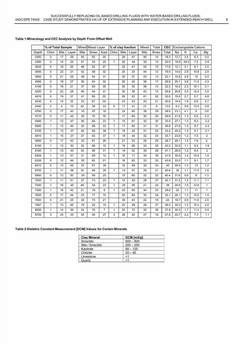
Mud Weight Optimization. Previous wells drilled from the
platform have had trajectories that built hole angles to 82
degrees in the deeper 12.25-in hole interval. The high angle of attack into a problematic shale at 12800-13000 ft TVD has
been a source of several hole instability occurrences. These
instabilities were mainly in the form of hole pack-offs andcollapse primarily due to weak rock strength and laminated
structure of the shale. As a consequence of the borehole
instability issues, a field-scale wellbore stability analysis wasconducted. The modeling used in the wellbore (in)stability
studies has been described previously2,3,4. The angle and
azimuth information at 13,000 ft TVD of two offset wells Aand B are shown on the minimum mud weight predictions
polar chart in Fig. 3. Table 3 contains the data used in the
analysis. Conclusions from the wellbore stability
study included:
• The higher hole angles in directions perpendicular to the
orientation of the maximum horizontal stress requiredhigher mud weights relative to wells drilled in the
directions of the maximum horizontal stress.
• The higher deviation angles required higher mud weights
that were thought to be destabilizing the problem shale on
a time-dependent basis. As a result, the higher densitiesserved to increase mud pressure penetration into the weak
shale laminations, thereby hastening wellbore
instability problems.
• The laminations in the shale limited the angle of attack
due to weak bedding plane-related rock strengthanisotropy. This meant that when the well trajectory was
parallel to the bedding planes more hole collaps
problems were observed as compared to when the wel
trajectory was perpendicular to the bedding planes, whererelatively fewer hole collapse problems were observed.
The findings of the wellbore (in)stability study supportedchanging the well trajectory design for the B-17 well so tha
the problem shale encountered in the 12.25-inch hole interva
would be drilled at lower angle to help reduce instability
problems. This change in the well design required a shallowerdepth for the kick-off point and the build-and-hold section inthe previous large-diameter interval.
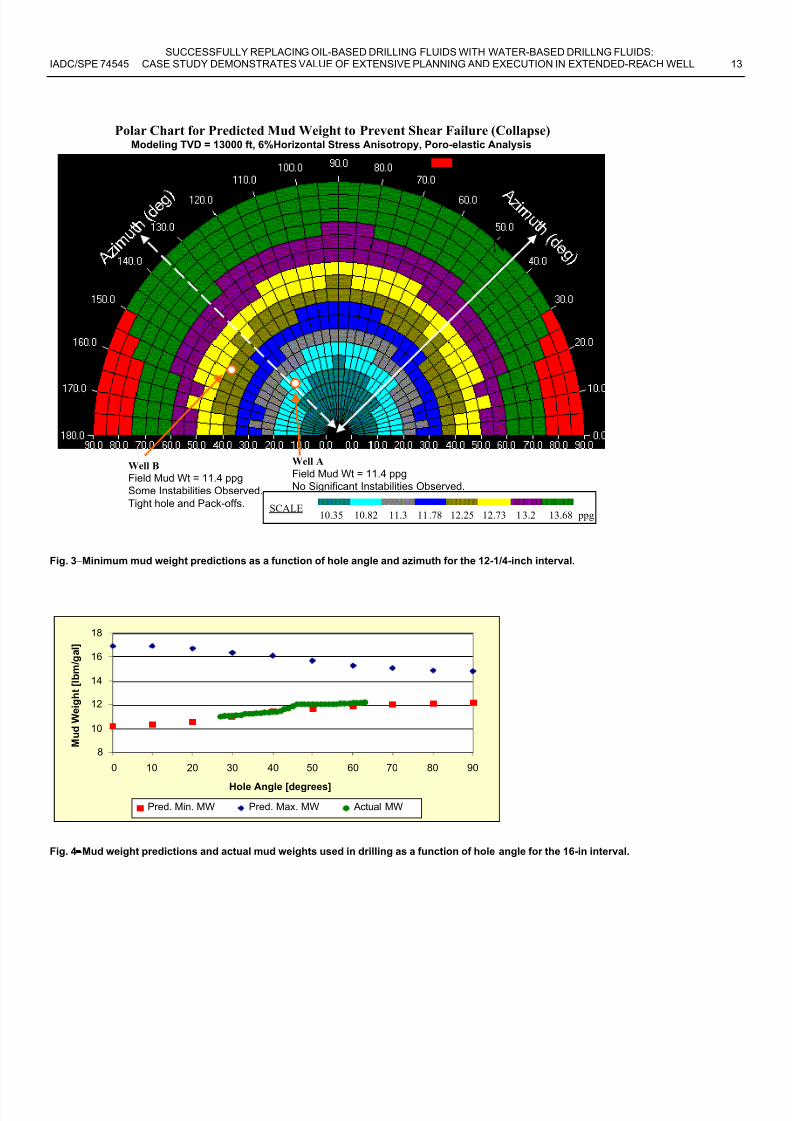
Hole Stability Modeling for the Large-Diameter Interval
After the initial data gathering exercise, a borehole stability
analysis was performed for the large-diameter interval. Table
4 includes the modeling input parameters used. A mud weightschedule with an initial mud weight of 11.5 lbm/gal and a fina
mud weight of 12.5 lbm/gal was developed as a result of
wellbore stability studies and offset data. The predicted mud
weights were based upon the anticipated hole angle with
depth. The minimum mud weights necessary to initiate hole
collapse and breakdown are depicted graphically in Fig. 4. Forany increases in mud weight above the 12.5 lbm/gal level, care
must be taken to avoid differential sticking across any
permeable zones encountered while drilling the section.
Hole Cleaning Efficiency Modeling. Once the mud weights
required to maintain a stable borehole were identified, the prewell planning study then focused on hole cleaning in the large
diameter interval below the 20-in casing. The hole cleaning
calculation methodology used in this paper was developed

8/7/2019 Successfully Replacing Oil-Based Drilling Fluids With Water-Based Drilling Fluids Case
http://slidepdf.com/reader/full/successfully-replacing-oil-based-drilling-fluids-with-water-based-drilling 3/16
SUCCESSFULLY REPLACING OIL-BASED DRILLING FLUIDS WITH WATER-BASED DRILLNG FLUIDS:IADC/SPE 74545 CASE STUDY DEMONSTRATES VALUE OF EXTENSIVE PLANNING AND EXECUTION IN EXTENDED-REACH WELL 3
from earlier steady-state hole cleaning modeling work 5.6. Key
parameters involved in hole cleaning modeling include:
• Mud density
• Fluid rheological parameters
• Cuttings size and shape
• Pump rate• Hole geometry
• Drill pipe eccentricity
• Hole angle
Since publication of the earlier papers, two more major
factors were integrated into the calculations. These factors,
described by others 7,8 include:
• Drill pipe rotation
• Rate of penetration
To quickly summarize the model’s numerical methods, the
following important items are calculated:
• The fluid rheological parameters are calculated using the
Herschel-Bulkley rheological model. The numerical
model and its parameters have been
described previously9.
• With estimated values for drill pipe eccentricity, the point
velocities in all sections of the annulus are calculatedusing numerical techniques.
• Particle settling velocities for both static and dynamic
cases are calculated using the methodology proposed
earlier by Chien 10.
• A fine-mesh grid scheme valid for eccentric wellbores isused to model the annulus cleaning efficiency.
• The volume of cuttings removed by drill pipe rotation for the input drilling conditions is approximated and adjusted
for ROP.
• Dimensionless cuttings bed height predictions are
calculated as fractions of the annular diameter projectedto be covered by a permeable cuttings bed. This
prediction corresponds to the case where flow rate and
drill pipe rotation ceases and all cuttings settle on the low
side of the hole.
• With the effect of drilled cuttings taken into account, the
calculated pressure drops and circulating annular muddensities for each section of a wellbore are integrated
together to arrive at a final annular mud weight and ECD.
Hole Cleaning Simulations. Once the proper mud weight wasdetermined for use in drilling the large-diameter interval
below the 20-in casing shoe, hole cleaning and hydraulic
simulations were initiated. The goal of the extensive pre-wellsimulation process was to determine the ranges of various
drilling fluid and operational parameters that would provide
good hole cleaning while drilling with WBM and keep ECD
below the fracture gradient at the 20-in casing shoe.
Many variables were investigated in the pre-well planning
process, which included:
• hole diameter: 17.5-in and 16-in
• drill pipe size: 5.5-in and 6.625-in
• hole deviation: 40° and 65°
• average cuttings diameter: 0.25-in to 0.75-in• drill pipe rotation speed: 50 – 110 rev/min
• drilling fluid rheological properties
A water-based drilling fluid having the rheologica
properties and density given in Table 2 [Fluid 1] served as the
principal test case for hydraulic simulations. As this fluid was
a WBM subjected only to moderate temperature and pressureconditions downhole, surface fluid density and rheologica
properties were not adjusted for downhole condition
However simulations were later run to help determine the
effect of increasing the WBM rheological properties onhole cleaning.
Hole angle. Two hole angles were used in the simulations
40° for the upper part and 65° for a short section near the
bottom of the 16-in interval.
Hole and drill pipe sizes. All hole cleaning modeling was
done using two hole ID and two drill pipe OD sizes. The
operator had a two-fold purpose here:
1. They wanted to see how much worse cleaning would be
with a 17.5-in bit compared to cleaning with a 16-in bit.
2. With each hole diameter, the operator wanted to compare predicted cleaning with 5.5-in drill pipe compared with
that using 6.625-in drill pipe.
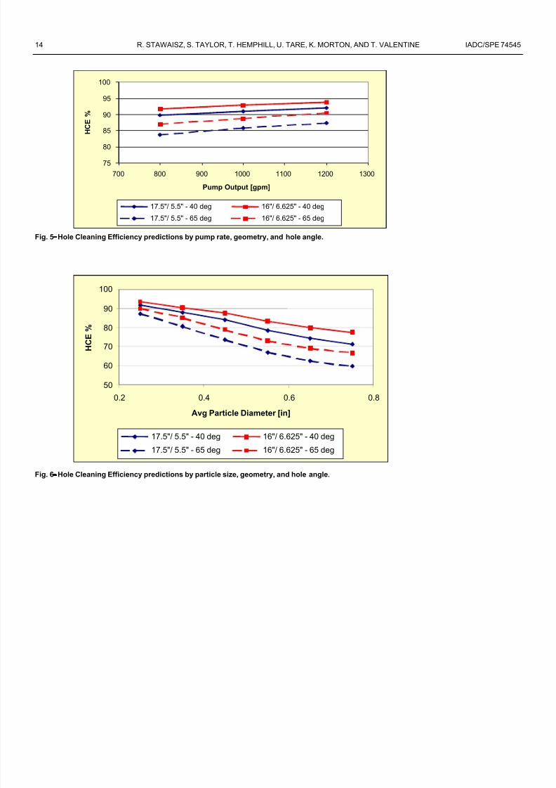
In Fig. 5, cleaning simulation results are shown for the 2
hole-size / drill pipe combinations at 40° and 65° from
vertical. These 2 simulations represent the best and wors
cases. The results at 40° show that good cleaning was to be
expected for 0.25-in diameter cuttings at the pump rates usedin the simulations. As expected, cleaning efficiencies
improved with increasing pump rate and smaller hydraulic
diameter. In the simulations at 65°, HCE predictions were
lower than those at 40°. Moreover, the spread between thesimulation results widened significantly.
Average particle diameter . The effect of particle diameter on
hole cleaning was also investigated. Particle size can
significantly affect particle slip velocity under staticconditions, and the effect is even greater under dynamic
conditions. In the simulations performed here, a range of
particle sizes from 0.25-in to 0.75-in average diameter wasimulated for the two deviation angles.
Fig. 6 shows the simulation results for the 2 hydraulic
diameter cases at 40° and 65° from vertical. In thesesimulations, pump output was held at 1000 gpm with 80
8/7/2019 Successfully Replacing Oil-Based Drilling Fluids With Water-Based Drilling Fluids Case
http://slidepdf.com/reader/full/successfully-replacing-oil-based-drilling-fluids-with-water-based-drilling 4/16
4 R. STAWAISZ, S. TAYLOR, T. HEMPHILL, U. TARE, K. MORTON, AND T. VALENTINE IADC/SPE 74545
rev/min rotation speed on the drill pipe. As expected, theresults show that cleaning efficiency decreases with increasing
particle size, and the effect is more pronounced at the higher
hole angle. These results indicated to the operator that a less-aggressive bit that would cut smaller cuttings would be
preferred given the operational constraints of this interval
[large-diameter hole, pump pressure limits, etc].
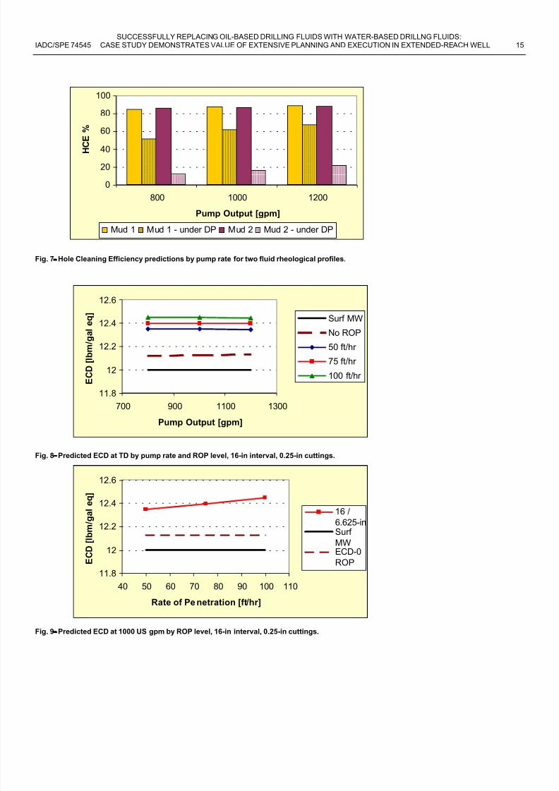
Fluid rheological properties. As part of the optimization
process in the pre-well planning phase, the effect of increasing
fluid rheological properties on hole cleaning was investigated.
A WBM having elevated rheological parameters as listed inTable 4 was included in the simulation matrix.
HCE predictions by pump output for the entire annulus are
shown in Fig. 7 for the two WBM rheological profiles. Here
the average cuttings diameter and drill pipe rotation speedwere held at 0.25-in and 80 rev/min respectively. Results show
little apparent change in cleaning for the two cases simulated.
However, velocity modeling studies in eccentric wellborehave clearly demonstrated that there can be a wide divergence
in fluid velocity above and below the eccentric drill pipe.Increased fluid rheological properties serve to exacerbate the
resulting flow diversion, often resulting in little to no flow
under the drill pipe. With no fluid movement under the drill pipe, cleaning at elevated hole angles suffers. Hence to
properly evaluate cleaning in eccentric wellbore, cleaning
under the drill pipe must also be investigated6.In these studies, the annular area lying immediately under
the rotating drill pipe was also evaluated for cleaning
efficiency. Except for cases where the drill pipe is in a
concentric position, cleaning in the narrow part of the annulusshould never be as efficient as it is in the wide part of the
annulus. However, for good hole cleaning performance at
elevated hole angles in the field, HCE values should not hover at the 0 or near-zero level. At these very low levels of HCE,
cleaning is nearly entirely dependent upon the mechanicaleffects of drill pipe rotation.
Fig. 7 demonstrates that the higher-viscosity Fluid 2 would
clean under the drill pipe much less efficiently than the baseFluid 1. Cuttings removal under the drill pipe for Fluid 2
ranges between 25-33% of that for Fluid 1. In the 65° sectionnear the end of the large-diameter interval, use of a high-
viscosity fluid to enhance drilling performance is
not recommended.
Hole Cleaning Modeling Results Summary. A number of
significant observations were made on the basis of thecleaning modeling results:
• The 17.5-in hole size originally planned was scaled back to 16-in as it was apparent that hole cleaning efficiency in
the large-diameter interval would be greatly improved by
reducing the bit diameter alone. Moreover, it was
assumed that the 16-in hole would be washed out
somewhat due to the dispersive nature of the formationwhen drilled with a water-based mud system.
• The higher the deviation, the more difficult is the holecleaning, even when the cuttings are small for the 17.5-in
hole. A 16-in hole is somewhat easier to clean and
improvements in hole cleaning are seen with large drill
pipe and higher pipe rotation compared to a 17.5-in hole.
• The larger the cutting, the less efficient will be the
hole cleaning.• More viscous drilling fluid [Mud 2 vs. Mud 1] does no
improve the hole cleaning.
• A 16-in hole at 40° and 65° degrees from vertical is easierto clean than a 17.5-in hole at the same angles
of deviation.
Predicted Equivalent Circulating Density [ECD]With the results of the hole cleaning simulations in hand
predictions of ECD with cuttings in the annulus were made
using the following input parameters:
• Hole ID 16-in
•Drill pipe OD 5.5-in and 6.625-in
• Pump output 800 – 1200 US gal/min
• Rate of penetration 50 – 100 ft/hr
• Average cuttings diameter 0.25-in
Fig. 8 shows the ECD predictions at TD by pump rate in
the 16-in/6.625-in interval for 0.25-in cuttings. Circulating
with no ROP gave baseline ECDs of 12.12-12.13 lbm/gal eqWith the ROP levels simulated, ECDs were predicted to rise to
12.35 - 12.45 lbm/gal eq. As expected, the higher the rate of
penetration, the higher the predicted ECD. In Fig. 9, only the
data at 1000 US gal/min is shown, and the predicted increasein ECD with increasing ROP is more evident. These predicted
ranges were well within the operator’s pore pressure–formation fracture gradient window [greater than14.0 lbm/gal expected].
Drilling Fluid SelectionVarious types of water based muds have been tried in this
interval and generally have had little success in achievinggood hole stability. The shales are very reactive and poor
performance from these fluids has resulted in stuck pipe, poor
drilling performance, and on some wells, losing the hole. Useof mineral oil-based or ester-based drilling fluids have no
eliminated the wellbore stability problem, as on occasion
sidetracks have had to be drilled. Since the platform does nothave a large capacity for storing cuttings while drilling a large
diameter hole with a mineral oil-based mud, the need for awater based mud to drill this interval became even more
important. A review of various water-based muds was
conducted to determine which system would be the best fluidchoice for drilling these chemically reactive shales. It was
determined that the drilling fluid would be an integra
component for success but other factors such as hole cleaning
proper mud rheological and density properties and solidcontrol would also play a major role in the success.

8/7/2019 Successfully Replacing Oil-Based Drilling Fluids With Water-Based Drilling Fluids Case
http://slidepdf.com/reader/full/successfully-replacing-oil-based-drilling-fluids-with-water-based-drilling 5/16
SUCCESSFULLY REPLACING OIL-BASED DRILLING FLUIDS WITH WATER-BASED DRILLNG FLUIDS:IADC/SPE 74545 CASE STUDY DEMONSTRATES VALUE OF EXTENSIVE PLANNING AND EXECUTION IN EXTENDED-REACH WELL 5
Based on the review of various drilling fluid candidates, it
was determined that a KCl/Polymer system was the bestchoice. The other water-based mud systems considered were:
• Silicate system
• KOH/lime system
• Calcium chloride system• Sodium chloride system.
These other systems had limitations that disqualified themfor further consideration. The silicate mud system had been
used by another operator on a nearby well in a similar interval
and had numerous problems with this system and ultimately
displaced to a mineral oil-based mud. Calcium chloride mudshave been used in the Gulf of Mexico but not in the North Sea
and problems controlling the fluid loss and rheological
properties have been reported. A KOH/Lime system had
previously been used on a nearby well with less than desired
results. Sodium chloride based systems have been used in the
North Sea with mixed results. Because of the high swellingcontent of the shales present, the NaCl-based system was not
predicted to be very successful in application here.
Drilling Fluid Formulation. The formulation for the whole mud dilution volume wasdivided into two sections based on the DCM results. This
volume was built by blending premix, brine and drillwater
with the required products in order to achieve the desired
formulation. Prior to use, all dilution volume was weighted
with barite to within ±0.3 lbm/gal of the active mud weight.
The most important aspect regarding the use of water-based
muds is the judicious use of whole mud dilution. Additionally,active mud volume should be dumped as required to maintain
continuous and adequate whole mud dilution. The plan was to
minimize the requirement for adding products directly to theactive system. As depicted by the DCM, the mud system
would be formulated initially with a KCl concentration of 30-
50 lbm/bbl [8.6–14.3 wt%] KCl. A fully soluble glycol was
also programmed at a concentration of 3-4% by volume. This
system was planned to drill down to top of the Alba formation
[± 6500 ft TVD]. The formulation for this section is found in
Table 5. At this depth, there was a substantial increase in theDCM surface area indicating a more chemically reactive
formation would be encountered to the total depth of the
interval. The mud system was then modified to increase KClconcentration to 50-60 lbm/bbl [14.3-17.2 wt%], maintain the
same glycol concentration as before, and begin additions of ashale-stabilizing surfactant. The formulation for the interval
below the Alba formation is also found in Table 5.The proprietary shale-stabilizing surfactant has been used
with good results by the operator on Gulf of Mexico wells.
The shales in this section are very reactive and it was
concluded that the mud system should be formulated with allrequired additives that would provide the most inhibition that
could be attained in the water-based mud system. It was
emphasized that the shale-stabilizing additives should be
added to and maintained in the active mud system prior todrilling the reactive intervals.
LogisticsPit volume requirements were reviewed prior to drilling this
section to ensure that there would be sufficient volumeavailable to mix and store the required mud and to carry ou
the necessary dilution of the premix with drillwater. A total of
3250 bbl available volume was identified.A total volume of 2800 bbls of concentrated KCl brine (70
lbm/bbl) was prepared and shipped to the rig. The
concentrated brine would be cut back as required with
drillwater. Drillwater is preferable to seawater, since the latterwill require pre-treatment to remove divalent ions before
blending with premix. If drillwater stocks were depleted, i
was planned to use pre-treated seawater to blend withthe premix.
A minimum of 3000 bbl of KCl polymer premix was
predicted to be required for this interval; 2000 bbl of which
could be shipped to the rig before the beginning of the sectionwith a second batch of premix being shipped out at a laterdate, when required. Due to logistical and surface pit
constraints it was not considered possible to offload all the
KCl polymer premix prior to displacing the well to KC polymer water based mud. All premixes were to be agitated on
a regular basis to ensure homogeneity of the batches.
Drilling Parameters and Guidelines
• It was determined that the rate of penetration would be
limited in order that an annular cuttings load of 4% byvolume would not be exceeded. This essentially limited
the ROP to a maximum of 150 ft/hr at the minimum
circulating rate of 1000 gpm.• In the event of mud pump failure, it was decided tha
drilling would be suspended if the circulating rate fel
below 1000 US gal/min and only be continued when 1000
US gal/min could be re-established.
• Frequent wiper trips were considered to be essential inorder to determine the hole condition.
• The level of overpull required for tripping out of the hole
is one of the most accurate indicator on the rig with whichto determine the degree of hole cleaning efficiency
Torque and drag levels were to be monitored while
drilling the large-diameter interval.
• It was decided that the hole would be circulated clean
based on visual confirmation at the shakers prior to wipertrips and no arbitrary time limits on the time taken for the
shakers to clean up were set.
• Adequate and constant rotation of the drillstring wasconsidered to be critical with respect to hole cleaning
particularly in the tangent section. Therefore, in order to
optimize hole cleaning the drillstring would be constantly
rotated at a minimum of 120 rev/min with the only
exception being sliding during the two build sections.

8/7/2019 Successfully Replacing Oil-Based Drilling Fluids With Water-Based Drilling Fluids Case
http://slidepdf.com/reader/full/successfully-replacing-oil-based-drilling-fluids-with-water-based-drilling 6/16
8/7/2019 Successfully Replacing Oil-Based Drilling Fluids With Water-Based Drilling Fluids Case
http://slidepdf.com/reader/full/successfully-replacing-oil-based-drilling-fluids-with-water-based-drilling 7/16
SUCCESSFULLY REPLACING OIL-BASED DRILLING FLUIDS WITH WATER-BASED DRILLNG FLUIDS:IADC/SPE 74545 CASE STUDY DEMONSTRATES VALUE OF EXTENSIVE PLANNING AND EXECUTION IN EXTENDED-REACH WELL 7
volume at TD. The glycol concentration was determined by
use of a hand held refractometer that proved to be easy to use,accurate and reliable.
An initial 4 lbm/bbl treatment of the proprietary shale
stabilizing surfactant was the principal exception to direct product addition to the active mud system. The treatment was
added while drilling prior to entering the Alba formation.There was a noticeable improvement in the cuttings integrity
and also cuttings travel on the screens after the initial
treatment. It was decided to maintain a product concentration
of ± 4 lbm/bbl thereafter. Moreover, there was no increase in
the rheological properties with additional of the material, afeature that is desirable for a shale inhibition agent. It is
somewhat difficult to quantify the value of the shale-
stabilizing surfactant as this is the only use to date in theregion and offset comparative data is not available. However,
the proprietary surfactant is considered an essential component
for any similar intervals drilled with KCl polymer water-based
fluids in the future.
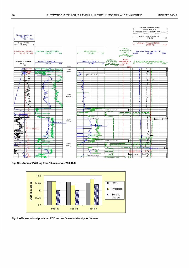
Actual Equivalent Circulating Densities. Pressure-while-
drilling tools were used while drilling the well to monitor
downhole circulating pressures. Fig. 10 shows an example
section from the PWD log as measured on well B-17. In thissegment from the 16-in interval, the ECD is measured to be
about 0.1 lbm/gal higher than the static mud density. Three
points near the end of the large diameter interval were selectedfor study of circulating ECD. For each of the selected points,
rotary drilling operations were in progress [e.g., no sliding]
and all necessary data including BHA configuration were
available. Actual PWD results were compared with resultsusing the same hydraulic / hole cleaning model used in the
pre-well planning. Key drilling parameters used in the
comparison are found in Table 3.The results show very good agreement between the model
predictions and actual field data. Average errors in ECD
predictions were:
• Average error 0.073 lbm/gal eq
• Average % error 0.60 %
Fig. 11 shows the measured and predicted ECD and actual
mud weights for the three cases. As noted earlier, pre-well
predictions of ECD under simulated drilling conditions rangedfrom 12.35-12.45 lbm/gal eq. Some differences in ECD values
between the predictions and the actual are expected since
various drilling parameters [e.g., ROP, drill pipe rpm, fluidrheology, etc.] used while drilling were different from those
used in the simulations. The results show that predictionsmade in the pre-well planning process can closely
approximate field results when similar operating parameters
are used. With enhanced advances in hydraulic modeling,these predictions are now better than “ballpark” estimates.
Drilling AccomplishmentsThere were several accomplishments during this first attempto drill the chemically reactive interval with a water based
mud system. The accomplishments were as follows:
• Two build sections - one at 40° and the other at 63° were
drilled successfully and there were no reportedsliding problems.
• There was minimal overpull on trips which was attributed
to good hole cleaning in the highly deviated interval.
• The 13 3/8-in casing was successfully run with minima
problems to the programmed depth.
• No wiper trip was required prior to running the 1
3/8-in casing.
• No down time related to mud related incidents and th
interval was drilled within the prescribed time frame.
• Hole conditions and cuttings integrity were excellen
throughout the interval.
• There was no downtime related to dilution volume
handling on the rig.
ConclusionsKey conclusions that come from this study include:
• The DCM was considered as a valuable tool for
distinguishing the reactive shale intervals and used to
dictate what mud treatments were required.
• The hole cleaning and hydraulic model used in this study
proved to be quite useful in the pre-well planning processas well as in the post-well analysis.
• A WBM having a rheological profile similar to that of
Fluid 1 was recommended. Use of high viscosity fluids
similar to Fluid 2 should be avoided in the highangle sections.
• The particle diameter of drilled cuttings was demonstrated
to be an important factor for hole cleaning efficiency in
the large diameter interval. Less aggressive PDC bits with
reduced cutter diameters were recommended and used sosmaller cuttings would be cut and cleaned more
efficiently from the wellbore.
• A maximum ECD of 12.35-12.45 lbm/gal was predicted
while drilling with a 12 lbm/gal with Fluid 1 in the
simulated operating ranges. Moreover, the ECD measurednear the bottom of the 16-in interval agreed quite closely
with those generated in the pre-well planning.
•
Extensive wellbore stability and hydraulic modeling inthe pre-well planning can greatly increase likelihood of
success in non-routine drilling situations.
AcknowledgementsThe authors wish to thank Britannia Operating Ltd., ChevronTexaco Petroleum Technology Company and Halliburton
Energy Services Inc., for permission to publish and presen
this paper.

8/7/2019 Successfully Replacing Oil-Based Drilling Fluids With Water-Based Drilling Fluids Case
http://slidepdf.com/reader/full/successfully-replacing-oil-based-drilling-fluids-with-water-based-drilling 8/16
8 R. STAWAISZ, S. TAYLOR, T. HEMPHILL, U. TARE, K. MORTON, AND T. VALENTINE IADC/SPE 74545
Nomenclature
BHA – Bottom Hole Assembly
CEC - Cation Exchange CapacityDCM - Dielectric Constant Measurement
ECD – Equivalent Circulating Density
HCE – Hole Cleaning EfficiencyKCl - Potassium Chloride
KOH - Potassium Hydroxide
LOT – leak-off test
MBT - Methylene Blue Test
PHPA – Partially-hydrolyzed polyacrylamide
PWD – pressure while drilling
Rev/min – revolutions per minute [rpm]TD – Total Depth
TVD – Total Vertical Depth
WBM – Water-Based Drilling Fluid
References1. Leung, P. K. and Steiger, R.P: "Dielectric Constant Measurement:
A New, Rapid Method To Characterize Shale at the Wellsite,"SPE 23887, 1992 IADC/SPE Conference, February 18-21, 1992,
New Orleans.2. Mody, F.K. and Hale, A.H.: “A borehole stability model to couple
the mechanics and chemistry of drilling fluid/shale interaction”, paper IADC/SPE 25728, presented at the IADC/SPE DrillingConference, Amsterdam, 23-25 February 1993.
3. Mody, F.K.: “Borehole stability in shales - a scientific and practical approach to improving water-base mud performance”, paper presented at the AADE-Houston Chapter Drilling Fluids
Conference, Houston 3-4 April 1996.4. Tare, U.A., Mody, F.K.: "Novel Approach to Borehole Stability
Modeling for ERD and Deepwater Drilling”, SPE 52188, 1999
SPE Mid-Continent Operations Symposium, Oklahoma City,OK, USA, 28-31 March, 1999.5. Kenny, P., Sunde, E., and Hemphill, T.,: "Hole Cleaning
Modeling: What’s ‘n’ Got To Do With It?" SPE Paper No.35099, presented at the 1996 IADC/SPE Drilling Conference,
New Orleans, Louisiana, March 12-15.6. Hemphill, T. and Pogue, T., “Field Applications of ERD Hole
Cleaning Modeling”, SPE Drilling & Completion (December 1999), 14 No. 4, 247.
7. Sanchez, A., Azar, J., Bassal, A., and Martins, A., “Effect of Drillpipe Rotation on Hole Cleaning During Directional-WellDrilling”, SPE Drilling & Completion (June 1999), 14
No. 2, 101.8. Isambourg, P., Bertin, D., and Brangetto, M., “Field Hydraulic
Tests Improve HPHT Drilling Safety and Performance”, SPE
Drilling & Completion (December 1999), 14 No. 4, 219.9. Hemphill, T., Pilehvari, A., and Campos, W., “Yield Power Law
Model More Accurately Predicts Mud Rheology”, Oil & GasJournal (August 23, 1993), 45-50.
10. Chien, S., “Settling Velocity of Irregularly Shaped Particles”, SPEDrilling & Completion (March 1996), 9 No. 4, 281.
8/7/2019 Successfully Replacing Oil-Based Drilling Fluids With Water-Based Drilling Fluids Case
http://slidepdf.com/reader/full/successfully-replacing-oil-based-drilling-fluids-with-water-based-drilling 9/16
SUCCESSFULLY REPLACING OIL-BASED DRILLING FLUIDS WITH WATER-BASED DRILLNG FLUIDS:IADC/SPE 74545 CASE STUDY DEMONSTRATES VALUE OF EXTENSIVE PLANNING AND EXECUTION IN EXTENDED-REACH WELL 9
Table 1-Mineralogy and CEC Analysis by Depth From Offset Well
% of Total Sample Mixed Mixed Layer % of clay fraction Mixed Total CEC Exchangeable Cations
Depth Chlor Illite Layer Illite Smec Kaol Chlor Illite Layer Illite Smec Total Na K Ca Mg
3300 0 17 26 45 55 30 28 42 40 14 19.3 13.7 3.5 6.3 2.5
3380 0 14 20 47 53 25 1 30 44 39 10 20.5 16.9 54.5 7.5 2.6
3635 0 16 20 48 52 27 32 41 42 10 17.6 12.1 3.1 8.1 2.5
3695 0 23 21 42 58 32 35 33 44 12 19.9 14.6 2.8 10.8 2.9
3900 0 21 25 46 54 31 32 37 43 13 23.1 15.8 2.8 12 3.3
4006 0 19 27 36 64 32 28 40 38 17 29.8 25.1 3.6 11.5 4.3
4100 0 18 21 37 63 35 30 35 38 13 22.3 16.2 2.3 10.1 3.1
4200 0 22 28 46 54 31 30 39 43 15 29.6 20.8 3.5 12.4 3.5
4416 0 19 37 41 59 22 26 52 41 22 32.8 19.4 2.7 5.7 4.8
4530 0 14 32 33 67 24 23 53 33 21 30.6 19.4 1.8 6.6 4.7
4540 2 4 10 42 58 33 9 17 41 21 6 13.5 4.3 0.6 10.4 0.8
4760 0 17 43 33 67 16 24 60 38 29 38.6 23.1 4.1 6 3.6
5210 0 11 43 30 70 19 17 64 30 30 29.8 21.9 1.3 6.6 2.2
5485 1 12 47 36 64 23 1 15 61 32 30 33.4 27.1 1.3 8.3 2.2
5650 1 13 45 32 68 22 1 17 60 31 31 36.8 27.6 1.5 8.7 2.2
5750 1 13 37 40 60 38 1 16 45 31 22 33.2 25.2 1.3 9.1 2.1
5810 1 15 37 37 63 37 1 18 44 32 23 33.7 23.8 1.2 7.5 2
5850 0 17 43 33 67 26 21 53 35 29 38.7 28.1 1.5 7.9 2
6150 1 12 52 32 68 15 1 16 68 33 35 42.2 33.9 1.1 9.3 1.6
6195 1 13 43 34 66 31 1 16 52 30 28 41.1 28.5 1.2 8.4 2
6304 1 13 57 31 69 12 1 16 71 34 39 41.6 35.6 1.4 10.4 1.5
6338 0 12 49 35 65 21 16 63 33 32 43.8 33.2 1.1 9.1 1.7
6510 0 13 49 33 67 26 16 58 32 33 40 30.5 1.2 12 1.2
6700 1 11 46 32 68 28 1 14 57 29 31 40.6 30 1.1 11.5 1.6
6900 0 12 50 35 65 25 15 60 32 32 40.4 31.6 0.9 8 1.3
7000 1 11 51 27 73 23 1 14 62 28 37 40.1 31.2 1.2 11.1 1.17250 1 16 45 46 54 23 1 20 56 41 24 39 29.9 1.5 12.6 1
7500 1 16 42 21 79 9 1 25 65 34 33 28.9 25 1.1 11 1
7600 0 17 44 23 77 10 25 65 35 34 33.1 26.1 1.3 10.5 1.5
7650 0 21 25 25 75 21 36 43 42 19 24 19.7 0.6 11.6 2.5
7667 1 13 46 18 82 10 1 20 69 28 37 38.5 30.3 1.5 10.2 2.6
8000 1 14 50 24 76 7 1 20 72 32 38 37.9 30.2 1.7 11.3 0.9
8705 3 24 35 55 45 27 3 28 42 47 16 27.8 22.7 2.2 7.3 1.1
Table 2-Dieletric Constant Measurement [DCM] Values for Certain Minerals
Clay Mineral DCM [m2/g]
Smectite 600 – 800Illite / Smectite 200 – 250
Kaolinite 80 – 120
Chlorite 20 – 40
Limestone <1
Quartz <1

8/7/2019 Successfully Replacing Oil-Based Drilling Fluids With Water-Based Drilling Fluids Case
http://slidepdf.com/reader/full/successfully-replacing-oil-based-drilling-fluids-with-water-based-drilling 10/16
10 R. STAWAISZ, S. TAYLOR, T. HEMPHILL, U. TARE, K. MORTON, AND T. VALENTINE IADC/SPE 74545
Table 3-Input parameters for the borehole stability analysis for 12.25- and 16-inch intervals.
Parameter 16-in 12.25-inHole Size (inch) 16.00 12.25
Modeled TVD-SS (ft) 6000 13000
Overburden Stress Gradient, Sv (psi/ft) 0.79 0.94
Max. Horizontal Stress Gradient, SH (psi/ft) 0.68 0.72
Min. Horizontal Stress Gradient, Sh (psi/ft) 0.67 0.70
Pore Pressure, Po (psi/ft) 0.452 0.47
Mohr-Coulomb Cohesion (psi) 100 1083
Mohr-Coulomb Friction Angle (deg) 25.2 32
Tensile Strength (psi) 0 50
Young’s Elastic Modulus (psi) 740,000 100,000
Poisson’s Ratio 0.32 0.25
Skempton’s Coefficient* 0.93 0.92
Undrained Poisson’s Ratio* 0.43 0.36
*Assumed
Table 4-Drilling Fluid Properties Used in Pre-Well Simulations
Property Fluid 1 Fluid 2
600 rpm 80 90300 rpm 56 67
200 rpm 45 57
100 rpm 33 45
6 rpm 13 24
3 rpm 11 22
API PV [cP] 24 23
API YP [lbf/100 ft2] 32 44
H-B ‘n’ 0.59 0.55
H-B K lbf/100 ft2s
n] 1.25 1.65
H-B τ0 [lbf/100 ft2] 8.0 18.0
Mud weight [lbm/gal] 12.0 12.0
Table 5–Water-Based Drilling Fluid Formulation, 16-in Interval
Additive Upper Part of 16-inInterval [3750 – 6500 ft]
Lower Part of 16-inInterval [6500 – 8843 ft]
KCl, ppb 30 - 40 40 - 55
Glycol, % v/v 3 - 4 3 - 4
Shale Stabilizing Surfactant, ppb 0 3 - 4
Starch, ppb 4 4
PAC LV, ppb 1 - 2 1.5 - 2
Biopolymer, ppb 1 1 - 1.5
Biocide as required as required
Oxygen Scavanger as required as requiredPHPA [ppb] 0 – 0.5 [calculated] 0.5 – 0.8 [calculated]
Caustic Soda [ppb] 0.2 – 0.25 0.2 – 0.25
Barite to give 11.0 – 11.5 lbm/gal to give 11.5 – 12.2 lbm/gal

8/7/2019 Successfully Replacing Oil-Based Drilling Fluids With Water-Based Drilling Fluids Case
http://slidepdf.com/reader/full/successfully-replacing-oil-based-drilling-fluids-with-water-based-drilling 11/16
SUCCESSFULLY REPLACING OIL-BASED DRILLING FLUIDS WITH WATER-BASED DRILLNG FLUIDS:IADC/SPE 74545 CASE STUDY DEMONSTRATES VALUE OF EXTENSIVE PLANNING AND EXECUTION IN EXTENDED-REACH WELL 11
Table 6-Drilling Fluid Properties During Drilling Operations, 16-in Interval
DrillingDay No.
MD[ft]
MudWeight
[lbm/gal]
PV[cP]
YP[lbf/100sq ft]
Gels10 Sec
Gels 10Min
API WL[ml/30min]
MudpH
Chlorides[mg/l]
Calcium[ppm]
MBT[ml/5cc]
LGSolids[% v/v]
1 3951 11.0 17 25 8 11 4.6 9.4 57200 280 1.5 0.3
2 5114 11.3 18 26 10 16 4.2 8.6 55000 380 13.7 2.3
3 5494 11.3 14 25 11 20 4.5 9.3 58000 600 16 2.1
4 6784 11.5 22 25 9 18 4.0 8.6 72200 560 22.5 2.9
5 6916 11.7 22 24 9 16 4.4 8.5 78000 560 22.5
6 8078 12.0 25 32 11 23 3.2 8.5 81000 480 25 3.8
7 8654 12.0 26 36 11 19 2.8 8.5 85500 480 25 5.7
8 8843 12.2 25 28 9 16 2.8 8.6 86500 480 27 5.1

8/7/2019 Successfully Replacing Oil-Based Drilling Fluids With Water-Based Drilling Fluids Case
http://slidepdf.com/reader/full/successfully-replacing-oil-based-drilling-fluids-with-water-based-drilling 12/16
12 R. STAWAISZ, S. TAYLOR, T. HEMPHILL, U. TARE, K. MORTON, AND T. VALENTINE IADC/SPE 74545
Fig. 1−Planned wellpath for Britannia well B-17.
Fig. 2−Dialectric Constant Measurements by depth, offset well B-15.
-16000
-12000
-8000
-4000
0 0 3000 6000 9000 12000 15000 18000
Horizontal Departure [ft]
T V D [ f t ]
8/7/2019 Successfully Replacing Oil-Based Drilling Fluids With Water-Based Drilling Fluids Case
http://slidepdf.com/reader/full/successfully-replacing-oil-based-drilling-fluids-with-water-based-drilling 13/16
SUCCESSFULLY REPLACING OIL-BASED DRILLING FLUIDS WITH WATER-BASED DRILLNG FLUIDS:IADC/SPE 74545 CASE STUDY DEMONSTRATES VALUE OF EXTENSIVE PLANNING AND EXECUTION IN EXTENDED-REACH WELL 13
Fig. 3−Minimum mud weight predictions as a function of hole angle and azimuth for the 12-1/4-inch interval.
Fig. 4−Mud weight predictions and actual mud weights used in drilling as a function of hole angle for the 16-in interval.
Well A
Field Mud Wt = 11.4 ppg
No Significant Instabilities Observed.
10.35 10.82 11.3 11.78 12.25 12.73 13.2 13.68 ppg
Polar Chart for Predicted Mud Weight to Prevent Shear Failure (Collapse)Modeling TVD = 13000 ft, 6%Horizontal Stress Anisotropy, Poro-elastic Analysis
Note: Significant Instability Problems
are predicted at these hole anglesand azimuths.
N-S
Well B
Field Mud Wt = 11.4 ppg
Some Instabilities Observed.
Tight hole and Pack-offs.SCALE
8
10
12
14
16
18
0 10 20 30 40 50 60 70 80 90
Hole Angle [degrees]
M u d W e i g h t [ l b m / g a l ]
Pred. Min. MW Pred. Max. MW Actual MW
8/7/2019 Successfully Replacing Oil-Based Drilling Fluids With Water-Based Drilling Fluids Case
http://slidepdf.com/reader/full/successfully-replacing-oil-based-drilling-fluids-with-water-based-drilling 14/16
14 R. STAWAISZ, S. TAYLOR, T. HEMPHILL, U. TARE, K. MORTON, AND T. VALENTINE IADC/SPE 74545
Fig. 5−Hole Cleaning Efficiency predictions by pump rate, geometry, and hole angle.
Fig. 6−Hole Cleaning Efficiency predictions by particle size, geometry, and hole angle.
75 80 85 90 95
100
700 800 900 1000 1100 1200 1300 Pump Output [gpm]
H C E %
17.5"/ 5.5" - 40 deg 16"/ 6.625" - 40 deg 17.5"/ 5.5" - 65 deg 16"/ 6.625" - 65 deg
50 60 70 80
90
100
0.2 0.4 0.6 0.8 Avg Particle Diameter [in]
H C E %
17.5"/ 5.5" - 40 deg 16"/ 6.625" - 40 deg 17.5"/ 5.5" - 65 deg 16"/ 6.625" - 65 deg
8/7/2019 Successfully Replacing Oil-Based Drilling Fluids With Water-Based Drilling Fluids Case
http://slidepdf.com/reader/full/successfully-replacing-oil-based-drilling-fluids-with-water-based-drilling 15/16
SUCCESSFULLY REPLACING OIL-BASED DRILLING FLUIDS WITH WATER-BASED DRILLNG FLUIDS:IADC/SPE 74545 CASE STUDY DEMONSTRATES VALUE OF EXTENSIVE PLANNING AND EXECUTION IN EXTENDED-REACH WELL 15
Fig. 7−Hole Cleaning Efficiency predictions by pump rate for two fluid rheological profiles.
Fig. 8−Predicted ECD at TD by pump rate and ROP level, 16-in interval, 0.25-in cuttings.
Fig. 9−Predicted ECD at 1000 US gpm by ROP level, 16-in interval, 0.25-in cuttings.
11.8
12
12.2
12.4
12.6
40 50 60 70 80 90 100 110
Rate of Penetration [ft/hr]
E C
D [ l b m / g a l e q ]
16 /
6.625-inSurf
MW
ECD-0ROP
0
20
40
60
80
100
800 1000 1200
Pump Output [gpm]
H C E
%
Mud 1
Mud 1 - under DP Mud 2
Mud 2 - under DP
11.8
12
12.2
12.4
12.6
700 900 1100 1300
Pump Output [gpm]
E C D [ l b m / g a l e q ]
Surf MW
No ROP
50 ft/hr
75 ft/hr
100 ft/hr
8/7/2019 Successfully Replacing Oil-Based Drilling Fluids With Water-Based Drilling Fluids Case
http://slidepdf.com/reader/full/successfully-replacing-oil-based-drilling-fluids-with-water-based-drilling 16/16
16 R. STAWAISZ, S. TAYLOR, T. HEMPHILL, U. TARE, K. MORTON, AND T. VALENTINE IADC/SPE 74545
Fig. 10 – Annular PWD log from 16-in interval, Well B-17
Fig. 11−Measured and predicted ECD and surface mud density for 3 cases.
11.5 11.75
12 12.25
12.5
8081 ft 8654 ft 8844 ft E C D [ l b m / g
a l e q ]
PWD
Predicted
Surface Mud Wt
Related Documents
![Water-based drilling fluids for high-temperature applications and …usir.salford.ac.uk/49775/3/Manuscript%20JPSE%201[1].pdf · 2020. 1. 7. · water-based drilling fluids and retard](https://static.cupdf.com/doc/110x72/60e68d39f58abb6c2803c537/water-based-drilling-fluids-for-high-temperature-applications-and-usir-20jpse2011pdf.jpg)