Ref: N-40124 0508 YLCC - 42, 62, 82, 102, 122, 152 YLCC-H- 42, 62, 82, 102, 122, 152 E Planta enfriadora y planta bomba de calor aire-agua Instrucciones de Instalación 2 - 14 IT IT IT GB Air-water cooling plants Installation Instructions F Groupe refroidisseur de liquides froid seul et réversible air-eau Instructions d'installation P Instalações arrefecedoras ar-água Instruções de Instalação D I Refrigeratori d'acqua e pompe di calore aira-acqua Istruzioni per l'Installazione Wasserkühlmaschinen und Wärmepumpen Luft-Wasser Hinweise zum Einbau NL Koelaggregaat en warmtepompen lucht-water Installatie-instructies N Kjøleanlegg luft-vann Installasjonsinstrukser 15 - 20 21 - 26 27 - 32 33 - 38 39 - 44 45 - 50 51 - 56 D Johnson Controls Manufacturing España, S.L. participa no Programa de Certificação EUROVENT. Os produtos correspondem aos referidos no Directório EUROVENT de Produtos Certificados, no programa AC1, AC2, AC3, LCP e FC. O programa LCP abrange instalações arrefecedoras condensadas por ar e bombas de calor até 600 kW. Johnson Controls Manufacturing España, S.L. participa en el Programa de Certificación EUROVENT. Los productos se corresponden con los relacionados en el Directorio EUROVENT de Productos Certificados, en el programa AC1, AC2, AC3, LCP y FC. El LCP, abarca plantas enfriadoras condensadas por aire y bombas de calor hasta 600 kW. Johnson Controls Manufacturing España, S.L. is participating in the EUROVENT Certification Programme. Products are as listed in the EUROVENT Directory of Certified Products, in the program AC1, AC2, AC3, LCP and FC. The LCP program covers air condensed water chillers and heat pumps of up to 600 kW Johnson Controls Manufacturing España, S.L. participe au Programme de Certification EUROVENT. Les produits figurent dans l'Annuaire EUROVENT des Produits Certifiés, dans le programme AC1, AC2, AC3, LCP et FC. Le programme LCP recouvre les groupes refroidisseurs de liquides froid seul et réversible, à con- densation par air jusqu'à 600 kW. Johnson Controls Manufacturing España, S.L. partecipa al Programma di Certificazione EUROVENT. I prodotti interessati figurano nell'Annuario EUROVENT dei Prodotti Certificati, nel programma AC1, AC2, AC3, LCP e FC. Il programma LCP è valido per refrigeratori d'acqua raffreddati ad aria e pompe di calore sino a 600 kW. Johnson Controls Manufacturing España, S.L. ist am Zertifikationsprogramm EUROVENT beteiligt. Die entsprechend gekennzeichneten Produkte sind im EUROVENT-Jahrbuch im Programm AC1, AC2, AC3, LCP und FC. enthalten. Das LCP- Programm umfasst luftgekühlte Kühlanlagen und Wärmepumpen bis 600 kW. Johnson Controls Manufacturing España, S.L. neemt deel aan het EUROVENT-certificatieprogramma. De produkten zijn opgenomen in het EUROVENT-jaarboek van de gecertificeerde produkten, in de programma AC1, AC2, AC3, LCP en FC. Het LCP programma omvat door lucht gecondenseerde koelaggregaten en warmtepompen tot 600 kW. Johnson Controls Manufacturing España, S.L. deltar i EUROVENT sertifiseringsprogram. Produktene er oppført i EUROVENT's katalog over sertifiserte produkt, i kategoriene AC1, AC2, AC3, LCP og FC. LCP-programmet omfatter luftkondenserte kjøleanlegg og varmepumper opptil 600 kW. ������������ � � � � � �� � ���������� � � �� � � �� � � � � � � � � � ���������������������

Welcome message from author
This document is posted to help you gain knowledge. Please leave a comment to let me know what you think about it! Share it to your friends and learn new things together.
Transcript
Ref: N-40124 0508
YLCC - 42, 62, 82, 102, 122, 152YLCC-H- 42, 62, 82, 102, 122, 152
E Planta enfriadora y planta bomba de calor aire-aguaInstrucciones de Instalación 2 - 14
ITITIT
GB Air-water cooling plantsInstallation Instructions
F Groupe refroidisseur de liquides froid seul et réversible air-eau Instructions d'installation
P Instalações arrefecedoras ar-águaInstruções de Instalação
D
I Refrigeratori d'acqua e pompe di calore aira-acqua Istruzioni per l'Installazione
Wasserkühlmaschinen und Wärmepumpen Luft-Wasser Hinweise zum Einbau
NL Koelaggregaat en warmtepompen lucht-waterInstallatie-instructies
N Kjøleanlegg luft-vannInstallasjonsinstrukser
15 - 20
21 - 26
27 - 32
33 - 38
39 - 44
45 - 50
51 - 56
D
Johnson Controls Manufacturing España, S.L. participa no Programa de Certificação EUROVENT.Os produtos correspondem aos referidos no Directório EUROVENT de Produtos Certificados, no programa AC1, AC2, AC3, LCP e FC.O programa LCP abrange instalações arrefecedoras condensadas por ar e bombas de calor até 600 kW.
Johnson Controls Manufacturing España, S.L. participa en el Programa de Certificación EUROVENT.Los productos se corresponden con los relacionados en el Directorio EUROVENT de Productos Certificados, en el programa AC1, AC2, AC3, LCP y FC.El LCP, abarca plantas enfriadoras condensadas por aire y bombas de calor hasta 600 kW.
Johnson Controls Manufacturing España, S.L. is participating in the EUROVENT Certification Programme.Products are as listed in the EUROVENT Directory of Certified Products, in the program AC1, AC2, AC3, LCP and FC.The LCP program covers air condensed water chillers and heat pumps of up to 600 kW
Johnson Controls Manufacturing España, S.L. participe au Programme de Certification EUROVENT.Les produits figurent dans l'Annuaire EUROVENT des Produits Certifiés, dans le programme AC1, AC2, AC3, LCP et FC.Le programme LCP recouvre les groupes refroidisseurs de liquides froid seul et réversible, à con-densation par air jusqu'à 600 kW.
Johnson Controls Manufacturing España, S.L. partecipa al Programma di Certificazione EUROVENT.I prodotti interessati figurano nell'Annuario EUROVENT dei Prodotti Certificati, nel programma AC1, AC2, AC3, LCP e FC.Il programma LCP è valido per refrigeratori d'acqua raffreddati ad aria e pompe di calore sino a 600 kW.
Johnson Controls Manufacturing España, S.L. ist am Zertifikationsprogramm EUROVENT beteiligt.Die entsprechend gekennzeichneten Produkte sind im EUROVENT-Jahrbuch im Programm AC1, AC2, AC3, LCP und FC. enthalten.Das LCP- Programm umfasst luftgekühlte Kühlanlagen und Wärmepumpen bis 600 kW.
Johnson Controls Manufacturing España, S.L. neemt deel aan het EUROVENT-certificatieprogramma.De produkten zijn opgenomen in het EUROVENT-jaarboek van de gecertificeerde produkten, in de programma AC1, AC2, AC3, LCP en FC.Het LCP programma omvat door lucht gecondenseerde koelaggregaten en warmtepompen tot 600 kW.
Johnson Controls Manufacturing España, S.L. deltar i EUROVENT sertifiseringsprogram.Produktene er oppført i EUROVENT's katalog over sertifiserte produkt, i kategoriene AC1, AC2, AC3, LCP og FC.LCP-programmet omfatter luftkondenserte kjøleanlegg og varmepumper opptil 600 kW.
���������������
�����
�������������
������
� � � � � � � ����������������������
2
EE
fig. 1 fig. 2
fig. 4 fig. 5
fig.7
fig.8
fig. 3
fig.6
�
��
����������
��
�
�
�
�
��
�
� ��
��
��
��
�
�
�
3
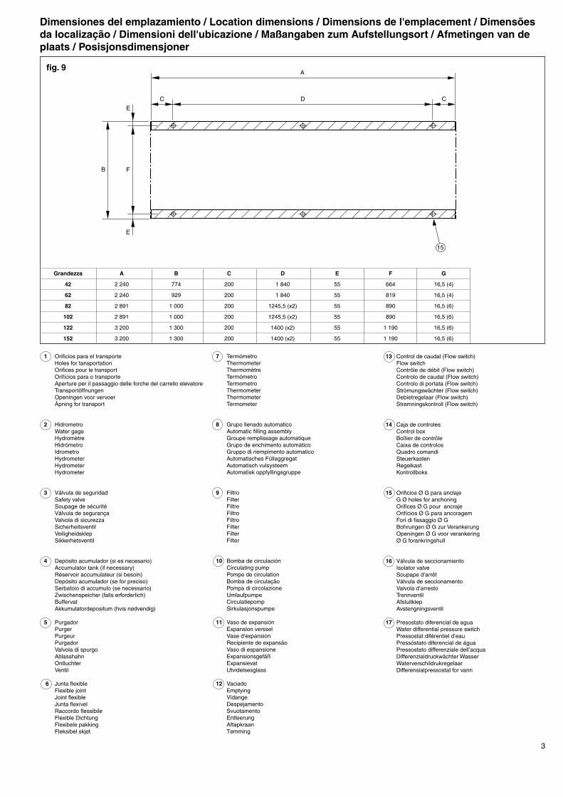
1 Orificios para el transporte Holes for tansportation Orifices pour le transport Orifícios para o transporte Aperture per il passaggio delle forche del carrello elevatore Transportöffnungen Openingen voor vervoer Åpning for transport
2 Hidrometro Water gage Hydromètre Hidrómetro Idrometro Hydrometer Hydrometer Hydrometer
3 Válvula de seguridad Safety valve Soupage de sécurité Válvula de segurança Valvola di sicurezza Sicherheitsventil Veiligheidsklep Sikkerhetsventil 4 Depósito acumulador (si es necesario) Accumulator tank (if necessary) Réservoir accumulateur (si besoin) Depósito acumulador (se for preciso) Serbatoio di accumulo (se necessario) Zwischenspeicher (falls erforderlich) Buffervat Akkumulatordepositum (hvis nødvendig)
5 Purgador Purger Purgeur Purgador Valvola di spurgo Ablasshahn Ontluchter Ventil
6 Junta flexible Flexible joint Joint flexible Junta flexível Raccordo flessibile Flexible Dichtung Flexibele pakking Fleksibel skjøt
7 Termómetro Thermometer Thermomètre Termómetro Termometro Thermometer Thermometer Termometer
8 Grupo llenado automatico Automatic filling assembly Groupe remplissage automatique Grupo de enchimento automático Gruppo di riempimento automatico Automatisches Füllaggregat Automatisch vulsysteem Automatisk oppfyllingsgruppe
9 Filtro Filter Filtre Filtro Filtro Filter Filter Filter
10 Bomba de circulación Circulating pump Pompe de circulation Bomba de circulação Pompa di circolazione Umlaufpumpe Circulatiepomp Sirkulasjonspumpe
11 Vaso de expansión Expansion verssel Vase d'expansion Recipiente de expansão Vaso di espansione Expansionsgefäß Expansievat Utvidelsesglass
12 Vaciado Emptying Vidange Despejamento Svuotamento Entleerung Aftapkraan Tømming
13 Control de caudal (Flow switch) Flow switch Contrôle de débit (Flow switch) Controlo de caudal (Flow switch) Controlo di portata (Flow switch) Strömungswächter (Flow switch) Debietregelaar (Flow switch) Strømningskontroll (Flow switch)
14 Caja de controles Control box Boîtier de contrôle Caixa de controlos Quadro comandi Steuerkasten Regelkast Kontrollboks
15 Orificios Ø G para anclaje G Ø holes for anchoring Orifices Ø G pour ancraje Orifícios Ø G para ancoragem Fori di fissaggio Ø G Bohrungen Ø G zur Verankerung Openingen Ø G voor verankering Ø G forankringshull
16 Válvula de seccionamiento Isolator valve Soupape d’arrêt Válvula de seccionamento Valvola d’arresto Trennventil Afsluitklep Avstengningsventil
17 Presostato diferencial de agua Water differential pressure switch Pressostat diférentiel d’eau Pressóstato diferencial de água Pressostato differenziale dell’acqua Differenzialdruckwächter Wasser Waterverschildrukregelaar Differensialpressostat for vann
fig. 9
Grandezza A B C D E F G
42 2 240 774 200 1 840 55 664 16,5 (4)
62 2 240 929 200 1 840 55 819 16,5 (4)
82 2 891 1 000 200 1245,5 (x2) 55 890 16,5 (6)
102 2 891 1 000 200 1245,5 (x2) 55 890 16,5 (6)
122 3 200 1 300 200 1400 (x2) 55 1 190 16,5 (6)
152 3 200 1 300 200 1400 (x2) 55 1 190 16,5 (6)
�
�
� � �
�
�
�
��
Dimensiones del emplazamiento / Location dimensions / Dimensions de l'emplacement / Dimensões da localização / Dimensioni dell'ubicazione / Maßangaben zum Aufstellungsort / Afmetingen van de plaats / Posisjonsdimensjoner
4
EE
YLCC-H 42
YLCC e YLCC-H 62
��
��� ���
���
��
����
����
����
���
��
���
���
��
������� ���
��� ������
������� ���
����
����
����
���
���
�
�
��
� �
�
����
��
��� ���
����
����
���
��
���
���
��
��� ���
��� ������
������� ���
���
����
����
����
���
���
���
�
��
�
��
����
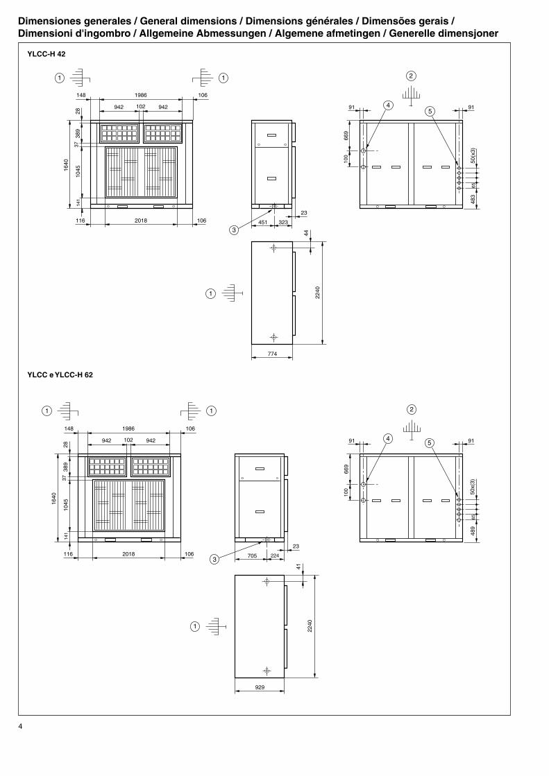
Dimensiones generales / General dimensions / Dimensions générales / Dimensões gerais /Dimensioni d'ingombro / Allgemeine Abmessungen / Algemene afmetingen / Generelle dimensjoner
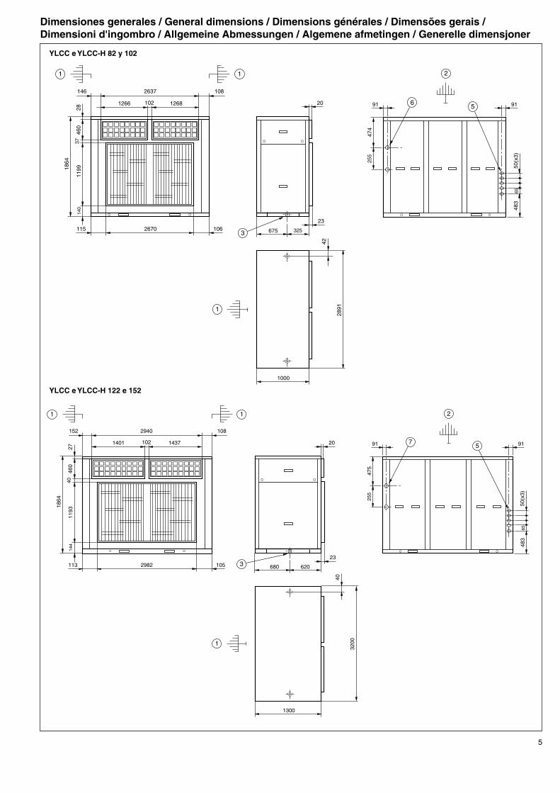
5
YLCC e YLCC-H 82 y 102
YLCC e YLCC-H 122 e 152
����
��
��� ���
��� ���
���� �������
������� ���
����
����
����
����
����
���
���
��
���
���
��
���
����
����
��
��
�� �
�
��
�
����
��
���
��� ���
���� �������
������� ���
����
����
����
����
����
���
���
��
���
���
��
���
����
����
���
��
�� ��
�
�
�� �
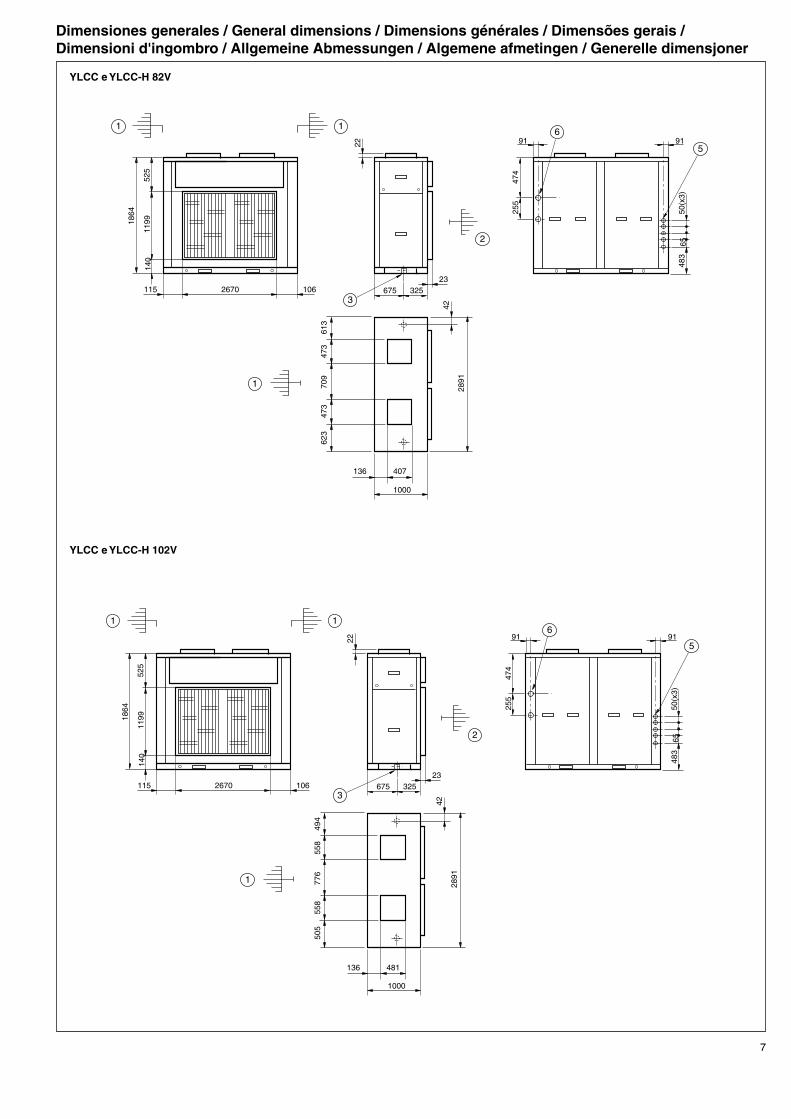
Dimensiones generales / General dimensions / Dimensions générales / Dimensões gerais /Dimensioni d'ingombro / Allgemeine Abmessungen / Algemene afmetingen / Generelle dimensjoner

6
EE
YLCC e YLCC-H 42V
YLCC e YLCC-H 62V
����� ���
��
����
������� ���
����
����
���
���
����
����
���
��
���
���
��
���
���
���
���
���
���
�����
�� �
�
�
��
�
�
��
��� ���
����
����
���
��
���
���
��
��
����
������� ���
����
����
���
���
���
��
���
���
���
���
���
��� ���
�
��
�
�
�
�
Dimensiones generales / General dimensions / Dimensions générales / Dimensões gerais /Dimensioni d'ingombro / Allgemeine Abmessungen / Algemene afmetingen / Generelle dimensjoner
7
YLCC e YLCC-H 82V
YLCC e YLCC-H 102V
����� ���
��
����
������� ���
����
����
���
���
����
����
���
��
���
���
��
����
��
���
���
���
���
���
��� ���
�
�
�
�
��
�
����� ���
��
����
������� ���
����
����
���
���
����
����
���
��
���
���
��
����
��
���
���
���
���
���
��� ���
�
�
�
�
��
�
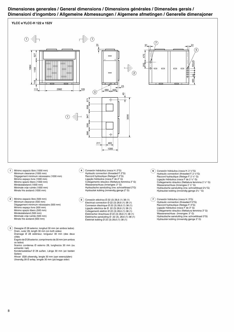
Dimensiones generales / General dimensions / Dimensions générales / Dimensões gerais /Dimensioni d'ingombro / Allgemeine Abmessungen / Algemene afmetingen / Generelle dimensjoner
8
EE
1 Mínimo espacio libre (1000 mm) Minimum clearance (1000 mm) Dégagement minimum nécessaire (1000 mm) Mínimo espaço livre (1000 mm) Minimo spazio libero (1000 mm) Mindestabstand (1000 mm) Minimale vrije ruimte (1000 mm) Minste frie avstand (1000 mm)
2 Mínimo espacio libre (500 mm) Minimum clearance (500 mm) Dégagement minimum nécessaire (500 mm) Mínimo espaço livre (500 mm) Minimo spazio libero (500 mm) Mindestabstand (500 mm) Minimale vrije ruimte (500 mm) Minste frie avstand (500 mm)
3 Desagüe Ø 28 exterior, longitud 30 mm (en ambos lados) Drain, outer 28, length 30 mm (on both sides) Drainage Ø 28 extérieur, longueur 30 mm (des deux
côtés Esgoto de Ø 28 exterior, comprimento de 30 mm (em ambos
os lados) Scarico condensa Ø esterno 28, lunghezza 30 mm (su
entrambi i lati) Kondensatablauf Ø 28 außen, Länge 30 mm (an beiden
Seiten) Afvoer Ø28 uitwendig, lengte 30 mm (aan weerszijden) Utvendig 28 Ø avløp, lengde 30 mm (på begge sider)
YLCC e YLCC-H 122 e 152V
4 Conexión hidráulica (rosca H. 2"G) Hydraulic connection (threaded F. 2"G) Raccord hydraulique (filetage F. 2’’G) Ligação hidráulica (rosca F de 2" G) Collegamento idraulico (filettatura femmina 2” G) Wasseranschluss (Innengew. 2" G) Hydraulische aansluiting (inw. schroefdraad 2"G) Hydraulisk kobling (innvendig gjenge 2” G)
5 Conexión eléctrica Ø 22 (3) 28,6 (1) 38 (1) Electrical connection Ø 22 (3) 28,6 (1) 38 (1) Connexion électrique Ø 22 (3) 28,6 (1) 38 (1) Ligação eléctrica de Ø 22 (3) 28,6 (1) 38 (1) Collegamenti elettrici Ø 22 (3) 28,6 (1) 38 (1) Elektrischer Anschluss Ø 22 (3) 28,6 (1) 38 (1) Elektrische aansluiting Ø 22 (3), 28,6 (1) 38 (1) Elektrisk kobling Ø 22 (3) 28,6 (1) 38 (1)
6 Conexión hidráulica (rosca H. 2 ½"G) Hydraulic connection (threaded F. 2 ½"G) Raccord hydraulique (filetage F. 2 ½" G) Ligação hidráulica (rosca F de 2 ½" G) Collegamento idraulico (filettatura femmina 2 ½" G) Wasseranschluss (Innengew 2 ½" G) Hydraulische aansluiting (inw. schroefdraad 2½"G) Hydraulisk kobling (innvendig gjenge 2½ ” G)
7 Conexión hidráulica (rosca H. 3"G) Hydraulic connection (threaded F.3"G) Raccord hydraulique (filetage F. 3’’G) Ligação hidráulica (rosca F de 3" G) Collegamento idraulico (filettatura femmina 3” G) Wasseranschluss (Innengew. 3" G) Hydraulische aansluiting (inw. schroefdraad 3"G) Hydraulisk kobling (innvendig gjenge 3” G)
Dimensiones generales / General dimensions / Dimensions générales / Dimensões gerais /Dimensioni d'ingombro / Allgemeine Abmessungen / Algemene afmetingen / Generelle dimensjoner
��
���
���
���
���
���
��� ���
��
��� ���
��
����
������� ���
����
����
���
���
����
����
���
��
���
���
��
����
�
�
�
��
�
�
9E
Instrucciones de instala-ción InspecciónEn su recepción, inspeccionar la mercan-cia y comunicar por escrito las posibles anomalías al transportista y a la Compañía de Seguros.
Protección del medio ambien-te
EmbalajeEl embalaje está compuesto de material reciclable. Su eliminación debe efectuarse de acuerdo con
las normas de recogida selectiva de resi-duos que el municipio tenga establecidas.
RefrigeranteContiene gas fluorado efecto invernadero cubierto por el protocolo de Kyoto.Para el tipo de gas y la cantidad por sistema ver la placa de características. GWP (Global Warming Potential): 2107.
Eliminación del aparatoAl proceder al desmontaje del aparato, debe efectuarse la recuperación ecológica de sus componentes. El circuito frigorífico está lleno de refrigerante que debe ser recupe-rado y entregado al fabricante del gas para proceder a su reciclaje. En el compresor hermético quedará aceite, por ello, aquel se entregará con el circuito sellado.El acondicionador se depositará en el lugar donde tengan establecido las autoridades municipales, para proceder a su recupera-ción selectiva.
TransporteLas unidades deben trasladarse siempre en posición vertical, con objeto de que el aceite no salga del compresor. Si por alguna razón precisa cambiarse esporádicamente esta posición, permanecerá en ella sólo el tiempo estrictamente necesario.
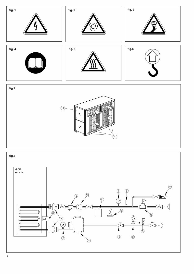
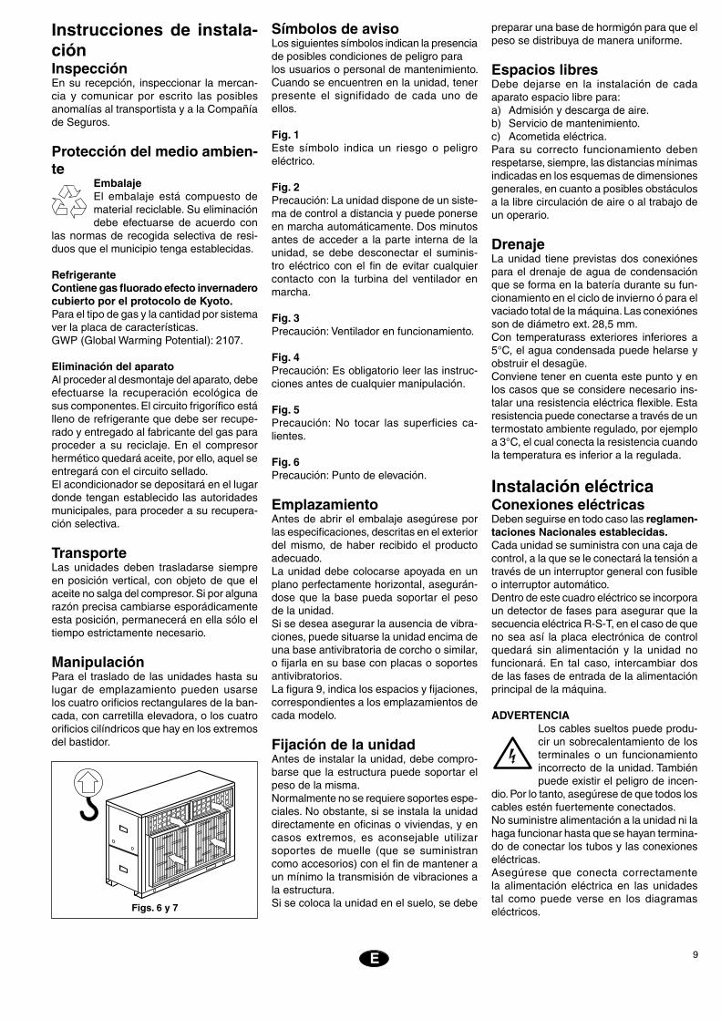
ManipulaciónPara el traslado de las unidades hasta su lugar de emplazamiento pueden usarse los cuatro orificios rectangulares de la ban-cada, con carretilla elevadora, o los cuatro orificios cilíndricos que hay en los extremos del bastidor.
Símbolos de avisoLos siguientes símbolos indican la presencia de posibles condiciones de peligro para los usuarios o personal de mantenimiento. Cuando se encuentren en la unidad, tener presente el signifidado de cada uno de ellos.
Fig. 1Este símbolo indica un riesgo o peligro eléctrico.
Fig. 2Precaución: La unidad dispone de un siste-ma de control a distancia y puede ponerse en marcha automáticamente. Dos minutos antes de acceder a la parte interna de la unidad, se debe desconectar el suminis-tro eléctrico con el fin de evitar cualquier contacto con la turbina del ventilador en marcha.
Fig. 3Precaución: Ventilador en funcionamiento.
Fig. 4Precaución: Es obligatorio leer las instruc-ciones antes de cualquier manipulación.
Fig. 5Precaución: No tocar las superficies ca-lientes.
Fig. 6Precaución: Punto de elevación.
EmplazamientoAntes de abrir el embalaje asegúrese por las especificaciones, descritas en el exterior del mismo, de haber recibido el producto adecuado.La unidad debe colocarse apoyada en un plano perfectamente horizontal, asegurán-dose que la base pueda soportar el peso de la unidad.Si se desea asegurar la ausencia de vibra-ciones, puede situarse la unidad encima de una base antivibratoria de corcho o similar, o fijarla en su base con placas o soportes antivibratorios.La figura 9, indica los espacios y fijaciones, correspondientes a los emplazamientos de cada modelo.
Fijación de la unidadAntes de instalar la unidad, debe compro-barse que la estructura puede soportar el peso de la misma.Normalmente no se requiere soportes espe-ciales. No obstante, si se instala la unidad directamente en oficinas o viviendas, y en casos extremos, es aconsejable utilizar soportes de muelle (que se suministran como accesorios) con el fin de mantener a un mínimo la transmisión de vibraciones a la estructura.Si se coloca la unidad en el suelo, se debe
preparar una base de hormigón para que el peso se distribuya de manera uniforme.
Espacios libresDebe dejarse en la instalación de cada aparato espacio libre para:a) Admisión y descarga de aire.b) Servicio de mantenimiento.c) Acometida eléctrica.Para su correcto funcionamiento deben respetarse, siempre, las distancias mínimas indicadas en los esquemas de dimensiones generales, en cuanto a posibles obstáculos a la libre circulación de aire o al trabajo de un operario.
DrenajeLa unidad tiene previstas dos conexiónes para el drenaje de agua de condensación que se forma en la batería durante su fun-cionamiento en el ciclo de invierno ó para el vaciado total de la máquina. Las conexiónes son de diámetro ext. 28,5 mm.Con temperaturass exteriores inferiores a 5°C, el agua condensada puede helarse y obstruir el desagüe. Conviene tener en cuenta este punto y en los casos que se considere necesario ins-talar una resistencia eléctrica flexible. Esta resistencia puede conectarse a través de un termostato ambiente regulado, por ejemplo a 3°C, el cual conecta la resistencia cuando la temperatura es inferior a la regulada.
Instalación eléctricaConexiones eléctricasDeben seguirse en todo caso las reglamen-taciones Nacionales establecidas.Cada unidad se suministra con una caja de control, a la que se le conectará la tensión a través de un interruptor general con fusible o interruptor automático.Dentro de este cuadro eléctrico se incorpora un detector de fases para asegurar que la secuencia eléctrica R-S-T, en el caso de que no sea así la placa electrónica de control quedará sin alimentación y la unidad no funcionará. En tal caso, intercambiar dos de las fases de entrada de la alimentación principal de la máquina.
ADVERTENCIALos cables sueltos puede produ-cir un sobrecalentamiento de los terminales o un funcionamiento incorrecto de la unidad. También puede existir el peligro de incen-
dio. Por lo tanto, asegúrese de que todos los cables estén fuertemente conectados.No suministre alimentación a la unidad ni la haga funcionar hasta que se hayan termina-do de conectar los tubos y las conexiones eléctricas.Asegúrese que conecta correctamente la alimentación eléctrica en las unidades tal como puede verse en los diagramas eléctricos.Figs. 6 y 7
10
EE
Antes de dar por finalizada la instalaciónVerificar: - El voltaje está siempre entre 342
- 436 V. - La sección de los cables de
alimentación es, como mínimo, la aconsejada en los esquemas eléctricos correspondientes.
- Se han dado instrucciones al usuario para su manejo.
- Se ha informado de la necesidad de la limpieza periódica del filtro de aire.
- Se ha cumplimentado la tarjeta de garantía.
- Se han dado instrucciones de man-tenimiento o efectuado contrato de revisión periódica.
E
Conexiones hidráulicasLas conexiones hidráulicas de la entrada y salida de agua de la planta deben realizarse respetando las direcciones de entrada y salida indicadas (Fig.8).Se puede utilizar tubería de hierro (no galvanizado) o de cobre, con dimensiones no inferiores a las indicadas, y teniendo presente las pérdidas de carga en dichas conexiones y en el intercambiador interno de la instalación.Debe dimensionarse la bomba de acuerdo con un caudal nominal que permita un ∆t de 5°C.Es conveniente realizar la conexión de la tubería mediante acoplamientos antivibratorios.En todos los casos se debe instalar un control de caudal para evitar la posibilidad de funcionar sin circulación de agua, asi como un filtro de agua obligatorio para poder aplicar la garantía.Se debe instalar en la tubería de retorno de agua un vaso de expansión adecuado para el volumen total de agua de la instalación.
No obstante, verificar en cada caso el volu-men mínimo necesario para la instalación.
Durante la estación invernal, con tempe-raturas exteriores inferiores a 0°C, deben tomarse precauciones para evitar que se hiele el agua en las redes de tubos y en el interior del intercambiador de la planta.Usualmente se aplican las siguientes so-luciones:a) Mantener el circulador siempre en mar-
cha.b) Llenar el circuito con una mezcla anti-
congelante (glicol).c) Vaciar el circuito.
Grupos hidráulicos GHPara evitar el desconfort que puede causar el descenso de la temperatura del agua durante el ciclo de deshielo, o el paro de la unidad por disparo del termostato antihielo en las instalaciones de poco volumen, es necesario emplear un depósito acumula-dor que aumente la inercia térmica de la instalación.Los volúmenes de agua de los grupos GH y su compatibilidad con las plantas YLCC/YLCC-H son los siguientes:
Modelo
Límites
de voltajeTemperatura entrada aire
a la batería T.S. Temperatura salida aguaDiferencia
de temp. entre
la salida y la
entrada
de agua
* A temperaturas de agua inferiores a las nominales, es aconsejable utilizar siempre mezclas anti-congelantes tipo glicol.
Máx.Mín.
Nominala
400
Ciclo de funcionamientoCiclo de funcionamiento
Frío / Calor
Mínimo °C
Frío / Calor
Máximo °C
Frío / Calor
Mínimo °C
Frío / Calor
Máximo °C
Mínim.
°C
Máxim.
°C
Límites de utilización
YLCC
3 7
YLCC-H
342 436
10 / -
10 / -10
46 / -
46 / 20
5* / -
5* / 30
15 / -
15 / 50
42 6 700 1,86 15 147
62 10 100 2,8 15 147
82 13 500 3,75 15 147
102 17 200 4,77 15 147
122 19 900 5,53 15 147
152 25 800 7,16 15 147
l/h l/s m c.d.a. kPa
UnidadYLCC
YLCC-H
Presión mínima suministrada por la bomba
Caudal aproximado de la
bomba ∆t 5°C
YLCC/YLCC-H 42, 62, 82, 102, 122 y 152
� � � � � � � �
��������������������
������������
����
�����
������
���
����
�
����
���
���
���������
��
������������
����
�����
������
���
����
����
���
������������
�� �� �� �
Esquema eléctrico Bomba de circulaciónEs esencial para el buen funcionamiento de las unidades, seleccionar una bomba adecuada que proporcione un caudal y una presión suficiente al circuito hidráulico. Para ello emplear los datos del cuadro adjunto.
El volumen de agua que tienen las plantas es de:
YLCC / YLCC-H LITROS
42 200
62 260
82 260
102 600 S
122 600 S
152 600 P
TAMAÑO
42 = 25 litros 102 = 38,2 litros
62 = 28 litros 122 = 78,5 litros
82 = 38,2 litros 152 = 73,5 litros
11E
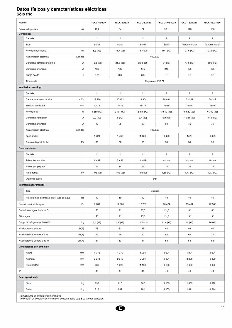
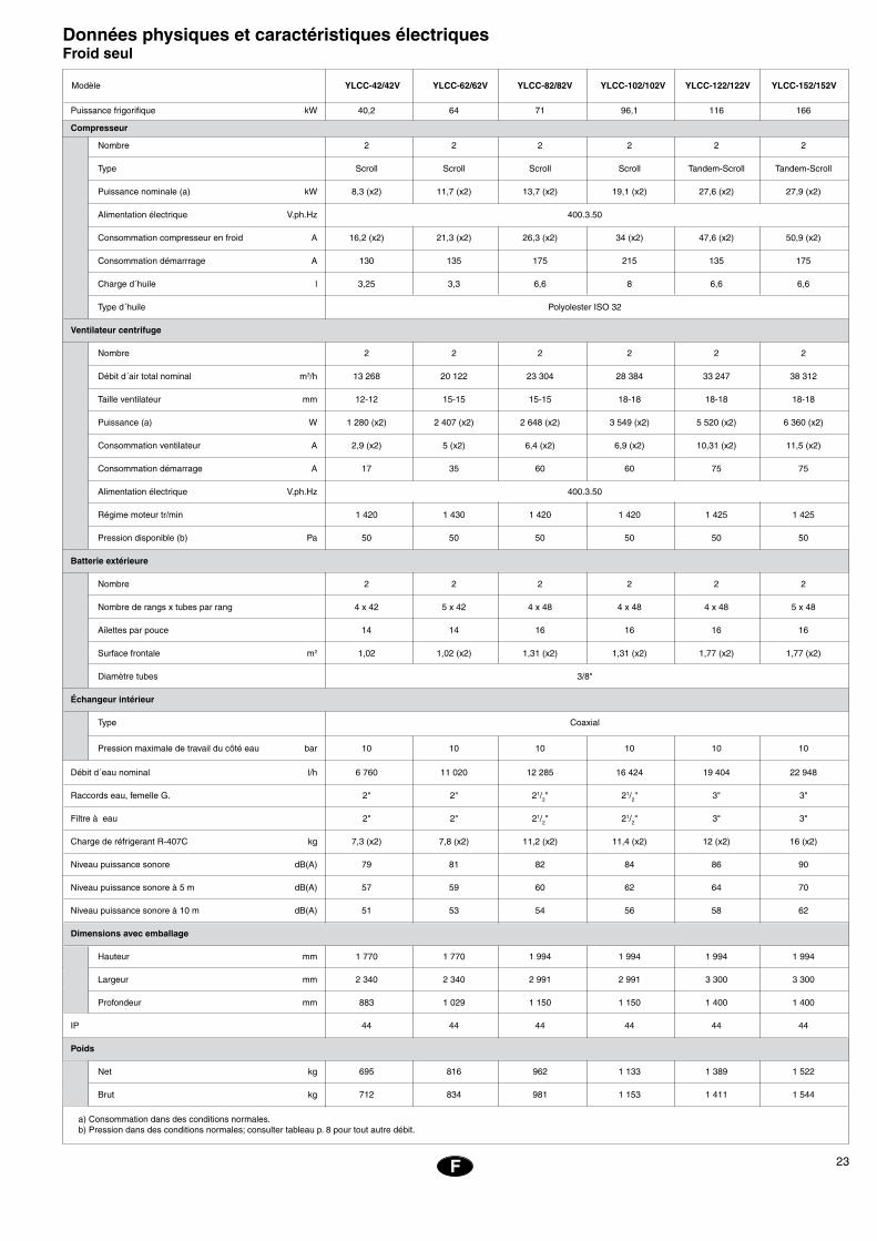
Datos físicos y características eléctricasSólo frío
Potencia frigorífica kW 40,2 64 71 96,1 116 166
Compresor
Cantidad 2 2 2 2 2 2
Tipo Scroll Scroll Scroll Scroll Tandem-Scroll Tandem-Scroll
Potencia nominal (a) kW 8,3 (x2) 11,7 (x2) 13,7 (x2) 19,1 (x2) 27,6 (x2) 27,9 (x2)
Alimentación eléctrica V.ph.Hz 400.3.50
Consumo compresor en frío A 16,2 (x2) 21,3 (x2) 26,3 (x2) 34 (x2) 47,6 (x2) 50,9 (x2)
Consumo arranque A 130 135 175 215 135 175
Carga aceite l 3,25 3,3 6,6 8 6,6 6,6
Tipo aceite Polyolester ISO 32
Ventilador centrífugo
Cantidad 2 2 2 2 2 2
Caudal total nom. de aire m3/h 13 268 20 122 23 304 28 834 33 247 38 312
Tamaño ventilador mm 12-12 15-15 15-15 18-18 18-18 18-18
Potencia (a) W 1 280 (x2) 2 407 (x2) 2 648 (x2) 3 549 (x2) 5 520 (x2) 6 360 (x2)
Consumo ventilador A 2,9 (x2) 5 (x2) 6,4 (x2) 6,9 (x2) 10,31 (x2) 11,5 (x2)
Consumo arranque A 17 35 60 60 75 75
Alimentación eléctrica V.ph.Hz 400.3.50
r.p.m. motor 1 420 1 430 1 420 1 420 1425 1 425
Presión disponible (b) Pa 50 50 50 50 50 50
Batería exterior
Cantidad 2 2 2 2 2 2
Tubos fondo x alto 4 x 42 5 x 42 4 x 48 4 x 48 4 x 48 5 x 48
Aletas por pulgada 14 14 16 16 16 16
Area frontal m2 1,02 (x2) 1,02 (x2) 1,56 (x2) 1,56 (x2) 1,77 (x2) 1,77 (x2)
Diámetro tubos 3/8"
Intercambiador interior
Tipo Coaxial
Presión máx. de trabajo en el lado de agua bar 10 10 10 10 10 10
Caudal nominal de agua l/h 6 760 11 020 12 285 16 424 19 404 22 948
Conexiones agua, hembra G. 2" 2" 21/2" 21/2" 3" 3"
Filtro agua 2" 2" 21/2" 21/2" 3" 3"
Carga de refrigerante R-407C kg 7,3 (x2) 7,8 (x2) 11,2 (x2) 11,4 (x2) 12 (x2) 16 (x2)
Nivel potencia sonora dB(A) 79 81 82 84 86 90
Nivel potencia sonora a 5 m dB(A) 57 59 60 62 64 70
Nivel potencia sonora a 10 m dB(A) 51 53 54 56 58 62
Dimensiones con embalaje
Altura mm 1 770 1 770 1 994 1 994 1 994 1 994
Anchura mm 2 340 2 340 2 991 2 991 3 300 3 300
Profundidad mm 883 1 029 1 150 1 150 1 400 1 400
IP 44 44 44 44 44 44
Peso aproximado
Neto kg 695 816 962 1 133 1 389 1 522
Bruto kg 712 834 981 1 153 1 411 1 544
Modelo
a) Consumo en condiciones nominales.b) Presión en condiciones nominales, consultar tabla pag. 8 para otros caudales.
YLCC-42/42V YLCC-62/62V YLCC-82/82V YLCC-102/102V YLCC-122/122V YLCC-152/152V
12
EE
E
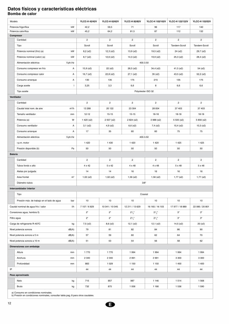
Datos físicos y características eléctricasBomba de calor
Potencia frigorífica kW 42,2 59,5 71 96 117 140
Potencia calorífica kW 45,2 64,2 81,5 87 112 132
Compresor
Cantidad 2 2 2 2 2 2
Tipo Scroll Scroll Scroll Scroll Tandem-Scroll Tandem-Scroll
Potencia nominal (frío) (a) kW 8,2 (x2) 12,3 (x2) 13,9 (x2) 19,5 (x2) 24 (x2) 29,7 (x2)
Potencia nominal (calor) (a) kW 8,7 (x2) 12,6 (x2) 14,3 (x2) 19,9 (x2) 25,3 (x2) 28,4 (x2)
Alimentación eléctrica V.ph.Hz 400.3.50
Consumo compresor en frío A 15,9 (x2) 22 (x2) 26,5 (x2) 34,4 (x2) 41,5 (x2) 54 (x2)
Consumo compresor calor A 16,7 (x2) 22,8 (x2) 27,1 (x2) 35 (x2) 43,5 (x2) 52,2 (x2)
Consumo arranque A 130 135 175 215 135 175
Carga aceite l 3,25 3,3 6,6 8 6,6 6,6
Tipo aceite Polyolester ISO 32
Ventilador
Cantidad 2 2 2 2 2 2
Caudal total nom. de aire m3/h 13 268 20 122 23 304 28 834 37 403 37 403
Tamaño ventilador mm 12-12 15-15 15-15 18-18 18-18 18-18
Potencia (a) W 1 420 (x2) 2 507 (x2) 2 824 (x2) 3 988 (x2) 5 505 (x2) 5 856 (x2)
Consumo ventilador A 3,1 (x2) 4,9 (x2) 6,6 (x2) 7,4 (x2) 10,4 (x2) 10,3 (x2)
Consumo arranque A 17 35 60 60 75 75
Alimentación eléctrica V.ph.Hz 400.3.50
r.p.m. motor 1 420 1 430 1 420 1 420 1 425 1 425
Presión disponible (b) Pa 50 50 50 50 50 50
Batería
Cantidad 2 2 2 2 2 2
Tubos fondo x alto 4 x 42 5 x 42 4 x 48 4 x 48 5 x 48 5 x 48
Aletas por pulgada 14 14 16 16 16 16
Area frontal m2 1,02 (x2) 1,02 (x2) 1,56 (x2) 1,56 (x2) 1,77 (x2) 1,77 (x2)
Diámetro tubos 3/8"
Intercambiador interior
Tipo Coaxial
Presión máx. de trabajo en el lado de agua bar 10 10 10 10 10 10
Caudal nominal de agua frío / calor l/h 7 107 / 6 829 10 041 / 10 045 12 211 / 13 629 16 165 / 16 103 17 977 / 18 889 22 085 / 20 801
Conexiones agua, hembra G. 2" 2" 21/2" 21/2" 3" 3"
Filtro agua 2" 2" 21/2" 21/2" 3" 3"
Carga de refrigerante R-407C kg 7,5 (x2) 8,6 (x2) 12,1 (x2) 12,1 (x2) 14,5 (x2) 20 (x2)
Nivel potencia sonora dB(A) 79 81 82 84 86 90
Nivel potencia sonora a 5 m dB(A) 57 59 60 62 64 70
Nivel potencia sonora a 10 m dB(A) 51 53 54 56 58 62
Dimensiones con embalaje
Altura mm 1 770 1 770 1 994 1 994 1 994 1 994
Anchura mm 2 340 2 340 2 991 2 991 3 300 3 300
Profundidad mm 883 1 029 1 150 1 150 1 400 1 400
IP 44 44 44 44 44 44
Peso aproximado
Neto kg 715 857 987 1 146 1 514 1 568
Bruto kg 732 875 1 006 1 166 1 536 1 590
a) Consumo en condiciones nominales.b) Presión en condiciones nominales, consultar tabla pag. 8 para otros caudales.
Modelo YLCC-H 42/42V YLCC-H 62/62V YLCC-H 82/82V YLCC-H 102/102V YLCC-H 122/122V YLCC-H 152/52V
13E
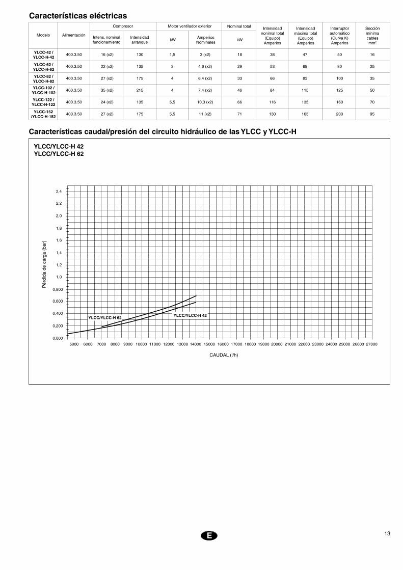
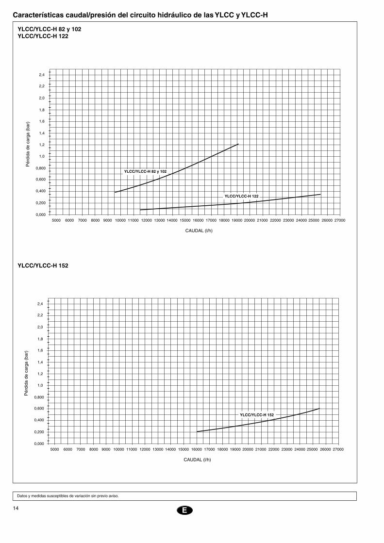
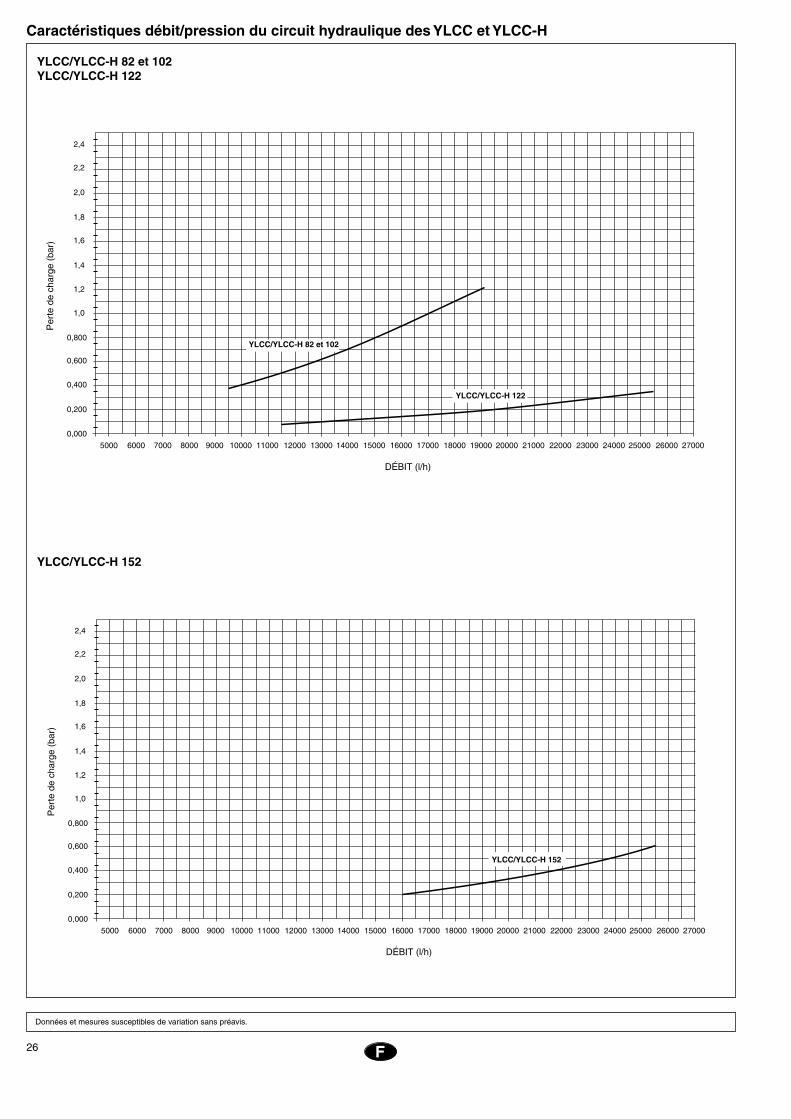
Características caudal/presión del circuito hidráulico de las YLCC y YLCC-H
���������������
���
����
����
����
����
���
������������
����� �����
�����
�����
�����
����� ����� ����� ����� �����
�����
���
���
����� ����� ����� ����� ����� ����� ����� �����
���
���
���
���
���
���
�������������������������
����������������������������
YLCC/YLCC-H 42YLCC/YLCC-H 62
16 (x2) 130 1,5 3 (x2) 18 38 47 50 16
22 (x2) 135 3 4,6 (x2) 29 53 69 80 25
27 (x2) 175 4 6,4 (x2) 33 66 83 100 35
35 (x2) 215 4 7,4 (x2) 46 84 115 125 50
24 (x2) 135 5,5 10,3 (x2) 66 116 135 160 70
27 (x2) 175 5,5 11 (x2) 71 130 163 200 95
Características eléctricas
Intensidad arranque
Modelo Alimentación
Compresor
Intens. nominal funcionamiento
kWAmperios Nominales
Motor ventilador exterior Intensidadnonimal total
(Equipo)Amperios
Interruptorautomático(Curva K)Amperios
Nominal total Secciónmínimacablesmm2
kW
400.3.50
400.3.50
400.3.50
400.3.50
400.3.50
400.3.50
Intensidadmáxima total
(Equipo)Amperios
YLCC-42 /YLCC-H-42
YLCC-62 /YLCC-H-62
YLCC-82 /YLCC-H-82
YLCC-102 /YLCC-H-102
YLCC-122 /YLCC-H-122
YLCC-152 /YLCC-H-152
14
EE
E
Características caudal/presión del circuito hidráulico de las YLCC y YLCC-H
Datos y medidas susceptibles de variación sin previo aviso.
YLCC/YLCC-H 152
���������������
���
����
����
����
����
���
������������
����� �����
�����
�����
�����
����� ����� ����� ����� �����
�����
���
���
����� ����� ����� ����� ����� ����� ����� �����
���
���
���
���
���
���
�������������������������
���������������
���������������
���
����
����
����
����
���
������������
����� �����
�����
�����
�����
����� ����� ����� ����� �����
�����
���
���
����� ����� ����� ����� ����� ����� ����� �����
���
���
���
���
���
���
�������������������������
��������������������
���������������
YLCC/YLCC-H 82 y 102YLCC/YLCC-H 122
15GB
Installations Instructions InspectionUpon reception, inspect the merchandise and notify both the carrier and the insur-ance company, in writing, of any possible damage.
Environmental protectionPacking
Packing is made of recyclable material. Its eliminate should be carried out in accordance with the existing regulations on selective
collection of residual material.
RefrigerantContains greenhouse effect fluorided gas covered by the Kyoto protocol.For the type of gas and quantity per system, see the identification plate.GWP (Global Warming Potential): 2107.
Elimination of the unitUpon disassembly of the unit, its compo-nents should be recuperated ecologically. The cooling circuit contains refrigerant which should be recuperated and then returned to the gas manufacturer for recycling. Oil will remain in the sealed compressor and, therefore, must be returned with its circuit sealed. The air conditioning unit will be deposited in an area established by the local authorities, for its selective recuperation.
TransportationThe units should always be transported in vertical position so as to avoid oil leaking out of the compressor. If, for any reason, this position need be changed sporadically, they will remain in that position a strictly necessary period of time.
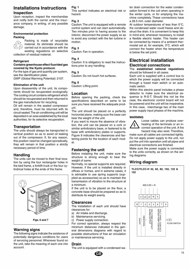
HandlingThe units can be moved to their final loca-tion by using the four rectangular holes in the bed frame, a forklift truck or the four cy-lindrical holes at the ends of the frame.
Warning signsThe following signs indicate the existence of potentially dangerous conditions for users of servicing personnel. Whenever found on the unit, take the meaning of each one into account.
Figs. 6 and 7
Fig. 1This symbol indicates an electrical risk or hazard.
Fig. 2Caution: The unit is equipped with a remote control system and can start automatically. Two minutes prior to having access to the interior, disconnect the power supply so as to avoid any contact with the fan turbine in motion.
Fig. 3Caution: Fan in operation.
Fig. 4Caution: It is obligatory to read the instruc-tions prior to any handling.
Fig. 5Caution: Do not touch hot surfaces.
Fig. 6Caution: Lifting point.
LocationBefore opening the packing, check the specifications described on same to be sure you have received the adequate prod-uct.The unit should be placed on a perfectly horizontal plane, making sure the base can bear the weight of the unit.If you want to insure the absence of vibra-tion, the unit can be placed on a cork or similar antivibratory base, or fastened to its base with antivibratory plates or supports. Figure 9 indicates the clearances and fas-tening points for the location of each mod-el.
Fastening the unitBefore installing the unit, make sure the structure is strong enough to bear the weight of same.Normally, no special supports are required. However, if the unit is installed directly in offices or homes, and in extreme cases, it is advisable to use spring supports (sup-plied as accessories) so as to maintain the transmission of vibration to the structure at a minimum.If the unit is to be placed on the floor, a concrete base should be prepared so as to distribute its weight evenly. ClearancesThe installation of each unit should have clearances for:a) Air intake and discharge.b) Maintenance servicing.c) Power supply connection.For correct operation, always respect the minimum distances indicated in the gen-eral dimensions diagrams with regard to possible obstructions of free air circulation or maintenance servicing. DrainThe unit is equipped with a condensed wa-
ter drain connection for the water conden-sation formed in the coil when operating in the winter cycle, or for emptying the ma-chine completely. These connections have a 28.5 mm. outer diameter.At outdoor temperatures of less than 5°C, the condensed water could freeze and ob-struct the drain. It is convenient to keep this in mind and, whenever necessary, to install a flexible electric heater. This heater can be connected by means of a ambient ther-mostat set at, for example, 3°C, which will connect the heater when the temperature is below the set point.
Electrical installationElectrical connectionsThe established national regulations should be followed in all cases. Each unit is supplied with a control box to which the power supply will be connected through a fused main switch or an auto-matic switch.Within this electric panel includes a phase detector to make sure the electrical se-quence is R-S-T. Should this not be the case, the electronic control board will not be powered and the unit will be inoperative. In this case, interchange two of the main power supply input phases of the machine. WARNING
Loose cables can produce over-heating of the terminals or an in-correct operation of the unit. A fire hazard may also exist. Therefore,
make sure all cables are connected tightly.Do not apply power supply to the unit, nor put the unit into operation until all pipes and electrical connections are finished.Make sure the power supply is connected to the units correctly, as shown on the wir-ing diagrams.
Wiring diagram
YLCC/YLCC-H 42, 62, 82, 102, 122 & 152
� � � � � � � �
����
�����
����
��
������������
�� �� �� �
�����������
��
����
�����
������
�������
��
���
������
����
�������
������
���
��
�������
16
EE
Prior to final approval of the installationCheck: - That voltage is always between 342
- 436 V. - That the power supply cable section
is at least equal to the section recom-mended in the corresponding wiring diagrams.
- - That operating instructions have been given to the user.
- That information has been given on the need to clean the air filter regularly.
- That the guarantee card has been filled out.
- That maintenance instructions have been given, or a periodical revision contract has been signed.
Nevertheless, check, in every case, the mini-mum volume needed for the installation.
Hydraulic connectionsThe hydraulic connections of the water in-take and outlet of the chiller should be car-ried out respecting the intake and outlet directions indicated. (Fig. 8)Iron (non galvanized) or copper tubing can be use, with dimensions no lower than those indicated, and keeping in mind the pressure drops at said connections and at the internal exchanger of the installation.Pump sizing should be carried out in ac-cordance with a nominal flow that allows an ∆t of 5°C.It is convenient that the tubing connection be carried out by means of antivibratory couplings.In all cases, a flow switch should be in-stalled to avoid operation without water cir-culation, as well as a water filter. These two requirements are obligatory for application of the warranty. An expansion vessel should be installed in the water return tubing. This vessel must be adequate for the total water volume of the installation.Chiller water volume is as follows:
GB
Circulating pumpFor proper operation of the units it is es-sential to select an adequate pump that provides sufficient flow and pressure to the hydraulic circuit. For this purpose, use the data in the following table.
During the winter season, with outdoor tem-peratures below 0°C, precautions should be taken to avoid the water from freezing in the tubing networks and inside the chiller exchanger.
The following solutions are usually applied:a) Always keep the circulator running.b) Fill the circuit with an antifreeze mixture
(glycol).c) Empty the circuit.
GH hydro kit To avoid discomfort caused by a drop in water temperature during the defrost cycle, or the unit turning off due to the antifreeze thermostat tripping in small volume instal-lations, it is necessary to use a collector tank to increase the thermal inertia of the installation.The water volumes of the GH hydro kits and their compatibility with the YLCC/YLCC-H chillers are as follows:
l/h l/s m c.d.a. kPa
YLCCYLCC-H
unit
Approx. flowof the pump
∆t 5°C
Minimum pressu-re supplied by the
pump
42 6 700 1,86 15 147
62 10 100 2,8 15 147
82 13 500 3,75 15 147
102 17 200 4,77 15 147
122 19 900 5,53 15 147
152 25 800 7,16 15 147
Limits of use
* At water temperatures below the nominal values, it is recommended to always use glycol type antifreeze mixtures.
Model
Voltagelimits
DB air inlet temperature to coil Water outlet temperature Temp. differential
between the
water outlet and
intake
Máx.Mín.
Nominalat
400
Operating cycleOperating cycle
Cool / Heat
Minimum °C
Cool / Heat
Maximum °C
Cool / Heat
Minimum °C
Cool / Heat
Maximum °C
Minimum
°C
Maximum
°C
YLCC
3 7
YLCC-H
342 436
10 / -
10 / -10
46 / -
46 / 20
5* / -
5* / 30
15 / -
15 / 50
SIZE
42 = 25 litres 102 = 38.2 litres
62 = 28 litres 122 = 78.5 litres
82 = 38.2 litres 152 = 73.5 litres
YLCC / YLCC-H LITRES
42 200
62 260
82 260
102 600 S
122 600 S
152 600 P
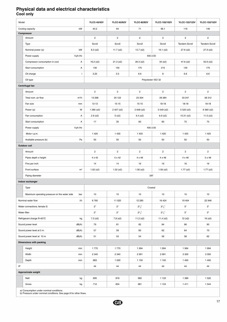
17
a) Consumption under nominal conditions.b) Pressure under nominal conditions. See page 8 for other flows.
GB
Physical data and electrical characteristicsCool only
Cooling capacity kW 40.2 64 71 96.1 116 146
Compressor
Amount 2 2 2 2 2 2
Type Scroll Scroll Scroll Scroll Tandem-Scroll Tandem-Scroll
Nominal power (a) kW 8.3 (x2) 11.7 (x2) 13.7 (x2) 19.1 (x2) 27.6 (x2) 27.9 (x2)
Power supply V.ph.Hz 400.3.50
Compressor consumption in cool A 16.2 (x2) 21.3 (x2) 26.3 (x2) 34 (x2) 47.6 (x2) 50.9 (x2)
Start consumption A 130 135 175 215 135 175
Oil charge l 3.25 3.3 6.6 8 6.6 6.6
Oil type Polyolester ISO 32
Centrifugal fan
Amount 2 2 2 2 2 2
Total nom. air flow m3/h 13 268 20 122 23 304 28 384 33 247 38 312
Fan size mm 12-12 15-15 15-15 18-18 18-18 18-18
Power (a) W 1 280 (x2) 2 407 (x2) 2 648 (x2) 3 549 (x2) 5 520 (x2) 6 360 (x2)
Fan consumption A 2.9 (x2) 5 (x2) 6.4 (x2) 6.9 (x2) 10.31 (x2) 11.5 (x2)
Start consumption A 17 35 60 60 75 75
Power supply V.ph.Hz 400.3.50
Motor r.p.m. 1 420 1 430 1 420 1 420 1 425 1 425
Available pressure (b) Pa 50 50 50 50 50 50
Outdoor coil
Amount 2 2 2 2 2 2
Pipes depth x height 4 x 42 5 x 42 4 x 48 4 x 48 4 x 48 5 x 48
Fins per inch 14 14 16 16 16 16
Front surface m2 1.02 (x2) 1.02 (x2) 1.56 (x2) 1.56 (x2) 1.77 (x2) 1.77 (x2)
Piping diameter 3/8"
Indoor exchanger
Type Coaxial
Maximum operating pressure on the water side bar 10 10 10 10 10 10
Nominal water flow l/h 6 760 11 020 12 285 16 424 19 404 22 948
Water connections. female G 2" 2" 21/2" 21/2" 3" 3"
Water filter 2" 2" 21/2" 21/2" 3" 3"
Refrigerant charge R-407C kg 7.3 (x2) 7.8 (x2) 11.2 (x2) 11.4 (x2) 12 (x2) 16 (x2)
Sound power level dB(A) 79 81 82 84 86 90
Sound power level at 5 m dB(A) 57 59 60 62 64 70
Sound power level at 10 m dB(A) 51 53 54 56 58 62
Dimensions with packing
Height mm 1 770 1 770 1 994 1 994 1 994 1 994
Width mm 2 340 2 340 2 991 2 991 3 300 3 300
Depth mm 883 1 029 1 150 1 150 1 400 1 400
IP 44 44 44 44 44 44
Approximate weight
Nett kg 695 816 962 1 133 1 389 1 522
Gross kg 712 834 981 1 153 1 411 1 544
Model YLCC-42/42V YLCC-62/62V YLCC-82/82V YLCC-102/102V YLCC-122/122V YLCC-152/152V

18
EE
GB
Physical data and electrical characteristicsHeat pump
Cooling capacity kW 42.2 59.5 71 96 117 140
Heating capacity kW 45.2 64.2 81.5 87 112 132
Compressor
Amount 2 2 2 2 2 2
Type Scroll Scroll Scroll Scroll Tandem-Scroll Tandem-Scroll
Nominal power (cool) (a) kW 8.2 (x2) 12.3 (x2) 13.9 (x2) 19.5 (x2) 24 (x2) 29.7 (x2)
Nominal power (heat) (a) kW 8.7 (x2) 12.6 (x2) 14.3 (x2) 19.9 (x2) 25.3 (x2) 28.4 (x2)
Power supply V.ph.Hz 400.3.50
Compressor compsumption in cool A 15.9 (x2) 22 (x2) 26.5 (x2) 34.4 (x2) 41.5 (x2) 54 (x2)
Compressor compsumption in heat A 16.7 (x2) 22.8 (x2) 27.1 (x2) 35 (x2) 43.5 (x2) 52.2 (x2)
Start consumption A 130 135 175 215 135 175
Oil charge l 3.25 3.3 6.6 8 6.6 6.6
Oil type Polyolester ISO 32
Fan
Amount 2 2 2 2 2 2
Total nom. air flow m3/h 13 268 20 122 23 304 28 384 37 403 37 403
Fan size mm 12-12 15-15 15-15 18-18 18-18 18-18
Power (a) W 1 420 (x2) 2 507 (x2) 2 824 (x2) 3 988 (x2) 5 505 (x2) 5 856 (x2)
Fan consumption A 3.1 (x2) 4.9 (x2) 6.6 (x2) 7.4 (x2) 10.4 (x2) 10.3 (x2)
Start consumption A 17 35 60 60 75 75
Power supply V.ph.Hz 400.3.50
Motor r.p.m. 1 420 1 430 1 420 1 420 1 425 1 425
Available pressure Pa 50 50 50 50 50 50
Coil
Amount 2 2 2 2 2 2
Pipes depth x height 4 x 42 5 x 42 4 x 48 4 x 48 5 x 48 5 x 48
Fins per inch 14 14 16 16 16 16
Front surface m2 1.02 (x2) 1.02 (x2) 1.56 (x2) 1.56 (x2) 1.77 (x2) 1.77 (x2)
Piping diameter 3/8"
Indoor exchanger
Type Coaxial
Maximum operating pressure on the water side bar 10 10 10 10 10 10
Nominal cold/hot water flow l/h 7 107 / 6 829 10 041 / 10 045 12 211 / 13 629 16 165 / 16 103 17 977 / 18 889 22 085 / 20 801
Water connections. female G 2" 2" 21/2" 21/2" 3" 3"
Water filter 2" 2" 21/2" 21/2" 3" 3"
Refrigerant charge R-407C kg 7.5 (x2) 8.6 (x2) 12.1 (x2) 12.1 (x2) 14.5 (x2) 20 (x2)
Sound power level dB(A) 79 81 82 84 86 90
Sound power level at 5 m dB(A) 57 59 60 62 64 70
Sound power level at 10 m dB(A) 51 53 54 56 58 62
Dimensions with packing
Height mm 1 770 1 770 1 994 1 994 1 994 1 994
Width mm 2 340 2 340 2 991 2 991 3 300 3 300
Depth mm 883 1 029 1 150 1 150 1 400 1 400
IP 44 44 44 44 44 44
Approximate weight
Nett kg 715 857 987 1 146 1 514 1 568
Gross kg 732 875 1 006 1 166 1 536 1 590
a) Consumption under nominal conditions.b) Pressure under nominal conditions. See page 8 for other flows.
Model YLCC-H 42/42V YLCC-H 62/62V YLCC-H 82/82V YLCC-H 102/102V YLCC-H 122/122V YLCC-H 152/52V

19GB
Flow/pressure characteristic of the hydraulic circuit for YLCC and YLCC-H
���������������
���
����
����
������
��
����������
����� �����
�����
�����
�����
����� ����� ����� ����� �����
�����
���
���
����� ����� ����� ����� ����� ����� ����� �����
���
���
���
���
���
���
�������������������������
����������������������������
YLCC/YLCC-H 42YLCC/YLCC-H 62
Electrical characteristics
Start-upintensity
Model Power supply
Compressor
Operating nominalintensity
kWNominal
amps
Outdoor fan motor Total nominal
kW
400.3.50
400.3.50
400.3.50
400.3.50
400.3.50
400.3.50
Total nominalintensity
(unit)amps
Automaticswitch
(K curve)Amps
Minimumcable
sectionmm2
Total maximumintensity
(unit) amps
16 (x2) 130 1,5 3 (x2) 18 38 47 50 16
22 (x2) 135 3 4,6 (x2) 29 53 69 80 25
27 (x2) 175 4 6,4 (x2) 33 66 83 100 35
35 (x2) 215 4 7,4 (x2) 46 84 115 125 50
24 (x2) 135 5,5 10,3 (x2) 66 116 135 160 70
27 (x2) 175 5,5 11 (x2) 71 130 163 200 95
YLCC-42 /YLCC-H-42
YLCC-62 /YLCC-H-62
YLCC-82 /YLCC-H-82
YLCC-102 /YLCC-H-102
YLCC-122 /YLCC-H-122
YLCC-152 /YLCC-H-152
20
EE
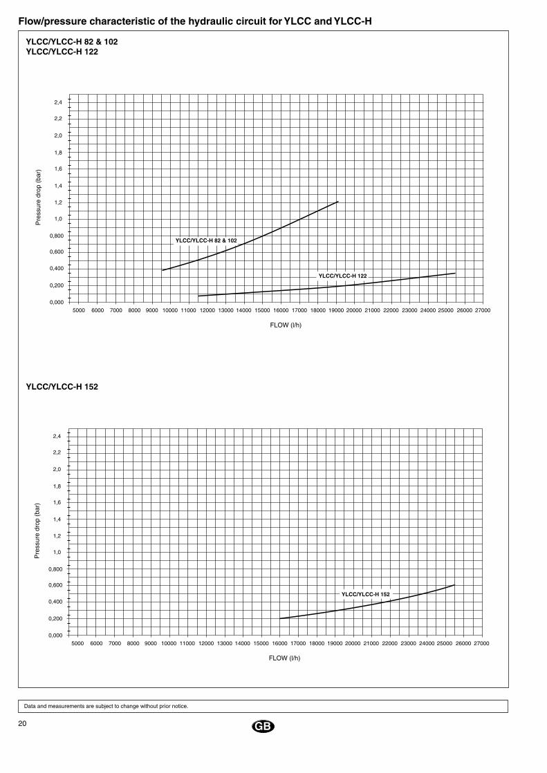
Flow/pressure characteristic of the hydraulic circuit for YLCC and YLCC-H
Data and measurements are subject to change without prior notice.
GB
YLCC/YLCC-H 152
YLCC/YLCC-H 82 & 102YLCC/YLCC-H 122
���������������
���
����
����
������
��
����������
����� �����
�����
�����
�����
����� ����� ����� ����� �����
�����
���
���
����� ����� ����� ����� ����� ����� ����� �����
���
���
���
���
���
���
�������������������������
��������������������
���������������
���������������
���
����
����
������
��
����������
����� �����
�����
�����
�����
����� ����� ����� ����� �����
�����
���
���
����� ����� ����� ����� ����� ����� ����� �����
���
���
���
���
���
���
�������������������������
���������������
21F
Instructions d’installation InspectionDès sa réception, inspecter la marchandi-se et communiquer par écrit les possibles anomalies au transporteur et à la compa-gnie d’assurances.
Protection de l’environnementEmballage
L’emballage est en matériel re-cyclable. Son élimination doit se faire selon les normes établies de ramassage sélectif de résidus en
vigueur dans chaque municipalité.
RéfrigérantContient du gaz fluoré effet de serre cou-vert par le protocole de Kyoto.Pour le type de gaz et la quantité par sys-tème, voir la plaque des caractéristiques. GWP (Global Warming Potential): 2107.
Élimination de l’appareilAu moment de s’en défaire, après une lon-gue vie en fonctionnement, il faut procéder à la récupération écologique de ses com-posants. Le circuit frigorifique est chargé de fluide frigorigène qui doit être récupéré et remis au fabricant du gaz pour qu’il soit recy-clé. Il restera de l’huile dans le compresseur hermétique qui doit être remis avec le circuit scellé.Le climatiseur sera déposé à un emplacement déterminé par les autorités municipales afin de procéder à sa récupération sélective.
TransportLes unités extérieures doivent toujours être transportées en position verticale afin que l’huile ne s’échappe pas du compresseur. Si pour un motif quelconque, la position de l’unité doit être provisoirement modifiée, elle ne devra y rester que le temps stricte-ment nécessaire.
ManipulationPour le transport de ces unités jusqu’à l’em-placement de l’installation, on peut employer soit les quatre orifices rectangulaires pour un chariot élévateur, soit les quatre orifices cylin-driques qu’il y a aux extrémités du châssis.
Figs. 6 et 7
Symboles d’avertissementLes symboles suivants vous mettent en garde sur l’existence de conditions poten-tiellement dangereuses pour les usagers ou le personnel de maintenance.
Chaque fois qu’il y en aura un sur l’appareil, il faudra tenir compte de ce qu’il indique.
Fig. 1Ce symbole avertit d’un danger électrique.
Fig. 2Précaution: l’unité est dotée d’une télécom-mande et peut, être mise en marche par une tierce personne. Il faut donc la débrancher du courant au moins deux minutes avant de pénétrer à l’intérieur, afin d’éviter tout contact avec la turbine du ventilateur en mouvement.
Fig. 3Précaution: ventilateur en mouvement.
Fig. 4Précaution: lire les instructions avant toute manipulation de l’appareil
Fig. 5Précaution: ne pas toucher les surfaces chaudes.
Fig. 6Précaution: point d’élévation.
EmplacementAvant d’ouvrir l’emballage s’assurer, à l’aide des spécifications inscrites à l’exté-rieur, que vous avez bien reçu le produit adéquat. L’appareil doit être monté sur un plan parfaitement horizontal en s’assurant que la base peut supporter le poids de l’ap-pareil. Si on veut s’assurer de l’absence de vibrations, on peut placer l’appareil sur une base antivibratile en liège ou dans un ma-tériau similaire ou la fixer sur sa base avec des plaques ou des supports antivibratiles. La figure 9 indique les espaces et les fixa-tions qui correspondent aux emplacements de chaque modèle.
Fixation de l’unitéAvant d’installer l’unité, il faut vérifier que la structure peut supporter son poids. Dans des conditions normales, des supports spéciaux ne sont pas nécessaires. Cependant, si l’ap-pareil doit être installé directement dans des bureaux ou des habitations, et dans certains cas extrêmes, il est recommandé d’employer des supports à ressort (fournis comme accessoires) afin que la transmission des vibrations à la structure soit minimale. Si l’appareil doit être placé sur le sol, il faut préparer une base en béton pour que le poids soit distribué uniformément.
Dégagements nécessairesAu moment de l’installation de chaqueunité, il faut laisser un espace libre pour:a) L’aspiration et le refoulement de l’air.b) Le service de maintenance.c) La connexion au réseau électrique.Pour que l’appareil fonctionne correcte-ment, il faut toujours respecter les distances minimales indiquées sur les schémas des dimensions générales concernant les pos-sibles obstacles à la libre circulation de l’air ou aux travaux de maintenance.
DrainageL’appareil est muni d’un raccord pour le drainage des condensats qui se forment dans la batterie pendant le fonctionnement en cycle d’hiver ou pour la vidange totale de l’appareil. Les raccords sont de 28,5 mm de diamètre. Par des températures ex-térieures inférieures à 5°C, l’eau de conden-sation peut prendre en glace et obstruer le drainage. Il convient de tenir compte de ce fait et d’installer une résistance électrique flexible, si on le considère nécessaire. Cette résistance peut être connectée à travers un thermostat d’ambiance régulé, par exemple, à 3°C, lequel connecte la résistance lorsque la température est inférieure à celle qui a été réglée.
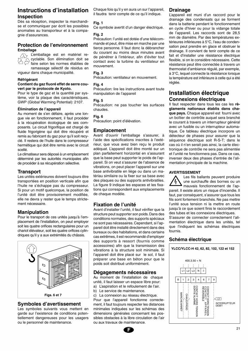
Installation électriqueConnexions électriquesIl faut respecter dans tous les cas les rè-glaments nationaux établis dans cha-que pays. Chaque appareil est fourni avec un boîtier de contrôle auquel sera branché le courant à travers un interrupteur général avec un fusible ou un interrupteur automa-tique. Ce tableau électrique incorpore un détecteur de phases pour assurer que la séquence électrique soit R-S-T; dans le cas où il n’en serait pas ainsi, la carte élec-tronique de contrôle ne sera pas alimentée et l’unité ne fonctionnera pas. Dans ce cas, inverser deux des phases d’entrée de l’ali-mentation principale de la machine.
AVERTISSEMENTLes fils ballants peuvent produire une surchauffe des bornes ou un mauvais fonctionnement de l’ap-
pareil. Il existe alors un risque d’incendie. Il faut, par conséquent, s’assurer que tous les fils sont fortement branchés. Ne pas mettre l’unité sous tension ni la mettre en route jusqu’à ce que soient finis le raccordement des tubes et les connexions électriques.S’assurer de connecter correctement l’ali-mentation électrique dans les unités, tel que l’indiquent les schémas électriques fournis.
Schéma électrique
YLCC/YLCC-H 42, 62, 82, 102, 122 et 152
� � � � � � � �
�����
����
������
����
��
��
���
��
�����
���
��������
��
�����������������
�������
����
��������
����
������������
�� �� �� �
���������
�����
�����
�������
����
��
�
22
EE
Derniers contrôlesVérifier que: - Le voltage est toujours entre
198-254 V ou 342-436 V. - La section des fils d’alimentation
est au moins celle qui est recom-mandée dans les schémas élec-triques correspondants.
- L’utilisateur a reçu les instructions d’utilisation.
- On a communiqué à l’utilisateur qu’il fallait nettoyer périodique-ment le filtre à air.
- La carte de garantie a été rem-plie.
- Les instructions concernant la maintenance ont été données et un contrat de révision périodique a été établi.
F
Raccordements hydrauliquesLes raccordements hydrauliques d’entrée et de sortie de l’eau doivent être faits en respectant les sens indiqués d’entrée et de sortie (Fig.8).On peut employer de la tuyauterie en fer (non galvanisé) ou en cuivre ayant des dimensions non inférieures à celles in-diquées et en tenant compte des pertes de charge dans les dits raccordements et dans l’échangeur interne de l’installation.Il faut dimensionner la pompe conformé-ment à un débit nominal qui permette un Dt de 5°C.Il convient de procéder au raccordement de la tuyauterie avec des raccords antivi-bratiles.Il faut, dans tous les cas, installer un con-trôle de débit pour éviter le fonctionnement de l’appareil sans circulation d’eau. Il faut aussi munir l’appareil d’un filtre pour que la garantie soit applicable. Il faut installer un vase d’expansion adé-quat au volume d’eau total de l’installation dans la tuyauterie de retour de l’eau.Le volume d’eau nécessaire à ces groupes est de :
En hiver, par des températures au-dessous de 0°C, il faut prendre des précautions pour éviter la prise en glace de l’eau dans les tuyauteries et à l’intérieur de l’échangeur du groupe refroidisseur.On emploie généralement les solutions sui-vantes :
Cependant, vérifier dans chaque cas, le volume minimum nécessaire pour l’installation.
Pompe de circulationIl est essentiel, pour que ces unités fonc-tionnent correctement, de sélectionner la pompe adéquate qui puisse fournir au cir-cuit hydraulique le débit d’eau et la pres-
a) Maintenir l’installation toujours en mar- che.b) Remplir le circuit d’une solution antigel (glycol).c) Vider le circuit.
Groupe hydraulique GHPour éviter l’inconfort que peut causer la baisse de la température de l’eau pendant le cycle de dégivrage, ou par l’arrêt de l’unité dû au déclenchement du thermos-tat antigel dans les installations de petit volume, il faut employer un réservoir tam-pon qui augmente l’inertie thermique de l’installation.Les volumes d’eau des groupes GH et la compatibilité de ceux-ci avec les groupes refroidisseurs YLCC/YLCC-H sont les sui-vants:
l/h l/s m c.d.a. kPa
UnitéYLCC
YLCC-H
Débit approximatif de la pompe ∆t 5°C
Pressionminimale fournie
par la pompe
42 6 700 1,86 15 147
62 10 100 2,8 15 147
82 13 500 3,75 15 147
102 17 200 4,77 15 147
122 19 900 5,53 15 147
152 25 800 7,16 15 147
sion suffisants. Pour ce choix, se servir des données du tableau ci-après.
Limites d’utilisation
Modèle
Limites
de voltageTempérature entrée d´air
à la batterie BS
Température sortie d’eauDiff. de
température entre
la sortie
et l´entrée
d´eau
* À des températures d’eau inférieures aux nominales, il est conseillé de toujours utiliser des mélanges antigel du type glycol.
MaximumMinimum
Nominalà
400
Cycle de fonctionnementCycle de fonctionnement
Froid / Chaud
Minimum °C
Froid / Chaud
Maximum °C
Froid / Chaud
Minimum °C
Froid / Chaud
Maximum °C
Minimum
°C
Maximum
°C
YLCC
3 7
YLCC-H
342 436
10 / -
10 / -10
46 / -
46 / 20
5* / -
5* / 30
15 / -
15 / 50
TAILLE
42 = 25 litres 102 = 38,2 litres
62 = 28 litres 122 = 78,5 litres
82 = 38,2 litres 152 = 73,5 litres
YLCC / YLCC-H LITRES
42 200
62 260
82 260
102 600 S
122 600 S
152 600 P
23F
Données physiques et caractéristiques électriquesFroid seul
Puissance frigorifique kW 40,2 64 71 96,1 116 166
Compresseur
Nombre 2 2 2 2 2 2
Type Scroll Scroll Scroll Scroll Tandem-Scroll Tandem-Scroll
Puissance nominale (a) kW 8,3 (x2) 11,7 (x2) 13,7 (x2) 19,1 (x2) 27,6 (x2) 27,9 (x2)
Alimentation électrique V.ph.Hz 400.3.50
Consommation compresseur en froid A 16,2 (x2) 21,3 (x2) 26,3 (x2) 34 (x2) 47,6 (x2) 50,9 (x2)
Consommation démarrrage A 130 135 175 215 135 175
Charge d´huile l 3,25 3,3 6,6 8 6,6 6,6
Type d´huile Polyolester ISO 32
Ventilateur centrifuge
Nombre 2 2 2 2 2 2
Débit d´air total nominal m3/h 13 268 20 122 23 304 28 384 33 247 38 312
Taille ventilateur mm 12-12 15-15 15-15 18-18 18-18 18-18
Puissance (a) W 1 280 (x2) 2 407 (x2) 2 648 (x2) 3 549 (x2) 5 520 (x2) 6 360 (x2)
Consommation ventilateur A 2,9 (x2) 5 (x2) 6,4 (x2) 6,9 (x2) 10,31 (x2) 11,5 (x2)
Consommation démarrage A 17 35 60 60 75 75
Alimentation électrique V.ph.Hz 400.3.50
Régime moteur tr/min 1 420 1 430 1 420 1 420 1 425 1 425
Pression disponible (b) Pa 50 50 50 50 50 50
Batterie extérieure
Nombre 2 2 2 2 2 2
Nombre de rangs x tubes par rang 4 x 42 5 x 42 4 x 48 4 x 48 4 x 48 5 x 48
Ailettes par pouce 14 14 16 16 16 16
Surface frontale m2 1,02 1,02 (x2) 1,31 (x2) 1,31 (x2) 1,77 (x2) 1,77 (x2)
Diamètre tubes 3/8"
Échangeur intérieur
Type Coaxial
Pression maximale de travail du côté eau bar 10 10 10 10 10 10
Débit d´eau nominal l/h 6 760 11 020 12 285 16 424 19 404 22 948
Raccords eau, femelle G. 2" 2" 21/2" 21/2" 3" 3"
Filtre à eau 2" 2" 21/2" 21/2" 3" 3"
Charge de réfrigerant R-407C kg 7,3 (x2) 7,8 (x2) 11,2 (x2) 11,4 (x2) 12 (x2) 16 (x2)
Niveau puissance sonore dB(A) 79 81 82 84 86 90
Niveau puissance sonore à 5 m dB(A) 57 59 60 62 64 70
Niveau puissance sonore à 10 m dB(A) 51 53 54 56 58 62
Dimensions avec emballage
Hauteur mm 1 770 1 770 1 994 1 994 1 994 1 994
Largeur mm 2 340 2 340 2 991 2 991 3 300 3 300
Profondeur mm 883 1 029 1 150 1 150 1 400 1 400
IP 44 44 44 44 44 44
Poids
Net kg 695 816 962 1 133 1 389 1 522
Brut kg 712 834 981 1 153 1 411 1 544
Modèle
a) Consommation dans des conditions normales.b) Pression dans des conditions normales; consulter tableau p. 8 pour tout autre débit.
YLCC-42/42V YLCC-62/62V YLCC-82/82V YLCC-102/102V YLCC-122/122V YLCC-152/152V
24
EE
F
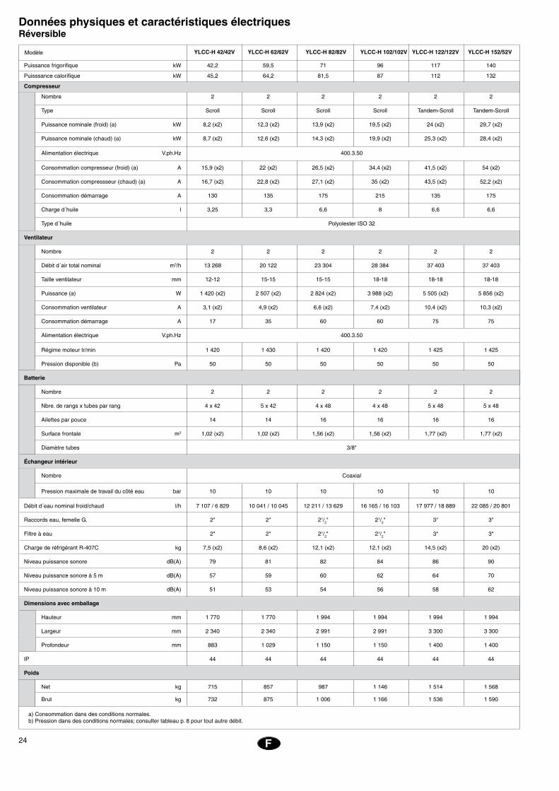
Données physiques et caractéristiques électriquesRéversible
Puissance frigorifique kW 42,2 59,5 71 96 117 140
Puisssance calorifique kW 45,2 64,2 81,5 87 112 132
Compresseur
Nombre 2 2 2 2 2 2
Type Scroll Scroll Scroll Scroll Tandem-Scroll Tandem-Scroll
Puissance nominale (froid) (a) kW 8,2 (x2) 12,3 (x2) 13,9 (x2) 19,5 (x2) 24 (x2) 29,7 (x2)
Puissance nominale (chaud) (a) kW 8,7 (x2) 12,6 (x2) 14,3 (x2) 19,9 (x2) 25,3 (x2) 28,4 (x2)
Alimentation électrique V.ph.Hz 400.3.50
Consommation compresseur (froid) (a) A 15,9 (x2) 22 (x2) 26,5 (x2) 34,4 (x2) 41,5 (x2) 54 (x2)
Consommation compressseur (chaud) (a) A 16,7 (x2) 22,8 (x2) 27,1 (x2) 35 (x2) 43,5 (x2) 52,2 (x2)
Consommation démarrage A 130 135 175 215 135 175
Charge d´huile l 3,25 3,3 6,6 8 6,6 6,6
Type d´huile Polyolester ISO 32
Ventilateur
Nombre 2 2 2 2 2 2
Débit d´air total nominal m3/h 13 268 20 122 23 304 28 384 37 403 37 403
Taille ventilateur mm 12-12 15-15 15-15 18-18 18-18 18-18
Puissance (a) W 1 420 (x2) 2 507 (x2) 2 824 (x2) 3 988 (x2) 5 505 (x2) 5 856 (x2)
Consommation ventilateur A 3,1 (x2) 4,9 (x2) 6,6 (x2) 7,4 (x2) 10,4 (x2) 10,3 (x2)
Consommation démarrage A 17 35 60 60 75 75
Alimentation électrique V.ph.Hz 400.3.50
Régime moteur tr/min 1 420 1 430 1 420 1 420 1 425 1 425
Pression disponible (b) Pa 50 50 50 50 50 50
Batterie
Nombre 2 2 2 2 2 2
Nbre. de rangs x tubes par rang 4 x 42 5 x 42 4 x 48 4 x 48 5 x 48 5 x 48
Ailettes par pouce 14 14 16 16 16 16
Surface frontale m2 1,02 (x2) 1,02 (x2) 1,56 (x2) 1,56 (x2) 1,77 (x2) 1,77 (x2)
Diamètre tubes 3/8"
Échangeur intérieur
Nombre Coaxial
Pression maximale de travail du côté eau bar 10 10 10 10 10 10
Débit d´eau nominal froid/chaud l/h 7 107 / 6 829 10 041 / 10 045 12 211 / 13 629 16 165 / 16 103 17 977 / 18 889 22 085 / 20 801
Raccords eau, femelle G. 2" 2" 21/2" 21/2" 3" 3"
Filtre à eau 2" 2" 21/2" 21/2" 3" 3"
Charge de réfrigérant R-407C kg 7,5 (x2) 8,6 (x2) 12,1 (x2) 12,1 (x2) 14,5 (x2) 20 (x2)
Niveau puissance sonore dB(A) 79 81 82 84 86 90
Niveau puissance sonore à 5 m dB(A) 57 59 60 62 64 70
Niveau puissance sonore à 10 m dB(A) 51 53 54 56 58 62
Dimensions avec emballage
Hauteur mm 1 770 1 770 1 994 1 994 1 994 1 994
Largeur mm 2 340 2 340 2 991 2 991 3 300 3 300
Profondeur mm 883 1 029 1 150 1 150 1 400 1 400
IP 44 44 44 44 44 44
Poids
Net kg 715 857 987 1 146 1 514 1 568
Brut kg 732 875 1 006 1 166 1 536 1 590
Modèle
a) Consommation dans des conditions normales.b) Pression dans des conditions normales; consulter tableau p. 8 pour tout autre débit.
YLCC-H 42/42V YLCC-H 62/62V YLCC-H 82/82V YLCC-H 102/102V YLCC-H 122/122V YLCC-H 152/52V

25F
Caractéristiques électriques
Caractéristiques débit/pression du circuit hydraulique des YLCC et YLCC-H
YLCC/YLCC-H 42YLCC/YLCC-H 62
���������������
���
����
����
����
����
��
�����������
����� �����
�����
�����
�����
����� ����� ����� ����� �����
�����
���
���
����� ����� ����� ����� ����� ����� ����� �����
���
���
���
���
���
���
�������������������������
����������������������������
Intensité déma-rrage
Modèle Alimentation
Compresseur
Intensité fonction-nement
kWAmpères nominaux
Moteur ventil. extérieur Nominal totale
kW
400.3.50
400.3.50
400.3.50
400.3.50
400.3.50
400.3.50
Intensitétotale
(appareil)Ampères
Interrupteurautomatique(Courbe K)Ampères
Sectionminimale
filsmm2
Intensitémaximum totale
(appareil)Ampères
16 (x2) 130 1,5 3 (x2) 18 38 47 50 16
22 (x2) 135 3 4,6 (x2) 29 53 69 80 25
27 (x2) 175 4 6,4 (x2) 33 66 83 100 35
35 (x2) 215 4 7,4 (x2) 46 84 115 125 50
24 (x2) 135 5,5 10,3 (x2) 66 116 135 160 70
27 (x2) 175 5,5 11 (x2) 71 130 163 200 95
YLCC-42 /YLCC-H-42
YLCC-62 /YLCC-H-62
YLCC-82 /YLCC-H-82
YLCC-102 /YLCC-H-102
YLCC-122 /YLCC-H-122
YLCC-152 /YLCC-H-152
26
EE
Caractéristiques débit/pression du circuit hydraulique des YLCC et YLCC-H
F
Données et mesures susceptibles de variation sans préavis.
YLCC/YLCC-H 152
���������������
���
����
����
����
����
��
�����������
����� �����
�����
�����
�����
����� ����� ����� ����� �����
�����
���
���
����� ����� ����� ����� ����� ����� ����� �����
���
���
���
���
���
���
�������������������������
���������������������
���������������
���������������
���
����
����
����
����
��
�����������
����� �����
�����
�����
�����
����� ����� ����� ����� �����
�����
���
���
����� ����� ����� ����� ����� ����� ����� �����
���
���
���
���
���
���
�������������������������
���������������
YLCC/YLCC-H 82 et 102YLCC/YLCC-H 122
27P
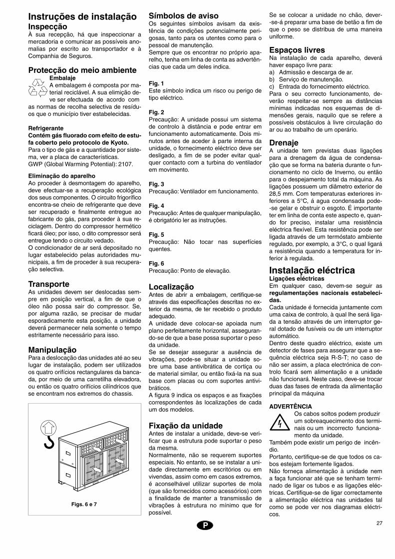
Instruções de instalaçãoInspecçãoÀ sua recepção, há que inspeccionar a mercadoria e comunicar as possíveis ano-malias por escrito ao transportador e à Companhia de Seguros.
Protecção do meio ambienteEmbalajeA embalagem é composta por ma- terial reciclável. A sua elimição de-ve ser efectuada de acordo com
as normas de recolha selectiva de resídu-os que o município tiver estabelecidas.
RefrigeranteContém gás fluorado com efeito de estu-fa coberto pelo protocolo de Kyoto.Para o tipo de gás e a quantidade por siste-ma, ver a placa de características.GWP (Global Warming Potential): 2107.
Eliminação do aparelhoAo proceder à desmontagem do aparelho, deve efectuar-se a recuperação ecológica dos seus componentes. O circuito frigorífico encontra-se cheio de refrigerante que deve ser recuperado e finalmente entregue ao fabricante do gás, para proceder à sua re-ciclagem. Dentro do compressor hermético ficará óleo; por isso, o dito compressor será entregue tendo o circuito vedado.O condicionador de ar será depositado no lugar estabelecido pelas autoridades mu-nicipais, a fim de proceder à sua recupera-ção selectiva.
TransporteAs unidades devem ser deslocadas sem-pre em posição vertical, a fim de que o óleo não possa sair do compressor. Se, por alguma razão, se precisar de mudar esporadicamente esta posição, a unidade deverá permanecer nela somente o tempo estritamente necessário para isso.
ManipulaçãoPara a deslocação das unidades até ao seu lugar de instalação, podem ser utilizados os quatro orifícios rectangulares da banca-da, por meio de uma carretilha elevadora, ou então os quatro orifícios cilíndricos que se encontram nos extremos do chassis.
Figs. 6 e 7
Símbolos de avisoOs seguintes símbolos avisam da exis-tência de condições potencialmente peri-gosas, tanto para os utentes como para o pessoal de manutenção.Sempre que os encontrar no próprio apa-relho, tenha em linha de conta as advertên-cias que cada um deles indica.
Fig. 1Este símbolo indica um risco ou perigo de tipo eléctrico.
Fig. 2Precaução: A unidade possui um sistema de controlo à distância e pode entrar em funcionamento automaticamente. Dois mi-nutos antes de aceder à parte interna da unidade, o fornecimento eléctrico deve ser desligado, a fim de se poder evitar qual-quer contacto com a turbina do ventilador em movimento.
Fig. 3Precaução: Ventilador em funcionamento.
Fig. 4Precaução: Antes de qualquer manipulação, é obrigatório ler as instruções.
Fig. 5Precaução: Não tocar nas superfícies quentes.
Fig. 6Precaução: Ponto de elevação.
LocalizaçãoAntes de abrir a embalagem, certifique-se através das especificações descritas no ex-terior da mesma, de ter recebido o produto adequado.A unidade deve colocar-se apoiada num plano perfeitamente horizontal, asseguran-do-se de que a base possa suportar o peso da unidade.Se se desejar assegurar a ausência de vibrações, pode-se situar a unidade so-bre uma base antivibrática de cortiça ou de material similar, ou então fixá-la na sua base com placas ou com suportes antivi-bráticos.A figura 9 indica os espaços e as fixações correspondentes às localizações de cada um dos modelos.
Fixação da unidadeAntes de instalar a unidade, deve-se veri-ficar que a estrutura pode suportar o peso da mesma.Normalmente, não se requerem suportes especiais. No entanto, se se instalar a uni-dade directamente em escritórios ou em vivendas, assim como em casos extremos, é aconselhável utilizar suportes de mola (que são fornecidos como acessórios) com a finalidade de manter a transmissão de vibrações à estrutura no mínimo que for possível.
Se se colocar a unidade no chão, dever- -se-á preparar uma base de betão a fim de que o peso se distribua de uma maneira uniforme.
Espaços livresNa instalação de cada aparelho, deverá haver espaço livre para:a) Admissão e descarga de ar.b) Serviço de manutenção.c) Entrada do fornecimento eléctrico.Para o seu correcto funcionamento, de-verão respeitar-se sempre as distâncias mínimas indicadas nos esquemas de di-mensões gerais, naquilo que se refere a possíveis obstáculos à livre circulação do ar ou ao trabalho de um operário.
DrenajeA unidade tem previstas duas ligações para a drenagem da água de condensa-ção que se forma na bateria durante o fun-cionamento no ciclo de Inverno, ou então para o despejamento total da máquina. As ligações possuem um diâmetro exterior de 28,5 mm. Com temperaturas exteriores in-feriores a 5°C, á agua condensada pode- -se gelar e obstruir o esgoto. É importante ter em linha de conta este aspecto e, quan-do for preciso, instalar uma resistência eléctrica flexível. Esta resistência pode ser ligada através de um termóstato ambiente regulado, por exemplo, a 3°C, o qual ligará a resistência quando a temperatura for in-ferior à regulada.
Instalação eléctricaLigações eléctricasEm qualquer caso, devem-se seguir as regulamentações nacionais estabeleci-das.Cada unidade é fornecida juntamente com uma caixa de controlo, à qual lhe será liga-da a tensão através de um interruptor ge-ral dotado de fusíveis ou de um interruptor automático.Dentro deste quadro eléctrico, existe um detector de fases para assegurar que a se-quência eléctrica seja R-S-T; no caso de não ser assim, a placa electrónica de con-trolo ficará sem alimentação e a unidade não funcionará. Neste caso, deve-se trocar duas das fases de entrada da alimentação principal da máquina
ADVERTÊNCIAOs cabos soltos podem produzirum sobreaquecimento dos termi- nais ou um incorrecto funciona- mento da unidade.
Também pode existir um perigo de incên- dio. Portanto, certifique-se de que todos os ca-bos estejam fortemente ligados.Não forneça alimentação à unidade nem a faça funcionar até que se tenham termi-nado de ligar os tubos e as ligações eléc-tricas. Certifique-se de ligar correctamente a alimentação eléctrica nas unidades tal como se pode ver nos diagramas eléctri-cos.
28
EE
Antes de dar por finalizada a instalaçãoVerificar se: - A voltagem se encontra sempre
entre 342 - 436 V. - A secção dos cabos de alimenta-
ção é, no mínimo, a aconselhada nos esquemas eléctricos corres-pondentes.
- Ao utente lhe foram dadas instru-ções para a sua utilização.
- Ele foi informado da necessidade da limpeza periódica do filtro de ar.
- Ele preencheu o cartão de garan-tia.
- Lhe foram dadas as instruções de manutenção ou efectuado um contrato de revisão periódica.
P
Ligações hidráulicasAs ligações hidráulicas da entrada e da sa-ída de água da instalação devem-se reali-zar respeitando as direcções de entrada e de saída indicadas (Fig. 8).Pode-se utilizar uma tubagem de ferro (não galvanizado) ou de cobre, com umas dimensões não inferiores às que tenham sido indicadas, devendo-se ter em linha de conta as perdas de carga que se produzem nas ditas ligações e no interpermutador in-terno da instalação.O dimensionamento da bomba deve ser realizado para um caudal nominal que per-mita um Dt de 5°C.É conveniente realizar a ligação da tubagem por meio de acopla-mentos antivibráticos.Deve-se instalar sempre um controlo de caudal a fim de evitar a possibilidade de funcionar sem circulação de água, assim como um filtro de água obrigatório para que a garantia seja de aplicação.Deve-se instalar, na tubagem de retorno
Durante a estação invernal, tendo tempe-raturas exteriores inferiores a 0°C, devem--se tomar precauções a fim de evitar que a água se possa gelar nas redes de tubos e no interior do interpermutador da instala-ção.Normalmente, aplicam-se as soluções seguintes:a) Manter o circulador sempre em funcio-
namento.b) Encher o circuito com uma mistura
anticongelante (glicol).c) Despejar o circuito.
Grupos hidráulicos GHPara evitar a falta de conforto que pode causar a descida da temperatura da água durante o ciclo de eliminação de gelo, ou a paragem da unidade por disparo do ter-móstato antigelo nas instalações de pouco volume, é preciso utilizar um depósito acu-mulador que aumente a inércia térmica da instalação.
de água, um vaso de expansão adequado para o volume total de água da instalação. O volume total de água que possuem as instalações é o seguinte:
YLCC/YLCC-H 42, 62, 82, 102, 122 e 152
Bomba de circulaçãoPara o bom funcionamento das unidades, é essencial seleccionar uma bomba ade-quada que proporcione um caudal e uma pressão suficientes ao circuito hidráulico. Para isso, há que utilizar os dados da ta-bela anexa.
42 6 700 1,86 15 147
62 10 100 2,8 15 147
82 13 500 3,75 15 147
102 17 200 4,77 15 147
122 19 900 5,53 15 147
152 25 800 7,16 15 147
l/h l/s m c.d.a. kPa
Pressão mínima fornecida
pela bomba
Caudal aproximado da bomba ∆t 5°C
UnidadeYLCC
YLCC-H
Limites de utilizaçãoDiferença de tem-
peratura entre a saída e a entrada de água
* A temperaturas de água inferiores às nominais, é aconselhável utilizar sempre misturas anticongelantes do tipo glicol.
Limites
de voltagem
Temperatura de entrada do arpara a bateria T.S. Temperatura de saída da água
Ciclo de funcionamentoCiclo de funcionamentoModelo
Nominala
400 VMínimo °C Máximo °C Mínimo °C Máximo °C
Máx.Mín. Frio / Calor Frio / Calor Frio / Calor Frio / Calor
YLCC 10 / - 46 / - 5* / - 15 / -
3 7342 436
YLCC-H 10 / -10 5* / 30 15 / 50
Mínimo
°C
Máximo
°C
46 / 20
� � � � � � � �
��������������������
����
�����
�
�����������
�����
������������
�� �� �� �
������������
����
���
�����
�����
���
����
����
���
������������
����
���
�����
�����
���
����
�
Esquemas eléctricos
YLCC / YLCC-H LITROS
42 200
62 260
82 260
102 600 S
122 600 S
152 600 P
TAMANHO
42 = 25 litros 102 = 38,2 litros
62 = 28 litros 122 = 78,5 litros
82 = 38,2 litros 152 = 73,5 litros
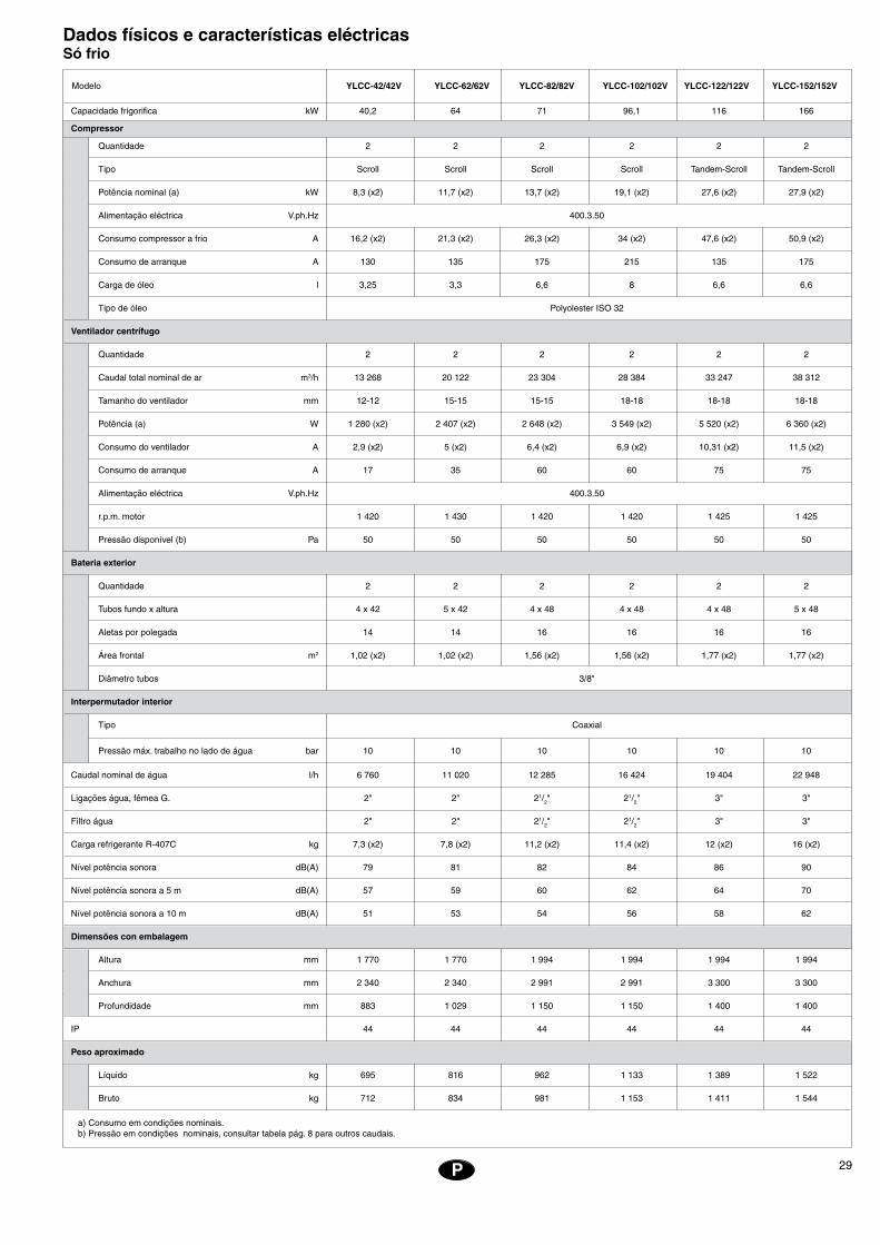
29P
Dados físicos e características eléctricas Só frio
Capacidade frigorifica kW 40,2 64 71 96,1 116 166
Compressor
Quantidade 2 2 2 2 2 2
Tipo Scroll Scroll Scroll Scroll Tandem-Scroll Tandem-Scroll
Potência nominal (a) kW 8,3 (x2) 11,7 (x2) 13,7 (x2) 19,1 (x2) 27,6 (x2) 27,9 (x2)
Alimentação eléctrica V.ph.Hz 400.3.50
Consumo compressor a frio A 16,2 (x2) 21,3 (x2) 26,3 (x2) 34 (x2) 47,6 (x2) 50,9 (x2)
Consumo de arranque A 130 135 175 215 135 175
Carga de óleo l 3,25 3,3 6,6 8 6,6 6,6
Tipo de óleo Polyolester ISO 32
Ventilador centrífugo
Quantidade 2 2 2 2 2 2
Caudal total nominal de ar m3/h 13 268 20 122 23 304 28 384 33 247 38 312
Tamanho do ventilador mm 12-12 15-15 15-15 18-18 18-18 18-18
Potência (a) W 1 280 (x2) 2 407 (x2) 2 648 (x2) 3 549 (x2) 5 520 (x2) 6 360 (x2)
Consumo do ventilador A 2,9 (x2) 5 (x2) 6,4 (x2) 6,9 (x2) 10,31 (x2) 11,5 (x2)
Consumo de arranque A 17 35 60 60 75 75
Alimentação eléctrica V.ph.Hz 400.3.50
r.p.m. motor 1 420 1 430 1 420 1 420 1 425 1 425
Pressão disponível (b) Pa 50 50 50 50 50 50
Bateria exterior
Quantidade 2 2 2 2 2 2
Tubos fundo x altura 4 x 42 5 x 42 4 x 48 4 x 48 4 x 48 5 x 48
Aletas por polegada 14 14 16 16 16 16
Área frontal m2 1,02 (x2) 1,02 (x2) 1,56 (x2) 1,56 (x2) 1,77 (x2) 1,77 (x2)
Diâmetro tubos 3/8"
Interpermutador interior
Tipo Coaxial
Pressão máx. trabalho no lado de água bar 10 10 10 10 10 10
Caudal nominal de água l/h 6 760 11 020 12 285 16 424 19 404 22 948
Ligações água, fêmea G. 2" 2" 21/2" 21/2" 3" 3"
Filtro água 2" 2" 21/2" 21/2" 3" 3"
Carga refrigerante R-407C kg 7,3 (x2) 7,8 (x2) 11,2 (x2) 11,4 (x2) 12 (x2) 16 (x2)
Nível potência sonora dB(A) 79 81 82 84 86 90
Nível potência sonora a 5 m dB(A) 57 59 60 62 64 70
Nível potência sonora a 10 m dB(A) 51 53 54 56 58 62
Dimensões con embalagem
Altura mm 1 770 1 770 1 994 1 994 1 994 1 994
Anchura mm 2 340 2 340 2 991 2 991 3 300 3 300
Profundidade mm 883 1 029 1 150 1 150 1 400 1 400
IP 44 44 44 44 44 44
Peso aproximado
Líquido kg 695 816 962 1 133 1 389 1 522
Bruto kg 712 834 981 1 153 1 411 1 544
Modelo
a) Consumo em condições nominais.b) Pressão em condições nominais, consultar tabela pág. 8 para outros caudais.
YLCC-42/42V YLCC-62/62V YLCC-82/82V YLCC-102/102V YLCC-122/122V YLCC-152/152V
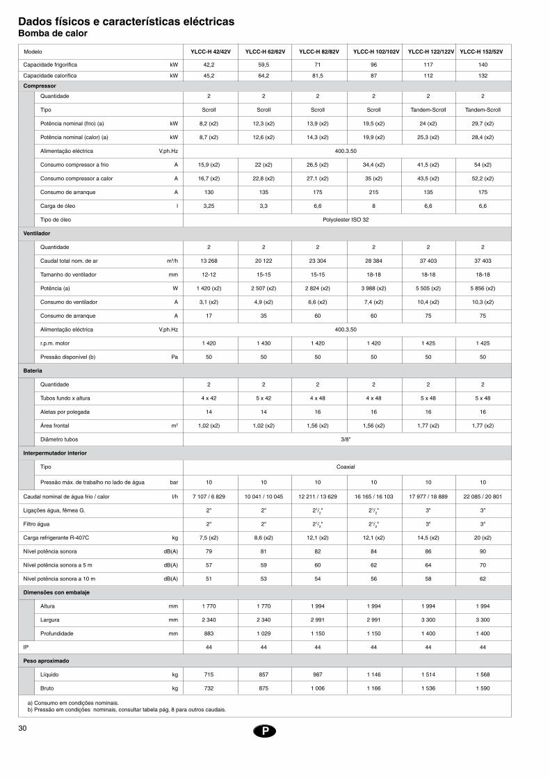
30
EE
P P
Dados físicos e características eléctricas Bomba de calor
Capacidade frigorifica kW 42,2 59,5 71 96 117 140
Capacidade calorífica kW 45,2 64,2 81,5 87 112 132
Compressor
Quantidade 2 2 2 2 2 2
Tipo Scroll Scroll Scroll Scroll Tandem-Scroll Tandem-Scroll
Potência nominal (frio) (a) kW 8,2 (x2) 12,3 (x2) 13,9 (x2) 19,5 (x2) 24 (x2) 29,7 (x2)
Potência nominal (calor) (a) kW 8,7 (x2) 12,6 (x2) 14,3 (x2) 19,9 (x2) 25,3 (x2) 28,4 (x2)
Alimentação eléctrica V.ph.Hz 400.3.50
Consumo compressor a frio A 15,9 (x2) 22 (x2) 26,5 (x2) 34,4 (x2) 41,5 (x2) 54 (x2)
Consumo compressor a calor A 16,7 (x2) 22,8 (x2) 27,1 (x2) 35 (x2) 43,5 (x2) 52,2 (x2)
Consumo de arranque A 130 135 175 215 135 175
Carga de óleo l 3,25 3,3 6,6 8 6,6 6,6
Tipo de óleo Polyolester ISO 32
Ventilador
Quantidade 2 2 2 2 2 2
Caudal total nom. de ar m3/h 13 268 20 122 23 304 28 384 37 403 37 403
Tamanho do ventilador mm 12-12 15-15 15-15 18-18 18-18 18-18
Potência (a) W 1 420 (x2) 2 507 (x2) 2 824 (x2) 3 988 (x2) 5 505 (x2) 5 856 (x2)
Consumo do ventilador A 3,1 (x2) 4,9 (x2) 6,6 (x2) 7,4 (x2) 10,4 (x2) 10,3 (x2)
Consumo de arranque A 17 35 60 60 75 75
Alimentação eléctrica V.ph.Hz 400.3.50
r.p.m. motor 1 420 1 430 1 420 1 420 1 425 1 425
Pressão disponível (b) Pa 50 50 50 50 50 50
Bateria
Quantidade 2 2 2 2 2 2
Tubos fundo x altura 4 x 42 5 x 42 4 x 48 4 x 48 5 x 48 5 x 48
Aletas por polegada 14 14 16 16 16 16
Área frontal m2 1,02 (x2) 1,02 (x2) 1,56 (x2) 1,56 (x2) 1,77 (x2) 1,77 (x2)
Diâmetro tubos 3/8"
Interpermutador interior
Tipo Coaxial
Pressão máx. de trabalho no lado de água bar 10 10 10 10 10 10
Caudal nominal de água frio / calor l/h 7 107 / 6 829 10 041 / 10 045 12 211 / 13 629 16 165 / 16 103 17 977 / 18 889 22 085 / 20 801
Ligações água, fêmea G. 2" 2" 21/2" 21/2" 3" 3"
Filtro água 2" 2" 21/2" 21/2" 3" 3"
Carga refrigerante R-407C kg 7,5 (x2) 8,6 (x2) 12,1 (x2) 12,1 (x2) 14,5 (x2) 20 (x2)
Nível potência sonora dB(A) 79 81 82 84 86 90
Nível potência sonora a 5 m dB(A) 57 59 60 62 64 70
Nível potência sonora a 10 m dB(A) 51 53 54 56 58 62
Dimensões con embalaje
Altura mm 1 770 1 770 1 994 1 994 1 994 1 994
Largura mm 2 340 2 340 2 991 2 991 3 300 3 300
Profundidade mm 883 1 029 1 150 1 150 1 400 1 400
IP 44 44 44 44 44 44
Peso aproximado
Líquido kg 715 857 987 1 146 1 514 1 568
Bruto kg 732 875 1 006 1 166 1 536 1 590
a) Consumo em condições nominais.b) Pressão em condições nominais, consultar tabela pág. 8 para outros caudais.
Modelo YLCC-H 42/42V YLCC-H 62/62V YLCC-H 82/82V YLCC-H 102/102V YLCC-H 122/122V YLCC-H 152/52V

31P
Características eléctricas
Intensidadede arranque
Modelo Alimentação
Compressor
Intensidade de funcionamento
kWAmpérios Nominais
Motor do ventilador exterior Nominal total
kW
400.3.50
400.3.50
400.3.50
400.3.50
400.3.50
400.3.50
Intensidadetotal
(Equipamento)Ampérios
Interruptorautomático(Curva K)Ampérios
Secçãomínima
dos cabosmm2
Intensidademáxima total
(Equipamento)Ampérios
YLCC/YLCC-H 42YLCC/YLCC-H 62
Características de caudal/pressão do circuito hidráulico das unidades YLCC e YLCC-H
���������������
���
����
����
����
����
�
������������
����� �����
�����
�����
�����
����� ����� ����� ����� �����
�����
���
���
����� ����� ����� ����� ����� ����� ����� �����
���
���
���
���
���
���
�������������������������
����������������������������
16 (x2) 130 1,5 3 (x2) 18 38 47 50 16
22 (x2) 135 3 4,6 (x2) 29 53 69 80 25
27 (x2) 175 4 6,4 (x2) 33 66 83 100 35
35 (x2) 215 4 7,4 (x2) 46 84 115 125 50
24 (x2) 135 5,5 10,3 (x2) 66 116 135 160 70
27 (x2) 175 5,5 11 (x2) 71 130 163 200 95
P P
YLCC-42 //YLCC-H-42
YLCC-62 //YLCC-H-62
YLCC-82 //YLCC-H-82
YLCC-102 //YLCC-H-102
YLCC-122 //YLCC-H-122
YLCC-152 / /YLCC-H-152
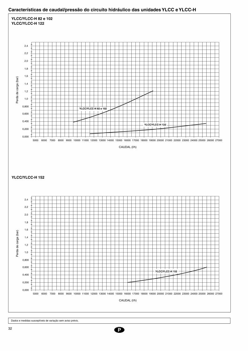
32
EE
YLCC/YLCC-H 82 e 102YLCC/YLCC-H 122
Características de caudal/pressão do circuito hidráulico das unidades YLCC e YLCC-H
P
Dados e medidas susceptíveis de variação sem aviso prévio.
YLCC/YLCC-H 152
���������������
���
����
����
����
����
�
������������
����� �����
�����
�����
�����
����� ����� ����� ����� �����
�����
���
���
����� ����� ����� ����� ����� ����� ����� �����
���
���
���
���
���
���
�������������������������
��������������������
���������������
���������������
���
����
����
����
����
�
������������
����� �����
�����
�����
�����
����� ����� ����� ����� �����
�����
���
���
����� ����� ����� ����� ����� ����� ����� �����
���
���
���
���
���
���
�������������������������
���������������
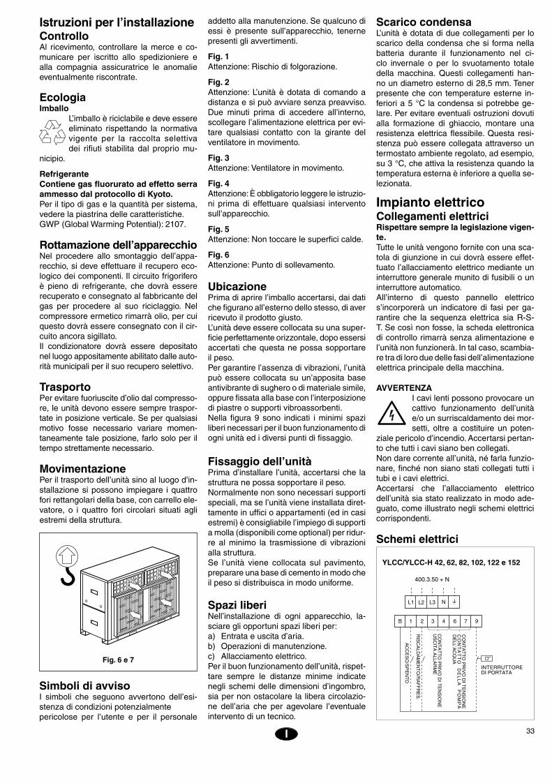
33I
Istruzioni per l’installazioneControlloAl ricevimento, controllare la merce e co-municare per iscritto allo spedizioniere e alla compagnia assicuratrice le anomalie eventualmente riscontrate.
EcologiaImballo
L’imballo è riciclabile e deve essere eliminato rispettando la normativa vigente per la raccolta selettiva dei rifiuti stabilita dal proprio mu-
nicipio.
RefrigeranteContiene gas fluorurato ad effetto serra ammesso dal protocollo di Kyoto.Per il tipo di gas e la quantità per sistema, vedere la piastrina delle caratteristiche.GWP (Global Warming Potential): 2107.
Rottamazione dell’apparecchioNel procedere allo smontaggio dell’appa-recchio, si deve effettuare il recupero eco-logico dei componenti. Il circuito frigorifero è pieno di refrigerante, che dovrà essere recuperato e consegnato al fabbricante del gas per procedere al suo riciclaggio. Nel compressore ermetico rimarrà olio, per cui questo dovrà essere consegnato con il cir-cuito ancora sigillato.Il condizionatore dovrà essere depositato nel luogo appositamente abilitato dalle auto-rità municipali per il suo recupero selettivo.
TrasportoPer evitare fuoriuscite d’olio dal compresso-re, le unità devono essere sempre traspor-tate in posizione verticale. Se per qualsiasi motivo fosse necessario variare momen-taneamente tale posizione, farlo solo per il tempo strettamente necessario.
MovimentazionePer il trasporto dell’unità sino al luogo d’in-stallazione si possono impiegare i quattro fori rettangolari della base, con carrello ele-vatore, o i quattro fori circolari situati agli estremi della struttura.
Fig. 6 e 7
addetto alla manutenzione. Se qualcuno di essi è presente sull’apparecchio, tenerne presenti gli avvertimenti.
Fig. 1Attenzione: Rischio di folgorazione.
Fig. 2Attenzione: L’unità è dotata di comando a distanza e si può avviare senza preavviso. Due minuti prima di accedere all’interno, scollegare l’alimentazione elettrica per evi-tare qualsiasi contatto con la girante del ventilatore in movimento.
Fig. 3Attenzione: Ventilatore in movimento.
Fig. 4Attenzione: È obbligatorio leggere le istruzio-ni prima di effettuare qualsiasi intervento sull’apparecchio.
Fig. 5Attenzione: Non toccare le superfici calde.
Fig. 6Attenzione: Punto di sollevamento.
UbicazionePrima di aprire l’imballo accertarsi, dai dati che figurano all’esterno dello stesso, di aver ricevuto il prodotto giusto.L’unità deve essere collocata su una super-ficie perfettamente orizzontale, dopo essersi accertati che questa ne possa sopportare il peso.Per garantire l’assenza di vibrazioni, l’unità può essere collocata su un’apposita base antivibrante di sughero o di materiale simile, oppure fissata alla base con l’interposizione di piastre o supporti vibroassorbenti.Nella figura 9 sono indicati i minimi spazi liberi necessari per il buon funzionamento di ogni unità ed i diversi punti di fissaggio.
Fissaggio dell’unitàPrima d’installare l’unità, accertarsi che la struttura ne possa sopportare il peso.Normalmente non sono necessari supporti speciali, ma se l’unità viene installata diret-tamente in uffici o appartamenti (ed in casi estremi) è consigliabile l’impiego di supporti a molla (disponibili come optional) per ridur-re al minimo la trasmissione di vibrazioni alla struttura.Se l’unità viene collocata sul pavimento, preparare una base di cemento in modo che il peso si distribuisca in modo uniforme.
Spazi liberiNell’installazione di ogni apparecchio, la-sciare gli opportuni spazi liberi per:a) Entrata e uscita d’aria.b) Operazioni di manutenzione.c) Allacciamento elettrico.Per il buon funzionamento dell’unità, rispet-tare sempre le distanze minime indicate negli schemi delle dimensioni d’ingombro, sia per non ostacolare la libera circolazio-ne dell’aria che per agevolare l’eventuale intervento di un tecnico.
Scarico condensaL’unità è dotata di due collegamenti per lo scarico della condensa che si forma nella batteria durante il funzionamento nel ci-clo invernale o per lo svuotamento totale della macchina. Questi collegamenti han-no un diametro esterno di 28,5 mm. Tener presente che con temperature esterne in-feriori a 5 °C la condensa si potrebbe ge-lare. Per evitare eventuali ostruzioni dovuti alla formazione di ghiaccio, montare una resistenza elettrica flessibile. Questa resi-stenza può essere collegata attraverso un termostato ambiente regolato, ad esempio, su 3 °C, che attiva la resistenza quando la temperatura esterna è inferiore a quella se-lezionata.
Impianto elettricoCollegamenti elettriciRispettare sempre la legislazione vigen-te.Tutte le unità vengono fornite con una sca-tola di giunzione in cui dovrà essere effet-tuato l’allacciamento elettrico mediante un interruttore generale munito di fusibili o un interruttore automatico.All’interno di questo pannello elettrico s’incorporerà un indicatore di fasi per ga-rantire che la sequenza elettrica sia R-S-T. Se così non fosse, la scheda elettronica di controllo rimarrà senza alimentazione e l’unità non funzionerà. In tal caso, scambia-re tra di loro due delle fasi dell’alimentazione elettrica principale della macchina.
AVVERTENZAI cavi lenti possono provocare un cattivo funzionamento dell’unità e/o un surriscaldamento dei mor-setti, oltre a costituire un poten-
ziale pericolo d’incendio. Accertarsi pertan-to che tutti i cavi siano ben collegati.Non dare corrente all’unità, né farla funzio-nare, finché non siano stati collegati tutti i tubi e i cavi elettrici.Accertarsi che l’allacciamento elettrico dell’unità sia stato realizzato in modo ade-guato, come illustrato negli schemi elettrici corrispondenti.
Schemi elettrici
YLCC/YLCC-H 42, 62, 82, 102, 122 e 152
� � � � � � � �
����������
���
���
��������
��
��
������
��
�����
��
���
������
����
���
����
��
������
�������
��������
�����
������������
�� �� �� �
����������������������
����������
���
���
��������
��
�����
���
�����
�
Simboli di avvisoI simboli che seguono avvertono dell’esi-stenza di condizioni potenzialmente pericolose per l’utente e per il personale
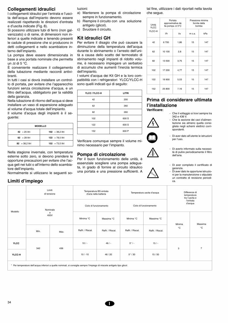
34
EE
Prima di considerare ultimata l’installazioneVerificare: - Che il voltaggio si trovi sempre tra
342 e 436 V. - Che la sezione dei cavi d’alimen-
tazione sia almeno quella consi-gliata negli schemi elettrici corri-spondenti.
- Di aver dato all’utente le istruzioni per l’uso.
- Di averlo informato sulla necessi-tà di pulire periodicamente il filtro dell’aria.
- Di aver compilato il certificato di garanzia.
- Di aver dato le opportune istruzio-ni per la manutenzione o stipulato un contratto di revisione periodi-ca.
I
Collegamenti idrauliciI collegamenti idraulici per l’entrata e l’usci-ta dell’acqua dall’impianto devono essere realizzati rispettando le direzioni d’entrata e d’uscita indicate (Fig. 8).Si possono utilizzare tubi di ferro (non gal-vanizzato) o di rame, di dimensioni non in-feriori a quelle indicate e tenendo presenti le cadute di pressione che si producono in detti collegamenti e nello scambiatore in-terno dell’impianto.La pompa deve essere dimensionata in base a una portata nominale che permetta un Dt di 5 °C.È conveniente realizzare il collegamento della tubazione mediante raccordi antivi-branti.In tutti i casi si dovrà installare un control-lo di portata, per evitare che l’apparecchio funzioni senza circolazione d’acqua, e un filtro dell’acqua, obbligatorio per la validità della garanzia.Nella tubazione di ritorno dell’acqua si deve installare un vaso di espansione adeguato al volume d’acqua totale dell’impianto.Il volume d’acqua degli impianti è il se-guente:
Nella stagione invernale, con temperature esterne sotto zero, si devono prendere le opportune precauzioni per evitare che l’ac-qua geli nei tubi o all’interno dello scambia-tore dell’impianto.Normalmente si utilizzano le seguenti so-
Verificare comunque sempre il volume mi-nimo necessario per l’impianto.
Pompa di circolazionePer il buon funzionamento delle unità, è essenziale scegliere una pompa adegua-ta, in grado di fornire al circuito idraulico una portata e una pressione sufficienti. A
Modello
Limiti
di tensioneTemperatura BS entrata
d’aria nella batteria Temperatura uscita d’acqua Differenza di temperatura tra l’uscita e
l’entrata d’acqua
* Per temperature dell’acqua inferiori a quelle nominali, si consiglia sempre l’impiego di miscele antigelo tipo glicol.
Máx.Mín.
Nominalea
400V
Ciclo di funzionamentoCiclo di funzionamento
Raffr. / Riscal.
Minima °C Massima °C Minima °C Massima °C
Minima
°C
Massima
°C
Limiti d’impiego
Raffr. / Riscal. Raffr. / Riscal. Raffr. / Riscal.
YLCC
3 7
YLCC-H
342 436
10 / -
10 / -10
46 / -
46 / 20
5* / -
5* / 30
15 / -
15 / 50
luzioni:a) Mantenere la pompa di circolazione sempre in funzionamento.b) Riempire il circuito con una soluzione antigelo (glicol).c) Svuotare il circuito.
Kit idraulici GHPer evitare il disagio che può causare la diminuzione della temperatura dell’acqua durante lo sbrinamento o l’arresto dell’uni-tà a causa dello scatto del termostato di sbrinamento negli impianti di ridotto volu-me, è necessario impiegare un serbatoio di accumulo che aumenti l’inerzia termica dell’impianto.I volumi d’acqua dei Kit GH e la loro com-patibilità con i refrigeratori YLCC/YLCC-H sono quelli indicati qui di seguito:
tal fine, utilizzare i dati riportati nella tavola che segue.
l/h l/s m c.a. kPa
UnitàYLCC
YLCC-H
Pressione minimafornita dalla
bomba
Portataapproximativa della pompa ∆t 5°C
42 6 700 1,86 15 147
62 10 100 2,8 15 147
82 13 500 3,75 15 147
102 17 200 4,77 15 147
122 19 900 5,53 15 147
152 25 800 7,16 15 147
MODELLO
42 = 25 litri 102 = 38,2 litri
62 = 28 litri 122 = 78,5 litri
82 = 38,2 litri 152 = 73,5 litri
YLCC / YLCC-H LITRI
42 200
62 260
82 260
102 600 S
122 600 S
152 600 P

35I
Dati tecnici e caratteristiche elettriche Unità solo freddo
Resa in raffrescamento kW 40,2 64 71 96,1 116 166
Compressore
Quantità 2 2 2 2 2 2
Tipo Scroll Scroll Scroll Scroll Tandem-Scroll Tandem-Scroll
Potenza nominale (a) kW 8,3 (x2) 11,7 (x2) 13,7 (x2) 19,1 (x2) 27,6 (x2) 27,9 (x2)
Alimentazione elettrica V.ph.Hz 400.3.50
Consumo in raffrescamento A 16,2 (x2) 21,3 (x2) 26,3 (x2) 34 (x2) 47,6 (x2) 50,9 (x2)
Consumo all´avviamento A 130 135 175 215 135 175
Carica d´olio l 3,25 3,3 6,6 8 6,6 6,6
Tipo d´olio Poliolestere ISO 32
Ventilatore centrifugo
Quantità 2 2 2 2 2 2
Portata d´aria nominale totale m3/h 13 268 20 122 23 304 28 384 33 247 38 312
Dimensioni ventilatore mm 12-12 15-15 15-15 18-18 18-18 18-18
Potenza (a) W 1 280 (x2) 2 407 (x2) 2 648 (x2) 3 549 (x2) 5 520 (x2) 6 360 (x2)
Consumo A 2,9 (x2) 5 (x2) 6,4 (x2) 6,9 (x2) 10,31 (x2) 11,5 (x2)
Consumo all´avviamento A 17 35 60 60 75 75
Alimentazione elettrica V.ph.Hz 400.3.50
Regime motore giri/min 1 420 1 430 1 420 1 420 1 425 1 425
Pressione disponible (b) Pa 50 50 50 50 50 50
Batteria esterna
Quantità 2 2 2 2 2 2
Numero di ranghi x altezza tubi 4 x 42 5 x 42 4 x 48 4 x 48 4 x 48 5 x 48
Alette per pollice 14 14 16 16 16 16
Superficie frontale m2 1,02 (x2) 1,02 (x2) 1,56 (x2) 1,56 (x2) 1,77 (x2) 1,77 (x2)
Diametro tubi 3/8"
Scambiatore interno
Tipo Coassiale
Pressione massina di lavoro nel lato acqua bar 10 10 10 10 10 10
Portata d´acqua nominale l/h 6 760 11 020 12 285 16 424 19 404 22 948
Attacchi acqua, femmina G. 2" 2" 21/2" 21/2" 3" 3"
Filtro acqua 2" 2" 21/2" 21/2" 3" 3"
Carica di refrigerante R407C kg 7,3 (x2) 7,8 (x2) 11,2 (x2) 11,4 (x2) 12 (x2) 16 (x2)
Livello di potenza sonora dB(A) 79 81 82 84 86 90
Livello di potenza a 5 m dB(A) 57 59 60 62 64 70
Livello di potenza a 10 m dB(A) 51 53 54 56 58 62
Dimensioni con imballo
Altezza mm 1 770 1 770 1 994 1 994 1 994 1 994
Larghezza mm 2 340 2 340 2 991 2 991 3 300 3 300
Profondità mm 883 1 029 1 150 1 150 1 400 1 400
IP 44 44 44 44 44 44
Peso approssimativo
Netto kg 695 816 962 1 133 1 389 1 522
Lordo kg 712 834 981 1 153 1 411 1 544
Modello
a) Consumo in condizioni nominalli.b) Pressione in condizioni nominalli (per portate differenti, consultare la tavola di pag.8).
YLCC-42/42V YLCC-62/62V YLCC-82/82V YLCC-102/102V YLCC-122/122V YLCC-152/152V
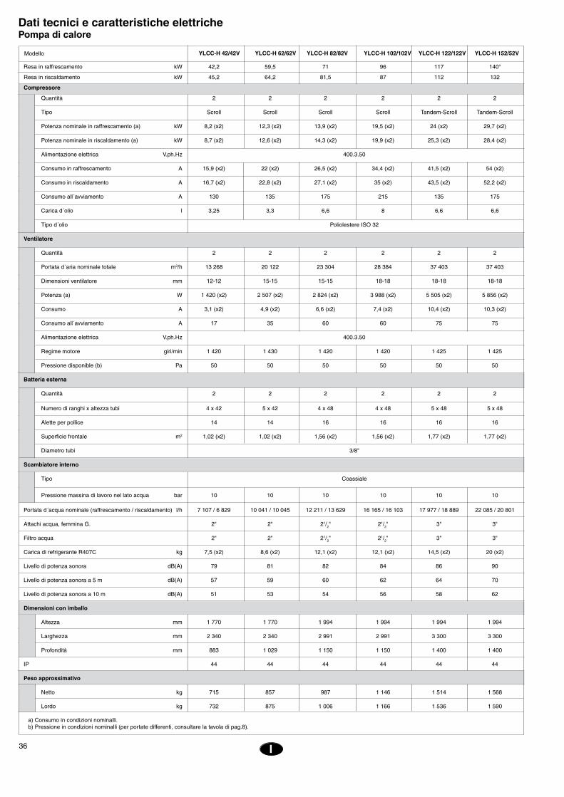
36
EE
I
Dati tecnici e caratteristiche elettriche Pompa di calore
Resa in raffrescamento kW 42,2 59,5 71 96 117 140“
Resa in riscaldamento kW 45,2 64,2 81,5 87 112 132
Compressore
Quantità 2 2 2 2 2 2
Tipo Scroll Scroll Scroll Scroll Tandem-Scroll Tandem-Scroll
Potenza nominale in raffrescamento (a) kW 8,2 (x2) 12,3 (x2) 13,9 (x2) 19,5 (x2) 24 (x2) 29,7 (x2)
Potenza nominale in riscaldamento (a) kW 8,7 (x2) 12,6 (x2) 14,3 (x2) 19,9 (x2) 25,3 (x2) 28,4 (x2)
Alimentazione elettrica V.ph.Hz 400.3.50
Consumo in raffrescamento A 15,9 (x2) 22 (x2) 26,5 (x2) 34,4 (x2) 41,5 (x2) 54 (x2)
Consumo in riscaldamento A 16,7 (x2) 22,8 (x2) 27,1 (x2) 35 (x2) 43,5 (x2) 52,2 (x2)
Consumo all´avviamento A 130 135 175 215 135 175
Carica d´olio l 3,25 3,3 6,6 8 6,6 6,6
Tipo d´olio Poliolestere ISO 32
Ventilatore
Quantità 2 2 2 2 2 2
Portata d´aria nominale totale m3/h 13 268 20 122 23 304 28 384 37 403 37 403
Dimensioni ventilatore mm 12-12 15-15 15-15 18-18 18-18 18-18
Potenza (a) W 1 420 (x2) 2 507 (x2) 2 824 (x2) 3 988 (x2) 5 505 (x2) 5 856 (x2)
Consumo A 3,1 (x2) 4,9 (x2) 6,6 (x2) 7,4 (x2) 10,4 (x2) 10,3 (x2)
Consumo all´avviamento A 17 35 60 60 75 75
Alimentazione elettrica V.ph.Hz 400.3.50
Regime motore giri/min 1 420 1 430 1 420 1 420 1 425 1 425
Pressione disponible (b) Pa 50 50 50 50 50 50
Batteria esterna
Quantità 2 2 2 2 2 2
Numero di ranghi x altezza tubi 4 x 42 5 x 42 4 x 48 4 x 48 5 x 48 5 x 48
Alette per pollice 14 14 16 16 16 16
Superficie frontale m2 1,02 (x2) 1,02 (x2) 1,56 (x2) 1,56 (x2) 1,77 (x2) 1,77 (x2)
Diametro tubi 3/8"
Scambiatore interno
Tipo Coassiale
Pressione massina di lavoro nel lato acqua bar 10 10 10 10 10 10
Portata d´acqua nominale (raffrescamento / riscaldamento) l/h 7 107 / 6 829 10 041 / 10 045 12 211 / 13 629 16 165 / 16 103 17 977 / 18 889 22 085 / 20 801
Attachi acqua, femmina G. 2" 2" 21/2" 21/2" 3" 3"
Filtro acqua 2" 2" 21/2" 21/2" 3" 3"
Carica di refrigerante R407C kg 7,5 (x2) 8,6 (x2) 12,1 (x2) 12,1 (x2) 14,5 (x2) 20 (x2)
Livello di potenza sonora dB(A) 79 81 82 84 86 90
Livello di potenza sonora a 5 m dB(A) 57 59 60 62 64 70
Livello di potenza sonora a 10 m dB(A) 51 53 54 56 58 62
Dimensioni con imballo
Altezza mm 1 770 1 770 1 994 1 994 1 994 1 994
Larghezza mm 2 340 2 340 2 991 2 991 3 300 3 300
Profondità mm 883 1 029 1 150 1 150 1 400 1 400
IP 44 44 44 44 44 44
Peso approssimativo
Netto kg 715 857 987 1 146 1 514 1 568
Lordo kg 732 875 1 006 1 166 1 536 1 590
a) Consumo in condizioni nominalli.b) Pressione in condizioni nominalli (per portate differenti, consultare la tavola di pag.8).
Modello YLCC-H 42/42V YLCC-H 62/62V YLCC-H 82/82V YLCC-H 102/102V YLCC-H 122/122V YLCC-H 152/52V

37I
Caratteristiche elettriche
Amperaggioall'avviamento
Modello Alimentazione
Compressore
Amperaggiodi funzionam.
kWAmperaggio
nominale
Motore del ventilatore esterno Nominale totale
kW
400.3.50
400.3.50
400.3.50
400.3.50
400.3.50
400.3.50
YLCC-42 /YLCC-H-42
YLCC-62 /YLCC-H-62
YLCC-82 /YLCC-H-82
YLCC-102 /YLCC-H-102
YLCC-122 /YLCC-H-122
YLCC-152 /YLCC-H-152
YLCC/YLCC-H 42YLCC/YLCC-H 62
Caratteristiche portata/pressione del circuito idraulico delle unità YLCC e YLCC-H
���������������
���
����
����
����
����
����
��
�������������
����� �����
�����
�����
�����
����� ����� ����� ����� �����
�����
���
���
����� ����� ����� ����� ����� ����� ����� �����
���
���
���
���
���
���
�������������������������
����������������������������
Amperaggiototale
(apparecchio)A
Interruttoreautomatico(curva K)
A
Sezioneminimadei cavi
mm2
Amperaggiomassimo totale(apparecchio)
A
16 (x2) 130 1,5 3 (x2) 18 38 47 50 16
22 (x2) 135 3 4,6 (x2) 29 53 69 80 25
27 (x2) 175 4 6,4 (x2) 33 66 83 100 35
35 (x2) 215 4 7,4 (x2) 46 84 115 125 50
24 (x2) 135 5,5 10,3 (x2) 66 116 135 160 70
27 (x2) 175 5,5 11 (x2) 71 130 163 200 95

38
EE
I
YLCC/YLCC-H 82 e 102YLCC/YLCC-H 122
Caratteristiche portata/pressione del circuito idraulico delle unità YLCC e YLCC-H
Dati e misure soggetti a variazioni senza preavviso.
YLCC/YLCC-H 152
���������������
���
����
����
����
����
����
��
�������������
����� �����
�����
�����
�����
����� ����� ����� ����� �����
�����
���
���
����� ����� ����� ����� ����� ����� ����� �����
���
���
���
���
���
���
�������������������������
���������������
���������������
���
����
����
����
����
����
��
�������������
����� �����
�����
�����
�����
����� ����� ����� ����� �����
�����
���
���
����� ����� ����� ����� ����� ����� ����� �����
���
���
���
���
���
���
�������������������������
��������������������
���������������
39
Hinweise zum EinbauÜberprüfungBei Empfang der Ware muss diese sofort auf mögliche Transportschäden hin über-prüft werden. Eventuelle Beanstandungen müssen dem Spediteur und der Versi-cherungsgesellschaft schriftlich zur Anzeige gebracht werden.
UmweltschutzVerpackung
Für die Verpackung kommt aus- schließlich wiederverwertbares Material zum Einsatz, das gemäß den kommunalen Auflagen für die
selektive Müllsortierung zu entsorgen ist.
KältemittelEnthält vom Kyoto-Protokoll erfasstes fluoriertes Treibhausgas.Art und Menge pro System sind dem jewei-ligen Typenschild zu entnehmen. GWP (Global Warming Potential): 2107.
Entsorgung des GerätsWird das Gerät erneuert und ausgeschlach-tet, ist bei seiner Zerlegung nach ökologi-schen Gesichtspunkten vorzugehen. Der Kältekreis enthält Kältemittel, das entspre-chend aufgefangen und dem Hersteller für Recycling-Zwecke wieder zur Verfügung ge-stellt werden muss. Im Verdichter verbleiben Ölrückstände, weshalb dieser entsprechend abzudichten ist.Zur selektiven Wiederverwertung der Einzel-komponenten ist das Altgerät an dem von den zuständigen Behörden bezeichneten Ort zu deponieren.
TransportUm ein Auslaufen des Öls aus dem Ver-dichter zu vermeiden, müssen die Geräte stets senkrecht weiterbefördert werden. Andere Lagen dürfen nur ausnahmsweise und nicht länger als unbedingt erforderlich in Frage kommen.
BehandlungDer Weitertransport der Maschinen bis zu ihrem endgültigen Aufstellungsort kann mit einem Gabelstapler über die vier unten im Rahmen vorgesehenen rechteckigen Öff-nungen bzw. die vier zylindrischen Öffnun-gen an den Enden des Rahmens erfolgen.
Fig. 6 und 7
D
HinweiszeichenDie nachfolgend beschriebenen Hinweiszei-chen weisen Benutzer und Servicepersonal auf eventuelle Gefahrenquellen hin. Den auf dem Gerät angebrachten Hinweiszeichen ist entsprechend Folge zu leisten.
Fig. 1Verweist auf eine elektrische Gefahren-quelle.
Fig. 2Achtung: Die Anlage ist für Fernbedienung ausgelegt und kann so unvermittelt anlau-fen. Zwei Minuten vor jedem Eingriff in das Gerät muss deshalb die Speisespannung unterbrochen werden, sodass jeder Kon-takt mit einem laufenden Ventilator ausge-schlossen ist.
Fig. 3Achtung: Ventilator in Betrieb.
Fig. 4Achtung: Vor allen weiteren Maßnahmen muss erst die entsprechende Anleitung gelesen werden.
Fig. 5Achtung: Heiße Oberflächen nicht berüh-ren.
Fig. 6Achtung: Hebepunkt.
AufstellungBevor das Gerät ausgepackt wird, ist anhand der außen an der Verpackung angebrachten Beschriftung sicherzustellen, dass auch tatsächlich die richtige Einheit geliefert wurde.Die Einheit muss auf einer vollkommen waagerechten Grundfläche zur Aufstellung kommen, wobei sichergestellt sein muss, dass der Unterbau dem Gewicht der Ma-schine standhält.Um das Auftreten von Schwingungen zu vermeiden, sollte die Einheit auf einer vibrationsfreien Unterlage wie etwa Kork oder einem ähnlichen Material bzw. auf entsprechenden Schwingungsdämpfern gelagert werden.Aus Fig. 9 ergibt sich der für die Aufstellung der einzelnen Modelle in Betracht zu ziehen-de Platz- und Befestigungsbedarf.
Befestigung des GerätsVor Aufstellung des Geräts muss überprüft werden, ob die Struktur dem Gewicht der Einheit standhält.Normalerweise sind keine besonderen Halterungen erforderlich. Kommt das Gerät jedoch direkt in Büro- oder Wohnräumen zur Aufstellung, ist in extremen Fällen unter Umständen die Verwendung von gefederten Spezialhalterungen zu empfehlen (werden als Zubehör geliefert), um so eine Übertra-gung von Schwingungen auf die Gebäude-struktur zu vermeiden.
Kommt das Gerät direkt am Erdboden zur Aufstellung, ist ein Betonunterbau vorzu-sehen, damit sich das Gewicht der Einheit gleichmäßig verteilen kann.
FreiraumBei der Aufstellung des Geräts muss genü-gend Freiraum vorgesehen werden für:a) Luftein- und -austritt,b) Wartungsarbeiten,c) Elektrischer Anschluss.Für einen korrekten Betrieb müssen stets die in den Maßangaben gemachten Min-destabstände zu Hindernissen eingehalten werden, die einen freien Luftumlauf bzw. die Vornahme von Wartungsarbeiten in Frage stellen können.
KondensatablaufFür die Entwässerung der Maschine und die Ableitung des beim Winterbetrieb anfallen-den Kondenswassers ist die Einheit mit zwei Abläufen ausgestattet. Die Anschlussstutzen haben einen Außendurchmesser von 28,5 mm. Bei Außentemperaturen unter 5°C kann das Kondenswasser einfrieren und den Ablauf verstopfen. Nötigenfalls ist hier an den Einbau eines Schlauchheizwiderstands zu denken. Dieser Widerstand kann über einen beispielsweise auf 3°C eingestellten Raumthermostat geführt werden, der den Heizwiderstand dann automatisch in Gang setzt, sobald die Temperatur unter den ein-gestellten Wert absinkt.
ElektrikElektrische AnschlüsseDen örtlichen Auflagen ist auf jeden Fall Folge zu leisten.Die hier beschriebenen Geräte werden mit einem entsprechenden Schaltkasten geliefert, der über einen Hauptschalter mit Sicherung oder einen automatischen Unter-brecher an das Netz anzuschließen ist.In dieser elektrischen Schalttafel ist ein Phasendetektor vorgesehen. Erfasst dieser eine nicht der Sequenz R-S-T entspre-chende Phasenfolge, wird die Versorgung der Steuerplatine unterbrochen und das Gerät stellt seinen Betrieb ein. In diesem Fall müssen zwei Phasen am Eintritt der Stromversorgung der Anlage gegeneinan-der ausgetauscht werden.
ACHTUNGLocker sitzende Kabel können zu einer Überhitzung der Klemmen oder einem fehlerhaften Betrieb der Anlage führen. Ferner be-
steht auch ein konkretes Brandrisiko. Alle Leitungskabel sind deshalb sorgfältig an-zuschließen.Gerät erst an das Netz anschließen und in Betrieb nehmen, wenn alle Leitungen und elektrischen Anschlüsse korrekt installiert sind.Beim elektrischen Anschluss nach den ent-sprechenden Schaltplänen vorgehen.
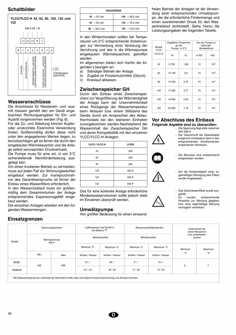
40
EE
Vor Abschluss des EinbausFolgende Aspekte sind zu überprüfen: - Die Spannung liegt stets zwischen
342-436 V. - Der Querschnitt der Speisekabel
entspricht mindestens dem in den entsprechenden Schaltschemen empfohlenen Richtwert.
- Die Benutzer sind entsprechend eingewiesen worden.
- Auf die Notwendigkeit einer re-gelmäßigen Reinigung des Filters wurde hingewiesen.
- Das Garantiezertifikat wurde aus-gefüllt.
- Es wurden entsprechende Hinweise zur Wartung gegeben bzw. eine regelmäßige Wartung vertraglich vereinbart.
D
YLCC/YLCC-H 42, 62, 82, 102, 122 und 152
42 6 700 1,86 15 147
62 10 100 2,8 15 147
82 13 500 3,75 15 147
102 17 200 4,77 15 147
122 19 900 5,53 15 147
152 25 800 7,16 15 147
l/h l/s m WS kPa
ModellYLCC
YLCC-H
Von der Pumpe zu liefernder
Mindestdruck
Ungefähre Fördermen-ge der
Pumpe ∆t 5°C
In den Wintermonaten sollten bei Tempe-raturen um 0°C entsprechende Vorkehrun-gen zur Vermeidung einer Vereisung der Verrohrung und des in die Wärmepumpe eingebauten Wärmetauschers getroffen werden.Im allgemeinen bieten sich hierfür die fol-genden Lösungen an:a) Ständiger Betrieb der Anlage.b) Zugabe on Frostschutzmittel (Glycol).c) Kreislauf ablassen.
Zwischenspeicher GHDurch den Einbau eines Zwischenspei-chers zur Vergrößerung der Wärmeträgheit der Anlage kann der Unannehmlichkeit eines Rückgangs der Wassertemperatur beim Abtauen bzw. einem Stillstand des Geräts durch ein Ansprechen des Abtau-thermostats bei den kleineren Einheiten zuvorgekommen werden.Nachstehend der Wasserinhalt der Zwischenspeicher GH und deren Kompatibilität mit den einzelnen YLCC/YLCC-H-Anlagen:
Das für eine konkrete Anlage erforderliche Mindestwasservolumen sollte jedoch stets im Einzelnen überprüft werden.
UmwälzpumpeVon größter Bedeutung für einen einwand-
WasseranschlüsseDie Anschlüsse für Wasserein- und -aus-tritt müssen gemäß den am Gerät ange-brachten Richtungsangaben für Ein- und Austritt vorgenommen werden (Fig. 8).Für die Zu- und Ableitung können Kupfer- oder unverzinkte Eisenrohre Verwendung finden. Größenmäßig dürfen diese nicht unter den angegebenen Werten liegen; zu berücksichtigen gilt es ferner die durch den eingebauten Wärmetauscher und die Anla-ge selbst verursachten Druckverluste.Die Pumpe muss für eine ein Dt von 5°C sicherstellende Nennförderleistung aus-gelegt sein.Um einen trockenen Betrieb zu vermeiden, muss auf jeden Fall ein Strömungswächter eingebaut werden. Zur Inanspruchnah-me des Garantieanspruchs ist ferner der Einbau eines Wasserfilters erforderlich.In den Wasserrücklauf muss ein größen-mäßig dem Gesamtvolumen der Anlage entsprechendes Expansionsgefäß einge-baut werden.Die einzelnen Anlagen arbeiten mit den fol-genden Wassermengen:
Unterschied zwi-schen Wasserein- und -austrittstem-
peratur
* Bei Wassertemperaturen unterhalb der Nennwerte sollte stets eine Glykol-Frostschutzmischung zum Einsatz kommen.
Einsatzgrenzen
Spannungsgrenzen Lufttemperatur bei Eintritt in die Batterie TT
Wasseraustrittstemperatur
Betriebszyklus Betriebszyklus
ModellNennspannung
400 V
Minimum °C Maximum °C Minimum °C Maximum °CMinimum
°C
Maximum
°CMax.Min. Kühlen / Heizen Kühlen / Heizen Kühlen / Heizen Kühlen / Heizen
3 7342 436YLCC 10 / - 46 / - 5* / - 15 / -
YLCC-H 10 / -10 46 / 20 5* / 30 15 / 50
freien Betrieb der Anlagen ist die Verwen-dung einer entsprechenden Umwälzpum-pe, die die erforderliche Fördermenge und einen ausreichenden Druck für den Was-serkreislauf sicherstellt. Siehe hierzu die Leistungsangaben der folgenden Tabelle.
� � � � � � � �
���
�����������
���
����
��
��
�������
�����
��
���
�����������������
���
�����������
���
����
��
����������
����
�������
����
����
����
�
���
����
������������
�� �� �� �
Schaltbilder BAUGRÖSSE
42 = 25 Liter 102 = 38,2 Liter
62 = 28 Liter 122 = 78,5 Liter
82 = 38,2 Liter 152 = 73,5 Liter
YLCC / YLCC-H LITER
42 200
62 260
82 260
102 600 S
122 600 S
152 600 P
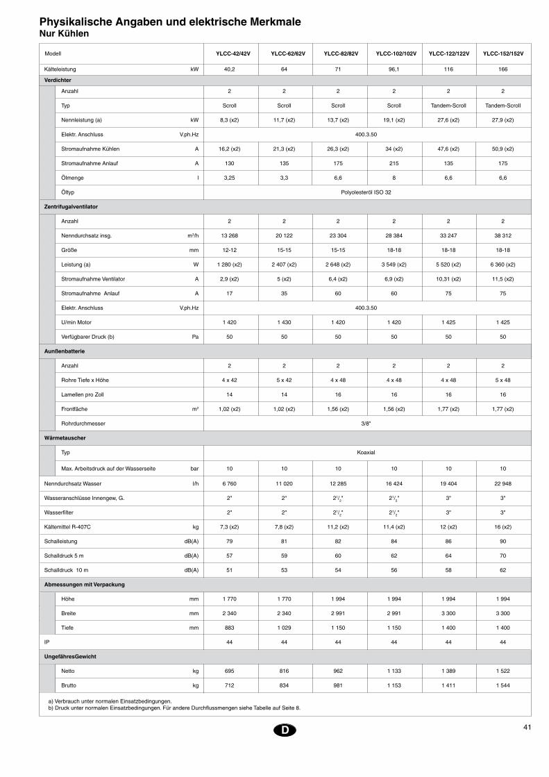
41D
Physikalische Angaben und elektrische MerkmaleNur Kühlen
Kälteleistung kW 40,2 64 71 96,1 116 166
Verdichter
Anzahl 2 2 2 2 2 2
Typ Scroll Scroll Scroll Scroll Tandem-Scroll Tandem-Scroll
Nennleistung (a) kW 8,3 (x2) 11,7 (x2) 13,7 (x2) 19,1 (x2) 27,6 (x2) 27,9 (x2)
Elektr. Anschluss V.ph.Hz 400.3.50
Stromaufnahme Kühlen A 16,2 (x2) 21,3 (x2) 26,3 (x2) 34 (x2) 47,6 (x2) 50,9 (x2)
Stromaufnahme Anlauf A 130 135 175 215 135 175
Ölmenge l 3,25 3,3 6,6 8 6,6 6,6
Öltyp Polyolesteröl ISO 32
Zentrifugalventilator
Anzahl 2 2 2 2 2 2
Nenndurchsatz insg. m3/h 13 268 20 122 23 304 28 384 33 247 38 312
Größe mm 12-12 15-15 15-15 18-18 18-18 18-18
Leistung (a) W 1 280 (x2) 2 407 (x2) 2 648 (x2) 3 549 (x2) 5 520 (x2) 6 360 (x2)
Stromaufnahme Ventilator A 2,9 (x2) 5 (x2) 6,4 (x2) 6,9 (x2) 10,31 (x2) 11,5 (x2)
Stromaufnahme Anlauf A 17 35 60 60 75 75
Elektr. Anschluss V.ph.Hz 400.3.50
U/min Motor 1 420 1 430 1 420 1 420 1 425 1 425
Verfügbarer Druck (b) Pa 50 50 50 50 50 50
Aunßenbatterie
Anzahl 2 2 2 2 2 2
Rohre Tiefe x Höhe 4 x 42 5 x 42 4 x 48 4 x 48 4 x 48 5 x 48
Lamellen pro Zoll 14 14 16 16 16 16
Frontfäche m2 1,02 (x2) 1,02 (x2) 1,56 (x2) 1,56 (x2) 1,77 (x2) 1,77 (x2)
Rohrdurchmesser 3/8"
Wärmetauscher
Typ Koaxial
Max. Arbeitsdruck auf der Wasserseite bar 10 10 10 10 10 10
Nenndurchsatz Wasser l/h 6 760 11 020 12 285 16 424 19 404 22 948
Wasseranschlüsse Innengew, G. 2" 2" 21/2" 21/2" 3" 3"
Wasserfilter 2" 2" 21/2" 21/2" 3" 3"
Kältemittel R-407C kg 7,3 (x2) 7,8 (x2) 11,2 (x2) 11,4 (x2) 12 (x2) 16 (x2)
Schalleistung dB(A) 79 81 82 84 86 90
Schalldruck 5 m dB(A) 57 59 60 62 64 70
Schalldruck 10 m dB(A) 51 53 54 56 58 62
Abmessungen mit Verpackung
Höhe mm 1 770 1 770 1 994 1 994 1 994 1 994
Breite mm 2 340 2 340 2 991 2 991 3 300 3 300
Tiefe mm 883 1 029 1 150 1 150 1 400 1 400
IP 44 44 44 44 44 44
UngefähresGewicht
Netto kg 695 816 962 1 133 1 389 1 522
Brutto kg 712 834 981 1 153 1 411 1 544
Modell YLCC-42/42V YLCC-62/62V YLCC-82/82V YLCC-102/102V YLCC-122/122V YLCC-152/152V
a) Verbrauch unter normalen Einsatzbedingungen.b) Druck unter normalen Einsatzbedingungen. Für andere Durchflussmengen siehe Tabelle auf Seite 8.
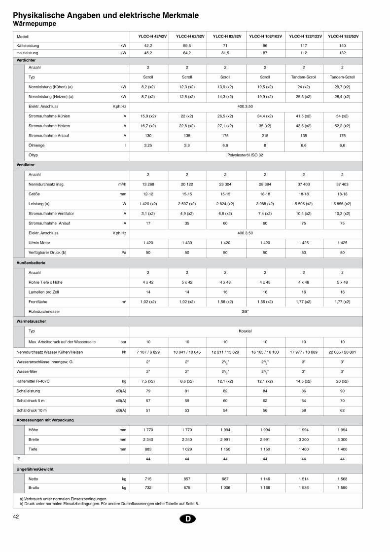
42
EE
D
Physikalische Angaben und elektrische MerkmaleWärmepumpe
Kälteleistung kW 42,2 59,5 71 96 117 140
Heizleistung kW 45,2 64,2 81,5 87 112 132
Verdichter
Anzahl 2 2 2 2 2 2
Typ Scroll Scroll Scroll Scroll Tandem-Scroll Tandem-Scroll
Nennleistung (Kühen) (a) kW 8,2 (x2) 12,3 (x2) 13,9 (x2) 19,5 (x2) 24 (x2) 29,7 (x2)
Nennleistung (Heizen) (a) kW 8,7 (x2) 12,6 (x2) 14,3 (x2) 19,9 (x2) 25,3 (x2) 28,4 (x2)
Elektr. Anschluss V.ph.Hz 400.3.50
Stromaufnahme Kühlen A 15,9 (x2) 22 (x2) 26,5 (x2) 34,4 (x2) 41,5 (x2) 54 (x2)
Stromaufnahme Heizen A 16,7 (x2) 22,8 (x2) 27,1 (x2) 35 (x2) 43,5 (x2) 52,2 (x2)
Stromaufnahme Anlauf A 130 135 175 215 135 175
Ölmenge l 3,25 3,3 6,6 8 6,6 6,6
Öltyp Polyolesteröl ISO 32
Ventilator
Anzahl 2 2 2 2 2 2
Nenndurchsatz insg. m3/h 13 268 20 122 23 304 28 384 37 403 37 403
Größe mm 12-12 15-15 15-15 18-18 18-18 18-18
Leistung (a) W 1 420 (x2) 2 507 (x2) 2 824 (x2) 3 988 (x2) 5 505 (x2) 5 856 (x2)
Stromaufnahme Ventilator A 3,1 (x2) 4,9 (x2) 6,6 (x2) 7,4 (x2) 10,4 (x2) 10,3 (x2)
Stromaufnahme Anlauf A 17 35 60 60 75 75
Elektr. Anschluss V.ph.Hz 400.3.50
U/min Motor 1 420 1 430 1 420 1 420 1 425 1 425
Verfügbarer Druck (b) Pa 50 50 50 50 50 50
Aunßenbatterie
Anzahl 2 2 2 2 2 2
Rohre Tiefe x Höhe 4 x 42 5 x 42 4 x 48 4 x 48 4 x 48 5 x 48
Lamellen pro Zoll 14 14 16 16 16 16
Frontfäche m2 1,02 (x2) 1,02 (x2) 1,56 (x2) 1,56 (x2) 1,77 (x2) 1,77 (x2)
Rohrdurchmesser 3/8"
Wärmetauscher
Typ Koaxial
Max. Arbeitsdruck auf der Wasserseite bar 10 10 10 10 10 10
Nenndurchsatz Wasser Kühen/Heizen l/h 7 107 / 6 829 10 041 / 10 045 12 211 / 13 629 16 165 / 16 103 17 977 / 18 889 22 085 / 20 801
Wasseranschlüsse Innengew, G. 2" 2" 21/2" 21/2" 3" 3"
Wasserfilter 2" 2" 21/2" 21/2" 3" 3"
Kältemittel R-407C kg 7,5 (x2) 8,6 (x2) 12,1 (x2) 12,1 (x2) 14,5 (x2) 20 (x2)
Schalleistung dB(A) 79 81 82 84 86 90
Schalldruck 5 m dB(A) 57 59 60 62 64 70
Schalldruck 10 m dB(A) 51 53 54 56 58 62
Abmessungen mit Verpackung
Höhe mm 1 770 1 770 1 994 1 994 1 994 1 994
Breite mm 2 340 2 340 2 991 2 991 3 300 3 300
Tiefe mm 883 1 029 1 150 1 150 1 400 1 400
IP 44 44 44 44 44 44
UngefähresGewicht
Netto kg 715 857 987 1 146 1 514 1 568
Brutto kg 732 875 1 006 1 166 1 536 1 590
Modell
a) Verbrauch unter normalen Einsatzbedingungen.b) Druck unter normalen Einsatzbedingungen. Für andere Durchflussmengen siehe Tabelle auf Seite 8.
YLCC-H 42/42V YLCC-H 62/62V YLCC-H 82/82V YLCC-H 102/102V YLCC-H 122/122V YLCC-H 152/52V
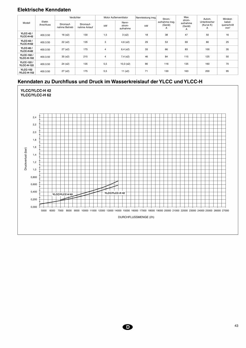
43D
Elektrische Kenndaten
Stromauf-nahme Anlauf
Modell Elektr.Anschluss
Verdichter
Stromauf-nahme Betrieb
kWNenn-strom-
aufnahme
Motor Außenventilator Nennleistung insg.
kW
400.3.50
400.3.50
400.3.50
400.3.50
400.3.50
400.3.50
Strom-aufnahme insg.
(Gerät)A
Autom.Unterbrecher
(Kurve K)A
Mindest-kabel-
querschnittmm2
Max.strom-
aufnahme(Gerät)
A
Kenndaten zu Durchfluss und Druck im Wasserkreislauf der YLCC und YLCC-H
YLCC/YLCC-H 42YLCC/YLCC-H 62
���������������������
���������������
���
����
���������
��
����� �����
�����
�����
�����
����� ����� ����� ����� �����
�����
���
���
����� ����� ����� ����� ����� ����� ����� �����
���
���
���
���
���
���
�������������������������
����������������������������
16 (x2) 130 1,5 3 (x2) 18 38 47 50 16
22 (x2) 135 3 4,6 (x2) 29 53 69 80 25
27 (x2) 175 4 6,4 (x2) 33 66 83 100 35
35 (x2) 215 4 7,4 (x2) 46 84 115 125 50
24 (x2) 135 5,5 10,3 (x2) 66 116 135 160 70
27 (x2) 175 5,5 11 (x2) 71 130 163 200 95
YLCC-42 /YLCC-H-42
YLCC-62 /YLCC-H-62
YLCC-82 /YLCC-H-82
YLCC-102 /YLCC-H-102
YLCC-122 /YLCC-H-122
YLCC-152 /YLCC-H-152
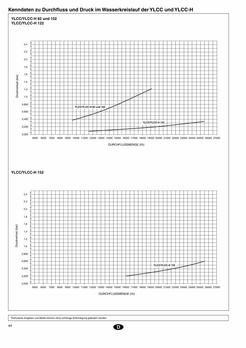
44
EE
Kenndaten zu Durchfluss und Druck im Wasserkreislauf der YLCC und YLCC-H
D
Technische Angaben und Maße können ohne vorherige Ankündigung geändert werden.
YLCC/YLCC-H 152
���������������������
���������������
���
����
���������
��
����� �����
�����
�����
�����
����� ����� ����� ����� �����
�����
���
���
����� ����� ����� ����� ����� ����� ����� �����
���
���
���
���
���
���
�������������������������
����������������������
���������������
���������������
���
����
���������
��
���������������������
����� �����
�����
�����
�����
����� ����� ����� ����� �����
�����
���
���
����� ����� ����� ����� ����� ����� ����� �����
���
���
���
���
���
���
�������������������������
���������������
YLCC/YLCC-H 82 und 102YLCC/YLCC-H 122
45NL
Installatie-instructiesControle bij ontvangstBij ontvangst dienen de goederen gecon-troleerd te worden en bij eventuele gebre-ken dient het transportbedrijf en de verze-keringsmaatschappij hiervan schriftelijk op de hoogte gesteld te worden.
Bescherming van het milieuVerpakking
De verpakking is met recyclebaar materiaal vervaardigd. De verpak-king dient overeenkomstig de door de gemeente vastgelegde milieu-
voorschriften afgevoerd te worden.
KoelmiddelBevat gefluoreerd gas broeikaseffect dat onder het Protocol van Kyoto valt.Voor het type gas en de hoeveelheid per systeem zie het typeplaatje.GWP (Global Warming Potential): 2107.
Afvoer van het toestel Bij het demonteren van het toestel, na een lange gebruikstijd, dienen de onderdelen gerecycleerd te worden. Het koelcircuit is gevuld met koelmiddel dat opgevan-gen dient te worden en dat vervolgens bij de fabrikant van het gas ingeleverd wordt om gerecycleerd te kunnen worden. In de hermetisch afgesloten compressor bevindt zich nog olie en daarom dient deze met het circuit verzegeld ingeleverd te worden.De airconditioner zal naar een door de ge-meentelijke overheid aangewezen plaats afgevoerd worden waar een selectieve teru-gwinning van de onderdelen plaats zal vin-den.
VervoerDeze toestellen dienen altijd in verticale stand verplaatst te worden, zodat de olie in de compressor er niet uit kan lopen. Indien het, om een of andere reden, toch nodig is deze stand bij uitzondering te wijzigen, dan dient dit niet langer dan de daarvoor strikt noodzakelijke tijd te gebeuren.
BehandelingVoor het verplaatsen van de units naar de plaats van installatie kunnen de vier recht-hoekige gaten van de grondplaat, met een heftruck, gebruikt worden of de vier cilin-dervormige gaten die zich aan de uiteinden van het frame bevinden.
WaarschuwingssymbolenDeze symbolen waarschuwen u voor mo-gelijk gevaarlijke situaties; men dient van de betekenis van deze symbolen op de hoogte te zijn en hier rekening mee te houden.
Fig. 1Dit symbool wijst op risico’s of gevaren die met elektriciteit te maken hebben.
Fig. 2Let op: het toestel is met afstandsbediening uitgerust en kan mogelijk ingeschakeld worden. De netspanning dient twee minu-ten voordat men het toestel openmaakt, uitgeschakeld te worden zodat ieder con-tact met de draaiende turbine van de venti-lator uitgesloten is.
Fig. 3Let op: ventilator in beweging.
Fig. 4Let op: het is verplicht, alvorens enige han-deling aan het toestel uit te voeren, eerst de aanwijzingen door te lezen.
Fig. 5Let op: de hete oppervlakken niet aan-raken.
Fig. 6Let op: takelpunt.
PlaatsAlvorens de verpakking open te maken controleren of de specificaties op de bui-tenkant van de verpakking kloppen en u het juiste toestel ontvangen heeft.Het toestel dient op een volledig vlakke on-dergrond geplaatst te worden en men dient erop te letten dat deze het gewicht van het toestel kan dragen.Indien u er zeker van wilt zijn dat er geen trillingen veroorzaakt worden, kan het toe-stel op een trillingdempende ondergrond van kurk of gelijksoortig materiaal ge- plaatst worden of aan de onderzijde met trillingdempende platen of steunen beves-tigd worden.In afbeelding 9 worden de ruimten en be-vestigingen vermeld die met het plaatsen van elk model overeenkomen.
Bevestiging van het toestelAlvorens het toestel te installeren contro-leren of de structuur het gewicht van het toestel kan dragen.Normaal zijn er geen speciale steunen ver-eist. Als echter het toestel direct in kanto-ren of woningen geplaatst wordt en in uit-zonderlijke gevallen, wordt geadviseerd de veersteunen (verkrijgbaar als toebehoren) te gebruiken teneinde de overdracht van trillingen naar de structuur tot een mini-mum te beperken.Wanneer het toestel op de vloer geplaatst wordt, dient er een betonnen ondergrond aangelegd te worden voor een gelijkmatige
Fig. 6 en 7
verdeling van het gewicht.
Vrije ruimtenBij het installeren van elk toestel dient er ruimte vrij gelaten te worden voor:a) Luchtaanvoer en -uitblaas.b) Onderhoud. c) Elektrische installatieVoor de juiste werking dienen de in de schema’s met algemene afmetingen aan-gegeven minimale afstanden in acht geno-men te worden in verband met voorwerpen die mogelijk de vrije luchtcirculatie of de onderhoudswerkzaamheden zouden kun-nen belemmeren.
AfvoerDe unit is voorzien van twee aansluitingen voor de afvoer van condenswater dat in de batterij tijdens het bedrijf in de wintercyclus gevormd wordt of voor het volledig ledigen van de machine. De aansluitingen hebben een uitwendige doorsnede van 28,5 mm.Bij buitentemperaturen onder 5°C kan het condenswater mogelijk bevriezen en de afvoer verstoppen. Men dient hiermee re-kening te houden en, indien men het nodig acht, een flexibel elektrisch verwarmings-element te installeren. Dit element kan via een regelbare ruimte-thermostaat aangesloten worden, bijvoor-beeld bij 3°C, waardoor het verwarming-selement bij een lagere dan de ingestelde temperatuur ingeschakeld wordt.
Elektrische installatieElektrische aansluitingenIn elk geval dienen de geldende landelijke voorschriften in acht genomen te worden.Elke airconditioner wordt met een schakel-kast geleverd die op de spanning aan-gesloten wordt door middel van een ho-ofdschakelaar met zekeringen of een automatische schakelaar.Deze schakelkast is van een fasedetector voorzien om te garanderen dat de elektri-sche volgorde R-S-T is. Is dit niet het geval, dan ontvangt de regelplaat geen stroom en werkt het toestel niet. In dat geval dienen twee van de ingangsfasen van de hoofd-voeding van de machine omgewisseld te worden.
WAARSCHUWINGLosse kabels kunnen tot storingen in de werking van het toestel en oververhitting bij de aansluitklem-men leiden. Bovendien bestaat er brandgevaar. Let er dus op dat alle
kabels goed vast zitten.De voedingsspanning niet aansluiten noch het toestel laten werken voordat alle leidin-gen aangesloten en elektrische aansluitin-gen gemaakt zijn.Erop letten dat de elektrische voeding correct aangesloten is volgens de schakel-schema’s.
46
EE
Alvorens het installeren als beëindigd te beschouwenControleren of: - De spanning altijd tussen 342 - 436
V ligt. - De doorsnede van de netspan-
ningkabels minimaal overeenkomt met de in de desbetreffende schakelschema’s aanbevolen doorsnede.
- De gebruiker aanwijzingen om-trent de bediening heeft gekre-gen.
- De gebruiker ingelicht is omtrent de noodzaak van het regelmatig reinigen van het luchtfilter.
- De garantiekaart ingevuld is. - Men aanwijzingen gegeven heeft
omtrent het onderhoud of dat er een servicecontract afgesloten is.
NL
Hydraulische aansluitingenDe hydraulische aansluitingen bij de water-toe- en waterafvoer van de warmtepomp dienen overeenkomstig de aan de zijkant van het toestel aangegeven richting van de toe- en afvoer uitgevoerd te worden (Fig. 8). Men kan hiervoor (niet-gegalvaniseerde) ijzerbuis gebruiken waarvan de afmetingen niet kleiner dan die van de voorziene aan-sluitingen zijn en rekening houdend met het vullingsverlies bij deze aansluitingen en in de interne warmtewisselaar van de installatie.Het ontwerp van de pomp dient uitgevoerd te worden met een nominaal debiet dat een Dt van 5°C mogelijk maakt.Aanbevolen wordt de leidingen met tril-lingdempende koppelingen aan te sluiten. In alle gevallen dient een debietregelaar geïnstalleerd te worden om uit te sluiten dat de installatie zonder watercirculatie werkt alsmede een waterfilter dat verplicht is om aanspraak op de garantie te kunnen maken. Ook dient er in de waterretourlei-ding een expansievat geïnstalleerd te wor-den dat geschikt is voor de totale waterca-paciteit van de installatie.De watercapaciteit van de aggregaten be-
YLCC/YLCC-H 42, 62, 82, 102, 122 en 152
l/h l/s waterkolom kPa
UnitYLCC
YLCC-H
Door pomp geleverde minimale
druk
Debiet van de pomp bij benadering
∆t 5°C
42 6 700 1,86 15 147
62 10 100 2,8 15 147
82 13 500 3,75 15 147
102 17 200 4,77 15 147
122 19 900 5,53 15 147
152 25 800 7,16 15 147
CirculatiepompHet is van wezenlijk belang voor een goede werking van de toestellen dat een geschik-te pomp wordt gekozen die voldoende doorstroming en druk naar het hydraulis-che circuit bezit. Hiertoe de gegevens uit bijgevoegd overzicht gebruiken.
Gebruikslimieten
Verschil tussen de wateruitlaat- en
waterinlaattemperatuur
* Bij watertemperaturen onder de nominale temperatuur wordt geadviseerd altijd anti-vriesmengsels van het type glysol te gebruiken.
Spanningsgrenzen Luchttemperatuur bij inlaat batterij DB
Wateruitlaattemperatuur
Bedrijfscyclus Bedrijfscyclus
ModelNominaal
bij400 Minimaal °C Maximaal °C Minimaal °C Maximaal °C
Max.Min. Koeling / verwarming Koeling / verwarming Koeling / verwarming Koeling / verwarming
Minim.
°C
Maxim.
°C
YLCC 10 / - 46 / - 5* / - 15 / -3 7342 436
YLCC-H 10 / -10 46 / 20 5* / 30 15 / 50
Toch dient in elk afzonderlijk geval het mini-maal benodigde volume voor de installatie gecontroleerd te worden.
Tijdens de winter bij temperaturen onder nul dienen er voorzorgsmaatregelen geno-men te worden ter voorkoming van het be-vriezen van de leidingen en van de warm-tewisselaar van de warmtepomp.Algemeen wordt dit als volgt opgelost:a) De installatie ledigen.b) Het circuit met een antivriesmengsel (glycol) vullen.c) Het circuit aftappen.
Hydraulische groepen GHTer voorkoming van het ongemak door een verlaging van de temperatuur van het water tijdens de ontdooicyclus of het uitschakelen van het toestel door het inschakelen van de antivriesthermostaat in installaties met be-perkt volumen, dient een buffervat gebruikt te worden die de thermische inertie van de installatie verhoogt. De aanbevolen minimale waterinhoud voor de groepen GH en de compatibiliteit met de aggregaten YLCC/YLCC-H zijn als volgt:
draagt:
� � � � � � � �
����
���
�����
�����
�
������������
�� �� �� �
���
����
��������
����
��
����
������
����
�������
�� �����������������
���
����
��������
����
��
��
���
����
����
��
��
Schakelschema’s
GROOTTE
42 = 25 liter 102 = 38,2 liter
62 = 28 liter 122 = 78,5 liter
82 = 38,2 liter 152 = 73,5 liter
YLCC / YLCC-H LITER
42 200
62 260
82 260
102 600 S
122 600 S
152 600 P
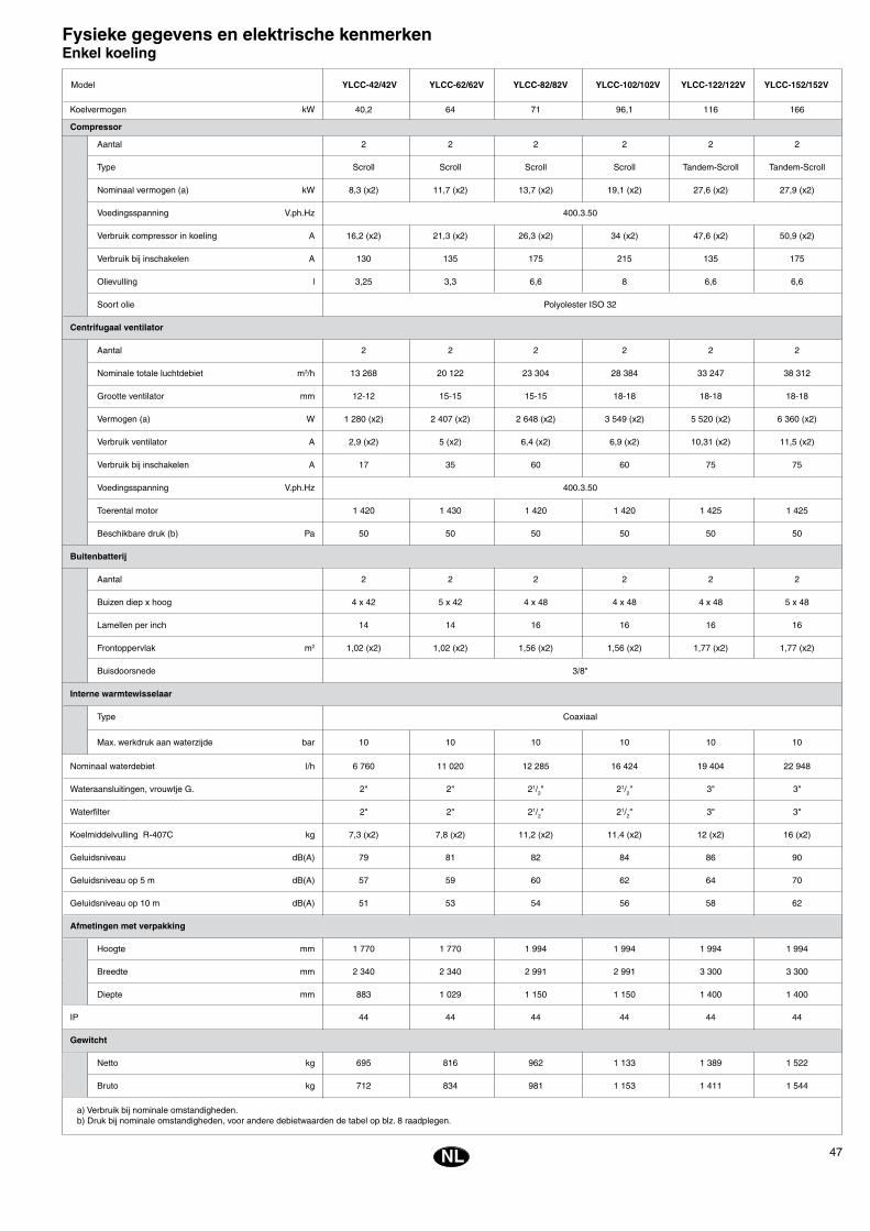
47NL
Fysieke gegevens en elektrische kenmerkenEnkel koeling
Koelvermogen kW 40,2 64 71 96,1 116 166
Compressor
Aantal 2 2 2 2 2 2
Type Scroll Scroll Scroll Scroll Tandem-Scroll Tandem-Scroll
Nominaal vermogen (a) kW 8,3 (x2) 11,7 (x2) 13,7 (x2) 19,1 (x2) 27,6 (x2) 27,9 (x2)
Voedingsspanning V.ph.Hz 400.3.50
Verbruik compressor in koeling A 16,2 (x2) 21,3 (x2) 26,3 (x2) 34 (x2) 47,6 (x2) 50,9 (x2)
Verbruik bij inschakelen A 130 135 175 215 135 175
Olievulling l 3,25 3,3 6,6 8 6,6 6,6
Soort olie Polyolester ISO 32
Centrifugaal ventilator
Aantal 2 2 2 2 2 2
Nominale totale luchtdebiet m3/h 13 268 20 122 23 304 28 384 33 247 38 312
Grootte ventilator mm 12-12 15-15 15-15 18-18 18-18 18-18
Vermogen (a) W 1 280 (x2) 2 407 (x2) 2 648 (x2) 3 549 (x2) 5 520 (x2) 6 360 (x2)
Verbruik ventilator A 2,9 (x2) 5 (x2) 6,4 (x2) 6,9 (x2) 10,31 (x2) 11,5 (x2)
Verbruik bij inschakelen A 17 35 60 60 75 75
Voedingsspanning V.ph.Hz 400.3.50
Toerental motor 1 420 1 430 1 420 1 420 1 425 1 425
Beschikbare druk (b) Pa 50 50 50 50 50 50
Buitenbatterij
Aantal 2 2 2 2 2 2
Buizen diep x hoog 4 x 42 5 x 42 4 x 48 4 x 48 4 x 48 5 x 48
Lamellen per inch 14 14 16 16 16 16
Frontoppervlak m2 1,02 (x2) 1,02 (x2) 1,56 (x2) 1,56 (x2) 1,77 (x2) 1,77 (x2)
Buisdoorsnede 3/8"
Interne warmtewisselaar
Type Coaxiaal
Max. werkdruk aan waterzijde bar 10 10 10 10 10 10
Nominaal waterdebiet l/h 6 760 11 020 12 285 16 424 19 404 22 948
Wateraansluitingen, vrouwtje G. 2" 2" 21/2" 21/2" 3" 3"
Waterfilter 2" 2" 21/2" 21/2" 3" 3"
Koelmiddelvulling R-407C kg 7,3 (x2) 7,8 (x2) 11,2 (x2) 11,4 (x2) 12 (x2) 16 (x2)
Geluidsniveau dB(A) 79 81 82 84 86 90
Geluidsniveau op 5 m dB(A) 57 59 60 62 64 70
Geluidsniveau op 10 m dB(A) 51 53 54 56 58 62
Afmetingen met verpakking
Hoogte mm 1 770 1 770 1 994 1 994 1 994 1 994
Breedte mm 2 340 2 340 2 991 2 991 3 300 3 300
Diepte mm 883 1 029 1 150 1 150 1 400 1 400
IP 44 44 44 44 44 44
Gewitcht
Netto kg 695 816 962 1 133 1 389 1 522
Bruto kg 712 834 981 1 153 1 411 1 544
Model
a) Verbruik bij nominale omstandigheden.b) Druk bij nominale omstandigheden, voor andere debietwaarden de tabel op blz. 8 raadplegen.
YLCC-42/42V YLCC-62/62V YLCC-82/82V YLCC-102/102V YLCC-122/122V YLCC-152/152V
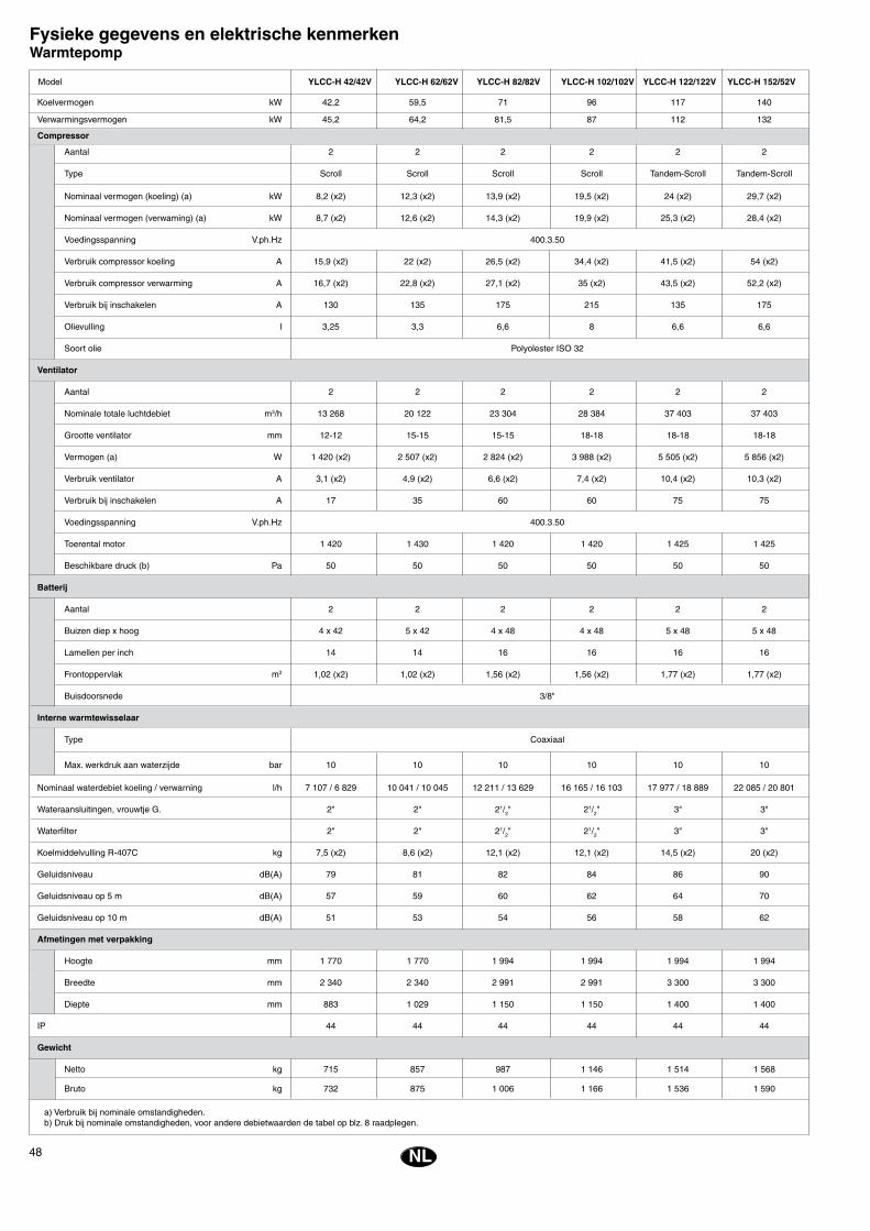
48
EE
NL
Fysieke gegevens en elektrische kenmerkenWarmtepomp
Koelvermogen kW 42,2 59,5 71 96 117 140
Verwarmingsvermogen kW 45,2 64,2 81,5 87 112 132
Compressor
Aantal 2 2 2 2 2 2
Type Scroll Scroll Scroll Scroll Tandem-Scroll Tandem-Scroll
Nominaal vermogen (koeling) (a) kW 8,2 (x2) 12,3 (x2) 13,9 (x2) 19,5 (x2) 24 (x2) 29,7 (x2)
Nominaal vermogen (verwaming) (a) kW 8,7 (x2) 12,6 (x2) 14,3 (x2) 19,9 (x2) 25,3 (x2) 28,4 (x2)
Voedingsspanning V.ph.Hz 400.3.50
Verbruik compressor koeling A 15,9 (x2) 22 (x2) 26,5 (x2) 34,4 (x2) 41,5 (x2) 54 (x2)
Verbruik compressor verwarming A 16,7 (x2) 22,8 (x2) 27,1 (x2) 35 (x2) 43,5 (x2) 52,2 (x2)
Verbruik bij inschakelen A 130 135 175 215 135 175
Olievulling l 3,25 3,3 6,6 8 6,6 6,6
Soort olie Polyolester ISO 32
Ventilator
Aantal 2 2 2 2 2 2
Nominale totale luchtdebiet m3/h 13 268 20 122 23 304 28 384 37 403 37 403
Grootte ventilator mm 12-12 15-15 15-15 18-18 18-18 18-18
Vermogen (a) W 1 420 (x2) 2 507 (x2) 2 824 (x2) 3 988 (x2) 5 505 (x2) 5 856 (x2)
Verbruik ventilator A 3,1 (x2) 4,9 (x2) 6,6 (x2) 7,4 (x2) 10,4 (x2) 10,3 (x2)
Verbruik bij inschakelen A 17 35 60 60 75 75
Voedingsspanning V.ph.Hz 400.3.50
Toerental motor 1 420 1 430 1 420 1 420 1 425 1 425
Beschikbare druck (b) Pa 50 50 50 50 50 50
Batterij
Aantal 2 2 2 2 2 2
Buizen diep x hoog 4 x 42 5 x 42 4 x 48 4 x 48 5 x 48 5 x 48
Lamellen per inch 14 14 16 16 16 16
Frontoppervlak m2 1,02 (x2) 1,02 (x2) 1,56 (x2) 1,56 (x2) 1,77 (x2) 1,77 (x2)
Buisdoorsnede 3/8"
Interne warmtewisselaar
Type Coaxiaal
Max. werkdruk aan waterzijde bar 10 10 10 10 10 10
Nominaal waterdebiet koeling / verwarning l/h 7 107 / 6 829 10 041 / 10 045 12 211 / 13 629 16 165 / 16 103 17 977 / 18 889 22 085 / 20 801
Wateraansluitingen, vrouwtje G. 2" 2" 21/2" 21/2" 3" 3"
Waterfilter 2" 2" 21/2" 21/2" 3" 3"
Koelmiddelvulling R-407C kg 7,5 (x2) 8,6 (x2) 12,1 (x2) 12,1 (x2) 14,5 (x2) 20 (x2)
Geluidsniveau dB(A) 79 81 82 84 86 90
Geluidsniveau op 5 m dB(A) 57 59 60 62 64 70
Geluidsniveau op 10 m dB(A) 51 53 54 56 58 62
Afmetingen met verpakking
Hoogte mm 1 770 1 770 1 994 1 994 1 994 1 994
Breedte mm 2 340 2 340 2 991 2 991 3 300 3 300
Diepte mm 883 1 029 1 150 1 150 1 400 1 400
IP 44 44 44 44 44 44
Gewicht
Netto kg 715 857 987 1 146 1 514 1 568
Bruto kg 732 875 1 006 1 166 1 536 1 590
a) Verbruik bij nominale omstandigheden.b) Druk bij nominale omstandigheden, voor andere debietwaarden de tabel op blz. 8 raadplegen.
Model YLCC-H 42/42V YLCC-H 62/62V YLCC-H 82/82V YLCC-H 102/102V YLCC-H 122/122V YLCC-H 152/52V

49NL
Elektrische gegevensCompressor
kW Nominaleampères
Motor buitenventilator Totaal nominaal
kW
400.3.50
400.3.50
400.3.50
400.3.50
400.3.50
400.3.50
Model Voedings-spanning StartstroomStroomsterkte
Totale stroom-sterkte
(toestel)ampère
Automatischeschakelaar(K-kromme)
ampère
Minimaledoorsnede
netspanning.mm2
Totale stroom-sterkte
maximum(toestel) A
YLCC/YLCC-H 42YLCC/YLCC-H 62
Kenmerken debiet en druk van het hydraulische circuit van de YLCC en YLCC-H
���������������
������
����
�����
����
��
������������
����� �����
�����
�����
�����
����� ����� ����� ����� �����
�����
���
���
����� ����� ����� ����� ����� ����� ����� �����
���
���
���
���
���
���
�������������������������
����������������������������
16 (x2) 130 1,5 3 (x2) 18 38 47 50 16
22 (x2) 135 3 4,6 (x2) 29 53 69 80 25
27 (x2) 175 4 6,4 (x2) 33 66 83 100 35
35 (x2) 215 4 7,4 (x2) 46 84 115 125 50
24 (x2) 135 5,5 10,3 (x2) 66 116 135 160 70
27 (x2) 175 5,5 11 (x2) 71 130 163 200 95
YLCC-42 /YLCC-H-42
YLCC-62 /YLCC-H-62
YLCC-82 /YLCC-H-82
YLCC-102 /YLCC-H-102
YLCC-122 /YLCC-H-122
YLCC-152 /YLCC-H-152
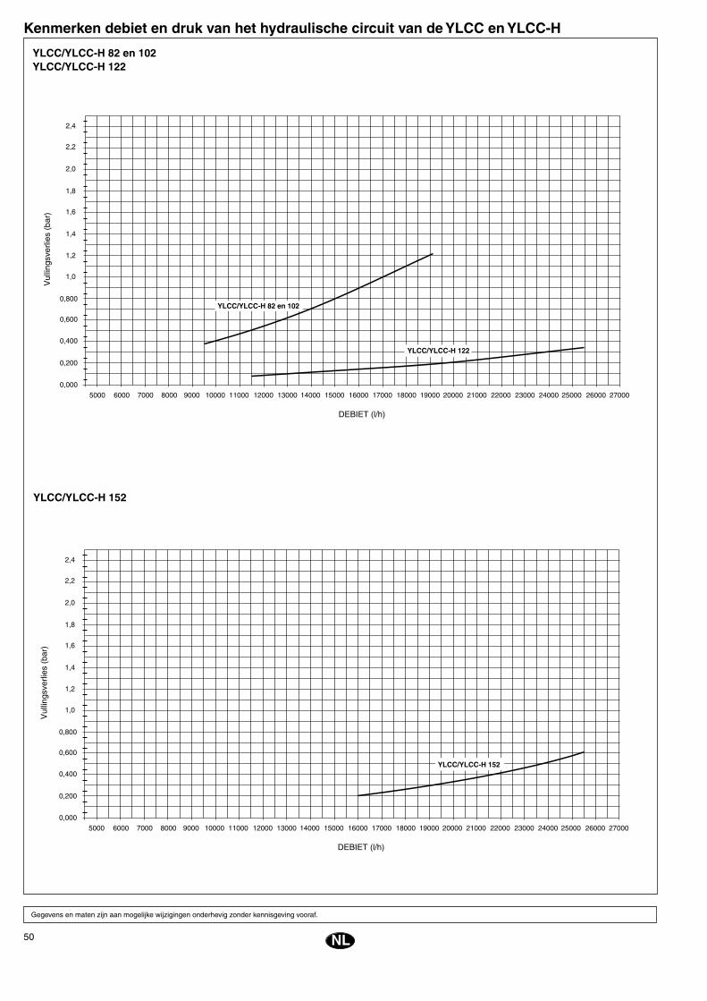
50
EE
YLCC/YLCC-H 82 en 102YLCC/YLCC-H 122
Kenmerken debiet en druk van het hydraulische circuit van de YLCC en YLCC-H
NL
Gegevens en maten zijn aan mogelijke wijzigingen onderhevig zonder kennisgeving vooraf.
YLCC/YLCC-H 152
���������������
������
����
�����
����
��
������������
����� �����
�����
�����
�����
����� ����� ����� ����� �����
�����
���
���
����� ����� ����� ����� ����� ����� ����� �����
���
���
���
���
���
���
�������������������������
���������������
���������������
������
����
�����
����
��
������������
����� �����
�����
�����
�����
����� ����� ����� ����� �����
�����
���
���
����� ����� ����� ����� ����� ����� ����� �����
���
���
���
���
���
���
�������������������������
���������������������
���������������
51N
InstallasjonsinstrukserInspiseringVed mottakelse av apparatet må man un-dersøke at alt er i korrekt stand, og med-dele mulige uregelmessigheter skriftlig til transportbyrået og forsikringsselskapet.
MiljøvernEmballasje
Emballasjen er laget av gjenvinn-bart materiale. Elimineringen må foretas i overensstemmelse med de regler som gjelder i hver kom-
mune for selektiv innsamling av avfallspro-dukter.
KjølemiddelInneholder fluoridgass med drivhuseffekt i henhold til Kyoto-protokollen. For type gass og mengde per system, se merkeplaten. GWP (Global Warming Potential): 2107.
Eliminering av apparatetNår man skal demontere et apparat for å eli-minere det, må alle apparatets komponen-ter gå gjennom en økologisk gjennvinnings-prosess. Kjølekretsen er full av kjølemiddel, som først må tømmes og deretter innleve-res til gassfabrikanten for resirkulering. Det vil være olje igjen inne i den hermetiske kompressoren, så derfor må man forsegle kretsen før man levererer denne inn.Luftkondisjoneringsapparatet må leveres til gjenvinning på et av de stedene kommu-nen har avsatt til dette formål.
TransporteringApparatene må alltid transporteres i loddrett stilling for å unngå at det skal renne olje ut av kompressoren. Hvis det av en eller an-nen grunn skulle være påkrevet å forandre på apparatets stilling, må dette ikke ta len-ger tid enn strengt tatt nødvendig.
ManipuleringFor flytting av enhetene til stedet de skal plasseres, kan man bruke de fire rektan-gulære hullene på underlaget med gaffel-truck, eller de fire runde hullene som finnes på apparatrammens ytterender.
VarselsymbolerNedenstående varselsymboler angir at det eksisterer visse farer for brukere og vedli-
Fig. 6 og 7
YLCC/YLCC-H 42, 62, 82, 102, 122 og 152
� � � � � � � �
�����������������
�������
�������
������
��
�������
������
��
�������
�������
������
���
��
������
�������
�����
����
����
����
�
������������
�� �� �� �
keholdspersonell i forbindelse med betje-ningen av apparatet. Disse symbolene må alltid tas til følge.
Fig. 1Dette symbolet angir en fare av elektrisk type.
Fig. 2Forsiktig: Enheten har fjernkontroll og kan starte automatisk. For å unngå enhver kon-takt med viftens turbin i bevegelse, må man frakoble strømtilførselen til apparatet to mi-nutter før man åpner det.
Fig. 3Forsiktig: Vifte i bevegelse.
Fig. 4Forsiktig: Man må alltid lese instruksene før enhver manipulering av apparatet.
Fig. 5Forsiktig: Ikke berør de varme overflatene.
Fig. 6Forsiktig: Løftepunkt.
PlasseringFør man tar enheten ut av emballasjen, må man forsikre seg om at man har fått riktig apparat ved å se på beskrivelsen på utsi-den av kassen.Enheten må plasseres på en helt jevn over-flate, og man må først forsikre seg om at underlaget den skal settes på, kan tåle en-hetens vekt.Vil man unngå vibrasjoner, kan man plas-sere enheten på et vibrasjons-dempende underlag av kork eller lignende, eller feste apparatets bunnplate med vibrasjonsdem-pende plater eller braketter.Figur 9 angir avstander og festepunkter for hver modell.
Festing av enhetenFør man begynner å montere, må man sjekke at strukturen er i stand til å tåle en-hetens vekt.Vanligvis er det ikke nødvendig å montere spesielle holdere. Hvis imidlertid enheten skal installeres direkte på kontorer eller i boliger, og i ekstreme tilfeller, anbefales man å bruke fjærholdere (som leveres som tilbehør) for å holde vibrasjonsoverføringen til strukturen på et minimumsnivå.Hvis man setter enheten på gulvet, må man først legge et underlag av betong for å oppnå en jevn fordeling av vekten.
Frie avstanderVed installering av hvert apparat må man avse plass til følgende:a) Luftinntak og luftavtrekk.b) Vedlikeholdsarbeid.c) Stikkledninger.For en korrekt drift av apparatet må man alltid respektere de minimums-avstandene som er angitt på skjemaene for generelle dimensjoner med tanke på mulige hindrin-ger for fri luftsirkulasjon eller vedlikeholds-
arbeid.
DrenasjeEnheten er utstyrt med to koblinger for drenasje av kondensvannet som dannes i batteriet under drift på vintersyklus eller for en total tømming av apparatet. Koblingene har en utvendig diameter på 28,5 mm. Ved temperaturer under 5°C kan kondensvan-net fryse og blokkere avløpet. Det er viktig å ta dette i betraktning, og i påkrevne til-felle bør man montere en elastisk elektrisk resistans. Denne resistansen kan tilkobles gjennom en regulert romtermostat, stilt på for eksempel 3°C, som vil aktivere resis-tansen når temperaturen synker under den regulerte.
Elektrisk installasjonElektriske koblingerMan må alltid overholde gjeldende elek-triske forskrifter på området. Hver enhet leveres med en kontrollboks, som strømmen kobles til ved hjelp av en hovedbryter med sikringer eller en automa-tisk bryter.Dette panelet har en fasedetektor for å sikre at fasesekvensen alltid er R-S-T, hvis ikke, vil den elektroniske kontrollplaten ikke motta strøm, og enheten vil ikke virke. Hvis det skal installeres elektrisk resistans, må denne ha egen nettledning og brytere, atskilt fra klimatiseringsapparatets lednin-ger og brytere.
ADVARSELLøse ledninger kan forårsake en overoppheting av polene eller en ukorrekt drift av enheten. Det er også fare for at det kan oppstå
brann. Man må derfor forsikre seg om at alle ledningene er godt festet.Man må verken føre strøm til enheten eller sette den i gang før man har montert alle rørene og fullført de elektriske koblingene.Man må forsikre seg om at den elektriske strømmen er korrekt koblet til enhetene, jfr. de elektriske skjemaene.
Elektriske skjemaer
52
EE
Før man anser installasjonen for avsluttetSjekk: - At spenningen alltid ligger mellom
342 – 436 V - At snittet på mateledningene er
minst det som anbefales på de respektive elektriske skjemaene.
- At bruker er blitt instruert angå-ende betjening av apparatet.
- At man har informert bruker om at luftfilteret må rengjøres regelmes-sig.
- At garantikortet er blitt fylt ut. - At man har gitt instrukser angå-
ende vedlikehold, eller at det er blitt skrevet kontrakt for regelmes-sige revisjoner.
N
Hydrauliske koblingerDe hydrauliske koblingene for inntak og ut-løp av vann til anlegget må foretas i samme retning som angitt på enheten (Fig. 8). Man kan bruke rørledninger av jern (ikke galvanisert) eller av kobber, som minst må ha de målene som er angitt. Man må også ta i betraktning ladningstapene ved nevnte koblingspunkt og i den indre utveksleren i installasjonen.Pumpen må dimensjoneres slik at det gis en nominell strømning som tillater en Dt på 5°C. Ved kobling av rørledningen anbefales man å bruke vibrasjonsdempende koblingsan-ordninger. I alle tilfeller må man installere en strøm-ningskontroll for å forhindre at enheten fun-gerer uten vannsirkulasjon, og et obligato-risk vannfilter, for at garantien skal kunne anvendes.I vannreturledningen må man installere et ekspansjonsbeger som er tilpasset instal-lasjonens totale vannvolum.Anleggenes vannvolum er følgende:
Om vinteren, med utendørstemperaturer under 0°C, må man treffe forsiktighetsre-gler for å unngå at vannet fryser til inne i rørene og inne i anleggets utveksler.De forholdsregler som vanligvis tas, er føl-gende:
Modell
Spennings-grenser
Temperaturluftinntak
til batteriet T.T.Temperatur vannutløp Temperatur-
forskjellmellom vann-
inntak og vannutløp
* Ved vanntemperaturer som ligger under de nominelle, bør man alltid bruke blandinger med frostvæsker av typen glykol.
Maks.Min.
Nominellved 400
Driftssyklus
Kulde / Varme
Minimum °C Maksimum °C Minimum °C Maksimum °C
Minimum
°C
Maksimum
°C
Bruksgrenser
Driftssyklus
Kulde / Varme Kulde / Varme Kulde / Varme
YLCC
3 7
YLCC-H
342 436
10 / -
10 / -10
46 / -
46 / 20
5* / -
5* / 30
15 / -
15 / 50
Man bør imidlertid i hvert tilfelle sjekke in-stallasjonens nødvendige minimumsvolum.
SirkulasjonspumpeFor å oppnå en tilfredsstillende drift av en-hetene må man velge en passende pumpe som forsyner den hydrauliske kretsen med
a) Sirkulatoren holdes i kontinuerlig drift.b) Kretsen fylles med en blanding
frostvæske (glykol).c) Tømme kretsen.
Hydrauliske enheter (HE)For å unngå den mangel på komfort som kan oppstå som følge av at temperaturen på vannet synker under avisingssyklusen, eller at enheten skal stoppe etter utløsning av antifrosttermostaten i mindre anlegg, er det nødvendig å bruke en oppsamlingsbe-holder for å øke installasjonens varemein-erti. Vannvolumene i EH-enhetene og disses kompatibilitet med YLCC/YLCC-H-anleg-gene er følgende:
tilstrekkelig strømning og trykk. Bruk infor-masjonen på vedlagte tabell.
l/h l/s m c.d.a. kPa
EnhetYLCC
YLCC-H
Minimumstrykk levert av pumpen
Tilnærmet pumpekapasitet ∆t 5°C
42 6 700 1,86 15 147
62 10 100 2,8 15 147
82 13 500 3,75 15 147
102 17 200 4,77 15 147
122 19 900 5,53 15 147
152 25 800 7,16 15 147
STØRRELSE
42 = 25 liter 102 = 38,2 liter
62 = 28 liter 122 = 78,5 liter
82 = 38,2 liter 152 = 73,5 liter
YLCC / YLCC-H LITER
42 200
62 260
82 260
102 600 S
122 600 S
152 600 P
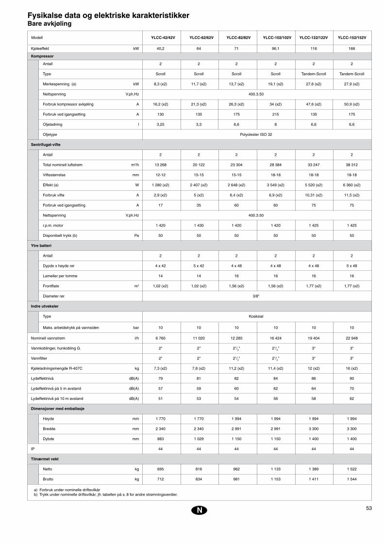
53N
Fysikalse data og elektriske karakteristikker Bare avkjøling
Kjøleeffekt kW 40,2 64 71 96,1 116 166
Kompressor
Antall 2 2 2 2 2 2
Type Scroll Scroll Scroll Scroll Tandem-Scroll Tandem-Scroll
Merkespenning (a) kW 8,3 (x2) 11,7 (x2) 13,7 (x2) 19,1 (x2) 27,6 (x2) 27,9 (x2)
Nettspenning V.ph.Hz 400.3.50
Forbruk kompressor avkjøling A 16,2 (x2) 21,3 (x2) 26,3 (x2) 34 (x2) 47,6 (x2) 50,9 (x2)
Forbruk ved igangsetting A 130 135 175 215 135 175
Oljeladning l 3,25 3,3 6,6 8 6,6 6,6
Oljetype Polyolester ISO 32
Sentrifugal-vifte
Antall 2 2 2 2 2 2
Total nominell luftstrøm m3/h 13 268 20 122 23 304 28 384 33 247 38 312
Viftestørrelse mm 12-12 15-15 15-15 18-18 18-18 18-18
Effekt (a) W 1 280 (x2) 2 407 (x2) 2 648 (x2) 3 549 (x2) 5 520 (x2) 6 360 (x2)
Forbruk vifte A 2,9 (x2) 5 (x2) 6,4 (x2) 6,9 (x2) 10,31 (x2) 11,5 (x2)
Forbruk ved igangsetting A 17 35 60 60 75 75
Nettspenning V.ph.Hz 400.3.50
r.p.m. motor 1 420 1 430 1 420 1 420 1 425 1 425
Disponibelt trykk (b) Pa 50 50 50 50 50 50
Ytre batteri
Antall 2 2 2 2 2 2
Dypde x høyde rør 4 x 42 5 x 42 4 x 48 4 x 48 4 x 48 5 x 48
Lameller per tomme 14 14 16 16 16 16
Frontflate m2 1,02 (x2) 1,02 (x2) 1,56 (x2) 1,56 (x2) 1,77 (x2) 1,77 (x2)
Diameter rør 3/8"
Indre utveksler
Type Koaksial
Maks. arbeidstrykk på vannsiden bar 10 10 10 10 10 10
Nominell vannstrøm l/h 6 760 11 020 12 285 16 424 19 404 22 948
Vannkoblinger, hunkobling G. 2" 2" 21/2" 21/2" 3" 3"
Vannfilter 2" 2" 21/2" 21/2" 3" 3"
Kjøleladningsmengde R-407C kg 7,3 (x2) 7,8 (x2) 11,2 (x2) 11,4 (x2) 12 (x2) 16 (x2)
Lydeffektnivå dB(A) 79 81 82 84 86 90
Lydeffektnivå på 5 m avstand dB(A) 57 59 60 62 64 70
Lydeffektnivå på 10 m avstand dB(A) 51 53 54 56 58 62
Dimensjoner med emballasje
Høyde mm 1 770 1 770 1 994 1 994 1 994 1 994
Bredde mm 2 340 2 340 2 991 2 991 3 300 3 300
Dybde mm 883 1 029 1 150 1 150 1 400 1 400
IP 44 44 44 44 44 44
Tilnærmet vekt
Netto kg 695 816 962 1 133 1 389 1 522
Brutto kg 712 834 981 1 153 1 411 1 544
Modell
a) Forbruk under nominelle driftsvilkårb) Trykk under nominelle driftsvilkår, jfr. tabellen på s. 8 for andre strømningsverdier.
YLCC-42/42V YLCC-62/62V YLCC-82/82V YLCC-102/102V YLCC-122/122V YLCC-152/152V
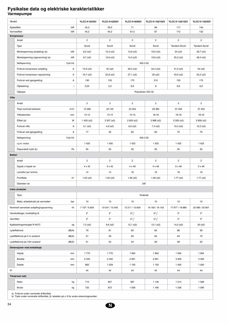
54
EE
N
Fysikalse data og elektriske karakteristikker Varmepumpe
Kjøleeffekt kW 42,2 59,5 71 96 117 140
Varmeeffekt kW 45,2 64,2 81,5 87 112 132
Kompressor
Antall 2 2 2 2 2 2
Type Scroll Scroll Scroll Scroll Tandem-Scroll Tandem-Scroll
Merkespenning (avkjøling) (a) kW 8,2 (x2) 12,3 (x2) 13,9 (x2) 19,5 (x2) 24 (x2) 29,7 (x2)
Merkespenning (oppvarming) (a) kW 8,7 (x2) 12,6 (x2) 14,3 (x2) 19,9 (x2) 25,3 (x2) 28,4 (x2)
Nettspenning V.ph.Hz 400.3.50
Forbruk kompressor avkjøling A 15,9 (x2) 22 (x2) 26,5 (x2) 34,4 (x2) 41,5 (x2) 54 (x2)
Forbruk kompressor oppvarming A 16,7 (x2) 22,8 (x2) 27,1 (x2) 35 (x2) 43,5 (x2) 52,2 (x2)
Forbruk ved igangsetting A 130 135 175 215 135 175
Oljeladning l 3,25 3,3 6,6 8 6,6 6,6
Oljetype Polyolester ISO 32
Vifte
Antall 2 2 2 2 2 2
Total nominell luftstrøm m3/h 13 268 20 122 23 304 28 384 37 403 37 403
Viftestørrelse mm 12-12 15-15 15-15 18-18 18-18 18-18
Effekt (a) W 1 420 (x2) 2 507 (x2) 2 824 (x2) 3 988 (x2) 5 505 (x2) 5 856 (x2)
Forbruk vifte A 3,1 (x2) 4,9 (x2) 6,6 (x2) 7,4 (x2) 10,4 (x2) 10,3 (x2)
Forbruk ved igangsetting A 17 35 60 60 75 75
Nettspenning V.ph.Hz 400.3.50
r.p.m. motor 1 420 1 430 1 420 1 420 1 425 1 425
Disponibelt trykk (b) Pa 50 50 50 50 50 50
Batteri
Antall 2 2 2 2 2 2
Dypde x høyde rør 4 x 42 5 x 42 4 x 48 4 x 48 5 x 48 5 x 48
Lameller per tomme 14 14 16 16 16 16
Frontflate m2 1,02 (x2) 1,02 (x2) 1,56 (x2) 1,56 (x2) 1,77 (x2) 1,77 (x2)
Diameter rør 3/8"
Indre utveksler
Type Koaksial
Maks. arbeidstrykk på vannsiden bar 10 10 10 10 10 10
Nominell vannstrøm avkjøling/oppvarming l/h 7 107 / 6 829 10 041 / 10 045 12 211 / 13 629 16 165 / 16 103 17 977 / 18 889 22 085 / 20 801
Vannkoblinger, hunkobling G. 2" 2" 21/2" 21/2" 3" 3"
Vannfilter 2" 2" 21/2" 21/2" 3" 3"
Kjøleladningsmengde R-407C kg 7,5 (x2) 8,6 (x2) 12,1 (x2) 12,1 (x2) 14,5 (x2) 20 (x2)
Lydeffektnivå dB(A) 79 81 82 84 86 90
Lydeffektnivå på 5 m avstand dB(A) 57 59 60 62 64 70
Lydeffektnivå på 10m avstand dB(A) 51 53 54 56 58 62
Dimensjoner med emballasje
Høyde mm 1 770 1 770 1 994 1 994 1 994 1 994
Bredde mm 2 340 2 340 2 991 2 991 3 300 3 300
Dybde mm 883 1 029 1 150 1 150 1 400 1 400
IP 44 44 44 44 44 44
Tilnærmet vekt
Netto kg 715 857 987 1 146 1 514 1 568
Brutto kg 732 875 1 006 1 166 1 536 1 590
a) Forbruk under nominelle driftsvilkårb) Trykk under nominelle driftsvilkår, jfr. tabellen på s. 8 for andre strømningsverdier.
Modell YLCC-H 42/42V YLCC-H 62/62V YLCC-H 82/82V YLCC-H 102/102V YLCC-H 122/122V YLCC-H 152/52V

55N
Elektriske karakteristikker
Startintensitetkompressor
Modell Nettspenning
Kompressor
Driftintensitetkompressor
kWNominelleampèrer
Motor utendørs vifte Totalt nominell
kW
400.3.50
400.3.50
400.3.50
400.3.50
400.3.50
400.3.50
Totalintensitet(Apparat)Ampèrer
Automatiskbryter
(K-kurve)Ampèrer
Minimums-snitt
ledninger
Total intensitetmaksimum(Apparat)Ampèrer
YLCC/YLCC-H 42YLCC/YLCC-H 62
Strømnings- og trykkarakteristikker i den hydrauliske kretsen til YLCC og YLCC-H
���������������
���������������
����
����
����
����
�
����� �����
�����
�����
�����
����� ����� ����� ����� �����
�����
���
���
����� ����� ����� ����� ����� ����� ����� �����
���
���
���
���
���
���
�������������������������
����������������������������
16 (x2) 130 1,5 3 (x2) 18 38 47 50 16
22 (x2) 135 3 4,6 (x2) 29 53 69 80 25
27 (x2) 175 4 6,4 (x2) 33 66 83 100 35
35 (x2) 215 4 7,4 (x2) 46 84 115 125 50
24 (x2) 135 5,5 10,3 (x2) 66 116 135 160 70
27 (x2) 175 5,5 11 (x2) 71 130 163 200 95
YLCC-42 /YLCC-H-42
YLCC-62 /YLCC-H-62
YLCC-82 /YLCC-H-82
YLCC-102 /YLCC-H-102
YLCC-122 /YLCC-H-122
YLCC-152 /YLCC-H-152

56
EE
YLCC/YLCC-H 82 og 102YLCC/YLCC-H 122
Strømnings- og trykkarakteristikker i den hydrauliske kretsen til YLCC og YLCC-H
N
Data og mål kan endres uten forhåndsvarsel.
YLCC/YLCC-H 152
���������������
����
����
����
����
�
���������������
����� �����
�����
�����
�����
����� ����� ����� ����� �����
�����
���
���
����� ����� ����� ����� ����� ����� ����� �����
���
���
���
���
���
���
�������������������������
���������������
���������������
���������������
����
����
����
����
�
����� �����
�����
�����
�����
����� ����� ����� ����� �����
�����
���
���
����� ����� ����� ����� ����� ����� ����� �����
���
���
���
���
���
���
�������������������������
���������������������
���������������


EN12100-1, EN12100-2, EN563, EN294, EN953, EN378, EN60204-1, EN60335-1, EN60335-2-40, EN61000-3
98/37/CEE, 2006/95/CEE, 2004/108/CEE, 97/23/CEE
DECLARACION CE DE CONFORMIDAD SOBRE MAQUINAS
FIRMA:
FABRICANTE:
Paseo Espronceda, 278, 08204 SABADELLDIRECCIÓN:
Certificamos que el equipo descrito, ha sido diseñado, fabricado y probado de conformidad con los requisitos básicos de la Directiva de Equipos a presión 97/23/CEE y sus correspondientes módulos de aplicación. Así mismo certificamos que el equipo es conforme a las exigencias básicas de las Directivas Europeas que le son aplicables, incluidas las modificaciones de las mismas y las correspondientes transposiciones a la ley nacional.
DIRECTIVAS DE LA CE APLICADAS:
NORMAS ARMONIZADAS APLICADAS:
APLICACIÓN DE LA MÁQUINA: Aire Acondicionado/Refrigeración
CATEGORIA D.E.P. : II (200 < PSxV < 1000)
Nº Organismo Notificado 0099
EN ISO 9001, EN ISO 14001NORMAS INTERNACIONALES YESPECIFICACIONES TÉCNICAS APLICADAS:
LUGAR: Sabadell, (España)
Módulo de evaluación : D1
Organismo Notificado: AENOR C/Génova, 6, 28004 Madrid
EN12100-1, EN12100-2, EN563, EN294, EN953, EN378, EN60204-1, EN60335-1, EN60335-2-40, EN61000-3
98/37/EEC, 2006/95/EEC, 2004/108/EEC, 97/23/EEC
CE DECLARATION OF CONFORMITY
SIGNED BY:
MANUFACTURER:
Paseo Espronceda, 278, 08204 SABADELLADDRESS:
We hereby certify that the mentioned equipment has been designed, manufactured and tested in accordance with essential requirements of Pressure Equipment Directive 97/23/EEC and its relevant application modules. We futher certify that the equipment complies with the essential requirements of the European Directives applicable, including their modifications and the corresponding transpositions from the national law.
EEC DIRECTIVES APPLIED:
APPLIED HARMONIZED STANDARDS:
MACHINE APPLICATION: Air Conditioning / Refrigeration
P.E.D. CATEGORY. : II (200 < PSxV < 1000)
Nr. of Notified Body: 0099
EN ISO 9001, EN ISO 14001APPLIED INTERNATIONAL TECHNICAL STANDARDS AND SPECIFICATIONS:
PLACE: Sabadell, (Spain)
Assessment Module : D1
Notified Body: AENOR C/Génova, 6, 28004 Madrid
. . . . . . . . . . . . . . . . . . . . . . . . . . . . . . . . . . . . . . . . . . .TIPO:
YLCC-42, 62, 82, 102, 122, 152YLCC-H-42, 62, 82, 102, 122, 152
. . . . . . . . . . . . . . . . . . . . . . . . . . . . . . . . . . . . . . . . . . .TIPO:
YLCC-42, 62, 82, 102, 122, 152YLCC-H-42, 62, 82, 102, 122, 152
ROMÁN LARRODA
JEFE DE GESTIÓN DE CALIDAD
ROMÁN LARRODA
QUALITY MANAGER
JOHNSON CONTROLS MANUFACTURING ESPAÑA, S.L.
JOHNSON CONTROLS MANUFACTURING ESPAÑA, S.L.

www.johnsoncontrols.com
Related Documents