IAEA-TM-25332 TWG-FR/109 LIMITED DISTRIBUTION WORKING MATERIAL Technical Meeting on "Operational and Decommissioning Experience with Fast Reactors" Cadarache, France, 11-15 March 2002 Reproduced by the IAEA Vienna, Austria, 2002 NOTE The material in this document has been supplied by the authors and has not been edited by the IAEA. The views expressed remain the responsibility of the named authors and do not necessarily reflect those of the government (s) of the designating Member State (s). hi particular, neither the IAEA nor any other organization or body sponsoring this MEETING can be held responsible for any material reproduced in this document.

Welcome message from author
This document is posted to help you gain knowledge. Please leave a comment to let me know what you think about it! Share it to your friends and learn new things together.
Transcript
IAEA-TM-25332
TWG-FR/109
LIMITED DISTRIBUTION
WORKING MATERIAL
Technical Meetingon
"Operational and Decommissioning Experience with Fast Reactors"
Cadarache, France, 11-15 March 2002
Reproduced by the IAEAVienna, Austria, 2002
NOTE
The material in this document has been supplied by the authors and has not been edited by the IAEA.The views expressed remain the responsibility of the named authors and do not necessarily reflect thoseof the government (s) of the designating Member State (s). hi particular, neither the IAEA nor anyother organization or body sponsoring this MEETING can be held responsible for any materialreproduced in this document.

CONTENTS
Meeting Report 1A. Stanculescu
List of participants 15
SESSION 1: Fast reactor operational experience
Fast breeder test reactor 15 years of operational experience 22K. V. Suresh Kumar, R.P. Kapoor, P. V. Ramalingam, B. Rajendran,G. Srinivasan, K. V. Kasiviswanathan
Operational experience and upgrading program of the experimental fastreactor JOYO 66
T. Aoyama, T. Odo, S. Suzuki, S. Yogo
Operating history, present status and future plans for Monju 188Y. Ibuki
Operational experience of BN-350 194I. Dumchev
Lifetime extension of the Phenix nuclear power plant 214L. Martin, D. Pepe, R. Dupraz
Lifetime extension of the Phenix nuclear power plant (viewgraphs) 222L. Martin
Advanced and innovative approaches to inspect the Phenix fast breeder reactor 258M. Giraud, P. Major, J. Gros, L. Martin, P. Benoist, O. Burat
Visual inspection of reactor internal structures (viewgraphs) 264R. Dupraz, P. Major, L. Martin
Reactor conical shell inspection (viewgraphs) 291R. Dupraz, M. Giraud, J. Gros, L. Martin
Sodium cleaning in Phenix steam generator modules 314O. Gastaldi, V. Grabon, Ch. Cavagna
Review of fast reactor operational experience gained in Russia. Approachesto coordinated research project 339
V.M. Poplavsky, Yu.M. Ashurko, Yu.E. Bagdassarov, A. V. Karpov,M.P. Nikulin, A.M. Tsiboulia, N.N. Oshkanov, A.I. Kiryshin, B.A. Vasilyev,K.L. Suknev, A.S. Korol'kov, V.V. Denisov
SESSION 2: Fast reactor decommissioning experience
Decommissioning experience from the experimental breeder reactor-II 363S.P. Henslee, K.E. Rosenberg
Decommissioning experience from the EBR-II (viewgraphs) 368S.P. Henslee
Overview of Tacis project K1.01/98A "Assistance to the elaboration of adecommissioning plan" for Aktau BN 350 NPP (Kazakhstan) 385
R. Brachi
Tacis project K1.01/98A. Achievements & recommendations (viewgraphs) 395R. Brachi
General review of the decommissioning of liquid metal fast reactors (LMFRs)in France 409
G. Rodriguez, R. Frith, M. Berte
Overall strategy of Creys Malville power station dismantling 462P. Alphonse
Disposal of Creys Malville sodium 470P. Alphonse
Superphenix. Strategy and orientations for dismantling reactor block. State of 479reflections in February 2002
D. Chiarot
Superphenix (SPX). Reactor vessel dismantling strategy and orientations (viewgraphs) 490D. Chiarot
Dismantling strategy for secondary loops and associated sodium circuits 502E. Joulia
Concept for dismantling the reactor vessel and the biological shield ofthe compact sodium-cooled nuclear reactor facility (KNK) 524
/. Hillebrand, J. Benkert (presented by W. Pfeifer)
Concept for dismantling the reactor vessel and the biological shield ofthe compact sodium-cooled nuclear reactor facility (KNK) (viewgraphs) 532
W. Pfeifer, I. Hillebrand
CEA Experimental feedback on sodium loop decommissioning 557O. Vinoche, G. Rodriguez
Sodium removal & decontamination process and decommissioningconsiderations for the PFBR components 576
M. Rajan, C.S. Surendran, V.Ganesan, B.S. Sodhi, S.C. Chetal,R.D. Kale, R. Indira, A.K. Bhaduri
SESSION 3: Fast reactor physics and engineering experiments and analyses
Intergranular reheat cracking in austenitic stainless steel welds. Experimentalprogram and numerical values 586
M.T. Cabrillat, L. Allais, M. Reytier, E. Pluyette
Present status of the RCC-MR code 599B. Riou, C. Escaravage, M. Sperandio, B. Salles, Y. Meziere,M.T. Cabrillat, B. Drubay
Analysis of Superphenix and Phenix neutron physics experiments with theERANOS code and data system 619
J. Tommasi, S. Czernecki, G. Rimpault, F. Varaine
Physics and engineering experiments in fast breeder test reactor 645K. V. Suresh Kumar, C.P. Reddy, R. Indira, R.S. Kesava Murthy,N. Kasinathan, R.P. Kapoor, P. V. Ramalingam, B. Rajendran,G. Srinivasan
SESSION 4: Preservation of fast reactor knowledge and experience
R&D LMFRs knowledge preservation French project 694F. Baque
LMFRs knowledge preservation (viewgraphs) 700F. Baque
R&D LMFRs knowledge preservation French project. Application to thesodium coolant and cover gas 710
G. Rodriguez
LMFRs R&D knowledge preservation: sodium coolant (viewgraphs) 715G. Rodriguez
JNC viewpoint on fast reactor knowledge preservation 728T. Irie

International Atomic Energy Agency
Technical Meeting (TM) on"Operational and Decommissioning Experience with Fast Reactors'
hosted by
CEA, Centre d'Etudes de Cadarache, France
11-15 March 2002
Meeting Report
INTRODUCTION
For three decades, several countries had large and vigorous fast breeder reactordevelopment programs. In most cases, fast reactor development programs were at their peaks by1980. Fast test reactors [Rapsodie (France), KNK-II (Germany), FBTR (India), JOYO (Japan),DFR (UK), BR-10, BOR-60 (Russia), EBR-II, Fermi, FFTF (U.S.A.)] were operating in severalcountries, with commercial size prototype reactors [Phenix, Superphenix (France), SNR-300(Germany), MONJU (Japan), PFR (UK), BN-350 (Kazakhstan), BN-600 (Russia)] just underconstruction or coming on line. From that time onward, fast reactor development in generalbegan to decline. By 1994 in the USA, the Clinch River Breeder Reactor (CRBR) had beencancelled, and the two fast reactor test facilities, FFTF and EBR-II had been shutdown - withEBR-II permanently, and FFTF in a standby condition. Thus, effort essentially disappeared forfast breeder reactor development. Similarly, programs in other nations were terminated orsubstantially reduced. In France, Superphenix was shut down at the end of 1998; SNR-300 inGermany was completed but not taken into operation, and KNK-II was permanently shut downin 1991 after 17 years of operation, and is scheduled to be dismantled by 2004; in the UK, PFRwas shut down in 1994; BN-350 in Kazakhstan was shut down in 1998.
It is difficult to argue that fast breeder reactors will be built in the near term when nocommercial market exists and there is a plentiful supply of cheap uranium. Nevertheless, it isreasonable to assume that, were nuclear energy to remain an option as part of the long-termworld energy supply mix, meeting the sustainability requirements vis-a-vis natural resources andlong-lived radioactive waste management will require deploying systems involving severalreactor types and fuel cycles operating in symbiosis. Apart from cost effectiveness,simplification, and safety considerations, a basic requirement to these reactor types and fuelcycles will be flexibility to accommodate changing objectives and boundary conditions. Thisflexibility can only be assured with the deployment of the fast neutron spectrum reactortechnology, and reprocessing.
At the same time that the interest in the fast reactor waned, also the retirement of many ofthe developers of this technology reached its peak, between 1990 and 2000, and hiringdiminished in parallel. Moreover, R&D programs are being discontinued, and facilities falling indisuse. Under these circumstances, the loss of the fast reactor knowledge base should be takenseriously. One particularly important aspect of this knowledge base is given by the accumulatedoperational experience.
The participants in the 33rd Annual Meeting of the International Working Group on FastReactors, "Technical Committee Meeting on Liquid Metal Fast Reactor Developments" (Vienna,16-18 May 2000), recommended holding a technical meeting (TM) on "Feedback fromOperational and Decommissioning Experience with Fast Reactors".
At the 34th Annual Meeting of the Technical Working Group on Fast Reactors, "TechnicalCommittee Meeting on Review of National Programmes on Fast Reactors and ADS"(Almaty/Kurchatov City, Kazakhstan, 14-18 May 2001), it was further recommended to launch aCoordinated Research Program (CRP) on "Generalisation and Analyses of OperationalExperience with Fast Reactor Equipment and Systems" (Preserve Fast Reactor Operation andDecommissioning Experience). It was agreed to structure the TM in such a way that, apart fromproviding an information exchange opportunity, it would also prepare the grounds for the CRP.
2SCOPE AND OBJECTIVES
The scope of the TM was to provide a global forum for information exchange on fastreactor operational and decommissioning experience.
The objectives of the TM were to:exchange detailed technical information on fast reactor operation and/ordecommissioning experience with DFR, PFR (UK); KNK-II (Germany);Rapsodie, Phenix, Superphenix (France); BR-10, BOR-60, BN-600 (Russia);BN-350 (Kazakhstan); SEFOR, EBR-II, Fermi, FFTF (U.S.A.); FTBR (India);JOYO, MONJU (Japan);present the status of the work concerning the knowledge preservation effortsrelated to the experience accumulated in the various member states from theoperation and decommissioning of fast reactors;start the preparation of the planned Co-ordinated Research Project (CRP) on"Generalization and Analyses of Operational Experience with Fast ReactorEquipment and Systems" (narrow down scope and objectives of the CRP,propose a detailed work plan).
General StatementsChina
FranceBackground
In France, the first chapter in the history of fast reactors was the construction of the mixedoxide fuelled, sodium cooled "Rapsodie" reactor (1962—»1966). The operation of Rapsodie wasexcellent from 1967 to 1978 (initially at 24 MWth, it was upgraded to 40 MWth in 1971).Rapsodie was an outstanding irradiation tool, allowing the demonstration of oxide fuelcapabilities, and an initial screening of the core structural material. However, from 1978 to 1982,the detection of primary sodium aerosols in areas surrounding the primary circuit disturbed itsoperation. The reactor was finally shut down in April 1983, after several end-of-life tests; at thistime, Phenix had proved able to ensure all irradiation needs. Since 1983, the reactor has beenundergoing decommissioning. The objective is to reach the IAEA level 2 by 2005, a surveillancestate should then last from 2005 to 2020 before final decommissioning.
The prototype fast reactor, Phenix (a pool type reactor, 250 MWei) went into commercialoperation in 1974. To-date, 51 cycles were run and more than 20 billion KWh's were produced.As the initial lifetime of the reactor was 20 years, the reactor should have been shut down in1994, but in the mid-nineties, the role of the reactor changed: it was to be used as an irradiationtool acting as a support to CEA's R&D transmutation programme within the framework of the1991 French law concerning long-lived radioactive waste management. This new objectiverequired an extension of the planned reactor lifetime. A large renovation programme wasdefined, and today most of this renovation programme has been accomplished. The greater partof the work still underway concerns repairs on the steam generators. Resuming power is plannedbefore the end of 2002, with a total of 6 operating cycles to carry out the experimental irradiationprogramme. The overall period will cover about 5 1A years.
Construction of the SuperPhenix plant lasted from 1977 to 1985. Full power was reachedin 1986, and until the end of 1996, the plant operated for 4 V2 years at different levels of power,with scheduled periods of maintenance and tests. It remained shutdown for 4 1A years, althoughstill in an operational state, due to ongoing administrative procedures, and a little more than 2years shutdown were due to technical incidents and repairs. The last operating year was
3remarkable: the complete programme of overall qualification by successive stages to 30, 60 and90% nominal power progressed without difficulty. After an interruption of activity of more than5 years, all the parameters were found to be normal. However, following the declaration made tothe French National Assembly on June 19,1997, the French government decided on February 2nd
1998, to permanently shut down the SuperPhenix plant.The governmental decree of December 31, 1998 finalised the immediate and permanent
shutdown of the plant. In conformity with this decree, the following operations were carried out:Core unloading from the reactor vessel and transfer to the fuel storage pool. Bythe end of February 2002, all 358 fuel elements had been transferred, as well asalmost half the breeders and part of the control rods. Out of a total of 650elements, 480 have already been unloaded
- Removal from service of non-required systemsStudies for primary vessel draining and sodium treatment.
In 2001, EDF made the decision to dismantle all first generation reactors, includingSuperPhenix up to the IAEA level 3 by the year 2025, without intermediate safe storage status(level 2).Ongoing Sodium Cooled Fast Reactor R&D
Preservation of acquired knowledge:Considerable effort has been put into long-term knowledge preservation (storage and access) foruse in future sodium cooled fast reactor designs. This task involves various activities: theelaboration of synthesis reports (including the SIMMER validation and CABRI experimentsynthesis for CDA analysis), SuperPhenix data storage (operational feedback), Phenix lifetimeextension feedback (in-service inspection and repair), updating of neutronics data banks andcode validation efforts, the new edition of RCC-MR (material analysis rules and criteria) andRAMSES2 (irradiated structural material rules).Preserving acquired knowledge not only includes feedback obtained from the Rapsodie, Phenix,and SuperPhenix reactors, but also knowledge acquired at the time of the EFR Project (1988-1998) that allowed considerable improvements to be made after careful observation of theSuperPhenix reactor in terms of technology, in-service inspection, safety, steam generatordesign, and neutronics.
Irradiation Programme:Experiments in the Phenix reactor (materials, transmutation of actinides, and irradiation oftargets containing long-lived fission products), and in BOR-60 ( transmutation of americium,nitride fuels).
Dismantling:A considerable amount of R&D has been launched to solve not only the problems encounteredduring the dismantling of SuperPhenix (e.g., assembly washing, draining of the reactor block,treatment of residual sodium), but also those encountered in the dismantling of experimentalequipment used over the past years (the treatment of experimental devices taken from theirradiation reactor, SILOE using Na-K, technological test devices, and so forth). And finally,preliminary studies have been carried out in a new radioactive sodium waste treatment facilityenabling us to process waste stored in the various CEA centres.
Maintaining the CEA expertise:CEA wishes to maintain its expertise in the field of liquid metal reactors, a competence whichtoday is based on a R&D programme covering four decades of studies. At present, following theshutdown of the SuperPhenix reactor, our efforts in terms of R&D have been greatly reduced,but maintaining our expertise will allow us, well beyond the support provided to the operation ofthe Phenix reactor, to exchange knowledge with other countries pursuing R&D in the field ofliquid metal fast reactor technology. This exchange of experience, acquired over a period of 25years of operation of the Phenix reactor, operation of the SuperPhenix (on a commercial scale),and the EFR studies, along with the studies described above, will allow us to sustain extensive
4knowledge about the liquid metal reactor type, and thus enable us to evaluate furtherdevelopments.
In conclusion, although the CEA has now decided to focus its R&D on gas cooled reactorconcepts, with the prospect of perfecting a gas cooled fast reactor in the long term (4th
generation), it nevertheless shall preserve activities and expertise it has acquired on sodiumcooled fast reactors over the years. CEA would like to pursue further exchanges with othercountries who are also engaged in liquid metal fast reactor research.
GermanyIn Germany, activities related to the development and operation of fast breeder reactors
have been terminated.The SNR 300 power reactor was not taken into operation. All sodium-wetted components
were removed. The inactive sodium was disposed off. The fuel elements that had already beenfabricated for the first core were put into containers, welded gas-tight, and stored at the federalnuclear fuel storage facility.
The Compact Sodium-cooled Reactor Facility KNK (20 MWei) was shut down in 1991 andcurrently is in the state of advanced dismantling. The nuclear fuels and sodium were disposedoff. All systems were removed. Disassembly of the activated reactor tank and its internals hasbeen started. Complete dismantling of the reactor building is planned to be completed by 2005.
IndiaThe present status with respect to the Fast Breeder Test Reactor operating experience and
Prototype Fast Breeder Reactor design are presented below.Fast Breeder Test Reactor
The Fast Breeder Test Reactor (FBTR) is a loop type reactor located at Kalpakkam, India.The reactor has been operated for 27,600 h till now at various power levels up to 17.4 MWt. Thepeak burn up of 90,000 MWd/T was achieved in the 70% PuC + 30% UC Mark-I fuel. TurboGenerator was synchronized to the grid with the nuclear steam to check its performance.Continued operation of TG is planned at high power. The post irradiation examination of the fueldischarged after 50,000 MWd/T peak burn up showed adequate gap between fuel and cladindicating higher burn up is possible. Present linear heat rating is 400 W/cm and the target burnup of the fuel is to be increased to 1,00,000 MWd/T. The core has 35 sub-assemblies (SA) now.
A reversible reactivity transient, which sets in at a specific core AT was observed duringlow power operation. The magnitude of the transient reduces and the AT at which the reactivitytransient sets in increases with respect to increase in core flow. The reactor operation wascontinued above a primary flow of 450 m3/h, as the phenomenon does not occur above thisvalue.
The core cover plate mechanism, which supports core thermocouples, got stuck at a higherposition and could not be lowered. The safety implication of the above was analyzed andthresholds of core AT and core mean temperatures were lowered and reactor operationcontinued.
The effectiveness of delayed neutron detectors for detecting clad failure was tested byoperating the reactor with vented fuel SA in the core. The void coefficient of reactivity at variouscore locations were measured using two special SA fabricated for this purpose. The voidcoefficient was found to be negative.
Comprehensive radiation survey has been carried out to ensure shielding efficiency in thecells having primary radiation components and cover gas system. The measured dose rates havebeen found to be less than the design values. The average annual collective dose is 2.2 P-mSv.This indicates very low radiation exposure from the plant.
5Performance of F-BTR till now has been very good and all problems encountered initially
have been overcome. The experience gained in operating the reactor is valuable. It is planned toexpand the core to full size in near future.Prototype Fast Breeder Reactor
The Prototype Fast Breeder Reactor (PFBR) is a 500 MWe, pool type sodium cooledreactor with 2 primary pumps, 4 intermediate heat exchangers and 2 secondary loops with 4steam generators per loop. The detailed design, R&D, manufacturing technology developmentand safety review are nearing completion. Major engineering experiments with respect tothermal hydraulics, component testing, sodium technology etc. have been completed. Todemonstrate technology development, full scale model / scaled down model / sector model ofcomponents such as primary sodium pump, steam generator, reactor vessel, roof slab, control roddrive mechanisms etc. have been fabricated. In order to design an optimum in-vessel shielding, aseries of fast reactor shielding mock up experiments involving transport through typical shieldconfigurations of steel, sodium, graphite and boron carbide have been carried out. Radiationstreaming mock up experiments are also planned. PFBR will be constructed at Kalpakkam andthe detailed project report for this project will be submitted for sanction shortly.Knowledge Preservation
India is in the initial stages of the commercialization of the fast reactors and the efforts onknowledge preservation goes in parallel with the design and operation. Care is taken to ensurethat all design and operation data are documented and archived with proper identification. InFBTR all design, drawings and operation related documents are stored separately in an airconditioned record room for immediate and future reference. However, for PFBR, from thebeginning all design documents and drawings are maintained in the electronic form. It is alsoplanned to provide access to all these documents in the Intranet at IGCAR through passwordprotection. Utilizing the experience gained by the experienced manpower over the years is animportant aspect in knowledge preservation. This is planned to a limited extent by involving theknowledgeable people by participating in seminars, training courses etc. Efforts are also on tointroduce courses related to nuclear energy in colleges and sponsoring new engineers/scientiststo these courses. To consolidate the knowledge available internationally, an effective way wouldbe to post the documents regarding the operating experience of all fast reactors in electronic formand make them available to all fast reactor specialists.
JapanJNC is undertaking a major program of research and development on liquid-metal cooled
fast breeder reactors, which is fully supported by the government of Japan and the electricalutilities. Hence, the perspective of JNC on knowledge preservation is rather different from thatof organizations where the fast reactor project has been scaled down or discontinued.
Within JNC, there is a statutory obligation to preserve documentary records of the fastreactor project. Over time the method of archiving has changed from optical (microfilm,microfiche etc.) to digital storage. It is the long-term objective of JNC to convert all its records todigital format and make them available to staff over its intranet.
JNC is also attempting to preserve 'human knowledge', that is, the expertise of staff whohave been involved in the fast reactor project over a long period and who are now nearingretirement. Based on this information, two computerized systems are currently beingconstructed: one which records in a readily accessible manner the background to key designdecisions for the Monju plant; and a second which uses simple relationships between designparameters to aid designers understand the knock-on effects of design choices (joint project withMitsubishi).
To its partners in international cooperation - the US/DoE and the organizations of theEuro-Japan collaboration - JNC is proposing a joint approach to knowledge preservation andretrieval. The proposed concept, dubbed the International Super-Archive Network (ISAN),
6would make use of the standardized software the new technologies of the internet increase themutual accessibility of fast reactor information.
JNC considers it extremely important to reflect the lessons learnt from previous experiencein the fast reactor field to the operation and maintenance of Monju and the design of futurereactors.
Kazakhstan
Russia
U.S.A.All first generation fast breeder reactors have been shutdown or decommissioned with only
the Fast Flux Test Facility remaining in a standby condition awaiting final decommissioning.Fast breeder reactor development activities have been terminated with limited technologydevelopment in transmutation and preprocessing.
The EBR-II, 62MWt, has completed decommissioning steps and is now in a radiologicaland industrially safe condition at the direction of the US DOE. These activities followedremoval of fuel for conditioning and the disposal of all bulk sodium coolant. As required by USregulations, residual sodium within reactor system will be deactivated under appropriateenvironmental permits after which the EBR-II will await future dismantling.
Session Summaries
Session 1: "Sodium Cooled Fast Reactor Operational Experience"The papers presented a comprehensive overview of the accumulated experience with the
operation of sodium cooled fast reactors.The world-wide 40+ years of fast reactor development represent a total of 300 years of
operation. Based on this figure, it was concluded that the sodium cooled fast reactor technologyhas reached a mature stage.
The advantages of this type of reactor were pointed out by the various presenters:Safe and reliable operationEasy operation and maintenanceLow environmental impactDemonstration of fuel cycle closure in some casesFlexibility for fuel cycle issues.
The technical difficulties encountered during the operation of fast reactors, and theirresolution, were presented.
The status of fast reactor development in the different countries is currently in a widerange:
Reactors being decommissionedOperating reactors in a lifetime extension processReactors under construction or in the commissioning phase
Several prototype reactor projects are going ahead, e.g., in China, India, Japan, Russia(these reactors are likely to be commissioned by 2010). However, large-scale commercial reactorconstruction is not expected before 2020.
There is a major interest for all countries to preserve the operational experience for boththe ongoing and future long-term projects.
Session 2: "Sodium Cooled Fast Reactor Decommissioning Experience"Decommissioning experience (both direct experience and decommissioning planning
activities) with sodium cooled fast reactors was presented in contributions from France,Germany, India, Kazakhstan, and the USA from. The discussions centred on commontechnologies and consistency of approach. Noted differences are justified on the grounds ofregulatory requirements rather than differences in technologies.
The resulting conclusions and recommendations were:Advanced planning is essentialRemove fuel as soon as possibleProceed with proven technologiesProceed quicklyMove from secondary to primary (from less active to more active)
- Primary systems will require different techniques, knowledge (remotetechnologies)Maintain staff, utilize same contractors, minimizing total staff
- Potential topics for collaborative R&D are:• Sharing of important information• Advanced planning• Interaction with regulatorsSharing of technologiesSpecific techniques
(carbonation, further sodium draining)Specific applications (de-fuelling, decommissioning of secondary systems)
• Available advanced sodium removal technologies• Feedback for Future Reactor DesignsApplication of 60Co dose rate
measurements to minimize decommissioning doseDesign of sodiumdraining systems and components.
Session 3: "Fast Reactor Physics and Engineering Experiments andAnalyses"
The technical session on "Fast Reactor Physics and Engineering Experiments andAnalyses" focused on some R&D performed in experimental and power fast reactors.The work done at CEA to understand the failure due to heat affected zone stress relief or reheatcracking in austenitic stainless steel welds, particularly in stabilized 321 or 347 materialsworking at high temperatures was reported. In the discussions, it was brought out that 321 steelis more suitable for low temperature applications, wherein such difficulties were notexperienced. RCC-MR code does not recommend usage of this material for high temperatureapplications. It was suggested that this study will be useful for life time extension of reactorswherein such steels are in use.
The status of the RCC-MR code was presented by Framatome, ANP. The new edition ofthe RCC-MR code will be brought out in French and English language shortly. It was brought inthe discussions that this code will find wide usage in high temperature nuclear reactor design andalso in other high temperature systems.
CEA's presentation covered neutron physics commissioning experiments for Superphenixand Phenix, which were re-evaluated using the recent ERANOS-1.2 code system. In thediscussion, the following points were mentioned: The misprediction of decay component ofburn-up reactivity swing needs to be investigated in the view points of use of higher neutronenergy groups, or improved fission products nuclear data. Accurate modelling process should berecommended especially for control rod worth calculation, whereas 2D homogeneous modellinggives close results with 3D for other parameters as criticality mass. The ERANOS system isapplicable to other type of fast reactor (e.g., gas and heavy liquid metal cooled), but the data isnot validated for this applications.
The results of physics and engineering experiments in the Fast Breeder Test Reactor(FBTR) were presented as well. It was brought out that it is essential and mandatory to carryout
8important safety related physics and engineering tests to validate the data used in safetyevaluation. The feedback in these experiments were also used to validate and redefine variousmathematical models/codes for better prediction.
Session 4: "Sodium cooled Fast Reactor Knowledge Preservation"France, Japan and Russia presented the status on sodium cooled fast reactor experience
preservation made in these countries. The reports underlined these countries' large experiencewith design, construction and operation of sodium cooled fast reactors.
The discussions underlined the importance of the IAEA support for knowledgepreservation of fast reactor experience.
All the participants agreed that it is very important to initiate a Coordinated ResearchProject (CRP) to develop a unified approach that could lead to an international sodium cooledfast reactor data base, specifically:
- proposing a data base structure: R&D, design, construction, operationalexperience (including description of incidents and problems), decommissioningwith tools, methods, calculation codes, etc.,proposing priorities among available documentation (defining some levels ofimportance),proposing attributes to the documents: title, date of issue, data base country,location, open or not, key words, abstract, names (facility, NPP, ...).
The output of the CRP should be a report with containing the description of the structure of therecommended bibliographic catalogue and the data format presentation.
Specification of the Proposed CRP on the"Generalization and Analyses of Operational Experience with
Fast Reactor Equipment and Systems"
Scope
Feedback from the commissioning, operational, and decommissioning experience ofexperimental and power sodium cooled fast reactors.
Objectives
Safeguard the feedback from commissioning, operation, and decommissioningexperience of experimental and power sodium cooled fast reactorsEnable easy access to the information from this feedback
- Attempt at generalization/synthesis of lessons learned from the commissioning,operation, and decommissioning of experimental and power sodium cooled fastreactors.
Participation
To be confirmed at the 35th Annual Meeting of the TWG-FR (Karlsruhe, April 22-26,2002). Candidates are: China, France, Germany, India, Japan, Kazakhstan, Russia, USARemark: UK to be contacted, participation deemed essential.
Content
Establish the list of the reactors to be consideredDefine/agree on topical areasEstablish the catalogue of documents and references to be includedDefine the structure of the abstracts, and the format of the referencesKey words glossary for the various topical areasDefine the path for sequential searches for the various topical areasEstablish the structure of the database and define the rules for access, sharing etc.(e.g., define several levels of access)Produce a synthesis/generalization of commissioning, operational, anddecommissioning experience
Organization of the CRP work
3 year activity2, maximum 3 Research Coordination Meetings (RCMs); heavy use of Internetand "virtual collaboration"Two stages: catalogue, synthesis
Deliverable
IAEA TECDOC and database hosted on IAEA server accessible through FR&ADS WebSite.
General Remarks on the"Development and Maintenance of a Scientific Data Base"
Introduction
Lot of scientific and technological research and development has taken place over theyears and the literature on these topics are available in various forms. They are available in theform of published literature in journals, conferences, seminars, meeting reports etc. Confidentialand restricted access information also remains with various organizations in different countries.With the development of electronic storage facilities, fast search systems and internet, a systemof maintenance of a scientific data base is possible presently. This report aims at giving adirection to develop and maintain a scientific data base. To describe the data base, examples aregiven in the field of sodium cooled fast reactors. They are only illustrative and not complete.
Structure of the data base
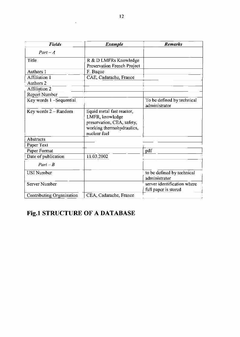
For better maintenance of the data base, the structure shall be defined properly. Thestructure shall contain all the essential information, and shall be defined keeping in mind thepresent and future requirements. Even though most of the fields are filled in the structure, a fewcan remain blank for future use and for other specific maintenance purposes. One example ofthe structure is given in Fig.l. Part A of the structure deals with fields specific to the publication
10and the technical content of the paper, whereas Part B deals with fields required for themaintenance of the report by technical and system administrator.
Access facilities in database
The database shall be designed such that it is available to the users around the worldthrough internet. To enable this, a suitable search facility shall be included. Searching shall bepossible on specific fields such as title, author, affiliation, report number, keywords andabstracts. Restricted searching such as published during the period (from say 1.1.2001 to31.12.2001) shall also be possible.
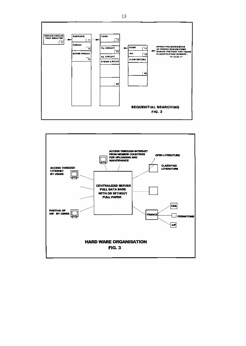
Sequential searching
For large technical data bases, sequential searching on specific, pre-defined key words willbe useful. These keywords sequence shall be pre-defined by the technical administrator groupand shall be assigned to each data. This keyword sequence may also be converted to a numbersimilar to US1 classification of books. Each report can have more than one USI numbersdepending on the contents. For searching reports in this way, the user has to continue search byselecting the fields from the pull down menu. An illustration is given in Fig.2.
Contents of database
The technical contents of the data base shall include information from various publishedjournals, papers presented in seminars etc. Also classified information from specificorganizations may also be placed on the data base with restricted access. Hence the design shallconsider provisions such as: open literature - accessible by all, information available to specificorganizations, on payment through on line credit card, payment through off line procedures, tospecific organizations by following specific procedures etc.
Uploading facilities
The data base shall be defined such that the data can be uploaded from specificorganizations, through password control. This will enable uploading of data from variousmember countries. A suitable field in the database shall be available to keep track from wherethe data was uploaded. Additionally provision shall be available for any individual to postcomplete data (literature/report etc.) through internet. This will be scrutinized by the technicaladministrator and uploaded to the database. However the allotment of USI number shall remainwith technical administrator.
Hardware/System Organisation:
A server located in a centralized place shall contain major information. It shall contain allthe fields in the structure, but with or without full text of reports. This server shall contain theinformation that are required for execution of a search and the results are passed on to the userthrough internet. Subsequently when the user asks for full text of the paper, it shall be madeavailable to them.
For storage of full text of reports, the servers containing the full text may remaindistributed in the member countries. This distributed system will enable users to get all the
11information and at the same time satisfy the countries having classified information, that theinformation is kept restricted and is available with them only. A pictorial representation of thisarrangement is shown in Fig.3.
Database establishment process
The establishment of such a database is an involved and time consuming process.Probably such a data base development can be considered in the following three phases:
Development and testingUploading data and making database available to publicContinuous maintenance and upkeep of database
Development and Testing: This is a process that can be planned and completed in a reasonabletime of ~ 18 months. During this period the complete architecture of the software and hardwareshall be completed. The sequential searching keyword structure shall be established. The serverarchitecture, including establishment of links to member countries can be considered. Alsominimum amount of data shall be posted in the servers and tested for its functioning.
Uploading of literature: On completion of the above activity, the next phase is uploadinginformation. Existing information such as those in INIS Atomindex, Journals etc. shall beuploaded. The organization responsible for maintenance of the full text distributed in differentcountries shall be defined and servers shall be made available.
Maintenance: The next is the maintenance of database. The maintenance is essential so that thedatabase is made available for all the 24 h of the day. Also care shall be taken from developmentstage onwards such that the developments in the electronic media will always assist in themaintenance of the database.
Conclusion
Maintenance of such large data bases will help in knowledge preservation not only in thearea of fast reactor technology, but also in other fields of Science and Technology. Adevelopment of a broad based user friendly software will assist the users as well as databasedevelopers. The organization leading the maintenance of this database (say IAEA) may alsoconsider maintenance of the data base in a self sustained way.
12
Fields
Part - A
Title
Authors 1Affiliation 1Authors 2Affiliation 2Report NumberKey words 1 -Sequential
Key words 2 - Random
AbstractsPaper TextPaper FormatDate of publication
Part - B
USI Number
Server Number
Contributing Organisation
Example
R & D LMFRs KnowledgePreservation French ProjectF. BaqueCAE, Cadarache, France
liquid metal fast reactor,LMFR, knowledgepreservation, CEA, safety,working thermohydraulics,nuclear fuel
11.03.2002
CEA, Cadarache, France
Remarks
To be defined by technicaladministrator
to be defined by technicaladministratorserver identification wherefull paper is stored
Fig.l STRUCTURE OF A DATABASE
13
SODIUM COOLEDFAST REACTOR
1 11
RAPSODIE
r^PHENIX
f«SUPER PHENIX
P"
COME
pr
Py. CIRCUIT
rnSy. CIRCUIT
STEAM CIRCUIT
PS
PUMP [-^
IHX pjj
FLOW METERS
r*s
OPERATING EXPERIENCEOF PHENIX SODIUM PUMP
^"DURING THE PAST TEN TEARSCLASSIFICATION NUMBER :
11.12.22.11
SEQUENTIAL SEARCHING
FIG. 2
ACCESS THROUGH INTERNETFROM MEMBER COUNTRIESFOR UPLOADING ANDMAINTENANCE
ACCESS THROUGHINTERNETBY USERS
OPEN LITERATURE
CLASSIFIEDLITERATURE
POSTING OFINF. BY USERS
CENTRALIZED SERVERFULL DATA BASE
WITH OR WITHOUTFULL PAPER
HARD WARE ORGANISATIONFIG. 3

LIST OF PARTICIPANTS
Technical Meeting on"Operational and Decommissioning Experience with Fast Reactors"
from 11 to 15 March 2002
CHINA
Mr. YU HongChina Institute of Atomic EnergyP.O. Box 275(95)Beijing, 102413, ChinaFax: ++86 10 693 5 84 2Tel: ++86 10 693 584 33E-mail: [email protected]
FRANCE
Mr. F. BAQUECEA/CE CadaracheDER/STR/LTTS Bat. 20113108 St. Paul lez Durance CedexFranceFax: ++33 4 42 25 79 49Tel.: ++33 4 42 25 38 30E-mail: [email protected]
Mr. Gilles RODRIGUEZCEA/CE CadaracheDER/STR/LTTS Bat. 20113108 St. Paul lez Durance CedexFranceFax: ++33 4 42 25 79 49Tel.: ++33442257347E-mail: [email protected]
Mr. Riccardo BRACHIEDF-CIDEN35-37, Rue Louis Guerin69100VilleurbanneFranceFax: ++33 4 72 82 40 35Tel.: ++33472824565E-mail: [email protected]
AG
Mrs. Jaleh PONCERRYEDF-CIDEN35-37, Rue Louis Guerin69100 VilleurbanneFranceFax: ++33 4 72 82 40 24Tel.: ++33 4 72 82 40 42E-mail: [email protected]
Mr. Phillipe ALPHONSEEdF-CIDEN35-37, Rue Louis Guerin69100 VilleurbanneFranceFax: ++Tel: ++33 4 72 82 47 40E-mail: [email protected]
D. CHIAROTEdF-CIDEN35-37, Rue Louis Guerin69100VilleurbanneFranceFax: ++Tel: ++33 4 72 82 42 04E-mail: [email protected]
E. JOULIAEdF-CIDEN35-37, Rue Louis Guerin69100 VilleurbanneFranceFax: ++Tel: ++33472824224E-mail: [email protected]
Mrs. Mane Therese CABRILLATCEA/CE CadaracheDER/STR/LTTS Bat. 20113108 St. Paul lez Durance CedexFranceFax: ++33 4 42 25 7187Tel.: ++33 4 42 2573 60E-mail: [email protected]
O. GASTALDICEA/CE CadaracheDER/STR/LTTS Bat. 20113108 St. Paul lez Durance CedexFranceFax: ++33 4 42 25 72 87Tel.: ++33442253787E-mail: [email protected]
M. GIRAUDFramatome ANP10 rue Juliette Recamier69456 Lyon Cedex 06 FranceFax: ++Tel: ++33 4 72 74 70 79E-mail: [email protected]
V. GRABONFramatome ANP10 rue Juliette Recamier69456 Lyon Cedex 06 FranceFax: ++33 4 72 74 73 40Tel: ++33472747366E-mail: [email protected]
B. RIOUFramatome ANP10 rue Juliette Recamier69456 Lyon Cedex 06 FranceFax: ++Tel.: ++33 4 72 74 73 60E-mail: [email protected]
M. BERTEFramatome ANP10 rue Juliette Recamier69456 Lyon Cedex 06 FranceFax: ++Tel.: ++33 4 72 74 70 63E-mail: [email protected]
Mr. Laurent MARTINCEA PHENIXDEN/VRH/DCP/DIRFax: ++33 4 66 79 14 52Tel: ++33466796484E-mail: [email protected]
Mr. Alexandre MOUROGOVEDF/R&D1 Avenue du General de Gaulle92141 Clamart CedexFranceFax: ++ 33 1 47 65 34 99Tel.: ++ 33 1 47 65 52 66E-mail: [email protected]
Mr. Jean TOMMASICEACE CadaracheDER/SPRC/LEPh Bat 23013108 St. Paul lez Durance CedexFranceFax: ++Tel.: ++33442257566E-mail: [email protected]
Mr. Patrick LEMOINECEADEN/DIR (Phenix Project) Bat 121CEA Saclay 91 191 GIF/YVETTETel:++33 1 690851 71E-mail: [email protected]
Mrs. Jackie LOUVETCEA/CE CadaracheDER/SERI/LCSIBat21213108 St. Paul lez Durance CedexFranceFax: ++Tel.: ++33442252757E-mail: [email protected]
Mr. Olivier VINOCHECEA/CE CadaracheDER/STR/LTTS Bat. 20113108 St. Paul lez Durance CedexFranceFax: ++33 4 42 25 79 49Tel.: ++33442254863E-mail: [email protected]
Mr JL CARBONNIERCEA/CE CadaracheDER/Dffi. Bat 70713108 St. Paul lez Durance CedexFax: ++33 4 42 25 76 27Tel.: ++3344225 4565E-mail: [email protected]
Mr Jean-Claude ASTEGIANOCEA/CE CadaracheDER/STR Bat 20813108 St. Paul lez Durance CedexFax: ++33 4 42 25 48 68Tel: ++33442257498E-mail: [email protected]
GERMANY
Mr. Wolfgang PFEIFERForschungszentrum Karlsruhe GmbHTechn./administer. Leitung StilllegungPostfach 3640D-76021 KarlsruheGermanyFax: ++49 724 782 43 86Tel: ++49 724 782 59 30E-mail: [email protected]
INDIA
Mr. K.V. SURESH KUMARIndia Gandhi Centre for Atomic Research (IGCAR)Kalpakkam - 603 102Tamil NaduIndiaFax: ++91 4114480336Tel: ++91 4114 4 80351E-mail: [email protected]
Mr. M. RAJANIndira Gandhi Centre for Atomic Research (IGCAR)Kalpakkam - 603 102Tamil Nadu, IndiaFax: ++91 4114 480 211Tel.: ++91 4114 480 311E-mail: [email protected]
Ms. Indira RAMAKRISHNANIndria Gandhi Centre for Atomic Research (IGCAR)Kalpakkam - 603 102Tamil Nadu, IndiaFax: ++91 4114 480060Tel: ++91 4114 480119E-mail: [email protected]
Mr. C.S. SURENDRANIndira Gandhi Centre for Atomic Research (IGCAR)Kalpakkam - 603 102Tamil Nadu, IndiaFax: ++91 4114 480 060 and ++91 4114 480 060Tel.: ++91 4114 480 104E-mail: [email protected]
JAPAN
Mr. Takafumi AOYAMAExperimental Fast Reactor "Joyo"O-arai Engineering CenterJapan Nuclear Cycle Development Institute (JNC)4002 Narita-cho, O-arai-machiHigashi-Ibaraki-gun, Ibaraki 311-1393JapanFax: ++8129 267 7481Tel.: ++81 29 267 4141 ext. 5412E-mail: [email protected].
Mr. Yoshihiro IBUKIJNC (Attache in Phenix)Centrale PHENIXBoitePostale 17130200 Bagnols sur CezeFranceFax: ++34 4 6690 1226Tel: ++34 4 6679 6413E-mail: [email protected]
Mr. Tsutomu IRIEJNC (Attache in S-Phenix)S-PHENIXCNPE de Creys-MalvilleBP63-38510MorestelFranceFax: ++34 4 7433 3425Tel: ++34 4 7433 3495E-mail: [email protected]
KAZAKHSTAN
Mr. Igor Vladirmrovich DUMCHEV466200 Kazakhstan, AktauIndustrial AreaP.O. Box 339KazakhstanFax: ++7 3292 51 5371Tel.: ++7 3292 51 53 71 and ++7 3292 562 452E-mail: [email protected]
RUSSIA
Mr. loun ACHOURKOState Scientific CenterInstitute for Physics and Power Engineering (IPPE)Bondarenko Sq. 1249033 Obninsk, Kaluga RegionRussian FederationFax: ++7 095 230 2326Tel.: ++7 084 39 95 053E-mail: [email protected]
USA
Mr. S. Paul HENSLEEArgonne National Laboratory-WestP.O. Box 2528Idaho Falls, Idaho 83403-2528USAFax: ++1 208 533 7735Tel: ++1 208 522 7042E-mail: [email protected]
SESSION 1:
Fast reactor operational experience

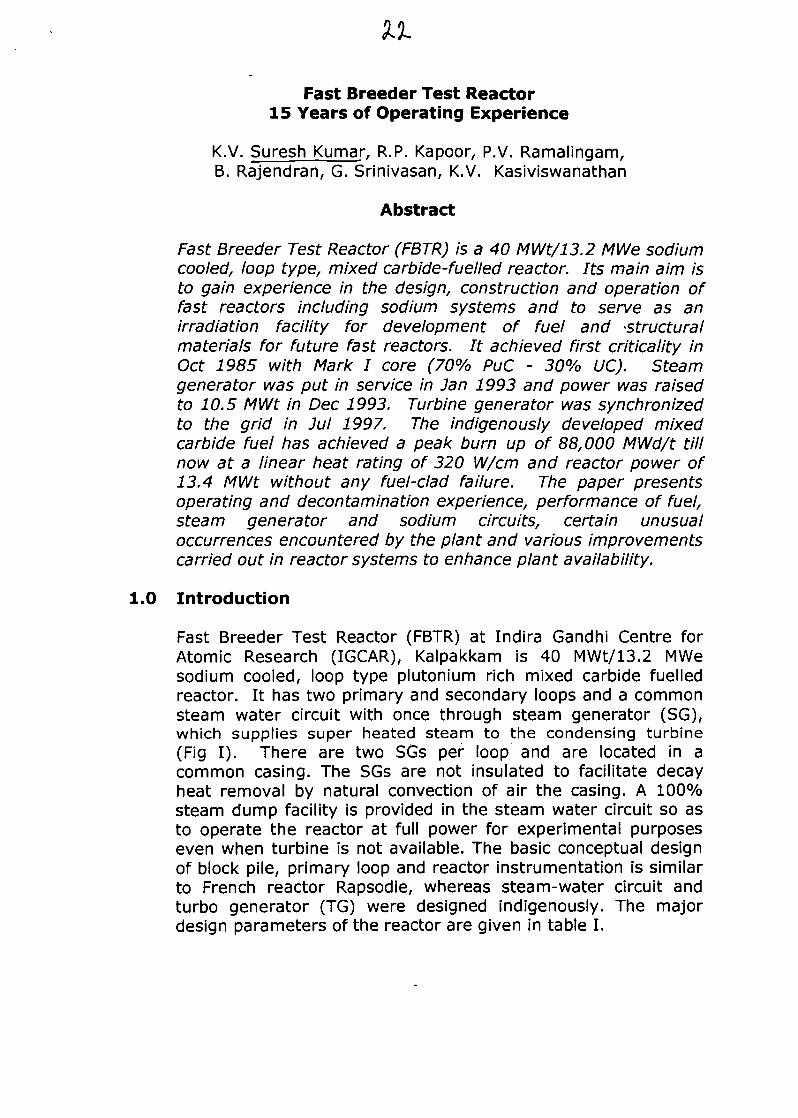
Fast Breeder Test Reactor15 Years of Operating Experience
K.V. Suresh Kumar, R.P. Kapoor, P.V. Ramalingam,B. Rajendran, G. Srinivasan, K.V. Kasiviswanathan
Abstract
Fast Breeder Test Reactor (FBTR) is a 40 MWt/13.2 MWe sodiumcooled, loop type, mixed carbide-fuelled reactor. Its main aim isto gain experience in the design, construction and operation offast reactors including sodium systems and to serve as anirradiation facility for development of fuel and -structuralmaterials for future fast reactors. It achieved first criticality inOct 1985 with Mark I core (70% PuC - 30% UC). Steamgenerator was put in service in Jan 1993 and power was raisedto 10.5 MWt in Dec 1993. Turbine generator was synchronizedto the grid in Jul 1997. The indigenously developed mixedcarbide fuel has achieved a peak burn up of 88,000 MWd/t tillnow at a linear heat rating of 320 W/cm and reactor power of13.4 MWt without any fuel-clad failure. The paper presentsoperating and decontamination experience, performance of fuel,steam generator and sodium circuits, certain unusualoccurrences encountered by the plant and various improvementscarried out in reactor systems to enhance plant availability.
1.0 Introduction
Fast Breeder Test Reactor (FBTR) at Indira Gandhi Centre forAtomic Research (IGCAR), Kalpakkam is 40 MWt/13.2 MWesodium cooled, loop type plutonium rich mixed carbide fuelledreactor. It has two primary and secondary loops and a commonsteam water circuit with once through steam generator (SG),which supplies super heated steam to the condensing turbine(Fig I). There are two SGs per loop and are located in acommon casing. The SGs are not insulated to facilitate decayheat removal by natural convection of air the casing. A 100%steam dump facility is provided in the steam water circuit so asto operate the reactor at full power for experimental purposeseven when turbine is not available. The basic conceptual designof block pile, primary loop and reactor instrumentation is similarto French reactor Rapsodie, whereas steam-water circuit andturbo generator (TG) were designed indigenously. The majordesign parameters of the reactor are given in table I.
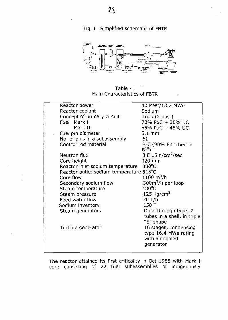
Fig. I Simplified schematic of FBTR
Table - IMain Characteristics of FBTR
Reactor powerReactor coolantConcept of primary circuitFuel Mark I
Mark IIFuel pin diameterNo. of pins in a subassemblyControl rod material
Neutron fluxCore heightReactor inlet sodium temperatureReactor outlet sodium temperatureCore flowSecondary sodium flowSteam temperatureSteam pressureFeed water flowSodium inventorySteam generators
Turbine generator
40 MWt/13.2 MWeSodiumLoop (2 nos.)70% PuC + 30% UC55% PuC + 45% UC5.1 mm61B4C (90% Enriched inB10)3 E 15 n/cm2/sec320 mm380°C515°C1100 m3/h300m3/h per loop480°C125 Kg/cm2
70T/h150 TOnce through type, 7tubes in a shell, in triple"S"shape16 stages, condensingtype 16.4 MWe ratingwith air cooledgenerator
The reactor attained its first criticality in Oct 1985 with Mark Icore consisting of 22 fuel subassemblies of indigenously
developed fuel (70% PuC+30% UC). While carrying out lowpower physics experiment (<500 kWt), a fuel-handling incidenttook place in May 1987 and the reactor could resume operationonly in May 89 after recovering from the incident. Subsequentlylow power physics and engineering experiments up to 1 MWtwere completed in 1992. After completion of commissioning ofSG and its leak detection system, reactor power was raised to10.2 MWt in Dec 93. After completing high power engineeringand physics tests, reactor power at high power was continued.Construction and commissioning of Turbo-Generator (TG) and itsauxiliaries were subsequently completed and TG wassynchronized to the grid producing 1.2 MWe in Jul '97. Reactorcore was gradually enhanced and power was raised in steps to13.4 MWt. Fuel pins of Mark I and Mark II compositions wereirradiated in the reactor and discharged for post irradiationexamination (PIE) to assess the fuel performance. Reactor wasoperated at 8 MWt for irradiation of Zirconium-Niobium (Zr-Nb)allow for PHWR programme. Nine irradiation campaigns havebeen completed so far up to a maximum power level of 13.4MWt and peak burn up of 88,000 MWd/t was achieved withoutany fuel-clad failure so far. The reactor parameters achieved sofar are given in Table 2.
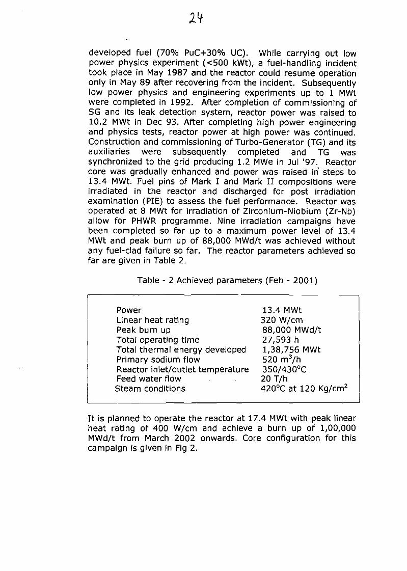
Table - 2 Achieved parameters (Feb - 2001)
PowerLinear heat ratingPeak burn upTotal operating timeTotal thermal energy developedPrimary sodium flowReactor inlet/outlet temperatureFeed water flowSteam conditions
13.4 MWt320 W/cm88,000 MWd/t27,593 h1,38,756 MWt520 m3/h350/430°C20 T/h420°C at 120 Kg/cm2
It is planned to operate the reactor at 17.4 MWt with peak linearheat rating of 400 W/cm and achieve a burn up of 1,00,000MWd/t from March 2002 onwards. Core configuration for thiscampaign is given in Fig 2.
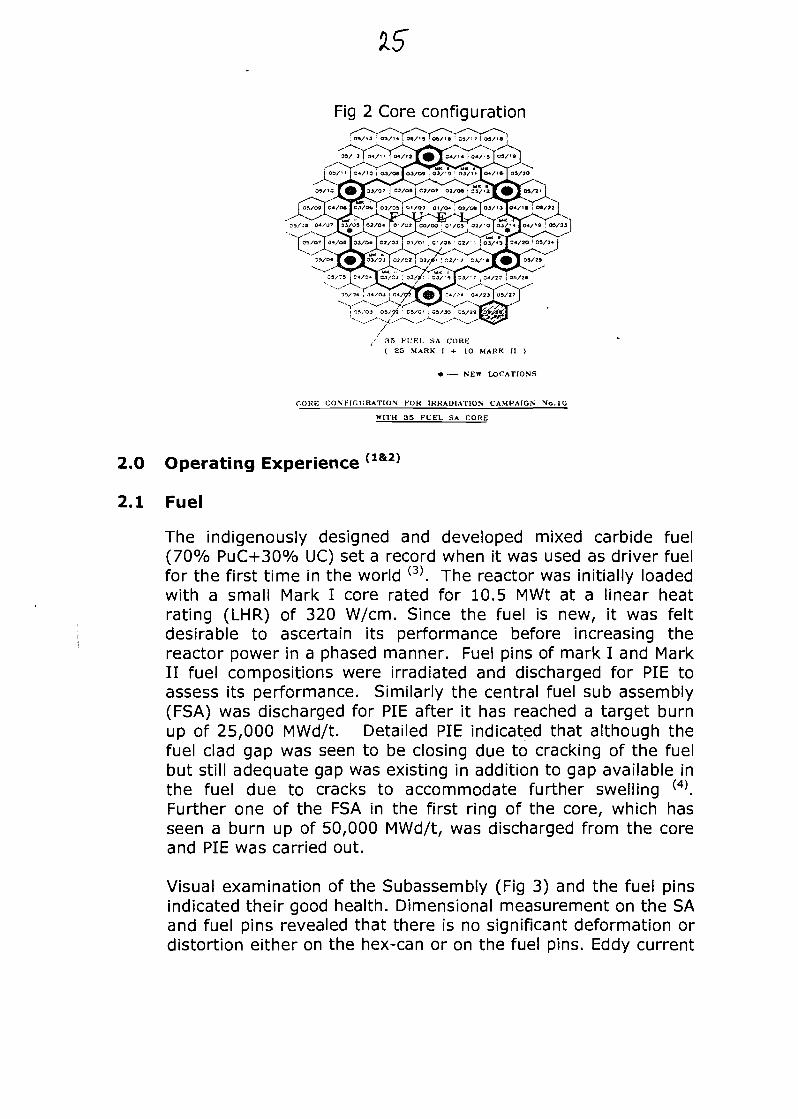
Fig 2 Core configuration
/ 35 FUEL SA CORE( 25 MARK I + 10 MARK II )
• NEW LOCATIONS
COUE C O N F I G U R A T I O N FOR IRRADIATION CAMPAIGN No.10
WITH 35 FUEL SA CORE
2.0 Operating Experience {1&2)
2.1 Fuel
The indigenously designed and developed mixed carbide fuel(70% PuC+30% UC) set a record when it was used as driver fuelfor the first time in the world (3). The reactor was initially loadedwith a small Mark I core rated for 10.5 MWt at a linear heatrating (LHR) of 320 W/cm. Since the fuel is new, it was feltdesirable to ascertain its performance before increasing thereactor power in a phased manner. Fuel pins of mark I and MarkII fuel compositions were irradiated and discharged for PIE toassess its performance. Similarly the central fuel sub assembly(FSA) was discharged for PIE after it has reached a target burnup of 25,000 MWd/t. Detailed PIE indicated that although thefuel clad gap was seen to be closing due to cracking of the fuelbut still adequate gap was existing in addition to gap available inthe fuel due to cracks to accommodate further swelling w.Further one of the FSA in the first ring of the core, which hasseen a burn up of 50,000 MWd/t, was discharged from the coreand PIE was carried out.
Visual examination of the Subassembly (Fig 3) and the fuel pinsindicated their good health. Dimensional measurement on the SAand fuel pins revealed that there is no significant deformation ordistortion either on the hex-can or on the fuel pins. Eddy current
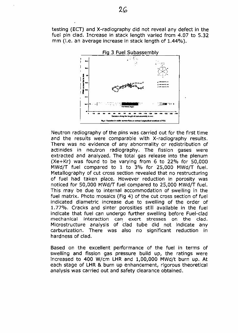
testing (ECT) and X-radiography did not reveal any defect in thefuel pin clad. Increase in stack length varied from 4.07 to 5.32mm (i.e. an average increase in stack length of 1.44%).
Fig 3 Fuel Subassembly
M O M O M I M C f M H I I M I M I M
Ototanc* »kM0 tb« l*r»
PlgJ VMtrtoit in width -«cro*«-fU4» * nttou* tofigrtudliwl location* o* PSA
Neutron radiography of the pins was carried out for the first timeand the results were comparable with X-radiography results.There was no evidence of any abnormality or redistribution ofactinides in neutron radiography. The fission gases wereextracted and analyzed. The total gas release into the plenum(Xe+Kr) was found to be varying from 6 to 22% for 50,000MWd/T fuel compared to 1 to 3% for 25,000 MWd/T fuel.Metallography of cut cross section revealed that no restructuringof fuel had taken place. However reduction in porosity wasnoticed for 50,000 MWd/T fuel compared to 25,000 MWd/T fuel.This may be due to internal accommodation of swelling in thefuel matrix. Photo mosaics (Fig 4) of the cut cross section of fuelindicated diametric increase due to swelling of the order of1.77%. Cracks and sinter porosities still available in the fuelindicate that fuel can undergo further swelling before Fuel-cladmechanical interaction can exert stresses on the clad.Microstructure analysis of clad tube did not indicate anycarburization. There was also no significant reduction inhardness of clad.
Based on the excellent performance of the fuel in terms ofswelling and fission gas pressure build up, the ratings wereincreased to 400 W/cm LHR and 1,00,000 MWd/t burn up. Ateach stage of LHR & burn up enhancement, rigorous theoreticalanalysis was carried out and safety clearance obtained.
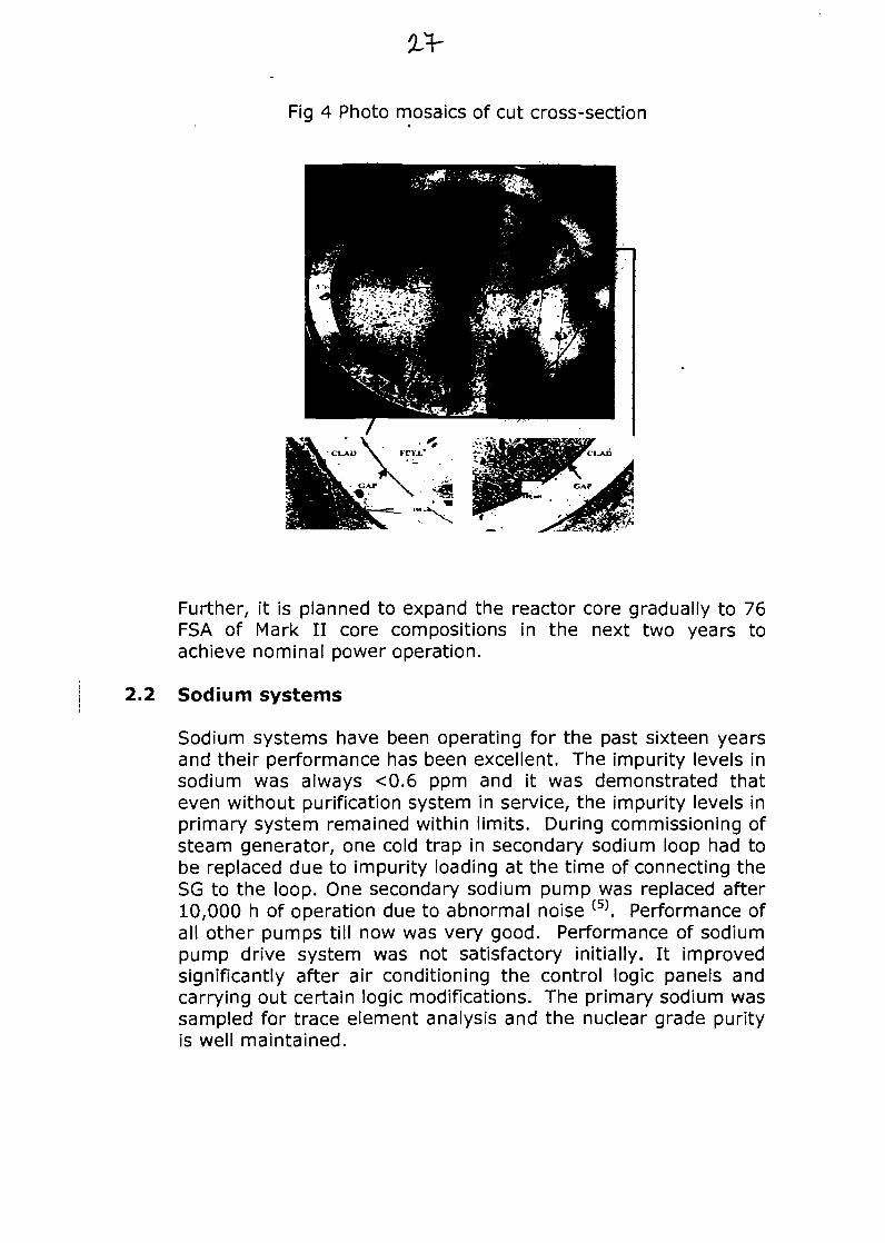
Fig 4 Photo mosaics of cut cross-section
Further, it is planned to expand the reactor core gradually to 76FSA of Mark II core compositions in the next two years toachieve nominal power operation.
2.2 Sodium systems
Sodium systems have been operating for the past sixteen yearsand their performance has been excellent. The impurity levels insodium was always <0.6 ppm and it was demonstrated thateven without purification system in service, the impurity levels inprimary system remained within limits. During commissioning ofsteam generator, one cold trap in secondary sodium loop had tobe replaced due to impurity loading at the time of connecting theSG to the loop. One secondary sodium pump was replaced after10,000 h of operation due to abnormal noise (5). Performance ofall other pumps till now was very good. Performance of sodiumpump drive system was not satisfactory initially. It improvedsignificantly after air conditioning the control logic panels andcarrying out certain logic modifications. The primary sodium wassampled for trace element analysis and the nuclear grade purityis well maintained.
An Electro-chemical carbon meter is installed in one of thesecondary sodium loops to measure the active carbon level inthe system. Its performance is being studied.
2.3 Reactor Assembly
The performance of control rod drive mechanism (CRDM) hasbeen satisfactory with friction force within limits and drop timeless than 400 ms. An on-line system to monitor the drop time ofcontrol rod (CR) during scram was commissioned. Similarly asystem was developed to measure friction force of CR duringpower operation. The 3 s interlock on CR raise movement,which was introduced before the first criticality was deleted asit was giving rise to large time in raising power and high start upduty demand on CRDM motors. The lower parts of two CRDMwere replaced one due to failure of translation bellows andanother due to failure of gripper bellows. Leaky silicone bellowsof one CRDM was replaced in-situ.
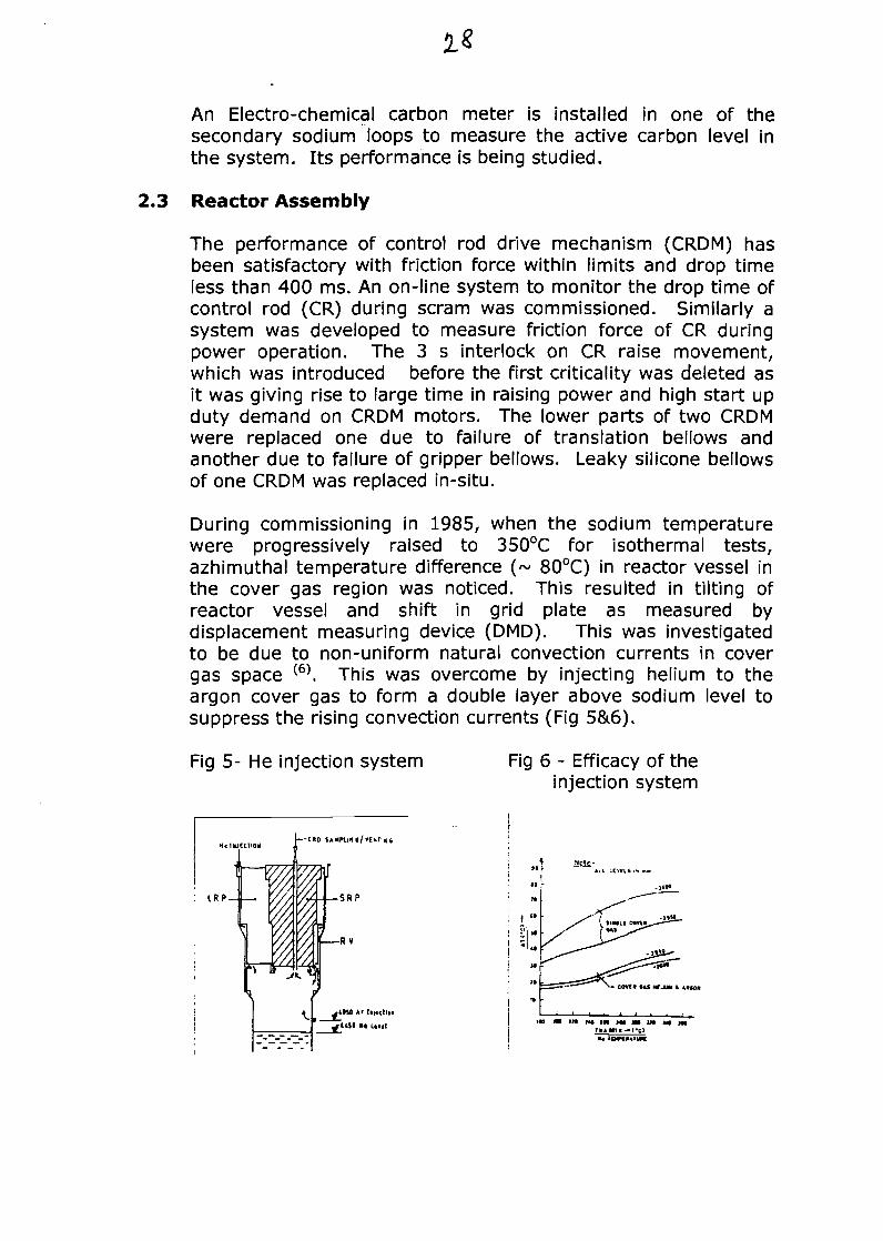
During commissioning in 1985, when the sodium temperaturewere progressively raised to 350°C for isothermal tests,azhimuthal temperature difference (~ 80°C) in reactor vessel inthe cover gas region was noticed. This resulted in tilting ofreactor vessel and shift in grid plate as measured bydisplacement measuring device (DMD). This was investigatedto be due to non-uniform natural convection currents in covergas space (6) This was overcome by injecting helium to theargon cover gas to form a double layer above sodium level tosuppress the rising convection currents (Fig 5&6).
Fig 5- He injection system Fig 6 - Efficacy of theinjection system
IRP
»t" r Ail LCmt i
<« m IM ru m »w m ut M* JM
The better heat transfer properties of helium also helped inhomogenizing the circumferential temperature thus keeping gridplate shift well within limits.
2.4 Steam Generator
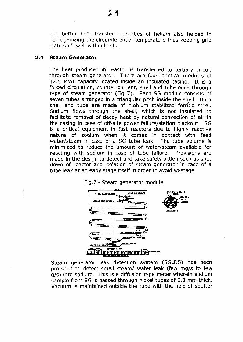
The heat produced in reactor is transferred to tertiary circuitthrough steam generator. There are four identical modules of12.5 MWt capacity located inside an insulated casing. It is aforced circulation, counter current, shell and tube once throughtype of steam generator (Fig 7). Each SG module consists ofseven tubes arranged in a triangular pitch inside the shell. Bothshell and tube are made of niobium stabilized ferritic steel.Sodium flows through the shell, which is not insulated tofacilitate removal of decay heat by natural convection of air inthe casing in case of off-site power failure/station blackout. SGis a critical equipment in fast reactors due to highly reactivenature of sodium when it comes in contact with feedwater/steam in case of a SG tube leak. The tube volume isminimized to reduce the amount of water/steam available forreacting with sodium in case of tube failure. Provisions aremade in the design to detect and take safety action such as shutdown of reactor and isolation of steam generator in case of atube leak at an early stage itself in order to avoid wastage.
Fig.7 - Steam generator module
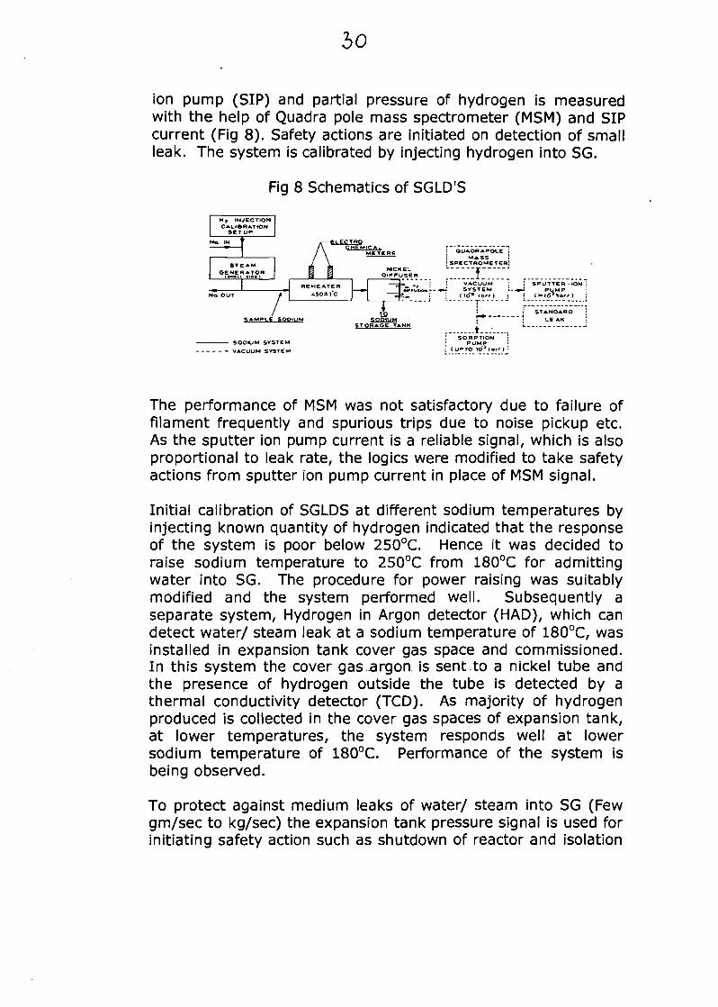
Steam generator leak detection system (SGLDS) has beenprovided to detect small steam/ water leak (few mg/s to fewg/s) into sodium. This is a diffusion type meter wherein sodiumsample from SG is passed through nickel tubes of 0.3 mm thick.Vacuum is maintained outside the tube with the help of sputter
io
ion pump (SIP) and partial pressure of hydrogen is measuredwith the help of Quadra pole mass spectrometer (MSM) and SIPcurrent (Fig 8). Safety actions are initiated on detection of smallleak. The system is calibrated by injecting hydrogen into SG.
Fig 8 Schematics of SGLD'S
ELECTROCHEMICAL
No OUT 4
SAMPLE SODIUM
SODIUM SYSTEM
STg
•IETERS
NIC K C LDIFFUSER
__! 3&--"«
iSQOIUMRAGE TANK
'. QUA OR A POLE
1 MASS
— -"V —: : VACUUM
HI*--*-* SVSTEM1 | <1tf" torr)
!
! SPUTTER -ION I- -«-J PUM P ;
i* STANDARD ;
^ ! LEAK ;
I SORPTION |; PUMP ij < UPTO 1O3 torr ) !
The performance of MSM was not satisfactory due to failure offilament frequently and spurious trips due to noise pickup etc.As the sputter ion pump current is a reliable signal, which is alsoproportional to leak rate, the logics were modified to take safetyactions from sputter ion pump current in place of MSM signal.
Initial calibration of SGLDS at different sodium temperatures byinjecting known quantity of hydrogen indicated that the responseof the system is poor below 250°C. Hence it was decided toraise sodium temperature to 250°C from 180°C for admittingwater into SG. The procedure for power raising was suitablymodified and the system performed well. Subsequently aseparate system, Hydrogen in Argon detector (HAD), which candetect water/ steam leak at a sodium temperature of 180°C, wasinstalled in expansion tank cover gas space and commissioned.In this system the cover gas argon is sent to a nickel tube andthe presence of hydrogen outside the tube is detected by athermal conductivity detector (TCD). As majority of hydrogenproduced is collected in the cover gas spaces of expansion tank,at lower temperatures, the system responds well at lowersodium temperature of 180°C. Performance of the system isbeing observed.
To protect against medium leaks of water/ steam into SG (Fewgm/sec to kg/sec) the expansion tank pressure signal is used forinitiating safety action such as shutdown of reactor and isolation
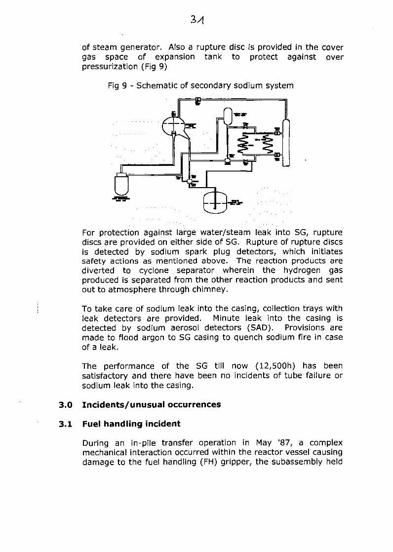
of steam generator. Also a rupture disc is provided in the covergas space of expansion tank to protect against overpressurization (Fig 9)
Fig 9 - Schematic of secondary sodium system
For protection against large water/steam leak into SG, rupturediscs are provided on either side of SG. Rupture of rupture discsis detected by sodium spark plug detectors, which initiatessafety actions as mentioned above. The reaction products arediverted to cyclone separator wherein the hydrogen gasproduced is separated from the other reaction products and sentout to atmosphere through chimney.
To take care of sodium leak into the casing, collection trays withleak detectors are provided. Minute leak into the casing isdetected by sodium aerosol detectors (SAD). Provisions aremade to flood argon to SG casing to quench sodium fire in caseof a leak.
The performance of the SG till now (12,500h) has beensatisfactory and there have been no incidents of tube failure orsodium leak into the casing.
3.0 Incidents/unusual occurrences
3.1 Fuel handling incident
During an in-pile transfer operation in May '87, a complexmechanical interaction occurred within the reactor vessel causingdamage to the fuel handling (FH) gripper, the subassembly held
by the gripper, guide tube and several reflector SA (28t7). Thebent SA was forcibly extracted through the guide tube. The bentof guide tube was estimated by three techniques, viz., opticalinspection, ultrasonic air gauging and mechanical disc gauging.The guide tube was cut and removed in two pieces usingspecially designed tools. The incident was investigated in detailand found to be due to system deficiencies combined withhuman error. Modifications viz., mechanical stopper for fuel-handling gripper and redundant interlocks for plug rotationauthorization were implemented. Also proper maintenance andoperating procedures for FH mechanisms were evolved andreviewed by an expert committee. It took two years to recoverfrom this incident and the reactor was restarted in May '89. Afterincorporating these modifications, 185 charging/discharging and177 transfer operations in 10 fuel-handling campaigns have beensuccessfully carried out over the past 13 years without anyincident.
3.2 Malfunctioning of core cover plate mechanism (CCPM)
The outlet temperature of 84 core SA is monitored by thermocouples which are housed in CCPM. The fuel SA thermo couplesignals are scanned by computer to generate trip signals.During normalization of pile after fuel handling operation in JulyX95, CCPM could not be lowered to normal working position fromfuel handling position. Various operations resulted in its gettingstuck at 81mm position above top of SA heads. The likelycauses were attributed to mechanical obstruction at the top,below the core cover plate or within the mechanism. Based onsystematic investigations viz., checking of obstruction, scanningthe space below the core cover plate and above the SA head byultrasonic under sodium scanner, ensuring leak tightness ofbottom metallic bellows etc, it was confirmed that the sticking isin the inter seal space between command tube and outer sheath.A safe jacking down force of 780 kg was applied and CCPM wasbrought to normal position and made functional. Howeverduring the next fuel handling operation in Jul '96, CCPM againgot stuck up at 80 mm position and it could not be normalizedeven after repeated trials. The exact cause for malfunctioning ofCCPM could not be identified (28l8).
Experiments were carried out on power to measure the fuel SAoutlet temperature with CCPM stuck at 80 mm position and atemperature attenuation of 7% (average) was found in Mark I
33
SA. However, this attenuation is large for Mark II SA wheresodium flow is less. Studies were conducted to find out theprobability of plugging during reactor operation and found to beacceptable. 3D analysis of outlet plenum thermal hydraulic wascarried out to establish the level of plugging that can be detectedviz., allowable plugging for fuel clad integrity. The studiesindicated that a flow reduction to 60% of the nominal flow forthe Mark II SA in the core periphery could be detected withCCPM at 80 mm position, whereas a flow reduction to 45% isrequired to cross the clad hot spot temperature. The designprovisions such as radial entry of sodium flow into the SA andhigh purity of sodium maintained, rules out blockage of flowthrough SA of the order mentioned above. PSA studies werecarried out based on available data from various fast reactors toestablish the probability of plugging in SA. Based on thesestudies, lowering of scram thresholds for core AT and core meantemperature (0m) from the fuel SA thermocouple was done andreactor operation continued with CCPM at 80 mm position.
An eddy current flow meter was developed for measuring actualflow through the FSA during shut down by installing it in FHguide tube and out of pile tests were carried out. This is plannedto be used in the reactor to estimate actual flow for selected SA.Also out of pile mockup trials were carried out for rectification ofstuck CCPM.
3.3 Na/Nak leak incidents
While preheating of secondary cold trap during initialcommissioning, about 2.5 litre of Nak leaked out from the Nakjacket through the spark plug type level probe. Investigationrevealed failure of level probe due to pressure build up duringpreheating due to non-availability of adequate expansion space.Modifications viz., capping of level probe, providing an argon potto allow expansion was carried out to prevent recurrence.
During routine sampling of secondary sodium system, about onelitre of sodium leaked out through the swage lock coupling of theflow through sampler. To prevent recurrence, provision wasmade in the sampler for helium leak testing prior to valving insodium.
During maintenance on the pressure regulator in the argonsupply system, about 2 litre of Nak backed up from the Nak
bubbler provided for argon purification and leaked out. As aremedial measure a back flow trap was introduced in the circuit.
3.4 Water leak for SG sub headers
In Jan 93, when SG was put in service for the first time, after 70h of operation, a water leak took place due to a linear pinholedefect in the end cap of one of the orifice assemblies at SG inlet.All similar end caps were ultrasonically inspected and four morewere found to have similar defects. The leaking cap wasreplaced and additional covers were welded for defective caps.The failure was attributed to material defect.
All the four modules of SG are provided with flanged orifices inthe water sub headers for flow measurement to study SGstability. In Aug'93 when reactor was operating at 9 MWt, feedwater was found to be leaking through the orifice flanges.Investigations revealed that leak tight orifice flanges underambient conditions tend to develop leak under operatingconditions due to differential expansion between water subheaders and SG modules. All the orifice flanges were replacedwith welded spools with integral orifices.
In Feb '98, while readjusting the setting of SG safety valves incold state, water leak was observed in one of the bosses inexperimental thermo well in the steam sub header of one of theSG modules. The leaking boss and plug were replaced withdummy piece and all other similar welds were checked for anydefects by liquid penetrant inspection. Investigation revealedthat failure is due to lack of heat treatment during fabrication.
3.5 Seizure of main boiler feed pump (9)
In Apr '92, while preheating feed water system, abnormal noisewas heard from the pump and the pump got seized.Investigation revealed that the failure was due to cavitation.The net positive suction head (NPSH) available to the pump wasfound to be very close to the required NPSH and it furtherreduced during operating transient. Modifications to improveNPSH available were carried out viz., rerouting of balancing leakoff line water back to suction tank instead of pump suction toreduce suction temperature, continuous cold water injection tothe suction, additional re-circulation line to avoid pumpoperating at low flows. Also steam heating of deaerator was
done using steam from package boiler. This resulted in a delay 8months to put SG in service.
In May '2001, while starting one of the main boiler feed pump(MBFP) in cold condition, abnormal noise was heard and thepump got seized. Damages to the pump noticed are similar toabove incident. Investigation is being carried out to find out thecause.
3.6 Reactivity transients
In Nov '94, when reactor was operating at 10.1 MWt, reactorpower started increasing without any movement of control rods.Control rods were lowered to restore the power to 10.1 MWt.However the power continued to rise and reached 10.45 MWtwithin a minute. Control rods were lowered by 7.6 mm (22 pcm)to bring back the power to 10.1 MWt. The reactivity recorderregistered a spike of 3 pcm during the incident. No permanentgain in the reactivity was observed before and after the incident.
In Apr1 95, when reactor power was stabilized at 7.1 MWt in theprocess of power raising to 10 MWt, there was a sharp increasein power of around 450 kWt in 7 s and reactor underwent scramon high positive reactivity (Threshold +10 pcm). The reactivityrecorder also indicated a spike of 10 pcm. A permanent gain ofabout 13.8 pcm was observed before and after the incident.
Both these incidents were analyzed by a task force constituted.Totally 19 postulates were studied to find out possible cause forthe transients. They were related to change in processparameters, movement of absorber rod, movement of fuel,reactivity change due to sodium void and moderator ingress tothe core. Several of these were tested with reactor operating atlow power as well as high power. However the cause of theincidents could not be identified. Ingress of sodium oil reactionproducts (due to oil leak from sodium pump) into the core wasconsidered as one of the probable cause. Sub critical operationat 400°C for one week did not reveal recurrence of the incident.Since the incident has occurred during high power operation, itwas decided to operate the reactor after increasing reactivityscram threshold. A fast recording data acquisition system wasdeveloped to gather more data if the incident recurs.
In 1998, when reactor was being operated at 8 MWt forirradiation of Zirconium - Niobium (Zr-Nb) alloy, reactivitytransient, which is repeatable in nature, was encountered.Following are the salient observations.
The transient is self limiting and the power remain stable afterthe transientThe reactivity gained (~ 30 to 40 pcm) while raise in power islost while manually lowering the power. There is no permanentgain in reactivity. The power increase is around 700 to 800 kWt.The on set of transient occurs at a specific value of mean coregradient temperature (A9m) of around 90 to 110°C across thecore for a given primary sodium flow. The transient can beobserved at any power level, if the above A6m is reached.The value of A0m at the onset of the reactivity transientincreases with increase in primary sodium flow and themagnitude of the transient also comes down.At a flow of equal to more than 460 m3/h the transient does notoccur.
The cause of the incident was investigated in detail by the taskforce. Following tests were carried out
• Suspecting the experimental Zr-Nb SA could be the causefor the incident, these were removed from the core andexperiment repeated. The transient was found to berecurring.
• The isothermal temperature flow and power coefficientwere measured and no abnormality was observed.
• To test the effect of control rod for the transient,experiments were conducted with one control rod at higherposition (405 mm) while power is maintained by other 5control rods (fig 10) and 5 control rods at 405 mm whilepower is maintained by 6th control rod. In both the teststransient were found to be recurring.
• In order to establish the self-limiting nature of thetransient and to ensure that there is no second transientafter the first one, tests were conducted. Reactor wasoperated beyond the transient region for more than 30 mtsand the power was found to be stable. While lowering thepower the negative transient of similar magnitude tookplace and the power was stable thereafter (fig 11)

Fig 10 - Power transient Test - One CR at 405 mm
TIME(13.4.W)
From the experiments conducted, it is concluded that thetransient is due to slight, thermally induced geometric changesin the core, which happens at low flow rates. It has come tolight because the reactor was operated at low power and lowflow rates, for Zr-Nb irradiation, in the regime it manifests.Since reactor is normally operated at higher power (12 to 15MWt) and correspondingly higher flow rates (>450m3/h), thereis no transient seen. With this, clearance was obtained fromsafety authorities for continuing operation of reactor at highpower after establishing stable regime for power operationwhenever core configuration and operating power is changed.
Fig - 11 Self-limiting nature of reactivity
TIUE {16.7.991
3.7 Water leak from BSC coils inside biological shield concrete
The reactor vessel of FBTR is surrounded by a safety steel vesseland further by two types of concrete namely 600 mm thickbiological shield and 900mm thick structural concrete (fig 12). Agap of 30mm is provided between the two concrete to take care

of differential thermal expansion. The biological shield concreteis cooled by circulating water through 180 coils embedded inconcrete. The biological shield cooling (BSC) system has twodistribution headers, each have 100% capacity. Each headerhas six sub headers with individual isolation valves (fig 13).Each sub header cools 60° sector of the concrete. The coils fromthe sub headers are laid in the concrete in such a way that twoadjacent coils are from different headers so that even if one subheader is not available, concrete cooling is not affected.
In Aug '2000, high inventory loss from BSC system wasobserved. Also water seepage was observed from the structuralconcrete manhole cover. When one of the sub headers inheader-A (A3), which cools 60° sector in the southwest portionof the concrete was isolated, the leak stopped. The leaky subheader was isolated, water collected inside Al cell (gap betweensteel vessel and biological concrete) was drained and reactoroperation continued. There was no increase in biological shieldconcrete temperature.
Fig. 12 - Biological and structural Concrete with cooling coils
In May '2001, again inventory loss in BSC system and waterseepage was observed. Reactor, which was operating at lowpower, was shutdown and investigation was carried out. Whenthe sub header in header-B (B5), which again cools the same60o sector in the southwest portion of the concrete, wasisolated, the leak stopped. Detailed investigation revealed

existence of minute leak in two more sub headers in header B(Bl & B4).
Fig. 13 - BSC system flow sheet.
Isothermal tests conducted at higher sodium temperature of375°C indicated that it is not possible to maintain the concretetemperature within limits as the first two leaky sub headers (A3& B5) cools the same l/6th region of the concrete. Hencereactor operation at high power was suspended.
Injecting proprietary formulation sealants arrested the leakpoints in the coils of the two sub headers and the coils weretested for healthiness. For remaining coils, a global sealanttreatment was carried out to arrest micro leaks and the systemwas normalized and power operation resumed.
As a future measure, four holes were drilled in the structuralconcrete up to the gap between biological and structuralconcrete to drain out water. This is to prevent entry of water toAl cell in case any leak in coils recurs in future and also providesafe draining passage for the leaking water collecting in theinterspace between structural concrete and biological concrete.Investigation carried out indicated that the leaking point is thesocket weld portion of the coil located in the inaccessible regionand it could have happened due to crevice corrosion.
4.0 Decontamination experience
Various components and mechanisms which are working inactive sodium of the primary circuit need to be decontaminated
before they are inspected, sent for maintenance or dismantledfor repair without the risk of sodium fire and radio activity. Thedecontamination facility consists of three pits. Pit No.l & 2 areused for large components viz., IHX, pump, etc. Pit No.3 is usedfor small components like guide tube, CRDM, level probes andcore co-ordination measuring device (CCMD)
Decontamination of equipments is done by admitting steam froman electrode package boiler. For large components like IHX andpump, the bulk sodium deposited on the equipment is removedby heating with the help of surface heaters prior to steamadmission. The drained sodium is collected in collection traysand disposed off. During steam admission "hydrogenconcentration and pressure build up in the pit is constantlymonitored. Rupture discs are provided in the pit to protectagainst high-pressure build up. In case the H2 concentrationincreases to > 2% and/or build up pressure, steam admission isstopped and the pit is flushed with argon. The effluent gases aresent to stack. When the hydrogen concentration reduced to<1%, the steam admission is restarted. The procedure isrepeated till there is no increase in hb concentration andpressure build up indicating completion of decontamination. Theequipment is now sprayed with water and the pit is filled withwater to remove any sodium sticking on the equipment. Theliquid effluent is drained and pumped into liquid effluent tanksfor disposal.
The primary sodium pumps were initially fitted with strainers inplace of non-return valves during first criticality to trap anyconstruction debris/impurities in sodium. Pumps were removedfrom primary system, decontaminated, refitted with NRVs andput back in the circuit. One CRDM, which was removed fromreactor due to, failure of metallic bellows was decontaminatedand its non-active parts were retrieved for reuse. Similarlyguide tube under sodium scanner, CCMD and periscope weredecontaminated after their use in reactor.
The fingers of charging and discharging flasks were periodicallydecontaminated in an alcohol pot located in RGB wheneverdifficulty is noticed in operating gripper fingers due to sodiumsticking. The grippers are cooled to atmospheric temperatureprior to lowering in alcohol pot. During decontamination offingers in alcohol pot, pressure build up in pot is constantlymonitored.
Rupture disc provided for decontamination pit failed once due toaging and degradation and was replaced. Generally thedecontamination experience in the plant has been satisfactory.
5.0 Modification in reactor protection system
During initial periods, there were large number of spuriousscram due to electro magnetic noise pickup by start up anddelayed neutron detector channels and due to 'cross talk1 of fineimpure test (FIT) pulse. Remedial measures viz., separation ofsignal cables from power cables, improvements in groundingsystem and reshaping FIT pulse were carried out and systemperformance improved.
A set of pre-start up channels with high sensitivity BF3proportional counters was commissioned. These channels alongwith startup channels help in smooth start up of the reactor withinherent neutron source, thus eliminating the need for highstrength auxiliary neutron source.
During reactor operation SG got isolated on waterside due todisturbance in control power supply making heat sink notavailable. Reactor did not trip on low feed water flow due tozero error in flow transmitter and reactor was shutdownmanually. In order to prevent recurrence of incident, protectioncircuit was modified to trip the reactor in case of isolation of SGdirectly and threshold setting of low feed water flow wasincreased to 50% of nominal flow.
Since the number of LOR and scram during high poweroperations was very high, an exercise was carried out tooptimize the trip parameters. As a first step, high windingtemperature trips of sodium pump drive system motors (88 No)were deleted and control panels of these systems were housed inan air conditional atmosphere. These steps have vastlyimproved performance of the drive system. As second step thetrip parameters of reactor protection system were reviewed andthe following modifications were carried out to improve thereliability of the system without compromising the safety.
• The positive reactivity scram is manually inhibited duringpower raising and made effective during steady poweroperation.
• Log P scram set at 110% of nominal power was givingspurious alarm due to inadequate margin between thenominal power and alarm threshold. Hence its setting wasjacked up to 125%. In order to ensure that Lin P channelis available, a new log P scram at 10% of nominal powerwas introduced which will be inhibited at low power (3% ofnominal power) by Lin P signal.
• LOR on low current in electro magnetic (EM) coil of anyCRDM was deleted. In case of dropping of any control rod,reactor will be shutdown either by -ve reactivity or controlrod level discordance.
• All class II LOR (power setback) parameters have beenchanged to class I LOR parameters.
• LOR threshold of control rod level discordance wasincreased from +/- 20 to +/- 40mm to provide moreoperating margin.
• Reactor trips from computer based central data processingsystem (CDPS), which do not involve computation orprocessing, were shifted to hardwired circuit to improvereliability of CDPS.All the above modification improved the reliability ofreactor protection system and spurious trips reduced.
6.0 Radiation protection
The activity release and man-rem expenditure in fast reactorsare generally expected to be very low compared to thermalreactors. In FBTR the total stack release and man-remexpenditures are 11.545 TBq and 16.195 man-rem respectivelyfrom criticality till date, which is much less than the allowedlimits. The total stack release and man-rem expenditures are1318.6 GBq and 805 man-mille rem respectively for the year2001.
7.0 Conclusion
FBTR has been fully commissioned with small core up to a powerlevel of 13.4 MWt and the performance of all the safety relatedsystems has been satisfactory. Large number of modificationswas carried out based on experience feed back and analysis ofvarious incidents to improve system performance. Construction,commissioning and operation of FBTR have given considerableamount of experience and confidence, which will help in itssmooth and sustained operation at nominal power and will also
give useful feedback for the design and commissioning of largefast reactors.
Acknowledgement:
The excellent work carried out by the staff of Reactor Operationand Maintenance Group, Design Group and other groups in thecenter is gratefully acknowledged
References.1. P.V.Ramalingam, et al.: Inter national conference on Nuclear
Engineering (999)2. Kapoor R.P, et al.: Technical committee meeting IAEA -
TECDOC-1180 (1998)3. Ganguly.C, et al.: Nuclear Technology, Vol.72, 59 (1986)4. Baldevraj, et al.: IAEA IWGFR Technical committee Meeting on
influence of high dose radiation on advanced reactor core,Structural and fuel material (1997)
5. Rajendran.B, et al.: 4th international conference on Liquid MetalEngineering and Technology, 705 (1988)
6. Srinivasan.G, et al.: 4th international conference on Liquid MetalEngineering and Technology (1988)
7. Bhoje S.B, et al.: International conference on fast Breeder andrelated fuel cycles (1991)
8. Bhoje S.B, et al.: Annual meeting of the International workinggroup on Fast Reactors (1996)
9. Kale R.D, et al.: Asian International Conference on FluidMachinery (1993)
FAST BREEDER TEST REACTOR15 YEARS OF OPERATING EXPERIENCE
K.V.SURESH KUMARR.P.KAPOORP.V.RAMALINGAMB.RAJENDRANG.SRINIVASANK.V.KASIVISWANATHAN
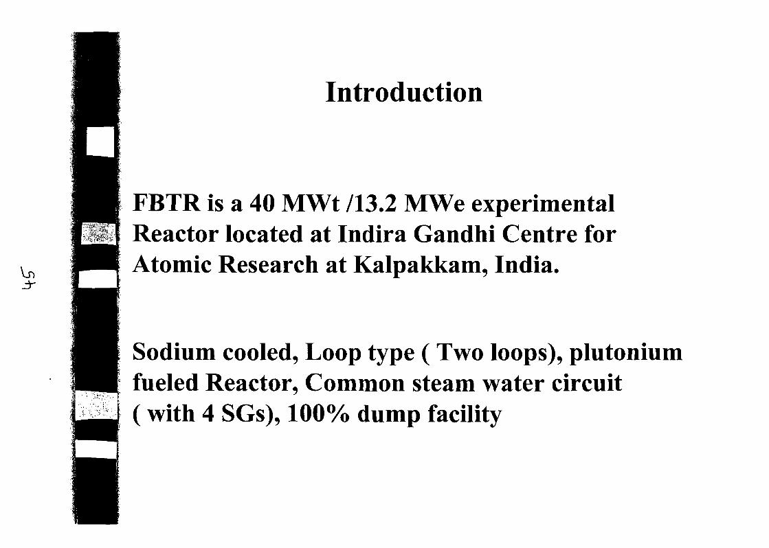
Introduction
I. V
FBTR is a 40 MWt 113.2 MWe experimentalReactor located at Indira Gandhi Centre forAtomic Research at Kalpakkam, India.
Sodium cooled. Loop type ( Two loops), plutoniumfueled Reactor, Common steam water circuit( with 4 SGs), 100% dump facility
REACTOR
VESSELINT. HEAT SURGE STEAM
EXCHANGER TANK GENERATORSTEAM
TURBINE GENERATOR
\\ /1
/•
•0
«i
!
c
SI»*Cto
K )
iio'c j».
\
ii*e<f
s~*\
u
s ^
t»
•a
G .-,
(?>P^ferP}v -
<ie'c/iit k.ri f•»
HEATERDEAERATOR /-\
11 1 /' — x I'<nc: r u'
PRIMARYPUMP
SECONDARY
PUMP
BOILER PEEDPUMP
CONDBNSATEPUMP
CIRCULATING COOLINGWATER TOWERPUMP
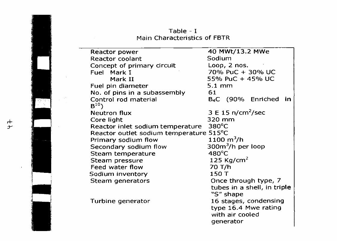
Table - IMain Characteristics of FBTR
3-
Reactor powerReactor coolantConcept of primary circuitFuel Mark I
Mark IIFuel pin diameterNo. of pins in a subassemblyControl rod materialB10)Neutron fluxCore lightReactor inlet sodium temperatureReactor outlet sodium temperaturePrimary sodium flowSecondary sodium flowSteam temperatureSteam pressureFeed water flowSodium inventorySteam generators
Turbine generator
40 MWt/13.2 MWeSodiumLoop, 2 nos.70% PuC + 30% UC55% PuC + 45% UC5.1 mm61B4C (90% Enriched in
3 E 15 n/cm2/sec320 mm380°C515°C1100 m3/h300m3/h per loop480°C125 Kg/cm2
70T/h150 TOnce through type, 7tubes in a shell, in triple"S" shape16 stages, condensingtype 16.4 Mwe ratingwith air cooledgenerator

First criticality in Oct, 1985 with 22 fuel SA ,Fii|l handling incident in May, 1987Power raised to 10 MWtin Jan, 1993T(J synchronised to grid in July, 1997Posit irradiation of fuel SA of burn up 25,000 &•• • > ' , " - , * • - , ' • •*• j '
i ~i : i;
50fOOO MWd/T carried out , shown excellentf / » . •< * ; ' j ~" J
V- \*"v '• '> - -. •••- - ' .
pelforniiance of fuelclad material for PHWR ) irradiated
. ' - • ' - ' •
operated at max. power of 1 3.4 MWturn u of 88000 MWt at 320 w/cri;
illahned to operate at 17.4 MWt corre' W/cm to achieve 1,00,000 MWd/T
A.
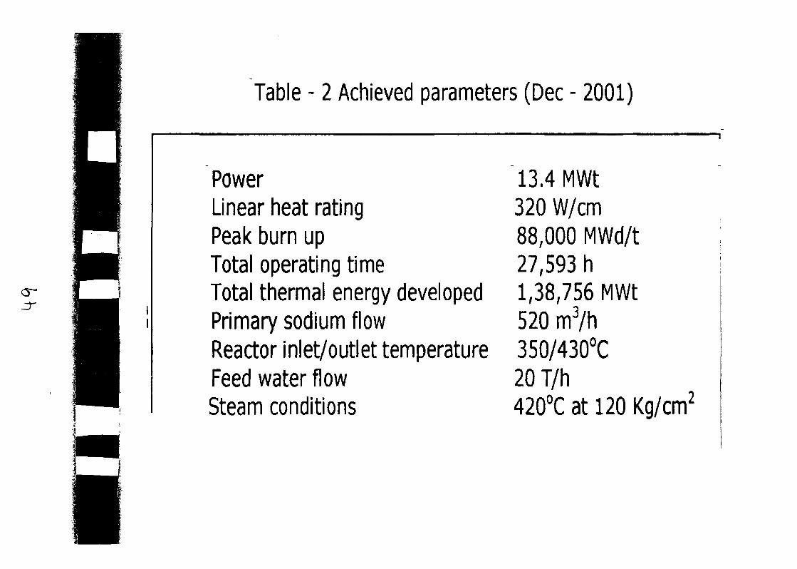
Table - 2 Achieved parameters (Dec - 2001)
PowerLinear heat ratingPeak burn upTotal operating timeTotal thermal energy developedPrimary sodium flowReactor inlet/outlet temperatureFeed water flowSteam conditions
13.4 MWt320 W/cm88,000 MWd/t27,593 h1,38,756 MWt520 m3/h350/430°C20T/h420°C at 120 Kg/cm2
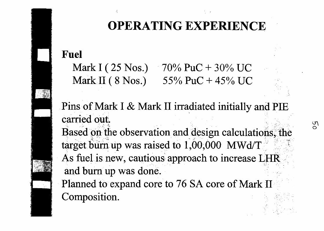
OPERATING EXPERIENCE
FuelMark I (25 Nos.)Mark II ( 8 Nos.)
70% PuC + 30% UC55% PuC + 45% UC
Pins of Mark I & Mark II irradiated initially and PIEcarried outBased on the observation and design calculations, thetarget burn up was raised to 1,00,000 MWd/TAs fuel is new, cautious approach to increase LHRand burn up was done.
Planned to expand core to 76 S A core of Mark IIComposition.
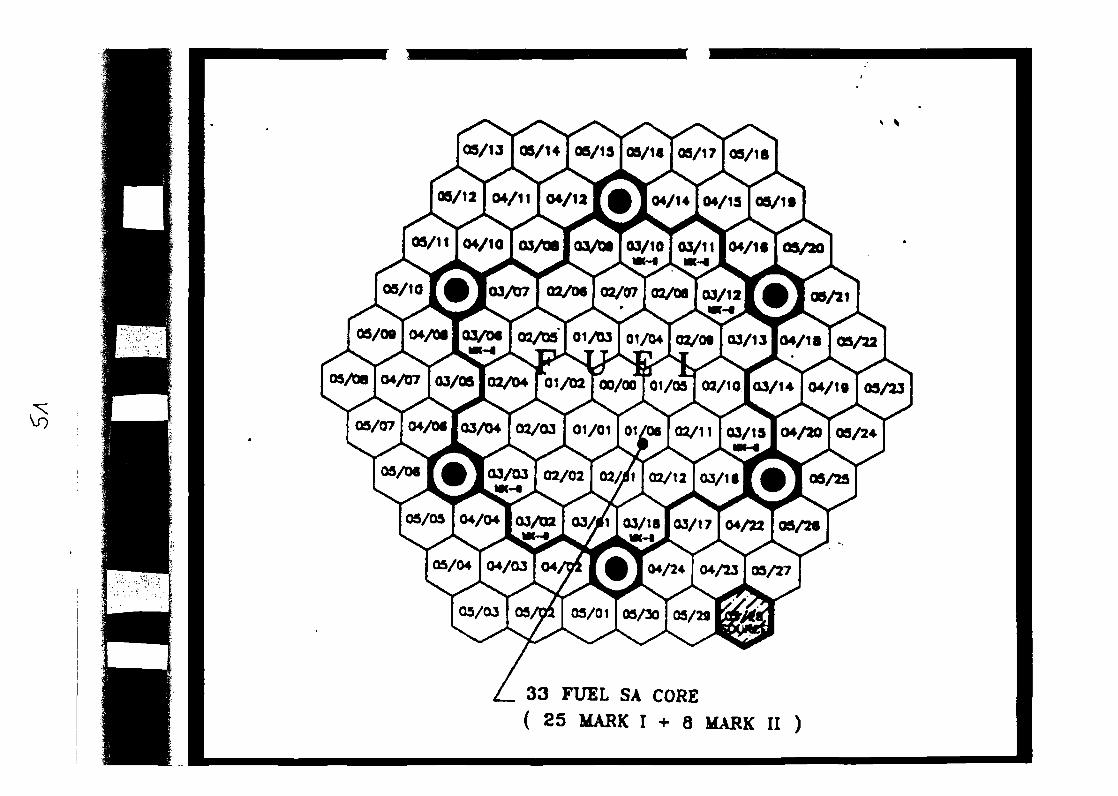
c$
08/13 05/14 OS/13 OS/U OS/17 j OS/18
OS/12 04/11 04/12 04/1404/13OS/1»
OS/H 04/10 03/M OJ/Dio3/10 03/1 lo4/1 •
05/10 I 103/07 I 02/06 I 02/07 I 02/08 I 03/121 • J 00/21
OS/0» | 04/08 103/06 I CO/tM I OiytuTot/tuTrr»/ftoTM/i7lo4/18 j 09/22
04/1 goS/23
oi/Oloi/0«o2/1 1 Ca/1so4/2003/24OS/07 04/Of 03/04
03/03 02/02 02/1 02/12 03/U
04/24 04/23 05/27
33 FUEL SA CORE
( 25 MASK I + 8 MAKK II )
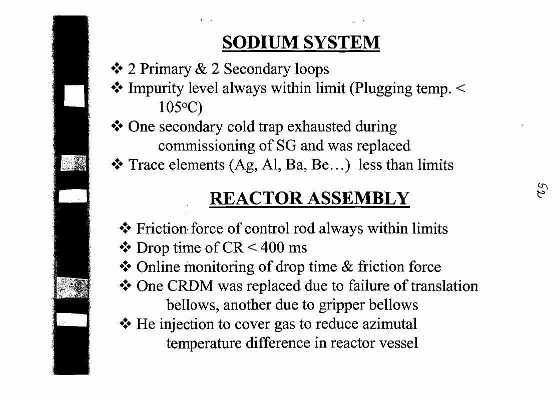
SODIUM SYSTEM* 2 Primary & 2 Secondary loops* Impurity level always within limit (Plugging temp. <
105°C)* One secondary cold trap exhausted during
commissioning of SG and was replaced* Trace elements (Ag, Al, Ba, Be...) less than limits
REACTOR ASSEMBLY
* Friction force of control rod always within limits* Drop time of CR < 400 ms& Online monitoring of drop time & friction force* One CRDM was replaced due to failure of translation
bellows, another due to gripper bellows*> He injection to cover gas to reduce azimutal
temperature difference in reactor vessel
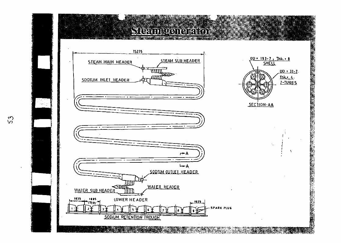
OU* 1 9 3 * 7 . Thk.i 8SHELL
STEAM SUB HEADERSTEAM MAIM HEADER
SODIUM INLET HEADER
SODIUM OUI LEI HEADER
WATER SUB HEADEjL lllH /
SODIUM RETENTION TROUGH

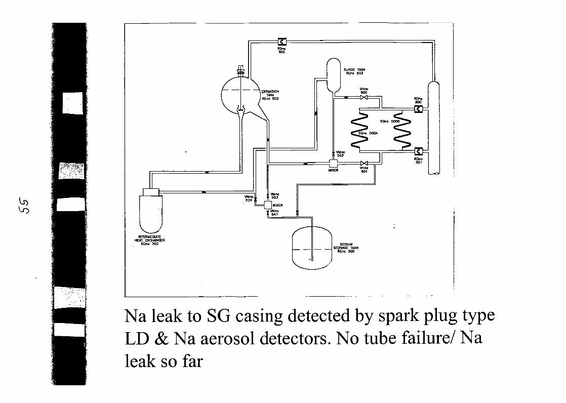
RDnc502
A EXPANSIONTANK
) HEno 502
VMno904
SURGE TANKREno 503
VHna500
RDna
VMno502
ROnc501
VHrw501
VMnoSO]
==T~Tv
ft
MTERMEOIATEHEAT EXCHANGER
ECna 700 SODIUMSTORAGE TANK
REno SCO
Na leak to SG casing detected by spark plug typeLD & Na aerosol detectors. No tube failure/ Naleak so far
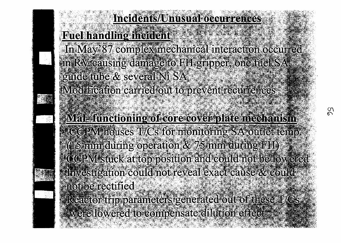

Na/NaK leaksNaK leak from one cold trap (2.5 1)Na leak from secondary Na samplerNaK leak from NaK bubbler in cover gas Argon supplysystemDeficiencies in system were corrected to preventrecurrenceWater leak from SG sub headersWater leak from end cap of SG inlet orifice assemblies- manufacturing defect correctedWater leak from flanged orifice joints meant for SGstability test) - flanged joints replaced by welded spoolswith integral orificesWater leak from one of the T/C wells meant for SGstability study -manufacturing defect corrected
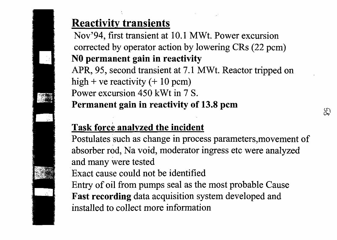
Reactivity transientsNov'94, first transient at 10.1 MWt. Power excursioncorrected by operator action by lowering CRs (22 pcm)
NO permanent gain in reactivityAPR, 95, second transient at 7.1 MWt. Reactor tripped onhigh + ve reactivity (+10 pcm)Power excursion 450 kWt in 7 S.Permanent gain in reactivity of 13.8 pcm
Task force analyzed the incidentPostulates such as change in process parameters,movement ofabsorber rod, Na void, moderator ingress etc were analyzedand many were testedExact cause could not be identifiedEntry of oil from pumps seal as the most probable CauseFast recording data acquisition system developed andinstalled to collect more information
c

Q~
In 1998 third series of transients, which are repeatable in nature, observedat 8 MWt during irradiation campaign of PHWR clad tube material(Zr-Nb alloy)Power increase of around 700 to 800 kWt from a stable power of 8 MWtwas observed with out the movement of CRs.
Other observations are:
• Self limiting and power remain steady after the transient• Reactivity gained (30-40 pcm) while raise in reactor power is lost
while manually lowering reactor power• No permanent gain in reactivity. Power increase during transient
is around 700 to 800 kWt• The on-set of reactivity transient occurs at a specific core AT of
appx. 90 to 110° C for any power level. While lowering power the- ve transient occurs at same AT
• The AT at which transient sets in increases with increase inprimary flow and magnitude of transient comes down.
At a primary flow of > 460 m3 /h, there is no transient
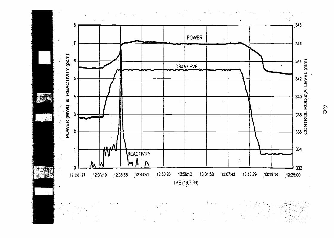
o
a:
g
12:28:24 12:3110 12.38:55 ,12:44:41 12:50:25 12:56:12 13:01:53 13:07:43 13:13:23 13:19:14 13:25:00
TIME (16.7.99)
O
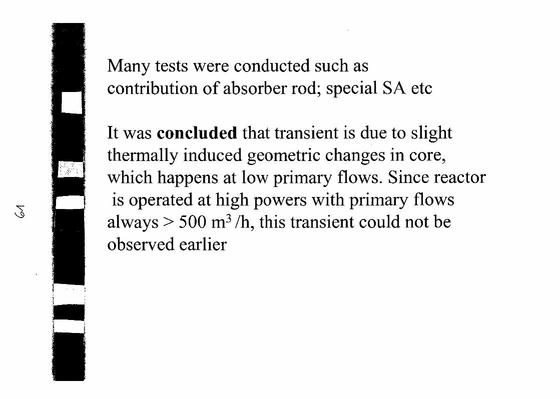
Many tests were conducted such ascontribution of absorber rod; special S A etc
It was concluded that transient is due to slightthermally induced geometric changes in core,which happens at low primary flows. Since reactoris operated at high powers with primary flowsalways > 500 m3 /h, this transient could not beobserved earlier
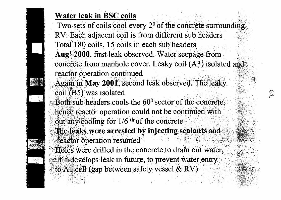
if •> •.-'.-rT* ;"''"'
xi-p-,-> '
Water leak in BSC coilsTwo sets of coils cool every 2° of the concrete surroundingRV. Each adjacent coil is from different sub headers ITotal 180 coils, 15 coils in each sub headersAug' 2000, first leak observed. Water seepage fromconcrete from manhole cover. Leaky coil (A3) isolated ai<|reactor operation continuedAgain in May 2001, second leak observed. TKeleakycoil (B5) was isolatedi;Bothf sub headers cools the 60° sector of the concrete^hence reactor operation could not be continued with
ati^boiing for 1/6 thof the concreteBleaks ivere arrested by injecting sfala^^ aiui:7^
eaclor operation resumed | J ,tfHdles were drilled in the concrete to drain out water,
rjsilfitedevelops leakin future, to prevent water entry•-1 id Aif^ell (gap between safety vessel & RV)
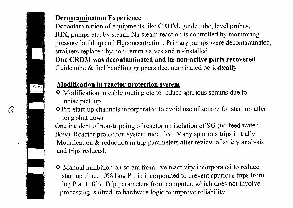
Decontamination ExperienceDecontamination of equipments like CRDM, guide tube, level probes,IHX, pumps etc. by steam. Na-steam reaction is controlled by monitoringpressure build up and H2 concentration. Primary pumps were decontaminated,strainers replaced by non-return valves and re-installedOne CRDM was decontaminated and its non-active parts recoveredGuide tube & fuel handling grippers decontaminated periodically
Modification in reactor protection system«J* Modification in cable routing etc to reduce spurious scrams due to
noise pick up*Pre-start-up channels incorporated to avoid use of source for start up after
long shut downOne incident of non-tripping of reactor on isolation of SG (no feed waterflow). Reactor protection system modified. Many spurious trips initially.Modification & reduction in trip parameters after review of safety analysisand trips reduced.
* Manual inhibition on scram from -ve reactivity incorporated to reducestart up time. 10% Log P trip incorporated to prevent spurious trips fromlog P at 110%. Trip parameters from computer, which does not involve
processing, shifted to hardware logic to improve reliability
1 1* *• ,
Conclusjoa
tj.
v>*
been :fully commissioned with sfflall c0felip toa power level of 13.4 MWt and peffomiaiiceofall:systenis has been satisfactory. Large no,;ofpnocMcalipns &;unpi;oyements wereI©6ti§tfucti0n. commissioning and dperatioiil&i *-J": *- " " . . - , ' „ - "° - ,"*•'" ', •;• * '..-.,,
iveli considerable experience, whicte^iH ht >;for signing, commissioning &
reactors
!*,
•.*-•*..„> "*
• ,
*.'
• ••«**
,«.*"-.£•'=*"•
•f.
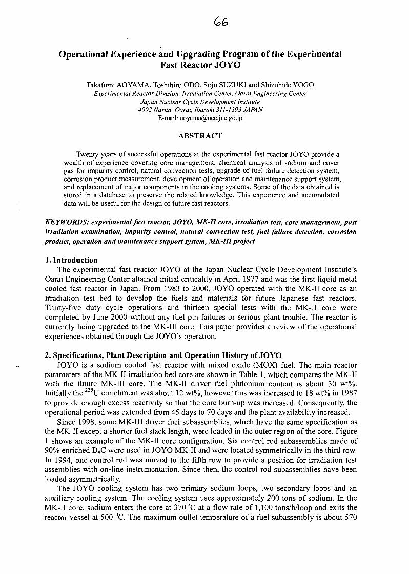
Operational Experience and Upgrading Program of the ExperimentalFast Reactor JOYO
Takafumi AOYAMA, Toshihiro ODO, Soju SUZUKI and Shizuhide YOGOExperimental Reactor Division, Irradiation Center, Oarai Engineering Center
Japan Nuclear Cycle Development Institute4002Narita, Oarai, Ibaraki 311-1393 JAPAN
E-mail: [email protected]
ABSTRACT
Twenty years of successful operations at the experimental fast reactor JOYO provide awealth of experience covering core management, chemical analysis of sodium and covergas for impurity control, natural convection tests, upgrade of fuel failure detection system,corrosion product measurement, development of operation and maintenance support system,and replacement of major components in the cooling systems. Some of the data obtained isstored in a database to preserve the related knowledge. This experience and accumulateddata will be useful for the design of future fast reactors.
KEYWORDS: experimental fast reactor, JOYO, MK-II core, irradiation test, core management, postirradiation examination, impurity control, natural convection test, fuel failure detection, corrosionproduct, operation and maintenance support system, MK-IHproject
1. IntroductionThe experimental fast reactor JOYO at the Japan Nuclear Cycle Development Institute's
Oarai Engineering Center attained initial criticality in April 1977 and was the first liquid metalcooled fast reactor in Japan. From 1983 to 2000, JOYO operated with the MK-II core as anirradiation test bed to develop the fuels and materials for future Japanese fast reactors.Thirty-five duty cycle operations and thirteen special tests with the MK-II core werecompleted by June 2000 without any fuel pin failures or serious plant trouble. The reactor iscurrently being upgraded to the MK-III core. This paper provides a review of the operationalexperiences obtained through the JOYO's operation.
2. Specifications, Plant Description and Operation History of JOYOJOYO is a sodium cooled fast reactor with mixed oxide (MOX) fuel. The main reactor
parameters of the MK-II irradiation bed core are shown in Table 1, which compares the MK-IIwith the future MK-III core. The MK-II driver fuel plutonium content is about 30 wt%.Initially the 235U enrichment was about 12 wt%, however this was increased to 18 wt% in 1987to provide enough excess reactivity so that the core burn-up was increased. Consequently, theoperational period was extended from 45 days to 70 days and the plant availability increased.
Since 1998, some MK-III driver fuel subassemblies, which have the same specification asthe MK-II except a shorter fuel stack length, were loaded in the outer region of the core. Figure1 shows an example of the MK-II core configuration. Six control rod subassemblies made of90% enriched B4C were used in JOYO MK-II and were located symmetrically in the third row.In 1994, one control rod was moved to the fifth row to provide a position for irradiation testassemblies with on-line instrumentation. Since then, the control rod subassemblies have beenloaded asymmetrically.
The JOYO cooling system has two primary sodium loops, two secondary loops and anauxiliary cooling system. The cooling system uses approximately 200 tons of sodium. In theMK-II core, sodium enters the core at 370 °C at a flow rate of 1,100 tons/h/loop and exits thereactor vessel at 500 °C. The maximum outlet temperature of a fuel subassembly is about 570
°C. An intermediate heat exchanger (IHX) separates radioactive sodium in the primary systemfrom non-radioactive sodium in the secondary system. The secondary sodium loops transportthe reactor heat from the EHX to the air-cooled dump heat exchanger (DHX). A flow diagramof the cooling system of MK-II core is shown in Fig. 2.
The operating data and history of the JOYO MK-II core are shown in Fig. 3 and Table 2.The reactor operated for 48,000 hours and the integrated power generated was 4,400GWh.During the MK-II operation, 382 driver fuel subassemblies and approximately 47,000 fuel pinswere irradiated. A peak burn-up value of 86.0 GWd/t was attained for the MK-II driver fuelwithout any fuel pin failures.
3. Core Management ExperienceA core management code system has been developed to predict the core parameters for
operation and refueling plans within the design limitations. The nuclear calculation is based ondiffusion theory and corrected with a bias method. Results from core physics tests and PostIrradiation Examinations (PIE) have been used to confirm the accuracy of these predictions.These verifications are also important to conduct various irradiation tests accurately. Thissection describes the method and verification for core and fuel management used with theJOYO MK-II core.
3.1 MethodThe MAGI calculation code system [1]'[2] was developed to predict the reactor parameters
required for core and fuel management of the JOYO MK-II core. Figure 4 shows the MAGIsystem outline. MAGI is a neutronic and thermo-hydraulic coupling code system thatcalculates the excess reactivity, power distribution, fuel burn-up, coolant flow rate andtemperature condition of each subassembly. MAGI uses diffusion theory with seven neutronenergy groups for the nuclear calculations.
The neutron cross section was collapsed from the 70 group JFS-3-J2 cross section set t3'processed from the JENDL-2 library. It was updated to the JFS-3-J3.2 cross section setbased on the JENDL-3.2 library [4] in 2001. The gamma-ray cross section that includesdelayed fission gamma-ray was processed from the JENDL-2 library to improve thecalculations of gamma heating in stainless steel. The core configuration was modeled inthree-dimensional Hex-Z geometry for each operational cycle. The actual reactor powerhistory was used in the burn-up calculation.
MAGI supported the refueling plan for each operational cycle. The number of fresh driverfuel subassemblies and their position were determined within design limitations of neutronicand thermal parameters with consideration for the following items; (1) burn-up of fuelsubassembly, (2) operation period of the cycle, (3) neutron fluence and temperature conditionof the irradiation test subassemblies. The number of discharged spent fuel subassembliesranges from 10 to 12, about one sixth of total driver fuel subassemblies. The frequentrefueling affects the core characteristics and irradiation conditions significantly so the MAGIcalculation needs to be verified in each operation cycle.
3.2 Verification of Core Management3.2.1 Core Physics Tests in Each Operational CycleCriticality and Burn-up Reactivity
The excess reactivity in a zero power critical condition was measured at the reactor start-upof each operational cycle. Measured data were compared with the MAGI calculated values thatincluded the bias factor (C-E) correction obtained for the previous cycle. The comparison ofcalculated and measured values is shown in Table 3. By using this bias method, it was foundthat the excess reactivity after refueling can be well predicted within an error of 0.1 %Ak/kk'.
The burn-up reactivity was determined by measuring the reactivity change during ratedpower operation. Measured values were compared with the MAGI burn-up calculation andboth agreed within 5 % as shown in Table 3. It is considered that the decrease of atomicnumber densities of major fissile nuclides as 235U and 239Pu are the dominant factor of burn-upreactivity because of JOYO's small core size, which results in hard neutron spectrum and smallinternal conversion ratio (~0.3). Therefore, the burn-up reactivity can be predicted accuratelyeven at a high burn-up.
Control Rod WorthEvery control rod's worth was calibrated with either the positive period method or the
inverse kinetics method during the low power test of each operational cycle. The calculationwas conducted with the CITATION code based on three dimensional diffusion theory using thesame cross section, geometry and atomic number densities as MAGI. After correcting with theprevious cycle's C/E, the calculated values were compared with the measurements. Table 3shows that both agreed within 2 %. When one control rod was moved from the third row to thefifth row in 1992, the worth of the relocated rod was reduced to one third. The calculationaccuracy was not changed significantly.
Reactivity CoefficientsReactivity coefficients are important for safety reasons and to account for the reactivity
change associated with temperature and power changes during reactor operation. Themeasured values are used to predict the reactivity change for the next operational cycle.
The isothermal temperature coefficients were measured by taking the difference ofreactivity at approximately 250 °C and 370 °C during reactor start-up. The measuredisothermal temperature coefficients were constant through the MK-II operation because theywere determined mainly by radial expansion of the core support plate, which is independent ofburn-up. However, when the core region was gradually extended from the 32nd cycle, theisothermal temperature coefficients were decreased as predicted with the mechanism. Table 4shows these values.
The power coefficients were measured at the reactor start-up and shutdown in eachoperational cycle. Figure 5 shows that the measured power coefficients decreased withincreasing core burn-up. It was considered that the fuel thermal expansion, which is the majorcomponent of the power coefficient of JOYO, decreases at high burn-up due to fuelrestructuring during irradiation. It was also observed that the power coefficients varieddepending on the reactor power as shown in Fig. 6. This phenomenon appeared to be due to acombination of the core bowing effect, fuel thermal expansion and Doppler effects. Thesecauses need further investigation.
3.2.2 Post Irradiation Examination (PIE)On-site Burn-up Distribution Measurement
The calculation accuracy of MAGFs axial power distribution was confirmed by comparingthe relative distribution of measured (144Pr) and calculated fuel bum-up. The burn-upmeasurement was taken in the JOYO spent fuel storage pond [5l The spent fuel subassemblywas contained in a stainless steel can, and it was set on a fuel-scanning device. Axial andcircumferential gamma-ray distributions were measured using a high purity germanium (Ge)detector by moving the fuel scanning system vertically and by rotating the subassembly aroundthe fixed detector. As illustrated in Fig. 7, the MK-II spent fuel subassembly with a burn-up of62.5 GWd/t and cooling time of 5.2 years was measured. It was shown that the measured andMAGI calculated values were close except at the upper region of the fuel column. Thisdifference was apparently due to the calculation error of neutron absorption by control rod.
Burn-up Ratio Measurement by 4 Nd MethodChemical analysis of I48Nd was conducted at the hot cell facility. As 148Nd is one of the
stable fission products and its fission yield is highly reliable, I48Nd production obtained bydestructive examination has been commonly used as a bum-up index [6l The calculated andmeasured burn-up ratios for the MK-II spent fuel from 0.3 atom % to 8.7 atom % is shown inFig. 8. Measured results agreed with the MAGI burn-up calculation within 5 % in each row.
Decay Heat MeasurementThe accuracy of decay heat calculations depends on the individual heat generation rate
from fission product decay nuclides and actinides, and the burn-up calculation for itsproduction and transmutation. To obtain experimental data and to improve the accuracy ofrelated calculations, the decay heat of MK-II spent fuel subassemblies was measured at theJOYO spent fuel storage pond [7]. The fuel bum-up was approximately 66 GWd/t and thecooling time was between 40 and 385 days. The measured decay heat is shown in Fig. 9.
The decay heat was then calculated with the ORIGEN2 code using the JENDL-3.2 crosssection library and the JNDC-V2 [8' decay data and fission yield data library. The fuel powerused as an input to ORIGEN2 was calculated by MAGI. The ratios of calculated toexperimental values were between 0.94 and 0.89, and decreased with a longer cooling time asshown in Fig. 9. This systematic discrepancy needs to be further investigated, but the changewith cooling time appears to be due to the actinides' decay heat uncertainty.
3.2.3 Reactor DosimetryThe neutron flux calculation error rate was evaluated to be less than 5 % in the fuel region
according to the comparison between MAGI and reactor dosimetry test results. Figure 10shows an example of adjusted neutron spectrum based on the foil activation method at the corecenter position of the MK-II. The dosimetry test results were used to correct MAGIcalculations to assure the neutron fluence used in the post irradiation test analysis. A HeliumAccumulation Fluence Monitor (HAFM) has been developed to improve the accuracy oflong-term irradiation tests.
3.3 MK-II Core Characteristics DatabaseDuring the MK-II operation, extensive data were accumulated from start-up and core
characteristics tests. These core management and core characteristics data were compiled into adatabase [2]. The core management data includes core specifications and configurations,atomic number densities before and after irradiation, neutron and gamma flux, neutron fluence,fuel burn-up, and temperature and power distributions. The core characteristics data includeexcess reactivities, control rod worths, and reactivity coefficients, e.g., temperature, power andburn-up. These core characteristics data were recorded on CD-ROM for user convenience.
4. Chemical Analysis of Sodium and Cover GasIt is essential for steady and safe operation of a sodium cooled fast reactor to limit the
coolant and cover gas impurities to prevent corrosion of reactor component materials and toreduce radiation dose by corrosion products (CPs). Therefore, impurity concentrations of bothcoolant sodium and cover gas argon were measured during the duty cycle operation and annualinspection period. The sodium impurity data include oxygen, hydrogen, nitrogen, chloride,tritium, metal elements and radioactive 110mAg, 22Na, 137Cs. The cover gas impurity datainclude C>2, N2, CO, CO2, Fb, CFL;, He, 3H and radioactive xenon and krypton isotopes.
These data were measured by chemical analysis, gas chromatography, beta-ray scintillationand gamma-ray spectrometry. The sodium impurity concentrations were also determined bythe sodium temperature in the plugging indicator. As an example, the trend of oxygen and
hydrogen in the primary sodium are shown in Fig. 11. The impurity data were also recorded inthe CD-ROM.
5. Decay Heat Removal Test of Natural ConvectionThe inherent safety of a fast reactor can be demonstrated by proving the natural convection
capability and establishing analytical techniques based on experiments. A series of naturalconvection tests was performed from 1981 to 1986 in JOYO. The natural convection test from100 MWt, which is the most critical situation for the reactor, was carried out at the end of 12th
cycle of the MK-II core in 1986 [9].The test was initiated by tripping primary and secondary sodium pumps manually without
pony motor operation, and the reactor was shut down simultaneously by tripping the pumps;moreover, the blowers of the DHXs were stopped immediately with the reactor scram signal.The central driver fuel subassemblies undergo the most severe temperature transition duringthe tests. Figure 12 shows the outlet temperature of one of these assemblies, together withprimary coolant flow rate variations. The peak temperature reached 519 °C due to coolant flowrate reductions. This peak is significantly below the initial temperature of 548 °C.Consequently, it is shown that the temperature increase will not cause any safety-relatedproblems, such as fuel cladding failure.
The post analysis results from a plant wide dynamics code MIMIR-N2 are in excellentagreement with the experimental data as shown in Fig. 12. Various key parameters are clarifiedto improve the calculation accuracy through the study. In the short-term analysis, theevaluation of thermo-hydraulic behavior in the core is largely affected by the inter-assemblyheat transfer effect, the pump flow coast characteristics and coolant flow distribution. For thelong-term analysis, it is important to assess precisely the buoyant head effect in the IHX, theheat exchange effects in the lower plenum of the IHX and others. The experimental result isalso applied to the assessment of natural convection characteristics in the MONJU reactor.
6. Upgrade of FFD System and Installation FP TrapsThe fuel failure detection (FFD) and the failed fuel detection and location (FFDL) are
important for LMFBR plants to achieve high availability and operational reliability. Fissionproduct (FP) traps are important for safety reasons: especially for conducting safeRun-beyond-cladding-breach (RBCB) tests.
The JOYO FFD system consists of both delayed neutron (DN) monitoring systems and acover gas (CG) precipitating system. The schematic diagram of the JOYO FFD system isillustrated in Fig. 13. Two DN monitoring systems are located adjacent to the primary coolingloops to detect the delayed neutrons emitted from precursors released into the coolant sodium.The CG precipitating system detects fission product of 88Rb i.e. beta decay of 88Kr releasedinto the cover gas argon.
A Run-to-Cladding-Breach (RTCB) test is planned in JOYO. The RTCB test is expected toimprove the FBR fuel performance. The results will increase the fuel burn-up and extend thecladding life-time. As part of the preparation work, the FFD system has been upgraded toimprove its accuracy and reliability and FP traps have been installed. A series of simulated fuelfailure tests has been conducted [10).
6.1 Upgrade of The FFD SystemOn-line Gamma-ray Monitor
The On-line Gamma-ray Monitor (OLGM), shown in Figure 13, has been developed andinstalled in JOYO. The OLGM consists of a charcoal bed that is made to selectively adsorb theisotopes of krypton and xenon, and a high purity Ge detector. The special feature of this systemis to be able to identify the isotopes in the cover gas by means of gamma-ray spectrum analysis.
The OLGM is also used to detect the tag gas that is originally contained inside a pressurizedstainless steel capsule. In the irradiation environment, the creep rupture may cause the capsuleto fail and release the tag gas into the cover gas. As shown in Fig. 14, the activated tag gasnuclides among the background fission products are clearly detected by OLGM and thismethod was found to be applicable [11].
Resonance lonization Mass SpectrometryThe Resonance lonization Mass Spectrometry (REVIS) is a method to detect xenon and
krypton with ultra high sensitivity using a laser technique '12' developed in collaboration withthe University of Tokyo and Nagoya University. The block diagram of a RIMS system with atime of flight (TOP) mass spectrometer is illustrated in Fig. 15. The optical parametricoscillator (OPO) is excited using the YAG laser at the 355 nm wavelength. The higherharmonic wave is then generated from 512 nm OPO light in the secondary higher harmonicgenerator (SHG), and the laser-ionized sample gas flows into the ionization chamber. The ionis then detected in the micro channel plate (MCP), and it is counted by the digital signalaverager (DSA). An example of measured data for sample argon gas containing 10 ppb ofxenon with a natural isotopic distribution is shown in Fig. 16. A sharp mass spectrum wasobtained by RMS, which demonstrates a high sensitivity to the diluted cover gas in the orderof few ppb.
6.2 Installation of FP TrapsTwo types of FP traps have been installed in JOYO. One is a cesium trap installed in the
primary coolant sodium purification system to capture cesium released from failed fuels. Anopen pore, foam-like glassy carbon that consists of thin struts of Reticulated Vitreous Carbon(RVC) is used as a material for collecting cesium. The capacity of this trap is designed to be7.4E+12 Bq. The other trap is a Cover Gas Clean-up System (CGCS) to collect and store thenoble fission gas released from failed fuels. Although it is planned that only one failed fuel pinwill be in the core at any time, the CGCS is designed to handle the releases of up to twelvefailed fuel pins.
6.3 Fuel Failure Simulation TestsAn in-pile simulation test was carried out at the end of the 7th operational cycle using two
artificially defected (slit) fuel pins to verify the performance of JOYO's FFDL system. Thissystem uses the sodium sipping method. The slit is 1.0 mm long and 0.1 mm wide andperforated on the fuel cladding at gas plenum position. In the FFDL operation, a signal level ofthe test subassembly was several hundreds times higher than the background measured forother core subassemblies (see Fig. 17). With this test, the FFDL system was confirmed to havethe capability to identify the failed fuel with a defect at a gas plenum position.
A FP source using U-Ni alloy tubes was irradiated at the end of 15th operational cycle. Thetest results show two important results. Both the CG and DN monitoring system weresuccessfully calibrated and the CG monitor was confirmed to have enough sensitivity to the FPgas released from the failed fuel pins. The major constants for the cover gas and DN behaviormodels were determined and the disengagement rate constant of the FP gas from the sodiumcoolant to cover gas region varied depending on the flow rate of the primary cooling system.
7. Measurement of Radioactive Corrosion Products (CP)The sodium cooled fast reactor JOYO has been operated more than 20 years (about 5
years of effective full power years) since its initial criticality and the cumulative reactoroutput achieved over 1.9E+5 MWd. Since JOYO has not yet experienced any operation with
breached fuels, FP radioactive contamination has not become an issue in the plant system.To reduce the radiation dose from long-lived 22Na, all primary coolant sodium in the maincirculating loops is drained into a storage tank during annual plant inspections. Under theseconditions, the spatial gamma-ray dose rate distribution is dominated by the radioactive CPsdeposited on inner surfaces of the primary piping and components. This means that mostpersonnel dose was due to these CPs.
7.1 Measured Results and AnalysisThe CP deposits on the inner surfaces of the primary main piping have been measured at
every annual inspection period since the end of MK-I operation in July of 1982. Thesemeasurements are made at 14 locations, shown in Fig. 18, using a Ge solid-state detectorsystem. The detector system was calibrated with a piping mock-up using two planer typestandard gamma-ray sources, 54Mn and 60Co, so that the absolute amounts of CP depositscould be obtained from the measured gamma-ray spectra.
In every annual inspection, gamma-ray dose rates from these CP deposits have beenmeasured using calcium sulfate (CaSO4) thermo-luminescence dosimeters (TLDs). Thegamma-ray dose rate distribution near the piping is measured in detail at 93 locations atone-meter intervals along loop (A) from the outlet to the inlet of the reactor vessel. At eachlocation, four TLDs are placed every 90 degrees around the thermal insulator cover. Thegeometrical conditions for the measurements are almost the same as those for the radioactiveCP deposit mentioned above.
The CP behavior analysis code PSYCHE [131 has been developed and verified with themeasured radiation data to analyze the distribution of corrosion product in the primarycooling system. A radiation dose calculation code has been developed by JNC, to analyze theCP deposition distribution along the piping and components of the primary cooling system.The build-up of CPs is shown in Fig. 19 together with the reactor operation time. ThePSYCHE calculations agree with the measured values.
7.2 Application of Optical FiberA Plastic Scintillation Fiber (PSF) measured the dose rate distribution in the primary
cooling system of JOYO [14]. Figure 20 shows the schematic diagram of the PSF system.Polystyrene was used as a scintillator that emits light in response to gamma-rays. Theradiation source's location was determined with the time of flight method by measuring thetime interval between the signals from two photo multipliers at each end of PSF. As seen fromthe pulse height distribution in Fig. 19, the measured count rate distribution does not have asharp gradient even for a single point irradiation; therefore, the unfolding method is applied toreproduce the actual dose rate distribution.
The gamma-ray dose rate profile of the A loop IHX, shown in Fig. 21, is an example ofthe measured PSF data. Two peaks were observed due to horizontal plates in these positionswhere there were large CP deposits. Comparing PSF results with a series of TLD point data,large differences were observed at these peaks. However, by employing the unfolding method,the PSF data coincided with the TLD results. The gamma-ray dose rate distributionmeasurement was greatly improved by the use of PSF.
8. Operation and Maintenance Support SystemsThe JOYO operation and maintenance support systems ensure more stable operations and
13
improve operational reliability. Artificial intelligence techniques [I5J have been applied todevelop these systems. One system objective is to support intelligent decision making by theoperators and maintenance engineers, and another is to conduct skill-based and rule-basedoperator actions automatically. With proper instructions and guidance from the support system,the JOYO operators can make better decisions and carry out necessary actions with moreconfidence and less mental pressure.
8.1 Operation Support SystemThe operation support system named JOYCAT (JOYO Conducting and Analyzing Tool)[16]
was developed to help operators make intelligent and quick decisions in cases of anomalousevent occurrences. Figure 22 illustrates the JOYCAT hardware configuration. The JOYCATsystem consists of a knowledgebase and an inference system connected to the JOYO dataacquisition system (JOYDAS). The JO YD AS collects on-line plant operation data from severalthousands sensors located in different positions in the plant at interval of 0.25 second.
Prior to its application to the JOYO plant, JOYCAT was validated by a full scope operatortraining simulator. The alarm signals used for this validation were triggered by a manual scramduring the reactor shut down process and by activating the reactor safety system during aperiodic test. The system has been used since 1988.
The features of the JOYCAT system are:
(1) When an alarm occurs, the system diagnoses the plant conditions based on data from thereactor systems and the main components.
(2) Based on the system knowledge base, the alarm sequences and plant interlocks arechecked. If nothing wrong is found, the system identifies the cause of the alarm. When ananomaly is found in some sequence or a safety system failure, the related information isdisplayed quickly on a CRT for the operators.
(3) After the cause of the alarm is identified, the most suitable operation manual for theanomaly is displayed for the operators.
8.2 Automatic Control Rod Operation SystemThe JOYO operators control the reactor power, i.e. neutron flux level, by adjusting the
position of the control rod subassemblies in the core. This is a manual operation performedfrom the central control room. To improve operational reliability as well as to reduce themental load on the operators, an automatic control rod operation system [16] has beendeveloped. This system has the following capabilities:
(1) drive the control rods;(2) indicate the rod drive stroke for each control;(3) indicate the criticality point (5E+4 cps for Source Range Monitor);(4) monitoring of the reactor period, neutron flux, thermal output of the reactor, rate of
reactor power change, heat-up rate at the reactor vessel inlet, and the temperaturedifference between the overflow tank and the reactor vessel outlet;
(5) guide the plant operation;(6) display information concerning the rod operation and the current plant conditions, i.e.
trend graphs of the thermal power, neutron flux and reactivity of the core.
In actual operation, the operator's actions in accordance with the above guidance should beconducted in a different manner depending on the reactor power level as described in Fig. 23.A fuzzy algorithm based on linguistic rules is employed to control non-linear characteristics,whereas this is a difficult problem for the conventional PI controller.
In the past, the control rod drive stroke was calculated by the operators prior to manualcontrol when approaching criticality. After the installation of the system, it calculates anddisplays an inverse multiplication curve and the stroke of each control rod subassembly thatneeds to be driven using the neutron flux and the vertical control rod position. The reliabilityof this system was validated during a complete operational cycle of the MK-II core. It was alsodemonstrated that the operation guides provided by the system were very similar to thosechosen by the experienced JOYO operators.
8.3 Maintenance Support SystemHigh security and reliability of equipment is required in nuclear reactor plants. The
equipment is designed based on failure analysis and preventive maintenance and conditionmonitoring are recommended. The condition monitoring technique has been developed todetect the failure and degradation of the machine as soon as possible to diagnose anomalycauses and to evaluate the machine's damage. The equipment is used under various stressesdepending on their operating environments and these stresses cause degradation or failuressuch as fatigue, wear and tear, corrosion and others, hi most cases, these appear as changes invibration or acoustic noise so vibration monitoring is a popular and effective techniqueespecially for rotating machines like motors or pumps.
In JOYO, a vibration monitoring systems named MEDUSA (MEchanical-fault DiagnosisUsing Spectrum Analysis) [17^ has been developed as an on-line vibration monitoring systemfor the major rotating machines such as the main pumps of the primary and secondary coolingsystems. MEDUSA monitors the vibration of major rotating machines automatically andcontinuously, and it notifies plant operators and maintenance engineers of any anomalies itdetects. Furthermore, the MEDUSA could assist in the analysis and interpretation of thevibration data.
System ConfigurationFigure 24 illustrates the system configuration of MEDUSA. Vibration signals are collected
by accelerometers mounted on each rotating machine and the signals are sent to themultiplexers (Fast Fourier Transform (FFT) analyzers) through the amplifiers and filters. Theengineering work station (EWS) manages the instruments and vibration data. The FFTanalyzers and multiplexers save the CPU load of the EWS for the signal processing soMEDUSA could easily deal with the increasing number of monitoring machines.
The MEDUSA monitors vibration levels (r.m.s. and peak levels), auto power spectrumdensities (APSDs), waveforms and probability density functions at every hour automatically,then the r.m.s. levels and the APSDs are compared with acceptable vibration levels to judgewhether the machine's condition is normal. If an anomaly condition is detected, warningmessages and beeps notify the plant operators and maintenance engineers. Monitoringintervals are variable and it is possible to monitor more frequently when an anomaly symptomis detected or for test runs after an inspection.
Vibration data has been kept for 300 days on the EWS, and the previous data is dumpedinto digital audiotapes. These data could be accessed on the terminals anytime, so that thefollow-up survey over a long term is possible. Operators can review how an anomalysymptom appears and how it increases by a trend graph and a three dimensional graph(time-frequency-amplitude of vibration). The characteristic vibration data for an anomalycondition of the rotating machine is saved with a label and description that includesphenomena, causes and measures against the anomaly. These data could be used as a

reference to judge the machine condition and to make a necessary action.
Experience of Vibration Monitoring in JOYOThe MEDUSA has been used as a regular part of plant maintenance and operation since
1990, and it is useful to detect anomalies and to diagnose their causes. As an example ofvibration monitoring in JOYO, the vibration level of a cooling blower suddenly increased bya factor often on December 31st 1992. This blower is placed in a nitrogen gas atmosphere andcannot be repaired while the reactor is operating.
Figure 25 shows the APSD of vibrations before and after the increase of vibration. Thevibration increased in higher frequency region over 5 kHz (increased -50 dB to -20 dB around6 kHz). Therefore, it was estimated that the vibration occurred due to loss of lubrication oil orbearing failure. Later at the annual inspection of the blower, it was found that there was a lossof lubrication oil in the bearing box and the vibration level decreased after refilling the oil.
9. Improvement of Countermeasures against Sodium LeaksA sodium leak accident occurred in the MONJU secondary cooling loop in December 1995.
At that time, the 11th annual inspection was being performed at JOYO and an inspection ofsodium piping and components was immediately carried out to confirm their integrity and toverify that there were no sodium leaks.
After the MONJU accident, an investigation was completed by the Safety Authority andfindings on the cause of the sodium leaks and ways to mitigate their effects were published.According to this report, the structural integrity of the JOYO thermocouple well was tested andconfirmed by hydraulic vibration evaluation based on water flow tests and ASME standards.Modifications were then made at JOYO to improve countermeasures against sodium leaks inthe secondary loop [18].
The improvements of these sodium leak countermeasures in the secondary loop stressedprevention, early detection and mitigation of the effects. The improvements were determinedaccording to the following considerations:
(1) Sodium Leak Prevention- All the thermocouples in the secondary loop were inspected by non-destructive examination
(X-ray, fiber scope inspection) to confirm their integrity.- All the thermocouples were replaced by new ones with compression fittings that seal any
sodium leaking between the thermocouple well and sheath in the event of a thermocouple wellrupture.
(2) Early Detection of Sodium Leaks- A new sodium leak monitor was installed in the central control room to verify the function
of each sodium leak detector.- A new fire alarm monitor was installed in the central control room to verify the function of
each fire detector. This monitor has a second alarm function that realarms if another detectorgoes off.
- Monitor cameras were installed in the secondary cooling facility to view the sodium pipingand components from the central control room.
(3) Mitigation of Sodium Leak Effect- Sodium leak trays were added under the sodium piping to prevent dispersion of leaking
sodium.- Anti-smoke dampers were added in the ventilation system to prevent the diffusion of
sodium aerosol. The dampers in the ventilation system are interlocked with the sodium leakdetector and fire detector to shut automatically.
- The penetration gaps between the piping and walls were sealed to prevent the diffusion ofsodium aerosol.
(4) Improvement of Manuals- Upgrade of Operational Manuals.
1. The emergency operational manual for JOYO sodium leaks was reviewed and verified asvalid.
2. The emergency operational manual was upgraded by incorporating the improvedcountermeasures against sodium leaks.
- Revision of Education and Training Schedule1. Emergency operation training, sodium fire-extinguishing training and overall disaster
prevention training have been carried out.2. The education and training schedule was revised to provide more skilled training.
JOYO's safety practice for sodium leaks were investigated by the Safety Authority. After asuccessful investigation, JOYO was allowed to restart operations in March 1997.
10. Upgrading Program and Modification of Core and Cooling System ComponentsJOYO is expected to play a greater role in providing an irradiation field for fuels and
materials irradiation tests and for the demonstration of innovative safety related systems forfuture fast reactors. To meet the increasing requirements for the various irradiation tests, theJOYO MK-III upgrading program was initiated to improve its irradiation capability nsu^i.po^The main objectives of the MK-III program are to increase the neutron flux, modify the coolingsystem to meet the power increase, increase the irradiation periods and upgrade the irradiationtechnology as shown in Fig. 26.
10.1 Outline of MK-III Project and SpecificationThe basic specifications of JOYO are previously shown in Table 1, which compares the
MK-II and MK-III cores. The MK-III core is divided into two regions with different plutoniumcontents and the core height is decreased from 55 cm to 50 cm to obtain higher neutron fluxwith smaller power peaking. Two of six control rods are shifted to the edge of the outer core toenlarge the high neutron flux irradiation field. Two layers of radial stainless steel reflector arereplaced by the shielding subassemblies, which contain boron carbide pellets, to reduce theneutron dose in the radial direction.
A whole plant design optimization increases the reactor thermal output from 100 MWt to140 MWt. The fast neutron flux increases about 30 % as shown in Fig. 27 and the maximumallowable number of fuel irradiation test rigs increases from nine to twenty-one. The MK-IIIcore will support various irradiation tests on advanced fuels like MA doped fuel, highplutonium content MOX fuel and vibration packed fuel. The irradiation technology has alsobeen developed to expand the capability and flexibility of fuels and materials irradiated.
The JOYO cooling systems need to be modified to increase the heat removal capacity.Figure 28 shows the components to be exchanged in the modifications and compares the plantcondition in the cooling system. The primary system sodium coolant flow rate increases by20 % and all Intermediate Heat Exchangers (IHX) and Dump Heat Exchangers (DHX) werereplaced. The cooling system modification completed in September 2001 and the coolingsystems were refilled with sodium then the initial purification was conducted. The cold trap inthe secondary sodium purification system will be replaced in the autumn of 2002.
10.2 Modification Work ExperienceSpecial attention was given to prevent air containment when cutting the sodium boundary
during this modification work. The following procedure was employed for replacing the DHX.First, the temporary supports for sodium piping and argon gas supply lines were installed inpreparation for cutting the sodium piping. Next, the sodium piping was cut to two-thirds oftheir thickness using the cutting tools. A glove box was installed to cover the sodium pipingcuts to keep the cover gas boundary filled with argon.
The sodium piping was cut off after a leak test was conducted. The sodium on the innersurface of the cutting part was scraped off and the residues were rinsed with alcohol. After theshut-off plug was set in the inner part of the piping to completely shield it, the beveling of thewelding part was done to prepare for the new piping weld. Since all the cutting positions ofthe sodium piping are horizontal, the cutting powder from the piping is relatively easy tocollect, preventing it from entering in the cooling system. In this way, all the sodium pipingwas cut off using the cutting bits.
The cover gas pressure in the secondary argon gas system at normal operation iscontrolled in the range of 34 kPa to 44 kPa. It was decided to lower the cover gas pressure to220 Pa at for the cutting work based on the experience of taking the surveillance materials outof the system, and the glove box pressure ratings. An automatic low-pressure argon controlsystem was newly installed in the system. The oxygen concentration inside the glove box wascontrolled below the level of 1000 ppm. The control value of oxygen and nitrogenconcentration in the system sodium piping is below 300 ppm and 1200 ppm, respectively.
10.3 Future ScheduleThe performance of newly installed components and cooling systems will be confirmed
through a series of functional system tests. The core replacement will start in the summer of2002. When the initial MK-III core configuration is complete, the reactor power will beincreased in steps to conduct performance tests that confirm the core physics and plantcharacteristics. The MK-III rated power operation will start in 2003.
11. ConclusionsThe successful operations of JOYO provide a wealth of experiences with core management,
impurity control, reactor engineering tests, innovative instrumentation techniques, operationand maintenance support systems, and component modifications. These experiences andaccumulated data are to be used for the design of future fast reactors. They are also useful forupgrading the JOYO core and plant to the MK-III configuration and are essential to securesteady and safe reactor operation and enhance the irradiation capability of JOYO in the future.
References[1] S. Maeda et al., "Fast Reactor Core Management in Japan: Twenty Years Evolution at JOYO,"
Trans. Int. Meeting on Research Reactor Fuel Management, Aachen, Germany, Apr. 1-3, 2001, pp.56-60(2001).
[2] S. Tabuchi and T. Aoyama, "Development of JOYO MK-II Core Characteristics Database," Proc.Symp. on Nuclear Data, Ibaraki, Japan, Nov. 18-19, 1999, pp.149-153 (2000).
[3] H. Takano and K. Kaneko, "Revision of Fast Reactor Group Constant Set JFS-3-J2," JAERI-M89-141 (1989).
[4] T. Nakagawa et al., "Japanese Evaluated Nuclear Data Library Version 3 Revision-2: JENDL-3.2,"J. Nucl. Set. Technol., 32 [12], 1259 (1995).
[5] M. Takamatsu and T. Aoyama, "Neutron Intensity of Fast Reactor Spent Fuel," Proc. Symp. onNuclear Data, Ibaraki, Japan, Nov. 27-28, pp. 21-26 1997 (1998).
[6] Atom Percent Fission in Uranium and'Plutonium Fuel (Neodymium) Annual Books of ASTMStandard, £-321-79(1971).
[7] S. Maeda and T. Aoyama, "Decay Heat of Fast Reactor Spent Fuel," Proc. Int. Conf. on NuclearData (ND2001), Ibaraki, Japan, Oct. 7-12, 2001, to be published.
[8] K. Tasaka et al, "JNDC Nuclear Data Library of Fission Products -Second Version-," JAERI1320(1990).
[9] M. Sawada et al., "Experiment and Analysis on Natural Convection Characteristics in theExperimental Fast Reactor JOYO," Nuclear Engineering and Design, 120, pp. 341-347 (1990).
[10] T. Aoyama et al., "The Operational Experience of the Experimental Fast Reactor "JOYO"," Proc.the 3rd Asian Symposium on Research Reactor, Ibaraki, Japan, Nov. 11-14, 1991, pp. 75-82 (1991).
[11] T. Aoyama and C. Ito "Integral Test on Activation Cross Section of Tag Gas Nuclides Using FastNeutron Spectrum Fields," Proc. Int. Conf. on Nuclear Data (ND2001), Ibaraki, Japan, Oct. 7-12,2001, to be published.
[12] K. Watanabe et al., "Development of Failed Fuel Detection and Location Technique UsingResonance lonization Mass Spectrometry," J. Nucl. Sci. Techno!., 38 [10], pp. 844-849 (2001).
[13] K. lizawa et al., "Transport of Radioactive Corrosion Product in Primary Systems of a SodiumCooled Fast Reactor," Proc. Material Behavior and Physical Chemistry in Liquid Metal Systems 2,Plenum Press, ISBN 0-306-45069-0, pp. 9-26 (1995).
[14] T. Aoyama et al., "Application of Optical Fiber for Radiation Measurement in Fast Reactor PrimaryCooling System," Proc. 12lh Pacific Basin Nuclear Conference, Seoul, Korea, Oct. 29 - Nov. 2, 2000,Vol. 2, pp. 1095-1105(2000).
[15] Y. Himeno et al., "Improvement of Man-Machine Interaction by Artificial Intelligence forAdvanced Reactors," Reliability Engineering and System Safety, 38, pp. 135-144 (1992).
[16] M. Sawada et al., "Operation and Maintenance Support Systems of the Experimental Fast ReactorJOYO," Proc. ANSInt. Topical Meeting on Safety of Operating Reactors, Seattle, USA, Sep. 17-20,1995, pp. 564-570(1995).
[17] M. Ueda et al., "Condition Monitoring System of Rotating Machines in the Experimental FastReactor JOYO," Proc. the 3rd JSME/ASME Joint Int. Conf. on Nuclear Engineering, Kyoto, Japan,Apr. 23-27, 1995, Vol. 3, pp. 1619-1621 (1995).
[18] Y. Maeda et al., "Current Status and Upgrading Program of the Experimental Fast Reactor JOYO,"ENC'98 Trans., Nice, France, Oct. 25-28, 1998, Vol. IV, Workshops, pp.21-30 (1998).
[19] S. Suzuki et al., "Upgrading Program of the Experimental Fast Reactor "JOYO" - The MK-IIIProgram -," Proc. 10th Pacific Basin Nuclear Conference, Kobe, Japan, Oct. 20-25, Vol. 1, pp.759-768(1996).
[20] A. Yoshida et al., "Upgrading Program of the Experimental Fast Reactor Joyo," Book ofAbst. Int.Conf. on Nuclear Engineering (ICONE-9), Nice, France, Apr. 8-12, 2001, Vol. 2, pp. 492 (2001).
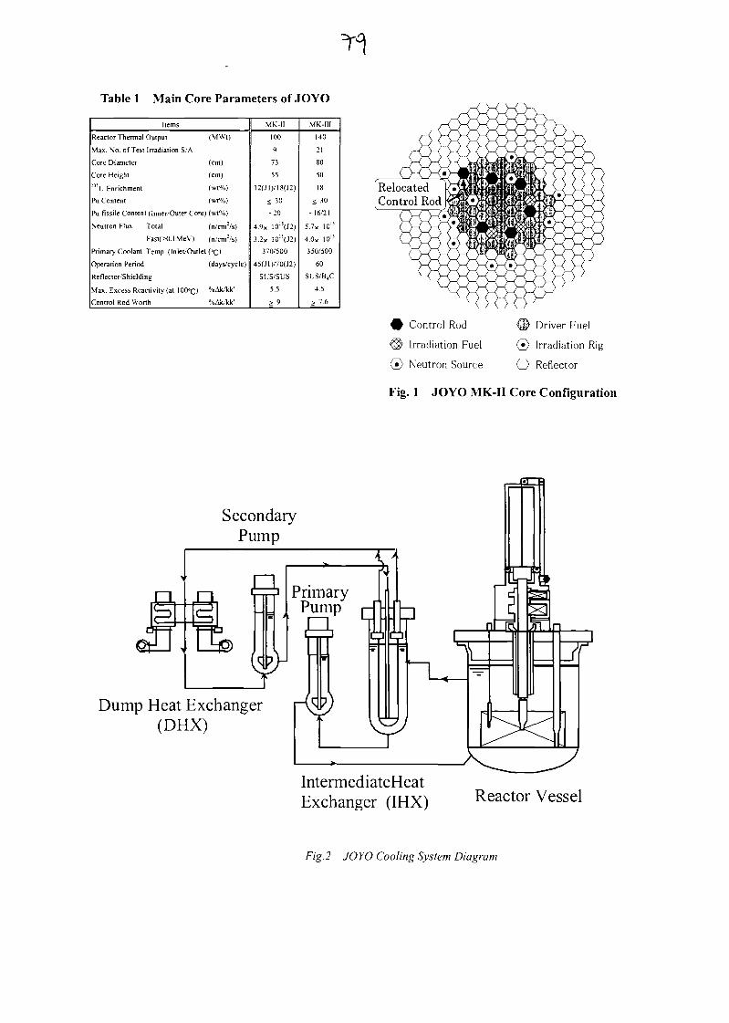
Table 1 Main Core Parameters of JOYO
Items
Reactor Thermal Output (MWt)
Max. No. of Test Irradiation S/A
Core Diameter (cm)
Core Height (cm):3'u Enrichment (wt%)
Pu Content (wt%)
Pu fissile Content (Inner/Outer Core) (wt%)
Neutron Flux Total (n/cm:/s)
Fast(X).lMeV) (n/cm:/s)
Primary Coolant Temp. (Inlet'Outlet (°c)
Operation Period (days/cycle)
Reflector'Shielding
Max. Excess Reactivity (at 100°c) %Alt/kk'
Control Rod Worth %Ak/kk'
MK-II
100
9
73
55
12(J1)/18(J2)
< 30
-20
4.9x 101!(J2)
3.2x 10I5(J2)
370/500
45(J1)/70(J2)
SUS/SUS
5.5
> 9
MK-III
140
21
80
50
18
< 30
-16/21
5.7x 10¹⁵
4.0X 10"
350/500
60
SUS/B.C
4.5
> 7.6
SecondaryPump
n
netLJ g
PrimaryPump
Dump Heat Exchanger(DHX)
Q Control Rod
® Irradiation Fuel
(•) Neutron Source
d> Driver Fuel
(•} Irradiation Rig
O Reflector
Fig. 1 JOYO MK-II Core Configuration
IntermediateHeatExchanger (IHX) Reactor Vessel
F/g.2 JOYO Cooling System Diagram
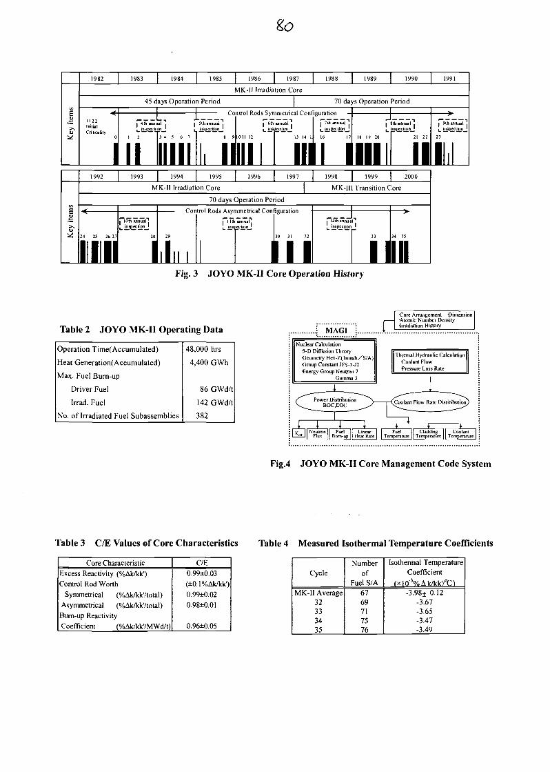
1982 1983 1984 1985 1986 1987 1988 1989 1990 1991
MK-II Irradiation Core
45 days Operation Period 70 days Operation Period
Control Rods Symmetrical Configuration
I 60i annual j I I 'Ui annual j l . Sthinnual"!l_ inspection^] I j_ inspec tirjn_] I ,__ JnspjecticmJ
13 14 l l 16 17 18 19 20 21
mi iini ii£1992 1993 1994 1995 [ 1996 I 1997 1998 1999 2000
MK-II Irradiation Core MK-III Transition Core
70 days Operation Period
24 25 26 2
I
I lOlh annual"!
Control Rods Asymmetrical Configuration
28
I
130 31 32
TIT?• 12lh annual". insDection '
34 35
IIIFig. 3 JOYO MK-II Core Operation History
Table 2 JOYO MK-II Operating Data
Operation Time(Accumulated)
Heat Generation(Accumulated)
Max. Fuel Burn-up
Driver Fuel
Irrad. Fuel
No. of Irradiated Fuel Subassemblies
48,000 hrs
4,400 GWh
86 GWd/t
142 GWd/t
382
• MAGI i
Nuclear Calculation•3-D Diffusion TheoryGeometry Hex-Z(lmesh/S/A)Group Constant JFS-3-J2•Energy Group Neutron 7
Gamma 3
Core Arrangement -DimensionP -Atomic Number Density
•Irradiation History
»Thermal Hydraulic CalculationCoolant Flow•Pressure Loss Rate
— -L— ^-~—CPower Distribution ^N ffn.-i,nt rimi nBOC.EOC ^^/ (Coolant How K^___^
1i i 4 1 *- ¥
v I I Neutron | Fuel }[ Linear±£2J| Flux ]| Bum-up || Heat Rate
ate Distribution)
*Fuel || Cladding II Coolant
Temperature 11 Temperature 1 1 Temperature
Fig.4 JOYO MK-II Core Management Code System
Table 3 C/E Values of Core Characteristics Table 4 Measured Isothermal Temperature Coefficients
Core Characteristic
Excess Reactivity (%Ak/kk')
Control Rod Worth
Symmetrical (%Ak/kk'/total)
Asymmetrical (%Ak/kk'/total)
Bum-up Reactivity
Coefficient (%Ak/kk'/MWd/t)
C/E0.99±0.03
(±0.1%Ak/kk')
0.9$»=0.02
0.98±0.01
0.96±0.05
Cycle
MK-II Average32333435
Numberof
Fuel S/A6769717576
Isothermal TemperatureCoefficient
(xlO"3%Ak/kk'/°C)-3.98± 0.12
-3.67-3.65-3.47-3.49
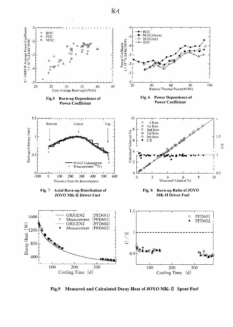
s/i
* -1
-2
-3
<0
-5
BOCHOCMOC
Aa A
cnD
°0 O
<£
20 25 30 35 40Core Average Bum-up(GWd/t)
Fig.5 Burn-up Dependence ofPower Coefficient
45
-6
-5
1| -4
^| -3
12 -2
~- l
-•-BOC.--•--MOC(down)
••<>-MOC(up)
020
.o -
40 60 80Reactor Thermal Power(M Wt)
Fig. 6 Power Dependence ofPower Coefficient
100
1.5
S15
D.
? 0.5
Bottom Center
M A G I Calculation0 Measurement^ Pr)
0-100 0 100 200 300 400 500 600
Distance from the Bottom(mm)
Fig. 7 Axial Burn-up Distribution ofJOYO MK-II Driver Fuel
10
§6
£ 4
0 Row1st Row2nd Row3rd Row4th RowC/E
2 4 6 8Measured Value(at.%)
Fig. 8 Burn-up Ratio of JOYOMK-II Driver Fuel
1.5
wu
0.510
1600-
100 200 300Cooling Time (d)
1.1
O
0.9
PFD601PFD602
100 200 300Cooling Time (d)
A^CU^JJ*]
Fig.9 Measured and Calculated Decay Heat of JOYO MK- II Spent Fuel
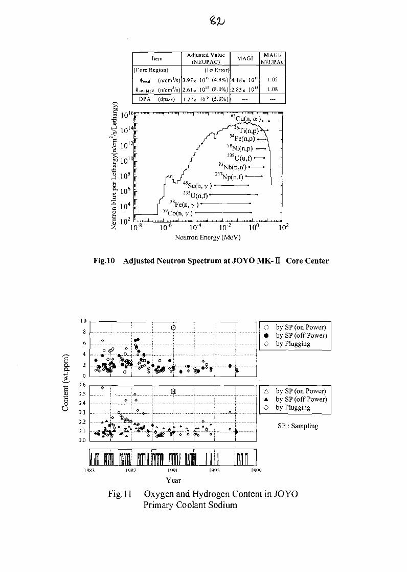
Item
(Core Region)
'('total (n/cm2/s)
^O.IMCV (n/cm2/s)
DPA (dpa/s)
Adjusted Value(NEUPAC)
(10 Error)
3.97x IO ' 5 (4.8%)
2.61 x 10¹⁵ (8.0%)
1.27X 10* (5.0%)
MAGI
4.18x 10¹⁵
2.83x 101S
—
MAGI/NEUPAC
1.05
1.08
—
ifJ3
en
E?c<3
10
10
10
10
108
106
104
16
14
12
10
10,2 :
""1 1
59°Fe(n,y)
yCo(n, y ) •....... j , ,,,,,.j i n,,,,.i . ......j . .....j
10-' 10" 10-2 10U
Neutron Energy (MeV)
Fig. 10 Adjusted Neutron Spectrum at JOYO MK- n Core Center
a.ex
0)-4—>
oU
10
8
6
4
2
0
0.6
0.5
0.4
0.3
0.2
0.1
0.0
1983
....Q ..... • ...... O--A-
-A, ! --*...
O by SP (on Power)• by SP (off Power)O by Plugging
A by SP (on Power)A by SP (off Power)O by Plugging
SP : Sampling
1987 1991
Year
1995 1999
Fig. 11 Oxygen and Hydrogen Content in JOYOPrimary Coolant Sodium
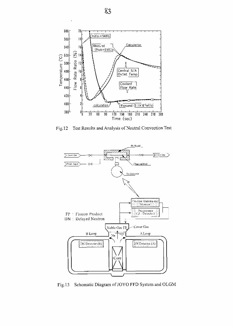
0 30 60 90 120 150 180 210 240 270 300Time (sec)
Fig. 12 Test Results and Analysis of Neutral Convection Test
Pb Shield
FP : Fission ProductDN : Delayed Neutron
;On-lme Gamma-ray::Monitor
Precipitator( 3 - Detector)
1,Noble Gas FPJ^ C°ver Gas
s
\
f
\
B Loop
•DN Detector (B)
>
*+.
=sd
^, 1 ,A f
\lCore
l\
-»-
A Loop
.,,.,,,,,,,,,,,,,,,.,,,,,,,, -viDN Detector (A):
J
\
/
Fig. 13 Schematic Diagram of JOYO FFD System and OLGM
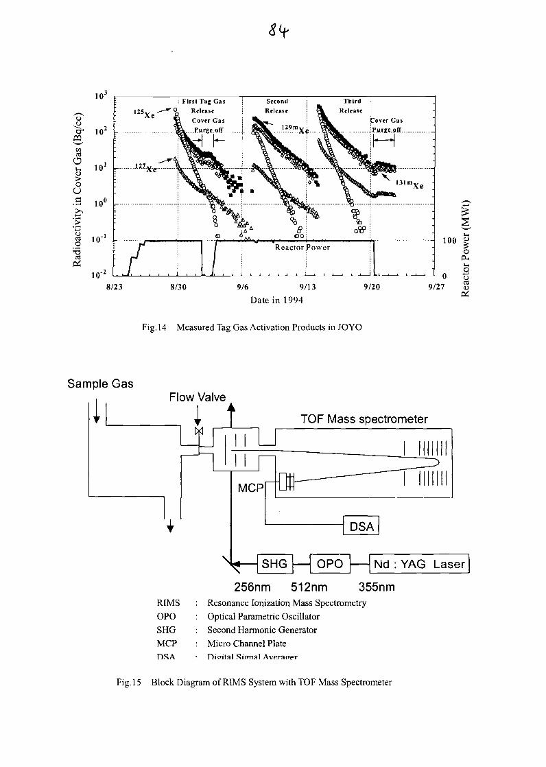
o
~crS
C/3esO
i—
OUc
>' -*oO
1
! First Tag Gas
Qi Release
Cover Gas
Purge__oflf
h
8/23 8/30 9/6 9/13
Date in 1994
Fig. 14 Measured Tag Gas Activation Products in JOYO
Sample Gas
IFlow Valve
I t
RIMS
OPOSHG
MCP
TOP Mass spectrometer
N
256nm 512nm 355nmResonance lonization Mass Spectrometry
Optical Parametric Oscillator
Second Harmonic Generator
Micro Channel PlateDigital Sicmal Averager
Fig. 15 Block Diagram of RIMS System with TOP Mass Spectrometer
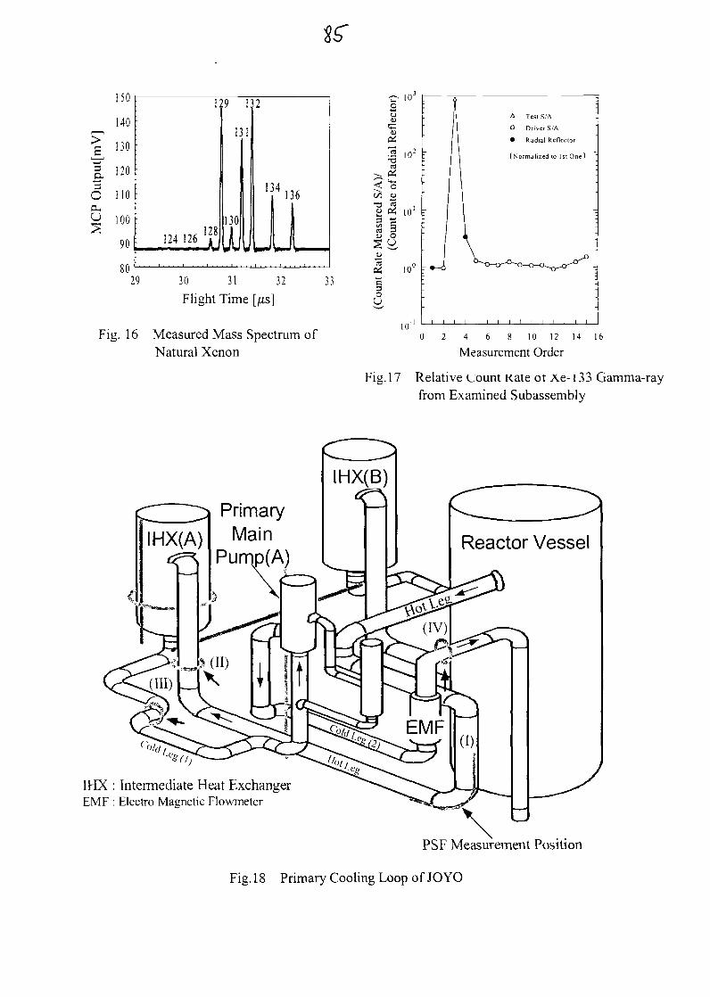
a."3O(X
IJU
140
130
120
110
100
90
on
1
. 124 126 'f
9
i:
130
J.
i
i
2
T136i1 129 30 31 32
Flight Time [jits]33
Fig. 16 Measured Mass Spectrum ofNatural Xenon
<on-o
u0$
T3IX&u_oO
10'
S1
ca05C3OU
10" r
10"
A Test S/A
O Driver S/A
Radial Refleclor
(Normal ized (o 1st One ]
l i l t
2 4 6 8 10 12 14
Measurement Order16
Fig. 1 7 Relative count Kate ot Ae- 1 3 3 Gamma-rayfrom Examined Subassembly
Reactor Vessel
IHX : Intermediate Heat ExchangerEMF : Electro Magnetic Flowmeter
PSF Measurement Position
Fig. 18 Primary Cooling Loop of JOYO
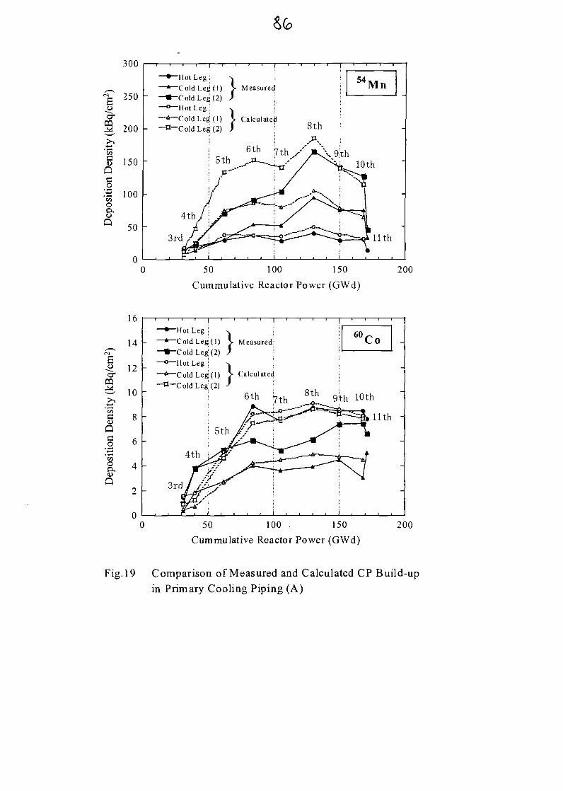
,0~croa
en
300
250
200
150
o:-S 100c/3oex
50 -
-Hot Leg i-ColdLeg^l)-ColdLe£(2)"Hot Leg i-Cold Leg ; ( l )-Cold Leg1 (2)
Measured
Calculated
9th10th
Mlth
50 100 150
Cummulative Reactor Power (GWd)
200
,O
m>.
§QowO
&Q
16
14
12
10
8
6
4
2
-Hot Leg \-Cold Leg( l )-Cold Leg: (2)"Hot Leg !-ColdLeg:( l )-Cold Leg; (2)
Measured;
Calculated
10th
. r-f i . , . .
nth -
50 100 150
Cummulative Reactor Power (GWd)200
Fig. 19 Comparison of Measured and Calculated CP Build-upin Primary Cooling Piping (A)
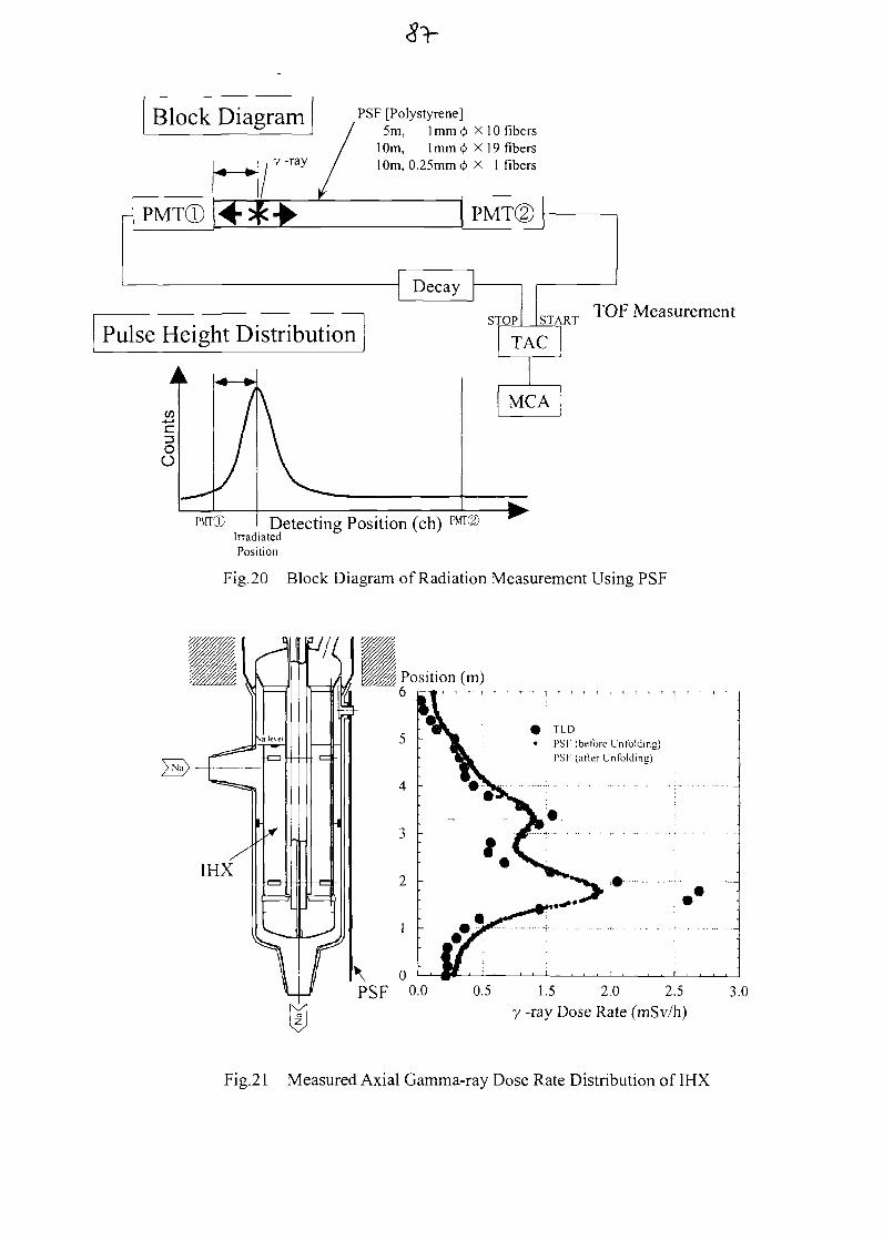
Block Diagram
PMTCD
y -ray
PSF [Polystyrene]5m, 1 mm cj> X 10 fibers
10m, 1mm </> X 19 fibers10m, 0.25mm <t> X 1 fibers
Pulse Height DistributionTOP Measurement
Detecting Position (ch) ™T©IrradiatedPosition
Fig.20 Block Diagram of Radiation Measurement Using PSF
TLDPSF (before Unfolding)PSF (after Unfolding)
0.5 1.5 2.0 2.5
y -ray Dose Rate (mSv/h)
Fig.21 Measured Axial Gamma-ray Dose Rate Distribution of IHX
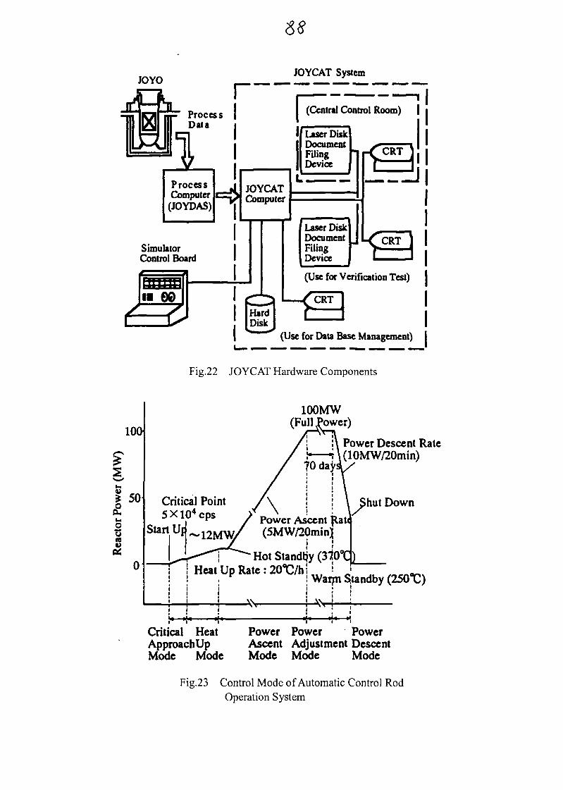
JOYOJOYCAT System
(Central Control Room) |
if Laser Disk
I DocumentFilingDevice
ProcessComputer
(JOYDAS)
JOYCATComputer
SimulatorControl Board
(Use for Verification Test)
(Use for Data Base Management)
Fig.22 JOYCAT Hardware Components
100
£ 5 0£oosP*
01
Critical Point5Xl04cps
100MW(Full Power)
Power Ascent flati(5MW/20min)
HotStandtjy(370°C)«%s\Om it * ! "
Power Descent Rate(10MW/20min)
Shut Down
Critical HeatApproachUpMode Mode
Power Power PowerAscent Adjustment DescentMode Mode Mode
Fig.23 Control Mode of Automatic Control RodOperation System
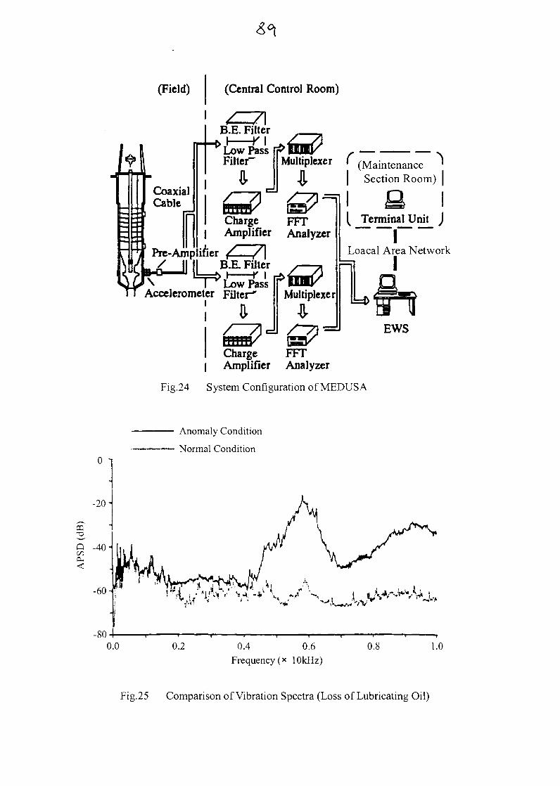
(Field) (Central Control Room)
CoaxialCable
IPre-Amp
B.E. Filter
Low PassFilter- Multiplexer C (Maintenance '
Section Room)
\Accelerometer Filter*
Charge FFT| Amplifier Analyzer
>f»Multiplexer
Low Pass
( Terminal Unit J
ILoacal Area Network
I
EWS
Charge FFT| Amplifier Analyzer
Fig.24 System Configuration of MEDUSA
Anomaly Condition
Normal Condition0 1
-20"
Q -40-eu
-60-^» .'* i V
-80'0.2 0.4 0.6
Frequency (x 10kHz)0.8 1.0
Fig.25 Comparison of Vibration Spectra (Loss of Lubricating Oil)
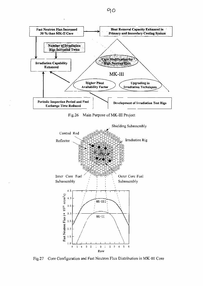
Fast Neutron Flux Increased30% than MK-H Core
Heat Removal Capacity Enhanced inPrimary and Secondary Cooling System
Number of IrradiationRigs Increased Twice
Core >lodificatipji forHigh Neutron Flux.- S " ,^ • ,» -. ' \ t $ , •*%%*. _
Irradiation CapabilityEnhanced
Higher PlantAvailability Factor
Upgrading inIrradiation Techniques
Periodic Inspection Period and FuelExchange Time Reduced
Development of Irradiation Test Rigs
Fig.26 Main Purpose of MK-III Project
Control Rod
Reflector
Inner Core Fuel
Subassembly
Shielding Subassembly
Irradiation Rig
Outer Core Fuel
Subassembly
4.5
Eo
3.5
X3
Oti 2.0u
X 1.5atu
1.0
/ MK-II \
/
5 4 3 2 1 0 1 2 3 4 5
Row
Fig.27 Core Configuration and Fast Neutron Flux Distribution in MK-III Core
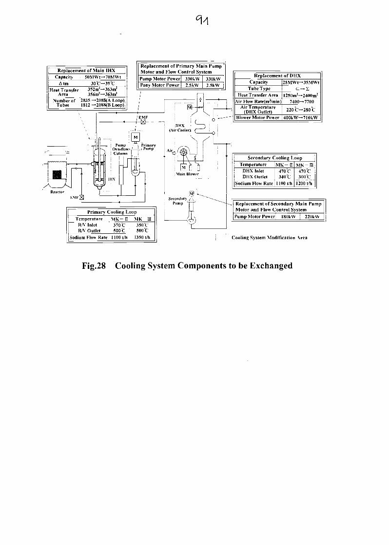
Replacement of Main 1HXCapacity SOMWt-70MW1
AtmHeat Transfer
Area
30°C—39°C352m2—363m2
356m2—363m2
Number of 2835 —Tubes 18
Replacement of Primary Main PumpMotor and Flow Control System
Pump Motor PowerPony Motor Power
330kW2.5kW
330kW2.5k\V
.ZU8S(A Loop)2088(B Loop) /
' , feF
- — p : Pump
I LCiJ
,..J
M !i-^-iJ-^-i Primary
i "m
ioHX(Air Cooler)
Pump
Primary Cooling Loop
TemperatureR/V InletRA' Outlet
Sodium Flow Rate
MK- n370"Csoot
noot/h ;
MK-m350 °C500 °C
1350 t/h
! |M|
: Main Blower
Replacement of DHXCapacity
Tube TypeHeat Transfer Area
Air Flow Rate(m}/min)Air Temperature
(DHX Outlet)Blower Motor Power
25MWt— 35MWt
C — I1250m2— 2400m2
7400—7700
220 °C— 280 °C
400k\V— 7IOkW
Secondary Cooling Loop
TemperatureDHX InletDHX Outlet
Sodium Flow Rate
MK- H470 °C340 C
l l O O f h
MK-ff l470°C300 °C
1200 t/h
Replacement of Secondary Main PumpMotor and Flow Control System
Pump Motor Power ISOkW 220k\V
Cooling System Modification Area
Fig.28 Cooling System Components to be Exchanged

No ' IAEA TM on Operational and DecommissioningExperience with Fast Reactors
Operational Experience and Upgrading Program ofthe Experimental Fast Reactor JOYO
March 11, 2002
T. AOYAMA, T. ODO, S. SUZUKI and S.YOGO
Experimental Reactor DivisionIrradiation Center, O-arai Engineering CenterJapan Nuclear Cycle Development Institute
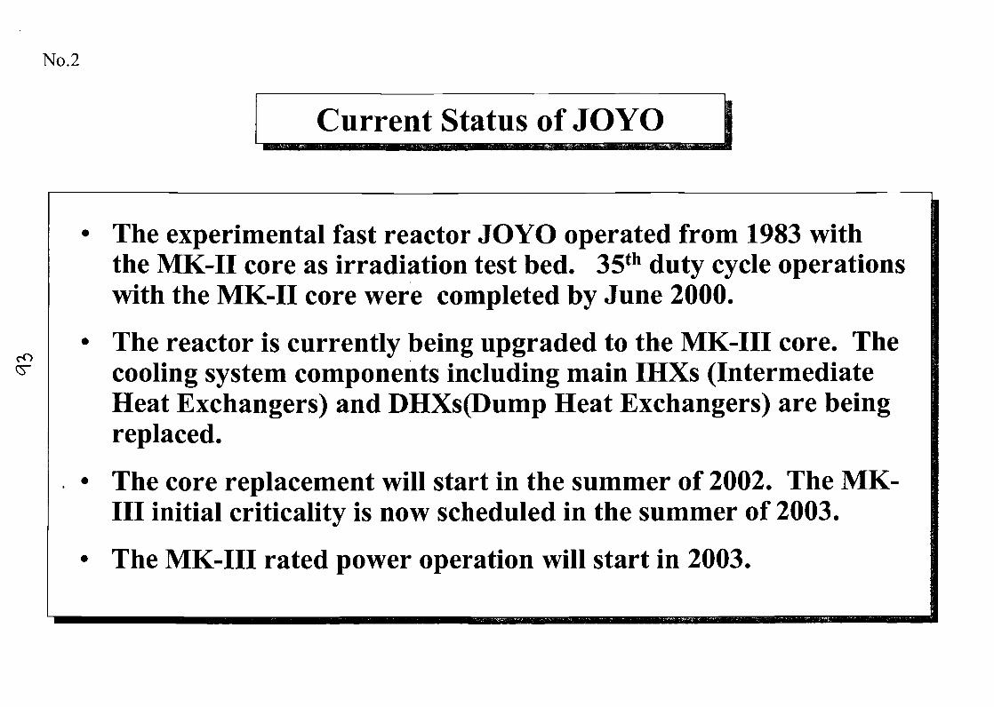
No.2
Current Status of JOYO
The experimental fast reactor JOYO operated from 1983 withthe MK-II core as irradiation test bed. 35th duty cycle operationswith the MK-II core were completed by June 2000.
The reactor is currently being upgraded to the MK-III core. Thecooling system components including main IHXs (IntermediateHeat Exchangers) and DHXs(Dump Heat Exchangers) are beingreplaced.
The core replacement will start in the summer of 2002. The MK-III initial criticality is now scheduled in the summer of 2003.
The MK-III rated power operation will start in 2003.

No.3
Operating History of JOYO
>•u.•
C/>
<u
1977 1978 1979
MK-I Breeder
Low Power TestPerformance Test
50M1
50MW0~100kW j
A
Initial Criticality1977. 4. 24
tWOi
1 2LA
PerformanceTest
1980 1981 1982 1983 1984
Core
75MWOperation
erationInspection ofPrimary Circulatit
Installation of Mechanical Snubberfor the Piping in Primary Loop
I N a i u i :t! * in i i i n i m r i I « • - , !
0 1 2 3 4 5 6
I f I I I ! I l l 1
"cu Eo «•>U .2a.
&
in Pump
111
10
1985 1986 1987 1988
MK-II Irradiation Core
Performance mn»*»»/ ^ *•100MW OperationTest
VJovo Data Aci|iiisition S\s!em(.IOYDAS) „ Upgrading of Cold Trap ^ ,
VSitnulator
N i i n i r a i i ' in u f a l i o i i I i ' \ !
9MWj° ' 2 •••••
a t
-^ ITVXA 1 'fc ^ •MT' « 0« i r N l A - i > < INTA-S
VControl Rod with Vibration RestrictionMechanism
Nadu ;tl ( it cu l a i i on 1 es(l 'i-t(!!);u-K K o : i < - t i v i t \ l o s tMonju Fuel Pre-conditioning Test
, IliBiL III i IMK-II Initial Criticality 1 c ,e Operation days 45^701982. 11. 22 1
Reprocessed Joyo Fuel loaded in the Core
1989 1990 1991 1992 1993 1994 1995 1996 1997 1998 1999 2000
MK-II Irradiation Core Transition Core
100MW Operation
VMeclianical faul t Diagnosis using Spectrum Analysis( M K D U S A ) VJoyo Consulting and Analy/.ing To
INTA-S
-MARICO-Upgrading of Sodium Lea^k Countermeasures
-> Modification of In-core Charge Machine Upgrading of Simulator
INTA-2PTM-1 PTM-2
»y T 24v
h > l ' l ) c i - : i \ Heat ' i l ' Jovo Sni ' i i l i
1-iticr
18 19 20 21 22 23* Y 24* 25 2627 28 29••• • •• i iiiiii i_LI i ' i i) |HT:ilinY I > i * . i i - i l i 11 t i i i t i Mcasurf i iH-nt \ \ i t i i Opt i fa l ! ;!H r
30 31 32 33 34 35
V: Installation of Equipment or System
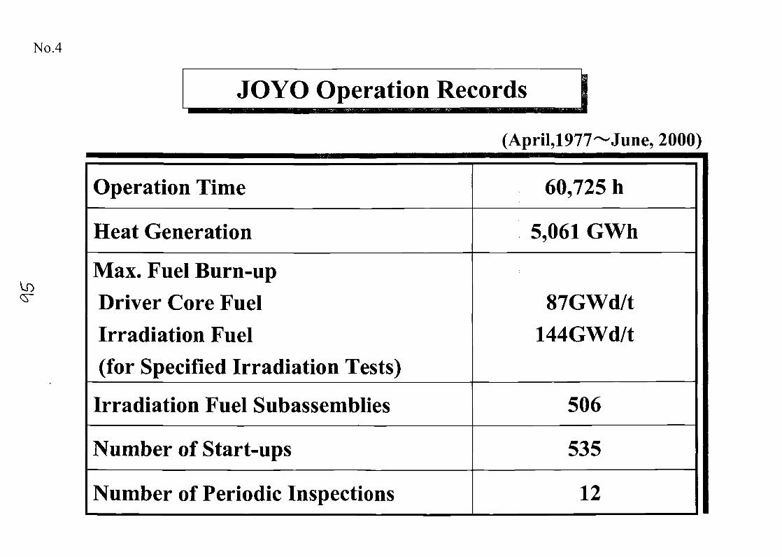
No.4
JOYO Operation Records
(April,1977~June, 2000)
Operation Time
Heat Generation
Max. Fuel Burn-upDriver Core FuelIrradiation Fuel(for Specified Irradiation Tests)
Irradiation Fuel Subassemblies
Number of Start-ups
Number of Periodic Inspections
60,725 h
5,061 GWh
87GWd/t144GWd/t
506
535
12
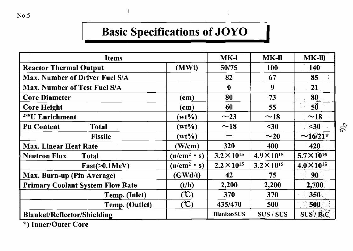
No.5
Basic Specifications of JOYO
ItemsReactor Thermal OutputMax. Number of Driver Fuel S/AMax. Number of Test Fuel S/ACore DiameterCore Height235U EnrichmentPu Content Total
FissileMax. Linear Heat RateNeutron Flux Total
Fast(XUMeV)Max. Burn-up (Pin Average)Primary Coolant System Flow Rate
Temp. (Inlet)Temp. (Outlet)
Blanket/Reflector/Shielding
(MWt)
(cm)(cm)
(wt%)(wt%)(wt%)(W/cm)
(n/cm2 • s)(n/cm2 • s)(GWd/t)
(t/h)
CC)CC)
MK-150/75
8208060
—23—18
—
3203.2 X1015
2.2 X10¹⁵
422,200370
435/470Blanket/SUS
MK-111006797355
—18<30—20400
4.9 X10¹⁵
3.2 X10¹⁵
752,200370500
sus / sus
MK-m14085218050
—18<30
—16/21*420
5.7 X10¹⁵
4.0 X10¹⁵
902,700350500
susy&c*) Inner/Outer Core
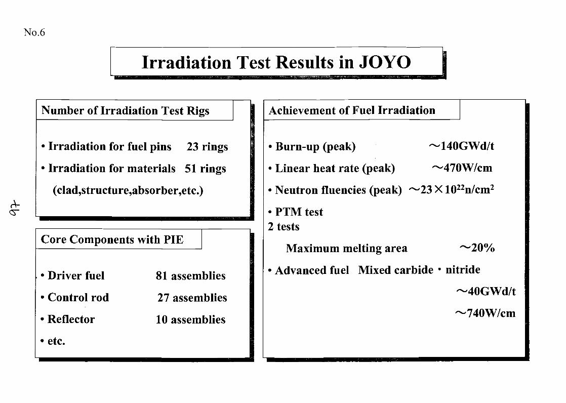
No.6
Irradiation Test Results in JOYO
Number of Irradiation Test Rigs
• Irradiation for fuel pins 23 rings
• Irradiation for materials 51 rings
(clad,structure,absorber,etc.)
Core Components with PIE
Driver fuel
Control rod
Reflector
etc.
81 assemblies
27 assemblies
10 assemblies
Achievement of Fuel Irradiation
140GWd/t
-470W/cm
23 X 1022n/cm2
• Burn-up (peak)
• Linear heat rate (peak)
• Neutron fluencies (peak)
• PTM test2 tests
Maximum melting area
• Advanced fuel Mixed carbide • nitride
40GWd/t
740W/cm
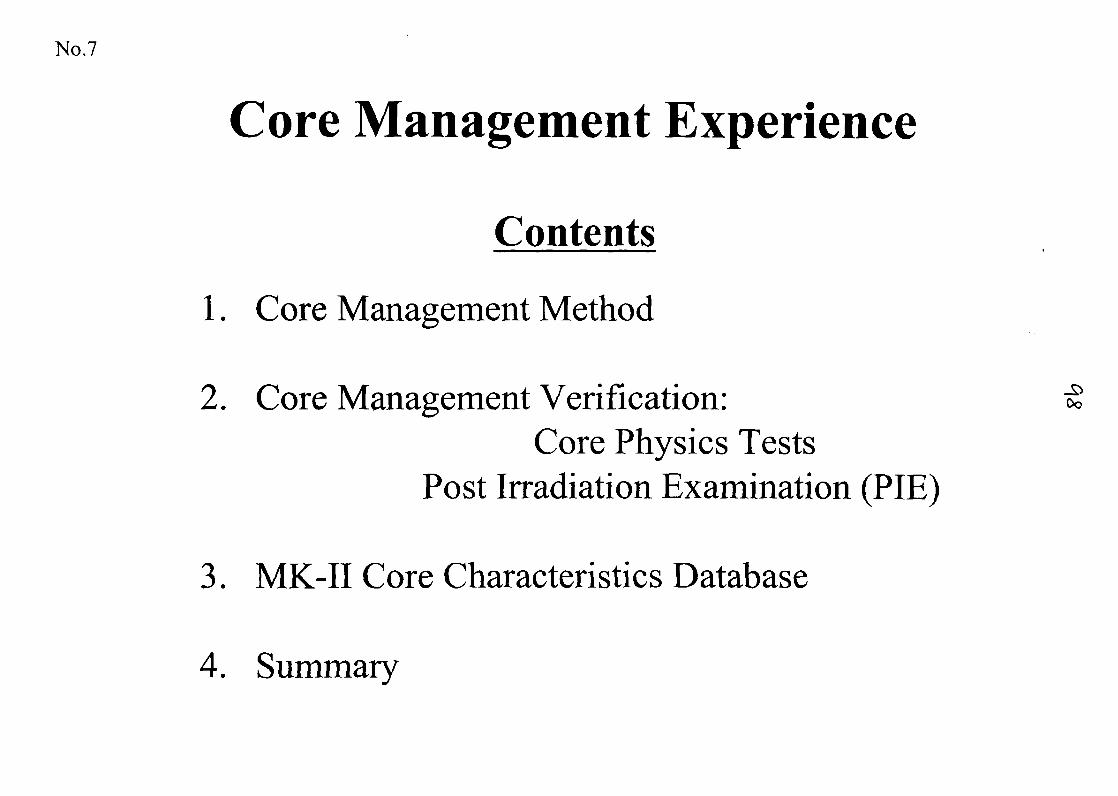
No.7
Core Management Experience
Contents
1. Core Management Method
2. Core Management Verification:Core Physics Tests
Post Irradiation Examination (PIE)
3. MK-II Core Characteristics Database
4. Summary
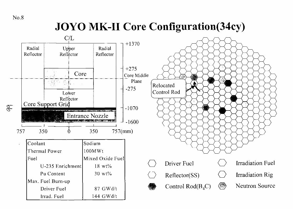
No.8
JOYO MK-II Core Configuration(34cy)C/L
RadialReflector
UpberReflector
RadialReflector
Core
! LoVer! Reflector
Core Support Grij
Entrance Nozzle
757 350 0 350 757(mm)
Coolant
Thermal Power
Fuel
U-235 Enrichment
Pu Content
Max. Fuel Burn-up
Driver Fuel
Irrad. Fuel
Sodium
lOOMWt
Mixed Oxide Fuel
18 wt%
30 wt%
87 GWd/t144 GWd/t
RelocatedControl Rod
O
Driver Fuel
Reflector(SS)
Control Rod(B4C)
OO
Irradiation Fuel
Irradiation Rig
Neutron Source
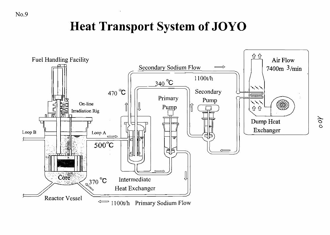
No.9
Heat Transport System of JOYO
Fuel Handling FacilitySecondary Sodium Flow
470 °C
n Ii1
^oop B 1
1
rr
°*\fK
P7R
•f ',
On-line <>
Irradiation Rig "
1
r
? ' 1
• ' -~ ~s? *:?|?-v-
1
rLoop A
500°C1
^
340 °C
IPrimary
Pump
HOOt/h
SecondaryPump
ton
Reactor Vessel
370 Intermediate
Heat Exchanger
1 lOOt/h Primary Sodium Flow
Air Flow7400m 3/min
\XXX
XXX
Dump HeatExchanger
oo
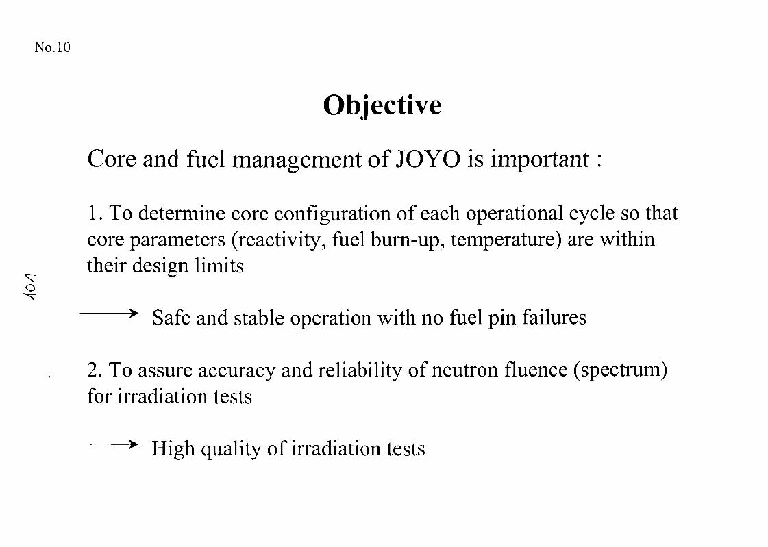
No. 10
Objective
Core and fuel management of JO YO is important :
1. To determine core configuration of each operational cycle so thatcore parameters (reactivity, fuel burn-up, temperature) are withintheir design limits
> Safe and stable operation with no fuel pin failures
2. To assure accuracy and reliability of neutron fluence (spectrum)for irradiation tests
> High quality of irradiation tests
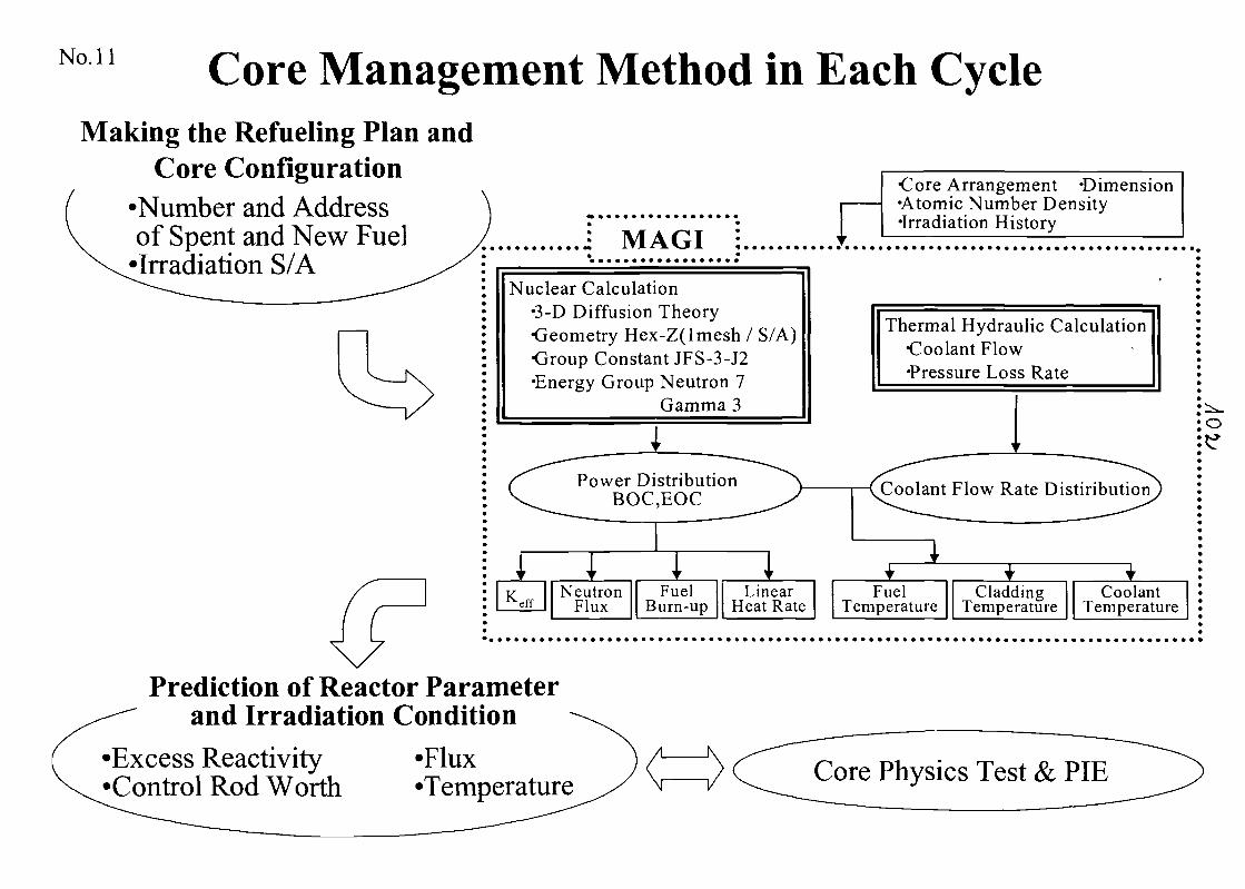
No. 11 Core Management Method in Each CycleMaking the Refueling Plan and
Core Configuration•Number and Addressof Spent and New Fuel•Irradiation S/A
MAGI
Nuclear Calculation•3-D Diffusion Theory•Geometry Hex-Z(lmesh / S/A)•Group Constant JFS-3-J2•Energy Group Neutron 7
Gamma 3
Power DistributionBOC,EOC
K effNeutron
FluxFuel
Burn-upLinear
Heat Rate
•Core Arrangement 'Dimension•Atomic Number Density•Irradiation History
Thermal Hydraulic Calculation•Coolant Flow•Pressure Loss Rate
Coolant Flow Rate Distiribution
o
Prediction of Reactor Parameterand Irradiation Condition
'Excess Reactivity•Control Rod Worth
•Flux'Temperature Core Physics Test & PIE
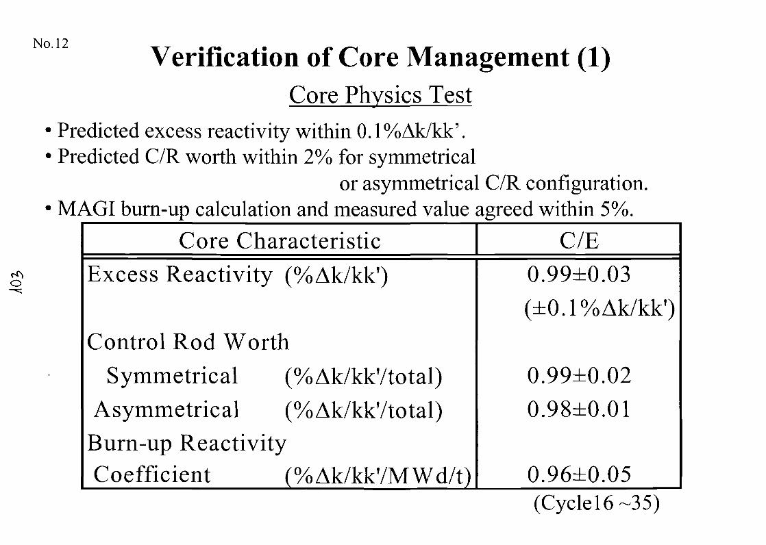
No. 12Verification of Core Management (1)
Core Physics Test
Predicted excess reactivity within 0.1%Ak/kk'.Predicted C/R worth within 2% for symmetrical
or asymmetrical C/R configuration.MAGI burn-up calculation and measured value agreed within 5%.
Core Characteristic C/EExcess Reactivity (%Ak/kk?)
Control Rod WorthSymmetrical (%Ak/kkVtotal)
Asymmetrical (%Ak/kkVtotal)Burn-up ReactivityCoefficient (%Ak/kk'/MWd/t)
0.99±0.03(±0.1%Ak/kk')
0.99±0.020.98±0.01
0.96±0.05(Cycle 16-35)
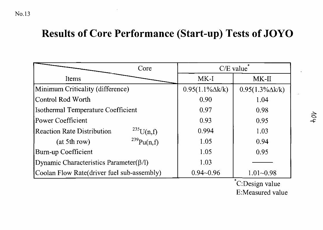
No. 13
Results of Core Performance (Start-up) Tests of JOYO
^^^^^^ CoreItems — • ^_^_
Minimum Criticality (difference)
Control Rod WorthIsothermal Temperature Coefficient
Power Coefficient
Reaction Rate Distribution 235U(n,f)
(at 5th row) 239Pu(n,f)Burn-up Coefficient
Dynamic Characteristics Parameter((3/l)
Coolan Flow Rate(driver fuel sub-assembly)
C/E valueMK-I
0.95(1. l%Ak/k)0.900.97
0.930.994
1.05
1.05
1.030.94-0.96
MK-II
0.95(1. 3%Ak/k)1.04
0.98
0.951.030.94
0.95
1.01-0.98
CiDesign valueE:Measured value
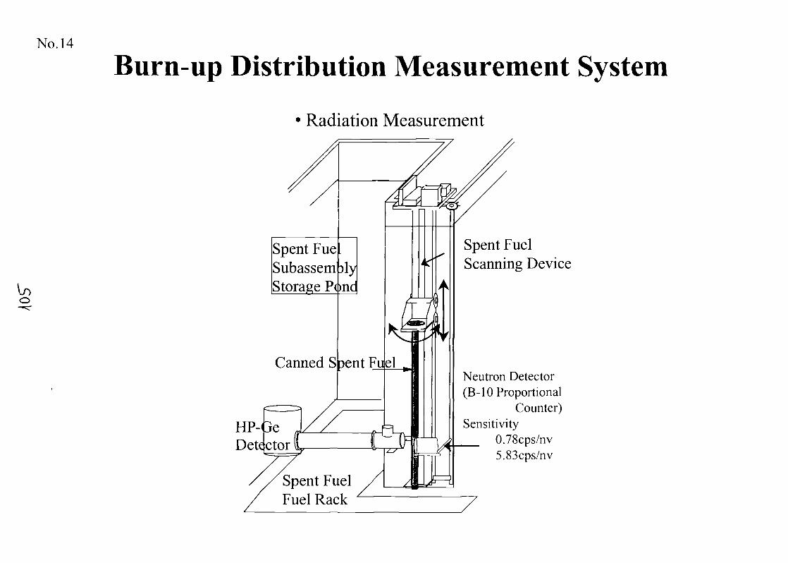
No. 14
Burn-up Distribution Measurement System
Radiation Measurement
Spent FueSubassem )lyStorage Pone
Canned S pent Flubl
HP-ueDeft ctor
Spent FuelFuel Rack
Spent FuelScanning Device
Neutron Detector(B-10 Proportional
Counter)Sensitivity
0.78cps/nv5.83cps/nv
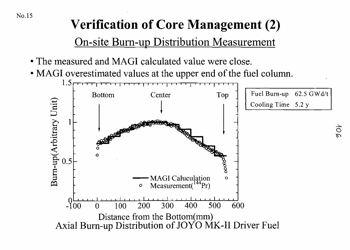
No. 15
Verification of Core Management (2)On-site Burn-up Distribution Measurement
The measured and MAGI calculated value were close.MAGI overestimated values at the upper end of the fuel column.
1.5
•e0.5
PQ
Bottom Center
MAGI Calculation0 Measurement( Pr)
I I I I I I I I I I I I I . I . I . . I . . I . I I I I I I I
Fuel Burn-up 62.5 GWd/t
Cooling Time 5.2 y
O
-100 6000 100 200 300 400 500Distance from the Bottom(mm)
Axial Burn-up Distribution of JOYO MK-II Driver Fuel
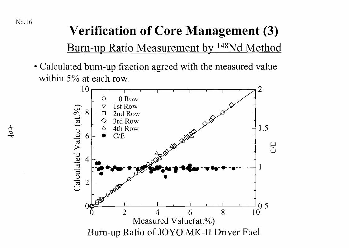
No. 16
Verification of Core Management (3)Burn-up Ratio Measurement by 148Nd Method
Calculated burn-up fraction agreed with the measured valuewithin 5% at each row.
ORow1 st Row2nd Row
O 3rd Row4th RowC/E
2 4 6 8Measured Value(at.%)
Burn-up Ratio of JOYO MK-II Driver Fuel
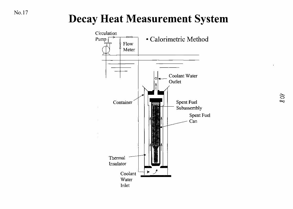
No. 17
Decay Heat Measurement SystemCirculation
V.
Pump-1X3 Calorimetric Method
Coolant WaterOutlet
Spent FuelSubassembly
Spent FuelCan
ThermalInsulator
CoolantWaterInlet
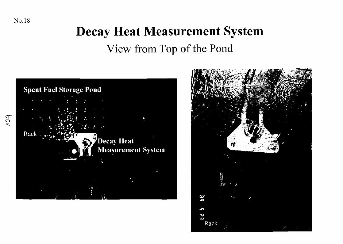
No. 18
Decay Heat Measurement SystemView from Top of the Pond
Spent Fuel Storage Pond
RackDecay HeatMeasurement System
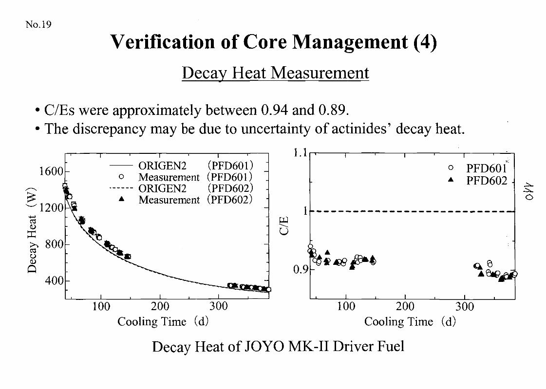
No. 19
Verification of Core Management (4)Decay Heat Measurement
C/Es were approximately between 0.94 and 0.89.The discrepancy may be due to uncertainty of actinides' decay heat.
l.lORIGEN2 (PFD601)
o Measurement (PFD601)ORIGEN2 (PFD602)Measurement (PFD602)
u
PFD601PFD602
0.9
100 200 300Cooling Time (d)
100 200 300Cooling Time (d)
Decay Heat of JOYO MK-II Driver Fuel
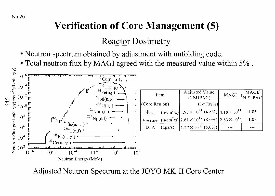
No.20
Verification of Core Management (5)Reactor Dosimetry
Neutron spectrum obtained by adjustment with unfolding code.Total neutron flux by MAGI agreed with the measured value within 5%
10 M| , , M,,,,|A / ' xCu(n, a )
g 102
2 10ill i i i mill t i i mill i i 1 1 inn i i i Mini i 111 mil i i i iinil i i i Mini i i i i m i l
Item
(Core Region)
^totai (n/cm2/s)
^xuiviev (n/cm2/s)
DPA (dpa/s)
Adjusted Value(NEUPAC)
(la Error)
3.97X 10¹⁵ (4.8%)
2.61X 10¹⁵ (8.0%)
1.27X 10'6 (5.0%)
MAGI
4.18X 10¹⁵
2.83X 10¹⁵
—
MAGI/NEUPAC
1.05
1.08
—
>-610'° lO'4 lO'2 10°Neutron Energy (MeV)
10'
Adjusted Neutron Spectrum at the JOYO MK-II Core Center
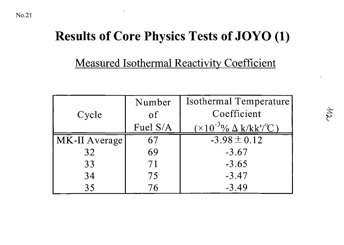
No.21
Results of Core Physics Tests of JOYO (1)
Measured Isothermal Reactivity Coefficient
CycleNumber
ofFuel S/A
Isothermal TemperatureCoefficient.-3(xi(T%Ak/kk'/0C)
MK-II Average32333435
6769717576
-3.98±0.12-3.67-3.65-3.47-3.49
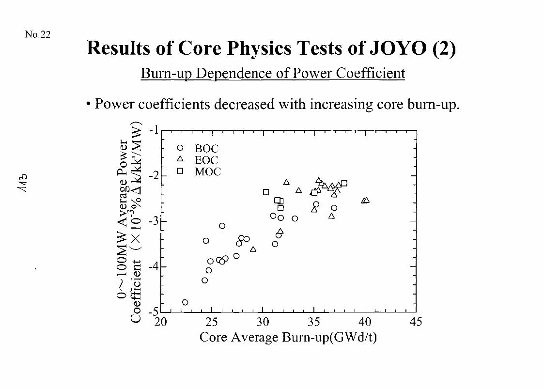
No.22
Results of Core Physics Tests of JOYO (2)Burn-up Dependence of Power Coefficient
• Power coefficients decreased with increasing core burn-up,
£ -1
-2
CD
-3
O ^ ,o a -4
o BOCA HOCn MOC
CHD
o
oQ9o
o
0 A
OA
o
•»*
o -5U 20
o
25 30 35 40Core Average Burn-up(GWd/t)
45
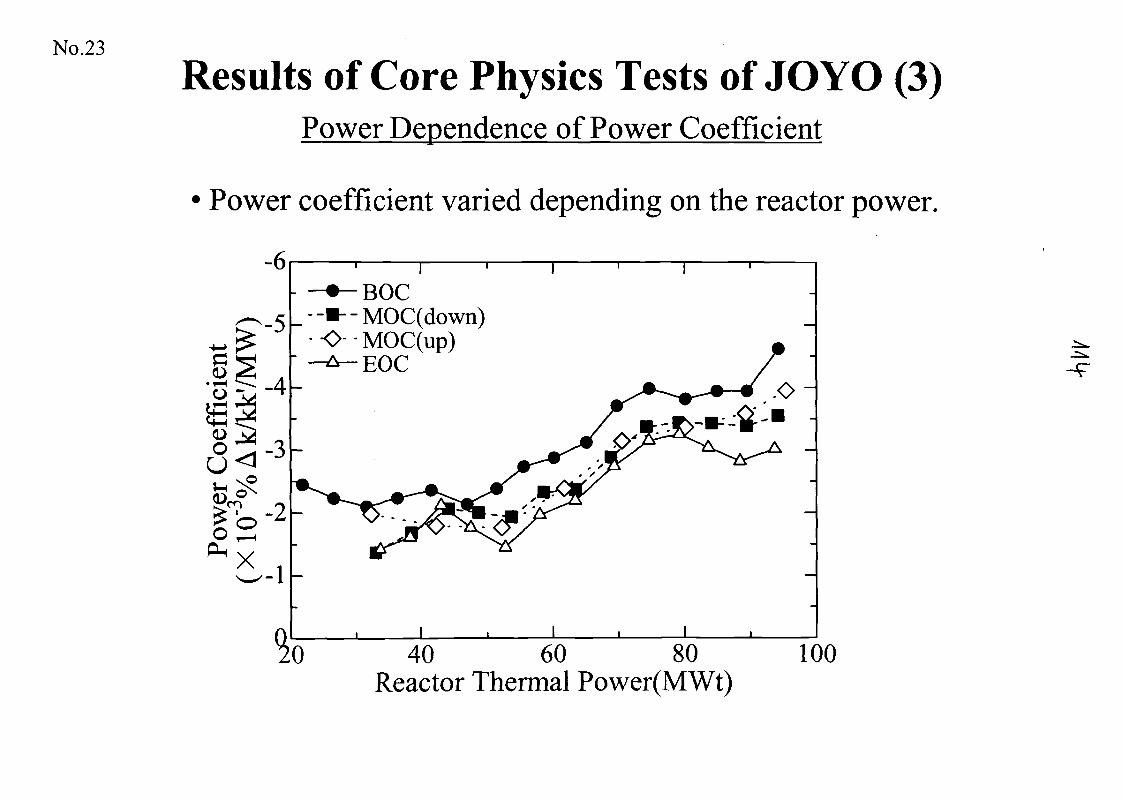
No.23
Results of Core Physics Tests of JOYO (3)Power Dependence of Power Coefficient
• Power coefficient varied depending on the reactor power.
-6
O -L4H+—I<D
oPH X -1
-•--MOC(down)O- • MOC(up)
EOC
0 40 60 80Reactor Thermal Power(MWt)
100
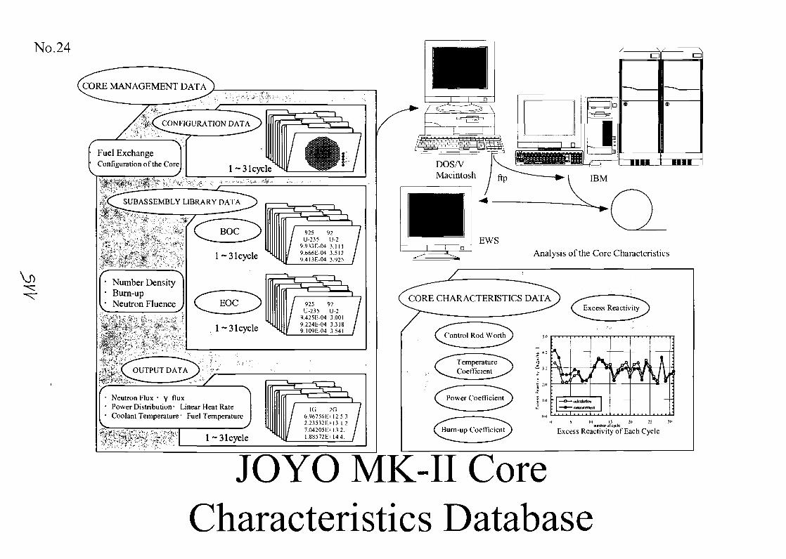
No.24
CORE MANAGEMENT DATA^ __^^ '. .-.'.'.. ;-V .
J.(^CONFIGURATION DATA^)
Fuel Exchange 1Configuration of the Corel l~31cycle
~ — <-, — — S, 1 .
V?<lw¥ix ,-"*"•" ' ' . • • •*• •• - . • • . . . - . . . .
.V,<^J5UBASSEMBLY LIBRARY DATA~^) ,—^4. iL^" M|i — — -*~*^ ff1"~
•• V-- •• • • > , ;
y* "N• Number Density• Burn-up
\v Neutron Fluence ,
j||xfj:;v•ii:.'-~- ,C" °UTPUT DAT^
•V'.'* *JT — — -— -
/ -*"Q" BOC ^J)
1 ~31cycle ^
<^r^r>l~31cycle
n — ^ i
/
925 92 /U-235 U-2 /
9.933E-04 3.1 II /9.666E-04 3.512 /
•vqj! 9.413E-04 3.925 /
A '~IZ ~^. 1 .: *™t 1 1
1
/
925 92 /U-235 U-2 /
9.425E-04 3.001 /9.224E-04 3.318 /
^4J[ 9.109E-04 3.541 /
r^ "• Neutron Flux • y flux• Power Distribution- Linear Heat Rate• Coolant Temperature • Fuel Temperature
V J
'f.^^V..*l~31cycle
1
/
1G 20 /6.96756EH25.3 /2.23532EH3 1.2 /7.04205F^132. /
-^ 1.88572EH44. /
'
Analysis of the Core Characteristics
CORE CHARACTERISTICS DATA(" Excess Reactivity
(^Control Rod WortrT)
CTemperature ^\Coefficient^
Power Coefficient
( Burn-up Coefficient^ Excess Reactivity of Each Cycle
JOYO MK-II CoreCharacteristics Database
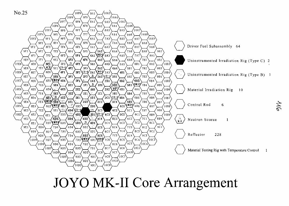
No.25
Driver Fuel Subassembly 64
U n i n s t r u m e n t e d I r radia t ion Rig (Type C) 2
Un ins t rumen ted I r rad ia t ion Rig (Type B) 1
Mater ia l I r rad ia t ion Rig 10
Control Rod 6
Neut ron Source 1
Reflector 228
Material Testing Rig with Temperature Control 1
JOYO MK-II Core Arrangement
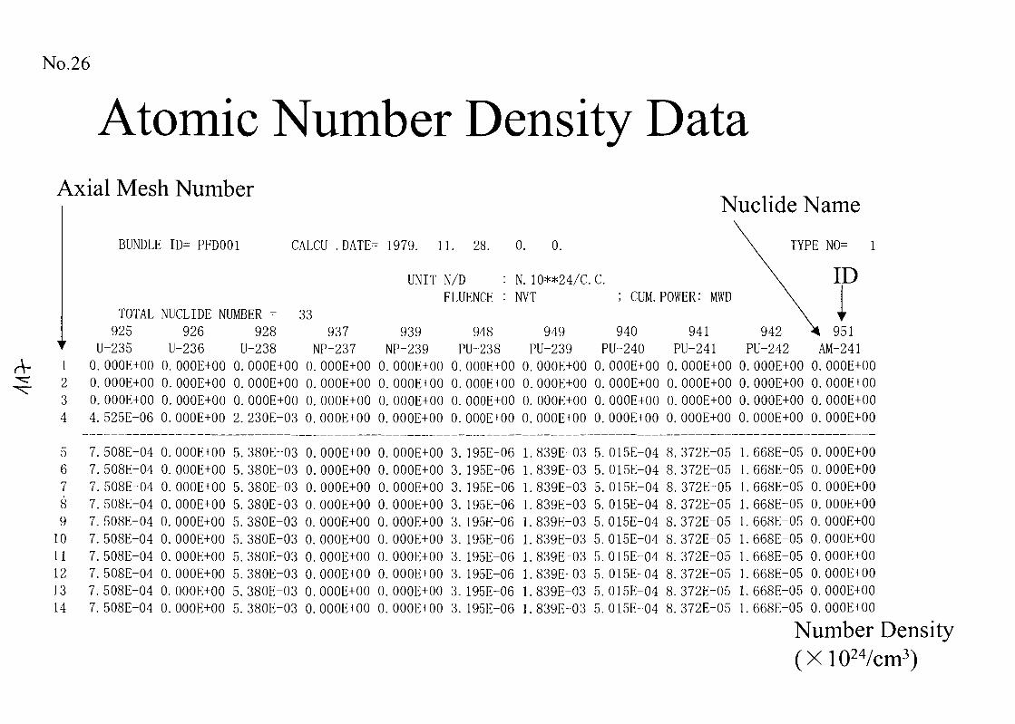
No.26
Atomic Number Density DataAxial Mesh Number
1234
56789
1011121314
Nuclide Name
BUNDLE ID= PFD001 CALCU .DATE- 1979. 11. 28. 0. 0.
UNIT N/DFLUENCE
N. 10**24/C. C.NVT CUM. POWER:
TOTAL NUCLIDE NUMBER = 33925 926 928 937
U-235 U-236 U-238 NP-2370. OOOE+00 0.OOOE+00 0. OOOE+00 0. OOOE+000.OOOE+00 0.OOOE+00 0. OOOE+00 0. OOOE+000.OOOE+00 0.OOOE+00 0. OOOE+00 0. OOOE+004. 525E-06 0. OOOE+00 2. 230E-03 0. OOOE+00
939 948 949 940 941NP-239 PU-238 PU-239 PU-240 PU-241
0. OOOE+00 0.OOOE+00 0.OOOE+00 0.OOOE+00 0.OOOE+000. OOOE+00 0.OOOE+00 0.OOOE+00 0.OOOE+00 0.OOOE+000. OOOE+00 0.OOOE+00 0.OOOE+00 0.OOOE+00 0. OOOE+000. OOOE+00 0.OOOE+00 0. OOOE+00 0. OOOE+00 0. OOOE+00
TYPE N0= 1
ID
951AM-241
942PU-2420.OOOE+00 0.OOOE+000.OOOE+00 0.OOOE+000.OOOE+00 0.OOOE+000.OOOE+00 0.OOOE+00
508E-04508E-04508E-04508E-04508E-04508E-04508E-04508E-04
7. 508E-047.508E-04
0.OOOE+000.OOOE+000.OOOE+000. OOOE+000.OOOE+000. OOOE+000.OOOE+000. OOOE+000.OOOE+000. OOOE+00
5. 380E-035. 380E-035. 380E-035. 380E-035. 380E-035. 380E-035. 380E-035. 380E-035. 380E-035. 380E-03
0. OOOE+000. OOOE+000. OOOE+000.OOOE+000.OOOE+000.OOOE+000.OOOE+000.OOOE+000.OOOE+000.OOOE+00
0. OOOE+00 3.0. OOOE+00 3.0. OOOE+00 3.0. OOOE+00 3.0. OOOE+00 3.0. OOOE+00 3.0. OOOE+00 3.0. OOOE+00 3.0. OOOE+00 3.0. OOOE+00 3.
195E-06195E-06195E-06195E-06195E-06195E-06195E-06195E-06195E-06195E-06
839E-839E-839E-839E-839E-839E-839E-839E-839E-
1.839E-
03 5.03 5.03 5.03 5.03 5.03 5.03 5.03 5.03 5.03 5.
015E-04015E-04015E-04015E-04015E-04015E-04015E-04015E-04015E-04015E-04
8. 372E-058.372E-058.372E-058.372E-058.372E-058.372E-058.372E-058.372E-058. 372E-058.372E-05
1. 668E-668E-668E-668E-668E-668E-668E-668E-668E-
05 0.05 0.05 0.05 0.05 0.05 0.05 0.05 0.05 0.
OOOE+00OOOE+00OOOE+00OOOE+00OOOE+00OOOE+00OOOE+00OOOE+00OOOE+00
1.668E-05 0. OOOE+00
Number Density(X1024/cm3)
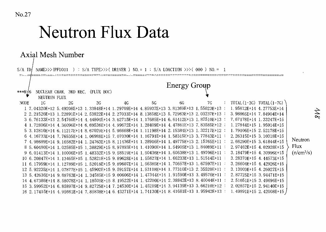
No.27
Neutron Flux DataAxial Mesh Number
S/A ID/ NAME>» (PFD001 ) : S/A TYPE>» ( DRIVER ) NO. = 1 : S/A LOACTION >» ( 000 ) NO. = 1
Energy Group**R-/6r
NODE1 7.2 2.3 6.4 1.5 3.6 4.7 4.8 5.9 6.10 6.11 6.12 5.13 5.14 4.15 3.16 2.
NUCLEAR CNEUTRON1G
04320E+1221526E+1376133E+1372806E+1412810E+1416733E+1498689E+1460480E+1401413E+1420847E+1417959E+1492235E+1442636E+1467386E+1459952E+1417415E+14
;HAR. SRD RECFLUX
2G5. 49208E+131.22891E+142. 54760E+144. 36096E+146. 11217E+147. 76535E+149. 16582E+141. 02585E+151. 10006E+151. 13465E+151. 12789E+151. 07877E+159. 88763E+148. 58078E+146. 85897E+144. 95661E+14
. (FLUX BOC)
3G1. 33848E+142. 53822E+144. 44804E+146. 69536E+148. 67029E+141. 06988E+151. 24763E+151. 38829E+151. 48332E+151. 52821E+151. 52018E+151.45902E+151.34585E+151. 18505E+159. 82725E+147. 85838E+14
4G1. 29709E+142. 27033E+143. 62715E+144. 99672E+145. 96668E+147. 07030E+148. 11436E+148. 97893E+149. 58519E+149. 89628E+149. 89607E+149. 59157E+149. 00606E+148. 19522E+147. 24530E+146. 43271E+14
4.8.1.1.1.1.1.1.1.1.1.1.1.1.1.1.
5G85937E+13 3.13858E+13 5.17685E+14 6.28409E+14 4.11198E+14 2.16791E+14 1.28916E+14 1.41090E+14 1.50436E+14 1.55627E+14 1.56385E+14 1.53118E+14 1.47344E+14 1.42200E+14 2.45219E+14 3.74130E+14 8.
6G81369E+13 1.72963E+13 2.61412E+13 1.47861E+13 7.15384E+13 1.58315E+13 3.49775E+13 2.54905E+13 1.60638E+13 1.66233E+13 1.70657E+13 1.77310E+13 2.91590E+13 3.38842E+13 8.94139E+13 3.41681E+13 1.
V•f7G
55023E+1303237E+1387510E+1383585E+1232217E+1277843E+1115765E+1184089E+1149706E+1151514E+1167597E+1135520E+1149576E+1140044E+1166210E+1295942E+13
TOTAL (1-3G)1.95812E+143. 98865E+147. 67178E+141. 27844E+151. 79106E+152. 26315E+152. 66290E+152. 97462E+153. 18479E+153. 28370E+153. 26604E+153. 13003E+152. 87725E+152. 51051E+152. 02857E+151. 49891E+15
TOTAL(1-7G)A4. 27753E+147. 84904E+141. 33247E+151. 95914E+152. 52178E+153. 10318E+153. 61844E+154. 02928E+154. 30996E+154. 44573E+154. 42926E+154. 26027E+153. 94471E+153. 49696E+152. 94140E+152. 42008E+15J
NeutronV Flux(n/cm3/s)
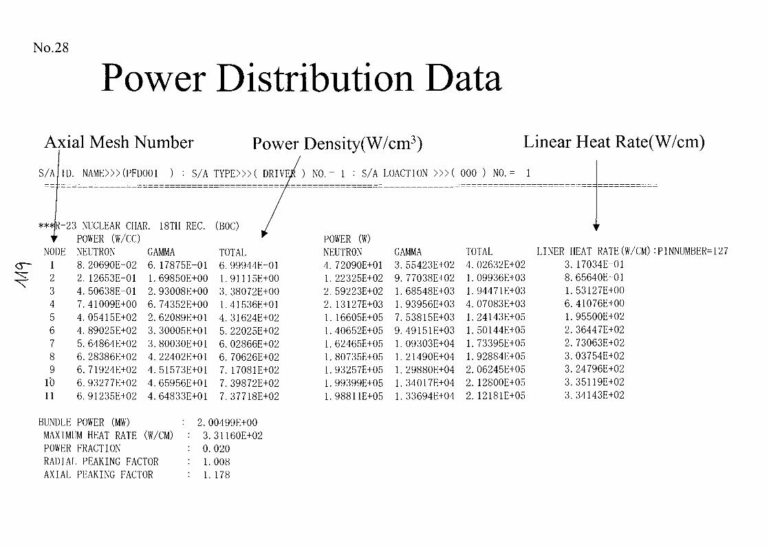
No.28
Power Distribution DataAxial Mesh Number Power Density(W/cm3) Linear Heat Rate(W/cm)
S/A ID. NAME>»(PFD001 ) : S/A TYPE>»( DRIVER ) NO. = 1 : S/A LOACTION >»( 000 ) NO. = 1
**=HR-23 NUCLEAR CHAR. 18TH REC. (BOC)t POWER (W/CC) r
NODE123456789
I'O11
NEUTRON8.2.4.7.4.4.5.6.6.6.6.
20690E-0212653E-0150638E-0141009E+0005415E+0289025E+0264864E+0228386E+0271924E+0293277E+0291235E+02
GAMMA6.1.2.6.2.3.3.4.4.4.4.
17875E-0169850E+0093008E+0074352E+0062089E+0130005E+0180030E+0122402E+0151573E+0165956E+0164833E+01
TOTAL6.1.3.1.4.5.6.6.7.7.7.
99944E-0191115E+0038072E+0041536E+0131624E+0222025E+0202866E+0270626E+0217081E+0239872E+0237718E+02
BUNDLE POWER (MW)MAXIMUM HEAT RATE (W/CM)POWER FRACTIONRADIAL PEAKING FACTORAXIAL PEAKING FACTOR
2. 00499E+003. 31160E+020.0201.0081. 178
POWER (W)NEUTRON4.1.2.2.1.1.1.1.1.1.1.
72090E+0122325E+0259223E+0213127E+0316605E+0540652E+0562465E+0580735E+0593257E+0599399E+0598811E+05
GAMMA3.9.1.1.7.9.1.1.1.1.1.
55423E+0277038E+0268548E+0393956E+0353815E+0349151E+0309303E+0421490E+0429880E+0434017E+0433694E+04
TOTAL LINER HEAT RATE (W/CM) :PINNUMBER= 1274.1.1.4.1.1.1.1.2.2.2.
02632E+0209936E+0394471E+0307083E+0324143E+0550144E+0573395E+0592884E+0506245E+0512800E+0512181E+05
3.8.1.6.1.2.2.3.3.3.3.
17034E-0165640E-0153127E+0041076E+0095500E+0236447E+0273063E+0203754E+0224796E+0235119E+0234143E+02
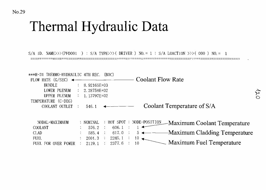
No.29
Thermal Hydraulic Data
S/A ID. NAME>»(PFD001 ) : S/A TYPE>»( DRIVER ) NO. = 1 : S/A LOACTION >»( 000 ) NO. = 1
***R-31 THERMO-HYDRAULIC 4TH REC. (BOC)FLOW RATE (G/SEC)
BUNDLELOWER PLENUMUPPER PLENUM
TEMPERATURE (C-DEG)COOLANT OUTLET : 546. 1
8.92165E+032.28758E+021. 13797E+02
Coolant Flow Rate
VO
Coolant Temperature of S/A
NODAL-MAXIMAUM : NOMINAL : HOT SPOTCOOLANT : 576.2 : 606. 1CLAD : 585.4 : 617.0FUEL : 2001.3 : 2245. 1FUEL FOR OVER POWER : 2119.1 : 2377.6
Maximum Coolant Temperature
Maximum Cladding Temperature
Maximum Fuel Temperature
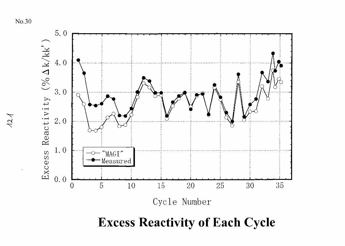
No.30
"N
5.0
4.0
3.0
£ 2.0oCD
00wCDOX
1.0
0.00
"MAGI"Measured
10 15 20 25 30 35
Cycle Number
Excess Reactivity of Each Cycle
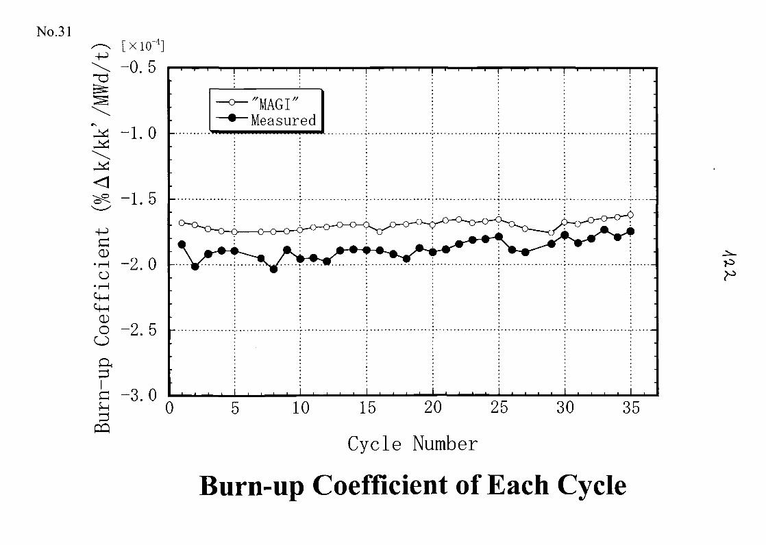
No.31[X10'4]
-0.5
-1.0
-1.5
0•i— IO
• I—Itf-l
-2.0
0OO
-2.5
-3.00
PQ
"MAGI"Measured
10 15 20 25
Cycle Number
30 35
Burn-up Coefficient of Each Cycle
No.32
Summary
1. JOYO core and fuel management techniques have beendeveloped for safe and stable reactor operation and foraccurate irradiation tests.
2. Core management calculations were verified.Core physics tests : Criticality,Reactivity changePIE results : Fuel burn-up, Decay heatReactor dosimetry : Neutron fluence and spectrum
3. Data of core management calculations and corecharacteristics test results were recorded in the CD-ROM.
No.33
Chemical Analysis for Purity Control ofSodium and Cover Gas in JOYO
Contents
1. Outline of Chemical Analysis and Monitoring in JOYO
2. Impurity Measurement in JOYO Coolant Sodium
3. Impurity Measurement in JOYO Cover Gas Argon
4. Accuracy and Reliability of Impurity Monitoring
5. Summary
No.34
Objectives
1. To Prevent Deterioration of Material
Strength Due to Corrosion, Carburization,
Nitrification etc.
2. To Reduce Radiation Dose by Corrosion
Products (CP)
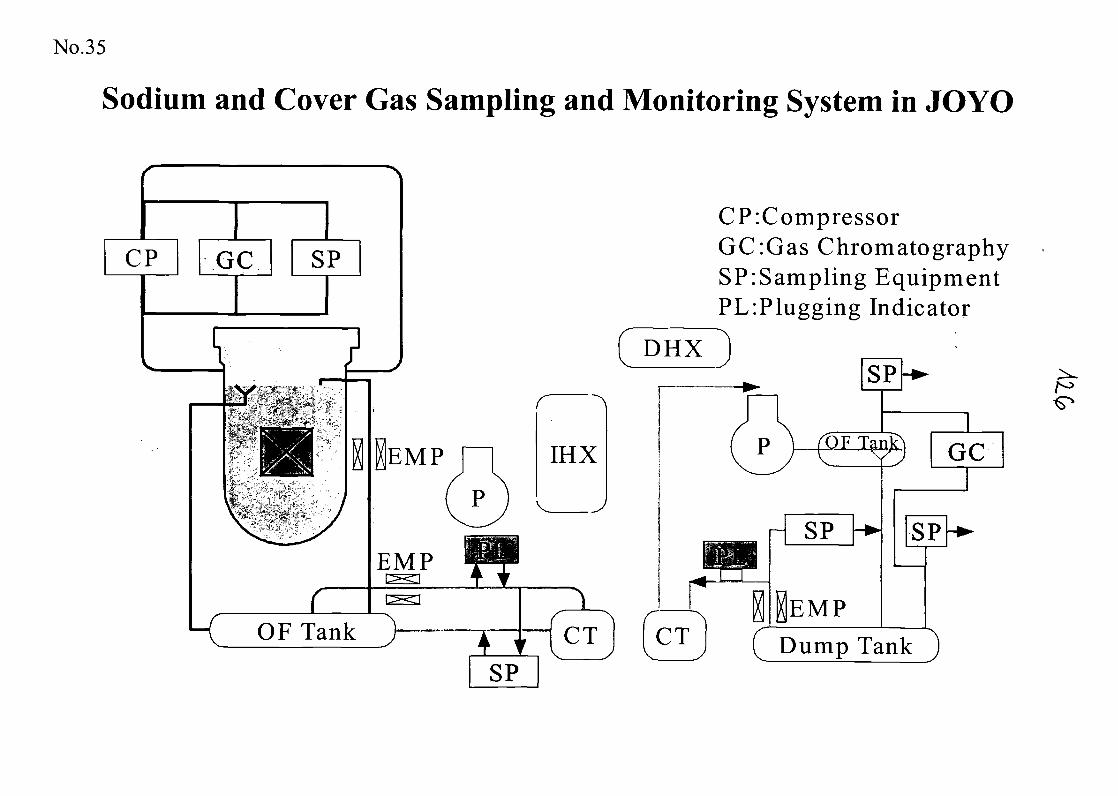
No.35
Sodium and Cover Gas Sampling and Monitoring System in JOYO
$£&&*&•*•
LK OF Tank
EMP
BMP
IHX
CP:CompressorGC:Gas ChromatographySP:Sampling EquipmentPL:Plugging Indicator
IEMPDump Tank
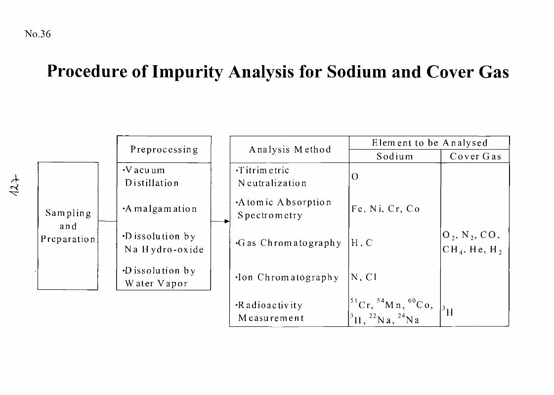
No.36
Procedure of Impurity Analysis for Sodium and Cover Gas
S a m p l i n gand
Prepara t ion
Preprocess ing
•VacuumDis t i l l a t ion
• A m a l g a m a t i o n
•D issolut ion byNa H y d r o - o x i d e
•D issolution byW ater Vapo r
^
Analys i s M ethod
•Titr imetricNeutral izat ion
•Atomic A b s o r p t i o nSpec t rome t ry
•Gas C h r o m a t o g r a p h y
•Ion C h r o m a t o g r a p h y
• R a d i o a c t i v i t yM e a s u r e m e n t
Element to be AnalysedSod ium
O
Fe, Ni, Cr, Co
H, C
N, Cl
51-, 54 , . 60^Cr , Mn, Co ,3,, 2 2 X T 2 4 X TH , N a , N a
Cover Gas
0 2 , N 2 , C O ,CH 4 , He , H 2
3H
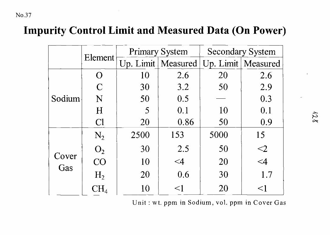
No.37
Impurity Control Limit and Measured Data (On Power)
Sodium
CoverGas
Element
OCNHCl
N2
02
COH2
CH4
Primary SystemUp. Limit
103050
520
2500
301020
10
Measured2.63.20.50.10.86
153
2.5<40.6
<1
Secondary SystemUp. Limit
2050
1050
5000
502030
20
Measured2.62.90.30.10.9
15
<2<4
1.7
<1
Unit : wt. ppm in Sodium, vol. ppm in Cover Gas
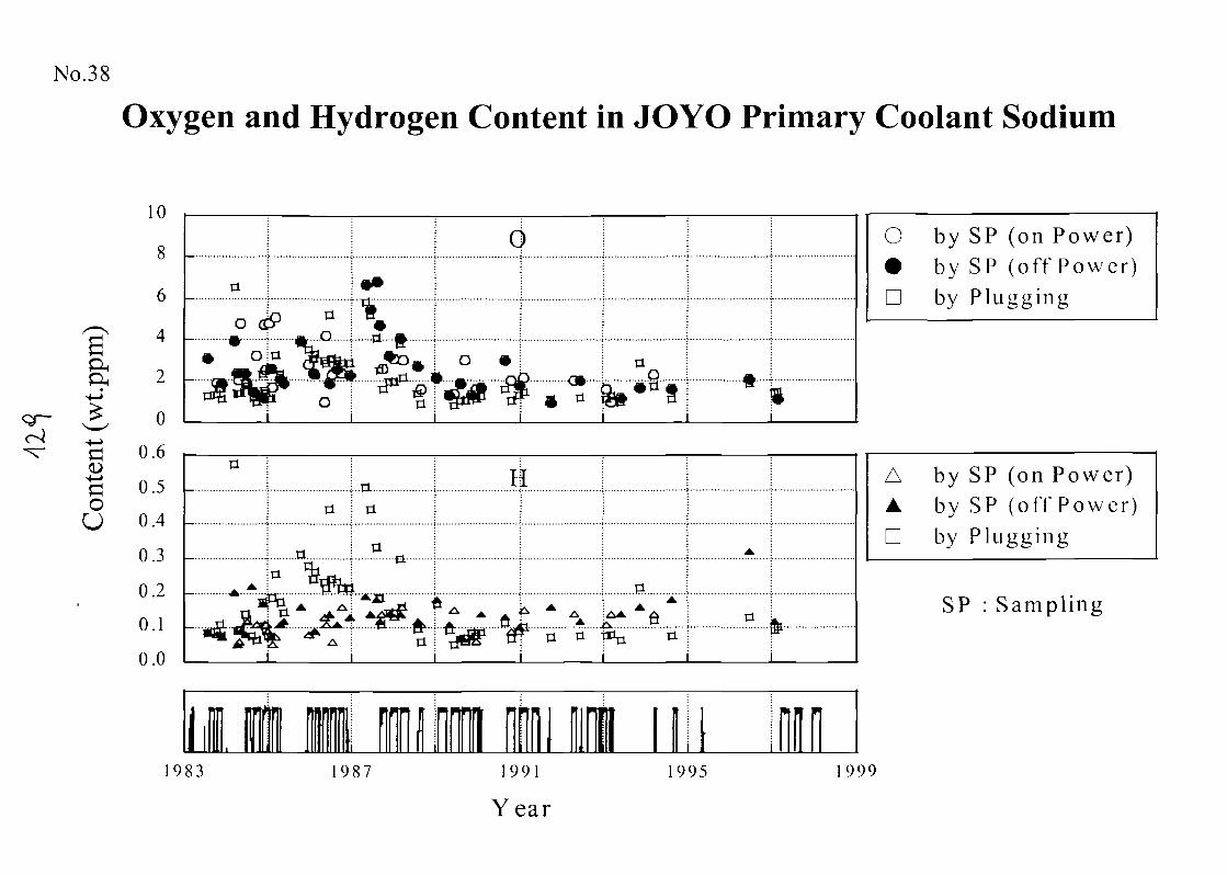
No.38
Oxygen and Hydrogen Content in JOYO Primary Coolant Sodium
ol^-4—>
G
GOU
10
8
6
4
2
0
0.6
0.5
0.4
0.3
0.2
0.1
0.0
a
o
o
o
..a..
H
.A
"fit"
...0..
a
m983 987 1991
Year
1995
O by SP (on Power)• by SP (off P o w e r )D by P l u g g i n g
A by SP (on Power)A by SP (of f P o w e r )D by P l u g g i n g
999
SP : Sampl ing
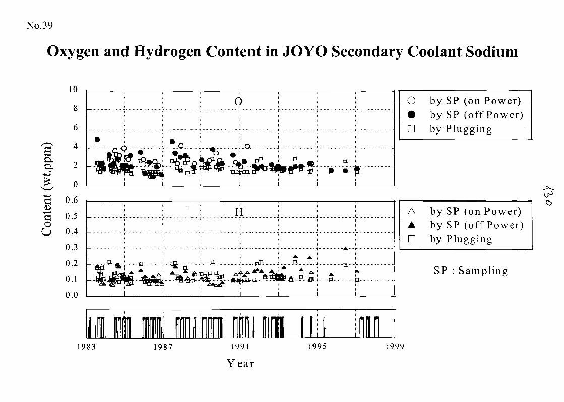
No.39
Oxygen and Hydrogen Content in JOYO Secondary Coolant Sodium
8
6
I 4o ( 2
•+->
& oG O-6
G 0.50
CJ 0.4
0.3
0.2
0.1
0.0
19
•
i^P Tftjf
\
£*<f^" «tf*
*Q
^fl'
^i
^oa
4
.. g. I..D
i
Tl a* •""5
ifcpT "k"
183
s ^fe
1 I 11I1
^^
L ^11 AjT -a-p-ia—
rt
.. U ] jift
*£V . . ^i
987
S A
^ * ^K. .ft... J?....HL..
mi im nhii id 1 1
M-
1
*.t±
ft| n
O by SP (on Power)• by SP (off Power)D by Plugging
A by SP (on Power)A by SP (off Power)D by Plugging
SP : Sampling
1991 1995 1999
Year
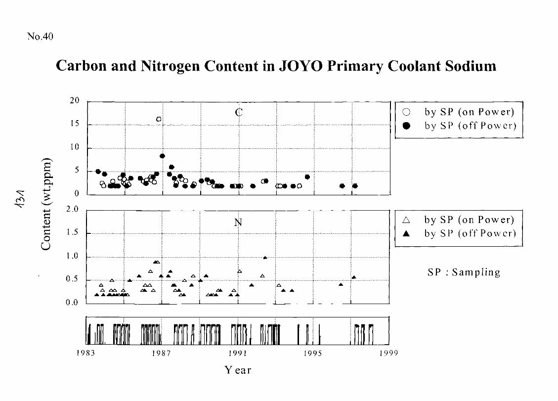
No.40
Carbon and Nitrogen Content in JOYO Primary Coolant Sodium
20
15
10
0
2.0
1.5
1.0
0.5
0.0
oiO by SP (on Power)• by SP (off P o w e r )
GOU
AA
A ;-A-A ! A
-A A---A ;A
AA A:AA
i
A A
A by SP (on Power)A by SP (off Power )
SP : Sampling
1983 987 1991
Year
995 999
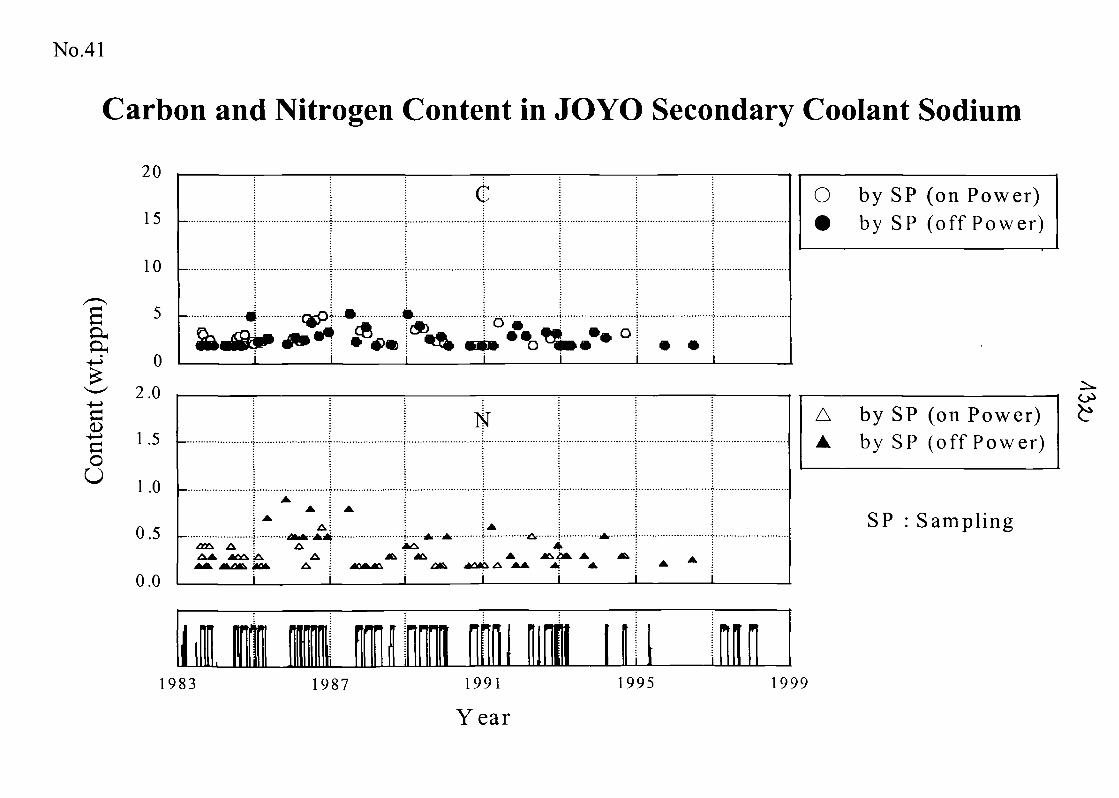
No.41
Carbon and Nitrogen Content in JOYO Secondary Coolant Sodium
OH
15
10
5
0 i
1 f !
i i i
O by SP (on Power)•
u. , , C D / ... f f D , -i r ^ \by br (ot t P o w e r )
2.0
G0
1.0
0.5
0.0
1983
A
A
-i 4,-jfc- .. ...
_L
A by SP (on Power)A by SP (off Power )
Oi
SP : Sampling
1987 1991
Year
1995 1999
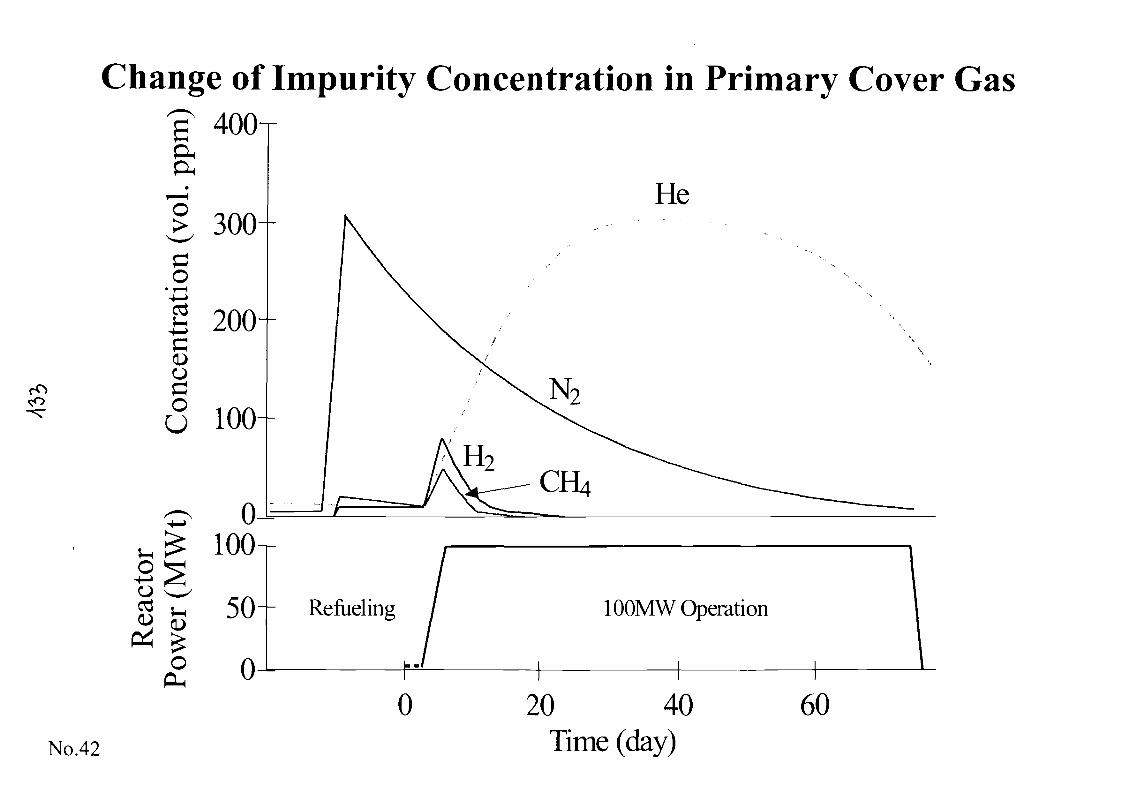
Change of Impurity Concentration in Primary Cover Gas400T
He
ao
coU
O
OPL,
50~" Refueling
0
100MW Operation
0No.42
20 40Time (day)
60
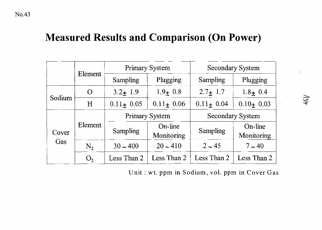
No.43
Measured Results and Comparison (On Power)
Sodium
CoverGas
Element
O
H
Element
N2
02
Primary System
Sampling
3.2+ 1.9
0.11+ 0.05
Plugging
1.9+ 0.8
0.11+ 0.06
Primary System
Sampling
30-400
Less Than 2
On-lineMonitoring
20-410
Less Than 2
Secondary System
Sampling
2.7+ 1.7
0.11+ 0.04
Plugging
1.8+ 0.4
0.10+ 0.03
Secondary System
Sampling
2-45
Less Than 2
On-lineMonitoring
7-40
Less Than 2
Unit : wt. ppm in Sodium, vol. ppm in Cover Gas
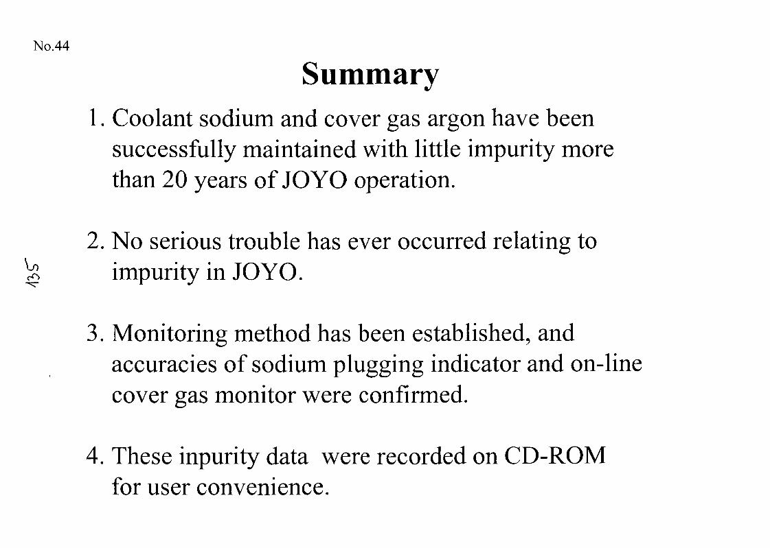
No.44
Summary1. Coolant sodium and cover gas argon have been
successfully maintained with little impurity morethan 20 years of JOYO operation.
2. No serious trouble has ever occurred relating toimpurity in JOYO.
3. Monitoring method has been established, andaccuracies of sodium plugging indicator and on-linecover gas monitor were confirmed.
4. These inpurity data were recorded on CD-ROMfor user convenience.
No.45
Radioactivity Measurement of JOYO CoverGas for Fuel Failure Detection
Contents
1. Outline of Fuel Failure Detection System in JOYOv<
2. Measured Cover Gas Radioactivity Using OLGM
3. Application for Upgrading of Irradiation Technology
4. Summary
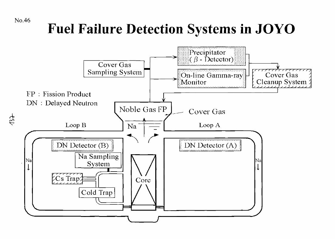
No.46
Fuel Failure Detection Systems in JOYO
A-
Cover GasSampling System
FP : Fission ProductDN : Delayed Neutron
Loop B
;;:;:;:*:;:( 13 - Detector) ;ji|ii|
Na
i
Noble Gas FPN
Na
|l DN Detector (B) ji
Na SamplingSystem
Cs Trap^
Cold Trap
Core
i;:On-line Gamma-ray;;;^Monitor £
Cover Gas
Loop A
;j DN Detector (A) i j
f y s f f f f f f f f f S f f /
Cover Gas; Cleanup SystemS/S//S/SS//S//S//
Na
1
V
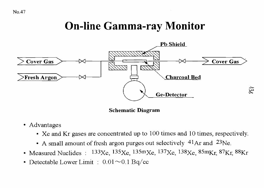
No.47
On-line Gamma-ray Monitor
^> Cover Gas
j!> Fresh Argon^>
Pb Shield
Cover Gas
Charcoal Bed
Ge-Detector
Schematic Diagram
Advantages• Xe and Kr gases are concentrated up to 100 times and 10 times, respectively.
• A small amount of fresh argon purges out selectively 41 Ar and 23Ne.
Measured Nuclides : 133Xe, 135Xe5 135mXe, 137Xe, 138Xe, 85mKr, 87Kr,
Detectable Lower Limit : 0.01-"-0.1 Bq/cc
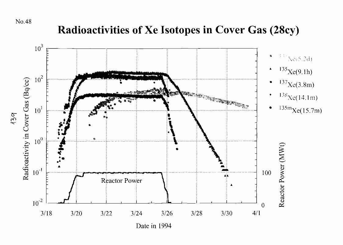
No.48
Radioactivities of Xe Isotopes in Cover Gas (28cy)
Reactor Povtfer
3/18 3/20
- 100
03/22 3/24 3/26 3/28 3/30 4/1
135
37
Xe(9.1h)
Xe(3.8m)
•38Xc( 14.1m)
135m Xe(15.7m)
(D£o
PL,S-l
O4—>O
Date in 1994
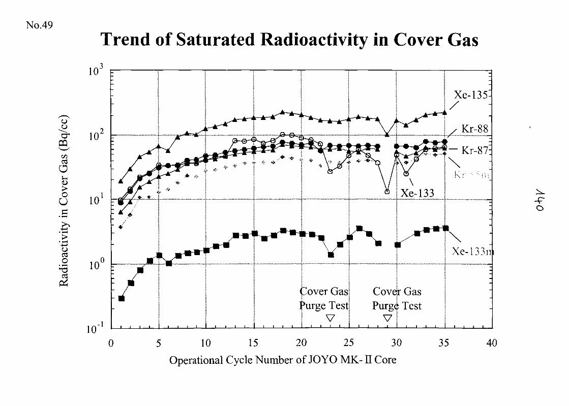
No.49
oo
&1/303O
VH<D
OUa
ocdO
Trend of Saturated Radioactivity in Cover Gas
103 F
10
10-1
0
Cover GasjPurge Test!
I V I
Covejr GasPurg^ Testvi
5 10 15 20 25 30
Operational Cycle Number of JOYO MK- E Core
35 40
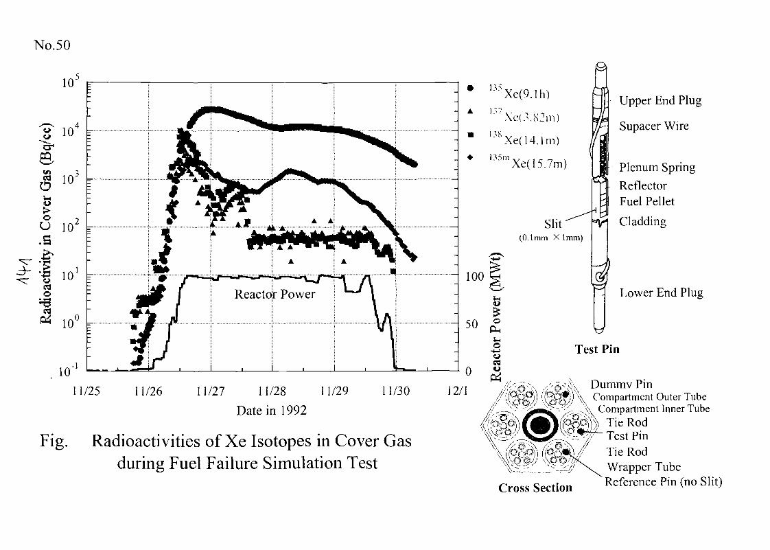
No.50
10'
3
eWl t.« inOS-i<o>o
io
cdo
"
10
10-1
11/25 11/26 11/27 11/28 11/29
Date in 1992
11/30
Fig. Radioactivities of Xe Isotopes in Cover Gasduring Fuel Failure Simulation Test
A
*
Xe(9.1h)
Ls/Xe{.".82m)
l 3 S Xe(14 .1m)135m
Xe(15.7m)
Slit(0.1 mm X 1mm)
100
Test Pin
12/1
Upper End Plug
Supacer Wire
Plenum Spring
ReflectorFuel Pellet
Cladding
Lower End Plug
Dummv Pin}) Compartment Outer Tube
'-^•\ Compartment Inner Tube' X T i e R o d
Test PinTie RodWrapper Tube
Cross Section Reference Pin (no Slit)
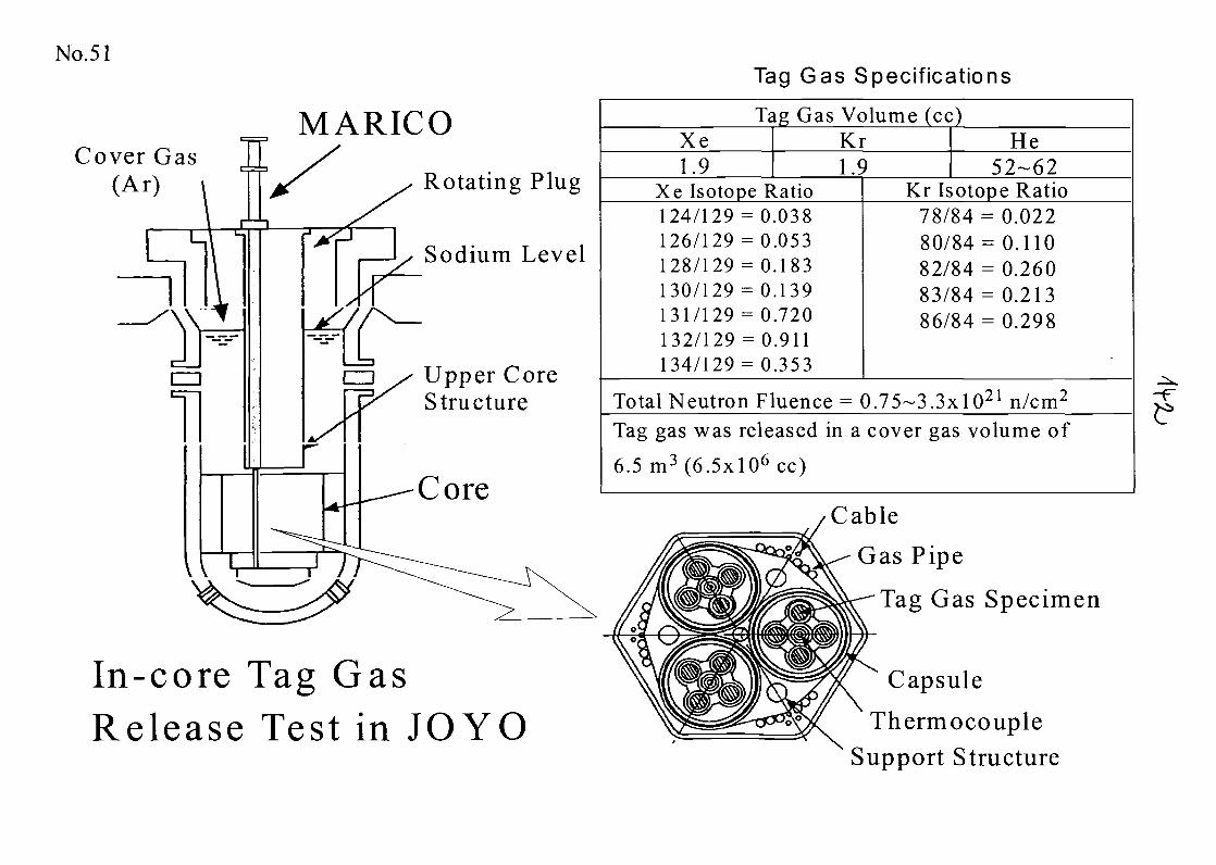
No.51
MARICOCover Gas
(Ar) Rotating Plug
Sodium Level
Upper CoreStructure
In-core Tag GasRelease Test in JOYO
Tag Gas Specifications
Tag Gas Volume (cc)Xe Kr He1.9 1.9 52-62
Xe Isotope Ratio124/129 = 0.038126/129 = 0.053128/129 = 0.183130/129 = 0.139131/129 = 0.720132/129 = 0.911134/129 = 0.353
Kr Isotope Ratio78/84 = 0.02280/84 = 0.11082/84 = 0.26083/84 = 0.21386/84 = 0.298
Total Neutron Fluence = 0.75~3.3xl021 n/cm2
Tag gas was released in a cover gas volume of
6.5 m3(6.5x!06cc)
Cable
Gas Pipe
Tag Gas Specimen
Capsule
ThermocoupleSupport Structure
-F
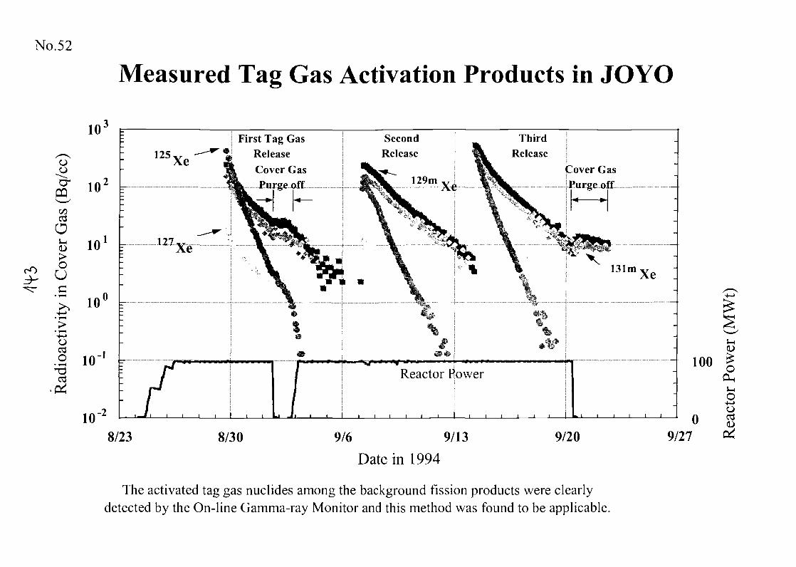
No.52
Measured Tag Gas Activation Products in JOYO
3-
Purge off
d h
.2 10'1 =-
8/23 8/30 9/6 9/13
Date in 1994
9/20
100(D
IPH^H
O
0 89/27
The activated tag gas nuclides among the background fission products were clearlydetected by the On-line Gamma-ray Monitor and this method was found to be applicable.
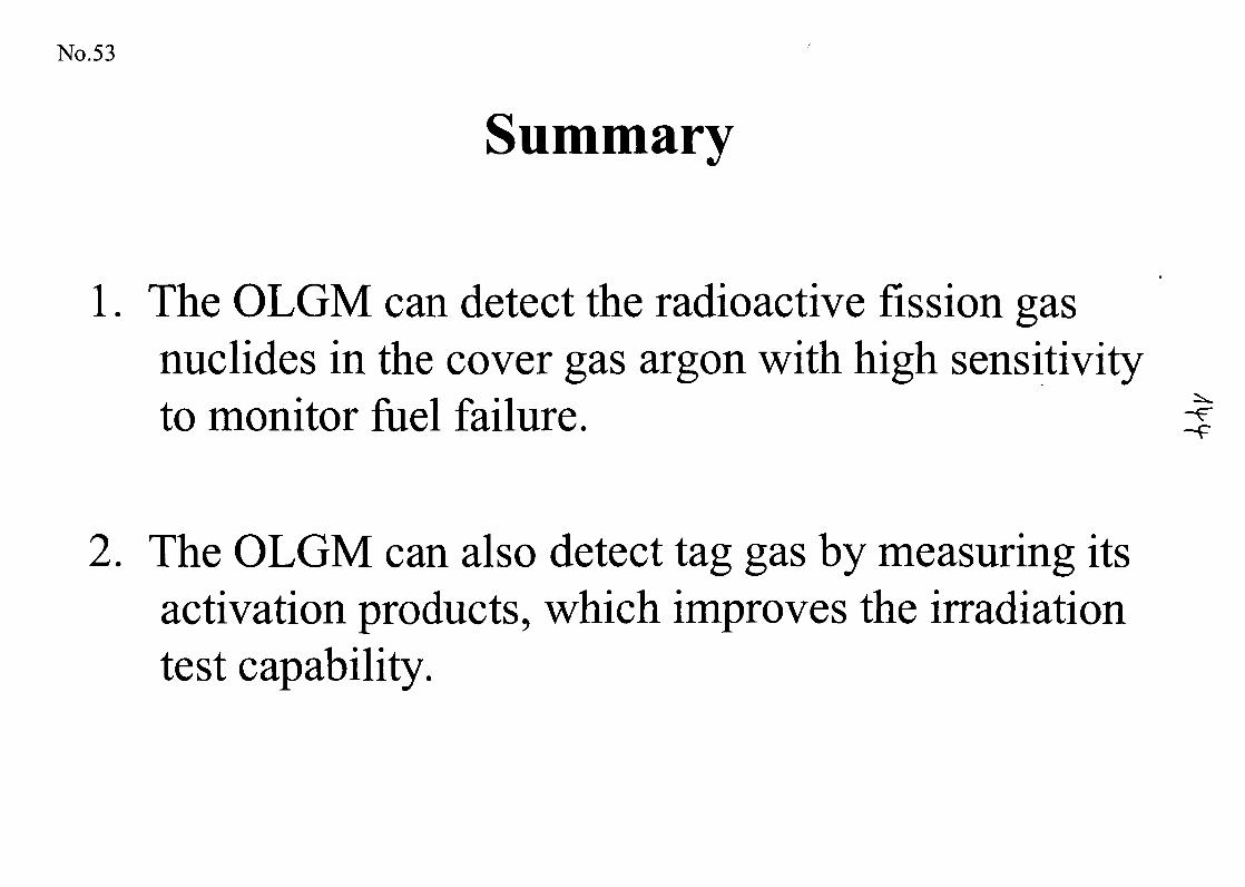
No.53
Summary
1. The OLGM can detect the radioactive fission gasnuclides in the cover gas argon with high sensitivityto monitor fuel failure. if
2. The OLGM can also detect tag gas by measuring itsactivation products, which improves the irradiationtest capability.
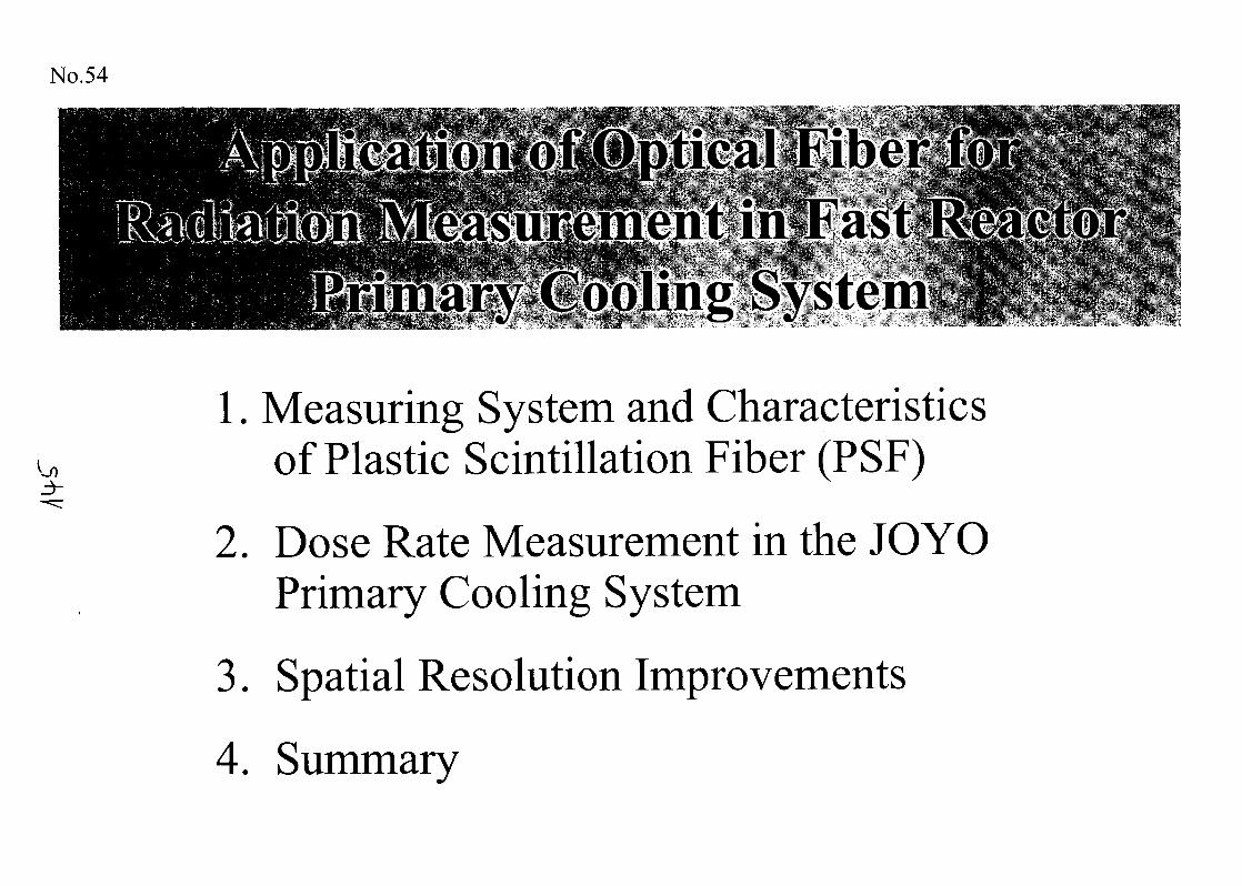
No.54
3-
1. Measuring System and Characteristicsof Plastic Scintillation Fiber (PSF)
2. Dose Rate Measurement in the JOYOPrimary Cooling System
3. Spatial Resolution Improvements
4. Summary
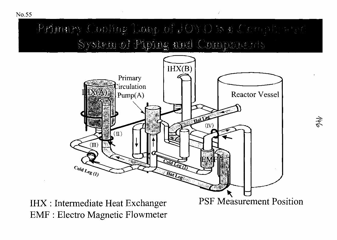
PrimaryCirculationPump(A)
IHX(B)
IHX : Intermediate Heat ExchangerEMF : Electro Magnetic Flowmeter
Reactor Vessel
PSF Measurement Position

OU
10
10
10
10
10
10
100
<D <D
-oo-CMCO
'"en"'! ci S: Tf• *f~>
I 1
I o\ . ..U-1 S
H T—
o..(J.o^o
2000
No.56
500 1000 1500
Gamma-ray Energy (keV)
Typical Gamma-ray Spectrum from Ge Solid State Detector
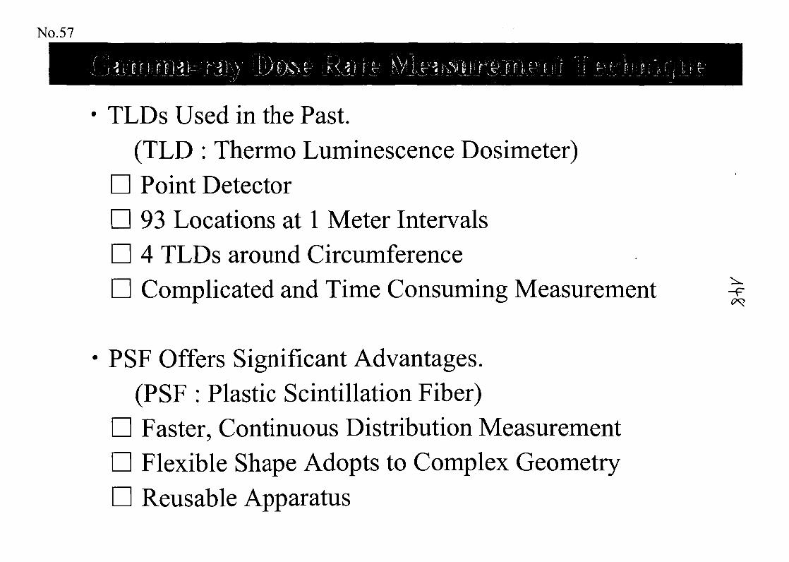
No.57
TLDs Used in the Past.(TLD : Thermo Luminescence Dosimeter)Point Detector93 Locations at 1 Meter Intervals4 TLDs around CircumferenceComplicated and Time Consuming Measurement
PSF Offers Significant Advantages.(PSF : Plastic Scintillation Fiber)Faster, Continuous Distribution MeasurementFlexible Shape Adopts to Complex GeometryReusable Apparatus
-F
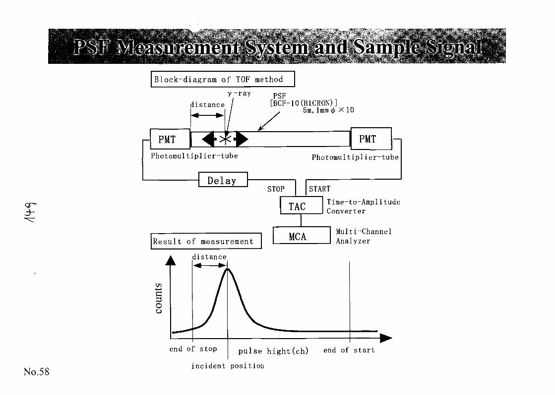
QP-
No.58
Block-diagram of TOP method
distance
y-ray psF
[BCF-IO(BICRON)]5m, 1mm 0 X 1 0
Photomultiplier-tube Photomul tip Her-tube
DelaySTART
Resul t of measurement
T irae-to-Ampli tudeConverter
Multi-ChannelAnalyzer
distance
end of stop pulse hight(ch) end of start
incident position
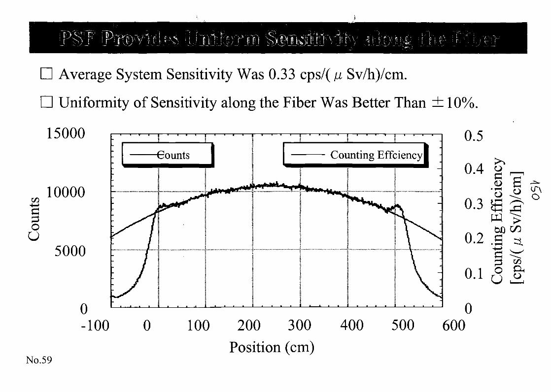
Average System Sensitivity Was 0.33 cps/( \i Sv/h)/cm.
Uniformity of Sensitivity along the Fiber Was Better Than ± 10%,
15000
en 10000
§oU
5000
Counting Effciencyl
No.59
200 300 400Position (cm)
0.5
04w.~
0.3
^ ~0.2
A 1U.I
0500 600
Cfl
o
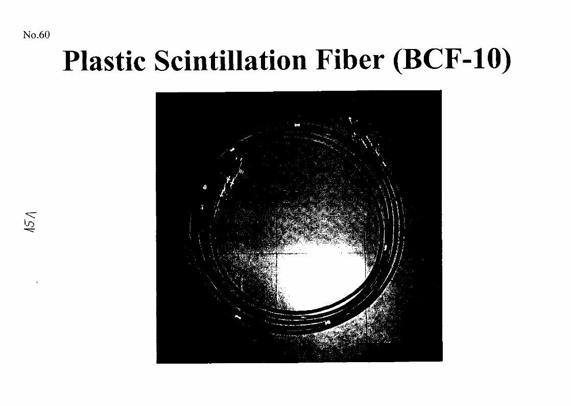
No.60
Plastic Scintillation Fiber (BCF-10)
1-0
No.61
Sensitivity Calibration
No. 62
PSF Set-up (1)
cO
No. 63
PSF Set-up (2)
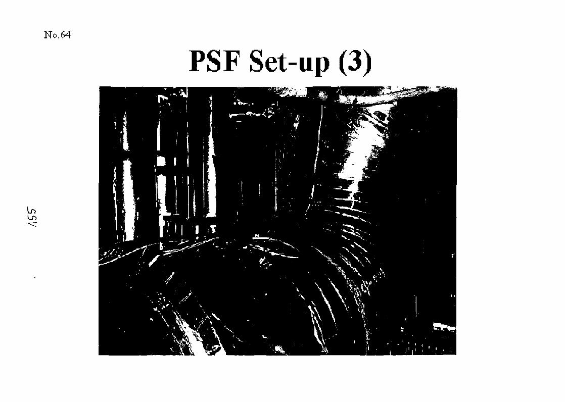
No. 64
In
PSF Set-up (3)
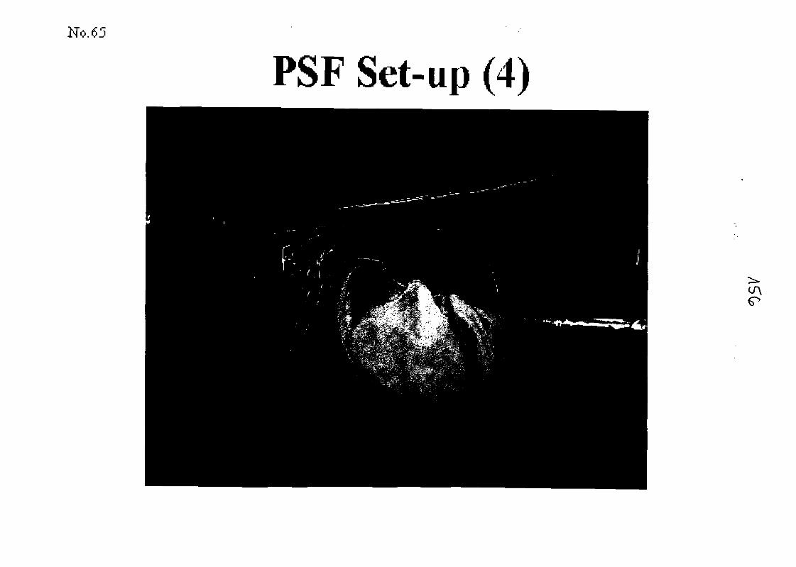
No.
PSF Set-up (4)
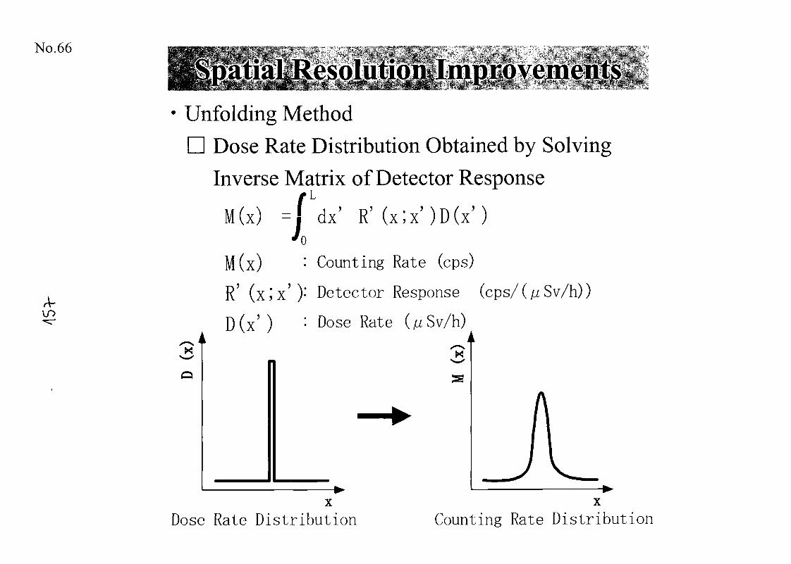
No.66
A-
Unfolding MethodDose Rate Distribution Obtained by Solving
Inverse Matrix of Detector Response
M(x) = f dx' R ' ( x ; x ) D ( x )70
M(x) : Counting Rate (cps)
R' (x;x'): Detector Response (cps/(/z Sv/h))
D(x' ) : Dose Rate
Dose Rate Distribution Counting Rate Distribution
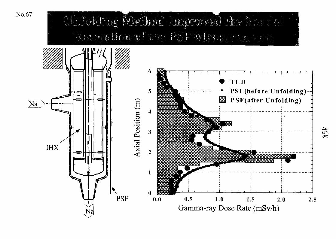
No.67
TLD
PSF(before Unfolding)PSF(after Unfolding)
0.5 1.0 1.5 2.0
Gamma-ray Dose Rate (mSv/h)
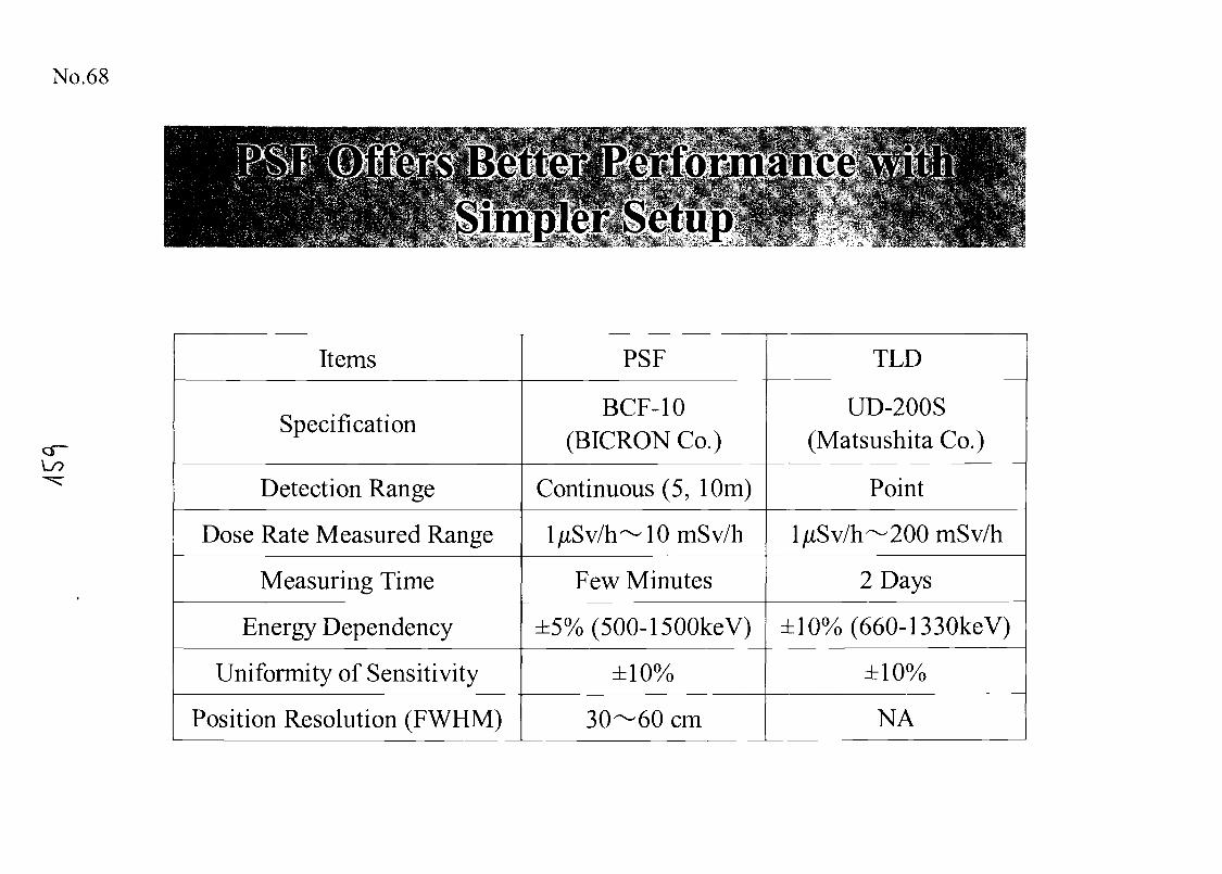
No.68
Lo
Items
Specification
Detection Range
Dose Rate Measured Range
Measuring Time
Energy Dependency
Uniformity of Sensitivity
Position Resolution (FWHM)
PSF
BCF-10(BICRON Co.)
Continuous (5, 10m)
ljLtSv/h~10mSv/h
Few Minutes
±5%(500-1500keV)
±10%
30—60 cm
TLD
UD-200S(Matsushita Co.)
Point
l/>tSv/h— 200mSv/h
2 Days
±10%(660-1330keV)
±10%
NA
No.69
Applying PSF to the JOYO primary cooling system CP
measurements provided several advantages.
(1) Simple setup : The measurements were performed by
setting PSF on the surface of cooling system components.
(2) Fast measurements : TOP analysis of PSF signals measured
radiation distribution along the fiber within a few minutes.
(3) Precise measurements : The unfolding method improved
the spatial distribution using the detector response matrix.
o
No.70
Operation and Maintenance Support System
1. JOYO Conducting and Analyzing Tool(JOYCAT)
2. Automatic Control Rod Operation System
3. Mechanical-fault Diagnosis Using SpectrumAnalysis (MEDUSA)
No.71
Other Operational Experiences
1. Decay Heat Removal Test by Natural Convection
2. Upgrade of FFDL System by Means of RIMS(Resonance lonization Mass Spectrometry)
3. Installation of FP Traps (CGCS, Cs Trap)
4. Fuel Failure Simulation Test
5. Improvement of Countermeasures against SodiumLeak Accident
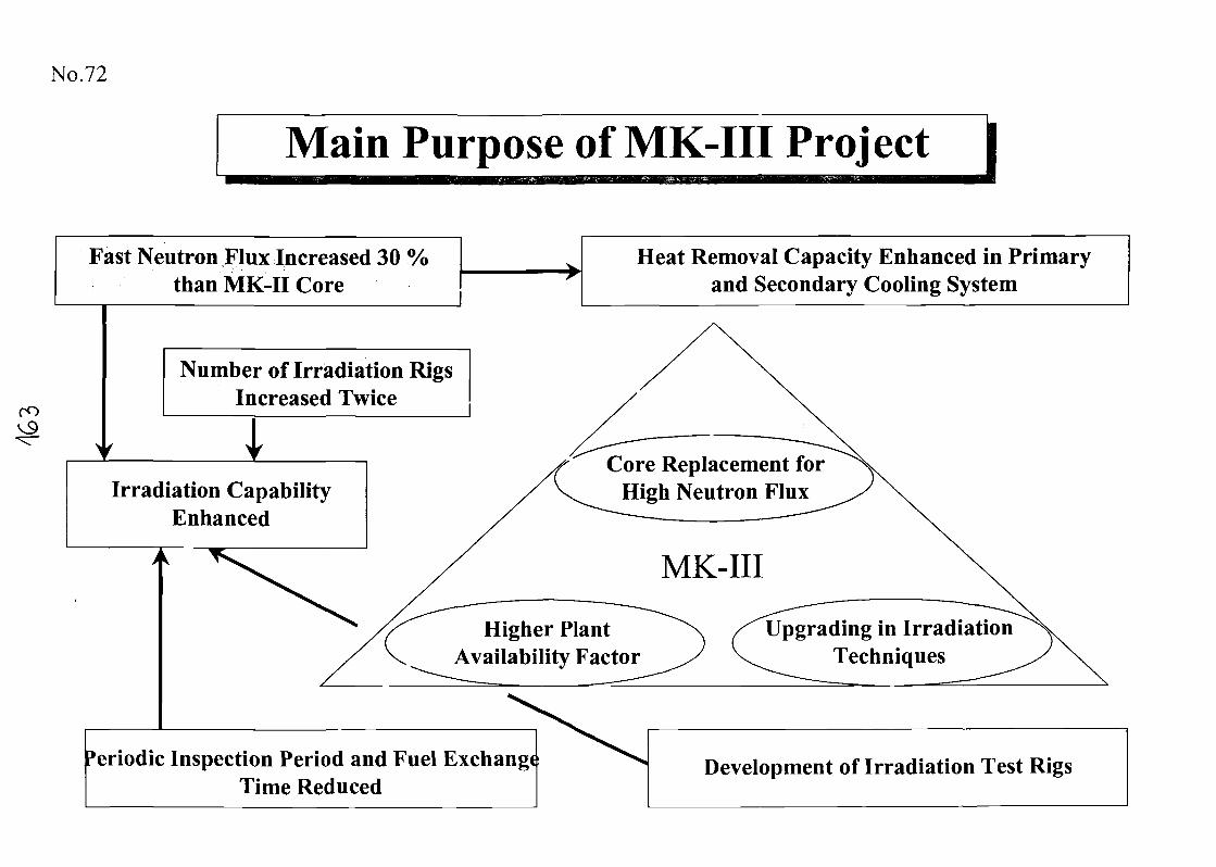
No.72
Main Purpose of MK-III Proj ect |
ro
Fast Neutron Flux Increased 30 %than MK-II Core
Number of Irradiation RigsIncreased Twice
Irradiation CapabilityEnhanced
Heat Removal Capacity Enhanced in Primaryand Secondary Cooling System
Higher PlantAvailability Factor
Core Replacement forHigh Neutron Flux
MK-III
Upgrading in IrradiationTechniques
'eriodic Inspection Period and Fuel ExchangeTime Reduced
Development of Irradiation Test Rigs
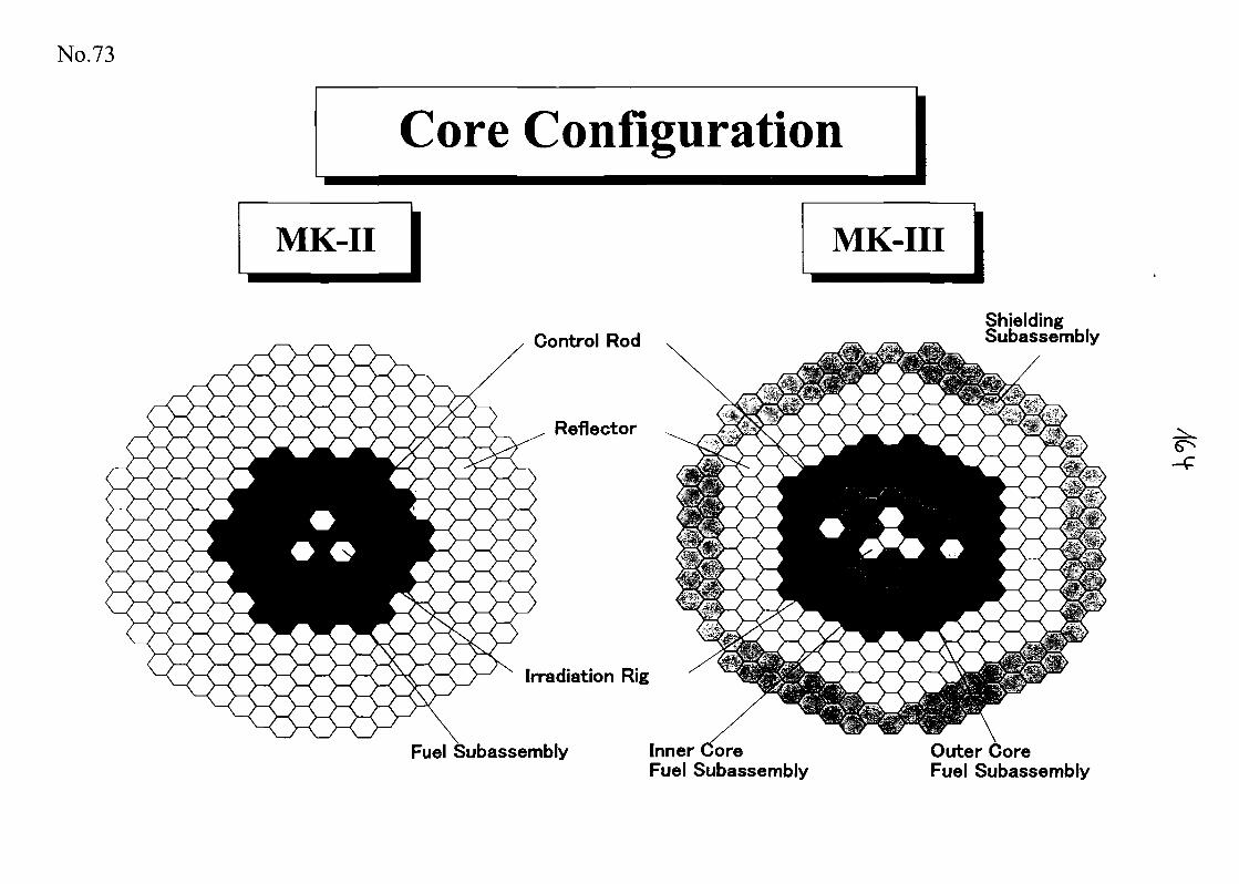
No.73
Core Configuration
MK-II
Control Rod
Reflector
Irradiation Rig
Fuel Subassembly
MK-III
Inner CoreFuel Subassembly
ShieldingSubassembly
Outer CoreFuel Subassembly
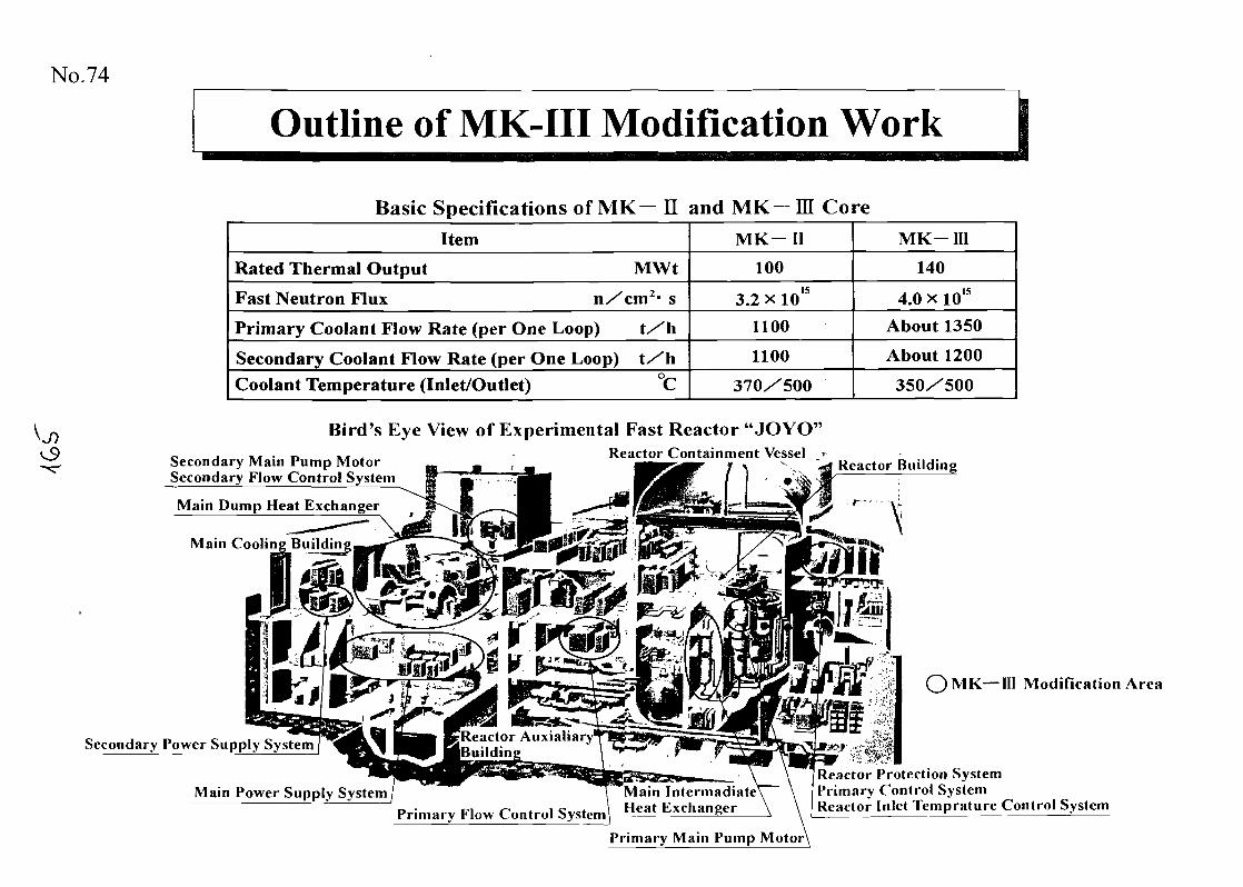
No.74
Outline of MK-III Modification Work
Basic Specifications of MK— H and MK-ffi CoreItem
Rated Thermal Output MWt
Fast Neutron Flux nXcm2- s
Primary Coolant Flow Rate (per One Loop) tXh
Secondary Coolant Flow Rate (per One Loop) tXhCoolant Temperature (Inlet/Outlet) °C
MK— II
100
3.2 x 10¹⁵
1100
1100
370X500
MK-III
140
4.0 x 10¹⁵
About 1350
About 1200
350X500
Secondary Main Pump MotorSecondary Flow Control System
Main Dump Heat Exchanger
—". 'Main Cooling Buildin
Bird's Eye View of Experimental Fast Reactor "JOYO"Reactor Containment Vessel T
Reactor Building
Secondary Power Supply System Reactor AuxiaharyBuildin
— III Modification Area
Main Power Supply SystemPrimary Flow Control Systcm
Reactor Protection SystemPrimary Control SystemReactor Inlet Temprature Control System
Primary Main Pump Motor\
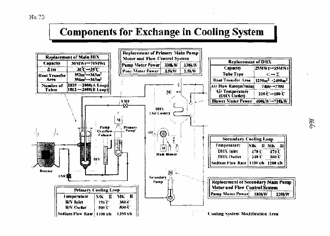
Components for Exchange in Cooling System I
or Main MIXCapacity
Heat TransferArm
Nuaber ofTubes
SOV1Wf-»7flMWl
356m1—28)5 — 208*< A I OOP)
Replacement of PrMutor Miitl Him (.".
Pimp VUtor PtowcrPony Motor Power
irnnry Msimirtil Sji"jJOkW
2.5k\V
in Pumpitem
"jjita^J.SkW
I eoi |» natureM Met
UOOt/h 1350 til
Replacement *f DUX
Jj*teTyp«___J c> IL__Trcn,Tcr Arm j 1250mz^24«0m2
Air FlovAir'Tentpe(U1I* Uuflel)
MotorP«wcr
S«-ontlar C
MK HJVIK^ mDH\ Inkt j 47I1C 4W\1)1 IV Outlet ! M*C lO'lV
Sodium How R»tc • 110d t* IIO«
Kcpbta^mcitolVfoforand Flow Cog<roISyste«t
Molor Ptmctj ItOkW
<nilirij» System M(Klif1C4tk>n Arva
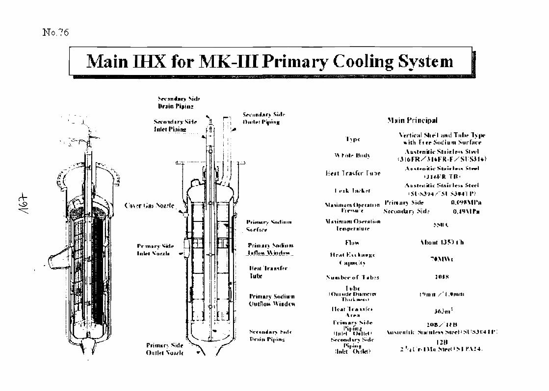
No.76
Main fflX for MK-III Primary Cooling System
Drain
- 1 I i ; J l»i.l«rr IInlt-t
,»-—-
C'»v<r i
Pr«iiry Sid*IllU-l
Hr
ties
l_o; '
i
V"*,
r!"~
'"V
i
*
f*V
^
Ij_
. . . .
L
(•irhr1 1
-
""V"
'^
i
p1I
~
1
im
^»—
j '
1 *
h' ' <J4
.j
1
",
•.
...
^
j
^
1
\
1!
$Tii
-
,1
llrnt
lubr
l'nc«»r
Sidp
^ tnlc Hiul>
littt IrSifi
I ,..L l.-.rtrt
Irttperilurr
Ruw
Nunibcrof
1'wbflOiniidr
l i t j>t Ir\rt-a
HllM
Main
till FreeTuhr
SurfaceSlit1!
A
FR TB'
• siSulr
Sfrnn«br> -SU
^ .si
Mid uf 1 3 5 3 t h
I ''nut
Outlfl '.Mil OHld>
AiiMi-nltir .SmiiilcJti>n'ct'SI !SJ«4 11'
Mri'l'.M I*A!4;
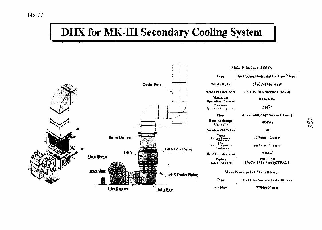
No.77
DHX for MK-III Secondary Cooling System
MIUI Principal of fHIX
A*«a
\luinunOp«f iMkM PffSMT*
hloi*
Unit faLi(hui|tfBCitf
Clf Tuftn
JFi*litli LtaiMl«
I4rn4 1 runitn Arc*
42 "mm
Main Principil ef Main BUwcr
e Mul-i Air inrliaii Tuibo
Ifikt Dintpt-t Air
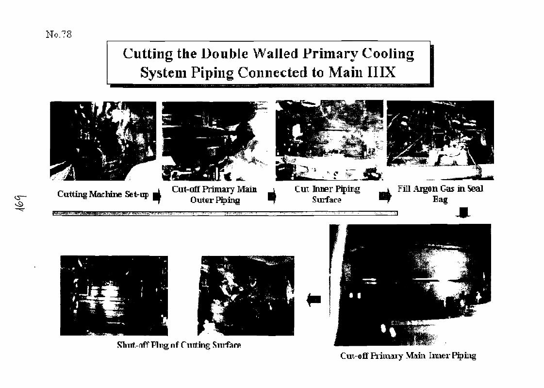
No.?8
Cutting the Double Walled Primary CoolingSystem Piping Connected to Main IIIX
Cutting Machine Set-up Cut-off Primary MainOuter Piping
Cut Inner PipingSurface
Fill Aigpn Gas in StealBag
Shirt.-nff Plug nf riirt.ing Surfan*Cui-oflf Piiinaiy Main Inner
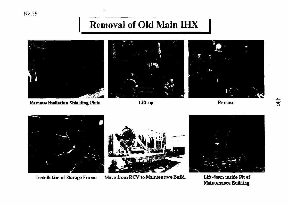
No.?9
Rc moval of Old Main fflX |
Remove Radiation Shfelding Plate Lift-up
Installation of Storage Frame Move from RCV to Maintenance Build.
Remove
Lift-down inside Pit ofMaintenance Building
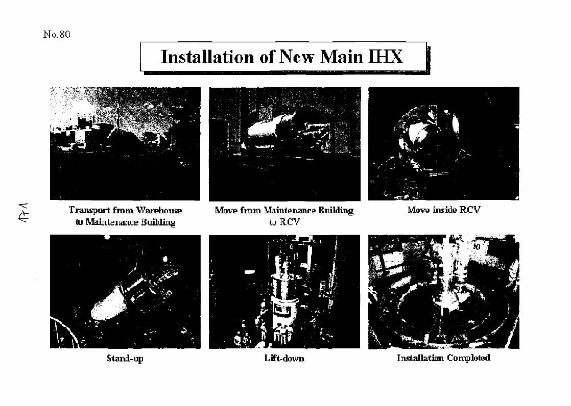
No.80
Installation of New Main fflX
Transport from Warohouse(u Maii
Stand-uji
from Maiiiterianco' EmldingOiRCV
Lift-down
Move inside RCV
Installation Completed
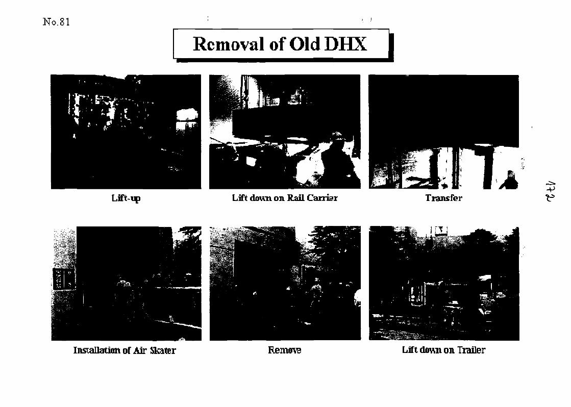
No. 81
Removal of Old DHX
Lift down on Rail Carrier Transfer•V
Installation of Air Skater Remove Lift down on Trailer
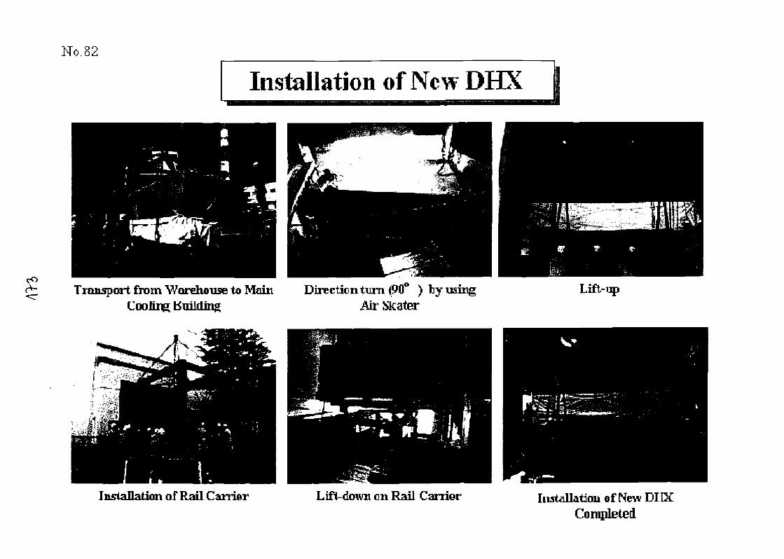
No.82
Installation of New DHX
Transport from Warehouse to MainCooling Building
Direction turn (90° ) hy usingAir Skater
Installation of Rail Carrier Lift-down on Rail Carrier
Lift-up
Installation of New DIIXCompleted
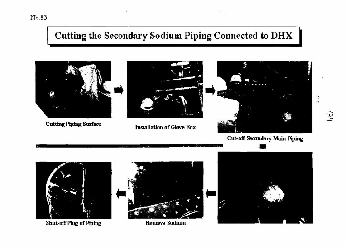
No.83
Cutting the Secondary Sodium Piping Connected to DHX I
Cutting Pqiing Surface Tnsrallat.inn nf Glnvp Rnx
Cut-off Secondary Main
Shut-oil Plug of Piping Remove Sodium
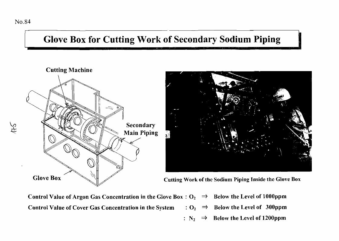
No. 84
Glove Box for Cutting Work of Secondary Sodium Piping
Cutting Machine
SecondaryMain Piping
Glove Box Cutting Work of the Sodium Piping Inside the Glove Box
Control Value of Argon Gas Concentration in the Glove Box : O2 =* Below the Level of lOOOppm
Control Value of Cover Gas Concentration in the System : O2 => Below the Level of 300ppm
: N2 =* Below the Level of 1200ppm
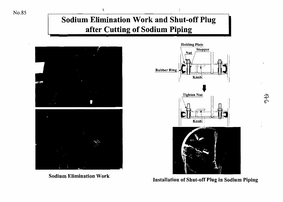
No.85
Sodium Elimination Work and Shut-off Plugafter Cutting of Sodium Piping
Rubber Ring
Holding PlateStopper
Nut /
ILLLKnob]
Tighten Nut
Sodium Elimination WorkInstallation of Shut-off Plug in Sodium Piping
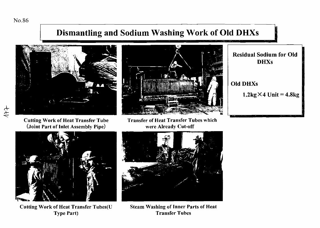
No.86
A-A-
Dismantling and Sodium Washing Work of Old DHXs
Cutting Work of Heat Transfer Tube(Joint Part of Inlet Assembly Pipe)
Transfer of Heat Transfer Tubes whichwere Already Cut-off
Cutting Work of Heat Transfer Tubes(UType Part)
Steam Washing of Inner Parts of HeatTransfer Tubes
Residual Sodium for OldDHXs
Old DHXs
1.2kg X 4 Unit = 4.8kg
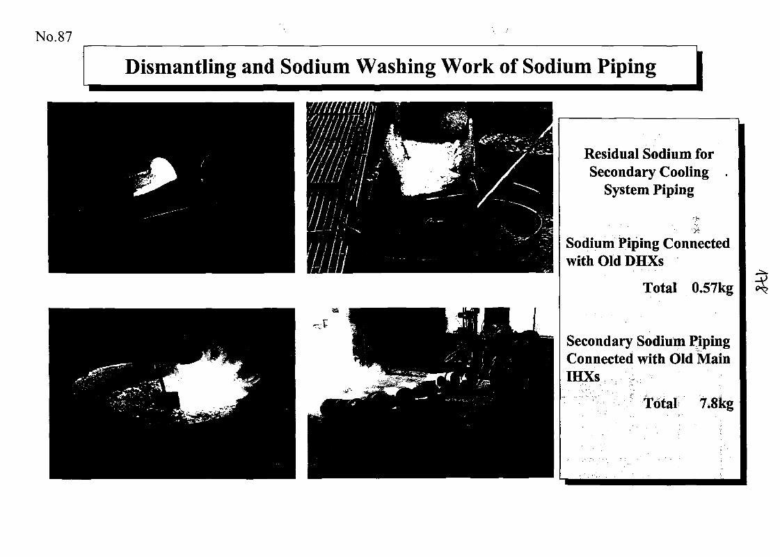
No.87
Dismantling and Sodium Washing Work of Sodium Piping
Residual Sodium forSecondary Cooling .
System Piping
Sodium Piping Connectedwith Old DHXs
Total 0.57kg
Secondary Sodium PipingConnected with Old MainIHXs
Total 7.8kg
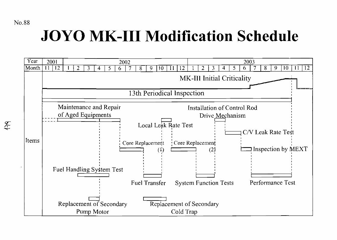
No.88
JOYO MK-III Modification ScheduleYear 2001 2002 2003
Month 11 12 1 2 3 4 5 6 7 8 9 10 11 12 1 I 2 I 3 | 4 | 5 | 6 | 7 | 8 I 9 |10 I 11 | 12
Items
MK-III Initial Criticality
13th Periodical Inspection
Maintenance and Repairof Aged Equipments
Installation of Control RodDrive Mechanism
Local Leak Rate Test
Core Replacement
Fuel Handling System Test
Core Replacement(2)
C/V Leak Rate Test
Inspection by MEXT
Fuel Transfer System Function Tests Performance Test
Replacement of SecondaryPump Motor
Replacement of SecondaryCold Trap
No.89
Summary
Twenty years of successful operations at JOYOprovides a wealth of experience on coremanagement, chemical analysis of sodium and covergas, CP measurement, replacement of majorcomponents in the cooling systems.
Some of the data obtained is stored in a databaseto preserve the related knowledge.
This experiences and accumulated data will beuseful for the design of future fast reactors.
Ofco
Fire Accident Site (1)
Fire Accident Site (2)
Outlook of Electric Tube Near Fire
&*>
Carton Box and Pail Can
o*
Fire Simulation Experiment (1)
Oo
Fire Simulation Experiment (2)
Sodium Chemical Reaction Experiment
-V
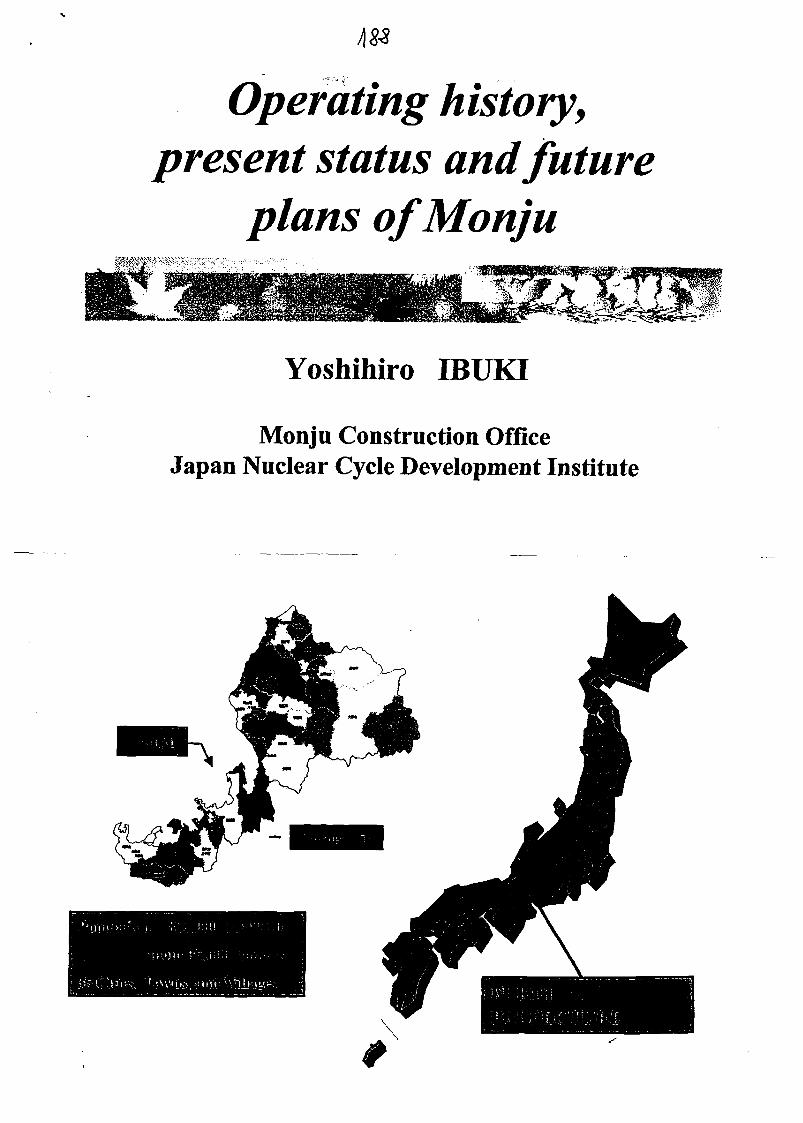
Operating history,present status and future
plans ofMonju
Yoshihiro IBUKI
Monju Construction OfficeJapan Nuclear Cycle Development Institute
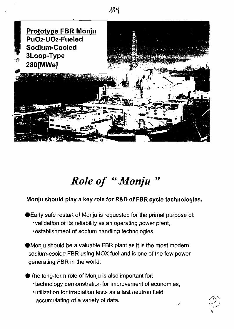
Prototype FBR MoniuPuO2-UO2-FueledSodium-Cooled3Loop-Type280[MWe]
Role of "Monju
Monju should play a key role for R&D of FBR cycle technologies.
arty safe restart of Monju is requested for the primal purpose of:validation of its reliability as an operating power plant,establishment of sodium handling technologies.
IMonju should be a valuable FBR plant as it is the most modernsodium-cooled FBR using MOX fuel and is one of the few powergenerating FBR in the world.
IThe long-term role of Monju is also important for:•technology demonstration for improvement of economies,• utilization for irradiation tests as a fast neutron fieldaccumulating of a variety of data.

/ ( R e - s t a r t )199311
19941 3 5 7 9 11
19951 3 5 7 9 1 1
Reactor power Electric output
System Start-up tests
Main schedule.Sa-'rfWwiiiWiin
Fuel loading &Minimum criticality
test
Core physicstest
Function tests Start-up tests
Shielding characteristics testr i T \
Initial connectionto the gridInitial criticality
I Tj I I
\Sodium leak accident
T| I //
Future plan to re-start• Start of construction• Start of fuel loading• Initial criticality• Initial generator
synchronization• Sodium leakage
accident
October 1985October 19935 April 199429 August 1995
8 December 1995
Application for safety licensing aimedat plant improvement
Plant improvement workComprehensive function testsFuel reloadSystem Start-up tests
Progress since the Sodium Leak Accident ofMonju1995 1996 1997 1998 1999 2000 2001
Election fir JCOGovernor in Fukui Accident
Preparation for SafetyLicensina Examination
Science Technology Agenc MEXT:PromotioiMEThRegulatiorCause Investigation
Comprehensive Safety Revk
Cause Investigation & Review ofCountermeasures
W/G on Follow-up ofCountermeasures for Moniu Safety
Round-Table ConferenceonFBR
The Long-Term Programfor Nuclear Energy
Round-TabtemSub-committeeference Haon FBR
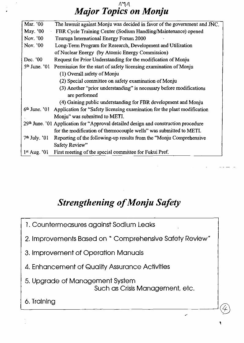
/n/iMajor Topics on Monju
Mar. '00 The lawsuit against Monju was decided in favor of the government and INC.May. '00 FBR Cycle Training Center (Sodium Handling/Maintenance) openedNov. '00 Tsuruga International Energy Forum 2000Nov. '00 Long-Term Program for Research, Development and Utilization
of Nuclear Energy (by Atomic Energy Commission)Dec. '00 Request for Prior Understanding for the modification of Monju5th June. '01 Permission for the start of safety licensing examination of Monju
(1) Overall safety of Monju(2) Special committee on safety examination of Monju(3) Another "prior understanding" is necessary before modifications
are performed(4) Gaining public understanding for FBR development and Monju
6th June. '01 Application for "Safety licensing examination for the plant modificationMonju" was submitted to MET!
29th June. '01 Application for "Approval detailed design and construction procedurefor the modification of thermocouple wells" was submitted to METI.
7th July. '01 Reporting of the folio wing-up results from the "Monju ComprehensiveSafety Review"
1st Aug.' 01 First meeting of the special committee for Fukui Pref.
Strengthening of Monju Safety
1. Countermeasures against Sodium Leaks
2. Improvements Based on * Comprehensive Safety Review"
3. Improvement of Operation Manuals
4. Enhancement of Quality Assurance Activities
5. Upgrade of Management SystemSuch as Crisis Management etc.
6. Training
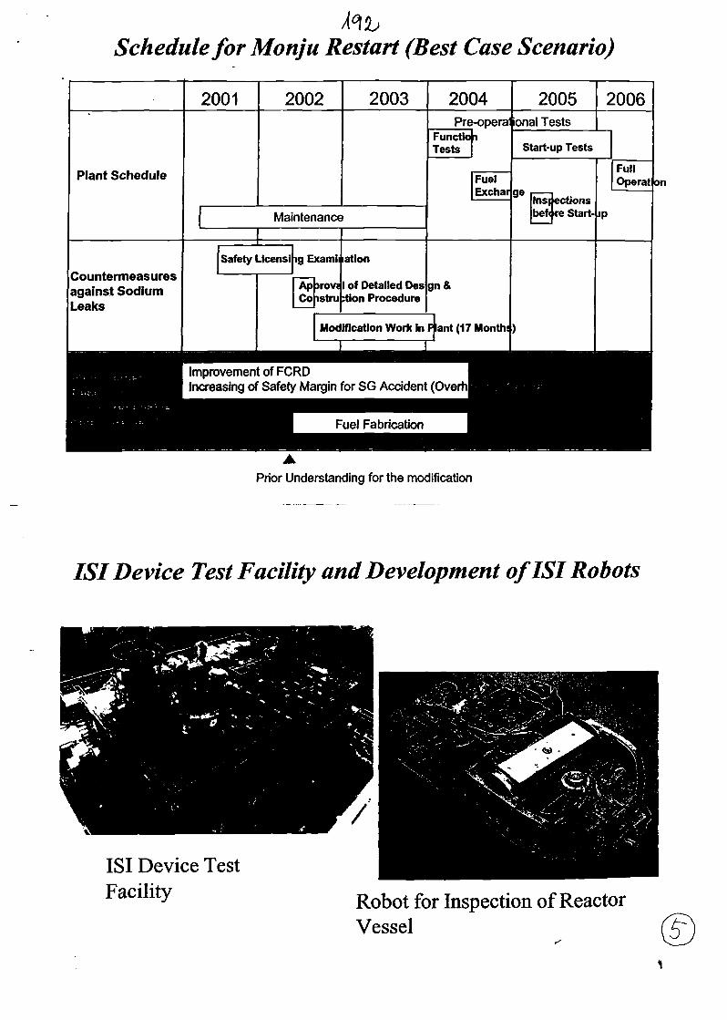
Schedule for Monju Restart (Best Case Scenario)
Plant Schedule
Countermeasuresagainst SodiumLeaks
2001 2002 2003
Maintenance
Safety Licensi ig Examli
ApCo
>rov;istru
ation
1 of Detailed Des:tion Procedure
Modification Work in
2004 ^Pre-opera
FunctioTests
gn&
P lant (17
i
FuelExchai
Month!
2005
onal Tests
2006
Start-up Tests
ge
)
lns|bef<
ectionsre Start-
FullOperat
<P
on
Improvement of FCRDIncreasing of Safety Margin for SG Accident (Ove
Prior Understanding for the modification
LSI Device Test Facility and Development of ISI Robots
ISI Device TestFacility Robot for Inspection of Reactor
Vessel

FBR Cycle Training Center,J«t
Sodium HajKjiing XjS&ihg FaailityI*£a. . T '** ^ . Maintenance TraiakaOSatilitv
Exercise on sodium fire fighting Exercise on maintenance
Long-Term R&D in Monju
2000 2005 2010 2015 2020
Mid-term MissionLong-term Mission
SafetyLicensing
ModificationWork
Pre-operationalTests
Demonstration ofPlant Reliability
Establishment ofSodium-HandlingTechniques
MANGISHLAC ATOMIC ENERGY COMPLEX(MAEC)
REPORT
((Operational experience ofBN-350»
Presented by Igor Dumchev,International investment andrelationship programsManager
AKTAU, KAZAKSTANMarch 2002
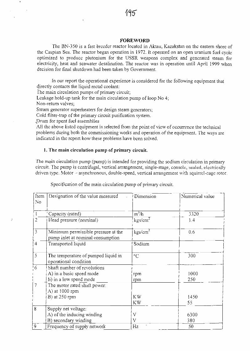
FOREWORDThe BN-350 is a fast breeder reactor located in Aktau, Kazakstan on the eastern shore of
the Caspian Sea. The reactor began operation in 1972. It operated on an open uranium fuel cycleoptimized to produce plutonium for the USSR weapons complex and generated steam forelectricity, heat and seawater desalination. The reactor was in operation until April 1999 whendecision for final shutdown had been taken by Government.
In our report the operational experience is considered for the following equipment thatdirectly contacts the liquid metal coolant:The main circulation pumps of primary circuit;Leakage hold-up tank for the main circulation pump of loop No 4;Non-return valves;Steam generator superheaters for design steam generators;Cold filter-trap of the primary circuit purification system.JJrum for spent fuel assembliesAll the above listed equipment is selected from the point of view of occurrence the technicalproblems during both the commissioning works and operation of the equipment. The ways areindicated in the report how these problems have been solved.
1. The main circulation pump of primary circuit.
The main circulation pump (pump) is intended for providing the sodium circulation in primarycircuit. The pump is centrifugal, vertical arrangement, single-stage, console, sealed, electricallydriven type. Motor - asynchronous, double-speed, vertical arrangement with squirrel-cage rotor.
Specification of the main circulation pump of primary circuit.
ItemNo
12
-)
4
5
6
7
8
9
Designation of the value measured
Capacity (rated)Head pressure (nominal)
Minimum permissible pressure at thepump inlet at nominal consumptionTransported liquid
The temperature of pumped liquid inoperational conditionShaft number of revolutionsA) in a basic speed modeB) in a low speed modeThe motor rated shaft power:A) at 1 000 rpmB) at 250 rpm
Supply net voltage:A) of the inducing windingB) secondary windingFrequency of supply network
Dimension
mj/hkgs/cm2
kgs/cm2
Sodium
°C
rpmrpm
KWKW
VVHz -
Numerical value
33201.4
0.6
300
1000250
145055
630038050

ItemNo
10
11
12
Designation of the value measured
Excessive gas pressure in the pump gaschamberDirection of the shaft rotation from thepump sideWeight of removable part
Dimension
Kilogauss/cm2
CounterClock- wise directionTon
Numerical value
0.9
18
The pump consists of the tank and the removable part, which are coupled using the flange capand bolts with nuts and locknuts. The coupling tightness is achieved by welding. Duringdismantling the welded seam is sheared.. The oil circulation is provided by the oil system.The pump motor is fitted on the steel cylindrical shell ring that is mounted on the support plateof the pump.The pump and motor are connected by the tooth-type spring coupling of progressive spring rate.The steel plates in the upper part of the tank protect the pump.Prescribed service life of the pump body is 30 years. The service life of the blade wheel - 7000hours. After the completion of the blade wheel service life the removable part of the pump isreplaced.
Event description.
Date: 1973Reactor status: Commissioning works.
Fault: vibration and increase of sodium level in the pump tank during the pumpswitching on to 1000 rpm. After relaxation of transitional processes the sodium level wasstabilized and set within the permissible limits.
The way of fault detection: Indications of sodium level gauge in the pump tank. Actuationof warning alarm system..
Defect origin: Defect of the project.Equipment recovery, repair or interchange: To eliminate vibration and increase of
sodium level in the pump tank during the pump switching on to 1000 rpm the additionallabyrinth seal was set between the removable part and pump body (see Fig. 2.14 and 2.15). Thesodium level in the pump tank has become stable during the pump switching on to 1000 rpm.
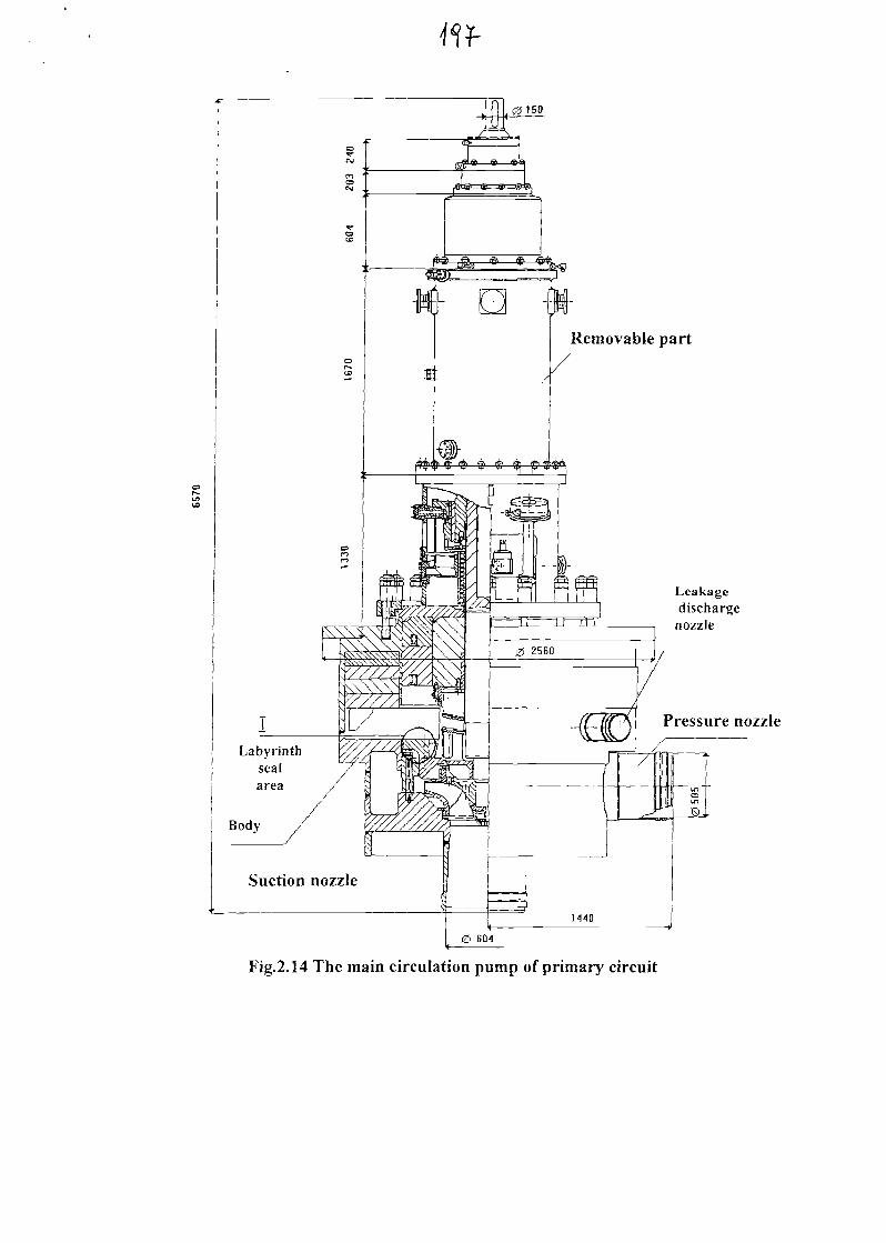
0150
Removable part
Labyrinthsealarea
Body
Suction nozzle
Leakagedischargenozzle
Pressure nozzle
Fig.2.14 The main circulation pump of primary circuit
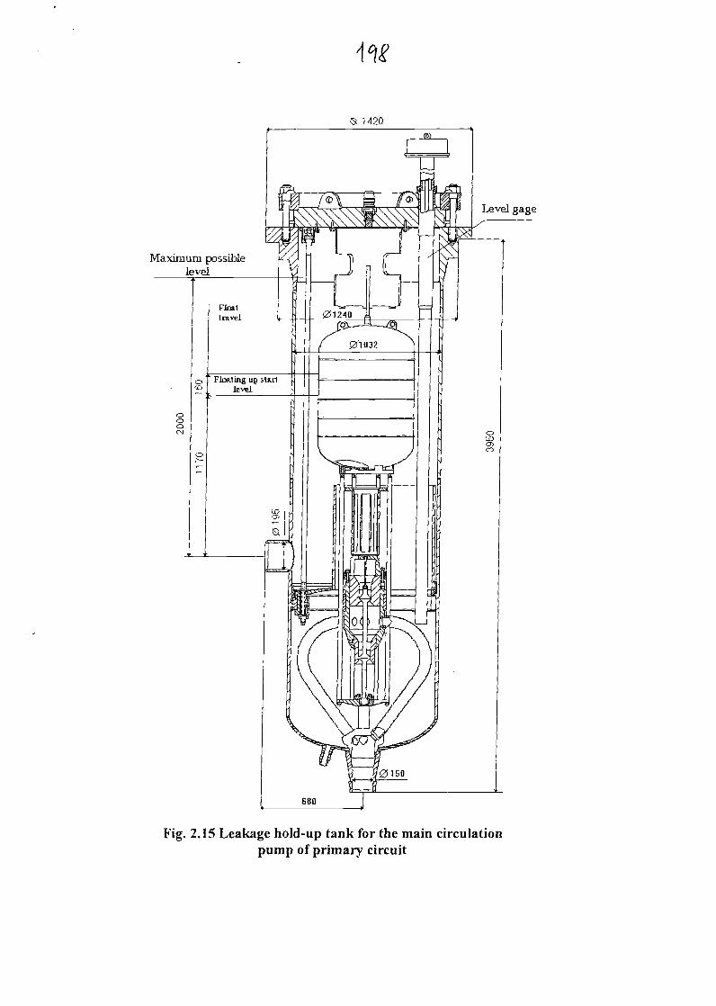
1420
Maximum possiblelevel
Fig. 2.15 Leakage hold-up tank for the main circulationpump of primary circuit
2. The pump leakage drain hold-up tank.
The pump leakage drain tank fulfills a function of both the gas separator and hydraulic seal thatprevents the gas entrainment into suction pipeline of the main circulation pump.The pump leakage drain tank consists of the tank and removable part coupled by the cap flange,bolts and nuts.The coupling tightness is achieved by welding.Deflector improves separation of gas by changing the sodium flow direction. The pressurecompensated valve is the double-inlet for sodium. Pressure variation at the pump suction sideand outlet nozzles makes no influence on the needle position and sodium consumption via thepump leakage drain tank.
The sodium flows out of the pump tank into the pump leakage drain tank via the pipeline of 219mm outside diameter and 12 mm wall thickness. From the pump leakage drain tank the sodiumflows via the pipeline of 159 mm diameter and 6 mm wall thickness to DU500 pipeline into thesuction pipeline of circulation pump.
Event description
Date: 1977+92Reactor status: Reactor operation at 650+750 MW power.
Fault: self-induced vibrations of sodium level in the pump leakage drain tank duringoperation of the main circulation pump (pump) at 1000 rpm in the loop No 4 of primary circuit.The self-induced vibrations eliminated by the cutting off the loop No 4 via the gascommunications from primary circuit and by maintaining the gas pressure in the loop No 4higher than that in all the rest primary circuit gas volume.
The way of fault detection: Indications of both the sodium level gauge in the pump tankand "Signal" float position alarm.
Defect origin: The hangers' spring tension had changed in the pipe that connects thepump tank and leakage drain tank during operation. This resulted in a change of the pipelines'angle of slope and caused the pipeline "sagging". In this area the whole cross-section of pipelinewas filled with sodium and there was a temporary reduction in sodium draining to the leakagedrain tank. Therefore the level of leakage drain tank fell. Then the sodium level raised in thepump tank due to reduction of sodium draining. After raising of level in the pump tank thesodium drained from stagnant area to the leakage tank and thus the level in the leakage hold-uptank started raising. After drop of sodium level in the pump leakage drain tank the processrepeated causina the period of self-induced vibrations 1.6 sec. (Fig. 2.17).
H,
T, sec
loo
Fig. 2.17 Self-induced vibrations of the leakage drain tank float (indications of the"Signal" alarm indicator).
Equipment recovery, repair or interchange: It was very complicated problem to find outthe exact reason for self-induced vibrations of sodium level in the leakage drain tank because ofthe discrete indications of the pump tank sodium level indicator and the smaller sodium levelvibration amplitude than the indicator scale interval. So the indicating instrument showed theconservative value for sodium level in the leakage drain hold-up tank.The first solution was to change the leakage tank float (with removable part). The change ofremovable part did not stop the self-induced vibrations in the leakage tank.After that the adjustment was carried out of the hangers' spring tension for the pipe connectingthe pump tank and pump leakage drain tank. This way the self-induced vibrations of sodiumlevel had been stopped.
3. The non-return valve of primary circuit loop.
Design specification.The non-return valve is intended to prevent the back flow of coolant in the loop when the pumpis tripped while other loops operate. The non-return valve consists of the body and the removablepart (ass. 350E)

to A
oLOf>CM
Fig. 2.18. The design non-return valve (ass.350).
The non-return valve body is a cylinder with two nozzles of diametrically opposite arrangement.The nozzles are welded to the lower part of the body. The inlet nozzle is located 143 cm higher
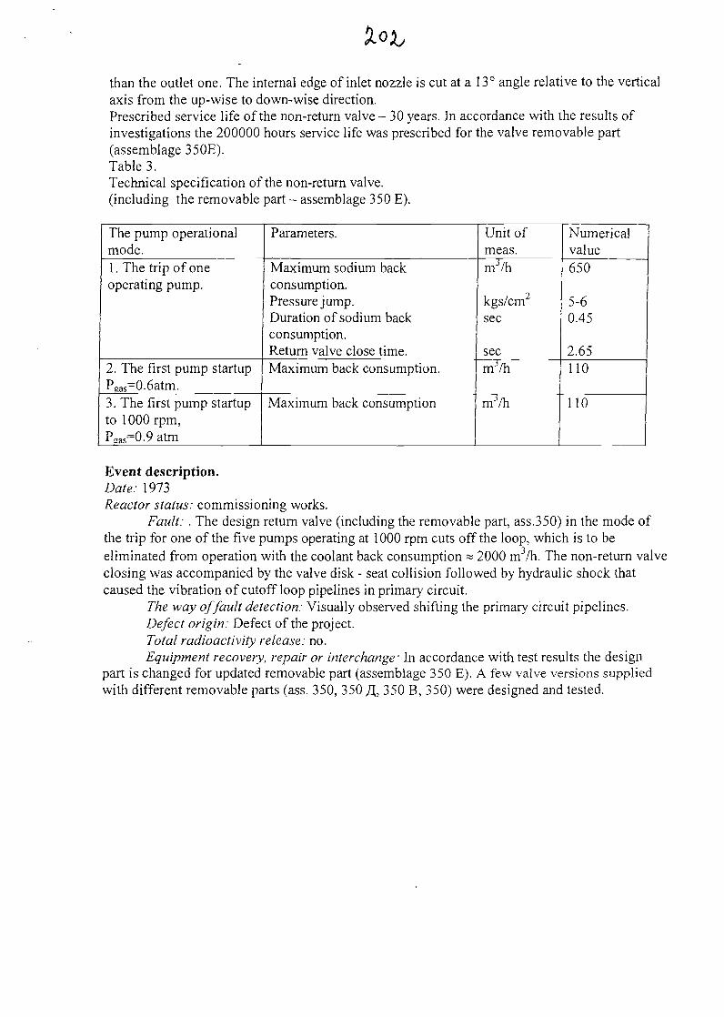
than the outlet one. The internal edge of inlet nozzle is cut at a 13° angle relative to the verticalaxis from the up-wise to down-wise direction.Prescribed service life of the non-return valve - 30 years. In accordance with the results ofinvestigations the 200000 hours service life was prescribed for the valve removable part(assemblage 350E).Table 3.Technical specification of the non-return valve.(including the removable part - assemblage 350 E).
The pump operationalmode.1 . The trip of oneoperating pump.
2. The first pump startupPsas=0.6atm.3. The first pump startupto lOOOrpm,P2as=0.9 atm
Parameters.
Maximum sodium backconsumption.Pressure jump.Duration of sodium backconsumption.Return valve close time.Maximum back consumption.
Maximum back consumption
Unit ofmeas.mj/h
kgs/cm2
sec
secmj/h
mj/h
Numericalvalue650
5-60.45
2.65110
110
Event description.Date: 1973Reactor status: commissioning works.
Fault: . The design return valve (including the removable part, ass.350) in the mode ofthe trip for one of the five pumps operating at 1000 rpm cuts off the loop, which is to beeliminated from operation with the coolant back consumption « 2000 m /h. The non-return valveclosing was accompanied by the valve disk - seat collision followed by hydraulic shock thatcaused the vibration of cutoff loop pipelines in primary circuit.
The way of fault detection: Visually observed shifting the primary circuit pipelines.Defect origin: Defect of the project.Total radioactivity release: no.Equipment recovery, repair or interchange: In accordance with test results the design
part is changed for updated removable part (assemblage 350 E). A few valve versions suppliedwith different removable parts (ass. 350, 350 J\, 350 B, 350) were designed and tested.
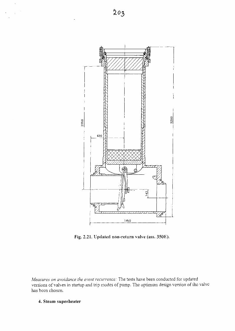
Fig. 2.21. Updated non-return valve (ass. 350E).
Measures on avoidance the event recurrence: The tests have been conducted for updatedversions of valves in startup and trip modes of pump. The optimum design version of the valvehas been chosen.
4. Steam superheater
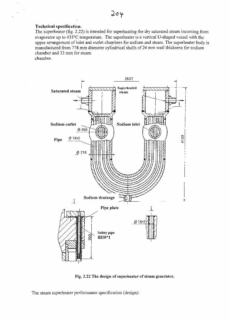
Technical specification.The superheater (fig. 2.22) is intended for superheating the dry saturated steam incoming fromevaporator up to 435°C temperature. The superheater is a vertical U-shaped vessel with theupper arrangement of inlet and outlet chambers for sodium and steam. The superheater body ismanufactured from 778 mm diameter cylindrical shells of 24 mm wall thickness for sodiumchamber and 33 mm for steamchamber.
2537
Saturated steam
Sodium outlet
Pipe
Fig. 2.22 The design of superheater of steam generator.
The steam superheater performance specification (design):
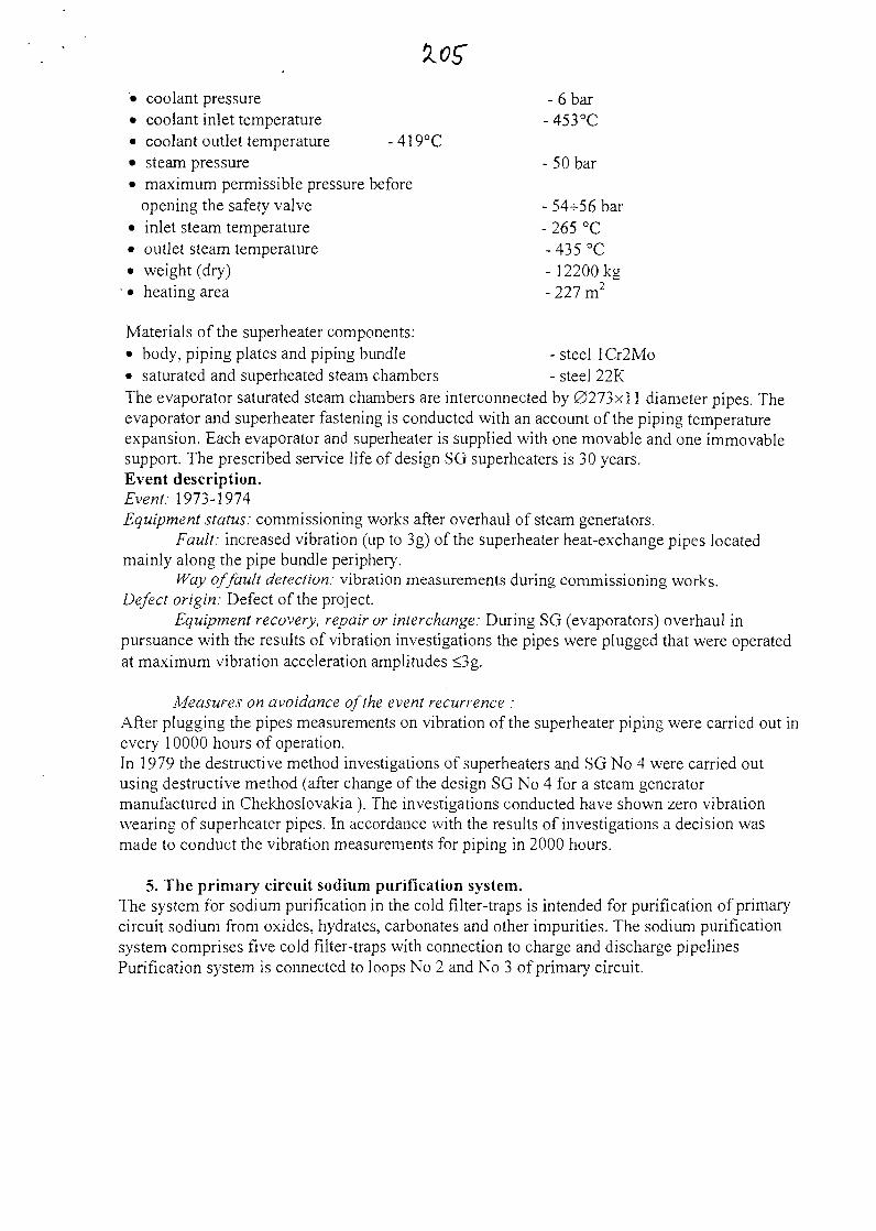
• coolant pressure - 6 bar• coolant inlet temperature -453°C• coolant outlet temperature -419°C• steam pressure - 50 bar• maximum permissible pressure before
opening the safety valve - 54-^56 bar• inlet steam temperature - 265 °C• outlet steam temperature - 435 °C• weight (dry) - 12200kg
' • heating area - 227 m2
Materials of the superheater components:• body, piping plates and piping bundle - steel 1 Cr2Mo• saturated and superheated steam chambers - steel 22KThe evaporator saturated steam chambers are interconnected by 0273x11 diameter pipes. Theevaporator and superheater fastening is conducted with an account of the piping temperatureexpansion. Each evaporator and superheater is supplied with one movable and one immovablesupport. The prescribed service life of design SG superheaters is 30 years.Event description.Event: 1973-1974Equipment status: commissioning works after overhaul of steam generators.
Fault: increased vibration (up to 3g) of the superheater heat-exchange pipes locatedmainly along the pipe bundle periphery.
Way of fault detection: vibration measurements during commissioning works.Defect origin: Defect of the project.
Equipment recovery, repair or interchange: During SG (evaporators) overhaul inpursuance with the results of vibration investigations the pipes were plugged that were operatedat maximum vibration acceleration amplitudes <3g.
Measures on avoidance of the event recurrence :After plugging the pipes measurements on vibration of the superheater piping were carried out inevery 10000 hours of operation.In 1979 the destructive method investigations of superheaters and SG No 4 were carried outusing destructive method (after change of the design SG No 4 for a steam generatormanufactured in Chekhoslovakia ). The investigations conducted have shown zero vibrationwearing of superheater pipes. In accordance with the results of investigations a decision wasmade to conduct the vibration measurements for piping in 2000 hours.
5. The primary circuit sodium purification system.The system for sodium purification in the cold filter-traps is intended for purification of primarycircuit sodium from oxides, hydrates, carbonates and other impurities. The sodium purificationsystem comprises five cold filter-traps with connection to charge and discharge pipelinesPurification system is connected to loops No 2 and No 3 of primary circuit.
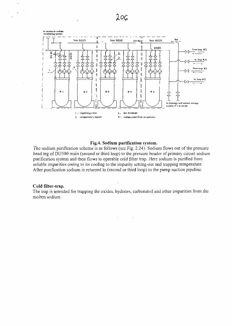
to cesium-in-sodiummonitoring system
from loop N3
to loop N 3
from loop N2
to drainage and sodium storagesystem of 1-st circuit
| - regulating valve
2 - recuperator's bypass
3 - gas discharge
A - sodium outlet from recuperator
FigA Sodium purification system.The sodium purification scheme is as follows (see Fig. 2.24). Sodium flows out of the pressurehead leg of DU500 main (second or third loop) to the pressure header of primary circuit sodiumpurification system and then flows to operable cold filter trap. Here sodium is purified fromsoluble impurities owing to its cooling to the impurity setting-out and trapping temperature.After purification sodium is returned to (second or third loop) to the pump suction pipeline.
Cold filter-trap.The trap is intended for trapping the oxides, hydrates, carbonated and other impurities from themolten sodium.
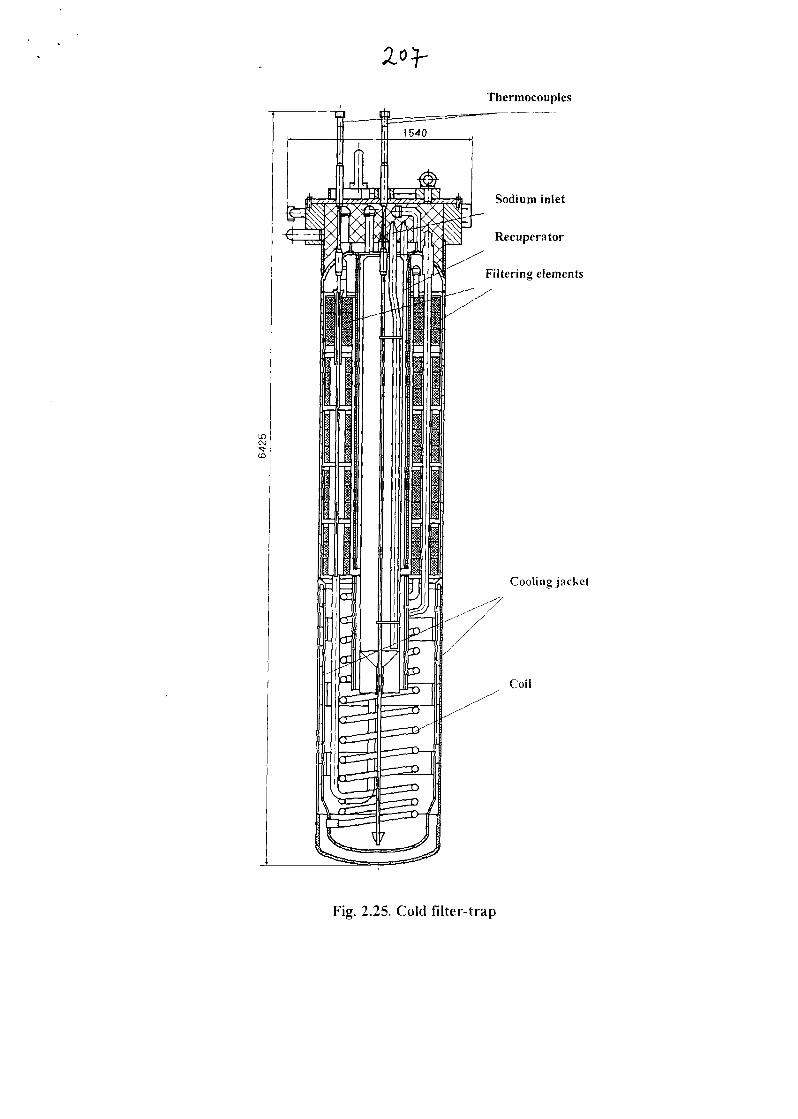
Thermocouples
Sodium inlet
Recuperator
Filtering elements
Cooling jacket
Coil
Fig. 2.25. Cold filter-trap
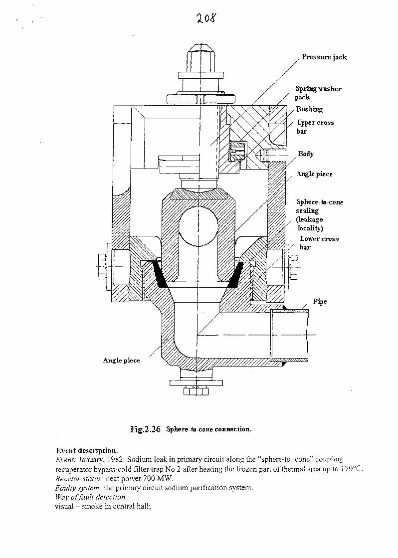
loi'
Ajigle piece
Pressure jack
Spring washerpack
, Bushing
Upper crossbar
Ilj. Body
, Ajtgle piece
Sphere-to-conesealing(leakagelocality)Lower crossbar
Pipe
Fig.2.26 Sphere-to-cone connection.
Event description.Event: January, 1982. Sodium leak in primary circuit along the "sphere-to- cone" couplingrecuperator bypass-cold filter trap No 2 after heating the frozen part of thermal area up to 170°C.Reactor status: heat power 700 MW.Faulty system: the primary circuit sodium purification system.Way of fault detection:visual - smoke in central hall;
actuation of fait signaling- increase of aerosol specific activity, reduction of insulation resistancein the upper electric heating area of cold filter-trap; Defect origin :hydraulic shock after occurrence of consumption via the trap resulted from heating thermal area;impact of temperature gradient with the micro-leakage available;defect of coupling assemblage "sphere-to-cone";Fallured equipment: bypass pipe connector "sphere-to-cone" of recuperator, the upper thermalarea of cold filter-trap electric heating.Total radioactivity release: 0.03 Ci.Equipment recovery, repair or interchange: defective connector "sphere-to-cone" is cut andreplaced for pipe.Measures on avoiding the event recurrence:all the design pipeline couplings "sphere-to-cone" are changed;procedures are adjusted when putting the cold filter-traps into operation
6. Cooling system for spent assemblies.
Brief description of the facility.The facility is an interim storage facility and is intended for interim accommodation and coolingof spent fuel assemblies (SFA) unloaded from the apparatus.The facility consists of a bath, drum for spent assemblies (DSA), drum drive, the drum driveshaft, drum automatic control mechanism, drum truck, displacer truck, displacer, truck drive,drive counterweight, dosimetric chamber cells, bellows compensator and screens
There are 38 cells for SFAs in the drum. The bath is supplied with air ducts for thecooling air inlet and outlet. The following brunch-pipes are located in the upper part of the bath:Loading one - connects the bath and transfer box and is intended for SFA loading into the drumcells.Unloading one - connects the bath and washing box and is intended for SFA unloading from thedrum cells.
Event description.Event: In April of 1976 when preparing to SFAs drum unloading (36 SFAs from interim
storage facility) followed by SFAs washing the lack of drum rotation was detected.Reactor status: Reactor 650MW heat power operation.Failed system: SFAs cooling system
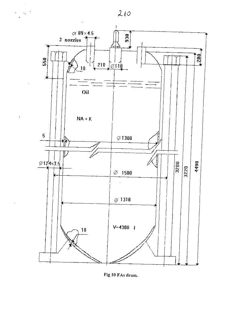
CA 89x4.5
Fig 10 FAs drum.
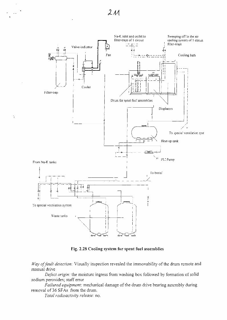
Na-K inlet and outlet tofilter-traps of 1 circuit
From Na-K tanks
Sweeping off to the aircooling system of I circuitfilter-traps
Cooling bath
Drum for spent fuel assemblies
To special ventilation system
To special ventilation syst
Heat-up tank
Fig. 2.28 Cooling system for spent fuel assemblies
Way of fault detection: Visually inspection revealed the immovability of the drum remote andmanual drive
Defect origin: the moisture ingress from washing box followed by formation of solidsodium peroxides; staff error
Failured equipment: mechanical damage of the drum drive bearing assembly duringremoval of 36 SFAs from the drum.
Total radioactivity release: no.
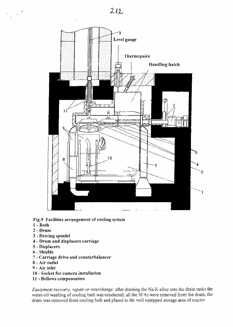
Fig.9 Facilities arrangement of cooling system1 - Bath2 - Drum3 - Driving spindel4 - Drum and displacers carriage5 - Displacers6 - Shields7 - Carriage drive and counterbalancer8 - Air outlet9 - Air inlet10 - Socket for camera installation11 - Bellows compensators
Equipment recovery, repair or interchange: after draining the Na-K alloy into the drain tanks thewater-oil washing of cooling bath was conducted, all the SFAs were removed from the drum, thedrum was removed from cooling bath and placed to the well equipped storage area of reactor
building with maintenance of inert gas medium inside the dram. Some two barrels were fittedinto the cooling bath (one in refueling box another in washing box) for placing the SFAs, fuelrods, control rods and sleeves of control and protection system (CPS).Measures on avoidance the event recurrence: decision was made to give up the usage of interimSFAs storage facility. The washing operations were conducted simultaneously with refuelingones. The emergency reloading system (ERS) that uses inert gas for FAs cooling became thestandard one for replacement of SFAs, control rods and sleeves (from reloading box into thewashing one). The SFAs cooling system was mothballed.
Lifetime extension of the Phenix Nuclear Power Plant
L. MARTIN, D. PEPE CEA - PHENIX
R. DUPRAZ FRAMATOME-ANP
Abstract
The French fast reactor prototype : Phenix, located atMarcoule in the Gard department, was put intocommercial operation in 1974. The total time ofpower operation of the plant is approximately100,000 hours.The initial objective of Fast Breeder Reactordemonstration has been achieved. Since the mid-nineties, the role of the reactor as an irradiationfacility has been emphasised, particularly in supportof the CEA's transmutation R&D programme in thecontext of the December 30th 1991 French law onlong-lived radioactive waste management.This new objective has required the extension of theplanned reactor lifetime. A renovation programmewas defined based on :
Plant safety improvements based on today'sstandards.
Evaluations and inspections of componentsin order to assess their condition and to identifypossible damaging mechanisms.
The estimation of the ability of components tocontinue operation taking into account theexperimental feedback.
The safety upgrading of the plant consistedessentially of the following :
The addition of a safety control rod to thereactor.
The partitioning of the secondary sodiumcircuits in the Steam Generator building to improveprotection against sodium fires.
The installation of an anti- whip system onthe high pressure steam pipes.
The construction of two redundant seismicresistant emergency water cooling circuits.
The seismic reinforcement of the plantbuildings.
An extensive evaluation campaign was carried out onall the equipment which is essential to safety.Damaging phenomena were systematicallyinvestigated. Following the evaluation, the equipmentwas either repaired or replaced, or it wasdemonstrated that equipment condition allowedlifetime to be extended.
Among the major works performed was thereplacement of the 321 stainless steel hot leg of thesecondary loops and the repair of the superheaterand reheater SG modules.
This latter operation is currently underway. The repairprocess consists in dismounting the modules,washing the internal residual secondary sodium,replacing potentially defective parts and remounting.
Special analysis was conducted regarding the reactorblock structures. The past and future damage rateswere evaluated, involving investigation ofmanufacturing data, determination of the behaviourof some particular mechanical assemblies such aswelded joints, estimation of the loadings fromoperating conditions associated with thermalcalculations.
In addition to these studies, and as a second defenceline, the main reactor structures were inspected usingvarious techniques. Because of the difficult access tothe structures, original inspection procedures had tobe developed and special equipment designed andmanufactured.The inspections included :
Ultrasonic examination of the reactor vesselupper hangers
Ultrasonic examination of the core supportconical shell
Televisual examination of the core cover plug
Most of the renovation programme of the plant hasbeen completed. The major remaining task is therepair of the SG modules. The power rising of thereactor is expected before the end of 2002.Six 120 EFPD operating cycles are scheduled tocarry out the irradiation programme, representingabout five-and-a-half years of operation.Considerable experience has been gained from thelifetime extension project in many fields, including themethodology which was developed, materials andcomponents behaviour, inspection techniques.
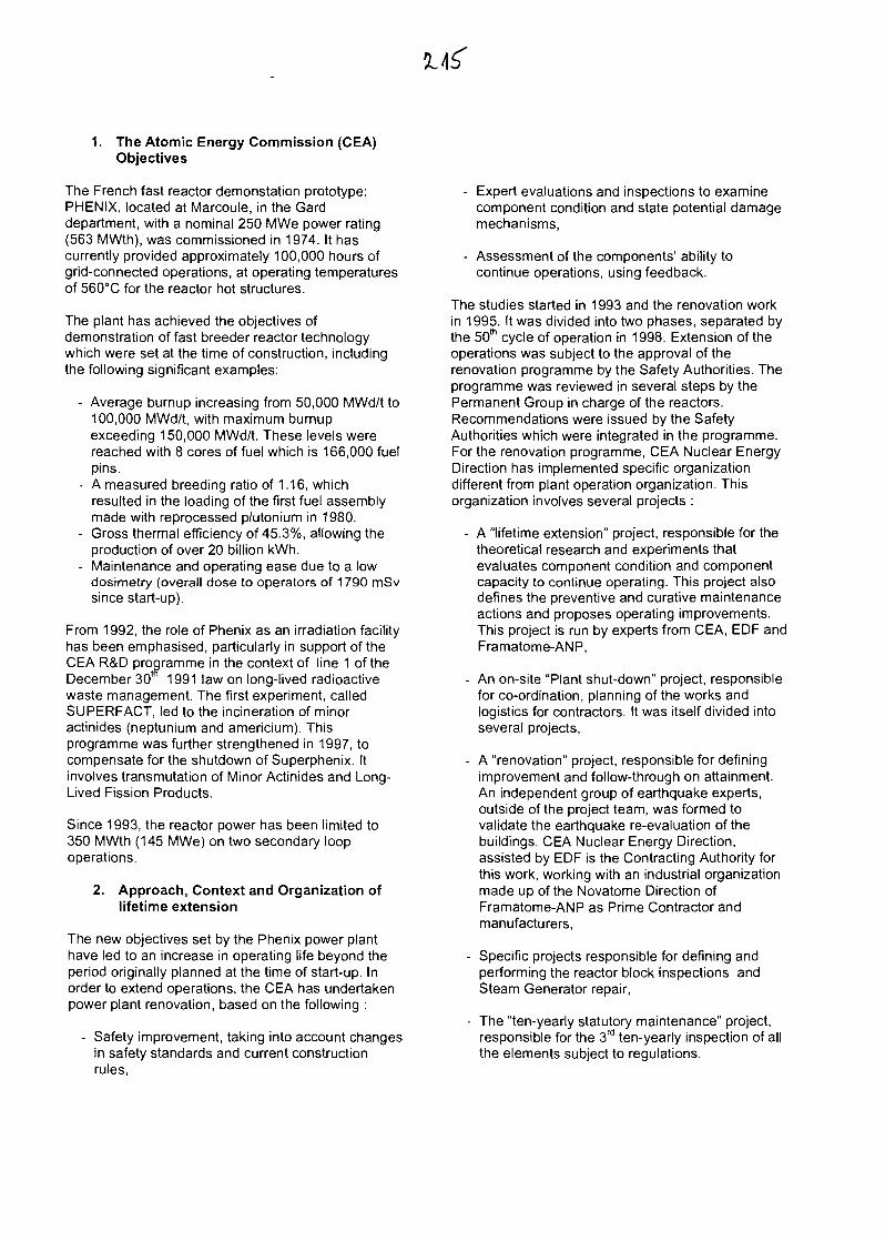
1. The Atomic Energy Commission (CEA)Objectives
The French fast reactor demonstation prototype:PHENIX, located at Marcoule, in the Carddepartment, with a nominal 250 MWe power rating(563 MWth), was commissioned in 1974. It hascurrently provided approximately 100,000 hours ofgrid-connected operations, at operating temperaturesof 560°C for the reactor hot structures.
The plant has achieved the objectives ofdemonstration of fast breeder reactor technologywhich were set at the time of construction, includingthe following significant examples:
- Average burnup increasing from 50,000 MWd/t to100,000 MWd/t, with maximum burnupexceeding 150,000 MWd/t. These levels werereached with 8 cores of fuel which is 166,000 fuelpins.
- A measured breeding ratio of 1.16, whichresulted in the loading of the first fuel assemblymade with reprocessed plutonium in 1980.
- Gross thermal efficiency of 45.3%, allowing theproduction of over 20 billion kWh.
- Maintenance and operating ease due to a lowdosimetry (overall dose to operators of 1790 mSvsince start-up).
From 1992, the role of Phenix as an irradiation facilityhas been emphasised, particularly in support of theCEA R&D programme in the context of line 1 of theDecember 30* 1991 law on long-lived radioactivewaste management. The first experiment, calledSUPERFACT, led to the incineration of minoractinides (neptunium and americium). Thisprogramme was further strengthened in 1997, tocompensate for the shutdown of Superphenix. Itinvolves transmutation of Minor Actinides and Long-Lived Fission Products.
Since 1993, the reactor power has been limited to350 MWth (145 MWe) on two secondary loopoperations.
2. Approach, Context and Organization oflifetime extension
The new objectives set by the Phenix power planthave led to an increase in operating life beyond theperiod originally planned at the time of start-up. Inorder to extend operations, the CEA has undertakenpower plant renovation, based on the following :
- Safety improvement, taking into account changesin safety standards and current constructionrules,
- Expert evaluations and inspections to examinecomponent condition and state potential damagemechanisms,
- Assessment of the components' ability tocontinue operations, using feedback.
The studies started in 1993 and the renovation workin 1995. It was divided into two phases, separated bythe 50th cycle of operation in 1998. Extension of theoperations was subject to the approval of therenovation programme by the Safety Authorities. Theprogramme was reviewed in several steps by thePermanent Group in charge of the reactors.Recommendations were issued by the SafetyAuthorities which were integrated in the programme.For the renovation programme, CEA Nuclear EnergyDirection has implemented specific organizationdifferent from plant operation organization. Thisorganization involves several projects :
- A "lifetime extension" project, responsible for thetheoretical research and experiments thatevaluates component condition and componentcapacity to continue operating. This project alsodefines the preventive and curative maintenanceactions and proposes operating improvements.This project is run by experts from CEA, EOF andFramatome-ANP,
- An on-site "Plant shut-down" project, responsiblefor co-ordination, planning of the works andlogistics for contractors. It was itself divided intoseveral projects,
- A "renovation" project, responsible for definingimprovement and follow-through on attainment.An independent group of earthquake experts,outside of the project team, was formed tovalidate the earthquake re-evaluation of thebuildings. CEA Nuclear Energy Direction,assisted by EDF is the Contracting Authority forthis work, working with an industrial organizationmade up of the Novatome Direction ofFramatome-ANP as Prime Contractor andmanufacturers,
- Specific projects responsible for defining andperforming the reactor block inspections andSteam Generator repair,
- The "ten-yearly statutory maintenance" project,responsible for the 3rd ten-yearly inspection of allthe elements subject to regulations.
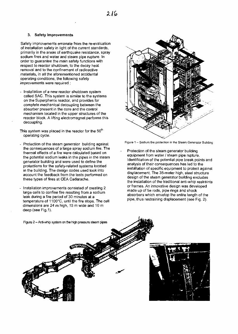
3. Safety Improvements
Safety improvements emanate from the re-evaluationof installation safety in light of the current standards,primarily in the areas of earthquake resistance, spraysodium fires and water and steam pipe rupture. Inorder to guarantee the main safety functions withrespect to reactor shutdown, to the decay heatremoval and to the confinement of radioactivematerials, in all the aforementioned accidentaloperating conditions, the following safetyimprovements were required :
- Installation of a new reactor shutdown systemcalled SAC. This system is similar to the systemson the Superphenix reactor, and provides forcomplete mechanical decoupling between theabsorber present in the core and the controlmechanism located in the upper structures of thereactor block. A lifting electromagnet performs thisdecoupling.
This system was placed in the reactor for the 50th
operating cycle.
- Protection of the steam generator building againstthe consequences of a large spray sodium fire. Thethermal effects of a fire were calculated based onthe potential sodium leaks in the pipes in the steamgenerator building and were used to define theprotections for the safety-related systems locatedin the building. The design codes used took intoaccount the feedback from the tests performed onthese types of fires at CEA Cadarache.
- Installation improvements consisted of creating 2large cells to confine fire resulting from a sodiumleak during a fire period of 30 minutes at atemperature of 1100°C, until the fire stops. The celldimensions are 24 m high, 15 m wide and 10 mdeep (see Fig.1).
Figure 2 - Anti-whip system on the high pressure steam pipes
Figure 1 - Sodium fire protection in the Steam Generator Building
Protection of the steam generator buildingequipment from water / steam pipe rupture.Identification of the potential pipe break points andanalysis of their consequences has led to theinstallation of specific equipment to protect againstdisplacement. The 35-meter high, steel structuredesign of the steam generator building excludesthe installation of the traditional anti-whip restraintsor frames. An innovative design was developedmade up of tie rods, pipe rings and shockabsorbers which envelop the entire length of thepipe, thus restraining displacement (see Fig. 2).
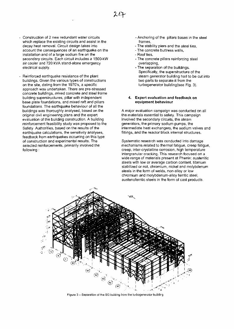
Construction of 2 new redundant water circuitswhich replace the existing circuits and assist in thedecay heat removal. Circuit design takes intoaccount the consequences of an earthquake on theinstallation and of a large sodium fire on thesecondary circuits. Each circuit includes a 1500-kWair cooler and 720 kVA stand-alone emergencyelectrical supply.
Reinforced earthquake resistance of the plantbuildings. Given the various types of constructionson the site, dating from the 1970's, a specificapproach was undertaken. There are pre-stressedconcrete buildings, mixed concrete and steel framebuilding superstructures, pillar with independentbase plate foundations, and mixed raft and pillarsfoundations. The earthquake behaviour of all thebuildings was thoroughly analysed, based on theoriginal civil engineering plans and the expertevaluation of the building construction. A buildingreinforcement feasibility study was proposed to theSafety Authorities, based on the results of theearthquake calculations, the sensitivity analyses,feedback from earthquakes occurring on this typeof construction and experimental results. Theselected reinforcements, primarily involved thefollowing :
4.
- Anchoring of the pillars bases in the steelframes,
- The stability piers and the steel ties,- The concrete buttress walls,- Roof ties,- The concrete pillars reinforcing steel
overlapping,- The separation of the buildings.
Specifically, the superstructure of thesteam generator building had to be cut intotwo parts to separate it from theturbogenerator building(see Fig. 3).
Expert evaluation and feedback onequipment behaviour
A major evaluation campaign was conducted on allthe materials essential to safety. This campaigninvolved the secondary circuits, the steamgenerators, the primary sodium pumps, theintermediate heat exchangers, the sodium valves andfittings, and the reactor block internal structures.
Systematic research was conducted into damagemechanisms related to thermal fatigue, creep fatigue,creep, inter-crystalline corrosion, high temperatureintergranular cracking. This research focused on awide range of materials present at Phenix: austeniticsteels with low or average carbon content, titaniumstabilized or not, chromium, nickel and molybdenumsteels in the form of welds, non-alloy or lowchromium and molybdenum-alloy ferritic steel,austenoferritic steels in the form of cast products.
Figure 3 - Separation of the SG bulding from the turbogenerator building
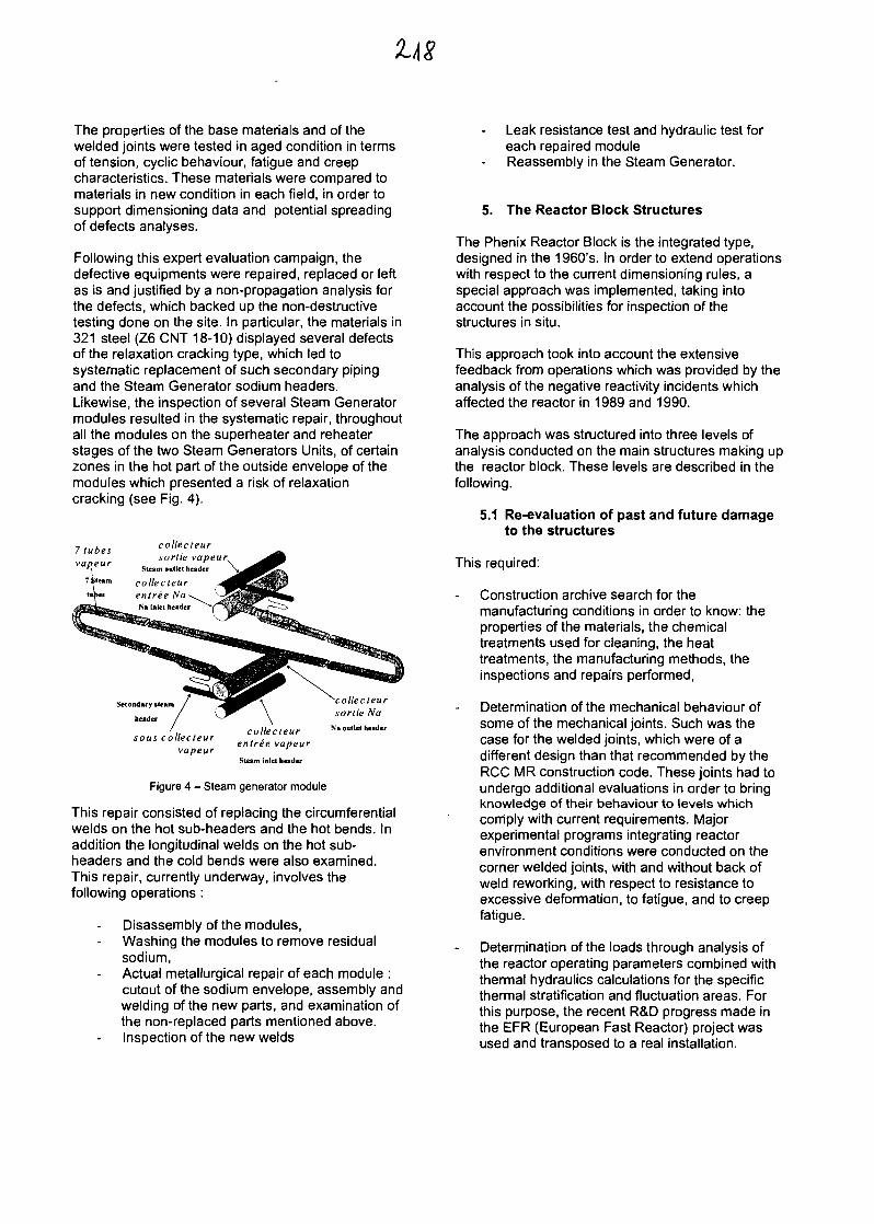
The properties of the base materials and of thewelded joints were tested in aged condition in termsof tension, cyclic behaviour, fatigue and creepcharacteristics. These materials were compared tomaterials in new condition in each field, in order tosupport dimensioning data and potential spreadingof defects analyses.
Following this expert evaluation campaign, thedefective equipments were repaired, replaced or leftas is and justified by a non-propagation analysis forthe defects, which backed up the non-destructivetesting done on the site. In particular, the materials in321 steel (Z6 CNT 18-10) displayed several defectsof the relaxation cracking type, which led tosystematic replacement of such secondary pipingand the Steam Generator sodium headers.Likewise, the inspection of several Steam Generatormodules resulted in the systematic repair, throughoutall the modules on the superheater and reheaterstages of the two Steam Generators Units, of certainzones in the hot part of the outside envelope of themodules which presented a risk of relaxationcracking (see Fig. 4).
collecteursortie vapeur^
Steam outlet header
collecteurentree NaNa inlet header
Secondary iteam
header
sous collecteurvapeur
collecteurentree vapeur
Steam inlet header
'collecteursortie Na
Na outlet header
Figure 4 - Steam generator module
This repair consisted of replacing the circumferentialwelds on the hot sub-headers and the hot bends. Inaddition the longitudinal welds on the hot sub-headers and the cold bends were also examined.This repair, currently underway, involves thefollowing operations:
Disassembly of the modules,Washing the modules to remove residualsodium,Actual metallurgical repair of each module :cutout of the sodium envelope, assembly andwelding of the new parts, and examination ofthe non-replaced parts mentioned above.Inspection of the new welds
Leak resistance test and hydraulic test foreach repaired moduleReassembly in the Steam Generator.
5. The Reactor Block Structures
The Phenix Reactor Block is the integrated type,designed in the 1960's. In order to extend operationswith respect to the current dimensioning rules, aspecial approach was implemented, taking intoaccount the possibilities for inspection of thestructures in situ.
This approach took into account the extensivefeedback from operations which was provided by theanalysis of the negative reactivity incidents whichaffected the reactor in 1989 and 1990.
The approach was structured into three levels ofanalysis conducted on the main structures making upthe reactor block. These levels are described in thefollowing.
5.1 Re-evaluation of past and future damageto the structures
This required:
Construction archive search for themanufacturing conditions in order to know: theproperties of the materials, the chemicaltreatments used for cleaning, the heattreatments, the manufacturing methods, theinspections and repairs performed,
Determination of the mechanical behaviour ofsome of the mechanical joints. Such was thecase for the welded joints, which were of adifferent design than that recommended by theRCC MR construction code. These joints had toundergo additional evaluations in order to bringknowledge of their behaviour to levels whichcomply with current requirements. Majorexperimental programs integrating reactorenvironment conditions were conducted on thecorner welded joints, with and without back ofweld reworking, with respect to resistance toexcessive deformation, to fatigue, and to creepfatigue.
Determination of the loads through analysis ofthe reactor operating parameters combined withthermal hydraulics calculations for the specificthermal stratification and fluctuation areas. Forthis purpose, the recent R&D progress made inthe EFR (European Fast Reactor) project wasused and transposed to a real installation.
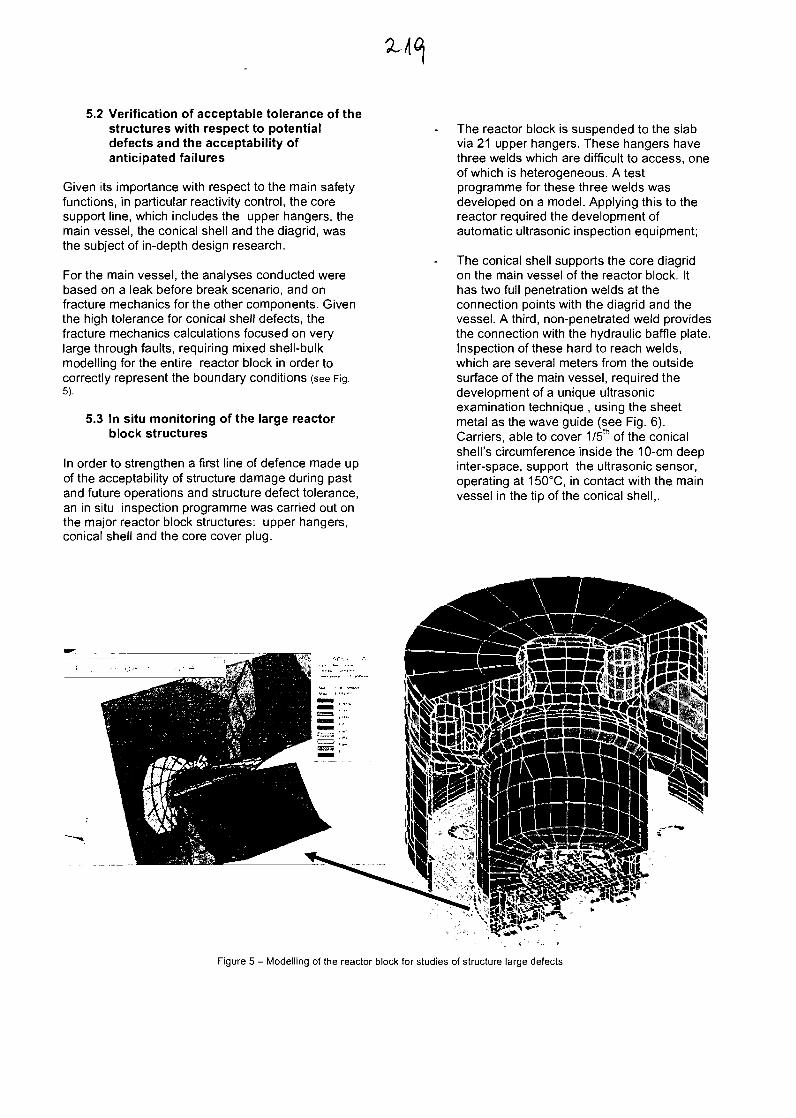
5.2 Verification of acceptable tolerance of thestructures with respect to potentialdefects and the acceptability ofanticipated failures
Given its importance with respect to the main safetyfunctions, in particular reactivity control, the coresupport line, which includes the upper hangers, themain vessel, the conical shell and the diagrid, wasthe subject of in-depth design research.
For the main vessel, the analyses conducted werebased on a leak before break scenario, and onfracture mechanics for the other components. Giventhe high tolerance for conical shell defects, thefracture mechanics calculations focused on verylarge through faults, requiring mixed shell-bulkmodelling for the entire reactor block in order tocorrectly represent the boundary conditions (see Fig.5).
5.3 In situ monitoring of the large reactorblock structures
In order to strengthen a first line of defence made upof the acceptability of structure damage during pastand future operations and structure defect tolerance,an in situ inspection programme was carried out onthe major reactor block structures: upper hangers,conical shell and the core cover plug.
The reactor block is suspended to the slabvia 21 upper hangers. These hangers havethree welds which are difficult to access, oneof which is heterogeneous. A testprogramme for these three welds wasdeveloped on a model. Applying this to thereactor required the development ofautomatic ultrasonic inspection equipment;
The conical shell supports the core diagridon the main vessel of the reactor block. Ithas two full penetration welds at theconnection points with the diagrid and thevessel. A third, non-penetrated weld providesthe connection with the hydraulic baffle plate.Inspection of these hard to reach welds,which are several meters from the outsidesurface of the main vessel, required thedevelopment of a unique ultrasonicexamination technique , using the sheetmetal as the wave guide (see Fig. 6).Carriers, able to cover 1/5th of the conicalshell's circumference inside the 10-cm deepinter-space, support the ultrasonic sensor,operating at 150°C, in contact with the mainvessel in the tip of the conical shell,.
Figure 5 - Modelling of the reactor block for studies of structure large defects
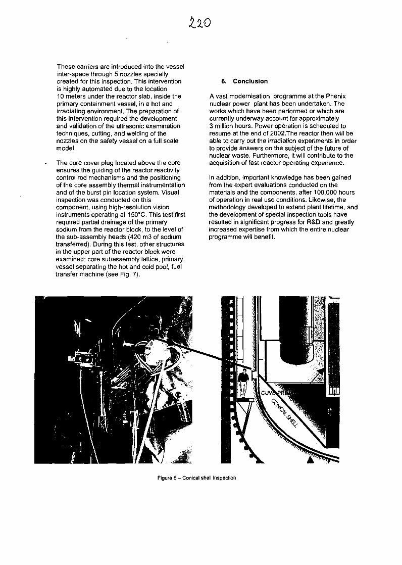
These carriers are introduced into the vesselinter-space through 5 nozzles speciallycreated for this inspection. This interventionis highly automated due to the location10 meters under the reactor slab, inside theprimary containment vessel, in a hot andirradiating environment. The preparation ofthis intervention required the developmentand validation of the ultrasonic examinationtechniques, cutting, and welding of thenozzles on the safety vessel on a full scalemodel.
The core cover plug located above the coreensures the guiding of the reactor reactivitycontrol rod mechanisms and the positioningof the core assembly thermal instrumentationand of the burst pin location system. Visualinspection was conducted on thiscomponent, using high-resolution visioninstruments operating at 150°C. This test firstrequired partial drainage of the primarysodium from the reactor block, to the level ofthe sub-assembly heads (420 m3 of sodiumtransferred). During this test, other structuresin the upper part of the reactor block wereexamined: core subassembly lattice, primaryvessel separating the hot and cold pool, fueltransfer machine (see Fig. 7).
6. Conclusion
A vast modernisation programme at the Phenixnuclear power plant has been undertaken. Theworks which have been performed or which arecurrently underway account for approximately3 million hours. Power operation is scheduled toresume at the end of 2002.The reactor then will beable to carry out the irradiation experiments in orderto provide answers on the subject of the future ofnuclear waste. Furthermore, it will contribute to theacquisition of fast reactor operating experience.
In addition, important knowledge has been gainedfrom the expert evaluations conducted on thematerials and the components, after 100,000 hoursof operation in real use conditions. Likewise, themethodology developed to extend plant lifetime, andthe development of special inspection tools haveresulted in significant progress for R&D and greatlyincreased expertise from which the entire nuclearprogramme will benefit.
Figure 6 - Conical shell inspection
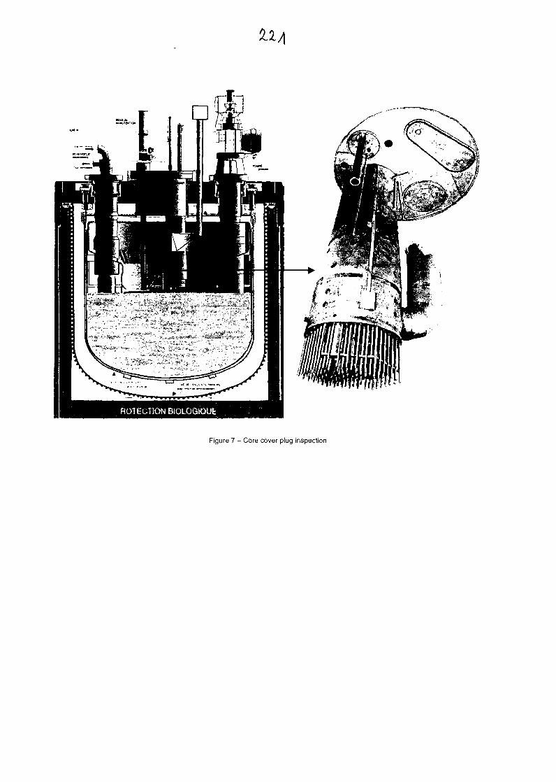
Figure 7 - Core cover plug inspection
X
'E-vJCQ.
U.T3UJ
UJU
reU
4-1c01o
<Or:L.
"ro
111u
CO
'43U(U
LIFETIME EXTENSION of thePHENIX NUCLEAR POWER PLANT
L. Martin IAEA Technical meeting 11-15th March 2002 ceaDirection de I'EnergieNucleaire
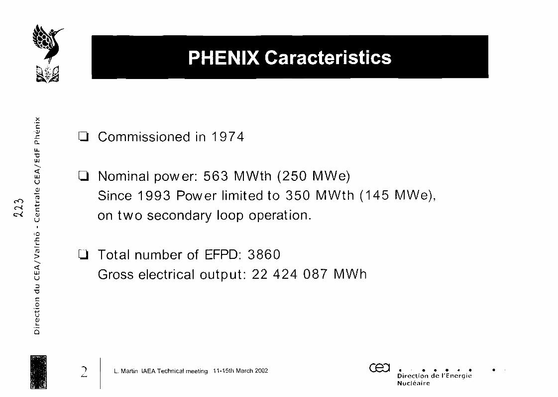
PHENIX Caracteristics
X
'c-01-CQ.
u."CLU
LJUU
QJ
0)UI
<oJCi_
(T3
UJu
TJCO
4~>U<U
3
Commissioned in 1974
Q Nominal power: 563 MWth (250 MWe)Since 1993 Power limited to 350 MWth (145 MWe),on two secondary loop operation.
Q Total number of EFPD: 3860Gross electrical output: 22 424 087 MWh
L. Martin IAEA Technical meeting 11-15th March 2002 CBd .Direction de I'EnergieNucleaire
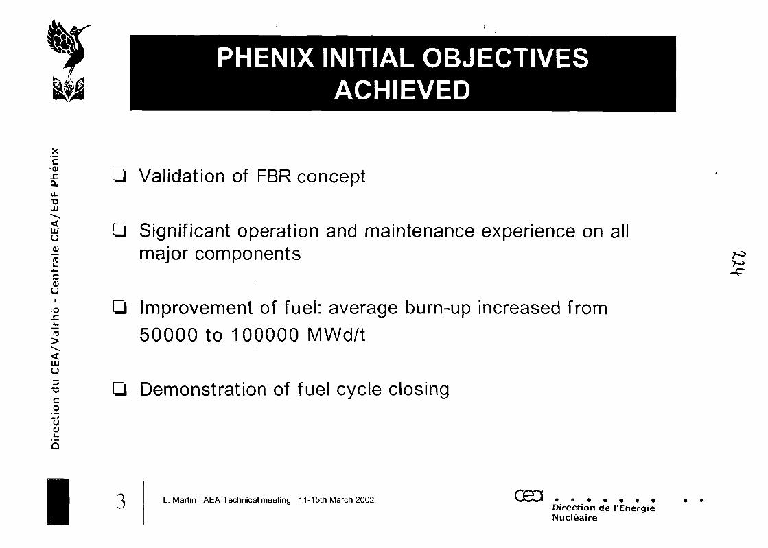
PHENIX INITIAL OBJECTIVESACHIEVED
X
'EJCQL
U.
LU
LUU
Ccuu
<o
TO
UJU
Co4JU(U
Validation of FBR concept
Significant operation and maintenance experience on allmajor components
Improvement of fuel: average burn-up increased from50000 to 100000 MWd/t
Demonstration of fuel cycle closing
I3 L. Martin IAEA Technical meeting 11-15th March 2002 CB3Direction de I'EnergieNucleaire
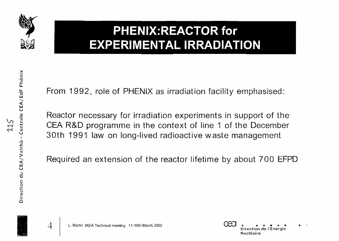
PHENIX:REACTOR forEXPERIMENTAL IRRADIATION
X
'E
u.T3UU
UUuJ3J
ro
0)ui
<oJC
15
UJu
Co•MU0)1_
Q
From 1992, role of PHENIX 3S irradiation facility emphasised:
Reactor necessary for irradiation experiments in support of theCEA R&D programme in the context of line 1 of the December30th 1991 law on long-lived radioactive waste management
Required an extension of the reactor lifetime by about 700 EFPD
4 L. Martin IAEA Technical meeting 11-15th March 2002 G9D .Direction de I'EnergieNucleaire
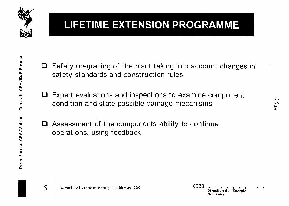
LIFETIME EXTENSION PROGRAMME
X'£
ULT3LU
UJu
ro1_
-MC0)u
<oJCu
15
UJu3
T3Co
Safety up-grading of the plant taking into account changes insafety standards and construction rules
Expert evaluations and inspections to examine componentcondition and state possible damage mecanisms
Assessment of the components ability to continueoperations, using feedback
I5 L. Martin IAEA Technical meeting 11-15th March 2002 ceaDirection de I'EnergieNucleaire
ORGANIZATION forLIFETIME EXTENSION (1/2)
X
'E-cysia.u.XJLU
I *JT- ro
LUUOJro
c01u
<oJZu
"rc
LUU
3TJCo4JUOJl_
5
A specific organization was set up:
A "lifetime extension" project, responsible for the theoreticalresearch and experiments that evaluates component conditionand component capacity to continue operating. This project alsodefines the preventive and curative maintenance actions and ifnecessary proposes operating improvements. This project is runby experts from CEA, EOF and Framatome-ANP
An on-site "plant shut-down" project, responsible for co-ordination, planning of the works and logistics for contractors
6 L. Martin IAEA Technical meeting 11-15th March 2002 G9D .Direction de I'EnergieNucleaire
ORGANIZATION forLIFETIME EXTENSION (2/2)
_x'£-<u.c0.
lit
UJU
re
c<Uui
<o
re
UJU
Co
'43U
I
A "renovation project" responsible for defining improvement andfollow-through of works. An independent group of earthquakeexperts, outside of the project team, was formed to validate theearthquake re-evaluation of the buildings. CEA Nuclear EnergyDirection, assisted by EOF is the Contracting Authority for this work,working with an industrial organization made up of the NovatomeDirection of Framatome-ANP as Prime Contractor and manufacturers
Q Specific projects responsible for defining and performing the reactorblock inspections
Q A "ten-yearly statutory maintenance" project responsible for the3rd ten-yearly inspection of all the elements subject to regulations
7 L. Martin IAEA Technical meeting 11-15th March 2002Direction de I'EnergieNucleaire
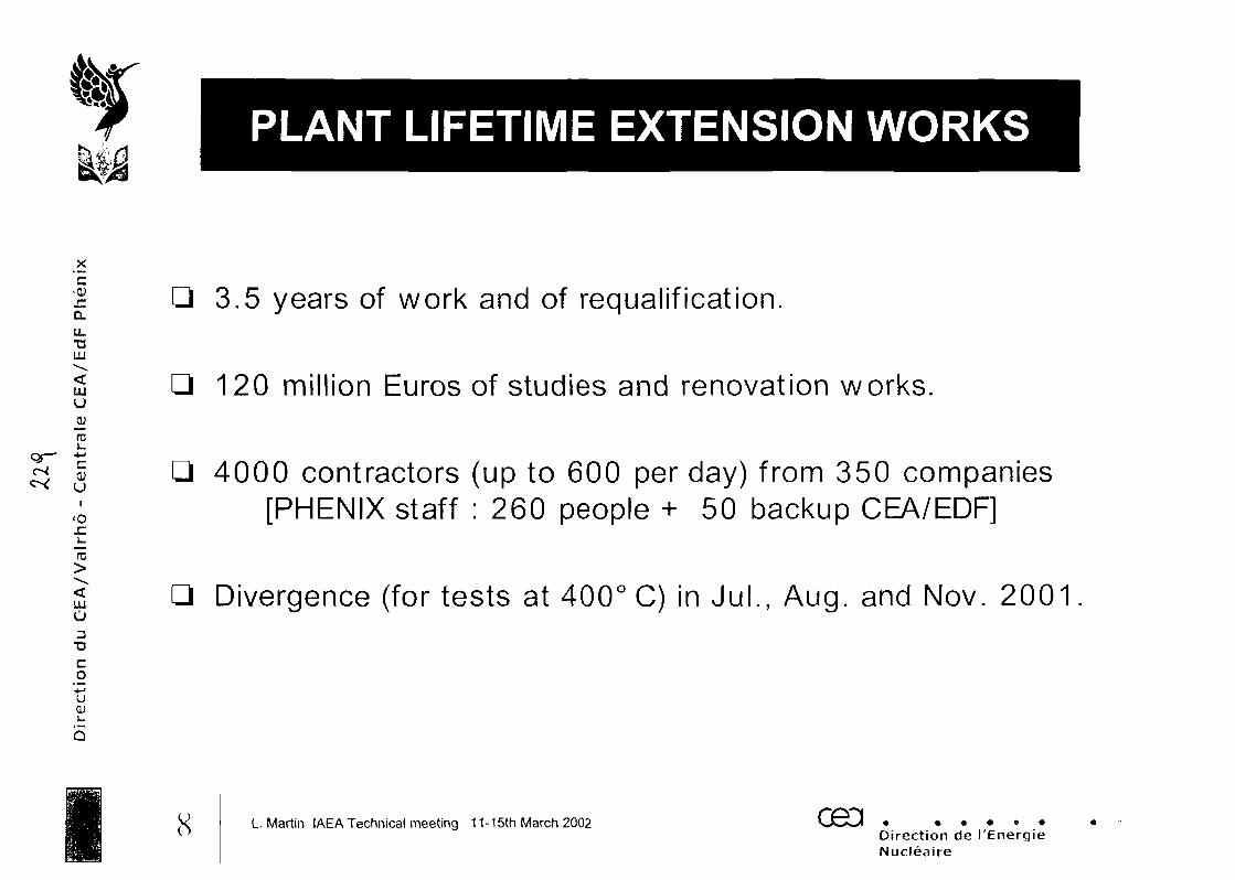
PLANT LIFETIME EXTENSION WORKS
c-0)
u.TJUU
LJUU
—ro*5
a<oJCL.
UJO
CO
'•MUOJ
3.5 years of work and of requalification.
120 million Euros of studies and renovation works.
4000 contractors (up to 600 per day) from 350 companies[PHENIX staff : 260 people + 50 backup CEA/EDF]
Q Divergence (for tests at 400° C) in JuL, Aug. and Nov. 2001
8 L. Martin IAEA Technical meeting 11-15th March 2002 GEODirection de I'EnergieNucleaire
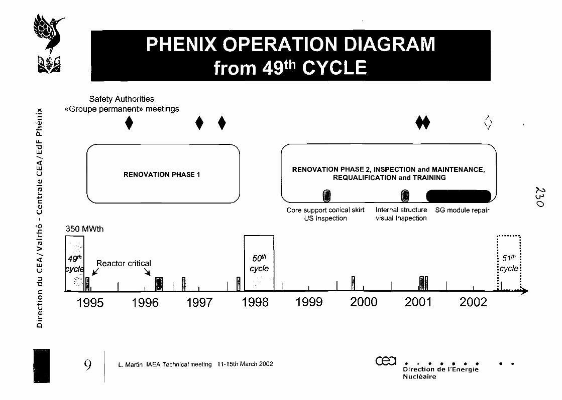
X
'EJCa.u_T3UJ
UJU
Vro
cOJuI
<ojz"TO
UJu3
"OCo
PHENIX OPERATION DIAGRAMfrom 49th CYCLE
Safety Authorities«Groupe permanent)) meetings
RENOVATION PHASE 1RENOVATION PHASE 2, INSPECTION and MAINTENANCE,
REQUALIFICATION and TRAINING
Core support conical skirt Internal structure SG module repairUS Inspection visual Inspection
350 MWth
O
49*:yc/e
Reactor critical
B. i , 1 i 1 . i 1cycle
51th
cycle
1995 1996 1997 1998 1999 2000 2001 2002
I9 L. Martin IAEA Technical meeting 11-15th March 2002 ceaDirection de I'EnergieNucleaire
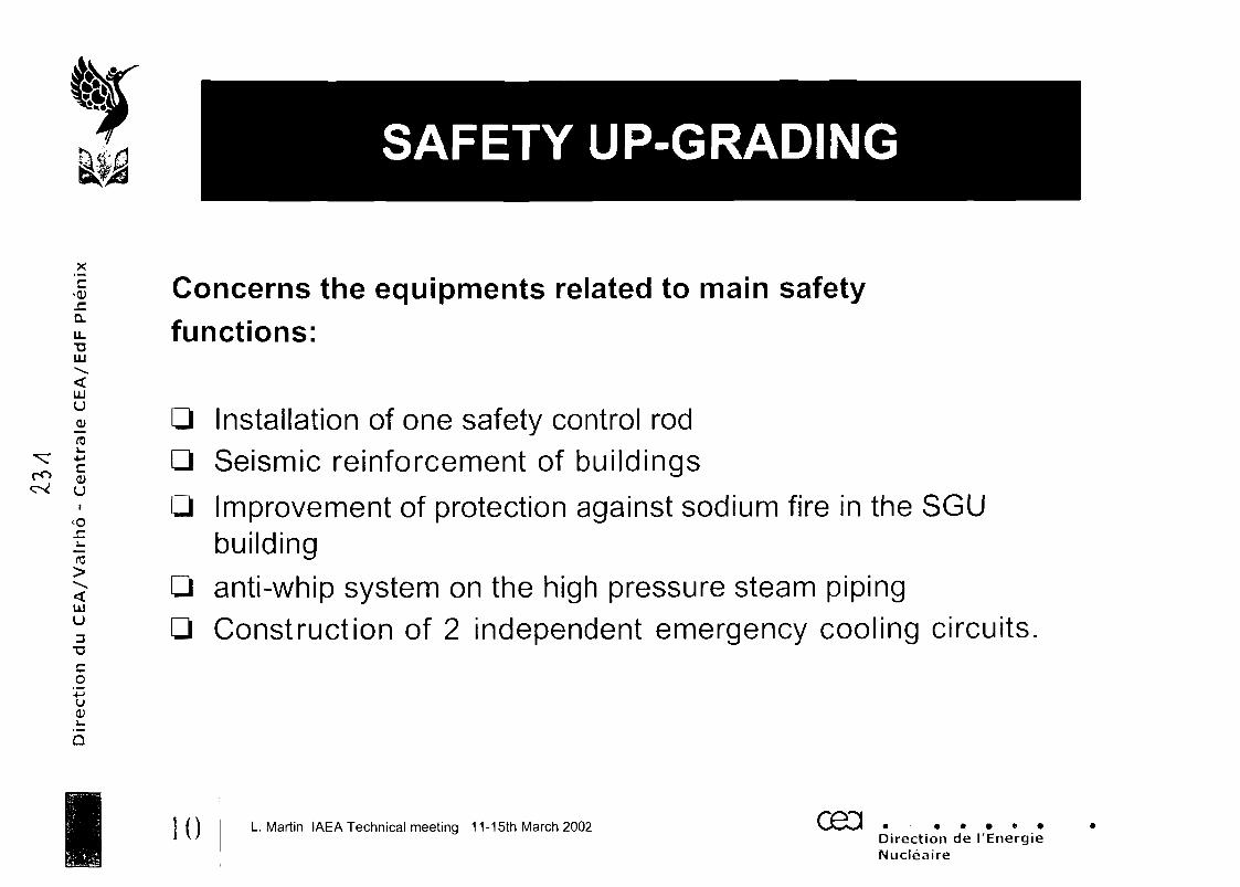
SAFETY UP-GRADING
ex!
X
'E
U.TJLU
LUU
ro4-Jc0)u
<or-!_
"ro
UJu3
T3
Co
4-JUOJ1_
5
Concerns the equipments related to main safetyfunctions:
Installation of one safety control rodSeismic reinforcement of buildings
Improvement of protection against sodium fire in the SGUbuildinganti-whip system on the high pressure steam pipingConstruction of 2 independent emergency cooling circuits,
0 L Martin IAEA Technical meeting 11-15th March 2002 CBd .Direction de I'EnergieNucleaire
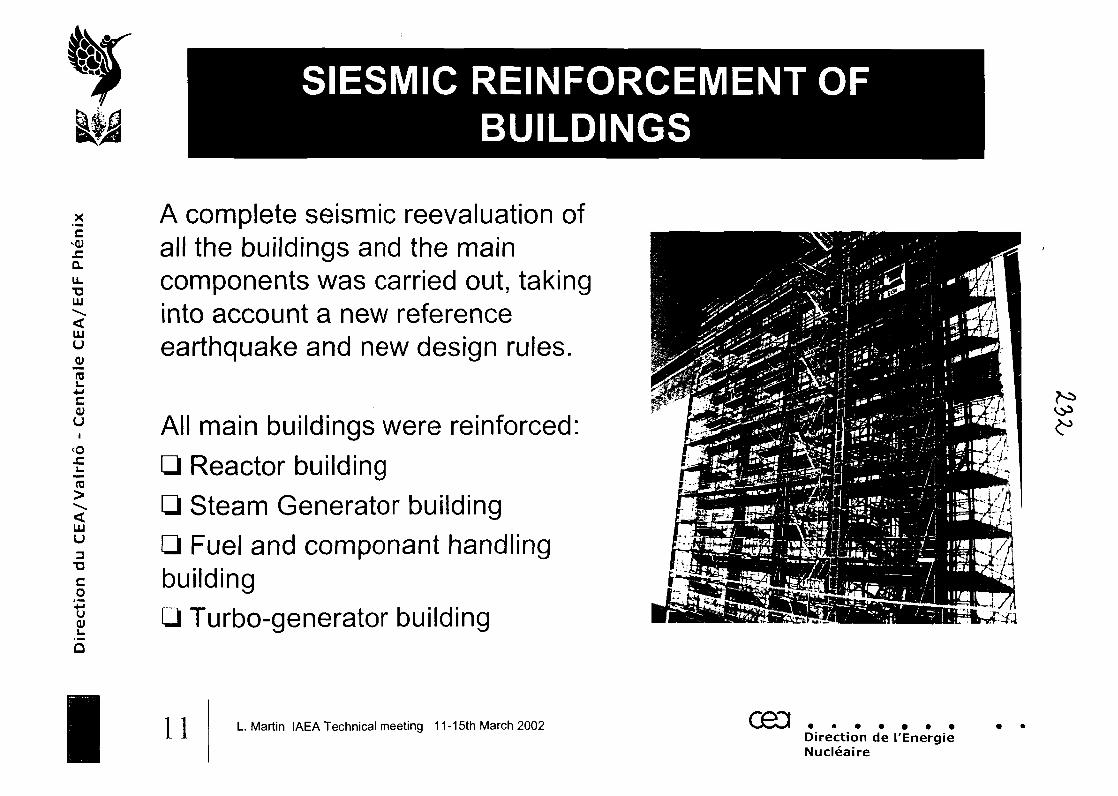
£'E
LLTJUJ
UJuJLJro+Jc0)(J
<o
U
3TJCo
"•Mu(U
I
SIESMIC REINFORCEMENT OFBUILDINGS
A complete seismic reevaluation ofall the buildings and the maincomponents was carried out, takinginto account a new referenceearthquake and new design rules.
All main buildings were reinforced:Reactor buildingSteam Generator building
Q Fuel and componant handlingbuilding
Turbo-generator building
11 L. Martin IAEA Technical meeting 11-15th March 2002 CH3Direction de I'EnergieNucleaire
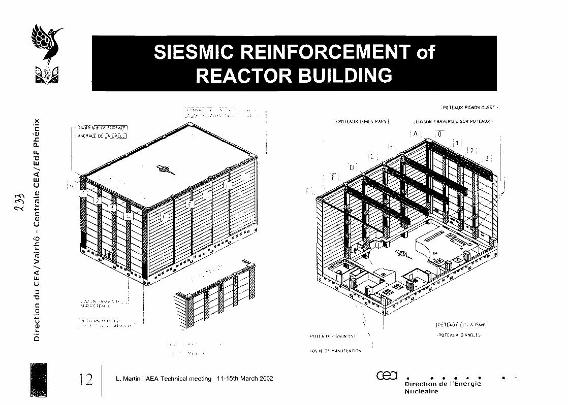
SIESMIC REINFORCEMENT ofREACTOR BUILDING
C'01
u.T3LU
aiu
cQJu
<0s:
UJu
c.ot5(U
5
I—(UAui'i?jVL-QS_5=i'B'lA*f I
•"»(ftAt-C DC jiAJQ AL_LL~)
• _pgi;EAUX LO«<GS
•:i lOU.'M' r-i M I ' . r - - ,• i • '<•• ' i r , i ,:i-i\~ .M:%
12 L Martin IAEA Technical meeting 11-15th March 2002
P U ' I E A J X I'lbSOH (M
POSH G> M/Njr tMIKJN
iPOTUUX PG«ON QUEST
i LIAISON r'HAVERSE'S SUR POTEAUX i
A i
( PC t [ AUX iV'. jS PAMS
• P O T E A U ^ D'ASG.ES ,
093 . .Direction de I'EnergieNucleaire
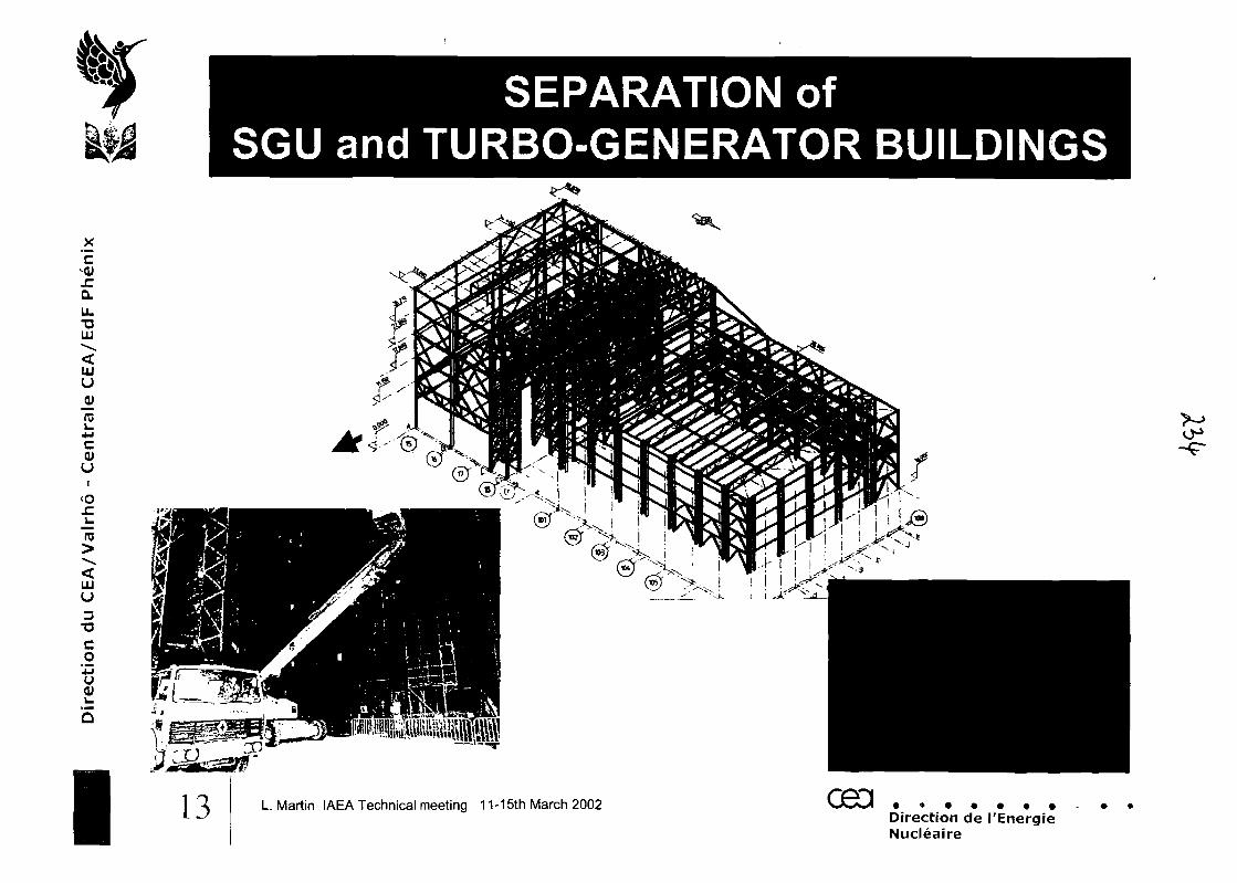
x'E^<uJCQ.
UL•aLU
LUU
(0i_4-1ca)u
i<oz:
u3
T5Co
I
SEPARATION ofSOU and TURBO-GENERATOR BUILDINGS
13
0°
L. Martin IAEA Technical meeting 11-15th March 2002 CH3Direction de I'EnergieNucleaire
IMPROVEMENT of PROTECTION AGAINSTSODIUM FIRE in the SGU BUILDING
£1QLLi.T3LU
LUU
TO1_
OJu
<ol-ro
LLJU
3T3Co
'+->uuQ
separation between sodium and steam circuits
thermal insulation of the building structural steelwork
Improvement of collection of leaking sodium
Modification of the auxiliary sodium circuit to limit the risk ofsodium leak
Reinforcement of SGU casing
14 L. Martin IAEA Technical meeting 11-15th March 2002 CH3 .Direction de I'EnergieNucleaire
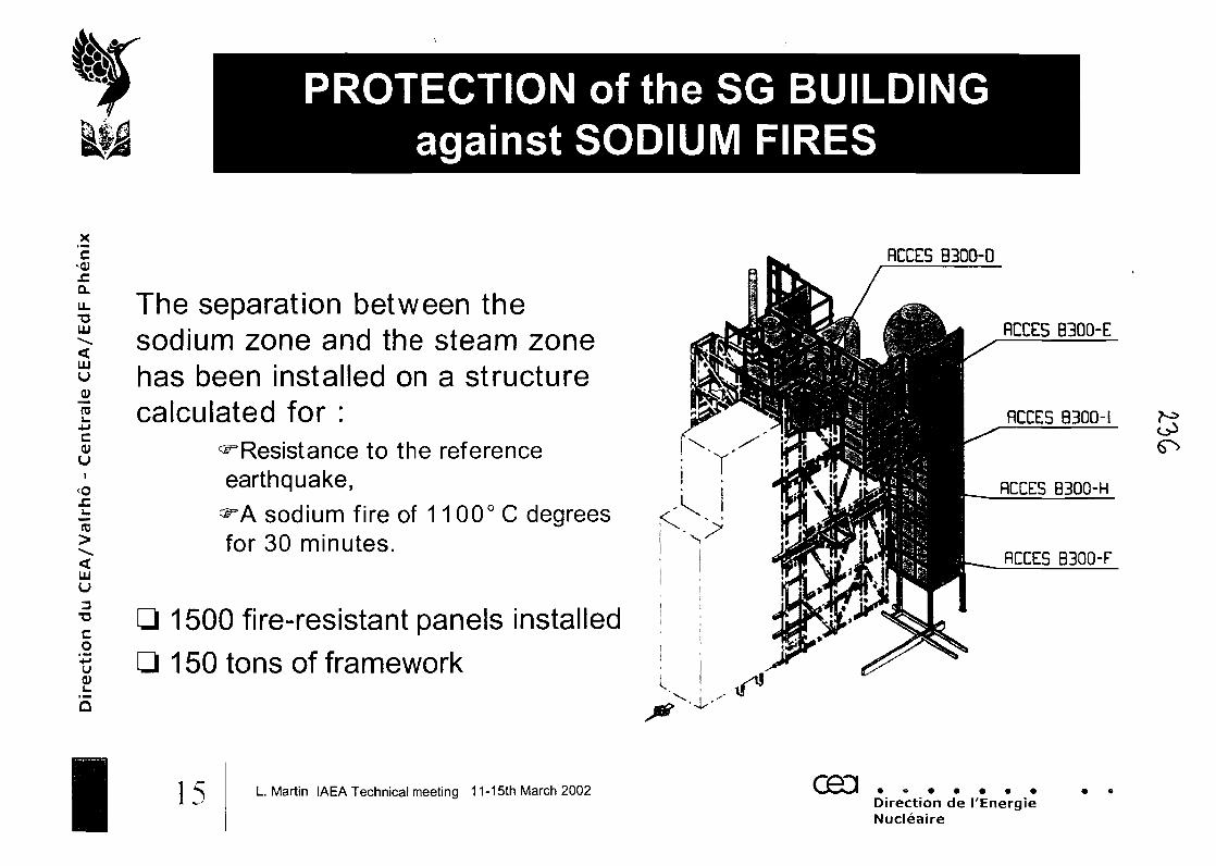
PROTECTION of the SG BUILDINGagainst SODIUM FIRES
_x'EsiO.U.
UJ
LUU
ro•Mccuu
<oJCu
"ro
LUU3•CCO'•MU(U
RCCE5 B300-0
I
The separation between thesodium zone and the steam zonehas been installed on a structurecalculated for :
^Resistance to the referenceearthquake,^A sodium fire of 1 1 00° C degreesfor 30 minutes.
1500 fire-resistant panels installed1 50 tons of framework
15 L. Martin IAEA Technical meeting 11-15th March 2002 oeaDirection de I'EnergieNucleaire
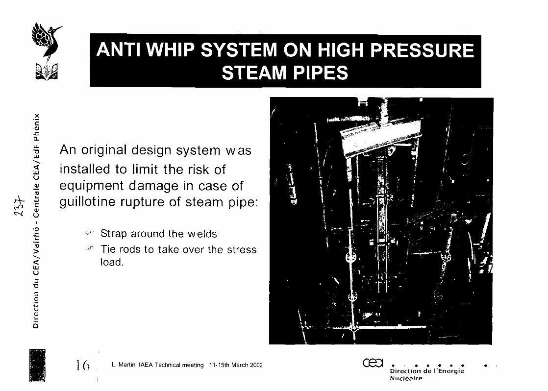
A-
x'E<oj-CQ.U.TJUJ
UJU
0)ui
<o
ro
UJU3
T3
Co•MUty
ANTI WHIP SYSTEM ON HIGH PRESSURESTEAM PIPES
An original design system wasinstalled to limit the risk ofequipment damage in case ofguillotine rupture of steam pipe:
^ Strap around the weldscfcr Tie rods to take over the stress
load.
16 L. Martin IAEA Technical meeting 11-15th March 2002 CB3 .Direction de I'EnergieNucleaire
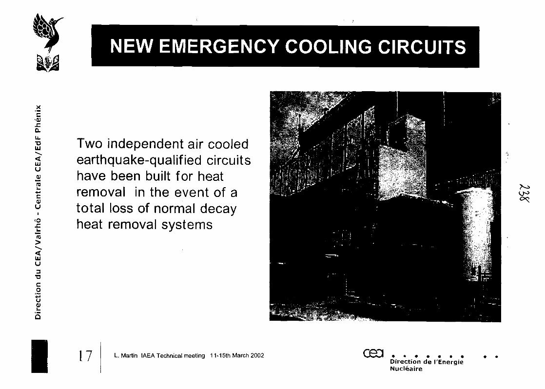
NEW EMERGENCY COOLING CIRCUITS
X
'E
TJHi
tuu
re4-1C<Uu
<oJC
15
uU3"0
co+Ju
I
Two independent air cooledearthquake-qualified circuitshave been built for heatremoval in the event of atotal loss of normal decayheat removal systems
17 L. Martin IAEA Technical meeting 11-15th March 2002 CB3Direction de I'EnergieNucleaire
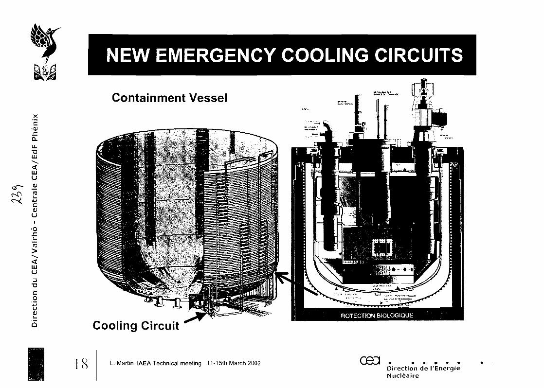
Q.U_T3UJ
uuu
0)u
<ox:i_75
UJu3TJCo
'•Mu
Q
NEW EMERGENCY COOLING CIRCUITS
Containment Vessel
Cooling Circuit
18 L. Martin IAEA Technical meeting 11-15th March 2002 CED .Direction de I'EnergieNucleaire
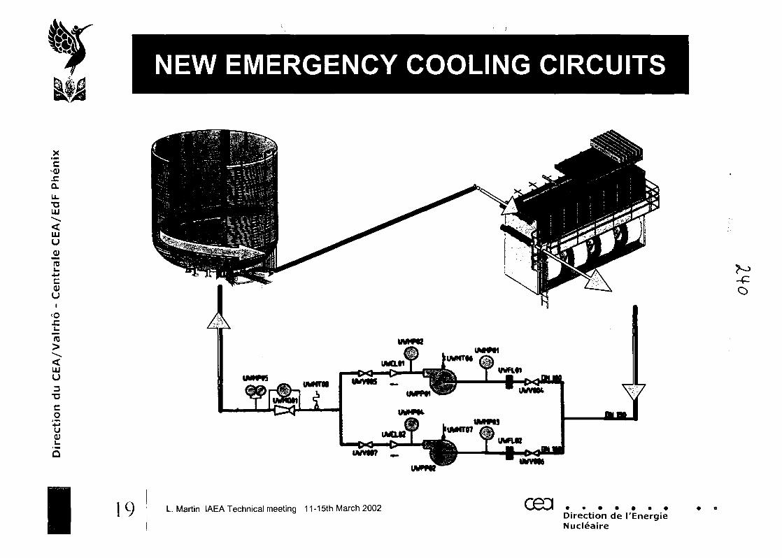
NEW EMERGENCY COOLING CIRCUITS
c-VJC0.u_•a111
LUU
ra-Mc
UI
<o
15
LUU3
T3Co*Ju(U
Q
i
O
19 L. Martin IAEA Technical meeting 11-15th March 2002 ceaDirection de I'EnergieNucleaire
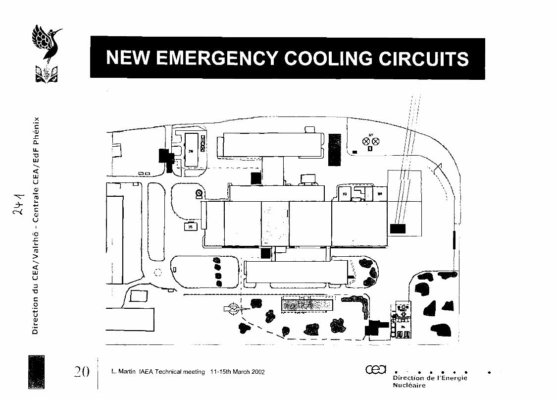
NEW EMERGENCY COOLING CIRCUITS
X
'EJCo.u.•auu
uuu
ro
Ut
JC
To
aiu3
T3Co
Q
20 L Martin IAEA Technical meeting 11-15th March 2002 CH3 .Direction de I'EnergieNucleaire
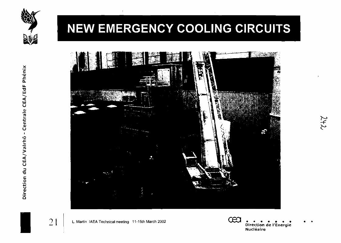
x'Es(U
JCQ.
ULTJLU
UJuQ)mi_4-1c<Uui
<o
UJU
3TJCo'•MUtu
I
NEW EMERGENCY COOLING CIRCUITS
L.Martin IAEA Technical meeting 11-15th March 2002 ceaDirection de I'EnergieNucleaire
EVALUATION of the CONDITIONof the COMPONENTS (1/2)
X
"EJCQ.
U.X3LU
UJU
jjjroL.
i
<o
"nj
LUU
co4->uOJ
Based on a dual approach:
Method centered on the main components: reactor block,pumps, IHX's, secondary loop, SGU
initial review design, evaluation of the damage resultingfrom mechanical and thermal loads, past and future, as wellas from the environment and manufacturing methods
A transverse method by damage mecanism such asmechanical fatigue from small number and large number ofcycles, irradiation, environment effects and the thermal agingof base and weld metals
22 L. Martin IAEA Technical meeting 11-15th March 2002 093Direction de I'EnergieNucleaire
EVALUATION of the CONDITIONof the COMPONENTS (2/2)
X
'E.cQ.u_TJUJ
UJu
(U1_4Jc<UuI
<o.cu75
UJu3
T3Co+Ju
The properties of the base materials and of the welded joints weretested in aged condition in terms of tension, cyclic behaviour,fatigue and creep characteristics. These materials were comparedto materials in new condition in each field, in order to supportdimensioning data and potential propagation of defects analyses
Following this expert evaluation campaign, the defectiveequipments were repaired, replaced or left as is and justified by apropagation analysis for the defects, which backed up the non-destructive testing done on the siteIn particular, the components made of 321 steel (Z6 CNT 18-10)displayed defects of the relaxation cracking type
I23 L. Martin IAEA Technical meeting 11-15th March 2002 oaciDirection de 1'EnergieNucleaire
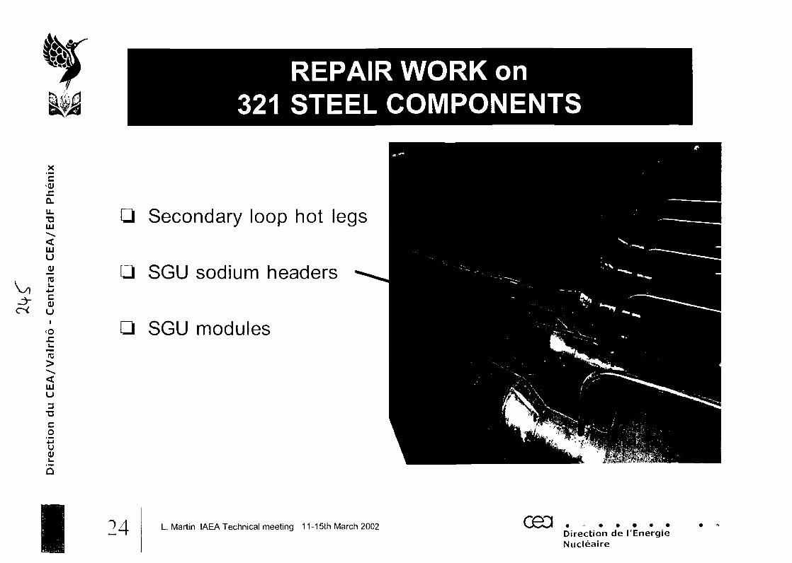
_x'E^<uJCa.LJLT3LU
LUuVro4-1cQJUi
<0
10
uuu3
~oco'u0)
REPAIR WORK on321 STEEL COMPONENTS
Secondary loop hot legs
SGU sodium headers
SGU modules
!4 L. Martin IAEA Technical meeting 11-15th March 2002 CBDDirection de I'EnergieNucleaire
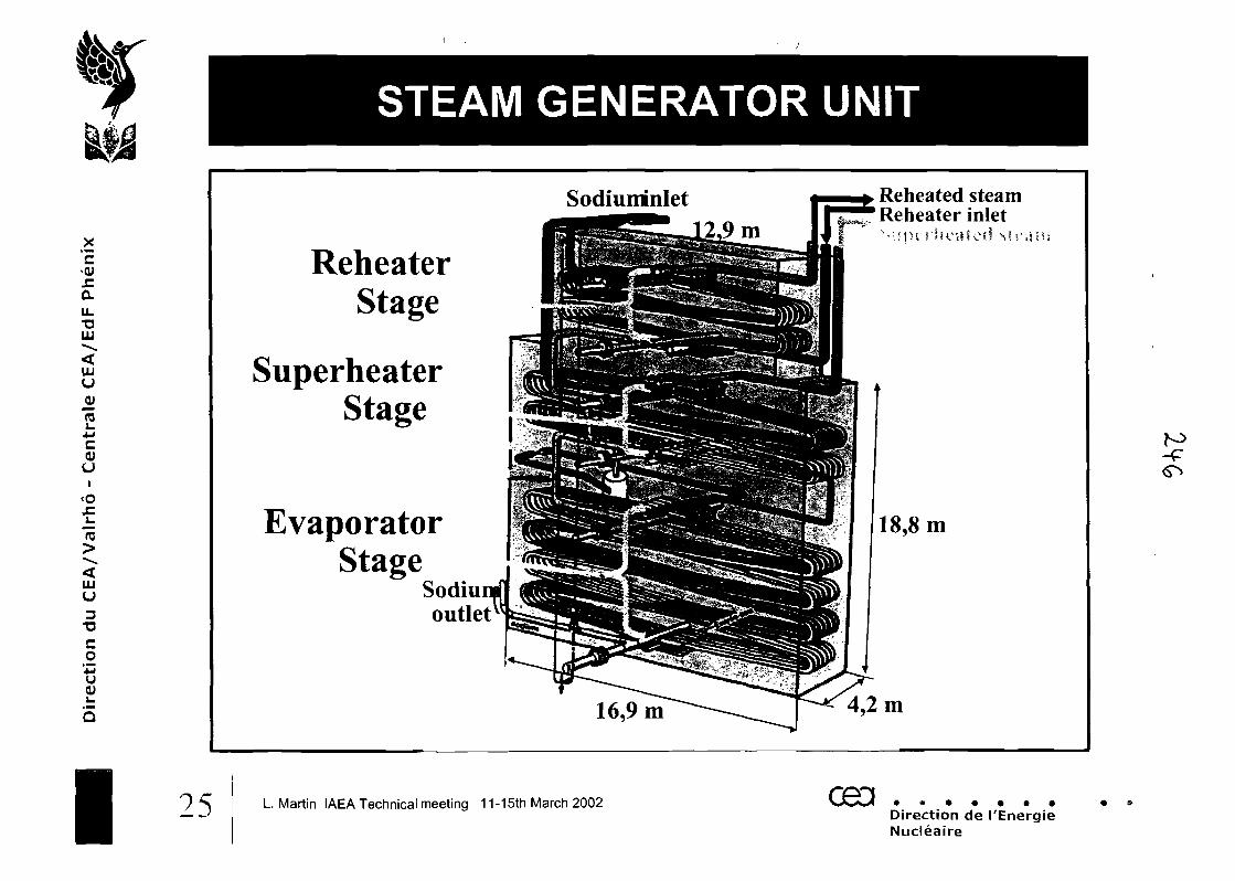
csQJ
.C
QL
U.•QUU"-•S.
<UJuJO)
rou4->C0)(JI
<0£i_
15
UJu
Co
'JMU0)
I
STEAM GENERATOR UNIT
ReheaterStage
SuperheaterStage
EvaporatorStage
Sodiuoutlet
Sodiummlet
16,9m
Reheated steamReheater inlet
18,8m
4,2m
25 L. Martin IAEA Technical meeting 11-15th March 2002 oeaDirection de I'EnergieNucleaire
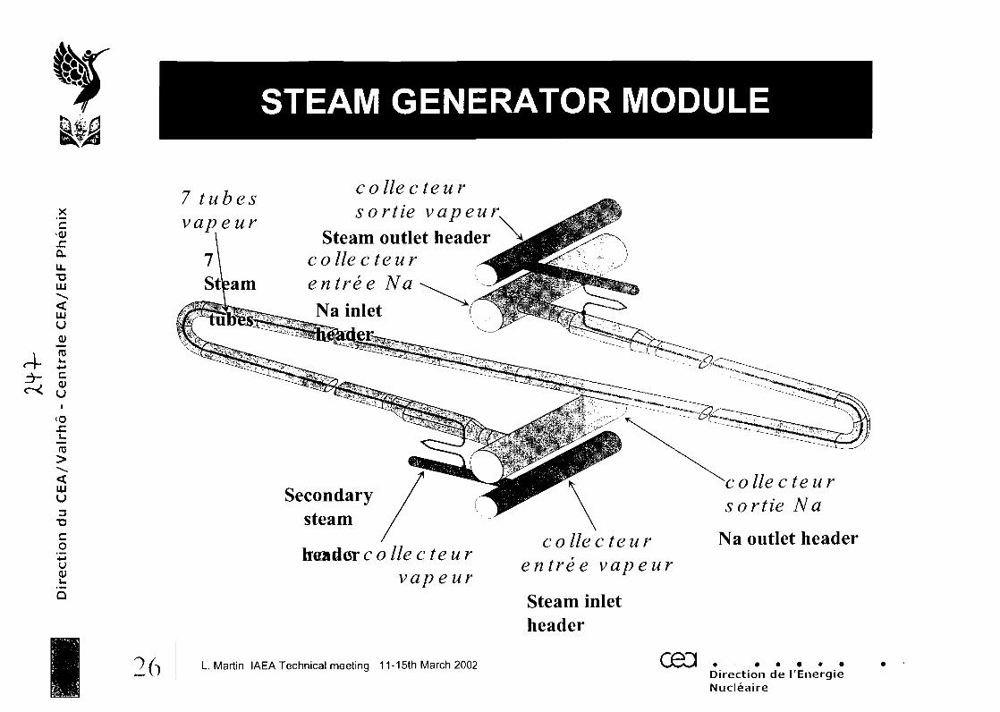
STEAM GENERATOR MODULE
X'£x:a.u.•aLU
uuu
i RJ4- £
cOJu
<oJZ
LUu3
T3
CO
4->UOJL.
5
7 tubesvapeur
26
co lie c teursortie vapeur,
Steam outlet headerco lie c teurentree NaNa inlet
Secondarysteam
header c o lie c teurvap e ur
c o lie c teuren tre e vapeur
Steam inletheader
c o lie c teursortie Na
Na outlet header
L Martin IAEA Technical meeting 11-15th March 2002Direction de I'EnergieNucleaire
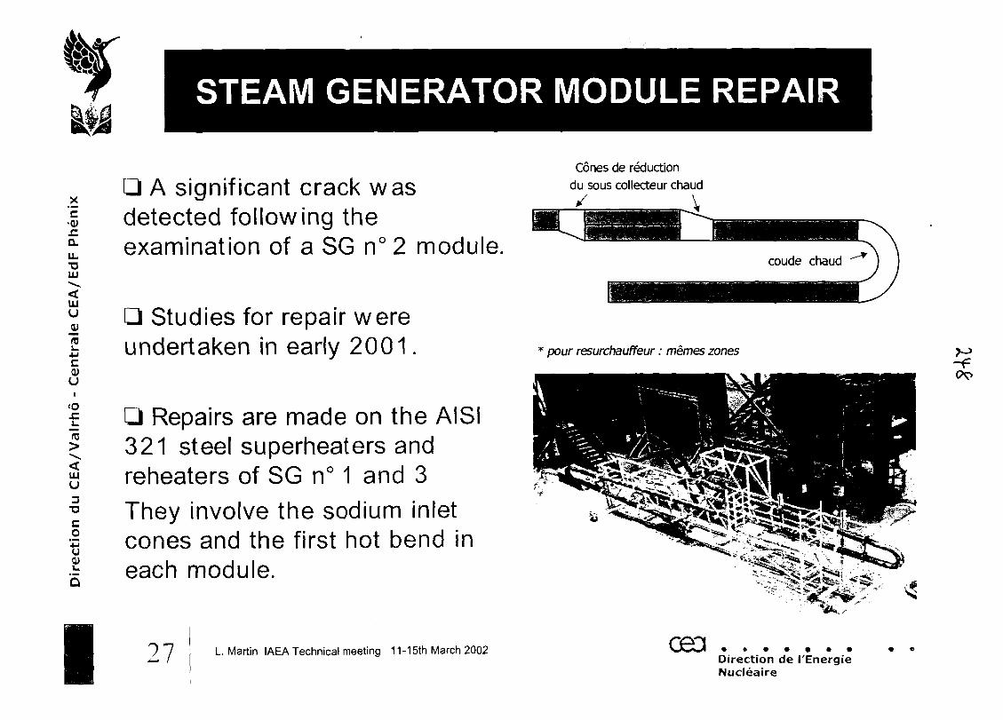
x'£
U.T311)
HIu
cOJu
<oJZ1_
15
LJJU
Co
'43u
I
STEAM GENERATOR MODULE REPAIR
A significant crack wasdetected following theexamination of a SG n°2 module.
Studies for repair wereundertaken in early 2001 .
Repairs are made on the AISI321 steel superheaters andreheaters of SG n° 1 and 3They involve the sodium inletcones and the first hot bend ineach module.
27 L. Martin IAEA Technical meeting 11-15th March 2002
Cones de reduction
du sous collecteur chaud
* pour resurchauffeur: memes zones
ceaDirection de I'EnergieNucleaire
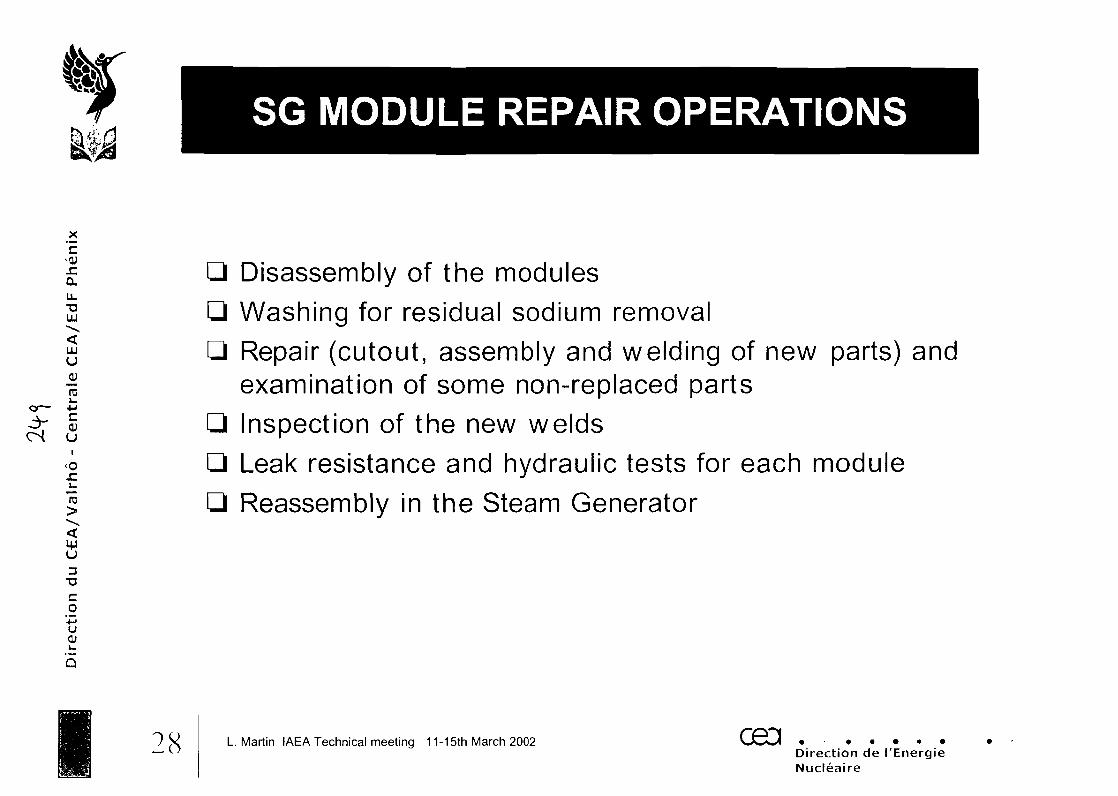
SG MODULE REPAIR OPERATIONS
cS
_x'EjrQ.U.TJuu
111u
ro
uI
<oJC
"ro
s3
TJCo4Jucu
Disassembly of the modulesWashing for residual sodium removal
Repair (cutout, assembly and welding of new parts) andexamination of some non-replaced parts
Inspection of the new welds
Leak resistance and hydraulic tests for each module
Reassembly in the Steam Generator
28 L. Martin IAEA Technical meeting 11-15th March 2002 CBDDirection de I'EnergieNucleaire
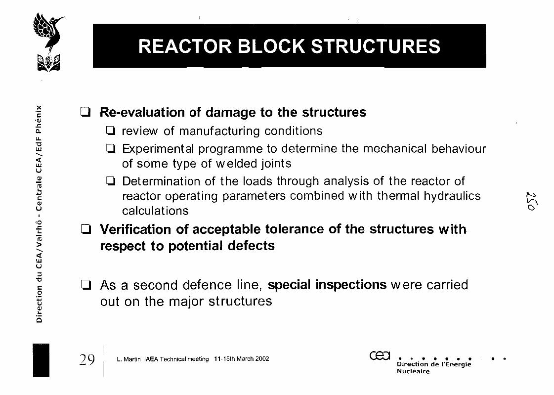
REACTOR BLOCK STRUCTURES
X
'E
u_TJuu
UJu
rau•Mc,0)uI
<ox:
LU(J
3•D
Co
'43U
J Re-evaluation of damage to the structuresQ review of manufacturing conditionsQ Experimental programme to determine the mechanical behaviour
of some type of welded jointsQ Determination of the loads through analysis of the reactor of
reactor operating parameters combined with thermal hydraulicscalculations
LJ Verification of acceptable tolerance of the structures withrespect to potential defects
As a second defence line, special inspections were carriedout on the major structures
L. Martin IAEA Technical meeting 11-15th March 2002 093Direction de I'EnergieNucleaire
MODELLING of THE REACTOR BLOCK
X
'EJZQ.
LLT3UU
UUu
OJU
<os:L.15
IDu
co'•MU0>
30 L. Martin IAEA Technical meeting 11-15th March 2002 cea .Direction de I'EnergieNucleaire
X'£JCD.U.TJUJ
ULIU
RJ
C<UuI
<o
UJu
Co"+Ju(U
I
INSPECTION of UPPER HANGERWELDINGS
^^Zr&^V&a&vJb,.*•»
L. Martin IAEA Technical meeting 11-15th March 2002 CH3 .Direction de I'EnergieNucleaire
X
'EJTau_"DUJ
UJu
U
CO
i<0JZi_
"ro
B3
T3Co'u
Q
CONICAL SKIRT US INSPECTION
Ultrasonic inspection of the coresupport conical skirt carried outunder sodium at 155 ° C
Sept-Oct 1999
32 L. Martin IAEA Technical meeting 11-15th March 2002 cea .Direction de I'EnergieNucleaire

X'Er.au.TJUJ
UJu
ra
c<UUI
<o
ro
UJU
co
OJ
Q
I
VISUAL INSPECTION OF INTERNALS
Visual inspection of theCore Cover Plug
and Internal
Structures
of the reactor
March-April
2001
BLOC REACTEiJR
L. Martin IAEA Technical meeting 11-15th March 2002 ceaDirection de I'EnergieNucleaire
TEN-YEAR STATUTORY MAINTENANCE
-QJ
JCQ.u_T3LU
UJU
0)
c0)UI
<ox:
U
T3C.24-1U(U
Turbo-generator overhaul
Ten-year maintenance of the major mechanical and electricalequipments for future availability in reactor operation :^ 470 valves dismantled and overhauled^ 33 pump motors and bodies dismantled and refurbished
^ 150 pressure apparatus inspected and subjected to the statutoryhydraulic qualification tests
^ 40 electrical panels inspected and repaired.
L. Martin IAEA Technical meeting 11-15th March 2002 ceci .Direction de I'EnergieNucleaire
X'E^QJSICLu_•aUJ
UJuJUroi_4-1c<uu
<ox:_t-ro
UJu3T3Co
'•MU(U
Q
I
PREPARATION FOR RESTARTINGTHE PLANT
Preparation of the staff and the installation for restartingPHENIX after 3.5 years of shutdown and 10 years ofintermittent operationFuture operation of the PHENIX reactor without incidents ormajor outage:^Guarantee the state of the installation.-=>Ensure that staff is competent and adequately trained.
Methodology adopted :^setting up of specific organization for requalification tests.^Improving staff competence and safety culture.
35 L. Martin IAEA Technical meeting 11-15th March 2002 CH3Direction de I'EnergieNucleaire
CONCLUSIONS
A-LP
X
'EJCD.
UJ
UJu
roL.4-1c0)u
<ox:
UJu3
T3
CoJ-Ju0)J_
Q
Future operation of the plant:Planned for 6 cycles of 120 EFPD, or 5.5 years of irradiation,starting at the end of 2002, to conduct experiments in thescope of CEA research into nuclear waste
^Research on the behavior of the constituent materials (includingthe matrices and moderators)^Irradiation of actinide-based compounds (primarily americium)
^Irradiation of targets containing long-lived fission products
significant experience gained from the lifetime extensionprogramme:
methodology, materials, components, inspection techniques...
~»/JO L Martin IAEA Technical meeting 11-15th March 2002 CBD .
Direction de I'EnergieNucleaire
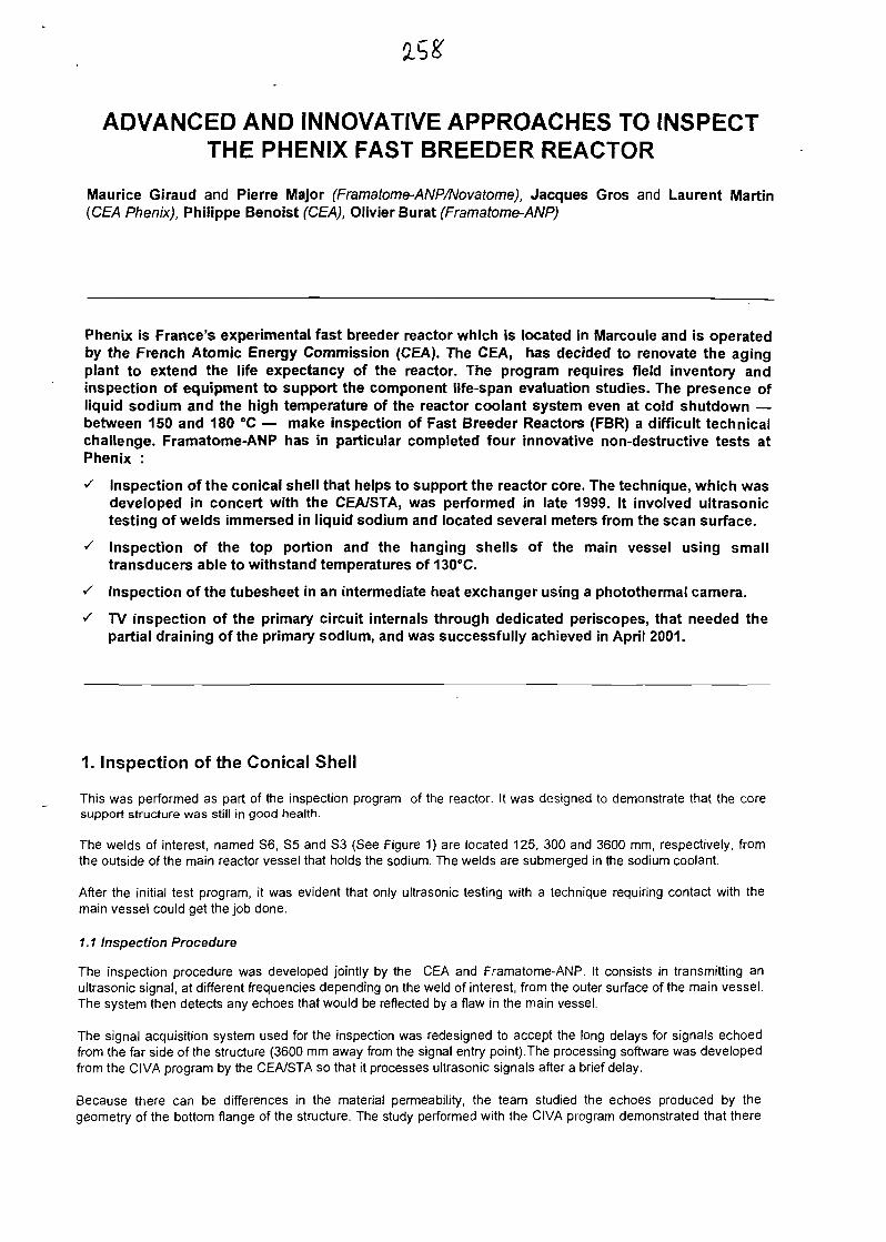
ADVANCED AND INNOVATIVE APPROACHES TO INSPECTTHE PHENIX FAST BREEDER REACTOR
Maurice Giraud and Pierre Major (Framatome-ANP/Novatome), Jacques Gros and Laurent Martin(CEA Phenix), Philippe Benoist (CEA), Olivier Burat (Framatome-ANP)
Phenix is France's experimental fast breeder reactor which is located in Marcoule and is operatedby the French Atomic Energy Commission (CEA). The CEA, has decided to renovate the agingplant to extend the life expectancy of the reactor. The program requires field inventory andinspection of equipment to support the component life-span evaluation studies. The presence ofliquid sodium and the high temperature of the reactor coolant system even at cold shutdown —between 150 and 180 °C — make inspection of Fast Breeder Reactors (FBR) a difficult technicalchallenge. Framatome-ANP has in particular completed four innovative non-destructive tests atPhenix :
S Inspection of the conical shell that helps to support the reactor core. The technique, which wasdeveloped in concert with the CEA/STA, was performed in late 1999. It involved ultrasonictesting of welds immersed in liquid sodium and located several meters from the scan surface.
^ Inspection of the top portion and the hanging shells of the main vessel using smalltransducers able to withstand temperatures of 130°C.
s Inspection of the tubesheet in an intermediate heat exchanger using a photothermal camera.
^ TV inspection of the primary circuit internals through dedicated periscopes, that needed thepartial draining of the primary sodium, and was successfully achieved in April 2001.
1. Inspection of the Conical Shell
This was performed as part of the inspection program of the reactor. It was designed to demonstrate that the coresupport structure was still in good health.
The welds of interest, named S6, S5 and S3 (See Figure 1) are located 125, 300 and 3600 mm, respectively, fromthe outside of the main reactor vessel that holds the sodium. The welds are submerged in the sodium coolant.
After the initial test program, it was evident that only ultrasonic testing with a technique requiring contact with themain vessel could get the job done.
1.1 Inspection Procedure
The inspection procedure was developed jointly by the CEA and Framatome-ANP. It consists in transmitting anultrasonic signal, at different frequencies depending on the weld of interest, from the outer surface of the main vessel.The system then detects any echoes that would be reflected by a flaw in the main vessel.
The signal acquisition system used for the inspection was redesigned to accept the long delays for signals echoedfrom the far side of the structure (3600 mm away from the signal entry point).The processing software was developedfrom the CIVA program by the CEA/STA so that it processes ultrasonic signals after a brief delay.
Because there can be differences in the material permeability, the team studied the echoes produced by thegeometry of the bottom flange of the structure. The study performed with the CIVA program demonstrated that there
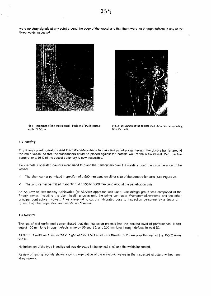
were no stray signals at any point around the edge of the vessel and that there were no through defects in any of thethree welds inspected.
Fig 1 - Inspection of the conical shell - Position of the inspectedwelds S3, S5,S6
Fig. 2 - Inspection of the conical shell - Short carrier operatingfrom the vault
1.2 Testing
The Phenix plant operator asked Framatome/Novatome to make five penetrations through the double barrier aroundthe main vessel so that the transducers could be placed against the outside wall of the main vessel. With the fivepenetrations, 98% of the vessel periphery is now accessible.
Two remotely operated carriers were used to place the transducers over the welds around the circumference of thevessel:
^ The short carrier permitted inspection of a 500-mm band on either side of the penetration axis (See Figure 2).
^ The long carrier permitted inspection of a 500 to 4600 mm band around the penetration axis.
An As Low as Reasonably Achievable (or ALARA) approach was used. The design group was composed of thePhenix owner, including the plant health physics unit, the prime contractor Framatome/Novatome and the otherprincipal contractors involved. They managed to cut the integrated dose to inspection personnel by a factor of 4(during both the preparation and inspection phases).
1.3 Results
The set of test performed demonstrated that the inspection process had the desired level of performance. It candetect 100 mm long through defects in welds S6 and S5, and 200 mm long through defects in weld S3.
All 97 m of weld were inspected in eight weeks. The transducers traveled 2.25 km over the wall of the 150°C mainvessel.
No indication of the type investigated was detected in the conical shell and the welds inspected.
Review of testing records shows a good propagation of the ultrasonic waves in the inspected structure without anystray signals.
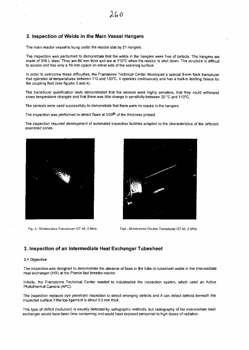
2. Inspection of Welds in the Main Vessel Hangers
The main reactor vessel is hung under the reactor slab by 21 hangers.
The inspection was performed to demonstrate that the welds in the hangers were free of defects. The hangers aremade of 316 L steel. They are 60 mm thick and are at 110°C when the reactor is shut down. The structure is difficultto access and has only a 10-mm space on either side of the scanning surface.
In order to overcome these difficulties, the Framatome Technical Center developed a special 8-mm thick transducerthat operates at temperatures between 110 and 130°C. It operates continuously and has a built-in feeding device forthe coupling fluid (see figures 3 and 4).
The transducer qualification tests demonstrated that the sensors were highly sensitive, that they could withstandsharp temperature changes and that there was little change in sensitivity between 20 °C and 110°C.
The sensors were used successfully to demonstrate that there were no cracks in the hangers.
The inspection was performed to detect flaws at 1/20*n of the thickness probed.
The inspection required development of automated inspection facilities adapted to the characteristics of the differentexamined zones.
Fig. 3 - Miniaturized Transducer OT 45, 2 MHz Fig4 - Miniaturized Double Transducer OT 45, 2 MHz
3. Inspection of an Intermediate Heat Exchanger Tubesheet
3.1 Objective
The inspection was designed to demonstrate the absence of flaws in the tube-to tubesheet welds in the intermediateheat exchanger (IHX) at the Phenix fast breeder reactor.
Initially, the Framatome Technical Center needed to industrialize the inspection system, which used an ActivePhotothermal Camera (ARC).
The inspection replaces dye penetrant inspection to detect emerging defects and it can detect defects beneath theinspected surface if the top ligament is about 0.5 mm thick.
This type of defect (inclusion) is usually detected by radiographic methods, but radiography of the intermediate heatexchanger would have been time consuming and would have exposed personnel to high doses of radiation.
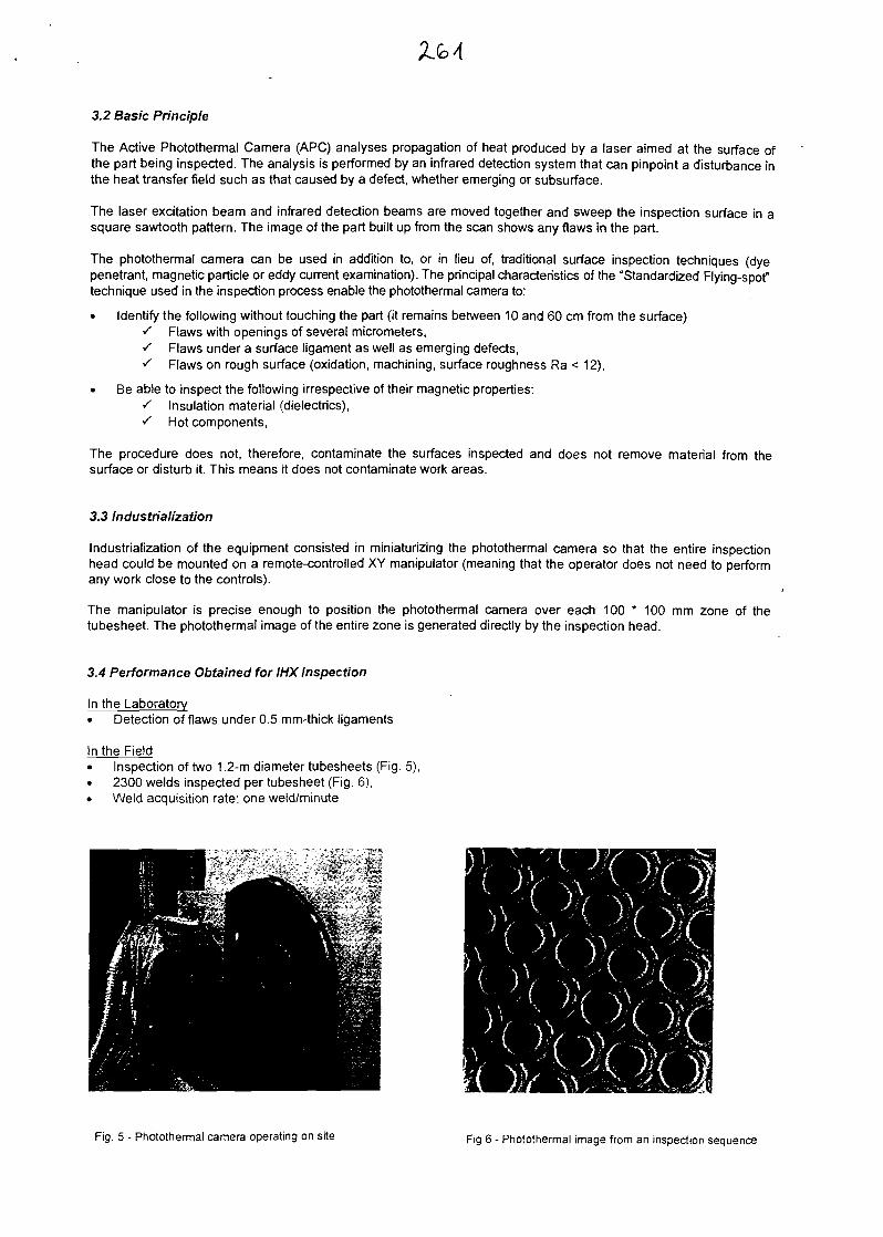
3.2 Basic Principle
The Active Photothermal Camera (ARC) analyses propagation of heat produced by a laser aimed at the surface ofthe part being inspected. The analysis is performed by an infrared detection system that can pinpoint a disturbance inthe heat transfer field such as that caused by a defect, whether emerging or subsurface.
The laser excitation beam and infrared detection beams are moved together and sweep the inspection surface in asquare sawtooth pattern. The image of the part built up from the scan shows any flaws in the part.
The photothermal camera can be used in addition to, or in lieu of, traditional surface inspection techniques (dyepenetrant, magnetic particle or eddy current examination). The principal characteristics of the "Standardized Flying-spot"technique used in the inspection process enable the photothermal camera to:
• Identify the following without touching the part (it remains between 10 and 60 cm from the surface)^ Flaws with openings of several micrometers,s Flaws under a surface ligament as well as emerging defects,s Flaws on rough surface (oxidation, machining, surface roughness Ra < 12),
• Be able to inspect the following irrespective of their magnetic properties:•/ Insulation material (dielectrics),s Hot components,
The procedure does not, therefore, contaminate the surfaces inspected and does not remove material from thesurface or disturb it. This means it does not contaminate work areas.
3.3 Industrialization
Industrialization of the equipment consisted in miniaturizing the photothermal camera so that the entire inspectionhead could be mounted on a remote-controlled XY manipulator (meaning that the operator does not need to performany work close to the controls).
The manipulator is precise enough to position the photothermal camera over each 100 * 100 mm zone of thetubesheet. The photothermal image of the entire zone is generated directly by the inspection head.
3.4 Performance Obtained for IHX Inspection
In the Laboratory• Detection of flaws under 0.5 mm-thick ligaments
In the Field• Inspection of two 1.2-m diameter tubesheets (Fig. 5),• 2300 welds inspected per tubesheet (Fig. 6),• Weld acquisition rate: one weld/minute
Fig. 5 - Photothermal camera operating on site Fig 6 - Photothermal image from an inspection sequence
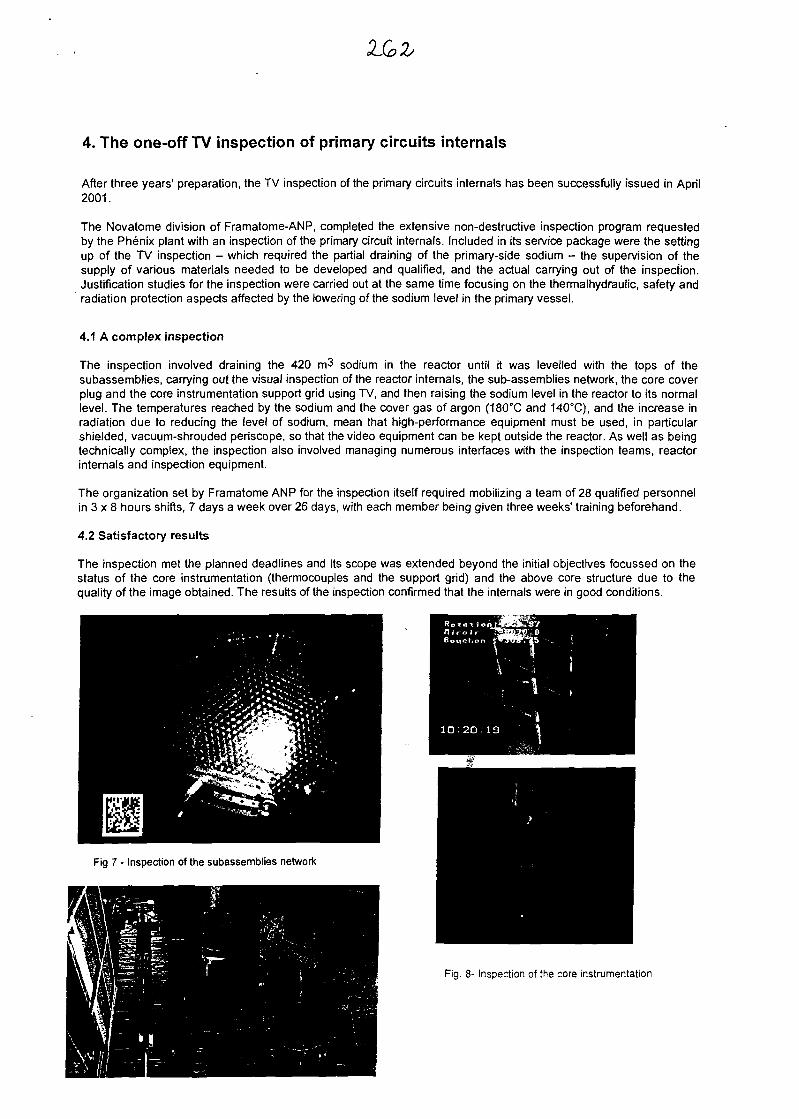
4. The one-off TV inspection of primary circuits internals
After three years' preparation, the TV inspection of the primary circuits internals has been successfully issued in April2001.
The Novatome division of Framatome-ANP, completed the extensive non-destructive inspection program requestedby the Phenix plant with an inspection of the primary circuit internals. Included in its service package were the settingup of the TV inspection - which required the partial draining of the primary-side sodium - the supervision of thesupply of various materials needed to be developed and qualified, and the actual carrying out of the inspection.Justification studies for the inspection were carried out at the same time focusing on the thermalhydraulic, safety andradiation protection aspects affected by the lowering of the sodium level in the primary vessel.
4.1 A complex inspection
The inspection involved draining the 420 m3 sodium in the reactor until it was levelled with the tops of thesubassemblies, carrying out the visual inspection of the reactor internals, the sub-assemblies network, the core coverplug and the core instrumentation support grid using TV, and then raising the sodium level in the reactor to its normallevel. The temperatures reached by the sodium and the cover gas of argon (180°C and 140°C), and the increase inradiation due to reducing the level of sodium, mean that high-performance equipment must be used, in particularshielded, vacuum-shrouded periscope, so that the video equipment can be kept outside the reactor. As well as beingtechnically complex, the inspection also involved managing numerous interfaces with the inspection teams, reactorinternals and inspection equipment.
The organization set by Framatome ANP for the inspection itself required mobilizing a team of 28 qualified personnelin 3 x 8 hours shifts, 7 days a week over 26 days, with each member being given three weeks' training beforehand.
4.2 Satisfactory results
The inspection met the planned deadlines and its scope was extended beyond the initial objectives focussed on thestatus of the core instrumentation (thermocouples and the support grid) and the above core structure due to thequality of the image obtained. The results of the inspection confirmed that the internals were in good conditions.
Fig 7 - Inspection of the subassemblies network
Fig. 8- Inspection of the core instrumentation

2-63
4. CONCLUSION
The objectives of the different inspection operations discussed here were achieved. The solutions involveddevelopment of innovative technical solutions to withstand the special operating conditions imposed by work in a FastBreeder Reactor, i.e. the presence of liquid sodium, the high temperatures of the components, even during shutdownand the stringent health physics limitations.
The processes demonstrated a high level of operability during the different inspections and the results obtainedattained the requisite levels of quality.
A major step has thus been taken, bringing the startup date for Phenix closer. Moreover, it leads to a great amount ofexperience in the field of In Service Inspection of Fast Breeder Reactors.
mm
Q9CI
ABOVE CORE
STRUCTURE
LOCATION
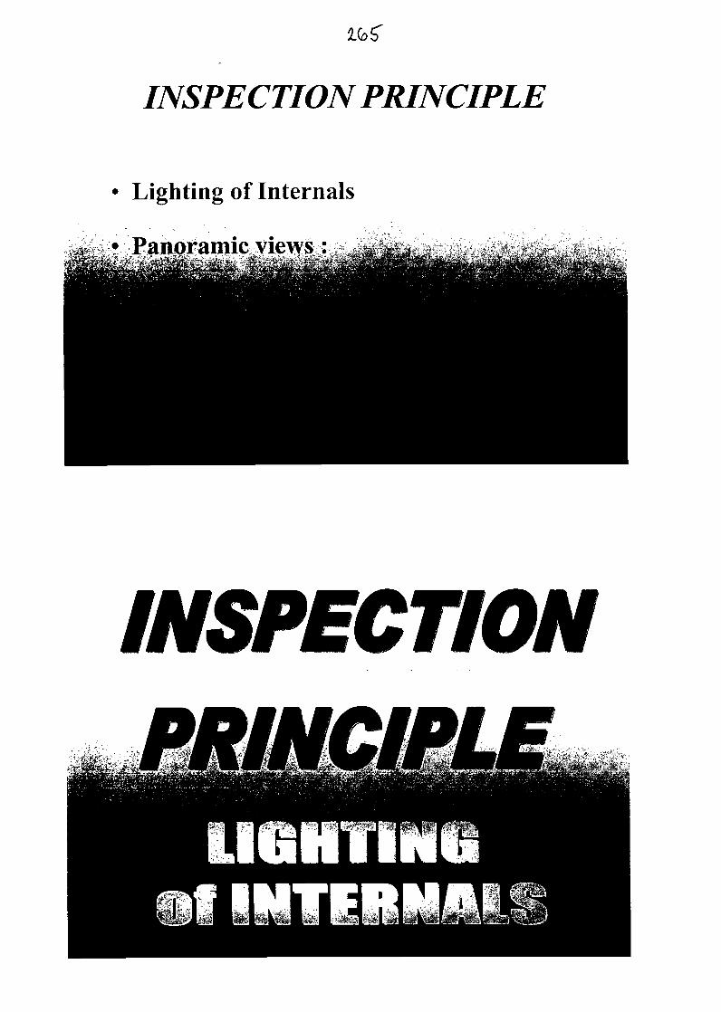
IfeS"
INSPECTION PRINCIPLE
Lighting of Internals
Panoramic/views:
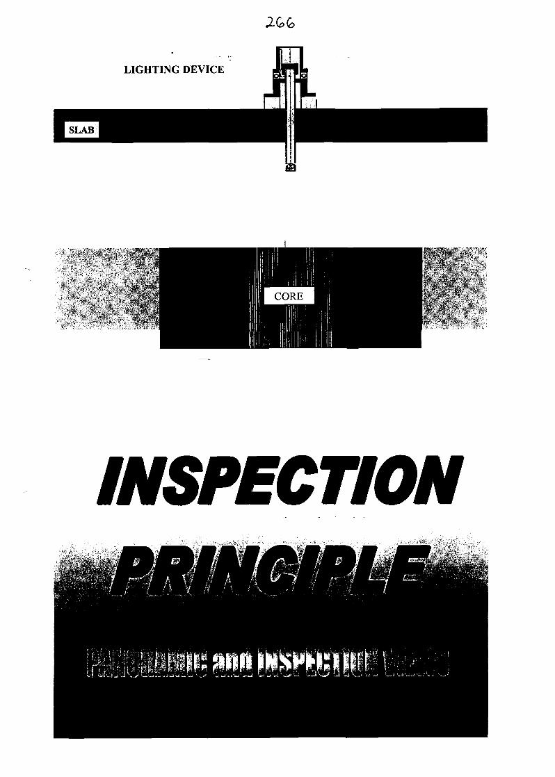
LIGHTING DEVICE
INSPECTION
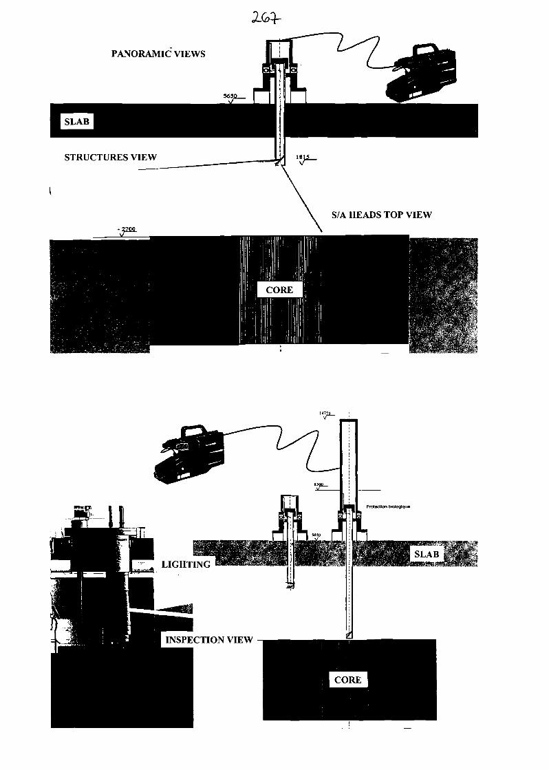
PANORAMIC VIEWS
STRUCTURES VIEW
S/A HEADS TOP VIEW
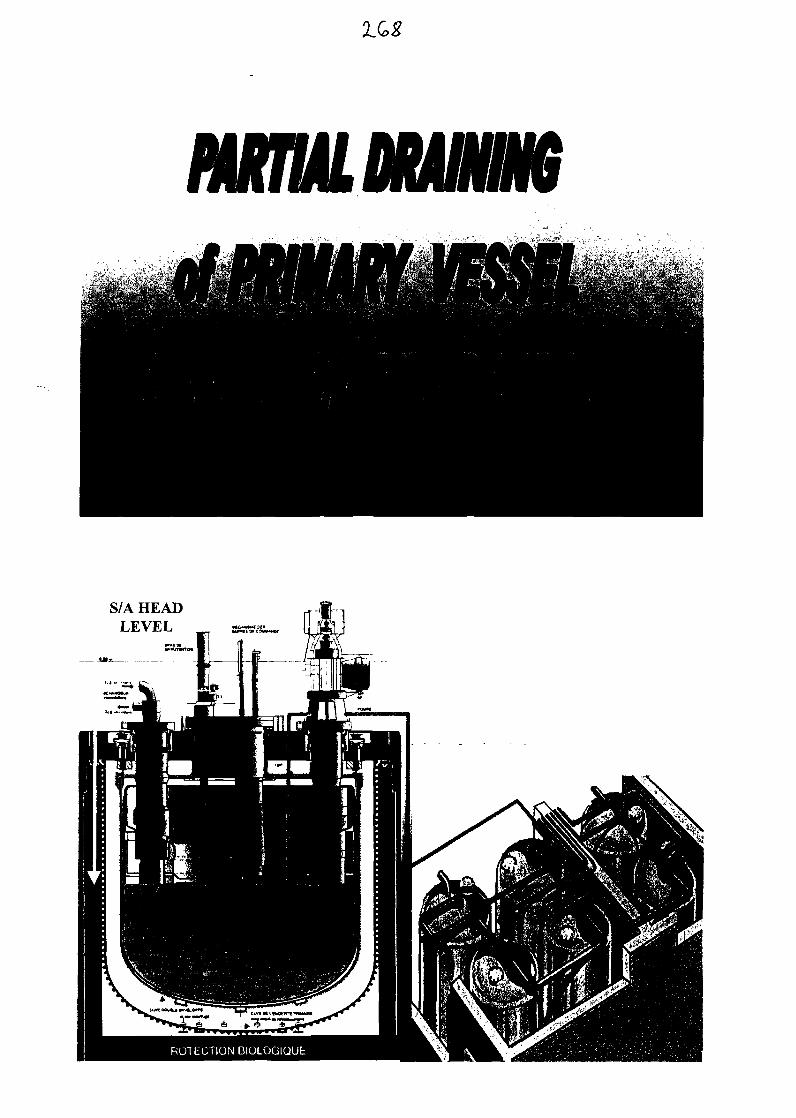
S/A HEADLEVEL
ll#«(JTWf«l
PARTIAL DRAININGOF VESSEL
Temperature : 180°C
Transfer of 42Q m3 of mi sodium toL^Kf ^ ** wS. I & I1*- A .j.** *. , it „
SODIUM DRAINING
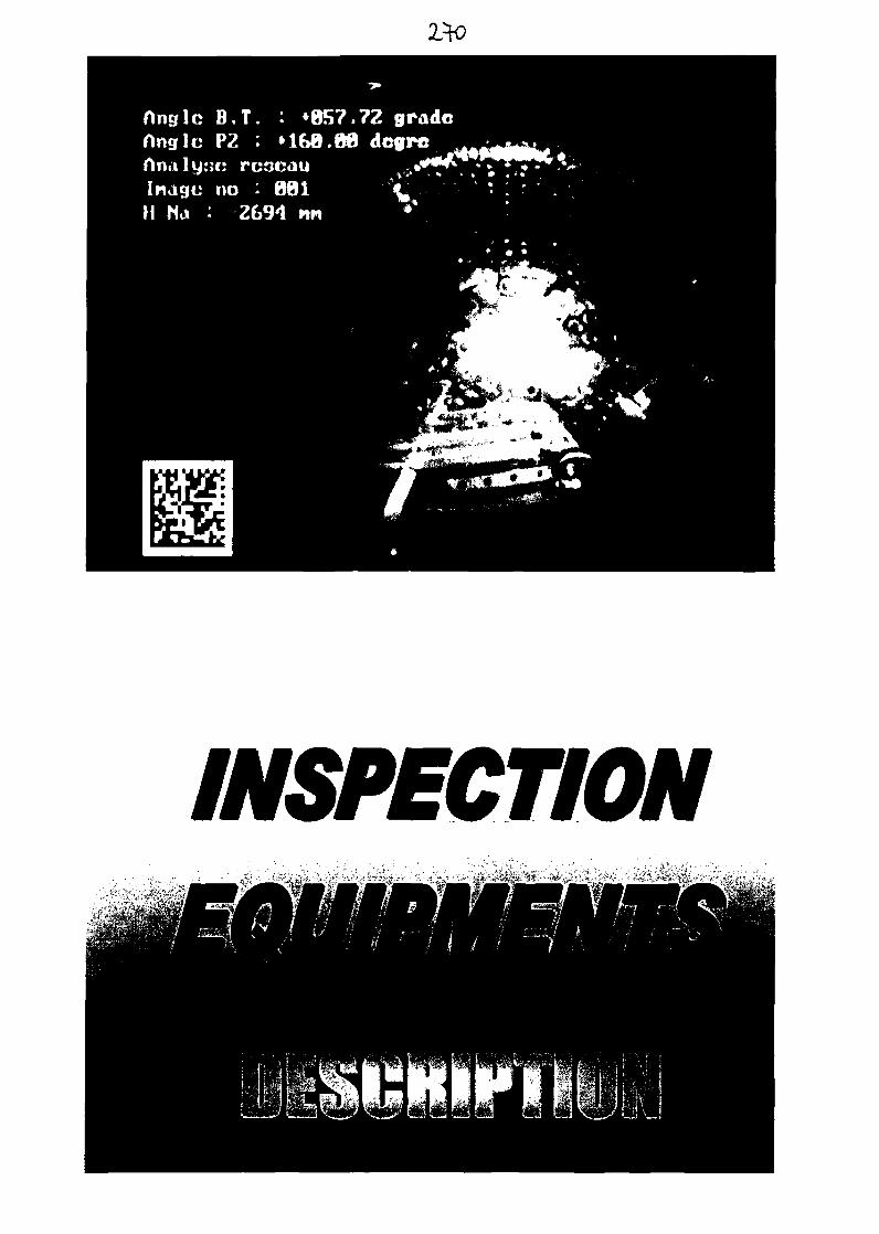
2*0
flnsfle B . T . : +BS7.72 gradennglc P2 : »1&0.00 dcgrc ,
Inagc no : BfllH Ha : 2S94 nn
INSPECTION
JilpC-. < ; . ;frl±jr '* ,i&- '-•;/>" i-.
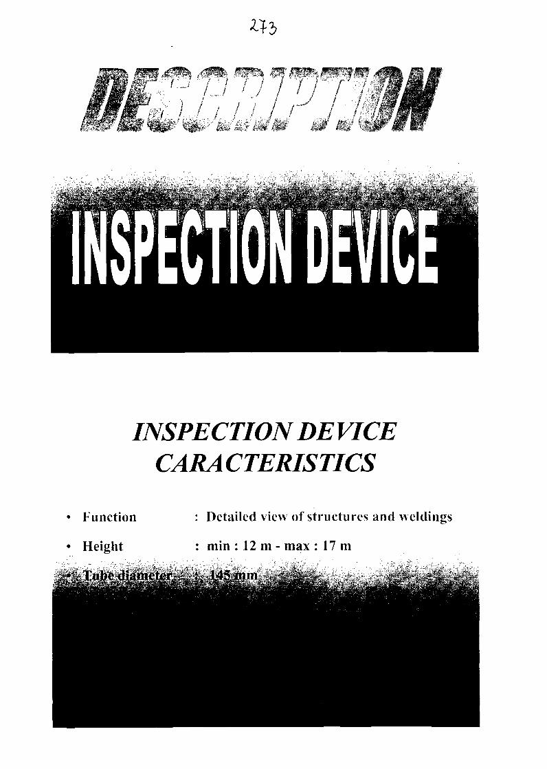
INSPECTION DE VICECARACTERISTICS
Function
Height
: Detailed view of structures and weldings
: min : 12 m - max : 17 m
FACTORY
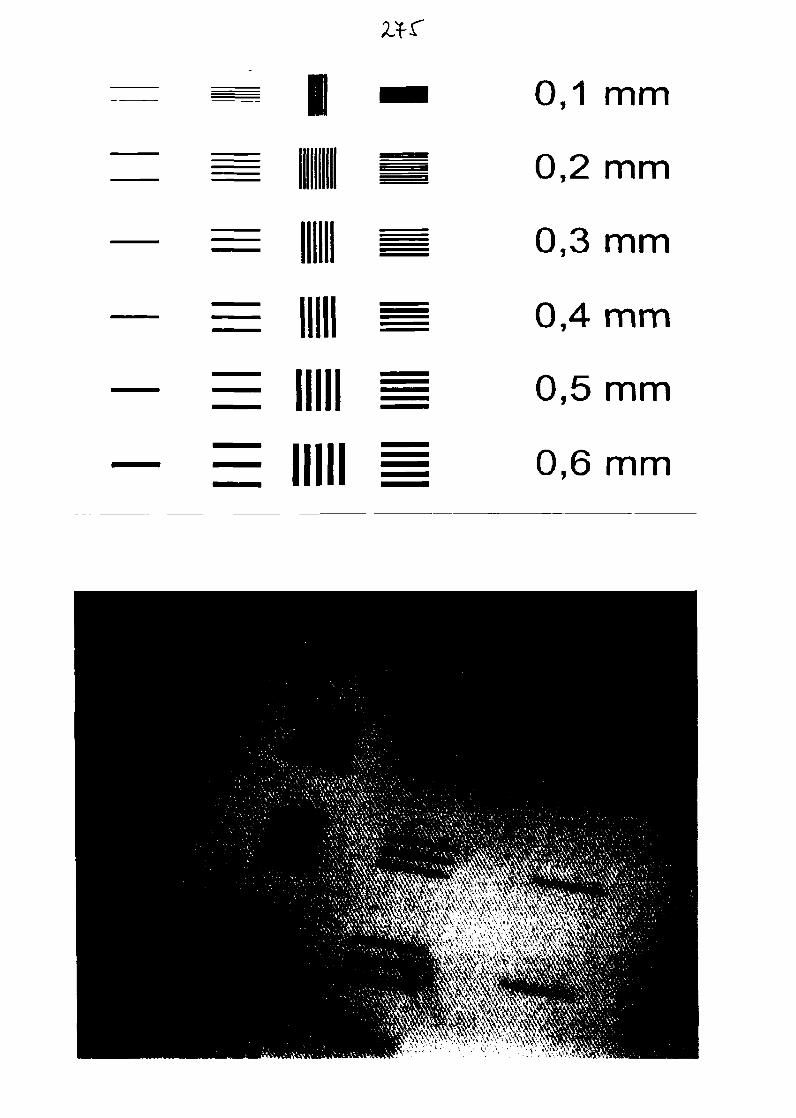
mil
0,1 mm
0,2 mm
0,3 mm
0,4 mm
0,5 mm
0,6 mm
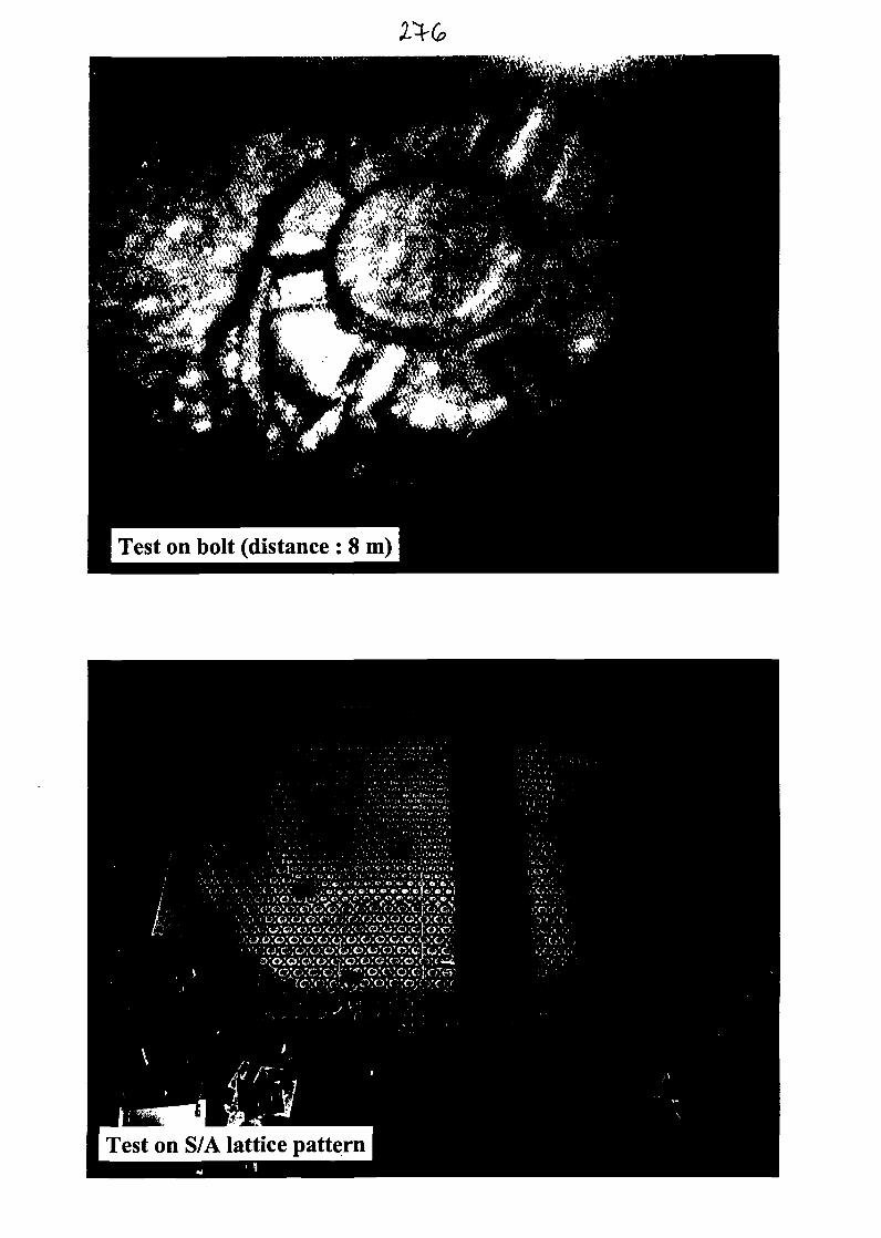
Test on bolt (distance : 8 m)
Test on S/A lattice pattern
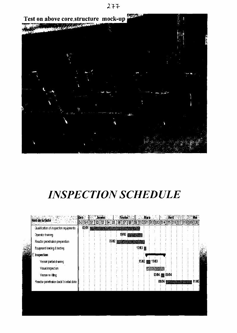
Test on above core.structure mock-up
INSPECTION SCHED ULE
NoridelJtkfieJanvier | .Fewier'forier: .] Marc
'|S7|S8'i39!S10|S11|SlAmi Mai
$-2iS>1iSHS2|-S3|S4|SS|sr|S7| '| lSiO|S11|Sl2|S13|S14|S15|S16]S17|S18|S19|S20[Mificafen of inspection equipments
Equipment loading I testing
E Inspection
Vessel partial draining
Visual inspection
Vessel re-filing
Reactor penetration back to initial state
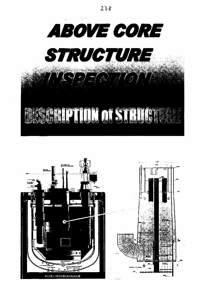
ABOVE CORESTRUCTURE

Pictures at manufacturing
External shellwelding details
Z4 r"Z8.1
Z8.2
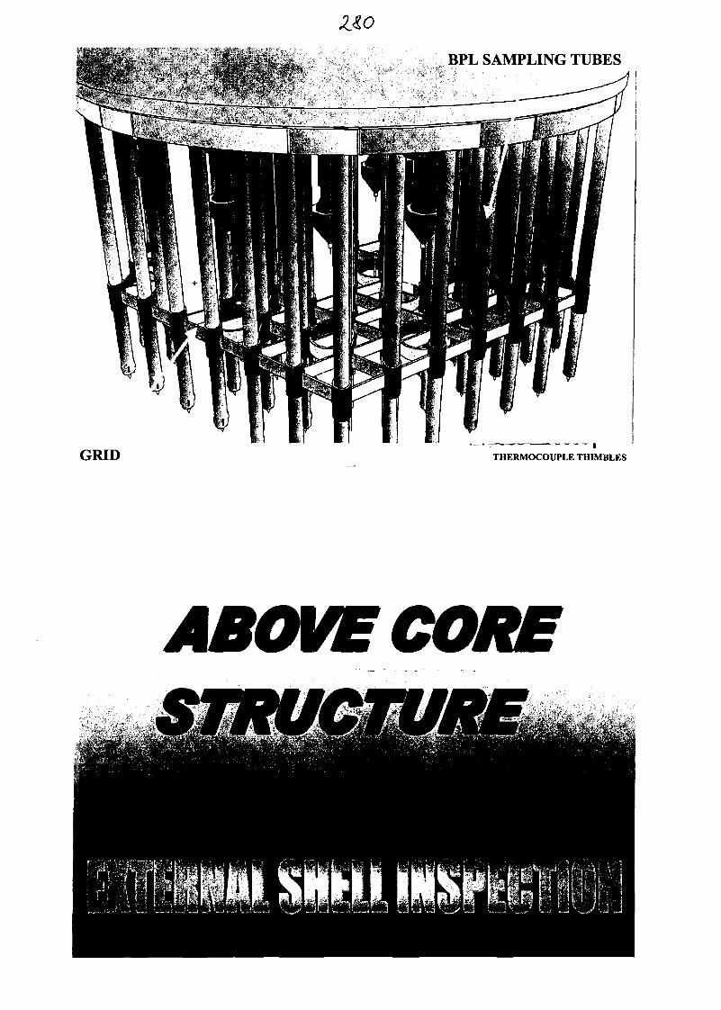
Z&oBPL SAMPLING TUBES
GRID THERMOCOUPLE THIMBLES
ABOVE CORE
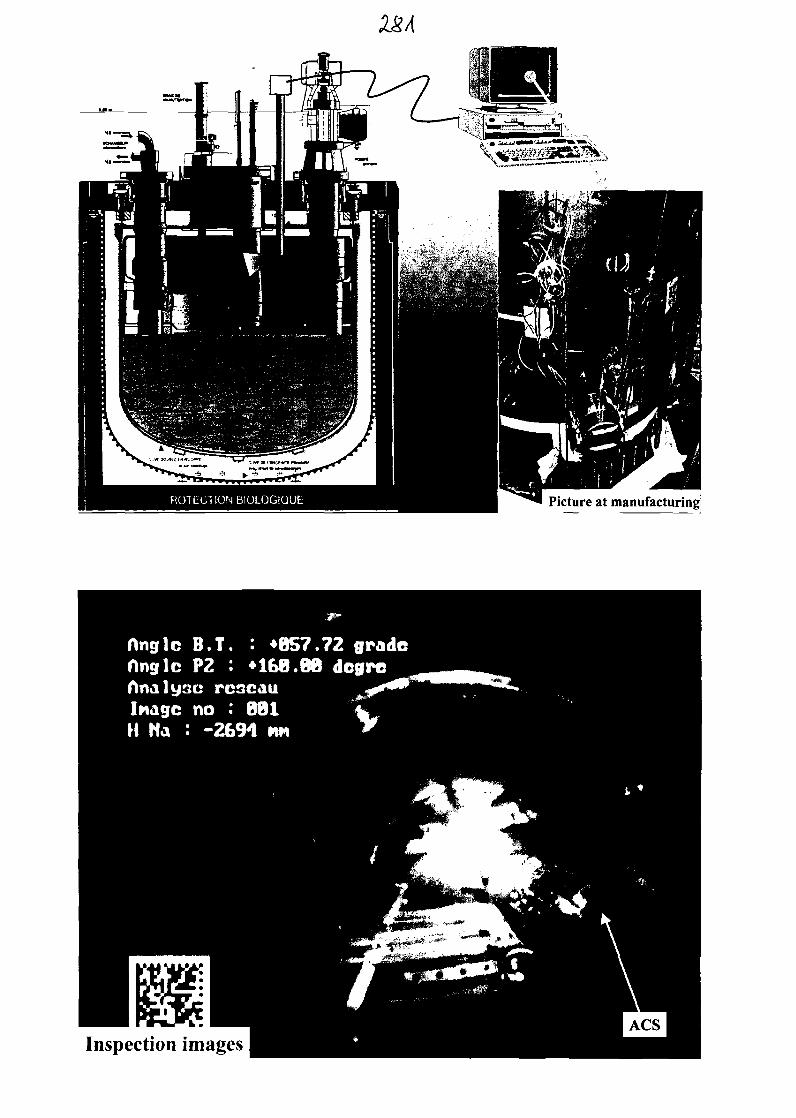
Picture at manufacturing
Inspection images
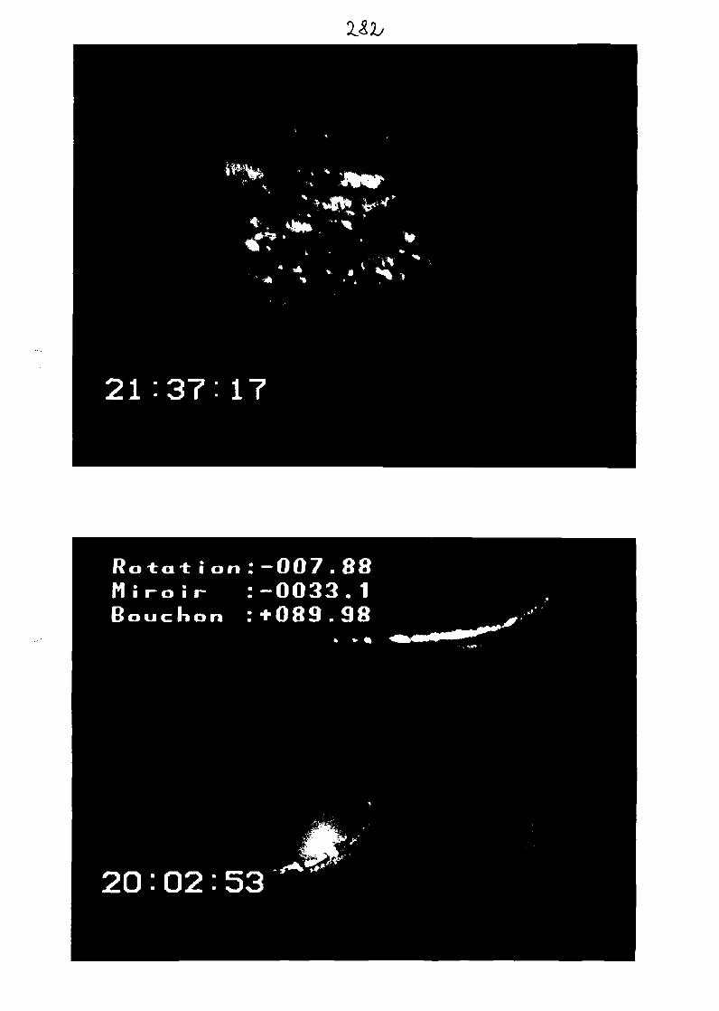
21:37:17
Ro±ai: ion:-007.88
" • i-o ii- :-0033. 1Bouchon :+089.98
20:02:53
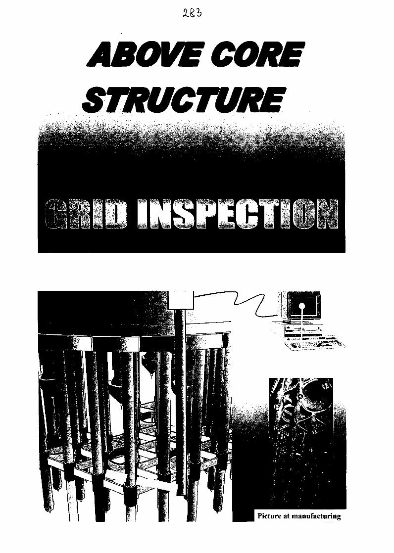
ABOVE CORESTRUCTURE
Picture at manufacturing
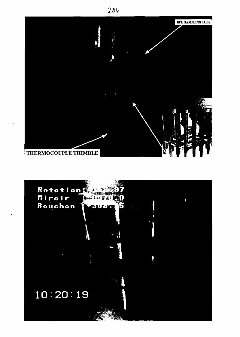
THERMOCOUPLE THIMBLE
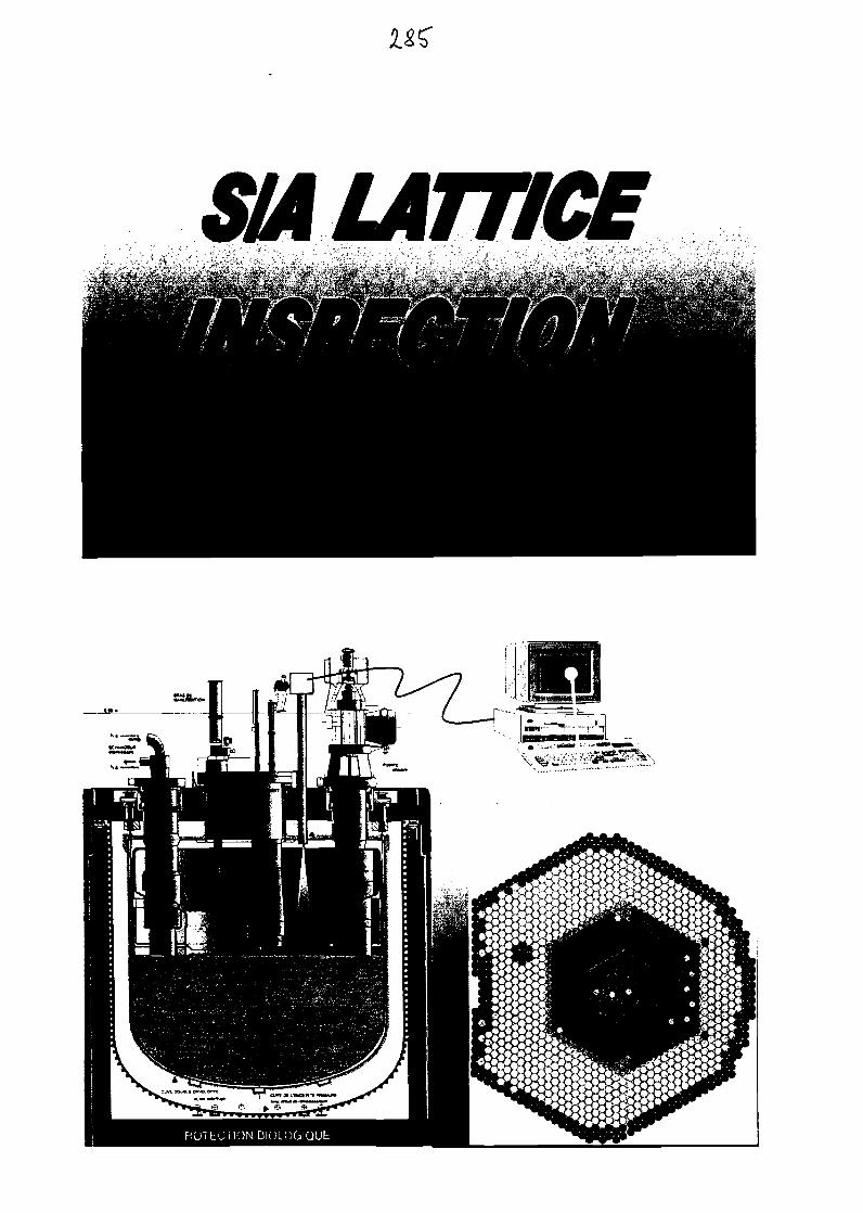
SIA LATTICE
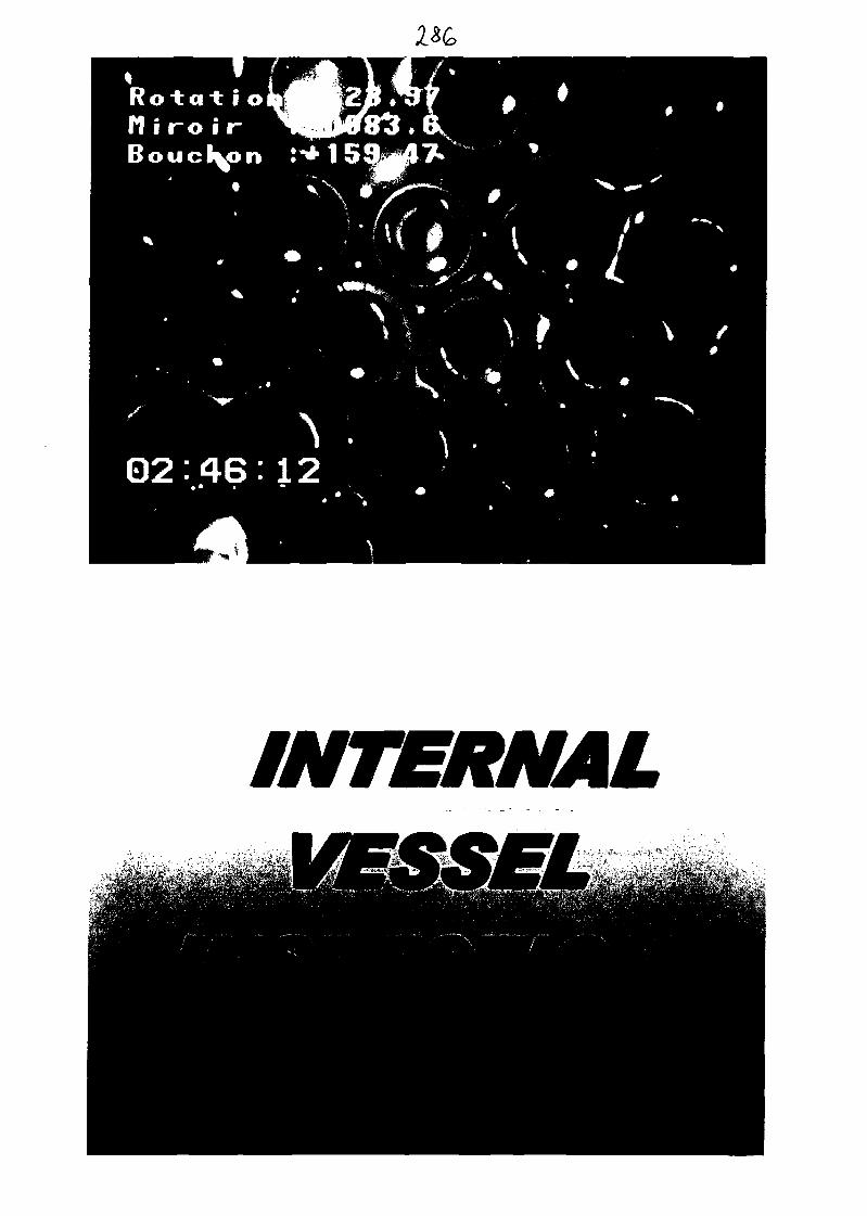
INTERNAL
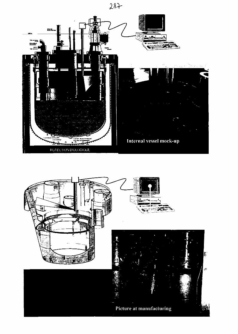
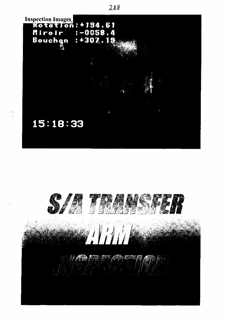
Inspection Images.on;+I94,61
niroir :-0058,4Bouchon :+307.19
15:18:33
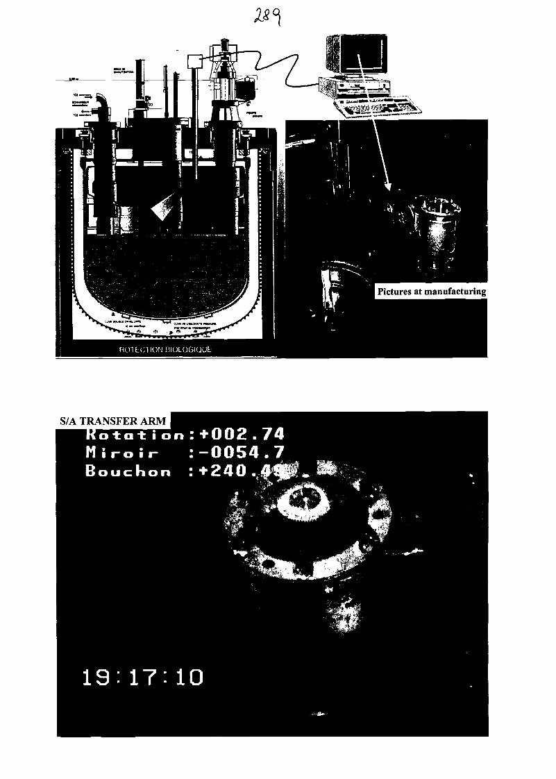
Pictures at manufacturing
S/A TRANSFER ARM

280
Good conditions of structures
1 significant .defect only on Above Core Structuree^Miaison:JbioilfeJfe
# DUPRAZIR MAJOR it. MARTIN
Thanks to :
- PHENIXplanning department,
NOVATOMEplanning department
- Inspection team.

CONICALPECTION
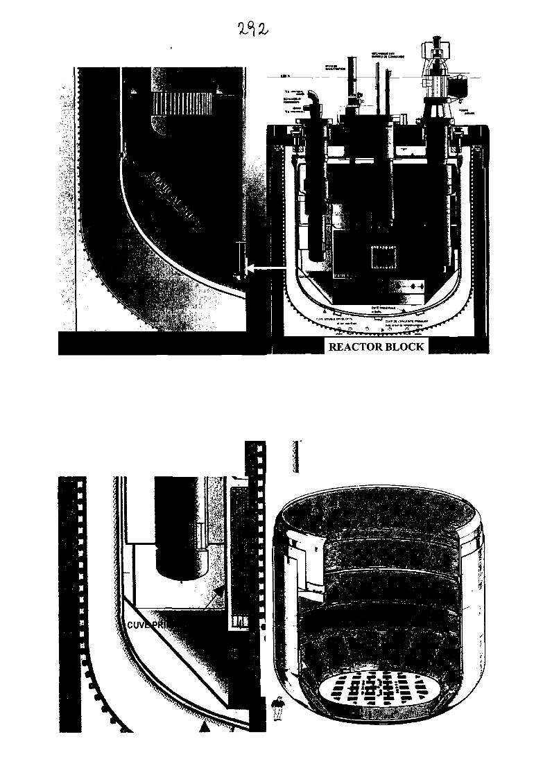
REACTOR BLOCK
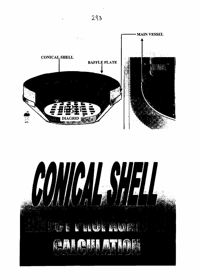
MAIN VESSEL
CONICAL SHELL
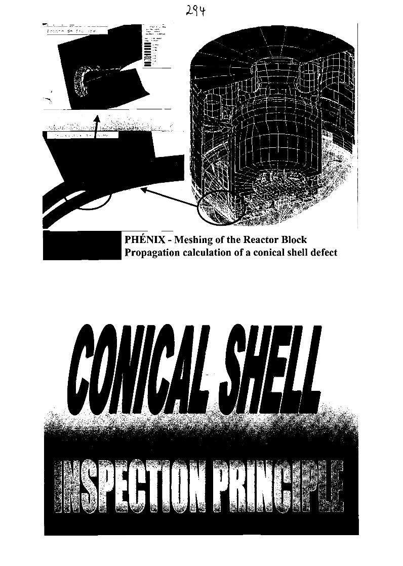
PHENIX - Meshing of the Reactor BlockPropagation calculation of a conical shell defect
LOCAL CONTROL ROOM
CARRYING OUT OF 5 NOZZLES THROUGHTHE SAFETY VESSEL
US SENSOR BAFFLE PLATE
„ LJwu-:
EXAMINATION
METHOD
Weld S3
Guided waves
Mock-up results
Time of flight
D2 no geometry echo,
no defect echo
28*
x r | i .rff
"" "
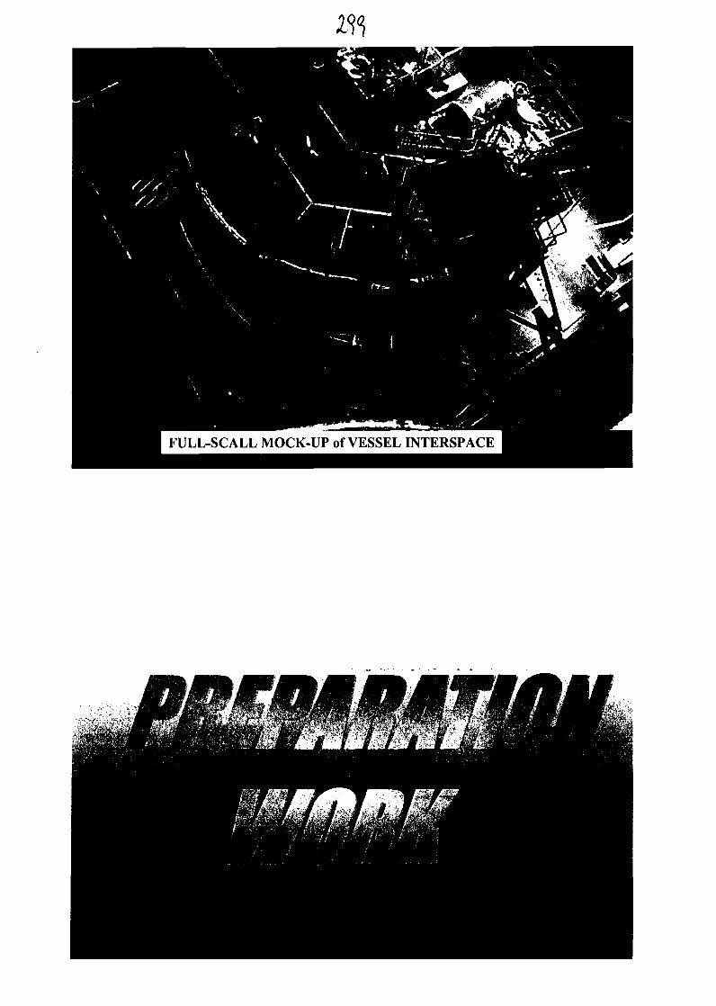
FULL-SCALL MOCK-UP of VESSEL INTERSPACE
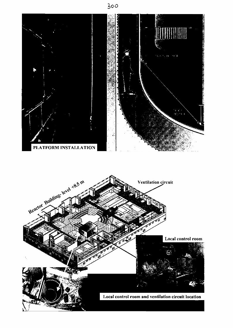
2>oo
PLATFORM INSTALLATION
Ventilation circuit
Local control room and ventilation circuit location
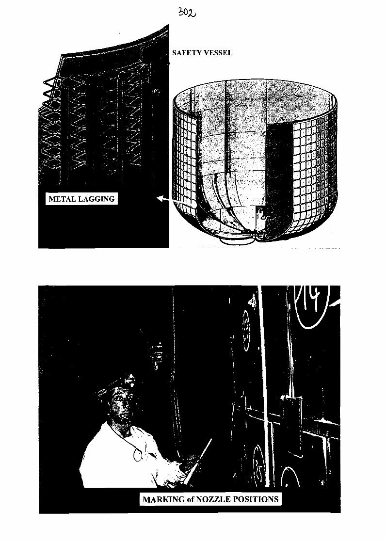
METAL LAGGING
MARKING of NOZZLE POSITIONS
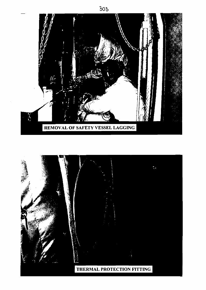
REMOVAL OF SAFETY VESSEL LAGGING
THERMAL PROTECTION FITTING
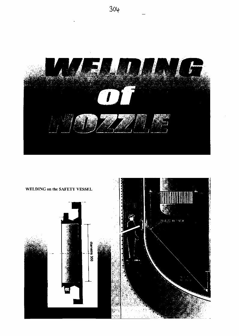
3<Xf
WELDING on the SAFETY VESSEL
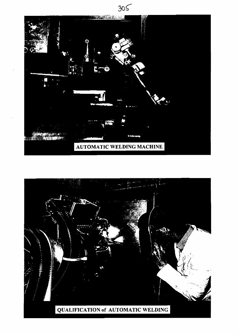
AUTOMATIC WELDING MACHINE
QUALIFICATION of AUTOMATIC WELDING
AUTOMATIC WELDING on the SAFETY VESSEL
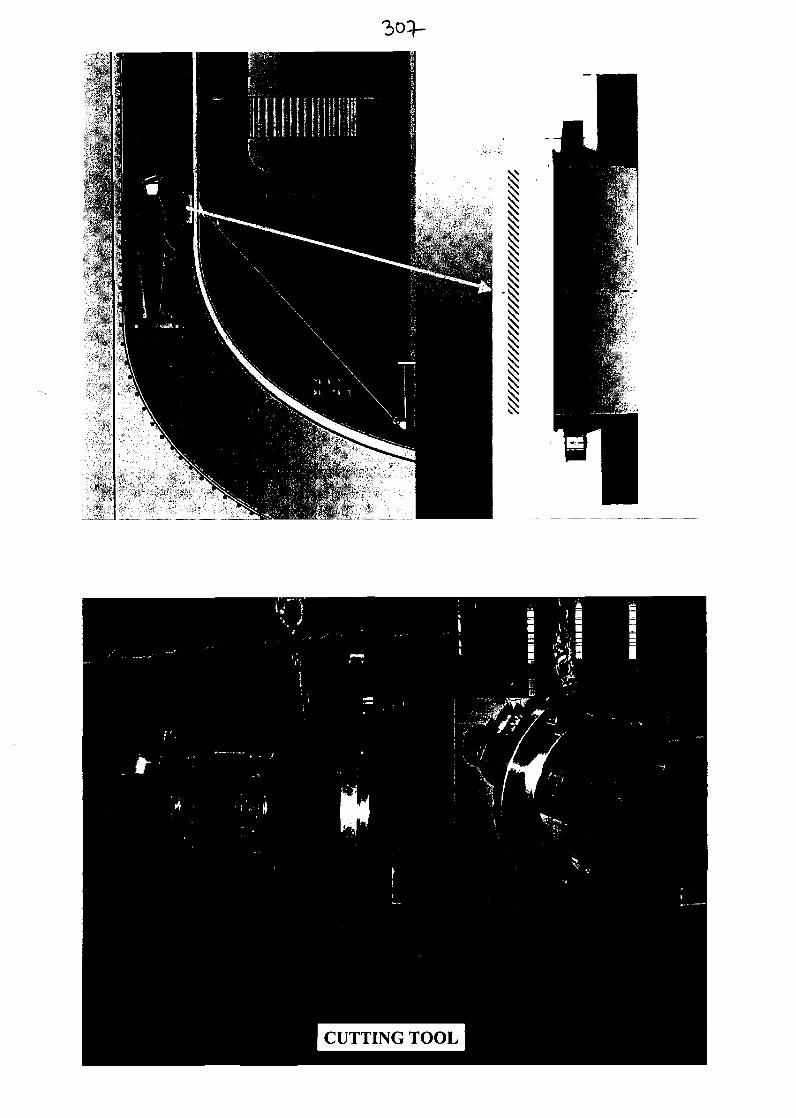
CUTTING TOOL
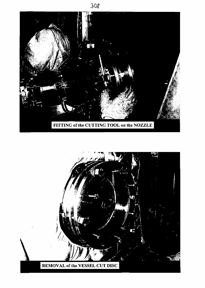
FITTING of the CUTTING TOOL on the NOZZLE
REMOVAL of the VESSEL CUT DISC
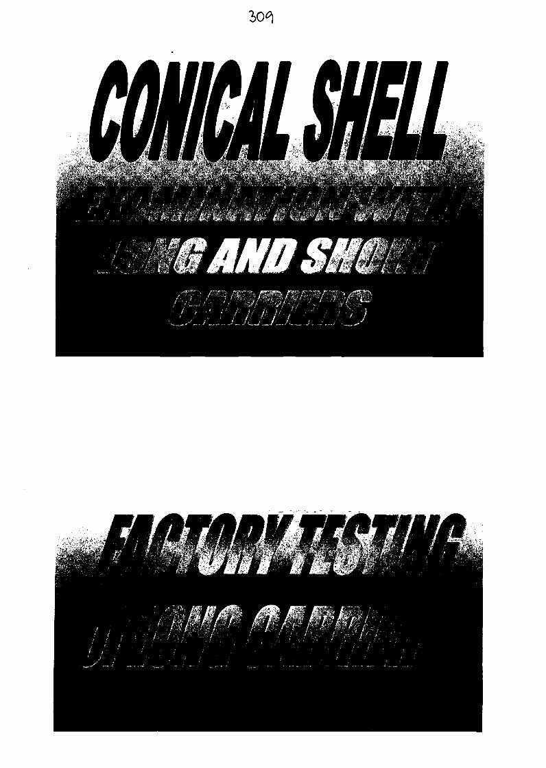

3/io
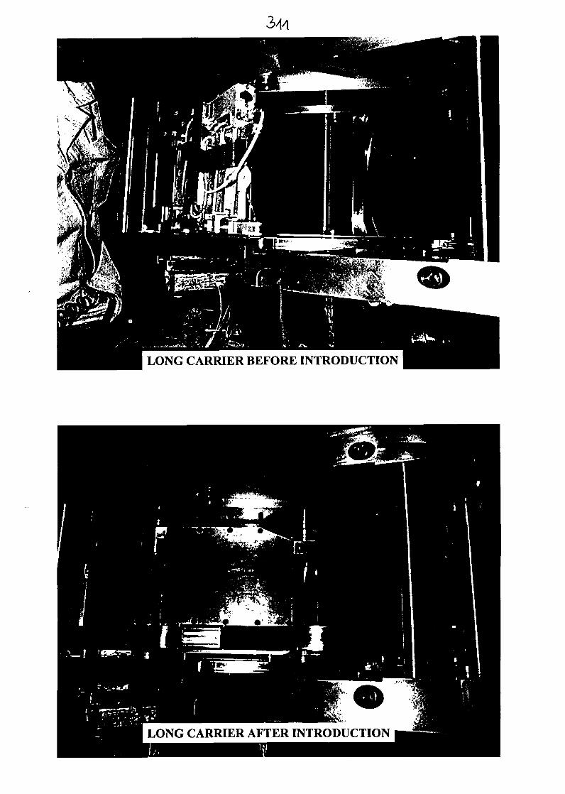
LONG CARRIER BEFORE INTRODUCTION
LONG CARRIER AFTER INTRODUCTION
3/13
Detection Thresholds:
Weld Defect lenght Defect depth(% of thickness)70%30% ,,
R. DUPRAZIM. GIRAUDIJ. GROSIL.MARTIN
THANKS TO :
- PHENIX Planning department,
• NOVATOMEplanning department,
• Inspection team,
- STA SAC LAY.

3/14
Sodium cleaning in Phenix Steam Generator modules(O. Gastaldi, CEA, France, V. Grabon, Framatome ANP; and Ch. Cavagna, CEA PHENIX)
ABSTRACTThe repair of the PHENIX steam-generator's modules needed to establish a particular sodium cleaningprocedure. The standard PHENIX cleaning procedure, using water vapour in presence of nitrogen and carbondioxide was indeed not suitable, because of bulky sodium residues and specific geometry of modules.A specific procedure, using a gradual water vapour nitrogen process has been developed, qualified andindustrially implemented in a very short delay, in order to clean efficiently the steam generators modules, beforerepair and requalification.
Introduction
With regard to the life time extension of the FBR Phenix, metallurgical examinations havebeen carried out on the Steam Generator (SG) in 1998-2000. Some cracks have been detectedin the hottest parts of the SG. It has been decided to repair all superheater and resuperheater ofthe SG.Because of the high reactivity of sodium with air and caustic corrosion risks that may ariseduring repair and further operations, due to sodium/moist air reaction products, residualsodium had to be eliminated in order to achieve the requalification of the SG before start up.For this, a particular sodium cleaning procedure has been established, qualified andindustrially implemented in a very short delay in accordance with Phenix start up planning.
Selection of the applied sodium cleaning process
The various ways to eliminate sodium residues are :Physical ways :> Blast cleaning>• Scraping : only for local use on accessible and little quantities of sodium>• Evaporation under vacuum : only on small material
Chemical ways :> Reaction with water : usual methods in 90% of cases> Reaction with alcohol : no more allowed in France> Reaction with other products : "exotic" methods
Sodium cleaning backgroundIn France methods using water/CO2 mixture are the usual ways of cleaning. For examplePhenix and Superphenix components (pumps, exchanger), fuel assemblies are cleaned inspecific pits with water vapour or sprayed water in presence of CO2. A particular procedure ofcarbonation has been achieved in situ on the "Barillet" of Superphenix in 1989 beforedismantling of this component. Up to now no cleaning operation had been performed on SGin France with the purpose of the component's requalificationIn other countries Water Vapour Nitrogen type processes (WVN) are generally preferred forsodium removal. Few data about some SG cleaning experiences have been reported.Generally the background about cleaning with water processes is good. Meticulous rinsing isrecommended following cleaning.Water is a common, cheap product. The products of the sodium/water reaction : sodiumhydroxide and hydrogen, are easily managed but the reaction must be controlled. The use ofCO2 lowers the caustic corrosion risk by conversion of the sodium hydroxide into solid andchemically inactive products : sodium carbonates. However, this product may form a barrier
between the sodium and the reactant gas likely to slow the process kinetic. Carbonationprocesses should be adapted case by case.
The Phenix Steam Generator particular geometryThe reactor is cooled by 3 secondary sodium circuits each of them having one SteamGenerator of modular concept. Each SG is composed of the economizer-evaporator, thesuperheaters and the resuperheaters stages; each of them is composed of 12 modules. 47modules from 2 SG's superheater and resuperheater have to be repaired. A superheatermodule has a S shape and is composed of a 27 m long-<j) 200 mm shell, containing 7 watervapour tubes (see figure 1). The sodium flows around the tubes. The tubes are maintained byregularly spaced grids.After draining of the SG, only a thin film of sodium lays on the tubes external walls and onthe shell internal wall. In the lower part of the superheater modules bulky sodium residues(until 5 cm thickness-65 g/sleeve) may be present in the 7 thermal protective sleeves aroundthe tubes (see figure 2). These sleeves are quasi closed spaces with a reduced annular gap lessthan 2 mm large.The total sodium residual mass may vary from some hundred of grams to several kilogramsdepending on the draining conditions and on each module geometric particularities such asmisalignment.
Definition of the SG cleaning wayLocal cleaning of the zones to be repaired with isolation of non repaired area under inertatmosphere was not an acceptable way because it required longer development to achieve thetightness in such a complex geometry. Then it was decided to clean the entire module withwater process.Because of the presence of bulky sodium residues in the sleeves, a procedure using nitrogenas water transport gas was preferred rather than CC>2, in order to produce liquid reactionproduct (aqueous sodium hydroxide) that may flow outside the sleeves and allow a completeelimination of sodium in a reasonable delay. The process has been adapted to avoid the riskdue to aqueous product flowing on metallic sodium.Further draining of sodium or scraping were not possible because of the too narrow accessgap-The sodium/water reaction characteristics are :> Immediate and exothermic reaction (138 kJ/mol)> Production of an explosive gas (hydrogen lower inflammable limit is 4% in air)> Production of a corrosive product (aqueous sodium hydroxide). Caustic stress corrosion
cracking risks arise at around 120°C on stainless steel (Phenix superheater andresuperheater material is an austenitic stainless steel)
The chosen process has to deal with all these difficulties :> The global kinetic of the sodium elimination rate can be controlled by the reactant
(water) supply : water is introduced in the form of water vapour with gradualincreasing concentration.
> The provisions made against hydrogen risk consist to clean under inert atmosphere(Na), to limit the HI maximal theoretical concentration to 1% in the effluent gas bylimiting the nominal water concentration in the first steps of the process and tomeasure continuously the H2 concentration in the effluent. Alarms and automaticactions are triggered if the H2 level reaches 3%. Otherwise, to prevent air entranceduring the treatment, the module is always kept in overpressure with regard toatmospheric pressure.
> The caustic corrosion risks must be limited at every step :o Before cleaning : the module is maintained under inert atmosphere to avoid the
formation of aqueous sodium hydroxide due to air ingress.o During cleaning : as aqueous sodium hydroxide is present, the preventive
measure against corrosion risk consists to control the sodium/water reactionexothermicity in order to maintain the temperature under 60°C. This isachieved through the control of water supply into the module.
o After cleaning : sodium hydroxide residues must be eliminated as far aspossible by meticulous rinsing to limit caustic corrosion risks during furtherheating (welding during repair, heating of SG before start up). This is achievedby filling the module with liquid water and circulation of water during longcycles (total time 100 hours). This procedure may allow NaOH residues todiffuse from any eventual defect and to be mechanically removed by waterflow.
Additional provisions should be made to avoid hazardous violent reaction- sodium/liquidwater type- due to uncontrolled flow of aqueous sodium hydroxide on metallic sodiumretentions. Bulky sodium residues should not be on the flowing line of liquid effluent. That iswhy the module could not be treated in the SG in-situ vertical position. An inclination of themodule of 30° with regard to the vertical position is needed. For the same reason, the reactantgas should flow from the lower inlet to the upper end of the module, because the water vapourreacts immediately with the first encountered sodium surfaces as it enters into the module.
Validation testsIn parallel with the cleaning procedure definition, validation tests have been carried out atCEA Cadarache in order to confirm the chosen options and to optimise the processparameters.> Draining tests of sleeve filled with liquid sodium were not successful and confirmed that
further draining of sodium is hazardous.> Cleaning tests on thick sodium samples to confirm the kinetics of sodium elimination.> Cleaning efficiency tests on Phenix module singularities (sleeve, grids, flow mixing
device). The test showed that a global flowing of the reactant gas in nominal conditionshas few efficiency on the elimination of the sodium inside the sleeves. A local treatment isnecessary to achieve the cleaning in a reasonable delay (about 30 hours) and withoutunacceptable temperature increase. This is performed by a local injection of the reactantgas inside the sleeve. For better access and efficiency a hole has been machined in thesleeve and the injection system through this hole has been optimised.
SG cleaning procedureGeneral requirements :S The module is initially under inert atmospherev' Holes have been machined in the 7 sleevesS The module is inclined at 30° with regard to the vertical position^ The cleaning phases have to be continuously carried outS Demineralized water is needed.The cleaning procedure has been defined as follows :> Global cleaning with wet NI sweeping: to treat the thin residues of metallic sodium
(module's position : 30 °)> Local cleaning with wet Na sweeping. The 7 sleeves are treated in parallel with a specific
rod : to treat the bulky sodium retentions (module's position : 30 °)
> Local cleaning with sprayed water in N2 flow : to complete the treatment of the bulkysodium retentions (module's position : 30 °)
> Global cleaning with sprayed water in N2 flow : to complete the treatment of metallicsodium (module's position : 30 °)
> Total immersion : to demonstrate the absence of metallic sodium (module's position : 30°)
The rinsing of sodium hydroxide is performed by> The previous total immersion of the module with water and water circulation, the module
being inclined at 30°> Local aspersion of sleeves with liquid water injection (module's position 30°)> Total immersion of the module with water and water circulation. The module is in
horizontal position to allow complete immersion of the sleeves
After draining water, the module is dried prior to be repaired.
Industrial facility
Intellectual pathwayBefore to apply the treatment on all the modules to be repaired, experimental operations havebeen done at an industrial scale on 2 modules to qualify the cleaning procedure. The differentstages of the procedure have been tested and the process has been assessed through thedifferent measurements (residual sodium mass, hydrogen release, temperature increase,efficiency).To achieve this first action, a prototypic cleaning unit has been adapted on a cleaning pit ofPHENIX. This facility has been developed to offer a great flexibility of use and to ensure avery well controlled process. This facility allows to inject the different gas mixtures and waterin the module. It is the same facility which allows to clean and to rinse the module.Once the process well qualified with both these tests modules, the definition and the buildingof the final industrial facility can be launched.
Process qualificationFor these qualification the chosen process is composed of 10 phases :
1. Sweeping with an inert gas2. Tightness test3. Global sweeping with wet Na (low dew point) in the module4. Sweeping with wet gas with local injection in the sleeves5. Local Sweeping with sprayed water/Na in the sleeves.6. Global Sweeping with sprayed water/N2 in the whole module7. Slow filling of the module and water forced convection8. Local water injection in the sleeves9. Total filling with water and water forced convection (five cycles)10. Drying
The total duration of the cleaning phase is about 60 hours and the cumulative duration of therinsing phases is about 100 hours.
Main measurements and instrumentationThe main parameters to consider during the cleaning of the module are :
> The temperatures of the module in different points corresponding to the potentialsodium retention where more reactivity is expected

> The hydrogen concentration in the gaseous effluent, which shows the progress of thereaction
> The oxygen fraction which allows to assess inert atmosphere condition to avoidpotential inflammation of hydrogen
> The pressure in the module which has to be close to 30 mbar to ensure that there is noair entrance.
During the rinsing phases the main parameters are :> The conductivity,> ThepH> The water temperature
To pass from one phase to another one, several criteria have been fixed :A minimal duration is required for each phase. In addition, at the end of each cleaning phasethe hydrogen concentration must be under a specific threshold, and no hot area must bedetected.During the rinsing phases water quality criteria are required at the end of the 2 last phases.
Results and qualificationDuring both the cleaning operations the hydrogen signal never exceeded 0,2 mol. %.Temperature increase is very limited. It shows that the reaction between water and metallicsodium is very slow, and that there is no uncontrolled reaction.The total amount of removed sodium which represents the total amount of residual sodium inthe modules of interest was evaluated to about 400 g.From one rinsing phase to another one the conductivity measured in the water effluentdecreases quickly. In the fifth rinsing phase, the water conductivity is around 1 uS/cm, whichshows that the sodium hydroxide removal becomes insignificant.After drying, no sodium hydroxide has been detected. The different assessments show that thesodium hydroxide removal is total.Then the development of and industrial facility was undertaken.
Industrial FacilityDescriptionIn order to limit the total duration of cleaning operations, the modules are treated in parallelon 2 lines. The facility is composed of two cleaning lines, two rinsing lines and a drying areaas drying duration is relatively short. By this way, all the modules can be treated according tothe start-up planning of PHENIX.The two cleaning lines are set in a closed area equipped with heating system. It allows towork without condensation risk with gaseous water having a water fraction in the gas mixtureabout 2 mol. %.A global view of the facility is given on figure 3.Each cleaning line is composed of:
> A preparation system : to produce the specific gaseous mixture for each phase> A feeding system to connect the module> A specific tank to separate liquid and gas> An effluent line for the gas> An effluent line for the liquids
The more complex part is the preparation system which gathers the different flow meters andthe different control instruments.

First experiments feedback
More than 12 modules have been totally treated up to now. The hydrogen production hasalways been very low and controlled. The average duration of the cleaning is always quite thesame (around 60 hours). The initial residual sodium quantity has never exceeded 400 grams.The temperature of the module always stayed under the criterion 60°C. The maximumtemperature increase was about 20°C (for an initial temperature of 25 °C).
Conclusion
The chosen process is well adapted to the specific geometry of the SG's modules. The lowwater fraction in the gas mixture allows to control in a good way the sodium water reactionwithout significant hydrogen concentration and temperature increase. The temperature issufficiently low to insure there is no problem of caustic corrosion due to the sodiumhydroxide during the cleaning phases. A long duration rinsing insures the total elimination ofsodium hydroxide.Up to now, all cleanings and all assessments are positive and a significant number of SG'smodules have been already treated.
Figure 1 : Module on transfer system
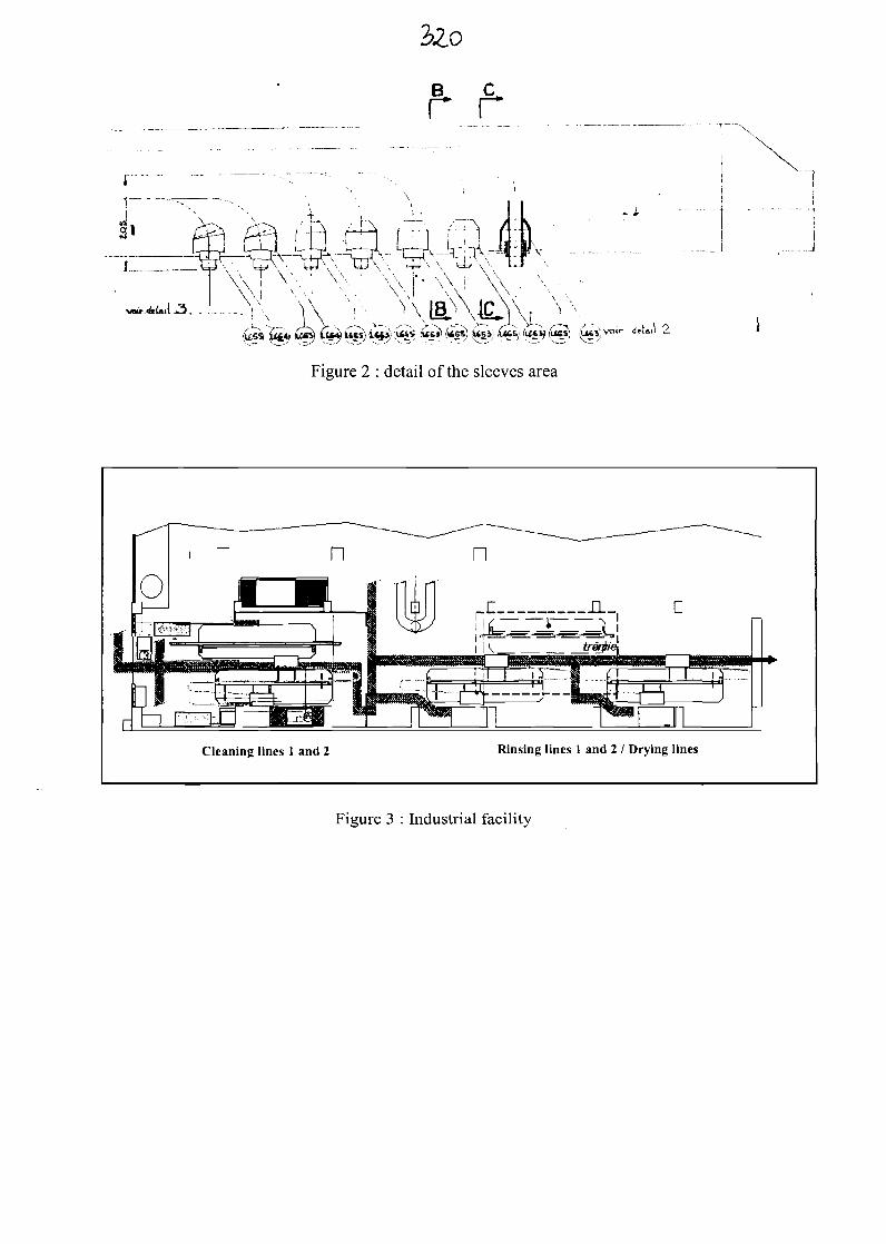
2>2.0
Y\ Y-v^s.4» ww) £55) i ) i ««») '5*ss) jiaaji £tes) ik i) i es)
Figure 2 : detail of the sleeves area
Cleaning lines 1 and 2 Rinsing lines 1 and 2 / Drying lines
Figure 3 : Industrial facility

AFRAMATOME ANP
Sodium cleaning in PhenixSteam generator (SG) modules
O. GASTALDI (CEA, Cadarache)V. GRABON (FRAMATOME ANP)
Ch. CAVAGNA (CEA, Phenix)
AFRAMATOME ANP
Main goals
oO
Phenix SG repair
Sodium removal before repair
Requalification after cleaning operation

AFRAMATOME ANP
Phenix Steam Generator
Resuperheater
Superheater
Economizer-Evaporator
AFRAMATOME ANP
Intellectual pathway
• Sodium distribution into the module
• Choice of specific process3-
"° • Validation tests
• Process qualification
• Industrial facility (47 modules)
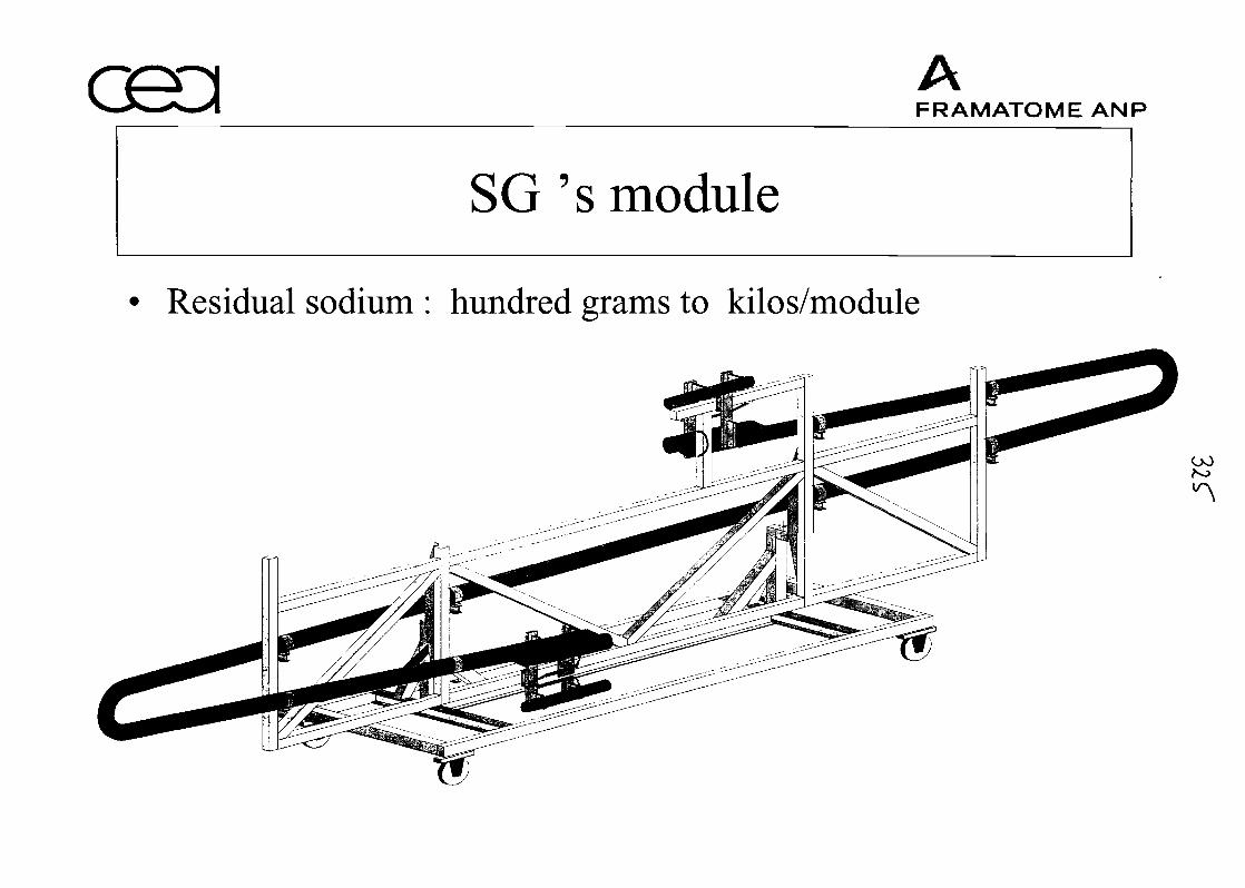
AFRAMATOME ANP
SG 's module
Residual sodium : hundred grams to kilos/module
00
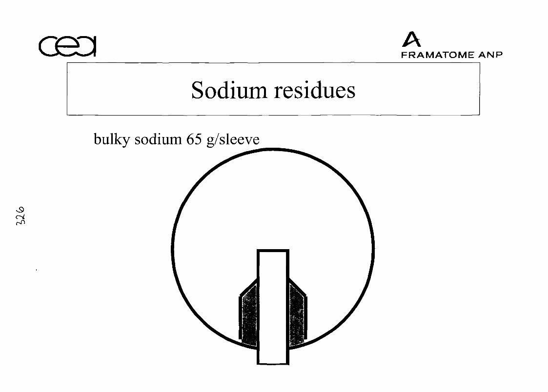
AFRAMATOME ANP
Sodium residues
bulky sodium 65 g/sleeve
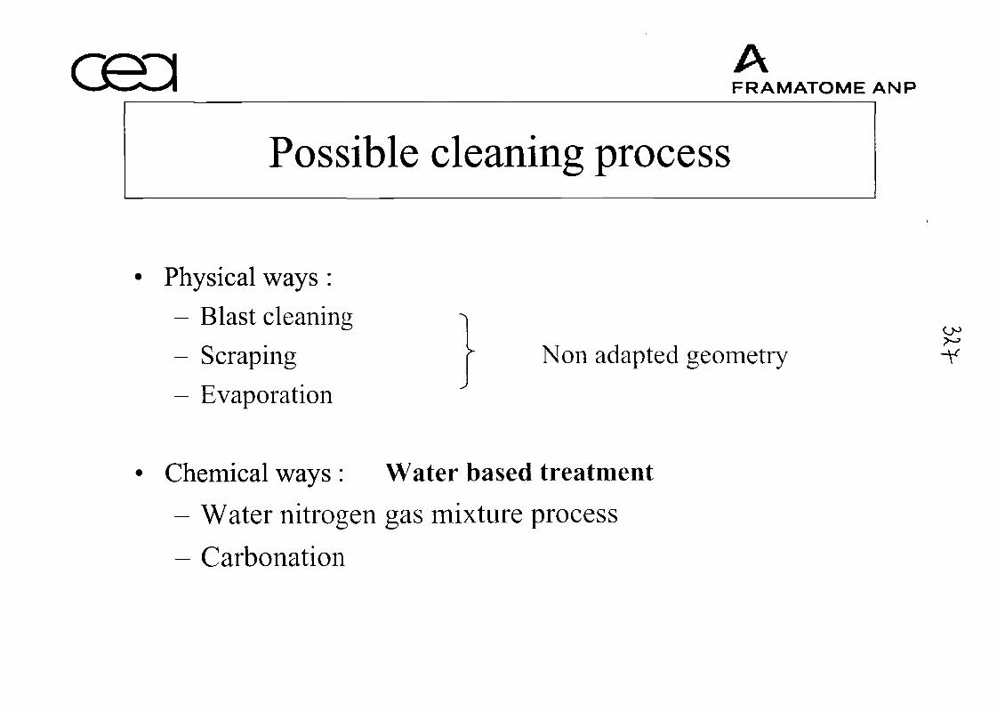
AFRAMATOME ANP
Possible cleaning process
Physical ways :
- Blast cleaning
- Scraping
- Evaporation
Non adapted geometry
Chemical ways : Water based treatment
- Water nitrogen gas mixture process
- Carbonation

AFRAMATOME ANP
Choice of the process
Water Vapour Nitrogen Process
Good kinetic of reaction
Liquid product => Treatment of sodium in sleeves
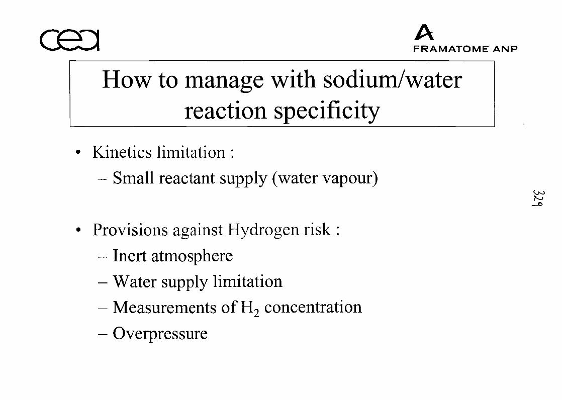
AFRAMATOME ANP
How to manage with sodium/waterreaction specificity
Kinetics limitation :
- Small reactant supply (water vapour)
Provisions against Hydrogen risk :
- Inert atmosphere
- Water supply limitation
- Measurements of H9 concentration£*
- Overpressure
Oo
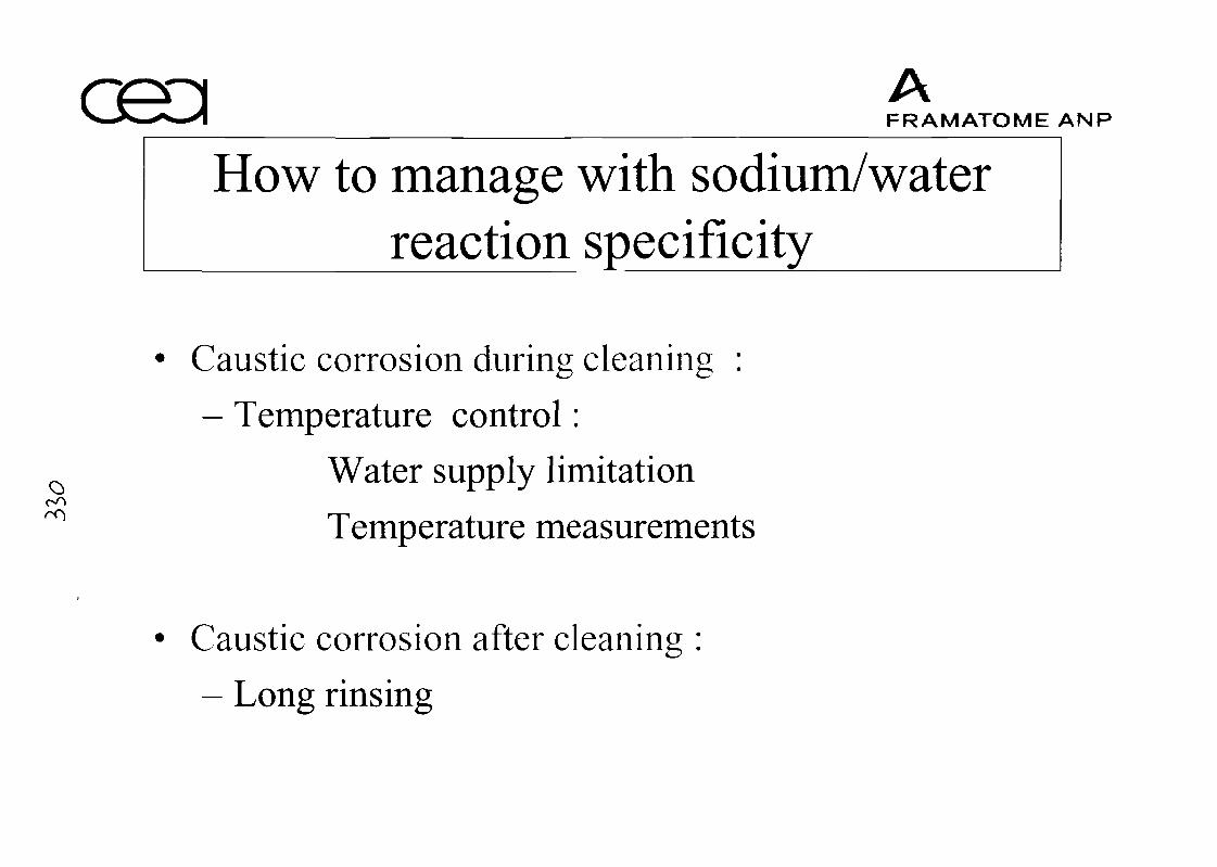
AFRAMATOME ANP
How to manage with sodium/waterreaction specificity
Caustic corrosion during cleaning :
- Temperature control:
Water supply limitation
Temperature measurements
Caustic corrosion after cleaning :
- Long rinsing
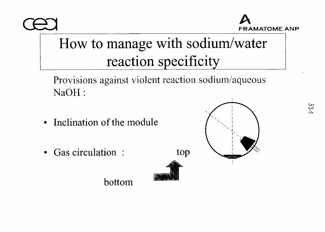
AFRAMATOME ANP
How to manage with sodium/waterreaction specificity
Provisions against violent reaction sodium/aqueousNaOH:
Inclination of the module
Gas circulation : top
bottom
00

AFRAMATOME ANP
Mock-up validation tests
r-O
Cleaning tests on thick sodium samples to confirmkinetics
Cleaning tests on singularities :
- Sleeves : local injection and machining
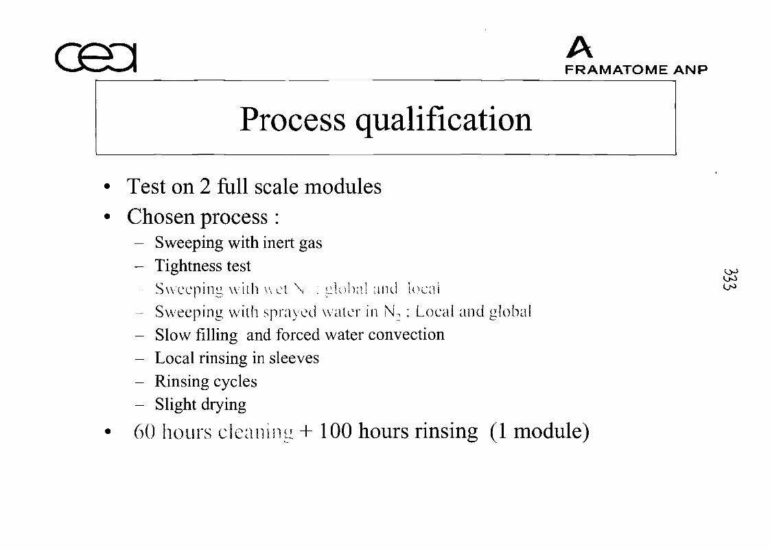
AFRAMATOME ANP
Process qualification
• Test on 2 full scale modules• Chosen process:
- Sweeping with inert gas- Tightness test
<oO
Sweeping wi th wet N , : global and local °°- Sweeping with sprayed water in N, : Local and global- Slow filling and forced water convection- Local rinsing in sleeves- Rinsing cycles- Slight drying
• 60 hours cleaning + 100 hours rinsing (1 module)
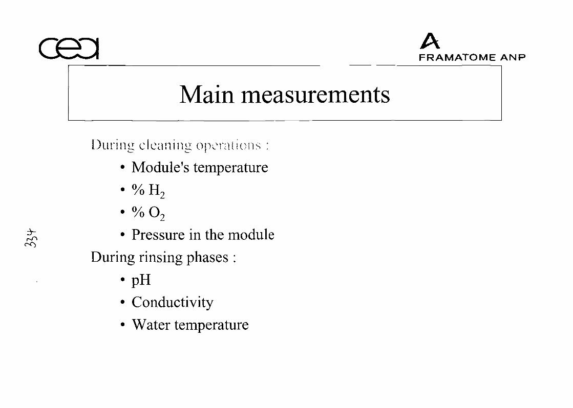
AFRAMATOME ANP
Main measurements
During cleaning operations :
• Module's temperature• o/ TT/oH2
• % O2
• Pressure in the moduleDuring rinsing phases :
•pH
• Conductivity
• Water temperature
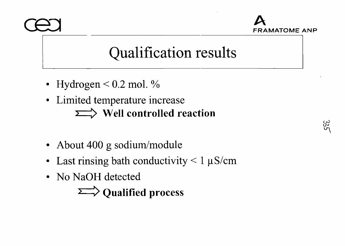
Qualification results
Hydrogen < 0.2 mol. %
Limited temperature increaseWell controlled reaction
About 400 g sodium/module
Last rinsing bath conductivity < 1 |i S/cm
No NaOH detected
Qualified process
AFRAMATOME ANP
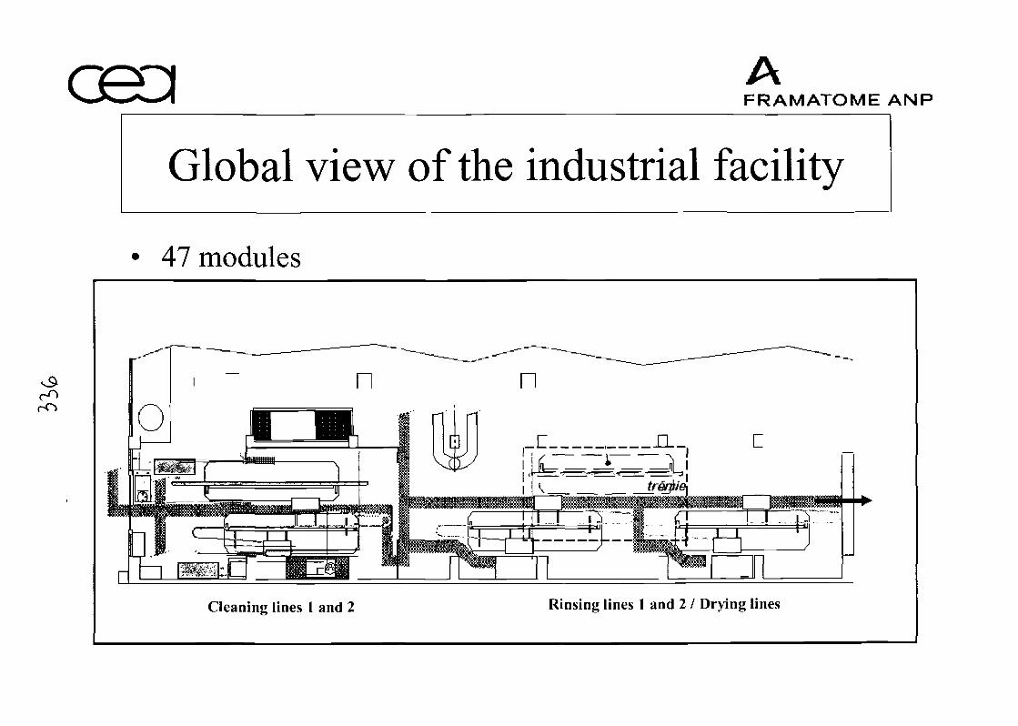
AFRAMATOME ANP
Global view of the industrial facility
47 modules
Cleaning lines 1 and 2 Rinsing lines 1 and 2 I Drying lines
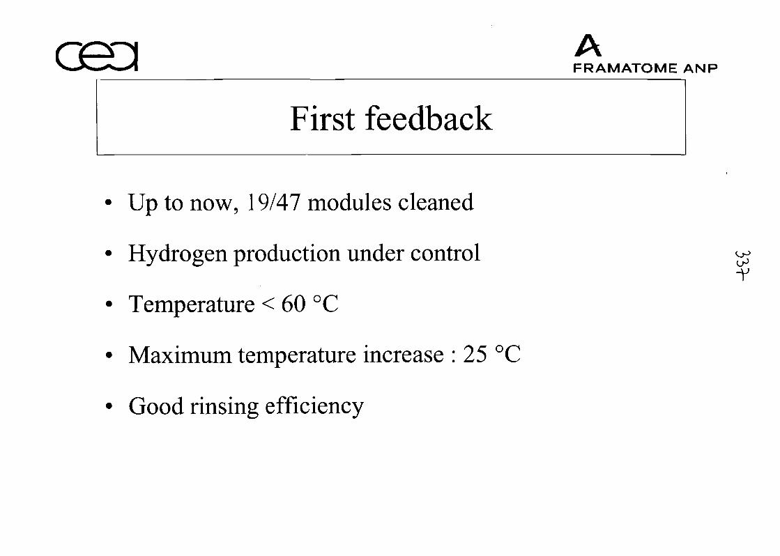
First feedback
Up to now, 19/47 modules cleaned
Hydrogen production under control
Temperature < 60 °C
Maximum temperature increase : 25 °C
Good rinsing efficiency
AFRAMATOME ANP
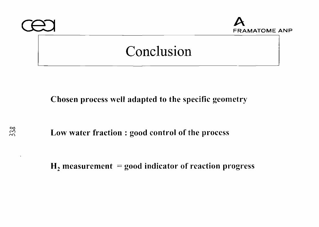
AFRAMATOME ANP
Conclusion
Chosen process well adapted to the specific geometry
00 Low water fraction : good control of the process
H2 measurement = good indicator of reaction progress
REVIEW OF FAST REACTOR OPERATIONAL EXPERIENCE GAINED IN RUSSIA.APPROACHES TO COORDINATED RESEARCH PROJECT
V. M. Poplavsky °, Yu. M. Ashurko ]), Yu. E. Bagdassarov 1}, A. V. Karpov °, M. P. Nikulin l\A. M. Tsiboulia l\ N. N. Oshkanov 2), A. I. Kiryushin 3), B. A. Vasilyev 3), K. L. Suknev 4),
A. S. Korol'kov 5) and V. V. Denisov 6)
!) State Scientific Center of the Russian Federation - Institute for Physics and Power Engineering(SSC RF IPPE), Obninsk,
2) Beloyarskaya Nuclear Power Plant (BNPP), Zarechny,3) Experimental Design Bureau of Machine Building (OKBM), Nizhny Novgorod,
4) Saint Petersburg Research and Design Institute ATOMENERGOPROEKT (SPAEP),Saint Petersburg,
5^ State Scientific Center of the Russian Federation - Research Institute of Atomic Reactors(SSC RF- RIAR), Dimitrovgrad,
6) Experimental and Design Organization "GIDROPRESS", Podolsk
Paper submitted to the Technical Meeting on"Operational and Decommissioning Experience with Fast Reactors"
CEA, Centre d'Etudes de Cadarache, FranceMarch 11-15, 2002
ABSTRACT
The review of the experience gained in Russia in the field of fast reactors with sodiumcoolant is given in the report. The information on fast reactors operating in the Russian Federa-tion (BR-10, BOR-60, BN-600) is presented: their current status, further prospects, and basic in-dices achieved by the facilities. The principal results of operation of test facilities and powerplants with fast reactors in Russia are summarized.
Necessity in implementation of special work on preservation and generalization of ex-perience gained in the field of fast reactors have been analyzed, as well as possibility of organiz-ing a coordinated research project in this area, hi particular, possible approaches to the organiza-tion of activities on systematization of published information on fast reactors.
Introduction
In the early stage of development of reactor technology based on the use of fast spectrumneutrons, large efforts were made on choosing coolant that would meet fast reactor requirementsto most extent. Among coolant candidates, liquid metals were considered (mercury, alkali metalsand their alloys and heavy liquid metals), as well as gases (helium and carbon dioxide). Later,possibility of use of dissociating gases (nitrogen tetraoxide) as fast reactor coolant was studied.As a result of these studies, sodium was chosen as the most promising coolant for NPP with fastreactors from the standpoint of its neutronics, physical, chemical, thermohydraulic and economi-cal parameters. Further, sodium was widely used as a coolant of stationary fast neutron reactors.
Fast reactor development during 50 years (about 350 reactor-years of operation) has beenin general successful. Feasibility of fast reactor application for commercial electricity productionhas been proved. Reliable, stable and in general safe operation of fast reactors has been demon-strated. It should be noted that almost all experience gained in fast reactor development and op-eration has been based on the use of sodium coolant.
Economical parameters of fast reactors are worse than those of thermal reactors, but thisdifference would decrease with expansion of fast reactor share in the nuclear power and turningfrom demonstration to commercial plants.
Actually, nobody can predict now what coolant will be chosen in the future for fast reac-tors. It is quite probable that more than one coolant will be used in fast reactors in the future,however, in any case sodium cooled fast reactors (SFR) are expected to be claimed.
In view of current pause in fast reactor development, the problem arises on preservationof experience gained in this area. The task of experience preservation should cover general as-pects of fast reactor development, but not only their operation and decommissioning.
The problem of experience preservation is urgent for each country involved in the devel-opment of this technology. In our opinion, international cooperation in this area will facilitateboth exchanging gained experience and working out common approach to its preservation.
1. Review of experience gained in fast reactors in Russia
Comprehensive studies on fast reactors (FR) were initiated in the USSR in the 50-ies ofXX-th century. As a result of these studies, several FR facilities were constructed, beginning withexperimental reactors (BR-5/BR-10 and BOR-60) to commercial reactors (BN-350 and BN-600).NPP with the BN-800 reactor is now under construction on Beloyarskaya site. Design studies arecarried out on large size reactor BN-1800.
1.1. Experimental reactor BR-5/BR-10
THE MAIN CHARACTERISTICS OF BR-5/BR-10 REACTOR
In January 1959, BR-5 reactor having 5 MW rated power was put into operation at theIPPE. There are three heat removal circuits in the BR-10 facility (sodium in the primary circuit,originally sodium-potassium and then sodium - in the secondary circuit, and air in the third cir-cuit) with two parallel loops. Initial parameters of the primary and secondary coolants were re-spectively 430°C/500°C and 380°C/450°C, i. e. close to those of power FR. Now sodium tem-peratures in the primary and secondary circuits are respectively equal to 330°C/450°C and270°C/370°C. There is a wide range of experimental devices in the reactor, namely test channelsand irradiation devices and beams of thermal and fast neutrons. There are 5 dry instrumentedchannels in the reactor. Fast neutron flux in the central loop channel is up to 8.4-1014 n/cm2-s.
THE MAIN STAGES OF BR-5/BR-10 OPERATION
There have been 4 main stages of BR-5/BR-10 reactor operation:1959-1964 - plutonium dioxide core loading, 7V/?=5 MW,
1964-1971 - uranium monocarbide core, 7V#=5 MW,1973-1979 - plutonium dioxide core, NR=8 MW,from 1983 till now - uranium mononitride core, 7^=8 MW.
Fissile element enrichment is 90%.Updating of the reactor took place in 1971-1973 and in 1979-1983.
The first redesign completed in 1973 envisaged increase of the reactor power up to10 MW, and so it was titled BR-10. However, because of some problems related to reactor vesselair cooling system reactor power was limited to 8 MW level.
The following procedures were performed during the first redesign:replacement of centrifugal pumps with electromagnetic pumps,replacement of the primary coolant,
- replacement of sodium-potassium alloy in the secondary circuit by sodium,- replacement of carbide fuel UC by plutonium dioxide,
installation of additional two sodium-air heat exchangers in the secondary loops.Before this redesign high carbon content was observed in sodium (40-170 ppm) because
of its high content in the initial sodium, and ingress of lubricant from the lower bearings of thecentrifugal pumps.
The above measures resulted in the decrease of carbon content in sodium down to 5-35 ppm.
In the course of the second overhaul of the reactor, the following main procedures wereperformed:
- replacement of reactor vessel with compensating cylinder because of high neutron flu-ence,turning from plutonium dioxide to uranium mononitride UN,installation of safety jackets on all main and auxiliary pipelines of the primary circuitfrom reactor vessel to shut-off valves,replacement of lyre-shaped sections (adopting thermal expansion) of the main primarypipelines by bellows,increase of reliability of normal and emergency power supply systems of the primarypumps and other measures increasing reactor safety.
As a result of reactor modification, unique experience has been gained in dismantling andreplacement of such large size component as reactor vessel.
THE MAIN RESUL TS OF OPERA TING EXPERIENCE OF BR-5/BR-10 RE A CTOR
The principal objective of the BR-5/BR-10 reactor was to gain practical experience of op-eration of sodium cooled fast reactor and find optimum solutions of engineering and technologi-cal problems arising in SFR operation, which can be used in the future power reactor designs.
In order to solve these problems, the following wide range of studies have been and stillare carried out on the reactor:
- tests of various fuel compositions (plutonium dioxide, uranium monocarbide andmononitride) in order to study burn-up effect on the fuel characteristics,study of various structural materials behavior as a function of fluence in fast neutronflux,studies of corrosion effect of sodium coolant on structural materials,mastering sodium technology including special aspects related to radioactive sodium,
- mastering reactor technology and optimization of various systems and equipment,operation with failed fuel elements (including tests of fuel elements with deliberatelyperforated cladding),
- using reactor as neutron source (in order to produce various isotopes for medical andtechnological purposes, to produce nuclear membranes and to treat oncological pa-tients).
A lot of information has been accumulated on tested fuel.Results of tests of advanced nitride fuel core performed during almost 19 years are very
important. Maximum burn-up values achieved for different fuel compositions are as follows:plutonium dioxide - 14.1% h.a.,uranium monocarbide - 6.1% h.a.,uranium mononitride - 9% h.a.Large experience has been gained in reactor operation with failed fuel elements, including
fuel elements with deliberately perforated cladding.In-pile tests of various structural, moderator and absorber materials are carried out on a
constant basis in order to study their behavior under irradiation.Mass transfer of various impurities and nuclides (manganese, cesium, etc.) and their dis-
tribution in the primary circuit has been studied.Methods of control of fission and corrosion products activity in the coolant and on the
primary piping walls have been developed.Sodium corrosion effect on the primary and secondary structural material (CrlSNilOTi
stainless steel) was studied by taking steel samples (Fig. 1) after 49000 hours to 210000 hoursoperation in sodium at the temperatures from 300°C to 450°C. This study revealed no significantcorrosion of material used during 40 years in sodium coolant, so it was possible to continue op-eration of the BR-10 reactor circuits (this study and laboratory tests of structural materials at500°C have shown that the circuit components made of similar stainless steels can be used in so-dium for 60 years without worsening of their properties because of corrosion in sodium, on con-dition that certain oxygen content in sodium is maintained).
22
Fig. 1 Points of taking steel samples from the pipes in the primary and secondary circuits inBR-5/BR-10 reactor
Systems of impurities control and removal from the coolant were developed and opti-mized.
Methods of removal of sodium residues from the circuit after draining have been devel-oped, as well as technology of cleaning of inner surface of the circuit (by steam or steam/gas)from sodium and decontamination of circuits. During reactor operation period, primary circuitcleaning from sodium was carried out three times (in 1961, 1971 and 1980). For this purpose,steam at 130°C temperature was supplied during -40 hours. Besides, two loops of the primarycircuit were subject to decontamination in 1961 and 1971. For instance, in 1971 decontamination
procedure repeated 6 times included the following stages:- filling with 0.3% water solution of KMnO4 at 60°C for 2-4 hours;- washing with distillate at 70°C;
filling with 1-1.5% water solution of H2C2O4 (oxalic acid) with addition of 1%(hydrogen peroxide) at 60°C for 2-4 hours;
- washing with distillate at 70°C.System of continuous control of the core by delay neutrons has been developed and tested
on the reactor, transport time from the core to the sensor being equal to 4 s. In addition, periodiccontrol of activity of gas fission products (xenon and krypton) in the cover gas of the primarypump vessels is carried out.
Passive (hydraulically suspended) safety rods were tested in the reactor.Production of isotopes 32P, 33P, 35S and 89Sr by (n-p) reaction, 127Xe, 131I and 198Au by
(n-y) reaction; 99Mo by (n-f) reaction, etc. has been organized.Technique has been developed, and now treatment of oncological patients is made on pe-
riodic basis using fast neutron beam (total number of treated patients is about 500).Special device has been designed and constructed for producing track membranes having
sterilization properties (pore diameter ranging from 0.5 pirn to 5 fim, pores density 106 to 109
I/cm2). In this device lavsan film is irradiated by the fission products in thermal neutron beam.This filtering film can be used for the final purification of water, separation of form elementsfrom the blood plasma and high-selectivity sterilizing micro filtration of liquids and gases.
Total number of sodium leaks occurred in the BR-5/BR-10 reactor during its operation is19.
These leaks were caused by the following reasons:
- burn-through of the pipeline wall by electric heaters 2 leaks- failures of level indicators in the pump vessels 6 leaks- failures of sodium valves 7 leaks- wrong sequence of procedures of heating pipeline with frozen sodium 2 leaks- manufacture defect 1 leak- crack in the pipeline wall 1 leak
- Pipeline wall burn-through events took place on the early stage of the BR-5 reactoroperation, since experience in design and operation of sodium systems at that timewas poor causing wrong decisions. These events were caused by the short circuit be-tween electric heater and pipeline resulting in the electric arc. In this view, powersupply system of electric heaters was modified, namely: transformer with insulatedneutral conductor. Such approach is used in all domestic fast reactors. No more leakshave occurred for this reason.
- Leaks in the sodium valves of the BR-5/BR-10 reactor occurred for two different rea-sons: failures of sealing bellows (on the early stage of operation), and design defectsof the new installed valves (on the later stage). In the first group of events sodiumleaks were confined within the guard gland sealing (i.e. the amount of leak was withinthe few cm3), and in the second group valve vessel lost its integrity because of ther-mal expansion of sodium, however, the leaks were also small.
- Heating of circuit with frozen sodium should start from sodium free level, and eachheater section should be switched on in the strict sequence only after sodium in theprevious section has been molten. If this sequence of procedures is not observed, ex-pansion of sodium caused by phase transition occurs in the restricted volume. This isthe cause of sodium communication ruptures. This was caused by either incorrect ar-rangement of heaters, or errors in operating instructions, or errors of personnel.
- Leak caused by manufacture defect occurred just after cold trap has been installed inthe primary circuit. Sodium leaked through the micro crack in the weld on the nozzleof the trap as a result of sodium heating in the pipeline. The cause of the leak was im-
proper control of welds after installation of the cold trap. Such leaks are revealed justafter putting into operation of the failed element of the system.
• One leak in the BR-5/BR-10 reactor took place through the crack in the area of drainpipeline connection to the main pipeline. This was caused by insufficient self-compensation of pipeline thermal expansion. Sodium leak was within a few dozens ofcm3. No sodium release beyond thermal insulation occurred. Visual inspection re-vealed the crack in the body of the drain pipeline connection unit. The crack of- 0.5mm width spread to the half of pipeline diameter (40 mm). In the vicinity of throughcrack, on the inner surface of connection unit, there were micro cracks of up to 0.4mm depth. The leak was caused by limited freedom of drain pipeline movement whenthe temperature in the main circuit changed.
• Sodium level indicator sensors in the pumps of the BR-5/BR-10 reactor are made of20 mm diameter stainless steel tube having 0.2 mm wall thickness. These tubes con-sist of sections with welded current collectors. Leaks occurred through the cracks inthe welds of the sections. After welding technology was modified, no leaks in thelevel indicator sensors took place.
It should be noted that almost all sodium leaks occurred on the early stage of reactor facil-ity operation, i.e. when sodium coolant technology had not been perfectly mastered and new de-sign approaches were still required on the components. No sodium leaks have occurred since1986.
Now steel samples cut off from reactor main vessel and guard vessel dismantled in 1980are studied in the hot cells of the IPPE. Extremely high neutron fluence has been gained by thereactor vessel (Crl8Ni9Ti steel), namely: 8-1022 n/cm2 exceeding that reached not only by anyother reactor vessel, but also by non-replaceable in-vessel structures. Neutron fluence is differentover the reactor vessel height ranging from zero to maximum value, thus making it possible todetermine mechanical characteristics, microstructure and swelling rate of Crl8Ni9Ti steel as afunction of neutron fluence and operating temperature.
CURRENT STA TE OF THE BR-10 RE A CTOR
In the recent years, maximum operating power level of the reactor is 6 MW with permit-ted maximum fuel burn-up 9 % h.a. Fast neutron fluence 6.31-1022 n/cm2 (En>0.1 MeV) has beenreached on the reactor vessel, design value being equal to7.0-1022 n/cm2.
License has been issued for reactor lifetime extension up to 31 December 2002.Experimental studies on methods and technologies of utilization and disposal of reactor
components are under way in order to support the project of reactor decommissioning.Special test facility has been constructed for testing methods of sodium waste conversion
into the safe condition by solid phase oxidation.Technology of conversion of the primary and secondary cold traps into the safe condition
has been developed.
Operating experience gained in the BR-5/BR-10 reactor has given the basis for optimiza-tion of the principal issues of physics and technology of sodium cooled fast reactors (SFR) andthe application of these results for development of further reactor designs: BOR-60, BN-350,BN-600 and BN-800.
1.2. Experimental reactor BOR-60
THE MAIN CHARACTERISTICS OF BOR-60 REACTOR
Thermal power up to 60 MWthElectric power 12 MWeHeat supply capacity 20 Gcal/hMaximum neutron flux 3.7-1015 cm'VMaximum power density in the core 1100 kW/1Average neutron energy 0.45 MeVFuel UO2 or UO2-PuO2
Enrichment with 235U 45-90%Maximum Pu content up to 40%Enrichment with 239Pu up to 70%Fuel burn-up rate 6%/yearAnnual neutron fluence 5-1022cm"2
Annual dose rate up to 25 dpa/yearPower rate non-uniformity factors:
axial 1.14radial 1.15volumetric 1.31
Number of cells in the reactor 256Number of control and safety rods:
automatic control rods 2shim rods 2safety rods 3
Neutron absorber material E^CCoolant sodiumCoolant temperature:
at the reactor inlet 330°Cat the reactor outlet 530°C
Sodium flow rate in the reactor up to 1200 m3/hSodium velocity in the core up to 8 m/sSodium flow rate in two secondary loops up to 1600 m3/hSteam pressure in the third circuit 10 MPaSuperheated steam temperature 500°CThermal power of one steam generator 30 MWPower of sodium-air heat exchanger 30 MWReactor run duration 90 daysRun-to-run interval 45 days
THE MAIN STAGES OF BOR-60 REACTOR OPERATION AND PERFORMANCE
Date of issue of Governmental Decree on DesignDevelopment of BOR-60 Reactor Facility 08 September 1964Start of design stage 1964Start of construction 1965Reactor first criticality 1968Connection to the grid 1969Start-up of heat supply facility 1991Production indices:
heat 7.4-109kWhelectricity 1.2-109kWh
Heat supplied for RIAR site needs 5.6 • 105 Gcal
Reactor availability (for all operating period) 0.64+0.73
ANALYSIS OF FAILURES OF BOR-60 REACTOR
Year
19701971197219731974197519761977197819791980198119821983198419851986198719881989199019911992199319941995199619971998Total
Control andsafety system
74141--1-1-1--12221----------
28
Electric equip-ment and power
supply4513412632-3411---211114--1-1
52
Mechanical com-ponents
.536-6111143313121---1------1
44
Instrumenta-tion
1-24---1--.---1--12--1-1-----
14
Personnel er-rors
963412-22333111211---1----1--
471. Most of reactor shutdowns were caused by the failures of power supply system.2. Introduction of new equipment results in the increase of number of failures.1980 - 1982 - replacement of feed water pumps.1985 - 1987 - replacement of devices of control and safety system.3. Growth of personnel skill led to considerable decrease of the number of reactor shut-
downs caused by personnel errors.
EXPERIENCE GAINED IN OPERA TION OF SODIUM CIRCUIT COMPONENTS
Reactor and in-vessel devices (IVD)All P/D including control rod drives operate quite reliably.However, in the early stage of reactor operation seizure of the large rotating plug oc-
curred. Annular gap between reactor vessel and the plug is 4 mm on average. Because of elliptic-ity of the plug (revealed during its installation), this gap width varies from 3 mm to 8 mm.
No seizures have occurred on the small rotating plug.Study of this phenomenon showed that the cause of seizure was deposits of sodium
aerosols on the cold surface of the reactor vessel above the liquid sodium level.hi order to restore free rotation of the plug, some techniques were worked out.1. After reactor shutdown, air flow rate provided for cooling biological shielding and reac-
tor vessel is decreased down to 20 %.2. Sodium temperature at the reactor inlet ~ 300°C is maintained.3. Alloy is heated in the freezing seals of rotating plugs.
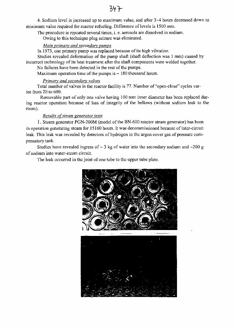
4. Sodium level is increased up to maximum value, and after 3-^4 hours decreased down tominimum value required for reactor refueling. Difference of levels is 1500 mm.
The procedure is repeated several times, i. e. aerosols are dissolved in sodium.Owing to this technique plug seizure was eliminated.
Main primary and secondary pumpsIn 1973, one primary pump was replaced because of its high vibration.Studies revealed deformation of the pump shaft (shaft deflection was 1 mm) caused by
incorrect technology of its heat treatment after the shaft components were welded together.No failures have been detected in the rest of the pumps.Maximum operation time of the pumps is ~ 180 thousand hours.
Primary and secondary valvesTotal number of valves in the reactor facility is 77. Number of "open-close" cycles var-
ies from 20 to 600.Removable part of only one valve having 100 mm inner diameter has been replaced dur-
ing reactor operation because of loss of integrity of the bellows (without sodium leak to theroom).
Results of steam generator tests
1. Steam generator PGN-200M (model of the BN-600 reactor steam generator) has beenin operation generating steam for 15160 hours. It was decommissioned because of inter-circuitleak. This leak was revealed by detectors of hydrogen in the argon cover gas of pressure com-pensatory tank.
Studies have revealed ingress of ~ 3 kg of water into the secondary sodium and ~200 gof sodium into water-steam circuit.
The leak occurred in the joint of one tube to the upper tube plate.
STEAM GENERATOR OPERATING EXPERIENCECHARACTERISTICS OF COMPLETELY TESTED BOR-60 STEAM GENERATORS
Characteristics
1. Date of putting into operation2. Test duration, h3. Thermal power, MW4. Steam capacity, t/h5 . Feed water temperature, °C6. Superheated steam temperature, °C7. Steam pressure, bar8. Sodium flow rate, t/h9. Inlet sodium temperature, °C10. Outlet sodium temperature, °C1 1 . Average heat flux, M W/m2
12. Maximum heat flux, MW/m2
Integral SG with helical tubes
Test modes
basicmax power
mode1971-1974
18000203019043090
410430295
0.1800.35
3145210465
90530485295
0.2630.63
Micro-modular direct (SG-1)
Test modes
basicmax power
mode1973-1980
320002435
200450
80360465280
0.1410.50
3044210445
80485455290
0.1750.55
Sectional PGN-200M(SG-2)
-model of BN-600 SGTest modes
basicmax power
mode1978-1982
150002030
200450
90400450300
0.0961.0
2536195470
864154703000.120.98
00
In 1979, tests were carried out in the micro-modular steam generator SG-1 to study so-dium-water interaction processes in case of small (up to 0.2 g/s) and large (up to 0.25 kg/s)water leaks.
The main results of tests:Various methods of leak detection have been verified.Serviceability and reliability of SG safety systems have been verified.Experience has been gained in accident elimination at BOR-60 reactor.
One-month period was required for SG repair before it was put into operation.
Currently, two reverse type steam generators (OPG-1 and OPG-2) are in operation inBOR-60 reactor.
CHARACTERISTICS OF OPG-1 and OPG-2 STEAM GENERATORS
Characteristics
Date of putting into operationTest duration, hThermal power, MWSteam capacity, t/hFeed water temperature,°CSuperheated steam temperature, °CSteam pressure, barSodium flow rate, t/hInlet sodium temperature, °COutlet sodium temperature, °CWeight, tAverage heat flux, MW/m2
Max heat flux, MW/m2
Micro-modular reversectype steam generator
OPG-11981
910002842
21047590
40048028028.5
0.1600.450
Modular reversed typesteam generator
OPG-21991
4300026.339
21046090
4304802839.1
0.1900.550
Reversed steam generator design implies sodium flowing inside the tubes with water-steam flowing on the shell side.
OPG-1 DESIGN
Steam generator consists of eight sections, each one containing preheater, evaporatorand superheater modules.
Steam generator is enclosed in casing with thermal insulation and electric heaters.Module vessel diameter and wall thickness are respectively 194 mm and 16 mm. Mod-
ule tube bundle consists of 19 tubes 025x3 mm (3.5 mm - thickness of superheater tube wall)spaced at 28.5 mm. Spacing of the tube bundle is assured by the grids. Straight section of thetube bundle is covered by hexagonal guide duct.
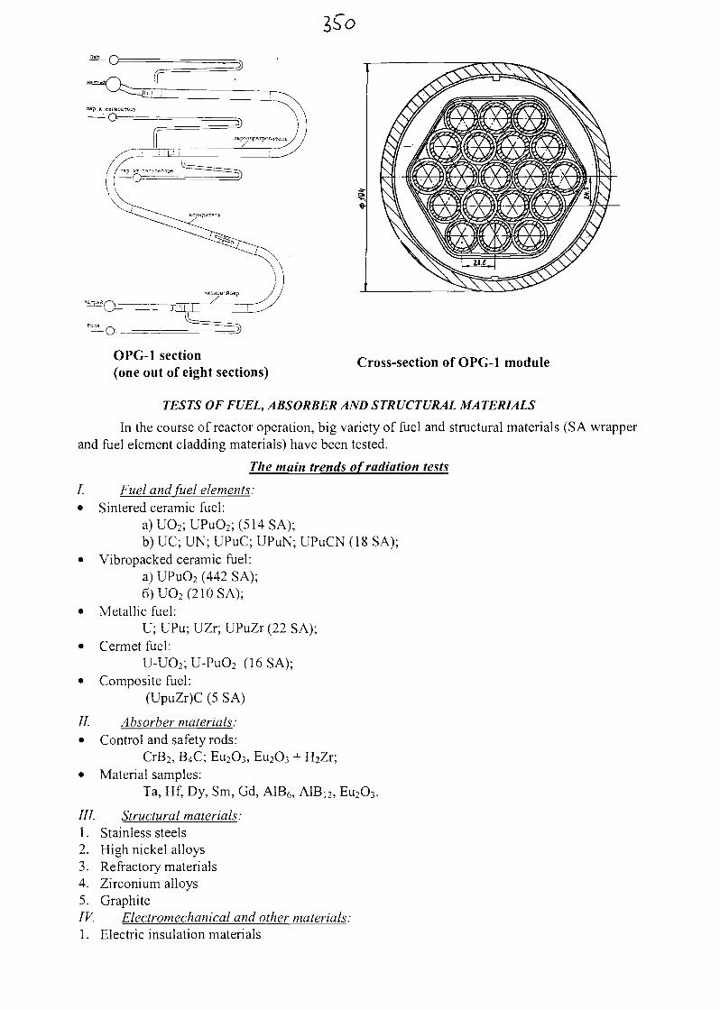
OPG-1 section(one out of eight sections)
Cross-section of OPG-1 module
TESTS OF FUEL, ABSORBER AND STRUCTURAL MA TERIALS
In the course of reactor operation, big variety of fuel and structural materials (SA wrapperand fuel element cladding materials) have been tested.
The main trends of radiation tests
I. Fuel and fuel elements:• Sintered ceramic fuel:
a)UO2;UPuO2;(514SA);b) UC; UN; UPuC; UPuN; UPuCN (18 SA);
• Vibropacked ceramic fuel:a) UPu02 (442 SA);6)UO2(210SA);
• Metallic fuel:U; UPu; UZr; UPuZr (22 SA);
• Cermet fuel:U-UO2;U-PuO2 (16SA);
• Composite fuel:(UpuZr)C (5 SA)
//. Absorber materials:• Control and safety rods:
CrB2, B4C; Eu2O3, Eu2O3 + H2Zr;• Material samples:
Ta, Hf, Dy, Sm, Gd, A1B6, AlBi2, Eu2O3.
///. Structural materials:1. Stainless steels2. High nickel alloys3. Refractory materials4. Zirconium alloys5. GraphiteIV. Electromechanical and other materials:1. Electric insulation materials
2. Magnetic materials3. Special ceramics4. Biological shielding materials
In 1981, reactor core was loaded with fuel elements having vibropacked pins based on re-actor grade plutonium. Introduction of getter solved the problem concerning physical and chemi-cal interaction of the fuel and cladding and assured high average fuel burn-up (13 4- 15%h.a.).Maximum burn-up achieved in some pilot fuel elements was 32% h.a.
hi 1998 tests of the fuel elements based on weapons grade plutonium started (18 SA).Also, accelerated tests of the following structural materials are under way:
• steels used for in-vessel devices (IVD) of water cooled water moderated reactors (VVR);
• zirconium alloys for VVR core;
• vanadium based alloys in lithium environment for fusion reactors.Currently, design and manufacture work is under way on independent loop for in-pile
tests of the fuel elements intended for BREST-300 lead cooled reactor.Strontium-89 production from yttrium targets continues for fabrication of strontium-89
preparation. Also, gadolinium-153 is produced from "European" targets for fabrication ofsources and preparation.
SODIUM TECHNOLOGY
Some important problems related to handling of sodium (both non-radioactive and radioac-tive) have been solved in the course of BOR-60 reactor operation.1. Sodium purity is maintained by the cold traps (CT) having limited capacity in terms of en-
trapped impurities. These expensive components required replacement. In order to avoid re-placement, system for CT regeneration has been designed, constructed and put into operationat the reactor facility.
2. One of the most important tasks is to assure reliable operation of the primary systems andcomponents with simultaneous decrease of personnel dose rates. Now highly effective sta-tionary system for sodium purification from caesium (SSOT) is provided on the reactor facil-ity.
3. New technologies have been developed solving the problem of decontamination of sodiumcomponents and disposal of sodium residues in the components to be repaired or decommis-sioned.
During 1995-2001 period, RIAR and OKB GIDROPRESS were involved in the studieson justification of extension of BOR-60 reactor main components lifetime showing that reactorfacility can be operated for 20 years more, i.e. its total lifetime can be extended up to 40 years.
By now, permission has been issued for BOR-60 reactor operation until 31 December,2009.
1.3. Belovarskava NPP with BN-600 reactor
THE MAIN CHARACTERISTICS OF BN-600 POWER UNIT
Reactor:arrangement pool-typesupport at the bottomvessel cooling agent cold sodiumnumber of heat removal loops 3inlet/outlet sodium temperature, °C 377/550sodium flow rate, t/h 25000
Core and fuel:fuel uranium dioxide pellets
fuel burn-up max/average, % h. a.diameter, cmheight, cm
Intermediate heat exchanger
Primary pump:designrpm
Steam generator:design
inlet/outlet sodium temperature, °Cinlet/outlet water/steam temperature, °Clive steam pressure, MPa
Secondary pump:designrpm
TurbogeneratorDecay heat removal system:
primary and secondary circuitsthird circuit
Refueling system
Fuel transfer systemSpent fuel storageWashing of subassemblies from sodium
10/6206104shell-and-tube design, secondary sodiumflowing on the tube side
centrifugal, one stage250-970
once-through, section & modular (8 sec-tions, 24 modules)518/328241/50714
centrifugal, one stage250-750standard 21OMW
normal operation systemsteam generator- deaerator2 rotating plugs, vertical refueling mecha-nismelevators with guide rampin-vessel storage, sodium and water poolssteam-gas-water
THE MAIN STAGES OF THE BN-600 REACTOR OPERATION
BN-600 power unit was connected to the grid on 8 April 1980.Rated power level 600 MWe was achieved on 22 December 1981.Since 1982 power unit has been operated to produce electricity and heat on commercial
basis.The first modification of the reactor core was made in 1987.The second modification of the reactor core made in 1993 facilitated reaching design fuel
burn-up of 10% h.a.Work on scheduled replacement of SG evaporator modules and extension of their lifetime
has been carried out.
THE MAIN RESUL TS OF BN-600 RE A CTOR OPERA TION
Power unit operation during over 20 years has demonstrated good agreement between de-sign and real characteristics of the main components. The following high technical and economi-cal indices have been achieved:
power unit gross efficiency 41.93%;- load factor over the whole period of operation 69.9% (over 74% - if early stage of
operation is neglected).By 28 January 2002, total time of BN-600 reactor operation since initial start-up is 150
thousand hours, i.e. 17 years.Operating experience has made it possible to improve technological modes, systems and
components of the BN-600 reactor power unit. In particular, the following modes were opti-mized:
connection of heat removal loop to the reactor in operation;- reactor decay heat removal;
- power unit start-up;- connection of steam generator section with power unit in operation.According to the original BN-600 reactor design there were two zones of 235U enrichment
(21% and 33%) in the uranium dioxide core, maximum fuel burn-up being equal to 9.7%h.a.Operation of the original BN-600 reactor core revealed that because of small gaps between sub-assemblies and the wrong choice of SA wrapper and fuel element cladding material fuel burn-upwas limited by 7.3% h.a. value. Moreover, even this burn-up caused fuel element failures andconsiderable bending of subassemblies at the end of each reactor run.
In order to eliminate bending of subassemblies and fuel element failures, the first modifi-cation of the core was made in 1987. The main features of this modification were addition of thethird enrichment zone in the core (17%, 21% and 26% enrichment zones, maximum fuel burn-up8.3% h.a.), elimination of rotation and shuffling of subassemblies, increase of the core heightfrom 75 cm to 100 cm with decrease of linear power from 54 kW/m to 47 kW/m, and applicationof the new cold worked (~20%) steel as SA wrapper and fuel cladding material. Refueling wasmade twice a year, with the interval 165 eff. days. As a result of modification, there were nomore fuel element failures, and further burn-up increase became possible.
After the second modification of the core implemented in 1993, 10% h.a. and 11.8% h.a.fuel burn-up was achieved respectively in the standard and pilot subassemblies. This modifica-tion was based on the application of new structural materials, and, in particular, ferritic-martensitic steel was used for the first time in the world practice as structural material for the SAwrapper.
Studies on the fuel burn-up increase were based on the results of in-pile tests of pilot sub-assemblies. Total number of irradiated subassemblies was 318 (over 40 thousand fuel elements).Uranium-plutonium vibropacked and pellet fuel subassemblies were tested successfully. In-piletests of 28 pilot subassemblies (PSA) with MOX fuel pellets have been completed, and 12 morePSAs are now irradiated. Besides, 6 vibropacked PSAs have been irradiated and 3 PSAs now un-dergo in-pile tests.
hi general, operation of reactor and in-vessel structures has been successful. The mostsignificant problems encountered during operation refer to sodium composite deposits on the re-actor vessel surface above the sodium level and prematurely exhausted lifetime of control rodguide tubes. Sodium composite deposits on the reactor vessel surface in the cover gas plenumwere caused by moisture brought by the argon gas supplied for replenishment and air enteringreactor vessel in the process of in-vessel replacement.
hi January 1987, ingress of deposits into sodium occurred during reactor operation at therated power level. This added small positive reactivity (0.03% §k/k), which was compensated byautomatic control system having considerable margin for compensation of such perturbations, hiorder to eliminate moisture and air penetration into the reactor, argon replenishment system wasmodified, drying unit was installed and sealing devices used for in-vessel components replace-ment were improved.
Since 1995, seizure of the small rotating plug was observed during reactor refueling, andthis seizure became stronger with time.
In order to determine the cause of this phenomenon, in 1997 a drilling was made of theplug body during scheduled reactor shutdown and its bearing unit was visually inspected. As aresult of inspection, sodium was revealed in the bearing unit. An attempt was made to removethe sodium by heating, but it failed. So it was decided to remove sodium and replace bearing (ifnecessary) during scheduled preventive repair (SPR) in 1998.
hi 1998, during SPR combined with reactor refueling, sodium was removed and the bear-ing was replaced. These procedures were carried out after the plug had been moved 650 mm up-wards in the gas-tight cask. Replaced bearing was plugged with sodium. Analysis showed thatthe amount of sodium (~15 kg) corresponded to the rate of sodium vapor transfer in the gap be-tween the large and small rotating plugs.
After that, the plug was lifted up to 2100mm height for inspection and measurements.Scratches were revealed on the lateral surface of the plug, so the surface was ground. Thesemeasures made it possible to restore design plug rotation force.
In the early stage of operation, failures of pump shafts and pump-drive shaft couplingsoccurred causing unscheduled reactor power decrease. These failures were because of coinci-dence of shaft resonance frequency and that of torsional vibrations caused by rectified rotor cur-rent pulsation that could not be eliminated. After source of failure had been identified and pumprotation frequency had been made different from resonance value, no more shaft failures wereobserved. Later, shaft design was modified, as well as the method of switching pump to non-controlled operation mode when operating at the steady state power level, and so the source ofpump failures was eliminated.
Reliability of the primary pumps was increased owing to the increase of lifetime of thebasic structural elements. The most significant was increase of the impeller lifetime from 35 000to 50 000 hours.
Sectional/modular steam generators are used in the BN-600 reactor. Each one out of threesteam generators consists of eight sections. Each section includes three modules, namely: evapo-rator, superheater and reheater. These modules are connected by the pipelines to form section.Sections of one steam generator are also connected by the pipelines with valves for section isola-tion on either sodium or water-steam side in case of failure. Owing to this design, failed sectioncan be put out of operation with all the rest sections still in operation without decreasing reactorpower.
During the whole period of SG operation, 12 leaks of steam and water into sodium haveoccurred, half of these leaks took place in the first year of operation because of manifestation ofhidden manufacture defects. Inter-circuit leaks took place mainly in the superheaters (6 events)and reheaters (5 events), while only one leak occurred in the evaporator (Table 1).
Analysis of leak events has demonstrated high resistance of SG design with respect to in-ter-circuit leaks. Operating experience confirmed the choice of SG concept: decrease of powergeneration caused by 12 water-to-sodium leaks was as low as 0.3%. Thus, in spite of SG leaks,its sectional/modular design assured planned rate of power increase and high performance.
Justification of possibility of evaporator lifetime extension from 50 thousand hours (de-sign value) to 105 thousand hours made in the process of their operation made it possible to re-place evaporators only once during the power unit lifetime instead of planned three times. Thiswas the result of evaporator conditions study program implemented for many years, modificationof water chemistry, decrease of the number of reactor transients and accidents as compared topredicted number, as well as procedures of chemical cleaning and washing out friable depositswith water performed on periodical basis.
Since 90-ies, scheduled replacement of SG evaporator modules has been carried out.
During BN-600 reactor operation, 27 sodium leaks have occurred.Below given is sodium leaks distribution with respect to their causes:
- failures of SG sodium valves 5 leaks- defects of flange joints 5 leaks- wrong sequence of procedures of melting sodium in the pipeline 4 leaks- holes made by personnel 2 leaks- manufacture defects 3 leaks- sodium valve defects 2 leaks- cracks in the pipelines 6 leaks
• Sodium valves provided for isolation of the BN-600 reactor steam generator modules fromthe circuit have flange joints backed up by «moustache» welds. It was initially assumed thatthe flange joints would assure integrity, so insufficient importance was attached to the qualityof welds. After sodium leaks had occurred in the flange joints, «moustache» welds were re-covered with subsequent quality. Since then no more leaks have occurred in the SG valves.
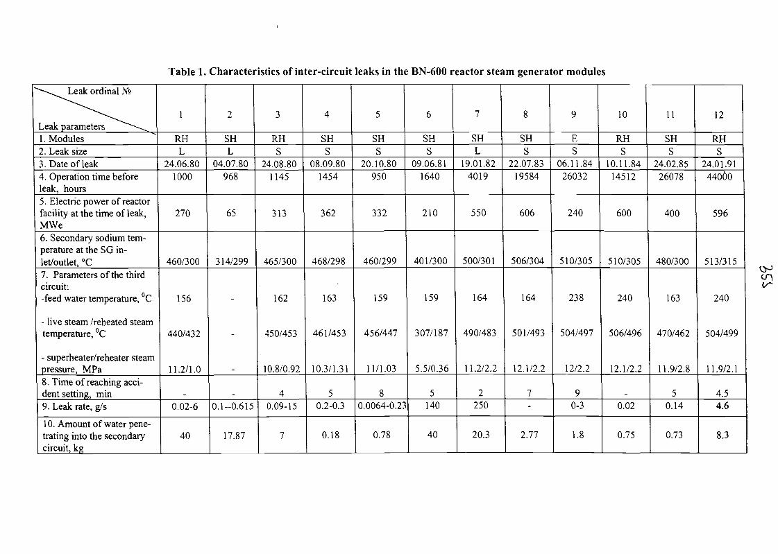
Table 1. Characteristics of inter-circuit leaks in the BN-600 reactor steam generator modules
"""- ^^^ Leak ordinal N°
^^\^^
Leak parameters ^^~\^1 . Modules2. Leak size3. Date of leak4. Operation time beforeleak, hours5. Electric power of reactorfacility at the time of leak,MWe6. Secondary sodium tem-perature at the SG in-let/outlet, °C7. Parameters of the thirdcircuit:-feed water temperature, °C
- live steam /reheated steamtemperature, °C
- superheater/reheater steampressure, MPa8. Time of reaching acci-dent setting, min9. Leak rate, g/s
10. Amount of water pene-trating into the secondarycircuit, kg
1
RHL
24.06.801000
270
460/300
156
440/432
11.2/1.0
-0.02-6
40
2
SHL
04.07.80968
65
314/299
-
-
-
-0.1-0.615
17.87
3
RHS
24.08.801145
313
465/300
162
450/453
10.8/0.92
40.09-15
7
4
SHS
08.09.801454
362
468/298
163
461/453
10.3/1.31
50.2-0.3
0.18
5
SHS
20.10.80950
332
460/299
159
456/447
11/1.03
80.0064-0.23
0.78
6
SHS
09.06.811640
210
401/300
159
307/187
5.5/0.36
5140
40
7
SHL
19.01.824019
550
500/301
164
490/483
11.2/2.2
2250
20.3
8
SHS
22.07.8319584
606
506/304
164
501/493
12.1/2.2
7-
2.77
9
ES
06.11.8426032
240
510/305
238
504/497
12/2.2
90-3
1.8
10
RHS
10.11.8414512
600
510/305
240
506/496
12.1/2.2
-0.02
0.75
11
SHS
24.02.8526078
400
480/300
163
470/462
11.9/2.8
50.14
0.73
12
RHS
24.01.9144060
596
513/315
240
504/499
11.9/2.1
4.54.6
8.3
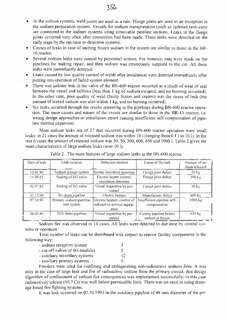
• In the sodium systems, weld joints are used as a rule. Flange joints are used as an exception inthe sodium preparation system. Vessels for sodium transportation (such as railroad tank-cars)are connected to the sodium systems using removable pipeline sections. Leaks in the flangejoints occurred very often after connection had been made. These leaks were detected on theearly stage by the operator or detection systems.
• Causes of leaks in case of melting frozen sodium in the system are similar to those in the BR-IO reactor.
• Several sodium leaks were caused by personnel actions. For instance, cuts were made on thepipelines for making repair, and then sodium was erroneously supplied to the cut. All theseleaks were immediately detected.
• Leaks caused by low quality control of welds after installation were detected immediately afterputting into operation of failed system element.
• There was sodium leak in the valve of the BN-600 reactor occurred as a result of wear of sealbetween the vessel and bellows (less than 1 kg of sodium escaped, and no burning occurred).In the other case, poor quality of weld (faulty fusion and craters) was the cause of leak (theamount of leaked sodium was also within 1 kg, and no burning occurred).
• Six leaks occurred through the cracks appearing in the pipelines during BN-600 reactor opera-tion. The main causes and nature of the events are similar to those in the BR-10 reactor, i.e.wrong design approaches or installation errors causing insufficient self-compensation of pipe-line thermal expansion.
Most sodium leaks out of 21 that occurred during BN-600 reactor operation were smallleaks: in 21 cases the amount of released sodium was within 10 1 (ranging from 0.1 1 to 10 1). In therest 6 cases the amount of released sodium was 30, 50, 300, 600, 650 and 1000 1. Table 2 gives themain characteristics of large sodium leaks (over 10 1).
Table 2. The main features of large sodium leaks in the BN-600 reactor
Date of leak
13.01.8011.08.81
02.07.82
31.12.9007.10.93
06.05.94
Leak location
Sodium receipt systemSealing of SG valve
Sealing of SG valve
SG drain pipelinePrimary sodium purifica-
tion system
IHX drain pipeline
Detection method
Smoke ionization detectorsElectric heater control,
ionization detectorsVisual inspection by per-
sonnelElectric heaters
Electric heaters, control ofradioactive aerosol appear-
anceVisual inspection by per-
sonnel
Cause of the leak
Flange joint defectFlange joint defect
Flange joint defect
Manufacture defectInsufficient pipeline self-
compensation
Cutting pipeline beforesodium is frozen
Amount of so-dium released
50kg300kg
30kg
600kg1000kg
650 kg
Sodium fire was observed in 14 cases. All leaks were detected in due time by control sys-tems or operators.
Total number of leaks can be distributed with respect to reactor facility components in thefollowing way:
- sodium reception system 5- cut-off valves of SG modules 5- auxiliary secondary systems 12- auxiliary primary systems 5.Powders were used for confining and extinguishing non-radioactive sodium fires. It was
only in the case of large leak and fire of radioactive sodium from the primary circuit, that designalgorithm of confinement of sodium fire consequences was implemented successfully: in this caseradioactivity release (10.7 Ci) was well below permissible limit. There was no need in using drain-age based fire fighting systems.
It was leak occurred on 07.10.1993 in the auxiliary pipeline of 48 mm diameter of the pri-
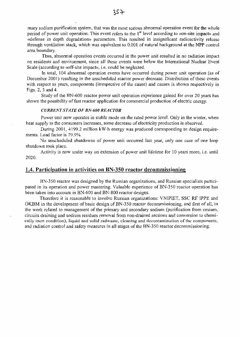
mary sodium purification system, that was the most serious abnormal operation event for the wholeperiod of power unit operation. This event refers to the 1st level according to «on-site impact» and«defense in depth degradation)) parameters. This resulted in insignificant radioactivity releasethrough ventilation stack, which was equivalent to 0.001 of natural background at the NPP controlarea boundary.
Thus, abnormal operation events occurred in the power unit resulted in no radiation impacton residents and environment, since all these events were below the International Nuclear EventScale (according to «off-site impact», i.e. could be neglected.
In total, 104 abnormal operation events have occurred during power unit operation (as ofDecember 2001) resulting in the unscheduled reactor power decrease. Distribution of these eventswith respect to years, components (irrespective of the cause) and causes is shown respectively inFigs. 2, 3 and 4.
Study of the BN-600 reactor power unit operation experience gained for over 20 years hasshown the possibility of fast reactor application for commercial production of electric energy.
CURRENT STA TE OF BN-600 RE A CTOR
Power unit now operates in stable mode on the rated power level. Only in the winter, whenheat supply to the consumers increases, some decrease of electricity production is observed.
During 2001, 4199.2 million kW-h energy was produced corresponding to design require-ments. Load factor is 79.9%.
No unscheduled shutdowns of power unit occurred last year, only one case of one loopshutdown took place.
Activity is now under way on extension of power unit lifetime for 10 years more, i.e. until2020.
1.4. Participation in activities on BN-350 reactor decommissioning
BN-350 reactor was designed by the Russian organizations, and Russian specialists partici-pated in its operation and power mastering. Valuable experience of BN-350 reactor operation hasbeen taken into account in BN-600 and BN-800 reactor designs.
Therefore it is reasonable to involve Russian organizations: VNEPIET, SSC RF EPPE andOKBM in the development of basic design of BN-350 reactor decommissioning, and first of all, inthe work related to management of the primary and secondary sodium (purification from cesium,circuits draining and sodium residues removal from non-drained sections and conversion to chemi-cally inert condition), liquid and solid radwaste, cleaning and decontamination of the components,and radiation control and safety measures in all stages of the BN-350 reactor decommissioning.
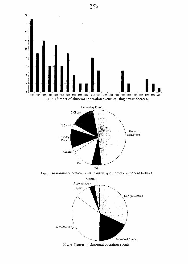
I10
1II i l l *1980 1981 1982 1983 1984 1985 1986 1987 1988 1989 1990 1991 1992 1993 1994 1995 1996 1997 1998 1999 2000 2001
Fig. 2 Number of abnormal operation events causing power decrease
Secondary Pump
3 Circuit
2 Circuit
PrimaryPump
Reactor
ElectricEquipment
SA
Fig. 3 Abnormal operation events caused by different component failures
Others -
Assemblage-
Repair ^^
Design Defects
Manufacturing
Personnel Errors
Fig. 4 Causes of abnormal operation events
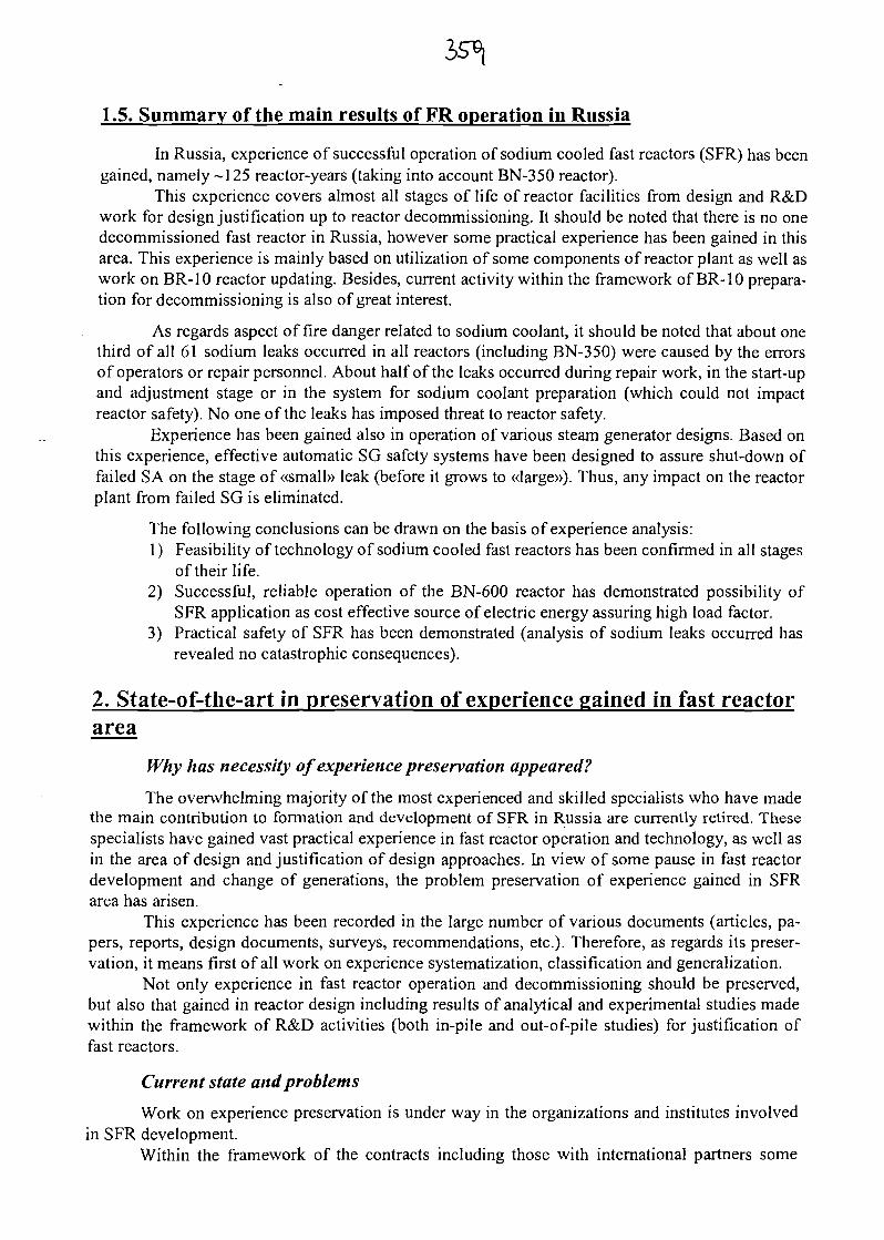
1.5. Summary of the main results of FR operation in Russia
In Russia, experience of successful operation of sodium cooled fast reactors (SFR) has beengained, namely -125 reactor-years (taking into account BN-350 reactor).
This experience covers almost all stages of life of reactor facilities from design and R&Dwork for design justification up to reactor decommissioning. It should be noted that there is no onedecommissioned fast reactor in Russia, however some practical experience has been gained in thisarea. This experience is mainly based on utilization of some components of reactor plant as well aswork on BR-10 reactor updating. Besides, current activity within the framework of BR-10 prepara-tion for decommissioning is also of great interest.
As regards aspect of fire danger related to sodium coolant, it should be noted that about onethird of all 61 sodium leaks occurred in all reactors (including BN-350) were caused by the errorsof operators or repair personnel. About half of the leaks occurred during repair work, in the start-upand adjustment stage or in the system for sodium coolant preparation (which could not impactreactor safety). No one of the leaks has imposed threat to reactor safety.
Experience has been gained also in operation of various steam generator designs. Based onthis experience, effective automatic SG safety systems have been designed to assure shut-down offailed SA on the stage of «small» leak (before it grows to «large»). Thus, any impact on the reactorplant from failed SG is eliminated.
The following conclusions can be drawn on the basis of experience analysis:1) Feasibility of technology of sodium cooled fast reactors has been confirmed in all stages
of their life.2) Successful, reliable operation of the BN-600 reactor has demonstrated possibility of
SFR application as cost effective source of electric energy assuring high load factor.3) Practical safety of SFR has been demonstrated (analysis of sodium leaks occurred has
revealed no catastrophic consequences).
2. State-of-the-art in preservation of experience gained in fast reactorarea
Why has necessity of experience preservation appeared?
The overwhelming majority of the most experienced and skilled specialists who have madethe main contribution to formation and development of SFR in Russia are currently retired. Thesespecialists have gained vast practical experience in fast reactor operation and technology, as well asin the area of design and justification of design approaches. In view of some pause in fast reactordevelopment and change of generations, the problem preservation of experience gained in SFRarea has arisen.
This experience has been recorded in the large number of various documents (articles, pa-pers, reports, design documents, surveys, recommendations, etc.). Therefore, as regards its preser-vation, it means first of all work on experience systematization, classification and generalization.
Not only experience in fast reactor operation and decommissioning should be preserved,but also that gained in reactor design including results of analytical and experimental studies madewithin the framework of R&D activities (both in-pile and out-of-pile studies) for justification offast reactors.
Current state and problems
Work on experience preservation is under way in the organizations and institutes involvedin SFR development.
Within the framework of the contracts including those with international partners some
studies have been made on summarizing experience gained in some topics concerning:- operation of the BN-600 reactor (design approaches, SA bending, SG, reactor operation
with failed fuel elements, transients and sodium leaks),operation of uranium mononitride core in the BR-10 reactor,
- results of post-irradiation studies of fuel elements with cladding made of ChS-68 steelirradiated in BOR-60, BN-350, BN-600, etc.
Electronic version of bibliographical catalogue of publications on SFR issued with partici-pation of IPPE from 1952 to 1998 has been developed.
However, because of the lack of investments, work on preservation and generalization ofexperience gained in the area of SFR has been decreased.
There are many enterprises and institutes participating in the work on SFR, such as:1) State Scientific Center of the Russian Federation - Institute for Physics and Power
Engineering (SSC RF IPPE), Obninsk;2) Experimental Machine Building Design Bureau (OKBM), Nizhny Novgorod;3) St. Petersburg Research an Design Institute ATOMENERGOPROEKT (SPAEP), St.
Petersburg;4) State Research Center of the Russian Federation - Research Institute of Atomic Reac-
tors (SRC RF- RIAR), Dimitrovgrad;5) Experimental Design Organization "Gidropress" (OKB GP), Podolsk;6) Beloyarskaya NPP (BNPP), Zarechny, etc.Considerable experience has been gained in these organizations in design, construction and
operation of SFR.
3. Proposals on approaches to organization of co-operation
On the previous TWGFR meeting in Kazakhstan, it was recommended to this IAEA meet-ing to include into the agenda (in addition to discussion on the results of fast reactor operation anddecommissioning) the issue of possibility of organization of joint work on preservation and gener-alization of experience gained in operation of SFRs.
Common nature of the problem ofFR experience preservation
By now, initial stage of SFR development has been completed. The main result of this stageis development and improvement of basic engineering and technological approaches practicallyconfirming feasibility of commercial SFRs producing electricity.
Obviously, the next stage of development of SFRs, i.e. large-scale construction of com-mercial power units will not start before 2020.
Thus, the problem of preservation and generalization of experience gained in the area ofSFRs including operation experience exists in each country, where this trend of nuclear power hasbeen and is still developed. In each country, efforts are made to solve this problem using variousmethods.
It should be noted that all these countries should be interested in preservation of this ex-perience gained in each country. This is because experience of each country is a unique contribu-tion to that gained in other countries. Only the whole experience can give complete idea of theproblems related to SFRs.
Importance and urgent nature of the task of preservation of FR operating experience is alsocaused by the fact that fast reactor plants have been/are decommissioned in many countries. Major-ity of personnel of these plants have been either retired or left for other areas. Thus, experiencegained in SFR operation has been mainly recorded only in some certain documents, namely: re-ports, instructions for operators, design and working materials, conclusions, surveys, etc.
Approaches to the problem solution
The task of preservation of operating experience on SFRs is a versatile, complicated prob-lem. Without pretending to get comprehensive solution of this problem, systematization of docu-ments containing data should be made as an initial step. Only availability of complete catalogues ofsuch documents on each aspect of SFR experience will make it possible to turn to the next stage,namely: generalization of the experience and development of recommendations for the advancedSFR designs.
Possible contribution by TWGFR
One of the most important directions of activity of IAEA Technical Working Group on FastReactors (TWGFR) is assistance in the work carried out in different countries on preservation ofexperience gained in SFR area (including operation experience).
It should be noted that TWGFR participates actively in this work on a permanent basis. Itsfunctions are as follows:
holding meetings on exchange experience gained in SFR operation and decommission-ing,preparation and issue of various materials summarizing experience gained in either spe-cific or most general aspects of SFR technology.
For instance, there is SFR design characteristics database which is updated on a periodicbasis, and also periodic reports on the status of development of SFR technology, hi these publica-tions, there are rather extensive lists of references on related topics. However these lists of refer-ences cannot be exhaustive, since there are, as a rule, only open publications (papers, articles,books, etc.).
From this standpoint, assistance by TWGFR in the development of comprehensive cata-logues of materials on all aspects of SFR operation and decommissioning experience issued in allcountries would be quite significant and useful contribution to this experience preservation andgeneralization.
However, this work implementation is obviously impossible within the framework of ameeting. In this view, proposal has appeared to study the possibility of organization of the Coordi-nated Research Project (CRP) on this issue.
Proposals on possible goals and tasks of CRP
There is no doubt that creation of such catalogues of materials containing information onSFR operating experience is hard and expensive work, since a large number of specialists from dif-ferent institutions should be involved.
So, what parts and directions of this work could be implemented within the framework ofthe Coordinated Research Project?
First of all, TWGFR could coordinate assistance in working out common approach to for-mation of such catalogues in TWGFR member states. Such catalogue can be made either as paperdocument, or electronic database. In the former case, its value is higher because of the possibilityof on-line processing of large arrays of data using various criteria.
Titles of the documents containing data on the SFR operating experience (with attached ab-stracts and other document attributes) are used as input data in catalogues. Obviously, it is expedi-ent to classify the documents in accordance with topic headings corresponding to different aspectsof SFR operating and decommissioning experience and facilities. Topic headings, in turn, can bedivided into subheadings.
In order to work out common concept of catalogue formation the following subjects areproposed to develop and agree upon with work participants:
classification on topic headings (subheadings),format of data presentation (list and form of their attributes),lists of key words and terms typical for each heading (subheading),
list of characteristics taken into account in the catalogue of SFR plants and their classi-fication,list of acronyms and measurement units,language of data presentation (English).
Besides the title of the document, the following attributes can be used:index of headings (subheadings) this document refers to,index of the plant (plants) described or mentioned in the document,authors and their affiliations,country,year of document issuing,place of storage (publication),list of key words used in the document,abstract, i.e. brief description of contents of the document, etc.
Proposed project of formation of the catalogue implies of course the possibility of its cor-rection in accordance with the comments and recommendations made by work participants.
Thus, a document will be issued as a result of CRP with the following items developed andagreed upon with the project participants:
list and structure of topical headings (subheadings),data presentation format (list and form of their attributes),lists of key words and terms typical for each heading (subheading),list of acronyms and measurement units,list of characteristics included in the catalogue of SFR plants and their classification.
The scope and nature of the proposed work make it possible to reliably implement it withinthe framework of Coordinate Research Project.
This is the necessary preparation stage for development of the common unified catalogue ofmaterials on experience of SFR operation and decommissioning provided the work is financed.
This work is valuable and promising even if separate catalogues are created in TWGFRmember states, since all these catalogues meet certain standard requirements agreed upon by allstates participating in the work.
Such databases would be useful, because all interested states could address the owners ofmaterial of their interest in order to acquire or exchange information.
Upon successful working out of common structure and format for catalogue of materials onexperience of SFR operation and decommissioning similar work can be implemented with respectto the catalogue of materials on general experience gained in SFR area including not only opera-tion, but also design and R&D issues, etc.
SESSION 2:
Fast reactor decommissioning experience

363
DECOMMISSIONING EXPERIENCE FROM THEEXPERIMENTAL BREEDER REACTOR-II
by
S. P. Henslee and K. E. Rosenberg
Engineering Technology DivisionArgonne National Laboratory-West
P. O. Box 2528Idaho Falls, ID 83403-2528
The submitted manuscript has been createdby the University of Chicago as Operator ofArgonne National Laboratory (AArgonne®)under contract No. W-31-109-ENG-38 withthe U.S. Department of Energy. The U.S.Government retains for itself, and othersacting on its behalf, a paid-up nonexclusive,irrevocable worldwide license in said articleto reproduce, prepare derivative works,distribute copies to the public, and performpublicly and display publicly, by or onbehalf of the Government.
To be Presentedat IAEA Technical Meeting
Cadarache, France
March 11-15,2002
*Work supported by the U.S. Department of Energy, Office of Nuclear Energy, Science andTechnology, and the Office of Environmental Management, under contract W-31-109-Eng-38.
Decommissioning Experience from the Experimental Breeder Reactor-II
Introduction
Consistent with the intent of this International Atomic Energy Agency technical meeting,decommissioning operating experience and contributions to the preparation for theCoordinated Research Project from Experimental Breeder Reactor-II activities will bediscussed. This paper will review aspects of the decommissioning activities of theExperimental Breeder Reactor-II, make recommendations for future decommissioningactivities and reactor system designs and discuss relevant areas of potential research anddevelopment.
EBR-II Operating Summary
The Experimental Breeder Reactor-II (EBR-II) was designed as a 62.5 MWt, metal fueled,pool reactor with a conventional 19 MWe power plant. The productive life of the EBR-IIbegan with first operations in 1964. Demonstration of the fast reactor fuel cycle, serving asan irradiation facility, demonstration of fast reactor passive safety and lastly, was well on itsway to close the fast breeder fuel cycle for the second time when the Integral Fast Reactorprogram was prematurely ended in October 1994 with the shutdown of the EBR-II.
The shutdown of the EBR-II was dictated without an associated planning phase that wouldhave provided a smooth transition to shutdown. Argonne National Laboratory and the U.S.Department of Energy arrived at a logical plan and sequence for closure activities. Thedecommissioning activities as described herein fall into in three distinct phases.
Current StatusThe plan describing the final condition of the EBR-II, was implemented in October 2000. Bythis time many important steps had been performed, forming the basis for the plan.Specifically, defueling of the reactor, the design and construction of the sodium processfacility and initial sodium processing had taken place.
At the writing of this paper, all physical work associated with the decommissioning activitiesof the EBR-II are complete. Remaining activities are limited to completion of finaldcoumentation specifying actions taken on a system-by-system basis, providing the finalconfiguration control. The following activities have been completed:
- Reactor defueling,- Spent fuel placed in interim storage,- Sodium Process Facility made operational,- Primary and secondary sodium coolant removed from reactor systems,- Sodium potassium coolants processed with sodium,- Sodium coolant converted to solid sodium hydroxide for disposal,- Passivation of sodium remaining within secondary and primary systems, and- Reactor and non-reactor systems placed in a radiological and industrially safe
condition.
Phase I EBR-II Decommissioning Activities
The initial phase of decommissioning activities was reactor defueling, completed inDecember 1996. Defueling was initiated in October 1994 and was completed 14 monthslater, 3 months ahead of schedule. Defueling included:
- Removal of 637 assemblies from the reactor core,- Washing sodium coolant from and drying each assembly,- Transfer of assemblies to a hot-cell facility for disassembly and repackaging, and- Transfer of spent fuel to interim storage.
Argonne originally anticipated significant modifications to both fuel handling equipment andcontrol systems prior to initiation of defueling. However, in order to minimize the timerequired to defuel, the risk of potential fuel handling equipment failure was accepted. Fuelhandling equipment performed well with only routine maintenance providing an adequatesafety margin during nearly continuous operation. Treatment of the EBR-II spent fuel is astate-of-the-art electrometallurgical application and will not be discussed here.
Performed in parallel to reactor defueling was the design and construction of the SodiumProcess Facility. The design and construction of the Sodium Process Facility is anapplication of known and demonstrated technology. The conversion of alkali metal to alkalihydroxide compounds by reaction with alkali hydroxide is routinely performed around theworld, e.g., DFR/PFR, at Dounreay and as planned at Superphenix.
Phase II EBR-II Decommissioning ActivitiesThe second decommissioning phase was sodium coolant removal and reaction. Constructionof the Sodium Process Facility provided Argonne the ability to react elemental sodium withwater to form sodium hydroxide, at compositions ranging from 30 to 73% by weight. Allsodium treated as part of the decommissioning activities was reacted to a 73% by weightsodium hydroxide. Compositions of 70% by weight sodium hydroxide or greater are solidbelow 60°C. The U. S. Environmental Protection Agency, the regulatory agency for reactiveand corrosive elements and compounds, does not regulate solid sodium hydroxide allowingits disposable as a low-level waste.
By late summer 2000 the secondary sodium coolant had been reacted to a solid sodiumhydroxide waste and the primary sodium was being drained. Processing of the primarysodium was completed in March 2001. In addition to the sodium utilized as EBR-II coolant,372 tonnes. Argonne also stored the Fermi I primary sodium inventory 281 tonnes, that wasalso reacted to sodium hydroxide and disposed of as low level waste. A total of 653 tonnes ofsodium was converted to 1,450 tonnes of solid sodium hydroxide.
Phase III Decommissioning of the EBR-II
The third and final phase of the decommissioning activity was the placement of reactor andnon-reactor systems in a radiological and industrially safe condition. The planning for thisphase included a detailed system-by-system evaluation to determine necessary actions basedon the following definition:
Radiologically and industrially safe is the placement of equipment and facility in acondition that does not pose any unusual, unexpected or additional industrial safetyrisk and does not pose a radiation or contamination risk beyond normal EBR-II levelsfor controlled access areas.
As the system-based planning was developed, necessary or newly identified surveillanceactivities were identified. Surveillance provides the regulator assurance that EBR-II systemswould not deteriorate.
A major component of the radiologically and industrially safe strategy was treatment of theresidual radioactive sodium remaining within system piping and components. Theconversion of the exposed residual sodium surfaces to a non-reactive layer of sodiumcarbonate was accomplished through a process called passivation. Passivation (orcarbonization) is achieved through the controlled humidification of the carbon dioxide covergas. The presence of water vapor in carbon dioxide forms a layer of sodium carbonate(sodium bicarbonate). The carbonate layer remains porous and does not impede reaction ratesuntil a layer of greater than 20 cm has been achieved. All exposed surfaces of sodiumremaining within both the primary and secondary systems have been passivated.
Subsequent to the draining of the primary sodium a close circuit TV camera was inserted intothe EBR-II primary tank. Among the objectives of this visual inspection were: confirmationof completion of the sodium coolant draining process, provide a visual understanding of thedraining process and residual sodium deposition locations and finally provide a visualassessment of tank and component integrity.
Visual examination provided evidence of the draining process, confirming the removal of allbut very small quantities of residual sodium. An additional visual examination followed thecompletion of passivation of all primary systems.
Summary and RecommendationsRecommendations for future decommissioning activities, reactor system designs andidentification of areas of potential research and development are the result of lessons learnedfrom EBR-II decommissioning activities. Although many of the recommendations are notnew, they were included due to the significance to this discussion.
Reactors plants should be shutdown in accordance to detailed planning allowingoperators and regulators a common understanding of facility conditions, the processesthat will take place, the interactions expected or required and to provide opencommunications of anticipated planning schedules.The volume of sodium to be measured from systems should be accomplished bycalculations of remaining sodium. If the potential exists for negotiation, the regulatorshould be educated on the relative safety, costs, risks and potential for environmental
impacts from the presence of bulk or residual sodium. This activity can significantlyreduce the cost to decommission a fast reactor.
A major benefit to the fast reactor community would be a reactor whose cost todecommission was "equal or near" the cost for a water-cooled reactor (PWR or BWR).Clearly, there will be significant disagreement from both within and outside of the fastreactor community. However, until a common goal is established, this or another one, and isembraced by the fast reactor community, no integrated progress will be made.
Any future fast reactor design should, as a fundamental design criteria, require all sodiumsystems be provided with an effective sodium removal capability, i.e., draining. In manycases techniques will be simple and inexpensive to implement. In other systems, reactorvessels or steam generators for example techniques will need to be debated.
Current methods for the reaction of residual sodium in situ are being studied, and applied atthe EBR-II, e. g., passivation. These techniques should be seriously considered for routineapplication and any necessary research and development should be pursued. Theformalization of specific requirements, suggested applications and process limitations shouldbe developed.
New techniques for the removal of sodium, both bulk and residual, should be pursued forboth current reactors as well as implemented into any new fast reactor designs. Techniquesshould address the entire range of possible alternatives, without limitations of currentlyexisting technologies. Potential future in situ techniques should be identified, prioritized andfully developed allowing the decommissioning of fast reactors to be forthright and costeffective.
ConclusionThe EBR-II decommissioning activities performed have been discussed. These activitieswere performed safely, effectively, efficiently and on schedule. Of primary interest are thoserecommendations stemming from the lessons learned in performing the decommissioningactivities. Goals have been suggested for future reactor designs and current decommissioningactivities. Finally, the decommissioning experience from the EBR-II has resulted indiscussion of relevant Coordinated Research Program topics.
Acknowledgement
Argonne National Laboratory's work was supported by the U. S. Department of Energy,Office of Nuclear Energy, Science and Technology, under contract W-31-109-Eng-38.

Decommissioning Experiencefrom the EBR-II
Presented toIAEA-TM
S. Paul HensleeDirector, EBR-II Plant Closure
Project
oo

Presentation Outline
Operating Experience MilestonesSummary Current StatusEBR-II Decommissioning ActivitiesConclusions

Argonne National Laboratory
Argoijine Matronalaboraiory-bast
Chicago, IllinlosvArgonneNatidnal~5?-g<pL8b'6ratery-Wi
[C»i $is$;i&'/< • IKICBt L4 K
W*t\ " " 'V-*-*-/»j'.•:,*•!-i ?
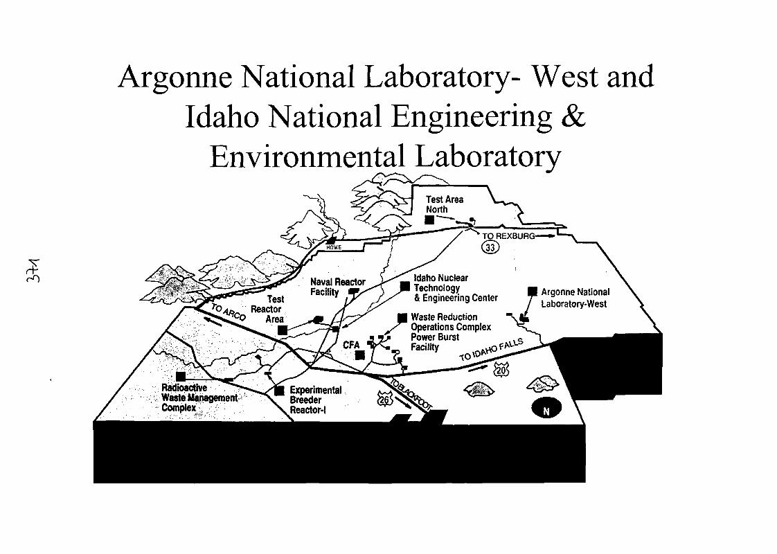
Argonne National Laboratory- West andIdaho National Engineering &
Environmental LaboratoryTest AreaNorth
TO REXBURG—*•*•"'•«
33
Idaho NuclearTechnology& Engineering Center
Naval ReactorFacility Argonne National
Laboratory-WestTestReactor
Area Waste ReductionOperations ComplexPower Burst
RadioactiveWaste ManagementComplex ,
ExperimentalBreederReactor-l

Experimental Breeder Reactor-II
1 Sodium Cooled, Metal Fueled, Pool Reactor• 62.5 MWt• Conventional Power Plant £• 19MWe
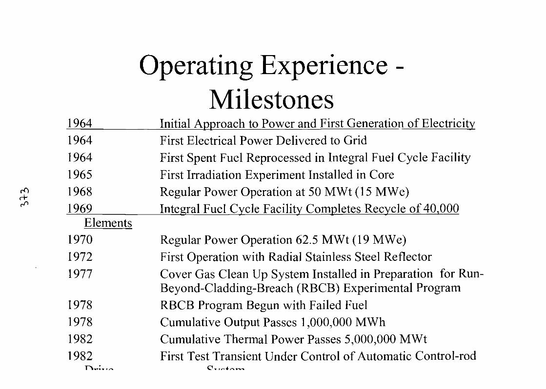
Operating Experience -Milestones
1964 Initial Approach to Power and First Generation of Electricity1964 First Electrical Power Delivered to Grid1964 First Spent Fuel Reprocessed in Integral Fuel Cycle Facility1965 First Irradiation Experiment Installed in Core1968 Regular Power Operation at 50 MWt (15 MWe)1969 Integral Fuel Cycle Facility Completes Recycle of 40,000
Elements1970 Regular Power Operation 62.5 MWt (19 MWe)1972 First Operation with Radial Stainless Steel Reflector1977 Cover Gas Clean Up System Installed in Preparation for Run-
Beyond-Cladding-Breach (RBCB) Experimental Program1978 RBCB Program Begun with Failed Fuel1978 Cumulative Output Passes 1,000,000 MWh1982 Cumulative Thermal Power Passes 5,000,000 MWt1982 First Test Transient Under Control of Automatic Control-rod
I !•*•••

19841985
198619911994199519981998200020012001200120012002
Operating Experience -Milestones (Contd.)
Twenty-years of OperationsThirty-year Operational Live EvaluationCompletedInherent Safety Demonstration Test Conducted
SeptemberDecemberDecemberAugustSeptemberJanuaryFebruarySeptember
MarchMarch
Forty-year Operational Live Evaluation CompletedEBR-II ShutdownDefueling CompleteSodium Process Facility OperationalSecondary Sodium Processing CompletePrimary Tank Drain InitiatedPrimary Sodium Processing Complete
Fermi-I Sodium Processing CompletePassivation of Secondary Sodium System CompletePassivation of Primary System Complete
EBR-II Plant Closure Project Complete
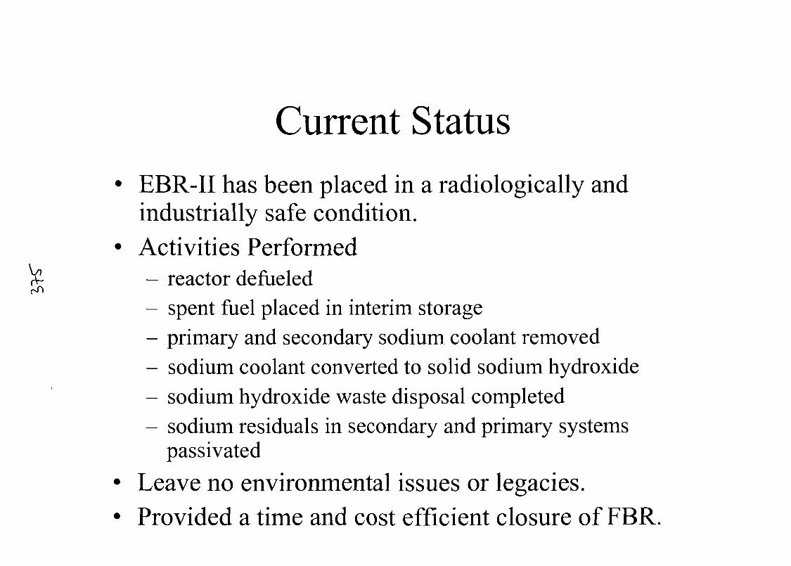
Current Status• EBR-II has been placed in a radiologically and
industrially safe condition.• Activities Performed
rv- - reactor defueledrT>
- spent fuel placed in interim storage- primary and secondary sodium coolant removed- sodium coolant converted to solid sodium hydroxide- sodium hydroxide waste disposal completed- sodium residuals in secondary and primary systems
passivated
• Leave no environmental issues or legacies.• Provided a time and cost efficient closure of FBR.
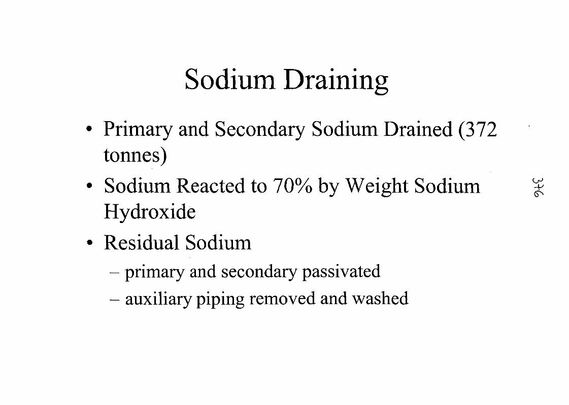
Sodium Draining
Primary and Secondary Sodium Drained (372tonnes)Sodium Reacted to 70% by Weight SodiumHydroxideResidual Sodium- primary and secondary passivated- auxiliary piping removed and washed
O-1•V
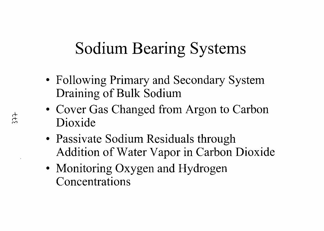
Sodium Bearing Systems
Following Primary and Secondary SystemDraining of Bulk SodiumCover Gas Changed from Argon to CarbonDioxidePassivate Sodium Residuals throughAddition of Water Vapor in Carbon DioxideMonitoring Oxygen and HydrogenConcentrations
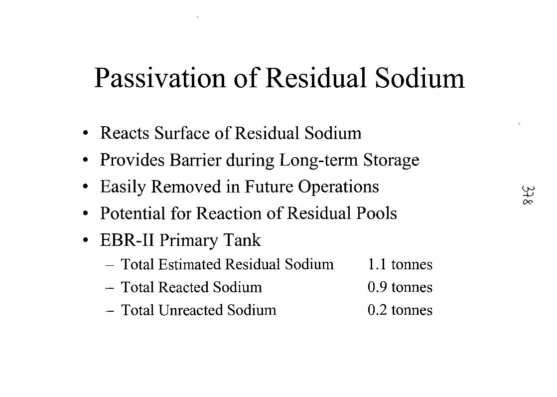
Passivation of Residual Sodium
Reacts Surface of Residual Sodium
Provides Barrier during Long-term Storage
Easily Removed in Future Operations ^ex?
Potential for Reaction of Residual Pools
EBR-II Primary Tank- Total Estimated Residual Sodium 1.1 tonnes
- Total Reacted Sodium 0.9 tonnes
- Total Unreacted Sodium 0.2 tonnes
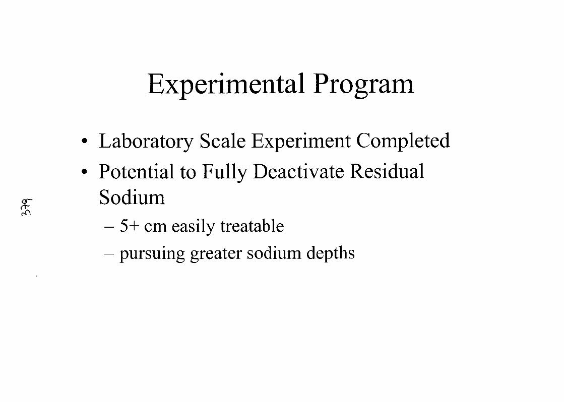
Experimental Program
• Laboratory Scale Experiment Completed
• Potential to Fully Deactivate Residualp Sodium
- 5+ cm easily treatable- pursuing greater sodium depths
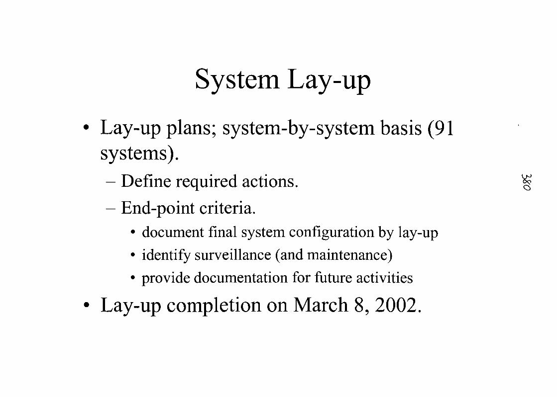
System Lay-up
Lay-up plans; system-by-system basis (91systems).- Define required actions. §
- End-point criteria.• document final system configuration by lay-up
• identify surveillance (and maintenance)
• provide documentation for future activities
Lay-up completion on March 8, 2002.
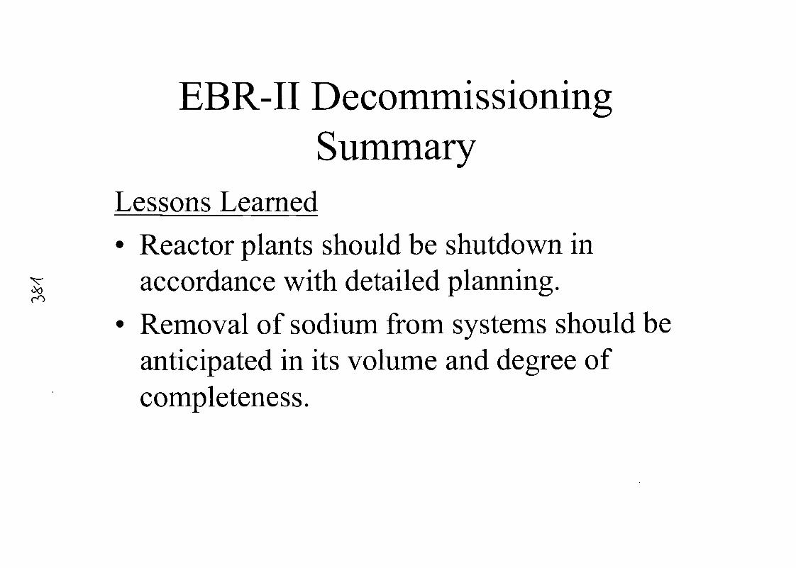
EBR-II DecommissioningSummary
Lessons Learned• Reactor plants should be shutdown in
accordance with detailed planning.• Removal of sodium from systems should be
anticipated in its volume and degree ofcompleteness.
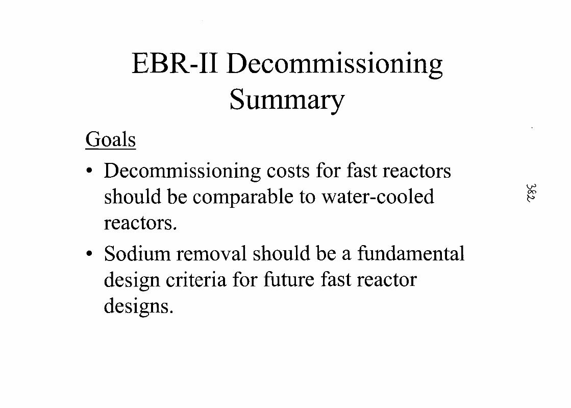
EBR-II DecommissioningSummary
GoalsDecommissioning costs for fast reactorsshould be comparable to water-cooledreactors.Sodium removal should be a fundamentaldesign criteria for future fast reactordesigns.
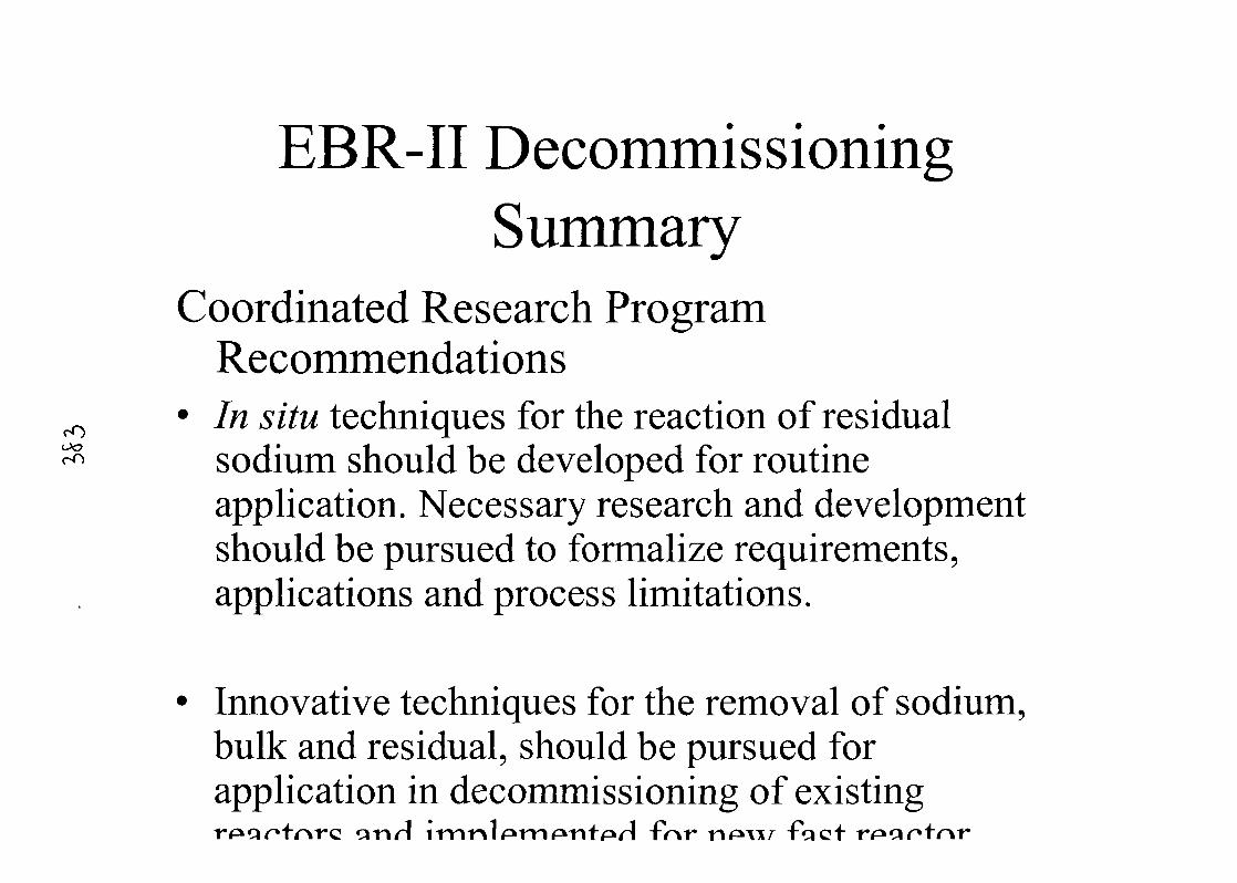
rOoo
EBR-II DecommissioningSummary
Coordinated Research ProgramRecommendations
• In situ techniques for the reaction of residualsodium should be developed for routineapplication. Necessary research and developmentshould be pursued to formalize requirements,applications and process limitations.
Innovative techniques for the removal of sodium,bulk and residual, should be pursued forapplication in decommissioning of existing
cinrl i
Conclusions
EBR-II Decommissioning Activities AreComplete- Safely, efficiently and on schedule.
- Lessons learned applicable to decommissioningactivities.
- Goals have been suggested for currentdecommissioning activities and future reactor designs.
- Recommendations made for coordinated researchprogram topics.

33 R. Brachi Paper_2_02_Pap_Brachi February 2002
Overview ofTacis project K1.01/98A "assistance to the elaboration of a decommissioning plan"
for Aktau BN350 NPP (Kazakhstan).
1. Introduction
This project is part of the On Site Assistance provided to the Aktau BN350 NPP, financed bythe 1998 budget of Tacis programme of the European Commission (EC).
Its implementation was entrusted by the EC to a consortium established between EDF andSogin. EDF acts as consortium leader trough its engineering unit in charge of nuclearfacilities decommissioning (CIDEN). Sogin is the Italian public company which owns,operates and has to decommission four Italian shut-down NPP formerly owned by ENEL.
The UKAEA had agreed to take part in the project which started in May 2000 for 18 months.The terms of reference of the project are stated in the service contract Tacis 00.0061, awardedby EC to EDF/Sogin Consortium in May 2000.
The project was co-ordinated by an EDF expert who was hosted, for the project duration, bythe Kazakhstan Nuclear Safety Center (NTSC) in Almaty.
This report gives an overview of the deliverables due by the Consortium as per the abovementioned service contract with the EC. Deliverables include administrative reports (notdetailed in this document), technical documentation, study tours and equipment.
Project's deliverables belongs to the EC and are given to the project Beneficiary, theMangyshlak Atomic Energy Complex (MAEC), the owner operator of the AktauBN350 NPP.
Implementation of the project, which covers 9 technical tasks addressing the essential topicsof nuclear decommissioning, was to be approached in two main phases: first data collection,then contribution to the elaboration of the decommissioning plan.
1.1. The international structure of support to BN350 decommissioning
In the period that preceded and followed the decision to shut-down the plant in April 1999,Kazakhstan authorities concluded two agreements, first with the US-DOE for it to assist in theelaboration of BN350 whole decommissioning plan by providing both financing under anISTC programme and technical review, second with Russian institutes for actually elaboratingthe decommissioning plan under commercial conditions with ISTC and Kazakhstan funding.
In order to preclude duplication of efforts, Tacis project's terms of reference commit theConsortium to fit in this pre-existing working organisation.
Two ways could be envisaged: either providing direct technical assistance to the Russianinstitutes, or making available European experience and know-how in the form of technicalreports that would be handed to the Beneficiary, then transferred by it or rather by NTSC tothe Russian institutes. As mentioned in administrative reports to the EC, the first approachcould not be worked out and the Consortium therefore settled on the second alternative.
As a result the Consortium's work had to focus on providing the Beneficiary with technicaladvice, options weighing, and qualitative judgements, instead of describing thedecommissioning tasks themselves. The resulting reports that have been or are being issuedfor each one of the nine technical tasks are mainly intended to be used, concurrently withother sources of information and knowledge, by the Russian institutes to establish the

R. Brachi Paper_2_02_Pap_Brachi February 2002
documents of the decommissioning plan, although in cases when these institutes could notimprove on them, they might be included into the preliminary decommissioning plan withoutmodifications.
The first draft of the complete BN350 NPP decommissioning plan was set up by the NTSCend January 2002 and will be presented by to a co-ordination expert meeting convened, underthe supervision of the IAEA, in Vienna from 19th to 21st of March 2002.
1.2. The data collection issue
As stated in the terms of reference of the project, "no dismantling plan can be devised, letalone carried out, without a complete knowledge of the plant, site, regulation, environment,industrial and organisational details which are the practical circumstances of and the referencefor its implementation".
Since the draft terms of reference had been earlier approved by the Beneficiary, it had beenimplied by the Consortium that data would be forthcoming during the initial phase of theproject, even if more or less organised. Unfortunately, mainly due to the poor document'sarchiving on the site, the actual implementation of the project was most of all characterised bythe dearth of technical information. Room by room data collection, was organised by theConsortium and entrusted to a local sub-contractor that produced a rough global assessmentof materials with figures of their masses, volumes, natures and radiological contents.
Outputs from this preliminary survey will be later on improved and completed in the frame ofNPP radiological characterisation survey1 to be implemented during the plant preparation tosafe enclosure.
One special mention yet should be made of the regulatory framework, where a quite completeset of the documents in force in Kazakhstan was gathered, copied and provided by NTSC inCD-ROM format. This however occurred 16 months after project initialisation.
This situation was not particular to Tads' part of the project, and we heard similar complaintsfrom our American colleagues. Russians contributors (mainly VINIPIET) were in a particularsituation since they owned the plant design documentation. Discussions about their providingsome of this information to the Consortium failed to produce results.
1.3. The Documentation Exchange System (DXS)
This system is provided to NTSC, as directed by the Beneficiary. It comprises a main serverlocated in Almaty running a dedicated software, and distant PCs in Aktau. The internetconnects the server to the distant partners which, besides Aktau, include KAEC, KATEP, theIAEA, the Consortium and other partners agreed by Kazakhstan, such as Russian institutes,ANL, Japanese companies.
The aim of the system is to create a reliable archive, using duplicated CD-ROMs, ofdocumentation to be used for BN350 decommissioning and to enable distant users to accessit.
The supply of this system and of the know-how transfer provided to NTSC and BN350experts, comes in excess to the assistance initially foreseen in the Tacis contract.
1 Activity also supported by another Tacis project (Kl .01/98 B), aimed to deliver equipment and methodologyfor radiological survey.
R. Brachi Paper_2_02_Pap_Brachi February 2002
2. The technical reports provided by Tacis project
Nine technical reports are issued by the Consortium in the framework of this project.Their content and present status is described as follows.
2.1. Data gathering, tools for elaboration and reporting
This report contains a brief description of the plant archives, the complete set of technical,financial and environment data gathered to this day and used for the elaboration of the othertechnical reports of the project, the justification and presentation of the specifications for adocumentation archive and exchange system (DXS), a brief report on the commissioning ofthe central part of this system (the server located in the premises of NTSC) and thespecifications for the Aktau station.
The description of the archives and set of plant and financial data exist as a draft written bySogin with help from a local subcontractor. The DXS part was written by NTSC (report oncommissioning will be issued after this is completed by end of first quarter 2002).Specifications for the Aktau station have been written down by Sogin in November 2001.
Purchase of equipment for the Aktau branch of DXS is in progress, in accordance with Tacisprocurement procedures.
2.2. Chain of responsibility and management
This task was cancelled at he initiative of the Beneficiary. A short report will be issued byEDF with diagrams of the main Kazakhstan organisations, with the exception of MAEC.These diagrams can presently be found in the project organisation report.
2.3. Environment data
A small quantity of data on the state of environment on and around the plant site (Caspian sea,soil, underground water, winds, population, economy, radioactive pollution, pollution byheavy metals) were communicated by Kazakhstan organisations, and part of this only orally,in informal meetings with experts.
This information will be entered into the data gathering report (see above 2.1), with everyqualification as to its accuracy.
Beside, in addition to the planned outputs of the project, the EC agreed to support thepublication of a book on Kazakhstan radiological pollution, based on date provided by aformer study financed by ISTC. Publication is managed by NTSC.
2.4. Waste facilities
As it turned out from discussions with Kazakhstan experts, besides temporary storage areasand buildings on plant site, possibly not suitable for further use, no facility is available inKazakhstan to dispose of radioactive waste.
A study is underway by KATEP, on orders from the government, to study options for thedisposal of radioactive waste in the Aktau area. The bulk of the waste disposed of in thisfacility would come from closed uranium mines, but some might be accepted originating from
R. Brachi Paper_2_02_Pap_Brachi February 2002
BN350, provided an impact study shows they are compatible with the characteristics of thechosen site.
This study is reported on by EDF in the first part of the technical report on the disposalpathways for BN350 dismantling waste. The same document makes proposals for thetemporary safe storage of conditioned radwaste on plant site.
The document exists as a final draft, pending comments from Kazakhstan organisations.
2.5. Financial data
Financial data obtained during the course of the project (staff projections, salaries, water andpower consumption) are included in the report on plant data (see above § 2.1).
When the study of decommissioning options involved a judgement on their comparativecosts, this judgement was made based on the European experts' knowledge of similar projectsin the CIS or Eastern Europe, when available, but not on local data.
The financial data and some assumptions used for the assessment of decommissioning costswere included in the costing document issued by Sogin in December 2001.
2.6. Rules and regulations
A report on existing regulations as been issued as a draft by NTSC, with a conclusionpointing to some shortcomings. A complete set of regulations governing decommissioning-related activities was issued by NTSC as a CD-ROM comprised of scanned images of thetexts in Russian language and a summary with automatic links to the texts. This CD-ROMwill be re-issued in English later on.
Comments from EDF on required complements to the regulations can be found in the reportson Operational Waste and Decommissioning Waste for issues connected to these topics.
Since the Consortium was informed by NTSC that a contract had been agreed with ArgonneNational Laboratory (USA) for the latter to provide advice on required complements toKazakhstan regulation, further foreseen developments on this issue were dropped to avoidduplication.
A limited support to complement regulations pertaining to waste management strategy, willbe provided, during 2002, by a subcontract awarded by the Tacis Consortium to NTSC (undernegotiation).
2.7. Quality Assurance
Task's completion report is under elaboration by a local Consortium's consultant. It willinclude three mission reports by the Consortium QA expert to Aktau, a small number ofdocuments (programmatic declaration, procedures) produced by the Aktau plant managementas a result of these missions, certificates of training of Aktau QA experts by theBureau Veritas in Moscow, and comments on the national Quality Programme by French QAexperts.
R. Brachi Paper_2_02_Pap_Brachi February 2002
2.8. Waste management
A first short report by EDF covers Operational Waste and, for respectively solid, liquidradwaste and sealed radioactive sources, provides an analysis of the waste, a judgement aboutregulatory issues and technical proposals for processing the waste2.
A second report by EDF covers Decommissioning Waste and, based on plant data and theinternational experience of managing waste from dismantling nuclear plants which isextensively described, mentions technical processes to address BN350 various categories ofradioactive and hazardous waste. It provides information about efforts directed to the creationof a national radwaste repository which, in addition to waste resulting from closed industrialfacilities, might take up part of BN350 radwaste. With the assumption that such a repositorymight not be ready in time for SAFSTOR preparation, it proposes temporary waste storagefacilities to be arranged in some BN350 existing buildings.
A third report by Sogin covers Conventional Waste. It provides general directions as to howeach type of waste should be handled.
Further elaboration of waste management strategy, will be supported, during 2002, by asubcontract awarded by the Tacis Consortium to NTSC (under negotiation).
2.9. Risk and environmental studies
Task's completion report will be issued by end of first quarter 2002. It will include 3 studiesproduced by NNC with results of calculations that assess the consequences of hypotheticalevents occurring while BN-350 is being decommissioned, in terms of atmospheric releases,propagation of contamination in the ground, and human mortality and morbidity, and a 4thstudy, also by NNC, presenting a general risk analysis of the main decommissioning phases.An appendix relates to the provision of codes and training that enabled NNC to carry outthese studies.
Kazakh expert training to use of the above mentioned codes is being completed during thesedays (Sogin expert mission to Kurchatov NNC premises, end February 2002).
2.10. Dismantling scenario
Task's report presents, based on a plant description making use of available plant data (seeabove 2.1.), a systematic analysis and a reasoned, weighted comparison of elementaryoptions, essentially focussing on the definition of the SAFSTOR, or 50 years confinement,state of the facility which is the strategy chosen by the government of Kazakhstan. As a resulttwo preferred decommissioning options are identified and described, the first aimed to overalloptimisation, but resulting in substantial expenditures in the initial 15 years period, the secondintended to minimise initial expenditures, while admitting sizeable care and maintenanceexpenses during the safe enclosure period. Required ancillary facilities are listed for bothoptions.
This report by UKAEA and AEA-Technology has been issued as a final draft, pendingcomments from Kazakhstan organisations.
2 Activity also supported by another Tacis project (K 1.01/98 C), aimed to deliver equipment for partial treatmentof operational LRW stored on the BN350 NPP site.
R. Brachi Paper_2_02_Pap_Brachi February 2002
2.11. Financial evaluation
The reports presents an overall costing of the main decommissioning phases (Safe enclosurepreparation, Care & Maintenance, Final Dismantling) for each essential expense count (suchas staff, waste, care & maintenance, etc.) and for both preferred options identified above(§ 2.10). The costing is based on overall assessments, since detailed data which would haveallowed to assess the elementary spending for each operation are not available. Fuel andsodium processing are not included in the costing, as the associate tasks are mainly a matterof the assistance programme of US-ANL, which agreed to provide the corresponding figures.
Task's completion report was issued by SOGIN in December 2001.
3. Study tours
In association with the implementation of the project tasks, specific study tours in Europewere organised by the Consortium. Among them, the following ones worth to be mentioned :
• Study tour to the PFR at Dounreay, in Scotland for BN350 experts involved in wastemanagement and contractors management,
• Study tour in France to NPPs under decommissioning (Brennilis, Creys-Malville) andwaste storage site (site de 1'Aube),
• Study tour in Italy to NPPs under decommissioning (Garigliano, Latina) and to Soginheadquarters meeting experts on decommissioning cost assessment and staffmanagement.
Consortium experts, in charge of each project's task, executed specific missions to the BN350site.
Project review meetings were organised in Kazakhstan and in Europe. The KazakhsatnAtomic Energy Committee was associated to these reviews, in consideration of its position ofNuclear Safety Authority.
4. Provided equipment
4.1. In Aktau
The specifications for the DXS local station were established by agreement between the localrepresentative of the consortium and the Beneficiary. In principle it is made up of 3 PCs.These will be bought locally, by the Consortium's local representative, under Tacisprocurement procedure, in progress at date.
Additional documentation archiving and editing equipment (PCs, scanners, printers &so) willalso be provided to the plant in order to improve the documents storage and managementconditions.
4.2. In Almaty
The DXS server (see above 1.3.) supply contract is near to completion. The server will becommissioned in March 2002.
R. Brachi Paper_2_02_Pap_Brachi February 2002
5. Conclusion on project's deliverables
The deliverables provided through the K1.01/98A project comply with the terms of referenceof the project. All the technical documents were mailed or handed to it as drafts in Englishand in Russian at various stages.
Only few comment from the Beneficiary has been received to this day.This is not very surprising, given that the actual application of the European know-howtransfer is to nourish the official decommissioning plan entrusted by the Kazakhstan side tothe Russian institutes.
The review of the plan during the spring of 2002, requested from the IAEA by the Kazakhstangovernment, is likely to highlight the contribution of Tacis.
The next step of development of the plan, which the Kazakhstan side calls the"decommissioning project", will undoubtedly build on the deliverables of the present Tacisproject, as well as on the comments and questions they elicited from the expertscommissioned by the IAEA to review the decommissioning plan.
6. General conclusion
The EDF/Sogin Consortium believes that the assistance provided through K1.01/98A projectcomplies with the Tacis project TOR as a whole.The achievements of each project task will be less or more valuable for the elaboration of thedecommissioning plan depending, among others, on the relevance given by the Kazakhstanside on various items of the plan.
The international peer review of the plan, envisaged under the supervision of the IAEA willhelp the Kazakhstan side to take the best profit of Tacis contribution.
The Consortium believes that several aspects of the plan need a further development andpossibly further contribution of western expertise. Among them the Consortium highlights theissues related to the characterisation, sorting, conditioning and storage of solid waste eitherissued from operation or expected to be produced during decommissioning implementation.
The decommissioning project implementation will require huge funding and Kazakhstan isopen to accept foreign contribution and technical assistance.The USA are already committed to support relevant and urgent activities, designed by thedecommissioning plan for the safe enclosure phase preparation, as spent fuel and sodium safedisposal.Japan Company RANDEC is also committed to provide technical assistance, namely forevaluation of radioactive inventory and workers exposure, waste conditioning and projectmanagement.
The EDF/Sogin Consortium is preparing, in agreement with Kazakh Partners, a new proposalto be submitted to EC, aimed to provide further support activities to be implemented toconvert the BN350 NPP to safe enclosure.

Tacis project Kl.01/98 A
Sogin report on Task 9 : Assessment of BN350 decommissioning costs - Methods
Basis and methods for Sogin report's elaboration are the following :
Option A: Minimising the pre SAFSTOR costs by limiting the decommissioning prior to
SAFSTOR to removal of sodium coolant and the operational waste. The penalty for
minimising the pre SAFSTOR costs is increased care and maintenance costs during the
SAFSTOR period.
Option B: Minimising care and maintenance costs during the SAFSTOR period by
undertaking decommissioning of a number of facilities prior to SAFSTOR. This results in
the removal of the sodium coolant and the operation waste plus the majority of the
decommissioning waste from the reactor building allowing the building size to be
reduced. This will leave the reactor vessel and primary containment within a new
weatherproof structure.
The option study for decommissioning of BN 350, makes the object of the
AEAT/NE/0162 report, provided by UKAEA, in the frame of the same Tacis project
(task 5) and has been adopted as baseline to identify the needed activities in each option.
• All costs are given in 20QO constant EURO (€ or EUR), regardless of when the
expenditures occur in time.
• The cost estimate is based'on BN-350 reactor plant data as far as possible but,
where information are not available, extrapolations from Sogin cost data w i l l be
used making reasonable assumptions according to international experience and
figures.
• Reference is made to the standardised list of cost items and their definitions,
published in the first half of 1999. [OECD, 1999].
Cost evaluation methodology - Room bases method :
• This method, classified as Top-Down, was developed by the German Company NIS
GmbH and embedded in the former STILLKO code and recently in the
CALCOM-CORA software.
Tacis project Kl.01/98 A
Sogin report on Task 9 : Assessment of BN350 decommissioning costs - Assumptions
Costs associated with the following items:
• sodium cleaning, treatment and disposal (all included: facility, personnel,
consumable and disposal cost, including secondary waste produced by the
treatment process),
• sodium residue cleaning in phase 1 for option B and phase 3 for option A (specific
process has to be defined),
• secondary wastes production during the safe enclosure period for option A
(detailed maintenance program has to be technically defined),
• closure of the fuel cycle
• direct disposal of the spent fuel
have not been included in the present study since they are under evaluat ion by other
organisations (USA).
• Sogin evaluation does not include demolition cost of the turbine b u i l d i n g and other
conventional buildings and systems as they will be operated by iVIAEC further to
BN350 de-commissioning for steam and electricity production from the other
fossil fuelled plants on MAEC site.
• The costs have been calculated without VAT or other taxes, and co.sl of l icens ing
process has been assumed not relevant for the decommissioning cost e s t ima t ion .
Clearance levels for material release or reuse
I t is assumed that all the needed regulation wil l be timely in place. For the t ime being
values consistent with the Sogin experience have been assumed in the present ca lcu la t ion
( I t a l i an standards that are in line with the international ones).
Waste disposal
For Category 2 waste final disposal, a cost of 4.000 € per cubic meter has been assumed.
This figure is based on the data quoted in the OECD report "low level radioactive waste
repository - an analysis of costs [OECD 1999\2] for the Dukovany repository in the
Czech republic.

Tacis project Kl.01/98 A
Sogin report on Task 9 : Assessment of BN350 decommissioning costs - Main Results
Main results in terms of projected costs, schedule, resource requirements and occupational
exposures are summarised in the following Tables A and B respectively for Option A and
Option B.
Phase
1- Plant preparation for SAFSTOR
2-SAFSTOR
3- Nuclear dismantling and siterelease
4- Site Restoration
Total
Cost[M€]
105
49
195
11
360
Duration
[y» m]9y
50 y
12y
3 y74 y
Manpower[M-Months]
38.800
94.400
35.200
5.800
174.200
Doses[Man-Sv]
5
1
8
0
14
Table A - Summary of Main results Option A
Phase
1- Plant preparation for SAFSTOR
2-SAFSTOR
3- Nuclear dismantling and siterelease
4- Site Restoration
Total
Cost
[M€]
140
32
176
11
359
Duration
[y, m]
15y
50 y
lOy
3 y
78 y
Manpower[M-Monthsl
69.300
58.600
27.700
5.800
161.400
Dosesf Man-
Sv]
9
1
6
0
16
Table B - Summary of Main results Option B
The first main conclusion of this study is that both options, A and B, have the same total cost.
At first glance, option A has a high personnel cost during phase 2 but option B needs of
repeating some investments, already made in phase 1, also in phase 3. A deeper analysis can
he performed looking at the detailed results.

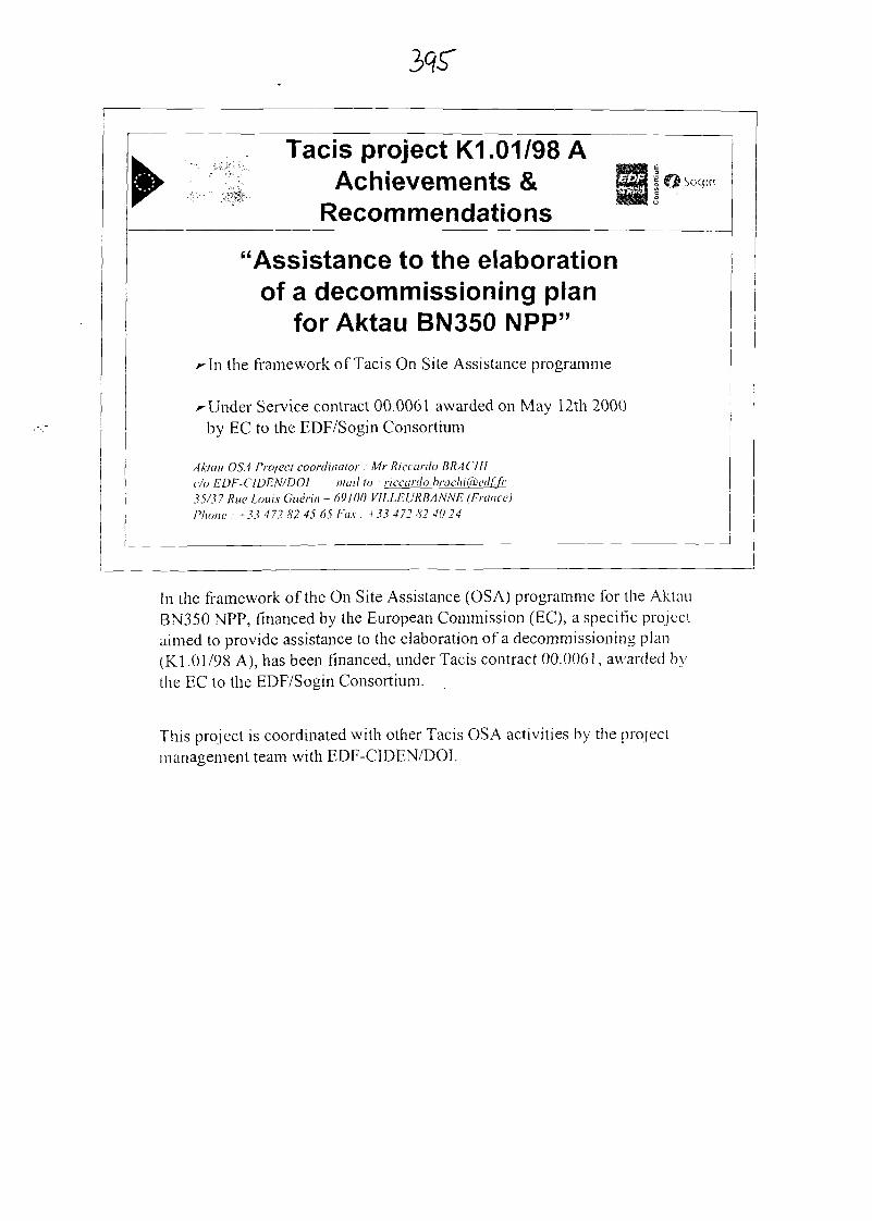
Tacis project K1 .01/98 AAchievements &
Recommendations
"Assistance to the elaborationof a decommissioning plan
forAktauBN350NPP"
^In the framework of Tacis On Site Assistance programme
r Under Service contract 00.0061 awarded on May 12th 2000by EC to the EDF/Sogin Consortium
A klu 11 OSA Project coordinator : Mr Riccardo BRA CHIc/o EDF-ClDEN/DOl mail to : riccarilo.brachi&ecl[.fr35/37 Rue Lows Guerin - 69100 VILLEVRBANNE (France)Phone : +33 472 82 45 65 Fax : +33 472 82 40 24
In the framework of the On Site Assistance (OSA) programme for the AktauBN350 NPP, financed by the European Commission (EC), a specific projectaimed to provide assistance to the elaboration of a decommissioning plan(Kl.01/98 A), has been financed, under Tacis contract 00.0061, awarded bythe EC to the EDF/Sogin Consortium.
This project is coordinated with other Tacis OSA activities by the projectmanagement team with EDF-CIDEN/DOI.
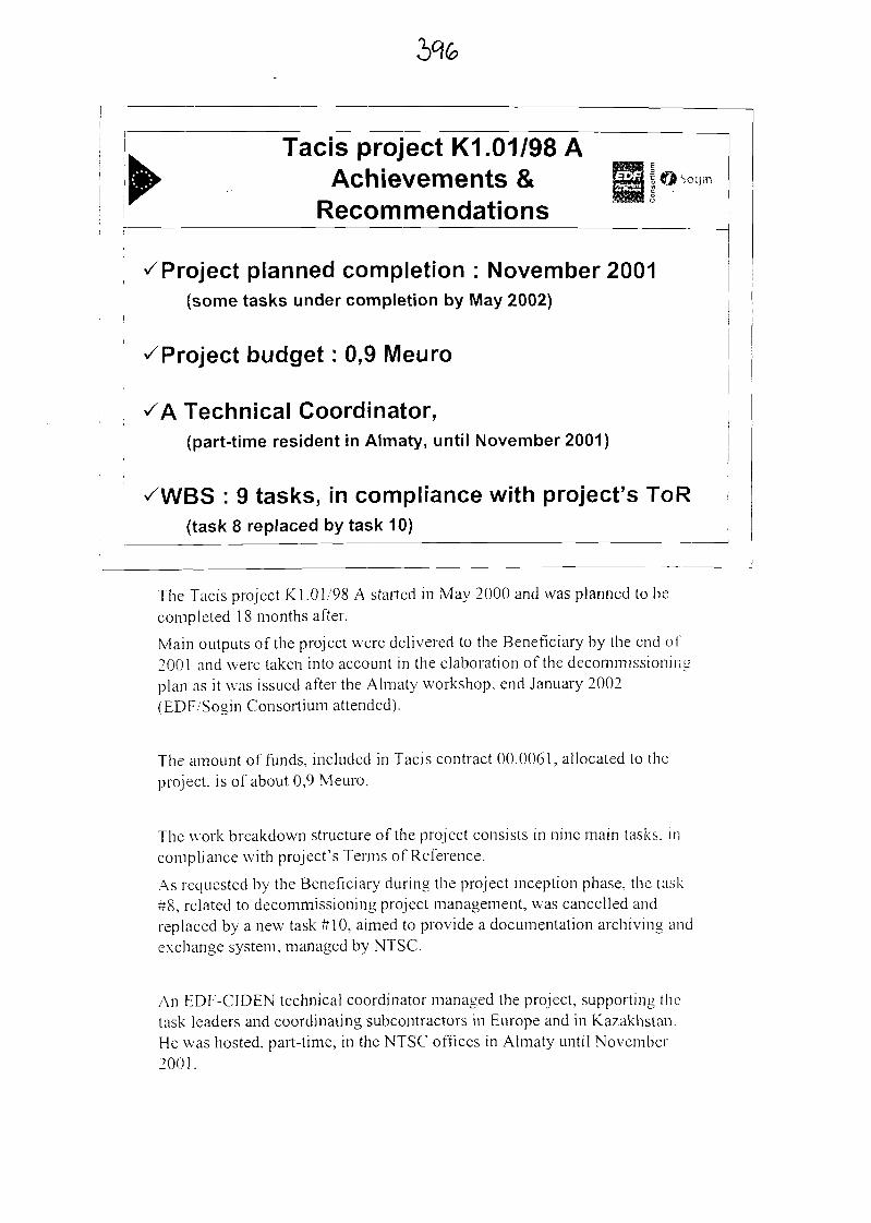
Tacis project K1.01/98 AAchievements &
RecommendationsISogm
^Project planned completion : November 2001(some tasks under completion by May 2002)
^Project budget : 0,9 Meuro
Technical Coordinator,(part-time resident in Almaty, until November 2001)
: 9 tasks, in compliance with project's ToR(task 8 replaced by task 10)
The Tacis project K 1.01/98 A started in May 2000 and was planned to hecompleted 18 months after.
Main outputs of the project were delivered to the Beneficiary by the end of2001 and were taken into account in the elaboration of the decommissioningplan as it was issued after the Almaty workshop, end January 2002(EDF/Sogin Consortium attended).
The amount of funds, included in Tacis contract 00.0061, allocated to theproject, is of about 0,9 Meuro.
The work breakdown structure of the project consists in nine main tasks, i ncompliance with project's Terms of Reference.
As requested by the Beneficiary during the project inception phase, the task#8, related to decommissioning project management, was cancelled andreplaced by a new task #10, aimed to provide a documentation archiving andexchange system, managed by NTSC.
An EDF-CIDEN technical coordinator managed the project, supporting thetask leaders and coordinating subcontractors in Europe and in Kazakhstan.He was hosted, part-time, in the NTSC offices in Almaty until November2001.
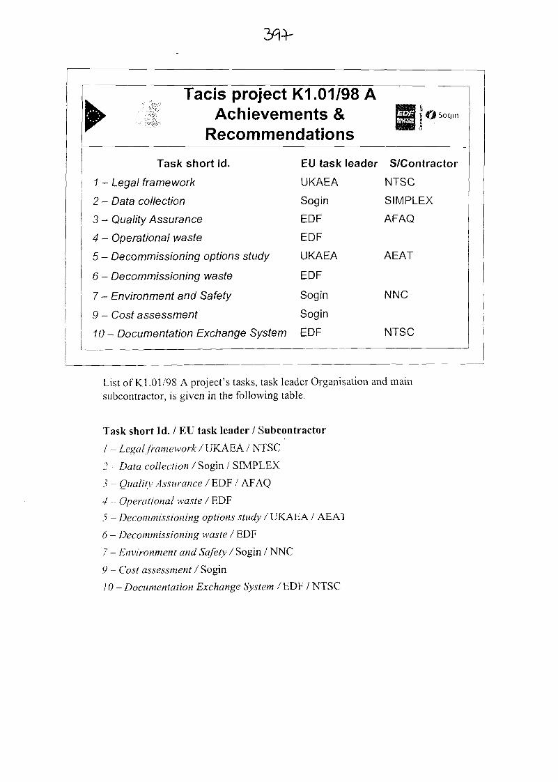
Tacis project K1.01/98 AAchievements &
Recommendations> Sogin
Task short Id.
1 - Legal framework
2 - Data collection
3 - Quality Assurance
4 - Operational waste
5 - Decommissioning options study
6 - Decommissioning waste
7 - Environment and Safety
9 - Cost assessment
EU task leader S/Contractor
UKAEA
Sogin
EOF
EOF
UKAEA
EOF
Sogin
Sogin
10- Documentation Exchange System EDF
NTSC
SIMPLEX
AFAQ
AEAT
NNC
NTSC
List of Kl.01/98 A project's tasks, task leader Organisation and mainsubcontractor, is given in the following table.
Task short Id. / EU task leader / Subcontractor
/ - Legal framework / UKAEA / NTSC
2 - Data collection / Sogin / SIMPLEX
3 - Quality Assurance IEDF / AFAQ
4 - Operational waste / EDF
5 - Decommissioning options study / UKAEA / AEAT
6 - Decommissioning waste / EDF
7 - Environment and Safety / Sogin / NNC
9 - Cost assessment / Sogin
10 - Documentation Exchange System /EDF / NTSC
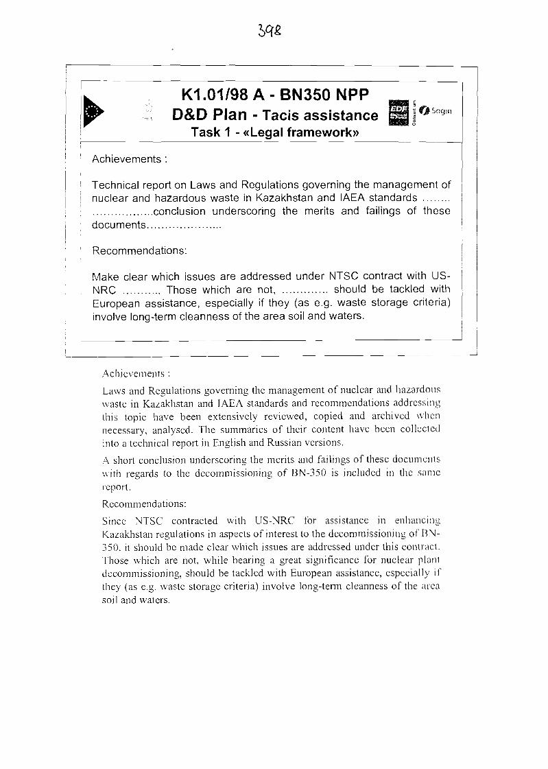
K1 .01/98 A - BN350 NPPD&D Plan - Tacis assistance
Task 1 - «Legal framework»
Achievements :
Technical report on Laws and Regulations governing the management ofnuclear and hazardous waste in Kazakhstan and IAEA standards
conclusion underscoring the merits and failings of thesedocuments
Recommendations:
Make clear which issues are addressed under NTSC contract with US-NRC Those which are not, should be tackled withEuropean assistance, especially if they (as e.g. waste storage criteria)involve long-term cleanness of the area soil and waters.
Achievements :
Laws and Regulations governing the management of nuclear and hazardouswaste in Kazakhstan and IAEA standards and recommendations addressingthis topic have been extensively reviewed, copied and archived whennecessary, analysed. The summaries of their content have been collectedinto a technical report in English and Russian versions.
A short conclusion underscoring the merits and failings of these documentswith regards to the decommissioning of BN-350 is included in the samereport.
Recommendations:
Since NTSC contracted with US-NRC for assistance in enhancingKazakhstan regulations in aspects of interest to the decommissioning of BN-350, it should be made clear which issues are addressed under this contract.Those which are not, while bearing a great significance for nuclear plantdecommissioning, should be tackled with European assistance, especially ifthey (as e.g. waste storage criteria) involve long-term cleanness of the areasoil and waters.

K1 .01/98 A - BN350 NPPD&D Plan - Tacis assistance
Task 2 - «Data collection))
Achievements:
A number of technical information, ......... is collected into a technicalreport.Information collected to this day is deem sufficient for drawing up apreliminary decommissioning plan, but not for warranting final decisionson technical options ......... and precise costing.
Recommendations:
To continue efforts ......... by carrying out plant inventory with support ofTacis 98B project for plant radiological characterisation. It is alsorecommended to improve knowledge on the state and content of thesolid waste operational repository (XTPO).
Achievements:
A number of technical information, either as figures, drawings and textshave been gathered. These relate to site and building arrangement, operationhistory, waste disposition, radioactivity of equipment, radioactive ambienceof rooms, dimensions and masses of equipment, overall masses andradioactivity of expected dismantling waste by physical nature, hazardouswaste existing on-site and radioactive sources. This information is collectedinto a technical report in English and Russian versions.
Information gathered with US-ANL assistance on the make-up of plantsystems was provided to Tacis.
Recommendations:
Since the information collected to this day is sufficient for drawing up apreliminary decommissioning plan, but not for warranting final decisions ontechnical options (such as the extension of the Safe enclosure orspecifications for waste handling facilities) and precise costing, it isrecommended to continue efforts at information gathering by carrying outplant inventory with support of Tacis 98B project for plant radiologicalcharacterisation. It is also recommended to improve knowledge on the stateand content of the solid waste operational repository.
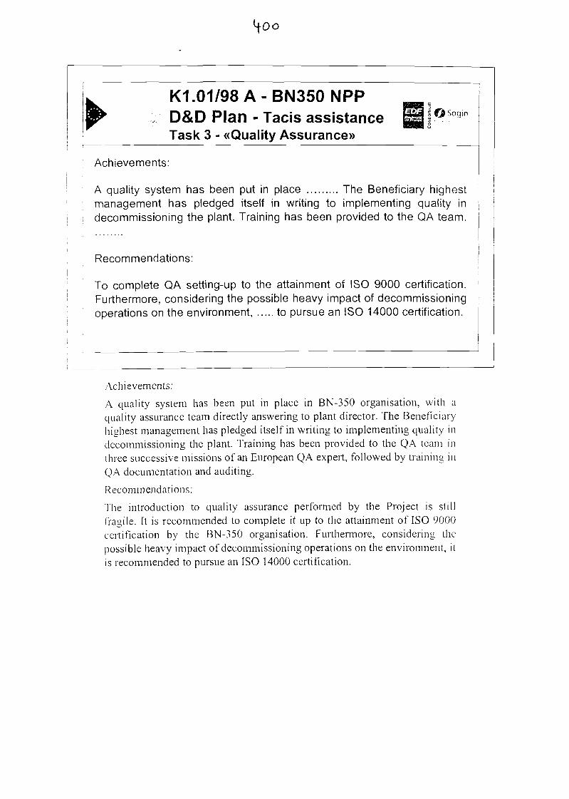
K1 .01/98 A - BN350 NPPD&D Plan - Tacis assistance °Sogm
Task 3 - «Quality Assurance»
Achievements:
A quality system has been put in place The Beneficiary highestmanagement has pledged itself in writing to implementing quality indecommissioning the plant. Training has been provided to the QA team.
Recommendations:
To complete QA setting-up to the attainment of ISO 9000 certification.Furthermore, considering the possible heavy impact of decommissioningoperations on the environment, to pursue an ISO 14000 certification.
Achievements:
A quality system has been put in place in BN-350 organisation, wi th aquality assurance team directly answering to plant director. The Beneficiaryhighest management has pledged itself in writing to implementing quality indecommissioning the plant. Training has been provided to the QA team inthree successive missions of an European QA expert, followed by training inQA documentation and auditing.
Recommendations:
The introduction to quality assurance performed by the Project is s t i l lfragile. It is recommended to complete it up to the attainment of ISO 9000certification by the BN-350 organisation. Furthermore, considering thepossible heavy impact of decommissioning operations on the environment, itis recommended to pursue an ISO 14000 certification.
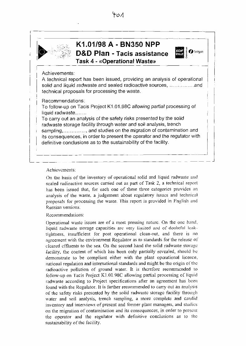
K1.01/98A-BN350NPPD&D Plan - Tacis assistance Bj°Sogm
Task 4 - «Operational Waste»
Achievements:A technical report has been issued, providing an analysis of operationalsolid and liquid radwaste and sealed radioactive sources, andtechnical proposals for processing the waste.
Recommendations:To follow-up on Tacis Project K1.01.98C allowing partial processing ofliquid radwasteTo carry out an analysis of the safety risks presented by the solidradwaste storage facility through water and soil analysis, trenchsampling, , and studies on the migration of contamination andits consequences, in order to present the operator and the regulator withdefinitive conclusions as to the sustainability of the facility.
Achievements:
On the basis of the inventory of operational solid and liquid radwaste andsealed radioactive sources carried out as part of Task 2, a technical reporthas been issued that, for each one of these three categories provides ananalysis of the waste, a judgement about regulatory issues and technicalproposals for processing the waste. This report is provided in English andRussian versions.
Recommendations:
Operational waste issues are of a most pressing nature. On the one hand,liquid radwaste storage capacities are very limited and of doubtful leak-tightness, insufficient for post operational clean-out, and there is noagreement with the environment Regulator as to standards for the release ofcleared effluents to the sea. On the second hand the solid radwaste storagefacility, the content of which has been only partially revealed, should bedemonstrate to be compliant either with the plant operational licence,national regulation and international standards and might be the origin of theradioactive pollution of ground water. It is therefore recommended tofollow-up on Tacis Project K1.01.98C allowing partial processing of l iquidradwaste according to Project specifications after an agreement has beenfound with the Regulator. It is further recommended to carry out an analysisof the safety risks presented by the solid radwaste storage facility throughwater and soil analysis, trench sampling, a more complete and candidinventory and interviews of present and former plant managers, and studieson the migration of contamination and its consequences, in order to presentthe operator and the regulator with definitive conclusions as to thesustainability of the facility.
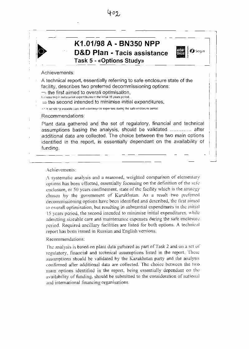
^ K1 .01/98 A - BN350 NPP^ D&D Plan - Tacis assistance
Task 5 - «Options Study»^g|^s°9in
Achievements:
A technical report, essentially referring to safe enclosure state of thefacility, describes two preferred decommissioning options:=> the first aimed to overall optimisation,bui resulting in substantial expenditures in the initial 15 years period.
^>the second intended to minimise initial expenditures,.vhile admitting sizeable care and maintenance expenses during the safe enclosure period.
Recommendations:
Plant data gathered and the set of regulatory, financial and technicalassumptions basing the analysis, should be validated afteradditional data are collected. The choice between the two main optionsidentified in the report, is essentially dependant on the availability offunding.
Achievements:
A systematic analysis and a reasoned, weighted comparison of elementaryoptions has been effected, essentially focussing on the definition of the safeenclosure, or 50 years confinement, state of the facility which is the strategychosen by the government of Kazakhstan. As a result two preferreddecommissioning options have been identified and described, the first aimedto overall optimisation, but resulting in substantial expenditures in the i n i t i a l15 years period, the second intended to minimise initial expenditures, wh i l eadmitting sizeable care and maintenance expenses during the safe enclosureperiod. Required ancillary facilities are listed for both options. A technicalreport has been issued in Russian and English versions.
Recommendations:
The analysis is based on plant data gathered as part of Task 2 and on a set ofregulatory, financial and technical assumptions listed in the report. Theseassumptions should be validated by the Kazakhstan party and the analysisconfirmed after additional data are collected. The choice between the twomain options identified in the report, being essentially dependant on theavailability of funding, should be submitted to the consideration of nationaland international financing organisations.
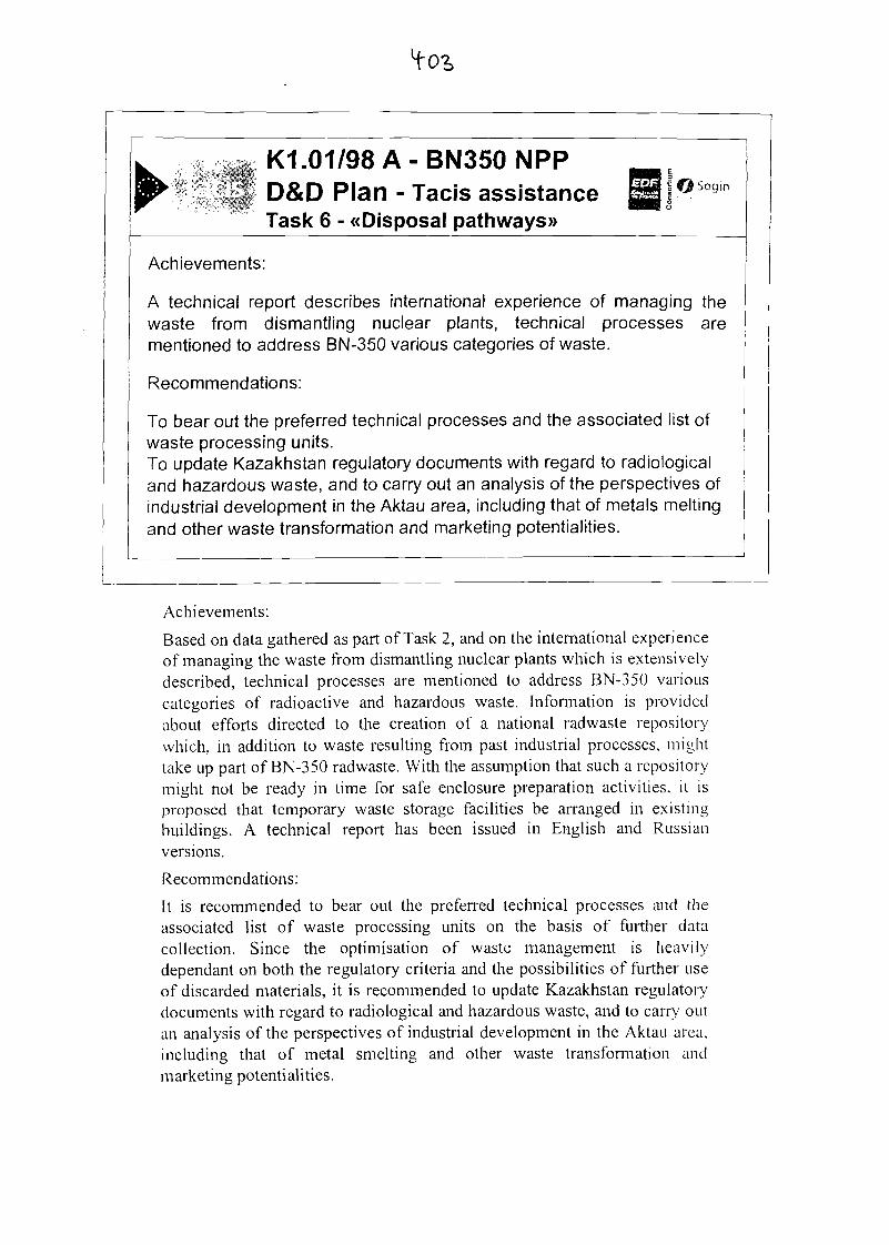
K1.01/98A-BN350NPPD&D Plan - Tacis assistanceTask 6 - ^Disposal path ways»
Achievements:
A technical report describes international experience of managing thewaste from dismantling nuclear plants, technical processes arementioned to address BN-350 various categories of waste.
Recommendations:
To bear out the preferred technical processes and the associated list ofwaste processing units.To update Kazakhstan regulatory documents with regard to radiologicaland hazardous waste, and to carry out an analysis of the perspectives ofindustrial development in the Aktau area, including that of metals meltingand other waste transformation and marketing potentialities.
Achievements:
Based on data gathered as part of Task 2, and on the international experienceof managing the waste from dismantling nuclear plants which is extensivelydescribed, technical processes are mentioned to address BN-350 variouscategories of radioactive and hazardous waste. Information is providedabout efforts directed to the creation of a national radwaste repositorywhich, in addition to waste resulting from past industrial processes, mighttake up part of BN-350 radwaste. With the assumption that such a repositorymight not be ready in time for safe enclosure preparation activities, it isproposed that temporary waste storage facilities be arranged in existingbuildings. A technical report has been issued in English and Russianversions.
Recommendations:
It is recommended to bear out the preferred technical processes and theassociated list of waste processing units on the basis of further datacollection. Since the optimisation of waste management is heavilydependant on both the regulatory criteria and the possibilities of further useof discarded materials, it is recommended to update Kazakhstan regulatorydocuments with regard to radiological and hazardous waste, and to carry outan analysis of the perspectives of industrial development in the Aktau area,including that of metal smelting and other waste transformation andmarketing potentialities.
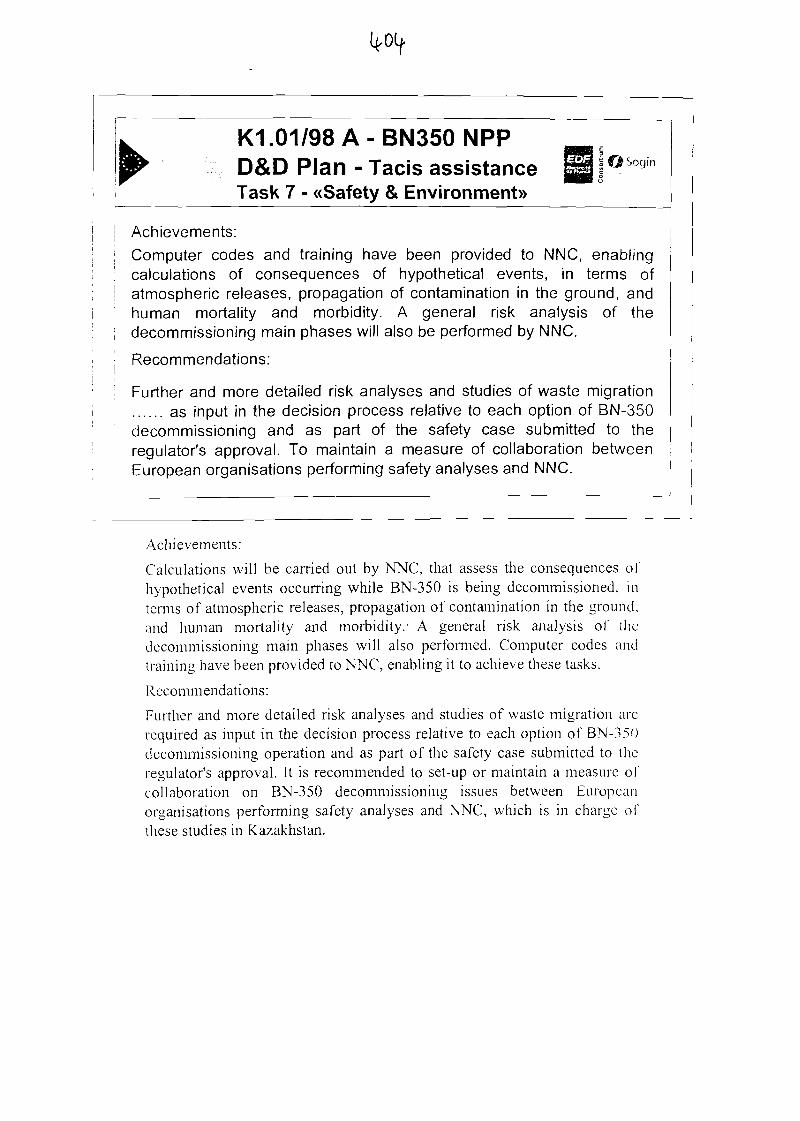
K1 .01/98 A - BN350 NPPD&D Plan - Tacis assistanceTask 7 - «Safety & Environment))
Achievements:
Computer codes and training have been provided to NNC, enablingcalculations of consequences of hypothetical events, in terms ofatmospheric releases, propagation of contamination in the ground, andhuman mortality and morbidity. A general risk analysis of thedecommissioning main phases will also be performed by NNC.
Recommendations:
Further and more detailed risk analyses and studies of waste migration...... as input in the decision process relative to each option of BN-350decommissioning and as part of the safety case submitted to theregulator's approval. To maintain a measure of collaboration betweenEuropean organisations performing safety analyses and NNC.
Achievements:
Calculations will be carried out by NNC, that assess the consequences ofhypothetical events occurring while BN-350 is being decommissioned, interms of atmospheric releases, propagation of contamination in the ground,and human mortality and morbidity.- A general risk analysis of thedecommissioning main phases will also performed. Computer codes andtraining have been provided to NNC, enabling it to achieve these tasks.
Recommendations:
Further and more detailed risk analyses and studies of waste migration arcrequired as input in the decision process relative to each option of BN-350decommissioning operation and as part of the safety case submitted to theregulator's approval. It is recommended to set-up or maintain a measure ofcollaboration on BN-350 decommissioning issues between Europeanorganisations performing safety analyses and NNC, which is in charge ofthese studies in Kazakhstan.
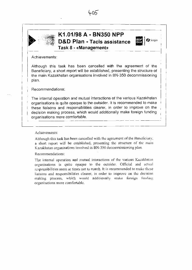
^ K1.01/98 A - BN350 NPPv|| D&D Plan - Tacis assistance g j°Sogn
Task 8 - «Management»
Achievements:
Although this task has been cancelled with the agreement of theBeneficiary, a short report will be established, presenting the structure ofthe main Kazakhstan organisations involved in BN-350 decommissioningplan.
Recommendations:
The internal operation and mutual interactions of the various Kazakhstanorganisations is quite opaque to the outsider. It is recommended to makethese liaisons and responsibilities clearer, in order to improve on thedecision making process, which would additionally make foreign fundingorganisations more comfortable.
Achievements:
Although this task has been cancelled with the agreement of the Beneficiary,a short report will be established, presenting the structure of the mainKazakhstan organisations involved in BN-350 decommissioning plan.
Recommendations:
The internal operation and mutual interactions of the various Kazakhstanorganisations is quite opaque to the outsider. Official and actualresponsibilities seem at times not to match. It is recommended to make theseliaisons and responsibilities clearer, in order to improve on the decisionmaking process, which would additionally make foreign fundingorganisations more comfortable.
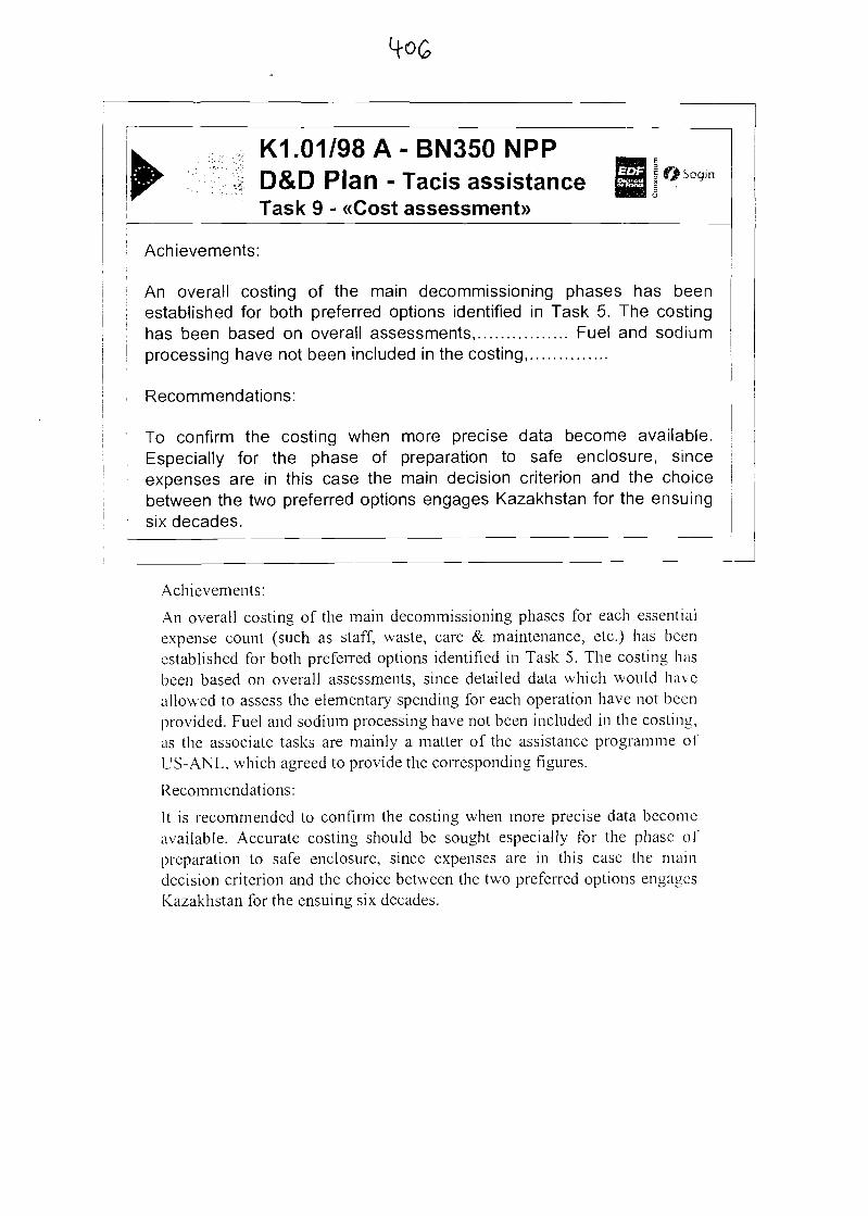
K1 .01/98 A - BN350 NPPD&D Plan - Tacis assistanceTask 9 - «Cost assessment))
Achievements:
An overall costing of the main decommissioning phases has beenestablished for both preferred options identified in Task 5. The costinghas been based on overall assessments ................. Fuel and sodiumprocessing have not been included in the costing ...............
Recommendations:
To confirm the costing when more precise data become available.Especially for the phase of preparation to safe enclosure, sinceexpenses are in this case the main decision criterion and the choicebetween the two preferred options engages Kazakhstan for the ensuingsix decades.
Achievements:
An overall costing of the main decommissioning phases for each essentialexpense count (such as staff, waste, care & maintenance, etc.) has beenestablished for both preferred options identified in Task 5. The costing hasbeen based on overall assessments, since detailed data which would haveallowed to assess the elementary spending for each operation have not beenprovided. Fuel and sodium processing have not been included in the costing,as the associate tasks are mainly a matter of the assistance programme ofUS-ANL, which agreed to provide the corresponding figures.
Recommendations:
It is recommended to confirm the costing when more precise data becomeavailable. Accurate costing should be sought especially for the phase ofpreparation to safe enclosure, since expenses are in this case the maindecision criterion and the choice between the two preferred options engagesKazakhstan for the ensuing six decades.
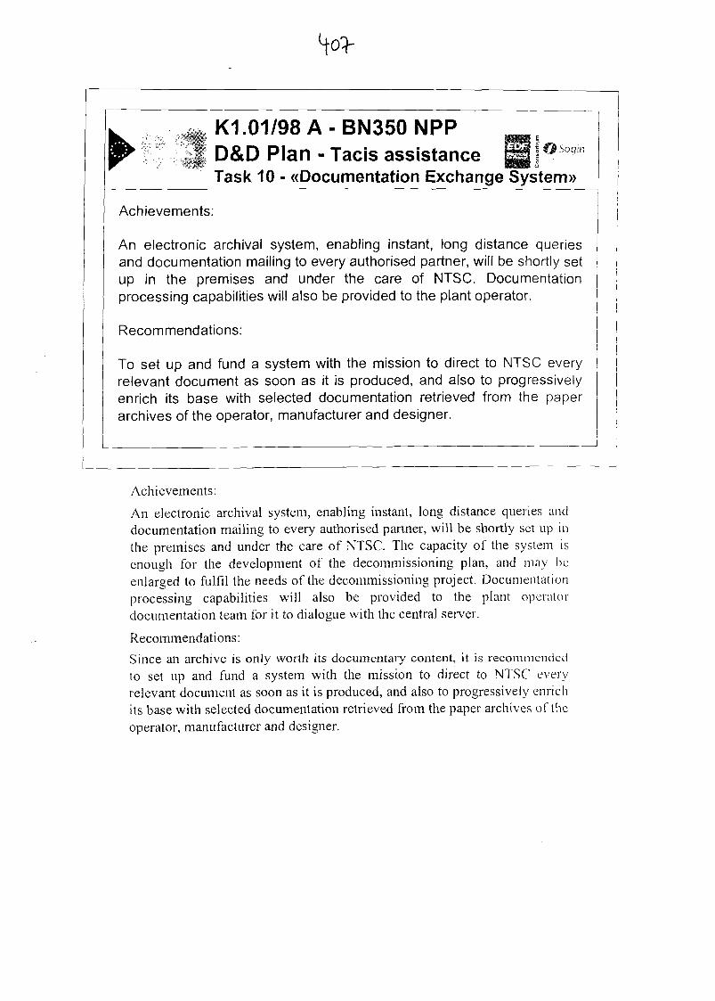
^ K1.01/98 A • BN350 NPP e
| D&D Plan - Tacis assistanceTask 10 - «Documentation Exchange System»
Achievements:
An electronic archival system, enabling instant, long distance queriesand documentation mailing to every authorised partner, will be shortly setup in the premises and under the care of NTSC. Documentationprocessing capabilities will also be provided to the plant operator.
Recommendations:
To set up and fund a system with the mission to direct to NTSC everyrelevant document as soon as it is produced, and also to progressivelyenrich its base with selected documentation retrieved from the paperarchives of the operator, manufacturer and designer.
Achievements:
An electronic archival system, enabling instant, long distance queries anddocumentation mailing to every authorised partner, will be shortly set up inthe premises and under the care of NTSC. The capacity of the system isenough for the development of the decommissioning plan, and may beenlarged to fulfil the needs of the decommissioning project. Documentationprocessing capabilities will also be provided to the plant operatordocumentation team for it to dialogue with the central server.
Recommendations:
Since an archive is only worth its documentary content, it is recommendedto set up and fund a system with the mission to direct to NTSC everyrelevant document as soon as it is produced, and also to progressively enrichits base with selected documentation retrieved from the paper archives of theoperator, manufacturer and designer.
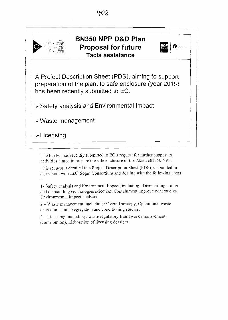
BN350 NPP D&D PlanProposal for future ™ 1 °SogIn
Tacis assistance
A Project Description Sheet (PDS), aiming to supportpreparation of the plant to safe enclosure (year 2015)has been recently submitted to EC.
>Safety analysis and Environmental Impact
^Waste management
^Licensing
The KAEC has recently submitted to EC a request for further support toactivities aimed to prepare the safe enclosure of the Akatu BN350 NPP.
This request is detailed in a Project Description Sheet (PDS), elaborated inagreement with EDF/Sogin Consortium and dealing with the following areas
1 - Safety analysis and Environment Impact, including : Dismantling optionand dismantling technologies selection, Containment improvement studies.Environmental impact analysis.
2 - Waste management, including : Overall strategy, Operational wastecharacterisation, segregation and conditioning studies.
3 - Licensing, including : waste regulatory framework improvement(contribution), Elaboration of licensing dossiers.

GENERAL REVIEW OF THE DECOMMISSIONING OF LIQUIDMETAL FAST REACTORS (LMFRs) IN FRANCE
G. RODRIGUEZ8, R. FRITHb, M. BERTEC
" CEA Cadarache Commissariat a I'Energie Atomique, CEA/DEN/DER/STR/LTTS Centre d'Etude deCADARACHE 13180St Paul lezDurance, Cedex, France.
* Electricite de France/CIDEN, 35-37 Rue Louis GUERIN, BP1212, 69611 VILLEURBANNE, Cedex, France.
c FRAMATOME ANP/Novatome Division, 10, rue Juliette RECAM1ER, 69456 LYON Cedex 06, France.
Abstract
This paper gives a general review of the decommissioning of Liquid Metal Fast Reactors (LMFRs) held sincethe last decades in France. It summarizes the main steps to process the decommissioning of RAPSODffi andSUPERPHENIX. This experimental feedback can highlight several recommendations and a general approachfor the decommissioning of future LMFRs still in operation.
Keywords: Liquid Metal Fast Reactor (LMFR), Decommissioning, Sodium treatment.
1. IntroductionIn the 60's and mid 70's, nuclear power was expected to develop very quickly across the world.The Fast breeder reactors were then developed in every nuclear countries with merely the sameconcept : liquid metal cooled (sodium or potassium sodium alloy) and mixed (U, Pu) oxidefuelled. Thus all countries have developed a nuclear program based on the building of researchbreeder reactors (RAPSODIE, KNKII, DFR), then there was the building of some prototypereactors (PHENTX, PFR, BN350) and at least the design or building of some commercialreactors (SUPERPHENTX, BN600, EFR (project)).As it is clearly expressed in paper mentioned in reference [ 1 ], "Seen from the early 70's, FastBreeder Reactors were second generation plants, whose turn should only come when thermalreactors will have significantly depleted the asU resources. On the other hand, they offered theprospects of unlimited energy supply".In the mid of the 80's it appears that the demand of nuclear energy was less important andcrucial than expected and in all European countries the development program for breedersreactors continuously decreased. It has been completely stopped in several countries such asGermany, Italy and latter in the United Kingdom. This new strategy was accompanied by thedefinitive shutdown of several breeders reactors. Thus the question of the decommissioning ofseveral LMFRs in Europe and even in the rest of the world became a major subject. Theinterest in the decommissioning of LMFRs raised with the final shutdown of prototype reactorssuch as PFR and the prematurely shut down of the SUPERPHENIX reactor in summer 1997.
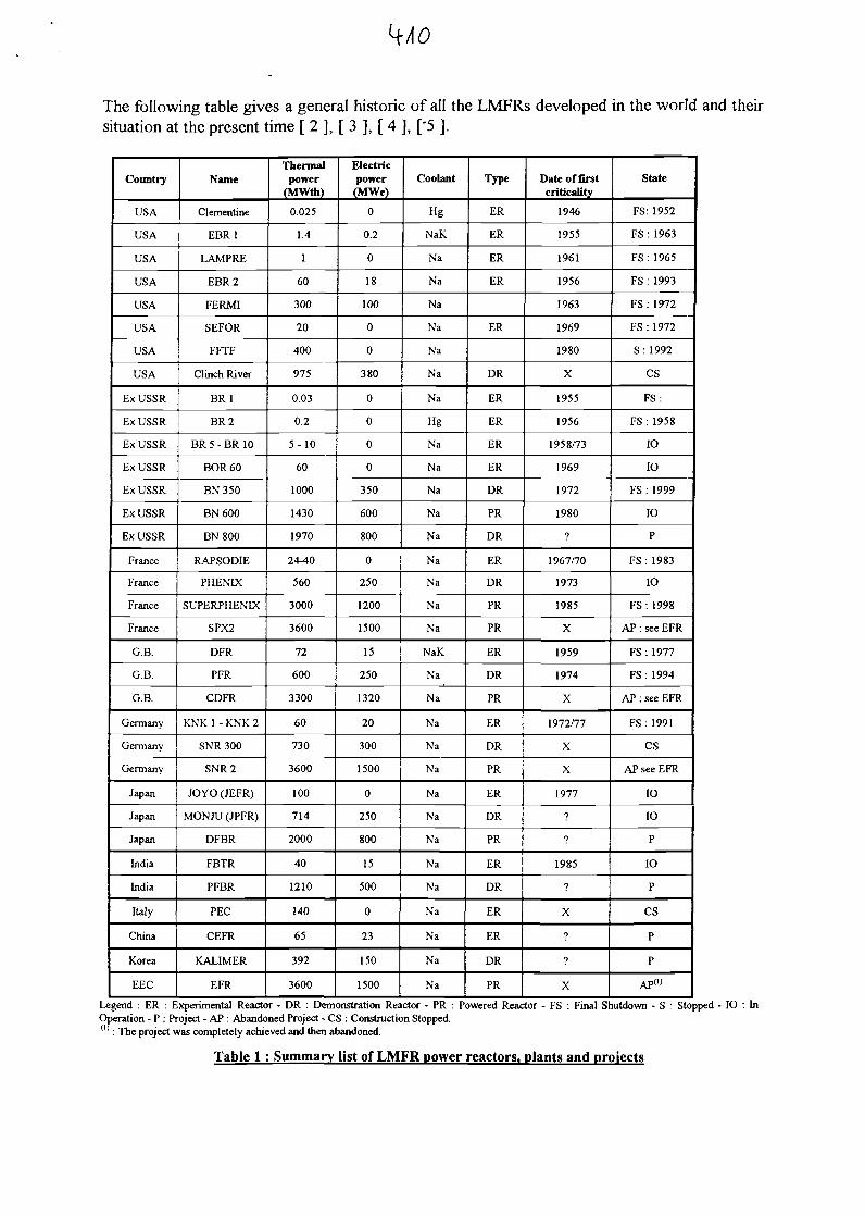
The following table gives a general historic of all the LMFRs developed in the world and theirsituation at the present time [ 2 ], [ 3 ], [ 4 ], ['5 ].
Country
USA
USA
USA
USA
USA
USA
USA
USA
Ex USSR
Ex USSR
Ex USSR
Ex USSR
Ex USSR
Ex USSR
Ex USSR
France
France
France
France
G.B.
G.B.
G.B.
Germany
Germany
Germany
Japan
Japan
Japan
India
India
Italy
China
Korea
EEC
Name
Clementine
EBR1
LAMPRE
EBR2
FERMI
SEFOR
FFTF
Clinch River
BR1
BR2
B R 5 - B R 10
BOR60
BN350
BN600
BN800
RAPSODIE
PHENLX
SUPERPHENLX
SPX2
DFR
PFR
CDFR
KNK 1 - KNK 2
SNR 300
SNR2
JOYO (JEFR)
MONJU (JPFR)
DFBR
FBTR
PFBR
PEC
CEFR
KALIMER
EFR
Thermalpower
(MWth)
0.025
1.4
1
60
300
20
400
975
0.03
0.2
5- 10
60
1000
1430
1970
24-40
560
3000
3600
72
600
3300
60
730
3600
100
714
2000
40
1210
140
65
392
3600
Electricpower(MWe)
0
0.2
0
18
100
0
0
380
0
0
0
0
350
600
800
0
250
1200
1500
15
250
1320
20
300
1500
0
250
800
15
500
0
23
150
1500
Coolant
Hg
NaK
Na
Na
Na
Na
Na
Na
Na
Hg
Na
Na
Na
Na
Na
Na
Na
Na
Na
NaK
Na
Na
Na
Na
Na
Na
Na
Na
Na
Na
Na
Na
Na
Na
Type
ER
ER
ER
ER
ER
DR
ER
ER
ER
ER
DR
PR
DR
ER
DR
PR
PR
ER
DR
PR
ER
DR
PR
ER
DR
PR
ER
DR
ER
ER
DR
PR
Date of firstcriticality
1946
1955
1961
1956
1963
1969
1980
X
1955
1956
1958/73
1969
1972
1980
?
1967/70
1973
1985
X
1959
1974
X
1972/77
X
X
1977
?
?
1985
?
X
?
?
X
State
FS: 1952
FS : 1963
FS : 1965
FS : 1993
FS: 1972
FS : 1972
S : 1992
CS
FS:
FS : 1958
10
IO
FS : 1999
10
P
FS : 1983
IO
FS : 1998
AP : see EFR
FS : 1977
FS : 1994
AP : see EFR
FS: 1991
CS
AP see EFR
IO
10
P
IO
P
CS
P
P
AP("
Legend : ER : Experimental Reactor - DR : Demonstration Reactor - PR : Powered Reactor - FS : Final Shutdown - S : Stopped - IO : InOperation - P : Project - AP : Abandoned Project - CS : Construction Stopped.
: The project was completely achieved and then abandoned.
Table 1 : Summary list of LMFR power reactors, plants and projects
It can clearly be seen that a majority of reactor built in the western countries are now stoppedand there is therefore in all these countries (USA, Western Europe and ex-USSR) developmentof studies and operations for the decommissioning of LMFRs. Thus the objective of this reviewis to present the different steps of the decommissioning of French LMFRs (RAPSODIE andSUPERPHENIX) in order to present the particularities of these decommissioning techniquesand to highlight the state of the art in decommissioning Liquid Metal Fast Reactors, that can beuseful when time will come for the reactor still in operation to be stopped. Even for fastreactors in project, it happens that taking into consideration the future decommissioning ofthese reactors in the design stage will become now an increasingly demand of safety authoritiesto accept the project for its future realization.
2. Specificities in the decommissioning of LMFRFor decommissioning operations, the main specificity in LMFRs is the nature of the coolantwhich is, for all the reactors ever built, always a liquid metal and that has to be considered as achemical waste at the final shutdown of the reactor. In its form, the liquid coolant (sodium orsodium-potassium alloy) cannot be considered as a stable nuclear waste due to its chemicalproperties : strong reaction with water and potential ignition with air when liquid [ 6 ], [ 7 ].Thus in the decommissioning phases it will be necessary to consider the transformation of thiscoolant into a stable chemical product.The treatment of sodium or NaK will be encountered at every steps of the decommissioningoperations :
- during the defiielling phase, the assembly will be covered by a residual film of sodium(or NaK) that has to be removed before storing the elements in the pool,
- every component extracted from the reactor will also be covered by a film of sodiumand can sometimes retain residual amount of sodium. This sodium will have to beremoved prior to the dismantling of the components,
- the metallic coolant coming from the primary and secondary circuits will have to bechemically treated in order to transform these large amounts of metallic radioactiveproducts (several tons to several hundred of tons) to stable products,
- the primary vessel drained from the primary coolant and the secondary circuit drainedfrom the secondary coolant will have inside some residual amount of liquid metal stuckto the surface or retained inside the structures as non drainable retentions. Hence, thisparticular situation will have to be solved prior to the study of the decommissioning ofthe main structures,
- at least, the decommissioning of a LMFR will produce several secondary wastes full ofsodium and highly activated or contaminated i.e. cold traps or cesium traps, etc... Aspecific treatment for these waste will have to be found.
Thus in the field of the decommissioning of LMFR the term of "sodium waste treatment" isgenerally used. This term gathers all the processes that can be used to transform sodium to achemical stable product to achieve the global decommission of the reactor [ 8 ].These specific techniques applied for the decommissioning of LMFRs and in particular, thespecific processes developed at every step for sodium treatment will be presented in thedescription of the decommissioning operations of the following reactors : RAPSODIE andSUPERPHENIX in the following chapters.
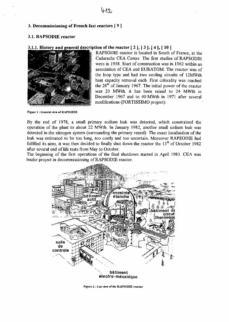
3. Decommissioning of French fast reactors [ 9 ]
3.1. RAPSODIE reactor
3.1.1. History and ;eneral description of the reactor [ 2 ] , [ 3 ] , [ 4 ] , [ 1 0 ]RAPSODIE reactor is located in South of France, at theCadarache CEA Centre. The first studies of RAPSODIEwere in 1958. Start of construction was in 1962 within anassociation of CEA and EURATOM. The reactor was ofthe loop type and had two cooling circuits of 12MWthheat capacity removal each. First criticality was reachedthe 28th of January 1967. The initial power of the reactorwas 20 MWth, it has been raised to 24 MWth inDecember 1967 and to 40 MWth in 1971 after severalmodifications (FORTISSIMO project).
Figure 1 : General view of RAPSODIE
By the end of 1978, a small primary sodium leak was detected, which constrained theoperation of the plant to about 22 MWth. In January 1982, another small sodium leak wasdetected in the nitrogen system (surrounding the primary vessel). The exact localisation of theleak was estimated to be too long, too costly and too uncertain. Moreover RAPSODIE hadfulfilled its aims, it was then decided to finally shut down the reactor the 13th of October 1982after several end of life tests from May to October.The beginning of the first operations of the final shutdown started in April 1983. CEA wasleader project in decommissioning of RAPSODIE reactor.
£^-~£<^!& y.^^^m^^M^^.:--:-:. '"'••
'*& *"•*«*£ -*-jftv'»:^^*5gf«^^^-.vy-^r..
ri- *>*^ ;
bailmentelectro-- mdcanf que
Figure Z : Cut view of the RAPSODIE reactor
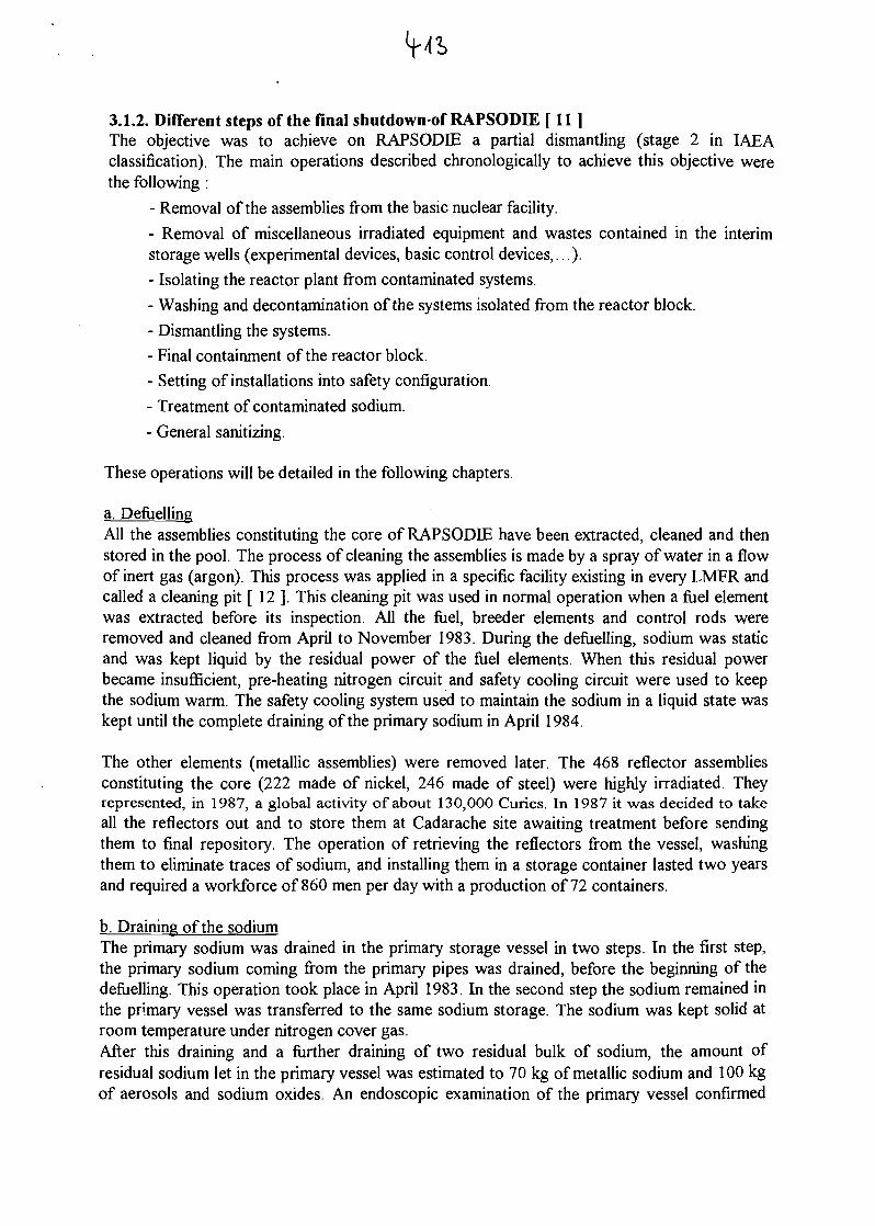
3.1.2. Different steps of the final shutdown-of RAPSODIE [ 11 ]The objective was to achieve on RAPSODIE a partial dismantling (stage 2 in IAEAclassification). The main operations described chronologically to achieve this objective werethe following :
- Removal of the assemblies from the basic nuclear facility.
- Removal of miscellaneous irradiated equipment and wastes contained in the interimstorage wells (experimental devices, basic control devices,...).
- Isolating the reactor plant from contaminated systems.
- Washing and decontamination of the systems isolated from the reactor block.
- Dismantling the systems.
- Final containment of the reactor block.
- Setting of installations into safety configuration.
- Treatment of contaminated sodium.
- General sanitizing.
These operations will be detailed in the following chapters.
a. DefuellingAll the assemblies constituting the core of RAPSODIE have been extracted, cleaned and thenstored in the pool. The process of cleaning the assemblies is made by a spray of water in a flowof inert gas (argon). This process was applied in a specific facility existing in every LMFR andcalled a cleaning pit [ 12 ]. This cleaning pit was used in normal operation when a fuel elementwas extracted before its inspection. All the fuel, breeder elements and control rods wereremoved and cleaned from April to November 1983. During the defuelling, sodium was staticand was kept liquid by the residual power of the fuel elements. When this residual powerbecame insufficient, pre-heating nitrogen circuit and safety cooling circuit were used to keepthe sodium warm. The safety cooling system used to maintain the sodium in a liquid state waskept until the complete draining of the primary sodium in April 1984.
The other elements (metallic assemblies) were removed later. The 468 reflector assembliesconstituting the core (222 made of nickel, 246 made of steel) were highly irradiated. Theyrepresented, in 1987, a global activity of about 130,000 Curies. In 1987 it was decided to takeall the reflectors out and to store them at Cadarache site awaiting treatment before sendingthem to final repository. The operation of retrieving the reflectors from the vessel, washingthem to eliminate traces of sodium, and installing them in a storage container lasted two yearsand required a workforce of 860 men per day with a production of 72 containers.
b. Draining of the sodiumThe primary sodium was drained in the primary storage vessel in two steps. In the first step,the primary sodium coming from the primary pipes was drained, before the beginning of thedefuelling. This operation took place in April 1983. In the second step the sodium remained inthe primary vessel was transferred to the same sodium storage. The sodium was kept solid atroom temperature under nitrogen cover gas.After this draining and a further draining of two residual bulk of sodium, the amount ofresidual sodium let in the primary vessel was estimated to 70 kg of metallic sodium and 100 kgof aerosols and sodium oxides. An endoscopic examination of the primary vessel confirmed
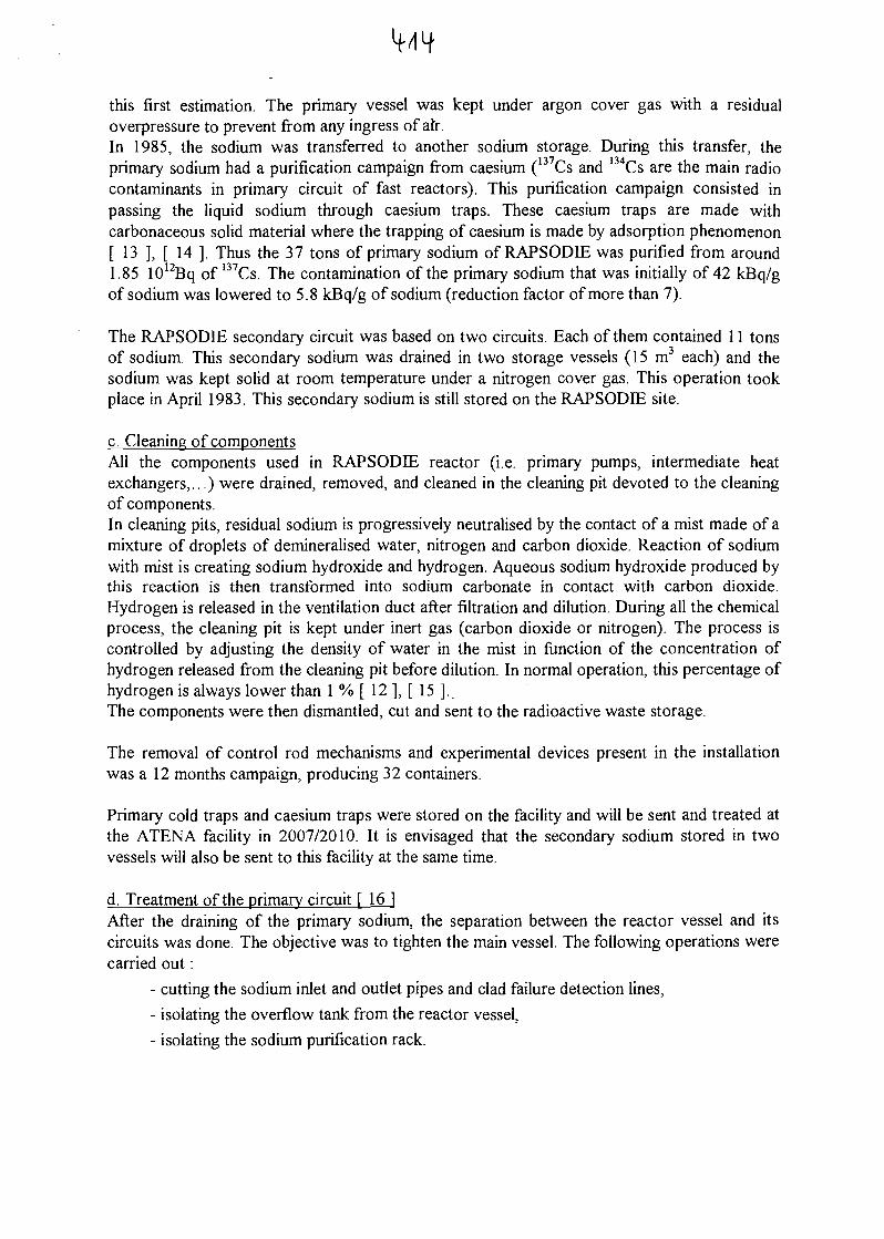
If/I Ifthis first estimation. The primary vessel was kept under argon cover gas with a residualoverpressure to prevent from any ingress of afr.In 1985, the sodium was transferred to another sodium storage. During this transfer, theprimary sodium had a purification campaign from caesium (137Cs and 134Cs are the main radiocontaminants in primary circuit of fast reactors). This purification campaign consisted inpassing the liquid sodium through caesium traps. These caesium traps are made withcarbonaceous solid material where the trapping of caesium is made by adsorption phenomenon[ 13 ], [ 14 ]. Thus the 37 tons of primary sodium of RAPSODIE was purified from around1.85 1012Bq of 137Cs. The contamination of the primary sodium that was initially of 42 kBq/gof sodium was lowered to 5.8 kBq/g of sodium (reduction factor of more than 7).
The RAPSODIE secondary circuit was based on two circuits. Each of them contained 11 tonsof sodium. This secondary sodium was drained in two storage vessels (15m3 each) and thesodium was kept solid at room temperature under a nitrogen cover gas. This operation tookplace in April 1983. This secondary sodium is still stored on the RAPSODIE site.
c. Cleaning of componentsAll the components used in RAPSODIE reactor (i.e. primary pumps, intermediate heatexchangers,...) were drained, removed, and cleaned in the cleaning pit devoted to the cleaningof components.In cleaning pits, residual sodium is progressively neutralised by the contact of a mist made of amixture of droplets of demineralised water, nitrogen and carbon dioxide. Reaction of sodiumwith mist is creating sodium hydroxide and hydrogen. Aqueous sodium hydroxide produced bythis reaction is then transformed into sodium carbonate in contact with carbon dioxide.Hydrogen is released in the ventilation duct after filtration and dilution. During all the chemicalprocess, the cleaning pit is kept under inert gas (carbon dioxide or nitrogen). The process iscontrolled by adjusting the density of water in the mist in function of the concentration ofhydrogen released from the cleaning pit before dilution. In normal operation, this percentage ofhydrogen is always lower than 1 % [ 12 ], [ 15 ] .The components were then dismantled, cut and sent to the radioactive waste storage.
The removal of control rod mechanisms and experimental devices present in the installationwas a 12 months campaign, producing 32 containers.
Primary cold traps and caesium traps were stored on the facility and will be sent and treated atthe ATENA facility in 2007/2010. It is envisaged that the secondary sodium stored in twovessels will also be sent to this facility at the same time.
d. Treatment of the primary circuit [161After the draining of the primary sodium, the separation between the reactor vessel and itscircuits was done. The objective was to tighten the main vessel. The following operations werecarried out:
- cutting the sodium inlet and outlet pipes and clad failure detection lines,
- isolating the overflow tank from the reactor vessel,
- isolating the sodium purification rack.
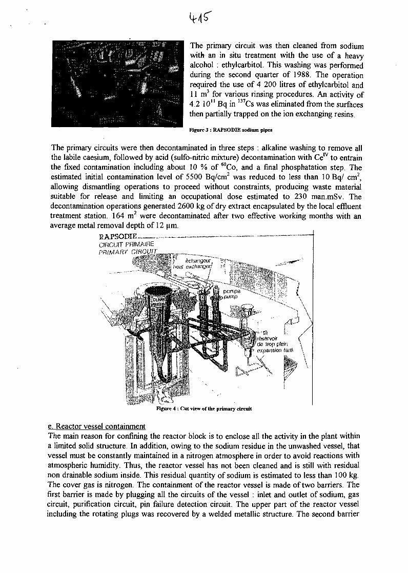
IMS'The primary circuit was then cleaned from sodiumwith an in situ treatment with the use of a heavyalcohol : ethylcarbitol. This washing was performedduring the second quarter of 1988. The operationrequired the use of 4 200 litres of ethylcarbitol and11 m3 for various rinsing procedures. An activity of4.2 1011 Bq in 137Cs was eliminated from the surfacesthen partially trapped on the ion exchanging resins.
Figure 3 : RAPSODIE sodium pipes
The primary circuits were then decontaminated in three steps : alkaline washing to remove allthe labile caesium, followed by acid (sulfo-nitric mixture) decontamination with Ce™ to entrainthe fixed contamination including about 10 % of 60Co, and a final phosphatation step. Theestimated initial contamination level of 5500 Bq/cm2 was reduced to less than 10 Bq/ cm2,allowing dismantling operations to proceed without constraints, producing waste materialsuitable for release and limiting an occupational dose estimated to 230 man.mSv. Thedecontamination operations generated 2600 kg of dry extract encapsulated by the local effluenttreatment station. 164 m2 were decontaminated after two effective working months with anaverage metal removal depth of 12 um.
RAPSODIE™ —..-CIRCUIT PRIMAiflEPRIMARY
Figure 4 : Cut view of the primary circuit
e. Reactor vessel containmentThe main reason for confining the reactor block is to enclose all the activity in the plant withina limited solid structure. In addition, owing to the sodium residue in the unwashed vessel, thatvessel must be constantly maintained in a nitrogen atmosphere in order to avoid reactions withatmospheric humidity. Thus, the reactor vessel has not been cleaned and is still with residualnon drainable sodium inside. This residual quantity of sodium is estimated to less than 100 kg.The cover gas is nitrogen. The containment of the reactor vessel is made of two barriers. Thefirst barrier is made by plugging all the circuits of the vessel : inlet and outlet of sodium, gascircuit, purification circuit, pin failure detection circuit. The upper part of the reactor vesselincluding the rotating plugs was recovered by a welded metallic structure. The second barrier
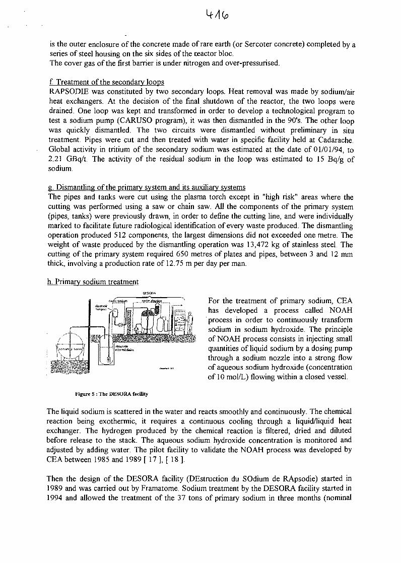
is the outer enclosure of the concrete made of rare earth (or Sercoter concrete) completed by aseries of steel housing on the six sides of the reactor bloc.The cover gas of the first barrier is under nitrogen and over-pressurised.
f. Treatment of the secondary loopsRAPSODEE was constituted by two secondary loops. Heat removal was made by sodium/airheat exchangers. At the decision of the final shutdown of the reactor, the two loops weredrained. One loop was kept and transformed in order to develop a technological program totest a sodium pump (CARUSO program), it was then dismantled in the 90's. The other loopwas quickly dismantled. The two circuits were dismantled without preliminary in situtreatment. Pipes were cut and then treated with water in specific facility held at Cadarache.Global activity in tritium of the secondary sodium was estimated at the date of 01/01/94, to2.21 GBq/t. The activity of the residual sodium in the loop was estimated to 15 Bq/g ofsodium.
g. Dismantling of the primary system and its auxiliary systemsThe pipes and tanks were cut using the plasma torch except in "high risk" areas where thecutting was performed using a saw or chain saw. All the components of the primary system(pipes, tanks) were previously drawn, in order to define the cutting line, and were individuallymarked to facilitate future radiological identification of every waste produced. The dismantlingoperation produced 512 components, the largest dimensions did not exceeded one metre. Theweight of waste produced by the dismantling operation was 13,472 kg of stainless steel. Thecutting of the primary system required 650 metres of plates and pipes, between 3 and 12 mmthick, involving a production rate of 12.75 m per day per man.
h. Primary sodium treatment
For the treatment of primary sodium, CEAhas developed a process called NOAHprocess in order to continuously transformsodium in sodium hydroxide. The principleof NOAH process consists in injecting smallquantities of liquid sodium by a dosing pumpthrough a sodium nozzle into a strong flowof aqueous sodium hydroxide (concentrationof 10 mol/L) flowing within a closed vessel.
Figure 5 : The DESORA facility
The liquid sodium is scattered in the water and reacts smoothly and continuously. The chemicalreaction being exothermic, it requires a continuous cooling through a liquid/liquid heatexchanger. The hydrogen produced by the chemical reaction is filtered, dried and dilutedbefore release to the stack. The aqueous sodium hydroxide concentration is monitored andadjusted by adding water. The pilot facility to validate the NOAH process was developed byCEA between 1985 and 1989 [ 17 ], [ 18 ].
Then the design of the DESORA facility (DEstruction du SOdium de RApsodie) started in1989 and was carried out by Framatome. Sodium treatment by the DESORA facility started in1994 and allowed the treatment of the 37 tons of primary sodium in three months (nominal
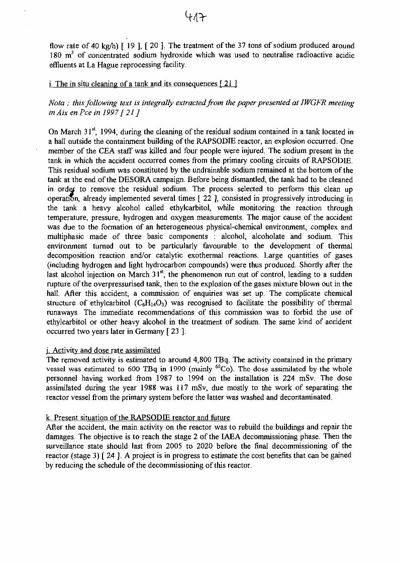
flow rate of 40 kg/h) [ 19 ], [ 20 ]. The treatment of the 37 tons of sodium produced around180 m3 of concentrated sodium hydroxide which was used to neutralise radioactive acidiceffluents at La Hague reprocessing facility.
i. The in situ cleaning of a tank and its consequences [ 21 ]
Nota : this following text is integrally extracted from the paper presented at IWGFR meetingin Aix en Pee in 1997 [21 ]
On March 31st, 1994, during the cleaning of the residual sodium contained in a tank located ina hall outside the containment building of the RAPSODIE reactor, an explosion occurred. Onemember of the CEA staff was killed and four people were injured. The sodium present in thetank in which the accident occurred comes from the primary cooling circuits of RAPSODIE.This residual sodium was constituted by the undrainable sodium remained at the bottom of thetank at the end of the DESORA campaign. Before being dismantled, the tank had to be cleanedin ordej to remove the residual sodium. The process selected to perform this clean upoperation, already implemented several times [ 22 ], consisted in progressively introducing inthe tank a heavy alcohol called ethylcarbitol, while monitoring the reaction throughtemperature, pressure, hydrogen and oxygen measurements. The major cause of the accidentwas due to the formation of an heterogeneous physical-chemical environment, complex andmultiphasic made of three basic components : alcohol, alcoholate and sodium. Thisenvironment turned out to be particularly favourable to the development of thermaldecomposition reaction and/or catalytic exothermal reactions. Large quantities of gases(including hydrogen and light hydrocarbon compounds) were thus produced. Shortly after thelast alcohol injection on March 31st, the phenomenon run out of control, leading to a suddenrupture of the overpressurised tank, then to the explosion of the gases mixture blown out in thehall. After this accident, a commission of enquiries was set up. The complicate chemicalstructure of ethylcarbitol (CeHnOs) was recognised to facilitate the possibility of thermalrunaways. The immediate recommendations of this commission was to forbid the use ofethylcarbitol or other heavy alcohol in the treatment of sodium. The same kind of accidentoccurred two years later in Germany [ 23 ].
j. Activity and dose rate assimilatedThe removed activity is estimated to around 4,800 TBq. The activity contained in the primaryvessel was estimated to 600 TBq in 1990 (mainly 60Co). The dose assimilated by the wholepersonnel having worked from 1987 to 1994 on the installation is 224 mSv. The doseassimilated during the year 1988 was 117 mSv, due mostly to the work of separating thereactor vessel from the primary system before the latter was washed and decontaminated.
k. Present situation of the RAPSODIE reactor and futureAfter the accident, the main activity on the reactor was to rebuild the buildings and repair thedamages. The objective is to reach the stage 2 of the IAEA decommissioning phase. Then thesurveillance state should last from 2005 to 2020 before the final decommissioning of thereactor (stage 3) [ 24 ]. A project is in progress to estimate the cost benefits that can be gainedby reducing the schedule of the decommissioning of this reactor.
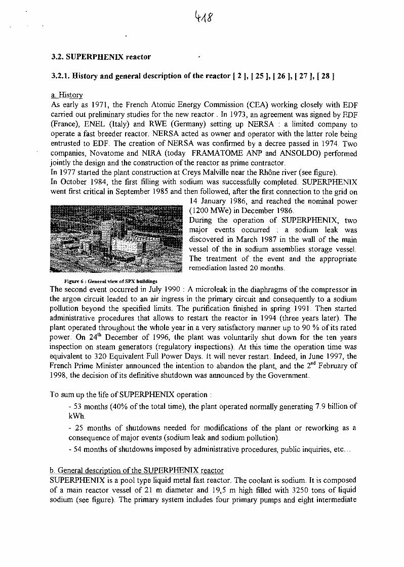
3.2. SUPERPHENIX reactor
3.2.1. History and general description of the reactor [ 2 ], [ 25 ], [ 26 ], [ 27 ], [ 28 ]
a. HistoryAs early as 1971, the French Atomic Energy Commission (CEA) working closely with EOFcarried out preliminary studies for the new reactor . In 1973, an agreement was signed by EDF(France), ENEL (Italy) and RWE (Germany) setting up NERSA : a limited company tooperate a fast breeder reactor. NERSA acted as owner and operator with the latter role beingentrusted to EDF. The creation of NERSA was confirmed by a decree passed in 1974. Twocompanies, Novatome and NIRA (today FRAMATOME ANP and ANSOLDO) performedjointly the design and the construction of the reactor as prime contractor.In 1977 started the plant construction at Creys Malville near the Rhone river (see figure).In October 1984, the first filling with sodium was successfully completed. SUPERPHENIXwent first critical in September 1985 and then followed, after the first connection to the grid on
14 January 1986, and reached the nominal power(1200 MWe) in December 1986.During the operation of SUPERPHENIX, twomajor events occurred : a sodium leak wasdiscovered in March 1987 in the wall of the mainvessel of the in sodium assemblies storage vessel.The treatment of the event and the appropriateremediation lasted 20 months.
fJttffr
Figure 6 : General view ofSPX buildings
The second event occurred in July 1990 : A microleak in the diaphragms of the compressor inthe argon circuit leaded to an air ingress in the primary circuit and consequently to a sodiumpollution beyond the specified limits. The purification finished in spring 1991. Then startedadministrative procedures that allows to restart the reactor in 1994 (three years later). Theplant operated throughout the whole year in a very satisfactory manner up to 90 % of its ratedpower. On 24th December of 1996, the plant was voluntarily shut down for the ten yearsinspection on steam generators (regulatory inspections). At this time the operation time wasequivalent to 320 Equivalent Full Power Days. It will never restart. Indeed, in June 1997, theFrench Prime Minister announced the intention to abandon the plant, and the 2nd February of1998, the decision of its definitive shutdown was announced by the Government.
To sum up the life of SUPERPHENTX operation :
- 53 months (40% of the total time), the plant operated normally generating 7.9 billion ofkWh.
- 25 months of shutdowns needed for modifications of the plant or reworking as aconsequence of major events (sodium leak and sodium pollution).
- 54 months of shutdowns imposed by administrative procedures, public inquiries, etc...
b. General description of the SUPERPHENIX reactorSUPERPHENIX is a pool type liquid metal fast reactor. The coolant is sodium. It is composedof a main reactor vessel of 21 m diameter and 19,5 m high filled with 3250 tons of liquidsodium (see figure). The primary system includes four primary pumps and eight intermediate
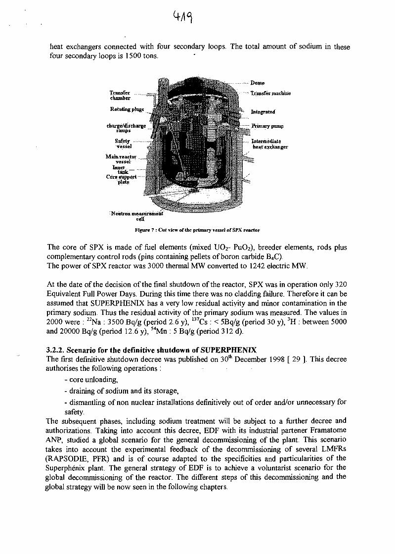
heat exchangers connected with four secondary loops. The total amount of sodium in thesefour secondary loops is 1500 tons.
Dome
Transfer machine
Integrated
'^"" Primary pump
.... Intermediateheat exchanger
Transferchamber
Rotating phigs
charge/dischargeramps
Safety-vessel
Main reactorvessel
Innertank""
Cote supportplate
Neutron measurement
Figure 7 : Cut view of the primary vessel of SPX reactor
The core of SPX is made of fuel elements (mixed UCV PuOa), breeder elements, rods pluscomplementary control rods (pins containing pellets of boron carbide B4C).The power of SPX reactor was 3000 thermal MW converted to 1242 electric MW.
At the date of the decision of the final shutdown of the reactor, SPX was in operation only 320Equivalent Full Power Days. During this time there was no cladding failure. Therefore it can beassumed that SUPERPHENIX has a very low residual activity and minor contamination in theprimary sodium. Thus the residual activity of the primary sodium was measured. The values in2000 were : 22Na : 3500 Bq/g (period 2.6 y), 137Cs : < 5Bq/g (period 30 y), 3H : between 5000and 20000 Bq/g (period 12.6 y), 54Mn : 5 Bq/g (period 312 d).
3.2.2. Scenario for the definitive shutdown of SUPERPHENIXThe first definitive shutdown decree was published on 30th December 1998 [ 29 ]. This decreeauthorises the following operations :
- core unloading,
- draining of sodium and its storage,
- dismantling of non nuclear installations definitively out of order and/or unnecessary forsafety.
The subsequent phases, including sodium treatment will be subject to a further decree andauthorizations. Taking into account this decree, EDF with its industrial partener FramatomeANP, studied a global scenario for the general decommissioning of the plant. This scenariotakes into account the experimental feedback of the decommissioning of several LMFRs(RAPSODIE, PFR) and is of course adapted to the specificities and particularities of theSuperphenix plant. The general strategy of EDF is to achieve a voluntarist scenario for theglobal decommissioning of the reactor. The different steps of this decommissioning and theglobal strategy will be now seen in the following chapters.
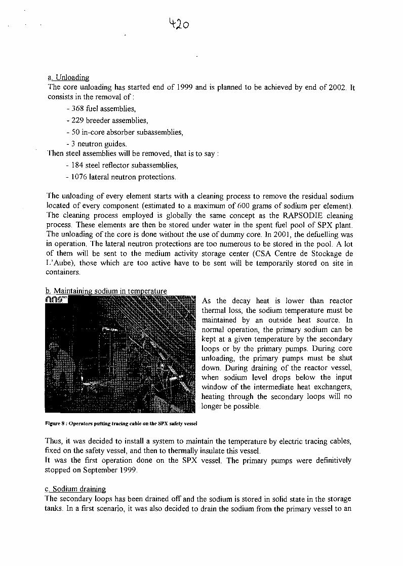
a. UnloadingThe core unloading has started end of 1999 and is planned to be achieved by end of 2002. Itconsists in the removal of:
- 368 fuel assemblies,
- 229 breeder assemblies,
- 50 in-core absorber subassemblies,
- 3 neutron guides.Then steel assemblies will be removed, that is to say :
- 184 steel reflector subassemblies,
- 1076 lateral neutron protections.
The unloading of every element starts with a cleaning process to remove the residual sodiumlocated of every component (estimated to a maximum of 600 grams of sodium per element).The cleaning process employed is globally the same concept as the RAPSODIE cleaningprocess. These elements are then be stored under water in the spent fuel pool of SPX plant.The unloading of the core is done without the use of dummy core. In 2001, the defuelling wasin operation. The lateral neutron protections are too numerous to be stored in the pool. A lotof them will be sent to the medium activity storage center (CSA Centre de Stockage deL'Aube), those which are too active have to be sent will be temporarily stored on site incontainers.
b. Maintaining sodium in temperatureAs the decay heat is lower than reactorthermal loss, the sodium temperature must bemaintained by an outside heat source. Innormal operation, the primary sodium can bekept at a given temperature by the secondaryloops or by the primary pumps. During coreunloading, the primary pumps must be shutdown. During draining of the reactor vessel,when sodium level drops below the inputwindow of the intermediate heat exchangers,heating through the secondary loops will nolonger be possible.
Figure 8 : Operators patting tracing cable on the SPX safety vessel
Thus, it was decided to install a system to maintain the temperature by electric tracing cables,fixed on the safety vessel, and then to thermally insulate this vessel.It was the first operation done on the SPX vessel. The primary pumps were definitivelystopped on September 1999.
c. Sodium drainingThe secondary loops has been drained off and the sodium is stored in solid state in the storagetanks. In a first scenario, it was also decided to drain the sodium from the primary vessel to an
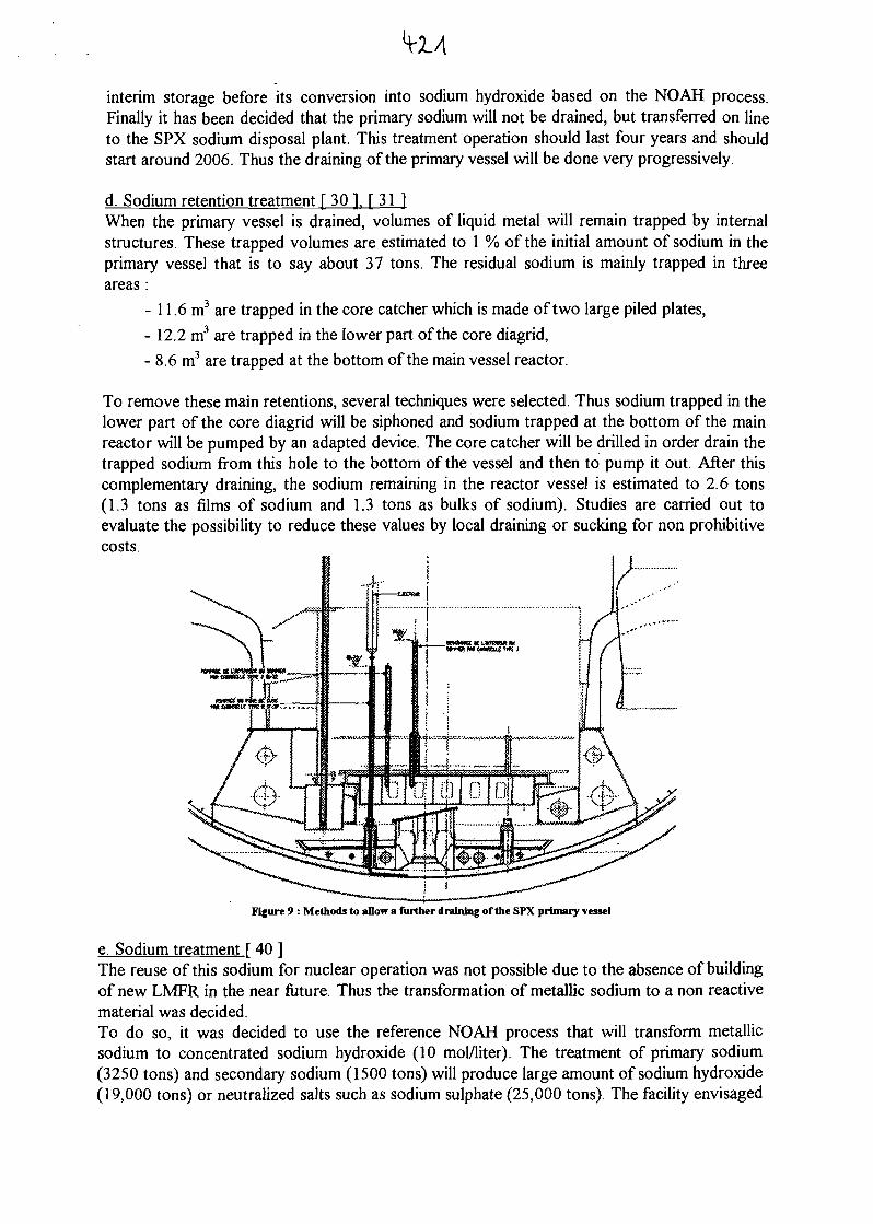
H-x/t
interim storage before its conversion into sodium hydroxide based on the NOAH process.Finally it has been decided that the primary sodium will not be drained, but transferred on lineto the SPX sodium disposal plant. This treatment operation should last four years and shouldstart around 2006. Thus the draining of the primary vessel will be done very progressively.
d. Sodium retention treatment [ 30 ]. [ 31 1When the primary vessel is drained, volumes of liquid metal will remain trapped by internalstructures. These trapped volumes are estimated to 1 % of the initial amount of sodium in theprimary vessel that is to say about 37 tons. The residual sodium is mainly trapped in threeareas :
- 11.6 m3 are trapped in the core catcher which is made of two large piled plates,
- 12.2 m3 are trapped in the lower part of the core diagrid,
- 8.6 m3 are trapped at the bottom of the main vessel reactor.
To remove these main retentions, several techniques were selected. Thus sodium trapped in thelower part of the core diagrid will be siphoned and sodium trapped at the bottom of the mainreactor will be pumped by an adapted device. The core catcher will be drilled in order drain thetrapped sodium from this hole to the bottom of the vessel and then to pump it out. After thiscomplementary draining, the sodium remaining in the reactor vessel is estimated to 2.6 tons(1.3 tons as films of sodium and 1.3 tons as bulks of sodium). Studies are carried out toevaluate the possibility to reduce these values by local draining or sucking for non prohibitivecosts.
Figure 9 : Methods to allow a further draining of the SPX primary vessel
e. Sodium treatment..[ 40 ]The reuse of this sodium for nuclear operation was not possible due to the absence of buildingof new LMFR in the near future. Thus the transformation of metallic sodium to a non reactivematerial was decided.To do so, it was decided to use the reference NOAH process that will transform metallicsodium to concentrated sodium hydroxide (10 mol/liter). The treatment of primary sodium(3250 tons) and secondary sodium (1500 tons) will produce large amount of sodium hydroxide(19,000 tons) or neutralized salts such as sodium sulphate (25,000 tons). The facility envisaged
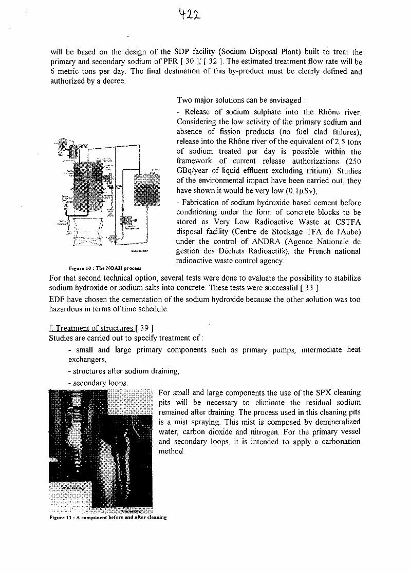
will be based on the design of the SDP facility (Sodium Disposal Plant) built to treat theprimary and secondary sodium of PFR [ 30 ],' [ 32 ]. The estimated treatment flow rate will be6 metric tons per day. The final destination of this by-product must be clearly defined andauthorized by a decree.
Two major solutions can be envisaged :
- Release of sodium sulphate into the Rhone river.Considering the low activity of the primary sodium andabsence of fission products (no fuel clad failures),release into the Rhone river of the equivalent of 2.5 tonsof sodium treated per day is possible within theframework of current release authorizations (250GBq/year of liquid effluent excluding tritium). Studiesof the environmental impact have been carried out, theyhave shown it would be very low (0.1 u,Sv),
- Fabrication of sodium hydroxide based cement beforeconditioning under the form of concrete blocks to bestored as Very Low Radioactive Waste at CSTFAdisposal facility (Centre de Stockage TFA de 1'Aube)under the control of ANDRA (Agence Nationale degestion des Dechets Radioactifs), the French nationalradioactive waste control agency.
Figure 10 : The NOAH process
For that second technical option, several tests were done to evaluate the possibility to stabilizesodium hydroxide or sodium salts into concrete. These tests were successful [ 33 ].
EDF have chosen the cementation of the sodium hydroxide because the other solution was toohazardous in terms of time schedule.
f. Treatment of structures [ 39 ]Studies are carried out to specify treatment of:
- small and large primary components such as primary pumps, intermediate heatexchangers,
- structures after sodium draining,
- secondary loops.For small and large components the use of the SPX cleaningpits will be necessary to eliminate the residual sodiumremained after draining. The process used in this cleaning pitsis a mist spraying. This mist is composed by demineralizedwater, carbon dioxide and nitrogen. For the primary vesseland secondary loops, it is intended to apply a carbonationmethod.
Figure 11 : A component before and after cleaning
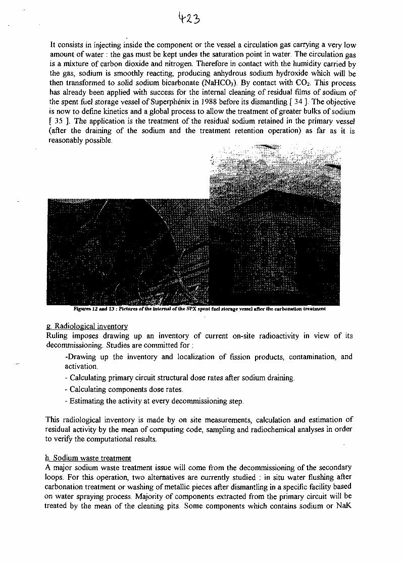
It consists in injecting inside the component or the vessel a circulation gas carrying a very lowamount of water : the gas must be kept under the saturation point in water. The circulation gasis a mixture of carbon dioxide and nitrogen. Therefore in contact with the humidity carried bythe gas, sodium is smoothly reacting, producing anhydrous sodium hydroxide which will bethen transformed to solid sodium bicarbonate (NaHCOs). By contact with CC>2. This processhas already been applied with success for the internal cleaning of residual films of sodium ofthe spent fuel storage vessel of Superphenix in 1988 before its dismantling [ 34 ]. The objectiveis now to define kinetics and a global process to allow the treatment of greater bulks of sodium[ 35 ]. The application is the treatment of the residual sodium retained in the primary vessel(after the draining of the sodium and the treatment retention operation) as far as it isreasonably possible.
Figures 12 and 13 : Pictures of the internal of the SPX spent fuel storage vessel after the carbonation treatment
g. Radiological inventoryRuling imposes drawing up an inventory of current on-site radioactivity in view of itsdecommissioning. Studies are committed for :
-Drawing up the inventory and localization of fission products, contamination, andactivation.
- Calculating primary circuit structural dose rates after sodium draining.
- Calculating components dose rates.
- Estimating the activity at every decommissioning step.
This radiological inventory is made by on site measurements, calculation and estimation ofresidual activity by the mean of computing code, sampling and radiochemical analyses in orderto verify the computational results.
h. Sodium waste treatmentA major sodium waste treatment issue will come from the decommissioning of the secondaryloops. For this operation, two alternatives are currently studied : in situ water flushing aftercarbonation treatment or washing of metallic pieces after dismantling in a specific facility basedon water spraying process. Majority of components extracted from the primary circuit will betreated by the mean of the cleaning pits. Some components which contains sodium or NaK
alloy and which require specific treatment will probably be treated in a CEA facility calledATENA that will be constructed in 2007.- This is particularly the case for primary andsecondary cold traps. These components present the major drawbacks to be not self drainingand to concentrate sodium impurities (sodium oxides and sodium hydride) and contamination(mainly caesium for primary cold traps and exclusively tritium for secondary cold traps).Methodology for processing these kind of components has been developed by CEA [ 8 ], [ 36], and will be applied at Marcoule, on ATENA based nuclear installation [ 37 ].For components containing NaK alloys, specific treatment will be defined with respect to theparticular specificity of NaK handling and treatment especially when the NaK can be supposedoxidized [38].
i. Decommissioning level 3 [ 41 ]EDF's strategy is now to shorten the time between the level 2 and the level 3. Thus it isenvisaged to achieve the level 3 decommissioning in 2025.To do so, a major part of the work will be focused on the dismantling of the primary vessel anddismantling of all the primary components. The studies on this subject are already engaged.First options oriented between different technical options. One of them is, after a possiblecleaning of residual sodium and carbonates to fill the primary vessel with water and to realizeunder water cutting of the internal structures.
4. GENERAL CONCLUSIONS ON LMFRs DECOMMISSIONING
4.1. Recommendations on LMFRs decommissioningDecommissioning of LMFRs is still a young technology that is not completely mature : it is notpossible to say at this present time that a LMFR has reached a stage 3 decommissioning level.It is then necessary to gain the maximal experimental feedback from the passed realization andfrom the decommissioning operations currently in progress. Thus from several works done inFrance for RAPSODEE and Superphenix and also from international technical exchange withother countries that are involved in LMFR de commissioning the following recommendationscan be highlighted :
- Prepare the work and the strategy of decommissioning in advance :When it is possible, it is worth to start the decommissioning studies at least two yearsbefore the date of the final shutdown. This type of work will be necessary to define thegeneral decommissioning strategies and to define in advance what will be the main worksto start, the possible supporting R&D to develop and to identify where will be the majordifficulties that can provoke major risks in the schedule.
- Use proven technologies :At a decommissioning stage, as far as it is possible, it is better to use proven technologiesfor all the operation linked to the decommissioning. Indeed, the time of decommissioningis not a time of important development and the main objective is to reduce the costs.These objectives are not compatible with the development of known technologies or thestart of new field of competence. It is better to know what are the general techniquesused all over the world in the frame of LMFRs decommissioning, to compare them andto adapt them to the specificity of the reactor to dismantle
- Use simple chemistry to treat sodium (water) :
For the treatment of sodium, the easier process is the better. Among the wide range ofprocesses developed to treat sodium, water has proven to be the most efficient reactantbecause : water is cheap, it produces well known by products (sodium hydroxide andhydrogen), it has been widely used to treat sodium. In some particular cases the ignitionof fire can be a way to treat metallic sodium. In that case, the treatment of contaminatedgaseous effluents must be particularly well defined. All the other products that can beused to treat sodium (organic compounds, oil, ammonia) will induce much moredrawbacks than advantages.
- Do the decommissioning as fast as we can at the beginning.This is of major importance in order to keep the exploitation team in place as far aspossible and to be very efficient the first years of the decommissioning program wherethe most difficult operations will take place : defuelling, sodium draining and sodiumtreatment. Knowledge of the plant disappears very quickly due to several reasons :retirement of the staff, transfer of operators to other plants... So it is necessary to do allthe possible works immediately. Moreover this strategy have the advantage to keep onthe team a new challenge where a new motivation can be found.To prevent from the loss of knowledge, in parallel development of a knowledgepreservation program must be done. This knowledge preservation will cover thefollowing items : data recording, written synthesis of specific subject, recording of thegeneral knowledge of experts before their retirement, preservation of the training tosodium and NaK technologies for the new teams. This strategy of knowledgepreservation is in progress in France [ 42 ], [ 43 ].
4.2. ConclusionsAs it can been seen from this paper, the decommissioning of a LMFR necessitates a specificknowledge on sodium and NaK handling until the least gram of alkali metal has disappeared ofthe plant. Thus the decommissioning of a fast reactor becomes a challenge where theknowledge preservation of sodium technology during the whole decommissioning time is themost difficult part to achieve.Nevertheless, even if the sodium technology is very specific, the decommissioning of FastReactors with sodium coolant do not present major technical difficulties. It can be seen fromthe dismantling of RAPSODEE and Superphenix that every step of decommissioning hasalready its identified technical solution that had already been tested. Decommissioning a LMFRis a long and huge work but all the steps are technically feasibles. In this field, the prematuredecommissioning of Superphenix will place French technology in the first places.
REFERENCES
[ 1 ]: BARRE B., "Fast breeders : Back to the fiiture !", European Nuclear Congress ENC 98, Transactionvolume IV pp 70-74 ENC'98, Nice, France, 25-28 Oct, 1998.
[ 2 ] : IAEA, "Status of liquid metal cooled fast breeder reactors", Technical reports series n°246,International Atomic Energy Agency, Vienna, 1985.
[ 3 ] : IAEA, "Fast reactor Database", IAEA-TECDOC-866, International Atomic Energy Agency, Vienna,1996
[ 4 ] : VENDRYES. G., "Les SurgSnerateurs", Collection du Commissariat a 1'Energie Atomique,Novembre 1986.
[ 5 ] : IAEA, "Status of liquid metal cooled fast reactors technology", IAEA-TECDOC-1083, InternationalAtomic Energy Agency, Vienna, April 1999
[ 6 ] : Atomic Energy Commission, "Liquid - Metals Handbook. SODIUM - NaK supplement", TED 5277,Department of the Navy. Washington D.C.,. JULY 1955
[ 7 ] : BORGSTEDT H.U, MATHEWS C.K., "Applied chemistry of the alkali metals.", Plenum press. NewYork. 1987.
[ 8 ] : RODRIGUEZ. G., SAROUL. J., ARNAULD DBS LIONS J.P., "Methods for sodium waste treatmentcoming from liquid metal fast reactors", Transaction volume IV pp 85-89 ENC'98, Nice, France, 25-28 Oct, 1998.
[ 9 ] : J. LECLERE, "Fast reactor development program in France in 1999", Technical Committee Meetingon Liquid Metal Fast Reactor (LNFR) Developments, 33rd Annual Meeting of the InternationalWorking Group On Fast Reactors (IWGFR), IAEA-TC-385.72 IWGFR/102, IAEA, Vienna, Austria,2000
[ 10 ] : DENIELOU. G., et al., "RAPSODIE development program : from design to operation", FastReactors (Proc. Natl Top. Mtg San Francisco, 1967), American Nuclear Society Rep. ANS-101,pages 5-55 to 5-75., San Francisco, USA, 1967.
[ 11 ] : ROGER. J., "Stage 2 : Dimantling of reactor . Case of the experimental FBR RAPSODIE",International Symposium on Decontamination and decommissioning, Knoxville, USA, 25-28 April,1994.
[ 12 ] : LUTTON J.M., COLBURN R.P., WELCH F., "Sodium removal and decontamination of LMFBRcomponents for maintenance", Atomic Energy Review n°184, 1980.
[ 13 ] : HANEBECK. R, MSIKA. D., MISRAKI. J., ALLEGRE. R., TUSCHE. R., "Development of Cstraps for commercial sodium-cooled fast breeder reactors, ELCESNA, KNK II, RAPSODIE", LiquidMetal Technology, LIMET 88, Avignon, France, 17-21 Oct, 1988.
[ 14 ] : KRASNOYAROV N. V., POLYAKOV. V. L., SOBOLEV. A. M., "The removal of cesium from thefast primary coolant, Liquid Metal Technology, LIMET 84, pp!85-190, 1984.
[ 15 ] : MASSE. F., RODRIGUEZ. G., "Cleaning and decontamination : experimental feedback fromPHENDC", IAEA IWGFR Specialists' Meeting on Sodium Removal and Disposal from LMFRs inNormal Operations and in the Framework of Decommissioning, Aix en Provence, France, 3-7 Nov,1997.
[ 16 ] : COSTES J.R., ANTOINE P., GAUCHON J.P., "Decontamination before dismantling a fast breederreactor cooling system", IAEA IWGFR Specialists' Meeting on Sodium Removal and Disposal fromLMFRs in Normal Operations and in the Framework of Decommissioning, Aix en Provence, France,3-7 Nov, 1997.
[ 17 ] : LEVILLAIN. C., LAFON A., "NOAH Experimental plant for treating contaminated sodium",International patent n°8606266, 1986.
[ 18 ] : LEVILLAIN. C., MICHAILLE, P., "Experimental plant for treating contaminated sodium", LiquidMetal Technology, LIMET 88, Avignon, France, 17-21 Oct, 1988.
[ 19 ] : de SEROUX. N., LATGE. C., ROGER. J., "Contaminated sodium disposal, NOAH process",SAFEWASTE 93, Avignon, France, 13-18 June, 1993.
[ 20 ] : ROGER. J., LATGE. C., RODRIGUEZ. G., "Transformation of sodium from the RAPSODIE FastBreeder Reactor into sodium hydroxide", International Conference on Decommissioning of NuclearInstallations, Luxembourg, 26-30 Sept, 1994.
[ 21 ] : MARMONIER. P., DEL NEGRO. R., "Information about the accident occurred near RAPSODIE(1994, March 31st)", IAEA IWGFR Specialists' Meeting on Sodium Removal and Disposal fromLMFRs in Normal Operations and in the Framework of Decommissioning, Aix en Provence, France,3-7 Nov, 1997.
[ 22 ] : ALLEGRE. R., OLLIVTER. J., MALET. J.C., MAGAUD. G, HANEBECK. N., TUSCHE. R.,EBSEN. W., "Experiences de nettoyage a 1'ethylcarbitol de reservoirs et de circuits en sodium",Liquid Metal Technology, LIMET 88, Avignon, France, 17-21 Oct, 1988.
[ 23 ] : MTNGES. J., CHERDRON. W., SCHUTZ. W., "Short report of an accident during sodium cleanupwith ethyl carbitol in a storage tank of a research facility", IAEA IWGFR Specialists' Meeting on

Sodium Removal and Disposal from LMFRs in Normal Operations and in the Framework ofDecommissioning, Aix en Provence, France, 3-7 Nov, 1997.
[ 24 ] : CERDAN. G., "Le demantelement des installations nucleaires experimentales du CEA", RevueGenerate Nucleaire - RGN n°6, Nov-Dec 2000, pp 66-68, 2000.
[ 25 ] : VENDRYES. G., "SUPERPHENIX, pourquoi ?", Nucleon Editor, 1997.
[ 26 ] : TAICLET. "G., Superphenix : the story of a premature end", Revue Generate Nucleaire, RGN 1998n°4, Aout-Septembre 1998, pp 114-122, 1998.
[ 27 ] : CARLE. R., "What lessons are to be learned from the Superphenix saga ?", Nuclear EuropeWorldscan, n°5-6 1998, pp 47-49, 1998.
[ 28 ] : LECLERE. J., GIRAUD. B., HUBERT. G., LEFEVRE. J.C., "Thirty years of fast reactordevelopment in France", Transaction volume IV pp 31-39 ENC'98, Nice, France, 25-28 Oct, 1998.
[29] : DECREE n°98-1305 - 30th December 1998 - French Official Journal n°303 published the 31st
December 1998.
[ 30 ] : RODRIGUEZ. G., MASSE. F., ROBIN. J.C., BERTE. M., BUCHWALDER. M, SERPANTIE J.P.,"Sodium waste treatment : from process development to industrial application", SAFEWASTE 2000,Vol 1 pp346-356, Montpellier, France, 1-5 Oct, 2000.
[ 3 1 ] : BAQUE. F, HAUDIQUET. C., MAJOR. P., "Superphenix LMFR decommissioning. Sodiumretention treatment by mechanical drilling of internal structures", ICEM'Ol, 8th InternationalConference on Radioactive Waste Management and Environmental Remediation, Bruges (Brugge),Belgium, 30 Sept - 4 Oct, 2001.
[ 32 ] : de MAGNY. E., BERTE. M., "Fast reactor bulk sodium coolant disposal. NOAH processapplication", IAEA IWGFR Specialists' Meeting on Sodium Removal and Disposal from LMFRs inNormal Operations and in the Framework of Decommissioning, Aix en Provence, France, 3-7 Nov,1997.
[ 33 ] : RODRIGUEZ. G., CAMARO. S., PIQUET. O., BERNARD. A., LE BESCOP. P., "Study of optimaltransformation of liquid effluents resulting from the destruction of radioactive sodium by water intoultimate solid wastes", IAEA IWGFR Specialists' Meeting on Sodium Removal and Disposal fromLMFRs in Normal Operations and in the Framework of Decommissioning, Aix en Provence, France,3-7 Nov, 1997.
[ 34 ] : KERVEGANT. M., POME. P., VERDIER. P., FOURNTE. J.L., DAVIOT. J.,"Nettoyage de la cuveet de 1'intercuve du barillet de SUPERPHENIX", Liquid Metal Technology, LIMET 88, Avignon,France, 17-21 Oct, 1988.
[ 35 ] : RODRIGUEZ. G., GASTALDI. O., "Sodium carbonatation process development in a view oftreatment of the primary circuit of Liquid Metal Fast Reactor (LMFR) in decommissioning phases",ICEM'Ol, 8th International Conference on Radioactive Waste Management and EnvironmentalRemediation, Bruges (Brugge), Belgium, 30 Sept - 4 Oct, 2001.
[ 36 ] : RODRIGUEZ. G., GOEDERT. K, COURNILLE. M., "Development of cutting techniques appliedon sodium wastes. Application to Liquid Metal Fast Reactors decommissioning", ICEM'Ol, 8th
International Conference on Radioactive Waste Management and Environmental Remediation,Bruges (Brugge), Belgium, 30 Sept - 4 Oct, 2001.
[ 37 ] : DEMOISY. Y., THOMTNE. G., RODRIGUEZ. G., "ATENA - Projet of storage and disposal plantfor radioactive sodium wastes", ICEM'Ol, 8th International Conference on Radioactive WasteManagement and Environmental Remediation, Bruges (Brugge), Belgium, 30 Sept - 4 Oct, 2001.
[ 38 ] : DESREUMAUX. I, CALAIS. M., ADRIANO, R., TRAMBAUD. S., KAPPENSTEIN C.,NGUEFACK. M., "Reactions of sodium-potassium alloys with inert gas impurities. Potential hazardsafter oxidation", Eur. Jour. Inorg. Chem, pp 2031-2045, 2000.
[ 39 ] : CfflAROT D., JOULIA E., "Strategy for the carbonatation of the SUPERPHENDC sodium circuitsand reactor block, IAEA Technical meeting on Operational and decommissioning experience withfast reactors, Cadarache, France, 11-15 March 2002. (This meeting).
[ 40 ] : ALPHONSE Ph., "Comprehensive strategy for the dismantling of SUPERPHENIX plant", IAEATechnical meeting on Operational and decommissioning experience with fast reactors, Cadarache,France, 11-15 March 2002. (This meeting).
[ 41 ] : CHIAROT D., "SPX: Strategy and orientations for dismantling the reactor bloc. State of reflectionsin February 2002", IAEA Technical meeting on Operational and decommissioning experience withfast reactors, Cadarache, France, 11-15 March 2002. (This meeting).
[ 42 ] : BAQUE F., "R&D LMFRs knowledge preservation French project", IAEA Technical meeting onOperational and decommissioning experience with fast reactors, Cadarache, France, 11-15 March2002. (This meeting).
[ 43 ] : RODRIGUEZ G., " R&D LMFRs knowledge preservation French project : application to sodiumcoolant and cover gas", IAEA Technical meeting on Operational and decommissioning experiencewith fast reactors, Cadarache, France, 11-15 March 2002. (This meeting).

"^nsv-
aafchr- *--'*«#^* . •• >< , , ^ XT*,''*' t- *;! ^^^ itsr:.. ... - •"- '
;*S-7^£#^>:' MStAJ Ifr- o
*>f-r*«»i<r **> '"«».,,»vif •
/tj?' V%-5£****S ^--'^^»'*
J**Wb^* "*• » ' • ' •*^ 'v^^* •mtiT*ifl - V
-v . , 1' ,i. • . . .:* vi.. ,«vv*A5iia4^^. »j |s m-
'' - •(<,»••
• ; . -mvrv»„ :., --- .Mil-
vE? &\;*4rt)>$- .*•' *.*, {...'•.«•« •*^JSI*»'';i*i«s''•**'*«-* ****» li'Jaf ' • ' ';T-
-4 .* |"*',
Mt. •"Bfri^^-t^-vj;?^,-:' yi ik.-T-:
_*•'i«j«.'
M^ MU^ m
xf!J»t|y^L.
rj^«5^f^T^-^
:,.,
rVoC&fS^^fl «
lPI
of SU
*" -z- *r»-..•«• JT t --^•-ft< * 7
""-"- lEilj-*'***':
*%»••'?' '' * A '""•***•. *«**%f
'"<_- '
J>i'*,x-,;',?:-"'., %«^
i*.!* I- ^r "L »*|r* % * * ><S.
fei^iVxI ^P^i7nr^rv^-^. *'.W* -I r??r * ! 'IT i -! *J I'-i-r ;.> I! »*p-f Z^*53KOi: * v ,
'xO' .."*'*m*<f ' . t t , . . '. 'Si?^--^^S8l^ffteo^Hwgwkr;- • Hj i *-' Jj^s^
KTPfgBHfcfi ^A Vn !%«fSfchl002SHQ * ' ^"^*» •OTSSE^ab*" *t- ' * "is-">
EOFE/ecirlcitftcfe France
DEN/DER/STR
Context of LMFRs in the worldIn the 60's and mid 70's an importantdevelopment on nuclear power was made inseveral countries ' f f- ' *"
LMFRs belong to that increasing development
A lot of LMFR projects, realisation andexploitation were developed . ;
-. $ •.". • •In France the development was made byRAPSODIE, PHENIX and SPXt :\ * ' ', .„ --.-
NOVATOME IAEA meeting - March 2002FRAMATOME
DEN/DER/STR
%^^^o@ fE m
In the mid 80's the demand of nuclearenergy was less important thanexpected
In all european countries LMFRsprograms decrease
Some LMFRs came to final shutdown,some other were prematurely shut down
EOFEfectrfcHttde Franc*
OVATOME IAEA meeting - March 2002FRAMATOME
DEN/DER/STR
Context of LMFRs in the world
• Now the context is the following
- Majority of reactor built in the westerncountries are now stopped
- The new developments of LMFRs is mainlylocated in Asia
- In this context France has a particularsituation
EOFElectricitycfe France
OVATOME IAEA meeting - March 2002FRAMATOME
OO
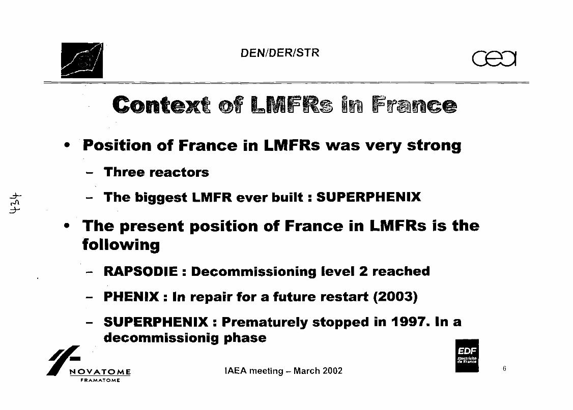
DEN/DER/STR O90I
Position of France in LMFRs was very strong
- Three reactors
- The biggest LMFR ever built: SUPERPHENIX
The present position of France in LMFRs is thefollowing
- RAPSODIE : Decommissioning level 2 reached
- PHENIX : In repair for a future restart (2003)
- SUPERPHENIX : Prematurely stopped in 1997. In adecommissionig phase
EOF
NOVATOMEFRAMATOME
IAEA meeting - March 2002
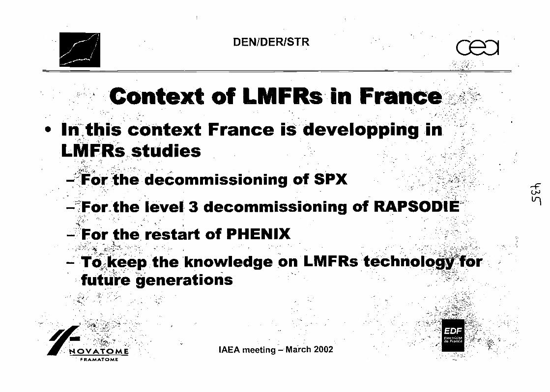
DEN/DER/STR
Context off LMFRs in FranceIn this context France is developping inLMFRs studies
- For the decommissioning of SPX ;: '•••' ' ' • ' " ' ' ' ' • . ' '/"
- For the level 3 decommissioning of RAPSODIEf f * ' " • ~^
-For the restart of PHENIX
- To keep the knowledge on LMFRs technology forfuture generations "
NOVATOME IAEA meeting - March 2002FRAMATOME
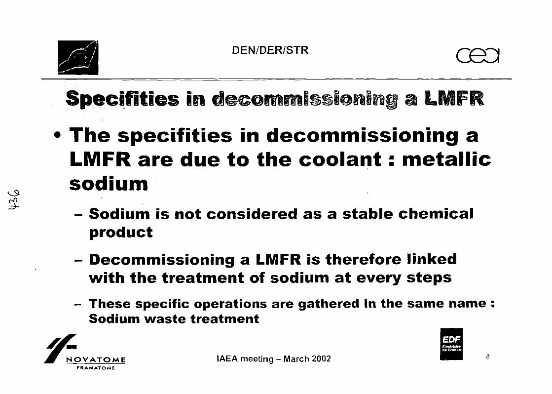
DEN/DER/STR G9D
•The specif ities in decommissioning aLMFR are due to the coolant: metallicsodium- Sodium is not considered as a stable chemical
product
- Decommissioning a LMFR is therefore linkedwith the treatment of sodium at every steps
- These specific operations are gathered in the same name :Sodium waste treatment
EOFeectrklt*do France
OVATOME IAEA meeting - March 2002FRAMATOME

DEN/DER/STR
Decommissioning off RAPSODIE reactorHistory
Located at Cadarache centreStart of construction in 1962Loop type with two cooling circuitsFirst criticality the 28th of January 1967Power from 20 MWth to 40 MWth
f, - - . . • . • -• . •' . • • - ' . ' ,••;•..
1978 and 1982 : detection of two small leaks in theprimary system13th Of October 1982 : Final shutdownApril 1983 : First operation in decommissioningDec 93 - March 94 : Treatment of the primary sodium
EOF
OVATOME IAEA meeting - March 2002FRAMATOME
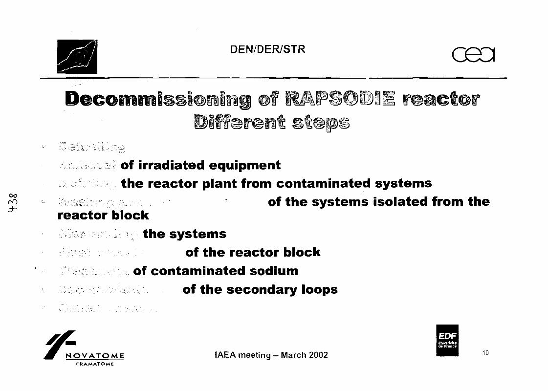
DEN/DER/STR oaoi
if
00oO
of irradiated equipmentthe reactor plant from contaminated systems
of the systems isolated from thereactor block
the systemsof the reactor block
of contaminated sodium^ of the secondary loops
EOFEtectrlcttAde France
NOVATOMEFRAMATOME
IAEA meeting - March 2002 10
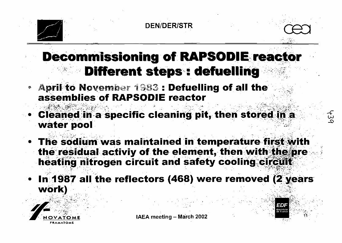
DEN/DER/STR
Decommissioning off RAPSODIE reactorDifferent steps : defuelling
April to : Defuelling of all the - v-assemblies of RAPSODIE reactor
Cleaned in a specific cleaning pit, then stored in awater pool
The sodium was maintained in temperature first withthe residual activiy of the element, then with the preiv • • ' • . • • . - •* " * t * *. ^ - • /w*arn'*- ™^'™"^'^?-• ** >.
heating nitrogen circuit and safety cooling circuit
In 1987 all the reflectors (468) were removed (2 yearswork) 1
EOFElectricityde France
NOVATOME IAEA meeting - March 2002FRAMATOME
11
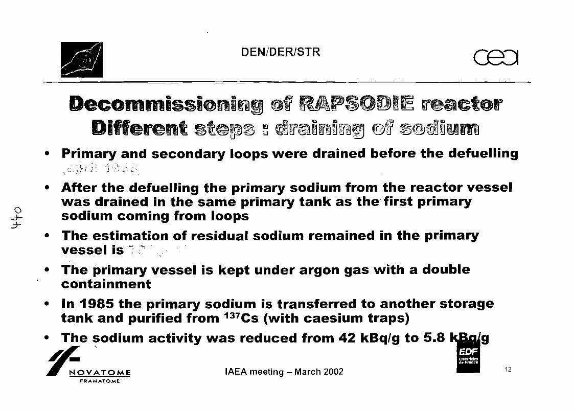
DEN/DER/STR
• Primary and secondary loops were drained before the defuelling
• After the defuelling the primary sodium from the reactor vesselwas drained in the same primary tank as the first primarysodium coming from loops
• The estimation of residual sodium remained in the primaryvessel is
• The primary vessel is kept under argon gas with a doublecontainment
• In 1985 the primary sodium is transferred to another storagetank and purified from 137Cs (with caesium traps)
• The sodium activity was reduced from 42 kBq/g to 5.8 kBu/a
NOVATOMEFRAMATOME
IAEA meeting - March 2002 12
DEN/DER/STR
Decommissioning of RAPSODIE reactorDifferent steps : Cleaning of componentsAll the components were removed and cleaned in acleaning pit
*."* >k r ° , , • " . - • - „ • „ , - ' . (~~
The process used was a water mist in carbone ^dioxide gas
Primary cold traps, caesium traps and secondarysodium have not been treated : they will be treated onATENA
EOF
NOVATOME IAEA meeting - March 2002FRAMATOME
DEN/DER/STR O9D
Different s f
• The primary circuits were separated and isolated from theprimary vessel
• They were then cleaned in 1988 by an in situ circulation of 4200litres of an heavy alcohol (ethyl carbitol)
• The primary circuits were then decontaminated with three baths: alkaline washing, acid decontamination with Celv, thenphosphatation rinsing.
• The contamination decreases from 5500 Bq/cm2 to less than 10Bq/cm2
EOFElectrleltA<te France
OVATOMEFRAMATOME
IAEA meeting - March 2002 14
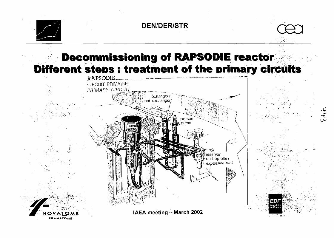
DEN/DER/STR
Decommissioning of RAPSODIE reactorDifferent steps s treatment off the primary circuits
RAPSODIE —• ~^CIRCUIT PRIMAIRhPRIMARY CIRCUir ,w_ ,
"X.
~' ochangeur
heat exchanger
reservoirde trop plein
'' expansion tank
NOVATOMEFRAMATOME
IAEA meeting - March 2002
EOF
15-
(JO

DEN/DER/STR G9D
, DecomfniDifferent
Pipes and tanks were cut with plasma torch
Exceptional or difficult cuttings were done withsaw
The cutting of the primary pipes produces 512elements lower than 1 metre long
It produces 13 472 kg of active stainless steel
EOFEtectrlcfttrfe France
OVATOME IAEA meeting - March 2002FRAMATOME
16
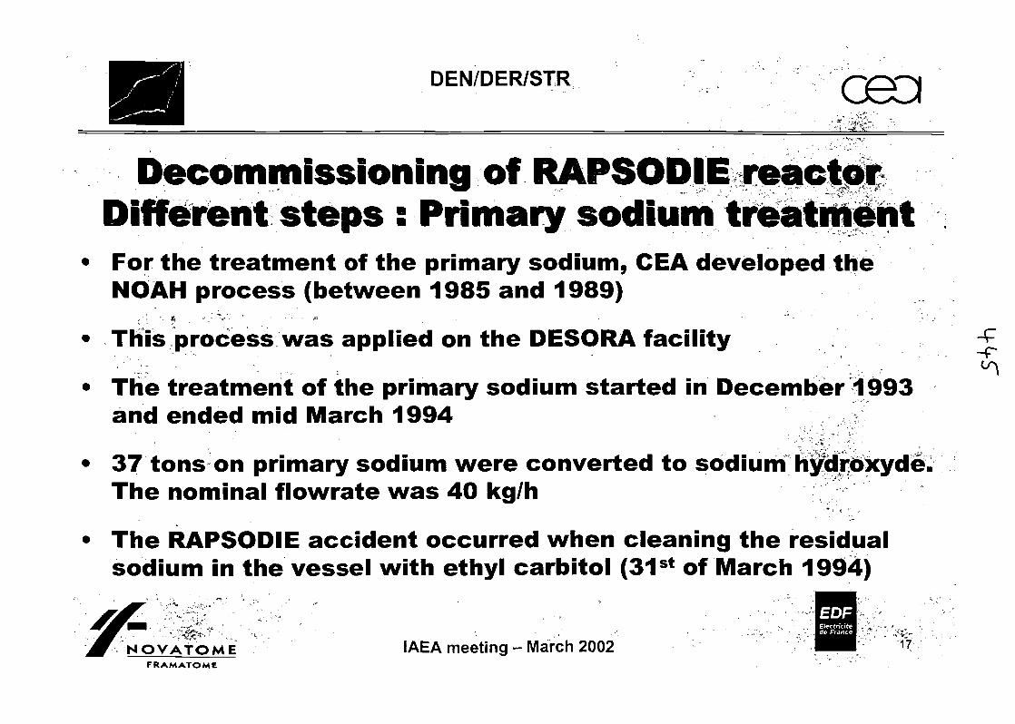
DEN/DER/STR
Decommissioning of RAPSODIE reactorDifferent steps : Primary sodium treatment
• For the treatment of the primary sodium, CEA developed theNOAH process (between 1985 and 1989)
K, "f ' •; -
• This process was applied on the DESORA facility' •'•'.,:'; • - - . ' " ' ""-• . . . .
• Tlie treatment of the primary sodium started in December 1993and ended mid March 1994
• 37 tons on primary sodium were converted to sodium hydroxyde.The nominal flowrate was 40 kg/h
• The RAPSODIE accident occurred when cleaning the residualsodium in the vessel with ethyl carbitol (31st of March 1994)
EOF
NOVATOME IAEA meeting - March 2002FRAMATOME
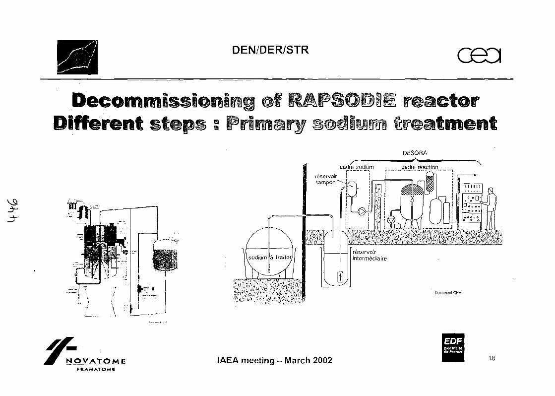
DEN/DER/STR
Different sfDESORA
sodium a trailer.
- V O - Q . ^•x .-o ,-/•>. v:-v- - - -
Document CFA
NOVATOMEFRAMATOME
IAEA meeting - March 2002
EOFBectrlcJt*</e Franco
18
DEN/DER/STR
Decommissioning of RAPSODIE reactorDifferent steps : present situation and future• RAPSODIE will reach the level 2 of the IAEA decommissioning
phase„ ' " " * , * . .'" - - *- ' " • v » . " . " " ' " • . .
• The removed activity is estimated to around 4800 TBq. ^"•' ' " ' ' " ' V - - - • • ' -v
• 600 TBq in 1990 are still contained in the primary vessel (mainly60Co)
'•»' • ' • • • < ,• The surveillance should last from 2005 to 2020, then stage 3 is
planned
• A project is in progress to estimate the cost benefits gained bythis surveillance phase
EOFElectricityde France
NOVATOME IAEA meeting-March 2002" FRAMATOME
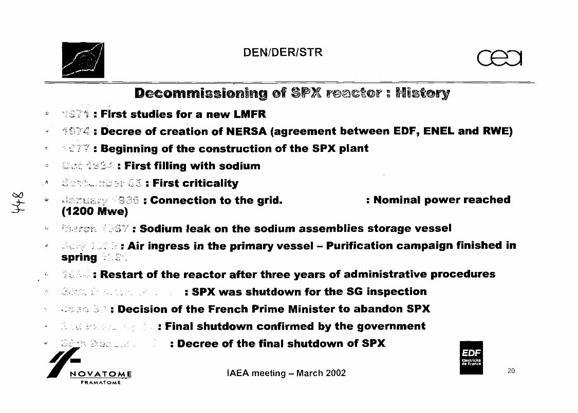
DEN/DER/STR
. , : First studies for a new LMFR. 4 : Decree of creation of NERSA (agreement between EOF, ENEL and RWE)
: Beginning of the construction of the SPX plant* - , : First filling with sodium
~ : .—•: i .1C : First criticality. :.: .. ;! ? : Connection to the grid. : Nominal power reached
(1200 Mwe)- ,-:~ : Sodium leak on the sodium assemblies storage vessel
, : Air ingress in the primary vessel - Purification campaign finished inspring
: Restart of the reactor after three years of administrative procedures: SPX was shutdown for the SG inspection
. . ; : Decision of the French Prime Minister to abandon SPX
a ! ; : Final shutdown confirmed by the governmente; L ^ : Decree of the final shutdown of SPX
EOFEtectrlclt*cfe France
OVATOME IAEA meeting - March 2002FRAMATOME
20

DEN/DER/STR
Summary of the life off SUPERPHENIX
53 months in operation (40 % of the totaltime) producing 7.9 billion of kWh
* * " * » - • * * **, ^ V - , ,- " . " f .«•"","" ,!*• *
25 months of shutdown for repair after majorevents ,, ;
54 months of shutdown imposed by -administrative procedures and public inquiries
-P
EOF
NOVATOME' FRAMATOME
IAEA meeting - March 2002
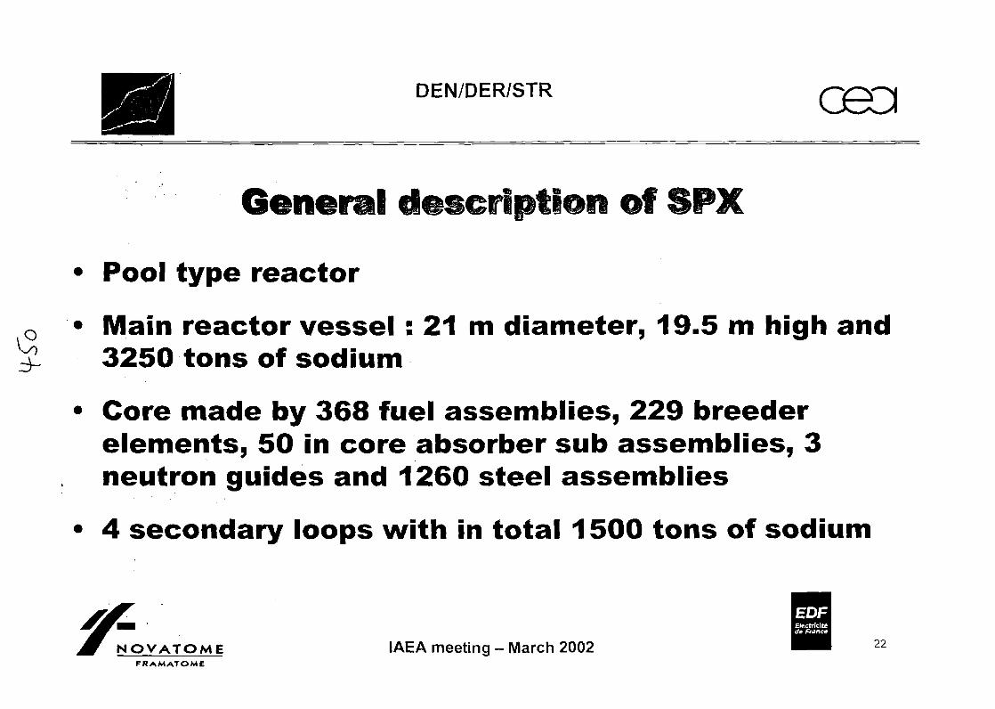
DEN/DER/STR O9G
of
• Pool type reactor
0 • Main reactor vessel : 21 m diameter, 19.5 m high and3250 tons of sodium
• Core made by 368 fuel assemblies, 229 breederelements, 50 in core absorber sub assemblies, 3neutron guides and 1260 steel assemblies
• 4 secondary loops with in total 1500 tons of sodium
EOFBectrlclt*cte France
OVATOME IAEA meeting - March 2002FRAMATOME
22
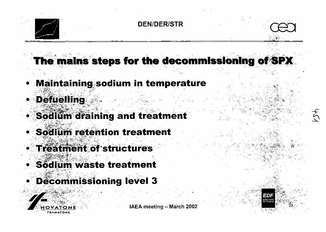
DEN/DER/STR
The mains steps for the decommissioning of SPX
•Maintaining sodium in temperature„ ->» . %^ \ , m
-••<*
i i,.^'.
j |j=f*:-i£i"Sodium retention treatmenty*ij • * ' t 1 •" Ti*^ •''"•'
}.$&? ^4':i:'''*^"'"-:>-x" ' • •^ ^^^ fK' Ai-i**'"'--1^ " .d/" - -' : ,Treatment of structures
• Sodium waste treatmenti * ** _"•&• • ~"" • •• • • • •
** ,-Wt „ "^ -h
; »- v,- - .**i'4"** i,»' ( ' r ' • f .
• Decommissioning level 3
.,-••**
-' &i • t' * • .< . . . • -. . . *' * " ,<» , - f~Sodium draininq and treatment :
EOF„
NOVATOME IAEA meeting - March 2002 ™ifv 23
FRAMATOME
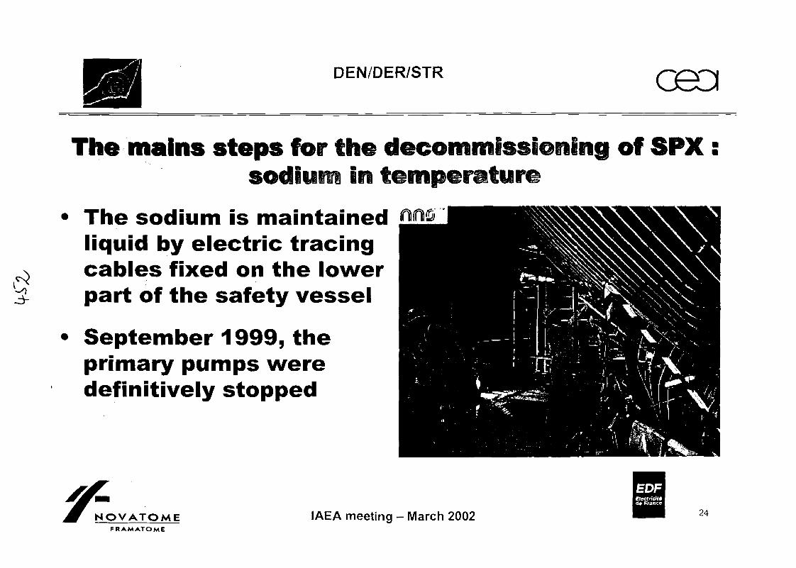
DEN/DER/STR
The mains steps for the decommissioning off SPX :in
The sodium is maintainedliquid by electric tracingcables fixed on the lowerpart of the safety vessel
September 1999, theprimary pumps weredefinitively stopped
NOVATOMEFRAMATOME
EOFElectricltt<fe France
IAEA meeting - March 2002 24
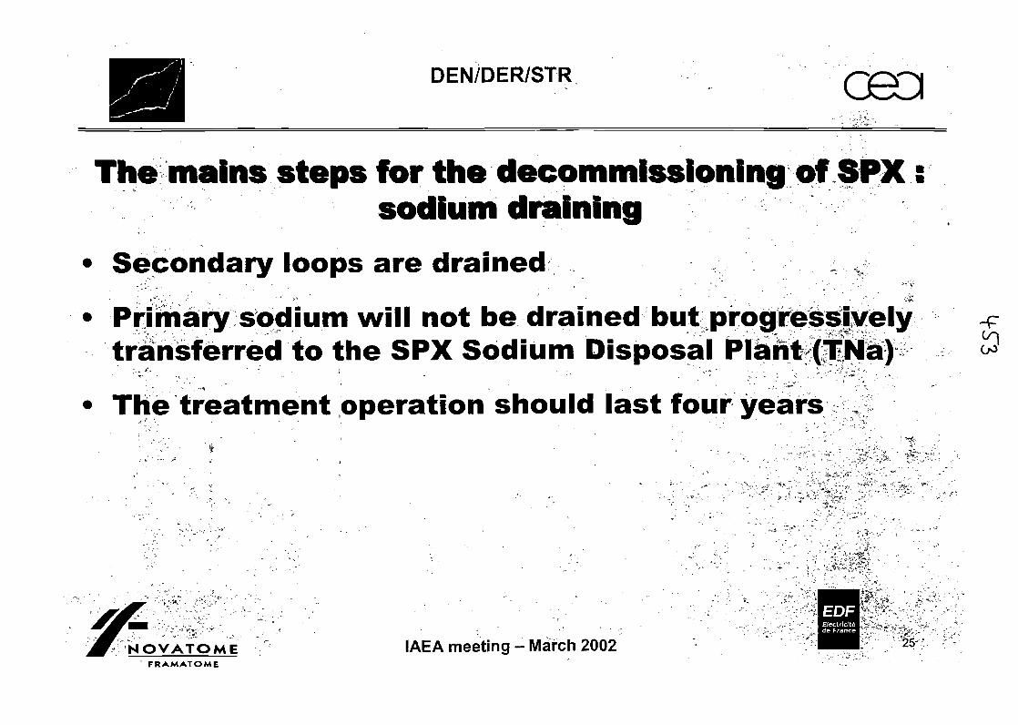
DEN/DER/STR
The mains steps for the decommissioning of SPXsodium draining
• Secondary loops are drained . ,.-*, x *
• .'-, ' - y
• Primary sodium will not be drained but progressivelytransferred to the SPX Sodium Disposal Plant (TNa)
• The treatment operation should last four years .,.
EOF
NOVATOME IAEA meeting - March 2002' FRAMATOME
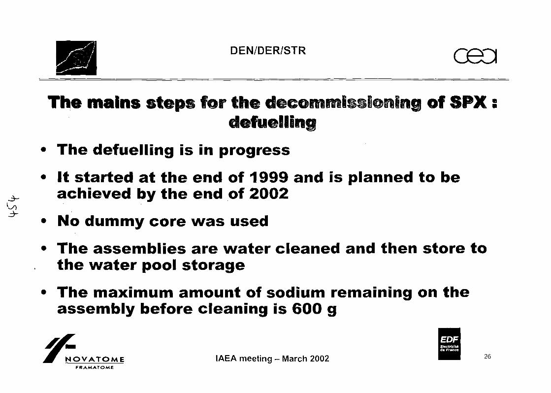
.3-
3-
DEN/DER/STR
The mains steps for the of SPXdefuelling
• The defuelling is in progress
• It started at the end of 1999 and is planned to beachieved by the end of 2002
• No dummy core was used
• The assemblies are water cleaned and then store tothe water pool storage
• The maximum amount of sodium remaining on theassembly before cleaning is 600 g
EOFE/ectrlcIttde France
NOVATOME IAEA meeting - March 2002FRAMATOME
26
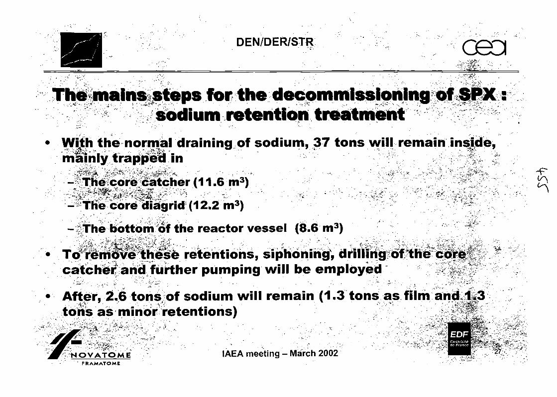
DEN/DER/STR
The mains steps for the decommissioning of SPX:sodium retention treatment, . ,
• With the normal draining of sodium, 37 tons will remain inside,mainly trapped 'in " - - . " . . ' - ' • ' V -*
-f-Thecore catcher (11.6 in / <w
-The core diagrid (12.2 m3) ^
- The bottom of the reactor vessel (8.6m3)
"*retentions, siphoning, drilling of thecatcher and further pumping will be employed
• After, 2.6 tons of sodium will remain (1.3 tons as film and 1.3tons as minor retentions)
' . rt,, _
NOVATOME IAEA meeting - March 2002F RAM ATOM E

DEN/DER/STR G9D
The mains steps for the decommissioning of SPX s
• The sodium will be treated by two facilities using theNOAH process
• Every facility will have a nominal sodium treatmentflow rate of about 120 kg/h (6 tons per day)
• Sodium hydroxide produced will be transformed tocement
• Cement blocks will be stored as Very LowRadioactive Wastes
EOFElectricityde France
OVATOME IAEA meeting - March 2002FRAMATOME
28
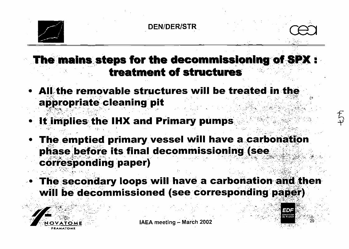
DEN/DER/STR
The mains steps for the decommissioning off SPX:treatment of structures
' All the removable structures will be treated in theappropriate cleaning pit V
• It implies the IHX and Primary pumps - q
• The emptied primary vessel will have a carbonationphase before its final decommissioning (see >™ -JK «*" , ' & "** * " . ' • ' -v - <*<* ' ^^ * * - "" ^"-WL11 •.-"»* "f. "^"--•- *« -»W-3 ' < -^ J
- ^-''VA , .- '^'- .. ^ . x ' . - - • - • ^ • «•** <'r;:^--: - * • -corresponding paper) ^
The secondary loops will have a carbonation and thenwill be decommissioned (see corresponding paper)
EOF:. s>,-VH
NOVATOME IAEA meeting - March 2002 iplpl: 29
FRAMATOME
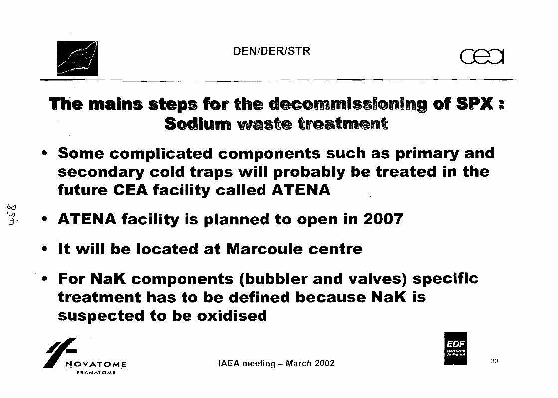
DEN/DER/STR
The mains steps for the of SPXSodium
• Some complicated components such as primary andsecondary cold traps will probably be treated in thefuture CEA facility called ATENA
• ATENA facility is planned to open in 2007
• It will be located at Marcoule centre
• For NaK components (bubbler and valves) specifictreatment has to be defined because NaK issuspected to be oxidised
EOFElectr/cfttde France
NOVATOME IAEA meeting - March 2002FRAMATOME
30
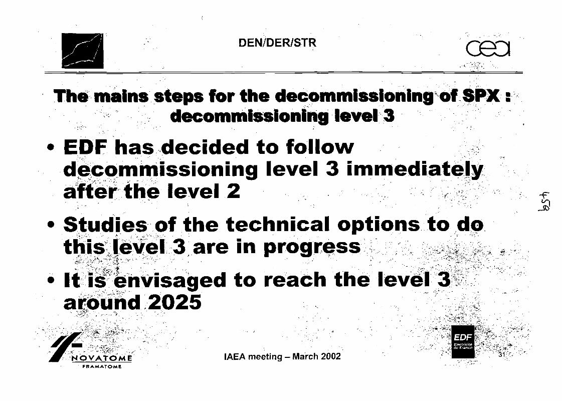
DEN/DER/STR
The mains steps ffor the decommissioning off SPX:decommissioning level 3
> EOF has decided to followdecommissioning level 3 immediatelyafter the level 2
» Studies of the technical options to dothis level 3 are in progress ^
1 It is envisaged to reach the level 3• " * * • * • • • ' ^^^^ -. ., •>* •" • ..
around 2025EOF
NOVATOME IAEA meeting - March 2002 " ••! 31FRAMATOME , - -"

DEN/DER/STR G8Q
The experimental feedback from the French experience is thefollowing- Prepare the works and the strategy of decommissioning
• Two years before the date of the final shutdown seems necessary- Use
• It is not time to develop complicate technology• The R&D works must be limited
- Use simple chemistry to treat sodium• Water is the cheapest, the easiest to handle, gives well known by
products (hydrogen and sodium hydroxyde)- Do the decommissioning in the very beginning
• By this way you will keep the knowledge, and the motivation of theoperators
• In parallel it worths to do a knowledge preservation project plus datarecording and to plan training of operators in sodium technology andtreatment for the next decade
EOFElectricltede France
NOVATOMEFRAMATOME
IAEA meeting - March 2002 32
DEN/DER/STR
General conclusionsDecommissioning a LMFR necessitates a specificknowledge in sodium and/or NaK handling
Tliis knowledge must be kept until the least gram of £sodium is on the plant
The technology is very specific but nothing presentsimpossibilities
With RAPSODIE and SPX all the decommissioningsteps have been defined and demonstrated exceptedthe decommissioning of the primary vessel
OVATOME IAEA meeting - March 2002FRAMATOME
33

EDFCIDEND.O. RNRCreys Malville Project
P. ALPHONSE
2002-02-19IAEA paper for March 2002.
OVERALL STRATEGY OF CREYS MALVILLE POWER STATIONDISMANTLING
Recap of the context:The power station was stopped by a government decision following the elections in 1997.This shutdown was then officialized by a letter dated April 1998 and the decree of December1998. This was a non-technical shutdown and as such had not been envisaged; there hasbeen no early warning.
Current dismantling strategy:The studies leading to shutdown and then dismantling were engaged in 1998 based on ascenario with a status corresponding to IAEA level 2 until 2046.In 2001, EDF management made the decision to dismantle all the first generation powerstations and Creys Malville between now and 2025. It should be noted that the presence ofstrongly irradiated stellite in the Creys Malville reactor would still require remote systems forworking in the reactor block after 2046.
The sequence of operations dictated by the dismantling strategy is as follows:eliminate the risks as soon as possible and in particular the risk related to thesodium, 3300 tonnes of which is kept in liquid form in the reactor vessel.dismantle the most active parts which are too radioactive to be sent tothe existing or planned storage centres. This may lead to on-site storage to allowdecay to occur before sending to a storage centre.planning of the work interventions in order to limit the costs.
Sequence of operations.
Phase 1:Unloading of the fissile, fertile and absorbent assemblies without installation of dummyassemblies. General dismantling studies and preparation of the files to obtain the decreesnecessary for complete dismantling. These files can only be developed once the feasibilitystudies have been terminated so that a preliminary safety report can be drafted.
Phase 2:

Demolition of the non-nuclear installations.Studies and construction of the sodium treatment installation.Drilling and siphon installation, construction of the drain line for sodium retentions.Removal of the steel assemblies from the lateral neutron shielding.Publication of the dismantling decrees.First dismantling phase for small primary components.Carbonation of the secondary circuits.
Phase 3:Sodium treatment.Dismantling of the secondary circuits.Dismantling of the equipment that no longer serves a purpose in the reactor building.
Dismantling of the remainder of the small primary components and all the large components(reactor coolant pumps and intermediate exchangers).
Phase 4:Inspection at completion of vessel sodium drainage.Carbonation of residual sodium in the reactor vessel.Washing of carbonate in the vessel.
Phase 5:Dismantling of the reactor block.Cleansing of the concrete in the reactor building.
Phase 6:Demolition of the reactor building,Rehabilitation of the site.
Main aspects of this strategy
Disposal of the caustic soda resulting from the sodium treatment: VLL concrete blocks.
Correct operation of the sodium treatment installation: Rhapsody and SDP (Dounreay)experience feedback.
Carbonation of the circuits and the vessel (see separate paper). Experience feedback fromheader and R&D work with the CEA.
Feasibility of carbonate washing in the vessel to be demonstrated. This point is closely relatedto the quality of draining and the effectiveness of Carbonation.
SPX1 DISMANTLING
Main strategic outlines
EOF I CIDEN-P.AtPHONSE 1 AIEA Me«(lng - March 20O2
HISTORY
Unexpected final shutdownas Information in June 1997,^ Decision in april 1998,.a Decree in december 1998
No studies to anticipate this shutdownas Quick preparation of activities for next monthsas Preparation of a new decree in this new contextma Preparation of long term strategy
EOF I CIDEN - P. ALPHONSE AJEA MMIIng • March 2002
NEW EOF STRATEGY FOR NPPDISMANTLING
Previous strategy:•=, Reach AIEA level 1
• Fuel handling to empty all the nuclear material• Emptying all sodium from circuits and reactor vessel• Chemical neutralization of residual sodium.
« AIEA level 2 (safe storage status)^ Reactor dismantling, AIEA level 3
• 50 years after final shutdown
EDF/CIDEN-P.ALPHONSE 3 A/EA M<*Mln9 - March 2002
NEW EOF STRATEGY FOR NPPDISMANTLING
New strategy^ No safe storage status (AIEA level 2)
ra 9 NNP dismantling finished in 2025• Dismantling demonstration• Dismantling industrialization
SPX1 strategy in this contextH 60Co activity of diagrid elements (stellite) too high after 50
years for human access (2500Sv/h in 2002)
EOF I CIDEN - f. ALPHONSE 4 ^ „„„„„„ .
STRATEGY OUTLINES
Defuelling as quickly as possible
Decrease by steps the risks« RadioactivityE, Chemical risks
Progressive dismantling from conventional to nuclearand more active partsa From balance of plan to reactor internals
Radwaste managementCost control and limitation.
EDFf CIDEN-P.ALPHONSE 5 AJEA Meeting - March 2O02
SPX1 STRATEGY
Emptying of all fuel assemblies
B Sodium heating by electrical heating wires. 2000-2002
• No use of ghost assemblies<=, Difficulties with new core
• Unused, it cannot be sent in a usued fuel retreatmentcentre or in a storage centre
• Too active (Am, Np...) to be recycled as a new fuel.Storage of the 2 cores in the pool.
eOF I CIDEN - P. ALPHONSE
SODIUM MANAGEMENT 1/2
Secondary sodium solid in storage tanks in SG buildings
No intermediate storage of primary circuitB Main vessel is a very good and storage tanka Sodium must be liquid (electric heaters)
Choice of sodium future: transformation in soda in NOAHdisplay
On line sodium emptying from vessel to NOAH display
EDF/CIDEN-P.ALPHONSE 7 A1EA Mee.lng - March 2002
SODIUM MANAGEMENT 2/2
A decree is needed for sodium treatment
EOF decide to ask for the decree only when soda futurewill be knownSoda futuree No industrial re-use possible
E Neutralization in sodium sulphate and release in Rhoneriver possible:
• Impact studies shown it was 0.1microSv/y• Public acceptance quite difficult• Project risk important (schedule with the end in 2025)
E Soda blocked in concrete
EOF I CIDEN-P.ALPHONSE 8 AJEA lto«lna - Ufarch 2002
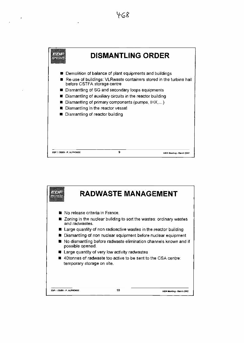
DISMANTLING ORDER
Demolition of balance of plant equipments and buildingsRe-use of buildings: VLRwaste containers stored in the turbine hallbefore CSTFA storage centreDismantling of SG and secondary loops equipmentsDismantling of auxiliary circuits in the reactor buildingDismantling of primary components (pumps, IHX,...)Dismantling in the reactor vesselDismantling of reactor building
EOF / CIDEN - P. ALPHONSE
RADWASTE MANAGEMENT
No release criteria in France.Zoning in the nuclear building to sort the wastes: ordinary wastesand radwastes.Large quantity of non radioactive wastes in the reactor buildingDismantling of non nuclear equipment before nuclear equipmentNo dismantling before radwaste elimination channels known and ifpossible opened.Large quantity of very low activity radwastes40tonnes of radwaste too active to be sent to the CSA centre:temporary storage on site.
EOF I CIDEN - P. ALPHONSE 10 AIEA Meeting - March 2002
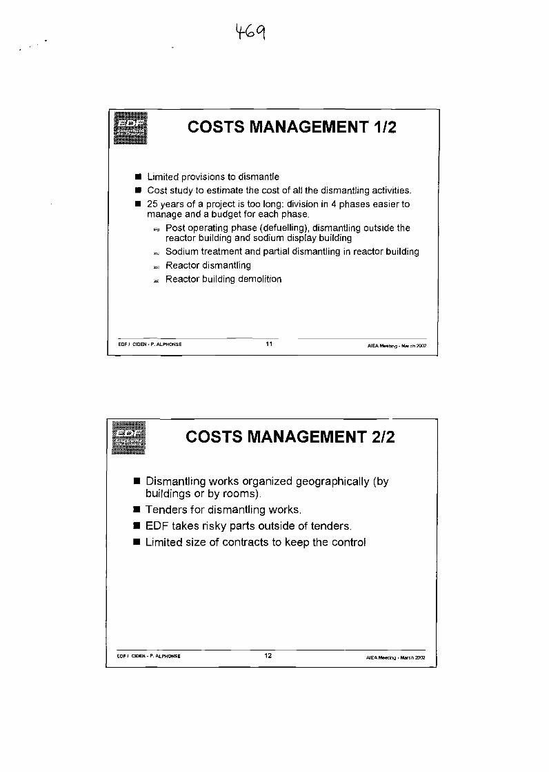
COSTS MANAGEMENT 1/2
Limited provisions to dismantleCost study to estimate the cost of all the dismantling activities.25 years of a project is too long: division in 4 phases easier tomanage and a budget for each phase.
B Post operating phase (defuelling), dismantling outside thereactor building and sodium display building
E Sodium treatment and partial dismantling in reactor buildingB Reactor dismantlinga Reactor building demolition
EOF / CIDEN • r. ALPHOHSE 11 AJEA Meeting - March 2002
COSTS MANAGEMENT 2/2
Dismantling works organized geographically (bybuildings or by rooms).Tenders for dismantling works.EOF takes risky parts outside of tenders.Limited size of contracts to keep the control
EOF / CIDEN • P. ALPHONSE 12 A1EA Meeting - March 2002
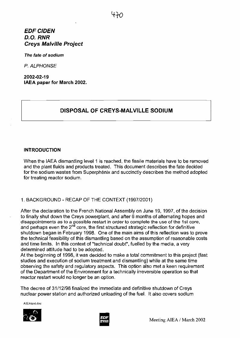
EOF CIDEND.O. RNRGreys Malville Project
The fate of sodium
P. ALPHONSE
2002-02-19IAEA paper for March 2002.
DISPOSAL OF CREYS-MALVILLE SODIUM
INTRODUCTION
When the IAEA dismantling level 1 is reached, the fissile materials have to be removedand the plant fluids and products treated. This document describes the fate decidedfor the sodium wastes from Superphenix and succinctly describes the method adoptedfor treating reactor sodium.
1. BACKGROUND - RECAP OF THE CONTEXT (1997/2001)
After the declaration to the French National Assembly on June 19, 1997, of the decisionto finally shut down the Creys powerplant, and after 6 months of alternating hopes anddisappointments as to a possible restart in order to complete the use of the 1st core,and perhaps even the 2nd core, the first structured strategic reflection for definitiveshutdown began in February 1998. One of the main aims of this reflection was to provethe technical feasibility of this dismantling based on the assumption of reasonable costsand time limits. In this context of "technical doubt", fuelled by the media, a verydetermined attitude had to be adopted.At the beginning of 1998, it was decided to make a total commitment to this project (faststudies and execution of sodium treatment and dismantling) while at the same timeobserving the safety and regulatory aspects. This option also met a keen requirementof the Department of the Environment for a technically irreversible operation so thatreactor restart would no longer be an option.
The decree of 31/12/98 finalized the immediate and definitive shutdown of Creysnuclear power station and authorized unloading of the fuel. It also covers sodium
AIEAtext.doc
Meeting AIEA / March 2002
removal and storage operations and the dismantling of the non-nuclear installationswithin the framework of a safety report and general rules for monitoring andmaintenance approved by the DSIN (French Nuclear Installations Safety Authority).
At the EDF-CIDEN, a so-called reference scenario based on the discharge of sodiumsulphate salts to the Rhone river (reflecting the Scottish approach used in the sodiumdisposal process, which is economically less expensive but "sensitive" in terms of itsacceptance by the media and the environmental lobby) has been developed andalternative solutions put forward.This scenario requires the installation of a primary sodium draining system as well as thetreatment of certain significant retentions in the vessel, and the construction of a"reactor" to transform the sodium into caustic soda. This reactor would be of the sametype as on the Sodium Disposal Process for PFR on DOUNREAY site, based on theprinciple developed by the CEA for the Rapsodie programme (NOAH process).
An early commitment to sodium draining before the very specific competences for thiscomplex operation are lost was another strong additional incentive drawn from theexperience feedback from other sites.
Faced with the risk relating to the discharge into the Rhone which this scenario involves,a fallback scenario for treatment involving caustic soda cementation and long-termstorage was chosen (with several possible technical options). The possibility ofintermediate storage of all sodium products, which would release the reactor from themonitoring requirements related to the liquid sodium, was not retained since the cost ofthis solution would cancel out the indirect gains made on the operating costs.
In 2001, the scenario of sodium sulphate discharge into the Rhone was abandoned infavour of the scenario known as treatment by cementation. In spite of a significantdifference in the cost, due to the climate surrounding the Public Inquiry File, it is nolonger certain that a new application to discharge to water in this first solution would belooked at favourably or that it would be authorized within reasonable delays. Thisdecision is consolidated by the desire on the part of EOF General Management toproceed to "immediate" dismantling of the nine definitively shutdown nuclear sites,thereby reducing the programming for Creys Malville to a total duration of 25 years. Therisk involved in an uncontrollable administrative delay therefore became unacceptable.
To conclude this first part, the choice of the sodium treatment solution for CreysMalville is based on a so-called on-line drainage system (no buffer storage) using toolsfabricated for this operation, followed in real time by treatment at 6 metric tonnes/dayin two caustic soda transformation reactors (NOAH process) nearly identical to theSDP ones. A total of 13 860 m3 of caustic soda from primary sodium will be mixedwith cement to make packages (26 400 cubes of 1m3) that will be stored on thesurface since they are only very slightly radioactive (< 100 Bq/g), and this in less than2 years.
AIEAtext.doc
Meeting AIEA / March 2002
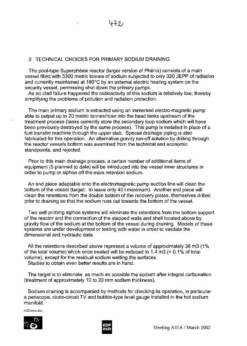
2 . TECHNICAL CHOICES FOR PRIMARY SODIUM DRAINING
The pool-type Superphenix reactor (larger version of Phenix) consists of a mainvessel filled with 3300 metric tonnes of sodium subjected to only 320 JEPP of radiationand currently maintained at 180°C by an external electric heating system on thesecurity vessel, permissing shut down the primary pumps.
As no clad failure happened the radioactivity of this sodium is relatively low, therebysimplifying the problems of pollution and radiation protection.
The main primary sodium is extracted using an immersed electro-magnetic pumpable to output up to 20 metric tonnes/hour into the head tanks upstream of thetreatment process (tanks currently store the secondary loop sodium which will havebeen previously destroyed by the same process). This pump is installed in place of afuel transfer machine through the upper slab. Special drainage piping is alsofabricated for this operation. An alternative gravity run-off solution by drilling throughthe reactor vessels bottom was examined from the technical and economicstandpoints, and rejected.
Prior to this main drainage process, a certain number of additional items ofequipment (5 planned to date) will be introduced into the vessel inner structures inorder to pump or siphon off the main retention sodium.
An end piece adaptable onto the electromagnetic pump suction line will clean thebottom of the vessel (target: to leave only 40 I maximum). Another end piece willclean the retentions from the double bottom of the recovery plates, themselves drilledprior to draining so that the sodium runs out towards the bottom of the vessel.
Two self-priming siphon systems will eliminate the retentions from the bottom supportof the reactor and the connection of the stepped walls and shell located above bygravity flow of the sodium at the bottom of the vessel during draining. Models of thesesystems are under development or testing with water in order to validate thedimensional and hydraulic data.
All the retentions described above represent a volume of approximately 38 m3 (1%of the total volume) which once treated will be reduced to 1.4 m3 (< 0.1 % of totalvolume), except for the residual sodium wetting the surfaces.
Studies to obtain even better results are in hand.
The target is to eliminate as much as possible the sodium after integral carbonation(treatment of approximately 10 to 20 mm sodium thickness).
Sodium draining is accompanied by methods for checking its operation, in particulara periscope, close-circuit TV and bubble-type level gauge installed in the hot sodiummanifold.AIEAtext.doc
Meeting AIEA / March 2002
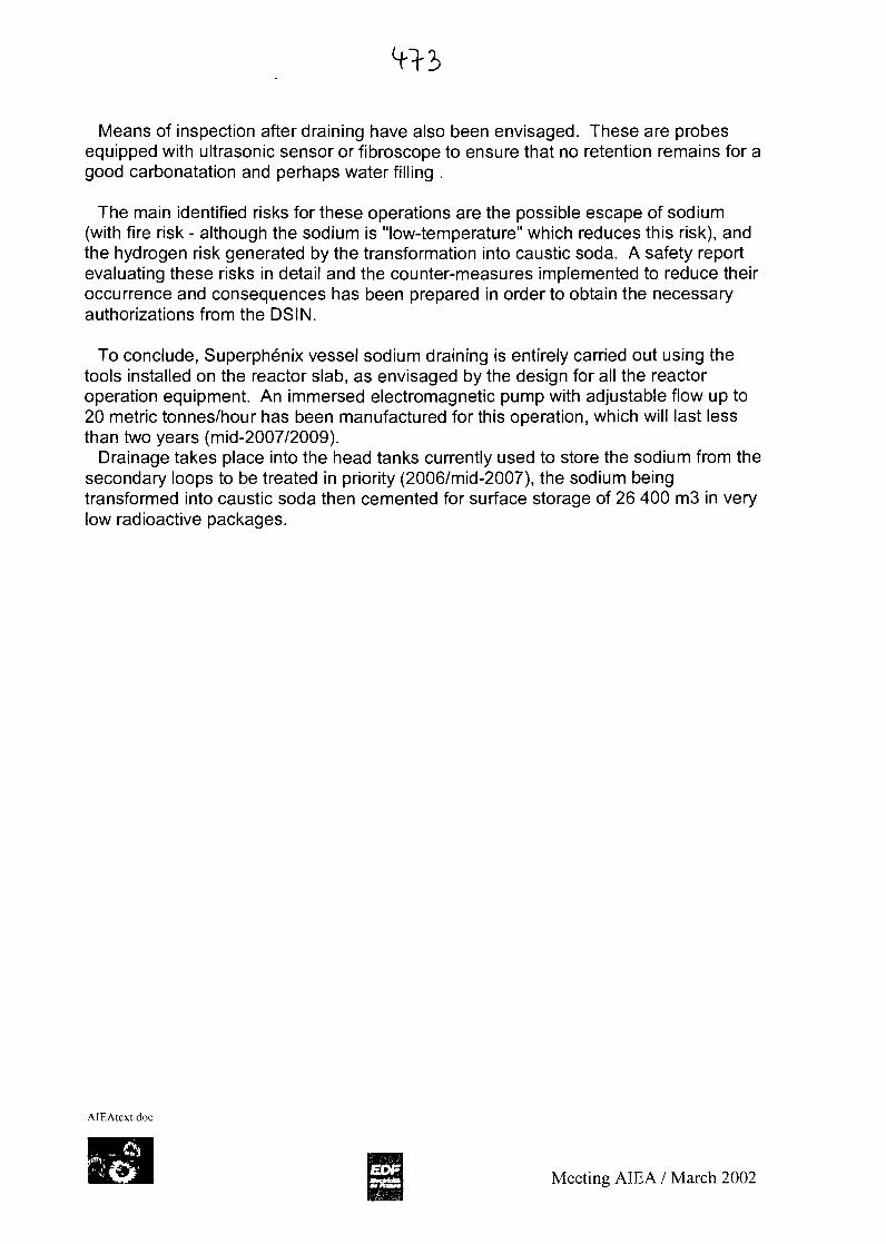
Means of inspection after draining have also been envisaged. These are probesequipped with ultrasonic sensor or fibroscope to ensure that no retention remains for agood carbonatation and perhaps water filling .
The main identified risks for these operations are the possible escape of sodium(with fire risk - although the sodium is "low-temperature" which reduces this risk), andthe hydrogen risk generated by the transformation into caustic soda. A safety reportevaluating these risks in detail and the counter-measures implemented to reduce theiroccurrence and consequences has been prepared in order to obtain the necessaryauthorizations from the DSIN.
To conclude, Superphenix vessel sodium draining is entirely carried out using thetools installed on the reactor slab, as envisaged by the design for all the reactoroperation equipment. An immersed electromagnetic pump with adjustable flow up to20 metric tonnes/hour has been manufactured for this operation, which will last lessthan two years (mid-2007/2009).
Drainage takes place into the head tanks currently used to store the sodium from thesecondary loops to be treated in priority (2006/mid-2007), the sodium beingtransformed into caustic soda then cemented for surface storage of 26 400 m3 in verylow radioactive packages.
AIEAtext.doc
Meeting AIEA / March 2002

SUPERPHENIX SODIUMDESTRUCTION
Present Sodium storageHistoric
Technical descriptionSafety rules
Forecast plan
EOF / CIDEN - P. ALPHONSE AIEA Meeting - March 2002
Present storage of sodium
Drum sodiumL Storagef 670 tons
SecondarySodium
1550 tons
. PrimarySodium
3300 tons
Radioac.bit
3H
3H
22Na
ON"
"H
Half-life(years)
2,612,3
12,3
2,60,8596
30,212,3
Radioactive mass1998
(Bq/g)
2,6295,0
2000,0
3800,0100,020,22,1
15000,0
Total radioactivityin 2007(GBq)
0,16 Without Tritium119 Tritium
0 Without Tritium1 871 Tritium
1 207 Without Tritium29 871 Tritium
IF / CIOEN - P. ALPHONSE AJEA Meeting - Maxh 2002
Historic
1997 Government « brutal stop» decision1998 First strategics studies to drain and store sodiumthe most quickly1999 Beginning of studies on 3 scenarios (dischargesodium sulphate in Rhone river, concrete blocks makingand store sodium in new tanks)2000 Principal studies of «NOAH» process and primarysodium draining2001 E.D.F. Head management Decision for « noradioactive liquid waste discharge » and so, select thescenario with concrete blocks making2001 June, beginning of principal studies for this processand final studies for upstream process (draining andNOAH)
EOF / CIDEN - P. ALPHONSE A1EA Meeting - March 2002
Technical description (1)
Electro
' Magnetic
Pump
DrainingSystem
EOF/ CIDEN - P AJ.PHONSE AJEA Mooting . March 2MB
Technical description (2)
^ , - Drilling machine
Details of drillinghead
— Bottom supportSiphon
Exemple of tools forretentions treatmentsbefore draining
EOF / CIDEN - P. ALPHONSE AIEA Meeting - March 2002
Technical description (3)
BMP with endpiece for finalsuction
Nozzle in Nozzle out in operation
EOF I CIDEN • P. ALPHONSE AIEA MMtlng - March 2002
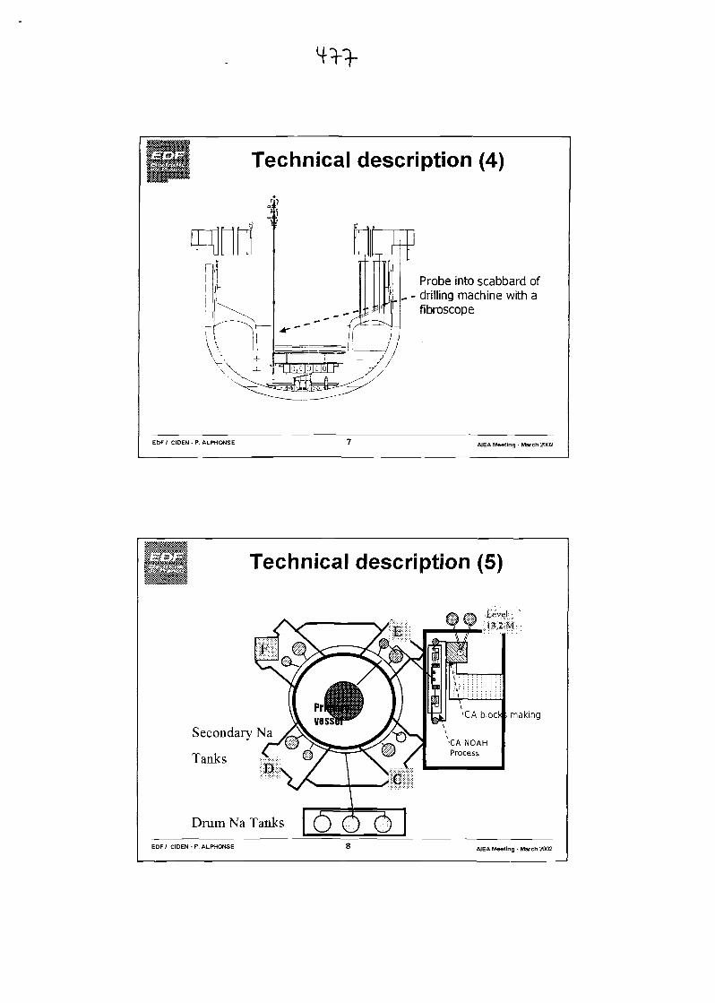
Technical description (4)
Probe into scabbard of_ - drilling machine with a
fibroscope
EOF/ CIDEN - P. ALPHONSE A1EA Meeting • March 2002
Technical description (5)
Secondary Na
Tanks
Drum Na Tanks
J3.2JVI
making
EOF/ CIDEN - P. ALPHONSE AJEA Meeting - March 2002
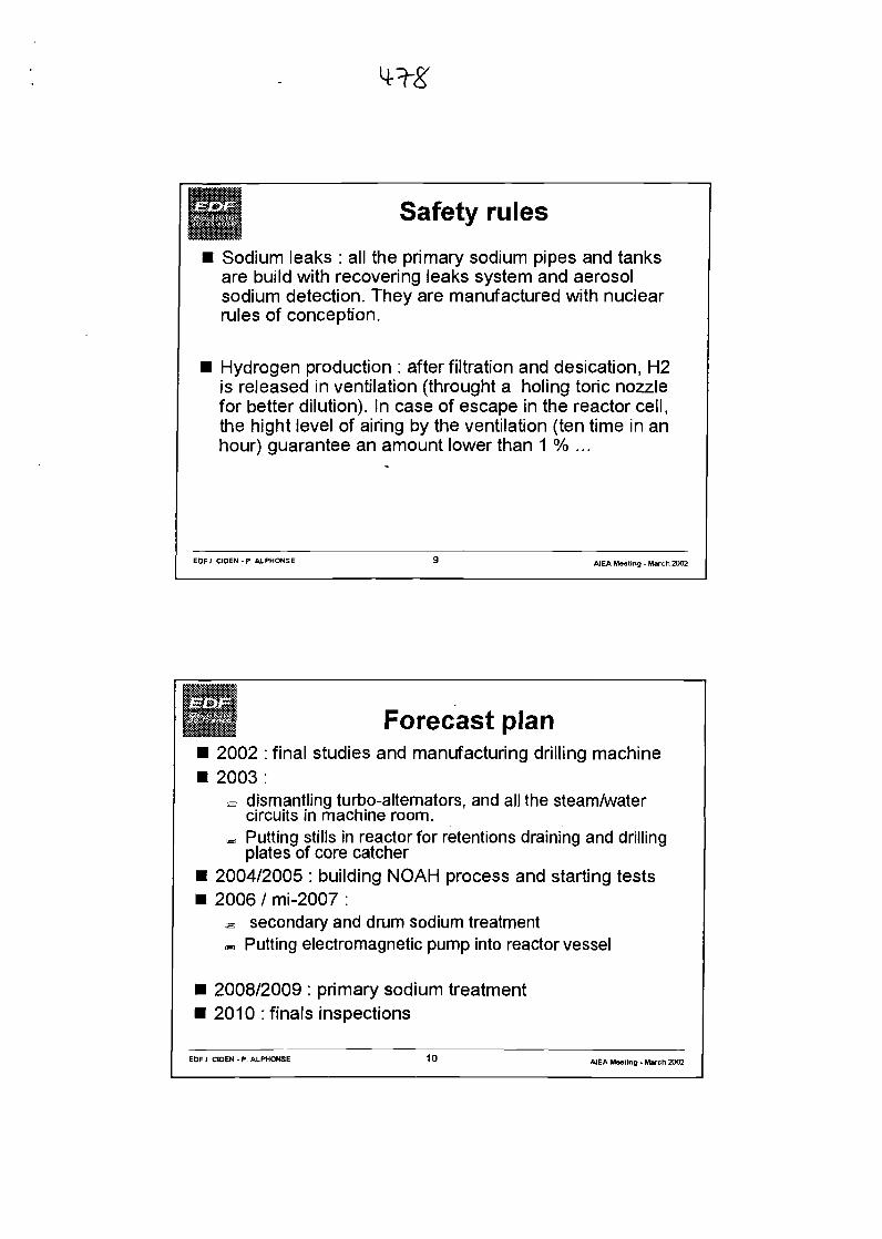
Safety rules
Sodium leaks : all the primary sodium pipes and tanksare build with recovering leaks system and aerosolsodium detection. They are manufactured with nuclearrules of conception.
Hydrogen production : after filtration and desication, H2is released in ventilation (throught a holing toric nozzlefor better dilution). In case of escape in the reactor cell,the hight level of airing by the ventilation (ten time in anhour) guarantee an amount lower than 1 % ...
EOF I CIOEN - P. A.LPHONSE 9 A1EA Mooting - March 2002
Forecast plan2002 : final studies and manufacturing drilling machine2003:e dismantling turbo-alternators, and all the steam/water
circuits in machine room.B Putting stills in reactor for retentions draining and drilling
plates of core catcher2004/2005 : building NOAH process and starting tests2006 / mi-2007 :« secondary and drum sodium treatment<=, Putting electromagnetic pump into reactor vessel
2008/2009 : primary sodium treatment2010 : finals inspections
EOF I CIDEN - P. ALPHONSE 10

SUPERPHENIX
STRATEGY AND ORIENTATIONS FOR DISMANTLING THE REACTOR BLOCK
STATE OF REFLECTIONS IN FEBRUARY 2002
D. ChiarotEOF Industry BranchCIDEN - Engineering Centre - FBR Operations Department
SUMMARY
The first studies for dismantling the Superphenix power station reactor block are currently progressing. Theyhave defined the broad outlines of the dismantling strategy and proposed a certain number of orientations.
Two dismantling methods have been considered:
- dismantling with the structures covered with sodium carbonate,- underwater dismantling.
In both cases, dismantling will be carried out "from the top" through the reactor slab and will be preceded bya preliminary phase of sodium retention reduction followed by a phase of vessel internals carbonation.
The parameters contributing to the efficiency of the carbonation operation have been determined in thelaboratory. A demonstration on a semi-industrial scale is planned on one sodium loop.
The dismantling studies are undertaken with a view to the work lasting eight years maximum.
1. INTRODUCTION
At present, the dismantling of Superphenix reactor block is planned to begin in 2014 and continue for aperiod of eight years.
The preliminary work prior to reactor dismantling will last from mid-2010 until the end of 2013. It will beginafter sodium draining from the reactor.
All the installations should have been dismantled by 2025.
Figures 1 and 2 show the reactor building and the reactor structures.
2. BACKGROUND
A preliminary approach - reflection in-house at EOF in 1999 - examined three initial conditions for reactordismantling. These are described below:
- vessel drained and maintained under inert gas (nitrogen): the internal structures are then either coveredwith a film of sodium or found under a pool of sodium (called "retention") in the case of non-drainablezones,
- vessel drained, followed by total carbonation of the internal structures. As this carbonation is neverperfect, certain metallic sodium may remain under the thickest retentions,
- vessel drained and all traces of sodium removed.
In order to check the feasibility of the dismantling operations based on these initial conditions, studies startedat the end of 1999 with manufacturers .
The main results of these studies are as follows:
- the installations can be dismantled in the three initial conditions,- the reactor vessel can be dismantled either from the bottom (from the vessel pit) or from the top (from the
slab),- the most radioactive structures are generally dismantled first,- the duration of the operations will vary between 6 and 20 years depending on the scenario and the
contractors.
3. STRATEGY
The results of studies led EOF to set down the following principles:
o reduction of the risks as early as possible,«=> closest possible containment,>=> anticipation of dismantling operations in order to facilitate reactor dismantling,"=> operations carried out on the basis of an ALARA approach.
3.1. EARLIEST POSSIBLE REDUCTION OF RISKS
Although all the dismantling operations generally lead to a reduction of the risk, the period covered by thispaper is between the end of reactor block draining (sodium treatment phase) and the end of the reactordismantling.
The sources of risks are:
- the presence of intense radioactive sources mainly consisting of certain radioactive reactor structures,- the presence of metallic sodium on the internal structures.
•=> As far as possible, the following risk sources will be eliminated at the earliest possible date:
• radioactive sources,• metallic sodium.
3.1.1. Presence of intense radioactive sources
The presence of very radioactive structures is the source of difficulties for dismantling operations:
- need to carry out certain operations by remote means,- risk of personnel radiation,- waste from dismantling the reactor structures attributed to different radiological categories,- difficulties of handling and packaging the most radioactive waste.
The result was either to make recommendations for the elimination of the highly irradiated structures assoon as possible, i.e. right at the start of the dismantling operation (insofar as this is technically feasible), orto implement arrangements aimed at assured reductions of the ambient dose rate.
o The most irradiant structures will be eliminated as early as possible,<=> In view of the radiological conditions in the vessel after sodium draining, the operations will beperformed by remotely operated equipment, at least until the environmental conditions authorizedirect human interventions.
3.1.2. Presence of metallic sodium on the internal structures and the main reactor vessel
3.1.2.1. Reduction of metallic sodium related risk
Metallic sodium has certain disadvantages: it is highly reactive with water and with other bodies, reactionproducts such as caustic soda and hydrogen can themselves be sources of risks.
There are several methods of neutralization:
- neutralization by oxidation,- neutralization by reaction with liquid water or a liquid associated with water,- neutralization by a mixture of carbon djoxide and steam that leads to the formation of sodium carbonate.
The carbonates obtained can be placed" in a water solution during a washing operation.
•=> After draining the reactor block, the residual metallic sodium is neutralized by carbonation.
NB: Total neutralization of the sodium cannot be guaranteed: metallic sodium may remain under thelayer of carbonate and has to be taken into account for dismantling operations.
3.1.2.2. Carbonation of residual sodium
The method of carbonation by a mixture of nitrogen/carbon dioxide/steam is well documented, as well as theinfluence of the various parameters ([COa], [H2O], T, treatment gas flow) on the nature of the bodiesobtained, and on the kinetics: these parameters and their impact was determined by the "CARNAC" testscarried out by the CEA at Cadarache. Furthermore, the process of carbonation was carried out in 1987 forthe dismantling of the intermediate storage vessel for spent fuel in Superphenix.The first point is that the carbonation of the sodium films should not present any particular problem.
The second point is that the thickness of the sodium that can be "carbonated in a reasonable time (a fewmonths)" probably has limits: it could be difficult to neutralize the sodium on all the retention thickness if thisexceeded a few centimeters due to the formation of a layer of carbonates covering the metallic sodium andpreventing the uniform diffusion of the carbonation gas.
In order to neutralize the largest possible quantity of sodium:
- the treatment gas must be able to reach the metallic sodium retentions,- the treatment gas must be distributed at best in the vessel,- there are as few retentions as possible and these are as thin as possible.
An evaluation/confirmation of the achievable performances on a semi-industrial scale (for the reactor blocktreatment) will be carried out under the TRIPOT test on a sodium loop at the CEA Cadarache. This is acarbonation test on a model representing the discontinuities (retentions, accessibility to carbonation fluid)encountered in the reactor block internal structures. This test could take place during 2004.
<=> After draining of the reactor block and before the residual sodium carbonation operation, theretentions will be treated in order to eliminate them or reduce the thickness.
3.1.2.3. Treatment of retentions
During 2000, it was proposed to treat (by drilling or siphoning) the five main retentions before draining thevessel, and - at the end of 2001 - to withdraw the steel assemblies and all the removable componentscrossing the slab.
Given that the removal of the primary pumps will give access to certain retentions, it appears convenient toexamine the merits of treating them.
This reflection will take place while bearing in mind the two dismantling scenarios envisaged.
In particular, the "feasibility of demonstrating safety" aspect will be incorporated in the reflection as well asthe technical and the cost aspects.
c> The retentions will be treated as thoroughly as technical and economic considerations permit,taking into account the method of dismantling adopted and the associated safety studies.
3.2. BEST ACHIEVABLE CONTAINMENT
The state of the installation at the end of the draining operations (fuel removed from the reactor building,primary circuit sodium and secondary loops sodium eliminated), and the presence of small quantities ofresidual sodium, means that the work will be carried out on the basis of a single containment barrier.However, the principle of precaution will require the installation of an additional temporary containment suchas formed by the reactor building enclosure.
During reactor vessel dismantling operations, the containment boundary will consist of the main vessel andthe underside of the slab. The containment would then consist of the plugs sealing the penetrations left afterextraction of the removable components, or airlocks for the transfers into and out of the vessel.
For the operations that take place outside the vessel (washing, complementary cutting, etc), the containmentboundary would be situated as close as possible to the structural elements extracted from the reactor. Itwould be either a containment barrier specific to the structural element (handling cask, vinyl, etc) or the limitof the containment consisting of the waste treatment installation.
3.3. EARLY DISMANTLING OPERATIONS TO FACILITATE REACTOR DISMANTLING
As recapped in 3.1.2.3, at the end of 2001, it was proposed to extract and dismantle all the removablecomponents crossing the slab in order to facilitate dismantling of the reactor block.
The components will be replaced by plugs:
- restoring the tightness of the slab containment barrier,- ensuring biological shielding of the zone above the slab after sodium draining.
>=> Before beginning reactor dismantling, all its components will have been removed from the slab(except for the core cover plug and the rotating plugs).
3.4. THE ALARA APPROACH
Dismantling operations will be performed using remotely operated equipment due to the dose ratesencountered in the vessel. Direct human interventions will only be considered after withdrawal of the mostirradiating structures or after implementation of arrangements to reduce radiation (removable protections orimmersion of structures under water).
The dosimetry targets will be defined and may require reviewing of the equipment used.
<=> In the field of radiation protection, all the dismantling operations will be carried out based on anALARA approach.
4. DECISIONS
The following decisions have been taken based on the strategy defined above.
4.1. UNLOADING OF THE STEEL ASSEMBLIES
This operation will be carried out before the beginning of reactor dismantling works, and preferably beforefreezing the sodium left in the vessel after draining. The results of the ideas contest has highlighted thetechnical difficulties and will extend the dismantling phase due to the presence of these assemblies at thetime of reactor dismantling.
Moreover, the presence of retentions in the base of these assemblies could exclude underwater dismantling,for reasons of acceptability in terms of safety.
<=> Before beginning reactor block dismantling, the steel assemblies will be extracted from the vessel.
4.2. EVACUATION OF ALL THE REMOVABLE COMPONENTS THROUGH THE SLAB
These components will be removed before beginning dismantling the reactor block and before freezing of thesodium in the vessel. The results of the studies has highlighted the technical difficulties and lengthened thedismantling period induced by the presence of these components at the time of reactor dismantling.
<=> Before beginning dismantling of the reactor, the removable components penetrating through theslab will have been dismantled (apart from the core cover plug and the rotating plugs).
These components will be replaced by plugs restoring the barrier created by the slab and providingbiological protection.
4.3. REDUCTION OF THE NUMBER OF DISMANTLING METHODS
The different dismantling methods envisaged are shown in Figure 3.
The studies by EDF/CIDEN have reduced this number.
4.3.1. Rejection of dismantling operations with structures covered with metallic sodiumunder inert gas
This method requires dismantling to be pursued under a nitrogen blanket. This requires an airlock forintroducing or extracting tools and waste, makes dismantling more complex and increases the risks topersonnel.
The risks due to the presence of metallic sodium will remain until dismantling of the reactor vessel and itsinternal structures has been completed.
This is a significant risk lasting a considerable time.
For this reason, it has been decided to reject this approach.
<=> Dismantling from an initial state in which the structures are covered with metallic sodiummaintained under an inert gas is rejected.
4.3.2. Rejection of dismantling by the bottom
This would be a delicate operation as the components are situated between 2 and 20 m above floor level.
If dismantling via the bottom is decided, i.e. transfer of the containment to the wall of the vessel pit, thearrangements necessary to prepare the future worksite under the vessel and to protect against the spread ofcontamination should be taken as soon as possible (and as long as the dose rate below the vessel remainsreasonable, i.e. before sodium draining).
This method requires gas inerting of the vessel pit in the event of dismantling with metallic sodium. Thisincreases the risk of carbonate dispersal to very probable when dismantling with sodium carbonate andcompletely excludes underwater dismantling.
Lastly, dismantling by the bottom will not eliminate the most irradiating structures at the earliest stage, withthe result that the operations become more delicate to execute.
It was thus decided to reject this method.
o Dismantling via the bottom is rejected.
The selected methods of dismantling are shown in Figure 4.
4.4. OPERATIONS PRIOR TO THE TWO DISMANTLING METHODS SELECTED
Whichever scenario is adopted out of the two dismantling methods considered, the operations will have to bepreceded by carbonation of the sodium remaining in the vessel. This sodium neutralization phase isnecessary to reduce the risk.
This phase consists of several operations, which could be as follows:
- inspection of the vessel internal structures after the draining operation in order to take stock of thecondition of the retentions,
- further treatment of the retentions if required by studies in progress,- carbonation (optimized parameters based on preset targets : thorough carbonation, nature of the
carbonates required, carbonation time limit, etc),- further treatment of the retentions by a chemical method (sodium neutralization by steam and carbon
dioxide, isolation of the sodium using a resin to ensure sealing from the ambient conditions, etc) or amechanical one (scraping, etc),
- inspection of the vessel internals in order to check the efficiency of this operation,- additional treatments if necessary, according to the selected dismantling scenario.
Whichever scenario is selected, it may be technically preferable to perform thorough carbonation.
It will be remembered that:
- in the case of the underwater dismantling scenario, the reduced quantities of sodium remaining under thecarbonate will facilitate filling of the vessel with water and reduce the safety constraints,
- in the case of the dry dismantling scenario, any reduction in the quantity of metallic sodium remainingunder the carbonates will reduce the precautions to be taken during dismantling operations.
o Dismantling of the reactor will be preceded by a phase for reducing the quantities of metallicsodium in the form of retention followed by a carbonation phase.
4.4.1. Treatment of the retentions
After draining of the reactor vessel ready for sodium treatment, elimination of the steel assemblies and thecomponents crossing the slab, and without other actions than the elimination of the five mainretentions, the estimated quantities of sodium are:
WETTED SURFACES (films)
RETENTIONS«1.3m3
«1.3m3
The first observation we can make on examination of this table is that the sodium coating will be completelyeliminated during the carbonation operation, provided that the carbonation fluid is circulated uniformly in thevessel.
Removing the reactor coolant pumps provides the opportunity for treating certain retentions which would notbe accessible otherwise.
If we only treat the retentions that are directly accessible after withdrawal of the reactor coolant pumps, it isestimated that a further 600 I of sodium could be eliminated. This would leave only approximately 700 I ofsodium in retentions in the vessel (before carbonation).
RETENTIONS « 0.7 m3
At present, based on the lessons learned , we are able to guarantee that 10 mm thick of sodium would beneutralized by carbonation (provided that it takes place in the best possible conditions, that is to say, theretentions are accessible to the treatment gas and this gas can be renewed).
However, the CEA glovebox tests have shown that several tens of millimeters of sodium can be carbonated,at least in laboratory conditions.
Therefore, we have set a target which is considered "reasonably achievable," and which is to carbonate20 mm thick of sodium.
On the basis of these assumptions, between 100 and 2001 of metallic sodium will be left under thecarbonates in the vessel.
Taking into account the residual retentions and their location, it seems at present that the underwaterdismantling scenario can be applied.
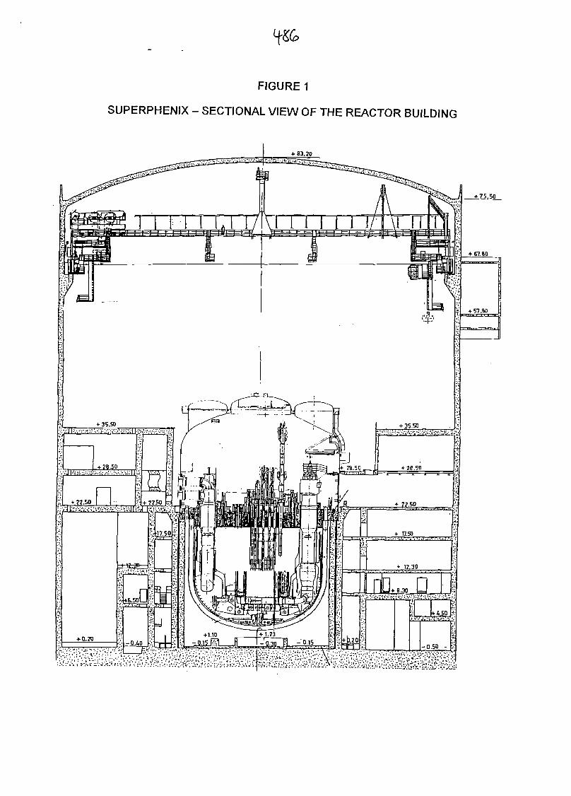
FIGURE 1
SUPERPHENIX - SECTIONAL VIEW OF THE REACTOR BUILDING
4- 83.20
I 1 1 1 i 1 I / '
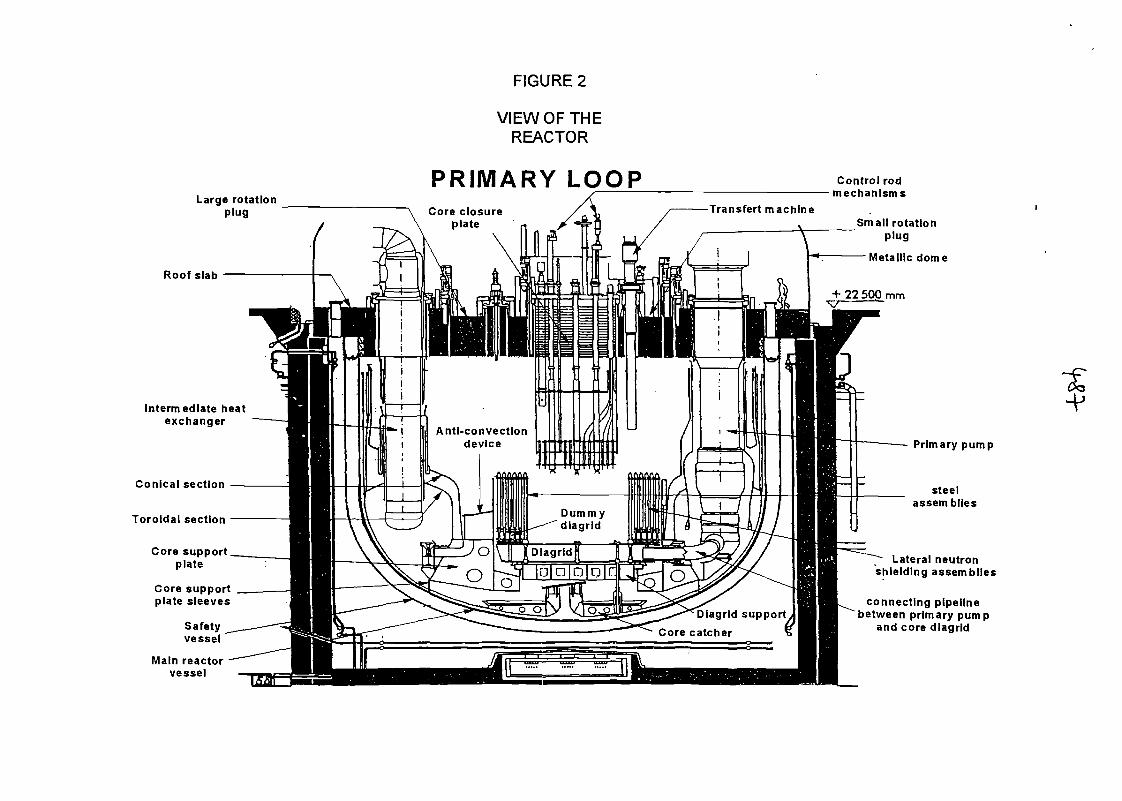
FIGURE 2
VIEW OF THEREACTOR
PRIMARY LOOPLarge rotation
plug
Roof slab
Intermediate heatexchanger
Conical section
Toroidal section
Core supportplate
Core supportplate sleeves
Safetyvessel
Main reactorvessel
Control rodmechanisms
Small rotationplug
Metallic dome
Anti-convectiondevice Primary pump
steelassemblies
Lateral neutronshielding assemblies
connecting pipelinebetween primary pump
and core dlagrid
FIGURES
DISMANTLING METHODS ENVISAGED
METALLICSODIUM
2 METHODS
THE SLAB-VIA THE BOTTOM
DISMANTLING
DISMANTLINGMETALLIC SODIUM +
CARBONATES
LOCALTREATMENTS
WASHINGcxa
CARBONAT1QN\ ,
LOCALTREATMENTS —
FILLING \AflTHWATER >».
DISMANTU NO OFVERY
IRRADIATINGSTRUCTURES
OTH^RSTRUCTURES
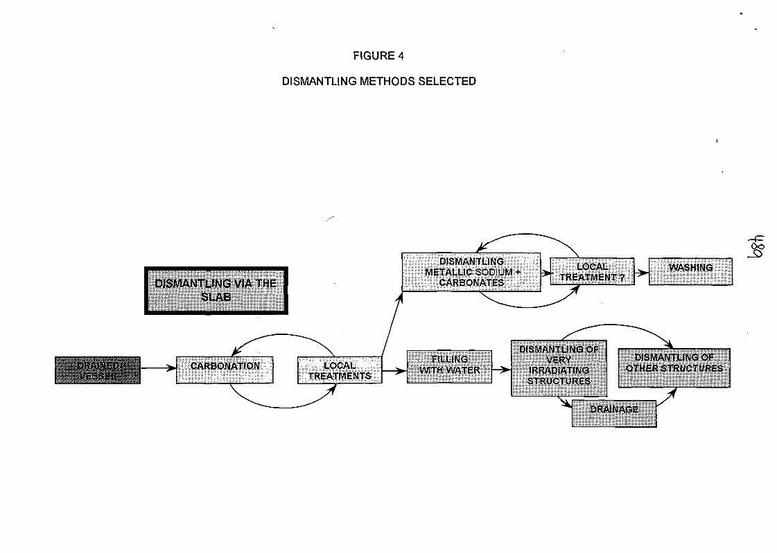
FIGURE 4
DISMANTLING METHODS SELECTED
DISMANTLING VIA THESLAB
DISMANTLINGMETALLIC SODIUM
CARBONATES
LOCAU' TREATMENT? >. WASHING
CARBONATfON"\
LOCALTREATMENTS
X
/
*^, ,. .FtLLINO
WITH WATER ~v
DISMANTyM^OFVBRV
IRRADIATINGSTRUCTURES
DISMANTLING OF

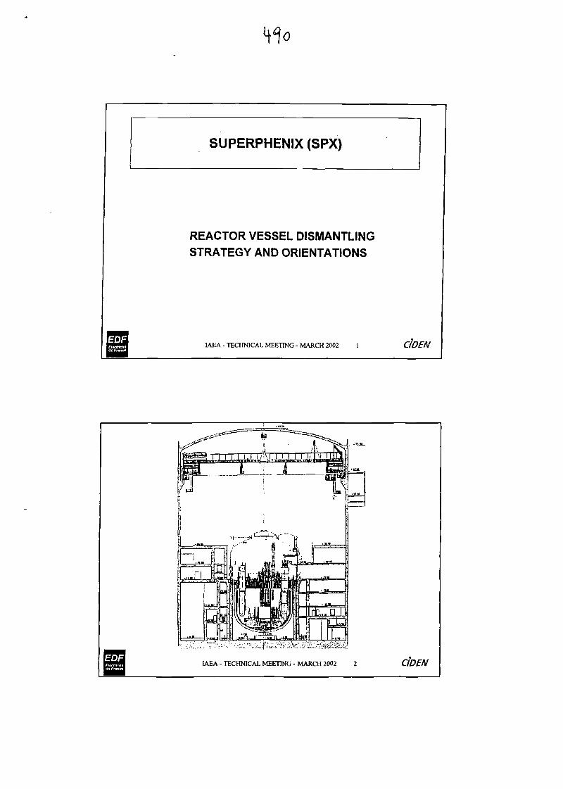
SUPERPHENIX (SPX)
REACTOR VESSEL DISMANTLING
STRATEGY AND ORIENTATIONS
IAEA - TECHNICAL MEETING - MARCH 2002 1 CIDEN
IAEA - TECHNICAL MEETING - MARCH 2002 2 CIDEN
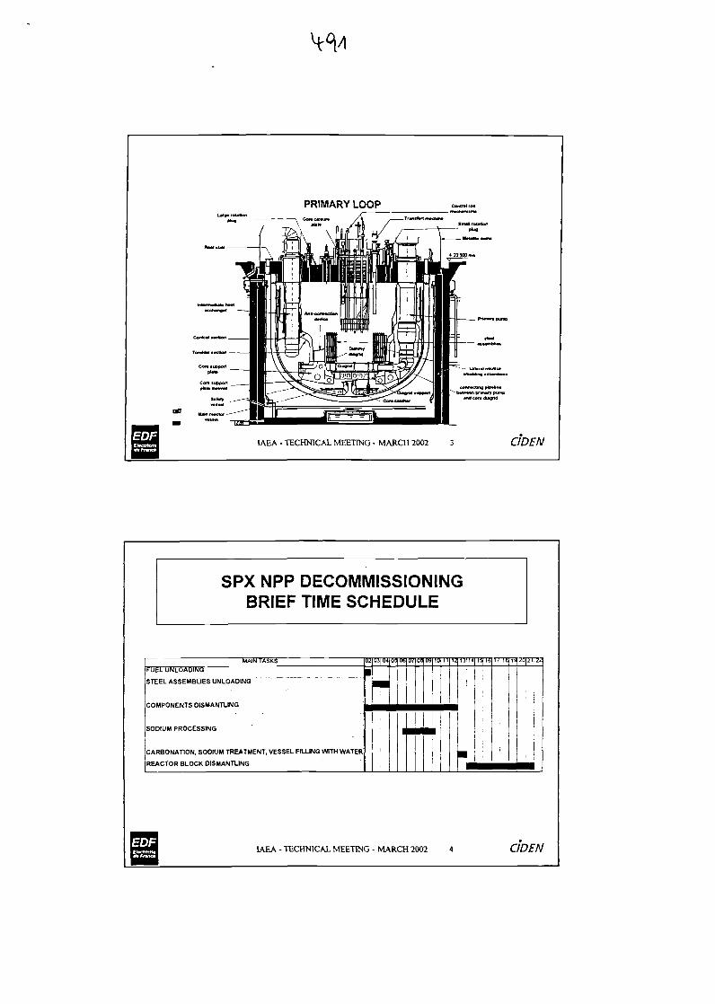
PRIMARY LOOPConclMur*
Snuttrttatton
IAEA - TECHNICAL MEETING - MARCH 2002 3 CIDEN
SPX NPP DECOMMISSIONINGBRIEF TIME SCHEDULE
MAIN TASKSFUEL UNLOADING
STEEL ASSEMBLIES UNLOADING "
COMPONENTS DISMANTLING
SODIUM PROCESSING
CARBONATION, SODIUM TREATMENT, VESSEL FILLING WITH WATER
REACTOR BLOCK DISMANTLING
inrojfw
•
|
05 OS
1
07
•
01
•
09
•
101 II
1
12 I5IH
•
15H6
I
i
:••
17
•
IB
m
IS|20|:i|22
•••
IAEA - TECHNICAL MEETING - MARCH 2002 4 CIDEN
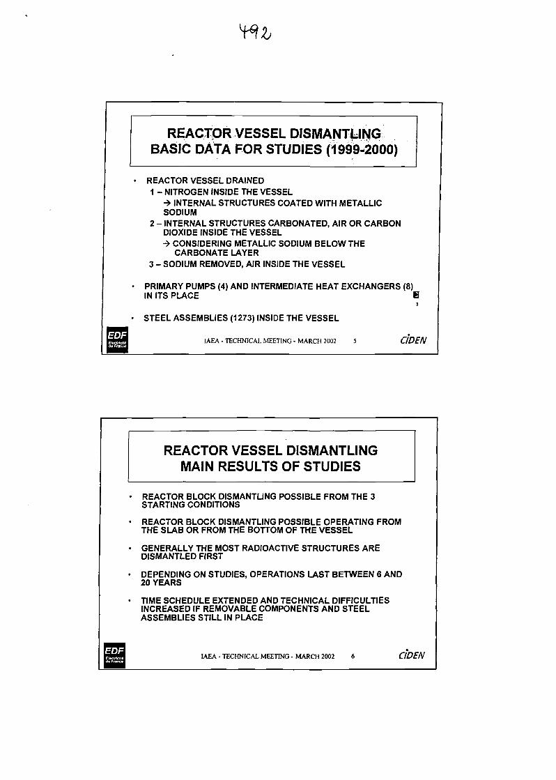
REACTOR VESSEL DISMANTLINGBASIC DATA FOR STUDIES (1999-2000)
REACTOR VESSEL DRAINED1 - NITROGEN INSIDE THE VESSEL
-» INTERNAL STRUCTURES COATED WITH METALLICSODIUM
2 - INTERNAL STRUCTURES CARBONATED, AIR OR CARBONDIOXIDE INSIDE THE VESSEL•» CONSIDERING METALLIC SODIUM BELOW THE
CARBONATE LAYER3 - SODIUM REMOVED, AIR INSIDE THE VESSEL
PRIMARY PUMPS (4) AND INTERMEDIATE HEAT EXCHANGERS (8)IN ITS PLACE H
3
STEEL ASSEMBLIES (1273) INSIDE THE VESSEL
IAEA - TECHNICAL MEETING - MARCH 2002 5 QDEN
REACTOR VESSEL DISMANTLINGMAIN RESULTS OF STUDIES
• REACTOR BLOCK DISMANTLING POSSIBLE FROM THE 3STARTING CONDITIONS
• REACTOR BLOCK DISMANTLING POSSIBLE OPERATING FROMTHE SLAB OR FROM THE BOTTOM OF THE VESSEL
• GENERALLY THE MOST RADIOACTIVE STRUCTURES AREDISMANTLED FIRST
• DEPENDING ON STUDIES, OPERATIONS LAST BETWEEN 6 AND20 YEARS
• TIME SCHEDULE EXTENDED AND TECHNICAL DIFFICULTIESINCREASED IF REMOVABLE COMPONENTS AND STEELASSEMBLIES STILL IN PLACE
IAEA-TECHNICAL MEETING-MARCH 2002 6 CIDEN
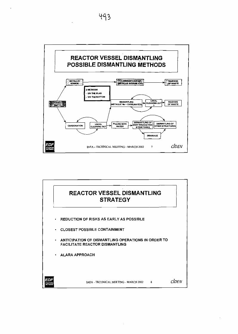
REACTOR VESSEL DISMANTLINGPOSSIBLE DISMANTLING METHODS
iMETALUcts „ '^auvuumttti^K,\tJiSOOIUMA* (METALLIC SOOtUM»NJ) ] *
/
2 METHODS
- VIA THE SLAB
- VIA THE BOTTOM ^^ ~ \
H rasliii DISMANTUNO CLEAN!NOLOUT >|f%5£SgP ((METALLIC N, - CARBONATES * CLE*N™O OUT
\ ^-^ / ^z^1 ^^ ^CAL F.LUNOW1TH ^f^^, D«SM*NT1
CARBONAT10N CLEAMNO OUT ~* WATER ^ 5™£r5£™ OTHER STR
V ^ V /
DRAINAGE
|3"tl LAiA - TECHNICAL MEETING - MARCH 2002 7
•MM
> WASHING" OF.WASTE
WASHINGOF WASTE
UNO OFUCTURES
CIDEN
REACTOR VESSEL DISMANTLINGSTRATEGY
REDUCTION OF RISKS AS EARLY AS POSSIBLE
CLOSEST POSSIBLE CONTAINMENT
ANTICIPATION OF DISMANTLING OPERATIONS IN ORDER TOFACILITATE REACTOR DISMANTLING
ALARA APPROACH
IAEA - TECHNICAL MEETING - MARCH 2002 8 CIDEN
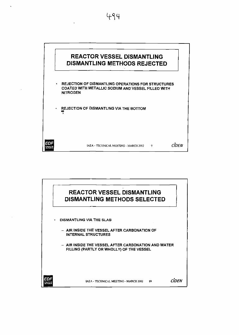
REACTOR VESSEL DISMANTLINGDISMANTLING METHODS REJECTED
REJECTION OF DISMANTLING OPERATIONS FOR STRUCTURESCOATED WITH METALLIC SODIUM AND VESSEL FILLED WITHNITROGEN
REJECTION OF DISMANTLING VIA THE BOTTOM3
IAEA - TECHNICAL MEETING - MARCH 2002 9 CIDEN
REACTOR VESSEL DISMANTLINGDISMANTLING METHODS SELECTED
DISMANTLING VIA THE SLAB
- AIR INSIDE THE VESSEL AFTER CARBONATION OFINTERNAL STRUCTURES
- AIR INSIDE THE VESSEL AFTER CARBONATION AND WATERFILLING (PARTLY OR WHOLLY) OF THE VESSEL
IAEA - TECHNICAL MEETING - MARCH 2002 10 CIDEN
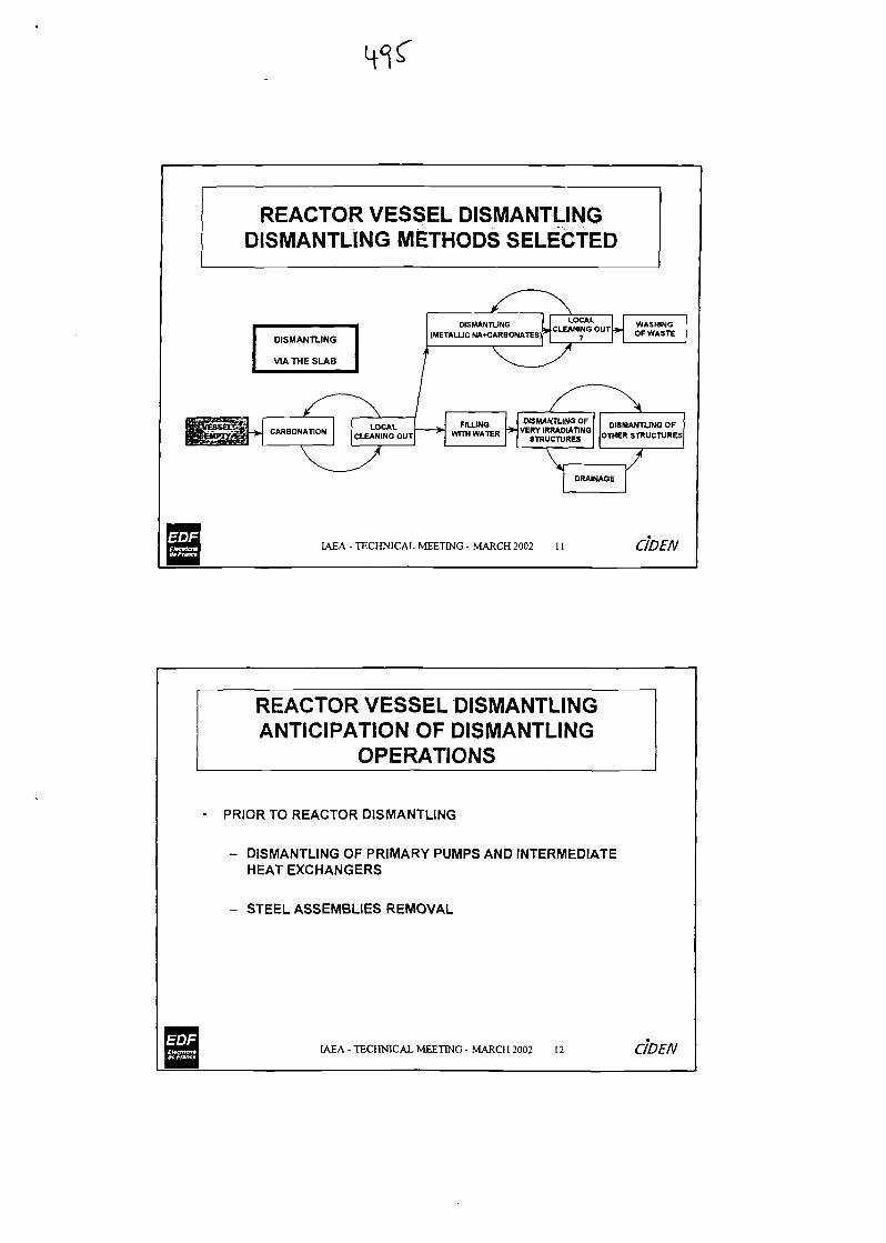
REACTOR VESSEL DISMANTLINGDISMANTLING METHODS SELECTED
LOCALCLEANING OUT
7>
WASHINGOF WASTE
IAEA - TECHNICAL MEETING - MARCH 2002 1 1 C1DEN
REACTOR VESSEL DISMANTLINGANTICIPATION OF DISMANTLING
OPERATIONS
PRIOR TO REACTOR DISMANTLING
- DISMANTLING OF PRIMARY PUMPS AND INTERMEDIATEHEAT EXCHANGERS
- STEEL ASSEMBLIES REMOVAL
IAEA - TECHNICAL MEETING - MARCH 2002 12 C1DEN
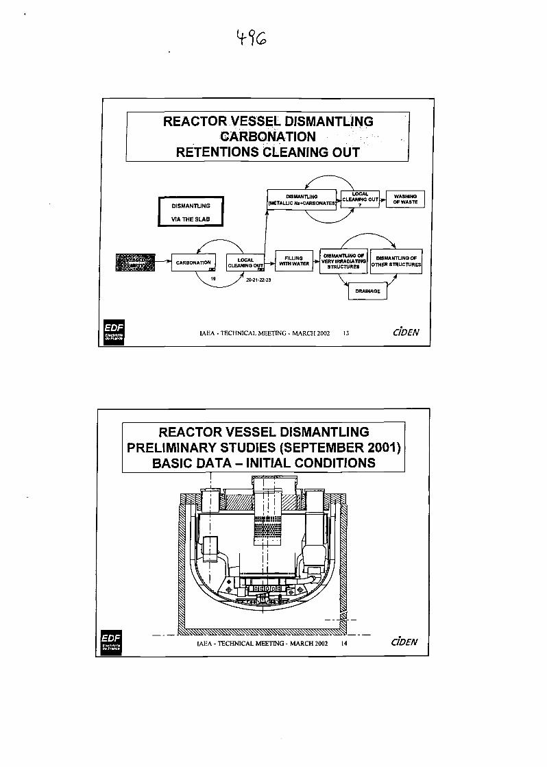
REACTOR VESSEL DISMANTLINGGARBONATION
RETENTIONS CLEANING OUT
IAEA - TECHNICAL MEETING - MARCH 2002 13 CIDEN
REACTOR VESSEL DISMANTLINGPRELIMINARY STUDIES (SEPTEMBER 2001)
BASIC DATA - INITIAL CONDITIONS
IAEA - TECHNICAL MEETING - MARCH 2002 CIDEN
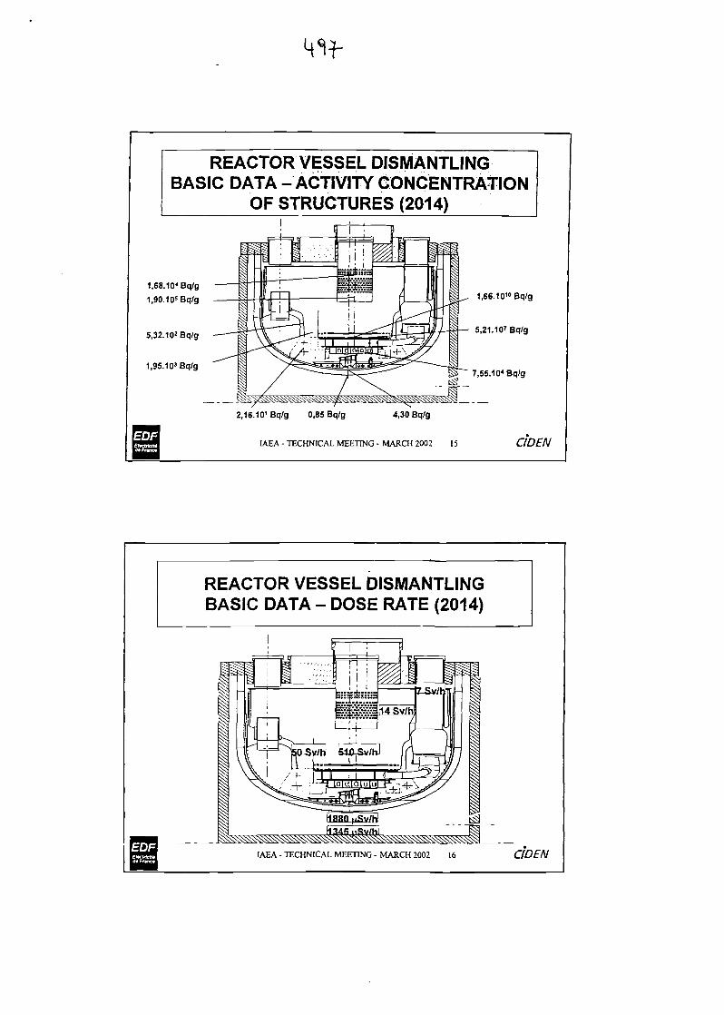
REACTOR VESSEL DISMANTLINGBASIC DATA -ACTIVITY CONCENTRATION
OF STRUCTURES (2014)
1.68.104 Bq/g
1,90.105Bq/g
5,32.102 Bq/g
1,95.103Bq/g
1,66.10" Bq/g
5,21.10'Bq/g
7,55.10* Bq/g
2,16.101Bq/g 0,85 Bq/g 4,30 Bq/g
IAEA - TECHNICAL MEETING - MARCH 2002 15 CIDEN
REACTOR VESSEL DISMANTLINGBASIC DATA - DOSE RATE (2014)
IAEA - TECHNICAL MEETING - MARCH 2002 I6 CIDEN
REACTOR VESSEL DISMANTLINGPRELIMINARY STUDIES
STUDIES COMPLETED :
- DISMANTLING WITH CARBONATED STRUCTURES- UNDERWATER DISMANTLING
STUDIES IN PROCESS OF COMPLETION ( < MAY 2002 )- PROJECT RISK ANALYSIS FOR EACH WAY
- ADVANTAGES / DISADVANTAGES COMPARISON FORDISMANTLING METHODS SELECTED
IAEA - TECHNICAL MEETING - MARCH 2002 17
IAEA - TECHNICAL MEETING - MARCH 2002 18
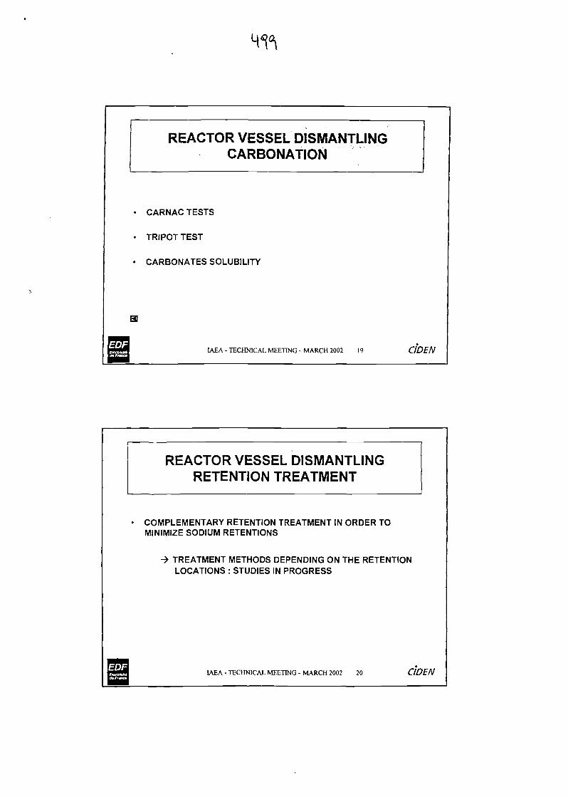
REACTOR VESSEL DISMANTLINGCARBONATION
CARNAC TESTS
TRIPOT TEST
CARBONATES SOLUBILITY
IAEA - TECHNICAL MEETING - MARCH 2002 19 C1DEN
REACTOR VESSEL DISMANTLINGRETENTION TREATMENT
COMPLEMENTARY RETENTION TREATMENT IN ORDER TOMINIMIZE SODIUM RETENTIONS
-> TREATMENT METHODS DEPENDING ON THE RETENTIONLOCATIONS : STUDIES IN PROGRESS
IAEA - TECHNICAL MEETING - MARCH 2002 20 CIDEN
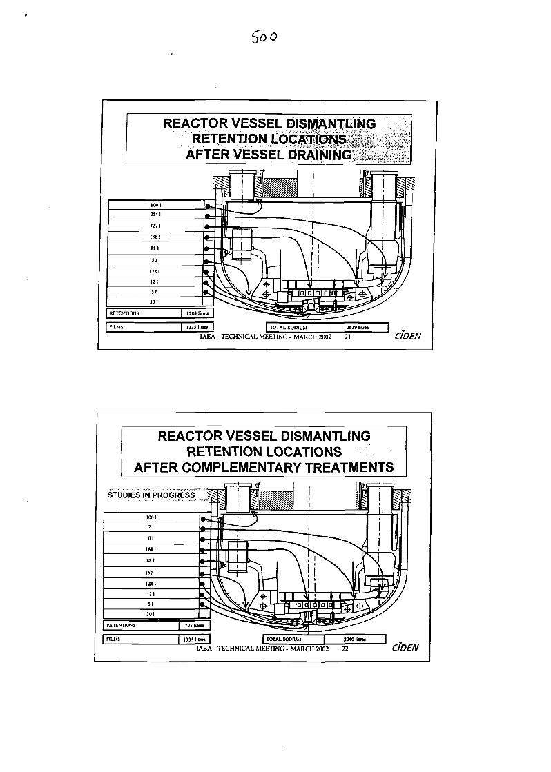
fro
REACTOR VESSEL DISMANTLINGRETENTION LOCATIONS >4
AFTER VESSEL DRAINING^ J
RETENTIONS
1335 lima
IAEA - TECHNICAL MEETING - MARCH 2002 CIDEN
REACTOR VESSEL DISMANTLINGRETENTION LOCATIONS
AFTER COMPLEMENTARY TREATMENTS
STUDIES IN PROGRESS
1001
1521
RETENTIONS 705UIH1
1335 lima [
IAEA - TECHNICAL MEETING - MARCH 2002 CIDEN
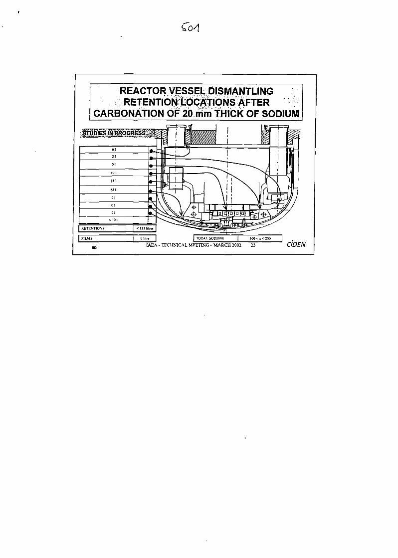
Col
REACTOR VESSEL DISMANTLINGRETENTIONlbcfriONS VVFTER
CARBONATION OF 20 mm THICK OF SODIUM
| FILMS TOTAL SODIUM
IAEA - TECHNICAL MEETING - MARCH 2002 23
100 < x < 200 1
CIDEN
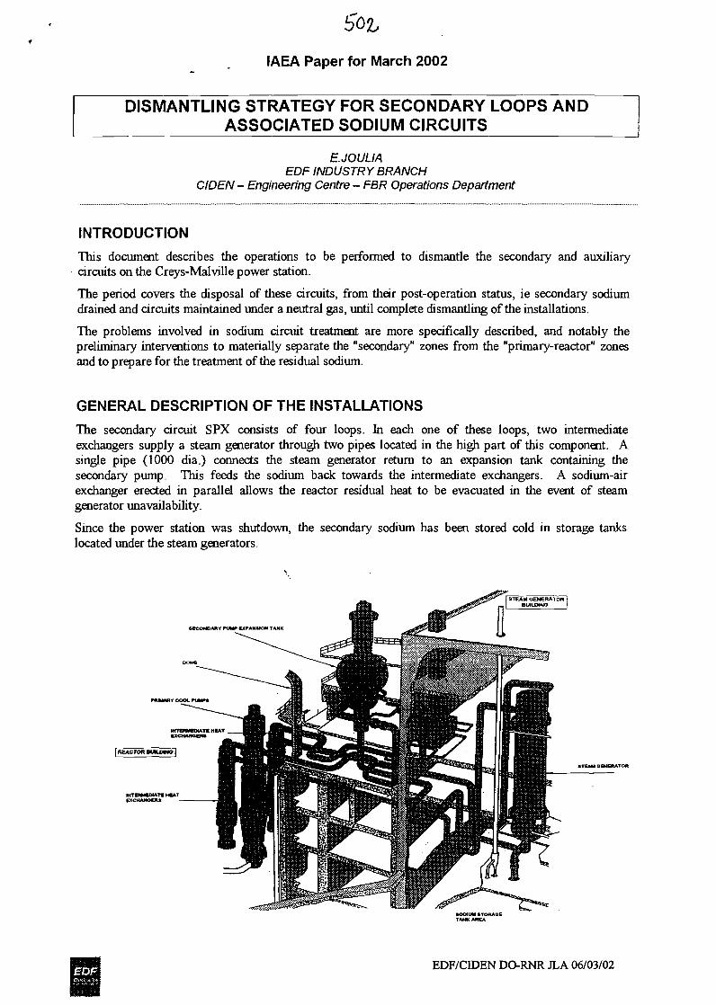
IAEA Paper for March 2002
DISMANTLING STRATEGY FOR SECONDARY LOOPS ANDASSOCIATED SODIUM CIRCUITS
E.JOULIAEOF INDUSTRY BRANCH
CIDEN- Engineering Centre - FBR Operations Department
INTRODUCTION
This document describes the operations to be performed to dismantle the secondary and auxiliarycircuits on the Creys-Malville power station.
The period covers the disposal of these circuits, from their post-operation status, ie secondary sodiumdrained and circuits maintained under a neutral gas, until complete dismantling of the installations.
The problems involved in sodium circuit treatment are more specifically described, and notably thepreliminary interventions to materially separate the "secondary" zones from the "primary-reactor" zonesand to prepare for the treatment of the residual sodium.
GENERAL DESCRIPTION OF THE INSTALLATIONS
The secondary circuit SPX consists of four loops. In each one of these loops, two intermediateexchangers supply a steam generator through two pipes located in the high part of this component. Asingle pipe (1000 dia.) connects the steam generator return to an expansion tank containing thesecondary pump. This feeds the sodium back towards the intermediate exchangers. A sodium-airexchanger erected in parallel allows the reactor residual heat to be evacuated in the event of steamgenerator unavailability.
Since the power station was shutdown, the secondary sodium has been stored cold in storage tankslocated under the steam generators.
SECONDARY PUMP EXPANSION TANK
STCAM OMERATOR
EDF/CBDEN DO-RNR JLA 06/03/02
IAEA Paper for March 2002
Some characteristics of the main secondary sodium circuits:- Secondary and auxiliary circuits: 4 loops Length(l loop): 1200 m
Residual Na: 366 kg
- Emergency cooling: 4 loops Length (1 loop):2300 mResidual Na: 18kg
DESCRIPTION OF THE PRELIMINARY OPERATIONS
The operations prior to residual sodium treatment and dismantling of the installations are designed toensure:
• Complementary draining: this draining operation complements the main draining operationscarried out at the end of the station operation phase. It is intended to collect together thesecondary sodium and the NaK for treatment in the sodium destruction installation.
The main operations are as follows:
- draining of the integrated auxiliary exchangers and the associated storage tanks,
- draining of the intermediate exchangers,
- draining of the NaK from the various tanks.
• Main isolations: these isolations are designed to separate the residual heat evacuation systems andthe primary circuits materially and functionally, and allow secondary sodium draining from theintermediate exchangers. These isolations will also be used to set up the carbonation installationsfor treatment of the circuits' residual sodium.
The main operations are as follows:
- isolation of the intermediate exchangers and the integrated auxiliary exchangers,
- isolation of the secondary sodium storage tanks.
CARBONATION OPERATIONSOn completion of the preliminary isolation operations and complementary draining, it is planned to treatthe residual sodium on the pipework and part of the components by system carbonation.
A system consists of one or more circuits from which the components or discontinuities which areunsuitable for system carbonation treatment are excluded (sodium retentions are too high, pipeworkclogged by solidified sodium, small pipes or components presenting pressure losses that are too high toallow proper sweeping by the carbonation gas).
The components not included in the carbonation system are replaced by flexible devices, temporarypipework or equipment necessary for the carbonation operation (circulation devices and on-lineinstrumentation) so that the treatment operation can be monitored and selected pipework swept.
The network is thus connected to the injection and discharge chambers.
The purpose of carbonation is to be able to overcome the risks due to the presence of sodium during thecircuit dismantling work. This allows most of the components and pipework to be filled with air.
EDF/CIDEN DO-RNR JLA 06/03/02
IAEA Paper for March 2002
R&D work with the Commissariat a 1'Energie Atomique on the sodium carbonation process (Camactests) were carried out in 2000 and 2001. These tests have defined:
the influence of the various parameters: temperature, reaction gas concentrations, etc.,
the carbonated sodium thicknesses,
type of carbonates formed: NaHCOS or/and Na2CO3
The choice of the carbonation operation is based on experience feedback from secondary pipeworktreatment operations for inspection and carbonation of the SPX irradiated assemblies storage tank on thePhenix power station at the time of its dismantling.
The carbonation of the pipework residual sodium therefore constitutes the reference solution for thetreatment of secondary and auxiliary SPX circuits.
However, it was decided to engage a demonstration site for treatment of an auxiliary circuit by thecarbonation process.
The selected auxiliary circuit has been in a so-called "fossil" condition since 1992. Today, this circuithas been partly dismantled and comprises several parts drained and maintained under inert gas. Itconsists of two identical and independent loops whose main characteristics are as follows:
Length of one loop: -270 m
Estimated quantity of residual sodium per loop: 12,8 kg.
Components per loop: 1 circulating pump, 1 heater, 1 clogging indicator, 1 expansion tank,1 steam trap, 1 sodium/air exchanger, 1 cold trap.
It is planned to proceed to pipework carbonation on one loop and then to dismantling of the installations.The other loop will be dismantled directly without preliminary treatment of the residual sodium. Acomparative assessment of the two methods and experience feedback from the operations will beexamined.
The decision to start a demonstration site for this circuit satisfies the following needs:
• to study the dismantling operations of an auxiliary sodium circuit on one site by comparing thecarbonated and non-carbonated states and performing experience feedback with a view todismantling all the secondary circuits.
• to materially engage the auxiliary circuits dismantling operations.
EDF/CIDEN DO-RNR JLA 06/03/02

IAEA Paper for March 2002
DISMANTLING OF SG BUILDING INSTALLATIONS - SECONDARY AND ASSOCIATEDCIRCUITS
This chapter concerns the dismantling of all the heat evacuation circuits and other materials contained inthe rooms housing the circuits (electric cables, ventilation systems, fire protection systems, lighting,etc.).
The significant aspects of SG building installations dismantling operations are as follows:
Dismantling of the water-steam parts
The preliminary stage consists in engaging the dismantling of the "water-steam" rooms of the steamgenerator buildings in order to have cleared areas for engaging work on dismantling the sodium zones.
This work can be started quickly without waiting for work on the sodium zones.
Dismantling of the sodium circuits
The project data are as follows:
- the residual sodium contained in the circuits has been previously carbonated. However, thepresence of residual metal sodium under the layer of carbonate cannot be excluded, on certaincomponents in particular. In situ washing by filling the main piping (1000 and 700 dia.) withwater is one option considered.
The steam generators are system carbonated with the pipework then washed and dismantled insitu.
Sodium piping is cut up after carbonation and removed to the site treatment workshop forwashing.
SUMMARY
The scenario for secondary and associated circuit dismantling operations can be divided into three mainphases:
the preliminary operations of secondary loop isolation from the primary part and residualsodium draining and collection in storage tanks for treatment in the sodium treatment installation.
These operations are currently either at the detailed design stage, or pending execution on site: workprogrammed from 2002 to 2004.
the residual sodium treatment of circuits by carbonation.
The demonstration site should make it possible to decide on the merits of this type of treatment oncomparable circuits. Even so, preliminary carbonation of the secondary/main circuits with specificcomponents such as the SGs seems unavoidable.
Preliminary studies of the carbonation of these circuits have been performed. The pilot site is plannedfor the beginning of 2003 and the application to the other secondary circuits from 2004 to 2006.
the dismantling operations on the heat evacuation circuits (secondary and auxiliary circuits).
The reference scenario retained is as follows:
treatment of the "water-steam" rooms and the sodium-free parts is engaged in priority,
the SGs are system carbonated with the pipework before being washed and dismantled in situ,
the sodium pipework is cut up and removed for washing in a workshop for treatment ofsecondary components located on the site. The main piping (1000 and 700 dia.) could bewashed in situ before cutting operations.
Work planned from 2005 to 2010.
EDF/CIDEN DO-RNR JLA 06/03/02
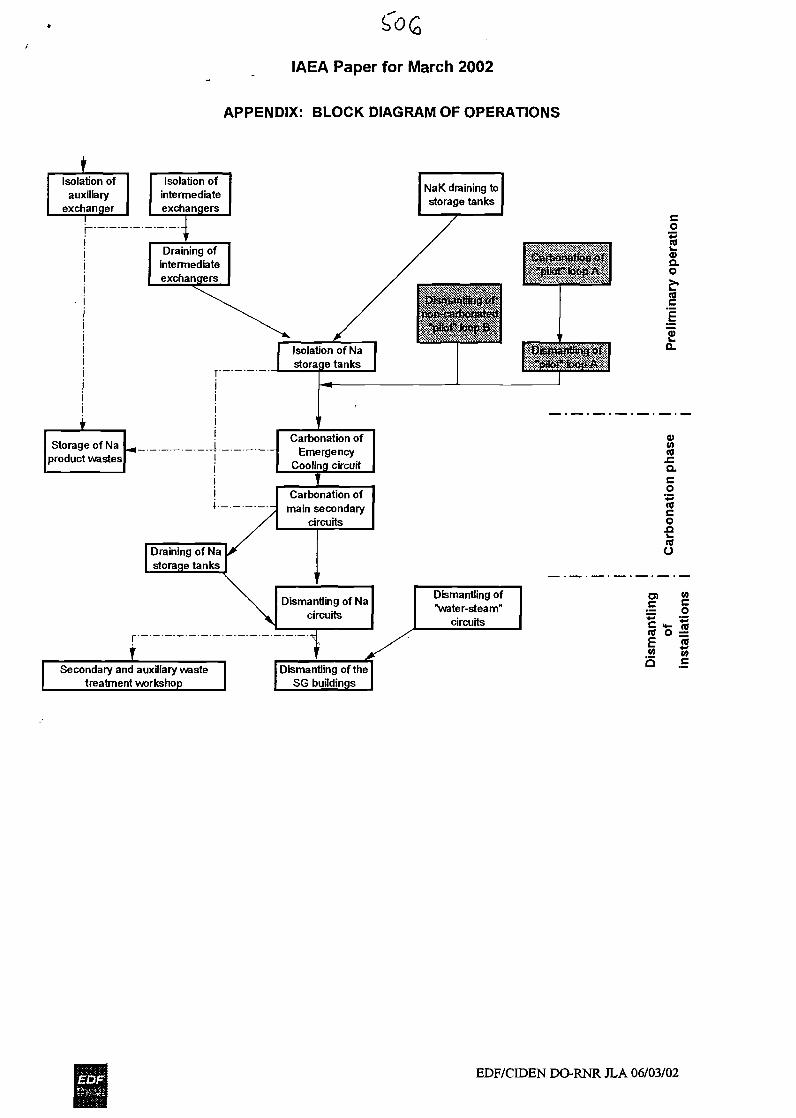
IAEA Paper for March 2002
APPENDIX: BLOCK DIAGRAM OF OPERATIONS
Isolation ofauxiliary
exchaneri
Isolation ofintermediateexchangers
Carbonation ofEmergency
Cooling circuit
J_Carbonation ofmain secondary
circuits
s0)Q.O
(0
0>w(0J=Q.cO
1OAtoO
Dismantling of Nacircuits
rr
Dismantling of"water-steam"
circuits
O)c
w
Secondary and auxiliary wastetreatment workshop
Dismantling of theSG buildings
-«
<0 O ~«w
E10Q
EDF/CIDEN DO-RNR JLA 06/03/02


-V
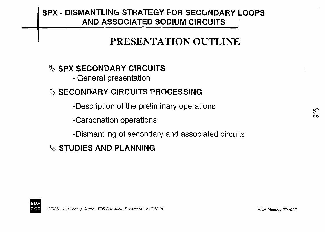
SPX - DISMANTLING STRATEGY FOR SECONDARY LOOPSAND ASSOCIATED SODIUM CIRCUITS
PRESENTATION OUTLINE
SPX SECONDARY CIRCUITS- General presentation
SECONDARY CIRCUITS PROCESSING
-Description of the preliminary operations
-Carbonation operations
-Dismantling of secondary and associated circuits
STUDIES AND PLANNING
o00
CIDEN - Engineering Centre - FBR Operations Department -E.JOULIA AIEA Meeting 03/2002
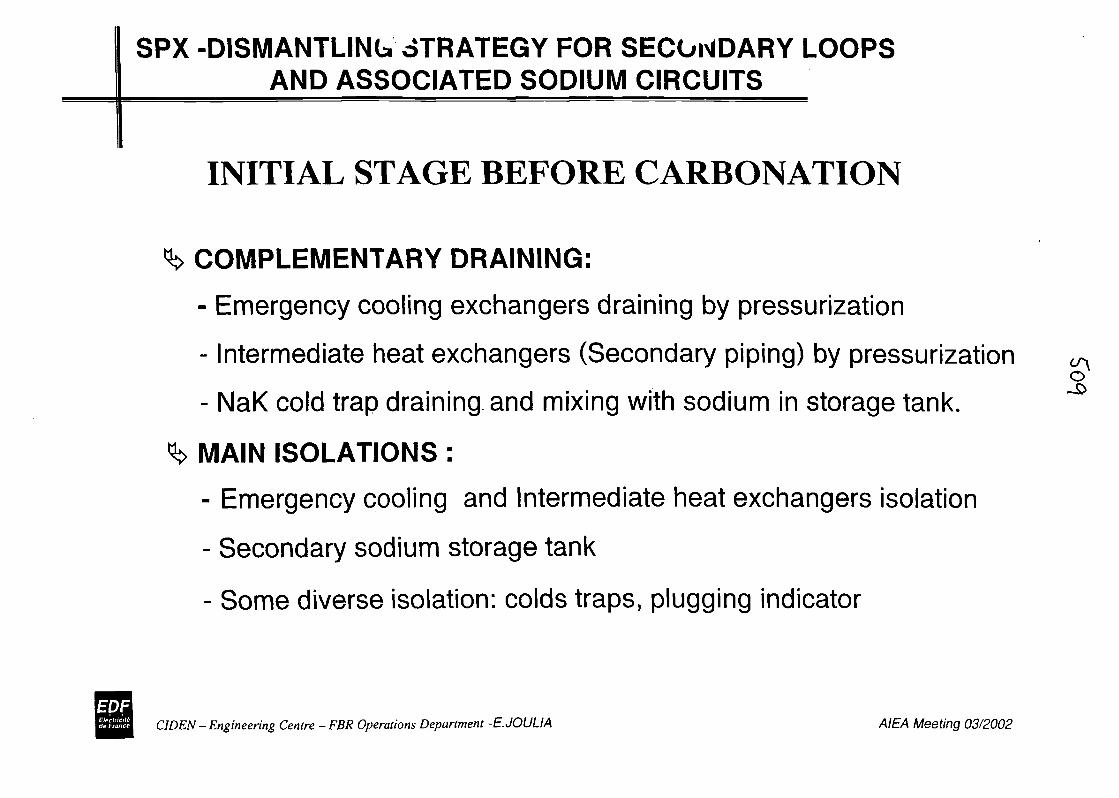
SPX -DISMANTLING STRATEGY FOR SECONDARY LOOPSAND ASSOCIATED SODIUM CIRCUITS
INITIAL STAGE BEFORE CARBONATION
COMPLEMENTARY DRAINING:
- Emergency cooling exchangers draining by pressurization
- Intermediate heat exchangers (Secondary piping) by pressurizationo
- NaK cold trap draining and mixing with sodium in storage tank.
MAIN ISOLATIONS :
- Emergency cooling and Intermediate heat exchangers isolation
- Secondary sodium storage tank
- Some diverse isolation: colds traps, plugging indicator
CIDEN - Engineering Centre - FBR Operations Department -E.JOULIA AIEA Meeting 03/2002
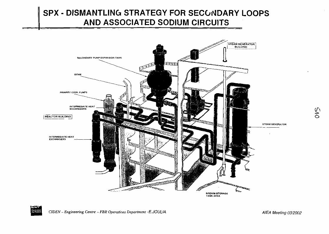
SPX - DISMANTLING STRATEGY FOR SECONDARY LOOPSAND ASSOCIATED SODIUM CIRCUITS
STEAM GENERATOR!_J3UILDUMG J
SECONDARY PUMP EXPANSION TANK
DOME
INTERMEDIATE HEATEXCHANGERS
STEAM GENERATOR
SODIUM STORAGETANK AREA
CIDEN - Engineering Centre - FBR Operations Department -E.JOULIA AIEA Meeting 03/2002

SPX -DISMANTLING 6TRATEGY FOR SECONDARY LOOPSAND ASSOCIATED SODIUM CIRCUITS
SECONDARY PUMP EXPANSION TANK
PRIMARY COOL PUMPS
INTERMEDIATE HEATEXCHANGERS
INTERMEDIATE HEATEXCHANGERS
STEAM GENERATOR
SODIUM STORAGETANK AREA
CIDEN - Engineering Centre-FBR Operations Department -E.JOULIA AIEA Meeting 03/2002
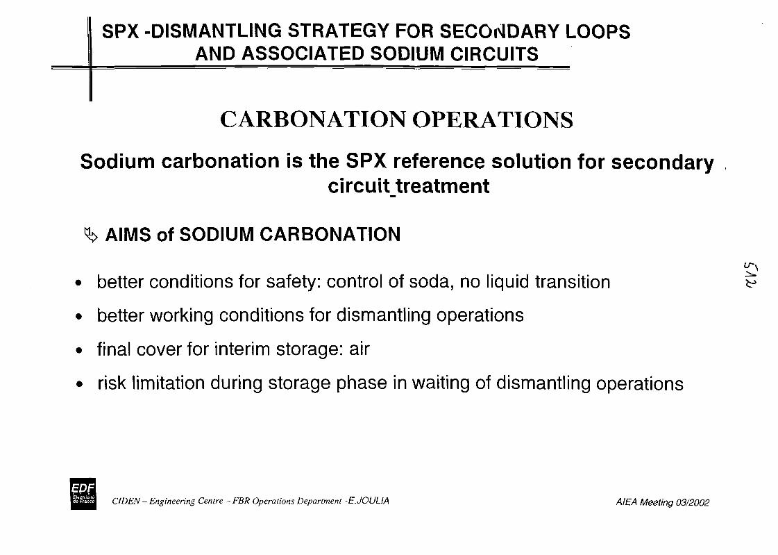
SPX -DISMANTLING STRATEGY FOR SECONDARY LOOPSAND ASSOCIATED SODIUM CIRCUITS
CARBONATION OPERATIONS
Sodium carbonation is the SPX reference solution for secondarycircuit_treatment
AIMS of SODIUM CARBONATION
better conditions for safety: control of soda, no liquid transition
better working conditions for dismantling operations
final cover for interim storage: air
risk limitation during storage phase in waiting of dismantling operations
•7CIDEN - Engineering Centre - FBR Operations Department -E.JOULIA AIEA Meeting 03/2002
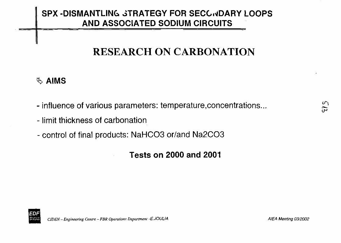
SPX -DISMANTLING JTRATEGY FOR SECONDARY LOOPSAND ASSOCIATED SODIUM CIRCUITS
RESEARCH ON CARBONATION
AIMS
- influence of various parameters: temperature,concentrations...
- limit thickness of carbonation
- control of final products: NaHCOS or/and Na2CO3
Tests on 2000 and 2001
CIDEN - Engineering Centre - FBR Operations Department -E.JOULIA AIEA Meeting 03/2002
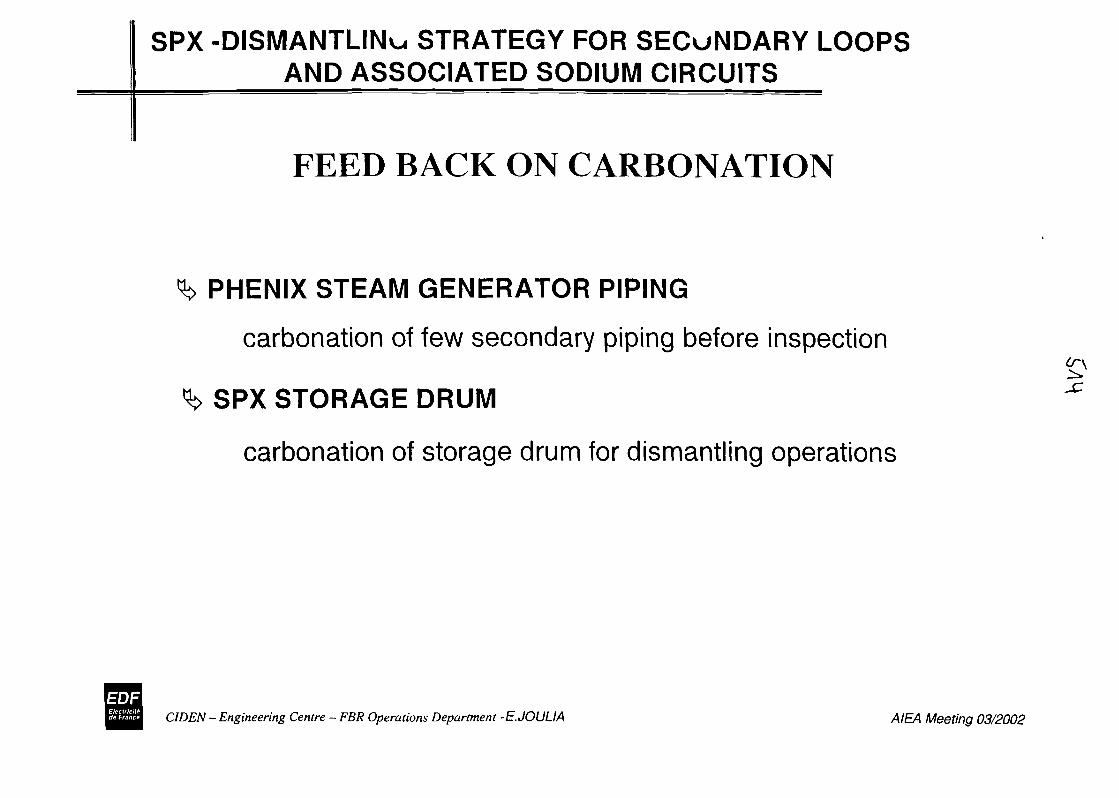
SPX -DISMANTLING STRATEGY FOR SECONDARY LOOPSAND ASSOCIATED SODIUM CIRCUITS
FEED BACK ON CARBONATION
PHENIX STEAM GENERATOR PIPING
carbonation of few secondary piping before inspection
SPX STORAGE DRUM
carbonation of storage drum for dismantling operations
CIDEN - Engineering Centre - FBR Operations Department -E.JOULIA AIEA Meeting 03/2002
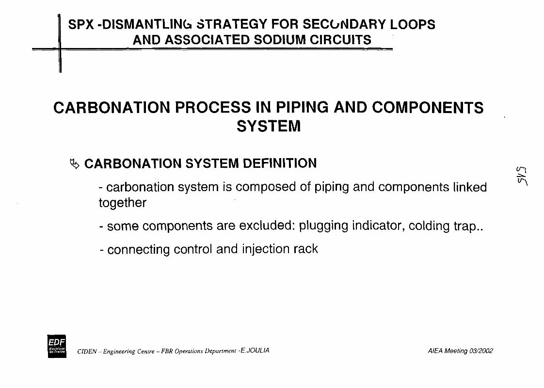
SPX -DISMANTLING STRATEGY FOR SECOMDARY LOOPSAND ASSOCIATED SODIUM CIRCUITS
CARBONATION PROCESS IN PIPING AND COMPONENTSSYSTEM
CARBONATION SYSTEM DEFINITION
- carbonation system is composed of piping and components linkedtogether
- some components are excluded: plugging indicator, colding trap..
- connecting control and injection rack
C1DEN - Engineer-ing Centre - FBR Operations Department -E.JOULIA AIEA Meeting 03/2002
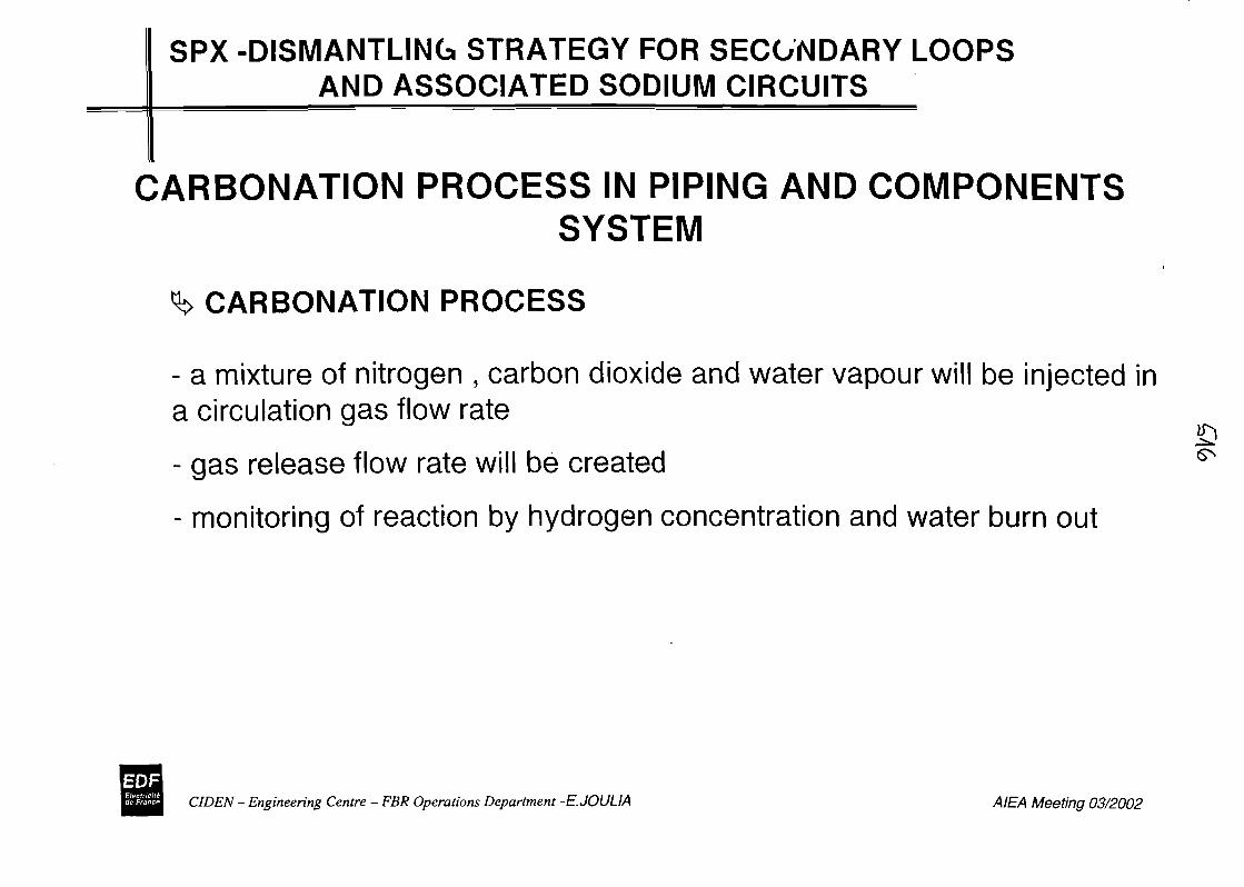
SPX -DISMANTLING STRATEGY FOR SECONDARY LOOPSAND ASSOCIATED SODIUM CIRCUITS
CARBONATION PROCESS IN PIPING AND COMPONENTSSYSTEM
CARBONATION PROCESS
- a mixture of nitrogen , carbon dioxide and water vapour will be injected ina circulation gas flow rate
- gas release flow rate will be created
- monitoring of reaction by hydrogen concentration and water burn out
CIDEN - Engineering Centre - FBR Operations Department -E.JOULIA AIEA Meeting 03/2002
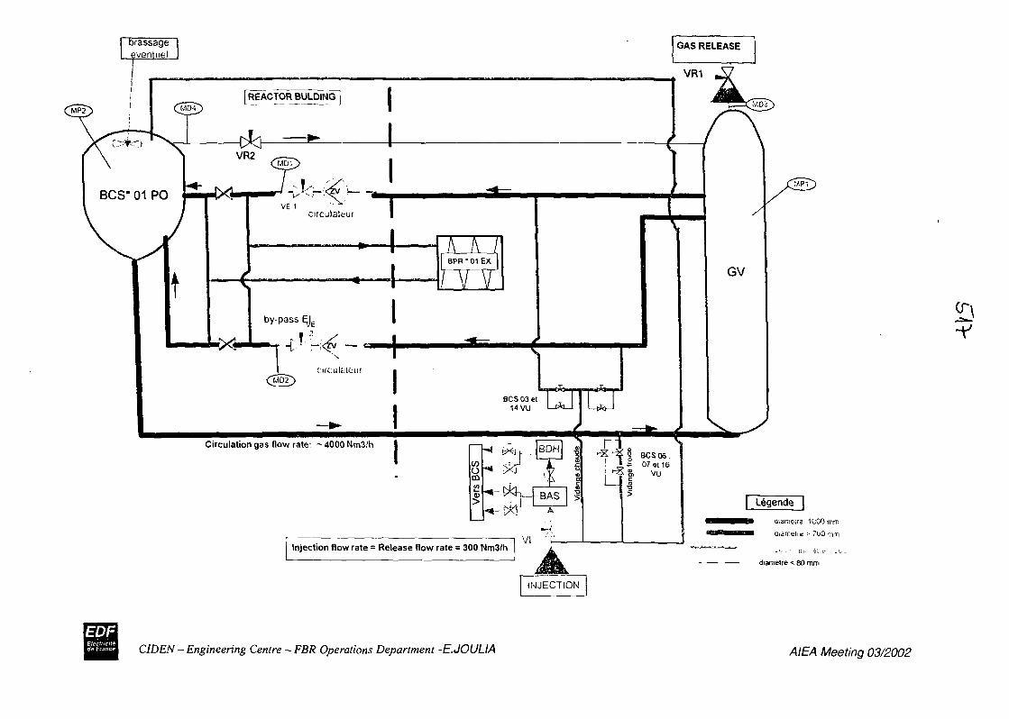
Circulation gas now rate: ~4000Nm3/h
'
Injection flow rate = Release flow rate = 300 Nm3/hVI
I IINJECTION
aiameive 1000 mtr,
aiamelis •* 700 -Tim
diamelre < 80 nvn
-v
CIDEN - Engineering Centre - FBR Operations Department -E.JOULIA AIEA Meeting 03/2002
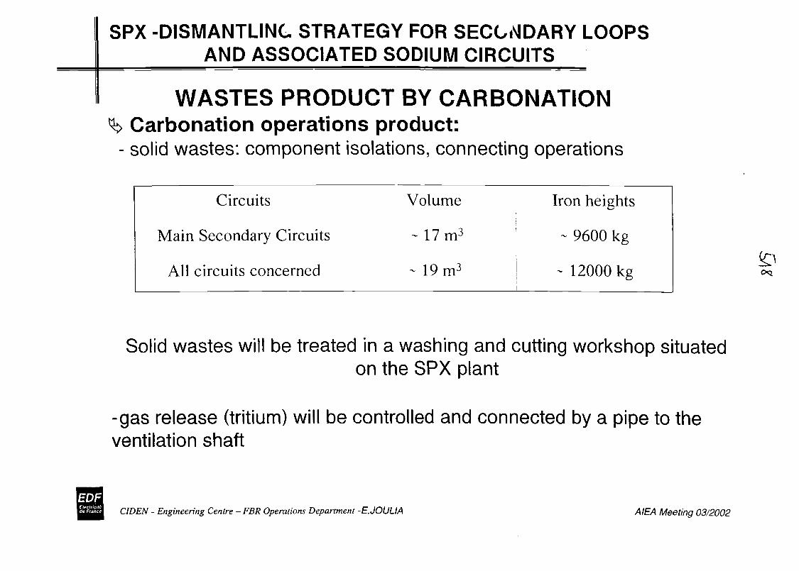
SPX -DISMANTLING STRATEGY FOR SECONDARY LOOPSAND ASSOCIATED SODIUM CIRCUITS
WASTES PRODUCT BY CARBONATIONCarbonation operations product:
- solid wastes: component isolations, connecting operations
Circuits
Main Secondary Circuits
All circuits concerned
Volume
- 17m3
- 19m3
Iron heights
- 9600 kg
- 12000 kg
Solid wastes will be treated in a washing and cutting workshop situatedon the SPX plant
-gas release (tritium) will be controlled and connected by a pipe to theventilation shaft
V]CIDEN - Engineering Centre - FBR Operations Department -E.JOULIA AIEA Meeting 03/2002
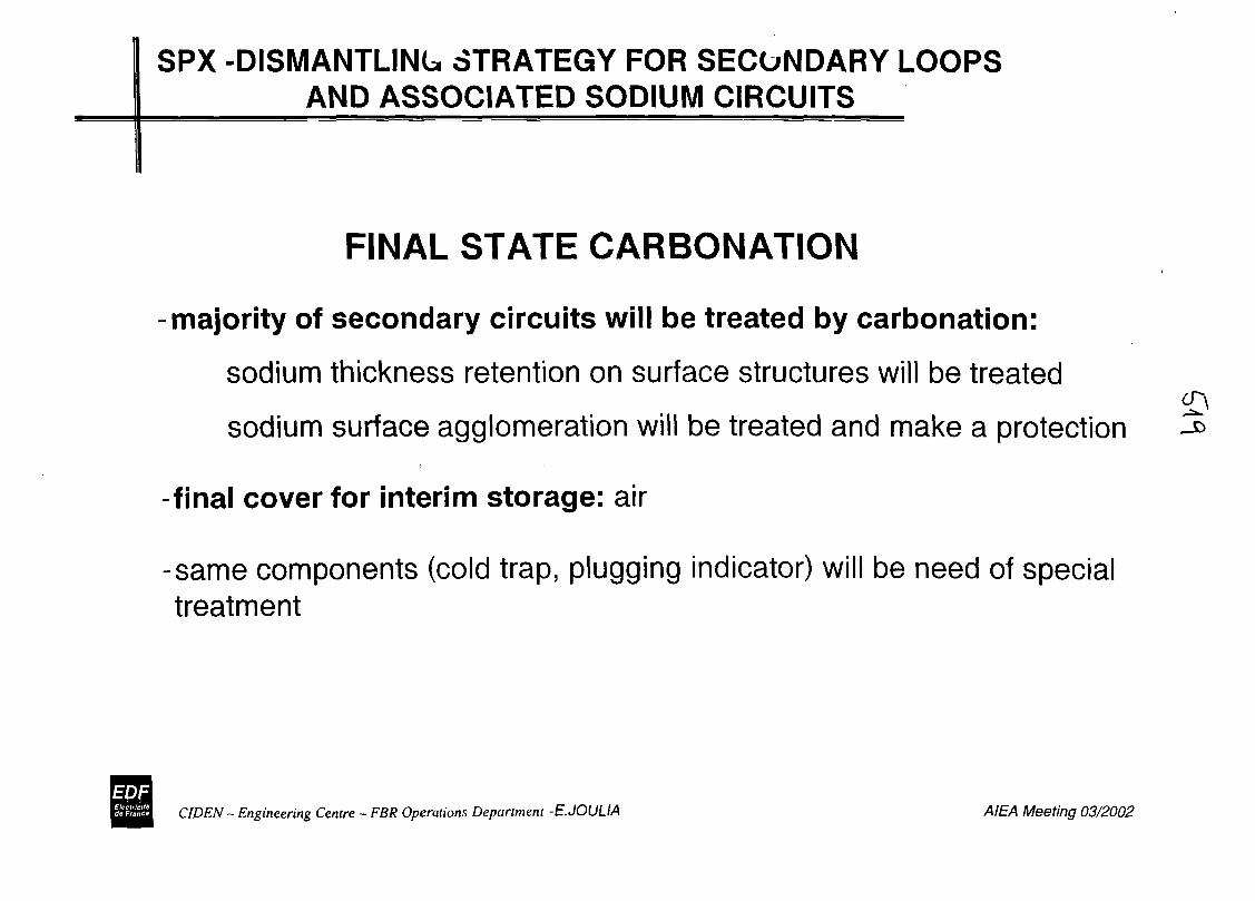
SPX -DISMANTLING STRATEGY FOR SECONDARY LOOPSAND ASSOCIATED SODIUM CIRCUITS
FINAL STATE CARBONATION
majority of secondary circuits will be treated by carbonation:
sodium thickness retention on surface structures will be treated
sodium surface agglomeration will be treated and make a protection
final cover for interim storage: air
-same components (cold trap, plugging indicator) will be need of specialtreatment
CIDEN - Engineering Centre - FBR Operations Department -E.JOULIA AIEA Meeting 03/2002
SPX -DISMANTLING STRATEGY FOR SECONDARY LOOPSAND ASSOCIATED SODIUM CIRCUITS
DISMANTLING OPERATIONS
SECONDARY SODIUM PIPING
Non specific technologies will be used: piping will be cut at the greatdimensions in steam generator building and will be treated in awashing and cutting workshop situated on the SPX plant
COMPONENTS
- majority will be treated in the same installation that the piping,
- preliminary studies are necessary to choose the treatment for fewcomponents: in particular cold trap
- The steam generators are system carbonatewith the pipework then washed and dismantled in situ
'•TjjCIDEN - Engineering Centre - FBR Operations Department -E.JOULIA AIEA Meeting 03/2002
O
SPX -DISMANTLING STRATEGY FOR SECONDARY LOOPSAND ASSOCIATED SODIUM CIRCUITS
STUDIES
CARBONATION
Tritium: in steel, part release during carbonation process..Detail studies for the carbonation operationsDeterminate the best moment for these operations {3
^
DISMANTLING OPERATIONS
- Preliminary studies for dismantling operations- Detail studies for the washing and cutting workshop situatedon the SPX plant
CIDEN - Engineering Centre - FBR Operations Department -E.JOULIA AIEA Meeting 03/2002
SPX -DISMANTLING STRATEGY FOR SECONDARY LOOPSAND ASSOCIATED SODIUM CIRCUITS
PLANNING
MAIN ISOLATIONS - COMPLEMENTARY DRAINING 2002-2004
CARBONATION
Secondary Circuits and auxiliary -4 loops: 2004 2009
DISMANTLING OPERATIONS
Secondary Circuits and auxiliary -1 years by loop: 2006 2010
A complete operation on Storage drum cooling circuit is planned in 2003
CIDEN - Engineering Centre - FBR Operations Department -E.JOULIA AIEA Meeting 03/2002
SPX -DISMANTLING STRATEGY FOR SECONDARY LOOPSAND ASSOCIATED SODIUM CIRCUITS
WASHING OPERATIONS
In situ washing by filling the main piping (1000 and 700 mm dia.)with water is one option considered
cr\
End of studies June 2002
CIDEN - Engineering Centre - FBR Operations Department -E.JOULIA AIEA Meeting 03/2002

WM'02 Conference, February 24-28, 2002, Tucson, AZ (Session 44, Abs # 40)
CONCEPT FOR DISMANTLING THE REACTOR VESSEL AND THE BIOLOGICAL SHIELD OFTHE COMPACT SODIUM-COOLED NUCLEAR REACTOR FACILITY (KNK)
Iris Hillebrand, Forschungszentrum Karlsruhe, GermanyJiirgen Benkert, Westinghouse Reaktor, Germany
ABSTRACT
The Compact Sodium-cooled Nuclear Reactor Facility (KNK) was an experimental nuclear power plant of 20MW electric power erected on the premises of the Karlsruhe Research Center. The plant was initially run asKNK I with a thermal core between 1971 and 1974 and then, between 1977 and 1991, with a fast core as theKNK II fast breeder plant.
Under the decommissioning concept, the plant is to be decommissioned completely to green field conditions atthe end of 2005 in ten steps, i.e. under the corresponding ten decommissioning permits. To this day, ninedecommissioning permits have been issued, the first one in 1993 and the most recent one, number nine, in 2001.
The decommissioning and demolition activities covered by decommissioning permits 1 to 7 have beencompleted. Under the 8th Decommissioning Permit, the components of the primary system and the rotatingreactor top shield are to be removed by late 2001. Under the 9th Decommissioning Permit, the reactor vesselwith its internals, the primary shield, and the biological shield are to be dismantled.
The residual sodium volume in the reactor vessel was estimated to amount to approx. 30 I. The maximum Co-60activation is on the order of 107 - 108 Bq/g; the maximum dose rate in the middle of the vessel was measured inApril 1997tobe55Sv/h.
The difficulty involved especially in dismantling KNK, on the one hand, is posed by the residual sodium in theplant, which determines the choice of neither wet nor thermical techniques to be used in disassembly. Anotherdifficulty is caused by the depth of activation by fast neutrons, as a result of which not only the reactor vesselproper, but also the..enlire primary^ shield (60 cm of grey cast iron) and large parts of the biological shield mustbe disassembled and disposed of under remote control.
INTRODUCTION
The Compact Sodium-cooled Nuclear Reactor Facility (KNK) was an experimental nuclear power plant of20 MW electric power erected on the premises of the Karlsruhe Research Center. The plant was initially run asKNK I with a thermal core between 1971 and 1974 and then, between 1977 and 1991, with a fast core as theKNK II fast breeder plant.
The reactor core of KNK was arranged in an unpressurized, thin-walled reactor vessel roughly in the middle ofthe containment (Fig. 1). Sodium was used as the coolant.
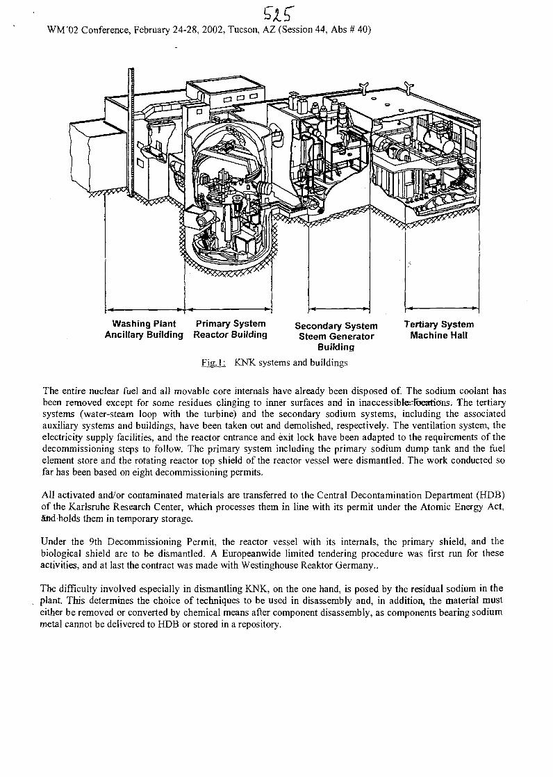
Si 5"WM'02 Conference, February 24-28, 2002, Tucson, AZ (Session 44, Abs # 40)
Washing PlantAncillary Building
Primary SystemReactor Building
Secondary SystemSteem Generator
Building
Tertiary SystemMachine Hall
KNK systems and buildings
The entire nuclear ftiel and all movable core internals have already been disposed of. The sodium coolant hasbeen removed except for some residues clinging to inner surfaces and in inaccessibfe?Ibeations. The tertiarysystems (water-steam loop with the turbine) and the secondary sodium systems, including the associatedauxiliary systems and buildings, have been taken out and demolished, respectively. The ventilation system, theelectricity supply facilities, and the reactor entrance and exit lock have been adapted to the requirements of thedecommissioning steps to follow. The primary system including the primary sodium dump tank and the fuelelement store and the rotating reactor top shield of the reactor vessel were dismantled. The work conducted sofar has been based on eight decommissioning permits.
All activated and/or contaminated materials are transferred to the Central Decontamination Department (HDB)of the Karlsruhe Research Center, which processes them in line with its permit under the Atomic Energy Act,laid holds them in temporary storage.
Under the 9th Decommissioning Permit, the reactor vessel with its internals, the primary shield, and thebiological shield are to be dismantled. A Europeanwide limited tendering procedure was first run for theseactivities, and at last the contract was made with Westinghouse Reaktor Germany..
The difficulty involved especially in dismantling KNK, on the one hand, is posed by the residual sodium in theplant. This determines the choice of techniques to be used in disassembly and, in addition, the material musteither be removed or converted by chemical means after component disassembly, as components bearing sodiummetal cannot be delivered to HDB or stored in a repository.
WM'02 Conference, February 24-28, 2002, Tucson, AZ (Session 44, Abs # 40)
Another difficulty is caused by the depth of activation by fast neutrons, as a result of which not only the reactorvessel proper, but also the entire primary shield (60 cm of grey cast iron) and large parts of the biological shieldmust be disassembled and disposed of under remote control.
PERMITS AND DEADLINES
Under the decommissioning concept, the plant is to be decommissioned completely to green field conditions inten steps, i.e. under the corresponding ten decommissioning permits. To this day, nine decommissioning permits
•have been issued, the first one in 1993 and the most recent one, number nine, in 2001.
The decommissioning and demolition activities covered by decommissioning permits 1 to 7 have beencompleted. Under the 8th Decommissioning Permit, the components of the primary system and the rotatingreactor top shield are to be removed by late 2001.
The 9th Decommissioning Permit covering disassembly of the reactor vessel and the biological shield was filedfor in July 1999 and, with a final amendment, again in March 2000. The expert opinion covering these activitieshas been available since December 2000, and the permit was issued in March 2001. The period between 2001and mid-2002 has been reserved for planning and preparing disassembly of the reactor vessel. From September2002 on, the reactor vessel with its internals is to be disassembled and disposed of, and from mid-2003 on, theprimary shield and the biological shield are to be disassembled and disposed of.
Under the 10th and last Decommissioning Permit, the remaining auxiliary systems (sodium washing plant,ventilation plant, liquid effluent system, gaseous effluent system, etc.) are to be dismantled and any buildingsremaining are to be decontaminated, measured for clearance, and then demolished, if necessary. Then the site isto be recultivated.
The safety report on which the application for the 10th Decommissioning Permit is based is being completed andwas submitted to the authority in June 2001. The work is to be finished probably at the end of 2005.
DISMANTLING THE REACTOR VESSEL AND THE BIOLOGICAL SHIELD
Initial Condition
After completion of the first eight decommissioning permits, the only remnants of the plant still in existence arethe reactor vessel with its internals installed in the primary shield and the biological shield. These componentsare located in the middle of the containment in the reactor building (see Fig. 2). The reactor vessel is inerted withnitrogen and closed with a lid. Other installations still in place are the ancillary plants building, the control roombuilding, and a storage facility. They contain some systems important in the decommissioning process, namelythe ventilation system, the washing system for components wetted with sodium, and the moderator store, whichmust be converted into a buffer store. The reactor building and the ancillary plants building are part of thecontrolled area.
The residual sodium volume in the reactor vessel was estimated to amount to approx. 30 1. The maximum Go-60activation is on the order of 107 - 10&Bq/g; the maximum dose rate in the middle of the vessel was measured inApril 1997 to be 55 Sv/h.
WM'02 Conference, February 24-28, 2002, Tucson, KL (Session 44, Abs # 40)
i— EntrancetoAncillaryBuilding
-r
iff- ReactorVessel
PrimaryShield
298309
Fig. 2: Cross section through the KNK containment after completion of the 8th Decommissioning Permit
Demolition Concept
Before dismantling of the reactor vessel is begun, the interior space of the vessel is treated with a wet gas. Forthis purpose, the nitrogen is added humidity so that any particulate sodium deposits can be immobilized. Thenthe vessel is dried. The dismantling work of possibly sodium covered components is to be carried out under anitrogen atmosphere.
The reactor vessel with its internals, and the primary shield, are to be disassembled within the existing shielding,i.e. the biological shield. For this purpose, a-shielding enclosure will be erecte£bta>8Hway*te¥ekabovethe reactorvessel, which will be equipped with a^bandling-CelL, an intervention cell, a, double-lid lock and^a transfer lock forbuilding rubbish, and all the necessary auxiliary systems (lifting gear, rails, lead glass windows, manipulators).The enclosure must have a shielding of 35 cm of steel required for radiological reasons, on the one hand, andensure separation from the containment in terms of ventilation, on the other hand.
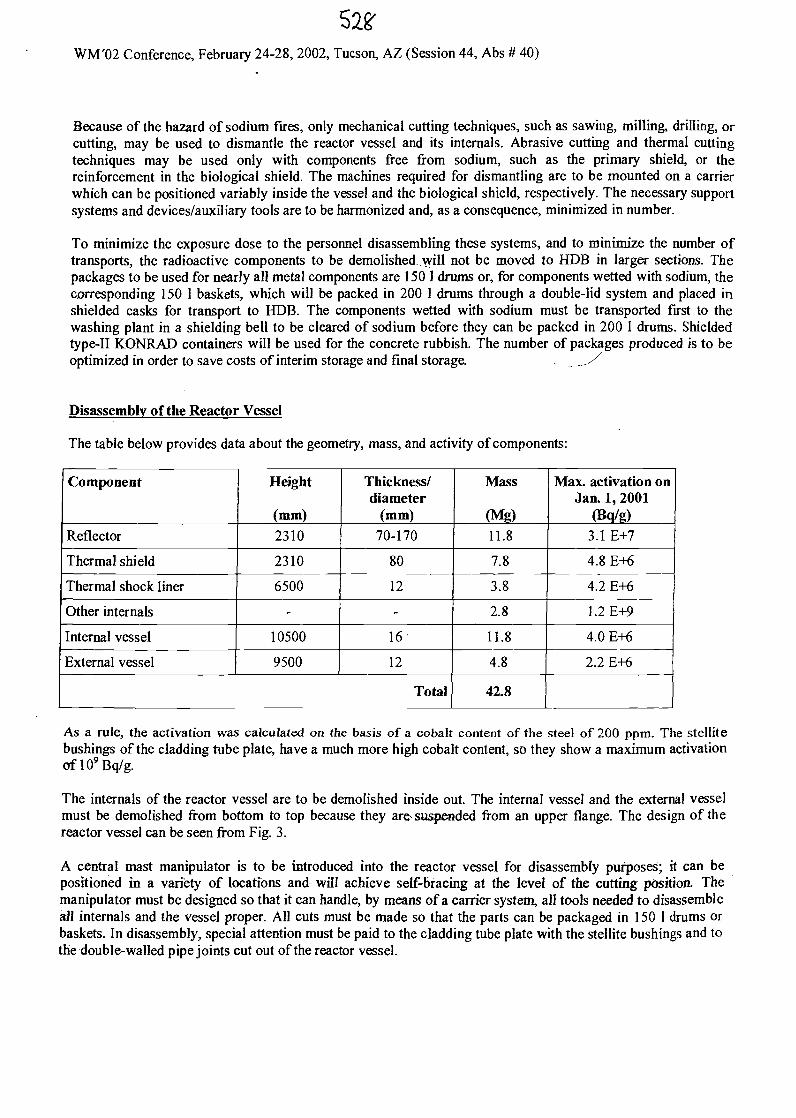
WM'02 Conference, February 24-28, 2002, Tucson, AZ (Session 44, Abs # 40)
Because of the hazard of sodium fires, only mechanical cutting techniques, such as sawing, milling, drilling, orcutting, may be used to dismantle the reactor vessel and its internals. Abrasive cutting and thermal cuttingtechniques may be used only with components free from sodium, such as the primary shield, or thereinforcement in the biological shield. The machines required for dismantling are to be mounted on a carrierwhich can be positioned variably inside the vessel and the biological shield, respectively. The necessary supportsystems and devices/auxiliary tools are to be harmonized and, as a consequence, minimized in number.
To minimize the exposure dose to the personnel disassembling these systems, and to minimize the number oftransports, the radioactive components to be demolished will not be moved to HDB in larger sections. Thepackages to be used for nearly all metal components are 150 1 drums or, for components wetted with sodium, thecorresponding 150 1 baskets, which will be packed in 200 1 drums through a double-lid system and placed inshielded casks for transport to HDB. The components wetted with sodium must be transported first to thewashing plant in a shielding bell to be cleared of sodium before they can be packed in 200 1 drums. Shieldedtype-II KONRAD containers will be used for the concrete rubbish. The number of packages produced is to beoptimized in order to save costs of interim storage and final storage. __./
Disassembly of the Reactor Vessel
The table below provides data about the geometry, mass, and activity of components:
Component
Reflector
Thermal shield
Thermal shock liner
Other internals
Internal vessel
External vessel
Height
(mm)2310
2310
6500
-
10500
9500
Thickness/diameter
(mm)
70-170
80
12
-
16
12
Total
Mass
(Mg)11.8
7.8
3.8
2.8
11.8
4.8
42.8
Max. activation onJan. 1, 2001
(Bq/g)3.1 E+7
4.8 E+6
4.2 E+6
1.2E+9
4.0 E+6
2.2 E+6
As a rule, the activation was calculated on the basis of a cobalt content of the steel of 200 ppm. The stellitebushings of the cladding tube plate, have a much more high cobalt content, so they show a maximum activationof 109 Bq/g.
The internals of the reactor vessel are to be demolished inside out. The internal vessel and the external vesselmust be demolished from bottom to top because they are suspended from an upper flange. The design of thereactor vessel can be seen from Fig. 3.
A central mast manipulator is to be introduced into the reactor vessel for disassembly purposes; it can bepositioned in a variety of locations and will achieve self-Bracing at the level of the cutting position. Themanipulator must be designed so that it can handle, by means of a carrier system, all tools needed to disassembleall internals and the vessel proper. All cuts must be made so that the parts can be packaged in 150 1 drums orbaskets. In disassembly, special attention must be paid to the cladding tube plate with the stellite bushings and tothe double-walled pipe joints cut out of the reactor vessel.
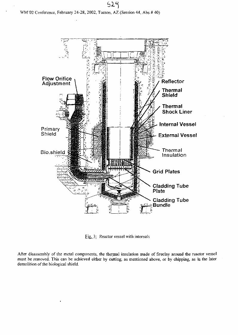
WM'02 Conference, February 24-28, 2002, Tucson, AZ (Session 44, Abs # 40)
Flow OrificeAdjustment
PrimaryShield
Bio.shield
Reflector
ThermalShield
ThermalShock Liner
Internal Vessel
i- External Vessel
ThermalInsulation
Grid Plates
Cladding TubePlate
Cladding Tube•fe£Mv BundleCD
Fig. 3: Reactor vessel with internals
After disassembly of the metal components, the thermal insulation made of fireclay around the reactor vesselmust be removed. This can be achieved either by cutting, as mentioned above, or by chipping, as in the laterdemolition of the biological shield.
530WM'02 Conference, February 24-28, 2002, Tucson, AZ (Session 44, Abs # 40)
Disassembly of the Primary Shield
At the level of the reactor core, the primary shield made of cast iron with lamellar graphite, GG-20, is situated ina niche of the biological shield outside the thermal insulation (see Fig, 3).
The total mass of the primary shield is approx. 90.5 Mg. Of this, 9.2 Mg is due to the conical part, whose foursegments are approximately equal in weight. The triangular segments of the cylindrical section each have a massof approx. 3.7 Mg, while the square ones have a mass of approx. 16.6 Mg. The maximum activation is1.55xl06Bq/g.
Perhaps it will be necessary, prior to demolition of the primary shield, to remove parts of the biological shieldabove the primary shield as far as the outside diameter of the primary shield. This makes the primary shieldfreely accessible from the top and from the inside.
The primary shield is demolished by remote operation from the enclosure. The planning is to install a platformbelow the primary shield in the reactor cavity on which parts of the primary shield can be deposited. The parts ofthe primary shield are then disassembled by means of a saw which can be carried by the crane; it is applied to thecomponent, braced, and thus allows horizontal and vertical cutting.
The parts cut off are attached to the crane by means of force-locking mechanical grabs, and are lifted to thejrunway level. The parts are filled into 200 I drums through the double-lid Jock, and are then taken to HDB inshielded shipping casks.
Disassembly of the Biological Shield
The reactor core is surrounded by a block of concrete of very high density (density 4.14 g/cm3), the biologicalshield, which was also activated by the neutron radiation emanating from the reactor core (see Fig. 3). Thespecific Co-60 activity of the concrete achieves a maximum of 8 x 10s Bq/g, which means that most of thedisassembly work must be carried out remotely.
The depth of demolition of the biological shield is determined by the depth of activation of the concrete.According to the new German Radiation Protection Ordinance, a clearance level for Co-60 of 0.09 Bq/g must beobserved for the unrestricted clearance of riuildihg rubbish: Probably, a total of 330 Mg of very-high-densityconcrete must be disposed of as radioactive waste.
Chipping will be the method of demolition (Fig. 4). For this purpose, an auxiliary platform variable in height isto be positioned in the reactor cavity, on which a small excavator will be placed. The concrete rubbish is to besucked through a hose right into the type-II KONRAD container set up at the building rubbish transfer lock ofthe containment.
The reinforcement bars in the concrete must be cut mechanically or thermally at the same time and disposed ofin 200 1 drums through the double-lid Jock.
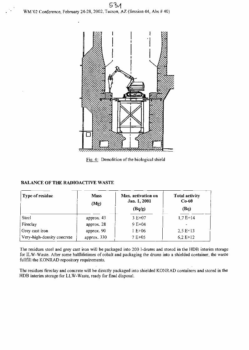
WM'02 Conference, February 24-28, 2002, Tucson, AZ (Session 44, Abs # 40)
XXXXXXXXXXN\XXNXXXXXXXX\XXXXX\\XX
Fig. 4: Demolition of the biological shield
BALANCE OF THE RADIOACTIVE WASTE
Type of residue
Steel
FireclayGrey cast ironVery-high-density concrete
Mass
(Mg)
approx. 43approx. 28approx. 90
approx. 330
Max. activation onJan. 1, 2001
(Bq/g)
3 E+079E+041 E+067E+05
Total activityCo-60
(Bq)
1.7E+14-
2,5 E+136,2 E+12
The residues steel and grey cast iron will be packaged into 200 1-drums and stored in the HDB interim storagefor ILW-Waste. After some halflifetimes of cobalt and packaging the drums into a shielded container, the wastefullfill the KONRAD repository requirements.
The residues fireclay and concrete will be directly packaged into shielded KONRAD containers and stored in theHDB interim storage for LLW-Waste, ready for final disposal.
rr
Concept for Dismantling the Reactor Vessel and theBiological Shield of the Compact Sodium-cooled
nuclear reactor facility (KNK)
Wolfgang PfeiferIris Hillebrand
Forschungszentrum Karlsruhe GmbH(Research Center Karlsruhe)
IAEA. M*ch 2002.PP1
rr
The Decommissioning Projects of theKarlsruhe Research Center
Niederaichbach NuclearPower Station
IAEA, M*rch XXI eft
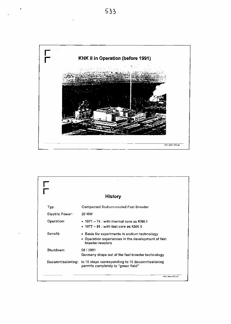
rr KNKII in Operation (before 1991)
IAEA, March 2002.ppt
rr
Typ:
Electric Power:
Operation:
Benefit:
Shutdown:
History
Compacted Sodium-cooled Fast Breeder
20 MW
• 1971 - 74 : with thermal core as KNK I• 1977 - 91 : with fast core as KNK II
• Basis for experiments in sodium technology• Operation experiences in the development of fast
breeder reactors
08/1991Germany drops out of the fast breeder technology
Decommissioning: In 10 steps corresponding to 10 decommissioningpermits completely to "green field"
IAEA.M*ch 1002 p
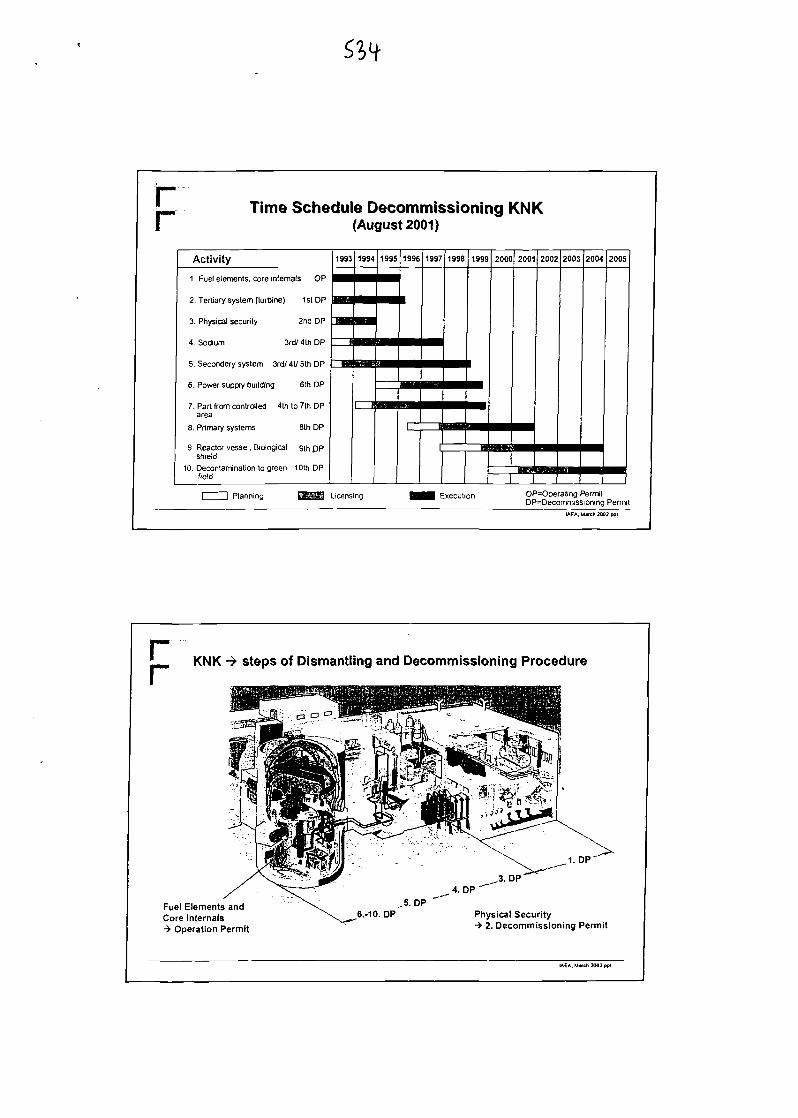
rr Time Schedule Decommissioning KNK(August 2001)
Activity 1 1993 1 1994 1 1995 [ 1996
1 . Fuel elements, core internals OP
2. Tertiary system (turbine) 1st DP
3. Physical security 2nd DP
4. Sodium 3rd/ 4th DP
5. Seconder/ system 3rd/ 4t/ 5th DP
6. Power supply building 6th DP
7. Part from controlled 4th to 7th DParea
8. Primary systems 8th DP
9. Reactor vessel. Biological gth DPshield
10. Decontamination to green 10th DPfield
ra
1997
zn
1998
^
1999
am
2000
••
2001
••
=y— r"1
2002
^
2003
mm
2004
Mi
2005
^
Planning Licensing i Execution OP=Operaiirtg PermitDP=Deconrvnissioning Permit
IAEA.Mwch2002.ppl
KNK -> steps of Dismantling and Decommissioning Procedure
Fuel Elements andCore Internals-> Operation Permit
1. DP"
Physical Security-> 2. Decommissioning Permit
IAEA. Match 2002 ppt
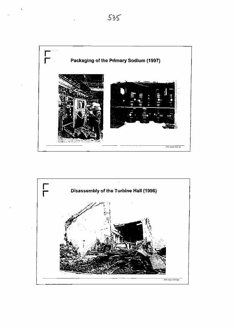
rr Packaging of the Primary Sodium (1997)
IAEA. March 2002 pp I
rr Disassembly of the Turbine Hall (1998)
IAEA. Mwcfi 2002 pot

r Work under the 8th Decommissioning Permit
Removal of theupper ceiling(02/00)
Disassembly oftheprimary cell(10/00)
Removal of thelower ceiling(02/01)
Dismantling of thedump tank(03/01)
+ 4,00 m
Dismantling of therotating lid(Planning 12/01)
- 8,60 m
IAEA. Mwch 2002. ppi
rr Break through the Wall to the Primary Purification Cell
(07 / 2000)
IAEA. March 2002 ppl
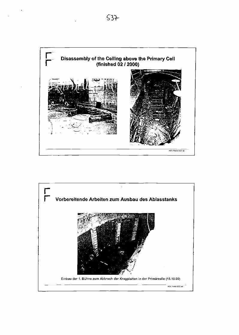
' Disassembly of the Ceiling above the Primary CellI (finished 02 / 2000)
IAEA. March 2002.ppt
1 Vorbereitende Arbeiten zum Ausbau des Ablasstanks
Einbau der 1. Biihne zum Abbruch der Kragplatten in der Primarzelle (16.10.00)
LftEA. M«cn 2002 ppt
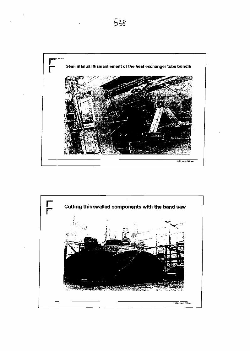
Semi manual dismantlement of the heat exchanger tube bundle
IAEA.Mvch2002.ppt
rr Cutting thickwalled components with the band saw
IAEA, Mwch 2002 .ppi
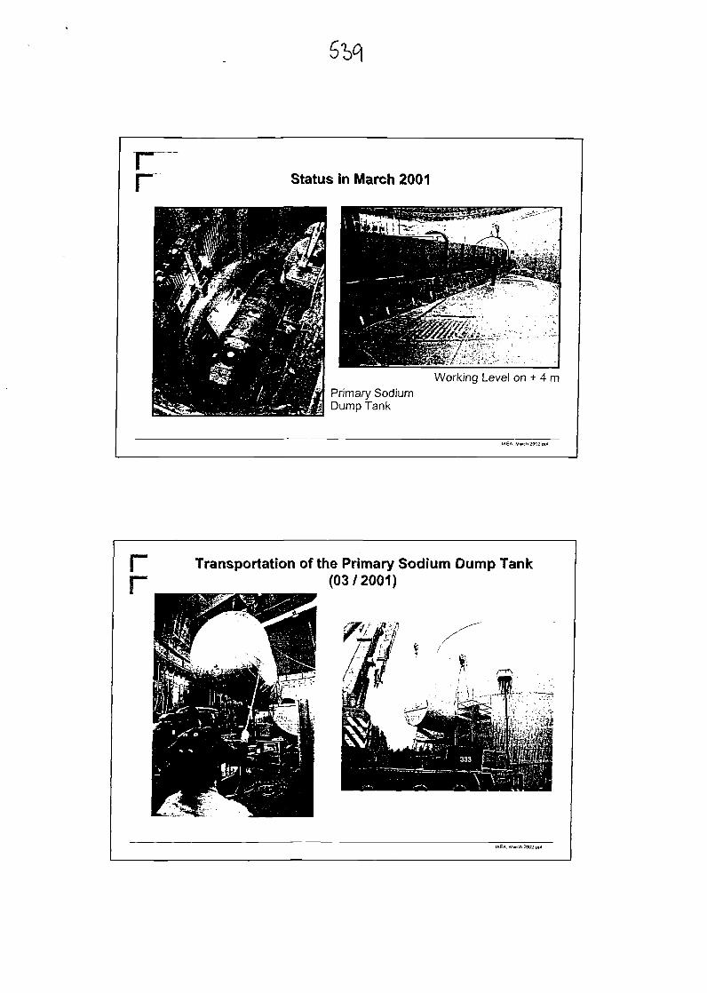
rr Status in March 2001
Working Level on + 4 mPrimary SodiumDump Tank
IAEA. March 2002.pp(
[""" Transportation of the Primary Sodium Dump Tank|— (03/2001)
IAEA. Match ?002.ppi

Rotating Lid during Tests .... during Assembly
IAEA. March 2002.ppl
rr Concept for Dismantling of the Reactor Vessel Lid
IAEA. Mwch 2002 ppl
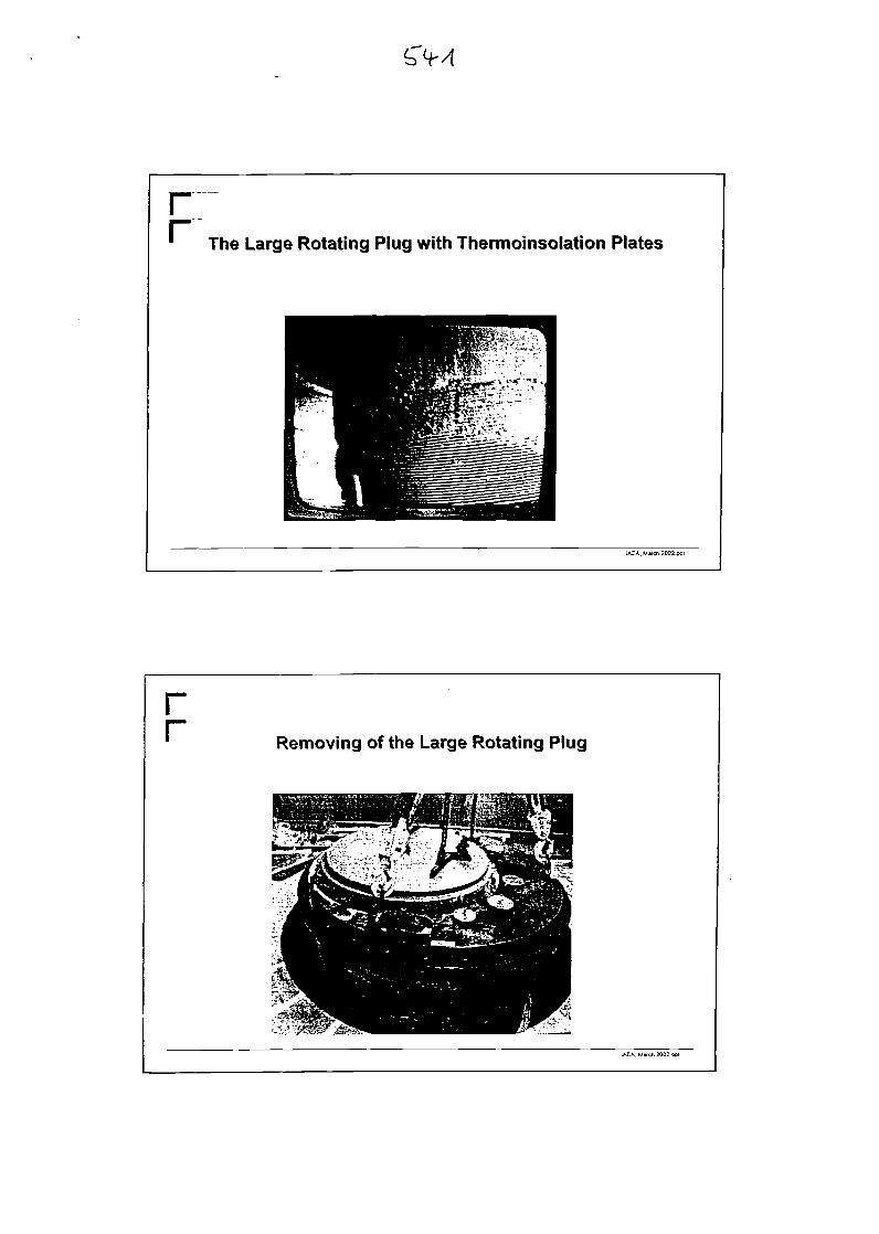
The Large Rotating Plug with Thermoinsolation Plates
IAEA. March 2QQ2.ppl
rr Removing of the Large Rotating Plug
IAEA. March 2002 ppt
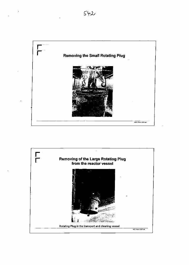
rr Removing the Small Rotating Plug
IAEA, M«rch 2002 ppl
rr Removing of the Large Rotating Plug
from the reactor vessel
Rotating Plug in the transport and cleaning vesselIAEA. March 2002.ppl
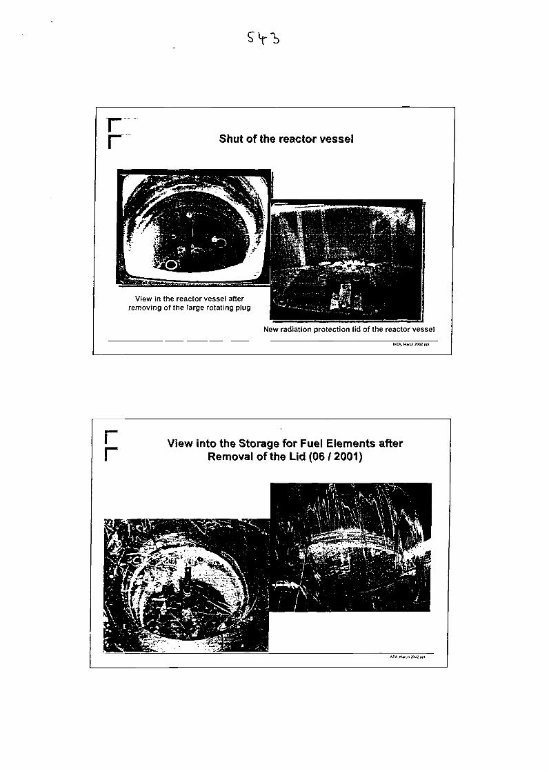
rr Shut of the reactor vessel
View in the reactor vessel afterremoving of the large rotating plug
New radiation protection lid of the reactor vessel
IAEA. March 2002
rr View into the Storage for Fuel Elements after
Removal of the Lid (06 / 2001)
IAEA. M«ch 2002 pp(
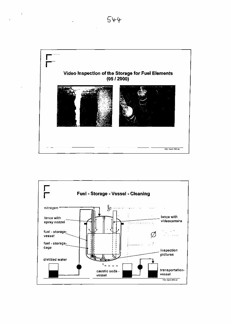
Video Inspection of the Storage for Fuel Elements(05/2000)
IAEA. March 2002 ppl
rr Fuel - Storage - Vessel - Cleaning
nitrogen
lance withspray nozzel
fuel - storagevessel
fuel - storagecage
distilled water
lance withvideocamera
inspectionpictures
transportation-vessel
IAEA. M»ch 2002.ppl
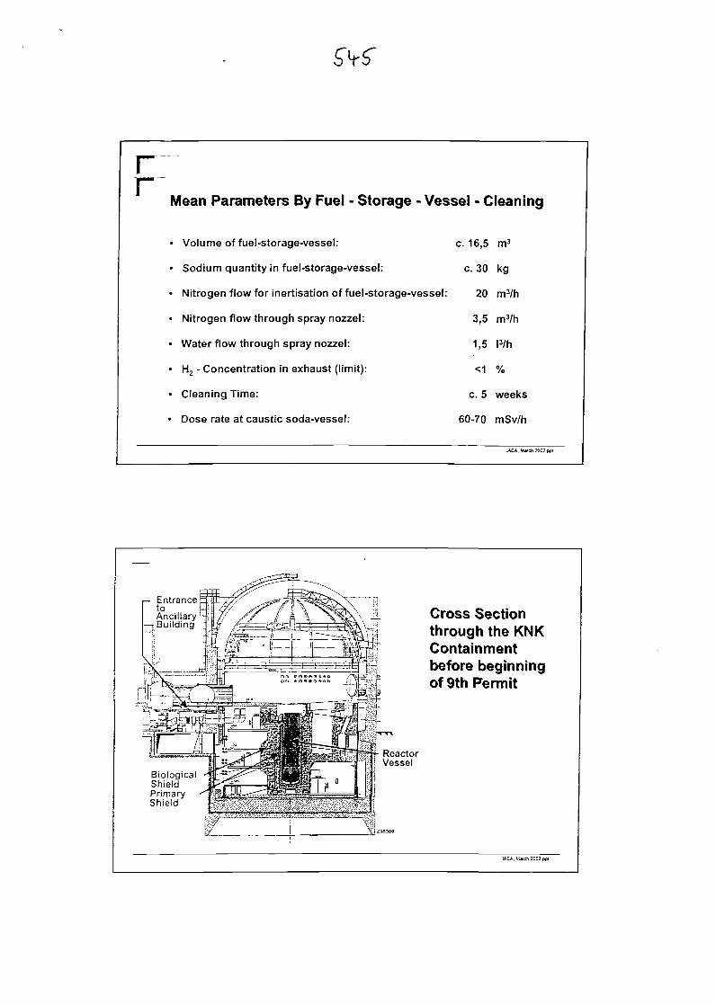
rrMean Parameters By Fuel - Storage - Vessel - Cleaning
• Volume of fuel-storage-vessel: c. 16,5 m3
• Sodium quantity in fuel-storage-vessel: c. 30 kg
• Nitrogen flow for inertisation of fuel-storage-vessel: 20 m3/h
• Nitrogen flow through spray nozzel: 3,5 m3/h
• Water flow through spray nozzel: 1,5 !3/h
• H2 - Concentration in exhaust (limit): <1 %
• Cleaning Time: c. 5 weeks
• Dose rate at caustic soda-vessel: 60-70 mSv/h
IAEA. Mwch 2002 ppl
r— EntrancetoAncillaryBuilding
Cross Sectionthrough the KNKContainmentbefore beginningof 9th Permit
ReactorVessel
BiologicalShieldPrimaryShield
IAEA. Mwch 2002 ppt
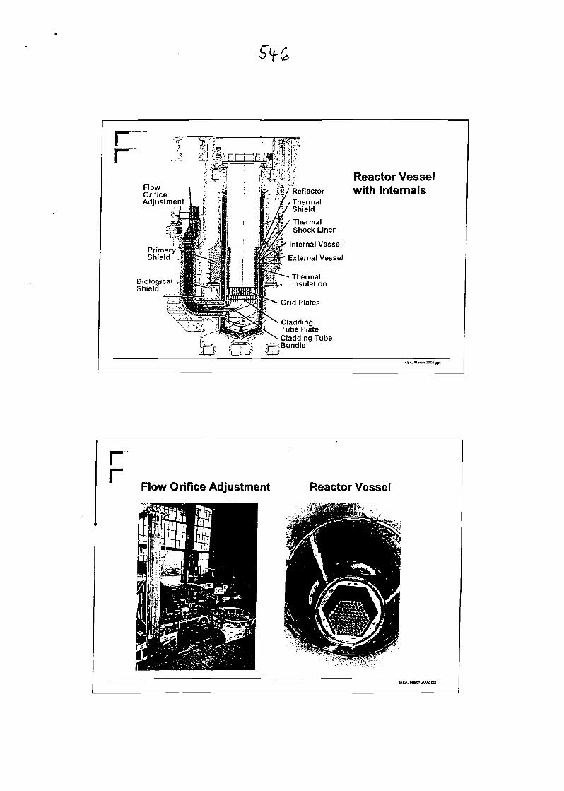
rr
FlowOrificeAdjustment
PrimaryShield
BiologicalShield
-«r~J |
t IJ4 r
0£=F
^ ReflectorThermalShield
ThermalShock Liner
Internal Vessel
External Vessel
ThermalInsulation
Grid Plates
CladdingTube PlateCladding Tube
jBundle
Reactor Vesselwith Internals
rrFlow Orifice Adjustment Reactor Vessel
IAEA. March 2002 ppl

rr
Individually Problems
• Sodium
"""" no wet or thermic cutting methods
• Fast Neutronsactivation up to a depth of 1.5 m
remoted-controlled disassembly of large parts
of the biological shield is neccessary
IAEA, March 2002.ppt
rr
Dose rate in the middle umm+ 55 Sv/hof the Vessel
(measured in April 1997)
The Design of the Enclosure has to consider theDose rate of 1 drum with parts of the Reflectordirectly behind the Shield
• DR (0,5 m) = 3 uSv/h and ""•• 35 cm steel• DR (2 m) =1 uSv/h
IAEA. March 2002 ppi
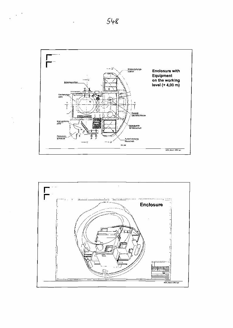
rr
Entdeckelungs-;tation Enclosure with
Equipmenton the workinglevel (+ 4,00 m)
IAEA. M*ch 2002.ppl
rEnclosure
IAEA. March 2002 pp(
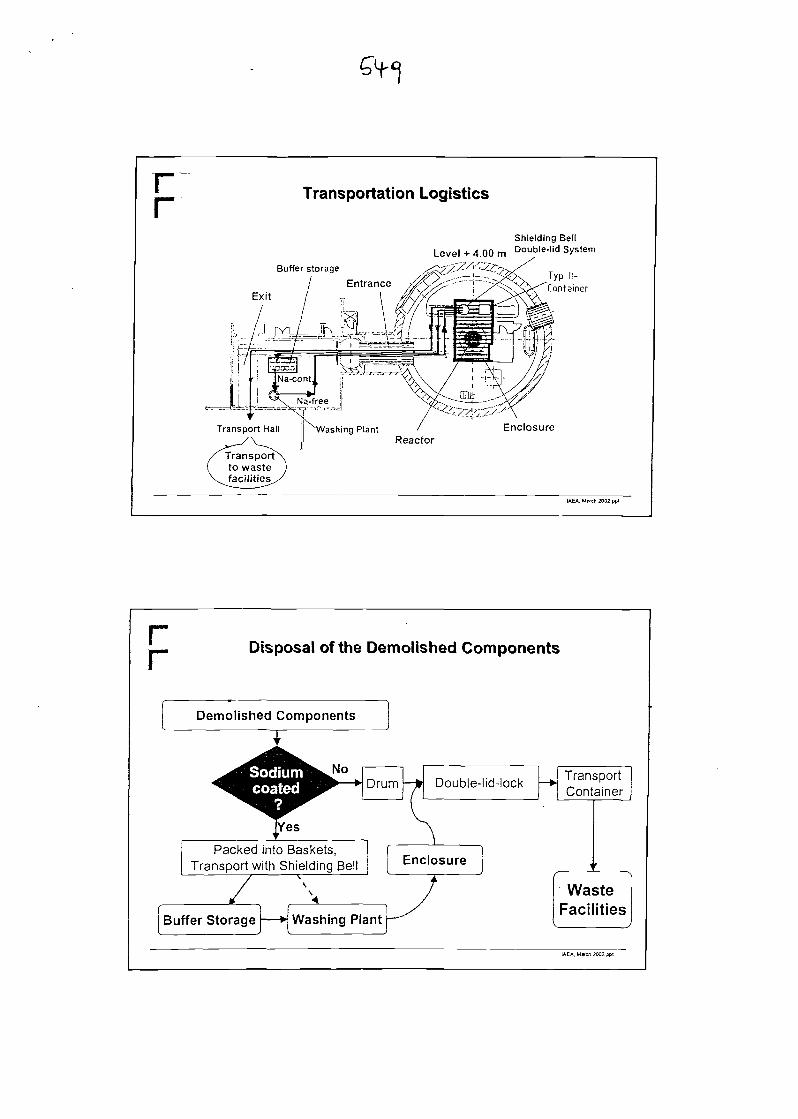
rr Transportation Logistics
Buffer storage
Exit
Shielding BellLevel + 4.00 m Double-|id System
Typ II-Container
Enclosure
IAEA. March 2002.pp!
rr Disposal of the Demolished Components
Demolished Components
WasteFacilities
IAEA. M»eh 2002.ppt
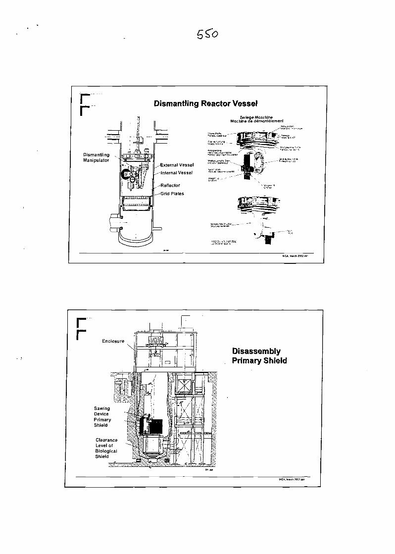
rr Dismantling Reactor Vessel
Dismantling ,Manipulator
Zerlege MaschlneMachine ae demantelement
External Vessel
-Internal Vessel
Reflector
Grid Plates
IAEA. M»ch 2002.PP1
rr Enclosure
ClearanceLevel ofBiologicalShield
DisassemblyPrimary Shield
IAEA. Mvch 2002 ppl
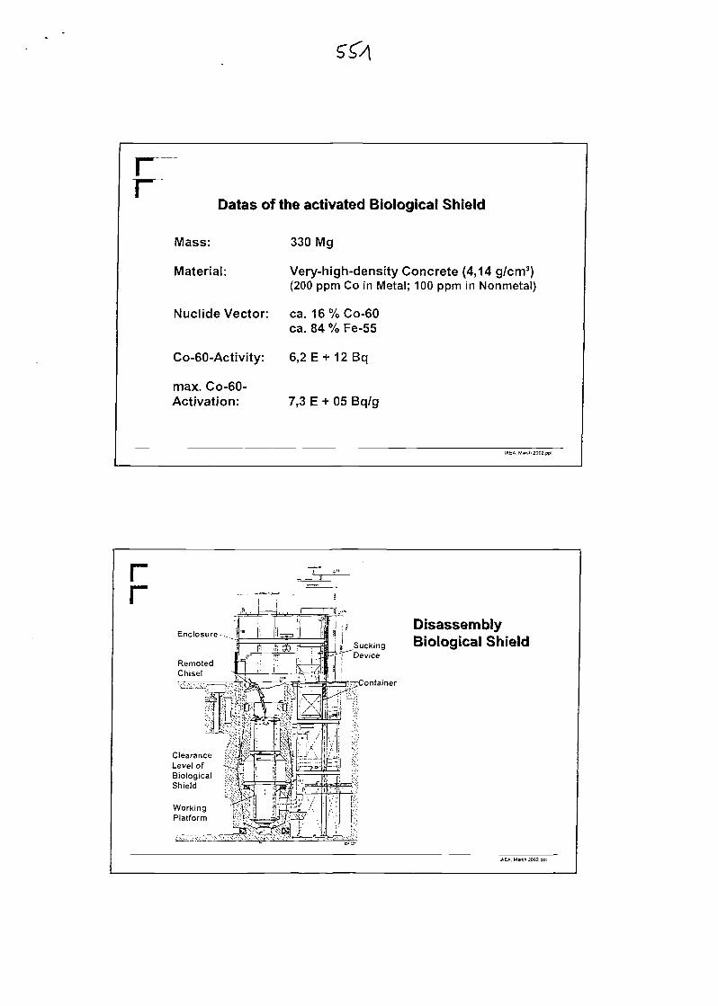
rr
Datas of the activated Biological Shield
Mass:
Material:
Nuclide Vector:
max. Co-60-Activation:
330 Mg
Very-high-density Concrete (4,14 g/cm3)(200 ppm Co in Metal; 100 ppm in Nonmetal)
ca. 16%Co-60ca. 84 % Fe-55
Co-60-Activity: 6,2 E + 12 Bq
7,3 E + 05 Bq/g
IAEA, M»fch2002.ppt
rr
Enclosure -
RemotedChisel
ClearanceLevel ofBiologicalShield
DisassemblyBiological Shield
IAEA. March 2002.ppl
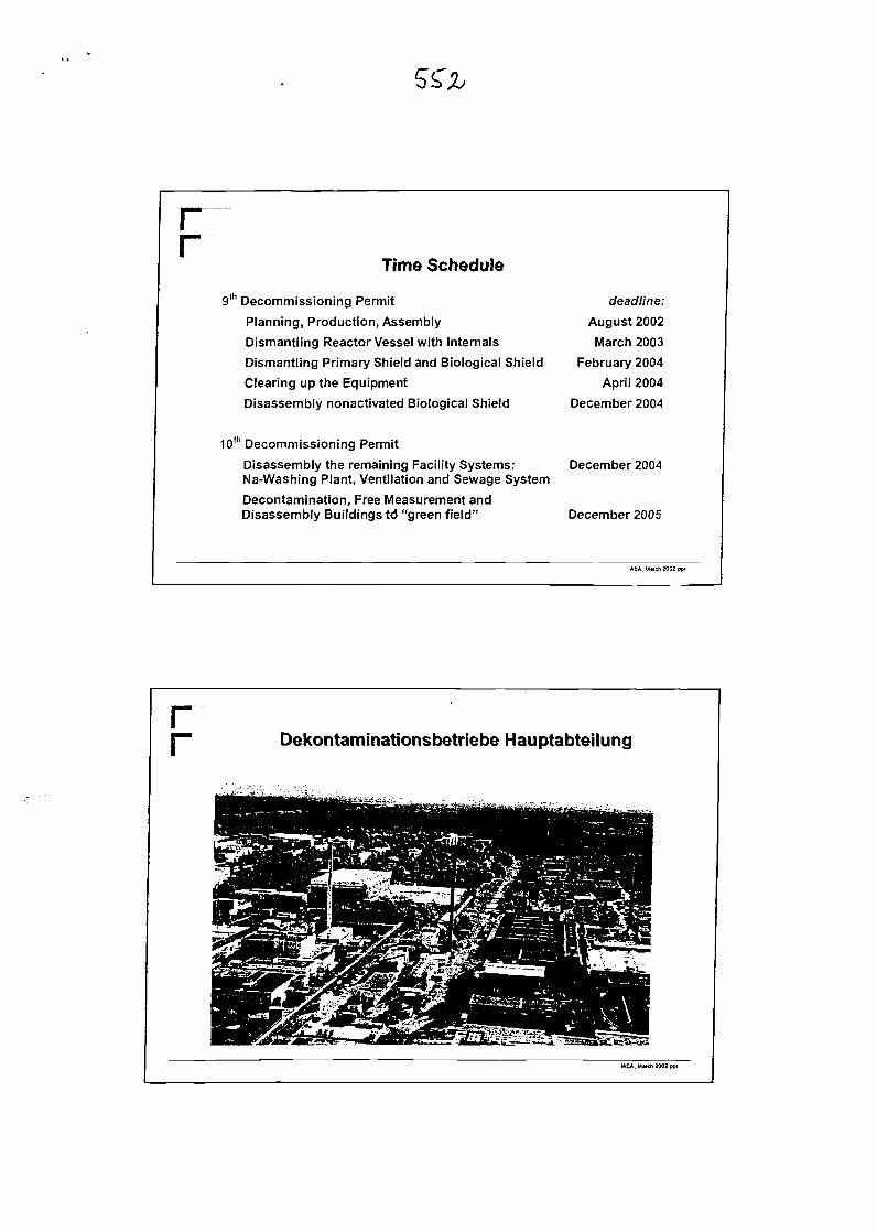
rTime Schedule
9th Decommissioning Permit
Planning, Production, Assembly
Dismantling Reactor Vessel with Internals
Dismantling Primary Shield and Biological Shield
Clearing up the Equipment
Disassembly nonactivated Biological Shield
10th Decommissioning Permit
Disassembly the remaining Facility Systems:Na-Washing Plant, Ventilation and Sewage System
Decontamination, Free Measurement andDisassembly Buildings td "green field"
deadline:
August 2002
March 2003
February 2004
April 2004
December 2004
December 2004
December 2005
IAEA. March 2002 ppl
rr Dekontaminationsbetriebe Hauptabteilung
IAEA. Mwch 2002.ppt
r Radioactive Waste Processing Paths
preliminarytreatment
nburnable | {burnable burnable ( |_ unburnable
;^ ^ . heated !nonne.ited 1
" ' ;...* waste'... Ill- ' w a s t e - 1
Repository GORLEBEN -4 > ' *• Repository KONRAD
IAEA, M»ch 2002.ppl
rr Further Treatment of the Waste
Reactor Vessel/ Primary Shield ^•Thermal insulation / Bio.shield
ca. 300 pieces200-l-drums
Waste Facilities
ILW-Interim Storage
\Packed into final
disposal containers Repository
KONRAD ?
ca. 100 piecesKONRAD -Typ It-
containers
Waste Facilities
LLW-Interim Storage
IAEA, March 2002 p
rr
Summary of the Waste under the 9th Permit
Components
Reaktor Vessel
Thermal Insulation
Primary Shield
Biological Shield
Type of residue
Steel
Fireclay
Cast Iron
Very-high-densityConcrete
Mass(Mg)
43
28
90
330
Total activityCo-60(Bq)
1.7E + 14
2.6E + 11
2.5E + 13
6.2E + 12
IAEA. March 2002-ppl
rr HDB-Abfalllager (Bau 526)
IAEA. Mtrch 2002.ppl
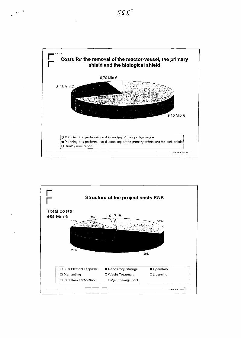
* Costs for the removal of the reactor-vessel, the primaryI shield and the biological shield
3,48Mio€
0,70Mio€
9,15 Mio€
D Planning and performance dismantling of the reactor-vessel• Planning and performance dismantling of the primary shield and the biol. shield
j D Quality assurance
IAEA. M»cn 2002 ppl
rrTotal costs:464 Mio €
10%
28%
Structure of the project costs KNK
7%1% 1% 1%
32%
20%
D Fuel Element Disposal
D Dismantling
LJ Radiation Protection
• Repository Storage
D Waste Treatment
D Projectmanagement
• Operation
D Licencing
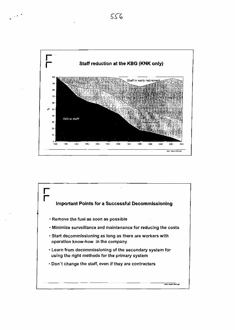
rr Staff reduction at the KBG (KNK only)
1990 1991 1992 1993 1994 1995 1996 1997 1996 1999 2000 2001 2OD2
IAEA. M«rch 2002 ppl
rr
Important Points for a Successful Decommissioning
• Rerhove the fuel as soon as possible
• Minimize surveillance and maintenance for reducing the costs
• Start decommissioning as long as there are workers withoperation know-how in the company
• Learn from decommissioning of the secondary system forusing the right methods for the primary system
• Don't change the staff, even if they are contracters
IAEA. March 2002.ppi

International Atomic Energy AgencyTechnical Meeting on
"Feedback from Operational and Decommissioning Experience with Fast Reactors"CEA Cadarache, France
Il-15march2002
CEA EXPERIMENTAL FEEDBACK ON SODIUM LOOP DECOMMISSIONING
O. VINOCHE, G. RODRIGUEZCEA/DEN/DER/STR 13 108 Saint Paul Lez Durance, France
ABSTRACTThe aim of this paper is to present experimental feedbackon sodium loop dismantling techniques at the CEA (TheFrench Atomic Energy Commission) and to offerrecommendations for the decommissioning of FastReactor secondary sodium loops.This study is based on acquired CEA decommissioningexperience which primarily concerns the following: thedecommissioning of RAPSODIE (France's first FastReactor), the PHENIX reactor secondary loopreplacement, the sodium loop decommissioning carriedout by the Laboratory of Sodium Technologies andTreatment, and several technical documents. This paperdeals with the main results of this survey.First, a comparison of 8 pipe-cutting techniques is made,taking into account speed in cutting, reliability,dissemination, fire risk due to the presence of sodium,cutting depth, and different types of waste (empty pipes,sodium-filled pipes, tanks...). This comparison has led usto recommend the use of an alternative saw or a chainsaw rather than the use of the plasma torch or grinder.Different techniques are recommended depending on ifthey are on-site, initial cuttings or if they are to be carriedout in a specially-designed facility referred to hereafter as"the cutting building".After the cutting stage, the sodium waste must beprocessed with water to become an ultimate stable waste.Four treatment processes are compared with differentstandards : speed, cost, low activity adaptability and"large sodium quantity" adaptability.Recommendations are also made for reliable storage, andfor the general dismantling system organization.Last, calculations are presented concerning a completedismantling facility prototype capable of treating largeamounts and volume of sodium wastes.
INTRODUCTIONSodium is primarily used in the nuclear industry as acoolant in primary and secondary loops of Liquid MetalFast Reactors. Several LMFRs will be shut down incoming years, and thus many sodium loops will have tobe decommissioned. Metal sodium is forbidden in bothactive and inactive waste for storage because it cannot beconsidered as ultimate waste: sodium reacts when cominginto contact with water and air, and therefore must beprocessed to become a chemically stable product Inorder to accomplish this transformation, a specificprocess must be applied using a reagent In most cases,this reagent is water. All waste components containing
sodium must be cut into reduced parts, and disposed insuch a way that the sodium itself can be treated.All these operations have been conducted at the CEA onseveral LMFR loops including RAPSODIE (the firstLMFR in France) and the PHENIX reactor but also onsome experimental loops. The aim of this document is topresent and assess the experimental feedback in this fieldin order to establish the general organization of a sodiumloop decommissioning system, and to determine what arethe most efficient techniques to be implemented whendealing with the very specific characteristics of sodium.
GENERAL ORGANIZATION SYSTEM [1J [2J
PRELIMINARY STAGES1. Emptying of the loop2. Estimation of the residual mass of sodium
(inspection, calculation...)3. Electricity dismantling4. Removal of the insulating material/Instruments
Long .period heated insulating material can becomepulverulent. In that case, insulating material andiron sheet should be dismantled in the same time.The system is then isolated from premises andventilated. Insulating material is wrapped intovinyl.
SYSTEM MAIN STAGES
On -site cutting
First storage
Cutting in specified building
Second storage uProcessing installation |
Final storage
A dismantling procedure is written before eachdismantling system is established. It describes thedismantling chronology and the steps of the system.
1. General view of the loop before operations 2. Removal of the insulating material 3. Removal of the instruments
4. Reciprocating saw cutting 5. General view after decommissioning
Fig. 1 Several pictures of a dismantling system (EPINAR test loop)
First, the cutting lines are drawn on the loop with themaximal precision, or marked on a plan. Pipes areattached to the existent frame by temporary hoists toavoid falls during the cutting operations. As in themajority of the dismantling operations, the risk of a fallby either the equipment or a worker is high. v
Experimental feedback from CEA sodium loopdismantling operations has clearly demonstrated that thisis the major risk, far beyond that of the hazards involvedin handling the sodium.
CUTTING STAGE [3] [3]Pipe and component cutting is necessary to allow athorough treatment of the residual sodium which iscarried out according to a special process. The number ofcuts to be made, and the geometrical configuration of thewaste are determined by the treatment process which isselected much sooner. In every large-scaledecommissioning work site studied, the cutting stage wasdivided into two phases : an initial, on-site cutting wascarried out on the loop using portable tools in order toextract long pipes and components. Then, the secondcutting phase was conducted inside a specially-designed"cutting building". This type of organization presents amajor advantage because it allows workers to handlelarge quantities of waste in a specifically-designedstructure, and not next to the loop itself where space andthe maneuverability of handling tools are limited.Components are systematically moved to the cuttingbuilding except tanks which are cut on-site into reducedparts. Only long parts of pipes are cut on-site, and entryand exit component pipes. 4 meters is the average lengthof the pipe parts that are removed and transferred to thecutting building.
This average depends on handling tools and accessibility.The cutting stage can be tricky when dealing with thevariable pipe lengths and diameters, and with thediversity of the components (pumps, gauges, valves, coldtraps...). Different tools may be used but they must meetseveral criteria : reliability, speed, cutting depth, lowsecondary emission, reduced sodium heat risk.Lubrification must be as low as possible to avoidsecondary effluent emission.Carbonation is recommended for large scale loops, inorder limit the sodium risk. The small size of the loops atthe CEA does not justify using this technique.Sodium loop cutting can be divided into successive steps.Components and pipes are bound to avoid falls,vibrations during cutting and saw blade jamming. Cuttingstarts with the upper parts of the loops in order to limitfalls.Metallic chips resulting from the sawing must beretrieved. These chips are to be classified in the samecategory as sodium waste and they too must beprocessed. Components with a complex internal structure(e.g. cold traps) are not drained if possible, because solidsodium keeps the internal structure in place and limitsvibration and overheating during cutting operations.The main cutting techniques used in the industry havebeen compared with a relative notation system for eachcriteria from 0 to 5. Estimations have been realized formissing data. Results for each techniques have then beencompared for different waste families (small size massivecomponents, variable diameters pipes, tanks). Thesetechniques are the following :
• Reciprocating saw• Band saw• Grinder
Plasma torchCircular sawHydraulic shearsNibbling machinePipe cutter
This comparison reveals that mechanical cuttingtechniques are preferable. Thermal techniques are fasterfor stainless steel cutting but slower for sodium cutting.Moreover, thermal techniques heat up the sodium (aneutral gas is then necessary to avoid burning) andpresent a dissemination risk when dealing with activesodium.The main recommended cutting techniques for a sodiumdecommissioning loop system are set down in thefollowing tables. These results take into account all thecriteria studied.
On-site cuttingResults for on-site cutting are given in the table below:
Componentfamily
Low diameter pipe(DN 25 maxi)
Cylindricalcomponent (no
internal structure)(DN 500 maxi)
High diameterpipes (DN 2200
maxi)
Mostefficient
technique
Portableband saw
Portableband saw
Circular saw
Breakdown tools
Reciprocating portablesaw
Hydraulic shearsPipe cutter
Nibbling machineReciprocating portable
sawHydraulic shears
Pipe cutterNibbling machine
Pipe cutler
Cutting in a specified building
Componentsfamily
Small size massivecomponents (200 x
200 maxi)
Low diameter pipe(DN 25 maxi)
Cylindricalcomponent (no
internal structure)(0 500 mm maxi)
Cylindricalcomponent
(internal structure)(01 500 maxi)
High diameterpipes (0 2200
maxi)
Mostefficient
technique
Band saw
Complementarytechnique
Reciprocating saw
Reciprocating sawNibbling machine
Reciprocating sawNibbling machine
Reciprocating sawCircular saw + diamond
cable
Nibbling machineReciprocating saw
Circular saw
TEMPORARY STORAGEStorage before cutting in a specified building and storagebefore treatment should be limited, if achievable, to oneworkday maximum so that the systematic use of a waste
container can be avoided (neutral gas is necessary). Thisstorage can be safe at ambient air temperature providingthe humidity is restricted to limit reactions at 2.5 gramsof water for 1 kg of air.During on-site cutting, the pipe parts are isolated withvinyl and tape, or with soldered steel. Pipe parts canthereby be moved quite safely to the cutting building.Metallic containers filled with neutral gas should beavailable for potential longer storage (more than oneweek) or for a halt of the works. In case of long storage,the neutral gas of the containers is renewed every 3months.
SODIUM TREATMENT PROCESSES [5] [6]The purpose of the process consists in turning sodiuminto a stable product vis a vis water and air. This processmust be efficient, adjustable (it must be applicable to allsodium loop constituents), reliable and sufficiently quick.Moreover, researchers must be able to check effluentcomposition and activity.Processes approved for sodium treatment are waterchemical methods. Alcohol is forbidden by the CEAsince an accident occurred during the decommissioningof the RAPSODIE reactor in 1994 [7] [8]. Physicalcleaning methods (e.g. scraping, evaporation) are morelimited at an industrial scale due to their relativelytedious nature.
General diagram of a water sodium waste treatmentprocess:
Water
Pipe Lsections "
(contaminated) •T ream en t
process
J Metallic'\ waste
Sodium Hydrogen +hydroxide neutral gas
(contamined) (+ tritium)
Fig. 2 Water treatment process diagram
Solid sodium treatment with water is carried outaccording to the reaction :
Na .did + H2O25°C
= NaOH +l/2H2 g M+ 138 kJanhydrid crbUllised 2S°C 2S°C eiolhennlc
NaOH + H20 e«ss = NaOH, H2O tvmm «,!„*»
With an excess of water a solution of sodium hydroxideis produced. This solution can then be transformed into achemically stable and solid waste, by cementation orceramisation process. Hydrogen must be dehumidifiedand evacuated after radioactive control in case of activesodium.Water can be projected as a liquid jet, as fog, or as vapor.Treatment speed differs according to the selected processbut the chemical reaction and the effluents are the same(sodium hydroxide and hydrogen). The main precautionto be taken to prevent hydrogen risk is to work underneutral gas. The explosive O2-H2 mixture is thus avoided.In the case of the process under air, a special study shouldbe carried out to assess the capacity of an armoredstructure in withstanding a fixed and known explosive
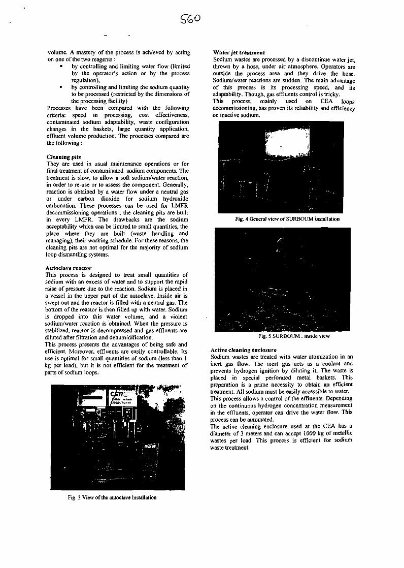
volume. A mastery of the process is achieved by actingon one of the two reagents :
• by controlling and limiting water flow (limitedby the operator's action or by the processregulation),
• by controlling and limiting the sodium quantityto be processed (restricted by the dimensions ofthe processing facility)
Processes have been compared with the followingcriteria: speed in processing, cost effectiveness,contaminated sodium adaptability, waste configurationchanges in the baskets, large quantity application,effluent volume production. The processes compared arethe following:
Cleaning pitsThey are used in usual maintenance operations or forfinal treatment of contaminated sodium components. Thetreatment is slow, to allow a soft sodium/water reaction,in order to re-use or to assess the component. Generally,reaction is obtained by a water flow under a neutral gasor under carbon dioxide for sodium hydroxidecarbonation. These processes can be used for LMFRdecommissioning operations ; the cleaning pits are builtin every LMFR. The drawbacks are the sodiumacceptability which can be limited to small quantities, theplace where they are built (waste handling andmanaging), their working schedule. For these reasons, thecleaning pits are not optimal for the majority of sodiumloop dismantling systems.
Autoclave reactorThis process is designed to treat small quantities ofsodium with an excess of water and to support the rapidraise of pressure due to the reaction. Sodium is placed ina vessel in the upper part of the autoclave. Inside air isswept out and the reactor is filled with a neutral gas. Thebottom of the reactor is then filled up with water. Sodiumis dropped into this water volume, and a violentsodium/water reaction is obtained. When the pressure isstabilized, reactor is decompressed and gas effluents arediluted after filtration and dehumidification.This process presents the advantages of being safe andefficient Moreover, effluents are easily controllable. Itsuse is optimal for small quantities of sodium (less than 1kg per load), but it is not efficient for the treatment ofparts of sodium loops.
Water jet treatmentSodium wastes are processed by a discontinue water jet,thrown by a hose, under air atmosphere. Operators areoutside the process area and they drive the hose.Sodium/water reactions are sudden. The main advantageof this process is its processing speed, and itsadaptability. Though, gas effluents control is tricky.This process, mainly used on CEA loopsdecommissioning, has proven its reliability and efficiencyon inactive sodium.
Fig. 4 General view of SURBOUM installation
Fig. 5 SURBOUM : inside view
Active cleaning enclosureSodium wastes are treated with water atomization in aninert gas flow. The inert gas acts as a coolant andprevents hydrogen ignition by diluting it The waste isplaced in special perforated metal baskets. Thispreparation is a prime necessity to obtain an efficienttreatment. All sodium must be easily accessible to water.This process allows a control of the effluents. Dependingon the continuous hydrogen concentration measurementin the effluents, operator can drive the water flow. Thisprocess can be automated.The active cleaning enclosure used at the CEA has adiameter of 3 meters and can accept 1000 kg of metallicwastes per load. This process is efficient for sodiumwaste treatment.
Fig. 3 View of the autoclave installation
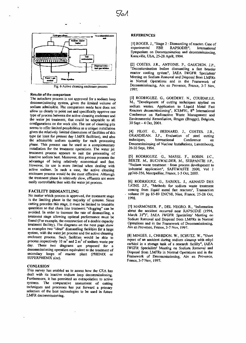
Fig. 6 Active cleaning enclosure process
Results of the comparisonThe autoclave process is not approved for a sodium loopdecommissioning system, given the limited volume ofsodium admissible. The comparison made here does notallow us clearly to point out and specifically approve onetype of process between the active cleaning enclosure andthe water jet treatment, that could be adaptable to allconfigurations on the work site. The use of cleaning pitsseems to offer limited possibilities as a unique installationgiven the relatively limited dimensions of facilities of thistype (at least for present day LMFR facilities), and alsothe admissible sodium quantity for each processingphase. This process can be used as a complementaryinstallation for the treatment operations. The water jettreatment process appears to suit the processing ofinactive sodium best. Moreover, this process presents theadvantage of being relatively economical and fast.However, its use is more limited when dealing withactive sodium. In such a case, the active cleaningenclosure process would be the most effective. Althoughthe treatment phase is relatively slow, effluents are moreeasily controllable than with the water jet process.
FACILITY DISMANTLINGNo matter which process is approved, the treatment stageis the limiting phase in the majority of systems. Sincecutting precedes this stage, it must be limited to treatablequantities so that chain line treatment "clogging" can beavoided. In order to increase the rate of dismantling, atreatment stage allowing optimal performance must befound (For example, the construction of a double capacitytreatment facility). The diagrams on the next page showas examples two "ideal" dismantling facilities for a largesystem, with the water jet process and the active cleaningenclosure process. Such facilities would be able toprocess respectively 10 m3 and 2 m3 of sodium waste perday. These two diagrams are proposed for adecommissioning operation equivalent to the treatment ofsecondary loops of reactor plant (PHENIX orSUPERPHENIX size).
CONLUSIONThis survey has enabled us to assess how the CEA hasdealt with its inactive sodium loop decommissioning.Furthermore, it has permitted an extrapolation to activesystems. The comparative assessment of cuttingtechniques and processes has put forward a primaryselection of the best technologies to be used in futureLMFR decommissioning.
REFERENCES
[1] ROGER. J., "Stage 2 : Dismantling of reactor. Case ofexperimental FBR RAPSODIE", InternationalSymposium on Decontamination and decommissioning,Knoxville, USA, 25-28 April, 1994.
[2] COSTES. J.R., ANTOINE. P., GAUCHON. J.P.,"Decontamination before dismantling a fast breederreactor cooling system", IAEA IWGFR Specialists'Meeting on Sodium Removal and Disposal from LMFRsin Normal Operations and in the Framework ofDecommissioning, Aix en Provence, France, 3-7 Nov1997.
[3] RODRIGUEZ. G., GOEDERT. N., COURNILLE.M., "Development of cutting techniques applied onsodium wastes. Application to Liquid Metal FastReactors decommissioning", ICEM'Ol, 8th InternationalConference on Radioactive Waste Management andEnvironmental Remediation, Bruges (Brugge), Belgium,30 Sept-4 Oct, 2001.
[4] PILOT. G., BERNARD. J., COSTES. J.R.,GRANDJEAN. J.P., Evaluation of steel cuttingtechniques, International Conference onDecommissioning of Nuclear Installations, Luxembourg,26-30 Sept, 1994.
[5] RODRIGUEZ. G., MASSE. F., ROBIN. J.C.,BERTE. M., BUCHWALDER. M., SERPANTIE J.P.,"Sodium waste treatment : from process development toindustrial application", SAFEWASTE 2000, Vol 1pp346-356, Montpellier, France, 1-5 Oct, 2000.
[6] RODRIGUEZ. G., SAROUL. J., ARNAUD DBSLIONS. J.P., "Methods for sodium waste treatmentcoming frorn liquid metal fast reactors", Transactionvolume IV pp 85-89 ENC98, Nice, France, 25-28 Oct,1998.
[7] MARMONIER. P., DEL NEGRO. R., "Informationabout the accident occurred near RAPSODIE (1994,March 31st)", IAEA IWGFR Specialists' Meeting onSodium Removal and Disposal from LMFRs in NormalOperations and in the Framework of Decommissioning,Aix en Provence, France, 3-7 Nov, 1997.
[8] MINGES. J., CHERDON. W., SCHUTZ. W., "Shortreport of an accident during sodium cleanup with ethylcarbitol in a storage tank of a research facility", IAEAIWGFR Specialists' Meeting on Sodium Removal andDisposal from LMFRs in Normal Operations and in theFramework of Decommissioning, Aix en Provence,France, 3-7 Nov, 1997.
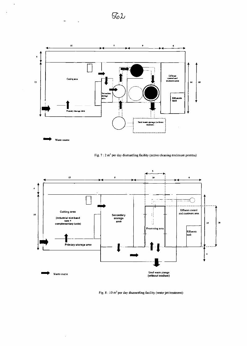
Waste course
Fig. 7 : 2 m3 per day dismantling facility (active cleaning enclosure process)
IS 9 10 6
DCutting area
(industrial size bandsaw*
complementary tools)
t
•
4 'r Primary storage area
Secondarystorage
area
I
__^__: ! i
Processing area
t I4 • *
Efflucand tre
ont controlatment area
Effluentstank
t
i
14
1
4
Waste course Steel waste storage(without sodium)
Fig. 8 : 10m3 per day dismantling facility (water jet treatment)
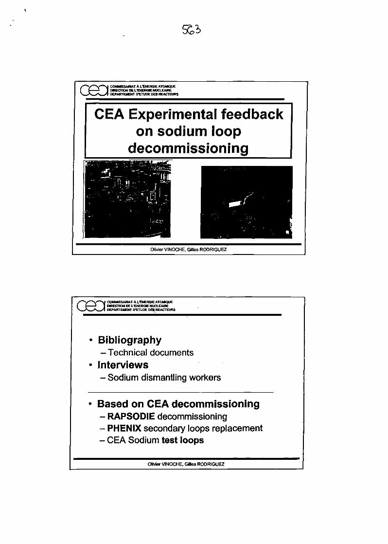
553
COMMISSARIAT A LtNERGIEATOMKJUENRECTONDEUENERCIENUCLEAfREDEPARTMENT D-ETUDEDESREACTEURS
CEA Experimental feedbackon sodium loop
decommissioning
Olivier VINOCHE, Gilles RODRIGUEZ
COMMISSARIAT A LtNERGIE ATOMK3UEDIRECTION DEL-EMERGENUCLEAIREDEPARTEMENT D'ETUDE OES REACTEURS
Bibliography-Technical documentsInterviews- Sodium dismantling workers
Based on CEA decommissioning- RAPSODIE decommissioning- PHENIX secondary loops replacement- CEA Sodium test loops
Olivier VINOCHE, Gilles RODRIGUEZ
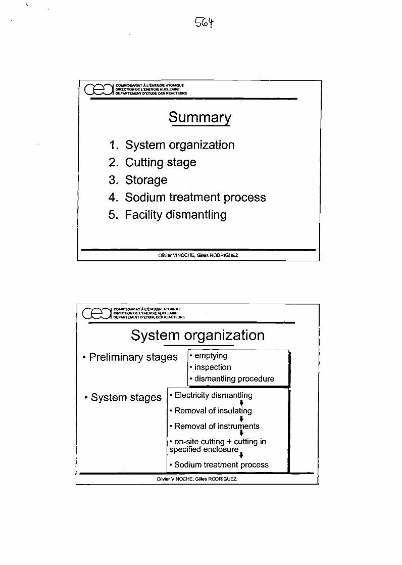
GSD COMMISSARIAT A t.'CNERGIE ATOMKXJEDIRECTION D6 LTNERGK NUCLEAKEDEPARTEMEHT D-ETUDE DES REACTEURS
Summary
1. System organization2. Cutting stage3. Storage4. Sodium treatment process5. Facility dismantling
Olivier VINOCHE. Gilles RODRIGUEZ
S~*/^**S~^i COMMISSARIAT A L'ENERGIEATOMKJUE( f J 1 OtRECnONOELTNERGIEt KXEAIRE\_A^^v»_^ D6PARTEMENT D^TU06 DES REACTEURS
System organization• Preliminary stag
• System stages
es • emptying• inspection• dismantling procedure
• Electricity dismantling
• Removal of insulating
*• Removal of instruments
• on-site cutting + cutting inspecified enclosure
• Sodium treatment process
Olivier VINOCHE, Gilles RODRIGUEZ
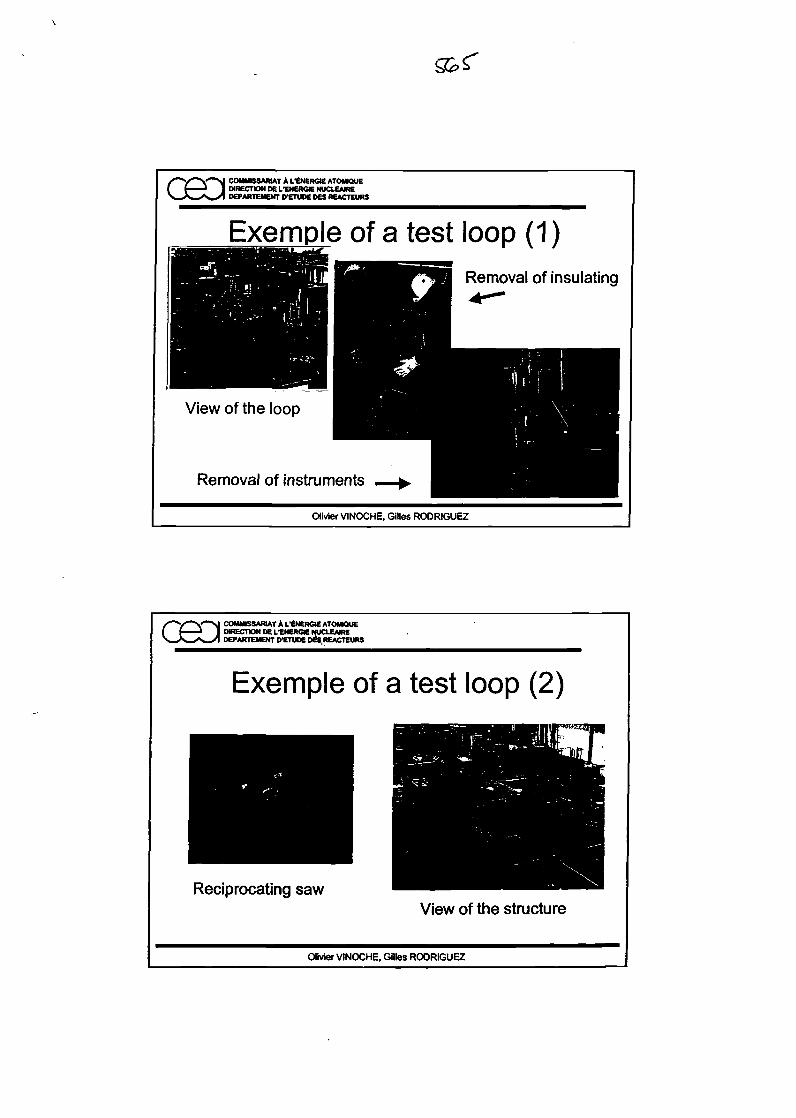
/'""V*~V*~M COMMISSARIAT A LtNERGlE ATOVK5UEI f 1 I DIRECTION DEL-ENEROE NUCLEATE
DEPARTEMENT D-ETUDE OES REACTEURS
Exemple of a test loop (1)Removal of insulating
View of the loop
Removal of instruments
Olivier VINOCHE. Gilles RODRIGUEZ
/"~V"V"->J COMMISSARIAT A fENERGMEATOMQUE( f J I DKECTIONIIEL'ENERGCNUCLEAIRE
DEPARTEMENT DTTUOE DC^REACTEURS
Exemple of a test loop (2)
Reciprocating sawView of the structure
Olivier VINOCHE. Gilles RODRIGUEZ
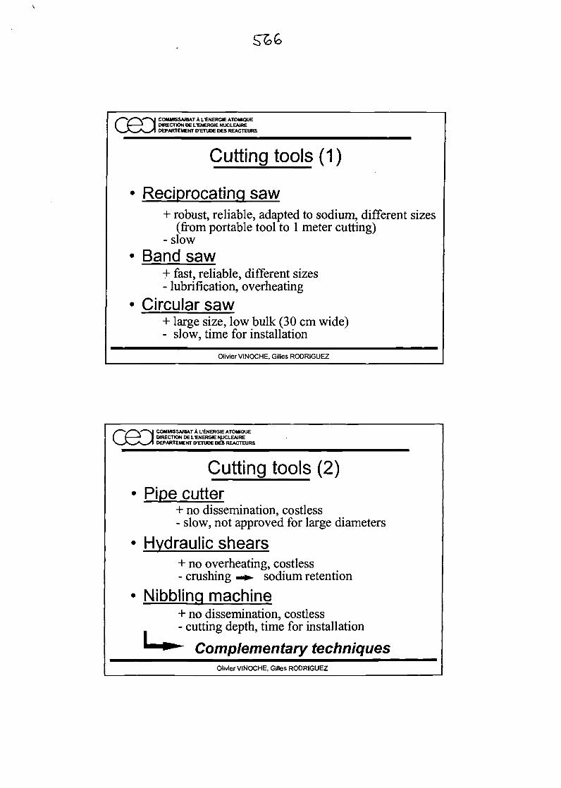
X""y""V"^ COMMISSARIAT A fENERGIEATOMKlUEI ( J I DIRECTION DE UENERGIE NUCLEATE
DEPARTEMENT PETUOE OES REACTEURS
Cutting tools (1)
Reciprocating saw+ robust, reliable, adapted to sodium, different sizes
(from portable tool to 1 meter cutting)- slow
Band saw+ fast, reliable, different sizes- lubrification, overheating
Circular saw+ large size, low bulk (30 cm wide)- slow, time for installation
Olivier VINOCHE, Gilles RODRIGUEZ
COMMISSARIAT A L-ENERGIEATOMIQUEDIRECTION D£ L-ENERGie HUCLEAIREDEPARTEMENT D'ETUDE DE5 REACTEURS
Cutting tools (2)Pipe cutter
+ no dissemination, costless- slow, not approved for large diameters
Hydraulic shears+ no overheating, costless- crushing -*- sodium retention
Nibbling machine+ no dissemination, costless- cutting depth, time for installation
Complementary techniquesOlivier VINOCHE, Gilles RODRIGUEZ
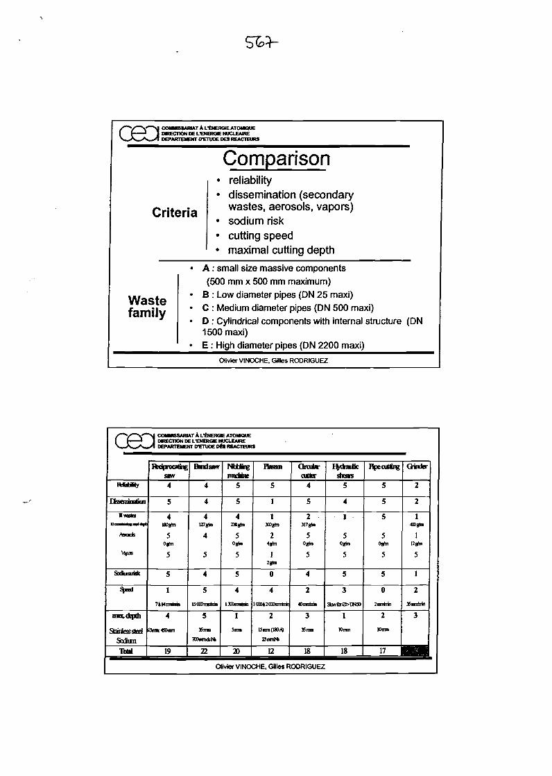
/"~V^V~>J COMMBSAMATAL'SNERGIEATOMWUEI 1 i I MRECTIONDEL'ENERGIENUCLEAIRE>W*»._^S_x1 DEPARTEMENTD'EniOEDESREACTEURS
Criteria
Wastefamily
Comparison• reliability• dissemination (secondary
wastes, aerosols, vapors)• sodium risk• cutting speed• maximal cutting depth
• A : small size massive components(500 mm x 500 mm maximum)
• B : Low diameter pipes (ON 25 maxi)• C : Medium diameter pipes (ON 500 maxi)• D : Cylindrical components with internal structure (DN
1500 maxi)• E : High diameter pipes (DN 2200 maxi)
Olivier VINOCHE, Gilles RODRIGUEZ
/"~V~V'~>J COMMISSARIAT A LtNERGIEATOMIQUE( (.I. il 1 DIRECTION DEL-ENERGIENOCLEAIREV^ - N-xl DEPARTEMENTD-ETUOEDitREACTEURS
Rebtiity
QsscnnatiGn
nrafcsBontitaaaliM
Ams*
\ipjs
Sadumifafc
*"•
m&LQQpOl
StarntesstedSodun
IbU
lu3 BU3UJ
saw4
5
4isogto
5Ogta
5
5
1
7iMmririn
4
0im«Dmn
19
Handsaw
4
4
4U7»ta
4
5
4
5
uooomntni
5
35 rrni
TOmnAf*
22
pwbuhnc
PHtlliM*
5
5
4238gta
5Oghi
5
5
4
I300mnkni
1
Sim
20
Items
5
1
1300ghl
24gin
1
0
4
OQOi2GODnnftni
2
15mn(U)W)
23mnNi
12
Orate-otter
4
5
2317gtn
5Oghi
5
4
2
Omrtnil
3
35 mn
18
fydratfcshears
5
4
1
5Ogta
5
5
3
SMrOOBD
1
Ktirni
18
HpecUting
5
5
5
5Ogta
5
5
0
2nnM,
2
Khnn
Oinkr
2
2
1«0gta
1Ugtn
5
1
2
35mrib>.
3
n 1BHOlivier VINOCHE, Gilles RODRIGUEZ
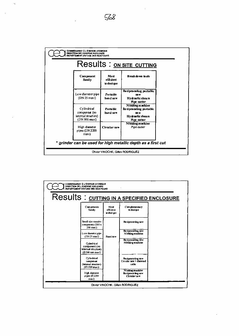
COMMISSARIAT A L'ENERGIE ATOMIQUEDIRECTION DC fENERGIE NUCLEAIREDEPARTEMENT 0-ETUDE DES REACTEURS
Results : ON SITE CUTTING
Componentfamily
Lowdiameterppe(DN25maxi)
Cylindricalcomponent (no
internal structure)(DN 500 maxi)
High diameterpipes (DN 2200
maxi)
Mostef fiiient
technique
Portableband saw
Portablehandsaw
Circular saw
Breakdown tools
Reciprocating portablesaw
Hydraulic shearsPipe cutter
NibblingmadiineReciprocating portable
sawHydraulic shears
Pipe cutterNibbling machine
Pipe cutter
* grinder can be used for high metallic depth as a first cut
Olivier VINOCHE, Gilles RODRIGUEZ
COMMISSARIAT A L-ENERGIEATOMIOUEDIRECTION DE L'ENERGIE NUCLEAIREDEPARTEMENT D'ETUDE DBS REACTEURS
ReSUltS ! CUTTING IN A SPECIFIED ENCLOSURE
Componentsfamily
&nall size massivecomponents (200 x
200 maxi)
Low diameter ppc(DN 25 maxi)
Cylindricalcomponent (no
internal stricture)(0500 mm maxi)
Cylindricalcomponent
(internal struct vie)(01 500 maxi)
High diameterpipes (02200
maxi)
Mostefficient
tecnnicaie
Handsaw
Com ptementa rytechnique
fed proa ting saw
Rea'proca ting sawNibWing machine
Reciprocating sawNibblingmacbine
Red proa ting sawCircular saw + diamond
cable
Nibbling machineReciprocating saw
Circular saw
Olivief VINOCHE, Gilles RODRIGUEZ
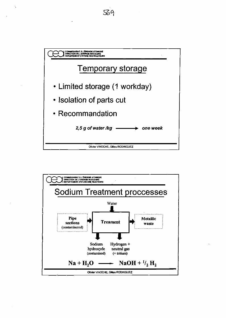
/•"V*V>J COMMISSARIAT A fENERGIEATOMraUEI I I I DIRECTION OEI/ENERGIENUCtEAIREX_X_^>»_/1 DEPARTEMENTD'ETUDEDESREACTEURS
Temporary storage
Limited storage (1 workday)
Isolation of parts cut
Recommandation
2,5 g of water /kg one week
Olivier VINOCHE, Gilles RODRIGUEZ
/">/""'V'"">J COMMISSARIAT A fENERdEATOMQUEI I I I DIRECTION DE L'ENERGIE NUCLEAHtE
DEPARTEMENTIXETUOEDeiREACTEURS
Sodium Treatment proccessesWater
\ Pipe UI sections ^i (contaminated) !
TreamentJ Metallic !^ waste j
Sodium Hydrogen +hydroxyde neutral gas(contamined) (+ tritium)
H2OOlivier VINOCHE, Gilles RODRIGUEZ
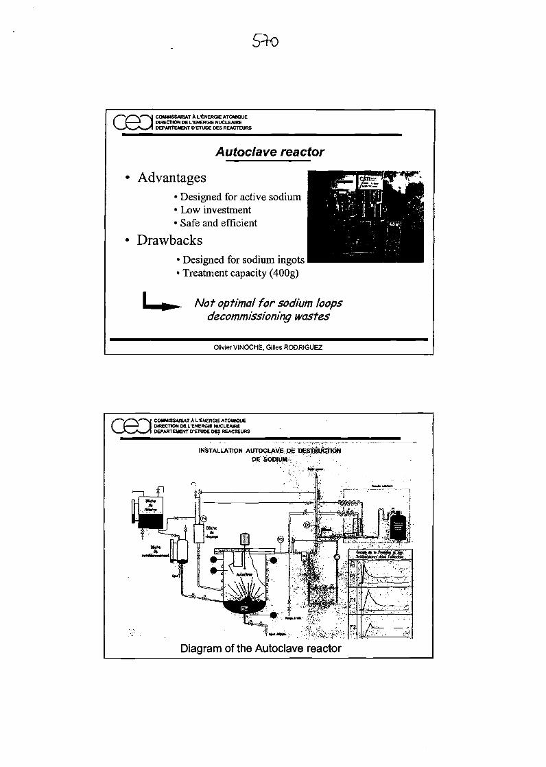
cea COMMISSARIAT A L'ENERGIE ATOMQUEDIRECTION DE L'ENERGIE NUCLEAIREDEPARTEMENT DTTUDE DES REACTEURS
Autoclave reactor
Advantages• Designed for active sodium• Low investment• Safe and efficient
Drawbacks• Designed for sodium ingots• Treatment capacity (400g)
Not opt/ma/ for sodium loopsdecommissioning wastes
Olivier VINOCHE, Gilles RODRIGUEZ
COMMISSARIAT A L'ENERGJE ATOWOUEDIRECTION DE L'ENERGIE NUCLEAIREDEPARTEMENT D'ETUDE DES REACTEURS
INSTALLATION AUTOCLAVE DE DESTRIK3TONDE SODIUM
Diagram of the Autoclave reactor
COMMISSARIAT A fENERGIEATOMIOUEI ( ' I DIRECTION HE LTNERdE NUCtEAIRE
DEPARTEMENTD'ETUOEDeSREACTEURS
Cleaning pits
Advantages• Already built on LMFR• Volume• Designed for active sodium
Drawbacks• Planning• Treatment speed• Admissible sodium mass
Necessary adaptation of the processA vailability problem
Olivier VINOCHE, Gilles RODRIGUEZ
COMMISSARIAT A UENERffleATOMiaUEI [ I 1 DIRECTION DEL-ENERGIE NUCLEATE
Water jet process
Advantages• Treatment speed• Adaptability• Reliable and efficient
Drawbacks• To be adapted to active wastes
Necessary adaptation of the process
Olivier VINOCHE. Gilles RODRIGUEZ
COMI«SSARlATALitNERGlEATOMK3OEDIRECTION DEL-ENERGieNUCLEAJREDePARTEMENT D-ETUDE DES REACTEURS
View of the water jetinstallation in Cadarache
Inside view
Olivier VINOCHE, Gilles RODRIGUEZ
COMMISSARIAT AL-ENERGKATOMKIUEDIRECTION DEL'ENERGIENUCLEAIREDEPARTEMEKriCETUDEMJREACTEURS
Active cleaning enclosure
Advantages
Treatment speedDesigned for active sodium
Drawbacks• Investment
Olivier VINOCHE, Gilles RODRIGUEZ
COMMBSAmATAl/ENERGIEATOWKJUEDIRECTION DEI/ENERGE NUCLEATEDEPARTEMENTD'ETUDEDESREACTEURS
Hydrogen release To a dehumidificalionunit
Dispersed water +inert gas mixture
Water injection
Diagram of the Active cleaning enclosure
Olivier VINOCHE. Gilles RODRIGUEZ
/ *V^V~*M COMMISSARIAT A L'tNERGIE ATOMOUE( fi 1 I DtftECnONDELtNERGlENUCLEAIREX_/V_^S^>1 DEPARTEMENT IXETUDE M$ REACTEURS
Comparative assessment
Treatment speed
OrrpJete trealrrert phase
Investment
Active sodiumapplicationAdaptability
Largp quantities ofsodum
TOIAL^25)
VtoterjetIreaoiEnt
4
50ilOOkgNl/(by
4
UMoics
2
4
3
17
Active washingeodosure
5
243kgl*/<by
3
tt9MOKB
4
3
4
19
Cleaning pits
2
2kgNi/(fay
5
5
4
3
19
Autoclave reacto
1
OLgOkgtt/day
4
0.45 Mars
5
0
0
^HlOlivier VINOCHE, Gilles RODRIGUEZ
COMMISSARIAT A I-£NERGJE ATOMMUEDIRECTION DE LTNEROE NUCLEAIREOEPARTEMENT D'ETUD€ DES REACTEURS
Dismantling installations (1)
Olivier VINOCHE, Gilles RODRIGUEZ
/—V"~V""M COMMISSARIAT A L'ENERGIEATOMIOUEI f J 1 DIRECTION DE LtNERGlE NUCLEAIREX_^^*s_>1 DEPARTEMENT D'ETUDE DES REACTEURS
Dismantling installations (2)IS
nLJCutting arta
flndkatrtefslM tend»*w*comptormntary foote^
f* 1r Primary *orag* ana
I —^
Secondaryttoragt
area
••*•
!•
hocestBg area
t I1 1
Effiiand In
t
cml controlatmeatarea
Efdicaistank
14
,
4
Olivier VINOCHE, Gilles RODRIGUEZ
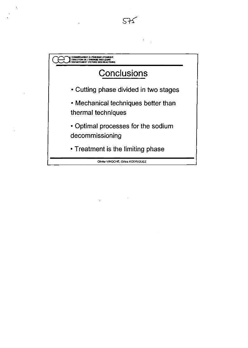
/"~V""%Y'"'N COMMISSARIAT A fENERGIEATOMMUEI f i 1 DIRECTION DELTNERGENUCLEAIRE
DEPARTEMENTD-ETUOeOESREACTEURS
Conclusions
• Cutting phase divided in two stages
• Mechanical techniques better thanthermal techniques
• Optimal processes for the sodiumdecommissioning
• Treatment is the limiting phase
Olivier VINOCHE, Giltes RODRIGUEZ

Sodium Removal & Decontamination Process and Decommissioning Considerationsfor the PFBR Components
M.Rajan, C.S. Surendran, V. Ganesan, B.S. Sodhi, S.C. Chetal and R.D. Kaleand
R. Indira and A.K. BhaduriIndira Gandhi Centre for Atomic Research, Kalpakkam - 603 102, India
Introduction:
The Prototype Fast Breeder Reactor (PFBR) is a sodium cooled pool type reactorof 500 MWe capacity. The reactor is being designed at IGCAR, Kalpakkam, India. It isplanned to construct the reactor at Kalpakkam. In the PFBR plant Nuclear Steam SupplySystem (NSSS) components are either wetted with primary sodium or secondary sodiumor some time both. Sodium cleaning is to be done before undertaking any maintenancework or disposal. The radioactivity of the primary sodium is significant compared to thesecondary sodium. In this paper, primary sodium cleaning and decontamination of thecomponents planned for PFBR are discussed. The choice of hard facing materials forNSSS components are also discussed.
Sodium Removal:
During the operation of the reactor there are two types of components, which areto be cleaned from sodium. These are 1) Core components and 2) Primary components.Fig. 1 shows the location of the facility for sodium cleaning in the nuclear island. Thecore components are handled by fuel handling machines where as the primarycomponents are handled by respective flask. The components that are to bedecontaminated are removed from the reactor when the reactor is in shutdown condition.The handling of the core components is based on fixed time duration and interval in thereactor. For the primary components, it is as and when required. The core component isnot meant for decontamination but for reprocessing and the primary component needs tobe decontaminated. The cleaning time of the core component is to be minimum and to becompleted during the fuel handling campaign, which is 20 days. For the primarycomponent, the cleaning of sodium can be done during reactor operation as well asshutdown condition. These considerations are taken during conceptual design stage of thereactor to evolve better design considering safety, economy, safe-disposal of thecomponents and safe decommissioning of the plant (Ref. 1 to 3).
The sodium cleaning system has the following design features. A schematic flowsheet of the design features is given in Fig. 2. The main objectives are:
Minimize sodium sticking on the component.Safe operation.Minimum quantity of waste generation.Fast cleaning.Effective cleaning.No damage to the component.
Sodium Removal from Core Components:
The core components are spent fuel assembly (SA), irradiated blanket SA andirradiated absorber SA. There are 94 core SA to be cleaned from sodium in eight monthsfull power reactor operation. The core SA coming out of the reactor is handled by celltransfer machine. This machine picks up the core SA from the ex-vessel transfer positionand keeps it in the washing vessel. The flow sheet of the SA washing is shown in Fig.3.Since the fuel SA is having maximum of 5 kW decay heat, nitrogen at 50 Nm3/h isrequired to cool the fuel SA. In order to minimize the sodium sticking on the core SA, thenitrogen flow helps to drain sodium as much as possible at the ex-vessel transfer positionwhile picking the core SA by cell transfer machine. Also, the dripping of sodium in thetransfer pot of the Inclined Fuel Transfer Machine (LbTJvI) is enhanced by holding the SAat an elevated location for a short duration. The time required for discharge of one coreSA from the reactor is about 3 hours so that the duration of sodium cleaning of a SA shallbe less than 3 hours. It is envisaged that 3 hours duration is required for washingoperation. However in the SA washing facility two SAs can be cleaned simultaneously.Also two stand-by vessels are provided at the facility. In washing process, it is possible toidentify the breached and non-breached SA.
The estimated sodium sticking on a core SA is about 2 kg. Considering the timeof washing and cooling requirements, steam cleaning is selected for the sodium cleaningof the core SA. The concentration of hydrogen at the exhaust is monitored and alwaysmaintained at less than 2% by varying the steam flow. The steam cleaning is safe andfast, but it lacks the effective cleaning from the crevices. However, water rinsing processis used after steam cleaning. The water is sprayed and re-circulated for about 30 to 40minute to identify the activity level in water using gamma-detector for ensuring whetherthe SA is cleaned is breached or non-breached. The exhaust gas during steam cleaning ismonitored for betta-activity to identify whether the SA is breached. The gas effluent issend to the stack and the liquid effluent is sent to waste treatment. The SA is washedwith DM water before transferring it to the storage pool containing water. From thestorage pool the fuel SA is taken for reprocessing.
Sodium Removal from Primary Components:
The primary components are classified into 1) Large Component and 2) SmallComponent. The large components are IHX, primary sodium pump, DHX, transfer armand transfer pot of IFTM. The small components are CSRDM, DSRDM, FFLM, bulksodium delayed neutron detectors and clad rupture detectors in argon. The largecomponents are handled by one bigger flask and the small components are handled byanother small flask. The sodium cleaning facility is also meant for decontamination of thecomponents. This facility is called decontamination facility, which is provided insideRCB. The safety of the plant was analyzed due to the presence of water and potentialhydrogen liberated from the facility and was found satisfactory. While removing thecomponent from the reactor by using flask, sufficient time is allowed to drain sodiumsticking on the component. For the IHX, the sodium wetted length is 10 m, and whiletaking it using a flask each 1 m raise of IHX into the flask, one hour time is given to
drain sodium from it. This will ensure minimum quantity of sodium sticking on it byavoiding sudden cooling and solidifying of sodium. Thus 10 to 12 hours are required forremoving IHX from reactor. Of all the primary components, IHX, is having maximumamount of sodium sticking on its surface. The estimated amount of sodium sticking onthe surface of IHX is 75 kg. This component when it is being cleaned gives maximumquantity of hydrogen. The hydrogen liberated during accidental rising of water level inDecontamination Vessel - 1, when IHX is being cleaned, was analyzed. For this analysis,instead of admitting water for bubbling, large quantity of water for rinsing was admittedinto the vessel due to operator error was analyzed. The pumping of water into the vesselis limited to 1 cm/minute raise in the vessel. Also the pump can start only when theexhaust valve is kept opened. If the valve fails to open before start of the pump, hydraulicrelief pot functions. Also a rupture disc with non-return valve is provided to open into thecell when the hydraulic relief pot does not function. Thus in any case the hydrogen fire isavoided. Moreover the cell air is continuously changed during the process of sodiumremoval. To avoid water entry into RGB, the water required for sodium cleaning is keptin a small tank of 3 m3 and a large tank of 10 m3 capacity outside RGB. By limiting thevolume of the tanks, the risk of water flooding in RGB is eliminated. The water fromsmall tank is used for carbon di oxide bubbling process and water from large tank forrinsing the component. CC>2 cylinders are kept outside RGB. The flow sheet of thedecontamination facility is shown in Fig.4.
In the decontamination facility two vessels are provided. One is for largecomponents and is called Decontamination Vessel - 1 (DV1). The other is for smallcomponents and is called Decontamination Vessel - 2 (DV2). The component is broughtto the respective vessel and positioned in it. A small quantity of water is admitted to thevessel bottom trough and heated to 70 to 80°C. Carboon di oxide is bubbled through thehot water which will carry the water vapour and react with the sodium sticking on thecomponent. The exhaust gas is monitored and the concentration of hydrogen is alwaysmaintained below 2% by controlling the flow rate of carbon-di-oxide bubbled. Thismethod has got better control of sodium water reaction. Also corrosion of the componentis not taking place due to absence of alkali. After the bubbling stage, the component isrinsed with water and DM water. The gas effluent is sent to the stack and the liquideffluent is sent to waste treatment. With this the sodium cleaning of the component isover and ready for decontamination.
Decontamination Process:
The choice of chemical decontamination process depends mainly on the end useviz. whether the component is for (a) re-qualification and reuse or (b) decommissioningand disposal purpose. Based on the available data on decontamination being followed inother reactor systems and considering the complexity involved in the process, thedecontamination of the primary component the following process is used. For thedecontamination process sulpho-phosphoric acid process for all component made of AISI304L, 316L and hard coating is used. The decontamination of the component is carriedout in the decontamination facility. After sodium cleaning, the acid (mixture ofphosphoric acid and sulphuric acid) for decontamination is admitted to the
decontamination vessel to remove surface layer activity. The component is immersed in asolution of 15 g/1 of sulphuric acid and 45 g/1 of phosphoric acid. The solution at 60°C iscirculated for about 6 hours. After this the solution is drained out from the vessel. Thecomponent is rinsed with domestic water as well as DM water. Subsequently the water isdrained out and the component is dried using surface heaters provided on the surface ofthe vessel. The component is taken out of the vessel and mopped with cotton beforetaking it out for doing any maintenance work. Fig. 5 shows the flow chart ofdecontamination process.
Even though mineral acid mixture containing sulphuric and phosphoric acids isfound to be a better choice than the organic based solutions for effective decontaminationof the components, some future studies are planned for better decontamination solution.However, considering the fact whether the component is for reuse or not and alsoconsidering the operation history of the various types of components, it can be stated thatone single composition of the decontamination solution cannot be applied to all types ofcomponents. Depending upon the requirements, for getting high decontamination factor,the concentration of F^SCU may be increased, or to limit inter granular corrosionconcentration of HaSd* is reduced with increase in HsPCV To limit the phosphate releasein the waste, concentration of H3?O4 may be reduced.
Radioactive Chemical Waste Generated:
During sodium removal from the primary component, liquid chemical in the formof aqueous solution of NaHCOs and Na2CC>3 will be generated. The reaction products area mixture of bicarbonate and carbonate of sodium depending on the availability ofsodium hydroxide to react with CC>2 and water. The amount of chemical waste as sodiumbicarbonate and sodium carbonate produced during sodium cleaning by COa-watervapour process depends on the relative amount of sodium in the component and theavailability of carbonate and water vapour. From laboratory experiments, it is found thatthe layer of NaHCO3/Na2CO3 is highly porous allowing the entire sodium sticking on thesurface to react, leaving no unreacted sodium on the component. At the end of sodiumdissolution step, water is sprayed on to the component. The water in the cleaning vessel israised to required level in steps so as to immerse the component and circulate to ensurecomplete dissolution of the reaction products. The contaminated water at this stage isdrained. Domestic water is used for second stage cleaning to reduce alkali content in thevessel to a minimum and drained out. Third stage is the chemical solution fordecontamination. Fourth and fifth stages involve domestic water and DM water cleaning.The typical liquid waste generated during cleaning and decontamination of primarysodium pump is nearly 260 m3, which is the maximum expected waste for a primarycomponent. During SA washing about 725 litres of liquid waste is generated. The liquidwaste is sent to radioactive waste building for treatment and disposal. The gaseous wastegenerated is directly sent to the stack. The solid waste in the form of waste cotton iscovered in polythene bag and sent for disposal.
Choice of Hardfacing materials for NSSS components:
The choice of hard facing material for different components of PFBR is aimed atkeeping induced activity to the minimum for maintenance and decommissioningpurposes, and also to reduce the shielding thickness required for the component handling,which in turn would reduce the flask weight, size of handling crane and loads on civilstructures. Induced activity, dose-rate and shielding computations were carried out for thevarious NSSS components of PFBR hard faced using the same amount of Stellite andColmonoy with their actual geometrical configuration and operating conditions.
Hardfacing of NSSS components with cobalt based alloys of Stellite, results indifficulties in maintenance, decommissioning and handling, due to induced activity ofCobalt-60. Hence Nickel based hard facing materials, Colmonoy and Triballoy wereconsidered as alternate choices. Induced activity computations were carried outconsidering the same amount of Stellite, Colmonoy-6 and Tribaloy-700. The activity anddose rate computations have been carried out for 0.25% Co in Colmonoy and T700 (sameas in the case of austenitic stainless steels).
For the in-vessel components, control and safety rod drive mechanism (CSRDM),Diverse safety rod drive mechanism (DSRDM), failed fuel location module (FFLM) andprimary sodium pump (PSP), saturation activity was calculated, as these components areexpected to be irradiated for 20 years. A cooling time of 2 or 5 years was considered inthe case of grid plate components, as these are expected to be handled only fordecommissioning purposes. In the case of CSRDM, DSRDM, FFLM and PSP, a coolingtime of 2 days has been considered. For the Control and Safety Rod (CSR) and DiverseSafety Rod (DSR), an irradiation time of two years and cooling time of 2 days wasconsidered (Ref.4).
It is found that from induced activity and dose rate considerations, Stellite can bereplaced by either Colmonoy-6 or Tribaloy-700. Based on fast reactor experience withcolmonoy, colmonoy has been chosen. An approximate estimate of the shieldrequirement assuming a permissible dose rate of 100 mR/h have been worked out. In thefollowing discussions, as the basic SS component itself becomes radioactive and requiresshielding, reduction in shield thickness is with respect to the minimum shielding requiredfor the SS component (Ref. 5).
At the grid plate top sleeve only decommisioning need be considered, since thereis no maintenance. It is seen that by replacing Stellite the man-rem requirement can bereduced by a factor of 250, while handling grid plate. By replacing Stellite in the case ofanti-rotation plugs in grid plate, man rem requirement can be reduced by a factor of 30during decommissioning. For the IHX seal flanges in inner vessel, the man-remrequirement comes down by a factor of 370 during decommissioning, if Stellite isreplaced.
In the case of CSRDM and DSRDM, by replacing Stellite, the lead shieldrequirement for maintenance of DSRDM and CSRDM can be reduced by 6 cm and 3 cm
respectively. From the point of view of shielding for IFTM (Inclined Fuel TransferMachine) and flask for handling, replacing stellite by colmonoy in CSR is highlybenificial. Based on the above considerations, colmonoy has been chosen as hardfacingmaterial for the grid plate components, CSRDM, DSRDM and CSR. For grid platecomponents, Cr-N coating is also being considered as an alternate option.
REFERENCES:
1. Experience of sodium removal from FBTR components in its operating phaseD. Jambunathan, M.S. Rao, V.S. Krishnamachari, K.V. Kasiviswanathan and M.Rajan, Technical Committee Meeting on "Sodium Removal and Disposal fromLMFRs in Normal Operation and in the Framework of Decommissioning",IWGFR-98, Aix-en-Provence, France, 3-7 Nov, 1997.
2. Sodium cleaning and disposal methods in experimental facilitiesK.K. Rajan, K. Gurumoorthy, M. Rajan and R.D. Kale, Technical CommitteeMeeting on "Sodium Removal and Disposal from LMFRs in Normal Operationand in the Framework of Decommissioning", IWGFR-98, Aix-en-Provence,France, 3-7 Nov, 1997.
3. Cleaning and Decontamination: Experimental Feed Back from PHENIXF.Masse and G. Rodriguez, IAEA Technical Committee meeting on sodiumRemoval and Decontamination from LMFRs, in Normal Operation and in theFrame Work of Decommissioning, IWGFR-98, 307 Nov, 1997, Aix-En Provence,France.
4. R.Indira, "Choice of Hardfacing Materials for LMFBR Components", p 459,Proc. of National Symposium on Radiation Physics (NSRP-13), 1999,Mangalore.
5. A.K.Bhaduri, R.Indira et.al, "Recommended Hardfacing Materials for NSSSComponents of PFBR", Task Force Report No. IGC/HTF/04, March 2000.
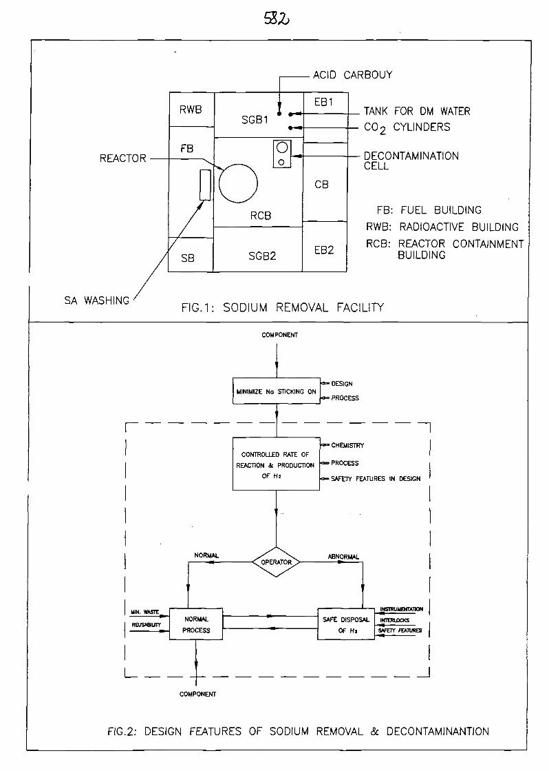
ACID CARBOUY
REACTOR
SA WASHING
TANK FOR DM WATER
C02 CYLINDERS
DECONTAMINATIONCELL
FB: FUEL BUILDING
RWB: RADIOACTIVE BUILDING
RGB: REACTOR CONTAINMENTBUILDING
FIG.1: SODIUM REMOVAL FACILITY
COMPONENT
MINIMIZE No STICKING ON
r
• DESIGN
* PROCESS
CONTROLLED RATE OF
REACTION 4 PRODUCTION
OF Hi
' CHEMISTRY
= PROCESS
•SAFETY FEATURES IN DESIGN
I I
FIG.2: DESIGN FEATURES OF SODIUM REMOVAL & DECONTAMINANTION
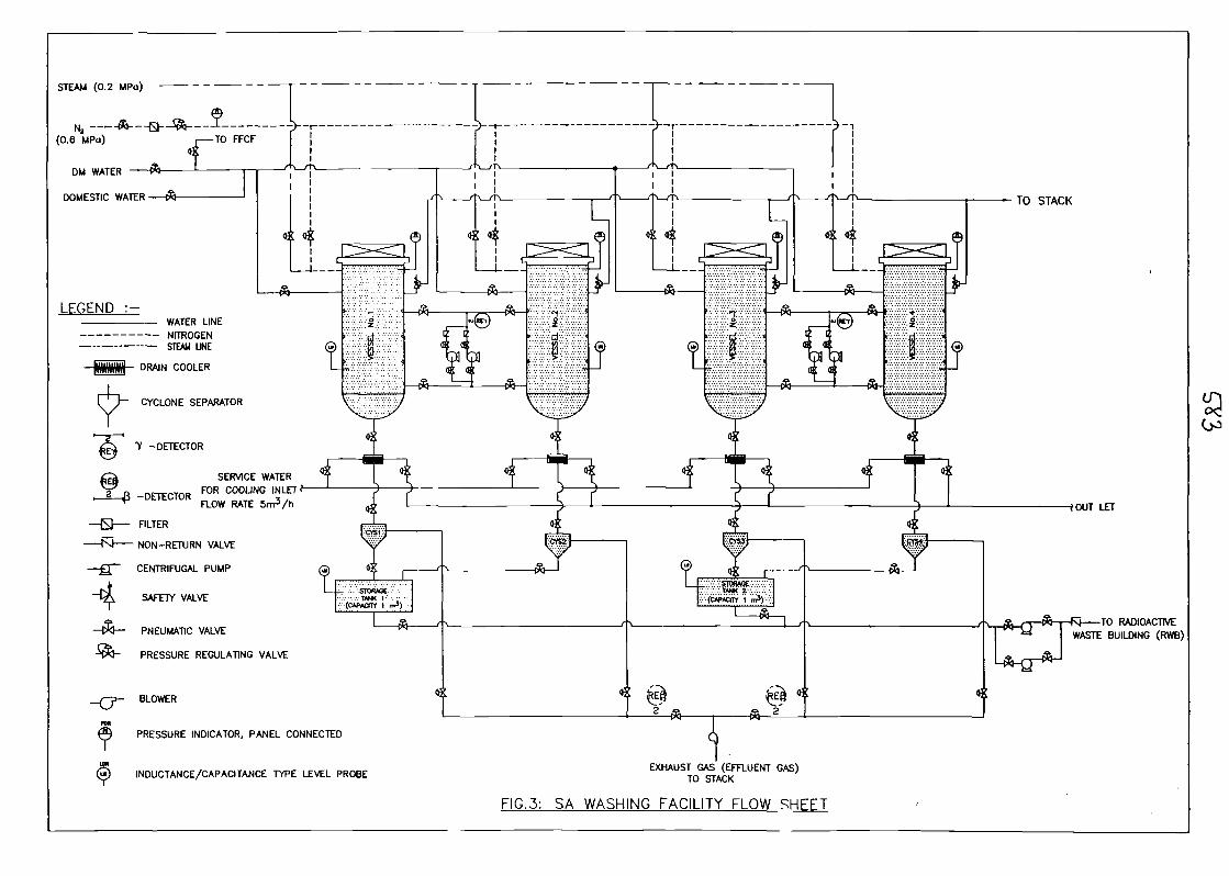
STEAM (0.2 MPo)
(0.6 MPo)
DM WATER
DOMESTIC WATER
LEGEND :-
NITROGENSTEAM UNE
tomM DRAIN COOLER
CYCLONE SEPARATOR
7 -DETECTOR
SERVICE WATER
_DETECTOR FOR COOLING INLETFLOW RATE
FILTER
- NON-RETURN VALVE
CENTRIFUGAL PUMP
SAFETY VALVE
PNEUMATIC VALVE
PRESSURE REGULATING VALVE
BLOWER
PRESSURE INDICATOR, PANEL CONNECTED
© INDUCTANCE/CAPACITANCE TYPE LEVEL PROBE
TO STACK
EXHAUST GAS (EFFLUENT GAS)TO STACK
FIG.3: SA WASHING FACILITY FLOW SHEET
•fOUT LET
TO RADIOACTIVEWASTE BUILDING (RWB)
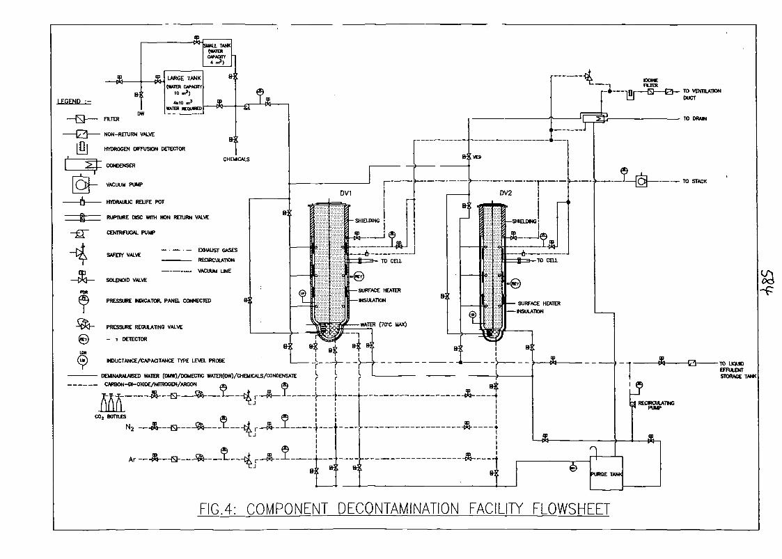
LEGEND :-
-4-&-
FILTER
NON-RETURN VALVE
HYDROGEN DIFFUSION DETECTOR
CONDENSER
VACUUM PUMP
HYDRAULIC REUFE POT
RUPTURE DISC WITH NON RETURN VALVE
CENTRIFUGAL PUMP
SAFETY VALVE
TO VENTILATIONDUCT
TO DRAIN
u»(a!)
SOLENOID VALVE
PRESSURE INDICATOR. PANEL CONNECTED
PRESSURE REGULATING VALVE
- 1 DETECTOR
INDUCTANCE/CAPACITANCE TYPE LEVEL PROBE
DEMINARALAISED WATER (DUW)/DOMECT)C WATER(DW)/CHEMICALS/CONDENSATE
CARBON-DI-OXIDE/NrTROGEN/ARGON
&-9
----- ffl --- H — • - 56
C02 BOTTLES
N2 —ft-
Ar
FIG.4: COMPONENT DECONTAMINATION FACILITY FLOWSHEET

ssrf START OF^DECONTAMINATION
SMALL LARGE
• SMJMrUI1E.l1 1 > •
\?/USE OV-2 V USE OV-1
PRELIMINARY SETUP | PRELIMINARY SETUP
COMPONENT LOWERED
TO DV-2COMPONENT LOWERED
TO DV-1
FILL WATER AT BOTTOM& HEAT TO 70' C
BUBBLING C02
STOP OR VARY C02
4 LOWER TEMP. OF WATER
> 2%
NEGLIGIBLE
FILL WATER
DRAIN
USE PROCESS LIQUID (ACID)
DRAIN
WASH WITH DOMESTIC ANDDM WATER
DRAIN
DRY WITH HEATER
MANUAL MOPPING THE SURFACE
| READY TO TAKE OUT
< 2%
( END OF DECONTAMINATION}
FIG.5: FLOW CHART FOR SODIUM CLEANING &PRIMARY COMPONENTS DECONTAMINATION.

SESSIONS:
Fast reactor physics and engineeringexperiments and analyses

Intergranular reheat cracking in austenitic stainless steel welds.Experimental program and numerical evaluations
CEA : M.T.CABRILLAT, L. ALLAIS, M. REYTffiR, E. PLUYETTE
Over the past years, failure due to heat affected zone stress relief or reheat cracking inaustenitic stainless steels welds, and particularly in stabilized austenitic steels like 321or 347 have been reported world-wide. More recently similar problems have beendiscovered on type 316 and 304 stainless steels working in the temperature range 520-550°C.It has been established that these cracks are generally concentrated hi sites of hightriaxial tension developed in the strain affected zone adjacent to welds as a result ofthe plastic strains introduced by the welding process, and that they are prevalent inthick sections or near very massive welds.An important research program has been undertaken at CEA to identify the damagemechanisms involved, determine the influent parameters and develop specificbehaviour and damage models able to predict this type of cracking.For that, several study directions were initiated:
> Metallurgical observations of welds were performed. Due to the complexity ofthe micro structure and behaviour of real welds, different HAZ were simulatedwith adapted thermo-mechanical treatments. It was thus possible tocharacterize the micro structure, identify the mechanical behaviour andquantify the intergranular damage of different materials.
> Tests on components with welds were performed in order to take into accountthe specificities of real welds.
> Finally simulations were necessary to validate the models developed in thefirst step. Residual stresses due to welding operation being important in themechanism, it is necessary to evaluate them with refined analyses. Then thecreep damage is estimated using different damage models in order to point outthe important parameters.
This paper presents the main results obtained during this research program
Intergranular Reheat Cracking in austenitic steels
M.T. CABRILLAT, L. ALLAIS, M. REYTffiR, E. PLUYETTECEA - FRANCE
osa AIEA meeting - Cadarache - 11-15/03/02
Intergranular Reheat Cracking in austenitic steels
Feedback from Phenix operation:many intergranular cracks on pipings in 321 steel working at 550°Cintergranular cracks in valves in 304H - 550°C
TamponValve304H
Expansion j
^1 304-)-*
Heat -. 77r
J "s'VMOi
vanne chaude(545 °C)
Steamgenera
GV
or
S'VMOSvanne froide
(345 °C)
— 'f Valve/ 304H
X
| 321 |
-^
^
V-L^J AIEA meeting - Cadarache - 11-15/03/02
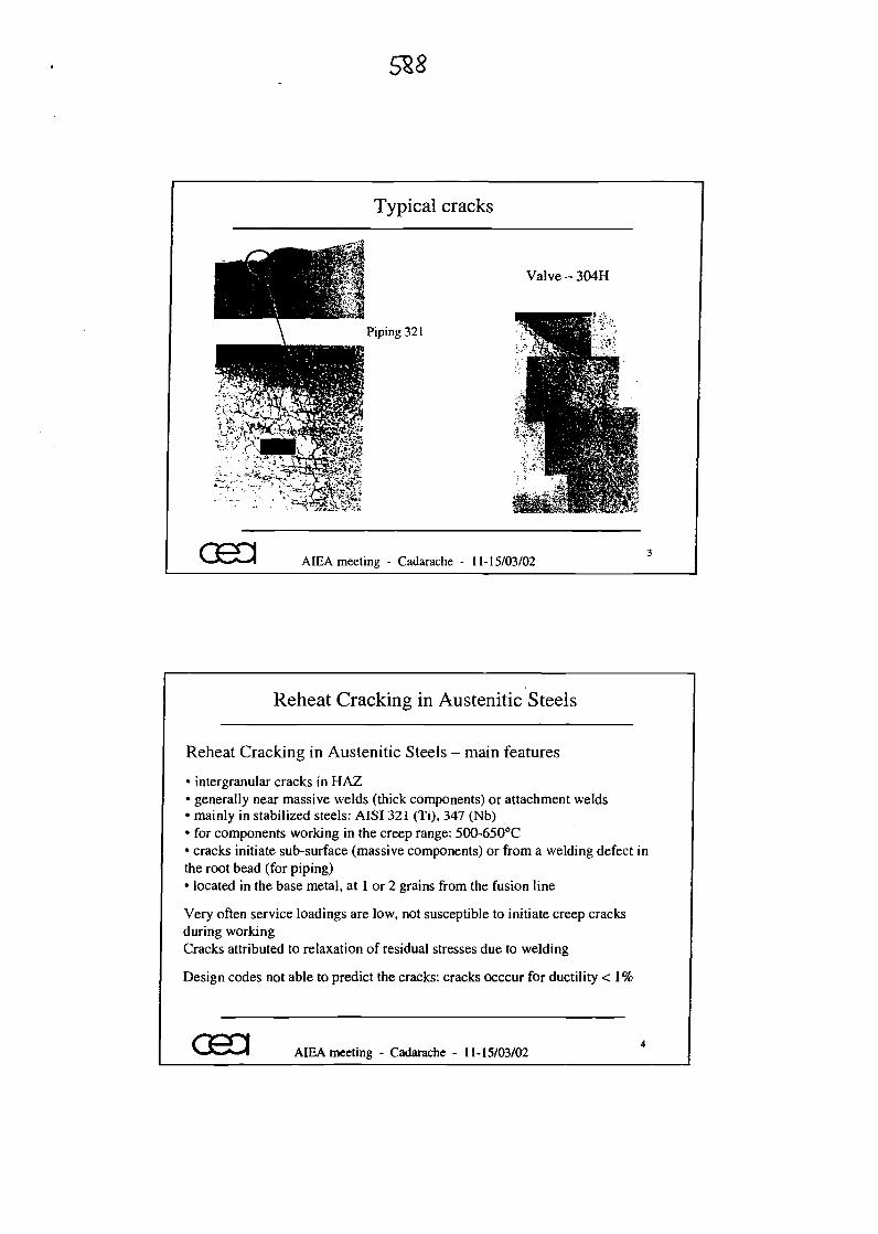
Typical cracks
^; --«€e^--• :-•-,-:..•**,".-~-;/ •• / «'••-c\
Valve-304H
Piping 321
C;.«>7:AV-Sli
CEO AIEA meeting - Cadarache - 11-15/03/02
Reheat Cracking in Austenitic Steels
Reheat Cracking in Austenitic Steels - main features
• intergranular cracks in HAZ• generally near massive welds (thick components) or attachment welds• mainly in stabilized steels: AISI 321 (Ti), 347 (Nb)• for components working in the creep range: 500-650°C• cracks initiate sub-surface (massive components) or from a welding defect inthe root bead (for piping)• located in the base metal, at 1 or 2 grains from the fusion line
Very often service loadings are low, not susceptible to initiate creep cracksduring workingCracks attributed to relaxation of residual stresses due to welding
Design codes not able to predict the cracks: cracks occcur for ductility < 1%
033 AIEA meeting - Cadarache - 11-15/03/02
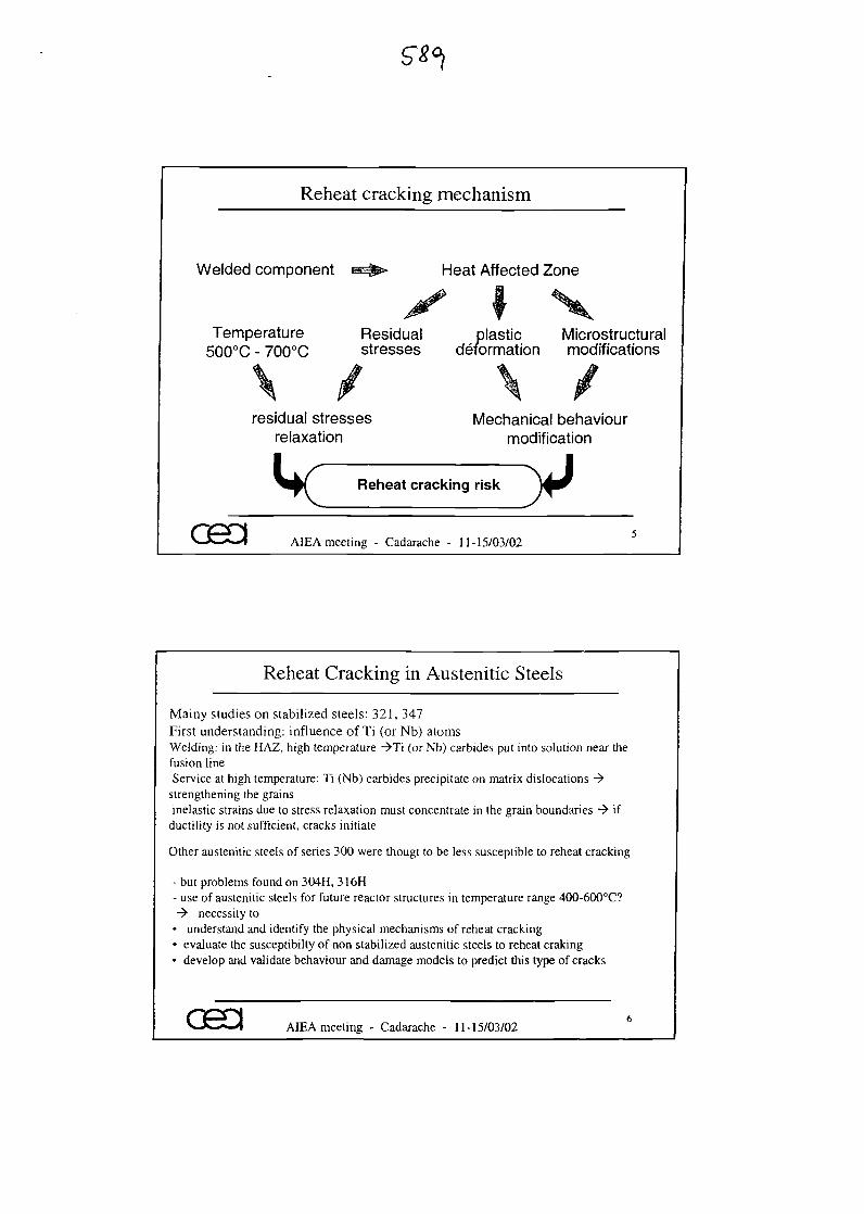
Reheat cracking mechanism
Welded component
Temperature500°C - 700°C
Heat Affected Zone
Residual plastic Microstructuralstresses deformation modifications
residual stressesrelaxation
Mechanical behaviourmodification
Reheat cracking risk yAIEA meeting - Cadarache - 11-15/03/02
Reheat Cracking in Austenitic Steels
Mainy studies on stabilized steels: 321, 347First understanding: influence of Ti (or Nb) atomsWelding: in the HAZ, high temperature ->Ti (or Nb) carbides put into solution near thefusion lineService at high temperature: Ti (Nb) carbides precipitate on matrix dislocations ->
strengthening the grainsinelastic strains due to stress relaxation must concentrate in the grain boundaries -> if
ductility is not sufficient, cracks initiate
Other austenitic steels of series 300 were thougt to be less susceptible to reheat cracking
• but problems found on 304H, 316H• use of austenitic steels for future reactor structures in temperature range 400-600°C?-> necessity to
• understand and identify the physical mechanisms of reheat cracking• evaluate the susceptibilty of non stabilized austenitic steels to reheat craking• develop and validate behaviour and damage models to predict this type of cracks
asa AIEA meeting - Cadarache - 11-15/03/02
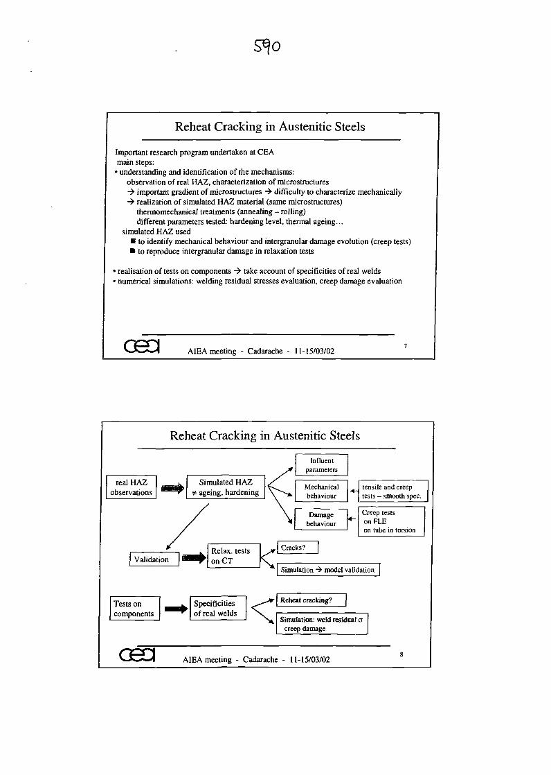
Reheat Cracking in Austenitic Steels
Important research program undertaken at CEAmain steps:
• understanding and identification of the mechanisms:observation of real HAZ, characterization of microstructures-> important gradient of microstructures -> difficulty to characterize mechanically-> realization of simulated HAZ material (same microstructures)
thermomechanical treatments (annealing - rolling)different parameters tested: hardening level, thermal ageing...
simulated HAZ used• to identify mechanical behaviour and intergranular damage evolution (creep tests)• to reproduce intergranular damage in relaxation tests
• realisation of tests on components -> take account of specificities of real welds• numerical simulations: welding residual stresses evaluation, creep damage evaluation
AIEA meeting - Cadarache - 11-15/03/02
Reheat Cracking in Austenitic Steels
sreal HAZ ^ K Simulated HAZ /
observations *^^^r ^ ageing, hardening \""v.
> \
i. Relax test0 " ^Validation BHi on £j <
Influent
i parameters
Mechanicalbehaviour
Damagebehaviour
racks?
tensile and creeptests - smooth spec.
Creep tests*~ on FLE
on tube in torsion
^ | Simulation •+ model validation
Tests on ^^^ Specificitiescomponents ^^^ of real welds < Re
IZSi
c
^adarache -
sheat cracking?
mulation: weld residual areep damage
11-15/03/02 8
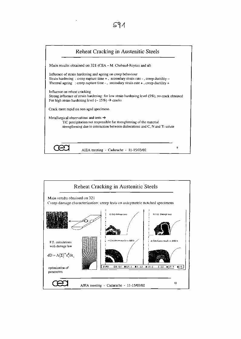
Reheat Cracking in Austenitic Steels
Main results obtained on 321 (CEA - M. Chabaud-Reytier and al)
Influence of strain hardening and ageing on creep behaviourStrain hardening : creep rupture time + , secondary strain rate - , creep ductility -Thermal ageing : creep rupture time - , secondary strain rate + , creep ductility +
Influence on reheat crackingStrong influence of strain hardening: for low strain hardening level (5%), no crack obtainedFor high strain hardening level (- 15%) -> cracks
Crack more rapid on non aged specimens
Metallurgical observations and tests ->TiC precipitation not responsible for strenghtening of the materialstrengthening due to interaction between dislocations and C, N and Ti solute
asa AIEA meeting - Cadarache - 11-15/03/02
Reheat Cracking in Austenitic Steels
Main results obtained on 321Creep damage characterization: creep tests on axisymetric notched specimens
F.E. calculationswith damage law
optimization ofparameters
osa
a) Exp.clamage map
c) Simulation results t= 600 h
b) Exp. Damage map
d) Simulation result t = 2000 h
00-0.5 \\,i 2-2.5 »2.5-3
AIEA meeting - Cadarache - 11-15/03/0210
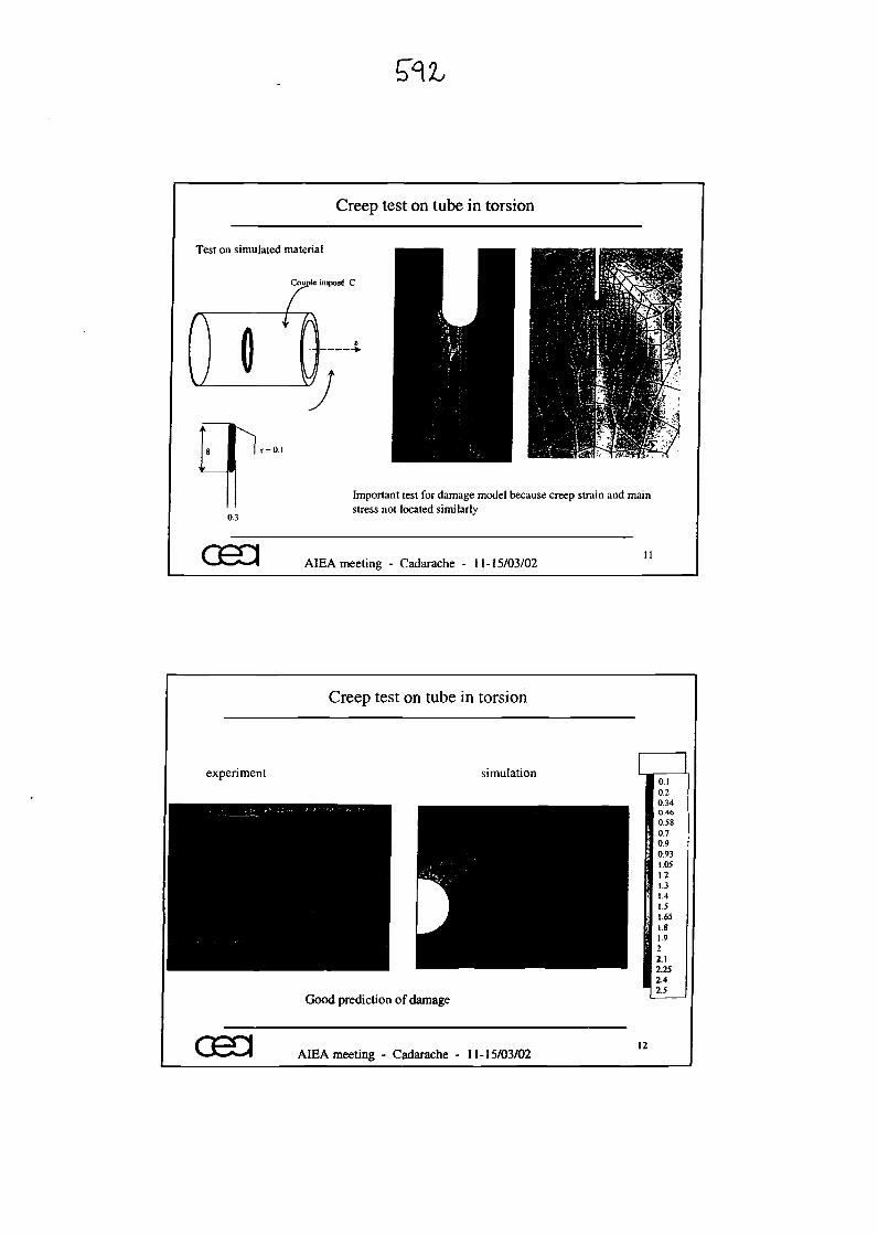
Creep test on tube in torsion
Test on simulated material
Couple impost C
osa
Important test for damage model because creep strain and mainstress not located similarly
AIEA meeting - Cadarache - 11-15/03/02
Creep test on tube in torsion
experiment simulation
Good prediction of damage
O.I0.20.340.460.580.70.90.931.051.21.31.41.51.651.81.922.12.252.42.5
CH3 AIEA meeting - Cadarache - 11-15/03/0212
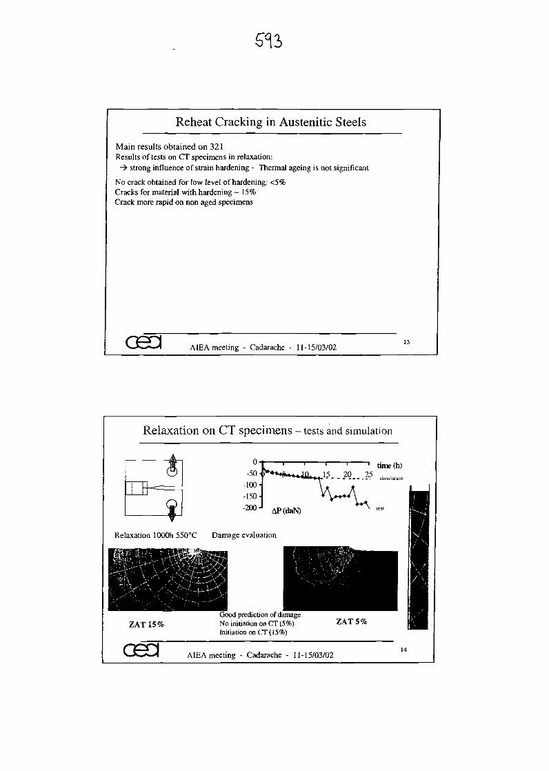
Reheat Cracking in Austenitic Steels
Main results obtained on 321Results of tests on CT specimens in relaxation:
-> strong influence of strain hardening - Thermal ageing is not significant
No crack obtained for low level of hardening: <5%Cracks for material with hardening ~ 15%Crack more rapid on non aged specimens
osa AIEA meeting - Cadarache - 11-15/03/0213
Relaxation on CT specimens - tests and simulation
o-50
-100--150--200-
~ l ' ' t i m e ( h )15 20 25 . , .
AP(daN)
Relaxation lOOOh 550°C Damage evaluation
ZAT 15%Good prediction of damageNo initiation on CT (5%)Initiation on CT( 15%)
ZAT 5%
asa AIEA meeting - Cadarache - 11-15/03/0214
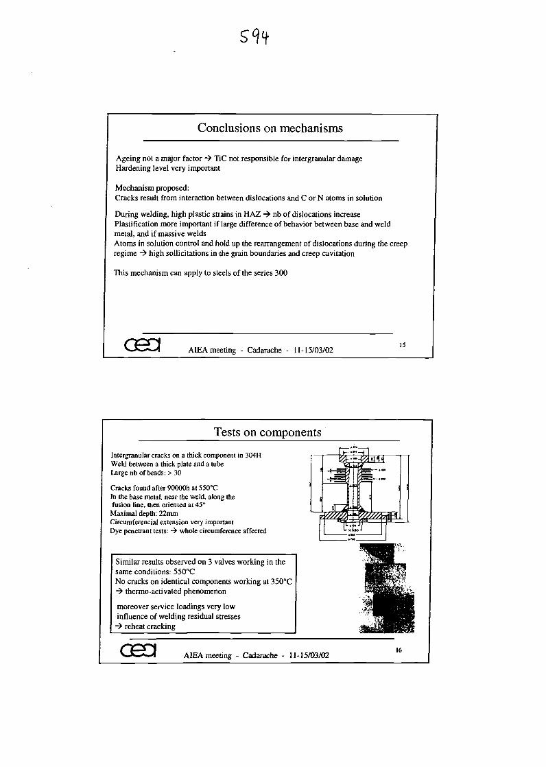
Conclusions on mechanisms
Ageing not a major factor -> TiC not responsible for intcrgranular damageHardening level very important
Mechanism proposed:Cracks result from interaction between dislocations and C or N atoms in solution
During welding, high plastic strains in HAZ -> nb of dislocations increasePlastification more important if large difference of behavior between base and weldmetal, and if massive weldsAtoms in solution control and hold up the rearrangement of dislocations during the creepregime -> high sollicitations in the grain boundaries and creep cavitation
This mechanism can apply to steels of the series 300
osa AIEA meeting - Cadarache - 11-15/03/0215
Tests on components
Intergranular cracks on a thick component in 304HWeld between a thick plate and a tubeLarge nb of beads: > 30
Cracks found after 90000h at 550°CIn the base metal, near the weld, along thefusion line, then oriented at 45°Maximal depth: 22mmCircuraferencial extension very importantDye penetrant tests: -> whole circumference affected
Similar results observed on 3 valves working in thesame conditions: 550°CNo cracks on identical components working at 350°C-> thermo-activated phenomenon
moreover service loadings very lowinfluence of welding residual stresses-> reheat cracking
033 AIEA meeting - Cadarache - 11-15/03/0216
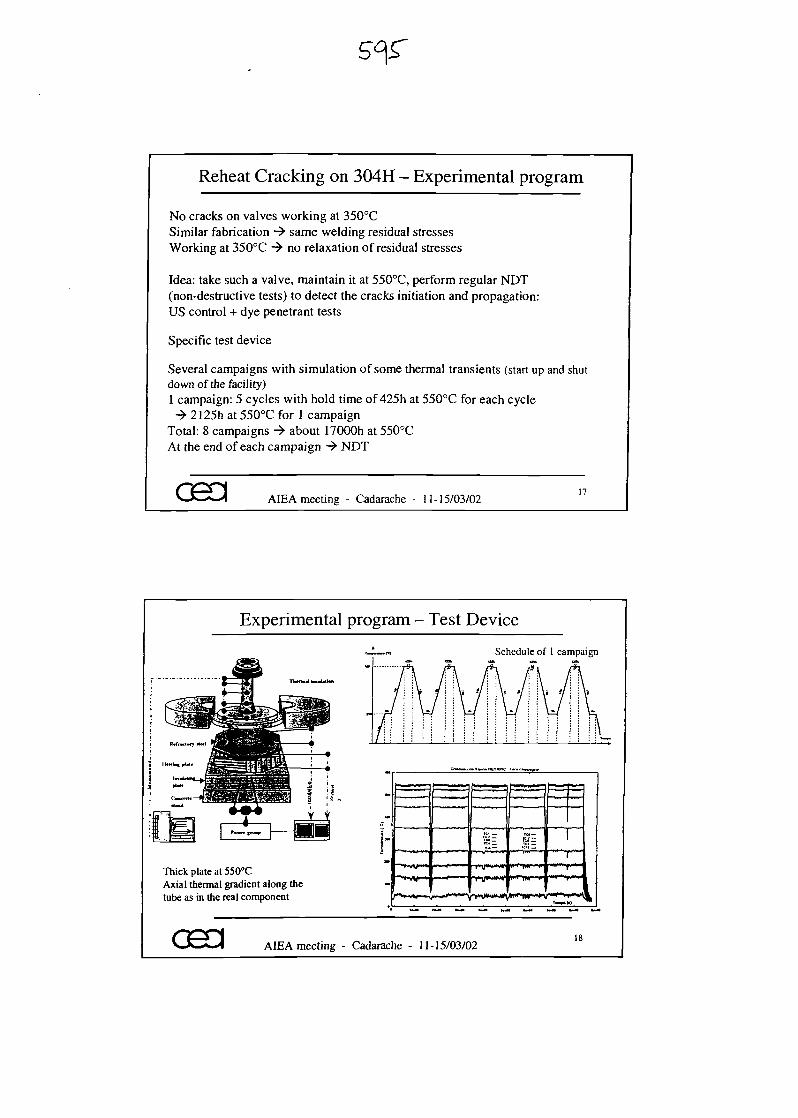
Reheat Cracking on 304H - Experimental program
No cracks on valves working at 350°CSimilar fabrication -> same welding residual stressesWorking at 350°C -> no relaxation of residual stresses
Idea: take such a valve, maintain it at 550°C, perform regular NOT(non-destructive tests) to detect the cracks initiation and propagation:US control + dye penetrant tests
Specific test device
Several campaigns with simulation of some thermal transients (start up and shutdown of the facility)1 campaign: 5 cycles with hold time of 425h at 550°C for each cycle-* 2125h at 550°C for 1 campaign
Total: 8 campaigns -» about 17000h at 550°CAt the end of each campaign -> NDT
GSd AIEA meeting - Cadarache - 11-15/03/0217
Experimental program - Test Device
Schedule of 1 campaign
Thick plate at 550°CAxial thermal gradient along thetube as in the real component
osa
>W~
"^"r-VV
AIEA meeting - Cadarache - 11-15/03/0218
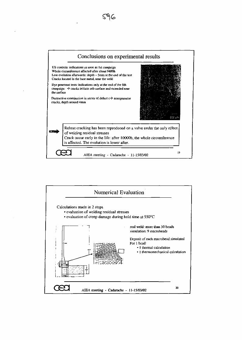
Conclusions on experimental results
US controls: indications as soon as 1st campaignWhole circumference affected after about 9400hLow evolution afterwards: depth - 5mm at the end of the testCracks located in the base metal, near the weld
Dye penetrant tests: indications only at the end of the 8thcampaign: •> cracks initiate sub-surface and extended nearthe surface
Destructive examination in sector of defect c-> intergranularcracks, depth around 4mm
Reheat cracking has been reproduced on a valve under the only effectof welding residual stressesCrack occur early in the life: after lOOOOh, the whole circumferenceis affected. The evolution is lower after.
AIEA meeting - Cadarache - 11-15/03/0219
Numerical Evaluation
Calculations made in 2 steps• evaluation of welding residual stresses• evaluation of creep damage during hold time at 550°C
real weld: more than 30 beadssimulation: 9 macrobeads
Deposit of each macrobead simulatedFor 1 bead:
• 1 thermal calculationI I • 1 thermomechanical calculation
I i
CH3 AIEA meeting - Cadarache - 11-15/03/0220
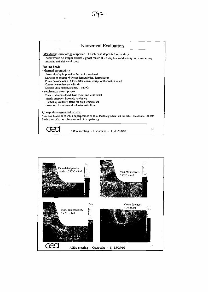
Numerical Evaluation
Welding: chronology respected -> each bead deposited separatelybead which no longer exists: « ghost material » : very low conductivity, very low Youngmodulus and high yield stress
For one bead:• thermal assumptions
Power density imposed in the bead consideredDuration of heating -> Rosenthal analytical formulationsPower density value -> F.E. calculations (shape of the molten zone)Convective exchanges with airCooling until interpass temp. (-100°C)
• mechanical assumptions2 materials considered: base metal and weld metalplastic behavior isotropic hardeningHardening recovery effect for high temperatureevolution of mechanical behavior with Temp
Creep damage evaluation:Structure heated at 550°C + superposition of axial thermal gradient on the tube - Hold time: 90000hEvaluation of stress relaxation and of creep damage
osa AIEA meeting - Cadarache - 11-15/03/0221
Cumulated plasticstrain - 550°C - t=0
Max. ppal stress 0,550°C -1=0
Creep damageT=90000h
cea AIEA meeting - Cadarache - 11-15/03/02
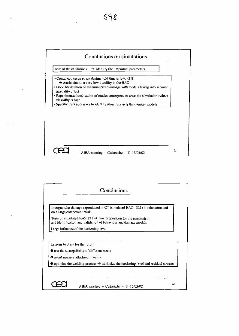
Conclusions on simulations
Aim of the emulations -> identify the important parameters
• Cumulated creep strain during hold time is low: <1%-> cracks due to a very low ductility in the HAZ
• Good localisation of maximal creep damage with models taking into accounttriaxiality effect
• Experimental localisation of cracks correspond to areas (in simulation) wheretriaxiality is high
1 Specific tests necessary to identify more precisely the damage models
AIEA meeting - Cadarache - 11-15/03/02
Conclusions
Intergranular damage reproduced in CT (simulated HAZ - 321) in relaxation andon a large component 304H
Tests on simulated HAZ 321 -^ new proposition for the mechanismand identification and validation of behaviour and damage models
Large influence of the hardening level
Lessons to draw for the future
* test the susceptibility of different steels
«9 avoid massive attachment welds
• optimize the welding process -> minimize the hardening level and residual stresses
AIEA meeting - Cadarache - 11-15/03/02

PRESENT STATUS
OF THE
RCC-MR CODE
Framatome ANP : B. Riou, C. Escaravage, M. Sperandio
EOF : B. Salles, Y. Meziere
CEA: : M.T. Cabrillat, B. Drubay
Technical Meeting on"Operational and Decommissioning Experience with Fast Reactors"
11-15 March 2002 AFRAMATOME ANP
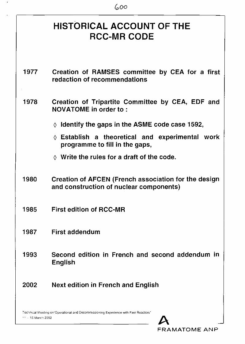
(o 00
HISTORICAL ACCOUNT OF THERCC-MR CODE
1977 Creation of RAMSES committee by CEA for a firstredaction of recommendations
1978 Creation of Tripartite Committee by CEA, EOF andNOVATOME in order to :
0 Identify the gaps in the ASME code case 1592,
0 Establish a theoretical and experimental workprogramme to fill in the gaps,
0 Write the rules for a draft of the code.
1980 Creation of AFCEN (French association for the designand construction of nuclear components)
1985 First edition of RCC-MR
1987 First addendum
1993 Second edition in French and second addendum inEnglish
2002 Next edition in French and English
Technical Meeting orY'Operational and Decommissioning Experience with Fast Reactors"
11-15 March 2002 AFRAMATOME ANP
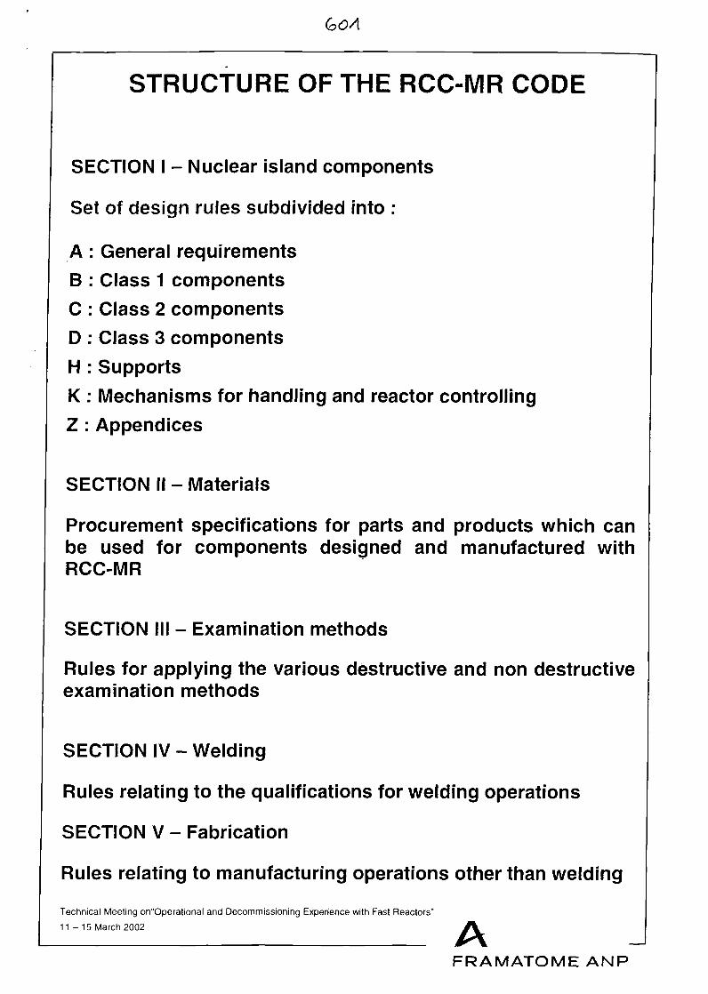
(oOA
STRUCTURE OF THE RCC-MR CODE
SECTION I - Nuclear island components
Set of design rules subdivided into :
A : General requirementsB : Class 1 componentsC : Class 2 componentsD : Class 3 componentsH : SupportsK : Mechanisms for handling and reactor controllingZ : Appendices
SECTION II - Materials
Procurement specifications for parts and products which canbe used for components designed and manufactured withRCC-MR
SECTION III - Examination methods
Rules for applying the various destructive and non destructiveexamination methods
SECTION IV - Welding
Rules relating to the qualifications for welding operations
SECTION V - Fabrication
Rules relating to manufacturing operations other than welding
Technical Meeting on"Operational and Decommissioning Experience with Fast Reactors"
11-15 March 2002 AFRAMATOME ANP
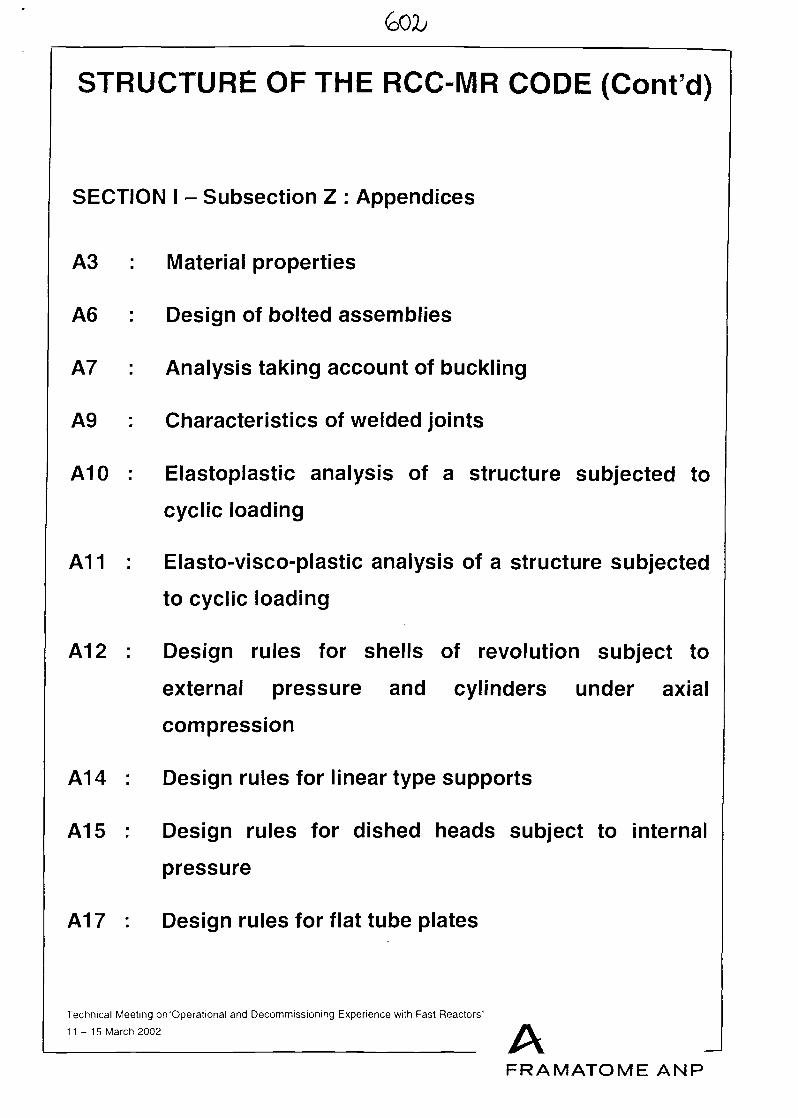
STRUCTURE OF THE RCC-MR CODE (Cont'd)
SECTION I - Subsection Z : Appendices
A3 : Material properties
A6 : Design of bolted assemblies
A7 : Analysis taking account of buckling
A9 : Characteristics of welded joints
A10 : Elastoplastic analysis of a structure subjected to
cyclic loading
A11 : Elasto-visco-plastic analysis of a structure subjected
to cyclic loading
A12 : Design rules for shells of revolution subject to
external pressure and cylinders under axial
compression
A14 : Design rules for linear type supports
A15 : Design rules for dished heads subject to internal
pressure
A17 : Design rules for flat tube plates
Technical Meeting on"Operational and Decommissioning Experience with Fast Reactors"
11-15 March 2002 AFRAMATOME ANP
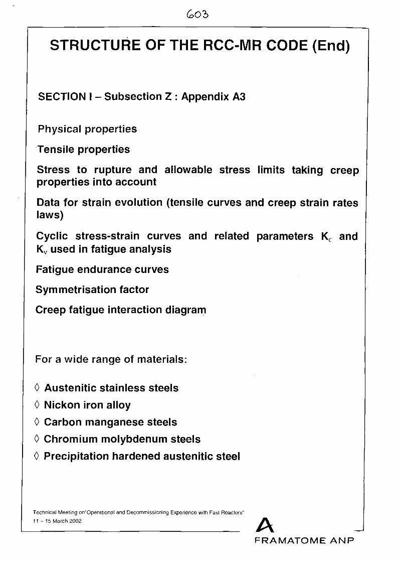
(oO'b
STRUCTURE OF THE RCC-MR CODE (End)
SECTION I - Subsection Z : Appendix A3
Physical properties
Tensile properties
Stress to rupture and allowable stress limits taking creepproperties into account
Data for strain evolution (tensile curves and creep strain rateslaws)
Cyclic stress-strain curves and related parameters Ke andKv used in fatigue analysis
Fatigue endurance curves
Symmetrisation factor
Creep fatigue interaction diagram
For a wide range of materials:
0 Austenitic stainless steels
0 Nickon iron alloy
0 Carbon manganese steels
0 Chromium molybdenum steels
0 Precipitation hardened austenitic steel
Technical Meeting on"Operational and Decommissioning Experience with Fast Reactors"
11-15 March 2002 AFRAMATOME ANP
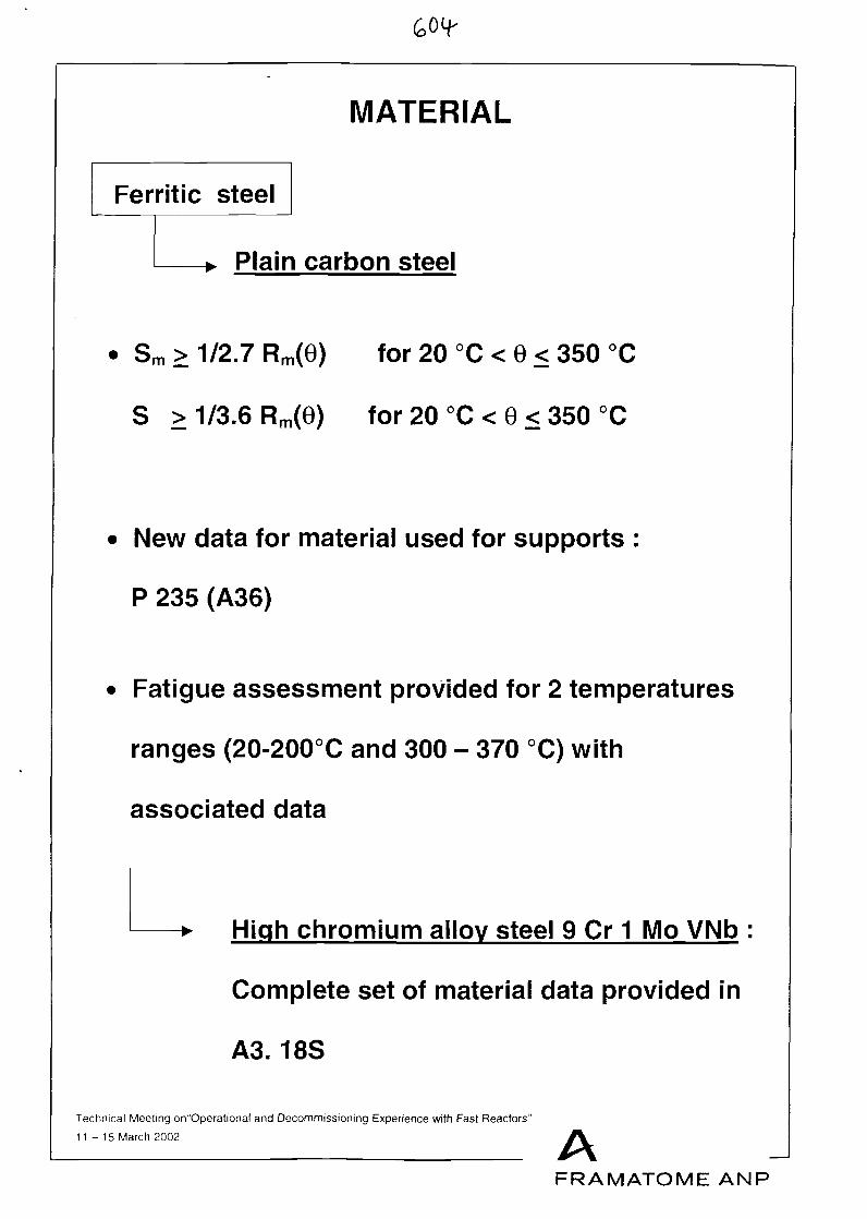
MATERIAL
Ferritic steel
-* Plain carbon steel
• Sm > 1/2.7 Rm(6) for 20 °C < 6 < 350 °C
S > 1/3.6 Rm(6) for 20 °C < 0 < 350 °C
New data for material used for supports :
P 235 (A36)
Fatigue assessment provided for 2 temperatures
ranges (20-200°C and 300 - 370 °C) with
associated data
High chromium alloy steel 9 Cr 1 Mo VNb
Complete set of material data provided in
A3. 18S
Technical Meeting on"Operational and Decommissioning Experience with Fast Reactors"
11-15 March 2002 AFRAMATOME ANP
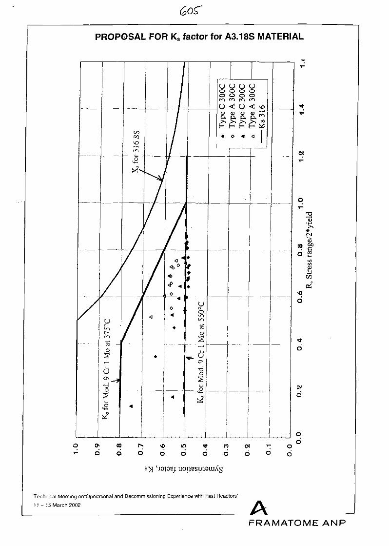
PROPOSAL FOR Ks factor for A3.18S MATERIAL
u u u uo o o oo o o o
m
Technical Meeting on"Operational and Decommissioning Experience with Fast Reactors"
11-15 March 2002 AFRAMATOME ANP
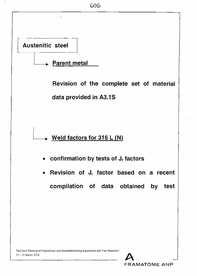
Austenitic steel
-> Parent metal
Revision of the complete set of material
data provided in A3.1S
Weld factors for 316 L(N)
• confirmation by tests of Jf factors
• Revision of Jr factor based on a recent
compilation of data obtained by test
Technical Meeting on"Operational and Decommissioning Experience with Fast Reactors"
11-15 March 2002 AFRAMATOME ANP
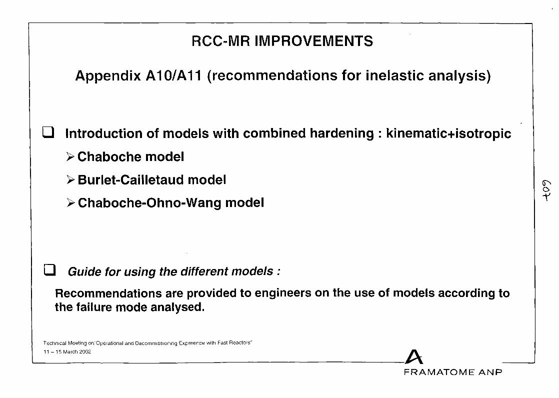
RCC-MR IMPROVEMENTS
Appendix A10/A11 (recommendations for inelastic analysis)
Q Introduction of models with combined hardening : kinematic+isotropic
> Chaboche model
> Burlet-Cailletaud model
>Chaboche-Ohno-Wang model
Guide for using the different models :
Recommendations are provided to engineers on the use of models according tothe failure mode analysed.
Technical Meeting on"Operational and Decommissioning Experience with Fast Reactors"
11-15 March 2002 AFRAMATOME ANP
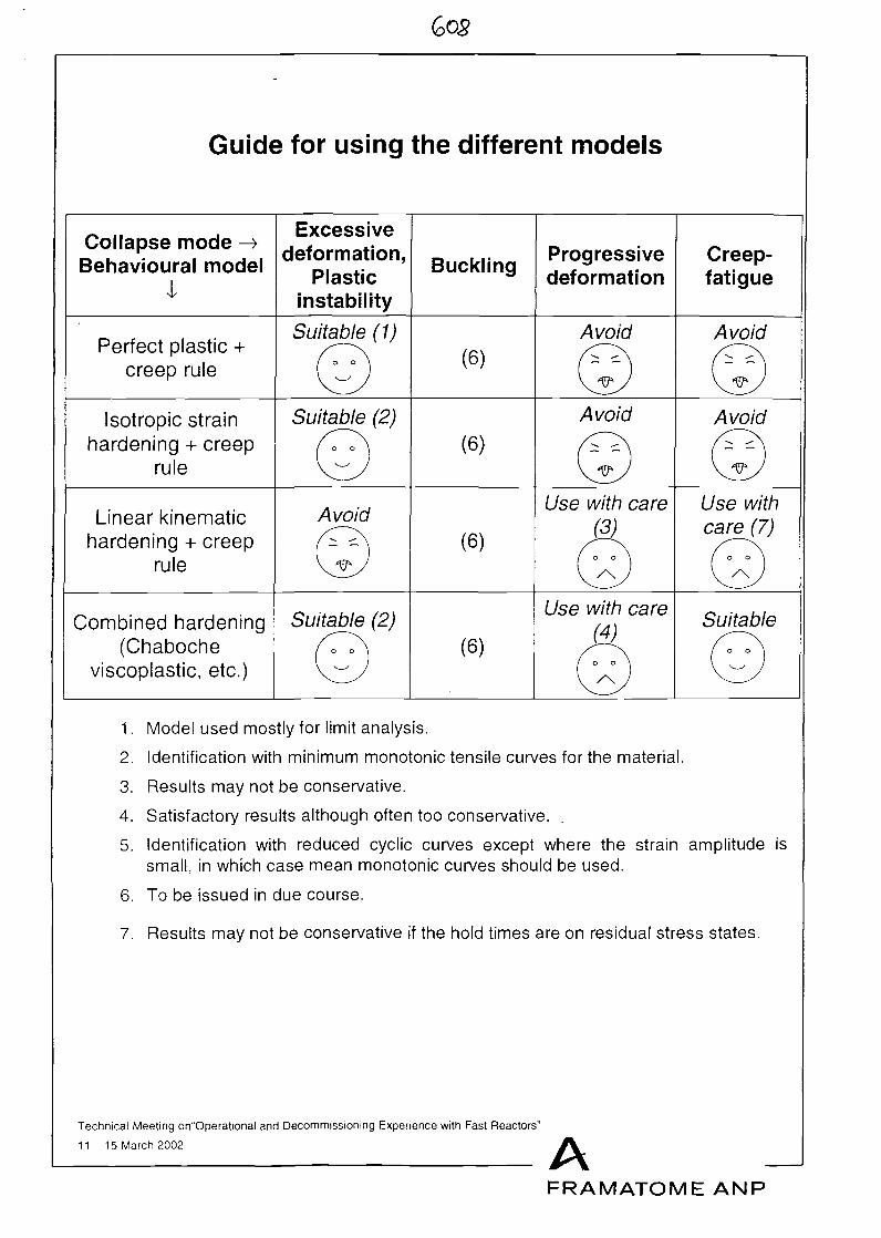
Guide for using the different models
Collapse mode ->Behavioural model
I
Excessivedeformation,
Plasticinstability
Buckling Progressivedeformation
Creep-fatigue
Perfect plastic +creep rule
Suitable (1)
©Avoid Avoid
(6)
Isotropic strainhardening + creep
rule
Suitable (2)
©Avoid
(6)
Linear kinematichardening + creep
rule
Avoid(6)
Use with care(3)
Use withcare (7)
o o
/\
Combined hardening(Chaboche
viscoplastic, etc.)
Suitable (2)(6)
Use with care(4)
AwSuitable
©1. Model used mostly for limit analysis.
2. Identification with minimum monotonic tensile curves for the material.
3. Results may not be conservative.
4. Satisfactory results although often too conservative.
5. Identification with reduced cyclic curves except where the strain amplitude issmall, in which case mean monotonic curves should be used.
6. To be issued in due course.
7. Results may not be conservative if the hold times are on residual stress states.
Technical Meeting orTOperational and Decommissioning Experience with Fast Reactors"
11-15 March 2002 AFRAMATOME ANP
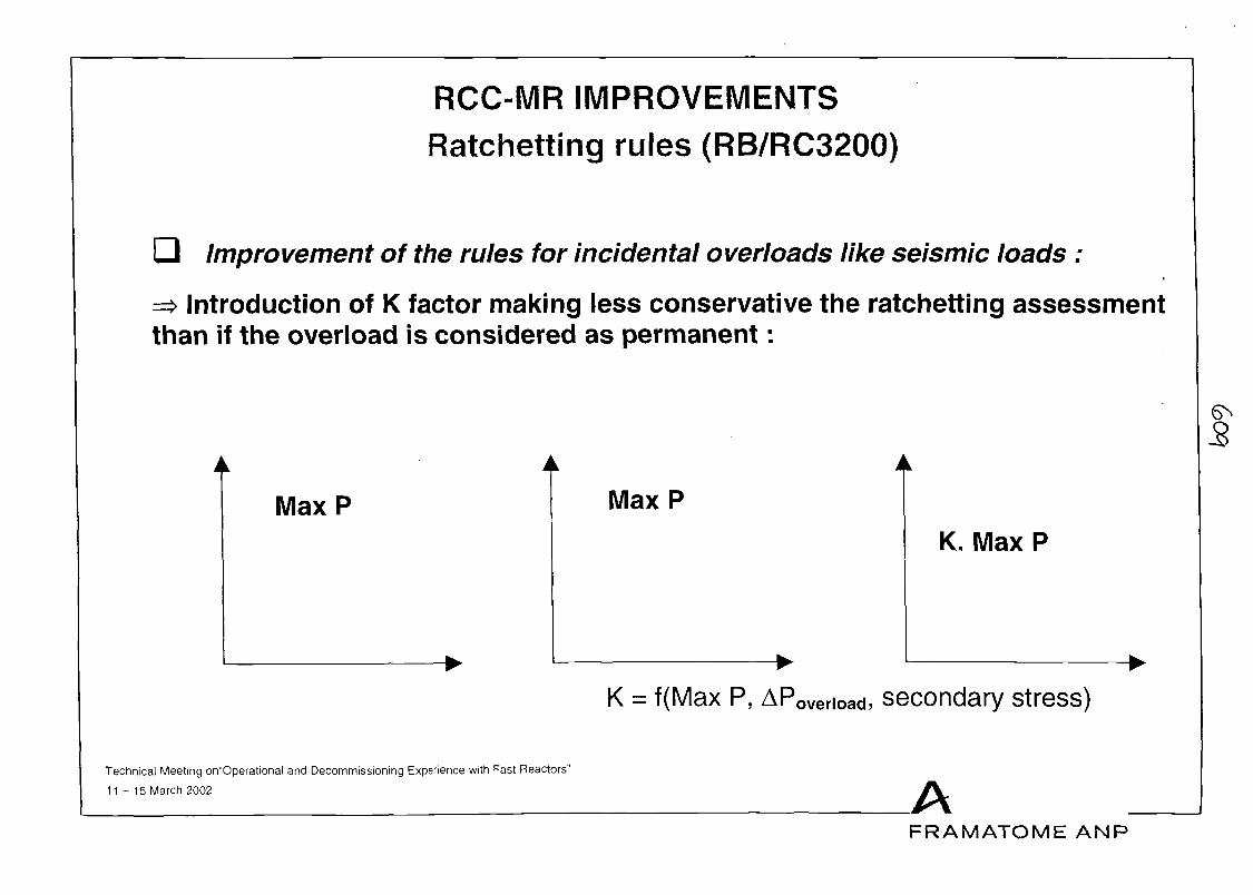
RCC-MR IMPROVEMENTSRatchetting rules (RB/RC3200)
Improvement of the rules for incidental overloads like seismic loads :
=> Introduction of K factor making less conservative the ratchetting assessmentthan if the overload is considered as permanent:
5
Max P Max P
K. Max P
K = f(Max P, APovenoad, secondary stress)
Technical Meeting on"Operational and Decommissioning Experience with Fast Reactors"
11-15 March 2002 AFRAMATOME ANP
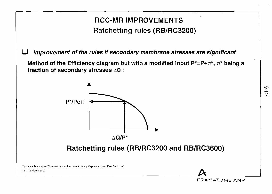
RCC-MR IMPROVEMENTSRatchetting rules (RB/RC3200)
Q Improvement of the rules if secondary membrane stresses are significant
Method of the Efficiency diagram but with a modified input P*=P+o*, o* being afraction of secondary stresses AQ :
P*/Peff
AQ/P'
Ratchetting rules (RB/RC3200 and RB/RC3600)
Technical Meeting on"Operational and Decommissioning Experience with Fast Reactors"
11-15 March 2002 AFRAMATOME ANP
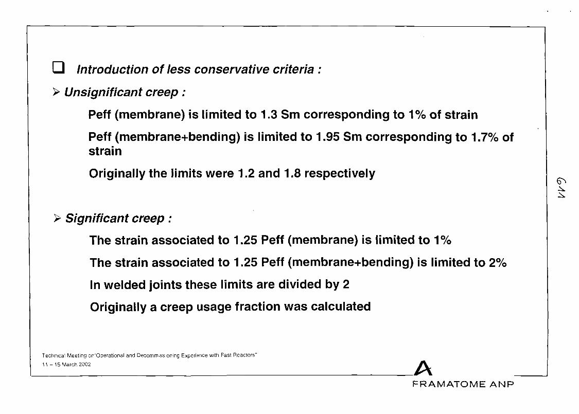
Q Introduction of less conservative criteria :
> Unsignificant creep :
Peff (membrane) is limited to 1.3 Sm corresponding to 1% of strain
Peff (membrane+bending) is limited to 1.95 Sm corresponding to 1.7% ofstrain
Originally the limits were 1.2 and 1.8 respectively
> Significant creep:
The strain associated to 1.25 Peff (membrane) is limited to 1%
The strain associated to 1.25 Peff (membrane+bending) is limited to 2%
In welded joints these limits are divided by 2
Originally a creep usage fraction was calculated
Technical Meeting on"Operational and Decommissioning Experience with Fast Reactors"
11-15 March 2002 AFRAMATOME ANP
MODIFICATIONS OF BUCKLING ANALYSIS INRCC-MR
Since May 1993, modifications of bucklinganalysis have been introduced in RCC-MR,concerning :
1.Definition of imperfection for buckling analysis
2. Appendix A12
3. Buckling analysis with significant creep
4. Buckling under cyclic loading (A7.4000)
Technical Meeting on"Operational and Decommissioning Experience with Fast Reactors"
11-15 March 2002 AFRAMATOME ANP
DEFINITION OF IMPERFECTION FORBUCKLING ANALYSIS
The definition of imperfection for bucklinganalysis can now be based on :
• Tolerances indicated on plans (as before)
• Or tolerances defined in chapter RF 4200(max. values of shape tolerances for typicalcomponents)
Technical Meeting on"Operational and Decommissioning Experience with Fast Reactors"
11 - 15 March 2002 AFRAMATOME ANP
APPENDIX A12
Appendix A12 of RCC-MR provides rules todetermine minimum thicknesses for shellssubmitted to external pressure or cylinders underaxial compression. These rules prevent fromelastic or elastoplastic instabilities.
To apply these rules, two parameters have to beassessed from diagrams :
• A : geometrical parameter
• B : parameter depending on the material
Modifications have been introduced to assess B :
• Figures A12.b1 to A12.b7 have been changed.They are now identical to the correspondingones in RCC-M.
• In the case of cylinders, B can be assessedusing an analytical method.
Technical Meeting on"Operational and Decommissioning Experience with Fast Reactors"
11-15 March 2002 AFRAMATOME ANP
BUCKLING ANALYSIS UNDER CREEP
A new method to prevent from buckling undercreep conditions is being introduced in AppendixA7 of RCC-MR (Chapter A7.5000). It is based on ananalytical model and has been verified in the caseof cylinders under external pressure.
It comprises the following steps :
• Determine the operating temperature and holdtime,
• Calculate the Euler buckling load PE,
• Calculate the load PL for which the structureplastifies,
• Determine the structure slenderness ratio PE/PLand choose the corresponding diagram,
• Determine the ratio x = P/PE (P = nominalloading),
• Determine the normalised imperfection 8 = d/h,
• If the point (x, 6) is under the failure curve of thediagram, creep buckling will not occur.
Technical Meeting on"Operational and Decommissioning Experience with Fast Reactors"
11 - 15 March 2002 AFRAMATOME ANP
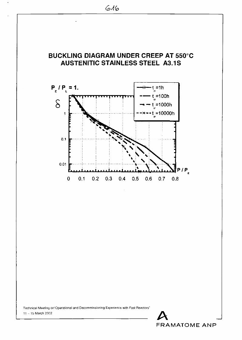
BUCKLING DIAGRAM UNDER CREEP AT 550 CAUSTENITIC STAINLESS STEEL A3.1S
0.01 -
i PIP0 0.1 0.2 0.3 0.4 0.5 0.6 0.7 0.8
Technical Meeting on"Operational and Decommissioning Experience with Fast Reactors"
11-15 March 2002 AFRAMATOME ANP
BUCKLING UNDER CYCLIC LOADING
In order to keep coherence between A7.4000(buckling under cyclic loading) and the newratcheting rule of RB 3261.11, modifications arebeing introduced in A7.4000.
The two methods of A7.4200 and A7.4300, wherethe efficiency diagram is used with modifiedstresses, are still valid, but they can now take intoaccount:
Loading with low primary stresses (modifiedefficiency diagram),
Primary overloads.
Technical Meeting on"Operational and Decommissioning Experience with Fast Reactors"
11 - 15 March 2002 AFRAMATOME ANP
CONCLUSIONS
The new edition of the RCC-MR code is inpreparation and should be issued soon.
This edition will contain improvementsfollowing R&D work performed in France andin Europe.
RCC-MR applicable not only for FBR but alsofor high temperature applications.
For more information, please contact the secretariat of afcen :
AFCEN - Tour FRAMATOME - F 92084 PARIS LA DEFENSE CEDEXTel : +33. (0)1.47.96.52.26Fax : +33. (0)1.47.96.05.01Email: [email protected]
Technical Meeting on"Operational and Decommissioning Experience with Fast Reactors"
11-15 March 2002 AFRAMATOME ANP
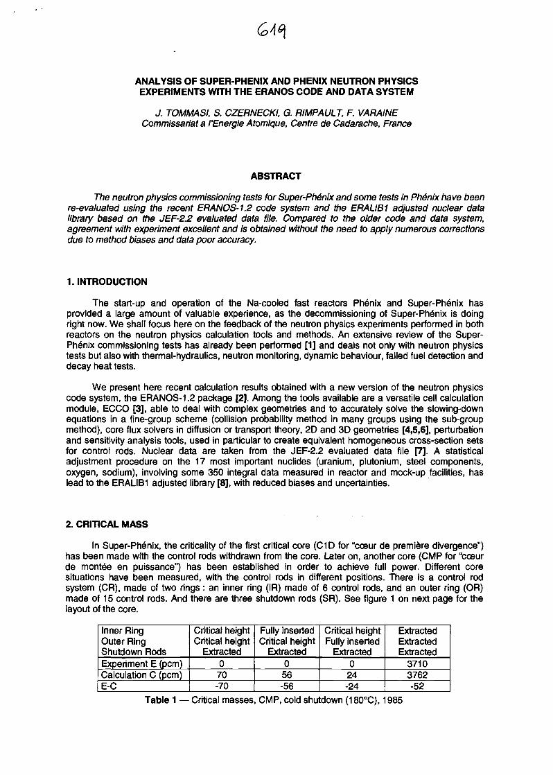
ANALYSIS OF SUPER-PHENIX AND PHENIX NEUTRON PHYSICSEXPERIMENTS WITH THE ERANOS CODE AND DATA SYSTEM
J. TOMMASI, S. CZERNECKI, G. RIMPAULT, F. VARAINECommissariat a I'Energie Atomique, Centre de Cadarache, France
ABSTRACT
The neutron physics commissioning tests for Super-Phenix and some tests in Phenix have beenre-evaluated using the recent ERANOS-1.2 code system and the ERALIB1 adjusted nuclear datalibrary based on the JEF-2.2 evaluated data file. Compared to the older code and data system,agreement with experiment excellent and is obtained without the need to apply numerous correctionsdue to method biases and data poor accuracy.
1. INTRODUCTION
The start-up and operation of the Na-cooled fast reactors Phenix and Super-Phenix hasprovided a large amount of valuable experience, as the decommissioning of Super-Ph6nix is doingright now. We shall focus here on the feedback of the neutron physics experiments performed in bothreactors on the neutron physics calculation tools and methods. An extensive review of the Super-Ph6nix commissioning tests has already been performed [1] and deals not only with neutron physicstests but also with thermal-hydraulics, neutron monitoring, dynamic behaviour, failed fuel detection anddecay heat tests.
We present here recent calculation results obtained with a new version of the neutron physicscode system, the ERANOS-1.2 package [2]. Among the tools available are a versatile cell calculationmodule, ECCO [3], able to deal with complex geometries and to accurately solve the slowing-downequations in a fine-group scheme (collision probability method in many groups using the sub-groupmethod), core flux solvers in diffusion or transport theory, 2D and 3D geometries [4,5,6], perturbationand sensitivity analysis tools, used in particular to create equivalent homogeneous cross-section setsfor control rods. Nuclear data are taken from the JEF-2.2 evaluated data file [7]. A statisticaladjustment procedure on the 17 most important nuclides (uranium, plutonium, steel components,oxygen, sodium), involving some 350 integral data measured in reactor and mock-up facilities, haslead to the ERALIB1 adjusted library [8], with reduced biases and uncertainties.
2. CRITICAL MASS
In Super-Ph6nix, the criticality of the first critical core (C1D for "cceur de premiere divergence")has been made with the control rods withdrawn from the core. Later on, another core (CMP for "coeurde montee en puissance") has been established in order to achieve full power. Different coresituations have been measured, with the control rods in different positions. There is a control rodsystem (CR), made of two rings: an inner ring (IR) made of 6 control rods, and an outer ring (OR)made of 15 control rods. And there are three shutdown rods (SR). See figure 1 on next page for thelayout of the core.
Inner RingOuter RingShutdown RodsExperiment E (pcm)Calculation C (pcm)E-C
Critical heightCritical height
Extracted070-70
Fully insertedCritical height
Extracted056-56
Critical heightFully inserted
Extracted024-24
ExtractedExtractedExtracted
37103762-52
Table 1 — Critical masses, CMP, cold shutdown (180°C), 1985
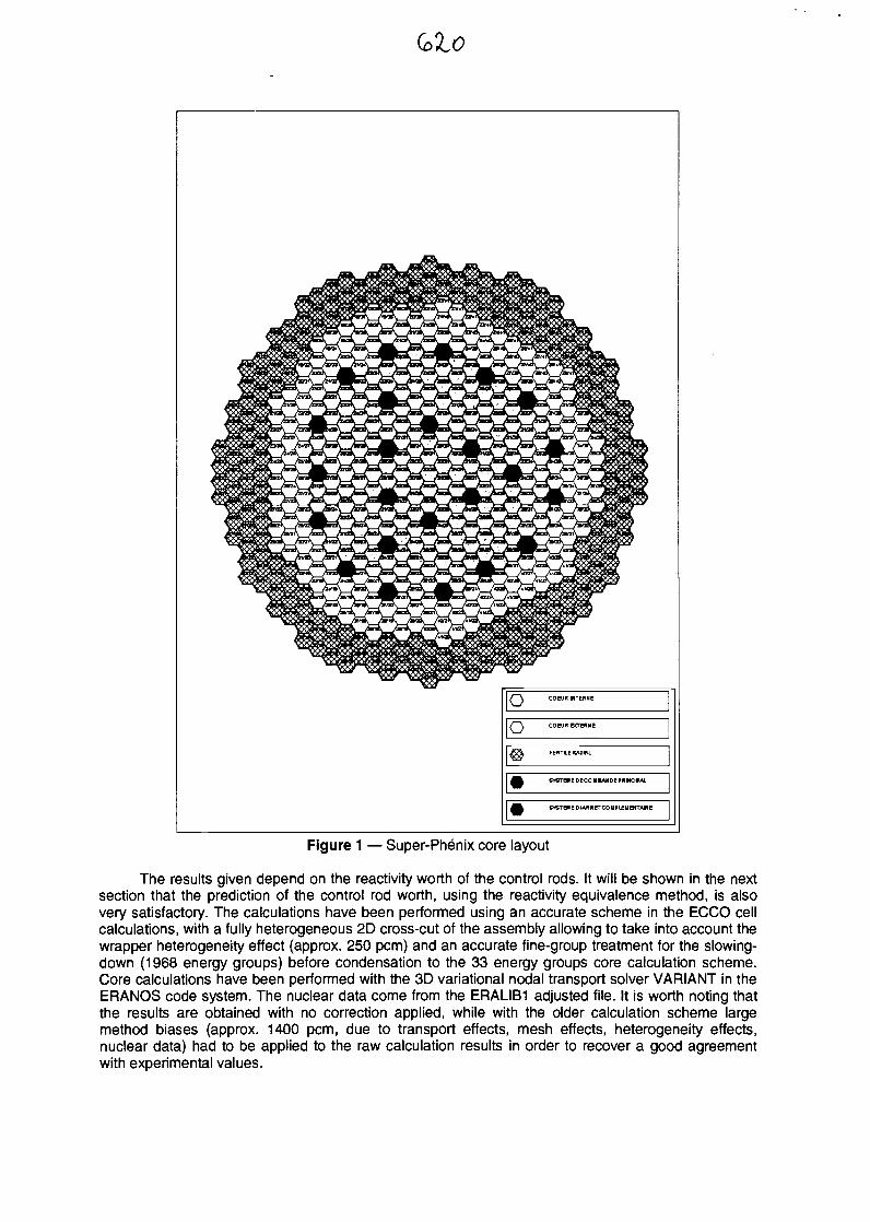
(olO
0 COEUHMTERNC
o COCUR&TMME
XSt FERTILE KADIMQCr
^ SverEUEDeCOUMANOMMMCPAL
^& CVSTEUeDtAKRCTCOUPUEUeMTAMe
Figure 1 — Super-Phenix core layout
The results given depend on the reactivity worth of the control rods. It will be shown in the nextsection that the prediction of the control rod worth, using the reactivity equivalence method, is alsovery satisfactory. The calculations have been performed using an accurate scheme in the ECCO cellcalculations, with a fully heterogeneous 2D cross-cut of the assembly allowing to take into account thewrapper heterogeneity effect (approx. 250 pcm) and an accurate fine-group treatment for the slowing-down (1968 energy groups) before condensation to the 33 energy groups core calculation scheme.Core calculations have been performed with the 3D variational nodal transport solver VARIANT in theERANOS code system. The nuclear data come from the ERALIB1 adjusted file. It is worth noting thatthe results are obtained with no correction applied, while with the older calculation scheme largemethod biases (approx. 1400 pcm, due to transport effects, mesh effects, heterogeneity effects,nuclear data) had to be applied to the raw calculation results in order to recover a good agreementwith experimental values.
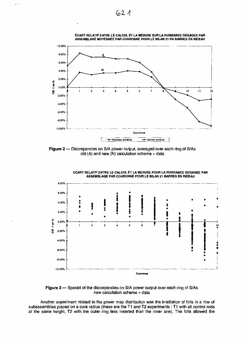
ECART RELATIF ENTRE LE CALCUL ET LA MESURE SUR LA PUISSANCE DEGAGEE PARASSEMBLAGE MOYENNEE PAR COURONNE POUR LE BILAN 21 PN BARRES EN RIDEAU
Couronne
-Nouveau schema -Ancien schema
Figure 2 — Discrepancies on S/A power output, averaged over each ring of S/Asold (A) and new (N) calculation scheme + data
ECART RELATIF ENTRE LE CALCUL ET LA MESURE POUR LA PUISSANCE DEGAGEE PARASSEMBLAGE PAR COURONNE POUR LE BILAN 21 BARRES EN RIDEAU
6.00%
4.00%
2.00% •
g 0.00% :
g -2.00%.
-4.00%-
-6.00% •
-8.00% •
• | t
• I ' l l *; i ! i ; • • ^
*
» * I 1 ; * <* * * ; § *
1 2 3 4 5 6 7 1
$
>
tii :
! i* 1
Couronn*
Figure 3 — Spread of the discrepancies on S/A power output over each ring of S/Asnew calculation scheme + data
Another experiment related to the power map distribution was the irradiation of foils in a row ofsubassemblies placed on a core radius (these are the T1 and T2 experiments : T1 with all control rodsat the same height, T2 with the outer ring less inserted than the inner one). The foils allowed the
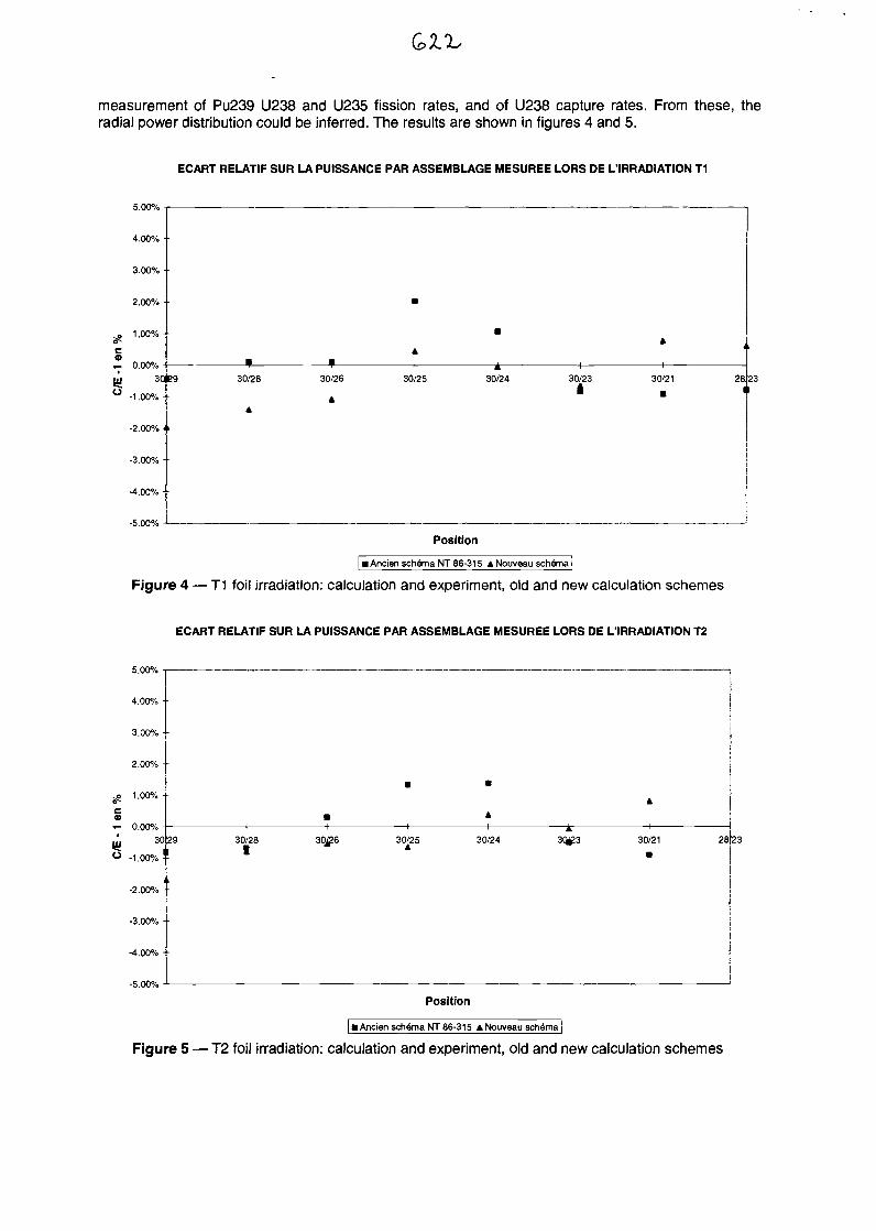
measurement of Pu239 U238 and U235 fission rates, and of U238 capture rates. From these, theradial power distribution could be inferred. The results are shown in figures 4 and 5.
ECART RELATIF SUR LA PUISSANCE PAR ASSEMBLAGE MESUREE LORS DE L'IRRADIATION T1
5.00%
4.00% •
3.00% •
2.00% • •
1.00%
,- 0.00%so eg
-1.00% - •
-2.00% <'
-3.00% -
-4.00% -
-5.00%
30/28 30/26
A
30/25 30/24 30/23 30/21 2823
Position
I Ancien schema NT 86-315 A Nouveau schema
Figure 4 — T1 foil irradiation: calculation and experiment, old and new calculation schemes
ECART RELATIF SUR LA PUISSANCE PAR ASSEMBLAGE MESUREE LORS DE L'IRRADIATION T2
5.00%
4.00% •
3.00% -
2.00% •
1.00% •
«- 0.00%3029
-1.00% ! -
-2.00% - •
-3.00% - -
-4.00% • •
-5.00%
30/28I
-4-
30J26 30/25 30/24
Position
30/21 28,23
| • Ancien schema NT 86-315 A Nouveau schema |
Figure 5 — T2 foil irradiation: calculation and experiment, old and new calculation schemes
3. CONTROL ROD WORTH
An extensive experimental programme has been carried out with the aim of precisely definingthe values of the different control rods and their interaction effects. The measurements have beenperformed with the reactor in a sub-critical state by using counters placed at the centre of the reactorand at 3 different locations under the reactor vessel. The responses of these last 3 counters wereamplified by neutron guides. This type of sub-critical measurement requires correction factors toaccount for the fact that the counters see a different perturbation depending on their position in thereactor. These correction factors have been calculated using different methods and data and show nodispersion in their results and so these corrections have therefore not been recalculated.
The preparation of cross sections for control rod absorbers requires a special treatment due tothe very high coupling of the heterogeneous control rod structure to the surrounding core cells. Themethod used is the reactivity equivalence method [9] which has been validated on the BALZAC 1Hexperiments performed in the MASURCA zero-power critical mock-up in Cadarache[10]. This methoduses the Sn transport option of the BISTRO code and its associated perturbation modules. The validityof such an approach for control rods has been evaluated not only for the reactivity variation of thecontrol rod but also for the absorption rates in the control rod and the surrounding core regions.
Antireactivity (pcm)Absorption rate
Heterogeneous(reference)
88460.345
Homogeneisationby volume
+24 %+24 %
Homogenisationby flux+6.8 %+7.0 %
Homogenisationby equivalence
-0.1 %-2.0 %
Table 2 — Control rod homogenisation techniques (SPX control rods model)
Antireactivity (pcm)Absorption rate
Heterogeneous(reference)
64010.258
Homogeneisationby volume
+23 %+23 %
Homogenisationby flux+4.2 %+4.2 %
Homogenisationby equivalence
0.0 %-1.0%
Table 3 — Control rod homogenisation techniques (SPX lower backup rods model)
One can see the validity of the recommended method (errors in the last column) but also theinadequacy of simpler methods (homogenisation by volume or by flux) for the determination of thecontrol rod worth. The control and shutdown systems have been measured under different situationsand their control rod reactivity worth have been calculated with the current scheme. The results aregiven in the table below.
Ap(CR), SR extractedAp(SR), CR fully inserted
Ap(SR), CR at critical heightAp(3 outer rods) other CR at critical heightAp(3 inner rods) other CR at critical height
Exp. (pcm)8067 ± 9951193 ±15510391120-1115±134-1530 ±184
Cal. (pcm)811911151009-1106-1505
C/E1.0060.9350.9710.9920.984
Table 4 — Super-Ph6nix control rod worth (CMP, 180°C, 1985)
Results with the previous calculation scheme were giving C/E values of about +5% to 20%. Thefact that the comparison is significantly improved indicates that both the method and the nuclear datahave been improved and that there remain probably no compensating effects. The results obtainedwith the ERANOS calculation scheme are therefore satisfactory and this scheme can be considered tobe reliable as an explicit treatment of all shadowing and transport effects is taken into account.
This good behaviour is also observed for the prediction of control rod reactivity worth in thePhenix reactor. There is only a ring of 6 control rods in this reactor. The results are gathered in table 5.
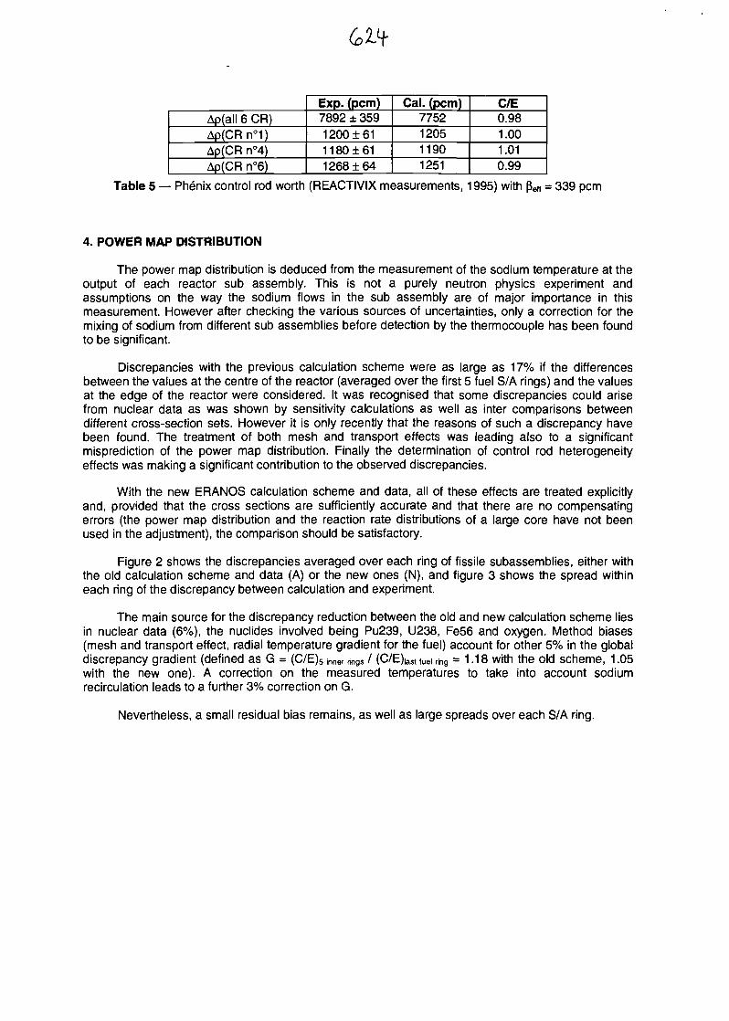
Ap(all 6 CR)Ap(CRn°1)Ap(CR n°4)Ap(CR n°6)
Exp. (pern)7892 ± 3591200 ±6111801611268 ±64
Cal. (pern)7752120511901251
C/E0.981.001.010.99
Table 5 — Phenix control rod worth (REACTIVIX measurements, 1995) with pe(( = 339 pcm
4. POWER MAP DISTRIBUTION
The power map distribution is deduced from the measurement of the sodium temperature at theoutput of each reactor sub assembly. This is not a purely neutron physics experiment andassumptions on the way the sodium flows in the sub assembly are of major importance in thismeasurement. However after checking the various sources of uncertainties, only a correction for themixing of sodium from different sub assemblies before detection by the thermocouple has been foundto be significant.
Discrepancies with the previous calculation scheme were as large as 17% if the differencesbetween the values at the centre of the reactor (averaged over the first 5 fuel S/A rings) and the valuesat the edge of the reactor were considered. It was recognised that some discrepancies could arisefrom nuclear data as was shown by sensitivity calculations as well as inter comparisons betweendifferent cross-section sets. However it is only recently that the reasons of such a discrepancy havebeen found. The treatment of both mesh and transport effects was leading also to a significantmisprediction of the power map distribution. Finally the determination of control rod heterogeneityeffects was making a significant contribution to the observed discrepancies.
With the new BRANDS calculation scheme and data, all of these effects are treated explicitlyand, provided that the cross sections are sufficiently accurate and that there are no compensatingerrors (the power map distribution and the reaction rate distributions of a large core have not beenused in the adjustment), the comparison should be satisfactory.
Figure 2 shows the discrepancies averaged over each ring of fissile subassemblies, either withthe old calculation scheme and data (A) or the new ones (N), and figure 3 shows the spread withineach ring of the discrepancy between calculation and experiment.
The main source for the discrepancy reduction between the old and new calculation scheme liesin nuclear data (6%), the nuclides involved being Pu239, U238, Fe56 and oxygen. Method biases(mesh and transport effect, radial temperature gradient for the fuel) account for other 5% in the globaldiscrepancy gradient (defined as G = (C/E)5 -nner rings / (C/E)iaSt fuei ring = 1.18 with the old scheme, 1.05with the new one). A correction on the measured temperatures to take into account sodiumrecirculation leads to a further 3% correction on G.
Nevertheless, a small residual bias remains, as well as large spreads over each S/A ring.
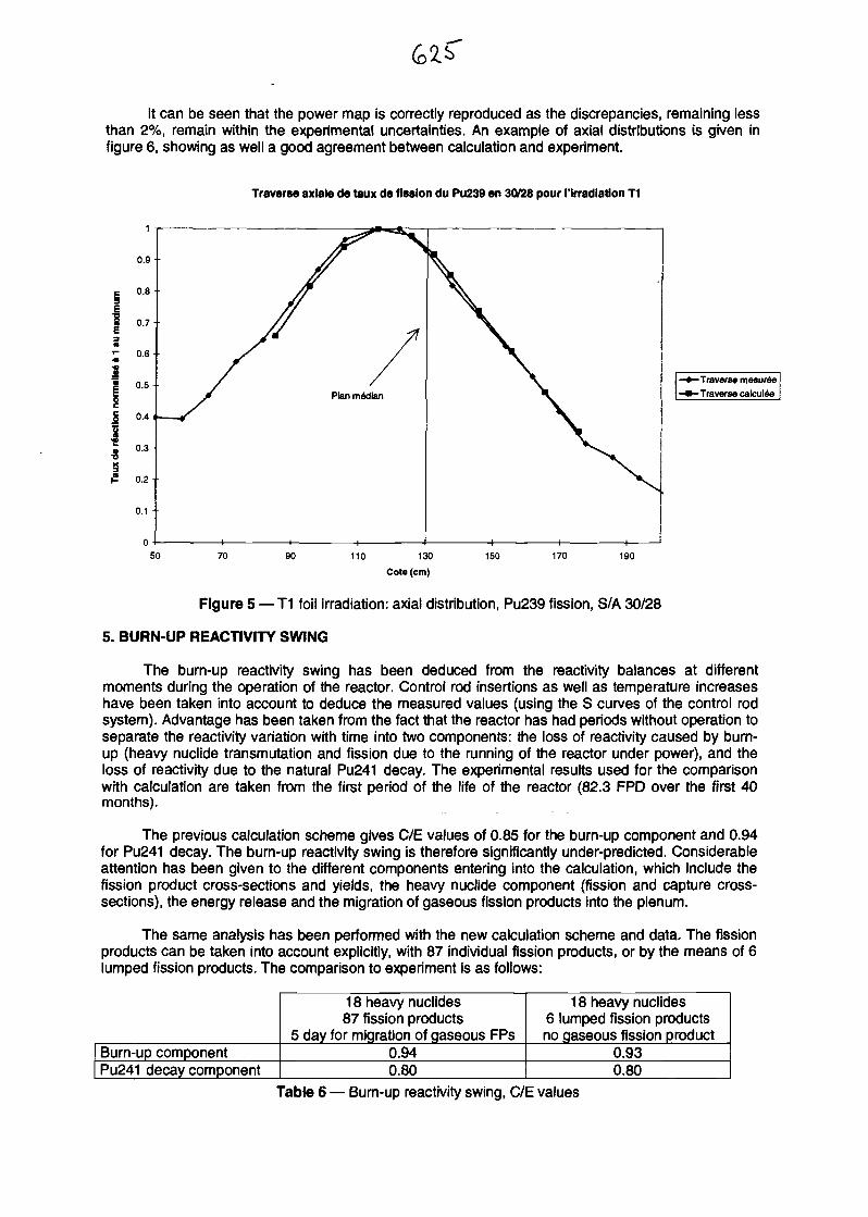
It can be seen that the power map is correctly reproduced as the discrepancies, remaining lessthan 2%, remain within the experimental uncertainties. An example of axial distributions is given infigure 6, showing as well a good agreement between calculation and experiment.
Traverse axiale de taux de fission du Pu239 en 30/28 pour ('irradiation T1
-Traverse mesuree- Traverse cafcu lee
110 130
Cote (cm)
150 170 190
Figure 5 — T1 foil irradiation: axial distribution, Pu239 fission, S/A 30/28
5. BURN-UP REACTIVITY SWING
The burn-up reactivity swing has been deduced from the reactivity balances at differentmoments during the operation of the reactor. Control rod insertions as well as temperature increaseshave been taken into account to deduce the measured values (using the S curves of the control rodsystem). Advantage has been taken from the fact that the reactor has had periods without operation toseparate the reactivity variation with time into two components: the loss of reactivity caused by burn-up (heavy nuclide transmutation and fission due to the running of the reactor under power), and theloss of reactivity due to the natural Pu241 decay. The experimental results used for the comparisonwith calculation are taken from the first period of the life of the reactor (82.3 FPD over the first 40months).
The previous calculation scheme gives C/E values of 0.85 for the burn-up component and 0.94for Pu241 decay. The burn-up reactivity swing is therefore significantly under-predicted. Considerableattention has been given to the different components entering into the calculation, which include thefission product cross-sections and yields, the heavy nuclide component (fission and capture cross-sections), the energy release and the migration of gaseous fission products into the plenum.
The same analysis has been performed with the new calculation scheme and data. The fissionproducts can be taken into account explicitly, with 87 individual fission products, or by the means of 6lumped fission products. The comparison to experiment is as follows:
18 heavy nuclides87 fission products
5 day for migration of gaseous FPs
18 heavy nuclides6 lumped fission productsno gaseous fission product
Burn-up component 0.94 0.93Pu241 decay component 0.80 0.80
Table 6 — Bum-up reactivity swing, C/E values
The calculation results are satisfactory even when using simplified calculation schemes withlumped fission products. The reasons for the improvement in the bum-up component are linked todifferences in the energy release per fission and the fission cross section of Plutonium 239, which forthe same power normalisation induce a different fluence. Also of importance are the fission productcross sections and the fact that complete decay chains are explicitly treated. However the decaycomponent remains mispredicted.
6. DOPPLER REACTIVITY COEFFICIENT
During the start-up of Super-Ph6nix, an experiment related to the Doppler effect has beenperformed, on the CMP core, decreasing slowly the temperature from 400°C to 180°C whilemaintaining isothermal conditions in the reactor. The increase in reactivity was compensated bycontrol rod insertion. The contributions of the expansion reactivity coefficient (linear with respect totemperature) and of the Doppler effect (logarithmic with respect to temperature) have been separated.The model took into account the effective temperature, using the Debye temperature. The comparisonof experiment and calculation, using the reference scheme is given in the following table.
Measured Doppler constantCalculated Doppler constantC/E
1240117512431.00
Table 7 — Doppler constant measurement and calculation
7. CONCLUSION
This paper presents the results obtained with the ERANOS calculation scheme and data forseveral major parameters of the Super-Phenix start up core (CMP) including the critical mass, thecontrol rod reactivity worth, the power map distribution, the burn up reactivity swing and the Dopplerfeedback.
Agreement of calculation results with experiment are very satisfactory: agreement within 100pcm for the critical mass, less than 5% discrepancy on control rod worth, a residual radial gradient ofless than 5% the radial power map, an discrepancy less than 10% on the reactivity swing, and a fullagreement on the Doppler constant.
This demonstrates a significant improvement on the predictions made with the previouscalculation scheme and data, in particular by calculating the values of the core experiments directlywithout the need for separate calculation and application of numerous additional corrections (e.g. thecontrol rod worth calculation with the old scheme and data required some 50 basic calculations toreach the method biases necessary, while only 3 are needed with the new tools).
REFERENCES
[1] Nuclear Science and Engineering, 106, 1-98, September 1990 (special issue devoted to Super-Phenix commissioning tests)
[2] J.Y. DORIATH, C. Me CALLIEN, E. KIEFHABER, U. WEHMANN, J.M. RIEUNIER, "ERANOS 1 :the advanced European system of codes for reactor physics calculation", International Conferenceon Mathematical Methods and Super Computing in Nuclear Applications, April 19-23, 1993,Karlsruhe, Germany
[3] G. RIMPAULT, "Algorithmic features of the ECCO cell code for treating heterogeneous fast reactorassemblies", International topical meeting on reactor physics and computation, Portland, Oregon,USA, May 1-5, 1995
[4] G. PALMIOTTI, J.M. RIEUNIER, C. GHO, M. SALVATORES, "The BISTRO optimised two-dimensional Sn transport code", Topical meeting on advances in reactor physics, mathematics andcomputation, Paris, France, April 1987
[5] C.B. CARRICO, E.E. LEWIS and G. PALMIOTTI, "Three dimensional variational nodal transportmethods for Cartesian, triangular and hexagonal criticality calculations", Nuclear Science andEngineering, 111, 168-179, June 1992
[6] G. PALMIOTTI, C.B. CARRICO and E.E. LEWIS, "Variational nodal methods with anisotropicscattering", Nuclear Science and Engineering, 115, 233-243, November 1993
[7] J.L. ROWLANDS and N. TUBBS, "The Joint Evaluated File", International conference on nucleardata for basic and applied sciences, Santa Fe, New Mexico, USA, May 1985
[8] E. FORT, W. ASSAL, G. RIMPAULT, J. ROWLANDS, P. SMITH, R. SOULE, "Realisation andperformance of the adjusted nuclear data library ERALIB 1 for calculation fast reactor neutronics",PHYSOR'96, Mito, Japan, September 1996
[9] J.L. ROWLANDS, C.R. EATON, "The spatial averaging of cross-sections for use in transporttheory reactor calculations, with an application to control rod fine homogenisation", Specialists'meeting on homogenisation methods in reactor physics, Lugano, Switzerland, November 1978
[10] M. CARTA, G. GRANGET, G. PALMIOTTI, M. SALVATORES, R. SOULE, "Control rodheterogeneity effects in liquid metal fast breeder reactors: method developments and experimentalvalidatiorf', Nuclear Science and Engineering, 100, 269-276,1988

ANALYSIS OF SUPER-PHENIX AND PHENIX NEUTRON PHYSICSEXPERIMENTS WITH THE ERANOS CODE AND DATA SYSTEM
J. TOMMASI, S. CZERNECKI, G. RIMPAULT, F. VARAINE gCommissariat a I'Energie Atomique, Centre de Cadarache, France <*>
BACKGROUND
• Start-up and operation of the Phenix and Super-Phenix Na-cooled fastreactors has provided a large amount of valuable experience.
• Focus here on the feedback of neutron physics experiments on neutronicscalculation tools and methods.
• Extensive review of Super-Phenix commissioning tests performed in Nucl.Sci. Eng. 106, 1-98, September 1990
• Since then, upgrading of the neutron physics calculation tool ERANOS andnuclear data used motivated a new interpretation of several neutronphysics tests.
NEUTRON PHYSICS ANALYSIS : THE ERANOS-1.2 PACKAGE (1)
Neutron physics code system, developed within an European framework(ERANOS = European Reactor ANalysis Optimized System).
Deterministic, modular code system, with a user's language allowing to writecomplex routines.
JEF-2.2 based nuclear data libraries (1968, 172 and 33 energy groups); ^statistical adjustment (over 350 integral values) used to produce the oERALIB1 library.
Including ECCO, a versatile cell calculation module using collisionprobabilities, subgroup method for self-shielding, with a wide availablerange of 1D, 2D and 3D geometries.
NEUTRON PHYSICS ANALYSIS : THE ERANOS-1.2 PACKAGE (2)
• Flux solvers : diffusion (1D, 2D, 3D), Sn transport (1D, 2D), nodal variationaltransport (2D, 3D).
• Homogeneous (no external source) or inhomogeneous (external source)problems.
• Direct or adjoint problems, fundamental and harmonics.
• Burn-up and decay.
• Perturbation theory techniques.
CRITICALMASS (1)
CMP loading in Super-Phenix, established to achieve full power.
Control rod system : 6 (inner ring, IR)+15 (outer ring, OR) control rods (CR),and 3 shutdown rods (SR).
Nuclear data from the ERALIB1 adjusted JEF-2.2 based nuclear data file.
Cell calculations : full 2D representation of fuel S/As (including wrapper), witha step in 1968 energy groups, homogenised with preservation of thereaction rate balance, and condensed to 33 groups.
Core calculations : 3D variational transport, 33 energy groups.
Control rod calculations : use of the reactivity homogenisation technique (seebelow).
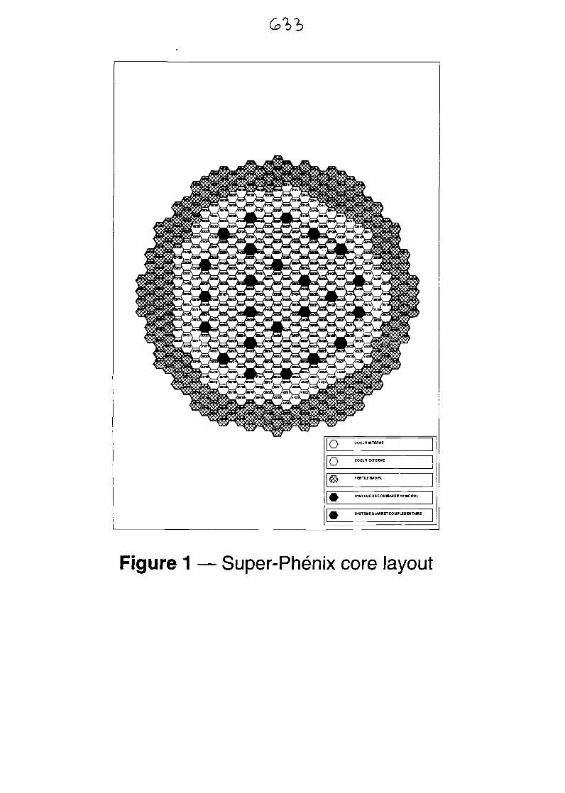
Figure 1 — Super-Phenix core layout
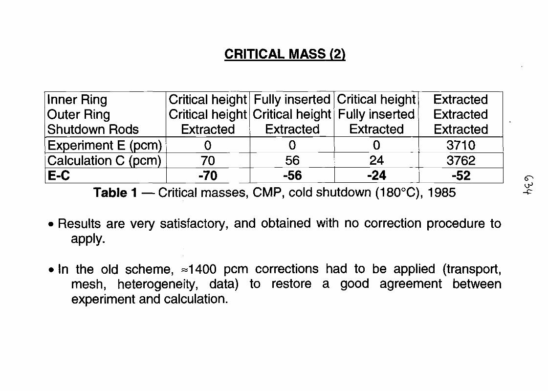
CRITICAL MASS (2)
Inner RingOuter RingShutdown RodsExperiment E (pern)Calculation C (pcm)E-C
Critical heightCritical height
Extracted070-70
Fully insertedCritical height
Extracted056-56
Critical heightFully inserted
Extracted024-24
ExtractedExtractedExtracted
37103762-52
Table 1 — Critical masses, CMP, cold shutdown (180°C), 1985
Results are very satisfactory, and obtained with no correction procedure toapply.
In the old scheme, -1400 pcm corrections had to be applied (transport,mesh, heterogeneity, data) to restore a good agreement betweenexperiment and calculation.
-p
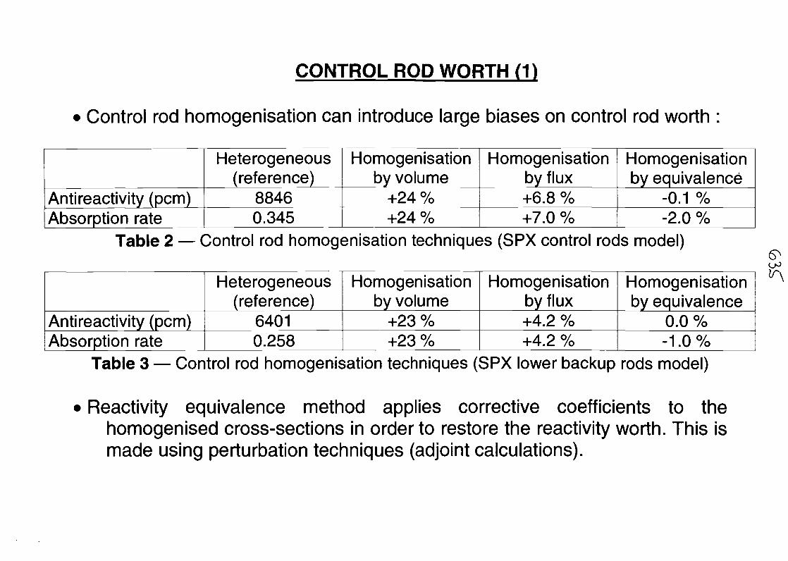
CONTROL ROD WORTH (1)
Control rod homogenisation can introduce large biases on control rod worth :
Anti reactivity (pern)Absorption rate
Heterogeneous(reference)
88460.345
Homogenisationby volume
+24 %+24 %
Homogenisationby flux+6.8 %+7.0 %
Homogenisationby equivalence
-0.1 %-2.0 %
Table 2 — Control rod homogenisation techniques (SPX control rods model)
Anti reactivity (pern)Absorption rate
Heterogeneous(reference)
64010.258
Homogenisationby volume
+23 %+23 %
Homogenisationby flux+4.2 %+4.2 %
Homogenisationby equivalence
0.0 %-1.0%
Table 3 — Control rod homogenisation techniques (SPX lower backup rods model)
• Reactivity equivalence method applies corrective coefficients to thehomogenised cross-sections in order to restore the reactivity worth. This ismade using perturbation techniques (adjoint calculations).
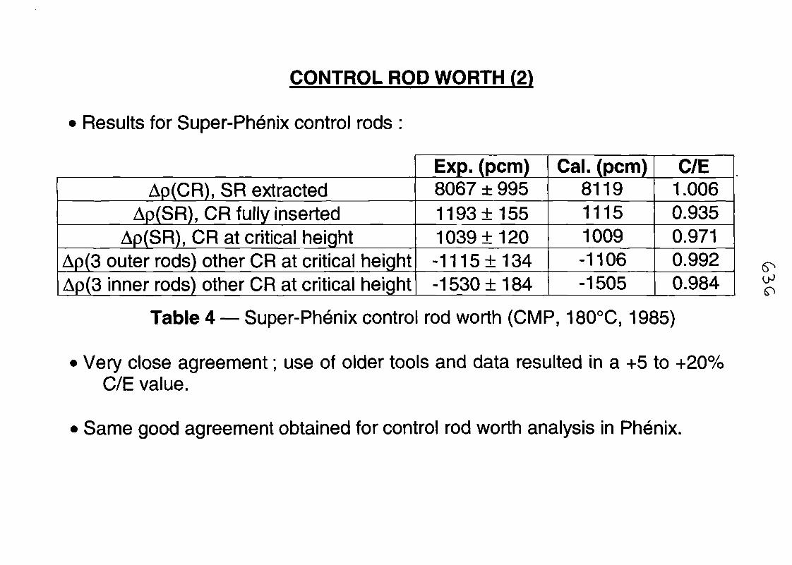
CONTROL ROD WORTH (2)
Results for Super-Phenix control rods :
Ap(CR), SR extractedAp(SR), CR fully inserted
Ap(SR), CR at critical heightAp(3 outer rods) other CR at critical heightAp(3 inner rods) other CR at critical height
Exp. (pern)8067 ± 9951193 ±1551039 ±120-1115±134-1530+184
Cal. (pcm)811911151009-1106-1505
C/E1.0060.9350.9710.9920.984
Table 4 — Super-Phenix control rod worth (CMP, 180°C, 1985)
Very close agreement; use of older tools and data resulted in a +5 to +20%C/E value.
Same good agreement obtained for control rod worth analysis in Phenix.
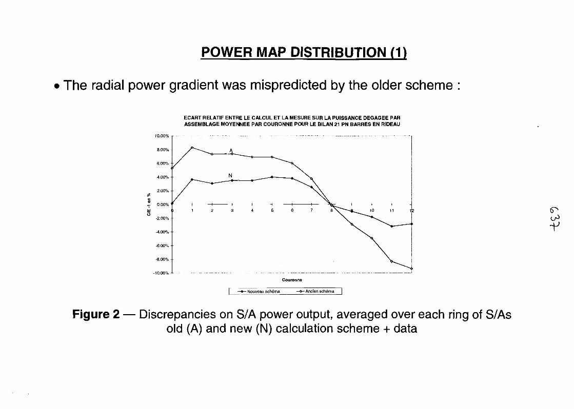
POWER MAP DISTRIBUTION (1)
The radial power gradient was mispredicted by the older scheme
ECART RELATIF ENTRE LE CALCUL ET LA MESURE SUR LA PUISSANCE DEGAGEE PARASSEMBLAGE MOYENNEE PAR COURONNE POUR LE BILAN 21 PN BARRES EN RIDEAU
-10.00% J
Couronne
- Nouveau schema -Ancien schema
-V
Figure 2 — Discrepancies on S/A power output, averaged over each ring of S/Asold (A) and new (N) calculation scheme + data
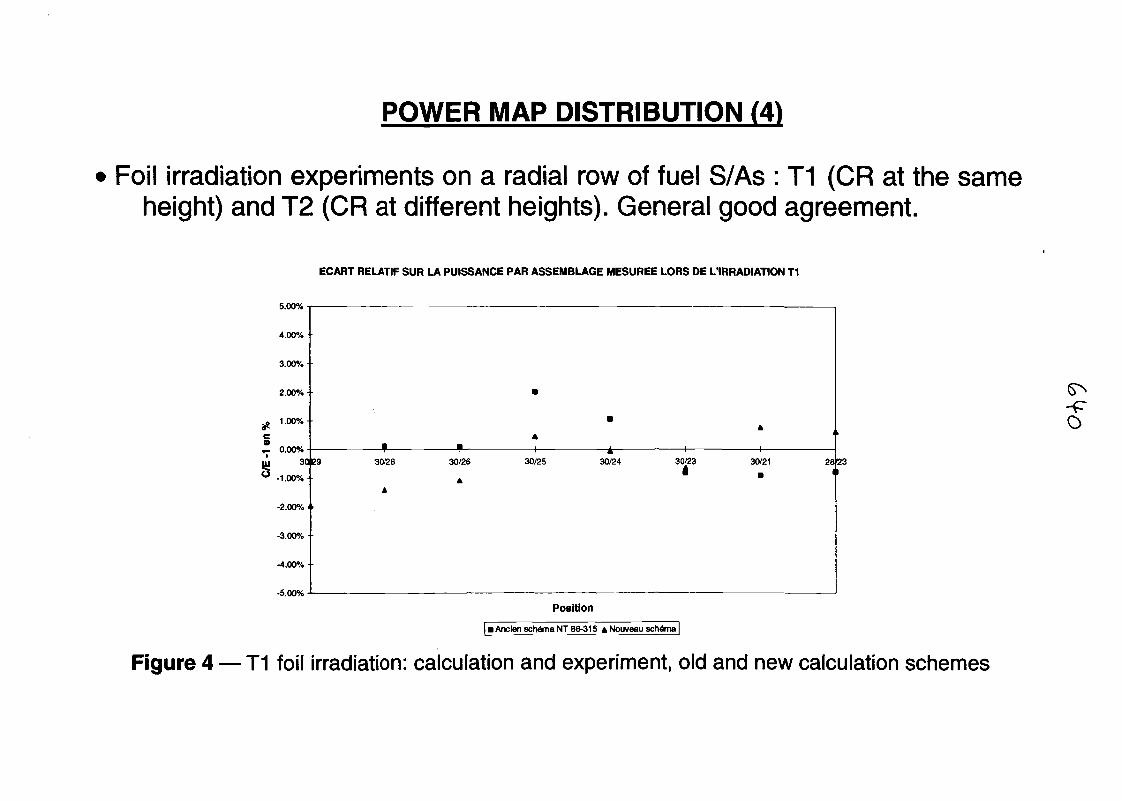
POWER MAP DISTRIBUTION (4)
Foil irradiation experiments on a radial row of fuel S/As : T1 (CR at the sameheight) and T2 (CR at different heights). General good agreement.
ECART RELATIF SUR LA PUISSANCE PAR ASSEMBLAGE MESUREE LORS DE L'IRRADIATION T1
5.00%
4.00%-
3.00% •
2.00%
S? 1.00%-
r- 0.00%
-1.00%
-2.00% • r
-3.00%
-4.00%
-5.00%
3029 '30/28
A
30/26
A
30/25 30/24 30/23 30/21 2823
o
Position
I Ancien schema NT 86-315 4 Nouveau schema |
Figure 4 — T1 foil irradiation: calculation and experiment, old and new calculation schemes
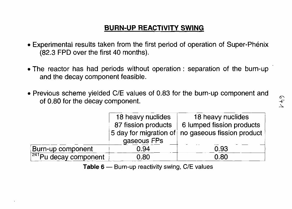
BURN-UP REACTIVITY SWING
• Experimental results taken from the first period of operation of Super-Phenix(82.3 FPD over the first 40 months).
• The reactor has had periods without operation : separation of the burn-upand the decay component feasible.
• Previous scheme yielded C/E values of 0.83 for the burn-up component andof 0.80 for the decay component.
18 heavy nuclides87 fission products
5 day for migration ofgaseous FPs
18 heavy nuclides6 lumped fission productsno gaseous fission product
-T
Burn-up component241 Pu decay component
0.94 0.930.80 0.80
Table 6 — Burn-up reactivity swing, C/E values
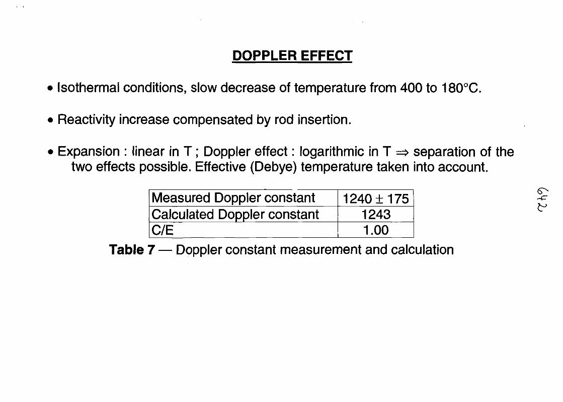
DOPPLER EFFECT
Isothermal conditions, slow decrease of temperature from 400 to 180°C.
Reactivity increase compensated by rod insertion.
Expansion : linear in T; Doppler effect: logarithmic in T => separation of thetwo effects possible. Effective (Debye) temperature taken into account.
Measured Doppler constantCalculated Doppler constantC/E
1240 ±17512431.00
Table 7 — Doppler constant measurement and calculation
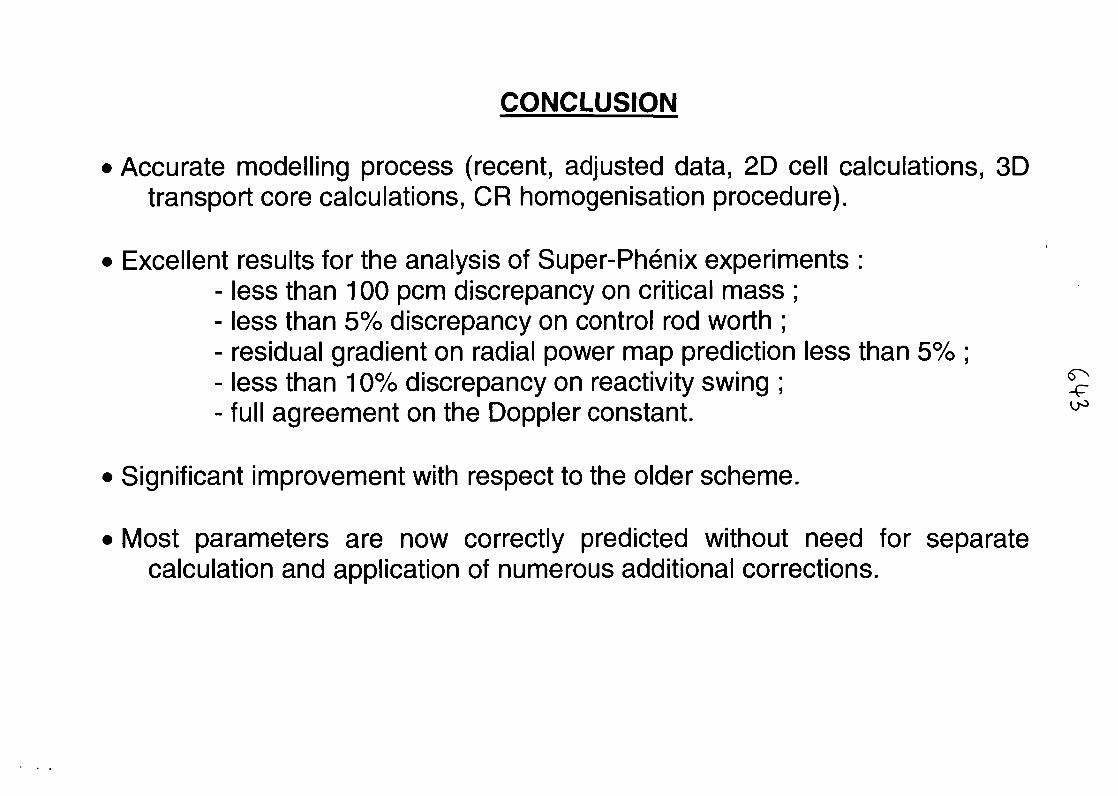
CONCLUSION
• Accurate modelling process (recent, adjusted data, 2D cell calculations, 3Dtransport core calculations, CR homogenisation procedure).
• Excellent results for the analysis of Super-Phenix experiments :- less than 100 pern discrepancy on critical mass ;- less than 5% discrepancy on control rod worth ;- residual gradient on radial power map prediction less than 5% ;- less than 10% discrepancy on reactivity swing ;- full agreement on the Doppler constant.
• Significant improvement with respect to the older scheme.
• Most parameters are now correctly predicted without need for separatecalculation and application of numerous additional corrections.
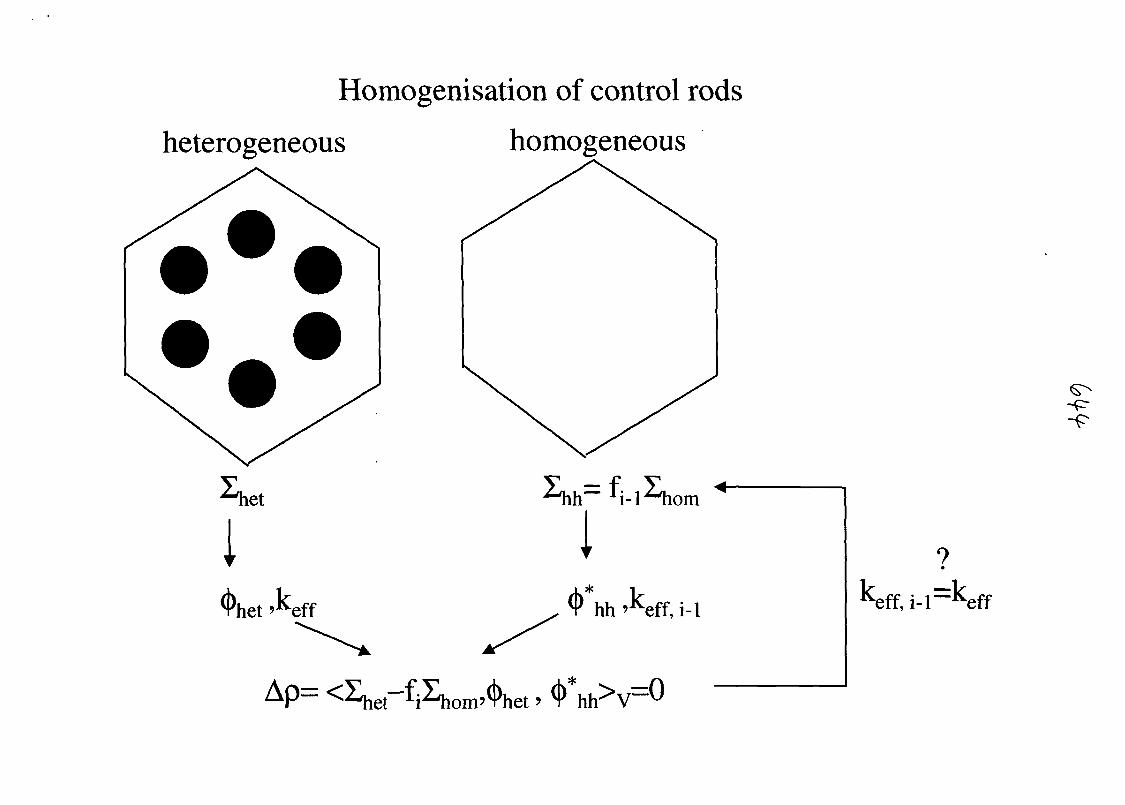
Homogenisation of control rods
heterogeneous homogeneous
et
l<t>het . eff
11
hh

Physics and Engineering Experiments in Fast BreederTest Reactor
K.V. Suresh Kumar, C.P. Reddy, R. IndiraR.S Kesava Murthy, N. Kasinathan, R.P. Kapoor,
P.V.Ramalingam, B. Rajendran, G. Srinivasan
Abstract
Fast Breeder Test Reactor (FBTR) is sodium cooled, loop type,mixed carbide-fueled reactor of 40 MWt/13.2 MWe capacityplant It was built to gain experience in design, construction andoperation of LMFBR and to serve as an irradiation facility fordevelopment of fuel and structural material for LMFBRprogramme. The reactor has 2 primary & secondary loops and acommon steam water circuit with once through steam generator,which supplies super heated steam to the turbine. The final heatrejection is through induced draft cooling tower. In order toenable reactor operation when the turbine is not available, a100% dump facility is incorporated in steam water circuit.Reactor achieved first criticality in Oct' 85 with Mark I small coreand Turbo generator was synchronized to the grid in Jul '97.
For steady power operation, it is essential and mandatory tocarryout important safety related Physics and Engineering teststo validate the data used in safety evaluation. Feedbacks fromthe experiments are also used to validate and refine variousmathematical models/codes for better prediction. This paperdetails the results of these physics and engineering tests.Certain important tests planned for future are also mentioned.
1.0 Introduction
Fast Breeder Test Reactor (FBTR) is a 40 MWt/13.2 MWe sodiumcooled reactor located at Kalpakkam, India. It has two primaryand two secondary loops and a common steam/water system.Each loop comprises a primary pump, an intermediatesodium/sodium heat exchanger (IHX) and two modules of oncethrough steam generator (SG). The steam generated can beused to drive a turbine or bypassed in a separate full capacitydump condenser. Presently reactor is fuelled by Mark-I (70%PuC+ 30% UC, 25 SA) and Mark II (55% PuC+ 45% UC, 10 SA)small core of PuC-UC and the maximum power reached is 13.4MWt.
Reactor physics experiments were continued from initialcriticality to full power operation. Initial core loading andapproach to criticality was followed by several physics testsrelated to measurement of control rod (CR) worth, subassembly(SA) worth, feed back reactivity coefficient related to power,coolant void, coolant temperature, coolant flow and cover gaspressure, kinetic experiments, flux tilting and flux measurementexperiments (1).
The power was raised to 10.2 MWt in Dec '93 for the first time.Before resorting to steady power operation, it is mandatory tocarry out important safety related high power engineering teststo validate all assumptions made in the safety evaluation reportto ensure plant safety under various anticipated incidentalsituation. The data obtained from these tests also helps thedesigner to improve mathematical modeling for betterprediction. Since these tests required special/off normal plantcondition, detailed procedures were prepared and prior clearanceobtained from safety authorities.
The design, operation and safety analysis require the predictionof the plant response to various transients. Loss of power topumps/power failure, turbine trip, uncontrolled withdrawal of acontrol rod are examples of anticipated events. Under loss ofoffsite power, the reactor is tripped and primary and secondarypumps run on diesel generator power. In case of stationblackout, only the primary pumps are run on batteries for half anhour. Under this condition, the secondary sodium circuit will beunder natural convection. In case of loss of battery (lowprobability event), the primary also will be under naturalconvection. The final heat sink under both loss of offsite andstation blackout condition is the SG where air under naturalconvection flows over the shells of the SG modules, which areenclosed in an insulated casing.
2.1 Physics Tests
Since first criticality various physics tests were conducted toensure inherent safety of reactor and to validate theassumptions made in the calculation safety report. Details ofexperiments are given in the subsequent paragraphs and Table 1gives the summary of the salient results.
Table 1 Initial physics experiments
Predicted
Critical mass (fuel SA) 21±2Worth of six control rods 6809(pcm) with 29 SA corePeripheral SA worth (pcm)Isothermal temp. coe. (pcm/°C) -5.03Sodium flow coefficient (Pcm/rpm)above 550 rpmPower coefficient (pcm/MWt) -38.05Burn up loss (pcm/MWd) 1.2Mi SA worth in 3rd ring (pern) 546±15
Measured
21.67234
-4.7-0.04
-461.2418±15
2.1 First approach to criticality
The approach to criticality was effected by the sourcemultiplication technique utilizing conventional inverse count rateplot (fig 1) against the number of fuel sub assemblies (SA)loaded in the core (2).
Fig 1 Inverse count rate plot
-*-W
T I II II II 17 II. II K fcl &
Antimony - Beryllium neutron source was loaded in Nickelreflector region to get adequate flux in the detectors in additionto inherent neutron source. Neutron detectors consisting of fourBF3 counters, two boron coated counters and three fissioncounters located in a block of graphite moderator in thebiological shield concrete surrounding the reactor vessel areutilized to monitor approach to criticality. The first criticalitywas achieved with 22 SA in Oct 85 against the calculated value
of 21+/-2 SA. Fig 2 gives the present core configuration with 35SA core.
Fig 2 - 3 5 fuel SA core.
a& FUEL SA CORE( •? = MARK I - 10 MARK II )
— NEW LOCATIONS
COR2_ CONFICL RATION FOR IRRADIATION CAMPAIGN N ' n . l H
WITH :v> F»:FI. s\ COHK
2.2 Control rod worth measurement
After the first criticality with 22 SA core, control rods werecalibrated to find out their worth. Reactor was made critical with5 rods at 450 mm and 6th rod at 172 mm. The control rod wascalibrated from 172 mm to 450 mm by positive period methodand below 172 mm by sub critical multiplication method.Integral worth of other rods were again measured by sub criticalmultiplication method. Due to presence of strong neutronsource, the sub critical multiplication method showed higherworth for control rods near source and less for away fromsource. Whenever the core was expanded to compensate forreactivity losses due to burn up by additional SA, the worth ofcontrol rods was calculated by inverse kinetic method. For 28and 29 fuel SA core, the worth of controls rods were predictedby 3D diffusion theory, based on the experience gained from theprevious core loading, as 6725 and 6809 pcm respectively. Theactual measured value for these 28 and 29 SA core is 7230 and7234 pcm respectively. Considering the fact that FBTR is a smallcore and diffusion theory has limitation in calculating worth ofsmall core, the agreement in the measured and calculated valuesare very good.
As CRs are located at the edge of the core, with sequentialexpansion of core, the worth gradually gets increased. The
integral worth of all the six control rods for 33 SA core is 7415pcm.
2.3 Peripheral SA worth.
After loading 23rd fuel SA and calibration of control rods, excessreactivity due to additional of this SA was measured and foundbe 1953+/-15 pcm against the calculated value of 2299+/-100pcm. The difference was attributed to the errors in measurementand error in estimation of cross section of Plutonium & Nickel(Ni) reflectors. Worth of nickel reflector subassembly replacingsodium in the third ring was measured by measuring the excessreactivity with and without Ni reflector SA in the third ring. Themeasured worth was 418±15 pcm compared to the calculatedvalue of 545±15 pcm. The higher estimated value was again dueto errors in the nickel cross section. Peripheral SA worth beyond23rd fuel SA was obtained from difference in excess reactivitybefore and after loading the fuel SA. The agreement betweenmeasured and calculation was very good.
2.4 Isothermal temperature coefficient
Isothermal temperature coefficient was measured in FBTR bynoting down positions of CR at criticality for various sodium inlettemperatures. The calibrated control rods worth were used inobtaining the reactivity change due to temperature changes.The measured isothermal temperature coefficient was -4.72pcm/K against the calculated coefficient, assuming free fuelexpansion, of - 5.03 pcm/K. Isothermal temperature coefficientis measured at the beginning of new core campaign after controlrod calibration. The variation in measured value is -4.6 to -4.72pcm/K, which agrees very well with estimated value.
2.5 Power coefficient of reactivity
The power coefficient is composed of two components, onerelated to fuel temperature, which is independent of flow andother related to sodium temperature and is dependent onprimary flow. The measured power coefficient compared withcalculated value is given in table 2.
The power coefficient is found to decrease with power to aminimum and then increase. The power at which the powercoefficient is minimum depends on the pump speed. Theminimum is between 1.3 to 2.1 MWt power for a pump speed of
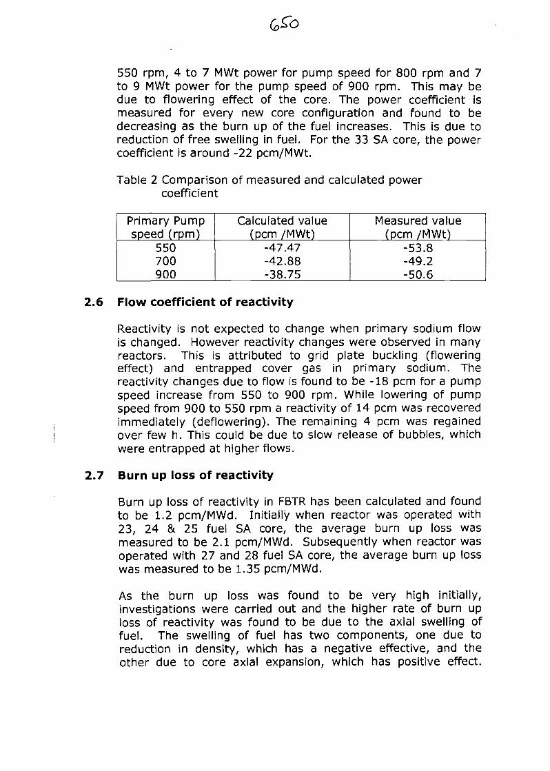
550 rpm, 4 to 7 MWt power for pump speed for 800 rpm and 7to 9 MWt power for the pump speed of 900 rpm. This may bedue to flowering effect of the core. The power coefficient ismeasured for every new core configuration and found to bedecreasing as the burn up of the fuel increases. This is due toreduction of free swelling in fuel. For the 33 SA core, the powercoefficient is around -22 pcm/MWt.
Table 2 Comparison of measured and calculated powercoefficient
Primary Pumpspeed (rpm)
550700900
Calculated value(pcm /MWt)
-47.47-42.88-38.75
Measured value(pcm /MWt)
-53.8-49.2-50.6
2.6 Flow coefficient of reactivity
Reactivity is not expected to change when primary sodium flowis changed. However reactivity changes were observed in manyreactors. This is attributed to grid plate buckling (floweringeffect) and entrapped cover gas in primary sodium. Thereactivity changes due to flow is found to be -18 pcm for a pumpspeed increase from 550 to 900 rpm. While lowering of pumpspeed from 900 to 550 rpm a reactivity of 14 pcm was recoveredimmediately (deflowering). The remaining 4 pcm was regainedover few h. This could be due to slow release of bubbles, whichwere entrapped at higher flows.
2.7 Burn up loss of reactivity
Burn up loss of reactivity in FBTR has been calculated and foundto be 1.2 pcm/MWd. Initially when reactor was operated with23, 24 & 25 fuel SA core, the average burn up loss wasmeasured to be 2.1 pcm/MWd. Subsequently when reactor wasoperated with 27 and 28 fuel SA core, the average burn up losswas measured to be 1.35 pcm/MWd.
As the burn up loss was found to be very high initially,investigations were carried out and the higher rate of burn uploss of reactivity was found to be due to the axial swelling offuel. The swelling of fuel has two components, one due toreduction in density, which has a negative effective, and theother due to core axial expansion, which has positive effect.
However the net effect is found to be negative giving rise tohigher reactivity loss due to burn up.
Also it is noticed that burn up loss for the fresh cores is higherthan the end of campaign. Investigation revealed that the burnup loss depend on the control rod position. For a fresh core, thecontrol rods are well inside the core. When the fuel expands inthis core, it is equivalent to control rod insertion. Hence thepositive reactivity effect due to axial height increase is less atthe beginning of campaign. At the end of campaign the controlrods are out of core and the insertion effect is not significant.The positive reactivity effect due to axial height increase is moreand hence less reactivity loss rate. The variation in- burn upreactivity loss due to control rod at the BOC and EOC is about0.3 to 0.6 pcm/MWd.
The burn up loss of reactivity is monitored for every corecampaign. For the present core, the burn up loss is measured tobe around 1.2 pcm/MWd, which agrees very well with thecalculated value.
2.8 Zero power transfer function and feedback transferfunction measurement.
Zero power transfer function of the reactor was measured to findout the response of reactor for ramp reactivity inputs at highpower by rod drop method and was compared with theoreticallycalculated value. The measured and calculated value is found tobe in good comparison and the deviation is within littlepercentage.
2.9 Neutron flux measurement and sodium activation
One low irradiated pin discharged from the reactor was takenand axial power distribution was measured by measuring Cs137
activity. Fig 3 gives the measured and calculated powerdistribution. The radial power distribution was obtained bymeasuring AT across different fuel SA. From these it was notedthat the axial power distribution agrees quite well with calculatedvalue. However radial power distribution from the core centerfalls steeper compared to calculated value. Due to this theoperating power had to be reduced by 12% from the calculatedpower. The difference is attributed to inaccuracy in estimatingcross-section of nickel reflectors and availability of sufficientdata.
Fig 3 Measured and calculated axial power distribution.
ie.a0 2«.ae 38.eeP o s t i o n of the p i a in em.
The neutron detectors are placed in biological shield and theaxial position of the detectors is above the fuel SA. The radialdistance between the core centers to neutron detectors is about2.5 m. Due to this, neutron spectrum varies significantly fromcore center to detector location and the attenuation factor isaround 106. U235 fission counters with a nominal efficiency of 1cps/nv are used as startup detectors. The predicted count ratefor these detectors in detector location is 810 Cps/w. Howeverthe measured count rate was found to be 200+/-5 Cps/W.Considering large flux attenuation, it is proposed to measure theflux distribution in core by using special SA with foil carryingcapsule for nominal core of 76 SA. The flux in reactor vesselbelow the rotating plugs and in sodium above SA head weremeasured using foils irradiation technique using special plugs in2001 to validate calculation methods. This helps in obtainingmore reliable estimates of induced activities in variouscomponents, such as control rod drive mechanism. Themeasurements were carried out using foil activation techniques.The irradiation of foils was carried out using specially fabricatedplugs, which are housed in the experimental canals. The foilcarrier rod with foils were loaded into these plugs and irradiatedfor one hour. At the end of irradiation, the foils were retrievedremotely and counted for gamma activity. Typical foils used werebare and Cadmium covered Manganese, gold, sodium and nickelfoils. The measured activities were compared with the calculatedactivities, obtained from 2-D transport calculations. Themeasured reaction rates at the end of irradiation are given intable 3
The neutron flux at primary sodium pump and intermediate heatexchanger (IHX) are very important as they contribute to

secondary sodium activation. The flux at these locations wasmeasured by Mn-Cu foils at different power levels. The fluxequivalent at IHX was extrapolated for 40 MWt and found to be4.3 x 104. Secondary sodium activation for this flux is estimatedto be 81 Bq/cc.
Table 3 we folding" distance (cm) of reaction rate in uppersodium region
Foil
Mn-Cu bareMn-Cu (Cd)
Au (cd)Rh
NaCIMn-Cu(big)
CiptexMeasured
48.546.055.322.648.5
Calculated46.345.766.219.454
145.5
PlumfacMeasured
48.246.860.730.4
-
The neutron flux due to streaming through the gaps of small andlarge rotating plugs were measured at 1 MWt using BoronCoated Counters (BCC) and BF3 counters. The measured fluxvaried between 0.5 and 2.3 n/cm2 as against the calculated fluxbetween 0.6 and 15 n/cm2. The dose due to this streaming at40 MWt is estimated as 20^is/h. The Na24 and Na22 activation inprimary circuit was measured as 49.9 MBq/g and 118.4 MBq/gagainst the calculated value of 74.3 MBq/g and 116.6 MBq/g.The cover gas of reactor is a mixture of He and Argon in theratio of 8:2. The measured cover gas activity is 0.5 G.Bq/m3
against a calculated value of 1.9 to 2.2 GBq/m3. Considering themagnitude of attenuation and uncertainties in the calculation,the measured value is in fairly good agreement.
2.10 Response of delayed neutron detection
In order to detect failure of clad, two delayed neutron detectors(DND) are provided in primary sodium circuit, one in east loopand the other in west loop. Sodium is sampled beforeintermediate heat exchanger inlet and presence of delayedneutrons are detected by boron counters of 8 Cps/nv efficiency.In addition there are two gas activity monitors provided one inthe clad rupture detection circuit (CRD) of cover gas and anotherin the combined discharge of CRD and primary cover gas. Thesedetectors detect the presence of gross gamma (y) activity incover gas.
To calibrate the DND system, an experiment was conducted bysimulating failed fuel pin by means of a stainless steel cladednatural uranium metal pin having a large exposed area. Theexperiment was conducted to study the correlation between fuelpin failure and delayed neutron count rate as a function of powerand flow and to study the feasibility of using differential countrate method to localize the failed fuel pin using DND east andwest. The simulated failed pin had an exposed area in the formof small holes of 2 mm diameter amounting to 5.94 cm2. Thispin was assembled in the central location of a special SA inwhich remaining pins were dummy pins filled with helium. Theexposed area of 5.94 cm2 is chosen equivalent to approximately1.5 cm2 of a regular fuel pin.
The measurements were done at different power levels rangingfrom 400 kWt to 1.8 MWt and primary flows ranging from 160 to300 m3/h with special SA in central location and off centrallocation (3rd ring). The main interest of the experiment was tofind out the ratio of signals obtained when the SA was in 3rd ring(03-05) to that of central location. Following are the salientresults of experiment.
• The increase in delayed neutron (DN) signal is measurableeven through small.
• Gamma activity in cover gas showed a large increase insignal (10 times) due to fission gases from special pin.
• DN signals are sensitive to changes in primary flows ofrespective loop.
• DN signals are also sensitive to inlet sodium temperaturesand it increases substantially with increase in sodiumtemperature.
• DN signals show a substantial sensitivity to the position ofthe defect. The ratio of the signal in the west loop to eastloop with special SA in central location are different by asmuch as ~ 50% as compared to the SA in 3rd ring (03-05)position near to west sodium outlet. This proves useful tosome extend in localizing the failed fuel. The lessermagnitude of increase in DN signal is attributed to lesserexposed area of the fuel pin and dilution effect. It isplanned to repeat these experiments with special pin withhigher exposed area after constituting the nominal corewith 76 SA.
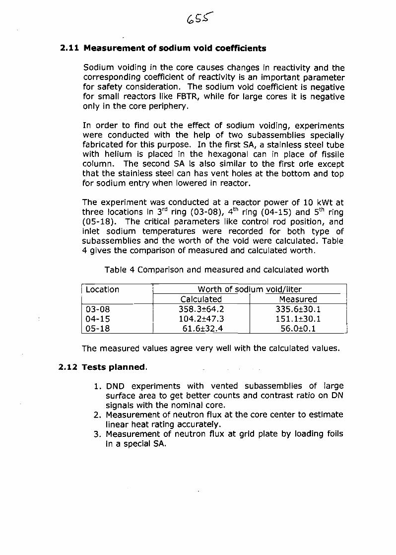
2.11 Measurement of sodium void coefficients
Sodium voiding in the core causes changes in reactivity and thecorresponding coefficient of reactivity is an important parameterfor safety consideration. The sodium void coefficient is negativefor small reactors like FBTR, while for large cores it is negativeonly in the core periphery.
In order to find out the effect of sodium voiding, experimentswere conducted with the help of two subassemblies speciallyfabricated for this purpose. In the first SA, a stainless steel tubewith helium is placed in the hexagonal can in place of fissilecolumn. The second SA is also similar to the first orie exceptthat the stainless steel can has vent holes at the bottom and topfor sodium entry when lowered in reactor.
The experiment was conducted at a reactor power of 10 kWt atthree locations in 3rd ring (03-08), 4th ring (04-15) and 5th ring(05-18). The critical parameters like control rod position, andinlet sodium temperatures were recorded for both type ofsubassemblies and the worth of the void were calculated. Table4 gives the comparison of measured and calculated worth.
Table 4 Comparison and measured and calculated worth
Location
03-0804-1505-18
Worth of sodium void/literCalculated358.3±64.2104.2±47.361.6±32.4
Measured335.6±30.1151.1±30.156.0±0.1
The measured values agree very well with the calculated values.
2.12 Tests planned.
1. DND experiments with vented subassemblies of largesurface area to get better counts and contrast ratio on DNsignals with the nominal core.
2. Measurement of neutron flux at the core center to estimatelinear heat rating accurately.
3. Measurement of neutron flux at grid plate by loading foilsin a special SA.

3.0 Engineering tests (3'4a5)
3.1 Primary pump coast down and battery take over.
In order to provide forced cooling to the core during total powerfailure, to keep sodium, clad & fuel temperatures with in limits,primary sodium pump drives are provided with flywheels forgradual coast down. Further back up is provided by batteries,which enable running of pumps for 30 minutes at around 150rpm. A test was conducted in Dec '89 to study the coast down ofpump speeds and flows to verify capacity of batteries to run thepump as per design intent.
Fig 4 Coast down test of Primary Sodium pumps
too
600
400
200
0
| '"i}'*»S?
1C
I
\\8atltry_/
""
( mm ) 30
-L
E o s lTc
resTER
^w...
^
50
»IINAIEO~7
™f\-
m*/ 1
IjS^pmoo RPM20C ST: i«:37:02 END: 17:36:45
PUMP SPEED W TIME
The pump coasted down from 900 rpm to 200 rpm in about 4minutes and batteries took over at a pump speed of 175 rpmand ran at 150 rpm for 37 minutes when the test was terminated(fig 4). The core flow during battery operation was about 50m3/h, which is adequate to remove decay heat during stationblack out condition.
3.2 Heat Removal capacity of SG casing.
The ultimate sink for decay heat during station black outcondition is provided by natural draft of air when the trap doorsof steam generator (SG) casing are opened (Fig 5). Tests wereconducted in Feb '90 to assess the heat removal capacity in thismode. The tests revealed that the additional heat loss due to theopening of trap doors is 280 kWt at 215°C and 606 kW at 350°C.The total heat loss including the losses in pipelines from thesystem in this mode was found to be 984 kWt at 350°C (6). Themaximum decay heat of the present small core is estimated as
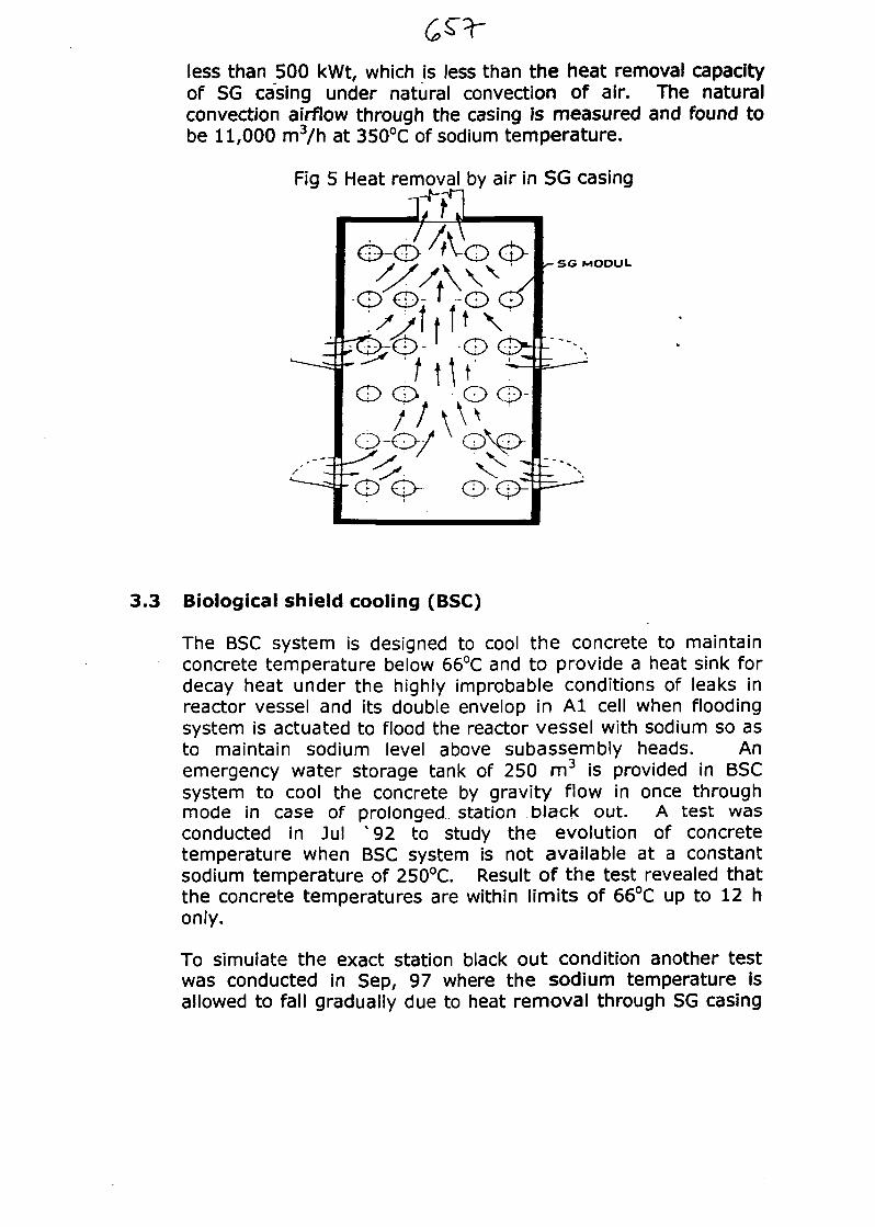
less than 500 kWt, which is less than the heat removal capacityof SG casing under natural convection of air. The naturalconvection airflow through the casing is measured and found tobe 11,000 m3/n at 350°C of sodium temperature.
Fig 5 Heat removal by air in SG casing
SG MOOUL
3.3 Biological shield cooling (BSC)
The BSC system is designed to cool the concrete to maintainconcrete temperature below 66°C and to provide a heat sink fordecay heat under the highly improbable conditions of leaks inreactor vessel and its double envelop in Al cell when floodingsystem is actuated to flood the reactor vessel with sodium so asto maintain sodium level above subassembly heads. Anemergency water storage tank of 250 m3 is provided in BSCsystem to cool the concrete by gravity flow in once throughmode in case of prolonged station black out. A test wasconducted in Jul X 92 to study the evolution of concretetemperature when BSC system is not available at a constantsodium temperature of 250°C. Result of the test revealed thatthe concrete temperatures are within limits of 66°C up to 12 honly.
To simulate the exact station black out condition another testwas conducted in Sep, 97 where the sodium temperature isallowed to fall gradually due to heat removal through SG casing
by natural convection of air. The test was conducted for 24h.Results of the test showed that the biological shield concrete andbulk structural concrete temperatures are well with in limits evenwithout emergency shield concrete cooling under gravity mode.However the appendix concrete temperature at sodium outletand inlet pipeline could be maintained only with the help ofblowers. It is planned to repeat the test with blower switched offafter getting safety clearance for higher operating temperaturemargin for the structural concrete.
3.4 Pre-heating and emergency cooling (PHEC) heat removalcapacity.
PHEC is provided for decay heat removal during (i) non-availability of primary loops due to leak in main pipe and itsdouble envelop outside Al cell (cell containing reactor vessel andsafety vessel) (ii) non-availability of both secondary loops due tocommon mode failure such as sodium leak in steam generator(SG) casing. PHEC is also used for initial preheating of primarymain circuit.
Tests were conducted in Oct '91 to assess the heat removalcapacity of the system at different sodium temperatures of 250,300 and 375°C. The results indicated that PHEC could remove300 kWt of heat at a system temperature of 375°C, which givesan extrapolated value of 420 kWt at a nominal reactortemperature of 520°C, as against the design capacity of 350kWt. This is adequate to maintain the temperature within limits.
3.5 Natural convection tests (5&7)
During station back out, the secondary sodium pumps will coastdown and come to rest; the primary pumps will coast down andafter running on batteries for 30 minutes will stop. Under thesecondition decay heat removal is by natural convection in primaryand secondary loops. Heat will be finally removed in SG due tonatural convection of air through SG casing by opening trapdoors. The layout of the circuits is designed to facilitate onset ofnatural convection. Tests were conducted to study theconvection with reactor operating at 170 kWt initial power andcontrol rods were not operated *-4). Precautions were taken todisable restart of the pumps, since a large positive reactivitywould be added to the reactor due to entry of cool sodium if thepumps were restarted. The tests were conducted separately forsecondary and primary loops as a first step for combined test.
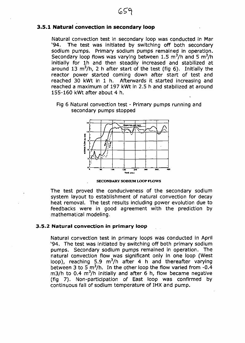
3.5.1 Natural convection in secondary loop
Natural convection test in secondary loop was conducted in Mar'94. The test was initiated by switching off both secondarysodium pumps. Primary sodium pumps remained in operation.Secondary loop flows was varying between 1.5 m3/h and 5 m3/hinitially for Ih and then steadily increased and stabilized ataround 13 m3/h, 2 h after start of the test (fig 6). Initially thereactor power started coming down after start of test andreached 30 kWt in 1 h. Afterwards it started increasing andreached a maximum of 197 kWt in 2.5 h and stabilized at around155-160 kWt after about 4 h.
Fig 6 Natural convection test - Primary pumps running andsecondary pumps stopped
SECONDARY SODIUM LOOP FLOWS
The test proved the conduciveness of the secondary sodiumsystem layout to establishment of natural convection for decayheat removal. The test results including power evolution due tofeedbacks were in good agreement with the prediction bymathematical modeling.
3.5.2 Natural convection in primary loop
Natural convection test in primary loops was conducted in April'94. The test was initiated by switching off both primary sodiumpumps. Secondary sodium pumps remained in operation. Thenatural convection flow was significant only in one loop (Westloop), reaching 5.9 m3/h after 4 h and thereafter varyingbetween 3 to 5 m3/h. In the other loop the flow varied from -0.4m3/h to 0.4 m3/h initially and after 6 h, flow became negative(fig 7). Non-participation of East loop was confirmed bycontinuous fall of sodium temperature of IHX and pump.
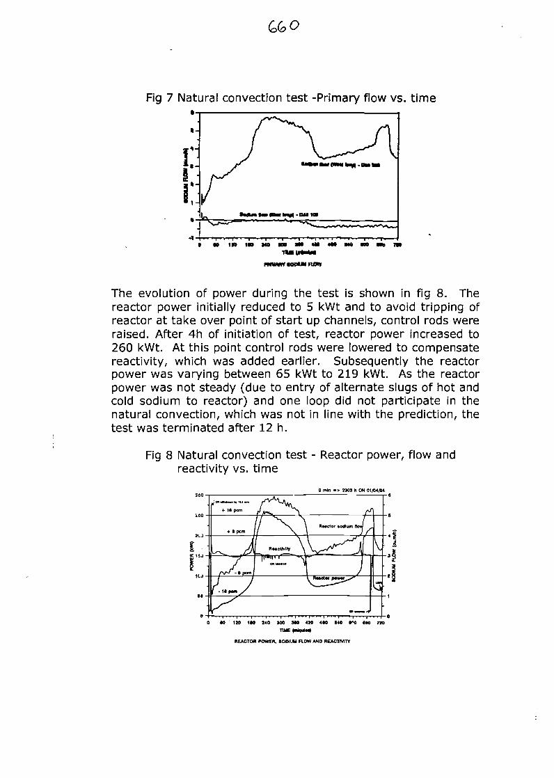
Fig 7 Natural convection test -Primary flow vs. time
c!*'
1 1-1
• DM IN
I W 1» IN tW
rniMiw IOMM no*
The evolution of power during the test is shown in fig 8. Thereactor power initially reduced to 5 kWt and to avoid tripping ofreactor at take over point of start up channels, control rods wereraised. After 4h of initiation of test, reactor power increased to260 kWt. At this point control rods were lowered to compensatereactivity, which was added earlier. Subsequently the reactorpower was varying between 65 kWt to 219 kWt. As the reactorpower was not steady (due to entry of alternate slugs of hot andcold sodium to reactor) and one loop did not participate in thenatural convection, which was not in line with the prediction, thetest was terminated after 12 h.
Fig 8 Natural convection test - Reactor power, flow andreactivity vs. time
0 mln -> 2103 h ON 01/04/H
0 60 120 1M 240 100 MO 420 4*0 840 i»0 (M T»
REACTOR POWER. SODIUM HOW AND REACTIVITY
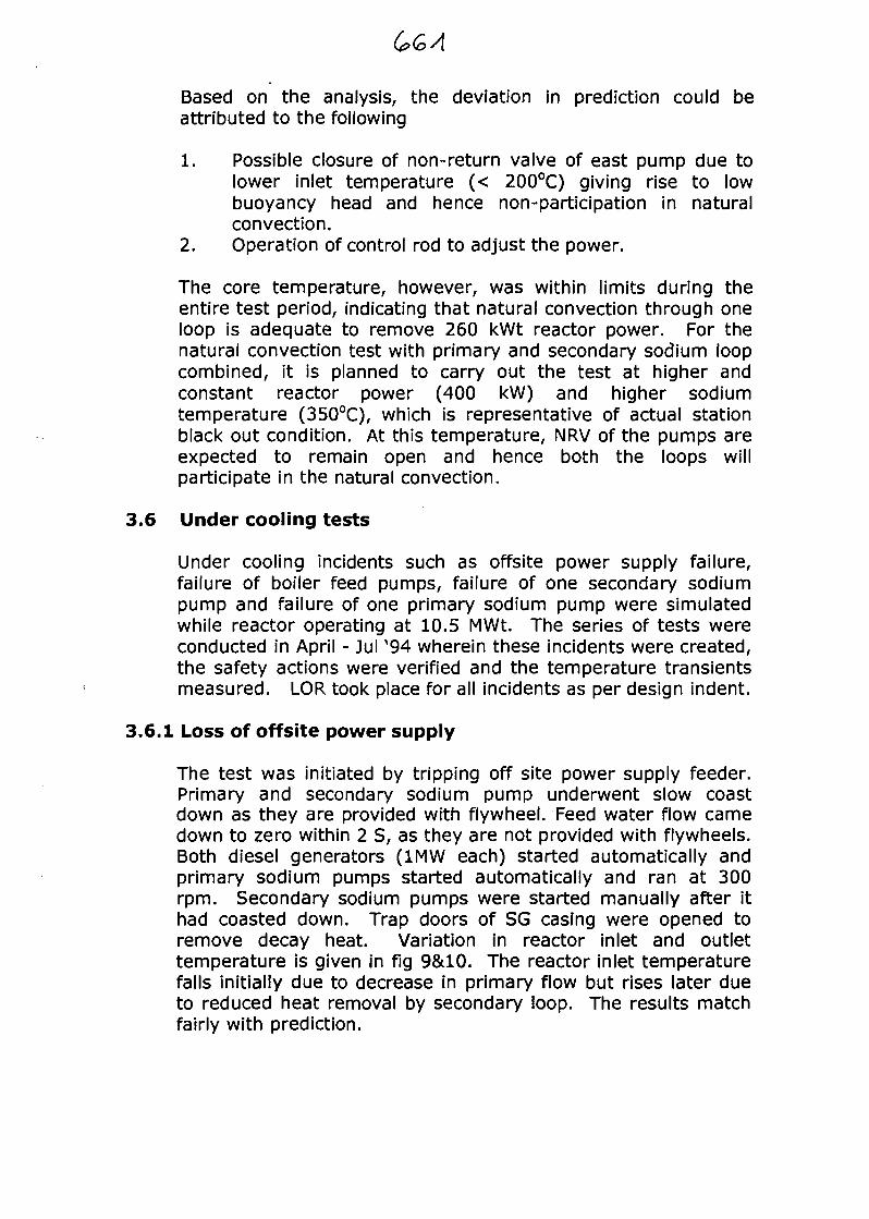
Based on the analysis, the deviation in prediction could beattributed to the following
1. Possible closure of non-return valve of east pump due tolower inlet temperature (< 200°C) giving rise to lowbuoyancy head and hence non-participation in naturalconvection.
2. Operation of control rod to adjust the power.
The core temperature, however, was within limits during theentire test period, indicating that natural convection through oneloop is adequate to remove 260 kWt reactor power. For thenatural convection test with primary and secondary sodium loopcombined, it is planned to carry out the test at higher andconstant reactor power (400 kW) and higher sodiumtemperature (350°C), which is representative of actual stationblack out condition. At this temperature, NRV of the pumps areexpected to remain open and hence both the loops willparticipate in the natural convection.
3.6 Under cooling tests
Under cooling incidents such as offsite power supply failure,failure of boiler feed pumps, failure of one secondary sodiumpump and failure of one primary sodium pump were simulatedwhile reactor operating at 10.5 MWt. The series of tests wereconducted in April - Jul '94 wherein these incidents were created,the safety actions were verified and the temperature transientsmeasured. LOR took place for all incidents as per design indent.
3.6.1 Loss of offsite power supply
The test was initiated by tripping off site power supply feeder.Primary and secondary sodium pump underwent slow coastdown as they are provided with flywheel. Feed water flow camedown to zero within 2 S, as they are not provided with flywheels.Both diesel generators (1MW each) started automatically andprimary sodium pumps started automatically and ran at 300rpm. Secondary sodium pumps were started manually after ithad coasted down. Trap doors of SG casing were opened toremove decay heat. Variation in reactor inlet and outlettemperature is given in fig 9&10. The reactor inlet temperaturefalls initially due to decrease in primary flow but rises later dueto reduced heat removal by secondary loop. The results matchfairly with prediction.

Fig 9 Reactor inlet temp.Vs. time
Fig 10 Reactor outlet temp,vs. time
S 350
f 300
zsa
I • I • • • • i • • • 11 • • • • i • • •RCACTCR B>trr TZTPSUTUK
O MEASURED
CALCULATED
0 0 0 00
S38
a 100 200 300 IBB see 600 700TDC CSJ 100 22? 300 400 sae eee ?ea2S2
3.6.2 Tripping of Main boiler feed pump (MBFP)
There are two MBFPs each having 100% capacity. In case offailure of one pump, the standby is started automatically withinless than 10 S and no reactor trip is initiated. The test isinitiated by switching off running pump. Standby MBFP startedautomatically and parameters got stabilized (Fig 11). No reactortrip is initiated.
Fig. 11 Feed water parameters for one MBFP trip.
FEED WATER/STEAM PARAMETERS
Failure of both MBFPS was simulated by switching off bothpumps. Reactor underwent LOR after a delay of 10 s as perdesign indent. The incident effectively resulted in loss of heatsink for which trap doors of SG casing were opened to removedecay heat within 30 minutes. It shows that even without thetrap door opening, the temperatures remain within limits.
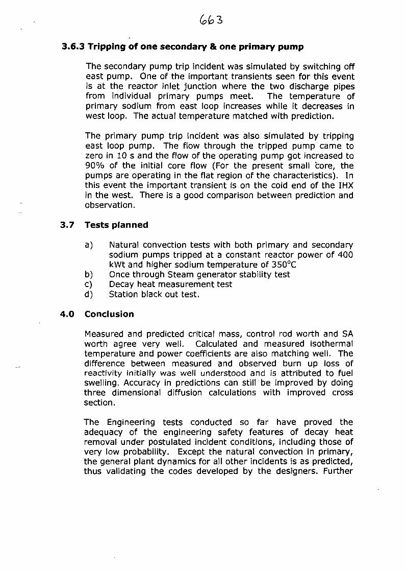
3.6.3 Tripping of one secondary & one primary pump
The secondary pump trip incident was simulated by switching offeast pump. One of the important transients seen for this eventis at the reactor inlet junction where the two discharge pipesfrom individual primary pumps meet. The temperature ofprimary sodium from east loop increases while it decreases inwest loop. The actual temperature matched with prediction.
The primary pump trip incident was also simulated by trippingeast loop pump. The flow through the tripped pump came tozero in 10 s and the flow of the operating pump got increased to90% of the initial core flow (For the present small core, thepumps are operating in the flat region of the characteristics). Inthis event the important transient is on the cold end of the IHXin the west. There is a good comparison between prediction andobservation.
3.7 Tests planned
a) Natural convection tests with both primary and secondarysodium pumps tripped at a constant reactor power of 400kWt and higher sodium temperature of 350°C
b) Once through Steam generator stability testc) Decay heat measurement testd) Station black out test.
4.0 Conclusion
Measured and predicted critical mass, control rod worth and SAworth agree very well. Calculated and measured isothermaltemperature and power coefficients are also matching well. Thedifference between measured and observed burn up loss ofreactivity initially was well understood and is attributed to fuelswelling. Accuracy in predictions can still'be improved by doingthree dimensional diffusion calculations with improved crosssection.
The Engineering tests conducted so far have proved theadequacy of the engineering safety features of decay heatremoval under postulated incident conditions, including those ofvery low probability. Except the natural convection in primary,the general plant dynamics for all other incidents is as predicted,thus validating the codes developed by the designers. Further
tests are planned to validate assumptions in safety report andimprove predictions
Acknowledgement:
The excellent work carried out by the staff of Reactor Operationand Maintenance Group, Design Group and other groups in thecenter is gratefully acknowledged
References:Dr. S.M. Lee, et al.; Int. conf. on Physics of reactors, operations,design and computation (1990)C.P. Reddy, et al.; Advisory group meeting "Evaluation of reactorcore physics tests" (1999).P.V. Ramalingam, et al.: Inter national conference on NuclearEngineering (999)R.P. Kapoor, et al.: Technical committee meeting IAEA -TECDOC-1180 (1998)G. Vaidyanathan, et al.: Meeting on Fast Reactor safety Obninsk,RussiaS.B. Bhoje, et al.; Int. Conference on Fast reactor and relatedfuel cycle (1991)G. Srinivasan, et al.; Indo-Kazak seminar on Operatingexperience on fast reactors (1996)
Physics and Engineering ExperimentsFast Breeder in Test Reactor
K.V. Suresh Kumar,
C.P. Reddy,
R. Indira,
N. Kasinathan,
R.S. Kesava Murthy,«/ j
R.P. Kapoor, P.V. Ramalingam,
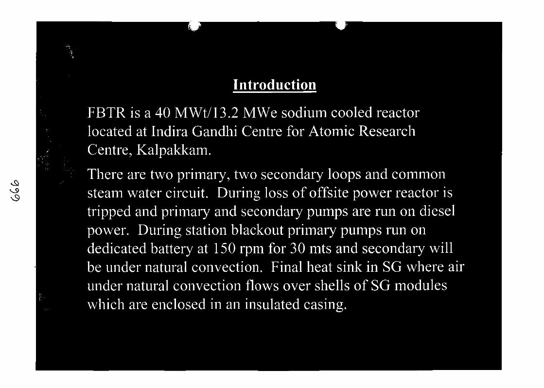
Introduction
FBTR is a 40 MWt/13.2 MWe sodium cooled reactorlocated at Indira Gandhi Centre for Atomic ResearchCentre, Kalpakkam.
There are two primary, two secondary loops and commonsteam water circuit. During loss of offsite power reactor istripped and primary and secondary pumps are run on dieselpower. During station blackout primary pumps run ondedicated battery at 150 rpm for 30 mts and secondary willbe under natural convection. Final heat sink in SG where airunder natural convection flows over shells of SG moduleswhich are enclosed in an insulated casing.
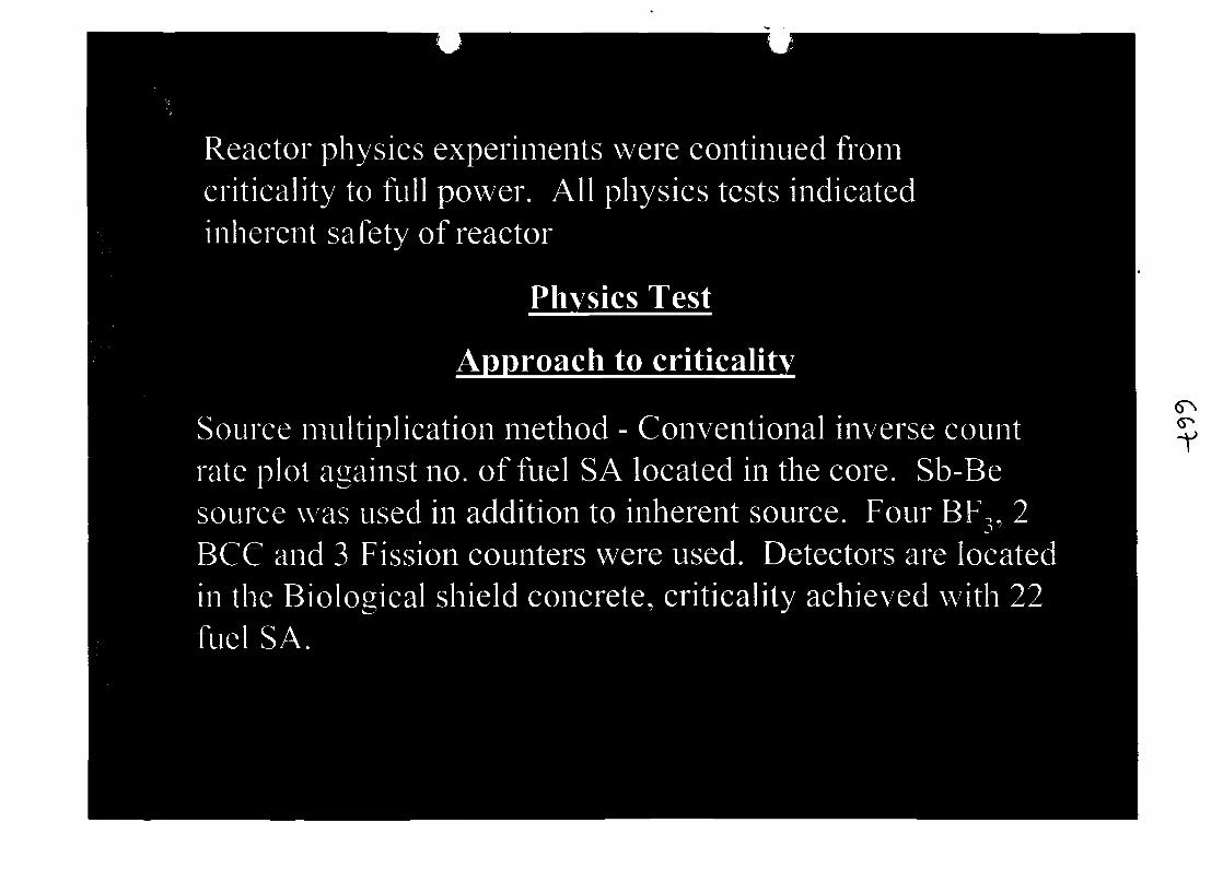
Reactor physics experiments were continued fromcriticality to full power. All physics tests indicatedinherent safety of reactor
Physics Test
AoDroach to criticalitv
Source multiplication method - Conventional inverse countrate plot against no. of fuel SA located in the core. Sb-Besource \vas used in addition to inherent source. Four BF,, 2BCC and 3 Fission counters were used. Detectors are locatedin the Biological shield concrete, criticality achieved with 22fuel SA.

33 FUEL SA CORE
( 25 MASK I + 6 MARK 11 )
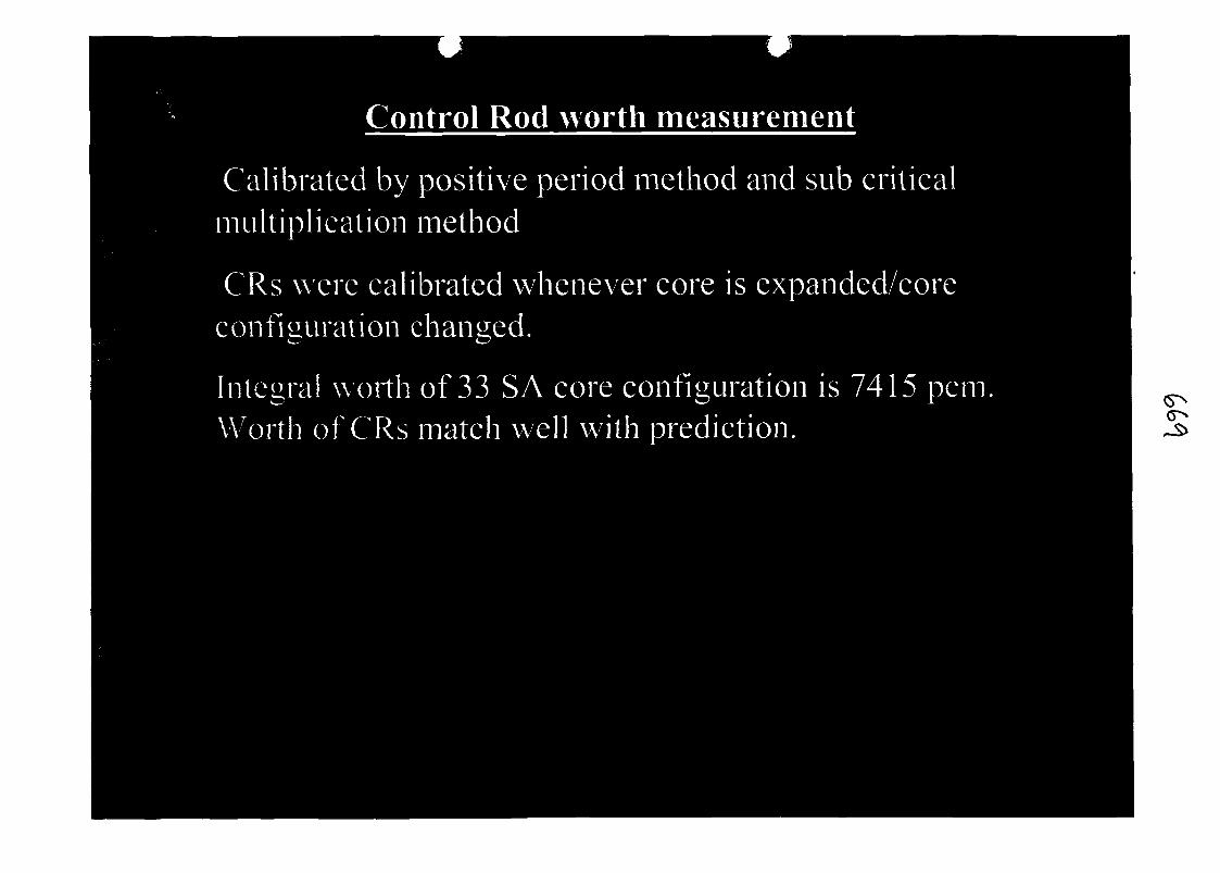
Control Rod worth measurement
Calibrated by positive period method and sub criticalmultiplication method
CRs were calibrated whenever core is expanded/coreconfiguration changed.
Integral worth of 33 SA core configuration is 7415 pcmWorth of CRs match well with prediction.
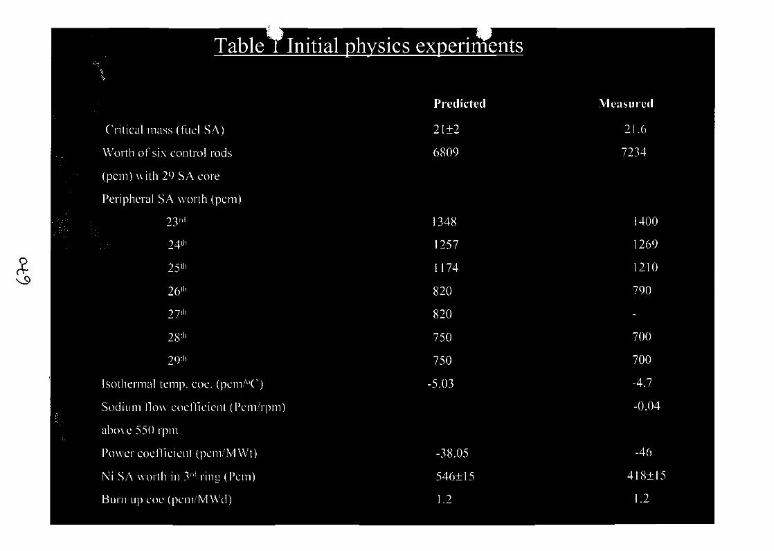
Table T Initial nhvsics exDenments
Crit ical mass (fuel SA)
Worth of six control rods
(pern) with 29 SA core
Peripheral SA worth (pern)
Predicted
21±2
6809
1348
1257
1174
Measured
7234
Isothermal temp. coe. (pcm/°C)
Sodium flow coefllcicnt (Pcm/rpm)
above 550 rpm
Power coefficient (pem/MWt)
Ni SA worth in 3'1' ring (Pern)
Burn up coe (pcm/MWd)
-38.05
546±15
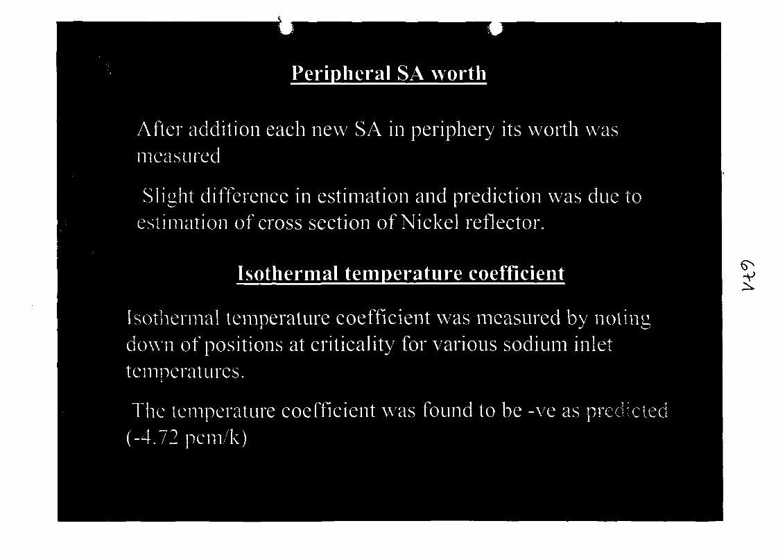
Peripheral SA worth
After addition each new SA in periphery its worth wasmeasured
Slight difference in estimation and prediction was due toestimation of cross section of Nickel reflector.
Isothermal temperature coefficient
Isothermal temperature coefficient was measured by notingdown of positions at criticality for various sodium inlettemperatures.
The temperature coefficient was found to be -ve as predicted(-4.72 pcm/k)
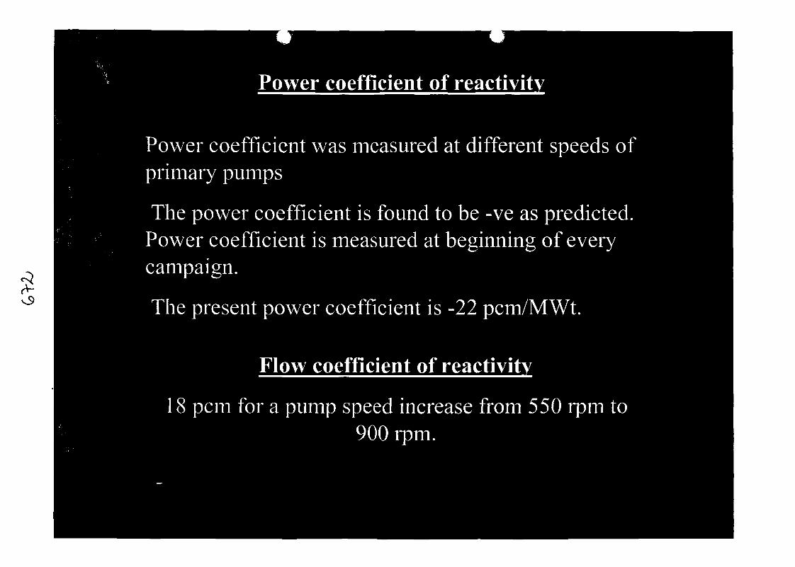
Power coefficient of reactivit
Power coefficient was measured at different speeds ofprimary pumps
The power coefficient is found to be -ve as predicted.Power coefficient is measured at beginning of everycampaign.
The present power coefficient is -22 pcm/MWt.
Flow coefficient of reactivity
18 pcm for a pump speed increase from 550 rpm to900 rpm.
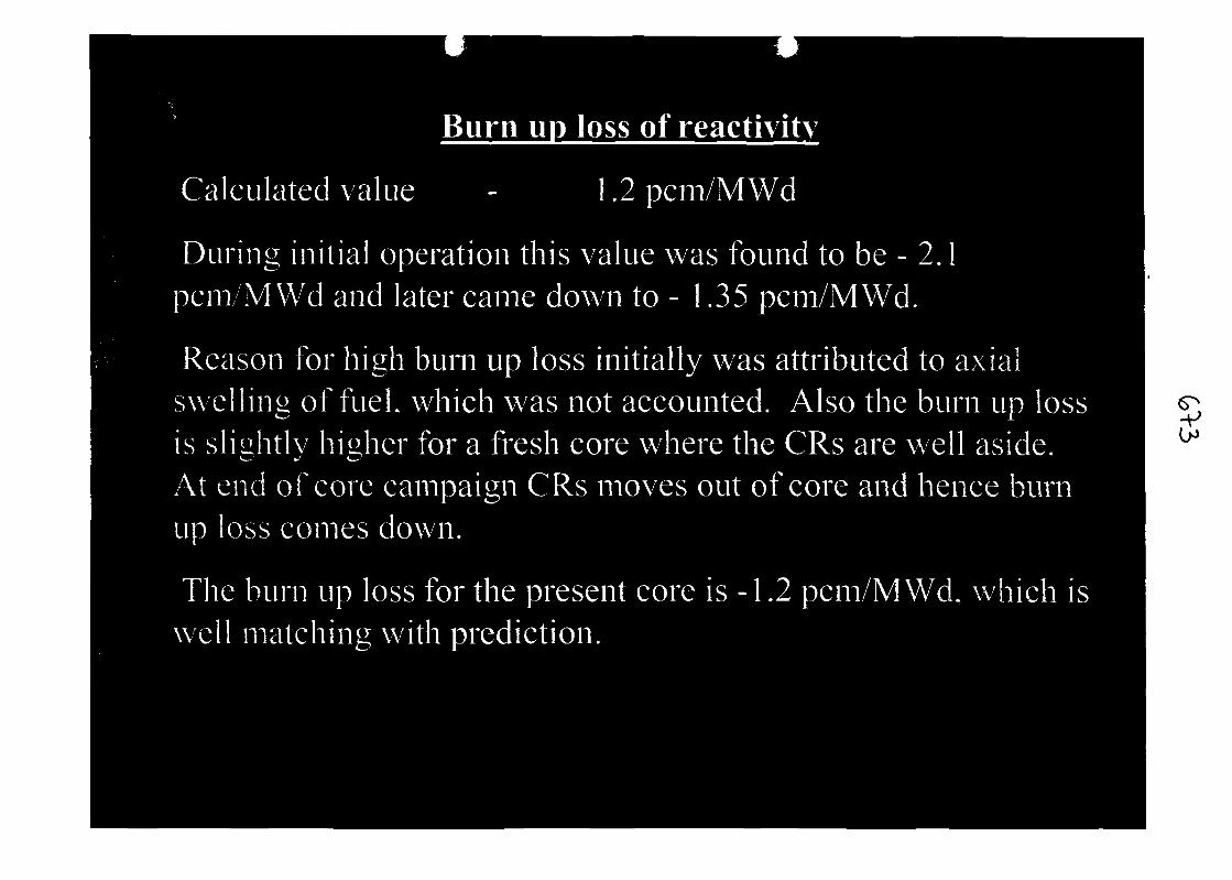
Burn UD loss of reactivity
Calculated value 1.2pcm/MWd
During in i t ia l operation this value was found to be - 2.1pcm/MWd and later came down to - 1.35 pcm/MWd.
Reason for high burn up loss initially was attributed to axialswelling of fuel, which was not accounted. Also the burn up lossis slightly higher for a fresh core where the CRs are well aside.*«••-- •<•' ^-'
At end of core campaign CRs moves out of core and hence burnup loss comes down.
The burn up loss for the present core is -1.2 pcm/MWd, which iswell matching with prediction.
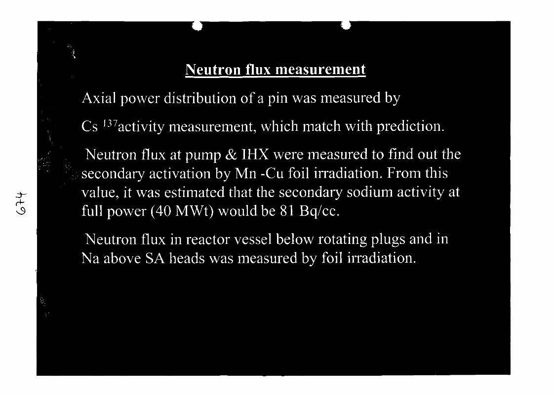
Neutron flux measurement
H-
Axial power distribution of a pin was measured by
Cs 137activity measurement, which match with prediction.
Neutron flux at pump & IHX were measured to find out thesecondary activation by Mn -Cu foil irradiation. From thisvalue, it was estimated that the secondary sodium activity atfull power (40 MWt) would be 81 Bq/cc.
Neutron flux in reactor vessel below rotating plugs and inNa above SA heads was measured by foil irradiation.
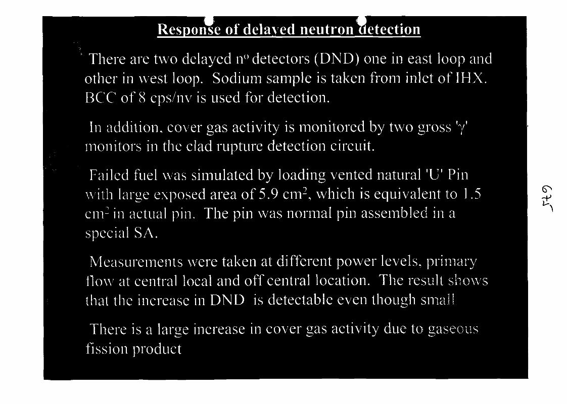
Response of delayed neutron Hetection
There are two delayed n° detectors (DND) one in east loop andother in west loop. Sodium sample is taken from inlet of IHX.BCC of 8 cps/nv is used for detection.
In addition, cover gas activity is monitored by two gross fy'monitors in the clad rupture detection circuit.
Failed fuel was simulated by loading vented natural 'U f Pinwith large exposed area of 5.9 cm2, which is equivalent to 1.5cm2 in actual pin. The pin was normal pin assembled in aspecial SA.
Measurements were taken at different power levels, primaryflow at central local and off central location. The result showsthat the increase in DND is detectable even though small
There is a large increase in cover gas activity due to gaseousfission product
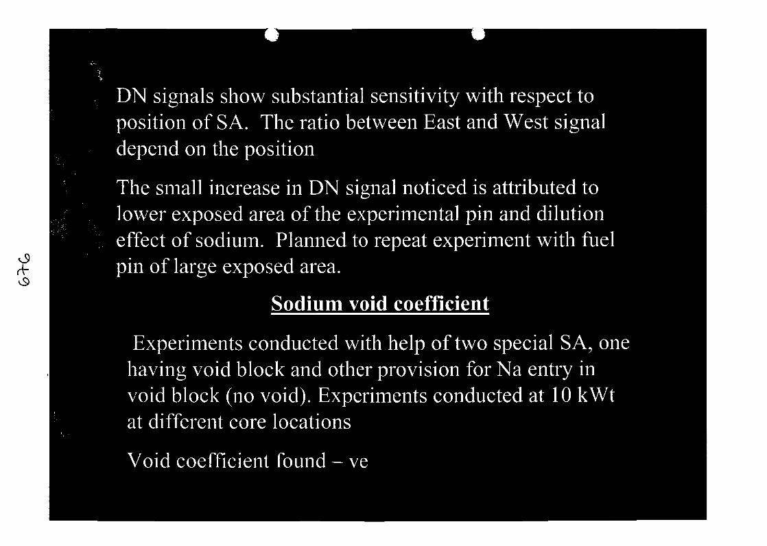
rf
DN signals show substantial sensitivity with respect toposition of SA. The ratio between East and West signaldepend on the position
The small increase in DN signal noticed is attributed tolower exposed area of the experimental pin and dilutioneffect of sodium. Planned to repeat experiment with fuelpin of large exposed area.
Sodium void coefficient
Experiments conducted with help of two special SA, onehaving void block and other provision for Na entry invoid block (no void). Experiments conducted at 10 kWtat different core locations
Void coefficient found - ve
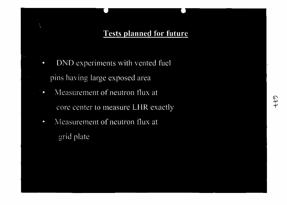
Tests olanned for future
DND experiments with vented fuel
pins having large exposed area
Measurement of neutron flux at
core center to measure LHR exactly
Measurement of neutron flux at
grid plate
•v•V
Engineering tests
Primary nun in coast down and battery take oyer test.
In order to provide force cooling during offsite power failure,pump drives are provided with flywheel. Further, batteriesare provided to run pumps at 150 rpm for l/2h. Capacity ofbatteries tested by conducting battery take over test.
Pump coasted down from 900 rpm to 200 rpm in 4 mts andbatteries took over at 175 rpm. Test terminated after 37 mts.
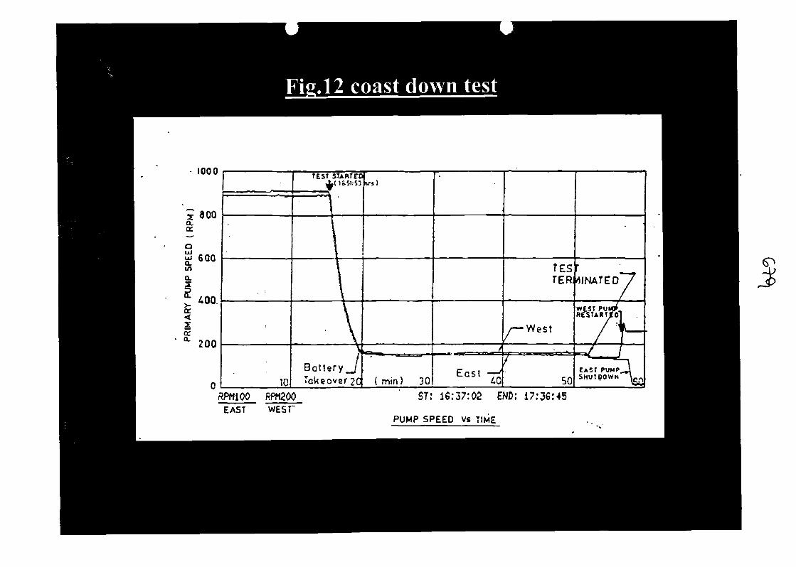
Fig.12 coast down test
1000
800
600
£00.
200
>
10
TEST STARTEDX( U51.-53
|
\A\Bat tery_JTakeover 2C
us)
( min) 30
/
E c s t7£
fesTER
/—West
•7
50
'IINATEO'T
WEST Puy£.REStARliTol
/ : '^//
-C^^JEAST PUMP_JSHUTQOWN^g-
RPH100 RPH2QOEAST WEST'
ST: 16:37:02 END: 17:36:45
PUMP SPEED Vs TIME
Heat Removal canacitv of SG casing.
o
SGs are cooled by air by natural convection during stationblackout.
Trap doors are provided for SG casing for this•Test conducted showed that SG could remove
280kWtat215°CNatemp
606 kW at 350°C Na temp
i.e. Total heat removed at 350°C including pipeline lossees isapprox. 1 MWt.
Airflow by natural convection is approx. 11,000 m3/h
Biological shield cooling heat removal
In case of sodium leak in Al cell, decay heat is removed bycooling concrete. Emergency storage tank is provided tocool concrete by gravity in case of station blackout
Test conducted simulating station blackout for 12 MWt<_^
without valving in emergency storage tank showed thatconcrete temperatures are within limits.
Preheating and Emergency cooling circuit heat removalcapacity.
PHEC is used for removal of decay heat by circulating coldnitrogen through reactor vessel double envelop in case of
(i) sodium leak out outside Al cell
(ii) non availability of both secondary pumps.
Tests conducted to assess its capacity showed that PHEC canremove 300 kWt at a sodium temp of 375°C.
Natural convection tests
During station black out pumps will coast down and run at150 rpm for 30 mts and come to rest. Secondary pumpsw i l l coast down on flywheel and come to rest.
Further, the decay heat removed by natural convection andthe heat is rejected through SG casing. Layout of circuit issuch that easy setting of natural convection is possible.
This capability was demonstrated with operating at 170kWt. The tests were conducted for secondary loop andprimary loop separately as a first step.
00
Natural convection in secondary loop
Test conducted by tripping both secondary pumps whilereactor is operating at 170 kWt.
Secondary flow varied from 1.5 m3/h to 5m3/h for Ih andlater increased to 13m3/h and stabilized. Reactor poweralso stabilized around 155-160 kWt after 4h
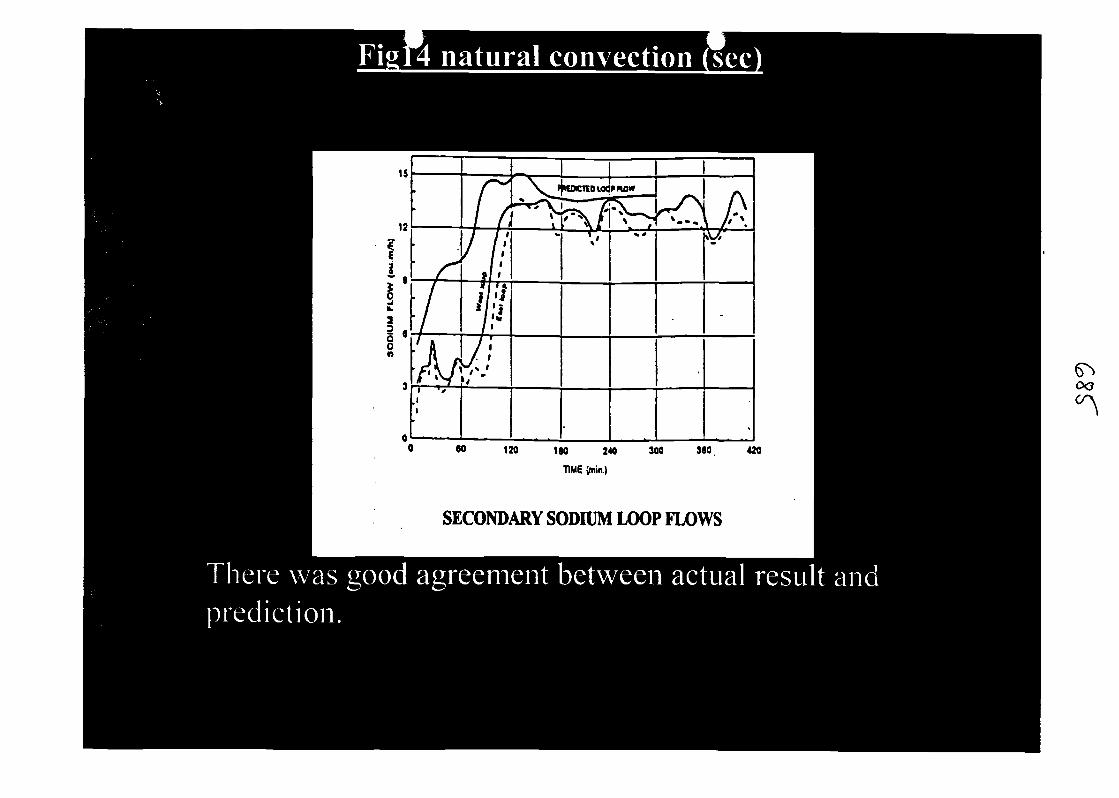
SECONDARY SODIUM LOOP FLOWS
03
Natural convection in primary loo
Tested conducted by tripping both primary pumps (batteryisolated) while reactor is operating at 170 kWt. Naturalconvection flow was predominant (5.9 m3/h) only in oneloop. Other loop did not participate in the naturalconvection.
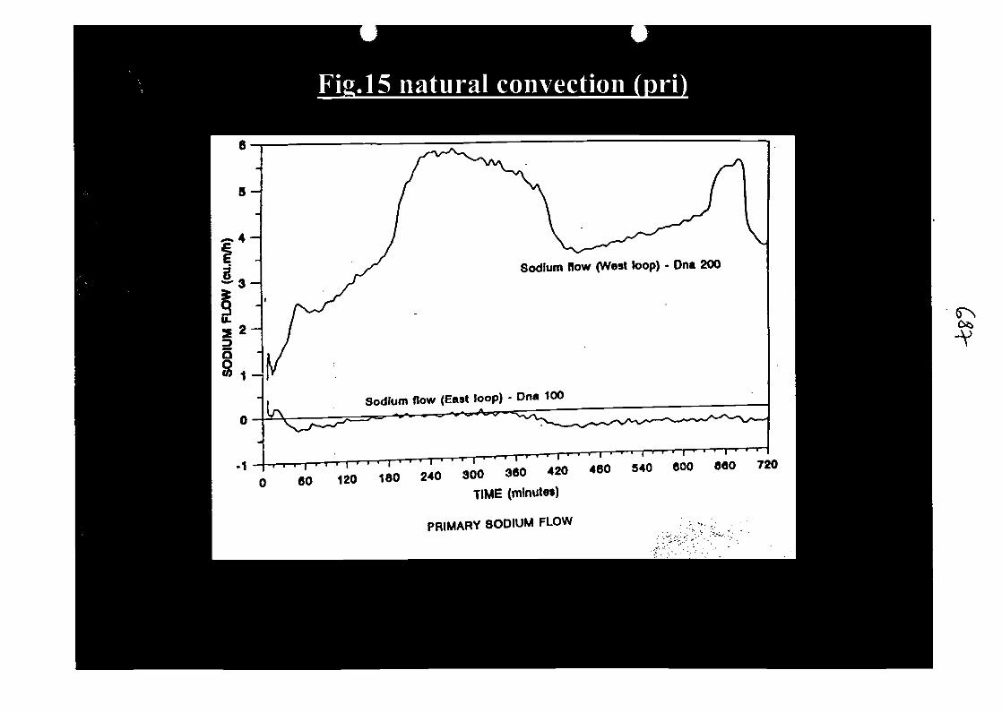
Sodium flow (West loop) - Dna 200
Sodium flow (East loop) - Dna 100
300 360 420
TIME (minutes)
PRIMARY SODIUM FLOW
-v
Oo
Reactor power was found to be varying from 65 kW to 219kW even after 12h of initiation of test.
SA outlet temperatures were within limits indicatingadequate core flow.
The deviation in prediction is due to non-opening of oneloop pump NRV due to low reactor inlet temp (<200°C).
Test is planned to be repeated at higher reactor power of400 kWt and at high sodium temperature of 350°C.
Under cooling tests
Under cooling tests such as offsite power failure, failure o1one primary pump, one secondary pump, main boiler feedpump etc were conducted while reactor is operating at 10.2MWt.
LOR took place on all events.
Offsite power failure
Primary & secondary coasted down as they are providedwith flywheel. Feed water flow came down to zero in 2S.
(X*
o
DCs started automatically and primary pumps were run at300 rpm automatically.
Secondary pumps were started manually after coasting down
Results match will prediction very well.
Failure of both MBFPs
Test simulated by tripping both MBFPs, reactor underwentLOR after a delay of 10 S as per design intent.
Sodium temperatures were within limits even withoutopening of SG casing trap doors.
Engineering tests planned for future.
Station blackout test at high reactor power of 400 kWt
SG stability test
Decay heat measurement test

Conclusion
All engineering tests conducted so far helped in validatingcodes developed by designers. Except for naturalconvection test in primary loop all results matched withprediction
Most of the predictions with respect to reactor physicsexperiments matched with measured value. The reason forvariations are well understood
These experiments gave valuable experience in theoperation of FBTR
-o

SESSION 4:
Preservation of fast reactor knowledge andexperience

R&D LMFRs Knowledge Preservation French Project
F. BAQUE*
" CEA Cadarache Commissariat a I'Energie Atomique, CEA/DEN/DER/STR/LTTS Centre d'Etude deCADARACHE 13180St Paul lez Durance, Cedex, France.
Abstract
The French Institutions involved in LMFRs development (EDF Utilities, CEA Research Institute andFRAMATOME-ANP Engineering) decided in 2000 year to preserve the R&D knowledge which was raisedduring the last four decades of the XXth century : the long term availability (some decades) of LMFRsexperience should be maintained thanks to an extensive, everlasting and intelligible form which could allowfuture designers to use this great amount of knowledge.
Among different types of architecture, the LMFRs Fund of Knowledge is being raised in 2001 and 2002 alongtwo complementary ways :
the main one gives an overall vision of R&D work undertaken through 23 R&D items :o an overall view of LMFRs conception,o 9 items about Core R&D work : Safety, Working, Thermohydraulics, Thermomechanics,
Design Rules, Materials, Fuel clad failure, Neutronics, Nuclear fuel,o 13 items about Reactor R&D work : Safety, Working, Sodium Coolant, Sodium Technology,
Thermohydraulics, cover gas Aerolics, Thermomechanics, Design Rules, in sodium equipmentMechanics, Materials, In Service Inspection and Repair, Sodium Fires, Decommissioning.
The other one deals with the Design of what can be a LMFR : Superphenix Plant was chosen as thelargest and validated industrial size LMFR through the conception of its 41 systems :
o Core system,o Monitoring systems,o Protective and Shut-down systems,o Primary systems,o Secondary and Steam Generator Systems,o Decay Heat Removal system,o Primary and secondary Handling systems,o Cleaning and Decontamination systems,o Fuel Storage system.
Each R&D item and each Superphenix system is described with a Documentary Form, written by Frenchspecialists : after a brief description of the different sub-items (some pages), the list of relevant references arelisted (some dozens to some hundreds of synthesis reports, basic literature, specialist interviews, Superphenixmeasurement data, EFR Project synthesis...).
Thus, the LMFRs Fund of Knowledge is made of the 64 Documentary Forms and of all the relevant bibliography(more than 10 000 documents). It is made of paper documents and of computerised CD-ROMs. Bibliographicresearch can be made easily thanks to computerised organisation.
The Fund is recorded under safe conditions by the CEA Record Office. Of course, accessibility and up dating arestrictly limited.
Keywords : Liquid Metal Fast Reactor (LMFR), Knowledge preservation
F. Baque CEA/DEN/CAD/DERTel. +33 (0)4 42 25 38 30 AIEA Operational and Decommissioning Experience with Fast ReactorsFrancois.baqiiefijcea.fr Cadarache France 11 - 15 March 2002
CONTENTS
1. Introduction : objective2. Available data3. Building an everlasting Documentary Fund4. The Fund architecture5. Documentary sheets6. Conclusion
1. Introduction : objective
After four decades of R&D work, and also of design, construction, operation anddecommissioning of prototype LMFRs (Rapsodie, Phenix and Superphenixl reactors,Superphenix2, ISOOProject and EFR projects), the absence of French and European futureproject highlighted the risk of loss of knowledge in various fields (excepted maybedecommissioning aspects). As R&D work came in the same time to its end, a number ofsynthesis reports were written and it became obvious that an overall preservation work had tobe undertaken.
Thus, the French nuclear partners (CEA Research Institute, EDF electrical Utilities,FRAMATOME-ANP Engineering Compagny) have decided in 1999 to perpetuate this hugeamount of knowledge and experience which have been acquired on LMFRs.
The aim is to create an everlasting data base of documentation, with easy access forconsulting, in order to help the LMFR designers of the next future (in 2040'...) : help forunderstanding the design and technical options which were selected in the XXth century(coolant, pool or loop type, fuel...), so that they will be able to make properly their ownchoice and face their R&D need.In that way, only consistent documents have to be selected by specialists, to not overcrowdsuch a base with worthless information.
2. Available data
The French sodium LMFRs knowledge is based on a large and consistent background : fourdecades of R&D work (1960-2000), on all the fields of sodium nuclear plants : neutronics,safety, thermalhydraulics, mechanics, sodium technology... A huge data base lies in testresults, modelling effort and licensing documents. A number of specific data bases exists indifferent services of the CEA and can be extensively used for the preservation project.For one decade, the ACCORE system has been specified by the CEA in order to preserve andprovide easy access to the experience gathered during nuclear studies (principally for LMFRsbut also for PWRs) : the ACCORE team deals with the management of technicaldocumentation, identify experience underlying to existent documents, find out non-writtenexperience through specialist interviews and, last but not least, provide an interactive accessto knowledge for every CEA agent. Of course, this system is of a great help for theDocumentary Fund project.
F. Baque CEA/DEN/CAD/DER 2Tel. +33 (0)4 42 25 38 30 AIEA Operational and Decommissioning Experience with Fast ReactorsFrancois.baqueffl cea.fr Cadarache France 11-15 March 2002
The industrial feedback of existing LMFRs is also of great interest because it gives a highlevel of qualification to R&D work and to design options, thanks to operating conditions.Rapsodie first prototype allowed feasibility tests from 1967 to 1981, Phenix NPP is stillrunning until 1974 and Superphenix 1 NPP was the largest worldwide LMFR between 1985and 1998.
After two intermediate steps (Superphenix2 and ISOOProject), the EFR project allowed tofinalize in the 90s a full detailed European LMFR design.
Due to the French cooperation between CEA, EOF and FRAMATOME-ANP LMFRspecialists, the large range of R&D knowledge could be faced : a lot of specialists were stillinvolved in the powerfull Superphenix Plant and/or EFR Project in the end of the 90s.
In the same time, the international cooperation was strong enough to also enlarge the Frenchspecialist view and let them embrace all the variety of design and technical options(principaly : DFR and PFR British Plants ; BOR60, BN350 and BN600 Soviet Plants, Joyoand Monju Japanese Reactors).
3. Building an everlasting Documentary Fund
As soon it was decided to preserve the LMFRs knowledge, the specifications of the projectwere raised : type of architecture (see hereafter), type and number of selected documents,LMFRs specialist work, access and up to dating of the Fund, confidence of the information...
It was decided that the CEA specialists should work for R&D items dealing with the core andthat the FRAMATOME-ANP specialists should work for R&D items dealing with the NPPand for Superphenix conception files.According to a specific Quality Insurance Form, each specialist selected the consistentdocuments that he could find in his own literature fund and also through ACCORE system.He wrote a documentary sheet (see §5 hereafter) : a brief synthesis where sub-items andassociated selected documents are listed. When it was considered that a strong synthesis wasnot available, the specialist wrote it.About 20 CEA specialists, 10 FRAMATOME-ANP specialists and 6 EDF specialists wereinvolved in writing and reviewing work.
After writing documentary sheets and, when necessary, synthesis documents, reviewing wasperform by other specialists. The project team finally homogenized the documentary sheetsand collected the documents.The Fund will be made of about 15 000 paper documents (1 500 000 pages), of correspondingmicrofilms and files on CD-ROMs (both HTML and PDF type). When CD-ROM format willbecome unavailable, the data will be transferred on an other support.
The Project team looked for all the selected documents then scanned them in order to obtainfiles and microfilms. Easy research will be possible through the Fund, using CD-ROMs, withexhaustive table of all the document characteristics (tittle, author, date of issue, place withinthe fund, key words). Active links exist within the data processing Fund : this modern
F. Baque CEA/DEN/CAD/DERTel. +33 (0)4 42 25 38 30 AIEA Operational and Decommissioning Experience with Fast ReactorsFrancois.baquefecea.fr Cadarache France 11-15 March 2002
approach avoids to deal with heavy catalogue of dispersed items (a former "classical" LMFRsdata base included about 250 items !).
The CEA Archive service will have the Fund in hand (papers, microfilms and CD-ROM) andkeep it for the next decades in classical safe conditions, in order to assume the integrity of theFund. EDF and FRAMATOME-ANP will have only the easy reproducing CD-ROM base.
Commercial to confidence is considered thanks to existing French LMFR KnowledgeProcedure. Future addenda will be possible (mainly for dismantling item and for Phenix endof life phase).
The project took place from mid 2000 (specifications) to mid 2002 (Fund available).
4. The Fund architecture
Among different types of architecture, it was decided to simplify the Fund by sharing it inonly two categories :
R&D items which can be either scientific fields (neutronics, mechanics...) orpolyvalent field (safety, design...),Conception files of Superphenix Plant (including R&D supporting work), consideredas a large (industrial size) and qualified LMFR.
It is a simple way to preserve the great variety of knowledge (no huge subject catalogue) and,thanks to active links within the soft base (information processing), it will be possible to findany specific information which deals with any particular subject : for example, mechanicalbehaviour of core materials will lie in different R&D items (mechanics, safety) andSuperphenix systems (Core).Of course, when looking after this information, the designer of the future will find a lot ofdocuments and will have to organize, to select and to range them ; but we think this is animportant part of his job in order to an LMFR specialist of the future...
The overall architecture of the LMFRs Documentary Fund is finally :Overall view of the Fund
- 21 R&D items:o 8 R&D items about the core :
• Safety• Thermalhydraulics• Thermomechanics• Codes and rules• Materials• Fuel clad failure• Neutronics• Fuel
o 13 R&D items about NPP :• Safety• Operational experience• Sodium coolant
F. Baque CEA/DEN/CAD/DERTel. +33 (0)4 42 25 38 30 AIEA Operational and Decommissioning Experience with Fast ReactorsFrancois.baqiiefrrcea.fr Cadarache France 11-15 March 2002

• Thermalhydraulics• Cover gas aeraulics• Thermomechanics• Codes and rules• Materials• In sodium equipments• In Service Inspection and Repair• Sodium fires• Dismantling
Superphenix conception systems : 9 main systems (41 systems)o Coreo Plant monitoringo Primary loopo Secondary loopo Handlingo Steam generatorso Cleaning and decontaminationo Fuel storageo Decay heat removal
Among the selected documentation, some documents can be mentioned for their majorinterest : the Superphenix Plant Safety Report, the licensing documents (SYFRA system), thecodes (only their documentation will be preserve : presentation, qualification, utilization,computer description), the RCC-MR rules (2000'version), LIMET'88 proceedings,ARCOPAC data base (Superphenix Plant measurement files) and EFR synthesis reports.
5. Documentary sheets
The LMFRs Documentary Fund is based on the 63 above mentioned items : each item isdescribed within a Documentary Sheet.
Each Documentary Sheet includes :a brief presentation of the R&D item (or of the Superphenix system) : objectives,processes, successive evolutions ...a list of all the sub-items and connected items,the knowledge assessment for each sub-item,the possible future prospects (ideas for future R&D...),the bibliographical list (title, author, reference, date of issue, Fund index).
Through writing, reviewing ad project team final checking phases, one can consider that thestate of the art could be reached. Of course, some specialists retired before this Fund wasbuilt, but their interviews, the existing documentation and so called "lower rank" specialistwork allowed to reach the goal.
F. Baque CEA/DEN/CAD/DERTel. +33 (0)4 42 25 38 30 AIEA Operational and Decommissioning Experience with Fast ReactorsFrancois.baquefecea.f'r Cadarache France 11-15 March 2002
6. Conclusion
After four decades of R&D, design and operation with LMFRs, and facing no project, CEA,EDF and FRAMATOME-ANP decided in 2000 year to preserve the LMFRs knowledge.
In 2002 year, this Fund is available : 63 items (overall conception, 21 R&D items and 41Superphenix system conception files) have been considered. Consistent documentation hasbeen selected (15 000 documents) and saved on paper, microfilm and CD-ROM medium.Easy access, integrity and up dating are available.
Among the risks that could disturb the LMFRs Documentary Fund building, the main one wasthe specialist missing. Thanks to coordinated efforts of CEA, EDF and FRAMATOME-ANPteams, and to extensive use of ACCORE system data (documentation and interviews), one canconsider that the French LMFRs knowledge is properly perpetuated.
F. Baque CEA/DEN/CAD/DERTel. +33 (0)4 42 25 38 30 AIEA Operational and Decommissioning Experience with Fast ReactorsFrancois.baquefa cea.t'r Cadarache France 11-15 March 2002
LMFRs Knowledge Preservation
Objective : to create an everlasting data base of documentationwith easy access for consulting, in order to keep knowledgeand experience acquired through the development, design,construction and operation of the French LMFR Plants(Rapsodie, Phenix, Superphenix, SPX2 and EFR Projects)V History, concept approach, evolution, supporting R&D...
> 22 R&D Topics, 41 Superphenix Plant Systems
> Common CEA, EOF and FRAMATOME-ANP realisation
> More than 15 000 documents (paper and CD-ROM medium)
> RCC-MR 2000 version (update of mechanical analysis rules)
> ARCOPAC data base of measures obtained from Superphenix operationF. BaqueTel. +33 (0)4 42 25 38 [email protected]
LMFRs Knowledge Preservation
o
Because no project is on the way,the LMFRs knowledgehave to be perpetuated :
CEA & EOF & FRAMA TOME-ANPdecided to collaborate in order to buildan everlasting data base . . .
F. BaqucTel.+33 (0)4 42 25 38 [email protected]
LMFRs Knowledge Preservation
The sodium LMFRs knowledge is basedon a large and consistent background :
• 1960 - 2000 R&D work, on all thetechnical fields of sodium nuclear plants
• Industrial feedback of existing sodiumLMFRs
• LMFRs Projects and internationalcooperation
F. BaqueTel. +33(0)442253830 LMFRs Knowledge Preservation
Sodium LMFRs documentary FundCEA Project (1/3)
Specification of the project: aim, exhaustivity, up to dating...
Definition of the fund architecture : see hereafter
Specification of the Specialist work : see hereafter
Ressources : manpower and subcontracting
Planning : mid 2000 to mid 2002
Risks that could disturb the project: Specialist missing, delay
F. BaqueTel. +33 (0)4 42 25 38 [email protected]
LMFRs Knowledge Preservation
Sodium LMFRs documentary FundCEA Project (2/3)
Quality Insurance Form : for writing, bibliographical selection,fund organization and everlasting operations
- actors . Project team : 3 CEA + 1 EOF + 1 FRA Persons. 20 CEA + 6 EOF + 10 FRA Specialists. CEA + EOF + FRA Archives Services. LMFR Coordinating Committe (CEA + EOF + FRA)
- Operations :
F. BaqueTel.+33 (0)4 42 25 38 [email protected]
. Specifications of the Project
. Looking for, explaining and helping Specialists
. Writing LMFR documents
. Reviewing among CEA, EOF and FRAMATOME
. Looking for, Copy, Scanning and Recording doc.
. Milestones meetingsLMFRs Knowledge Preservation 5
1CLEAR, j — * *~i »~^~- r -,' i ".' > :'. "I ' •
Sodium LMFRs documentary FundCEA Project (3/3)
Specifications for the bibliographical fund everlasting :
- Availability : paper fund at the CEA Archive Service, CD-ROM at CEA,EOF and FRAMATOME
- Integrity : classical rules for Public Archives
- Commercial to confidence : along French LMFBR Knowledge Procedure
- Paper fund organization : Project documents, Overall view documents,exhaustive table with all the document caracteristics (tittle, author, dateof issue, place within the fund...)
- CD-ROM organization : .doc, .xls and .pdf filesactive links within fund architecture
- Fund everlasting : by the CEA as Public Find service, possible addendaF. BaqueTel. +33 (0)4 42 25 38 30 LMFRs Knowledge Preservation [email protected] ^ A
Building a sodium LMFRsdocumentary Fund (1/3)
1 global item : overall view of LMFRs conception
21 R&D items :. 9 items associated to the Core. 13 items associated to the Reactor
41 Superphenix Conception files (41 equipments,circuits and components)
Assuming licensing knowledge
F. BaqueTel.+33 (0)4 42 25 38 [email protected]
LMFRs Knowledge Preservation
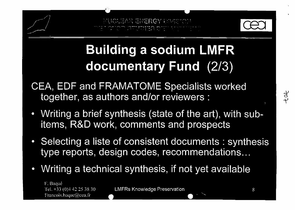
Building a sodium LMFRdocumentary Fund (2/3)
CEA, EOF and FRAMATOME Specialists workedtogether, as authors and/or reviewers :
«
• Writing a brief synthesis (state of the art), with sub-items, R&D work, comments and prospects
• Selecting a liste of consistent documents : synthesistype reports, design codes, recommendations...
• Writing a technical synthesis, if not yet availableF. BaqueTel. +33 (0)4 42 25 38 [email protected]
LMFRs Knowledge Preservation
•v
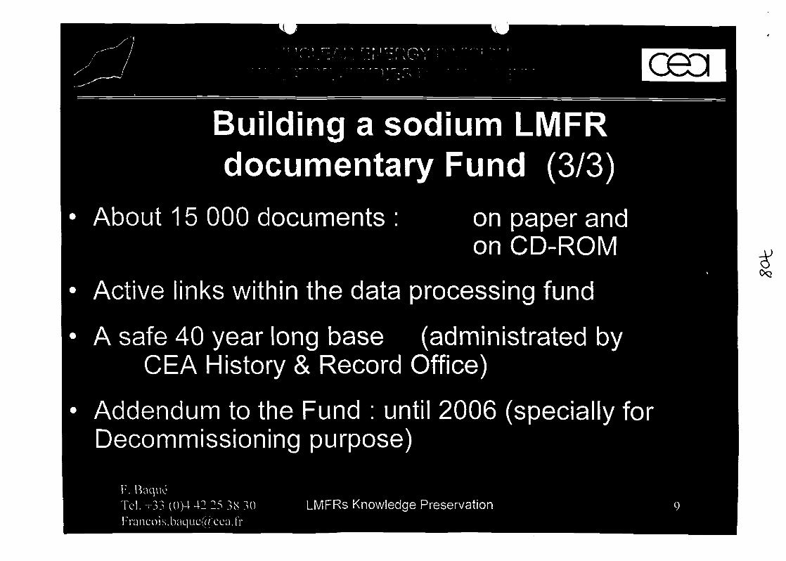
Building a sodium LMFRdocumentary Fund (3/3)
About 15 000 documents : on paper andon CD-ROM
Active links within the data processing fund
A safe 40 year long base (administrated byCEA History & Record Office)
Addendum to the Fund : until 2006 (specially forDecommissioning purpose)
F. BaqueTel.+33 ( 0 ) 4 4 2 2 5 3 8 3 [email protected]
LMFRs Knowledge Preservation
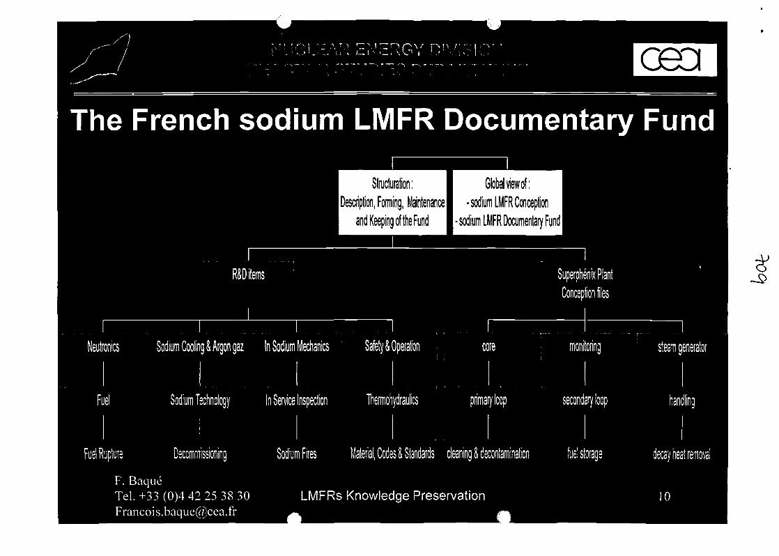
The French sodium LMFR Documentary Fund
Stfucturation: Global view of:Maintenance! -sodium LMFRConceptic
and Keeping of the Fund I • sodium LMFR Documentary Fund I
R&D items tnloilo «
Sodium Cooling & Argon gaz In Sodium Mechanics
F. BaqueTel. +33 (0)4 42 25 38 [email protected]
Material, Codes & Standards cleaning & decontamination
LMFRs Knowledge Preservation
steam generator
decay heat removal
R&D LMFRs KNOWLEDGE PRESERVATION FRENCH PROJECTAPPLICATION TO THE SODIUM COOLANT AND COVER GAS
G.RODRIGUEZ3
" CEA Cadarache Commissariat a I'Energie Atomique, CEA/DEN/DER/STR/LTTS Centre d'Etude deCADARACHE 13180 St Paul lez Durance, Cedex, France.
Abstract
In the frame of Liquid Metal Fast reactors knowledge preservation French project, CEA has separated the field ofthis subject in several items and has designed several experts to treat specific areas. Thus, this paper presents howthis study was made dealing with the following item : sodium coolant and cover gas. This papers explains whatwere the main difficulties by making this study and how they can be solved.
Keywords : Liquid Metal Fast Reactor (LMFR), Knowledge preservation, Sodium coolant.
1. IntroductionDevelopment of R&D linked to Liquid Metal Fast Reactors had an important stop in Francesince the decision of the final shutdown of Superphenix in 1998. From the very beginning ofthis technology until now with the decommissioning aspects, France have accumulated a hugeknowledge in this field mainly shared by three companies : CEA, EDF and FRAMATOMEANP.In 2000, it has been decided to create an everlasting data base of documentation with easyaccess for consulting, in order to keep knowledge an experience acquired through thedevelopment, design, construction and operation of the French LMFR plants (RAPSODIE,Phenix, Superphenix and EFR projects).
This data base was considered to be important in order to perpetuate the knowledge onLMFRs for the following decades. The absence of French and European future project on thissubject highlighted the risk of loss of knowledge in various field (excepted maybedecommissioning aspects), and expresses the need to drive as soon as possible such a project.
2. General presentation of the projectA very brief presentation of the general project is made in the following lines. For moredetailed data, refer to paper presented by M. BAQUE [ 1 ].
The R&D LMFRs preservation knowledge French project started in 2000. CEA is the leaderproject. The aim of this data base project is to include :
- Synthesis of history, concept approach, evolution and supporting R&D of FrenchLMFRs
- 22 R&D topics and 41 SUPERPHENIX plant systems
- Description of the main common CEA, EDF and FRAMATOME ANP realizations
- More than 1500 documents (papers and CD Rom medium)
- RCC MR 2000 version (updates of the mechanical analysis rules).
- Data base of all the measurement recorded and obtained from SUPERPHENIXexploitation.
From the R&D part, the most important item are the following :
- Neutronic
-Fuel
- Fuel rupture
- Sodium cooling and argon gas
- Sodium technology
- In sodium mechanics
- Safety and operation
- Thermohydraulic
- In sodium inspection
- Sodium fires
- Material codes and standards
- Decommissioning
This paper deals with the treatment of the "sodium coolant and cover gas" item.
3. The item "Sodium coolant and cover gas"
3.1. Work askedTo treat this item (as every other items), it was given the following constraints :
- It was necessary to write a small presentation text to present the context of this itemand some very general informations.
- It was necessary to select a limited number of references considered to cover thewhole subject of the item. The number of 150 references was given as an upper limit.
- This study as the whole project must be done in a limited time (from 2000 to mid2002) and will not continue after. Thus the given list of referenced papers will nothave any reevaluation with time.
These constraints and specifically the limited number of referenced papers was the majordifficulties to deal with such a wide item. Thus, to try to solve these difficulties, the firstoperation was to divide this subject into several sub items.
3.2. Description of the sub itemsIn order to be more precise in the definition of the indispensable knowledge on sodiumcoolant and cover gas, it was decided to define several sub items. Eight sub items wereselected and even in these sub items, another division was made. At the end this strategy leadsto the following list:
- O General knowledge on sodium- Physical properties
- Chemical properties- Thermal properties
This sub item deals with all the properties of metallic sodium that is necessary to knowto have a good knowledge of how the metallic sodium behaves.
- © Primary sodium- Specifications for primary sodium- Pollution monitoring- Activation- Measurement techniques- Purification techniques
The most important operations dealing with the primary sodium are covered by thissub item.
- © Secondary sodium- Specifications for secondary sodium- Pollution monitoring- Measurement techniques- Purification techniques
The most important operations dealing with the secondary sodium are covered by thissub item.
- 0 Experimental feedback from PHENIX and SUPERPHENIX- Recall of the experimental feedback gained from the main incidentoccurred in PHENIX plant in operation- Recall of the experimental feedback gained from the main incidentoccurred in SUPERPHENIX plant in operation
This sub item is covering the major experimental feedback gained by some incidentsencountered on French fast operators in operation. That is to say for example severalsodium/water reactions on Phenix Steam Generators, pollution of the primary sodiumby air ingress on Superphenix reactor, etc...
- © Argon cover gas- Physical and chemical properties- Behavior with sodium — Aerosols- Specifications for fast reactors- Measurement techniques
All the basic knowledge of the argon cover gas and its behavior in contact with liquidsodium are gathered in this sub item.
- © Narrow items- Corrosion in sodium- Sodium compatibility- Sodium potassium alloy (NaK alloy)- Cleaning - Decontamination - Requalification for the reuse of thecomponents
This sub item covers all the subjects where there was a fear that they will not beproperly treated in another item because they are at the border line between two fieldof knowledge.
- © Further or other coolants - Comparison with sodiumIt was found necessary to define this sub item in order to remind for the future whatwere in the past the reasons to select sodium as coolant for fast reactors and notanother coolant (such as gas or lead or whatever). And also to remind what were thecomparisons between sodium and other coolants with the choice criteria.
- © Books, technical documents and general conferences on sodium technologyBecause this subject: sodium coolant, was too wide, and because it was really difficultto select a limited number of document when several thousand have been written onthis subject, it was decided to define a sub items where unavoidable referenceddocuments must be conserved. These document are not concerned to only one sub itembut they generally treats all of them. Thus the general international conference onliquid metal technology (LEVIET) or some Handbook on liquid sodium were selectedin this sub item.
4. Difficulties in doing this selectionSeveral sorts of difficulties arose when time is arrived to select the final papers. Thesedifficulties can be sum up in four questions :
- Am I the best person chosen to select the best document ?It is of course difficult to identify the right person that knows every about sodiumcoolant. This question means that even if I have been chosen, my own knowledge isonly partial and mainly focused on my field of competence. So, it is necessary to keepin mind that all the field of the subject must be covered and not only what I know themost.
- How can I be sure that I will not miss something important (one paper or worst onepart of the field of this item) ?
- How it is possible to select around 150 documents when several thousand wereproduced all over the world ?Of course to solve this problem it should be argued that now we can store everythingon computer. There is no more a limitation of space memory. But by selectingeverything it is not possible to let to the future generation the experimental feedback ofwhat it is useful to know and what is not (or far less). By storing everything, we let tothe future a huge amount of data and documents with no hierarchy betweenthemselves. We are not in a knowledge preservation attitude but in a general archivestrategy with no increase in value by French experts. It is not the aim of this project.
To answer as much as possible to these previous questions, the following recommendationshappened to be very useful:
- Try to choose only the papers written as synthesis.
- Try to ask to every specialists : "What are the five documents that summarize yourfield of speciality the best ?"
- Try to keep the same importance in every subject and not only in the field of yourspeciality.
- Try to see abroad if the field of interests is the same or not.
- And finally keep in mind that your selection is maybe not the best but it is better thannothing (!!).
5. Synthesis of this studyThe selection of all the document designed to covered this subject is now over. 121documents were selected : 92 French documents coming from CEA, EDF and FRAMATOMEand 29 foreign documents coming from all the countries that have worked or are still workingin fast reactors. Ten general books were selected (sodium handbooks, IAEA conferences onliquid metal technology or specialist meetings, IAEA technical documents). Moreover all theup to date courses given at sodium school were selected because they were easily availableand they were a good synthesis of every specific subject (i.e. corrosion, purification, sodiummonitoring, cleaning, etc...). The compilation of all the sodium school courses was counted asonly one reference but in fact it gathers more than 70 courses.
6. ConclusionsThe list to treat about "sodium coolant and argon cover gas" is now finished and considered asdefinitively complete. After doing this kind of work there is still a feeling that nonetheless alot a knowledge is lost or difficult to maintain through the ages : principally the knowledge ofretired experts.It was possible to notice also that the field of interest in one particular subject in sodiumcoolant depends strongly on what happens during the LMFRs life. For example for Frenchpart, it was mainly sodium pollution and purification consequence of the air ingress inSuperphenix and also materials and corrosion as a consequence of the intermediate fuelsodium storage leak. In Great Britain, a lot of documents were focused on sodium/oilinteraction due to the oil ingress in PFR. This field of interest is also linked to the questions ofthe national safety authorities. As an example studies on In Service Inspection and Repairstarted in a lot of countries in the 90's after questions of safety authorities on this subject.Before, nothing was asked and as a consequence the development in this field was no soimportant. The trouble is that it is not possible or obvious to predict what will be the field ofquestions coming from the safety authorities in thirty years.It can be said as a final conclusion that this selection on sodium coolant is now ready for thefuture, so the knowledge preservation is on the way. This list of document is also very usefulfor the present time.
REFERENCES
[ 1 ] : F. BAQUE, "R&D LMFRs knowledge preservation French project", IAEA Technical meeting onOperational and decommissioning experience with fast reactors, Cadarache, France, 11-15 March2002. (This meeting).


NUCLEAR^NERGY DIVISIONSTUDIES DEPARTMENT
REACTOR TECHNOLOGY SERVICE*
7437 -grodfi
IAEA meeting 11-15 March 2002
V
-v
Oo
W<F!
"the friain characteristics of the sodium tcoolant and cover gas"
Vsi'' Li

NUCLEAR ENERGY DIVISIONREACTOR STUDIES DEPARTMENTREACTOR TECHNOLOGY SERVICE
The main items 1/3
D Sodium (general knowledge)• Physical properties• Chemical properties• Thermal properties '
D Primary sodium "^Specifications for primary sodiumPollution monitoringActivation ,Measurement techniques (Plugging indicators, chemistry, etc..)Purification techniques , . -
- 0) Secondary sodium -. . ' • -. ,. ' • " : •*• • ::'l^ • : - * : ~ \ ' \ ;-• • Specifications for primary sodium .
• Pollution monitoring<v • Measurement techniques (Plugging indicators, chemistry, etc..) -; • Purification techniques , . .
* : f ' - ;.* . ' - . " . - t , ,. . " ' • " , " _ • . - , . - * • _ - • ; : - • .<:/*'.'_ ^ ' :X.";J " ' ' ' . ' ' J V*"* "
1 J, ,* *" " '*«**'
[email protected] " IAEA meeting 11-15 March 2002 > 5
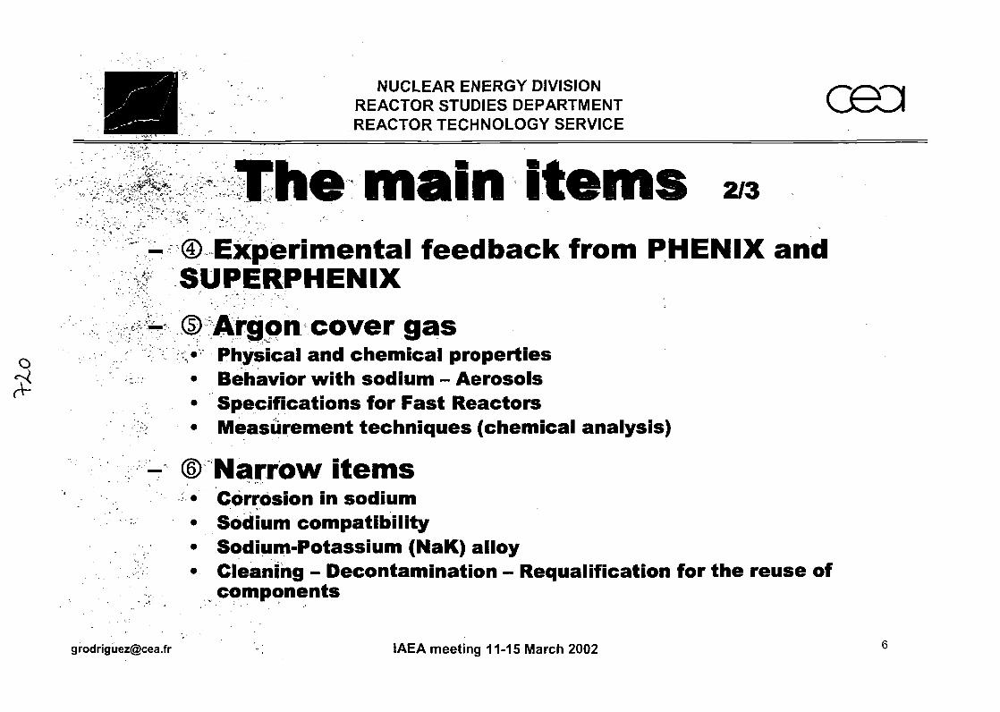
NUCLEAR ENERGY DIVISIONREACTOR STUDIES DEPARTMENTREACTOR TECHNOLOGY SERVICE
The main items 2/3- © Experimental feedback from PHENIX and
SUPERPHENIX
— ©Argon cover gas0 > Physical and chemical properties7^ • Behavior with sodium - Aerosols
• Specifications for Fast Reactors• Measurement techniques (chemical analysis)
- ©Narrow items• Corrosion in sodium• Sodium compatibility• Sodium-Potassium (NaK) alloy• Cleaning - Decontamination - Requalification for the reuse of
components
[email protected] ' • ' • • • : ' • > ' . IAEA meeting 11-15 March 2002
NUCLEAR ENERGY DIVISIONREACTOR STUDIES DEPARTMENTREACTOR TECHNOLOGY SERVICE
mam• -"•"»>. "* • ^ * -. • • . " „ . • . " •* * » * * * ""* , - * v ' *'"°*
©Future or other coolants - Comparison withsodium
and general conferences on sodium
[email protected] IAEA meeting 11-15 March 2002

NUCLEAR ENERGY DIVISIONREACTOR STUDIES DEPARTMENTREACTOR TECHNOLOGY SERVICE
Difficulties in doing this study• Several sorts of difficulties :
- « Psychological questions » :• Am I the best person to select the best documents ?• How can I be sure thai V will not miss something important
(one subject or one paper) ?• How can I select around 150 documents on this subject when
several thousands were produced all over the world ?
- Difficulties in finding the right documents :. • If I select to many documents, the aim of this study will not
' be achieved (= to preserve only the basic knowledge onsodium coolant, with a restricted number of documents)
• By selecting some documents, I will neglect other documents.Sometime the choice is very difficult.
" ' ' , ", *V r • ... , ' • ' '; - ,
[email protected] IAEA meeting 11-15 March 2002 8
NUCLEAR ENERGY DIVISIONREACT OR STUDIES DEPARTMENTREACTOR TECHNOLOGY SERVICE
Difficulties in doing this study• How to deal with this difficulties :
-Try to choose only the papers written as synthesis-Try to ask to every specialists : "What are the five
documents that summarize your field of specialitythe best?" - ' .. ''-• -.,J^^.:.
- Keep in mind that your work maybe is not the bestbut is better than nothing (II) i S 1
- Try to keep the same importance in every subject• /v-^alici-'ndt"only in the field of your speciailfty:"f |? ^: ;>':'
-Try to see abroad iff the field of interest is the• Isairie"orhot . • " " ^' ' • " • f&^
[email protected] ' ? IAEA meeting 11-15 March 2002 .:" 9
NUCLEAR ENERGY DIVISIONREACTOR STUDIES DEPARTMENTREACTOR TECHNOLOGY SERVICE
Synthesis of this study• 121 documents were selected :
- 92 french documents coming from CEA, EOF or FRAMATOME ANP
- 29 foreign documents
• 10 conferences or general books were selected :
- LIMET88, IAEA Conferences, etc...«**'
- Book from M. BORGSTEDT, from M. FOUST, Liquid Metal Handbookfrom Dpt of Navy (USA)
• All the presentations of sodium school were selected :
- Easily available
- Good synthesis of each item
[email protected] IAEA meeting 11-15 March 2002 10
NUCLEAR ENERGY DIVISIONREACTC>R STUDIES DEPARTMENTREACTOR TECHNOLOGY SERVICE
General conclusions»
• The work is over now
I still have the feeling that a lot of knowledgeis hot covered (personal knowledge of retiredpeople...) *'• ; '; :; ' " V
I think that this work was necessary even ifthe subject is too wide to be completelytreated... - " . . ' - • -:-:<-?$:
[email protected] '• : IAEA meeting 11-15 March 2002 11
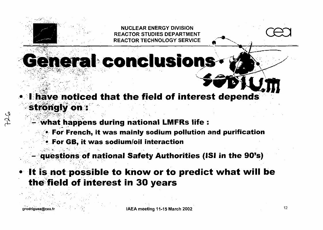
ZQQZsi- [email protected]
u
aqjeqwv }3ipa4d o} 40 /wou>|jo p|3ij ei|)
eiqissod jou si
(sfiQ6 am u! ISl) sdi|uoi||nv A|a|e$ jeuoiieu jo suoijsanb - i. ',-,''' . . • -j '\ V , "*
uoi|3eja;ui no/uinipos SBM ;i '99 JQJ •uoijBOijund PUB uoi;n||od uinipos AIUIBUI sewv ;i
fii|3uaij joj •
' „ - ,'*">-'"
Suunp suaddeq
spuadap: uo
peoijou
saianisNOISIAia A9H3N3 yVSIOON
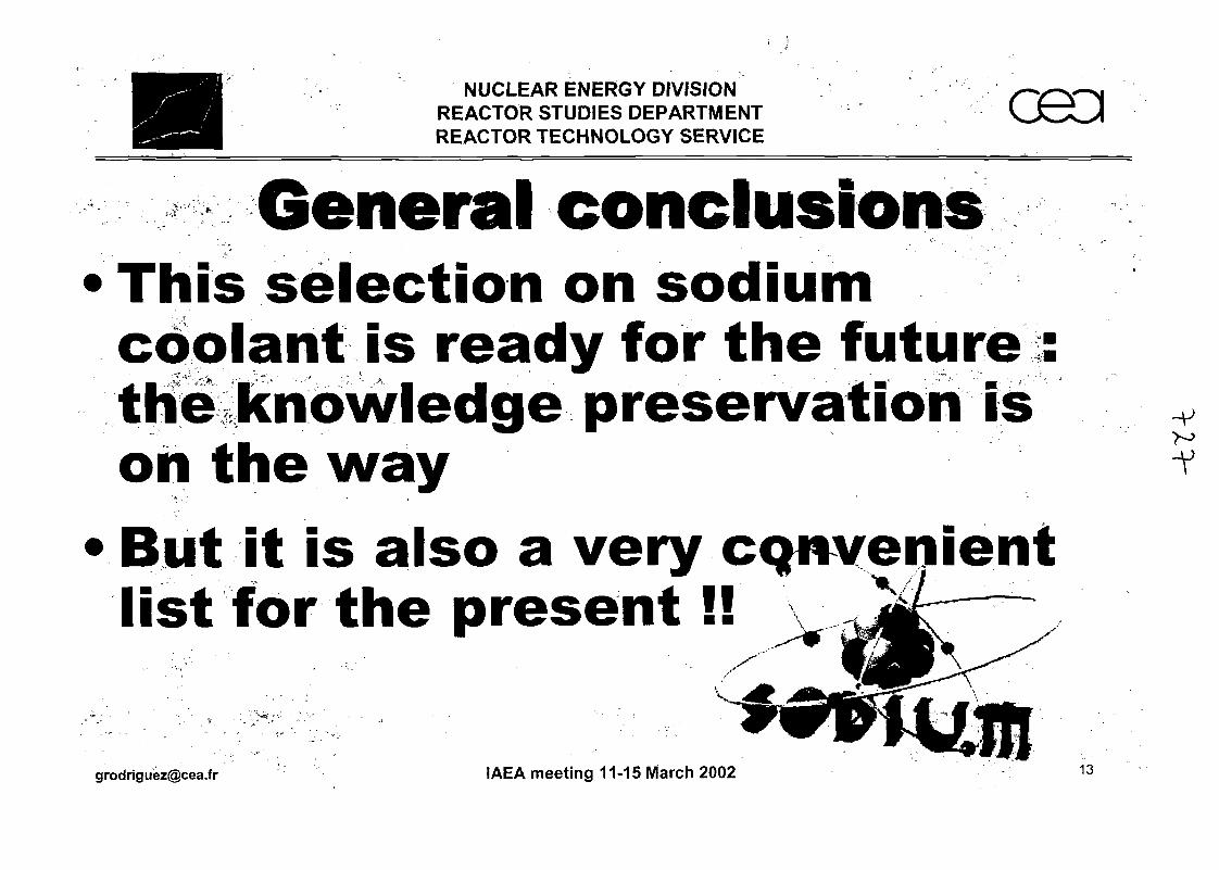
NUCLEAR ENERGY DIVISIONREACTOR STUDIES DEPARTMENTREACTOR TECHNOLOGY SERVICE
General conclusionsThis selection on sodiumcoolant is ready for the future :the knowledge preservation ison the wayBut it is also a very CQnvenientlist for the present!!
-V
[email protected] IAEA meeting 11-15 March 2002 13

IAEA-TWGFR - Feedback from Operational and Decommissioning Experience on Fast Reactors -
JNC Viewpoint on Fast Reactor Knowledge Preservation
Presented by Tsutomu IRffi
International Cooperation & Technology Development CenterJapan Nuclear Cycle Development Institute (JNC)
Abstract
JNC is undertaking a major program of research and development on liquid-metal cooled fast
breeder reactors, which is fully supported by the government of Japan and the electrical
utilities. Hence, the perspective of JNC on knowledge preservation is rather different from
that of organizations where the fast reactor project has been scaled down or discontinued.
Within JNC, there is a statutory obligation to preserve documentary records of the fast reactor
project Over time the method of archiving has changed from optical (microfilm, microfiche
etc.) to digital storage. It is the long-term objective of JNC to convert all its records to digital
format and make them available to staff over its intranet.
JNC is also attempting to preserve 'human knowledge', that is, the expertise of staff who
have been involved in the fast reactor project over a long period and who are now nearing
retirement. Based on this information, two computerized systems are currently being
constructed: one which records Hu,a readily accessible manner the background to key design
decisions for the Monju plant; and a second which uses simple relationships between design
parameters to aid designers understand the knock-on effects of design choices (joint project
with Mitsubishi).
To its partners in international cooperation - the US/DoE and the organizations of the
Euro- Japan collaboration - JNC is proposing a joint approach to knowledge preservation and
retrieval. The proposed concept, dubbed the International Super-Archive Network (ISAN),
would make use of the standardized software the new technologies of the internet increase the
mutual accessibility of fast reactor information.
JNC considers it extremely important to reflect the lessons learnt from previous experience in
the fast reactor field to the operation and maintenance of Monju and the design of future
reactors.


JNC Viewpoint on Fast Reactor Knowledge Preservation
Yoshio YOKOTA, Peter HARRISON, Tsutomu IRIE
International Cooperation & Technology Development CenterTsuruga Head Office
Japan Nuclear Cycle Development Institute (JNC)
Abstract
JNC is undertaking a major program of research and development on liquid-metal cooled fastbreeder reactors, which is fully supported by the government of Japan and the electricalutilities. Hence, the perspective of JNC on knowledge preservation is rather different fromthat of organizations where the fast reactor project has been scaled down or discontinued.
Within JNC, there is a statutory obligation to preserve documentary records of the fast reactorproject. Over time the method of archiving has changed from optical (microfilm, microficheetc.) to digital storage. It is the long-term objective of JNC to convert all its records to digitalformat and make them available to staff over its intranet.
JNC is also attempting to preserve 'human knowledge', that is, the expertise of staff whohave been involved in the fast reactor project over a long period and who are now nearingretirement. Based on this information, two computerized systems are currently beingconstructed : one which records in a readily accessible manner the background to key designdecisions for the Monju plant; and a second which uses simple relationships between designparameters to aid designers understand the knock-on effects of design choices (joint projectwith Mitsubishi).
To its partners in international cooperation - the US/DoE and the organizations of theEuro-Japan collaboration - JNC is proposing a joint approach to knowledge preservation andretrieval. The proposed concept, dubbed the International Super-Archive Network (ISAN),would make use of the standardized software the new technologies of the internet increasethe mutual accessibility of fast reactor information.
JNC considers it extremely important to reflect the lessons learnt from previous experience inthe fast reactor field to the operation and maintenance of Monju and the design of futurereactors.
1. Current status of Japan's FBR Project
JNC has two operable fast reactors: the experimental-scale reactor Joyo which is currentlybeing upgraded to improve its ability to perform irradiation experiments; and the prototypeMonju which remains shutdown since the 1995 sodium leak accident. It is always difficult topredict when Monju will return to operation, but it is hoped that - if all goes well - Monjucould be restarted in 2005.Most of the R&D effort in the project is now directed towards the so-called Feasibility Studywhich is looking at ways to optimize the design of future fast reactors, and the entire cycle,with a view to commercialization. This is a joint project with JAPC and other Japaneseresearch organizations.The point is that - in contrast to what has been happening in Europe and the USA - Japanstill has a major fast reactor project which continues to have the full support of the Japanese
government and the electricity industry. This gives a very different perspective on knowledgepreservation.
2. JNC approach to knowledge preservation
As a publicly-funded research organization JNC have a statutory obligation to keep alldocumentary records of the fast reactor project.With such a huge number of documents to manage it is necessary to consider how to makethem accessible to JNC's staff. It is the long-term objective to transform all the documentsinto electronic format and make them available via company intranet. This is an ongoingproject.Preserving what could be called "human" knowledge is also being attempted. It's a realproblem for JNC that many very experienced staff are reaching retirement age and areleaving the organization. These were the people who were involved in the design andconstruction of Monju from the outset, and they have a breadth of experience which would bedifficult for someone entering the project today to acquire. Hence, building a computerizedsystem based on their accumulated knowledge is attempted.
2.1. Preservation of human knowledge
There were the key staff, who are now nearing retirement or have already retired, in theMonju design process. Interviews them about their experience are being made.The computerized system, based on this knowledge, is in two parts:- The first part is a record of the decision making process behind each key design parameter
on the plant. Starting with an index of the major systems and components, it is possible tolook up, for example: Why was a loop design chosen in favour of a pool? Why three loops?.. .and so on, down to a more detailed level. Without this system staff would have to searchthrough dozens of old reports to find such an explanation.- The second part - the design interaction guide - uses simple relationships to illustrate howa change in one design parameter has a knock-on effect on others. This is a joint project withMitsubishi and it is still at an early stage, but it is hoped to be useful to future designers.
2.2. Retain all documentary records of the FR project
As mentioned, it is JNC's obligation to preserve everything as possible. This includes all thebackground R&D, the design documents, drawings and so on. It also includes the computercodes that were used at the design stage.A major effort have been made to index all the information by technical area, and already theindex is available to JNC's staff over the company intranet. In the future, it is hoped to add amore sophisticated cross-referencing system.There is also a long-term project to select, from this huge archive, a more limited set of keypapers.
For example, storage media and scale for Monju are as follows (it does not includebackground R&D or anything related to Joyo.);The original paper documents are considered to be the primary reference source, and theyare always retained - even after they have been scanned or transformed to some othermedium. It is estimated that there are about one million pages of such documents.A few years ago, the best way to preserve these seemed to be microfilm or microfiche - butthis has now been abandoned in favour of digital storage. Documents are scanned into AdobeAcrobat (pdf) format using a high-speed scanner. So far there are about 66 Gigabytes ofdocuments stored in this way.
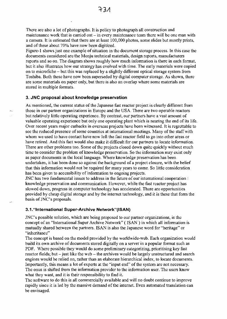
There are also a lot of photographs. It is policy to photograph all construction andmaintenance work that is carried out - in every maintenance team there will be one man witha camera. It is estimated that there are at least 100,000 photos, some slides but mostly prints,and of these about 70% have now been digitized.Figure-1 shows just one example of situation in the document storage process. In this case thedocuments considered are the Monju technical materials, design reports, manufacturersreports and so on. The diagram shows roughly how much information is there in each format,but it also illustrates how our strategy has evolved with time. The early materials were copiedon to microfiche - but this was replaced by a slightly different optical storage system fromToshiba. Both these have now been superseded by digital computer storage. As shown, thereare some materials on paper only, but there is also an overlap where some materials arestored in multiple formats.
3. JNC proposal about knowledge preservation
As mentioned, the current status of the Japanese fast reactor project is clearly different fromthose in our partner organizations in Europe and the USA. There are two operable reactorsbut relatively little operating experience. By contrast, our partners have a vast amount ofvaluable operating experience but only one operating plant which is nearing the end of its life.Over recent years major cutbacks in overseas projects have been witnessed. It is regrettable tosee the reduced presence of some countries at international meetings. Many of the staff withwhom we used to have contact have now left the fast reactor field to go into other areas orhave retired. And this fact would also make it difficult for our partners to locate information.There are other problems too. Some of the projects closed down quite quickly without muchtime to consider the problem of knowledge preservation. So the information may exist onlyas paper documents in the local language. Where knowledge preservation has beenundertaken, it has been done so against the background of a project closure, with the beliefthat this information would not be required for many years to come. So little considerationhas been given to accessibility of information to ongoing projects.JNC has two fundamental issues to address in the future of our international cooperation :knowledge preservation and communication. However, while the fast reactor project hasslowed down, progress in computer technology has accelerated. There are opportunitiesprovided by cheap digital storage and by the internet technology, and it is these that form thebasis of JNC's proposals.
3.1."International Super-Archive Network"(ISAN)
JNC's possible solution, which are being proposed to our partner organizations, is theconcept of an "International Super Archive Network" (IS AN) in which all information ismutually shared between the partners. ISAN is also the Japanese word for "heritage" or"inheritance"The concept is based on the model provided by the worldwide-web. Each organization wouldbuild its own archive of documents stored digitally on a server in a popular format such asPDF. Where possible they would do some preliminary categorizing, prioritising key fastreactor fields; but -just like the web - the archives would be largely unstructured and searchengines would be relied on, rather than an elaborate hierarchical index, to locate documents.Importantly, this means a lot of experts at the "input end" of the system are not necessary.The onus is shifted from the information provider to the information user. The users knowwhat they want, and it is their responsibility to find it.The software to do this is all commercially available and will no doubt continue to improverapidly since it is led by the massive demand of the internet. Even automated translation canbe envisaged.
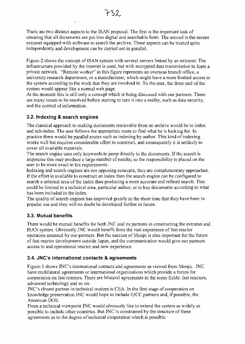
There are two distinct aspects to the ISAN proposal. The first is the important task ofensuring that all documents are put into digital and searchable form. The second is the secureextranet equipped with software to search the archive. These aspects can be treated quiteindependently and development can be carried out in parallel.
Figure-2 shows the concept of ISAN system with several servers linked by an extranet. Theinfrastructure provided by the internet is used, but with encrypted data transmission to form aprivate network. "Remote worker" in this figure represents an overseas branch office, auniversity research department, or a manufacturer, which might have a more limited access tothe system according to the work that they are involved in. To the user, the front-end of thesystem would appear like a normal web page.At the moment this is still only a concept which is being discussed with our partners. Thereare many issues to be resolved before starting to turn it into a reality, such as data security,and the control of information.
3.2. Indexing & search engines
The classical approach to making documents retrievable from an archive would be to indexand sub-index. The user follows the appropriate route to find what he is looking for. Inpractice there would be parallel routes such as indexing by author. This kind of indexingworks well but requires considerable effort to construct, and consequently it is unlikely tocover all available materials.The search engine uses only keywords to jump directly to the documents. If the search isimprecise this may produce a large number of results; so the responsibility is placed on theuser to be more exact in his requirements.Indexing and search engines are not opposing concepts, they are complementary approaches.If the effort is available to construct an index then the search engine can be configured tosearch a selected area of the index thus producing a more accurate and refined search. Thiscould be limited to a technical area, particular author, or to key documents according to whathas been included in the index.The quality of search engines has improved greatly in the short time that they have been inpopular use and they will no doubt be developed further in future.
3.3. Mutual benefits
There would be mutual benefits for both JNC and its partners in constructing the extranet andISAN system. Obviously JNC would benefit from the vast experience of fast reactoroperation amassed by our partners. But the success of Monju is also important for the futureof fast reactor development outside Japan, and the communication would give our partnersaccess to and operational reactor and new experience.
3.4. JNC's international contacts & agreements
Figure-3 shows JNC's international contacts and agreements as viewed from Monju. JNChave multilateral agreements or international organizations which provide a forum forcooperation on fast reactors. There are bilateral agreements in the some fields: fast reactors,advanced technology and so on.JNC's closest partner in technical matters is CEA. In the first stage of cooperation onknowledge preservation JNC would hope to include EJCC partners and, if possible, theAmerican DOE.From a technical viewpoint JNC would obviously like to extend the system as widely aspossible to include other countries. But JNC is constrained by the structure of theseagreements as to the degree of technical cooperation which is possible.
3.5. Special Challenges for Japan
There are also some special challenges for Japan in creating the ISAN system.In Japan a mixed writing system is used, which has two phonetic alphabets (hiragana andkatakana), each about 50 characters, plus the kanji characters which originated in China -there are over 2000 kanji in regular use - with no spaces between words. This makes the taskof optical character recognition a bit more difficult.What makes it more difficult still is that before computers became so widespread, a largeproportion of the technical documents were hand-written. At present optical characterrecognition is almost impossible for these.Japanese is completely unlike English and the other European languages. The translationsoftware is still not of a high enough standard to be useful.So, it is difficult, but we believe that this concept could be the way forward for a cooperativeproject with long-term objectives but limited resources, spread over geographically remotelocations.
4. Conclusions
JNC has the long-term objectives to transform all the documents into electronic format andmake them available via company intranet. Further preserving what could be called "human"knowledge is also being attempted.JNC is proposing a joint approach to knowledge preservation and retrieval. The proposedconcept, dubbed the International Super-Archive Network (ISAN), would make use of thestandardized software and the internet technologies.JNC considers it extremely important to reflect the lessons learnt from previous experience inthe fast reactor field to the operation and maintenance of Monju and the design of futurereactors.
Fig.1 Example of infromation storage
Field: Monju technical materials
Computer Storage 50%
Toshiba System 50%
Microfiche 45%conversion project
Original Paper Documents 100%
Fig.2 Concept of Extranet and ISAM System
Content - Document archives (ISAN)- Joint project documents- Operating data from plants
Access - JNC+partner organizations- Restricted user base
Security - User ID / Password- ENCRYPTION
Security - Standard internet-PDF Search Engine
Partner's internet server
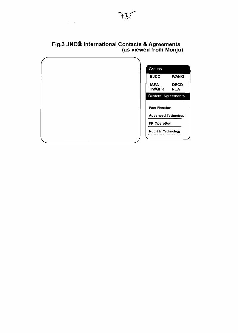
Fig.3 JNCQ International Contacts & Agreements(as viewed from Monju)
Groups
EJCC
IAEATWGFR
WANO
OECDNEA
Bilateral Agreements
Fast Reactor
Advanced Technology
FR Operation
Nuclear Technology

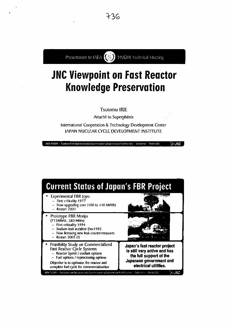
JNC Viewpoint on Fast ReactorKnowledge Preservation
Tsutomu IRIE
Attache to Superphenix
International Cooperation & Technology Development Center
JAPAN NUCLEAR CYCLE DEVELOPMENT INSTITUTE
ling Experience on Fast Reactors • Cadarache • March 2002
Current Status of Japan's FBR ProjectExperimental FBR Jqyo- First criticality 1977- Now upgrading core (100 to 140 MWth)- Restart 2003
Prototype FBR Monju(715MWth,280MWe)- First criticality 1994- Sodium leak accident Dec J 995- Now licensing new leak countermeasures- Restart 2005 (?)
Feasibility Study on CommercializedFast Reactor Cycle Systems- Reactor layout / coolant options- Fuel options / reprocessing options
Objective is to optimize the reactor andcomplete fuel cycle for commercialization
Japan's fast reactor projectis still very active and has
the full support of theJapanese government and
electrical utilities.

JNC Approach to Knowledge Preservation
Retain all documentary records of the FR project
Preserved information must be accessible
- transform to electronic format
- access via company intranet
Attempt to preserve "Human" knowledge
- many experienced staff now reaching retirement
- attempting to build a computerized system
nee on Fast Reactors • Cadarache - March 2002
Preservation of Human Knowledge
• Attempting to preserve human knowledge by:- Recording interviews with key staff
- 'Memoirs' of staff in decision-making process
• Based on this, construction of computerized:"FBR Plant Design Planning System"- Explanation of each design decision
(e.g. Power, dimensions, layout...)
- Design interaction guide(knock-on effect of changing design parameters)
(joint project with Mitsubishi)
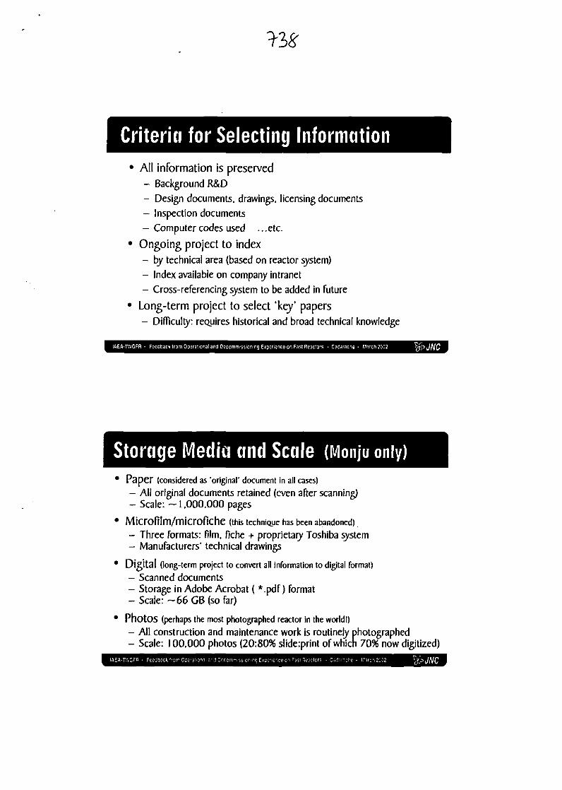
Criteria for Selecting Information• All information is preserved
- Background R&D
- Design documents, drawings, licensing documents
- Inspection documents
- Computer codes used ...etc.
• Ongoing project to index- by technical area (based on reactor system)
- Index available on company intranet
- Cross-referencing system to be added in future
• Long-term project to select 'key* papers- Difficulty: requires historical and broad technical knowledge
Storage Media and Scale (Monju only)Paper (considered as 'original' document in all cases)- All original documents retained (even after scanning)- Scale: ~ 1.000.000 pages
Microfilm/microfiche (this technique has been abandoned)- Three formats: film, fiche + proprietary Toshiba system- Manufacturers' technical drawings
Digital (long-term project to convert all information to digital format)- Scanned documents- Storage in Adobe Acrobat ( *.pdf) format- Scale: ~66 GB (so far)
PhotOS (perhaps the most photographed reactor in the world!)
- All construction and maintenance work is routinely photographed- Scale: 100.000 photos (20:80% slide:print of which 7096 now digitized)

Example of Information StorageField: Monju technical materials
Computer Storage 50%
Toshiba System 50%
Microfiche 45%conversion project
Original Paper Documents
IAEA-TWGFR - Feedback from Operational and Decommissioning Experience on Fast Reactors • Cadarache • March 2002
Benefiting from Past ExperienceContinuing project in japan could benefit from previousexperience abroad but:
• limited and declining effort in JNC's partner organizations- Reduced presence at international meetings
- Contact staff redeployed or retired
- Limited expertise remains to perform information evaluation
• overseas information inaccessible- Some projects closed over short period, hence limited archiving
- Information may not be in an accessible format
- Archiving performed with a view to long-term storage withoutconsideration of immediate access
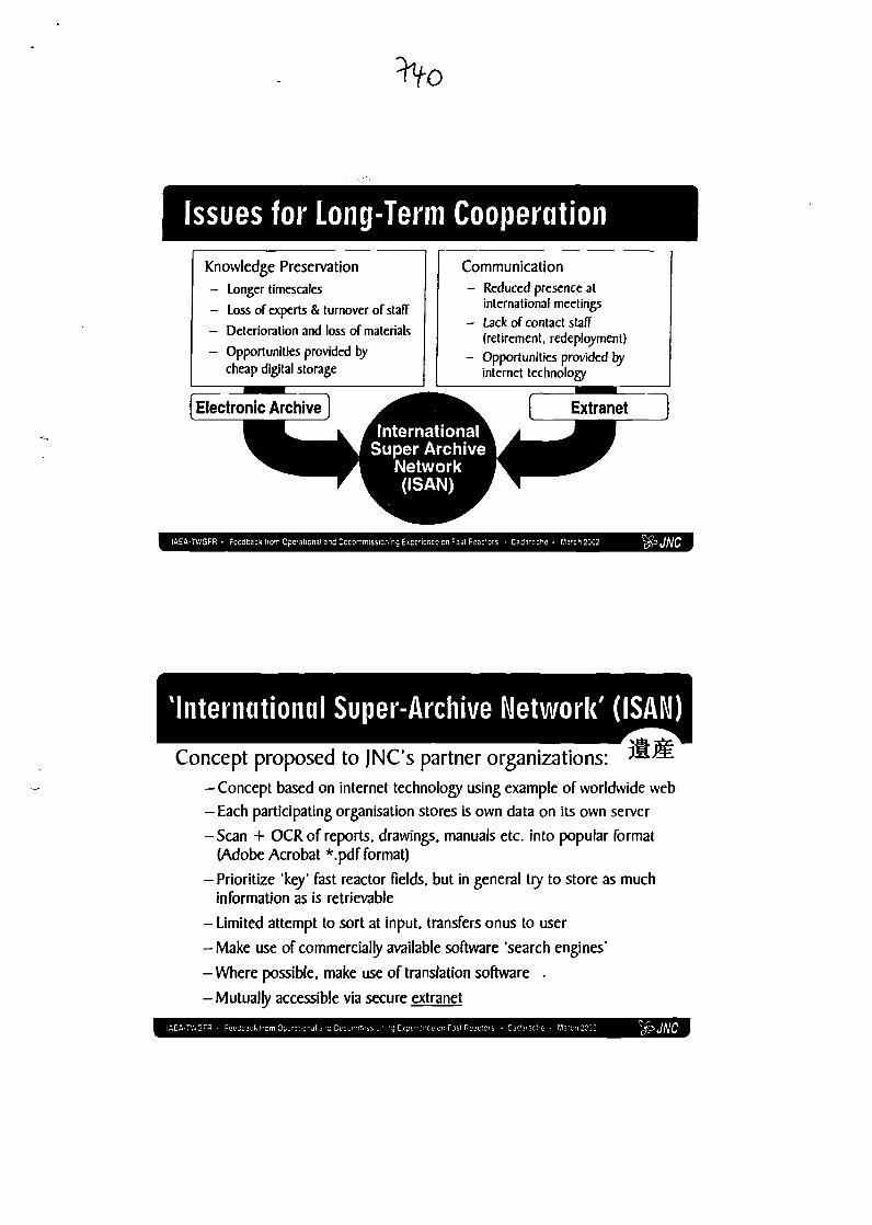
o
Issues for Long-Term CooperationKnowledge Preservation
- Longer timescales
- Loss of experts & turnover of staff
— Deterioration and loss of materials
- Opportunities provided bycheap digital storage
Communication- Reduced presence at
international meetings
- Lack of contact staff(retirement, redeployment)
- Opportunities provided byinternet technology
ache • March2002
International Super-Archive Network' (ISAM)
Concept proposed to JNCs partner organizations: ^^
-Concept based on internet technology using example of worldwide web
— Each participating organisation stores is own data on its own server
-Scan + OCR of reports, drawings, manuals etc. into popular format(Adobe Acrobat *.pdf format)
-Prioritize 'key' fast reactor fields, but in general try to store as muchinformation as is retrievable
- Limited attempt to sort at input, transfers onus to user
- Make use of commercially available software 'search engines'
- Where possible, make use of translation software .
- Mutually accessible via secure extranet
Building the ISAM SystemArchive Extranet
Technical reportsPlant manualsComponent drawingsOperational dataetc.
tlback from Operational and Decommissioning Experience on Fas! Reactors - Cadarache - March2002
Concept of Extranet and ISAN SystemContent - Document archives (ISAN)
- Joint project documents- Operating data from plants
Access - JNC + partner organizations- Restricted user base
Security -User ID/Password- ENCRYPTION
Software - Standard internet- PDF Search Engine
Partner's internet server
ioning Experience on Fast Reactors • Cadarache • March 2002
Indexing & Search Engines
in index |
AF [SEABCH|
+A+F ISEAHCHJ
F slte:/A
Indexed archive Search Engine
Mutual Benefits
Vast experience of fastreactor operation
Partners
Contributing to success of Monju
Access to an operational reactor
New operation experience
JNC's International Contacts & Agreements
t-K If- ,(DOE) |
Monju
OECDNEA
EJCC
Groups
EJCC
IAEATWGFR
WANO
OECDNEA
Bilateral Agreements
Fast Reactor
Advanced Technology
FR Operation
Nuclear Technology
IAEA TWGFRIAEA-TWGFR - Feedback Irom Operational and Decommissioning Experience on Fast Reactors • Cadarache - March 2002
Special Challenges for JapanDifficulty of Optical Character Recognition (OCR)
Japanese combines 3 different writing systems:
2 phonetic 'alphabets' + over 2000 Japanese kanjicharacters (with no spaces)
Some early information is hand-written
Difficulty of translating from/to Japanese
(software is currently not of a high enough standard)
JNC Viewpoint on Fast Reactor Knowledge PreservationPresenter: Tsutomu IRIE
Attach^ to SuperphenixCNPDE de Creys-MaMlleBP63. 38510 Morestel. FRANCETel: +33 4 74 33 34 95Fax: +33474333425Email: [email protected]
Further Yoshio YOKOTAInformation: Group Leader
International Cooperation Group|apan Nuclear Cycle Development Institute
International Cooperation & Technology Development CenterI. Shiraki. Tsuruga. Fukui. IAPAN 919-1279
Tel: +81 77039 1031 Ext. 5320Fax: +81 770399182Email: [email protected]
Website: www.jnc.go.jrVjncweh/
IAEA-TWGFR • Feedback from Cperationa

Related Documents